Self-gelling hydrogels based on oppositely charged dextran microspheres
Upload
khangminh22Category
view
2download
0
BiofaBrication of implants for articular joint repair
Cartilage regeneration in reinforced gelatin-based hydrogels
Jetze Visser2015
promotorProf. dr. W.J.A. Dhert
copromotorenDr. ir. J. MaldaDr. ir. D. Gawlitta

Biofabrication of implants for articular joint repair: Cartilage regeneration in reinforced gelatin-based hydrogels
Jetze VisserPhD thesis, Utrecht University, University Medical Center Utrecht, Utrecht, the Netherlands
Copyright © J. Visser 2015. All rights reserved. No parts of this thesis may be reproduced, stored in a retrieval system of any nature or transmitted in any form or by any means, without prior written consent of the author. The copyright of the articles that have been published has been transferred to the respective journals.
Financial support for the printing of this thesis was generously provided by:De Nederlandse Orthopaedische Vereniging, the Dutch society for Biomaterials and Tissue Engineering, Anna Fonds te Leiden, Livit Orthopedie MRI Centrum and Chipsoft.
The research in this thesis was financially supported by: the Netherlands Institute for Regenerative Medicine, the European Community’s Seventh Framework Programme (FP7/2007-2013) under grant agreement n309962 (HydroZONES) and the Dutch Arthritis Foundation.
ISBN 978-94-6169-706-6
Layout and printing: Optima Grafische Communicatie, Rotterdam, the Netherlands
Cover design: Marco Bot
Biofabrication of implants for articular joint repairCartilage regeneration in reinforced gelatin-based hydrogels
Bioprinten van implantaten voor het herstel van gewrichtsschadeKraakbeenregeneratie in verstevigde gelatine hydrogel
(met een samenvatting in het Nederlands)
proefschrift
ter verkrijging van de graad van doctor aan de Universiteit Utrechtop gezag van de rector magnificus, prof. dr. G.J. van der Zwaan,
ingevolge het besluit van het college voor promotiesin het openbaar te verdedigen op dinsdag 25 augustus 2015 des avonds te 6.00 uur
door
Jetze Vissergeboren op 6 januari 1985 te Gaasterland


this thesis is Based upon the following puBlications:
Reinforcement of hydrogels using three-dimensionally printed microfibres.Visser J, Melchels FPW, Jeon JE, van Bussel EM, Kimpton LS, Byrne HM, Dhert WJA, Dalton PD, Hutmacher DW, Malda J. Nature Communications. 2015;6:6933 doi: 10.1038/ncomms7933
Crosslinkable Hydrogels derived from Cartilage, Meniscus and Tendon Tissue.Visser J, Levett PA, Te Moller NC, Besems J, Boere KW, Van Rijen MH, de Grauw JC, Dhert WJA, van Weeren PR, Malda J. Tissue Engineering Part A. 2015 Apr;21(7-8):1195-206
Endochondral bone formation in gelatin methacrylamide hydrogel with embedded cartilage-derived matrix particles.Visser J, Gawlitta D, Benders KE, Toma SM, Pouran B, van Weeren PR, Dhert WJA, Malda J. Biomaterials. 2015 Jan;37:174-182
Biofabrication of tissue constructs by 3D bioprinting of cell-laden microcarriers.Levato R, Visser J, Planell JA, Engel E, Malda J, Mateos-Timoneda MA. Biofabrication. 2014 Sep;6(3):035020
Covalent attachment of a three-dimensionally printed thermoplast to a gelatin hydrogel for mechanically enhanced cartilage constructs.Boere KW*, Visser J*, Seyednejad H, Rahimian S, Gawlitta D, van Steenbergen MJ, Dhert WJA, Hennink WE, Vermonden T, Malda J. Acta Biomaterialia. 2014 Jun;10(6):2602-11*Authors contributed equally to this manuscript
Weefsel uit de printer: de mogelijkheden van 3D-printen in de geneeskunde.Visser J, Melchels FP, Dhert WJ, Malda J.Nederlands Tijdschrijft voor Geneeskunde. 2013;157(52):A7043
Engineering hydrogels for biofabrication.Malda J, Visser J, Melchels FP, Jüngst T, Hennink WE, Dhert WJA, Groll J, Hutmacher DW. Advanced Materials. 2013 Sep;25(36):5011-28
Biofabrication of multi-material anatomically shaped tissue constructs.Visser J, Peters B, Burger TJ, Boomstra J, Dhert WJ, Melchels FP, Malda J. Biofabrication. 2013 Sep;5(3):035007

taBle of contents
introduction
Chapter 1 General introduction, outline and research questions 9
Chapter 2 Engineering hydrogels for biofabrication 27
part i Biological improvement of gelma hydrogel with tissue-derived matrices
Chapter 3 Crosslinkable hydrogels derived from cartilage, meniscus and tendon tissue 61
Chapter 4 Endochondral bone formation in gelatin methacrylamide hydrogel with embedded cartilage-derived matrix particles
81
part ii mechanical improvement of gelma hydrogel constructs with 3d-printed scaffolds
Chapter 5 Covalent attachment of a three-dimensionally printed thermoplast to a gelatin hydrogel for mechanically enhanced cartilage constructs
103
Chapter 6 Reinforcement of hydrogels with three-dimensionally printed microfibres 127
Chapter 7 Preliminary results of a translational animal modelCartilage repair with a combination of chondrons and MSCs in gelatin methacrylamide hydrogel: the establishment of an equine model
153
part iii Biofabrication of complex shaped constructs from gelma for osteochondral tissue repair
Chapter 8 Biofabrication of multi-material anatomically shaped tissue constructs 171
Chapter 9 Biofabrication of tissue constructs by 3D bioprinting of cell-laden microcarriers 187
Chapter 10 Preliminary results of a translational animal modelBiofabrication of anatomically shaped implants for regeneration of the rabbit humeral head
207
discussion and summary
Chapter 11 General discussion and future perspectives 221
ReferencesList of abbreviationsSummary and answers to the research questionsNederlandse samenvattingPapers not included in this thesisAcknowlegements/DankwoordCurriculum Vitae
237265271281289291295


Chapter 1General Introduction, Outline and Research Questions
This introduction was partially based on the following
publication:
Visser J, Melchels FP, Dhert WJ, Malda J. Weefsel uit
de printer: de mogelijkheden van 3D-printen in de
geneeskunde. [Tissue printing: the potential application
of 3D printing in medicine]. Nederlands Tijdschrift voor
Geneeskunde. 2013;157(52):A7043.

Introduction 11
introduction
regenerative medicine
The acute or chronic degeneration of tissues in the human body can be regarded as the fundamental cause for morbidity and mortality1. All tissues degenerate over time, only some regenerate (heal) better than others. For example, a small skin laceration or stable bone fracture is likely to heal spontaneously. In contrast, heart and brain tissue have poor regenerative capacities, which becomes clinically evident by organ failure after hypoxia2,3. Cartilage is another tissue with very limited healing capacities, as no nerves and blood vessels are present to initiate regeneration4. Therefore, cartilage defects can occur already in young patients, usually as a result of acute degeneration5,6. Chronic degeneration of cartilage is a common problem in middle-aged and older patients: a disease known as osteoarthritis7.
The field of regenerative medicine aims to assist the body to restore the function of an injured tissue. Traditionally, the development of regenerative therapies relies on the engineering of tissues by a combination of cells, growth factors and biomaterials8,9. Based on these principles, the first regenerative therapies for the repair of focal cartilage defects have already been implemented in health care6.
Multiple disciplines contribute to further development of regenerative medicine. Advances in stem cell research offer increasing knowledge on the differentiation of multipotent mesenchymal stromal cells (MSCs) as the cellular component of regenera-tive therapies10. In addition, advances in the field of biomaterials and bioengineering have yielded materials and techniques to potentially create implants with biological and mechanical compatibility for the regeneration of tissues11,12.
This chapter is an introduction to cartilage tissue, its acute and chronic degeneration and the current options and challenges in treatment. Next, biofabrication is introduced as a tool for the engineering of implants in regenerative medicine. This chapter con-cludes with research questions that focus on the biofabrication of implants for articular joint repair.
articular cartilage tissue
In every articulating joint, the long bones are covered by a layer of cartilage that pro-vides smooth articulation and shock absorption. Cartilage is avascular and aneural, and separated from the underlying bone by a calcified cartilage zone and a tidemark layer13. Therefore, nutrition of the cartilage tissue predominantly depends on the synovial fluid. The unique mechanical properties of cartilage can be ascribed to its specific extracel-lular matrix (ECM) composition, being water (70%), within a network of collagen type II and proteoglycans13. Chondrocytes are the only residing cells. A superficial, transitional
12 Chapter 1
and bottom zone can be identified in cartilage, based on its ECM composition, collagen alignment and chondrocyte subtype14.
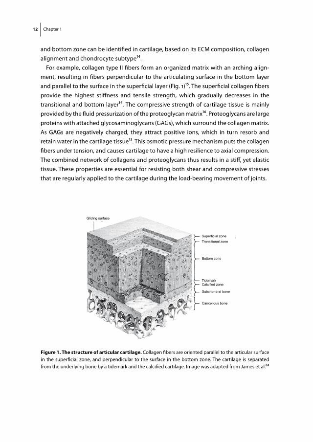
For example, collagen type II fibers form an organized matrix with an arching align-ment, resulting in fibers perpendicular to the articulating surface in the bottom layer and parallel to the surface in the superficial layer (Fig. 1)15. The superficial collagen fibers provide the highest stiffness and tensile strength, which gradually decreases in the transitional and bottom layer14. The compressive strength of cartilage tissue is mainly provided by the fluid pressurization of the proteoglycan matrix16. Proteoglycans are large proteins with attached glycosaminoglycans (GAGs), which surround the collagen matrix. As GAGs are negatively charged, they attract positive ions, which in turn resorb and retain water in the cartilage tissue13. This osmotic pressure mechanism puts the collagen fibers under tension, and causes cartilage to have a high resilience to axial compression. The combined network of collagens and proteoglycans thus results in a stiff, yet elastic tissue. These properties are essential for resisting both shear and compressive stresses that are regularly applied to the cartilage during the load-bearing movement of joints.
Gliding surface
Superficial zoneTransitional zone
Bottom zone
TidemarkCalcified zone
Subchondral bone
Cancellous bone
figure 1. the structure of articular cartilage. Collagen fibers are oriented parallel to the articular surface in the superficial zone, and perpendicular to the surface in the bottom zone. The cartilage is separated from the underlying bone by a tidemark and the calcified cartilage. Image was adapted from James et al.84
Introduction 13
cartilage defects
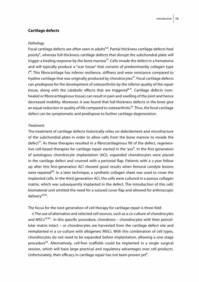
PathologyFocal cartilage defects are often seen in adults5,6. Partial thickness cartilage defects heal poorly4, whereas full-thickness cartilage defects that disrupt the subchondral plate will trigger a healing response by the bone marrow17. Cells invade the defect in a hematoma and will typically produce a “scar tissue” that consists of predominantly collagen type I18. This fibrocartilage has inferior resilience, stiffness and wear resistance compared to hyaline cartilage that was originally produced by chondrocytes17. Focal cartilage defects can predispose for the development of osteoarthritis by the inferior quality of the repair tissue, along with the catabolic effects that are triggered6,17. Cartilage defects (non-healed or fibrocartilaginous tissue) can result in pain and swelling of the joint and hence decreased mobility. Moreover, it was found that full-thickness defects in the knee give an equal reduction in quality of life compared to osteoarthritis19. Thus, the focal cartilage defect can be symptomatic and predispose to further cartilage degeneration.
Treatment The treatment of cartilage defects historically relies on debridement and microfracture of the subchondral plate in order to allow cells from the bone marrow to invade the defect17. As these therapies resulted in a fibrocartilaginous fill of the defect, regenera-tive cell-based therapies for cartilage repair started in the ‘90s6. In the first generation of autologous chondrocyte implantation (ACI), expanded chondrocytes were placed in the cartilage defect and covered with a periostal flap. Patients with a 2-year follow up after this first-generation ACI showed good results when femoral condyle lesions were repaired20. In a later technique, a synthetic collagen sheet was used to cover the implanted cells. In the third generation ACI, the cells were cultured in a porous collagen matrix, which was subsequently implanted in the defect. The introduction of this cell/biomaterial unit omitted the need for a sutured cover flap and allowed for arthroscopic delivery21,22.
The focus for the next generation of cell therapy for cartilage repair is three-fold: 1) The use of alternative and selected cell sources, such as a co-culture of chondrocytes
and MSCs23,24. In this specific procedure, chondrons – chondrocytes with their pericel-lular matrix intact – or chondrocytes are harvested from the cartilage defect site and reimplanted in a co-culture with allogeneic MSCs. With this combination of cell types, chondrocytes do not need to be expanded before implantation, allowing a one-stage procedure25. Alternatively, cell-free scaffolds could be implanted in a single surgical session, which will have large practical and regulatory advantages over cell products. Unfortunately, their efficacy in cartilage repair has not been proven yet9.

14 Chapter 1
2) The development of strong, stiff and instructive biomaterials for the delivery of cells. Biomaterials serve as a scaffold for the cells and usually consist of hydrated polymer networks, known as hydrogels. Fibrin glue is currently used as a cell delivery vehicle, because of its availability in clinical grade and surgical applicability6,9. However, fibrin glue was not designed for application in regenerative medicine: it holds no specific biochemical cues and the crosslinked fibrin polymer network is soft and has a high deg-radation rate26-28. A large effort is made for development of more instructive and strong gels with a controlled degradation rate that balances with tissue regeneration9,29,30.
3) Improving the surgical workflow and techniques for implantation of cells and bio-materials in the cartilage defects. Examples are a one-stage procedure by the implanta-tion of cell-free scaffolds or allogeneic cells, and the arthroscopic delivery of cells by spraying of the hydrogel31.
osteochondral defects
PathologyOsteochondral lesions involve the cartilage and the underlying bone. The etiology is proposed to be multifactorial, including trauma, both acute and repetitive, and genetic factors32,33. Osteochondral defects are often seen in young patients.
TreatmentAs debridement and microfracture were found not to result in the regeneration of durable repair tissue, several replacement therapies with autografts and allografts were developed17. Another valid treatment option for large osteochondral defects is the combination of autologous bone implantation and ACI34. This procedure - known as the ‘sandwich technique’ – is performed in two surgical sessions.
The most popular replacement technique is the transfer of autologous osteochondral grafts: a procedure usually referred to as ‘mosaicplasty’18,35. Plugs consisting of viable bone with hyaline cartilage are transferred into the defect from a non weight-bearing location in the joint. The surgical procedure is done in one session and patients can quickly rehabilitate. However, there is limited availability of tissue, a chance of donor site morbidity and a poor defect fill in between the transferred plugs18. Nevertheless, the short-term clinical outcomes for mosaicplasty are superior to a commercially available cell-free collagen scaffold (TruFit)36. In addition to TruFit, numerous biphasic scaffolds were engineered, with distinct matrix, cells and/or growth factor compositions for the cartilage and bone component35. These products have not yet successfully found their way to clinical application.

Introduction 15
osteoarthritis
PathologyA quarter of people above 55 years of age suffer from frequent knee pain and half of this population has osteoarthritic features of the knee on X-ray7. The diagnosis in this group is symptomatic osteoarthritis. Moreover, on examination with MRI, nearly 90% of middle aged and elder people have osteoarthritic changes in the knee joint37. Risk factors in-clude obesity, occupational overloading and a previous knee injury. Osteoarthritis is a disease of the whole joint, involving the cartilage, but also the subchondral bone, the synovium, ligaments and the periarticular muscles. Inflammation that can potentially be located in all of these structures contributes to pain and further degeneration38. Future therapies will specifically target the inflammation and degeneration process6,38.
TreatmentCurrent pharmacologic therapies rely on paracetamol and nonsteroidal anti-inflamma-tory drugs (NSAIDs)39. Operative treatments include osteotomies for alignment of the knee joint in order to unload the most affected side40 and distraction of the joint to allow regeneration of the cartilage tissue41. Replacement of the joint with a prosthesis is the ultimate solution for end-stage osteoarthritis42. Arthroplasty leads to long-term improvement of the quality of life and reduction of pain, as proven in particular for the replacement of the knee43 and hip joint44.
3d printing
New printing techniques enable the production of three-dimensional objects from a digital model that can be either designed, or derived from 3D-scanning data. Because of its constructive nature, 3D printing is an additive manufacturing technique. The development was based on inkjet printing that started in the 1950s, followed by stereo-lithography in the ‘80s and fused deposition modeling (FDM) in 1990 (Fig. 2)11. Nowadays, 3D printing is able to produce complex tools from plastic or metals, such as bike or car components, machine parts but also electrical elements12. In fact, every material with a reasonable stiffness that retains its shape after deposition has a potential in 3D printing. For example, real-size houses we recently printed from concrete. This digitization of manufacturing was recently termed ‘the third industrial revolution’ by The Economist45.
The exploration of the clinical potential of 3D printing has just started by generating customized objects based on CT or MRI scans of patients. Currently, the technique is clinically applied for the production of:
16 Chapter 1
1950 1990198019701960 20102000 2020
continuous inkjet printing
first cell sorter
laser printing
drop-on-demandinkjetprinting
chondrocytesredifferentiate
in 3D environment
stereolithography
tissue engineering coined
3D printing
hydrogels withRGD sequences
laser directwriting of cells
tissue engineeringscaffolds by FDM
inkjet printingof cells
fused depositionmodelling (FDM)
organ printingcoined
robotic dispening ofcell-laden hydrogels
melt electrospinning
journal and internationalsociety for biofabrication
clinical application of o.a.:FDM scaffolds
3D surgery planningprinted saw molds
printed titanium implants
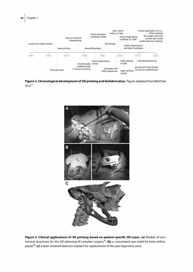
figure 2. chronological development of 3d printing and biofabrication. Figure adapted from Melchels et al.11
A
B
C
figure 3. clinical applications of 3d printing based on patient-specific 3d-scans. (a) Models of ana-tomical structures for the 3D-planning of complex surgery47; (b) a customized saw mold for knee arthro-plasty48; (c) a laser-sintered titanium implant for replacement of the jaw (layerwise.com).
Introduction 17
1) Models of anatomical structures for 3D-planning of complex surgery (Fig. 3a). The specific location of surgery, being the brain, heart, jaw or joint, can sometimes better be visualized with a model than on a screen45,46. 3D-models are usually printed from thermoplastic polymers, and used for the preparation of a surgical procedure. Moreover, when printed from softer materials, the 3D-model can be subject of practice for sur-geons. In addition, the models aid in explanation to the patient and can even visualize their facial appearance after reconstructive maxillofacial surgery46,47.
2) Surgical tools, such as custom-made saw molds for knee arthroplasty48 or a drill guide for reducing the error in the placement of pedicle screws in spine surgery (Fig. 3b).
3) Prostheses and implants, such as laser-sintered titanium implants for maxillofacial surgery49 or for surgical reconstruction of the pelvis after tumor or trauma (Fig. 3c). Recent developments include 3D-printed casts for the external fixation of fractures.
Biodegradable thermoplastic polymer scaffolds
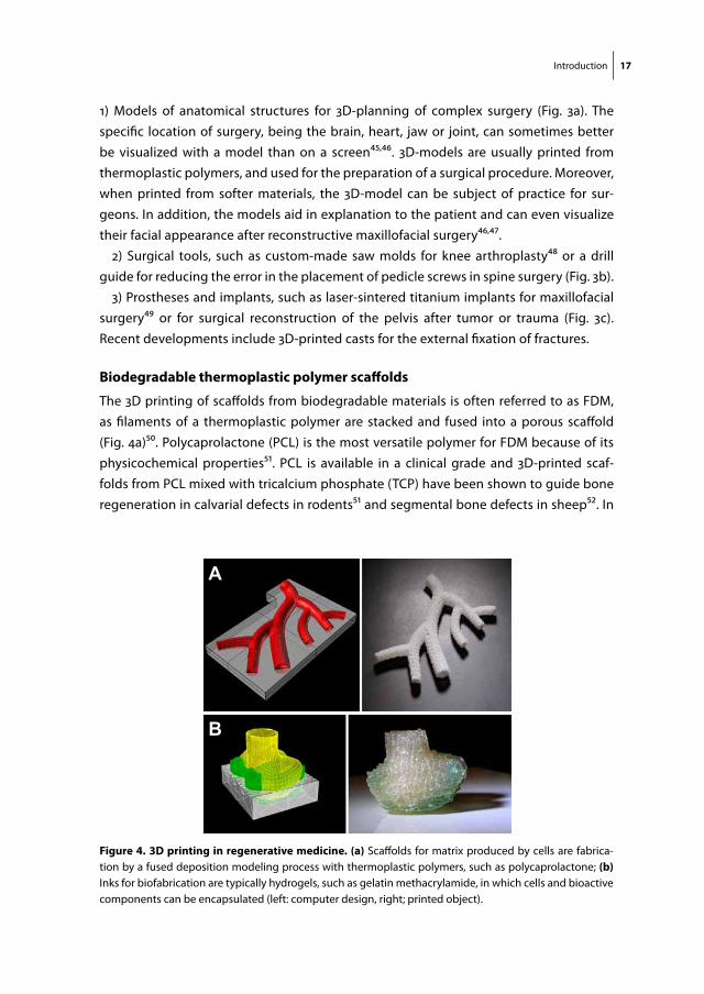
The 3D printing of scaffolds from biodegradable materials is often referred to as FDM, as filaments of a thermoplastic polymer are stacked and fused into a porous scaffold (Fig. 4a)50. Polycaprolactone (PCL) is the most versatile polymer for FDM because of its physicochemical properties51. PCL is available in a clinical grade and 3D-printed scaf-folds from PCL mixed with tricalcium phosphate (TCP) have been shown to guide bone regeneration in calvarial defects in rodents51 and segmental bone defects in sheep52. In
A
B
figure 4. 3d printing in regenerative medicine. (a) Scaffolds for matrix produced by cells are fabrica-tion by a fused deposition modeling process with thermoplastic polymers, such as polycaprolactone; (b) Inks for biofabrication are typically hydrogels, such as gelatin methacrylamide, in which cells and bioactive components can be encapsulated (left: computer design, right; printed object).

18 Chapter 1
addition, a porous shoulder ‘prosthesis’ based on PCL was demonstrated a promising scaffold for cell infiltration and subsequent articular cartilage regeneration in a rabbit model53. Melt electrospinning constitutes a new form of FDM. By establishment of an electrostatic field between the printer needle and the collecting platform, filaments with a diameter of a few micrometers can be deposited in a controlled architecture54. These filaments have the potential to better resemble the natural fibrous ECM than the thicker, yet stronger, filaments produced with traditional FDM55,56, although natural extracellular matrix polymers are within the nanometer scale.
Biofabrication
Biofabrication is the construction of well-defined biological products from raw materi-als, such as cells, molecules, extracellular matrices and biomaterials57,58. The printing of cells started in home-transformed inkjet printers, with the advent of tissue engineering in the ‘90s. Today, biofabrication is a ‘trending’ additive manufacturing technique that is also referred to as (3D) bioprinting11,12. Gartner, Inc., a leading information technology research and advisory company, located both 3D bioprinting systems and 3D printing on their hype cycle (Fig. 5). 3D Bioprinting systems was considered a young, upcoming tech-nology, whereas consumer 3D printing was placed just over the top of the hype cycle, at the peak of inflated expectations. This hype cycle illustrates that a realistic picture of
VIS
IBIL
ITY
MATURITY
TECHNOLOGYTRIGGER
PEAK OFINFLATED
EXPECTATIONS
TROUGH OFDISILLUSIONMENT
SLOPE OFENLIGHTMENT
PLATEAU OFPRODUCTIVITY
figure 5. the generic hype cycle by gartner inc. 3D Bioprinting Systems was placed as a technology trigger with increasing visibility. Consumer 3D printing was located over the peak of inflated expectations. (www.gartner.com). Attribution: Gartner, generic Hype Cycle. Gartner, Hype Cycle for 3D Printing, 2014, Pete Basiliere, Michael Shanler, 21 July 2014
Introduction 19
biofabrication should be presented to society in order to prevent inflated expectations and soften the subsequent ‘trough of disillusionment’.
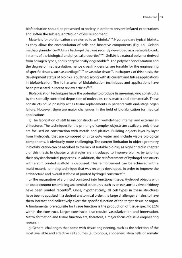
Materials for biofabrication are referred to as “bioinks”59. Hydrogels are typical bioinks, as they allow the encapsulation of cells and bioactive components (Fig. 4b). Gelatin methacrylamide (GelMA) is a hydrogel that was recently developed as a versatile bioink, in terms of the biological and physical properties60,61. GelMA is a natural polymer derived from collagen type I, and is enzymatically degradable62. The polymer concentration and the degree of methacrylation, hence crosslink density, are tunable for the engineering of specific tissues, such as cartilage60,63 or vascular tissue64. In chapter 2 of this thesis, the development status of bioinks is outlined, along with its current and future applications in biofabrication. The full arsenal of biofabrication techniques and applications have been presented in recent review articles35,36.
Biofabrication techniques have the potential to produce tissue-mimicking constructs, by the spatially controlled deposition of molecules, cells, matrix and biomaterials. These constructs could possibly act as tissue replacements in patients with end-stage organ failure. However, there are major challenges in the field of biofabrication for medical applications:
1) The fabrication of stiff tissue constructs with well-defined internal and external ar-chitectures. The techniques for the printing of complex objects are available, only these are focused on construction with metals and plastics. Building objects layer-by-layer from hydrogels, that are composed of circa 90% water and include viable biological components, is obviously more challenging. The current limitation in object geometry in biofabrication can be ascribed to the lack of suitable bioinks, as highlighted in chapter 2 of this thesis. In chapter 2, strategies are introduced to improve bioinks by tailoring their physicochemical properties. In addition, the reinforcement of hydrogel constructs with a stiff, printed scaffold is discussed. This reinforcement can be achieved with a multi-material printing technique that was recently developed, in order to improve the architecture and overall stiffness of printed hydrogel constructs65.
2) The maturation of a printed construct into functional tissue. Hydrogel objects with an outer contour resembling anatomical structures such as an ear, aortic valve or kidney have been printed recently12. Once, hypothetically, all cell types in these structures have been deposited in a desired anatomical order, the large challenge remains to have them interact and collectively exert the specific function of the target tissue or organ. A fundamental prerequisite for tissue function is the production of tissue-specific ECM within the construct. Larger constructs also require vascularization and innervation. Matrix formation and tissue function are, therefore, a major focus of tissue engineering research.
3) General challenges that come with tissue engineering, such as the selection of the most available and effective cell sources (autologous, allogeneic, stem cells or somatic
20 Chapter 1
cells); a sterile and standardized workflow from the engineering stage to the bedside; the certification of custom-made tools, prostheses and advanced therapy medicinal products (ATMPs) and a reduction of the manufacturing costs.
tissue-derived matrices
All tissues and organs consist of an organized collection of cells and ECM. The complex interaction between cells and ECM regulates the specific function of the tissue. As the field of regenerative medicine aims to restore tissue function, ECM is a scaffold material worthwhile exploring for the engineering of tissues. The architecture and the biochemi-cal cues in the ECM could potentially guide seeded cells in the regeneration of new tissue66. Before ECM can be used in tissue engineering, cells need to be removed from the original tissue by chemical and/or mechanical processes, to reduce its antigenicity67. In this fashion, several tissue-derived matrices (TDM), e.g. derived from the heart, liver and the trachea were acquired. These TDMs were shown useful substrates for tissue regeneration in clinical proof of principle studies68.
Preliminary research demonstrates that TDM also forms a potential scaffold biomate-rial for bone and cartilage engineering69. However, it is not known which specific growth factors and signaling molecules of the TDM are responsible for guiding cell differentia-tion. As a consequence, it is unclear which tissue the matrix should be derived from and which decellularization process should be applied. For example, is decellularized bone tissue the best scaffold for bone regeneration, or do cells just as well produce bone matrix on a scaffold derived from fat tissue?
There are several options to produce TDM from native tissues, e.g.: leaving the original tissue structure intact; molding or printing of freeze-dried, particulated TDM into a po-rous scaffold or enzymatically digest TDM into a collagenous hydrogel70,71. The TDM can be subsequently implanted as a cell-free biomaterial, or be recellularized in vitro prior to implantation. A challenge in the production of TDM is to remove the resident cells from the tissues, while retaining any bioactive cues.
The most abundant polymer in TDM is collagen, as collagen is the major ECM compo-nent of most tissues. TDM gels, therefore, have physical properties similar to collagen gels, and may form an instructive cell-carrier for cartilage repair and/or biofabrication.
outline and research questions
Biofabrication is a potential tool for joint repair, especially for large (osteo)chondral defects. The regenerative treatment options for large joint defects are currently limited, as biomaterials for the delivery of cells and/or bioactive factors have biological and mechanical shortcomings. For example, osteochondral defects require the repair of two
Introduction 21
distinctive tissue types and the larger they are, the more they are exposed to mechanical forces in the joint. Here, biofabrication offers potential control over the strength and stiffness of constructs, their internal organization and external architecture.
Bioinks for the fabrication of such constructs require specific biological signals, in order to differentiate cells into the line of the target tissue. These biological signals can potentially be provided by hydrogels based on native, decellularized matrices.
The overall aim of this thesis is to deploy biofabrication techniques to improve cartilage and osteochondral tissue repair. GelMA hydrogel was selected as a cell carrier across all chapters of this thesis, because its potential for biofabrication60,61,72 and in vitro cartilage regeneration63,73 was yet demonstrated. Three specific aims can be identified:
Part I) Biological improvement of GelMA hydrogel with tissue-derived matrices (Chapters 3 and 4)
Part II) Mechanical improvement of GelMA hydrogel constructs with 3D-printed scaf-folds (Chapters 5, 6 and 7)
Part III) Biofabrication of complex shaped constructs from GelMA for osteochondral tissue repair (Chapter 8, 9 and 10)
Specific research questions to be addressed in this thesis:
Chapter 2. What is the current status of hydrogels as a bioink for biofabrication and what are the opportunities in this field?
Hydrogels with suspended biological components, such as growth factors or cells, can serve as bioinks for the fabrication of three-dimensional structures11,12. However, the printability of hydrogels is usually poor, and bioinks have been insufficiently developed to simultaneously meet the biological and mechanical demands for tissue implants. This review of the literature highlights the current status of bioink development and also presents several approaches to modify bioinks and biofabrication approaches to make the next step in this field.
Part I) Biological improvement of GelMA hydrogel with tissue-derived matricesChapter 3. Can stable hydrogels be derived from natural tissues, such as cartilage, meniscus and tendon? Does the addition of such tissue-derived matrices to GelMA hydrogel enhance chondrogenic differentiation of chondrocytes and MSCs in vitro?
Tissue-derived matrices have been shown able to guide cell fate68. Also, the addition of small amounts of hyaluronic acid and chondroitin sulfate to GelMA were shown to
22 Chapter 1
improve differentiation of embedded chondrocytes63,73. Can we further improve cellular differentiation in GelMA by the addition of cartilage, tendon and meniscus matrices, which were decellularized, but still contained limited amounts of GAGs?
Chapter 4. What is the effect of cartilage-derived matrix particles in GelMA on the differen-tiation of chondrocytes and MSCs? Can osteochondral tissue be regenerated in bilayered hydrogel constructs with chondrocytes and MSCs?
Scaffolds composed of cartilage-derived matrix (CDM) particles have been shown beneficial for cartilage matrix production by MSCs74. In contrast, they seemed to trig-ger a counterproductive effect on seeded chondrocytes. Here, we aimed for CDM to improve the differentiation of both cell types, when suspended with the cells in GelMA hydrogel. Tissue formation in these hydrogel constructs is evaluated in vitro and in vivo in a subcutaneous rat model. In addition, bilayered hydrogel constructs consisting of a separate chondrocyte and MSC layer are implanted. These two adjacent cell types can potentially reproduce osteochondral tissue.
Part II) Mechanical improvement of GelMA hydrogel constructs with 3D-printed scaf-foldsChapter 5. Does the covalent attachment of a 3D-printed scaffold as reinforcement to GelMA gel lead to stronger constructs?
Hydrogels can serve as a temporary carrier for cells to secrete tissue-specific extracel-lular matrix and remodel tissue. However, hydrogels are too soft to withstand the forces acting in large weight-bearing tissue defects. Therefore, porous scaffolds fabricated from thermoplastic polymers, such as PCL, were used to reinforce hydrogels65,75-77. Both materials can be printed in one session. Still, the hydrogel and PCL have a poor physical connection. In this chapter we aim to chemically modify the PCL for covalent attachment to GelMA hydrogels. In addition, we investigate if human chondrocytes suspended in the hydrogel component of such constructs produce cartilage matrix in vitro and in vivo.
Chapter 6. Could the mechanical properties of articular cartilage be approached with composite constructs consisting of a hydrogel reinforced with 3D-printed microfibers? How do chondrocytes embedded in these constructs respond to dynamic loading in an in vitro bioreactor culture?
Traditional 3D-printed scaffolds can successfully reinforce hydrogels. Because these scaffolds were constructed from thick fibers, they have a relatively large polymer mass, are stiffer than articular cartilage, and have low elasticity65,75,76. In this chapter we aim to overcome these issues by reinforcing hydrogels with microfiber scaffolds that are 3D-printed with a new technique termed melt electrospinning54. The differentiation of

Introduction 23
human chondrocytes embedded in these constructs is extensively tested in response to a repetitive mechanical loading regime in a bioreactor.
Chapter 7. How can (reinforced) GelMA hydrogel be applied in an equine model for the repair of focal cartilage defects?
Cell therapies for the repair of focal cartilage defects currently rely on rapidly degrad-ing cell carriers, such as fibrin glue21,23,78. These vehicles contrast with hydrogels that have been specifically engineered for use in regenerative medicine, which have a lower degradation rate to balance with new tissue formation by embedded cells29,30,79. Now GelMA has proven its role in supporting cartilage tissue formation by embedded cells in vitro60,63,73, we here set out to translate (reinforced) GelMA to clinical application. The International Cartilage Repair Society has recognized that equine chondral defect mod-els form a valuable pre-clinical evaluation method for cartilage repair therapies80. This chapter describes the in vitro work, cadaveric and pilot studies leading to the establish-ment of a cartilage defect model in equine stifle joints. Furthermore, a long-term study for the evaluation of cell-carriers for cartilage repair in ponies is outlined.
Part III) Biofabrication of complex shaped constructs for osteochondral tissue repairChapter 8. Which support and construction materials can best be combined to establish the complex geometry of anatomical structures in a multi-material 3D printing setting?
So far, printed objects for regenerative medicine had relatively simple geometries, because of limitations in biofabrication materials and techniques. In this chapter, we set out to print more complex shapes by deposition of the construction material, such as PCL or a bioink, in one session with a temporary support material. Support materials are specifically selected to be compatible with the construction material.
Chapter 9. Can GelMA bioinks be improved for bone regeneration by the incorporation of microcarriers?
One challenge in the engineering of functional tissue grafts is to obtain a sufficient amount of cells. Microcarriers (MCs) can serve as an expansion vehicle for in vitro cul-tured cells81,82. Cell types, such as chondrocytes and osteoblasts, cultured on these MCs have shown to retain their matrix forming capacities83. In this chapter, the biofabrication and bone regeneration properties were evaluated of a GelMA bioink with MSC-seeded MCs.
Chapter 10. Can both bone and cartilage tissue be regenerated in a shoulder replacement model in rabbits with an anatomically shaped, biphasic implant?
One of the advantages of biofabrication over other tissue engineering methods is the generation of implants with a complex hierarchy. Here we aimed to fabricate a

24 Chapter 1
biodegradable, porous implant based on PCL and GelMA for the replacement of an articular joint. Such implants have once been shown to successfully regenerate cartilage tissue in a shoulder replacement model in rabbits53. In this chapter, the next genera-tion biodegradable joint implant was biofabricated consisting of a bone and a cartilage component, with specific biological and mechanical properties. A pilot study on the feasibility of the model is ongoing in three rabbits. A study comparing three different cartilage components of the implant was outlined.


Chapter 2Engineering Hydrogels for Biofabrication
Jos MaldaJetze VisserFerry P. MelchelsTomasz JüngstWim E. HenninkWouter J.A. DhertJürgen GrollDietmar W. Hutmacher
Advanced Materials. 2013 Sep;25(36):5011-28
28 Chapter 2
aBstract
With advances in tissue engineering, the possibility of regenerating injured tissue or failing organs has become a realistic prospect for the first time in medical history. Tissue engineering – the combination of bioactive materials with cells to generate en-gineered constructs that functionally replace lost and/or damaged tissue – is a major strategy to achieve this goal. One facet of tissue engineering is biofabrication, where three-dimensional tissue-like structures composed of biomaterials and cells in a single manufacturing procedure are generated. Cell-laden hydrogels are commonly used in biofabrication and are termed “bioinks”. Hydrogels are particularly attractive for biofab-rication as they recapitulate several features of the natural extracellular matrix and allow cell encapsulation in a highly hydrated mechanically supportive three-dimensional environment. Additionally, they allow for efficient and homogeneous cell seeding, can provide biologically-relevant chemical and physical signals and can be formed in vari-ous shapes and biomechanical characteristics. However, while advances in modifying hydrogels for enhanced bioactivation, cell survival and tissue formation, little attention has so far been paid to optimize hydrogels for the physico-chemical demands of the biofabrication process. The resulting lack of hydrogel bioinks have been identified as one major hurdle for a more rapid progress of the field. In this review we summarize and focus on the deposition process, the parameters and demands of hydrogels in bio-fabrication, with special attention to robotic dispensing as an approach that generates constructs of clinically relevant dimensions. We aim to highlight this current lack of ef-fectual hydrogels within biofabrication and initiate new ideas and developments in the design and tailoring of hydrogels. The successful development of a “printable” hydrogel that support cell adhesion, migration and differentiation will significantly advance this exciting and promising approach for tissue engineering.
Engineering hydrogels for biofabrication 29
introduction
Tissue engineering (TE) aims for the full restoration of damaged or degenerated tissues and organs through the use of TE, cell and growth factor delivery. Tissue-engineered constructs will have to mimic a certain degree of the native complexity of the tissue in order to assist in restoration of the full structure and functionality of the tissue. Tradition-ally, the three main components of TE are cells, scaffolds and growth factors and they are combined to form a construct that can be immediately implanted or incubated in vitro prior to implantation. A scaffold can successfully deliver cells and/or growth factors to a damaged or degenerated tissue or organ, while simultaneously providing temporal mechanical support for the period the newly formed tissue matures. However, the three-dimensional (3D) constructs that have been generated for these scaffold-based or scaffold-guided TE approaches are typically based on the random distribution of cells, matrix, and bioactive cues, since their manufacturing does not allow the control of specific distribution. Mimicking the biological and functional organizational complexity of native tissues is now regarded as the next challenge in the full regeneration of tissues.
To address this challenge, additive manufacturing (AM) technology has been employed to generate bio-engineered 3D structures to replicate the complex nature of tissue11. In this approach, termed “biofabrication”57,85, biological structures for TE, pharmacokinetic or basic cell biology studies (including disease models) are created by an computer-aided manufacturing process for patterning and assembling living and non-living ma-terials with a prescribed 3D organization86. The resulting shape can be customized, and include open inner structures that improve the supply of nutrients towards embedded cells87. Moreover, the fabricated structures can be used to study interactions between different cells and/or bioactive compounds88-92, but could also lead to functional tissue equivalents93, and potentially, to whole functioning organs.94 Recent investigations have, for example, adopted biofabrication for the engineering of 3D constructs with the organizational features of different tissues, including skin95,96, meniscus97, aortic valves98, cartilage99,100, bone101, and blood vessels102.
Whilst AM technologies, as applied in the processing of metals, ceramics and thermo-plastic polymers have inspired the field of biofabrication, these “classic” AM approaches generally involve the use of organic solvents, high temperatures or crosslinking agents that are not compatible with living cells and/or bioactive proteins. Hydrogels can be pro-cessed under more cell friendly conditions and often classified in the biofabrication field as “bioinks”. From a biological point of view, high water content hydrogels are attractive candidates for the incorporation of cells and bioactive compounds, because they can provide an instructive, aqueous 3D environment, simulating the natural extracellular matrix.101
30 Chapter 2
Historically, hydrogels used in tissue engineering applications are predominantly based on naturally derived polymers, including alginate, gelatin, collagen, chitosan, fibrin and hyaluronic acid29,30,103. Cells benefit from the abundance of chemical signals present in these hydrogels, resulting in high viability and proliferation rates29,104. These signals can also be used to induce the formation of specific neo-tissues29,30, however, due to batch-to-batch variation and the sensitivity of cells (especially stem cells) to these variations, reproducibility of constructs often remains complicated. In addition, imple-mentation of these materials in biofabrication can be challenging due to their variable printability.
In contrast to hydrogels based on natural polymers, 3D printed structures with high shape fidelity can be obtained with polymers based on synthetic networks, like poly(ethylene glycol)105 and pluronics106-108. However, these hydrogels provide embed-ded cells with an inert environment without active binding sites79, often resulting in low cell viability106-108. In order to improve control over cellular differentiation in these gels, bioactive compounds have to be added or grafted to the network, like peptide sequences109 and growth factors30,110,111. Peptide sequences can modulate cellular behav-ior by providing binding sites in otherwise inert hydrogels112, whereas growth factors can further direct cellular differentiation in order to regenerate a specific tissue type. There already are a number of reviews on the mandatory biological characteristics of hydrogels for biomedical applications and this goes beyond the scope of this review. For further reading we recommend recent reviews by Seliktar104 and by DeForest and Anseth79.
The present review will focus on the physicochemical aspects important for the de-velopment and characterization of hydrogels for biofabrication. Despite the fact that photocuring methods, such as two-photon polymerization113 and stereolithograpy114 can also yield organized 3D cell-laden hydrogel structures, their working principles do not involve deposition of gels and cells and hence pose different demands regarding hydrogel properties. Therefore, these techniques fall outside the scope of the current review. Here, we guide the reader in making choices regarding available approaches to tailor existing hydrogel platforms by means of physicochemical modification. Finally, current developments in hydrogels that could impact on the composition and proper-ties of future hydrogel bioinks will be discussed.
the Biofabrication window
Although major progress has been made with both natural and synthetic hydrogels in biofabrication115, bioinks have some significant complications regarding the re-quired physical and biological properties. The central problem is that the fabrication of complex, tissue-like structures with high resolution dictates narrow boundaries for the physical properties of the hydrogels. Additionally, the hydrogel construct should
Engineering hydrogels for biofabrication 31
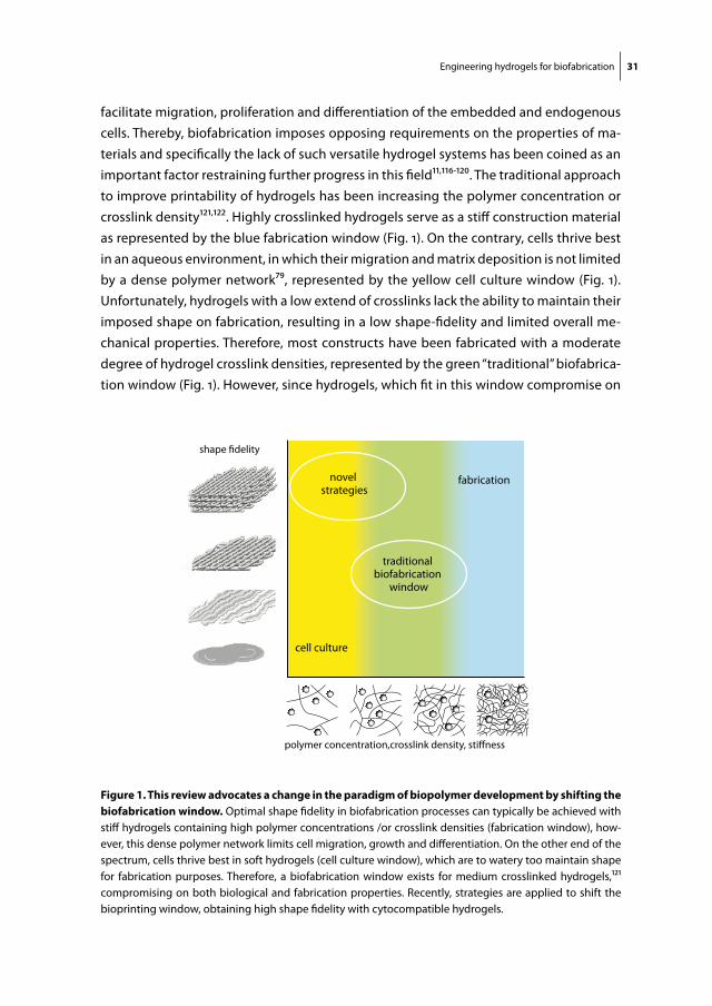
facilitate migration, proliferation and differentiation of the embedded and endogenous cells. Thereby, biofabrication imposes opposing requirements on the properties of ma-terials and specifically the lack of such versatile hydrogel systems has been coined as an important factor restraining further progress in this field11,116-120. The traditional approach to improve printability of hydrogels has been increasing the polymer concentration or crosslink density121,122. Highly crosslinked hydrogels serve as a stiff construction material as represented by the blue fabrication window (Fig. 1). On the contrary, cells thrive best in an aqueous environment, in which their migration and matrix deposition is not limited by a dense polymer network79, represented by the yellow cell culture window (Fig. 1). Unfortunately, hydrogels with a low extend of crosslinks lack the ability to maintain their imposed shape on fabrication, resulting in a low shape-fidelity and limited overall me-chanical properties. Therefore, most constructs have been fabricated with a moderate degree of hydrogel crosslink densities, represented by the green “traditional” biofabrica-tion window (Fig. 1). However, since hydrogels, which fit in this window compromise on
novel strategies
traditional biofabrication
window
cell culture
fabrication
figure 1. this review advocates a change in the paradigm of biopolymer development by shifting the biofabrication window. Optimal shape fidelity in biofabrication processes can typically be achieved with stiff hydrogels containing high polymer concentrations /or crosslink densities (fabrication window), how-ever, this dense polymer network limits cell migration, growth and differentiation. On the other end of the spectrum, cells thrive best in soft hydrogels (cell culture window), which are to watery too maintain shape for fabrication purposes. Therefore, a biofabrication window exists for medium crosslinked hydrogels,121 compromising on both biological and fabrication properties. Recently, strategies are applied to shift the bioprinting window, obtaining high shape fidelity with cytocompatible hydrogels.

32 Chapter 2
biological, as well as fabrication properties, there is a need to shift this biofabrication window in order to achieve high shape-fidelity with hydrogels that facilitate maximal cell and tissue compatibility (“novel strategies” (Fig. 1)).
Hydrogels for biofabrication should allow the translation of the computer-aided design (CAD) to a tissue construct that potentially contains intricate internal and/or external organizational structures. This requires a high degree of control over the deposition process, which is closely associated with the printability of the hydrogel. The printing of inks on paper is well documented with various available tests that are taking in account surface and structural properties of the paper, however quantification of printability of ink on paper remains difficult123. Standardized tests to evaluate the capacity of hydrogels to be printed do not yet exist. Obviously, an important outcome parameter from a physical point of view would be the geometric accuracy or shape fidel-ity of the generated constructs. As such, there is a strong need for methods of geometry comparison of tissue-engineered constructs that go beyond simple visual inspection, manual measurements using rulers or calipers124 and photographs97,122,125,126. Optical methods have been developed to assess the geometric fidelities of tissue constructs using laser triangulation.124 Although this yields valuable data on the outer contours of homogeneous solid tissue replacements, such as for the meniscus, this technique will not visualize the potentially more intricate internal geometry. More recently, Murphy et al.96 evaluated properties relevant to bioprinting, including printability, of a range of available hydrogels. In an attempt to quantify the printability, deviation of a 1.0 x 1.0 cm printed square area was determined. Although the authors were challenged by the fact that not all hydrogels could be reproducibly processed by the printer, this allowed for an, albeit rough, quantification, of the printability. Nevertheless, the fabrication of tissue structures is likely to require a significantly higher resolution than what could be evaluated in this approach. In view of this, the visualization of the difference between a computer design and a mCT generated image of a tissue construct, as represented in a heat map127, is a promising development, despite the fact that this will not discriminate between different hydrogels in a single generated tissue blueprint.
hydrogel Based BiofaBrication systems
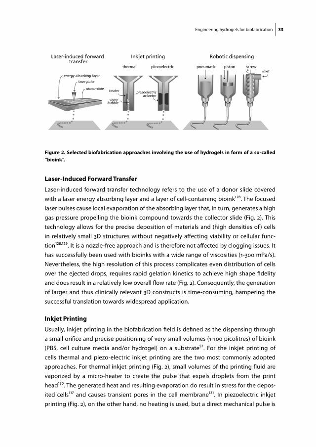
The use of hydrogels as a carrier for cells and/or bioactive compounds has been described for many deposition-based biofabrication approaches101,118. Briefly, these can be divided in methods based on laser-induced forward transfer, inkjet printing (both thermal and piezoelectric) and robotic dispensing (Fig. 2). Each technique demanding very specific requirements for characteristics of the hydrogel-based bioinks, with regards to their rheology and post-curing rate in order to achieve reliable fabrication of 3D constructs.
Engineering hydrogels for biofabrication 33
laser-induced forward transfer
Laser-induced forward transfer technology refers to the use of a donor slide covered with a laser energy absorbing layer and a layer of cell-containing bioink128. The focused laser pulses cause local evaporation of the absorbing layer that, in turn, generates a high gas pressure propelling the bioink compound towards the collector slide (Fig. 2). This technology allows for the precise deposition of materials and (high densities of ) cells in relatively small 3D structures without negatively affecting viability or cellular func-tion128,129. It is a nozzle-free approach and is therefore not affected by clogging issues. It has successfully been used with bioinks with a wide range of viscosities (1-300 mPa/s). Nevertheless, the high resolution of this process complicates even distribution of cells over the ejected drops, requires rapid gelation kinetics to achieve high shape fidelity and does result in a relatively low overall flow rate (Fig. 2). Consequently, the generation of larger and thus clinically relevant 3D constructs is time-consuming, hampering the successful translation towards widespread application.
inkjet printing
Usually, inkjet printing in the biofabrication field is defined as the dispensing through a small orifice and precise positioning of very small volumes (1-100 picolitres) of bioink (PBS, cell culture media and/or hydrogel) on a substrate57. For the inkjet printing of cells thermal and piezo-electric inkjet printing are the two most commonly adopted approaches. For thermal inkjet printing (Fig. 2), small volumes of the printing fluid are vaporized by a micro-heater to create the pulse that expels droplets from the print head130. The generated heat and resulting evaporation do result in stress for the depos-ited cells117 and causes transient pores in the cell membrane131. In piezoelectric inkjet printing (Fig. 2), on the other hand, no heating is used, but a direct mechanical pulse is
figure 2. selected biofabrication approaches involving the use of hydrogels in form of a so-called “bioink”.

34 Chapter 2
applied to the fluid in the nozzle by a piezoelectric actuator, which causes a shock wave that forces the bioink through the nozzle.
Inkjet printing has successfully been applied for accurate deposition of cells132 and even allows for the generation of, albeit small, 3D structures133. One of the main restric-tions of the inkjet technology is perhaps the low upper limit of the viscosity for the ink (Table 1), which is in the order of 0.1 Pa/s134, complicating the deposition of higher viscous natural extracellular matrix materials135. As small droplets of this ink are depos-ited onto a substrate with high velocity, the low viscosity will facilitate spreading of the droplet on the surface upon impact. This impedes building up 3D constructs, for which inkjet technology originally was not developed. Moreover, most researchers in this area have been using commercially available inkjet printers, which are designed for dispens-ing low-viscous inks -not containing particles measuring over 1 μm- at high resolution. Since this involves channels and orifices measuring not much larger than the diameter of a cell, challenges regarding both cell viability and inkjet system reliability result136. In summary, as a consequence of the small droplet size and the diffusion-dependent gelation of inkjet printers results in a challenge to translate this technology to larger, more clinically relevant, sizes.
robotic dispensing
An alternative approach for the design and fabrication of organized 3D hydrogel con-structs is based on dispensing systems. For this method, hydrogels with suspended cells are generally inserted in disposable plastic syringes and dispensed, either pneumatic, piston- or screw-driven, on a building platform (Fig. 2). Rather than single droplets, robotic dispensing yields larger hydrogel strands. In order to maintain the shape of the constructs after printing, hydrogels with higher viscosities are often used. Resolution that can be achieved with robotic dispensing is in the order of 200 μm, which is consid-erably lower compared to laser- or inkjet-based systems. Nevertheless, fabrication speed using robotic dispensing is consequently significantly higher (Table 1) and anatomically shaped constructs have successfully been generated (Fig. 3). Piston-driven deposition generally provides more direct control over the flow of the hydrogel from the nozzle,
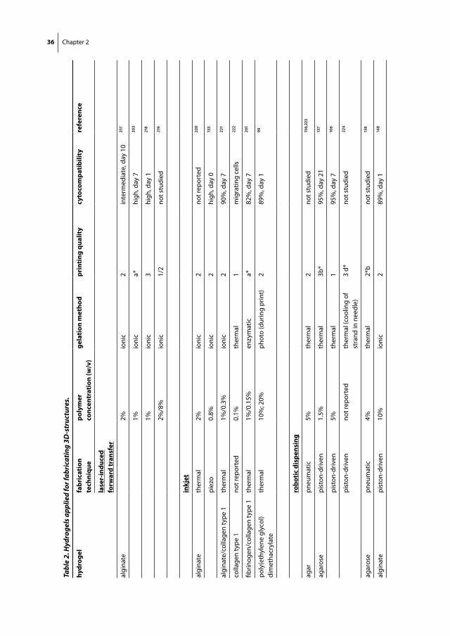
Table 1. Typical characteristics of three key dispensing approaches in biofabrication.
Laser-inducedforward transfer
Inkjet printing Robotic dispensing
Resolution ++ + +/-
Fabrication speed - +/- ++
Hydrogel viscosity +/- - +
Gelation speed ++ ++ +/-

Engineering hydrogels for biofabrication 35
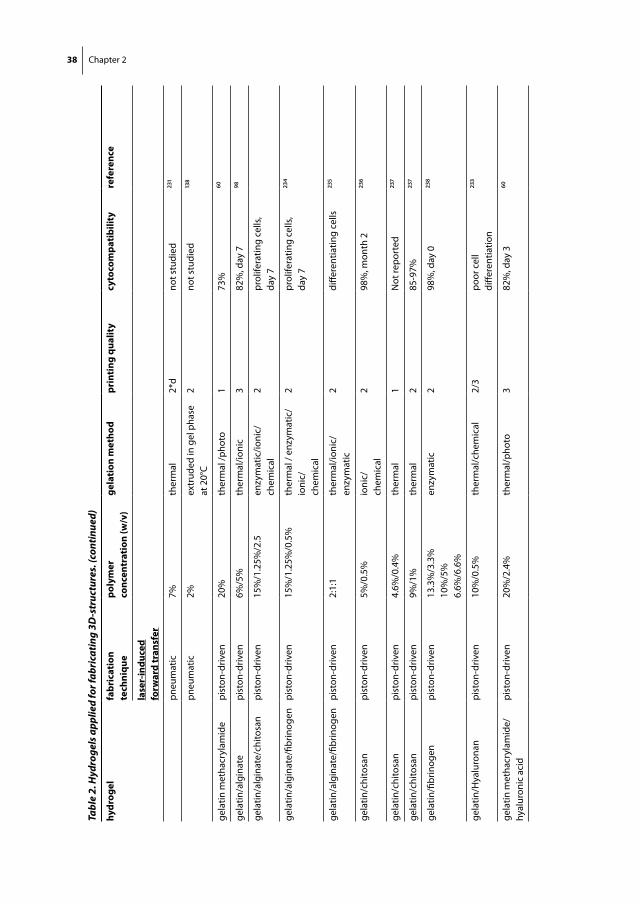
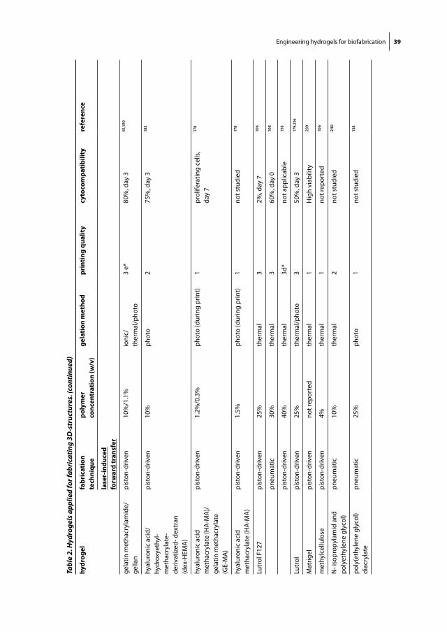
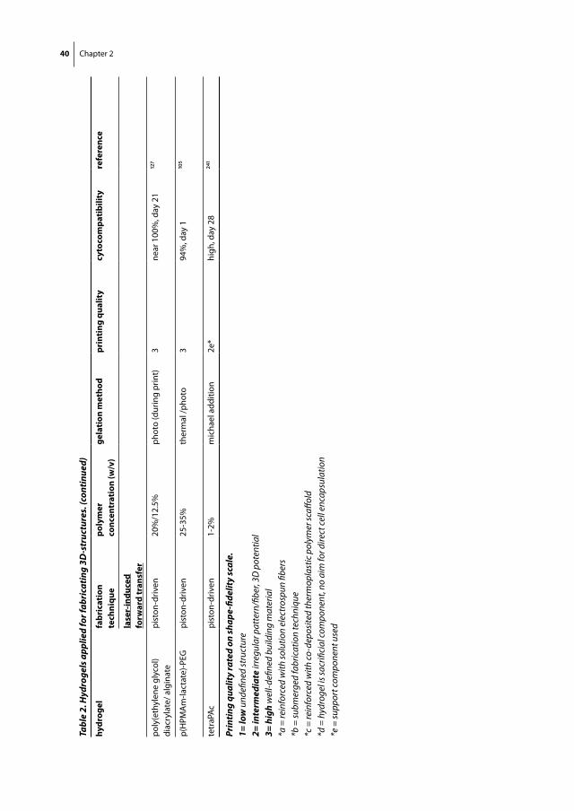
due to the delay of the compressed gas volume in the pneumatic systems. On the other hand, screw-based systems may give more spatial control and are beneficial for the dispensing of hydrogels with higher viscosities. To further improve the printing quality of the 3D constructs, deposition within high viscous crosslinking solutions has been explored137,138. Cells have been deposited with high viability and no notable effects on differentiation capacity using both pneumatic and piston driven systems (see Table 2). Screw extrusion can generate larger pressure drops at the nozzle, which can potentially be harmful for embedded cells. Thus, the screw design needs to be specifically designed to accommodate biofabrication, rather then using off-the-shelf screws designed for oth-
figure 3. Biofabrication examples - Aortic valve model reconstructed from micro-CT images (a). The root and leaflet regions rendered separately into 3D geometries (green color indicates valve root and red color indicates valve leaflets) and printed (b). An ovine meniscus reconstructed from micro-CT images (c) and printed (d). A miniaturized distal femur from a human knee designed using Rhino Software LxWxH: 40x35x-32mm) containing a cartilage layer (green) and a bone component (yellow) and a support structure (white) (e) and printed after manual removal of the support structure (f). Reproduced with permission from Duan et al.98 and Wiley (a, b), Cohen et al.216 Liebert (c, d), and Visser et al.190 (e, f ).
36 Chapter 2
Tabl
e 2.
Hyd
roge
ls a
pplie
d fo
r fab
rica
ting
3D-s
truc
ture
s.
hydr
ogel
fabr
icat
ion
tech
niqu
epo
lym
er
conc
entr
atio
n (w
/v)
gela
tion
met
hod
prin
ting
qua
lity
cyto
com
pati
bilit
yre
fere
nce
lase
r-in
duce
dfo
rwar
d tr
ansf
er
algi
nate
2%io
nic
2in
term
edia
te, d
ay 1
0217
1%io
nic
a*hi
gh, d
ay 7
203
1%io
nic
3hi
gh, d
ay 1
218
2%/8
%io
nic
1/2
not s
tudi
ed219
inkj
et
algi
nate
ther
mal
2%io
nic
2no
t rep
orte
d22
0
piez
o0.
8%io
nic
2hi
gh, d
ay 0
133
algi
nate
/col
lage
n ty
pe 1
ther
mal
1%/0
.3%
ioni
c2
90%
, day
722
1
colla
gen
type
1no
t rep
orte
d0.
1%th
erm
al1
mig
ratin
g ce
lls22
2
fibrin
ogen
/col
lage
n ty
pe 1
ther
mal
1%/0
.15%
enzy
mat
ica*
82%
, day
720
1
poly
(eth
ylen
e gl
ycol
) di
met
hacr
ylat
eth
erm
al10
%; 2
0%ph
oto
(dur
ing
prin
t)2
89%
, day
199
robo
tic
disp
ensi
ng
agar
pneu
mat
ic5%
ther
mal
2no
t stu
died
156,22
3
agar
ose
pist
on-d
riven
1.5%
ther
mal
3b*
95%
, day
21
137
pist
on-d
riven
5%th
erm
al1
95%
, day
7106
pist
on-d
riven
not r
epor
ted
ther
mal
(coo
ling
of
stra
nd in
nee
dle)
3 d*
not s
tudi
ed22
4
agar
ose
pneu
mat
ic4%
ther
mal
2*b
not s
tudi
ed138
algi
nate
pist
on-d
riven
10%
ioni
c2
89%
, day
1148

Engineering hydrogels for biofabrication 37
Tabl
e 2.
Hyd
roge
ls a
pplie
d fo
r fab
rica
ting
3D-s
truc
ture
s. (c
ontin
ued)
hydr
ogel
fabr
icat
ion
tech
niqu
epo
lym
er
conc
entr
atio
n (w
/v)
gela
tion
met
hod
prin
ting
qua
lity
cyto
com
pati
bilit
yre
fere
nce
lase
r-in
duce
dfo
rwar
d tr
ansf
er
pist
on-d
riven
2%io
nic
282
%, d
ay 3
106
pist
on-d
riven
2%io
nic
275
-94%
, day
0179
,216,2
25
pneu
mat
ic1.
5% -
3%io
nic
2 (3
%)
85%
, day
0 (1
.5%
)22
6
pist
on-d
riven
4%io
nic
2no
t stu
died
122
pist
on-d
riven
2%io
nic
c*70
%, d
ay 3
65
pneu
mat
ic3.
5%io
nic
c*84
%, d
ay 0
76
pist
on-d
riven
4%io
nic
c*94
%, d
ay 7
75
pneu
mat
ic5%
ioni
c1*
bno
t stu
died
138
pist
on-d
riven
1%io
nic
2no
t stu
died
227
Pist
on4%
Ioni
c2
95%
, day
722
8
algi
nate
/fibr
inpn
eum
atic
6.3%
/?%
ioni
c/en
zym
atic
1no
t stu
died
223
algi
nate
/gel
atin
pist
on-d
riven
7.5%
/5%
ther
mal
/ioni
c/ch
emic
al2
95%
, day
022
9
atel
ocol
lage
npn
eum
atic
3%th
erm
alc*
95%
, day
1020
2
colla
gen
type
1pn
eum
atic
0.3%
ther
mal
286
%, d
ay 1
108,23
0
pneu
mat
ic0.
223%
pH (s
odiu
m
bica
rbon
ate)
2*e
not s
tudi
ed23
1
pist
on-d
riven
0.1%
ther
mal
1m
igra
ting
cells
222
gela
tinpi
ston
-driv
en20
%th
erm
al/c
hem
ical
295
%, m
onth
123
2
pist
on-d
riven
20%
ther
mal
/che
mic
al2/
3po
or c
ell
diffe
rent
iatio
n23
3
38 Chapter 2
Tabl
e 2.
Hyd
roge
ls a
pplie
d fo
r fab
rica
ting
3D-s
truc
ture
s. (c
ontin
ued)
hydr
ogel
fabr
icat
ion
tech
niqu
epo
lym
er
conc
entr
atio
n (w
/v)
gela
tion
met
hod
prin
ting
qua
lity
cyto
com
pati
bilit
yre
fere
nce
lase
r-in
duce
dfo
rwar
d tr
ansf
er
pneu
mat
ic7%
ther
mal
2*d
not s
tudi
ed23
1
pneu
mat
ic2%
extr
uded
in g
el p
hase
at
20°
C2
not s
tudi
ed138
gela
tin m
etha
cryl
amid
epi
ston
-driv
en20
%th
erm
al /p
hoto
173
%60
gela
tin/a
lgin
ate
pist
on-d
riven
6%/5
%th
erm
al/io
nic
382
%, d
ay 7
98
gela
tin/a
lgin
ate/
chito
san
pist
on-d
riven
15%
/1.2
5%/2
.5en
zym
atic
/ioni
c/ch
emic
al2
prol
ifera
ting
cells
, da
y 7
gela
tin/a
lgin
ate/
fibrin
ogen
pist
on-d
riven
15%
/1.2
5%/0
.5%
ther
mal
/ en
zym
atic
/io
nic/
chem
ical
2pr
olife
ratin
g ce
lls,
day
723
4
gela
tin/a
lgin
ate/
fibrin
ogen
pist
on-d
riven
2:1:
1th
erm
al/io
nic/
enzy
mat
ic2
diffe
rent
iatin
g ce
lls23
5
gela
tin/c
hito
san
pist
on-d
riven
5%/0
.5%
ioni
c/ch
emic
al2
98%
, mon
th 2
236
gela
tin/c
hito
san
pist
on-d
riven
4.6%
/0.4
%th
erm
al1
Not
repo
rted
237
gela
tin/c
hito
san
pist
on-d
riven
9%/1
%th
erm
al2
85-9
7%23
7
gela
tin/fi
brin
ogen
pist
on-d
riven
13.3
%/3
.3%
10%
/5%
6.6%
/6.6
%
enzy
mat
ic2
98%
, day
023
8
gela
tin/H
yalu
rona
npi
ston
-driv
en10
%/0
.5%
ther
mal
/che
mic
al2/
3po
or c
ell
diffe
rent
iatio
n23
3
gela
tin m
etha
cryl
amid
e/
hyal
uron
ic a
cid
pist
on-d
riven
20%
/2.4
%th
erm
al/p
hoto
382
%, d
ay 3
60
Engineering hydrogels for biofabrication 39
Tabl
e 2.
Hyd
roge
ls a
pplie
d fo
r fab
rica
ting
3D-s
truc
ture
s. (c
ontin
ued)
hydr
ogel
fabr
icat
ion
tech
niqu
epo
lym
er
conc
entr
atio
n (w
/v)
gela
tion
met
hod
prin
ting
qua
lity
cyto
com
pati
bilit
yre
fere
nce
lase
r-in
duce
dfo
rwar
d tr
ansf
er
gela
tin m
etha
cryl
amid
e/ge
llan
pist
on-d
riven
10%
/1.1
%io
nic/
ther
mal
/pho
to3
e*80
%, d
ay 3
61,190
hyal
uron
ic a
cid/
hy
drox
yeth
yl-
met
hacr
ylat
e-de
rivat
ized
- dex
tran
(d
ex-H
EMA
)
pist
on-d
riven
10%
phot
o2
75%
, day
3183
hyal
uron
ic a
cid
met
hacr
ylat
e (H
A-M
A)/
gela
tin m
etha
cryl
ate
(GE-
MA
)
pist
on-d
riven
1.2%
/0.3
%ph
oto
(dur
ing
prin
t)1
prol
ifera
ting
cells
, da
y 7
178
hyal
uron
ic a
cid
met
hacr
ylat
e (H
A-M
A)
pist
on-d
riven
1.5%
phot
o (d
urin
g pr
int)
1no
t stu
died
178
Lutr
ol F
127
pist
on-d
riven
25%
ther
mal
32%
, day
7106
pneu
mat
ic30
%th
erm
al3
60%
, day
0108
pist
on-d
riven
40%
ther
mal
3d*
not a
pplic
able
158
Lutr
olpi
ston
-driv
en25
%th
erm
al/p
hoto
350
%, d
ay 3
179,21
6
Mat
rigel
pist
on-d
riven
not r
epor
ted
ther
mal
1H
igh
viab
ility
239
met
hylc
ellu
lose
pist
on-d
riven
4%th
erm
al1
not r
epor
ted
106
N- i
sopr
opyl
amid
and
po
lyet
hyle
ne g
lyco
l)pn
eum
atic
10%
ther
mal
2no
t stu
died
240
poly
(eth
ylen
e gl
ycol
) di
acry
late
pneu
mat
ic25
%ph
oto
1no
t stu
died
138
40 Chapter 2
Tabl
e 2.
Hyd
roge
ls a
pplie
d fo
r fab
rica
ting
3D-s
truc
ture
s. (c
ontin
ued)
hydr
ogel
fabr
icat
ion
tech
niqu
epo
lym
er
conc
entr
atio
n (w
/v)
gela
tion
met
hod
prin
ting
qua
lity
cyto
com
pati
bilit
yre
fere
nce
lase
r-in
duce
dfo
rwar
d tr
ansf
er
poly
(eth
ylen
e gl
ycol
) di
acry
late
/ alg
inat
epi
ston
-driv
en20
%/1
2.5%
phot
o (d
urin
g pr
int)
3ne
ar 1
00%
, day
21
127
p(H
PMA
m-la
ctat
e)-P
EGpi
ston
-driv
en25
-35%
ther
mal
/pho
to3
94%
, day
1105
tetr
aPAc
pist
on-d
riven
1-2%
mic
hael
add
ition
2e*
high
, day
28
241
Prin
ting
qual
ity
rate
d on
shap
e-fid
elit
y sc
ale.
1= lo
w u
ndefi
ned
stru
ctur
e2=
inte
rmed
iate
irre
gula
r pat
tern
/fibe
r, 3D
pot
entia
l3=
hig
h w
ell-d
efine
d bu
ildin
g m
ater
ial
*a =
rein
forc
ed w
ith so
lutio
n el
ectr
ospu
n fib
ers
*b =
subm
erge
d fa
bric
atio
n te
chni
que
*c =
rein
forc
ed w
ith co
-dep
osite
d th
erm
opla
stic
pol
ymer
scaff
old
*d =
hyd
roge
l is s
acrifi
cial
com
pone
nt, n
o ai
m fo
r dire
ct ce
ll en
caps
ulat
ion
*e =
supp
ort c
ompo
nent
use
d
Engineering hydrogels for biofabrication 41
er applications. Taken together, robotic dispensing allows the fabrication of organized constructs of clinically-relevant sizes within a realistic time frame, hence this technology is often regarded as the most promising118,120.
Key hydrogel properties in BiofaBrication
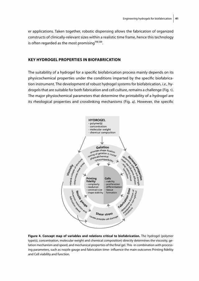
The suitability of a hydrogel for a specific biofabrication process mainly depends on its physicochemical properties under the conditions imparted by the specific biofabrica-tion instrument. The development of robust hydrogel systems for biofabrication, i.e., hy-drogels that are suitable for both fabrication and cell culture, remains a challenge (Fig. 1). The major physiochemical parameters that determine the printability of a hydrogel are its rheological properties and crosslinking mechanisms (Fig. 4). However, the specific
figure 4. concept map of variables and relations critical to biofabrication. The hydrogel (polymer type(s), concentration, molecular weight and chemical composition) directly determines the viscosity, ge-lation mechanism and speed, and mechanical properties of the final gel. This -in combination with process-ing parameters, such as nozzle gauge and fabrication time- influence the main outcomes Printing fidelity and Cell viability and function.
42 Chapter 2
processing parameters, such as nozzle gauge (Fig. 4), will consequently determine the shear stress the embedded cells are exposed to, as well as the maximal time required for fabrication of a clinically relevant size (cm3-scale) construct (Fig. 4). Finally, once the hy-drogel precursors have been printed and the cells have survived, the printed construct has to possess, develop or be endowed with shape fidelity and sufficient mechanical stability, for example by (post-processing) gelation as a result of crosslinking.
These parameters are interlinked and important for the different biofabrication tech-nologies, however, absolute numbers can be considerably different given the nature of the deposition process. For example, inkjet printing is generally limited to low maximum viscosities, while with robotic dispensing bioinks with higher viscosities can be processed. Accordingly, inkjet printing requires rapid gelation to allow fabrication of an intricate 3D structure. On the other hand, robotic dispensing will facilitate the maintenance of the initial shape after deposition of hihj viscous liquids allowing for gelation (crosslinking) of the generated structures post-fabrication, as well as building large constructs in the x, y, z directions. This illustrates how the viscosity of the hydrogel forming solution dictates how quickly it needs to solidify. In addition, swelling or contraction characteristics of hydrogels must also be considered and taken in account when designing a biofabri-cated tissue construct of particular size. Moreover, care should be taken when applying different bioinks with dissimilar swelling behaviour, since this can be complicated due to limited grafting of the layers and deformation of the final construct.
rheology
Rheology is the study of the flow of matter under application of an external force, and is therefore highly relevant to biofabrication. Nevertheless, its importance is un-derestimated, given the high number of investigations that do not take rheology into account when developing or evaluating hydrogels for biofabrication. In the instances that rheological data is presented, it often lacks the clear correlation to the results of the deposition processes, underscoring the complexity of field of rheology and its poorly understood role in biofabrication. Here, we discuss the influence of number of rheologi-cal parameters on the biofabrication process.
Viscosity
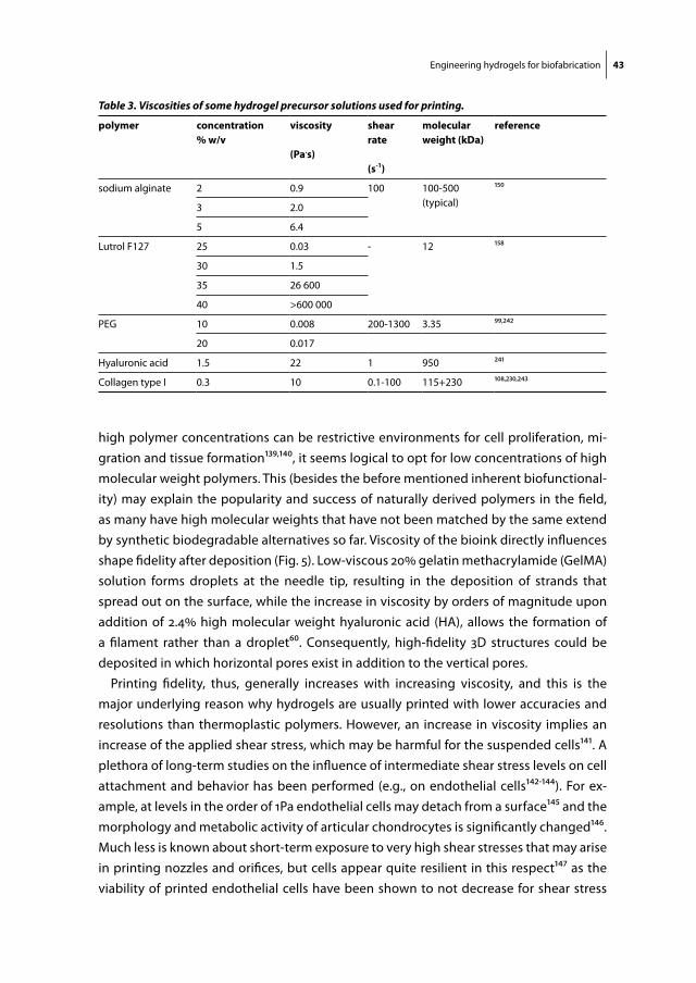
Viscosity is the resistance of a fluid to flow upon application of a stress. In biofabrication, a high viscosity impedes both surface tension-driven droplet formation (particularly im-portant for filament-based deposition techniques) and the collapse of deposited struc-tures. The viscosity of a polymer solution, such as a hydrogel precursor, is predominantly determined by the polymer concentration and molecular weight. This is illustrated in Table 3 for a number of hydrogel forming polymers, including sodium alginate (typical molecular weight 200 kDa) and Lutrol F127 (molecular weight 12 kDa). As hydrogels of
Engineering hydrogels for biofabrication 43
high polymer concentrations can be restrictive environments for cell proliferation, mi-gration and tissue formation139,140, it seems logical to opt for low concentrations of high molecular weight polymers. This (besides the before mentioned inherent biofunctional-ity) may explain the popularity and success of naturally derived polymers in the field, as many have high molecular weights that have not been matched by the same extend by synthetic biodegradable alternatives so far. Viscosity of the bioink directly influences shape fidelity after deposition (Fig. 5). Low-viscous 20% gelatin methacrylamide (GelMA) solution forms droplets at the needle tip, resulting in the deposition of strands that spread out on the surface, while the increase in viscosity by orders of magnitude upon addition of 2.4% high molecular weight hyaluronic acid (HA), allows the formation of a filament rather than a droplet60. Consequently, high-fidelity 3D structures could be deposited in which horizontal pores exist in addition to the vertical pores.
Printing fidelity, thus, generally increases with increasing viscosity, and this is the major underlying reason why hydrogels are usually printed with lower accuracies and resolutions than thermoplastic polymers. However, an increase in viscosity implies an increase of the applied shear stress, which may be harmful for the suspended cells141. A plethora of long-term studies on the influence of intermediate shear stress levels on cell attachment and behavior has been performed (e.g., on endothelial cells142-144). For ex-ample, at levels in the order of 1Pa endothelial cells may detach from a surface145 and the morphology and metabolic activity of articular chondrocytes is significantly changed146. Much less is known about short-term exposure to very high shear stresses that may arise in printing nozzles and orifices, but cells appear quite resilient in this respect147 as the viability of printed endothelial cells have been shown to not decrease for shear stress
Table 3. Viscosities of some hydrogel precursor solutions used for printing.
polymer concentration% w/v
viscosity
(pa.s)
shear rate
(s-1)
molecular weight (kda)
reference
sodium alginate 2 0.9 100 100-500 (typical)
150
3 2.0
5 6.4
Lutrol F127 25 0.03 - 12 158
30 1.5
35 26 600
40 >600 000
PEG 10 0.008 200-1300 3.35 99,242
20 0.017
Hyaluronic acid 1.5 22 1 950 241
Collagen type I 0.3 10 0.1-100 115+230 108,230,243
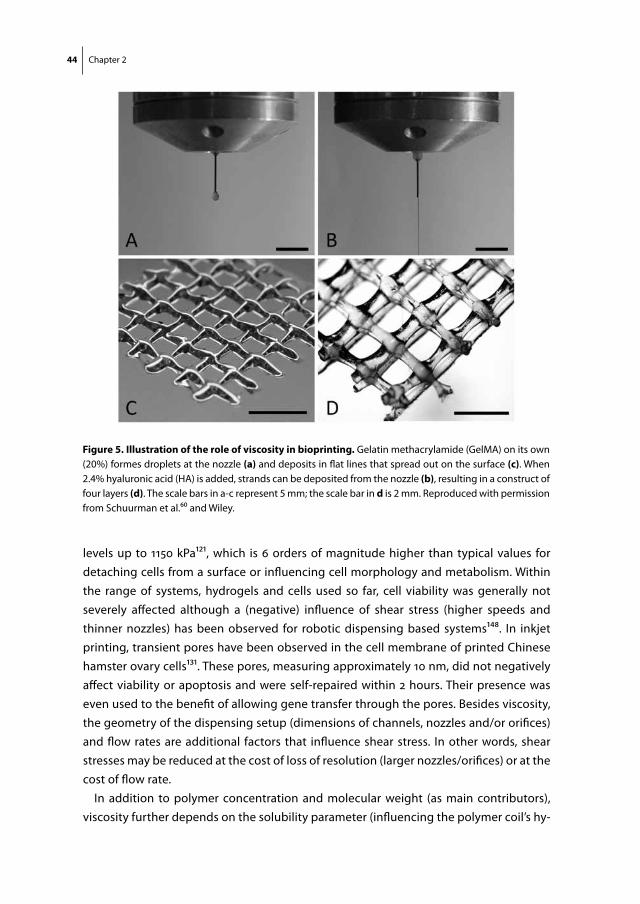
44 Chapter 2
levels up to 1150 kPa121, which is 6 orders of magnitude higher than typical values for detaching cells from a surface or influencing cell morphology and metabolism. Within the range of systems, hydrogels and cells used so far, cell viability was generally not severely affected although a (negative) influence of shear stress (higher speeds and thinner nozzles) has been observed for robotic dispensing based systems148. In inkjet printing, transient pores have been observed in the cell membrane of printed Chinese hamster ovary cells131. These pores, measuring approximately 10 nm, did not negatively affect viability or apoptosis and were self-repaired within 2 hours. Their presence was even used to the benefit of allowing gene transfer through the pores. Besides viscosity, the geometry of the dispensing setup (dimensions of channels, nozzles and/or orifices) and flow rates are additional factors that influence shear stress. In other words, shear stresses may be reduced at the cost of loss of resolution (larger nozzles/orifices) or at the cost of flow rate.
In addition to polymer concentration and molecular weight (as main contributors), viscosity further depends on the solubility parameter (influencing the polymer coil’s hy-
figure 5. illustration of the role of viscosity in bioprinting. Gelatin methacrylamide (GelMA) on its own (20%) formes droplets at the nozzle (a) and deposits in flat lines that spread out on the surface (c). When 2.4% hyaluronic acid (HA) is added, strands can be deposited from the nozzle (b), resulting in a construct of four layers (d). The scale bars in a-c represent 5 mm; the scale bar in d is 2 mm. Reproduced with permission from Schuurman et al.60 and Wiley.
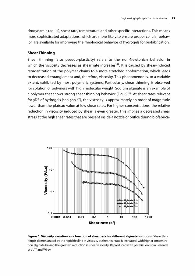
Engineering hydrogels for biofabrication 45
drodynamic radius), shear rate, temperature and other specific interactions. This means more sophisticated adaptations, which are more likely to ensure proper cellular behav-ior, are available for improving the rheological behavior of hydrogels for biofabrication.
shear thinning
Shear thinning (also pseudo-plasticity) refers to the non-Newtonian behavior in which the viscosity decreases as shear rate increases149. It is caused by shear-induced reorganization of the polymer chains to a more stretched conformation, which leads to decreased entanglement and, therefore, viscosity. This phenomenon is, to a variable extent, exhibited by most polymeric systems. Particularly, shear thinning is observed for solution of polymers with high molecular weight. Sodium alginate is an example of a polymer that shows strong shear thinning behavior (Fig. 6)150. At shear rates relevant for 3DF of hydrogels (100-500 s-1), the viscosity is approximately an order of magnitude lower than the plateau value at low shear rates. For higher concentrations, the relative reduction in viscosity induced by shear is even greater. This implies a decreased shear stress at the high shear rates that are present inside a nozzle or orifice during biofabrica-
figure 6. Viscosity variation as a function of shear rate for different alginate solutions. Shear thin-ning is demonstrated by the rapid decline in viscosity as the shear rate is increased, with higher concentra-tion alginate having the greatest reduction in shear viscosity. Reproduced with permission from Rezende et al.150 and Wiley.
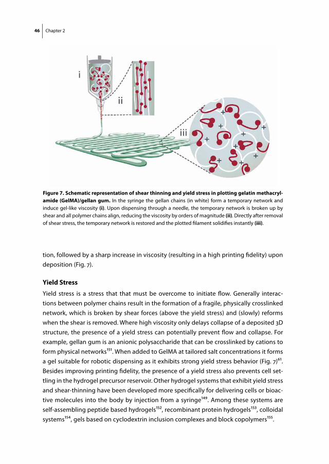
46 Chapter 2
tion, followed by a sharp increase in viscosity (resulting in a high printing fidelity) upon deposition (Fig. 7).
yield stress
Yield stress is a stress that that must be overcome to initiate flow. Generally interac-tions between polymer chains result in the formation of a fragile, physically crosslinked network, which is broken by shear forces (above the yield stress) and (slowly) reforms when the shear is removed. Where high viscosity only delays collapse of a deposited 3D structure, the presence of a yield stress can potentially prevent flow and collapse. For example, gellan gum is an anionic polysaccharide that can be crosslinked by cations to form physical networks151. When added to GelMA at tailored salt concentrations it forms a gel suitable for robotic dispensing as it exhibits strong yield stress behavior (Fig. 7)61. Besides improving printing fidelity, the presence of a yield stress also prevents cell set-tling in the hydrogel precursor reservoir. Other hydrogel systems that exhibit yield stress and shear-thinning have been developed more specifically for delivering cells or bioac-tive molecules into the body by injection from a syringe149. Among these systems are self-assembling peptide based hydrogels152, recombinant protein hydrogels153, colloidal systems154, gels based on cyclodextrin inclusion complexes and block copolymers155.
figure 7. schematic representation of shear thinning and yield stress in plotting gelatin methacryl-amide (gelma)/gellan gum. In the syringe the gellan chains (in white) form a temporary network and induce gel-like viscosity (i). Upon dispensing through a needle, the temporary network is broken up by shear and all polymer chains align, reducing the viscosity by orders of magnitude (ii). Directly after removal of shear stress, the temporary network is restored and the plotted filament solidifies instantly (iii).

Engineering hydrogels for biofabrication 47
crosslinKing mechanisms for hydrogels
Gelation of a printed hydrogel structure is necessary to preserve its shape; even struc-tures constructed from the most viscous precursor solution will change shape due to shape and collapse at some point. The gelation can either be physical (based on revers-ible interaction), chemical (based on formation of covalent chemical bonds) (Table 4), or a subsequent cascade and combination of both processes (Fig. 8).
Table 4. Advantages and disadvantages of different crosslinking strategies for biofabrication.
crosslinking advantages disadvantages
Physical Ionic - Reversible interactions ensure constant viscosity during printing - Excellent compatibility with biological systems
- Requires additional crosslinking agent and / or post-processing crosslinking- Mechanically weak constructs
Stereocomplex - Reversible interactions ensure constant viscosity during printing- Excellent compatibility with biological systems
- Relatively slow gelation- Relatively high viscosity of the building blocks- Requires additional crosslinking agent and / or post-processing crosslinking- Mechanically weak constructs
Thermal - Reversible interactions ensure constant viscosity during printing- Rapid reassembly to gels after printing - Excellent compatibility with biological systems
- Requires post-processing crosslinking
Chemical UV - Polymerisation through irradiation during printing does not affect viscosity during printing in the nozzle- Allows for post-processing crosslinking (stabilization) of mechanically weak physically crosslinked hydrogel constructs
- High reaction rates necessary as polymerisation needs to be completed between nozzle and deposition- May involve exposure of constructs to irradiation- Irradiation may affect embedded cells
Wet-chemical - No need for irradiation or other further stabilization- Mechanically stable constructs
- May require (potentially harmful) crosslinking agent- A trigger for chemical reactivity with required stringent control of crosslinking kinetics is needed to avoid viscosity change in the nozzle throughout printing time but ensure crosslinking between nozzle and deposition
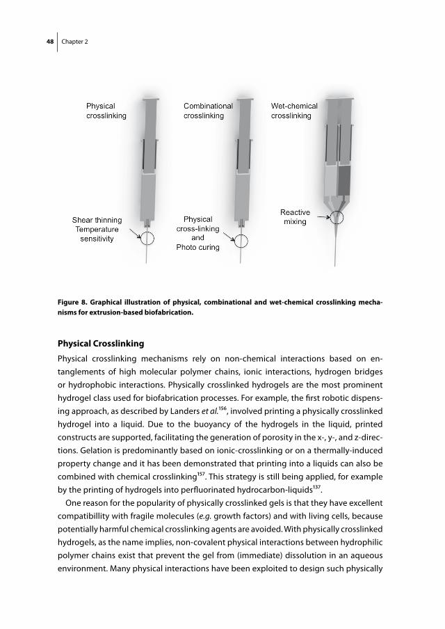
48 Chapter 2
physical crosslinking
Physical crosslinking mechanisms rely on non-chemical interactions based on en-tanglements of high molecular polymer chains, ionic interactions, hydrogen bridges or hydrophobic interactions. Physically crosslinked hydrogels are the most prominent hydrogel class used for biofabrication processes. For example, the first robotic dispens-ing approach, as described by Landers et al.156, involved printing a physically crosslinked hydrogel into a liquid. Due to the buoyancy of the hydrogels in the liquid, printed constructs are supported, facilitating the generation of porosity in the x-, y-, and z-direc-tions. Gelation is predominantly based on ionic-crosslinking or on a thermally-induced property change and it has been demonstrated that printing into a liquids can also be combined with chemical crosslinking157. This strategy is still being applied, for example by the printing of hydrogels into perfluorinated hydrocarbon-liquids137.
One reason for the popularity of physically crosslinked gels is that they have excellent compatibillity with fragile molecules (e.g. growth factors) and with living cells, because potentially harmful chemical crosslinking agents are avoided. With physically crosslinked hydrogels, as the name implies, non-covalent physical interactions between hydrophilic polymer chains exist that prevent the gel from (immediate) dissolution in an aqueous environment. Many physical interactions have been exploited to design such physically
figure 8. graphical illustration of physical, combinational and wet-chemical crosslinking mecha-nisms for extrusion-based biofabrication.
Engineering hydrogels for biofabrication 49
crosslinked hydrogels, these interactions include hydrogen bonding, ionic interactions (polyelectrolyte hydrogels), stereocomplex formation of polymers or polymer fragments of opposite chirality, and hydrophobic interactions (e.g. self-assembly peptides)158,159.
ionic crosslinking
Ionic crosslinking is therefore an important mechanism in biofabrication, particularly for biopolymers. For example, alginate is a polysaccharide that consists of mannuronic and glucuronic acid residues and that is highly soluble in water as Na-salt. However, upon addition of Ca2+ ions (or other di/trivalent cations) rapid gelation of alginate occurs. Since this crosslinking occurs under mild and physiological conditions, alginate gels have been studied as system for the controlled release of pharmaceutical proteins and for the entrapment of living cells for TE applications160-162. As a consequence alginate has been widely applied in biofabrication approaches (Table 2). In recent years, hydro-gels have also been developed exploiting electrostatic interactions between particles (nano and or micro) of opposite charge dispersed in an aqueous systems. These gels are rapidly formed upon mixing of the particles of opposite charge, but become fluid above a certain shear stress, sufficient to break the interactions between the charged particles, making them suitable as injectable drug delivery system and likely also for bioprinting163,164.
stereocomplex crosslinking
Stereocomplex formation occurs, for example, between poly(D-lactic acid) (PDLA) and poly(L-lactic acid) (PLLA), homopolymers of D- and L-lactic acid, respectively. When oligomers of D- and L-lactic acid are coupled to water-soluble polymers like dextran or polyethylene glycol, hydrogels are formed which are crosslinked by stereocomplexes composed of oligomers of opposite chirality. Stereocomplexation does not occur im-mediately upon mixing of the hydrogel building blocks, allowing their use as injectable systems for controlled drug/protein release and as scaffolds for entrapment of cells165-167. An additional form of complexation mechanisms is the formation of inclusion com-plexes. For example, cyclodextrins, cyclic oligosaccharides composed of R-1,4-coupled D-glucose units contain a hydrophobic internal cavity that can accommodate lipophilic guest molecules. Cyclodextrins have therefore been investigated for the solubilization of hydrophobic drugs, but also used for the design of super-molecular materials, includ-ing hydrogels. In this approach, hydrophilic polymers are derivatized with cyclodextrin units, which, upon mixing with a guest molecule-derivatized polymer, result in the formation of a hydrogel structure. These systems can be readily loaded with bioactive proteins and used as injectable sustained release system168-170.
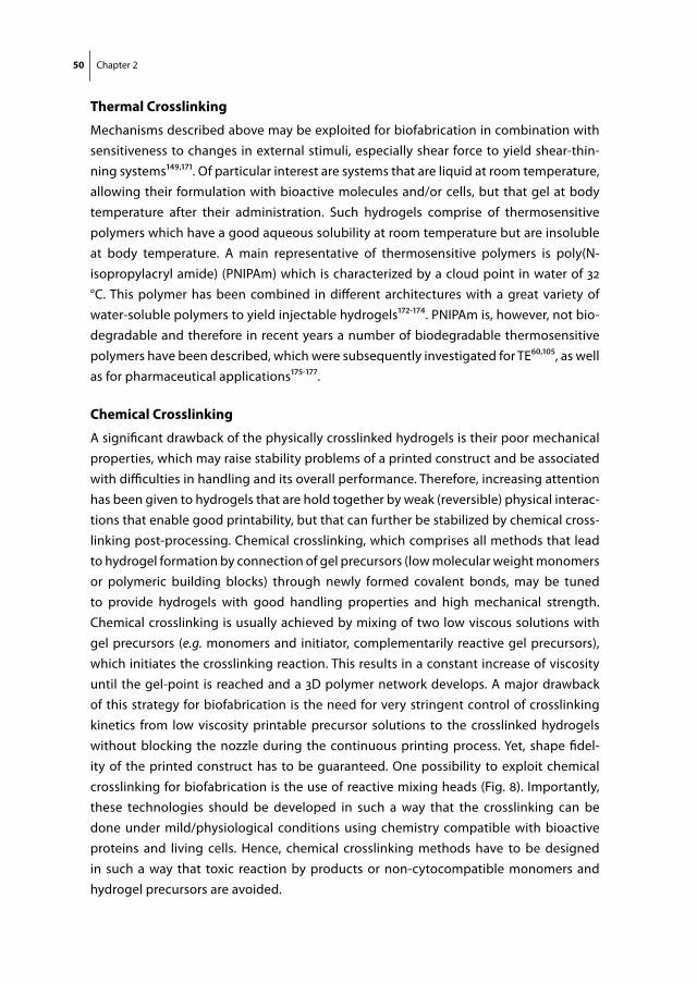
50 Chapter 2
thermal crosslinking
Mechanisms described above may be exploited for biofabrication in combination with sensitiveness to changes in external stimuli, especially shear force to yield shear-thin-ning systems149,171. Of particular interest are systems that are liquid at room temperature, allowing their formulation with bioactive molecules and/or cells, but that gel at body temperature after their administration. Such hydrogels comprise of thermosensitive polymers which have a good aqueous solubility at room temperature but are insoluble at body temperature. A main representative of thermosensitive polymers is poly(N-isopropylacryl amide) (PNIPAm) which is characterized by a cloud point in water of 32 °C. This polymer has been combined in different architectures with a great variety of water-soluble polymers to yield injectable hydrogels172-174. PNIPAm is, however, not bio-degradable and therefore in recent years a number of biodegradable thermosensitive polymers have been described, which were subsequently investigated for TE60,105, as well as for pharmaceutical applications175-177.
chemical crosslinking
A significant drawback of the physically crosslinked hydrogels is their poor mechanical properties, which may raise stability problems of a printed construct and be associated with difficulties in handling and its overall performance. Therefore, increasing attention has been given to hydrogels that are hold together by weak (reversible) physical interac-tions that enable good printability, but that can further be stabilized by chemical cross-linking post-processing. Chemical crosslinking, which comprises all methods that lead to hydrogel formation by connection of gel precursors (low molecular weight monomers or polymeric building blocks) through newly formed covalent bonds, may be tuned to provide hydrogels with good handling properties and high mechanical strength. Chemical crosslinking is usually achieved by mixing of two low viscous solutions with gel precursors (e.g. monomers and initiator, complementarily reactive gel precursors), which initiates the crosslinking reaction. This results in a constant increase of viscosity until the gel-point is reached and a 3D polymer network develops. A major drawback of this strategy for biofabrication is the need for very stringent control of crosslinking kinetics from low viscosity printable precursor solutions to the crosslinked hydrogels without blocking the nozzle during the continuous printing process. Yet, shape fidel-ity of the printed construct has to be guaranteed. One possibility to exploit chemical crosslinking for biofabrication is the use of reactive mixing heads (Fig. 8). Importantly, these technologies should be developed in such a way that the crosslinking can be done under mild/physiological conditions using chemistry compatible with bioactive proteins and living cells. Hence, chemical crosslinking methods have to be designed in such a way that toxic reaction by products or non-cytocompatible monomers and hydrogel precursors are avoided.
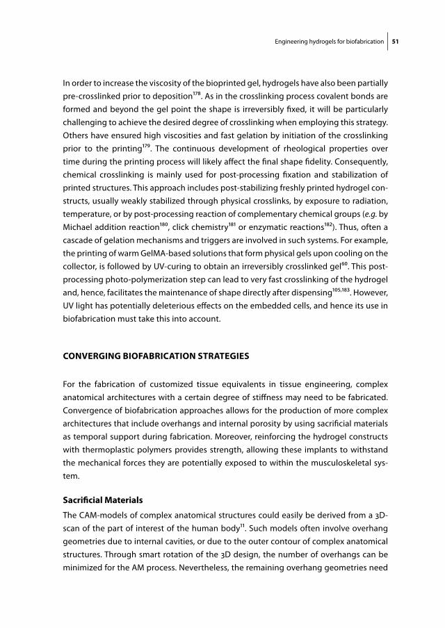
Engineering hydrogels for biofabrication 51
In order to increase the viscosity of the bioprinted gel, hydrogels have also been partially pre-crosslinked prior to deposition178. As in the crosslinking process covalent bonds are formed and beyond the gel point the shape is irreversibly fixed, it will be particularly challenging to achieve the desired degree of crosslinking when employing this strategy. Others have ensured high viscosities and fast gelation by initiation of the crosslinking prior to the printing179. The continuous development of rheological properties over time during the printing process will likely affect the final shape fidelity. Consequently, chemical crosslinking is mainly used for post-processing fixation and stabilization of printed structures. This approach includes post-stabilizing freshly printed hydrogel con-structs, usually weakly stabilized through physical crosslinks, by exposure to radiation, temperature, or by post-processing reaction of complementary chemical groups (e.g. by Michael addition reaction180, click chemistry181 or enzymatic reactions182). Thus, often a cascade of gelation mechanisms and triggers are involved in such systems. For example, the printing of warm GelMA-based solutions that form physical gels upon cooling on the collector, is followed by UV-curing to obtain an irreversibly crosslinked gel60. This post-processing photo-polymerization step can lead to very fast crosslinking of the hydrogel and, hence, facilitates the maintenance of shape directly after dispensing105,183. However, UV light has potentially deleterious effects on the embedded cells, and hence its use in biofabrication must take this into account.
conVerging BiofaBrication strategies
For the fabrication of customized tissue equivalents in tissue engineering, complex anatomical architectures with a certain degree of stiffness may need to be fabricated. Convergence of biofabrication approaches allows for the production of more complex architectures that include overhangs and internal porosity by using sacrificial materials as temporal support during fabrication. Moreover, reinforcing the hydrogel constructs with thermoplastic polymers provides strength, allowing these implants to withstand the mechanical forces they are potentially exposed to within the musculoskeletal sys-tem.
sacrificial materials
The CAM-models of complex anatomical structures could easily be derived from a 3D-scan of the part of interest of the human body11. Such models often involve overhang geometries due to internal cavities, or due to the outer contour of complex anatomical structures. Through smart rotation of the 3D design, the number of overhangs can be minimized for the AM process. Nevertheless, the remaining overhang geometries need
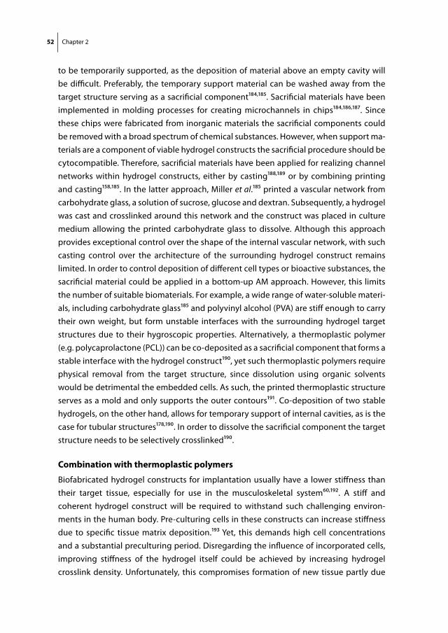
52 Chapter 2
to be temporarily supported, as the deposition of material above an empty cavity will be difficult. Preferably, the temporary support material can be washed away from the target structure serving as a sacrificial component184,185. Sacrificial materials have been implemented in molding processes for creating microchannels in chips184,186,187. Since these chips were fabricated from inorganic materials the sacrificial components could be removed with a broad spectrum of chemical substances. However, when support ma-terials are a component of viable hydrogel constructs the sacrificial procedure should be cytocompatible. Therefore, sacrificial materials have been applied for realizing channel networks within hydrogel constructs, either by casting188,189 or by combining printing and casting158,185. In the latter approach, Miller et al.185 printed a vascular network from carbohydrate glass, a solution of sucrose, glucose and dextran. Subsequently, a hydrogel was cast and crosslinked around this network and the construct was placed in culture medium allowing the printed carbohydrate glass to dissolve. Although this approach provides exceptional control over the shape of the internal vascular network, with such casting control over the architecture of the surrounding hydrogel construct remains limited. In order to control deposition of different cell types or bioactive substances, the sacrificial material could be applied in a bottom-up AM approach. However, this limits the number of suitable biomaterials. For example, a wide range of water-soluble materi-als, including carbohydrate glass185 and polyvinyl alcohol (PVA) are stiff enough to carry their own weight, but form unstable interfaces with the surrounding hydrogel target structures due to their hygroscopic properties. Alternatively, a thermoplastic polymer (e.g. polycaprolactone (PCL)) can be co-deposited as a sacrificial component that forms a stable interface with the hydrogel construct190, yet such thermoplastic polymers require physical removal from the target structure, since dissolution using organic solvents would be detrimental the embedded cells. As such, the printed thermoplastic structure serves as a mold and only supports the outer contours191. Co-deposition of two stable hydrogels, on the other hand, allows for temporary support of internal cavities, as is the case for tubular structures178,190. In order to dissolve the sacrificial component the target structure needs to be selectively crosslinked190.
combination with thermoplastic polymers
Biofabricated hydrogel constructs for implantation usually have a lower stiffness than their target tissue, especially for use in the musculoskeletal system60,192. A stiff and coherent hydrogel construct will be required to withstand such challenging environ-ments in the human body. Pre-culturing cells in these constructs can increase stiffness due to specific tissue matrix deposition.193 Yet, this demands high cell concentrations and a substantial preculturing period. Disregarding the influence of incorporated cells, improving stiffness of the hydrogel itself could be achieved by increasing hydrogel crosslink density. Unfortunately, this compromises formation of new tissue partly due
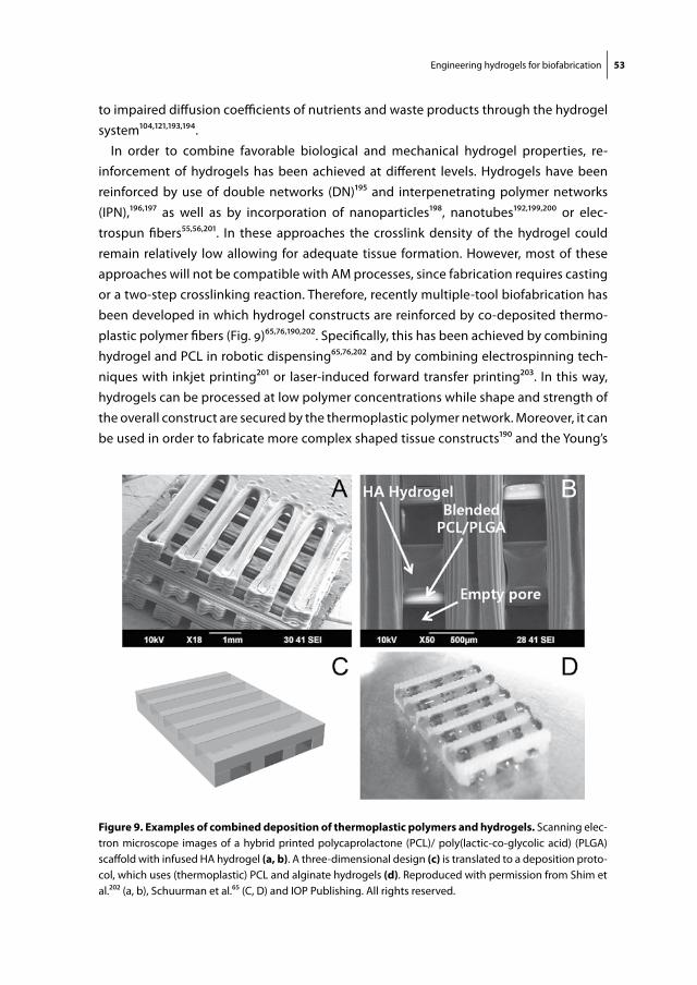
Engineering hydrogels for biofabrication 53
to impaired diffusion coefficients of nutrients and waste products through the hydrogel system104,121,193,194.
In order to combine favorable biological and mechanical hydrogel properties, re-inforcement of hydrogels has been achieved at different levels. Hydrogels have been reinforced by use of double networks (DN)195 and interpenetrating polymer networks (IPN),196,197 as well as by incorporation of nanoparticles198, nanotubes192,199,200 or elec-trospun fibers55,56,201. In these approaches the crosslink density of the hydrogel could remain relatively low allowing for adequate tissue formation. However, most of these approaches will not be compatible with AM processes, since fabrication requires casting or a two-step crosslinking reaction. Therefore, recently multiple-tool biofabrication has been developed in which hydrogel constructs are reinforced by co-deposited thermo-plastic polymer fibers (Fig. 9)65,76,190,202. Specifically, this has been achieved by combining hydrogel and PCL in robotic dispensing65,76,202 and by combining electrospinning tech-niques with inkjet printing201 or laser-induced forward transfer printing203. In this way, hydrogels can be processed at low polymer concentrations while shape and strength of the overall construct are secured by the thermoplastic polymer network. Moreover, it can be used in order to fabricate more complex shaped tissue constructs190 and the Young’s
figure 9. examples of combined deposition of thermoplastic polymers and hydrogels. Scanning elec-tron microscope images of a hybrid printed polycaprolactone (PCL)/ poly(lactic-co-glycolic acid) (PLGA) scaffold with infused HA hydrogel (a, b). A three-dimensional design (c) is translated to a deposition proto-col, which uses (thermoplastic) PCL and alginate hydrogels (d). Reproduced with permission from Shim et al.202 (a, b), Schuurman et al.65 (C, D) and IOP Publishing. All rights reserved.
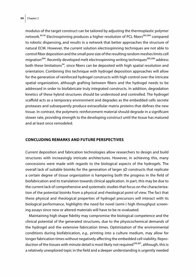
54 Chapter 2
modulus of the target construct can be tailored by adjusting the thermoplastic polymer network.65,76 Electrospinning produces a higher resolution of PCL fibers201,203 compared to robotic dispensing, and results in a network that better approaches the structure of natural ECM. However, the current solution electrospinning techniques are not able to control fiber deposition and the small pore size of the resulting random meshes limits cell migration204. Recently developed melt electrospinning writing techniques205,206 address both these limitations54, since fibers can be deposited with high spatial resolution and orientation. Combining this technique with hydrogel deposition approaches will allow for the generation of reinforced hydrogel constructs with high control over the intricate spatial organization, although grafting between fibers and the hydrogel needs to be addressed in order to biofabricate truly integrated constructs. In addition, degradation kinetics of these hybrid structures should be understood and controlled. The hydrogel scaffold acts as a temporary environment and degrades as the embedded cells secrete proteases and subsequently produce extracellular matrix proteins that defines the new tissue. In contrast, the polymeric reinforcement material should degrade in a significant slower rate, providing strength to the developing construct until the tissue has matured and at least once remodeled.
concluding remarKs and future perspectiVes
Current deposition and fabrication technologies allow researchers to design and build structures with increasingly intricate architectures. However, in achieving this, many concessions were made with regards to the biological aspects of the hydrogels. The overall lack of suitable bioinks for the generation of larger 3D constructs that replicate a certain degree of tissue organization is hampering both the progress in the field of biofabrication and its translation towards clinical application. In part, this may be due to the current lack of comprehensive and systematic studies that focus on the characteriza-tion of the potential bioinks from a physical and rheological point of view. The fact that these physical and rheological properties of hydrogel precursors will interact with its biological performance, highlights the need for novel (semi-) high throughput screen-ing assays since new or altered materials will have to be re-evaluated.
Maintaining high shape fidelity may compromise the biological competence and the clinical potential of the generated structures, due to the physicochemical demands of the hydrogel and the extensive fabrication times. Optimization of the environmental conditions during biofabrication, e.g., printing into a culture medium, may allow for longer fabrication times without negatively affecting the embedded cell viability. Repro-duction of the tissues with minute detail is most likely not required129,207, although, this is a relatively unexplored topic in the field and a deeper understanding is urgently needed
Engineering hydrogels for biofabrication 55
to which degree the directed organization will contribute to the ultimate organization of the regenerated tissue. A collection of deposited cells and matrix within a 3D struc-ture is not yet a functional tissue and following the biofabrication, extracellular matrix deposition and remodeling are important processes to form functional tissue structures that will determine the ultimate success of the generated tissue replacement. It will take time to actually achieve the required reorganization and to realize functional interaction of the neo-tissue. Besides this, it remains also to be determined if this reorganization should fully take place after implantation or that an in vitro conditioning period, e.g., in a bioreactor with mechanical loading regimes or ectopically in the human body, should be incorporated in the approach. The inclusion of more rigid thermoplastic polymer fibers within hydrogel constructs, either generated by fiber deposition modeling65 or electrospinning54,55, may assist in taking some of the initial load-bearing, potentially decreasing the bioreactor culture required.
For polymer chemists and material scientists, it remains a challenge to develop unique bioinks, taking in account the required biological competence, the physical requirements dictated by the biofabrication process, as well as the relative toxicity of crosslinking208 and photo-initiator initiator209 agents. Promising developments are the generation of IPNs for biomedical applications, including those based on gelatin meth-acrylamide and gellan gum methacrylate118,195, which demonstrated to have improved mechanical properties while allowing cellular survival. In addition, double-network (DN) hydrogels210,211 are an example of hydrogels that have, despite their high water content (~90 wt%), unsurpassed mechanical strength and toughness and are, therefore, sug-gested as potential full tissue (cartilage) replacements212. However, care should be taken in this instance since compression resistance is lost after repeated compression due to breakage of the primary polymer network. Novel DN hydrogels have recently been developed that show partial healing capacity of the primary network213. Incorporation of cells in these hydrogel systems will still remain a challenge due to the limited cyto-compatibility of the crosslinking agents, as well as to the two-step synthesis procedure required to create these IPNs118,214, although incorporation as a reinforcing component of a biofabricated construct can be envisioned.
The range of biomaterials that could be applied as bioinks could be extended through the further development of biofabrication methods that can process hydrogel precur-sor solutions that rely on the addition of a crosslinking agent. Obviously, processing pre-mixed components is problematic due to the increasing viscosity as a result of the initiation of the crosslinking reaction. To avoid crosslinking within the nozzle it is very important to synchronize feed rate and crosslinking kinetics.
An additional important challenge is the scale-up and speed of bioabrication, in order to manufacture constructs of clinically relevant sizes. Approaches to potentially improve production speed include the further convergence of biofabrication technolo-
56 Chapter 2
gies, combining approaches with different scales of resolution (e.g., laser-based and robotic dispensing approaches), as well as high throughput production of smaller organized units215 that can subsequently be assembled in the laboratory or in situ in to larger structures129. Still often a trade-off between resolution and speed has to be made. While relatively large constructs can be manufactured with robotic dispensing, scale-up issues should be considered for both laser- and inkjet-based systems129. With respect to inkjet printing, if systems were to be redesigned specifically for bioprinting with respect to dimensions, the process may become more reliable and of less impact on cell viability and function. Moreover, higher viscosities may be permitted as larger channels and orifices imply lower pressure drops and shear stresses, thereby widening the range of processable hydrogels and facilitating 3D construction. Even at a tenfold decrease in printing resolution (e.g. from 1200 dpi to 120 dpi), the minimum feature size (200 μm) may still be acceptable for many bioprinting applications. Although inkjet printers applied for bioprinting purposes were designed to print in 2D, 3D inkjet print-ers have recently become commercially available. 3D inkjet printing works by jetting a photo curable resin in thin layers (typically 28 μm) onto a tray, followed immediately by UV curing to prevent spreading of the droplets. In this way, polymer parts of up to 150 μm in height have been fabricated. These developments clearly illustrate the enormous, yet unexplored, potential of inkjet technology.
Taken together, biofabrication potentially allows for further automation, standardiza-tion and control of the generation of customized implants, despite remaining regulatory challenges that still need to be overcome in the translation towards clinical application. However, with the suitable bioinks, supported by advanced biofabrication technologies this technology will allow us to study how cells interact with their surrounding matrix and cells. In addition, this can provide in vitro screening models for toxicity screening, drug testing, as well as models of diseased tissue.
acKnowledgements
We extend our thanks to Dr. Paul Dalton for proof reading the manuscript. The re-search leading to these results has received funding from the European Community’s Seventh Framework Programme (FP7/2007-2013) under grant agreements n°309962 (HydroZONES) and n°272286 (PrintCART). Jetze Visser was supported by a grant from the Dutch government to the Netherlands Institute for Regenerative Medicine (NIRM, grant n°FES0908), Jos Malda was supported by the Dutch Arthritis Foundation and Dietmar W Hutmacher by the Hans Fischer Senior Fellowship , Institute for Advanced Studies, Technical University Munich.


Part IBiological improvementof GelMA hydrogelwith tissue-derived matrices
C
M
Y
CM
MY
CY
CMY
K
Jetze Tussenblad v2.pdf 1 14-06-15 20:00
Part IBiological improvementof GelMA hydrogelwith tissue-derived matrices
C
M
Y
CM
MY
CY
CMY
K
Jetze Tussenblad v2.pdf 1 14-06-15 20:00

Part IBiological improvementof GelMA hydrogelwith tissue-derived matrices
C
M
Y
CM
MY
CY
CMY
K
Jetze Tussenblad v2.pdf 1 14-06-15 20:00
Part IBiological improvementof GelMA hydrogelwith tissue-derived matrices
C
M
Y
CM
MY
CY
CMY
K
Jetze Tussenblad v2.pdf 1 14-06-15 20:00
Biological Improvement of GelMA Hydrogel with Tissue-Derived Matrices

Chapter 3Crosslinkable Hydrogels derived from Cartilage, Meniscus and Tendon Tissue
Jetze VisserPeter A. LevettNikae C.R. te MollerJeremy BesemsKristel W.M. BoereMattie H.P. van RijenJanny C. de GrauwWouter J.A. DhertP. René van WeerenJos Malda
This chapter is also published in the doctoral thesis of Peter. A
Levett
Tissue Engineering Part A. 2015 Apr;21(7-8):1195-206
62 Chapter 3
aBstract
Decellularized tissues have proven to be versatile matrices for the engineering of tis-sues and organs. These matrices usually consist of collagens, matrix-specific proteins, and a set of largely undefined growth factors and signaling molecules. Although several decellularized tissues have found their way to clinical applications, their use in the engineering of cartilage tissue has only been explored to a limited extent. We set out to generate hydrogels from several tissue-derived matrices, as hydrogels are the current preferred cell carriers for cartilage repair. Equine cartilage, meniscus and tendon tissue was harvested, decellularized, enzymatically digested and functionalized with methacrylamide groups. After photo-crosslinking, these tissue digests were mechani-cally characterized. Next, gelatin methacrylamide hydrogel (GelMA) was functionalized with these methacrylated tissue digests. Equine chondrocytes and MSCs (Mesenchymal stromal cells) (both from 3 donors) were encapsulated and cultured in vitro up to 6 weeks. Gene expression (COL1A1, COL2A1, ACAN, MMP3, 13 and 14), cartilage-specific matrix formation and hydrogel stiffness were analyzed after culture. The cartilage, meniscus and tendon digests were successfully photo-crosslinked into hydrogels. The addition of the tissue-derived matrices to GelMA affected chondrogenic differentiation of MSCs, although no consequent improvement was demonstrated. For chondrocytes, the tissue-derived matrix gels performed worse compared to GelMA alone. This work demonstrates for the first time that native tissues can be processed into crosslinkable hydrogels for the engineering of tissues. Moreover, the differentiation of encapsulated cells can be influenced in these stable, decellularized matrix hydrogels.
Crosslinkable hydrogels derived from tissue-derived matrices 63
introduction
In tissue engineering, there is a rationale for designing biomimetic materials that re-cre-ate the native cell niche68,79. Tissue-derived matrices for example can provide structural and biological support for matrix formation by embedded or invading cells66. Native tissues that have been decellularized while maintaining the natural growth factors and signaling molecules, may thus provide the ultimate biomimetic environment244. Despite the clinical translation of decellularized materials for the repair of skin, bone, heart valves etc., the application in the field of cartilage regeneration has only been explored to a limited extent67,69.
There is a strong need for novel biomaterials for cartilage tissue engineering30,245. Hydrogels are good potential candidates, since they can support the chondrogenic morphology and simultaneously serve as a temporary scaffold for matrix formation. Moreover, hydrogels are easily delivered to a cartilage defect and allow for engineering of advanced cartilage constructs246.
Currently, fibrin glue is the clinical standard for cell delivery to cartilage defects 6. However, this gel is relatively unstable with a high degradation rate and is thus a deliv-ery vehicle rather than a support structure for cartilage matrix formation26,27. Therefore, several new hydrogels are being designed, in which ideally the degradation rate is bal-anced with active cartilage matrix formation, and biochemical cues are incorporated to direct the behavior of encapsulated cells247,248. Hydrogels derived from natural tissues are interesting candidates to meet these requirements, as they may form a potential scaffold for cells and include the appropriate biochemical cues. To this end, native matrix gels have been acquired from several tissues through digestion with pepsin enzymes70,71,77,249. These hydrogels allowed for the invasion of cells and subsequent matrix deposition. However, tissue-derived matrix gels so far have only been physically crosslinked resulting in low shape stability, which is a serious drawback.
In the current study, decellularized matrices were derived from cartilage, meniscus and tendon tissues. Cartilage has a high level of collagen II and GAGs; meniscus has an intermediate level of GAGs, and a mixture of collagen types I and II, whereas tendon is predominantly composed of collagen type I and a small amount of GAGs250. Decellular-ized cartilage tissue may contain the biochemical cues that are present in the native chondrocyte niche. Whereas intuitively a collagen type II scaffold would be the scaffold of choice for cartilage engineering, there are indications that this type of collagen induces catabolic pathways in cultured chondrocytes74,251,252. On the other hand, collagen type I scaffolds have proven efficacy in the regeneration of cartilage tissue253,254. Therefore, both types of collagen and a mixed composition (meniscus tissue) were evaluated here. The tissue-derived matrices were used for the functionalization of Gelatin Methacryl-amide (GelMA) hydrogels. GelMA has been identified as a stable, versatile hydrogel for
64 Chapter 3
tissue regeneration255-257. It can be synthesized at low cost and gelatin is widely avail-able as a substrate; cell adhesion sites are abundant and cells are allowed to migrate through the hydrogel and remodel the newly formed tissue. We previously showed that functionalizing GelMA with glycosaminoglycans (GAGs) can substantially improve cartilage matrix formation in in vitro models 63. In the current study, cartilage, meniscus and tendon tissues were processed into hydrogels that were covalently crosslinked to GelMA hydrogel. The potential of these matrices to enhance cartilage tissue formation by chondrocytes and mesenchymal stromal cells (MSCs) in vitro was evaluated.
materials and methods
development of crosslinkable tissue-derived matrix hydrogels
Stifle joints (n=8; age 3-10 years) were obtained from horses that had died or were eu-thanized due to non-orthopeadic ailments. Consent was obtained from the owner prior to tissue harvest and tissue was only obtained from macroscopically healthy joints. The stifle joints were dissected and the full-thickness cartilage was harvested from the entire femoral condyles. Also both complete menisci and the patellar tendons were harvested, 0.5 cm from their anchoring site in the bone. The tissues were dissected into small pieces (ca. 5x5x5 mm for meniscus and tendon, and ca. 5x5x2 mm for cartilage tissue) and all do-nors were pooled. Three random samples were taken from each tissue type to measure the GAG and DNA content. The obtained values will thus reflect the variability between donors and sample location (e.g. cartilage from the medial or lateral condyle). Then the tissues were separately milled in liquid nitrogen (A11 basic analytical mill, IKA, Staufen, Germany). The cartilage fragments were subsequently sieved through pores of 710 μm. Cells were removed from the tissues by treatment with 10 mM Tris / 1% triton on a roller bench for 24 hours; sonication for 2 hours at 55±10 kHz and a nuclease solution consist-ing of 1 U/ml desoxyribonuclease and 1 U/ml ribonuclease in PBS on a roller bench for 72 hours at 37°C. The resulting matrices (from cartilage, meniscus and tendon tissue) were freeze-dried and digested with pepsin (Sigma-Aldrich, St. Louis, Missouri, USA) in a 0.01M hydrochloric acid solution at 37°C on a roller bench, until clear suspensions were obtained. The pH of the solutions was raised to 9.0 for one hour (using 1 M NaOH), in order to irreversibly inactivate the remaining pepsin enzymes 258, before adjustment to 7.5 (using 1 M HCl). Next, methacrylic anhydride (Sigma) was added dropwise (2.5 ml per gram matrix) and was allowed to react with the matrices under constant stirring for one hour. The methacrylated tissue-derived matrices (CartMA, MenMA and TendMA) were dialyzed against distilled water for 7 days at 40°C to remove unreacted methacrylic acid and anhydride. After freeze-drying, the tissue digests were dissolved in PBS 10% (w/v),

Crosslinkable hydrogels derived from tissue-derived matrices 65
containing photoinitiator Irgacure 2959 (0.1% (w/v), Ciba, BASF, Ludwigshafen am Rhein, Germany). A schematic overview of the experimental set-up is presented in Figure 1.
characterization of tissue-derived matrices
Collagen type I (rat tail, BD Biosciences, Bedford, MA, USA), collagen type II (from chicken sternal cartilage, Sigma), meniscus, tendon and cartilage digests (not methacrylated) were electrophoresed on a Bolt 4-12% Bis-Tris Plus gel (Novex, life technologies) under reducing conditions (1.25% 2-mercaptoethanol). The proteins were visualized with Page Blue (Thermo Scientific) and compared to a Multicolor High Range protein ladder (Thermo Scientific). Images were recorded using a Epson perfection 4490 Photo scanner.
The success of the methacrylation procedure was evaluated using proton nuclear magnetic resonance (1H NMR). 1H NMR spectra of 10 mg/mL solutions of decellularized cartilage, meniscus and tendon tissue digests, and their methacrylated equivalents (respectively cartMA, menMA and tendMA), were recorded on a Mercury 300 MHz in-strument (Varian Associates Inc., NMR Instruments, Palo Alto, CA). Chemical shifts were recorded in ppm with reference to the solvent peak (δ= 4.8 ppm for D2O).
figure 1. experimental set-up of the study. n = the number of analyzed samples per donor. GAG = glycos-aminoglycans; Col = Collagen; NMR = Nuclear Magnetic Resonance; IHC = Immunohistochemistry.

66 Chapter 3
Blending of tissue digests with gelma
For cellular differentiation experiments, the methacrylated tissue digests (cartMA, menMA and tendMA), were separately blended with GelMA at 37°C, and will be referred to as the cartilage, meniscus and tendon group, respectively. GelMA was synthesized by reaction of type A gelatin (Sigma) with methacrylic anhydride as described previ-ously60,62. The final composition of the hydrogels was 8% GelMA and 2% tissue digest in 1x PBS (Phosphate-Buffered Saline) with 0.1% photoinitiator (all w/v). GelMA (10% w/v) was used as a control.
photo-crosslinking of hydrogels
Photo-crosslinking of all hydrogels was performed for 15 minutes in a custom-made Teflon mold (width x height = 4 mm x 2 mm) using 365 nm UV light in a UVP CL-1000L crosslinker (UVP, Upland, California, USA). The crosslinked samples were stored overnight at 37°C in PBS before analyzing the compressive modulus.
compressive mechanical testing
The compressive modulus of all three uncrosslinked and crosslinked (-MA) tissue digests was measured, and compared to crosslinked GelMA gels (all n=5). The compressive mod-ulus was also measured at day 1 and week 6 of in vitro culture for all experimental groups (crosslinked cartilage, meniscus, tendon and GelMA gels, all n=5). Measurements were performed by uniaxial unconfined compression in air at room temperature. Hydrogels and hydrogel-cell constructs were compressed to approximately 20% strain in 2 minutes using a Dynamic Mechanical Analyzer (DMA 2980, TA Instruments, New Castle, DE, USA). The compressive modulus was calculated from the linear derivative of the stress/strain curve at 10-15% strain.
isolation of equine chondrocytes and mscs
Full-thickness cartilage was harvested under sterile conditions from the stifle joint of fresh equine cadavers (n=3, age 3-10 years) with macroscopically healthy cartilage and with consent of the owners. After overnight digestion in 0.15% type II collagenase (Worthington Biochemical Corp) at 37˚C, the suspension was filtered, stored at -196°C and encapsulated in the hydrogels at passage 1, according to a previously described protocol255.
With approval of the institutional animal ethical committee, bone marrow aspirates were obtained from the iliac crest of healthy horses under general anesthesia (n=3). The mononuclear fraction (MNF) was isolated according to a previously described proto-col259. The cells were stored at -196 °C and encapsulated in the hydrogels at passage 3-4. The multilineage potential of cells cultured from the bone marrow aspirates was confirmed by a three-way differentiation assay as previously described259,260.
Crosslinkable hydrogels derived from tissue-derived matrices 67
Viability assay
To evaluate the effect of the addition of the methacrylated tissue digests to GelMA on embedded cells, the viability of chondrocytes and MSCs (both 3 donors) was analyzed on day 1. The cells had been encapsulated in the cartilage, meniscus, tendon and GelMA hydrogels at a concentration of 5×10⁶ cells/ml. A LIVE/DEAD Viability Assay (Molecular Probes MP03224, Eugene, USA) was performed according to the manufacturer’s instruc-tions. Live and dead cells were counted for 3 samples per time point, at four locations within each construct. Viability was calculated as: (live cells / total cells) x 100.
cellular differentiation experiments
Equine chondrocytes and MSCs (both 3 donors, 15×106 cells/ml) were embedded in the cartilage, meniscus, tendon and GelMA groups. The gels were cultured in vitro for up to 6 weeks in chondrogenic differentiation medium. For chondrocyte-laden hydrogels this consisted of DMEM (41965, Invitrogen) supplemented with 0.2 mM L-ascorbic acid 2-phosphate, 0.5% human serum albumin (SeraCare Life Sciences), 1x ITS-X (Invitrogen), 100 units/ml penicillin, 100 µg/ml streptomycin, 25 mM 4-(2-hydroxyethyl)-1-pipera-zineethanesulfonic acid (HEPES) (Invitrogen) and 5 ng/ml TGFb-2. MSC-laden samples were cultured in DMEM (31966, Invitrogen) supplemented with 0.2 mM L-ascorbic acid 2-phosphate, 1x ITS+ premix (BD Biosciences, USA), 0.1 µM dexamethasone, 100 units/ml penicillin and 100 µg/ml streptomycin, and 10 ng/ml TGFb-2 (R&D Systems). Cell free hydrogels cultured for six weeks served as a negative control group.
histology, immunohistochemistry and biochemistry
After 4 and 6 weeks of culture (3 and 5 replicates respectively), the DNA and glycos-aminoglycan (GAG) content was quantified for all donors and groups. To this end, the samples were digested overnight in papain solution (200 µl per sample (0.01 M cysteine, 250 µg/ml papain, 0.2 M NaH2PO4 and 0.01 M EDTA) at 60 °C). Total DNA was quantified using the Picogreen DNA assay (Invitrogen) according to the manufacturer’s instruc-tions. Total GAG content was determined by photospectrometry at 525 and 595 nm, after reaction with dimethyl-methylene blue using a microplate reader (Biorad). The ratio of both absorbances was calculated and the GAG content was quantified using a chondroitin sulphate (Sigma) standard. The concentrations of GAG and DNA in each papain digest were normalized per donor to the 4-week GelMA control group. GAG/DNA was calculated to display the single cell synthetic activity for the production of cartilage specific matrix.
After 6 weeks of culture, 3 samples from each donor were taken for histology and immunohistochemistry. Samples were dehydrated through a graded ethanol series, cleared in xylene and embedded in paraffin. The samples were sectioned into 5 µm slices and a triple stain of hematoxylin (Klinipath BV, Duiven, The Netherlands) fast green, and
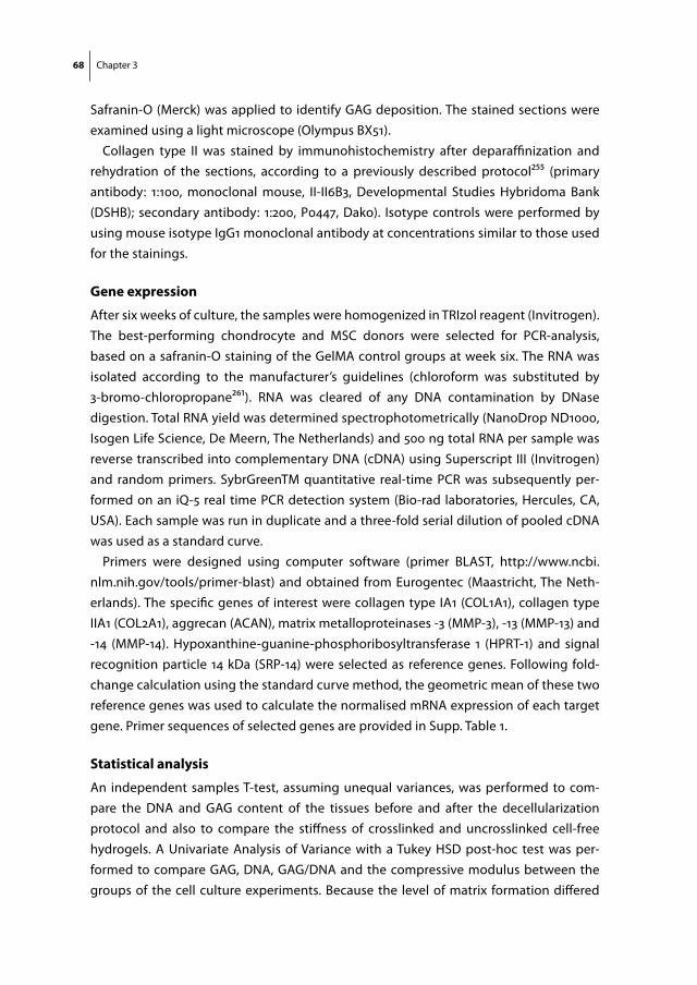
68 Chapter 3
Safranin-O (Merck) was applied to identify GAG deposition. The stained sections were examined using a light microscope (Olympus BX51).
Collagen type II was stained by immunohistochemistry after deparaffinization and rehydration of the sections, according to a previously described protocol255 (primary antibody: 1:100, monoclonal mouse, II-II6B3, Developmental Studies Hybridoma Bank (DSHB); secondary antibody: 1:200, P0447, Dako). Isotype controls were performed by using mouse isotype IgG1 monoclonal antibody at concentrations similar to those used for the stainings.
gene expression
After six weeks of culture, the samples were homogenized in TRIzol reagent (Invitrogen). The best-performing chondrocyte and MSC donors were selected for PCR-analysis, based on a safranin-O staining of the GelMA control groups at week six. The RNA was isolated according to the manufacturer’s guidelines (chloroform was substituted by 3-bromo-chloropropane261). RNA was cleared of any DNA contamination by DNase digestion. T otal RNA yield was determined spectrophotometrically (NanoDrop ND1000, Isogen Life Science, De Meern, The Netherlands) and 500 ng total RNA per sample was reverse transcribed into complementary DNA (cDNA) using Superscript III (Invitrogen) and random primers. SybrGreenTM quantitative real-time PCR was subsequently per-formed on an iQ-5 real time PCR detection system (Bio-rad laboratories, Hercules, CA, USA). Each sample was run in duplicate and a three-fold serial dilution of pooled cDNA was used as a standard curve.
Primers were designed using computer software (primer BLAST, http://www.ncbi.nlm.nih.gov/tools/primer-blast) and obtained from Eurogentec (Maastricht, The Neth-erlands). The specific genes of interest were collagen type IA1 (COL1A1), collagen type IIA1 (COL2A1), aggrecan (ACAN), matrix metalloproteinases -3 (MMP-3), -13 (MMP-13) and -14 (MMP-14). Hypoxanthine-guanine-phosphoribosyltransferase 1 (HPRT-1) and signal recognition particle 14 kDa (SRP-14) were selected as reference genes. Following fold-change calculation using the standard curve method, the geometric mean of these two reference genes was used to calculate the normalised mRNA expression of each target gene. Primer sequences of selected genes are provided in Supp. Table 1.
statistical analysis
An independent samples T-test, assuming unequal variances, was performed to com-pare the DNA and GAG content of the tissues before and after the decellularization protocol and also to compare the stiffness of crosslinked and uncrosslinked cell-free hydrogels. A Univariate Analysis of Variance with a Tukey HSD post-hoc test was per-formed to compare GAG, DNA, GAG/DNA and the compressive modulus between the groups of the cell culture experiments. Because the level of matrix formation differed

Crosslinkable hydrogels derived from tissue-derived matrices 69
significantly between the cell donors, a randomized block design was used, correcting for donor effects. GAG and DNA were normalized to the GelMA control group at week 4 for each separate cell donor; the compressive modulus was normalized to GelMA day 1. The statistical analyses were done using SPSS statistics (IBM, version 20). For the PCR data, Kruskal Wallis and Dunn’s multiple comparison post-hoc tests were used to test differences between experimental conditions for each primer pair using Graphpad soft-ware (Graphpad Prism version 5.2 for Windows). Differences were considered significant when P<0.05 for all tests.
results
decellularization procedure
The DNA content of the cartilage, meniscus and tendon tissues decreased significantly after decellularization, to values below 50 µg/mg dry weight (Fig. 2a). The DNA content was unaltered by the subsequent dialysis. The GAG content of all three tissues showed large variations between donors and/or sample location (Fig. 2b). Yet, the variation, as well as the absolute GAG content decreased considerably after the decellularization procedure and remained unaltered after dialysis. 58 ± 10% of methacrylated and decel-lularized material could be obtained from the original tissues (expressed in dry weight).
characterization of tissue-derived matrices
The decellularized cartilage, meniscus and tendon matrices were successfully digested with pepsin enzymes until clear or close to clear solutions were obtained. Short treat-ment of the tissue particles (cartilage) or fibers (meniscus and tendon) with pepsin resulted in viscous substances, whereas overnight treatment resulted in low-viscosity solutions. Overnight digestion was used to facilitate the methacrylation procedure. Gel electrophoresis showed that all digested tissues consisted of polymers with a molecular weight predominantly in the range of 130-300 kiloDaltons (kDa) (Fig. 3a). The profile of the collagen I solution reflects the collagen monomers (two subunits), dimers (two subunits) and trimers. This typical profile can also be observed in the tendon and menis-cus digests. The collagen type II control only displays monomers with one subunit. This single unit monomer can also be found in the cartilage digest. Successful methacrylation of the solutions was confirmed with NMR by the double peak that emerged between 5 and 6 ppm after methacrylation of all three tissue digests (Fig. 3b-g). Comparing the stiffness of methacrylated tissue digests (cartMA, menMA and tendMA) with GelMA and non-methacrylated tissue digests revealed significant variations (Fig. 4). CartMA was stiffer than all other groups (66.2 ± 11.9 kPa, P<0.05) and GelMA was stiffer (33.8 ± 6.5 kPa, P<0.05) compared to menMA (15.1 ± 5.4 kPa) and tendMA (11.4 ± 0.6 kPa). The

70 Chapter 3
figure 3. characterization of tissue-derived matrices. (a) Protein gel of tissue digests, collagen type I and II. (b-d) Nuclear Magnetic Resonance (NMR) of the tissue digests shows an inhomogeneous tissue profile after the decellularization procedure, reflecting the natural polymers. (e-g) The two peaks that ap-peared after methacrylation (shaded area, between 5-6 ppm) show the presence of vinyl protons, and con-firm the success of the methacrylation procedure.
0
100
200
300
400
500
600
Before decell After decell After dialysis
DN
A pe
r dry
tiss
ue
wei
ght (
µg/m
g)
Cartilage
Meniscus
Tendon
0
20
40
60
80
100
120
Before decell After decell After dialysis
GA
G p
er d
ry ti
ssue
w
eigh
t (µg
/mg)
Cartilage
Meniscus
Tendon
A
B
*
*
figure 2. the effect of the decellular-ization protocol on dna and glycos-aminoglycan (gag) content of equine cartilage, meniscus and tendon tis-sues. (a) The DNA content of all tissues was significantly reduced by the decellu-larization protocol. (b) The GAG content of all tissues directly after harvesting from the knee joint (before decell) shows large standard deviations, caused by donor and location variations. The subsequent decellularization procedure significantly reduced and standardized the GAG con-tents.
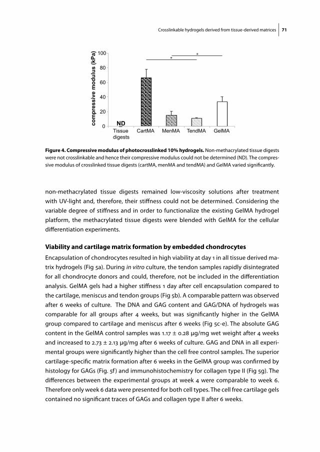
Crosslinkable hydrogels derived from tissue-derived matrices 71
non-methacrylated tissue digests remained low-viscosity solutions after treatment with UV-light and, therefore, their stiffness could not be determined. Considering the variable degree of stiffness and in order to functionalize the existing GelMA hydrogel platform, the methacrylated tissue digests were blended with GelMA for the cellular differentiation experiments.
Viability and cartilage matrix formation by embedded chondrocytes
Encapsulation of chondrocytes resulted in high viability at day 1 in all tissue derived ma-trix hydrogels (Fig 5a). During in vitro culture, the tendon samples rapidly disintegrated for all chondrocyte donors and could, therefore, not be included in the differentiation analysis. GelMA gels had a higher stiffness 1 day after cell encapsulation compared to the cartilage, meniscus and tendon groups (Fig 5b). A comparable pattern was observed after 6 weeks of culture. The DNA and GAG content and GAG/DNA of hydrogels was comparable for all groups after 4 weeks, but was significantly higher in the GelMA group compared to cartilage and meniscus after 6 weeks (Fig 5c-e). The absolute GAG content in the GelMA control samples was 1.17 ± 0.28 µg/mg wet weight after 4 weeks and increased to 2.73 ± 2.13 µg/mg after 6 weeks of culture. GAG and DNA in all experi-mental groups were significantly higher than the cell free control samples. The superior cartilage-specific matrix formation after 6 weeks in the GelMA group was confirmed by histology for GAGs (Fig. 5f ) and immunohistochemistry for collagen type II (Fig 5g). The differences between the experimental groups at week 4 were comparable to week 6. Therefore only week 6 data were presented for both cell types. The cell free cartilage gels contained no significant traces of GAGs and collagen type II after 6 weeks.
0
20
40
60
80
100
Tissuedigests
CartMA MenMA TendMA GelMA
com
pres
sive
mod
ulus
(kPa
)
ND
**
figure 4. compressive modulus of photocrosslinked 10% hydrogels. Non-methacrylated tissue digests were not crosslinkable and hence their compressive modulus could not be determined (ND). The compres-sive modulus of crosslinked tissue digests (cartMA, menMA and tendMA) and GelMA varied significantly.
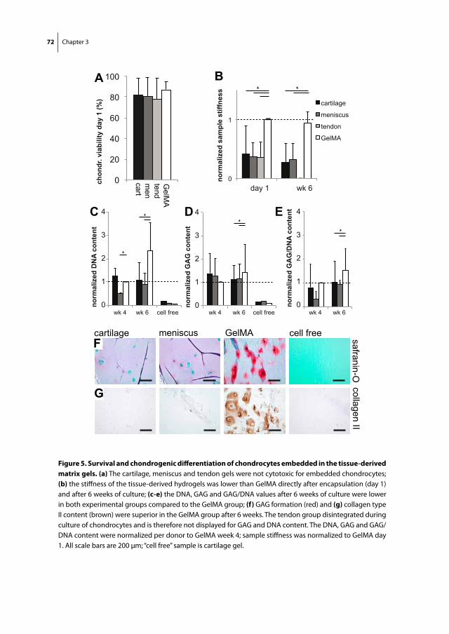
72 Chapter 3
0
1
day 1 wk 6
norm
aliz
ed s
ampl
e st
iffne
ss
cartilage
meniscus
tendon
GelMA
0
20
40
60
80
100
chon
dr. v
iabi
lity
day
1 (%
)
cart
GelM
Atendm
en
A
wk 4 wk 6 cell free
wk 4 wk 6 cell free
**
* *B
cartilage meniscus GelMA safranin-O
cell free
collagen II
F
G
*
0
1
2
3
4
norm
aliz
ed G
AG
/DN
A co
nten
t
wk 4 wk 6 0
1
2
3
4
norm
aliz
ed G
AG
con
tent
0
1
2
3
4
norm
aliz
ed D
NA
cont
ent
C D E*
figure 5. survival and chondrogenic differentiation of chondrocytes embedded in the tissue-derived matrix gels. (a) The cartilage, meniscus and tendon gels were not cytotoxic for embedded chondrocytes; (b) the stiffness of the tissue-derived hydrogels was lower than GelMA directly after encapsulation (day 1) and after 6 weeks of culture; (c-e) the DNA, GAG and GAG/DNA values after 6 weeks of culture were lower in both experimental groups compared to the GelMA group; (f) GAG formation (red) and (g) collagen type II content (brown) were superior in the GelMA group after 6 weeks. The tendon group disintegrated during culture of chondrocytes and is therefore not displayed for GAG and DNA content. The DNA, GAG and GAG/DNA content were normalized per donor to GelMA week 4; sample stiffness was normalized to GelMA day 1. All scale bars are 200 µm; “cell free” sample is cartilage gel.

Crosslinkable hydrogels derived from tissue-derived matrices 73
0
20
40
60
80
100
MSC
via
bilit
y da
y 1
(%)
cart
GelM
Atendm
en
A
C
norm
aliz
ed G
AG
con
tent
* *
0
1
2
3
day 1 wk 6
norm
aliz
ed s
ampl
e st
iffne
ss
B * *
cartilage meniscus tendon GelMA safranin-Ocollagen II
cell freeF
G
cartilage
meniscus
t endon
GelMA
* *
norm
aliz
ed D
NA
cont
ent
0
1
2
3
4
wk 4 wk 6 cell free 0
1
2
0
1
wk 4 wk 6 cell free wk 4 wk 6
norm
aliz
ed G
AG
/DN
A c
onte
nt
2 D E
figure 6. survival and chondrogenic differentiation of mscs embedded in the tissue-derived matrix gels. (a) The cartilage, meniscus and tendon gels were not cytotoxic for embedded MSCs; (b) directly after encapsulation of the MSCs (day 1), the stiffness of GelMA samples was highest; after 6 weeks of culture, Gel-MA as well as the tendon group were stiffer; (c-d) differences were observed in the DNA and GAG content of the experimental groups; (e) GAG/DNA content was higher in the cartilage and meniscus gels, although this difference was not statistically significant; (f) GAGs (red) and (g) collagen type II (brown) localization in all groups after 6 weeks. The DNA and GAG content were normalized per donor to GelMA week 4; sample stiffness was normalized to GelMA day 1. All scale bars are 200 µm; “cell free” sample is cartilage gel.

74 Chapter 3
Viability and cartilage matrix formation by embedded mscs
MSCs in all experimental groups retained a high viability one day after encapsulation in the hydrogels (Fig. 6a). The stiffness of GelMA gels was highest one day after encap-sulation of the MSCs (Fig. 6b). GelMA and tendon gels showed superior stiffness after 6 weeks of cell culture. The DNA content was higher in the tendon and GelMA gels com-pared to the cartilage and meniscus gels, both after 4 and 6 weeks of culture (Fig. 6c). A comparable amount of GAG was measured for all groups; only the cartilage gels had a statistically lower amount than the GelMA group (Fig. 6d). The absolute GAG content in the GelMA control samples was 3.48 ± 3.62 µg/mg wet weight after 4 weeks and 3.82 ± 4.38 µg/mg after 6 weeks of culture. The GAG/DNA values for the cartilage and meniscus gels were larger than found in the GelMA group (due to a lower DNA content in cartilage and meniscus gels), although these differences were not statistically significant. Staining of GAGs and collagen type II showed abundant cartilage-specific matrix formation by MSCs in all groups (Fig. 6f, g).
gene expression levels
The poor interaction of the chondrocytes with the various tissue cultures (Fig. 5) led to insufficient RNA yields in the cartilage and meniscus groups (the tendon group having disintegrated and not being available for that reason), so that the chondrocytes were
figure 7. gene expression by mscs in tissue-derived matrix gels. Gene expressions for aggrecan and collagen type II were similar in all hydrogels cultured with MSCs. Collagen I expression was higher in the cartilage hydrogel compared to meniscus. MMP-3 expression was similar in all cultures, whereas expression of MMP-13 and MMP-14 was lower in tendon gels compared to GelMA and cartilage respectively. Separate data points were presented (n=5) including the median and interquartile range.

Crosslinkable hydrogels derived from tissue-derived matrices 75
excluded from the gene expression analysis. In contrast, the RNA yields of MSCs were sufficient for all samples. ACAN, as well as COL2 expression was similar for all experimen-tal groups (Fig. 7). The expression of COL1A1 was significantly lower in meniscus than in cartilage gels. Catabolic enzyme MMP-13 and MMP-14 expression was significantly lower in the tendon group compared to GelMA and the cartilage group respectively. These were the only target genes for which a significant difference existed between the experimental conditions.
discussion
In this study, crosslinkable hydrogels were created, based on matrix derived from cartilage, meniscus and tendon tissues. These substrates allowed for the biological functionalization of the existing GelMA hydrogel system, in which they influenced the quantity and quality of matrix produced by embedded cells. All tissue types negatively influenced outcomes for chondrocytes, whereas encapsulated MSCs exhibited variable differentiation patterns, depending of the type of tissue the matrix gel was derived from.
To our knowledge, this is the first report in which decellularized tissues are covalently crosslinked into stable hydrogels. Previously, the Badylak group has derived hydrogels from the extracellular matrix of the dermis, urinary bladder and the central nervous system70,71,249. These hydrogels allowed for the infiltration and adhesion of cells and influenced their differentiation. In addition, hydrogels derived from heart, cartilage and adipose were recently shown capable of supporting tissue formation by embed-ded cells77. Analogous to our work, the hydrogels were obtained by pepsin digestion of the respective tissues. However, only physical crosslinking of the natural polymers was accomplished, resulting in considerable contraction of the hydrogel constructs during culture. This behavior is comparable to other natural polymer networks like collagen gels and fibrin glue27,262,263. The resulting shape instability, however, is unfavorable for the sustainable filling and regeneration of a tissue defect, especially for load-bearing tissues such as cartilage. We have now successfully overcome this issue by covalent crosslinking of the matrix-derived hydrogels through the addition of methacrylamide groups. These substrates were subsequently incorporated into GelMA hydrogel, because we aimed to further develop this versatile hydrogel, which was proven efficient for cartilage matrix formation by embedded cells60,63,255. The methacrylation procedure resulted in a very substantial increase in the compressive modulus, which was largest in the cartilage-derived matrix and of the same order of magnitude as occurring in the GelMA reference matrix. The methacrylation procedure can hence be considered as an important asset in the production of extracellular matrices for tissues that have to withstand biomechani-cal forces.

76 Chapter 3
The chondrogenic potential of MSCs in extracellular matrix gels was greater than that of chondrocytes. MSCs have previously shown capable of forming a cartilage specific matrix in 3D-hydrogel systems264. The quality and quantity of cartilaginous tissue formed by MSCs was found comparable to that of chondrocytes, although dependent of the type of hydrogel265. From our work we can conclude that equine MSCs thrive relatively well in GelMA gels. Nevertheless, chondrocytes from the different donors did show less donor variation than the MSCs, which is a known phenomenon for the latter cell type266. Still, MSCs are of great interest as an allogeneic cell source for the single-stage repair of cartilage tissue24. A limitation for the application of MSCs in vivo is that they require the addition of growth factors to be directed toward the chondrogenic lineage260. Recently, chondrocytes have shown capable of guiding MSC differentiation, and therefore, a co-culture of MSCs and chondrocytes holds promise for the repair of cartilage tissue 24.
The absolute GAG production by chondrocytes embedded in the GelMA hydrogels is similar to the amounts reported in previous in vitro studies60,63. However, a consis-tent negative effect of the incorporation of all three tissue-derived components was observed on the differentiation ofchondrocytes. This is in line with previous reports on the culture of chondrocytes on collagen matrices 74,251,252. Collagen type II matrix induces catabolic pathways in cultured in articular chondrocytes, including the upregulation of MMP-3, -13 and -14251,252. In addition, earlier work from our group showed poor GAG pro-duction of chondrocytes cultured on decellularized cartilage matrix scaffolds (collagen type II) and even accelerated degradation of the scaffolds74. In the current work, scaffold (i.e. hydrogel) disintegration was observed only for the tendon hydrogels (collagen type I), which may be a result of the catabolic activities of the chondrocytes, analogous to those observed in osteoarthritis267,268. Unfortunately, we were unable to analyze MMP expression by chondrocytes, since the tendon gels had disintegrated and RNA yield was too low in the cartilage and meniscus groups. In contradiction to these findings, successful cultures of chondrocytes were shown on synthetic collagen type I and II ma-trices269-272. The literature is thus inconclusive about the effect of collagen matrices on chondrocyte behavior, although the upregulation of inflammatory pathways has been clearly indicated.
In interpreting cell-matrix interactions, the difference between pure collagen scaffolds and tissue-derived matrices should be taken into account. In the latter, other matrix components, growth factors and/or signaling molecules may contribute to effects on cell behavior68,244. For example, it was shown that several growth factors were retained in decellularized bladder submucosa matrix273 and small intestinal submucosa matrix274. The decellularization protocol in the current study was relatively mild compared to previous studies67. Therefore, a panel of growth factors is likely to be retained within the matrix, although this was not specifically studied here. The main components of the tissue-derived matrices were shown to be collagens type I and II, the proportions
Crosslinkable hydrogels derived from tissue-derived matrices 77
depending on the original tissue. However, the exact biochemical composition of the polymers, for example the amount of available reactive amines to be methacrylated, remains unknown. As a result, the degree of methacrylation of the tissue-derived ma-trices was not controlled, and will hence vary between tissue types and tissue donors. This limitation should be taken into account during the interpretation of the responses of embedded cells.
The absence of trypsin as a protein-cleaving enzyme in the current protocol lead to the preservation of some of the GAGs (ca. 10%, compared to 0% when treated with trypsin74) while the DNA content could be decreased to acceptable standards, i.e, below 50 µg/mg dry tissue67. Chondrocytes probably benefit more from GAG- than collagen components in hydrogel cultures60,63. Therefore, the current outcomes could be improved by a modi-fied decellularization protocol, preserving still more GAGs.
For the chondrogenic differentiation of MSCs, our results show a slight preference for a collagen type I rich matrix (tendon gels) over collagen type II (cartilage gels). For example, MSCs proliferated more in tendon and GelMA gels and the sample stiffness was higher after culture, compared to meniscus and cartilage gels. In addition, MSCs in the tendon gels showed reduced expression of MMP-13 and -14, although gene expres-sion of cartilage-specific matrix genes was similar. Recently, Yang et al. also analyzed the effects of tendon-derived matrix on MSCs and found a reduced expression of collagen type I, which is considered a marker for inferior fibrocartilage formation263. The lowest GAG production by MSCs was observed in the cartilage matrix gels, along with a higher gene expression of collagen type I. Previous research however revealed a stimulatory effect of cartilage matrix on the chondrogenic differentiation of MSCs in vivo275,276. In ad-dition, other work showed that chondrogenesis of bovine MSCs was slightly enhanced in collagen type II compared to collagen type I gels277. It appears that certainly collagens influence the differentiation of MSCs, yet the optimal collagen composition still needs to be unraveled and will require specific tailoring for the target tissue to be engineered.
Further research should identify the specific biological cues in native tissues that are favorable to cells in tissue engineering. Unfortunately, the specific factors responsible for the cell behavior in decellularized tissues are still largely unknown. A better understand-ing of the native cell niche can guide the process of producing biomimetic materials.
conclusion
Crosslinkable hydrogels were created from cartilage, meniscus and tendon tissue through a process that included enzymatic digestion and methacrylation. The meth-acrylation procedure successfully increased the stiffness of these matrices, which is a critical factor in the manufacturing of scaffolds for use in musculoskeletal tissue repair.
78 Chapter 3
Moreover, a stable hydrogel platform was created by covalent incorporation of these tissue-derived matrices in versatile GelMA hydrogels. The response of embedded cells to these matrices depended on the cell type and the matrix components. Chondrocytes performed relatively poor in the tissue-derived matrix gels compared to the GelMA con-trol group. The chondrogenic differentiation capacity of MSCs was comparable across all hydrogels.
acKnowledgements
The authors would like to thank Karin van Leersum and Trudy van Ruiten for their as-sistance in the experimental work. The antibody against collagen type II (II-II6B3), devel-oped by T.F Linsenmayer, was obtained from the DSHB developed under the auspices of the NICHD and maintained by The University of Iowa, Department of Biology, Iowa City, IA 52242. Jetze Visser was supported by a grant from the Dutch government to the Netherlands Institute for Regenerative Medicine (NIRM, grant n°FES0908) and Jos Malda was supported by the Dutch Arthritis Foundation.
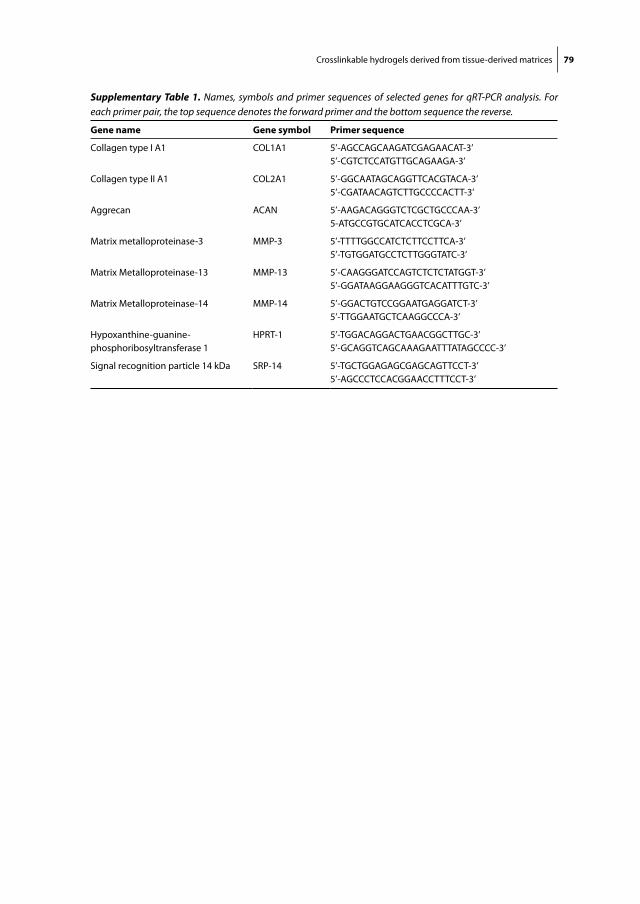
Crosslinkable hydrogels derived from tissue-derived matrices 79
Supplementary Table 1. Names, symbols and primer sequences of selected genes for qRT-PCR analysis. For each primer pair, the top sequence denotes the forward primer and the bottom sequence the reverse.
gene name gene symbol primer sequence
Collagen type I A1 COL1A1 5’-AGCCAGCAAGATCGAGAACAT-3’5’-CGTCTCCATGTTGCAGAAGA-3’
Collagen type II A1 COL2A1 5’-GGCAATAGCAGGTTCACGTACA-3’5’-CGATAACAGTCTTGCCCCACTT-3’
Aggrecan ACAN 5’-AAGACAGGGTCTCGCTGCCCAA-3’5-ATGCCGTGCATCACCTCGCA-3’
Matrix metalloproteinase-3 MMP-3 5’-TTTTGGCCATCTCTTCCTTCA-3’5’-TGTGGATGCCTCTTGGGTATC-3’
Matrix Metalloproteinase-13 MMP-13 5’-CAAGGGATCCAGTCTCTCTATGGT-3’5’-GGATAAGGAAGGGTCACATTTGTC-3’
Matrix Metalloproteinase-14 MMP-14 5’-GGACTGTCCGGAATGAGGATCT-3’5’-TTGGAATGCTCAAGGCCCA-3’
Hypoxanthine-guanine-phosphoribosyltransferase 1
HPRT-1 5’-TGGACAGGACTGAACGGCTTGC-3’5’-GCAGGTCAGCAAAGAATTTATAGCCCC-3’
Signal recognition particle 14 kDa SRP-14 5’-TGCTGGAGAGCGAGCAGTTCCT-3’5’-AGCCCTCCACGGAACCTTTCCT-3’

Chapter 4Endochondral Bone Formation in Gelatin Methacrylamide Hydrogel with embedded Cartilage-Derived Matrix Particles
Jetze VisserDebby GawlittaKim E.M. BendersSelynda M.H. TomaBehdad PouranP. René van WeerenWouter J.A. DhertJos Malda
Biomaterials. 2015 Jan;37:174-182
82 Chapter 4
aBstract
The natural process of endochondral bone formation in the growing skeletal system is increasingly inspiring the field of bone tissue engineering. However, in order to create relevant-size bone grafts, a cell carrier is required that ensures a high diffusion rate and facilitates matrix formation, balanced by its degradation. Therefore, we set out to engi-neer endochondral bone in gelatin methacrylamide (GelMA) hydrogels with embedded multipotent stromal cells (MSCs) and cartilage-derived matrix (CDM) particles. CDM particles were found to stimulate the formation of a cartilage template by MSCs in the GelMA hydrogel in vitro. In a subcutaneous rat model, this template was subsequently remodeled into mineralized bone tissue, including bone-marrow cavities. The GelMA was almost fully degraded during this process. There was no significant difference in the degree of calcification in GelMA with or without CDM particles: 42.5 ± 2.5 % vs. 39.5 ± 8.3 % (mean ± standard deviation), respectively. Interestingly, in an osteochondral setting, the presence of chondrocytes in one half of the constructs fully impeded bone forma-tion in the other half by MSCs. This work offers a new avenue for the engineering of relevant-size bone grafts, by the formation of endochondral bone within a degradable hydrogel.
Endochondral bone formation in GelMA hydrogel 83
introduction
Engineering bone through the endochondral pathway has gained increased attention over recent years259. This approach is based on our growing knowledge on the formation of long bones in the developing embryo278 and on the bone fracture healing process279. The formation of long bones starts with the condensation of mesenchymal stromal cells (MSCs), which then differentiate into chondrocytes. These chondrocytes secrete a cartilage-specific matrix, rich in collagen type II and glycosaminoglycans (GAGs). In a terminal hypertrophic differentiation process, the chondrocytes subsequently recruit a mixture of cells that is responsible for the ossification and vascularization of the cartilage template280. Thus, the hypertrophic chondrocyte is the director of the development of long bones in the human body.
Bone tissue engineering, however, has traditionally focused on mimicking the intra-membranous pathway281,282. This process is more straightforward than endochondral ossification and naturally occurs in, for example, the formation of the flat bones of the skull278. A major drawback to this approach for the repair of large bone defects is the limited size of the engineered tissues281. Large engineered bone constructs require rapid vascularization in order to provide cells in the core of the construct with sufficient oxygen and nutrients. A co-culture of osteogenic and vascular progenitor cells or the engineering of advanced prevascularized constructs may offer solutions185,281,283. Alter-natively, the endochondral approach could overcome this limitation as chondrocytes thrive well in hypoxic conditions284,285. Also, the natural healing of bone fractures relies on endochondral ossification within the fracture callus279. In this context, chondrogeni-cally pre-differentiated MSC aggregate cultures have shown capable of recapitulating the process of endochondral bone formation in vivo286-288. Moreover, these hypertrophic cell aggregates and cartilage grafts stimulated endochondral bone formation in seg-mental bone defects289,290.
To increase the size of the endochondral bone forming constructs, a scaffold may be required as a carrier for cells or cell aggregates, as recently shown for biodegradable polymer or organic scaffold materials288,291,292. We additionally developed cartilage-derived matrix (CDM), obtained by the decellularization of cartilage tissue69,74. Following this process, CDM consists of predominantly collagen type II, in the absence of GAGs and cells. Biochemical cues are supposedly retained in this decellularized biomaterial that can direct the differentiation of cells69. We have recently shown that these CDM scaffolds are suitable templates for in vitro cartilage matrix formation by seeding MSCs74. Nevertheless, hydrogels may be preferred over dry, (in)organic scaffolds, since their degradation profile is tailorable, biochemical cues can easily be incorporated to direct cell fate 79 and they allow for the fabrication of multiphasic constructs246,293.
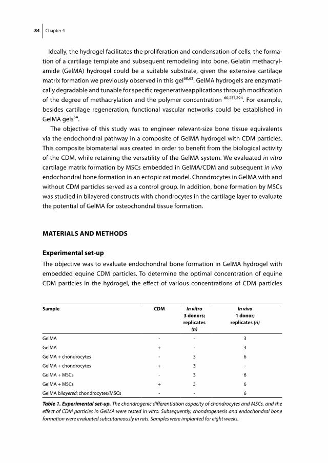
84 Chapter 4
Ideally, the hydrogel facilitates the proliferation and condensation of cells, the forma-tion of a cartilage template and subsequent remodeling into bone. Gelatin methacryl-amide (GelMA) hydrogel could be a suitable substrate, given the extensive cartilage matrix formation we previously observed in this gel60,63. GelMA hydrogels are enzymati-cally degradable and tunable for specific regenerativeapplications through modification of the degree of methacrylation and the polymer concentration 60,257,294. For example, besides cartilage regeneration, functional vascular networks could be established in GelMA gels64.
The objective of this study was to engineer relevant-size bone tissue equivalents via the endochondral pathway in a composite of GelMA hydrogel with CDM particles. This composite biomaterial was created in order to benefit from the biological activity of the CDM, while retaining the versatility of the GelMA system. We evaluated in vitro cartilage matrix formation by MSCs embedded in GelMA/CDM and subsequent in vivo endochondral bone formation in an ectopic rat model. Chondrocytes in GelMA with and without CDM particles served as a control group. In addition, bone formation by MSCs was studied in bilayered constructs with chondrocytes in the cartilage layer to evaluate the potential of GelMA for osteochondral tissue formation.
materials and methods
experimental set-up
The objective was to evaluate endochondral bone formation in GelMA hydrogel with embedded equine CDM particles. To determine the optimal concentration of equine CDM particles in the hydrogel, the effect of various concentrations of CDM particles
sample cdm In vitro3 donors;replicates
(n)
In vivo1 donor;
replicates (n)
GelMA - - 3
GelMA + - 3
GelMA + chondrocytes - 3 6
GelMA + chondrocytes + 3 -
GelMA + MSCs - 3 6
GelMA + MSCs + 3 6
GelMA bilayered: chondrocytes/MSCs - - 6
Table 1. Experimental set-up. The chondrogenic differentiation capacity of chondrocytes and MSCs, and the effect of CDM particles in GelMA were tested in vitro. Subsequently, chondrogenesis and endochondral bone formation were evaluated subcutaneously in rats. Samples were implanted for eight weeks.
Endochondral bone formation in GelMA hydrogel 85
on the GelMA mechanical properties was tested. Chondrogenesis was assessed as the cartilage-specific matrix formation by equine chondrocytes and MSCs in in vitro cultures for up to six weeks (Table 1). Both cell types were incorporated in GelMA with and without CDM particles (CDM + and CDM - respectively). After eight weeks of subcuta-neous implantation in rats, the same groups were evaluated for chondrogenesis and endochondral bone formation in vivo. In addition, bilayered samples were implanted to assess the effect of chondrocytes on the endochondral bone forming capacity by MSCs.
production of cdm particles
Full-thickness cartilage was harvested from cadaveric stifle joints (knee) of healthy equine donors (age 3-10 years) that had been euthanized for reasons other than joint disease, with consent of the owners. The cartilage was pooled and decellularized ac-cording to a protocol adapted from Benders et al.74. In short, after washing the cartilage slices in phosphate-buffered saline (PBS), they were snap-frozen in liquid nitrogen and lyophilized overnight. Then, cartilage was milled in liquid nitrogen (A11 basic analytical mill, IKA, Staufen, Germany) for a few minutes in order to increase exposure to the fol-lowing chemical treatments, which were all performed on a shaker plate at 2,000 rpm. The cartilage particles were treated with six cycles of 0.25% trypsin-EDTA (Invitrogen) at 37°C for 48 hours in total. The particles were then washed in PBS and underwent a 4-hour treatment with a nuclease solution of 50 U/ml deoxyribonuclease (Sigma) and 1 U/ml ribonuclease A (Sigma) in 10 mM Tris-HCl (pH 7.5), at 37°C. Next, the particles were treated with 10 mM hypotonic Tris-HCl for 20 hours followed by 1% (v/v) Triton X-100 in PBS for 24 hours, both at room temperature. The particles were thoroughly washed in PBS in 6 cycles for 48 hours in total, in order to remove all enzymatic agents. The suspen-sion of cartilage particles in PBS was lyophilized overnight and the pellet was milled again in liquid nitrogen and sieved through pores of 300 μm. The length and width of the CDM particles was measured from 2D light microscope images with ImageJ software (1.46r, National Institutes of Health, USA).
isolation of equine chondrocytes and multipotent stromal cells
Macroscopically healthy full-thickness cartilage was harvested under sterile conditions from the stifle joint of fresh equine cadavers (n=3, age 3-10 years) with consent of the owners. After fragmentation and overnight digestion in type II collagenase (Worthing-ton Biochemical Corp) at 37˚C, the suspension was filtered through a 100 μm cell strainer, washed in PBS and stored in liquid nitrogen at -196°C in culture medium (Dulbecco’s Modified Eagle Medium (DMEM) 41965, Invitrogen) supplemented with 20% heat-inacti-vated fetal bovine serum (FBS, Biowhittaker) and 10% dimethylsulfoxide (DMSO (Merck, Darmstadt, Germany)). Upon thawing, the chondrocytes were seeded at a density of 5× 10³ cells/cm2 and expanded for 10-12 days in a monolayer culture in chondrocyte
86 Chapter 4
expansion medium consisting of DMEM, 10% FBS, 100 units/ml penicillin and 100 µg/ml streptomycin (Invitrogen), and 10 ng/ml FGF-2 (R&D Systems) and embedded in GelMA at passage 1.
With approval of the local animal ethical committee, a bone marrow aspirate from the sternum was obtained from healthy, living equine donors (n=3, age 3-10 years). The mononuclear fraction (MNF) was isolated by centrifuging the sample on Ficoll-Paque (Sigma). The MNF was seeded at a density of 2.5×10⁵ cells/cm2 and expanded in a mono-layer culture till sub-confluency in MSC expansion medium containing a-MEM (22561, Invitrogen) complemented with 10% heat-inactivated FBS, 0.2 mM L-ascorbic acid 2-phosphate (Sigma), 100 units/ml penicillin and 100 µg/ml streptomycin, and 1 ng/ml FGF-2 and embedded in GelMA in passages 3-4.
The multilineage potential of the cells that were cultured from the bone marrow aspi-rate was investigated by a three-way differentiation assay as previously described74,260,295.
preparation of gelma with cdm particles and cells
GelMA was synthesized by reaction of porcine type A gelatin (Sigma-Aldrich, St. Louis, Missouri, USA) with methacrylic anhydride (Sigma-Aldrich) at 50 °C for one hour, as previously described60,62. In short, methacrylic anhydride was added dropwise to a 10% solution of gelatin in PBS under constant stirring. To achieve a high degree of functionalization, 0.6 g of methacrylic anhydride was added per gram of gelatin. The functionalized polymer was dialyzed against distilled water for 7 days at 40 °C to remove methacrylic acid and anhydride, neutralized to pH 7.4 with 10% sodium bicarbonate (Merck, Darmstadt, Germany), freeze-dried and stored at -20 °C until use. This protocol results in a degree of functionalization of circa 75% 60.
Defrosted GelMA was dissolved in PBS at 70°C at a concentration of 10% (w/v) con-taining a photoinitiator Irgacure 2959 (Ciba, BASF, Ludwigshafen am Rhein, Germany) at a final concentration of 0.1% (w/v). The CDM particles were mixed (in various con-centrations, see section 2.5) in the GelMA with a positive displacement pipet. Then chondrocytes or MSCs were suspended in the hydrogel at a concentration of 5×10⁶ cells/ml for the viability assay and at a concentration of 20×106 cells/ml for the in vitro and in vivo differentiation analyses. For mechanical analyses, cylindrical GelMA samples of 1.3 mm height and 8-9 mm diameter were UV-crosslinked at an intensity of 180 mW/cm2 (350-450 nm, Hönle UV technology, Munich, Germany). For all other assays, the cell- and CDM-laden GelMA was crosslinked for 15 minutes in a custom-made air-sealed Teflon mold (sample size ca. 8x8x2 mm) using 365nm light in a UVP CL-1000L crosslinker (UVP, Upland, California, USA).
Chondrocyte-laden samples were cultured in vitro in chondrogenic differentiation medium (DMEM (41965, Invitrogen) supplemented with 0.2 mM L-ascorbic acid 2-phos-phate, 0.5% human serum albumin (SeraCare Life Sciences), 1x ITS-X (Invitrogen), 100

Endochondral bone formation in GelMA hydrogel 87
units/ml penicillin and 100 µg/ml streptomycin, 25 mM 4-(2-hydroxyethyl)-1-piper-azineethanesulfonic acid (HEPES) (Invitrogen) and 5 ng/ml TGF-b2)) and MSC-laden samples were cultured in MSC chondrogenic differentiation medium (DMEM (31966, Invitrogen) supplemented with 0.2 mM L-ascorbic acid 2-phosphate, 1x ITS+ premix (BD Biosciences, USA), 0.1 µM dexamethasone (Sigma-Aldrich), 100 units/ml penicillin and 100 µg/ml streptomycin, and 10 ng/ml TGFb-2 (R&D Systems)). In vitro culture was done in three replicates per donor for 1 and 14 days for the viability assay and for four and six weeks for in vitro differentiation. Two weeks pre-culturing was performed for the in vivo differentiation study for chondrocytes and MSCs (each 1 donor). Bilayered GelMA samples were created by crosslinking a layer with chondrocytes onto a layer with MSCs in a double molding process (height: 2+2 mm), and pre-cultured for two weeks in 50/50 chondrocyte/MSC chondrogenic differentiation medium. This was done to assess the influence of chondrocytes on bone formation by MSCs in vivo.
sample stability and compression modulus
In order to find the maximum amount of CDM particles that can be incorporated in GelMA while maintaining a stable, crosslinked construct, CDM particles were mixed in the GelMA in concentrations of 1%, 1.5%, 2%, 3%, 4% and 5% (w/v). 100 µL GelMA/CDM mixtures without cells were photocrosslinked and maintained in chondrocyte differen-tiation medium at 37°C for 1 week, after which sample integrity was macroscopically assessed. In addition, the stiffness of these samples was measured at room temperature by unconfined compression with a dynamic mechanical analyzer (TA instruments, DMA 2980). A force increasing from 0-5 Newton at a rate of 0.5 N/min was applied to the surface of the samples (8-9 mm diameter). The displacement and applied force were recorded during the compression and converted to stress and strain based on the initial specimen dimensions. The stress–strain curve was plotted and the compression modu-lus was calculated from the slope of the linear part of this curve. Failure of a sample was defined as the sudden disintegration with a concomitant drop in stress.
Viability assay
To visualize cell viability, a LIVE/DEAD Viability Assay (Molecular Probes MP03224, Eu-gene, USA) was performed according to the manufacturer’s instructions. The samples were examined using an Olympus BX51 microscope and photomicrographs taken with an Olympus DP70 camera (both Olympus, The Netherlands). The excitation/emission filters were set at 488/530 nm to observe living (green) cells and at 530/580 nm to detect dead (red) cells. Live and dead cells were counted in 3 samples per time point, at four locations within each construct (chondrocytes and MSCs, both 1 donor). Viability was calculated as (alive cells / total cells counted) x 100 %.
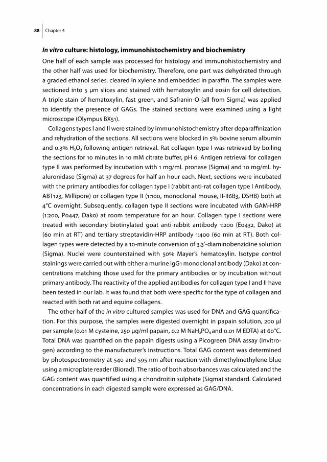
88 Chapter 4
In vitro culture: histology, immunohistochemistry and biochemistry
One half of each sample was processed for histology and immunohistochemistry and the other half was used for biochemistry. Therefore, one part was dehydrated through a graded ethanol series, cleared in xylene and embedded in paraffin. The samples were sectioned into 5 µm slices and stained with hematoxylin and eosin for cell detection. A triple stain of hematoxylin, fast green, and Safranin-O (all from Sigma) was applied to identify the presence of GAGs. The stained sections were examined using a light microscope (Olympus BX51).
Collagens types I and II were stained by immunohistochemistry after deparaffinization and rehydration of the sections. All sections were blocked in 5% bovine serum albumin and 0.3% H2O2 following antigen retrieval. Rat collagen type I was retrieved by boiling the sections for 10 minutes in 10 mM citrate buffer, pH 6. Antigen retrieval for collagen type II was performed by incubation with 1 mg/mL pronase (Sigma) and 10 mg/mL hy-aluronidase (Sigma) at 37 degrees for half an hour each. Next, sections were incubated with the primary antibodies for collagen type I (rabbit anti-rat collagen type I Antibody, ABT123, Millipore) or collagen type II (1:100, monoclonal mouse, II-II6B3, DSHB) both at 4°C overnight. Subsequently, collagen type II sections were incubated with GAM-HRP (1:200, P0447, Dako) at room temperature for an hour. Collagen type I sections were treated with secondary biotinylated goat anti-rabbit antibody 1:200 (E0432, Dako) at (60 min at RT) and tertiary streptavidin-HRP antibody 1:400 (60 min at RT). Both col-lagen types were detected by a 10-minute conversion of 3,3’-diaminobenzidine solution (Sigma). Nuclei were counterstained with 50% Mayer’s hematoxylin. Isotype control stainings were carried out with either a murine IgG1 monoclonal antibody (Dako) at con-centrations matching those used for the primary antibodies or by incubation without primary antibody. The reactivity of the applied antibodies for collagen type I and II have been tested in our lab. It was found that both were specific for the type of collagen and reacted with both rat and equine collagens.
The other half of the in vitro cultured samples was used for DNA and GAG quantifica-tion. For this purpose, the samples were digested overnight in papain solution, 200 µl per sample (0.01 M cysteine, 250 µg/ml papain, 0.2 M NaH2PO4 and 0.01 M EDTA) at 60°C. Total DNA was quantified on the papain digests using a Picogreen DNA assay (Invitro-gen) according to the manufacturer’s instructions. Total GAG content was determined by photospectrometry at 540 and 595 nm after reaction with dimethylmethylene blue using a microplate reader (Biorad). The ratio of both absorbances was calculated and the GAG content was quantified using a chondroitin sulphate (Sigma) standard. Calculated concentrations in each digested sample were expressed as GAG/DNA.

Endochondral bone formation in GelMA hydrogel 89
implantation and evaluation of samples in rats
The animal study was approved by the local Ethics Committee for Animal Experimenta-tion and was in compliance with the Institutional Guidelines on the Use of Laboratory Animals. Six 10 to 11-weeks old male athymic rats (Hsd:RH-Foxn1rnu Harlan Laboratories B.V., The Netherlands) were anesthetized with 1.5% isoflurane in oxygen. One dorsal pocket was created for each sample on the rats, in which the sample was placed with a forceps. Six pockets per animal were created and not more than one sample from a group was implanted per animal according to a randomized scheme. The skin was closed in one layer using Vicryl 4.0 sutures. Preoperatively and postoperatively, the animals received 0.05 mg/kg buprenorphine subcutaneously. The rats were housed solitary for one day postoperatively and afterwards in groups at the Central Laboratory Animal Institute of Utrecht University. The replicates in the experimental groups were divided over different rats (table 1). Three and six weeks after implantation, the animals received subcutaneously administered fluorochromes to monitor bone formation: 100 mg/kg xylenol orange and 10 mg/kg calcein green, respectively (both from Sigma) 296. Eight weeks after implantation, the rats were killed; the tibial bones from three rats and all subcutaneous samples were harvested and fixed in formalin.
rat study: X-ray and micro-ct
To screen for the existence of calcified tissue in different explants, the samples were imaged in a Faxitron® X-ray system, while immersed in formalin in a 24-Wells plate. A dose of 22 kV was applied for 12 seconds and the femur of the rats was taken along as a positive control. In order to quantify the degree of calcification accurately, the explants underwent micro-CT scans (Quantum FX- Perkin Elmer). The scan parameters were 90 kV tube voltage, 180 μA tube current, 40 μm resolution and 3 min scan time. Reconstruc-tion of 2D projections was automatically performed using the in-built software of the micro-CT while pre-processing (image calibration and noise reduction) of the images was undertaken with the aid of an Analyze-11.0 package. Local bone segmentation was performed to yield the total amount of calcified tissue for subsequent calculation of bone volume per total sample volume (BV/TV), i.e. degree of calcification. Redundant rat tissue in the images was manually eliminated prior to the segmentation step.
rat study: histology and immunohistochemistry
After 3D-imaging, the explants were split in two parts; one half of each sample was embedded in polymethylmethacrylate (MMA) and the other half was decalcified in ethylenediamine tetraacetic acid (EDTA) and embedded in paraffin. The paraffin samples underwent a safranin-O triple staining and collagen type I and II localization. In addition, a double staining of alcian blue and picrosirius red was performed to detect aligned collagenous structures. Tartrate-resistant acid phosphatase (TRAP) was stained to detect

90 Chapter 4
osteoclasts and macrophages. Slides were therefore incubated with 0.2 M acetate buffer – tartaric acid pH 5.0 for 20 minutes at room temperature. Then 25 mg Naphtol AS-MX phosphate (final concentration 0.5 mg/ml) and 55 mg fast red TR salt (final concentration 1.1 mg/ml) were added and incubation was continued until the osteoclasts were bright red (all products from Sigma). Samples were counterstained with Mayer’s hematoxylin.
MMA embedded samples were cut in 20-30 μm sections with a Leica 4 SP1600 Saw Microtome system (Leica, Germany). The sections were stained with methylene blue / basic fuchsine and evaluated with light microscopy. In addition, the presence of fluoro-chromes was assessed from unstained sections.
statistical analysis
The stiffness of GelMA constructs with various concentrations of CDM particles was analyzed with an ANOVA followed by Bonferroni post-hoc correction (SPSS statistics (IBM software)). To evaluate the in vitro differentiation of MSCs and chondrocytes separately, a one-way ANOVA was performed in a randomized block design to correct for donor variability. A Bonferroni post-hoc test was applied. An independent T-test, assuming un-equal variances, was performed to compare the degree of calcification in vivo between GelMA with and without CDM particles. A p-value <0.05 was considered significant.
results
characterization of gelma with cdm particles
The size of the generated CDM particles as measured in a 2D plane was 400 ± 167 by 179 ± 62 µm. GelMA samples with a concentration of 2% or more (w/v) of these CDM par-ticles disintegrated in culture medium after a week. In addition, a maximum stiffness of the CDM/GelMA samples, without cells, was found when a concentration of 1 to 1.5% of CDM particles was incorporated (Fig. 1a). These samples exhibited a higher compressive modulus compared to the GelMA samples without particles (p = 0.000) and compared to higher concentrations of 2-4% CDM particles (p = 0.002). All samples with 0-4% CDM particles remained intact during compression, only samples with 5% (w/v) CDM particles disintegrated at a force of 2.8 ± 0.4 N. A concentration of 1.5 % CDM particles was chosen for cellular differentiation experiments in order to achieve a maximal biologic effect of the particles on the encapsulated cells without sample disintegration over the course of culture. The particles were equally distributed throughout the GelMA as observed with stereomicroscopy (Fig. 1b). Histology on cross-sections of these samples showed that CDM particles consisted predominantly of collagen type II (Fig. 1C) and did not contain any residual cells (as confirmed by H&E-staining; Fig. 1D) nor GAGs (as observed in the safranin-O stained sections; Fig. 1e).

Endochondral bone formation in GelMA hydrogel 91
Viability of mscs and chondrocytes
The viability of equine chondrocytes and MSCs in GelMA ranged between 71-96% after 1 and 14 days of culture and was not significantly affected by the co-incorporation of 1.5% CDM particles (Fig. 2a).
In vitro cartilage tissue formation
MSCs produced significantly more GAG/DNA in GelMA with CDM particles compared to without after 6 weeks of in vitro culture (15.7 ± 3.5 vs. 11.3 ± 3.6 mg/mg (p = 0.010)) (Fig. 2b). Chondrocytes and MSCs produced a comparable amount of GAG/DNA in GelMA without CDM after 6 weeks. Noteworthy, GAG production by chondrocytes was negatively affected by co-embedding of CDM particles in GelMA after 4 weeks (4.8 ± 1.9 vs. 8.2 ± 1.7 mg/mg (p = 0.011)) and 6 weeks (5.2 ± 3.9 vs. 12.1 ± 6.0 mg/mg (p = 0.000)). Histological observations confirmed these quantitative findings by showing superior GAG and collagen type II matrix formation by chondrocytes in GelMA/CDM- (Fig. 2c, d) compared to GelMA/CDM+ (Fig. 2e, f ). MSCs formed abundant cartilage-specific matrix in GelMA/CDM- (Fig. 2g, h) and GelMA/CDM+ samples (Fig. 2i, j). GAG deposition in GelMA by MSCs was more clustered compared to a homogeneously spread matrix produced by chondrocytes.
figure 1. mechanical testing and imaging of gelma hydrogel with embedded cdm particles. (a) A significant increase of GelMA stiffness was observed when 1-1.5% CDM par-ticles were incorporated vs. no CDM particles or a higher particle concentration (**p < 0.01). Samples with 5% CDM particles disintegrated during the compression test. (b) CDM particles (1.5% (w/v)) were divided equally through the GelMA sample as observed with stereomicros-copy; (c) all CDM particles were positive for collagen type II; (d) no remaining cells (H&E staining) or (e) GAGs (Safranin-O staining) were detected. All scale bars represent 500 µm.
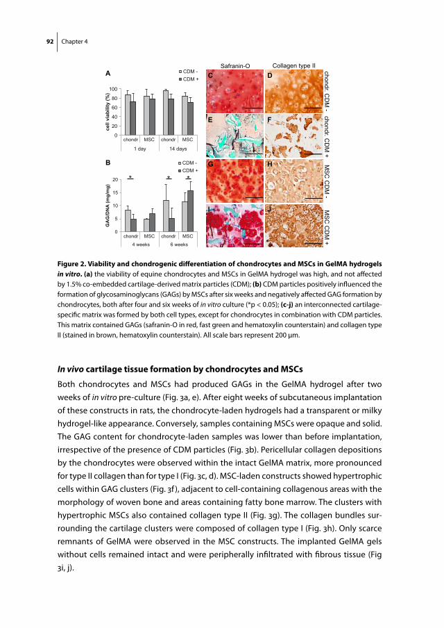
92 Chapter 4
In vivo cartilage tissue formation by chondrocytes and mscs
Both chondrocytes and MSCs had produced GAGs in the GelMA hydrogel after two weeks of in vitro pre-culture (Fig. 3a, e). After eight weeks of subcutaneous implantation of these constructs in rats, the chondrocyte-laden hydrogels had a transparent or milky hydrogel-like appearance. Conversely, samples containing MSCs were opaque and solid. The GAG content for chondrocyte-laden samples was lower than before implantation, irrespective of the presence of CDM particles (Fig. 3b). Pericellular collagen depositions by the chondrocytes were observed within the intact GelMA matrix, more pronounced for type II collagen than for type I (Fig. 3c, d). MSC-laden constructs showed hypertrophic cells within GAG clusters (Fig. 3f ), adjacent to cell-containing collagenous areas with the morphology of woven bone and areas containing fatty bone marrow. The clusters with hypertrophic MSCs also contained collagen type II (Fig. 3g). The collagen bundles sur-rounding the cartilage clusters were composed of collagen type I (Fig. 3h). Only scarce remnants of GelMA were observed in the MSC constructs. The implanted GelMA gels without cells remained intact and were peripherally infiltrated with fibrous tissue (Fig 3i, j).
chondr. CD
M -
Collagen type IISafranin-O
MS
C C
DM
-chondr. C
DM
+M
SC
CD
M +
0
5
10
15
20
4 weeks 6 weeks
GA
G/D
NA
(mg/
mg)
0
20
40
60
80
100
CDM - CDM +
1 day 14 days
cell
viab
ility
(%)
chondr MSC
*
A
B
C D
E F
G H
I J
chondr MSC
chondr MSC chondr MSC
CDM - CDM +
* *
figure 2. Viability and chondrogenic differentiation of chondrocytes and mscs in gelma hydrogels in vitro. (a) the viability of equine chondrocytes and MSCs in GelMA hydrogel was high, and not affected by 1.5% co-embedded cartilage-derived matrix particles (CDM); (b) CDM particles positively influenced the formation of glycosaminoglycans (GAGs) by MSCs after six weeks and negatively affected GAG formation by chondrocytes, both after four and six weeks of in vitro culture (*p < 0.05); (c-j) an interconnected cartilage-specific matrix was formed by both cell types, except for chondrocytes in combination with CDM particles. This matrix contained GAGs (safranin-O in red, fast green and hematoxylin counterstain) and collagen type II (stained in brown, hematoxylin counterstain). All scale bars represent 200 µm.

Endochondral bone formation in GelMA hydrogel 93
In vivo endochondral bone formation by mscs: histology and ihc
Endochondral bone formation in the gels containing MSCs was more specifically studied. Complete cross-sections of the samples revealed central GAG clusters that co-localized with collagen type II positive areas (Fig. 4a, b); remnants of CDM particles were not detected. Collagen type I positive areas were located peripherally to the central carti-lage clusters (Fig. 4c). A comparable localization of woven bone was revealed by basic fuchsin on MMA embedded samples (Fig. 4d). Collagen (type I) bundles were identified throughout the constructs with polarized light on picro-sirius red stained slides (Fig. 4e, f ). Fluorescent dyes were retained in the samples in a diffuse pattern and there was no uniform direction of bone growth (i.e. inward or outward) (Fig. 4g). A clear outward, appositional bone growth was observed in the rat tibia that was taken along as a control (Fig. 4h). Multinucleated, TRAP-positive osteoclasts (red) were found adjacent to areas rich in collagen type I (Fig. 4i).
safranin-O safranin-O collagen type Icollagen type II
chon
drocytes
in G
elM
A
MSC
sin
Gel
MA
2 weeks pre-culturing 8 weeks subcutaneous implantation
A B C D
E
cell-free
Gel
MA
I J
F HG
figure 3. In vitro and in vivo chondrogenic differentiation of chondrocytes and mscs in gelma hydro-gels. a) chondrocytes secreted glycosaminoglycans (GAGs: red) after 2 weeks of in vitro pre-culture; b) the content of GAGs was lower after eight weeks of subsequent subcutaneous implantation in rats; pericellular deposition of collagen types II (c) and I (d) were observed. (e) Abundant GAG production by MSCs before implantation; (f) hypertrophic cells were observed within GAG clusters (red, dashed line) after implanta-tion, adjacent to fatty bone marrow (white), hematopoietic bone marrow, and bone (intense green, black line); (g) hypertrophic cells were located within collagen type II clusters (brown, dashed line); (h) collagen type I (brown, black line) was located between the hypertrophic cell clusters (dashed line) and the fatty bone marrow. No effect of the presence of CDM particles on histological outcome was observed after im-plantation. Therefore, only the groups without CDM particles are presented. (i,j) GelMA samples without cells remained intact in vivo with peripheral infiltration of host tissue. All scale bars represent 100 µm.
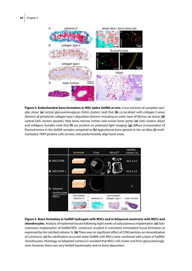
94 Chapter 4
1000μm
safranin-O
collagen type II
collagen type I
alcian blue / picro-sirius red
basic fuchsin
A
B
C
D
E
I
G H
E F
non-
pola
rized
pola
rized
fluorochromes
Gel
MA
-MS
C
tibia
TRAP
50μm
200μm
100μm
200μm
figure 4. endochondral bone formation in msc-laden gelma in vivo. Cross-sections of complete sam-ples show: (a) central glycosaminoglycan (GAG) clusters (red) that (b) co-localized with collagen II areas (brown); c) peripheral collagen type I deposition (brown) including an outer layer of fibrous rat tissue; (d) central GAG clusters (purple), fatty bone marrow (white) and woven bone (pink); (e) GAG clusters (blue) and collagens bundles (red) that (f) are positive on polarized light imaging; (g) diffuse incorporation of fluorochromes in the GelMA samples compared to (h) appositional bone growth in the rat tibia; (i) multi-nucleated, TRAP positive cells (arrows, red) predominantly align bone areas.
X-ray MicroCT
A. MSC/CDM -
B. MSC/CDM +
bilayered
chondrocytes
MSCs
39.5 ± 8.3
43.5 ± 2.5
0
schematic calcifiedvolume (%)
safranin-O safranin-O basic fuchsin
C.
5 mm
collagen type I
5 mm
post-implantpre-implant
figure 5. Bone formation in gelma hydrogels with mscs and in bilayered constructs with mscs and chondrocytes. Analysis of explanted tissues following eight weeks of subcutaneous implantation. (a) Sub-cutaneous implantation of GelMA/MSC constructs resulted in consistent mineralized tissue formation as expressed by the calcified volume-%. (b) There was no significant effect of CDM particles on mineralization of constructs. (c) No calcification occurred when GelMA with MSCs were combined with a layer of GelMA/chondrocytes. Histology on bilayered constructs revealed that MSCs still cluster and form glycosaminogly-cans; however, there was very limited hypertrophy and no bone deposition.

Endochondral bone formation in GelMA hydrogel 95
In vivo endochondral bone formation by mscs: X-ray and micro-ct
Radiographic examination revealed a high degree of calcification in all MSC samples with and without CDM particles in a 2D plane (Fig. 5a and b). The calcified volume fraction in the MSC-containing samples, as calculated from the 3D micro-CT images, was 39.5 ± 8.3 for CDM- and 42.5 ± 2.5 for CDM+ (p = 0.503). Mineral depositions were most abundant in the periphery of the samples, although scattered calcifications could be observed in the central regions. No calcifications were detected in any of the chondrocyte or the bilay-ered MSC/chondrocyte samples (Fig. 5c). The MSCs in the bilayered constructs did form GAG clusters, however, there was a very limited degree of hypertrophy and a complete absence of bone and bone marrow formation.
discussion
MSCs have previously been shown capable of mimicking the natural process of en-dochondral bone formation286-292. In several of these studies, aggregated MSCs were cultured and subsequently implanted. Cell aggregates constitute an attractive culture model as the condensation of cells, as a first step in endochondral bone formation, is per definition achieved. Also, cartilage grafts that are derived from fracture callus have shown to be a successful matrix for bone formation in orthotopic locations 290. Engineer-ing of larger tissues, however, requires a scaffold to carry cartilage grafts, cell aggregates or separate cells. Recent work showed that pre-differentiated MSCs seeded on a porous copolymer scaffold were capable of bridging large bone defects in rats291. However, the exclusiveness of the endochondral route to bone formation was not evident in these experiments, and was likely combined with intramembranous bone regeneration.
Alternatively, choosing a biomaterial that more closely mimics the properties of the natural (starting) tissue may favor endochondral bone regeneration. GelMA hydrogel is a suitable scaffold for the formation of a cartilage matrix by embedded cell 60,63. In the present study, the aqueous hydrogel environment allowed for clustering of MSCs and chondrogenic matrix production. In comparison, a more homogeneous distribution of cells and matrix was observed in chondrocyte-laden gels. Prior to subcutaneous implan-tation, the constructs were cultured in chondrogenic medium for two weeks, which is short compared to previous studies on in vivo endochondral bone formation286-288,292. The cartilage matrix clusters formed by MSCs in GelMA appear to be an attractive tem-plate for endochondral bone formation in a subcutaneous rat model. The newly formed matrix accounted for the integrity of the constructs, since the GelMA was almost fully degraded. This confirmed the unique degradation behavior of GelMA as a cell carrier in regenerative medicine, for which the degradation of the biomaterial should be balanced to the formation of neo-tissue.
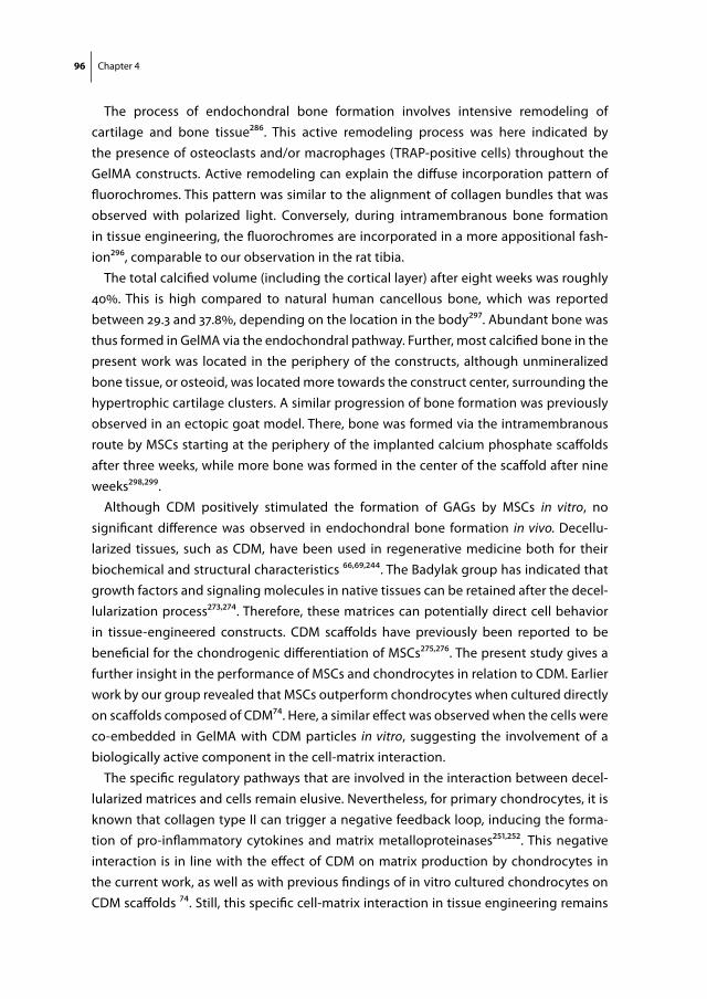
96 Chapter 4
The process of endochondral bone formation involves intensive remodeling of cartilage and bone tissue286. This active remodeling process was here indicated by the presence of osteoclasts and/or macrophages (TRAP-positive cells) throughout the GelMA constructs. Active remodeling can explain the diffuse incorporation pattern of fluorochromes. This pattern was similar to the alignment of collagen bundles that was observed with polarized light. Conversely, during intramembranous bone formation in tissue engineering, the fluorochromes are incorporated in a more appositional fash-ion296, comparable to our observation in the rat tibia.
The total calcified volume (including the cortical layer) after eight weeks was roughly 40%. This is high compared to natural human cancellous bone, which was reported between 29.3 and 37.8%, depending on the location in the body297. Abundant bone was thus formed in GelMA via the endochondral pathway. Further, most calcified bone in the present work was located in the periphery of the constructs, although unmineralized bone tissue, or osteoid, was located more towards the construct center, surrounding the hypertrophic cartilage clusters. A similar progression of bone formation was previously observed in an ectopic goat model. There, bone was formed via the intramembranous route by MSCs starting at the periphery of the implanted calcium phosphate scaffolds after three weeks, while more bone was formed in the center of the scaffold after nine weeks298,299.
Although CDM positively stimulated the formation of GAGs by MSCs in vitro, no significant difference was observed in endochondral bone formation in vivo. Decellu-larized tissues, such as CDM, have been used in regenerative medicine both for their biochemical and structural characteristics 66,69,244. The Badylak group has indicated that growth factors and signaling molecules in native tissues can be retained after the decel-lularization process273,274. Therefore, these matrices can potentially direct cell behavior in tissue-engineered constructs. CDM scaffolds have previously been reported to be beneficial for the chondrogenic differentiation of MSCs275,276. The present study gives a further insight in the performance of MSCs and chondrocytes in relation to CDM. Earlier work by our group revealed that MSCs outperform chondrocytes when cultured directly on scaffolds composed of CDM74. Here, a similar effect was observed when the cells were co-embedded in GelMA with CDM particles in vitro, suggesting the involvement of a biologically active component in the cell-matrix interaction.
The specific regulatory pathways that are involved in the interaction between decel-lularized matrices and cells remain elusive. Nevertheless, for primary chondrocytes, it is known that collagen type II can trigger a negative feedback loop, inducing the forma-tion of pro-inflammatory cytokines and matrix metalloproteinases251,252. This negative interaction is in line with the effect of CDM on matrix production by chondrocytes in the current work, as well as with previous findings of in vitro cultured chondrocytes on CDM scaffolds 74. Still, this specific cell-matrix interaction in tissue engineering remains
Endochondral bone formation in GelMA hydrogel 97
a remarkable phenomenon, since chondrocytes naturally reside in a collagen type II matrix in articular cartilage. Chondrocytes may require their natural pericellular collagen type VI matrix for differentiation in decellularized cartilage matrices300, or the collagen type II is too degraded for the cells to consider it a healthy template to form cartilage, whereas MSCs with a more regenerative nature might in fact be triggered to remodel and deposit new healthy tissue.
We showed that endochondral bone formation in MSC-seeded GelMA was fully sup-pressed in layered GelMA constructs with chondrocytes in the adjacent layer. This was a more rigorous effect compared to bi-layered cultures in agarose gels, in which partial suppression of mineralization was found293. The proposed underlying mechanism is the production of parathyroid hormone-related protein by chondrocytes, which inhibits hypertrophy of MSCs301. Although this finding is unsatisfactory for osteochondral tissue engineering, the suppression of bone formation is encouraging for the field of cartilage tissue engineering, which explores MSCs as an allogeneic cell source for the single-stage repair of articular cartilage6. To this end, co-cultures of bone marrow-derived MSCs and articular chondrocytes have been shown beneficial for cartilage matrix formation24. In this light, GelMA would be a potential carrier for a co-culture of MSCs and chondrocytes, regarding the abundant matrix formation by both cell types separately and the fact that chondrocytes in this hydrogel can prevent bone formation by MSCs.
Future work will evaluate the bone forming capacities of the current constructs in orthotopic locations. The construct size displayed here is large enough for the repair of segmental bone defects in rodents; however, scale-up is required to reach relevant dimensions for clinical application in humans. Therefore, it should be investigated what is the upper size limit for the solid GelMA constructs, regarding diffusion limitations. Al-ternatively, large, porous MSC-laden constructs can be 3D-printed, as GelMA is a proven effective bio-ink for 3D bioprinting of cartilaginous constructs72,190. In addition, GelMA may serve as a carrier for hypertrophic cell aggregates, since these have demonstrated capable of forming a bony bridge in segmental bone defects in rats289. However, encap-sulation of single MSCs in the GelMA/CDM constructs, as was done in the current work, may be a more straightforward approach to the repair of bone defects.
conclusion
The process of endochondral bone formation was recapitulated by MSCs in GelMA hydrogels in an ectopic rat model, irrespective of the co-incorporation of CDM particles. The formation of bone was based on a cartilage template in the hydrogel that was formed by the MSCs in vitro within two weeks. A large amount of mineralized bone including bone marrow cavities was subsequently formed in vivo, surrounding hyper-

98 Chapter 4
trophic cartilage clusters. A major fraction of the GelMA hydrogel carrier was degraded in this process. Chondrocytes fully inhibited in vivo bone formation by MSCs in bilayered GelMA constructs. The current work forms a good starting point for the engineering of relevant-size endochondral bone constructs in the versatile GelMA hydrogel system.
acKnowledgements
The authors would like to thank Kristel Boere for her assistance with the mechanical testing and Mattie van Rijen for his assistance in fluorescent microscope imaging. The antibody against collagen type II (II-II6B3), developed by T.F Linsenmayer, was obtained from the DSHB developed under the auspices of the NICHD and maintained by The Uni-versity of Iowa, Department of Biology, Iowa City, IA 52242. Jetze Visser was supported by a grant from the Dutch government to the Netherlands Institute for Regenerative Medicine (NIRM, grant n°FES0908); DG was supported by a VENI fellowship (11208) from the Dutch Technology Foundation, STW, Applied Science Division of NWO and the Tech-nology Program of the Ministry of Economic Affairs. Kim Benders received an Alexandre Suerman Stipendium from the University Medical Center Utrecht and Jos Malda was supported by the Dutch Arthritis Foundation.


Part 2

Part 2Mechanical Improvement of GelMA Hydrogel Constructs with 3D-Printed Scaffolds

Chapter 5Covalent Attachment of a Three-Dimensionally Printed Thermoplast to a Gelatin Hydrogel for Mechanically Enhanced Cartilage Constructs
Kristel W.M. Boere*
Jetze Visser*
Hajar SeyednejadSima RahimianDebby GawlittaMies J. van SteenbergenWouter J.A. DhertWim E. HenninkTina Vermonden Jos Malda
*Authors contributed equally to this manuscript
Acta Biomaterialia. 2014 Jun;10(6):2602-11
104 Chapter 5
aBstract
Hydrogels can provide a suitable environment for tissue formation by embedded cells, allowing its application in regenerative medicine. However, hydrogels only pos-sess limited mechanical strength and have therefore been reinforced for application in load-bearing conditions. In most approaches the reinforcing component and the hydrogel network have poor interactions and the synergetic effect of both materials on the mechanical properties is not effective. Therefore, in the present study, a ther-moplastic polymer blend of poly(hydroxymethylglycolide-co-ε-caprolactone)/poly(ε-caprolactone) (pHMGCL/PCL) was functionalized with methacrylate groups (pMHMGCL/PCL) and covalently grafted to gelatin methacrylamide (GelMA) hydrogel through photopolymerization. The grafting resulted in an at least 5x increased interface-binding strength between the hydrogel and thermoplastic polymer material. GelMA constructs were reinforced with 3D printed pHMGCL/PCL and pMHMGCL/PCL scaffolds and tested in a model for a focal articular cartilage defect. In this model, covalent bonds at the in-terface of both materials resulted in constructs with an improved resistance to repeated axial and rotational forces. Moreover, chondrocytes embedded within the constructs were able to form cartilage-specific matrix both in vitro and in vivo. Thus, by grafting the interface of different materials, stronger hybrid cartilage constructs can be engineered.

Stronger constructs with hydrogel-thermoplast attachement 105
introduction
Hydrogels consist of hydrophilic polymer networks that are able to hold large amounts of water in a three-dimensional (3D) structure, while maintaining their shape104,302. Thereby they can provide a 3D aqueous environment to embedded cells, analogous to the extra-cellular matrix of natural tissues29,303. For tissue engineering purposes, stem cells304,305, tissue specific cells306 and/or bioactive factors111,231,304 can be incorporated in the tempo-rary hydrogel scaffold to direct specific tissue regeneration29,293. By doing so, hydrogel systems have already been clinically applied for regeneration of a range of tissue types including skin, blood vessels, neural tissues and cartilage11,29. Unfortunately, hydrogels have limited mechanical strength due to their high water content115,307, which may result in construct failure of the hydrogel under mechanically challenging conditions, as found in the load-bearing bone and cartilage tissues. One approach to overcome this limita-tion is by stimulation of extracellular matrix formation of the cells prior to implantation, resulting in a stiffer implant60. However, this requires long in vitro preconditioning peri-ods, limiting clinical translation. The most straightforward approach to directly enhance the stiffness and strength of a hydrogel is by increasing its polymer concentration and crosslinking density171,246. Nevertheless, this also impacts the diffusion rates of bioactive factors, nutrients and cell metabolites through the hydrogel, thereby most likely also the regenerative capacities of embedded cells104,121,246. Therefore, alternative strategies have been explored to increase the strength of hydrogel constructs, e.g. through cre-ation of interpenetrating polymer networks (IPNs)183,195-197,308 or incorporation of solid particles309-311 and nanofibers/nanotubes312-314. Mechanical properties of hydrogels can also be improved by integrating a secondary scaffold material, such as fiber mats315-317, randomly organized porous polylactic acid scaffolds 318,319 non-woven meshes 320 or electrospun polymer networks55,56,203,321,322. Moreover, with advances in biofabrication techniques, a rigid thermoplastic polymer network can be fabricated layer-by-layer, along with the hydrogel construct65,75,76,190,201,323 allowing for a tailored reinforcement of hydrogels. In addition, when mechanical stability is provided by this secondary rigid network, hydrogels with a lower crosslink density can be processed65, which is beneficial for the viability and proliferation capacity of embedded cells79,104,121,246. Besides, reinforc-ing the cell-laden hydrogel with a secondary scaffold material may also reduce the often-experienced swelling or shrinking of the hydrogel-based implant that can lead to imperfect filling of the tissue defect324.
In the present generation of constructs, however, the reinforcing network and the hydrogel show insufficient adhesion, mostly because of their different physicochemical properties76,325, which leads to construct disintegration upon application of mechanical stresses. Hence, the introduction of chemical bonds between both components may

106 Chapter 5
improve the construct strength to withstand the challenging mechanical conditions in the musculoskeletal system.
Therefore, this study aims to mechanically enhance cartilage implants by grafting a hydrogel to a 3D-fabricated biodegradable thermoplastic polymer network. To achieve this, the polyester poly(hydroxymethylglycolide-co-ε-caprolactone) (pHMGCL326) was functionalized with methacryl groups coupled to the hydroxyl side groups of this polymer. In previous studies, we have shown that pHMGCL is more hydrophilic than e.g. poly-ε caprolactone (PCL) due to the presence of the pendant hydroxyl groups326, fa-cilitating cell attachment, matrix deposition327 and resulting in an increased degradation rate328. Thereby, pHMGCL is more likely to balance its degradation to the formation of neo-tissue50, compared to PCL65,75,76. However, pHMGCL containing more than 20% HMG is an amorphous polymer with a low glass transition temperature (Tg) and therefore has low dimensional stability. PCL, on the other hand, is semi-crystalline, which is beneficial for dimensional stability, but has no reactive groups to allow for example surface graft-ing. To increase the dimensional stability of pHMGCL, it can be blended with PCL329. The blending also improves the physical properties of the material for scaffold fabrication techniques such as electrospinning330 and 3D fiber deposition (3DF)327.
In the present study, covalent binding between methacrylated pHMGCL (pMHMGCL) blended with PCL and a methacrylated gelatin hydrogel (GelMA) through photopoly-merization was investigated. The interface-binding strength between GelMA and pMH-MGCL/PCL was studied and reinforced constructs as fabricated with 3DF were tested
figure 1. overview of the performed experiments in the present study. Poly(hydroxymethylglycolide-co-ε-caprolactone) pHMGCL, methacrylate-functionalized pHMGCL (pMHMGCL) and their corresponding blends with poly-ε caprolactone (MA- and MA+ respectively) were characterized with NMR, DSC and GPC. Reinforced constructs of MA- and MA+ with methacrylated gelatin (GelMA) were UV-irradiated and the interface-binding strength and strength of the reinforced construct was tested. Constructs of MA+/GelMA were further tested in vitro and in vivo for cartilage specific matrix production. All mechanical, in vitro and in vivo experiments were performed in quadruplicate.
Stronger constructs with hydrogel-thermoplast attachement 107
with a repetitive loading regime. Finally, the in vitro and in vivo regenerative capacities of human chondrocytes within these fiber-reinforced constructs were analyzed.
materials and methods
materials
All reagents and solvents were purchased from Sigma-Aldrich (Zwijndrecht, the Nether-lands) and used without purification, unless stated otherwise. Benzyl alcohol, acetone, triethylamine (TEA) and dimethyl sulfoxide (DMSO) were obtained from Merck (Darm-stadt, Germany). Peptide grade dichloromethane (DCM) and tetrahydrofuran (THF) were obtained from Biosolve (Valkenswaard, the Netherlands). N,N’-dimethyl amino pyridine (DMAP) was purchased from Fluka (Zwijndrecht, the Netherlands). Irgacure 2959 was obtained from Ciba Specialty Chemicals Inc (Basel, Switzerland). Type II collagenase was purchased from Worthington Biochemical Corp, (Lakewood, New Jersey). Phosphate-buffered saline (PBS), Dulbecco’s Modified Eagle Medium (DMEM), ITS-X, penicillin, streptomycin and Picogreen DNA assay were provided by Invitrogen (Carlsbad, Califor-nia). Fetal bovine serum (FBS) was purchased from Biowhittaker (Walkersville, Maryland). FGF-2 and TGF-β2 were obtained from R&D Systems (Minneapolis, Minnesota). Human serum albumin was provided by SeraCare Life Sciences (Milford, Massachusetts). Histo-clear II was obtained from BiozymTC, the Netherlands. Buprenorphine (Temgesic) was purchased from Schering-Plough/Merck (USA). Antibody against collagen type II (1:100; II-6B3II) was obtained from Developmental Studies Hybridoma Bank, USA. Polylactic acid (PLA) filament for 3D printing was obtained from Ultimaker LTD, Geldermalsen, The Netherlands.
synthesis of poly-ε caprolactone (pcl)
Poly-ε caprolactone (PCL) was synthesized by ring opening polymerization of ε-caprolactone (CL) using benzyl alcohol (BnOH) and stannous octoate (SnOct2) as initia-tor and catalyst, respectively, according to a previously described method 326. The molar ratio of CL/BnOH was 300/1 in the feed. The obtained PCL was characterized by 1H NMR, GPC and DSC.
synthesis of methacrylated poly(hydroxymethylglycolide-co-ε-caprolactone) (pmhmgcl)
Poly(hydroxymethylglycolide-co-ε-caprolactone) (pHMGCL) was synthesized as de-scribed before by ring opening polymerization of 3S-benzyloxymethyl-1,4-dioxane-2,5-dione (benzyl protected hydroxymethyl glycolide (BMG)) and ε-caprolactone in the melt using BnOH and SnOct2 as initiator and catalyst, respectively, followed by removal of
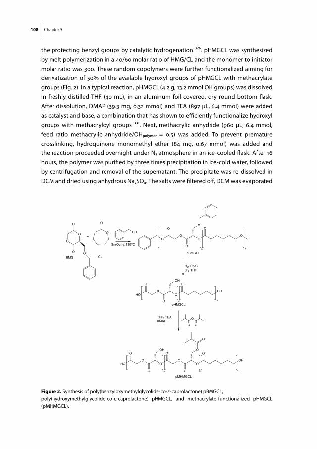
108 Chapter 5
the protecting benzyl groups by catalytic hydrogenation 326. pHMGCL was synthesized by melt polymerization in a 40/60 molar ratio of HMG/CL and the monomer to initiator molar ratio was 300. These random copolymers were further functionalized aiming for derivatization of 50% of the available hydroxyl groups of pHMGCL with methacrylate groups (Fig. 2). In a typical reaction, pHMGCL (4.2 g, 13.2 mmol OH groups) was dissolved in freshly distilled THF (40 mL), in an aluminum foil covered, dry round-bottom flask. After dissolution, DMAP (39.3 mg, 0.32 mmol) and TEA (897 µL, 6.4 mmol) were added as catalyst and base, a combination that has shown to efficiently functionalize hydroxyl groups with methacryloyl groups 331. Next, methacrylic anhydride (960 µL, 6.4 mmol, feed ratio methacrylic anhydride/OHpolymer = 0.5) was added. To prevent premature crosslinking, hydroquinone monomethyl ether (84 mg, 0.67 mmol) was added and the reaction proceeded overnight under N2 atmosphere in an ice-cooled flask. After 16 hours, the polymer was purified by three times precipitation in ice-cold water, followed by centrifugation and removal of the supernatant. The precipitate was re-dissolved in DCM and dried using anhydrous Na2SO4. The salts were filtered off, DCM was evaporated
O
O
O
O O
O OH
BMG CL
O
+
Sn(Oct)2, 130oCO
O
O
O
O
OO
O
m n
pBMGCL
H2, Pd/Cdry THF
HO
O
O
O
OH
O
O
OH
m n
THF/ TEADMAP
O
O
O
HO
O
O
O
OH
O
O
O
O
O
O
O
O
OH
pHMGCL
m k n
pMHMGCL
figure 2. Synthesis of poly(benzyloxymethylglycolide-co-ε-caprolactone) pBMGCL, poly(hydroxymethylglycolide-co-ε-caprolactone) pHMGCL, and methacrylate-functionalized pHMGCL (pMHMGCL).
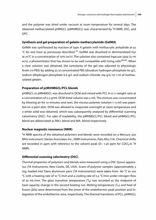
Stronger constructs with hydrogel-thermoplast attachement 109
and the polymer was dried under vacuum at room temperature for several days. The obtained methacrylated pHMGCL (pMHMGCL) was characterized by 1H NMR, DSC, and GPC.
synthesis and gel preparation of gelatin methacrylamide (gelma)
GelMA was synthesized by reaction of type A gelatin with methacrylic anhydride at 50 °C for one hour as previously described 62. GelMA was dissolved in demineralized H20 at 70°C in a concentration of 10% (w/v). The solution also contained Irgacure 2959 (0.1% w/v), a photoinitiator that has shown to be well compatible with living cells332,333. When a clear solution was obtained, the osmolarity of the gel was adjusted to physiologic levels (1x PBS) by adding 50 ul concentrated PBS (disodium hydrogen phosphate 60 g/L, sodium dihydrogen phosphate 6.6 g/L and sodium chloride 164 g/L) to 1 ml of methac-rylated gelatin.
preparation of p(m)hmgcl/pcl blends
pHMGCL or pMHMGCL was dissolved in DCM and mixed with PCL in a 1:1 weight ratio at a concentration of 0.2 g/mL DCM (total volume was 5 ml). The mixture was concentrated by blowing air for 10 minutes and next, the viscous polymer solution (~3 ml) was pipet-ted on a petri dish. DCM was allowed to evaporate overnight at room temperature and a white solid was obtained, which was subsequently analysed by differential scanning calorimetry (DSC). For sake of readability, the pMHMGCL/PCL blend and pHMGCL/PCL blend are abbreviated as MA+ blend and MA- blend respectively.
nuclear magnetic resonance (nmr)
1H NMR spectra of the obtained polymers and blends were recorded on a Mercury 300 MHz instrument (Varian Associates Inc., NMR Instruments, Palo Alto, CA). Chemical shifts are recorded in ppm with reference to the solvent peak (δ= 7.26 ppm for CDCl3 in 1H NMR).
differential scanning calorimetry (dsc)
Thermal properties of polymers and blends were measured using a DSC Q2000 appara-tus (TA Instruments, New Castle, DE, USA). Scans of polymer samples (approximately 5 mg, loaded into Tzero aluminum pans (TA Instruments)) were taken from -80 °C to 100 °C with a heating rate of 10 °C/min and a cooling rate of 0.5 °C/min under nitrogen flow of 50 mL/min. The glass transition temperature (Tg) was recorded as the midpoint of heat capacity change in the second heating run. Melting temperature (Tm) and heat of fusion (ΔHf) were determined from the onset of the endothermic peak position and in-tegration of the endothermic area, respectively. The thermal transitions of PCL, pHMGCL
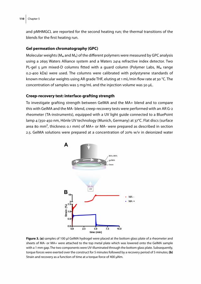
110 Chapter 5
and pMHMGCL are reported for the second heating run; the thermal transitions of the blends for the first heating run.
gel permeation chromatography (gpc)
Molecular weights (Mw and Mn) of the different polymers were measured by GPC analysis using a 2695 Waters Alliance system and a Waters 2414 refractive index detector. Two PL-gel 5 μm mixed-D columns fitted with a guard column (Polymer Labs, Mw range 0.2-400 kDa) were used. The columns were calibrated with polystyrene standards of known molecular weights using AR grade THF, eluting at 1 mL/min flow rate at 30 °C. The concentration of samples was 5 mg/mL and the injection volume was 50 μL.
creep-recovery test: interface-grafting strength
To investigate grafting strength between GelMA and the MA+ blend and to compare this with GelMA and the MA- blend, creep-recovery tests were performed with an AR G-2 rheometer (TA-instruments), equipped with a UV light guide connected to a BluePoint lamp 4 (350-450 nm, Hönle UV technology (Munich, Germany) at 37°C. Flat discs (surface area 80 mm2, thickness 0.1 mm) of MA+ or MA- were prepared as described in section 2.5. GelMA solutions were prepared at a concentration of 20% w/v in deionized water
figure 3. (a) samples of 100 μl GelMA hydrogel were placed at the bottom glass plate of a rheometer and sheets of MA- or MA+ were attached to the top metal plate which was lowered onto the GelMA sample with a 1 mm gap. The two components were UV-illuminated through the bottom glass plate. Subsequently, torque forces were exerted over the construct for 5 minutes followed by a recovery period of 5 minutes; (b) Strain and recovery as a function of time at a torque force of 400 μNm.
Stronger constructs with hydrogel-thermoplast attachement 111
containing 0.1 w/v% Irgacure 2959. For each sample, measurements were performed in triplicate. The MA+ and MA- discs were attached with a photosticker (HEMA, Groningen, the Netherlands) to the upper 20 mm diameter plate of the geometry (Fig. 3a). 100 μL of GelMA solution (20% w/v, also containing 0.1% w/v Irgacure) was pipetted at the bottom plate before lowering the top plate to a gap of 1.0 mm: the level at which GelMA and MA+ or MA- had a standardized surface interface of 100 ± 10 mm2 (Fig. 3a). Then, the construct was UV-illuminated for 10 minutes (light intensity of 180 mW/cm2). Next, the obtained constructs were mechanically deformed at different torque values ranging from 50 to 1500 μNm consisting of 5 minutes creep followed by 5 minutes recovery, while keeping the temperature at 37°C. In the creep step, a constant torque force was exerted on the top MA+/- layer that was connected to the GelMA sheet and the observed strain or deformation of the material was recorded over time. In the recovery step, the applied force was released, allowing the (grafted) materials to recover to their starting position, representing the elastic properties of the material. The percentage of recovery was calculated as follows:
Chapter 5
! 81
Netherlands) to the upper 20 mm diameter plate of the geometry (Fig. 3a). 100 μL of GelMA solution (20% w/v, also containing 0.1% w/v Irgacure) was pipetted at the bottom plate before lowering the top plate to a gap of 1.0 mm: the level at which GelMA and MA+ or MA- had a standardized surface interface of 100 ± 10 mm2 (Fig. 3a). Then, the construct was UV-illuminated for 10 minutes (light intensity of 180 mW/cm2). Next, the obtained constructs were mechanically deformed at different torque values ranging from 50 to 1500 μNm consisting of 5 minutes creep followed by 5 minutes recovery, while keeping the temperature at 37°C. In the creep step, a constant torque force was exerted on the top MA+/- layer that was connected to the GelMA sheet and the observed strain or deformation of the material was recorded over time. In the recovery step, the applied force was released, allowing the (grafted) materials to recover to their starting position, representing the elastic properties of the material. The percentage of recovery was calculated as follows:
!"#$%&! !!"#)!!"#$%&!(!"!!"#
!"#$%&! !!!"# !×100%.
Three-dimensional fiber deposition Printing of PCL, MA+ and MA- was performed using a Bioscaffolder (SYS+ENG, Salzgitter-Bad, Germany)65. Constructs were designed with Rhino 3D software (McNeel, Seattle, WA, USA) and the Standard Tessellation Language (STL) files of these models were translated to the Bioscaffolder through computer-aided manufacturing (CAM) software (PrimCAM, Einsiedeln, Switzerland). 1) A semi-open hollow cuboid was printed (LxWxH: 12x4x2mm), which was filled with GelMA for measuring construct strength; 2) a dome-shaped scaffold (diameter: 15 mm, height 3 mm, strand spacing 1.5 mm, 27 layers) was fabricated for mechanical testing in a model representing an articular chondral defect; 3) a cylindrical scaffold (diameter: 10 mm, height: 0.9 mm, strand spacing 2 mm, 5 layers) was fabricated as a reinforcing framework to GelMA loaded with chondrocytes for in vitro and in vivo evaluation. Optimal printing was achieved by melting PCL at 160 °C and MA+ and MA- at 140 °C for extrusion with a 25G metal needle (DL Technology LLC, Haverhill, MA, USA), at a pressure of 0.5 MPa, and a deposition speed of 250 mm/min, producing fibers with a mean thickness of 0.26 mm. Air (20 °C) was blown over the construct to facilitate rapid solidification of the printed fibers. A shape inspired by the femoral condyles of a knee joint was fabricated from PLA with an Ultimakertm (Ultimaker LTD, Geldermalsen, The Netherlands) filament-extrusion machine. An indentation was included (diameter: 15 mm, depth 1 mm) to mimic a chondral defect. The dome-shaped scaffolds were fabricated to tightly fit in this holder for mechanical testing.
Fabrication of reinforced GelMA constructs GelMA solution (10% w/v, containing 0.1% w/v Irgacure 2959) was added to the MA+ or MA- framework to create fiber-reinforced constructs. First, a mold was printed from PVA with the Ultimakertm machine in which the frameworks were placed. Then, the GelMA solution was infused at the periphery of the frameworks using a positive displacement pipet, until all pores were completely filled. The constructs were UV-irradiated for 10 minutes with a UV intensity of 120 mW/cm2. After photopolymerization, the constructs were taken from the molds and any excess of GelMA at the outside of the constructs was removed. Integrity of constructs on axial loading To investigate whether interface grafting of pMHMGCL to GelMA results in a stronger construct, two approaches were used to investigate construct failure. 1) The semi-open cuboids filled with GelMA were UV-irradiated for 10 minutes at 120 mW/cm2 and placed in unconfined position between the parallel plates (upper plate 6 mm in diameter) using a DMA 2980 Dynamic Mechanical Analyzer (TA Instruments, New Castle, DE, USA). A force ramp of 0-15 N, with incremental steps of 1.5 N/min was applied at the centre of the construct. Construct failure was defined as the force at which GelMA was squeezed out of the MA+ or MA- cuboid. The force and
Three-dimensional fiber depositionPrinting of PCL, MA+ and MA- was performed using a Bioscaffolder (SYS+ENG,
Salzgitter-Bad, Germany)65. Constructs were designed with Rhino 3D software (McNeel, Seattle, WA, USA) and the Standard Tessellation Language (STL) files of these models were translated to the Bioscaffolder through computer-aided manufacturing (CAM) software (PrimCAM, Einsiedeln, Switzerland). 1) A semi-open hollow cuboid was printed (LxWxH: 12x4x2mm), which was filled with GelMA for measuring construct strength; 2) a dome-shaped scaffold (diameter: 15 mm, height 3 mm, strand spacing 1.5 mm, 27 lay-ers) was fabricated for mechanical testing in a model representing an articular chondral defect; 3) a cylindrical scaffold (diameter: 10 mm, height: 0.9 mm, strand spacing 2 mm, 5 layers) was fabricated as a reinforcing framework to GelMA loaded with chondrocytes for in vitro and in vivo evaluation. Optimal printing was achieved by melting PCL at 160 °C and MA+ and MA- at 140 °C for extrusion with a 25G metal needle (DL Technology LLC, Haverhill, MA, USA), at a pressure of 0.5 MPa, and a deposition speed of 250 mm/min, producing fibers with a mean thickness of 0.26 mm. Air (20 °C) was blown over the construct to facilitate rapid solidification of the printed fibers. A shape inspired by the femoral condyles of a knee joint was fabricated from PLA with an Ultimakertm (Ultimaker LTD, Geldermalsen, The Netherlands) filament-extrusion machine. An indentation was
112 Chapter 5
included (diameter: 15 mm, depth 1 mm) to mimic a chondral defect. The dome-shaped scaffolds were fabricated to tightly fit in this holder for mechanical testing.
fabrication of reinforced gelma constructs
GelMA solution (10% w/v, containing 0.1% w/v Irgacure 2959) was added to the MA+ or MA- framework to create fiber-reinforced constructs. First, a mold was printed from PVA with the Ultimakertm machine in which the frameworks were placed. Then, the GelMA solution was infused at the periphery of the frameworks using a positive displacement pipet, until all pores were completely filled. The constructs were UV-irradiated for 10 minutes with a UV intensity of 120 mW/cm2. After photopolymerization, the constructs were taken from the molds and any excess of GelMA at the outside of the constructs was removed.
integrity of constructs on axial loading
To investigate whether interface grafting of pMHMGCL to GelMA results in a stronger construct, two approaches were used to investigate construct failure.
1) The semi-open cuboids filled with GelMA were UV-irradiated for 10 minutes at 120 mW/cm2 and placed in unconfined position between the parallel plates (upper plate 6 mm in diameter) using a DMA 2980 Dynamic Mechanical Analyzer (TA Instruments, New Castle, DE, USA). A force ramp of 0-15 N, with incremental steps of 1.5 N/min was applied at the centre of the construct. Construct failure was defined as the force at which GelMA was squeezed out of the MA+ or MA- cuboid. The force and displacement were recorded throughout compression. Measurements were performed in triplicate and the results were analysed using Thermal Advantage (v. 1.1A) and Microsoft® Excel software.
2) Cylindrical dome-shaped scaffolds, consisting of MA+/GelMA or MA-/GelMA were UV irradiated for 10 min (120 mW/cm2) and were then press-fit in a holder inspired by a knee chondral defect. Because the indentation was 1 mm deep, and the top of the dome was 3 mm in height, the implant raised maximally 2 mm from the defect ridge, matching the curvature of the joint model. In this semi-confined environment the constructs were axially loaded with 20 N (using an AR G-2 rheometer (TA-instruments)) and the change in height of the scaffold was recorded during the compression. Next, 100 creep-recovery cycles were applied onto the construct, each consisting of a 10-second creep step with a torque of 0.01 Nm followed by a 10-second recovery step. The construct was axially com-pressed for approximately 1 mm, so that the mechanical properties of the PLA holder would not disturb the measurements. The construct strain, resistance to compression and recovery during the creep-recovery cycles were analysed and the constructs were visually inspected after the mechanical loading for signs of structural damage. Supple-mentary Figure 4 shows the experimental set-up.
Stronger constructs with hydrogel-thermoplast attachement 113
harvest of human chondrocytes
Macroscopically healthy human cartilage from a discarded talus bone was obtained immediately after resection from a 7-years old patient, undergoing an orthopaedic intervention for an ankle disease, according to the institutional code of conduct regard-ing the use of discarded tissues in the University Medical Center Utrecht. The cartilage was sectioned into small slices under sterile conditions and washed three times with PBS supplemented with penicillin and streptomycin. The full-thickness cartilage was digested overnight using 0.15% type II collagenase at 37 °C and the obtained cell suspen-sion was filtered (100 μm cell strainer) and washed three times with phosphate-buffered saline (disodium hydrogen phosphate 3 g/L, sodium dihydrogen phosphate 0.33 g/L and sodium chloride 8.2 g/L). Cells were then resuspended in chondrocyte expansion me-dium: DMEM supplemented with 10% heat-inactivated FBS, 100 units/mL penicillin and 100 μg/mL streptomycin, and 10 ng/mL FGF-2 and expanded for 10 days in monolayer cultures (seeding density 5,000 cells/cm2) for use in passage 2.
In vitro redifferentiation of chondrocytes in a fiber reinforced gelma construct
Chondrocytes were resuspended in 10% GelMA (also containing Irgacure 0.1% (w/v)) at a concentration of 20x106 cells/mL. As a negative control group to histological stainings, a sample of chondrocytes was mortalized through a 2-hour trypsin treatment (0.25% trypsin-EDTA, life technologies Europe, Bleiswijk, the Netherlands) before suspension in the hydrogel. The pores of the printed cylindrical MA+ constructs (described in section 2.10) were infused with the cell-laden GelMA solution and UV-irradiated for 5 minutes. For in vitro redifferentiation, these samples (n=4) were cultured for 6 weeks in chondrocyte differentiation medium: DMEM supplemented with 0.2 mM ascorbic acid 2-phosphate, 0.5% human serum albumin, 1x ITS-X, 100 units/mL penicillin and 100 µg/mL streptomycin, and 5 ng/mL TGF-β2, with biweekly medium change.
In vivo redifferentiation of chondrocytes in a fiber reinforced gelma construct
For in vivo redifferentiation, the fiber-reinforced samples (n=4) described in the previous paragraph were pre-cultured for 2 weeks in chondrocyte differentiation medium before subcutaneous implantation. This study was approved by the local Ethics Committee for Animal Experimentation and was in compliance with the Institutional Guidelines on the Use of Laboratory Animals. Four 11-weeks old male athymic rats (Hsd:RH-Foxn1rnu Harlan Laboratories B.V., The Netherlands) were anesthetized with 1.5% isoflurane. A dorsal pocket was created on each rat in which the 10-mm diameter cylindrical construct was placed with a forceps. The skin was closed using Vicryl 4.0 sutures. Preoperatively and postoperatively, the animals received 0.05 mg/kg buprenorphine subcutaneously. The rats were housed in groups at the Central Laboratory Animal Institute of Utrecht Univer-sity. The rats were sacrificed and the samples were harvested 8 weeks after implantation.
114 Chapter 5
Scaffold morphology and cellular differentiation was investigated and a quarter of each explant was analysed with 1H NMR to assess degradation of the MA+ component.
histological, immunohistochemical and biochemical analysis
After the in vitro and in vivo differentiation experiments, the samples were split and pro-cessed for histology, immunohistochemistry and biochemistry. Therefore, one part of the samples was dehydrated through a graded ethanol series, cleared in Histoclear and embedded in paraffin. The samples were sectioned into 5 µm slices and a triple stain of Weigert’s hematoxylin, fast green, and Safranin-O was applied to detect tissue formation and deposition of glycosaminoglycans (GAGs).
Immunolocalization of collagen type II involved dewaxing and rehydration through graded alcohol series, washing in PBS/Tween (0.1%), followed by antigen retrieval with 1 mg/mL pronase (30 min) and 10 mg/mL hyaluronidase (30 min). Next, samples were blocked with 0.3% H2O2 and 5% BSA (bovine serum albumin) in PBS for 30 minutes and then incubated overnight at 4 °C with antibodies against collagen type II (1:100 from as-cites, II-II6B3, Developmental Studies Hybridoma Bank). Then, samples were washed and incubated for 60 minutes with a horseradish peroxidase-conjugated goat anti-mouse antibody. Antibody-binding was visualized using 3,3’diaminobenzidine (DAB) solution for 10 minutes and counterstaining was performed with Mayer’s hematoxylin. Isotype control stainings were performed by using mouse isotype IgG1 monoclonal antibody at concentrations similar to those used for the primary antibodies. All stained sections were examined using a light microscope (Olympus BX51).
For DNA and GAG quantification, a part of the in vitro samples was digested overnight in 20 µl papain solution per mg construct (0.01 M cysteine, 250 µg/ml papain, 0.2 M NaH2PO4 and 0.01 M EDTA) at 60 °C. Total DNA was quantified using a Quant-iT Pico-green dsDNA kit (Invitrogen) according to the manufacturer’s instructions. Total GAG content was determined by photospectrometry at 540 and 595 nm after reaction with 1,9-dimethyl-methylene blue (DMMB, 341088; Sigma) using a microplate reader (Biorad) 334. The ratio of both absorbances was calculated and the GAG content was quantified using chondroitin sulphate C (C4384; Sigma). Concentrations in the papain digest were expressed as GAG/DNA.
statistics
A Mann-Whitney-U test for independent samples was used for comparing construct failure between the two groups. Raw data were processed in SPSS version 18 (IBM soft-ware, USA) and p<0.05 was considered significant. All data are represented as means ± standard deviations.

Stronger constructs with hydrogel-thermoplast attachement 115
results and discussion
Poly(hydroxymethylglycolide-co-ε-caprolactone) (pHMGCL) was methacrylated (pMH-MGCL) and blended with poly-ε caprolactone (PCL) (1:1) to obtain the thermoplastic polymer blends pHMGCL/PCL (abbreviated as MA-) and pMHMGCL/PCL (abbreviated as MA+). In addition, a hydrogel was produced from methacrylated gelatin (GelMA). Figure 1 shows an overview of the performed experiments to characterize the polymers and blends and to investigate interface-binding strength between both materials and the cartilage specific matrix production in hydrogel constructs reinforced with a MA+ scaffold.
polymer synthesis and characterization
Poly(benzyloxymethylglycolide-co-ε-caprolactone), pBMGCL, was synthesized via ring opening polymerization (ROP) of benzyl protected hydroxymethyl glycolide (BMG) and ε-caprolactone in the melt at 130 °C for 16 hours using benzyl alcohol (BnOH) and stannous octoate (SnOct2) as initiator and catalyst, respectively, and obtained in a high yield (Table 1). The synthesized polymer was deprotected to yield poly(hydroxymethylglycolide-co-ε-caprolactone), pHMGCL (Fig. 2). The molar ratio of HMG/CL was calculated using 1H-NMR by comparing the integrals of peaks belonging to methylene protons of HMG units (3.7-4.0 ppm) and those of CL units (1.3-4.2 ppm) and was found to be very close to the feed ratio, as expected for polymers obtained in high yield (Table 1). The thermal properties of pBMGCL and pHMGCL were investigated by DSC and no melting endo-therms were detected showing that these polymers were completely amorphous as can be expected for a random copolymer 335. DSC analysis also showed that removal of the bulky benzyl rings resulted in a decrease in Tg (Table 1).
HMG/CL molar ratio*
Degree of methacrylation****
Yield (%)
Mw (kDa)
PDI Tg (°C) Tm (°C) ΔH(J/g)
PCL N.A 0 87 79.1 2.0 -61 57 71
pBMGCL 0 96 36.6 2.3 -25 - -
pHMGCL 39/61 0 95 31.9 1.8 -38 - -
pMHMGCL 39/61 44 74 32.4 2.2 -22 - -
MA-** -44 56 40
MA+*** -47 52 37
Table 1. Overview of the polymer characteristics* HMG/CL ratio based on 1H NMR analysis** 1:1 pHMGCL/PCL*** 1:1 pMHMGCL/PCL**** Measured by 1H NMR
116 Chapter 5
Subsequently, pHMGCL was functionalized with methacrylate groups aimed at a de-gree of methacrylation of 50% using methacrylic anhydride, 4-dimethylamine (DMAP) and triethylamine (TEA) as the reactant, catalyst and base (Fig. 2) to yield pMHMGCL. A degree of methacrylation of 50% was chosen because it allows for sufficient bonding after photopolymerization without losing the beneficial properties of the pendant hy-droxyl groups 326. The structural analysis of the obtained polymer by 1H NMR (Supporting Information (SI) Fig. 1) showed the presence of methacrylate groups at 1.9-2.0 ppm and 5.6- 6.4 ppm (peaks j and i). The degree of substitution (DS) was calculated by compari-son of the average integrals of peaks at 1.9-2.0 ppm and those of protons attributed to non-functionalized HMG units (4.0-4.3 ppm) and found to be 44%.
After introduction of the methacrylate groups, the molecular weight of the polymer as determined by GPC showed a very slight increase from 31.9 kDa for pHMGCL to 32.4 kDa for pMHMGCL indicating that neither premature cross-linking nor chain scission had occurred. DSC analysis showed that after methacrylation the Tg increased from -38°C to -22°C, which indicates a lower mobility of pMHMGCL chains with rather bulky methacrylate side groups compared to polymers bearing only hydroxyl groups.
PCL was synthesized via ring opening polymerization following the procedures for the synthesis of pBMGCL. DSC analysis showed a melting temperature of PCL of 57°C and a heat of fusion (ΔH) of 71 J/g, similar to other reported PCLs 336. GPC analysis showed a molecular weight (Mw) of 79.1 kDa and polydispersity of 2.0.
Since p(M)HMGCL is fully amorphous with a low Tg, it was blended with PCL to in-troduce crystallinity and allowing the preparation of scaffolds of suitable dimensional stability. DSC thermograms of the blends pMGMGCL and PHMGCL with PCL (MA+ and MA-, blend ratio 1:1) are shown in Supplementary Figure 2. The melting temperatures of MA+ and MA-, were slightly lower than that of PCL (Table 1). The heat of fusion (ΔH) of the blends was lower compared to PCL (37 and 40 J/g, for MA+ and MA- respectively, compared to 71 J/g for PCL). The reduction in ΔH is in agreement with the percentage of PCL in the scaffolds, which is in line with previously obtained results of blends from PCL/pHMGCL 329. Also, a single Tg was found between the Tg of PCL and p(M)HMGCL, showing that p(M)HMGCL and PCL are fully miscible.
Binding strength of ma+ or ma- to gelma
To determine the binding strength of MA+ or MA- to GelMA, creep recovery experi-ments were performed. A schematic representation of the experimental set-up is shown in Figure 3a. Torque forces ranging from 50 to 1500 μNm were applied to measure the resistance over the interface between MA+ or MA- and GelMA. A torque force up to 300 μNm over the grafted MA+ or MA- with GelMA yielded a strain between 0.5 and 0.8% for both groups and subsequently; after removal of the torque, 95-100% recovery was observed (data not shown). These numbers are similar to creep-recovery tests for GelMA
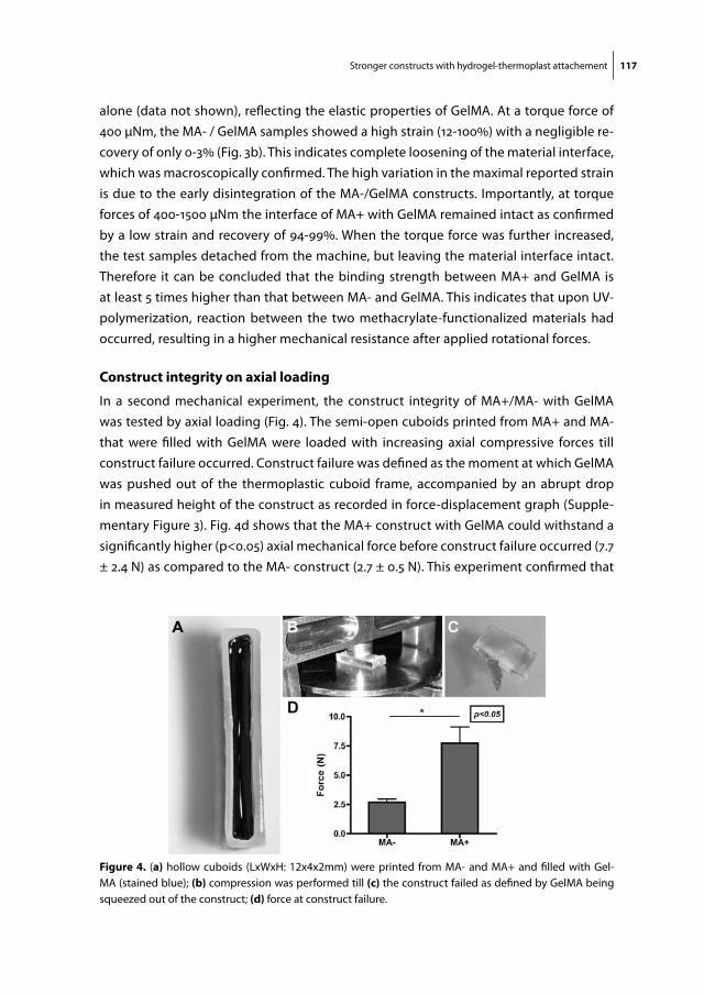
Stronger constructs with hydrogel-thermoplast attachement 117
alone (data not shown), reflecting the elastic properties of GelMA. At a torque force of 400 μNm, the MA- / GelMA samples showed a high strain (12-100%) with a negligible re-covery of only 0-3% (Fig. 3b). This indicates complete loosening of the material interface, which was macroscopically confirmed. The high variation in the maximal reported strain is due to the early disintegration of the MA-/GelMA constructs. Importantly, at torque forces of 400-1500 μNm the interface of MA+ with GelMA remained intact as confirmed by a low strain and recovery of 94-99%. When the torque force was further increased, the test samples detached from the machine, but leaving the material interface intact. Therefore it can be concluded that the binding strength between MA+ and GelMA is at least 5 times higher than that between MA- and GelMA. This indicates that upon UV-polymerization, reaction between the two methacrylate-functionalized materials had occurred, resulting in a higher mechanical resistance after applied rotational forces.
construct integrity on axial loading
In a second mechanical experiment, the construct integrity of MA+/MA- with GelMA was tested by axial loading (Fig. 4). The semi-open cuboids printed from MA+ and MA- that were filled with GelMA were loaded with increasing axial compressive forces till construct failure occurred. Construct failure was defined as the moment at which GelMA was pushed out of the thermoplastic cuboid frame, accompanied by an abrupt drop in measured height of the construct as recorded in force-displacement graph (Supple-mentary Figure 3). Fig. 4d shows that the MA+ construct with GelMA could withstand a significantly higher (p<0.05) axial mechanical force before construct failure occurred (7.7 ± 2.4 N) as compared to the MA- construct (2.7 ± 0.5 N). This experiment confirmed that
figure 4. (a) hollow cuboids (LxWxH: 12x4x2mm) were printed from MA- and MA+ and filled with Gel-MA (stained blue); (b) compression was performed till (c) the construct failed as defined by GelMA being squeezed out of the construct; (d) force at construct failure.
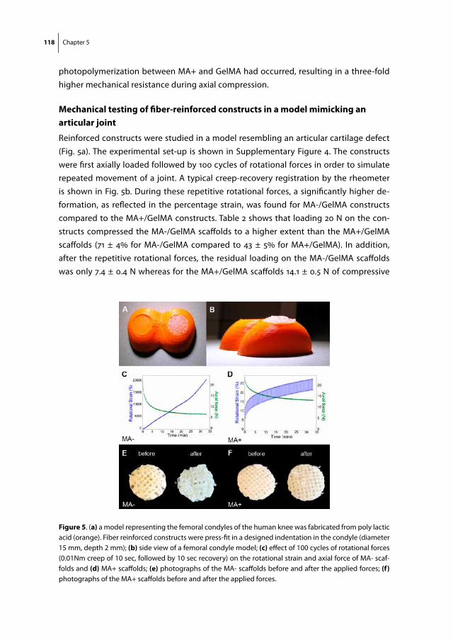
118 Chapter 5
photopolymerization between MA+ and GelMA had occurred, resulting in a three-fold higher mechanical resistance during axial compression.
mechanical testing of fiber-reinforced constructs in a model mimicking an articular joint
Reinforced constructs were studied in a model resembling an articular cartilage defect (Fig. 5a). The experimental set-up is shown in Supplementary Figure 4. The constructs were first axially loaded followed by 100 cycles of rotational forces in order to simulate repeated movement of a joint. A typical creep-recovery registration by the rheometer is shown in Fig. 5b. During these repetitive rotational forces, a significantly higher de-formation, as reflected in the percentage strain, was found for MA-/GelMA constructs compared to the MA+/GelMA constructs. Table 2 shows that loading 20 N on the con-structs compressed the MA-/GelMA scaffolds to a higher extent than the MA+/GelMA scaffolds (71 ± 4% for MA-/GelMA compared to 43 ± 5% for MA+/GelMA). In addition, after the repetitive rotational forces, the residual loading on the MA-/GelMA scaffolds was only 7.4 ± 0.4 N whereas for the MA+/GelMA scaffolds 14.1 ± 0.5 N of compressive
figure 5. (a) a model representing the femoral condyles of the human knee was fabricated from poly lactic acid (orange). Fiber reinforced constructs were press-fit in a designed indentation in the condyle (diameter 15 mm, depth 2 mm); (b) side view of a femoral condyle model; (c) effect of 100 cycles of rotational forces (0.01Nm creep of 10 sec, followed by 10 sec recovery) on the rotational strain and axial force of MA- scaf-folds and (d) MA+ scaffolds; (e) photographs of the MA- scaffolds before and after the applied forces; (f) photographs of the MA+ scaffolds before and after the applied forces.
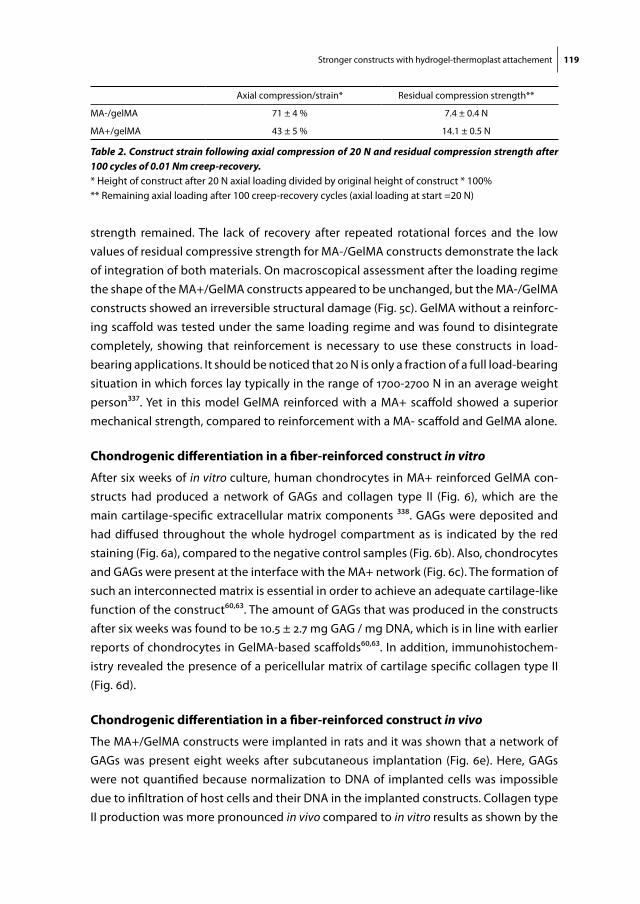
Stronger constructs with hydrogel-thermoplast attachement 119
strength remained. The lack of recovery after repeated rotational forces and the low values of residual compressive strength for MA-/GelMA constructs demonstrate the lack of integration of both materials. On macroscopical assessment after the loading regime the shape of the MA+/GelMA constructs appeared to be unchanged, but the MA-/GelMA constructs showed an irreversible structural damage (Fig. 5c). GelMA without a reinforc-ing scaffold was tested under the same loading regime and was found to disintegrate completely, showing that reinforcement is necessary to use these constructs in load-bearing applications. It should be noticed that 20 N is only a fraction of a full load-bearing situation in which forces lay typically in the range of 1700-2700 N in an average weight person337. Yet in this model GelMA reinforced with a MA+ scaffold showed a superior mechanical strength, compared to reinforcement with a MA- scaffold and GelMA alone.
chondrogenic differentiation in a fiber-reinforced construct in vitro
After six weeks of in vitro culture, human chondrocytes in MA+ reinforced GelMA con-structs had produced a network of GAGs and collagen type II (Fig. 6), which are the main cartilage-specific extracellular matrix components 338. GAGs were deposited and had diffused throughout the whole hydrogel compartment as is indicated by the red staining (Fig. 6a), compared to the negative control samples (Fig. 6b). Also, chondrocytes and GAGs were present at the interface with the MA+ network (Fig. 6c). The formation of such an interconnected matrix is essential in order to achieve an adequate cartilage-like function of the construct60,63. The amount of GAGs that was produced in the constructs after six weeks was found to be 10.5 ± 2.7 mg GAG / mg DNA, which is in line with earlier reports of chondrocytes in GelMA-based scaffolds60,63. In addition, immunohistochem-istry revealed the presence of a pericellular matrix of cartilage specific collagen type II (Fig. 6d).
chondrogenic differentiation in a fiber-reinforced construct in vivo
The MA+/GelMA constructs were implanted in rats and it was shown that a network of GAGs was present eight weeks after subcutaneous implantation (Fig. 6e). Here, GAGs were not quantified because normalization to DNA of implanted cells was impossible due to infiltration of host cells and their DNA in the implanted constructs. Collagen type II production was more pronounced in vivo compared to in vitro results as shown by the
Axial compression/strain* Residual compression strength**
MA-/gelMA 71 ± 4 % 7.4 ± 0.4 N
MA+/gelMA 43 ± 5 % 14.1 ± 0.5 N
Table 2. Construct strain following axial compression of 20 N and residual compression strength after 100 cycles of 0.01 Nm creep-recovery.* Height of construct after 20 N axial loading divided by original height of construct * 100%** Remaining axial loading after 100 creep-recovery cycles (axial loading at start =20 N)
120 Chapter 5
extensive network formation reflected by the immunohistochemical stainings (Fig. 6f ). Also, collagen type II was deposited at the interface of the MA+ scaffold, contributing to the integration of neo-tissue with the polyester scaffold. This is important, since the neo-tissue together with the MA+ scaffold will determine the mechanical properties of the construct after the hydrogel component has been degraded50.
degradation of pmhmgcl in vivo
Degradation of the explanted MA+ component was shown with 1H NMR by the disap-pearance of HMG units (Supplementary Figure 5), which is in line with previous obser-vations328,339. Furthermore, NMR shows a reduction in the methacrylate signals at 5.6 and 6.4 ppm. This is most likely caused by both crosslinking of pMHMGCL with GelMA and hydrolysis of the ester groups connecting the methacrylate groups of pMHMGCL. Since no photoinitiator was incorporated in the polyester, it was to be expected that not all methacrylate groups in pMHMGCL had photopolymerized. Degradation of these constructs will therefore lead to the formation of methacrylic acid. As is shown before for methacrylated dextran-based hydrogels340,341, methacrylic acid does not cause cytotoxicity and therefore does not affect the suitability of these materials for tissue engineering purposes.
figure 6. Human articular chondrocytes produced cartilage-specific matrix components in MA+ reinforced GelMA constructs after 6 weeks in vitro culture as shown by positive safranin-O staining (a, c; red) for gly-cosaminoglycans (GAGs) produced by chondrocytes in GelMA. The MA+ scaffold architecture is visible in dark red. In negative control samples (b), GelMA stains green and the MA+ stains dark red by the safranin-O triple staining. Staining collagen type II staining is visible in the pericellular matrix of the chondrocytes (d), MA+ scaffold in purple. After 8 weeks in vivo with 2 weeks pre-culturing there was production of GAGs (e), although less extensive compared to in vitro cultures (c). An interconnected collagen type II network was formed in vivo (f). Scale bar C-F = 200 μm.

Stronger constructs with hydrogel-thermoplast attachement 121
conclusions
This study showed that a 3D-fabricated pMHMGCL/PCL thermoplastic polymer scaffold could be covalently linked to a chondrocyte-laden GelMA hydrogel. Covalently graft-ing both materials significantly improved the binding strength between the materials and consequently resulted in an enhanced mechanical integrity of reinforced hydrogel constructs. Embedded chondrocytes showed significant cartilage-specific matrix depo-sition in these constructs both in vitro and in vivo. Moreover, since both materials have shown their ability to support matrix formation and both can be applied in additive manufacturing techniques, the current work allows for the fabrication of mechanically enhanced, patient-specific cartilage implants.
acKnowledgements
The authors would like to thank Kim Benders for her assistance in isolating human chon-drocytes. Also we would like to thank Marco Raaben for optimizing printing parameters for MA+/MA-, Ben Peters for designing the knee implant model and Jeremy Besems for assisting in the histology analyses. The collagen type II monoclonal antibody (developed by T.F. Linsenmayer) was obtained from the Developmental Studies Hybridoma Bank. Jos Malda was supported by the Dutch Arthritis Association, Kristel Boere and Jetze Visser were supported by Netherlands Institute of Regenerative Medicine (NIRM). Debby Gawlitta was supported by the Dutch Technology Foundation, STW (Veni 11208).
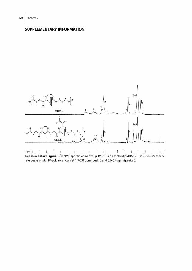
122 Chapter 5
supplementary information
supplementary figure 1. 1H NMR spectra of (above) pHMGCL, and (below) pMHMGCL in CDCl3. Methacry-late peaks of pMHMGCL are shown at 1.9-2.0 ppm (peak j) and 5.6-6.4 ppm (peaks i).
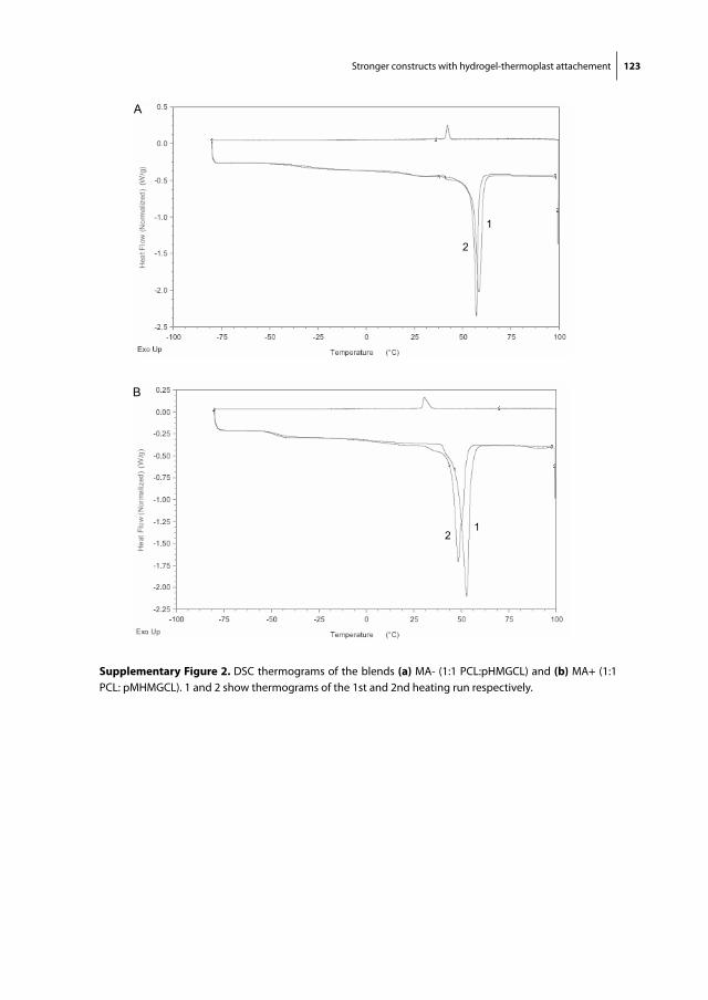
Stronger constructs with hydrogel-thermoplast attachement 123
A
B
1
12
2
supplementary figure 2. DSC thermograms of the blends (a) MA- (1:1 PCL:pHMGCL) and (b) MA+ (1:1 PCL: pMHMGCL). 1 and 2 show thermograms of the 1st and 2nd heating run respectively.
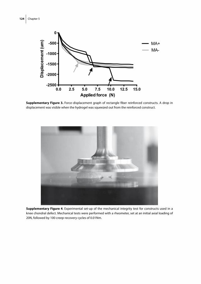
124 Chapter 5
0.0 2.5 5.0 7.5 10.0 12.5 15.0-2500
-2000
-1500
-1000
-500
0
MA-MA+
Applied force (N)
Dis
plac
emen
t (um
)
supplementary figure 3. Force-displacement graph of rectangle fiber reinforced constructs. A drop in displacement was visible when the hydrogel was squeezed out from the reinforced construct.
supplementary figure 4. Experimental set-up of the mechanical integrity test for constructs used in a knee chondral defect. Mechanical tests were performed with a rheometer, set at an initial axial loading of 20N, followed by 100 creep-recovery cycles of 0.01Nm.
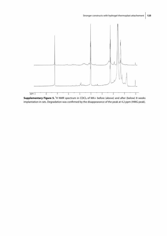
Stronger constructs with hydrogel-thermoplast attachement 125
supplementary figure 5. 1H NMR spectrum in CDCl3 of MA+ before (above) and after (below) 8 weeks implantation in rats. Degradation was confirmed by the disappearance of the peak at 4.2 ppm (HMG peak).

Chapter 6Reinforcement of Hydrogels using Three-Dimensionally Printed Microfibres
Jetze VisserFerry P.W. MelchelsJune E. JeonErik M. van BusselLaura S. KimptonHelen M. ByrneWouter J.A. DhertPaul D. DaltonDietmar W. HutmacherJos Malda
Nature Communications. 2015;6:6933 doi: 10.1038/
ncomms7933
128 Chapter 6
aBstract
Despite intensive research, hydrogels currently available for tissue repair in the musculoskeletal system are unable to meet the mechanical, as well as the biological, requirements for successful outcomes. Here, we reinforce soft hydrogels with highly or-ganised, high-porosity microfibre networks that are 3D-printed with a technique termed melt electrospinning writing. We show that the stiffness of the gel/scaffold composites increases synergistically (up to 54-fold), compared to hydrogels or microfibre scaffolds alone. Modelling affirms that reinforcement with defined microscale structures is ap-plicable to numerous hydrogels. The stiffness and elasticity of the composites approach that of articular cartilage tissue. Human chondrocytes embedded in the composites are viable, retain their round morphology and are responsive to an in vitro physiological loading regime in terms of gene expression and matrix production. The current approach of reinforcing hydrogels with 3D-printed microfibres offers a fundament for producing tissue constructs with biological and mechanical compatibility.
introduction
Hydrogels are an important class of biomaterials with many applications, including as cell carriers for the engineering of tissues104,246. In this respect, hydrogels are designed to provide the cells with a fully hydrated three-dimensional (3D) environment comparable to the extracellular matrix of native tissues29,79. When embedded within hydrogels, cells need to form a tissue-specific matrix that is capable of repairing or regenerating the damaged tissue. However, hydrogels often have inadequate mechanical properties, which are either unfavourable to embedded cells or make them too weak for application in the musculoskeletal system6,307,342.
The performance of hydrogel implants is expected to be superior when they closely match the mechanical properties of their target tissue56,343. This is based on the principle that cells in native tissues are responsive to different types of mechanical stresses, such as compression, tension, and shear344-346. These properties, e.g. stiffness, can be improved by increasing the hydrogel polymer concentration or crosslink density79,246,347 or by the formation of tissue-specific extracellular matrix prior to implantation of the graft63,246,348. However, this generally compromises the biological performance of the hydrogel79,246 or requires a long and costly period of pre-culture.
Tissue engineers have, therefore, been inspired by the architecture of native tissues, which derive their unique mechanical properties from a fibrous protein framework that supports the aqueous component, forming a complex composite303. For example, hy-drogels have been reinforced with nanofibres192,200,349, microfibres350 and woven316,343,351
Reinforcement of hydrogels with 3D-printed microfibres 129
or non-woven352 scaffolds. The mechanical properties of hydrogels in such composites are less demanding, so they can be processed with a low crosslink density, which is beneficial for cell migration and the formation of neo-tissue79,246. Recent composite systems include non-woven scaffolds, manufactured via solution electrospinning tech-niques55,56,201,321,322 and scaffolds fabricated via 3D printing65,76,77,255,353,354. Due to the small fibre diameters that can be obtained, electrospun meshes have the potential to mimic native tissue extracellular matrix structures, including its mechanical properties. How-ever, a disadvantage of traditional solution electrospinning techniques is the limited control over network architecture. Recently, melt electrospinning has been used in a direct writing mode, and may overcome this limitation, with the layer-by-layer assembly of the low diameter fibres, permitting tight control over the network architecture54,206.
This study aims to mechanically reinforce gelatin methacrylamide (GelMA) hydrogels with organized, high-porosity poly(ε-caprolactone) (PCL) fibre scaffolds. GelMA is a hy-drogel platform with recent use that allows for matrix deposition by embedded cells, e.g. vascular networks or cartilage matrix60,63,64. Reinforcing scaffolds with different porosi-ties were fabricated from medical-grade PCL by melt electrospinning in a direct writing mode54. Fibrous hydrogel composites were then fabricated by infusing and crosslinking GelMA within the PCL scaffolds. The stiffness and recovery under cyclic compression of these composites were analysed depending on PCL scaffold porosity and the degree of crosslinking of the GelMA. A mathematical model was developed using the scaffold parameters, and subsequently used to simulate and predict the degree of hydrogel reinforcement. Finally, human primary chondrocytes were encapsulated in the compos-ite constructs and their viability, morphology, and chondrogenic differentiation were investigated in an in vitro culture assay under physiological compressive loading.
We demonstrate that hydrogels are reinforced in a synergistic fashion with high-porosity microfibre scaffolds. The stiffness of the composites approaches that of ar-ticular cartilage, while maintaining a relevant elasticity. Chondrocytes embedded in the composite constructs respond positively to a repetitive mechanical loading regime in a bioreactor culture, in terms of cartilage gene expression and matrix formation. These hydrogel/microfiber composites thus offer a mechanically and biologically favourable environment for the engineering of tissues.
methods
fabrication of pcl microfibre scaffolds
Several scaffolds were 3D-printed from medical-grade PCL (PURAC, Gorinchem, the Netherlands) with a custom-made melt electrospinning device54. PCL was heated to 103°C in a 2 ml polypropylene syringe and extruded at a rate of 18 μl/hour using a syringe
130 Chapter 6
pump. In combination with an electrostatic field of 8-10 kV between the syringe needle tip (23G) and the collector plate (3 cm distance), a stable PCL jet was obtained. Defined scaffold architectures, with dimensions up to 120x120x1 mm, were realized through computer-aided movement of the aluminium collector plate at a speed of 1400 mm/min, using Mach3 motion control software (Artsoft, USA). A predefined 0-90° architecture was imposed, with a fibre spacing of 0.2, 0.4, 0.6, 0.8 or 1.0 mm. The melt electrospinning writing was terminated when scaffolds reached a height of 1.0 mm, to ensure maximum quality of the architecture. To investigate the effect of PCL flow rate on fibre diameter and scaffold porosity, we printed constructs at 4x and 10x flow rate, with a fibre spacing of 0.4 mm and 1.0 mm respectively. Cylindrical samples were extracted from the scaf-folds with a 5 mm diameter biopsy punch. Two scaffolds were stacked in order to achieve a height of 2 mm, which is comparable to the thickness of human cartilage in the knee joint355. The porosity and mechanical properties of the melt electrospun scaffolds were compared to scaffolds fabricated with traditional 3D printing technologies. To this end, scaffolds were 3D-printed from PCL with a BioScaffolder system (SYS+ENG, Salzgitter-Bad, Germany) as described previously190. Briefly, PCL was heated till 70 °C and extruded with an Auger screw through a 27 gauge needle. Scaffolds measuring 40x40x2 mm were fabricated with a fibre spacing of 0.75, 1.0, 1.25, 1.5 and 1.75 mm. The quality of the scaffolds was imaged both with stereomicroscopy and Scanning Electron Microscopy (Hitachi TM3000, Japan and Quanta 200, FEI, Milton, Australia). The fibre diameter was measured with ImageJ software (National Institutes of Health, USA). The porosity of the PCL scaffolds was determined gravimetrically.
etching of pcl microfibre scaffolds
PCL scaffolds were etched in order to increase its hydrophilicity and surface area, which could potentially contribute to the stiffness of reinforced GelMA constructs. Cylindrical PCL scaffolds with a porosity of 94% were treated with 70% ethanol and subsequently etched with 5M sodium hydroxide for 0, 1, 2, 4, 8 and 16 hours. After etching, the scaffolds were washed in deionized H2O until the pH reached 7.4, and then air-dried. The effect of etching was evaluated by measuring the fibre diameter (ImageJ) from SEM images, and by assessing the weight from 2 x 5 mm diameter scaffolds (expressed in relative weight loss). Since mild etching will increase hydrophilicity and may facilitate perfu-sion of GelMA through the PCL scaffold, 2 hours of etching was performed for all other experiments presented.
preparation of gelatin methacrylamide and alginate gels
GelMA was synthesized by reaction of type A gelatin (Sigma-Aldrich, St. Louis, Missouri, USA) with methacrylic anhydride at 50 °C for one hour as previously described63. GelMA was dissolved in Phosphate Buffered Saline (PBS) at 60 °C at a concentration of 10% (w/v)

Reinforcement of hydrogels with 3D-printed microfibres 131
containing 12.5 or 25 mM ammonium persulfate (APS). 12.5 or 25 mM tetramethylethyl-enediamide (TEMED) was added followed by 5 seconds vortexing in order to initiate crosslinking of the GelMA. Alginate (IMCD, Amersfoort, The Netherlands) was dissolved in PBS at 3% (w/v), and used as a control gel to GelMA for the mechanical analyses.
preparation of reinforced hydrogel constructs
The scaffolds were placed in an injection mold that was custom made from polymeth-ylmethacrylate in order to fit 10 cylinders with a diameter of 5 mm and a height of 2 mm. All cylindrical voids in the mold were interconnected so that gel could be serially perfused. The mold was sealed with a sheet of polyethylene that was fixed between two glass histology slides. Directly after mixing in the TEMED, the GelMA solution as described above was injected in the mold untill all PCL scaffolds were fully infused. Crosslinking of the GelMA was allowed in this mold at 37° C for 1 hour. Cell-free samples were then stored in PBS at 37° C. Chondrocyte-laden samples were kept in chondrocyte expansion medium. In order to evaluate the effect of etching time of the scaffolds on construct stiffness, GelMA was reinforced with scaffolds etched for 0-16 hours (all n=5) and crosslinked with 25 mM APS/TEMED. In addition, 93-98% porosity PCL scaffolds (all n=5) were infused with alginate in the mold. The alginate composite constructs were then crosslinked by immersion in a 102 mmol calciumchloride solution for 30 minutes.
harvest of equine cartilage
Full-thickness cartilage was harvested from the knee joint from one equine donor (10 years old) with macroscopically healthy cartilage. This was done after consent of the horse owner and according to the ethical guidelines of Utrecht University. Equine cartilage was used because of the availability and its similarities to human cartilage355. Cylindrical samples with a diameter of 5 mm and a height of 2 mm (n=8) were taken with a biopsy punch from the medial patellofemoral groove and stored in PBS for up to 3 hours.
mechanical analyses
The stiffness (or compressive modulus) of GelMA and alginate hydrogels, PCL scaffolds, the composite constructs and articular cartilage (all n=5) was measured by single uni-axial unconfined compression in air at room temperature, after 1-3 days submersion in PBS from their preparation. We confirmed that for single cycle compression testing, the absence of a PBS immersion bath does not influence the stress responses of hydrogel samples. The effect of crosslinking with 12.5 or 25 mM APS/TEMED was tested. The stress/strain curves of (reinforced) GelMA that was crosslinked with 12.5 mM APS/TEMED were compared with cartilage samples. Over a period of two minutes, a force ramp (axial strain rate ca. 25%/min) was applied to the samples employing a microtester (Instron,
132 Chapter 6
Melbourne, Australia) or a Dynamic Mechanical Analyser (DMA 2980, TA Instruments, New Castle, DE, USA). The stiffness was calculated from the linear derivative of the stress/strain curve at 12-15% strain. In the low-porosity scaffolds that were fabricated with traditional 3D printing, the 6-9% strain region was taken, as these constructs often disintegrated when strained beyond 10%. The compression cycle of GelMA reinforced with 97% and 82% porosity scaffolds was captured from the side (hand-held digital microscope 1.3 MP, Meade instruments, Europe GmbH & Co, Rhede, Germany) in order to analyse the lateral expansion of both components of the composite construct. In addi-tion, images from the top of these constructs were taken with a stereomicroscope, when uncompressed and at 30% strain between two glass slides.
In order to test the time-dependent stress response, GelMA, GelMA reinforced with 93% porosity scaffolds and articular cartilage samples, were subjected to a series of isostrain steps356. Samples were 2% pre-strained for 5 minutes, followed by strains of 6%, 9% and 13% that were consecutively applied for 15 minutes each. The experiments were performed in PBS and the stress response of all samples was recorded. The modulus on fast initial loading and the equilibrium modulus were extracted and the stress decay rate was estimated by fitting to a bi-exponential function.
The resistance to axial deformation of GelMA and GelMA reinforced with PCL con-structs (porosity 93% and 97%) was measured after a cyclic (20x) axial strain of 20% (All-round-line Z020, Zwick Roell, Germany). In addition, the resistance after 20 cycles of axial deformation of 50% was measured for GelMA constructs. The recovery measurements were performed in PBS and constructs were allowed to recover for 1 minute after every cycle. GelMA constructs reinforced with a 93% porous scaffold underwent compression with incremental maximum strains of 20-40% (with 5% increments) in order to analyse the maximal strain that could be exerted before irreversible damage would occur.
modelling the fibre reinforcement of hydrogels
A mathematical model was constructed to investigate further the mechanisms by which the 3D-printed scaffolds reinforce the hydrogels. There is an extensive literature on the modelling of fibre reinforced biological materials, with recent cartilage-focussed examples357,358. Fibre reinforced materials are often modelled by assuming it is reason-able to define a continuously varying fibre density and orientation and then making the material properties a function of these. In this instance, given that we know the arrange-ment and approximate number of fibres in each plane of the material, we take the more direct approach of considering how each fibre stretches as the scaffold deforms. Our model takes into account the number of fibres in the scaffold and the fibre diameter; the Young’s modulus of PCL and the construct dimensions. In the model, the composite construct was viewed as an elastic solid, in which the PCL fibres are placed under tension by the hydrogel on axial compression.
Reinforcement of hydrogels with 3D-printed microfibres 133
harvest of human chondrocytes
Macroscopically healthy cartilage was harvested either from a discarded talus bone that was resected from a 7-year old patient undergoing an orthopaedic intervention, or from the femoral condyles of knee replacement surgery patients (age: 71.0 ± 4.1; n = 6) with consent. This was in concordance with the institutional code of conduct regarding the use of discarded tissues in the University Medical Center Utrecht, and ethics approval was also obtained from Queensland University of Technology and Prince Charles hos-pital prior to sample collection. Cartilage was cut into small slices and washed with PBS supplemented with penicillin and streptomycin. The cartilage was digested overnight in 0.15% type II collagenase at 37°C. The resulting cell suspension was filtered (100 μm cell strainer) and washed three times with phosphate-buffered saline. Then cells were resuspended in chondrocyte expansion medium (DMEM supplemented with 10% FBS (Fetal Bovine Serum), 100 units/mL penicillin and 100 μg/mL streptomycin, and 10 ng/mL FGF-2) and expanded for 10 days in monolayer cultures (seeding density 5,000 cells/cm2). For the short-term study (7 day), chondrocytes from the talus bone were used at passage 2, and for the long-term study (28 day), chondrocytes obtained from the femoral condyles of the different donors were pooled and used at passage 1.
cell viability
Chondrocytes were mixed in the GelMA/APS solution at a concentration of 10 million/ml. Crosslinking was done with different proportions of APS/TEMED (12.5/12.5 and 25/25 mM) in order to evaluate cytotoxicity of the redox crosslinking process. The viability of the chondrocytes was measured 4 hours (day 1) and 7 days after embedding and crosslinking of the GelMA constructs. To visualize cell viability, a LIVE/DEAD Viability Assay (Molecular Probes MP03224, Eugene, USA) was performed according to the manufacturer’s instruc-tions. The samples were examined using a light microscope with the excitation/emission filters set at 488/530 nm to observe living (green) cells and at 530/580 nm to detect dead (red) cells. Photographs were taken with an Olympus DP70 camera. The ratio dead/alive was measured by assessing multiple parts of the sample.
cell morphology
The morphology and location of chondrocytes in the reinforced GelMA constructs was assessed 7 days after encapsulation. Reinforced GelMA constructs with chondrocytes (n=3, 93% porosity) were dehydrated through a graded ethanol series, cleared in xylene and embedded in paraffin. The samples were sectioned into 10 µm slices and stained with hematoxyline and eosine for the detection of GelMA, the PCL scaffold and the cells. In addition, the location of chondrocytes and their relation to the PCL fibres were assessed at days 1 and 7 by fluorescent staining with 4’,6-diamidino-2-phenylindole (DAPI). To this end, constructs from GelMA only and reinforced with a PCL scaffold (93%
134 Chapter 6
porosity) were crosslinked with 12.5 mM APS/TEMED (n=3). The GelMA was subsequently permeabilized with 1% Triton/PBS for 15 minutes and incubated with DAPI (0.1 µg/ml in PBS) for 5 minutes, followed by three washing steps with PBS. Fluorescence microscopy images were taken (with excitation/emission filter 330-385nm) to detect the cell nuclei (blue).
mechanical stimulation
For the chondrocyte redifferentiation experiment, 0.5% hyaluronic acid was added to 10% GelMA to promote redifferentiation of embedded chondrocytes60,63. Chondrocyte-laden GelMA-HA gels and GelMA-HA-PCL composite gels (PCL scaffold porosity: 93%) were able to swell freely under static conditions during the first 14 days. Following this pre-culture period, the constructs were cultured for another 14 days using a pre-established loading protocol (3 hours/day, 20% strain, 1 Hz sinusoidal loading) in a commercial bioreactor (Cartigen C10-12c, Tissue Growth Technologies, Minnetonka, MN, USA). Constructs were cultured in high glucose DMEM supplemented with 10 ng/mL TGF-β3, 1% ITS, 1.25 mg/mL bovine serum albumin, 10-7 M dexamethasone, and other additives (GlutaMAX-1, 110 mg/L sodium pyruvate, 10 mM HEPES, 0.1 mM nonessential amino acides, 50 U/mL penicillin, 50 μg/mL streptomycin, 0.5 μg/mL fungizone and 0.1 mM L-ascorbic acid). Constructs were cultured for a total of 28 days.
qrt-pcr
Gene expression analysis was performed on the GelMA-HA hydrogels and the GelMA-HA hydrogels reinforced with 93% porosity PCL scaffold following 28 days of culture. RNA from the compressed (C) and non-compressed (NC) constructs was purified using the TRIzol reagent (n=4). cDNA synthesis was carried out using the SuperScriptTM III first-strand synthesis supermix kit. Gene expression of ACAN (F: 5’-GCCTGCGCTCCAAT-GACT-3’, R: 5’-TAATGGAACACGATGCCTTTCA-3’, NM_001135), COL2A1 (F: 5’-GGCAATAG-CAGGTTCACGTACA-3’, R: 5’-CGATAACAGTCTTGCCCCACTT-3’, NM_001844), COL1A1 (F: 5’-CAGCCGCTTCACCTACAGC-3’, R: 5’-TTTTGTATTCAATCACTGTCTTGCC-3’, NM_000088), and COL10A1 (F: 5’-ACCCAACACCAAGACACAGTTCT-3’, R: 5’-TCTTACTGCTATACCTT-TACTCTTTATGGTGTA-3’, NM_000493) were analyzed by real-time PCR using the SYBR GreenERTM qPCR supermix universal kit. All reagents and kits were purchased from Life Technologies and samples were processed according to the manufacturer’s instructions. The cycle threshold (Ct) value of each gene was normalized to the housekeeping gene β2 microglobulin (B2M, F: 5’-ATGAGTATGCCTGCCGTGTGA-3’, R: 5’-GGCATCTTCAAACCTC-CATGATG-3’) using the comparative Ct method (2-DCt).
Reinforcement of hydrogels with 3D-printed microfibres 135
glycosaminoglycan analysis
Samples from the compression experiment were digested in 0.5 mg/mL proteinase K solution overnight at 60°C (n = 5). Digested samples were analyzed for GAG using the 1, 9-dimethylmethylene blue assay at pH 3. GAG measurements for each construct were normalized to its wet weight.
immunohistochemistry
After 28 days, the reinforced GelMA-HA gels were paraffin-embedded and sectioned at 5 μm. For antigen retrieval, ready-to-use proteinase K solution (Dako) was used for 10 min-utes at 37 °C. Sections were blocked with 2% FBS solution prior to exposure to primary antibodies: I-8H5 (MP Biomedicals), dilution 1:300 for collagen type I; II-II6B3 (DSHB), dilution 1:200 for collagen type II. Following incubation in fluorescence-labelled goat anti-mouse secondary antibody (Alexa Fluor 488, Invitrogen), sections were mounted with Prolong Gold (Invitrogen) and visualized using a confocal fluorescence microscope (A1R Confocal, Nikon).
statistics
All data were expressed as mean ± standard deviation of five independent samples, unless stated otherwise. One-way ANOVA with Bonferroni correction was performed to compare the stiffness of the reinforced hydrogels; the effect of scaffold porosity was compared for every hydrogel and the effect of the hydrogel was compared for every scaffold porosity. Two-way ANOVA was used to evaluate the effect of compression and hydrogel types on gene expression, GAG/ww, and stiffness. An independent samples T-test, not assuming equal variances, was performed to evaluate cell viability (SPSS, IBM software, USA). Differences were considered significant when P < 0.05.
results
fabrication of pcl microfibre scaffolds
PCL scaffolds of 1 mm height were 3D-printed with a reproducible quality using melt electrospinning writing (Fig. 1a and Supplementary Movie 1). Scaffolds were fabricated with fibre spacings between 0.2 mm (Fig. 1b) and 1.0 mm (Fig. 1c). The fibres were well aligned and fused at the 0°-90° oriented junctions (Fig. 1d. The fidelity of fibre deposition decreased for constructs higher than 1 mm, probably because of the electric isolating effect of the scaffold that had already been deposited on the collector plate. Therefore, two scaffolds were stacked in the current study to obtain 2 mm high constructs. The scaffold porosity could be controlled within the range of 93-98% by varying the set fibre spacing between 0.2 and 1.0 mm (Fig. 1e). Flow rates of 18 μL/hr, 72 μL/hr and 180 μL/hr
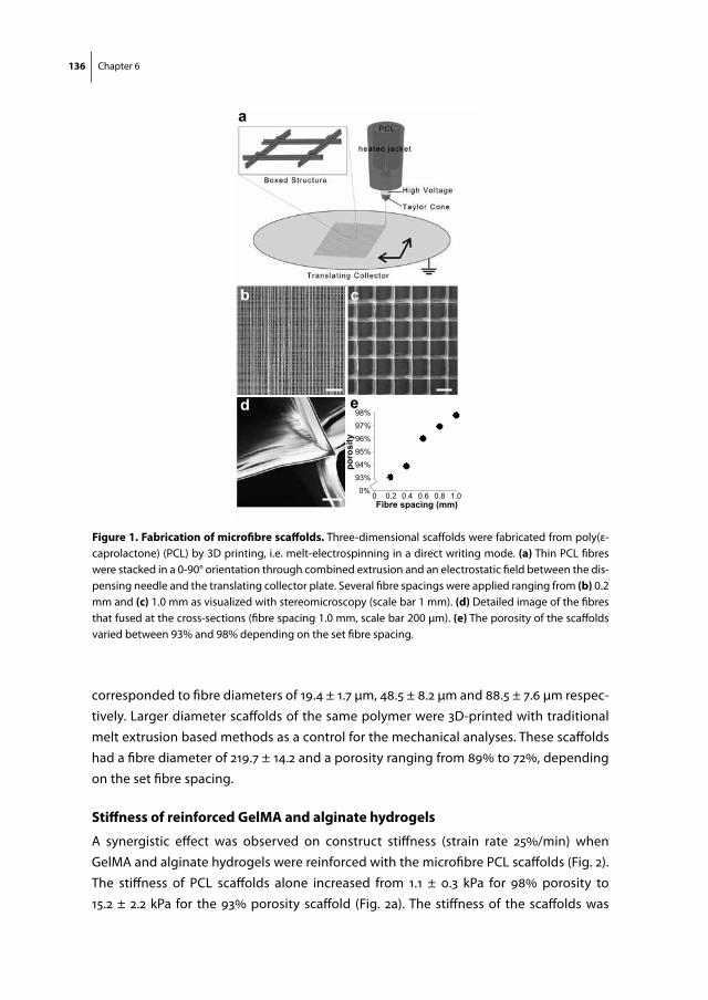
136 Chapter 6
corresponded to fibre diameters of 19.4 ± 1.7 µm, 48.5 ± 8.2 μm and 88.5 ± 7.6 μm respec-tively. Larger diameter scaffolds of the same polymer were 3D-printed with traditional melt extrusion based methods as a control for the mechanical analyses. These scaffolds had a fibre diameter of 219.7 ± 14.2 and a porosity ranging from 89% to 72%, depending on the set fibre spacing.
stiffness of reinforced gelma and alginate hydrogels
A synergistic effect was observed on construct stiffness (strain rate 25%/min) when GelMA and alginate hydrogels were reinforced with the microfibre PCL scaffolds (Fig. 2). The stiffness of PCL scaffolds alone increased from 1.1 ± 0.3 kPa for 98% porosity to 15.2 ± 2.2 kPa for the 93% porosity scaffold (Fig. 2a). The stiffness of the scaffolds was
0%93%94%95%96%97%98%
poro
sity
Fibre spacing (mm)0 0.2 0.4 0.6 0.8 1.0
a
b c
d e
figure 1. fabrication of microfibre scaffolds. Three-dimensional scaffolds were fabricated from poly(ε-caprolactone) (PCL) by 3D printing, i.e. melt-electrospinning in a direct writing mode. (a) Thin PCL fibres were stacked in a 0-90° orientation through combined extrusion and an electrostatic field between the dis-pensing needle and the translating collector plate. Several fibre spacings were applied ranging from (b) 0.2 mm and (c) 1.0 mm as visualized with stereomicroscopy (scale bar 1 mm). (d) Detailed image of the fibres that fused at the cross-sections (fibre spacing 1.0 mm, scale bar 200 μm). (e) The porosity of the scaffolds varied between 93% and 98% depending on the set fibre spacing.
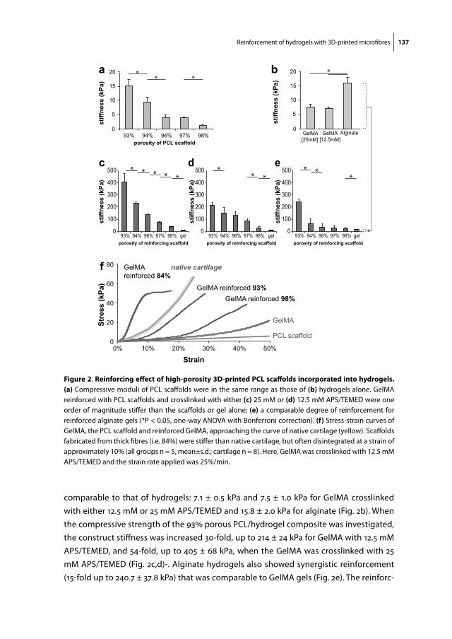
Reinforcement of hydrogels with 3D-printed microfibres 137
comparable to that of hydrogels: 7.1 ± 0.5 kPa and 7.5 ± 1.0 kPa for GelMA crosslinked with either 12.5 mM or 25 mM APS/TEMED and 15.8 ± 2.0 kPa for alginate (Fig. 2b). When the compressive strength of the 93% porous PCL/hydrogel composite was investigated, the construct stiffness was increased 30-fold, up to 214 ± 24 kPa for GelMA with 12.5 mM APS/TEMED, and 54-fold, up to 405 ± 68 kPa, when the GelMA was crosslinked with 25 mM APS/TEMED (Fig. 2c,d)-. Alginate hydrogels also showed synergistic reinforcement (15-fold up to 240.7 ± 37.8 kPa) that was comparable to GelMA gels (Fig. 2e). The reinforc-
0
5
10
15
20
0
100
200
300
400
500
93% 94% 96% 97% 98% 0
100
200
300
400
500
93% 94% 96% 97% 98% 0
100
200
300
400
500
93% 94% 96% 97% 98%
stiff
ness
(kPa
) st
iffne
ss (k
Pa)
stiff
ness
(kPa
)
93% 94% 96% 97% 98% 0
GelMA [25mM]
GelMA [12.5mM]
Alginate
a b
c d e
** *
gel gel gel
* **** *
*** *
*
f
0
20
40
60
80
0% 10% 20% 30% 40% 50%
Stre
ss (k
Pa)
Strain
native cartilage
GelMA
GelMA reinforced 98%GelMA reinforced 93%
GelMA reinforced 84%
porosity of PCL scaffold
porosity of reinforcing scaffold
PCL scaffold
5
10
15
20 *
porosity of reinforcing scaffoldporosity of reinforcing scaffold
stiff
ness
(kPa
)
stiff
ness
(kPa
)
figure 2. reinforcing effect of high-porosity 3d-printed pcl scaffolds incorporated into hydrogels. (a) Compressive moduli of PCL scaffolds were in the same range as those of (b) hydrogels alone. GelMA reinforced with PCL scaffolds and crosslinked with either (c) 25 mM or (d) 12.5 mM APS/TEMED were one order of magnitude stiffer than the scaffolds or gel alone; (e) a comparable degree of reinforcement for reinforced alginate gels (*P < 0.05, one-way ANOVA with Bonferroni correction). (f) Stress-strain curves of GelMA, the PCL scaffold and reinforced GelMA, approaching the curve of native cartilage (yellow). Scaffolds fabricated from thick fibres (i.e. 84%) were stiffer than native cartilage, but often disintegrated at a strain of approximately 10% (all groups n = 5, mean±s.d.; cartilage n = 8). Here, GelMA was crosslinked with 12.5 mM APS/TEMED and the strain rate applied was 25%/min.
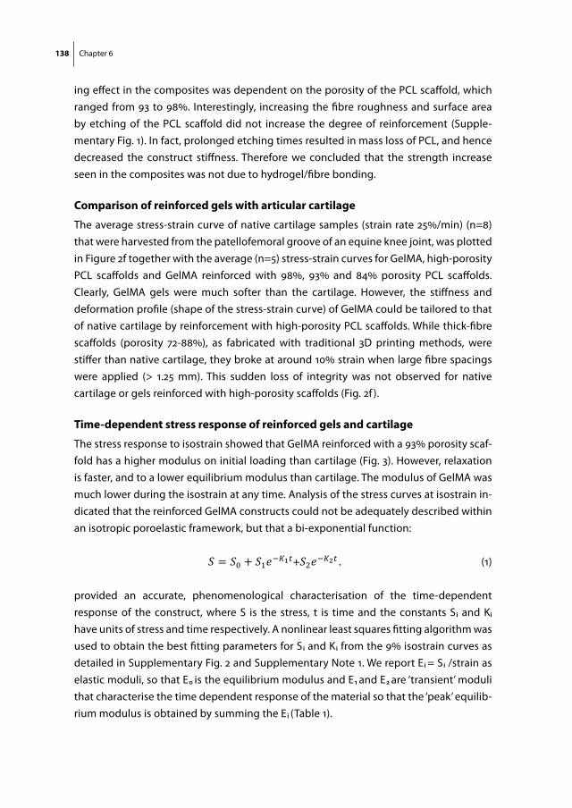
138 Chapter 6
ing effect in the composites was dependent on the porosity of the PCL scaffold, which ranged from 93 to 98%. Interestingly, increasing the fibre roughness and surface area by etching of the PCL scaffold did not increase the degree of reinforcement (Supple-mentary Fig. 1). In fact, prolonged etching times resulted in mass loss of PCL, and hence decreased the construct stiffness. Therefore we concluded that the strength increase seen in the composites was not due to hydrogel/fibre bonding.
comparison of reinforced gels with articular cartilage
The average stress-strain curve of native cartilage samples (strain rate 25%/min) (n=8) that were harvested from the patellofemoral groove of an equine knee joint, was plotted in Figure 2f together with the average (n=5) stress-strain curves for GelMA, high-porosity PCL scaffolds and GelMA reinforced with 98%, 93% and 84% porosity PCL scaffolds. Clearly, GelMA gels were much softer than the cartilage. However, the stiffness and deformation profile (shape of the stress-strain curve) of GelMA could be tailored to that of native cartilage by reinforcement with high-porosity PCL scaffolds. While thick-fibre scaffolds (porosity 72-88%), as fabricated with traditional 3D printing methods, were stiffer than native cartilage, they broke at around 10% strain when large fibre spacings were applied (> 1.25 mm). This sudden loss of integrity was not observed for native cartilage or gels reinforced with high-porosity scaffolds (Fig. 2f ).
time-dependent stress response of reinforced gels and cartilage
The stress response to isostrain showed that GelMA reinforced with a 93% porosity scaf-fold has a higher modulus on initial loading than cartilage (Fig. 3). However, relaxation is faster, and to a lower equilibrium modulus than cartilage. The modulus of GelMA was much lower during the isostrain at any time. Analysis of the stress curves at isostrain in-dicated that the reinforced GelMA constructs could not be adequately described within an isotropic poroelastic framework, but that a bi-exponential function:
Reinforcement of hydrogels using 3D-printed microfibres
! 104
lower equilibrium modulus than cartilage. The modulus of GelMA was much lower during the isostrain at any time. Analysis of the stress curves at isostrain indicated that the reinforced GelMA constructs could not be adequately described within an isotropic poroelastic framework, but that a bi-exponential function:
! = !! + !!!!!!!+!!!!!!!, (1)
provided an accurate, phenomenological characterisation of the time-dependent response of the construct, where S is the stress, t is time and the constants S! and K!!have units of stress and time respectively. A nonlinear least squares fitting algorithm was used to obtain the best fitting parameters for S! and K! from the 9% isostrain curves as detailed in Supplementary Fig. 2 and Supplementary Note 1. We report E! = S!/strain as elastic moduli, so that E! is the equilibrium modulus and E! and E! are ‘transient’ moduli that characterise the time dependent response of the material so that the ‘peak’ equilibrium modulus is obtained by summing the E! (Table 1). Modelling the fibre reinforcement of hydrogels The mechanism we propose to explain the synergistic reinforcement is illustrated in Figure 4a. Hydrogels can be reasonably described as incompressible359, so the volume of the hydrogel is conserved and vertical compression must be accompanied by horizontal expansion. As a composite construct is loaded, each ‘semi-confined cell' of hydrogel (right column in Fig. 4a) expands horizontally and places the surrounding fibres under tension. We hypothesise that the fibres’ resistance to elongation under compression loading, results in a pre-stress of the scaffold fibres. This resistance leads to the observed increase in stiffness, as the stiffness of bulk PCL is approximately four orders of magnitude higher than that of the gels. In order to confirm our hypothesis, we developed a mathematical model that enables us to make the following prediction for the construct stiffness, C:
! = !!!"!!!! !!! !/! (2)
where Nf denotes the number of fibres in the construct, E the Young's modulus of the reinforcing polymer, r the fibre radius, R the construct radius and λ the axial strain (expressed as a fraction of the initial height). A derivation and more detailed explanation of the model are provided in the Supplementary Table 1 and Supplementary Note 2. Video analysis of the compression cycle of reinforced gels The model was further validated by lateral video imaging of the compression cycle of the GelMA/PCL composites, which revealed elongation (stretching) of PCL microfibres and a concave profile at the sides of the construct due to lateral displacement of water from GelMA (Supplementary Movie 2, 97% porosity scaffold). The microfibres stretched 9 ± 1 % on 30% axial strain. In addition, from a top view it was observed that the PCL scaffold area expanded 17% and the aqueous component expanded 23% (including exudation of water) (Fig. 4a). Microfibre compared to thick-fibre composites The reinforcing effect was only observed in high-porosity scaffolds fabricated from thin fibres (diameter <48.2 μm), as indicated in Figure 4b. The 3D printing of thicker fibres (diameter >88.5 μm) resulted in a significantly lower scaffold porosity, ranging from 88% to 72% (PCL fraction of 12% to 28%, respectively), depending on the fibre thickness and spacing between the fibres. The stiffness of the thick-fibre scaffolds ranged from 1.8 ± 0.2 MPa for 88% porosity to 16.1 ± 1.7 MPa for 72% porosity. These scaffolds had stiffnesses similar to those of their composite counterparts with crosslinked GelMA. The compression cycle of GelMA reinforced with an 82% porosity scaffold is
(1)
provided an accurate, phenomenological characterisation of the time-dependent response of the construct, where S is the stress, t is time and the constants S i and Ki
have units of stress and time respectively. A nonlinear least squares fitting algorithm was used to obtain the best fitting parameters for S i and K i from the 9% isostrain curves as detailed in Supplementary Fig. 2 and Supplementary Note 1. We report E i = S i /strain as elastic moduli, so that E 0 is the equilibrium modulus and E 1 and E 2 are ‘transient’ moduli that characterise the time dependent response of the material so that the ‘peak’ equilib-rium modulus is obtained by summing the E i (Table 1).
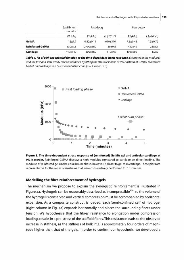
Reinforcement of hydrogels with 3D-printed microfibres 139
modelling the fibre reinforcement of hydrogels
The mechanism we propose to explain the synergistic reinforcement is illustrated in Figure 4a. Hydrogels can be reasonably described as incompressible359, so the volume of the hydrogel is conserved and vertical compression must be accompanied by horizontal expansion. As a composite construct is loaded, each ‘semi-confined cell’ of hydrogel (right column in Fig. 4a) expands horizontally and places the surrounding fibres under tension. We hypothesise that the fibres’ resistance to elongation under compression loading, results in a pre-stress of the scaffold fibres. This resistance leads to the observed increase in stiffness, as the stiffness of bulk PCL is approximately four orders of magni-tude higher than that of the gels. In order to confirm our hypothesis, we developed a
Fast loading phase
Equilibrium phase
0
1000
2000
3000
0 1 2 3 4 5
Mod
ulus
(kPa
)
Time (minutes)
GelMA
Reinforced GelMA
Cartilage
figure 3. the time-dependent stress response of (reinforced) gelma gel and articular cartilage at 9% isostrain. Reinforced GelMA displays a high modulus compared to cartilage on direct loading. The modulus of reinforced gels in the equilibrium phase, however, is closer to gel than cartilage. These plots are representative for the series of isostrains that were consecutively performed for 15 minutes.
Equilibrium modulus
Fast decay Slow decay
E0 (kPa) E1 (kPa) k1 (·103 s-1) E2 (kPa) k2 (·103 s-1)
gelma 12±1.7 0.82±0.11 610±310 7.8±0.43 1.5±0.76
reinforced gelma 130±7.8 2700±160 180±9.8 430±49 28±1.1
cartilage 440±140 300±160 110±45 430±200 4.9±2
Table 1. Fit of a bi-exponential function to the time-dependent stress response. Estimates of the moduli Ei and the fast and slow decay rates ki obtained by fitting the stress response at 9% isostrain of GelMA, reinforced GelMA and cartilage to a bi-exponential function (n = 3, mean±s.d).
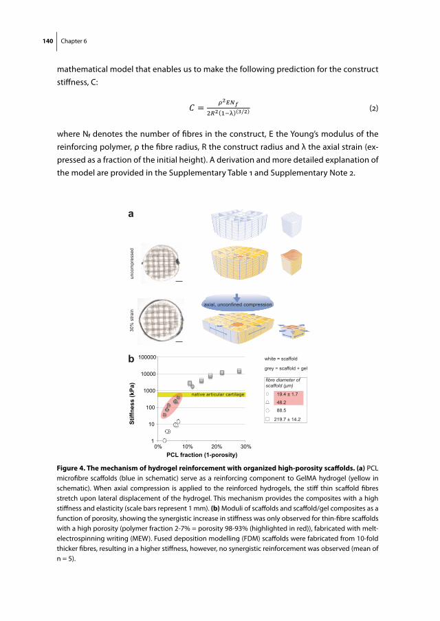
140 Chapter 6
mathematical model that enables us to make the following prediction for the construct stiffness, C:
Reinforcement of hydrogels using 3D-printed microfibres
! 104
lower equilibrium modulus than cartilage. The modulus of GelMA was much lower during the isostrain at any time. Analysis of the stress curves at isostrain indicated that the reinforced GelMA constructs could not be adequately described within an isotropic poroelastic framework, but that a bi-exponential function:
! = !! + !!!!!!!+!!!!!!!, (1)
provided an accurate, phenomenological characterisation of the time-dependent response of the construct, where S is the stress, t is time and the constants S! and K!!have units of stress and time respectively. A nonlinear least squares fitting algorithm was used to obtain the best fitting parameters for S! and K! from the 9% isostrain curves as detailed in Supplementary Fig. 2 and Supplementary Note 1. We report E! = S!/strain as elastic moduli, so that E! is the equilibrium modulus and E! and E! are ‘transient’ moduli that characterise the time dependent response of the material so that the ‘peak’ equilibrium modulus is obtained by summing the E! (Table 1). Modelling the fibre reinforcement of hydrogels The mechanism we propose to explain the synergistic reinforcement is illustrated in Figure 4a. Hydrogels can be reasonably described as incompressible359, so the volume of the hydrogel is conserved and vertical compression must be accompanied by horizontal expansion. As a composite construct is loaded, each ‘semi-confined cell' of hydrogel (right column in Fig. 4a) expands horizontally and places the surrounding fibres under tension. We hypothesise that the fibres’ resistance to elongation under compression loading, results in a pre-stress of the scaffold fibres. This resistance leads to the observed increase in stiffness, as the stiffness of bulk PCL is approximately four orders of magnitude higher than that of the gels. In order to confirm our hypothesis, we developed a mathematical model that enables us to make the following prediction for the construct stiffness, C:
! = !!!"!!!! !!! !/! (2)
where Nf denotes the number of fibres in the construct, E the Young's modulus of the reinforcing polymer, r the fibre radius, R the construct radius and λ the axial strain (expressed as a fraction of the initial height). A derivation and more detailed explanation of the model are provided in the Supplementary Table 1 and Supplementary Note 2. Video analysis of the compression cycle of reinforced gels The model was further validated by lateral video imaging of the compression cycle of the GelMA/PCL composites, which revealed elongation (stretching) of PCL microfibres and a concave profile at the sides of the construct due to lateral displacement of water from GelMA (Supplementary Movie 2, 97% porosity scaffold). The microfibres stretched 9 ± 1 % on 30% axial strain. In addition, from a top view it was observed that the PCL scaffold area expanded 17% and the aqueous component expanded 23% (including exudation of water) (Fig. 4a). Microfibre compared to thick-fibre composites The reinforcing effect was only observed in high-porosity scaffolds fabricated from thin fibres (diameter <48.2 μm), as indicated in Figure 4b. The 3D printing of thicker fibres (diameter >88.5 μm) resulted in a significantly lower scaffold porosity, ranging from 88% to 72% (PCL fraction of 12% to 28%, respectively), depending on the fibre thickness and spacing between the fibres. The stiffness of the thick-fibre scaffolds ranged from 1.8 ± 0.2 MPa for 88% porosity to 16.1 ± 1.7 MPa for 72% porosity. These scaffolds had stiffnesses similar to those of their composite counterparts with crosslinked GelMA. The compression cycle of GelMA reinforced with an 82% porosity scaffold is
(2)
where Nf denotes the number of fibres in the construct, E the Young’s modulus of the reinforcing polymer, ρ the fibre radius, R the construct radius and λ the axial strain (ex-pressed as a fraction of the initial height). A derivation and more detailed explanation of the model are provided in the Supplementary Table 1 and Supplementary Note 2.
1
10
100
1000
10000
100000
0% 10% 20% 30%
Stiff
ness
(kPa
)
PCL fraction (1-porosity)
fibre diameter of scaffold (μm)
19.4 ± 1.7
48.288.5
219.7 ± 14.2
white = scaffold
grey = scaffold + gel
a
b
unco
mpr
esse
d30
% s
train
native articular cartilage
axial, unconfined compression
figure 4. the mechanism of hydrogel reinforcement with organized high-porosity scaffolds. (a) PCL microfibre scaffolds (blue in schematic) serve as a reinforcing component to GelMA hydrogel (yellow in schematic). When axial compression is applied to the reinforced hydrogels, the stiff thin scaffold fibres stretch upon lateral displacement of the hydrogel. This mechanism provides the composites with a high stiffness and elasticity (scale bars represent 1 mm). (b) Moduli of scaffolds and scaffold/gel composites as a function of porosity, showing the synergistic increase in stiffness was only observed for thin-fibre scaffolds with a high porosity (polymer fraction 2-7% = porosity 98-93% (highlighted in red)), fabricated with melt-electrospinning writing (MEW). Fused deposition modelling (FDM) scaffolds were fabricated from 10-fold thicker fibres, resulting in a higher stiffness, however, no synergistic reinforcement was observed (mean of n = 5).

Reinforcement of hydrogels with 3D-printed microfibres 141
Video analysis of the compression cycle of reinforced gels
The model was further validated by lateral video imaging of the compression cycle of the GelMA/PCL composites, which revealed elongation (stretching) of PCL microfibres and a concave profile at the sides of the construct due to lateral displacement of water from GelMA (Supplementary Movie 2, 97% porosity scaffold). The microfibres stretched 9 ± 1 % on 30% axial strain. In addition, from a top view it was observed that the PCL scaffold area expanded 17% and the aqueous component expanded 23% (including exudation of water) (Fig. 4a).
microfibre compared to thick-fibre composites
The reinforcing effect was only observed in high-porosity scaffolds fabricated from thin fibres (diameter <48.2 μm), as indicated in Figure 4b. The 3D printing of thicker fibres (diameter >88.5 μm) resulted in a significantly lower scaffold porosity, ranging from 88% to 72% (PCL fraction of 12% to 28%, respectively), depending on the fibre thickness and spacing between the fibres. The stiffness of the thick-fibre scaffolds ranged from 1.8 ± 0.2 MPa for 88% porosity to 16.1 ± 1.7 MPa for 72% porosity. These scaffolds had stiffnesses similar to those of their composite counterparts with crosslinked GelMA. The compres-sion cycle of GelMA reinforced with an 82% porosity scaffold is shown in Supplementary
e
0
10
20
30
40
5% 10% 15% 20%
stre
ss (k
Pa)
strain
20%
25%
30%
35%
40%
0 5% 10% 15% 20%
stre
ss (k
Pa)
GelMA + 97% porosity mesh20% strain
cycle 20 cycle 1
0
5
10
15
stre
ss (k
Pa)
strain
GelMA 20% strain
cycle 20 cycle 1
a b
0
5
10
15
20
25
10% 20% 30% 40% 50%
stre
ss (k
Pa)
strain
GelMA50% strain
d
cycle 20 cycle 1
0
5
10
15
5% 10% 15% 20%
stre
ss (k
Pa)
strain
strain
cycle 20 cycle 1
GelMA + 93% porosity mesh20% strain
c
GelMA + 93% porosity mesh20-40% strain
5
10
15
5% 10% 15% 20%
figure 5. cyclic compression testing of gelma and reinforced gelma constructs. The stress-strain curves of the first and last of 20 cycles of 20% compression are shown for (a) GelMA alone (b) GelMA reinforced with a 97% po-rosity PCL scaffold and (c) GelMA reinforced with a 93% porosity PCL scaffold. For all groups no decay in stress was observed. (d) GelMA constructs also recovered after 20 cycles of 50% axial compression, however (e) GelMA reinforced with a 93% porous PCL scaffold required substantially less force to be com-pressed to 20% strain, after being compressed to over 30% strain (ar-row) (mean of n = 3).

142 Chapter 6
Movie 3. Exudation of fluid was observed; while the relatively thick scaffold fibres were compressed, they did not elongate.
recovery of gelma constructs after compression
The recovery of (reinforced) GelMA constructs after repetitive axial compression was measured. Figure 5a-c show that GelMA, as well as reinforced GelMA constructs are fully elastic after 20 cycles of 20% strain. The stress/strain curves of the initial and final loading cycle are shown. GelMA also fully recovered after repetitive 50% axial strain (Fig. 5d). However, GelMA reinforced with 93% porosity PCL microfibre scaffolds showed significantly decreased resistance when axially deformed by over 35% (Fig. 5e).
chondrogenic differentiation of embedded human chondrocytes
Haematoxylin and eosin stained sections revealed that chondrocytes retained their spherical morphology within the fibre-reinforced hydrogels after 7 days (Fig. 6c). Chon-
figure 6. differentiation of chondrocytes embedded in reinforced gelatin methacrylamide/hyal-uronic acid-hydrogels. (a) Stereomicroscopy image of a GelMA-HA gel and (b) of a GelMA-HA gel rein-forced with a PCL scaffold (93% porosity) on day 1 (scale bars represent 2 mm). (c) Hematoxylin/eosin stain-ing after 7 days of culture shows that chondrocytes remained within the GelMA component and retained a round morphology (scale bar represent 500 μm, inlay 200 μm). (d) DAPI staining confirms a homogenous distribution of the cells throughout the construct scale bar represent 200 μm). (e) Chondrocytes remained viable over 7 days of culture in the gels. Gene expression analysis for (f) ACAN, (g) COL2A1, (h) COL1A1, and (i) COL10A1 at day 14 for compressed (C) and non-compressed (NC) groups (n = 4, mean±s.d.; *P < 0.05, two-way ANOVA). All gene expression levels were normalized to the housekeeping gene β2 microglobulin (B2M). (j) Stiffness of the constructs following long-term culture (n = 4). (k) GAG/ww values at day 28 (n = 5).

Reinforcement of hydrogels with 3D-printed microfibres 143
drocytes were also homogenously distributed throughout the construct as shown by the DAPI-stained cell nuclei (Fig. 6d). Chondrocytes maintained high cell viability at day 1 and day 7 when cross-linked with 12.5 mM APS/TEMED (Fig. 6e). Following 14 days of culture, hydrogels (GelMA with 0.5% hyaluronic acid (Lifecore, USA) (GelMA-HA) for im-proved chondrogenic differentiation63 and GelMA-HA with 93% porous PCL mesh) were subjected to physiological loading cycles for another 14 days. The stress response to the 1 Hz dynamic loading regime is presented in Supplementary Fig. 3. Analysis of the qRT-PCR data indicated that for chondrocytes within the fibre-reinforced hydrogels, ACAN (gene expression for GAG synthesis) and COL1A1 (gene expression for collagen type I) mRNA levels were significantly up-regulated in the compressed (“C”) groups compared to the control, non-compressed groups (“NC”) (Fig. 6f-i; p < 0.05). Further, chondrocytes in the reinforced gels were more responsive to loading regime than cells in GelMA alone. Stiffness values were ~400 kPa in cell-laden fibre-reinforced hydrogels (Fig. 6j). There was no significant effect of reinforcement or compression on construct stiffness and glycosaminoglycan (GAG) content (Fig. 6k). The chondrocytes within the gels exhibited pericellular collagen type I and II deposition in all groups, with no discernible differences between the groups (Supplementary Fig. 4).
discussion
In this study, high strength composite constructs were fabricated by combining 3D-printed high-porosity scaffolds with a hydrogel. These composite hydrogels can be customized to yield a wide range of mechanical properties and, from a biological point of view, have the capacity to support cell proliferation and extracellular matrix produc-tion. The PCL scaffolds were built by micrometre scale fibres that were organized and interconnected through the melt electrospinning writing process. With this unique and new 3D printing technique, pre-set network architectures can be realized in a direct writing mode54. This technique allows fibres to be printed well below the limits of classi-cal melt-extrusion based 3D printing technologies such as fused deposition modelling50, with filament diameters as small as 5 µm, instead of 100 µm or larger206.
Hydrogels have previously been reinforced with solution electrospun nonwo-vens55,56,201,322. However, most traditional solution electrospun meshes have disadvan-tages from both a mechanical and biological point of view, e.g. fibres are not fused and hence slide under loading, meshes are usually not thicker then a 100 microns and have a pore size of less than 5 μm and are, therefore, too dense for cell infiltration201,204,322. To overcome these issues related to traditional solution electrospinning, fibres have been collected in an earthed ethanol bath, yielding nonwovens with high-porosities55,56. Hydrogel stiffness was increased 4-fold when reinforced with these randomly organized

144 Chapter 6
non-wovens, irrespective of the porosity55,201. Silk microfibres350 or carbon nanotubes192 also formed porous reinforcing structures for hydrogels, permitting cellular infiltration and differentiation. However, the stiffness of the gels increased only 1 to 3-fold, as the fibres were not fused. In contrast, in our current composite model consisting of a rela-tively soft hydrogel (7.1 – 15.8 kPa) and a highly porous and soft PCL scaffold (1.1 - 15.2 kPa), the maximum stiffness obtained was a factor of fifty larger (405 kPa) than that of the hydrogels alone, on a strain rate of 25%/min.
The stiffness of cartilage and (reinforced) hydrogels is strongly strain-rate depen-dent357,358. We found that the reinforced hydrogels were one order of magnitude stiffer than cartilage on initial fast loading at 9% strain. However, the modulus of reinforced hydrogels displayed a steep decrease to an equilibrium value roughly one-third the equilibrium modulus of cartilage, yet still one order of magnitude larger than the equi-librium modulus of hydrogel alone.
The effect of reinforcement can be explained by the highly organized fibre architecture of the scaffolds. The mathematical model we developed demonstrated that the hydrogel places the PCL fibres under tension on axial compression, and predicts a theoretical up-per bound on the attainable stiffness. However, the theoretical stiffness of the reinforced hydrogels is one order of magnitude larger than that observed experimentally. This is reasonable since an idealized construct was considered, in which the fibres are initially taut at zero strain, the hydrogel is purely elastic and there is no slip between the fibres and the hydrogel. In fact, in our experimental set-up, we showed that very little water, or hydrogel, was compressed out of the constructs, so the fibres did not completely lock the hydrogel. The stress relaxation on isostrain (Fig. 3) reflects the exudation of the aque-ous component (water or gel) from the reinforcing scaffold. For cartilage we observed a higher equilibrium modulus, which may be a combined effect of the osmotic pressure of fixed charges on proteoglycans and an organised extracellular matrix.
Etching the high-porosity scaffolds did not result in a further increase in stiffness of the composites. This approach was based on our previous finding that covalent at-tachment of the hydrogel component to a scaffold that was fabricated from modified, methacrylated PCL, resulted in increased construct strength255. It should be noted that etching results in an increase of van de Waals forces but does not establish covalent bonds between the hydrogel and the reinforcing scaffold.
Infiltrating hydrogel into scaffolds that had been fabricated with traditional 3D melt-printing techniques with thick fibres (≥88 μm)50, did not show a significant mechanical effect. Axial loading of these constructs requires compression of the PCL through a strong vertical column of fibre crossings, which is not easily deformed. Video imaging of the compression cycle confirmed that thick fibres were not stretched and water flowed out of these scaffolds without providing a synergistic effect. In contrast, the columns of fine fibre crossings are easily deformed under axial loading, yet they are supported by

Reinforcement of hydrogels with 3D-printed microfibres 145
the hydrogel component in the composites. Supplementary Movie 2 shows some local distortion of the columns, but no large scale buckling of the columns, so the microfibres are put under tension. We further note that this axial loading reduces the horizontal pore size, improving gel confinement. To our knowledge we are the first to show the synergistic effect of a well-designed scaffold/hydrogel system; the work shown in this paper could therefore lead to a paradigm shift in the field.
Reinforced GelMA hydrogels possess stress-strain curves that closely resemble those of healthy articular cartilage. Also, in absolute terms, the stiffness of the biodegrad-able composites was comparable to the stiffness of articular cartilage, which has been reported to range from 400-800 kPa360-362. On the other hand, the stiffness of scaffolds fabricated with traditional 3D printing was one order of magnitude larger than that of articular cartilage, which is consistent with previous reports65,76. The porosity of these scaffolds ranged between 72% and 89%, whereas the porosities reported in the litera-ture range from 28.9% and 91.2%50,190,363. Nevertheless, when aiming to fabricate high-porosity scaffolds (> 80%) from thick fibres, large fibre spacing (> 1.5 mm) is required, which causes scaffold disintegration under strains of approximately 10%. In addition, the thicker fibres occupy a relatively high volume that is inaccessible for tissue formation until the scaffold has degraded.
Hydrogels reinforced with woven scaffolds, composed of either polyglycolic acid343 or PCL316,351 have previously been reported to possess tensile, compressive and shear properties comparable to native cartilage. The porosity of these woven scaffolds was 70-74%, compared to 93-98% in the present study. The stiffness of the woven com-posites was reported up to 0.2 Mpa (at equilibrium stress), which was twice as stiff as the scaffold without the gel316. Both the woven and the melt electrospun composites showed axial recovery after compression for 10% and 20%, respectively. The water that was compressed out of the scaffolds was likely reabsorbed during the relaxation phase, comparable to fluid dynamics in articular cartilage364. Our reinforced hydrogels showed decreased resistance if compressed by 35% or more, which may be due to fractures or delamination in the PCL scaffold junctions. For translational purposes, it is important to realize that native cartilage is exposed to 15-45% axial deformation under long-term static compression365.
Incorporation of organized fibrous PCL scaffolds within a well-characterized hydrogel system makes it possible to culture cells in a customizable, mechanically diversified environment. The hydrogel component of the composite constructs will degrade within months63,255, allowing the regeneration of new tissue, while the PCL component degrades within years51 forming a temporary reinforcing network to the new tissue. Under physiological compressive loading of 20% strain and 1 Hz, our gene expression data suggest that chondrocyte expression of matrix mRNAs is significantly up-regulated in composite hydrogels compared to non-reinforced, weak hydrogels. These results
146 Chapter 6
highlight the importance of developing cell-culture platforms and tissue engineered constructs that better mimic the in vivo mechano-environment of natural articular cartilage. Still, the exact mechanisms of stress-transfer to the cells in fibre-reinforced hydrogels remain to be investigated.
In conclusion, the current work represents a significant step towards developing biomechanically functional tissue constructs. The stiffness of the constructs was sig-nificantly enhanced, achieving values similar to those of native articular cartilage, by combining hydrogels with 3D-printed, high-porosity melt electrospun PCL scaffolds. This synergistic effect could be modulated by altering the porosity of the reinforcing scaffolds. The composite constructs have a strong elastic component and recover after physiological axial strains. Finally, human chondrocytes encapsulated in the GelMA/PCL composites were found to be more responsive to mechanical loading, which led to significant changes in gene expression in vitro.
acKnowledgements
The authors thank dr. Christina Theodoropoulos for her assistance with SEM imaging; Mr. Onur Bas for his assistance with the dynamic bioreactor; Mr. Mies Steenbergen for his assistance with video imaging and Kim Benders MD, for harvesting the human chondrocytes. We are also grateful to prof. Dirk Grijpma and Mrs. Anita Bijsterveld-Podt from the University of Twente for facilitating mechanical testing on their Zwick universal mechanical tester. We thank prof. Harrie Weinans for fruitful discussions on cartilage biomechanics. The II-II6B3 monoclonal antibody developed by T.F. Linsenmayer was ob-tained from the Developmental Studies Hybridoma Bank developed under the auspices of the NICHD and maintained by The University of Iowa, Department of Biology, Iowa City, IA 52242. Jetze Visser was supported by a grant from the Dutch government to the Netherlands Institute for Regenerative Medicine (NIRM, grant nFES0908); Ferry Melchels was supported by a Marie Curie grant from the European Commission (PIOF-GA-272286) and Jos Malda was supported by the Dutch Arthritis Foundation. This work was also sup-ported by the Australia National Health and Medical Research Council and the European Community’s Seventh Framework Programme (FP7/2007-2013) under grant agreement n309962 (HydroZONES).
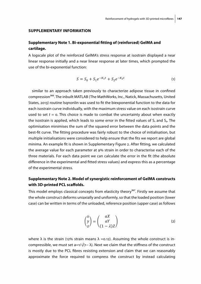
Reinforcement of hydrogels with 3D-printed microfibres 147
supplementary information
supplementary note 1. Bi-exponential fitting of (reinforced) gelma and cartilage.
A logscale plot of the reinforced GelMA’s stress response at isostrain displayed a near linear response initially and a near linear response at later times, which prompted the use of the bi-exponential function:
Reinforcement of hydrogels using 3D-printed microfibres
! 118
Supplementary Note 1. Bi-exponential fitting of (reinforced) GelMA and cartilage. A logscale plot of the reinforced GelMA’s stress response at isostrain displayed a near linear response initially and a near linear response at later times, which prompted the use of the bi-exponential function:
! = !! + !!!!!!! + !!!!!!! (1) similar to an approach taken previously to characterize adipose tissue in confined compression366. The inbuilt MATLAB (The MathWorks, Inc., Natick, Massachusetts, United States, 2013) routine lsqnonlin was used to fit the biexponential function to the data for each isostrain curve individually, with the maximum stress value on each isostrain curve used to set ! = 0. This choice is made to combat the uncertainty about when exactly the isostrain is applied, which leads to some error in the fitted values of S1 and S2. The optimisation minimises the sum of the squared error between the data points and the best-fit curve. The fitting procedure was fairly robust to the choice of initialisation, but multiple initialisations were considered to help ensure that the fits we report are global minima. An example fit is shown in Supplementary Figure 2. After fitting, we calculated the average value for each parameter at 9% strain in order to characterise each of the three materials. For each data point we can calculate the error in the fit (the absolute difference in the experimental and fitted stress values) and express this as a percentage of the experimental stress.
(1)
similar to an approach taken previously to characterize adipose tissue in confined compression366. The inbuilt MATLAB (The MathWorks, Inc., Natick, Massachusetts, United States, 2013) routine lsqnonlin was used to fit the biexponential function to the data for each isostrain curve individually, with the maximum stress value on each isostrain curve used to set t = 0. This choice is made to combat the uncertainty about when exactly the isostrain is applied, which leads to some error in the fitted values of S1 and S2. The optimisation minimises the sum of the squared error between the data points and the best-fit curve. The fitting procedure was fairly robust to the choice of initialisation, but multiple initialisations were considered to help ensure that the fits we report are global minima. An example fit is shown in Supplementary Figure 2. After fitting, we calculated the average value for each parameter at 9% strain in order to characterise each of the three materials. For each data point we can calculate the error in the fit (the absolute difference in the experimental and fitted stress values) and express this as a percentage of the experimental stress.
supplementary note 2. model of synergistic reinforcement of gelma constructs with 3d-printed pcl scaffolds.
This model employs classical concepts from elasticity theory367. Firstly we assume that the whole construct deforms uniaxially and uniformly, so that the loaded position (lower case) can be written in terms of the unloaded, reference position (upper case) as follows
Chapter 6
! 119
Supplementary Note 2. Model of synergistic reinforcement of GelMA constructs with 3D-printed PCL scaffolds. This model employs classical concepts from elasticity theory367. Firstly we assume that the whole construct deforms uniaxially and uniformly, so that the loaded position (lower case) can be written in terms of the unloaded, reference position (upper case) as follows
!!!
=!"!"
1 − ! ! (2)
where ! is the strain (12% strain means ! =0.12). Assuming the whole construct is incompressible, we must set a=1/ 1 − ! . Next we claim that the stiffness of the construct is mostly due to the PCL fibres resisting extension and claim that we can reasonably approximate the force required to compress the construct by instead calculating the tensile force required to stretch PCL fibres by a factor 1/ 1 − ! . This neglects any mechanical contribution the GelMA makes to scaffold stiffness, which is reasonable because we know the GelMA is very weak in comparison to the composite scaffolds. In this hypothesis the GelMA is only important for converting vertical load into fibre extension. If we consider one fibre in uniaxial tension then, according to linear elasticity theory, the tensile force in the fibre is given by
!! = !!!! !!!! − 1 (3)
where ! is the fibre radius and E is the Young's modulus of PCL. Our next modelling assumption, that the tensile force in all the fibres can be summed linearly to approximate the force applied to deform the composite scaffold, implies that the stress on the scaffold surface, S, is given by
! = !!!!!!!!!
!!!! − 1 (4)
where R is the construct radius and !! is the number of fibres in the construct. The stiffness is calculated as the derivative of this stress with respect to strain, so that the predicted stiffness of the construct is
! = !"!" =
!!!!!!!! !!! ! ! (5)
To evaluate this prediction for the construct stiffness we consider the placement of fibres in one layer. This allows us to approximate the length of PCL fibre, L, in a given layer and the number of fibres under tension, !!", in that layer. Noting that !!"#, the volume of PCL in a construct, is given by
!!"# = !!!!!! (6) where !! is the number of layers in a construct, we use the measured PCL volume to estimate !!!!. Finally we multiply by !!" to obtain an approximation for !!!!. We take the Young's modulus of PCL to be 310MPa, the construct radius R=2.5mm and we approximate the stiffness at 12% strain. The numbers used in this section and the predicted stiffnesses are stated in Supplementary Table 1.
(2)
where λ is the strain (12% strain means λ =0.12). Assuming the whole construct is in-compressible, we must set a=1/√(1− λ). Next we claim that the stiffness of the construct is mostly due to the PCL fibres resisting extension and claim that we can reasonably approximate the force required to compress the construct by instead calculating

148 Chapter 6
the tensile force required to stretch PCL fibres by a factor 1/√(1− λ). This neglects any mechanical contribution the GelMA makes to scaffold stiffness, which is reasonable be-cause we know the GelMA is very weak in comparison to the composite scaffolds. In this hypothesis the GelMA is only important for converting vertical load into fibre extension. If we consider one fibre in uniaxial tension then, according to linear elasticity theory, the tensile force in the fibre is given by
Chapter 6
! 119
Supplementary Note 2. Model of synergistic reinforcement of GelMA constructs with 3D-printed PCL scaffolds. This model employs classical concepts from elasticity theory367. Firstly we assume that the whole construct deforms uniaxially and uniformly, so that the loaded position (lower case) can be written in terms of the unloaded, reference position (upper case) as follows
!!!
=!"!"
1 − ! ! (2)
where ! is the strain (12% strain means ! =0.12). Assuming the whole construct is incompressible, we must set a=1/ 1 − ! . Next we claim that the stiffness of the construct is mostly due to the PCL fibres resisting extension and claim that we can reasonably approximate the force required to compress the construct by instead calculating the tensile force required to stretch PCL fibres by a factor 1/ 1 − ! . This neglects any mechanical contribution the GelMA makes to scaffold stiffness, which is reasonable because we know the GelMA is very weak in comparison to the composite scaffolds. In this hypothesis the GelMA is only important for converting vertical load into fibre extension. If we consider one fibre in uniaxial tension then, according to linear elasticity theory, the tensile force in the fibre is given by
!! = !!!! !!!! − 1 (3)
where ! is the fibre radius and E is the Young's modulus of PCL. Our next modelling assumption, that the tensile force in all the fibres can be summed linearly to approximate the force applied to deform the composite scaffold, implies that the stress on the scaffold surface, S, is given by
! = !!!!!!!!!
!!!! − 1 (4)
where R is the construct radius and !! is the number of fibres in the construct. The stiffness is calculated as the derivative of this stress with respect to strain, so that the predicted stiffness of the construct is
! = !"!" =
!!!!!!!! !!! ! ! (5)
To evaluate this prediction for the construct stiffness we consider the placement of fibres in one layer. This allows us to approximate the length of PCL fibre, L, in a given layer and the number of fibres under tension, !!", in that layer. Noting that !!"#, the volume of PCL in a construct, is given by
!!"# = !!!!!! (6) where !! is the number of layers in a construct, we use the measured PCL volume to estimate !!!!. Finally we multiply by !!" to obtain an approximation for !!!!. We take the Young's modulus of PCL to be 310MPa, the construct radius R=2.5mm and we approximate the stiffness at 12% strain. The numbers used in this section and the predicted stiffnesses are stated in Supplementary Table 1.
(3)
where ρ is the fibre radius and E is the Young’s modulus of PCL. Our next modelling assumption, that the tensile force in all the fibres can be summed linearly to approxi-mate the force applied to deform the composite scaffold, implies that the stress on the scaffold surface, S, is given by
Chapter 6
! 119
Supplementary Note 2. Model of synergistic reinforcement of GelMA constructs with 3D-printed PCL scaffolds. This model employs classical concepts from elasticity theory367. Firstly we assume that the whole construct deforms uniaxially and uniformly, so that the loaded position (lower case) can be written in terms of the unloaded, reference position (upper case) as follows
!!!
=!"!"
1 − ! ! (2)
where ! is the strain (12% strain means ! =0.12). Assuming the whole construct is incompressible, we must set a=1/ 1 − ! . Next we claim that the stiffness of the construct is mostly due to the PCL fibres resisting extension and claim that we can reasonably approximate the force required to compress the construct by instead calculating the tensile force required to stretch PCL fibres by a factor 1/ 1 − ! . This neglects any mechanical contribution the GelMA makes to scaffold stiffness, which is reasonable because we know the GelMA is very weak in comparison to the composite scaffolds. In this hypothesis the GelMA is only important for converting vertical load into fibre extension. If we consider one fibre in uniaxial tension then, according to linear elasticity theory, the tensile force in the fibre is given by
!! = !!!! !!!! − 1 (3)
where ! is the fibre radius and E is the Young's modulus of PCL. Our next modelling assumption, that the tensile force in all the fibres can be summed linearly to approximate the force applied to deform the composite scaffold, implies that the stress on the scaffold surface, S, is given by
! = !!!!!!!!!
!!!! − 1 (4)
where R is the construct radius and !! is the number of fibres in the construct. The stiffness is calculated as the derivative of this stress with respect to strain, so that the predicted stiffness of the construct is
! = !"!" =
!!!!!!!! !!! ! ! (5)
To evaluate this prediction for the construct stiffness we consider the placement of fibres in one layer. This allows us to approximate the length of PCL fibre, L, in a given layer and the number of fibres under tension, !!", in that layer. Noting that !!"#, the volume of PCL in a construct, is given by
!!"# = !!!!!! (6) where !! is the number of layers in a construct, we use the measured PCL volume to estimate !!!!. Finally we multiply by !!" to obtain an approximation for !!!!. We take the Young's modulus of PCL to be 310MPa, the construct radius R=2.5mm and we approximate the stiffness at 12% strain. The numbers used in this section and the predicted stiffnesses are stated in Supplementary Table 1.
(4)
where R is the construct radius and N f is the number of fibres in the construct. The stiffness is calculated as the derivative of this stress with respect to strain, so that the predicted stiffness of the construct is
Chapter 6
! 119
Supplementary Note 2. Model of synergistic reinforcement of GelMA constructs with 3D-printed PCL scaffolds. This model employs classical concepts from elasticity theory367. Firstly we assume that the whole construct deforms uniaxially and uniformly, so that the loaded position (lower case) can be written in terms of the unloaded, reference position (upper case) as follows
!!!
=!"!"
1 − ! ! (2)
where ! is the strain (12% strain means ! =0.12). Assuming the whole construct is incompressible, we must set a=1/ 1 − ! . Next we claim that the stiffness of the construct is mostly due to the PCL fibres resisting extension and claim that we can reasonably approximate the force required to compress the construct by instead calculating the tensile force required to stretch PCL fibres by a factor 1/ 1 − ! . This neglects any mechanical contribution the GelMA makes to scaffold stiffness, which is reasonable because we know the GelMA is very weak in comparison to the composite scaffolds. In this hypothesis the GelMA is only important for converting vertical load into fibre extension. If we consider one fibre in uniaxial tension then, according to linear elasticity theory, the tensile force in the fibre is given by
!! = !!!! !!!! − 1 (3)
where ! is the fibre radius and E is the Young's modulus of PCL. Our next modelling assumption, that the tensile force in all the fibres can be summed linearly to approximate the force applied to deform the composite scaffold, implies that the stress on the scaffold surface, S, is given by
! = !!!!!!!!!
!!!! − 1 (4)
where R is the construct radius and !! is the number of fibres in the construct. The stiffness is calculated as the derivative of this stress with respect to strain, so that the predicted stiffness of the construct is
! = !"!" =
!!!!!!!! !!! ! ! (5)
To evaluate this prediction for the construct stiffness we consider the placement of fibres in one layer. This allows us to approximate the length of PCL fibre, L, in a given layer and the number of fibres under tension, !!", in that layer. Noting that !!"#, the volume of PCL in a construct, is given by
!!"# = !!!!!! (6) where !! is the number of layers in a construct, we use the measured PCL volume to estimate !!!!. Finally we multiply by !!" to obtain an approximation for !!!!. We take the Young's modulus of PCL to be 310MPa, the construct radius R=2.5mm and we approximate the stiffness at 12% strain. The numbers used in this section and the predicted stiffnesses are stated in Supplementary Table 1.
(5)
To evaluate this prediction for the construct stiffness we consider the placement of fibres in one layer. This allows us to approximate the length of PCL fibre, L, in a given layer and the number of fibres under tension, N f l, in that layer. Noting that VPGL, the volume of PCL in a construct, is given by
Chapter 6
! 119
Supplementary Note 2. Model of synergistic reinforcement of GelMA constructs with 3D-printed PCL scaffolds. This model employs classical concepts from elasticity theory367. Firstly we assume that the whole construct deforms uniaxially and uniformly, so that the loaded position (lower case) can be written in terms of the unloaded, reference position (upper case) as follows
!!!
=!"!"
1 − ! ! (2)
where ! is the strain (12% strain means ! =0.12). Assuming the whole construct is incompressible, we must set a=1/ 1 − ! . Next we claim that the stiffness of the construct is mostly due to the PCL fibres resisting extension and claim that we can reasonably approximate the force required to compress the construct by instead calculating the tensile force required to stretch PCL fibres by a factor 1/ 1 − ! . This neglects any mechanical contribution the GelMA makes to scaffold stiffness, which is reasonable because we know the GelMA is very weak in comparison to the composite scaffolds. In this hypothesis the GelMA is only important for converting vertical load into fibre extension. If we consider one fibre in uniaxial tension then, according to linear elasticity theory, the tensile force in the fibre is given by
!! = !!!! !!!! − 1 (3)
where ! is the fibre radius and E is the Young's modulus of PCL. Our next modelling assumption, that the tensile force in all the fibres can be summed linearly to approximate the force applied to deform the composite scaffold, implies that the stress on the scaffold surface, S, is given by
! = !!!!!!!!!
!!!! − 1 (4)
where R is the construct radius and !! is the number of fibres in the construct. The stiffness is calculated as the derivative of this stress with respect to strain, so that the predicted stiffness of the construct is
! = !"!" =
!!!!!!!! !!! ! ! (5)
To evaluate this prediction for the construct stiffness we consider the placement of fibres in one layer. This allows us to approximate the length of PCL fibre, L, in a given layer and the number of fibres under tension, !!", in that layer. Noting that !!"#, the volume of PCL in a construct, is given by
!!"# = !!!!!! (6) where !! is the number of layers in a construct, we use the measured PCL volume to estimate !!!!. Finally we multiply by !!" to obtain an approximation for !!!!. We take the Young's modulus of PCL to be 310MPa, the construct radius R=2.5mm and we approximate the stiffness at 12% strain. The numbers used in this section and the predicted stiffnesses are stated in Supplementary Table 1.
(6)
where Nl is the number of layers in a construct, we use the measured PCL volume to estimate ρ2Nl Finally we multiply by Nf l to obtain an approximation for ρ2Nf. We take the Young’s modulus of PCL to be 310MPa, the construct radius R=2.5mm and we ap-proximate the stiffness at 12% strain. The numbers used in this section and the predicted stiffnesses are stated in Supplementary Table 1.
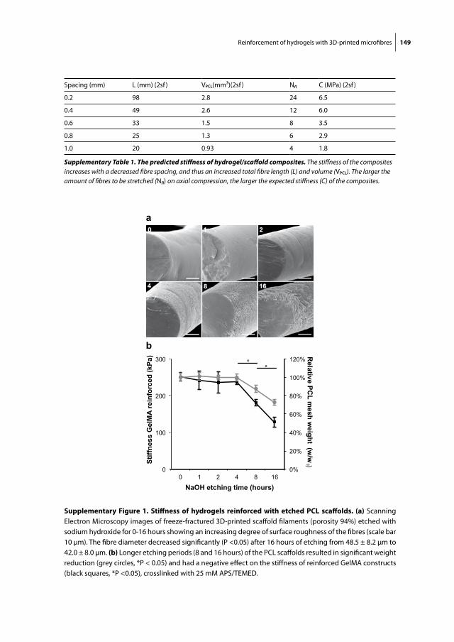
Reinforcement of hydrogels with 3D-printed microfibres 149
b
a
0%
20%
40%
60%
80%
100%
120%
0
100
200
300
0 1 2 4 8 16
Relative PC
L mesh w
eight (w/w
0 ) Stiff
ness
Gel
MA
rein
forc
ed (k
Pa)
NaOH etching time (hours)
**
supplementary figure 1. stiffness of hydrogels reinforced with etched pcl scaffolds. (a) Scanning Electron Microscopy images of freeze-fractured 3D-printed scaffold filaments (porosity 94%) etched with sodium hydroxide for 0-16 hours showing an increasing degree of surface roughness of the fibres (scale bar 10 μm). The fibre diameter decreased significantly (P <0.05) after 16 hours of etching from 48.5 ± 8.2 μm to 42.0 ± 8.0 μm. (b) Longer etching periods (8 and 16 hours) of the PCL scaffolds resulted in significant weight reduction (grey circles, *P < 0.05) and had a negative effect on the stiffness of reinforced GelMA constructs (black squares, *P <0.05), crosslinked with 25 mM APS/TEMED.
Spacing (mm) L (mm) (2sf ) VPCL(mm3)(2sf ) Nf l C (MPa) (2sf )
0.2 98 2.8 24 6.5
0.4 49 2.6 12 6.0
0.6 33 1.5 8 3.5
0.8 25 1.3 6 2.9
1.0 20 0.93 4 1.8
Supplementary Table 1. The predicted stiffness of hydrogel/scaffold composites. The stiffness of the composites increases with a decreased fibre spacing, and thus an increased total fibre length (L) and volume (VPCL). The larger the amount of fibres to be stretched (Nf l) on axial compression, the larger the expected stiffness (C) of the composites.
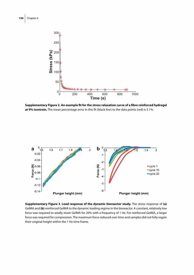
150 Chapter 6
0 200 400 600 800 10000
50
100
150
200
250
300
Time (s)
Stre
ss (k
Pa)
supplementary figure 2. an example fit for the stress relaxation curve of a fibre reinforced hydrogel at 9% isostrain. The mean percentage error in this fit (black line) to the data points (red) is 5.1%.
supplementary figure 3. load response of the dynamic bioreactor study. The stress response of (a) GelMA and (b) reinforced GelMA to the dynamic loading regime in the bioreactor. A constant, relatively low force was required to axially strain GelMA for 20% with a frequency of 1 Hz. For reinforced GelMA, a larger force was required for compression. The maximum force reduced over time and samples did not fully regain their original height within the 1 Hz time frame.
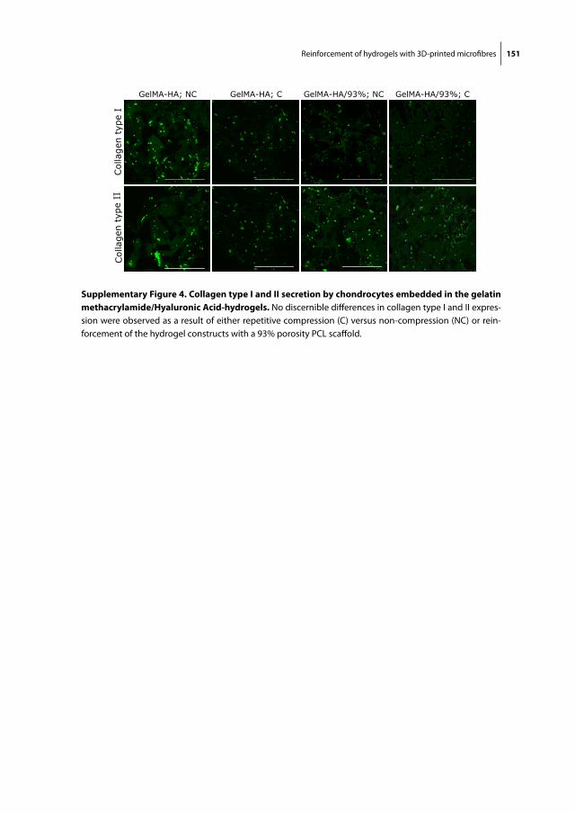
Reinforcement of hydrogels with 3D-printed microfibres 151
supplementary figure 4. collagen type i and ii secretion by chondrocytes embedded in the gelatin methacrylamide/hyaluronic acid-hydrogels. No discernible differences in collagen type I and II expres-sion were observed as a result of either repetitive compression (C) versus non-compression (NC) or rein-forcement of the hydrogel constructs with a 93% porosity PCL scaffold.


Chapter 7Preliminary results of a translational animal model
Cartilage Repair with a Combination of Chondrons and MSCs in Gelatin Methacrylamide Hydrogel: the Establishment of an Equine Model
Jetze VisserIrina A.D. ManciniHarold BrommerPia H. PuhakkaLucienne A. VonkImo HoeferWouter J.A. DhertPaul D. DaltonJuha TöyräsDaniël B.F. SarisP. René van WeerenJos Malda
The results of the 1-year follow-up of ponies in this cartilage
repair study are awaited before this manuscript will be
submitted for publication
154 Chapter 7
aBstract
Gelatin methacrylamide (GelMA) hydrogel has been shown to support the formation of a cartilage matrix by embedded cells in vitro. In addition, when reinforced with a structured microfiber scaffold, GelMA approached the stiffness of articular cartilage, yet the potential of GelMA and reinforced GelMA for the repair of in vivo articular cartilage defects remains to be demonstrated. To this end, a surgical technique for implanting and UV-crosslinking GelMA and reinforced GelMA into cartilage defects (10 mm di-ameter) was developed using cadaveric equine stifle joints (n=3) and applied in one Shetland pony (two defects in one stifle joint) to study surgical feasibility and implant fixation. Next, a mixture of allogeneic chondrons and expanded MSCs was implanted in four different experimental groups in both stifle joints of eight Shetland ponies, comparing three GelMA-based groups with fibrin glue, the clinical standard cell carrier, using two cell concentrations. The groups were 1) GelMA, 2) reinforced GelMA (high cell concentrations), 3) ‘GelMA cap’ and 4) fibrin glue (low cell concentration). The ‘GelMA cap’ group consists of cells on the bottom of the defect capped with cell-free GelMA. With this set-up, we aimed to study the mechanism of tissue regeneration – ‘bottom-up’ or ‘substitutive’ (within the hydrogel) – depending on the biomaterial and the amount of cells used. The implants were still in place after 50 flexion-extension cycles in cadav-eric stifle joints as well as after 2 weeks in vivo in a pilot study. Abundant infiltration of fibroblastic cells into the GelMA was found in that animal after 2 weeks. The cohort of eight ponies recovered well from bilateral joint surgery and baseline evaluation of the implants was conducted using optical coherence tomography and ultrasound imaging, confirming the location of the implant and the capturing the quality of the subchondral bone and the surrounding cartilage. In conclusion, a model was developed to study the cartilage repair process in Shetland ponies. GelMA hydrogel, with or without reinforcing microfiber scaffolds, was successfully UV-crosslinked and fixated in cartilage defects in the stifle joint. A study that evaluates the potential of GelMA compared to fibrin glue for the long-term regeneration (12 months) of cartilage is currently ongoing in eight ponies.
Cartilage repair in an equine model 155
introduction
Cells for the repair of focal cartilage defects are usually introduced in a hydrogel6,9. Fibrin glue is the standard cell delivery vehicle, because of the availability in clinical grade and its surgical applicability6,9. However, fibrin glue was not specifically developed for ap-plication in regenerative medicine as the crosslinked fibrin polymer network is relatively soft and as it has a high degradation rate26,27. Efforts are currently being made to develop more instructive and stronger gels with controlled degradation rates that balances with the process of tissue regeneration9,29,30.
In these tailored hydrogels, the matrix that is formed by embedded cells is meant to be deposited within the gel, gradually substituting the volume of the hydrogel29,368. This process was confirmed for chondrocytes and multipotent mesenchymal stromal cells (MSCs) embedded in GelMA hydrogels in vitro and in vivo in Chapter 3, 4 and 5 of this thesis, as well as in other studies60,63,73,257. In contrast, when cells are implanted in a chondral defect in fibrin369, cartilage tissue formation is likely to occur from the bottom of the defect. Here, we aim to study these different regenerative processes – bottom-up or substitutive - in an orthotopic animal model.
For the purpose of the testing orthopedic interventions or devices, horses have been recognized suitable animals, considering the similarities between equine and human cartilage of the biological and the challenging mechanical environment80,355,370. In this study, a cartilage repair model was established in the stifle joint of Shetland ponies. The Shetland pony was selected because of its robust nature, availability, ease of surgical management and housing, and for having a weight that comes closer to the human situation than that of other horse breeds371.
The different tested treatments were GelMA, GelMA reinforced with 3D printed micro-fiber scaffolds (described in Chapter 6), fibrin glue and cell-free GelMA covering the cells (‘GelMA cap’). In the ‘GelMA cap’ group, a low amount of cells is deposited on the bottom of the defect, and subsequently capped with cell-free GelMA. The cap can potentially control the ingrowth of cells from the bottom of the defect. This repair mechanism is also aimed for in recently developed therapies, in which the cartilage defect is covered with a cell-free biomaterial after microfracture372,373.
A cell combination of equine chondrons and MSCs was selected24, inspired by encour-aging preliminary results of a study on cartilage repair in humans, using a mixture of autologous chondrons and allogeneic MSCs25,374. Here, two cell concentrations are ap-plied: relative low concentrations as often used for clinical cell therapy (used in the fibrin and ‘GelMA cap’ group) and higher concentrations, which are more commonly used for hydrogel-based tissue engineering (applied in the GelMA and reinforced GelMA group).
Implantation techniques were first established in cadaveric equine stifle joints and then in a pilot study in a Shetland pony. A comparative study of the treatments was

156 Chapter 7
subsequently initiated in eight Shetland ponies. The one-year follow-up is ongoing, including intensive monitoring featuring repeated arthroscopic assessment with help of advanced imaging techniques of the implant surface and content. At the end point, cartilage matrix formation will be qualified and quantified. In addition, the DNA of the explant will be matched with the implanted cells and the host DNA, to study which source is responsible for matrix formation.
materials and methods
experimental set-up
First, we tested the viability and morphology of equine chondrons after storage in liquid nitrogen, for potential use as an allogeneic cell source for the cartilage repair studies in ponies. Next, the effect of various crosslinking periods (ranging from 30-300 seconds) of GelMA with a focused UV-source on cell viability and hydrogel stiffness was assessed. GelMA was implanted and crosslinked in cadaveric stifles (n=3) and in the stifle joint of one Shetland pony as a feasibility study for the cartilage repair study with GelMA hydrogels. Finally, the GelMA, reinforced GelMA, ‘GelMA cap‘ and fibrin glue groups with allogeneic chondrons and MSCs were implanted in eight ponies (four defects per animal).
preparation of gelma
GelMA was synthesized by reaction of porcine type A gelatin (Sigma-Aldrich, St. Louis, Missouri, USA) with methacrylic anhydride (Sigma-Aldrich) at 50 °C for one hour, as previously described60,62. In short, methacrylic anhydride was added dropwise to a 10% solution of gelatin in PBS under constant stirring. To achieve a high degree of function-alization, 0.6 g of methacrylic anhydride was added per gram of gelatin. The functional-ized polymer was dialyzed against distilled water for 4 days at room temperature to remove methacrylic acid and anhydride and was subsequently neutralized to pH 7.4 with 10% sodium bicarbonate (Merck, Darmstadt, Germany). This protocol results in a degree of functionalization of approximately 75%60. The dissolved GelMA was filtered (SFCA membrane, 0.2 µm pore size) (Thermo Fisher Nalgene) prior to freeze-drying and storage at -20 °C until use. Upon use, defrosted GelMA was dissolved in PBS at 70°C at a concentration of 10% (w/v) containing a photoinitiator Irgacure 2959 (Ciba, BASF, Ludwigshafen am Rhein, Germany) at a final concentration of 0.1% (w/v).
preparation of 3d printed microfiber scaffolds
Scaffolds were fabricated with a custom-made melt electrospinning machine in a direct-write mode54, according to the protocol extensively described in Chapter 5. Fibers
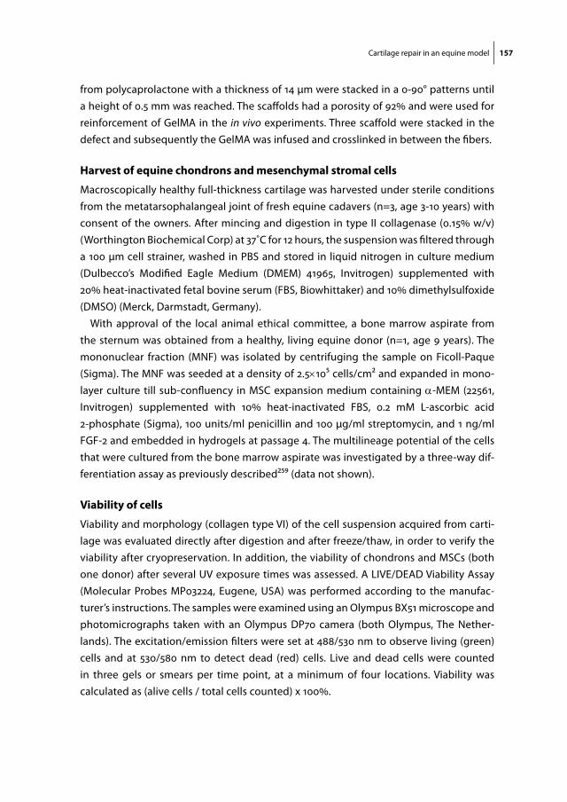
Cartilage repair in an equine model 157
from polycaprolactone with a thickness of 14 µm were stacked in a 0-90° patterns until a height of 0.5 mm was reached. The scaffolds had a porosity of 92% and were used for reinforcement of GelMA in the in vivo experiments. Three scaffold were stacked in the defect and subsequently the GelMA was infused and crosslinked in between the fibers.
harvest of equine chondrons and mesenchymal stromal cells
Macroscopically healthy full-thickness cartilage was harvested under sterile conditions from the metatarsophalangeal joint of fresh equine cadavers (n=3, age 3-10 years) with consent of the owners. After mincing and digestion in type II collagenase (0.15% w/v) (Worthington Biochemical Corp) at 37˚C for 12 hours, the suspension was filtered through a 100 μm cell strainer, washed in PBS and stored in liquid nitrogen in culture medium (Dulbecco’s Modified Eagle Medium (DMEM) 41965, Invitrogen) supplemented with 20% heat-inactivated fetal bovine serum (FBS, Biowhittaker) and 10% dimethylsulfoxide (DMSO) (Merck, Darmstadt, Germany).
With approval of the local animal ethical committee, a bone marrow aspirate from the sternum was obtained from a healthy, living equine donor (n=1, age 9 years). The mononuclear fraction (MNF) was isolated by centrifuging the sample on Ficoll-Paque (Sigma). The MNF was seeded at a density of 2.5×10⁵ cells/cm2 and expanded in mono-layer culture till sub-confluency in MSC expansion medium containing a-MEM (22561, Invitrogen) supplemented with 10% heat-inactivated FBS, 0.2 mM L-ascorbic acid 2-phosphate (Sigma), 100 units/ml penicillin and 100 µg/ml streptomycin, and 1 ng/ml FGF-2 and embedded in hydrogels at passage 4. The multilineage potential of the cells that were cultured from the bone marrow aspirate was investigated by a three-way dif-ferentiation assay as previously described259 (data not shown).
Viability of cells
Viability and morphology (collagen type VI) of the cell suspension acquired from carti-lage was evaluated directly after digestion and after freeze/thaw, in order to verify the viability after cryopreservation. In addition, the viability of chondrons and MSCs (both one donor) after several UV exposure times was assessed. A LIVE/DEAD Viability Assay (Molecular Probes MP03224, Eugene, USA) was performed according to the manufac-turer’s instructions. The samples were examined using an Olympus BX51 microscope and photomicrographs taken with an Olympus DP70 camera (both Olympus, The Nether-lands). The excitation/emission filters were set at 488/530 nm to observe living (green) cells and at 530/580 nm to detect dead (red) cells. Live and dead cells were counted in three gels or smears per time point, at a minimum of four locations. Viability was calculated as (alive cells / total cells counted) x 100%.
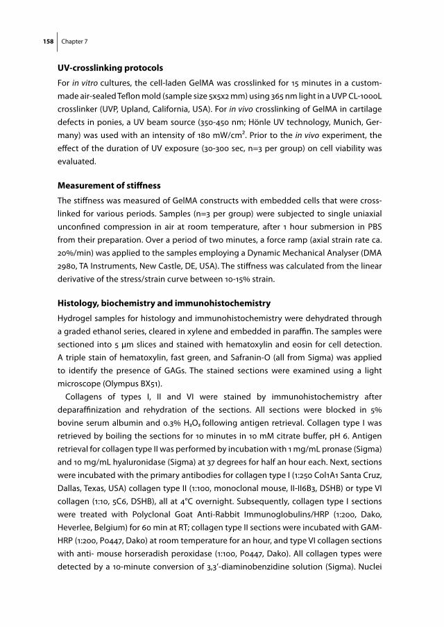
158 Chapter 7
uV-crosslinking protocols
For in vitro cultures, the cell-laden GelMA was crosslinked for 15 minutes in a custom-made air-sealed Teflon mold (sample size 5x5x2 mm) using 365 nm light in a UVP CL-1000L crosslinker (UVP, Upland, California, USA). For in vivo crosslinking of GelMA in cartilage defects in ponies, a UV beam source (350-450 nm; Hönle UV technology, Munich, Ger-many) was used with an intensity of 180 mW/cm2. Prior to the in vivo experiment, the effect of the duration of UV exposure (30-300 sec, n=3 per group) on cell viability was evaluated.
measurement of stiffness
The stiffness was measured of GelMA constructs with embedded cells that were cross-linked for various periods. Samples (n=3 per group) were subjected to single uniaxial unconfined compression in air at room temperature, after 1 hour submersion in PBS from their preparation. Over a period of two minutes, a force ramp (axial strain rate ca. 20%/min) was applied to the samples employing a Dynamic Mechanical Analyser (DMA 2980, TA Instruments, New Castle, DE, USA). The stiffness was calculated from the linear derivative of the stress/strain curve between 10-15% strain.
histology, biochemistry and immunohistochemistry
Hydrogel samples for histology and immunohistochemistry were dehydrated through a graded ethanol series, cleared in xylene and embedded in paraffin. The samples were sectioned into 5 µm slices and stained with hematoxylin and eosin for cell detection. A triple stain of hematoxylin, fast green, and Safranin-O (all from Sigma) was applied to identify the presence of GAGs. The stained sections were examined using a light microscope (Olympus BX51).
Collagens of types I, II and VI were stained by immunohistochemistry after deparaffinization and rehydration of the sections. All sections were blocked in 5% bovine serum albumin and 0.3% H2O2 following antigen retrieval. Collagen type I was retrieved by boiling the sections for 10 minutes in 10 mM citrate buffer, pH 6. Antigen retrieval for collagen type II was performed by incubation with 1 mg/mL pronase (Sigma) and 10 mg/mL hyaluronidase (Sigma) at 37 degrees for half an hour each. Next, sections were incubated with the primary antibodies for collagen type I (1:250 Col1A1 Santa Cruz, Dallas, Texas, USA) collagen type II (1:100, monoclonal mouse, II-II6B3, DSHB) or type VI collagen (1:10, 5C6, DSHB), all at 4°C overnight. Subsequently, collagen type I sections were treated with Polyclonal Goat Anti-Rabbit Immunoglobulins/HRP (1:200, Dako, Heverlee, Belgium) for 60 min at RT; collagen type II sections were incubated with GAM-HRP (1:200, P0447, Dako) at room temperature for an hour, and type VI collagen sections with anti- mouse horseradish peroxidase (1:100, P0447, Dako). All collagen types were detected by a 10-minute conversion of 3,3’-diaminobenzidine solution (Sigma). Nuclei

Cartilage repair in an equine model 159
were counterstained with 50% Mayer’s hematoxylin. Isotype control stainings were car-ried out with either a murine IgG1 monoclonal antibody (Dako) at concentrations match-ing those used for the primary antibodies or by incubation without primary antibody.
cadaveric studies for cartilage repair with gelma
Three cadaveric equine stifle joints were obtained with consent of the owners. The techniques for making chondral defects in the medial trochlear ridge, and subsequent implantation and UV-crosslinking of (reinforced) GelMA were developed on these ca-daveric stifle joint. The fixation of the implants was controlled after closure of the wound and 50 manual flexion-extension cycles.
pilot study for the cartilage repair model in a shetland pony
The animal studies were approved by the local Ethics Committee for Animal Experiments and were in compliance with the Institutional Guidelines on the Use of Laboratory Ani-mals. The surgeries were performed under sterile conditions in the surgery theatre at the department of Equine Sciences of Utrecht University. For evaluation of the surgical feasibility and hydrogel fixation, a pilot study was performed in one Shetland pony (age: 24 years, weight: 142 kg). Two chondral defects were made in the medial femoral ridge in the femoropatellar joint, and two experimental groups (reinforced GelMA and GelMA cap) were implanted in a surgical procedure described below. The pony was euthanized after two weeks (for veterinary education purposes) and the presence of GelMA was verified by macroscopic inspection, histology and immunohistochemistry.
long-term evaluation of cartilage repair in shetland ponies
Four experimental groups (fibrin glue, GelMA cap, GelMA and reinforced GelMA) were tested in the equine cartilage defect model (Fig. 1). A mixture of allogeneic MSCs and chondrons (80/20% ratio) was implanted in every defect in two concentrations in four groups: a low cell concentration (2 million cells/mL) that is currently used in human car-tilage repair was applied in fibrin glue; a ‘GelMA cap’ implant consisted of 1 million cells in a small volume of GelMA on the bottom of defect, which were covered by a layer of cell-free GelMA. A high cell concentration of 20 million cells/mL was implanted in GelMA gel and GelMA reinforced with a 3D printed scaffold.
Two chondral defects were made in both stifle joints of eight Shetland ponies (age: 7 ± 4 years, weight 191 ± 28 kg, mean ± SD). The low and high cell concentration groups were paired in every stifle, and their location (proximal or distal) and side (left or right leg) was randomized. A power of 0.94 was set, based on the outcomes of the International Car-tilage Repair Society macroscopic scoring system that was performed in a comparable study in goats23.
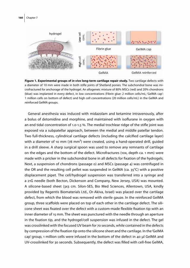
160 Chapter 7
General anesthesia was induced with midazolam and ketamine intravenously, after a bolus of detomidine and morphine, and maintained with isoflurane in oxygen with an end tidal concentration of 1.0-1.5 %. The medial trochlear ridge of the stifle joint was exposed via a subpatellar approach, between the medial and middle patellar tendon. Two full-thickness, cylindrical cartilage defects (including the calcified cartilage layer) with a diameter of 10 mm (78 mm2) were created, using a hand-operated drill, guided in a drill sleeve. A sharp surgical spoon was used to remove any remnants of cartilage on the edges and the bottom of the defect. Microfractures (10x, depth ca. 1 mm) were made with a pricker in the subchondral bone in all defects for fixation of the hydrogels. Next, a suspension of chondrons (passage 0) and MSCs (passage 4) was centrifuged in the OR and the resulting cell pellet was suspended in GelMA (ca. 35°C) with a positive displacement pipet. The cell/hydrogel suspension was transferred into a syringe and a 21G needle (both Becton, Dickenson and Company, New Jersey, USA) was mounted. A silicone-based sheet (3x3 cm. Silon-SES, Bio Med Sciences, Allentown, USA, kindly provided by Regentis Biomaterials Ltd., Or-Akiva, Israel) was placed over the cartilage defect, from which the blood was removed with sterile gauze. In the reinforced GelMA group, three scaffolds were placed on top of each other in the cartilage defect. The sili-cone sheet was fixated over the defect with a custom-made flexible fixation tip with an inner diameter of 15 mm. The sheet was punctured with the needle through an aperture in the fixation tip, and the hydrogel/cell suspension was infused in the defect. The gel was crosslinked with the focused UV beam for 70 seconds, while contained in the defects by compression of the fixation tip onto the silicone sheet and the cartilage. In the ‘GelMA cap’ group, 1 million cells were infused in the bottom of the defect in 40 µl GelMA and UV-crosslinked for 30 seconds. Subsequently, the defect was filled with cell-free GelMA,
figure 1. experimental groups of in vivo long-term cartilage repair study. Two cartilage defects with a diameter of 10 mm were made in both stifle joints of Shetland ponies. The subchondral bone was mi-crofractured for anchorage of the hydrogel. An allogeneic mixture of 80% MSCs (red) and 20% chondrons (blue) was implanted in every defect, in low concentrations (Fibrin glue: 2 million cells/mL; ‘GelMA cap’: 1 million cells on bottom of defect) and high cell concentrations (20 million cells/mL) in the GelMA and reinforced GelMA groups.

Cartilage repair in an equine model 161
which was UV-crosslinked for 60 seconds. In the fibrin glue group, the cell pellet was suspended in the fibrinogen component after the defects had been made. The glue was then injected in the defect and allowed to crosslink for 3 minutes.
The implanted hydrogels and the surrounding cartilage were scanned with optical coherence tomography (OCT) (Ilumien Optis PCI Optimization System, St. Jude Medical, St Paul, MN, USA) and ultrasound (Boston Scientific, San Jose, CA, USA) imaging systems, along the length of three standardized sites of the implant. The stiffness of the cartilage at three standardized sites surrounding the defects was measured (Artscan 200, Artscan Oy, Helsinki, Finland) to obtain baseline values for cartilage. The wound was closed in 4 layers and full weight bearing was allowed after recovery from anesthesia. The ponies received NSAIDS up to 14 days and opiates up to 3 days postoperatively. For antibiotic prophylaxis, ampicillin was administered intravenously once before and procaine peni-cillin once after surgery.
At 2, 6 and 12 months, biomaterial degradation and tissue regeneration is assessed ar-throscopically (Table 1). The surface is imaged with a regular camera and the implant and the subchondral bone are imaged in detail with OCT and ultrasound. The stiffness of the implant and surrounding cartilage is measured. The repair sites are also imaged trans-cutaneous ultrasound at aforementioned time points, including an early evaluation at 3 weeks. The gait of the ponies is objectively monitored over time by means of pressure/
Day of surgery
3 weeks 2 months 6 months 12 months
oct (implant structure) X X X X
ultrasound (implant structure and subchondral bone)
X X X X
mech. analyser (implant stiffness) X X X
camera (Implant surface) X X X
transcutaneous ultrasound X X X X
gait analysis (Force and pressure plate)
Before surgery
X X X
gag/dna (cartilage matrix quantification)
X
macro- & microscopy (cartilage matrix qualification)
X
dna detection X
Table 1. Outcome parameters of the long-term cartilage repair study in Shetland ponies. Tissue formation is monitored over time with arthroscopic optical coherence tomography (OCT) and ultrasound. In addition, the stiffness of the repair tissue will be measured with a mechanical analyzer. The study is terminated at 12 months, when final values will be obtained with imaging. The quantity and quality of the newly formed tissue in the de-fect will be assessed with biochemistry, histology and immunohistochemistry. The DNA in the explanted tissue is compared to the DNA of the implanted cells and the host tissue.
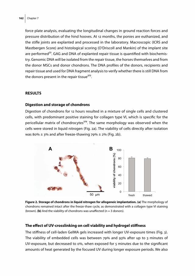
162 Chapter 7
force plate analysis, evaluating the longitudinal changes in ground reaction forces and pressure distribution of the hind hooves. At 12 months, the ponies are euthanized, and the stifle joints are explanted and processed in the laboratory. Macroscopic (ICRS and Mastbergen Score) and histological scoring (O’Driscoll and Mankin) of the implant site are performed23. GAG and DNA of explanted repair tissue is quantified with biochemis-try. Genomic DNA will be isolated from the repair tissue, the horses themselves and from the donor MSCs and donor chondrons. The DNA profiles of the donors, recipients and repair tissue and used for DNA fragment analysis to verify whether there is still DNA from the donors present in the repair tissue375.
results
digestion and storage of chondrons
Digestion of chondrons for 12 hours resulted in a mixture of single cells and clustered cells, with predominant positive staining for collagen type VI, which is specific for the pericellular matrix of chondrocytes376. The same morphology was observed when the cells were stored in liquid nitrogen (Fig. 2a). The viability of cells directly after isolation was 80% ± 3% and after freeze-thawing 79% ± 2% (Fig. 2b).
the effect of uV-crosslinking on cell viability and hydrogel stiffness
The stiffness of cell-laden GelMA gels increased with longer UV-exposure times (Fig. 3). The viability of embedded cells was between 79% and 93% after up to 3 minutes of UV-exposure, but decreased to 0%, when exposed for 5 minutes due to the significant amounts of heat generated by the focused UV during longer exposure periods. We also
0
20
40
60
80
100
fresh thawed
viab
ility
of c
hond
rons
(%)
50 μm
A B
figure 2. storage of chondrons in liquid nitrogen for allogeneic implantation. (a) The morphology of chondrons remained intact after the freeze-thaw cycle, as demonstrated with a collagen type VI staining (brown). (b) And the viability of chondrons was unaffected (n = 3 donors).

Cartilage repair in an equine model 163
found that the stiffness of the gels decreased, when cells had been suspended in GelMA for over 30 minutes prior to crosslinking, although this observation was not quantified.
cadaver and pilot study in one shetland pony
The cadaveric studies showed that the infusion and UV-crosslinking of the GelMA gel in cartilage defects was a feasible procedure. There was full penetration of the gel into the highly porous 3D-printed scaffolds. UV-crosslinking of 70 seconds was sufficient for firm crosslinking of the gel, but without generating too much heat. The crosslinked gels stayed in the defect after repetitive flexion/extension cycles. Furthermore, reinforced and non-reinforced GelMA hydrogels were successfully implanted and crosslinked in chondral defects in the stifle joint of a Shetland pony (Fig. 4a,b). The pony recovered well and the GelMA hydrogel stayed in place in both cartilage defects two weeks after implantation, as observed macroscopically (Fig. 4c), and the GelMA gel was infiltrated with cells of a fibroblastic nature (Fig. 4d). An inflammatory response was observed in the underlying bone, by the presence of fibroblastic cells, neutrophil granulocytes and multinucleated cells (Fig. 3d-f ). Bone remodeling was observed under the defect.
0%
20%
40%
60%
80%
100%
0
10
20
30
40
0 100 200 300
Cel
l via
bilit
y
stiff
ness
Gel
MA
(kPa
)
UV crosslinking time (seconds)
figure 3. cell viability and hydrogel stiffness depending on uV exposure times. The viability of chon-drocytes and MSCs (both n=1) in GelMA decreased after UV exposure for 200 seconds (grey circles). The stiffness of hydrogels increased with longer UV exposure (black squares). GelMA in the equine stifle joints was crosslinked for 70 seconds.

164 Chapter 7
2 mm
Saf-O
Collagen II
Collagen I
a
b
c d
f
e
100 µm
figure 4. pilot study in a shetland pony for fixation of gelma. (a,b) reinforced GelMA and the ‘GelMA cap’ group were implanted in the stifle joint of one Shetland pony. (c) The gels stayed in the cartilage defect after two weeks. (d-f) Cells migrated into the hydrogel and only scarce remnants of GelMA were observed between the cells (light green in zoom picture).
Hea
lthy
carti
lage
Gel
MA
Rei
nfor
ced
Gel
MA
Ultrasound OCT
cartilage
bone
microfracture
microfiberscaffolds
figure 5. Baseline imaging of implants with oct and us. Baseline values were obtained of healthy car-tilage and of the gels in the defect directly after implantation. The hydrogel, reinforcing scaffolds and the subchondral bone could be clearly identified with OCT and ultrasound.

Cartilage repair in an equine model 165
long-term evaluation of cartilage repair in shetland ponies
Two cartilage defects in both stifle joints of eight Shetland ponies were made and re-paired in one surgical session. OCT and ultrasound imaging confirmed the depth of the defect, including the microfractures, and the location of the microfiber scaffolds (Fig. 5). All ponies were able to walk unassisted after recovery from anesthesia, with limited stiffness in the hind legs. Walking turned to normal within two weeks postoperatively. No adverse events related to the surgery were observed until one month of follow-up.
discussion
In this study, a cartilage defect model in the trochlea of Shetland ponies was used. The implantation and in situ crosslinking of GelMA gel appeared to be feasible in a pilot study with the gel remaining in the defect site after two weeks of full weight bearing. As a follow-up, a comparative study was initiated in eight ponies, comparing fibrin glue with GelMA and reinforced GelMA as a carrier for allogeneic chondrons and MSCs. Low cell concentrations that are clinically feasible were compared to high cell concentrations, which are often used in in vitro tissue engineering to establish an interconnected matrix.
We found that two chondral defects with diameter of 10 mm could be made and repaired on the medial femoral trochlear ridge in both stifle joints of Shetland ponies, followed by a good clinical recovery after surgery. The size of the defect was chosen in order to avoid spontaneous healing that might occur in smaller defects24.
The GelMA that was crosslinked in the defects remained in place after repetitive flexion-extension cycles in cadaveric joint and after two weeks in a pony. No additive fixation techniques were used, except for the application of microfractures in the subchondral bone for anchoring of the gel. However, the gel was fully infiltrated by fibroblastic cells in the Shetland pony after two weeks. The degradation rate of GelMA in vitro7 and in immunocompromized rats25 has been found to be low63,377, with GelMA serving as a scaf-fold for matrix formation to embedded cells for at least eight weeks embedded cells. In cell-free gels in nude rats, only limited cell infiltration was observed25. This difference in hydrogel degradation and cellular infiltration can most likely be ascribed to the immu-nocompetency of the horses, and the abundant presence of cells from the bone marrow that can enzymatically break down the GelMA257,377.
In this study, a mixture of allogeneic chondrons and MSCs was implanted as cell therapy for cartilage repair. This combination of cells was based on two clinical trials on cartilage repair in humans, in which autologous chondrons and allogeneic MSCs20,25 or chondrocytes and a bone marrow concentrate26 were implanted in one surgical ses-sion. In addition, the presence of chondrocytes in the vicinity of MSCs in GelMA in vivo was shown to prevent endochondral bone formation by MSCs377. Allogeneic instead of
166 Chapter 7
autologous chondrons were implanted in the current study, as two experimental groups contained a high cell concentration, which cannot be obtained in a rapid digestion pro-tocol of the autologous cartilage23. Allogeneic chondrocytes have been applied in the knee joint of horses378 and humans previously379,380. No adverse events were observed, although it remains uncertain whether allogeneic chondrons or chondrocytes have the same regenerative potential as their autologous counterparts.
The mechanism of cartilage formation in a co-culture of chondrocytes (or chondrons) with MSCs is under debate24. Initially, MSCs were thought to contribute primarily to matrix formation, but recent studies suggest that chondrocytes are the major contribu-tors381,382, where MSCs have a trophic role in the co-culture and disappear over time. Pre-liminary results from the IMPACT trial support this theory, as no allogeneic DNA could be retraced in biopsies from repair cartilage one year after implantation of autologous chondrons and allogeneic MSCs25. Whether the implanted chondrons or homing host cells were responsible for tissue formation remains unclear, however. In the follow-up of the current study, we hope to differentiate between the host cells and implanted chondrons and MSCs (both allogeneic), by comparing the DNA profiles of the donors and recipients to the DNA that is present in the defect site after one year.
In vitro tissue engineering in GelMA hydrogels has shown that high cell concentra-tions (20 million cells per mL) are required to form an interconnected matrix within the hydrogel63,383,28,73. In contrast, much lower concentrations (around 2 million cells per mL) are applied in clinical cell therapies, like autologous chondrocyte implantation369. The amount of cells that is required may depend on the options for interaction within the gel. In fibrin glue, the cartilage matrix formation is based on direct cell-cell contact, which is allowed by contraction and rapid degradation of the fibrin glue25. In contrast, cells in low concentrations in slowly degrading hydrogels, like GelMA, may not be able to communicate and form an interconnected matrix. To study the value of GelMA gel combined with a low amount of cells, the ‘GelMA cap’ group was introduced in the pres-ent study.
In conclusion, a model for evaluating cartilage repair in Shetland ponies was estab-lished, after preliminary in vitro, cadaveric and pilot studies, to monitor cartilage repair by a mixture of allogeneic chondrons and MSCs in several GelMA-based implants. This study is at the moment of writing still ongoing. It is anticipated that this comparative study, in combination with ongoing in vitro cultures, will further elucidate the mechanism of cartilage regeneration after the implantation of cell-seeded hydrogels, depending on the biomaterial and the cell concentration. We expect cartilage to regenerate upwards, from the bottom of the defect in the ‘GelMA gap’ and the fibrin group. In contrast, we hypothesize that cartilage matrix will be deposited within the hydrogel in the GelMA groups with high cell concentrations.
Cartilage repair in an equine model 167
acKnowledgements
The authors thanks mr. Gernot Hochleitner and mr. Elder Linssen for producing scaf-folds with melt-electrospinning. Regentis Biomaterials Ltd., for providing the silicone sheets. Mr. Filipe Serra Braganca and mr. Tsjester Huppes for assisting in the surgeries. Dr. Janny de Grauw and mr. Thijs van Loon for taking care of anesthesia in the ponies and the complete ‘equine cartilage repair team’ for logistics around the surgeries. Dr. Guy Grinwis, DVM, veterinary pathologist, for his help in interpreting histology of explants. Dr. Imo Hofer from the experimental cardiology dept. of the UMC Utrecht, for providing the OCT machine. The monoclonal antibodies for the detection of collagens developed by T.F. Linsenmayer were obtained from the Developmental Studies Hybridoma Bank developed under the auspices of the NICHD and maintained by The University of Iowa, Department of Biology, Iowa City, IA 52242. This work was supported by the European Community’s Seventh Framework Programme (FP7/2007-2013) under grant agreement n309962 (HydroZONES). Jetze Visser was supported by a grant from the Dutch govern-ment to the Netherlands Institute for Regenerative Medicine

Part 3
Part 3Biofabrication of Complex Shaped Constructs from GelMA for Osteochondral Tissue Repair


Chapter 8Biofabrication of Multi-Material Anatomically Shaped Tissue Constructs
Jetze VisserBenjamin PetersThijs BurgerJelle BoomstraWouter DhertFerry MelchelsJos Malda
Biofabrication. 2013 Sep;5(3):035007

172 Chapter 8
aBstract
Additive manufacturing in the field of regenerative medicine aims to fabricate organized tissue-equivalents. However, the control over shape and composition of biofabricated constructs is still a challenge and needs to be improved. The current research aims to improve shape, by converging a number of biocompatible, quality construction materi-als into a single three-dimensional fiber deposition process. To demonstrate this, several models of complex anatomically shaped constructs were fabricated by combined depo-sition of poly(vinyl alcohol), poly(ε-caprolactone), gelatin methacrylamide/gellan gum and alginate hydrogel. Sacrificial components were co-deposited as temporary support for overhang geometries and were removed after fabrication by immersion in aqueous solutions. Embedding of chondrocytes in the gelatin methacrylamide/gellan compo-nent demonstrated that the fabrication and the sacrificing procedure did not affect cell viability. Further, it was shown that anatomically shaped constructs can be successfully fabricated, yielding advanced porous thermoplastic polymer scaffolds, layered porous hydrogel constructs, as well as reinforced cell-laden hydrogel structures. In conclusion, anatomically shaped tissue constructs of clinically relevant sizes can be generated when employing multiple building and sacrificial materials in a single biofabrication session. The current techniques offer improved control over both internal and external construct architecture underscoring its potential to generate customized implants for human tis-sue regeneration.
Biofabrication of anatomically shaped tissue constructs 173
introduction
Additive Manufacturing (AM) is the layer-by-layer construction of objects based on a three-dimensional (3D) model data set11,118. In the field of regenerative medicine (RM), AM has the potential to produce customized tissue implants to replace damaged or eroded parts of the human body. In order to achieve this, a balanced combination of cells, growth factors, matrix and/or biomaterials needs to be processed into a 3D-construct with controlled architecture. Unlike conventional subtractive manufacturing, AM offers full control over internal and external architecture of the object and every deposited layer serves as a fundament for the next layer. Moreover, AM technologies, including 3D fiber deposition (3DF) 11,118, potentially allow for reproducibility and customization of complex tissue analogs with limited waste of the often expensive building biomaterials.
Scaffolds for tissue engineering have been fabricated with 3DF from biodegradable thermoplastic polymers, e.g. polycaprolactone (PCL)50,53,384 and PCL-derivatives327, poly-lactic acid (PLA)385 or PolyActive®386 allowing for direct implantation328,387 with the pos-sibility of prior cell seeding8 or incorporation of growth factors53. In addition, scaffolds have also been fabricated from hydrogels, where the hydrogel serves as a carrier for cells or bioactive factors, while simultaneously serving as a building block100,105,121,148,388. Recently, the combined deposition of thermoplastic polymers and hydrogels was developed in order to reinforce hydrogel constructs with a thermoplastic polymer network65,75,76.
For the translation of biofabrication to the clinic, tissue equivalents must be fabri-cated from digital blueprints of the anatomical structure that needs to be repaired or replaced11,179. To this end, control over both shape and composition of implants needs to be improved11,116-118, addressing complex internal and external architectures as well as multiple tissue types of the target structure. For example, when pursuing to fabricate a vascular network, the desired lumen diameter, branching pattern, vessel stiffness and possibly the different tissue types in the vessel wall need to be addressed. Similarly, when aiming to generate a construct with the shape of the external ear, the complex auricular shape, as well as the different tissue types (i.e. cartilage, skin and blood vessels) need to be put in place. In order to achieve this, better control over the deposition is needed, requiring novel construction biomaterials that facilitate tissue regeneration. In addition, in order to process these materials in three dimensions with high resolution, biofabrication techniques need to be optimized.
The current research aims to improve the shape of constructs by integrating several quality construction biomaterials into a single fabrication session. This includes materi-als that temporarily support overhang geometries in complex structures, as layer-by-layer fabrication will fail in the absence of a base layer. These support materials need to be sacrificed after fabrication, a principle that has already been applied in microfluid-

174 Chapter 8
ics184,186,389, but also for the casting of collagen scaffolds390 and for achieving internal porosity in tissue-engineered constructs391,392. Moreover, sacrificial materials have been applied for realizing controlled internal architectures within hydrogel constructs, either by casting188 or combining printing and casting158,185. For the current 3DF approach, sac-rificial materials were selected so that they can be processed layer-by-layer and removed from the target structure without compromising its shape. Furthermore, sacrificial mate-rials should support, and form a stable interface with adjacent components, and should not compromise cellular survival.
Here, we demonstrate how several relevant-size models of complex anatomical structures, being a vascular network, an ear and a distal femur, can be fabricated by combining building and sacrificial materials in a multi-material 3DF setting. These in-clude thermoplastic polymers and hydrogels that provide both mechanical support and a suitable environment for cells to regenerate tissue.
materials and methods
materials
Polyvinyl alcohol (PVA) filament (diameter 3 mm, melting point 160-170°C, density 1.25-1.35 g/cm3) (Kuraray USA, Houston, TX, USA) was obtained from Makerbot Industries, NY, USA. PCL (average Mn 45,000; Mw 48,000-90,000) was obtained from Sigma-Aldrich, Zwijndrecht, The Netherlands. Alginate hydrogel (10% w/v) was prepared by mixing sodium alginate powder (Sigma-Aldrich) overnight at 37°C in dH2O. Gelatin methacryl-amide (GelMA) was synthesized as described previously63. GelMA-gellan hydrogel was prepared by dissolving GelMA (10% w/v) and gellan gum (Gelzantm CM, Sigma-Aldrich) (1.1% w/v) at 90°C for 20 minutes in dH2O containing 0.1% w/v photoinitiator Irgacure 2959 (Ciba, BASF, Ludwigshafen am Rhein, Germany). In case cells were mixed in the hydrogel, D-mannose (5.4% w/v) was added to the mixture to obtain isotonic conditions 61. GelMA-gellan hydrogels were stained with fast green (Merck, Whitehouse Station, NJ, USA) for visualization purposes when printing multi-layered constructs.
experimental design
Several anatomically shaped constructs were designed using Rhinoceros computer aided design (CAD) software (McNeel, Seattle, WA, USA), including structures inspired by blood vessels, an ear and a distal femur (Table 1). Complementary structures were designed in order to temporarily support overhangs in the target structures on biofab-rication. The CAD-files were loaded via computer-aided manufacturing (CAM) software (PrimCAM, Einsiedeln, Switzerland) in which a building material (PCL, GelMA-gellan hydrogel, or both) was assigned to the target structure and a specific sacrificial material

Biofabrication of anatomically shaped tissue constructs 175
(PVA, PCL or alginate hydrogel) was assigned to the support components. A stack of all these materials was fabricated, with subsequent removal of the sacrificial components, in order to evaluate the effects of the full fabrication process on the survival of cells embedded in the GelMA-gellan hydrogel component.
cells: equine chondrocytes and mesenchymal stromal cells (mscs)
Full-thickness cartilage was harvested (with consent of the owner) under sterile condi-tions from the stifle joint of a fresh equine cadaver (n=1; 7 years old) with macroscopi-cally healthy cartilage that died of natural causes in the clinic. After overnight digestion in type II collagenase (Worthington Biochemical Corp) at 37˚C the suspension was filtered and washed in PBS. The chondrocytes were seeded at a density of 5× 10³ cells/cm2 and expanded for 10 days in a monolayer culture in chondrocyte expansion medium consisting of DMEM (Dulbecco’s Modified Eagle Medium 41965, Invitrogen), 10% heat-inactivated fetal bovine serum (Biowhittaker), 100 units/ml penicillin and 100 µg/ml streptomycin (Invitrogen), and 10 ng/ml FGF-2 (R&D Systems).
MSCs were obtained from a sternal bone marrow aspirate from a healthy, living equine donor (n=1), with approval of the institutional ethics committee. The mononuclear frac-tion (MNF) was isolated by centrifuging the sample on Ficoll-Paque. The MNF was seeded at a density of 2.5×10⁵ cells/cm2 and expanded in a monolayer culture till subconfluency in MSC expansion medium containing a-MEM (22561, Invitrogen) supplemented with 10% heat-inactivated fetal bovine serum, 0.2 mM L-ascorbic acid 2-phosphate (Sigma), 100 units/ml penicillin and 100 µg/ml streptomycin, and 1 ng/ml FGF-2.
target construct permanent material
sacrificial material
sacrificing procedure printed structures
Thermoplastic polymer
PCL PVA Wash in water Models of a vascular branch, ear and DNA-helix
Hydrogel GelMA-gellan PCL Manual removal Model of a distal femur
Alginate Wash in citrate solution
Box with tubes
Fiber reinforced hydrogel
PCL + GelMA-gellan Alginate Wash in citrate solution
Single tube
Table 1. Printing of a thermoplastic polymer (PCL), a hydrogel (gelMA-gellan) or a combination of both in a fiber reinforced construct required specific sacrificial materials (PCL, PVA or alginate hydrogel) in order to achieve optimal shape fidelity. Different procedures were applied to sacrifice these materials.

176 Chapter 8
histology
MSCs were suspended in gelatin hydrogel (from bovine skin, type B, Sigma-Aldrich) (10% w/v, 5×10⁶ cells/ml), which was perfused through the lumen of a 3D-printed fiber reinforced tube. The tube was processed into cross-sectional 5 μm paraffin slides and a triple-stained with hematoxylin, fast green, and Safranin-O (all from Sigma). To visualize the cells, gelatin and the GelMA-gellan (vessel wall) component, stained sections were examined using a light microscope (Olympus BX51).
three-dimensional fiber deposition
Constructs were fabricated using the BioScaffolder 3DF system (SYS+ENG, Salzgitter-Bad, Germany), which can build three-dimensional objects by coordinated motion of several dispensing heads, depositing on a stationary platform. Four dispensing heads were used, employing different types of extrusion: piston-driven extrusion for GelMA-gellan and alginate hydrogel; auger screw driven melt extrusion for PCL, and filament extrusion for PVA. The filament extruder was custom-built, based on the commercially available open-source Ultimaker 3DF machine (Ultimaker LTD, Geldermalsen, The Netherlands) and was adapted for use within the BioScaffolder multiple-tool dispensing setting. The BioScaffolder was located at room temperature in a custom-built laminar flow cabinet to ensure sterile conditions and to facilitate rapid cooling of deposited thermoplastic materials. Fabrication parameters were set for each printing material, as detailed in Table 2. Strand spacing for both hydrogels ranged between 0.8 and 1.8 mm, in which the first setting yields a solid - at a given ratio of spindle speed and translational speed - and the second a porous construct. Both strand spacings were used in order to represent respectively the cartilage and bone component of a structure inspired by a distal femur.
pVa pcl gelma-gellan alginate
Materials specifications Filament Granules,mn 45,000
Hydrogel, 10%-1.1% w/v
Hydrogel,10% w/v
Extrusion mechanism filament auger screw piston piston
Printing temperature 185°C 90°C 35°C 25°C
Needle type Ultimaker® Nozzle DL Technology EZ-FLO™ (Haverhill, MA, USA)
Nordson EFD Precision Tips (East Providence, RI, USA)
Nordson EFD Precision Tips
Needle internal diameter (mm, (Gauge))
0.4 (22G) 0.32 (23G) 0.32 (23G) 0.5 (21G)
Deposition speed (mm min-1)
350 150 1250 900
Layer thickness (mm) 0.20 0.17-0.20 0.17-0.20 0.19-0.20
Strand spacing (mm) 1.3-1.5 0.7-1.2 0.8-1.8 0.8-1.8
Table 2. Specifications of the BioScaffolder 3DF-system (SYS+ENG) for dispensing different materials in the cur-rent study.
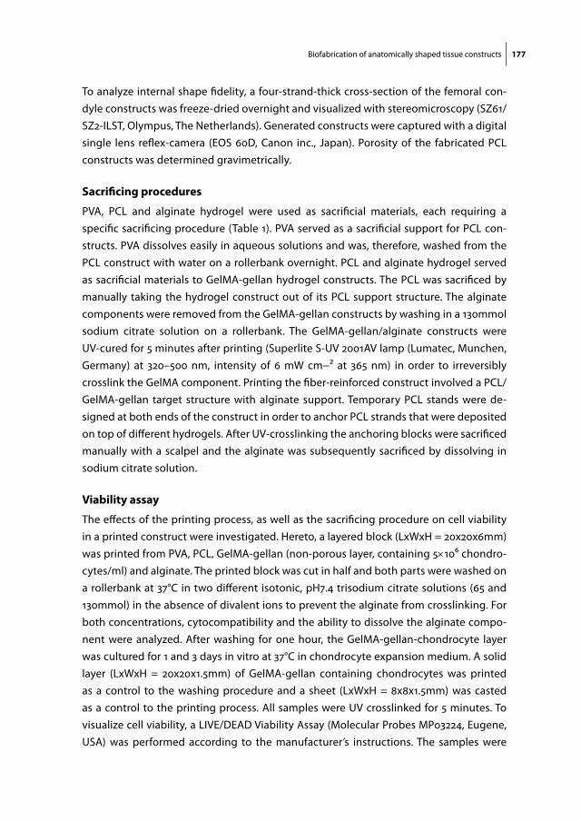
Biofabrication of anatomically shaped tissue constructs 177
To analyze internal shape fidelity, a four-strand-thick cross-section of the femoral con-dyle constructs was freeze-dried overnight and visualized with stereomicroscopy (SZ61/SZ2-ILST, Olympus, The Netherlands). Generated constructs were captured with a digital single lens reflex-camera (EOS 60D, Canon inc., Japan). Porosity of the fabricated PCL constructs was determined gravimetrically.
sacrificing procedures
PVA, PCL and alginate hydrogel were used as sacrificial materials, each requiring a specific sacrificing procedure (Table 1). PVA served as a sacrificial support for PCL con-structs. PVA dissolves easily in aqueous solutions and was, therefore, washed from the PCL construct with water on a rollerbank overnight. PCL and alginate hydrogel served as sacrificial materials to GelMA-gellan hydrogel constructs. The PCL was sacrificed by manually taking the hydrogel construct out of its PCL support structure. The alginate components were removed from the GelMA-gellan constructs by washing in a 130mmol sodium citrate solution on a rollerbank. The GelMA-gellan/alginate constructs were UV-cured for 5 minutes after printing (Superlite S-UV 2001AV lamp (Lumatec, Munchen, Germany) at 320–500 nm, intensity of 6 mW cm−2 at 365 nm) in order to irreversibly crosslink the GelMA component. Printing the fiber-reinforced construct involved a PCL/GelMA-gellan target structure with alginate support. Temporary PCL stands were de-signed at both ends of the construct in order to anchor PCL strands that were deposited on top of different hydrogels. After UV-crosslinking the anchoring blocks were sacrificed manually with a scalpel and the alginate was subsequently sacrificed by dissolving in sodium citrate solution.
Viability assay
The effects of the printing process, as well as the sacrificing procedure on cell viability in a printed construct were investigated. Hereto, a layered block (LxWxH = 20x20x6mm) was printed from PVA, PCL, GelMA-gellan (non-porous layer, containing 5×10⁶ chondro-cytes/ml) and alginate. The printed block was cut in half and both parts were washed on a rollerbank at 37°C in two different isotonic, pH7.4 trisodium citrate solutions (65 and 130mmol) in the absence of divalent ions to prevent the alginate from crosslinking. For both concentrations, cytocompatibility and the ability to dissolve the alginate compo-nent were analyzed. After washing for one hour, the GelMA-gellan-chondrocyte layer was cultured for 1 and 3 days in vitro at 37°C in chondrocyte expansion medium. A solid layer (LxWxH = 20x20x1.5mm) of GelMA-gellan containing chondrocytes was printed as a control to the washing procedure and a sheet (LxWxH = 8x8x1.5mm) was casted as a control to the printing process. All samples were UV crosslinked for 5 minutes. To visualize cell viability, a LIVE/DEAD Viability Assay (Molecular Probes MP03224, Eugene, USA) was performed according to the manufacturer’s instructions. The samples were
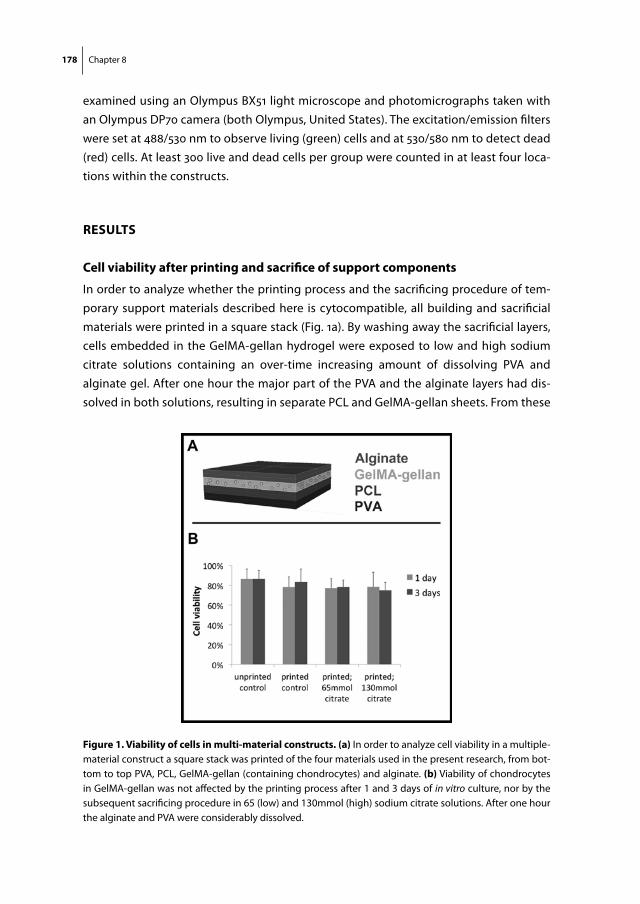
178 Chapter 8
examined using an Olympus BX51 light microscope and photomicrographs taken with an Olympus DP70 camera (both Olympus, United States). The excitation/emission filters were set at 488/530 nm to observe living (green) cells and at 530/580 nm to detect dead (red) cells. At least 300 live and dead cells per group were counted in at least four loca-tions within the constructs.
results
cell viability after printing and sacrifice of support components
In order to analyze whether the printing process and the sacrificing procedure of tem-porary support materials described here is cytocompatible, all building and sacrificial materials were printed in a square stack (Fig. 1a). By washing away the sacrificial layers, cells embedded in the GelMA-gellan hydrogel were exposed to low and high sodium citrate solutions containing an over-time increasing amount of dissolving PVA and alginate gel. After one hour the major part of the PVA and the alginate layers had dis-solved in both solutions, resulting in separate PCL and GelMA-gellan sheets. From these
figure 1. Viability of cells in multi-material constructs. (a) In order to analyze cell viability in a multiple-material construct a square stack was printed of the four materials used in the present research, from bot-tom to top PVA, PCL, GelMA-gellan (containing chondrocytes) and alginate. (b) Viability of chondrocytes in GelMA-gellan was not affected by the printing process after 1 and 3 days of in vitro culture, nor by the subsequent sacrificing procedure in 65 (low) and 130mmol (high) sodium citrate solutions. After one hour the alginate and PVA were considerably dissolved.
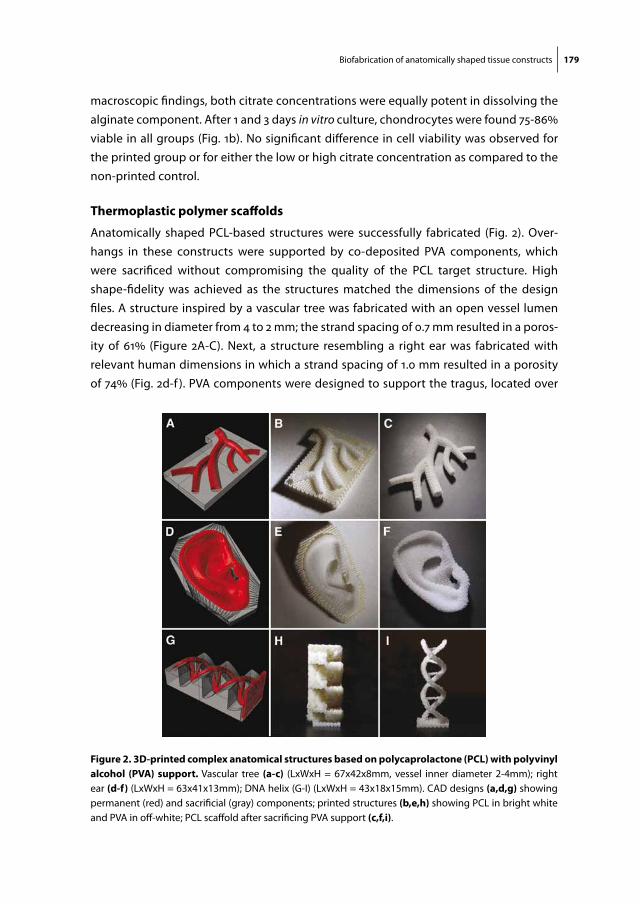
Biofabrication of anatomically shaped tissue constructs 179
macroscopic findings, both citrate concentrations were equally potent in dissolving the alginate component. After 1 and 3 days in vitro culture, chondrocytes were found 75-86% viable in all groups (Fig. 1b). No significant difference in cell viability was observed for the printed group or for either the low or high citrate concentration as compared to the non-printed control.
thermoplastic polymer scaffolds
Anatomically shaped PCL-based structures were successfully fabricated (Fig. 2). Over-hangs in these constructs were supported by co-deposited PVA components, which were sacrificed without compromising the quality of the PCL target structure. High shape-fidelity was achieved as the structures matched the dimensions of the design files. A structure inspired by a vascular tree was fabricated with an open vessel lumen decreasing in diameter from 4 to 2 mm; the strand spacing of 0.7 mm resulted in a poros-ity of 61% (Figure 2A-C). Next, a structure resembling a right ear was fabricated with relevant human dimensions in which a strand spacing of 1.0 mm resulted in a porosity of 74% (Fig. 2d-f ). PVA components were designed to support the tragus, located over
figure 2. 3d-printed complex anatomical structures based on polycaprolactone (pcl) with polyvinyl alcohol (pVa) support. Vascular tree (a-c) (LxWxH = 67x42x8mm, vessel inner diameter 2-4mm); right ear (d-f) (LxWxH = 63x41x13mm); DNA helix (G-I) (LxWxH = 43x18x15mm). CAD designs (a,d,g) showing permanent (red) and sacrificial (gray) components; printed structures (b,e,h) showing PCL in bright white and PVA in off-white; PCL scaffold after sacrificing PVA support (c,f,i).

180 Chapter 8
a cavity representing the auditory channel and for overhangs up to 60° in the outer contour of the ear. Additionally, the model of the DNA-helix is a powerful demonstration of the successful co-deposition of support material, since 0 to 90° overhangs are present in this complex structure (Fig. 2g-i).
hydrogel constructs
A miniaturized model of a distal femur (Fig. 3) was printed including a solid layer (green) representing the cartilage component and a porous bone component (yellow) (Fig. 3b). GelMA-gellan hydrogel strands allowed for proper deposition onto the porous PCL sup-port structure (Fig. 3c). Moreover, their stiffness after deposition was sufficient to retain shape and to support the overlying layers. The shape-fidelity of the internal architecture was shown in a cross-section of the femoral condyles (Fig. 3d, 3e). The hydrogel construct could be manually removed from the PCL support structure.
In a different approach, alginate hydrogel provided internal support for creating interconnected tubes within a GelMA-gellan hydrogel box (Fig. 4). Both hydrogels were compatible with the co-deposition process and the high-viscosity alginate was found to be stable enough to carry the overlying structures without crosslinking. By sacrificing
figure 3. multi-compartment hydrogel construct. a) Distal femur from a human knee (b) was designed in Rhino (LxWxH: 40x35x32mm) containing a bone component (yellow), a cartilage layer (green) and a sup-port structure (white); (c) the distal femur printed in hydrogel including PCL support structure; (d) hydrogel component after manually removing support structure; (e) freeze-dried four-layer thick cross-section (level marked by white lines in fig. 3d) from the femoral condyles showing a solid cartilage component (marked by dashed boundary lines) and a porous bone component.
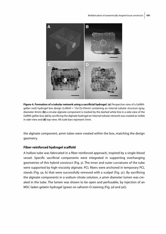
Biofabrication of anatomically shaped tissue constructs 181
the alginate component, 4mm tubes were created within the box, matching the design geometry.
fiber-reinforced hydrogel scaffold
A hollow tube was fabricated in a fiber-reinforced approach, inspired by a single blood vessel. Specific sacrificial components were integrated in supporting overhanging geometries of this hybrid construct (Fig. 5). The inner and outer curvatures of the tube were supported by high-viscosity alginate. PCL fibers were anchored in temporary PCL stands (Fig. 5a, b) that were successfully removed with a scalpel (Fig. 5c). By sacrificing the alginate components in a sodium citrate solution, a 4mm diameter lumen was cre-ated in the tube. The lumen was shown to be open and perfusable, by injection of an MSC-laden gelatin hydrogel (green on safranin-O staining (Fig. 5d and 5e)).
figure 4. formation of a tubular network using a sacrificial hydrogel. (a) Perspective view of a GelMA-gellan (red) hydrogel box design (LxWxH = 15x15x10mm) containing an internal tubular structure (gray, diameter 4mm); (b) a circular alginate component is marked by the dashed white line in a side-view of the GelMA-gellan box; (c) by sacrificing the alginate hydrogel an internal tubular network was created as visible in side-view and (d) top-view. All scale bars represent 5mm.

182 Chapter 8
discussion
Anatomically shaped constructs were fabricated by integrating biocompatible ther-moplastics, hydrogels and sacrificial materials into a single 3DF-based biofabrication approach. The application of specific sacrificial materials was essential in supporting in-ternal and external overhang geometries in these constructs. Co-deposition of multiple materials and the sacrificing procedures did not adversely affect the shape of the target structure or viability of embedded cells.
Overhangs are inevitable in the internal and external geometry of most anatomical structures, although, for AM purposes, they can be minimized through optimal 3D rota-
figure 5. complex fiber-reinforced construct. (a) Design of a fiber reinforced single tube (inner diameter 4mm, outer diameter 6mm, length 20mm) including anchoring stands (white: PCL, red: GelMA-gellan, blue: alginate); (b) construct directly after printing, scalpel cuts for removing stands represented by dashed lines; (c) tube after removing PCL stands; (d) cross-section of printed tube, right: design, left: after infusion with gelatin containing MSCs (safranin-O staining, red: GelMA-gellan tube wall; green: gelatin-MSC mixture). Reinforcing PCL fibers that were present in the tube wall were dissolved during the embedding process; (e) magnification from picture (d) of gelatin hydrogel containing MSCs (blue dots) (scale bar represents 200μm).
Biofabrication of anatomically shaped tissue constructs 183
tion of the digital blueprint. The remaining overhangs may require mechanical support components which need to be sacrificed by dissolving them in aqueous media or by manual removal from the target structure, as was recognized in a US patent in 1996393. This patent has mainly been applied for fabricating solid objects from thermoplastic polymers with commercial filament-based 3DF-machines. Obviously, when aiming to support constructs for biomedical applications, the range of suitable support materials will be smaller, since the material and its removal needs to be biocompatible. Therefore, in the current study, several specific biocompatible support materials were implemented.
In the first place, clinically relevant structures were realized by co-deposition of PVA as a soluble support material to PCL. Importantly, PCL is a biocompatible and degradable polymer that has gained FDA-approved in a range of devices, and PCL scaffolds have proven to facilitate abundant formation of neo-tissue at orthotopic locations in animal models53 40 and in humans387,394. In order to achieve this, they can be loaded with growth factors53 or cells394,395, or can be functionalized by mixing in other components387. The current fabrication technique allow for customization of complex PCL-implants.
Printing complex structures from hydrogels is more challenging than printing them from thermoplastic polymers, since the large water fraction compromises the shape fidelity of hydrogel structures121,122. This may explain why hydrogel printed structures so far mainly have been fabricated using relatively simple architectures11,118. More complex, vessel-like constructs have been realized by co-printing hydrogels employing an ink-jet printer231 or a Fab@home dispensing system241. Hereby, channels were created in controlled hydrogel structures; even so, the complexity in 3D-geometry was limited231 or the support component could not be sacrificed241. Both issues were addressed in a com-bined approach of printing a sacrificial vascular structure as a framework for subsequent hydrogel casting185. The carbohydrate glass vascular network was printed with high resolution, however casting offers limited control over the composition of the hydrogel construct, including gradients of different biomaterials, cell types or growth factors. For this reason, layer-by-layer assembly using multiple-materials, as demonstrated here, would be favorable for the fabrication of tissue equivalents.
Recently, GelMA-based hydrogels have shown to facilitate specific differentiation of different cell types63,64. In addition, GelMA hydrogel platforms have been tailored for better shape fidelity whilst retaining their beneficial biological properties60,61. With the addition of gellan gum to GelMA, a hydrogel was created with beneficial rheological properties improving shape-fidelity in 3DF61. By processing GelMA/gellan in combina-tion with removable or soluble support materials the current research took a next step and the generated construct complexity goes beyond was has been achieved in 3DF with hydrogels so far60,105,121,133,148,179,232. A miniaturized model of a distal femur was constructed employing two hydrogel printing heads realizing structures representing a bone and cartilage component that can potentially contain specific cells, growth factors
184 Chapter 8
or bioactive peptides for tissue regeneration148,225,396. The vertical porosity in the bone component facilitates diffusion of nutrients and oxygen87, whereas chondrocytes are more likely to thrive under the relatively hypoxic conditions in the solid cartilage compo-nent397. The femoral condyles were supported during fabrication by a PCL component, which could be manually removed afterwards, possibly facilitated by the hydrophobic character of PCL. Nevertheless, the approach of creating a removable joint between the building and sacrificial component is not applicable when complexity of the target structure demands an internal or embracing support. Therefore, sacrificial materials have been introduced that can be washed away from the target structure158,184-186,188,389,390,398. Still, there is a lack of support materials that are soluble and allow for deposition along with the hydrogel target structure. High-concentration alginate hydrogel meets both these requirements as was illustrated here with the realization of a tubular network in a GelMA-gellan hydrogel box. It should be noted however, that the resolution of the current tubes was lower compared to casting techniques185,188,399.
Future 3DF constructs may increasingly consist of multiple types of materials. For ex-ample, methods have been introduced recently to improve the mechanical properties of hydrogel constructs by co-depositing a PCL network65,75,76. An additional advantage of this fiber reinforcement approach would be increasing the complexity of printed struc-tures, as PCL can be processed with high shape-fidelity and its fibers can form a rigid network51. Nevertheless, in contrast to earlier rectangle hybrid designs65,75,76, integration of a reinforcing PCL network in complex structures may require deposition of PCL onto hydrogel in the absence of a fundamental PCL layer. As attachment of thermoplastic polymer strands onto hydrogel is poor, multiple-material designs should offer smart solutions. Therefore, in the present fiber-reinforced tube model, temporary PCL-stands were designed at both ends for anchoring the strands. Another solution could be implementation of a temporary support for PCL, as PVA was used in the current study. However, a material interface between PVA and hydrogel should be avoided, since the PVA would dissolve in contact with the hydrogel. This results in an unstable material interface compromising the shape fidelity of the target structure.
To increase the resolution of the fabrication technology, different technologies may need to be combined, as recently was achieved for solution electrospinning and inkjet printing201. With inkjet printing, heterogeneous tissue constructs can be fabricated with high resolution221. However, the droplet-driven technique may be less suitable for fabricating complex constructs of relevant size (particularly in height) as compared to 3DF. Moreover, for the fabrication of complex anatomical structures, melt electrospin-ning techniques may need to be integrated205, allowing for control over high-resolution fiber deposition54, in contrast to traditional solution electrospinning where fibers are randomly deposited. In addition, interfacial bonding between the hydrogel and its
Biofabrication of anatomically shaped tissue constructs 185
reinforcing fibers should be addressed, in order to further improve the integrity of the construct.
In line with earlier reports15,18, 22, the present biofabrication process did not affect cell viability. Also, the sacrificing procedure of alginate in both low (65mmol) and high (130mmol) sodium citrate concentrations was not harmful to the cells. It was already known that cells are able to survive a 20-minute treatment with 55mmol citrate solutions for dissolving encapsulating alginate beads398. Based on the current results, higher so-dium citrate concentrations also seem to be compatible with cells embedded in GelMA-gellan hydrogel. Still, the longer-term effect on cellular behavior and the question whether or not higher sodium citrate concentrations would result in shorter dissolving times of alginate hydrogel, needs to be investigated.
Future research still needs to be performed in order to optimize the translation of a digital blueprint of the target anatomical structure into a printable CAD-file including sacrificial and building components. In addition, software and hardware have to be integrated for reproducible fabrication with multiple tools. Complexity of constructs should be further increased and cells and bioactive components should be integrated.
To conclude, with the current research, an important step was made toward the biofabrication of anatomically shaped tissue constructs for application in the field of RM. High complexity of the constructs was achieved by the deposition of temporary mechanical support components in a multiple-tool biofabrication setting. Selection of the right polymer for the support component is crucial, since its fabrication or removal process can compromise the shape and viability of the target structures.
acKnowledgements
The research leading to these results has received funding from the European Commu-nity’s Seventh Framework Programme (FP7/2007-2013) under grant agreements n°309962 (HydroZONES) and n°272286 (PrintCART). Jetze Visser was supported by a grant from the Dutch government to the Netherlands Institute for Regenerative Medicine (NIRM, grant n°FES0908) and Jos Malda was supported by the Dutch Arthritis Foundation.

Chapter 9Biofabrication of Tissue Constructs by 3D Bioprinting of Cell-laden Microcarriers
Riccardo LevatoJetze VisserJosep A PlanellElisabeth EngelJos MaldaMiguel A Mateos-Timoneda
Biofabrication. 2014 Sep;6(3):035020

188 Chapter 9
aBstract
Bioprinting allows the fabrication of living constructs with custom-made architectures by spatially controlled deposition of multiple bioinks. This is important for the genera-tion of tissue, such as osteochondral tissue, which displays a zonal composition in the cartilage domain supported by the underlying subchondral bone. Challenges in fabri-cating functional grafts of clinically relevant size include the incorporation of cues to guide specific cell differentiation and the generation of sufficient cells, which is hard to obtain with conventional cell culture techniques. A novel strategy to address these demands is to combine bioprinting with microcarrier technology. This technology al-lows for the extensive expansion of cells, while they form multi-cellular aggregates, and their phenotype can be controlled. In this work, living constructs were fabricated via bioprinting of cell-laden microcarriers. Mesenchymal Stromal Cell (MSC)-laden poly-lactic acid microcarriers, obtained via static culture or spinner flask expansion, were encapsulated in gelatin methacrylamide-gellan gum bioinks, and the printability of the composite material was studied. This bioprinting approach allowed for the fabrication of constructs with high cell concentration and viability. Microcarrier encapsulation improved the compressive modulus of the hydrogel constructs, facilitated cell adhe-sion, and supported osteogenic differentiation and bone matrix deposition by MSCs. Bilayered osteochondral models were fabricated using microcarrier-laden bioink for the bone compartment. These findings underscore the potential of this new microcarrier-based biofabrication approach for bone and osteochondral constructs.
Biofabrication with cell-laden microcarriers 189
introduction
Tissue engineering can yield three-dimensional (3D) tissue-like constructs that can serve as experimental platforms for biological studies and drug screening400, and as implants for clinical application. Recapitulating the complexity of living tissues, with regards to the variations in cell types, matrix components and organization, remains however a major challenge. Bioprinting is an innovative technology that allows for the generation of organized 3D tissue constructs via a layer-by-layer deposition process of cells and bio-materials58,126. In this way, hydrogel matrices with embedded viable cells have already been produced, such as functional vascular-like networks with enhanced transfer of nutrients185,283. In this fashion, bioprinting can potentially address the zonal organization of cartilage and osteochondrondral constructs100,190,221.
The building materials in biofabrication are generally cell-laden hydrogels - also known as bioinks. Bioinks are critical components in biofabrication, as they should possess the right rheological parameters required for the printing process and, simultaneously, offer an optimal environment for cell survival, proliferation, migration and biosynthetic activ-ity115,246. Among them, thermo- and photoresponsive gelatin methacrylamide (GelMA) has been proven as a versatile and promising platform for cartilage tissue engineering63. At the same time, by blending GelMA with viscosity enhancers, such as hyaluronic acid60 or gellan gum61,190, it displays improved properties for printing of geometrically complex structures.
There are several challenges in the fabrication of hydrogel-based tissue constructs. For example, hydrogels provide a highly hydrophilic microenvironment in which suspended cells are constrained to a round shape, regardless their native morphology401. Therefore, inclusion of cues to guide cell fate would be desired. Second, printing of large, clinically-relevant grafts requires the encapsulation of high amounts of cells, which are difficult to obtain from biopsies402. For this reason, time-consuming 2D expansion steps are required, which reduces the therapeutic potential of the cultured cells by affecting their phenotype (e.g. dedifferentiation, loss of pluripotency)403. Moreover, hydrogels are too soft for application in load-bearing locations in the body221. Consequently, strategies to enhance biological and mechanical properties of bioinks, and the high numbers of regenerative cells will have to be incorporated or attracted once implanted in the host in order to obtain functional tissue constructs.
A potential solution would be to produce composite printable materials by suspend-ing particles with bioactive potential into the hydrogel matrix. Among particulate materials, microcarriers (MCs) are especially interesting, due to their versatility and wide array of applications. MCs are particles designed to promote attachment, homing and survival of adherent-dependent cells404. Due to their size that usually ranges from 60 to 400 µm81,82, MCs offer a very high specific surface area for cell proliferation. They usually
190 Chapter 9
have a low density that facilitates their suspension in culture medium, and hence their application in stirred tanks bioreactors. Dynamic expansion on MCs is a well-established and scalable technology that allows for achieving high cell amounts. After the in vitro culture, cells can be either retrieved from the carriers, or be used for regenerative thera-pies as MC-cells complexes. These aggregates are rich in cell contacts and extracellular matrix (ECM). This resembles the in vivo microenvironment, which results in improved biological activity of cells405. Many cell types cultured on MCs, including chondrocytes83, osteoblasts83, keratinocytes406 and tenocytes407 have been found to better retain their phenotype and display greater potential to regenerate the tissue of their competence compared to 2D culture. Mesenchymal Stromal Cells (MSCs) from different sources (i.e. bone marrow, adipose tissue, placenta-derived) can be cultured on MCs to either preserve their pluripotency or to improve their differentiation404,408. Moreover, MCs can be loaded with bioactive molecules as a cue to guide the differentiation of cells409,410. Cultured MCs can be easily embedded in hydrogel matrices, and their encapsulation in-creases the mechanical strength of the gel, and offers a high cell-anchoring and spread-ing surface411. For example, encapsulation of cell-laden MCs has been investigated to promote attachment, viability and proliferation of MSCs in agarose and hyaluronic acid gels412,413. In addition, osteoblastic cells have been shown to induce superior forma-tion in a synthetic hydrogel when incorporated as complexes with MCs compared to suspended cells. This indicates that MC-loaded hydrogels are promising composite materials for bone regeneration401. Thus, MCs are potential candidates to perform cell expansion, improve hydrogels mechanical properties and introduce cues to guide cell behavior.
The aim of this work is to generate living tissues constructs of clinically relevant sizes, by combining bioprinting and MC culture technologies. GelMA-based hydrogels were used as bioinks, and the effect of the incorporation of custom designed polylactic acid MCs82 was evaluated for the mechanical and printing properties. In addition, morphol-ogy and osteogenic potential of cells in MC-laden bioinks was assessed. Several methods were explored to obtain MC-enriched bioinks, including culture of MSCs on MCs in a spinner flask bioreactor, prior to biofabrication. To provide a proof of application of such an approach, biphasic scaffolds consisting of an osteogenic layer with MC-laden bioink, and a cartilage region composed by MC-free bioink were fabricated.
materials and methods
materials
Polylactic acid (PLA, Purasorb PLDL 7038, IV midpoint 3.8 dL g-1, Mw ≈ 850000 Da) was purchased from Purac (The Netherlands). (–)-Ethyl-L-lactate (purity = 99.0%) and polyvi-
Biofabrication with cell-laden microcarriers 191
nyl alcohol (PVA, 30–70 kDa, 88% hydrolyzed) were obtained from Sigma-Aldrich (Spain). PLA MCs were fabricated using a green solvent-based method, which allows tuning of the particle size, as described in a previous report82. MCs with a mean diameter of 120 µm, and a surface area of 2 cm2 mg-1 were used. GelMA was synthesized from gelatin derived from porcine skin (Sigma-Aldrich) as described elsewhere221. GelMA hydrogels were obtained by dissolving GelMA (10% w/v) in deionized water supplemented with 5.4% w/v D-mannose (Sigma-Aldrich) and 0.1% w/v of Irgacure 2959 (Ciba, BASF, Ger-many) under magnetic stirring for 20 minutes at 90°C. In order to optimize GelMA as a bioink for 3D printing, 1% w/v gellan gum (Gelzantm CM, Sigma-Aldrich) was added. Cells and cell-laden MCs were mixed in the GelMA solutions. The other reagents where purchased from Sigma-Aldrich, unless specified otherwise.
microcarrier surface modification
PLA MCs were functionalized with human recombinant collagen type I (FibroGen, USA), in order to improve cell response to the material, according to an established protocol414. Briefly, MC surface was enriched in carboxyl group by controlled hydrolysis in 50 mM NaOH for 10 minutes. The generated groups were activated with ethyl(dimethylaminopropyl) carbodiimide (Acros Organics, Belgium) and N-hydroxysuccinimide. This allowed for the covalent binding between the free amines of the collagen and the activated COOH, after soaking the samples in a collagen type I solution (100 µg mL-1, 24 hours). All reactions byproducts were water soluble and eliminated by washing the samples in Phosphate Buffered Saline (PBS).
cells and culture conditions
MSCs were isolated from the long bones of 2-4 weeks old Lewis rats according to a previously published protocol415. Briefly, rats were anesthetized using 5% isoflurane and sacrificed through CO2 saturated atmosphere. Bone-marrow was obtained by flushing the bone with control medium -M199 supplemented with 20% Fetal Bovine Serum (FBS), 1% Pyr, 1% Pen/Strep, 1% L-glu and 22 µg mL-1 heparin-. The cellular fraction was resuspended in control medium, plated in Petri dishes and allowed to settle for 24 h. The adherent cell population was cultured in Advanced DMEM supplemented with 15% FBS, 1% Pen/Strep and 1% L-glu until reaching sub-confluency. Then, cells were expanded into T-flasks and cultured until passage 2. The acquired population of cells was highly enriched in Stro-1+, CD105+, CD44+, CD34-and CD45- MSCs. For all experiments, cells between passage 4 and 6 were used. These cells were retrieved from different rats and pooled together. The protocols concerning the animal care were previously approved by Committee on the Ethics and Animal Experiments of the Scientific Park of Barcelona (Permit number: 0006S/13393/2011). Cell expansion and experiments were carried out by

192 Chapter 9
culturing MSCs in proliferation medium, consisting of Advanced DMEM, supplemented with 10% FBS, 1% Pen/Strep and 1% L-glu.
microcarrier culture
MCs were prepared for cell culture by soaking them in 70% v/v ethanol, repeated washing with PBS under sterile conditions, and incubation in serum-free tissue culture medium. MSCs were cultured on PLA MCs both under static and dynamic conditions. For static culture, 3 mg of MCs were placed into an ultra-low attachment multiwell plate (Costar, Corning Inc., USA). The MSC suspension was seeded directly onto the particles, at a density between 1·105 – 3·105 cells/well. For dynamic culture, a 250 mL spinner flask device was used (BellCo, USA). The bioreactor was filled with 100 mL of culture medium and with 2 g L-1 of MCs. The inoculum consisted of 2·105 cells mL-1. An intermitted stirring regime was maintained for the first 6 hours of culture (30 rpm for 1 minute every 30 minutes). After this seeding period, the suspension was stirred continuously at 30-35 rpm. 2 mL samples were taken from the MCs suspension to estimate the number of cells in culture. The MC-MSCs complexes were lysed with M-PER solution (Thermo Scientific, Spain). The cell amount was calculated from a standard curve, by measuring lactate de-hydrogenase (LDH) activity in the supernatant using the Cytotoxicity Detection KitPLUS (Roche, Switzerland).
cell viability in mc-laden bioinks
30 mg mL-1 of MCs where either preseeded with MSCs and then suspended into GelMA-Gellan Gum solutions, or directly co-suspended with the cells into the hydrogels. The mixtures were then manually dispensed through a 20G conical needle (inner diameter = 0.61 mm, Nordson EFD, USA) into a multiwell plate and exposed to UV irradiation (in-tensity of 4 mWcm-2, λ = 365 nm for 15 minutes) to induce an irreversible crosslinking of the hydrogel. At day 1 and 3 of culture, MSC viability was evaluated from microscopy im-ages using a LIVE/DEAD Assay (calcein AM/ethidium homodimer, Life Sciences, USA). 5 random fields for each sample (n=3) were used to count living cells. A control group was prepared by dispensing MSC-laden MCs suspended in PBS and not exposed to UV light. To evaluate cell localization on MCs and into the hydrogel, samples were cultured for 4 hours, fixed in buffered paraformaldehyde, permeabilized with 0.5% v/v Triton X-100 and stained with phalloidin-FITC (Life Sciences, USA) and 4’,6-diamidino-2-phenylindole (DAPI).
mechanical properties of mc-laden bioink
The effect of MC concentration on the compressive modulus of GelMA-Gellan Gum hydrogels was assessed in an unconfined uniaxial compression test, using a dynamic mechanical analyzer (TA 2980 DMA, TA Instruments, USA). UV-crosslinked hydrogels
Biofabrication with cell-laden microcarriers 193
samples measuring 4x4x2 mm, containing increasing amounts of MCs (0, 30, 40 and 50 mg/mL) were subjected to a force ramp of 1 N/min up to 4 N and the related stress-strain curve was obtained. The slope of the curve in the elastic region was used as a represen-tative value for the compression modulus. 5 replicates for each sample were tested. The assay was performed at room temperature.
osteogenic differentiation
The role of MCs in the differentiation of MSCs towards the osteogenic lineage was investigated. First, MC culture was compared to standard culture on 2D polystyrene surfaces. After that, the differentiation capability of the cells encapsulated in GelMA based hydrogels was evaluated. To this end, 30 µL of hydrogel mixture was placed into a poly(dimethyl siloxane) mold and UV-crosslinked. A preliminary test evaluating the effect of different MCs concentrations on osteogenic differentiation was also performed (data not shown). Since no consistent differences were found, we kept the concentration of MCs at 30 mg/mL for the differentiation assay. The volume of the gels samples used (30 uL), the cells densities and MCs amount where chosen so that all the experimental group had approx. the same number of cells. The experimental groups are summarized in Table 1.
All samples were cultured for 21 days either in medium with or without supplemented osteogenic factors (10-8 M dexamethasone, 50 µg mL-1 ascorbic acid, 10 mM β-glycerol phosphate). Differentiation was studied by quantifying alkaline phosphatase (ALP) activity at day 7, 14 and 21 of culture; osteocalcin (OCN) secretion at day 14 and 21, and by alizarin red staining on cryostat sections at day 21 to assess the deposition of mineralized matrix. For ALP analysis, samples were washed with sterile PBS and the hydrogels were grinded using a pestle. Protein extracts were obtained inducing cell lysis with M-PER solution, followed by centrifugation for 15 minutes at 2500 rpm, to remove debris from cells, gels and MCs. ALP activity was measured using Sensolyte® pNPP Alkaline Phospha-tase Assay Kit (AnaSpec, Inc., USA). OCN quantification was performed from cell culture
experimental group
description mscs density
TCPS Culture on 2D tissue culture polystyrene surfaces 105 cm-2
MCs Static culture on MCs 105 cm-2
GelMA Cells encapsulated in GelMA 8·106 mL-1
GelMA-GG Cells encapsulated in GelMA-Gellan Gum 8·106 mL-1
GelMA-GGMC-MSCs
Preseeding on 30 mg mL-1 MCs overnight and encapsulation in GelMA-Gellan Gum hydrogels
8·106 mL-1
GelMA-GGMCs and MSCs
30 mg mL-1 MCs and the cell suspension are mixed together in GelMA-Gellan Gum hydrogels, with no preseeding
8·106 mL-1
Table 1. Experimental groups analyzed in the osteogenic differentiation assay.

194 Chapter 9
supernatant using an Enzyme-Linked ImmunoSorbent Assay kit (Demeditec Diagnostic GmbH, Germany), following the instructions of the manufacturer. OCN and ALP data were normalized against total cell number, as evaluated measuring LDH activity.
Bioprinting of mc-laden gelma
Models of the constructs were obtained using Computer Aided Design (CAD) software (Rhinoceros, McNeel, Seattle, WA, USA). The CAD files were loaded in Computer Aided Manufacturing (CAM) software (PrimCAM, Einsiedeln, Switzerland), and printed with the Bioscaffolder system (SYS+ENG, Salzgitter-Bad, Germany), which has been described previously63. GelMA-GG hydrogels loaded with MCs, tested for printability, and used as a bioink. While 50 mg mL-1 was the highest printable MC suspension, a concentration of 40 mg mL-1 MCs was chosen to maximize the amount of MCs and loaded cells, while simultaneously maintain a safety margin to prevent nozzle clogging by formation of MC-MSCs complexes during the pre-culture period. The optimal settings for printing were found to be an extrusion velocity of 2.40 (adimensional number) and a printing speed of 475 mm/min, at room temperature. The dispensing tip was a 20G conical nozzle. Distance between the hydrogel strands was set at 2.25 mm in the CAM model, while layer-to-layer spacing was set to 0.4 mm. Printed constructs were then UV cured for 5 minutes (λ = 320–500 nm, intensity of 6 mWcm2 at 365 nm, Superlite S-UV 2001AV lamp, Lumatec, Germany), and the immediately captured with an Olympus DP70 camera con-nected to a stereomicroscope. MC-MSCs complexes were introduced into the GelMA-GG hydrogels in order to assess the effect on cell viability and printability. MSCs were either pre-cultured on MCs under static conditions (12h) or in a spinner flask bioreactor for 5 days. For these assays, cylindrical, single-layered constructs were produced (diameter 16 mm, height 2.5 mm), using the settings described previously. To test cell viability, the constructs were cultured for 1 and 3 days in proliferation medium and then were analyzed using a LIVE/DEAD assay. To evaluate cell distribution in the printed constructs, cells were fluorescently stained for actin, and observed with a fluorescence microscope (Olympus BX51, Olympus, USA). In the samples, a total of 10·106 cells mL-1 was encapsu-lated, with or without 40 mg mL-1 of MCs.
fabrication of bilayered osteochondral models
Cylindrical, bilayered constructs with anatomically relevant size (diameter 16 mm, height 5 + 5 mm) were fabricated, composed of two different bioinks. GelMA-GG encapsulat-ing 40 mg mL-1 MCs was used to represent the bone compartment, while the cartilage layer was printed using the GelMA-GG without MCs. The optimal conditions to print the hydrogel without MCs were found to be an extrusion velocity of 3.80, a printing speed of 600 mm/min, and 34°C temperature.
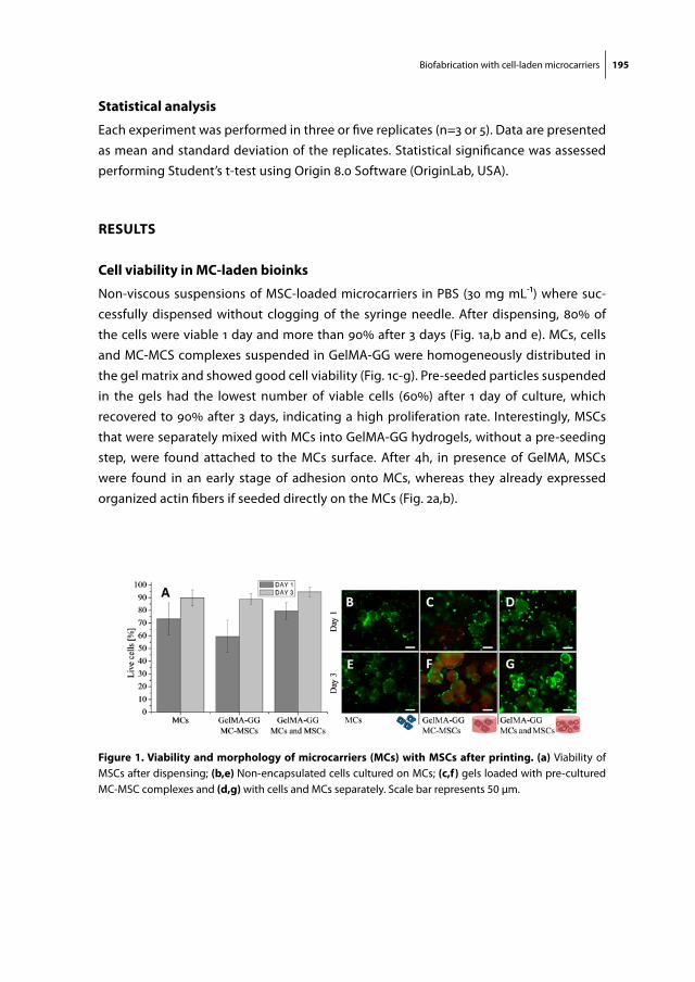
Biofabrication with cell-laden microcarriers 195
statistical analysis
Each experiment was performed in three or five replicates (n=3 or 5). Data are presented as mean and standard deviation of the replicates. Statistical significance was assessed performing Student’s t-test using Origin 8.0 Software (OriginLab, USA).
results
cell viability in mc-laden bioinks
Non-viscous suspensions of MSC-loaded microcarriers in PBS (30 mg mL-1) where suc-cessfully dispensed without clogging of the syringe needle. After dispensing, 80% of the cells were viable 1 day and more than 90% after 3 days (Fig. 1a,b and e). MCs, cells and MC-MCS complexes suspended in GelMA-GG were homogeneously distributed in the gel matrix and showed good cell viability (Fig. 1c-g). Pre-seeded particles suspended in the gels had the lowest number of viable cells (60%) after 1 day of culture, which recovered to 90% after 3 days, indicating a high proliferation rate. Interestingly, MSCs that were separately mixed with MCs into GelMA-GG hydrogels, without a pre-seeding step, were found attached to the MCs surface. After 4h, in presence of GelMA, MSCs were found in an early stage of adhesion onto MCs, whereas they already expressed organized actin fibers if seeded directly on the MCs (Fig. 2a,b).
figure 1. Viability and morphology of microcarriers (mcs) with mscs after printing. (a) Viability of MSCs after dispensing; (b,e) Non-encapsulated cells cultured on MCs; (c,f) gels loaded with pre-cultured MC-MSC complexes and (d,g) with cells and MCs separately. Scale bar represents 50 µm.

196 Chapter 9
mechanical properties of mc-laden gelma
The incorporation of MCs into the GelMA-GG hydrogels resulted in an increment of the compressive modulus (Fig. 3). The stiff PLA MCs reinforced the softer hydrogel matrix, and the compression modulus increased along with the MC concentration. For the high-est concentration tested, stiffness was 2-fold higher than for MC-free gels.
figure 2. (a) Morphology of MSCs 4 hours after mixing with cell-free microcarriers in GelMA-GG (dashed circle indicates a MC) and (b) seeded directly on the MCs in absence of the gel. Scale bar is 40 µm. Cytoskel-eton stained in green, nuclei in blue.
figure 3. compression modulus of gelma-gg with different concentrations of mcs. The four samples show significantly different moduli (p<0.05).
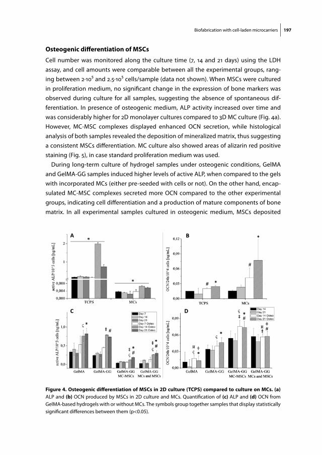
Biofabrication with cell-laden microcarriers 197
osteogenic differentiation of mscs
Cell number was monitored along the culture time (7, 14 and 21 days) using the LDH assay, and cell amounts were comparable between all the experimental groups, rang-ing between 2·105 and 2.5·105 cells/sample (data not shown). When MSCs were cultured in proliferation medium, no significant change in the expression of bone markers was observed during culture for all samples, suggesting the absence of spontaneous dif-ferentiation. In presence of osteogenic medium, ALP activity increased over time and was considerably higher for 2D monolayer cultures compared to 3D MC culture (Fig. 4a). However, MC-MSC complexes displayed enhanced OCN secretion, while histological analysis of both samples revealed the deposition of mineralized matrix, thus suggesting a consistent MSCs differentiation. MC culture also showed areas of alizarin red positive staining (Fig. 5), in case standard proliferation medium was used.
During long-term culture of hydrogel samples under osteogenic conditions, GelMA and GelMA-GG samples induced higher levels of active ALP, when compared to the gels with incorporated MCs (either pre-seeded with cells or not). On the other hand, encap-sulated MC-MSC complexes secreted more OCN compared to the other experimental groups, indicating cell differentiation and a production of mature components of bone matrix. In all experimental samples cultured in osteogenic medium, MSCs deposited
figure 4. osteogenic differentiation of mscs in 2d culture (tcps) compared to culture on mcs. (a) ALP and (b) OCN produced by MSCs in 2D culture and MCs. Quantification of (c) ALP and (d) OCN from GelMA-based hydrogels with or without MCs. The symbols group together samples that display statistically significant differences between them (p<0.05).
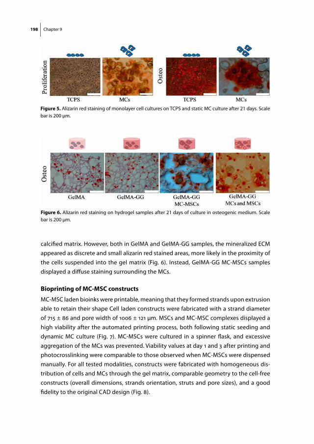
198 Chapter 9
calcified matrix. However, both in GelMA and GelMA-GG samples, the mineralized ECM appeared as discrete and small alizarin red stained areas, more likely in the proximity of the cells suspended into the gel matrix (Fig. 6). Instead, GelMA-GG MC-MSCs samples displayed a diffuse staining surrounding the MCs.
Bioprinting of mc-msc constructs
MC-MSC laden bioinks were printable, meaning that they formed strands upon extrusion able to retain their shape Cell laden constructs were fabricated with a strand diameter of 715 ± 86 and pore width of 1006 ± 121 µm. MSCs and MC-MSC complexes displayed a high viability after the automated printing process, both following static seeding and dynamic MC culture (Fig. 7). MC-MSCs were cultured in a spinner flask, and excessive aggregation of the MCs was prevented. Viability values at day 1 and 3 after printing and photocrosslinking were comparable to those observed when MC-MSCs were dispensed manually. For all tested modalities, constructs were fabricated with homogeneous dis-tribution of cells and MCs through the gel matrix, comparable geometry to the cell-free constructs (overall dimensions, strands orientation, struts and pore sizes), and a good fidelity to the original CAD design (Fig. 8).
figure 5. Alizarin red staining of monolayer cell cultures on TCPS and static MC culture after 21 days. Scale bar is 200 µm.
figure 6. Alizarin red staining on hydrogel samples after 21 days of culture in osteogenic medium. Scale bar is 200 µm.
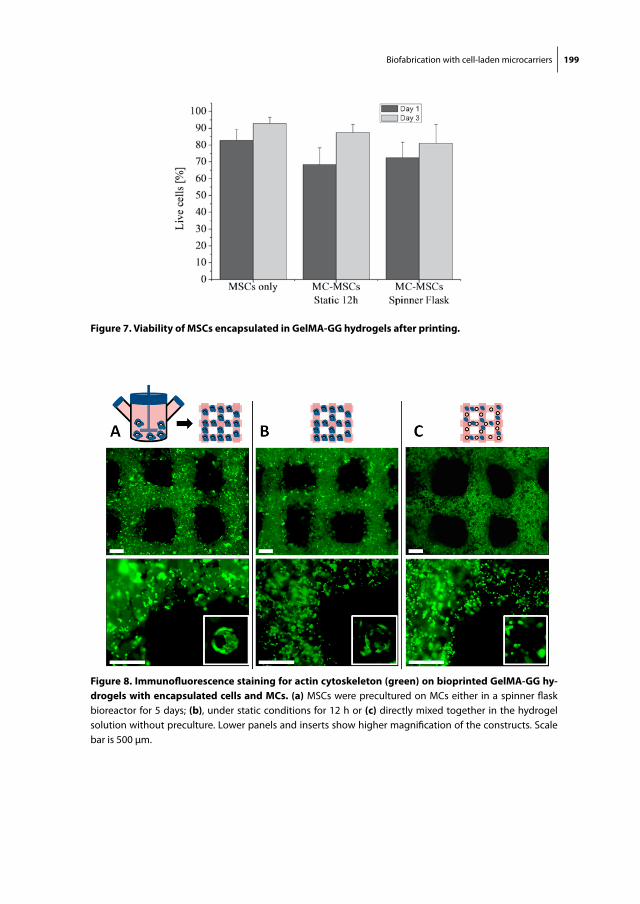
Biofabrication with cell-laden microcarriers 199
figure 7. Viability of mscs encapsulated in gelma-gg hydrogels after printing.
figure 8. immunofluorescence staining for actin cytoskeleton (green) on bioprinted gelma-gg hy-drogels with encapsulated cells and mcs. (a) MSCs were precultured on MCs either in a spinner flask bioreactor for 5 days; (b), under static conditions for 12 h or (c) directly mixed together in the hydrogel solution without preculture. Lower panels and inserts show higher magnification of the constructs. Scale bar is 500 µm.
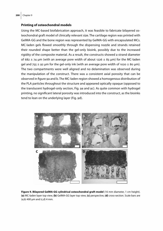
200 Chapter 9
printing of osteochondral models
Using the MC-based biofabrication approach, it was feasible to fabricate bilayered os-teochondral graft model of clinically relevant size. The cartilage region was printed with GelMA-GG and the bone region was represented by GelMA-GG with encapsulated MCs. MC-laden gels flowed smoothly through the dispensing nozzle and strands retained their rounded shape better than the gel-only bioink, possibly due to the increased rigidity of the composite material. As a result, the constructs showed a strand diameter of 682 ± 74 µm (with an average pore width of about 1226 ± 83 µm) for the MC-laden gel and 755 ± 92 µm for the gel-only ink (with an average pore width of 1020 ± 80 µm). The two compartments were well aligned and no delamination was observed during the manipulation of the construct. There was a consistent axial porosity that can be observed in figure 9a and b. The MC-laden region showed a homogenous distribution of the PLA particles throughout the structure and appeared optically opaque (opposed to the translucent hydrogel-only section, Fig. 9a and 9c). As quite common with hydrogel printing, no significant lateral porosity was introduced into the construct, as the bioinks tend to lean on the underlying layer (Fig. 9d).
figure 9. Bilayered gelma-gg cylindrical osteochondral graft model (16 mm diameter, 1 cm height). (a) MC-laden layer top view, (b) GelMA-GG layer top view, (c) perspective, (d) cross-section. Scale bars are (a,b) 400 µm and (c,d) 4 mm.
Biofabrication with cell-laden microcarriers 201
discussion
In this study, living 3D structures containing MC-MSCs complexes were fabricated using bioprinting technology. MCs were found suitable substrates to for cell adhesion and os-teogenic differentiation and acted as reinforcing material to the hydrogel. Furthermore, high cells concentrations could be obtained by pre-culturing MSCs on MCs.
GelMA-GG was chosen as a bioink for bioprinting. Due to its shear-thinning behavior, it can be easily extruded into filaments, which then maintain their shape once deposited on the printing substrate, thus allowing the generation of 3D printed structures with good shape fidelity61,190. Finally, the obtained scaffolds can be irreversibly crosslinked after mild UV-exposure. We found this procedure had little impact on cell viability, which is in line with previous research195,333,416. It should be noted that human MSCs may show different survival rates compared to rat MSCs in response to mechanical stresses and UV radiation, although previous work reported reassuring results regarding MSCs dif-ferentiation (hence survival) after UV-encapsulation in collagenous hydrogels417.
Another issue regarding the current crosslinking set-up, is that constructs were UV cured after the printing process, may limit the size of the constructs, since UV may not penetrate deeply into larger grafts. However, this can be solved by inducing photocross-linking during the printing process. Such technology has been recently described by Cui et al., and could be adapted to our system by a hardware modification99.
In this work, cells and MCs were either suspended as precultured MC-MSCs complexes or mixed separately into the hydrogel. The first approach is preferable, since such aggre-gates have been shown to promote cell viability, biomolecules synthesis and differentia-tion411, due to the establishment of cell-cell contacts and actin cytoskeleton reorganiza-tion418. However, since large aggregates can easily clog the injection nozzle, expansion periods under static culture should be limited. As an interesting alternative, MCs and MSCs can be separately mixed, without preculture steps. The current work showed that such suspensions can easily be dispensed, and once suspended in the bioink, cells were able to migrate through the hydrogel matrix to adhere, spread and proliferate on the MC surface. Although it could be possible to use this approach to tune MSCs adhesion and response, the amount of cells that could be loaded into the gel would be limited by stan-dard 2D proliferation protocols. Therefore, 3D-expansion methods are required. To retain a printable bioink, cells should be expanded on individual MCs or small aggregates, a condition that can be achieved in a stirring bioreactor, as also shown in this study.
Composite bioinks were thus created, in which MCs, made of a mechanically stiff poly-mer, were dispersed in the softer hydrogel matrix. It is known that hydrogel stiffness can be improved increasing the polymer concentration or the crosslinking degree (UV expo-sure, temperature)60. A high crosslink density however is less desirable, as it can hamper the migration of encapsulated cells and their ability to homogeneously colonize the

202 Chapter 9
hydrogel with newly synthesized extracellular matrix79. Instead, incorporation of MCs does not alter the nature of the hydrogel network, and construct stiffness was shown to increase along with the concentration of MCs. However, it should be considered that stress at failure may be reduced, although this was not evident in our mechanical assay. MC reinforcement of hydrogels does not lead to compressive moduli similar to hard tissues. When hydrogel-based constructs are implanted in load-bearing locations, external fixation will be required to reduce weight on the implant. Another strategy that can be implemented to improve the mechanical properties of hydrogel constructs, is co-printing of a supportive thermoplastic polymer network60,255. Still, in all regenerative approaches, the final mechanical properties should be provided by the neo-tissue that is secreted by the embedded cells419.
To further enhance the hydrogel compression modulus and match the stiffness of hard tissues, it may be feasible to encapsulate particles made of different materials (e.g. calcium phosphates)420, provided that they do not sediment over the time scale of the printing process and their size allows the extrusion of the bioink. However, an advantage of MCs encapsulation is to use them as devices to efficiently expand MSCs and then print MC-MSCs aggregates with improved biological behavior and bone forming potential408. For this reason, MCs with a highly porous core made from low density materials and suitable for spinner flask culture were chosen82.
The potential to improve the osteogenic differentiation of MSCs by encapsulating them with MCs into GelMA hydrogels was studied in vitro. All the samples cultured with differentiation medium displayed calcified matrix deposition, and MSC commitment towards osteogenic lineage, thus supporting the suitability to use GelMA-based gels for bone bioprinting. Alizarin red staining, which appeared as discrete spots surrounding cells without MCs, intensely marked diffused areas around MC-MSCs complexes. This indicates strongly mineralized regions, probably due to the fact that local cell density is higher on cell-colonized MCs, a factor affecting cell behavior and differentiation408. At a molecular level, MC-laden samples showed markedly reduced ALP activity compared to their respective controls. This was accompanied by a higher secretion of OCN, which is a late marker for maturation of osteoblasts, and key component of bone extracellular matrix421. MC-MSCs gels gave the best results regarding the secretion of OCN, and at the same time induced matrix calcification, suggesting that they are able to form a mature bone-like tissue. This discrepancy of ALP levels in vitro and bone-forming capacity of MSCs was recently described by Goh et al. who compared the bone forming potential of human fetal MSCs cultured as monolayers with Cytodex 3 MCs. Despite a 45-fold reduc-tion in ALP activity on MCs, MSCs cultured on MCs and MC-MSCs complexes induced better and more consistent bone formation in vitro and in vivo (in a rodent model), indi-cating that MC culture can improve the potential of MSCs in bone tissue engineering422.
Biofabrication with cell-laden microcarriers 203
Eventually, it is worthwhile to underline that the addition of gellan gum to the bioink formulation did not have a relevant effect on osteogenic differentiation of MSCs. Gel-lan gum, may thus be safely mixed with GelMA for printing of bone tissue in order to increase the solution viscosity and improve the printability of the bioink61. The results of the differentiation assay also suggest that it is not advisable to use solely MSCs in GelMA-based hydrogels for the cartilage region, since they can easily differentiate to-wards osteoblastic lineage. For this reason, it would be preferable to use chondrocytes, which have shown capable of chondrogenic differentiation in GelMA in vitro and in vivo63,255. MSCs can play an important role in maintaining chondrocyte phenotype in co-cultures381,423,424, although the mechanism underlying this crosstalk is not fully un-derstood, and cases of downregulation of chondrocytes differentiation have also been reported425. However, co-cultures of MSCs and chondrocytes in hydrogel systems have been reported, suggesting the beneficial effect of the combination of such cell types in generating bone and cartilage tissues. For instance, Mo et al. demonstrated that MSCs and chondrocytes each encapsulated in different compartment of an alginate matrix, interacted, possibly due to trophic factors secretion, determining an enhancement of GAGs secretion by chondrocytes and an initiation of osteogenesis of MSCs, which induced osteocalcin production426. These effects were found to be dependent on the MSC/chondrocyte ratio426.
Proven that MC-laden GelMA-GG can be a matrix for bone tissue engineering, the mate-rial was used as a bioink to construct model of an osteochondral graft. Recently, calcium phosphate particles (size 100-212 µm) have been introduced at low concentrations (up to 15 mg mL-1) into alginate bioinks to promote bone regeneration148. Poldervaart et al. also printed gelatin microparticles for controlled release of Bone Morphogenic Protein-2427. Both cases showed promising results in terms of in vivo osteoinduction, however low amounts of particles where encapsulated. We found that the addition of high concen-trations of MCs to GelMA-GG hydrogels did not reduce the printability of the ink, nor did it affect the size of the extruded strands and the porosity. Living constructs were obtained by adding MC-MSCs to the bioink mixture, either after a short period of static culture (12h) or longer culture (5 days) in a spinner flask bioreactor. Both approaches generated viable MC-MSCs complexes, but the latter has a clear advantage, as dynamic culture allows cell proliferation while preventing formation of large, difficult to extrude, aggregates. Furthermore, spinner flask culture has the great potential to combine 3D printing with a well-established cell expansion technology. To date, bioprinting of cell aggregates was prevalently performed by producing tissue spheroids and using them as bioink components428. Despite of the interesting biological performance, spheroid generation methods are still time consuming and not suitable for mass production, thus limiting the size of printable tissues428. Conversely, microcarrier culture is a simple, industrially scalable technology to achieve large cell numbers, with precise control over
204 Chapter 9
cell culture conditions429. MSCs aggregates have been demonstrated to improve cell proliferation, survival and multilineage differentiation, especially when the endogenous ECM produced in the aggregates is preserved430. Such matrix preservation is a charac-teristic of MC-MSCs complexes405 which are profitable to induce cell differentiation and build tissue engineered constructs431. Additionally, to further exploit the advantage of 3D cell-cell connections, MCs with an open porous structure could be used, so that cells can colonize the inside of the carrier and display a 3D organization in it403. MC culture opens promising possibilities when combined with bioprinting technologies.
In tissue constructs fabricated from all MC-bioinks (short-term static culture, dynamic culture, and without preseeding), the complexes or the free cells and particles were homogeneously distributed in the printed graft with shape fidelity comparable to that of the cell-free constructs, thus proving the printability of MC-MSCs complexes. Under these conditions, zonal constructs composed of MC-laden and MC-free layers of gels with clinically relevant size were obtained. The size of the strand was not significantly affected by the presence of the MCs, thus allowing a good stacking and alignment of the two compartments, which generated a consistent and well-aligned axial porosity all through the construct. The high viability of MSCs, and the results of the multimaterial printing process demonstrates the feasibility of a combined MC culture-bioprinting strategy to generate large, living constructs, with potential applications in osteochon-dral tissue engineering and as 3D tissue models.
conclusions and future perspectiVes
MC-laden GelMA-based bioink was shown to be a promising composite material for bioprinting. PLA MCs acted as a mechanical reinforcement to the soft GelMA matrix, without compromising the printability of GelMA bioinks. Additionally, encapsulation of MC-MSCs complexes - with improved cell adhesion and cell-cell contacts – supported bone matrix deposition, and hence is of great interest for the engineering of bone tissue. Finally, MC-MSC-rich living construct where obtained using bioprinting combined with microcarrier dynamic expansion. These are key findings to build advanced constructs for bone and cartilage tissue engineering. Furthermore, the printability of bioinks with high MC concentrations opens possibilities for the fabrication of biomedical screening mod-els. Drug-encapsulating MCs could be used, adding an additional level of complexity in the bioprinting of living tissues. Co-delivery of cells and growth factors with control over the spatial and temporal distributions would be possible, and constitutes another promising trend that can be explored in the area of biofabrication.

Biofabrication with cell-laden microcarriers 205
acKnowledgments
RL acknowledges the Spanish Ministry of Education, Culture and Sport (MECD) for its financial support through the FPU programme (grant reference AP2010-4827). JV was supported by a grant from the Dutch government to the Netherlands Institute for Regenerative Medicine (NIRM, grant n°FES0908) and JM was supported by the Dutch Arthritis Foundation.

Chapter 10Preliminary results of a translational animal model
Biofabrication of Anatomically Shaped Implants for Regeneration of the Rabbit Humeral Head
Jetze VisserRoel J.H. CustersPaul D. DaltonRazmara NizakDaniël B.F. SarisDebby GawlittaJos Malda
The results of the in vivo section of this study in rabbits
are awaited before this manuscript will be submitted for
publication.

208 Chapter 10
aBstract
In the present thesis, the state of the art of cartilage regeneration, biofabrication tech-niques for orthopaedic applications and mechanical reinforcement of hydrogels were explored. In this Chapter, these facets culminate to enter the next level in the form of a functional reconstruction of complex anatomical structures such as a shoulder joint. We aimed to biofabricate a customized, biphasic implant for the restoration of the humeral head. The implant was based on a CT-scan of a rabbit front leg identify-ing the bony and cartilaginous compartments. The bone component was printed from poly-ε-caprolactone (PCL) with fused deposition modelling (porosity 74%) and was coated with calcium phosphates. The cartilage component consisted of a gelatin-based hydrogel that was reinforced with organized PCL microfibers (porosity 92%) printed with melt electrospinning writing. Both components were manually fused prior to hydrogel infusion. Three variations of the cartilage compartment will be compared, i.e. fiber reinforced GelMA containing 1) expanded rabbit chondrocytes or 2) TGF-β and 3) a cell- and growth factor free control group. The complex biphasic scaffolds matched the anatomical dimensions of the rabbit humerus and were successfully implanted in cadav-eric rabbits. The implants remained intact after abduction/adduction cycles of the rabbit shoulder. Chondrogenesis of expanded rabbit chondrocytes in GelMA was confirmed in vitro. A pilot study in three rabbits is ongoing to preliminary assess construct behaviour in the three groups, and to monitor the rehabilitation of the animals. Thereafter, the scaffolds will be implanted in 18 rabbits (n=6) to study bone and cartilage regeneration and implant shape conservation. This approach for the regeneration of both cartilage and bone tissue in a customized implant potentially offers a biological solution for the replacement of (partially) degenerated joints.
Regeneration of the rabbit humeral head 209
introduction
Tissue degeneration in articular joints can result from osteoarthritic processes, or can comprise osteochondral defects caused by trauma and/or genetic factors32,33. The stan-dard therapy for joint degeneration is replacement of the diseased tissue with a prothe-sis7,18. Regenerative medicine, however, seeks for solutions that regenerate degenerated tissue, rather than to replace it1. In orthopedics, this strategy has been applied for the repair of focal articular cartilage defects6. Autologous chondrocyte implantation (ACI) is the most common of these regenerative treatments369. Nevertheless, these therapies do not address the underlying bone and have an upper size limit for the defect to be repaired6,9. Regenerative medicine thus has no solution yet for the regeneration of completely or partially degenerated joints.
A biphasic implant of a complex shape is likely required for the repair of large osteo-chondral joint defects, with specific biological and mechanical cues432. In this context, numerous biphasic scaffolds were engineered in simple cylindrical shapes, with distinct matrix, cells and/or growth factor compositions for the cartilage and bone compo-nents35,36. A few of these implants have found their way to clinical application, however, they do not address the complex architecture of large joint defects.
Additive manufacturing is a powerful approach to design and produce organized im-plants, and often use a fused deposition modeling (FDM) process to fabricate scaffolds11. The most appealing approach so far of FDM and tissue repair with an large osteochon-dral implant was presented by Lee et al53. In their study, the proximal humerus of rabbits was replaced with a porous implant from poly-ε-caprolactone (PCL) and hydroxyapatite, combined with transforming growth factor(TGF)-β3 in a collagenous carrier in the car-tilage layer. The articular surface of the shoulder was successfully regenerated through the activity of endogenous cells that were attracted or differentiated by the introduced growth factor. However, bone regeneration was not studied, and the biphasic nature of the scaffold was limited in terms of biological and mechanical properties.
Recent advancements in additive manufacturing in our group allow for the produc-tion of complex structures from PCL (Chapter 8)190. Combined with cells and growth factors11,12, in a process termed “biofabrication”, such scaffolds can provide the sufficient morphological, mechanical and chemical cues to promote regeneration. PCL has been demonstrated a successful scaffold material for the regeneration of bone defects50-53, especially when the polymer material was coated with ceramics to improve bone con-duction433,434.
Organized scaffolds with thinner fibers that reinforce hydrogel structures are more suitable to produce the elastic cartilage component, when used as a reinforcement to hydrogels, as demonstrated in Chapter 654. The reinforcement of hydrogels with micro-fibers, which were produced by a melt electrospinning writing (MEW) process, resulted
210 Chapter 10
in composite constructs with stiffnesses resembling those of native articular cartilage435. In these composites, cartilage matrix could be produced by chondrocytes in vitro, when cultured within reinforced gelatin methacrylamide / hyaluronic acid (GelMA/HA) hydro-gels. The addition of a small amount of HA to GelMA is favorable for the chondrogenesis of embedded MSCs60,63,73, hence this hydrogel composition was adopted in the current work.
This research project aims for the biofabrication of a biodegradable implant with a customized shape for the regeneration of the rabbit shoulder. Potentially, a combina-tion of the thick, rigid PCL fibers and the microfibrous hydrogel composite containing a clinically relevant cell composition results in a biphasic implant for the regeneration of bone and cartilage tissue. Such an implant could make the step from cell therapy for focal cartilage defects to the regeneration of partial or complete joint defects.
materials and methods
design of the implants
A humerus (upper arm) was harvested from a cadaveric New-Zealand White (NZW) rab-bit and subsequently scanned with a Micro-CT (Voxel size 120 µm; Quantum FX- Perkin Elmer). An osteochondral implant was designed using CAD-software, based on the shape of the humeral head. The cartilage component was separately segmented from the CT-scan and a stem was designed to press-fit the prosthesis in the humeral shaft. A sacrificial support structure was added in the design to facilitate the realization of the complex overhanging shapes during the printing process. The data set was then translated into standard tessellation language (.stl) for 3D printing.
fabrication and coating of the bone component
The bone component of the implant was 3D-printed from PCL (Sigma-Aldrich; Mn 45.000) with the BioScaffolder (SYS+ENG, Salzgitter-Bad, Germany). Fibers with a diameter of 160 µm were deposited in a 0-90° orientation with 750 µm spacing. Polyvinyl alcohol (PVA) was printed as a temporary support structure along with the PCL to create the dome-shaped humeral head. After printing, the PVA was washed away in dH2O on a rollerbank overnight at 37 °C. The implant was etched with 70% ethanol (1 h) and 5M NaOH (4 h), followed by coating with a five times concentrated simulated body fluid solution (NaCl (40 g), CaCl2·2H2O (1.84 g), MgCl2·6H2O (1.52 g), NaHCO3 (1.72 g), and Na2-HPO4·2H2O (0.9 g) salts in 1 L of dH2O) for 24 hours at 37 °C under continuous gentle stirring. Following this coating step, the samples were immersed in a calcium phosphate solution (NaCl (8 g), CaCl2·2H2O (0.59 g), Na2HPO4·H 2O (0.36 g), and Tris (6.05 g) in 1 L dH2O, pH 7.4) at 37

Regeneration of the rabbit humeral head 211
°C for 24 h on a roller plate. The coating procedure was based on a combination of two protocols433,434. The coated samples were washed three times in dH2O.
fabrication of the cartilage component
The microfibers for the implant were fabricated from PCL (PURAC, Zwijndrecht, the Neth-erlands) using a custom-built melt electrospinning machine as previously described. The MEW fibers with a diameter of 14 µm were stacked with a spacing of 200 µm, with the overall scaffold dimensions of 60x60x0.4 mm (lxwxh). A defined pattern to cover the bone component was cut from the MEW scaffold and melted onto the coated bone component of the implant with a hot spatula. The cartilage component was infused with GelMA/HA hydrogel (stained with fast green for visualization purposes only in Fig. 1f ). The gel was allowed to air-dry and was subsequently crosslinked for 70 seconds with a focused UV source with an intensity of 180 mW/cm2 (350-450 nm, Hönle UV technology, Munich, Germany).
preparation of gelma/ha hydrogel
GelMA was synthesized by reaction of porcine type A gelatin (Sigma-Aldrich, St. Louis, Missouri, USA) with methacrylic anhydride at 50 °C for one hour as previously described63. GelMA was dissolved in Phosphate Buffered Saline (PBS) at 60 °C at a concentration of 9.5% (w/v). Methacrylated hyaluronic acid in a concentration of 0.5% (w/v) was added to the GelMA solution to promote redifferentiation of embedded chondrocytes60,63,73.
measurement of the stiffness of the cartilage and bone component
Scaffolds representing the bone (FDM; thick fibers) and the cartilage (MEW; thin fibers) component with dimensions of 6 mm diameter and 2 mm height were punched from larger sheets for mechanical tests. The microfiber scaffolds for the cartilage components of the implant (stack of 5 to reach 2 mm height) were infused with GelMA hydrogel (at circa 37 °C) in a custom-made Teflon mold. After thermal gelation of the hydrogel (15 minutes), the samples were UV-crosslinked for 70 seconds on both sides with the fo-cused UV source. Samples (n=5 per group) were subjected to single uniaxial unconfined compression in air at room temperature, after 1 hour of submersion in PBS from their preparation. Over a period of two minutes, a force ramp (axial strain rate ca. 10%/min) was applied to the samples employing a Dynamic Mechanical Analyser (DMA 2980, TA Instruments, New Castle, DE, USA). The stiffness was calculated from the linear derivative of the stress/strain curve between 3-10% strain.
212 Chapter 10
harvest and culture of rabbit chondrocytes for confirmation of chondrogenesis in gelma/ha gels
Macroscopically healthy full-thickness cartilage was harvested under sterile conditions from the shoulder, hip and knee joints of fresh NZW rabbit cadavers (n=3, weight 4-5 kg). After fragmentation and overnight digestion in type II collagenase (Worthington Biochemical Corp) at 37˚C, the suspension was filtered through a 100 μm cell strainer, washed in PBS and stored in liquid nitrogen at -196°C in culture medium (Dulbecco’s Modified Eagle Medium (DMEM) 41965, Invitrogen) supplemented with 20% heat-inacti-vated fetal bovine serum (FBS, Biowhittaker) and 10% dimethylsulfoxide (DMSO (Merck, Darmstadt, Germany)). Upon thawing, the chondrocytes were seeded at a density of 5× 10³ cells/cm2 and expanded for 10-12 days in a monolayer culture in chondrocyte expansion medium consisting of DMEM, 10% FBS, 100 units/ml penicillin and 100 µg/ml streptomycin (Invitrogen), and 10 ng/ml FGF-2 (R&D Systems) and embedded in GelMA/HA at passage 2 at a concentration of 20 million cells per mL gel.
The gel with cells was infused in a mold for samples with a diameter of 6 mm and height of 2 mm. The samples were UV-crosslinked for 70 seconds on both sides with the focused UV source. The samples (n=3) were cultured for four weeks in vitro in chondrogenic differentiation medium (DMEM (41965, Invitrogen), supplemented with 0.2 mM L-ascorbic acid 2-phosphate, 0.5% human serum albumin (SeraCare Life Sci-ences), 1x ITS-X (Invitrogen), 100 units/ml penicillin and 100 µg/ml streptomycin, 25 mM 4-(2-hydroxyethyl)-1-piperazineethanesulfonic acid (HEPES) (Invitrogen) and 5 ng/ml TGF-b2)). Samples at day 1 of culture were taken as a control for the histology analysis. For the implantation of the cell-laden scaffold in rabbits, the rabbit chondrocytes will be infused in GelMA/HA into the cartilage component of the implant and UV-crosslinked for 70 seconds.
histology and immunohistochemistry
The samples were processed for histology and immunohistochemistry by dehydration through a graded ethanol series, cleared in xylene and embedded in paraffin. The samples were sectioned into 5 µm slices and a triple stain of hematoxylin, fast green, and Safranin-O (all from Sigma) was applied to identify the presence of GAGs.
Collagen type II was stained by immunohistochemistry after deparaffinization and rehydration of the sections. The sections were blocked in 5% bovine serum albumin and 0.3% H2O2 following antigen retrieval. Antigen retrieval for collagen type II was performed by incubation with 1 mg/mL pronase (Sigma) and 10 mg/mL hyaluronidase (Sigma) at 37 degrees for half an hour each. Next, sections were incubated with the primary antibody for collagen type II (1:100, monoclonal mouse, II-II6B3, DSHB) at 4°C overnight, followed by incubation with GAM-HRP (1:200, P0447, Dako) at room temperature for an hour. Collagen type II was detected by a 10-minute conversion of 3,3’-diaminobenzidine solu-
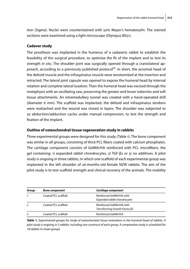
Regeneration of the rabbit humeral head 213
tion (Sigma). Nuclei were counterstained with 50% Mayer’s hematoxylin. The stained sections were examined using a light microscope (Olympus BX51).
cadaver study
The prosthesis was implanted in the humerus of a cadaveric rabbit to establish the feasibility of the surgical procedure, to optimize the fit of the implant and to test its strength in situ. The shoulder joint was surgically opened through a craniolateral ap-proach, according to a previously published protocol53. In short, the acromial head of the deltoid muscle and the infraspinatus muscle were tenotomized at the insertion and retracted. The lateral joint capsule was opened to expose the humeral head by internal rotation and complete lateral luxation. Then the humeral head was excised through the metaphysis with an oscillating saw, preserving the greater and lesser tubercles and soft tissue attachments. An intramedullary tunnel was created with a hand-operated drill (diameter 6 mm). The scaffold was implanted, the deltoid and infraspinatus tendons were reattached and the wound was closed in layers. The shoulder was subjected to 50 abduction/adduction cycles under manual compression, to test the strength and fixation of the implant.
outline of osteochondral tissue regeneration study in rabbits
Three experimental groups were designed for this study (Table 1). The bone component was similar in all groups, consisting of thick PCL fibers coated with calcium phosphates. The cartilage component consists of GelMA/HA reinforced with PCL microfibers, the gel containing: 1) expanded rabbit chondrocytes, 2) TGF-β2 or 3) no additives. A pilot study is ongoing in three rabbits, in which one scaffold of each experimental group was implanted in the left shoulder of 26-months-old female NZW rabbits. The aim of the pilot study is to test scaffold strength and clinical recovery of the animals. The mobility
Group Bone component Cartilage component
1 Coated PCL scaffold Reinforced GelMA/HA withExpanded rabbit chondrocytes
2 Coated PCL scaffold Reinforced GelMA/HA withTransforming Growth Factor β2
3 Coated PCL scaffold Reinforced GelMA/HA
Table 1. Experimental groups for study of osteochondral tissue restoration in the humeral head of rabbits. A pilot study is ongoing in 3 rabbits, including one construct of each group. A comparative study is scheduled for 18 rabbits (n=6 per group).
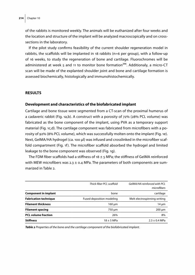
214 Chapter 10
of the rabbits is monitored weekly. The animals will be euthanized after four weeks and the location and structure of the implant will be analyzed macroscopically and on cross-sections in the laboratory.
If the pilot study confirms feasibility of the current shoulder regeneration model in rabbits, the scaffolds will be implanted in 18 rabbits (n=6 per group), with a follow-up of 16 weeks, to study the regeneration of bone and cartilage. Fluorochromes will be administered at week 5 and 11 to monitor bone formation296. Additionaly, a micro-CT scan will be made of the explanted shoulder joint and bone and cartilage formation is assessed biochemically, histologically and immunohistochemically.
results
development and characteristics of the biofabricated implant
Cartilage and bone tissue were segmented from a CT-scan of the proximal humerus of a cadaveric rabbit (Fig. 1a,b). A construct with a porosity of 72% (28% PCL volume) was fabricated as the bone component of the implant, using PVA as a temporary support material (Fig. 1c,d). The cartilage component was fabricated from microfibers with a po-rosity of 92% (8% PCL volume), which was successfully molten onto the implant (Fig. 1e). Next, GelMA/HA hydrogel (ca. 100 µl) was infused and crosslinked in the microfiber scaf-fold compartment (Fig. 1f ). The microfiber scaffold absorbed the hydrogel and limited leakage to the bone component was observed (Fig. 1g).
The FDM fiber scaffolds had a stiffness of 18 ± 5 MPa; the stiffness of GelMA reinforced with MEW microfibers was 2.3 ± 0.4 MPa. The parameters of both components are sum-marized in Table 2.
Thick-fiber PCL scaffold GelMA/HA reinforced with PCL microfibers
component in implant bone cartilage
fabrication technique Fused deposition modeling Melt electrospinning writing
filament thickness 160 µm 14 µm
filament spacing 750 µm 200 µm
pcl volume fraction 26% 8%
stiffness 18 ± 5 MPa 2.3 ± 0.4 MPa
Table 2 Properties of the bone and the cartilage component of the biofabricated implant.
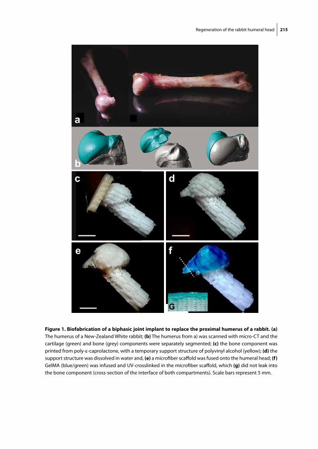
Regeneration of the rabbit humeral head 215
c d
e f
a
b
G
figure 1. Biofabrication of a biphasic joint implant to replace the proximal humerus of a rabbit. (a) The humerus of a New-Zealand White rabbit; (b) The humerus from a) was scanned with micro-CT and the cartilage (green) and bone (grey) components were separately segmented; (c) the bone component was printed from poly-ε-caprolactone, with a temporary support structure of polyvinyl alcohol (yellow); (d) the support structure was dissolved in water and, (e) a microfiber scaffold was fused onto the humeral head; (f) GelMA (blue/green) was infused and UV-crosslinked in the microfiber scaffold, which (g) did not leak into the bone component (cross-section of the interface of both compartments). Scale bars represent 5 mm.

216 Chapter 10
The fibers of the bone component initially had a smooth surface, as objectified with SEM scanning (Fig. 2a). The subsequent coating protocol resulted in sedimentation of calcium phosphate structures (Fig 2b,c). SEM scanning of the microfiber scaffold showed
100 µm 30 µm
30 µm 5 µm
a b c
30 µm
5 µm
e fd
figure 2. sem imaging of scaffolds for the bone and the cartilage components of the implant. The bone component was from printed fibers (diameter 160 µm), of which cross-sections are shown (a) before coating and (b,c) after coating with calcium phosphates. (d,e) The scaffold for the cartilage component of the implant was fabricated from melt electrospun microfibers (diameter 14 µm) in a 0-90° orientation; (f) cross-section of a single PCL microfiber.
200 µm 200 µm
a b
c
figure 3. In vitro differentiation of rabbit chondrocytes in gelma/ha hydrogel. Rabbit chondrocytes produced an interconnected cartilage matrix consisting of (a) glycosaminoglycans (safranin-O staining) and (b) collagen type II (brown), within the GelMA/HA hydrogel; (c) safranin-O staining of the sample at day 1 illustrates the basic level of GAG staining by the HA incorporation in the GelMA gel (scale bar represents 30 µm).
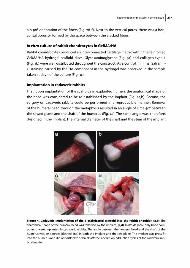
Regeneration of the rabbit humeral head 217
a 0-90° orientation of the fibers (Fig. 2d-f ). Next to the vertical pores, there was a hori-zontal porosity, formed by the space between the stacked fibers.
In vitro culture of rabbit chondrocytes in gelma/ha
Rabbit chondrocytes produced an interconnected cartilage matrix within the reinforced GelMA/HA hydrogel scaffold discs. Glycosaminoglycans (Fig. 3a) and collagen type II (Fig. 3b) were well distributed throughout the construct. As a control, minimal Safranin-O staining caused by the HA component in the hydrogel was observed in the sample taken at day 1 of the culture (Fig. 3c).
implantation in cadaveric rabbits
First, upon implantation of the scaffolds in explanted humeri, the anatomical shape of the head was considered to be re-established by the implant (Fig. 4a,b). Second, the surgery on cadaveric rabbits could be performed in a reproducible manner. Removal of the humeral head through the metaphysis resulted in an angle of circa 40° between the sawed plane and the shaft of the humerus (Fig. 4c). The same angle was, therefore, designed in the implant. The internal diameter of the shaft and the stem of the implant
a b
c d
40°
figure 4. cadaveric implantation of the biofabricated scaffold into the rabbit shoulder. (a,b) The anatomical shape of the humeral head was followed by the implant; (c,d) scaffolds (here only bone com-ponent) were implanted in cadaveric rabbits. The angle between the humeral head and the shaft of the humerus was 40 degrees (dashed line) in both the implant and the saw plane. The implant was press-fit into the humerus and did not dislocate or break after 50 abduction-adduction cycles of the cadaveric rab-bit shoulder.

218 Chapter 10
were circa 6 mm. Therefore, after removal of the proximal bone marrow with a 6 mm drill, there was a tight fit of the implant in the humerus (Fig. 4d). The implant was still macroscopically intact after 50 abduction/adduction cycles of the shoulder. The implan-tation of the biofabricated scaffolds into the shoulder of NZW rabbits was thus a feasible procedure.
discussion
Anatomically shaped, biphasic scaffolds were fabricated for the restoration of the hu-meral head in the rabbit shoulder. The complex design of the implant was based on a CT-scan of the proximal humerus, so that the cartilage and bone components matched the anatomical dimensions. The bone component consisted of PCL fibers with a porosity of 74%, which were coated with calcium phosphate. The cartilage component consisted of GelMA/HA hydrogel reinforced with PCL microfibers (92% porosity).
The biofabrication techniques FDM and MEW were combined for producing the biphasic implant. The bone component relied on a rigid FDM scaffold, which was previ-ously shown to guide bone formation when ceramics were included or coated51-53. The cartilage component separately was previously shown to support the formation of a cartilage matrix in vitro60,63,73,435, which was reproduced here for rabbit chondrocytes. The two components were thermally fused by hand. A future biofabrication setup should allow for a single procedure, by direct MEW upon the FDM scaffold, in order to further customized the architecture of the implant205.
The current implant adds to the previously presented models that it consists of two components for bone and cartilage regeneration with distinct mechanical and biologi-cal properties53,436. The difference between both components in the study by Lee et al. was only the administration of TGF-β to the top layer of the scaffold, which was absorbed in a rapidly degrading collagen gel 53. The new cartilage matrix was formed between the thick PCL/hydroxyapatite fibers, although these fibers form an unnatural environment for chondrocytes. Our implant aims for the cartilage matrix to be deposited within the reinforced GelMA/HA hydrogel, which better matches the stiffness and elasticity of articular cartilage than a FDM PCL scaffold360-362,435, and which was proven a durable scaffold for cartilage matrix formation in other work in this thesis.
Both components of the current implant have an open connection to each other, through their vertical pores. Nevertheless, for osteochondral tissue engineering, the cartilage and bone component may need to be separated by an impermeable layer, like in native tissues432,437, although this layer will prohibit migration of cells from the bone marrow to the cartilage component. Such a separation may, therefore, have a negative impact on the chondrogenic regeneration in the TGF-β group compared to

Regeneration of the rabbit humeral head 219
the expanded chondrocytes group. The interface between both compartments remains open in the current implants to facilitate migration of cells to the cartilage layer, which was shown the key to cartilage regeneration in the study by lee et al.
The follow-up of the presented work will evaluate bone and cartilage regeneration in the implants in vivo, comparing the presence and absence of chondrocytes and TGF-β in the cartilage component. In the human situation, the group with chondrocytes could potentially be translated as a matrix assisted ACI for osteochondral purposes. However, the outcomes of the outlined animal study should be interpreted with care, as rabbits are known for their huge regenerative capacity438, so tissue formation in humans will of-ten be more challenging. Furthermore, the osteochondral scaffolds are here implanted in fresh defects, which are likely to heal better than osteochondral defects that present naturally. Also, the mechanical loading in the rabbit is lower than in weight-bearing joint in humans.
Altogether, implants with anatomical dimensions addressing both the biological and mechanical properties of bone and cartilage tissue were fabricated for the regenera-tion of large joint defects. The efficacy of these implants for joint repair remains to be demonstrated in the comparative study in rabbits that follows this work.


Chapter 11General Discussion and Future Perspectives

General discussion and future perspectives 223
The work presented in this thesis -shows that constructs from biodegradable materials can be biofabricated with relevant dimensions for joint repair. In Part I the biological properties of gelatin methacrylamide (GelMA) gels are modified by the incorpora-tion of tissue-derived matrices. Part II demonstrates that the strength and stiffness of GelMA gels is significantly improved by reinforcement with 3D-printed scaffolds. Such a composite scaffold is subsequently used in vivo in the equine stifle joint, first in a pilot study, then in a full-scale experimental that is ongoing at the moment of writing but of which study design and initial results are described in this thesis. In Part III, complex shaped constructs for the repair of osteochondral defects are biofabricated and a model for the replacement of the entire shoulder joint of rabbits with 3D-printed implants is presented.
Biological improvement of gelma with extracellular matrix components
The regeneration of tissue in the work presented in this thesis relies on cells encapsu-lated in a biodegradable GelMA hydrogel. Part I of this thesis aimed for the biological improvement of this hydrogel with help of tissue-derived matrices (TDMs). As TDMs are decellularized tissues, they form the ultimate substrate for tissue engineering based on biology. Both the structure and function (through adherence of bio-active substances to matrix components) of the tissue can be retained, forming an instructive scaffold for embedded, seeded or invading cells66. TDMs have a potential in regenerative medicine, as demonstrated in several proof-of-concept studies for the regeneration of tissues such as liver, lung and trachea68. In addition, several in vitro studies have reported positive stimulatory effects of TDMs on cells70,71,77,249. Also, cartilage matrix production by in vitro cultured chondrocytes was stimulated when cultured on synthetic matrices consisting of collagen types I and II, which are common extracellular matrix components269-272.
Nevertheless, as TDMs are derived from natural tissues with minimal processing steps67, the matrix composition remains ill-defined and donor dependent. A standard-ized product is required for successful and predictable clinical application of TDMs. Therefore, many studies remain to be done on establishing the optimal biological and structural composition of TDMs for the regeneration of specific tissues, along with opti-mization of processing TDMs for use in biomaterials.
The TDMs used in Chapters 3 and 4 consisted predominantly of collagens in a dis-solved or particulated state, without or with small amounts of glycosaminoglycans (GAGs), and an undefined panel of growth factors and signaling molecules244,273,274. In contrast to the findings in previous reports, we found a neutral or negative effect of the addition of TDMs to GelMA on tissue formation by MSCs and chondrocytes, respectively. Earlier reports already pointed at the negative interaction of TDMs and chondrocytes, as collagen matrices appeared to induce catabolic pathways in cultured chondrocytes, which even led to degradation of the collagen matrix74,251,252. More specifically, the matrix
224 Chapter 11
degradation was a result of pro-inflammatory cytokines and matrix metalloproteinases (MMPs) that were produced by the chondrocytes251,252. This response of chondrocytes to collagen matrix components may also be a mechanism of tissue degeneration in osteoarthritis.
As GelMA itself is based on a denatured collagen type I matrix, the addition of more collagens in the form of TDM may not lead to major changes to the biochemical com-position of the gel. Instead, to present a more natural matrix composition to embedded chondrocytes, the addition of GAGs may be required. Indeed there is a body of literature that suggests that hyaluronic acid (HA) may have potential for stimulating chondro-genesis by chondrocytes63,73,439-441. In particular, the dedifferentiation of chondrocytes in GelMA and other hydrogels was reduced by the presence of functionalized HA, which was evidenced by a lower expression of collagen type I and a more rounded cell morphology. The addition of only a small amount of HA to GelMA hydrogels resulted in more abundant chondrocyte differentiation compared to higher concentrations or the absence of HA73. Therefore, a specific polymer composition (9.5/0.5% w/v GelMA/HA) was adopted in a number of studies in this thesis.
The matrices derived from cartilage, meniscus and tendon tissue used in this thesis may have a positive effect on chondrocytes when processed in a way that significantly more GAGs are retained. In order to achieve this, several modifications could be made to the series of chemical and mechanical treatments that are currently performed in the decellularization process, on the condition of course that this process is still effective and hence the tissues remain sufficiently decellularized67. However, the realization of such changes in the decellularization process may not be easy and, given our results, ad-dition of natural or synthetic HA to hydrogels seems a more straightforward approach, especially when the hydrogel (like GelMA) consists of denatured collagens. The HA is preferably covalently crosslinked to the GelMA, by methacrylation of the HA (HA-MA), for a sustained positive biological and mechanical effect on the tissue-engineered con-struct63,73. Future biological optimization of GelMA should thus focus on the exploration of the effect of addition of defined matrix components (like HA) instead of TDMs.
mechanical improvement of gelma with 3d printed fibers
Hydrogels are soft due to the high water and low polymer content, which makes them suit-able vehicles for matrix formation by embedded cells29,246. Nevertheless, most hydrogels are too soft for tissue repair when used as large, unconfined implants in weight-bearing locations. Hydrogel stiffness can be improved by increasing the polymer concentration, however, a dense polymer network restricts cell-driven matrix formation79,104. In finding ways to meet both the biological and the mechanical requirements of hydrogels for tissue engineering, researchers have been inspired by the fiber-reinforced extracellular matrix (ECM) structure of natural tissues55,56,77. Like hydrogels, natural tissues have high
General discussion and future perspectives 225
water content, but derive their strength and stiffness from an organized matrix of which the core is formed by fibrillar collagens. The configuration of the ECM is tissue-specific, resulting in differences in biomechanical characteristics of tissues. For example, the collagen meshwork interspersed with hydrophilic proteoglycan aggregates in cartilage results in a stiff and resilient tissue, and the strongly mineralized collagen skeleton in bone in very stiff, but more brittle, tissue.
In Parts II and III of this thesis, hydrogels were reinforced with printed polycaprolac-tone (PCL) fibers, in order to improve stiffness and shape stability. In these constructs, GelMA provided a suitable watery environment to embedded cells, and a secondary, reinforcing network was provided by the rigid thermoplastic polymer fibers, not unlike the composite structure of native cartilage. The stiffness of this network could be tai-lored by altering the fiber diameter or the spacing of the fibers363. Nevertheless, the 3D printed networks of PCL fibers applied in this thesis had a simple 0-90° orientation that did not mimic the complex structure of the natural ECM.
Scaffolds produced with this process of fused deposition modeling (FDM) typically have large intrinsic stiffness50,65hydrogels reinforced with thick fibers (diameter ca. 200 μm) were shown to have high stiffness, yet these composites possessed low elasticity (Chapter 6). In line with these biomechanical properties, thick-fiber FDM scaffolds have shown promise to support the formation of bone matrix in orthotopic locations52. Nev-ertheless, FDM scaffolds have also been applied as a cell carrier for cartilage regenera-tion, in vitro442,443 and in vivo, and have successfully been translated to the clinic (i.e. in the “INSTRUCT” trial444).
The electrospun microfiber scaffolds (fiber diameter ca. 20 μm) presented in Chapter 6 may form a suitable alternative to the FDM scaffolds, as the biomechanical properties of hydrogels reinforced with these scaffolds better resemble the stiffness and elasticity of native articular cartilage. In addition, the porosity of microfiber scaffolds is significantly higher, resulting in more space for matrix production by embedded cells. The synergistic increase in stiffness when combining a soft hydrogel with a soft microfiber scaffold was also observed for other gels than GelMA. The mechanical properties of the hydrogel constructs were evaluated under compressive loading, however, future research is re-quired to evaluate the performance under different loading regimes, for example tensile and shear testing, and combinations of different loads. It may well be that the 0-90° orientation of the fibers results in a poor resistance to combined compressive and shear loads, as the structure of vertical boxes that provides the stiffness to the PCL/hydrogel composite may be disrupted.
The elasticity of hydrogels reinforced with microfibers results in shape recovery after deformation by compression, and these deformation-reshaping cycles transfer mechani-cal stresses to the embedded cells. This cyclical stresses are advantageous, as repetitive compression of hydrogels can lead to improved synthesis of embedded chondrocytes445,

226 Chapter 11
which are known to be sensitive to mechanic cues from their environment344,445,446. In this thesis, chondrocytes in GelMA reinforced with microfiber scaffolds responded stronger to repetitive compression in a bioreactor in terms of gene expression than cells in GelMA alone; however, the formation of cartilage matrix was similar. As the hydrogel constructs in this work were subjected to a mechanical loading regime for only 2 weeks, a difference in ECM production may be expected after longer culture periods.
The newly formed ECM needs to gradually take over the mechanical resistance of the constructs that was initially provided by the thermoplastic polymer fibers, as these will degrade over the course of 2-3 years50. This transition may need to be faster in microfiber-based compared to FDM scaffolds, since the fiber diameter is 10-fold smaller, resulting in faster degradation. In this context, recent studies are encouraging, as they showed increasing stiffness of GelMA-HA-MA constructs provided by the newly formed matrix of embedded chondrocytes over the course of 8 weeks of in vitro culture63,73. The reinforcement of hydrogels with organized microfibers thus forms a promising approach for tissue-engineered constructs in terms of mechanical and biological compatibility.
the regenerative process of cartilage tissue in a focal defect
The mechanism of cartilage regeneration in a focal defect has not been fully elucidated, but follows most likely either a ‘bottom-up’ or substitutive pathway, for example within a biodegradable material. The regeneration of cartilage after an autologous chondrocyte implantation (ACI) procedure with fibrin glue is probably bottom-up, as cells will adhere to the bottom and the edges of the defect while the fibrin rapidly degrades. A compa-rable principle will apply after microfracturing of the subchondral plate: a hematoma forms in the defect and cells that migrate up from the bone marrow initiate a healing process17. In contrast, biomaterials that are designed for regenerative applications aim to serve as a supportive scaffold for matrix formation that is meant to generally substitute the artificial scaffold368. The formation of new matrix within the biomaterial should be balanced by degradation of the latter, hence retaining a constant volume of the implant50.
The mechanism of tissue regeneration in a focal cartilage defect is most likely de-pendent on the shape stability and the degradation rate of the cell carrier. In Chap-ters 3, 4 and 6 and in other studies, GelMA was found to degrade over the course of months63,73,257, which means the degradation rate is significantly lower than that of fibrin glue21,23,78. Thus, when following processes in the petri dish, cells in fibrin glue would repair bottom-up, whereas cells in GelMA repair in the substitutive manner.
The process of matrix formation within GelMA gels was objectified in vitro (Chapters 3 and 4) and in vivo in rats (Chapters 4 and 6). Cells only invaded the periphery of GelMA samples after 8 weeks of culture in subcutaneous pockets in the immunocompromised rats. In contrast, the pilot study in a pony showed a massive infiltration of cells and deg-

General discussion and future perspectives 227
radation of the GelMA after two weeks, but despite this infiltration, the GelMA retained its shape. Although this was a pilot study only, it lies at hand to conclude that the im-mune status of the host probably has a major influence on biomaterial degradation and tissue regeneration.
The follow-up study of cartilage repair in ponies, described in Chapter 7, aims to gain further insight in the biomaterial-dependency of the regenerative process after cell therapy for cartilage repair. To achieve this, the following four experimental groups were designed: 1) plain GelMA and 2) reinforced GelMA, both with a high concentration of embedded cells, and 3) ‘GelMA cap’ and 4) fibrin glue, both with a low concentration of cells. The high concentration of cells was based on standards in tissue engineering research, whereas the low concentration was based on clinical cell therapy standards. It can be conjectured that, when a low concentration of cells is suspended in a slowly degrading hydrogel, like GelMA, there is reduced cell-cell contact, which probably limits cartilage matrix formation447. To address this point without raising the number of cells to levels that are not feasible in the clinic, the GelMA cap group was introduced, where a low number of cells are deposited on the bottom of the defect, which is subsequently capped with a cell-free layer of GelMA. The hypothesis is that the GelMA cap configura-tion may result in controlled bottom-up regeneration of cartilage tissue. This controlled ingrowth of cells from the bone marrow has also been an aim of other recently devel-oped therapies, in which the cartilage defect is covered with a cell-free biomaterial after microfracture372,373.
In the long-term, both the substitutive and the bottom-up mechanisms of cartilage repair may lead to a comparable quality of repair tissue. Both approaches have not yet been directly compared in a clinical study. Most current cell therapies for cartilage repair are performed using rapidly degrading cell carriers, with some success. For example, ACI with fibrin glue has resulted in a good fill of the defect with fibrocartilaginous or hyaline-like tissue6,9. Alternatively, cells seeded on a collagen type I/III matrix (matrix-induced autologous chondrocyte implantation, MACI), which degrades more slowly than fibrin, also initiated regeneration of cartilaginous tissue369,448. Still, the quality of the repair tissue after two years of follow-up in patients treated with MACI was similar to that of microfracture448. The outcomes of the equine study may provide evidence whether the regenerative mechanism of cartilage in focal defects is really dependent on the type of the cell carrier, and if so, what is the effect of this process on the quality of the repair tissue after 1 year.
Biofabrication of osteochondral tissue
Organ or tissue defects often involve multiple tissue types, for which the repair may de-mand implants featuring a defined organization of multiple cell types. Therefore in Part III of this thesis biofabrication technology was used not only to reinforce hydrogels, but
228 Chapter 11
also to impose an internal organization and an external architecture on the constructs. Large constructs were printed from a combination of various hydrogel bioinks, with sep-arate layers for the regeneration of bone and cartilage tissue. However, these constructs were not selected for translation into animal models, as they were too soft to survive in the mechanically challenging orthotopic location without a reinforcing structure. Also, successful simultaneous regeneration of both bone and cartilage tissue has not yet been attained in these constructs. In particular, chondrocytes inhibited endochondral bone formation by MSCs in bilayered GelMA constructs in rats. Whereas the inhibition of endochondral bone formation is encouraging for engineering cartilage tissue with a co-culture of MSCs and chondrocytes24, the engineering of osteochondral tissue may need another approach. For example, the bone and cartilage layer might be separated by an impermeable layer, preventing chondrocytes from inhibiting endochondral bone formation by MSCs. Alternatively, MSCs may be osteogenically differentiated via the intramembranous pathway, or the bone component of an osteochondral implant may be left cell-free.
It was the last approach that was chosen for the implants that were fabricated for the repair of osteochondral tissue in the shoulder joint of rabbits (Chapter 10), which contained a cell-free bone component. More specifically, they consisted of stiff PCL fibers coated with calcium phosphate, as these minerals have proven to improve the osteoconductivity of such scaffolds52,433. The cartilage component relied on expanded chondrocytes in GelMA reinforced with PCL microfibers. A cell-free cartilage group containing only Transforming Growth Factor beta (TGF-β) was included in this study to be able compare the outcome with a previous study on the regeneration of the articular surface in a similar rabbit model53. That study focused only on cartilage formation (not on bone) and demonstrated the formation of a cartilage layer by cells that were attracted from the bone marrow by TGF-β into the porous scaffold that had been implanted in the rabbit shoulder. The osteochondral implant presented in Chapter 10 expanded on this previously published implant in the sense that it consisted of two components with distinct mechanical and biological characteristics for the repair of cartilage and bone tissue. The shoulder replacement model in rabbits can serve as a model for the repair of osteochondral defects, however with respect to translational aspects one should realize that a fresh defect in rabbits may have a larger regenerative capacity for both bone and cartilage compared to a natural defect in humans438.
Testing in cadaveric rabbits suggested that the implant is strong enough for immedi-ate implantation. Nevertheless, the mechanical loading in unconfined defects is much larger in humans compared to rabbits. In order to ensure sufficient strength, the carti-lage tissue may need to be matured in a bioreactor prior to implantation. Altogether, within Part III of this thesis, organized scaffolds with cartilage and bone components were developed for the regeneration of osteochondral or partial joint defects. Although
General discussion and future perspectives 229
bone and cartilage were successfully regenerated separately in vitro and in vivo, the re-generation of osteochondral tissue through these scaffolds still needs to be established.
Biofabrication versus self-organization
Biofabrication has now been recognized as a promising technique for the engineer-ing of tissue constructs that could ultimately be applied to treat damaged, diseased or degenerated tissue11,12. Nevertheless, biofabrication should be considered a tool in a multidisciplinary research field and not as the independent solution for the generation of functional tissues. One may even question the need for biofabrication. For example, research in cell biology has already produced functional engineered tissues, without the need for imposing a cellular organization with biofabrication techniques. The large self-organizing capacity of stem cells resulted in organoids for tissue repair449: functional mini-guts were grown from single intestinal stem cells450. In fact, these ‘guts’ are epithelial structures, originating from a single stem cell that resides in the epithelium of the colon. Nevertheless, biofabrication may certainly add value to cell biology when the organiza-tion of the target tissue cannot be re-established by a single stem cell. In other words, biofabrication could help in the assembly and structuring of tissues originating from multiple cell types. First steps in this direction were made by the printing of multicellular spheroids, originating from a mixture of two cell types, which subsequently fused into defined patterns222,451,452. Using this approach, mini-guts may not only be able to repair the epithelial cell layer, but also deeper layers of the colon. In addition, biofabrication may enable scaling up the size of these constructs, as shown in chapters 8 and 9, and may provide an integrated network of perfusable channels185,283.
The balance between biofabrication and self-organization also applies to the genera-tion of potential implants for repair of chondral tissue. Biofabrication was originally in-troduced as a tool to recreate all zones of articular cartilage100. However, should all layers of cartilage tissue be recreated by the selective printing of cells, growth factors or ECM components453? Or is this strategy overcomplicated and should we better understand and make use of the intrinsic regenerative capacity of nature? For example, there is evidence that all zones may potentially be established from one cell type, by stimulation with the right differential mechanical and biochemical signals454.
In the case of osteochondral tissue engineering, distinct zones for bone and cartilage regeneration may at least need to be fabricated. These tissues are very close anatomi-cally, and cartilage even transforms into bone during growth and development278, yet the properties and regenerative capacities of both tissues in their mature forms are very different245. In this context, most scaffolds that are developed for the repair of osteo-chondral tissue are biphasic35,432. The two components may contain different cells or growth factors, or can be cell-free, with only differences in components and structure. In Chapters 8 and 9, bilayered hydrogel constructs were fabricated. This approach may
230 Chapter 11
help in scaling up the size of cell-laden hydrogel implants that have been used success-fully for the repair of osteochondral tissue455. The fabrication process may even include the construction of perfusable channels and an impermeable layer in between the two compartments, as discussed earlier185,283,432. It can be concluded that the extent of organization and structure to be imposed with biofabrication thus depends on the self-organizing capacity of the cells used and the interaction between the different cell types in the tissue engineered constructs. The technique offers various options in regenerative medicine that have as yet not been fully explored.
shape versus function
Once a construct is fabricated in a desired shape, what should be the required function-ality before implantation? In Part III of this thesis it was shown that constructs with com-plex anatomical shapes could be created with biofabrication techniques. In addition, other studies have demonstrated excellent control over the printing of microvasculature in such constructs185,283. Integration of biofabrication techniques that control micro- and macro-architecture will probably lead to constructs with the size of tissues and organs, in which the major cell and matrix types are in the correct anatomical locations. How-ever, the proper functioning of such tissue-equivalents will remain a major challenge, as the communication mechanisms between cells and homeostasis in organs are complex and often poorly understood phenomena.
If immediate functionality of the tissue is not essential, cells could be given the op-portunity to grow and produce matrix following implantation in orthotopic locations. This maturation in situ would apply to non-vital tissues such as cartilage or bone. The mechanical stability of the implants could in this case be temporarily provided by a reinforcing scaffold, as describe above. As an example, RM approaches for auricular reconstruction rely on a PCL scaffold to retain shape and on a cell/hydrogel component for the regeneration of auricular cartilage456. The regenerated tissue is expected, over the course of several months, to gradually take over the supporting role of the PCL scaf-fold50. In contrast, a more immediate physiological function of the 3D-printed implant would be required for the repair of vital organs, such as the heart457 or liver458. Should tissue-engineered organs be ultimately implanted in future medicine, complete tissue function would in those cases need to be established unequivocally prior to implanta-tion. To achieve this, tissue maturation is typically performed in a bioreactor or in ectopic locations in the body459.
Alternatively, shape and function could be integrated in a bionic approach. Artificial implants for the substitution of tissue function, like a hearing aid or pacemaker, have proven efficacy. In an attempt to combine these medical devices with regenerative solu-tions, the geometry of a human ear was printed from a cell-laden hydrogel, along with a conducting polymer consisting of infused silver nanoparticles460. This proof-of-concept
General discussion and future perspectives 231
project resulted in a matrix for tissue regeneration of the outer ear, including a conduc-tor for acoustic signals. This strategy could possibly be extended for the repair of vital organs, such as the heart or kidney, by simultaneous printing of myocardial tissue and a pacemaker or renal tissue and a dialysis membrane, respectively. An ethical framework for the advancement of these regenerative and bionic techniques should also be de-fined, as supernatural functions can potentially be engineered461,462. Nevertheless, the replacement of tissues with devices and prostheses is well established and will remain for a long time, as the long-term efficacy of these therapies has been demonstrated. Still, the life expectancy of most traditional implants is limited, as their biological effect and mechanical function do not match with natural tissues. Therefore, tissue replacement on a biological level through regenerative strategies will ultimately result in the most durable restoration of its function.
pitfalls and possible solutions in the translation from bench to bedside
Only very few biomaterials and tissues that are engineered in the laboratory find their way to clinical applications463-466. This situation is undesired, since developed potential solutions have limited value if they are not clinically applicable. The major challenges in translating tissue engineering to clinical application are discussed here.
Over the past years, research in biofabrication has predominantly focused on improv-ing the printing process and its compatibility with cells. The first practical applications of biofabrication are acknowledged to be in the screening of cell-cell interactions, phar-maceutics and patient specific disease models86,88, as also outlined in Chapter 2. In the case of regenerative implants, biofabrication strategies should be focused on a clinical application, adjusted to patient needs. Once a promising therapy has been developed in the laboratory, its safety and efficacy should be demonstrated in relevant animal models.
The next step in translation comprises clinical trials in humans, for which regulatory hurdles apply. These regulations depend on the type of product that is to be applied. A 3D-printed implant without cells or growth factors could be considered a medical device465. A medical device has been defined by the US food and drug administration (FDA) as a health care product that does not achieve its purpose by chemical action or by being metabolized467. In Europe, medical devices should comply with a set of technical requirements, after which a conformity marking (CE mark) is granted. How-ever, 3D-printed implants are usually customized for patient needs and are, therefore, categorized as custom made devices. Individual products in this group should still meet the technical requirements, but are exempt from a CE mark. For example, commercially available implants are fabricated from titanium in customized shapes with a GMP print-ing process46,468. This process is standardized and meets the technical requirements, so that not every individual implant needs a CE mark.
232 Chapter 11
Once biological components are included, the scaffold will be categorized as an ad-vanced therapy medicinal product (ATMP)469,470. ATMPs are medicines based on genes, cells or tissues. For example, ChondroCelect® (ACI) and MACI are authorized ATMPs for the repair of focal cartilage defects471. The quality, safety and efficacy of the product must be scientifically demonstrated, before the ATMP grade may be granted471. Implants should be fabricated according to good manufacturing practice (GMP), guaranteeing sterility and reproducibility470. This optimization and standardization is a critical stage in the development of an ATMP in which many candidates fail, and is therefore also termed ‘the valley of death’464. In this stage, the help of industrial partners is required, although they have often not been involved in the development of the product.
The valley of death can best be crossed with a combination of a good product, sufficient funding and enthusiastic researchers and industrial partners. This could be organized better than is usually the case by the early teaming up of academy and in-dustry in the start-up phase of the research, although admittedly academic progress may be delayed by the protection of intellectual property and patent requests by industrial partners. With such an approach, medical-grade materials and GMP could be used already in the laboratory phase and avoid backwards engineering from interesting findings with products and techniques that are hard to apply in a hospital466. In this way, industrial partners may be easier recruited for the production and doctors may be more interested in participating in the experimental work, as the translational approach is better feasible.
translation of the presented biofabrication approaches to clinical applications
In addition to the general challenges in translation that apply for tissue engineering and biofabrication, there are specific challenges and opportunities in regard to the work presented in this thesis:
1) Medical-grade biomaterials. The biomaterials – PCL and GelMA – that formed the substrates for biofabrication in this thesis have potential for safe clinical application. PCL is available in medical grade, as used in a few of the presented studies, and PCL-based scaffolds have been approved and applied for bone regeneration in humans51. The GelMA used in this thesis was produced from gelatin with relatively high endotoxin levels that are not compliant with clinical application in humans. Only for the rabbit and equine studies, the GelMA was filtered to remove any bacteria that were either present in the gelatin at the start of the synthesis, or may have entered during some stage of the synthesis process. The removal of all pathogens and the elimination of batch-to-batch variations are still challenging, as gelatin is usually of bovine or porcine origin. Neverthe-less, no adverse events, or inflammation other than related to the implantation surgery, were observed after implantation of GelMA constructs in ponies. This was in line with
General discussion and future perspectives 233
findings of others in rodents472. Future experimental work should be performed, how-ever, with gelatins with low endotoxin levels, which are now commercially available473. Preferably, the endotoxin levels are further reduced to zero, which may be achieved with advanced sterilization methods during gelatin production combined with active endo-toxin removal474 or through the synthesis of recombinant gelatin375. Once clinical-grade GelMA is developed, in vitro work should affirm comparable cellular differentiation in GelMA with high and low endotoxin levels, before proceeding to animal models. In cases in which GelMA is printed the sterility of the GelMA of the hydrogel should be re-evaluated after the printing process.
2) Crosslinking the GelMA. In the current work, GelMA was crosslinked with UV light or with a redox reaction. Both techniques have significant limitations, as they are cytotoxic when applied in high doses. UV crosslinking in the laboratory is performed with a low intensity source, to preserve the viability of cells and to minimize the DNA damage. However, this low-intensity source is only effective in an oxygen-deprived environment, as oxygen inhibits the photopolymerization process475. Since it is hard to remove oxygen from the articular joint area, a strong, focused UV source was used in the rabbit and equine studies. Although this UV beam did not affect cell viability when used for shorter than three minutes, as shown in Chapter 7, the lamp generated much heat when it was used repetitively during the equine surgeries. DNA damage is not unlikely to occur with such a powerful UV source, so there is a need for new crosslinking methods. In coming years, the crosslinking of GelMA with visible light will be developed476, and previous research has already shown that visible light photoinitiators can be used to crosslink hydrogels functionalized with acrylate groups477. However, the downside of photocross-linking is the limited penetration of light in larger, reinforced constructs. As the fibers may block the light in these reinforced hydrogels, redox crosslinking with ammonium persulfate/tetramethylethylenediamide was selected in Chapter 6. However, high con-centrations of these crosslinking agents are cytotoxic. Therefore, future studies should focus on the crosslinking of large, reinforced GelMA constructs with alternative redox agents478 or enzymes, such as transglutaminases479 or genipin480.
3) GMP for the printing procedure. The bioprinters that produced the implants pre-sented in this thesis were located in university laboratories. Whereas an aseptic environ-ment was facilitated by laminar air flow, the manufacturing standards were still far from GMP level. As the biofabrication hardware rapidly develops, and industrial partners are increasingly interested in the technique, biofabrication will become a more reproduc-ible and sterile technique in coming years. The best physical location of the bioprinters still needs to be defined. The jury is still out whether printers can be best located in the surgical theatre or in cell therapy facilities outside or inside the hospital. The printer is required in the theatre in case of in situ repair, which has been developed for skin481 and osteochondral tissue225. However, practical barriers were identified in these studies to

234 Chapter 11
the presence of a 3D-printer in the surgical arena. A GMP facility close to the surgery theatre is probably preferable in the first clinical studies.
4) Devices and ATMPs. Should cartilage repair or osteochondral tissue repair with rein-forced GelMA in the rabbit and equine studies prove to be effective, this cell/biomaterial product still requires approval as an ATMP. The first clinical therapies in which biofab-rication will be used can most easily be based on existing devices and ATMPs. The cell component is best based on MACI, using expanded autologous chondrocytes448. When the biomaterials – GelMA and PCL – and the fabrication techniques are standardized to GMP level, an ATMP label could be requested. Nevertheless, a more feasible first step may be to label the biodegradable osteochondral implant that was developed for the rabbit shoulder as a medical device, provided no cells and growth factors are included. Such a strategy may pave the road for biofabricated ATMPs - including cells - that follow in the future.
Biofabrication in the hospital of the future
Biofabrication may still be in its infancy, but significant progress has been made over recent years. Extrapolation of the progress made thus far leads to speculations about the role of biofabrication for the repair of tissues in future health care45,482. We may envision a collection of 3D printers close to the operating room, churning out customized spare body parts from a collection of bioinks and cells. However, for biofabrication to become an established and functional technique, its development has to pass the stages of the Gartners hype cycle (Gartner Inc.) for emerging technologies (see introduction, Fig. 5). First, the ‘trough of disillusionment’ must be crossed, which follows the ‘peak of inflated expectations’. Then, the ‘plateau of productivity’ needs to be reached, by means of standardized and sterile biomaterials and fabrication methods, university-industry partnerships, and safe and efficient treatments. Achieving this progress of biofabrica-tion demands a multidisciplinary approach, connecting chemists, biologists, engineers, doctors and entrepreneurs. A balanced group of colleagues with these backgrounds has been involved in the realization of the work presented in this thesis, and will be involved in moving biofabrication further from the laboratory setting to the operating theatre.


References

References 239
references
1 DeWitt, N. Regenerative medicine. Nature 453, 301 (2008). 2 Passier, R., van Laake, L. W. & Mummery, C. L. Stem-cell-based therapy and lessons from the heart.
Nature 453, 322-329 (2008). 3 Recknor, J. B. & Mallapragada, S. K. Nerve Regeneration: Tissue Engineering Strategies, in The
Biomedical Engineering Handbook: Tissue Engineering and Artificial Organs, J.D. Bronzino, Editor. Taylor & Francis: New York (2006).
4 van Osch, G. J. et al. Cartilage repair: past and future--lessons for regenerative medicine. Journal of cellular and molecular medicine 13, 792-810 (2009).
5 Carnes, J., Stannus, O., Cicuttini, F., Ding, C. & Jones, G. Knee cartilage defects in a sample of older adults: natural history, clinical significance and factors influencing change over 2.9 years. Osteoarthritis and cartilage / OARS, Osteoarthritis Research Society 20, 1541-1547 (2012).
6 Mastbergen, S. C., Saris, D. B. & Lafeber, F. P. Functional articular cartilage repair: here, near, or is the best approach not yet clear? Nature reviews. Rheumatology 9, 277-290 (2013).
7 Felson, D. T. Clinical practice. Osteoarthritis of the knee. The New England journal of medicine 354, 841-848 (2006).
8 van Blitterswijk, C. A., Moroni, L., Rouwkema, J., Siddappa, R. & Sohier, J. Tissue engineering – an introduction, in Tissue Engineering. C.A. van Blitterswijk, Editor. Elsevier (2008).
9 Makris, E. A., Gomoll, A. H., Malizos, K. N., Hu, J. C. & Athanasiou, K. A. Repair and tissue engineer-ing techniques for articular cartilage. Nature reviews. Rheumatology 11, 21-34 (2015).
10 Dimmeler, S., Ding, S., Rando, T. A. & Trounson, A. Translational strategies and challenges in regen-erative medicine. Nature medicine 20, 814-821 (2014).
11 Melchels, F. P. W. et al. Additive manufacturing of tissues and organs. Progress in Polymer Science 37, 1079-1104 (2012).
12 Murphy, S. V. & Atala, A. 3D bioprinting of tissues and organs. Nature biotechnology 32, 773-785 (2014).
13 Martel-Pelletier, J., Boileau, C., Pelletier, J. P. & Roughley, P. J. Cartilage in normal and osteoarthritis conditions. Best practice & research. Clinical rheumatology 22, 351-384 (2008).
14 Coates, E. E. & Fisher, J. P. Phenotypic variations in chondrocyte subpopulations and their response to in vitro culture and external stimuli. Annals of biomedical engineering 38, 3371-3388 (2010).
15 Hayes, A. J., Hall, A., Brown, L., Tubo, R. & Caterson, B. Macromolecular organization and in vitro growth characteristics of scaffold-free neocartilage grafts. The journal of histochemistry and cyto-chemistry : official journal of the Histochemistry Society 55, 853-866 (2007).
16 Li, L. P. & Herzog, W. The role of viscoelasticity of collagen fibers in articular cartilage: theory and numerical formulation. Biorheology 41, 181-194 (2004).
17 Mandelbaum, B. R. et al. Articular cartilage lesions of the knee. The American journal of sports medicine 26, 853-861 (1998).
18 Bedi, A., Feeley, B. T. & Williams, R. J., 3rd. Management of articular cartilage defects of the knee. The Journal of bone and joint surgery. American volume 92, 994-1009 (2010).
19 Heir, S. et al. Focal cartilage defects in the knee impair quality of life as much as severe osteo-arthritis: a comparison of knee injury and osteoarthritis outcome score in 4 patient categories scheduled for knee surgery. The American journal of sports medicine 38, 231-237 (2010).
20 Brittberg, M. et al. Treatment of deep cartilage defects in the knee with autologous chondrocyte transplantation. The New England journal of medicine 331, 889-895 (1994).
240 Chapter 11
21 Saris, D. B. et al. Characterized chondrocyte implantation results in better structural repair when treating symptomatic cartilage defects of the knee in a randomized controlled trial versus micro-fracture. The American journal of sports medicine 36, 235-246 (2008).
22 Filardo, G. et al. Arthroscopic second generation autologous chondrocytes implantation associ-ated with bone grafting for the treatment of knee osteochondritis dissecans: Results at 6 years. The Knee 19, 658-663 (2012).
23 Bekkers, J. E. et al. Single-stage cell-based cartilage regeneration using a combination of chon-drons and mesenchymal stromal cells: comparison with microfracture. The American journal of sports medicine 41, 2158-2166 (2013).
24 de Windt, T. S. et al. Concise Review: Unraveling Stem Cell Cocultures in Regenerative Medicine: Which Cell Interactions Steer Cartilage Regeneration and How? Stem cells translational medicine 3, 723-733 (2014).
25 de Windt, T. et al. Allogeneic mesenchymal stem cells are safe and stimulate cartilage regeneration upon co-implantation with chondrons in the IMPACT trial. Abstract no. 16.3.2 at the International Cartilage Repair Society conference, Chicago (2015).
26 Deponti, D. et al. Fibrin-based model for cartilage regeneration: tissue maturation from in vitro to in vivo. Tissue engineering. Part A 18, 1109-1122 (2012).
27 Homminga, G. N., Buma, P., Koot, H. W., van der Kraan, P. M. & van den Berg, W. B. Chondrocyte behavior in fibrin glue in vitro. Acta orthopaedica Scandinavica 64, 441-445 (1993).
28 Ye, Q. et al. Fibrin gel as a three dimensional matrix in cardiovascular tissue engineering. European journal of cardio-thoracic surgery : official journal of the European Association for Cardio-thoracic Surgery 17, 587-591 (2000).
29 Hunt, N. C. & Grover, L. M. Cell encapsulation using biopolymer gels for regenerative medicine. Biotechnology letters 32, 733-742 (2010).
30 Spiller, K. L., Maher, S. A. & Lowman, A. M. Hydrogels for the repair of articular cartilage defects. Tissue engineering. Part B, Reviews 17, 281-299 (2011).
31 de Windt, T. S. et al. Arthroscopic airbrush assisted cell implantation for cartilage repair in the knee: a controlled laboratory and human cadaveric study. Osteoarthritis and cartilage / OARS, Osteoarthritis Research Society 23, 143-150 (2015).
32 Flynn, J. M., Kocher, M. S. & Ganley, T. J. Osteochondritis dissecans of the knee. Journal of pediatric orthopedics 24, 434-443 (2004).
33 Crawford, D. C. & Safran, M. R. Osteochondritis dissecans of the knee. The Journal of the American Academy of Orthopaedic Surgeons 14, 90-100 (2006).
34 Bartlett, W. et al. Autologous chondrocyte implantation at the knee using a bilayer collagen membrane with bone graft. A preliminary report. The Journal of bone and joint surgery. British volume 87, 330-332 (2005).
35 Panseri, S. et al. Osteochondral tissue engineering approaches for articular cartilage and sub-chondral bone regeneration. Knee surgery, sports traumatology, arthroscopy : official journal of the ESSKA 20, 1182-1191 (2012).
36 Hindle, P., Hendry, J. L., Keating, J. F. & Biant, L. C. Autologous osteochondral mosaicplasty or TruFit plugs for cartilage repair. Knee surgery, sports traumatology, arthroscopy : official journal of the ESSKA 22, 1235-1240 (2014).
37 Guermazi, A. et al. Prevalence of abnormalities in knees detected by MRI in adults without knee osteoarthritis: population based observational study (Framingham Osteoarthritis Study). Bmj 345, e5339 (2012).
References 241
38 Pelletier, J. P., Martel-Pelletier, J. & Abramson, S. B. Osteoarthritis, an inflammatory disease: poten-tial implication for the selection of new therapeutic targets. Arthritis and rheumatism 44, 1237-1247 (2001).
39 Bijlsma, J. W., Berenbaum, F. & Lafeber, F. P. Osteoarthritis: an update with relevance for clinical practice. Lancet 377, 2115-2126 (2011).
40 Smith, J. O., Wilson, A. J. & Thomas, N. P. Osteotomy around the knee: evolution, principles and results. Knee surgery, sports traumatology, arthroscopy : official journal of the ESSKA 21, 3-22 (2013).
41 Wiegant, K. et al. Sustained clinical and structural benefit after joint distraction in the treatment of severe knee osteoarthritis. Osteoarthritis and cartilage / OARS, Osteoarthritis Research Society 21, 1660-1667 (2013).
42 Lohmander, L. S. & Roos, E. M. Clinical update: treating osteoarthritis. Lancet 370, 2082-2084 (2007). 43 Shan, L., Shan, B., Suzuki, A., Nouh, F. & Saxena, A. Intermediate and long-term quality of life after
total knee replacement: a systematic review and meta-analysis. The Journal of bone and joint surgery. American volume 97, 156-168 (2015).
44 Learmonth, I. D., Young, C. & Rorabeck, C. The operation of the century: total hip replacement. Lancet 370, 1508-1519 (2007).
45 The third industrial revolution. The Economist (2012). 46 Holzapfel, B. M. et al. Customised osteotomy guides and endoprosthetic reconstruction for peri-
acetabular tumours. International orthopaedics 38, 1435-1442 (2014). 47 Spottiswoode, B. S. et al. Preoperative three-dimensional model creation of magnetic resonance
brain images as a tool to assist neurosurgical planning. Stereotactic and functional neurosurgery 91, 162-169 (2013).
48 Noble, J. W., Jr., Moore, C. A. & Liu, N. The value of patient-matched instrumentation in total knee arthroplasty. The Journal of arthroplasty 27, 153-155 (2012).
49 Gagg, G., Ghassemieh, E. & Wiria, F. E. Effects of sintering temperature on morphology and me-chanical characteristics of 3D printed porous titanium used as dental implant. Materials science & engineering. C, Materials for biological applications 33, 3858-3864 (2013).
50 Hutmacher, D. W. Scaffolds in tissue engineering bone and cartilage. Biomaterials 21, 2529-2543 (2000).
51 Woodruff, M. A. & Hutmacher, D. W. The return of a forgotten polymer-Polycaprolactone in the 21st century. Progress in Polymer Science 35, 1217-1256 (2010).
52 Reichert, J. C. et al. A tissue engineering solution for segmental defect regeneration in load-bearing long bones. Science translational medicine 4, 141ra193 (2012).
53 Lee, C. H. et al. Regeneration of the articular surface of the rabbit synovial joint by cell homing: a proof of concept study. Lancet 376, 440-448 (2010).
54 Brown, T. D., Dalton, P. D. & Hutmacher, D. W. Direct writing by way of melt electrospinning. Advanced materials 23, 5651-5657 (2011).
55 Coburn, J. et al. Biomimetics of the extracellular matrix: an integrated three-dimensional fiber-hydrogel composite for cartilage tissue engineering. Smart Structures and Systems 7, 213-222 (2011).
56 Coburn, J. M., Gibson, M., Monagle, S., Patterson, Z. & Elisseeff, J. H. Bioinspired nanofibers support chondrogenesis for articular cartilage repair. Proceedings of the National Academy of Sciences of the United States of America 109, 10012-10017 (2012).
57 Calvert, P. Materials science. Printing cells. Science 318, 208-209 (2007). 58 Mironov, V. et al. Biofabrication: a 21st century manufacturing paradigm. Biofabrication 1, 022001
(2009).

242 Chapter 11
59 Jakab, K., Damon, B., Neagu, A., Kachurin, A. & Forgacs, G. Three-dimensional tissue constructs built by bioprinting. Biorheology 43, 509-513 (2006).
60 Schuurman, W. et al. Gelatin-methacrylamide hydrogels as potential biomaterials for fabrication of tissue-engineered cartilage constructs. Macromolecular Bioscience 13, 551-561 (2013).
61 Melchels, F. P. W., Dhert, W. J. A., Hutmacher, D. W. & Malda, J. Development and characterisation of a new bioink for additive tissue manufacturing. Journal of Materials Chemistry B 2, 2282-2289 (2014).
62 Van Den Bulcke, A. I. et al. Structural and rheological properties of methacrylamide modified gelatin hydrogels. Biomacromolecules 1, 31-38 (2000).
63 Levett, P. A. et al. A biomimetic extracellular matrix for cartilage tissue engineering centered on photocurable gelatin, hyaluronic acid and chondroitin sulfate. Acta biomaterialia 10, 214-223 (2014).
64 Chen, Y. C. et al. Functional Human Vascular Network Generated in Photocrosslinkable Gelatin Methacrylate Hydrogels. Advanced functional materials 22, 2027-2039 (2012).
65 Schuurman, W. et al. Bioprinting of hybrid tissue constructs with tailorable mechanical properties. Biofabrication 3, 021001 (2011).
66 Badylak, S. F., Freytes, D. O. & Gilbert, T. W. Extracellular matrix as a biological scaffold material: Structure and function. Acta biomaterialia 5, 1-13 (2009).
67 Crapo, P. M., Gilbert, T. W. & Badylak, S. F. An overview of tissue and whole organ decellularization processes. Biomaterials 32, 3233-3243 (2011).
68 Badylak, S. F., Weiss, D. J., Caplan, A. & Macchiarini, P. Engineered whole organs and complex tis-sues. Lancet 379, 943-952 (2012).
69 Benders, K. E. M. et al. Extracellular matrix scaffolds for cartilage and bone regeneration. Trends in biotechnology 31, 169-176 (2013).
70 Medberry, C. J. et al. Hydrogels derived from central nervous system extracellular matrix. Bioma-terials 34, 1033-1040 (2013).
71 Wolf, M. T. et al. A hydrogel derived from decellularized dermal extracellular matrix. Biomaterials 33, 7028-7038 (2012).
72 Billiet, T., Gevaert, E., De Schryver, T., Cornelissen, M. & Dubruel, P. The 3D printing of gelatin methacrylamide cell-laden tissue-engineered constructs with high cell viability. Biomaterials 35, 49-62 (2014).
73 Levett, P. A., Hutmacher, D. W., Malda, J. & Klein, T. J. Hyaluronic Acid enhances the mechanical properties of tissue-engineered cartilage constructs. PloS one 9, e113216 (2014).
74 Benders, K. E. M. et al. Multipotent stromal cells outperform chondrocytes on cartilage-derived matrix scaffolds. cartilage 5, 221-230 (2014).
75 Shim, J. H., Lee, J. S., Kim, J. Y. & Cho, D. W. Bioprinting of a mechanically enhanced three-dimen-sional dual cell-laden construct for osteochondral tissue engineering using a multi-head tissue/organ building system. Journal of Micromechanics and Microengineering 22 (2012).
76 Lee, H., Ahn, S., Bonassar, L. J. & Kim, G. Cell(MC3T3-E1)-Printed Poly(-caprolactone)/Alginate Hy-brid Scaffolds for Tissue Regeneration. Macromolecular rapid communications 34, 142-149 (2012).
77 Pati, F. et al. Printing three-dimensional tissue analogues with decellularized extracellular matrix bioink. Nature communications 5, 3935 (2014).
78 Lorentz, K. M., Kontos, S., Frey, P. & Hubbell, J. A. Engineered aprotinin for improved stability of fibrin biomaterials. Biomaterials 32, 430-438 (2011).
79 DeForest, C. A. & Anseth, K. S. Advances in bioactive hydrogels to probe and direct cell fate. An-nual review of chemical and biomolecular engineering 3, 421-444 (2012).
References 243
80 Mcllwraight, C. W., Fortier, L. A., Frisbie, D. D. & Nixon, A. J. Equine Models of Articular Cartilage Repair. Cartilage 2, 317-326 (2011).
81 Ayyildiz-Tamis, D., Avci, K. & Deliloglu-Gurhan, S. I. Comparative investigation of the use of various commercial microcarriers as a substrate for culturing mammalian cells. In vitro cellular & develop-mental biology. Animal 50, 221-231 (2014).
82 Levato, R., Mateos-Timoneda, M. A. & Planell, J. A. Preparation of biodegradable polylactide microparticles via a biocompatible procedure. Macromolecular Bioscience 12, 557-566 (2012).
83 Malda, J. & Frondoza, C. G. Microcarriers in the engineering of cartilage and bone. Trends in biotechnology 24, 299-304 (2006).
84 James, C. B. & Uhl, T. L. A review of articular cartilage pathology and the use of glucosamine sulfate. Journal of athletic training 36, 413-419 (2001).
85 Mironov, V., Boland, T., Trusk, T., Forgacs, G. & Markwald, R. R. Organ printing: computer-aided jet-based 3D tissue engineering. Trends Biotechnol. 21, 157-161 (2003).
86 Guillemot, F., Mironov, V. & Nakamura, M. Bioprinting is coming of age: Report from the Interna-tional Conference on Bioprinting and Biofabrication in Bordeaux (3B’09). Biofabrication 2, 010201 (2010).
87 Shipley, R. J. et al. Design criteria for a printed tissue engineering construct: a mathematical homogenization approach. Journal of theoretical biology 259, 489-502 (2009).
88 Catros, S. et al. Laser-assisted bioprinting for creating on-demand patterns of human osteopro-genitor cells and nano-hydroxyapatite. Biofabrication 3, 025001 (2011).
89 Hanson Shepherd, J. N. et al. 3D Microperiodic Hydrogel Scaffolds for Robust Neuronal Cultures. Advanced functional materials 21, 47-54 (2011).
90 Poellmann, M. J., Barton, K. L., Mishra, S. & Johnson, A. J. Patterned hydrogel substrates for cell culture with electrohydrodynamic jet printing. Macromolecular Bioscience 11, 1164-1168 (2011).
91 Choi, W. S., Ha, D., Park, S. & Kim, T. Synthetic multicellular cell-to-cell communication in inkjet printed bacterial cell systems. Biomaterials 32, 2500-2507 (2011).
92 Gruene, M. et al. Laser printing of three-dimensional multicellular arrays for studies of cell-cell and cell-environment interactions. Tissue engineering. Part C, Methods 17, 973-982 (2011).
93 Marga, F. et al. Toward engineering functional organ modules by additive manufacturing. Biofab-rication 4, 022001 (2012).
94 Mironov, V., Kasyanov, V., Drake, C. & Markwald, R. R. Organ printing: promises and challenges. Regen Med 3, 93-103 (2008).
95 Lee, W. et al. Multi-layered culture of human skin fibroblasts and keratinocytes through three-dimensional freeform fabrication. Biomaterials 30, 1587-1595 (2009).
96 Murphy, S. V., Skardal, A. & Atala, A. Evaluation of hydrogels for bio-printing applications. Journal of Biomedical Materials Research Part A 101A, 272-284 (2013).
97 Cohen, D. L. et al. Increased mixing improves hydrogel homogeneity and quality of three-dimensional printed constructs. Tissue Eng Part C Methods 17, 239-248 (2011).
98 Duan, B., Hockaday, L. A., Kang, K. H. & Butcher, J. T. 3D Bioprinting of heterogeneous aortic valve conduits with alginate/gelatin hydrogels. J Biomed Mater Res A 101, 1255-1264 (2013).
99 Cui, X., Breitenkamp, K., Finn, M. G., Lotz, M. & D’Lima, D. D. Direct human cartilage repair using three-dimensional bioprinting technology. Tissue engineering. Part A 18, 1304-1312 (2012).
100 Klein, T. J. et al. Strategies for zonal cartilage repair using hydrogels. Macromolecular Bioscience 9, 1049-1058 (2009).
101 Fedorovich, N. E. et al. Hydrogels as extracellular matrices for skeletal tissue engineering: state-of-the-art and novel application in organ printing. Tissue Eng. 13, 1905-1925 (2007).

244 Chapter 11
102 Visconti, R. P. et al. Towards organ printing: engineering an intra-organ branched vascular tree. Expert Opin Biol Ther 10, 409-420 (2010).
103 Dash, M., Chiellini, F., Ottenbrite, R. M. & Chiellini, E. Chitosan-A versatile semi-synthetic polymer in biomedical applications. Prog Polym Sci 36, 981-1014 (2011).
104 Seliktar, D. Designing cell-compatible hydrogels for biomedical applications. Science 336, 1124-1128 (2012).
105 Censi, R. et al. A Printable Photopolymerizable Thermosensitive p(HPMAm-lactate)-PEG Hydrogel for Tissue Engineering. Advanced Functional Materials 21, 1833-1842 (2011).
106 Fedorovich, N. E., De Wijn, J. R., Verbout, A. J., Alblas, J. & Dhert, W. J. Three-dimensional fiber deposition of cell-laden, viable, patterned constructs for bone tissue printing. Tissue engineering. Part A 14, 127-133 (2008).
107 Fedorovich, N. E. et al. Evaluation of photocrosslinked Lutrol hydrogel for tissue printing applica-tions. Biomacromolecules 10, 1689-1696 (2009).
108 Smith, C. M. et al. Three-dimensional bioassembly tool for generating viable tissue-engineered constructs. Tissue Eng. 10, 1566-1576 (2004).
109 Bongio, M. et al. Biomimetic modification of synthetic hydrogels by incorporation of adhesive peptides and calcium phosphate nanoparticles: in vitro evaluation of cell behavior. European cells & materials 22, 359-376 (2011).
110 Lee, K. Y., Peters, M. C., Anderson, K. W. & Mooney, D. J. Controlled growth factor release from synthetic extracellular matrices. Nature 408, 998-1000 (2000).
111 Censi, R., Di Martino, P., Vermonden, T. & Hennink, W. E. Hydrogels for protein delivery in tissue engineering. Journal of controlled release : official journal of the Controlled Release Society 161, 680-692 (2012).
112 Hersel, U., Dahmen, C. & Kessler, H. RGD modified polymers: biomaterials for stimulated cell adhe-sion and beyond. Biomaterials 24, 4385-4415 (2003).
113 Kasko, A. M. & Wong, D. Y. Two-photon lithography in the future of cell-based therapeutics and regenerative medicine: a review of techniques for hydrogel patterning and controlled release. Future medicinal chemistry 2, 1669-1680 (2010).
114 Arcaute, K., Mann, B. K. & Wicker, R. B. Stereolithography of three-dimensional bioactive poly(ethylene glycol) constructs with encapsulated cells. Ann Biomed Eng 34, 1429-1441 (2006).
115 Billiet, T., Vandenhaute, M., Schelfhout, J., Van Vlierberghe, S. & Dubruel, P. A review of trends and limitations in hydrogel-rapid prototyping for tissue engineering. Biomaterials 33, 6020-6041 (2012).
116 Varghese, D. et al. Advances in tissue engineering: cell printing. The Journal of thoracic and cardio-vascular surgery 129, 470-472 (2005).
117 Nakamura, M., Iwanaga, S., Henmi, C., Arai, K. & Nishiyama, Y. Biomatrices and biomaterials for future developments of bioprinting and biofabrication. Biofabrication 2, 014110 (2010).
118 Derby, B. Printing and prototyping of tissues and scaffolds. Science 338, 921-926 (2012). 119 Jakab, K., Neagu, A., Mironov, V. & Forgacs, G. Organ printing: fiction or science. Biorheology 41,
371-375 (2004). 120 Ferris, C. J., Gilmore, K. G., Wallace, G. G. & In het Panhuis, M. Biofabrication: an overview of the
approaches used for printing of living cells. Applied microbiology and biotechnology 97, 4243-4258 (2013).
121 Khalil, S. & Sun, W. Bioprinting endothelial cells with alginate for 3D tissue constructs. Journal of biomechanical engineering 131, 111002 (2009).
References 245
122 Tirella, A., Orsini, A., Vozzi, G. & Ahluwalia, A. A phase diagram for microfabrication of geometri-cally controlled hydrogel scaffolds. Biofabrication 1, 045002 (2009).
123 Fardim, P. Paper and surface chemistry—Part 1: Fiber surface and wet end chemistry. TAPPI Journal 1 (2002).
124 Ballyns, J. J. et al. An optical method for evaluation of geometric fidelity for anatomically shaped tissue-engineered constructs. Tissue Eng Part C Methods 16, 693-703 (2010).
125 Butscher, A. et al. Printability of calcium phosphate powders for three-dimensional printing of tissue engineering scaffolds. Acta Biomater 8, 373-385 (2012).
126 Kang, K. H., Hockaday, L. A. & Butcher, J. T. Quantitative optimization of solid freeform deposition of aqueous hydrogels. Biofabrication 5, 035001 (2013).
127 Hockaday, L. A. et al. Rapid 3D printing of anatomically accurate and mechanically heterogeneous aortic valve hydrogel scaffolds. Biofabrication 4, 035005 (2012).
128 Koch, L., Gruene, M., Unger, C. & Chichkov, B. Laser assisted Cell Printing. Curr Pharm Biotechnol (2012).
129 Guillotin, B. & Guillemot, F. Cell patterning technologies for organotypic tissue fabrication. Trends Biotechnol. 29, 183-190 (2011).
130 Derby, B. Bioprinting: inkjet printing proteins and hybrid cell-containing materials and structures. Journal of Materials Chemistry 18, 5717-5721 (2008).
131 Cui, X., Dean, D., Ruggeri, Z. M. & Boland, T. Cell damage evaluation of thermal inkjet printed Chinese hamster ovary cells. Biotechnol Bioeng 106, 963-969 (2010).
132 Nakamura, M. et al. Biocompatible inkjet printing technique for designed seeding of individual living cells. Tissue Eng. 11, 1658-1666 (2005).
133 Arai, K. et al. Three-dimensional inkjet biofabrication based on designed images. Biofabrication 3, 034113 (2011).
134 Calvert, P. Inkjet printing for materials and devices. Chem Mater 13, 3299-3305 (2001). 135 Moon, S. et al. Layer by layer three-dimensional tissue epitaxy by cell-laden hydrogel droplets.
Tissue Eng Part C Methods 16, 157-166 (2010). 136 Chahal, D., Ahmadi, A. & Cheung, K. C. Improving piezoelectric cell printing accuracy and reli-
ability through neutral buoyancy of suspensions. Biotechnol Bioeng 109, 2932-2940 (2012). 137 Duarte Campos, D. F. et al. Three-dimensional printing of stem cell-laden hydrogels submerged in
a hydrophobic high-density fluid. Biofabrication 5, 015003 (2013). 138 Maher, P. S., Keatch, R. P., Donnelly, K., Mackay, R. E. & Paxton, J. Z. Construction of 3D biological
matrices using rapid prototyping technology. Rapid Prototyping Journal 15, 204-210 (2009). 139 Bryant, S. J. & Anseth, K. S. Hydrogel properties influence ECM production by chondrocytes
photoencapsulated in poly(ethylene glycol) hydrogels. J Biomed Mater Res 59, 63-72 (2002). 140 Nicodemus, G. D. & Bryant, S. J. Cell encapsulation in biodegradable hydrogels for tissue engi-
neering applications. Tissue Eng Pt B-Rev 14, 149-165 (2008). 141 Aguado, B. A., Mulyasasmita, W., Su, J., Lampe, K. J. & Heilshorn, S. C. Improving viability of stem
cells during syringe needle flow through the design of hydrogel cell carriers. Tissue Eng Part A 18, 806-815 (2012).
142 Feugier, P., Black, R. A., Hunt, J. A. & How, T. V. Attachment, morphology and adherence of human endothelial cells to vascular prosthesis materials under the action of shear stress. Biomaterials 26, 1457-1466 (2005).
143 Morigi, M. et al. Fluid shear-stress modulates surface expression of adhesion molecules by endothelial-cells. Blood 85, 1696-1703 (1995).

246 Chapter 11
144 van der Meer, A. D., Poot, A. A., Feijen, J. & Vermes, I. Analyzing shear stress-induced alignment of actin filaments in endothelial cells with a microfluidic assay. Biomicrofluidics 4 (2010).
145 Macario, D. K., Entersz, I., Abboud, J. P. & Nackman, G. B. Inhibition of apoptosis prevents shear-induced detachment of endothelial cells. J Surg Res 147, 282-289 (2008).
146 Smith, R. L., Carter, D. R. & Schurman, D. J. Pressure and shear differentially alter human articular chondrocyte metabolism: a review. Clin Orthop Relat Res, S89-95 (2004).
147 Saunders, R. E., Gough, J. E. & Derby, B. Delivery of human fibroblast cells by piezoelectric drop-on-demand inkjet printing. Biomaterials 29, 193-203 (2008).
148 Fedorovich, N. E. et al. Biofabrication of Osteochondral Tissue Equivalents by Printing Topologi-cally Defined, Cell-Laden Hydrogel Scaffolds. Tissue engineering. Part C, Methods (2011).
149 Guvendiren, M., Lu, H. D. & Burdick, J. A. Shear-thinning hydrogels for biomedical applications. Soft Matter 8, 260-272 (2012).
150 Rezende, R. A., Bartolo, P. J., Mendes, A. & Maciel, R. Rheological Behavior of Alginate Solutions for Biomanufacturing. Journal of Applied Polymer Science 113, 3866-3871 (2009).
151 Tang, J. M., Tung, M. A. & Zeng, Y. Y. Compression strength and deformation of gellan gels formed with mono- and divalent cations. Carbohydrate polymers 29, 11-16 (1996).
152 Mart, R. J., Osborne, R. D., Stevens, M. M. & Ulijn, R. V. Peptide-based stimuli-responsive biomateri-als. Soft Matter 2, 822-835 (2006).
153 Banta, S., Wheeldon, I. R. & Blenner, M. Protein Engineering in the Development of Functional Hydrogels. Annual Review of Biomedical Engineering 12, 167-186 (2010).
154 Wang, Q., Wang, J., Lu, Q., Detamore, M. S. & Berkland, C. Injectable PLGA based colloidal gels for zero-order dexamethasone release in cranial defects. Biomaterials 31, 4980-4986 (2010).
155 Araki, J. & Ito, K. Recent advances in the preparation of cyclodextrin-based polyrotaxanes and their applications to soft materials. Soft Matter 3, 1456-1473 (2007).
156 Landers, R., Hubner, U., Schmelzeisen, R. & Mulhaupt, R. Rapid prototyping of scaffolds derived from thermoreversible hydrogels and tailored for applications in tissue engineering. Biomaterials 23, 4437-4447 (2002).
157 Pfister, A. et al. Biofunctional Rapid Prototyping for Tissue-Engineering Applications: 3D Bioplot-ting versus 3D Printing. Journal of Polymer Science: Part A: Polymer Chemistry 42, 624-638 (2004).
158 Chang, C. C., Boland, E. D., Williams, S. K. & Hoying, J. B. Direct-write bioprinting three-dimensional biohybrid systems for future regenerative therapies. Journal of Biomedical Materials Research Part B-Applied Biomaterials 98B, 160-170 (2011).
159 Dankers, P. Y. W., Harmsen, M. C., Brouwer, L. A., Van Luyn, M. J. A. & Meijer, E. W. A modular and supramolecular approach to bioactive scaffolds for tissue engineering. Nature Materials 4, 568-574 (2005).
160 Gacesa, P. Alginates. Carbohydrate Polymers 8, 162-181 (1988). 161 Wee, S. & Gombotz, W. R. Protein release from alginate matrices. Adv Drug Deliv Rev 31, 267-285
(1998). 162 Kolambkar, Y. M. et al. An alginate-based hybrid system for growth factor delivery in the functional
repair of large bone defects. Biomaterials 32, 65-74 (2011). 163 Van Tomme, S. R., van Steenbergen, M. J., De Smedt, S. C., van Nostrum, C. F. & Hennink, W. E. Self-
gelling hydrogels based on oppositely charged dextran microspheres. Biomaterials 26, 2129-2135 (2005).
164 Wang, Q., Wang, L., Detamore, M. S. & Berkland, C. Biodegradable colloidal gels as moldable tissue engineering scaffolds. Adv Mater 20, 236-239 (2008).
References 247
165 de Jong, S. J., van Dijk-Wolthuis, W. N. E., Kettenes-van den Bosch, J. J., Schuyl, P. J. W. & Hen-nink, W. E. Monodisperse enantiomeric lactic acid oligomers: Preparation, characterization, and stereocomplex formation. Macromolecules 31, 6397-6402 (1998).
166 Rashkov, I., Manolova, N., Li, S. M., Espartero, J. L. & Vert, M. Synthesis, characterization, and hydrolytic degradation of PLA/PEO/PLA triblock copolymers with short poly(L-lactic acid) chains. Macromolecules 29, 50-56 (1996).
167 Buwalda, S. J., Dijkstra, P. J., Calucci, L., Forte, C. & Feijen, J. Influence of amide versus ester linkages on the properties of eight-armed PEG-PLA star block copolymer hydrogels. Biomacromolecules 11, 224-232 (2010).
168 Li, L. et al. Polymer Networks Assembled by Host−Guest Inclusion between Adamantyl and β-Cyclodextrin Substituents on Poly(acrylic acid) in Aqueous Solution. Macromolecules 41, 8677-8681 (2008).
169 van de Manakker, F. et al. Protein-Release Behavior of Self-Assembled PEG–β-Cyclodextrin/PEG–Cholesterol Hydrogels. Adv Funct Mater 19, 2992-3001 (2009).
170 Kretschmann, O. et al. Switchable hydrogels obtained by supramolecular cross-linking of ada-mantyl-containing LCST copolymers with cyclodextrin dimers. Angewandte Chemie 45, 4361-4365 (2006).
171 Hennink, W. E. & van Nostrum, C. F. Novel crosslinking methods to design hydrogels. Advanced drug delivery reviews 54, 13-36 (2002).
172 Chaterji, S., Kwon, I. K. & Park, K. Smart Polymeric Gels: Redefining the Limits of Biomedical De-vices. Prog Polym Sci 32, 1083-1122 (2007).
173 Peppas, N. A. & Leobandung, W. Stimuli-sensitive hydrogels: ideal carriers for chronobiology and chronotherapy. J Biomater Sci Polym Ed 15, 125-144 (2004).
174 Thomas, J. D., Fussell, G., Sarkar, S., Lowman, A. M. & Marcolongo, M. Synthesis and recovery char-acteristics of branched and grafted PNIPAAm-PEG hydrogels for the development of an injectable load-bearing nucleus pulposus replacement. Acta Biomater 6, 1319-1328 (2010).
175 Klouda, L. & Mikos, A. G. Thermoresponsive hydrogels in biomedical applications. European journal of pharmaceutics and biopharmaceutics : official journal of Arbeitsgemeinschaft fur Phar-mazeutische Verfahrenstechnik e.V 68, 34-45 (2008).
176 Joo, M. K., Park, M. H., Choi, B. G. & Jeong, B. Reverse thermogelling biodegradable polymer aque-ous solutions. J Mater Chem 19, 5891-5905 (2009).
177 Park, M. H., Joo, M. K., Choi, B. G. & Jeong, B. Biodegradable thermogels. Accounts of chemical research 45, 424-433 (2012).
178 Skardal, A. et al. Photocrosslinkable hyaluronan-gelatin hydrogels for two-step bioprinting. Tissue engineering. Part A 16, 2675-2685 (2010).
179 Cohen, D. L., Malone, E., Lipson, H. & Bonassar, L. J. Direct freeform fabrication of seeded hydrogels in arbitrary geometries. Tissue engineering 12, 1325-1335 (2006).
180 Censi, R., Fieten, P. J., Di Martino, P., Hennink, W. E. & Vermonden, T. In-situ forming hydrogels by simultaneous thermal gelling and Michael addition reaction between methacrylate bearing thermosensitive triblock copolymers and thiolated hyaluronan. Journal of controlled release : of-ficial journal of the Controlled Release Society 148, e28-29 (2010).
181 Lallana, E., Sousa-Herves, A., Fernandez-Trillo, F., Riguera, R. & Fernandez-Megia, E. Click chemistry for drug delivery nanosystems. Pharm Res 29, 1-34 (2012).
182 Teixeira, L. S., Feijen, J., van Blitterswijk, C. A., Dijkstra, P. J. & Karperien, M. Enzyme-catalyzed crosslinkable hydrogels: emerging strategies for tissue engineering. Biomaterials 33, 1281-1290 (2012).
248 Chapter 11
183 Pescosolido, L. et al. Hyaluronic acid and dextran-based semi-IPN hydrogels as biomaterials for bioprinting. Biomacromolecules 12, 1831-1838 (2011).
184 Dang, F. et al. Replica multichannel polymer chips with a network of sacrificial channels sealed by adhesive printing method. Lab on a chip 5, 472-478 (2005).
185 Miller, J. S. et al. Rapid casting of patterned vascular networks for perfusable engineered three-dimensional tissues. Nature materials 11, 768-774 (2012).
186 Gan, Z., Zhang, L. & Chen, G. Solvent bonding of poly(methyl methacrylate) microfluidic chip using phase-changing agar hydrogel as a sacrificial layer. Electrophoresis 32, 3319-3323 (2011).
187 Reed, H. A. et al. Fabrication of microchannels using polycarbonates as sacrificial materials. Jour-nal of Micromechanics and Microengineering 11, 733-737 (2001).
188 Golden, A. P. & Tien, J. Fabrication of microfluidic hydrogels using molded gelatin as a sacrificial element. Lab on a chip 7, 720-725 (2007).
189 Ling, Y. et al. A cell-laden microfluidic hydrogel. Lab on a chip 7, 756-762 (2007). 190 Visser, J. et al. Biofabrication of multi-material anatomically shaped tissue constructs. Biofabrica-
tion 5, 035007 (2013). 191 Reiffel, A. J. et al. High-fidelity tissue engineering of patient-specific auricles for reconstruction of
pediatric microtia and other auricular deformities. PLoS One 8, e56506 (2013). 192 Shin, S. R. et al. Carbon nanotube reinforced hybrid microgels as scaffold materials for cell encap-
sulation. Acs Nano 6, 362-372 (2012). 193 Erickson, I. E. et al. High mesenchymal stem cell seeding densities in hyaluronic acid hydrogels
produce engineered cartilage with native tissue properties. Acta biomaterialia 8, 3027-3034 (2012). 194 Patel, P. N., Gobin, A. S., West, J. L. & Patrick, C. W., Jr. Poly(ethylene glycol) hydrogel system sup-
ports preadipocyte viability, adhesion, and proliferation. Tissue engineering 11, 1498-1505 (2005). 195 Shin, H., Olsen, B. D. & Khademhosseini, A. The mechanical properties and cytotoxicity of cell-
laden double-network hydrogels based on photocrosslinkable gelatin and gellan gum biomac-romolecules. Biomaterials 33, 3143-3152 (2012).
196 Myung, D. et al. Biomimetic strain hardening in interpenetrating polymer network hydrogels. Polymer 48, 5376-5387 (2007).
197 Suri, S. & Schmidt, C. E. Photopatterned collagen-hyaluronic acid interpenetrating polymer network hydrogels. Acta biomaterialia 5, 2385-2397 (2009).
198 Min Kyoon, S. et al. A tough nanofiber hydrogel incorporating ferritin. Appl. Phys. Lett. 93, 3 (2008). 199 Min Kyoon Shin, S. I. K., Seon Jeong Kim, Byung Joo Kim, Insuk So, Mikhail E. Kozlov, Jiyoung Oh,
and Ray H. Baughman. A tough nanofiber hydrogel incorporating ferritin. Appl. Phys. Lett. 93, 3 (2008).
200 Saez-Martinez V, G.-G. S., Vera C, Olalde B, Madarieta I, Obieta I, Garagorri N. New Hybrid System: Poly(ethylene glycol) Hydrogel with Covalently Bonded Pegylated Nanotubes. Journal of Applied Polymer Science 120, 124-132 (2010).
201 Xu, T. et al. Hybrid printing of mechanically and biologically improved constructs for cartilage tissue engineering applications. Biofabrication 5, 015001 (2012).
202 Shim, J. H., Kim, J. Y., Park, M., Park, J. & Cho, D. W. Development of a hybrid scaffold with synthetic biomaterials and hydrogel using solid freeform fabrication technology. Biofabrication 3, 034102 (2011).
203 Catros, S. et al. Layer-by-layer tissue microfabrication supports cell proliferation in vitro and in vivo. Tissue engineering. Part C, Methods 18, 62-70 (2012).

References 249
204 Pham, Q. P., Sharma, U. & Mikos, A. G. Electrospun poly(epsilon-caprolactone) microfiber and mul-tilayer nanofiber/microfiber scaffolds: characterization of scaffolds and measurement of cellular infiltration. Biomacromolecules 7, 2796-2805 (2006).
205 Dalton, P. D. et al. Electrospinning and additive manufacturing: converging technologies. bioma-terials science 1, 171-185 (2013).
206 Farrugia, B. L. et al. Dermal fibroblast infiltration of poly(epsilon-caprolactone) scaffolds fabricated by melt electrospinning in a direct writing mode. Biofabrication 5, 025001 (2013).
207 Forgacs, G. Tissue engineering: Perfusable vascular networks. Nat Mater 11, 746-747 (2012). 208 Temenoff, J. S., Shin, H., Conway, D. E., Engel, P. S. & Mikos, A. G. In vitro cytotoxicity of redox
radical initiators for cross-linking of oligo(poly(ethylene glycol) fumarate) macromers. Biomacro-molecules 4, 1605-1613 (2003).
209 Williams, C. G., Malik, A. N., Kim, T. K., Manson, P. N. & Elisseeff, J. H. Variable cytocompatibility of six cell lines with photoinitiators used for polymerizing hydrogels and cell encapsulation. Biomateri-als 26, 1211-1218 (2005).
210 Johnson, J. A., Turro, N. J., Koberstein, J. T. & Mark, J. E. Some hydrogels having novel molecular structures. Prog Polym Sci 35, 332-337 (2010).
211 Haque, M. A., Kurokawa, T. & Gong, J. P. Super tough double network hydrogels and their applica-tion as biomaterials. Polymer 53, 1805-1822 (2012).
212 Azuma, C. et al. Biodegradation of high-toughness double network hydrogels as potential materi-als for artificial cartilage. J Biomed Mater Res A 81, 373-380 (2007).
213 Harrass, K., Kruger, R., Moller, M., Albrecht, K. & Groll, J. Mechanically strong hydrogels with revers-ible behaviour under cyclic compression with MPa loading. Soft Matter 9, 2869-2877 (2013).
214 Gong, J. P. Why are double network hydrogels so tough? Soft Matter 6, 2583-2590 (2010). 215 Rivron, N. C. et al. Tissue assembly and organization: developmental mechanisms in microfabri-
cated tissues. Biomaterials 30, 4851-4858 (2009). 216 Cohen, D. L. et al. Increased mixing improves hydrogel homogeneity and quality of three-
dimensional printed constructs. Tissue engineering. Part C, Methods 17, 239-248 (2011). 217 Koch, L. et al. Skin tissue generation by laser cell printing. Biotechnology and bioengineering 109,
1855-1863 (2012). 218 Guillotin, B. et al. Laser assisted bioprinting of engineered tissue with high cell density and mi-
croscale organization. Biomaterials 31, 7250-7256 (2010). 219 Yan, J., Huang, Y. & Chrisey, D. B. Laser-assisted printing of alginate long tubes and annular con-
structs. Biofabrication 5, 015002 (2013). 220 Boland, T., Xu, T., Damon, B. & Cui, X. Application of inkjet printing to tissue engineering. Biotech-
nology journal 1, 910-917 (2006). 221 Xu, T. et al. Complex heterogeneous tissue constructs containing multiple cell types prepared by
inkjet printing technology. Biomaterials 34, 130-139 (2013). 222 Jakab, K. et al. Tissue engineering by self-assembly of cells printed into topologically defined
structures. Tissue Engineering Part A 14, 413-421 (2008). 223 Landers, R. et al. Fabrication of soft tissue engineering scaffolds by means of rapid prototyping
techniques. Journal of Materials Science 37, 3107-3116 (2002). 224 Norotte, C., Marga, F. S., Niklason, L. E. & Forgacs, G. Scaffold-free vascular tissue engineering
using bioprinting. Biomaterials 30, 5910-5917 (2009). 225 Cohen, D. L., Lipton, J. I., Bonassar, L. J. & Lipson, H. Additive manufacturing for in situ repair of
osteochondral defects. Biofabrication 2, 035004 (2010).

250 Chapter 11
226 Khalil, S., Nam, J. & Sun, W. Multi-nozzle deposition for construction of 3D biopolymer tissue scaf-folds. Rapid Prototyping Journal 11, 9-17 (2005).
227 Song, S. J. et al. Sodium alginate hydrogel-based bioprinting using a novel multinozzle bioprint-ing system. Artificial organs 35, 1132-1136 (2011).
228 Zhang, Y., Yu, Y., Chen, H. & Ozbolat, I. T. Characterization of printable cellular micro-fluidic chan-nels for tissue engineering. Biofabrication 5, 025004 (2013).
229 Yan, Y. N. et al. Direct construction of a three-dimensional structure with cells and hydrogel. Journal of Bioactive and Compatible Polymers 20, 259-269 (2005).
230 Smith, C. M., Christian, J. J., Warren, W. L. & Williams, S. K. Characterizing environmental factors that impact the viability of tissue-engineered constructs fabricated by a direct-write bioassembly tool. Tissue engineering 13, 373-383 (2007).
231 Lee, W. et al. On-demand three-dimensional freeform fabrication of multi-layered hydrogel scaf-fold with fluidic channels. Biotechnology and bioengineering 105, 1178-1186 (2010).
232 Wang, X. et al. Generation of three-dimensional hepatocyte/gelatin structures with rapid proto-typing system. Tissue engineering 12, 83-90 (2006).
233 Zhang, T. et al. Three-dimensional gelatin and gelatin/hyaluronan hydrogel structures for trau-matic brain injury. Journal of Bioactive and Compatible Polymers 22, 19-29 (2007).
234 Li, S. J. et al. Direct Fabrication of a Hybrid Cell/Hydrogel Construct by a Double-nozzle Assem-bling Technology. Journal of Bioactive and Compatible Polymers 24, 249-265 (2009).
235 Xu, M., Wang, X., Yan, Y., Yao, R. & Ge, Y. An cell-assembly derived physiological 3D model of the metabolic syndrome, based on adipose-derived stromal cells and a gelatin/alginate/fibrinogen matrix. Biomaterials 31, 3868-3877 (2010).
236 Yan, Y. et al. Fabrication of viable tissue-engineered constructs with 3D cell-assembly technique. Biomaterials 26, 5864-5871 (2005).
237 Cheng, J. et al. Rheological properties of cell-hydrogel composites extruding through small-diameter tips. Journal of Manufacturing Science and Engineering-Transactions of the Asme 130 (2008).
238 Xu, W. et al. Rapid prototyping three-dimensional cell/gelatin/fibrinogen constructs for medical regeneration. Journal of Bioactive and Compatible Polymers 22, 363-377 (2007).
239 Snyder, J. E. et al. Bioprinting cell-laden matrigel for radioprotection study of liver by pro-drug conversion in a dual-tissue microfluidic chip. Biofabrication 3, 034112 (2011).
240 Iwami, K. et al. Bio rapid prototyping by extruding/aspirating/refilling thermoreversible hydrogel. Biofabrication 2, 014108 (2010).
241 Skardal, A., Zhang, J. & Prestwich, G. D. Bioprinting vessel-like constructs using hyaluronan hy-drogels crosslinked with tetrahedral polyethylene glycol tetracrylates. Biomaterials 31, 6173-6181 (2010).
242 Gonzaleztello, P., Camacho, F. & Blazquez, G. Density and Viscosity of Concentrated Aqueous-Solutions of Polyethylene-Glycol. J Chem Eng Data 39, 611-614 (1994).
243 Knapp, D. M. et al. Rheology of reconstituted type I collagen gel in confined compression. J Rheol 41, 971-993 (1997).
244 Badylak, S. F. et al. Biologic scaffolds for constructive tissue remodeling. Biomaterials 32, 316-319 (2011).
245 Huey, D. J., Hu, J. C. & Athanasiou, K. A. Unlike bone, cartilage regeneration remains elusive. Sci-ence 338, 917-921 (2012).
246 Malda, J. et al. 25th anniversary article: engineering hydrogels for biofabrication. Advanced materi-als 25, 5011-5028 (2013).

References 251
247 Moreira Teixeira, L. S. et al. The effect of platelet lysate supplementation of a dextran-based hydrogel on cartilage formation. Biomaterials 33, 3651-3661 (2012).
248 Nguyen, L. H., Kudva, A. K., Guckert, N. L., Linse, K. D. & Roy, K. Unique biomaterial compositions direct bone marrow stem cells into specific chondrocytic phenotypes corresponding to the vari-ous zones of articular cartilage. Biomaterials 32, 1327-1338 (2011).
249 Freytes, D. O., Martin, J., Velankar, S. S., Lee, A. S. & Badylak, S. F. Preparation and rheological char-acterization of a gel form of the porcine urinary bladder matrix. Biomaterials 29, 1630-1637 (2008).
250 Mescher, A. L. Junqueira’s basic histology: Text & atlas, 12th edition. The McGraw-Hill Companies. 251 Klatt, A. R. et al. A critical role for collagen II in cartilage matrix degradation: collagen II induces
pro-inflammatory cytokines and MMPs in primary human chondrocytes. Journal of orthopaedic research : official publication of the Orthopaedic Research Society 27, 65-70 (2009).
252 Fichter, M. et al. Collagen degradation products modulate matrix metalloproteinase expression in cultured articular chondrocytes. Journal of orthopaedic research : official publication of the Orthopaedic Research Society 24, 63-70 (2006).
253 Delcogliano, M. et al. Use of innovative biomimetic scaffold in the treatment for large osteochon-dral lesions of the knee. Knee surgery, sports traumatology, arthroscopy : official journal of the ESSKA 22, 1260-1269 (2014).
254 Zheng, M. H. et al. Matrix-induced autologous chondrocyte implantation (MACI): biological and histological assessment. Tissue engineering 13, 737-746 (2007).
255 Boere, K. W. et al. Covalent attachment of a three-dimensionally printed thermoplast to a gelatin hydrogel for mechanically enhanced cartilage constructs. Acta biomaterialia 10, 2602-2611 (2014).
256 Nikkhah, M. et al. Directed endothelial cell morphogenesis in micropatterned gelatin methacry-late hydrogels. Biomaterials 33, 9009-9018 (2012).
257 Nichol, J. W. et al. Cell-laden microengineered gelatin methacrylate hydrogels. Biomaterials 31, 5536-5544 (2010).
258 Piper, D. W. & Fenton, B. H. Ph Stability and Activity Curves of Pepsin with Special Reference to Their Clinical Importance. Gut 6, 506-& (1965).
259 Gawlitta, D. et al. Modulating endochondral ossification of multipotent stromal cells for bone regeneration. Tissue engineering. Part B, Reviews 16, 385-395 (2010).
260 Pittenger, M. F. et al. Multilineage potential of adult human mesenchymal stem cells. Science 284, 143-147 (1999).
261 Chomczynski, P. & Mackey, K. Substitution of Chloroform by Bromochloropropane in the Single-Step Method of Rna Isolation. Analytical Biochemistry 225, 163-164 (1995).
262 Fujiwara, T. et al. Direct contact of fibroblasts with neuronal processes promotes differentiation to myofibroblasts and induces contraction of collagen matrix in vitro. Wound repair and regeneration : official publication of the Wound Healing Society [and] the European Tissue Repair Society 21, 588-594 (2013).
263 Yang, G. et al. Enhancement of tenogenic differentiation of human adipose stem cells by tendon-derived extracellular matrix. Biomaterials 34, 9295-9306 (2013).
264 Williams, C. G. et al. In vitro chondrogenesis of bone marrow-derived mesenchymal stem cells in a photopolymerizing hydrogel. Tissue engineering 9, 679-688 (2003).
265 Erickson, I. E. et al. Differential maturation and structure-function relationships in mesenchymal stem cell- and chondrocyte-seeded hydrogels. Tissue engineering. Part A 15, 1041-1052 (2009).
266 Carter-Arnold, J. L., Neilsen, N. L., Amelse, L. L., Odoi, A. & Dhar, M. S. In vitro analysis of equine, bone marrow-derived mesenchymal stem cells demonstrates differences within age- and gender-matched horses. Equine veterinary journal 46, 589-595 (2014).
252 Chapter 11
267 Xu, L. et al. Increased expression of the collagen receptor discoidin domain receptor 2 in articular cartilage as a key event in the pathogenesis of osteoarthritis. Arthritis and rheumatism 56, 2663-2673 (2007).
268 Zhang, Y. et al. An essential role of discoidin domain receptor 2 (DDR2) in osteoblast differentia-tion and chondrocyte maturation via modulation of Runx2 activation. Journal of bone and mineral research : the official journal of the American Society for Bone and Mineral Research 26, 604-617 (2011).
269 Nehrer, S. et al. Canine chondrocytes seeded in type I and type II collagen implants investigated in vitro. Journal of biomedical materials research 38, 95-104 (1997).
270 Nehrer, S. et al. Matrix collagen type and pore size influence behaviour of seeded canine chondro-cytes. Biomaterials 18, 769-776 (1997).
271 Rutgers, M. et al. Effect of collagen type I or type II on chondrogenesis by cultured human articular chondrocytes. Tissue engineering. Part A 19, 59-65 (2013).
272 Schwarz, S. et al. Processed xenogenic cartilage as innovative biomatrix for cartilage tissue en-gineering: effects on chondrocyte differentiation and function. Journal of tissue engineering and regenerative medicine (2012).
273 Chun, S. Y. et al. Identification and characterization of bioactive factors in bladder submucosa matrix. Biomaterials 28, 4251-4256 (2007).
274 Voytik-Harbin, S. L., Brightman, A. O., Kraine, M. R., Waisner, B. & Badylak, S. F. Identification of extractable growth factors from small intestinal submucosa. Journal of cellular biochemistry 67, 478-491 (1997).
275 Chen, C. C. et al. Cartilage fragments from osteoarthritic knee promote chondrogenesis of mes-enchymal stem cells without exogenous growth factor induction. Journal of orthopaedic research : official publication of the Orthopaedic Research Society 30, 393-400 (2012).
276 Xue, J. X. et al. Chondrogenic differentiation of bone marrow-derived mesenchymal stem cells induced by acellular cartilage sheets. Biomaterials 33, 5832-5840 (2012).
277 Bosnakovski, D. et al. Chondrogenic differentiation of bovine bone marrow mesenchymal stem cells (MSCs) in different hydrogels: influence of collagen type II extracellular matrix on MSC chondrogenesis. Biotechnology and bioengineering 93, 1152-1163 (2006).
278 Kronenberg, H. M. Developmental regulation of the growth plate. Nature 423, 332-336 (2003). 279 Scammell, B. E. & Roach, H. I. A new role for the chondrocyte in fracture repair: endochondral
ossification includes direct bone formation by former chondrocytes. Journal of bone and mineral research : the official journal of the American Society for Bone and Mineral Research 11, 737-745 (1996).
280 Mackie, E. J., Tatarczuch, L. & Mirams, M. The skeleton: a multi-functional complex organ: the growth plate chondrocyte and endochondral ossification. The Journal of endocrinology 211, 109-121 (2011).
281 Ma, J. et al. Concise review: cell-based strategies in bone tissue engineering and regenerative medicine. Stem cells translational medicine 3, 98-107 (2014).
282 Dawson, J. I., Kanczler, J., Tare, R., Kassem, M. & Oreffo, R. C. Bridging the gap: Bone regeneration using skeletal stem cell-based strategies - Where are we now? Stem cells 32, 35-44 (2013).
283 Kolesky, D. B. et al. 3D Bioprinting of Vascularized, Heterogeneous Cell-Laden Tissue Constructs. Advanced materials 26, 3124-3130 (2014).
284 Hirao, M., Tamai, N., Tsumaki, N., Yoshikawa, H. & Myoui, A. Oxygen tension regulates chondrocyte differentiation and function during endochondral ossification. The Journal of biological chemistry 281, 31079-31092 (2006).
References 253
285 Grimshaw, M. J. & Mason, R. M. Bovine articular chondrocyte function in vitro depends upon oxy-gen tension. Osteoarthritis and cartilage / OARS, Osteoarthritis Research Society 8, 386-392 (2000).
286 Scotti, C. et al. Recapitulation of endochondral bone formation using human adult mesenchymal stem cells as a paradigm for developmental engineering. Proceedings of the National Academy of Sciences of the United States of America 107, 7251-7256 (2010).
287 Pelttari, K. et al. Premature induction of hypertrophy during in vitro chondrogenesis of human mesenchymal stem cells correlates with calcification and vascular invasion after ectopic trans-plantation in SCID mice. Arthritis and rheumatism 54, 3254-3266 (2006).
288 Farrell, E. et al. In-vivo generation of bone via endochondral ossification by in-vitro chondrogenic priming of adult human and rat mesenchymal stem cells. BMC musculoskeletal disorders 12, 31 (2011).
289 van der Stok, J. et al. Chondrogenically differentiated mesenchymal stromal cell pellets stimulate endochondral bone regeneration in critical-sized bone defects. European cells & materials 27, 137-148 (2014).
290 Bahney, C. S. et al. Stem cell-derived endochondral cartilage stimulates bone healing by tissue transformation. Journal of bone and mineral research : the official journal of the American Society for Bone and Mineral Research 29, 1269-1282 (2014).
291 Harada, N. et al. Bone regeneration in a massive rat femur defect through endochondral ossifica-tion achieved with chondrogenically differentiated MSCs in a degradable scaffold. Biomaterials 35, 7800-7810 (2014).
292 Janicki, P., Kasten, P., Kleinschmidt, K., Luginbuehl, R. & Richter, W. Chondrogenic pre-induction of human mesenchymal stem cells on beta-TCP: enhanced bone quality by endochondral hetero-topic bone formation. Acta biomaterialia 6, 3292-3301 (2010).
293 Sheehy, E. J., Vinardell, T., Buckley, C. T. & Kelly, D. J. Engineering osteochondral constructs through spatial regulation of endochondral ossification. Acta biomaterialia 9, 5484-5492 (2013).
294 Benton, J. A., DeForest, C. A., Vivekanandan, V. & Anseth, K. S. Photocrosslinking of gelatin macromers to synthesize porous hydrogels that promote valvular interstitial cell function. Tissue engineering. Part A 15, 3221-3230 (2009).
295 Gawlitta, D., van Rijen, M. H., Schrijver, E. J., Alblas, J. & Dhert, W. J. Hypoxia impedes hypertrophic chondrogenesis of human multipotent stromal cells. Tissue engineering. Part A 18, 1957-1966 (2012).
296 van Gaalen, S. M. et al. Use of fluorochrome labels in in vivo bone tissue engineering research. Tissue engineering. Part B, Reviews 16, 209-217 (2010).
297 Hildebrand, T., Laib, A., Muller, R., Dequeker, J. & Ruegsegger, P. Direct three-dimensional morpho-metric analysis of human cancellous bone: microstructural data from spine, femur, iliac crest, and calcaneus. Journal of bone and mineral research : the official journal of the American Society for Bone and Mineral Research 14, 1167-1174 (1999).
298 Kruyt, M. C. et al. Analysis of ectopic and orthotopic bone formation in cell-based tissue-engi-neered constructs in goats. Biomaterials 28, 1798-1805 (2007).
299 Kruyt, M. et al. Analysis of the dynamics of bone formation, effect of cell seeding density, and potential of allogeneic cells in cell-based bone tissue engineering in goats. Tissue engineering. Part A 14, 1081-1088 (2008).
300 Vonk, L. A. et al. Preservation of the chondrocyte’s pericellular matrix improves cell-induced cartilage formation. Journal of cellular biochemistry 110, 260-271 (2010).
254 Chapter 11
301 Fischer, J., Dickhut, A., Rickert, M. & Richter, W. Human articular chondrocytes secrete parathyroid hormone-related protein and inhibit hypertrophy of mesenchymal stem cells in coculture during chondrogenesis. Arthritis and rheumatism 62, 2696-2706 (2010).
302 Vermonden, T., Censi, R. & Hennink, W. E. Hydrogels for protein delivery. Chem Rev 112, 2853-2888 (2012).
303 Abbott, A. Cell culture: biology’s new dimension. Nature 424, 870-872 (2003). 304 Bian, L. et al. Enhanced MSC chondrogenesis following delivery of TGF-beta3 from alginate micro-
spheres within hyaluronic acid hydrogels in vitro and in vivo. Biomaterials 32, 6425-6434 (2011). 305 Rustad, K. C. et al. Enhancement of mesenchymal stem cell angiogenic capacity and stemness by
a biomimetic hydrogel scaffold. Biomaterials 33, 80-90 (2012). 306 Klein, T. J. et al. Long-term effects of hydrogel properties on human chondrocyte behavior. Soft
Matter 6, 5175-5183 (2010). 307 Anseth, K. S., Bowman, C. N. & Brannon-Peppas, L. Mechanical properties of hydrogels and their
experimental determination. Biomaterials 17, 1647-1657 (1996). 308 Matricardi, P., Di Meo, C., Coviello, T., Hennink, W. E. & Alhaique, F. Interpenetrating Polymer Net-
works polysaccharide hydrogels for drug delivery and tissue engineering. Advanced drug delivery reviews (2013).
309 Krüger, R. & Groll, J. Fiber reinforced calcium phosphate cements - on the way to degradable load bearing bone substitutes? Biomaterials 33, 5887-5900 (2012).
310 Shin, M. K. et al. A tough nanofiber hydrogel incorporating ferritin. Appl Phys Lett 93, 163902 (2008). 311 Reza Nejadnik, M., Mikos, A. G., Jansen, J. A. & Leeuwenburgh, S. C. G. Facilitating the miner-
alization of oligo(poly(ethylene glycol) fumarate) hydrogel by incorporation of hydroxyapatite nanoparticles. J Biomed Mater Res A. 100, 1316-1323 (2012).
312 Ryon Shin, S. et al. Carbon nanotube reinforced hybrid microgels as scaffold materials for cell encapsulation. ACS nano 6, 362-372 (2012).
313 Saez-Martinez, V. et al. New hybrid system: Poly(ethylene glycol) hydrogel with covalently bonded pegylated nanotubes. J Appl Polym Sci 120, 124-132 (2011).
314 Kai, D. et al. Mechanical properties and in vitro behavior of nanofiber-hydrogel composites for tissue engineering applications. Nanotechnology 23, 95705 (2012).
315 Holloway, J. L., Lowman, A. M. & Palmese, G. R. Mechanical evaluation of poly(vinyl alcohol)-based fibrous composites as biomaterials for meniscal tissue replacement. Acta biomaterialia 6, 4716-4724 (2010).
316 Liao, I. C., Moutos, F. T., Estes, B. T., Zhao, X. & Guilak, F. Composite Three-Dimensional Woven Scaf-folds with Interpenetrating Network Hydrogels to Create Functional Synthetic Articular Cartilage. advanced functional materials 23, 5833-5839 (2013).
317 Jang, J. et al. A cell-laden nanofiber/hydrogel composite structure with tough-soft mechanical property. Appl Phys Lett 102 (2013).
318 Caterson, E. J. et al. Three-dimensional cartilage formation by bone marrow-derived cells seeded in polylactide/alginate amalgam. J Biomed Mater Res 57, 394-403 (2001).
319 Wayne, J. S., McDowell, C. L., Shields, K. J. & Tuan, R. S. In vivo response of polylactic acid-alginate scaffolds and bone marrow-derived cells for cartilage tissue engineering. Tissue Eng 11, 953-963 (2005).
320 Ameer, G. A., Mahmood, T. A. & Langer, R. A biodegradable composite scaffold for cell transplanta-tion. J Orthop Res 20, 16-19 (2002).
321 Kim, M. et al. Composite System of PLCL Scaffold and Heparin-Based Hydrogel for Regeneration of Partial-Thickness Cartilage Defects. Biomacromolecules 13, 2287-2298 (2012).

References 255
322 Bosworth, L. A., Turner, L. A. & Cartmell, S. H. State of the art composites comprising electrospun fibres coupled with hydrogels: a review. Nanomedicine 9, 322-335 (2013).
323 Kundu, J., Shim, J. H., Jang, J., Kim, S. W. & Cho, D. W. An additive manufacturing-based PCL-alginate-chondrocyte bioprinted scaffold for cartilage tissue engineering. Journal of tissue engineering and regenerative medicine (2013).
324 Dado, D. & Levenberg, S. Cell-scaffold mechanical interplay within engineered tissue. Semin Cell Dev Biol 20, 656-664 (2009).
325 Moutos, F. T. & Guilak, F. Composite scaffolds for cartilage tissue engineering. Biorheology 45, 501-512 (2008).
326 Seyednejad, H. et al. Synthesis and characterization of hydroxyl-functionalized caprolactone co-polymers and their effect on adhesion, proliferation, and differentiation of human mesenchymal stem cells. Biomacromolecules 10, 3048-3054 (2009).
327 Seyednejad, H. et al. Preparation and characterization of a three-dimensional printed scaffold based on a functionalized polyester for bone tissue engineering applications. Acta biomaterialia 7, 1999-2006 (2011).
328 Seyednejad, H. et al. In vivo biocompatibility and biodegradation of 3D-printed porous scaffolds based on a hydroxyl-functionalized poly(epsilon-caprolactone). Biomaterials 33, 4309-4318 (2012).
329 Seyednejad, H. et al. Coaxially electrospun scaffolds based on hydroxyl-functionalized poly(ε-caprolactone) and loaded with VEGF for tissue engineering applications. Biomacromolecules 13, 3650-3660 (2012).
330 Seyednejad, H. et al. An electrospun degradable scaffold based on a novel hydrophilic polyester for tissue-engineering applications. Macromol Bioscience 11, 1684-1692 (2011).
331 Censi, R. et al. Photopolymerized Thermosensitive Poly(HPMAlactate)-PEG-Based Hydrogels: Effect of Network Design on Mechanical Properties, Degradation, and Release Behavior. Biomac-romolecules 11, 2143-2151 (2010).
332 Vermonden, T. et al. Photopolymerized thermosensitive hydrogels: synthesis, degradation, and cytocompatibility. Biomacromolecules 9, 919-926 (2008).
333 Fedorovich, N. E. et al. The effect of photopolymerization on stem cells embedded in hydrogels. Biomaterials 30, 344-353 (2009).
334 Gawlitta, D., van Rijen, M. H. P., Schrijver, E. J. M., Alblas, J. & Dhert, W. J. A. Hypoxia Impedes Hypertrophic Chondrogenesis of Human Multipotent Stromal Cells. Tissue Eng Part A 18, 1957-1966 (2012).
335 Loontjens, C. A. M. et al. Synthesis and Characterization of Random and Triblock Copolymers of ε-Caprolactone and (Benzylated)hydroxymethyl glycolide. Macromolecules 40, 7208-7216 (2007).
336 Wu, C.-S. A comparison of the structure, thermal properties, and biodegradability of polycapro-lactone/chitosan and acrylic acid grafted polycaprolactone/chitosan. Polymer 46, 147-155 (2005).
337 Kutzner, I. et al. Loading of the knee joint during activities of daily living measured in vivo in five subjects. J Biomech 43, 2164-2173 (2010).
338 Buckwalter, J. A. & Mankin, H. J. Instructional Course Lectures, The American Academy of Ortho-paedic Surgeons-Articular Cartilage. Part I: Tissue Design and Chondrocyte-Matrix Interactions. J Bone Jt Surg, Am Vol 79-A, 600-614 (1997).
339 Samadi, N., van Nostrum, C. F., Vermonden, T., Amidi, M. & Hennink, W. E. Mechanistic studies on the degradation and protein release characteristics of poly(lactic-co-glycolic-co-hydroxymethyl-glycolic acid) nanospheres. Biomacromolecules 14, 1044-1053 (2013).
340 De Groot, C. J. et al. In vitro biocompatibility of biodegradable dextran-based hydrogels tested with human fibroblasts. Biomaterials 22, 1197-1203 (2001).
256 Chapter 11
341 Cadée, J. A. et al. In vivo biocompatibility of dextran-based hydrogels. J Biomed Mater Res 50, 397-404 (2000).
342 Ben-David, D. et al. Low dose BMP-2 treatment for bone repair using a PEGylated fibrinogen hydrogel matrix. Biomaterials 34, 2902-2910 (2013).
343 Moutos, F. T., Freed, L. E. & Guilak, F. A biomimetic three-dimensional woven composite scaffold for functional tissue engineering of cartilage. Nature materials 6, 162-167 (2007).
344 Discher, D. E., Janmey, P. & Wang, Y. L. Tissue cells feel and respond to the stiffness of their sub-strate. Science 310, 1139-1143 (2005).
345 Kouwer, P. H. et al. Responsive biomimetic networks from polyisocyanopeptide hydrogels. Nature 493, 651-655 (2013).
346 Jeon, J. E. et al. Effect of preculture and loading on expression of matrix molecules, matrix metal-loproteinases, and cytokines by expanded osteoarthritic chondrocytes. Arthritis and rheumatism 65, 2356-2367 (2013).
347 Nguyen, Q. T., Hwang, Y., Chen, A. C., Varghese, S. & Sah, R. L. Cartilage-like mechanical properties of poly (ethylene glycol)-diacrylate hydrogels. Biomaterials 33, 6682-6690 (2012).
348 Wan, L. Q. et al. Matrix deposition modulates the viscoelastic shear properties of hydrogel-based cartilage grafts. Tissue engineering. Part A 17, 1111-1122 (2011).
349 Maranchi, J. P., Trexler, M. M., Guo, Q. & Elisseeff, J. Fibre-reinforced hydrogels with high optical transparency. International Materials Reviews 59, 264-296 (2014).
350 Yodmuang, S. et al. Silk microfiber-reinforced silk hydrogel composites for functional cartilage tissue repair. Acta biomaterialia 11, 27-36 (2015).
351 Moutos, F. T., Estes, B. T. & Guilak, F. Multifunctional hybrid three-dimensionally woven scaffolds for cartilage tissue engineering. Macromolecular Bioscience 10, 1355-1364 (2010).
352 Marijnissen, W. J. et al. Alginate as a chondrocyte-delivery substance in combination with a non-woven scaffold for cartilage tissue engineering. Biomaterials 23, 1511-1517 (2002).
353 Agrawal, A., Rahbar, N. & Calvert, P. D. Strong fiber-reinforced hydrogel. Acta biomaterialia 9, 5313-5318 (2013).
354 Cha, C. et al. Structural Reinforcement of Cell-Laden Hydrogels with Microfabricated Three Di-mensional Scaffolds. biomaterials science 2, 703-709 (2014).
355 Malda, J. et al. Comparative study of depth-dependent characteristics of equine and human osteochondral tissue from the medial and lateral femoral condyles. Osteoarthritis and cartilage / OARS, Osteoarthritis Research Society 20, 1147-1151 (2012).
356 Mansour, J. M. & Welter, J. F. Multimodal evaluation of tissue-engineered cartilage. J Med Biol Eng 33, 1-16 (2013).
357 Pierce, D. M., Ricken, T. & Holzapfel, G. A. A hyperelastic biphasic fibre-reinforced model of articu-lar cartilage considering distributed collagen fibre orientations: continuum basis, computational aspects and applications. Computer Methods in Biomechanics and Biomedical Engineering 16, 1344-1361 (2013).
358 Hosseini, S. M., Wilson, W., Ito, K. & van Donkelaar, C. C. How preconditioning affects the measure-ment of poro-viscoelastic mechanical properties in biological tissues. Biomechanics and Modeling in Mechanobiology 13, 503-513 (2014).
359 Hong, W., Zhao, X. H., Zhou, J. X. & Suo, Z. G. A theory of coupled diffusion and large deformation in polymeric gels. Journal of the Mechanics and Physics of Solids 56, 1779-1793 (2008).
360 Athanasiou, K. A., Agarwal, A. & Dzida, F. J. Comparative study of the intrinsic mechanical proper-ties of the human acetabular and femoral head cartilage. Journal of orthopaedic research : official publication of the Orthopaedic Research Society 12, 340-349 (1994).
References 257
361 Jurvelin, J. S., Buschmann, M. D. & Hunziker, E. B. Optical and mechanical determination of Pois-son’s ratio of adult bovine humeral articular cartilage. Journal of biomechanics 30, 235-241 (1997).
362 Chen, A. C., Bae, W. C., Schinagl, R. M. & Sah, R. L. Depth- and strain-dependent mechanical and electromechanical properties of full-thickness bovine articular cartilage in confined compres-sion. Journal of biomechanics 34, 1-12 (2001).
363 Moroni, L., de Wijn, J. R. & van Blitterswijk, C. A. 3D fiber-deposited scaffolds for tissue engineering: influence of pores geometry and architecture on dynamic mechanical properties. Biomaterials 27, 974-985 (2006).
364 Kwan, M. K., Lai, W. M. & Mow, V. C. Fundamentals of fluid transport through cartilage in compres-sion. Annals of biomedical engineering 12, 537-558 (1984).
365 Grodzinsky, A. J., Levenston, M. E., Jin, M. & Frank, E. H. Cartilage tissue remodeling in response to mechanical forces. Annual review of biomedical engineering 2, 691-713 (2000).
366 Gefen, A. & Haberman, E. Viscoelastic properties of ovine adipose tissue covering the gluteus muscles. Journal of biomechanical engineering 129, 924-930 (2007).
367 Applied Solid Mechanics, Editor: Howell P. Cambridge University Press, UK. (2009). 368 Annabi, N. et al. 25th anniversary article: Rational design and applications of hydrogels in regen-
erative medicine. Advanced materials 26, 85-123 (2014). 369 Brittberg, M. Cell carriers as the next generation of cell therapy for cartilage repair: a review of the
matrix-induced autologous chondrocyte implantation procedure. The American journal of sports medicine 38, 1259-1271 (2010).
370 Chu, C. R., Szczodry, M. & Bruno, S. Animal models for cartilage regeneration and repair. Tissue engineering. Part B, Reviews 16, 105-115 (2010).
371 Convery, F. R., Akeson, W. H. & Keown, G. H. The repair of large osteochondral defects. An experi-mental study in horses. Clinical orthopaedics and related research 82, 253-262 (1972).
372 Study to Evaluate the Safety and Performance of Treatment of Articular Cartilage Lesions Located on the Femoral Condyle With gelrinC. ClinicalTrials.gov NCT00989794.
373 Safety and Efficacy Study of HYTOP® in the Treatment of Focal Chondral Defects. ClinicalTrials.gov NCT01791062.
374 IMPACT: Safety and Feasibility of a Single-stage Procedure for Focal Cartilage Lesions of the Knee. ClinicalTrials.gov NCT02037204.
375 Sutter, M., Siepmann, J., Hennink, W. E. & Jiskoot, W. Recombinant gelatin hydrogels for the sustained release of proteins. Journal of controlled release : official journal of the Controlled Release Society 119, 301-312 (2007).
376 Poole, C. A. Articular cartilage chondrons: form, function and failure. Journal of anatomy 191 ( Pt 1), 1-13 (1997).
377 Visser, J. et al. Endochondral bone formation in gelatin methacrylamide hydrogel with embedded cartilage-derived matrix particles. Biomaterials 37, 174-182 (2015).
378 Ortved, K. F., Nixon, A. J., Mohammed, H. O. & Fortier, L. A. Treatment of subchondral cystic lesions of the medial femoral condyle of mature horses with growth factor enhanced chondrocyte grafts: a retrospective study of 49 cases. Equine veterinary journal 44, 606-613 (2012).
379 Ha, C. W., Noh, M. J., Choi, K. B. & Lee, K. H. Initial phase I safety of retrovirally transduced human chondrocytes expressing transforming growth factor-beta-1 in degenerative arthritis patients. Cytotherapy 14, 247-256 (2012).
380 Dhollander, A. A. et al. Midterm results of the treatment of cartilage defects in the knee using alginate beads containing human mature allogenic chondrocytes. The American journal of sports medicine 40, 75-82 (2012).

258 Chapter 11
381 Wu, L., Prins, H. J., Helder, M. N., van Blitterswijk, C. A. & Karperien, M. Trophic effects of mesenchy-mal stem cells in chondrocyte co-cultures are independent of culture conditions and cell sources. Tissue engineering. Part A 18, 1542-1551 (2012).
382 Wu, L., Leijten, J., van Blitterswijk, C. A. & Karperien, M. Fibroblast growth factor-1 is a mesen-chymal stromal cell-secreted factor stimulating proliferation of osteoarthritic chondrocytes in co-culture. Stem cells and development 22, 2356-2367 (2013).
383 Visser, J. et al. Crosslinkable Hydrogels Derived from Cartilage, Meniscus, and Tendon Tissue. Tis-sue engineering. Part A (2015).
384 De Santis, R. et al. A Basic Approach Toward the Development of Nanocomposite Magnetic Scaf-folds for Advanced Bone Tissue Engineering. Journal of Applied Polymer Science 122, 3599-3605 (2011).
385 Serra, T., Planell, J. A. & Navarro, M. High-resolution PLA-based composite scaffolds via 3-D print-ing technology. Acta biomaterialia (2012).
386 Woodfield, T. B. et al. Design of porous scaffolds for cartilage tissue engineering using a three-dimensional fiber-deposition technique. Biomaterials 25, 4149-4161 (2004).
387 Probst, F. A., Hutmacher, D. W., Muller, D. F., Machens, H. G. & Schantz, J. T. [Calvarial reconstruction by customized bioactive implant]. Handchirurgie, Mikrochirurgie, plastische Chirurgie : Organ der Deutschsprachigen Arbeitsgemeinschaft fur Handchirurgie : Organ der Deutschsprachigen Arbe-itsgemeinschaft fur Mikrochirurgie der Peripheren Nerven und Gefasse : Organ der Vereinigung der Deutschen Plastischen Chirurgen 42, 369-373 (2010).
388 Wang, X. H. et al. Generation of three-dimensional hepatocyte/gelatin structures with rapid prototyping system. Tissue engineering 12, 83-90 (2006).
389 Hamblin, M. N. et al. Capillary flow in sacrificially etched nanochannels. Biomicrofluidics 5, 21103 (2011).
390 Sachlos, E., Reis, N., Ainsley, C., Derby, B. & Czernuszka, J. T. Novel collagen scaffolds with pre-defined internal morphology made by solid freeform fabrication. Biomaterials 24, 1487-1497 (2003).
391 Hollister, S. J. Porous scaffold design for tissue engineering. Nature materials 4, 518-524 (2005). 392 Hwang, C. M. et al. Fabrication of three-dimensional porous cell-laden hydrogel for tissue engi-
neering. Biofabrication 2, 035003 (2010). 393 Crump, S. S., Comb, J. W., Priedeman Jr, W. R. & Zinniel, R. L. Process of support removal for fused
deposition modeling. United States Patent 5503785 (1996). 394 Schantz, J. T. et al. Repair of calvarial defects with customized tissue-engineered bone grafts I.
Evaluation of osteogenesis in a three-dimensional culture system. Tissue engineering 9 Suppl 1, S113-126 (2003).
395 Park, S. H., Kim, T. G., Kim, H. C., Yang, D. Y. & Park, T. G. Development of dual scale scaffolds via direct polymer melt deposition and electrospinning for applications in tissue regeneration. Acta biomaterialia 4, 1198-1207 (2008).
396 Guo, X. et al. Effects of TGF-beta3 and preculture period of osteogenic cells on the chondrogenic differentiation of rabbit marrow mesenchymal stem cells encapsulated in a bilayered hydrogel composite. Acta biomaterialia 6, 2920-2931 (2010).
397 Malda, J., Martens, D. E., Tramper, J., van Blitterswijk, C. A. & Riesle, J. Cartilage tissue engineering: controversy in the effect of oxygen. Critical reviews in biotechnology 23, 175-194 (2003).
398 Kitahara, S. et al. In vivo maturation of scaffold-free engineered articular cartilage on hydroxyapa-tite. Tissue engineering. Part A 14, 1905-1913 (2008).
References 259
399 Takei, T., Kishihara, N., Ijima, H. & Kawakami, K. Fabrication of capillary-like network in a matrix of water-soluble polymer using poly(methyl methacrylate) microfibers. Artificial cells, blood substi-tutes, and immobilization biotechnology 40, 66-69 (2012).
400 Rouwkema, J. et al. In vitro platforms for tissue engineering: implications for basic research and clinical translation. Journal of tissue engineering and regenerative medicine 5, e164-167 (2011).
401 Wang, C. et al. The control of anchorage-dependent cell behavior within a hydrogel/microcarrier system in an osteogenic model. Biomaterials 30, 2259-2269 (2009).
402 Zhu, Y. et al. Ex vivo expansion of adipose tissue-derived stem cells in spinner flasks. Biotechnology journal 4, 1198-1209 (2009).
403 Chang, J. et al. Optimization of culture of mesenchymal stem cells: a comparison of conventional plate and microcarrier cultures. Cell proliferation 45, 430-437 (2012).
404 Sart, S., Agathos, S. N. & Li, Y. Engineering stem cell fate with biochemical and biomechanical properties of microcarriers. Biotechnology progress 29, 1354-1366 (2013).
405 Urciuolo, F., Imparato, G., Palmiero, C., Trilli, A. & Netti, P. A. Effect of process conditions on the growth of three-dimensional dermal-equivalent tissue obtained by microtissue precursor as-sembly. Tissue engineering. Part C, Methods 17, 155-164 (2011).
406 Borg, D. J. et al. Functional and phenotypic characterization of human keratinocytes expanded in microcarrier culture. Journal of biomedical materials research. Part A 88, 184-194 (2009).
407 Stich, S. et al. Continuous cultivation of human hamstring tenocytes on microcarriers in a spinner flask bioreactor system. Biotechnology progress 30, 142-151 (2014).
408 Tseng, P. C. et al. Spontaneous osteogenesis of MSCs cultured on 3D microcarriers through altera-tion of cytoskeletal tension. Biomaterials 33, 556-564 (2012).
409 Bouffi, C. et al. The role of pharmacologically active microcarriers releasing TGF-beta3 in cartilage formation in vivo by mesenchymal stem cells. Biomaterials 31, 6485-6493 (2010).
410 Delcroix, G. J. et al. The therapeutic potential of human multipotent mesenchymal stromal cells combined with pharmacologically active microcarriers transplanted in hemi-parkinsonian rats. Biomaterials 32, 1560-1573 (2011).
411 Martin, Y., Eldardiri, M., Lawrence-Watt, D. J. & Sharpe, J. R. Microcarriers and their potential in tissue regeneration. Tissue engineering. Part B, Reviews 17, 71-80 (2011).
412 Zhang, Q. C. et al. Preparation of open porous polycaprolactone microspheres and their applica-tions as effective cell carriers in hydrogel system. Mat Sci Eng C-Mater 32, 2589-2595 (2012).
413 Kim, B. S., Choi, J. S., Kim, J. D., Yeo, T. Y. & Cho, Y. W. Improvement of stem cell viability in hyaluronic acid hydrogels using dextran microspheres. Journal of biomaterials science. Polymer edition 21, 1701-1711 (2010).
414 Punet, X. et al. Enhanced cell-material interactions through the biofunctionalization of polymeric surfaces with engineered peptides. Biomacromolecules 14, 2690-2702 (2013).
415 Gonzalez-Vazquez, A., Planell, J. A. & Engel, E. Extracellular calcium and CaSR drive osteoinduction in mesenchymal stromal cells. Acta biomaterialia 10, 2824-2833 (2014).
416 Hwang, N. S., Varghese, S., Li, H. & Elisseeff, J. Regulation of osteogenic and chondrogenic differ-entiation of mesenchymal stem cells in PEG-ECM hydrogels. Cell and tissue research 344, 499-509 (2011).
417 Rowland, C. R., Lennon, D. P., Caplan, A. I. & Guilak, F. The effects of crosslinking of scaffolds engineered from cartilage ECM on the chondrogenic differentiation of MSCs. Biomaterials 34, 5802-5812 (2013).
260 Chapter 11
418 Sart, S., Errachid, A., Schneider, Y. J. & Agathos, S. N. Modulation of mesenchymal stem cell actin organization on conventional microcarriers for proliferation and differentiation in stirred bioreac-tors. Journal of tissue engineering and regenerative medicine 7, 537-551 (2013).
419 Naito, H. et al. The effect of mesenchymal stem cell osteoblastic differentiation on the mechanical properties of engineered bone-like tissue. Tissue engineering. Part A 17, 2321-2329 (2011).
420 Marelli, B. et al. Accelerated mineralization of dense collagen-nano bioactive glass hybrid gels increases scaffold stiffness and regulates osteoblastic function. Biomaterials 32, 8915-8926 (2011).
421 Christenson, R. H. Biochemical markers of bone metabolism: an overview. Clinical biochemistry 30, 573-593 (1997).
422 Goh, T. K. et al. Microcarrier culture for efficient expansion and osteogenic differentiation of hu-man fetal mesenchymal stem cells. BioResearch open access 2, 84-97 (2013).
423 Nakaoka, R., Hsiong, S. X. & Mooney, D. J. Regulation of chondrocyte differentiation level via co-culture with osteoblasts. Tissue engineering 12, 2425-2433 (2006).
424 Dahlin, R. L., Meretoja, V. V., Ni, M., Kasper, F. K. & Mikos, A. G. Chondrogenic phenotype of articular chondrocytes in monoculture and co-culture with mesenchymal stem cells in flow perfusion. Tissue engineering. Part A 20, 2883-2891 (2014).
425 Xu, L. et al. Mesenchymal stem cells downregulate articular chondrocyte differentiation in non-contact coculture systems: implications in cartilage tissue regeneration. Stem cells and develop-ment 22, 1657-1669 (2013).
426 Mo, X. T. et al. Variations in the ratios of co-cultured mesenchymal stem cells and chondrocytes regulate the expression of cartilaginous and osseous phenotype in alginate constructs. Bone 45, 42-51 (2009).
427 Poldervaart, M. T. et al. Sustained release of BMP-2 in bioprinted alginate for osteogenicity in mice and rats. PloS one 8, e72610 (2013).
428 Mironov, V., Kasyanov, V., Drake, C. & Markwald, R. R. Organ printing: promises and challenges. Regenerative medicine 3, 93-103 (2008).
429 Rafiq, Q. A., Brosnan, K. M., Coopman, K., Nienow, A. W. & Hewitt, C. J. Culture of human mesenchy-mal stem cells on microcarriers in a 5 l stirred-tank bioreactor. Biotechnology letters 35, 1233-1245 (2013).
430 Kim, J. & Ma, T. Endogenous extracellular matrices enhance human mesenchymal stem cell ag-gregate formation and survival. Biotechnology progress 29, 441-451 (2013).
431 Chen, M. et al. A modular approach to the engineering of a centimeter-sized bone tissue construct with human amniotic mesenchymal stem cells-laden microcarriers. Biomaterials 32, 7532-7542 (2011).
432 Martin, I., Miot, S., Barbero, A., Jakob, M. & Wendt, D. Osteochondral tissue engineering. Journal of biomechanics 40, 750-765 (2007).
433 Nandakumar, A., Yang, L., Habibovic, P. & van Blitterswijk, C. Calcium Phosphate Coated Electros-pun Fiber Matrices as Scaffolds for Bone Tissue Engineering. Langmuir : the ACS journal of surfaces and colloids 26, 7380-7387 (2010).
434 Luickx, N. et al. Optimization of the activation and nucleation steps in the precipitation of a cal-cium phosphate primer layer on electrospun poly(varepsilon-caprolactone). Journal of biomedi-cal materials research. Part A (2014).
435 Visser, J. et al. Reinforcement of hydrogels using three-dimensionally printed microfibres. Nature Communications 6, doi: 10.1038/ncomms7933 (2015).
436 Woodfield, T. B. et al. Rapid prototyping of anatomically shaped, tissue-engineered implants for restoring congruent articulating surfaces in small joints. Cell proliferation 42, 485-497 (2009).
References 261
437 Buckwalter, J. A. & Mankin, H. J. Articular cartilage: tissue design and chondrocyte-matrix interac-tions. Instructional course lectures 47, 477-486 (1998).
438 Wei, X., Gao, J. & Messner, K. Maturation-dependent repair of untreated osteochondral defects in the rabbit knee joint. Journal of biomedical materials research 34, 63-72 (1997).
439 Akmal, M. et al. The effects of hyaluronic acid on articular chondrocytes. The Journal of bone and joint surgery. British volume 87, 1143-1149 (2005).
440 Allemann, F. et al. Effects of hyaluronan on engineered articular cartilage extracellular matrix gene expression in 3-dimensional collagen scaffolds. Journal of biomedical materials research 55, 13-19 (2001).
441 Kawasaki, K., Ochi, M., Uchio, Y., Adachi, N. & Matsusaki, M. Hyaluronic acid enhances proliferation and chondroitin sulfate synthesis in cultured chondrocytes embedded in collagen gels. Journal of cellular physiology 179, 142-148 (1999).
442 Hendriks, J. A., Moroni, L., Riesle, J., de Wijn, J. R. & van Blitterswijk, C. A. The effect of scaffold-cell entrapment capacity and physico-chemical properties on cartilage regeneration. Biomaterials 34, 4259-4265 (2013).
443 Moroni, L., Hendriks, J. A., Schotel, R., de Wijn, J. R. & van Blitterswijk, C. A. Design of biphasic polymeric 3-dimensional fiber deposited scaffolds for cartilage tissue engineering applications. Tissue engineering 13, 361-371 (2007).
444 INSTRUCT for Repair of Knee Cartilage Defects. ClinicalTrials.gov NCT01041885. 445 Jeon, J. E., Schrobback, K., Hutmacher, D. W. & Klein, T. J. Dynamic compression improves biosyn-
thesis of human zonal chondrocytes from osteoarthritis patients. Osteoarthritis and cartilage / OARS, Osteoarthritis Research Society 20, 906-915 (2012).
446 Ahearne, M. Introduction to cell-hydrogel mechanosensing. Interface focus 4, 20130038 (2014). 447 de Windt, T. et al. unraveling chondrocyte and MSC cocultures: direct cell-cell contact and chon-
droinduction are key mechanisms for cartilage regeneration. Abstract no. 16.3.4 at the International Cartilage Repair Society conference, Chicago (2015).
448 Saris, D. et al. Matrix-Applied Characterized Autologous Cultured Chondrocytes Versus Micro-fracture: Two-Year Follow-up of a Prospective Randomized Trial. The American journal of sports medicine 42, 1384-1394 (2014).
449 Lancaster, M. A. & Knoblich, J. A. Organogenesis in a dish: modeling development and disease using organoid technologies. Science 345, 1247125 (2014).
450 Sato, T. & Clevers, H. Growing self-organizing mini-guts from a single intestinal stem cell: mecha-nism and applications. Science 340, 1190-1194 (2013).
451 Jakab, K. et al. Tissue engineering by self-assembly and bio-printing of living cells. Biofabrication 2 (2010).
452 Jakab, K., Neagu, A., Mironov, V., Markwald, R. R. & Forgacs, G. Engineering biological structures of prescribed shape using self-assembling multicellular systems. Proceedings of the National Academy of Sciences of the United States of America 101, 2864-2869 (2004).
453 Schuurman, W. et al. Cartilage regeneration using zonal chondrocyte subpopulations: a promis-ing approach or an overcomplicated strategy? Journal of tissue engineering and regenerative medicine (2012).
454 Karimi, T., Barati, D., Karaman, O., Moeinzadeh, S. & Jabbari, E. A developmentally inspired com-bined mechanical and biochemical signaling approach on zonal lineage commitment of mesen-chymal stem cells in articular cartilage regeneration. Integrative biology : quantitative biosciences from nano to macro 7, 112-127 (2015).

262 Chapter 11
455 Lam, J. et al. Osteochondral defect repair using bilayered hydrogels encapsulating both chon-drogenically and osteogenically pre-differentiated mesenchymal stem cells in a rabbit model. Osteoarthritis and cartilage / OARS, Osteoarthritis Research Society 22, 1291-1300 (2014).
456 Otto, I. A. et al. Auricular reconstruction using biofabrication-based tissue engineering strategies. Biofabrication (accepted pending minor revisions).
457 Gaetani, R. et al. Cardiac tissue engineering using tissue printing technology and human cardiac progenitor cells. Biomaterials 33, 1782-1790 (2012).
458 Struecker, B., Raschzok, N. & Sauer, I. M. Liver support strategies: cutting-edge technologies. Nature reviews. Gastroenterology & hepatology 11, 166-176 (2014).
459 Martin, I., Wendt, D. & Heberer, M. The role of bioreactors in tissue engineering. Trends in biotech-nology 22, 80-86 (2004).
460 Mannoor, M. S. et al. 3D printed bionic ears. Nano letters 13, 2634-2639 (2013). 461 Niemansburg, S. L., van Delden, J. J., Oner, F. C., Dhert, W. J. & Bredenoord, A. L. Ethical implications
of regenerative medicine in orthopedics: an empirical study with surgeons and scientists in the field. The spine journal : official journal of the North American Spine Society 14, 1029-1035 (2014).
462 Gilbert, F. Nano-Bionic Devices for the Purpose of Cognitive Enhancement: Toward a Preliminary Ethical Framework. Trends in Augmentation of Human Performance 1, 125-138 (2013).
463 Hollister, S. J. & Murphy, W. L. Scaffold translation: barriers between concept and clinic. Tissue engineering. Part B, Reviews 17, 459-474 (2011).
464 Hollister, S. J. Scaffold engineering: a bridge to where? Biofabrication 1, 012001 (2009). 465 Webber, M. J., Khan, O. F., Sydlik, S. A., Tang, B. C. & Langer, R. A perspective on the clinical transla-
tion of scaffolds for tissue engineering. Annals of biomedical engineering 43, 641-656 (2015). 466 Evans, C. H. Barriers to the clinical translation of orthopedic tissue engineering. Tissue engineering.
Part B, Reviews 17, 437-441 (2011). 467 Bergsland, J., Elle, O. J. & Fosse, E. Barriers to medical device innovation. Medical devices 7, 205-209
(2014). 468 http://www.materialise.com. 469 Pearce, K. F. et al. Regulation of advanced therapy medicinal products in Europe and the role of
academia. Cytotherapy 16, 289-297 (2014). 470 Abou-El-Enein, M. et al. Good Manufacturing Practices (GMP) manufacturing of advanced therapy
medicinal products: a novel tailored model for optimizing performance and estimating costs. Cytotherapy 15, 362-383 (2013).
471 Regulation (EC) No. 1394/2007 of the European Parliament and of the Council of 13 November 2007 on advanced therapy medicinal products and amending Directive 2001/83/EC and Regula-tion (EC) No. 726/2004. . Official Journal of the European Union. 324, 121-131 (2007).
472 Sirova, M. et al. Immunocompatibility evaluation of hydrogel-coated polyimide implants for ap-plications in regenerative medicine. Journal of biomedical materials research. Part A 102, 1982-1990 (2014).
473 Matsui, M. & Tabata, Y. Enhanced angiogenesis by multiple release of platelet-rich plasma con-tents and basic fibroblast growth factor from gelatin hydrogels. Acta biomaterialia 8, 1792-1801 (2012).
474 Magalhaes, P. O. et al. Methods of endotoxin removal from biological preparations: a review. J Pharm Pharm Sci 10, 388-404 (2007).
475 Ligon, S. C., Husar, B., Wutzel, H., Holman, R. & Liska, R. Strategies to reduce oxygen inhibition in photoinduced polymerization. Chemical reviews 114, 557-589 (2014).
References 263
476 Mazaki, T. et al. A novel, visible light-induced, rapidly cross-linkable gelatin scaffold for osteo-chondral tissue engineering. Scientific reports 4, 4457 (2014).
477 Fairbanks, B. D., Schwartz, M. P., Bowman, C. N. & Anseth, K. S. Photoinitiated polymerization of PEG-diacrylate with lithium phenyl-2,4,6-trimethylbenzoylphosphinate: polymerization rate and cytocompatibility. Biomaterials 30, 6702-6707 (2009).
478 Temenoff, J. S. & Mikos, A. G. Review: tissue engineering for regeneration of articular cartilage. Biomaterials 21, 431-440 (2000).
479 Chen, P. Y. et al. Fabrication of large perfusable macroporous cell-laden hydrogel scaffolds using microbial transglutaminase. Acta biomaterialia 10, 912-920 (2014).
480 Cui, L., Jia, J., Guo, Y., Liu, Y. & Zhu, P. Preparation and characterization of IPN hydrogels composed of chitosan and gelatin cross-linked by genipin. Carbohydrate polymers 99, 31-38 (2014).
481 Campbell, P. G. & Weiss, L. E. Tissue engineering with the aid of inkjet printers. Expert Opin Biol Th 7, 1123-1127 (2007).
482 The coming revolution in knee repair. Scientific American (2015).


List of Abbreviations

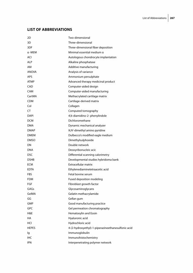
List of Abbreviations 267
list of aBBreViations
2D Two-dimensional
3D Three-dimensional
3DF Three-dimensional fiber deposition
α -MEM Minimal essential medium α
ACI Autologous chondrocyte implantation
ALP Alkaline phosphatase
AM Additive manufacturing
ANOVA Analysis of variance
APS Ammonium persulphate
ATMP Advanced therapy medicinal product
CAD Computer-aided design
CAM Computer-aided manufacturing
CartMA Methacrylated cartilage matrix
CDM Cartilage-derived matrix
Col Collagen
CT Computed tomography
DAPI 4’,6-diamidino-2- phenylindole
DCM Dichloromethane
DMA Dynamic mechanical analyzer
DMAP N,N’-dimethyl amino pyridine
DMEM Dulbecco’s modified eagle medium
DMSO Dimethylsulphoxide
DN Double network
DNA Deoxyribonucleic acic
DSC Differential scanning calorimetry
DSHB Developmental studies hybridoma bank
ECM Extracellular matrix
EDTA Ethylenediaminetetraacetic acid
FBS Fetal bovine serum
FDM Fused deposition modeling
FGF Fibroblast growth factor
GAGs Glycosaminoglycans
GelMA Gelatin methacrylamide
GG Gellan gum
GMP Good manufacturing practice
GPC Gel permeation chromatography
H&E Hematoxylin and Eosin
HA Hyaluronic acid
HCl Hydrochloric acid
HEPES 4-(2-hydroxyethyl)-1-piperazineethanesulfonic acid
Ig Immunoglobulin
IHC Immunohistochemistry
IPN Interpenetrating polymer network
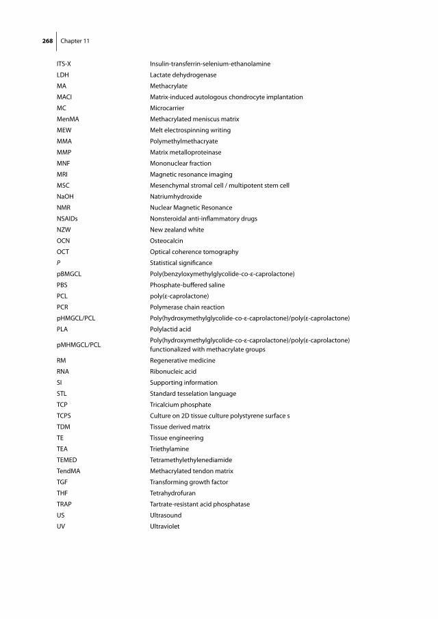
268 Chapter 11
ITS-X Insulin-transferrin-selenium-ethanolamine
LDH Lactate dehydrogenase
MA Methacrylate
MACI Matrix-induced autologous chondrocyte implantation
MC Microcarrier
MenMA Methacrylated meniscus matrix
MEW Melt electrospinning writing
MMA Polymethylmethacryate
MMP Matrix metalloproteinase
MNF Mononuclear fraction
MRI Magnetic resonance imaging
MSC Mesenchymal stromal cell / multipotent stem cell
NaOH Natriumhydroxide
NMR Nuclear Magnetic Resonance
NSAIDs Nonsteroidal anti-inflammatory drugs
NZW New zealand white
OCN Osteocalcin
OCT Optical coherence tomography
P Statistical significance
pBMGCL Poly(benzyloxymethylglycolide-co-ε-caprolactone)
PBS Phosphate-buffered saline
PCL poly(ε-caprolactone)
PCR Polymerase chain reaction
pHMGCL/PCL Poly(hydroxymethylglycolide-co-ε-caprolactone)/poly(ε-caprolactone)
PLA Polylactid acid
pMHMGCL/PCLPoly(hydroxymethylglycolide-co-ε-caprolactone)/poly(ε-caprolactone) functionalized with methacrylate groups
RM Regenerative medicine
RNA Ribonucleic acid
SI Supporting information
STL Standard tesselation language
TCP Tricalcium phosphate
TCPS Culture on 2D tissue culture polystyrene surface s
TDM Tissue derived matrix
TE Tissue engineering
TEA Triethylamine
TEMED Tetramethylethylenediamide
TendMA Methacrylated tendon matrix
TGF Transforming growth factor
THF Tetrahydrofuran
TRAP Tartrate-resistant acid phosphatase
US Ultrasound
UV Ultraviolet


Summary and Answers to Research Questions


Summary and answers to research questions 273
In this thesis, implants were biofabricated for the repair of chondral and osteochondral articular joint defects. The implants were based on gelatin methacrylamide (GelMA) hydrogels combined with printed fibers from polycaprolactone (PCL) for mechanical re-inforcement. In Part I of this thesis, biological modifications of GelMA by the addition of matrix derived from cartilage, meniscus or tendon tissue did show a neutral or negative effect on cartilage matrix production by encapsulated MSCs and chondrocytes, respec-tively. Furthermore, MSCs in GelMA in a subcutaneous rat model could not be locked in their chondrogenic state, considering the evident process of endochondral bone formation in these constructs. Both the quantity and quality of bone formed by MSCs in GelMA are nonetheless encouraging for bone tissue engineers. In Part II, hydrogels were successfully reinforced with microfibers. These hydrogel/microfiber composites ap-proached the stiffness and elasticity of articular cartilage and permitted the formation of cartilage matrix by embedded chondrocytes. In Part III, reinforced GelMA was applied for the biofabrication of larger, osteochondral constructs. Orthotopic animal models were established for evaluating the efficacy of reinforced GelMA for the repair of focal cartilage defects (in ponies) and for total joint replacement (in rabbits). The preparation of the biofabricated implants was described, as well as the implantation and preliminary outcomes of both animal models.
engineering hydrogels for biofabrication
Hydrogels with low polymer content are beneficial for tissue formation by embedded cells. However, these gels are poor bioinks for the fabrication of three-dimensional (3D) structures with high mechanical integrity, because of their watery nature. Hydrogels with high polymer content have better shape-stability and stiffness and, hence, are better building blocks for biofabrication. Unfortunately, these gels limit the formation of an interconnected tissue by embedded cells. chapter 2 outlines the current status of hydrogels as a bioink for biofabrication and the opportunities in this field.
We highlighted how the biology vs. fabrication dilemma in the development of bioinks could be resolved by smart chemistry and engineering. Changing the polymer structure of bioinks, while retaining an open microporosity for tissue regeneration, could opti-mize its rheological properties for printing. One example is to combine polymers with different properties in one bioink, such as GelMA
Alternatively, the biofabrication process itself can be tailored to produce 3D constructs from ‘watery’ hydrogels. The hydrogel could be crosslinked more effective and earlier in the biofabrication process, e.g. by cooling the collector platform, UV-crosslinking in the nozzle or with dual extrusion systems. Also, co-deposited sacrificial materials can temporarily support watery gels by printing with multiple materials (Chapter 8).
274 Chapter 11
part i) Biological improVement of gelma hydrogel with tissue-deriVed matrices
crosslinkable hydrogels derived from cartilage, meniscus and tendon tissue
Gelatin is a polymer derived from the porcine skin. The denatured collagen type I matrix contains a wide variety of adhesion sites and biochemical cues to embedded cells. The gelatin in the work presented in this thesis was methacrylated (into GelMA) in order to covalently crosslink the polymers. Chondrocytes embedded in GelMA gels were previ-ously shown capable of forming a cartilage matrix within the gel in vitro. In chapter 3 we aimed to further improve the biological properties of the GelMA gel by the addition of tissue-derived matrices (TDM). The positive effect of several decellularized tissues on cell differentiation was yet demonstrated. Moreover, tissue-derived matrices served as a substrate for tissue engineering in clinical proof-of-concept studies. The following research questions were posed here: Can stable hydrogels be derived from natural tissues, such as cartilage, meniscus and tendon? Does the addition of such tissue-derived matrices to GelMA hydrogel enhance chondrogenic differentiation of chondrocytes and MSCs in vitro?
Cartilage, meniscus and tendon tissue were successfully decellularized, digested into a collagenous gels and functionalized with methacrylate groups. This process resulted in crosslinked tissue-derived hydrogels with a reasonable stiffness. Unfortunately, chon-drocytes embedded in GelMA that was functionalized with these matrices performed worse than chondrocytes in GelMA alone. MSCs produced more matrix than chondro-cytes, but there was no added value of the tissue-derived matrices.
endochondral bone formation in gelatin methacrylamide hydrogel with embedded cartilage-derived matrix particles
In previous work, porous scaffolds from cartilage-derived matrix (CDM) were shown to be effective substrates for the deposition of cartilage matrix by seeded mesenchymal stem cells (MSCs) in vitro. On the contrary, chondrocytes did not form a cartilage matrix and eventually degraded the scaffold. The aim of chapter 4 was to study what is the effect of cartilage-derived matrix particles in GelMA on the differentiation of chondrocytes and MSCs, and whether osteochondral tissue can be regenerated in bilayered hydrogel constructs with chondrocytes and MSCs.
CDM particles suspended in GelMA were found to have a negative effect on in vitro car-tilage matrix formation by chondrocytes and a mildly positive effect of matrix formation by embedded MSCs. In a subcutaneous, immunocompromized rat model, chondrocytes produced a small amount of cartilage matrix, whereas MSCs formed an interconnected cartilage matrix. Moreover, MSCs hypertrophied and abundant endochondral bone was formed. The calcified area in the constructs was comparable to the mineral content in native bone (circa 40%), irrespective of the presence of CDM particles. In bilayered hy-
Summary and answers to research questions 275
drogels with separate layers of chondrocytes and MSCs, cartilage was formed predomi-nantly by MSCs, but no endochondral ossification occurred. As chondrocytes prevent MSCs from endochondral bone formation, the current approach is not appropriate for the regeneration of osteochondral tissue.
part ii) mechanical improVement of gelma hydrogel constructs with 3d-printed scaffolds
covalent attachment of a three-dimensionally printed thermoplast to a gelatin hydrogel for mechanically enhanced cartilage constructs
Hydrogels are soft, due to the high water content. To withstand the challenging environment in articular joints, hydrogels have been reinforced with 3D-printed scaf-folds from thermoplastic polymers, such as poly(ε-caprolactone) (PCL). Biofabrication techniques have been optimized to print PCL and the hydrogel in one session to cre-ate organized constructs with high stiffness. Nevertheless, both components of the constructs have a poor physical connection. Therefore, in chapter 5 it was investigated whether the covalent attachment of a 3D-printed scaffold as reinforcement to GelMA gel leads to stronger constructs.
It was demonstrated that GelMA hydrogel could be crosslinked to a thermoplastic polymer (poly(hydroxymethylglycolide-co-ε-caprolactone)/poly(ε-caprolactone) that was functionalized with methacrylate groups. Covalent grafting of both materials led to increased interface-binding strength. In addition, GelMA reinforced with a 3D-printed scaffold of the methacrylated polymer was stiffer and stronger than the gel reinforced with the non-methacrylated polymer. In these reinforced gels, Human chondrocytes produced cartilage matrix in the GelMA component in vitro and in vivo, subcutaneously in immunocompromized rats.
reinforcement of hydrogels with three-dimensionally printed microfibres
Hydrogels have been reinforced through scaffolds fabricated with fused deposition modeling (FDM) (chapter 5) and with solution electrospun meshes. The FDM scaffolds are typically constructed from fibers with a thickness of circa 200 µm and provided a stiff reinforcement to the hydrogels. Nevertheless, these scaffolds have a relatively large polymer mass, are stiffer than articular cartilage, and have low elasticity. On the other hand, solution electrospun meshes consist of thin fibers, but fiber organization and relevant scaffold dimensions are hard to achieve with this technique. Melt electrospin-ning was therefore introduced as a 3D-printing technique to produce well-organized scaffolds from microfibers. In chapter 6, the following questions were addressed: could the mechanical properties of articular cartilage be approached with composite constructs

276 Chapter 11
consisting of a hydrogel reinforced with 3D-printed microfibers? How do chondrocytes embedded in these constructs respond to dynamic loading in an in vitro bioreactor culture?
Scaffolds with a fiber diameter of circa 20 µm and a high porosity (93-98%) were fabri-cated with melt electrospinning. The stiffness and elasticity of hydrogels reinforced with these microfiber scaffolds approached values of native articular cartilage, while both the hydrogel and the microfiber scaffold were soft. The soft microfiber scaffolds achieved this synergistic degree of reinforcement through confining the hydrogel upon axial compression and by stretching of the fibers, as was demonstrated with video imaging. Modeling affirmed that reinforcement with defined microfiber scaffolds is applicable to numerous hydrogels. Human chondrocytes embedded in reinforced GelMA responded positively to a dynamic loading regime in terms of chondrogenic differentiation; the reinforcing scaffold did not limit this process.
cartilage repair with a co-culture of chondrons and mscs in gelatin methacrylamide hydrogel: the establishment of an equine model
Cell therapies for the repair of focal cartilage defects currently rely on rapidly degrad-ing cell carriers, such as fibrin glue. In contrast, hydrogels that have been specifically engineered for the use in regenerative medicine, have a lower degradation rate to bal-ance with new tissue formation by embedded cells within the gel. GelMA has proven to support the formation of cartilage matrix by embedded chondrocytes in vitro. Chapter 4 demonstrated a slow degradation rate in immunocompromized rats, but also showed extensive endochondral bone formation when only MSCs were embedded. In order to translate reinforced GelMA to clinical applications, in chapter 7, it was investigated how (reinforced) GelMA hydrogel can be applied in an equine model for the repair of focal cartilage defects. A co-culture of allogeneic chondrons and MSCs was used to prevent bone formation and to allow a one-step implantation procedure.
Reinforced GelMA gels were successfully UV-crosslinked into cartilage defects in the stifle joint of Shetland ponies. The constructs stayed in place after flexion-extension cycles of cadaveric stifles and after two weeks of implantation in a weight-bearing pony. The Shetland pony was found a feasible cartilage repair model, as these animals have a resilient nature and permit easier logistics compared to horses, while still approaching the cartilage thickness and biomechanics of humans. A long-term study to the regen-eration of focal cartilage defects in Shetland ponies is ongoing, comparing (reinforced) GelMA to fibrin glue as a carrier of a mixture of allogeneic equine chondrons and MSCs. Baseline images of the implants were acquired with ultrasound and optical coherence tomography. All animals recovered well from surgery and showed normal gait within two weeks.

Summary and answers to research questions 277
part iii) BiofaBrication of compleX shaped constructs for osteochondral tissue repair
Biofabrication of multi-material anatomically shaped tissue constructs
The work presented in this thesis so far addressed biological modifications of GelMA gels with tissue-derived matrices (part I) and the mechanical improvement of GelMA gels with 3D-printed scaffolds (part II). In Part III, we aimed to fabricate constructs for the repair of large osteochondral joint defects, or ultimately, for the biological restoration of partial of complete joints. In the introduction of this thesis, a few approaches were introduced for the biofabrication of constructs with relevant sizes and a well-defined internal and external architecture. One approach is modification of the bioink itself, as shown in Chapter 9; another is the implementation of a temporary support to over-hanging structures in the printed construct. To this end, in chapter 8, it was explored which support and construction materials can best be combined to establish the complex geometry of anatomical structures in a multi-material 3D-printing setting.
Specific support materials were designed for biofabrication with hydrogels and PCL. Prerequisites for support materials were found its printability, sufficient stiffness, it should not react with the construction material and the process of washing away the support material should be compatible with cell survival. Polyvinyl alcohol was found a suitable support material for the fabrication of PCL scaffolds, and a high concentration of alginate gel was a proper support material for creating GelMA/Gellan Gum hydrogel constructs. Printing of multiple materials in one session resulted in anatomically shaped constructs for the engineering of tissues with relevant sizes.
Biofabrication of tissue constructs by 3d bioprinting of cell-laden microcarriers
Microcarriers (MCs) are used in tissue engineering as an expansion vehicle for cells. MCs may form a solution for obtaining the high cell numbers that are usually required to create a functional new tissue. Cells are cultured and form matrix on the round surface of the MCs, in which biochemical substances could be incorporated for the controlled differentiation of these cells, e.g. for differentiation into the bone or cartilage lineages. In order to fabricate osteochondral grafts, in chapter 9 it was investigated whether GelMA bioinks can be improved for bone regeneration by the incorporation of microcarriers.
MSCs formed a calcified matrix in a GelMA/Gellan Gum bioink, when precultured on MCs under osteogenic conditions and incorporated in the ink. The bioink with MC/MSC complexes was printable and had a higher initial stiffness than the bioink without MCs. Hydrogel constructs with two components were printed with relevant sizes for osteo-chondral grafts. However, the regeneration of both bone and cartilage tissue in such a construct remains to be established.

278 Chapter 11
3d-printed biodegradable shoulder replacement in a rabbit model: a pilot study on osteochondral tissue regeneration
The biological restoration of whole articular joints based on 3D-printed implants has previously been explored in proof-of concept studies in rabbit models. However, the regeneration of both bone and cartilage in these implants has not been established yet. The work in chapter 10 aimed to fabricate and implant the next generation of this 3D-printed osteochondral implant, with a distinct cartilage and bone component. In a pilot study in rabbits, it was investigated whether both bone and cartilage tissue could be regenerated in a shoulder replacement model in rabbits with a single 3D-printed biodegrad-able implant.
A porous, degradable shoulder replacement for rabbits was biofabricated from PCL, consisting of a bone and a cartilage component. The bone component had a porosity of 74% and was coated with calcium phosphate. The cartilage component consisted of GelMA reinforced with a melt electrospun PCL network with a porosity of 92%. The im-plant design was improved based on implantations in three cadaveric rabbits, resulting in strong implants, with the right anatomical dimensions. The content of the cartilage component varied in three experimental groups: 1) with allogeneic chondrocytes; 2) with Transforming Growth Factor β, and 3) cell-free. The model is currently tested in a pilot study in three rabbits (each group n=1). When the fixation and preliminary tissue formation suffice, a study to bone and cartilage formation will commence with n=6 per group with a follow-up of 20 weeks.
Altogether, the work in this thesis resulted in implants for articular joint regeneration, consisting of gelatin-based hydrogels that were reinforced with 3D-printed fibers. The shape and content of the implants could be tailored with biofabrication techniques, based on 3D-scans of the joint defect. Animal models were initiated to evaluate the repair capacities of the implants for a focal cartilage defect and for a complete joint. With tissue regeneration in reinforced hydrogels, larger articular joint defects in patients can potentially be repaired on a biological level.


Nederlandse Samenvatting

Nederlandse Samenvatting 283
nederlandse samenVatting
Het werk in dit proefschrift laat zien hoe stevige en biologisch actieve implantaten wor-den gemaakt en toegepast voor het herstel van defecten in een gewricht. Deze defecten komen meestal voor bij jonge mensen als gevolg van een groeistoornis of door een trauma. Momenteel kunnen kleine kraakbeendefecten al worden gerepareerd middels celtherapie. Omvangrijke schade in het gewricht wordt nu nog vervangen door een pro-these van kunststof of metaal. In dit proefschrift is een stevige, nieuwe dragerstructuur voor de celtherapie ontwikkeld, zodat ook grotere defecten op een biologisch niveau kunnen worden hersteld. De implantaten worden op maat gemaakt met een 3D-printer en zijn gebaseerd op een gecrosslinkte gelatine hydrogel (GelMA), welke is versterkt met vezels van een afbreekbaar plastic (polycaprolactone (PCL)). Omdat ook cellen en/of groeifactoren kunnen worden geprint in het implantaat wordt het proces biofabrica-tion genoemd.
Het eerste deel van het proefschrift beschrijft hoe de GelMA gel biologisch is aan-gepast door de toevoeging van extracellulaire matrices verkregen van kraakbeen-, meniscus-, en peesweefsel. Deze toevoeging blijkt een neutraal effect te hebben op volwassen stamcellen (MSCs) in de GelMA en een negatief effect op matrix productie van kraakbeencellen. Tevens zien we dat er bot werd gevormd in een implantaat van GelMA met MSCs, wanneer deze onder de huid was geïmplanteerd in ratten. Dit bot wordt gevormd via de endochondrale route, waarbij mineralisatie van een kraakbeen-matrix plaatsvindt, zoals ook gebeurt bij de groei van lange pijpbeenderen. De graad van mineralisatie is vergelijkbaar met natuurlijk botweefsel en hiertussen zijn gebieden lijkend op beenmerg aanwezig. Dit is een veelbelovende bevinding voor het regenere-ren van bot, echter, wanneer MSCs gebruikt worden voor kraakbeenherstel in GelMA hydrogelen hebben deze dus een andere chondrogene stimulatie nodig dan die van de huidige extracellulaire matrices, om botvorming te voorkomen.
In het tweede deel laten we zien dat GelMA gel sterker en stijver wordt wanneer deze gecombineerd wordt met een netwerk van 3D-geprinte vezels van PCL. Een chemische binding van deze vezels aan de hydrogel leidt tot sterkere constructen, bovendien lijkt de stijfheid en elasticiteit van hydrogelen versterkt met microvezels (ca. 20 μm) op die van kraakbeen uit de knie. Kraakbeencellen in deze constructen produceren een kraakbeenspecifieke matrix zowel in vitro als onder de huid in ratten. Deze versterkte GelMA is vervolgens geïmplanteerd in kraakbeendefecten in de knieën van acht Shet-land pony’s om de regeneratie van kraakbeen te bestuderen in een relevante omgeving. Pony’s vormen een goed model voor de mens gezien de dikte van het kraakbeen en de belasting van de gewrichten. Een mix van chondronen (kraakbeencellen met hun peri-cellulaire matrix intact) en MSCs is geïmplanteerd in GelMA, in vezelversterkte GelMA en in fibrinelijm (de klinische standaard). Het proces van de groei van nieuw kraakbeen in
284 Chapter 11
de defecten wordt momenteel een jaar lang gevolgd met verscheidene beeldvormende technieken, waaronder kijkoperaties.
In het derde deel van het proefschrift gebruiken we verschillende biofabrication technieken om grotere implantaten te maken met anatomische vormen. Controle over architectuur van het implantaat is namelijk nodig om een groter defect van het gewricht te repareren, dat vaak een unieke vorm heeft en zowel kraakbeen als botweefsel be-treft. Na aanpassing van de reologische eigenschappen van GelMA hydrogel met een verdikker (Gellan Gum), konden grote en gelaagde constructen worden geprint. Over-hangende delen in anatomische gevormde structuren werden tijdelijk ondersteund door een ander printbaar materiaal, die vervolgens kon worden weggewassen in een celvriendelijke procedure. Microcarriers werden gebruikt in de ‘botlaag’ van deze con-structen om grote hoeveelheden MSCs te kunnen expanderen en om hun osteogene differentiatie te stimuleren. Het meest veelbelovende en haalbare construct is dooront-wikkeld voor de vervanging van de gehele schouderkop in konijnen. Het implantaat werd ontworpen en geprint op basis van een CT-scan van de schouderkop met daarin een bot- en kraakbeencomponent. De botcomponent bestaat uit dikke PCL filamenten gecoat met hydroxyapatiet en de kraakbeencomponent bestaat uit GelMA versterkt met PCL microvezels en daarin kraakbeencellen of een groeifactor. Een pilot studie naar de stevigheid en fixatie van het implantaat is gaande in drie konijnen.
Het werk in dit proefschrift heeft dus geleid tot sterkere en biologisch actieve im-plantaten voor het herstel van schade aan gewrichten. Door biofabrication technieken kan de inhoud en vorm van het implantaat worden afgestemd op de patiënt. Met deze benadering kunnen mogelijk grotere delen van het gewricht van patiënten op een biologisch niveau worden hersteld.


Papers not included in this thesis
Acknowledgements/Dankwoord
Curriculum Vitae

Papers not included in this thesis 289
papers not included in this thesis
Gawlitta D, Benders KE, Visser J, van der Sar AS, Kempen DH, Theyse LF, Malda J, Dhert WJA. Decellularized Cartilage-Derived Matrix as Substrate for Endochondral Bone Re-generation.Tissue Eng Part A. 2015 Feb;21(3-4):694-703.
de Windt TS, Vonk LA, Buskermolen JK, Visser J, Karperien M, Bleys RL, Dhert WJ, Saris DB.Arthroscopic airbrush assisted cell implantation for cartilage repair in the knee: a con-trolled laboratory and human cadaveric study. Osteoarthritis Cartilage. 2015 Jan;23(1):143-50.
Visser J, Verra WC, Kuijlen JM, Horsting PP, Journée HL. Recovery of TES-MEPs during surgical decompression of the spine: a case series of eight patients. Journal of Clinical Neurophysiology. 2014 Dec;31(6):568-74.
Hellegering J, Visser J, Kloke HJ, D’Ancona FCH, Hoitsma AJ, van der Vliet JA, Warlé MC. Poor early graft function impairs long-term outcome in living donor kidney transplanta-tion. World Journal of Urology. 2013 Aug;31(4):901-6.
Visser J, Brinkman JM, Bleys RL, Castelein RM, van Heerwaarden RJ. The safety and fea-sibility of a less invasive distal femur closing wedge osteotomy technique: a cadaveric dissection study of the medial aspect of the distal femur. Knee Surgery, Sports Traumatology, Arthroscopy. 2013 Jan;21(1):220-7.
Visser J, Busch VJJF, de Kievit- van der Heijden I, ten Ham AM. Non-Hodgkin’s Lymphoma of the synovium discovered in total knee arthroplasty: a case report. BMC Research Notes. 2012 Aug 20;5:449.
Hellegering J, Visser J, Kloke HJ, D’Ancona FCH, Hoitsma AJ, van der Vliet JA, Warlé MC. Influence of prolonged warm ischemia in living donor kidney transplantation. Transplantation Proceedings 2012 Jun;44(5):1222-6.
Visser J, Tienen van TG, Hoogeveen AR, Diercks RL. Het compartimentsyndroom van de diepe achterste loge van het onderbeen: diagnostische en therapeutische problemen. Sport en Geneeskunde 2010 Oct;43(4):28-33

290 Chapter 11
Parastatidis I, Thomson L, Burke A, Chernysh I, Nagaswami C, Visser J, Stamer S, Liebler DC, Koliakos G, Heijnen HF, Fitzgerald GA, Weisel JW, Ischiropoulos H. Fibrinogen beta-chain tyrosine nitration is a prothrombotic risk factor. The Journal of Biological Chemistry. 2008 Dec 5;283(49):33846-53.
Mouser VHM, Melchels FP, Visser J, Gawlitta D, Dhert WJA, Malda J. Tailoring a gelatin methacrylamide and gellan hydrogel for cartilage biofabrication. In preparation
Zhao X, Erali R, Otto IA, Visser J, Melchels FP, Saris DBF, Malda J, Randolph MA. Cartilage regeneration using different chondrocyte sources and photochemically crosslinked gelatin-methacrylamide (GelMA) hydrogel.In preparation
Boere KWM, van den Dikkenberg J, Gao Y, Visser J, Hennink WE, Vermonden T. Thermogel-ling and chemoselectively cross-linked hydrogels with controlled mechanical properties and degradation behavior.In preparation
Acknowledgements/Dankwoord 291
acKnowledgements/danKwoord
Promotor en copromotorenGeachte prof. dr. Dhert, beste Wouter,Vier jaar geleden diende ik me per email aan voor een promotieplek. Wat ben ik blij dat ik langs mocht komen en dat je het vertrouwen in me had na dit gesprek. Ik heb ook onze latere gesprekken - veelal op borrels – erg gewaardeerd. We zaten op een lijn over de toekomst van biofabrication, een lijn die we voor verscheidene gezelschappen hebben gepresenteerd. Hoe ongemakkelijk voelde ik me op jouw kamer een dag voor zo’n presentatie, toen mijn verklaring van goed gedrag niet op orde leek te zijn, juist toen er een lid van het koninklijk huis langs zou komen. Het werd een unieke 1 april grap die je erg sportief hebt opgevat! Veel plezier en succes als decaan.
Geachte dr. ir. Malda, beste Jos,Mede door jouw enthousiasme en harde werken is biofabrication in Utrecht als een speer gegaan de afgelopen jaren. Het was fijn en vanzelfsprekend om als PhD student mee te gaan in deze flow; ik betwijfel of ik ooit nog zoveel mediaoptredens zal hebben. Ik heb geleerd van je vermogen om de juiste mensen bij elkaar te brengen, zowel binnen de afdeling als internationaal. Bedankt dat je me mee nam naar Australië met Annelie en de kinderen. Ik zal de Aussie koffies, BBQs en hikes niet snel vergeten.
Geachte dr. ir. Gawlitta, beste Debby,Je was de side-kick vanuit de kaakchirurgie bij wie ik altijd terecht kon voor een prak-tische vraag. Ik heb geleerd van je geduld om studenten te begeleiden. Het zou erg gaaf zijn als het je lukt om iets van het huidige werk klinisch toe te passen.
CollegaeGeachte dr. ir. Melchels, beste Ferry,Toen ik in Brisbane aan kwam was jij al een halve Aussie. Terug in Nederland heb je die vibe niet meer verloren en je hunkerde nog wel eens terug. Ik hoop dat jij en de dames in Schotland een vergelijkbaar avontuur tegemoet gaan. Zonder jouw logica en kennis over polymeren en engineering was dit proefschrift zeker van mindere kwaliteit gewe-est. Doordat je deze kennis met geduld over kan brengen was je een consultant voor vele PhD studenten; de afdeling gaat dit missen!
Geachte prof. dr. Saris, beste Daan,Bedankt dat ik altijd mijn werk kon toetsen aan je scherpe klinische blik. Ik heb bewon-dering voor je pragmatisme en je strakke, translationele onderzoekslijn.
292 Chapter 11
Geachte prof. dr. van Weeren, beste René,Bedankt voor het kritisch nakijken van mijn stukken, inclusief de algemene discussie. Deze stroomlijning is zeker terug te zien in dit proefschrift!
Dear prof. dr. Hutmacher, dear Dietmar,Thanks for having me in Australia and for your great hospitality to dine at your place not only once.
Loek, zonder jou aan mijn rechterzijde was Q zoveel saaier geweest. Het filosoferen over het leven, de wereld en changing the face of science zal ik missen. Onze gedeelde passie voor de natuur en bergen bracht ons zelfs in Nepal en we komen elkaar in de toekomst zeker nog tegen.
Dino, man van de Tiramisu & Radler, wat was het mooi wonen op de Jeremiestraat.
Mattie, bedankt dat je me op weg hebt geholpen in en rondom het lab, voor de koffie en de borrels.
Willemijn, bedankt voor alle achterklap als moeder van de afdeling en voor je hulp aan vele willekeurige aspecten van dit proefschrift.
Orthopedie: Tom, Beeki (we staan gelijk op de Mt. Ventoux), Anika & Kim, Rhandy, Croes, Maaike, Anita, Vivian, Maarten, Behdad, Parisa, Imke, Razmara, Maurits, Anne, Huub (be-dankt voor de stoelen op de middenlijn van de Kuip), Riccardo, Marianne, Said, Barbara, Michelle, Lucienne, Joris, Schuurman, Fiona, Hsiao-Yin, Saskia, Mechteld, Linda, Angela, Yvonne, Kim, dank voor een prachtige tijd in Utrecht!
Diergeneeskunde: Harold, Irina, Janneke, Filipe, Nikae, Stefan, Annemiek, Jannie, Thijs, professor van Barneveld, Pia, Juha, Jaimy, Bert, Peter, Henk, Henk en het hele equine cartilage repair team, bedankt voor de soepele samenwerking!
Farmacie: Kristel, fijn dat we gelijk zijn opgestart, bedankt voor je trouwe hulp, onder de gepassioneerde begeleiding van Tina, Mies, Sima en professor Hennink.
Australia: Patrina, Mohid, Tomasz, Marco, Urip, Paul (I really appreciated our talks and dinners all over the world), Travis, Pete (great person for an exchange and I am honoured to be your paranimf ) & Libby, thanks for the introduction in Brisbane and its surround-ings – including New Zealand.

Acknowledgements/Dankwoord 293
Studenten: Ben, Erik, Jeremy, Selynda, Twan, Karin, Marco, Trudy, Bram, Lydia, Ali, Britta en Elder, jullie zijn een belangrijk fundament onder dit proefschrift, dank!
Anderen: professor Öner, Jelle Boomstra, Laura Creemers, Jacqueline Alblas, bedankt voor jullie input.
Martijn Brinkman, Ronald van Heerwaarden en professor Castelein, bedankt dat jullie mijn kruiwagen waren middels de femur osteotomie studie, die mij naar Utrecht bracht.
ParanimfenBram, vaste maat vanaf het begin in Groningen, fijn dat ik aan je zijde mocht staan bij jouw verdediging in Amsterdam, ik heb alle vertrouwen in je wederdienst in Utrecht.
Tommy, ik ben blij dat wij al snel elkaars respect en vriendschap vonden. Bedankt voor het sparren over de inhoud van ons werk en je gezelschap op vele congressen.
Vrienden en familieThijs, veel bergtoppen hebben we al gezien, veel kilometers gefietst, beiden uit de klei getrokken, bedankt dat ik altijd op je vriendschap kan rekenen.
Dre, een vriend vanaf de eerste zeildag en tot de laatste. Iedereen van de P.J., met name ook de Jonge Honden, Helly, de Goeroe en Paul, bedankt voor 18 onvergetelijke zomers op het water.
Mannen van de Whiskey en K.V. Rumpite atque Vomate, onze activiteiten zijn belangrijk en zullen blijven.
Jongens uit Dronten, fijn dat we nog steeds vrienden van het eerste uur zijn.
Lieve Frans en Gerda, bedankt voor de vaste uitvalsbasis aan de Perzikgaarde, waar het eten altijd goed smaakt en altijd een logeerplek is. FW, daar samen naar ‘de Belg’ kijken is erg inspirerend.
Lieve Sietske, jouw werk is eigenlijk veel belangrijker dan wat ik de afgelopen vier jaar heb gedaan. Fijn om al 28 jaar getuige te zijn van jouw eigen wil, je nuchterheid, prak-tisch inzicht en avonturisme.

294 Chapter 11
Lieve papa en mama, klassieke piano op zondag, spreuken op het toilet, eten aan de ronde tafel, rode wijn uit Frankrijk, toch beide benen aan de grond, tussen de Friese meren en altijd interesse. Bedankt voor dit veilige nest, om altijd naar terug te keren.
Elisa, gelukkig is onze liefde is veel sterker dan twee proefschriften. Tegelijk een pro-motietraject was een fantastische tijd met veel vrijheid. Je leerde me box-plotjes, keek stukken na, zocht me op waar ik ook was, begreep de missie. Na zeven jaar op afstand nu eindelijk samen, van mij mag dat voor altijd duren.
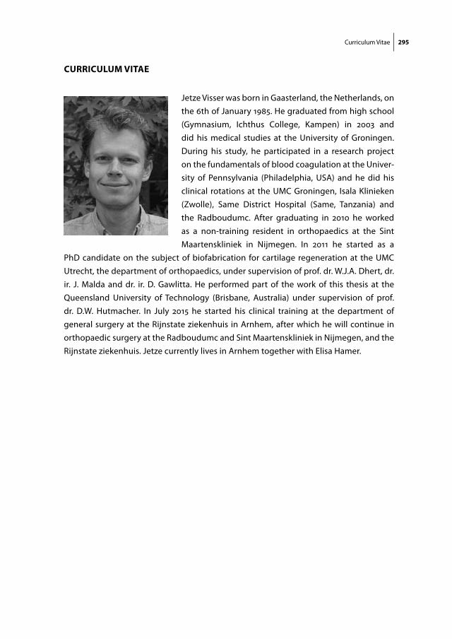
Curriculum Vitae 295
curriculum Vitae
Jetze Visser was born in Gaasterland, the Netherlands, on the 6th of January 1985. He graduated from high school (Gymnasium, Ichthus College, Kampen) in 2003 and did his medical studies at the University of Groningen. During his study, he participated in a research project on the fundamentals of blood coagulation at the Univer-sity of Pennsylvania (Philadelphia, USA) and he did his clinical rotations at the UMC Groningen, Isala Klinieken (Zwolle), Same District Hospital (Same, Tanzania) and the Radboudumc. After graduating in 2010 he worked as a non-training resident in orthopaedics at the Sint Maartenskliniek in Nijmegen. In 2011 he started as a
PhD candidate on the subject of biofabrication for cartilage regeneration at the UMC Utrecht, the department of orthopaedics, under supervision of prof. dr. W.J.A. Dhert, dr. ir. J. Malda and dr. ir. D. Gawlitta. He performed part of the work of this thesis at the Queensland University of Technology (Brisbane, Australia) under supervision of prof. dr. D.W. Hutmacher. In July 2015 he started his clinical training at the department of general surgery at the Rijnstate ziekenhuis in Arnhem, after which he will continue in orthopaedic surgery at the Radboudumc and Sint Maartenskliniek in Nijmegen, and the Rijnstate ziekenhuis. Jetze currently lives in Arnhem together with Elisa Hamer.

Copyright © 2022 FDOKUMEN