Structure and dynamics of dextran in binary mixtures of a good and a bad solvent
Upload
universiteitutrechtCategory
view
1download
0
ARTICLE IN PRESS
0142-9612/$ - se
doi:10.1016/j.bi
�Correspond7839.
E-mail addr
Biomaterials 26 (2005) 2129–2135
www.elsevier.com/locate/biomaterials
Self-gelling hydrogels based on oppositely charged dextranmicrospheres
Sophie R. Van Tommea, Mies J. van Steenbergena, Stefaan C. De Smedtb,Cornelus F. van Nostruma, Wim E. Henninka,�
aDepartment of Pharmaceutics, Utrecht Institute for Pharmaceutical Sciences (UIPS), University Utrecht, Sorbonnelaan 16, P.O. Box 800082,
3508 TB, Utrecht, The NetherlandsbLaboratory of General Biochemistry and Physical Pharmacy, Department of Pharmaceutics, Ghent University, Harelbekestraat 72, 9000, Ghent,
Belgium
Received 11 March 2004; accepted 26 May 2004
Available online 27 July 2004
Abstract
This paper presents a novel self-gelling hydrogel potentially suitable for controlled drug delivery and tissue engineering. The
macroscopic gels are obtained by mixing dispersions of oppositely charged crosslinked dextran microspheres. These microspheres in
turn were prepared by crosslinking of dextran derivatized with hydroxyethyl methacrylate emulsified in an aqueous poly(ethylene
glycol) solution. Negatively or positively charged microspheres were obtained by addition of methacrylic acid (MAA) or
dimethylaminoethyl methacrylate (DMAEMA) to the polymerization mixture. Rheological analysis showed that instantaneous
gelation occurred when equal volumes of oppositely charged microspheres, dispersed in buffer solutions of pH 7, were mixed. The
shear modulus of the networks could be tailored from 30 to 6500 Pa by varying the water content of the system. Moreover,
controlled strain and creep experiments showed that the formed networks were mainly elastic. Importantly for application of these
systems, e.g. as controlled matrix of pharmaceutically active proteins, it was demonstrated that the hydrogel system has a reversible
yield point, meaning that above a certain applied stress, the system starts to flow, whereas when the stress is removed, gel formation
occurred. Further it was shown that the network structure could be broken by either a low pH or a high ionic strength of the
medium. This demonstrates that the networks, formed at pH 7 and at low ionic strength, are held together by ionic interactions
between the oppositely charged dextran microspheres. This system holds promise as injectable gels that are suitable for drug delivery
and tissue engineering applications.
r 2004 Elsevier Ltd. All rights reserved.
Keywords: Injectable hydrogels; Dextran microspheres; Ionic interactions; Viscoelasticity; Drug delivery; Tissue engineering
1. Introduction
Hydrogels are an important class of materials thathave been studied extensively in the last decades for thecontrolled release of pharmaceutical proteins, and fortissue engineering applications [1–5]. Formation ofhydrogels can be achieved by both chemical andphysical crosslinking [6]. By chemical crosslinking
e front matter r 2004 Elsevier Ltd. All rights reserved.
omaterials.2004.05.035
ing author. Tel: +31-30-253-6964; fax: +31-30-251-
ess: [email protected] (W.E. Hennink).
covalent bonds between the different polymer chainsare introduced. Chemical crosslinking results in anetwork with a relatively high mechanical strengthand, depending on the nature of the chemical bonds inthe building blocks and the crosslinks, in relatively longdegradation times. However, chemical crosslinking canpossibly damage the entrapped bioactive substance,leading to a loss of activity. Moreover, the crosslinkingagents are mostly toxic and removal needs to be ensuredbefore in vivo application. In recent years there is agrowing interest in physically crosslinked hydrogels. Insuch systems non-permanent bonds, based on physical

ARTICLE IN PRESS
mixing
shear network recovery
Dex-HEMA-DMAEMAmicrospheres
In situ gelling
Dex-HEMA-MAAmicrospheres
Fig. 1. The concept of the physically crosslinked hydrogel system. The hydrogel is obtained after mixing aqueous dispersions of negatively charged
dex-HEMA-MAA and positively charged dex-HEMA-DMAEMA microspheres. When shear is applied, the interactions between the microspheres
are broken and the sample flows. Upon removal of the shear stress, the network rebuilds itself.
S.R. Van Tomme et al. / Biomaterials 26 (2005) 2129–21352130
interactions between the polymer chains, are created.Different methods have been investigated to preparephysically crosslinked hydrogels. An attractive class ofphysically crosslinked gels is those where gel formationis not instantaneous, but occurs a certain time aftermixing the hydrogel components (e.g. stereocomplexgels [7–10]) or after a certain trigger (e.g. temperature[3,11–15]). Such systems can be administered by injec-tion as liquid formulation and gellify in situ. Gelformation through chemical crosslinking can also occurusing UV light as a trigger [16,17].
In our Department, both chemically and physicallycrosslinked dextran hydrogels have been developed inrecent years. An organic solvent free approach to obtaincrosslinked microspheres has been described wherepreparation occurs in an all-aqueous environment[18,19]. The in vivo biocompatibility of dextran-basedhydrogels and microspheres has been demonstrated aswell as the relation between in vitro and in vivodegradation behavior [20–22].
In this paper a novel injectable hydrogel system, asschematically outlined in Fig. 1, is investigated. Themacroscopic hydrogels are designed by combining theinjectability of microspheres with physical crosslinkingthrough ionic interactions. Anionically or cationicallycharged microspheres were prepared and gels wereobtained by mixing aqueous dispersions of the oppo-sitely charged microspheres. Gel formation was studiedby rheological experiments and special attention wasgiven to the reversibility of the system.
2. Materials and methods
2.1. Materials
Dextran T40 (from Leuconostoc ssp.), N,N,N0,N0-tetramethylethylenediamine (TEMED) and 2-hydro-xyethyl methacrylate (HEMA) were obtained from
Fluka (Buchs, Switzerland). Poly(ethylene glycol)(PEG) 10000 and potassium peroxodisulfate (KPS)were provided by Merck (Darmstadt, Germany). N-2-hydroxyethylpiperazine-N0-2-ethanesulfonic acid (Hepes)was purchased from Acros Chimica (Geel, Belgium).Methacrylic acid (MAA) and dimethylaminoethylmethacrylate (DMAEMA) were provided by Sigma-Aldrich (Zwijndrecht, The Netherlands).
2.2. Hydroxyethyl methacrylate-derivatized dextran
(dex-HEMA)
Dextran was derivatized with hydroxyethyl metha-crylate (dex-HEMA) (Fig. 2A) as described previously[23]. The degree of substitution (DS, i.e. the number ofHEMA groups per 100 glucopyranose units) used in thisstudy was 6.
2.3. Preparation of charged microspheres
The dextran microspheres with a water content of70% were obtained through radical polymerization ofdex-HEMA, emulsified in an aqueous PEG solution[18,24]. In short: aqueous solutions of PEG (40% (w/w))and dex-HEMA (20% (w/w)) were prepared in Hepesbuffer (100mM pH 7.0). PEG, dex-HEMA and buffersolution, 197.6, 18.3 and 284.1 g respectively (totalweight 500 g) were transferred into a 500mL glasscylinder. Subsequently, either 12.5mmol of MAA (Fig.2B), or 12.5mmol of DMAEMA (Fig. 2C) was added tothe two-phase system (molar ratio HEMA/MAA orDMAEMA=0.53). The two-phase system was flushedwith nitrogen and intensively mixed (30min, 11000 rpm,IKA Ultra-Turraxs T 25 basic, IKA-sWERKEGMBH & CO.KG, Staufen, Germany). In this way, awater-in-water emulsion was created that was allowed tostabilize for 15min. Next, a TEMED solution (10mL,20%v/v, adjusted to pH 7 with 4M HCl) and a KPSsolution (18mL, 50mg/mL), both freshly prepared, were

ARTICLE IN PRESS
O
O
OHO
HO OOO
O
O
O
OH
O
O
O
ON
O
ON
H
(A)
(B)
(C)
Fig. 2. Chemical structures of dex-HEMA (A), methacrylic acid (B)
and dimethylaminoethyl methacrylate (C).
S.R. Van Tomme et al. / Biomaterials 26 (2005) 2129–2135 2131
added to the mixture. The emulsified droplets wereallowed to polymerize for 30min at ambient tempera-ture. Under these conditions the HEMA conversion is490% [25]. Two types of microspheres were prepared,containing either MAA (dex-HEMA-MAA) or DMAE-MA (dex-HEMA-DMAEMA). The crosslinked parti-cles were collected and purified by multiple washing andcentrifugation steps (thrice with reversed osmosis water,15min, 3000 rpm). Ultimately the microspheres werelyophilized.
The particle size distribution of the microspheres wasdetermined using a Coulter Counter Multisizers 3(Beckman Coulter Nederland B.V., The Netherlands)with a 100-mm orifice.
2.4. Formation of macroscopic gels with charged
microspheres
Lyophilized microspheres (dex-HEMA-MAA or dex-HEMA-DMAEMA) were dispersed in Hepes buffer(100mM pH 7; solid content between 10% and 25%).The dispersions were stored at 4 1C for 2 h to allow fullhydration of the microspheres. The equilibrium watercontent of the rehydrated microspheres was determinedusing the blue dextran exclusion assay [26]. To studypossible gel formation, equal volumes (200 mL) of thetwo different microsphere dispersions were mixed.
2.5. Rheological experiments
The rheological measurements were performed usinga controlled stress rheometer (AR1000-N, TA Instru-ments, Etten-Leur, The Netherlands), equipped with anacrylic flat plate geometry (20mm diameter) and a gapof 500 mm. Immediately after mixing equal volumes ofboth dispersions (see Section 2.4), the sample was placedbetween the plates. A solvent trap was used to preventevaporation of the solvent. The viscoelastic properties ofthe sample were determined by measuring the G0 (shearstorage modulus) and G00 (loss modulus) at 20 1C with aconstant strain of 1% and constant frequency of 1Hz.Also frequency sweep and strain sweep experimentswere performed. Creep experiments were performed toevaluate the extent of recovery of the material afterdeformation. In the creep experiment a shear stress of1 Pa was applied while the strain was monitored. After1min the stress was removed and the recovery of thesample was monitored by measuring the strain during2min. As a control, the same rheological experimentswere performed on dispersions containing only dex-HEMA-MAA or dex-HEMA-DMAEMA micro-spheres.
To determine the yield point of the system, stresssweep experiments were performed at 20 1C. Duringthese experiments the G0 and G00 were monitored whilethe stress was increased. The frequency was keptconstant to 1Hz. The experiment was performed 4times in a row using the same sample. After eachexperiment the sample was allowed to recover for 1 h.
Most experiments were performed on hydrogelscontaining 15% (w/w) of freeze-dried microspheres.Controlled strain and creep experiments were alsoperformed on hydrogels with different percentages(10%–25%w/w) solid content. The influence of pHand ionic strength on the systems was studied by usingdifferent buffers (phosphate buffer (100mM, pH 3) orHepes buffer (100mM, pH 7) with variable ionicstrengths (NaCl, from 17–1000mM)).
3. Results and discussion
3.1. Preparation of charged dex-HEMA microspheres
Charged dextan particles were obtained by radicalcopolymerization of dex-HEMA with either MAA orDMAEMA. At physiological pH both MAA andDMAEMA are mainly ionized (pKa MAA=4.7; pKaDMAEMA=8.4; [27]), resulting in charged micro-spheres at this pH. The mean volume diameters of thedex-HEMA-MAA and the dex-HEMA-DMAEMAmicrospheres were comparable (8.3 and 7.5 mm respec-tively; 90%o12.5 mm (Fig. 3)). The equilibrium water

ARTICLE IN PRESS
0
5
10
15
20
25
2-4 4-6 6-8 8-10 10-12 12-14 14-16 16-18 18-40
particle size (µm)
Vo
lum
e (%
)
Fig. 3. Volume diameter distribution of dex-HEMA-MAA (light) and
dex-HEMA-DMAEMA (dark) microspheres.
0
100
200
300
400
500
600
0.01 0.10 1.00 10.00 100.00
% strain
G' a
nd
G"
(Pa)
0
1
2
3
4
5
6
tan
(δ)
Fig. 4. Storage modulus G0 (—), loss modulus G00 ( ) and tan(d)(- - -) of a dex-HEMA-MAA/dex-HEMA-DMAEMA microsphere
dispersion (solid content 15% (w/w)) at 20 1C as a function of the
% strain.
0
100
200
300
400
500
600
0 4 8 12 16 20time (min)
G' a
nd
G"
(Pa)
0.00
0.01
0.02
0.03
0.04
0.05
0.06
0.07
0.08
0.09
0.10
tan
(δ)
tan
(δ)
0
1
2
3
4
5
6
0 2 4 6 8 10 12 14 18 20
time (min)
0
1
2
3
4
5
6
G' a
nd
G"
(Pa)
(a)
(b)
16
Fig. 5. (a) Storage modulus G0 (—), loss modulus G00 ( ) and
tan(d) (- - -) of a dex-HEMA-MAA/dex-HEMA-DMAEMA micro-
sphere dispersion (solid content 15% (w/w); 20 1C). G0, G00 and tan(d)were followed in time after mixing the anionic and cationic dex-
HEMA microspheres. (b) Storage modulus G0 (—), loss modulus G00
( ) and tan(d) (- - -) of a dex-HEMA-MAA microsphere dispersion
(solid content 15% (w/w)) at 20 1C as a function of the time.
S.R. Van Tomme et al. / Biomaterials 26 (2005) 2129–21352132
content of the rehydrated microspheres was 70%, asdetermined with the blue dextran exclusion assay [26].
3.2. Gel formation through ionic interactions between
microspheres
Addition of buffer to freeze-dried microspherescreated a homogenous opalescent dispersion. It shouldbe noted that the lyophilized microspheres absorbedwater resulting in a dispersion of hydrated microspheresin a continuous aqueous phase. The percentage of freewater depends on the amount of dried particlesdispersed in the aqueous phase and amounts 50% whenthe solid content of the dispersion was 15%. When thesolid content was 10% or less, the dispersions werefreely flowing. Increasing the solid content, and sodecreasing the amount of free water, yielded moreviscous dispersions. With a solid content above 25%(free water is o16%), dispersions with a very highviscosity were obtained.
When equal volumes of dex-HEMA-MAA and dex-HEMA-DMAEMA microsphere dispersions weremixed, gelation clearly occurred instantly. However,the obtained gel could be easily handled by a positivedisplacement pipette. This implicates that the networkcan be easily broken and rebuilt when exposed to stressand deformation, as expected for physical crosslinking.This aspect is studied in more detail is Sections 3.3 and3.5.
3.3. Rheological characterization of the system
The viscoelastic properties of dex-HEMA-MAA/dex-HEMA-DMAEMA microsphere dispersions (15% solidcontent) were investigated with controlled strain experi-ments.
Fig. 4 shows that when a strain of 1% is applied thesample is still in the linear viscoelastic deformationrange. As Fig. 5a shows, after mixing the anionic andcationic dex-HEMA microspheres, the storage modulus

ARTICLE IN PRESSS.R. Van Tomme et al. / Biomaterials 26 (2005) 2129–2135 2133
(G0) increased gradually in time while the loss modulus(G00) remained low. The G00=G0 ratio or tan(d) was lowerthan 0.1, which indicates that the obtained material ismainly elastic. Fig. 5b shows the rheological character-istics of a dex-HEMA-MAA microsphere dispersionwith the same solid content. Compared with the mixtureof oppositely charged microspheres Fig. 5b shows thatthe tan(d) was substantially higher (44). It indicatesthat, as expected, an elastic network does not exist in adispersion of negatively charged dex-HEMA spheres.Positively charged dex-HEMA microspheres showedcomparable results (data not shown).
Fig. 6a shows the results of a creep experiment on amixture of dex-HEMA-MAA and dex-HEMA-DMAE-MA microspheres. Upon applying the shear stress(1 Pa), the system deformed, evolving to 0.15% strain.When the stress was removed, the sample recoveredalmost completely, confirming the almost fully elasticproperties of the material, and indicating the presence ofa network. In contrast, the dex-HEMA-MAA micro-sphere dispersion showed mainly viscous behavior
0.00
0.02
0.04
0.06
0.08
0.10
0.12
0.14
0.16
0.18
0 50 100 150 200
time (s)
% s
trai
n
0
500
1000
1500
2000
2500
0 50 100 150 200
time (s)
% s
trai
n
(a)
(b)
Fig. 6. (a) Creep experiment on a dex-HEMA-MAA/dex-HEMA-
DMAEMA microsphere dispersion (solid content 15% (w/w), applied
stress 1 Pa, 20 1C). (b) Creep experiment on a dex-HEMA-MAA
microsphere dispersion (solid content 15% (w/w), applied stress 1 Pa,
20 1C).
(Fig. 6b). The deformation in the retardation phasewas more than a 10000 fold stronger than the one in Fig.6a. Also, after removal of the stress the sample did notrecover, indicating that the dispersion is not elastic.These results are in full agreement with the high value oftan(d) for this dispersion (Fig. 5b).
3.4. Influence of solid content, pH and ionic strength on
gel properties
Fig. 7 shows the G0 and tan(d) of dex-HEMA-MAA/dex-HEMA-DMAEMA microsphere dispersions as afunction of the solid content of the dispersions. Whenthe solid content of the mixture was 10%, the micro-spheres did not establish a network structure asevidenced from the high tan(d) (�1.6). Obviously, dueto the high water content, anionic and cationic dex-HEMA microspheres are too far separated from eachother to form a network. From 12.5% solid content(58% free water) on, the microspheres do interact andcreate a network, clearly illustrated by the increase in G0
and the low tan(d). For dispersions with a solid contentof 25%, G0 equaled 6500 Pa while tan(d) was 0.09. For a25% dispersion of dex-HEMA-MAA microspheres, G0
equaled 700 Pa while tan(d) was 0.3. The high G0 of thedex-HEMA-MAA dispersion can be explained by thelow free water content (16.5%), which forces themicrospheres to be closely packed despite their negativecharge. The higher tan(d) indicates that there is lesselasticity in these dispersions when compared to the dex-HEMA-MAA/dex-HEMA-DMAEMA system.
Table 1 shows the rheological properties of a dex-HEMA-MAA/dex-HEMA-DMAEMA dispersion (so-lid content 15%), prepared at respectively pH 3 and pH7. Interestingly and in contrast to pH 7-dispersions, atpH 3 the system shows mainly viscous behavior
0
1000
2000
3000
4000
5000
6000
7000
8000
9000
5 10 15 20 25 30
solid content (%)
G' (
Pa)
0.0
0.2
0.4
0.6
0.8
1.0
1.2
1.4
1.6
1.8
2.0
tan
(δ)
Fig. 7. Storage modulus G0 ( ) and tan(d) (- - -) as a function of the
solid content of dex-HEMA-MAA/dex-HEMA-DMAEMA micro-
sphere dispersions. The data are shown as sample mean7the standard
deviation (n ¼ 3).
ARTICLE IN PRESS
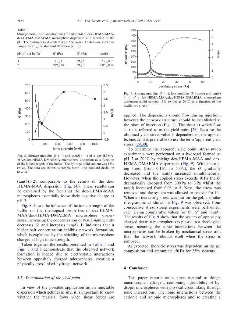
Table 1
Storage modulus G0 loss modulus G00 and tan(d) of dex-HEMA-MAA/
dex-HEMA-DMAEMA microsphere dispersion as a function of the
pH. The hydrogel solid content was 15% (w/w). All data are shown as
sample mean7the standard deviation (n ¼ 3)
pH of the buffer G0 (Pa) G00 (Pa) tan(d)
3 1171 2975 2.770.2
7 509718 2972 0.0670.00
0
100
200
300
400
500
600
700
0 200 400 600 800 1000
ionic strenght (mM)
G' (
Pa)
-0.5
0
0.5
1
1.5
2
2.5
3
3.5
tan
(δ)
Fig. 8. Storage modulus G0 (—) and tan(d) (- - -) of a dex-HEMA-
MAA/dex-HEMA-DMAEMA microsphere dispersion as a function
of the ionic strength of the buffer. The hydrogel solid content was 15%
(w/w). The data are shown as sample mean7the standard deviation
(n ¼ 3).
0
50
100
150
200
250
300
350
400
450
0 10 20 30 40 50
oscillatory stress (Pa)
G' a
nd
G"
(Pa)
0
1
2
3
4
5
6
7
tan
(δ)
Fig. 9. Storage modulus G0 (—), loss modulus G00 ( ) and tan(d)(- - -) of a dex-HEMA-MAA/dex-HEMA-DMAEMA microsphere
dispersion (solid content 15% (w/w)) at 20 1C as a function of the
oscillatory stress.
S.R. Van Tomme et al. / Biomaterials 26 (2005) 2129–21352134
(tan(d)42), comparable to the results of the dex-HEMA-MAA dispersion (Fig. 5b). These results canbe explained by the fact that the dex-HEMA-MAAmicrospheres essentially loose their negative charge atpH 3.
Fig. 8 shows the influence of the ionic strength of thebuffer on the rheological properties of dex-HEMA-MAA/dex-HEMA-DMAEMA microsphere disper-sions. Increasing the concentration of NaCl significantlydecreases G0 and increases tan(d). It indicates that ahigher salt concentration inhibits network formation,which is explained by the shielding of the microspherecharges at high ionic strength.
Taken together the results presented in Table 1 andFigs. 7 and 8 demonstrate that the observed networkformation is indeed due to electrostatic interactionsbetween oppositely charged microspheres, creating aphysically crosslinked hydrogel network.
3.5. Determination of the yield point
In view of the possible application as an injectabledispersion which gellifies in situ, it is important to knowwhether the material flows when shear forces are
applied. The dispersions should flow during injection,however the network structure should be established atthe place of injection (Fig. 1). The shear at which flowstarts is referred to as the yield point [28]. Because theobtained yield stress value is dependent on the appliedtechnique, it is preferable to use the term ‘apparent yieldstress’ [29,30].
To determine the apparent yield point, stress sweepexperiments were performed on a hydrogel formed atpH 7 at 20 1C by mixing dex-HEMA-MAA and dex-HEMA-DMAEMA dispersions (Fig. 9). With increas-ing stress (from 0.1 Pa to 50 Pa), the G0 graduallydecreased and the tan(d) increased simultaneously.However, when the applied stress exceeds 10 Pa the G0
dramatically dropped from 300 Pa to 3 Pa whilst thetan(d) increased from 0.08 to 5. Next, the stress wasremoved and the system was allowed to recover for 1 h.When an increasing stress was put on the gel, a similarrheogramme as shown in Fig. 9 was observed. Fourconsecutive stress sweep experiments were performed,each giving comparable values for G0, G00 and tan(d).The results of Fig. 9 show that the system of oppositelycharged dextran microspheres is plastic in a rheologicalsense, meaning the ionic interactions between themicrospheres can be broken by mechanical stress andthat the network rebuilds itself when the stress isremoved.
As expected, the yield stress was dependent on the gelcomposition and amounted 150 Pa for 25% systems.
4. Conclusion
This paper reports on a novel method to designmacroscopic hydrogels, combining injectability of hy-drogel microspheres with physical crosslinking throughionic interactions. The ionic interactions between thecationic and anionic microspheres and so creating a

ARTICLE IN PRESSS.R. Van Tomme et al. / Biomaterials 26 (2005) 2129–2135 2135
physical network, can be broken when exposed to stress.The gel forms again when the stress is removed,indicating the reversible character of the system. Anumber of possible applications for this novel systemcan be foreseen among which controlled delivery ofpharmaceutically active proteins and entrapment ofliving cells for tissue engineering. At present, we arestudying the release of proteins from these systems.
Acknowledgement
The authors like to thank J.F.W. Nijsen and S.W.Zielhuis from the Department of Nuclear Medicine,University Medical Center, Utrecht, The Netherlandsfor assisting in the particle size measurements.
References
[1] Gombotz WR, Pettit DK. Biodegradable Polymers for Protein
and Peptide Drug Delivery. Bioconjugate Chem 1995;6:332–51.
[2] Lee KY, Mooney DJ. Hydrogels for Tissue engineering. Chem
Rev 2001;101:1869–80.
[3] Hatefi, A, Amsden, B. Biodegradable injectable in situ forming
drug delivery systems. J Contr Rel 2002;80:9–28.
[4] Hoffman AS. Hydrogels for biomedical applications. Adv Drug
Del Rev 2002;43:3–12.
[5] Drury JL, Mooney DJ. Hydrogels for tissue engineering: scaffold
design variables and applications. Biomaterials 2003;24:4337–51.
[6] Hennink WE, van Nostrum CF. Novel crosslinking methods to
design hydrogels. Adv Drug Del Rev 2002;54:13–36.
[7] de Jong SJ, de Smedt SC, Wahls MWC, Demeester J, Kettenes-
van den Bosch JJ, Hennink WE. Novel self-assembled hydrogels
by stereocomplex formation in aqueous solution of enantiomeric
lactid acid oligomers grafted to dextran. Macromolecules
2000;33:3680–6.
[8] Bos GW, Jacobs JJL, Koten JW, Van Tomme S, Veldhuis T, van
Nostrum CF, Den Otter W, Hennink WE. In situ crosslinked
biodegradable hydrogels loaded with IL-2 are effective tools for
local IL-2 therapy. Eur J Pharm Sciences 2004;21:561–7.
[9] Li SM, Vert M. Synthesis, characterization and stereocomplex-
induced gelation of block copolymers prepared by ring opening
polymerization of L(D)-lactide in the presence of poly(ethylene
glycol). Macromolecules 2003;36:8008–14.
[10] Fujiwara T, Mukose T, Yamaoka T, Yamane H, Sakurai S,
Kimura Y. Novel thermo-responsive formation of a hydrogel by
stereocomplexation between PLLA-PEG-PLLA and PDLA-
PEG-PDLA block copolymers. Macromol Biosci 2001;1:204–8.
[11] Jeong B, Kim SW, Bae YH. Thermosensitive sol-gel reversible
hydrogels. Adv Drug Del Rev 2002;54:37–51.
[12] Jeong B, Bae YH, Lee DS, Kim SW. Biodegradable block
copolymers as injectable drug-delivery systems. Nature
1997;388:860–2.
[13] Kim S, Healy KE. Synthesis and characterization of injectable
Poly(N-isopropylacrylamide-co-acrylic acid) hydrogels with pro-
teolytically degradable cross links. Biomacromolecules
2003;4:1214–23.
[14] Zentner GM, Rathi R, Shih C, McRea JC, Seo M, Oh H, Hee
BG, Mestecky J, Moldoveanu Z, Morgan M, Weitman S.
Biodegradable block copolymers for delivery of proteins and
water-insoluble drugs. J Contr Rel 2001;72:203–15.
[15] Cellesi F, Tirelli N, Hubbell JA. Towards a fully synthetic
substitute of alginate: development of a new process using
thermal gelation and chemical cross-linking. Biomaterials
2004;25:5115–24.
[16] Anseth KS, Metters AT, Bryant SJ, Martens PJ, Elisseeff JH,
Bowman CN. In situ forming degradable networks and their
application in tissue engineering and drug delivery. J Contr Rel
2002;78:199–209.
[17] Park YD, Tirelli N, Hubbell JA. Photopolymerized hyaluronic
acid-based hydrogels and interpenetrating networks. Biomaterials
2003;24:893–900.
[18] Franssen O, Hennink WE. A novel preparation method for
polymeric microparticles without the use of organic solvents. Int J
Pharm 1998;168:1–7.
[19] Franssen O, Vandervennet L, Roders P, Hennink WE. Degrad-
able dextran hydrogels: controlled release of a model protein from
cylinders and microspheres. J Contr Rel 1999;60:211–21.
[20] de Groot CJ, van Luyn MJA, van Dijk-Wolthuis WNE, Cadee
JA, Plantinga JA, den Otter W, Hennink WE. In vitro
biocompatibility of biodegradable dextran-based hydrogels tested
with human fibroblasts. Biomaterials 2001;22:1197–203.
[21] Cadee JA, van Luyn MJA, Brouwer LA, Plantinga JA, van
Wachem PB, de Groot CJ, den Otter W, Hennink WE. In vivo
biocompatibility of dextran-based hydrogels. J Biomed Mater Res
2000;50:397–404.
[22] Cadee JA, Brouwer LA, den Otter W, Hennink WE, van Luyn
MJA. A comparative biocompatibility study of microspheres
based on dextran or poly(lactic-co-glycolic acid) after subcuta-
neous injection in rats. J Biomed Mater Res 2001;56:600–9.
[23] van Dijk-Wolthuls WNE, Tsang SKY, Kettenes-van den Bosch
JJ, Hennink WE. A new class of polymerizable dextrans with
hydrolyzable groups: hydroxyethyl methacrylated dextran with
and without oligolactate spacer. Polymer 1997;38:6235–42.
[24] Stenekes RJH, Franssen O, van Bommel EMG, Crommelin DJA,
Hennink WE. The preparation of Dextran Microspheres in an
All-Aqueous system: effect of the formulation parameters on
particle characteristics. Pharm Res 1998;15:557–61.
[25] Stenekes RJH, Hennink WE. Polymerization kinetics of dextran-
bound methacrylate in an aqueous two-phase system. Polymer
2000;41:5563–9.
[26] Stenekes RJH, Hennink WE. Equilibrium water content of
microspheres based on cross-linked dextran. Int J Pharm
1999;189:131–5.
[27] van de Wetering P, Zuidam NJ, van Steenbergen MJ, van der
Houwen OAGJ, Underberg WJM, Hennink WE. A Mechanistic
study of the Hydrolytic Stability of Poly(2-(dimethylamino)ethyl
methacrylate. Macromolecules 1998;31:8063–8.
[28] Martin A. Physical pharmacy. 4th ed. London: Lea & Febiger
(Chapter 17).
[29] Semancik JR. Yield stress measurements using controlled stress
rheometry. TA Instruments Publication RH-058.
[30] Barnes HA, Hutton JF, Walters K. An introduction to Rheology.
New York: Elsevier; 1991.
Copyright © 2022 FDOKUMEN