Carbon attrition during the circulating fluidized bed combustion of a packaging-derived fuel
12
Carbon Attrition During the Circulating Fluidized Bed Combustion of a Packaging-Derived Fuel MARIA LAURA MASTELLONE and UMBERTO ARENA* ‡§ Department of Chemical Engineering, University “Federico II” of Naples, Napoli, Italy; ‡ Institute for Combustion Research, National Research Council (CNR), Napoli, Italy; § Department of Environmental Sciences, S.U.N. University of Naples, Caserta, Italy Cylindrical pellets of a market-available packaging-derived fuel, obtained from a mono-material collection of polyethylene terephthalate (PET) bottles, were batchwise fed to a laboratory scale circulating fluidized bed (CFB) combustor. The apparatus, whose riser was 41 mm ID and 4 m high, was operated under both inert and oxidizing conditions to establish the relative importance of purely mechanical attrition and combustion-assisted attrition in generating carbon fines. Silica sand particles of two size distributions were used as inert materials. For each run, carbon load and carbon particle size distribution in the riser and rates of attrited carbon fines escaping the combustor were determined as a function of time. A parallel investigation was carried out with a bubbling fluidized bed (BFB) combustor to point out peculiarities of attrition in CFB combustors. After devolatilization, PET pellets generated fragile aggregates of char and sand, which easily crumbled, leading to single particles, partially covered by a carbon-rich layer. The injected fixed carbon was therefore present in the bed in three phases: an A-phase, made of aggregates of sand and char, an S-phase, made of individual carbon-covered sand particles and an F-phase, made of carbon fines, abraded by the surfaces of the A- and S-phases. The effects of the size of inert material on the different forms under which fixed carbon was present in the bed and on the rate of escape of attrited carbon fines from the combustor were investigated. Features of carbon attrition in CFB and BFB combustors are discussed. © 1999 by The Combustion Institute NOMENCLATURE d c surface/volume mean diameter of carbon particles (mm) d fr surface/volume mean diameter of fragments (on mass basis) (mm) e c rate of generation of carbon fines (g/min) E c rate of elutriated carbon fines, in continuous operated combustors (g/min) k attrition rate constant, as defined in Eq. 2 k* attrition rate constant, as defined in Eq. 5 (l/mm) G s mass flux of circulating solids (kg/sm 2 ) M f particle multiplication factor, i.e., the ratio between the number of (fragmented and nonfragmented) particles collected at the end of devolatilization and the number of injected particles S f probability of particle breakage, i.e., the ratio between the number of particles that undergo primary fragmentation and that of particles injected into the bed t elapsed time of each run (min) t9 activation time (min) t dev devolatilization time of a fuel particle (min) t r time in which fixed carbon was effectively exposed to combustion and attrition (min) t bo burn-out time of a fuel particle (min) U superficial gas velocity (m/s) U mf minimum fluidization velocity of inert material (m/s) U t terminal velocity of inert material (m/s) w b total amount of solids (g) w c total amount of carbon (g) W c total amount of carbon, in continuous operated combustors (g) Subscripts A related to aggregates of silica sand particles and fixed carbon CFB related to the whole CFB loop cy2 collected from the second cyclone F related to carbon fines ri related to the riser S related to silica sand particles covered by a carbon layer *Corresponding author. E-mail: [email protected] COMBUSTION AND FLAME 117:562–573 (1999) 0010-2180/99/$–see front matter © 1999 by The Combustion Institute PII S0010-2180(98)00158-8 Published by Elsevier Science Inc.
Transcript of Carbon attrition during the circulating fluidized bed combustion of a packaging-derived fuel
Carbon Attrition During the Circulating Fluidized BedCombustion of a Packaging-Derived Fuel
MARIA LAURA MASTELLONE† and UMBERTO ARENA*‡§
†Department of Chemical Engineering, University “Federico II” of Naples, Napoli, Italy; ‡Institute forCombustion Research, National Research Council (CNR), Napoli, Italy; §Department of Environmental
Sciences, S.U.N. University of Naples, Caserta, Italy
Cylindrical pellets of a market-available packaging-derived fuel, obtained from a mono-material collection ofpolyethylene terephthalate (PET) bottles, were batchwise fed to a laboratory scale circulating fluidized bed(CFB) combustor. The apparatus, whose riser was 41 mm ID and 4 m high, was operated under both inert andoxidizing conditions to establish the relative importance of purely mechanical attrition and combustion-assistedattrition in generating carbon fines. Silica sand particles of two size distributions were used as inert materials.For each run, carbon load and carbon particle size distribution in the riser and rates of attrited carbon finesescaping the combustor were determined as a function of time. A parallel investigation was carried out with abubbling fluidized bed (BFB) combustor to point out peculiarities of attrition in CFB combustors. Afterdevolatilization, PET pellets generated fragile aggregates of char and sand, which easily crumbled, leading tosingle particles, partially covered by a carbon-rich layer. The injected fixed carbon was therefore present in thebed in three phases: an A-phase, made of aggregates of sand and char, an S-phase, made of individualcarbon-covered sand particles and an F-phase, made of carbon fines, abraded by the surfaces of the A- andS-phases. The effects of the size of inert material on the different forms under which fixed carbon was presentin the bed and on the rate of escape of attrited carbon fines from the combustor were investigated. Featuresof carbon attrition in CFB and BFB combustors are discussed. © 1999 by The Combustion Institute
NOMENCLATURE
dc surface/volume mean diameter ofcarbon particles (mm)
dfr surface/volume mean diameter offragments (on mass basis) (mm)
ec rate of generation of carbon fines (g/min)Ec rate of elutriated carbon fines, in
continuous operated combustors (g/min)k attrition rate constant, as defined in Eq. 2k* attrition rate constant, as defined in Eq.
5 (l/mm)Gs mass flux of circulating solids (kg/sm2)Mf particle multiplication factor, i.e., the
ratio between the number of(fragmented and nonfragmented)particles collected at the end ofdevolatilization and the number ofinjected particles
Sf probability of particle breakage, i.e., theratio between the number of particlesthat undergo primary fragmentation andthat of particles injected into the bed
t elapsed time of each run (min)
t9 activation time (min)tdev devolatilization time of a fuel particle
(min)tr time in which fixed carbon was
effectively exposed to combustion andattrition (min)
tbo burn-out time of a fuel particle (min)U superficial gas velocity (m/s)Umf minimum fluidization velocity of inert
material (m/s)Ut terminal velocity of inert material
(m/s)wb total amount of solids (g)wc total amount of carbon (g)Wc total amount of carbon, in continuous
operated combustors (g)
Subscripts
A related to aggregates of silica sandparticles and fixed carbon
CFB related to the whole CFB loopcy2 collected from the second cycloneF related to carbon finesri related to the riserS related to silica sand particles covered
by a carbon layer*Corresponding author. E-mail: [email protected]
COMBUSTION AND FLAME 117:562–573 (1999)0010-2180/99/$–see front matter © 1999 by The Combustion InstitutePII S0010-2180(98)00158-8 Published by Elsevier Science Inc.
INTRODUCTION
The influence of fuel particle comminution [1,2] on the performances of either bubbling(BFB) and circulating fluidized bed (CFB)combustors and gasifiers has been generallyrecognized [3–5]. The contribution of commi-nuted carbon fines to the overall conversionof fixed carbon has been found [6, 7] to besignificant, particularly under the operatingconditions of circulating fluidized bed reac-tors. The combustion– comminution patternsfor low-volatile fuels are generally very differ-ent from those of high-volatile, waste-derivedfuels [8]. Some of the most attractive alterna-tive fuels, like refuse-derived fuels [9] andtire-derived fuels [2], show exaggerated com-minution, with a strong tendency to generateincoherent particles and/or a multitude of finefragments; this plays a crucial role in theconversion of fixed carbon in a fluidized bed.On the other hand, packaging-derived fuels,like chips of polyethylene terephthalate(PET), generate aggregates made of a numberof sand particles kept together by a carbon-rich connecting matrix. The result is a greatlyincreased residence time for the fixed carbonin a BFB reactor [10].
The aim of this paper was to acquire infor-mation about the mechanism and the signifi-cance of carbon attrition during the combus-tion of a commercially available packaging-derived fuel (PDF) in a circulating fluidizedbed reactor. To this end, a small-scale CFBcombustor (CFBC) was charged batchwisewith pellets obtained from a mono-materialcollection of polyethylene terephthalatebottles. According to the standard proce-dure already used for experiments duringcombustion in a bubbling fluidized bed [10],carbon attrition rates were determined as afunction of time. However, whereas attritionrates were simply obtained in a bubblingfluidized bed combustor (BFBC) by filter-ing carbon fines from the outlet gases, in aCFBC a more elaborate technique was re-quired, due to solids’ circulation. The resultswere finally compared with those obtained byburning the same PET pellets in a laboratory-scale BFBC.
EXPERIMENTAL
Apparatus and Procedures
The apparatus used to investigate carbon attri-tion of PET pellets was the CFBC made of ahigh-temperature austenitic stainless steel,which is schematically sketched in Fig. 1. Basi-cally, it consisted of a riser (41 mm ID), acyclone, a recirculation standpipe, and an L-valve to control the reinjection of solids into theriser. The main geometric parameters of theloop are given in Table 1. Figure 1 indicates allthe inlets and outlets. Nitrogen or a mixture ofnitrogen 1 oxygen was supplied at the riserbottom. The riser was equipped with a two-stage cyclone. The solids separated by the firstcyclone were conveyed to the standpipe andsubsequently transferred to the riser by meansof an L-valve [11]. Fines separated by the sec-ond cyclone were collected in the bottle down-stream the cyclone leg. A vessel was fitted to thebottom of the riser and used to collect all thesolids in the loop: it was maintained undervacuum and cooled down with nitrogen toquench reaction between char and air.
Nine pairs of electrical heaters and propor-tional integrative differential (PID) controllerswere used to maintain the temperatures of thevarious sections of the CFBC at the desiredlevels. The riser was maintained at 850°C, whilethe recirculation standpipe was kept at 500°C toavoid risk of sintering in the moving packed bed
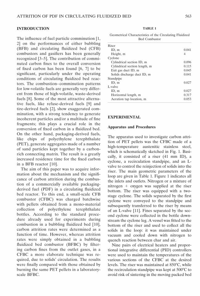
TABLE 1
Geometrical Characteristics of the Circulating FluidizedBed Combustor
RiserID, m 0.041Height, m 4
CycloneCylindrical section ID, m 0.096Cylindrical section length, m 0.115Exit gas duct ID, m 0.045Solids discharge duct ID, m 0.041
StandpipeID, m 0.027
L-valveID, m 0.027Horizontal length, m 0.317Aeration tap location, m 0.053
563ATTRITION OF PDF IN CIRCULATING FLUIDIZED BED

[11]. A probe, placed after the second cyclone,was used for on-line analysis of flue gas: themeasurement of the concentrations of CO, CO2and O2, together with that of carbon finesescaping from the reactor, made it possible toassess the accuracy of the tests through a globalcarbon balance. The error was always less than12%. A set of 15 Druck PDCR 130/C pressure
transducers were located along the loop as shownin Fig. 1. Voidages and solids hold-up in each partof the loop were calculated from pressure read-ings by means of the pressure gradient technique[12]. Pressure signals and gas concentrationswere recorded on paper, displayed on a moni-tor, and stored by means of a data acquisitionunit interfaced with a personal computer.
At the beginning of a run, the hold-up of inertmaterial in the loop was 1.8 kg. The flow rates offluidizing gas and the L-valve aeration streamwere set up to give particular values of the totalfluidizing velocity, U, and the mass flux, Gs ofsolids. A batch of silica sand and devolatilizedPET pellets was then charged in the CFB loopby means of the hopper. Each batch containedan amount of devolatilized pellets equivalent to2 g of fixed carbon and 200 g of inert material.It was prepared in advance using the BFBapparatus described below; here the bed ofsilica sand was kept at a temperature of 850°C,charged with fresh PET pellets and fluidized bynitrogen at a velocity of three times that forminimum fluidization. Devolatilized PET pel-lets were used instead of the fuel particles toavoid the fast release of volatiles and theircombustion throughout the loop. The injectionof the batch into the riser marked the start-up ofa run (t 5 0). Gas concentrations at the riseroutlet were subsequently recorded and finesfrom the second cyclone collected. At a fixedtime after the start-up, the air and nitrogensupplies to the riser were turned off, and all thesolids contained in the whole loop were dis-charged into the vacuum-operated vessel. Fol-lowing this first period, the combustor was againcharged with 1.8 kg of silica sand and, when theriser was again at 850°C, a new batch of devola-tilized PET pellets and inert material was in-jected and taken in the loop according to thesame technique, but for a longer period. Five orsix successive periods of time were utilized toobtain a complete monitoring of attrition underboth oxidizing and inert conditions.
The time, tr, during which carbon was effec-tively exposed to combustion and attrition, wasdifferent from t. Due to the circulation of solidsthrough the combustor loop, it is tr 5 twb,ri/wb,CFB, where wb,ri and wb,CFB are the totalamounts of solids in the riser and in the wholecombustor, respectively. The proportion is
Fig. 1. The CFB combustor used as experimental appara-tus. 1) riser; 2) cyclones; 3) device for solids mass fluxmeasurement; 4) standpipe; 5) L-valve; 6) vacuum vessel; 7)fuel feeding hopper. P# 5 pressure transducer; T# 5temperature controller.
564 M. L. MASTELLONE AND U. ARENA

based on the assumptions that the CFB loopwas operated under steady-state conditions andthat the carbon surface was available to com-bustion and attrition only in the riser. The latterassumption was supported by the peculiar oper-ating conditions (i.e., temperature, oxygen con-centration, and particle velocity profiles) and bythe form under which fixed carbon was found tobe present in the bed. It was also assumed thatcarbon fines collected in the second cyclone weregenerated by attrition [13]. Solids discharged fromthe CFB loop were sieved and the carbon contentof each fraction was determined by chemicalanalysis. The overall amount, wc, of fixed carbon,the relative importance of different phases [10] inwhich it was present in the loop, and the Sautercarbon particle diameter, dc, all were directlydetermined from these measurements.
A laboratory scale BFB combustor (internaldiameter 41 mm) was used for the preparationof batches of devolatilized pellets, which werethen injected into the CFB loop. The same appa-ratus was also used for batchwise experiments onfragmentation (fragmented and unfragmentedparticles were retrieved at any time after injectionby means of a basket) and attrition phenomena(carbon fines were filtered from the outlet gasesby means of a “two-exit head”) [1, 2]. The exper-imental procedure was that recently set up forother packaging-derived fuels [10]. Experimentsinvolved injecting a batch of fuel particles into abed of 200 g of silica sand, kept at 850°C. The bedwas fluidized with nitrogen, at a superficial gasvelocity three times that for minimum fluidiza-tion, during the fragmentation tests, as well asduring the devolatilization time of the attritiontests. In these latter, the bed was fluidized at 0.8m/s by nitrogen or oxygen 1 nitrogen during thecollection of carbon fines [10].
A Philips XL 30 SEM (scanning electronmicroscope), coupled with an EDX (energydisperse X-ray) analyzer was used to investigatethe microstructure of some devolatilized fuelparticles. The apparatus has an optical resolu-tion of 2 nm (at 30 kV) and allows elementaryanalysis of the specimen’s surface.
Materials
Proximate and ultimate analyses of the pelletsof recycled PET are given in Table 2, together
with the characteristics of the two inert materi-als used. The fuel pellets were formed frompellets of polyethylene terephthalate, madefrom a mono-material collection of PET bottles,by successive mechanical shredding, washing,and a final pelletization of the resulting flakes.Table 2 also reports the analyses of pellets ofvirgin PET, generally utilized as raw material inthe industrial production of bottles. These latterwere tested as reference to investigate a possi-ble effect of the recycling processes (the pelleti-zation one, in particular) on the comminution ofthe polymer.
RESULTS AND DISCUSSION
Primary Fragmentation
Primary fragmentation of a fuel particle occursjust after its injection into the hot bed, as aconsequence of losses of material (moisture andvolatiles) and internal stresses due to heating,drying, and devolatilization [1, 2]. The basket-equipped BFBC was operated batchwise withpellets of recycled or virgin PET, charged in abed, which alternatively was made of 0.3–0.4mm and 0.09–0.2 mm silica sand particles.Table 3 reports values of the parameters defin-ing the significance of primary fragmentation(namely, the probability of particle breakage,Sf, the particle multiplication factor, Mf, andthe surface/volume mean particle diameter offragments, dfr), as obtained from a significantnumber of experiments (more than 50). Thedevolatilized particles retrieved with the baskettechnique just after the end of devolatilization(tdev), although very fragile, preserved the indi-viduality and approximately the original shapeand size of the “mother” fuel particle. In otherwords, both types of PET pellets did not un-dergo any particle breakage (Sf > 0) duringdevolatilization, i.e. they did not generate anyfragments or subparticles (Mf > 1). Theseresults were in accordance with those providedby similar experiments recently carried out withchips of PET or a mixture of PET and polyole-fins [10].
Careful examination of devolatilized particlessuggested that they formed a sort of char–sandaggregate, which embodied a certain amount of
565ATTRITION OF PDF IN CIRCULATING FLUIDIZED BED
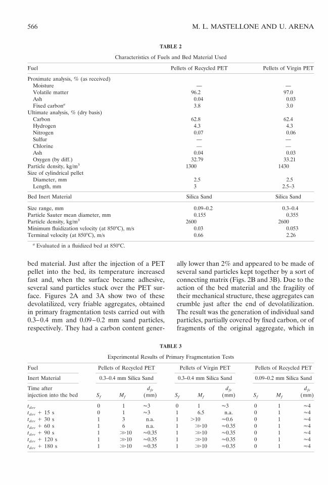
bed material. Just after the injection of a PETpellet into the bed, its temperature increasedfast and, when the surface became adhesive,several sand particles stuck over the PET sur-face. Figures 2A and 3A show two of thesedevolatilized, very friable aggregates, obtainedin primary fragmentation tests carried out with0.3–0.4 mm and 0.09–0.2 mm sand particles,respectively. They had a carbon content gener-
ally lower than 2% and appeared to be made ofseveral sand particles kept together by a sort ofconnecting matrix (Figs. 2B and 3B). Due to theaction of the bed material and the fragility oftheir mechanical structure, these aggregates cancrumble just after the end of devolatilization.The result was the generation of individual sandparticles, partially covered by fixed carbon, or offragments of the original aggregate, which in
TABLE 2
Characteristics of Fuels and Bed Material Used
Fuel Pellets of Recycled PET Pellets of Virgin PET
Proximate analysis, % (as received)Moisture — —Volatile matter 96.2 97.0Ash 0.04 0.03Fixed carbona 3.8 3.0
Ultimate analysis, % (dry basis)Carbon 62.8 62.4Hydrogen 4.3 4.3Nitrogen 0.07 0.06Sulfur — —Chlorine — —Ash 0.04 0.03Oxygen (by diff.) 32.79 33.21
Particle density, kg/m3 1300 1430Size of cylindrical pellet
Diameter, mm 2.5 2.5Length, mm 3 2.5–3
Bed Inert Material Silica Sand Silica Sand
Size range, mm 0.09–0.2 0.3–0.4Particle Sauter mean diameter, mm 0.155 0.355Particle density, kg/m3 2600 2600Minimum fluidization velocity (at 850°C), m/s 0.03 0.053Terminal velocity (at 850°C), m/s 0.66 2.26
a Evaluated in a fluidized bed at 850°C.
TABLE 3
Experimental Results of Primary Fragmentation Tests
Fuel Pellets of Recycled PET Pellets of Virgin PET Pellets of Recycled PET
Inert Material 0.3–0.4 mm Silica Sand 0.3–0.4 mm Silica Sand 0.09–0.2 mm Silica Sand
Time afterinjection into the bed Sf Mf
dfr
(mm) Sf Mf
dfr
(mm) Sf Mf
dfr
(mm)
tdev 0 1 '3 0 1 '3 0 1 '4tdev 1 15 s 0 1 '3 1 6.5 n.a. 0 1 '4tdev 1 30 s 1 3 n.a. 1 .10 '0.6 0 1 '4tdev 1 60 s 1 6 n.a. 1 ..10 '0.35 0 1 '4tdev 1 90 s 1 ..10 '0.35 1 ..10 '0.35 0 1 '4tdev 1 120 s 1 ..10 '0.35 1 ..10 '0.35 0 1 '4tdev 1 180 s 1 ..10 '0.35 1 ..10 '0.35 0 1 '4
566 M. L. MASTELLONE AND U. ARENA

turn easily generate further smaller fragmentsand eventually single sand particles. Data inTable 3 quantify the extent of this crumbling.When 0.3–0.4 mm silica sand was used, pelletsof virgin PET produced individually coveredsand particles earlier than the recycled pellets,probably due to some changes during recyclingof the pellets. However, in both cases the prob-ability of aggregate breakage, under inert con-ditions, became Sf 5 1 shortly after the devola-tilization time tdev. The other fragmentationparameters can be estimated as Mf .. 10 anddfr > 350 mm for both fuels, about 90 s aftertdev. Figures 2C and 2D show two of these sandparticles, which easily originated by the aggre-gate crumbling when the basket was retrievedafter an interval sufficiently longer than thedevolatilization time. The particle was partially
covered by a smooth layer of material, having athickness of 1–3 mm and a carbon content(evaluated by EDX microanalysis) of more than80%. This is in agreement with findings ob-tained in the investigation already mentionedand carried out with flakes of PET or a PE-PETmixture [10]. The behavior of char–sand aggre-gates appeared different in experiments carriedout with a bed of 0.09–0.2 mm silica sandparticles; Sf remained equal to zero (and Mf 51) up to about 3 minutes after tdev. This in-creased consistency of the mechanical structureof aggregates should be related to the finer sizeof sand particles, which allowed a lower voidagein the resulting aggregates and offered a greaterspecific surface area for sticking to the PET.Figures 3B and 3D seem to support this consid-eration. The layer between sand particles again
Fig. 2. Photographs of material retrieved by the basket after primary fragmentation tests with pellets of recycled PET,charged in a bed of 0.3–0.4 mm sand. (A) The single char–sand aggregate obtained after the injection of a single pellet (SEMmagnification 5 322). (B) A restricted area of photograph 2A showing a C-rich connecting bridge (SEM magnification 531422). (C) A single sand particle, partially covered by a C-rich layer (SEM magnification 5 3150). (D) A singlecarbon-covered sand particle, showing the imprint of the connection to another sand particle (SEM magnification 5 3380).
567ATTRITION OF PDF IN CIRCULATING FLUIDIZED BED

had a high content of carbon (EDX microanal-ysis gave values from 80 to 94%), but its thick-ness was often as large as 5–7 mm (Fig. 3D). Inother words, the connecting matrix appearedmore and more resistant with respect to thatwhich keeps together coarser sand particles.
The reported findings imply that fixed carbonwas present in the bed in three phases: anA-phase, made of aggregates of sand and char;an S-phase, made of individual carbon-coveredsand particles; and an F-phase, made of carbonfines, abraded by the surfaces of A- and S-phases. Sieving and chemical analyses of about20 batches of devolatilized PET pellets indi-cated the significance of each of the threephases. When the coarser sand particles wereused as bed material, fixed carbon was presentalmost completely as the S-phase (about 94% of
the total amount of fixed carbon for recycledpellets). The char–sand aggregates representeda fraction of ;6%, whereas carbon fines weregenerally not more than 0.5%. This distributionremained the same when virgin PET pelletswere used instead of recycled ones. A remark-able effect was observed by using the finer inertmaterial: the above-mentioned increased cohe-sion of char–sand aggregates led to a greaterfraction of fixed carbon present in the bed asA-phase (up to 15%) and a substantial absenceof F-phase (0.1% or less).
This pattern of primary fragmentation greatlyincreased the residence time of fixed carbon inthe fluidized bed reactors. Fixed carbon can beremoved from a particle by combustion or bywearing against combustor walls or other bedsolids. This latter phenomenon generated at-
Fig. 3. Photographs of material retrieved by the basket after primary fragmentation tests with pellets of recycled PET,charged in a bed of 0.09–0.2 mm sand. (A) The single char–sand aggregate obtained after the injection of a single pellet (SEMmagnification 5 320). (B) A restricted area of photograph 3A showing some C-rich connecting bridges (SEM magnifica-tion 5 3322). (C) A single sand particle, partially covered by a C-rich layer (SEM magnification 5 3287). (D) A restrictedarea of photograph 3B showing the interstice between sand surface and the C-rich layer (SEM magnification 5 3257).
568 M. L. MASTELLONE AND U. ARENA
trited carbon fines, which can burn off along thecombustor or escape through the cyclone.
Carbon Fines Generation
Operating Conditions of the Loop
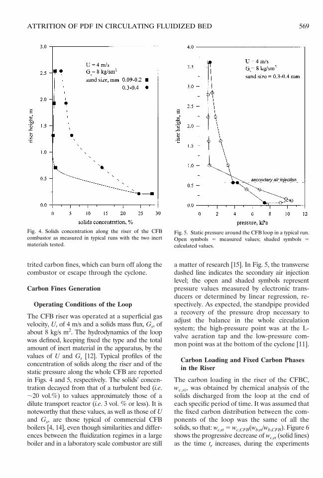
The CFB riser was operated at a superficial gasvelocity, U, of 4 m/s and a solids mass flux, Gs, ofabout 8 kg/s m2. The hydrodynamics of the loopwas defined, keeping fixed the type and the totalamount of inert material in the apparatus, by thevalues of U and Gs [12]. Typical profiles of theconcentration of solids along the riser and of thestatic pressure along the whole CFB are reportedin Figs. 4 and 5, respectively. The solids’ concen-tration decayed from that of a turbulent bed (i.e.;20 vol.%) to values approximately those of adilute transport reactor (i.e. 3 vol. % or less). It isnoteworthy that these values, as well as those of Uand Gs, are those typical of commercial CFBboilers [4, 14], even though similarities and differ-ences between the fluidization regimes in a largeboiler and in a laboratory scale combustor are still
a matter of research [15]. In Fig. 5, the transversedashed line indicates the secondary air injectionlevel; the open and shaded symbols representpressure values measured by electronic trans-ducers or determined by linear regression, re-spectively. As expected, the standpipe provideda recovery of the pressure drop necessary toadjust the balance in the whole circulationsystem; the high-pressure point was at the L-valve aeration tap and the low-pressure com-mon point was at the bottom of the cyclone [11].
Carbon Loading and Fixed Carbon Phasesin the Riser
The carbon loading in the riser of the CFBC,wc,ri, was obtained by chemical analysis of thesolids discharged from the loop at the end ofeach specific period of time. It was assumed thatthe fixed carbon distribution between the com-ponents of the loop was the same of all thesolids, so that: wc,ri 5 wc,CFB(wb,ri/wb,CFB). Figure 6shows the progressive decrease of wc,ri (solid lines)as the time tr increases, during the experiments
Fig. 4. Solids concentration along the riser of the CFBcombustor as measured in typical runs with the two inertmaterials tested.
Fig. 5. Static pressure around the CFB loop in a typical run.Open symbols 5 measured values; shaded symbols 5calculated values.
569ATTRITION OF PDF IN CIRCULATING FLUIDIZED BED

carried out at different oxygen concentrations. Inthis and Figs. 7 and 9, the residence time tr ispreferred to run time t to provide a more correctcomparison between curves relative to differentoperating conditions. As expected, the carbon
loading reduced when the oxygen content in thefluidizing gas was increased. Figure 6 also reportsthe distribution of fixed carbon in the A-, S-, andF-phases (dashed lines). It is confirmed that, withboth the bed materials used, fixed carbon waspresent in the riser almost completely in theS-phase. The dominant role of this phase couldalso explain the lower loadings of fixed carbonfound during the runs carried out with the finerinert material, under the same oxidizing condi-tions, but with the different solids distributionshown in Fig. 4. The higher specific surface areaallowed more carbon to be exposed; this led to fastcarbon consumption in the riser. It is also inter-esting to observe that the “life-time” of char–sandaggregates was strongly reduced by an increaseof O2 content. This suggests that, under operat-ing conditions similar to those tested, theseaggregates do not create any potential concernrelated to particle agglomeration [4].
Rates of Fines Generation
The rates of generation of carbon fines, ec(t),were obtained from a carbon fines balance onthe whole CFB loop. At a given t, the net rate ofgeneration of carbon fines is given by the sum ofthe rate of change of carbon fines load in theCFB loop and the rate of carbon fines collectedat second cyclone [13]. The equation:
ec@~ti11 2 ti!/ 2#
5 @wcF,CFB~ti11! 2 wcF,CFB~ti!#/Dt
1 wcF,cy2/Dt (1)
must be satisfied, where the symbols are thoseof Fig. 1 and the time (ti11 2 ti)/ 2 is the middleof each specific period of measurement Dt 5(ti11 2 ti); ec is a net rate of carbon finesgeneration, i.e. the difference between the ab-solute rates of generation and of combustion offines in the CFB riser. As in previous studies forbubbling and circulating fluidized bed combus-tors [1, 13], only ec was evaluated. The rates ofcarbon fines generation obtained by means ofEq. 1 can be considered as being substantiallyequal to the rates of carbon attrition by abra-sion. The specific experimental procedure usedand the reported findings both support theassumption that carbon fines can be generatedonly by the wearing of carbon-covered sand
Fig. 6. Carbon loading in the riser as a function of time tr,with the indication of the significance of various phases offixed carbon, in experiments under different oxidizing con-ditions and with different inert materials. (Ug 5 4 m/s; Gs
5 8 kg/sm2).
Fig. 7. Carbon elutriation rate as a function of time tr, inexperiments under inert and oxidizing conditions (A) andwith different inert materials (B). (Ug 5 4 m/s; Gs 5 8kg/sm2).
570 M. L. MASTELLONE AND U. ARENA

particles against either the walls of the combus-tor or the other bed materials.
Figure 7A compares carbon fines’ attritionrates obtained under inert conditions (whenonly nitrogen was used to circulate solids in theloop, so mechanical stresses were entirely re-sponsible for generating fines) and oxidizingconditions (when a nitrogen 1 oxygen mixturewas used and the contributions from combus-tion must be taken into account). As expected,the rates obtained for purely mechanical attri-tion were negligible compared with those forcombustion-assisted attrition. A similar resultwas found in experiments with char of a bitumi-nous coal during CFB combustion [13], as wellas with devolatilized PET chips during BFBcombustion [10]. The peak rate of purely me-chanical attrition is related not to the fastpeeling of surface asperities from the wholeparticles [1], but, more likely, to the detachmentof the connecting bridges (Figs. 2B and 3B)made of the layer, which remain stuck on sandparticles after the aggregate had crumbled. Theright side of the curve in Fig. 7A for mechanicalattrition decreased very slowly with an asymp-totic trend: the mechanical abrasion of carbon-covered sand particles cannot produce signifi-cant size degradation, only the removal of thethin carbon-rich layer.
The shape in Fig. 7A of the curves for carbonfines generated into the loop under oxidizingconditions is typical of combustion-assisted at-trition [1, 13]. The curves display a peak at a sortof “activation time,” t9 [1, 10]. The maximum ofec is probably related to two opposite effects: theaction of combustion, which assisted attrition bymaking easier the detachment of the C-rich layer,and a reduction of the area of fixed carbonexposed to abrasion and then available to bedetached. Comparison of the ec curves obtained atdifferent oxidizing conditions confirms there is“assistance” of attrition by combustion: a higheroxygen concentration made easier the detachmentof a carbon layer, reducing the activation timeand increasing the absolute value of the ec peak.Finally, Fig. 7B compares carbon fines attritionrates obtained under the same oxidizing condi-tions, but operating the CFB riser with differentinert material. The lower amount of carbon inthe riser already highlighted by Fig. 6, led tolower rates of attrited carbon fines.
Evaluation of Attrition Rate Constants forOperations in BFB and CFB Combustors
The tendency of carbon to generate attritedfines is generally expressed [1] by means of asemi-empirical attrition rate constant k, whichembodies the effects of the operating variableson rates of carbon fines generation. In the caseof continuous operations in a BFBC:
k 5 Ec/@~U 2 Umf!Wc/dc# (2)
where Ec is the mass rate of carbon fines, (U 2Umf) the excess of superficial gas velocity abovethe minimum for fluidization and Wc/dc is pro-portional to the area of carbon exposed toattrition in the bed, Wc and dc being the mass ofcarbon in the bed and the Sauter average car-bon particle diameter, respectively. In the caseof batch operations:
k 5
E0
tbo ec~t!~U 2 Umf!wc~t!/ dc ~t!
dt
tbo (3)
where, apart from the variability with the time,the meaning of ec(t), wc(t) and dc(t) is thesame of Ec, Wc, and dc in Eq. 2. According to aseries of studies reviewed in [1], an approximateexpression for the attrition rate constant in abatchwise operated BFBC is:
k 5ec~t!
~U 2 Umf!wc~t!/dc~t!per t9 , t , tbo
(4)
As a first approximation, Eq. 4 can be extendedto carbon attrition in CFBCs using the rates ofcarbon fines generation ec(t) (as those given inFig. 7 and evaluated by Eq. 1), the carbon loadsin the riser wc,ri(t) (as those given in Fig. 6 orevaluated by subtracting from the amount ofinjected fixed carbon that which escaped theloop as carbon fines, carbon monoxide, or car-bon dioxide) and substituting Umf with theterminal velocity Ut. This solution has alreadybeen adopted in a study on carbon attritionduring CFB combustion of a bituminous coal[13], but cannot be utilized here, due to thedifferent phenomenology of attrition. Analysisof some SEM pictures in Figs. 2 and 3 suggeststhat there is a sort of envelope made of carboncovering the inert particles, even though it doesnot stick over their whole surface, but, more
571ATTRITION OF PDF IN CIRCULATING FLUIDIZED BED
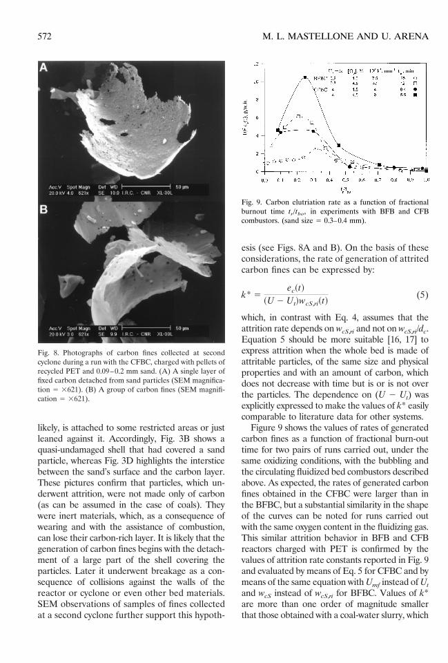
likely, is attached to some restricted areas or justleaned against it. Accordingly, Fig. 3B shows aquasi-undamaged shell that had covered a sandparticle, whereas Fig. 3D highlights the intersticebetween the sand’s surface and the carbon layer.These pictures confirm that particles, which un-derwent attrition, were not made only of carbon(as can be assumed in the case of coals). Theywere inert materials, which, as a consequence ofwearing and with the assistance of combustion,can lose their carbon-rich layer. It is likely that thegeneration of carbon fines begins with the detach-ment of a large part of the shell covering theparticles. Later it underwent breakage as a con-sequence of collisions against the walls of thereactor or cyclone or even other bed materials.SEM observations of samples of fines collectedat a second cyclone further support this hypoth-
esis (see Figs. 8A and B). On the basis of theseconsiderations, the rate of generation of attritedcarbon fines can be expressed by:
k* 5ec~t!
~U 2 Ut!wcS,ri~t!(5)
which, in contrast with Eq. 4, assumes that theattrition rate depends on wcS,ri and not on wcS,ri/dc.Equation 5 should be more suitable [16, 17] toexpress attrition when the whole bed is made ofattritable particles, of the same size and physicalproperties and with an amount of carbon, whichdoes not decrease with time but is or is not overthe particles. The dependence on (U 2 Ut) wasexplicitly expressed to make the values of k* easilycomparable to literature data for other systems.
Figure 9 shows the values of rates of generatedcarbon fines as a function of fractional burn-outtime for two pairs of runs carried out, under thesame oxidizing conditions, with the bubbling andthe circulating fluidized bed combustors describedabove. As expected, the rates of generated carbonfines obtained in the CFBC were larger than inthe BFBC, but a substantial similarity in the shapeof the curves can be noted for runs carried outwith the same oxygen content in the fluidizing gas.This similar attrition behavior in BFB and CFBreactors charged with PET is confirmed by thevalues of attrition rate constants reported in Fig. 9and evaluated by means of Eq. 5 for CFBC and bymeans of the same equation with Umf instead of Ut
and wcS instead of wcS,ri for BFBC. Values of k*are more than one order of magnitude smallerthat those obtained with a coal-water slurry, which
Fig. 8. Photographs of carbon fines collected at secondcyclone during a run with the CFBC, charged with pellets ofrecycled PET and 0.09–0.2 mm sand. (A) A single layer offixed carbon detached from sand particles (SEM magnifica-tion 5 3621). (B) A group of carbon fines (SEM magnifi-cation 5 3621).
Fig. 9. Carbon elutriation rate as a function of fractionalburnout time tr/tbo, in experiments with BFB and CFBcombustors. (sand size 5 0.3–0.4 mm).
572 M. L. MASTELLONE AND U. ARENA

shows a similar attrition phenomenology [17].This again confirms the low tendency of PET fixedcarbon to generate attrited fines.
CONCLUSIONS
Carbon attrition of a commercially available,packaging-derived fuel has been investigated bymeans of batchwise experiments in bubblingand circulating fluidized bed combustors. Afterdevolatilization, PET pellets generate aggre-gates of char and sand, that easily crumble,leading to single particles, partially covered by acarbon-rich layer. The fixed carbon was thenpresent in the bed in three phases: an A-phase,made of aggregates of sand and char; an S-phase,made of individual carbon-covered sand particles;and an F-phase, made of carbon fines, attrited bythe surfaces of A- and S-phases. The S-phase ofcarbon-covered inert particles predominates, in-creasing the carbon residence time in a reactor. Asa consequence, the prediction of the fate of fixedcarbon (i.e., kinetic parameters, attrition constant,etc.) could be made by referring only to thisphase. The fraction of char–sand aggregates andtheir consistency are affected by the size of inertmaterial, but under the operating conditionstested they did not create concerns about ag-glomeration of particles. This conclusion mustbe verified in continuously operated experi-ments. The effect of the recycling process on thecomminution of the polymer has been investi-gated, but no remarkable influence was de-tected. The rate equation for carbon attrition,already derived for coals and low-volatile fuels,was modified to take into account the differentattrition phenomenology of the tested PDF.
The authors are indebted to Mr. Antonio Cam-marota, who contributed to the experimental ac-tivity with the CFB combustor, and to Mrs. CleliaZucchini and Mr. Sabatino Russo, who cooper-ated in SEM investigations and preparations ofpictures. The help of the undergraduate studentSergio Armenante in performing some of theexperimental runs is also acknowledged. Testedmaterials were kindly provided by Replastic (theItalian Consortium for plastic recycling) and bySINCO Ricerche S.p.A. (M&G Group).
REFERENCES1. Chirone, R., Massimilla, L. and Salatino, P., Prog.
Energy Combust. Sci. 17:297–326 (1991).2. Arena, U., Cammarota, A. and Chirone, R., in Fluid-
ization VIII (J. F. Large and C. Laguerie, Eds.),American Institute of Chemical Engineers, New York,1996, pp. 434–438.
3. Engstrom, F., and Lee, Y. Y., in Circulating FluidizedBed Technology III (P. Basu, M. Horio, and M. Hasa-tani, Eds.), Pergamon Press, New York, 1991, p. 15.
4. Brereton, C., in Circulating Fluidized Beds (J. R. Grace,A. A. Avidan, and T. Knowlton, Eds.), Chapman &Hall, 1997, pp. 386–387.
5. Hannes, J. P., Renz, U., and van den Bleek, C. M., inProceedings of the 14th International Conference onFluidized Bed Combustion (F. D. S. Preto, Ed.), Amer-ican Society of Mechanical Engineers, New York,1997, pp. 1151–1161.
6. Arena, U., Chirone, R., D’Amore, M., Miccio M., andSalatino, P., Powder Technol. 82:301–316 (1995).
7. Werner, A., and W. Linzer, in Proceeding of 2ndEuropean Conference on Fluidization (M. Olazar andM. J. San Jose, Eds.), Servicio Editorial Universidaddel Pais Vasco, Spain, 1997, pp. 271–278.
8. Arena, U., Chirone, R. and Salatino, P., Twenty-SixthSymposium (International) on Combustion, The Com-bustion Institute, Pittsburgh, PA, 1996, pp. 3243–3251.
9. Arena, U., Cammarota, A., Chirone, R. and D’Anna,G., in Proceedings of the 13th International Conferenceon Fluidized Bed Combustion (K. J. Heinschel, Ed.),American Society of Mechanical Engineers, NewYork, 1995, pp. 943–949.
10. Arena, U., Cammarota, A. and Mastellone, M. L., Fuel77:1185–1193 (1998).
11. Arena, U., Cammarota, A., and Mastellone, M. L.,Fluidization IX (L. S. Fan and T. M. Knowlton, Eds.),American Institute of Chemical Engineers, 1998, pp.365–372.
12. Arena, U., Cammarota, A., Massimilla, L., and Pirozzi,D., in Circulating Fluidized Bed Technology II (P. Basuand J. F. Large, Eds.), Pergamon Press, New York,1988, pp. 223–230.
13. Arena, U., Cammarota, A., Massimilla, L., Siciliano, L.,and Basu, P., Combust. Sci. Technol. 73:383–394 (1990).
14. Lafanechere, L., and Jestin, L., in Proceedings of the13th International Conference on Fluidized Bed Com-bustion (K. J. Heinschel, Ed.), American Society ofMechanical Engineers, New York, 1995, pp. 971–980.
15. Leckner, B., Twenty-Sixth Symposium (International)on Combustion, The Combustion Institute, Pittsburgh,1996, pp. 3231–3241.
16. Ray, Y. C., Jiang, T. S., and Wen, C. Y., PowderTechnology, 49:193–198 (1987).
17. Massimilla, L., and Miccio, M., Twenty-First Sympo-sium (International) on Combustion, The CombustionInstitute, Pittsburgh, 1986, pp. 357–367.
Received 1 April 1998; accepted 29 July 1998.
573ATTRITION OF PDF IN CIRCULATING FLUIDIZED BED