Mathematical Modeling of Circulating Fluidized Bed Combustors
Upload
independentCategory
view
4download
0
An extension of the preconditioned advection upstreamsplitting method for 3D two-phase flow calculations in
circulating fluidized beds
Juray De Wilde a,1, Geraldine J. Heynderickx a,*, Jan Vierendeels b, Erik Dick b,Guy B. Marin a
a Laboratorium voor Petrochemische Techniek, Ghent University, Krijgslaan 281, Blok S5, 9000 Gent, Belgiumb Department of Flow, Heat and Combustion Mechanics, Ghent University, St. Pietersnieuwstraat 41, 9000 Gent, Belgium
Received 28 September 2001; received in revised form 31 May 2002; accepted 31 May 2002
Abstract
For the calculation of gas�/solid flow in circulating fluidized beds, a Eulerian�/Eulerian approach is taken. An integration scheme
based on dual time stepping and a finite volume technique is developed and implemented in 3D. The inviscid part of the equations is
treated following an extension of the preconditioned advection upstream splitting method (AUSMP) to two-phase flows.
Calculations on an industrial size straight riser are performed. The influence of the inelasticity of particle�/particle collisions on the
stability of the flow is investigated. Further, the effects of a double abrupt side outlet configuration are shown.
# 2002 Elsevier Science Ltd. All rights reserved.
Keywords: Advection upstream splitting method (AUSM); Gas�/solid flow; Circulating fluidized bed (CFB); Kinetic theory of granular flow
(KTGF); Fluid transients
Nomenclature
a linearization matrixA point linearization matrixB explicit information matrixCP heat capacity at constant pressure (J kg�1 K�1)c speed of sound (m s�1)C, D viscous flux matrixdp particle diameter (m)D diagonal of a matrixe restitution coefficientE total energy (J)F flux in x -direction
/g/ gravity (mr s�2)G superficial mass flux (kg m�2 s�1)H enthalpy (J kg�1)
* Corresponding author. Tel.: �/32-9-264-4516; fax: �/32-9-264-4999
E-mail address: [email protected] (G.J. Heynderickx).
Computers and Chemical Engineering 26 (2002) 1677�/1702
www.elsevier.com/locate/compchemeng
0098-1354/02/$ - see front matter # 2002 Elsevier Science Ltd. All rights reserved.
PII: S 0 0 9 8 - 1 3 5 4 ( 0 2 ) 0 0 1 5 7 - 6

i i-coordinate
i grid point ii? neighboring grid point i?ii? cell interface between i and i?ii? distance between i and i? (m)j j-coordinate
k turbulent energy gas phase (J kg�1)k k -coordinate
m mass (kg)M Mach numbern pseudo-time/iteration level
/n/ normal directionnn number of nodesP mean total pressure (N m�2)Ps solid phase pressure (M mr
�2)q12 gas�/solid turbulence correlation (m2 s�2)qg/s kinetic energy gas�/solid phase (m2 s�2)
/q/ fluctuation energy flux (kg s�3)Q vector of conservative variables
/r/ position vectorRe Reynolds numbers speed (m s�1)
/s/ viscous stress tensor (kg m�1 s�2)S matrix containing source termst time (s)T temperature (K)
/u/ local mean velocity gas phase (mr s�1)
/v/ local mean velocity solid phase (mr s�1)
V volume (m3)wr maximum connective speed in the flow field (m s�1)x x-position (m)y y-position (m)
y1 distance to the solid wall from node near the solid wall (m)z z-position (m)
Greek notations
b interphase momentum transfer coefficient (kg mr�3 s�1)
b parameter for artificial dissipation (m s�1)/G/ preconditioning matrixg dissipation of kinetic fluctuation energy by inelastic particle�/particle collisions (kg mr
�1 s�3)g ratio of specific heat CP/CV
D differencedad parameter for artificial dissipationo dissipation of turbulent kinetic energy of the gas phase (mr
2 s�3)
o12 dissipation of q12 (mr2 s�3)
og volume fraction gas phase (mg3 mr
�3)
os volume fraction solid phase (ms3 mr
�3)
os,max maximum solids concentration�/0.64356z local axe parallel to interfaceh local axe parallel to interfaceU granular temperature solid phase (J kg�1)k von Karman constant (gas phase wall functions)k conductivity kinetic fluctuation energy solid phase (kg m�1 s�1)l conductivity (W m�1 K�1)mg molecular viscosity gas phase (Pa s)mg
t turbulent viscosity gas phase (Pa s)ms shear viscosity solid phase (kg m�1 s�1)
J. De Wilde et al. / Computers and Chemical Engineering 26 (2002) 1677�/17021678

n kinematic viscosity (m2 s�1)n12
t turbulent correlation viscosityj local axis normal to interfacejs bulk viscosity solid phase (kg m�1 s�2)rs gas density (kgg mg
�3)rsp solid phase density (kgsp msp
�3)s parameter turbulence equationst pseudo time (s)fs sphericity factor particlesf flux in normal directionf matrix of the conservative variables
/f/ flux vectorOther
�� averaged over the bottom inletSubscriptg gas phasei of grid point ii? of grid point i?ii? cell interface between i and i?n normalp particleref references solid phasesp solid phasew wallx x-direction
y y-direction
z z-direction
Superscript
_ vector= tensor? viscous terms? neighbor�/ negative part�/ positive partad artificial dissipation(c) convective termsg gas phasei of grid point ii? of grid point i?ii? cell interface between i and i?inb at the bottom inletn iteration numbernum numerical(P) pressure terms(Ps) solid phase pressures solid phasesp solid phaseT transposedt turbulenttot totaltur turbulent
J. De Wilde et al. / Computers and Chemical Engineering 26 (2002) 1677�/1702 1679
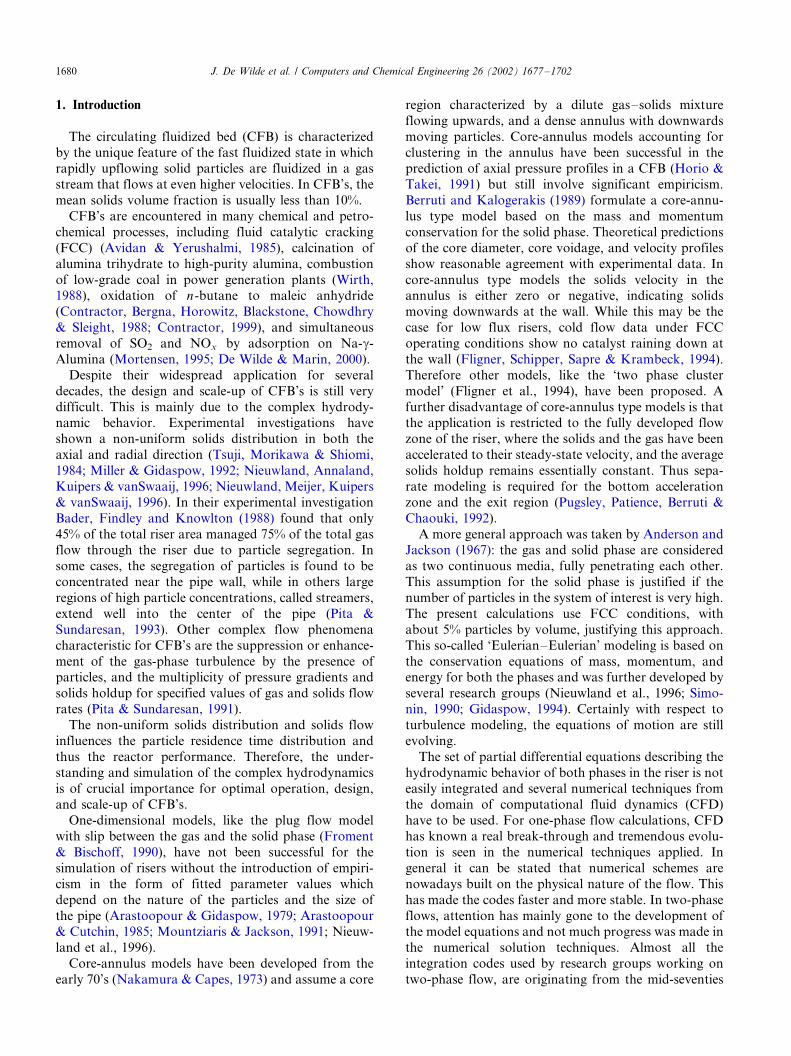
1. Introduction
The circulating fluidized bed (CFB) is characterized
by the unique feature of the fast fluidized state in whichrapidly upflowing solid particles are fluidized in a gas
stream that flows at even higher velocities. In CFB’s, the
mean solids volume fraction is usually less than 10%.
CFB’s are encountered in many chemical and petro-
chemical processes, including fluid catalytic cracking
(FCC) (Avidan & Yerushalmi, 1985), calcination of
alumina trihydrate to high-purity alumina, combustion
of low-grade coal in power generation plants (Wirth,1988), oxidation of n-butane to maleic anhydride
(Contractor, Bergna, Horowitz, Blackstone, Chowdhry
& Sleight, 1988; Contractor, 1999), and simultaneous
removal of SO2 and NOx by adsorption on Na-g-
Alumina (Mortensen, 1995; De Wilde & Marin, 2000).
Despite their widespread application for several
decades, the design and scale-up of CFB’s is still very
difficult. This is mainly due to the complex hydrody-namic behavior. Experimental investigations have
shown a non-uniform solids distribution in both the
axial and radial direction (Tsuji, Morikawa & Shiomi,
1984; Miller & Gidaspow, 1992; Nieuwland, Annaland,
Kuipers & vanSwaaij, 1996; Nieuwland, Meijer, Kuipers
& vanSwaaij, 1996). In their experimental investigation
Bader, Findley and Knowlton (1988) found that only
45% of the total riser area managed 75% of the total gasflow through the riser due to particle segregation. In
some cases, the segregation of particles is found to be
concentrated near the pipe wall, while in others large
regions of high particle concentrations, called streamers,
extend well into the center of the pipe (Pita &
Sundaresan, 1993). Other complex flow phenomena
characteristic for CFB’s are the suppression or enhance-
ment of the gas-phase turbulence by the presence ofparticles, and the multiplicity of pressure gradients and
solids holdup for specified values of gas and solids flow
rates (Pita & Sundaresan, 1991).
The non-uniform solids distribution and solids flow
influences the particle residence time distribution and
thus the reactor performance. Therefore, the under-
standing and simulation of the complex hydrodynamics
is of crucial importance for optimal operation, design,and scale-up of CFB’s.
One-dimensional models, like the plug flow model
with slip between the gas and the solid phase (Froment
& Bischoff, 1990), have not been successful for the
simulation of risers without the introduction of empiri-
cism in the form of fitted parameter values which
depend on the nature of the particles and the size of
the pipe (Arastoopour & Gidaspow, 1979; Arastoopour& Cutchin, 1985; Mountziaris & Jackson, 1991; Nieuw-
land et al., 1996).
Core-annulus models have been developed from the
early 70’s (Nakamura & Capes, 1973) and assume a core
region characterized by a dilute gas�/solids mixture
flowing upwards, and a dense annulus with downwards
moving particles. Core-annulus models accounting for
clustering in the annulus have been successful in theprediction of axial pressure profiles in a CFB (Horio &
Takei, 1991) but still involve significant empiricism.
Berruti and Kalogerakis (1989) formulate a core-annu-
lus type model based on the mass and momentum
conservation for the solid phase. Theoretical predictions
of the core diameter, core voidage, and velocity profiles
show reasonable agreement with experimental data. In
core-annulus type models the solids velocity in theannulus is either zero or negative, indicating solids
moving downwards at the wall. While this may be the
case for low flux risers, cold flow data under FCC
operating conditions show no catalyst raining down at
the wall (Fligner, Schipper, Sapre & Krambeck, 1994).
Therefore other models, like the ‘two phase cluster
model’ (Fligner et al., 1994), have been proposed. A
further disadvantage of core-annulus type models is thatthe application is restricted to the fully developed flow
zone of the riser, where the solids and the gas have been
accelerated to their steady-state velocity, and the average
solids holdup remains essentially constant. Thus sepa-
rate modeling is required for the bottom acceleration
zone and the exit region (Pugsley, Patience, Berruti &
Chaouki, 1992).
A more general approach was taken by Anderson andJackson (1967): the gas and solid phase are considered
as two continuous media, fully penetrating each other.
This assumption for the solid phase is justified if the
number of particles in the system of interest is very high.
The present calculations use FCC conditions, with
about 5% particles by volume, justifying this approach.
This so-called ‘Eulerian�/Eulerian’ modeling is based on
the conservation equations of mass, momentum, andenergy for both the phases and was further developed by
several research groups (Nieuwland et al., 1996; Simo-
nin, 1990; Gidaspow, 1994). Certainly with respect to
turbulence modeling, the equations of motion are still
evolving.
The set of partial differential equations describing the
hydrodynamic behavior of both phases in the riser is not
easily integrated and several numerical techniques fromthe domain of computational fluid dynamics (CFD)
have to be used. For one-phase flow calculations, CFD
has known a real break-through and tremendous evolu-
tion is seen in the numerical techniques applied. In
general it can be stated that numerical schemes are
nowadays built on the physical nature of the flow. This
has made the codes faster and more stable. In two-phase
flows, attention has mainly gone to the development ofthe model equations and not much progress was made in
the numerical solution techniques. Almost all the
integration codes used by research groups working on
two-phase flow, are originating from the mid-seventies
J. De Wilde et al. / Computers and Chemical Engineering 26 (2002) 1677�/17021680

(Patankar & Spalding, 1972; Harlow & Amsden, 1975;
Rivard & Torrey, 1977, 1979) and are pressure-based
and using a staggered grid. In this work, a density-based
integration method is developed and recent numerical
techniques used in one-phase flow calculations are
introduced, to enhance the solution accuracy, the
numerical stability, and the convergence speed.
2. Two-fluid model
The gas and solid phase are considered as two
continuous media, fully penetrating each other (Ander-
son & Jackson, 1967). This assumption for the solid
phase is justified for the present calculations, as the
number of particles in the system of interest is high
Table 1
Conservation equations
J. De Wilde et al. / Computers and Chemical Engineering 26 (2002) 1677�/1702 1681

enough (about 5% particles by volume). The so-called
‘Eulerian�/Eulerian’ modeling is based on the conserva-
tion equations of mass, momentum, and energy for both
the phases and was further developed by several
research groups (Nieuwland et al., 1996; Simonin,
1990; Gidaspow, 1994). Within the solid phase, stress
is transmitted by forces exerted at points of mutual
contact between the particles. The solid phase shear
stress is usually written in a Newtonian form, introdu-
cing a solid phase pressure and solid phase viscosity.
These closure terms can be calculated either on an
empirical base (Tsuo & Gidaspow, 1990; Sun &
Gidaspow, 1999) or by introducing the kinetic theory
of granular flow (KTGF) (Haff, 1983; Jenkins & Savage,
1983; Lun, Savage, Jeffrey & Chepurniy, 1984; Johnson
& Jackson, 1987; Sinclair & Jackson, 1989). In the
KTGF, the collisions between the particles are seen as
interactions of the fluctuating and the mean motion of
the particles. The solid phase pressure and viscosity are
thus directly related to the solid phase turbulence,
commonly quantified by the granular temperature. A
transport equation for the solid phase turbulence is
derived through the KTGF and solved simultaneously
with the mass, momentum, and energy conservation
equations. In the present calculations, the solid phase
temperature is assumed to equal the gas phase tempera-
Table 2
Constitutive equations
J. De Wilde et al. / Computers and Chemical Engineering 26 (2002) 1677�/17021682
ture. As a result, no solid phase total energy equations is
to be solved.
The gas phase turbulent viscosity is estimated follow-
ing the Prandtl�/Kolmogorov relation. A two-equationk �/o model modified for gas�/solids interactions is used
for the calculation of the gas phase turbulent kinetic
energy and dissipation. The k �/o model (Laundar &
Spalding, 1974) has been successfully used in one-phase
flow predictions, reason for attempting to extend this
model to a multi-phase environment. Simulations were
carried out to investigate the importance of the gas
phase turbulence.In this work it was tried to include the mutual
influence of gas�/solids turbulence by gas�/solids drag.
Due to the gas�/solids turbulence correlation, enhance-
ment of the gas�/solids turbulence by gas�/solids drag is
possible. Louge, Mastorakos and Jenkins (1991) were
the first to investigate the influence of the gas phase
turbulence on dilute gas�/solids flow, using a one
equation closure model for the gas phase turbulence.For the gas�/solids turbulence correlation these authors
proposed an algebraic expression based on the func-
tional form by Koch (1990) for a dilute gas�/solids
suspension at very low particle Reynolds number,
extended to higher particle Reynolds numbers. He and
Simonin (1990), Simonin, Deutsch and Minier (1993)
calculated the value of the gas�/solids turbulence corre-
lation from an additional semi-empirical transportequation, an approach adopted in this work. The
covariance tensor components are computed with the
help of the eddy viscosity concept (Simonin, 1990, 1996).
The fluid�/particle turbulent viscosity is written in terms
of the fluid�/particle velocity covariance and an eddy�/
particle interaction time. The transport equation for the
gas�/solid turbulence covariance is derived from the
fluid Langevin equation (Simonin, 1990) and theparticle dynamic equation (accounting only for the
drag force) after cross-multiplication by the velocity
fluctuations (Simonin et al., 1993). The fluid�/particle
covariance equation is written in an approximate form
which underlines the particulate transport. On the left-
hand side (LHS) of the Eq. (11), the first term is the
time-dependent term and the second term models the
convective transport. The first term on the right-handside (RHS) of the equation models the transport of the
covariance by the velocity fluctuations. The next four
terms represent the production by the mean velocity
gradients. The last but one term on the RHS accounts
for the destruction rate due to viscous action in the
continuous phase and the loss of correlation by cross-
ing-trajectory effects. The last term represents the
influence of the turbulent momentum transfer betweenthe phases due to drag.
For the calculation of the inter-phase total energy
transport by drag, appearing in the gas phase total
energy equation, it is assumed that the contact plane
between the phases has a velocity equal to the mean
velocity of the two phases.
Table 1 shows all the conservation equations in-
volved. The model parameter values used for thecalculations are found in De Wilde (2001). The con-
stitutive equations (Nieuwland et al., 1996; Nieuwland,
1995) are presented in Table 2 (De Wilde, 2001). The
physical properties of the solid phase result from
particle�/particle collisions caused by the solid phase
turbulence. The expression for the solid phase viscosity
and for the conductivity of the solid phase turbulence
consists of a collisional and a kinetic part. The solid�/
solid interaction is indeed determined by the number of
collisions and by the intensity of a collision. The latter
depends on the mean free path of the particles and
becomes dominant for low particle concentrations.
The inter-phase momentum transfer coefficient b is
modeled as in Gidaspow (1994), Ferschneider and Mege
(1996). For dense regimes (ogB/0.80), b is calculated
using the Ergun-equation. In dilute regimes (og]/0.80),b is determined using the correlation of Wen and Yu
(1966).
The turbulent viscosity for the correlation tensor
between the fluctuating velocities of the two phases
(n12t ) is calculated as in Csanady (1963), Simonin (1990,
1996).
The presented model has been developed and used by
many other two-phase research groups (Simonin, 1990;Nieuwland et al., 1996) but is certainly to be taken with
precaution. Indeed the model still shows several short-
comings and the equations of motion for gas�/solid flow
and even for simple gas flow are still evolving, certainly
with respect to turbulence modeling (Agrawal, Loezos,
Syamlal & Sundaresan, 2001; Zhang & VanderHeyden,
2001).
3. Boundary conditions
Boundary conditions have to be imposed at the inlets,
outlets, and solid bounding walls of the domain.
Following the eigenvalue analysis (De Wilde, Heyn-
derickx & Marin, 1999), all variables except the gas
phase pressure should be prescribed at the inlets. The
gas phase pressure is prescribed at the outlets.For the gas phase the no-slip condition at solid walls
is applied. The behavior of the gas velocity in the
vicinity of a solid wall is rather complex (Schlichting,
1979; Rodi, 1987). Calculation of the near wall behavior
is possible but demands a lot of extra grid points. In
order to avoid an exponential rise of CPU-time, use is
made of wall functions to calculate the effect of the solid
wall on the bulk flow at this stage of the modeling.Wall functions are applied to the grid point in the
immediate vicinity of the wall. This grid point has to be
positioned in the full turbulent zone at a distance y��/
J. De Wilde et al. / Computers and Chemical Engineering 26 (2002) 1677�/1702 1683

y1ut /n (ut see Eq. (31)) between 30 and 100. This means
that the external grid points are not positioned at the
wall itself, but at a certain distance.
Wall functions for pure gas flow are applied.Although it is expected that the gas flow field near the
wall will be modified by the presence of solid particles,
no accurate model is available yet.
The value of the wall shear force is calculated from
the well known logarithmic law (Hinze, 1959):
u
ut
�1
kln
�y1ut
nE
�with ut�
ffiffiffiffiffitw
rg
s(31)
Assuming a value y� of 50 results in:
ut�u
(1=k)ln[50E](32)
The k �/o model used in the bulk flow (Fox, 1996) is
not valid in the immediate vicinity of the wall. The gas
phase turbulence variables near the solid wall are
calculated from:
k�u2tffiffiffiffiffiffiCm
p
o�u4t
50kn�
u3t
ky1
(33)
These wall functions do not take into accountinteractions with the solid particles yet. It is assumed
that the particles will disturb the viscous sublayer of the
gas, but this topic still needs a lot of research.
For the solid phase it is also assumed that the mean
flow in the vicinity of the wall is parallel to the wall.
Sinclair and Jackson (1989) calculate the value of the
specific shear stress as:
sw��osms
@nT
@r jw
�f?
ffiffiffi3
pprsposU
1=2i nTi
6osmax[1 � (os=osmax
)1=3](34)
The flux of pseudothermal energy to the wall is
calculated as (Sinclair & Jackson, 1989):
qpU��osk@U
@r�gw�n � sw (35)
In this equation gw is the dissipation of solid phase
turbulent energy due to inelastic collisions between
particles and the wall. The last term models generation
of pseudothermal energy by slip.
The dissipation of solid phase turbulent energy at the
solid wall is modeled as:
gw�
ffiffiffi3
pposrspU
3=2i (1 � e2
w)
4osmax[1 � (os=osmax
)1=3](36)
The gas�/solid turbulence covariance in the vicinity of
the wall is calculated following the formula of Louge et
al. (1991). This approach is only valid for very dilute
particle flow (og�/0.995), somewhat lower than the
expected particle concentration range in our calcula-
tions.
q12�4
p0:5�dp(u � v)2
T12U0:5
(37)
Introducing:
T12�4dprsp
3Ccdsrg½
ffiffiffiffiffiffi2k
p�
ffiffiffiffiffiffiffi3U
p½
(38)
with:
Ccd �
24
Recp
(1�0:15Rec0:687
p ) (39)
valid in the range:
0BRecpB800 : Rec
p�½
ffiffiffiffiffiffi2k
p�
ffiffiffiffiffiffiffi3U
p½ogrgdpfs
mg
(40)
The solid wall does not perform any work. Further-more, it is assumed that the solid wall is adiabatic. Thus
there is no contribution of the solid wall in the
discretized total energy equation of the gas phase.
4. Computational method
Most algorithms for incompressible or low speed flow
and for two-phase flow are pressure-based, which
essentially means that the equations are solved sequen-
tially (Patankar & Spalding, 1972; Harlow & Amsden,
1975; Rivard & Torrey, 1977, 1979). Thus, the pressure
and the velocity field are solved iteratively in a
segregated manner, introducing an additional iteration
loop. For two-phase flow calculations, usually heavyunder-relaxation is imposed and a staggered grid
approach is taken (Harlow & Amsden, 1975; Rivard &
Torrey, 1977, 1979).
In the past years, density based methods are extended
towards low Mach number flows with the precondition-
ing technique (Weiss & Smith, 1995; Liou & Steffen,
1993; Liou & Edwards, 1999), which shows promising
results. In density based methods all the equations aresolved simultaneously, eliminating the pressure�/velocity
correction loop. We extended this method for two-phase
flow (Liou, 2001).
4.1. Preconditioning
To reduce the stiffness of the set of equations due tothe low-Mach gas flow, preconditioning is applied to the
gas phase equations. The preconditioner used in this
work is based on the preconditioner of Weiss and Smith
J. De Wilde et al. / Computers and Chemical Engineering 26 (2002) 1677�/17021684

(1995). However, some modifications for the presence of
the solid phase have been introduced.
The derivation of the preconditioning matrix begins
by defining the transformation matrix @Q=@W: The
vector Q of the conservative variables is:
The matrix W of the primitive variables is:
WT�(og P vx vy vz ux uy uz T U
k o q12) (42)
The transformation matrix is:
(43)
with:
K1�@rg
@P jT
�rg
P
K2�@rg
@T jP
��rg
T
C1�og
���Eg�
P
rg
�K2
��rgCP
�(44)
The preconditioning matrix in terms of the primitive
variables is obtained by replacing K1 by T1 (Weiss &
Smith, 1995):
G ˜W�
@Q
@W(K1 l T1) (45)
with:
T1��
1
u2ref
�1
CP � T
�(46)
and:
uref � ½u½�2(mg � mtur
g )
�1
Dx�
1
Dy�
1
Dz
�rg
if ½u½Bcg
cg if ½u½�cg
(47)
QT�
osrsp ogrg osrspvx osrspvy osrspvz ogrgux ogrguy
� ogrguz ogrgEg
3
2osrspU ogrgk ogrgo osrspq12
264
375 (41)
J. De Wilde et al. / Computers and Chemical Engineering 26 (2002) 1677�/1702 1685

The form of Eq. (47) ensures that as uref approaches
cg, T1 reduces to g /cg2.
In contrast with Weiss and Smith (1995), in this work
the conservative variables were chosen as the dependentvariables. The preconditioning matrix in terms of the
conservative variables is obtained by back-transforma-
tion:
GQ�GW ��@Q
@W
��1
(48)
It was experienced that the preconditioner obtained
this way does not perform well. The convergence
problems were solved by setting the off-diagonal ele-
ments in the first column of both the matrix @Q=@W
and GW equal to zero. For the solid phase equations, the
elements in the first column of the preconditioner (45),
describing the dependence on the solids volume fraction,
are very large compared with the other values in thatmatrix. This is due to the fact that, in these matrix
elements, the large solid phase density values are no
longer compensated for by the small solid volume
fraction values. Thus, the diagonal dominance of the
system is disturbed. Therefore, in the definition of the
preconditioner, not the full Jacobian is considered and,
except for the solid phase mass balance, the partial
derivatives towards the solids volume fraction areneglected. This implies a decoupling of the gas phase
and the solid phase. Preconditioning is then restricted to
the gas phase, for which it was initially developed.
Remark that the speed of sound is not directly appear-
ing in the elements set to zero (see Eq. (43)). Further-
more, not considering these elements will not affect the
solution because the preconditioning matrix is in the
LHS of the equation to be solved (see paragraph onSection 4.6).
4.2. Spatial discretisation
A finite volume cell centered approach is taken.
Application of the divergence theorema results in:
gVi
9 � f dV �gSi
f � n dS (49)
The surface integral is discretized and an ordinary
summation of fluxes is obtained.
4.2.1. Inviscid fluxes
The inviscid fluxes are treated following an extension
of the preconditioned advection upstream splitting
method (AUSMP) from single phase to multiphase
flow. For each phase, the inviscid fluxes are split intoconvective terms and acoustic flux terms. Convective
flux terms at a cell interface are treated upwind
following the value of the advective velocity at the cell
interface.
�f(c)
g=s n�ii?�fg=s
i=i?(sg=s n)ii?�f
g=s
i=i?sg=snii?
�fg=s
i=i?cgnum=s
ii? Mg=snii?
(50)
with:
fi=i?�fi if Mnii?
]0
fi? if Mnii?B0
(51)
Liou and Edwards (1999) have clearly shown the
improvements of AUSM-family schemes compared with
the flux difference splitting (FDS) and flux vector
splitting (FVS) methods. A distinct feature of the
AUSM-schemes is the formulation of the fluxes in terms
of a Mach number. This allows an easy generalization to
both low Mach number and multiphase applications.Remark that, as a result of the preconditioning, for
the gas phase, the numerical speed of sound cgnum
ii? is to be
used in the formulation Eq. (50) (Liou & Edwards,
1999). The new numerical speed of sound at the cell
interface ii? is calculated according to:
cnumii? �c
gii?
ffiffiffiffiffiffiffiffiffiffiffiffiffiffiffiffiffiffiffiffiffiffiffiffiffiffiffiffiffiffiffiffiffiffiffiffiffiffiffiffiffiffiffiffiffiffiffiffiffiffiffiffiffiffiffiffiffiffiffi4M2
refii?� (Mg
nii?)2(1 � M2
ref ii?)2
q1 � M2
ref ii?
(52)
The calculation of the numerical speed of sound at the
cell interface ii? cii?num requires the knowledge of (Mn
ii?
g)2
and Mrefii?
2 which are obtained as follows:
M refi �
urefi
cgii?
M refi? �
urefi?
cgii?
9>>>=>>>;[M2
ref ii?�
(M refi )2 � (Mref
i? )2
2(53)
Mgni�uinii?=c
gii?
Mgni?�ui?nii?=c
gii?
�[(Mg
nii?)2�
(Mgni
)2 � (Mgni?
)2
2(54)
and:
cgii?�
cgi � c
gi?
2(55)
A general formulation for the cell interface advective
velocity, for both subsonic and supersonic flow of gas
and solid phase, combines the wave speeds travellingtowards the cell interface ii? from the adjacent cells. This
is formally written by combining the contributions from
the grid points i and a neighbor i? (Liou & Steffen,
1993):
Mnii?�M ii?
ni�M i?i
ni(56)
A superscript jk stands for movement starting from
grid point j towards grid point k .
The advective velocity for both phases is calculated
applying the Van Leer splitting (Van Leer, 1982).For Mach numbers smaller than 1, the Van Leer
splitting in the external normal direction to the interface
ii? is:
J. De Wilde et al. / Computers and Chemical Engineering 26 (2002) 1677�/17021686

MachB1
M ii?ni��
1
4(Mni
�1)2
Mi?ini?��
1
4(Mni?
�1)2
(57)
For Mach numbers exceeding 1 or equal to 1, the Van
Leer splitting in the external normal direction to the
interface ii? is:
Mach]1
M ii?ni�
1
2(Mni
� ½Mni½)
Mi?in i?�
1
2(Mni?
� ½Mni?½)
(58)
where:
Mni�Mi � nii? Mni?
�Mi? � nii? (59)
As preconditioning is applied to the gas phase, Mgni
is
to be replaced by a newly defined Mnumn
i
and Mgni?
by˜Mnum
ni?in Equations (57) and (58).
˜Mnumni
�[(1 � M2
ref ii?)Mnum
ni� (1 � M2
ref ii?)Mnum
ni?]
2(60)
˜Mnumni?
�[(1 � M2
ref ii?)Mnum
ni?� (1 � M2
ref ii?)Mnum
ni]
2(61)
with:
Mnumni
�ui � nii?
cnumii?
(62)
Mnumni?
�ui? � nii?
cnumii?
(63)
For the formulation of ˜Mnumni
and ˜Mnumni?
reference is
made to Liou and Edwards (1999).
For each phase, the pressure terms at the cell interface
ii? can be written as:
Pg=sii?�Pii?
g=si�Pi?i
g=si?(64)
The superscript jk indicates information travelling
from j towards k .The acoustic flux terms are governed by the acoustic
wave speeds and the pressure splitting is weighted using
the polynomial expansion of the characteristic speeds.
The simplest first order form is:
½Mg=snii?
½B1
Pii?g=si
�Pg=si
2(1�Mg=s
nii?)
Pi?ig=si?
�Pg=si?
2(1�Mg=s
nii?)
(65)
½Mg=snii?
½]1
Pii?g=si
�Pg=si
2
�1�
Mg=snii?
½Mg=snii?
½
�
Pi?ig=si?
�Pg=si?
2
�1�
Mg=snii?
½Mg=snii?
½
� (66)
It can easily be seen that the pressure splitting is
nearly central for low Mach numbers. Therefore,
artificial dissipation should be added to the massbalances and to the total energy equations (Vierendeels,
Riemslagh & Dick, 1999). As in gas�/solid flow the
pressure drop in the tube is mainly due to hydrostatic
effect, i.e. the weight of the gas�/solid mixture in the
gravitational field, the artificial dissipation in terms of a
pressure difference is distributed over both phases,
following the weight fraction of both phases in the
mixture (De Wilde, 2001). Thus the artificial dissipationresults in following contributions to:
. solid phase mass balance:
Xcell interfaces
�dad
�osrsp
ogrg � osrsp
�ii?
(Pi? � Pi)
bn
� Dt � Sii?
Vi
�(67)
Fig. 1. Integration scheme for the flow field calculation based on
pseudo-time stepping coupled to a fourth order Runge�/Kutta scheme.
J. De Wilde et al. / Computers and Chemical Engineering 26 (2002) 1677�/1702 1687

. gas phase mass balance:
Xcell interfaces
�dad
�ogrg
ogrg � osrsp
�ii?
(Pi? � Pi)
bn
� Dt � Sii?
Vi
�(68)
. gas phase total energy equation:
Xcell interfaces
�dad
�osrg
ogrg � osrsp
�ii?
Hgii?(Pi? � Pi)
bn
� Dt � Sii?
Vi
�(69)
with: wr� ½umax½ the maximum convective speed in the
flow field; dad�/0.5 a parameter that can be chosen;Hg�/Eg�/P /rg the enthalpy;
Hgii?�
(Hgi � H
gi?)
2(70)
½ii?½�ffiffiffiffiffiffiffiffiffiffiffiffiffiffiffiffiffiffiffiffiffiffiffiffiffiffiffiffiffiffiffiffiffiffiffiffiffiffiffiffiffiffiffiffiffiffiffiffiffiffiffiffiffiffiffiffiffiffiffiffiffiffiffiffiffiffiffi(xi?�xi)
2�(yi?�yi)2�(zi?�zi)
2
q
the distance between two points;
bn� ½wr½�2(mgii?
� mturgii?
)
rgii?
+ ½ii?½
for convective and viscous contribution, respectively.
4.2.2. Viscous fluxes
The viscous fluxes are calculated following a central
scheme. For complex geometrical structures, it is not
possible to find direct information about the gradientsin the x -, y -, and z -directions. This requires the
introduction of a local complete set of directions (j ,
h , z ) at every cell interface, such that information about
the gradients in these local directions is present in the
grid (Steelant & Dick, 1994). The j direction is chosen
normal to the cell interface and is the only direction in
which the gradient depends only on information from i
and i?. The h and z directions are chosen in the cellinterface and the gradients in these directions depend
also on information from non-neighboring grid points
(De Wilde, 2001). A coordinate transformation results
in the gradients in the x -, y-, and z -directions.
@F
@j
@F
@h
@F
@z
0BBBBBBBB@
1CCCCCCCCA�
@x
@j
@y
@j
@z
@j
@x
@h
@y
@h
@z
@h
@x
@z
@y
@z
@z
@z
0BBBBBBBB@
1CCCCCCCCA
�
@F
@x
@F
@y
@F
@z
0BBBBBBBB@
1CCCCCCCCA
(71)
4.3. Treatment of the source terms
Source terms occur in the Navier�/Stokes and in the
turbulence equations as a result of gas�/solid interac-
tions and of gravity. The turbulence equations contain
extra turbulence source terms.
The source terms are split into a positive and anegative part. The negative part is taken into account at
the iteration level (n�/1), the positive part at level (n)
(Steelant & Dick, 1994). Next, linearization of the
negative part is performed:
S�S�(n)�S�(n�1)
�S�(n)�S�(n)�@S�
@Q� (Q(n�1)�Q(n)) (72)
The separate treatment of the positive and the
negative part of the source terms, allows to increase
the diagonal dominance of the LHS matrix.
4.4. Relaxation method
For the integration in time and space, a dual time
stepping method and a finite volume technique are used,
respectively. The integration scheme is based on semi-
implicit pseudo-time stepping. A numerical stepper, thepseudo-time, is introduced for the solution of the non-
steady state problem:
@Q
@t�spatial terms 0
@Q
@t�
@Q
@t�spatial terms (73)
First order backward discretisation in physical and
pseudo time is performed. Thus, for a node i , equation
(73) becomes:
Dt
Dt(Q(t�Dt)(n�1)
i �Q(t�Dt)(n)
i )�Q(t�Dt)(n�1)
i
�Q(t)i �(Dt � spatial terms) (74)
with: i � /{1, 2, . . ., nn}.
The pseudo-time t is related to the iteration number
n , as each iteration performs a pseudo-time step Dt . Aconverged solution for Q[] at a certain physical time
level is obtained when @Q /@t�/0, i.e. when the differ-
ence in the values of Q[] between iterations vanishes.
J. De Wilde et al. / Computers and Chemical Engineering 26 (2002) 1677�/17021688

Preconditioning is acting on the pseudo-time term, so
that the solution of the original equation set is not
modified.
Spatial discretisation and linearization of the con-servation equations result in the following matrix
formulation of the problem to be solved for Qtnew
[] at
each time level tnew:
a(Q[])Qtnew
[]� b(Q[]) (75)
with:
Q[]�
Q1
Q2
nQi
nQnp
0BBBBBB@
1CCCCCCA
(76)
The LHS of Eq. (75) contains all implicit information,
the RHS all explicit information. Both information from
the node i itself and information required from other
nodes i ? can be treated implicitly. Because of the non-
linearity of the equations, i.e. the fact that a(Q[]) and
b(Q[]) in Eq. (75) do depend on Q[], a solution is seeked
iteratively, starting from an initial guess. To obtain
convergence with an iterative method, it suffices that thematrix a (Eq. (75)) is diagonally dominant:
½a[j][j]½�Xnp
i�1; i"j
½a[j][i]½ (77)
This also guarantees the boundedness property for the
numerical integration scheme. To maximize the stability
of the numerical integration scheme, a point semi-
implicit approach is taken in this work. This means
that for the equations in a node i , information required
from the node i itself was treated implicitly i.e. put in the
LHS, whereas the information from the other nodes i ?required to calculate b was treated in an explicit way i.e.
put in the RHS. This reduces the matrix a(Q[]) in Eq.
(75) to a diagonal matrix:
a � DQ[]�b
with :
a�
A1
A2 0:::
Ai :::0 Anp
266666664
377777775�
::: 0D
0:::
24
35
and : DQ[i]�DQi[15�1] b[i]�Bii?i [15�1]
i � f1; 2; . . . ; nng (78)
This allows a pointwise solution of DQi for each
pseudo-time step Dt . Applying preconditioning, linear-
ization of the spatial derivative terms, and properlinearization of the source terms, finally results in the
following form of the conservation equations for each
node i :�Dt
DtG�I�Ai�
@S�
@Qt�
@K�
@Q
�(n)
(Q(t�Dt)(n�1)
i �Q(t�Dt)(n)
i )
��
Q(t)i �
Xi?
(A?i?(n)Q(t�Dt)(n)
i? �(I�A(n)i )Q(t�Dt)(n)
i
�C (n)hi�D(n)
zi�S(n)�K (n))
�(79)
The first term at the RHS of the equations resultsfrom the time dependent term (accumulation term) in
the equations. Ch and Dz contain information for the
viscous fluxes about the gradients in the local h ,
respectively, z direction. An extra superscript-index is
applied, representing the pseudo-time level of the
variables. Remark that the matrix Ai comprises a
summation over all the neighbors i?. Introducing Ai
and Bi , following simplified notation of Eq. (79) isobtained:
A(n)i DQ(t�Dt)
i �B(n)i (80)
Remark that, as in the Jacobi iteration scheme, theupdates in ALL nodes are calculated using information
on the previous iteration level before updating the
values to the new iteration level. Thus the numerical
method applied does not use the most recently available
Table 3
Simulation conditions
Case 1 Case 2 Case 3 Case 4 Case 5
�uzinb� (m s�1) 12.635
vzinb (m s�1) 6.0
Gs (kg m�2 s�1) 577.8
Uinb (m2 s�2) 20.0 20.0 0.0 20.0 0.0
e 1.0 0.995 0.995 1.0 0.995
rsp (kg m�3) 963.0
dp (mm) 60
Outlet type Straight Double abrupt
J. De Wilde et al. / Computers and Chemical Engineering 26 (2002) 1677�/1702 1689

information. Although immediate use of the calculated
updates increases the convergence speed, the stability
becomes worse.
To further increase the numerical stability, thepseudo-time stepping is combined with a fourth-order
Runge�/Kutta technique which provides some under-
relaxation.
Q0�QnRK
Q1�Q0�a1 � DQ(Q0)
Q2�Q0�a2 � DQ(Q1)
Q3�Q0�a3 � DQ(Q2)
Q4�Q0�a4 � DQ(Q3)
Qn�1RK �Q4
� (81)
Fig. 1 shows the complete integration scheme for the
calculation of the flow field. Vierendeels (1998) proposes
a1�/1/4; a2�/1/3; a3�/1/2; and a4�/1 values adopted in
this work.
5. Case studies
All calculations were performed for an industrial scale
riser with a diameter of 1.56 m and a height of 14.434 m.
Two different outlet configurations are used (Fig. 2): astraight top outlet (configuration A) and two abrupt
side outlets with a surface area of 0.955 m2 each
(configuration C). For calculations with one abrupt
side outlet, reference is made to (De Wilde, Heynder-
ickx, Vierendeels & Marin, 2001).
A structured grid is used for the calculations. The 3D
grid is built up starting from a 2D cross section of the
tube (Fig. 3, top). The latter contains about 200 nodesand 67 cross sections are positioned axially in the tube
(Fig. 3, bottom). Grid refinement can be introduced in
the bottom and top section (Fig. 3, bottom) and at solid
bounding walls. Calculations on a finer grid and a grid
independency study were not performed due to the
extremely long computation times.
Table 3 summarizes the simulation conditions for the
different case studies.
5.1. Straight tube with bottom inlet and top outlet
5.1.1. Elastic particle�/particle collisions and high
granular temperature
The simulation conditions are shown in Table 3 (Case
1). The particle�/particle collisions are assumed elastic.
The solid phase is of Geldart A type.
A steady-state solution was obtained after 70 000
min of CPU time on an IBM RS/6000 397
workstation. Fig. 4 shows the convergence history as
a function ofthe iteration number for the first1200 iterations. The residual is defined as the
maximum value of the update in the field. It is seen
that the residual initially drops fast, but then the
convergence slows down. This could be avoided
by using a line-method instead of a point-method.
Although no cylindrical symmetry was imposed,
the solution is cylindrically symmetrical. Therefore,
the results can be presented for an axial
cross section of the riser through the center of the
tube.
In the axial direction, it is seen that the bottom zone
of the riser is more dense than the fully developed top
region (Fig. 5). Remark, however, that the high inlet
solid fraction of 10% (Table 3) decreases sharply within
the first centimeters of the reactor, due to the fast
acceleration of the particles from the inlet axial velocity
of 6.0 m s�1 to the gas phase velocity of about 12.6 m
s�1 by mixing and drag. The denser bottom entrance/
developing zone reaches to a height of about 3�/4 m.
Higher in the riser, the solids volume fraction os is seen
to decrease slowly, due to the increasing axial velocity
(Fig. 6) and the required conservation of mass. In the
radial direction, segregation of the particulate phase
near the solid wall is visible (Fig. 5) and a core-annulus
type of flow pattern develops. The annulus reaches 9/10
cm from the solid wall, which is 12.8% of the tube
radius, corresponding to 9/25% of the cross sectional
surface area. The annulus usually has a thickness, which
Fig. 2. Geometrical configurations used for the simulations.
J. De Wilde et al. / Computers and Chemical Engineering 26 (2002) 1677�/17021690

is an order of magnitude smaller than the column
diameter (Lim, Zhu & Grace, 1995).
Fig. 6 shows the axial solid phase velocity vz in an
axial cross section of the riser. The linear acceleration
with height is remarkable. This acceleration is mainly
due to the expansion of the gas with height, as the
pressure decreases. In the radial direction, towards the
fully developed zone of the riser (z �/3�/4 m), a typical
turbulent velocity profile develops under the influence of
the viscous forces.
In the fully developed zone of the riser, the slip
between the gas and the solid phase is small, with values
between 0.05 and 0.1 m s�1, corresponding to the
terminal velocity of the particles (Froment & Bischoff,
1990).
To investigate the importance of the gas phase
turbulence, simulations were carried out in which the
gas phase turbulence is ignored. In the latter case, the
granular temperature drops quickly. This is due to the
drag term in the granular temperature transport equa-
tion Eq. (10). On ignoring the gas phase turbulence, the
gas�/solid turbulence correlation q12 becomes zero and
the drag term in Eq. (10) becomes a strong negative
source term. However, in the presented simulations that
take into account the gas phase turbulence, it is seen that
the gas and solid phase turbulence are very well
correlated (Fig. 7, Left Fig. 8: q12:/2k :/3U), making
the drag term in Eqs. (8) and (10) less important. Thus, a
possibility to simplify the equation set is to neglect the
drag term in the turbulence equations Eqs. (8) and (10)
(Nieuwland et al., 1996), omitting the calculation of the
gas�/solid turbulence correlation q12. Under these con-
ditions, the effect of putting the gas phase turbulence k
equal to zero on the value of the granular temperature
U is less pronounced. This should, however, be seen as a
positive result of the used k �/o �/U �/q12 model, resulting
in the prediction of good gas�/solid turbulence correla-
tion. However, in the development of the code, the gas
phase turbulence and the gas�/solid turbulence correla-
tion were not neglected because the code was intended
to run both dense and dilute cases. In the latter case, the
gas phase turbulence is believed to play a more
Fig. 3. Grid generation: * in a 2D cross section of the tube (top); *
axial positioning of the cross sections (bottom); (k: axial numbering of
the cross sections).
Fig. 4. Convergence behavior of the integration scheme. The residual is the maximum absolute value of the update of the viscous variables.
J. De Wilde et al. / Computers and Chemical Engineering 26 (2002) 1677�/1702 1691

important role. Furthermore, it was observed that even
in some dense case studies, the gas phase turbulent
viscosity cannot be neglected. Also, the gas phase and
solid phase turbulence are not necessarily well corre-
lated.
5.1.2. Inelastic particle�/particle collisions and low
granular temperature
Changing the coefficient of restitution e from 1.0 to
0.995 (Case 2 and 3, see Table 3), results in a drastic
change of the hydrodynamic behavior. This is due to the
Fig. 5. Solids volume fraction (�/). Steady-state flow field Case 1 (conditions see Table 3).
Fig. 6. Solid phase axial velocity (m s�1). Steady-state flow field Case 1 (conditions see Table 3).
Fig. 7. Granular temperature U (m2 s�2): Case 1 left, Case 2 right (conditions see Table 3).
J. De Wilde et al. / Computers and Chemical Engineering 26 (2002) 1677�/17021692

Fig. 8. Steady-state flow field Case 1 (conditions see Table 3).
Fig. 9. Time-dependent calculation of the solids volume fraction (os). Unsteady flow field Case 3 (conditions see Table 3).
J. De Wilde et al. / Computers and Chemical Engineering 26 (2002) 1677�/1702 1693

strong dissipation of the granular temperature (Fig. 7).
The strong sensitivity towards the coefficient of restitu-
tion was also observed by many other researchers (Pita
& Sundaresan, 1991, 1993; Nieuwland et al., 1996).
With a restitution coefficient of 0.995, a steady-state is
not achieved and oscillating behavior is seen. Never-
theless, the solution remains axisymmetrical. Fig. 9
shows the time-dependent behavior of the solids volume
fraction in an axial cross section of the riser. A
perturbation in the solid volume fraction is seen to
originate at the top of the riser, grows from underneath
towards the bottom of the riser and is then blown out.
Large-scale fluctuations, with dimensions ranging up to
the pipe diameter, have been described by Dasgupta,
Jackson & Sundaresan (1994). A theoretical study on
the propagation of a voidage disturbance in uniformly
fluidized beds (Needham & Merkin, 1983), predicts that
slugging behavior can occur as a result of non-linear
effects. Whereas a linearized theory predicts exponential
growth of a disturbance in case of instability, this
growth is curbed by the non-linearity. This study reveals
that under conditions for which a steady state is
unstable to small-amplitude disturbances, the bed may
restabilize into a quasisteady periodic state. This is
clearly the behavior seen in this case study.
Chen, Gibilaro and Foscolo (1999) have also reported
perturbations in the solids volume fraction to primarily
being transported vertically. These authors further
Fig. 10. Time-dependent calculation of the pressure (P ) at the center line (time as in Fig. 9). Unsteady flow field Case 3 (conditions see Table 3).
J. De Wilde et al. / Computers and Chemical Engineering 26 (2002) 1677�/17021694

reported that hydrodynamic interactions result in hor-
izontal transport of the perturbation. This phenomenon
is also seen in the present calculations.The oscillations are also found in the velocity (not
shown) and pressure fields (Fig. 10). Particle segregation
immediately causes a local increase of the pressure and
decrease of the axial velocity. Essential is the speed at
which the system reacts to correct the perturbation, in
other words the inertia of the system. It is seen that, as
the axial particle transport decreases locally, the inertia
of the system causes the particles feed not to be adapted
immediately. This results in growth of the perturbation.
As the particles are fed from the bottom and move
upwards, the zone of increased particle fraction grows
from underneath and thus shows a movement down-
ward, in the sense opposite to the convective direction.
Fig. 11. Time-dependent calculation of the granular temperature (U ) (time as in Fig. 9). Unsteady flow field Case 3 (conditions see Table 3).
Fig. 12. The solids volume fraction (os). Instantaneous flow field Case 4 (conditions see Table 3).
J. De Wilde et al. / Computers and Chemical Engineering 26 (2002) 1677�/1702 1695

Furthermore, transfer in the radial direction occurs.
This phenomenon, the so-called ‘gravity wave’, is seen to
be a pressure wave. The low propagation speed for the
pressure is typical for two-phase flow.Buyevich (1999) states that in an assemblage of
particles supported by a flowing fluid, random fluctua-
tions of the local assemblage concentration appear. As
the drag force and other constituents of the interphase
interaction force are nonlinear functions of the concen-
tration, the concentrational fluctuations induce a fluc-
tuating random force exerted by the fluid on the
particles, thus violating the balance of gravity, buoy-ancy, and drag forces. Moreover, the concentration
fluctuations bring about fluctuations in the effective
two-phase mixture density, so that an additional fluc-
tuating force arises by the action of gravity. Buyevich
(1999) further states that, in a vertical fluidized bed
supported by an upward flowing fluid, the above
mentioned fluctuating forces accelerate the particles
either upward or downward, depending on the sign ofthe concentration fluctuations, so that primarily vertical
fluctuations occur. This is clearly demonstrated from the
calculation results in the present case and was confirmed
in other calculations.
Fluctuations and instabilities in the flow field result
from the convective, the acoustic, and the source terms.
The viscous terms on the other hand, are dampening the
fluctuations. This was clearly demonstrated by Muddeand Simonin (1999), who showed that when the
turbulent viscosity is high, all oscillations are dampened
and a steady solution is obtained. When the turbulent
viscosity becomes smaller, the flow becomes transient.
Needham and Merkin (1983) have also shown that the
solid phase viscosity gives rise just to dispersive effects.
Using a simple hyperbolic model (i.e. no solids viscosity
ms), Christie, Ganser and Sanzserna (1991), Christie andPalencia (1991) have been capable of reproducing
oscillatory behavior corresponding to slugging. Need-
ham and Merkin (1983) have demonstrated that both
type of models, containing and excluding the solids
viscosity ms, can exhibit smooth transition solutions
connecting two stable states.
A theoretical study by Needham and Merkin (1983)
has clearly shown the strong stabilizing influence of thesolid phase collisional pressure on gas�/solid flow. In
fact, neglecting the particle collisional pressure, the
fluidized bed is predicted to be always unstable to small
amplitude disturbances (Murray, 1965). The study by
Needham and Merkin (1983) has also revealed that the
exponential growth of disturbances in case of instability,
as predicted by the linearized theory, is curbed by the
non-linearity. Thus, in case the fluidized bed is unstableto small-amplitude disturbances, the bed may restabilize
into a quasisteady periodic state. Here again, the solid
phase collisional pressure is seen to play an important
role. Needham and Merkin (1983) conclude that, even
when the solid phase collisional pressure is not suffi-
ciently strong to stabilize the uniform state completely,
it must still be included to give the flow the possibility of
reaching a new, quasisteady state, as it is one of the maindissipative mechanisms in the system curbing the
unbounded growth of voidage perturbations.
Earlier, Fanucci, Ness and Yen (1979) revealed the
effect of the solid phase pressure function on the
possibility of shock formation in gas�/solid fluidized
beds. As the dependence of the solid phase pressure on
the solids volume fraction increases (i.e. @Ps/@os in-
creases), in other words, as the bed becomes more‘incompressible’, there is less chance for shock forma-
tion to occur and the gas�/solid flow becomes more
stable.
Using the KTGF, the solid phase pressure is strongly
related to the value of the granular temperature (Table
2) (Gidaspow, 1994; Nieuwland, 1995):
Ps� [1�2(1�e)osg]osrspU (15)
Looking at the calculational results, it is clear that thesolid phase pressure is much higher for elastic particle�/
particle collisions than for inelastic particle�/particle
collisions, due to the granular temperature (Fig. 7).
Furthermore, from Eq. (15), a higher value of the
granular temperature U results in an increased depen-
dence of the solid phase pressure Ps to the solids volume
fraction os (i.e. @Ps/@os is higher). According to Fanucci
et al. (1979), this leads to an improved stability, asindeed seen from the calculations. In case of oscillating
flow, it is also seen that the termination of the voidage
perturbation growth (Dt�/3.2 s) (Fig. 9) coincides with a
local increase of the granular temperature (Fig. 11) and
thus a local increase of the solid phase pressure and the
dependence of the solid phase pressure to the solids
volume fraction, most pronounced at the central axis of
the tube.Srivastava, Agrawal, Sundaresan, Karri and Knowl-
ton (1998) have experimentally shown that the onset of
unstable flow in CFBs roughly coincides with conditions
where the granular stresses and wall friction become
unimportant. In view of the preceding discussion, this
seems an explainable observation. Indeed, when the
viscous terms and the solid phase pressure become
unimportant, unstable flow develops.For the frequency of the porosity and pressure
fluctuations, the value of 0.15 Hz calculated in this
work, is in good agreement with the power spectrum
diagrams reported in literature (Tsuo & Gidaspow,
1990; Gidaspow, Huilin & Therdthianwong, 1995; Liu,
Grace, Bi, Morikawa & Zhu, 1999). The fact that the
frequency is somewhat lower may be due to the higher
length of the riser simulated in this work. The frequencyof large-scale oscillations produced by gravity decreases
with increasing riser height, as seen from the basic
incompressible frequency relation equal to the square
J. De Wilde et al. / Computers and Chemical Engineering 26 (2002) 1677�/17021696

root of the gravity divided by the riser length (Sun &
Gidaspow, 1999). Applying this relation to the riser
simulated in this work, a typical oscillation frequency of
0.21 Hz should be seen, in good agreement with thecomputations.
Remark that the sensitivity towards the coefficient of
restitution for particle�/particle collisions can be ex-
plained as this parameter describes the energy dissipa-
tion resulting from one collision. As a result, the value of
the restitution coefficient has to be very accurate, which
is not the case. If many collisions take place, the energy
dissipation will follow an exponential rule. Introducinga parameter that describes the energy dissipation result-
ing from a number of collisions would reduce the
sensitivity.
Recent studies (Agrawal et al., 2001; Zheng, Wan,
Qian, Wei & Jin, 2001; Zhang & VanderHeyden, 2001,
2002) give a strong indication that the strong depen-
dency towards the coefficient of restitution e is due to
the inappropriate use of the KTGF. These studiesindicate that to obtain good results with the KTGF,
sufficient resolution is to be used, with grid sizes of only
several particle diameters. For industrial scale risers this
is impossible with the current computational resources.
If rough grids are used, sub grid corrections, accounting
for the turbulent motion of the solid phase, should be
introduced. Sub-grid models for the solid phase are still
in the early developing stage. An approach for devel-oping a sub-grid model is proposed by Agrawal et al.
(2001). Zheng et al. (2001) take into account the meso-
scale structures by using a k �/o �/kp�/op�/U model, in
which the kp�/op model is used to describe the turbulent
motion of the solid phase, whereas the KTGF is used to
take into account the collisions between the particles.
The Eulerian�/Eulerian approach and the KTGF
have, however, been used by many research groupsover the years without sub-grid scale corrections (Lun et
al., 1984; Sinclair & Jackson, 1989; Gidaspow, 1994;
Nieuwland et al., 1996), showing interesting results. The
use of the presented model allows to compare the
qualitative results and the model behavior from our
calculations with literature to get confidence in the
mathematical method implemented. The aim of the
present work is to develop a novel density-basedintegration technique for gas�/solid flow calculations
(Liou, 2001). The inclusion of a sub-grid model will only
result in changes in the constitutive equations and the
addition of some turbulence transport equations. The
mathematical treatment presented in this paper remains
valid.
5.2. Influence of the exit geometry: straight tube with
bottom inlet and two opposed abrupt side outlets
Calculations were performed making use of the
geometrical configuration with two side outlets at a
distance of 1.23 m from the top of the riser (configura-
tion C in Fig. 2). The simulation conditions are shown
in Table 3, Case 4 and 5. Both calculations with a
restitution coefficient for particle�/particle collisions
equal to 1.0 (elastic particle�/particle collisions) and
equal to 0.995 have been carried out.
There are two geometrical symmetry planes: a sym-
metry plane across the two outlets (cross section I) and
another symmetry plane between the two outlets (cross
section II) (Fig. 2). These symmetries were not imposed
and, surprisingly, are not found in the solution.
The flow structure in the top outlet region of the riser
with one recirculation eye was found to be stable. Thus,
to obtain a stable state, symmetry breaking has to take
place. This is clearly seen in Fig. 12, showing the solids
volume fraction os in cross sections I and II of the riser
and in Fig. 13 showing projections of the solid phase
velocity vectors in the same cross sections with focus on
the exit and top zone.
A symmetrical solution is not stable. Small perturba-
tions in the solids volume fraction always occur in a
gas�/solid system. In case of a stable solution, such
perturbations are dampened out and disappear, not
affecting the solution. However, if the symmetrical field
is unstable, small perturbations may cause the system to
evolve towards a stable non-symmetrical solution or to
oscillate. If a small perturbation in the solids volume
fraction occurs just beneath the outlets, the flow is
preferentially directed to one side of the riser, with
recirculation to the opposite side of the riser (Fig. 13).
Both sides have an equal probability of becoming the
preferential side. As a result, multiple solutions exist.
Switch-over during operation from one flow field to
another can take place due to large perturbations in the
riser or any other impulse in the system, as was seen in
case of inelastic particle�/particle collisions.
In the bottom and fully developed zone of the riser,
the profiles are very similar to those obtained with a
straight top outlet (Figs. 5 and 6), with only little effect
of the exit configuration seen. This is probably because
the total outlet surface area equals the horizontal riser
surface area and thus the restrictive strength of the exit
is small (Gupta & Berruti, 2000; De Wilde et al., 2001).Particle segregation is seen to occur near the solid
wall, at the external boundary of the vortex in the top
region of the riser, and where the upflow and recycle
downflow encounter (Fig. 12). The eye of the vortex
shows a low solids volume fraction, as expected from the
centrifugal effect due to the inertia of the solid phase.
In the bottom and middle part of the riser, the typical
velocity profiles develop as a result of the viscous and
the gravitational forces. As the flow approaches the
outlets, where the upflowing and downflowing recycled
suspension encounter, a zone of increased solids volume
fraction exists. As explained before, it originates from a
J. De Wilde et al. / Computers and Chemical Engineering 26 (2002) 1677�/1702 1697

perturbation. It is explained next how this zone of
increased solids volume fraction is sustained.
Since the flow resistance is higher at the side suffering
the zone of increased solids volume fraction, the flow
is directed towards the opposite side which becomes
the preferential side for outflow. The side suffering
the zone of increased solids volume fraction becomes
the recycle side. The increased flow rate at one side of
the riser lowers the probability of solids segregation
to occur at that side of the riser. This is the
first stabilization mechanism for the asymmetric solu-
tion. Another reason for sustaining the zone of
increased solids volume fraction once it is formed, is
the fact that it is positioned where the gas�/
solids suspension flowing upwards from the bottom
inlet and the recycled gas�/solids suspension
flowing downwards from the top of the riser meet.
The inertia of the solid phase then results in
retaining the zone of increased solids volume fraction
at that location. This is a second stabilization mechan-
ism for the asymmetric solution obtained in the calcula-
tions.
Comparing the radial outflow at both outlets shows
that almost equal parts of the total flow are removed
from the riser through both the outlets. Thus, the
internal asymmetry of the riser is not easily detected
externally.
For inelastic particle�/particle collisions, an oscillating
solution, as in case of a straight top outlet, was
found. The period of the oscillation is 9/5 s, which is
somewhat smaller compared with the straight tube.
This is probably due to the shorter distance between
inlet and outlet, as the outlets are situated at 12.6 m
in this case. The frequency of large-scale oscillations
produced by gravity increases with decreasing
riser height, as seen from the basic incompressible
frequency relation equal to the square root of the
gravity divided by the riser length (Sun & Gidaspow,
1999).
The flow pattern in the top exit region of the riser
is influenced by the oscillations occurring in the
middle and bottom part of the riser. Fig. 14 focuses
on the time-dependency of the flow in the top exit
region of the riser, showing the solids volume
fraction and the cross sectional projections of the
solid phase velocity in cross sections I and II of the
riser.
At any time, an increased solids volume fraction at
the top of the riser and at the external boundary of the
vortex is calculated. This is the result of the inertia of the
particles.
The flow field at Dt�/3.6 s shows that the flow is
preferentially directed towards one outlet, with recircu-
lation to the other outlet. Again it is seen that both
outlets are responsible for approximately the same
outflux, one from upflow, the other from downflow.
Thus, again, the internal asymmetry of the riser is
externally not easily detected.
In the next 1.3 s, the orientation of the central vortex
is seen to turn from axial cross section I towards axial
cross section II (Fig. 14). This spiraling motion is
believed to persist in combination with the oscillation
in the middle and bottom section of the riser. The flow
field at Dt�/4.9 s is seen to be symmetrical in cross
section I.
Fig. 13. The cross sectional projection of the solids velocity (/v) (m s�1). Instantaneous flow field Case 4 (conditions see Table 3).
J. De Wilde et al. / Computers and Chemical Engineering 26 (2002) 1677�/17021698

Fig. 14. The solids volume fraction (os) (color) and the cross sectional projection of the solids velocity (/v) (m s�1). Time-dependent calculation Case 5
(conditions see Table 3).
J. De Wilde et al. / Computers and Chemical Engineering 26 (2002) 1677�/1702 1699

6. Conclusions
A novel integration scheme is developed for the
calculation of gas�/solid flow in circulating fluidizedbeds with the Eulerian�/Eulerian approach. The integra-
tion scheme is based on dual time stepping and a finite
volume technique. The advection upstream splitting
method AUSM is extended to two-phase flows. Pre-
conditioning is applied to accelerate the convergence.
Calculations on a simple straight tube geometry show
that the model behavior, reported in literature, is well
calculated. In particular with respect to the influence ofinelastic particle�/particle collisions, it is shown that the
latter result in a fluctuating flow field.
Calculations with a double abrupt side outlet config-
uration show that the geometrical symmetries are not
always followed by the flow field. Symmetry breaking
occurs, resulting in a stable asymmetric solution.
Acknowledgements
This work was financed by the European Commission
within the frame of the Non-Nuclear Energy Program,
Joule III project under contract JOF3-CT95-0012 and
Thermie project under contract no SF 243/98 DK/BE/
UK (project partners: Laboratorium voor Petrochem-
ische Techniek-Universiteit Gent, FLS miljo a/s-Den-
mark & Howden Air & Gas Division, UK). Geraldine
Heynderickx and Guy Marin are grateful to the ‘Fondsvoor Wetenschappelijk Onderzoek-Vlaanderen’ (FWO-
N) for financial support of the CFD Research. Ger-
aldine Heynderickx and Guy Marin are grateful to the
‘Bijzonder Onderzoeksfonds’ BOF-RUG for financial
support of the gas�/solid two-phase flow research.
References
Agrawal, K., Loezos, P. N., Syamlal, M. & Sundaresan, S. (2001). The
role of meso-scale structures in rapid gas�/solid flows. Journal of
Fluid Mechanics 445 , 151.
Anderson, T. & Jackson, R. (1967). A fluid mechanical description of
fluidized beds. Industrial Engineering and Chemical Fundamentals
6 , 527.
Arastoopour, H. & Gidaspow, D. (1979). Vertical pneumatic convey-
ing using 4 hydrodynamic models. Industrial Engineering and
Chemical Fundamentals 18 (2), 123.
Arastoopour, H. & Cutchin, J. H. (1985). Measurement and analysis
of particle�/particle interaction in a concurrent flow of particles in a
dilute gas�/solid system. Chemical Engineering and Sciences 40 (7),
1135.
Avidan, A. & Yerushalmi, J. (1985). Solids mixing in an expanded top
fluid bed. American Institute of Chemical Engineering Journal 31
(5), 835.
Bader, R., Findley, J. & Knowlton, T. M. (1988). Gas/solids flow
patterns in a 30.5-cm-diameter circulating fluidized bed. In P. Basu
& J. F. Large (Eds.), Circulating fluidized bed technology II , p. 123).
Toronto: Pergamon Press.
Berruti, F. & Kalogerakis, N. (1989). Modeling the internal flow
structure of circulating fluidized-beds. Canadian Journal of Chemi-
cal Engineering 67 (6), 1010.
Buyevich, Y. A. (1999). Particulate stresses in dense disperse flow.
Industrial Engineering and Chemical Research 38 (3), 731.
Chen, Z., Gibilaro, L. G. & Foscolo, P. U. (1999). Two-dimensional
voidage waves in fluidized beds. Industrial Engineering and
Chemical Research 38 (3), 610.
Christie, I. & Palencia, C. (1991). An exact Riemann solver for a
fluidized-bed model. IMA Journal of Numerical Analysis 11 (4),
493.
Christie, I., Ganser, G. H. & Sanzserna, J. M. (1991). Numerical-
solution of a hyperbolic system of conservation-laws with source
term arising in a fluidized-bed model. Journal of Computer and
Physics 93 (2), 297.
Contractor, R. M. (1999). Dupont’s CFB technology for maleic
anhydride. Chemical Engineering and Sciences 54 (22), 5627.
Contractor, R. M., Bergna, H. E., Horowitz, H. S., Blackstone, C. M.,
Chowdhry, U. & Sleight, A. W. (1988). Butane oxidation to maleic
anhydride in a recirculating solids reactor. In J. W. Ward (Ed.),
Catalysis , p. 645). Elsevier.
Csanady, G. T. (1963). Turbulent diffusion of heavy particles in the
atmosphere. Journal of Atomic Science 20 , 201.
Dasgupta, S., Jackson, R. & Sundaresan, S. (1994). Turbulent gas�/
particle flow in vertical risers. American Institute of Chemical
Engineering Journal 40 (2), 215.
De Wilde, J. (2001). Adsorption of SO2 and NOx in a riser: kinetics
and 3D gas�/solid hydrodynamics. Ph.D. Dissertation , Gent,
Belgium: Ghent University.
De Wilde, J. & Marin, G. B. (2000). Investigation of simultaneous
adsorption of SO2 and NOx on Na�/g-Al2O3 with transient
techniques. Catalysis Today 62 (4), 321.
De Wilde, J., Heynderickx, G.H., Marin, G.B. (1999). 3D simulation
of circulating fluidized bed reactors, Fluidization and fluid�/particle
systems (p. 119), AIChE, Annual Meeting, Dallas, TX, USA.
De Wilde, J., Heynderickx, G.J., Vierendeels, J., Marin, G.B. (2001).
3D flow patterns in circulating fluidized bed reactors: effect of T-
outlet. Proceedings, United Engineering Foundation*/Chemical
Reactor Engineering (CRE) VIII conference, June 23�/29, 2001,
Barga, Italy.
Fanucci, J. B., Ness, N. & Yen, R. H. (1979). Formation of bubbles in
gas�/particulate fluidized-beds. Journal of Fluid Mechanics 94 , 353.
Ferschneider, G. & Mege, P. (1996). Eulerian simulation of dense
phase fluidized beds. Revista I. Francaise Petrol 51 (2), 301.
Fligner, M., Schipper, P. H., Sapre, A. V. & Krambeck, F. J. (1994).
Two phase cluster model in riser reactors: impact of radial density
distribution on yields. Chemical Engineering and Sciences 49 (24B),
5813.
Fox, R. O. (1996). Computational methods for turbulent reacting
flows in the chemical process industry. Revista I. Francaise Petrol
51 (2), 215.
Froment, G.F., Bischoff, K.B. (1990). Chemical reactor analysis and
design (2nd ed.). Wiley Series in Chemical Engineering.
Gidaspow, D. (1994). Multiphase flow and fluidization: continuum and
kinetic theory descriptions . Academic Press.
Gidaspow, D., Huilin, L., Therdthianwong, A. (1995). Measurement
and computation of turbulence in a circulating fluidized bed.
International Fluidization Conference , Tours, France.
Gupta, S.K., Berruti, F. (2000). Evaluation of the gas�/solid suspen-
sion density in CFB risers with exit effects, Powder Technology , 108
(1), 1, 21.
Haff, P. K. (1983). Grain flow as a fluid-mechanical phenomenon.
Journal of Fluid Mechanics 134 , 401.
Harlow, F. H. & Amsden, A. A. (1975). Numerical-calculation of
multiphase fluid-flow. Journal of Computer and Physics 17 (1), 19.
J. De Wilde et al. / Computers and Chemical Engineering 26 (2002) 1677�/17021700

He, J., Simonin, O. (1991). Modelisation Numerique d’un Ecoulement
Turbulent Diphasique Gaz�/Solids entre Deux Parois Verticales.
Electricite de France.
Hinze, J. (1959). Turbulence: an introduction to its mechanism and
theory . New York: McGraw-Hill.
Horio, M. & Takei, Y. (1991). Macroscopic structure of recirculating
flow of gas and solid in circulating fluidized beds. In P. Basu, M.
Horio & M. Hasatani (Eds.), Circulating fluidized beds , vol. 3, p.
207). Oxford: Pergamon.
Jenkins, J. T. & Savage, S. B. (1983). A theory for the rapid flow of
identical, smooth, nearly elastic, spherical-particles. Journal of
Fluid Mechanics 130 , 187.
Johnson, P. C. & Jackson, R. (1987). Frictional collisional constitutive
relations for antigranulocytes-materials, with application to plane
shearing. Journal of Fluid Mechanics 176 , 67.
Koch, D. L. (1990). Kinetic-theory for a monodisperse gas�/solid
suspension. Physics of Fluids A-Fluid Dynamics 2 (10), 1711.
Laundar, B. E. & Spalding, D. B. (1974). The numerical computation
of turbulent flow. Comparative Methods In Applied Mechanical
Engineering 3 , 269.
Lim, K.S., Zhu, J.X., Grace, J.R. (1995). Hydrodynamics of gas�/solid
fluidization. International Journal of Multiphase Flow , 21 (Suppl.
141) pp. 141�/193.
Liou, M.-S. (2001). Ten years in the making AUSM-family. AIAA
paper 2001�/2521.
Liou, M.-S. & Steffen, C. J., Jr (1993). A new flux splitting scheme.
Journal of Computer and Physics 107 , 23.
Liou, M. -S., Edwards, J. R. (1999). AUSM schemes and extensions
for low Mach and multiphase flows. In 30th Computational Fluid
Dynamics , Von Karman Institute for Fluid Dynamics Lecture
Series 1999�/03.
Liu, J. Z., Grace, J. R., Bi, H. T., Morikawa, H. & Zhu, J. X. (1999).
Gas dispersion in fast fluidization and dense suspension upflow.
Chemical Engineering and Sciences 54 (22), 5441.
Louge, M. Y., Mastorakos, E. & Jenkins, J. T. (1991). The role of
particle collisions in pneumatic transport. Journal of Fluid Me-
chanics 231 , 345.
Lun, C. K. K., Savage, S. B., Jeffrey, D. J. & Chepurniy, N. (1984).
Kinetic theories for granular flow-inelastic particles in couette-flow
and slightly inelastic particles in a general flowfield. Journal of Fluid
Mechanics 140 , 223.
Miller, A. & Gidaspow, D. (1992). Dense, vertical gas�/solid flow in a
pipe. American Institute of Chemical Engineering Journal 38 (11),
1801.
Mortensen, L. (1995). Experience from a 10 Mw demonstration project
with an innovative SOx and NOx adsorption process (SNAP).
Presented at EPRI�/EPA-DOE SO2 Control Symposium , Miami
Beach, USA.
Mountziaris, T. J. & Jackson, R. (1991). The effects of aeration on the
gravity flow of particles and gas in vertical standpipes. Chemical
Engineering and Sciences 46 (2), 381.
Mudde, R. F. & Simonin, O. (1999). Two- and three-dimensional
simulations of a bubble plume using a two-fluid model. Chemical
Engineering and Sciences 54 (21), 5061.
Murray, J. D. (1965). On the mathematics of fluidization. Part 1.
Fundamental equations and wave propagation. Journal of Fluid
Mechanics 21 , 465.
Nakamura, K. & Capes, C. E. (1973). Vertical pneumatic conveying*/
theoretical study of uniform and annular particle flow models.
Canadian Journal of Chemical Engineering 51 (1), 39.
Needham, D. J. & Merkin, J. H. (1983). The propagation of a voidage
disturbance in a uniformly fluidized-bed. Journal of Fluid Me-
chanics 131 , 427.
Nieuwland, J.J. (1995). Hydrodynamic modelling of gas�/solid two-
phase flows . Ph.D. thesis, The Netherlands: Universiteit Twente.
Nieuwland, J. J., Annaland, M. V., Kuipers, J. A. M. & vanSwaaij, W.
P. M. (1996). Hydrodynamic modeling of gas/particle flows in riser
reactors. American Institute of Chemical Engineering Journal 42
(6), 1569.
Nieuwland, J. J., Meijer, R., Kuipers, J. A. M. & vanSwaaij, W. P. M.
(1996). Measurements of solids concentration and axial solids
velocity in gas�/solid two-phase flows. Powder Technology 87 (2),
127.
Patankar, S. V. & Spalding, D. B. (1972). Calculation procedure for
heat, mass and momentum-transfer in 3-dimensional parabolic
flows. International Journal of Heat Mass Transfer 15 (10), 1787.
Pita, J. A. & Sundaresan, S. (1991). Gas�/solid flow in vertical tubes.
American Institute of Chemical Engineering Journal 37 (7), 1009.
Pita, J. A. & Sundaresan, S. (1993). Developing flow of a gas�/particle
mixture in a vertical riser. American Institute of Chemical Engineer-
ing Journal 39 (4), 541.
Pugsley, T. S., Patience, G. S., Berruti, F. & Chaouki, J. (1992).
Modeling the catalytic-oxidation of N-butane to maleic-anhydride
in a circulating fluidized-bed reactor. Industrial Engineering and
Chemical Research 31 (12), 2652.
Rivard, W. C., Torrey, M. D. (1977). K-FIX: a computer program for
transient, two-dimensional, two-fluid flow. Los Alamos, La-Nureg-
6623.
Rivard, W. C., Torrey, M. D. (1979). Threed: an extension of the K-FIX
code for three dimensions. Los Alamos, La-Nureg-6623.
Rodi, W. (1987). Turbulence models for practical applications. In
Proceedings of lecture series 1987�/06: introduction to the modeling
of turbulence . Von Karman Institute for Fluid Dynamics.
Schlichting, H. (1979). Boundary-layer theory (7th ed.. Mcgraw-Hill.
Simonin, O. (1990). Eulerian formulation for particle dispersion in
turbulent two-phase flows. Proceedings of the fifth workshop on two-
phase flow predictions , March 19�/22, Erlangen, Frg.
Simonin, O. (1996). Combustion and turbulence in two-phase flows.
Continuum modelling of dispersed two-phase flows , Von Karman
Institute for Fluid Dynamics Lecture Series 1996�/02.
Simonin, O., Deutsch, E. & Minier, J. P. (1993). Eulerian prediction of
the fluid particle correlated motion in turbulent 2-phase flows.
Applied Sciences and Research 51 (1�/2), 275.
Sinclair, J. L. & Jackson, R. (1989). Gas�/particle flow in a vertical
pipe with particle�/particle interactions. American Institute of
Chemical Engineering Journal 35 (9), 1473.
Srivastava, A., Agrawal, K., Sundaresan, S., Karri, S. B. R. &
Knowlton, T. M. (1998). Dynamics of gas�/particle flow in
circulating fluidized beds. Powder Technology 100 (2-3), 173.
Steelant, J. & Dick, E. (1994). A multigrid method for the compressible
Navier�/Stokes equations coupled to the k �/o turbulence equations.
International Journal of Numeric Heat Fluid Flow 4 , 99.
Sun, B. & Gidaspow, D. (1999). Computation of circulating fluidized-
bed riser flow for the fluidization VIII benchmark test. Industrial
Engineering and Chemical Research 38 (3), 787.
Tsuji, Y., Morikawa, Y. & Shiomi, H. (1984). LDV measurements of
an air solid 2-phase flow in a vertical pipe. Journal of Fluid
Mechanics 139 , 417.
Tsuo, Y. P. & Gidaspow, D. (1990). Computation of flow patterns in
circulating fluidized-beds. American Institute of Chemical Engineer-
ing Journal 36 (6), 885.
Van Leer, B. (1982). Flux�/vector splitting for the Euler equations.
Lecture notes in physics , vol. 170, (p. 507), New York/Berlin:
Springer.
Vierendeels, J. (1998). Een Numeriek Model voor de Vulling van de
Linkerhartkamer. Ph.D. Dissertation, Gent, Belgium: Ghent Uni-
versity.
Vierendeels, J., Riemslagh, K. & Dick, E. (1999). A multigrid semi-
implicit line-method for viscous incompressible and low mach
number flows on high aspect ratio grids. Journal of Computational
Physics 154 , 310.
Weiss, J. M. & Smith, W. A. (1995). Preconditioning applied to
variable and constant density flows. AIAA Journal 33 (11), 2050.
J. De Wilde et al. / Computers and Chemical Engineering 26 (2002) 1677�/1702 1701

Wen, Y. C. & Yu, Y. H. (1966). Mechanics of fluidization. Chemical
Engineering Program Symposium Series 62 (62), 100.
Wirth, K. E. (1988). Axial pressure profile in circulating fluidized-beds.
Chemical Engineering Technology 60 (7), 572.
Zhang, D. Z., VanderHeyden, W. B. (2001). High-resolution three-
dimensional numerical simulation of a circulating fluidized bed.
Powder Technology , 116 (2�/3), Sp. Iss. SI, 133.
Zhang, D. Z. & VanderHeyden, W. B. (2002). The effects of mesoscale
structures on the macroscopic momentum equations for two-phase
flows. International Journal of Multiphase Flow 28 (5), 805.
Zheng, Y., Wan, X., Qian, Z., Wei, F. & Jin, Y. (2001). Numerical
simulation of the gas�/particle turbulent flow in riser reactor based
on k �/o �/kp�/op�/U two-fluid model. Chemical Engineering and
Sciences 56 , 6813.
J. De Wilde et al. / Computers and Chemical Engineering 26 (2002) 1677�/17021702
Copyright © 2022 FDOKUMEN