Solids Transport Modeling in a Fluidized Drum Granulator
12
Solids Transport Modeling in a Fluidized Drum Granulator † Rodrigo Rojas, Juliana Pin ˜ a,* and Vero ´nica Bucala ´ Department of Chemical Engineering, UniVersidad Nacional del Sur, PLAPIQUI, CONICET, Camino La Carrindanga Km. 7, (8000) Bahı ´a Blanca, Argentina The fluidized-bed granulator (FDG) involves the use of a fluidized bed in a drum granulator, which is a horizontal cylinder fitted with internal flights. Despite its demonstrated success on an industrial scale, there are few published fundamental studies of this granulation process. In this work, a mathematical model to represent the solids flow pattern within the different active and passive zones of the rotating FDGs is developed. The fluidization table geometry as well as the angular velocity, drum inclination angle, and flights number strongly affect the mass holdups. Relatively high rotational speeds, inclination angles, and number of flights allow increasing the active mass holdups, reducing the passive mass, and eliminating the kilning flow. The model presented in this work, which accounts for the solids mass flows and holdups in the different zones of a FDG, provides a firm foundation for integration with energy and population balances. 1. Introduction Granulation is an important particle size enlargement process, widely used in the pharmaceutical, agricultural, fertilizer, and mining industries. Granulation includes a number of processes that purposely convert, by a sequence of events, small particles into large permanent masses in which the initial primary units are still identifiable. Several granulation technologies are used for particles growth with different aims, such as improving handling and flowability, obtaining a certain size, enhancing the product appearance, controlling the particle moisture content, reducing dusting or material losses, producing structurally useful forms, etc. 1-3 The granulation of solid particles implies two joint conditions: primarily, particles must be thoroughly mixed, and second, the binder must be applied to the moving bed of particles in the appropriate manner and form. Particularly, the wet or melt granulation employs a liquid as a binder to promote the particles enlargement. The powder mixing can be performed either mechanically (e.g., higher shear mixers, rotating drums, and pans) or pneumatically, as occurs in the fluidized beds. 4 Kaltenbach-Thuring S.A. developed the fluidized-bed drum granulation process for granulating various inorganic fertilizers. This technology began to be used in the industry in 1986. 5 The fluidized-bed granulator (FDG) consists of the combination of a drum granulator and a fluidized bed installed inside the unit. It is claimed that the main advantages of this process are, among others, its universal character, which allows using this technol- ogy to granulate any type of product provided it can be molten, dissolved, or suspended in the form of a pumpable liquid or slurry; its simplicity; the production of very high quality granules; and the possibility to use it also for particles (prills or granules) fattening/coating. 6,7 Figure 1 shows the FDG scheme given by Lauchard and Kordek. 7 The FDG is an inclined (from the horizontal) cylinder fitted with internal flights. The drum rotates around its axis, and a fluidized bed is located within it where air is blown upward. The fluidization table is also inclined to allow the solids discharge toward the drum bottom. This design offers the very good heat and mass transfer rates provided by fluidization but with lower air flow rates than the fluidized-bed granulators. 6,8 The FDG modeling is quite complex; the mathematical description of the particles circulation pattern is one of the main difficulties. As is shown in Figure 2, the granules inside the unit are mechanically raised by the flights, sliding and rolling, up to the upper part of the drum, from where they fall onto the fluidized bed for cooling or drying (i.e., melt or wet granulation, respectively). The slope of the fluidized table surface allows the particles to flow down along the inclined perforated plate and fall into the lower part of the drum after being sprayed with the liquid binder. The flights raise the granules coated with a new layer to be further cooled or dried. The same cycle is then repeated until the desired particle size is achieved. 9 Despite its demonstrated success on an industrial scale, there are few published fundamental studies of this granulation † Part of the Special Issue to honor Professor Hugo de Lasa. * To whom correspondence should be addressed. Tel.: 54-291-486- 1700, ext. 265. Fax: 54-291-486-1600. E-mail: [email protected]. Figure 1. Fluidized drum granulator (from ref 7). Figure 2. Solids transport within the FDG. Ind. Eng. Chem. Res. 2010, 49, 6986–6997 6986 10.1021/ie901691v 2010 American Chemical Society Published on Web 02/08/2010
-
Upload
independent -
Category
Documents
-
view
1 -
download
0
Transcript of Solids Transport Modeling in a Fluidized Drum Granulator
Solids Transport Modeling in a Fluidized Drum Granulator†
Rodrigo Rojas, Juliana Pina,* and Veronica Bucala
Department of Chemical Engineering, UniVersidad Nacional del Sur, PLAPIQUI, CONICET, Camino LaCarrindanga Km. 7, (8000) Bahıa Blanca, Argentina
The fluidized-bed granulator (FDG) involves the use of a fluidized bed in a drum granulator, which is ahorizontal cylinder fitted with internal flights. Despite its demonstrated success on an industrial scale, thereare few published fundamental studies of this granulation process. In this work, a mathematical model torepresent the solids flow pattern within the different active and passive zones of the rotating FDGs is developed.The fluidization table geometry as well as the angular velocity, drum inclination angle, and flights numberstrongly affect the mass holdups. Relatively high rotational speeds, inclination angles, and number of flightsallow increasing the active mass holdups, reducing the passive mass, and eliminating the kilning flow.The model presented in this work, which accounts for the solids mass flows and holdups in the differentzones of a FDG, provides a firm foundation for integration with energy and population balances.
1. Introduction
Granulation is an important particle size enlargement process,widely used in the pharmaceutical, agricultural, fertilizer, andmining industries. Granulation includes a number of processesthat purposely convert, by a sequence of events, small particlesinto large permanent masses in which the initial primary unitsare still identifiable. Several granulation technologies are usedfor particles growth with different aims, such as improvinghandling and flowability, obtaining a certain size, enhancingthe product appearance, controlling the particle moisture content,reducing dusting or material losses, producing structurally usefulforms, etc.1-3
The granulation of solid particles implies two joint conditions:primarily, particles must be thoroughly mixed, and second, thebinder must be applied to the moving bed of particles in theappropriate manner and form. Particularly, the wet or meltgranulation employs a liquid as a binder to promote the particlesenlargement. The powder mixing can be performed eithermechanically (e.g., higher shear mixers, rotating drums, andpans) or pneumatically, as occurs in the fluidized beds.4
Kaltenbach-Thuring S.A. developed the fluidized-bed drumgranulation process for granulating various inorganic fertilizers.This technology began to be used in the industry in 1986.5 Thefluidized-bed granulator (FDG) consists of the combination ofa drum granulator and a fluidized bed installed inside the unit.It is claimed that the main advantages of this process are, amongothers, its universal character, which allows using this technol-ogy to granulate any type of product provided it can be molten,dissolved, or suspended in the form of a pumpable liquid orslurry; its simplicity; the production of very high qualitygranules; and the possibility to use it also for particles (prillsor granules) fattening/coating.6,7
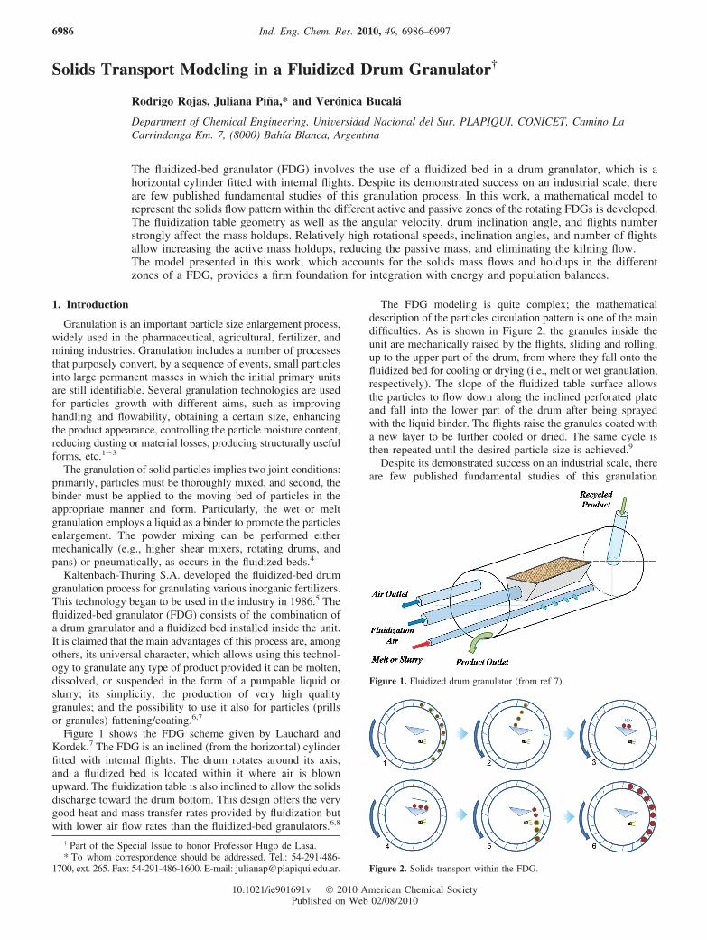
Figure 1 shows the FDG scheme given by Lauchard andKordek.7 The FDG is an inclined (from the horizontal) cylinderfitted with internal flights. The drum rotates around its axis,and a fluidized bed is located within it where air is blownupward. The fluidization table is also inclined to allow the solidsdischarge toward the drum bottom. This design offers the verygood heat and mass transfer rates provided by fluidization butwith lower air flow rates than the fluidized-bed granulators.6,8
The FDG modeling is quite complex; the mathematicaldescription of the particles circulation pattern is one of the maindifficulties. As is shown in Figure 2, the granules inside theunit are mechanically raised by the flights, sliding and rolling,up to the upper part of the drum, from where they fall onto thefluidized bed for cooling or drying (i.e., melt or wet granulation,respectively). The slope of the fluidized table surface allowsthe particles to flow down along the inclined perforated plateand fall into the lower part of the drum after being sprayedwith the liquid binder. The flights raise the granules coated witha new layer to be further cooled or dried. The same cycle isthen repeated until the desired particle size is achieved.9
Despite its demonstrated success on an industrial scale, thereare few published fundamental studies of this granulation
† Part of the Special Issue to honor Professor Hugo de Lasa.* To whom correspondence should be addressed. Tel.: 54-291-486-
1700, ext. 265. Fax: 54-291-486-1600. E-mail: [email protected].
Figure 1. Fluidized drum granulator (from ref 7).
Figure 2. Solids transport within the FDG.
Ind. Eng. Chem. Res. 2010, 49, 6986–69976986
10.1021/ie901691v 2010 American Chemical SocietyPublished on Web 02/08/2010
process.10,11 To the best of our knowledge, there is a lack ofresearch papers involving the design and modeling of FDGswith the purpose of understanding and improving their operation.Contrarily, there is abundant literature regarding mathematicalmodels to represent the solids flow pattern within rotating drumdryers with internal flights.12-18
In this work, some previous studies by other authors aboutdrum dryers are extended to represent the solids movementwithin a fluidized drum unit to carry out a melt granulationprocess for fertilizer production. The developed model is usedfor design purposes (i.e., the definition of the drum dimensions,the inclination and rotational speed, the geometry and numberof flights, and the fluidized-bed table dimensions and locationwithin the drum). The effect of the design parameters on thesolids holdup and operating regime is analyzed.
2. Mathematical Model
For flighted rotary dryers, many authors, among othersSheehan et al.16 and Britton et al.,17 proposed a solids transportcompartment model involving perfectly mixed tanks linked ina series arrangement. Each cell or compartment exchanges masswith the subsequent one. For a FDG, this model is an attractivebasis to work with; however, the phenomena that occur on thefluidization table (cooling/solvent evaporation) and within thebinder spray zone should also be considered.
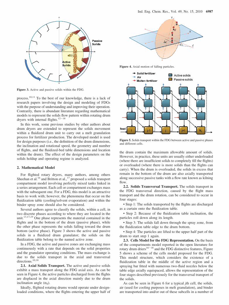
Several authors agree to classify the solids, within a cell, intwo discrete phases according to where they are located in theunit.13,17,19 One phase represents the material contained in theflights and in the bottom of the drum (passive phase), whilethe other phase represents the solids falling toward the drumbottom (active phase). Figure 3 shows the active and passivesolids in a fluidized drum granulator; the solids on thefluidization table belong to the named active zone.
In a FDG, the active and passive zones are exchanging masscontinuously with a rate that depends on the solid propertiesand the granulator operating conditions. The mass exchange isdue to the solids transport in the axial and transversaldirections.10,18
2.1. Axial Solids Transport. The active and passive solidsexhibit a mass transport along the FDG axial axis. As can beseen in Figure 4, the active particles discharged from the flightsare displaced in the axial direction mainly due to the druminclination angle (Rd).
Ideally, flighted rotating drums would operate under design-loaded conditions, where the flights entering the upper half of
the drum contain the maximum allowable amount of solids.However, in practice, these units are usually either underloaded(where there are insufficient solids to completely fill the flights)or overloaded (where there is more solids than the flights cancarry). When the drum is overloaded, the solids in excess thatremain in the bottom of the drum are also axially transportedalong successive passive tanks with a flow rate known as kilningflow.
2.2. Solids Transversal Transport. The solids transport inthe FDG transversal direction, caused by the flight masstransport and the drum rotation, can be considered to occur infour stages:
• Step 1: The solids transported by the flights are dischargedas a curtain onto the fluidization table.
• Step 2: Because of the fluidization table inclination, theparticles roll down along its length.
• Step 3: The solids fall down through the spray zone, fromthe fluidization table edge to the drum bottom.
• Step 4: The particles are lifted to the upper half part of thedrum to start step 1 again.
2.3. Cells Model for the FDG Representation. On the basisof the compartments model reported in the open literature forrotary drum driers16-18 and the FDG distinctive features, Figure5 shows a scheme of the cells model proposed for the FDG.This model structure, which considers the existence of afluidization table in the middle of the active region and aspraying bar fitted with numerous two-fluid nozzles below thetable edge axially equispaced, allows the representation of thefour stages described previously for the transversal transport ofthe solids.
As can be seen in Figure 6 for a typical jth cell, the solids,air (used for cooling purposes in melt granulation), and binderare transported into and/or out of these subcells in a number of
Figure 3. Active and passive solids within the FDG.
Figure 4. Axial motion of falling particles.
Figure 5. Solids transport within the FDG between active and passive phasesand different cells.
Ind. Eng. Chem. Res., Vol. 49, No. 15, 2010 6987
ways, with the solids motion being both between phases withinthe same cell and toward neighboring compartments.
According to previous researchers,16,18 the solids transportout of a subcell is proportional to the mass contained in it. Inother words, the mass flow of solids leaving each subcell canbe expressed as
where m and m are the mass flow rate and holdup of the subcell,respectively. The solids transport coefficient k is related to theinverse of the solids residence time in a given subcell.
In Figure 6 and according to eq 1, k 4j m p
j represents the massflow rate of the solids that are transported out of the passivephase through discharge from the flights into the active solidsabove the fluidization table (AS1), with m p
j being the solidsmass belonging to the passive phase of cell j. Because of theFDG slope, this mass flow can either fall in the active zoneAS1 of the same cell or forward. For this reason, the total streamleaving the active zone AS1 (k 1
j m a1j ) is split between two flows:
C fA1
j k 1j m a1
j , which represents the active solids fraction in thefluidization bed that is discharged to the contiguous cell, and(1 - CfA1
j ) k 1j m a1
j , which is the fraction of solids that falls in thesame compartment. C fA1
j is defined as the forward partitioningcoefficient for the zone AS1.
To avoid the undesired granules agglomeration, most of thesolids discharged from the flights should reach the fluidizationtable to be cooled down. The granules that fall down from thefluidization table edge should be at a temperature low enoughto allow the solidification of the sprayed molten binder beforethe solids reach the drum bottom. In fact, the FDG design shouldguarantee that all the material transported by the flights isdischarged onto the fluidization table before falling through thespraying zone or toward the drum bottom.11 Therefore, it isassumed that all the solids transported by the flights fall withinthe fluidization area. The particles that fall down from the tableedge can either pass through the spray zone of the same cell (1- C fA2
j ) k 2j m a2
j or the contiguous one (C fA2
j k 2j m a2
j ). As a finalstep within the active zone, the solids that have been coated bybinder drops can be either discharged in the passive cells j[(1- C fA3
j ) k 2j m a3
j ] or (j + 1)(C fA3
j k 3j m a3
j ).The drum design load is a critical parameter to identify the
existence or not of the kilning flow. Porter20 simply suggestedthat the design load is equal to the amount of passive solidsrequired to entirely fill one-half of the flights within the drum.
Thus,
where for a cell j, m p,designj is the design load, Nf is the flights
number, and m f,i)1j is the maximum load of a flight (i ) 1 or
θi ) 0). According to Porter,20 a flight is filled to maximumload when its tip is located at the horizontal position (see Figure7 for θi ) 0).
If the passive solids mass in any cell exceeds the design point,the kilning flow appears between the passive phase of successivecells, and the flights operate at their maximum capacity.Therefore, the flow of solids transported by the flights up tothe active subcell AS1 reaches a maximum value: |k 4
j mpj |max.
Consequently, if the FDG is operated at overloaded conditions,the following flow rates should be considered:16,17
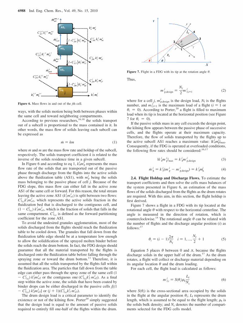
2.4. Flight Holdup and Discharge Flows. To estimate thetransport coefficients and then solve the cells mass balances ofthe system presented in Figure 6, an estimation of the massflows of the solids discharged from the flights as the drum rotatesare required. With this aim, in this section, the flight holdup isfirst derived.
Figure 7 shows a flight in a FDG with its tip located at therotational angle θ with respect to the horizontal centerline. Theangle is measured in the direction of rotation, which iscounterclockwise.15 The rotational angle θ can be related withthe number of flights and the discharge angular position (i) asfollows:17
Equation 5 places θ between 0 and π, because the flightsdischarge solids in the upper half of the drum.17 As the drumrotates, a flight will collect or discharge material depending onits angular location θ and the drum loading.
For each cell, the flight load is calculated as follows:
where S(θi) is the cross-sectional area occupied by the solidsin the flight at the angular position θi; Lf represents the drumlength, which is assumed to be equal to the flight length; Fb isthe solids bulk density; and Nc denotes the number of compart-ments selected for the FDG cells model.
Figure 6. Mass flows in and out of the jth cell.
m ) km (1)
Figure 7. Flight in a FDG with its tip at the rotation angle θ.
m p,designj )
Nf
2m f,i)1
j (2)
|k 4j m p
j |max ) k 4j m p,design
j (3)
m kj ) k 5
j (m pj - m p,design
j ) ) k 5j mk
j (4)
θi ) (i - 1)2πNf
i ) 1, ...,Nf
2+ 1 (5)
m f,ij ) S(θi)Fb
Lf
Nc(6)
6988 Ind. Eng. Chem. Res., Vol. 49, No. 15, 2010
To evaluate the flight cross-sectional area for two-segmentperpendicular flights (as the one shown in Figure 7), theprocedure proposed by Lisboa et al.21 is applied.
The kinetic angle of repose (φ), shown in Figure 7, is theangle of the level of the free-flowing particles to the horizontal.13
Since for melt granulation the granules can be assumed to becompletely solidified when they are lifted up by the flights11
and the particles do not change their sizes dramatically duringthe enlargement process, a constant kinetic repose angle alongthe axial direction of the FDG is considered.
As suggested by Lisboa et al.,21 to establish the location ofa flight in the FDG, the following two-axes systems are required:(a) a fixed coordinate system located at the drum center (X, Y)and (b) a moving coordinate system placed at the tip of theflight (x, y). The flight cross-sectional area can be determinedif the coordinates of the intersection of the solids surface withthe segments of the flights or the drum wall are known.
As proposed by Lisboa et al.,21 for flights sufficientlyseparated to avoid interference effects, the three following flightloading cases are considered:
(i). The solids held in the flight contact the drum wall(see Figure 7). Given γ ) φ - δ, the particles reach the drumwall if γ > arctan((y2)/(x2)). In this case, the sectional area iscalculated as
where the parameter � is defined as follows:
For θi ) 0, eq 7 leads to the maximum allowable cross-sectional area occupied by the solids in the flight. This conditionis used to establish the FDG load regime and the mass flowrates discharged by the flights, which affect the mass-averagecycle time and thus the transport coefficients.
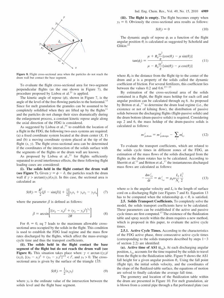
(ii). The solids held in the flight contact the basesegment of the flight but do not reach the drum wall (seeFigure 8). This situation takes place when: γ < arctan ((y2)/(x2)), [(x5 - x1)2 + (y5 - y1)2]1/2 < l′, and y5 > 0. The cross-sectional area is given by the surface of the triangle 135:
where y5 is the ordinate value of the intersection between thesolids level and the flight base segment.
(iii). The flight is empty. The flight becomes empty wheny5 ) 0. Obviously the cross-sectional area results as follows:
The dynamic angle of repose φi as a function of the flightangular position θi is calculated as suggested by Schofield andGlikin:22
where R0 is the distance from the flight tip to the center of thedrum and µ is a property of the solids called the dynamiccoefficient of friction. For several fertilizers, this coefficient liesbetween the values 0.2 and 0.6.23-25
By estimation of the cross-sectional area of the solidscontained in a flight, the flight mass holdup for each cell andangular position can be calculated through eq 6. As proposedby Britton et al.,17 to determine the drum load regime (i.e., theexistence or not of kilning flow), the distribution of passivesolids between the discharging flights (flight-passive solids) andthe drum bottom (drum-passive solids) is required. Consideringeqs 2 and 6, the mass holdup of the drum-passive solids iscalculated as follows:
To evaluate the transport coefficients, which are related tothe solids cycle times in different zones of the FDG, anestimation of the mass flows of the solids discharged from theflights as the drum rotates has to be calculated. According toSherritt et al.13 and Britton et al.,17 the instantaneous dischargedmass flows are calculated as follows:
where ω is the angular velocity and Li is the length of surfacecord on a discharging flight (see Figures 7 and 8). Equation 13has to be computed when the relationship φi < θi is satisfied.
2.5. Solids Transport Coefficients. To completely solve themodel, the solids transport coefficients have to be calculated.These parameters can be established if the active and passivecycle times are first computed.17 The existence of the fluidizationtable and spray nozzle within the drum requires a new method,which is proposed in this paper, to evaluate the active cycletimes.
2.5.1. Active Cycle Times. According to the characteristicsof the FDG active phase, three consecutive active cycle times(corresponding to the solids transports described by steps 1-3of section 2.2) are identified:
(a). Active time of AS1 (tiA1). At each discharging angularposition, tiA1 accounts for the time required by the solids to travelfrom the flight to the fluidization table. Figure 9 shows the AS1fall height for a given angular position θi. Using the fall point(flight tip), the initial solids velocity, and the coordinates ofthe slope of the fluidized-table surface, the equations of motionare solved to finally calculate the average fall time.
The geometry and location of the fluidization table withinthe drum are presented in Figure 10. For melt granulation, airis blown from a central pipe through a flat perforated plate (see
Figure 8. Flight cross-sectional area when the particles do not reach thedrum wall but contact the base segment.
S(θi) )R2
2[� - sin(�)] + 1
2 |y2x1 + y4x2 - y2x4| (7)
� ) arcsin[[(x2 - x4)2 + (y2 - y4)
2]1/2
2R ] (8)
S(θi) )12
|x1y5| (9)
S(θi) ) 0 (10)
tan(φi) )µ + R0
ω2
g[cos(θi) - µ sin(θi)]
µ - R0ω2
g[sin(θi) - µ cos(θi)]
(11)
m p,drumj ) m p,design
j - ∑i
mf,ij (12)
-dm f,i
j
dt) m iA1
j ) FbωLf
Nc
Li2
2(13)
Ind. Eng. Chem. Res., Vol. 49, No. 15, 2010 6989

Figure 1) to cool down the granules. Therefore, the air issupposed to leave the fluidization table in a direction perpen-dicular to its surface (external fans draw the air out of thegranulator).
A force balance for a particle located on the fluidization table,assuming that the buoyancy due to air is negligible and thatthere are spherical granules, gives
where CD is the drag coefficient; Fair and Fp are the air andparticle densities, respectively; and dp is the volume meanparticle diameter. CD is calculated by means of the correlationgiven by Sherritt et al.,26 later used by Britton et al.17
To solve eqs 14 and 15, the departure velocity of the particlefrom the flight is needed. This velocity is calculated accountingfor the particle rolling on the solids surface contained in theflight and the influence of the drum angular velocity.14 Toestimate the rolling velocity, a new coordinate system isemployed (x′, y′; see Figure 11a). By means of a force balance,the rolling velocity becomes
Figure 11b shows the tangential velocity in terms of thestationary coordinate system. In view of this contribution andthe rolling velocity (eq 16) expressed in terms of the system
(X, Y), the particle departure velocity can be expressed as
Using eqs 17 and 18 and considering that, for t ) 0, a certainparticle is located at the position given by Y0 ) R0 sin(θi) andX0 ) R0 cos(θi), eqs 14 and 15 can be integrated twice to obtainthe position of a granule above the fluidization table as a functionof time. The active time tiA1 is established for the condition ofintersection between the particles trajectory and the equationthat represents the location of the fluidization table surface,which for a cross-sectional area corresponding to an isoscelestriangle is given by (see Figure 10)
(b). Active time of AS2 (tiA2). As was mentioned, becauseof the fluidization-table inclination, the particles roll down alongits surface. The time associated with this transport is a functionof the location on the fluidization table where the particles reachits surface; this contact point is also dependent on the discharg-ing angular position. In fact, the distance traveled by the particlesalong the table increases with θi (see Figure 9).
The particle rolling velocity on the table is calculated bymeans of a force balance at the fluidization-table surface, asillustrated in Figure 12a. Considering another coordinate system(x′′, y′′) and assuming that, for t ) 0, a certain particle is locatedon the table surface at x′′ ) 0 with zero velocity (Vix′′
0 ) 0), theequation of particle motion (which considers the friction forceon the aerated table surface to be negligible) is integrated twiceto obtain the distance traveled by the rolling particle as afunction of time:11
The active time tiA2 is evaluated from eq 20 for the particlesthat reach the fluidization table edge (x′′e, see Figure 12b); thecorresponding traveled vertical distance is
(c). Active time of AS3 (tiA3). As is illustrated in Figure 9,tiA3 is the time required by a falling particle to travel from thefluidization table edge to the mean radius (Rp), defined by Brittonet al.17 as follows:
The particle rolling velocity at the table edge represents theinitial velocity (Vf,ti
0 ) of the particles that fall from the fluidizationtable toward the spray zone:
Vfti0 corresponds to the initial velocity in the x′′ direction; its
decomposition in the (X, Y) system becomes
Figure 9. Geometrical parameters to calculate the active and passive cycletimes.
Figure 10. Fluidization table location and air velocity decomposition inthe stationary coordinate system.
dVY
dt) -gcos(Rd) +
3FairCD
4dpFp[Vaircos(E - ε1) - VY]2 (14)
dVX
dt)
3FairCD
4dpFp[Vair sin(E - ε1) - VX]2 (15)
Vix′ ) (2Ligcos(Rd)[sin(φi) - µcos(φi)])1/2 (16)
ViX0 ) -ωR0sin(θi) - (2Ligcos(Rd)[sin(φi) -
µcos(φi)])1/2 cos(φi)(17)
ViY0 ) ωR0cos(θi) - (2Ligcos(Rd)[sin(φi) -
µcos(φi)])1/2 sin(φi)(18)
Y ) Lf,t1sinε1 -
sin(ε2) - sin(ε1)
cos(ε2) + cos(ε1)[X - X0 - Lf,t1
cos(ε1)]
(19)
x'' ) gcos(Rd)sin(E - ε1)t2
2(20)
HiA2) x''esin(E - ε1) (21)
Rp )(R + R0)
2(22)
Vfti
0 ) - [2x''eigcos(Rd)sin(E - ε1)]
1/2 (23)
6990 Ind. Eng. Chem. Res., Vol. 49, No. 15, 2010
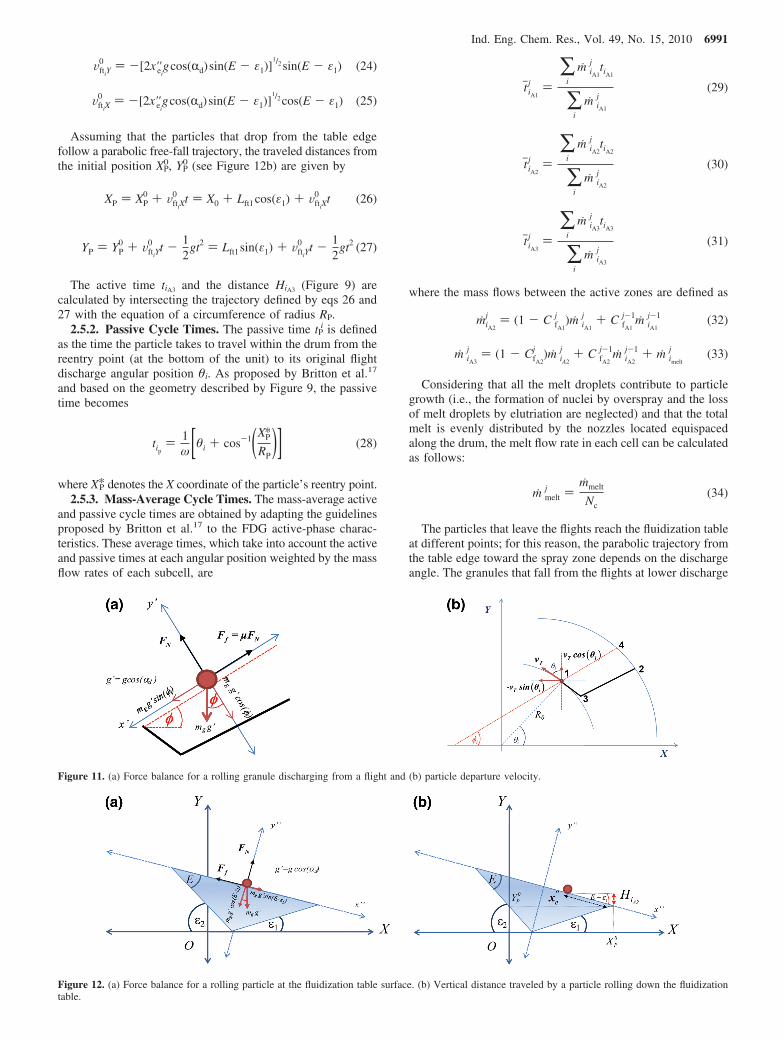
Assuming that the particles that drop from the table edgefollow a parabolic free-fall trajectory, the traveled distances fromthe initial position XP
0, YP0 (see Figure 12b) are given by
The active time tiA3 and the distance HiA3 (Figure 9) arecalculated by intersecting the trajectory defined by eqs 26 and27 with the equation of a circumference of radius RP.
2.5.2. Passive Cycle Times. The passive time tPi is defined
as the time the particle takes to travel within the drum from thereentry point (at the bottom of the unit) to its original flightdischarge angular position θi. As proposed by Britton et al.17
and based on the geometry described by Figure 9, the passivetime becomes
where XP* denotes the X coordinate of the particle’s reentry point.2.5.3. Mass-Average Cycle Times. The mass-average active
and passive cycle times are obtained by adapting the guidelinesproposed by Britton et al.17 to the FDG active-phase charac-teristics. These average times, which take into account the activeand passive times at each angular position weighted by the massflow rates of each subcell, are
where the mass flows between the active zones are defined as
Considering that all the melt droplets contribute to particlegrowth (i.e., the formation of nuclei by overspray and the lossof melt droplets by elutriation are neglected) and that the totalmelt is evenly distributed by the nozzles located equispacedalong the drum, the melt flow rate in each cell can be calculatedas follows:
The particles that leave the flights reach the fluidization tableat different points; for this reason, the parabolic trajectory fromthe table edge toward the spray zone depends on the dischargeangle. The granules that fall from the flights at lower discharge
Figure 11. (a) Force balance for a rolling granule discharging from a flight and (b) particle departure velocity.
Figure 12. (a) Force balance for a rolling particle at the fluidization table surface. (b) Vertical distance traveled by a particle rolling down the fluidizationtable.
VftiY0 ) -[2x''ei
gcos(Rd)sin(E - ε1)]1/2 sin(E - ε1) (24)
VftiX0 ) -[2x''ei
gcos(Rd)sin(E - ε1)]1/2 cos(E - ε1) (25)
XP ) XP0 + VftiX
0 t ) X0 + Lft1cos(ε1) + VftiX0 t (26)
YP ) YP0 + VftiY
0 t - 12
gt2 ) Lft1 sin(ε1) + VftiY0 t - 1
2gt2 (27)
tip) 1
ω[θi + cos-1(XP*
RP)] (28)
tjiA1
j )∑
i
m iA1
j tiA1
∑i
m iA1
j(29)
tjiA2
j )∑
i
m iA2
j tiA2
∑i
m iA2
j(30)
tjiA3
j )∑
i
m iA3
j tiA3
∑i
m iA3
j(31)
miA2
j ) (1 - C fA1
j )m iA1
j + C fA1
j-1m iA1
j-1 (32)
m iA3
j ) (1 - CfA2
j )m iA2
j + C fA2
j-1m iA2
j-1 + m imelt
j (33)
m meltj )
mmelt
Nc(34)
Ind. Eng. Chem. Res., Vol. 49, No. 15, 2010 6991

angles have more probability to be coated by the sprayed binder;therefore, the following equation is proposed to represent themelt distribution according to the particles’ discharge angle:
where θin and θfin represent the initial and final discharge anglepositions, respectively.
After the calculation of the mass-average times, the transportcoefficients k1
j to k4j are evaluated by means of the following
equations:17
The forward partitioning coefficients are determined as theratio of the average forward migration of the falling solids inthe corresponding active phase to the length selected for thecells:
For an overloaded FDG, the kilning flow requires theevaluation of k5
j , which is given by
The kilning angle (θkj ) can be established once the drum-
passive mass is computed from eq 12. The equation to evaluatethe kilning angle, reported by Britton et al.,17 is
2.6. Steady-State Mass Balances for a FDG. 2.6.1. PassiveSolids Mass Balance. Assuming that ms
0 (recycle stream of thegranulation circuit) enters into the FDG unit at the passive zone,the mass balance for cell 1 becomes (see Figure 6)
For the subsequent cells, the mass balance is given by
where CfA3Nc ) 0.
2.6.2. Active Solids Mass Balances.
where Cf,A10 ) Cf,A2
0 ) Cf,A1Nc ) Cf,A2
Nc ) 0. The mass balance givenby eq 47 assumes negligible the particles elutriation above thefluidization bed.
3. FDG Operating and Geometrical Parameters
The features of a drum can vary greatly.13 On the basis ofthe geometrical data reported by Degreve et al.27 for a 26-30TPH (tons per hour) NPK flighted drum granulator, a diameterof 4.3 m and equispaced perpendicular two-segment flights areselected for the FDG studied in this work. Considering the ratioLd/Dd ) 2 proposed by Capes28 for fertilizer granulation drums,a length Ld ) 8.6 m is fixed. A flight segment l′ (see Figure 7)of 0.07 m and a fold angle (RA) equal to 135° are chosen.Because of the limited available information regarding thefluidized-table dimensions and location, the following param-eters are specified (see Figure 10): Lf,t2) 1.75 m, Lf,t1) 1.19 m,eccentricity (X0) ) 0.45 m, right angle (ε1) ) 37°.9 For agranulator output of about 14-16 kg/s (i.e., a 26-30 TPH plantcapacity with a recycle ratio of 1:1),9 a mean granule sizeenlargement of about 20-30% is attainable,6 which is desiredto obtain round granules. To ensure that all the granules fallfrom the flights onto the fluidized table surface, the flightsnumber (Nf) and base segment length (l, see Figure 7) as wellas the drum inclination and rotational speed have to be carefullyselected. The values of these variables are established by trialand error to define a base case: l ) 0.24 m, 20 flights, a drumslope of 5°, and a 5 rpm rotational speed. Except for the basesegment length, the other mentioned variables are modified tostudy their effect on the solids flow patterns.
The air mass flow rate required for cooling purposes isdetermined by the melting point of the fertilizer and the plantcapacity. Potassium nitrate is selected as model fertilizer(melting temperature ) 333 °C). A total air mass flow rate of25 kg s-1 is chosen in order to adiabatically cool down theoutput to 140-150 °C and thus to guarantee the � rhombohedralstructure for the particles that leave the granulation unit.8,29,30
All the geometrical and operating variables selected to definethe base case are summarized in Table 1.
4. Numerical Solution
To solve the described FDG steady-state compartment model,the kinetic angle of repose, cross-sectional area, and cord lengthof the material contained in the flights are estimated for everyangular position. This first calculation is required to determinethe rotation angles for which the flight solids discharge beginsand finishes and to estimate the mass flows (miA1
j ) of the solids
m imelt
j ) m meltj ( θfin - θi
θfin - θin) (35)
k 1j ) 1
tjiA1
j(36)
k 2j ) 1
tjiA2
j(37)
k 3j ) 1
tjiA3
j(38)
k 4j ) 1
tjip
j(39)
CfA1
j )HjA1sin(Rd)
Lf/Nc) [ ∑
i
m iA1
j HiA1
∑i
m iA1
j ]sin(Rd)
Lf/Nc(40)
C fA2
j )HjA2sin(Rd)
Lf/Nc) [ ∑
i
m iA2
j HiA2
∑i
m iA2
j ]sin(Rd)
Lf/Nc(41)
C fA3
j )HjA3sin(Rd)
Lf/Nc) [ ∑
i
m iA3
j HiA3
∑i
m iA3
j ]sin(Rd)
Lf/Nc(42)
k 5j ) ω
θ kj
(43)
m p,drumj
LfFb) R2
2[θ k
j - sin(θ kj )] (44)
ms0 + (1 - Cf,A3
1 )k31ma3
1 - k51mk
1 - k41mp
1 ) 0 for j ) 1 (45)
k 5j-1m k
j-1 + C f,A3j-1 k 3
j-1m a3j-1 + (1 - C f,A3
j )k 3j m a3
j - k 5j mk
j -k 4
j m pj ) 0(46)
k4j m p
j - k 1j m a1
j ) 0 (47)
C f,A1j-1 k 1
j-1m a1j-1 + (1 - C f,A1
j )k 1j m a1
j - k 2j m a2
j ) 0 (48)
C f,A2j-1 k 2
j-1m a2j-1 + (1 - C f,A2
j )k 2j m a2
j + m imelt
j - k 3j m a3
j ) 0
(49)
6992 Ind. Eng. Chem. Res., Vol. 49, No. 15, 2010

discharged from the flights as the drum rotates. The time andtraveled distance for the three active subzones (AS1, AS2, andAS3) and the passive phase (PS) are then calculated. Aftercomputing the mass flow rate of the particles discharged bythe flights at different rotation angles (miA1
j ), the mass-averagecycle times, which allow for estimating the transport coefficientsbetween the active and passive phases (k1
j to k4j ), are evaluated.
The forward partitioning coefficients (CfA1
j to CfA3
j ) are alsocomputed. Assuming an underloaded operating regime, thesteady-state mass balances are next solved. Subsequently, thepassive solids mass is compared with the design load. Ifthe drum load hypothesis is incorrect, the kilning transportcoefficient (k5
j ) is estimated and the steady-state mass balancesare solved again.
The described calculation procedure is repeated for a differentfixed number of model cells (Nc) to assess the optimal numberof compartments that can provide a good balance between thesolution accuracy and the computing time. For the base casedefined by Table 1, about 50 compartments are required toaccurately represent the FDG (the mass error predictions arelower than 0.2%). Therefore, this discretization step is used forall the simulations performed in this work. The maximumnumber of cells, for which the maximum axial advance resultsequal to the cell length, is 65.18
5. Results and Discussion
According to the developed model, the partitioning coef-ficients are constant for all the cells (except for cells 0 and Nc
for which the partitioning coefficients are set equal to zero).Figure 13 shows the forward partitioning coefficients, for anycell, as a function of the rotational speed and the druminclination angle (the other variables are fixed at the corre-sponding values listed in Table 1). The coefficients CfA2
j andCfA3
j are the lowest and highest ones, respectively, independentof the selected Rd and ω values. This result is in good agreementwith the distances HjA2 and HjA3 traveled by the solids in theactive zones 2 and 3 (see Figure 9).
For a given drum inclination angle, CfA1
j decreases as therotational speed is increased. This behavior is directly relatedwith the effect of the drum angular velocity on the solidsdeparture velocity from the flights (eqs 17 and 18): the higherthe rotational speed, the higher is the initial solids velocity. Asa result, the particles reach the fluidization table at shorterdistances HjA1, leading to less forward solids transport. For thesame reason, as ω increases, longer are the distances HjA2
traveled by the solids and higher CfA2
j coefficients are expected.In addition and because of the greater xe′′ values, the result isthat the initial particle velocities at the fluidization table edge(eqs 24 and 25) are higher. Consequently, the particles reachthe drum walls within shorter distances HjA3 and CfA3
j decreases.For the FDG design of the base case, the minimum andmaximum rotational speeds, to avoid the solids discharge fromthe flights outside of the fluidization table, are about 3 and 9rpm, respectively.
As can be seen in Figure 13, as the drum inclination anglediminishes, the partitioning coefficients decrease. This effect iscaused by the direct influence of Rd on these parameters (eqs40-42). The diminution observed for all the partitioningcoefficients is given basically by the relationship [sin(2°)/sin(5°)].
Figure 14 shows the solids transport coefficients as afunction of the rotational speed, with the other variables beingthe ones listed in Table 1. Accordingly with the modelassumptions, the transport coefficients k1-k4 are identical forall the cells (except for j ) 0 and j ) Nc) and are not affectedby the number of flights. The solids transport coefficientsare not significantly influenced by the inclination angle. Infact, for changes in the inclination angle from 5° to 2°, thetransport coefficients exhibit differences lower than 0.3%.
Table 1. FDG Base Case: Geometrical and Operating Variables
Drum Geometry
Dd, m 4.3Ld, m 8.6Rd, (deg) 5
Flights Number and Geometryl′, m 0.07l, m 0.24RA, (deg) 135Lf, m 8.6Nf 20
Fluidization Table Geometry and LocationX0, m 0.45Lft1, m 1.19Lft2, m 1.75ε1, (deg) 37
Operating Variablesms
0, kg s-1 8.3mmelt, kg s-1 8.3ma, kg s-1 25ω, rad s-1 0.5234 (5 rpm)
Figure 13. Forward partitioning coefficients as a function of Rd and rotationspeed.
Figure 14. Solids transport coefficients as a function of the rotation speed(Rd ) 5°).
Ind. Eng. Chem. Res., Vol. 49, No. 15, 2010 6993
The transport coefficient k1 does not vary significantly againstchanges in the rotational speed. The higher the rotationalspeed, the higher is the solids departure velocity from theflights. However and despite the higher departure velocity,the particles travel longer distances along their parabolictrajectory before reaching the fluidization table. As ωincreases, the location at which the particles intersect thetable surface is also higher (xe′′, see Figure 12b). For this
reason and considering eq 20, higher AS2 active times and,therefore, lower k2 are obtained as the drum rotates faster.Regarding k3, the higher ω, the higher is the solids initialvelocity at the table edge and, thus, the shorter are thedistances Hj A3. As a result, the active time of zone AS3diminishes and consequently k3 rises, as the drum rotation isincreased. The passive cycle time is inversely proportionalto the angular velocity (eq 31); therefore, as the drum rotationis increased, higher transport coefficients k4 are observed.
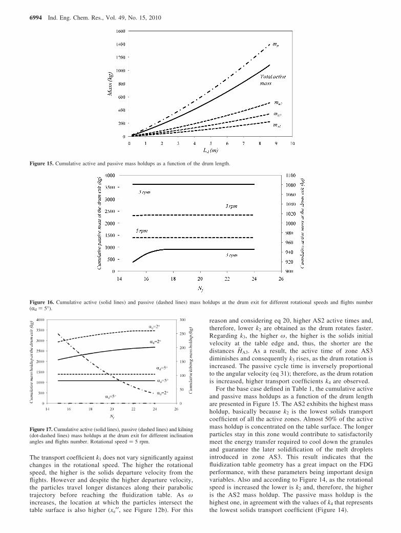
For the base case defined in Table 1, the cumulative activeand passive mass holdups as a function of the drum lengthare presented in Figure 15. The AS2 exhibits the highest massholdup, basically because k2 is the lowest solids transportcoefficient of all the active zones. Almost 50% of the activemass holdup is concentrated on the table surface. The longerparticles stay in this zone would contribute to satisfactorilymeet the energy transfer required to cool down the granulesand guarantee the later solidification of the melt dropletsintroduced in zone AS3. This result indicates that thefluidization table geometry has a great impact on the FDGperformance, with these parameters being important designvariables. Also and according to Figure 14, as the rotationalspeed is increased the lower is k2 and, therefore, the higheris the AS2 mass holdup. The passive mass holdup is thehighest one, in agreement with the values of k4 that representsthe lowest solids transport coefficient (Figure 14).
Figure 15. Cumulative active and passive mass holdups as a function of the drum length.
Figure 16. Cumulative active (solid lines) and passive (dashed lines) mass holdups at the drum exit for different rotational speeds and flights number(Rd ) 5°).
Figure 17. Cumulative active (solid lines), passive (dashed lines) and kilning(dot-dashed lines) mass holdups at the drum exit for different inclinationangles and flights number. Rotational speed ) 5 rpm.
6994 Ind. Eng. Chem. Res., Vol. 49, No. 15, 2010

Figure 16 presents the cumulative total active and passivemasses at the drum exit as a function of the flights numberand drum rotational speed. As the angular velocity is raised,the passive and active mass holdups decrease and increase,respectively. This effect is in good agreement with the valuesof the solid transport coefficients presented in Figure 14. Forexample, if the rotational speed is increased from 3 to 5 rpm,the total active mass increases about 20% while the passivemass holdup decreases almost 40%. This result indicates thatthe rotational speed can be manipulated to govern the solidsdistribution within the drum and, consequently, to meet theenergy requirements. At 5 rpm, the number of flights(between 15 and 24) does not affect the total mass holdupsand the FDG operates at underloaded conditions. At 3 rpm,changes in the flights number may lead to kilning flow. Asthe angular velocity and the number of flights decrease, theflow of solids transported by the flights reaches the maximumallowable value given by eq 3. For this reason, kilning flowis observed in the system for 3 rpm and a number of flightslower than 17 (see eq 4).
The effect of the number of flights and the inclination angleon the mass holdups is shown in Figure 17. An inclinationangle of 2° leads to active and passive mass holdups 1.9-2.5and 2.1-2.5 times higher than the corresponding values forthe base case. The inclination angle increment significantlydiminishes the forward partitioning coefficients and, therefore,the solids migration toward the drum exit. For this reason,the mass holdups are greater. The kilning flow takes placeat low inclination angles independently of the number offlights. Thus and according to the FDG operating features,the inclination angle cannot be strongly reduced. High flightsnumber minimizes the kilning holdup, which is recommendedto avoid an uneven particle growth.
6. Conclusions
The model presented in this work, which accounts for thesolids mass flows and holdups in the different FDG zones,
provides a firm foundation for integration with energy andpopulation balances. The simultaneous solution of all theconstitutive equations will allow improving the understandingof this unit and introducing design improvements to enhancethe granules quality. The inclusion of energy and populationbalances will be the subject of future papers.
The fluidization table geometry and the angular velocitystrongly affect the residence time of the particles on thefluidization table, resulting in them being variables that canbe adjusted to meet the thermal requirements for the meltdroplets solidification.
The passive mass holdup is the highest one in the FDGsystem. This result indicates that the energy transfer abovethe fluidization table has to be efficient to cool down thegranules and to guarantee that all the particles are in the solidstate before they are transported by the flights; otherwise,caking or agglomeration mechanisms may take place.
The rotational speed and inclination drum angle also appearas key variables since their values govern the solids distribu-tion within the drum. Increments in the angular velocityincrease the active mass holdup and reduce the passive mass.When the inclination angle is raised, both the active andpassive mass holdups decrease. The number of flights has astrong influence on the kilning mass; if a diminution in thisholdup is desired, relatively high drum inclination angles,rotational speeds, and number of flights should be used.
Nomenclature
CD ) drag coefficient (dimensionless)Cf ) forward partitioning coefficient (dimensionless)dp ) particle volume mean diameter (m)D ) diameter (m)E ) fluidization table internal angle, see Figure 10 (radians)Ff ) friction force (N)FN ) normal force (N)g ) acceleration due to gravity (m2 s-1)H ) height (m)
Figure 18. Kilning mass holdups at the drum exit for different inclination angles and rotational speeds (Nf ) 20).
Ind. Eng. Chem. Res., Vol. 49, No. 15, 2010 6995
k ) solids transport coefficient (s-1)L ) length (m)l′ ) length of the flight segment nearest to the tip (m)l ) base length of a flight (m)m ) mass holdup (kg)mg ) granule mass (kg)m ) mass flow rate (kg s-1)ms
0 ) recycle stream of a granulation circuit (kg s-1)Nc ) number of compartments selected for the cell model
(dimensionless)Nf ) total flights number (dimensionless)R ) drum radius (m)R0 ) distance from the flight tip to the center of the drum (m)RP ) mean radius, see eq 22 (m)S ) flight cross-sectional area filled with solids (m2)t ) time (s)Vair ) air velocity (m s-1)VY ) particle velocity in the Y coordinate direction (m s-1)VX ) particle velocity in the X coordinate direction (m s-1)Vx′ ) maximum initial velocity of a single particle falling from a
flight (m s-1)VT ) tangential velocity (m s-1)X ) stationary horizontal axis (m)x ) abscissa of the moving coordinate system (m)Y ) stationary vertical axis (m)y ) ordinate of the moving coordinate system (m)
Greek Letters
RA ) angle between the two flight segments (radians)Rd ) drum inclination angle (radians)� ) angle defined by eq 8 (radians)δ ) angle between the fixed and moving coordinate systems; this
angle shown in Figure 7 is negative (radians)γ ) φ - δ (radians)φ ) kinetic angle of repose (radians)θ ) angle of rotation (radians)µ ) dynamic coefficient of friction (dimensionless)ω ) angular velocity (radians s-1)F ) density (kg m-3)ε1 ) right inclination angle of the fluidization table (radians)ε2 ) left inclination angle of the fluidization table (radians)
Subscripts
air ) air used as cooling medium in the fluidization tableA1 ) active solids phase 1A2 ) active solids phase 2A3 ) active solids phase 3b ) bulkd ) drume ) right fluidization table edgef ) flightft ) fluidization tablei ) angular positionk ) kilning phasemelt ) molten fertilizer used as binderp ) passive phase1 ) active mass phase 12 ) active mass phase 23 ) active mass phase 34 ) passive mass5 ) kilning mass
Superscripts
0 ) at t ) 0j ) cell number
Literature Cited
(1) Barbosa-Canovas, G. V.; Ortega-Rivas, E.; Juliano, P.; Yan, H. FoodPowders. Physical Properties, Processing and Functionality; KluwerAcademic/Plenum Publishers: New York, 2005.
(2) Liu, L. X.; Litster, J. D. Population Balance Modeling of Granulationwith a Physically Based Coalescence Kernel. Chem. Eng. Sci. 2002, 57,2183–2191.
(3) Tan, H. S.; Goldschmidt, M. J. V.; Boerefijn, R.; Hounslow, M. J.;Salman, A. D.; Kuipers, J. A. M. Population Balance Modelling of FluidizedBed Melt Granulation, An Overview. Chem. Eng. Res. Des. 2005, 83, 871–880.
(4) Saleh, K.; Guigon, P. Coating and encapsulation processes inpowder technology. In Handbook of Powder Technology; Salman, A. D.,Hounslow, M. J., Seville, J. P. K., Eds.; Elsevier: Amsterdam, TheNetherlands, 2007.
(5) Valkov, S. Fluidized-bed granulation of ammonium nitrate andcalcium-ammoniun nitrate. Chem. Pet. Eng. 2000, 36, 3–5.
(6) Thuring, P.; Vogel, E. The fluidized drum granulation process (FDG)and its various applications. Presented at IFA Technical Conference, Tunisia,1986.
(7) Lauchard, D.; Kordek, M. Granulation KT’s progress using fluidizeddrum granulation (FDG) technology. Presented at IFA Technical Conference,USA, 2000.
(8) Kaltenbach-Thuring. Fluid drum granulation of potassium nitrate.Nitrogen & Methanol, 1999, 237, 53-55.
(9) Thuring, P.; Sombret, J.; Vogel, E. U.S. Patent 4,749,349, 1988.(10) Kordek M. A. Granulation par pulverization de multiples couches
minces de sels fondus dans un tambour a lit fluidise. Ph.D. Thesis, Universitede Technologie de Compiegne, France, 1995.
(11) Litster, J. D.; Sarwono, R. Fluidized drum granulation of agglomer-ate formation. Powder Technol. 1996, 88, 165–172.
(12) Kelly, J. K. Flight design in rotary dryers. Powder Technol. 1992,10, 979–993.
(13) Sherritt, R.; Caple, R.; Behie, L.; Mehrotra, A. The movement ofsolids through flighted rotating drums. Part I: Model formulation. Can.J. Chem. Eng. 1993, 71, 337–346.
(14) Wang, F. Y.; Cameron, I. T.; Litster, J. D.; Rudolph, V. Afundamental study of particle transport through rotary dryers for flight designand system optimization. Drying Technol. 1995, 13, 1261–1278.
(15) Revol, D.; Briens, C. L.; Chabagno, J. M. The design of flights inrotary dryers. Powder Technol. 2001, 121, 230–238.
(16) Sheehan, M. E.; Britton, P. F.; Schneider, P. A. A model for solidstransport in flighted rotary dryers based on physical considerations. Chem.Eng. Sci. 2005, 60, 4171–4182.
(17) Britton, P. F.; Sheehan, M. E.; Schneider, P. A. A physicaldescription of solids transport in flighted rotary dryers. Powder Technol.2006, 165, 153–160.
(18) Lee, A. Modeling the solids transport phenomena within flightedrotary dryers. Ph.D. Thesis, James Cook University, Australia, 2008.
(19) Matchett, A. J.; Sheikh, M. S. An improved model of particlemotion in cascading rotary dryers. Trans. Inst. Chem. Eng. 1990, 68,139–148.
(20) Porter, S. J. The design of rotary driers and coolers. Trans. Inst.Chem. Eng. 1963, 41, 272–280.
(21) Lisboa, M. H.; Vitorino, D. S.; Delaiba, W. B.; Finzer, J. R. D.;Barrozo, M. A. S. A study of particle motion in rotary drier. Braz. J. Chem.Eng. 2007, 24 (3), 365–374.
(22) Schofield, F. R.; Glikin, P. G. Rotary driers and coolers for granularfertilizers. Trans. Inst. Chem. Eng. 1962, 40, 183–189.
(23) Aphale, A.; Bolander, N.; Park, J.; Shaw, L.; Svec, J.; Wassgren,C. Granular fertiliser particle dynamics on and off a spinner spreader.Biosyst. Eng. 2003, 85, 319–329.
(24) Grift, T. E.; Kweon, G.; Hofstee, J. W.; Piron, E.; Villette, S.Dynamic friction coefficient measurement of granular fertilizer particles.Biosyst. Eng. 2006, 95, 507–515.
(25) Kweon, G.; Grift, T. E.; Miclet, D. A spinning-tube device fordynamic friction coefficient measurement of granular fertilizer particles.Biosyst. Eng. 2007, 97, 145–152.
(26) Sherritt, R. G.; Caple, R.; Behie, L. A.; Mehrotra, A. K. Themovement of solids through flighted rotating drums. 2. Solids gas interac-tions and model validation. Can. J. Chem. Eng. 1994, 72, 240–248.
6996 Ind. Eng. Chem. Res., Vol. 49, No. 15, 2010
(27) Degreve, J.; Baeyens, J.; Van de Velden, M. Spray-agglomerationof NPK-fertilizer in a rotating drum granulator. Powder Technol. 2006, 163,188–195.
(28) Capes C. E. Handbook of Powder Technology; Vol 1: ParticleSize Enlargement; Elsevier Science: Amsterdam, The Netherlands, 1980.
(29) Westphal, M. J.; Wood, J. W.; Redin, R. D.; Ashworth, T.Calorimetric and photoacoustic investigation of KNO3 phase transitions.J. Appl. Phys. 1993, 73 (11), 7302–7310.
(30) Kumar, N.; Nath, R. Thermal and ferroelectric properties ofpotassium nitrate: Polyvinylidene fluoride composite films. IEEE Trans.Dielectr. Electr. Insul. 2005, 12 (6), 1145–1150.
ReceiVed for reView October 28, 2009ReVised manuscript receiVed December 15, 2009
Accepted December 21, 2009
IE901691V
Ind. Eng. Chem. Res., Vol. 49, No. 15, 2010 6997
![chapter – 21 solids [surface area and volume of 3-d solids]](https://static.fdokumen.com/doc/165x107/632737f8051fac18490e22eb/chapter-21-solids-surface-area-and-volume-of-3-d-solids.jpg)