
Progress of circulating fluidized bed combustion technology in ...
14
© The Author 2017. Published by Oxford University Press on behalf of National Institute of Clean-and-Low-Carbon Energy. This is an Open Access article distributed under the terms of the Creative Commons Attribution Non-Commercial License (http://creativecommons.org/licenses/by-nc/4.0/), which permits non-commercial re-use, distribution, and reproduction in any medium, provided the original work is properly cited. For commercial re-use, please contact [email protected] 36 Received: 27 September, 2017; Accepted: 31 October, 2017 Review Article Progress of circulating fluidized bed combustion technology in China: a review Runxia Cai 1 , Xiwei Ke 1 , Junfu Lyu 1, *, Hairui Yang 1 , Man Zhang 1 , Guangxi Yue 1 and Wen Ling 2 1 Department of Thermal Engineering, Tsinghua University, Beijing 100084, China 2 Shenhua Group Co. Ltd., Beijing 100011, China *Corresponding author. E-mail: [email protected] Abstract Circulating fluidized bed (CFB) technology plays an important role in the utilization of low-grade coal in China. This article reviews CFB combustion technology development in China and summarizes recent achievements. Since 1990 Chinese engineers and researchers have been undertaking work to improve CFB boiler technology. A completely novel CFB boiler design theory was developed and used in the domestic manufacturing of CFB boilers with various capacities. China is the largest supplier and customer of CFB boilers in the world due to the widespread use of CFB boilers. In 2007, the lower energy consumption CFB technology was successfully developed by re-specifying the fluidization state, which reduced the power consumption of forced fans and solved the potential erosion problems on the water wall. Afterwards, in order to increase the electric power generation efficiency, the supercritical CFB (SCCFB) boiler was developed and the first 600 MW SCCFB boiler was demonstrated and put into commercial operation in 2013. The success of the technology is evident with over 80 SCCFB boilers on order with capacities of 350 MW to 660 MW. Chinese scientists and engineers are also developing technology to lower the emissions of CFB combustion to meet the requirements of China’s strict emission regulations. This emission reduction is through high-efficiency desulfurization by limestone injection into the furnace and low NO x combustion, ultra-low emission of SO 2 and NO x in the furnace can be realized by improving the bed quality and increasing the solid circulation rate. There is currently further research and design development being undertaken to develop a 660 MW ultra-supercritical CFB (USCCFB) boiler. The new boiler is expected to be operational before 2020 resulting in higher efficiency and lower energy consumption and emissions. Key words: circulating fluidized bed (CFB); progress; supercritical; low electric consumption; ultra-low emission; supercritical CFB (SCCFB) Introduction Coal is the major energy resource in China and this is unlikely to change for the foreseeable future. China has a wide variety of coals and among them are low-grade coals with a high ash content, which is mainly produced in the coal washing process resulting in coal gangue, middling and coal slurry. Circulating fluidized bed (CFB) technology has developed rapidly in recent decades due to its fuel flexibility, effective NO x formation control and high-sulfur capture efficiency. As a result, CFB technology is regarded as the best option to utilize low-quality coal [1]. By 2016, over 3000 CFB boilers were in commercial operation with a total installed capacity of over 90000 MW among which over 100 units are 300 MW. Clean Energy, 2017, Vol. 1, No. 1, 36–49 doi: 10.1093/ce/zkx001 Advance Access Publication Date: 22 November 2017 Homepage: https://academic.oup.com/ce Downloaded from https://academic.oup.com/ce/article/1/1/36/4647354 by guest on 29 March 2022
-
Upload
khangminh22 -
Category
Documents
-
view
2 -
download
0
Transcript of Progress of circulating fluidized bed combustion technology in ...

© The Author 2017. Published by Oxford University Press on behalf of National Institute of Clean-and-Low-Carbon Energy. This is an Open Access article distributed under the terms of the Creative Commons Attribution Non-Commercial License (http://creativecommons.org/licenses/by-nc/4.0/), which permits non-commercial re-use, distribution, and reproduction in any medium, provided the original work is properly cited. For commercial re-use, please contact [email protected]
36
Received: 27 September, 2017; Accepted: 31 October, 2017
Review Article
Progress of circulating fluidized bed combustion technology in China: a reviewRunxia Cai1, Xiwei Ke1, Junfu Lyu1,*, Hairui Yang1, Man Zhang1, Guangxi Yue1 and Wen Ling2
1Department of Thermal Engineering, Tsinghua University, Beijing 100084, China 2Shenhua Group Co. Ltd., Beijing 100011, China
*Corresponding author. E-mail: [email protected]
AbstractCirculating fluidized bed (CFB) technology plays an important role in the utilization of low-grade coal in China. This article reviews CFB combustion technology development in China and summarizes recent achievements. Since 1990 Chinese engineers and researchers have been undertaking work to improve CFB boiler technology. A completely novel CFB boiler design theory was developed and used in the domestic manufacturing of CFB boilers with various capacities. China is the largest supplier and customer of CFB boilers in the world due to the widespread use of CFB boilers. In 2007, the lower energy consumption CFB technology was successfully developed by re-specifying the fluidization state, which reduced the power consumption of forced fans and solved the potential erosion problems on the water wall. Afterwards, in order to increase the electric power generation efficiency, the supercritical CFB (SCCFB) boiler was developed and the first 600 MW SCCFB boiler was demonstrated and put into commercial operation in 2013. The success of the technology is evident with over 80 SCCFB boilers on order with capacities of 350 MW to 660 MW. Chinese scientists and engineers are also developing technology to lower the emissions of CFB combustion to meet the requirements of China’s strict emission regulations. This emission reduction is through high-efficiency desulfurization by limestone injection into the furnace and low NOx combustion, ultra-low emission of SO2 and NOx in the furnace can be realized by improving the bed quality and increasing the solid circulation rate. There is currently further research and design development being undertaken to develop a 660 MW ultra-supercritical CFB (USCCFB) boiler. The new boiler is expected to be operational before 2020 resulting in higher efficiency and lower energy consumption and emissions.
Key words: circulating fluidized bed (CFB); progress; supercritical; low electric consumption; ultra-low emission; supercritical CFB (SCCFB)
IntroductionCoal is the major energy resource in China and this is unlikely to change for the foreseeable future. China has a wide variety of coals and among them are low-grade coals with a high ash content, which is mainly produced in the coal washing process resulting in coal gangue, middling and coal slurry. Circulating fluidized bed (CFB) technology
has developed rapidly in recent decades due to its fuel flexibility, effective NOx formation control and high-sulfur capture efficiency. As a result, CFB technology is regarded as the best option to utilize low-quality coal [1]. By 2016, over 3000 CFB boilers were in commercial operation with a total installed capacity of over 90000 MW among which over 100 units are 300 MW.
Clean Energy, 2017, Vol. 1, No. 1, 36–49
doi: 10.1093/ce/zkx001Advance Access Publication Date: 22 November 2017Homepage: https://academic.oup.com/ce
Dow
nloaded from https://academ
ic.oup.com/ce/article/1/1/36/4647354 by guest on 29 M
arch 2022

China started research on bubbling fluidized bed (BFB) in the 1960s. A series of BFB boilers with small capacities of 4–130 t/h steam were developed and the theory of BFB boiler design was established. During that period researchers invented fly ash recirculation com-bustion technology to solve the problems of severe ero-sion on immersed tubes and low boiler efficiency in BFB boilers. Chinese researchers have continued their work on CFB combustion technology. There have been mis-takes with BFB boilers from 1980s designed under the misapprehension that a CFB boiler was a combination of the BFB furnace and a separator [2]. Research showed that the gas–solid flow pattern, or the fluidization state in CFB and BFB is completely different. This misunder-standing led to many problems including insufficient boiler load and severe erosion on the heating surfaces after separators. Therefore, China in the 1990s under-took more fundamental research to investigate the mechanisms of CFB combustion. This research led to a better understanding and design theory for CFB boiler technology and was put into practice with the domes-tic manufacturing of various capacities of CFB boil-ers. As a result of this novel design theory a new lower energy consumption CFB technology was developed by re-specifying the fluidization state, and successfully applied to over 200 CFB boilers. The energy saving from the design with the CFB boilers resulted in a reduction of the power consumption of forced fans and the potential erosion of water walls [3].
In order to increase and demonstrate power gener-ation efficiency Chinese researchers developed a new 600 MW supercritical CFB (SCCFB) boiler. The boiler went into commercial operation in the Sichuan Province in 2013. The SCCFB boiler technology was applied to about 80 CFB boilers with capacities of 350–660 MW and exported overseas. In 2011, the National Emission Regulation was introduced, where both SO2 and NOx emissions must be less than 100 mg/m3. In 2014, the Clean Air Action Plan was introduced with stricter emission requirements for coal fired power plants. The Plan and ultra-low emis-sions raised further challenges for CFB boilers in China, with SO2 required to be less than 35 mg/m3 and NOx to be less than 50 mg/m3. Chinese scientific researchers are investigating how to lower emissions of CFB com-bustion to meet the new National Emission Regulations and ultra-low emission requirements. One option is high efficiency desulfurization by limestone injection into the furnace and lower NOx combustion. This has been suc-cessfully tested in two demonstration units resulting in ultra-low emission of SO2 and NOx in a CFB furnace by improving the bed quality and increasing the solid circulation rate.
This article will review the scientific research and industrial applications of CFB combustion technology in ultra-low power consumption, ultra-supercritical param-eters and ultra-low emission.
1 Lowering energy consumption of CFB using fluidization state specification design theory1.1 Fluidization state theory analysis
Traditional CFB boilers use the design theory of CFB chem-ical reactors [4], and require the particle density in the upper furnace to be higher than 15 kg/m3 [5]. Accordingly, a bed pressure drop of around 8–12 kPa should be kept in the fast bed to achieve a higher particle density. The high par-ticle concentration in the dense phase enhanced the air penetration resistance, which resulted in the higher power consumption of draft fans [6]. The power consumption of fans accounts for over 60% of the auxiliary power of CFB power plants, which is 2–3% higher than that of pulverized coal (PC) boilers. In addition, coarse particles can result in the severe erosion on membrane walls in the lower fur-nace [7].
Chinese scientific researchers using the basic mecha-nisms of fast fluidization have proposed a fluidization state map. Engineers can reduce the bed inventory and the power consumption of draft fans, as well as the erosion on water walls by re-specifying the fluidization state of CFB boilers [8].
The feedstock, as well as the bed material, has a wide size distribution in CFB boilers. As shown in Fig. 1, the flow pattern in the furnace is composed of the bubbling or tur-bulent bed formed by large particles at the bottom and the fast bed formed by fine particles in the freeboard [9]. In the light of the gas–solid flow and heat transfer in the furnace, the bed material can be divided into two groups, effective material and ineffective material. The effective material consists of fine particles, which can be entrained into the freeboard by the fluidizing air and directly affect the heat transfer in the dilute zone. The ineffective material refers to those larges particles, which can only stay at the bot-tom of the furnace and makes a minor contribution to the heat transfer [10]. It provides the ignition energy for fuel
0 100 200 3000
10
20
30
40
0 100 200 300 0 50 100
Furn
ace
heig
ht (m
)
Total solid density (kg/m3)
2nd air
Pressure drop
Solid density (kg/m3)
Ine�ective solid
Bubbling bed
+
Solid density (kg/m3)
E�ective solid
Fast fluidized bed
=
Fig. 1 The combination of fast bed and bubbling bed in a CFB furnace
Cai et al. | 37D
ownloaded from
https://academic.oup.com
/ce/article/1/1/36/4647354 by guest on 29 March 2022

particle ignition, and ensures enough residence time of large fuel particles for burnout. However, too much inef-fective material also causes some negative effects, includ-ing intensifying the erosion on membrane water walls, increasing the pressure head and energy consumption of forced fans, and enhancing the penetration resistance of secondary air. As a result, the inventory of ineffective material should be properly controlled.
The gas–solid flow above the dense bed is known as fast fluidization [11]. Previous studies have shown that the axial profile of particle concentration is influenced by many factors, including the superficial gas velocity, the bed inventory, the solid circulation rate and the bed geometric structure [12–14]. As the flow resistance is rela-tively small in loop seals and the furnace height is usually higher than the transport disengaging height (TDH), the geometric structure usually has a minor impact on the gas–solid flow in CFB boilers. The superficial gas velocity and the bed inventory are the major influencing factors on axial voidage profile. The effect of bed inventory on the axial voidage profile can be seen in Fig. 1 [13]. In the fast fluidized bed, the increasing of bed inventory only leads to the increasing of height of the dense zone. Only the solid voidage in transition zone is affected, while voidages in the dense zone and dilute zone remain unchanged [14]. Lu et al. [15] found that the further increase of bed inventory after a critical value had a minor impact on heat trans-fer. The effects of furnace pressure drop on heat trans-fer in a 135 MW CFB boiler were also modeled by Liu et al. [16]. The results showed that when the total pressure drop decreased by 1 kPa from the traditional one, the heat transfer coefficient was expected to decrease approxi-mately by 2%. Consequently, it is feasible to reduce the bed pressure without affecting the heat transfer in the furnace.
Unlike fan energy consumption and erosion, the effect of bed pressure drop on the combustion efficiency is twofold. On the one hand, at a certain air velocity, the higher bed inventory increases the solid concentration in the transition zone and intensifies the particle agglom-eration. As the terminal velocity of particle clusters is larger than that of a single particle, intensive back mix-ing of the clusters takes place along the furnace height. The clusters collapse and reform periodically in the gas–solid flow stream [17], prolonging the residence time of fine particles in the furnace, and increasing the burnout rate. On the other hand, the increasing solid density in the transition zone increases the pressure head of sec-ondary air, reduces the penetration depth of second-ary air and exacerbates the gas–solid mixing [18]. These problems lead to the oxygen-lean atmosphere in the core area of the furnace [19, 20], which are adverse to the coal combustion. As a result of the double-edged effect of the bed pressure drop on the combustion efficiency, there exists an optimal bed pressure drop, which can achieve the highest combustion efficiency, schematically shown in Fig. 2.
1.2 Lower energy consumption CFB boiler industrial practice
The lower energy consumption CFB technology based on state specification design theory can be clearly illustrated with the fluidization state map proposed by Yue et al. [9], as shown in Fig. 3. In order to simultaneously realize the lower pressure drop in the furnace and the sufficient particle dens-ity in the dilute zone, the bed quality should be improved to increase the proportion of effective material, shown in Fig. 4. In the engineering boiler design, the state specification the-ory is used to optimize the bed inventory of the effective material. Both the mass balance model and residence time model are used to optimize the bed inventory of the ineffect-ive material. At the same time, in order to reconstruct the fluidization state, it is necessary to optimize the performance of the circulating system, such as: (i) improving the cyclone efficiency; (ii) modifying the loopseal; (iii) controlling the feed coal size; (iv) redesigning the heating surface.
The first lower energy consumption CFB boiler based on the re-specification of the fluidization state began
Car
bon
lost
in fl
y as
h
Solid density increasing
Res
iden
ce ti
me
Oxy
gen
mix
ing
abili
ty
Fig. 2 Effect of suspension particle density on coal combustion rate
Gas velocity uf (m/s)
0 2 4 6 8
One stage cyclone
Soft
coalC
D
E
B
A
Recommended
G
H
I
F
Ash
cir
cula
ting
rate
GS
kg/(
m2 ·s
)
10
30
5
10
15
20
25
Har
d co
al
Lower limitationfor fast bed
Limitation for erosion protection
(Two stage cyclone)
Bed quality
Fig. 3 Fluidization state determination in proper selection of super-ficial gas velocity and solid circulating rate for a CFB boiler (symbols except the yellow asterisk are the states used by international CFBs)
38 | Clean Energy, 2017, Vol. 1, No. 1D
ownloaded from
https://academic.oup.com
/ce/article/1/1/36/4647354 by guest on 29 March 2022

commercial operational in 2007. As shown in Fig. 5, the field test results [10] showed that with the pressure drop decrease from 7.3 to 3.2 kPa, the solid suspension den-sity in the dilute zone was barely influenced due to the higher collection efficiency of the cyclones. The average heat transfer coefficient in the furnace was kept nearly the same and the furnace temperature decreased less than 17°C. The optimum bed pressure was around 5.7 kPa for this boiler based on this analysis. The electric power con-sumption of the unit reduced by 2.5%, and the availability reached 95%. Some operation data is shown in Table 1.
The lower energy consumption technology was success-fully applied in over 200 CFB boilers with various capaci-ties [8]. The electric power consumption of 135 MW and 300 MW energy saving CFB boilers is significantly lower
than other CFB boilers in China and abroad. Moreover, the electric power consumption of a 300 WM subcritical CFB boiler is close to that of 300 MW subcritical PC boilers. This improvement greatly enhances the competitiveness of CFB boilers [21].
2 Supercritical and ultra-supercritical CFB boiler technologyCFB boilers have excellent advantages in fuel flexibility and cost-effectiveness in emission control. But compared with supercritical or ultra-supercritical PC boilers, the power plant efficiency is not sufficient because of the lower steam parameters. Supercritical and ultra-supercritical CFB (USCCFB) combustion technology combines the advantages of CFB combustion and the supercritical or ultra-supercrit-ical steam cycle, which can achieve high-efficiency cleaner coal combustion. Therefore, there is an urgent requirement to increase the steam parameters of CFB boilers to super-critical or even ultra-supercritical parameters. CFB com-bustion technology is more suitable for combining with supercritical and ultra-supercritical steam cycle for its rela-tively uniform heat flux [22, 23]. With the support of the National High-Tech Research and Development Program of China, Chinese scientists and engineers initiated a study on the key issues of the SCCFB boiler in 2002 resulting in a demonstration CFB boiler in 2013 [3].
2.1 Fundamental investigation of supercritical and USCCFB boiler technology
Hydrodynamic safety of water walls is the key issue of supercritical and ultra-supercritical boilers. Spiral tube is usually used to increase the mass flux of supercritical water in tubes to solve the heat transfer deterioration. In contrast to PC boilers, CFB boilers can only use vertical tubes for avoiding erosion on water walls. As a result, the mass flux in the tubes of CFB boilers is smaller than PC boilers. The hydrodynamic characteristics of supercrit-ical water in supercritical PC boilers, cannot be applied to SCCFB boilers. Therefore, hydrodynamic safety of water walls, especially the characteristics of heat transfer in CFB boilers need to be first comprehensively studied. Heat transfer to water walls in a CFB boiler depends on the gas–solid two-phase flow. Before the development of the first 600 MW SCCFB boiler, further research of the gas–solid flow in an ultra-large furnace was needed as it has not been studied in detail. For instance, the riser height of a 600 MW SCCFB boiler is more than 50 m, which exceeds all the laboratory scale and industrial scale CFB, as well as the bed area.
2.1.1 Solid suspension density of an ultra large CFB furnaceThe difference of solid suspension density between 38 m and 54 m riser were experimentally studied in a cool
15
Fine particle
Coarse particle
Classical CFB Novel CFB
Fine particle
Coarse particle
10
Bed
inve
ntor
y, ∆P,
kPa
5
0
Fig. 4 Comparison of bed inventory between classical and novel CFB
0 10 20 304
8
12
16
20
0 100 200 300 4000
5
10
15
20
Dis
tanc
e fr
om d
istr
ibut
or (m
)
Solid suspension density (kg/m3)
75t/h, 3220Pa75t/h, 3830Pa75t/h, 5680Pa75t/h, 7330Pa
Fig. 5 Suspension density profiles along the furnace
Cai et al. | 39D
ownloaded from
https://academic.oup.com
/ce/article/1/1/36/4647354 by guest on 29 March 2022
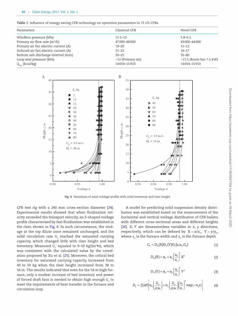
CFB test rig with a 240 mm cross-section diameter [24]. Experimental results showed that when fluidization vel-ocity exceeded the transport velocity, an S-shaped voidage profile characterized by fast fluidization was established in the riser, shown in Fig. 6. In such circumstance, the void-age at the top dilute zone remained unchanged, and the solid circulation rate Gs reached the saturated carrying capacity, which changed little with riser height and bed inventory. Measured Gs
* equaled to 9–10 kg/(m2•s), which was consistent with the calculated value by the correl-ation proposed by Xu et al. [25]. Moreover, the critical bed inventory for saturated carrying capacity increased from 40 to 50 kg when the riser height increased from 38 to 54 m. The results indicated that even for the 54 m high fur-nace, only a modest increase of bed inventory and power of forced draft fans is needed to obtain high enough Gs to meet the requirements of heat transfer in the furnace and circulation loop.
A model for predicting solid suspension density distri-bution was established based on the measurement of the horizontal and vertical voidage distribution of CFB boilers with different cross-sectional areas and different heights [26]. X, Y are dimensionless variables in x, y directions, respectively, which can be defined by X x x= / o , Y y y= / o, where xo is the furnace width and yo is the furnace depth.
C D X D Y D z u GY zP f S( ) ( ) ( , , )= X (1)
D X a auu
XX
c
( ) f
c
= +0 22
æ
èçççç
ö
ø÷÷÷÷ (2)
D Y a auu
Yc
Y( ) f
c
= +0 22
æ
èçççç
ö
ø÷÷÷÷ (3)
D f P nGu
nGu
uuz = ∆ +( ) s
s f
s
s f
f
c0 1ρ ρ
æ
èçççç
ö
ø÷÷÷÷÷
æ
èçççç
ö
ø÷÷÷÷÷
æ
èççççç
ö
ø÷÷÷÷ ( )
é
ë
êêê
ù
û
úúú
d
n zexp − 2 (4)
Table 1 Influence of energy saving CFB technology on operation parameters in 75 t/h CFBs
Parameters Classical CFB Novel CFB
Windbox pressure (kPa) 11.5–12 5.8–6.2Primary air flow rate (m3/h) 47 000–48 000 43 000–44 000Primary air fan electric current (A) 19–20 11–12Induced air fan electric current (A) 21–22 16–17Bottom ash discharge interval (min) 20–25 35–40Loop seal pressure (kPa) ~12 (Primary air) ~11.5 (Roots fan 7.5 kW)Qnet (kcal/kg) 14 654–15 910 14 654–15 910
40A B
Iv, kg
Ug = 3.9 m/s
Hr = 38 m
Ug = 3.9 m/s
Hr = 54 m
5Iv, kg
405060708090
15152030304050607080
35
30
25
20
Hei
ght z
, m
15
10
5
0
40
45
50
55
35
30
25
20
Hei
ght z
, m
15
10
5
00.90 0.95
Voidage ε0.94 0.96 0.98 1.00
Voidage ε1.00
Fig. 6 Variations of axial voidage profile with solid inventory and riser height
40 | Clean Energy, 2017, Vol. 1, No. 1D
ownloaded from
https://academic.oup.com
/ce/article/1/1/36/4647354 by guest on 29 March 2022

f P p p p P( ) exp( )o 1 2∆ = + ∆ (5)
The comparison of solid suspension density distribution between measurement and model prediction is shown in Fig. 7. Among all the measured points, 75.7% of data were within ±10% error, 93.4% of data were within ±20% error, and over 96.9% was within ±40% error range. Thus, the model is reliable enough for engineering CFB design.
2.1.2 Uniformity and stability of solid–gas two-phase flow between multi-circulating loopsA heavier separation load of cyclones results with the increasing of boiler capacity and the gradual increase of the fluidizing air and solid circulation rate. Cyclone per-formance deteriorates with the increasing of cyclone diameter, and too larger size of a cyclone brings difficulties for the arrangement and installation of a CFB boiler. As a result, multiple cyclones, rather than a single cyclone, are widely used in large scale CFB boilers. Three or four cyclones are used in 300 MW CFB boilers and four or six cyclones are used in 600 MW CFB boilers. For a CFB boiler with multi cyclones arranged in parallel, hypothetically the furnace can be divided into several parallel sections according to the number of cyclones. Each cyclone and its corresponding downcomer, loopseal, and the furnace form an independent circulation loop. The arrangement brings the non- uniform gas–solid flow among the circulation loops, and the solid concentration, the bed pressure drop, and the solid or gas flow rate in one circulation loop differ from the others. This non-uniform flow is a threat to the safe operation of CFB boilers. It was found that the dis-tribution of bed material in the circulation loops was sig-nificantly non-uniform. The solid circulation rate in each circulation loop can be controlled within 10% deviation by adjusting the aeration rate in loop seals [27, 28]. Based on
the pressure drop constraint and an empirical correlation for cyclone pressure drop, Mo et al. [29] investigated the mal-distribution of gas–solid flow in two identical paral-lel cyclones, and proposed theoretical methods to limit the non-uniform in solid flow through parallel cyclones. Due to the effects of wall friction and solid acceleration, the variation of cyclone pressure drop showed non-linear characteristics, which resulted in the multi-value of the gas–solid flow model in two cyclones. As a result, the driv-ing source in the multi-cyclone system can cause the flow rate oscillation of different circulation loops.
2.1.3 Bed inventory overturn for twin beds and bed surface wave for large bed section areaIn order to improve gas–solid mixing and reduce the car-bon content of fly ash in the large cross-sectional furnace the twin bed is widely used in furnace design of large-scale CFB boilers. However, in industrial practice, two independ-ent distributors at the bottom of the pant legs will easily cause the bed inventory imbalance between two legs, or even result in the bed inventory overturn [30]. When bed inventory overturn occurs, bed inventory in one leg is blown out and transferred into the other leg, causing bed material in one side to empty and the other side to become packed. Modeling and experimental results showed that the asymmetric flow between both sides of the furnace led to the lateral solid flow in the upper furnace, which was the essential cause of bed inventory overturn [31, 32]. A characteristic time pressure drop difference between double furnaces changed from zero to the stable state at the largest value, was used to describe the intensity of lateral mass transfer from one leg to the other. The zero pressure drop difference represented the balance state. As shown in Fig. 8, the characteristic time of bed inven-tory overturn was positively correlated with the height of branch point and negatively correlated with the air vel-ocity. In other words, increasing the branch point height
0 50 100 150 2000.0
0.5
1.0
1.5
2.0
2.5 0.54 m/s, with partition 0.54 m/s, without partition 0.45 m/s, without partition
Time (s)
Di�
eren
ce o
f pre
ssur
e dr
op in
rise
r be
twee
n bo
th s
ides
(kPa
)
Fig. 8 Impact of branch point height and fluidizing velocity on the char-acteristic time
120
90
60
Mea
sure
men
t Cp
kg/m
3
30
00 30 60
Model prediction Cp kg/m3
–10%
+10%
90 120
Fig. 7 Comparison of solid suspension density distribution between measurement and model prediction
Cai et al. | 41D
ownloaded from
https://academic.oup.com
/ce/article/1/1/36/4647354 by guest on 29 March 2022

and decreasing the fluidizing air will reduce the intensity of the bed inventory overturn.
The fluidization uniformity should be carefully consid-ered for the large sectional furnace, because the bed sur-face wave occurs in some conditions [33, 34]. The model prediction, as shown in Fig. 9, discovered that the wave resulted from the bed size, the fluidization velocity, as well as the bed inventory. All of the studies mentioned above form the fundamental theories on the water wall safety of the SCCFB boiler.
2.1.4 Local heat transfer model and the heat flux distributionAlthough the mechanisms of heat transfer between heat-ing surfaces and gas–solid flow have been intensively stud-ied by chemical engineering researchers, CFB combustion engineers are more concerned about heat transfer on the water wall [35]. As the heat capacity of solid is far larger than that of gas, the mechanisms of heat transfer in CFB furnace can be simplified into particle convection and radiation [36]. Chinese researchers have developed vari-ous methods to measure the heat transfer coefficients of these two mechanisms. Field tests were carried out of CFB boilers with different capacities. This resulted in a pro-posal for a semi-empirical correlation for calculating the heat transfer coefficients in a CFB furnace [15]. As shown in Fig. 10, the correlation considered the effect of many factors, including the bed temperature, the local particle density, the geometry of the membrane wall, the working fluid temperature and the medium-side heat transfer. The field test and experimental results reported in the litera-ture agree well with this semi-empirical correlation.
The advantage of the model is that local heat transfer coefficients can be calculated by local suspension particle density. Coupling this model with the suspension density model mentioned above, the heat flux distribution of water walls can be obtained [37, 38]. This method was verified in field tests of the 15, 25, 50, 135 and 300 MW CFB boilers [26, 39, 40]. Temperatures were measured by thermocouples
welded in membrane walls, and then heat flux profiles were calculated by means of the finite element method. A typical result of heat flux distribution in the 135 MW CFB boiler is shown in Fig. 11. The local heat transfer coefficient decreased with increasing height, and the heat flux and the heat transfer coefficients were lower in the center than those near the corner.
A mechanism heat transfer model based on the mem-brane walls configuration was proposed and validated by the heat flux profile in the 300 MW CFB boiler, which is shown in Fig. 12. The model provides good accuracy for correlating 85% of the data within ±10%.
2.1.5 Hydrodynamic model predictionThe medium side heat transfer should be used in the heat flux model. As mentioned above, low-mass-flux vertical tube is widely used in SCCFB boilers, however it is not studied in detail in the literature. Li et al. [41, 42] investi-gated the hydrodynamics of low-mass-flux vertical tube, proposed relevant correlations, and established a compre-hensive model to evaluate the hydrodynamic security at different conditions. As shown in Fig. 13, the model pre-diction agreed with the operation data of the 600 MW CFB boiler, validating the fundamental studies on heat trans-fer [43].
2.2 SCCFB boiler demonstration
2.2.1 600 MW SCCFB boilerThe first 600 MW SCCFB boiler was designed and built in Baima Town, Sichuan Province, China, based on the tech-nologies mentioned above. The plant became operational on 14 April 2013. Vertical smooth tube with low mass flow rate was used for water walls in the lower part of the fur-nace, while internally ribbed tube was used in the upper part of the furnace [44]. As shown in Fig. 14, twin furnaces and twin distributors were designed in the furnace, and a discontinuous membrane water wall panel which was heated in double sides was located at the combined wall
0 100 200 300 400 500 6000
3000
6000
9000
12 000
Bed
pre
ssur
e (P
a)
Time (s)
ExperimentSimulation
Fig. 9 Lateral bed pressure wave of large scale CFB boilers
200
150
Hea
t tra
nsfe
r co
e�ci
ent (
W/(
m2 ·°
C))
100
500 4 8 12
Solid suspension density (kg/m3)
1 2
3
16 20
1 - Tb = 900°C, Tf = 250°C
2 - Tb = 880°C, Tf = 250°C
3 - Tb = 860°C, Tf = 250°C
Wang YJestinBlumelKeithAnderssonJin X
Fig. 10 Heat transfer coefficients vs suspension particle density and temperature
42 | Clean Energy, 2017, Vol. 1, No. 1D
ownloaded from
https://academic.oup.com
/ce/article/1/1/36/4647354 by guest on 29 March 2022
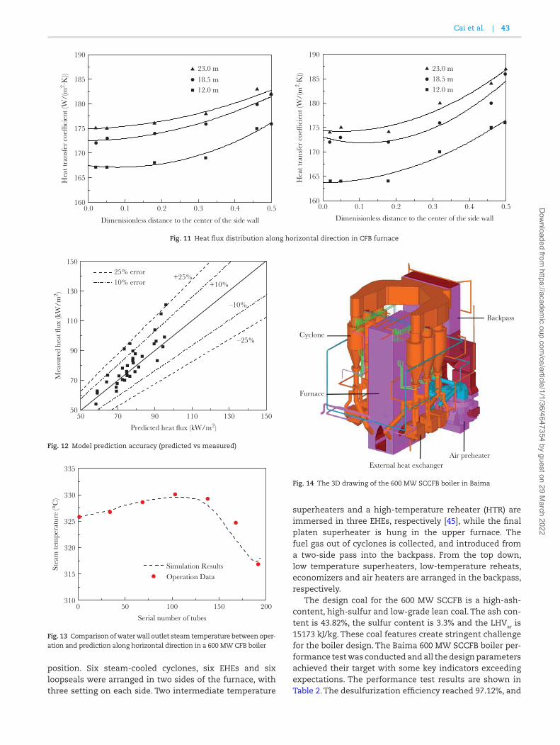
position. Six steam-cooled cyclones, six EHEs and six loopseals were arranged in two sides of the furnace, with three setting on each side. Two intermediate temperature
superheaters and a high-temperature reheater (HTR) are immersed in three EHEs, respectively [45], while the final platen superheater is hung in the upper furnace. The fuel gas out of cyclones is collected, and introduced from a two-side pass into the backpass. From the top down, low temperature superheaters, low-temperature reheats, economizers and air heaters are arranged in the backpass, respectively.
The design coal for the 600 MW SCCFB is a high-ash-content, high-sulfur and low-grade lean coal. The ash con-tent is 43.82%, the sulfur content is 3.3% and the LHVar is 15173 kJ/kg. These coal features create stringent challenge for the boiler design. The Baima 600 MW SCCFB boiler per-formance test was conducted and all the design parameters achieved their target with some key indicators exceeding expectations. The performance test results are shown in Table 2. The desulfurization efficiency reached 97.12%, and
0.0 0.1 0.2 0.3 0.4 0.5160
165
170
175
180
185
190
23.0 m
18.5 m12.0 m
Hea
t tra
nsfe
r co
e�ci
ent (
W/(
m2 ·K
))
Dimenisionless distance to the center of the side wall
0.0 0.1 0.2 0.3 0.4 0.5160
165
170
175
180
185
190
23.0 m18.5 m12.0 m
Hea
t tra
nsfe
r co
e�ci
ent (
W/(
m2 ·K
))
Dimenisionless distance to the center of the side wall
Fig. 11 Heat flux distribution along horizontal direction in CFB furnace
50 70 90 110 130 15050
70
90
110
130
150
–10%
+10%
–25%
25% error 10% error
Mea
sure
d he
at fl
ux (k
W/m
2 )
Predicted heat flux (kW/m2)
+25%
Fig. 12 Model prediction accuracy (predicted vs measured)
0 50 100 150 200310
315
320
325
330
335
Stea
m te
mpe
ratu
re (°
C)
Simulation ResultsOperation Data
Serial number of tubes
Fig. 13 Comparison of water wall outlet steam temperature between oper-ation and prediction along horizontal direction in a 600 MW CFB boiler
Cyclone
Furnace
Air preheater
Backpass
External heat exchanger
Fig. 14 The 3D drawing of the 600 MW SCCFB boiler in Baima
Cai et al. | 43D
ownloaded from
https://academic.oup.com
/ce/article/1/1/36/4647354 by guest on 29 March 2022

the NOx emission concentration was 111.94 mg/Nm3. Due to the high accuracy of the thermal calculation, the bed temperature was in complete agreement with the design value. The 600 MW SCCFB boiler show that Chinese CFB boiler technology is world class.
2.2.2 350 MW SCCFB boilerThe key technologies of the 600 MW SCCFB boiler were applied in the design of the 350 MW SCCFB boiler. In September, 2015, the first 350 MW SCCFB boiler was put into commercial operation in Shanxi Guojin Power Plant. By the end of 2016, the number of 350 MW SCCFB reached 11 with a further 70 units on order.
There is one air distributor in a 350 MW SCCFB boiler with a single furnace without external heat exchangers. Fourteen superheater wingwalls and six reheater wingwalls were hung in the upper furnace near the front wall. Three steam-cooled cyclones, as well as three loop seals under them were installed beside the rear wall. Parallel passes were arranged in the secondary pass, the low- temperature reheater in the front pass with low temperature super-heaters in the rear pass. The flue gas from two-side paral-lel passes combined and passed through the economizer and air preheater [46]. The main design parameters of the 350 MW SCCFB are shown in Table 3. The coal in this boiler includes lignite, lean coal, bituminous, anthracite, coal gangue and coal slurry. The performance test results indi-cated that the temperature of gas and steam as well as the boiler efficiency were very close to that of the design values. The pollutant concentration in flue gas was lower than the ultra-low emission limit. The water wall safety and project economy worked satisfactorily.
2.2.3 660 MW USCCFB boilerThe success of the Baima SCCFB boiler encouraged the development of the UCCFB boiler [47]. The Ministry of Science and Technology of China has provided support to design and demonstrate the 660 MW UCCFB boiler during
China’s 13th Five-Year Plan. The main design parameters of the 660 MW UCCFB are shown in Table 4. The design thermal efficiency should be higher than 92% (converted to LHVar = 14.65 MJ/kg), desired power supply coal consump-tion should be lower than 290 gce/(kW·h), and the pollu-tant emission concentration should achieve the ultra-low legislative emission requirements [48].
Table 3 The main design parameters of the 350 MW SCCFB
Design parameters Unit BMCR BRL
Main steam pressure MPa 25.40 25.26Main steam temperature °C 571 571Main steam flow rate t/h 1110 1045.9Inlet/Outlet pressure of reheat steam
MPa 4.49/4.3 4.24/4.07
Inlet/Outlet temperature of reheat steam
°C 320/569 315/569
Reheat steam flow rate t/h 928.31 880.82Feed water temperature °C 281 277
Table 4 The main design parameters of the 660 MW UCCFB
Design parameters Unit Design value
Main steam pressure MPa 29.40Main steam temperature °C 605Main steam flow rate t/h 1980Inlet/Outlet pressure of reheat steam
MPa 6.16/5.96
Inlet/Outlet temperature of reheat steam
°C 361/623
Reheat steam flow rate t/h 1655.7Feed water temperature °C 297Boiler efficiency % ≥92.5Coal consumption rate of power supply
gce/kW·h <290
NOx emission mg/Nm3 <50SO2 emission mg/Nm3 <35Particulate emission mg/Nm3 <10
Table 2 The performance test results of the 600 MW CFB boiler in Baima
Operation parameters Unit Design value Measured value
Power load MW 600 620.05Main steam pressure MPa 25.39 24.64Main steam temperature °C 571 570.02Steam flow rate t/h 1819.1 1823.01Reheat steam pressure MPa 4.149 3.98Reheat steam temperature °C 569 567.64Total attemperation flow rate t/h 142 109.2Bed temperature °C 890 890Flue gas temperature °C 128 141.47Boiler efficiency % 91.01 91.52SO2 emission mg/Nm3 <380 192.04Calcium/sulfur ratio 2.1 2.07Desulfurization efficiency % 96.7 97.12NO2 emission mg/Nm3 <160 111.94Particulate emission mg/Nm3 <30 9.34
44 | Clean Energy, 2017, Vol. 1, No. 1D
ownloaded from
https://academic.oup.com
/ce/article/1/1/36/4647354 by guest on 29 March 2022

3 Ultra-low emission CFB boiler technology3.1 Background of ultra-low emission CFB boiler technology
NOx emission from a CFB boiler is lower than PC boilers due to its lower combustion temperature. The NOx emission from a CFB boiler is less than 200 mg/m3, and the sulfur retention efficiency by limestone injection into the furnace reaches 90–95% [49, 50]. The pollutant emissions can meet the emission standards of most countries in the world, such as Australia, Japan, Canada, Switzerland, Indonesia and the Philippines. NOx and SO2 emission concentrations are limited to less than 100 mg/m3 in the National Emission Regulation for a Power Station Boiler, which results in some challenges for CFB boilers [51]. The heavy haze in parts of China resulted in the Clean Air Action Plan, which requires ultra-low emission of NOx less than 50 mg/m3 and SO2 less than 35 mg/m3. It is difficult for traditional CFB boilers to achieve the ultra-low emission requirements. CFB boilers have to be equipped with expensive gas clean systems including a flue gas desulphurization (FGD) tower and a selective catalytic reduction (SCR) reactor, which leads to higher investment and operation costs. The additional costs mean traditional CFB boilers no longer have the advantage of lower cost pollution control [52].
Chinese engineers after considering the mechanisms of CFB combustion have proposed a technological roadmap for ultra-low emission control of SO2 and NOx based on the high efficiency desulfurization by limestone injection into furnaces and low NOx combustion technology [53].
3.2 Formation and reduction of NOx in CFB combustion
NOx emission from CFB combustion are well studied in the literature [54, 55]. Various factors, such as coal type, bed temperature, air staging, and limestone, can affect the NOx emission from CFB. Due to the low temperature combustion, thermal-NOx is hardly found in CFB boilers [56]. The fuel-NOx
plays the dominant role and should be well controlled in CFB boilers [57, 58]. As mentioned above, the flow pattern in the furnace is composed of the dense bubbling or turbulent bed at the bottom and the fast bed in the freeboard. The dense bed consists of the almost non-solid bubble phase and the emulsion phase which is approximately in the minimum flu-idization state, as shown in Fig. 15. The coarse fuel particles, whose terminal velocity is larger than the superficial gas vel-ocity, tend to sink into the dense bed and complete the devol-atilization and combustion. In contrast, the fine particles will be entrained into the dilute zone by the fluidizing gas, and cluster with circulating materials [59].
As shown in Fig. 15a, fuel particles are surrounded by inert materials in the emulsion phase of the dense zone. The gas velocity inside the emulsion phase is close to the minimum fluidization velocity, and extra gas passes through the bed as bubbles. The decreasing of particle size leads to a decrease in minimum fluidization velocity, so the amount of gas flow passing directly by the particle sur-faces decreases. Moreover, the mass transfer resistance increases between the bubble phase and fuel particle sur-faces [60], which leads to an oxygen-lean condition for the fuel combustion. The intensified reducing atmosphere will restrain the transformation of char-nitrogen and volatile nitrogen of coarse fuel particle into NOx [9, 61]. As shown in Fig. 16, the conversion rate of char-nitrogen, as well as the
0 1000 2000 3000 40000
5
10
15
200.18–0.20 mm0.275–0.30 mm0.40–0.45 mm
NO
em
issi
on c
once
ntra
tion
(ppm
v)
Time (s)
Fig. 16 Effect of bed particle size on NO emission
A B
Heat transfer
Mass transfer
Fuel particle(Mainly char)
Bubble phase
Emulsion phase
Hea
ting
Surf
ace
Fuel particle(Mainly char)
Heat transfer
Mass transfer
Cluster
Main stream
Fig. 15 Schematic diagram of the fluidization regime in CFB boilers
Cai et al. | 45D
ownloaded from
https://academic.oup.com
/ce/article/1/1/36/4647354 by guest on 29 March 2022

NO emission concentration, increased with the increasing of the size of the bed material [62].
As shown in Fig. 15b, in the upper furnace, it is fast bed, and in the fast bed the gas phase and emulsion phase inver-sion occurs in contrast to the bubbling bed in the lower fur-nace [63]. The cluster is the discrete phase and the gas is the continuous phase. The heat and mass transfer behavior of fuel particles in clusters can still be analogous to that in the emulsion phase of dense bed. As the cluster tendency of par-ticles is higher than that of coarse particles, and the increas-ing solid circulation rate leads to the larger size of clusters [64, 65], the mass transfer between the gas and clusters is reduced when the bed material size is smaller. The reducing atmos-phere in the upper furnace reduces the generation of NOx [66].
The intensified reducing atmosphere will inevitably gen-erate a large amount of CO. CO, as well as char, will con-tinue to reduce the NOx [67], especially in the CFB furnace. The large quantities of ash in the circulating loops will sig-nificantly catalyze the CO–NO reaction. A large amount of char reaction surfaces is needed to intensify the combustion process due to the low bed temperature and reaction rate in CFB boilers. These surfaces are also active for NOx reduction. Surface area is relevant to the char reactivity. As the com-bustion reactivity is low for the low-volatile high-rank coal, more surfaces are needed in combustion. As a result, the NOx reduction process is intensified for low-volatile high-rank coals. The high concentration of CO in the furnace flows into the cyclones to be burnt out. The swirling flow in cyclones improves the mixing of CO and O2, intensifies the oxidation rate of CO, and ensure the combustion efficiency of CFB boil-ers. Therefore, the ultra-low emission of NOx can be realized in following several methods. In order to reconcile NOx emis-sion and combustion efficiency, the bed temperature should be kept at around 850°C. The overall collection efficiency for fine materials should be improved to reduce the bed material size and increase the solid circulation rate. The height of the secondary air nozzle is heightened to delay the secondary air entering time. Combination of these methods can expand the reducing zone to control the NOx emission [53].
3.3 Capture of SO2 by limestone during CFB combustion
The fundamental process of absorption of sulfur dioxide by sorbents in CFB boilers is shown in Fig. 17. SO2 and other
sulfides are generated from the combustion of sulfur con-tent in coal. The calcination reaction releases the CO2 and enlarges many pores in the limestone. In the oxygen-rich atmosphere, the sulfation reaction captures the SO2 and generates the CaSO4, which results in the external pores blocked by CaSO4 and prohibit the SO2 from continuing reacting with the inner part of limestone [50, 68, 69].
Several studies were undertaken to investigate the influ-encing factors on the sulfation process. The calcination reaction can significantly increase the surface porosity of limestone, but a too high temperature enhances the sin-tering of sorbent particles and results in the lower porosity and surface area [70, 71]. As the molar volume of CaSO4 (52 m3/kmol) is much larger than that of CaO (17 m3/kmol), the production blocks the surface pores and prohibits the reac-tion of inner CaO. Previous studies found that an effective SO2 penetration depth is lower than tens of micrometers or even smaller, while the specific surface area of fine particles is larger than that of coarser particles [69, 71]. As a result, although the fragment and attrition of sorbent particles can enhance the utilization of the inner part of limestone, the utilization of coarser sorbent particles is still lower than that of fine particles. In addition, the particle residence time is another key factor for limestone utilization. Due to the limi-tation of cyclone collection efficiency, extremely small parti-cles cannot be captured and will escape from the circulation loops within a short period of time. As shown in Fig. 18, coarser limestone particles ranging from 0 to 1000 μm, or
Fresh limestone CO2 is releasedthrough pores
CO2
SO2
Pores blocked byCaSO4 Unreacted pore
surface
Sulfation ofexternal surface
Fig. 17 Schematic diagram of absorption of sulfur dioxide by sorbents [69]
100
Nov
el
Tradi
tiona
l
Res
idua
l abo
ve m
esh Ri/
%
Particle size di/µm
0 200 400 600 800 1000
75
50
25
0
Fig. 18 Recommended particle size distribution of limestone
46 | Clean Energy, 2017, Vol. 1, No. 1D
ownloaded from
https://academic.oup.com
/ce/article/1/1/36/4647354 by guest on 29 March 2022

even coarser, is adopted for the desulfurization in the trad-itional CFB boilers due to the low cyclone collection effi-ciency. With the increasing of cyclone collection efficiency, finer sorbent particles can be used for SO2 capture because of the increasing residence time. This method increases the utilization of limestone, reduces the Ca/S molar ratio, and weakens the catalytic effect of sorbent particles on NOx [72]. Chinese scientists recently made progress in higher effi-ciency sulfur capture. It is suggested that the fine sorbent particle ranges from 0 to 200 μm, whose cut size is 25 to 50 μm. The desulfurization efficiency in a furnace can reach over 99% with the Ca/S molar ratio smaller than 2.
Bed temperature is another key factor for SO2 capture and the recommended temperature is around 850°C. The sulfation process should be under oxidizing condition as the gas atmosphere also affects the SO2 capture.
3.4 Ultra-low emission CFB boiler technology practices
Two 220 t/h CFB boilers in Changzhi and Linqing have achieved the goal of ultra-low emission of NOx and SO2 by improving the cyclone efficiency to increase the bed quality, reducing the average bed material size and increasing the solid circulation rate [52]. The fuel of these two projects is shown in Table 5, the main operation parameters are shown in Table 6, with the cut size of fly ash particle decreasing from 22 μm to 12 μm. The desulfurization efficiency in the two boilers was higher than 99.5% with Ca/S molar ratio less than 2. The SO2 emission concentration was lower than 35 mg/Nm3 by limestone injection into furnace for desulfur-ization. Without the SCR or SNCR, the initial NOx emission concentration was lower than 50 mg/Nm3.
4 ConclusionCFB combustion technology plays an important role in China in providing energy. Due to the wide use of CFB boilers, China
is the largest supplier and customer of CFB boilers in the world. Chinese researchers have over 30 years experienced both failure and success in establishing a comprehensive design theory on CFB boilers. Successful research projects based on design theory have further advanced internation-ally CFB combustion technology. Some of the advances in CFB technology include lower energy consumption for CFB boilers based on the reconstruction of the fluidization state. The research and development of SCCFB boiler technology has resulted in ultra-low emission CFB boilers based on limestone injection into the furnace for desulfurization and low-NOx combustion. The recent development and demon-stration of the 660 MW USCCFB boiler will further result in better integration of CFB combustion technology. The suc-cessful research resulting in increasing ultra-high parame-ters, ultra-low power consumption and ultra-low emissions will ensure a future role for CFB technology in China.
AcknowledgmentsThis work was supported by the National Thirteen-Five Year Research Program of China (2016YFB0600201).
Conflict of interest statement. None declared.
References[1] Koornneef J, Junginger M, Faaij A. Development of
fluidized bed combustion—an overview of trends, performance and cost. Prog Energy Combust Sci 2007; 33:19–55.
[2] Yue G, Li Y, Lu X, et al. The first pilot compact CFB boiler with water cooled separator in China. In: Proceedings of the 14th International Conference on Fluidized Bed Combustion, Vancouver, Canada, 1997, pp.497–506.
[3] Yue G, Lu J, Xu P, et al. The up-to-date development and future circulating fluidized bed combustion technol-ogy. Electric Power 2016; 49:1–13.
[4] Yates JG. Fundamentals of Fluidized Bed Chemical Process. London: Butterworths, 1983.
[5] Reh L, Hirsch M, Plass L. Method of and apparatus for carrying out an exothermic process. U.S. Patent 4,111,158[P]. 1978-9-5.
[6] Yang S, Yang H, Lu J, et al. The new generation combus-tion technology for energy saving circulating fluidized bed boilers. J Power Eng 2009; 29(8):728–32.
[7] Yang H, Zhang H, Lu J, et al. Novel CFB boiler tech-nology with reconstruction of its fluidization state. In: Proceedings of the 20th International Conference on Fluidized Bed Combustion. Springer, Berlin, Heidelberg, 2009, pp.195–9.
Table 6 The initial NOx emission and main operation param-eters for CFB boilers
Parameters Changzhi Linqing
Average bed temperature (°C) 860 860Windbox pressure (kPa) 5.8 5.9Pressure drop of dilute region (kPa) 1.3 1.2SO2 emission (mg/Nm3) 9.88 22.6NOx emission (mg/Nm3) 49.83 46.18Calcium/sulfur molecular ratio 1.60 1.82Sulfur capture efficiency (%) 99.71 99.53Boiler thermal efficiency (%) 91.24 91.86
Table 5 Proximate and ultimate analysis results of fuel for CFB boilers
Name LHVar (MJ/kg) Mar (%) Aar (%) Vdaf (%) Car (%) Har (%) Oar (%) Nar (%) Sar (%)
Changzhi 16.67 11.50 34.61 25.25 43.26 1.70 7.14 0.73 1.06Linqing 20.00 7.35 29.26 16.23 53.43 1.95 5.54 0.82 1.66
Cai et al. | 47D
ownloaded from
https://academic.oup.com
/ce/article/1/1/36/4647354 by guest on 29 March 2022

[8] Yang H, Yue G, Zhang H, et al. Updated design and operation experience of CFB boilers with energy sav-ing process in China. VGB PowerTech 2011; 91:49–53.
[9] Yue G, Lu J, Zhang H, et al. Design theory of circulating fluidized bed boilers. In: 18th International Conference on Fluidized Bed Combustion. Am Soc Mech Eng 2005:135–46.
[10] Yang H, Zhang H, Yang S, et al. Effect of bed pressure drop on performance of a CFB boiler. Energy Fuels 2009; 23:2886–90.
[11] Mo X, Wang P, Yang H, et al. A hydrodynamic model for circulating fluidized beds with low riser and tall riser. Powder Technol 2015; 274:146–53.
[12] Bai D, Jin Y, Yu Z, et al. The axial distribution of the cross-sectionally averaged voidage in fast fluidized beds. Powder Technol 1992; 71:51–8.
[13] Li J, Tung Y, Kwauk M. Axial voidage profiles of fast fluidized beds in different operating regions. In: Basu P, Large JF (eds), Circulating Fluidized Bed Technology II. Oxford: Pergamon,1988:193–203.
[14] Xu G, Gao S. Necessary parameters for specifying the hydrodynamics of circulating fluidized bed risers – a review and reiteration. Powder Technol 2003; 137:63–76.
[15] Lu J, Zhang J, Yue G, et al. Heat transfer coefficient cal-culation method of the heater in the circulating fluid-ized bed furnace. Heat Transfer Asia Res 2002; 31:540–50.
[16] Liu X, Zhang M, Lu J, et al. Effect of furnace pressure drop on heat transfer in a 135MW CFB boiler. Powder Technol 2015; 284:19–24.
[17] Berruti F, Pugsley TS, Godfroy L, et al. Hydrodynamics of circulating fluidized bed risers: a review. Can J Chem 1995; 73:579–602.
[18] Yang J, Yang H, Yue G. Experimental study on second-ary air jet penetration in circulating fluidized bed. J Power Eng 2008; 28:509–13.
[19] Lu J, Wang Q, Li Y, et al. Unburned carbon loss in fly ash of CFB boilers burning hard coal. Tsinghua Sci Technol 2003; 8:687–91.
[20] Xiao X, Yang H, Zhang H, et al. Research on carbon con-tent in fly ash from circulating fluidized bed boilers. Energy Fuels 2005; 19:1520–25.
[21] Su J, Hu N. Application of fluidization reconstruction energy-saving combustion technology on 300MW CFB boiler. Adv Material Res 2012; 516:140–5.
[22] Lu J, Yu L, Yue G, et al. Heat flux distribution along water walls of circulating fluidized bed. J Power Eng 2006; 26:336–40.
[23] Wu Y, Lu J, Zhang J, et al. Conceptual design of an 800 MWe supercritical pressure circulating fluidized bed. Boiler Technol 2004; 35:1–5.
[24] Hu N, Zhang H, Yang H, et al. Effects of riser height and total solids inventory on the gas-solids in an ultra-tall CFB riser. Powder Technol 2009; 196:8–13.
[25] Xu G, Gao S. More fundamentals of dilute suspension collapse and choking for vertical conveying systems. AIChE J 2001; 47:2177–96.
[26] Yuxin W, Junfu L, Jiansheng Z. Heat flux and hydrody-namics of the membrane wall of supercritical pressure circulating fluidized bed boiler. In: 5th International
symposium on multiphase flow, heat mass transfer and energy conversion, 2005 (No. 149).
[27] Yue G, Yang H, Nie L, et al. Hydrodynamics of 300 MW and 600 MW circulating fluidized bed boilers with asymmetric cyclone layout. In: Proceedings of the 9th International Conference on Circulating Fluidized Beds. Hamburg, 2008, pp. 153–8.
[28] Yang S, Yang H, Liu Q, et al. Research on flow non-uni-formity in main circulation loop of a CFB boiler with multiple cyclones. In: Proceedings of the 20th International Conference on Fluidized Bed Combustion, Xi’an, 2009, pp. 341–4.
[29] Mo X, Cai R, Huang X, et al. The effects of wall friction and solid acceleration on the mal-distribution of gas-solid flow in double identical parallel cyclones. Powder Technol 2015; 286:471–7.
[30] Guevel LT, Thomas P. Fuel flexibility and petroleum coke combustion at provence 250 MW CFB. In: 17th international conference on fluidized bed combustion. Am Soc Mech Eng 2003:643–9.
[31] Li J, Wang W, Yang H, et al. Bed inventory overturn in a circulating fluid bed riser with pant-leg structure. Energy Fuels 2009; 23:2565–9.
[32] Li J, Hu N, Yao X, et al. Experimental study of the bed Inventory overturn in pant-legs furnace of CFB boilers. J China UnivMining Technol 2011; 40:54–9.
[33] Hu N, Li J, Liu X, et al. Mechanism study of lateral bed pressure wave of large scale CFB boilers. Proc CSEE 2013; 33:1–7.
[34] Jiang H, Lu J, Hu N, et al. Modelling research on effects of static bed height on lateral bed pressure fluctua-tions in large cross section circulating fluidized bed boilers. J China Coal Soc 2016; 41:2533–40.
[35] Grace JR. Heat transfer in circulating fluidized beds. Circ Fluid Bed Technol 1986.
[36] Zhang R, Yang H, Lu J, et al. Theoretical and experi-mental analysis of bed-to-wall heat transfer in heat recovery processing. Powder Technol 2013; 249:186–95.
[37] Wang Y, Lu J, Yang H, et al. Measurement of heat trans-fer in a 465t/h circulating fluidized bed boiler. In: 18th International Conference on Fluidized Bed Combustion. American Society of Mechanical Engineers, 2005, pp. 327–35.
[38] Zhang R, Yang H, Zhang H, et al. Research on heat transfer inside the furnace of large scale CFB boilers. In: Proceedings of the 10th International Conference of CFB, Sunriver, USA, 2011, pp. 66–74.
[39] Zhang R, Yang H, Hu N, et al. Experimental investiga-tion and model validation of the heat flux profile in a 300MW CFB boiler. Powder Technol 2013; 246:31–40.
[40] Zhang P, Lu JF, Yang HR, et al. Heat transfer coefficient distribution in the furnace of a 300MWe CFB boiler. In: Proceedings of the 20th International Conference on Fluidized Bed Combustion. Springer, Berlin, Heidelberg, 2009, pp. 167–71.
[41] Li Y, Nie L, Hu X K, et al. Structure and performance of a 600MWe supercritical CFB boiler with water cooled panels. In: Proceedings of the 20th International
48 | Clean Energy, 2017, Vol. 1, No. 1D
ownloaded from
https://academic.oup.com
/ce/article/1/1/36/4647354 by guest on 29 March 2022

Conference on Fluidized Bed Combustion. Springer, Berlin, Heidelberg, 2009, pp. 132–6.
[42] Li Y, Li W, Wu Y, et al. Hydrodynamics of the water wall in a 600 MW supercritical circulating fluidized bed boiler with water cooled panels within the furnace. Proc CSEE 2008; 28:1–5.
[43] Yue G, Ling W, Lu J, et al. Development and demonstra-tion of the 600 MW supercritical CFB boiler in Baima power plant. In: Proceedings of the 22nd Fluidized Bed Conversion, Turku, Finland, 2015.
[44] Yue G, Yang H, Nie Li, et al. Hydrodynamics of 300MWe and 600MWe CFB boilers with asymmetric cyclone lay-out. In Werther J (ed). Proceedings of the 9th International Conference of CFB, Hamberg, 2008, pp. 153–8.
[45] Zhang M, Wu H, Lu Q, et al. Heat transfer characteris-tics of fluidized bed heat exchanger in a 300MW CFB boiler. Powder Technol 2012; 222:1–7.
[46] Cheng W, Song G, Zhou X, et al. Study on operation characteristics of the Dongfang’s 350 MW supercritical CFB boiler. Dongfang Electric Rev 2016; 30:38–42.
[47] Lu J, Man Z, Yang H, et al. Conceptual design of a sim-plified 660MW ultra-supercritical circulating fluidized bed boiler. Proc CSEE 2014; 34:741–7.
[48] Cai R, Lu J, Ling W, et al. Progress of supercritical and ultra-supercritical circulating fluidized bed boiler technology. Electric Power 2016; 49:1–7.
[49] Tullin CJ, Goel S, Morihara A, et al. Nitrogen oxide (NO and N2O) formation for coal combustion in a fluidized bed: effect of carbon conversion and bed temperature. Energy Fuels 1993; 7:796–802.
[50] Anthony EJ, Granatstein DJ. Sulfation phenomena in fluidized bed combustion systems. Progress Energy Combust Sci 2001; 27:215–36.
[51] Li J, Yang H, Wu Y, et al. Effects of the updated National Emission Regulation in China on circulating fluidized bed boilers and the solutions to meet them. Environ Sci Technol 2013; 47:6681–7.
[52] Yue G, Cai R, Lu J, et al. From a CFB reactor to a CFB boiler – the review of R&D progress of CFB coal com-bustion technology in China. Powder Technol 2016.
[53] Li J, Zhang M, Yang H, et al. The theory and practice of NOx emission control for circulating fluidized bed boilers based on the re-specification of the fluidization state. Fuel Process Technol 2016; 150:88–93.
[54] Winter F, Wartha C, Löffler G, et al. The NO and N2O formation mechanism during devolatilization and char combustion under fluidized-bed conditions. In: Symposium (international) on combustion. Elsevier, 1996, pp. 3325–34.
[55] Yue GX, Pereira FJ, Sarofim AF, et al. Char nitrogen con-version to NOx in a fluidized bed. Combust Sci Technol 1992; 83:245–56.
[56] Hampartsoumian E, Gibbs BM. NOx formation and reduction in fluidized bed combustors. J Inst Energy 1984; 57:402–10.
[57] Hou X, Zhang H, Yang S, et al. N2O decomposition over the circulating ashes from coal-fired CFB boilers. Chem Eng J 2008; 140:43–51.
[58] Knöbig T, Werther J, Åmand L, et al. Comparison of large- and small-scale circulating fluidized bed com-bustors with respect to pollutant formation and reduction for different fuels. Fuel 1998; 77:1635–42.
[59] Kwauk M, Li J. Fluidization regimes. Powder Technol 1996; 87:193–202.
[60] Jin X, Lu J, Yang H, et al. Comprehensive mathematical model for coal combustion in a circulating fluidized bed combustor. Tsinghua Sci Technol 2001; 6:319–25.
[61] Tarelho LAC, Matos MAA, Pereira FJMA. Axial concen-tration profiles and NO flue gas in a pilot-scale bub-bling fluidized bed coal combustor. Energy Fuels 2004; 18:1615–24.
[62] Li J, Yang X, Yang H, et al. Experimental study and modelling of NOx generation from char nitrogen in the bubbling bed. J China Coal Soc 2016; 41:1546–53.
[63] Zhang C, Lin Y, Zhang M. A unified model for fast flu-idization dynamics. Part II: prediction of upside dilute phase holdup and lower dense phase holdup. J Eng Thermophys 2011; 33:694–8.
[64] Xu J, Zhu JX. Visualization of particle aggregation and effects of particle properties on cluster characteristics in a CFB riser. Chem Eng J 2011; 168:376–89.
[65] Guenther C, Breault R. Wavelet analysis to characterize cluster dynamics in a circulating fluidized bed. Powder Technol 2007; 173:163–73.
[66] Liu X, Zhao Y, Xu X. Theoretically studies of the coal particle cluster combustion behavior in a circulating fluidized bed. Proc CSEE 2006; 26:30–4.
[67] Amand LE, Leckner B. Oxidation of volatile nitrogen compounds during combustion in circulating fluid-ized bed boilers. Energy Fuels 1991; 5:809–15.
[68] Qiao R, Lu J, Wu X, et al. Modeling of sulfur retention in circulating fluidized bed coal combustors. Tsinghua Sci Technol 2001; 6:314–8.
[69] Basu P. Circulating Fluidized Bed Boilers: Design, Operation and Maintenance. Switzerland: Springer, 2015.
[70] Fuertes AB, Alvarez D, Rubiera F, et al. Surface area and pore size changes during sintering of calcium oxide particles. Che Eng Commun 1991; 109:73–88.
[71] Haji-Sulaiman MZ, Scaroni AW. Calcination and sul-phation behaviour of sorbents in fluidized bed com-bustion. Fuel 1991; 70:169–76.
[72] Liu H, Gibbs BM. The influence of calcined limestone on NOx and N2O emissions from char combustion in fluidized bed combustors. Fuel 2001; 80:1211–5.
Cai et al. | 49D
ownloaded from
https://academic.oup.com
/ce/article/1/1/36/4647354 by guest on 29 March 2022