BX Third Function Valve Kit - Land Pride
14
1 © Copyright 2021 Printed Before You Start General Information Your BX Third Function Valve Kit is exclusively designed for your Kubota 60 & 70 series BX tractors. Please read these installation instructions thoroughly before assembling this kit to your Kubota tractor and loader. Especially read information relating to safety concerns. These assembly instructions apply to the Third Function Valve Kit Accessories listed below: • 380-337A: 3FVK FF BX2670 . . . . . . . . . . . . . . page 2 Further Assistance Your Land Pride dealer wants you to be satisfied with your new BX Third Function Valve Kit. If for any reason you do not understand any part of this manual or are not satisfied with the service received, the following actions are suggested: 1. Discuss any problems you have with your Third Function Valve Kit with your dealership service personnel so they can address the problem. 2. If you are still not satisfied, seek out the owner or general manager of the dealership, explain the question/problem, and request assistance. 3. For further assistance write to: Land Pride Service Department 1525 East North Street P.O. Box 5060 Salina, Ks. 67402-5060 E-mail address [email protected] When you see this symbol, the subsequent instructions and warnings are serious - follow without exception. Your life and the lives of others depend on it! ! WARNING: Cancer and reproductive harm. www.P65Warnings.ca.gov ! California Proposition 65 IMPORTANT: Before you begin, thoroughly read these instructions and check to be sure all parts are accounted for. Please retain these installation instructions for future reference and parts ordering information. Assembly Instructions A detailed listing of parts for this kit is provided on page 8 for kits. Use the list that is for your specific Third Function Valve Kit as a checklist to inventory parts received. Please contact your local Land Pride dealer for any missing hardware. Direction Reference All directional references are made from the operator seat while facing the direction the machine will operate. Directional Arrows Used in Illustrations Initial Preparations WARNING ! To avoid serious injury or death: Hydraulic fluid under high pressure can penetrate the skin and/or eyes causing a serious injury. Wear protective gloves and safety glasses or goggles when working with hydraulic systems. The steps listed below must be followed before installing this kit: The steps listed below must be followed before installing this kit: 1. Reduce engine speed. Park tractor and attachment on solid, level ground. 2. Unhook the attachment from the loader arms, back away from attachment several feet, and lower loader arms until they are fully down. 3. Put tractor in park or set park brake, turn off engine, and remove ignition key to prevent unauthorized starting. 4. Relieve all hydraulic pressure to auxiliary hydraulic lines. 5. Wait for all components to come to a complete stop before leaving the operator’s seat. 6. Use steps, grab-handles and anti-slip surfaces when stepping on and off the tractor. 7. As a safety precaution, disconnect the negative battery cable from battery terminal. Move cable away from terminal to avoid accidental contact. U D B F R L U = up L = left B = back D = down R = right F = front KEY: For Kubota 60 & 70 Series Tractors BX Third Function Valve Kit #380-137A & 380-337A Installation Instructions Manual No. 380-145M 01/18/21
-
Upload
khangminh22 -
Category
Documents
-
view
3 -
download
0
Transcript of BX Third Function Valve Kit - Land Pride

1© Copyright 2021 Printed
Before You Start
General InformationYour BX Third Function Valve Kit is exclusively designed for your Kubota 60 & 70 series BX tractors. Please read these installation instructions thoroughly before assembling this kit to your Kubota tractor and loader. Especially read information relating to safety concerns.
These assembly instructions apply to the Third Function Valve Kit Accessories listed below:
• 380-337A: 3FVK FF BX2670 . . . . . . . . . . . . . . page 2
Further AssistanceYour Land Pride dealer wants you to be satisfied with your new BX Third Function Valve Kit. If for any reason you do not understand any part of this manual or are not satisfied with the service received, the following actions are suggested:
1. Discuss any problems you have with your Third Function Valve Kit with your dealership service personnel so they can address the problem.
2. If you are still not satisfied, seek out the owner or general manager of the dealership, explain the question/problem, and request assistance.
3. For further assistance write to:
Land Pride Service Department1525 East North Street
P.O. Box 5060Salina, Ks. 67402-5060
E-mail [email protected]
When you see this symbol, the subsequent instructions and warnings are serious - follow without exception. Your life and the lives of others depend on it!
!
WARNING: Cancer and reproductive harm. www.P65Warnings.ca.gov!
California Proposition 65
IMPORTANT: Before you begin, thoroughly read these instructions and check to be sure all parts are accounted for. Please retain these installation instructions for future reference and parts ordering information.
Assembly InstructionsA detailed listing of parts for this kit is provided on page 8 for kits. Use the list that is for your specific Third Function Valve Kit as a checklist to inventory parts received. Please contact your local Land Pride dealer for any missing hardware.
Direction Reference All directional references are made from the operator seat while facing the direction the machine will operate.
Directional Arrows Used in Illustrations
Initial Preparations
WARNING!To avoid serious injury or death: Hydraulic fluid under high pressure can penetrate the skin and/or eyes causing a serious injury. Wear protective gloves and safety glasses or goggles when working with hydraulic systems.
The steps listed below must be followed before installing this kit:The steps listed below must be followed before installing this kit:1. Reduce engine speed. Park tractor and attachment
on solid, level ground.
2. Unhook the attachment from the loader arms, back away from attachment several feet, and lower loader arms until they are fully down.
3. Put tractor in park or set park brake, turn off engine, and remove ignition key to prevent unauthorized starting.
4. Relieve all hydraulic pressure to auxiliary hydraulic lines.
5. Wait for all components to come to a complete stop before leaving the operator’s seat.
6. Use steps, grab-handles and anti-slip surfaces when stepping on and off the tractor.
7. As a safety precaution, disconnect the negative battery cable from battery terminal. Move cable away from terminal to avoid accidental contact.
U
DB
F
R
L U = up
L = left
B = back
D = down
R = right
F = front
KEY:
For Kubota 60 & 70 Series Tractors
BX Third Function Valve Kit#380-137A & 380-337A Installation Instructions
Manual No. 380-145M
01/18/21

Assembly Instructions
BX Third Function Valve Kit #380-137A & 380-337A Installation Instructions Manual No. 380-145M 1/18/212
Valve Mount & Valve AssemblyRefer to Figure 1 & Figure 2:1. Bolt the valve mount plate (#2) to existing hole “D” in
tractor platform with 5/16" x 1" bolt (#6) and hex whiz nut (#8). Tighten hex whiz nut to 17 ft-lbs.
2. Attach valve (#12) to valve mount plate (#2) using1/4" x 7/8" bolts (#18). Tighten bolts to 8 ft-lbs.
3. Attach 62" long hose (#13) to “T” port in valve (#12) using adapter (#21).
4. Attach 48" long hose (#17) to “P” port in valve(#12) using adapter (#21).
5. Route hydraulic hoses (#13 & #17) left of valve mount plate (#2) and down beneath tractor platform.
6. Install adapters (#22) and red dust caps (#28) to“A” & “B” ports on valve (#12). Attach quick couplers (#26) to adapters (#22).
7. Tighten installed fittings and hydraulic hoses.
Third Function Valve Kit Figure 1
U
DB
F
R
L
73113
Port A
Port B
Port T
Attaches to the positive (+) post on the tractor battery.
Port P
12
Valve port identification
Assembly Instructions
Valve LocationFigure 2
D
2
4
4
8 6
12
19
32
13
17
B-port
A-port
35837
Assembly Instructions
1/18/21 BX Third Function Valve Kit #380-137A & 380-337A Installation Instructions Manual No. 380-145M 3
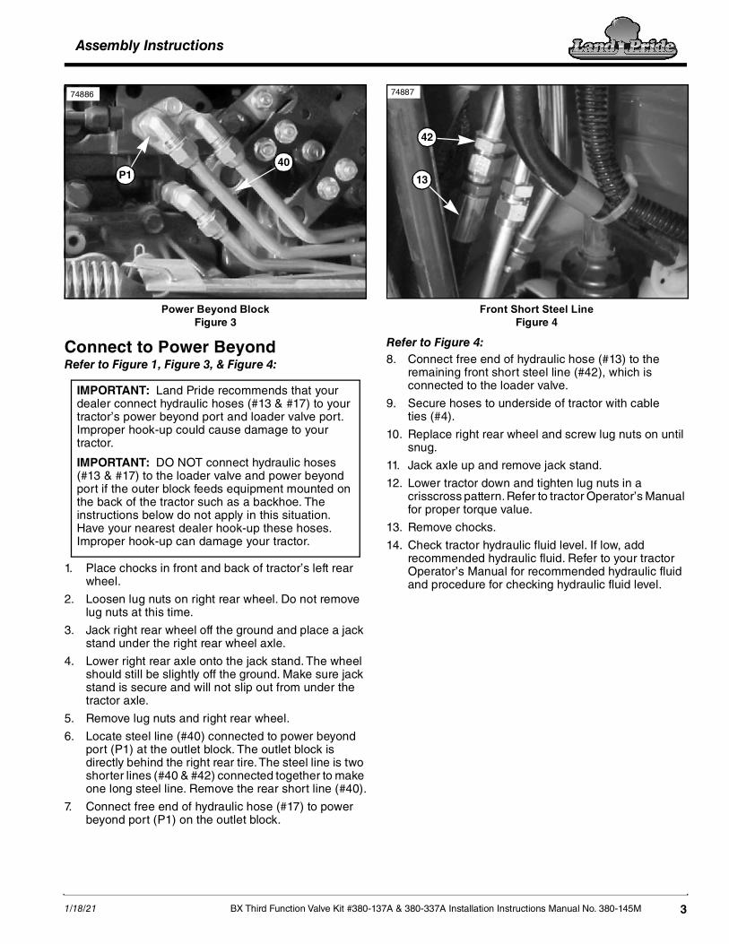
Power Beyond BlockFigure 3
Connect to Power BeyondRefer to Figure 1, Figure 3, & Figure 4:
1. Place chocks in front and back of tractor’s left rear wheel.
2. Loosen lug nuts on right rear wheel. Do not remove lug nuts at this time.
3. Jack right rear wheel off the ground and place a jack stand under the right rear wheel axle.
4. Lower right rear axle onto the jack stand. The wheel should still be slightly off the ground. Make sure jack stand is secure and will not slip out from under the tractor axle.
5. Remove lug nuts and right rear wheel.
6. Locate steel line (#40) connected to power beyond port (P1) at the outlet block. The outlet block is directly behind the right rear tire. The steel line is two shorter lines (#40 & #42) connected together to make one long steel line. Remove the rear short line (#40).
7. Connect free end of hydraulic hose (#17) to power beyond port (P1) on the outlet block.
40P1
74886
IMPORTANT: Land Pride recommends that your dealer connect hydraulic hoses (#13 & #17) to your tractor’s power beyond port and loader valve port. Improper hook-up could cause damage to your tractor.
IMPORTANT: DO NOT connect hydraulic hoses (#13 & #17) to the loader valve and power beyond port if the outer block feeds equipment mounted on the back of the tractor such as a backhoe. The instructions below do not apply in this situation. Have your nearest dealer hook-up these hoses. Improper hook-up can damage your tractor.
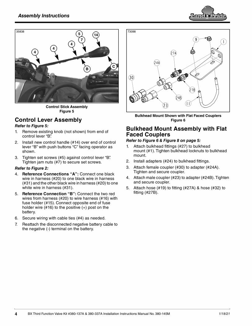
Front Short Steel LineFigure 4
Refer to Figure 4:8. Connect free end of hydraulic hose (#13) to the
remaining front short steel line (#42), which is connected to the loader valve.
9. Secure hoses to underside of tractor with cable ties (#4).
10. Replace right rear wheel and screw lug nuts on until snug.
11. Jack axle up and remove jack stand.
12. Lower tractor down and tighten lug nuts in a crisscross pattern. Refer to tractor Operator’s Manual for proper torque value.
13. Remove chocks.
14. Check tractor hydraulic fluid level. If low, add recommended hydraulic fluid. Refer to your tractor Operator’s Manual for recommended hydraulic fluid and procedure for checking hydraulic fluid level.
13
42
74887
Assembly Instructions
BX Third Function Valve Kit #380-137A & 380-337A Installation Instructions Manual No. 380-145M 1/18/214
Control Stick AssemblyFigure 5
Control Lever AssemblyRefer to Figure 5:1. Remove existing knob (not shown) from end of
control lever “B”.
2. Install new control handle (#14) over end of control lever “B” with push buttons “C” facing operator as shown.
3. Tighten set screws (#5) against control lever “B”. Tighten jam nuts (#7) to secure set screws.
Refer to Figure 2:4. Reference Connections “A”: Connect one black
wire in harness (#20) to one black wire in harness (#31) and the other black wire in harness (#20) to one white wire in harness (#31).
5. Reference Connection “B”: Connect the two red wires from harness (#20) to wire harness (#16) with fuse holder (#15). Connect opposite end of fuse holder wire (#16) to the positive (+) post on the battery.
6. Secure wiring with cable ties (#4) as needed.
7. Reattach the disconnected negative battery cable to the negative (-) terminal on the battery.
B
147
5
44
4
C
35838
Bulkhead Mount Shown with Flat Faced CouplersFigure 6
Bulkhead Mount Assembly with Flat Faced CouplersRefer to Figure 6 & Figure 8 on page 5:1. Attach bulkhead fittings (#27) to bulkhead
mount (#1). Tighten bulkhead locknuts to bulkhead mount.
2. Install adapters (#24) to bulkhead fittings.
3. Attach female coupler (#30) to adapter (#24A). Tighten and secure coupler.
4. Attach male coupler (#23) to adapter (#24B). Tighten and secure coupler.
5. Attach hose (#19) to fitting (#27A) & hose (#32) to fitting (#27B).
7309873098

Assembly Instructions
1/18/21 BX Third Function Valve Kit #380-137A & 380-337A Installation Instructions Manual No. 380-145M 5
Bulkhead Mount Shown with Pioneer CouplersFigure 7
Bulkhead Mount Assembly with Pioneer CouplersRefer to Figure 7:1. Attach bulkhead fittings (#27) to bulkhead
mount (#1). Tighten bulkhead locknuts to bulkhead mount.
2. Slide red dust plugs (#35) on bulkhead fitting.
3. Attach male couplers (#36) to bulkhead fittings. Tighten and secure coupler.
4. Attach hose (#19) to fitting (#27A) & hose (#32) to fitting (#27B).
Cross Beam & Hose Holder AssemblyFigure 8
7309874929
19
3
11 9
1
32
Crossbeam
109
Disconnect couplers
35839
Cross Beam Mount AssemblyRefer to Figure 1 on page 2, & Figure 6 on page 4, & Figure 8:1. Orient bulkhead mount (#1) as shown in Figure 8,
attach mount to the right-hand side of loader crossbeam with u-bolt (#11) and hex whiz nuts (#9). Tighten hex whiz nuts to 20 ft-lbs.
Hose Route Along Loader ArmFigure 9
Hydraulic Hose RoutingRefer to Figure 1 on page 2, Figure 8, & Figure 9:2. Route hoses (#19 & #32) along loader arm and
through loader loop bracket to third function valve (#10).
3. Install female couplers (#25) and black dust plugs (#29) to hoses (#19 & #32).
4. Connect hose (#32) to port “A” on the left-hand side of valve block (#12).
5. Connect hose (#19) to port “B” on the right-hand side of valve block (#12).
6. Secure hydraulic hoses (#19 & #32) as needed with cable ties (#4).
Hose Holder Bracket AssemblyRefer to Figure 1 on page 2 & Figure 8:1. Attach hose holder bracket (#3) to the loader’s
right-hand arm as shown in Figure 8 with 3/8"-16 x 3 1/32" x 2 3/4" u-bolt (#10) and hex whiz nuts (#9).
2. Tighten whiz nuts to the correct torque.
32 Loader Loop Bracket
4
19
19
32
35840

Assembly Instructions
BX Third Function Valve Kit #380-137A & 380-337A Installation Instructions Manual No. 380-145M 1/18/216
Check Operating and Fluid LevelThe Third Function Valve is now ready to be used with a multitude of attachments. Be sure to familiarize yourself with a complete understanding of how to operate the Third Function Valve Kit.
DANGER!To avoid serious injury or death: Do not allow bystanders to be near the attachment, loader arms, or tractor during operation. They can become entangled, pinched, or crushed by the equipment. Disconnect and lockout power source before making adjustments or servicing tractor and attachment. 1. Hook attachment to the tractor front loader and
couple hydraulic hoses to the bulkhead couplers at the front of the loader.
2. Raise attachment off the ground and operate the third function hydraulics using the push-buttons on the newly installed control handle.
• The top red button switch will actuate the attachment in one direction.
• The bottom red button switch will actuate the attachment in the opposite direction.
3. Refer to Figure 1 on page 2: Switch hoses (#19 & #32) at couplers (#25) if the attachment’s hydraulic cylinder(s) operate in the opposite direction intended.
4. Once hoses and cylinder(s) are full of hydraulic fluid, check tractor hydraulic fluid level.
5. If low, add recommended hydraulic fluid.
Relieve Hydraulic System PressureBe sure to lower the attachment to the ground and to relieve all hydraulic pressure to the attachment before leaving the tractor seat. Relieve hydraulic pressure to the attachment as follows:
1. Turn tractor switch key to off.
2. Press and hold both red buttons down on the control handle until all movement at the attachment stops.
IMPORTANT: Refer to your tractor Operator’s Manual for recommended hydraulic fluid and procedure for checking hydraulic fluid level.

Assembly Instructions
1/18/21 BX Third Function Valve Kit #380-137A & 380-337A Installation Instructions Manual No. 380-145M 7
This page left blank intentionally.

Assembly Instructions
BX Third Function Valve Kit #380-137A & 380-337A Installation Instructions Manual No. 380-145M 1/18/218
Third Function Valve Kit for Cab TractorFigure 10
73118
811-253C - (#13)
811-277C - (#19)
841-563C - (#17)
Hydraulic Hose Identification Chart
73117
Replacement valve (#30) for 810-926C (valve only)

Assembly Instructions
1/18/21 BX Third Function Valve Kit #380-137A & 380-337A Installation Instructions Manual No. 380-145M 9
Kit No. 380-337A BX THIRD FUNCTION VALVE KIT (Equipped with flat faced couplers)
Item Part No. Description Qty1 380-223D PLATE, BX BLKHD MOUNT . . . . . . . . . . . . . . . . . . . . . . . . . . . . . . . . . . . . . . . . . . . . . . . . 12 380-224D PLATE, BX VALVE MOUNT. . . . . . . . . . . . . . . . . . . . . . . . . . . . . . . . . . . . . . . . . . . . . . . . . 13 380-226D BRKT, HOSE HOLDER. . . . . . . . . . . . . . . . . . . . . . . . . . . . . . . . . . . . . . . . . . . . . . . . . . . . 14 800-112C CABLE TIE .19X7.25 1.75D 50LB . . . . . . . . . . . . . . . . . . . . . . . . . . . . . . . . . . . . . . . . . . . . 85 801-204C SCREW SET SCKT HD 5/16-18X3/4 . . . . . . . . . . . . . . . . . . . . . . . . . . . . . . . . . . . . . . . . . 26 802-159C HHCS 5/16-18X1 GR5 . . . . . . . . . . . . . . . . . . . . . . . . . . . . . . . . . . . . . . . . . . . . . . . . . . . . 17 803-008C NUT HEX 5/16-18 PLT . . . . . . . . . . . . . . . . . . . . . . . . . . . . . . . . . . . . . . . . . . . . . . . . . . . . 28 803-043C NUT HEX WHIZ 5/16-18 PLT . . . . . . . . . . . . . . . . . . . . . . . . . . . . . . . . . . . . . . . . . . . . . . . 19 803-198C NUT HEX WHIZ 3/8-16 PLT . . . . . . . . . . . . . . . . . . . . . . . . . . . . . . . . . . . . . . . . . . . . . . . . 4
10 806-132C U-BOLT 3/8-16 X 3 1/32 X 2 3/4 . . . . . . . . . . . . . . . . . . . . . . . . . . . . . . . . . . . . . . . . . . . . . 111 806-256C U-BOLT 3/8-16X3 1/2X4 1/8 RND. . . . . . . . . . . . . . . . . . . . . . . . . . . . . . . . . . . . . . . . . . . . 112 810-926C VALVE, THIRD FUNCTION . . . . . . . . . . . . . . . . . . . . . . . . . . . . . . . . . . . . . . . . . . . . . . . . . 113 811-253C HH3/8R2 062 9/16FJIC . . . . . . . . . . . . . . . . . . . . . . . . . . . . . . . . . . . . . . . . . . . . . . . . . . . . 114 380-165S ASY, PUSH BUTTON CNTRL HNDL. . . . . . . . . . . . . . . . . . . . . . . . . . . . . . . . . . . . . . . . . . 115 833-495C FUSE, 10 AMP MINI BLADE. . . . . . . . . . . . . . . . . . . . . . . . . . . . . . . . . . . . . . . . . . . . . . . . 116 833-650C BLADE FUSE HOLDER, MINI . . . . . . . . . . . . . . . . . . . . . . . . . . . . . . . . . . . . . . . . . . . . . . 117 841-563C HH3/8R2 048 9/16FJIC . . . . . . . . . . . . . . . . . . . . . . . . . . . . . . . . . . . . . . . . . . . . . . . . . . . . 118 802-418C HSHCS 1/4-20X7/8. . . . . . . . . . . . . . . . . . . . . . . . . . . . . . . . . . . . . . . . . . . . . . . . . . . . . . . 219 851-277C HH1/4R2 054 9/16MORB 9/16FJIC . . . . . . . . . . . . . . . . . . . . . . . . . . . . . . . . . . . . . . . . . . . 220 861-543C CP 3/4FORB QD FML FLATFACE . . . . . . . . . . . . . . . . . . . . . . . . . . . . . . . . . . . . . . . . . . . 121 811-170C AD 9/16MORB 9/16MJIC . . . . . . . . . . . . . . . . . . . . . . . . . . . . . . . . . . . . . . . . . . . . . . . . . . 222 811-636C AD 9/16MORB STRAIGHT UNION . . . . . . . . . . . . . . . . . . . . . . . . . . . . . . . . . . . . . . . . . . . 223 841-099C CP 3/4FORB QD FLATFACE . . . . . . . . . . . . . . . . . . . . . . . . . . . . . . . . . . . . . . . . . . . . . . . 124 841-103C AD 3/4MORB 9/16FORB. . . . . . . . . . . . . . . . . . . . . . . . . . . . . . . . . . . . . . . . . . . . . . . . . . . 225 841-466C CP 9/16FORB QD 1/4BODY FEMALE . . . . . . . . . . . . . . . . . . . . . . . . . . . . . . . . . . . . . . . . 226 841-467C CP 9/16 FORB QD 1/4 BODY MALE. . . . . . . . . . . . . . . . . . . . . . . . . . . . . . . . . . . . . . . . . . 227 851-276C AD 9/16MJIC9/16MORB BLKHD W/LN . . . . . . . . . . . . . . . . . . . . . . . . . . . . . . . . . . . . . . . . 228 851-976C DUST CAP, 1/4" QD AG . . . . . . . . . . . . . . . . . . . . . . . . . . . . . . . . . . . . . . . . . . . . . . . . . . . 229 851-977C BLACK DUST PLUG, 1/2" QD AG. . . . . . . . . . . . . . . . . . . . . . . . . . . . . . . . . . . . . . . . . . . . 230 850-472C HYDRO-TEK VALVE REPLACEMENT . . . . . . . . . . . . . . . . . . . . . . . . . . . . . . . . . . . . . . . . . 1

Assembly Instructions
BX Third Function Valve Kit #380-137A & 380-337A Installation Instructions Manual No. 380-145M 1/18/2110
Third Function Valve Kit for Cab TractorFigure 11
35841
811-253C - (#14)
811-277C - (#22)
841-563C - (#20)
Hydraulic Hose Identification Chart
73117
Replacement valve (#25) for 810-926C (valve only)
Pioneer couplers (#19)
with dustcaps (#23)

Assembly Instructions
1/18/21 BX Third Function Valve Kit #380-137A & 380-337A Installation Instructions Manual No. 380-145M 11
Kit No. 380-137A BX THIRD FUNCTION VALVE KIT (Equipped with pioneer couplers)
Item Part No. Description Qty1 380-165S ASSEMBLY, PUSH BUTTON CONTROL HANDLE . . . . . . . . . . . . . . . . . . . . . . . . 12 380-223D PLATE, BX BLKHD MOUNT . . . . . . . . . . . . . . . . . . . . . . . . . . . . . . . . . . . . . . . . . 13 380-224D PLATE, BX VALVE MOUNT . . . . . . . . . . . . . . . . . . . . . . . . . . . . . . . . . . . . . . . . . . 14 380-226D BRKT, HOSE HOLDER . . . . . . . . . . . . . . . . . . . . . . . . . . . . . . . . . . . . . . . . . . . . . 15 800-112C CABLE TIES . . . . . . . . . . . . . . . . . . . . . . . . . . . . . . . . . . . . . . . . . . . . . . . . . . . . . 86 802-159C HHCS 5/16-18X1 GR5. . . . . . . . . . . . . . . . . . . . . . . . . . . . . . . . . . . . . . . . . . . . . . 17 802-418C HSHCS 1/4-20X7/8 . . . . . . . . . . . . . . . . . . . . . . . . . . . . . . . . . . . . . . . . . . . . . . . . 28 803-043C NUT HEX WHIZ 5/16-18 PLT. . . . . . . . . . . . . . . . . . . . . . . . . . . . . . . . . . . . . . . . . 19 803-198C NUT HEX WHIZ 3/8-16 PLT. . . . . . . . . . . . . . . . . . . . . . . . . . . . . . . . . . . . . . . . . . 410 806-132C U-BOLT 3/8-16 X 3 1/32 X 2 3/4 . . . . . . . . . . . . . . . . . . . . . . . . . . . . . . . . . . . . . . 111 806-256C U-BOLT 3/8-16X3 1/2X4 1/8 RND . . . . . . . . . . . . . . . . . . . . . . . . . . . . . . . . . . . . . 112 810-926C VALVE, THIRD FUNCTION . . . . . . . . . . . . . . . . . . . . . . . . . . . . . . . . . . . . . . . . . . 113 811-170C AD 9/16MORB 9/16MJIC. . . . . . . . . . . . . . . . . . . . . . . . . . . . . . . . . . . . . . . . . . . . 214 811-253C HH3/8R2 062 FJIC9/16 . . . . . . . . . . . . . . . . . . . . . . . . . . . . . . . . . . . . . . . . . . . . . 115 811-636C AD 9/16MORB STRAIGHT UNION . . . . . . . . . . . . . . . . . . . . . . . . . . . . . . . . . . . . 216 833-495C FUSE, 10 AMP MINI BLADE . . . . . . . . . . . . . . . . . . . . . . . . . . . . . . . . . . . . . . . . . 117 833-650C BLADE FUSE HOLDER, MINI . . . . . . . . . . . . . . . . . . . . . . . . . . . . . . . . . . . . . . . . 118 841-466C CP 9/16FORB QD 1/4BODY FEMALE. . . . . . . . . . . . . . . . . . . . . . . . . . . . . . . . . . 219 841-467C CP 9/16 FORB QD 1/4 BODY MALE . . . . . . . . . . . . . . . . . . . . . . . . . . . . . . . . . . . 420 841-563C HH3/8R2 048 9/16FJIC . . . . . . . . . . . . . . . . . . . . . . . . . . . . . . . . . . . . . . . . . . . . . 121 851-276C AD 9/16MJIC9/16MORB BLKHD W/LN . . . . . . . . . . . . . . . . . . . . . . . . . . . . . . . . . 222 851-277C HH1/4R2 054 9/16MORB 9/16FJIC . . . . . . . . . . . . . . . . . . . . . . . . . . . . . . . . . . . . 223 851-976c DUST CAP, 1/4" QD AG. . . . . . . . . . . . . . . . . . . . . . . . . . . . . . . . . . . . . . . . . . . . . 424 851-977C DUST PLUG, 1/4" QD AG . . . . . . . . . . . . . . . . . . . . . . . . . . . . . . . . . . . . . . . . . . . 225 850-472C HYDRO-TEK VALVE REPLACEMENT . . . . . . . . . . . . . . . . . . . . . . . . . . . . . . . . . 1

Assembly Instructions
BX Third Function Valve Kit #380-137A & 380-337A Installation Instructions Manual No. 380-145M 1/18/2112
Control HandleFigure 12
380-165S Push Button Control HandleItem Part No. Description Qty1 801-091C CRPHMS 6-32X5/8 SS . . . . . . . . . . . . . . . . . . . . . . . . . . . . . . . . . . . . . . . . . . . . . . . . . . . . 32 837-053C COVER, PUSH BUTTON CNTRL HNDL. . . . . . . . . . . . . . . . . . . . . . . . . . . . . . . . . . . . . . . 13 837-054C BASE, PUSH BUTTON CNTRL HNDL . . . . . . . . . . . . . . . . . . . . . . . . . . . . . . . . . . . . . . . . 14 833-739C SWITCH, P9 PB NO SPST MOM RED . . . . . . . . . . . . . . . . . . . . . . . . . . . . . . . . . . . . . . . . 25 804-054C WASHER LOCK #10 . . . . . . . . . . . . . . . . . . . . . . . . . . . . . . . . . . . . . . . . . . . . . . . . . . . . . . 16 801-250C HSBHCS #10-32X1 3/8. . . . . . . . . . . . . . . . . . . . . . . . . . . . . . . . . . . . . . . . . . . . . . . . . . . . 17 803-008C NUT HEX 5/16-18 PLT . . . . . . . . . . . . . . . . . . . . . . . . . . . . . . . . . . . . . . . . . . . . . . . . . . . . 28 801-204C SCREW SET SCKT HD 5/16-18X3/4 . . . . . . . . . . . . . . . . . . . . . . . . . . . . . . . . . . . . . . . . . 29 380-225D MOUNT TUBE, CONTROL STICK . . . . . . . . . . . . . . . . . . . . . . . . . . . . . . . . . . . . . . . . . . . 1
10 803-269C NUT HEX 10-32 PLT . . . . . . . . . . . . . . . . . . . . . . . . . . . . . . . . . . . . . . . . . . . . . . . . . . . . . . 1
73015

Assembly Instructions
1/18/21 BX Third Function Valve Kit #380-137A & 380-337A Installation Instructions Manual No. 380-145M 13
This page left blank intentionally.

Corporate Office: P.O. Box 5060Salina, Kansas 67402-5060 USA
www.landpride.com