Disc Harrow - Land Pride
46
Table of Contents Cover photo may show optional equipment not supplied with standard unit. For an Operator’s Manual and Decal Kit in French or Spanish Language, please see your Land Pride dealer. Read the Operator’s Manual entirely. When you see this symbol, the subsequent instructions and warnings are serious - follow without exception. Your life and the lives of others depend on it! ! Disc Harrow DH3510 & DH3512 322-251M Operator’s Manual Printed 8/7/20 25988
-
Upload
khangminh22 -
Category
Documents
-
view
3 -
download
0
Transcript of Disc Harrow - Land Pride

Table of Contents
Cover photo may show optional equipment not supplied with standard unit. For an Operator’s Manual and Decal Kit in French or Spanish Language, please see your Land Pride dealer.
Read the Operator’s Manual entirely. When you see this symbol, the subsequent instructions and warnings are serious - follow without exception. Your life and the lives of others depend on it!
!
Disc HarrowDH3510 & DH3512
322-251MOperator’s Manual
Printed 8/7/20
25988

8/7/20DH3510 & DH3512 Disc Harrow 322-251M
Machine IdentificationRecord your machine details in the log below. If you replace this manual, be sure to transfer this information to the new manual.
If you, or the dealer, have added Options not originally ordered with the machine, or removed Options that were originally ordered, the weights and measurements are no longer accurate for your machine. Update the record by adding the machine weight and measurements provided in the Specifications & Capacities Section of this manual with the Option(s) weight and measurements.
Dealer Contact Information
Model Number
Serial Number
Machine Height
Machine Length
Machine Width
Machine Weight
Delivery Date
First Operation
Accessories
Name:
Street:
City/State:
Telephone:
Email:
WARNING: Cancer and reproductive harm - www.P65Warnings.ca.gov!California Proposition 65
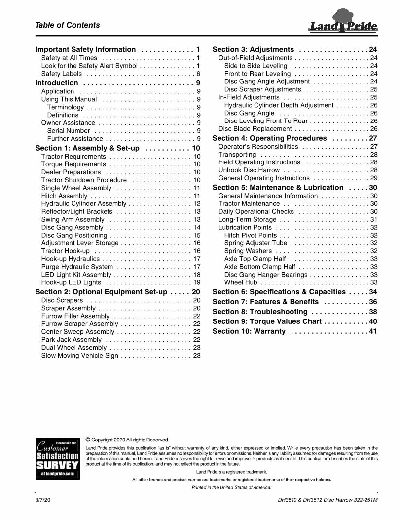
Table of Contents
8/7/20
© Copyright 2020 All rights Reserved
Land Pride provides this publication “as is” without warranty of any kind, either expressed or implied. While every precaution has been taken in thepreparation of this manual, Land Pride assumes no responsibility for errors or omissions. Neither is any liability assumed for damages resulting from the useof the information contained herein. Land Pride reserves the right to revise and improve its products as it sees fit. This publication describes the state of thisproduct at the time of its publication, and may not reflect the product in the future.
Land Pride is a registered trademark.
All other brands and product names are trademarks or registered trademarks of their respective holders.
Printed in the United States of America.
DH3510 & DH3512 Disc Harrow 322-251M
Important Safety Information . . . . . . . . . . . . . 1Safety at All Times . . . . . . . . . . . . . . . . . . . . . . . . . 1Look for the Safety Alert Symbol . . . . . . . . . . . . . . . 1Safety Labels . . . . . . . . . . . . . . . . . . . . . . . . . . . . . 6
Introduction . . . . . . . . . . . . . . . . . . . . . . . . . . . 9Application . . . . . . . . . . . . . . . . . . . . . . . . . . . . . . . 9Using This Manual . . . . . . . . . . . . . . . . . . . . . . . . . 9
Terminology . . . . . . . . . . . . . . . . . . . . . . . . . . . . . 9Definitions . . . . . . . . . . . . . . . . . . . . . . . . . . . . . . 9
Owner Assistance . . . . . . . . . . . . . . . . . . . . . . . . . . 9Serial Number . . . . . . . . . . . . . . . . . . . . . . . . . . . 9Further Assistance . . . . . . . . . . . . . . . . . . . . . . . . 9
Section 1: Assembly & Set-up . . . . . . . . . . . 10Tractor Requirements . . . . . . . . . . . . . . . . . . . . . . 10Torque Requirements . . . . . . . . . . . . . . . . . . . . . . 10Dealer Preparations . . . . . . . . . . . . . . . . . . . . . . . 10Tractor Shutdown Procedure . . . . . . . . . . . . . . . . 10Single Wheel Assembly . . . . . . . . . . . . . . . . . . . . 11Hitch Assembly . . . . . . . . . . . . . . . . . . . . . . . . . . . 11Hydraulic Cylinder Assembly . . . . . . . . . . . . . . . . . 12Reflector/Light Brackets . . . . . . . . . . . . . . . . . . . . 13Swing Arm Assembly . . . . . . . . . . . . . . . . . . . . . . 13Disc Gang Assembly . . . . . . . . . . . . . . . . . . . . . . . 14Disc Gang Positioning . . . . . . . . . . . . . . . . . . . . . . 15Adjustment Lever Storage . . . . . . . . . . . . . . . . . . . 16Tractor Hook-up . . . . . . . . . . . . . . . . . . . . . . . . . . 16Hook-up Hydraulics . . . . . . . . . . . . . . . . . . . . . . . . 17Purge Hydraulic System . . . . . . . . . . . . . . . . . . . . 17LED Light Kit Assembly . . . . . . . . . . . . . . . . . . . . . 18Hook-up LED Lights . . . . . . . . . . . . . . . . . . . . . . . 19
Section 2: Optional Equipment Set-up . . . . . 20Disc Scrapers . . . . . . . . . . . . . . . . . . . . . . . . . . . . 20Scraper Assembly . . . . . . . . . . . . . . . . . . . . . . . . . 20Furrow Filler Assembly . . . . . . . . . . . . . . . . . . . . . 22Furrow Scraper Assembly . . . . . . . . . . . . . . . . . . . 22Center Sweep Assembly . . . . . . . . . . . . . . . . . . . . 22Park Jack Assembly . . . . . . . . . . . . . . . . . . . . . . . 22Dual Wheel Assembly . . . . . . . . . . . . . . . . . . . . . . 23Slow Moving Vehicle Sign . . . . . . . . . . . . . . . . . . . 23
Section 3: Adjustments . . . . . . . . . . . . . . . . . 24Out-of-Field Adjustments . . . . . . . . . . . . . . . . . . . . 24
Side to Side Leveling . . . . . . . . . . . . . . . . . . . . . 24Front to Rear Leveling . . . . . . . . . . . . . . . . . . . . 24Disc Gang Angle Adjustment . . . . . . . . . . . . . . . 24Disc Scraper Adjustments . . . . . . . . . . . . . . . . . 25
In-Field Adjustments . . . . . . . . . . . . . . . . . . . . . . . 25Hydraulic Cylinder Depth Adjustment . . . . . . . . . 26Disc Gang Angle . . . . . . . . . . . . . . . . . . . . . . . . 26Disc Leveling Front To Rear . . . . . . . . . . . . . . . . 26
Disc Blade Replacement . . . . . . . . . . . . . . . . . . . . 26
Section 4: Operating Procedures . . . . . . . . . 27Operator’s Responsibilities . . . . . . . . . . . . . . . . . . 27Transporting . . . . . . . . . . . . . . . . . . . . . . . . . . . . . 28Field Operating Instructions . . . . . . . . . . . . . . . . . 28Unhook Disc Harrow . . . . . . . . . . . . . . . . . . . . . . . 28General Operating Instructions . . . . . . . . . . . . . . . 29
Section 5: Maintenance & Lubrication . . . . . 30General Maintenance Information . . . . . . . . . . . . . 30Tractor Maintenance . . . . . . . . . . . . . . . . . . . . . . . 30Daily Operational Checks . . . . . . . . . . . . . . . . . . . 30Long-Term Storage . . . . . . . . . . . . . . . . . . . . . . . . 31Lubrication Points . . . . . . . . . . . . . . . . . . . . . . . . . 32
Hitch Pivot Points . . . . . . . . . . . . . . . . . . . . . . . . 32Spring Adjuster Tube . . . . . . . . . . . . . . . . . . . . . 32Spring Washers . . . . . . . . . . . . . . . . . . . . . . . . . 32Axle Top Clamp Half . . . . . . . . . . . . . . . . . . . . . 33Axle Bottom Clamp Half . . . . . . . . . . . . . . . . . . . 33Disc Gang Hanger Bearings . . . . . . . . . . . . . . . . 33Wheel Hub . . . . . . . . . . . . . . . . . . . . . . . . . . . . . 33
Section 6: Specifications & Capacities . . . . . 34Section 7: Features & Benefits . . . . . . . . . . . 36Section 8: Troubleshooting . . . . . . . . . . . . . . 38Section 9: Torque Values Chart . . . . . . . . . . . 40Section 10: Warranty . . . . . . . . . . . . . . . . . . . 41

Table of Contents Continued
8/7/20
Parts Manual QR LocatorThe QR (Quick Reference) code on the cover and to the left will take you to the Parts Manual for this equipment. Download the appropriate App on your smart phone, open the App, point your phone on the QR code and take a picture.
Dealer QR LocatorThe QR code on the left will link you to available dealers for Land Pride products. Refer to Parts Manual QR Locator on this page for detailed instructions.
DH3510 & DH3512 Disc Harrow 322-251M
Table of Contents
See previous page for Table of Contents.

Important Safety Information
8/7/20 1
Important Safety InformationListed below are common practices that may or may not be applicable to the products described in this manual.
Tractor Shutdown & Storage If engaged, disengage power
take-off. Park on solid, level ground and
lower implement to ground or onto support blocks.
Put tractor in park or set park brake, turn off engine, and remove switch key to prevent unauthorized starting.
Relieve all hydraulic pressure to auxiliary hydraulic lines.
Wait for all components to stop before leaving operator’s seat.
Use steps, grab-handles and anti-slip surfaces when stepping on and off the tractor.
Detach and store implement in an area where children normally do not play. Secure implement using blocks and supports.
OFF REMOVE
Look for the Safety Alert SymbolThe SAFETY ALERT SYMBOL indicates there is a potential hazard to personal safety involved and extra safety precaution must be taken. When you see this symbol, be alert and carefully read the message that follows it. In addition to design and configuration of equipment, hazard control, and accident prevention are dependent upon the awareness, concern, prudence, and proper training of personnel involved in the operation, transport, maintenance, and storage of equipment.
Safety Precautions for ChildrenTragedy can occur if the operator is not alert to the presence of children, Children generally are attracted to implements and their work. Never assume children will remain
where you last saw them. Keep children out of the work area
and under the watchful eye of a responsible adult.
Be alert and shut the implement and tractor down if children enter the work area.
Never carry children on the tractor or implement. There is not a safe place for them to ride. They may fall off and be run over or interfere with the control of the power machine.
Never allow children to operate the power machine, even under adult supervision.
Never allow children to play on the power machine or implement.
Use extra caution when backing up. Before the tractor starts to move, look down and behind to make sure the area is clear.
Safety at All TimesCareful operation is you best assurance against an accident. All operators, no matter how much experience they may have, should carefully read this manual and other related manuals, or have the manuals read to them, before operating the power machine and this implement. Thoroughly read and understand
the “Safety Label” section. Read all instructions noted on them.
Do not operate the equipment while under the influence of drugs or alcohol as they impair the ability to safely and properly operate the equipment.
The operator should be familiar with all functions of the tractor and attached implement, and be able to handle emergencies quickly.
Make sure all guards and shields appropriate for the operation are in place and secured before operating the implement.
Keep all bystanders away from equipment and work area.
Start tractor from the driver’s seat with hydraulic controls in neutral.
Operate tractor and controls from the driver’s seat only.
Never dismount from a moving tractor or leave tractor unattended with engine running.
Do not allow anyone to stand between tractor and implement while backing up to implement.
Keep hands, feet, and clothing away from power-driven parts.
While transporting and operating equipment, watch out for objects overhead and along side such as fences, trees, buildings, wires, etc.
Do not turn tractor so tight as to cause hitched implement to ride up on the tractor’s rear wheel.
Store implement in an area where children normally do not play. When needed, secure Implement against falling with support blocks.
!
Be Aware of Signal WordsA signal word designates a degree or level of hazard seriousness. The signal words are:
Indicates a hazardous situation that, if not avoided, will result in death or serious injury.
Indicates a hazardous situation that, if not avoided, could result in death or serious injury.
Indicates a hazardous situation that, if not avoided, may result in minor or moderate injury.
WARNING
CAUTION!
!
DANGER!

Important Safety Information
8/7/202
Listed below are common practices that may or may not be applicable to the products described in this manual.
Use A Safety Chain A safety chain will help control
drawn machinery should it separate from the tractor drawbar.
Use a chain with the strength rating equal to or greater than the gross weight of the towed implement.
Attach the chain to the tractor drawbar support or other specified anchor location. Allow only enough slack in the chain to permit turning.
Always hitch the implement to the machine towing it. Do not use the safety chain to tow the implement.
Practice Safe Maintenance Understand procedure before doing
work. Refer to the Operator’s Manual for additional information.
Work on a level surface in a clean dry area that is well-lit.
Lower implement to the ground and follow all shutdown procedures before leaving the operator’s seat to perform maintenance.
Do not work under any hydraulic supported equipment. It can settle, suddenly leak down, or be lowered accidentally. If it is necessary to work under the equipment, securely support it with stands or suitable blocking beforehand.
Use properly grounded electrical outlets and tools.
Use correct tools and equipment for the job that are in good condition.
Allow equipment to cool before working on it.
Disconnect battery ground cable (-) before servicing or adjusting electrical systems or before welding on implement.
Inspect all parts. Make certain parts are in good condition & installed properly.
Replace parts on this implement with genuine Land Pride parts only. Do not alter this implement in a way which will adversely affect its performance.
Do not grease or oil implement while it is in operation.
Remove buildup of grease, oil, or debris.
Always make sure any material and waste products from the repair and maintenance of the implement are properly collected and disposed.
Remove all tools and unused parts from equipment before operation.
Do not weld or torch on galvanized metal as it will release toxic fumes.
Tire Safety Tire changing
can be dangerous and must be performed by trained personnel using the correct tools and equipment.
Always properly match the wheel size to the properly sized tire.
Always maintain correct tire pressure. Do not inflate tires above recommended pressures shown in the Operator’s Manual.
When inflating tires, use a clip-on chuck and extension hose long enough to allow you to stand to one side and NOT in front of or over the tire assembly. Use a safety cage if available.
Securely support the implement when changing a wheel.
When removing and installing wheels, use wheel handling equipment adequate for the weight involved.
Make sure wheel bolts have been tightened to the specified torque.
Transport Safely Comply with federal, state, and
local laws. Use towing vehicle and trailer of
adequate size and capacity. Secure equipment towed on a trailer with tie downs and chains.
Sudden braking can cause a towed trailer to swerve and upset. Reduce speed if towed trailer is not equipped with brakes.
Avoid contact with any over head utility lines or electrically charged conductors.
Always drive with load on end of loader arms low to the ground.
Always drive straight up and down steep inclines with heavy end of a tractor with loader attachment on the “uphill” side.
Engage park brake when stopped on an incline.
Maximum transport speed for an attached equipment is 20 mph. DO NOT EXCEED. Never travel at a speed which does not allow adequate control of steering and stopping. Some rough terrains require a slower speed.
As a guideline, use the following maximum speed weight ratios for attached equipment:
20 mph when weight of attached equipment is less than or equal to the weight of machine towing the equipment.10 mph when weight of attached equipment exceeds weight of machine towing equipment but not more than double the weight.
IMPORTANT: Do not tow a load that is more than double the weight of the vehicle towing the load.
Important Safety Information
8/7/20 3
Listed below are common practices that may or may not be applicable to the products described in this manual.
Wear Personal Protective Equipment (PPE) Wear protective clothing and
equipment appropriate for the job such as safety shoes, safety glasses, hard hat, and ear plugs.
Clothing should fit snug without fringes and pull strings to avoid entanglement with moving parts.
Prolonged exposure to loud noise can cause hearing impairment or hearing loss. Wear suitable hearing protection such as earmuffs or earplugs.
Operating equipment safely requires the operator’s full attention. Avoid wearing headphones while operating equipment.
Use Seat Belt and ROPS Land Pride recommends the use
of a CAB or roll-over-protective-structures (ROPS) and seat belt in almost all power machines. Combination of a CAB or ROPS and seat belt will reduce the risk of serious injury or death if the power machine should be upset.
If ROPS is in the locked-up position, fasten seat belt snugly and securely to help protect against serious injury or death from falling and machine overturn.
Keep Riders Off Machinery Never carry riders on the tractor or
implement. Riders obstruct operator’s view
and interfere with the control of the power machine.
Riders can be struck by objects or thrown from the equipment.
Never use tractor or implement to lift or transport riders.
Prepare for Emergencies Be prepared if a fire starts. Keep a first aid kit and fire
extinguisher handy. Keep emergency numbers for
doctor, ambulance, hospital, and fire department near the phone.
911
Use Safety Lights and Devices Slow moving tractors, and
self-propelled equipment can create a hazard when driven on public roads. They are difficult to see, especially at night. Use the Slow Moving Vehicle (SMV) sign when on public roads.
Flashing warning lights and turn signals are recommended whenever driving on public roads.
Avoid High Pressure Fluids Escaping fluid
under pressure can penetrate the skin causing serious injury.
Relieve all residual pressure before disconnecting hydraulic lines or performing work on the hydraulic system.
Make sure all hydraulic fluid connections are properly tightened/torqued and all hydraulic hoses and lines are in good condition before applying pressure to the system.
Use a piece of paper or cardboard, NOT BODY PARTS, to check for suspected leaks.
Wear protective gloves and safety glasses or goggles when working with hydraulic systems.
DO NOT DELAY. If an accident occurs, see a doctor familiar with this type of injury immediately. Any fluid injected into the skin or eyes must be treated within a few hours or gangrene may result.
Important Safety Information
8/7/204
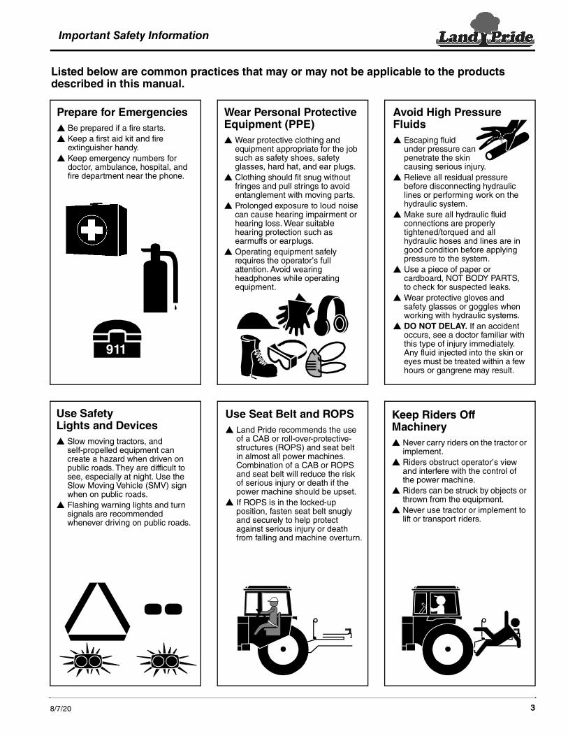
Handle Chemicals Properly Protective clothing should be
worn. Handle all chemicals with care. Follow instructions on container
label. Agricultural chemicals can be
dangerous. Improper use can seriously injure persons, animals, plants, soil, and property.
Inhaling smoke from any type of chemical fire can be a serious health hazard.
Store or dispose of unused chemicals as specified by the chemical manufacturer.
Dig Safe - Avoid Underground Utilities USA: Call 811
CAN: digsafecanada.ca Always contact your local utility companies (electrical, telephone, gas, water, sewer, and others) before digging so that they may mark the location of any underground services in the area.
Be sure to ask how close you can work to the marks they positioned.
Listed below are common practices that may or may not be applicable to the products described in this manual.
Avoid crystalline Silica (quartz) DustBecause crystalline silica is a basic component of sand and granite, many activities at construction sites produce dust containing crystalline silica. Trenching, sawing, and boring of material containing crystalline silica can produce dust containing crystalline silica particles. This dust can cause serious injury to the lungs (silicosis).There are guidelines which should be followed if crystalline silica (quartz) is present in the dust.
Be aware of and follow OSHA (or other local, State, or Federal) guidelines for exposure to airborne crystalline silica.
Know the work operations where exposure to crystalline silica may occur.
Participate in air monitoring or training programs offered by the employer.
Be aware of and use optional equipment controls such as water sprays, local exhaust ventilation, and enclosed cabs with positive pressure air conditioning if the machine has such equipment. Otherwise respirators shall be worn.
Where respirators are required, wear a respirator approved for protection against crystalline silica containing dust. Do not alter respirator in any way. Workers who use tight-fitting respirators can not have beards/mustaches which interfere with the respirator seal to the face.
If possible, change into disposable or washable work clothes at the work site; shower and change into clean clothing before leaving the work site.
Do not eat, drink, use tobacco products, or apply cosmetics in areas where there is dust containing crystalline silica.
Store food, drink, and personal belongings away from the work area.
Wash hands and face before eating, drinking, smoking, or applying cosmetics after leaving the exposure area.

Important Safety Information
8/7/20 5
This page left blank intentionally.

Important Safety InformationTable of Contents
DH3510 & DH3512 Disc Harrow 322-251M 8/7/206
WARNING: Cancer and Reproductive Harm - www.P65Warnings.ca.gov
To prevent injury or death:
Read and understand Operator’s Manual before using.Lower implement, stop tractor engine, set park brake and remove ignition
Do now allow riders.Keep others away during operation.Safely support and secure implement before repairs are made.
key before servicing, adjusting, repairing or unplugging.
CAUTION
818-719C
25989
25989
25989
838-293CWarning: Read Manual
818-719CCaution: General Instructions
Safety LabelsYour Disc Harrow comes equipped with all safety labels in place. They were designed to help you safely operate your implement. Read and follow their directions.1. Keep all safety labels clean and legible.2. Refer to this section for proper label placement. Replace
all damaged or missing labels. Order new labels from your nearest Land Pride dealer. To find your nearest dealer, visit our dealer locator at www.landpride.com.
3. Some new equipment installed during repair requires safety labels to be affixed to the replaced component as
specified by Land Pride. When ordering new components make sure the correct safety labels are included in the request.
4. Refer to this section for proper label placement.To install new labels:a. Clean surface area where label is to be placed.b. Spray soapy water onto the cleaned area.c. Peel backing from label and press label firmly onto the
surface.d. Squeeze out air bubbles with edge of a credit card or
with a similar type of straight edge.
838-588C Warning: 20 MPH Maximum Speed
Important Safety Information

Important Safety InformationTable of Contents
DH3510 & DH3512 Disc Harrow 322-251M8/7/20 7
35913
25990
25990
25989
818-831CWarning: High Pressure
838-615C2" x 9" Amber Reflector (2 places)
838-614C 2" x 9" Red Reflector (2 places)
838-603C 2" x 9" Orange Reflector (2 places)
Important Safety InformationTable of Contents
DH3510 & DH3512 Disc Harrow 322-251M 8/7/208
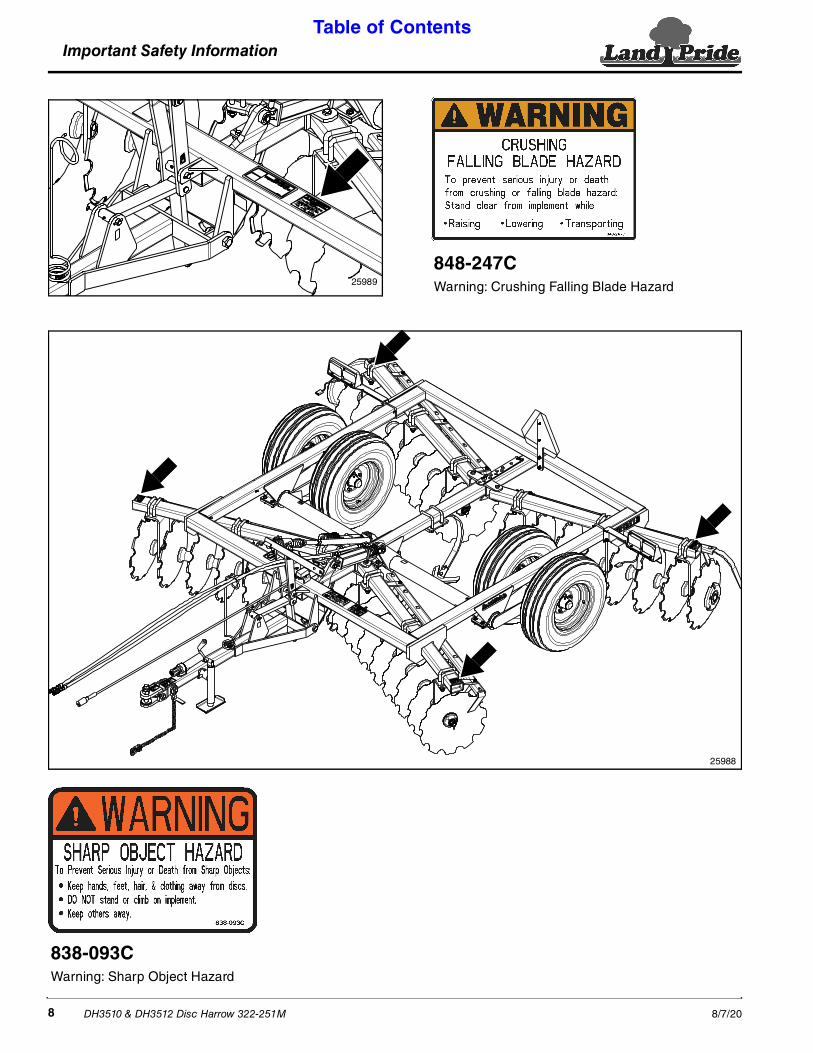
838-093CWarning: Sharp Object Hazard
25988
25989
848-247CWarning: Crushing Falling Blade Hazard
Introduction Table of Contents
DH3510 & DH3512 Disc Harrow 322-251M8/7/20 9
The parts on your Disc Harrow have been specially designed by Land Pride and should only be replaced with genuine Land Pride parts. Contact a Land Pride dealer if customer service or repair parts are required. Your Land Pride dealer has trained personnel, repair parts, and equipment needed to service the im.plement.
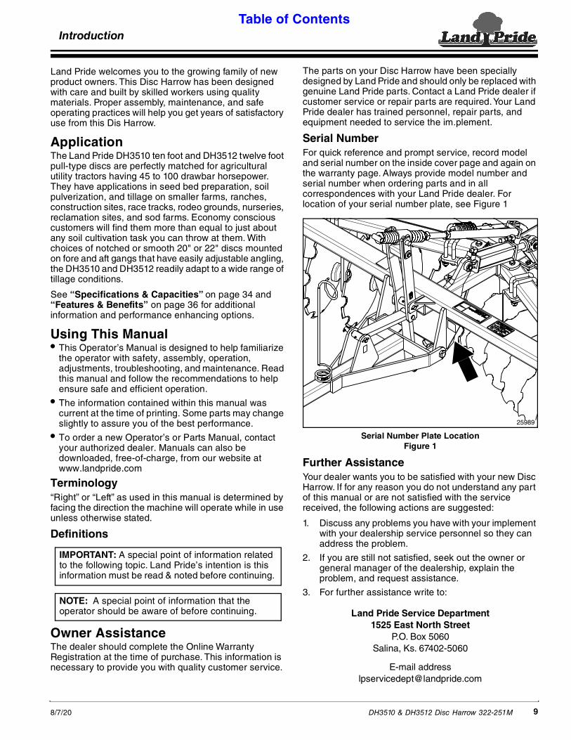
Serial NumberFor quick reference and prompt service, record model and serial number on the inside cover page and again on the warranty page. Always provide model number and serial number when ordering parts and in all correspondences with your Land Pride dealer. For location of your serial number plate, see Figure 1
Serial Number Plate LocationFigure 1
Further AssistanceYour dealer wants you to be satisfied with your new Disc Harrow. If for any reason you do not understand any part of this manual or are not satisfied with the service received, the following actions are suggested:
1. Discuss any problems you have with your implement with your dealership service personnel so they can address the problem.
2. If you are still not satisfied, seek out the owner or general manager of the dealership, explain the problem, and request assistance.
3. For further assistance write to:
Land Pride Service Department1525 East North Street
P.O. Box 5060Salina, Ks. 67402-5060
E-mail [email protected]
25989
IntroductionLand Pride welcomes you to the growing family of new product owners. This Disc Harrow has been designed with care and built by skilled workers using quality materials. Proper assembly, maintenance, and safe operating practices will help you get years of satisfactory use from this Dis Harrow.
ApplicationThe Land Pride DH3510 ten foot and DH3512 twelve foot pull-type discs are perfectly matched for agricultural utility tractors having 45 to 100 drawbar horsepower. They have applications in seed bed preparation, soil pulverization, and tillage on smaller farms, ranches, construction sites, race tracks, rodeo grounds, nurseries, reclamation sites, and sod farms. Economy conscious customers will find them more than equal to just about any soil cultivation task you can throw at them. With choices of notched or smooth 20" or 22" discs mounted on fore and aft gangs that have easily adjustable angling, the DH3510 and DH3512 readily adapt to a wide range of tillage conditions.
See “Specifications & Capacities” on page 34 and “Features & Benefits” on page 36 for additional information and performance enhancing options.
Using This Manual• This Operator’s Manual is designed to help familiarize
the operator with safety, assembly, operation, adjustments, troubleshooting, and maintenance. Read this manual and follow the recommendations to help ensure safe and efficient operation.
• The information contained within this manual was current at the time of printing. Some parts may change slightly to assure you of the best performance.
• To order a new Operator’s or Parts Manual, contact your authorized dealer. Manuals can also be downloaded, free-of-charge, from our website at www.landpride.com
Terminology“Right” or “Left” as used in this manual is determined by facing the direction the machine will operate while in use unless otherwise stated.
Definitions
Owner AssistanceThe dealer should complete the Online Warranty Registration at the time of purchase. This information is necessary to provide you with quality customer service.
IMPORTANT: A special point of information related to the following topic. Land Pride’s intention is this information must be read & noted before continuing.
NOTE: A special point of information that the operator should be aware of before continuing.

Section 1: Assembly & Set-up Table of Contents
DH3510 & DH3512 Disc Harrow 322-251M 8/7/2010
Section 1: Assembly & Set-up
Tractor RequirementsTractor horsepower and weight must be capable of controlling the Disc Harrow under all operating conditions. Smaller horsepower and lighter weight tractors must not be used.
• DH3510 ModelHorsepower . . . . . . . . . . . . . . . 45-100 hp (33-75 kW)Hitch Type . . . . . . . . . . . . . . . . . . . . . . . . . . DrawbarHydraulic Outlets . . . . . . . . . . . . . . . .2 duplex outlets
• DH3512 Model Horsepower . . . . . . . . . . . . . . . 55-100 hp (41-75 kW)Hitch Type . . . . . . . . . . . . . . . . . . . . . . . . . . DrawbarHydraulic Outlets . . . . . . . . . . . . . . . .2 duplex outlets
! WARNINGTo avoid serious injury or death: Lightweight tractors with rear attached implements may need weights added to the front to maintain steering control. Consult your tractor Operator’s Manual to determine proper weight requirements and maximum weight limitations.
Torque RequirementsRefer to “Torque Values Chart for Common Bolt Sizes” on page 40 to determine correct torque values when tightening hardware during assembly and maintenance.
Dealer PreparationsRead and understand the Operator’s Manual. An understanding of how it works will aid in the assembly and setup.
Go through the “Assembly Checklist” on this page before assembling the Disc Harrow. Speed up your assembly task and make the job safer by having all needed parts and equipment readily at hand.
This harrow has been partially assembled at the factory. However, there are still some assembly requirements before the machine is ready for operation.
Tractor Shutdown ProcedureThe following are basic tractor shutdown procedures. Follow these procedures and any additional shutdown procedures provided in your tractor Operator’s Manual before leaving the operator’s seat.
1. Reduce engine speed and disengage power take-off if engaged.
2. Park tractor and implement on level, solid ground.
3. Lower implement to ground or onto non-concrete support blocks.
4. Put tractor in park or set park brake, turn off engine, and remove switch key to prevent unauthorized starting.
5. Relieve all hydraulic pressure to auxiliary hydraulic lines.
6. Wait for all components to come to a complete stop before leaving the operator’s seat.
7. Use steps, grab-handles and anti-slip surfaces when stepping on and off the tractor.
Assembly Checklist4 Check Reference
Make sure miscellaneous assembly tools are on hand: Hammer, tape measure, hacksaw, assortment of wrenches & sockets, 3/8" drill, drill bits, and spirit level.
Have a forklift or hoist capable of 2500 lbs.
Have a minimum of two people available during assembly and set-up.
Check to see if auxiliary tractor weights are needed.
Make sure quick disconnect adaptors match tractor’s duplex outlets.
Make sure all major components and loose parts are shipped with the machine.
Section 1 & Section 2
Make sure working parts move freely, bolts are tight & cotter pins are spread.
Operator’sManual
Make sure all grease fittings are in place and lubricated.
Section 5Page 32
Make sure all safety labels are correctly located and legible. Replace if damaged.
Pages 6 to 8
Double check to make sure all fasteners & pins are installed in the correct location. Refer to the Parts Manual if unsure. NOTE: All assembled hardware from the factory has been installed in the correct location. Remember location of a part or fastener if removed during assembly. Keep parts separated.
See Parts Manual322-251P
Make sure all Red and Amber reflectors are correctly located and visible when machine is in transport position.
Page 7
Make sure all tires are inflated to the specified psi air pressure.
Section 8Page 40
Make sure all wheel bolts and axle nuts are tightened to the specified torque.
Section 8Page 40
Section 1: Assembly & Set-up Table of Contents
DH3510 & DH3512 Disc Harrow 322-251M8/7/20 11
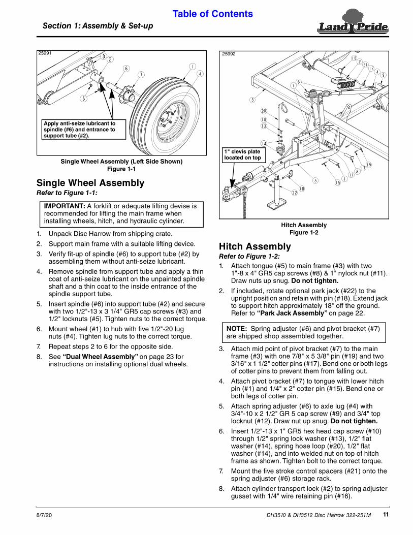
Hitch AssemblyFigure 1-2
Hitch AssemblyRefer to Figure 1-2:1. Attach tongue (#5) to main frame (#3) with two
1"-8 x 4" GR5 cap screws (#8) & 1" nylock nut (#11). Draw nuts up snug. Do not tighten.
2. If included, rotate optional park jack (#22) to the upright position and retain with pin (#18). Extend jack to support hitch approximately 18" off the ground. Refer to “Park Jack Assembly” on page 22.
3. Attach mid point of pivot bracket (#7) to the main frame (#3) with one 7/8" x 5 3/8" pin (#19) and two 3/16" x 1 1/2" cotter pins (#17). Bend one or both legs of cotter pins to prevent them from falling out.
4. Attach pivot bracket (#7) to tongue with lower hitch pin (#1) and 1/4" x 2" cotter pin (#15). Bend one or both legs of cotter pin.
5. Attach spring adjuster (#6) to axle lug (#4) with 3/4"-10 x 2 1/2" GR 5 cap screw (#9) and 3/4" top locknut (#12). Draw nut up snug. Do not tighten.
6. Insert 1/2"-13 x 1" GR5 hex head cap screw (#10) through 1/2" spring lock washer (#13), 1/2" flat washer (#14), spring hose loop (#20), 1/2" flat washer (#14), and into welded nut on top of hitch frame as shown. Tighten bolt to the correct torque.
7. Mount the five stroke control spacers (#21) onto the spring adjuster (#6) storage rack.
8. Attach cylinder transport lock (#2) to spring adjuster gusset with 1/4" wire retaining pin (#16).
25992
1" clevis plate located on top
NOTE: Spring adjuster (#6) and pivot bracket (#7) are shipped shop assembled together.
Single Wheel Assembly (Left Side Shown)Figure 1-1
Single Wheel AssemblyRefer to Figure 1-1:
1. Unpack Disc Harrow from shipping crate.
2. Support main frame with a suitable lifting device.
3. Verify fit-up of spindle (#6) to support tube (#2) by assembling them without anti-seize lubricant.
4. Remove spindle from support tube and apply a thin coat of anti-seize lubricant on the unpainted spindle shaft and a thin coat to the inside entrance of the spindle support tube.
5. Insert spindle (#6) into support tube (#2) and secure with two 1/2"-13 x 3 1/4" GR5 cap screws (#3) and 1/2" locknuts (#5). Tighten nuts to the correct torque.
6. Mount wheel (#1) to hub with five 1/2"-20 lug nuts (#4). Tighten lug nuts to the correct torque.
7. Repeat steps 2 to 6 for the opposite side.
8. See “Dual Wheel Assembly” on page 23 for instructions on installing optional dual wheels.
25991
Apply anti-seize lubricant to spindle (#6) and entrance to support tube (#2).
IMPORTANT: A forklift or adequate lifting devise is recommended for lifting the main frame when installing wheels, hitch, and hydraulic cylinder.

Section 1: Assembly & Set-up Table of Contents
DH3510 & DH3512 Disc Harrow 322-251M 8/7/2012
Hydraulic Cylinder Assembly
! WARNINGTo avoid serious injury or death: Hydraulic fluid under high pressure can penetrate the skin and/or eyes causing a serious injury. Wear protective gloves and safety glasses or goggles when working with hydraulic systems. Use a piece of cardboard or wood rather than hands when searching for leaks. A doctor familiar with this type of injury must treat the injury within a few hours or gangrene may result. DO NOT DELAY.Refer to Figure 1-3:
1. Position hydraulic cylinder (#3) with ports on top as shown. Install two 90 degree elbows (#4) into the cylinder ports with elbow fittings facing forward. Tighten elbows in cylinder as needed.
2. Screw 111" long hydraulic hose (#5) into the front elbow at cylinder base end and tighten.
3. Screw 123" long hydraulic hose (#7) into the rear elbow at cylinder rod end and tighten.
4. Thread adapter fittings (#6) onto the other end of the hydraulic hoses and tighten.
IMPORTANT: Attach cylinder base to the front main frame lug. Hydraulic fittings will be stressed if cylinder base is attached to the rear main frame lug.
5. Purge hydraulic cylinder of air before continuing.
a. Place hydraulic cylinder near a hydraulic power source on the ground in an area where it can be extend and retract freely.
b. Connect hydraulic hoses to a power source.
c. Fully extend & retract cylinder two or more cycles until cylinder rod moves in and out smoothly.
d. Refer to “Purge Hydraulic System” on page 17 if cylinder will not move smoothly.
6. Attach hydraulic cylinder base to the main frame lug with 1" x 2 3/4" clevis pin (#1). Make sure hydraulic ports are positioned on top and cylinder base positioned to the front as shown.
7. Secure clevis pin with cotter pin (#2). Bend one or both legs of cotter pin.
8. Route hydraulic hoses through pivot bracket (#9) and spring hose loop (#8).
9. Adjust fittings on cylinder as needed to prevent wear on outside of hose due to any frame contact.
10. Connect hydraulic hoses to a power source and extend cylinder until holes in the rod clevis align with axle lug hole.
11. Attach cylinder rod to axle frame with 1" x 2 3/4" clevis pin (#1) and cotter pin (#2). Bend one or both legs of cotter pin.
Hydraulic Cylinder AssemblyFigure 1-3
26524

Section 1: Assembly & Set-up Table of Contents
DH3510 & DH3512 Disc Harrow 322-251M8/7/20 13
Hydraulic Cylinder Transport LockFigure 1-4
Refer to Figure 1-4:12. Fully extend hydraulic cylinder.
13. Remove transport lock (#1) from storage bar (#2) and pin to cylinder rod with wire retaining pin (#3).
14. Retract cylinder until weight of Disc Harrow is supported by the transport lock.
Reflector/Light BracketsRefer to Figure 1-5:1. Attach left-hand reflector bracket (#6) and right-hand
right-hand reflector bracket (#7) to the disc frame with Red & Orange reflectors facing rearward using 1/2"-13 u-bolts (#13), flat washers (#11), and hex nylock nuts (#10).
2. Tighten nylock nuts (#1) to the correct torque.
26539
Swing Arm AssemblyRefer to Figure 1-5:1. Insert swing arms (#3A) through slots at rear of
mainframe with pivot hole end in first and sharp object decal on the other end facing up.
2. Connect the two arms together at the center with two spacers (#1), one top slide bracket (#5), one bottom slide bracket (#2), two 3/4"-10 x 5" GR5 hex head bolts (#8), and two 3/4" locknuts (#9). Tighten locknuts to the correct torque.
3. Insert 1/2" spacer (#15) over rear pin located on the main frame.
4. Install end hole on stabilizer bar (#4) over rear pin and third hole back from the opposite end over the top slide bracket pin.
5. Secure stabilizer bar with hairpin cotters (#12).
6. Apply a bead of silicone on the inside lip of the swing tube outer ends. Press end caps (#14) into tube ends.
7. Repeat steps 1 to 6 to install front swing arms (#3B).
NOTE: Bolt (#8) must be inserted in the left side of the front slide bracket (#5) before positioning the slide bracket under the hydraulic lift cylinder.
Swing Arm Assembly (Hydraulic Cylinder and Spring Adjuster Not Shown for Clarity)Figure 1-5
25993
Pivot Hole
Sharp Object Decals Must Facing Up
Section 1: Assembly & Set-up Table of Contents
DH3510 & DH3512 Disc Harrow 322-251M 8/7/2014
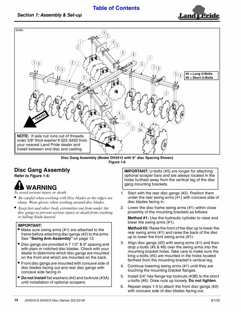
Disc Gang AssemblyRefer to Figure 1-6:
! WARNINGTo avoid serious injury or death: • Be careful when working with Disc blades as the edges are
sharp. Wear gloves when working around disc blades.• Keep feet and other body extremities out from under the
disc gangs to prevent serious injury or death from crushing or falling blade hazard.
IMPORTANT: • Make sure swing arms (#1) are attached to the
frame before attaching disc gangs (#2) to the arms. See “Swing Arm Assembly” on page 13.
• Disc gangs are provided in 7 1/2" & 9" spacing and with plain or notched disc blades. Check with your dealer to determine which disc gangs are mounted on the front and which are mounted on the back.
• Front disc gangs are mounted with concave side of disc blades facing out and rear disc gangs with concave side facing in.
• Do not install flat washers (#4) and locknuts (#3A) until installation of optional scrapers.
1. Start with the rear disc gangs (#2). Position them under the rear swing arms (#1) with concave side of disc blades facing in.
2. Lower the disc frame swing arms (#1) within close proximity of the mounting brackets as follows:
Method #1: Use the hydraulic cylinder to raise and lower the swing arms (#1).
Method #2: Raise the front of the disc up to lower the rear swing arms (#1) and raise the back of the disc up to lower the front swing arms (#1).
3. Align disc gangs (#2) with swing arms (#1) and then drop u-bolts (#5 & #6) over the swing arms into the mounting bracket holes. Take care to make sure the long u-bolts (#5) are mounted in the holes located farthest from the mounting bracket’s vertical leg.
4. Continue lowering swing arms (#1) until they are touching the mounting bracket flanges.
5. Install 3/4" hex flange top locknuts (#3B) to the short u-bolts (#6). Draw nuts up loosely. Do not tighten.
6. Repeat steps 1-5 to attach the front disc gangs (#2) with concave side of disc blades facing out.
IMPORTANT: U-bolts (#5) are longer for attaching optional scraper bars and are always located in the holes furthest away from the vertical leg of the disc gang mounting brackets.
Disc Gang Assembly (Model DH3512 with 9" disc Spacing Shown)Figure 1-6
TRAVEL
#5 = Long U-Bolts#6 = Short U-Bolts
NOTE: If axle nut runs out of threads, order 3/8" thick washer # 322-345D from your nearest Land Pride dealer and install between end disc and casting.
25994
Section 1: Assembly & Set-up Table of Contents
DH3510 & DH3512 Disc Harrow 322-251M8/7/20 15
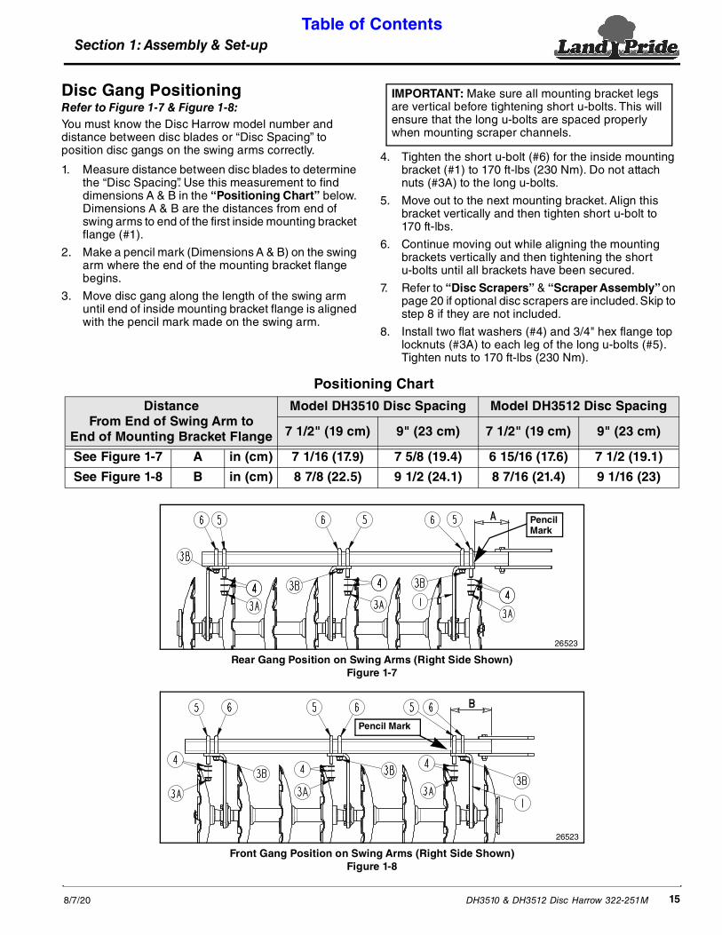
Disc Gang PositioningRefer to Figure 1-7 & Figure 1-8:You must know the Disc Harrow model number and distance between disc blades or “Disc Spacing” to position disc gangs on the swing arms correctly.
1. Measure distance between disc blades to determine the “Disc Spacing”. Use this measurement to find dimensions A & B in the “Positioning Chart” below. Dimensions A & B are the distances from end of swing arms to end of the first inside mounting bracket flange (#1).
2. Make a pencil mark (Dimensions A & B) on the swing arm where the end of the mounting bracket flange begins.
3. Move disc gang along the length of the swing arm until end of inside mounting bracket flange is aligned with the pencil mark made on the swing arm.
Rear Gang Position on Swing Arms (Right Side Shown)Figure 1-7
Front Gang Position on Swing Arms (Right Side Shown)Figure 1-8
Positioning Chart
Distance From End of Swing Arm to
End of Mounting Bracket Flange
Model DH3510 Disc Spacing Model DH3512 Disc Spacing
7 1/2" (19 cm) 9" (23 cm) 7 1/2" (19 cm) 9" (23 cm)
See Figure 1-7 A in (cm) 7 1/16 (17.9) 7 5/8 (19.4) 6 15/16 (17.6) 7 1/2 (19.1)
See Figure 1-8 B in (cm) 8 7/8 (22.5) 9 1/2 (24.1) 8 7/16 (21.4) 9 1/16 (23)
26523
Pencil Mark
26523
Pencil Mark
4. Tighten the short u-bolt (#6) for the inside mounting bracket (#1) to 170 ft-lbs (230 Nm). Do not attach nuts (#3A) to the long u-bolts.
5. Move out to the next mounting bracket. Align this bracket vertically and then tighten short u-bolt to 170 ft-lbs.
6. Continue moving out while aligning the mounting brackets vertically and then tightening the short u-bolts until all brackets have been secured.
7. Refer to “Disc Scrapers” & “Scraper Assembly” on page 20 if optional disc scrapers are included. Skip to step 8 if they are not included.
8. Install two flat washers (#4) and 3/4" hex flange top locknuts (#3A) to each leg of the long u-bolts (#5). Tighten nuts to 170 ft-lbs (230 Nm).
IMPORTANT: Make sure all mounting bracket legs are vertical before tightening short u-bolts. This will ensure that the long u-bolts are spaced properly when mounting scraper channels.

Section 1: Assembly & Set-up Table of Contents
DH3510 & DH3512 Disc Harrow 322-251M 8/7/2016
Adjustment Lever StorageRefer to Figure 2-10 on page 23:Store adjustment lever (#6) in a suitable location. One location would be pinned under stabilize bar (#8) with hairpin cotter (#7) as shown. If disc gang is angled such that pinning the bar in front does not work, then try pinning it behind.
Tractor Hook-up
! DANGERTo avoid serious injury or death: A crushing hazard exists while hooking-up and unhooking the implement. Keep people and animals away while backing-up to the implement or pulling away from the implement. Do not operate hydraulic controls while a person or animal is directly behind the power machine or near the implement.
! WARNINGTo avoid serious injury or death: • Always follow “Tractor Shutdown Procedure” provided in
this manual before dismounting the tractor.• Jack must be installed on the hitch and jack attachment pin
must be fully inserted and secured before working on or around an implement not hooked to the tractor drawbar.
Refer to Figure 1-9:1. Make certain park jack (#6) is properly attached to
implement hitch mount (#5) and secured with detent pin (#7).
2. Pivot clevis hitch (#3) up horizontally and support in this position with wire retaining pin (#4).
3. Start tractor and raise lower 3-point arms fully up. Back tractor within close proximity of clevis (#3).
4. Raise or lower park jack (#6) to align clevis (#3) with tractor drawbar. Drawbar should fit between lower and upper plates of clevis.
5. Back tractor up to implement hitch clevis (#3) until holes in drawbar and clevis are aligned.
6. Remove wire retaining pin (#4) and store in a safe place for future use.
7. Insert 1 1/4" flat washers (#9 & #10) equally above and below tractor drawbar until both spaces between drawbar and clevis plates are filled. This will reduce drawbar wear.
8. Insert 1 1/4" -7 x 6 1/2" GR5 hex bolt (#2) through bottom clevis hole, 1 1/4" washers (#9), tractor drawbar, remaining 1 1/4" washers (#10) and out through upper clevis hole. Secure hex bolt with hex nut (#13) and jam nut (#14). Tighten hex nut snugly to remove all play and then back nut one-quarter turn. Tighten Jam nut (#14) tight against hex nut (#13).
9. Lower park jack (#6) until implement weight is removed from park jack. Rotate park jack counterclockwise 90 degrees and reinsert detent pin (#7) for storage.
10. Attach hitch safety chain (#1) to tractor. Adjust chain length to remove all slack except what is necessary to permit turning. Lock chain hook securely to the safety chain.
11. Pin tractor drawbar in fixed center position.
Tractor Hook-upFigure 1-9
2599837298

Section 1: Assembly & Set-up Table of Contents
DH3510 & DH3512 Disc Harrow 322-251M8/7/20 17
Hook-up HydraulicsThe standard set-up requires one duplex outlet to operate the two-way lift cylinder.
Refer to Figure 1-9 on page 16:1. If not already completed, route hydraulic hoses (#12)
through hose spring support loop (#15).
2. Connect quick release coupler on end of hydraulic hoses (#12) to tractor remote outlet.
3. Start tractor and operate control lever to raise and lower Disc Harrow. If the implement works opposite of what it should, shut tractor down and switch hydraulic hose connections at the duplex outlet. Refer to “Tractor Shutdown Procedure” on page 10.
4. Cycle lift cylinder back and forth several times to purge air from it. If operation continues to be sluggish, it may be necessary to purge air from the cylinder and hydraulic lines. Refer to “Purge Hydraulic System” on this page.
Purge Hydraulic System
! WARNINGTo avoid serious injury or death: Hydraulic fluid under high pressure can penetrate the skin and/or eyes causing a serious injury. Wear protective gloves and safety glasses or goggles when working with hydraulic systems. Use a piece of cardboard or wood rather than hands when searching for leaks. A doctor familiar with this type of injury must treat the injury within a few hours or gangrene may result. DO NOT DELAY.1. Shut tractor down and relieve all hydraulic pressure
before dismounting. Refer to “Tractor Shutdown Procedure” on page 10.
2. With implement lowered to the ground, remove connecting pin from rod end of cylinder. Block cylinder support in a vertical position with rod end up.
3. Cycle hydraulic system to extend and retract cylinder. Repeat this process 2 times ending with cylinder fully retracted.
4. Shut tractor down and relieve all hydraulic pressure before dismounting.
5. Crack fitting at the rod end of cylinder to allow air to escape.
6. Restart tractor and slowly activate tractor control lever to extend the cylinder rod until air free oil leaks from the fitting.
7. Follow tractor shutdown procedures before dismounting tractor.
8. Tighten fitting on the rod end of cylinder.
9. Pin clevis on rod end of cylinder to the Disc Harrow.
10. Crack fitting at the base end of the cylinder and repeat steps 6-8.
11. Tighten fitting on base end of cylinder.
12. Slowly cycle Disc Harrow to transport position while checking to make sure hydraulic hoses are not pinched in the process.

Section 1: Assembly & Set-up Table of Contents
DH3510 & DH3512 Disc Harrow 322-251M 8/7/2018
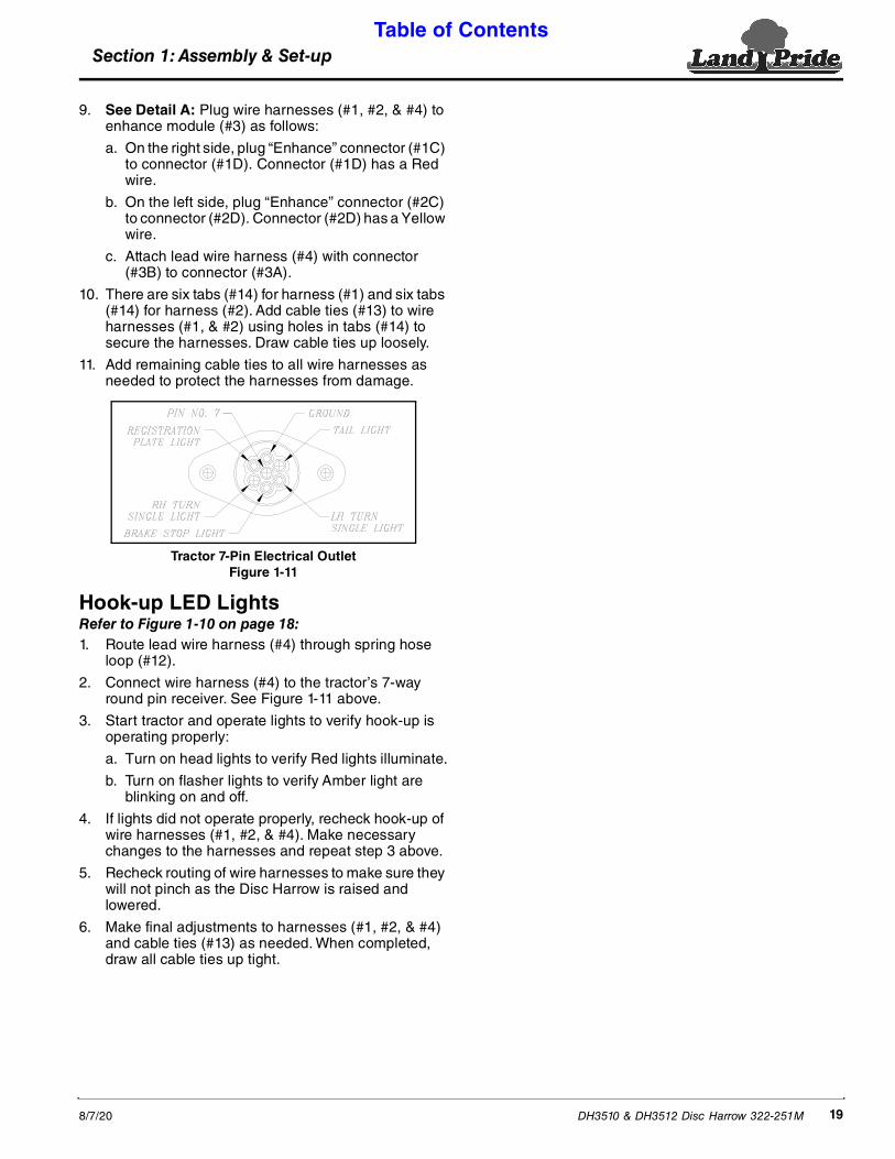
LED Light Kit AssemblyRefer to Figure 1-10:The lead wiring harness (#4) is equipped with a 7-way round pin connector. Make sure your tractor is equipped with the 7-pin electrical outlet shown in Figure 1-11 on page 19.
1. Lower Disc Harrow until discs and wheels are resting on the ground.
2. Shut tractor down properly before dismounting. Refer to “Tractor Shutdown Procedure” on page 10.
3. Mount right-hand light (#6) on top of the right-hand reflector bracket (#15) as shown with Red light facing back and to the inside.
a. Secure light assembly (#6) with 1/4"-20 x 1" GR 5 hex bolts (#7), flat washers (#8) and nylock nuts (#9) as shown.
b. Tighten nylock nuts (#9) to the correct torque.
4. Mount left-hand light (#5) on top of the left-hand reflector bracket (#16) as shown with Red light facing back and to the inside.
a. Secure light assembly (#5) with 1/4"-20 x 1" GR 5 hex bolts (#7), flat washers (#8) and nylock nuts (#9).
b. Tighten nylock nuts (#9) to the correct torque.
IMPORTANT: Amber lights “A” are located outside facing front and back. Red lights “B” are located inside facing back only.
5. Attach enhance module (#3) to the mainframe as shown with #10-24 x 1" cap screws (#10) and nylock nuts (#11). Tighten nylock nuts.
6. Plug “Light” connector (#1B) on the right-hand side to connector (#1A) for LED light (#6).
7. Plug “Light” connector (#2B) on the left-hand side to connector (#2A) for LED light (#5).
8. Route wire harnesses (#1 & #2) on both sides of the mainframe to the front and along the front beam to enhance module (#3).
IMPORTANT: Connectors on wire harness (#1 & #2) are labeled “Light” on one end and “Enhancer” on the other end. Ends labeled “Light” connect to the light assemblies (#5 & #6). Ends labeled “Enhancer” connect to enhance module (#3).
IMPORTANT: See Detail A: Connector (#1D) has a Red wire and connects to wire harness (#1) on the right side. Connector (#2D) has a yellow wire and connects to wire harness (#2) on the left side.
LED Light Kit Assembly (Mainframe shown without components for clarity)Figure 1-10
Amber Lights “A”
Amber Lights “A”
Red Light “B”
Red Light “B”
70250
Detail A
70482
Section 1: Assembly & Set-up Table of Contents
DH3510 & DH3512 Disc Harrow 322-251M8/7/20 19
9. See Detail A: Plug wire harnesses (#1, #2, & #4) to enhance module (#3) as follows:
a. On the right side, plug “Enhance” connector (#1C) to connector (#1D). Connector (#1D) has a Red wire.
b. On the left side, plug “Enhance” connector (#2C) to connector (#2D). Connector (#2D) has a Yellow wire.
c. Attach lead wire harness (#4) with connector (#3B) to connector (#3A).
10. There are six tabs (#14) for harness (#1) and six tabs (#14) for harness (#2). Add cable ties (#13) to wire harnesses (#1, & #2) using holes in tabs (#14) to secure the harnesses. Draw cable ties up loosely.
11. Add remaining cable ties to all wire harnesses as needed to protect the harnesses from damage.
Tractor 7-Pin Electrical OutletFigure 1-11
Hook-up LED LightsRefer to Figure 1-10 on page 18:1. Route lead wire harness (#4) through spring hose
loop (#12).
2. Connect wire harness (#4) to the tractor’s 7-way round pin receiver. See Figure 1-11 above.
3. Start tractor and operate lights to verify hook-up is operating properly:
a. Turn on head lights to verify Red lights illuminate.
b. Turn on flasher lights to verify Amber light are blinking on and off.
4. If lights did not operate properly, recheck hook-up of wire harnesses (#1, #2, & #4). Make necessary changes to the harnesses and repeat step 3 above.
5. Recheck routing of wire harnesses to make sure they will not pinch as the Disc Harrow is raised and lowered.
6. Make final adjustments to harnesses (#1, #2, & #4) and cable ties (#13) as needed. When completed, draw all cable ties up tight.

Section 2: Optional Equipment Set-up Table of Contents
DH3510 & DH3512 Disc Harrow 322-251M 8/7/2020
Section 2: Optional Equipment Set-up
Back Right & Front Left Scraper Assembly Back Left and Front Right Scraper Assembly
Type “A”
25995
4 11/16" (11.9cm)
25995
Type “B”4 11/16" (11.9cm)
Model DH3510 Disc Harrow With Blades Spaced 7 1/2" ApartFigure 2-2
Disc ScrapersRefer to Figure 2-1:Orient disc scrapers as shown in Figure 2-1 to determine scraper types.
The bottom of Type “A” is skewed up to the left and mounted on the back right and front left disc gangs.
The bottom of Type “B” is skewed up to the right and mounted on the back left and front right disc gangs.
Disc Scraper OrientationFigure 2-1
Scraper AssemblyRefer to Figures 2-2, 2-3, 2-4 & 2-5:1. Determine correct orientation of scraper mounting
brackets (#1) by locate the figure that illustrates your Disc Harrow model number and disc blade spacing. Be sure to check the disc blade spacing on both the front and rear disc gangs as they can be different. Mounting brackets for disc gangs with 7 1/2" blade spacing will have more square holes than ones with 9" blade spacings.
Type “B”Back Left & Front Right
Disc Scrapers
Type “A”Back Right & Front Left
Disc Scrapers
26585
2. Select the correct mounting bracket (#1) for the back right disc gang and then orient the square bolt holes in the mounting bracket to match the square bolt holes in the mounting bracket shown in the illustration.
3. Bolt Type “A” disc scrapers to scraper mounting bracket (#1) with 1/2"-13 x 1 1/4" GR5 round head square neck bolts (#7) and 1/2" hex flange lock nuts (#8). Draw nuts up snug. Do Not tighten.
4. Attach scraper hangers (#6) to the long u-bolts (#4) with 3/4" flat washers (#3) and 3/4" hex flange locknuts (#2). Draw nuts up snug. Do not tighten.
5. Attach scraper mounting bracket (#1) to scraper hangers (#6) with 1/2"-13 x 1 1/4" GR5 round head square neck bolts (#7) and 1/2" hex flange lock nuts (#8). Draw nuts up snug. Do not tighten.
6. Recheck fit-up of the scraper assembly and then tighten u-bolt hex flange nuts (#2) and scraper hanger locknuts (#8) to the correct torque.
7. Adjust individual scrapers (#5) to be within close contact without touching the disc blade. Tighten scraper mounting nuts (#8) to the correct torque. See “Disc Scraper Adjustments” on page 25 for detailed scraper adjustment instructions.
8. Repeat steps 2 - 7 for the front left scraper assembly with Type “A” scrapers.
9. Repeat steps 2 - 7 for the back left scraper assembly with Type “B” scrapers.
10. Repeat steps 2 - 7 for the front right scraper assembly with Type “B” scrapers.
IMPORTANT: Disc scrapers (#5) must point in towards the disc concave surfaces. Hex head square neck bolts (#7) can be inserted from the bottom or top when attaching disc scrapers.

Section 2: Optional Equipment Set-up Table of Contents
DH3510 & DH3512 Disc Harrow 322-251M8/7/20 21
Back Right & Front Left Scraper Assembly Back Left and Front Right Scraper Assembly
Type “A”
26582
Type “B”
Model DH3510 Disc Harrow With Blades Spaced 9" ApartFigure 2-3
Back Right & Front Left Scraper Assembly Back Left and Front Right Scraper Assembly
Type “A”
26583
Type “B”
Model DH3512 Disc Harrow With Blades Spaced 7 1/2" ApartFigure 2-4
Back Right & Front Left Scraper Assembly Back Left and Front Right Scraper Assembly
Type “A” 5 3/4" (14.6 cm)
26584
Type “B”5 3/4" (14.6 cm)
Model DH3512 Disc Harrow With Blades Spaced 9" ApartFigure 2-5
Section 2: Optional Equipment Set-up Table of Contents
DH3510 & DH3512 Disc Harrow 322-251M 8/7/2022
Furrow Filler AssemblyRefer to Figure 2-6:1. Attach furrow filler (#1) to the right back end disc with
5/8"-11 x 2" GR5 round head square neck bolt (#4), spring lock washers (#9) and 5/8" hex nut (#8).
2. Tighten nuts to the correct torque.
3. Repeat steps 1 & 2 for the left side.
Right Rear Furrow filler & Scraper AssemblyFigure 2-6
Furrow Scraper AssemblyRefer to Figure 2-6:1. Remove existing 1/2" x 1 1/4" round head bolt (#6),
hex nut (#7B) and end scraper (#10). Keep scraper for reuse.
2. Attach right furrow scraper (#3) and end scraper (#10) to scraper bar with new 1/2"-13 x 1 1/2" GR5 round head square neck bolt (#5) and 1/2" hex locknut (#7A). Make sure furrow scraper is positioned above the end scraper as shown.
3. Tighten nut to the correct torque.
4. Repeat steps 1, 2 & 3 for the left side furrow scraper.
5. Adjust individual scrapers to be within close contact with disc concave surfaces without touching. See “Disc Scraper Adjustments” on page 25.
25997
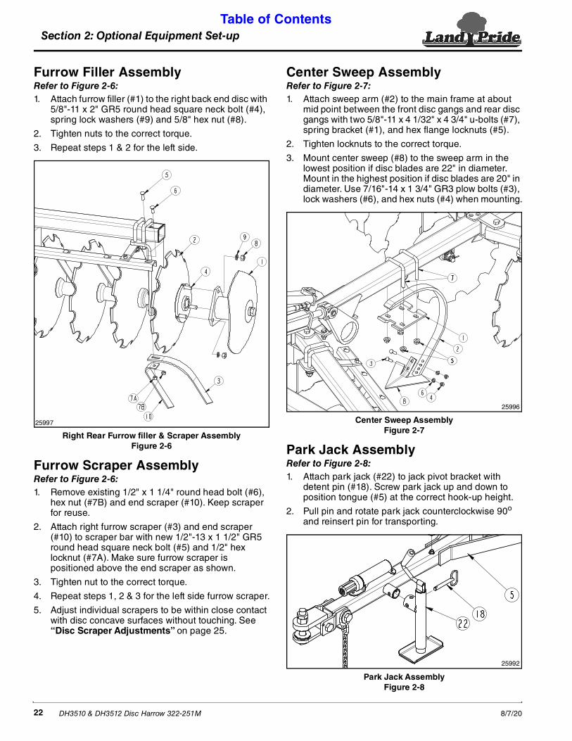
Center Sweep AssemblyRefer to Figure 2-7:1. Attach sweep arm (#2) to the main frame at about
mid point between the front disc gangs and rear disc gangs with two 5/8"-11 x 4 1/32" x 4 3/4" u-bolts (#7), spring bracket (#1), and hex flange locknuts (#5).
2. Tighten locknuts to the correct torque.
3. Mount center sweep (#8) to the sweep arm in the lowest position if disc blades are 22" in diameter. Mount in the highest position if disc blades are 20" in diameter. Use 7/16"-14 x 1 3/4" GR3 plow bolts (#3), lock washers (#6), and hex nuts (#4) when mounting.
Center Sweep AssemblyFigure 2-7
Park Jack AssemblyRefer to Figure 2-8:1. Attach park jack (#22) to jack pivot bracket with
detent pin (#18). Screw park jack up and down to position tongue (#5) at the correct hook-up height.
2. Pull pin and rotate park jack counterclockwise 90o and reinsert pin for transporting.
Park Jack AssemblyFigure 2-8
25996
25992

Section 2: Optional Equipment Set-up Table of Contents
DH3510 & DH3512 Disc Harrow 322-251M8/7/20 23
Dual Wheel AssemblyRefer to Figure 2-9:1. Support main frame off the floor with a suitable lifting
device.
2. Install single bolt-on spindle (#6) to inside of axle frame (#2) with two 1/2"-13 x 3 1/4" GR5 hex head cap screws (#3) and 1/2" hex locknuts (#5). Tighten nuts to the correct torque.
3. Mount wheel (#1) to hub (#7) with five 1/2"-20 lug nuts (#4). Tighten lug nuts to the correct torque.
4. Repeat steps 2 to 6 for the opposite side.
Single Wheel Assembly (Right Side Shown)Figure 2-9
26500
Slow Moving Vehicle SignRefer to Figure 2-10:Attach slow moving vehicle sign (#2) to the back of the frame (#1) with 1/2"-13 x 3 1/32" x 5" u-bolt (#5), spring lock washers (#4)and 1/2" hex nuts (#3). Tighten nuts to the correct torque.
Slow Moving Vehicle Sign Figure 2-10
26527
Section 3: Adjustments Table of Contents
DH3510 & DH3512 Disc Harrow 322-251M 8/7/2024
Section 3: Adjustments
Out-of-Field AdjustmentsSome adjustments can be made on concrete slabs or on a good level surface.
Side to Side LevelingCheck tire pressure. All tires should have equal pressure. See “Tire Inflation Chart” on page 40. Unequal tire pressure will allow the disc to dig in deeper on the side with the lowest tire pressure. This will make the Disc Harrow pull at an angle to the direction of travel.
Front to Rear LevelingRefer to Figure 3-1:
! WARNINGTo avoid serious injury or death: • Total compressed length of leveling springs (#3) is 12 1/2"
between flat washers. Never adjust nuts (#4) to compress springs under 12 1/2". Compressing springs too tight can damage the spring adjuster resulting in flying projectiles and sudden drop of the Disc Harrow.
• Do not fully unscrew spring adjuster rod (#5) from adjuster tube (#6). Unscrewing the rod will result in a sudden drop of the front disc gangs. Maximum allowable exposed rod (#5) between nuts (#4) and adjuster tube (#6) is 15".
Most operating problems are due to unequal pressure and penetration of the front and rear gangs. Preset the harrow with the rear disc blades almost touching the ground and the front disc blades approximately 2 inches off the ground as follows:
Front to Back LevelingFigure 3-1
Refer to Figure 3-7 on page 26:1. Lower Disc Harrow until rear disc blades are almost
touching the ground. Raise implement slightly and then add stroke control spacers (#4 & #5) to the cylinder rod until rod is full.
2. Lower machine until cylinder is pressing against the stroke control spacers.
1
2
26530
3 654
Refer to Figure 3-1:3. Turn spring adjuster to position the front disc blades
approximately 2 inches above the rear disc blades as follows:
• Turn spring adjuster (#2) clockwise with adjusting lever (#1) to lower the rear disc blades.
• Turn spring adjuster (#2) counterclockwise with adjusting lever (#1) to raise the rear disc blades.
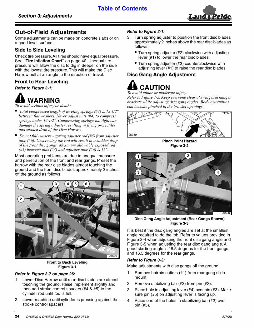
Disc Gang Angle Adjustment
! CAUTIONTo avoid minor or moderate injury: Refer to Figure 3-2. Keep everyone clear of swing arm hanger brackets while adjusting disc gang angles. Body extremities can become pinched in the bracket openings.
Pinch Point HazardFigure 3-2
Disc Gang Angle Adjustment (Rear Gangs Shown)Figure 3-3
It is best if the disc gang angles are set at the smallest angle required to do the job. Refer to values provided in Figure 3-4 when adjusting the front disc gang angle and Figure 3-5 when adjusting the rear disc gang angle. A good starting angle is 18.5 degrees for the front gangs and 16.5 degrees for the rear gangs.
Refer to Figure 3-3:Make adjustments with disc gangs off the ground:
1. Remove hairpin cotters (#1) from rear gang slide mount.
2. Remove stabilizing bar (#2) from pin (#3).
3. Place hole in adjusting lever (#4) over pin (#3). Make sure pin (#5) on adjusting lever is facing up.
4. Place one of the holes in stabilizing bar (#2) over pin (#5).
25989
5
3
2
4
1
26528
Section 3: Adjustments Table of Contents
DH3510 & DH3512 Disc Harrow 322-251M8/7/20 25
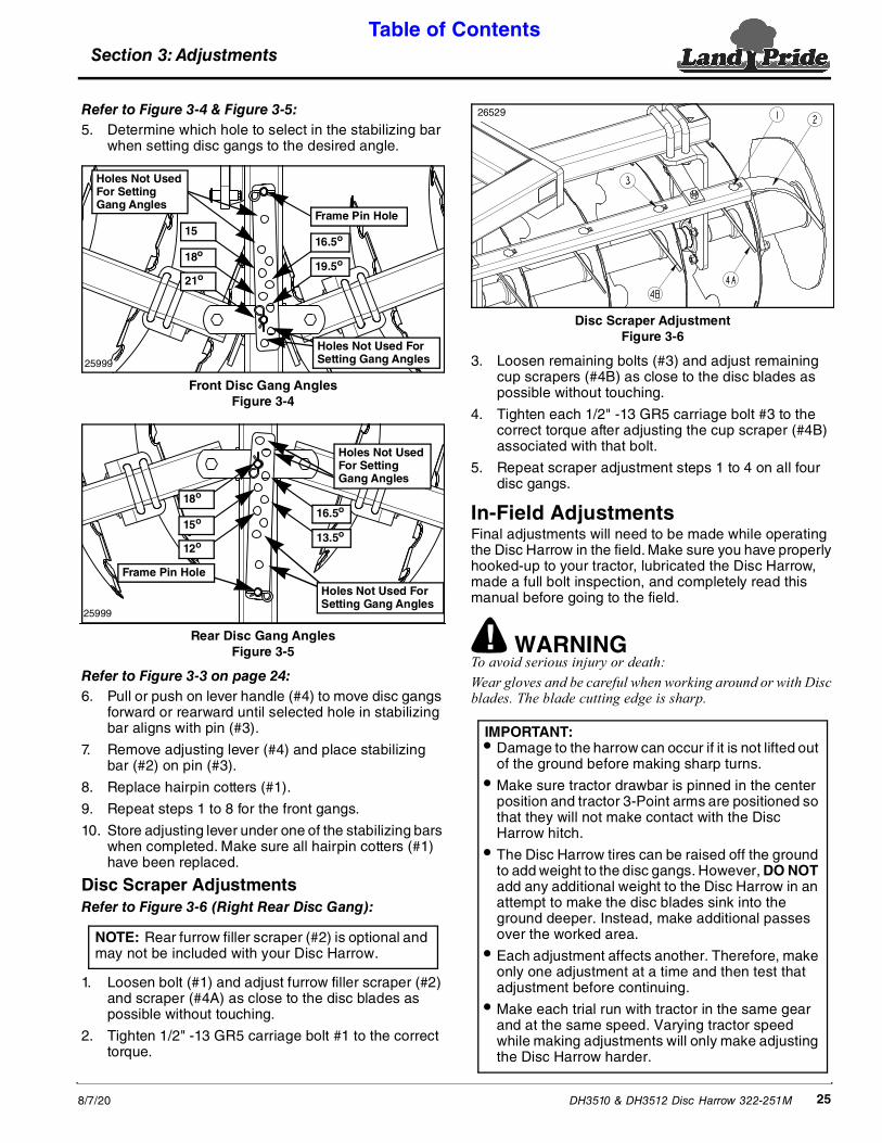
Refer to Figure 3-4 & Figure 3-5:5. Determine which hole to select in the stabilizing bar
when setting disc gangs to the desired angle.
Front Disc Gang AnglesFigure 3-4
Rear Disc Gang AnglesFigure 3-5
Refer to Figure 3-3 on page 24:6. Pull or push on lever handle (#4) to move disc gangs
forward or rearward until selected hole in stabilizing bar aligns with pin (#3).
7. Remove adjusting lever (#4) and place stabilizing bar (#2) on pin (#3).
8. Replace hairpin cotters (#1).
9. Repeat steps 1 to 8 for the front gangs.
10. Store adjusting lever under one of the stabilizing bars when completed. Make sure all hairpin cotters (#1) have been replaced.
Disc Scraper AdjustmentsRefer to Figure 3-6 (Right Rear Disc Gang):
1. Loosen bolt (#1) and adjust furrow filler scraper (#2) and scraper (#4A) as close to the disc blades as possible without touching.
2. Tighten 1/2" -13 GR5 carriage bolt #1 to the correct torque.
16.5o
19.5o
15
18o
21o
Frame Pin Hole
Holes Not Used For Setting Gang Angles
Holes Not Used For Setting Gang Angles25999
16.5o
13.5o
18o
15o
12o
Frame Pin Hole
Holes Not Used For Setting Gang Angles
Holes Not Used For Setting Gang Angles
25999
NOTE: Rear furrow filler scraper (#2) is optional and may not be included with your Disc Harrow.
Disc Scraper AdjustmentFigure 3-6
3. Loosen remaining bolts (#3) and adjust remaining cup scrapers (#4B) as close to the disc blades as possible without touching.
4. Tighten each 1/2" -13 GR5 carriage bolt #3 to the correct torque after adjusting the cup scraper (#4B) associated with that bolt.
5. Repeat scraper adjustment steps 1 to 4 on all four disc gangs.
In-Field AdjustmentsFinal adjustments will need to be made while operating the Disc Harrow in the field. Make sure you have properly hooked-up to your tractor, lubricated the Disc Harrow, made a full bolt inspection, and completely read this manual before going to the field.
! WARNINGTo avoid serious injury or death: Wear gloves and be careful when working around or with Disc blades. The blade cutting edge is sharp.
26529
IMPORTANT: • Damage to the harrow can occur if it is not lifted out
of the ground before making sharp turns.
• Make sure tractor drawbar is pinned in the center position and tractor 3-Point arms are positioned so that they will not make contact with the Disc Harrow hitch.
• The Disc Harrow tires can be raised off the ground to add weight to the disc gangs. However, DO NOT add any additional weight to the Disc Harrow in an attempt to make the disc blades sink into the ground deeper. Instead, make additional passes over the worked area.
• Each adjustment affects another. Therefore, make only one adjustment at a time and then test that adjustment before continuing.
• Make each trial run with tractor in the same gear and at the same speed. Varying tractor speed while making adjustments will only make adjusting the Disc Harrow harder.

Section 3: Adjustments Table of Contents
DH3510 & DH3512 Disc Harrow 322-251M 8/7/2026
Hydraulic Cylinder Depth AdjustmentRefer to Figure 3-7:
1. Remove all stroke control spacers (#4 & #5) from the hydraulic cylinder.
2. Lower Disc Harrow to desired working depth and travel froward. Your travel speed will be determined by soil conditions.
3. When working depth is achieved, stop tractor, shut tractor engine off, and remove switch key.
4. Select required size and number of stroke control spacers (#3) that will fit between hydraulic cylinder and rod eye clevis. The following spacers are available.
• Two 1" (2.5 cm) spacers• One 1 1/4" (3.2 cm) spacer• One 1 1/2" (3.8 cm) spacer• One 1 3/4" (4.4 cm) spacer
5. Return to the tractor and raise the Disc Harrow up. Once fully raised, turn tractor engine off and remove switch key.
6. Install preselected stroke control spacers (shown as #4 & #5 in this example) on the cylinder rod.
7. Lower Disc Harrow against installed stroke control spacers. Recheck working depth. If needed, adjust size and quantity of stroke control spacers until desired working depth is achieved.
Hydraulic Cylinder Depth AdjustmentFigure 3-7
IMPORTANT: Because soil firmness varies from field to field, make depth adjustments while working in the field.
26531
Disc Gang AngleIncreasing the disc gang angle will help the Disc Harrow to penetrate the soil and remove vegetation. However, too much angle can cause the Disc Harrow to operate erratically. Therefore, it is best if the disc gang angles are set at the smallest angle required to do the job. Make sure the angle of the front disc gangs is 3 degrees more than the rear disc gangs.
See also Section 8: Troubleshooting for helpful solutions to setting the disc gang angles.
Disc Leveling Front To RearRefer to Figure 3-1 on page 24:The truest way to level your disc from front to rear is to observe behind the center of the Disc Harrow. In most soil conditions, a slight ridge in the center is actually a level operation. More air pockets will form where soil is thrown against each other, causing a small ridge to from that will disappear after a soaking rain.
1. If unit is leaving a significant ridge in the center, raise disc rear gangs by turning spring adjuster (#2) counterclockwise.
2. If unit is leaving a furrow (valley) in the center, lower the rear disc gangs by turning spring adjuster (#2) clockwise.
3. See also Section 8: Troubleshooting for helpful solutions to leveling the Disc Harrow.
Disc Blade ReplacementRefer to Figure 3-8:When replacing notched disc blades, assemble the disc blades in a spiral pattern.
See note in Figure 1-6 on page 14: Order 3/8" thick washer(s) from your nearest Land Pride dealer if axle nut(s) runs out of threads before the disc blades are tight on the axle.
Disc Replacement (Spiral)Figure 3-8
25989

Section 4: Operating Procedures Table of Contents
DH3510 & DH3512 Disc Harrow 322-251M8/7/20 27
Section 4: Operating Procedures
! WARNINGTo avoid serious injury or death: • Allow only persons to operate this implement who have
fully read and comprehended this manual, who have been properly trained in the safe operation of this implement, and who are age 16 or older. Serious injury or death can result from the inability to read, understand, and follow instructions provided in this manual.
• Do not use implement to lift objects; to pull objects such as fence posts, stumps, etc; or to push objects. The unit is not designed or guarded for these uses.
• Never carry riders on the implement or tractor. Riders can obstruct the operator’s view, interfere with controls, be pinched by moving components, become entangled in rotating components, struck by objects, thrown about, fall off and be run over, etc.
• Do not alter implement or replace parts on the implement with other brands. Other brands may not fit properly or meet OEM (Original Equipment Manufacturer) specifications. They can weaken the integrity and impair the safety, function, performance, and life of the implement. Replace parts only with genuine OEM parts.
• Perform scheduled maintenance. Check for loose hardware, missing parts, broken parts, structural cracks, and excessive wear. Make repairs before putting the implement back into service.
• Keep everyone away from the Disc Harrow while raising, lowering, and transporting the implement to protect against falling blade hazard.
• Always make sure the tractor is shut off and no one is near the tractor when installing stroke control spacers and/or transport lock. Also, keep away from possible pinch points during installation as the hydraulic lines could burst dropping the unit suddenly.
• Do not use tires as a step or lean against them. They can suddenly move even when they appear to be solidly against the ground causing a falling hazard against metal protruding objects and sharp disc blades.
• Make sure safety labels are in their proper location and are in good condition before operating the attached implement. Read and obey all instructions on the labels.
• Pin drawbar in the fixed center position and make sure tractor 3-Point arms are positioned so that they will not make contact with the Disc Harrow hitch.
• Raise Disc Harrow out of the ground to make sharp turns. Do not turn tractor tires into the tongue or frame. Doing this can result in loss of control and/or damage the implement. Slow down and watch tractor tires carefully when forced to make sharp turns.
• Do not use implement to lift objects; to pull objects such as fence posts, stumps, etc; or to push objects. The unit is not designed or guarded for these uses.
• Do not use implement to tow other equipment unless it is designed with a tow hitch. Doing so can result in loss of control and damage the equipment.
Operator’s ResponsibilitiesHazard control and accident prevention are dependent upon the awareness, concern, prudence, and proper training involved in the operation, transport, storage, and maintenance of the Disc Harrow. It is absolutely essential that no one operates the harrow unless they are age 16 or older and have read, fully understood, and are totally familiar with the Operator’s Manual. Make sure the operator has paid particular attention to:
• Important Safety Information, page 1
• Section 1: Assembly & Set-up, page 10
• Section 2: Optional Equipment Set-up, page 20
• Section 3: Adjustments, page 24
• Section 4: Operating Procedures, page 27
• Section 5: Maintenance & Lubrication, page 30
Perform the following inspections before using your Disc Harrow.
! DANGERTo avoid serious injury or death: • Do not allow anyone near the tractor or implement while
operating. Stop operation if bystanders are too close. They can be hit by flying projectiles, become entangled in the equipment, or ran over.
• Never make contact with underground utilities such as electrical power lines, gas lines, phone lines, etc. They can cause serious injury or death from electrocution, explosion, or fire. If in doubt, call 811 (USA) before digging so that they can mark the location of underground services in the area. For contact information, see Dig Safe in the “Important Safety Information” starting on page 1.
• Always secure equipment with solid, non-concrete supports before working under it. Never go under equipment supported by concrete blocks or hydraulics. Concrete can break, hydraulic lines can burst, and/or hydraulic controls can be actuated even when power to hydraulics is off.
Operating Checklist Check Ref.
Read “Important Safety Information” 1
Read all of the “Tractor Hook-up” and preparation instructions. 16
Read “Section 4: Operating Procedures” 27
Lubricate the harrow as needed. Refer to “Lubrication Points”. 32
Check harrow initially and periodically for loose bolts & pins. Pay special attention to disc gang hanger bolts and axle nuts. Refer to “Torque Values Chart”.
40
Section 4: Operating Procedures Table of Contents
DH3510 & DH3512 Disc Harrow 322-251M 8/7/2028
Transporting
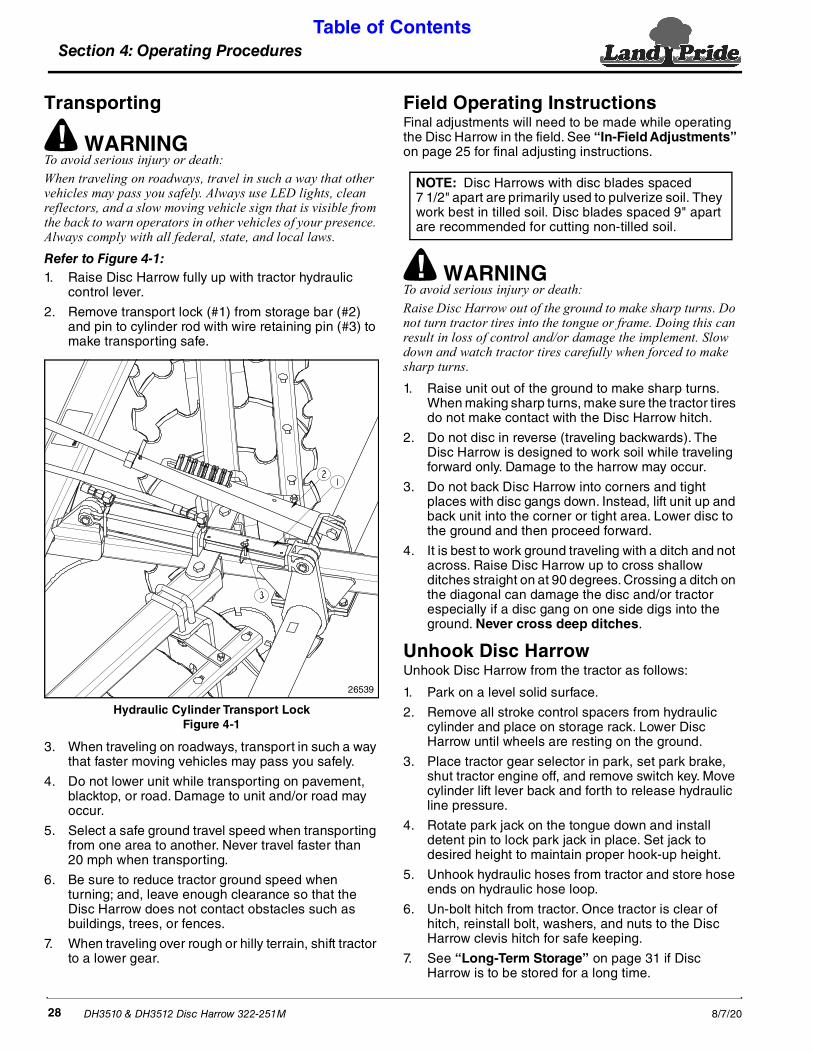
! WARNINGTo avoid serious injury or death: When traveling on roadways, travel in such a way that other vehicles may pass you safely. Always use LED lights, clean reflectors, and a slow moving vehicle sign that is visible from the back to warn operators in other vehicles of your presence. Always comply with all federal, state, and local laws.Refer to Figure 4-1:1. Raise Disc Harrow fully up with tractor hydraulic
control lever.
2. Remove transport lock (#1) from storage bar (#2) and pin to cylinder rod with wire retaining pin (#3) to make transporting safe.
Hydraulic Cylinder Transport LockFigure 4-1
3. When traveling on roadways, transport in such a way that faster moving vehicles may pass you safely.
4. Do not lower unit while transporting on pavement, blacktop, or road. Damage to unit and/or road may occur.
5. Select a safe ground travel speed when transporting from one area to another. Never travel faster than 20 mph when transporting.
6. Be sure to reduce tractor ground speed when turning; and, leave enough clearance so that the Disc Harrow does not contact obstacles such as buildings, trees, or fences.
7. When traveling over rough or hilly terrain, shift tractor to a lower gear.
26539
Field Operating InstructionsFinal adjustments will need to be made while operating the Disc Harrow in the field. See “In-Field Adjustments” on page 25 for final adjusting instructions.
! WARNINGTo avoid serious injury or death: Raise Disc Harrow out of the ground to make sharp turns. Do not turn tractor tires into the tongue or frame. Doing this can result in loss of control and/or damage the implement. Slow down and watch tractor tires carefully when forced to make sharp turns.1. Raise unit out of the ground to make sharp turns.
When making sharp turns, make sure the tractor tires do not make contact with the Disc Harrow hitch.
2. Do not disc in reverse (traveling backwards). The Disc Harrow is designed to work soil while traveling forward only. Damage to the harrow may occur.
3. Do not back Disc Harrow into corners and tight places with disc gangs down. Instead, lift unit up and back unit into the corner or tight area. Lower disc to the ground and then proceed forward.
4. It is best to work ground traveling with a ditch and not across. Raise Disc Harrow up to cross shallow ditches straight on at 90 degrees. Crossing a ditch on the diagonal can damage the disc and/or tractor especially if a disc gang on one side digs into the ground. Never cross deep ditches.
Unhook Disc Harrow Unhook Disc Harrow from the tractor as follows:
1. Park on a level solid surface.
2. Remove all stroke control spacers from hydraulic cylinder and place on storage rack. Lower Disc Harrow until wheels are resting on the ground.
3. Place tractor gear selector in park, set park brake, shut tractor engine off, and remove switch key. Move cylinder lift lever back and forth to release hydraulic line pressure.
4. Rotate park jack on the tongue down and install detent pin to lock park jack in place. Set jack to desired height to maintain proper hook-up height.
5. Unhook hydraulic hoses from tractor and store hose ends on hydraulic hose loop.
6. Un-bolt hitch from tractor. Once tractor is clear of hitch, reinstall bolt, washers, and nuts to the Disc Harrow clevis hitch for safe keeping.
7. See “Long-Term Storage” on page 31 if Disc Harrow is to be stored for a long time.
NOTE: Disc Harrows with disc blades spaced 7 1/2" apart are primarily used to pulverize soil. They work best in tilled soil. Disc blades spaced 9" apart are recommended for cutting non-tilled soil.

Section 4: Operating Procedures Table of Contents
DH3510 & DH3512 Disc Harrow 322-251M8/7/20 29
General Operating InstructionsBefore putting your Land Pride 35 Series Disc Harrow into service you must thoroughly review the Operator’s Manual. Once you have read the Operator’s Manual and properly attached your Land Pride Disc Harrow on your tractor drawbar, you should be ready to raise it into transport position and head for the work site. You should have already removed any sizable tree limbs, rocks, or debris from this area. You might have already plowed this area previously in preparation for planting. Do not attempt to disc wet or mucky soil and all areas should be well drained and capable of being walked on without having the soil stick to your shoes.
Discing action will commence as soon as you lower the disc from transport position, the unit touches the ground, and tractor begins to move forward. Your travel speed forward will be determined by soil conditions and available tractor horsepower. Never try to disc in reverse and when you reach the end of a pass, raise the unit up into transport before turning. Trying to turn sharply with the unit in the ground will cause extreme side loading on the discs and may cause damage. Making disc gang adjustments is relatively easy by raising the disc off of the ground, pulling the locking pin, making the required gang angle adjustment, and then reverse the process till your back in action.
Ground conditions and the finish you require will determine how you position the angles of your front and rear disc gangs. Both of the front and rear disc gangs have five angle adjustment positions. The best ground finish will usually be achieved when the rear gang is set at a slightly lesser angle than the front gang. The more aggressive you set the angle of the gangs, the more aggressive the cutting action in the soil profile will be. The more aggressive the cutting action is, the more horsepower will be required to pull your unit. Achieving the desired effect may require a little experimentation in your given conditions. If the soil is building up on or sticking to your discs then the soil is too wet and discing operations should be discontinued until the ground is dry and more workable. Optional disc scrapers are recommended and will significantly improve overall performance in conditions where soil continually tends to buildup or stick to discs.
Once you are finished using your disc and you have traveled to your equipment storage area, lower it out of transport position parking it on a dry and level surface. Clean it, service it, and make it ready for the next use by replacing any parts that may have become excessively worn or damaged during field operation.
With a little practice you will be able to achieve excellent results from your Land Pride 35 Series Disc Harrow. See “Features and Benefits” section or “Specifications & Capacities” for additional information and performance enhancing options.

Section 5: Maintenance & Lubrication Table of Contents
DH3510 & DH3512 Disc Harrow 322-251M 8/7/2030
General Maintenance InformationThe parts on your Disc Harrow have been specially designed and should only be replaced with genuine Land Pride parts. Do not alter the harrow in a way which will adversely affect its performance.
Proper servicing and adjustments are key to the long life of any implement. With careful inspection and routine maintenance, you can avoid costly downtime and repair.
Check all bolts after using the unit for several hours to be sure they are tight. Replace any worn, damaged, or illegible safety labels by obtaining new labels from your Land Pride dealer.
! DANGERTo avoid serious injury or death: Always secure equipment with solid, non-concrete supports before working under it. Never go under equipment supported by concrete blocks or hydraulics. Concrete can break, hydraulic lines can burst, and/or hydraulic controls can be actuated even when power to hydraulics is off.
! WARNINGTo avoid serious injury or death: • Do not alter implement or replace parts on the implement
with other brands. Other brands may not fit properly or meet OEM (Original Equipment Manufacturer) specifications. They can weaken the integrity and impair the safety, function, performance, and life of the implement. Replace parts only with genuine OEM parts.
• Wear gloves and be careful when working around or with Disc blades. The blade cutting edge is sharp.
• Hydraulic fluid under high pressure can penetrate the skin and/or eyes causing a serious injury. Wear protective gloves and safety glasses or goggles when working with hydraulic systems. Use a piece of cardboard or wood rather than hands when searching for leaks. A doctor familiar with this type of injury must treat the injury within a few hours or gangrene may result. DO NOT DELAY.
Tractor Maintenance One of the most important things you can do to prevent hydraulic system problems is ensure that your tractor's reservoir remains free of dirt and contamination.
Use a clean cloth to wipe hose ends before attaching them to your tractor. Replace your tractor’s hydraulic filter element at the prescribed intervals. These simple maintenances will go a long way to prevent occurrence of control valve and hydraulic cylinder problems.
Disc Gang Axle Nut LocationFigure 5-1
Daily Operational Checks1. Clean the unit of dirt and trash to minimize rusting
and wear.
2. Visually inspect all nuts for tightness. Torque loose nuts to the torque value listed on page 40.
3. Inspect all bearings for wear. Replace any worn out bearings.
4. Lubricate unit as required. See Lubrication Points on page 32 for detailed lubrication information.
5. Replace any decals that are worn or damaged.
25989
Disc Gang Axle Nut
IMPORTANT: Refer to Figure 5-1. Torque disc gang axle nuts to 500 ft. lbs. after the first initial 5 hours of operation. Not tightening the axle nuts may result in the nut becoming loose or lost resulting in possible damage to the axle and/or disc gang.
See note in Figure 1-6 on page 14: Use the extra washers provided with u-bolt hardware bag if an axle nut runs out of threads before the disc blades are tight on the axle.
Section 5: Maintenance & Lubrication
Section 5: Maintenance & Lubrication Table of Contents
DH3510 & DH3512 Disc Harrow 322-251M8/7/20 31
Long-Term StorageClean, inspect, service, and make necessary repairs to the implement when storing it for long periods and at the end of the season. This will help to ensure the unit is ready for field use the next time you hook-up to it.
1. Clean off any dirt and grease that may have accumulated on the Disc Harrow and moving parts. Scrape off compacted dirt and then wash surface thoroughly with a garden hose.
2. Inspect all nuts for tightness. Torque loose nuts to the torque value listed on page 40.
3. Inspect all bearings for wear. Replace any worn out bearings.
4. Clean dirt, oil, and grease from areas where paint has been worn, chipped, or scratched. Prime bare metal surfaces after cleaning and repaint to prevent rust. Ask your dealer for Land Pride aerosol touch-up paint. Paint is also available in touch-up bottles with brush, quarts, and gallon sizes by adding TU, QT, or GL to the end of the aerosol part number.
5. Replace any decals that are worn or damaged.
6. Lubricate Disc Harrow per the Lubrication Section starting on page 32 to keep moisture out of moving components. Be sure to lubricate Spring Adjuster Tube as noted in the section to prevent moisture from collecting in the bottom of the tube and freezing.
7. Spray cutting blades with a rust inhibitor or paint to prevent rust.
Land Pride Touch-up PaintPart No. Part Description
821-011C PAINT LP BEIGE SPRAY CAN821-066C PAINT ORANGE SPRAY CAN821-070C PAINT GP GLOSS BLACK SPRAY CAN
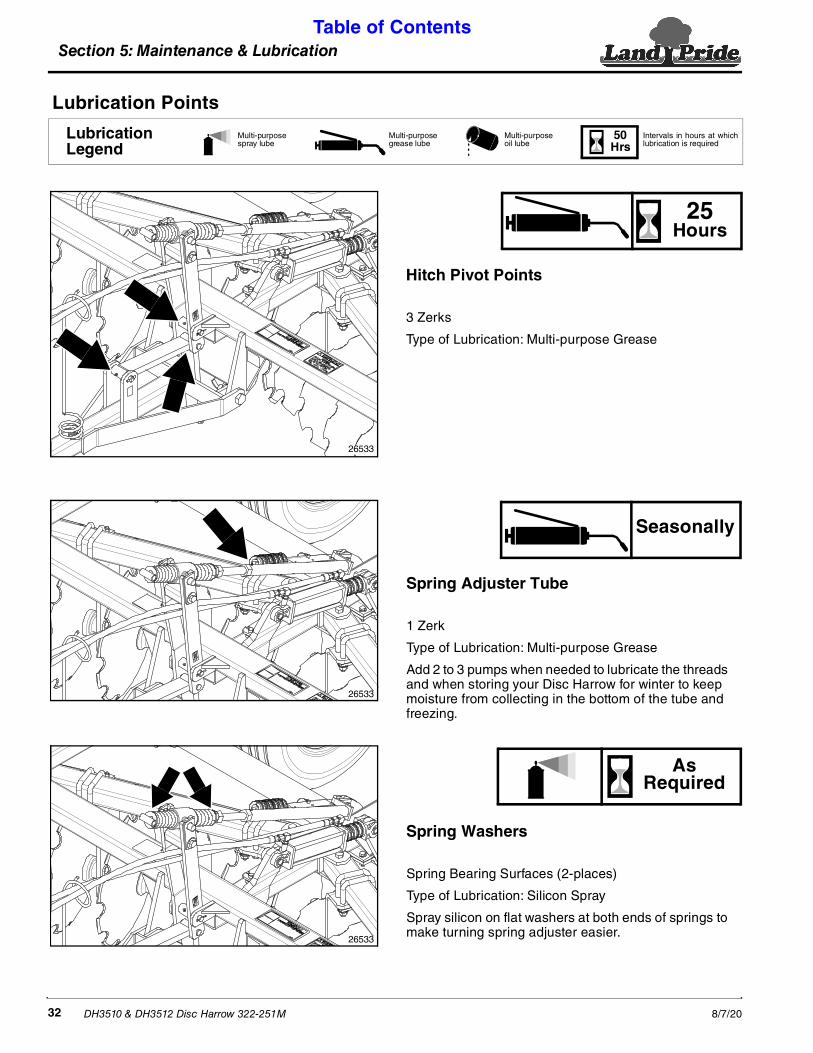
Section 5: Maintenance & Lubrication Table of Contents
DH3510 & DH3512 Disc Harrow 322-251M 8/7/2032
Spring Adjuster Tube
1 Zerk
Type of Lubrication: Multi-purpose Grease
Add 2 to 3 pumps when needed to lubricate the threads and when storing your Disc Harrow for winter to keep moisture from collecting in the bottom of the tube and freezing.
Spring Washers
Spring Bearing Surfaces (2-places)
Type of Lubrication: Silicon Spray
Spray silicon on flat washers at both ends of springs to make turning spring adjuster easier.
Lubrication Points
26533
26533
26533
Hitch Pivot Points
3 Zerks
Type of Lubrication: Multi-purpose Grease
25Hours
Seasonally
AsRequired
50Hrs
Multi-purpose spray lube
Multi-purpose grease lube
Multi-purpose oil lube
Intervals in hours at whichlubrication is required
LubricationLegend

Section 5: Maintenance & Lubrication Table of Contents
DH3510 & DH3512 Disc Harrow 322-251M8/7/20 33
Disc Gang Hanger Bearings
1 Zerk for every hanger bearing
Type of Lubrication: Multi-purpose Grease
Wheel Hub
1 Zerk per wheel hub
Depending on which wheel you have, the zerk may be located inside the hub or outside the hub. See illustration.
Type of Lubrication: Multi-purpose Grease
26534
26535
26536
26537
Outside Location
Inside Location
Axle Top Clamp Half
3 Zerks
Type of Lubrication: Multi-purpose Grease
Lower Disc Harrow until wheels are resting on the ground to relieve pressure on upper clamp halves before applying grease.
Axle Bottom Clamp Half
3 Zerks
Type of Lubrication: Multi-purpose Grease
Raise Disc Harrow up until gangs are slightly off the ground to relieve pressure on lower clamp halves before applying grease.
25Hours
25Hours
25Hours
25Hours
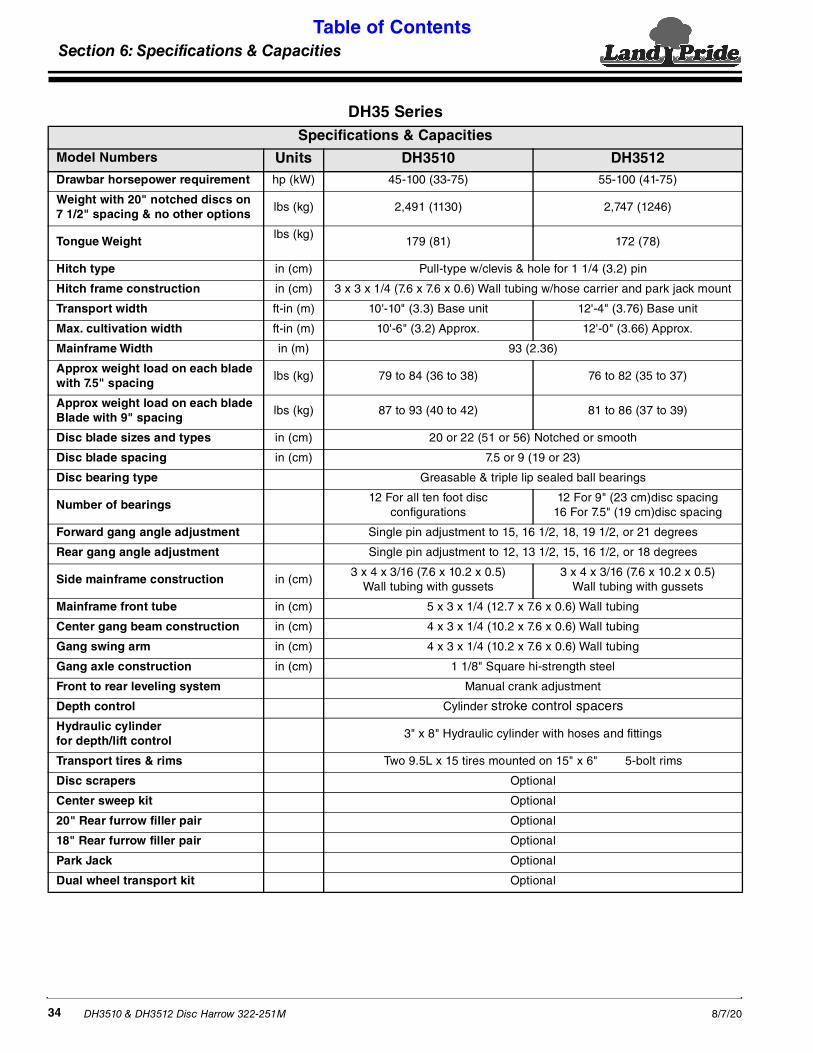
Section 6: Specifications & Capacities Table of Contents
DH3510 & DH3512 Disc Harrow 322-251M 8/7/2034
Section 6: Specifications & Capacities
DH35 SeriesSpecifications & Capacities
Model Numbers Units DH3510 DH3512Drawbar horsepower requirement hp (kW) 45-100 (33-75) 55-100 (41-75)
Weight with 20" notched discs on 7 1/2" spacing & no other options
lbs (kg) 2,491 (1130) 2,747 (1246)
Tongue Weightlbs (kg)
179 (81) 172 (78)
Hitch type in (cm) Pull-type w/clevis & hole for 1 1/4 (3.2) pin
Hitch frame construction in (cm) 3 x 3 x 1/4 (7.6 x 7.6 x 0.6) Wall tubing w/hose carrier and park jack mount
Transport width ft-in (m) 10'-10" (3.3) Base unit 12'-4" (3.76) Base unit
Max. cultivation width ft-in (m) 10'-6" (3.2) Approx. 12'-0" (3.66) Approx.
Mainframe Width in (m) 93 (2.36)
Approx weight load on each blade with 7.5" spacing
lbs (kg) 79 to 84 (36 to 38) 76 to 82 (35 to 37)
Approx weight load on each blade Blade with 9" spacing
lbs (kg) 87 to 93 (40 to 42) 81 to 86 (37 to 39)
Disc blade sizes and types in (cm) 20 or 22 (51 or 56) Notched or smooth
Disc blade spacing in (cm) 7.5 or 9 (19 or 23)
Disc bearing type Greasable & triple lip sealed ball bearings
Number of bearings12 For all ten foot disc
configurations12 For 9" (23 cm)disc spacing
16 For 7.5" (19 cm)disc spacing
Forward gang angle adjustment Single pin adjustment to 15, 16 1/2, 18, 19 1/2, or 21 degrees
Rear gang angle adjustment Single pin adjustment to 12, 13 1/2, 15, 16 1/2, or 18 degrees
Side mainframe construction in (cm)3 x 4 x 3/16 (7.6 x 10.2 x 0.5)
Wall tubing with gussets3 x 4 x 3/16 (7.6 x 10.2 x 0.5)
Wall tubing with gussets
Mainframe front tube in (cm) 5 x 3 x 1/4 (12.7 x 7.6 x 0.6) Wall tubing
Center gang beam construction in (cm) 4 x 3 x 1/4 (10.2 x 7.6 x 0.6) Wall tubing
Gang swing arm in (cm) 4 x 3 x 1/4 (10.2 x 7.6 x 0.6) Wall tubing
Gang axle construction in (cm) 1 1/8" Square hi-strength steel
Front to rear leveling system Manual crank adjustment
Depth control Cylinder stroke control spacers
Hydraulic cylinder for depth/lift control
3" x 8" Hydraulic cylinder with hoses and fittings
Transport tires & rims Two 9.5L x 15 tires mounted on 15" x 6" 5-bolt rims
Disc scrapers Optional
Center sweep kit Optional
20" Rear furrow filler pair Optional
18" Rear furrow filler pair Optional
Park Jack Optional
Dual wheel transport kit Optional

Section 6: Specifications & Capacities Table of Contents
DH3510 & DH3512 Disc Harrow 322-251M8/7/20 35
Overall DimensionsFigure 6-1
26581

Section 7: Features & Benefits Table of Contents
DH3510 & DH3512 Disc Harrow 322-251M 8/7/2036
Section 7: Features & Benefits
DH35 Series
Features Benefits
Two working widths and several models to choose from
Designed to meet the operational and geographical needs of our customers.
Pull-type clevis hitch attachment for 45 to 100 hp tractors
Allows easy one person attachment to a wider range of lower priced new or used utility tractors.
High weight per blade concentration Makes for easier disc penetration.
Heavy duty carrier frame and tongue construction
Provides for years of dependable service and performance.
Single pin release and lock on five position gang angling front and rear
Makes gang adjustments for less or more aggressive tillage an easy task.
Notched or smooth disc selection in 20" or 22" disc sizes
Lets customers choose a configuration that’s just right for their tillage task.
Greasable triple sealed disc bearing Provides for ease of service and longer bearing life.
Large transport tires with option of adding two more
Provides capability of road and field transport over tough surface conditions.
Hydraulic depth and transport controlGoes from working to transport position and back again with easy single tractor hydraulic control lever manipulation.
Front to rear leveling system Provides uniform front to rear disc gang penetration.
Optional dirt Scrapers Keeps discs from balling up with sticky mud.
Optional 18" and 20" furrow filler blades
Provides for more uniform finish on multiple pass applications.
Optional center sweep kit Provides more consistent uniform finish between gangs.
Optional park jack Assures easier hitch attachment to tractor.
2 Rear disc choices Choose Notched or Smooth rear discs to achieve your desired finish.

Section 7: Features & Benefits Table of Contents
DH3510 & DH3512 Disc Harrow 322-251M8/7/20 37
This page left blank intentionally.
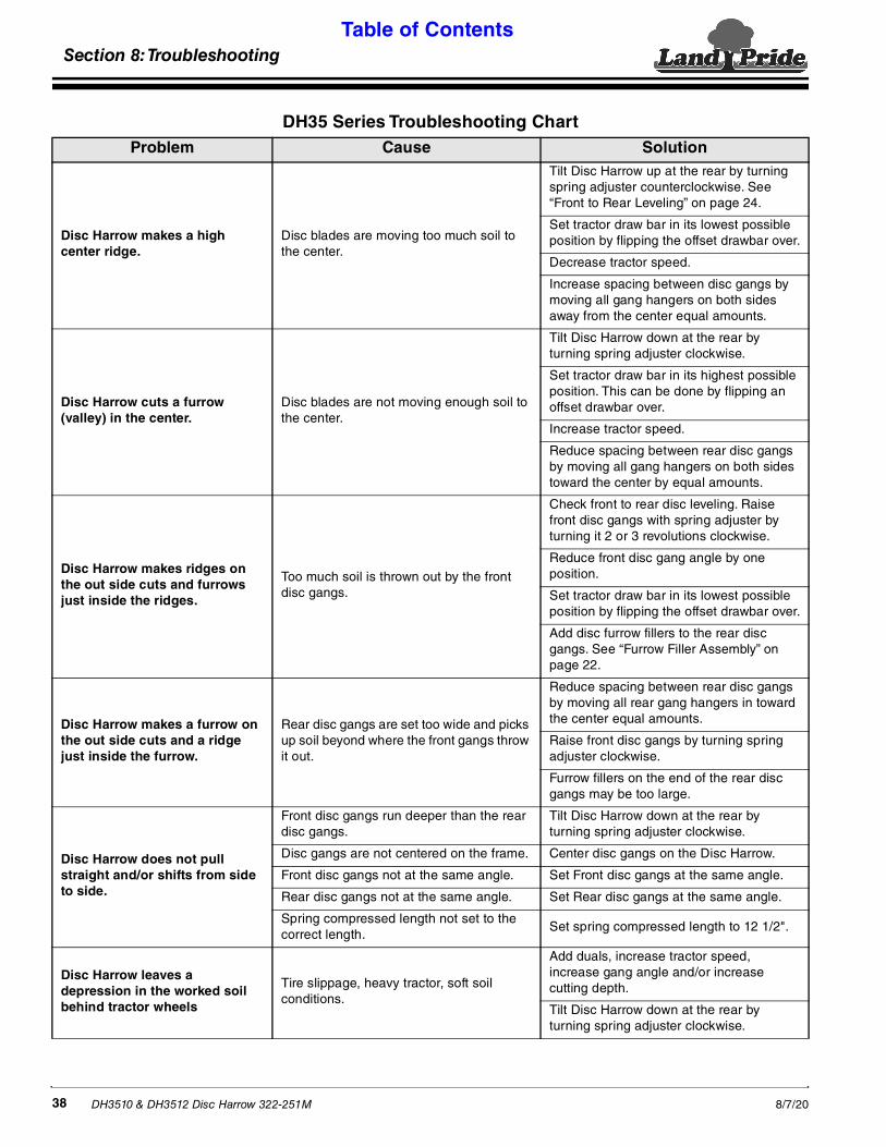
Section 8: Troubleshooting Table of Contents
DH3510 & DH3512 Disc Harrow 322-251M 8/7/2038
DH35 Series Troubleshooting ChartProblem Cause Solution
Disc Harrow makes a high center ridge.
Disc blades are moving too much soil to the center.
Tilt Disc Harrow up at the rear by turning spring adjuster counterclockwise. See “Front to Rear Leveling” on page 24.
Set tractor draw bar in its lowest possible position by flipping the offset drawbar over.
Decrease tractor speed.
Increase spacing between disc gangs by moving all gang hangers on both sides away from the center equal amounts.
Disc Harrow cuts a furrow (valley) in the center.
Disc blades are not moving enough soil to the center.
Tilt Disc Harrow down at the rear by turning spring adjuster clockwise.
Set tractor draw bar in its highest possible position. This can be done by flipping an offset drawbar over.
Increase tractor speed.
Reduce spacing between rear disc gangs by moving all gang hangers on both sides toward the center by equal amounts.
Disc Harrow makes ridges on the out side cuts and furrows just inside the ridges.
Too much soil is thrown out by the front disc gangs.
Check front to rear disc leveling. Raise front disc gangs with spring adjuster by turning it 2 or 3 revolutions clockwise.
Reduce front disc gang angle by one position.
Set tractor draw bar in its lowest possible position by flipping the offset drawbar over.
Add disc furrow fillers to the rear disc gangs. See “Furrow Filler Assembly” on page 22.
Disc Harrow makes a furrow on the out side cuts and a ridge just inside the furrow.
Rear disc gangs are set too wide and picks up soil beyond where the front gangs throw it out.
Reduce spacing between rear disc gangs by moving all rear gang hangers in toward the center equal amounts.
Raise front disc gangs by turning spring adjuster clockwise.
Furrow fillers on the end of the rear disc gangs may be too large.
Disc Harrow does not pull straight and/or shifts from side to side.
Front disc gangs run deeper than the rear disc gangs.
Tilt Disc Harrow down at the rear by turning spring adjuster clockwise.
Disc gangs are not centered on the frame. Center disc gangs on the Disc Harrow.
Front disc gangs not at the same angle. Set Front disc gangs at the same angle.
Rear disc gangs not at the same angle. Set Rear disc gangs at the same angle.
Spring compressed length not set to the correct length.
Set spring compressed length to 12 1/2".
Disc Harrow leaves a depression in the worked soil behind tractor wheels
Tire slippage, heavy tractor, soft soil conditions.
Add duals, increase tractor speed, increase gang angle and/or increase cutting depth.
Tilt Disc Harrow down at the rear by turning spring adjuster clockwise.
Section 8: Troubleshooting
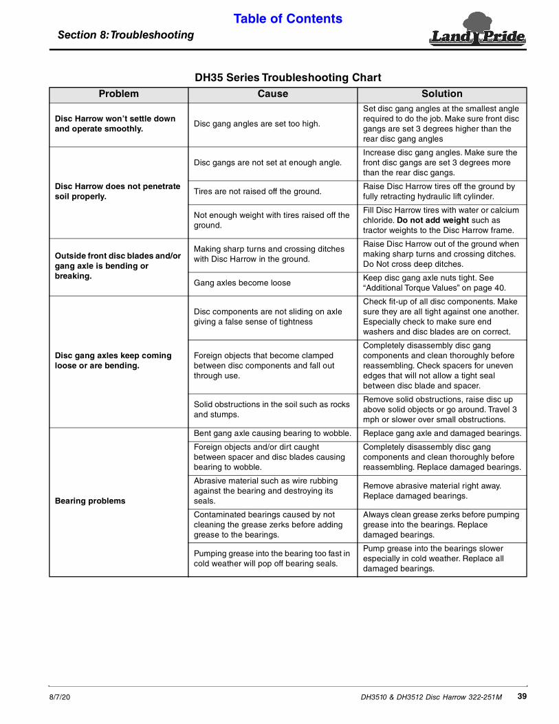
Section 8: Troubleshooting Table of Contents
DH3510 & DH3512 Disc Harrow 322-251M8/7/20 39
Disc Harrow won’t settle down and operate smoothly.
Disc gang angles are set too high.
Set disc gang angles at the smallest angle required to do the job. Make sure front disc gangs are set 3 degrees higher than the rear disc gang angles
Disc Harrow does not penetrate soil properly.
Disc gangs are not set at enough angle.Increase disc gang angles. Make sure the front disc gangs are set 3 degrees more than the rear disc gangs.
Tires are not raised off the ground.Raise Disc Harrow tires off the ground by fully retracting hydraulic lift cylinder.
Not enough weight with tires raised off the ground.
Fill Disc Harrow tires with water or calcium chloride. Do not add weight such as tractor weights to the Disc Harrow frame.
Outside front disc blades and/or gang axle is bending or breaking.
Making sharp turns and crossing ditches with Disc Harrow in the ground.
Raise Disc Harrow out of the ground when making sharp turns and crossing ditches. Do Not cross deep ditches.
Gang axles become looseKeep disc gang axle nuts tight. See “Additional Torque Values” on page 40.
Disc gang axles keep coming loose or are bending.
Disc components are not sliding on axle giving a false sense of tightness
Check fit-up of all disc components. Make sure they are all tight against one another. Especially check to make sure end washers and disc blades are on correct.
Foreign objects that become clamped between disc components and fall out through use.
Completely disassembly disc gang components and clean thoroughly before reassembling. Check spacers for uneven edges that will not allow a tight seal between disc blade and spacer.
Solid obstructions in the soil such as rocks and stumps.
Remove solid obstructions, raise disc up above solid objects or go around. Travel 3 mph or slower over small obstructions.
Bearing problems
Bent gang axle causing bearing to wobble. Replace gang axle and damaged bearings.
Foreign objects and/or dirt caught between spacer and disc blades causing bearing to wobble.
Completely disassembly disc gang components and clean thoroughly before reassembling. Replace damaged bearings.
Abrasive material such as wire rubbing against the bearing and destroying its seals.
Remove abrasive material right away. Replace damaged bearings.
Contaminated bearings caused by not cleaning the grease zerks before adding grease to the bearings.
Always clean grease zerks before pumping grease into the bearings. Replace damaged bearings.
Pumping grease into the bearing too fast in cold weather will pop off bearing seals.
Pump grease into the bearings slower especially in cold weather. Replace all damaged bearings.
DH35 Series Troubleshooting ChartProblem Cause Solution

Section 9: Torque Values Chart Table of Contents
DH3510 & DH3512 Disc Harrow 322-251M 8/7/2040
Section 9: Torque Values Chart
Torque Values Chart for Common Bolt SizesBolt Head Identification Bolt Head Identification
Bolt Size (inches) Grade 2 Grade 5 Grade 8
Bolt Size(Metric) Class 5.8 Class 8.8 Class 10.9
in-tpi 1 N · m 2 ft-lb 3 N · m ft-lb N · m ft-lb mm x pitch 4 N · m ft-lb N · m ft-lb N · m ft-lb
1/4" - 20 7.4 5.6 11 8 16 12 M 5 X 0.8 4 3 6 5 9 7
1/4" - 28 8.5 6 13 10 18 14 M 6 X 1 7 5 11 8 15 11
5/16" - 18 15 11 24 17 33 25 M 8 X 1.25 17 12 26 19 36 27
5/16" - 24 17 13 26 19 37 27 M 8 X 1 18 13 28 21 39 29
3/8" - 16 27 20 42 31 59 44 M10 X 1.5 33 24 52 39 72 53
3/8" - 24 31 22 47 35 67 49 M10 X 0.75 39 29 61 45 85 62
7/16" - 14 43 32 67 49 95 70 M12 X 1.75 58 42 91 67 125 93
7/16" - 20 49 36 75 55 105 78 M12 X 1.5 60 44 95 70 130 97
1/2" - 13 66 49 105 76 145 105 M12 X 1 90 66 105 77 145 105
1/2" - 20 75 55 115 85 165 120 M14 X 2 92 68 145 105 200 150
9/16" - 12 95 70 150 110 210 155 M14 X 1.5 99 73 155 115 l215 160
9/16" - 18 105 79 165 120 235 170 M16 X 2 145 105 225 165 315 230
5/8" - 11 130 97 205 150 285 210 M16 X 1.5 155 115 240 180 335 245
5/8" - 18 150 110 230 170 325 240 M18 X 2.5 195 145 310 230 405 300
3/4" - 10 235 170 360 265 510 375 M18 X 1.5 220 165 350 260 485 355
3/4" - 16 260 190 405 295 570 420 M20 X 2.5 280 205 440 325 610 450
7/8" - 9 225 165 585 430 820 605 M20 X 1.5 310 230 650 480 900 665
7/8" - 14 250 185 640 475 905 670 M24 X 3 480 355 760 560 1050 780
1" - 8 340 250 875 645 1230 910 M24 X 2 525 390 830 610 1150 845
1" - 12 370 275 955 705 1350 995 M30 X 3.5 960 705 1510 1120 2100 1550
1-1/8" - 7 480 355 1080 795 1750 1290 M30 X 2 1060 785 1680 1240 2320 1710
1-1/8" - 12 540 395 1210 890 1960 1440 M36 X 3.5 1730 1270 2650 1950 3660 2700
1-1/4" - 7 680 500 1520 1120 2460 1820 M36 X 2 1880 1380 2960 2190 4100 3220
1-1/4" - 12 750 555 1680 1240 2730 2010 1 in-tpi = nominal thread diameter in inches-threads per inch
1-3/8" - 6 890 655 1990 1470 3230 2380 2 N· m = newton-meters
1-3/8" - 12 1010 745 2270 1670 3680 2710 3 ft-lb= foot pounds
1-1/2" - 6 1180 870 2640 1950 4290 3160 4 mm x pitch = nominal thread diameter in millimeters x thread pitch1-1/2" - 12 1330 980 2970 2190 4820 3560
Torque tolerance + 0%, -15% of torquing values. Unless otherwise specified use torque values listed above.
Additional Torque Values
Wheel Hex Slotted Nut 3/4"-16 UNFTighten nut until wheel turns hard. Back nut off until wheel turns freely. Install cotter pin.
Disc gang axle nuts 500 ft. lbs (678 Nm)
Tire Inflation ChartTire Size Inflation PSI
9.5L x 15 x 8 ply rib Implement 44
5.8 8.8 10.9

Section 10: Warranty Table of Contents
DH3510 & DH3512 Disc Harrow 322-251M8/7/20 41
WarrantyLand Pride warrants to the original purchaser that this Land Pride product will
be free from defects in material and workmanship beginning on the date ofpurchase by the end user according to the following schedule when used asintended and under normal service and conditions for personal use.
Overall Unit: One year Parts and Labor
Hydraulic Cylinder: One year Parts and Labor.
Hoses and seals: Considered wear items.
Disc Blades: Considered wear items.
This Warranty is limited to the repair or replacement of any defective part byLand Pride and the installation by the dealer of any such replacement part, anddoes not cover common wear items. Land Pride reserves the right to inspect anyequipment or parts which are claimed to have been defective in material orworkmanship.
This Warranty does not apply to any part or product which in Land Pride’sjudgment shall have been misused or damaged by accident or lack of normalmaintenance or care, or which has been repaired or altered in a way whichadversely affects its performance or reliability, or which has been used for apurpose for which the product is not designed. Misuse also specifically includesfailure to properly maintain oil levels, grease points, and driveline shafts.
Claims under this Warranty should be made to the dealer which originally soldthe product and all warranty adjustments must be made through an authorizedLand Pride dealer. Land Pride reserves the right to make changes in materials ordesign of the product at any time without notice.
This Warranty shall not be interpreted to render Land Pride liable for damagesof any kind, direct, consequential, or contingent to property. Furthermore, LandPride shall not be liable for damages resulting from any cause beyond itsreasonable control. This Warranty does not extend to loss of crops, any expenseor loss for labor, supplies, rental machinery or for any other reason.
No other warranty of any kind whatsoever, express or implied, is madewith respect to this sale; and all implied warranties of merchantability andfitness for a particular purpose which exceed the obligations set forth in thiswritten warranty are hereby disclaimed and excluded from this sale.
This Warranty is not valid unless registered with Land Pride within 30 days fromthe date of purchase.
Section 10: Warranty
IMPORTANT: The Online Warranty Registration should be completed by the dealer at the time of purchase. This information is necessary to provide you with quality customer service.
Model Number ____________________ Serial Number ____________________

Corporate Office: P.O. Box 5060Salina, Kansas 67402-5060 USA
www.landpride.com