Biffi ICON3000 LonWorks Interface, Biffi (VCIOM-16746-EN)
28
Installation, Operation and Maintenance Manual MDE 262 Rev. 2 September 2021 Biffi ICON3000 Lonworks Bus Module Copyright © Biffi. The information in this document is subject to change without notice. Updated data sheets can be obtained from our website www.biffi.it or from your nearest Biffi Center: Biffi Italia s.r.l. - Strada Biffi 165, 29017 Fiorenzuola d'Arda (PC) – Italy PH: +39 0523 944 411 – [email protected]
-
Upload
khangminh22 -
Category
Documents
-
view
1 -
download
0
Transcript of Biffi ICON3000 LonWorks Interface, Biffi (VCIOM-16746-EN)
Installation, Operation and Maintenance Manual MDE 262 Rev. 2
September 2021
Biffi ICON3000Lonworks Bus Module
Copyright © Biffi. The information in this document is subject to change without notice. Updated data sheets can be obtained from our website www.biffi.it or from your nearest Biffi Center: Biffi Italia s.r.l. - Strada Biffi 165, 29017 Fiorenzuola d'Arda (PC) – Italy PH: +39 0523 944 411 – [email protected]

Rev. Date Description Prepared Approved
2 September 2021 General update (Migration to new template)
1 August 2021 Updated to ICON3000 Series F.Paciotti C. Doglio
0 February 2015 First Issue as part of MAN618-5 C. Doglio A.Affaticati
Revision Details
September 2021Revision Details Installation, Operation and Maintenance Manual
MDE 262 Rev. 2
Revision Details
i
Table of ContentsSeptember 2021
Installation, Operation and Maintenance ManualMDE 262 Rev. 2
Table of Contents
Table of Contents
Section 1: Introduction to LonWorks Protocol1.1 Nodes Addressing ......................................................................................... 41.2 Message Services .......................................................................................... 4
Section 2: LonWorks Implementation in ICON30002.1 Fieldbus Media .............................................................................................. 5
2.1.1 Specification for 16 AWG / 1.3 mm – Twisted Pair Cable ..................... 62.1.2 Bus Communication Topology ............................................................ 7
Section 3: ICON3000 LonWorks Interface3.1 Network Wiring ............................................................................................ 93.2 LD1-LD5: Status LED .................................................................................... 103.3 LD6: Service LED ......................................................................................... 113.4 Local Procedures ......................................................................................... 12
3.4.1 FDI Control Menu ............................................................................. 123.4.2 Positioner Menu ............................................................................... 143.4.3 Node Report Menu ........................................................................... 153.4.4 Service Pin Message ......................................................................... 16
Section 4: ICON3000 LonWorks Communication Profile4.1 Actuator Runtime Input Variables ................................................................ 174.2 Actuator Output Variables ........................................................................... 184.3 Actuator Setup and Configuration Variables ................................................ 204.4 Maintenance Variables ................................................................................ 224.5 Factory Commissioning Variables (Read Only) ............................................. 224.6 Fault Detection Function Configuration ....................................................... 23

NotesSeptember 2021
Installation, Operation and Maintenance Manual MDE 262 Rev. 2
This page is intentionally left blank
Installation, Operation and Maintenance ManualMDE 262 Rev. 2 September 2021
Introduction to LonWorks Protocol 1
Section 1: Introduction to LonWorks Protocol
Section 1: Introduction to LonWorks ProtocolLonWorks is a complete platform for implementing control network systems created by Echelon Corporation. LonWorks has been approved as ANSI/EIA-709.1 and as ISO/IEC 14908, Parts 1, 2, 3, and 4 Standards.
Devices in a LonWorks network communicate using LonTalk®, the standardized language of the network. LonTalk consists of a series of underlying protocols that allow intelligent communication among various devices on a network. The protocol provides a set of services that allow the application program in a device to send and receive messages from other devices over the network without needing to know the topology of the network or the names, addresses or functions of other devices. Support for network management services allow for remote network management tools to interact with devices over the network, including reconfiguration of network addresses and parameters, downloading of application programs, reporting of network problems and start/stop/reset of device application programs. LonTalk – and thus LonWorks networks – can be implemented over basically any medium, including power lines, twisted pair, radio frequency (RF), infrared (IR), coaxial cable and fibre optics.
A control network is a group of "nodes", each with one or more sensors or actuators, plus localized computational capability, that communicate over one or more media, using a standard protocol to control and monitoring application. Communication among the nodes may be peer-to-peer (distributed control) or master-slave (centralized control); in either case, intelligence in the nodes permits the distribution of processing loads. If the control functions are also distributed, both system performance and reliability can be dramatically enhanced.
LonWorks networks really describe a complete solution to the problem of control systems.
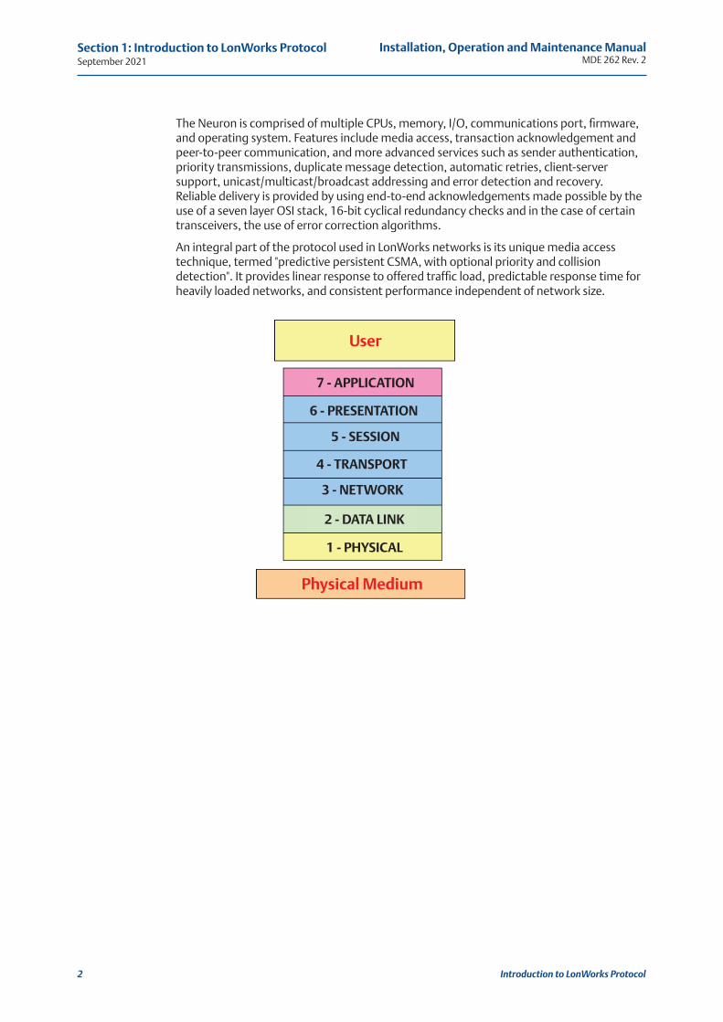
Protocols are generally designed to follow the ISO standard "Open Systems Interconnection Reference Model," which encompasses a full set of protocol features, and classifies them according to seven functional categories referred to as "layers". Thus the "seven layer ISO-OSI model".
The LonTalk protocol implements all seven layers of the ISO-OSI model and the entire LonTalk protocol stack is contained in the Neuron chip that is a complete system on a chip.
NOTICEBiffi Italia has taken every care in collecting and verifying the documentation contained in this Installation, Operation and Maintenance Manual. The informations herein contained are reserved property of Biffi Italia.
September 2021Installation, Operation and Maintenance Manual
MDE 262 Rev. 2
Introduction to LonWorks Protocol2
Section 1: Introduction to LonWorks Protocol
The Neuron is comprised of multiple CPUs, memory, I/O, communications port, firmware, and operating system. Features include media access, transaction acknowledgement and peer-to-peer communication, and more advanced services such as sender authentication, priority transmissions, duplicate message detection, automatic retries, client-server support, unicast/multicast/broadcast addressing and error detection and recovery. Reliable delivery is provided by using end-to-end acknowledgements made possible by the use of a seven layer OSI stack, 16-bit cyclical redundancy checks and in the case of certain transceivers, the use of error correction algorithms.
An integral part of the protocol used in LonWorks networks is its unique media access technique, termed "predictive persistent CSMA, with optional priority and collision detection". It provides linear response to offered traffic load, predictable response time for heavily loaded networks, and consistent performance independent of network size.
User
7 - APPLICATION
6 - PRESENTATION
5 - SESSION
4 - TRANSPORT
3 - NETWORK
2 - DATA LINK
1 - PHYSICAL
Physical Medium
Installation, Operation and Maintenance ManualMDE 262 Rev. 2 September 2021
Introduction to LonWorks Protocol
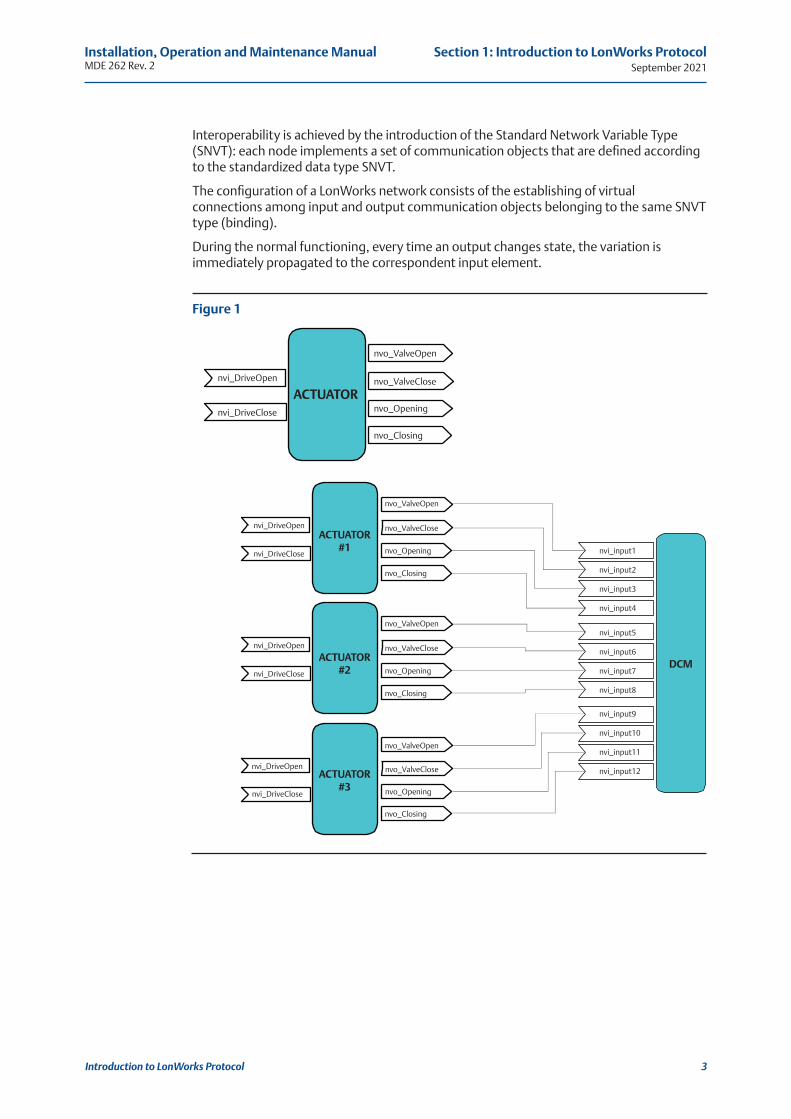
Interoperability is achieved by the introduction of the Standard Network Variable Type (SNVT): each node implements a set of communication objects that are defined according to the standardized data type SNVT.
The configuration of a LonWorks network consists of the establishing of virtual connections among input and output communication objects belonging to the same SNVT type (binding).
During the normal functioning, every time an output changes state, the variation is immediately propagated to the correspondent input element.
Figure 1
3
Section 1: Introduction to LonWorks Protocol
ACTUATOR
ACTUATOR #1
ACTUATOR #2
ACTUATOR #3
DCM
nvi_DriveOpen
nvi_DriveClose
nvo_ValveOpen
nvo_ValveClose
nvo_Opening
nvo_Closing
nvi_DriveOpen
nvi_DriveClose
nvo_ValveOpen
nvo_ValveClose
nvo_Opening
nvo_Closing
nvi_DriveOpen
nvi_DriveClose
nvi_DriveClose
nvi_DriveOpen
nvo_Closing
nvo_Opening
nvo_ValveClose
nvo_ValveOpen
nvo_Closing
nvo_Opening
nvo_ValveClose
nvo_ValveOpen
nvi_input1
nvi_input2
nvi_input3
nvi_input4
nvi_input5
nvi_input6
nvi_input7
nvi_input8
nvi_input9
nvi_input10
nvi_input11
nvi_input12
September 2021Installation, Operation and Maintenance Manual
MDE 262 Rev. 2
Introduction to LonWorks Protocol4
Section 1: Introduction to LonWorks Protocol
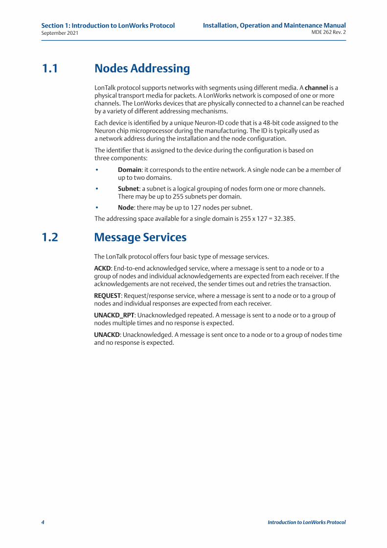
1.1 Nodes Addressing
LonTalk protocol supports networks with segments using different media. A channel is a physical transport media for packets. A LonWorks network is composed of one or more channels. The LonWorks devices that are physically connected to a channel can be reached by a variety of different addressing mechanisms.
Each device is identified by a unique Neuron-ID code that is a 48-bit code assigned to the Neuron chip microprocessor during the manufacturing. The ID is typically used as a network address during the installation and the node configuration.
The identifier that is assigned to the device during the configuration is based on three components:
• Domain: it corresponds to the entire network. A single node can be a member of up to two domains.
• Subnet: a subnet is a logical grouping of nodes form one or more channels. There may be up to 255 subnets per domain.
• Node: there may be up to 127 nodes per subnet.
The addressing space available for a single domain is 255 x 127 = 32.385.
1.2 Message Services
The LonTalk protocol offers four basic type of message services.
ACKD: End-to-end acknowledged service, where a message is sent to a node or to a group of nodes and individual acknowledgements are expected from each receiver. If the acknowledgements are not received, the sender times out and retries the transaction.
REQUEST: Request/response service, where a message is sent to a node or to a group of nodes and individual responses are expected from each receiver.
UNACKD_RPT: Unacknowledged repeated. A message is sent to a node or to a group of nodes multiple times and no response is expected.
UNACKD: Unacknowledged. A message is sent once to a node or to a group of nodes time and no response is expected.
Installation, Operation and Maintenance ManualMDE 262 Rev. 2 September 2021
LonWorks Implementation in ICON3000 5
Section 2: LonWorks Implementation in ICON3000
Section 2: LonWorks Implementation in ICON3000
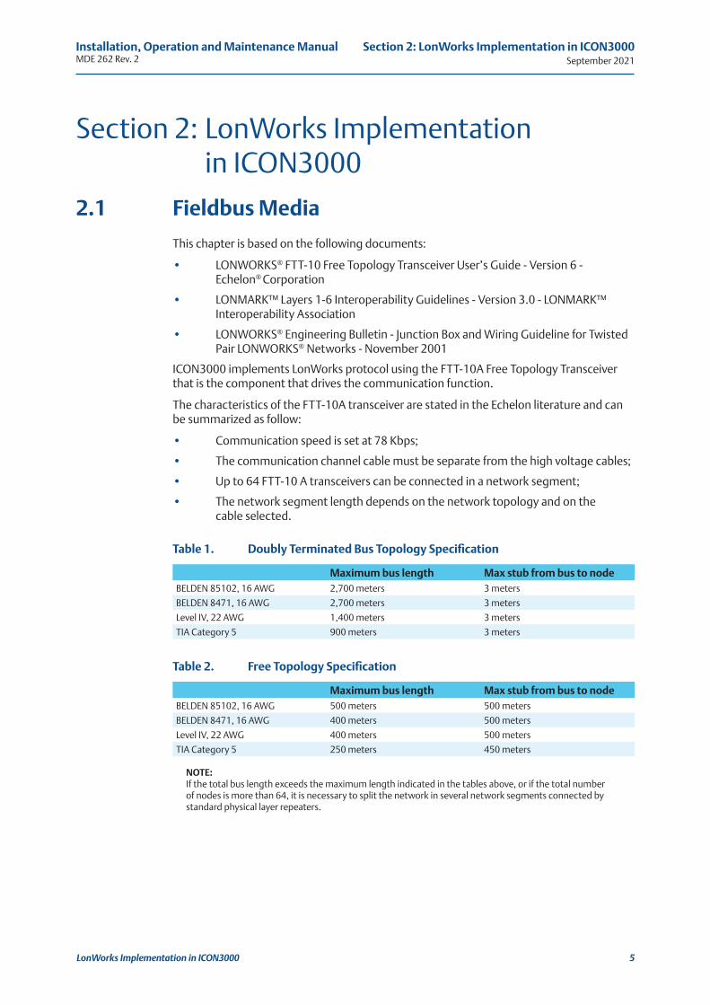
2.1 Fieldbus Media
This chapter is based on the following documents:
• LONWORKS® FTT-10 Free Topology Transceiver User’s Guide - Version 6 - Echelon® Corporation
• LONMARK™ Layers 1-6 Interoperability Guidelines - Version 3.0 - LONMARK™ Interoperability Association
• LONWORKS® Engineering Bulletin - Junction Box and Wiring Guideline for Twisted Pair LONWORKS® Networks - November 2001
ICON3000 implements LonWorks protocol using the FTT-10A Free Topology Transceiver that is the component that drives the communication function.
The characteristics of the FTT-10A transceiver are stated in the Echelon literature and can be summarized as follow:
• Communication speed is set at 78 Kbps;
• The communication channel cable must be separate from the high voltage cables;
• Up to 64 FTT-10 A transceivers can be connected in a network segment;
• The network segment length depends on the network topology and on the cable selected.
NOTE: If the total bus length exceeds the maximum length indicated in the tables above, or if the total number of nodes is more than 64, it is necessary to split the network in several network segments connected by standard physical layer repeaters.
Table 1. Doubly Terminated Bus Topology Specification
Table 2. Free Topology Specification
Maximum bus length Max stub from bus to nodeBELDEN 85102, 16 AWG 2,700 meters 3 meters
BELDEN 8471, 16 AWG 2,700 meters 3 meters
Level IV, 22 AWG 1,400 meters 3 meters
TIA Category 5 900 meters 3 meters
Maximum bus length Max stub from bus to nodeBELDEN 85102, 16 AWG 500 meters 500 meters
BELDEN 8471, 16 AWG 400 meters 500 meters
Level IV, 22 AWG 400 meters 500 meters
TIA Category 5 250 meters 450 meters
September 2021Installation, Operation and Maintenance Manual
MDE 262 Rev. 2
LonWorks Implementation in ICON30006
Section 2: LonWorks Implementation in ICON3000
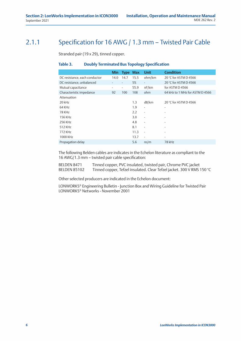
2.1.1 Specification for 16 AWG / 1.3 mm – Twisted Pair Cable
Stranded pair (19 x 29), tinned copper.
The following Belden cables are indicates in the Echelon literature as compliant to the 16 AWG/1.3 mm – twisted pair cable specification:
BELDEN 8471 Tinned copper, PVC insulated, twisted pair, Chrome PVC jacket BELDEN 85102 Tinned copper, Tefzel insulated. Clear Tefzel jacket. 300 V RMS 150 °C
Other selected producers are indicated in the Echelon document:
LONWORKS® Engineering Bulletin - Junction Box and Wiring Guideline for Twisted Pair LONWORKS® Networks - November 2001
Table 3. Doubly Terminated Bus Topology Specification
Min Type Max Unit ConditionDC resistance, each conductor 14.0 14.7 15.5 ohm/km 20 °C for ASTM D 4566
DC resistance, unbalanced - - 5% - 20 °C for ASTM D 4566
Mutual capacitance - - 55.9 nF/km for ASTM D 4566
Characteristic impedance 92 100 108 ohm 64 kHz to 1 MHz for ASTM D 4566
Attenuation
20 kHz 1.3 dB/km 20 °C for ASTM D 4566
64 KHz 1.9 - -
78 KHz 2.2 - -
156 KHz 3.0 - -
256 KHz 4.8 - -
512 KHz 8.1 - -
772 KHz 11.3 - -
1000 KHz 13.7 - -
Propagation delay 5.6 ns/m 78 kHz
Installation, Operation and Maintenance ManualMDE 262 Rev. 2 September 2021
LonWorks Implementation in ICON3000 7
Section 2: LonWorks Implementation in ICON3000
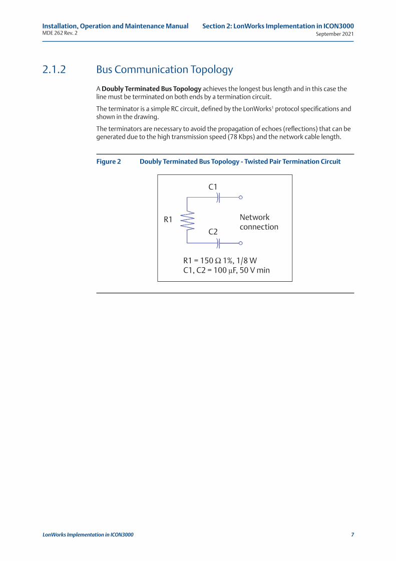
2.1.2 Bus Communication Topology
A Doubly Terminated Bus Topology achieves the longest bus length and in this case the line must be terminated on both ends by a termination circuit.
The terminator is a simple RC circuit, defined by the LonWorks1 protocol specifications and shown in the drawing.
The terminators are necessary to avoid the propagation of echoes (reflections) that can be generated due to the high transmission speed (78 Kbps) and the network cable length.
R1 = 150 Ω 1%, 1/8 W C1, C2 = 100 µF, 50 V min
Network connection
C2
R1
C1
Figure 2 Doubly Terminated Bus Topology - Twisted Pair Termination Circuit
September 2021Installation, Operation and Maintenance Manual
MDE 262 Rev. 2
ICON3000 LonWorks Interface8
Section 3: ICON3000 LonWorks Interface
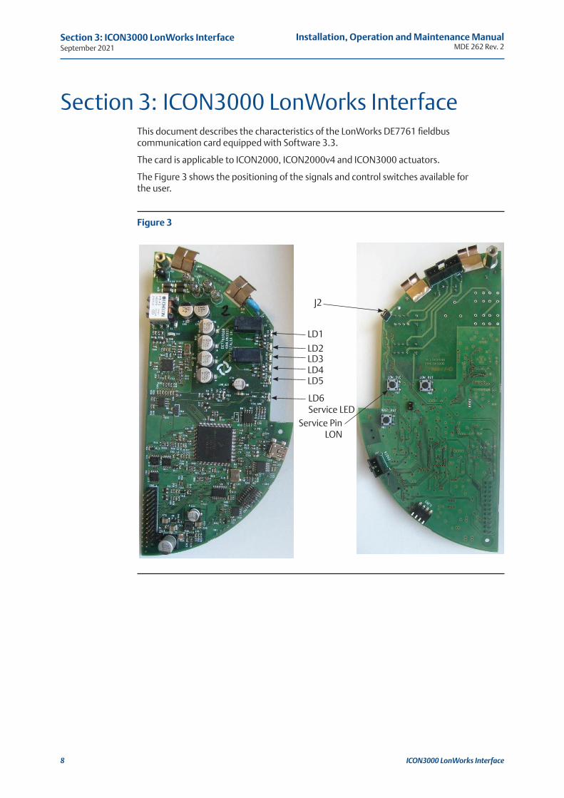
J2
LD1
LD2LD3LD4LD5
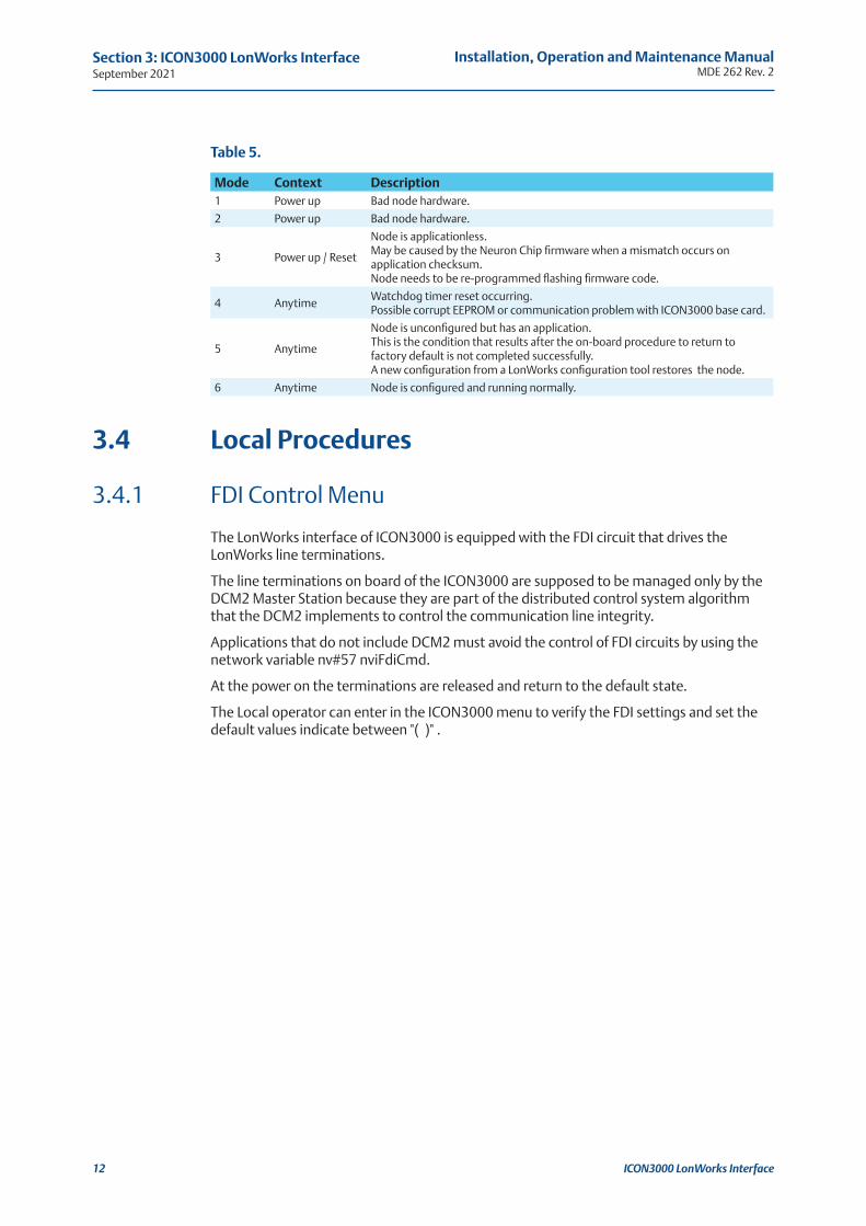
LD6 Service LED
Service Pin LON
Section 3: ICON3000 LonWorks InterfaceThis document describes the characteristics of the LonWorks DE7761 fieldbus communication card equipped with Software 3.3.
The card is applicable to ICON2000, ICON2000v4 and ICON3000 actuators.
The Figure 3 shows the positioning of the signals and control switches available for the user.
Figure 3
A1 A2 A3 A4 A5 A6
Installation, Operation and Maintenance ManualMDE 262 Rev. 2 September 2021
ICON3000 LonWorks Interface 9
Section 3: ICON3000 LonWorks Interface
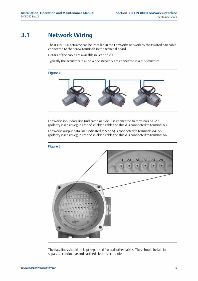
3.1 Network Wiring
The ICON3000 actuator can be installed in the LonWorks network by the twisted pair cable connected to the screw terminals in the terminal board.
Details of the cable are available in Section 2.1.
Typically the actuators in a LonWorks network are connected in a bus structure.
Figure 4
LonWorks input data line (indicated as Side B) is connected to terminals A1- A2 (polarity insensitive); in case of shielded cable the shield is connected to terminal A3.
LonWorks output data line (indicated as Side A) is connected to terminals A4- A5 (polarity insensitive); in case of shielded cable the shield is connected to terminal A6.
Figure 5
The data lines should be kept separated from all other cables. They should be laid in separate, conductive and earthed electrical conduits.
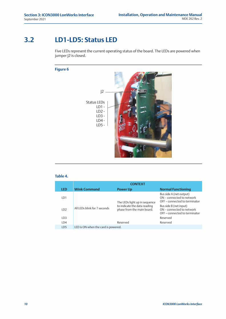
J2
Status LEDs LD1 - LD2 - LD3 - LD4 - LD5 -
September 2021Installation, Operation and Maintenance Manual
MDE 262 Rev. 2
ICON3000 LonWorks Interface
Figure 6
10
Section 3: ICON3000 LonWorks Interface
3.2 LD1-LD5: Status LED
Five LEDs represent the current operating status of the board. The LEDs are powered when jumper J2 is closed.
Table 4.
CONTEXT
LED Wink Command Power Up Normal Functioning
LD1
All LEDs blink for 7 seconds
The LEDs light up in sequence to indicate the data reading phase from the main board.
Bus side A (net output)ON – connected to network OFF – connected to terminator
LD2Bus side B (net input)ON – connected to network OFF – connected to terminator
LD3 Reserved
LD4 Reserved Reserved
LD5 LED is ON when the card is powered.
Installation, Operation and Maintenance ManualMDE 262 Rev. 2 September 2021
ICON3000 LonWorks Interface 11
Section 3: ICON3000 LonWorks Interface
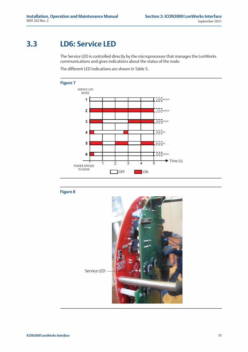
3.3 LD6: Service LED
The Service LED is controlled directly by the microprocessor that manages the LonWorks communications and gives indications about the status of the node.
The different LED indications are shown in Table 5.
Figure 7
Figure 8
SERVICE LED MODE
POWER APPLIED TO NODE
OFF ON
Time (s)
CONTINUOUS
REPEATED
REPEATED
CONTINUOUS
CONTINUOUS
CONTINUOUS
Service LED
September 2021Installation, Operation and Maintenance Manual
MDE 262 Rev. 2
ICON3000 LonWorks Interface12
Section 3: ICON3000 LonWorks Interface
Table 5.
Mode Context Description1 Power up Bad node hardware.
2 Power up Bad node hardware.
3 Power up / Reset
Node is applicationless.May be caused by the Neuron Chip firmware when a mismatch occurs on application checksum.Node needs to be re-programmed flashing firmware code.
4 AnytimeWatchdog timer reset occurring.Possible corrupt EEPROM or communication problem with ICON3000 base card.
5 Anytime
Node is unconfigured but has an application.This is the condition that results after the on-board procedure to return to factory default is not completed successfully.A new configuration from a LonWorks configuration tool restores the node.
6 Anytime Node is configured and running normally.
3.4 Local Procedures
3.4.1 FDI Control Menu
The LonWorks interface of ICON3000 is equipped with the FDI circuit that drives the LonWorks line terminations.
The line terminations on board of the ICON3000 are supposed to be managed only by the DCM2 Master Station because they are part of the distributed control system algorithm that the DCM2 implements to control the communication line integrity.
Applications that do not include DCM2 must avoid the control of FDI circuits by using the network variable nv#57 nviFdiCmd.
At the power on the terminations are released and return to the default state.
The Local operator can enter in the ICON3000 menu to verify the FDI settings and set the default values indicate between "( )" .
Installation, Operation and Maintenance ManualMDE 262 Rev. 2 September 2021
ICON3000 LonWorks Interface 13
Section 3: ICON3000 LonWorks Interface
Restore procedures:
• Move the local selector to OFF and then press simultaneously OPEN and STOP.
• LANGUAGE: Select the language and press YES.
• VIEW MODE press NO.
• Enter the password.
• SETUP MODE press YES.
• ACTUATOR SETUP press YES.
• Press NO to scroll the list of available routines until:
• FDI CONTROL press YES.
— NODE TYPE: (SLAVE): press YES if it is correct, or press NO to change.
— ADDRESS MODE: (SUBNET): press YES if it is correct, or press NO to change.
— LOOP TIME: (250): press YES if it is correct, or press NO to change.
• CONTROL MODE: press YES to change or press NO to skip to RELAY routine.
— FDI ENABLE ALL press NO.
— FDI DISABLE ALL press YES.
• RELAY: Press YES to change or NO to return to FDI CONTROL.
— NETWORK A (ON NET) press YES if it is correct, or press NO to change.
— NETWORK B (ON NET) press YES if it is correct, or press NO to change.
View procedures:
• Move the local selector to OFF and then press simultaneously OPEN and STOP.
• LANGUAGE: Select the language and press YES.
• VIEW MODE press YES.
• Press NO to scroll the list of available routines until:
• FDI CONTROL press YES.
• Press YES to scroll the current values of FDI CONTROL parameters.
September 2021Installation, Operation and Maintenance Manual
MDE 262 Rev. 2
ICON3000 LonWorks Interface14
Section 3: ICON3000 LonWorks Interface
Configuration procedures:
• Move the local selector to OFF and then press simultaneously OPEN and STOP.
• LANGUAGE: Select the language and press YES.
• VIEW MODE press NO.
• Enter the password.
• SETUP MODE press YES.
• ACTUATOR SETUP press YES.
• Press NO to scroll the list of available routines until:
• POSITIONER press YES.
— DEAD BAND: (xx): acceptable value from 0.1 to 25.5%; press YES if it is correct, or press NO to change.
— MOTION INHIBIT TIME: (xx): acceptable value from 1 to 255 s; press YES if it is correct, or press NO to change.
View procedures:
• Move the local selector to OFF and then press simultaneously OPEN and STOP.
• LANGUAGE: Select the language and press YES.
• VIEW MODE press YES.
• Press NO to scroll the list of available routines until:
• POSITIONER press YES.
• Press YES to scroll the current values of POSITIONER parameters.
3.4.2 Positioner Menu
The positioner function is available only on the modulating actuators and it is enabled when the network variable nv#31 nviInchingMode has been set to the value ST_ON.
The value 0 of position request (nv#6 SetPoint), received from the LonWorks bus, corresponds to the request R% = 0% = valve fully closed, and the value 100 corresponds to the request R% = 100% = valve fully open.
The ICON 3000 compares the current position % of the actuator with the position request R%, received from the bus, and if the difference is greater than the dead band, the actuator is driven to reach the new requested position. The following options can be configured via either bus or local operator interface:
• Dead band: configurable from 0.1% to 25.5% of the maximum position error (difference between the position request % and current position %). The configured value should be great enough to avoid “hunting” effect of the actuator.
!WARNINGIf the dead band value set by the operator is not compatible with the position resolution that the ICON3000 can obtain by the mechanical chain of the actuator, the ICON3000 will use as dead band value the best resolution possible.
• Motion inhibit time: it allows to adjust the length of the delay time between two cycles of the motor. It can be configured from 1 to 255 s and allows to set the maximum number of start/hour of electrical motor.
Installation, Operation and Maintenance ManualMDE 262 Rev. 2 September 2021
ICON3000 LonWorks Interface 15
Section 3: ICON3000 LonWorks Interface
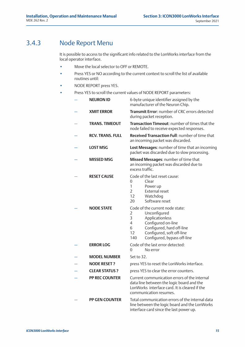
3.4.3 Node Report Menu
It is possible to access to the significant info related to the LonWorks interface from the local operator interface.
• Move the local selector to OFF or REMOTE.
• Press YES or NO according to the current context to scroll the list of available routines until:
• NODE REPORT press YES.
• Press YES to scroll the current values of NODE REPORT parameters:
— NEURON ID 6-byte unique identifier assigned by the manufacturer of the Neuron Chip.
— XMIT ERROR Transmit Error: number of CRC errors detected during packet reception.
— TRANS. TIMEOUT Transaction Timeout: number of times that the node failed to receive expected responses.
— RCV. TRANS. FULL Received Transaction Full: number of time that an incoming packet was discarded.
— LOST MSG Lost Messages: number of time that an incoming packet was discarded due to slow processing.
— MISSED MSG Missed Messages: number of time that an incoming packet was discarded due to excess traffic.
— RESET CAUSE Code of the last reset cause: 0 Clear 1 Power up 2 External reset 12 Watchdog 20 Software reset
— NODE STATE Code of the current node state: 2 Unconfigured 3 Applicationless 4 Configured on-line 6 Configured, hard off-line 12 Configured, soft off-line 140 Configured, bypass off-line
— ERROR LOG Code of the last error detected: 0 No error
— MODEL NUMBER Set to 32.
— NODE RESET ? press YES to reset the LonWorks interface.
— CLEAR STATUS ? press YES to clear the error counters.
— PP REC COUNTER Current communication errors of the internal data line between the logic board and the LonWorks interface card. It is cleared if the communication resumes.
— PP GEN COUNTER Total communication errors of the internal data line between the logic board and the LonWorks interface card since the last power up.

September 2021Installation, Operation and Maintenance Manual
MDE 262 Rev. 2
ICON3000 LonWorks Interface16
Section 3: ICON3000 LonWorks Interface
3.4.4 Service Pin Message
This function forces the LonWorks interface to send on the networks its service pin message.
• Move the local selector to REMOTE.
• Press STOP.
Installation, Operation and Maintenance ManualMDE 262 Rev. 2 September 2021
LonWorks Communication Profile 17
Section 4: LonWorks Communication Profile
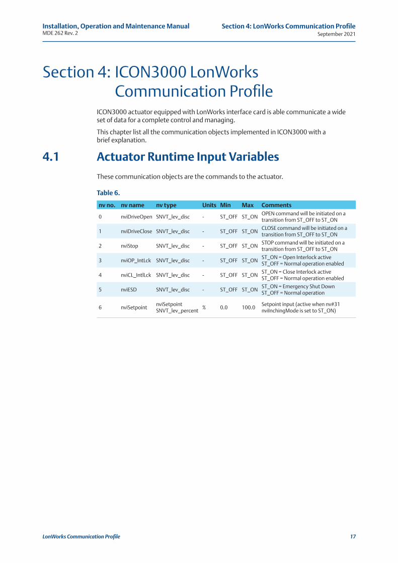
Section 4: ICON3000 LonWorks Communication ProfileICON3000 actuator equipped with LonWorks interface card is able communicate a wide set of data for a complete control and managing.
This chapter list all the communication objects implemented in ICON3000 with a brief explanation.
4.1 Actuator Runtime Input Variables
These communication objects are the commands to the actuator.
Table 6.
nv no. nv name nv type Units Min Max Comments
0 nviDriveOpen SNVT_lev_disc - ST_OFF ST_ONOPEN command will be initiated on a transition from ST_OFF to ST_ON
1 nviDriveClose SNVT_lev_disc - ST_OFF ST_ONCLOSE command will be initiated on a transition from ST_OFF to ST_ON
2 nviStop SNVT_lev_disc - ST_OFF ST_ONSTOP command will be initiated on a transition from ST_OFF to ST_ON
3 nviOP_IntLck SNVT_lev_disc - ST_OFF ST_ONST_ON = Open Interlock active ST_OFF = Normal operation enabled
4 nviCL_IntlLck SNVT_lev_disc - ST_OFF ST_ONST_ON = Close Interlock active ST_OFF = Normal operation enabled
5 nviESD SNVT_lev_disc - ST_OFF ST_ONST_ON = Emergency Shut Down ST_OFF = Normal operation
6 nviSetpointnviSetpoint SNVT_lev_percent
% 0.0 100.0Setpoint input (active when nv#31 nviInchingMode is set to ST_ON)
September 2021Installation, Operation and Maintenance Manual
MDE 262 Rev. 2
LonWorks Communication Profile18
Section 4: LonWorks Communication Profile
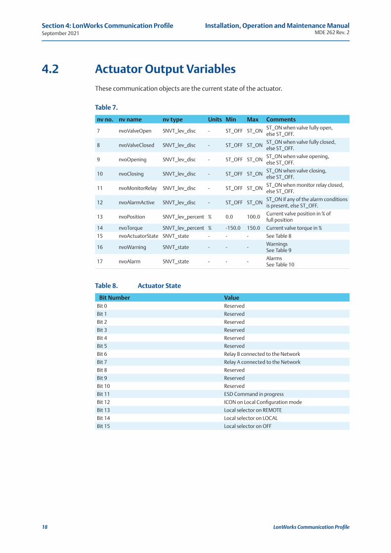
4.2 Actuator Output Variables
These communication objects are the current state of the actuator.
nv no. nv name nv type Units Min Max Comments
7 nvoValveOpen SNVT_lev_disc - ST_OFF ST_ONST_ON when valve fully open, else ST_OFF.
8 nvoValveClosed SNVT_lev_disc - ST_OFF ST_ONST_ON when valve fully closed, else ST_OFF.
9 nvoOpening SNVT_lev_disc - ST_OFF ST_ONST_ON when valve opening, else ST_OFF.
10 nvoClosing SNVT_lev_disc - ST_OFF ST_ONST_ON when valve closing, else ST_OFF.
11 nvoMonitorRelay SNVT_lev_disc - ST_OFF ST_ONST_ON when monitor relay closed, else ST_OFF.
12 nvoAlarmActive SNVT_lev_disc - ST_OFF ST_ONST_ON if any of the alarm conditions is present, else ST_OFF.
13 nvoPosition SNVT_lev_percent % 0.0 100.0Current valve position in % of full position
14 nvoTorque SNVT_lev_percent % -150.0 150.0 Current valve torque in %
15 nvoActuatorState SNVT_state - - - See Table 8
16 nvoWarning SNVT_state - - -Warnings See Table 9
17 nvoAlarm SNVT_state - - -Alarms See Table 10
Bit Number ValueBit 0 Reserved
Bit 1 Reserved
Bit 2 Reserved
Bit 3 Reserved
Bit 4 Reserved
Bit 5 Reserved
Bit 6 Relay B connected to the Network
Bit 7 Relay A connected to the Network
Bit 8 Reserved
Bit 9 Reserved
Bit 10 Reserved
Bit 11 ESD Command in progress
Bit 12 ICON on Local Configuration mode
Bit 13 Local selector on REMOTE
Bit 14 Local selector on LOCAL
Bit 15 Local selector on OFF
Table 7.
Table 8. Actuator State
Installation, Operation and Maintenance ManualMDE 262 Rev. 2 September 2021
LonWorks Communication Profile 19
Section 4: LonWorks Communication Profile
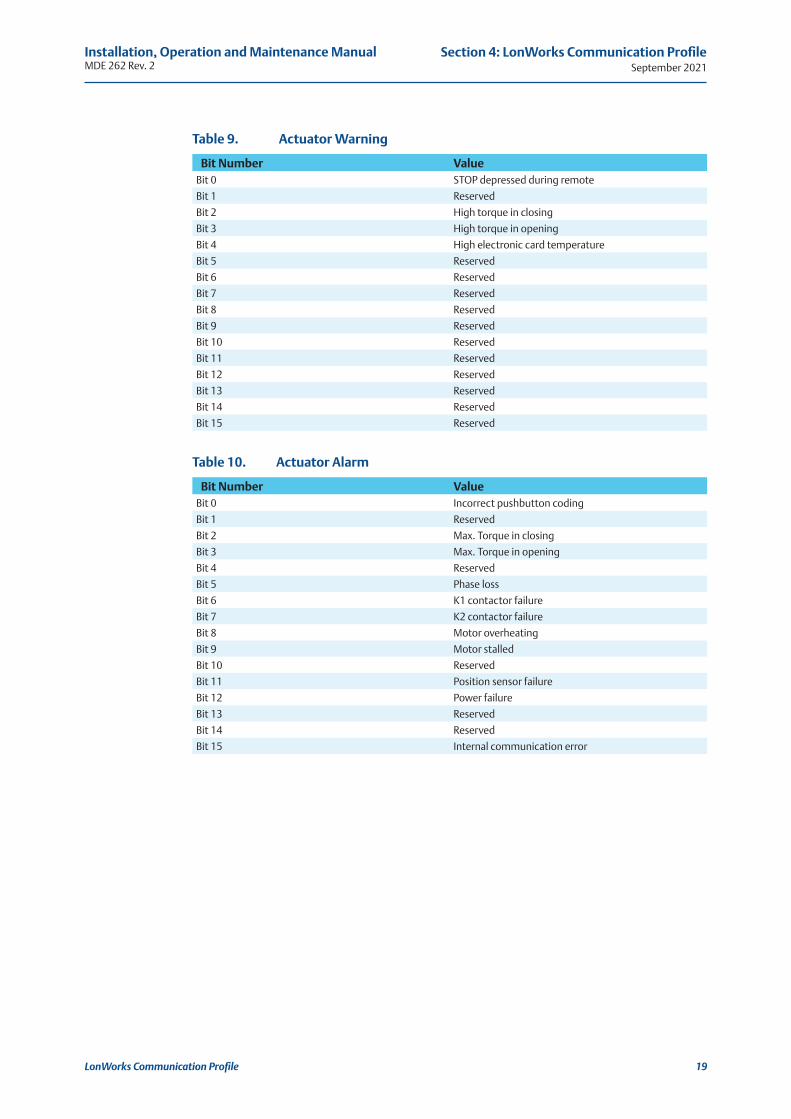
Bit Number ValueBit 0 Incorrect pushbutton coding
Bit 1 Reserved
Bit 2 Max. Torque in closing
Bit 3 Max. Torque in opening
Bit 4 Reserved
Bit 5 Phase loss
Bit 6 K1 contactor failure
Bit 7 K2 contactor failure
Bit 8 Motor overheating
Bit 9 Motor stalled
Bit 10 Reserved
Bit 11 Position sensor failure
Bit 12 Power failure
Bit 13 Reserved
Bit 14 Reserved
Bit 15 Internal communication error
Bit Number ValueBit 0 STOP depressed during remote
Bit 1 Reserved
Bit 2 High torque in closing
Bit 3 High torque in opening
Bit 4 High electronic card temperature
Bit 5 Reserved
Bit 6 Reserved
Bit 7 Reserved
Bit 8 Reserved
Bit 9 Reserved
Bit 10 Reserved
Bit 11 Reserved
Bit 12 Reserved
Bit 13 Reserved
Bit 14 Reserved
Bit 15 Reserved
Table 9. Actuator Warning
Table 10. Actuator Alarm
September 2021Installation, Operation and Maintenance Manual
MDE 262 Rev. 2
LonWorks Communication Profile20
Section 4: LonWorks Communication Profile
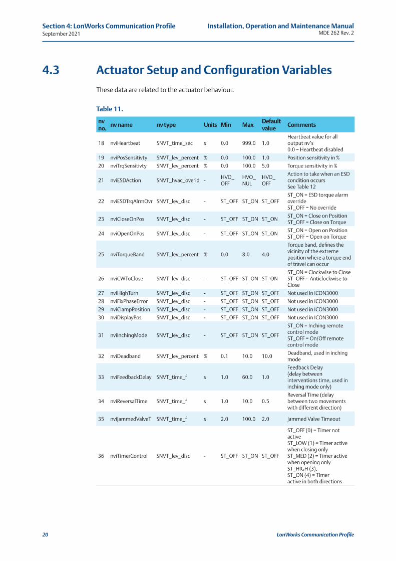
4.3 Actuator Setup and Configuration Variables
These data are related to the actuator behaviour.
Table 11.
nv no.
nv name nv type Units Min MaxDefaultvalue
Comments
18 nviHeartbeat SNVT_time_sec s 0.0 999.0 1.0Heartbeat value for all output nv’s0.0 = Heartbeat disabled
19 nviPosSensitivty SNVT_lev_percent % 0.0 100.0 1.0 Position sensitivity in %
20 nviTrqSensitivty SNVT_lev_percent % 0.0 100.0 5.0 Torque sensitivity in %
21 nviESDAction SNVT_hvac_overid -HVO_OFF
HVO_NUL
HVO_OFF
Action to take when an ESD condition occurs See Table 12
22 nviESDTrqAlrmOvr SNVT_lev_disc - ST_OFF ST_ON ST_OFFST_ON = ESD torque alarm override ST_OFF = No override
23 nviCloseOnPos SNVT_lev_disc - ST_OFF ST_ON ST_ONST_ON = Close on Position ST_OFF = Close on Torque
24 nviOpenOnPos SNVT_lev_disc - ST_OFF ST_ON ST_ONST_ON = Open on Position ST_OFF = Open on Torque
25 nviTorqueBand SNVT_lev_percent % 0.0 8.0 4.0
Torque band, defines the vicinity of the extreme position where a torque end of travel can occur
26 nviCWToClose SNVT_lev_disc - ST_OFF ST_ON ST_ONST_ON = Clockwise to Close ST_OFF = Anticlockwise to Close
27 nviHighTurn SNVT_lev_disc - ST_OFF ST_ON ST_OFF Not used in ICON3000
28 nviFixPhaseError SNVT_lev_disc - ST_OFF ST_ON ST_OFF Not used in ICON3000
29 nviClampPosition SNVT_lev_disc - ST_OFF ST_ON ST_OFF Not used in ICON3000
30 nviDisplayPos SNVT_lev_disc - ST_OFF ST_ON ST_OFF Not used in ICON3000
31 nviInchingMode SNVT_lev_disc - ST_OFF ST_ON ST_OFF
ST_ON = Inching remote control mode ST_OFF = On/Off remote control mode
32 nviDeadband SNVT_lev_percent % 0.1 10.0 10.0Deadband, used in inching mode
33 nviFeedbackDelay SNVT_time_f s 1.0 60.0 1.0
Feedback Delay (delay between interventions time, used in inching mode only)
34 nviReversalTime SNVT_time_f s 1.0 10.0 0.5Reversal Time (delay between two movements with different direction)
35 nviJammedValveT SNVT_time_f s 2.0 100.0 2.0 Jammed Valve Timeout
36 nviTimerControl SNVT_lev_disc - ST_OFF ST_ON ST_OFF
ST_OFF (0) = Timer not active ST_LOW (1) = Timer active when closing only ST_MED (2) = Timer active when opening only ST_HIGH (3), ST_ON (4) = Timeractive in both directions
Installation, Operation and Maintenance ManualMDE 262 Rev. 2 September 2021
LonWorks Communication Profile 21
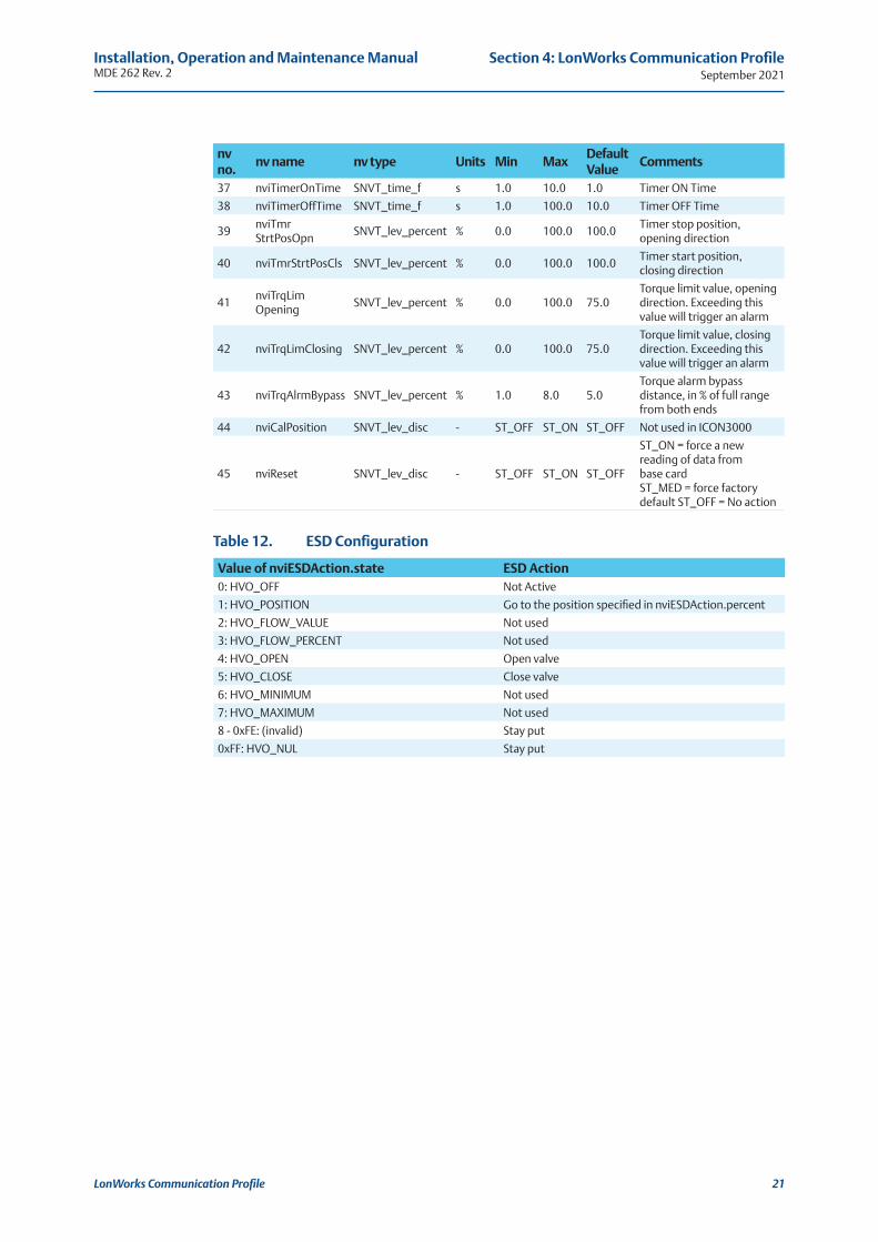
Section 4: LonWorks Communication Profile
Table 12. ESD Configuration
nv no.
nv name nv type Units Min MaxDefaultValue
Comments
37 nviTimerOnTime SNVT_time_f s 1.0 10.0 1.0 Timer ON Time
38 nviTimerOffTime SNVT_time_f s 1.0 100.0 10.0 Timer OFF Time
39nviTmr StrtPosOpn
SNVT_lev_percent % 0.0 100.0 100.0Timer stop position, opening direction
40 nviTmrStrtPosCls SNVT_lev_percent % 0.0 100.0 100.0Timer start position, closing direction
41nviTrqLim Opening
SNVT_lev_percent % 0.0 100.0 75.0Torque limit value, opening direction. Exceeding this value will trigger an alarm
42 nviTrqLimClosing SNVT_lev_percent % 0.0 100.0 75.0Torque limit value, closing direction. Exceeding this value will trigger an alarm
43 nviTrqAlrmBypass SNVT_lev_percent % 1.0 8.0 5.0Torque alarm bypass distance, in % of full range from both ends
44 nviCalPosition SNVT_lev_disc - ST_OFF ST_ON ST_OFF Not used in ICON3000
45 nviReset SNVT_lev_disc - ST_OFF ST_ON ST_OFF
ST_ON = force a new reading of data from base cardST_MED = force factory default ST_OFF = No action
Value of nviESDAction.state ESD Action0: HVO_OFF Not Active
1: HVO_POSITION Go to the position specified in nviESDAction.percent
2: HVO_FLOW_VALUE Not used
3: HVO_FLOW_PERCENT Not used
4: HVO_OPEN Open valve
5: HVO_CLOSE Close valve
6: HVO_MINIMUM Not used
7: HVO_MAXIMUM Not used
8 - 0xFE: (invalid) Stay put
0xFF: HVO_NUL Stay put
September 2021Installation, Operation and Maintenance Manual
MDE 262 Rev. 2
LonWorks Communication Profile22
Section 4: LonWorks Communication Profile
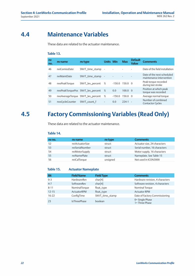
4.4 Maintenance Variables
These data are related to the actuator maintenance.
4.5 Factory Commissioning Variables (Read Only)
These data are related to the actuator maintenance.
Table 13.
Table 14.
Table 15. Actuator Nameplate
nv no.
nv name nv type Units Min MaxDefaultValue
Comments
46 nviComissDate SNVT_time_stamp - - - - Date of the field installation
47 nviMaintDate SNVT_time_stamp - - - -Date of the next scheduled maintenance intervention
48 nvoPeakTorque SNVT_lev_percent % -150.0 150.0 0Peak torque recorded during last stroke
49 nvoPeakTorquePos SNVT_lev_percent % 0.0 100.0 0Position at which peak torque was recorded
50 nvoAverageTorque SNVT_lev_percent % -150.0 150.0 0 Average normal torque
51 nvoCycleCounter SNVT_count_f - 0.0 224-1 -Number of combined Contactor Cycles
nv no. nv name nv type Comments52 nviActuatorSize struct Actuator size, 24 characters
53 nviSerialNumber struct Serial number, 16 characters
54 nviMotorSupply struct Motor supply, 16 characters
55 nviNamePlate struct Nameplate. See Table 15
56 nviCalTorque unsigned Not used in ICON3000
Bit Field Name Field Type Comments0-3 HardwareRev char[4] Hardware revision, 4 characters
4-7 SoftwareRev char[4] Software revision, 4 characters
8-11 NominalTorque float_type Nominal Torque
12-15 ActuatorRPM float_type Actuator RPM
16-22 ConfigTime SNVT_time_stamp Date of Factory Commissioning
23 IsThreePhase boolean0= Single Phase1= Three Phase
Installation, Operation and Maintenance ManualMDE 262 Rev. 2 September 2021
LonWorks Communication Profile 23
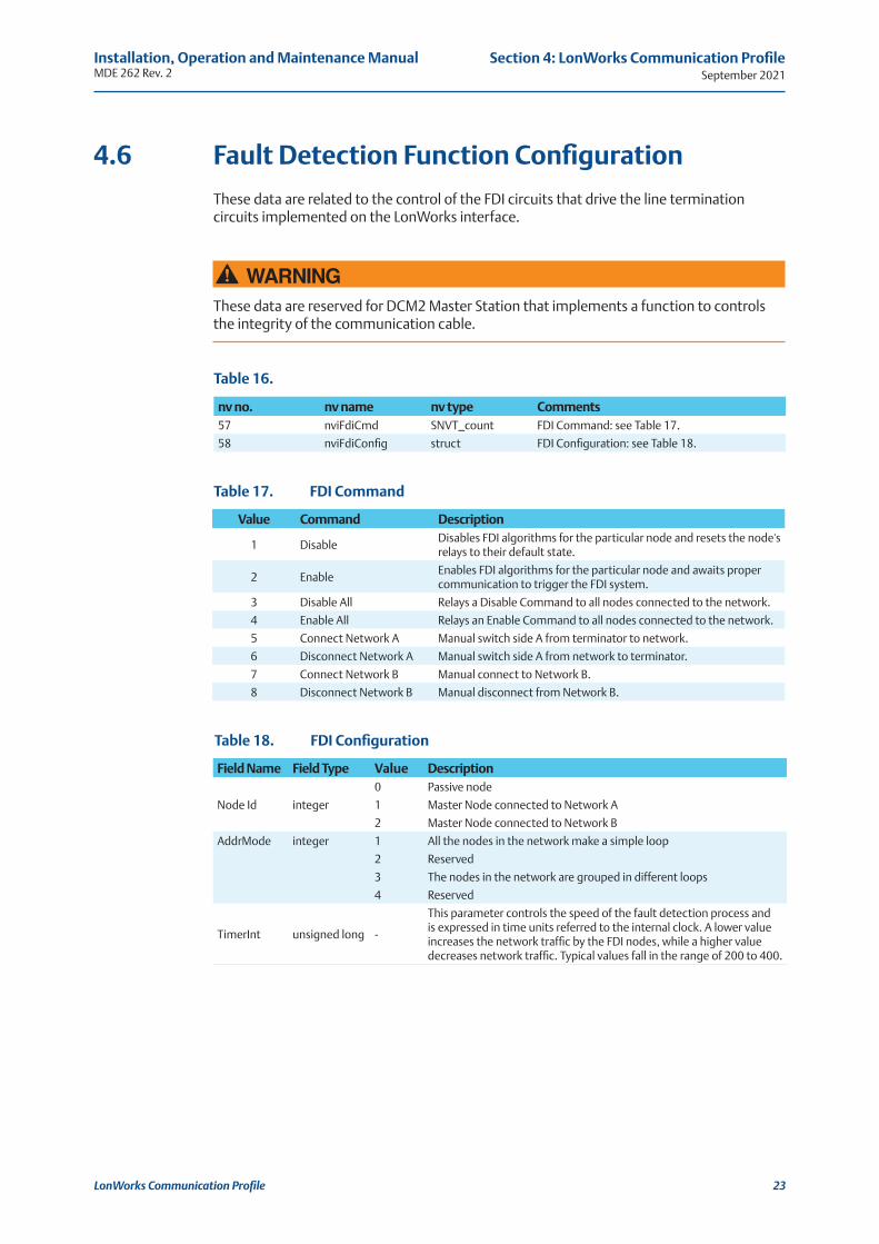
Section 4: LonWorks Communication Profile
Table 18. FDI Configuration
Table 17. FDI Command
Table 16.
Value Command Description
1 DisableDisables FDI algorithms for the particular node and resets the node's relays to their default state.
2 EnableEnables FDI algorithms for the particular node and awaits proper communication to trigger the FDI system.
3 Disable All Relays a Disable Command to all nodes connected to the network.
4 Enable All Relays an Enable Command to all nodes connected to the network.
5 Connect Network A Manual switch side A from terminator to network.
6 Disconnect Network A Manual switch side A from network to terminator.
7 Connect Network B Manual connect to Network B.
8 Disconnect Network B Manual disconnect from Network B.
nv no. nv name nv type Comments57 nviFdiCmd SNVT_count FDI Command: see Table 17.
58 nviFdiConfig struct FDI Configuration: see Table 18.
Field Name Field Type Value Description
Node Id integer
0 Passive node
1 Master Node connected to Network A
2 Master Node connected to Network B
AddrMode integer 1 All the nodes in the network make a simple loop
2 Reserved
3 The nodes in the network are grouped in different loops
4 Reserved
TimerInt unsigned long -
This parameter controls the speed of the fault detection process and is expressed in time units referred to the internal clock. A lower value increases the network traffic by the FDI nodes, while a higher value decreases network traffic. Typical values fall in the range of 200 to 400.
4.6 Fault Detection Function Configuration
These data are related to the control of the FDI circuits that drive the line termination circuits implemented on the LonWorks interface.
! WARNINGThese data are reserved for DCM2 Master Station that implements a function to controls the integrity of the communication cable.

For complete list of sales and manufacturing sites, please visit www.biffi.it or contact us at [email protected]
Biffi Italia s.r.l. Strada Biffi 16529017 Fiorenzuola d’Arda (PC)ItalyT +39 0523 944 411
VCIOM-16746-EN ©2021 Biffi. All rights reserved.
The contents of this publication are presented for information purposes only, and while every effort has been made to ensure their accuracy, they are not to be construed as warranties or guarantees, express or implied, regarding the products or services described herein or their use or applicability. All sales are governed by our terms and conditions, which are available on request. We reserve the right to modify or improve the designs or specifications of our products at any time without notice.