
The memory integrated network interface
10
The Memory-Integrated Network lnterf ace Ron Minnich David Sarnoff Research Center Dan Burns Frank Hady Supercomputing Research Center Our zero-copy ATM Memory-Integrated Network Interface targets 1-Gbps bandwidth with 1.2-p4latency for applications that need to send or receive data at very frequent intervals. Applications can send or receive packets without operating system support, initiate packet transmission with one memory write, and determine packet arrival. At the same time the operating system can use MINI for communicationsand for supporting standard networking software. Simulations show MINI “bounces” a single ATM cell in a round-triptime of 3.9 ps at 10 hibytes/s. he bandwidth and high latency of cur- rent networks limit the set of cluster computing applications to those that require little use of the network. Running a distributed computation on a network of 100 or more machines for five minutes allows only a few seconds of communications if speedup is to reach acceptable levels. Thus such applications must require only a byte of com- munication for every thousand to ten thousand floating-point operations. While these sorts of low communication rate applications exist, studies of other types of applications’ show a much higher frequency of communication with large amounts of data, requiring application-to-application laten- cy on the order of one microsecond. New high-bandwidth networks should widen the scope of cluster computing applications to include those requiring substantial communica- tions. Asynchronous transfer mode (ATM) in par- ticular provides a clear long-term path to gigabit-per-second bandwidths. However, the commercial network interfaces designed for these new networks are not suitable for a large set of distributed and cluster computing appli- cations. These interfaces require operating sys- tem interaction each time a message is sent or received, greatly increasing latency and decreas- ing throughput. We needed an interface that does not involve the operating system in send- ing or receiving messages but does support opti- mized versions of TCPAP (Transmission Control Protocolhternet Protocol) and NFS (Network File System). Our Memory-Integrated Network Interfxe (MINI) architecture integrates the network inter- face into the memory hierarchy, not the input/ output hierarchy, as shown in Figure 1, next page. Typical implementations of network inter- faces use the 110 bus. They suffer from band- width and latency limitations imposed by DMA start-up times, low-I/O cycle times (compared to the CPU cycle times), limited VO address space, multiple data copying, and CPU bus contention. Placing the network interface on the other side of main memory avoids these problems. MINI meets certain application-driven perfor- mance goals. That is, we based the architecture of the interface on our experiences kvith appli- cations that have succeeded (and failed) in a clus- ter and a distributed programming environment, We specified the performance shown later for two point-to-point connected workstations. We did not consider a switched system in the goals, as the ATM switch market remains immature. The goals are as follows: 1. 1-ps application-to-application latency for small, single ATM cell messages. (Measured from the initiation of a host send command until the data is loaded into the target node’s memory, excluding fiber delay.) 0740-7475/95/$04.00 8 1995 IEEE February 7995 7 7
-
Upload
independent -
Category
Documents
-
view
1 -
download
0
Transcript of The memory integrated network interface

The Memory-Integrated Network lnterf ace
Ron Minnich
David Sarnoff Research Center
Dan Burns
Frank Hady
Supercomputing Research
Center
Our zero-copy ATM Memory-Integrated Network Interface targets 1-Gbps bandwidth with 1.2-p4 latency for applications that need to send or receive data at very frequent intervals. Applications can send or receive packets without operating system support, initiate packet transmission with one memory write, and determine packet arrival. At the same time the operating system can use MINI for communications and for supporting standard networking software. Simulations show MINI “bounces” a single ATM cell in a round-trip time of 3.9 ps at 10 hibytes/s.
he bandwidth and high latency of cur- rent networks limit the set of cluster computing applications to those that require little use of the network.
Running a distributed computation on a network of 100 or more machines for five minutes allows only a few seconds of communications if speedup is to reach acceptable levels. Thus such applications must require only a byte of com- munication for every thousand to ten thousand floating-point operations. While these sorts of low communication rate applications exist, studies of other types of applications’ show a much higher frequency of communication with large amounts of data, requiring application-to-application laten- cy on the order of one microsecond.
New high-bandwidth networks should widen the scope of cluster computing applications to include those requiring substantial communica- tions. Asynchronous transfer mode (ATM) in par- ticular provides a clear long-term path to gigabit-per-second bandwidths. However, the commercial network interfaces designed for these new networks are not suitable for a large set of distributed and cluster computing appli- cations. These interfaces require operating sys- tem interaction each time a message is sent or received, greatly increasing latency and decreas- ing throughput. We needed an interface that does not involve the operating system in send- ing or receiving messages but does support opti-
mized versions of TCPAP (Transmission Control Protocolhternet Protocol) and NFS (Network File System).
Our Memory-Integrated Network Interfxe (MINI) architecture integrates the network inter- face into the memory hierarchy, not the input/ output hierarchy, as shown in Figure 1, next page. Typical implementations of network inter- faces use the 110 bus. They suffer from band- width and latency limitations imposed by DMA start-up times, low- I/O cycle times (compared to the CPU cycle times), limited VO address space, multiple data copying, and CPU bus contention. Placing the network interface on the other side of main memory avoids these problems.
MINI meets certain application-driven perfor- mance goals. That is, we based the architecture of the interface on our experiences kvith appli- cations that have succeeded (and failed) in a clus- ter and a distributed programming environment, We specified the performance shown later for two point-to-point connected workstations. We did not consider a switched system in the goals, as the ATM switch market remains immature.
The goals are as follows:
1. 1-ps application-to-application latency for small, single ATM cell messages. (Measured from the initiation of a host send command until the data is loaded into the target node’s memory, excluding fiber delay.)
0740-7475/95/$04.00 8 1995 IEEE February 7995 7 7

2. I-Gbps sustained application-to-application bandwidth
3. A multiuser environment. (Measurements on 1 and 2
4. Interoperability with an existing network standard
for large (-4 Kbyte) messages.
take place in this environment).
(ATM). -- , I CPU 1 I :-& networkinterface I b - 7 L I . $. CPUbus $.
I F
interface - networ interface
Figure 1. MINI network interface hierarchy.
5. Support for high-performance (zero-copy) TCP/IP and
6. Direct network access to 256 Mbytes of main memory,
7. Nonblocking polling of message receipt status. 8. Support for many virtual channels (1K to 4K).
NFS.
64 Mbytes mapped at a time.
Hardware architecture Figure 2 shows the major components of the MINI archi-
tecture. MINI has several memory-addressable areas that allow communication between the host and network interface. The physical layer interface card (PIC) block controls host access to these memory-addressable areas, converting the DRAM accesses issued by the host. This block is the only part of the architecture that must be redesigned when porting the design to another host. Note that we currently use a 72-pin SIMM bus, the timing and pinout of which is standard on most worksta- tions and personal computers.
Before using the interface, a process must reserve and ini- tialize channels into the network. MINI allows user process- es or the operating system to have one or more channels, each corresponding to an ATM virtual channel (VC), into the network. The VC/CRC (cyclic redundancy check) control
(SIMM bus)
Figure 2. MINI architecture.
I2 /€E€ Micro
table contains two control word entries for each VC, a send and a receive. Each control word contains a pointer to a dou- ble-page area in main memory, the VC status, and the ATM cell header informa- tion. The operating system initializes con- trol words whenever a process requests a channel into the network. Also, part of the channel initialization process allocates to the requesting process the double page indicated by the control word. MINI s u p ports a maximum of 4K VCs when page size is 4 Kbytes, 2K VCs for 8-Kbyte pages, and 1K VCs for 16-Kbyte pages.
Setting up the channel is relatively slow, since it involves creating an ATM circuit with a remote host; once complete, the channel operates with very little overhead. User processes or the operating system can initiate a send with a write to either the high- or low-priority FIFO buffer.
The MINI control logic uses the infor- mation in the high- or low-priority FIFO along with the proper entry of the VC control table to read the required data directly from main memory, segment the data into ATM Adaptation Layer 5 cells, and send it into the network. (AAL5 specifics ATM cells for computer-to- computer communications.) An update

Page maps
VCERC control table page Memory map
Send CRC
Receive control Main memory
(64 to 256 Mbytes)
VC/CRC control table , _ _ - - (1 6 Mbytes)
High-/low-priority FIFO page
Figure 3. Host memory and maps.
~~ ~~
Figure 4. Double pages data handling.
of the VC control table send word notifies the sending process of a completed send. The control logic reassembles cells arriving from the network directly into main memory at a location stored in the VC control table. User processes or the operating system can check arrival status with VC con- trol table reads at any time.
The main memory map of a machine featuring a MINI inter- face appears in Figure 3. The structure of the memory map is key to allowing a user process to send and receive data without operating system involvement in a multiuser envi- ronment. At channel setup time, the control logic allocates six pages to a channel. Two pages in main memory space hold the receive data and two more hold the send data. One page within the VCKRC control table space is user read only and initialized by the operating system at setup time. This page contains the send and receive control words, and a send CRC and receive CRC. The final page allows a user process to write to the high- or low-priority FIFO. Using the address bus to indicate the channel number on which the send is to
Table 1. The VC table transmit control word.
Item Bits
Upper VCI bits GFC* Stop offset Double-page pointer Current offset Header HEC Last cell header HEC**
'Generic flow control "Header error correction
4 to 6 4
0 to 3 to 0 to 8 8 -
2 5 2
I Table 2. The VC table receive control word.
Item Bits
PDU count 8 Status 7 Dropped-cell count Double-page pointer 1 3 t o 1 5 Current offset 10 to 12 Stop offset 1 0 t o 12
10 (MSB is sticky)
take place achieves multiuser protection. VC/CRC control table. This dual-port SRAM table holds
setup and status information for each channel. Information used to send messages into the network remains in the 64- bit transmit word, while information used upon receiving data stays in the 64-bit receive word. The transmit control word (see Table 1) includes a pointer to a double page allo- cated by the operating system as the channel's data space. MINI sends data from within the double page, as shown in Figure 4, and generates ATM headers using the data stored in the send word.
Sending starts at the current offset, which is updated after each ATM cell transmits. MINI stops sending after reaching the stop offset. When MINI reaches the end of a page of memory during a send or receive, it wraps to the beginning of the double page. It can place the data in page 1, with the header at the end of page 0 (right before the data) and the trailer at the start of page 0 (right after the data). This layout permits sending and receiving data in a page-aligned man- ner, even if a header and trailer are present. An example of its use appears in the NFS discussion later.
The receive control word (Table 2) includes a current off- set, stop offset, and double-page pointer used as described for the transmit word. A protocol data unit (PDU) count incre- ments each time a full AAL5 message is received, giving the
February 1995 73

process using the channel a convenient place to poll for mes- sage arrival. When the interface drops arriving cells, possibly due to contention for main memory, the drops are recorded in the dropped cell count field. This field features a "sticky" most significant bit so that no drops go unnoticed. Status bits denote whether the channel represented by the control word has been allocated and record possible errors. They also determine whether to place arriving cells on 6-word bound- aries (packed) or on 8-word boundaries with AALS CRCs and real-time clock values placed in two extra words.
Tables 1 and 2 contain a number of fields specified as ranges. The size of the pages used by the host determines the size of the current and stop offsets held. A 512-word page (4 Kbytes) requires an offset of only 10 bits while a 2K-word (16 Kbytes) page requires a 12-bit offset. MINI provides address space for 256 Mbytes of network-mappable memory. This requires a 15-bit double-page pointer for 4-Kbyte pages and a 13-bit double-page pointer for 16-Kbyte pages. MINI allows 64 Mbytes of memory to be mapped into the network at any one time. This number follows from MINI'S support for 4K channels, each referencing a pair of 8-Kbyte double pages.
The same dual-port SRAM used to hold the VC control words also holds a mnsmit and receive AALS CRC value for each VC. Each time a cell passes across the network interface bus, the AAL5 CRC calculator fetches the channel's CRC value. (This occurs in parallel with the network interface controller fetch of the VC control word). The AALS CRC calculator updates the channel's CRC to include the passing cell, and then stores the result in the CRC table (again in parallel with the VC control word store). This method of calculating the CRC allows for arbitrary interleaving of cells from different VCs. High- and low-priority FIFOs. A user or operating sys-
tem host write to either the high- or low-priority FIFO initi- ates message sends. During this write, MINI takes the start and stop offsets within the channel's double page from the host data bus. For user process-initiated sends, MINI latch- es the virtual channel identfier (VCI) on which the send is to take place from the address bus. Therefore a process can initiate a write on a given VC only if it gains write access to the proper address. A special case of VCI equal to zero allows the kernel to access all channels without having to gain access (and fetch TLB entries) to a separate page for each channel. When the host address bus indicates a request to send on channel zero, MINI latches the VC number from the data bus rather than the address bus. The kernel always occu- pies channel zero.
Two FIFOs assure that low-latency messages can be sent even when the interface is currently sending very large mes- sages. A process performing bulk data transfer will send large messages using the low-priority FIFO. Another process can still send a small, low-latency message by writing to the high- priority FIFO. MINI will interrupt any low-priority sends between ATM cells, send the high-priority message, and then
resume sending the low-priority message. MINI does not stall unsuccessful writes to the command
FIFOs. To determine if a send command write was success- ful, the process can read the send command status word associated with each channel.
Pseudo dual-port memory. This section of the host's main memory is directly accessible to the network interface. We decided to make this space very large, possibly encom- passing all of the host's memory. Due to its size, storage for this block must be constructed from dynamic RAM.
Since dual-port DRAMS do not exist, we will initially con- struct this block with off-the-shelf SIMMs and multiplexers, and a pseudo dual-port main memory. The network interface will take control of the memory during unused processor- memory cycles. When the processor accesses main memo- ry, MINI will relinquish its use of the SIMMs in time for the processor to identify a normal access.
Arbitration for use of main memory is much less complex when the host has a memory busy line back to the CPU. When the CPU detects a main memory access, MINI could assert the memory busy line, causing the CPU to wait until MINI completes its memory access.
The best method for sharing main memory between the host and network interface would be to implement a true dual-port DRAM. Such a DRAM would simultaneously fetch two rows and decode two column addresses. Collisions for the same row would cause the second requester, either the host or network interface, to wait. Unfortunately, such chips do not yet exist.
MINI control logic. The state machine within the MINI control logic moves data between the transmit and receive FIFOs and main memory, updating VC/CRC table entries, processing transmit commands, and segmenting or reassem- bling ATM cells. The MINI control logic operates on one ATM cell at a time and services the received cells first. This mini- mizes the probability of receive logic FIFO overflow. When no received cells are present, MINI moves cells from main memory to the transmit logic in response to send commands from the host.
Cell receipt involves the following steps:
1. Using the VCI in the received cell as an index into the VC/CRC control table, MINI fetches the channel's receive control word and CRC.
2. The receive control word forms a main memory address, and MINI initiates a store and updates the CRC.
3. When the pseudo dual-port main memory begins the requested write, MINI increments the offset counter, requests the next write, and updates the CRC.
4. Step 3 repeats until six words have been written to main memory.
5. MINI stores the updated receive control word and CRC in the VCKRC control table.
14 / € € € M i c r o

When the final cell of an AAL5 PDL is received, MINI stores two extra words (the locally calculated AAL5 CRC and the real-time clock value) at main memory addresses suc- ceeding the final data words. Also on a final cell, MINI ini- tializes the channel’s CRC control table entry. If the flag called Pack Arriving Cells has not been set, MINI stores the real- time clock value and the current AAL5 CRC value after each cell. Note that if the stop offset is reached while storing incoming cells, no further writes to the main memory occur, though VCKRC control table updates still take place.
Cell transmission involves the following steps:
1. The VCI held in the high- or low-priority FIFO redds the receive word and CRC from the VCKRC control table.
2. MINI sends the ATM cell’s header, formed using infor- mation from the VC control table receive word, to the transmit FIFO while a main memory read is requested.
3. When granted use of main memory, the network inter- face initiates a read from the address specified by the FIFO and VC control table contents.
4. MINI sends the word read from main memory to both the transmit FIFO and the CRC logic, increments the off- set counter, and initiates a read from the next address location.
5 . Step 4 repeats until six words have been read from main memory.
6. MINI stores the updated VC control send word and CRC in the VCKRC control table, and the VCI within the net- work interface controller for use on future cell sends.
ControVstatus, transmit, and receive logic. The con- troustatus block contains a 100-ns-resolution, real-time clock readable by both the host and network interface, along with board configuration and test logic. The transmit and receive logic blocks contain FIFOs that perform asynchronous trans- fer of ATM cells between the physical layer interface and the network interface.
Packaging. Implementation of the MINI architecture requires the six different boards shown in Figure 5 . Two of the boards, the Finisar transmit and receive modules, are off- the-shelf parts required to implement the physical link into the network. These modules have a 16-bit interface that runs at 75 MHz. The PIC board is the network interface to the Finisar conversion board that translates 64-bit network inter- face words into Finisar 16-bit words. The network interface board contains all the hardware necessary to implement the MINI architecture. The main memory is off-the-shelf, 16- Mbyte SIMMs residing on the network interface board. SIMM extenders plug into the host’s SIMM slots, extending the memory bus to the network interface board.
The separation of the PIC functions from the network inter- face board eases the migration of the design to other hosts or physical media. For instance, to use the design over different
Finisar modules
PIC board \ SlMMs
Network interface
\
SIMM extenders
Figure 5. MINI boards.
physical media, designers would replace the PIC board and Finisar modules. To change from an Indy host to a Sun, DEC, or HP system, designers would redesign host-dependent por- tions of the network interface board, using the same 64-bit interface to the PIC. This eliminates the need to redesign the physical layer.
Flow control. MINI provides hardware support for the low-level form of flow control developed by Seitz to keep the network from dropping cells.’ MINI sends a stop message from a receiving node to the transmitting node (or switch port) when the receiving FIFO fills past some predetermined high- water mark. Once the receiving FIFO is less full, the receiv- ing node restarts transmission by sending a start message.
The MINI architecture also supports software-implemented flow control. In the event that it becomes necessary to drop incoming cells, the MINI hardware keeps a count of the num- ber of cells dropped on a per-VC basis within the VC control table. Real-time clock values automatically passed within mes- sages may also prove useful.
Performance. A detailed VHDL simulation of the initial MINI design gathered some performance statistics.
7houghput. ATM cells are packaged and transmitted at a rate of one cell every 400 ns (20 MINI control logic stare machine states), or 0.96 Gbps. Note that this is the real data transfer rate. The total bit transfer rate, including ATM head- er information is 1.12 Gbps. The PIC board removes the cells 64-bits at a time from a transmit FIFO at a rate of 1.2 Gbps and sends them 16 bits at a time (at 75 MHz) to a Finisar
February 1995 15
Network link
Interface hardware DMA engine
Receive ring buffer Transmit ring buffer
9
d
I ~rotoco~ software I
4 4
Q1 0 2 Q3 Q4 Q5 Q6 Q7 Q8 Incoming data queues Outgoing data queues
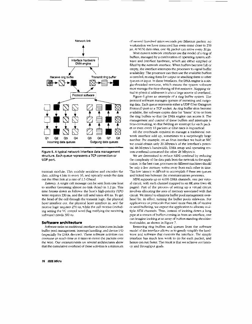
Figure 6. A typical network interface data management structure. Each queue represents a TCP connection or UDP port.
transmit module. This module serializes and encodes the data, adding 4 bits to every 16, and optically sends the data out the fiber link at a rate of 1.5 Gbaud.
Latency. A single cell message can be sent from one host to another (assuming almost no link delay) in 1.2 ps. This time breaks down as follows: the host’s high-priority FIFO write requires 230 ns, and the cell send takes 400 ns. To get the head of the cell through the transmit logic, the physical layer interface out, the physical layer interface in, and the receive logic requires 270 ns, while the cell receive (includ- ing setting the VC control word flag notifying the receiving software) needs 300 ns.
Software architecture Software tasks on traditional interface architectures include
buffer pool management, interrupt handling, and device I/O (especially for DMA devices). These software activities can consume as much time as it takes to move the packets over the wire. Our measurements on several architectures show that the cumulative overhead of these activities is a minimum
of several hundred microseconds per Ethernet packet; no workstation we have measured has even come close to 250 ps. At MINI data rates, one 4K packet can arrive every 30 p.
Most current network interfaces use the model of a ring of buffers, managed by a combination of operating system soft- ware and interface hardware, which are either emptied or filled by the network interface. When buffers become full or empty, the interface interrupts the processor to signal buffer availability. The processor can then use the available buffers as needed, reusing them for output or attaching them to other queues as input. In these interfaces, the DMA engine is a sin- gle-threaded resource, which means the system software must manage the time-sharing of that resource. Mapping vir- tual to physical addresses is also a large source of overhead.
Figure 6 gives an example of a ring buffer system. The protocol software manages queues of incoming and outgo- ing data. Each queue represents either a UDP (User Datagram Protocol) port or a TCP socket. As ring buffer slots become available, the software copies data (or ‘‘loans’’ it) to or from the ring buffers so that the DMA engine can access it. The management and control of these buffers and interrupts is time-consuming, so that fielding an interrupt for each pack- et or even every 10 packets at Gbit rates is impractical.
All the overheads required to manage a traditional net- work interface add up, sometimes to a surprisingly large number. For example, on an Sbus interface we built at SRC we could obtain only 20 Mbytes/s of the interface’s poten- tial 48-Mbytes/s bandwidth; DMA setup and operating sys- tem overhead consumed the other 28 Mbytes/s.
We are determined to reduce MINI overhead by reducing the complexity of the data path from the network to the appli- cation. In the best case, processes on different machines should be only a few memory writes away from each other in time. This low latency is difficult to accomplish if there are queues and linked lists between the communications processes.
MINI supports up to 4,096 DMA channels, one per virtu- al circuit, with each channel mapped to an 8 K area (two 4K pages). Part of the process of setting up a virtual circuit involves allocating the area of memory associated with that circuit. We intend to eliminate buffer pool management over- head by, in effect, turning the buffer pools sideways. For applications or protocols that need more than 8K of receive or send buffering, we expect the application to allocate mul- tiple ATM channels. Thus, instead of looking down a long pipe at a stream of buffers coming in from an interface, one can imagine looking at an array of buffers standing shoulder- to-shoulder, as shown in Figure 7 .
Removing ring buffers and queues from the software model of the interface allows us to greatly simplify the hard- ware and software that controls the interface. The simple interface has much less work to do for each packet, and hence can run faster. The result is that we achieve our laten- cy and throughput goals.
16 IEEE Micro

Network link
I I
\\\ virtual vc1 vc2 vc3 circuits + + +
One TCP connection or UDP port (incoming)
VCll VC12 VC13
One TCP connection or UDP port (outgoing)
Figure 7. How MINI uses multiple ATM circuits to support buffering on a connection or port.
The design of the MINI architecture explicitly considers communication protocols. MINI provides low-level message status information including corruption or loss of data noti- fication, time of arrival, and network link activity. MINI allows access to data with very little overhead. Users can directly access data as well as set start and stop offsets for message sends or receives without operating system involvement. Through its allocation of double-page regions of memory, MINI reduces copying and conserves main-memory band- width. These features allow efficient implementation of stan- dard communication protocols such as SunRPC TCP, and NFS as well as specific user-programmed protocols. A more detailed description of NFS along with a set of examples describing different uses of MINI follow.
Zerocopy NFS protocol. This protocol is the basis of the NFS, which permits file sharing in a networked environment. NFS is an integral part of most Unix workstation-based net- works. Our measurements show that over 60 percent of the data that flows on our networks is NFS read and write traffic; well over 66 percent of the packets are NFS control packets. Proper optimization of higher level protocols such as NFS is essential to achieving high network performance.
From the beginning, the MINI team included support for a highly optimized NFS within the MINI architecture. This support, along with changes we have identified to the NFS packet structure, will allow NFS to use our Gbps network. One of the most important optimizations ensures that NFS does not unnecessarily copy data. With MINI, NFS will not copy; data passes directly from the network to the correct place in memory and comes from its original location in memory directly into the network. We call this optimization zero-copy NFS, since the data is never copied.
Fixed size
IP header
NFS replyhequest
Figure 8. A typical NFS read reply or write request packet.
The fact that a given NFS implementation uses a zero-copy TCP or UDP does not imply that the NFS protocol itself is zero- copy. One of the optimizations that makes zero-copy proto- cols work well is data alignment on page boundaries. But since the data and header portions of an N F S packet look like data to the lower levels of the protocol stack (that is, TCP), the NFS packet may be page-aligned while the actual NFS data is not (requiring copying so that it is aligned by page). Even when lower level protocols benefit from page-aligned data, higher level protocols may still pay data-copying penalties.
To take advantage of MINI’S support for zero-copy NFS, we changed the format of the NFS packets. To explain why, we must first give a quick overview of NFS packet formats.
Figure 8 shows typical packets for NFS versions two and three. NFS packets consist of either client requests, such as read or write requests; and server replies, which are answers to requests. Since NFS uses either TCP/IP or UDPAP, the first part of the packet is a standard IP header. Following this header is the NFS section, which consists of a standard XFS header (the same for all NFS requests, regardless of type), and the request-dependent part (a set of parameters which is different for every type of request and reply), and data. The length of the data field equals zero on everything but NFS write requests and read replies.
A high-performance implementation requires that NFS data begin and end on a fixed boundary. In a standard NFS, vari- able-length data follows variable-length header information. Moreover, due to the manner in which the header is encod- ed, the software cannot easily determine its size. The head- er’s embedded-length information (much more in version three than in version two) cannot be practically decoded with hardware. The only way to have the data begin and end on fixed memory boundaries is to reorder the fields in the NFS packets so that data is positioned at a fixed offset in the packet and to fix the length of the data.
Figure 9 (next page) shows the modified NFS packet with a fixed-size NFSAP header, followed by fixed-size data placed in the middle of the packet, followed by the variable- length NFS header. Because MINI works with packets that start in the middle of a buffer and wrap around to the top, we place the packet so that the data is aligned by page, as
February 1995 17

IP header
I NFS reply/request, part 1 I Data
I NFS reply request, part 2 I NFS attribute information
Fixed ’ size
Variable size
Figure 9. Modified NFS packet with fixed-size data in the mid d I e.
I Fixed-size NFSllP header I 1
I I J
Figure IO. Placement of the modified NFS packet in MINI memory.
shown in Figure 10. When the software sends the packet over the fiber link, it sends the fixed-size NFS header first, fol- lowed by the data, and then by the variable-size trailer. Packets move over the network and arrive at MINI, header first. These packets are then stored so that the trailer comes first in memory, followed by the header, and then by the data. Virtual multicast, Because the data associated with a VC
can come from any page pair in memory, we can associate a single page with many VCs. The data can be stored once, and then sent on each VC by simply writing to the high- or low-priority FIFO. Thus the cost of sending the same Nbyte message on Mchannels is iV+ Mmemory writes. This virtu- al multicast technique has some of the advantages of multi- cast and is fairly easy to use.
Barrier synchronization. Many parallel applications must synchronize component processes to stabilize the state of the application prior to moving to a new activity. A mes- sage-passing machine usually accomplishes this synchro- nization by creating a master process. Each slave process to be synchronized sends a message to the master process. After receiving a message from each slave process, the master
sends a message to each slave process informing the process that it may proceed. This technique is typically called barri- er synchronization.
Single-cell messages are particularly useful for barrier syn- chronization. The component processes set up links to the master program. When they are ready to synchronize, they send one cell to the master. The master waits as the single cell messages come in, until a cell has been received from each component process. The receive time per cell is 300 ns. The master can then use virtual multicast to send one “go” cell to all the other processes, at a cost of 400 fls per cell. Thus barrier synchronization using this simple algorithm costs 700 ns per participant.
Network graphics example. We used an array of work- stations, assembled into a custom rack, to display pictures as though they were one large bitmap;’ this example of network graphics illustrates some of the software capabilities. To sup- port this large display, we broke the problem into
1. drawing on a 16-Mpixel virtual bitmap (16 displays worth of image), and
2 . copying from a piece of the large virtual bitmap onto the frame buffer of each of the 16 physical displays.
A renderer program draws on the large virtual bitmap, viewing the bitmap as a large frame buffer, while a painter program copies graphics from the large virtual bitmap to the individual display. We used the Mether-NFS (MNFS).’ dis- tributed shared-memory system to support the large virtual bitmap. MNFS supports a shared memory that can span a network of computers. The very simple painter program copies from one frame buffer-in this case, the large virtual bitmap-to another. To improve the efficiency of this process, the renderer uses barrier synchronization to tell the painters to repaint their displays. Figure 11 shows the layout of the renderer and the painters.
Figure 12 is an example of the system in action. The fig- ure is the tiger image that comes with the GNU ghostscript distribution. (GNIJ ghostscript is a freely available Postscript interpreter.) We took the picture in a darkened room using an IndyCam.
This program could be changed to achieve higher perfor- mance given MINI-equipped hosts. For example, we could implement the barrier synchronization just described and use MNFS only for the actual bitmap pages.
We could also use a higher performance system, requiring the use of more VCs. The bitmap on a color version of this display requires 16 Mbytes or 4,096 pages of memory. Four machines share each page, as shown in Figure 11, and each machine needs part of 1,024 pages for its bitmap. MINI would let us open up 128 connections to each machine and send the 1,024 pages in groups of 128.
A worst case. that is, clearing the bitmap and repainting
18 /E€€ Micro

Figure 11. Layout of the renderer and the painters in dis- tributed shared memory.
every pixel, would mean sending 16,384 pages to the vari- ous hosts. Each 4,096-byte page takes 40 ps, so the total time to transfer the entire &bit bitmap will be 0.66 seconds. In practice the entire bitmap is not being “dirtied” every time; we can achieve a frame rate of 24 frames per second if only a megabyte or so of the virtual bitmap is dirtied each frame. At the receiving end, the pages are placed so that they are virtually contiguous, even if not physically contiguous, mak- ing the block transfer an efficient copy.
THE MINI ARCHITECTURE treats the network interface as a first-class citizen, rather than relegating it to the VO bus. By giving the network interface a dedicated port to main memory; we achieve high throughput without significantly disrupting the host’s processing. The separation of channel initialization from message sending allows a user or operat- ing system process to initiate sending a single write, pro- viding low-latency operation. MINI’S multiuser environment and support for a standard network (ATM) make the archi- tecture portable to real-world systems.
We designed specific features of the MINI architecture with existing network protocols in mind, particularly those which allow fixed-size data within a packet to arrive aligned by page. Using these capabilities, we are implementing a zero- copy NFS and TCP. MIKI allows for efficient implementation of a number of facilities required by parallel applications. Rapid bulk transfer, barrier synchronization, and virtual mul- ticast are all available to a parallel application with very lit- tle overhead.
We concurrently designed, developed, and simulated the MINI hardware and the software that uses it. This type of concurrent engineering is essential to the realization of Gbps rates for computer communications protocols. Ip
Figure 12. Example of the large bitmap.
References A Kolawa and B Strickland, ”Automatic Parallelization of Pro- grams for Distributed-Memory Systems A Case Study,” Proc Cluster Workshop, Supercomputing Computations Research Institute, 1993 ”Myrinet Link Specifications,’ Myricom Inc , Tallahassee, Fla , Dec I O , 1993 R Minnich, “Mether-NFS A Modified NFS Which SupportsVir- tual Shared-Memory, ” Proc Symp Experiences with Distributed and Multiprocessor Systems, Usenix Assoc , Berkeley, Calif ,
R Minnich, ”Mether A Memory System for Network Multi- processors,” PhD thesis, Univ of Pennsylvania, Dept of Com- puter Science, Philadelphia, 1991
1993, pp 89-108
Ron Minnich holds the position of tech- nology leader, high-performance coni- puting and communications, at the David Sarnoff Research Center in Princeton: New Jersey. His research interests include high-bandwidth networking architectures, both hardware and sofware; cluster and
distributed computing; and high-performance video pro- cessing and distribution. Prior work at the Supercomputing Research Center included initiating the MINI project; the design and implementation o f distributed shared-memoiy systems, including MNFS; cluster and distributed computing research; and symbolic debuggers for the Splash FPGA-based computer systems.
February 1995 19

Call for Articles IEEE M k m Special Issue
on Microcontrollers and Embedded Systems
October 1995 This special issue will bring together innovative prac-
tice and research from industry and universities to offer readers a comprehensive scenario of present and future technologies, applications, and research issues in micro- controllers and microcontroller-based embedded systems.
Topics of interest include, but are not limited to
Microcontroller design CPU cures Macrocells Int egra t ion Custornization
Kernels for deeply embedded systems Scalability Device integration
Tools System simulation Performance evaluation Monitoring
Examples of hardware-software codesign Critical issues in embedded applications (of particular interest are applications in vertical areas: automotive, telecommunications, consumer electronics)
Existing activities and trends in standards for embedded systems
Operating systems issues
Programming environments
Applications
Standards
Authors interested in participating should submit a 100-word abstract, preferably via e-mail or fax, by March 1 to the Guest Editor:
Gianluigi Castem Etnoteam
k a Adelaide Bono Cairoli 34, 20127 Milano, Italy
Phone: 39-2-261-621 Fax: 39-2-261-10755
E-mail: [email protected]
Minnich received BS and M S degrees in electrical engi- neering from the University of Delaware and his PhD in computer science from the University of Pennsylvania, Phila- delphia. He is a member of the IEEE, the IEEE Computer Society, and the Tau Beta Pi and Eta Kappa Nu honor societies.
Dan Burns is a research staff member at the Supercomputing Research Center, Bowie, Maryland. His primary research interests include architecture study, hard- ware and software design and prototype, and limited manufacture of systems. In addition to MINI he has worked on Hnet,
a 5-Gbyte/s, 64-node network switch; and Splash-2, a repro- grammable FPGA-based systolic array processor. Prior work at Northrop Corporation included a T4/T3/T2 programmable demultiplexer for Time Division Multiplexing Systems, a portable doppler radar design. and lead systems engineer for a large-scale communications system.
Burns received BS and MS degrees from Johns Hopkins [Jniversity, Baltimore.
Frank Hady is a research staff member at the Supercomputing Research Center, where he helped design and build Hnet and used Hnet to study network perfor- mance with realistic traffic. He has also developed analytical models to accurately predict the performance of wormhole-
routed networks. His research interests include network-to- host interface. high-speed switch design, network protocols, network-routing algorithms and topologies, and network traf- fic modeling.
Hady received BS and MS degrees in electrical engineer- ing from the University of Virginia, Charlottesville, and his PhD in electrical engineering from the University of Maryland, College Park. He is a member of the IEEE, the IEEE Computer Society, and the Tau Beta Pi and Eta Kappa Nu honor societies.
Direct correspondence about this article to Ron Minnich, David Sarnoff Research Center, CN 5300, Princeton. NJ 08453- 5300; [email protected].
Reader Interest Survey Indicate your interest in this article by circling the appropriate number on the Reader Service Card.
Medium 154 High 155 Low 153
20 IEEE Micro