LTE 10A Air Interface
216
LTE 10A Air Interface LZT 123 8959 R1A © Ericsson 2009 - 1 - LTE 10A Air Interface STUDENT BOOK LZT 123 8959 R1A
-
Upload
independent -
Category
Documents
-
view
0 -
download
0
Transcript of LTE 10A Air Interface

LTE 10A Air Interface
LZT 123 8959 R1A © Ericsson 2009 - 1 -
LTE 10A Air Interface
STUDENT BOOK LZT 123 8959 R1A

LTE 10A Air Interface
- 2 - © Ericsson 2009 LZT 123 8959 R1A
DISCLAIMER This book is a training document and contains simplifications. Therefore, it must not be considered as a specification of the system. The contents of this document are subject to revision without notice due to ongoing progress in methodology, design and manufacturing. Ericsson assumes no legal responsibility for any error or damage resulting from the usage of this document. This document is not intended to replace the technical documentation that was shipped with your system. Always refer to that technical documentation during operation and maintenance.
© Ericsson 2009 This document was produced by Ericsson. • It is used for training purposes only and may not be copied or
reproduced in any manner without the express written consent of Ericsson.
This Student Book, LZT 123 8959, R1A supports course number LZU 108 7260 .
LTE 10A Air Interface
LZT 123 8959 R1A © Ericsson 2009 - 3 -
Table of Contents
1 LTE/SAE INTRODUCTION ...........................................................5 OBJECTIVES:...................................................................................................5
INTRODUCTION....................................................................................7
LTE RADIO INTERFACE .....................................................................18 RADIO CHANNEL AND CHANNEL CODING ................................................22 SCRAMBLING ................................................................................................33 MODULATION ................................................................................................34
2 RADIO INTERFACE....................................................................41 OBJECTIVES:.................................................................................................41
INTRODUCTION..................................................................................43 MEDIUM ACCESS CONTROL (MAC)............................................................45 CHANNEL STRUCTURE................................................................................47 LOGICAL CHANNELS ....................................................................................47 TRANSPORT CHANNELS .............................................................................48 PHYSICAL CHANNELS..................................................................................50
TIME-DOMAIN STRUCTURE ..............................................................52
DOWNLINK TRANSMISSION TECHNIQUE .......................................56
DOWNLINK REFERENCE SIGNALS..................................................60 DOWNLINK TRANSPORT-CHANNEL PROCESSING ..................................63
DOWNLINK L1/L2 CONTROL SIGNALING........................................67
PHYSICAL-LAYER PROCEDURE ......................................................78 POWER CONTROL ........................................................................................78 LINK ADAPTATION ........................................................................................78 PAGING – PHYSICAL-LAYER ASPECTS......................................................79 CELL SEARCH ...............................................................................................83
SYSTEM INFORMATION.....................................................................86
UPLINK RADIO ACCESS....................................................................90
LTE 10A Air Interface
- 4 - © Ericsson 2009 LZT 123 8959 R1A
THE UPLINK PHYSICAL RESOURCE...........................................................90 UPLINK L1/L2 CONTROL SIGNALING ..........................................................96 CONTROL SIGNALING ON PUSCH ............................................................100 FEEDBACK REPORTS WITHOUT SPATIAL MULTIPLEXING....................102 FEEDBACK REPORTS WITH SPATIAL MULTIPLEXING ...........................103
PHYSICAL-LAYER PROCEDURES ..................................................105 POWER CONTROL ......................................................................................105 LINK ADAPTATION ......................................................................................106 RANDOM ACCESS- PHYSICAL-LAYER ASPECTS....................................107 UPLINK TRANSMIT-TIMING CONTROL .....................................................114
MULTIPLE INPUT MULTIPLE OUTPUT (MIMO)...............................116
3 SCHEDULING ...........................................................................131 OBJECTIVES:...............................................................................................131
SCHEDULING....................................................................................133 DOWNLINK SCHEDULING FRAMEWORK .................................................140 UPLINK SCHEDULING FRAMEWORK........................................................145 CONNECTION SETUP .................................................................................152 RRM RELATED MEASUREMENTS IN LTE.................................................155
4 MOBILITY..................................................................................159 OBJECTIVES:...............................................................................................159
MOBILITY ..........................................................................................161 INTRA-LTE MOBILITY..................................................................................162 HANDOVER EVALUATION AND EXECUTION ...........................................179 IDLE MODE TASKS......................................................................................189 RRC_IDLE MODE MOBILITY.......................................................................191 CELL RESELECTION EVALUATION PROCESS ........................................195 INTER-WORKING WITH 3G/2G...................................................................198 INTER-WORKING WITH CDMA2000...........................................................203
5 ABBREVIATIONS .....................................................................205

1 LTE/SAE Introduction
LZT 123 8959 R1A © Ericsson 2009 - 5 -
1 LTE/SAE Introduction
OBJECTIVES:
On completion of this chapter the students will be able to:Explain the LTE Radio Interface general principles
– Describe the evolution of cellular networks– Summarize the evolution of 3GPP releases, from release 99
to release 8– Describe the radio interface techniques– Explain the difference between the FDD and TDD mode– Describe the flexible spectrum usage– Explain the concepts of channel coding and FEC (Forward
Error Correction)– Describe the principle for OFDM– Describe the principle for SC-FDMA
Figure 1-1. Objectives.
LTE 10A Air Interface
- 6 - © Ericsson 2009 LZT 123 8959 R1A
Intentionally Blank
1 LTE/SAE Introduction
LZT 123 8959 R1A © Ericsson 2009 - 7 -
INTRODUCTION This course describes the Long Term Evolution (LTE) and System Architecture Evolution (SAE) for third generation cellular networks as in Release 8 of 3GPP (Third Generation Partnership Project).
The term “generation” regarding cellular network evolution is sometimes misleading and not always accurate. However, many people often refer to “2G”, “3G” or even “4G” when it comes to the different generations of the mobile telecommunications systems.
The following historical overview is based on conventional and informal terms in the mobile industry, media and press.
First generation (1G) of modern cellular networks includes e.g. NMT (Nordic Mobile Telephony), AMPS (Advanced Mobile Phone Service) and TACS (Total Access Communication System). These systems all have in common that the user traffic, which is voice, is transmitted with analogue FDMA (Frequency Division Multiple Access) radio techniques. NMT was developed during the seventies and launched 1981.
Second generation (2G) includes systems like GSM (Global System for Mobile communications), D-AMPS (Dual-mode AMPS), PDC (Personal Digital Communications) and IS-95. The new thing with these systems was that they supported both voice and data traffic with digital TDMA (Time Division Multiple Access) or CDMA (Code Division Multiple Access) circuit switched radio techniques. GSM standardization started in 1982 and it was launched 1991.
Enhancements of 2G, like the introduction of packet data GPRS (General Packet Radio Service), is often referred to as 2.5G. Further enhancements, like EDGE (Enhanced Data rates for GSM and TDMA Evolution), is referred to as 2.75G.
In 1986, the ITU (International Telecommunication Union) started to work on the IMT-2000 standard, which is a guideline for every Third generation (3G) standard. In 1992, the World Administrative Radio Conference (WARC) identified the radio frequency bands 1885-2025 and 2110-2200 MHz as the common worldwide spectrum for 3G systems.
LTE 10A Air Interface
- 8 - © Ericsson 2009 LZT 123 8959 R1A
In January 1998, European Telecommunications Standards Institute (ETSI) reached a consensus where WCDMA (Wideband Code Division Multiple Access) and TD-CDMA (Time Division- Code Division Multiple Access) were chosen as multiple access methods for the FDD (Frequency Division Duplex) and TDD (Time Division Duplex) mode of UMTS (Universal Mobile Telecommunication System), respectively. UMTS is the term used in Europe for 3G systems. 3G was commercially launched 2001 in Japan and 2003 in Europe.
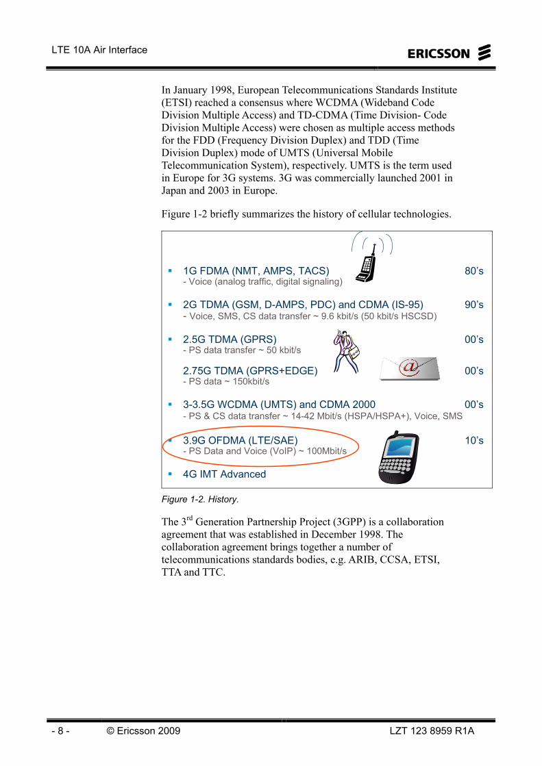
Figure 1-2 briefly summarizes the history of cellular technologies.
1G FDMA (NMT, AMPS, TACS) 80’s- Voice (analog traffic, digital signaling)
2G TDMA (GSM, D-AMPS, PDC) and CDMA (IS-95) 90’s- Voice, SMS, CS data transfer ~ 9.6 kbit/s (50 kbit/s HSCSD)
2.5G TDMA (GPRS) 00’s- PS data transfer ~ 50 kbit/s
2.75G TDMA (GPRS+EDGE) 00’s- PS data ~ 150kbit/s
3-3.5G WCDMA (UMTS) and CDMA 2000 00’s- PS & CS data transfer ~ 14-42 Mbit/s (HSPA/HSPA+), Voice, SMS
3.9G OFDMA (LTE/SAE) 10’s- PS Data and Voice (VoIP) ~ 100Mbit/s
4G IMT Advanced
Figure 1-2. History.
The 3rd Generation Partnership Project (3GPP) is a collaboration agreement that was established in December 1998. The collaboration agreement brings together a number of telecommunications standards bodies, e.g. ARIB, CCSA, ETSI, TTA and TTC.
1 LTE/SAE Introduction
LZT 123 8959 R1A © Ericsson 2009 - 9 -
The original scope of 3GPP was to produce globally applicable Technical Specifications and Technical Reports for a 3rd Generation Mobile System based on evolved GSM core networks and the radio access technologies that they support (i.e., Universal Terrestrial Radio Access (UTRA) both Frequency Division Duplex (FDD) and Time Division Duplex (TDD) modes). The scope was subsequently amended to include the maintenance and development of the Global System for Mobile communication (GSM) Technical Specifications and Technical Reports including evolved radio access technologies (e.g. General Packet Radio Service (GPRS) and Enhanced Data rates for GSM Evolution (EDGE)). See www.3gpp.org for further information.
The first practically implemented 3GPP specification for WCDMA was released and frozen 1999 and is called Release 99.
WCDMA Release 99 supports both circuit switched (CS) and packet switched (PS) traffic up to a theoretical rate 2 Mbps.
The evolution of 3G called HSDPA (High Speed Downlink Packet Access, specified in Release 5 - 2002) and HSUPA (High Speed Uplink Packet Access, specified in Release 6 – 2004) increase the maximum downlink (DL) bit rate to 14 Mbps and the uplink (UL) rate to maximum 5.76 Mbps. HSDPA and HSUPA is referred to as HSPA (High Speed Packet Access). HSUPA is also called EUL (Enhanced Uplink).
The next step for WCDMA, called HSPA evolution or HSPA+, is currently ongoing (specified in Release 7 and 8) and aims to increase the maximum bit rates even further (up to 42 Mbps in DL). This is accomplished using e.g. MIMO (Multiple Input Multiple Output) antenna solutions and Higher Order Modulation (HOM).

LTE 10A Air Interface
- 10 - © Ericsson 2009 LZT 123 8959 R1A
HSPA Evolution– gradually improved performance at a low additional cost
LTE– improved performance in a wide range of spectrum
allocations
HSUPAMBMS
Rel 6
HSUPAMBMS
Rel 6
MIMOHOMCPC
Rel 7
MIMOHOMCPC
Rel 7Rel 4Rel 4R99R99
HSDPA
Rel 5
HSDPA
Rel 5
4G4G4G4GFurther
enhancements
WCDMA/HSPAWCDMA/HSPAWCDMAWCDMA HSPA EvolutionHSPA EvolutionRel 8
LTELTELTE LTE
AdvancedAdvanced
Figure 1-3. 3GPP evolution.
In September 2007 the 3GPP family was extended with yet another member, the Evolved UTRAN (E-UTRAN). The work with creating the concept was officially started in the summer of 2006 when the study phase was successfully completed and the 3GPP work item “3G Long Term Evolution – Evolved Packet System RAN” (LTE) commenced. More than 50 companies and research institutes are participating in the largest joint standardization effort ever to specify the new world wide radio access and the evolved core network technology.
Ericsson is playing a key role as an important and visual driver in this process.
The standard development in 3GPP is grouped into two work items, where Long Term Evolution (LTE) targets the radio network evolution and System Architecture Evolution (SAE) targets the evolution of the packet core network. Common to both LTE and SAE is that only a Packet Switched (PS) domain will be specified. The result of these work items are the Evolved UTRAN (E-UTRAN) and the Evolved Packet Core (EPC). These together (E-UTRAN+EPC) builds the Evolved Packet System (EPS).
LTE/SAE is specified from 3GPP Release 8.
Note that LTE and SAE refer to the work items in 3GPP. The name of the actual Radio Access Network (RAN) is E-UTRAN and the name of the Core Network (CN) is EPC.

1 LTE/SAE Introduction
LZT 123 8959 R1A © Ericsson 2009 - 11 -
A parallel Partnership Project was also established - "3GPP2," which, quite similar to its sister project 3GPP, also standardizes International Telecommunication Union's (ITU) International Mobile Telecommunications "IMT-2000" based networks. 3GPP2 focuses on the evolution of cdmaOne with cdma2000 and EV-DO (HRPD) while 3GPP focuses on the evolution of GSM, WCDMA, HSPA and LTE. 3GPP2 is divided into four Technical specification groups comprised of representatives from the Project's Individual Member companies. The TSGs are:
- TSG-A for Access Network Interfaces - TSG-C for cdma2000 - TSG-S Services and Systems Aspects - TSG-X Core Networks
LTE is the Global standard for Next Generation – FDD and TDD
CDMA Track (3GPP2)
GSM Track (3GPP)
2001 2005 2008 2010
LTEFDD and TDD
GSM WCDMA HSPA
TD-SCDMA
CDMA One EVDO Rev A
CDMA Track (3GPP2)
GSM Track (3GPP)
2001 2005 2008 2010
LTEFDD and TDD
GSM WCDMA HSPA
TD-SCDMA
CDMA One EVDO Rev A
LTE - FDD- TDD
Figure 1-4. Mobile System Evolution.
The E-UTRAN standard is based on Orthogonal Frequency Division Multiplexing (OFDM) and OFDMA (Orthogonal Frequency Division Multiple Access) downlink operation and Single Carrier Frequency Domain Multiple Access (SC-FDMA) uplink operation. These choices support great spectrum flexibility with a number of possible deployments from 1.4 MHz up to 20 MHz spectrum allocations. It will support both FDD and TDD mode of operation and targets both a paired spectrum allocation with uplink and downlink separated in frequency, and unpaired spectrum with uplink and downlink operating on the same frequency.
Furthermore, E-UTRAN supports use of different MIMO (Multiple Input Multiple Output) multiple antenna configurations. This increases the data rates and spectrum efficiency.

LTE 10A Air Interface
- 12 - © Ericsson 2009 LZT 123 8959 R1A
LTE is sometimes referred to as 3.9G. Why not 4G? Well, ITU has defined IMT Advanced, which is the follower to IMT2000. IMT Advanced is regarded as 4G and is meant to support theoretical bitrates up to approximately 1Gbit/s and may be deployed with LTE Release 10 (also referred to as LTE Advanced).
LTE Release 10 will probably fulfill the IMT Advanced requirements. LTE Release 10 will simply be called LTE in Release 10, since it is built on the same solutions as LTE in Release 8 but with some extra features like simultaneous communication with different base stations (COMP) and spectrum aggregation.
The first LTE networks based on 3GPP Release 8 are expected to be implemented in 2009.
EPS in 3GPP Release 8 is based on a simplified network architecture compared to Release 6. The number of user-plane nodes is reduced from four in Release 6 (NodeB, RNC, SGSN and GGSN) to only two (e-NodeB and S-GW) in EPS.
Only a Packet Switched (PS) domain is defined in LTE. This means that the traditionally Circuit Switched (CS) services will be carried by PS bearers.
CN SAE CN (EPC)
RNC RNC
NodeB NodeB e-NodeB e-NodeB
WCDMA LTE/SAE
Moving RNC functions to e-NodeB
UE UE
A flat architecture for optimized performance and cost efficiency
SGSN
GGSN
P/S-GW
Figure 1-5. Simplified network architecture.

1 LTE/SAE Introduction
LZT 123 8959 R1A © Ericsson 2009 - 13 -
LTE Requirements
The performance of LTE as specified in 3GPP Release 8 shall fulfill a number of requirements regarding throughput and latency listed below. This seems to be quite easily achieved, thanks to, among other improvements, the simplified network architecture. Data rates of more than 300 Mbps in DL seems to be possible to reach.
Also, it is a requirement that E-UTRAN architecture should reduce the cost of future network deployment whilst enabling the usage of existing site locations. It is expected that the reduction of the number of nodes and interfaces contributes to this overall goal.
Furthermore, should all specified interfaces be open for multi-vendor equipment interoperability. There are two identified interfaces that will be standardized, S1 and X2. For them no major problems regarding multi-vendor interoperability have been identified during the study item phase.
E-UTRA should support significantly increased instantaneous peak data rates. The supported peak data rate should scale according to size of the spectrum allocation.
Note that the peak data rates may depend on the numbers of transmit and receive antennas (MIMO configuration) at the UE (User Equipment). The targets for DL and UL peak data rates are specified in terms of a reference UE configuration comprising:
a) Downlink capability: 2 receive antennas at UE
b) Uplink capability: 1 transmit antenna at UE
For this baseline configuration, the system should support an instantaneous downlink peak data rate of 100Mbps within a 20 MHz downlink spectrum allocation (5 bps/Hz) and an instantaneous uplink peak data rate of 50Mbps (2.5 bps/Hz) within a 20MHz uplink spectrum allocation. The peak data rates should then scale linearly with the size of the spectrum allocation.
In case of spectrum shared between downlink and uplink transmission, E-UTRA does not need to support the above instantaneous peak data rates simultaneously.

LTE 10A Air Interface
- 14 - © Ericsson 2009 LZT 123 8959 R1A
The control plane latency should be lower than 100ms. The control plane latency is here defined as the transition time from ECM-IDLE to ECM-CONNECTED state (see later next chapter for definition of these states).
Also, the one-way user plane latency shall not exceed 5 ms in an unloaded situation for small IP-packets.
Target rates for user throughput
Downlink
- Target for user throughput per MHz at the 5 % point of the C.D.F., 2 to 3 times Release 6 HSDPA.
- Target for averaged user throughput per MHz, 3 to 4 times Release 6 HSDPA. Both targets should be achieved assuming Release 6 reference performance is based on a single Tx antenna at the Node B with enhanced performance type 1 (Rx diversity) receiver in UE whilst the E-UTRA may use a maximum of 2 Tx antennas at the Node B and 2 Rx antennas at the UE.
- The supported user throughput should scale with the spectrum bandwidth.
Uplink
- Target for user throughput per MHz at the 5 % point of the C.D.F., 2 to 3 times Release 6 Enhanced Uplink (deployed with a single Tx antenna at the UE and 2 Rx antennas at the Node B).
- Target for averaged user throughput per MHz, 2 to 3 times Release 6 Enhanced Uplink (deployed with a single Tx antenna at the UE and 2 Rx antennas at the Node B).
- Both should be achievable by the E-UTRA using a maximum of a single Tx antenna at the UE and 2 Rx antennas at the Node B. Greater user throughput should be achievable using multiple Tx antennas at the UE.
- The user throughput should scale with the spectrum bandwidth provided that the maximum transmit power is also scaled.

1 LTE/SAE Introduction
LZT 123 8959 R1A © Ericsson 2009 - 15 -
Targets for spectrum efficiency
E-UTRA should deliver significantly improved spectrum efficiency and increased cell edge bit rate whilst maintaining the same site locations as deployed today.
Spectrum efficiency needs to be significantly increased as followings:
Downlink
In a loaded network, target for spectrum efficiency (bits/sec/Hz/site), 3 to 4 times Release 6 HSDPA This should be achieved assuming Release 6 reference performance is based on a single Tx antenna at the Node B with enhanced performance type 1 receiver in UE whilst the E-UTRA may use a maximum of 2 Tx antennas at the Node B and 2 Rx antennas at the UE.
Uplink
In a loaded network, target for spectrum efficiency (bits/sec/Hz/site), 2 to 3 times Release 6 Enhanced Uplink (deployed with a single Tx antenna at the UE and 2 Rx antennas at the Node B). This should be achievable by the E-UTRA using a maximum of a single Tx antenna at the UE and 2Rx antennas at the Node B.
High data rates– Downlink: >100 Mbps– Uplink: >50 Mbps– Cell-edge data rates 2-3 x HSPA Rel. 6 (@ 2006)
Low delay/latency – User plane RTT: < 10 ms RAN RTT (fewer nodes, shorter TTI)– Channel set-up: < 100 ms idle-to-active (fewer nodes, shorter messages, quicker node resp.)
High spectral efficiency – Targeting 3 X HSPA Rel. 6 (@ 2006 )
Spectrum flexibility– Operation in a wide-range of spectrum allocations, new and existing– Wide range of Bandwidth: 1.4, 3, 5, 10, 15 and 20 MHz, FDD and TDD
Simplicity – Less signaling, Auto Configuration e-NodeB– ”PnP”, ”Simple as an Apple”
Cost-effective migration from current/future 3G systems
State-of-the-art towards 4G
Focus on services from the packet-switched domain Figure 1-6. LTE requirements

LTE 10A Air Interface
- 16 - © Ericsson 2009 LZT 123 8959 R1A
eNB functionality
eNB is the RAN node in the EPS architecture that is responsible for radio transmission to and reception from UEs in one or more cells. The eNB is connected to EPC nodes by means of an S1 interface. The eNB is also connected to its neighbor eNBs by means of the X2 interface. Some significant changes have been made to the eNB functional allocation compared to UTRAN. Most Rel-6 RNC functionality has been moved to the E-UTRAN eNB. Below follows a description of the functionality provided by eNB. • Cell control and MME pool support
eNB owns and controls the radio resources of its own cells. Cell resources are requested by and granted to MMEs in an ordered fashion. This arrangement supports the MME pooling concept. S-GW pooling is managed by the MMEs and is not really seen in the eNB.
• Mobility control The eNB is responsible for controlling the mobility for terminals in active state. This is done by ordering the UE to perform measurement and then performing handover when necessary.
• Control and User Plane security The ciphering of user plane data over the radio interface is terminated in the eNB. Also the ciphering and integrity protection of RRC signaling is terminated in the eNB.
• Shared Channel handling Since the eNB owns the cell resources, the eNB also handles the shared and random access channels used for signaling and initial access.
• Segmentation/Concatenation Radio Link Control (RLC) Service Data Units (SDUs) received from the Packet Data Convergence Protocol (PDCP) layer consist of whole IP packets and may be larger than the transport block size provided by the physical layer. Thus, the RLC layer must support segmentation and concatenation to adapt the payload to the transport block size.

1 LTE/SAE Introduction
LZT 123 8959 R1A © Ericsson 2009 - 17 -
• HARQ A Medium Access Control (MAC) Hybrid Automatic Repeat reQuest (HARQ) layer with fast feedback provides a means for quickly correcting most errors from the radio channel. To achieve low delay and efficient use of radio resources, the HARQ operates with a native error rate which is sufficient only for services with moderate error rate requirements such as for instance VoIP. Lower error rates are achieved by letting an outer Automatic Repeat reQuest (ARQ) layer in the eNB handle the HARQ errors.
• Scheduling A scheduling with support for QoS provides for efficient scheduling of UP and CP data.
• Multiplexing and Mapping The eNB performs mapping of logical channels onto transport channels.
• Physical layer functionality The eNB handles the physical layer such as scrambling, Tx diversity, beamforming processing and OFDM modulation. The eNB also handles layer one functions like link adaptation and power control.
• Measurements and reporting eNB provides functions for configuring and making measurements on the radio environment and eNB-internal variables and conditions. The collected data is used internally for Radio Resource Management (RRM) but can be reported for the purpose of multi-cell RRM.
• Automated operation and maintenance. eNB provides functions for Automated Neighbor Relations (ANR) and Automatic Integration of RBS.
Cell control and MME pool support
Mobility control
Control and User Plane security
Shared Channel handling
Segmentation/Concatenation
HARQ
Scheduling.Multiplexing and Mapping
Physical layer functionality
Measurements and reporting
Automated operation and maintenance
S-GW
eNB
MME
eNBX2
S1
Uu
Figure 1-7. eNodeB functionality.

LTE 10A Air Interface
- 18 - © Ericsson 2009 LZT 123 8959 R1A
LTE RADIO INTERFACE The LTE radio interface is based on OFDM (Orthogonal Frequency Division Multiplex) and OFDMA (Orthogonal Frequency Division Multiple Access) in DL and SC-FDMA (Single Carrier Frequency Division Multiple Access) in UL. These techniques are well suited for flexible bandwidth operation. This enables operators to deploy LTE in different regions with different frequency bands and bandwidths available.
OFDM also shows very good performance in highly time dispersive radio environments (i.e. many delayed and strong multipath reflections). That is because the data stream is distributed over many subcarriers. Each subcarrier will thus have a slow symbol rate and correspondingly, a long symbol time. This means that the Inter Symbol Interference (ISI) is reduced.
The users in DL are separated with OFDMA, which means that each user has its own time- and frequency resources.
The uplink transmission technique, SC-FDMA, is realized in a similar manner as for the downlink (OFDM) and is also called DFTS-OFDM (Discrete Fourier Transform Spread – OFDM). The time domain structure is also similar in uplink and downlink. SC-FDMA has much lower PAPR (Peak to Average Power Ratio) than OFDM. This is one of the reasons for the choice of SC-OFDM for the uplink since the power amplifier in the UE can be made more power efficient and manufactured at a lower cost.
In addition to that, both FDD (Frequency Division Duplex) and TDD (Time Division Duplex) is supported, which opens up for deployment in both paired and unpaired spectrum. In FDD, different frequency bands are used for UL and DL. In TDD the UL and DL transmissions are separated in time. There are pros and cons with both methods. TDD has some more overhead and latency, due to the frequent switching in time. On the other hand, the TDD mode enables radio channel reciprocity, which means that UL measurements can be used for DL transmissions, and vice versa. The TTD mode is also simpler to deploy in areas with limited available spectrum since it can utilize unpaired frequency bands.
A half duplex FDD mode (HD-FDD) is also defined, where the UE does not have to transmit at the same time as it receives. Therefore, more cost effective UEs can be manufactured since a duplex filter is not needed.

1 LTE/SAE Introduction
LZT 123 8959 R1A © Ericsson 2009 - 19 -
The radio resources are defined in the time- and frequency domain and divided into so called resource blocks. Dynamic channel dependent scheduling allocates a number of these time- and frequency resources to different users at different times.
Link adaptation adapts the modulation scheme and coding rate to the varying radio channel condition.
HARQ (Hybrid Automatic Repeat and Request) caters for very quick layer 2 retransmission functionality. In addition, ordinary ARQ is implemented in the RLC layer.
The LTE radio transmissions are based on a very short TTI (Transmission Time Interval) of 1ms, which speeds up the operation of all of the above functions. The short TTI also reduces the radio interface latency, which is one of the main concerns in the LTE development.
Flexible bandwidth– Possible to deploy in 6 different bandwidths
up to 20 MHz
Uplink: SC-FDMA with dynamic bandwidth (Pre-coded OFDM)– Low PAPR Higher power efficiency– Reduced uplink interference (enables intra-cell
orthogonality )
Downlink: Adaptive OFDM and OFDMA– Channel-dependent scheduling and link adaptation
in time and frequency domain
Multi-Antennas, both RBS and terminal– MIMO, antenna beams, TX- and RX diversity, interference rejection– High bit rates and high capacity TXTX RXRXTXTX RXRX
time
frequency
time
frequency
time
frequency
Harmonized FDD and TDD concept– Maximum commonality between FDD and TDD
Minimum UE capability: BW = 20 MHz
10 15 20 MHz10 15 20 MHz33
fDL
fUL
FDDFDD--onlyonlyfDL
fUL
HalfHalf--duplex FDDduplex FDDfDL/UL
TDDTDD--onlyonlyfDL
fUL
FDDFDD--onlyonlyfDL
fUL
HalfHalf--duplex FDDduplex FDDfDL/UL
TDDTDD--onlyonly
∆f=15kHz
1 ms
180 kHz
User #2 scheduledUser #1 scheduled
User #3 scheduled
1.41.4 55
Figure 1-8. LTE Physical layer.
In contrary to WCDMA, the uplink transmissions in LTE are, thanks to the SC-FDMA solution, well separated within a cell (intra-cell orthogonality). This leads to a less extensive power control operation.

LTE 10A Air Interface
- 20 - © Ericsson 2009 LZT 123 8959 R1A
In order to increase the spectrum efficiency, capacity and overall data rates the use of multiple antennas, MIMO (Multiple Input Multiple Output) is included in the standard. With these multiple antennas and advanced signal processing such as spatial multiplexing, the radio channel can be separated into several layers, or “data pipes”. Up to four layers can be utilized. This corresponds to up to four times higher data rates for a given bandwidth.
The maximum number of Resource Blocks that can be allocated is 100. The 10 remaining RBs (since 20 MHz corresponds to 110 RBs) are needed as guard bands.
LTE physical-layer specification supports any bandwidth in the range 6 RBs to 110 RBs in steps of one RB
Radio requirements only specified for a limited set of bandwidths– Can be different for different frequency bands
Relatively straighforward to extend to additional bandwidths– e.g. for new frequency bands
All UEs must support the maximum bandwidth of each supported band
The maximum number of RBs that can be allocated is 100
6 RB (≈1.1 MHz)
110 RB (≈20 MHz)
Figure 1-9. Bandwidth flexibility.
UE states and area concepts
LTE is developed to have a simpler architecture (fewer nodes) and less signaling (fewer messages) than UTRAN. Also, the number of states which the UE can be in (corresponding to RRC states) are reduced from 5 in UTRAN (DETACHED, IDLE, URA_PCH, CELL_FACH, CELL_DCH) to only 3 in E-UTRAN (DETACHED, IDLE and CONNECTED).
Furthermore, the area concept is somewhat simplified in LTE compared to UTRAN. In LTE only one area for idle mode mobility is defined; the Tracking Area (TA). In UTRAN, Routing Area (RA) and UTRAN Registration Area (URA) is defined for PS traffic and Location Area (LA) for CS traffic.

1 LTE/SAE Introduction
LZT 123 8959 R1A © Ericsson 2009 - 21 -
In ECM-IDLE (EPS Connection Management IDLE) the UE position is only known by the network on TA level, whereas in ECM-CONNECTED, the UE location is known on cell level by the eNB.
ECM-IDLE
EMM-DEREGISTERED
MME
Tracking Area (TA)
UE positionnot known in network
Signaling connection establishment
Signaling connection release
Attach accept, TAU accept
Detach, Attach reject, TAU reject
EMM-REGISTERED
ECM-CONNECTED
Tracking Area Update(TAU)
Handover
PLMN selection
UE position known on Cell level in eNodeBUE pos known on TA level in MME
eNB
RRC_IDLE RRC_IDLE RRC_CONNECTED
ECM: EPC Connection Management
EMM: EPC Mobility Management
RRC: Radio Resource Management
Figure 1-10. Protocol states and Mobility
When a UE attaches to the network it is assigned an IP address from a P-GW. The IP-address is kept regardless of if the UE enters idle mode or not as long as it is attached to the network, but is released if the UE detaches from the network.
Figure 1-11 LTE states.
LTE 10A Air Interface
- 22 - © Ericsson 2009 LZT 123 8959 R1A
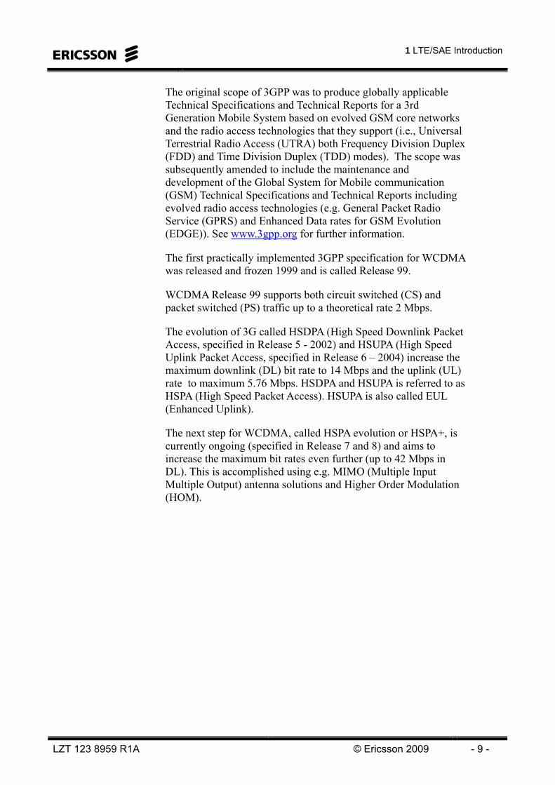
In Figure 1-12, the UE categories are shown.
421Layers for DL spatial mux.
64QAM16QAMMax UL mod
64QAMMax DL mod
755050255UL peak rate
3001501005010DL peak rate
54321Category
421Layers for DL spatial mux.
64QAM16QAMMax UL mod
64QAMMax DL mod
755050255UL peak rate
3001501005010DL peak rate
54321Category
All UEs support 4 Tx antennas at eNodeBSoft buffer sizes under discussionMBMS is a separate capabilityFDD, HD-FDD and TDD are independent capabilities
Figure 1-12 UE Categories
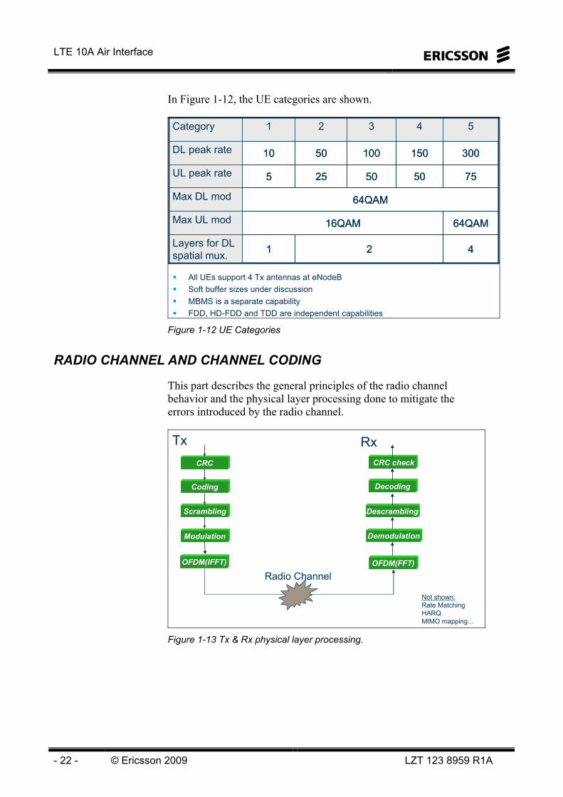
RADIO CHANNEL AND CHANNEL CODING
This part describes the general principles of the radio channel behavior and the physical layer processing done to mitigate the errors introduced by the radio channel.
Coding
Scrambling
Modulation
CRC
Decoding
Descrambling
Demodulation
CRC check
Radio Channel
Not shown:Rate MatchingHARQMIMO mapping...
OFDM(IFFT) OFDM(FFT)
Tx Rx
Figure 1-13 Tx & Rx physical layer processing.

1 LTE/SAE Introduction
LZT 123 8959 R1A © Ericsson 2009 - 23 -
Error detection and Correction - CRC and FEC Coding
In all radio systems the air interface will add noise to the signal (Figure 1-14). This will produce a distortion in the received signal. In the case of an analogue cellular system the human ear perform error correction of this received signal and noise. However in digital systems we do not have this luxury.
This noise will result in bit errors, that is what left the transmitter as a logic 1 could be interpreted as a logic 0 if the level of noise lowers the amplitude below the threshold for a logic 0. The same could be the case for a transmitted logic 0 being interpreted as a logic 1.
All digital systems must have some method of overcoming these errors.
Digital Cellular
Analog Cellular
Transmitted Signal Received Signal + Noise
Transmitted Signal Received Signal + Noise
Figure 1-14: Digital Cellular Error Correction
This concept can be related to addressing envelopes. The address on the left (Figure 1-15) contains just enough information to get to the destination. The envelope on the right contains some unnecessary or redundant data.
If both envelopes were subjected to the same amount of errors the one on the left would be undeliverable. However the redundant data in the right hand one would allow it to be delivered.
A process that produces this error protection without increasing the bandwidth too much is required for cellular transmissions.

LTE 10A Air Interface
- 24 - © Ericsson 2009 LZT 123 8959 R1A
Example: Mailing a letter – Extra (redundant) symbols in address help correct lost symbols– ZIP codes used to detect errors in the address
With minimal data...Errors are uncorrectable
With redundant data...Errors are correctable
EM5 Main StreetLittletown
Eddie McConnell5 Main StreetLittletown LT1701
Figure 1-15: Digital Cellular Error Correction; Example: Mailing a letter in the US. Extra redundant symbols in address help correct symbols. ZIP codes are used to detect errors in the address.
CRC
Cyclic Redundancy Check (CRC) is used to detect if there are any uncorrected errors left after error correction.
Blocks of data are passed through a CRC generator (Figure 1-16), which will perform a mathematical division on the data producing a remainder or checksum. This is added to the block of data and transmitted.
The same division is performed on the data block in the receiver. If a different checksum is produced the receiver will know that there is an error in the block of data (alternatively there is an error in the received checksum). This knowledge can be used to calculate Block Error Ratio (BLER) used in the outer loop power control.
The longer the checksum, the greater is the accuracy of the process. In the example the checksum is twelve bits long. 24 bits of binary information represents 16 777 216 (224) different combinations. It could be imagined that various combinations of errors on the data and the checksum would produce the same checksum. The longer the checksum the less likely it is for this to happen. LTE uses a 24 bit CRC for the user data channels.

1 LTE/SAE Introduction
LZT 123 8959 R1A © Ericsson 2009 - 25 -
Cyclic-Redundancy Check (CRC) Coding– Identifies corrupted data– CRC is used by retransmission functionality
Checksum 24 bits110010…110011
Original Data
x bits
CRC Generator
Original Data
x bits
CRC Generator
Original Data 1001011010…Original Data 1001011010…
CRC Generator
Re-Generated Checksum110010…110001
CRC Generator
Re-Generated Checksum110010…110001
Transmitter
Receiver
If Checksums do not match, there is an error
Received Data 1001010010…
Received Checksum
110010…110011
Received Data 1001010010…
Received Checksum
110010…110011
RF Transmission Path
RF Transmission Path
Figure 1-16: CRC Coding
FEC
The next part in the transmitter is Forward Error Correction (FEC). The function of this block is to help the receiver correct bit errors caused by the air interface.
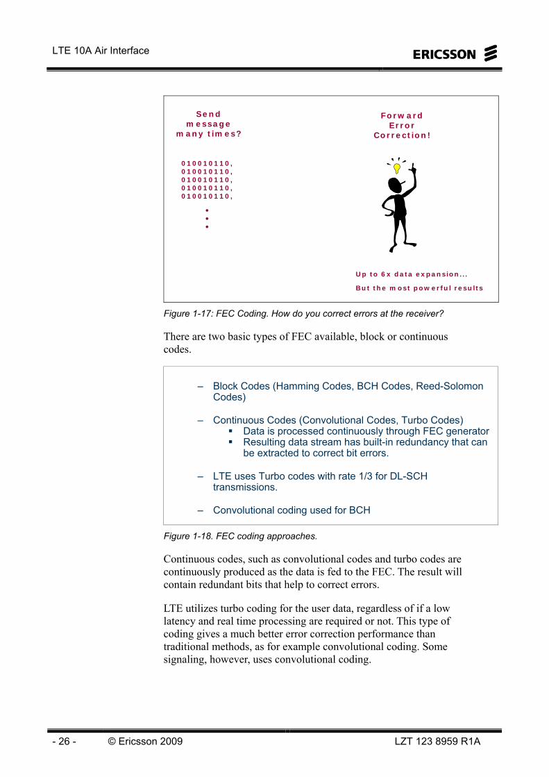
One method for correcting these errors would be to send the information a number of times (Figure 1-17). Provided this is more than twice, the receiver could select which message is most correct by a “best out of three” decision. The more times the data is transmitted the better is the error protection. However the bandwidth is also increased proportionally
What is required is a system that provides forward error correction with minimal increase in the bandwidth.
LTE 10A Air Interface
- 26 - © Ericsson 2009 LZT 123 8959 R1A
Sendmessage
many times?
010010110,010010110,010010110,010010110,010010110,
•••
ForwardError
Correction!
Up to 6x data expansion...
But the most powerful results
Figure 1-17: FEC Coding. How do you correct errors at the receiver?
There are two basic types of FEC available, block or continuous codes.
– Block Codes (Hamming Codes, BCH Codes, Reed-Solomon Codes)
– Continuous Codes (Convolutional Codes, Turbo Codes)Data is processed continuously through FEC generatorResulting data stream has built-in redundancy that can be extracted to correct bit errors.
– LTE uses Turbo codes with rate 1/3 for DL-SCH transmissions.
– Convolutional coding used for BCH
Figure 1-18. FEC coding approaches.
Continuous codes, such as convolutional codes and turbo codes are continuously produced as the data is fed to the FEC. The result will contain redundant bits that help to correct errors.
LTE utilizes turbo coding for the user data, regardless of if a low latency and real time processing are required or not. This type of coding gives a much better error correction performance than traditional methods, as for example convolutional coding. Some signaling, however, uses convolutional coding.
1 LTE/SAE Introduction
LZT 123 8959 R1A © Ericsson 2009 - 27 -
In LTE the turbo coding is quite similar to the coding in WCDMA, but improved with a QPP interleaver (Quadrature Permutation Polynomial interleaver).
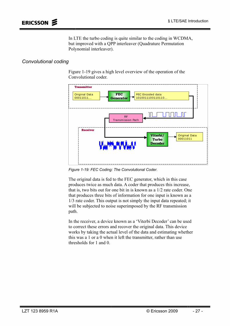
Convolutional coding
Figure 1-19 gives a high level overview of the operation of the Convolutional coder.
Original Data 00011011...
FEC Generator
FEC Encoded data 1010011100110110...
Original Data 00011011
Viterbi/ Turbo
Decoder
Transmitter
Receiver
RF Transmission Path
Original Data 00011011...
FEC Generator
Original Data 00011011...
FEC Generator
FEC Encoded data 1010011100110110...FEC Encoded data 1010011100110110...
Original Data 00011011
Viterbi/ Turbo
Decoder
Original Data 00011011
Viterbi/ Turbo
Decoder
Transmitter
Receiver
RF Transmission Path
RF Transmission Path
Figure 1-19: FEC Coding: The Convolutional Coder.
The original data is fed to the FEC generator, which in this case produces twice as much data. A coder that produces this increase, that is, two bits out for one bit in is known as a 1/2 rate coder. One that produces three bits of information for one input is known as a 1/3 rate coder. This output is not simply the input data repeated; it will be subjected to noise superimposed by the RF transmission path.
In the receiver, a device known as a ‘Viterbi Decoder’ can be used to correct these errors and recover the original data. This device works by taking the actual level of the data and estimating whether this was a 1 or a 0 when it left the transmitter, rather than use thresholds for 1 and 0.

LTE 10A Air Interface
- 28 - © Ericsson 2009 LZT 123 8959 R1A
kc
)0(kd
)1(kd
)2(kd
Constraint length 7Coding rate 1/3
Figure 1-20: Tail Biting Convolutional Encoder.
Figure 1-20 shows how the convolutional encoder in E-UTRAN is structured using a shift register and twelwe XOR gates. For every input data bit there will be three output bits produced.
Multipath propagation and channel coding
Many radio propagation effects such as reflections can attenuate the transmitted radio signal Figure 1-21.
Figure 1-21: Multipath Propagation. The received signal contains many time-delayed replicas.
1 LTE/SAE Introduction
LZT 123 8959 R1A © Ericsson 2009 - 29 -
τ0 τ1 τ2 t(μs)
P0
P1
P2
Power (dB)
P2,τ1
P0,τ0 P1,τ2
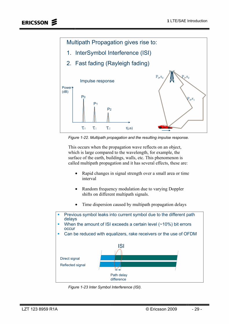
Multipath Propagation gives rise to:
1. InterSymbol Interference (ISI)
2. Fast fading (Rayleigh fading)
Impulse response
Figure 1-22. Multipath propagation and the resulting impulse response.
This occurs when the propagation wave reflects on an object, which is large compared to the wavelength, for example, the surface of the earth, buildings, walls, etc. This phenomenon is called multipath propagation and it has several effects, these are:
• Rapid changes in signal strength over a small area or time interval
• Random frequency modulation due to varying Doppler shifts on different multipath signals.
• Time dispersion caused by multipath propagation delays
Previous symbol leaks into current symbol due to the different path delaysWhen the amount of ISI exceeds a certain level (~10%) bit errorsoccurCan be reduced with equalizers, rake receivers or the use of OFDM
Direct signal
Reflected signal
Path delay difference
ISI
Figure 1-23 Inter Symbol Interference (ISI).

LTE 10A Air Interface
- 30 - © Ericsson 2009 LZT 123 8959 R1A
Multipath propagation yields signal paths of different lengths with different times of arrival at the receiver. Typical values of time delays (µs) are 0.2 in Open environment, 0.5 Suburban and 3 in Urban.
Direct S ignal
Reflected S ignal
Com bined S ignal
Figure 1-24: Multipath Fading.
The combination of direct and out-of-phase reflected waves at the receiver yields attenuated signals (Figure 1-24). This results in a varying received signal power as illustrated in Figure 1-25.
Power
distance
Time between fades is related to
• RF frequency
• Geometry of multipath vectors
• Vehicle speed: Up to 4 fades/sec per kilometer/hour
path lossRayleigh
Deep fade caused by destructive summationof two or more multipath reflections
Figure 1-25 Path loss and fast fading.
This attenuation can result in bit errors that occur in consecutive blocks of data (burst errors). As a result the decoder fails to recover such errors.

1 LTE/SAE Introduction
LZT 123 8959 R1A © Ericsson 2009 - 31 -
Interleaving
The solution to overcome the problem with burst errors is to use a block interleaving technique as shown in Figure 1-26.
Time
Am
plitu
de
Time
Am
plitu
de
To decoder
Original Data Samples1 2 3 4 5 6 7 8 9
Interleaving Matrix
1 2 34 5 67 8 9
Transmitter
Interleaved Data Samples1 4 7 2 5 8 3 6 9
Original Data Samples1 2 3 4 5 6 7 8 9
Interleaving Matrix
1 2 34 5 67 8 9
Transmitter
Interleaved Data Samples1 4 7 2 5 8 3 6 9
RF Transmission Path
RF Transmission Path
Interleaved Data Samples1 4 7 2 5 8 3 6 9
Errors Clustered
Interleaved Data Samples1 4 7 2 5 8 3 6 9
Errors Clustered
De-Interleaving
Matrix
1 2 34 5 67 8 9
De-Interleaved Data Samples1 2 3 4 5 6 7 8 9
Receiver
Errors Distributed
De-Interleaving
Matrix
1 2 34 5 67 8 9
De-Interleaved Data Samples1 2 3 4 5 6 7 8 9
Receiver
Errors Distributed
De-Interleaving
Matrix
1 2 34 5 67 8 9
De-Interleaved Data Samples1 2 3 4 5 6 7 8 9
Receiver
Errors Distributed
Figure 1-26: Block Interleaving.
A radio channel produces bursty errors. Because continuous codes are most effective against random errors, interleaving is used to randomize the bursty errors. The interleaving scheme can be either block interleaving or convolutional interleaving. Typically, block interleaving is used in cellular applications. The first step of interleaving is determined by the delay requirements of the service.
Turbo Codes
Turbo Codes are newly introduced parallel, recursive, and systematic convolutional codes. These codes are used for channel coding and decoding in order to detect and correct errors occurring in the transmission of digital data through different channels
The iterative method of the decoding scheme helps to achieve the theoretical limit (near Shannon-limit) in error correction performance. Each decoder uses the received data and extrinsic information, which has been delivered by the preceding decoder to give decoded data and new extrinsic information. Interleaving helps the decoders to improve their correction capability by keeping the extrinsic information with the received data un-correlated.
LTE 10A Air Interface
- 32 - © Ericsson 2009 LZT 123 8959 R1A
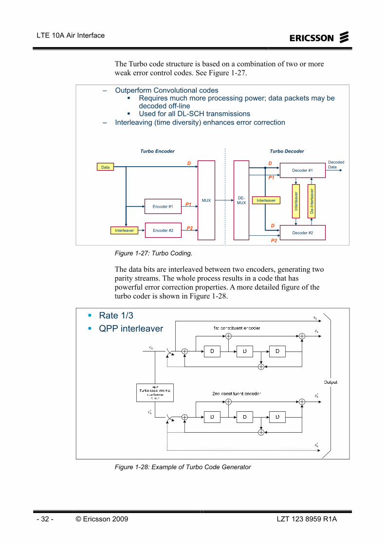
The Turbo code structure is based on a combination of two or more weak error control codes. See Figure 1-27.
– Outperform Convolutional codesRequires much more processing power; data packets may be decoded off-lineUsed for all DL-SCH transmissions
– Interleaving (time diversity) enhances error correction
Encoder #1
Encoder #2
MUX
DataDecodedData
DE-MUX
Decoder #2
D
P1
P2
D
P1
P2
D
Turbo Encoder Turbo Decoder
Interleaver
Interleaver
Inte
rleav
er
De-
Inte
rleav
er
Decoder #1
Figure 1-27: Turbo Coding.
The data bits are interleaved between two encoders, generating two parity streams. The whole process results in a code that has powerful error correction properties. A more detailed figure of the turbo coder is shown in Figure 1-28.
Rate 1/3QPP interleaver
kc
kc′
kx′
kx
kz
kz′
Figure 1-28: Example of Turbo Code Generator

1 LTE/SAE Introduction
LZT 123 8959 R1A © Ericsson 2009 - 33 -
In LTE a QPP (Quadrature Permutation Polynomial) interleaver is used between two rate ½ encoders. The overall coding rate is 1/3.
Rate matching
Rate matching is performed on the data to change the data rate to one that can be accommodated by the system. It should be noted that this function could not only be used to reduce the data rate (by puncturing bits) but also to increase the data rate (by padding it with extra bits).
– Rate Matching is used to equalize the data rates to fit the transport format
– Rate Matching may be performed by:Padding with extra bitsPuncturing of bits
)0(kd
)1(kd
)2(kd
ke
)0(kv
)1(kv
)2(kv
kw
Figure 1-29:Rate Matching
SCRAMBLING
In LTE, a frequency reuse of 1 will typically be used. This means that all cells use the same frequency band(s). For UEs close to the cell border, this will lead to massive interference in both UL and DL.
In order to reduce this inter cell interference, a cell specific bit-level scrambling is applied for all transmissions in both UL and DL.
Other solutions for mitigating the inter-cell interference includes e.g. Inter Cell Interference Co-ordination (ICIC). ICIC co-ordinates the radio resource allocations (scheduling) between neighboring cells that experience problems.

LTE 10A Air Interface
- 34 - © Ericsson 2009 LZT 123 8959 R1A
Cell specific bit-level scrambling used in LTE for all datastreams in UL and DL
– used in order to achieve interference randomization between cells
No frequency planning (freq reuse 1)– massive inter-cell interference mitigated by scrambling and
interference co-ordination techniques (e.g. ICIC)
Common scrambling used for cells in broadcast/multicast service transmissions (MBMS)
Figure 1-30. Scrambling in LTE.
MODULATION
The next step after channel coding and scrambling is modulation. The modulation process maps blocks of scrambled bits onto symbols. The different symbols correspond to a specific amplitude and/or phase shift of the carrier wave. Three different modulation schemes are supported in E-UTRAN; • QPSK (Quadrature Phase shift keying)
• 16-QAM (16 Quadrature Amplitude Modulation)
• 64-QAM (64 Quadrature Amplitude Modulation)
QPSK is theoretically a pure phase modulation, i.e. it has constant amplitude, while 16-QAM and 64-QAM both uses a combination of phase and amplitude.
The acknowledgements in DL are transmitted with BPSK (Binary Phase Shift Keying), which only has one bit per symbol.
The different modulation schemes are produced by an IQ-modulator. The IQ modulator splits the data stream (pairs of 1’s and 0’s) into on I-branch (Inphase) and one Q-branch (Quadrature phase). The In-phase part corresponds to the real part and the Quadrature phase corresponds to the imaginary part in the mathematical expression I+jQ.
1 LTE/SAE Introduction
LZT 123 8959 R1A © Ericsson 2009 - 35 -
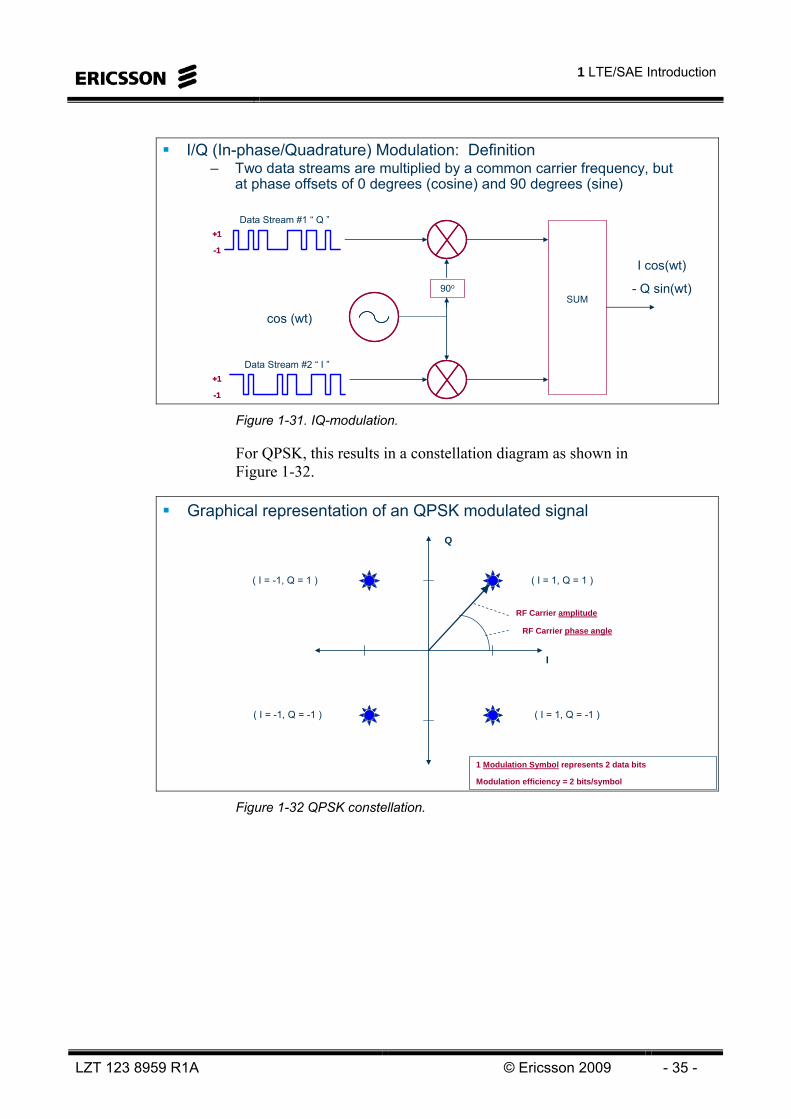
I/Q (In-phase/Quadrature) Modulation: Definition– Two data streams are multiplied by a common carrier frequency, but
at phase offsets of 0 degrees (cosine) and 90 degrees (sine)
Data Stream #1 “ Q ”
Data Stream #2 “ I ”
90o
SUM
cos (wt)
I cos(wt)
- Q sin(wt)
+1
-1
+1
-1
+1
-1
+1
-1 Figure 1-31. IQ-modulation.
For QPSK, this results in a constellation diagram as shown in Figure 1-32.
Graphical representation of an QPSK modulated signal
I
Q
( I = 1, Q = 1 )
( I = -1, Q = -1 )
( I = -1, Q = 1 )
( I = 1, Q = -1 )
1 Modulation Symbol represents 2 data bits
Modulation efficiency = 2 bits/symbol
RF Carrier amplitude
RF Carrier phase angle
Figure 1-32 QPSK constellation.

LTE 10A Air Interface
- 36 - © Ericsson 2009 LZT 123 8959 R1A
The 1’s and 0’s are actually converted the to different amplitude levels depending on the modulation scheme (e.g. ±1/√2 for QPSK) according to:
)1(),( +ibib I Q
00 21 21 01 21 21− 10 21− 21 11 21− 21−
At the receiver side, a corresponding IQ-demodulation takes place. Here the I and Q data streams are recovered as illustrated in Figure 1-33.
By multiplying by the sin and cosine at the receiver, the original I and Q data streams are recovered
90o
Splitcos(wt)
Q cos(wt)
- I sin(wt)
LPF
LPF
Data Stream #1 “ I ”
Data Stream #2 “ Q ”
+1
-1
+1
-1
Figure 1-33 IQ-demodulation
The three different modulation schemes and constellation diagrams are illustrated in Figure 1-34.

1 LTE/SAE Introduction
LZT 123 8959 R1A © Ericsson 2009 - 37 -
The sub-carriers are modulated with a certain modulation scheme– maps the data bits into a carrier phase and amplitude (symbols)
E-UTRAN user data channels supports QPSK, 16QAM and 64QAM16QAM allows for twice the peak data rate compared to QPSK64QAM allows for three times the data rate compared to QPSKHigher order modulation more sensitive to interference
– Useful mainly in good radio channel conditions (high C/I, Little or no dispersion, Low speed)e.g. Close to cell site & Micro/Indoor cells
BPSK is used for some signaling (PHICH)
2 bits/symbol 4 bits/symbol 6 bits/symbol64-QAM16-QAMQPSK
1 bit/symbolBPSK
0
1
00
11
10
01 1111 111111
Figure 1-34. Modulation.
In E-UTRAN, the modulation is carried out per sub-carrier in the OFDM signal. This means that each 15 kHz subcarrier is modulated with either QPSK, 16-QAM or 64-QAM.
OFDM
At the transmitter the coded and modulated data stream is split up to a number of sub-streams. The number of sub-streams can range from typically 12 (one resource block) and up to 1200 (100 resource blocks at 20MHz bandwidth). Each stream is fed into the IFFT block and transformed into a corresponding subcarrier. This is the principle of OFDM. The number of subcarriers thus ranges from 12 to 1200.
At the receiver a reverse process is performed. The OFDM signal is fed into a FFT block. The output of the FFT block corresponds to the input of the IFFT block at the transmitter side. This parallel data stream output is converted into a serial stream, demodulated, and decoded.

LTE 10A Air Interface
- 38 - © Ericsson 2009 LZT 123 8959 R1A
Parallel transmission using a large number of narrowband “sub-carriers”“Multi-carrier” transmissionImplemented with IFFT (Inverse Fast Fourier Transform) at transmitter and FFT at receiver sideUplink uses similar approach, but with precoder to achieve single carrier properties
Δf = 15 kHz
20 MHz (example)
S/P
f1
f2
fMΣ
IFFT
Coded and modulated data split
f1
f2
fMfilter
FFT
Tx Rx
P/S
Figure 1-35 OFDM principle
Benefits
+ Frequency diversity+ Robust against ISI+ Easy to implement+ Flexible BW+ Suitable for MIMO+ Classic technology
(WLAN, ADSL etc)
Drawbacks
- Sensitive to doppler and freq errors
- High PAPR (not suitable for uplink)
- Overhead
• Orthogonal: all other subcarriers zero at sampling point
• Sub carrier spacing 15 kHz (MBMS also 7.5 kHz)
• Delay spread << Symbol time < Coherence time
f
∆f=15kHz
Figure 1-36 OFDM - Orthogonal Frequency Multiple Multiplexing
OFDMA
OFDMA (Orthogonal Frequency Multiple Access) is the multiple access method that separates the users and channels in frequency and time. The different users and/or different channels are orthogonal within one cell. This means that they do not interfere with each other in the same cell. This is valid for both uplink and downlink in LTE.

1 LTE/SAE Introduction
LZT 123 8959 R1A © Ericsson 2009 - 39 -
Frequency Division Multiple Access
Each User has a unique frequency
(1 voice channel per user)
All users transmit at the same time
AMPS, NMT, TACS
Each Transmitter has a unique
Scrambling Code
Each Data Channel has a unique Channelization
code
Many users share the same frequency and time
IS-95, cdma2000, WCDMA
CodeDivision Multiple Access
SpreadSpectrumMultipleAccess
CodeDivision Multiple Access
SpreadSpectrumMultipleAccess
Each User has a unique time slot
Each Data Channel has a unique
position within the time slot
Several users share the same frequency
IS-136, GSM, PDC
Time Division Multiple Access
time
frequency
timefrequencyfrequency
OrthogonalFrequencyDivision Multiple Access
Each User and each channel has a unique
Time and Frequency Resource
Many users are separated in frequency and/or time
LTE, Wimax(WLAN 802.11a,g, DAB radio)
Figure 1-37 Multiple Access approaches.
OFDMA is used by LTE and Wimax. WLAN 802.11 a,g, ADSL, VDSL and DAB radio uses OFDM.
In WCDMA, the users/channels are not orthogonal in uplink within the cell. This leads to a high interference level and a need for an extensive and accurate power control.

LTE 10A Air Interface
- 40 - © Ericsson 2009 LZT 123 8959 R1A
Intentionally Blank

2 Radio Interface
LZT 123 8959 R1A © 2009 Ericsson - 41 -
2 Radio Interface
OBJECTIVES:
On completion of this chapter the students will be able to:Explain the Radio Interface Structure
–Detail the channel structure of the radio interface–Describe the physical signals in UL and DL–Detail the time-domain structure in the radio interface in UL and DL for both FDD and TDD mode–Detail the downlink transmission technique–Have a good understanding of the OFDM principle, signal generation and processing–Detail the reference symbols in DL–Detail the control signaling in DL–Explain the paging procedure–Explain cell search procedure–Explain HARQ–Detail the uplink transmission technique–Have a good understanding of the SC-FDMA principle, signal generation and processing–Explain the pros and cons with OFDM and SC-FDMA–Detail the control signaling in UL–Detail the random access procedure–Describe the Power Control in UL and DL–Describe the concepts of layers, channel rank, spatial multiplexing, open and closed loop spatial multiplexing, TX diversity, beamforming, SU-MIMO and MU-MIMO
Figure 2-1. Objectives.

LTE 10A Air Interface
- 42 - © Ericsson 2009 LZT 123 8959 R1A
Intentionally Blank
2 Radio Interface
LZT 123 8959 R1A © 2009 Ericsson - 43 -
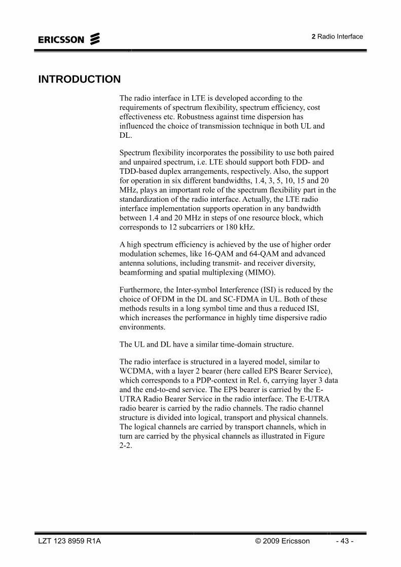
INTRODUCTION The radio interface in LTE is developed according to the requirements of spectrum flexibility, spectrum efficiency, cost effectiveness etc. Robustness against time dispersion has influenced the choice of transmission technique in both UL and DL.
Spectrum flexibility incorporates the possibility to use both paired and unpaired spectrum, i.e. LTE should support both FDD- and TDD-based duplex arrangements, respectively. Also, the support for operation in six different bandwidths, 1.4, 3, 5, 10, 15 and 20 MHz, plays an important role of the spectrum flexibility part in the standardization of the radio interface. Actually, the LTE radio interface implementation supports operation in any bandwidth between 1.4 and 20 MHz in steps of one resource block, which corresponds to 12 subcarriers or 180 kHz.
A high spectrum efficiency is achieved by the use of higher order modulation schemes, like 16-QAM and 64-QAM and advanced antenna solutions, including transmit- and receiver diversity, beamforming and spatial multiplexing (MIMO).
Furthermore, the Inter-symbol Interference (ISI) is reduced by the choice of OFDM in the DL and SC-FDMA in UL. Both of these methods results in a long symbol time and thus a reduced ISI, which increases the performance in highly time dispersive radio environments.
The UL and DL have a similar time-domain structure.
The radio interface is structured in a layered model, similar to WCDMA, with a layer 2 bearer (here called EPS Bearer Service), which corresponds to a PDP-context in Rel. 6, carrying layer 3 data and the end-to-end service. The EPS bearer is carried by the E-UTRA Radio Bearer Service in the radio interface. The E-UTRA radio bearer is carried by the radio channels. The radio channel structure is divided into logical, transport and physical channels. The logical channels are carried by transport channels, which in turn are carried by the physical channels as illustrated in Figure 2-2.

LTE 10A Air Interface
- 44 - © Ericsson 2009 LZT 123 8959 R1A
Segmentation, ARQ
Ciphering
Header Compr.
Hybrid ARQHybrid ARQ
MAC multiplexing
Antenna and resrouce mapping
Coding + RM
Data modulation
Antenna and resource mapping
Coding
ModulationAntenna and resource assignment
Modulationscheme
MA
C s
ched
uler
Retransmission control
Priority handling, payload selection
Payload selection
RLC#i
PHY
PDCP#i
User #i User #j
MAC
Concatenation, ARQ
Deciphering
Header Compr.
Hybrid ARQHybrid ARQ
MAC demultiplexing
Antenna and resrouce mapping
Coding + RM
Data modulation
Antenna and resource demapping
Decoding
Demodulation
RLC
PHY
PDCP
MAC
eNodeB UE
Red
unda
ncy
vers
ion
IP packet IP packet
EPS bearers
E-UTRA Radio Bearers
Logical Channels
Transport Channels
Physical Channels
Figure 2-2. Radio interface structure.
The protocols performing the functions in the radio interface are: PDCP (Packet Data Convergence Protocol), RLC (Radio Link Protocol), MAC (Medium Access Control) and the physical layer. For control signaling the RRC (Radio Resource Control) protocol is used to transfer the NAS (Non Access Stratum) information over the radio interface.
The PDCP protocol maps the EPS bearer onto the E-UTRA Radio Bearer and performs Robust Header Compression (ROHC). The RLC protocol maps the E-UTRA Radio Bearer to a logical channel and performs segmentation, in-sequence delivery and retransmissions. The MAC protocol maps the logical channel to a transport channel and is responsible for Hybrid ARQ (HARQ) and scheduling. The physical layer maps the transport channel onto a physical channel and performs channel coding, modulation etc.

2 Radio Interface
LZT 123 8959 R1A © 2009 Ericsson - 45 -
The radio interface protocol architecture is shown in Figure 2-3 for both Control Plane and User Plane.
PHYMACRLC
PDCPRRC
UE
PHYMACRLC
PDCP
eNB
RRCNAS NAS
PHYMACRLC
PDCPUE
PHYMACRLC
eNBPDCP
User Plane
Control PlaneMME
S-GW
S1-CPS1-CP
S1-UPS1-UP Figure 2-3. Radio interface protocol architecture.
MEDIUM ACCESS CONTROL (MAC)
The MAC layer for the LTE access can be compared to the Rel-6 MAC-hs/MAC-e and covers mainly similar functionality: HARQ, priority handling (scheduling), transport format selection and DRX control (not part of MAC in Rel-6).
The Hybrid ARQ (HARQ) protocol is very similar to the solution adopted for HSDPA, i.e., the protocol uses multiple stop-and-wait hybrid ARQ processes. The motivation for this type of protocol is to allow continuous transmission, which cannot be achieved with a single stop-and-wait scheme, while at the same time having some of the simplicity of a stop-and-wait protocol. The functionality and performance is similar to that of a window based selective repeat protocol but only single-bit HARQ feedback is required.
The protocol is modeled as a number of parallel HARQ processes, where each process uses a simple stop-and-wait protocol. By using NHARQ parallel HARQ processes, where NHARQ > Round trip time / subframe length, a continuous transmission is achieved. The maximum UE processing time before sending a HARQ feedback has been specified such that 8 HARQ process are needed for continuous transmission in FDD with a typical eNB implementation.

LTE 10A Air Interface
- 46 - © Ericsson 2009 LZT 123 8959 R1A
In 3GPP, the current working assumption is to use a synchronous HARQ for the uplink and an asynchronous HARQ for the downlink. That is, for the uplink, the subframe when the retransmission occurs is known at the receiver, while for the downlink the scheduler has the freedom to choose the subframe for the retransmission dynamically. For both up- and downlink a synchronous, single-bit HARQ feedback (ACK/NACK) is sent providing feedback about the success of the previous transmission. The HARQ protocol is adaptive in both uplink and downlink meaning that the scheduler can decide to use a different resource for a retransmission compared to for the previous (re)transmission.
The redundancy version of a (re)transmission needs to be known by the receiver. Thus, the redundancy version and an indication whether the transmission contains a first transmission or a retransmission is indicated on the PDCCH.
In case the data is a retransmission of previously stored data, the received data is soft combined with the data stored in the soft buffer. In case the received data is not a retransmission or a retransmission of data that has not been stored, the soft buffer is cleared and only the latest received data is placed in the buffer.
Receiver processing
NAK
Receiver processing
ACK
3 7
TrBlk 3
TrBlk 3 TrBlk 3
Demultiplexed into logical channels and forwarded to RLC for reordering
Receiver processing
ACK
Receiver processing
ACK
2 6
TrBlk 5TrBlk 2
TrBlk 2 TrBlk 5
TrBlk 1
Receiver processing
ACK
Receiver processing
NAK
1 5 9
TrBlk 1 TrBlk 4 TrBlk 4
1 ms TTI Fixed timing relation
TrBlk 0 TrBlk 0 TrBlk 0
CFN 0
Receiver processing
4
NAK
Receiver processing
NAK
8
Hybrid ARQ
processes
Figure 2-4 HARQ principle – four multiple HARQ processes
The MAC layer does not support in-order delivery to RLC. HARQ retransmissions will lead to that MAC Protocol Data Units (PDUs) are received in a different order than they were sent. Due to the lack of MAC sequence numbers it is up to the RLC receivers to restore the original sequence and to provide in-order delivery to higher layers.

2 Radio Interface
LZT 123 8959 R1A © 2009 Ericsson - 47 -
The MAC layer supports the ARQ in the RLC layer with certain triggers if residual HARQ errors are detected, e.g., if the maximum number of HARQ transmissions has been reached.
Finally, MAC also allows flows from a single user to be multiplexed. Correspondingly, the MAC header carries multiplexing information used to de-multiplex RLC PDUs to different flows.
CHANNEL STRUCTURE
The physical layer provides transport channels to the L2. These transport channels differ in their characteristics how data is transmitted and are mapped to different logical channels provided by the MAC layer. Logical channels describe which type of data is conveyed.
LOGICAL CHANNELS
The logical channels can be divided into control channels and traffic channels. The control channels are used for transfer of control plane information and the traffic channels are used for the transfer of user plane information. The following logical channels are supported for LTE:
Control Channels • Broadcast Control Channel (BCCH): A downlink channel
for broadcasting system control information.
• Paging Control Channel (PCCH): A downlink channel that transfers paging information. This channel is used when the network does not know the location cell of the UE.
• Common Control Channel (CCCH): This channel is used by the UEs having no RRC connection with the network. CCCH would be used by the UEs when accessing a new cell or after cell reselection.
• Multicast Control Channel (MCCH): A point-to-multipoint downlink channel used for transmitting MBMS scheduling and control information from the network to the UE, for one or several MTCHs. After establishing an RRC connection this channel is only used by UEs that receive MBMS.
• Dedicated Control Channel (DCCH): A point-to-point bi-directional channel that transmits dedicated control information between a UE and the network. Used by UEs having an RRC connection.
LTE 10A Air Interface
- 48 - © Ericsson 2009 LZT 123 8959 R1A
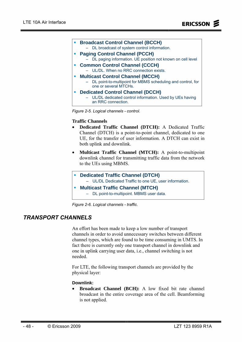
Broadcast Control Channel (BCCH)– DL broadcast of system control information.
Paging Control Channel (PCCH)– DL paging information. UE position not known on cell level
Common Control Channel (CCCH)– UL/DL. When no RRC connection exists.
Multicast Control Channel (MCCH)– DL point-to-multipoint for MBMS scheduling and control, for
one or several MTCHs. Dedicated Control Channel (DCCH)
– UL/DL dedicated control information. Used by UEs having an RRC connection.
Figure 2-5. Logical channels - control.
Traffic Channels • Dedicated Traffic Channel (DTCH): A Dedicated Traffic
Channel (DTCH) is a point-to-point channel, dedicated to one UE, for the transfer of user information. A DTCH can exist in both uplink and downlink.
• Multicast Traffic Channel (MTCH): A point-to-multipoint downlink channel for transmitting traffic data from the network to the UEs using MBMS.
Dedicated Traffic Channel (DTCH)– UL/DL Dedicated Traffic to one UE, user information.
Multicast Traffic Channel (MTCH)– DL point-to-multipoint. MBMS user data.
Figure 2-6. Logical channels - traffic.
TRANSPORT CHANNELS
An effort has been made to keep a low number of transport channels in order to avoid unnecessary switches between different channel types, which are found to be time consuming in UMTS. In fact there is currently only one transport channel in downlink and one in uplink carrying user data, i.e., channel switching is not needed.
For LTE, the following transport channels are provided by the physical layer:
Downlink: • Broadcast Channel (BCH): A low fixed bit rate channel
broadcast in the entire coverage area of the cell. Beamforming is not applied.

2 Radio Interface
LZT 123 8959 R1A © 2009 Ericsson - 49 -
• Downlink Shared Channel (DL-SCH): A channel with possibility to use HARQ and link adaptation by varying the modulation, coding and transmit power. The channel is possible to broadcast in the entire cell and beamforming may be applied. UE power saving (DRX) is supported to reduce the UE power consumption. MBMS transmission is also supported.
• Paging Channel (PCH): A channel that is broadcasted in the entire cell. DRX is supported to enable power saving.
• Multicast channel (MCH): A separate transport channel for multicast (MBMS). This channel is broadcast in the entire coverage area of the cell. Combining of MBMS transmissions from multiple cells (MBSFN) is supported.
Broadcast Channel (BCH)– System Information broadcasted in the entire coverage area of the cell.
Beamforming is not applied.
Downlink Shared Channel (DL-SCH)– User data, control signaling and System Info. HARQ and link adaptation.
Broadcast in the entire cell or beamforming. DRX and MBMS supported.
Paging Channel (PCH) – Paging Info broadcasted in the entire cell. DRX
Multicast Channel (MCH) – MBMS traffic broadcasted in entire cell. MBSFN is supported.
Figure 2-7. Transport channels DL.
Uplink: • Uplink Shared channel (UL-SCH): A channel with
possibility to use HARQ and link adaptation by varying the transmit power, modulation and coding. Beamforming may be applied.
• Random Access Channel (RACH): A channel used to obtain timing synchronization (asynchronous random access) and to transmit information needed to obtain scheduling grants (synchronous random access). The transmission is typically contention based. For UEs having an RRC connection there is some limited support for contention free access.
Uplink Shared channel (UL-SCH)– User data and control signaling. HARQ and link adaptation. Beamforming may be
applied.
Random Access Channel (RACH)– Random Access transmissions (asynchronous and synchronous). The transmission is
typically contention based. For UEs having an RRC connection there is some limited support for contention free access.
Figure 2-8. Transport channels UL.

LTE 10A Air Interface
- 50 - © Ericsson 2009 LZT 123 8959 R1A
PHYSICAL CHANNELS
The physical layer offers services to the MAC layer in the form of transport channels. User data to be transmitted is delivered to the physical layer from the MAC layer in the form of transport blocks. The MAC layer at the transmitter side also provides the physical layer with control information necessary for transmission and/or reception of the user data.
The physical layer defines physical channels and physical signals. A physical channel corresponds to a set of physical resources used for transmission of data and/or control information from the MAC layer. A physical signal, which also corresponds to a set of physical resources, is used to support physical-layer functionality but do not carry any information from the MAC layer. From a specification perspective, the interface between 3GPP TS 36.211 and 36.212 is defined in terms of physical channels, while physical signals are generated inside 36.211.
The following physical channels and physical signals are defined:
Physical channelsPhysical Downlink Shared Channel (PDSCH)
– transmission of the DL-SCH transport channelPhysical Uplink Shared Channel (PUSCH)
– transmission of the UL-SCH transport channelPhysical Control Format Indicator Channel (PCFICH)
– indicates the PDCCH format in DLPhysical Downlink Control Channel (PDCCH)
– DL L1/L2 control signalingPhysical Uplink Control Channel (PUCCH)
– UL L1/L2 control signalingPhysical Hybrid ARQ Indicator Channel (PHICH)
– DL HARQ infoPhysical Broadcast Channel (PBCH)
– DL transmission of the BCH transport channel.Physical Multicast Channel (PMCH)
– DL transmission of the MCH transport channel.Physical Random Access Channel (PRACH)
– UL transmission of the random access preamble as given by the RACH transport channel.Physical signals
Reference Signals (RS)– support measurements and coherent demodulation in uplink and downlink.
Primary and Secondary Synchronization signals (P-SCH and S-SCH)– DL only and used in the cell search procedure.
Sounding Reference Signal (SRS)– supports UL scheduling measurements
Figure 2-9. Physical channels and signals.

2 Radio Interface
LZT 123 8959 R1A © 2009 Ericsson - 51 -
Figure 2-10 illustrates the logical channels and the mapping to transport channels and physical channels.
UL-SCHPCHPCH DL-SCH
PCCHPCCH Logical Channels “type of information”(traffic/control)
Transport Channels“how and with what characteristics”(common/shared/mc/bc)
Downlink Uplink
PDSCHPDSCH
Physical Channels“bits, symbols, modulation, radio frames etc”
MTCHMTCH MCCHMCCH BCCHBCCH DTCHDTCH DCCHDCCH DTCHDTCH DCCHDCCH CCCHCCCH
PRACHPRACH
RACHRACH
CCCHCCCH
MCH BCH
PUSCHPUSCHPBCHPBCH PCFICHPCFICH PUCCHPUCCH
-CQI -ACK/NACK-Sched req.
-Sched TF DL-Sched grant UL-Pwr Ctrl cmd-HARQ info
MIB SIB
PMCHPMCH PHICHPHICHPDCCHPDCCH
ACK/NACKPDCCH
info
Physical Signals“only L1 info”RSRS SRSSRSP-SCHP-SCH S-SCHS-SCH RSRS
-meas for DL sched -meas for mobility-coherent demod
-half frame sync-cell id
-frame sync-cell id group -coherent demod
-measurements for UL scheduling
Figure 2-10 Channel mapping

LTE 10A Air Interface
- 52 - © Ericsson 2009 LZT 123 8959 R1A
TIME-DOMAIN STRUCTURE Figure 2-11 illustrates the high-level time-domain structure for LTE transmission in case of FDD mode-of-operation. The figure is valid for both the downlink and uplink transmission direction (except that PBCH and SCH are only for DL and in uplink the symbols are called DFTS-OFDM symbols). Each (radio) frame of length Tf = 10 ms consists of ten equally-sized subframes of length Tsubframe = 1 ms. Each subframe, in turn, consists of two equally-sized slots of length Tslot = 0.5 ms. The subframe is the typical scheduling unit of LTE while the slots are relevant in case of frequency hopping.
Normal CP, 7 OFDM symbols per slot
TCP Tu ≈ 66.7 μs
#0 #1 #9
One OFDM symbol
One slot (0.5 ms) = 7 OFDM symbols
One subframe (1 ms) = two slots
One radio frame (10 ms) = 10 subframes = 20 slots
#2 #3 #4 #5 #6 #7 #8
•PBCH sent in subframe #0, slot 1, symbol 0-3 over 4 consequtive radio frames (40 ms)
•SCH sent in subframe #0 and #5, slot 0 and 10, symbol 5-6 (4-5 in case of extended CP)
PBCH
S-SCH P-SCH S-SCH P-SCH
Figure 2-11 Time-domain structure FDD
In the general FDD case, all slots of a carrier are available for downlink transmission (in case of a downlink carrier) or uplink transmission (in case of an uplink carrier). However, LTE should allow for half-duplex terminals in case of FDD operation, implying that, from a terminal point-of-view, downlink reception and uplink transmission do not coincide for such terminals. The assumption is that this is ensured by means of scheduling restrictions.

2 Radio Interface
LZT 123 8959 R1A © 2009 Ericsson - 53 -
As illustrated in Figure 2-12, the LTE time-domain structure in case of TDD operation is similar to that of FDD with the following exceptions: • The 10 ms frame is assumed to consist of two equal-sized half-
frames, each of length 5 ms and each consisting of five subframes of length 1 ms.
• The second subframe within each half-frame (subframe #1 and #6 within the frame) has a special structure. More specifically, it consists of a downlink part (DwPTS), a guard period (GP), and an uplink part (UpPTS). The downlink-to-uplink switching point thus takes place within the second subframe of each half-frame, i.e. there can be two downlink-to-uplink switching points within each frame.1 The corresponding uplink-to-downlink switching point can take place at any sub-sequent subframe boundary within the half-frame. Thus, the first subframe of each half frame is always a downlink subframe.
UpPTS
DL to UL switch point in special subframe #1 and #6 onlyOther subframes allocated to UL or DLSum of DwPTS, GP and UpPTS always 1 msSubframe #0 and #5 always DL
– Used for cell search signals (S-SCH)
DwPTS GP(Guard Period)
#0 #1 #9
One subframe (1 ms)
1st half frame (5 ms) = 5 subframes
One radio frame (10 ms) = 10 subframes =20 slots
#2 #3 #4 #5 #6 #7 #8
2nd half frame (5 ms) = 5 subframes
#2 #3#0 #4 #7 #8 #9#5
S-SCH
P-SCH
Figure 2-12 Time-domain structure TDD.
1 In case of only a single downlink-to-uplink switching within a 10 ms frame, the second subframe of the second half-
frame consists of DwPTS only.

LTE 10A Air Interface
- 54 - © Ericsson 2009 LZT 123 8959 R1A
Figure 2-13 shows the TDD UL/DL configurations. Configuration 1 is the configuration that is most compatible with TD-SCDMA.
#2 #3#0 #4 #7 #8 #9#5
#2 #3#0 #4 #7 #8 #9#5
#2 #3#0 #4 #7 #8 #9#5
#2 #3#0 #4 #7 #8 #9#5
#2 #3#0 #4 #5
#9#9#6
#6 #7 #8 #9#9#9
#2 #3#0 #4 #5 #6 #7 #8 #9#9#9
#2 #3#0 #4 #7 #8 #9#5
0
1
2
3
4
5
6
Special subframes #1 & #6
Figure 2-13. TDD UL/DL configurations.
Figure 2-14 shows the different configurations of the DwPTS, GP and UpPTS lengths (in terms of symbols), for normal CP.
13 10
One subframe, 14 symbols, (1 ms)
19 4
110 3
111 2
112 1
23 9
29 3
210 2
211 1
Figure 2-14. TDD special subframe configurations.
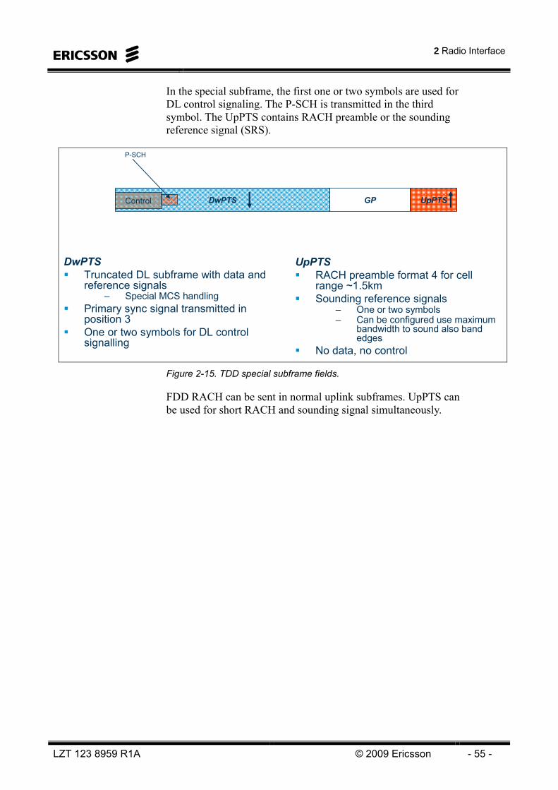
2 Radio Interface
LZT 123 8959 R1A © 2009 Ericsson - 55 -
In the special subframe, the first one or two symbols are used for DL control signaling. The P-SCH is transmitted in the third symbol. The UpPTS contains RACH preamble or the sounding reference signal (SRS).
DwPTSTruncated DL subframe with data and reference signals
– Special MCS handlingPrimary sync signal transmitted in position 3One or two symbols for DL control signalling
UpPTSDwPTS GP
UpPTSRACH preamble format 4 for cell range ~1.5kmSounding reference signals
– One or two symbols– Can be configured use maximum
bandwidth to sound also band edges
No data, no control
Control
P-SCH
Figure 2-15. TDD special subframe fields.
FDD RACH can be sent in normal uplink subframes. UpPTS can be used for short RACH and sounding signal simultaneously.

LTE 10A Air Interface
- 56 - © Ericsson 2009 LZT 123 8959 R1A
DOWNLINK TRANSMISSION TECHNIQUE LTE downlink transmission is based on Orthogonal Frequency Division Multiplex (OFDM). The basic LTE downlink physical resource can thus be seen as a time-frequency grid as illustrated in Figure 2-16, where each resource element corresponds to one OFDM subcarrier during one OFDM symbol interval. A Resource Block corresponds to twelve OFDM sub-carriers during one 0.5 ms slot. The smallest unit that can be allocated by the scheduler is two consecutive Resource Blocks (12 sub-carriers during 1ms). This is sometimes referred to as a Scheduling Block (SB) and is equal to the TTI (Transmission Time Interval) of 1 ms.
One Resource Block is 12 sub-carriers during one 0.5 ms slot The basic TTI (Transmission Time Interval) for DL-SCH is 1 ms
– TTI is a transport channel property– Subframe is a physical channel property– One (or two) transport blocks per TTI sent to L1
Δf = 15 kHz
One slot (Tslot = 0.5 ms, 7 OFDM symbols)
One Resource Block(12×7 = 84 resource elements)
Figure 2-16 The LTE downlink physical resource
For LTE, the downlink subcarrier spacing is Δf = 15 kHz. Assuming an FFT-based (Fast Fourier Transform) transmitter/receiver implementation, this corresponds to a sampling rate
FFTs Nf ⋅= 15000 (1)
where NFFT is the FFT size equal to 2048.

2 Radio Interface
LZT 123 8959 R1A © 2009 Ericsson - 57 -
Parallel transmission using a large number of narrowband “sub-carriers”“Multi-carrier” transmission
– Typically implemented with FFT (Fast Fourier Transform) and Inverse FFT
Δf = 15 kHz
TCP ≈ 4.7 μsTCP ≈ 4.7 μs
TCP-E ≈ 16.7 μsTCP-E ≈ 16.7 μs
S/P
f1f2
fM Σ20 MHz (example)
Insertion of cyclic prefix prior to transmission– Improved robustness in time-dispersive channels – requires CP > delay spread– Spectral efficiency loss
CopySymbols per slot
CP length
Configuration, Δf
3≈33.3 μs7.5 kHz
6≈16.7 μs15 kHzExtended
7≈4.7 μs*15 kHzNormal
Symbols per slot
CP length
Configuration, Δf
3≈33.3 μs7.5 kHz
6≈16.7 μs15 kHzExtended
7≈4.7 μs*15 kHzNormal
IFFT
* First symbol of each slot has a CP length of 5.2 μs Figure 2-17 DL OFDM with Cyclic Prefix.
In addition to the 15 kHz subcarrier spacing, a reduced subcarrier spacing Δflow = 7.5 kHz is also defined for LTE. This reduced subcarrier spacing specifically targets MBSFN-based multicast/broadcast transmission. The cyclic prefix is then extended to 33.3μs in order to better cope with the timing differences that may occur when several base-stations are involved the transmission of the same MBMS data.
The remaining discussions within this and the following chapters will focus on the 15 kHz subcarrier spacing unless explicitly stated otherwise.

LTE 10A Air Interface
- 58 - © Ericsson 2009 LZT 123 8959 R1A
Benefits
+ Frequency diversity+ Robust against ISI+ Easy to implement+ Flexible BW+ Suitable for MIMO+ Classic technology
(WLAN, ADSL etc)
Drawbacks
- Sensitive to doppler and freq errors
- High PAPR (not suitable for uplink)
- Overhead
• Orthogonal: all other subcarriers zero at sampling point
• Sub carrier spacing 15 kHz (MBMS also 7.5 kHz)
• Delay spread << Symbol time < Coherence time
f
∆f=15kHz
Figure 2-18. Downlink: OFDM - Orthogonal Frequency Division Multiplexing.
The symbol time in LTE is chosen to 66.7µs. This choice is based on the average radio channel delay spread (a measure of the radio channel time dispersion) and the coherence time (a measure of how slow the radio channel changes). The symbol time should be much longer than the delay spread in order to keep the ISI (Inter Symbol Interference) low. Also, the cyclic prefix should be longer than the expected delay spread in order to completely remove ISI.
However, if the symbol time is too long (i.e. longer than the coherence time), the radio channel will change considerably during one symbol. This would lead to inter carrier interference (ICI).

2 Radio Interface
LZT 123 8959 R1A © 2009 Ericsson - 59 -
Each sub-carrier experiences flat fading (non-frequency selective)– no need for equaliser
User data spread over many sub-carriers over large BW– frequency diversity, reduces fading
Long symbol time (66,7µs >> time dispersion)– reduces ISI
FFT cyclic operation => possible to insert CP at transmitter andremove it at receiver
– reduces ISI
f t15kHz
66,7μs
Figure 2-19. OFDM properties.
As mentioned above, in addition to the 15 kHz subcarrier spacing, a reduced subcarrier spacing Δflow = 7.5 kHz is also defined for LTE and specifically targeting MBSFN transmission. The use of the reduced subcarrier spacing also scales the OFDM symbol time, including the cyclic-prefix length, by a factor of two, thus providing a twice as long cyclic prefix (≈ 33.3 μs). In the case of the 7.5 kHz subcarrier spacing, the resource block consists of 24 subcarriers, i.e. the resource-block “bandwidth” is still 180 kHz.
In Figure 2-20 the downlink transmission and receiving scheme is illustrated. The coded and modulated symbols are converted from serial to parallel and transformed by an inverse fourier transform (typically implemented with an Inverse Fast Fourier Transform - IFFT). Now each parallel symbol stream is modulating a 15 kHz subcarrier and the symbol time is 1/Δf = 1/15kHz = 66.7 μs. A cyclic prefix (CP) of 4.7μs is inserted. This is the normal CP, there are also extended CP of 16.7 and 33.3 μs. In the first symbol, however, the normal CP is 5.2 μs, in order to fit the seven symbols per slot.
The CP is copy of the last part of the symbol in order to preserve the subcarrier orthogonality. This is possible since the FFT is a cyclic operation, but it is required that the time dispersion of the radio channel is shorter than the CP length.

LTE 10A Air Interface
- 60 - © Ericsson 2009 LZT 123 8959 R1A
Size-NIFFT
CPinsertion
M symbols
TuTCP
TuTCP-E
Tu = 1/Δf
0
0
Δf
M subcarriers
Size-NFFT
CPremoval
M symbols
0
0
to RF tx
from RF rx
S/PFrom coding & modulation
P/STo demodulation
& decoding
Figure 2-20. Downlink Tx and Rx scheme - OFDM.
DOWNLINK REFERENCE SIGNALS The downlink reference signals consist of so-called reference symbols which are known symbols inserted within in the OFDM time/frequency grid. The reference signals can be used by the UE for downlink channel estimation to enable coherent detection. Three types of reference signals are defined for the LTE downlink. • Up to four cell-specific reference signals, each corresponding to
one downlink antenna port.
• MBSFN reference signals within MBSFN subframes
• UE-specific reference signals, sometimes also referred to as dedicated reference signals. The detailed structure of the dedicated reference signals is still to be determined and is thus not further discussed.
In case of a single antenna port (a single transmit antenna), a single cell-specific unicast reference signal is inserted into the time/frequency grid according to Figure 2-21. As can be seen, the reference symbols are inserted within the first and the third last2 OFDM symbol of each slot and with a frequency-domain spacing of six subcarriers. Furthermore, there is a frequency-domain staggering of three subcarriers between the first and second reference symbols. Within each resource block there is thus a total of four reference symbols.
2 The fifth and fourth OFDM symbol in case of normal and extended cyclic prefix respectively
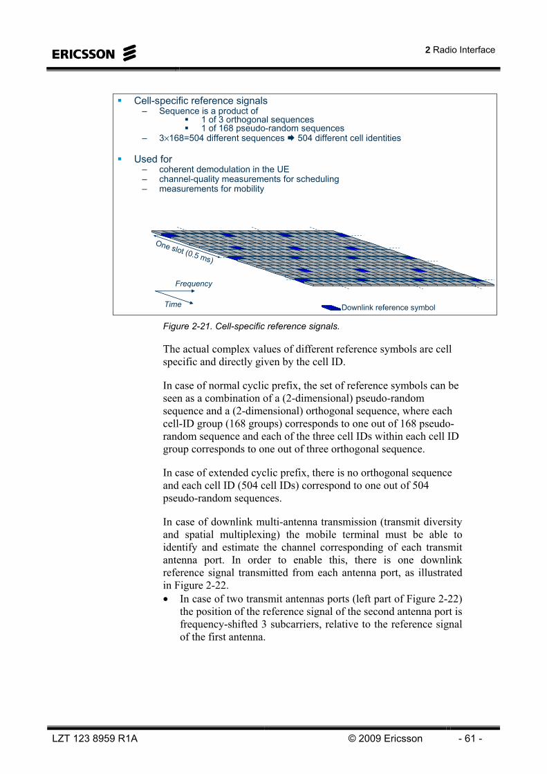
2 Radio Interface
LZT 123 8959 R1A © 2009 Ericsson - 61 -
Cell-specific reference signals– Sequence is a product of
1 of 3 orthogonal sequences1 of 168 pseudo-random sequences
– 3×168=504 different sequences 504 different cell identities
Used for – coherent demodulation in the UE– channel-quality measurements for scheduling– measurements for mobility
Downlink reference symbol
One slot (0.5 ms)
Time
Frequency
Figure 2-21. Cell-specific reference signals.
The actual complex values of different reference symbols are cell specific and directly given by the cell ID.
In case of normal cyclic prefix, the set of reference symbols can be seen as a combination of a (2-dimensional) pseudo-random sequence and a (2-dimensional) orthogonal sequence, where each cell-ID group (168 groups) corresponds to one out of 168 pseudo-random sequence and each of the three cell IDs within each cell ID group corresponds to one out of three orthogonal sequence.
In case of extended cyclic prefix, there is no orthogonal sequence and each cell ID (504 cell IDs) correspond to one out of 504 pseudo-random sequences.
In case of downlink multi-antenna transmission (transmit diversity and spatial multiplexing) the mobile terminal must be able to identify and estimate the channel corresponding of each transmit antenna port. In order to enable this, there is one downlink reference signal transmitted from each antenna port, as illustrated in Figure 2-22. • In case of two transmit antennas ports (left part of Figure 2-22)
the position of the reference signal of the second antenna port is frequency-shifted 3 subcarriers, relative to the reference signal of the first antenna.

LTE 10A Air Interface
- 62 - © Ericsson 2009 LZT 123 8959 R1A
• In case of four antenna ports (right part of Figure 2-22), additional reference signals, corresponding to the third and fourth antennas port, are transmitted within the second OFDM symbol of each slot. Note that this implies that the reference-symbol density on the third and fourth antenna port is lower (one half), compared to that of the first and second antenna port.
As can also be seen from Figure 2-22, in a resource element carrying a reference symbol for a certain antenna port, nothing is being transmitted at the other antenna ports. Thus there is no interference to reference symbols from other antenna ports within the cell. This is because the UE has to be able to separate the antenna ports when it is performing measurements for spatial multiplexing (MIMO).
One reference signal per antenna port– 1, 2, or 4 antenna ports supported– specified per antenna port, reference signals are not pre-coded
Different time/frequency resources used for different antenna ports– Nothing transmitted on ‘other’ antennas when reference symbol transmitted on one
antenna
Higher density in time for antenna 1, 2 than antenna 3, 4
Antenna port #1
Antenna port #2
Antenna port #3
Antenna port #4
Antenna port #1
Antenna port #2
Time
Frequency
Antenna port #1
Antenna port #2
Antenna port #3
Antenna port #4
Antenna port #1
Antenna port #2
Time
Frequency
Figure 2-22 Cell-specific reference signals - multiple antennas.
Reference-signal frequency shifting
The exact position of the reference symbols can be shifted in the frequency domain between different cells as illustrated in Figure 2-23. This implies that the frequency-domain positions of the reference symbols can expressed as
First reference symbols: pk = p0 + 6 · k
Second reference symbols: pk = (p0 + 3) mod 6+ 6 · k
where the cell-specific frequency shift p0 can take values in the range 0 to 5.

2 Radio Interface
LZT 123 8959 R1A © 2009 Ericsson - 63 -
The cell-specific frequency shift p0 is directly given by cell identity (Cell ID) group. Thus, as soon as the cell ID group is found as part of the cell search, the frequency shift of the downlink reference signals of that cell is known.
Shift = 0 Shift = 1 Shift = 5Shift = 0 Shift = 1 Shift = 5
First reference symbols: pk = p0 + 6 · k
Second reference symbols: pk = (p0 + 3) mod 6 + 6 · k
where the cell-specific frequency shift p0 is in the range of 0-5. Figure 2-23 Reference signal frequency shifts
DOWNLINK TRANSPORT-CHANNEL PROCESSING
LTE has inherited the basic principle from WCDMA/HSPA that data is delivered to the physical layer, i.e. on the transport channels, in form of Transport Blocks of a certain size. In terms of the more detailed transport-block structure, LTE has adopted a similar approach as was adopted for HSPA: • In case of single-antenna transmission, there can be at most one
single transport block, of dynamic size, for each TTI
• In case of multi-antenna transmission, there can be up to two transport blocks of dynamic size for each TTI, where each transport block corresponds to one codeword in case of downlink spatial multiplexing.
With this transport-block structure in mind, the LTE downlink transport-channel processing, more specifically the processing of DL-SCH3, can be outlined according to Figure 2-24 with two, mainly separated, processing chains, each corresponding to the processing of a single transport block.
3 The processing of other downlink transport channels is similar although typically with some additional constraints
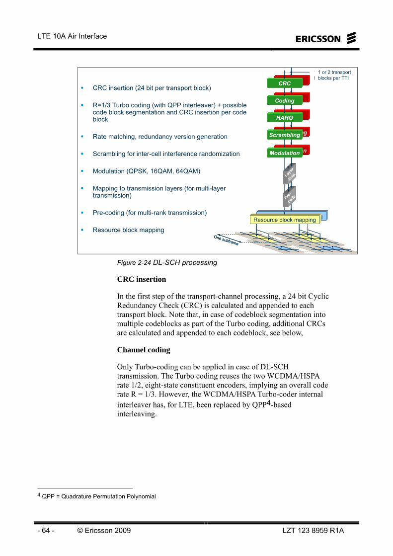
LTE 10A Air Interface
- 64 - © Ericsson 2009 LZT 123 8959 R1A
Resource block mapping
Layer
map.
Resource block mapping
Layer
map.
Resource block mappingResource block mappingResource block mapping
Layer
map.Lay
er
map.
1 transport block per TTI
HARQ
Coding
Scrambling
Modulation
CRC1 or 2 transport blocks per TTI
Pre-
code
HARQ
Coding
Scrambling
Modulation
CRC1 or 2 transport blocks per TTI
Pre-
code
HARQ
Coding
Scrambling
Modulation
CRC1 or 2 transport blocks per TTI
HARQ
Coding
Scrambling
Modulation
CRC
HARQ
Coding
Scrambling
Modulation
CRC1 or 2 transport blocks per TTI
Pre-
codePre-
codePre-
code
HARQ
Coding
Scrambling
Modulation
CRC
Resource block mappingResource block mapping
One subframe
One subframe
CRC insertion (24 bit per transport block)
R=1/3 Turbo coding (with QPP interleaver) + possible code block segmentation and CRC insertion per code block
Rate matching, redundancy version generation
Scrambling for inter-cell interference randomization
Modulation (QPSK, 16QAM, 64QAM)
Mapping to transmission layers (for multi-layer transmission)
Pre-coding (for multi-rank transmission)
Resource block mapping
Figure 2-24 DL-SCH processing
CRC insertion
In the first step of the transport-channel processing, a 24 bit Cyclic Redundancy Check (CRC) is calculated and appended to each transport block. Note that, in case of codeblock segmentation into multiple codeblocks as part of the Turbo coding, additional CRCs are calculated and appended to each codeblock, see below,
Channel coding
Only Turbo-coding can be applied in case of DL-SCH transmission. The Turbo coding reuses the two WCDMA/HSPA rate 1/2, eight-state constituent encoders, implying an overall code rate R = 1/3. However, the WCDMA/HSPA Turbo-coder internal interleaver has, for LTE, been replaced by QPP4-based interleaving.
4 QPP = Quadrature Permutation Polynomial

2 Radio Interface
LZT 123 8959 R1A © 2009 Ericsson - 65 -
In case of large transport blocks (length > 6120 corresponding to a code block including CRC of 6144 bits), code-block segmentation is applied. The code-block segmentation segments the input to the Turbo coder into smaller code blocks that are separately coded. Furthermore, in case of code-block segmentation a 24 bit CRC is also appended to each codeblock. The use of a per-code-block CRC allows for early termination of each the decoding of each codeblock if the CRC checks at the receiver/decoder side.
Rate matching including physical-layer hybrid-ARQ functionality
The rate matching consists of two parts, sub-block interleaving and bit collection/selection.
The sub-block interleaving, separately interleaves the three output blocks of the Turbo codes, corresponding to the system systematic bits and the two constituent encoders.
The output of the sub-block interleavers are then inserted into a circular buffer such that the systematic bits are inserted at the head, followed by alternative insertion of the bits of the two constituent encoders. Depending on the number of bits that fits into the assigned physical resource (depending on the number of resource blocks and layers, and the selected modulation scheme), a number of consecutive number of consecutive bits are then extracted from the circular buffer where the exact set of extracted bits depends on the redundancy version.
Bit-level scrambling
Downlink scrambling implies that the block of code bits delivered by the hybrid-ARQ functionality is multiplied (exclusive-or operation) by a bit-level scrambling sequence
LTE applies downlink scrambling to the code bits of each transport channel (“bit-level scrambling”). Downlink scrambling is applied to all transport channels as well as to the downlink L1/L2 control signaling. For all downlink transport channels except the MCH, as well as for L1/L2 control, the scrambling sequences should be different between neighbor cells in order to ensure interference randomization between the cells. In contrast, for MBSFN-based multicast/broadcast using the MCH transport channel, the same scrambling should be applied to all cells taking part in the MBSFN transmission.

LTE 10A Air Interface
- 66 - © Ericsson 2009 LZT 123 8959 R1A
Data modulation
The downlink data modulation maps blocks of scrambled bits to corresponding blocks of complex modulations symbols. The set of modulation schemes supported for the LTE downlink includes QPSK, 16QAM, and 64QAM, corresponding to two, four, and six bits per modulation symbol respectively.
Multi-antenna processing
The multi-antenna processing maps the modulation symbols corresponding to, in the general case, two transport blocks, and maps the result to the different antennas. LTE specifications support up to four transmit antennas. The first release will, however, only support up to two transmit antennas, thus enabling up to 2x2 MIMO.
Resource-block mapping
The resource-block mapping maps the symbols to be transmitted on each antenna to the resource elements of the set of resource blocks assigned by the MAC scheduler for the transmission of the transport block(s).
Downlink scheduling is carried out on a subframe (1 ms) basis. However, a downlink resource block is defined as a number of subcarriers during one 0.5 ms slot. As a consequence, the downlink resource-block assignment is carried out in terms of pairs of resource blocks, where each pair consists of two consecutive resource blocks within a subframe.
The physical resource to which the DL-SCH is mapped is, in the specification, referred to as the Physical Downlink Shared Channel (PDSCH).

2 Radio Interface
LZT 123 8959 R1A © 2009 Ericsson - 67 -
DOWNLINK L1/L2 CONTROL SIGNALING Downlink L1/L2 control signaling is used for transmitting downlink scheduling assignments required for the terminal to properly receive, demodulate and decode the DL-SCH, uplink scheduling grants informing the terminal about resources and transport format for UL-SCH transmission, and hybrid-ARQ acknowledgements in response to UL-SCH transmission.
As illustrated in Figure 2-25, the downlink L1/L2 control channels are mapped to the first (up to four) OFDM symbols within the subframe (in the figure two symbols are used). Thus, each subframe can be said to be divided into a control region, followed by a data region. The size of the control region is always equal to an integer number of OFDM symbols (1, 2, 3 or 4 OFDM symbols can be used for control signaling) and can be varied per subframe. This maximizes the spectral efficiency as the control signaling overhead can be adjusted to match the instantaneous traffic situation.
The location of the control signaling at the beginning of the subframe is advantageous as it allows the terminal to decode the downlink scheduling assignment prior to the end of the subframe. Processing of the DL-SCH can therefore begin earlier compared to the case of the control signaling spanning the full subframe duration. This minimizes the delay in the DL-SCH decoding and thus the overall downlink transmission delay.
Furthermore, by transmitting the L1/L2 control channel at the beginning of the sub-frame, i.e. by allowing for early decoding of the L1/L2 control information, mobile terminals that are not scheduled may turn off their receiver circuitry for a large part of the subframe, with reduced terminal power consumption as a consequence.

LTE 10A Air Interface
- 68 - © Ericsson 2009 LZT 123 8959 R1A
Downlink control signaling– DL scheduling (transport format and resource assignment)– UL scheduling grants– ACK/NACK related to UL transmission
Transmitted in first n OFDM symbols, n≤4– Allows for micro sleep
DL scheduling assignment, UL scheduling grant– Individual per MAC ID– Convolutional coding, QPSK, transmitted over the full BW
One slot (0.5 ms)One sub-frame (1 ms)
Reference symbols L1/L2 control
One slot (0.5 ms)One sub-frame (1 ms)
Reference symbols L1/L2 control Figure 2-25 DL control signaling
The downlink L1/L2 control signaling consists of three different physical channel types: • PCFICH (Physical Control Format Indicator Channel),
informing the terminal about the number of OFDM symbols (1, 2, 3 or 4) used for L1/l2 control signaling in the current subframe. There is only one PCFICH in a cell.
• PDCCH (Physical Downlink Control Channel), used to carry downlink scheduling assignments and uplink scheduling grants. In addition, it may also be used for power control of a group of terminals. Typically, there are multiple PDCCHs in a cell.
• PHICH (Physical Hybrid-ARQ Indicator Channel), used to transmit ACK/NAK in response to reception of UL-SCH transmissions. Typically, there are multiple PHICH in a cell.
In the following pages, the three channel types are described separately.

2 Radio Interface
LZT 123 8959 R1A © 2009 Ericsson - 69 -
PCFICH – Physical Control Format Indicator Channel
The PCFICH is used to indicate the number of OFDM symbols used for L1/L2 control signaling in the current subframe, or, equivalently, where in the subframe the data region starts. Reception of the PCFICH is thus essential to correct operation of the system. If the PCFICH is incorrectly decoded, the terminal will neither know where to find the control channels, nor where the data region starts, and will therefore lose any uplink scheduling grants transmitted as well as any DL-SCH data transmission intended for the terminal. The target error rate of the PCFICH is an implementation issue, but an error rate of one percent is commonly assumed in 3GPP.
Two bits of information, corresponding to a control region size of 1, 2, or 3 OFDM symbols5, are coded into a 32-bit long sequence using a rate-1/16 simplex code. The coded bits are scrambled, QPSK-modulated and mapped to 16 resource elements. To be compatible with the different Tx diversity schemes, which are specified on groups of 4 symbols, the 16 resource elements are grouped into 4 groups of 4 elements each. The four groups are well-separated in frequency to obtain good diversity. Furthermore, to avoid inter-cell PCFICH collisions, the location of the four groups in the frequency domain depends on the physical-layer cell identity.
Indicates number of OFDM symbols used for PDCCH (NPDCCH)– Two bits of information, four alternatives:
NPDCCH = 1, 2, 3 when # of RB more than 10NPDCCH = 2, 3, 4 when # of RB less or equal to 10
Block code + QPSK 16 symbolsMapping to four groups of resource elements in first OFDM symbol
– Resource elements not available for PDCCH mapping
2 bits 32 bitsRate 1/16block code
16 symbolsQPSKmodulation
44
4
4
44
4
4
t
Figure 2-26. PCFICH mapping.
5 Four symbols are used for low BW allocations.

LTE 10A Air Interface
- 70 - © Ericsson 2009 LZT 123 8959 R1A
The transmission power of the PCFICH is under control of the eNB. If necessary for coverage in a certain cell, the power of the PCFICH can be set higher than for other channels by “borrowing” power from e.g. PDCCHs.
PDCCH – Physical Downlink Control Channel
The PDCCHs are used for: • Downlink scheduling assignments, including PDSCH resource
indication, transport format, hybrid-ARQ information, transport block size, MIMO-related control information (if applicable) and PUCCH power control commands
• Uplink scheduling grants, including PUSCH resource indication, transport format, hybrid-ARQ related information, and PUSCH power control commands.
• Power-control commands of groups of terminals (as a complement to the power control commands piggy-backed with the scheduling decisions)
A PDCCH carries one of the above messages. As multiple mobile terminals can be scheduled simultaneously, on both downlink and uplink, there must be a possibility to transmit multiple scheduling messages within each subframe. Each scheduling message is transmitted on a separate PDCCH and consequently there are typically multiple PDCCHs in each cell and each terminal monitors multiple PDCCHs.
The different scheduling messages have different payload sizes. For example, supporting spatial multiplexing with non-contiguous allocation of resource blocks in the frequency domain require a larger scheduling message than an uplink grant supporting frequency-contiguous allocations only. Link adaptation, i.e., to match the code rate of the error-correcting code of the PDCCH to the instantaneous radio conditions, is also supported. Thus, there will be multiple formats for the PDCCH where each format is defined by the payload size and the code rate.
The processing of the PDCCH is illustrated in Figure 2-27. A CRC is attached to each PDCCH payload, where the MAC ID (RNTI) is included in the CRC calculation. Upon reception of a PDCCH, the terminal will check the CRC using its own RNTI. If the CRC checks, the message is declared to be correctly received and intended for the terminal. Thus, the identity of the terminal who is supposed to receive the PDCCH message is implicitly encoded in the CRC and not explicitly transmitted.

2 Radio Interface
LZT 123 8959 R1A © 2009 Ericsson - 71 -
After CRC attachment follows channel coding with a tail-biting convolution codes, rate matching and QPSK modulation. Depending on the PDCCH message size (three sizes are supported, size A, B and C) and the channel coding rate (including rate matching), the size of the coded PDCCH corresponds to 1, 2, 4 or 8 control-channel elements (CCEs), where each CCE corresponds to 36 resource elements (for 5 MHz).
The coded and modulated PDCCHs are multiplexed such that all control-channel elements corresponding to the first PDCCH are followed by all the control-channel elements corresponding to the second PDCCH and so on. The multiplexed CCEs are then mapped to resource elements, which is described as a permutation of groups of four QPSK symbols followed by a cell-specific cyclic shift. Groups of four QPSK symbols are used for the same reasons as for the PCFICH, namely to support the different Tx diversity schemes, and the cyclic shift serves the purpose of randomizing the mapping between different cells. Resource elements not used for PCFICH, PHICH or reference signals in the control region are used for transmission of the PDCCH. Furthermore, to obtain an even power distribution between the OFDM symbols and to allow for flexible power control, the mapping is done such that each CCE spans all OFDM symbols in the control region6.
Similarly to the PCFICH, the transmission power of each PDCCH is under the control of the eNB. Power adjustments can therefore be used as a complementary link adaptation mechanism in addition to adjusting the code rate. Relying on power adjustments alone might seem a tempting solution and, although possible in principle, it can result in relatively large power differences between PDCCHs, which has implications from an RF implementation perspective. Therefore, the two mechanisms for link adaptation, power adjustments and different code rates, complement each other.
In many cases, not all the PDCCH that are possible to transmit in the control region are used. Unused PDCCHs are part of the interleaving and mapping process in the same was as any other PDCCH. At the terminal, the CRC will not check for those “dummy” PDCCHs. Preferably, the power is set to zero for those unused PDCCHs; power that can be used by some other control channel instead.
6 This is the design target, some CCEs may in some cases not span all the OFDM symbols.

LTE 10A Air Interface
- 72 - © Ericsson 2009 LZT 123 8959 R1A
Coding
CRC
RM
Scramb
QPSK
PDCCH
Coding
CRC
RM
Scramb
QPSK
PDCCH
Coding
CRC
RM
Scramb
QPSK
PDCCH
Coding
CRC
RM
Scramb
QPSK
PDCCH
Multiplexing of CCEs
Each PDCCH consists of 1, 2, 4 or 8 CCEs
Interleaving
Cell-specific shift
Mapped to REs not used for PCFICH, PHICH or RS
MAC ID
Scrambling
Figure 2-27 PDCCH processing.
As described above, each PDCCH supports multiple formats and the format used is a-priori unknown to the terminal. Therefore, the terminal needs to blindly detect the format of the PDCCHs. Clearly, with the requirement to monitor multiple PDCCHs, each with an unknown format, the number of blind decodings in the terminal may become unattractively high. Using a fixed CCE size and allowing aggregation of only 1, 2, 4 or 8 CCEs helps in reducing the number of blind decoding attempts. Additional restrictions in the CCE aggregation structure will most likely be imposed although at the time of writing this has not yet been decided upon in 3GPP.

2 Radio Interface
LZT 123 8959 R1A © 2009 Ericsson - 73 -
Control Channel Element 1Control Channel Element 2Control Channel Element 3Control Channel Element 4Control Channel Element 5Control Channel Element 6
Control channel candidates on which the UE attempts to decode the information (10 decoding attempts in this example)
PD
CC
H c
andi
date
1
PD
CC
H c
andi
date
2
PD
CC
H c
andi
date
3
PDC
CH
can
dida
te 4
PD
CC
H c
andi
date
5
PDC
CH
can
dida
te 6
PDC
CH
can
dida
te 7
PDC
CH
can
dida
te 8
PDC
CH
can
dida
te 9
PDC
CH
can
dida
te 1
0
Control channel candidate set
Figure 2-28. PDCCH blind decoding.
Downlink scheduling assignments
Downlink assignments can take three different payload sizes, where size A<B<C: • Size A, supporting downlink scheduling with restrictions. Size
A assignments have the same PDCCH payload size as uplink grants.
• Size B, supporting downlink assignments without spatial multiplexing.
• Size C, supporting downlink assignments with spatial multiplexing.
The downlink assignments consists of resource-block indication, modulation and transport-block size, hybrid-ARQ related information, PUCCH power control commands, and (if applicable) information related to spatial multiplexing.
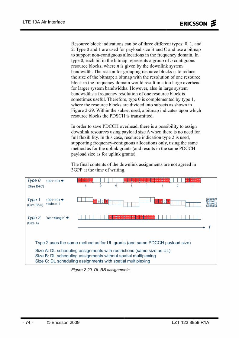
LTE 10A Air Interface
- 74 - © Ericsson 2009 LZT 123 8959 R1A
Resource block indications can be of three different types: 0, 1, and 2. Type 0 and 1 are used for payload size B and C and use a bitmap to support non-contiguous allocations in the frequency domain. In type 0, each bit in the bitmap represents a group of n contiguous resource blocks, where n is given by the downlink system bandwidth. The reason for grouping resource blocks is to reduce the size of the bitmap; a bitmap with the resolution of one resource block in the frequency domain would result in a too large overhead for larger system bandwidths. However, also in large system bandwidths a frequency resolution of one resource block is sometimes useful. Therefore, type 0 is complemented by type 1, where the resource blocks are divided into subsets as shown in Figure 2-29. Within the subset used, a bitmap indicates upon which resource blocks the PDSCH is transmitted.
In order to save PDCCH overhead, there is a possibility to assign downlink resources using payload size A when there is no need for full flexibility. In this case, resource indication type 2 is used, supporting frequency-contiguous allocations only, using the same method as for the uplink grants (and results in the same PDCCH payload size as for uplink grants).
The final contents of the downlink assignments are not agreed in 3GPP at the time of writing.
10011101 1 0 0 1 1 1 0 1
”start+length”
Subset 0Subset 1Subset 2Subset 3
10011101 +subset 1
1 0 0 1 1 1 0 1
Type 0
Type 1
Type 2
(Size B&C)
(Size B&C)
(Size A)
Type 2 uses the same method as for UL grants (and same PDCCH payload size)
Size A: DL scheduling assignments with restrictions (same size as UL)Size B: DL scheduling assignments without spatial multiplexingSize C: DL scheduling assignments with spatial multiplexing
f
Figure 2-29. DL RB assignments.

2 Radio Interface
LZT 123 8959 R1A © 2009 Ericsson - 75 -
The downlink scheduling assignments are sent to the user equipment on PDCCH. The Downlink Control Information (DCI) on the PDCCH has several supported formats, shown in Figure 2-30.
The formats supported are: DCI 0, 1A, 1, 2 and 2A. DCI 0 is for UL and uses an allocation type similar to type 2. DCI 1, 2 and 2A uses DL allocation type 0, which is a bitmap pointing out the allocated RBs. DCI 1A uses allocation type 2, which indicates start and length of the allocation of RBs. DCI 1 is used for tx-diversity while DCI 2 is used for closed loop spatial multiplexing and DCI 2A is used for open loop spatial multiplexing.
Type 0
Type 0
Type 2
Type 0
”Type 2”
Resource Allocation Type
OL spatial multiplexingDCI 2A
CL spatial multiplexingDCI 2
Independent of tx modeDCI 1A
Tx diversityDCI 1
UplinkDCI 0
UseDCI format on PDCCH
Type 0
Type 0
Type 2
Type 0
”Type 2”
Resource Allocation Type
OL spatial multiplexingDCI 2A
CL spatial multiplexingDCI 2
Independent of tx modeDCI 1A
Tx diversityDCI 1
UplinkDCI 0
UseDCI format on PDCCH
Figure 2-30. PDCCH signaling formats.
Below follows an example of the message contents for DCI Format 1A.
DCI format 1A is used for the compact scheduling of one PDSCH codeword.
The following information is transmitted by means of the DCI format 1A:– 1 bit for the format Flag for PDSCH allocation
Used to indicate NRB assignment for RA-RNTI, P-RNTI, or SI-RNTI– 1 bit to indicate Localized/Distributed VRB (Virtual Resource Block) assignment – N bits for the Resource block assignment (depends on NDL
RB)– 5 bits for the Modulation and coding scheme– 3 bits (FDD) or 4 bits (TDD) HARQ process number – 1 bit for New data indicator (indicates gap size for overhead messages) – 2 bits for Redundancy version – 2 bits for TPC command for PUCCH – 2 bits for Downlink Assignment Index (TDD only)
Zeros are used to pad out the message to fit the correct block size
Some of these fields are reserved when the CRC is scrambled with a RA-RNTI, P-RNTI, or SI-RNTI
Figure 2-31. DCI Format 1A, message contents.
LTE 10A Air Interface
- 76 - © Ericsson 2009 LZT 123 8959 R1A
Uplink scheduling grants
Uplink scheduling grants all have payload size A and consist of resource-block indication, the modulation and transport block size the terminal shall use for the transmission, hybrid-ARQ related information and PUSCH power control commands. The resource block indication is encoded as the first resource block to transmit upon and the number of resource blocks. The final contents of the uplink scheduling grants are not agreed in 3GPP at the time of writing.
Power control commands
As a complement to the power control commands sent as part of the downlink scheduling assignments and the uplink scheduling grants, there is a possibility to transmit a power control command using payload size A. The power control message is directed to a group of terminals using a group identity. Each terminal in the group has two bits on reserved for power control commands, i.e., even thought he message is directed to a group of terminals the power control is individual per terminal.
PHICH – Physical Hybrid-ARQ Indicator Channel
The PHICH is used for transmission of hybrid-ARQ acknowledgements in response to UL-SCH transmission. There is one PHICH present for each terminal expecting an acknowledgement in the subframe.
Each PHICH carries one bit, which is repeated three times, modulated, spread with a spreading factor of four and mapped to three groups of four resource elements each. Multiple PHICHs form a PHICH group and the PHICHs within a PHICH group are code-multiplexed using different orthogonal spreading sequences and share the same set of resource elements. This is motivated by power control of the PHICH; with CDM the power difference between subcarriers is not as large as with pure FDM. If more PHICH capacity than possible with a single PHICH group (corresponding to 12 resource elements) additional PHICH groups can be configured. Within each PHICH group, CDM is used while FDM is used between the groups.

2 Radio Interface
LZT 123 8959 R1A © 2009 Ericsson - 77 -
The power setting of the PHICH, and consequently the PHICH error rate, is not specified but considered an implementation issue. However, 3GPP typically assumes an ACK-to-NAK error rate of 10-2 and an NAK-to-ACK error rate in the range of 10-3 to 10-4 in the LTE design. The reason is that an NAK-to-ACK error would imply a loss of a transport block at the MAC level, a loss that has to be recovered by RLC retransmissions with the associated delays. As the PHICH target error rates are lower than the PCFICH error rate, the PHICH mapping is designed not to be dependent on the PCFICH value. Therefore, semi-static configuration is used to reserve resources for PHICH.
Typically, the PHICH is transmitted in the first OFDM symbol only. However, in some propagation environments, this would unnecessarily restrict the PHICH coverage. To alleviate this, it is possible to configure a PHICH duration of three OFDM symbols7. In this case the control region is three OFDM symbols long in all subframes.
The PHICH configuration is part of the system information (MIB on the BCH); one bit indicates whether the duration is one or three OFDM symbols and two bits indicate the amount of resources set aside for PHICHs.
There is no explicit indication in the scheduling grant upon which PHICH the terminal shall expect the acknowledgement. Instead, the PHICH number used for transmission of the acknowledgement is derived from the number of the first CCE of the PDCCH carrying the grant.
7 In case of a mixed unicast/MBSFN subframe, the extended PHICH duration is two OFDM symbols.
LTE 10A Air Interface
- 78 - © Ericsson 2009 LZT 123 8959 R1A
PHYSICAL-LAYER PROCEDURE This section describes different downlink physical layer procedures being part of the LTE concept
POWER CONTROL
Downlink power control, or power boosting, can be used on both the data channel (PDSCH) and control channels (PBCH, PDCCH, PCFICH, and PHICH).
As a default solution, the data channel power is distributed uniformly over the scheduled resource blocks (i.e. no power control is used). More sophisticated strategies include e.g. (i) allocating relatively high power, but few resource blocks to power limited users and vice-versa for bandwidth-limited users, and (ii) allocating more power to resource blocks with good channel quality.
Power control on the control channels may be used to improve coverage. For common control channels, which have to reach the cell border (e.g. PBCH and P/S-SCH), this can be done by borrowing power from user plane resource blocks transmitted simultaneously. In the extreme case the full eNB power is allocated to the PBCH and P/S-SCH. For control channels targeting individual UEs, e.g. the PDCCH, a simple approach is to use similar strategy. Alternatively, dynamic power control based on the addressed UEs channel quality can be used. This will enable more PDCCHs to be multiplexed, and hence the ability to schedule more users in parallel.
No special measurements exist for downlink power control. It relies on CQIs and handover measurements.
LINK ADAPTATION
For unicast traffic, link adaptation is used and is controlled by the eNB. A common modulation and channel code is used in the frequency domain per UE and codeword. The modulation and coding scheme (MCS) is selected based on CQI feedback and buffer content.

2 Radio Interface
LZT 123 8959 R1A © 2009 Ericsson - 79 -
Rapid interference variations make it difficult to predict the link quality accurately, and select MCS based on such knowledge. Instead, preliminary, MCS selection is based on averaged link quality. Different operating points can then be used. To reach low delay (few retransmissions), a margin to the interference variations can be included. This however leads to limited throughput, as often an unnecessary robust MCS is used. To reach high throughput, a low margin (even negative) is used. This will instead lead to a larger number of retransmissions, and hence a larger delay. The risk of throughput loss or large delays in case of negative margins is reduced by the use of incremental redundancy for retransmissions.
PAGING – PHYSICAL-LAYER ASPECTS
Paging is used for network-initiated connection setup. An efficient paging procedure should allow the UE to sleep with no receiver processing most of the time and to briefly wake up at predefined time intervals to monitor paging information from the network.
In WCDMA, a separate physical-layer paging indicator channel, monitored at predefined time instants, is used to signal the UE to receive the paging information. As the paging indicator is significantly shorter than the duration of the paging information, this approach minimizes the time the UE is awake.
For LTE, paging relies on the PDCCH, monitored at predefined time instants according to a DRX cycle. This is illustrated in Figure 2-32. No separate physical-layer paging indicator channel is used as the potential power savings are very small due to the short duration of PDCCH transmission, at most three OFDM symbols. If the terminal detects its paging group identity on the PDCCH, it demodulates and decodes the PDSCH and forwards the decoded data on the paging transport channel (PCH) to the MAC layer. The PCH transport block contains the exact identity of the terminal being paged. A terminal not finding its identity on the detected PCH will discard the information and sleep according to the DRX cycle. Obviously, as the uplink is not necessarily time aligned when paging a terminal, no ACK/NAK signaling can take place and consequently hybrid ARQ with soft combining cannot be used for paging messages.
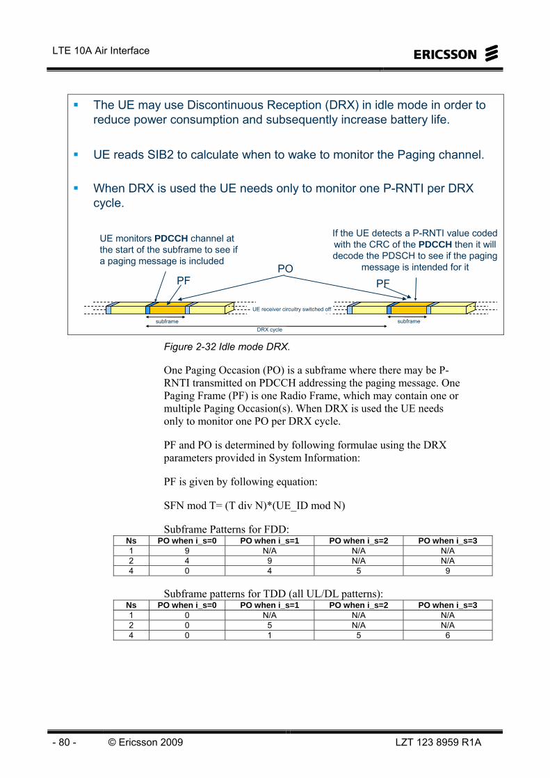
LTE 10A Air Interface
- 80 - © Ericsson 2009 LZT 123 8959 R1A
The UE may use Discontinuous Reception (DRX) in idle mode in order to reduce power consumption and subsequently increase battery life.
UE reads SIB2 to calculate when to wake to monitor the Paging channel.
When DRX is used the UE needs only to monitor one P-RNTI per DRX cycle.
subframeDRX cycle
subframe
UE receiver circuitry switched off
UE monitors PDCCH channel at the start of the subframe to see if a paging message is included
If the UE detects a P-RNTI value coded with the CRC of the PDCCH then it will decode the PDSCH to see if the paging
message is intended for itPOPF PF
Figure 2-32 Idle mode DRX.
One Paging Occasion (PO) is a subframe where there may be P-RNTI transmitted on PDCCH addressing the paging message. One Paging Frame (PF) is one Radio Frame, which may contain one or multiple Paging Occasion(s). When DRX is used the UE needs only to monitor one PO per DRX cycle.
PF and PO is determined by following formulae using the DRX parameters provided in System Information:
PF is given by following equation:
SFN mod T= (T div N)*(UE_ID mod N)
Subframe Patterns for FDD: Ns PO when i_s=0 PO when i_s=1 PO when i_s=2 PO when i_s=3 1 9 N/A N/A N/A 2 4 9 N/A N/A 4 0 4 5 9
Subframe patterns for TDD (all UL/DL patterns): Ns PO when i_s=0 PO when i_s=1 PO when i_s=2 PO when i_s=3 1 0 N/A N/A N/A 2 0 5 N/A N/A 4 0 1 5 6

2 Radio Interface
LZT 123 8959 R1A © 2009 Ericsson - 81 -
Index i_s pointing to PO from subframe pattern defined in the tables above (for FDD and TDD modes respectively) is derived from following calculation:
i_s = floor(UE_ID/N) mod Ns
System Information DRX parameters stored in the UE shall be updated locally in the UE whenever the DRX parameter values are changed in SI. If the UE has no IMSI, for instance when making an emergency call without USIM, the UE shall use as default identity UE_ID = 0 in the PF and i_s formulas above.
The following Parameters are used for the calculation of the PF and i_s:
T: DRX cycle of the UE. T is determined by the shortest of the UE specific DRX value, if allocated by upper layers, and a default DRX value broadcast in system information. If UE specific DRX is not configured by upper layers, the default value is applied. • nB: 4T, 2T, T, T/2, T/4, T/8, T/16, T/32.
• N: min(T,nB)
• Ns: max(1,nB/T)
• UE_ID: IMSI mod 1024.
IMSI is given as sequence of digits of type Integer (0..9), IMSI shall in the formulae above be interpreted as a decimal integer number, where the first digit given in the sequence represents the highest order digit.
For example:
IMSI = 12 (digit1=1, digit2=2)
In the calculations, this shall be interpreted as the decimal integer "12", not "1x16+2 = 18".

LTE 10A Air Interface
- 82 - © Ericsson 2009 LZT 123 8959 R1A
Example:
T = 64
nB = 2T = 128
UE_ID = IMSI mod(1024)
PF PF
T=pagingDefault [32,64,128,256]
10ms
1ms
SFN 0 SFN 1023SFN 63
Subframe number
95404
N/AN/A942
N/AN/AN/A91
i_s=3i_s=2i_s=1i_s=0Ns
Subframe number
95404
N/AN/A942
N/AN/AN/A91
i_s=3i_s=2i_s=1i_s=0Ns
PFindex when: SFN mod T= (T div N)*(UE_ID mod N)
i_s = floor(UE_ID/N) mod Ns
T: 32, 64, 128, 256 radio frames. nB: 4T, 2T, T, 1/2T, 1/4T, 1/8T, 1/16T, 1/32T N: min(T,nB)Ns: max(1,nB/T)UE_ID: IMSI mod 1024
Subframe 0 Subframe 4 Subframe 9
PDCCH PDSCH
PF
N = min(T,nB) = 64Ns = max(1,nB/T) = 2UE_ID = IMSI mod 1024 = e.g 0PF : SFN mod T= (T div N)*(UE_ID mod N) =0, 63, 127…
Figure 2-33. DRX Paging Frame.
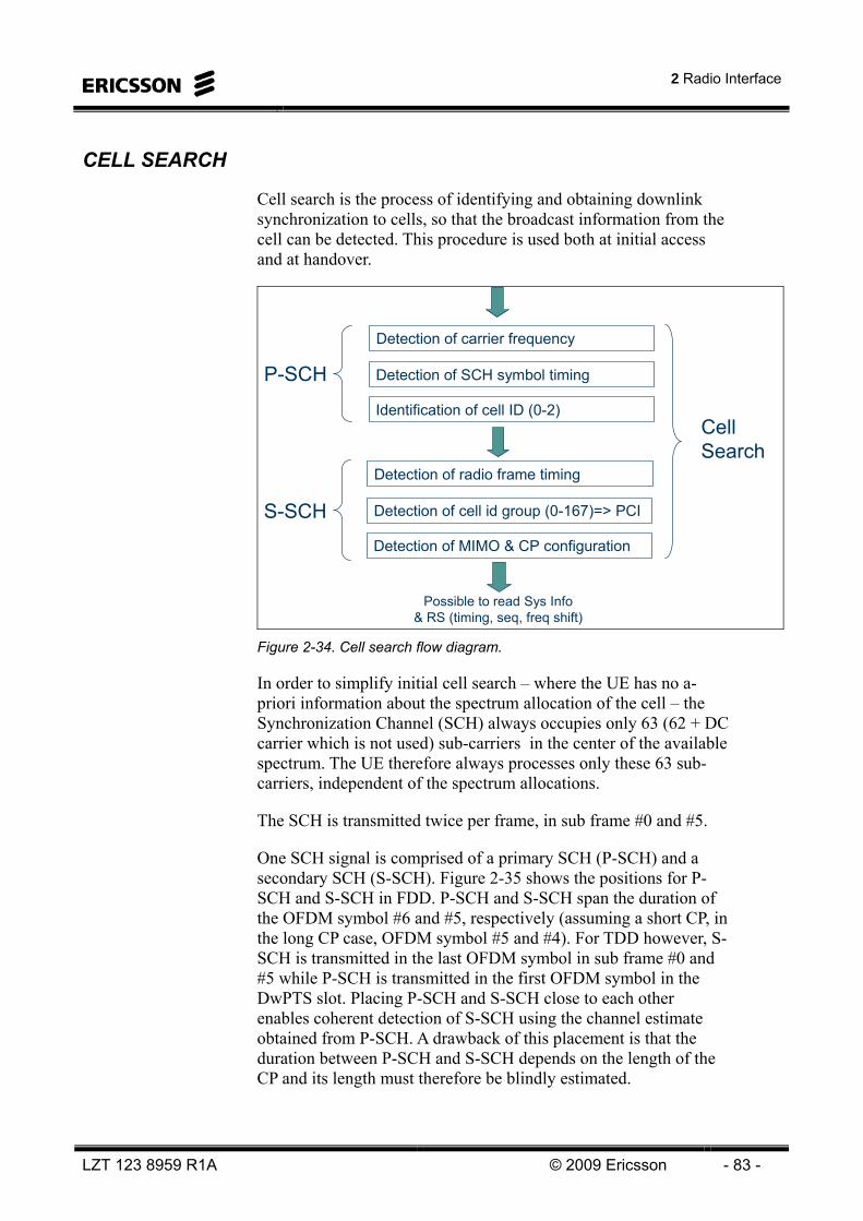
2 Radio Interface
LZT 123 8959 R1A © 2009 Ericsson - 83 -
CELL SEARCH
Cell search is the process of identifying and obtaining downlink synchronization to cells, so that the broadcast information from the cell can be detected. This procedure is used both at initial access and at handover.
Detection of carrier frequency
Detection of SCH symbol timing
Identification of cell ID (0-2)
P-SCH
S-SCH
Detection of radio frame timing
Detection of cell id group (0-167)=> PCI
Detection of MIMO & CP configuration
Possible to read Sys Info & RS (timing, seq, freq shift)
Cell Search
Figure 2-34. Cell search flow diagram.
In order to simplify initial cell search – where the UE has no a-priori information about the spectrum allocation of the cell – the Synchronization Channel (SCH) always occupies only 63 (62 + DC carrier which is not used) sub-carriers in the center of the available spectrum. The UE therefore always processes only these 63 sub-carriers, independent of the spectrum allocations.
The SCH is transmitted twice per frame, in sub frame #0 and #5.
One SCH signal is comprised of a primary SCH (P-SCH) and a secondary SCH (S-SCH). Figure 2-35 shows the positions for P-SCH and S-SCH in FDD. P-SCH and S-SCH span the duration of the OFDM symbol #6 and #5, respectively (assuming a short CP, in the long CP case, OFDM symbol #5 and #4). For TDD however, S-SCH is transmitted in the last OFDM symbol in sub frame #0 and #5 while P-SCH is transmitted in the first OFDM symbol in the DwPTS slot. Placing P-SCH and S-SCH close to each other enables coherent detection of S-SCH using the channel estimate obtained from P-SCH. A drawback of this placement is that the duration between P-SCH and S-SCH depends on the length of the CP and its length must therefore be blindly estimated.

LTE 10A Air Interface
- 84 - © Ericsson 2009 LZT 123 8959 R1A
Primary and secondary synchronization signal (P-SCH & S-SCH)– Transmitted in subframe #0 and #5
Primary synchronization signal can be used as phase reference for secondary reference signal
– Uses 62 center subcarriers (~6 resource blocks) cell search procedure independent of system bandwidth
10 ms radio frame
1 ms subframe
#0 #1 #2 #3 #4 #6#5 #7 #8 #9
OFDM symbolSecondary
synchronization signalPrimary
synchronization signal
0.5 ms slot 0.5 ms slot 0.5 ms slot 0.5 ms slot
0 1 2 3 4 5 6 0 1 2 3 4 5 6
62 s
ubca
rrie
rs
0 1 2 3 4 5 6 0 1 2 3 4 5 6
syst
em b
andw
idth
Figure 2-35. Cell Search (FDD).
P-SCH is used to find the timing of SCH as well as to correct possible frequency errors of the local UE oscillator. Three different P-SCHs are defined, each of them are mapped to a certain cell identity within a cell group. Furthermore, P-SCH are frequency domain defined Zadoff-Chu sequences of length 63, with the DC carrier punctured (indices 25, 29, 34 are used). Since P-SCH occurs twice per frame it does not uniquely determine the frame timing but has an ambiguity of 5 ms. Therefore the S-SCH signals transmitted in sub-frame #0 and #5 differ and are used to resolve this ambiguity. Furthermore, the S-SCH encodes the cell group – in total 168 cell groups - to which the cell belongs. Hence, after detection of P-SCH (giving the cell ID within a cell group) and S-SCH (giving the cell group) the 10 ms frame timing as well as the total cell ID (among the available 3*168=504) is detected.
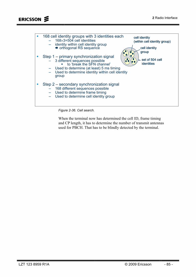
2 Radio Interface
LZT 123 8959 R1A © 2009 Ericsson - 85 -
168 cell identity groups with 3 identities each– 168×3=504 cell identities– identity within cell identity group
orthogonal RS sequence
Step 1 – primary synchronization signal– 3 different sequences possible
to ‘break the SFN channel’– Used to determine (at least) 5 ms timing– Used to determine identity within cell identity
group
Step 2 – secondary synchronization signal– 168 different sequences possible– Used to determine frame timing– Used to determine cell identity group
cell identity (within cell identity group)
cell identity group
set of 504 cell identities
cell identity (within cell identity group)
cell identity group
set of 504 cell identities
Figure 2-36. Cell search.
When the terminal now has determined the cell ID, frame timing and CP length, it has to determine the number of transmit antennas used for PBCH. That has to be blindly detected by the terminal.

LTE 10A Air Interface
- 86 - © Ericsson 2009 LZT 123 8959 R1A
SYSTEM INFORMATION The System Information (SI) that is broadcasted in the whole cell area, is carried by the logical channel BCCH, which in turn is carried by either of the transport channels BCH or DL-SCH.
A static part of SI is called MIB (Master Information Block) is transmitted on the BCH, which in turn is carried by the PBCH.
A dynamic part of SI, called SIBs (System Information Blocks) is mapped onto RRC System Information messages (SI-1,2,3…) on DL-SCH, which in turn is carried by PDSCH.
BCCH information split into two partsStatic part consisting of Master Information Block (MIB)
– Transmission period = 40 ms– Transmitted on BCH
Dynamic part consisting of System Information Blocks(SIB 1-8) mapped onto different RRC SI messages (SIs)
– Period SI-1: 80 ms, Period SI-2: 160 ms, Period SI-3: 320 ms, – Transmitted on DL-SCH
Figure 2-37. System Information.
Master Information Block (MIB)– Fixed amount of information (~40-60bits)– Transmitted using BCH transport channel (PBCH physical
channel)– Fixed transport format and scheduling
System Information Blocks (SIBs)– Transmitted using DL-SCH transport channel– Flexible transport format and scheduling– Transmitted as any other information carried on DL-SCH
PCH BCH DL-SCH
PCCH BCCH DTCH DCCH
MIB SIBs
PDSCHPDSCHPBCHPBCH PCFICHPCFICH PHICHPHICHPDCCHPDCCHPDSCHPDSCHPBCHPBCH PCFICHPCFICH PHICHPHICHPDCCHPDCCH
Figure 2-38. System Information channel mapping.

2 Radio Interface
LZT 123 8959 R1A © 2009 Ericsson - 87 -
The MIB contains e.g. number of antennas, system bandwidth, PHICH configuration, transmitted power and scheduling information on how the SIBs are scheduled together with other data on DL-SCH.
BCH mapped to– First subframe of every frame– First four OFDM symbols of second slot– Six centre resource blocks (72 sub-carriers)
One frame (10 ms)
Six centre resource
blocks (72 sub-carrie
rs)
: BCH
: Primary SCH
: Secondary SCH
4×72-48 = 240 resource elements* 480 coded bits per frame
* eight reference symbols within this part of each resource block1st slot 2nd slot
Figure 2-39. Physical Broadcast Channel - PBCH.
The PBCH is mapped onto the first four OFDM symbols of the second slot in the first subframe of every frame. In the frequency domain, PBCH uses the 72 centre sub-carriers, which corresponds to six resource blocks.
Over one radio frame, this corresponds to 4 (symbols) x 72 (subcarriers) = 288 resource elements. However, 48 resource elements (8 reference symbols per resource block and 6 resource blocks) are occupied by reference symbols and thus 240 resource elements are used for PBCH per frame. This corresponds to 480 coded bits per frame, since QPSK is used.
The BCH TTI is 40 ms, and thus a BCH transport block of 1920 bits are delivered to L1 every 40 ms.

LTE 10A Air Interface
- 88 - © Ericsson 2009 LZT 123 8959 R1A
BCH TTI = 40 ms One BCH TrBlk delivered to L1 every 40 msChannel coded and mapped to four subframes
– Very low code rate UE typically needs to receive only a subset of the subframes (depending on the channel conditions) i.e. each subframe is self-decodable
From basic cell search (P-SCH and S-SCH) UE finds 10 ms (frame) timingFrom BCH decoding at 4 different timing positions UE finds 40 ms timing (correct decoding -no explicit signalling indicates 40ms timing)
frame 4×k frame 4×k+1 frame 4×k+2 frame 4×k+3 frame 4×k+4
Channel codingincl. rate matching
Demultiplexing
Channel codingincl. rate matching
Demultiplexing
4×480 bits
1920 bits
One BCH transport block Next BCH transport block
Figure 2-40. BCH coding and mapping.
480 bits are mapped onto one subframe per radio frame in four consecutive radio frames. These 480 bits are self-decodable, with a very low code rate (a lot of redundancy), so UEs with good radio conditions only need to receive a subset of the subframes. UEs with bad radio conditions, on the other hand, need to receive all subframes. This will have impact on the battery consumption and SIB acquisition time.
Coded transport block mapped to N subframesUEs in bad positions need to receive all N subframes for proper decodingUEs in good positions may receive less subframes and still correctly decode SIB Faster SIB acquisition and reduced battery consumption
UEs in bad positions receive all five subframes
UEs in good positions may receive fewer subframes
12
34
56
12
34
56
12
34
56
12
34
56
Figure 2-41. Decoding of SIB.
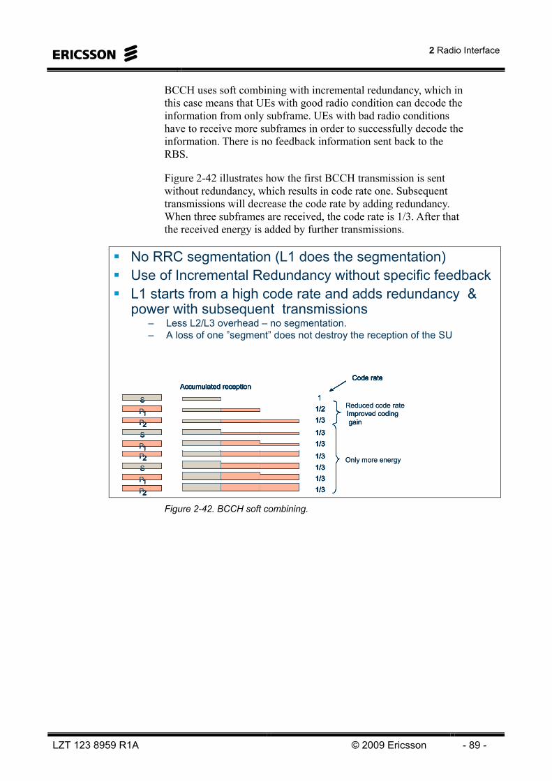
2 Radio Interface
LZT 123 8959 R1A © 2009 Ericsson - 89 -
BCCH uses soft combining with incremental redundancy, which in this case means that UEs with good radio condition can decode the information from only subframe. UEs with bad radio conditions have to receive more subframes in order to successfully decode the information. There is no feedback information sent back to the RBS.
Figure 2-42 illustrates how the first BCCH transmission is sent without redundancy, which results in code rate one. Subsequent transmissions will decrease the code rate by adding redundancy. When three subframes are received, the code rate is 1/3. After that the received energy is added by further transmissions.
No RRC segmentation (L1 does the segmentation)Use of Incremental Redundancy without specific feedback L1 starts from a high code rate and adds redundancy & power with subsequent transmissions
– Less L2/L3 overhead – no segmentation. – A loss of one ”segment” does not destroy the reception of the SU
Only more energy
Reduced code rate S
Accumulated reception
P1P2SP1P2SP1P2
1/3
1/31/31/31/3
1/3
1/3Improved codinggain
1/21
Code rate
S
Accumulated reception
P1P2SP1P2SP1P2
1/3
1/31/31/31/3
1/3
1/31/21
Code rate
Only more energy
Reduced code rate S
Accumulated reception
P1P2SP1P2SP1P2
1/3
1/31/31/31/3
1/3
1/3Improved codinggain
1/21
Code rate
S
Accumulated reception
P1P2SP1P2SP1P2
1/3
1/31/31/31/3
1/3
1/31/21
Code rate
S
Accumulated reception
P1P2SP1P2SP1P2
1/3
1/31/31/31/3
1/3
1/3Improved codinggain
1/21
Code rate
S
Accumulated reception
P1P2SP1P2SP1P2
1/3
1/31/31/31/3
1/3
1/31/21
Code rate
Figure 2-42. BCCH soft combining.

LTE 10A Air Interface
- 90 - © Ericsson 2009 LZT 123 8959 R1A
UPLINK RADIO ACCESS
THE UPLINK PHYSICAL RESOURCE
LTE uplink transmission is based on DFT-spread OFDM (Discreet Fourier Transform Spread OFDM, DFTS-OFDM). It is also often referred to as Single-Carrier FDMA (SC-FDMA).
Figure 2-43 shows the basic structure of DFTS-OFDM modulation with a size-M DFT being applied to the block of M modulation symbols. The output of the DFT is then mapped to selective inputs of a size-N IFFT. The DFT size M, i.e. the number of non-zero inputs to the IFFT, determines the instantaneous bandwidth of the transmitted signal while the frequency mapping determines the position of the transmitted signal within the overall available uplink spectrum. Finally, a cyclic prefix is inserted. In the figure we can also see how two different users are assigned different carrier frequencies and bandwidths. This makes the uplink orthogonal.
Size-M1DFT
OFDM with DFT-based pre-coding Low PAPR Same basic ”OFDM” parameters as for downlink
– Δf = 15 kHz, TCP ≈ 4.7 / 5.2 μs, TCP-E ≈ 16.7 μsOrthogonal uplink – no intra cell interference
Size-NIFFT
CPinsertion
Block of M1 symbols for user 1
0
”Single-carrier” signalf1
TuTCP
TuTCP-E
Size-M2DFT
Size-NIFFT
CPinsertionBlock of
M2 symbols for user 2
0
”Single-carrier” signalf2
TuTCP
TuTCP-E
M2<M1
Figure 2-43 UL transmisson scheme – DFTS-OFDM.

2 Radio Interface
LZT 123 8959 R1A © 2009 Ericsson - 91 -
DFTS-OFDM can also be seen as conventional OFDM transmission, combined with DFT-based pre-coding. Thus one can very well speak about a “subcarrier spacing” also in case of DFTS-OFDM. Furthermore, similar to OFDM, the DFTS-OFDM physical resource can be seen as a time-frequency grid with the additional constraint that a resource assigned to a mobile terminal must always consist of a set of consecutive subcarriers in order to keep the single-carrier property of the uplink transmission.
The uplink DFTS-OFDM subcarrier spacing equals Δf = 15 kHz and resource blocks, consisting of twelve subcarriers in the frequency domain, are defined also for the uplink. However, in contrast to the downlink, no unused DC subcarrier is defined for the uplink as this would destroy the “single-carrier” property of the uplink transmission (single-carrier characteristics require the transmission of consecutive subcarriers).
Similar to the downlink, also for the uplink the LTE physical-layer specification allows for a very high degree of flexibility in terms of the overall transmission bandwidth by allowing for, in essence, any number of uplink resource blocks. However, once again there will be restrictions in the sense that there will, at least initially, only be radio-frequency requirements defined for a limited set of uplink bandwidths.
Furthermore, in order to limit the complexity of the DFT operation, the uplink resource assignment should always be such that the DFT size can always be factorized into factors of 2, 3, and 5. As the resource-block size itself can be factorized into these factors, this means that also the number of assigned resource blocks can be factorized into factors of 2, 3, and 5. As an example, a UE can thus be dynamically assigned an instantaneous bandwidth corresponding to e.g. six, eight, or nine resource blocks, but cannot be assigned a bandwidth corresponding to seven resource blocks.
Also in terms of the more detailed time-domain structure, the LTE uplink is very similar to the downlink. Each 1 ms uplink subframe consists of two slots of length Tslot = 0.5 ms. Each slot then consists of a number of DFTS-OFDM blocks including the cyclic prefix. Also similar to the downlink, two cyclic-prefix lengths, a normal cyclic prefix and an extended cyclic prefix, are defined for the uplink.
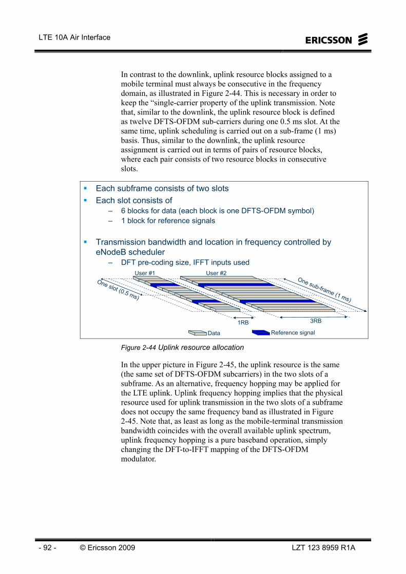
LTE 10A Air Interface
- 92 - © Ericsson 2009 LZT 123 8959 R1A
In contrast to the downlink, uplink resource blocks assigned to a mobile terminal must always be consecutive in the frequency domain, as illustrated in Figure 2-44. This is necessary in order to keep the “single-carrier property of the uplink transmission. Note that, similar to the downlink, the uplink resource block is defined as twelve DFTS-OFDM sub-carriers during one 0.5 ms slot. At the same time, uplink scheduling is carried out on a sub-frame (1 ms) basis. Thus, similar to the downlink, the uplink resource assignment is carried out in terms of pairs of resource blocks, where each pair consists of two resource blocks in consecutive slots.
Each subframe consists of two slotsEach slot consists of
– 6 blocks for data (each block is one DFTS-OFDM symbol)– 1 block for reference signals
Transmission bandwidth and location in frequency controlled by eNodeB scheduler
– DFT pre-coding size, IFFT inputs used
One slot (0.5 ms)
One sub-frame (1 ms)
Data Reference signal
User #1 User #2
1RB 3RB
Figure 2-44 Uplink resource allocation
In the upper picture in Figure 2-45, the uplink resource is the same (the same set of DFTS-OFDM subcarriers) in the two slots of a subframe. As an alternative, frequency hopping may be applied for the LTE uplink. Uplink frequency hopping implies that the physical resource used for uplink transmission in the two slots of a subframe does not occupy the same frequency band as illustrated in Figure 2-45. Note that, as least as long as the mobile-terminal transmission bandwidth coincides with the overall available uplink spectrum, uplink frequency hopping is a pure baseband operation, simply changing the DFT-to-IFFT mapping of the DFTS-OFDM modulator.

2 Radio Interface
LZT 123 8959 R1A © 2009 Ericsson - 93 -
Uplink transmission can hop on slot boundaries– to obtain channel diversity– to obtain interference diversity
One sub-frame (1 ms)1 RB
(12 sub-carriers)
User #1 User #3User #2
3 RB(36 sub-carriers)
One sub-frame (1 ms)
User #1 User #3User #2
No hopping
Hopping
Figure 2-45 Uplink frequency hopping
Uplink reference signals
There are two types of uplink reference signals in LTE, reference signals for channel estimation to support coherent uplink transmission and so-called sounding reference signals.
Reference signals for channel estimation
As illustrated in Figure 2-44, the uplink reference signals used for channel estimation are transmitted within the fourth block of each uplink slot8 and with an instantaneous bandwidth equal to the bandwidth of the data transmission. Note that, in the general case, uplink frequency hopping may be applied, implying that the two slots of Figure 2-44 are transmitted on different, perhaps substantially separated, frequencies. In this case, interpolation between the two reference-signal blocks of a subframe may not be possible as the channel, due to the frequency separation, may differ substantially between the two blocks.
8 This assumes the normal cyclic prefix, i.e. seven blocks per slot

LTE 10A Air Interface
- 94 - © Ericsson 2009 LZT 123 8959 R1A
Reference signals for channel sounding
As mentioned above in addition to the above discussed reference signals, which are used for uplink channel estimation, so-called sounding reference signals (SRS) can also be transmitted on the LTE uplink. The intention with the sounding reference signals is for the network to be able to estimate the channel quality of the uplink channel for different UEs in order to be able to apply uplink channel-dependent scheduling. The sounding reference signals can also be used to estimate the timing of UE transmissions and to derive timing-control commands for uplink time alignment.
Sounding reference signals are transmitted independently of the transmission of any uplink data, i.e. a UE may transmit a sounding reference signal also in subframes where the UE does not have any data transmission. Furthermore, the sounding-reference-signal bandwidth can very well be, and typically is, different from that of any simultaneous data transmission from the same UE, see Figure 2-46.
It is yet to be determined if the sounding reference signals are to be transmitted within the first or the last9 DFTS-OFDM block of a subframe (Figure 2-46 assumes the first symbol).
The basic principles for generating the channel-sounding reference signals are similar to those of the demodulation reference signals, with basically one difference: The frequency-domain reference-signal sequence (the same sequences as for the uplink demodulation reference signal sequences) is mapped to every second input of the IFFT.
One slot (0.5 ms)
One sub-frame (1 ms)
Data Demodulation reference signal
User #1 User #2
Channel-sounding reference signal
One slot (0.5 ms)
One sub-frame (1 ms)
Data Demodulation reference signal
User #1 User #2
Channel-sounding reference signal
Figure 2-46 Uplink channel-sounding reference signal
9 Yet to be determined if the sounding RS is in the first or the last DFTS-OFDM block.

2 Radio Interface
LZT 123 8959 R1A © 2009 Ericsson - 95 -
Sounding-reference-signal transmissions are configured with • a certain bandwidth, indicating how many resource blocks (in
the frequency domain) the sounding reference signal will cover
• a certain period, indicating the distance, in time, between consecutive SRS transmissions (current assumption is 2, 5, 10 , 20 , 40, 80, and 160 subframes)
• a certain duration, indicating how many times the sounding reference signal will be transmitted
Uplink transport-channel processing
The LTE uplink transport-channel processing can be outlined according to Figure 2-47. Assuming no uplink spatial multiplexing, only a single transport block, of dynamic size, is transmitted for each TTI.
UL-SCH processing similar to DL-SCH
HARQ
Coding
Scrambling
Modulation
CRC
CRC insertion (24 bits)
Rel 6 Turbo coding (with QPP interleaver)
Rate matching, redundancy version generation
UE-specific scrambling for interference randomization
Modulation (QPSK, 16QAM, 64QAM)
To DFTS-OFDM modulation, including mapping to assigned frequency resource
Figure 2-47 UL-SCH processing.
CRC insertion
Similar to the downlink, a CRC is calculated and appended to each uplink transport block.
Channel coding
Uplink channel coding relies on the same Turbo code, including the same QPP-based internal interleaver, as is used for the downlink.

LTE 10A Air Interface
- 96 - © Ericsson 2009 LZT 123 8959 R1A
Physical-layer hybrid-ARQ functionality
The uplink physical-layer aspects of the LTE uplink hybrid-ARQ are, in essence, identical to the corresponding downlink functionality, i.e. the hybrid-ARQ physical-layer functionality extracts, from the block of coded bits delivered by the channel coder, the exact set of bits to be transmitted at each transmission/retransmission instant.
Bit-level scrambling
Similar to the downlink, bit-level scrambling can also be applied to the coded bits on the LTE uplink.
Data modulation
Similar to the downlink, the uplink data modulation maps blocks of coded/scrambled bits to complex modulation symbols. The set of modulation schemes supported for the LTE uplink includes QPSK, 16QAM and 64-QAM, corresponding to two, four and six bits per modulation symbol respectively.
The block of modulation symbols are then applied to the DFTS-OFDM modulator which also maps the signal to the assigned frequency band.
UPLINK L1/L2 CONTROL SIGNALING
Uplink L1/L2 control signaling consists of one (or more) of the following pieces of information: • Hybrid-ARQ acknowledgements related to reception of DL-
SCH transport blocks,
• CQI (Channel-Quality Indicator) indicating the instantaneous downlink channel quality perceived by the terminal. Similar to HSPA, the CQI reports can be used by the network for downlink channel-dependent scheduling and rate control. However, in contrast to HSPA, the LTE CQI reports indicate the channel quality in both the time and frequency domain
• Scheduling requests, used by the terminal to request UL-SCH resources in case it does not have a valid scheduling grant.
Note that the uplink transport format is completely decided by the scheduler in the eNB. Consequently, and in contrast to HSPA, there is no need for signaling the transport format in the uplink control signaling.

2 Radio Interface
LZT 123 8959 R1A © 2009 Ericsson - 97 -
Two different cases can be differentiated with respect to transmission of uplink control signaling: • The terminal does not have a valid scheduling grant, i.e., no
UL-SCH resources have been assigned in the current subframe. A separate physical channel, the Physical Uplink Control Channel (PUCCH) is used for transmission of uplink control signaling in this case.
• The terminal has a valid scheduling grant, i.e., UL-SCH resources have been assigned in the current subframe. In this case the uplink control signaling is transmitted on the PUSCH in order to preserve the single-carrier properties. Obviously, as the terminal has been assigned UL-SCH resources, there is no need to support transmission of the scheduling request in this case.
Control signaling on PUCCH
Control signaling on PUCCH is transmitted using one out of four formats: format 1A and 1B are used for transmission of ACK/NAK, format 2 is used for transmission of CQI and format 1 is used for scheduling request.
Uplink control signaling– ACK/NAK, triggered by DL data transmission (PUCCH format 1A,1B or PUSCH)– CQI, transmitted at regular time intervals (PUCCH format 2 or PUSCH)– Scheduling request (PUCCH format 1)
If data and control are transmitted simultaneously -> PUSCH– control located in the same region as data (time multiplexed)– required to preserve single-carrier properties
If only control is transmitted -> PUCCH– control located at reserved region at band edges– one RB is shared by multiple UEs through orthogonal spreading sequences
Spatial mux, 2 TB
Figure 2-48. UL control signaling.

LTE 10A Air Interface
- 98 - © Ericsson 2009 LZT 123 8959 R1A
The PUCCH is transmitted on resources located at the edges of the uplink system bandwidth as illustrated in Figure 2-49. Each such resource consists of twelve “subcarriers” (one resource block) within each slot of an uplink subframe. In order to provide frequency diversity, these frequency resources are frequency hopping on the slot boundary, i.e. one resource consists of 12 subcarriers at the upper part of the spectrum within the first slot of a subframe and an equally sized resource at the lower part of the spectrum during the second slot of the subframe or vice verse. If more resources are needed for the PUCCH, e.g. in case of very large overall transmission bandwidth supporting a large number of users, additional resources blocks can be assigned next to the previously assigned resource blocks.
The bandwidth of one resource block during one subframe is too large for the control signaling needs of a single terminal. Therefore, to efficiently exploit the resources set aside for control signaling, multiple terminals can share the same resource block. This is done by CDMA between different terminals where different cyclic shifts of a cell-specific length-12 CAZAC sequence are assigned to the terminals. The resource used by a PUCCH is therefore not only specified in the time-frequency domain by the resource-block pair, but also by the cyclic shift (and, for format 1A and 1B, additionally by an orthogonal cover as described further below). Typically, up to six cyclic shifts can be used in a cell. The length-12 CAZAC sequence is generated in the same way as the sequences for uplink reference signals.
Simultaneous data and control on PUSCH
Slot #0Slot #1
One sub-frame (1 ms)
Uplink resources assigned for L1/L2 control signaling
12 ”sub-carriers”
Total available uplink bandwidth
Slot #0Slot #1
One sub-frame (1 ms)
Uplink resources assigned for L1/L2 control signaling
12 ”sub-carriers”
Total available uplink bandwidth
Control only on PUCCH– Up to six users can be code-multiplexed in same RB
One slot (0.5 ms)
One sub-frame (1 ms)
Data Reference signal
User #1 User #2
Control
Figure 2-49 UL control signaling PUSCH/PUCCH

2 Radio Interface
LZT 123 8959 R1A © 2009 Ericsson - 99 -
PUCCH format 1A and 1B – hybrid-ARQ acknowledgement
PUCCH format 1A and 1B are used for transmission of hybrid-ARQ acknowledgements with the difference between the two being the number of bits. Format 1A supports a single acknowledgement bit to be used in absence of downlink spatial multiplexing, while format 1B supports two acknowledgement bits for the case of DL-SCH spatial multiplexing with two transport blocks per TTI.
One (format 1A) or two (format 1B) acknowledgements bits are modulated using BPSK or QPSK, respectively, resulting in one modulation symbol. In addition to the PUCCH-specific cyclic shift of the length-12 CAZAC sequence as described above, the PUCCH resource for format 1A and 1B is further specified by an orthogonal cover sequence. Orthogonal cover sequences are applied to both the four information symbols in a slot as well as to the three reference signal symbols. Thus, with three10 reference symbols per slot, up to three acknowledgements can be transmitted for each of the cyclic shifts. Typically, up to six cyclic shifts can be used, resulting in up to 18 terminals with PUCCH format 1A/1B sharing one resource block.
The same PUCCH structure is used in the two slots of a subframe. To further randomize the inter-cell interference between PUCCH resource blocks, cyclic shift hopping (per OFDM symbol) and orthogonal cover hopping (per slot) are used.
Hybrid-ARQ acknowledgements are transmitted a fixed time after the reception of a DL-SCH transport block. Furthermore, the PUCCH resource to use is derived from the index of the first control channel element in the PDCCH used for scheduling the downlink transmission (or from RRC signaling in case of persistent scheduling).
PUCCH format 1 – Scheduling Request
PUCCH format 1 is used for transmitting scheduling requests. The overall structure is similar to that used for hybrid-ARQ acknowledgements.
Each active terminal is assigned a dedicated resource for scheduling request through RRC signaling, providing the possibility to request an uplink grant every x subframe.
10 This assumes normal cyclic prefix. The same structure is used for extended cyclic prefix but with only two reference
signals per slot.

LTE 10A Air Interface
- 100 - © Ericsson 2009 LZT 123 8959 R1A
PUCCH format 2 – CQI reports
PUCCH format 2 is used for CQI reports. The CQI reports coded and modulated using QPSK. Each of the ten QPSK symbols (assuming normal cyclic prefix) is multiplied by a cyclically shifted length-12 CAZAC sequence and transmitted in one DFTS-OFDM symbol. As the same underlying principle of cyclically shifted CAZAC sequences is used for PUCCH format 2 as for format 1A/1B, hybrid-ARQ acknowledgements and CQI from different terminals can be transmitted on the same time-frequency resource by assigning different cyclic shifts. One cyclically shifted CAZAC sequence carries a single CQI report, i.e., consumes the same amount of resources as three hybrid ARQ acknowledgements (assuming normal cyclic prefix).
CONTROL SIGNALING ON PUSCH
When the terminal is transmitting data on PUSCH, i.e., has a valid scheduling grant in the subframe, control signaling cannot be simultaneously sent on PUCCH as this would violate the single-carrier properties. Instead, control signaling is time multiplexed with data on the PUSCH. Only hybrid-ARQ acknowledgements and CQI reports are transmitted on the PUSCH as there obviously is no need to request a scheduling grant when the terminal already is scheduled. Buffer status and other scheduling-related information are instead provided as “inband” MAC reports.
CQI and hybrid-ARQ acknowledgements are time-multiplexed with coded data bits prior to the DFT precoder as illustrated in Figure 2-50. The mapping of the control signaling is defined such that the control signaling is located next to the reference signals as illustrated in Figure 2-51. The reason to this is to improve the decoding performance of the critical control signaling as the channel estimates are of better quality close to the reference symbols. For data, this is not as critical as, unlike control signaling, hybrid-ARQ retransmissions can be used.

2 Radio Interface
LZT 123 8959 R1A © 2009 Ericsson - 101 -
For CQI, it is known from RRC signaling in which subframes the CQI report will be transmitted and the presence or absence of CQI reports is taken into account in the DL-SCH rate matching. As the RRC signaling is robust, there is (in practice) no risk of CQI-related mismatch of rate matching parameters between the terminal and the eNB. The hybrid-ARQ acknowledgements, on the other hand, are triggered by scheduling assignments on the PDCCH. As the PDCCH is not as robust as RRC signaling (the error rate on the PDCCH is in the order of one percent), the presence or absence of acknowledgements are not accounted for in the DL-SCH rate matching. Instead, the acknowledgements are punctured in to the coded bit stream. Thus, the non-punctured bits are not affected by presence/absence of hybrid-ARQ acknowledgements and the problem of a mismatch between the rate matching in the terminal and the eNB is avoided.
ACK/NACK – Always transmitted using QPSK– Is punctured into UL-SCH to avoid errors due to missed DL assignments and
thus different interpretations of ACK/NACK symbolsCQI, PMI, and RI
– Use the same modulation scheme as UL-SCH but different code rate– Are multiplexed into UL-SCH since configured by reliable higher layer signaling
Turbocoding
Conv.coding
Blockcoding
Blockcoding
Ratematching
Ratematching
Ratematching
MUX QPSK16/64QAM
QPSK
DFT
punctured
IFFT
UL-SCH
CQI, PMI
RI
ACK/NACK
Figure 2-50 Time-multiplexing of control- and user-data onto PUSCH

LTE 10A Air Interface
- 102 - © Ericsson 2009 LZT 123 8959 R1A
The figure below shows where in time and frequency the different signaling is sent.
ACK/NACK close to reference signalsRI rather close to reference signals since needed for correct interpretation of CQI and PMI
1 subframe = 14 SC-FDMA symb. = 1 ms
Reference signals
hannel-Quality IndicatorPrecoding-Matrix IndicatorACK/NACKRank Indicator
1 subframe = 14 SC-FDMA symb. = 1 ms
Reference signals
hannel-Quality IndicatorPrecoding-Matrix IndicatorACK/NACKRank Indicator
Samples within SC-FDMA symb.
Figure 2-51 Control signaling on PUSCH, normal CP
FEEDBACK REPORTS WITHOUT SPATIAL MULTIPLEXING
Feedback from the user equipment is used by Link Adaptation. The structure of the feedback depends on whether spatial multiplexing is used or not. Without spatial multiplexing (only one layer, with or without TX diversity), only the Channel Quality Indicator (CQI), the recommended transport format based on measurements on the reference signals, is sent from the user equipment to the RBS.
The feedback can be sent on either the PUCCH if no PUSCH resources are scheduled, or on PUSCH if PUSCH resources are scheduled. Periodic reporting with PUCCH format 2 is used when spatial multiplexing is used. Without spatial multiplexing, reporting mode 1-0 is used. On PUSCH, uplink grant polling from the RBS triggers the feedback reporting, also referred to as a-periodic reporting. On PUSCH, without spatial multiplexing, reporting mode 3-0 is used.
The CQI on PUCCH is a wideband average over the whole bandwidth, while the CQI on PUSCH is reported per subband. See Figure 2-52.
2 Radio Interface
LZT 123 8959 R1A © 2009 Ericsson - 103 -
When the report is transmitted on PUSCH, it is multiplexed together with the HARQ-ACK after coding and before interleaving. The power and the modulation and coding scheme is the same for the feedback report and HARQ-ACK and follows the PUSCH power control.
When no CQI resources are configured on PUCCH for user equipment, or when there is downlink traffic, the link adaptation must schedule the feedback reports on PUSCH. The CQI reflects the recommended transport format of the modulation scheme and coding rate. The CQI is estimated by the user equipment from measurements on the downlink reference signal and Signal to Noise and Interference Ratio (SINR).
FEEDBACK REPORTS WITH SPATIAL MULTIPLEXING
With spatial multiplexing, a more extensive feedback report is needed. The structure depends on whether open or closed loop spatial multiplexing is used.
The feedback for closed loop consists of Channel Quality Indicator (CQI), Precoder Matrix Indicator (PMI), and Rank Indicator (RI). For the closed loop there are separate CQIs per layer. The CQI on PUCCH is a wideband report, while the CQI on PUSCH is reported per subband in case of open loop spatial multiplexing. Closed loop uses a wideband report on PUSCH.
The feedback for open loop uses only CQI and RI. The PUCCH report is periodically scheduled, with CQI and PMI on one rate and RI on another rate. For open loop, there is one CQI sent from the user equipment to the RBS.
The number of CQI resources per slot is configurable.
The periodicity of the reporting is common for all user equipment in the cell. On PUCCH the reporting mode for closed loop is 1-1 and for open loop 1-0. On PUSCH, the reporting mode is 1-2 for closed loop and 3-0 for open loop.
The PUSCH and PUCCH reporting modes and CQI and PMI feedback types are shown in Figure 2-52.

LTE 10A Air Interface
- 104 - © Ericsson 2009 LZT 123 8959 R1A
YESWide-band
Wide-band
1-1YESSub-band
Wide-band
1-2Closed Loop
YES-Wide-band
1-0YES-Sub-band
3-0Open Loop
-Wide-band
1-0--Sub-band
3-0No Spatial Mux/Tx Div
RIPMICQIReporting Mode
RIPMICQIReporting Mode
PUCCHPUSCH
YESWide-band
Wide-band
1-1YESSub-band
Wide-band
1-2Closed Loop
YES-Wide-band
1-0YES-Sub-band
3-0Open Loop
-Wide-band
1-0--Sub-band
3-0No Spatial Mux/Tx Div
RIPMICQIReporting Mode
RIPMICQIReporting Mode
PUCCHPUSCH
Figure 2-52. PUSCH and PUCCH Reporting Modes.
The sub-band size is configured by higher layers, according to 3GPP TS 36.213.
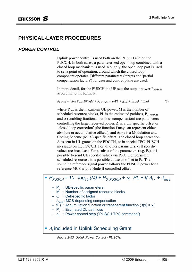
2 Radio Interface
LZT 123 8959 R1A © 2009 Ericsson - 105 -
PHYSICAL-LAYER PROCEDURES
POWER CONTROL
Uplink power control is used both on the PUSCH and on the PUCCH. In both cases, a parameterized open loop combined with a closed loop mechanism is used. Roughly, the open loop part is used to set a point of operation, around which the closed loop component operates. Different parameters (targets and 'partial compensation factors') for user and control plane are used.
In more detail, for the PUSCH the UE sets the output power PPUSCH according to the formula:
PPUSCH = min {Pmax, 10logM + P0_PUSCH + α·PL + f(Δi )+ ΔMCS} [dBm] (2)
where Pmax is the maximum UE power, M is the number of scheduled resource blocks, PL is the estimated pathloss, P0_PUSCH and α (enabling fractional pathloss compensation) are parameters controlling the target received power, Δi is a UE specific offset or ‘closed loop correction’ (the function f may can represent either absolute or accumulative offsets), and ΔMCS is a Modulation and Coding Scheme (MCS) specific offset. The closed loop correction Δi is sent in UL grants on the PDCCH, or in special TPC_PUSCH messages on the PDCCH. For all other parameters, cell specific values are broadcast. For a subset of the parameters (e.g. P0), it is possible to send UE specific values via RRC. For persistent scheduled resources, it is possible to use an offset to P0. The sounding reference signal power follows the PUSCH power for a reference MCS with a Node B controlled offset.
PPUSCH = 10 ⋅ log10 (M) + P0_PUSCH + α ⋅ PL + f( Δi ) + Δmcs
– P0 : UE-specific parameters – M : Number of assigned resource blocks– α : Cell-specific factor– Δmcs : MCS-depending compensation– f(.) : Accumulation function or transparent function ( f(x) = x ) – PL : Estimated DL path loss– Δi : Power-control step (”PUSCH TPC command”)
Δi included in Uplink Scheduling Grant
Figure 2-53. Uplink Power Control - PUSCH.

LTE 10A Air Interface
- 106 - © Ericsson 2009 LZT 123 8959 R1A
For PUCCH, the UE sets the power according to the formula
PPUCCH = min {Pmax, P0_PUCCH + PL + f(Δj ) } [dBm] (3)
Note that for PUCCH, full pathloss compensation is always used, and the resource allocation is always one resource block. Further, the function f for the PUCCH always represents accumulation. The closed loop correction Δj is sent in DL assignments on the PDCCH, or in special TPC_PUCCH messages on the PDCCH. The latter may be configured to be the same as the TPC_PUSCH.
PPUCCH = P0_PUCCH + PL + f( Δi )– P0 : UE-specific parameters – PL : Estimated DL path loss– Δi : Power-control step (”PUCCH TPC command”)– f(.) : Accumulation function
Δi included in Downlink Scheduling Control (when present)
Δi for multiple UEs jointly coded and transmitted on PDCCH
– Used when no Downlink Scheduling Control
Figure 2-54. Uplink Power Control - PUCCH.
So called ‘inter-cell power control’ is assisted by the X2-based overload indicator. This may be used by the eNB as an input to power control and scheduling.
LINK ADAPTATION
Uplink link adaptation, i.e., selection of modulation and channel coding, is controlled by the network. The eNB measures the uplink channel quality and orders the UE to use a specific modulation and coding scheme (MCS) based on this. Other parameters may also be taken into account, such as UE power headroom, scheduled bandwidth, buffer content and acceptable delay.

2 Radio Interface
LZT 123 8959 R1A © 2009 Ericsson - 107 -
Rapid interference variations make it difficult to predict the link quality accurately, and select MCS based on such knowledge. Instead, preliminary, MCS selection is based on averaged link quality. Different operating points can then be used. To reach low delay (few retransmissions), a margin to the interference variations can be included. This however leads to limited throughput, as often an unnecessary robust MCS is used. To reach high throughput, a low margin (even negative) is used. This will instead lead to a larger number of retransmissions, and hence a larger delay. The risk of throughput loss or large delays in case of negative margins is reduced by the use of incremental redundancy for retransmissions.
RANDOM ACCESS- PHYSICAL-LAYER ASPECTS
When UEs are not uplink synchronized and need access to the network, they carry out a random access procedure which takes into account the timing misalignment that may exist in the uplink.
General
During initial access, the UE seeks access to the core network in order to register and commence services. The random access (RA) serves as an uplink control procedure to enable the UE to access the network.
Although the UE can time synchronize to the downlink broadcast control channels (BCCH), due to the propagation (round-trip) delay, there will be a timing uncertainty in the uplink. Therefore, the RA shall reserve a sufficient time window to accommodate various arrival times.
Since the initial access attempt cannot be scheduled by the network, the RA procedure is by definition contention based. Collisions may occur and an appropriate contention-resolution scheme needs to be implemented. Including user data on the contention-based uplink is not spectrally efficient due to the need for guard periods and retransmissions. Therefore, it has been decided to separate the transmission of the random access preamble, whose purpose is to obtain uplink synchronization, from the transmission of user data.
In addition to the usage during initial access, the RA will also be used when the UE has lost the uplink synchronization, is in an idle or a low-power mode or handover.

LTE 10A Air Interface
- 108 - © Ericsson 2009 LZT 123 8959 R1A
Random access preamble transmission may occur at preconfigured resources only
– 0.8 ms long preamble 0.2 ms guard (30 km) in 1 ms reservation– bandwidth corresponds to 6 resource blocks
10 ms frame
1 ms 1.08 MHz 1 ms 1.08 MHz
Uplink resource reserved for random access preamble
transmission
Uplink resources used for data transmission
Figure 2-55. Random access.
Preamble and message transmission
The RA procedure is illustrated in Figure 2-56. In the first step, the uplink transmission is non-synchronized and only a preamble is sent. The resources used for the non-synchronized RA and the format of the preamble are further clarified in the following two sections. In the first steps (1, 2, 3, 4, 5), the UE obtains uplink synchronization and is assigned resources for uplink transmission. During the next steps (6, 7, 8), uplink transmission is synchronized. The UE transmits information on the scheduled resource, e.g., information necessary for further scheduling or setting up a connection (RRC connection request message).
Random ID (preamble)
Timing adj.Uplink grant
L2 sched. info.or
RRC conn. req.or
data(scheduled tx)
L1/L2
L3
2
3
5 6
7
81
Not synchronized Synchronized
4
further scheduled tx
Figure 2-56 Non-synchronized Random Access.
2 Radio Interface
LZT 123 8959 R1A © 2009 Ericsson - 109 -
RA physical resource
A single RA opportunity consists of a time slot and a fixed bandwidth. The RA time slot length TRA shall accommodate the preamble sent by the UE and the required guard period (GP) to take into account the unknown uplink timing. The timing misalignment amounts to 6.7 μs/km. 3GPP has decided for a minimum TRA of 1 ms. Here the preamble length is then 902.5 μs including a cyclic prefix of around 102.5 μs. A guard time of 97.5 μs suffices for cell radius up to 15 km. Larger guard periods and cyclic prefix are needed to accommodate timing uncertainties from cells larger than 15 km. Such large cells may also require longer preambles to increase the received energy. In order to support RA under various cell conditions RAN1 has defined additionally 3 RA preamble formats which require a TRA of 2 ms or even 3 ms. These larger slots are created by the eNB by not scheduling traffic in the consecutive subframe(s). Those extended preambles contain repetitions and/or a longer cyclic prefix.
For TDD an additional “short” RA is defined. The short RA preamble only spans 133 μs. Because of this very short duration the preamble will most likely not contain a cyclic prefix but a technique called overlap-and-add will be used to enable frequency-domain processing. At the time of writing many details regarding applicability and performance of this short RA are still open.
According to 3GPP, the bandwidth of a RA opportunity is 1.08 MHz (6RB). The effective bandwidth utilized by the RA preamble is 1.05 MHz leaving small spectral guard bands on each side. This is necessary since RA and regular uplink data are separated in frequency-domain but are not completely orthogonal.
For FDD systems, RA opportunities do not occur simultaneously in different frequency bands but are separated in time. This spreads out processing load in the RA receiver. 3GPP defines RA configurations determining how often RA opportunities occur. In total 16 such configurations are defined, ranging from one RA opportunity every 20 ms (very low RA load) to one every 1 ms (very high RA load).
In TDD not all subframes are DL subframes reducing subframes that can be allocated to RA. To provide also in TDD configurations for high RA loads multiple RA opportunities can be scheduled in a single subframe.

LTE 10A Air Interface
- 110 - © Ericsson 2009 LZT 123 8959 R1A
The rather small bandwidth of 1.05 MHz of the RA preamble has been considered to provide good enough timing estimates. Furthermore fit all RA preambles into all defined spectrum allocations enabling the same preamble formats for all spectrum allocations.11
In order to compensate for the rather low frequency diversity obtained within 1.05 MHz the RA opportunity hops in frequency-domain. No final decision has been made on the frequency hopping period, currently 10 ms and 40 ms are considered. A period of 40 ms has the drawback that knowledge of frame-timing is not sufficient to find a RA opportunity but other means are required to obtain the correct 40 ms timing. For FDD RA opportunities are restricted to the outermost 6 RBs of the physical uplink shared channel at each band edge.
The TDMA/FDMA structure of the RA opportunities in FDD is visualized in Figure 2-57. Here only one 1.08 MHz band is allocated to RA at each time whereas several bands are possible in case of TDD. The RA opportunities always occur at the band edges of the physical uplink shared channel directly adjacent to the physical uplink control channel.
The transmit power of the RA preamble during initial access is set according to an open loop power control. The power is calculated with the same formula as the transmit power for PUCCH, with the only differences that the closed-loop correction Δj is always zero and P0_PUCCH is replaced by P0_RACH.
1 ms
6 R
B1
RB
10 ms
RA
PUSCH
PUCCH
time
frequency
1 ms
6 R
B1
RB
10 ms
RA
PUSCH
PUCCH
time
frequency
Figure 2-57. Time-frequency structure of non-synchronized RA for FDD.
11 For the 1.4 MHz spectrum allocation (6 RB) RA and the physical uplink control channel (PUCCH) overlap. It is up to the base
station implementation how to handle this overlap.

2 Radio Interface
LZT 123 8959 R1A © 2009 Ericsson - 111 -
Preamble format
In the RA slot, the UE transmits a preamble which should provide sufficient guard time TGP to cover the initial timing misalignment of the uplink transmission. The preamble implicitly includes a random ID which identifies the UE. LTE provides for each cell 64 such random IDs and thus 64 preambles.
The upper picture in Figure 2-58 shows the detailed timing of the basic random-access preamble. The preamble starts with a cyclic prefix (CP) to enable simple frequency-domain processing. Its length is in the order of TGP + TDS = 97.5 + 5 μs = 102.5 μs, where TDS corresponds to the maximum delay spread and TGP corresponds to the maximum round trip time. The CP ensures that the received signal is always circular (after removing the CP in the RA receiver) and thus can be processed by FFTs. Following the CP comes the RA sequence with duration 1000 μs - 2·TGP - TDS = 800 μs. The RA subcarrier spacing is 1/800 μs = 1250 Hz.
Figure 2-58 also shows the extended preamble formats. Format 1 has an extended CP and is suited for cell radius up to approximately 100 km. However, since no repetition occurs this format is only suited for environments with good propagation conditions. Format 2 contains a repeated sequence and a cyclic prefix of approximately 200 μs. With a RA opportunity length of 2 ms the remaining guard period is also approximately 200 μs. This format supports cell radii of up to approximately 30 km. Format 3 also contains a repeated sequence and an extended CP. Using a RA opportunity length of 3 ms this format supports cell radius of up to approximately 100 km. In opposite to format 1 format 3 contains a repeated sequence and is therefore better suited for environments with bad propagation conditions.

LTE 10A Air Interface
- 112 - © Ericsson 2009 LZT 123 8959 R1A
800 μs≈100 μs
≈680 μs
1600 μs≈200 μs
≈680 μs
Format 1 (long CP)
Format 2 (long [repeated] preamble)
Format 3 (long CP and preamble)
Format 0
Repeated preamble
Repeated preamble
800 μs
1600 μs
Format 0: Max{Tprop} = 50 μs Max cell radius: ≈15 kmFormat 1: Max{Tprop} ≈ 260 μs Max cell radius: ≈80 kmFormat 2: Max{Tprop} = 100 μs Max cell radius: ≈30 kmFormat 3: Max{Tprop} ≈ 360 μs Max cell radius: ≈110 km
Figure 2-58. Random access preamble formats.
The requirements on the RA sequence comprising the preamble are two-fold: good auto-correlation function (ACF) properties and good cross-correlation function (CCF) properties. A sequence that has ideal (periodic) ACF and good CCF properties is the Zadoff-Chu sequence: the periodic ACF of Zadoff-Chu sequence is only non-zero at time-lag zero (and periodic extensions) and the magnitude of the CCF is equal to the square-root of the sequence length N. Due to special properties of Zadoff-Chu sequences the number of sequences is maximized if N is chosen prime. This together with the requirement that the effective RA bandwidth N·1250 Hz should fit into 1.05 MHz leads to N = 839.

2 Radio Interface
LZT 123 8959 R1A © 2009 Ericsson - 113 -
Out of one Zadoff-Chu sequence – in the following also denoted root sequence – multiple preamble sequences can be derived by cyclic shifting: Due to the ideal ACF of Zadoff-Chu sequence multiple mutually orthogonal sequences can be derived from a single root sequence by cyclic shifting one root sequence multiple times the maximum allowed round trip time plus delay spread in time-domain. The correlation of such a cyclic shifted sequence and the underlying root sequence has its peak no longer at zero but at the cyclic shift. If the received signal has now a valid round trip delay – i.e. not larger than the maximum assumed round trip time – the correlation peak occurs at the cyclic shift plus the round trip delay which is still in the correct correlation zone. For small cells up to 1.5 km radius all 64 preambles can be derived from a single root sequence and are therefore orthogonal to each other. In larger cells not all sequences can be derived from a single root sequence and multiple root sequences must be allocated to a cell. Sequences derived from different root sequences are not orthogonal to each other.
One disadvantage of Zadoff-Chu sequences is their behavior at high frequency offsets: A frequency-offset creates an additional correlation peak in time-domain. A frequency offset has to be considered high if it becomes substantial relative to the RA subcarrier spacing of 1250 Hz, e.g. from 400 Hz upwards. The offset of the second correlation peak relative to the main peak depends on the root sequence. An offset smaller than TCS may lead to wrong timing estimates whereas values larger than TCS increase the false alarm rate. In order to cope with this problem LTE has a high-speed mode (or better high frequency offset mode) which disables certain cyclic shift values and root sequences so that transmitted preamble and round trip time can uniquely be identified. Additionally a special receiver combining both correlation peaks is required. For cells larger than approximately 35 km no set of 64 preambles exists that allows unique identification of transmitted preamble and estimation of propagation delay, i.e. cells larger than 35 km cannot be supported in high speed mode.

LTE 10A Air Interface
- 114 - © Ericsson 2009 LZT 123 8959 R1A
Step 1 - random access preamble (RACH)
Step 2 - random access response (DL-SCH)
Step 3 – terminal identification (UL-SCH)
Step 4 – contention resolution (DL-SCH)
eNodeB
user data
UE
Synchronize to downlink timing
(from cell search)
Adjust uplink timing
S-GW
Only if UE is not known in Node B(initial random access)
Figure 2-59. RA signaling flow.
UPLINK TRANSMIT-TIMING CONTROL
Different UEs within a cell will experience different propagation delay to/from the cell site, depending on their exact position within the cell coverage area. If UEs set their transmit timing based only on the timing of the received downlink timing, their corresponding uplink transmissions will thus arrive at the cell site with potentially very different timing. If these receive-timing differences are too large, the orthogonality between the uplink transmissions of different UEs will not be retained. Thus, an active uplink transmit-timing control is needed to ensure that uplink transmissions from different UEs are received with approximately the same timing at the cell site.
The transmit-timing control operates such that the network measures the received uplink timing of the different UEs. If the received timing of a specific UE is “lagging” behind, the UE is commanded to advance its transmit timing a certain amount. Similarly, a UE can be ordered to retard it transmit timing. The steps by which the UEs can advance/retard their timings are multiple of 16⋅Ts ≈ 0.52 μs. The timing-control commands are transmitted as higher-layer signaling (MAC) to the UEs.
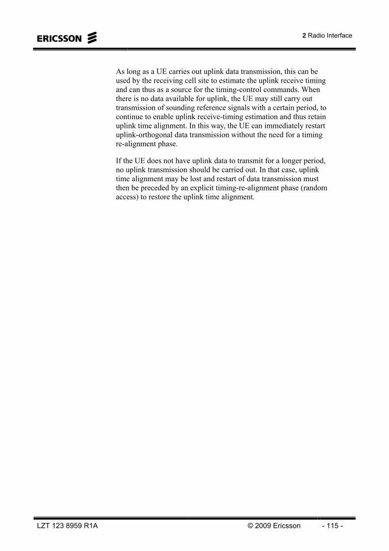
2 Radio Interface
LZT 123 8959 R1A © 2009 Ericsson - 115 -
As long as a UE carries out uplink data transmission, this can be used by the receiving cell site to estimate the uplink receive timing and can thus as a source for the timing-control commands. When there is no data available for uplink, the UE may still carry out transmission of sounding reference signals with a certain period, to continue to enable uplink receive-timing estimation and thus retain uplink time alignment. In this way, the UE can immediately restart uplink-orthogonal data transmission without the need for a timing re-alignment phase.
If the UE does not have uplink data to transmit for a longer period, no uplink transmission should be carried out. In that case, uplink time alignment may be lost and restart of data transmission must then be preceded by an explicit timing-re-alignment phase (random access) to restore the uplink time alignment.

LTE 10A Air Interface
- 116 - © Ericsson 2009 LZT 123 8959 R1A
MULTIPLE INPUT MULTIPLE OUTPUT (MIMO) The LTE specifications support the use of multiple antennas at both transmitter (tx) and receiver (rx). MIMO (Multiple Input Multiple Output) uses this antenna configuration.
With multiple antennas at the transmitter and only single antenna at the receiver (referred to as MISO) it is possible to obtain so called Beamforming. With this method the transmission signal is steered in a beneficial direction (typically towards the UE). This is accomplished by adjusting the phase (and sometimes amplitude) of the different antenna elements by multiplying the signal with complex weights. This method increases the SNR (Signal to Noise Ratio) and thus the capacity.
With this configuration it is also possible to achieve Transmit Diversity. This is done by transmitting time-shifted copies of the signal and thus achieving diversity in the time-domain. This method also increases the SNR.
With multiple antennas at the receiver (SIMO or MIMO), it is possible to use receive diversity. A combining method (typically MRC – Maximum Ratio Combining) is applied to increase the SNR of the received signal.
With multiple antennas at both transmitter and receiver, it is possible to use all of the above mentioned methods.
However, with multiple antennas at both transmitter and receiver, it is also possible to achieve spatial multiplexing, also referred to as MIMO. This method creates several layers, or “data pipes” in the radio interface. The maximum number of layers that can be created depends on the radio channel characteristics and the number of tx and rx antennas. The maximum number of layers that the radio channel can support is equal to the channel rank. The maximum number of layers that effectively can be used is equal or less than the minimum number of antenna elements at the tx or rx side or the channel rank. The number of layers that actually is used for transmission is referred to as the transmission rank.
The data rate can at optimal circumstances be multiplied by the number of layers.
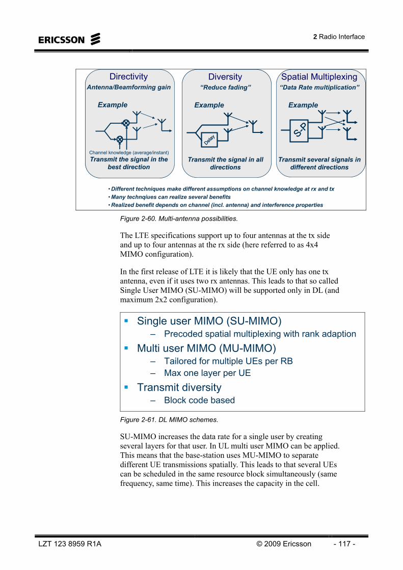
2 Radio Interface
LZT 123 8959 R1A © 2009 Ericsson - 117 -
Diversity“Reduce fading”
Example
Transmit the signal in all Transmit the signal in all directionsdirections
Diversity“Reduce fading”
Example
Transmit the signal in all Transmit the signal in all directionsdirections
Spatial Multiplexing“Data Rate multiplication”
Example
Transmit several signals in Transmit several signals in different directionsdifferent directions
Spatial Multiplexing“Data Rate multiplication”
Example
Transmit several signals in Transmit several signals in different directionsdifferent directions
S-PS-PDela
yDela
y
DirectivityAntenna/Beamforming gain
Example
Transmit the signal in the Transmit the signal in the best directionbest direction
DirectivityAntenna/Beamforming gain
Example
Transmit the signal in the Transmit the signal in the best directionbest direction
Channel knowledge (average/instant)
• Different techniques make different assumptions on channel knowledge at rx and tx• Many technqiues can realize several benefits• Realized benefit depends on channel (incl. antenna) and interference properties
Figure 2-60. Multi-antenna possibilities.
The LTE specifications support up to four antennas at the tx side and up to four antennas at the rx side (here referred to as 4x4 MIMO configuration).
In the first release of LTE it is likely that the UE only has one tx antenna, even if it uses two rx antennas. This leads to that so called Single User MIMO (SU-MIMO) will be supported only in DL (and maximum 2x2 configuration).
Single user MIMO (SU-MIMO)– Precoded spatial multiplexing with rank adaption
Multi user MIMO (MU-MIMO)– Tailored for multiple UEs per RB– Max one layer per UE
Transmit diversity– Block code based
Figure 2-61. DL MIMO schemes.
SU-MIMO increases the data rate for a single user by creating several layers for that user. In UL multi user MIMO can be applied. This means that the base-station uses MU-MIMO to separate different UE transmissions spatially. This leads to that several UEs can be scheduled in the same resource block simultaneously (same frequency, same time). This increases the capacity in the cell.

LTE 10A Air Interface
- 118 - © Ericsson 2009 LZT 123 8959 R1A
High SINRs needed– Service area close to cell center
Less likely that cell edge UEs use multiple layers- go for beamforming or diversity instead
Service area grows if surrounding cells have low load– Multiple layers on or near the cell edge not uncommon
MU-MIMO SU-MIMO
Figure 2-62. Spatial multiplexing operation.
Multiple layers means that the time- and frequency resources (Resource Blocks) can be reused in the different layers up to a number of times corresponding to the channel rank. This means that the same resource allocation is made on all transmitted layers.
OFDM works particularly well with MIMO – MIMO becomes difficult when there is time dispersion– OFDM sub-carriers are flat fading (no time dispersion)
3GPP supports one, two, or four transmit Antenna PortsMultiple antenna ports Multiple time-frequency grids Each antenna port defined by an associated Reference Signal
Antenna port #1Antenna port #2Antenna port #3Antenna port #4
Single-antenna transmisson
Multi-antenna transmisson
Figure 2-63. Multi-antenna transmission.

2 Radio Interface
LZT 123 8959 R1A © 2009 Ericsson - 119 -
In MU-MIMO, the different UEs that are spatially multiplexed are allocated the same resource blocks, but spatially separated by the antenna arrangement and associated processing. This means that each UE does not experience a data rate multiplication as with SU-MIMO. Instead the cell benefits from the reuse of the resources.
High load at least in cell of interest in order to find UEs for co-scheduling
– Grouping UEs need careful scheduler design and soundingHigh SINRs needed
– MU-MIMO service area close to cell centerLess likely that cell edge UEs use MU-MIMO
Similar to single user MIMO (SU-MIMO) except the transmissions now come from different UEs
– Uplink SU-MIMO not yet supported in LTE
Figure 2-64. MU-MIMO operation.
The data rate only increases logarithmically as a function of the SNR (or SINR – Signal to Interference and Noise Ratio), at a high SNR. This is according to the Shannon theorem
rdata = BW x log2(SNR+1)
(max data rate rdata is equal to the bandwith, BW, multiplied by the base-2 logarithm of the SNR plus 1).
On the other hand, at a low SNR, the max data rate increases almost linearly. Therefore, it is not efficient aiming only to obtain a high SNR. It is more efficient to try to create several “data pipes” with lower SNR (sharing SNR), which will lead to a multiplication of the maximum achievable data rate with up to the channel rank rmax.

LTE 10A Air Interface
- 120 - © Ericsson 2009 LZT 123 8959 R1A
High SINR satures single layer throughputSINR ”shared” among layersIdeally, multiple layers better (C2layers > C1layer)In practice, MIMO may be worse due to
– Inter stream cross-talk=> lowers MIMO SINR:s
– SINR imbalance
SINR: ρPower: PPower: P
N+I
SINR: ρ/2Power: P/2
N+I
SINR: ρ/2Power: P/2
N+I
Single layer Two layers
Capacity (bps)
ρ/2 ρ/2
C1layer
C2layers
SINR
High SINR => greater chance multiple layers is better! Figure 2-65. Single layer vs. Multiple layers.
LTE uses precoder based MIMO operation. A precoder, which is a complex matrix of size equal to the number of layers times the number of transmit antennas, is used to form the “beams” for the different layers separately.
Spatial Multiplexing w. Pre-coding based Beam-forming– Multiple parallel data streams Higher data rates– One or two code words– Number of layers ≤ Number of antenna ports– Pre-coding weights based on UE feedback (beam-forming)
Transmit Diversity (”open-loop”)– Transmission of same information from multiple antenna ports
Diversity– One code word
Layermapping Precoding
Up to four layers
RE mappingUp to four
”Antenna Ports”
RE mapping
One or two code words
Multi-antenna processing
Figure 2-66. LTE Multi-antenna transmission.

2 Radio Interface
LZT 123 8959 R1A © 2009 Ericsson - 121 -
When spatial multiplexing is used, maximum two codewords (transport blocks) per TTI will be used. When no spatial multiplexing is used, only one codeword per TTI will be used.
Maximum of two code wordsMapping to up to four layers
– Number of layers depends on channel ”rank”– Dynamically adjusted based on UE reports
One layer(No MIMO)
Two layers Three layers Four layers
One code word Two code words Two code words Two code words
Transport format (modulation scheme and code rate)may differ between the code wordsSame number of symbols on each layer
Layermapping
Up to four layers
Figure 2-67. DL spatial multiplexing - layer mapping.
Given the minimum number of transmit or receive antennas, the transmission rank can at maximum be equal to that minimum number. For example, if four transmit antennas and two receive antennas are used, then the transmission rank can one or two. If the transmission rank is lower than the channel rank (i.e. there are more antennas than layers), then the remaining antenna ports can be used for beamforming at the same time as the spatial multiplexing.

LTE 10A Air Interface
- 122 - © Ericsson 2009 LZT 123 8959 R1A
Better data rate coverage and capacity– Directivity and diversity improves link budget
Potential for higher data rates– Spatial domain provides extra dimension
Extra dimension offers increased data ratesIdeally: rmax times higher data rate than single Tx(rmax = min{#tx antennas, #rx antennas})
Transmit r ≤ rmax parallel symbol streams (layers)Max rmax parallel ”data pipes”Number of layers r depends on channel properties
– Channel rank r: #effective data pipes channel can support(data pipes with sufficiently strong SINR)
Rank adaption dynamically adjusts #layers
Higher spectral efficiency!
Up to rmax times higher throughput! Figure 2-68. Possible multi-antenna benefits.
The number of useful layers is here denoted r, and the maximum number of layers rmax.
One symbol from each of NL layers linearly mapped to NA antenna ports
UE reports recommended precoder matrix W (including channel rank)– Set of available precoder matrices = The precoder ”code book”
Used precoder matrix signaled by network– Network does not need to follow UE recommendation
One layer ”Closed-loop” TX diversity = ”Beam forming”
x
PrecodingW
yxWy ⋅=
4 antenna portsLayer 1
Layer 2
Layer 3
Example: NL = 3, NA = 4
Figure 2-69. DL spatial multiplexing.
In the DL, the UE estimates the spatial properties of the radio channel by measuring the DL reference symbols from the different antenna ports. This estimation is used to give feedback to the eNodeB so that the eNodeB can allocate an appropriate amount of resources make an optimal antenna mapping.
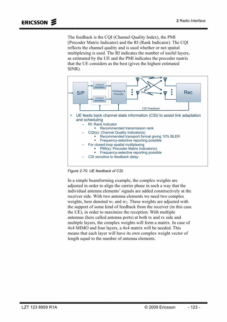
2 Radio Interface
LZT 123 8959 R1A © 2009 Ericsson - 123 -
The feedback is the CQI (Channel Quality Index), the PMI (Precoder Matrix Indicator) and the RI (Rank Indicator). The CQI reflects the channel quality and is used whether or not spatial multiplexing is used. The RI indicates the number of useful layers, as estimated by the UE and the PMI indicates the precoder matrix that the UE considers as the best (gives the highest estimated SINR).
UE feeds back channel state information (CSI) to assist link adaptation and scheduling
– RI: Rank IndicatorRecommended transmission rank
– CQI(s): Channel Quality Indicator(s)Recommended transport format giving 10% BLERFrequency-selective reporting possible
– For closed-loop spatial multiplexingPMI(s): Precoder Matrix Indicator(s)Frequency-selective reporting possible
– CSI sensitive to feedback delay
S/P Rec
Coding & Modulation
Coding & Modulation
CSI Feedback
CW2layer & Precoder
Figure 2-70. UE feedback of CSI.
In a simple beamforming example, the complex weights are adjusted in order to align the carrier phase in such a way that the individual antenna elements’ signals are added constructively at the receiver side. With two antenna elements we need two complex weights, here denoted w1 and w2. These weights are adjusted with the support of some kind of feedback from the receiver (in this case the UE), in order to maximize the reception. With multiple antennas (here called antenna ports) at both tx and rx side and multiple layers, the complex weights will form a matrix. In case of 4x4 MIMO and four layers, a 4x4 matrix will be needed. This means that each layer will have its own complex weight vector of length equal to the number of antenna elements.
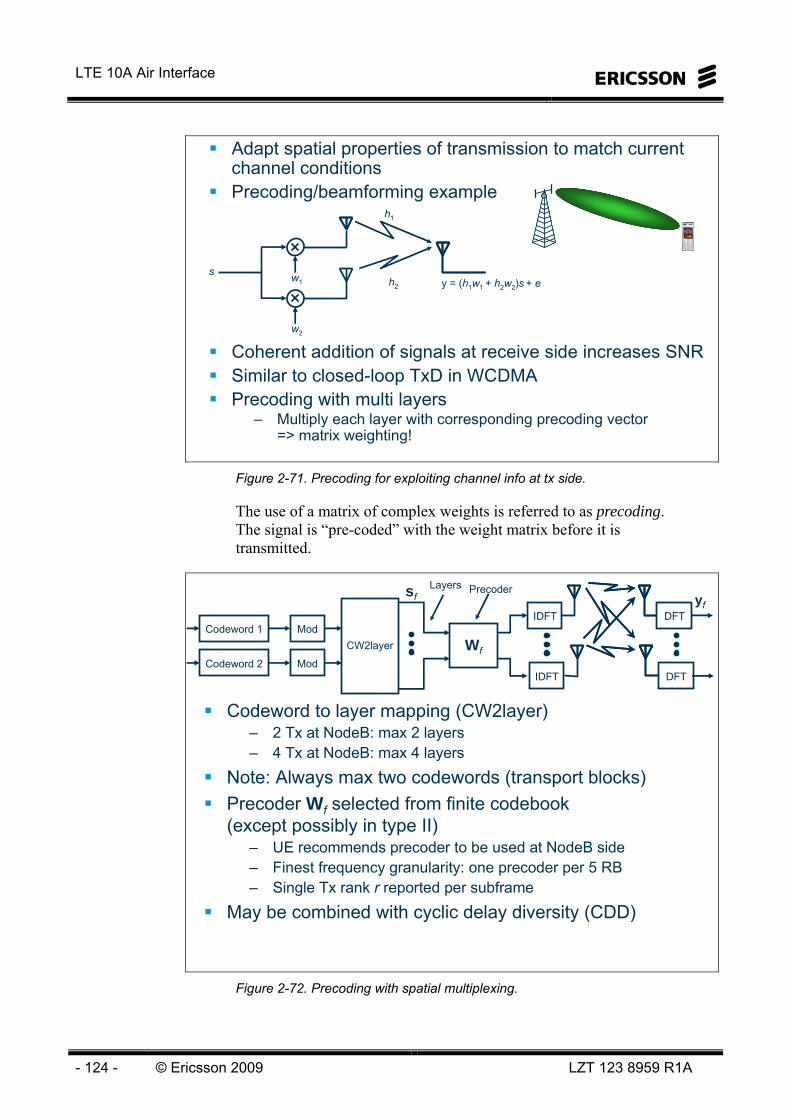
LTE 10A Air Interface
- 124 - © Ericsson 2009 LZT 123 8959 R1A
Adapt spatial properties of transmission to match current channel conditionsPrecoding/beamforming example
Coherent addition of signals at receive side increases SNRSimilar to closed-loop TxD in WCDMAPrecoding with multi layers
– Multiply each layer with corresponding precoding vector=> matrix weighting!
w1
w2
sh2
h1
y = (h1w1 + h2w2)s + e
Figure 2-71. Precoding for exploiting channel info at tx side.
The use of a matrix of complex weights is referred to as precoding. The signal is “pre-coded” with the weight matrix before it is transmitted.
yf
Codeword 1
Codeword 2
Mod
Mod
CW2layer Wf
IDFT
IDFT
sf
DFT
DFT
Precoder
Codeword to layer mapping (CW2layer)– 2 Tx at NodeB: max 2 layers– 4 Tx at NodeB: max 4 layers
Note: Always max two codewords (transport blocks)Precoder Wf selected from finite codebook(except possibly in type II)
– UE recommends precoder to be used at NodeB side– Finest frequency granularity: one precoder per 5 RB– Single Tx rank r reported per subframe
May be combined with cyclic delay diversity (CDD)
Layers
Figure 2-72. Precoding with spatial multiplexing.

2 Radio Interface
LZT 123 8959 R1A © 2009 Ericsson - 125 -
The UE will measure the different reference signals, which are transmitted separately on the different antenna ports in DL, and estimate the optimal precoder weights. The UE will choose a precoder matrix from a finite codebook, that consists of a number of precoder matrixes. Only the index of the chosen precoder matrix (Precoder Matrix Index – PMI) and Rank Indicator (RI) will be signaled to the eNB, together with the CQI.
The eNB does not have to follow the UE “recommendation” of precoder matrix, since the eNB might consider another matrix more appropriate when taking other UEs in the cell into account.
Figure 2-73 shows an example of different precoder matrixes up to channel rank two (max two layers).
⎥⎦
⎤⎢⎣
⎡1001
21
⎥⎦
⎤⎢⎣
⎡10
⎥⎦
⎤⎢⎣
⎡−11
21
⎥⎦
⎤⎢⎣
⎡11
21
⎥⎦
⎤⎢⎣
⎡01
⎥⎦
⎤⎢⎣
⎡−1111
21
⎥⎦
⎤⎢⎣
⎡− j1
21
⎥⎦
⎤⎢⎣
⎡j1
21
⎥⎦
⎤⎢⎣
⎡− jj11
21
6
5
4
3
2
1
NL = 2Codebook
indexNumber of layers
NL = 1
Codebook subset and rank restriction:
eNB can restrict precoder and rank selection to arbitrary subset of possible combinations
Figure 2-73. Precoder codebook for SU-MIMO.
Spatial multiplexing is divided into closed-loop and open-loop spatial multiplexing.
Closed-loop spatial multiplexing is typically used when the UE feedback delay is sufficiently low for giving an up-to-date estimate of the current radio channel conditions. That is typically at low speeds (low mobility scenarios).
Open loop can be used when the feedback is too old (typically at high speeds). Then an averaged channel estimation is used over a longer term basis.
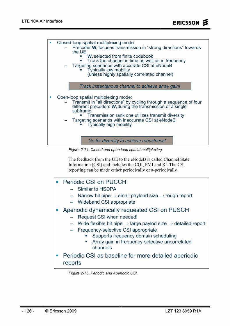
LTE 10A Air Interface
- 126 - © Ericsson 2009 LZT 123 8959 R1A
Closed-loop spatial multiplexing mode:– Precoder Wf focuses transmission in ”strong directions” towards
the UEWf selected from finite codebookTrack the channel in time as well as in frequency
– Targeting scenarios with accurate CSI at eNodeBTypically low mobility(unless highly spatially correlated channel)
Open-loop spatial multiplexing mode:– Transmit in ”all directions” by cycling through a sequence of four
different precoders Wf during the transmission of a singlesubframe
Transmission rank one utilizes transmit diversity– Targeting scenarios with inaccurate CSI at eNodeB
Typically high mobility
Go for diversity to achieve robustness!
Track instantanous channel to achieve array gain!
Figure 2-74. Closed and open loop spatial multiplexing.
The feedback from the UE to the eNodeB is called Channel State Information (CSI) and includes the CQI, PMI and RI. The CSI reporting can be made either periodically or a-periodically.
Periodic CSI on PUCCH– Similar to HSDPA– Narrow bit pipe → small payload size → rough report– Wideband CSI appropriate
Aperiodic dynamically requested CSI on PUSCH– Request CSI when needed!– Wide flexible bit pipe → large paylod size → detailed report– Frequency-selective CSI appropriate
Supports frequency domain schedulingArray gain in frequency-selective uncorrelatedchannels
Periodic CSI as baseline for more detailed aperiodic reports
Figure 2-75. Periodic and Aperiodic CSI.
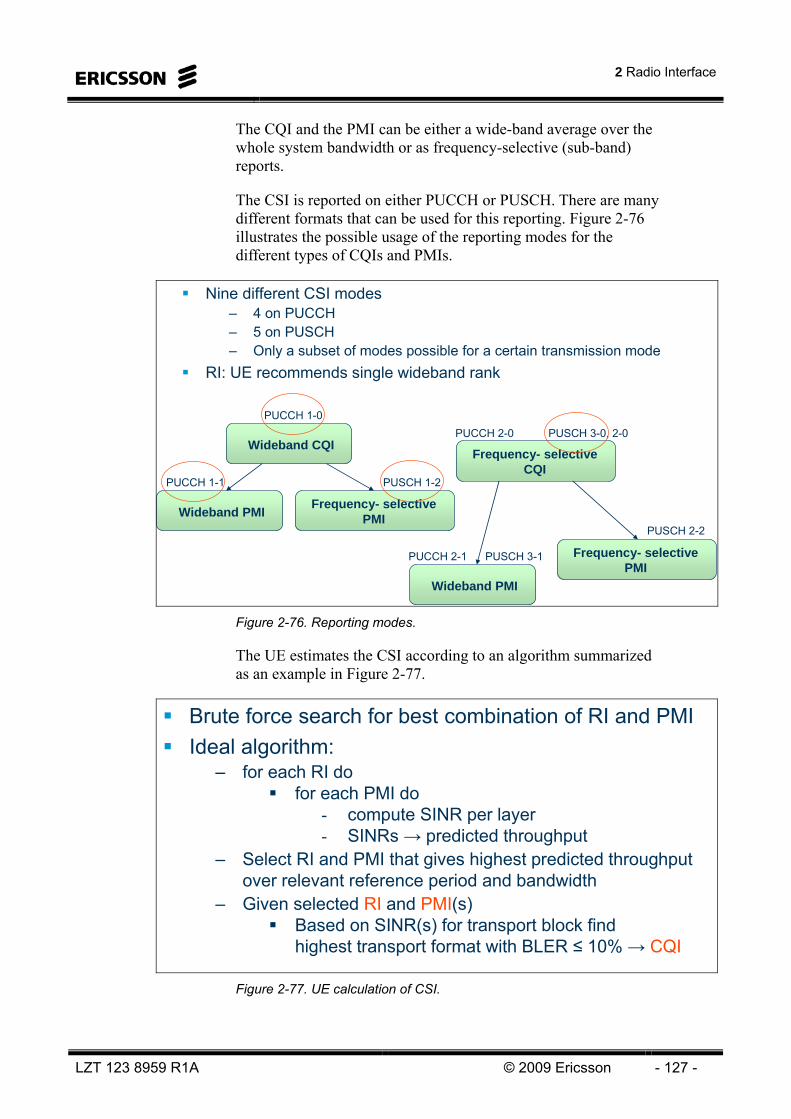
2 Radio Interface
LZT 123 8959 R1A © 2009 Ericsson - 127 -
The CQI and the PMI can be either a wide-band average over the whole system bandwidth or as frequency-selective (sub-band) reports.
The CSI is reported on either PUCCH or PUSCH. There are many different formats that can be used for this reporting. Figure 2-76 illustrates the possible usage of the reporting modes for the different types of CQIs and PMIs.
Nine different CSI modes – 4 on PUCCH– 5 on PUSCH– Only a subset of modes possible for a certain transmission mode
RI: UE recommends single wideband rank
Wideband CQIFrequency- selective
CQI
Wideband PMI Frequency- selectivePMI
Wideband PMI
Frequency- selectivePMI
PUCCH 2-0 PUSCH 3-0, 2-0PUCCH 1-0
PUCCH 1-1 PUSCH 1-2
PUCCH 2-1 PUSCH 3-1
PUSCH 2-2
Figure 2-76. Reporting modes.
The UE estimates the CSI according to an algorithm summarized as an example in Figure 2-77.
Brute force search for best combination of RI and PMIIdeal algorithm:
– for each RI dofor each PMI do
- compute SINR per layer- SINRs → predicted throughput
– Select RI and PMI that gives highest predicted throughput over relevant reference period and bandwidth
– Given selected RI and PMI(s)Based on SINR(s) for transport block findhighest transport format with BLER ≤ 10% → CQI
Figure 2-77. UE calculation of CSI.

LTE 10A Air Interface
- 128 - © Ericsson 2009 LZT 123 8959 R1A
How can we practically implement a four antenna-port configuration? Well, a suitable way of achieving uncorrelated antenna elements is to use polarization diversity with cross-polarization. But we only have two orthogonal polarizations, so we have to have two pairs of cross-polarized antenna pairs in order to get four antenna ports.
Many different possible antenna configurations– Only two different ones considered here
Exploit orthogonal polarizations– Reduces inter-layer interference– Dual-layer transmission possible also in line-of-sight– Line-of-sight not uncommon in urban environments
Two cross-polarized antennas
Two pairs of cross-polarized antennas– Dual stream spatial multiplexing– Array gain by means of beamforming on pairs of co-polarized antennas– Limited radome size
0.5λ
Figure 2-78. Antenna setup at eNodeB.
Different radio channel scenarios require different MIMO modes. Sometimes beamforming is most suitable, typically at bad SINRs close to cell edges, and sometimes spatial multiplexing is beneficial, typically closer to the basestation. Of course there are exceptions to this assumptions. Figure 2-79 summarizes the most likely usage of the different modes.
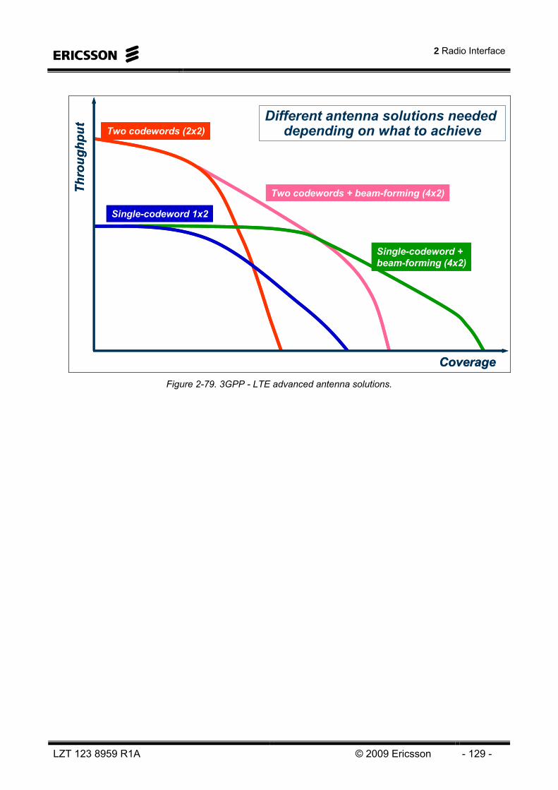
2 Radio Interface
LZT 123 8959 R1A © 2009 Ericsson - 129 -
Two codewords + beam-forming (4x2)Two codewords + beam-forming (4x2)
Two codewords (2x2)Two codewords (2x2)
Single-codeword + beam-forming (4x2)Single-codeword + beam-forming (4x2)
Single-codeword 1x2Single-codeword 1x2
Coverage
Thro
ughp
ut
Coverage
Thro
ughp
ut
Different antenna solutions needed depending on what to achieve
Figure 2-79. 3GPP - LTE advanced antenna solutions.

LTE 10A Air Interface
- 130 - © Ericsson 2009 LZT 123 8959 R1A
Intentionally Blank

3 Scheduling
LZT 123 8959 R1A © 2009 Ericsson - 131 -
3 Scheduling
OBJECTIVES:
On completion of this chapter the students will be able to:Describe the Dynamic Resource Allocation (Scheduling)
–Describe UL and DL Scheduling principles and signaling–Explain the scheduler interactions with other functions–Explain the concepts of dynamic and semi-persistent scheduling
Figure 3-1. Objectives.

LTE 10A Air Interface
- 132 - © Ericsson 2009 LZT 123 8959 R1A
Intentionally Blank
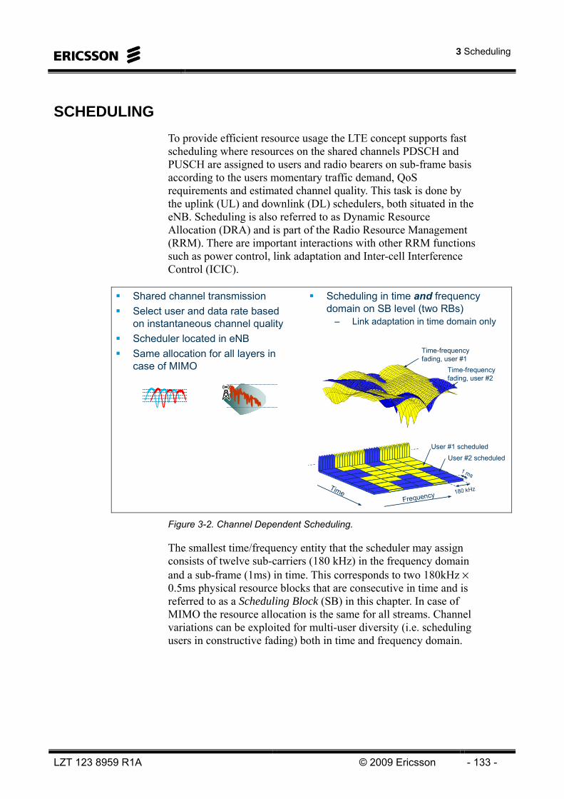
3 Scheduling
LZT 123 8959 R1A © 2009 Ericsson - 133 -
SCHEDULING To provide efficient resource usage the LTE concept supports fast scheduling where resources on the shared channels PDSCH and PUSCH are assigned to users and radio bearers on sub-frame basis according to the users momentary traffic demand, QoS requirements and estimated channel quality. This task is done by the uplink (UL) and downlink (DL) schedulers, both situated in the eNB. Scheduling is also referred to as Dynamic Resource Allocation (DRA) and is part of the Radio Resource Management (RRM). There are important interactions with other RRM functions such as power control, link adaptation and Inter-cell Interference Control (ICIC).
180 kHz
1 ms
Shared channel transmissionSelect user and data rate based on instantaneous channel qualityScheduler located in eNBSame allocation for all layers in case of MIMO
data1data2data3data4
TimeFrequency
User #1 scheduledUser #2 scheduled
Time-frequency fading, user #1
Time-frequency fading, user #2
Scheduling in time and frequency domain on SB level (two RBs)
– Link adaptation in time domain only
Figure 3-2. Channel Dependent Scheduling.
The smallest time/frequency entity that the scheduler may assign consists of twelve sub-carriers (180 kHz) in the frequency domain and a sub-frame (1ms) in time. This corresponds to two 180kHz × 0.5ms physical resource blocks that are consecutive in time and is referred to as a Scheduling Block (SB) in this chapter. In case of MIMO the resource allocation is the same for all streams. Channel variations can be exploited for multi-user diversity (i.e. scheduling users in constructive fading) both in time and frequency domain.

LTE 10A Air Interface
- 134 - © Ericsson 2009 LZT 123 8959 R1A
In the downlink, the scheduler may assign a set of resource blocks to a user according to the agreed PDCCH scheme while in the uplink resource blocks assigned to a specific user must be contiguous in the frequency to preserve the SC-FDMA structure. Also only a limited set of DFT sizes will be allowed, i.e. multiples of powers of 2, 3 and 5. This further limits the number of RB that can be assigned to a user.
In addition to providing an efficient utilization of the radio resource the scheduler is responsible for ensuring the QoS requirements for the individual logical channels to as large extent as possible. When this is not possible due to resource limitations the scheduler performs prioritization between users and logical channels according to the QoS requirements.
In the downlink, where the eNB has immediate access to the transmit buffers of the radio bearers, the scheduler performs the prioritization both between users and different radio bearers of a user.
In the UL on the other hand the scheduler only prioritizes between different users based on buffer status reports. The prioritization between different logical channels within one UE will be done in the UE with assistance from the network.
Although fast dynamic scheduling is the base line for LTE scheduling several methods for limiting the control signaling demands for services such as speech (VoIP) where small packets are generated regularly have been discussed in 3GPP. A concept where resources are assigned semi-statically called “semi-persistent” scheduling has been agreed.
Scheduling is part of the basic LTE functions. The Scheduler distributes radio interface and RBS resources between various user and control data flows requesting transmission in the cell. For every upcoming 1 ms transmission time interval, the Scheduler determines the users that are assigned resources.
Link Adaptation, which includes transport format selection, is closely related to scheduling and the two functions interact by exchanging information prior to each scheduling decision.
The operator controls part of the scheduling behavior via the QoS framework.
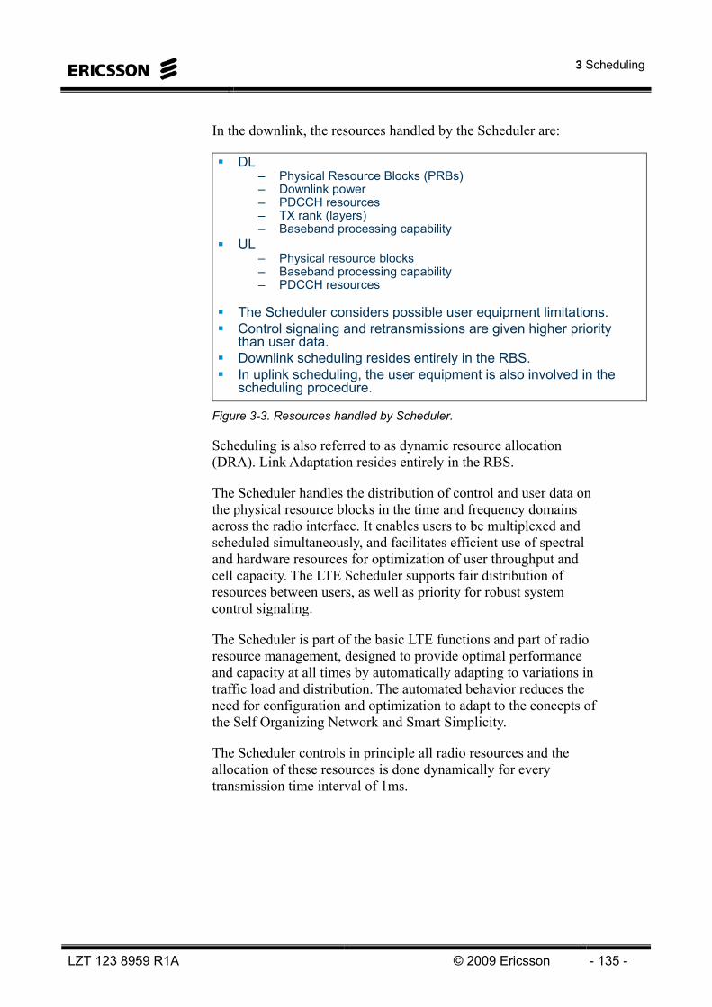
3 Scheduling
LZT 123 8959 R1A © 2009 Ericsson - 135 -
In the downlink, the resources handled by the Scheduler are:
DL– Physical Resource Blocks (PRBs)– Downlink power– PDCCH resources– TX rank (layers)– Baseband processing capability
UL– Physical resource blocks– Baseband processing capability– PDCCH resources
The Scheduler considers possible user equipment limitations. Control signaling and retransmissions are given higher priority than user data. Downlink scheduling resides entirely in the RBS.In uplink scheduling, the user equipment is also involved in thescheduling procedure.
Figure 3-3. Resources handled by Scheduler.
Scheduling is also referred to as dynamic resource allocation (DRA). Link Adaptation resides entirely in the RBS.
The Scheduler handles the distribution of control and user data on the physical resource blocks in the time and frequency domains across the radio interface. It enables users to be multiplexed and scheduled simultaneously, and facilitates efficient use of spectral and hardware resources for optimization of user throughput and cell capacity. The LTE Scheduler supports fair distribution of resources between users, as well as priority for robust system control signaling.
The Scheduler is part of the basic LTE functions and part of radio resource management, designed to provide optimal performance and capacity at all times by automatically adapting to variations in traffic load and distribution. The automated behavior reduces the need for configuration and optimization to adapt to the concepts of the Self Organizing Network and Smart Simplicity.
The Scheduler controls in principle all radio resources and the allocation of these resources is done dynamically for every transmission time interval of 1ms.

LTE 10A Air Interface
- 136 - © Ericsson 2009 LZT 123 8959 R1A
Scheduling details
For every cell in every transmission time interval (1ms), the Scheduler determines the user equipment that is assigned resources. Each radio bearer is given a certain priority, based on algorithms which take the QCI (QoS Class Indicator) related parameters as input.
A higher scheduling priority gives the radio bearer a higher probability to obtain resources and enables the user equipment to perform transmission or reception. The allocation of resources is made per user equipment. The user equipment priority is defined as the highest scheduling priority of the radio bearers belonging to the user equipment, including retransmissions. The user equipment with the highest priority is selected first for transmission.
In the uplink, some radio bearers with lower priorities may get a "free ride" if a radio bearer with a high priority belongs to the same user equipment. In the uplink, when the user equipment has many radio bearers, they are grouped into Logical Channel Groups (LCGs, also sometimes referred to as radio bearer groups). The buffer status report is then expanded so it reports the buffer status per radio bearer group. Each radio bearer group is given a certain priority.
The Scheduler controls all radio interface resources, except the following physical signal and channel transmissions, as shown in Figure 3-4:
• Reference Signal (RS)
• Sounding Reference Signal (SRS)
• Synchronization Channel (SCH)
• Physical Broadcast Channel (PBCH)
• Physical HARQ Indicator Channel (PHICH)
• Physical Uplink Control Channel (PUCCH)
• Physical Random Access Channel (PRACH)
• Physical Control Format Indicator Channel (PCFICH)
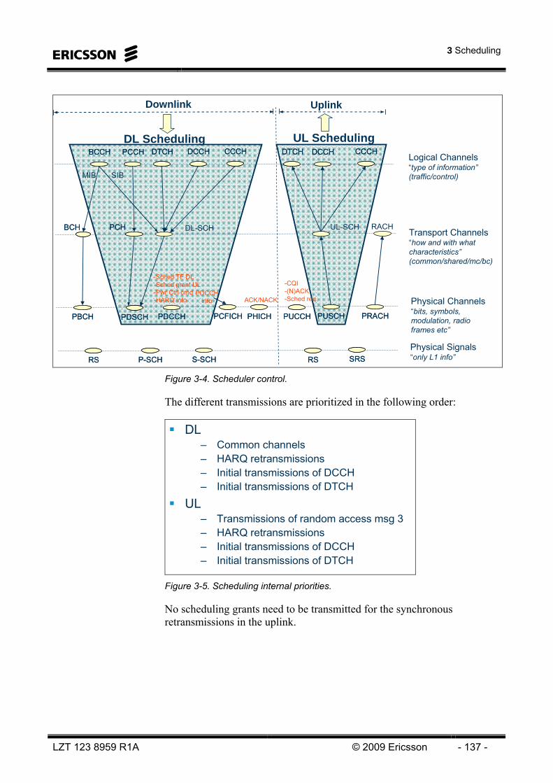
3 Scheduling
LZT 123 8959 R1A © 2009 Ericsson - 137 -
UL-SCHPCHPCH DL-SCH
PCCHPCCH Logical Channels “type of information”(traffic/control)
Transport Channels“how and with what characteristics”(common/shared/mc/bc)
Downlink Uplink
PDSCHPDSCH
Physical Channels“bits, symbols, modulation, radio frames etc”
BCCHBCCH DTCHDTCH DCCHDCCH DTCHDTCH DCCHDCCH CCCHCCCH
PRACHPRACH
RACH
CCCHCCCH
BCHBCH
PUSCHPUSCHPBCHPBCH PCFICHPCFICH PUCCHPUCCH
-CQI -(N)ACK-Sched req.
-Sched TF DL-Sched grant UL-Pwr Ctrl cmd-HARQ info
MIB SIB
PHICHPHICHPDCCHPDCCH
ACK/NACKPDCCH
info
Physical Signals“only L1 info”
DL Scheduling UL Scheduling
RSRS P-SCHP-SCH S-SCHS-SCH RSRS SRSSRS Figure 3-4. Scheduler control.
The different transmissions are prioritized in the following order:
DL– Common channels– HARQ retransmissions– Initial transmissions of DCCH– Initial transmissions of DTCH
UL– Transmissions of random access msg 3– HARQ retransmissions– Initial transmissions of DCCH– Initial transmissions of DTCH
Figure 3-5. Scheduling internal priorities.
No scheduling grants need to be transmitted for the synchronous retransmissions in the uplink.
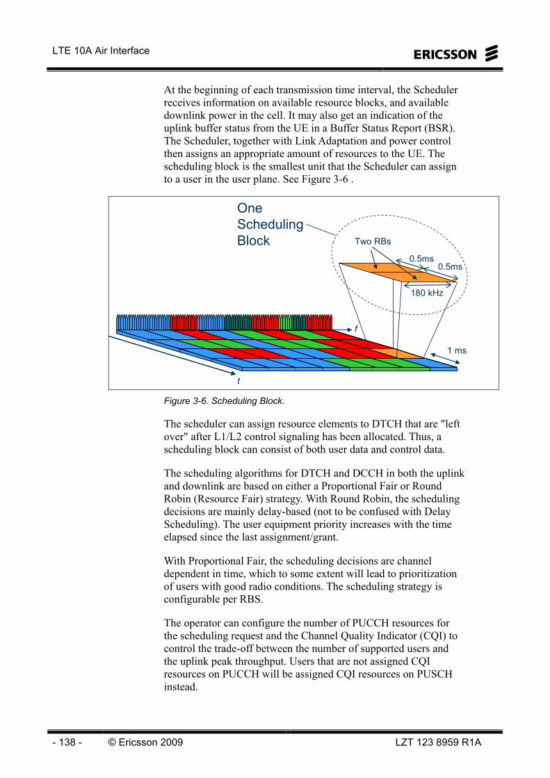
LTE 10A Air Interface
- 138 - © Ericsson 2009 LZT 123 8959 R1A
At the beginning of each transmission time interval, the Scheduler receives information on available resource blocks, and available downlink power in the cell. It may also get an indication of the uplink buffer status from the UE in a Buffer Status Report (BSR). The Scheduler, together with Link Adaptation and power control then assigns an appropriate amount of resources to the UE. The scheduling block is the smallest unit that the Scheduler can assign to a user in the user plane. See Figure 3-6 .
f
t
Two RBs
0.5ms0.5ms
One Scheduling Block
180 kHz
1 ms
Figure 3-6. Scheduling Block.
The scheduler can assign resource elements to DTCH that are "left over" after L1/L2 control signaling has been allocated. Thus, a scheduling block can consist of both user data and control data.
The scheduling algorithms for DTCH and DCCH in both the uplink and downlink are based on either a Proportional Fair or Round Robin (Resource Fair) strategy. With Round Robin, the scheduling decisions are mainly delay-based (not to be confused with Delay Scheduling). The user equipment priority increases with the time elapsed since the last assignment/grant.
With Proportional Fair, the scheduling decisions are channel dependent in time, which to some extent will lead to prioritization of users with good radio conditions. The scheduling strategy is configurable per RBS.
The operator can configure the number of PUCCH resources for the scheduling request and the Channel Quality Indicator (CQI) to control the trade-off between the number of supported users and the uplink peak throughput. Users that are not assigned CQI resources on PUCCH will be assigned CQI resources on PUSCH instead.

3 Scheduling
LZT 123 8959 R1A © 2009 Ericsson - 139 -
An overview of the inputs and outputs of the Scheduler in uplink and downlink is shown in Figure 3-7. Unless otherwise stated, both uplink and downlink scheduling is considered.
OutputAssignment (DL)
Grant (UL)
Scheduler
•Tx rank(DL)
•MCS(DL)
•#SE(UL)
Data related inputs
•HARQ retransmissions
•Data buffer (DL)
User related inputs
•UE capabilities
•UE measurement gaps
•Sync status
RRC Connection Request (UL)
QoS translation
Available RBS resources
•BB Capacity
•Throughput (licence)
OSS-RCQoS parametersQCI table
•UE prioritization
•Resource Allocation
•PDCCH resources
•Buffer estimation (UL)
•RB and symbols•DL Power
Power ControlUL closed & open loop PC
SR (UL), BSR (UL)
UE
Resource A
lloc
BB: Base BandBSR: Buffer Status ReportCQI: Channel Quality IndicatorCW: Code WordHARQ: Hybrid ARQMCS: Modulation and Coding SchemePELR: Packet Error Loss RatePF: Proportional FairPMI: Precoder Matrix IndicatorQoS: Quality of ServiceQCI: QoS Class IndicatorRF: Resource FairRI: Rank IndicatorSE: Scheduling ElementSINR: Signal to Interf and Noise RatioSR: Scheduling RequestTBS: Transport Block SizeTF: Transport FormatTPC: Transmit Power Control
QoS framework
Link AdaptationTF selection
SINR estimation# CW
CQI (DL),PMI(DL),RI(DL)
max TB
S
Scheduling Strategy per RBS (RF, PF)
QCI table•QoS configuration
•Priorities etc
•LCGs
Core NW
QC
I
parameters
power headroom
TPC (UL)
Grants (UL)Assignments (DL)
SINR(UL)
Figure 3-7. Scheduler interactions.

LTE 10A Air Interface
- 140 - © Ericsson 2009 LZT 123 8959 R1A
DOWNLINK SCHEDULING FRAMEWORK
The overall scheduling concept for the downlink is illustrated in Figure 3-8. To support fast channel dependent link adaptation and channel dependent time and frequency domain scheduling the UE may be configured to report the Channel Quality Indicator (CQI) reports. Typically, the UE bases the CQI reports on measurements on DL reference signals. For TDD the channel reciprocity could be utilized for channel dependent scheduling to some extent, although one must keep in mind that even if the fading characteristics are reciprocal in TDD the UL and DL will experience different interference and there might be an unbalance in pathgain between uplink and downlink. Based on the CQI reports and QoS requirements of the different logical channels the scheduler assigns time and frequency resources, i.e. scheduling blocks. The resource assignment is signaled on the Physical Downlink Control Channel (PDCCH). The UE monitors the control channels to determine if it is scheduled on the shared channel (PDSCH) and if so, what physical layer resources to find the data scheduled.
Ue provides a Channel Quality Report (CQI) based on DL reference symbols Scheduler assigns resources per RB based on QoS, CQI etc.Resource allocation is transmitted in connection with data Many details remain open in 3GPP
CQI report
CQI report
eNodeB
DL scheduler
Ue
Reference symbols
Reference symbols
Resource allocation
DataResource allocation
Resource allocation
Resource allocation
Data
Figure 3-8. DL scheduling mechanism.
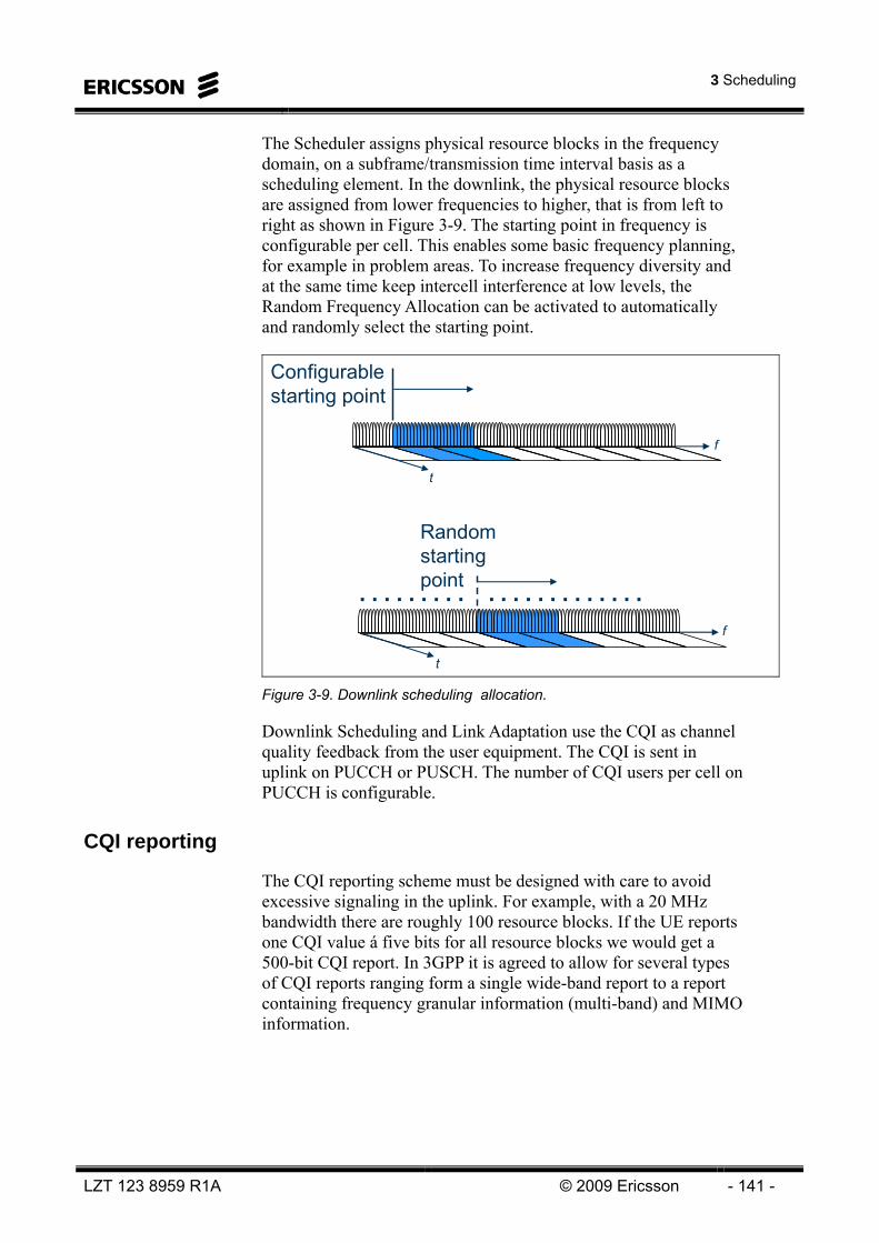
3 Scheduling
LZT 123 8959 R1A © 2009 Ericsson - 141 -
The Scheduler assigns physical resource blocks in the frequency domain, on a subframe/transmission time interval basis as a scheduling element. In the downlink, the physical resource blocks are assigned from lower frequencies to higher, that is from left to right as shown in Figure 3-9. The starting point in frequency is configurable per cell. This enables some basic frequency planning, for example in problem areas. To increase frequency diversity and at the same time keep intercell interference at low levels, the Random Frequency Allocation can be activated to automatically and randomly select the starting point.
f
t
Configurable starting point
f
t
Randomstarting point. . . . . . . . . . . . . . . . . . . . . .
Figure 3-9. Downlink scheduling allocation.
Downlink Scheduling and Link Adaptation use the CQI as channel quality feedback from the user equipment. The CQI is sent in uplink on PUCCH or PUSCH. The number of CQI users per cell on PUCCH is configurable.
CQI reporting
The CQI reporting scheme must be designed with care to avoid excessive signaling in the uplink. For example, with a 20 MHz bandwidth there are roughly 100 resource blocks. If the UE reports one CQI value á five bits for all resource blocks we would get a 500-bit CQI report. In 3GPP it is agreed to allow for several types of CQI reports ranging form a single wide-band report to a report containing frequency granular information (multi-band) and MIMO information.

LTE 10A Air Interface
- 142 - © Ericsson 2009 LZT 123 8959 R1A
The CQI reports will be transmitted on the Physical Uplink Control Channel (PUCCH) if there is no Physical Uplink Shared Channel (PUSCH) resource available. The PUCCH resources for CQI reporting will be configured through RRC (possible MAC optimizations are FFS). The resources are autonomously revoked when the UE looses UL synchronization but can also be revoked through RRC. When the UE has simultaneous UL data and has an allocation on the PUSCH these resources cannot be used due to the single carrier structure. In this case the CQI reports are transmitted on the PUSCH time multiplexed (before DFT precoding) with the data transport block on PUSCH. It is agreed that the eNB should not need to blindly detect if there is a CQI report included. This means that the CQI transmissions must be known to the eNB and the UE cannot transmit CQI reports autonomously.
The size of a PUCCH CQI is very limited, in the order of 10 bits. This means that several consecutive sub-frames are needed to provide a multi-band report, i.e. sub-frame concatenation. The PUSCH report on the other hand could allow for more bits and it is agreed in 3GPP that different CQI formats can be used on the PUCCH and on the PUSCH as illustrated in Figure 3-10.
The eNB can configure (through RRC) the UE to transmit CQI report periodically. As illustrated in Figure 3-10, when a periodic CQI reporting instance coincides with an UL transmission on the PUSCH the CQI report will be transmitted on the PUSCH and the PUCCH resources are unused. In addition to the periodic reporting, a-periodic reporting has been agreed in 3GPP. It is also agreed that a CQI report could be requested from the eNB either using a poll bit in the grant or to use a specific TF for indicating “only” CQI.
PUCCH
PUSCH
CQI not tranmitted on PUCCH as data is transmitted on PUSCH
Periodic CQI reporting using ”type B”
CQI tranmitted on PUSCH using ”type A” together with UL data
Only CQI tranmitted using ”type C”
Figure 3-10. CQI transmission.
Periodic CQI will be transmitted on PUCCH unless the UE has a scheduled resource on the PUSCH. In this case the report will be transmitted on the PUSCH. Different CQI formats can be used on the PUCCH and PUSCH. In addition a-periodic CQI reports can be transmitted, either trigger with UL data or requested by the eNB.

3 Scheduling
LZT 123 8959 R1A © 2009 Ericsson - 143 -
With a “wide-band average” we refer to a mutual information based average where the SINR is averaged in the mutual information domain over a set of sub-bands. The set of sub-bands, S, is semi-statically configured through higher layer signaling (RRC). The actual averaging will not be specified but with appropriate requirements on the UE it is believed that a linear average or linear in dB will not be sufficient. A wide-band average CQI report could consist of a five bit index to a 32-entry CQI table (four bits with 16-entries is also discussed) with approximately equal step size in equivalent SINR. A step size of 1dB is considered with a 32dB dynamic range. The CQI is defined in terms of channel coding rate and modulation order (QPSK, 16QAM, 64QAM). The detailed CQI table is still under consideration in 3GPP.
In addition to a wide-band average two different schemes for PUSCH transmission have been identified for multi-band reports, a “UE-Selected sub-bands Feedback” and a “eNB Configured sub-bands”. In both cases a wide-band average is computed and used as a reference. In addition, M sub-bands (M could be fixed or configured) are selected and encoded differentially using three bits relative to the wide-band average. In the case “UE selected sub-bands” the UE selects M sub-bands to report. The UE internal procedure to select sub-bands will not be specified but the selected sub-bands should correspond to the highest CQI values. The sub-band selection is signaled using,
⎥⎥
⎤⎢⎢
⎡⎟⎟⎠
⎞⎜⎜⎝
⎛MN
2log (4)
bits where N is the number of sub-bands needed to cover the system bandwidth. The supported sub-band sizes and M values will be a function of system bandwidths. However, the possibility of other M values and specifying multiple M values for each range of the system bandwidth not precluded. The “eNB selected sub-bands” scheme is similar with the exception that the eNB configures what sub-bands the UE should report.
Figure 3-11 shows the sub-band sizes and the number of sub-bands as a function of the allocated bandwidth. The number of sub-bands (M) is the M best sub-bands, selected by the UE.
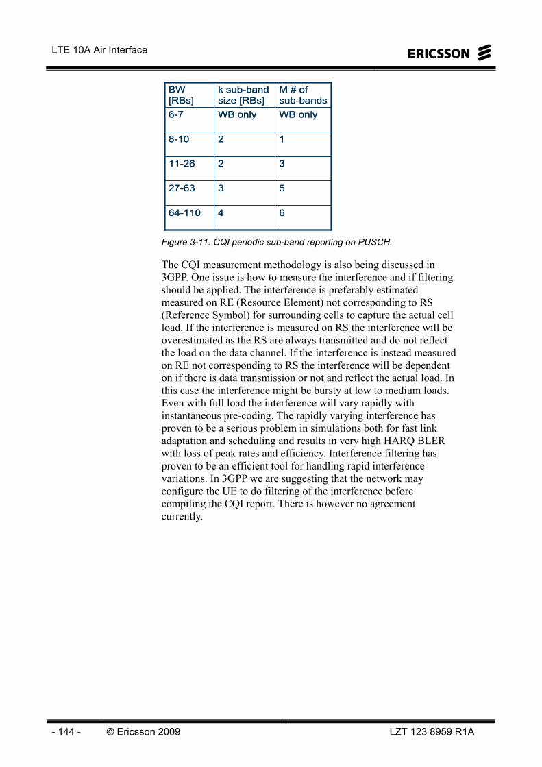
LTE 10A Air Interface
- 144 - © Ericsson 2009 LZT 123 8959 R1A
6464-110
5327-63
3211-26
128-10
WB onlyWB only6-7
M # of sub-bands
k sub-band size [RBs]
BW[RBs]
6464-110
5327-63
3211-26
128-10
WB onlyWB only6-7
M # of sub-bands
k sub-band size [RBs]
BW[RBs]
Figure 3-11. CQI periodic sub-band reporting on PUSCH.
The CQI measurement methodology is also being discussed in 3GPP. One issue is how to measure the interference and if filtering should be applied. The interference is preferably estimated measured on RE (Resource Element) not corresponding to RS (Reference Symbol) for surrounding cells to capture the actual cell load. If the interference is measured on RS the interference will be overestimated as the RS are always transmitted and do not reflect the load on the data channel. If the interference is instead measured on RE not corresponding to RS the interference will be dependent on if there is data transmission or not and reflect the actual load. In this case the interference might be bursty at low to medium loads. Even with full load the interference will vary rapidly with instantaneous pre-coding. The rapidly varying interference has proven to be a serious problem in simulations both for fast link adaptation and scheduling and results in very high HARQ BLER with loss of peak rates and efficiency. Interference filtering has proven to be an efficient tool for handling rapid interference variations. In 3GPP we are suggesting that the network may configure the UE to do filtering of the interference before compiling the CQI report. There is however no agreement currently.
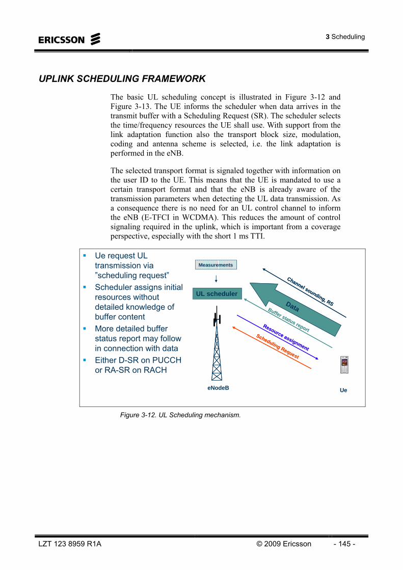
3 Scheduling
LZT 123 8959 R1A © 2009 Ericsson - 145 -
UPLINK SCHEDULING FRAMEWORK
The basic UL scheduling concept is illustrated in Figure 3-12 and Figure 3-13. The UE informs the scheduler when data arrives in the transmit buffer with a Scheduling Request (SR). The scheduler selects the time/frequency resources the UE shall use. With support from the link adaptation function also the transport block size, modulation, coding and antenna scheme is selected, i.e. the link adaptation is performed in the eNB.
The selected transport format is signaled together with information on the user ID to the UE. This means that the UE is mandated to use a certain transport format and that the eNB is already aware of the transmission parameters when detecting the UL data transmission. As a consequence there is no need for an UL control channel to inform the eNB (E-TFCI in WCDMA). This reduces the amount of control signaling required in the uplink, which is important from a coverage perspective, especially with the short 1 ms TTI.
Ue request UL transmission via ”scheduling request”Scheduler assigns initial resources without detailed knowledge of buffer content More detailed buffer status report may follow in connection with dataEither D-SR on PUCCH or RA-SR on RACH
Resource assignment
Resource assignment
eNodeB
UL scheduler
Ue
Scheduling Request
Scheduling Request
Buffer status report
DataBuffer status report
Data
Channel sounding, RS
Channel sounding, RS
Measurements
Figure 3-12. UL Scheduling mechanism.

LTE 10A Air Interface
- 146 - © Ericsson 2009 LZT 123 8959 R1A
Uplink transport format controlled by NodeB– No TFC selection in the UE
Modulation, coding
Buffer
MultiplexingScheduler
Buffer
Uplink channel qualityScheduler
Multiplexing
Buffer
Modulation, coding
Priority handling
Buffer
eNodeB eNodeB
UE UE
CQ
I
Sta
tus
TF s
elec
tion
Downlink Uplink
Downlink channel quality
Figure 3-13. UL Scheduling.
The assigned resources and transmission parameters is revealed to the UE via the PDCCH. Additional Scheduling Information (SI) such as Buffer Status Report (BSR) or power headroom report may be transmitted together with data as MAC control elements. The eNB may configure the UE to transmit a wide-band sounding reference signal that can be used for estimating the UL channel quality. Additional channel quality estimates can be obtained from other UL transmissions such as, data transmission or control signaling (CQI reports and HARQ ACK/NACK signals).
Scheduling resources among users in the uplink is complicated by the fact that the scheduler is situated in the eNB and is not automatically aware of the users resource demand, i.e., what users and what radio bearers have data to transmit and how much data there is in the transmit buffers. The concept for uplink scheduling suggested is based on a resource reservation principle.

3 Scheduling
LZT 123 8959 R1A © 2009 Ericsson - 147 -
When data arrives to the transmit buffers of a UE and the UE has no grant for transmission on the PUSCH, the UE needs to request permission to transmit. According to current agreements a Buffer Status Report (BSR) is trigger. If the UE has no PUSCH resource a Scheduling Request (SR) is triggered as well. The SR will either be transmitted on the RACH channel (RA-SR) or on dedicated resources on the PUCCH (Dedicated SR, D-SR) if such resources are available. The PUCCH resources for dedicated SR are assigned and revoked by the eNB through RRC. In addition, the resources are autonomously revoked when the UE looses UL synchronization. The UL scheduler monitors the users’ requests and distributes the available resources among the various users.
A Dedicated Scheduling Request (D-SR) is typically used when the UE uplink is time synchronized. The purpose is to enable UE to rapidly request resources for uplink data transmission. In 3GPP, a dedicated solution for the scheduling request has been agreed. For the dedicated approach, each active user is assigned a dedicated channel for performing the scheduling request. The benefit with this method is that no UE ID has to be transmitted explicitly, since the UE is identified by the channel used. Furthermore, no intra-cell collisions will occur in contrast to the contention based approach.
The D-SR is repeatedly transmitted on consecutive SR opportunities on PUCCH until the UE receives an UL grant on PDCCH. The transmission is stopped at least when PUCCH resources are released and/or UL synch is lost even if the UE has not received any UL grant on PDCCH. After stopping transmission on the D-SR, the UE transmits on the RA-SR (i.e. accesses the system via RACH).
The Random Access Scheduling Request (RA-SR) is used when the UE has lost UL synchronization or if it has no D-SR resources.
From a scheduling request the scheduler has limited knowledge of what type of data and of what priority the UE has. For further information a grant is issued by the scheduler. The grant addresses a UE and not a specific logical channel. In its simplest form the scheduling grant is valid only for the next UL TTI. However, to reduce the amount of control signaling required several proposals with alternative durations similar as for the downlink are being discussed.
Following the initial scheduling request, a more detained Buffer Status Report (BSR) can be provided by the UE to the eNB as a MAC control element. Additional information such as UE power headroom has also been discussed in 3GPP.

LTE 10A Air Interface
- 148 - © Ericsson 2009 LZT 123 8959 R1A
A BSR is triggered when at least one of the following criteria is fulfilled: • UL data arrives in the UE transmission buffer and the data
belongs to a radio bearer (logical channel) group with higher priority than those for which data already existed in the UE transmission buffer.
• BSR is triggered when UL-SCH resources are allocated and number of padding bits is larger than the BSR size
• when the UE arrives to a new cell
A triggered BSR is cancelled in case the uplink grant is large enough to accommodate all pending data, but not both data and BSR.
A SR is triggered and transmitted in addition if the BSR is not transmitted before the first available SR opportunity.
Uplink scheduling takes place in the RBS, and resources are assigned per user equipment. When user equipment has several radio bearers, the user equipment performs the prioritization between the radio bearers and is referred to as the user equipment rate control function.
The resources not used by the physical signals PUCCH and PRACH are used as scheduling elements for uplink scheduling, so PUCCH and PRACH have absolute priority over other control and user data channels in the uplink.
The random access response message on PDSCH contains the grant for random access message 3 (RRC connection request).
The user equipment sends a scheduling request on PUCCH to the scheduler to indicate that it has data in the buffer and asks uplink scheduling to start assigning uplink resource blocks to the user equipment in upcoming subframes.
When user equipment is scheduled in a subframe, the uplink scheduler transmits a scheduling grant to the user equipment, indicating the resource blocks and transport format to use for uplink transmission.
Uplink grants are produced by the Scheduler and sent to the user equipment on PDCCH.

3 Scheduling
LZT 123 8959 R1A © 2009 Ericsson - 149 -
Together with the uplink data, the user equipment transmits buffer status information to the RBS such that the uplink scheduler knows roughly the amount of data in the user equipment buffer. In cooperation with the link adaptation and power control functionality the uplink scheduler use this information together with the channel quality information to assign an appropriate number of resource blocks to user equipment in the uplink.
The scheduling request uses PUCCH format 1 and the number of scheduling request users per cell is configurable with a parameter that sets the number of users that are allocated scheduling request resources. The periodicity of the scheduling request is 10 ms, and equal for all user equipment in the cell. If no scheduling request resources are allocated on PUCCH for the user equipment, the user equipment uses the random access process to request resources.
To increase capacity and coverage, Time Spread Allocation Scheduling is used in uplink. This enables multiple user equipment to be scheduled in one subframe by distributing one user equipment transmission over several subframes, but at a lower bandwidth. This leads to an improved link budget and improved capacity and coverage. See Figure 3-14.
f
t
f
t
Without Time Spread Allocation
With Time Spread Allocation
User 1User 2User 3
User 1User 2User 3
Figure 3-14. UL scheduling allocation..
LTE 10A Air Interface
- 150 - © Ericsson 2009 LZT 123 8959 R1A
Link Adaptation
Link Adaptation performs transport format selection to enforce the quality requirement while using the available resources in an efficient way. Transport format selection includes selecting the modulation and coding scheme and transport block size. In the downlink, the selection is channel dependent because Link Adaptation uses CQI reports from the user equipment to adapt the transmissions to current radio conditions.
For the uplink, Link Adaptation takes SINR into account. The SINR is based on measurements on the uplink demodulation reference signal. The transport format selection influences the scheduling decision, so the scheduling decision is implicitly influenced by channel quality estimations (CQI for downlink and SINR for uplink). Link Adaptation is not used in the uplink for random access message 3 (RRC connection request) or retransmissions.
Link Adaptation for downlink common channels uses a default SINR for these transmissions to reach the cell edge. The Scheduler provides link adaptation with RLC and MAC header sizes to consider when selecting a transport format.
The Scheduler retrieves information about the number of scheduling elements to use in uplink, number of layers and modulation and coding scheme to use in downlink from Link Adaptation.
Antenna mapping, part of Link Adaptation, controls multi-antenna transmission by deciding the antenna mapping mode (TX diversity, spatial multiplexing or beamforming, as well as submodes within each mode), spatial multiplexing rank and spatial multiplexing precoding matrix. Channel prediction, also part of Link Adaptation, provides information needed for decisions in the other Link Adaptation functions and Power Control. It includes collecting channel measurements, made in the downlink by the user equipment and sent to the RBS in channel feedback reports containing CQI, precoding matrix indicator (PMI), and rank indicator (RI). In UL the SINR is considered.
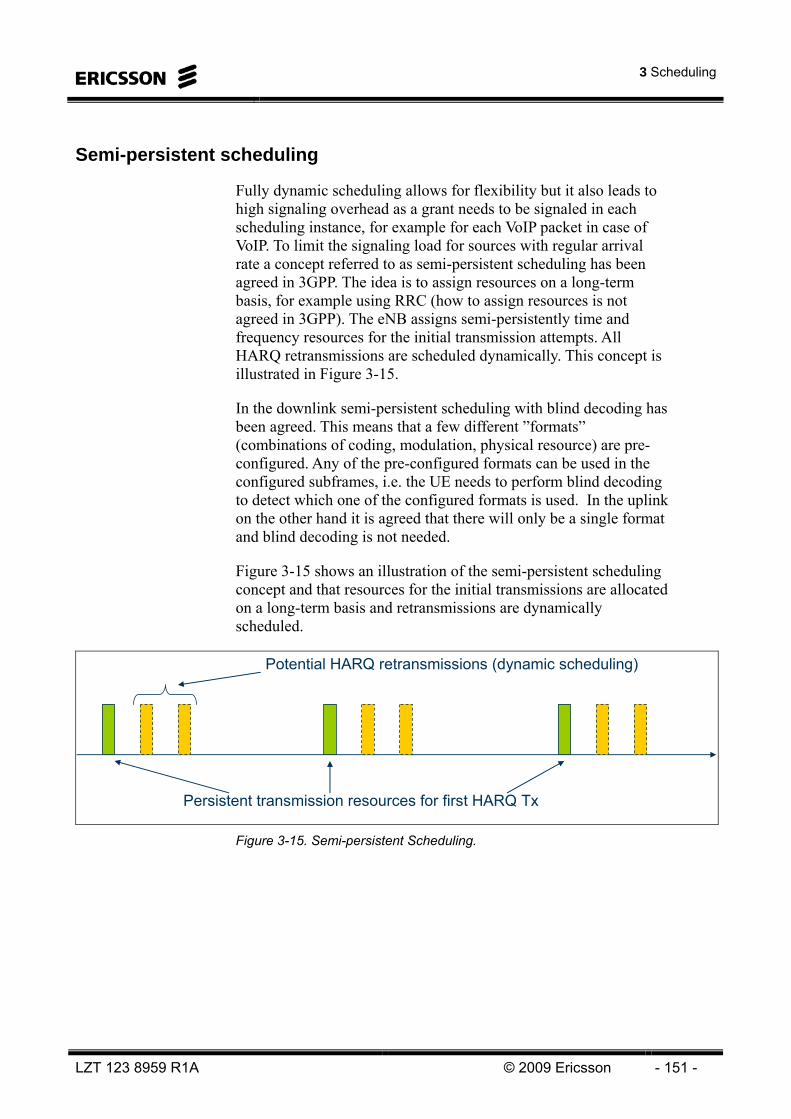
3 Scheduling
LZT 123 8959 R1A © 2009 Ericsson - 151 -
Semi-persistent scheduling
Fully dynamic scheduling allows for flexibility but it also leads to high signaling overhead as a grant needs to be signaled in each scheduling instance, for example for each VoIP packet in case of VoIP. To limit the signaling load for sources with regular arrival rate a concept referred to as semi-persistent scheduling has been agreed in 3GPP. The idea is to assign resources on a long-term basis, for example using RRC (how to assign resources is not agreed in 3GPP). The eNB assigns semi-persistently time and frequency resources for the initial transmission attempts. All HARQ retransmissions are scheduled dynamically. This concept is illustrated in Figure 3-15.
In the downlink semi-persistent scheduling with blind decoding has been agreed. This means that a few different ”formats” (combinations of coding, modulation, physical resource) are pre-configured. Any of the pre-configured formats can be used in the configured subframes, i.e. the UE needs to perform blind decoding to detect which one of the configured formats is used. In the uplink on the other hand it is agreed that there will only be a single format and blind decoding is not needed.
Figure 3-15 shows an illustration of the semi-persistent scheduling concept and that resources for the initial transmissions are allocated on a long-term basis and retransmissions are dynamically scheduled.
Persistent transmission resources for first HARQ Tx
Potential HARQ retransmissions (dynamic scheduling)
Figure 3-15. Semi-persistent Scheduling.
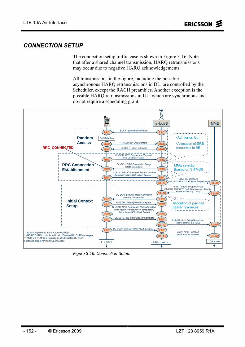
LTE 10A Air Interface
- 152 - © Ericsson 2009 LZT 123 8959 R1A
CONNECTION SETUP
The connection setup traffic case is shown in Figure 3-16. Note that after a shared channel transmission, HARQ retransmissions may occur due to negative HARQ acknowledgements.
All transmissions in the figure, including the possible asynchronous HARQ retransmissions in DL, are controlled by the Scheduler, except the RACH preambles. Another exception is the possible HARQ retransmissions in UL, which are synchronous and do not require a scheduling grant.
eNodeB MME
BCCH: System Information
UL-SCH: RRC Connection Request(Initial UE identity, Cause)
Cell Selection
DL-SCH: RRC Connection Setup(SRB1 parameters)
Initial UE Message(eNB UE S1AP id **,NAS:Attach Request,TAI)
Initial Context Setup Request(MME UE S1AP id ***, NAS: Attach Accept, Security,
Bearer params, e.g. TEID)
DL-SCH: Security Mode Command(Security Configuration)
UL-SCH: Security Mode Complete
Initial Context Setup Response(Bearer params, e.g. TEID)
UL-SCH: RRC Connection Setup Complete(Selected PLMN id, NAS: Attach Request *)
PRACH: RACH preamble
DL-SCH: RACH response
DL-SCH: RRC Connection Reconfiguration(Intra-frequency measurement configuration,
Bearer Setup, NAS: Attach Accept)
UL-SCH: RRC Conn Reconf Complete
* The IMSI is provided in the Attach Request** eNB UE S1AP id is included in all UE-related DL S1AP messages*** MME UE S1AP id is included in all UE-related UL S1AP messages except for Initial UE message
Uplink NAS Transport(NAS: Attach Complete)
UL Inform Transfer (NAS: Attach Complete)
LTE active LTE activeRRC connected
Random Access
RRC Connection Establishment
Initial Context Setup
•Admission Ctrl
•Allocation of SRB resources in BB
MME selection (based on S-TMSI)
Allocation of payload bearer resources
RRC_CONNECTED MACMAC
S1-APS1-AP
RRCRRC RRCRRC
MACMACMACMAC MACMAC
RRCRRC RRCRRC
RRCRRC RRCRRC
RRCRRC RRCRRC
S1-APS1-AP
S1-APS1-AP S1-APS1-AP
RRCRRCRRCRRC
RRCRRC RRCRRC
RRCRRCRRCRRC
RRCRRC RRCRRC
S1-APS1-AP S1-APS1-AP
RRCRRC RRCRRC
S1-APS1-APS1-APS1-AP
Figure 3-16. Connection Setup.

3 Scheduling
LZT 123 8959 R1A © 2009 Ericsson - 153 -
Inter-Cell Interference Coordination (ICIC)
Inter-cell Interference Coordination, located in eNB, has the task to manage radio resources (notably the radio resource blocks) such that inter-cell interference is kept under control. The specific ICIC techniques that will be used in E-UTRA are for further study.
ICIC is inherently a multi-cell RRM function that needs to take into account the resource usage status and traffic load situation of multiple cells.
According to a fairly broad consensus in 3GPP RAN1, the Release 8 LTE standard will not support ICIC in the downlink.
Uplink inter-cell interference coordination consists of two inter-related mechanisms, the details of which are currently discussed within the 3GPP. The first part is a pro-active ICIC mechanism. The basic idea of this scheme is that a potentially disturbing eNB pro-actively sends a resource block specific indication to its potentially disturbed neighbor. This message indicates which resource blocks will be scheduled (with a high probability) with high power (i.e. by cell edge UEs). Thus this message allows the receiving eNB(s) to try to avoid to schedule the same resource blocks for its cell edge UEs. This way the pro-active scheme allows neighbor eNBs to reduce the probabilities of “exterior-exterior” (i.e. cell edge) UEs to simultaneously take into use the same resource blocks.
In addition, the 3GPP also discusses the use of the overload indicator (OI) that was originally proposed for inter-cell power control purposes. It is currently agreed in 3GPP that the OI also carries information at the resource block granularity. As opposed to the pro-active scheme, the overload indication is a reactive scheme that indicates a high detected interference level on a specific resource block to neighbor eNB(s). The details of OI based ICIC and its joint operation with the pro-active scheme is FFS at 3GPP.
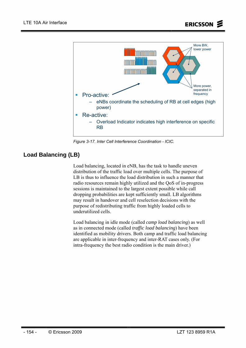
LTE 10A Air Interface
- 154 - © Ericsson 2009 LZT 123 8959 R1A
Pro-active:– eNBs coordinate the scheduling of RB at cell edges (high
power)
Re-active:– Overload Indicator indicates high interference on specific
RB
More BW, lower power
More power, separated in frequency
Figure 3-17. Inter Cell Interference Coordination - ICIC.
Load Balancing (LB)
Load balancing, located in eNB, has the task to handle uneven distribution of the traffic load over multiple cells. The purpose of LB is thus to influence the load distribution in such a manner that radio resources remain highly utilized and the QoS of in-progress sessions is maintained to the largest extent possible while call dropping probabilities are kept sufficiently small. LB algorithms may result in handover and cell reselection decisions with the purpose of redistributing traffic from highly loaded cells to underutilized cells.
Load balancing in idle mode (called camp load balancing) as well as in connected mode (called traffic load balancing) have been identified as mobility drivers. Both camp and traffic load balancing are applicable in inter-frequency and inter-RAT cases only. (For intra-frequency the best radio condition is the main driver.)

3 Scheduling
LZT 123 8959 R1A © 2009 Ericsson - 155 -
X2AP Support for ICIC and Load Balancing
Load balancing for idle and connected mode has been recently discussed in RAN3. While load balancing is not identified as a mobility driver for intra-LTE intra-frequency scenarios, it is recognized as a mobility driver for inter-frequency and inter-RAT cases. In fact, for inter-RAT, load balancing (sharing) is explicitly identified as one of the RRM requirements.
For the intra-frequency intra-LTE case, X2AP is used for ICIC and load balancing purposes.
An eNB initiates the procedure by sending LOAD INFORMATION message to intra-frequency neighboring eNBs. The LOAD INFORMATION message can carry interference overload indication. The Load indication procedure shall be used to send interference overload indication when the eNB experiences too high interference level on some resource blocks.
Whether an eNB receiving a LOAD INFORMATION message should respond with a LOAD INFORMATION message is FFS.
RRM RELATED MEASUREMENTS IN LTE
Measurements are the key to ensure appropriate execution of RRM functions. Measurements are needed for single cell as well as for multi-cell RRM functions. Measurements are to be done both at the UE and at the eNB(s). Since E-UTRAN will support several RRM functions, different measurements serve different purposes. In general, the measurements should provide a good estimate of the used and available radio resources, cell coverage, short and long term channel quality, cell load, service quality, time alignment during handovers, load on the transport network etc. In addition, measurements should provide good mobility support not only within E-UTRAN but also between E-UTRAN and other access networks including UTRAN and GERAN. We note that another set of measurements is needed to support positioning services, but the description of these is out of the scope of this report.
For eNB and UE measurements, the downlink and uplink reference symbols play a key role.

LTE 10A Air Interface
- 156 - © Ericsson 2009 LZT 123 8959 R1A
eNB Measurements
In E-UTRAN, certain types of measurements shall be performed internally in the eNB and will not be exchanged between the eNBs. These measurements do not need to be specified in the standard, rather they will be implementation dependent. On the other hand, measurements, which are to be exchanged between the eNBs over the X2 interface need to be standardized.
The eNB measurements are described below. The positioning related measurements are not listed since they depend upon the exact positioning method used in E-UTRAN. Also, the current description does not explicitly take into account the impacts of multiple transmit and receive antennas on the measured quantities and measurement procedures (this issue is FFS). At the time of writing, all of the eNB measurements are implementation specific and need not be specified in the standard.
DL total Tx power: Transmitted carrier power measured over the entire cell transmission bandwidth.
DL resource block Tx power: Transmitted carrier power measured over a resource block.
DL total Tx power per antenna branch: Transmitted carrier power measured over the entire bandwidth per antenna branch.
DL resource block Tx power per antenna branch: Transmitted carrier power measured over a resource block.
DL total resource block usage: Ratio of downlink resource blocks used to total available downlink resource blocks (or simply the number of downlink resource blocks used).
UL total resource block usage: Ratio of uplink resource blocks used to total available uplink resource blocks (or simply the number of uplink resource blocks used).
DL resource block activity: Ratio of scheduled time of downlink resource block to the measurement period.
UL resource block activity: Ratio of scheduled time of uplink resource block to the measurement period.
DL transport network loss rate: Packet loss rate of GTP-U (or frame) packets sent by the access gateway on S1 user plane. The measurement shall be done per traffic flow. The eNB shall use the sequence numbers of GTP-U (or frame) packets to measure the downlink packet loss rate.

3 Scheduling
LZT 123 8959 R1A © 2009 Ericsson - 157 -
UL transport network loss rate: Packet loss rate of GTP-U (or frame) packets sent by the eNB on S1 user plane. The measurement shall be done per traffic flow. The access gateway shall use the sequence numbers of GTP-U (or frame) packets to measure the downlink packet loss rate.
UL RTWP: Received total wideband power including noise measured over the entire cell transmission bandwidth at the eNB.
UL received resource block power: Total received power including noise measured over one resource block at the eNB.
UL SIR (per UE): Ratio of the received power of the reference signal transmitted by the UE to the total interference received by the eNB over the UE occupied bandwidth.
UL HARQ BLER: The block error ratio based on CRC check of each HARQ level transport block.
Propagation delay: Estimated one way propagation delay measured during random access transmission.
UE Tx time difference: Time difference between the reception of the UE transmitted signal and the reference symbol transmission time instant.
DL RS TX power: Downlink reference signal transmit power is determined for a considered cell as the linear average over the power contributions (in [W]) of the resource elements that carry cell-specific reference signals which are transmitted by the eNB within its operating system bandwidth.
For inter-cell interference coordination purposes, it may be useful to measure the user plane load (for instance in terms of number of sent user plane packets/bits per second). The definition of such measurements and associated procedures are for further study.

LTE 10A Air Interface
- 158 - © Ericsson 2009 LZT 123 8959 R1A
UE Measurements
The UE measurement quantities are described below.
RSRP (Reference Symbol Received Power): It is determined for a considered cell as the linear average over the power contributions (in [W]) of the resource elements that carry cell-specific reference signals within the considered measurement frequency bandwidth.
RSRQ (Reference Symbol Received Quality): Reference Signal Received Quality (RSRQ) is defined as the ratio N×RSRP/(E-UTRA carrier RSSI), where N is the number of RB’s of the E-UTRA carrier RSSI measurement bandwidth. The measurements in the numerator and denominator shall be made over the same set of resource blocks.

4 Mobility
LZT 123 8959 R1A © 2009 Ericsson - 159 -
4 Mobility
OBJECTIVES:
On completion of this chapter the students will be able to:
Describe the Intra LTE mobility–Describe intra-LTE mobility in connected and idle mode–Explain the concept of event triggered periodical reporting–Describe the mobility measurements
Explain inter-working with 2G/3G
Figure 4-1. Objectives.

LTE 10A Air Interface
- 160 - © Ericsson 2009 LZT 123 8959 R1A
Intentionally Blank

4 Mobility
LZT 123 8959 R1A © 2009 Ericsson - 161 -
MOBILITY The LTE mobility can be divided into “Intra-LTE mobility” and “Inter-LTE mobility” (inter-working with 2G/3G and CDMA 2000). It can be further divided into RRC_CONNECTED and RRC_IDLE mode mobility. IRAT-HO (Inter Radio Access Technology Handover) is one type of “Inter-LTE mobility” in RRC_CONNECTED mode while cell reselection is referred to as RRC_IDLE mode mobility.
RRC_CONNECTED mode mobility– Intra-LTE Handover
Intra-eNode BInter-eNode BIntra-MME HandoverInter-MME (pool) Handover
Inter-RAT Handover (3G/2G, CDMA2000)
RRC_IDLE mode mobility– Intra frequency cell reselection– Inter frequency cell reselection– IRAT cell reselection (3G/2G, CDMA2000)
Cell reselection with TA update
• UE performs cell reselection based on measurements
•EPC (MME) keeps track of UEs on TA level
• UE may belong to multiple TAs!
Handover
•Controlled by RAN
•The controlling node (eNB) changes frequently!
• No cell reselection!
Figure 4-2. LTE mobility.
ECM-IDLE
EMM-DEREGISTERED
MME
Tracking Area (TA)
UE positionnot knownin network
Signalingconnectionestablishment
Signalingconnectionrelease
Attach accept, TAU accept
Detach, Attach reject, TAU reject
EMM-REGISTERED
ECM-CONNECTED
Tracking Area Update(TAU)
Handover
PLMN selection
UE position known on Cell level in eNodeBUE pos known on TA level in MME
eNB
RRC_IDLE RRC_IDLE RRC_CONNECTED
ECM: EPC Connection Management
EMM: EPC MobilityManagement
RRC: Radio ResourceManagement
Figure 4-3. Protocol states and mobility.

LTE 10A Air Interface
- 162 - © Ericsson 2009 LZT 123 8959 R1A
RRC Idle mode mobility– PLMN selection– RAT and frequency selection (frequency priority)– Cell selection (Cell barred, blacklisted cell, cell offset)– Intra frequency cell reselection control– IRAT cell reselection control (WCDMA, GSM, CDMA 2000, frequency
priority)– Tracking Area support– Speed dependent scaling
RRC Connected mode mobility– Evaluation
Best cell selectionBad coverageUE capability dependent redirection target choice
– ExecutionS1 HOX2 HOIntra eNB HORelease with Redirect (IRAT: UTRAN, GERAN, CDMA2000)
Figure 4-4. RRC Mobility.
INTRA-LTE MOBILITY
In this section we describe intra-LTE mobility procedures both for RRC_CONNECTED and RRC_IDLE modes.
RRC_CONNECTED mode mobility
In LTE, network controlled UE assisted handovers with context transfer between eNB’s are used to support UE mobility. An intra-LTE handover can be executed either via the X2 or via the S1 interface. As long as the UE moves between eNB’s that belong to the same pooling area where the UE is currently registered, the handovers are always executed via the X2 interface. (Recall that the X2 interface is assumed to always exist between two neighbor eNB’s belonging to the same pooling area.)
In cases when the UE moves between eNB’s that belong to different pooling areas the handover procedure necessarily has to be executed via the S1 interface. In such cases at least the MME function, holding the UE context has to be relocated from one MME node in the first pool to another MME node in the second pool. There is possibility to relocate also the S-GW node during the S1 handover procedure, if it is needed (e.g., if no IP connectivity exists between the target eNB and the current S-GW). However, it is assumed that in the typical case the S-GW will not have to be relocated during an S1 handover, since IP connectivity will be configured in the network such that all S-GW’s will have connectivity to all eNB’s.

4 Mobility
LZT 123 8959 R1A © 2009 Ericsson - 163 -
Intra eNB HO Inter eNB HO
X2 HO S1 HO Intra cell HO
Intra E-UTRA HO
Intra frequency HO
(Inter frequency HO)
MME Relocation
S-GW Relocation
S-GW & MME Relocation Figure 4-5. Intra LTE Handover procedures.
From a procedural and message sequence point of view the S1 handover procedure will be identical both for intra-LTE and for inter-3GPP access mobility. Note, however, that there might be need for some extra signaling messages in the intra-LTE S1 handover case for transferring the PDCP SN status, which is not used in the IRAT S1 handover case.
A simplified chart of the message sequence at intra-LTE handover is shown in Figure 4-6.
S1
X2
S1
eNode BeNode B
MME/S-GW
VI
III
II
IV
I
V
eNode BeNode B
I. Handover RequestII. Handover Request AckIII. Handover CommandIV. “Start Packet Forwarding”V. Handover ConfirmVI. Path SwitchVII. Path Switch AckVIII. Release Resource
VIII
Source Target
VII
S/P-GW
Figure 4-6. Intra-LTE HO (within one MME pool).
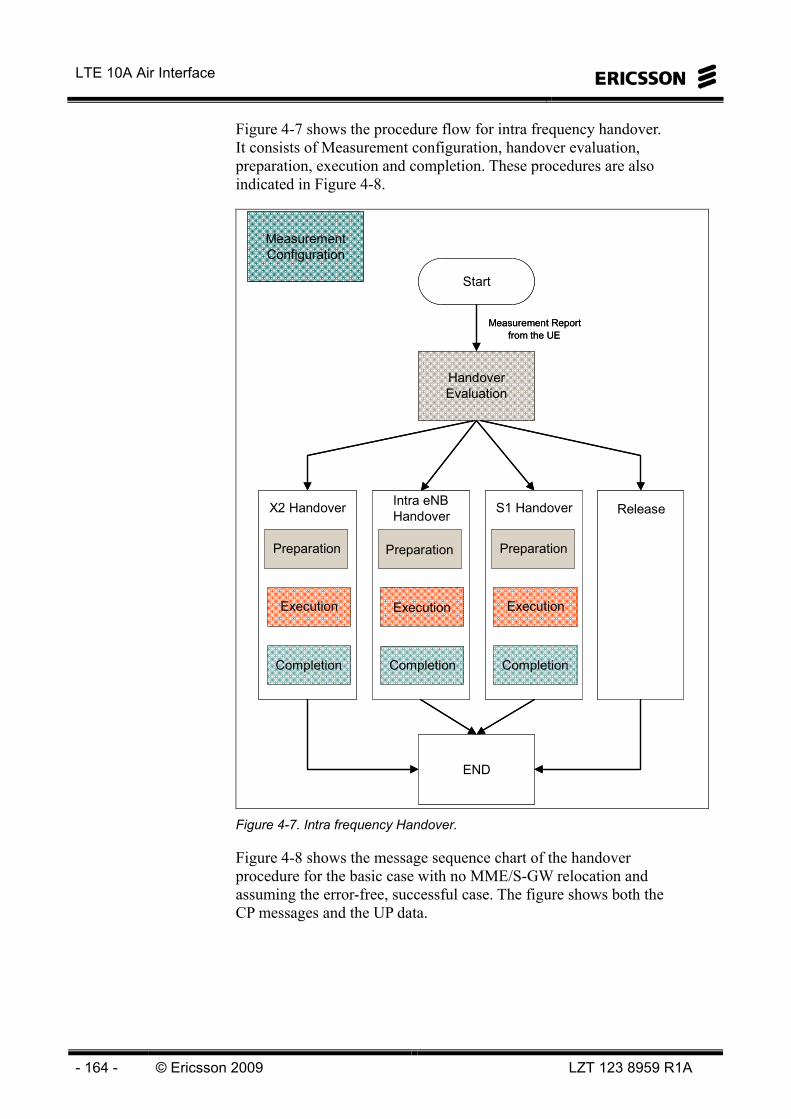
LTE 10A Air Interface
- 164 - © Ericsson 2009 LZT 123 8959 R1A
Figure 4-7 shows the procedure flow for intra frequency handover. It consists of Measurement configuration, handover evaluation, preparation, execution and completion. These procedures are also indicated in Figure 4-8.
Measurement Configuration
Handover Evaluation
Start
Measurement Report from the UE
X2 Handover
Preparation
Execution
Completion
S1 Handover
Preparation
Execution
Completion
Release
END
Intra eNBHandover
Preparation
Execution
Completion
Measurement Configuration
Handover Evaluation
Start
Measurement Report from the UE
X2 Handover
Preparation
Execution
Completion
S1 Handover
Preparation
Execution
Completion
Release
END
Intra eNBHandover
Preparation
Execution
Completion
Figure 4-7. Intra frequency Handover.
Figure 4-8 shows the message sequence chart of the handover procedure for the basic case with no MME/S-GW relocation and assuming the error-free, successful case. The figure shows both the CP messages and the UP data.
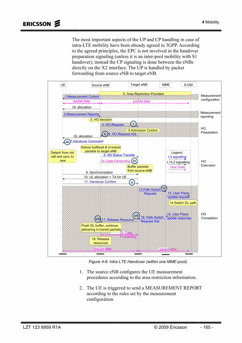
4 Mobility
LZT 123 8959 R1A © 2009 Ericsson - 165 -
The most important aspects of the UP and CP handling in case of intra-LTE mobility have been already agreed in 3GPP. According to the agreed principles, the EPC is not involved in the handover preparation signaling (unless it is an inter-pool mobility with S1 handover); instead the CP signaling is done between the eNBs directly on the X2 interface. The UP is handled by packet forwarding from source eNB to target eNB.
I
II
III
IV
V
VIII
Legend
packet data packet data
UL allocation
2.Measurement Reports3. HO decision
4. HO Request
5.Admission Control6. HO Request Ack
7.Handover CommandDL allocation
DL Data Forwarding
11. Handover Confirm
17. Release Resource
12.Path Switch Request
UE Source eNB Target eNB S-GW
Detach from old cell and sync to
new
Deliver buffered & in-transit packets to target eNB
Buffer packets from source eNB9. Synchronisation
10. UL allocation + TA for UE
packet data
DL DataForwarding
Flush DL buffer, continue delivering in-transit packets
packet data
L3 signallingL1/L2 signalling
User Data
1.Measurement Control
16. Path Switch Request Ack
.18. Release resources
HO Preparation
MME
0. Area Restriction Provided
13. User Plane update request
15. User Plane update response
14.Switch DL path
8. SN Status Transfer
HO Execution
HO Completion
VI
VII
Measurementconfiguration
Measurementreporting
Figure 4-8. Intra LTE Handover (within one MME-pool).
1. The source eNB configures the UE measurement procedures according to the area restriction information.
2. The UE is triggered to send a MEASUREMENT REPORT according to the rules set by the measurement configuration.

LTE 10A Air Interface
- 166 - © Ericsson 2009 LZT 123 8959 R1A
3. Based on the measurement report the source eNB decides to perform a handover and selects the target cell.
4. The source eNB issues a HANDOVER REQUEST message to the target eNB passing necessary information to prepare the HO at the target side (UE X2 signalling context reference at source eNB, UE S1 EPC signalling context reference, target cell ID, RRC context including the C-RNTI of the UE in the source eNB, AS-configuration (excluding physical layer configuration), EPC bearer context and physical layer ID of the source cell + MAC for possible RLF recovery). UE X2 / UE S1 signalling references enable the target eNB to address the source eNB and the EPC. The EPC bearer context includes necessary RNL and TNL addressing information, and QoS profiles of the EPC bearers.
5. Admission Control may be performed by the target eNB dependent on the received EPC bearer QoS information to increase the likelihood of a successful HO, if the resources can be granted by target eNB. The target eNB configures the required resources according to the received EPC bearer QoS information and reserves a C-RNTI and optionally a RACH dedicated preamble. The AS-configuration to be used in the target cell can either be specified independently (i.e., an “establishment”) or as a delta compared to the AS-configuration used in the source cell (i.e., a “reconfiguration”).
6. Target eNB prepares the handover with L1/L2 and sends the HANDOVER REQUEST ACKNOWLEDGE to the source eNB. The HANDOVER REQUEST ACKNOWLEDGE message includes a transparent container to be sent to the UE as part of the Handover Command. The container includes the new C-RNTI, optionally a dedicated RACH preamble, indication of the expiry time of the dedicated RACH preamble and possibly some other parameters i.e. access parameters, SIBs, etc. The HANDOVER REQUEST ACKNOWLEDGE message may also include RNL/TNL information for the forwarding tunnels, if necessary.
NOTE: As soon as the source eNB receives the HANDOVER REQUEST ACKNOWLEDGE, or as soon as the transmission of the handover command is initiated in the downlink, data forwarding may be initiated.
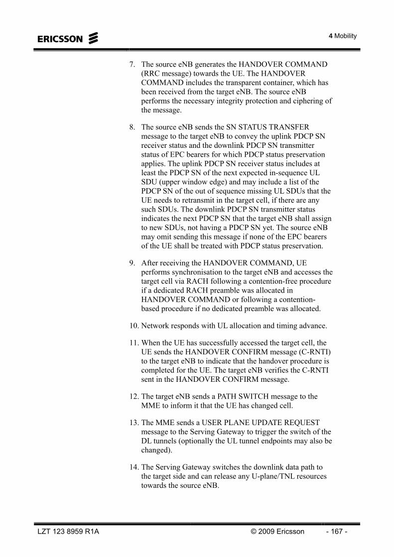
4 Mobility
LZT 123 8959 R1A © 2009 Ericsson - 167 -
7. The source eNB generates the HANDOVER COMMAND (RRC message) towards the UE. The HANDOVER COMMAND includes the transparent container, which has been received from the target eNB. The source eNB performs the necessary integrity protection and ciphering of the message.
8. The source eNB sends the SN STATUS TRANSFER message to the target eNB to convey the uplink PDCP SN receiver status and the downlink PDCP SN transmitter status of EPC bearers for which PDCP status preservation applies. The uplink PDCP SN receiver status includes at least the PDCP SN of the next expected in-sequence UL SDU (upper window edge) and may include a list of the PDCP SN of the out of sequence missing UL SDUs that the UE needs to retransmit in the target cell, if there are any such SDUs. The downlink PDCP SN transmitter status indicates the next PDCP SN that the target eNB shall assign to new SDUs, not having a PDCP SN yet. The source eNB may omit sending this message if none of the EPC bearers of the UE shall be treated with PDCP status preservation.
9. After receiving the HANDOVER COMMAND, UE performs synchronisation to the target eNB and accesses the target cell via RACH following a contention-free procedure if a dedicated RACH preamble was allocated in HANDOVER COMMAND or following a contention-based procedure if no dedicated preamble was allocated.
10. Network responds with UL allocation and timing advance.
11. When the UE has successfully accessed the target cell, the UE sends the HANDOVER CONFIRM message (C-RNTI) to the target eNB to indicate that the handover procedure is completed for the UE. The target eNB verifies the C-RNTI sent in the HANDOVER CONFIRM message.
12. The target eNB sends a PATH SWITCH message to the MME to inform it that the UE has changed cell.
13. The MME sends a USER PLANE UPDATE REQUEST message to the Serving Gateway to trigger the switch of the DL tunnels (optionally the UL tunnel endpoints may also be changed).
14. The Serving Gateway switches the downlink data path to the target side and can release any U-plane/TNL resources towards the source eNB.
LTE 10A Air Interface
- 168 - © Ericsson 2009 LZT 123 8959 R1A
15. User Plane update response sent to the MME
16. The MME confirms the PATH SWITCH message with the PATH SWITCH ACK message (optionally including new UL tunnel endpoint in case they have been changed).
17. By sending RELEASE RESOURCE the target eNB informs the source eNB about the successful completion of the handover and triggers the release of resources.
18. Upon reception of the RELEASE RESOURCE message, the source eNB can release radio and C-plane related resources associated to the UE context. However, the data forwarding may be still be ongoing even after that point.
Measurements
The UE measurements necessary for the handover are configured from the source eNB via RRC. It is generally assumed that downlink measurements, done by the UE, are used for the handover decision (measurements performed by the source eNB may also assist the decision). The reporting can be done on an event triggered and/or periodic basis.
However, the UE is also required to detect and measure neighbor cells itself, since no neighbor cell list is configured in the measurement command for intra-LTE mobility (for inter-frequency measurements at least the carrier frequencies need to be indicated in the measurement configuration). The measurement configurations that need to be indicated for inter-system measurements depend on the target system type and may include neighbor cell lists
Depending on whether the UE needs transmission/reception gaps to perform the given measurement, measurements are classified as gap assisted or non-gap assisted. The required gap patterns are allocated by the eNB and configured in the UE.
UE handover measurements included in LTE standard are:
• RSRP (Reference Symbol Received Power- mean measured power per reference symbol)
• RSRQ (Reference Symbol Received Quality)
4 Mobility
LZT 123 8959 R1A © 2009 Ericsson - 169 -
Investigations in standardization work are ongoing to possibly include other measurements (RS-SINR, RSRP/E_UTRA carrier RSSI). It is however assumed below that RSRP is typically used for best cell evaluation according to present status of standardization. RSRQ can be used for Bad LTE coverage measurements e.g. to trigger start of gap assisted measurements.
The handover evaluation algorithm proposed in this document is based only on handover measurements on mean DL channel performance. In TDD systems the channel path gain is the same in DL and UL. The measurement filter time constant must be set to properly weight large scale fading impact. Fast fading is not considered in handover while it is assumed that the fading coherence time is to short relative to handover execution time and exploring the frequency selective channel in UE scheduling will reduce the fast fading problem. The possible imbalances in DL and UL path gain due to non-compensated feeder losses, incorrect reference symbol power and alike deteriorates handover performance but simulations has shown that the level of impact is relatively low. Concerning UL measurements it is for FFS if including UL interference level will gain to handover performance.
Best cell DL measurement setup in UE
The following configured information is assumed to be included in UE measurement setup (to be standardized): • Trigger condition for event that start measurement reporting.
• Trigger condition for stop measurement reporting
• Type of measurements
• Time between periodic reporting
• L3 measurement filtering parameters. Offset, time to trigger and hysteresis
• Measurement bandwidth 1)
1) The UE handover measurements perform estimations on received cell reference symbols power. While cells may have different bandwidths the UE must be informed on the bandwidth the measurements shall use (that is the bandwidth that is covered by all cells).

LTE 10A Air Interface
- 170 - © Ericsson 2009 LZT 123 8959 R1A
The following UE DL measurement report event is setup:
Event: “Change of best cell” (other cell is better than source cell).
• Is reported when RSRPCandidate > RSRPSourceCell +bestCellThreshold + bestCellHysteres/2
• Starts periodic BestCell measurement reports
• Stops periodic measurement reports when no candidate cells fulfills RSRPCandidate > RSRPSourceCell +bestCellThreshold – bestCellHysteres /2
It is assumed that UE cannot distinguish Intra- MME cells from Inter-MME cells and may not handle cell specific thresholds (i.e. do not have neighbor cell information). The threshold for event triggers must therefore be the minimum threshold that covers all neighbor cell threshold settings. The cell unique thresholds are then applied in eNB.
The UE finds intra frequency cells and detects the identities by their synchronization signals. The UE performs handover measurements on detected cells reference symbols, filters and evaluates measurement results with respect to event conditions. If condition for start event is met a measurement report to source RBS and BestCellEvaluation is sent. If parameter TimeToTrigger is set the event is considered not to be fulfilled until the event condition is fulfilled during the TimeToTrigger. Then the event report is sent. Periodic reporting results in measurement reports being sent periodically as long as condition for stop event is not met.
Concept: UE measures, evaluate and reports standardized ”events”
Events are used for triggering network actions e.g. handover
Standardized events and parameters controlled by the network is used by the UE e.g. Offsets, hysteresis, averaging time, thresholds..
UE sends report only when network is interested in the information i.e only when event criteria is fulfilled.
Figure 4-9. Event triggered measurement reporting.

4 Mobility
LZT 123 8959 R1A © 2009 Ericsson - 171 -
UE measures on cells and reports only when it according to event criteria is important (WCDMA, LTE..)+ UE transmit reports immediately and only when Network configured ”event criteria” are fulfilled.
Typical events:
- A neighbour cell becomes offset better than serving cell (A3)
- Serving cell becomes worse than an absolute threshold (A2)
- ... Figure 4-10. Event triggered measurement reporting.
Cell A
Cell B
Time
1st UE meas. Rep.
Cell B > Cell A + bestCellThreshold +bestCellHysteresis/2
bestCellThreshold
PeriodicalUE meas. Rep.
bestCellhysteresis/2
RSRP
Measurement reports include both CellA (source cell) and cellB.
Cell B < Cell A + bestCellThreshold- bestCellHysteresis/2
bestCellhysteresis/2
Figure 4-11 Event triggered periodical reporting.

LTE 10A Air Interface
- 172 - © Ericsson 2009 LZT 123 8959 R1A
Once the RRC_CONNECTION setup has been completed, the user equipment monitors the RSRP of the serving cell. When the serving cell RSRP drops below a parameter defined threshold, set by the sMeasure parameter, the user equipment commences RSRP and RSRQ measurements (depending on configuration) on the serving and surrounding cells. The user equipment is configured to send an event triggered measurement report when one or several intra frequency cells are measured to be better than the current serving cell by a parameter defined margin.
When a measurement report is received by the serving RBS the intra frequency handover process commences. The serving RBS evaluates the measurement reports and then determines the most suitable handover candidate cell, which is then referred to as the target RBS.
The serving RBS communicates with the target RBS via the X2 interfaces and attempts to set up the handover. If no X2 interface is defined then the signaling is conducted via the S1 interface.
If the target RBS is able to accommodate the handover request it assigns the required resources and send this information to the serving RBS so that the information can be forwarded to the user equipment. The user equipment then attempts the handover to the target cell using the assigned resources.
The user plane data flow from the S-GW is redirected to the target RBS once the user equipment has successfully attached. The original serving RBS is then informed of the successful handover and it releases the resources assigned to the user equipment.
If the target RBS is unable to accept the handover attempt then it will send the HANDOVER PREPARATION FAILURE message to the serving RBS. When this occurs the serving RBS reevaluates the handover candidate list and attempts to set up the handover to the next best candidate RBS.
If no suitable handover candidate cell exists then the call continues on the serving cell.
A diagram showing the Intra-LTE handover process is available in TS 36.300 Section 10.
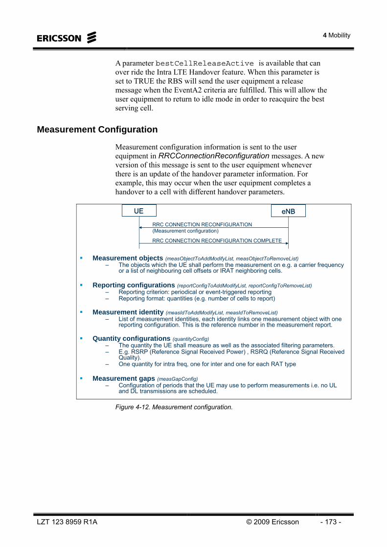
4 Mobility
LZT 123 8959 R1A © 2009 Ericsson - 173 -
A parameter bestCellReleaseActive is available that can over ride the Intra LTE Handover feature. When this parameter is set to TRUE the RBS will send the user equipment a release message when the EventA2 criteria are fulfilled. This will allow the user equipment to return to idle mode in order to reacquire the best serving cell.
Measurement Configuration
Measurement configuration information is sent to the user equipment in RRCConnectionReconfiguration messages. A new version of this message is sent to the user equipment whenever there is an update of the handover parameter information. For example, this may occur when the user equipment completes a handover to a cell with different handover parameters.
Measurement objects (measObjectToAddModifyList, measObjectToRemoveList)– The objects which the UE shall perform the measurement on e.g. a carrier frequency
or a list of neighbouring cell offsets or IRAT neighboring cells.
Reporting configurations (reportConfigToAddModifyList, reportConfigToRemoveList)– Reporting criterion: periodical or event-triggered reporting– Reporting format: quantities (e.g. number of cells to report)
Measurement identity (measIdToAddModifyList, measIdToRemoveList)– List of measurement identities, each identity links one measurement object with one
reporting configuration. This is the reference number in the measurement report.
Quantity configurations (quantityConfig)– The quantity the UE shall measure as well as the associated filtering parameters. – E.g. RSRP (Reference Signal Received Power) , RSRQ (Reference Signal Received
Quality).– One quantity for intra freq, one for inter and one for each RAT type
Measurement gaps (measGapConfig)– Configuration of periods that the UE may use to perform measurements i.e. no UL
and DL transmissions are scheduled.
UEUE
RRC CONNECTION RECONFIGURATION(Measurement configuration)
eNBeNB
RRC CONNECTION RECONFIGURATION COMPLETE
Figure 4-12. Measurement configuration.
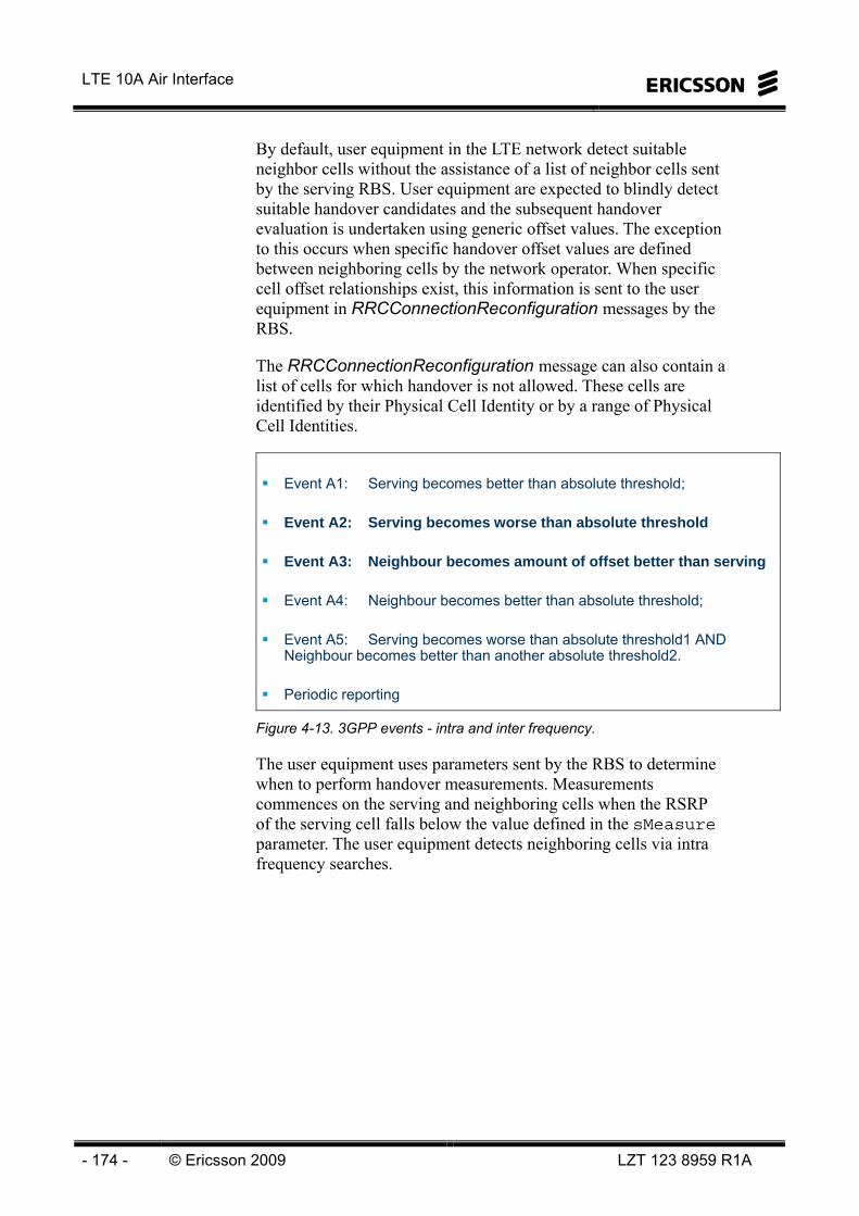
LTE 10A Air Interface
- 174 - © Ericsson 2009 LZT 123 8959 R1A
By default, user equipment in the LTE network detect suitable neighbor cells without the assistance of a list of neighbor cells sent by the serving RBS. User equipment are expected to blindly detect suitable handover candidates and the subsequent handover evaluation is undertaken using generic offset values. The exception to this occurs when specific handover offset values are defined between neighboring cells by the network operator. When specific cell offset relationships exist, this information is sent to the user equipment in RRCConnectionReconfiguration messages by the RBS.
The RRCConnectionReconfiguration message can also contain a list of cells for which handover is not allowed. These cells are identified by their Physical Cell Identity or by a range of Physical Cell Identities.
Event A1: Serving becomes better than absolute threshold;
Event A2: Serving becomes worse than absolute threshold
Event A3: Neighbour becomes amount of offset better than serving
Event A4: Neighbour becomes better than absolute threshold;
Event A5: Serving becomes worse than absolute threshold1 AND Neighbour becomes better than another absolute threshold2.
Periodic reporting
Figure 4-13. 3GPP events - intra and inter frequency.
The user equipment uses parameters sent by the RBS to determine when to perform handover measurements. Measurements commences on the serving and neighboring cells when the RSRP of the serving cell falls below the value defined in the sMeasure parameter. The user equipment detects neighboring cells via intra frequency searches.

4 Mobility
LZT 123 8959 R1A © 2009 Ericsson - 175 -
Event A3
The user equipment uses either RSRP or RSRQ measurements to determine whether to enter the EventA3 condition. The triggerQuantityA3 parameter is used to configure whether RSRP or RSRQ values are used to trigger EventA3.
Measurements of RSRP and RSRQ are performed on the serving and detected neighboring cells. The measured values of RSRP and RSRQ can then be filtered based upon the settings of the filterCoefficientEUtraRsrp and filterCoefficientEUtraRsrq parameters. The filter averages a number of measurements in order to filter out the impact of large scale fast fading.
The user equipment then uses an offset value, a3offset, and a hysteresis value, hysteresisA3, to determine whether to trigger the EventA3. Non default offset relationships use the value cellIndividualOffsetEUtran instead of a3offset for the particular cell relationship.
The formula used by the user equipment for evaluating entry to EventA3 is shown below:
Mn = measured value of the neighboring cell (either RSRP or RSRQ)
Ms = measured value of the serving cell (either RSRP or RSRQ)
offsetaMsAHysteresisMn 33 +>−

LTE 10A Air Interface
- 176 - © Ericsson 2009 LZT 123 8959 R1A
Time
RSRP / RSRQ
A3offset HysteresisA3
timeToTriggerA3
reportAmountA3(0 = continual during event)
Enter Event A3 Leave Event A3
UE measure neighboring cellsmeasurement reports can be
RSRP and/or RSRQ (reportQuantityA3)
Measurement ReportsreportIntervalA3
Cell A
Cell B
To activate the functionbestCellReleaseActive = TRUE
triggerQuantityA3 = trigger on RSRP or RSRQ
sMeasure(triggers on
RSRP only)
Filtering can be appliedto measurements beforeReports are sent to the
RBS
Figure 4-14. Event A3 - Neighbor becomes amount offset better than serving.
Once EventA3 is triggered, the user equipment will wait a predetermined time (timeToTriggerA3) before it commences sending measurement reports to the serving RBS. These measurement reports contain measurements for the serving cells and up to three detected intra frequency neighbor cells. The reportQuantityA3 parameter indicates whether RSRP or RSRQ measurements, or both, are to be included in the measurement reports.

4 Mobility
LZT 123 8959 R1A © 2009 Ericsson - 177 -
Reporting criteria– Reporting threshold– Hysteresis– Time-to-trigger– Reporting interval
Measured results– Event id– Cell identity– Measured measurement quantity
UEUE
MEASUREMENT REPORT (Measured results)
eNBeNB
Reporting criteriafulfilled
Figure 4-15. Measurement reporting.
Measurement reports are sent periodically whilst the EventA3 condition is active. The parameter reportIntervalA3 determines the time interval between measurement reports. The parameter reportAmountA3 indicates how many reports to send; a value of 0 indicates that the reports should be sent indefinitely whilst the EventA3 condition is active.
The user equipment uses the same offset and hysteresis values to determine when to leave EventA3 when the serving cell improves in RSRP or RSRQ relative to the neighboring cells. The formula used by the UE is shown below:
Mn = measured value of the neighboring cell (either RSRP or RSRQ)
Ms = measured value of the serving cell (either RSRP or RSRQ)
The Measurement Reports will be Event triggered and resent periodically as long as the event is fulfilled.
offsetaMsAHysteresisMn 33 +<+

LTE 10A Air Interface
- 178 - © Ericsson 2009 LZT 123 8959 R1A
Event A2
Event A2 follows a similar principle as event A3.
Time
RSRP / RSRQ
HysteresisA2Prim
timeToTriggerA2Prim
reportAmountA2Prim(0 = continual during event)
Enter Event A2
UE measures serving & neighboring cells
Measurement reports can beRSRP and/or RSRQ
(reportQuantityA2Prim)
Measurement ReportsreportIntervalA2Prim
Cell A
triggerQuantityA2Prim = triggeron RSRP or RSRQ
sMeasure(triggers on RSRP only)
Filtering can be appliedto measurements before
Reports are sent to the RBS
Leave Event A2
HysteresisA2Prim
a2ThresholdRsrpPrimOr
a2ThresholdRsrqPrim
Figure 4-16. Event A2 - Serving becomes worse than absolute threshold.
Inequality A2-1 (Entering condition)
Inequality A2-2 (Leaving condition)
The variables in the formula are defined as follows:
Ms is the measurement result of the serving cell, not taking into account any offsets.
HysteresisA2 is the hysteresis parameter for this event (i.e. hysteresis as defined within reportConfigEUTRA for this event).
Thresh is the threshold parameter for this event (i.e. a2-Threshold as defined within reportConfigEUTRA for this event).
ThreshAHysteresisMs <+ 2
ThreshAHysteresisMs >− 2

4 Mobility
LZT 123 8959 R1A © 2009 Ericsson - 179 -
Ms is expressed in dBm in case of RSRP, or in dB in case of RSRQ.
HysteresisA2 is expressed in dB.
Thresh is expressed in the same unit as Ms.
Events for IRAT HO
Event B1: Neighbour becomes better than absolute threshold;
Event B2: Serving becomes worse than absolute threshold1 AND Neighbour becomes better than another absolute threshold2.
Periodic reporting
Figure 4-17. 3GPP events for IRAT.
HANDOVER EVALUATION AND EXECUTION
When a measurement report is received by the RBS the Best Cell Evaluation process is used to perform the handover evaluation. This process performs handover evaluations based on the filtered downlink channel measurements contained in the measurement report.
Evaluates if one or more intra frequency cell is better than current serving cell.
Use event triggered and periodical reporting from UE
No measurement list sent to UE (UE search for all 504 physical cell id and reports the cell(s) fulfilling the event criteria).
UE Event Trigger controlled by: – L3 filtering (How much averaging is done before event evaluation)– Offset (How much better in dB)– Time to trigger (For how long)
Figure 4-18. Best cell evaluation.

LTE 10A Air Interface
- 180 - © Ericsson 2009 LZT 123 8959 R1A
The Best Cell Evaluation process maintains a list of the cell candidates reported by the user equipment in the measurement reports. The list is updated whenever measurement reports are received by the serving cell. The process ranks the serving and handover candidate cells using the appropriate offset and hysteresis values in order to determine the best candidate cell. If the serving cell is the highest ranked cell then the user equipment remains on the serving cell.
If another cell is identified as the best candidate cell then the serving RBS sends a request over the X2 link to the target RBS requesting the allocation of resources to facilitate the handover. If there is no X2 connection between the serving and target RBS then the handover signalling will be transmitted via the S1 interface and the MME. Alternately, if the Automated Neighbor Relations feature is activated then the serving RBS will create the neighbor cell relationship and establish a X2 link to the target RBS prior to facilitating the handover.
source eNodeB
HANDOVERREQUEST
HANDOVER REQUEST ACKNOWLEDGE
target eNodeB
or HANDOVER PREPARATION FAILURE
Figure 4-19. Handover preparation.
The target RBS performs admission control and if it is able to accept the handover it reserves cell resources required for the user equipment. The target RBS sends the information to the serving RBS for forwarding to the user equipment.
Upon receiving a positive acknowledgement to the handover request, the serving RBS completes any ongoing HARQ processes and sends a handover direction to the user equipment.
If the target RBS informs the serving cell that it is unable to accept the handover, the parameter minBestCellHoAttempts , determines the number of attempts for handover to a cell better than the serving one, before handover is attempted to the next best cell. If there is no next best cell in the UE, report handover to the best cell is attempted repeatedly.

4 Mobility
LZT 123 8959 R1A © 2009 Ericsson - 181 -
Best Cell Evaluation
The proposed solution for Best cell evaluation in the eNB makes it possible to:
• Set handover threshold relative to source cell
• Handle both intra-MME and inter-MME cells in evaluation
• Set different handover thresholds for intra-MME handovers and inter-MME handovers.
• Set cell specific offsets relative to handover threshold to compensate for cell DL/UL imbalance or to offset handover region.
• If best cell handover proposal is rejected and another cell that also have higher quality than the source cell is available that cell is proposed for handover.
A neighbor list is configured in the eNB that contains cell-ID, Inter/Intra-MME relation, cell specific offset, etc.
BestCellEvaluation keeps a list with best cell candidates. The list is updated based on measurement reports. The size of the list should correspond to the max number of cell measurements that UE can report in a message report. The Best cell candidate list can contain both Intra and Inter MME LTE cells. A proposal for handover is trigged when current source cell no longer is best cell.
If BestCellEvaluation receives a measurement report while it already processes other measurement report the new report will be buffered. When starting a UE best cell evaluation the latest buffered measurement report will be considered.

LTE 10A Air Interface
- 182 - © Ericsson 2009 LZT 123 8959 R1A
CellIntra/ Inter MME
?
Calculate handover margins using handover threshold and cell specific
offset
BestCellCandidates
Update best cell candidate list
BestCellSelectionkeepCurrentCell
Set trigger toUE Connection
Coordination
Inter-MME
Intra-MME
changeBestCellProposal
Measurement reportEvent / Periodic
Verify that Cell-ID is known and valid
End
Reset trigger to UE Connection Coordination
Figure 4-20. Best Cell Evaluation.

4 Mobility
LZT 123 8959 R1A © 2009 Ericsson - 183 -
1. The received measurement report is validated. Cell-ID’s are checked against configured information. If a cell is unknown the corresponding measurement is discarded. The unknown cell is reported to O&M to possibly update the neighbor cell list.
2. Different handover thresholds may be set for cells within the same MME and for cells in a neighbor MME. This makes it possible to have a general threshold for Inter MME handovers that is higher than for intra-MME handovers. Information on inter-/intra-MME relations is available in RBS neighbor list. A cell specific offset to handover threshold may also be defined to modify threshold for a specific cell. Handover threshold and cell specific offset is applied to candidate cell estimates to find handover margin
handoverMargin = RSRPCandidate - (RSRPSourceCell+handoverThreshold+cellSpecificOffset)
3. BestCellCandidate list is generated in order of handover margin.
4. The cell with positive and highest handoverMargin is selected as best cell. If there are no cell that fulfills this requirement current source cell is best cell.
5. If another cell than current source cell is best cell a trigger to the handler for UE connection is sent indicating that an HO proposal for UE is available. If current source cell is best cell a possible buffered and not handled trigger in UE connection coordination is reset.

LTE 10A Air Interface
- 184 - © Ericsson 2009 LZT 123 8959 R1A
A summary of connected mode mobility is shown below.
RRC (measurement configuration):
HO parameters (intra LTE carrier frequency,
offsets, IRAT cell lists, Hyst etc)
HO?
RS: UE measures RSRP & RSRQ
RS: UE m
easures RSRP & RSRQ
Neighboring cellServing cell
Measurement reports
eNB makes HO decision based on UE measurements
handoverMargin = RSRPCandidate –(RSRPSourceCell+handoverThreshold+cellSpecificOffset)
offsetaMsAHysteresisMn 33 +>−
Event?
UE measures on serving cell and scans all neighboring intra-LTE cells (504 PCIs)
-> No UE neighbor list for intra-LTE
-> Detected ”good” cells are reported
-> IRAT cell lists are used
Figure 4-21. Connected mode mobility.
Handover execution
The handover execution starts when the serving RBS sends an RRCConnectionReconfiguration message to the user equipment telling it to perform a handover.
The handover execution ends when the user equipment successfully accesses the target RBS and sends a Handover Confirm message.
Once the user equipment has successfully connected to the target RBS, the target RBS notifies the MME and S-GW that the handover has occurred. The MME and S-GW switch the bearer from serving RBS to target RBS which then becomes the serving RBS. The RBS informs the source RBS that the handover is complete.
The bearer between S-GW and the RBS is setup per RBS and not per cell. If the UE is moving to a cell in the same RBS then there is no switching of the bearers.
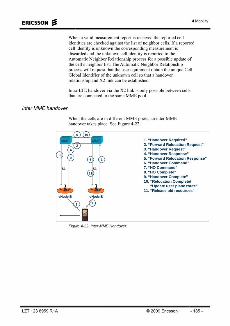
4 Mobility
LZT 123 8959 R1A © 2009 Ericsson - 185 -
When a valid measurement report is received the reported cell identities are checked against the list of neighbor cells. If a reported cell identity is unknown the corresponding measurement is discarded and the unknown cell identity is reported to the Automatic Neighbor Relationship process for a possible update of the cell’s neighbor list. The Automatic Neighbor Relationship process will request that the user equipment obtain the unique Cell Global Identifier of the unknown cell so that a handover relationship and X2 link can be established.
Intra-LTE handover via the X2 link is only possible between cells that are connected to the same MME pool.
Inter MME handover
When the cells are in different MME pools, an inter MME handover takes place. See Figure 4-22.
eNode BeNode B
MME
S1
MME
42
11
7
9
10
3
1. “Handover Required”2. “Forward Relocation Request”3. “Handover Request”4. “Handover Response”5. “Forward Relocation Response”6. “Handover Command”7. “HO Command”8. “HO Complete”9. “Handover Complete”10. “Relocation Complete/
“Update user plane route”11. “Release old resources”
5
6 1
8
eNode BeNode B
S1
Figure 4-22. Inter MME Handover.
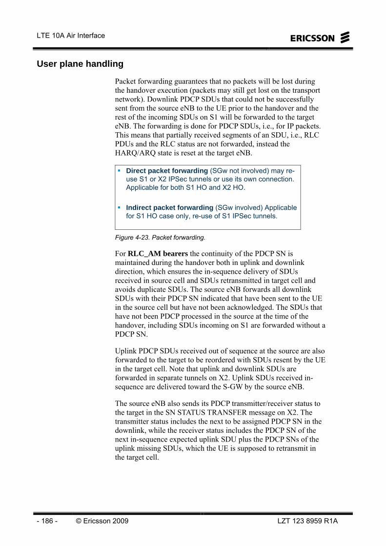
LTE 10A Air Interface
- 186 - © Ericsson 2009 LZT 123 8959 R1A
User plane handling
Packet forwarding guarantees that no packets will be lost during the handover execution (packets may still get lost on the transport network). Downlink PDCP SDUs that could not be successfully sent from the source eNB to the UE prior to the handover and the rest of the incoming SDUs on S1 will be forwarded to the target eNB. The forwarding is done for PDCP SDUs, i.e., for IP packets. This means that partially received segments of an SDU, i.e., RLC PDUs and the RLC status are not forwarded, instead the HARQ/ARQ state is reset at the target eNB.
Direct packet forwarding (SGw not involved) may re-use S1 or X2 IPSec tunnels or use its own connection. Applicable for both S1 HO and X2 HO.
Indirect packet forwarding (SGw involved) Applicable for S1 HO case only, re-use of S1 IPSec tunnels.
Figure 4-23. Packet forwarding.
For RLC_AM bearers the continuity of the PDCP SN is maintained during the handover both in uplink and downlink direction, which ensures the in-sequence delivery of SDUs received in source cell and SDUs retransmitted in target cell and avoids duplicate SDUs. The source eNB forwards all downlink SDUs with their PDCP SN indicated that have been sent to the UE in the source cell but have not been acknowledged. The SDUs that have not been PDCP processed in the source at the time of the handover, including SDUs incoming on S1 are forwarded without a PDCP SN.
Uplink PDCP SDUs received out of sequence at the source are also forwarded to the target to be reordered with SDUs resent by the UE in the target cell. Note that uplink and downlink SDUs are forwarded in separate tunnels on X2. Uplink SDUs received in-sequence are delivered toward the S-GW by the source eNB.
The source eNB also sends its PDCP transmitter/receiver status to the target in the SN STATUS TRANSFER message on X2. The transmitter status includes the next to be assigned PDCP SN in the downlink, while the receiver status includes the PDCP SN of the next in-sequence expected uplink SDU plus the PDCP SNs of the uplink missing SDUs, which the UE is supposed to retransmit in the target cell.
4 Mobility
LZT 123 8959 R1A © 2009 Ericsson - 187 -
After the UE arrives to the target cell a PDCP status report can be exchanged between the UE and the eNB. The status report provides information about the potential SDUs that need to be retransmitted and indicates the PDCP SN of the next in-sequence SDU that the sender should continue the transmission after the retransmitted SDUs.
For RLC_UM bearers the PDCP SN is reset during the handover and an in-sequence cumulative forwarding method is used, where no PDCP SDUs are retransmitted in the target cell. This means that the source eNB forwards downlink PDCP SDUs in-sequence starting from the first SDU which has not been sent in the source cell (any SDUs that have been at least attempted to send in the source cell is not going to be resent in the target cell).
In the uplink the source eNB releases the in-sequence received SDUs toward the S-GW and discards any out of sequence received SDUs. Consequently the source eNB does not forward uplink data to the target eNB. The UE PDCP entity does not attempt to retransmit any PDCP SDU in the target cell for which transmission had already started in the source cell. Instead UE PDCP entity starts the transmission with new PDCP SDU’s.
In-order delivery
After the downlink path is switched at the Serving GW downlink packets on the forwarding path and on the new direct path may arrive interchanged at the target eNB. The target eNB should first deliver all forwarded packets to the UE before delivering any of the packets received on the new direct path. The method employed in the target eNB to enforce the correct delivery order of packets is an implementation specific detail, outside the scope of the standard.
However, in order to assist the reordering function in the target eNB, the Serving GW shall send one or more tagged empty packets on the old path immediately after switching the path for each EPC bearer of the UE. The tagged packet shall not contain user data, they are only used to indicate the end of the packet stream. The tagging can be indicated in the GTP header. After completing the sending of the tagged packets the GW shall not send any further user data packets via the old path. Upon receiving the tagged packets by the source eNB, the source eNB shall forward the packet unchanged toward the target eNB.

LTE 10A Air Interface
- 188 - © Ericsson 2009 LZT 123 8959 R1A
Maintaining security
During mobility the security context is transferred from the source to the target eNB at handover preparation. New security keys are derived in the target cell based on the security keys at the source cell (more specifically based on an eNB specific base-key). Both the target eNB and the UE perform this same key generation process autonomously to obtain the new keys.
The Hyper Frame Number (HFN) and the PDCP SN, which together compose the sequence number input to the ciphering algorithm, are maintained continuous during the handover at least for RLC_AM data bearers. The source eNB sends the current HFN, together with the PDCP SN to the target eNB in the SN Status Transfer message, as we have seen above. (For RLC_UM bearers and for signaling bearers the HFN and PDCP SN are reset after the handover).
The UE and the eNB can start using the new security keys in the target cell immediately after the handover without any further reconfiguration signaling. It is enough to signal only the selected ciphering algorithm and the identifier of the base key set (obtained during initial authentication and used to derive ciphering and integrity keys) in the HO Command.
Error cases
Error cases during the handover process, i.e., when the UE fails to synchronize at the target eNB are handled via the common radio link recovery RRC procedure. We note that a radio link failure may occur basically at any time during the ECM-CONNECTED state of the UE, when it loses the serving cell. The handover failure can be seen as a special case of the RL failure where the RL failure occurs after the UE has received a HO command, which has ordered the UE to switch to a target cell but the UE has failed to access that cell. Although the triggering criteria for the regular RL failure and for the handover failure case will be typically different, the RRC recovery mechanism used will be the same.
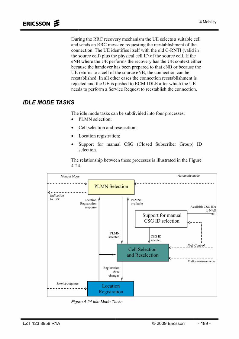
4 Mobility
LZT 123 8959 R1A © 2009 Ericsson - 189 -
During the RRC recovery mechanism the UE selects a suitable cell and sends an RRC message requesting the reestablishment of the connection. The UE identifies itself with the old C-RNTI (valid in the source cell) plus the physical cell ID of the source cell. If the eNB where the UE performs the recovery has the UE context either because the handover has been prepared to that eNB or because the UE returns to a cell of the source eNB, the connection can be reestablished. In all other cases the connection reestablishment is rejected and the UE is pushed to ECM-IDLE after which the UE needs to perform a Service Request to reestablish the connection.
IDLE MODE TASKS
The idle mode tasks can be subdivided into four processes: • PLMN selection;
• Cell selection and reselection;
• Location registration;
• Support for manual CSG (Closed Subscriber Group) ID selection.
The relationship between these processes is illustrated in the Figure 4-24.
PLMN Selection
Location Registration
PLMNsavailable
PLMN selected
LocationRegistration
response
Registration Area
changes
Indication to user
Manual Mode Automatic mode
Service requests
NAS Control
Radio measurements
Cell Selection and Reselection
Support for manual CSG ID selection
AvailableCSG IDsto NAS
CSG IDselected
Figure 4-24 Idle Mode Tasks
LTE 10A Air Interface
- 190 - © Ericsson 2009 LZT 123 8959 R1A
The UE shall, if necessary, then register its presence, by means of a NAS registration procedure, in the tracking area of the chosen cell and as outcome of a successful Location Registration the selected PLMN becomes the registered PLMN.
If the UE finds a more suitable cell, according to the cell reselection criteria, it reselects onto that cell and camps on it. If the new cell does not belong to at least one tracking area to which the UE is registered, location registration is performed.
If necessary, the UE shall search for higher priority PLMNs at regular time intervals and search for a suitable cell if another PLMN has been selected by NAS.
Search of available CSG IDs may be triggered by NAS to support manual CSG ID selection within the registered PLMN.
If the UE loses coverage of the registered PLMN, either a new PLMN is selected automatically (automatic mode), or an indication of which PLMNs are available is given to the user, so that a manual selection can be made (manual mode).
Registration is not performed by UEs only capable of services that need no registration.
The purpose of camping on a cell in idle mode is fourfold:
a) It enables the UE to receive system information from the PLMN.
b) When registered and if the UE wishes to establish an RRC connection, it can do this by initially accessing the network on the control channel of the cell on which it is camped.
c) If the PLMN receives a call for the registered UE, it knows (in most cases) the set of tracking areas in which the UE is camped. It can then send a "paging" message for the UE on the control channels of all the cells in this set of tracking areas. The UE will then receive the paging message because it is tuned to the control channel of a cell in one of the registered tracking areas and the UE can respond on that control channel.
d) It enables the UE to receive ETWS notifications.
If the UE is unable to find a suitable cell to camp on, or the USIM is not inserted, or if the location registration failed UE enters a "limited service" state in which it can only attempt to make emergency calls.
4 Mobility
LZT 123 8959 R1A © 2009 Ericsson - 191 -
RRC_IDLE MODE MOBILITY
Cell selection
The principles of PLMN selection in E-UTRA are based on the 3GPP PLMN selection principles. Cell selection is required on transition from EMM_DEREGISTERED to EMM-REGISTERED and from ECM-IDLE or ECM-CONNECTED.
Cell selection: • The UE NAS identifies a selected PLMN and equivalent
PLMNs;
• The UE searches the E-UTRA frequency bands and for each carrier frequency identifies the strongest cell. It reads cell system information broadcast to identify its PLMN(s):
• The UE may search each carrier in turn (“initial cell selection”) or make use of stored information to shorten the search (“stored information cell selection”).
• The UE seeks to identify a suitable cell; if it is not able to identify a suitable cell it seeks to identify an acceptable cell. When a suitable cell is found or if only an acceptable cell is found it camps on that cell and commence the cell reselection procedure:
• A suitable cell is one for which the measured cell attributes satisfy the cell selection criteria; the cell PLMN is the selected PLMN, registered or an equivalent PLMN; the cell is not barred or reserved and the cell is not part of a tracking area which is in the list of “forbidden tracking areas for roaming”;
• An acceptable cell is one for which the measured cell attributes satisfy the cell selection criteria and the cell is not barred;
Transition to RRC_IDLE:
On transition from RRC_CONNECTED to RRC_IDLE, a UE should camp on the last cell for which it was in RRC_CONNECTED or a cell/any cell of set of cells or frequency be assigned by RRC in the state transition message.
Recovery from out of coverage:
The UE should attempt to find a suitable cell in the manner described for stored information or initial cell selection above. If no suitable cell is found on any frequency or RAT the UE should attempt to find an acceptable cell.

LTE 10A Air Interface
- 192 - © Ericsson 2009 LZT 123 8959 R1A
Cell reselection
UE in RRC_IDLE performs cell reselection. The principles of the procedure are the following: • The UE makes measurements of attributes of the serving and
neighbour cells to enable the reselection process:
• There is no need to indicate neighbouring cell in the serving cell system information to enable the UE to search and measure a cell i.e. E-UTRAN relies on the UE to detect the neighbouring cells;
• For the search and measurement of inter-frequency neighbouring cells, only the carrier frequencies need to be indicated;
• Measurements may be omitted if the serving cell attribute fulfils particular search or measurement criteria.
• Cell reselection identifies the cell that the UE should camp on. It is based on cell reselection criteria which involves measurements of the serving and neighbour cells:
• Intra-frequency reselection is based on ranking of cells;
• Inter-frequency reselection is based on absolute priorities where UE tries to camp on highest priority frequency available. Absolute priorities for reselection are provided only by the RPLMN and valid only within the RPLMN; priorities are given by the system information and valid for all UEs in a cell, specific priorities per UE can be signalled in the RRC Connection Release message. A validity time can be associated with UE specific priorities.
• For inter-frequency neighbouring cells, it is possible to indicate layer-specific cell reselection parameters (e.g., layer specific offset). These parameters are common to all neighbouring cells on a frequency;
• An NCL can optionally be provided by the serving cell to handle specific cases for intra- and inter-frequency neighbouring cells. This NCL can contain cell specific cell reselection parameters (e.g., cell specific offset) for specific neighbouring cells;
• It should be possible to prevent the UE from reselecting to specific detected neighbouring cells;
• Cell reselection can be speed dependent (speed detection based on UTRAN solution);
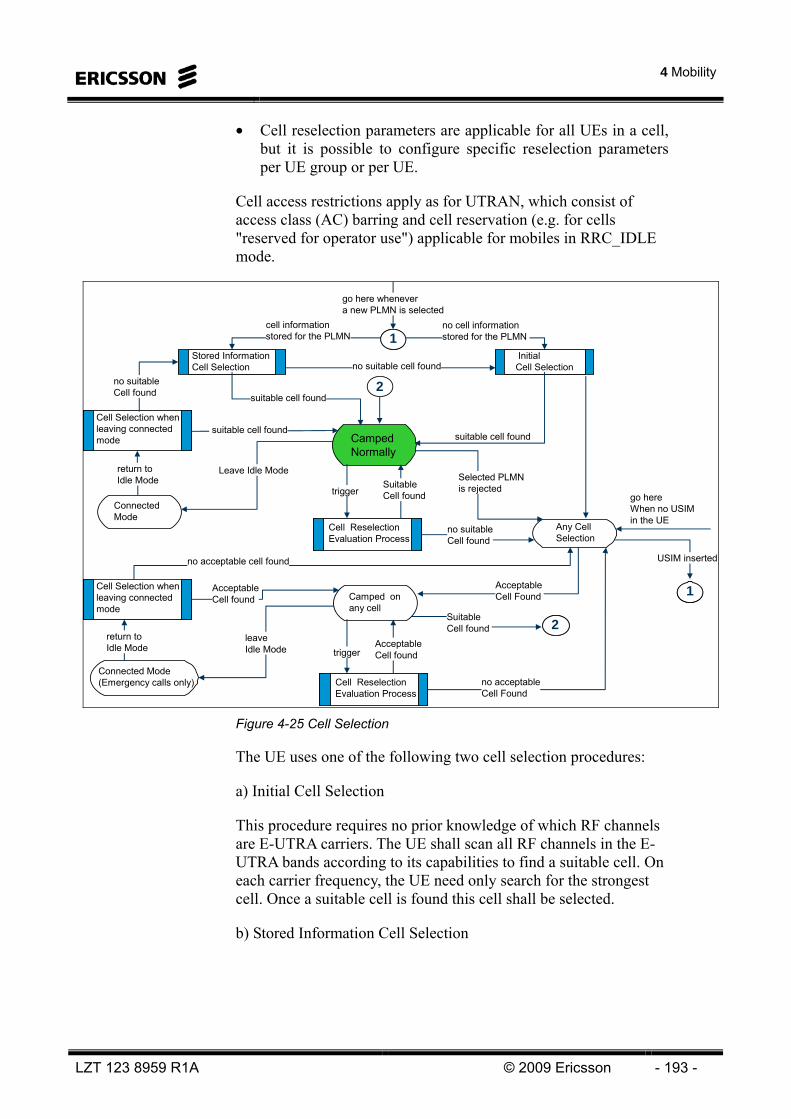
4 Mobility
LZT 123 8959 R1A © 2009 Ericsson - 193 -
• Cell reselection parameters are applicable for all UEs in a cell, but it is possible to configure specific reselection parameters per UE group or per UE.
Cell access restrictions apply as for UTRAN, which consist of access class (AC) barring and cell reservation (e.g. for cells "reserved for operator use") applicable for mobiles in RRC_IDLE mode.
Stored Information Cell Selection
Initial Cell Selection
Cell Selection when leaving connected mode
Cell Selection when leaving connected mode
Cell Reselection Evaluation ProcessCell Reselection Evaluation Process
Connected Mode
Any Cell Selection
Cell Reselection Evaluation ProcessCell Reselection Evaluation Process
Camped on any cell
Connected Mode (Emergency calls only)
2
Camped Normally
go here whenever a new PLMN is selected
no cell information stored for the PLMN
cell informationstored for the PLMN
no suitable cell found
suitable cell found
Selected PLMN is rejected
suitable cell found
no suitable Cell found
return to Idle Mode
Leave Idle Mode
triggerSuitableCell found
no suitableCell found
go hereWhen no USIM in the UE
11
11
USIM inserted
22
AcceptableCell Found
SuitableCell found
no acceptable cell found
Cell Selection when leaving connected mode
Cell Selection when leaving connected mode
triggerAcceptableCell found
no acceptableCell Found
leave Idle Mode
AcceptableCell found
return toIdle Mode
suitable cell found
Figure 4-25 Cell Selection
The UE uses one of the following two cell selection procedures:
a) Initial Cell Selection
This procedure requires no prior knowledge of which RF channels are E-UTRA carriers. The UE shall scan all RF channels in the E-UTRA bands according to its capabilities to find a suitable cell. On each carrier frequency, the UE need only search for the strongest cell. Once a suitable cell is found this cell shall be selected.
b) Stored Information Cell Selection

LTE 10A Air Interface
- 194 - © Ericsson 2009 LZT 123 8959 R1A
This procedure requires stored information of carrier frequencies and optionally also information on cell parameters, from previously received measurement control information elements or from previously detected cells. Once the UE has found a suitable cell the UE shall select it. If no suitable cell is found the Initial Cell Selection procedure shall be started.
Cell Selection Criterion
The cell selection criterion S is fulfilled when:
Srxlev > 0
Where:
Srxlev = Qrxlevmeas – (Qrxlevmin + Qrxlevminoffset) - Pcompensation
Where:
the signaled value QrxlevminOffset is only applied when a cell is evaluated for cell selection as a result of a periodic search for a higher priority PLMN while camped normally. During this periodic search for higher priority PLMN the UE may check the S criteria of a cell using parameter values stored from a different cell of this higher priority PLMN.
When camped on a cell, the UE shall regularly search for a better cell according to the cell reselection criteria. If a better cell is found, that cell is selected. The change of cell may imply a change of RAT.
For normal service, the UE shall camp on a suitable cell, tune to that cell's control channel(s) so that the UE can: • Receive system information from the PLMN; and
• receive registration area information from the PLMN, e.g., tracking area information; and
Srxlev Cell Selection RX level value (dB) Qrxlevmeas Measured cell RX level value (RSRP). Qrxlevmin Minimum required RX level in the cell (dBm) Qrxlevminoffset Offset to the signalled Qrxlevmin taken into account in the Srxlev
evaluation as a result of a periodic search for a higher priority PLMN while camped normally in a VPLMN [5]
Pcompensation max(PEMAX – PUMAX, 0) (dB) PEMAX Maximum TX power level an UE may use when transmitting on the
uplink in the cell (dBm) defined as PEMAX in [TS 36.101] PUMAX Maximum RF output power of the UE (dBm) according to the UE
power class as defined in [TS 36.101]
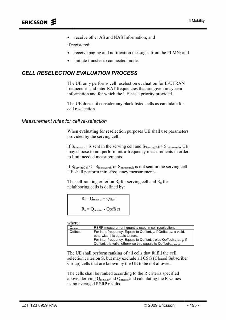
4 Mobility
LZT 123 8959 R1A © 2009 Ericsson - 195 -
• receive other AS and NAS Information; and
if registered:
• receive paging and notification messages from the PLMN; and
• initiate transfer to connected mode.
CELL RESELECTION EVALUATION PROCESS
The UE only performs cell reselection evaluation for E-UTRAN frequencies and inter-RAT frequencies that are given in system information and for which the UE has a priority provided.
The UE does not consider any black listed cells as candidate for cell reselection.
Measurement rules for cell re-selection
When evaluating for reselection purposes UE shall use parameters provided by the serving cell.
If Sintrasearch is sent in the serving cell and SServingCell > Sintrasearch, UE may choose to not perform intra-frequency measurements in order to limit needed measurements.
If SServingCell <= Sintrasearch, or Sintrasearch is not sent in the serving cell UE shall perform intra-frequency measurements.
The cell-ranking criterion Rs for serving cell and Rn for neighboring cells is defined by:
Rs = Qmeas,s + QHyst Rn = Qmeas,n - Qoffset
where: Qmeas RSRP measurement quantity used in cell reselections. Qoffset For intra-frequency: Equals to Qoffsets,n, if Qoffsets,n is valid,
otherwise this equals to zero. For inter-frequency: Equals to Qoffsets,n plus Qoffsetfrequency, if Qoffsets,n is valid, otherwise this equals to Qoffsetfrequency.
The UE shall perform ranking of all cells that fulfill the cell selection criterion S, but may exclude all CSG (Closed Subscriber Group) cells that are known by the UE to be not allowed.
The cells shall be ranked according to the R criteria specified above, deriving Qmeas,n and Qmeas,s and calculating the R values using averaged RSRP results.
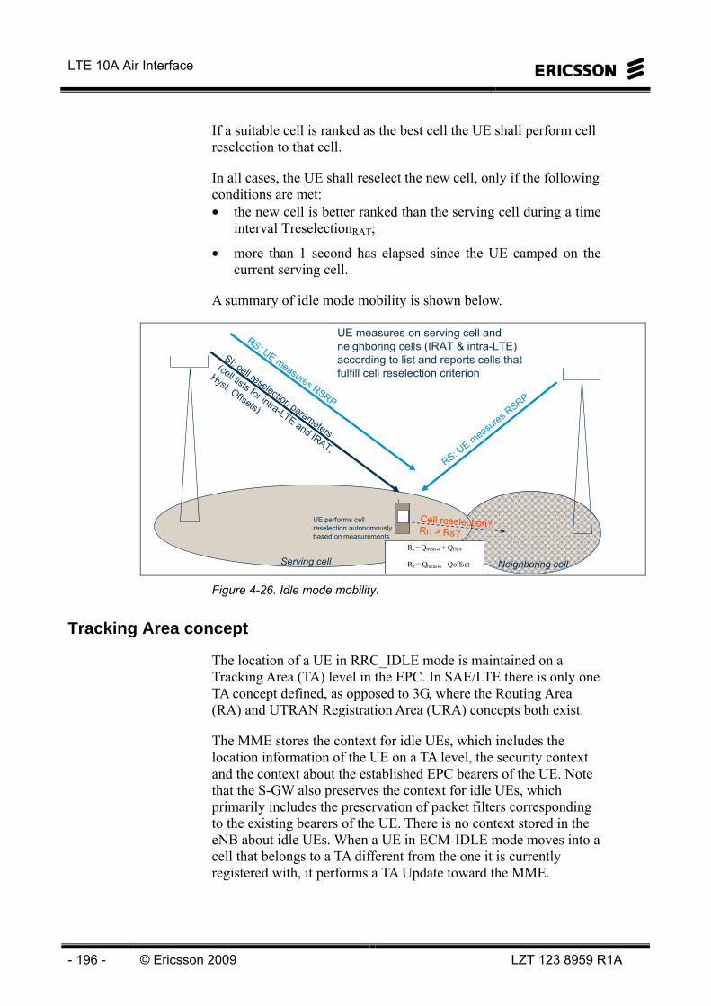
LTE 10A Air Interface
- 196 - © Ericsson 2009 LZT 123 8959 R1A
If a suitable cell is ranked as the best cell the UE shall perform cell reselection to that cell.
In all cases, the UE shall reselect the new cell, only if the following conditions are met: • the new cell is better ranked than the serving cell during a time
interval TreselectionRAT;
• more than 1 second has elapsed since the UE camped on the current serving cell.
A summary of idle mode mobility is shown below.
SI: cell reselection parameters
(cell lists for intra-LTE and IRAT,
Hyst, Offsets)
Cell reselection?Rn > Rs?
RS: UE measures RSRP
RS: UE m
easures RSRP
UE performs cell reselection autonomously based on measurements
Neighboring cellServing cell
Rs = Qmeas,s + QHyst Rn = Qmeas,n - Qoffset
UE measures on serving cell and neighboring cells (IRAT & intra-LTE) according to list and reports cells that fulfill cell reselection criterion
Figure 4-26. Idle mode mobility.
Tracking Area concept
The location of a UE in RRC_IDLE mode is maintained on a Tracking Area (TA) level in the EPC. In SAE/LTE there is only one TA concept defined, as opposed to 3G, where the Routing Area (RA) and UTRAN Registration Area (URA) concepts both exist.
The MME stores the context for idle UEs, which includes the location information of the UE on a TA level, the security context and the context about the established EPC bearers of the UE. Note that the S-GW also preserves the context for idle UEs, which primarily includes the preservation of packet filters corresponding to the existing bearers of the UE. There is no context stored in the eNB about idle UEs. When a UE in ECM-IDLE mode moves into a cell that belongs to a TA different from the one it is currently registered with, it performs a TA Update toward the MME.

4 Mobility
LZT 123 8959 R1A © 2009 Ericsson - 197 -
In order to avoid excessive TA Update signaling by UEs on tracking area borders the standard supports the so call TA-list concept where multiple TAs can be assigned to the UE. According to this concept each cell belongs to only one TA but the UE can be assigned multiple such TAs.
When the UE enters a cell that does not belong to any of the TA it is currently registered with, it performs a TA Update toward the MME. The MME selects a suitable list of TA’s for the UE to camp on and sends this information back to the UE in the TA Update Confirm message.
In case the UE reselects a cell that belongs to a pooling area different from the one where the UE context is located, the network has to perform an MME relocation optionally combined with a GW relocation during the TA Update procedure. When the eNB, where the UE has performed the cell reselection, realizes that it cannot route the TA Update message to the MME where the UE context is located due to being in a different pooling area, it routes the NAS message to a default MME in its own pool. This MME will identify the source MME based on the S-TMSI provided by the UE and will fetch the context from the source MME. When the context fetch is successfully completed it acknowledges the TA Update toward the UE.
TA1TA1
TA4TA4TA3TA3
TA2TA2
UE’s belong to multiple TA1. UE belongs to TA1, TA3 and TA2.
The UE can move within TA1, TA2 and TA3 without TA update.
2. The UE will perform a TA update when moving to a cell withinTA4.
3. After succesful TA update in TA4 the UE will belong to TA2, TA3 and TA4
MMETA Update
TA list 1: TA list 2: ..........- TA1 - TA2- TA2 - TA3- TA3 - TA4
TA Update
confirm
Figure 4-27. Tracking Area concept - multiple tracking areas.
Finally, we note that in RRC_CONNECTED mode the UE does not perform TA Updates as long as it moves within the same pooling area. Only after an S1 handover executed on the border of a pooling area the UE is triggered from the network to perform a TA Update.
LTE 10A Air Interface
- 198 - © Ericsson 2009 LZT 123 8959 R1A
INTER-WORKING WITH 3G/2G
This chapter deals with inter-working between LTE (E-UTRAN) and • 3G (UTRAN)
• 2G (GERAN)
There are in principle two ways of inter-working between LTE and 3G and 2G respectively. The inter-working can be performed by a prepared handover (network controlled) or by a cell re-selection (UE controlled or network assisted). A cell re-selection typically includes signaling with the network but in some cases it may be performed without signaling (i.e., cell change).
The inter working-mechanisms and state transitions described in this chapter assume that the NAS signaling protocols are (at least) compatible enough to map PDP Contexts with EPS Bearers.
State Transitions due to Inter-System Mobility
The agreed state transitions that will be supported between 2G/3G and LTE are shown in Figure 4-28. The methods to execute the supported state transitions are the following: • Network controlled, prepared handover, for UEs in connected
state
• Network controlled Cell Change Order (CCO) with Network Assisted Cell Change (NACC) to GERAN, for UEs in connected state
• UE based cell reselection, for UEs in idle state
The network controlled, prepared handover based state transition is executed via the 2G/3G-LTE inter-system handover procedure, while the cell reselection based state change is executed via a Routing Area Update (LTE to 2G/3G) or via a Tracking Area Update (2G/3G to LTE) procedure.
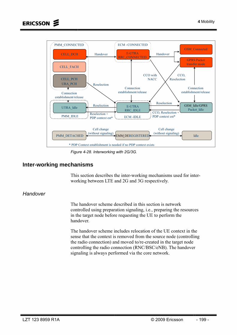
4 Mobility
LZT 123 8959 R1A © 2009 Ericsson - 199 -
Handover
CELL_PCHURA_PCH
CELL_DCH
UTRA_Idle
E-UTRARRC_CONNECTED
E-UTRARRC_IDLE
GSM_Idle/GPRS Packet_Idle
GPRS Packet transfer mode
GSM_ConnectedHandover
ReselectionReselection
Reselection
Connectionestablishment/release
Connectionestablishment/release
Connectionestablishment/release
CCO, Reselection
CCO withNACC
CELL_FACH
CCO, Reselection +PDP context est*
PMM_CONNECTED
PMM_IDLE
* PDP Context establishment is needed if no PDP context exists
Reselection +PDP context est*
ECM - CONNECTED
ECM -IDLE
PMM_DETACHED EMM_DEREGISTERED Idle
Cell change (without signaling)
Cell change(without signaling)
Figure 4-28. Interworking with 2G/3G.
Inter-working mechanisms
This section describes the inter-working mechanisms used for inter-working between LTE and 2G and 3G respectively.
Handover
The handover scheme described in this section is network controlled using preparation signaling, i.e., preparing the resources in the target node before requesting the UE to perform the handover.
The handover scheme includes relocation of the UE context in the sense that the context is removed from the source node (controlling the radio connection) and moved to/re-created in the target node controlling the radio connection (RNC/BSC/eNB). The handover signaling is always performed via the core network.

LTE 10A Air Interface
- 200 - © Ericsson 2009 LZT 123 8959 R1A
The handover starts by the source node (RNC/BSC/eNB) requesting handover (relocation) from the connected core network node. The core network node requests resources from the target system. The target system responds back and provides the necessary “Handover Command” to request the UE to change to the configuration of the target system. Once the UE is detected under the target system the target system updates the packet data routing. The sequence at handover from LTE to 3G is schematically shown in Figure 4-29.
SGSNSGSN
RNC
Node BNode B
MME
eNode BeNode B
sourceS-GW
PDN-GW
targetS-GW
1
1. Handover Required2. Forward Relocation Request3. Create PDP Context Request4. Create PDP Context Response5. Relocation Request6. Relocation Request Ack7. Update PDP Context Request8. Update PDP Context Response9. Forward Relocation Response10. Create Bearer Request11. Create Bearer Response12. HO Command13. HO from E -UTRAN Command14. HO to UTRAN Complete15. Relocation Complete16. Forward Relocation Complete17. Forward Relocation Complete Ack18. Update PDP Context Request19. Update Bearer Request20. Update Bearer Response21. Update PDP Context Response
2
34
5 6
78
9
1011
12
1314
15
16
1718
19
20
21
SGSNSGSN
RNC
Node BNode B
MME
eNode BeNode B
Figure 4-29. LTE to 3G Handover.
The handover example shown in the figure assumes a change of the S-GW, which may not be necessary in all cases.
The user plane is handled via packet forwarding during the handover. This means that the source side (eNB in the example) starts forwarding packets to the target side (to the RNC) at step 12. The forwarding may go directly between the eNB and the RNC if IP connectivity exists between the two nodes. In case direct connectivity is not available between the eNB and the RNC the forwarding can be performed via the S-GW. Then the MME needs to request the allocation of forwarding tunnel endpoints at the source S-GW at step 10-11. These steps are omitted in case of direct forwarding.

4 Mobility
LZT 123 8959 R1A © 2009 Ericsson - 201 -
The forwarding is performed in-sequence for downlink SDUs that have not been successfully sent in the source system.
We note that the S-GW functionality does not necessarily have to be relocated during the procedure and the S-GW and PDN-GW functionality may reside in the same physical node. (One exception when these two functions are located in separate nodes is the roaming scenario.)
The MME needs to map the EPC bearer QoS parameters to PDP context QoS parameters during the context transfer before sending message 2 (in the LTE to 2G/3G direction). Similarly, in the 2G/3G to LTE direction the MME needs to perform the mapping when it receives the context from the source 2G/3G system.
A similar message sequence diagram applies for the handover from 3G to LTE direction and to the 2G – LTE handover cases as well.
Cell re-selection
Cell re-selection is UE controlled, guided by parameters provided by the network.
Cell re-selection between 3G and LTE is supported for UEs in PMM_IDLE and in ECM-IDLE states, respectively. Cell re-selection between 2G and LTE is supported both in Idle and in ECM-IDLE states, respectively and also in Active and in ECM-CONNECTED states, respectively.
The cell reselection is controlled both on NAS and AS level. The NAS level control in the UE includes such functions as maintaining a priority order of PLMNs and the set of forbidden TAs. The AS level cell reselection parameters such as the priorities of different inter-RAT frequencies and the priorities of different E-UTRAN frequencies can be provided to the UE either via system information broadcast or via dedicated signaling. The RRC release signaling can be used to convey re-selection parameters to the UE upon entering idle state.
The cell re-selection scheme includes relocation of the UE context in the sense that the context is removed from the source node, holding the latest UE context (SGSN/MME) and moved to/re-created in the target node.
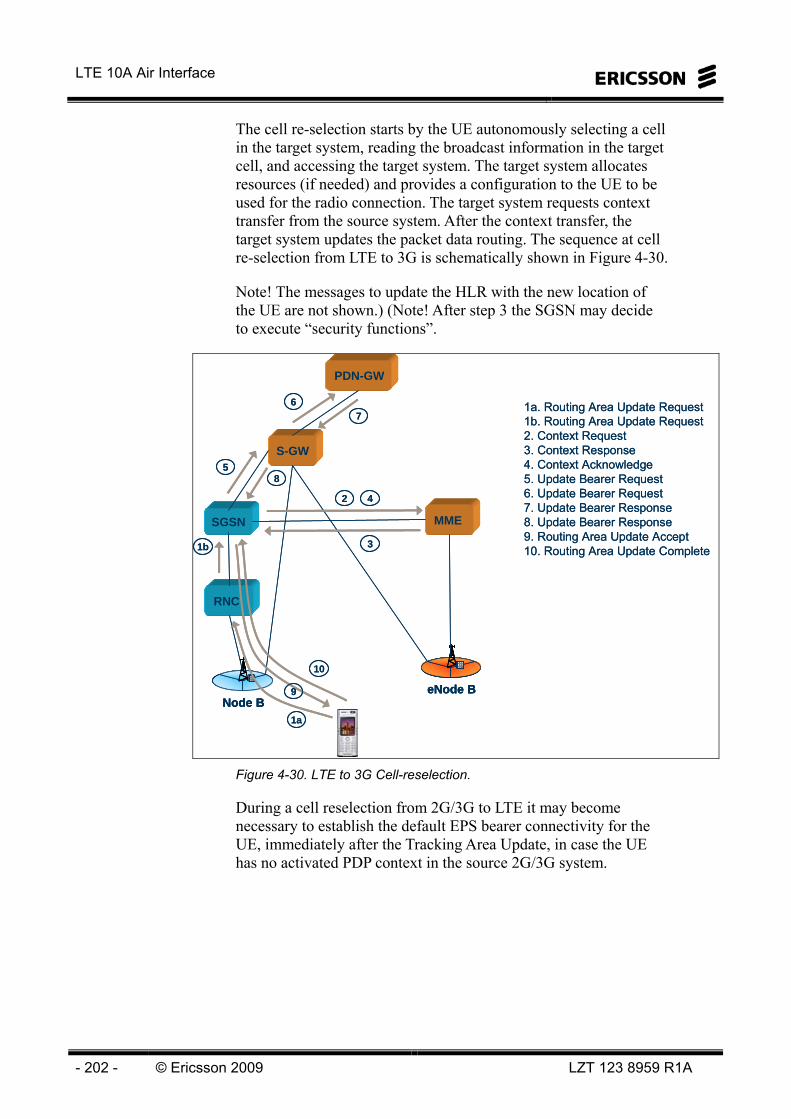
LTE 10A Air Interface
- 202 - © Ericsson 2009 LZT 123 8959 R1A
The cell re-selection starts by the UE autonomously selecting a cell in the target system, reading the broadcast information in the target cell, and accessing the target system. The target system allocates resources (if needed) and provides a configuration to the UE to be used for the radio connection. The target system requests context transfer from the source system. After the context transfer, the target system updates the packet data routing. The sequence at cell re-selection from LTE to 3G is schematically shown in Figure 4-30.
Note! The messages to update the HLR with the new location of the UE are not shown.) (Note! After step 3 the SGSN may decide to execute “security functions”.
SGSN
RNC
Node B
MME
eNode B
PDN-GW
S-GW
1a. Routing Area Update Request1b. Routing Area Update Request2. Context Request3. Context Response4. Context Acknowledge5. Update Bearer Request6. Update Bearer Request7. Update Bearer Response8. Update Bearer Response9. Routing Area Update Accept10. Routing Area Update Complete
2
1b 3
1a
67
4
58
9
10
SGSNSGSN
RNC
Node BNode B
MME
eNode BeNode B
PDN-GW
S-GW
1a. Routing Area Update Request1b. Routing Area Update Request2. Context Request3. Context Response4. Context Acknowledge5. Update Bearer Request6. Update Bearer Request7. Update Bearer Response8. Update Bearer Response9. Routing Area Update Accept10. Routing Area Update Complete
2
1b 3
1a
67
4
58
9
10
Figure 4-30. LTE to 3G Cell-reselection.
During a cell reselection from 2G/3G to LTE it may become necessary to establish the default EPS bearer connectivity for the UE, immediately after the Tracking Area Update, in case the UE has no activated PDP context in the source 2G/3G system.

4 Mobility
LZT 123 8959 R1A © 2009 Ericsson - 203 -
In case of cell reselection in “active mode”, the user plane is expected to be handled via a hard switch at the S-GW. If any handling of pending user plane packets shall be applied, packet forwarding may be used. However, it is noted that during a cell reselection there is a high risk of losing some packets anyway due to the relatively long delay associated with the cell-reselection process, independent of whether packet forwarding is employed or not.
Inter-working with the CS Domain (in 3G and 2G)
LTE is a packet-only system. However, inter-working with the CS domain is handled by functions as SRVCC (Single Radio Voice Call Continuity) and CS Fallback.
INTER-WORKING WITH CDMA2000
The detailed solution for E-UTRAN to EV-DO handover is based on that the UE pre-registers and reserves resources in EV-DO before it leaves the E-UTRAN cell. The registration and resource reservation signaling is transparently tunneled through E-UTRAN and the MME between the UE and the EV-DO RNC. The control of the handover including measurement control and the trigger for performing the handover is done by the eNB.
CDMA-eHRPD Session Continuity
The purpose of the CDMA-eHRPD Session continuity, coverage triggered feature is to manage the redirection of user equipment in RRC_CONNECTED mode towards a CDMA-eHRPD network when the user equipment measures bad coverage on the LTE network. The redirection is network controlled based upon user equipment measurement reports of the serving LTE cell.
The CDMA-eHRPD Session continuity, coverage triggered feature uses the Event A2 (Serving becomes worse than threshold) measurement process as defined in TS 36.300 and TS 36.331.

LTE 10A Air Interface
- 204 - © Ericsson 2009 LZT 123 8959 R1A
The measurement process employed by the user equipment for the evaluation of the serving cell uses parameters sent by the serving RBS to the user equipment. These parameters, which are sent to the user equipment in RRCConnectionReconfiguration messages, include a hysteresis values, measurement filtering parameters and time to trigger counters. The hysteresis values and time to trigger counters are included in the evaluation in order to prevent the redirection to the CDMA-eHRPD network being based upon a small number of measurements taken during a rapid fade in the radio link.
The user equipment measurements are reported to the serving RBS which makes the ultimate decision on redirection to the CDMA-eHRPD network. Two types of measurements are used in the handover evaluation process:
• RSRP (Reference Symbol Received Power) which represents the mean measured power per reference symbol
• RSRQ (Reference Symbol Received Quality) which provides an indication of the reference signal quality
The user equipment will inform the RBS when it has bad LTE coverage. The bad coverage release can be set to trigger on the RSRP value, the RSRQ value or both and the measurement reports sent by the user equipment to the RBS contain either or both of these values.
The RBS makes the decision on whether to release the user equipment with redirection to a CDMA-eHRPD network or to handover the user equipment to another LTE cell. The RBS makes the choice depending on the user equipment capabilities and RBS licenses. If the user equipment is released with redirection to a CDMA-eHRPD network, the release message will contain cell information to help the user equipment to find a suitable CDMA-eHRPD cell.

5 Abbreviations
LZT 123 8959 R1A © 2009 Ericsson - 205 -
5 Abbreviations
LTE 10A Air Interface
- 206 - © Ericsson 2009 LZT 123 8959 R1A
Intentionally Blank

5 Abbreviations
LZT 123 8959 R1A © 2009 Ericsson - 207 -
3GPP 3rd Generation Partnership Project ACIR Adjacent Channel Interference Ratio ACK Acknowledgement ACLR Adjacent Channel Leakage Ratio ACP Automatic Cell Planning ACS Adjacent Channel Selectivity AES Advanced Encryption Standard AGW Access Gateway AIF Auto-Integration Function AISG Antenna Interface Standards Group AM Acknowledged Mode AMBR Aggregate Maximum Bit Rate A-MPR Additional Maximum Power Reduction ANR Automated Neighbour Relation APAC Asia Pacific API Application Programming Interface APN Access Point Name ARP Allocation and Retention Priority ARQ Automatic Repeat Request ARW Add RBS Wizard AS Access Stratum AS Application Server A-SBG Access SBG ASC Antenna System Controller ASD Automatic SW Download ASSL Adjacent Subcarrier Set Leakage ASSR Adjacent Subcarrier Set Rejection BCCH Broadcast Control Channel BCH Broadcast Channel BEM Block Edge Masks BM-SC Broadcast-Multicast Service Center BS Base Station BSR Buffer Status Report BW Bandwidth C/I Carrier-to-Interference Power Ratio CA Certificate Authority CAPEX Capital Expenditure CAZAC Constant Amplitude Zero Auto-Correlation CCCH Common Control Channel CCE Control Channel Element CDD Cyclic Delay Diversity CDF Cumulative Distribution Function CDMA Code Division Multiple Access CE Carrier Ethernet CEPT The European Conference of Postal and Telecommunications Administrations CM Configuration Management CMC Connection Mobility Control CMDB Configuration Management Data Base

LTE 10A Air Interface
- 208 - © Ericsson 2009 LZT 123 8959 R1A
CN Core Network COMINF Common O&M Infrastructure CO-OP Cooperative Open-OSS Project (interface also called Itf-P2P) CORBA Common Object Request Broker Architecture CP Cyclic Prefix CP Control Plane CPC Continous Packet Connectivity C-plane Control Plane CQI Channel Quality Indicator CRC Cyclic Redundancy Check C-RNTI Cell RNTI CS Circuit Switched CSCF Call Session Control Function CSG Closed Subscriber Group CSV Comma-Separated Values CTR Cell TRace CW Codeword CW Continuous-wave DCCH Dedicated Control Channel DCH Dedicated Channel DCI Downlink Control Information DCN Data Communication Network DFT Discrete Fourier Transform DFT-S-OFDM DTF Spread OFDM DHCP Dynamic Host Configuration Protocol DL Downlink DL-SCH Downlink Shared Channel DNS Domain Name Service DRB Data Radio Bearer DRX Discontinuous Reception DSCP Differentiated Services Code Point DTCH Dedicated Traffic Channel DTX Discontinuous Transmission DwPTS Downlink Pilot Time Slot EBS Event Based Statistics ECC Electronic Communications Committee ECGI E-UTRAN Cell Global Identifier ECM EPS Connection Management E-DCH Enhanced DCH EHPLMN Equivalent Home PLMN EMEA Europe, Middle East and Africa EMM EPS Mobility Management eNB E-UTRAN NodeB eNode B E-UTRAN NodeB EPC Ericsson Policy Control EPC Evolved Packet Core EPS Evolved Packet System (E-UTRAN and EPC) E-RAB E-UTRAN Radio Access Bearer ETSI European Telecommunications Standards Institute

5 Abbreviations
LZT 123 8959 R1A © 2009 Ericsson - 209 -
ETWS Earth Quake and Tsunami Warning System E-UTRA Evolved UTRA E-UTRAN Evolved UTRAN, used as synonym for LTE in the document. EV-DO Evolution - Data Optimized EVM Error Vector Magnitude FCC Federal Communications Commission FDD Frequency Division Duplex FDM Frequency Division Multiplexing FDMA Frequency Division Multiple Access FEC Forward Error Correction FFS For Further Study FFT Fast Fourier Transform FM Fault Management FMX Fault Management Expert FQDN Fully Qualified Domain Name FS Frame Structure FTP File Transfer Protocol GBR Guaranteed Bit Rate GCL Generalized Chirp Like GE Gigabit Ethernet GERAN GSM EDGE Radio Access Network GGSN Gateway GPRS Support Node GMPLS Generalized Multi-Protocol Label Switching GNSS Global Navigation Satellite System GP Guard Period GPRS General Packet Radio Service GSM Global System for Mobile communication GTP GPRS Tunneling Protocol GTP-C GTP Control GTP-U GTP User Data Tunneling GUI Graphical user Interface GUTI Globally Unique Temporary Identifier GW Gateway HA-CS High Availability Cluster Solution HARQ Hybrid ARQ HO Handover HOM Higher Order Modulation HPLMN Home PLMN HRPD High Rate Packet Data HSDPA High Speed Downlink Packet Access HS-DSCH High Speed Downlink Shared Channel HSPA High Speed Packet Access HSS Home Subscriber Server HSUPA High Speed Uplink Packet Access HTTP Hypertext Transfer Protocol HW Hardware IASA Inter-Access Anchor ICIC Inter-Cell Interference Coordination I-CSCF Interrogating CSCF

LTE 10A Air Interface
- 210 - © Ericsson 2009 LZT 123 8959 R1A
ID Identifier IEEE Institute of Electrical and Electronics Engineers IETF Internet Engineering Task Force IFFT Inverse FFT IMEI International Mobile Equipment Identity IMS IP Multimedia Telephony IMS IP Multimedia subsystem IMSI Individual Mobile Subscriber Identity IMT International Mobile Telecommunications IP Internet Protocol IRAT Inter Radio Access Technology IS Integrated Site ITU International Telecommunications Union ITU-R ITU Radio communication Sector JSR Java Specification Request KPI Key Performance Indicator LB Load Balancing LCID Logical Channel ID LCR Low Chip Rate LCR-TDD Low Chip Rate TDD LDC Linear Dispersion Code LDPC Low-Density Parity-check Code LED Light Emitting Diode LTE Long Term Evolution, used as synonym for E-UTRAN in the document. MAC Medium Access Control MBA Management Based Activation MBMS Multimedia Broadcast Multicast Service MBR Maximum Bit Rate MBSFN Multicast Broadcast Single Frequency Network MCCH Multicast Control Channel MCE Multi-cell/multicast Coordination Entity MCH Multicast Channel MCS Modulation and Coding Scheme MEF Mobile Entertainment Forum MGC Media Gateway Controller MGW Media Gateway MIB Master Information Block MIB Management Information Base MIMO Multiple Input Multiple Output ML-PPP Multilink point to point protocol MM Multi Mediation MM Mobility Management MME Mobility Management Entity MMS Multimedia Messaging Service Managed Objects interface (MOCI) MMTel Multi Media Telephony MOCI Managed Object Configuration Interface MOP Maximum Output Power MPLS Multiple Protocol Label Switching MPR Maximum Power Reduction

5 Abbreviations
LZT 123 8959 R1A © 2009 Ericsson - 211 -
MS Management Services MSAP MCH Subframe Allocation Pattern MTAS Multimedia Telephony Application Server MTCH Multicast Traffic Channel MU-MIMO Multiple User-MIMO mUPE MBMS UPE NACK Negative Acknowledgement NAS Non-Access Stratum NCC Network Color Code NCL Neighbour Cell List NCLI Node Command Line Interface NCS Neighbouring Cell Support NE Network Element NEM Network Element Manager NGMN Next Generation Mobile Networks NGSA Next Generation Service Assurance NH Next Hop Key NM Network Management NMS Network Management System NMX Network level deployment of expert rules NOC Network Operations Center NR Neighbor cell Relation NRT Non Real Time N-SBG Network SBG O&M Operation and Maintenance OAM Operations Administration and Management OFDM Orthogonal Frequency Division Multiplexing OFDMA Orthogonal Frequency Division Multiple Access OMC Operation and Maintenance Center OOB Out Of Band OPEX Operating Expenditures OSS Operation and Support System OSS-RC Operation and Support System Radio and Core OTN Operator Terminal Network P(N)CCH Paging (and Notification) Control Channel P2P Peer-to-Peer PA Power Amplifier PAPR Peak to Average Power Ratio PAR Peak to Average Ratio PARC Per Antenna Rate Control PBBTE Provider Backbone Bridge Traffic Engineering PBC Power and Battery Cabinet PBCH Physical Broadcast CHannel PBN Packet Backbone Network PBR Prioritised Bit Rate PCC Policy Charging Control PCCH Paging Control Channel PCEF Policy Charging Enforcement Function PCFICH Physical Control Format Indicator CHannel

LTE 10A Air Interface
- 212 - © Ericsson 2009 LZT 123 8959 R1A
PCH Paging Channel PCI Physical Cell ID PCRF Policy Control and Charging Rules Function P-CSCF Proxy - Call Session Control Function PDCCH Physical Downlink Control CHannel PDCP Packet Data Convergence Protocol PDN Packet Data Network PDP Packet Data Protocol PDSCH Physical Downlink Shared CHannel PDU Protocol Data Unit P-GW PDN Gateway PHICH Physical Hybrid ARQ Indicator CHannel PHR Power Headroom Report PHS Personal Handy-phone System PHY Physical layer PLMN Public Land Mobile Network PM Performance Management PMCH Physical Multicast CHannel PMI Precoder Matrix Indicator PMIP Proxy Mobile IP PnP Plug and Play PoP Point of Presence PRACH Physical Random Access CHannel PRB Physical Resource Block P-RNTI Paging RNTI PS Packet Switched PSC Packet Scheduling P-SCH Primary Synchronization Channel PSK Pre-Shared Keys PSTN Public Switched Telephone Network PTT Push to Talk PUCCH Physical Uplink Control CHannel PUSCH Physical Uplink Shared Channel QAM Quadrature Amplitude Modulation QCI QoS Class Identifier QoS Quality of Service QPP Quadrature Permutation Polynomial QPSK Quadrature Phase Shift Keying RA Random Access RA Registration Authority RAC Radio Admission Control RACH Random Access Channel RAN Radio Access Network RANAP RAN Application Part RA-RNTI Random Access RNTI RAT Radio Access Technology RB Radio Bearer RB Resource Block RBC Radio Bearer Control
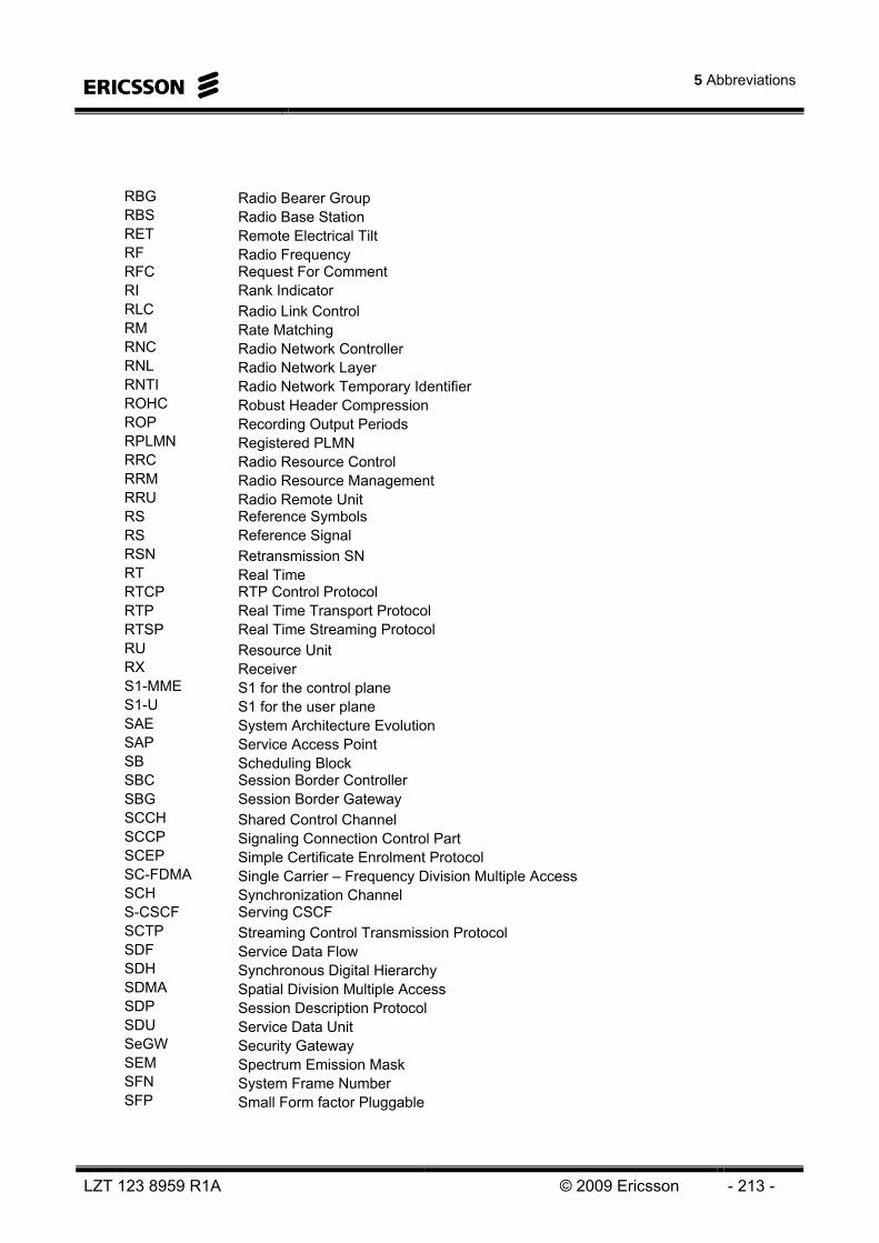
5 Abbreviations
LZT 123 8959 R1A © 2009 Ericsson - 213 -
RBG Radio Bearer Group RBS Radio Base Station RET Remote Electrical Tilt RF Radio Frequency RFC Request For Comment RI Rank Indicator RLC Radio Link Control RM Rate Matching RNC Radio Network Controller RNL Radio Network Layer RNTI Radio Network Temporary Identifier ROHC Robust Header Compression ROP Recording Output Periods RPLMN Registered PLMN RRC Radio Resource Control RRM Radio Resource Management RRU Radio Remote Unit RS Reference Symbols RS Reference Signal RSN Retransmission SN RT Real Time RTCP RTP Control Protocol RTP Real Time Transport Protocol RTSP Real Time Streaming Protocol RU Resource Unit RX Receiver S1-MME S1 for the control plane S1-U S1 for the user plane SAE System Architecture Evolution SAP Service Access Point SB Scheduling Block SBC Session Border Controller SBG Session Border Gateway SCCH Shared Control Channel SCCP Signaling Connection Control Part SCEP Simple Certificate Enrolment Protocol SC-FDMA Single Carrier – Frequency Division Multiple Access SCH Synchronization Channel S-CSCF Serving CSCF SCTP Streaming Control Transmission Protocol SDF Service Data Flow SDH Synchronous Digital Hierarchy SDMA Spatial Division Multiple Access SDP Session Description Protocol SDU Service Data Unit SeGW Security Gateway SEM Spectrum Emission Mask SFN System Frame Number SFP Small Form factor Pluggable
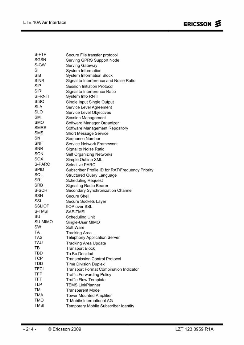
LTE 10A Air Interface
- 214 - © Ericsson 2009 LZT 123 8959 R1A
S-FTP Secure File transfer protocol SGSN Serving GPRS Support Node S-GW Serving Gateway SI System Information SIB System Information Block SINR Signal to Interference and Noise Ratio SIP Session Initiation Protocol SIR Signal to Interference Ratio SI-RNTI System Info RNTI SISO Single Input Single Output SLA Service Level Agreement SLO Service Level Objectives SM Session Management SMO Software Manager Organizer SMRS Software Management Repository SMS Short Message Service SN Sequence Number SNF Service Network Framework SNR Signal to Noise Ratio SON Self Organizing Networks SOX Simple Outline XML S-PARC Selective PARC SPID Subscriber Profile ID for RAT/Frequency Priority SQL Structured Query Language SR Scheduling Request SRB Signaling Radio Bearer S-SCH Secondary Synchronization Channel SSH Secure Shell SSL Secure Sockets Layer SSLIOP IIOP over SSL S-TMSI SAE-TMSI SU Scheduling Unit SU-MIMO Single-User MIMO SW Soft Ware TA Tracking Area TAS Telephony Application Server TAU Tracking Area Update TB Transport Block TBD To Be Decided TCP Transmission Control Protocol TDD Time Division Duplex TFCI Transport Format Combination Indicator TFP Traffic Forwarding Policy TFT Traffic Flow Template TLP TEMS LinkPlanner TM Transparent Mode TMA Tower Mounted Amplifier TMO T-Mobile International AG TMSI Temporary Mobile Subscriber Identity
5 Abbreviations
LZT 123 8959 R1A © 2009 Ericsson - 215 -
TNL Transport Network Layer TSP Ericsson Telecom Server Platform TTI Transmission Time Interval TX Transmit UCI Uplink Control Information UE User Equipment UETR UE TRace UL Uplink UL-SCH Uplink Shared Channel UM Unacknowledged Mode UMTS Universal Mobile Telecommunication System UP User Plane UPE User Plane Entity U-plane User plane UpPTS Uplink Pilot Time Slot URA UTRAN Routing Area UTRA UMTS Terrestrial Radio Access UTRAN UMTS Terrestrial Radio Access Network VoIP Voice over IP VPLMN Visited PLMN VRB Virtual Resource Block WAP Wireless Access Protocol WAPECS Wireless Access Policy for Electronic Communications Services WCDMA Wideband Code Division Multiple Access WDM Wavelength Division Multiplexing X2-C X2-Control plane X2-U X2-User plane XML Extensible Markup Language

LTE 10A Air Interface
- 216 - © Ericsson 2009 LZT 123 8959 R1A
Intentionally Blank