LTE-advanced modem design: challenges and perspectives
13
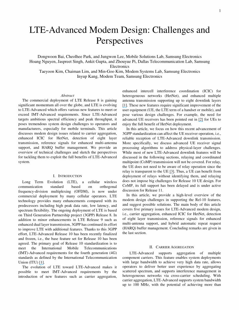
1 Abstract The commercial deployment of LTE Release 8 is gaining significant momentum all over the globe, and LTE is evolving to LTE-Advanced which offers various new features to meet or exceed IMT-Advanced requirements. Since LTE-Advanced targets ambitious spectral efficiency and peak throughput, it poses tremendous system design challenges to operators and manufacturers, especially for mobile terminals. This article discusses modem design issues related to carrier aggregation, enhanced ICIC for HetNet, detection of eight layer transmission, reference signals for enhanced multi-antenna support, and HARQ buffer management. We provide an overview of technical challenges and sketch the perspectives for tackling them to exploit the full benefits of LTE-Advanced system. I. INTRODUCTION Long Term Evolution (LTE), a cellular wireless communication standard based on orthogonal frequency-division multiplexing (OFDM), is now under commercial deployment by many cellular operators. LTE technology provides many enhancements compared with its predecessors including high peak data rate, low latency, and spectrum flexibility. The ongoing deployment of LTE is based on Third Generation Partnership project (3GPP) Release 8. In addition to minor enhancements in LTE Release 9 such as enhanced dual layer transmission, 3GPP has continued its effort to improve LTE with additional features. Thanks to this 3GPP effort, LTE-Advanced Release 10 has been recently finalized and frozen, i.e., the base feature set for Release 10 has been agreed. The primary goal of Release 10 standardization is to meet the International Mobile Telecommunications (IMT)-Advanced requirements for the fourth generation (4G) standards as defined by the International Telecommunication Union (ITU) [1]. The evolution of LTE toward LTE-Advanced makes it possible to meet IMT-Advanced requirements by the introduction of new features such as carrier aggregation, enhanced intercell interference coordination (ICIC) for heterogeneous networks (HetNet), and enhanced multiple antenna transmission supporting up to eight downlink layers [1]. These new features require significant improvement of the user equipment (UE, the LTE term of a handset or mobile), and pose various design challenges. For example, the need for advanced UE receivers has been pointed out in [2] for UEs to enjoy the full benefit of HetNet deployment. In this article, we focus on how this recent advancement of 3GPP standardization can affect the UE receiver operation, i.e., reliable reception of LTE-Advanced downlink transmission. More specifically, we discuss advanced UE receiver signal processing algorithms to address physical-layer challenges. While most of new LTE-Advanced downlink features will be discussed in the following sections, relaying and coordinated multipoint (CoMP) transmission will not be covered. For relay, the UE does not need to be aware of relay operation since the relay is transparent to the UE [3]. Thus, a UE can benefit from deployment of relays without identifying them, and relaying does not impose big challenges for Release 10 UE design. For CoMP, its full support has been delayed and is under active discussion for Release 11. In this article, we provide a high-level overview of the modem design challenges in supporting the Rel-10 features, and suggest possible solutions. The main body of this article covers five primary issues for LTE-Advanced modem design, i.e., carrier aggregation, enhanced ICIC for HetNet, detection of eight layer transmission, reference signals for enhanced multi-antenna support, and hybrid automatic repeat request (HARQ) buffer management. Concluding remarks are given in the last section. II. CARRIER AGGREGATION LTE-Advanced supports aggregation of multiple component carriers. This feature enables system deployments with large bandwidth to achieve very high data rate, allows operators to deliver better user experience by aggregating scattered spectrum, and supports interference management in heterogeneous networks via cross-carrier scheduling. With carrier aggregation, LTE-Advanced supports system bandwidth up to 100 MHz, with the potential of achieving more than LTE-Advanced Modem Design: Challenges and Perspectives Dongwoon Bai, Cheolhee Park, and Jungwon Lee, Mobile Solutions Lab, Samsung Electronics Hoang Nguyen, Jaspreet Singh, Ankit Gupta, and Zhouyue Pi, Dallas Telecommunication Lab, Samsung Electronics Taeyoon Kim, Chaiman Lim, and Min-Goo Kim, Modem Systems Lab, Samsung Electronics Inyup Kang, Modem Team, Samsung Electronics
-
Upload
independent -
Category
Documents
-
view
1 -
download
0
Transcript of LTE-advanced modem design: challenges and perspectives
1
Abstract
The commercial deployment of LTE Release 8 is gaining
significant momentum all over the globe, and LTE is evolving
to LTE-Advanced which offers various new features to meet or
exceed IMT-Advanced requirements. Since LTE-Advanced
targets ambitious spectral efficiency and peak throughput, it
poses tremendous system design challenges to operators and
manufacturers, especially for mobile terminals. This article
discusses modem design issues related to carrier aggregation,
enhanced ICIC for HetNet, detection of eight layer
transmission, reference signals for enhanced multi-antenna
support, and HARQ buffer management. We provide an
overview of technical challenges and sketch the perspectives
for tackling them to exploit the full benefits of LTE-Advanced
system.
I. INTRODUCTION
Long Term Evolution (LTE), a cellular wireless
communication standard based on orthogonal
frequency-division multiplexing (OFDM), is now under
commercial deployment by many cellular operators. LTE
technology provides many enhancements compared with its
predecessors including high peak data rate, low latency, and
spectrum flexibility. The ongoing deployment of LTE is based
on Third Generation Partnership project (3GPP) Release 8. In
addition to minor enhancements in LTE Release 9 such as
enhanced dual layer transmission, 3GPP has continued its effort
to improve LTE with additional features. Thanks to this 3GPP
effort, LTE-Advanced Release 10 has been recently finalized
and frozen, i.e., the base feature set for Release 10 has been
agreed. The primary goal of Release 10 standardization is to
meet the International Mobile Telecommunications
(IMT)-Advanced requirements for the fourth generation (4G)
standards as defined by the International Telecommunication
Union (ITU) [1].
The evolution of LTE toward LTE-Advanced makes it
possible to meet IMT-Advanced requirements by the
introduction of new features such as carrier aggregation,
enhanced intercell interference coordination (ICIC) for
heterogeneous networks (HetNet), and enhanced multiple
antenna transmission supporting up to eight downlink layers
[1]. These new features require significant improvement of the
user equipment (UE, the LTE term of a handset or mobile), and
pose various design challenges. For example, the need for
advanced UE receivers has been pointed out in [2] for UEs to
enjoy the full benefit of HetNet deployment.
In this article, we focus on how this recent advancement of
3GPP standardization can affect the UE receiver operation, i.e.,
reliable reception of LTE-Advanced downlink transmission.
More specifically, we discuss advanced UE receiver signal
processing algorithms to address physical-layer challenges.
While most of new LTE-Advanced downlink features will be
discussed in the following sections, relaying and coordinated
multipoint (CoMP) transmission will not be covered. For relay,
the UE does not need to be aware of relay operation since the
relay is transparent to the UE [3]. Thus, a UE can benefit from
deployment of relays without identifying them, and relaying
does not impose big challenges for Release 10 UE design. For
CoMP, its full support has been delayed and is under active
discussion for Release 11.
In this article, we provide a high-level overview of the
modem design challenges in supporting the Rel-10 features,
and suggest possible solutions. The main body of this article
covers five primary issues for LTE-Advanced modem design,
i.e., carrier aggregation, enhanced ICIC for HetNet, detection
of eight layer transmission, reference signals for enhanced
multi-antenna support, and hybrid automatic repeat request
(HARQ) buffer management. Concluding remarks are given in
the last section.
II. CARRIER AGGREGATION
LTE-Advanced supports aggregation of multiple
component carriers. This feature enables system deployments
with large bandwidth to achieve very high data rate, allows
operators to deliver better user experience by aggregating
scattered spectrum, and supports interference management in
heterogeneous networks via cross-carrier scheduling. With
carrier aggregation, LTE-Advanced supports system bandwidth
up to 100 MHz, with the potential of achieving more than
LTE-Advanced Modem Design: Challenges and
Perspectives
Dongwoon Bai, Cheolhee Park, and Jungwon Lee, Mobile Solutions Lab, Samsung Electronics
Hoang Nguyen, Jaspreet Singh, Ankit Gupta, and Zhouyue Pi, Dallas Telecommunication Lab, Samsung
Electronics
Taeyoon Kim, Chaiman Lim, and Min-Goo Kim, Modem Systems Lab, Samsung Electronics
Inyup Kang, Modem Team, Samsung Electronics

2
1Gbps throughput for downlink and 500 Mbps throughput for
uplink.
The component carriers can be contiguous within the same
band as shown in Fig. 1 (a), non-contiguous in the same band as
shown in Fig. 1 (b), or in different bands as shown in Fig. 1 (c).
Each of the aggregated component carriers can have a different
bandwidth. The component carriers that a UE needs to support
are determined through a UE-specific configuration process
and a dynamic activation and deactivation process. The carrier
aggregation configuration is UE-specific. Each UE is
configured with a primary component carrier (also known as
Primary Cell or PCell). All the other component carriers can be
configured as secondary component carriers (also known as
Secondary Cells or SCells). The configured SCells are subject
to activation/de-activation through either the
activation/de-activation medium access control or the SCell
de-activation timer maintained by the UE. This concept is
shown in Fig. 1 (d). An SCell can be de-activated, e.g., when
there is not enough traffic for the SCell. This allows a UE to
turn off part of the transceiver chain, e.g., radio frequency (RF)
front end and fast Fourier transform (FFT), to save power. Due
to this activation/de-activation process, the state of SCells can
be frequently changed. As a result, the radio link monitoring is
only supported in PCell but not in SCells to avoid complex UE
behavior and additional control signaling overhead. Despite
this kind of effort, the increased complexity due to physical
downlink control channel (PDCCH) decoding and timing
tracking of multiple component carriers cannot be avoided.
However, it does not create any complicated technical issue but
extra hardware including additional PDCCH decoding and
timing tracking blocks for additional component carriers and
memory buffer to cope with a relative propagation delay
difference among component carriers at UE side.
The receiver RF filter design depends on the type of carrier
aggregation. For carrier aggregation with intra-band contiguous
component carriers, either a single RF filter or two separate RF
filters can be used. To use a single FFT to cover the contiguous
component carriers, the carriers should be separated by integer
multiples of 300 kHz – the least common multiple of the LTE
channel raster (100 kHz) and the LTE subcarrier spacing (15
kHz). In that case, the contiguous component carriers can be
separated in digital baseband. The advantage of using a single
RF filter is low hardware complexity due to a single RF chain
for carrier aggregation. However, it requires an
analog-to-digital converter and RF filter with larger bandwidth.
Moreover, due to activation and de-activation of component
carriers, there is a retuning issue when a single RF is used for
these component carriers. When the status of an SCell is
changed from activated to de-activated, the UE can save power
by retuning its RF from an aggregated bandwidth including the
SCell to a smaller bandwidth excluding the SCell. However,
during this retuning procedure, some packets may be dropped
due to RF transition time for retuning. In LTE, the impact of RF
retuning to PDCCH is exacerbated because the PDCCH is
located at the beginning of each subframe – a region likely to
fall into the transition due to RF retuning. Loss of a PDCCH
leads to loss of the entire physical downlink shared channel
(PDSCH) subframe in the absence of control information
required for decoding, which causes increased packet errors.
RF retuning is closely related to the measurement of the
de-activated SCell since the UE needs to retune its RF
whenever the de-activated SCell measurement is required. Thus,
LTE-Advanced should balance the packet loss due to RF
retuning and the measurement of de-activated SCells to achieve
optimal network performance.
For carrier aggregation with non-contiguous component
carriers (either in the same band or different bands), separate
RF filters and FFTs are needed. Moreover, harmonics and inter
modulation products from uplink inter-band carrier aggregation
transmitter can desensitize the receive band or have
considerable impact on other radio technology in the handset.
Thus, elements of the RF like the transmit/receive filter with
proper attenuation should be carefully considered. Moreover, to
support multi-band carrier aggregation, new UE modems need
to include additional components such as band switch, diplexer,
and duplexer. The additional insertion loss due to these
components needs to be handled properly by using a
higher-gain power amplifier or a better duplexer, and relaxing
the RF requirement or implementation margin.
III. ENHANCED ICIC FOR HETNET
A HetNet consists of low-power picocells, and femtocells in
addition to high-power macrocells [2]. In contrast to a
traditional homogeneous deployment of macrocells where the
data rate of end users at the cell edge can suffer, the deployment
of picocells and femtocells can improve end user experience
connected to these cells. However, this benefit comes with the
cost of additional intercell interference between heterogeneous
cells. While a HetNet can be deployed in LTE Release 8/9, this
cross-tier interference is effectively handled by enhanced ICIC,
a recently developed interference coordination feature in
LTE-Advanced Release 10. Note that picocells are deployed by
operators while femtocells are mostly deployed by end users
possibly in an unplanned manner. Moreover, a femtocell can
restrict public access, i.e., closed subscriber group (CSG).
Thus, it is more difficult to manage cross-tier interference
between a macrocell and a femtocell than between a macrocell
and a picocell.
The use of carrier aggregation is a possible solution to
manage cross-tier interference. For example, control signaling
of a macrocell is assigned at one carrier while control signaling
of a pico/femto-cell is assigned at the other carrier. The
partition of control channels eliminates the possibility of
cross-tier interference. However, depending on the availability
of spectrum for operators, carrier aggregation may not be
employed.
In the cochannel deployment scenario without carrier
aggregation, resources should be partitioned in a more
sophisticated manner to manage cross-tier interference because
two heterogeneous cells share the same bandwidth. To
minimize this cross-tier interference, an almost blank subframe
(ABS) is introduced for enhanced ICIC, where most of
subcarriers remain unused, and thus its interference to other cell
is limited. Even in ABS, some reference signal, i.e., common
reference signal (CRS), and some essential control signals, i.e.,
physical broadcast channel (PBCH), primary synchronization

3
signal (PSS), and secondary synchronization signal (SSS), need
to be transmitted to support legacy UEs of Release 8/9.
Now, the necessity of advanced UE receivers and their
modem design challenge come into play. Since CRS,
synchronization signals, and PBCH are still transmitted in
ABS, they inevitably collide with signals from other cell. Even
with recent standardization effort, this type of collision is
unavoidable. An advanced UE receiver with interference
cancellation techniques will still benefit from the HetNet
cochannel deployments while a legacy UE of Release 8/9 can
maintain its connection to the macrocell thanks to interference
management through ABS. The rationale behind this
interference cancellation technique is that if the interference is
strong, then it can be decoded and cancelled one by one from
the strongest interference–successive interference cancellation
(SIC). In SIC, ordering does matter and the strongest
interference can be cancelled first. If the interference is not
strong enough to be decoded, it can be ignored. However,
imperfect interference cancellation can degrade the quality of
measurements used for radio link monitoring, radio resource
management, and channel quality indicator (CQI) feedback.
To illustrate the effectiveness of interference cancellation, let
us consider the cell search procedure under enhanced ICIC as
an example. If overlapping or adjacent cells are frame
synchronized, even with ABS, synchronization signals (i.e.,
PSS and SSS) of these cells will collide. For a homogeneous
deployment, this may not be a problem since the UE just needs
to attach to the cell providing higher downlink power, i.e., the
cell with higher correlation of synchronization signals.
However, in a HetNet deployment, the UE may want to attach
to the cell providing lower downlink power. This could happen
if the access to the cell with higher power is restricted (e.g.,
CSG femtocell).
Fig. 2 (a) illustrates the cell search procedure with SIC. In
this procedure, the UE indentifies cells one by one starting from
the cell with the highest power. However, PSS and SSS of the
detected cell are cancelled before the next cell is detected. This
SIC on synchronization signals can be applied until all cells are
detected. In Fig. 2 (b), we consider a two cell deployment
scenario where the target cell power is 10dB less than the
interfering cell power. It is clearly shown that the use of SIC is
essential to reduce the detection error in the HetNet cell search
procedure with enhanced ICIC. In general, the advanced UE
receiver needs the capability of interference mitigation to enjoy
the full benefit of a HetNet deployment with the enhanced ICIC
feature of LTE-Advanced.
IV. DETECTION OF EIGHT LAYER TRANSMISSION
The LTE-Advanced system should fulfill the ITU
requirements of the downlink peak spectral efficiency of
30bps/Hz. The peak spectral efficiency is the highest
achievable data rate per overall cell bandwidth assuming
error-free conditions when all available radio resources for the
corresponding link direction are assigned to a single UE. While
two or four layer transmission would be more prevalent even
for the LTE-Advanced system, the required downlink peak
spectral efficiency can only be attained using high order
antenna configurations (i.e., 8×8). The main challenge of high
order multiple-input and multiple-output (MIMO) is
computational complexity. Maximum likelihood (ML)
detection is optimal in the sense that it minimizes error
probability when the distributions of all data are equally likely.
However, due to its high complexity in 8×8 MIMO systems
with high modulation order, a direct implementation of ML
detection might not be a viable option for such MIMO systems.
Instead of ML detection, linear MIMO detection algorithms
having lower complexity than optimal ML detection, such as
zero-forcing (ZF) or minimum mean square error (MMSE), can
be applied with interference cancellation techniques. However,
both still have much inferior performance than ML detection.
Thus several near ML algorithms such as sphere decoding
(SD) [4] and K-best [5] have been introduced. Those
algorithms are unceasingly being improved to achieve
performance close to ML with lower complexity. In particular,
the classical K-best detector attempts to output a list of size K
consisting of the most likely values of the transmitted symbols
based on the observations, and is used for hard detection of
symbols [5]. As K increases, the computational complexity
increases while the performance improves.
Fig. 3 shows (a) the block error rate (BLER) performance
and (b) the computational complexity comparisons of K-best
with different K values and MMSE detection algorithms for an
8×8 MIMO system. It can be seen that the performance
improvement of K-best becomes marginal as K value exceeds
256 for 16QAM while the computational complexity of K-best
grows linearly with K. Thus, with a careful choice of K, it is
possible to achieve performance close to ML with much lower
computational complexity. Nevertheless, the computational
complexity of K-best is still relatively high to be implemented
in a real handset with high order antenna configurations.
The challenge in LTE-Advanced system design is
therefore to devise a MIMO detector that achieves performance
close to ML, while still incurring computational cost within the
reach of current hardware. Existing near ML MIMO detectors
such as K-best only take us halfway in that direction. Moreover,
the soft bit value calculation of the MIMO detector [6] and the
use of iterative detection and decoding [4] can be studied to
further enhance their performance. In short, more research
effort is required to realize the gains of MIMO systems with the
hardware constraints.
V. REFERENCE SIGNALS FOR ENHANCED MULTI-ANTENNA
SUPPORT
In LTE/LTE-Advanced, the evolved NodeB (eNodeB, the
LTE term of a basestation) transmits certain pre-defined
reference signal sequences along with the data. These are
employed by the UE to estimate the downlink channel for the
twin purposes of feeding back channel state information (CSI)
to the eNodeB, and equalization of the downlink channel in the
process of data demodulation. In LTE/LTE-Advanced, there
are four non-overlapping CRS patterns (corresponding to four
transmit antenna ports), as shown in Fig. 4. Since the CRS is
used for data demodulation, the density of the reference signals
is high.

4
One of the requirements for LTE-Advanced is that it
should support up to eight layer transmission, which implies
that there need to be at least eight transmit antenna ports.
Towards this, a key change in the reference signal design
philosophy from LTE Release 8 is the separation of the
demodulation reference signals (DM-RS) from the channel
state information reference signals (CSI-RS) in Release 10.
This potentially saves significant reference signal overhead, as
it allows the densely populated DM-RS to be UE-specific. In a
particular resource block (RB), the eNodeB needs to transmit
DM-RS only for the layers that are being transmitted to the
scheduled UE, irrespective of the number of transmit antenna
ports. On the other hand, CSI-RS continues to be transmitted
from each of the antenna ports at the eNodeB, to enable full CSI
feedback from the UE.
In light of the new reference signal designs for
LTE-Advanced, significant new challenges emerge from a
modem design perspective, as discussed next.
A. CSI-RS
In order to provide for eight CSI-RS patterns, the density
of CSI-RS in LTE-Advanced is significantly lesser than that of
CRS. Specifically, there is only one CSI-RS resource element
(RE) per RB per antenna port (Fig. 4). Furthermore, unlike
CRS, which is transmitted in every subframe (every 1ms),
CSI-RS is expected to be transmitted only once every five or
ten subframes. Such sparse nature of CSI-RS poses a major
technical hurdle for UE modem development in
LTE-Advanced. In particular, advanced algorithms are needed
for CSI-RS based channel estimation and for computation of
the CSI feedback parameters such as CQI, (i.e., modulation and
coding rate) because existing methods may incur throughput
degradation and/or result in a failure to meet the target BLER
requirements. Our results in Fig. 5 (discussed next) provide a
glimpse of some of these issues.
Typically, algorithm design for CSI feedback involves the
computation of an effective signal-to-noise ratio (SNR) metric.
The effective SNR is a physical layer abstraction meant to
convert a set of different SNRs, experienced during coded
transmission over a frequency selective fading channel, into an
equivalent SNR that would result in a similar BLER when
transmitting over the static additive white Gaussian noise
(AWGN) channel [7]. Using the computed effective SNR, and,
pre-computed reference BLER vs. SNR curves for the AWGN
channel, the UE can feedback the largest CQI that meets the
target BLER requirement. With ideal channel state information
at the UE, the preceding abstraction is known to work well.
However, using standard MMSE channel estimation at the
CSI-RS RE locations, we observe that the effective SNR
prediction can be significantly erroneous. In Fig. 5 (a), we
consider 50 different channel realizations, and plot the
following three effective SNRs: (i) predicted effective SNR
with ideal CSI, (ii) predicted effective SNR with CSI-RS based
channel estimation, (iii) the actual effective SNR. We can
observe that with ideal CSI, the prediction matches the actual
effective SNR closely, while with estimated CSI, there can be
significant errors. This can result in inaccurate CQI feedback,
potentially causing the downlink BLER to overshoot the
mandated target BLER.
Next, we consider the impact of CSI-RS channel
estimation on throughput performance. This entails not only
CQI feedback, but also, and perhaps more crucially from a
throughput perspective, the spatial preprocessing (i.e., PMI/RI)
feedback because channel estimation errors can result in
sub-optimal PMI/RI feedback, leading to throughput
degradation. For a 2×2 MIMO system, Fig. 5 (b) depicts the
throughput as a function of the SNR. We observe that channel
estimation errors result in about 2 dB performance loss in the
low SNR regime.
Our results demonstrate the need to investigate advanced
algorithms for CSI-RS channel estimation and CSI feedback.
Possible strategies to improve the CSI-RS channel estimation
performance could include exploitation of the time-frequency
correlations (across different RBs, and/or different subframes),
e.g., using a two-dimensional (2-D) MMSE filter. This is
accompanied by a caveat that such approaches hinge critically
on the estimation of the channel’s power delay profile (PDP)
and the Doppler shift, which pose significant technical
challenges by themselves. Potential benefits of exploiting these
correlations are indicated by the results in Fig. 5 (b), wherein
we have depicted the throughput gains obtained using a 2-D
MMSE interpolator, with known PDP and Doppler shift.
B. DM-RS
LTE-Advanced DM-RS is expected to be used mainly for
multi-layer transmission supporting up to eight DM-RS
antenna ports. DM-RS mapping to REs is illustrated in Fig. 4.
DM-RS is multiplexed by a hybrid scheme of code division and
frequency division multiplexing. For code division
multiplexing, the time-domain orthogonal cover code (OCC) or
Walsh sequence is used [8]. At each receiver antenna of UEs,
channel estimates associated with each transmission layer (or
antenna port) are obtained by de-spreading the received
reference signals with the known reference signal sequence and
OCC. This orthogonal de-spreading with the scrambled OCC is
valid when the channel is constant over reference signals, i.e.,
under static or slowly time-varying channels. Regarding
precoding, UEs can demodulate data in the PDSCH without
precoding information because both data and DM-RS use the
same precoder or beam-forming matrix within the same RBs.
The precoder itself is not specified in the specification and its
usage depends on eNodeB vendors.
In general, DM-RS channel estimation involves an
interpolation using the reference signals. It is well-known that a
2-D MMSE filter is an optimal linear filter minimizing the
mean squared error of channel estimation [9]. The 2-D MMSE
filter uses correlation information both in the frequency and
time domain. Since the 2-D filter is computationally more
complex than two similar one-dimensional (1-D) filters, 1-D
filters are frequently adopted and applied separately in the time
domain and the frequency domain. However, the lower
complexity of 1-D filters comes at the cost of a higher error

5
floor as shown in Fig. 5 (c). Lower complexity methods of 2-D
MMSE filters need to be identified to make them viable for
implementation in UE modems. In addition, it is shown that the
DM-RS channel estimation performance can be improved by
considering the properties of time-varying channels.
With the advent of advanced LTE-Advanced transmission
techniques, some aspects of DM-RS based channel estimation
merit investigation. First, the baseline of DM-RS channel
estimation is performed per RB. This single RB-based channel
estimation may restrict the availability and performance of
channel estimation methods. For example, frequency domain
correlation information required for MMSE-based
interpolation cannot be directly obtained in a per-RB basis,
since the number of reference signals is very limited.
Nevertheless, a UE may use the precoding granularity in
multiple RBs, and improve the channel estimation performance
through RB bundling [8]. Second, multi-user interference
besides inter-cell interference also needs to be considered when
multi-user MIMO (MU-MIMO) schemes are used. When
MU-MIMO is configured, the eNodeB may try to select
precoding matrices which minimize the multi-user interference
among co-scheduled UEs. In practice, however, the precoded
DM-RS at co-scheduled UEs may not be perfectly orthogonal
to each other. In addition, the reference signal sequences of
co-scheduled UEs are not orthogonal. Due to non-orthogonal
precoding and reference signal sequences of MU-MIMO
transmission, interference cancellation schemes are required to
obtain reasonable channel estimation performance. In practice,
SIC can be adopted for interference cancellation, where
interference is eliminated by repeating estimation and
subtraction schemes.
VI. HARQ BUFFER MANAGEMENT
The data channel uses a turbo code for forward error
correction (FEC) and employs a stop-and-go protocol known as
HARQ, where a codeword can be punctured and transmitted in
multiple attempts. Which of the bits are punctured in a given
attempt is indicated by the redundancy version index. For each
HARQ attempt that fails decoding, the UE sends a negative
acknowledgement and waits for the next retransmission
attempt.
HARQ brings many benefits, including throughput
maximization, latency control with time-interlaced HARQ
processes and fine control of system resource usage. However,
HARQ is effective only if the UE has the memory to store the
soft bits (i.e., soft channel bits) after decoding fails. This is
because the probability of successful decoding of a single
HARQ transmission can be very low, especially when the base
station overestimates the channel strength or performs
aggressive puncturing, where soft combining of multiple
HARQ attempts is needed to ensure successful decoding.
Storage requirement is perhaps the biggest disadvantage of
HARQ. Compared to LTE Release 8 and Release 9,
LTE-Advanced requires larger HARQ storage due to the higher
throughput. Thus, it becomes crucial to reduce the storage
requirement by managing the HARQ buffer efficiently. Table 1
lists the required buffer sizes for different UE categories, of
which the last three are new additions for LTE-Advanced. Note
that the UE capability is classified into several categories in
LTE-Advanced [10]. A UE from category 5, 6, or 7 must be
able to store about 3.7 million soft bits. For UE category 8, the
number is increased ten-fold. Such storage requirements pose a
big challenge for handset modem designers. Suppose it takes 4
logic gates to store one bit, and each soft bit is represented by an
8-bit integer. Then, UE category 5 would require a gate count of
about 117 million just for the HARQ data buffering. Thus,
without efficient techniques for HARQ buffer management,
such storage requirement would mean a very large die size for
on-chip memory.
Fortunately, it is not necessary to store the soft bits at the
original resolution. A soft bit is typically in the form of
log-likelihood ratio, which can be represented by 8-bits
accurately. When decoding fails, the soft bits can be
compressed to a significantly lower resolution before sending
to storage. In some cases a 1-bit compressed resolution is able
to maintain a throughput loss of less than 1 dB in SNR.
However, in high data rate scenarios, such low resolution
causes significant throughput losses especially when the
effective FEC code rate is too high for a given SNR.
To improve the throughput performance in challenging
scenarios, the compressed resolution needs to be higher than 1
bit. In particular, fractional rates can be achieved using vector
quantization techniques [11]. Because soft bits belonging to the
same modulation symbol are more strongly correlated than bits
that do not, it is beneficial to group together soft bits that come
from the same modulation symbol when vectorizing the
log-likelihood ratio sequence to be compressed.
In addition to compression, HARQ buffer memory needs to
be further managed via non-compressive techniques in case of
carrier aggregation. For example, the required buffer size for
UE category 5 is 3,667,200 soft bits divided equally among all
configured downlink component carriers. The eNodeB,
however, assumes a soft buffer size of 3,667,200 for rate
matching per component carrier, regardless of the number of
component carriers. While the number of soft bits received can
exceed the required storage space, the UE can choose to store
more soft bits than the specification requires. Because not all
configured component carriers are fully utilized at all times, the
UE can dynamically divide HARQ storage space among
component carriers by assigning less (no) storage to
under-utilized (idle) component carriers and more to loaded
component carriers. However, a mechanism should be in place
to rebalance the memory usage when an underutilized/idle
component carrier becomes busy.
VII. CONCLUSION
LTE Advanced is a flexible wireless broadband technology
that promises significant enhancements in the end-user
experience. This article provides a high-level overview of UE
modem design challenges in supporting LTE-Advanced
Release 10 features and suggests possible solutions. Various
challenges in the following areas are identified and their
implications and solutions to LTE-Advanced modem design
are covered: carrier aggregation, enhanced ICIC for HetNet,
detection of eight layer transmission, reference signals for

6
enhanced multi-antenna support, and HARQ buffer
management. By overcoming the challenges in the UE modem
design, LTE-Advanced will deliver on its promise of
significant enhancements in the end-user experience.
ACKNOWLEDGMENT
The authors would like to thank Dr. Hairuo Zhuang, Dr.
Chun Kin Au Yeung, Dr. Jung Hyun Bae, and Dr. Andrey Rog
for providing simulation results. The authors would also like to
thank Dr. Sudhir Ramakrishna for coordinating collective
efforts in Dallas.
REFERENCES
[1] S. Parkvall, A. Furuskär, and E. Dahlman, "Evolution of LTE toward
IMT-advanced," IEEE Communications Magazine, vol.49, no.2,
February 2011, pp.84-91.
[2] A. Damnjanovic, J. Montojo, Y. Wei, T. Ji, T. Luo, M. Vajapeyam, T.
Yoo, O. Song, D. Malladi, "A survey on 3GPP heterogeneous networks,"
IEEE Wireless Communications, vol.18, no.3, June 2011, pp.10-21.
[3] A. Ghosh, R. Ratasuk, B. Mondal, N. Mangalvedhe, and T. Thomas,
"LTE-advanced: next-generation wireless broadband technology," IEEE
Wireless Communications, vol.17, no.3, June 2010, pp.10-22.
[4] B. M. Hochwald and S. ten Brink, "Achieving near-capacity on a
multiple-antenna channel," IEEE Transactions on Communications,
vol.51, no.3, March 2003, pp. 389- 399.
[5] Z. Guo and P. Nilsson, “Algorithm and Implementation of the K-Best
Sphere Decoding for MIMO Detection,” IEEE Journal on Selected Areas
in Communications, vol. 24, no. 3, March 2006, pp. 491-503.
[6] J. Lee, J.-W. Choi, and H. Lou, "MIMO maximum likelihood soft
demodulation based on dimension reduction," in Proceedings of IEEE
GLOBECOM, 2010.
[7] J. Zhuang, L. Jalloul, R. Novak and J, Park, IEEE 802.16m Evaluation
Methodology Document (IEEE 802.16m-08/004r4), November 2008.
[8] Evolved Universal Terrestrial Radio Access (E-UTRA); Physical
channels and modulation (Release 10), 3GPP TS 36.211, V10.2.0, June
2011.
[9] P. Hoeher, S. Kaiser, and P. Robertson, “Pilot-symbol-aided channel
estimation in time and frequency,” in proceedings of IEEE GLOBECOM,
Communication Theory Mini-Conference, 1997, pp. 90-96.
[10] Evolved Universal Terrestrial Radio Access (E-UTRA); User Equipment
(UE) radio access capabilities (Release 10), 3GPP TS 36.306 V10.2.0,
June 2011.
[11] R. M. Gray, “Quantization,” IEEE Transactions on Information Theory,
vol. 44, No. 6, October 1998, pp. 2325-2383.
BIOGRAPHIES
Dongwoon Bai ([email protected]) is a staff engineer at Samsung
Mobile Solutions Lab, San Diego, CA. He received the B.S. degree in electrical
engineering from Seoul National University in 1998 and the M.S. degree in
electrical engineering from KAIST in 2000. He received the S.M. degree in
applied mathematics and the Ph.D. degree in engineering science from Harvard
University in 2006 and 2009, respectively. From 2009 to 2011, he worked at
AppliedMicro, Sunnyvale, CA.
Cheolhee Park ([email protected]) is a staff engineer with Mobile
Solutions Lab, Samsung R&D center in San Diego, CA, where he works on the
LTE modem design. Before he joined Samsung, he was with Satellite and
Mobile Terminal Division of Hyundai Electronics Industry Co. from 1997 to
1999 and with the Wireless Network Research Center of Korea Electronics
Technology Institute from 1999 to 2004. He received his Ph.D. degree in
electrical and computer engineering at the University of Texas at Austin in
2010.
Jungwon Lee ([email protected]) is a director at Samsung Mobile
Solutions Lab in San Diego, CA. He received his PhD degree in Electrical
Engineering from Stanford University in 2005. From 2003 to 2010, he was with
Marvell Semiconductor Inc., as a Principal Engineer and Staff Manager, where
he led a wireless systems and research group consisting of more than 15
engineers with PhD degrees. Since 2010, he has been with Samsung US R&D
Center. Dr. Lee has co-authored more than 40 papers as well as standards
contributions for various standards bodies, and he holds over 30 US patents.
His main research interests lie in wireless and wireline communication theory.
Hoang Nguyen ([email protected]) is a staff engineer at Samsung
Telecommunication America in Dallas, Texas, where he works on 3G/4G
wireless systems. Prior to joining Samsung, he was a research engineer with
Nokia Inc. and then a member of technical staff with Lincoln Laboratory at
MIT. He received the B.S. degree (summa cum laude) in 1999 from University
of Missouri–Columbia and the M.S. and Ph.D. degrees in 2002 and 2003 from
University of California–Davis, all in electrical engineering. He is a member of
Phi Kappa Phi and Tau Beta Pi honor societies. He holds a Missouri registered
EIT license, 5 issued patents and many patents pending. He authored over 20
journal and conference papers. He is a Graduate Research Fellow of the U.S.
National Science Foundation.
Jaspreet Singh ([email protected]) is a Senior Research Engineer at
the Samsung R&D center in Dallas, Texas, where he is working on advanced
algorithms for LTE-A terminal modem development. He received the B.Tech.
degree in electrical engineering from the Indian Institute of Technology, Delhi,
in 2004, and the M.S. and Ph.D. degrees in electrical and computer engineering
from the University of California, Santa Barbara, in 2005 and 2009,
respectively. He was a summer intern at the Swiss Federal Institute of
Technology, Lausanne, in 2003, and at Qualcomm Flarion Technologies, New
Jersey, in 2008.
Ankit Gupta ([email protected]) received the B.Tech. degree in
2003 from the Indian Institute of Technology, Delhi, India, and the M.A. and
Ph.D. degrees in 2006 and 2009, respectively, from Princeton University,
Princeton, NJ, all in electrical engineering. He is a Senior Research Engineer
with Samsung Telecommunications America.
Zhouyue Pi ([email protected]) is Director with Samsung R&D center in
Dallas, Texas, where he leads next generation standardization and development
efforts. Before joining Samsung, he worked in Nokia Research Center in Dallas
and San Diego on 3G standardization and modem development. He has
published more than 20 research papers and more than 80 patents and patent
applications. He received his B.E. degree in Automation from Tsinghua
University (with honor), his M.S. degree in Electrical Engineering from Ohio
State University, and his MBA degree from Cornell University (with
distinction).
Taeyoon Kim ([email protected]) has been a senior systems
engineer with Samsung Electronics since October 2009, where he works on the
system design of modem chipset and 3GPP standardization work. Prior to join
Samsung, he was with Cellular Product Group at Freescale Semiconductor in
Austin, Texas from 2006 to 2009. He received his Ph.D. degree in electrical and
computer engineering from the University of Texas at Austin in 2006.
Chaiman Lim ([email protected]) is a principal engineer at Samsung
Modem Team in Suwon, Korea, where he is working on modem chipset
development. He has been with Samsung Electronics since 1998 where he is
primarily involved in the system design of 3G (WCDMA/HSPA) and 4G (LTE)
modem for a terminal. His current research interests include advanced MIMO
and LTE-Advanced.
Min-Goo Kim ([email protected]) joined Samsung Electronics in
1993 and is currently the head of groups in the area of mobile systems and RF
technologies. He has been deeply involved in the research and development of
3G (WCDMA/HSPA) technologies for the applications for a terminal. His
current research interests include LTE and LTE evolution. He holds a Ph.D. in
electronics engineering from Seoul National University (SNU), Seoul, Korea.
Inyup Kang ([email protected]) received the B.S. and M.S. degrees
in Electronics Engineering from Seoul National University, Korea, in 1985 and
1987, respectively, and the Ph.D. degree in Electrical Engineering from UCLA
in 1996. From 1988 to 1991, he was at Korea Telecom Research Center, Korea.
From 1996 to 2009, he was at Qualcomm, San Diego, where he was leading
generations of cellular modem chipsets as VP of Technology. Since 2010, he

7
has been working at Samsung Electronics as EVP in charge of R&D and
commercialization of cellular baseband & RF chipset and software for 2G, 3G,
and 4G. His main research interests are on the fundamental and theoretical
aspects of cellular wireless communications.

8
Figure 1. LTE-Advanced carrier aggregation scenarios for different component carrier locations.

9
(a) Procedure
(b) Cell Search performance under the pedestrian (EPA) channel model
Figure 2. Cell search for ehanced ICIC with SIC.
-10 -5 0 5 1010
-3
10-2
10-1
100
SNR
Pro
babili
ty o
f dete
ction e
rror
PSS+SSS miss, with SIC
PSS+SSS miss, without SIC

10
(a) BLER performance comparison
(a) Computational complexity comparison
Figure 3. BLER performance and computational complexity comparison (8×8 MIMO with 2 code words, vehicular channel model
with 70 Hz Doppler shift, 16QAM, code rate 0.8).
0.001
0.01
0.1
1
15 17 19 21 23 25
BLE
R
SNR (dB)
MMSE
K-Best (K=64)
K-Best (K=256)
K-Best (K=1024)
Real multiplication Real addtion Real division10
0
101
102
103
104
105
106
Num
be
r of o
pe
ratio
ns
MMSE
K-Best(K=64)
K-Best(K=256)
K-Best(K=1024)

11
Figure 4. Reference signals: locations and density of CRS, CSI-RS and DM-RS.

12
(a) Impact of CSI-RS channel estimation errors on the accuracy of effective SNR prediction under 1.4 MHz typical urban (ETU) channel model
(b) Impact of CSI-RS channel estimation errors on the link throughput under 2x2 MIMO 1.4 MHz ETU channel model
(c) The mean square error of DM-RS channel estimation under 2x2 MIMO 10MHz EPA channel model
Figure 5. CSI-RS and DM-RS channel estimation. Impact of CSI-RS channel estimation errors on the (a) accuracy of effective
SNR prediction (b) achieved throughput. (c) DM-RS channel estimation performance with MMSE and linear interpolation.
5 10 15 20 25 30 35 40 45 500
1
2
3
4
5
6
7
Channel Realization
Eff
ecti
ve S
NR
Actual effective SNR
Predicted effective SNR with ideal CSI
Predicted effective SNR based on CSI-RS
-4 -2 0 2 4 6 8 10 120
0.5
1
1.5
2
2.5
SNR (dB)
Th
rou
gh
pu
t (M
bp
s)
CSI-RS based estimated channel
Ideal CSI
CSI-RS based estimated channel
(known PDP and Doppler)
0 5 10 15 20 25 30-40
-35
-30
-25
-20
-15
-10
-5
0
SNR (dB)
Mean
sq
uare
err
or
(dB
)
2-D MMSE w/ considering time-varying channel
2-D MMSE w/o considering time-varying channel
1-D Linear interpolation

13
Table 1. Total number of soft bits supported by LTE-Advanced UE categories [10]
UE Category Total number of soft bits
Category 1 250,368
Category 2 1,237,248
Category 3 1,237,248
Category 4 1,827,072
Category 5 3,667,200
Category 6 3,654,144
Category 7 3,654,144
Category 8 35,982,720