Implementation, integration, and verification of MIMAX WLAN modem
16
-
Upload
independent -
Category
Documents
-
view
2 -
download
0
Transcript of Implementation, integration, and verification of MIMAX WLAN modem
6th International Workshop on Reconfigurable Communication-Centric Systems-on-Chip
June 20 � 22, 2011 Montpellier, France
Proceedings
Edited by
Leandro Soares Indrusiak
Diana Goehringer
Gabriel Marchesan Almeida
Gilles Sassatelli
IEEE Catalog Number CFP1126P-ART
ISBN
978-1-4577-0642-4

6th International Workshop on Reconfigurable Communication-Centric Systems-on-Chip (ReCoSoC)
Copyright À 2011 by the Institute of Electrical and Electronic Engineers, Inc. All rights reserved. Copyright and Reprint Permission Abstracting is permitted with credit to the source. Libraries are permitted to photocopy beyond the limit of U.S. copyright law, for private use of patrons, those articles in this volume that carry a code at the bottom of the first page, provided the per-copy fee indicated in the code is paid through Copyright Clearance Center, 222 Rosewood Drive, Danvers, MA 01923. Other copying, reprint, or reproduction requests shouldbe addressed to IEEE Copyrights Manager, IEEE Service Center, 445 Hoes Lane, P.O. Box 1331, Piscataway, NJ 08855-1331. IEEE Catalog Number CFP1126P-ART ISBN 978-1-4577-0642-4 Additional copies of this publication are available from Curran Associates, Inc. 57 Morehouse Lane Red Hook, NY 12571 USA +1 845 758 0400 +1 845 758 2633 (FAX) email: [email protected]
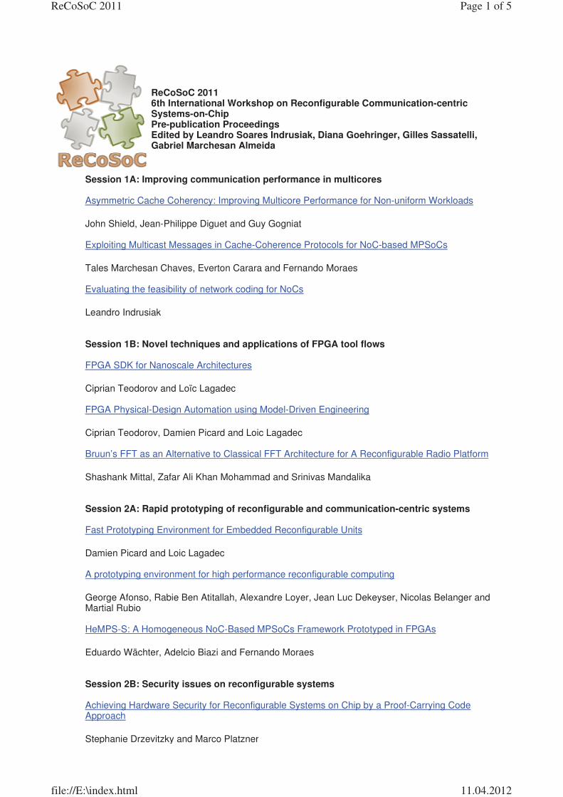
Session 1A: Improving communication performance in multicores Asymmetric Cache Coherency: Improving Multicore Performance for Non-uniform Workloads John Shield, Jean-Philippe Diguet and Guy Gogniat Exploiting Multicast Messages in Cache-Coherence Protocols for NoC-based MPSoCs Tales Marchesan Chaves, Everton Carara and Fernando Moraes Evaluating the feasibility of network coding for NoCs Leandro Indrusiak Session 1B: Novel techniques and applications of FPGA tool flows FPGA SDK for Nanoscale Architectures Ciprian Teodorov and Loïc Lagadec FPGA Physical-Design Automation using Model-Driven Engineering Ciprian Teodorov, Damien Picard and Loic Lagadec Bruun’s FFT as an Alternative to Classical FFT Architecture for A Reconfigurable Radio Platform Shashank Mittal, Zafar Ali Khan Mohammad and Srinivas Mandalika Session 2A: Rapid prototyping of reconfigurable and communication-centric systems Fast Prototyping Environment for Embedded Reconfigurable Units Damien Picard and Loic Lagadec A prototyping environment for high performance reconfigurable computing George Afonso, Rabie Ben Atitallah, Alexandre Loyer, Jean Luc Dekeyser, Nicolas Belanger and Martial Rubio HeMPS-S: A Homogeneous NoC-Based MPSoCs Framework Prototyped in FPGAs Eduardo Wächter, Adelcio Biazi and Fernando Moraes Session 2B: Security issues on reconfigurable systems Achieving Hardware Security for Reconfigurable Systems on Chip by a Proof-Carrying Code Approach Stephanie Drzevitzky and Marco Platzner
ReCoSoC 2011 6th International Workshop on Reconfigurable Communication-centric Systems-on-Chip Pre-publication Proceedings Edited by Leandro Soares Indrusiak, Diana Goehringer, Gilles Sassatelli, Gabriel Marchesan Almeida
Page 1 of 5ReCoSoC 2011
11.04.2012file://E:\index.html
Secure extensions of FPGA soft core processors for symmetric key cryptography Lubos Gaspar, Viktor Fischer, Lilian Bossuet and Robert Fouquet Secure Remote Reconfiguration of an FPGA-based Embedded System An Braeken, Jan Genoe, Serge Kubera, Nele Mentens, Abdellah Touhafi, Ingrid Verbauwhede, Yannick Verbelen, Jo Vliegen and Karel Wouters Session 3A: Resource monitoring and management in multiprocessor systems Monitoring Software Communication Channels on a Shared Memory Multi-Processor System on Chip Daniela Genius and Nicolas Pouillon Dynamic Resource Management in Modern Multicore SoCs by Exposing NoC Services Antonios Motakis, George Kornaros and Marcello Coppola Multi-Objective Mapping for Matrix-Based Nanocomputer Architectures Nataliya Yakymets, Sébastien Le Beux, Kotb Jabeur and Ian O’Connor Session 3B: High-level programming languages for reconfigurable systems Dataflow Programming Model For Reconfigurable Computing Laurent Gantel, Amel Khiar, Benoît Miramond, Amine Benkhelifa, Fabrice Lemonnier and Lounis Kessal Evaluation of Speculative Execution Techniques For High-Level Language to Hardware Compilation Benjamin Thielmann, Jens Huthmann and Andreas Koch A Reconfigurable Fabric Supporting Full C/C++ Input Alexandre Junqueira, Mateus Rutzig, Fábio Itturriet, João Victor Portal and Luigi Carro Session 4A: Advanced on-chip communication A Dependable and Dynamic Network on chip suitable for FPGA-based Reconfigurable Systems Cedric Killian, Mohamed Frihi, Camel Tanougast, Salah Toumi and Abbas Dandache High-Performance On-Chip Network Platform for Memory-on-Processor Architectures Masoud Daneshtalab, Masoumeh Ebrahimi, Pasi Liljeberg, Juha Plosila and Hannu Tenhunen Temperature-based covert channel in FPGA systems Taras Iakymchuk, Krzysztof Kepa and Maciej Nikodem Session 4B: Self reconfigurable systems Partial Reconfiguration in the Implementation of Autonomous Radio Receivers for Space Gian Carlo Cardarilli, Marco Re, Ilir Shuli and Lorenzo Simone
Page 2 of 5ReCoSoC 2011
11.04.2012file://E:\index.html
Self-reparable system on FPGA for Single Event Upset recovery Uros Legat, Anton Biasizzo and Franc Novak A Self-Reconfigurable Platform for General Purpose Image Processing Systems on Low-Cost Spartan-6 FPGAs Salih Bayar, Mehmet Tükel and Arda Yurdakul Session 5: Novel routing and flow control techniques for NoCs A SDM-TDM based Circuit-Switched router for On-Chip Networks Angelo Kuti Lusala and Jean-Didier Legat A new mechanism to reduce congestion on TDM Networks-on-Chips Daniel Vergeylen, Angelo Kuti Lusala and Jean-Didier Legat Session 6: Validating MPSoC designs at multiple levels of abstraction An approach for power and performance evaluation of Reconfigurable SoC at mixed abstraction levels Matthias Kuehnle and Alisson Brito Exploring Heterogeneous NoC-based MPSoCs: from FPGA to High-Level Modeling Luciano Ost, Gabriel Marchesan Almeida, Marcelo Mandelli, Eduardo Wachter, Sameer Varyani, Leandro Soares Indrusiak, Gilles Sassatelli, Michel Robert and Fernando Moraes Special session: Dependability in multiprocessor and reconfigurable SoCs Invited paper: Design Criteria for dependable System-on-Chip Architectures Thomas Hollstein, Faizal A. Samman, Ashok Jaiswal, Haoyuan Ying, Manfred Glesner, Klaus Hofmann Re2DA: Reliable and Reconfigurable Dynamic Architecture Hung-Manh Pham, Ludovic Devaux and Sébastien Pillement Invited paper: System-Wide Fault Management based on IEEE P1687 IJTAG A. Jutman, S. Devadze, J. Aleksejev Automatic Saboteur Placement for Emulation-Based Multi-Bit Fault Injection Johannes Grinschgl, Armin Krieg, Christian Steger, Reinhold Weiss, Holger Bock, Josef Haid Special session: Reconfigurable computing in education (RCE) Enhancing Learning of Digital Systems using a Remote FPGA Lab Fearghal Morgan and Seamus Cawley Invited paper: Implementation Scenario for Teaching Partial Reconfiguration of FPGA Pierre Leray, Amor Nafkha, Christophe Moy
Page 3 of 5ReCoSoC 2011
11.04.2012file://E:\index.html
Invited paper: Implementing digital data hiding algorithms in reconfigurable hardware: Experiences on teaching and research Rene Cumplido, Claudia Feregrino-Uribe, Jose Juan Garcia-Hernandez Special session: EU Projects focusing on tools and architectures for reconfigurable computing and multiprocessors Invited paper: Parallel programming and Run-time Resource Management Framework for Many-core Platforms: The 2PARMA Approach C. Silvano, W. Fornaciari, S. Crespi Reghizzi, G. Agosta, G. Palermo, V. Zaccaria, P. Bellasi, F. Castro, S. Corbetta, E. Speziale, D. Melpignano, J.M. Zins, H. Hubert, B. Stabernack, J. Brandenburg, M. Palkovic, P. Raghavan, C. Ykman-Couvreur, I. Anagnostopoulos, A. Bartzas, D. Soudris, T. Kempf, G. Ascheid, H. Meyr, J. Ansari, P. Mahonen, and B. Vanthournout Invited paper: Implementation, Integration, and Verification of MIMAX WLAN Modem Z. Stamenkovic, K. Tittelbach-Helmrich, M. Wickert, J. Ibanez, S. Ruiz, and G. Dimosthenous Invited paper: Rendering FPGAs to Multi-Core Embedded Computing (REFLECT) Koen Bertels, João Cardoso, George Constantidines, Pedro Diniz, Fernando Gonçalves, Michael Huebner, Bryan Olivier, and Zlato Petrov Invited paper: SPARTAN Project: Efficient Implementation of Computer Vision Algorithms onto Reconfigurable Platform Targeting to Space Applications K. Siozios, D. Diamantopoulos, I. Kostavelis, Ev. Boukas, L. Nalpantidis, D. Soudris, Ant. Gasteratos, Marcos Avilés, and I. Anagnostopoulos Invited paper: ERA – Embedded Reconfigurable Architectures: Overview and Results from the 1st Year Luigi Carro, UFRGS, Brazil Tutorials The Xilinx Design Language (XDL) – Tutorial and Use Cases Christian Beckhoff, Dirk Koch, Jim Torresen Natural and malicious soft errors: dependability and security issues in reconfigurable platforms Régis Leveugle Poster Session Self-organization of reconfigurable processing elements during mobile robots missions Laurent Rodriguez, Jérôme Felus and Benoît Miramond Runtime-Datapath-Remapping for Fault-Tolerant Coarse-Grained Reconfigurable Architectures Sven Eisenhardt, Anja Küster, Thomas Schweizer, Tommy Kuhn and Wolfgang Rosenstiel Differential Pair Routing to Balance Dual Signals of WDDL Designs in Cluster-Based Mesh FPGA Emna Amouri, Zied Marrakchi and Habib Mehrez Comparison of periodic and aperiodic task models for cyber-physical-systems Andreas Thuy
Page 4 of 5ReCoSoC 2011
11.04.2012file://E:\index.html
Study and modeling of a new configuration of an optical network on chip (ONOC) Using FDTD Malèk Channoufi, Pierre Lecoy, Rabah Attia and Bruno Delacressonniere Towards a Power and Energy Efficient Use of Partial Dynamic Reconfiguration Robin Bonamy, Daniel Chillet, Olivier Sentieys and Sebastien Bilavarn Exploration of MPSoC Monitoring and Management Systems Mohammad Fattah, Masoud Daneshtalab, Pasi Liljeberg and Juha Plosila Extending Java for Heterogeneous Embedded System Description Gary Plumbridge and Neil Audsley NoCmodel: an extensible framework for Network-on-Chips modeling Oscar Daniel Diaz, Armando Astarloa, Aitzol Zuloaga, Jesús Lázaro and Jaime Jimenez FPGA Bitstream Protection with PUFs, Obfuscation, and Multi-boot Sezer Goren, Abdullah Yildiz, Ozgur Ozkurt and H. Fatih Ugurdag Efficient Congestion-Aware Selection Method for On-Chip Networks Masoumeh Ebrahimi, Masoud Daneshtalab and Juha Plosila A study on fine granular fault tolerance methodologies for FPGAs Mahtab Niknahad, Oliver Sander and Juergen Becker RecoNoC: a Reconfigurable Network-on-Chip Robbe Vancayseele, Brahim Al Farisi, Wim Heirman, Karel Bruneel and Dirk Stroobandt Simulations of NoC topologies for Generalized Hierarchical Completely-Connected Networks Toshinori Takabatake The Co-Simulation Interface SystemC/Matlab Applied in JPEG Algorithm Walid Hassairi, Mohamad Abid and Moncef Bousselmi Genetic mapping of hard real-time applications onto NoC-based MPSoCs – a first approach Paris Mesidis and Leandro Indrusiak Reconfigurable Streaming Processor Core with Interconnected Floating-Point Arithmetic Units for Multicore Adaptive Signal Processing Systems Faizal Arya Samman, Pongyupinpanich Surapong and Manfred Glesner Approach of an FPGA based adaptive stepper motor control system Nadine Dahm, Michael Huebner and Juergen Becker
Page 5 of 5ReCoSoC 2011
11.04.2012file://E:\index.html
Stamenkovic Zoran
Von: Hübner, Michael [[email protected]]
Gesendet: Donnerstag, 14. April 2011 15:36
An: Stamenkovic Zoran
Cc: João M. P. Cardoso; Göhringer, Diana
Betreff: ReCoSoC 2011 Special Session on EU Projects focusing on tools and architectures for reconfigurable computing and multiprocessors
Wichtigkeit: Hoch
Seite 1 von 1
29.06.2011
����������������� ����
��
������������������ ����������� ����������������������������������������������������� !""�#�$%����
&����'�
����������������������������������������������(�����������)��*�
+�+,-����)���
��
�������������������������������������������&������������������������������������.�
/�������� ������������������������������������&����&������������(�%��)���������������������
�������������������������������&�������������������������������
���������&���� ���������������������������&��������.�,�������������������������&��������������
������������#��&���������������0�����'.�
��
%������������������������������&���������������������� ��������������������������
�������������&������������������������������������.�
1������������������&�����������������������+���2��� !"".�
��
3�������������
��������������4�����5���*�
6����+.�%.����������$�(%7(%��%��������)���8���.����
+�������9��&�����3�������������������1����������#3�1'��:��������+������.9��&���8��.����
��
ReCoSoC'2011 in Montpellier�
�������������� ����������������������������������������
Implementation, Integration, and Verification of
MIMAX WLAN Modem
Z. Stamenkovic
IHP
Frankfurt (Oder), Germany
K. Tittelbach-Helmrich
IHP
Frankfurt (Oder), Germany
M. Wickert
Dresden University of Technology
Dresden, Germany
J. Ibanez
University of Cantabria
Santander, Spain
S. Ruiz
TTI
Santander, Spain
G. Dimosthenous
PrimeTel
Limassol, Cyprus
Abstract�This paper describes the concept, implementation,
integration, and verification of an RF-MIMO wireless LAN
system called MIMAX. A test setup for trying out the complete
MIMAX modem in laptop form factor is presented. The purpose
is to verify, debug, and improve all the components and entire
system taking into account real-time operation parameters
(traffic load, timing, error recovery, etc.). The correctness of the
front-end specific MIMAX control functions like beamforming
weights handling and setting has been verified. The compatibility
with the standard SISO IEEE802.11a WLAN has also been
proved.
Keywords-Baseband; MAC; MIMO;WLAN
I. INTRODUCTION
We have introduced a concept for multiple-input, multiple-output (MIMO) communication with signal weighting and combining near the transmitting and receiving antennas in the analogue front-end [1]-[4]. As a result of this paradigm shift, the customized integrated circuits and systems [5]-[8] have been developed that comply with the new requirements in relation to the front-end processing concept. Our RF-MIMO approach called MIMAX (MIMO for MAXimum reliability and performance) is compatible with the existing WLAN standard IEEE802.11a and able to achieve faster and more energy efficient data transmission. A system demonstrator has been developed to test and validate the MIMAX concept in real scenarios.
The paper gives a brief overview of the MIMAX system architecture and components. Then the implementation of the individual subsystems such as reconfigurable (in respect of the antenna number and channel conditions) medium access control (MAC) and baseband processors, analogue front-end circuits, and an antenna array is described. Finally, the system integration and verification aspects are presented.
II. SYSTEM ARCHITECTURE AND COMPONENTS
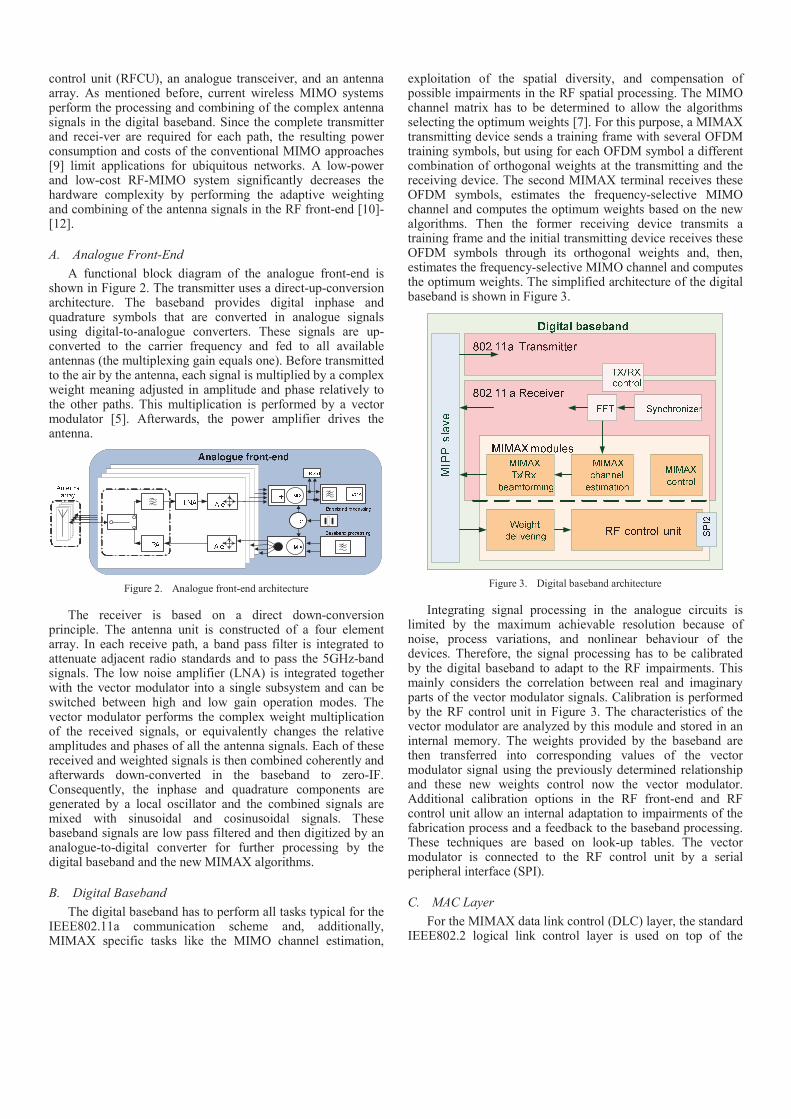
MIMAX operates compatibly to IEEE802.11a and amends the basic parts of this standard such as the physical and data link layer. Figure 1 shows the different communication layers investigated and developed in MIMAX. The MIMAX physical medium dependent layer consists of a new analogue front-end which performs the weighting and combining of multiple transmit and receive signals (in the conventional MIMO system, the digital baseband does it). It is controlled by an IEEE802.11a digital baseband which is extended for MIMAX specific operations. Likewise, the medium access control ensures data and control flow between the new baseband and the logical link control (LLC) layer. Finally, the compatibility to IEEE802 is achieved by a compliant LLC layer.
Figure 1. Communication layers addressed in MIMAX
The different functionalities of Figure 1 are integrated into separated subsystems that are assembled into a system demonstrator for verification and testing. These subsystems comprise a MAC processor, a baseband processor with RF
control unit (RFCU), an analogue transceiver, and an antenna array. As mentioned before, current wireless MIMO systems perform the processing and combining of the complex antenna signals in the digital baseband. Since the complete transmitter and recei-ver are required for each path, the resulting power consumption and costs of the conventional MIMO approaches [9] limit applications for ubiquitous networks. A low-power and low-cost RF-MIMO system significantly decreases the hardware complexity by performing the adaptive weighting and combining of the antenna signals in the RF front-end [10]-[12].
A. Analogue Front-End
A functional block diagram of the analogue front-end is shown in Figure 2. The transmitter uses a direct-up-conversion architecture. The baseband provides digital inphase and quadrature symbols that are converted in analogue signals using digital-to-analogue converters. These signals are up-converted to the carrier frequency and fed to all available antennas (the multiplexing gain equals one). Before transmitted to the air by the antenna, each signal is multiplied by a complex weight meaning adjusted in amplitude and phase relatively to the other paths. This multiplication is performed by a vector modulator [5]. Afterwards, the power amplifier drives the antenna.
Figure 2. Analogue front-end architecture
The receiver is based on a direct down-conversion principle. The antenna unit is constructed of a four element array. In each receive path, a band pass filter is integrated to attenuate adjacent radio standards and to pass the 5GHz-band signals. The low noise amplifier (LNA) is integrated together with the vector modulator into a single subsystem and can be switched between high and low gain operation modes. The vector modulator performs the complex weight multiplication of the received signals, or equivalently changes the relative amplitudes and phases of all the antenna signals. Each of these received and weighted signals is then combined coherently and afterwards down-converted in the baseband to zero-IF. Consequently, the inphase and quadrature components are generated by a local oscillator and the combined signals are mixed with sinusoidal and cosinusoidal signals. These baseband signals are low pass filtered and then digitized by an analogue-to-digital converter for further processing by the digital baseband and the new MIMAX algorithms.
B. Digital Baseband
The digital baseband has to perform all tasks typical for the IEEE802.11a communication scheme and, additionally, MIMAX specific tasks like the MIMO channel estimation,
exploitation of the spatial diversity, and compensation of possible impairments in the RF spatial processing. The MIMO channel matrix has to be determined to allow the algorithms selecting the optimum weights [7]. For this purpose, a MIMAX transmitting device sends a training frame with several OFDM training symbols, but using for each OFDM symbol a different combination of orthogonal weights at the transmitting and the receiving device. The second MIMAX terminal receives these OFDM symbols, estimates the frequency-selective MIMO channel and computes the optimum weights based on the new algorithms. Then the former receiving device transmits a training frame and the initial transmitting device receives these OFDM symbols through its orthogonal weights and, then, estimates the frequency-selective MIMO channel and computes the optimum weights. The simplified architecture of the digital baseband is shown in Figure 3.
Figure 3. Digital baseband architecture
Integrating signal processing in the analogue circuits is limited by the maximum achievable resolution because of noise, process variations, and nonlinear behaviour of the devices. Therefore, the signal processing has to be calibrated by the digital baseband to adapt to the RF impairments. This mainly considers the correlation between real and imaginary parts of the vector modulator signals. Calibration is performed by the RF control unit in Figure 3. The characteristics of the vector modulator are analyzed by this module and stored in an internal memory. The weights provided by the baseband are then transferred into corresponding values of the vector modulator signal using the previously determined relationship and these new weights control now the vector modulator. Additional calibration options in the RF front-end and RF control unit allow an internal adaptation to impairments of the fabrication process and a feedback to the baseband processing. These techniques are based on look-up tables. The vector modulator is connected to the RF control unit by a serial peripheral interface (SPI).
C. MAC Layer
For the MIMAX data link control (DLC) layer, the standard IEEE802.2 logical link control layer is used on top of the
IEEE802.11 medium access control layer. The new functi-onalities of the MIMAX baseband processor impose some changes on the MAC protocol. It is necessary to know the configuration of the transceiver including the number of antennas at transmitter and receiver side and to maintain a database of active and available users (MAC addresses, last optimum weights, etc.). These tasks and the storage are related to MAC because no memory (except for the weight table in RF control unit) is available at the baseband processor. The MAC protocol has to control the data flow and specific instructions to the digital baseband depending on the communication scheme. It also initiates the MIMAX channel estimation procedure, which normally consists of a pair of training frames, exchanged between two stations. Another important MIMAX feature is the transmission of an RTS frame before each regular 802.11 frame. This is to allow the receiver to identify the transmitter of the frame and to set its receiver antenna configuration to the optimum weights for that connection before receiving the regular frame. There is a single RTS frame before each multicast or broadcast frame, and a RTC/CTS pair before each unicast frame. The MAC layer has been developed using the state machine approach and the specification and description language (SDL). Functionally complex or rarely used parts of the MAC protocol have been implemented in software. Time critical or software inefficient functions are swapped to dedicated hardware [13].
Figure 4. Hardware/software partitioning of the MAC layer
The hardware/software partitioning of the MAC layer is shown in Figure 4. A general purpose processor executes the software part and a hardware accelerator takes over buffering for the next frame, a cyclic redundancy check (CRC) and an optional encryption (in transmit direction), and CRC, frame address filtering, generation of acknowledgements and CTS frames and an optional decryption (in receive direction). Furthermore, a back-off procedure for frame sending, 6 timers, a system timer and several interfaces are provided as hardware modules. The interfaces include a 16-bit MIMAX EPP interface to the physical layer (MIPP), a CardBus interface to
the host computer, a serial RS232 interface for UART, and general purpose inputs/outputs.
III. IMPLEMENTATION
The developed algorithms, components, and subsystems have been implemented in hardware (except the MAC proce-ssor, which is a hardware/software co-design). The MIMAX modem prototype assembles the following hardware:
• An antenna array made up of 4 multiband microstrip-fed planar F-shaped monopoles
• An analogue front-end that uses vector modulators as an analogue weighting circuitry
• An OFDM baseband processor that supports the new analogue front-end
• An enhanced MAC processor for MIMAX specific tasks and compatibility to 802.11a
A. Antenna Array
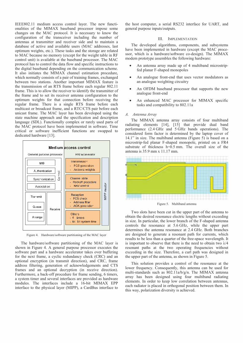
The MIMAX antenna array consists of four multiband radiating elements [14], [15] that provide dual band performance (2.4 GHz and 5 GHz bands operations). The considered form factor is determined by the laptop cover of 14.1� in size. The multiband antenna (Figure 5) is based on a microstrip-fed planar F-shaped monopole, printed on a FR4 substrate of thickness h=0.5 mm. The overall size of the antenna is 35.9 mm x 11.17 mm.
Figure 5. Multiband antenna
Two slots have been cut in the upper part of the antenna to obtain the desired resonance electric lengths without exceeding in size. In particular, the lower branch of the F-shaped antenna controls the resonance at 5.6 GHz, while the upper part determines the antenna resonance at 2.4 GHz. Both branches are designed to generate a resonant path for currents, which results to be less than a quarter of the free-space wavelength. It is important to observe that there is the need to obtain two そ/4 resonant paths at the two operating frequencies without exceeding in the size. Therefore, a curl path was designed in the upper part of the antenna, as shown in Figure 5.
This solution provides a control of the resonance at the lower frequency. Consequently, this antenna can be used for multi-standards such as 802.11a/b/g/n. The MIMAX antenna array has been designed using four multiband radiating elements. In order to keep low correlation between antennas, each radiator is placed in orthogonal position between them. In this way, polarization diversity is achieved.
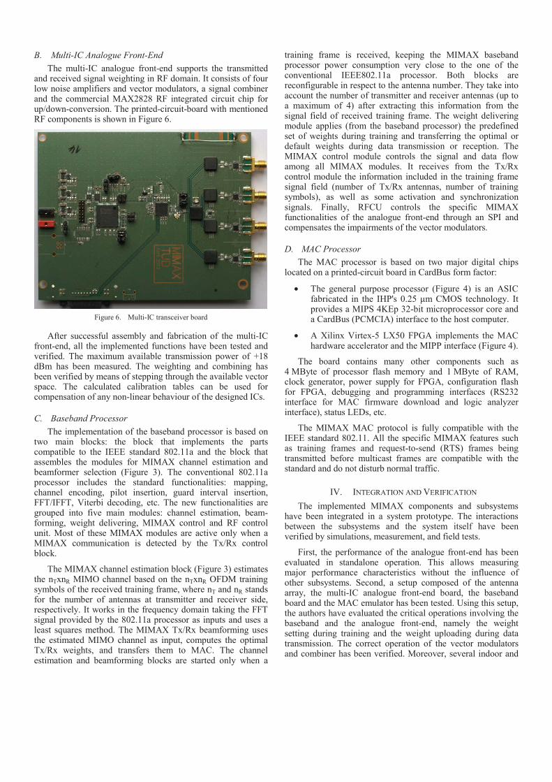
B. Multi-IC Analogue Front-End
The multi-IC analogue front-end supports the transmitted and received signal weighting in RF domain. It consists of four low noise amplifiers and vector modulators, a signal combiner and the commercial MAX2828 RF integrated circuit chip for up/down-conversion. The printed-circuit-board with mentioned RF components is shown in Figure 6.
Figure 6. Multi-IC transceiver board
After successful assembly and fabrication of the multi-IC front-end, all the implemented functions have been tested and verified. The maximum available transmission power of +18 dBm has been measured. The weighting and combining has been verified by means of stepping through the available vector space. The calculated calibration tables can be used for compensation of any non-linear behaviour of the designed ICs.
C. Baseband Processor
The implementation of the baseband processor is based on two main blocks: the block that implements the parts compatible to the IEEE standard 802.11a and the block that assembles the modules for MIMAX channel estimation and beamformer selection (Figure 3). The conventional 802.11a processor includes the standard functionalities: mapping, channel encoding, pilot insertion, guard interval insertion, FFT/IFFT, Viterbi decoding, etc. The new functionalities are grouped into five main modules: channel estimation, beam-forming, weight delivering, MIMAX control and RF control unit. Most of these MIMAX modules are active only when a MIMAX communication is detected by the Tx/Rx control block.
The MIMAX channel estimation block (Figure 3) estimates the nTxnR MIMO channel based on the nTxnR OFDM training symbols of the received training frame, where nT and nR stands for the number of antennas at transmitter and receiver side, respectively. It works in the frequency domain taking the FFT signal provided by the 802.11a processor as inputs and uses a least squares method. The MIMAX Tx/Rx beamforming uses the estimated MIMO channel as input, computes the optimal Tx/Rx weights, and transfers them to MAC. The channel estimation and beamforming blocks are started only when a
training frame is received, keeping the MIMAX baseband processor power consumption very close to the one of the conventional IEEE802.11a processor. Both blocks are reconfigurable in respect to the antenna number. They take into account the number of transmitter and receiver antennas (up to a maximum of 4) after extracting this information from the signal field of received training frame. The weight delivering module applies (from the baseband processor) the predefined set of weights during training and transferring the optimal or default weights during data transmission or reception. The MIMAX control module controls the signal and data flow among all MIMAX modules. It receives from the Tx/Rx control module the information included in the training frame signal field (number of Tx/Rx antennas, number of training symbols), as well as some activation and synchronization signals. Finally, RFCU controls the specific MIMAX functionalities of the analogue front-end through an SPI and compensates the impairments of the vector modulators.
D. MAC Processor
The MAC processor is based on two major digital chips located on a printed-circuit board in CardBus form factor:
• The general purpose processor (Figure 4) is an ASIC fabricated in the IHP's 0.25 たm CMOS technology. It provides a MIPS 4KEp 32-bit microprocessor core and a CardBus (PCMCIA) interface to the host computer.
• A Xilinx Virtex-5 LX50 FPGA implements the MAC hardware accelerator and the MIPP interface (Figure 4).
The board contains many other components such as 4 MByte of processor flash memory and 1 MByte of RAM, clock generator, power supply for FPGA, configuration flash for FPGA, debugging and programming interfaces (RS232 interface for MAC firmware download and logic analyzer interface), status LEDs, etc.
The MIMAX MAC protocol is fully compatible with the IEEE standard 802.11. All the specific MIMAX features such as training frames and request-to-send (RTS) frames being transmitted before multicast frames are compatible with the standard and do not disturb normal traffic.
IV. INTEGRATION AND VERIFICATION
The implemented MIMAX components and subsystems have been integrated in a system prototype. The interactions between the subsystems and the system itself have been verified by simulations, measurement, and field tests.
First, the performance of the analogue front-end has been evaluated in standalone operation. This allows measuring major performance characteristics without the influence of other subsystems. Second, a setup composed of the antenna array, the multi-IC analogue front-end board, the baseband board and the MAC emulator has been tested. Using this setup, the authors have evaluated the critical operations involving the baseband and the analogue front-end, namely the weight setting during training and the weight uploading during data transmission. The correct operation of the vector modulators and combiner has been verified. Moreover, several indoor and
outdoor experiments to evaluate the physical layer performance of the MIMAX with respect to single-antenna terminals have been conducted.
On the other hand, a setup assembling the baseband processor, the MAC processor and the WLAN driver software has been used to debug and verify the interactions between mentioned subsystems under realistic conditions. Finally, the stability and robustness of the final MIMAX WLAN modem prototype has been demonstrated.
A. Standalone Verification of Analogue Front-End
A control FPGA and USB interface on the analogue front-end board allows the standalone verification of the design. Using a control program stored in FPGA, the major performance characteristics have been measured without the influence of other subsystems (baseband and MAC).
RF receiver characteristics have been observed for the signal path from the antenna input connector (SMA) to the input of the commercial RFIC including an adapter cable which is required for accessing the RF signal at this point. The measured characteristics are shown in Table 1.
TABLE I. RF RECEIVER CHARACTERISTICS
PARAMETER VALUE
Gain 15.5 dB
Noise figure 7.4 dB
Input referred 1 dB compression -34 dBm
Input referred 3rd order intersect point -23.8 dBm
Power consumption 180 mW
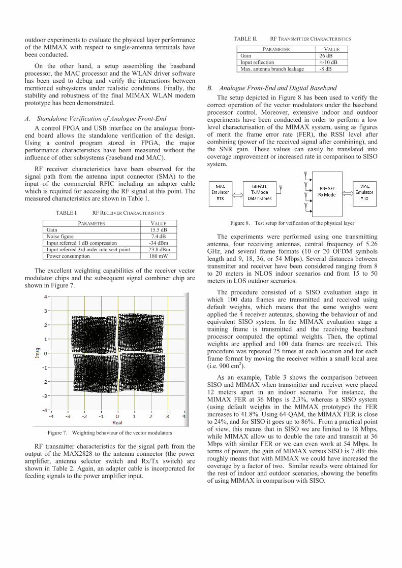
The excellent weighting capabilities of the receiver vector
modulator chips and the subsequent signal combiner chip are shown in Figure 7.
Figure 7. Weighting behaviour of the vector modulators
RF transmitter characteristics for the signal path from the output of the MAX2828 to the antenna connector (the power amplifier, antenna selector switch and Rx/Tx switch) are shown in Table 2. Again, an adapter cable is incorporated for feeding signals to the power amplifier input.
TABLE II. RF TRANSMITTER CHARACTERISTICS
PARAMETER VALUE
Gain 26 dB
Input reflection <-10 dB
Max. antenna branch leakage -8 dB
B. Analogue Front-End and Digital Baseband
The setup depicted in Figure 8 has been used to verify the correct operation of the vector modulators under the baseband processor control. Moreover, extensive indoor and outdoor experiments have been conducted in order to perform a low level characterisation of the MIMAX system, using as figures of merit the frame error rate (FER), the RSSI level after combining (power of the received signal after combining), and the SNR gain. These values can easily be translated into coverage improvement or increased rate in comparison to SISO system. ! " # $% & ' ( ) *+ , - , # . , / * 0 ! " # $1 & ' ( ) * ' " 2$ / 3 4 , - ( .5 1 6' " 2$ / 3 4 , - ( .5 % 6
Figure 8. Test setup for veification of the physical layer
The experiments were performed using one transmitting antenna, four receiving antennas, central frequency of 5.26 GHz, and several frame formats (10 or 20 OFDM symbols length and 9, 18, 36, or 54 Mbps). Several distances between transmitter and receiver have been considered ranging from 8 to 20 meters in NLOS indoor scenarios and from 15 to 50 meters in LOS outdoor scenarios.
The procedure consisted of a SISO evaluation stage in which 100 data frames are transmitted and received using default weights, which means that the same weights were applied the 4 receiver antennas, showing the behaviour of and equivalent SISO system. In the MIMAX evaluation stage a training frame is transmitted and the receiving baseband processor computed the optimal weights. Then, the optimal weights are applied and 100 data frames are received. This procedure was repeated 25 times at each location and for each frame format by moving the receiver within a small local area (i.e. 900 cm
2).
As an example, Table 3 shows the comparison between SISO and MIMAX when transmitter and receiver were placed 12 meters apart in an indoor scenario. For instance, the MIMAX FER at 36 Mbps is 2.3%, whereas a SISO system (using default weights in the MIMAX prototype) the FER increases to 41.8%. Using 64-QAM, the MIMAX FER is close to 24%, and for SISO it goes up to 86%. From a practical point of view, this means that in SISO we are limited to 18 Mbps, while MIMAX allow us to double the rate and transmit at 36 Mbps with similar FER or we can even work at 54 Mbps. In terms of power, the gain of MIMAX versus SISO is 7 dB: this roughly means that with MIMAX we could have increased the coverage by a factor of two. Similar results were obtained for the rest of indoor and outdoor scenarios, showing the benefits of using MIMAX in comparison with SISO.
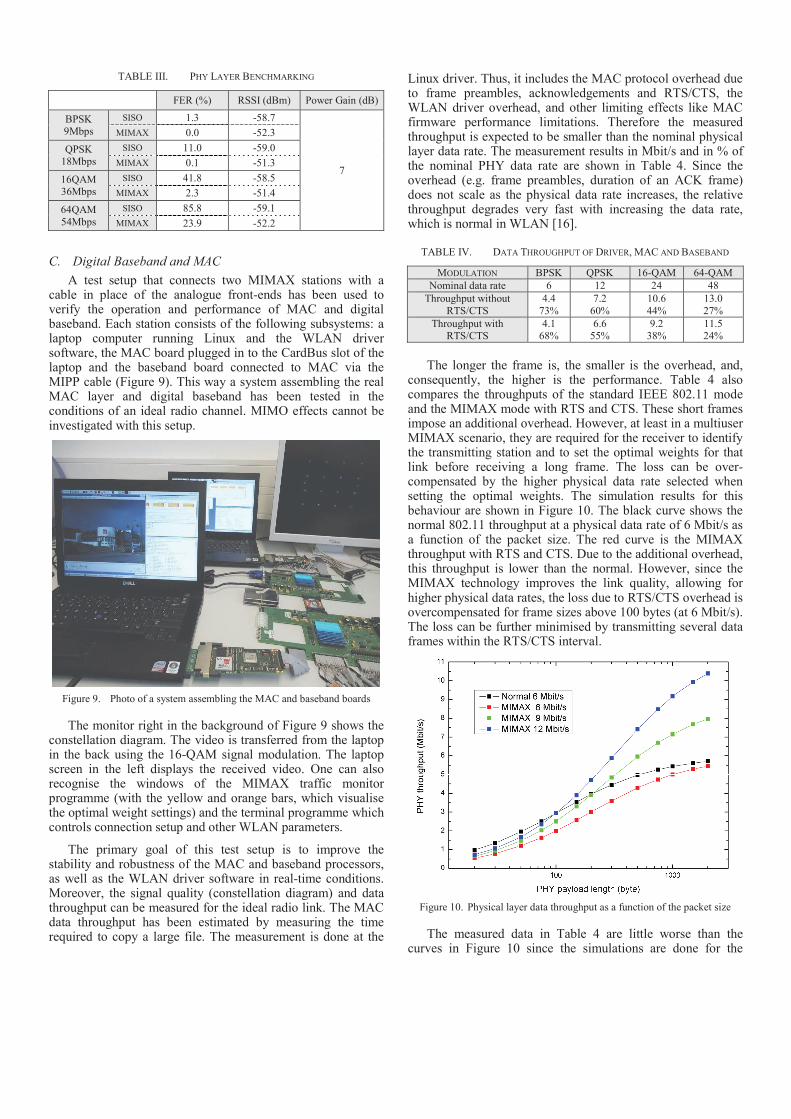
TABLE III. PHY LAYER BENCHMARKING
FER (%) RSSI (dBm) Power Gain (dB)
BPSK 9Mbps
SISO 1.3 -58.7
7
MIMAX 0.0 -52.3
QPSK 18Mbps
SISO 11.0 -59.0
MIMAX 0.1 -51.3
16QAM 36Mbps
SISO 41.8 -58.5
MIMAX 2.3 -51.4
64QAM
54Mbps
SISO 85.8 -59.1
MIMAX 23.9 -52.2
C. Digital Baseband and MAC
A test setup that connects two MIMAX stations with a cable in place of the analogue front-ends has been used to verify the operation and performance of MAC and digital baseband. Each station consists of the following subsystems: a laptop computer running Linux and the WLAN driver software, the MAC board plugged in to the CardBus slot of the laptop and the baseband board connected to MAC via the MIPP cable (Figure 9). This way a system assembling the real MAC layer and digital baseband has been tested in the conditions of an ideal radio channel. MIMO effects cannot be investigated with this setup.
Figure 9. Photo of a system assembling the MAC and baseband boards
The monitor right in the background of Figure 9 shows the constellation diagram. The video is transferred from the laptop in the back using the 16-QAM signal modulation. The laptop screen in the left displays the received video. One can also recognise the windows of the MIMAX traffic monitor programme (with the yellow and orange bars, which visualise the optimal weight settings) and the terminal programme which controls connection setup and other WLAN parameters.
The primary goal of this test setup is to improve the stability and robustness of the MAC and baseband processors, as well as the WLAN driver software in real-time conditions. Moreover, the signal quality (constellation diagram) and data throughput can be measured for the ideal radio link. The MAC data throughput has been estimated by measuring the time required to copy a large file. The measurement is done at the
Linux driver. Thus, it includes the MAC protocol overhead due to frame preambles, acknowledgements and RTS/CTS, the WLAN driver overhead, and other limiting effects like MAC firmware performance limitations. Therefore the measured throughput is expected to be smaller than the nominal physical layer data rate. The measurement results in Mbit/s and in % of the nominal PHY data rate are shown in Table 4. Since the overhead (e.g. frame preambles, duration of an ACK frame) does not scale as the physical data rate increases, the relative throughput degrades very fast with increasing the data rate, which is normal in WLAN [16].
TABLE IV. DATA THROUGHPUT OF DRIVER, MAC AND BASEBAND
MODULATION BPSK QPSK 16-QAM 64-QAM
Nominal data rate 6 12 24 48
Throughput without
RTS/CTS
4.4
73%
7.2
60%
10.6
44%
13.0
27%
Throughput with RTS/CTS
4.1 68%
6.6 55%
9.2 38%
11.5 24%
The longer the frame is, the smaller is the overhead, and,
consequently, the higher is the performance. Table 4 also compares the throughputs of the standard IEEE 802.11 mode and the MIMAX mode with RTS and CTS. These short frames impose an additional overhead. However, at least in a multiuser MIMAX scenario, they are required for the receiver to identify the transmitting station and to set the optimal weights for that link before receiving a long frame. The loss can be over-compensated by the higher physical data rate selected when setting the optimal weights. The simulation results for this behaviour are shown in Figure 10. The black curve shows the normal 802.11 throughput at a physical data rate of 6 Mbit/s as a function of the packet size. The red curve is the MIMAX throughput with RTS and CTS. Due to the additional overhead, this throughput is lower than the normal. However, since the MIMAX technology improves the link quality, allowing for higher physical data rates, the loss due to RTS/CTS overhead is overcompensated for frame sizes above 100 bytes (at 6 Mbit/s). The loss can be further minimised by transmitting several data frames within the RTS/CTS interval.
Figure 10. Physical layer data throughput as a function of the packet size
The measured data in Table 4 are little worse than the curves in Figure 10 since the simulations are done for the
physical layer only. They take into account the data frame itself, acknowledgement, RTS/CTS frames and relevant SIFS times. The additional overhead sources like backoff periods, MAC header length, beacons, etc. are not included.
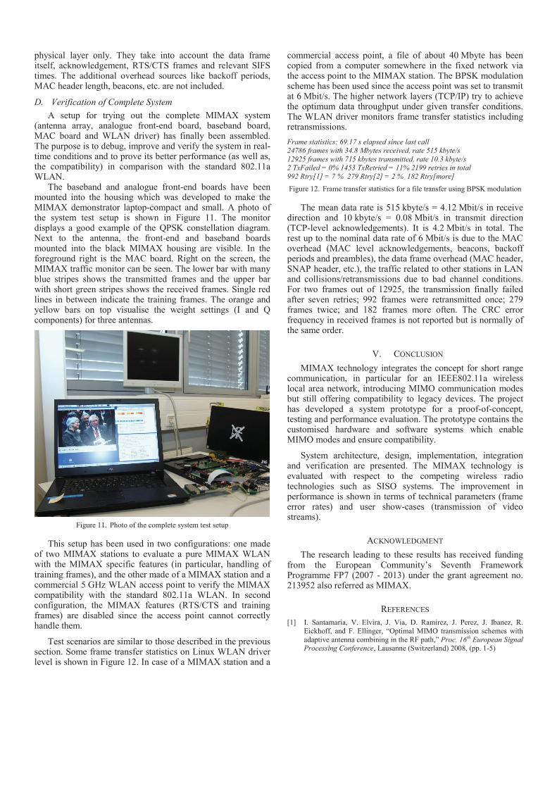
D. Verification of Complete System
A setup for trying out the complete MIMAX system (antenna array, analogue front-end board, baseband board, MAC board and WLAN driver) has finally been assembled. The purpose is to debug, improve and verify the system in real-time conditions and to prove its better performance (as well as, the compatibility) in comparison with the standard 802.11a WLAN.
The baseband and analogue front-end boards have been mounted into the housing which was developed to make the MIMAX demonstrator laptop-compact and small. A photo of the system test setup is shown in Figure 11. The monitor displays a good example of the QPSK constellation diagram. Next to the antenna, the front-end and baseband boards mounted into the black MIMAX housing are visible. In the foreground right is the MAC board. Right on the screen, the MIMAX traffic monitor can be seen. The lower bar with many blue stripes shows the transmitted frames and the upper bar with short green stripes shows the received frames. Single red lines in between indicate the training frames. The orange and yellow bars on top visualise the weight settings (I and Q components) for three antennas.
Figure 11. Photo of the complete system test setup
This setup has been used in two configurations: one made of two MIMAX stations to evaluate a pure MIMAX WLAN with the MIMAX specific features (in particular, handling of training frames), and the other made of a MIMAX station and a commercial 5 GHz WLAN access point to verify the MIMAX compatibility with the standard 802.11a WLAN. In second configuration, the MIMAX features (RTS/CTS and training frames) are disabled since the access point cannot correctly handle them.
Test scenarios are similar to those described in the previous section. Some frame transfer statistics on Linux WLAN driver level is shown in Figure 12. In case of a MIMAX station and a
commercial access point, a file of about 40 Mbyte has been copied from a computer somewhere in the fixed network via the access point to the MIMAX station. The BPSK modulation scheme has been used since the access point was set to transmit at 6 Mbit/s. The higher network layers (TCP/IP) try to achieve the optimum data throughput under given transfer conditions. The WLAN driver monitors frame transfer statistics including retransmissions.
Frame statistics: 69.17 s elapsed since last call
24786 frames with 34.8 Mbytes received, rate 515 kbyte/s
12925 frames with 715 kbytes transmitted, rate 10.3 kbyte/s 2 TxFailed = 0% 1453 TxRetried = 11% 2199 retries in total
992 Rtry[1] = 7 % 279 Rtry[2] = 2 % 182 Rtry[more]
Figure 12. Frame transfer statistics for a file transfer using BPSK modulation
The mean data rate is 515 kbyte/s = 4.12 Mbit/s in receive direction and 10 kbyte/s = 0.08 Mbit/s in transmit direction (TCP-level acknowledgements). It is 4.2 Mbit/s in total. The rest up to the nominal data rate of 6 Mbit/s is due to the MAC overhead (MAC level acknowledgements, beacons, backoff periods and preambles), the data frame overhead (MAC header, SNAP header, etc.), the traffic related to other stations in LAN and collisions/retransmissions due to bad channel conditions. For two frames out of 12925, the transmission finally failed after seven retries; 992 frames were retransmitted once; 279 frames twice; and 182 frames more often. The CRC error frequency in received frames is not reported but is normally of the same order.
V. CONCLUSION
MIMAX technology integrates the concept for short range communication, in particular for an IEEE802.11a wireless local area network, introducing MIMO communication modes but still offering compatibility to legacy devices. The project has developed a system prototype for a proof-of-concept, testing and performance evaluation. The prototype contains the customised hardware and software systems which enable MIMO modes and ensure compatibility.
System architecture, design, implementation, integration and verification are presented. The MIMAX technology is evaluated with respect to the competing wireless radio technologies such as SISO systems. The improvement in performance is shown in terms of technical parameters (frame error rates) and user show-cases (transmission of video streams).
ACKNOWLEDGMENT
The research leading to these results has received funding from the European Community�s Seventh Framework Programme FP7 (2007 - 2013) under the grant agreement no. 213952 also referred as MIMAX.
REFERENCES
[1] I. Santamaria, V. Elvira, J. Via, D. Ramirez, J. Perez, J. Ibanez, R.
Eickhoff, and F. Ellinger, �Optimal MIMO transmission schemes with
adaptive antenna combining in the RF path,� Proc. 16th European Signal Processing Conference, Lausanne (Switzerland) 2008, (pp. 1-5)
[2] R. Eickhoff, R. Kraemer, I. Santamaria, and L. Gonzalez, �Developing
energy-efficient MIMO radios,� IEEE Vehicular Technology Magazine, vol. 4, pp. 34-41, 2009.
[3] J. Via, V. Elvira, I. Santamaria and R. Eickhoff, �Analog antenna combining for maximum capacity under OFDM transmissions,� Proc.
IEEE Inter. Conference on Communications, Dresden (Germany) 2009,
(pp. 1-5)
[4] Z. Stamenkovic, K. Tittelbach-Helmrich, M. Krstic, J. Perez, J. Via, and
J. Ibanez, �Architecture of an analog combining MIMO system
compliant to IEEE802.11a,� Proc. ICT-MobileSummit 2009, Santander (Spain) 2009, (pp.1-8)
[5] N. Joram, U. Mayer, R. Eickhoff, and F. Ellinger, �Fully integrated active CMOS vector modulator for 802.11a compliant diversity
transceivers,� Proc. International IEEE Conference on Microwaves,
Communications, Antennas and Electronic System, Tel-Aviv (Israel) 2009, (pp. 1-4)
[6] J. Via, V. Elvira, I. Santamaria, and R. Eickhoff, �Minimum BER
beamforming in the RF domain for OFDM transmissions and linear receivers,� Proc. IEEE International Conference on Acoustics, Speech
and Signal Processing, Taipei (Taiwan) 2009, (pp. 2513-2516)
[7] V. Elvira, J. Ibanez, I. Santamaria, M. Krstic, K. Tittelbach-Helmrich,
and Z. Stamenkovic, �Baseband processor for RF-MIMO WLAN,�
Proc. 17th IEEE International Conference on Electronics, Circuits, and Systems, Athens (Greece) 2010, (pp. 798-801)
[8] K. Tittelbach-Helmrich, E. Miletic, P. Wcislek, and Z. Stamenkovic,
�MAC hardware platform for RF-MIMO WLAN,� Proc. 53rd IEEE International Midwest Symposium on Circuits and Systems, Seattle
(USA) 2010, (pp. 339-342)
[9] H. Boelcskei, D. Gesbert, C. B. Papadias, and A.-J. van der Veen,
Space-Time Wireless Systems: From Array Processing to MIMO Communications, Cambridge University Press, Cambridge 2006.
[10] F. Ellinger and W. Baechtold, �Adaptive antenna receiver module for WLAN at C-band with low power consumption,� IEEE Microwave and
Wireless Components Letters, vol. 12, pp. 348-350, 2002.
[11] J. Via, I. Santamaria, V. Elvira, and R. Eickhoff, �A general criterion for analog Tx-Rx beamforming under OFDM transmissions,� IEEE Trans.
on Signal Processing, vol. 58, pp. 2155-2167, 2010.
[12] A. Jahanian, F. Tzeng, and P. Heydari, �Code modulated path sharing
multi-antenna receivers: theory and design,� IEEE Trans. Wireless
Communications, vol. 8, pp. 2193-2201, 2009.
[13] Z. Stamenkovic, E. Miletic, M. Obrknezev, and K. Tittelbach-Helmrich,
�MAC protocol implementation in RF-MIMO WLAN,� Proc. 16th
IEEE International Conference on Electronics, Circuits, and Systems, Yasmine Hammamet (Tunisia) 2009, (pp. 303-306)
[14] O. Gago, L. Gonzalez, and R. Eickhoff, �Study of the optimum number of radiating elements for different portable devices operating in a MIMO
system,� Proc. the European Wireless Conference, Aalborg (Denmark)
2009.
[15] O. Gago, L. Gonzalez, R. Eickhoff, and I. Santamaria, �MIFA: Modified
IFA radiating element for small handheld devices,� Proc. the 18th ICT
MobileSummit, Santander (Spain) 2009.
[16] G. Bianchi, �Performance analysis of the IEEE 802.11 distributed
coordination function,� IEEE Journal on Selected Areas in Communications, vol. 18, pp. 535-547, 2000.