CAN interface for FMS Introduction
10
22:10-079 Issue 2 en-GB 1 (10) © Scania CV AB 2015, Sweden Introduction CAN interface for FMS Introduction This document contains information on the FMS standard. The FMS standard is an open interface developed by several truck manufacturers. FMS-Standard description version 03 is supported. The C137 connector is Scania’s interface for FMS standard messages. IMPORTANT! For FMS standard messages, it is not permitted to connect to any other connector or other CAN bus. Incorrect connection can cause functional disorder. More information on the FMS standard can be found at www.fms-standard.com. More information on the C137 connector is found in the C137 document – Connector for FMS. Detailed information on CAN messages for FMS is found in the CAN Specification for FMS document which is in English.
-
Upload
khangminh22 -
Category
Documents
-
view
1 -
download
0
Transcript of CAN interface for FMS Introduction
22:10-079 Issue 2 en-G
CAN interface for FMS
IntroductionMore information on the FMS standard can be found at www.fms-standard.com.
More information on the C137 connector is found in the C137 document – Connector for FMS.
Detailed information on CAN messages for FMS is found in the CAN Specification for FMS document which is in English.
IntroductionThis document contains information on the FMS standard. The FMS standard is an open interface developed by several truck manufacturers. FMS-Standard description version 03 is supported.
The C137 connector is Scania’s interface for FMS standard messages.
IMPORTANT!
For FMS standard messages, it is not permitted to connect to any other connector or other CAN bus. Incorrect connection can cause functional disorder.
B 1 (10)© Scania CV AB 2015, Sweden
CAN interface for FMSIntroduction
ding
Abbreviations in this documentAbbreviation Explanation
CAN Controller Area Network
ECU Electronic Control Unit
FMS Fleet Management System
BCI Bodywork Communication Interface
TCO Tachograph
DTCO Digital tachograph with remote driver card information downloa
OBD On-board diagnostics
EOBD European On-board Diagnostics
TP.CM Transport Protocol - Connection Management
TP.DT Transport Protocol - Data Transfer
© Scania CV AB 2015, Sweden
22:10-079 Issue 2 en-GB 2 (10)
CAN interface for FMSRequirements for CAN communication with the vehicle
351
572
Connector C137
More information on the connector is found in the C137 document – Connector for FMS CAN.
343
377
Location of C137
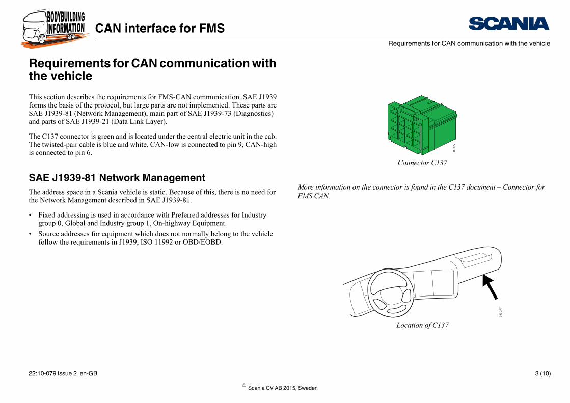
Requirements for CAN communication with the vehicleThis section describes the requirements for FMS-CAN communication. SAE J1939 forms the basis of the protocol, but large parts are not implemented. These parts are SAE J1939-81 (Network Management), main part of SAE J1939-73 (Diagnostics) and parts of SAE J1939-21 (Data Link Layer).
The C137 connector is green and is located under the central electric unit in the cab. The twisted-pair cable is blue and white. CAN-low is connected to pin 9, CAN-high is connected to pin 6.
SAE J1939-81 Network ManagementThe address space in a Scania vehicle is static. Because of this, there is no need for the Network Management described in SAE J1939-81.
• Fixed addressing is used in accordance with Preferred addresses for Industry group 0, Global and Industry group 1, On-highway Equipment.
• Source addresses for equipment which does not normally belong to the vehicle follow the requirements in J1939, ISO 11992 or OBD/EOBD.
© Scania CV AB 2015, Sweden
22:10-079 Issue 2 en-GB 3 (10)

CAN interface for FMSRequirements for CAN communication with the vehicle
SAE J1939-21 Data Link LayerSAE J1939-21 defines 5 message types:
• Commands - Not supported.
• Requests - Not supported.
• Broadcast/Response - All available information is sent periodically.
• Acknowledgement - Not supported.
• Group Functions - Proprietary messages och Multipacket messages, TP.CM, TP.DT, are supported.
Note:According to section 5.2.1 SAE J1939-21, revised version July 1998, priority bits in message identifiers must be filtered out and ignored by the receivers.
General guidelines• Control units connected to a CAN bus must be able to handle up to 100% CAN
bus load with the correct messages with no significant functional limitations or malfunctions.
• Under normal circumstances the CAN bus load should never exceed 80%.
• Avoid closing control loops over the CAN because the guaranteed access time is relatively long and fast control loops require a lot of bandwidth. If closed control loops over the CAN are still required, then they must be fully capable of sending the necessary CAN messages using only half the transmission frequency.
© Scania CV AB 2015, Sweden
22:10-079 Issue 2 en-GB 4 (10)
CAN interface for FMSConnectors and cables
More information on the FMS standard can be found at www.fms-standard.com.
Connectors and cables• Scania uses connectors according to the FMS standard.
• Scania uses twisted-pair cables (twisted 40 times per metre) with no shield or jacket.
• The electrical properties (resistance, impedance, capacitance etc.) are defined in SAE J1939-15 Physical Layer Light.
• The cable cross-sectional areas for cables fitted by the bodybuilder must be at least 0.75 mm² inside the cab and 1.5 mm² outside the cab.
• Scania recommends the following colours and markings for the FMS-CAN net-work cables:
– CAN-low should be marked as CAN_L and CAN-high as CAN_H.– CAN_L should be white and CAN_H should be blue. To avoid misunder-
standing it is important that the cables retain their colour for the lifetime of the vehicle.
© Scania CV AB 2015, Sweden
22:10-079 Issue 2 en-GB 5 (10)

CAN interface for FMSConnection to FMS-CAN
< 30 m
> 0.1 m
< 3
m
C137 ECU X
ECU Z ECU Y
348
622
Connection to FMS-CANTopologyThe topology is primarily a bus cable with the nodes connected to the bodybuilder’s FMS-CAN network with at least 0.1 metre between each node.
• The length of the cables should not exceed 30 metres (main cable) between the connector in the truck and the control unit with the other termination resistor.
• If more than one control unit is connected, the length of the cables between the main cable and control unit should not exceed 3 metres.
• The cables should be as short as possible to minimise the effect of electromagnet-ic interference.
• The number of control units in the bodybuilder’s FMS-CAN network should not exceed 9.
The figure shows the principle of the bodybuilder’s FMS-CAN network topology:
• C137 is the connector that makes the interface to Scania’s network.
• ECU X is the FMS control unit in the bodywork with a termination resistor. See also next section.
© Scania CV AB 2015, Sweden
22:10-079 Issue 2 en-GB 6 (10)

CAN interface for FMSTermination resistors
CAN_H
ECU X Scania
CAN_L
CAN_H
CAN_L
RR
b346
398
C137
6
9
Termination resistorsThe FMS-CAN bus cable must be terminated using a 120 Ohm resistor at each end in accordance with SAE J1939-15 Physical Layer.
Depending on the other control units connected to the CAN bus, there must be a 120 Ohm termination resistor in the control unit which is connected to the FMS-CAN in-terface for bodybuilders.
If the control unit is not equipped with an internal termination resistor, an external termination resistor must be connected as close to the control unit as possible (see illustration).
© Scania CV AB 2015, Sweden
22:10-079 Issue 2 en-GB 7 (10)

CAN interface for FMSTermination resistors
ermination resistor in e control unit connect-
ed to C137
Yes
No
No
Yes
Yes
Yes
Termination of the bodybuilder’s FMS-CAN bus.There must be a 120 Ohm termination resistor at each end of the FMS-CAN bus for the communication to work without interference. Check that there is a termination resistor at each end of the FMS-CAN bus using a multimeter. The resistance should be 60 Ohm (two 120 Ohm resistors connected in parallel).
A number of different systems can be connected to the cable harness of the body-builder’s FMS-CAN bus. Certain systems have a built-in termination resistor and others are unterminated.
The table shows when there is to be a termination resistor in connector C137 or in the control unit connected to C137.
Systems in the vehicle TthDTCO Scania Communicator
C200FMS-CAN interface
No No Yes
Yes No Yes
Yes Yes Yes
No Yes Yes
Yes No No
Yes Yes No
© Scania CV AB 2015, Sweden
22:10-079 Issue 2 en-GB 8 (10)
CAN interface for FMSFault validation of communication (time-out)
Fault validation of communication (time-out)Avoid FMS-CAN communication when the starter key is in the lock or radio posi-tion. Also avoid communication during the starting sequence of the control units con-nected to the bodybuilder’s FMS-CAN network.
During normal operation, when the starter key is in the drive position, a message should not be validated as missed (time-out) until at least 5 times the message period time. A longer fault validation time is permitted.
During the engine starting sequence, when the starter motor is turning, the supply voltage can be extremely low. Therefore, communication from the FMS-CAN can-not be guaranteed during this sequence. For this reason, no fault codes related to FMS-CAN communication should be set when the system voltage is below 18 V.
When the starter key is turned to the drive position, the FMS-CAN communication will be started within 10,000 ms. A message cannot be considered missing until after 10,000 ms + 5 x the message period time. Example: If a message has a period time of 100 ms it cannot be considered missing until after 10,000 + 5 x 100 = 10,500 ms. Longer fault validation times are permitted.
© Scania CV AB 2015, Sweden
22:10-079 Issue 2 en-GB 9 (10)

CAN interface for FMSSource addresses
Source addressesThe source addresses according to the table are used for messages that are forwarded from Scania’s FMS-CAN bus to the bodybuilder’s FMS-CAN bus via the C137 in-terface. The addresses in the table must not be used by any other control unit in the bodybuilder’s FMS-CAN network. This may lead to clashes and functional distur-bances.
Note:The table shows the addresses currently in use, but addresses may be added in the future.
Name Explanation Source address (Hex)
EMS Engine Management System 00
GMS Gearbox Management System 03
BMS Brake Management System 0B
RET Retarder 10
ICL Instrument Cluster 17
LAS Locking and Alarm System 1D
VIS Visibility System 1E
COO Coordinator 27
BWE Bodywork Electrical System E6
SMS Suspension Management System 2F
APS Air Processing System 30
TCO Tachograph EE
© Scania CV AB 2015, Sweden
22:10-079 Issue 2 en-GB 10 (10)