Effects of Variability in Lateral Pipe-Soil Interaction and Pipe ...
Upload
independentCategory
view
1download
0
Pipe Stress Interface
User Guide

DisclaimerInformation of a technical nature, and particulars of the product and its use, is given by AVEVASolutions Ltd and its subsidiaries without warranty. AVEVA Solutions Ltd and its subsidiaries disclaimany and all warranties and conditions, expressed or implied, to the fullest extent permitted by law.
Neither the author nor AVEVA Solutions Ltd, or any of its subsidiaries, shall be liable to any person orentity for any actions, claims, loss or damage arising from the use or possession of any information,particulars, or errors in this publication, or any incorrect use of the product, whatsoever.
CopyrightCopyright and all other intellectual property rights in this manual and the associated software, and everypart of it (including source code, object code, any data contained in it, the manual and any otherdocumentation supplied with it) belongs to AVEVA Solutions Ltd or its subsidiaries.
All other rights are reserved to AVEVA Solutions Ltd and its subsidiaries. The information contained inthis document is commercially sensitive, and shall not be copied, reproduced, stored in a retrievalsystem, or transmitted without the prior written permission of AVEVA Solutions Ltd. Where suchpermission is granted, it expressly requires that this Disclaimer and Copyright notice is prominentlydisplayed at the beginning of every copy that is made.
The manual and associated documentation may not be adapted, reproduced, or copied, in any materialor electronic form, without the prior written permission of AVEVA Solutions Ltd. The user may also notreverse engineer, decompile, copy, or adapt the associated software. Neither the whole, nor part of theproduct described in this publication may be incorporated into any third-party software, product,machine, or system without the prior written permission of AVEVA Solutions Ltd, save as permitted bylaw. Any such unauthorised action is strictly prohibited, and may give rise to civil liabilities and criminalprosecution.
The AVEVA products described in this guide are to be installed and operated strictly in accordance withthe terms and conditions of the respective licence agreements, and in accordance with the relevantUser Documentation. Unauthorised or unlicensed use of the product is strictly prohibited.
First published September 2007
© AVEVA Solutions Ltd, and its subsidiaries
AVEVA Solutions Ltd, High Cross, Madingley Road, Cambridge, CB3 0HB, United Kingdom
TrademarksAVEVA and Tribon are registered trademarks of AVEVA Solutions Ltd or its subsidiaries. Unauthoriseduse of the AVEVA or Tribon trademarks is strictly forbidden.
AVEVA product names are trademarks or registered trademarks of AVEVA Solutions Ltd or itssubsidiaries, registered in the UK, Europe and other countries (worldwide).
The copyright, trade mark rights, or other intellectual property rights in any other product, its name orlogo belongs to its respective owner.
AVEVA Solutions Ltd

Pipe Stress Interface User Guide
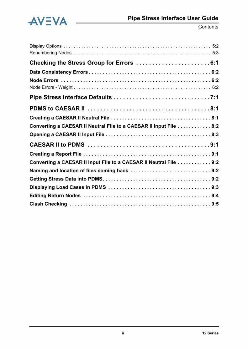
Contents Page
Pipe Stress Interface User GuideContents
User GuideIntroduction . . . . . . . . . . . . . . . . . . . . . . . . . . . . . . . . . . . . . . . . . . . . . 1:1About this User Guide . . . . . . . . . . . . . . . . . . . . . . . . . . . . . . . . . . . . . . . . . . . . . . 1:1Overview of the PSI Application . . . . . . . . . . . . . . . . . . . . . . . . . . . . . . . . . . . . . . 1:1
Starting the Application . . . . . . . . . . . . . . . . . . . . . . . . . . . . . . . . . . . 2:1
Groups Tab . . . . . . . . . . . . . . . . . . . . . . . . . . . . . . . . . . . . . . . . . . . . . 3:1Creating a Stress Group . . . . . . . . . . . . . . . . . . . . . . . . . . . . . . . . . . . . . . . . . . . . 3:1Adding and Removing Members . . . . . . . . . . . . . . . . . . . . . . . . . . . . . . . . . . . . . 3:1Rebuild Selected Group . . . . . . . . . . . . . . . . . . . . . . . . . . . . . . . . . . . . . . . . . . . . 3:3Find a Group. . . . . . . . . . . . . . . . . . . . . . . . . . . . . . . . . . . . . . . . . . . . . . . . . . . . . . 3:3
Display Tab . . . . . . . . . . . . . . . . . . . . . . . . . . . . . . . . . . . . . . . . . . . . . 4:1Graphics . . . . . . . . . . . . . . . . . . . . . . . . . . . . . . . . . . . . . . . . . . . . . . . . . . . . . . . . 4:1Animation . . . . . . . . . . . . . . . . . . . . . . . . . . . . . . . . . . . . . . . . . . . . . . . . . . . . . . . . 4:3Animation Speed . . . . . . . . . . . . . . . . . . . . . . . . . . . . . . . . . . . . . . . . . . . . . . . . . . . . . . . . . 4:4Processing Order . . . . . . . . . . . . . . . . . . . . . . . . . . . . . . . . . . . . . . . . . . . . . . . . . . . . . . . . . 4:4
Active Stress Group. . . . . . . . . . . . . . . . . . . . . . . . . . . . . . . . . . . . . . . . . . . . . . . . 4:4
Menus and Toolbars . . . . . . . . . . . . . . . . . . . . . . . . . . . . . . . . . . . . . . 5:1Context Menus . . . . . . . . . . . . . . . . . . . . . . . . . . . . . . . . . . . . . . . . . . . . . . . . . . . . 5:1Pipe Stress Interface Toolbar . . . . . . . . . . . . . . . . . . . . . . . . . . . . . . . . . . . . . . . . 5:2Node Details Form . . . . . . . . . . . . . . . . . . . . . . . . . . . . . . . . . . . . . . . . . . . . . . . . . 5:2
12 Seriesi
Pipe Stress Interface User GuideContents
Display Options . . . . . . . . . . . . . . . . . . . . . . . . . . . . . . . . . . . . . . . . . . . . . . . . . . . . . . . . . . 5:2Renumbering Nodes . . . . . . . . . . . . . . . . . . . . . . . . . . . . . . . . . . . . . . . . . . . . . . . . . . . . . . 5:3
Checking the Stress Group for Errors . . . . . . . . . . . . . . . . . . . . . . . 6:1Data Consistency Errors . . . . . . . . . . . . . . . . . . . . . . . . . . . . . . . . . . . . . . . . . . . . 6:2Node Errors . . . . . . . . . . . . . . . . . . . . . . . . . . . . . . . . . . . . . . . . . . . . . . . . . . . . . . 6:2Node Errors - Weight . . . . . . . . . . . . . . . . . . . . . . . . . . . . . . . . . . . . . . . . . . . . . . . . . . . . . . 6:2
Pipe Stress Interface Defaults . . . . . . . . . . . . . . . . . . . . . . . . . . . . . . 7:1
PDMS to CAESAR II . . . . . . . . . . . . . . . . . . . . . . . . . . . . . . . . . . . . . . 8:1Creating a CAESAR II Neutral File . . . . . . . . . . . . . . . . . . . . . . . . . . . . . . . . . . . . 8:1Converting a CAESAR II Neutral File to a CAESAR II Input File . . . . . . . . . . . . 8:2Opening a CAESAR II Input File . . . . . . . . . . . . . . . . . . . . . . . . . . . . . . . . . . . . . . 8:3
CAESAR II to PDMS . . . . . . . . . . . . . . . . . . . . . . . . . . . . . . . . . . . . . . 9:1Creating a Report File . . . . . . . . . . . . . . . . . . . . . . . . . . . . . . . . . . . . . . . . . . . . . . 9:1Converting a CAESAR II Input File to a CAESAR II Neutral File . . . . . . . . . . . . 9:2Naming and location of files coming back . . . . . . . . . . . . . . . . . . . . . . . . . . . . . 9:2Getting Stress Data into PDMS. . . . . . . . . . . . . . . . . . . . . . . . . . . . . . . . . . . . . . . 9:2Displaying Load Cases in PDMS . . . . . . . . . . . . . . . . . . . . . . . . . . . . . . . . . . . . . 9:3Editing Return Nodes . . . . . . . . . . . . . . . . . . . . . . . . . . . . . . . . . . . . . . . . . . . . . . 9:4Clash Checking . . . . . . . . . . . . . . . . . . . . . . . . . . . . . . . . . . . . . . . . . . . . . . . . . . . 9:5
12 Seriesii

Pipe Stress Interface User GuideIntroduction
1 Introduction
1.1 About this User GuideThis document provides guidance to the piping/stress engineer on how to create andconfigure stress groups using the Pipe Stress Interface (PSI) application. It is assumed thatthe piping/stress engineer has a basic understanding of the PDMS software.
1.2 Overview of the PSI ApplicationThe PSI application allows you to create stress groups from existing pipe lines within thePDMS Design application. When a stress group has been created the PSI application willcreate a CAESAR II CII format file, which can be selected in CAESAR II and converted to aCAESAR II _A format file. The stress engineer can then perform stress calculations on thetransferred stress group.
Once the stress engineer has finished the analysis; he can create a report file (withextension .out) and a CAESAR II neutral file showing the modified pipe. These files can bethen be imported back into PDMS to assist the piping engineer update the PDMS model tomatch.
12 Series1:1

Pipe Stress Interface User GuideIntroduction
12 Series1:2

Pipe Stress Interface User GuideStarting the Application
2 Starting the Application
1. Start the Pipework Application, the Pipework Application Form is displayed.
Figure 2:1. Pipework Application Form
2. Select Utilities>Pipe Stress Interface from the main menu Figure 2:2.: Utilities pull-down menu.
12 Series2:1

Pipe Stress Interface User GuideStarting the Application
Figure 2:2. Utilities pull-down menu
12 Series2:2

Pipe Stress Interface User GuideStarting the Application
3. A Default Creation Zone form is now displayed Figure 2:3.: Default Creation ZoneForm. Select a zone in which to create your Stress Groups from the form and selectOK.
Figure 2:3. Default Creation Zone Form
If no zone is found, a new zone should be created with its purpose set to PSI; only zoneswith their purpose set to PSI will be displayed in the Default Creation Zone (PSI is thedefault selection for Stress Zones; this can be modified in the PSI defaults form).
Note: A Stress Group is a PDMS pipe with a list of branches to be stressed.
4. The Pipe Stress Interface form is now displayed Figure 2:4.: Pipe Stress InterfaceForm.
Figure 2:4. Pipe Stress Interface Form
12 Series2:3

Pipe Stress Interface User GuideStarting the Application
12 Series2:4

Pipe Stress Interface User GuideGroups Tab
3 Groups Tab
3.1 Creating a Stress Group1. To create a new Stress Group, select the New Stress Group button on the Pipe
Stress Interface form’s Groups tab (Figure 2:4.: Pipe Stress Interface Form). A NewStress Group Name form is displayed (Figure 3:1.: New Stress Group Name Form);enter the name of your new stress group and select OK. To close the window withoutcreating a new stress group select the Dismiss button.
Figure 3:1. New Stress Group Name Form
Note: Stress Group names containing slashes or periods are not valid and will cause laterproblems if used.
2. Once you have created a new Stress Group it will be displayed in the Existing Groupsbox (Figure 3:2.: Existing Groups Box) on the Pipe Stress Interface form and in theDesign Explorer hierarchy if displayed.
Figure 3:2. Existing Groups Box
3.2 Adding and Removing Members1. To add branches to a Stress Group, select the Stress Group you want to add to by
clicking on it in the Existing Groups list and then click the Add/Remove Membersbutton on the Pipe Stress Interface form. The Pipe Stress Interface now becomes
12 Series3:1

Pipe Stress Interface User GuideGroups Tab
greyed out and inactive.Note: The lowest level to add to a Stress Group is a branch; branches can be split if itis necessary to stress part of a branch.
2. Select the branches to include in the Stress Group by graphically selecting them usingthe left mouse button. Figure 3:3.: Branches included in the Stress Group shows thebranches to include in a stress group have been selected in red.Note: This colour might vary depending upon your configuration settings.
Figure 3:3. Branches included in the Stress Group
3. To remove a branch which you have selected, select it again and you will be promptedwith a choice to remove the selected branch from the stress group. (Figure 3:4.:Remove Branch dialogue)
Figure 3:4. Remove Branch dialogue
4. Once you have finished selecting the branches to include in your stress group selectthe Esc (escape) key. The Pipe Stress Interface form will now become active.
12 Series3:2

Pipe Stress Interface User GuideGroups Tab
5. The branches that you selected to include in your stress group should now be listed inthe Group Members box (Figure 3:5.: Group Members Box). Members can be addedor removed from a group at any time by selecting the Add/Remove Members buttonor right clicking on a Stress Group to reveal a context menu and selecting Add CE orRemove CE. See Context Menus for more details.
Figure 3:5. Group Members Box
3.3 Rebuild Selected GroupThe Rebuild Selected Group button allows you to rebuild and refresh members of thecurrently selected group.
3.4 Find a GroupThe Find Groups button allows you to determine what Stress Groups the current elementbelongs to. Graphically select a branch and select the Find Groups button and a form willbe displayed that lists the Stress Groups that the branch belongs to.
12 Series3:3

Pipe Stress Interface User GuideGroups Tab
12 Series3:4

Pipe Stress Interface User GuideDisplay Tab
4 Display Tab
4.1 GraphicsThe Graphics section (Figure 4:1.: Graphics section) on the Display Tab contains two radiobuttons which can be toggled between; Main Nodes and Case Nodes and three checkbox options; Branches, Graphics and Connected which can be checked on/off.
Figure 4:1. Graphics section
Toggling between the Main Nodes and Case Nodes (Load case nodes returned from afterstressing) shows the node numbers of the respected selection in the 3D Design window.(Figure 4:2.: Nodes shown on branch)
Figure 4:2. Nodes shown on branch
Checking the Branches box shows the names of the branches in the selected Stress Groupin the 3D Design window. (Figure 4:3.: Branch names shown)
12 Series4:1

Pipe Stress Interface User GuideDisplay Tab
Figure 4:3. Branch names shown
Checking the Graphics box means that all graphics are turned on. Not checking theGraphics box only shows the current Stress Group in the 3D view, i.e. all other pipes,equipment and structures are not shown (Figure 4:4.: Stress Group shown only).
Note: Current limitation: it may be necessary to use the right-button context menu itemrefresh to show the current group after un-checking the Graphics box
12 Series4:2

Pipe Stress Interface User GuideDisplay Tab
Figure 4:4. Stress Group shown only
The Connected box turns the equipment that is connected to the Stress Group on and off inthe 3D view (Figure 4:5.: Connected equipment turned on).
Figure 4:5. Connected equipment turned on
4.2 AnimationThe Animation section on the Display Tab allows you to view the processing order of thecomponents in a Stress Group. Firstly select the Stress Group you want to view from theExisting Group box, and then select the Show button. The individual components of theselected Stress Group will be highlighted in the 3D view in the order in which they will beprocessed (Figure 4:6.: Processing Order of a Stress Group).
12 Series4:3

Pipe Stress Interface User GuideDisplay Tab
Figure 4:6. Processing Order of a Stress Group
4.2.1 Animation SpeedThe speed at which the processing order is display in the 3D view can be controlled by theSpeed track bar (Figure 4:7.: Speed Track Bar). To view the order faster slide the bar to theright, to view the order slower slide the bar to the left.
Figure 4:7. Speed Track Bar
4.2.2 Processing OrderBranches are processed in the order in which they appear in the Group Members box. Tochange this processing order select the branch you want to move in the Group MembersBox (Figure 3:5.: Group Members Box) and click on the up or down arrows to the right of thebox.
Note: Current Limitation: the Group Members box does not always update when the upand down arrows are selected. To force an update switch to a different stress-groupand back.
4.3 Active Stress GroupThe original pipe is displayed by default in red and the returned stress pipe is displayed ingreen by default (Figure 4:8.: Returned pipe with minimal deflections), but both of these canbe changed in the Interface Settings.
12 Series4:4

Pipe Stress Interface User GuideDisplay Tab
Figure 4:8. Returned pipe with minimal deflections
The transparency of the currently active stress group can be altered as shown in Figure4:9.: Display options (It is set to Solid as default). Both the Main Group and the currentlyselected Load Case can be changed independently.
Off removes the current active group from the 3D view.
Figure 4:9. Display options
12 Series4:5

Pipe Stress Interface User GuideDisplay Tab
12 Series4:6

Pipe Stress Interface User GuideMenus and Toolbars
5 Menus and Toolbars
5.1 Context MenusContext menu are ones that pop up when you right-click over certain items in a form. Theyare used to gain access to context sensitive commands. There is one context menus on thePipe Stress Interface linked to the items in the Existing Groups box (Figure 3:2.: ExistingGroups Box).
Existing Group context menu
Right-clicking an item in the Existing Group box i.e. the name of a Stress group brings up acontext menu as shown in Figure 5:1.: Context Menu on the Existing Group box below.
Figure 5:1. Context Menu on the Existing Group box
Delete current Group Deletes the currently selected Stress group
Show Node Details Brings up the Show Details form as shown in Figure 5:2.:Node Details Form
Refresh current Group Rebuilds and refreshes members of the currently selectedgroup
12 Series5:1

Pipe Stress Interface User GuideMenus and Toolbars
Figure 5:2. Node Details Form
5.2 Pipe Stress Interface ToolbarThe PSI toolbar (Figure 5:3.: Main menu and toolbars) is located under the main menu bar.
Figure 5:3. Main menu and toolbars
Each icon on the PSI toolbar and its assigned action or purpose is listed in Table 5: 1.: TableMenu Shortcut Items below.
Table 5: 1. Table Menu Shortcut Items
5.3 Node Details FormThe Node details form (Figure 5:2.: Node Details Form) can also be displayed by selectingthe Edit Nodes button on the Output/Input tab in addition to accessing it via the ExistingGroup context menu.
5.3.1 Display OptionsThe columns displayed on the Node Details form can be customised from the Pipe StressInterface Defaults form.
Show Pipe Modification form
Modify Stress Defaults (See chapter 4)
12 Series5:2

Pipe Stress Interface User GuideMenus and Toolbars
The Node Details form has two radio buttons (Figure 5:4.: Display Format). Selecting AllNodes displays all node on the form (inactive and active nodes), selecting Active Nodesjust displays active nodes i.e. those nodes with a node number.
Figure 5:4. Display Format
5.3.2 Renumbering NodesNodes of a stress group can be renumbered by selecting the Renumber Nodes buttonlocated on the Node Details form (Figure 5:5.: Node Renumbering Form).
Figure 5:5. Node Renumbering Form
Single Node Renumbering
To renumber a single node, select the appropriate node in the list and enter a new nodenumber in the New Number text box. Select Update Numbers to view the changes andthen select Apply to save the changes.
Note: If you choose a node number that is already in use then you will be asked if you wantto renumber all subsequent nodes; these will be renumbered according to theincrement value in the Increment text box.
12 Series5:3

Pipe Stress Interface User GuideMenus and Toolbars
Cascading Node Renumbering
When you select a node to be renumbered using the Cascade option, all subsequent nodesare also renumbered according to the increment value in the Increment text box.
Reset Button
This resets all nodes to their original node numbers.
12 Series5:4

Pipe Stress Interface User GuideChecking the Stress Group for Errors
6 Checking the Stress Group for Errors
The Check Group button on the Output/Input tab checks the selected Stress Group forDatacon and Node errors. When the Check group button is selected it displays a tabbedwindow (Figure 6:1.: Pipe Stress System Errors form). Results from the checks aredisplayed under the appropriate tab.
Figure 6:1. Pipe Stress System Errors form
12 Series6:1

Pipe Stress Interface User GuideChecking the Stress Group for Errors
6.1 Data Consistency ErrorsThe Data Consistency Errors tab displays Data Consistency errors for each branch in theStress Group.
6.2 Node ErrorsThe Node errors tab shows problems such as the component weight not being set. Theseerrors should be rectified before the pipe is sent to be stressed.
6.2.1 Node Errors - WeightIf the weight of a component such as an instrument is not set, then an error in the NodeErrors tab will be display:
Unable to Find Weight for INST /FE-117
INST =15392/5691
As there is no weight is the catalogue for this, it can be set locally in the design by use of aUDA (User-defined Attribute) called PSIWEIGHT. The PSIWEIGHT attribute’s valueremains persistent once set and overrides the catalogue value.
To set the PSIWEIGHT UDA modify the component’s attributes by selecting:Modify>Attributes from the main menu.
Note: To see changes to the list of Datacon and Node Errors, refresh the Stress Group(See Context Menus) before selecting the Check Group button. This will insure thatall changes to the Stress Group are up to date.
Setting a temporary weight for a Stress Run
1. In the Existing Group box (Figure 3:2.: Existing Groups Box), right-click on theselected stress group and select Show Node Details from the context menu. SeeFigure 5:1.: Context Menu on the Existing Group box for more details.
2. The Node Details from will now be displayed (Figure 5:2.: Node Details Form).3. Locate the component that’s weight needs to be change. (If the weight is zero the Error
column will be flagged as True on the Node Details form)4. Right-click anywhere on the component’s row to bring up a context menu (Figure 6:2.:
Display Node Attributes).
Figure 6:2. Display Node Attributes
5. Select Display node attributes from the context menu. 6. Alternatively select the Node Attributes button the Node Details form.
12 Series6:2

Pipe Stress Interface User GuideChecking the Stress Group for Errors
7. A form will be displayed with the majority of the fields being read-only. However if theweight is zero then the weight field can be changed. Once you have changed theweight to a suitable value, select Apply and a message will be displayed warning youthat the changes made by this method are only temporary. See Figure 6:3.:Confirmation Message.
Figure 6:3. Confirmation Message
Note: Further changes to weight values can be made within Caesar II.
12 Series6:3

Pipe Stress Interface User GuideChecking the Stress Group for Errors
12 Series6:4

Pipe Stress Interface User GuidePipe Stress Interface Defaults
7 Pipe Stress Interface Defaults
The Pipe Stress Interface Defaults form allows the user to configure PSI to suit the user’sproject data. This can be configured in many ways so it is important to provide facilities touse this data rather than make project changes to suit PSI.
The defaults file is principally used to tell PSI where to extract information and what units toexpect, but it also defines how PSI works in the user environment.
• When the Modify Stress Defaults icon is selected from the PSI toolbar, thePipe Stress Interface Defaults form is displayed (Figure 7:1.: Pipe Stress InterfaceDefaults Form).
Figure 7:1. Pipe Stress Interface Defaults Form
The Pipe Stress Interface Defaults form has five tabs: • Database Units• Interface Settings• Expressions• Restraint Data• Node Form Display Columns
For information on how to use the Pipe Stress Interface Defaults form, refer to the PSIAdmin guide.
12 Series7:1

Pipe Stress Interface User GuidePipe Stress Interface Defaults
12 Series7:2

Pipe Stress Interface User GuidePDMS to CAESAR II
8 PDMS to CAESAR II
8.1 Creating a CAESAR II Neutral FileTo create a CAESAR II Neutral file for a selected Stress Group, select the Write Data to ciifile button on the Output/Input tab.
Important: Do a Save Work immediately after creating a CAESAR Neutral File so that alldata relating to the Stress Group is saved within PDMS.
Once the button has been selected three folders called input, output and logs are used tostore the data. They are located in the same area as the project directories e.g.C:\ProjectPath\Project\Sampsi where the name of the project is Sam. The files containedwithin these folders are named according to the name given to your Stress Group. SeeTable 8: 1.: Input and Output Folders.
The input folder contains the newly created CAESAR II Neural File (*.cii) which can be inputinto Caesar II.
The output folder contains an xml file which contains pipe stress data exported from PDMSin a predefined schema.
The logs folder contains a HTML reports viewable via a web browser: _log.html whichcontains information about the conversion from the *.xml file to the Caesar II Neural File.The _log.html contains version information for the .cii converter, and also any messages todo with the running of the conversion process - it is a good place to look if things go wrong.It also contains information about the PDMS elements translated, and any assumptions and
12 Series8:1

Pipe Stress Interface User GuidePDMS to CAESAR II
default values used (for example missing weights or wall thicknesses). The stress engineermay find it useful to have a look at this file.
Table 8: 1. Input and Output Folders
8.2 Converting a CAESAR II Neutral File to a CAESAR II Input FileIt is necessary to convert the neutral file created in the Pipe Stress interface to a Caesar IIInput file before the Stress Group can be viewed and analysed in Caesar II.
1. Start up Caesar II and Select Tools>External Interfaces>CAESAR II Neutral Filefrom the main menu (Figure 8:1.: Tools pull-down menu).
Figure 8:1. Tools pull-down menu
2. The Neutral File Generator form is displayed (Figure 8:2.: Neutral File Generatorbox). Select the radio button labelled Convert Neutral File to CAESAR II Input File.
3. Select the Browse button and navigate to the *.cii file in the input folder created by thePipe Stress Interface.
4. Select the Convert button. A message confirming the conversion is displayed.
Folder Name Examples of files produced
(To CAESAR II)
(From PDMS 12.0)
12 Series8:2

Pipe Stress Interface User GuidePDMS to CAESAR II
Figure 8:2. Neutral File Generator box
8.3 Opening a CAESAR II Input File• In Caesar II, Select File>Open from the main menu, select the Caesar II Input File
(*._A) and select Open (Figure 8:3.: Opening a Caesar II Neutral File).
Figure 8:3. Opening a Caesar II Neutral File
• Select Input>Piping from the Main menu to display the Caesar II piping inputspreadsheet which contains all the information of the Stress Group created in PDMS.(Figure 8:4.: Piping Input Form)
12 Series8:3

Pipe Stress Interface User GuidePDMS to CAESAR II
Figure 8:4. Piping Input Form
12 Series8:4

Pipe Stress Interface User GuideCAESAR II to PDMS
9 CAESAR II to PDMS
In order to bring back stress data from CAESAR to PDMS, two CAESAR files need to becreated;
• Report File (*.OUT) containing Displacement data for one or more Load Cases • Neutral file(*.CII) of the stress pipe
9.1 Creating a Report FileIn CAESAR II open the appropriate piping input file (*._A) (Figure 8:3.: Opening a Caesar IINeutral File) which should now be ready to be stressed and has been error checked inCAESAR. Then select Output>Static from the main menu to display the Static OutputProcessor screen.
Figure 9:1. Static Output Processor Screen
Next, select one or more load cases under Load Cases Analysed. For information onediting load cases please see the CAESAR II User Guide. Then Select Displacementsunder Report Options which will output translations and rotations for each node. Otherreport options may be selected too, but are not passed back into PDMS.
12 Series9:1

Pipe Stress Interface User GuideCAESAR II to PDMS
Note: It is important to select the 132 column report option under Miscellaneous Optionsrather than the standard 80 column report, otherwise PSI might encounter problemsreading back the data.
Note: It is advised that you don’t add the optional two title lines in CAESAR for similarreasons as above.
Now save the report file File> Save.
9.2 Converting a CAESAR II Input File to a CAESAR II Neutral File In order for PDMS to determine if any changes have been made to the stress pipe withinCAESAR, the current piping input file needs to be converted to a neutral file.
Important: This step must implemented either directly before the producing the report fileor directly after, so that the representation of the pipe in consistent in both files.
1. Select Tools>External Interfaces>CAESAR II Neutral File… from the main menu(Figure 8:1.: Tools pull-down menu).
2. A Neutral File Generator box should now be displayed (Figure 8:2.: Neutral FileGenerator box). Select the second radio button labelled “CAESAR II Input File toNeutral File”.
3. Select the Browse button and navigate to the appropriate *._A file.4. Select the Convert button. A message confirming the conversion should be displayed.
9.3 Naming and location of files coming backIn order for PDMS to find the two new files from CAESAR (neutral and report) they need tobe saved to the Output directory which is located in the same area as the project directoriese.g. C:\ProjectPath\Project\Sampsi where the name of the project is Sam. The naming ofthe files is also important; the new files should have the same name as the correspondingXML file in the output folder.
9.4 Getting Stress Data into PDMSTo get data back into PDMS, select a Stress Group from the Existing Groups box (Figure3:2.: Existing Groups Box) which has been stressed in CAESAR and has a correspondingneutral and report file in the output folder.
Now select the Convert Stress Data button on the Output/Input tab. If this is successful anew XML file (StressGroupNameRet.XML) will be created and saved to the return folderwhich is located at the same place as the input and output folders.
If for any reason the process fails e.g. the CAESAR report file is missing, then an error willbe displayed (Figure 9:2.: PSI Error).
12 Series9:2

Pipe Stress Interface User GuideCAESAR II to PDMS
Figure 9:2. PSI Error
A HTML log (*_RetLog.html) is also created and stored in the logs folder every time theConvert Output button is selected. The log gives more detail on what the conversionprocess has found and where, if any problems have occurred. Any Errors will be highlightedin Red, Warnings in Blue and Restraints in green.
Figure 9:3. Table Output and Return folder contents
9.5 Displaying Load Cases in PDMSOnce a return XML file has been created it can be opened and loaded into CAESAR byselecting the Read Stress File button on the Output/Input Tab. The return XML filesshould all be stored in the return folder and the file browser should automatically navigateto this.
Folder Name Examples of files produced
12 Series9:3

Pipe Stress Interface User GuideCAESAR II to PDMS
Figure 9:4. Load Case Models
Note: Make sure you have the corresponding Stress Group selected in the ExistingGroups box so that the main pipe and load case models can be shown in the 3Dview.
Note: You may have to re-select the Stress Group after opening the file to see the changes.
The Load Case Model list should now be populated with a list of load cases; any invalidload cases will be deleted. To view different load cases overlaid on the original pipe, simplyselect the required load case from the list.
9.6 Editing Return NodesReturn nodes can be edited by selecting the Edit Return Nodes button on the Output/Input tab.
Once this button is selected a Node Details form will be displayed containing information onthe returned nodes.
Figure 9:5. Return Node Details Form
The return node details form includes two new columns; deflection and status. Deflectionsare set for active nodes that have been stressed and have deflection data returned toPDMS. The status column is also set for active nodes. Any new nodes will be set to New;deleted nodes will be set to Deleted and nodes which are unchanged are set to False.
New Nodes
New nodes that have been added in CAESAR e.g. an expansion loop will be displayed inPDMS as node numbers in space connected by a dotted line, as can be seen below:
12 Series9:4

Pipe Stress Interface User GuideCAESAR II to PDMS
Figure 9:6. New nodes added in CAESAR and displayed in PDMS
9.7 Clash CheckingLoad cases can be clash checked by selecting the clasher icon on the Output/Input tab
. Select the load case you want to clash check from the list of load case models andselect the clasher icon. Any items that clash will be added to the drawlist.
12 Series9:5

Pipe Stress Interface User GuideCAESAR II to PDMS
12 Series9:6

Index
Pipe Stress Interface User Guide
AAnimation . . . . . . . . . . . . . . . . . . . . . . . . 4:3
speed . . . . . . . . . . . . . . . . . . . . 4:3, 4:4Application
starting . . . . . . . . . . . . . . . . . . . . . . . 2:1
CCAESAR II
converting . . . . . . . . . . . . . . . . . . . . . 8:2create neutral file . . . . . . . . . . . . . . . 8:1open input file . . . . . . . . . . . . . . . . . . 8:3to PDMS . . . . . . . . . . . . . . . . . . . . . . 9:1
Caesar IIcreate neutral file . . . . . . . . . . . . . . . 8:1
Checkingstress group . . . . . . . . . . . . . . . . . . . 6:1
Clash Checking . . . . . . . . . . . . . . . . . . . . 9:5
DDefaults
psi . . . . . . . . . . . . . . . . . . . . . . . . . . . 7:1Display Options . . . . . . . . . . . . . . . . . . . . 5:2
EErrors
data consistency . . . . . . . . . . . . . . . . 6:2node . . . . . . . . . . . . . . . . . . . . . . . . . 6:2weight . . . . . . . . . . . . . . . . . . . . . . . . 6:2
FForm
node details . . . . . . . . . . . . . . . . . . . 5:2
GGraphics . . . . . . . . . . . . . . . . . . . . . . . . . 4:1Group
active stress . . . . . . . . . . . . . . . . . . . 4:4find . . . . . . . . . . . . . . . . . . . . . . . . . . 3:3rebuild . . . . . . . . . . . . . . . . . . . . . . . 3:3
Groups Tab . . . . . . . . . . . . . . . . . . . . . . 3:1
MMembers
add . . . . . . . . . . . . . . . . . . . . . . . . . . 3:1remove . . . . . . . . . . . . . . . . . . . . . . . 3:1
Menus . . . . . . . . . . . . . . . . . . . . . . . . . . 5:1context . . . . . . . . . . . . . . . . . . . . . . . 5:1
NNode Cascading
renumbering . . . . . . . . . . . . . . . . . . . 5:4Node Single
renumbering . . . . . . . . . . . . . . . . . . . 5:3Nodes
new . . . . . . . . . . . . . . . . . . . . . . . . . 9:4renumbering . . . . . . . . . . . . . . . . . . . 5:3
Nodes Returnedit . . . . . . . . . . . . . . . . . . . . . . . . . . 9:4
12 SeriesIndex page 1

Pipe Stress Interface User Guide
PPDMS to CAESAR II . . . . . . . . . . . . . . . . 8:1Processing Order . . . . . . . . . . . . . . . . . . 4:4PSI Application
overview . . . . . . . . . . . . . . . . . . . . . . 1:1
RReport File
create . . . . . . . . . . . . . . . . . . . . . . . . 9:1
SStress Group
creating . . . . . . . . . . . . . . . . . . . . . . . 3:1
TToolbar
psi . . . . . . . . . . . . . . . . . . . . . . . . . . . 5:2Toolbars . . . . . . . . . . . . . . . . . . . . . . . . . 5:1
12 SeriesIndex page 2
Copyright © 2022 FDOKUMEN