Asymmetric and symmetric rolling of magnesium: Evolution of microstructure, texture and mechanical...
12
Materials Science and Engineering A 550 (2012) 19–30 Contents lists available at SciVerse ScienceDirect Materials Science and Engineering A jo ur n al hom epage: www.elsevier.com/locate/msea Asymmetric and symmetric rolling of magnesium: Evolution of microstructure, texture and mechanical properties Somjeet Biswas a , Dong-Ik Kim b , Satyam Suwas a,∗ a Department of Materials Engineering, Indian Institute of Science, Bangalore 560012, India b Korea Institute of Science and Technology, 136791 Seoul, Republic of Korea a r t i c l e i n f o Article history: Received 14 January 2012 Received in revised form 28 March 2012 Accepted 29 March 2012 Available online 5 April 2012 Keywords: Asymmetric rolling Magnesium Texture Continuous dynamic recovery and recrystallization (CDRR) Mechanical property a b s t r a c t In the present study, asymmetric rolling was carried out for incorporating a shear component during the rolling at different temperatures, and was compared with conventional (symmetric) rolling. The microstructures were investigated using electron back-scatter diffraction (EBSD). The strain incorpo- rated was compared with the help of grain orientation spread (GOS). GOS was eventually used as a criterion to partition the microstructure for separating the deformed and the dynamically recrystal- lized (DRX) grains. The texture of the partitioned DRX grains was shifted by ∼30 ◦ along the c-axis from the deformed grains. The mechanism of dynamic recrystallization (DRX) has been identified as continuous dynamic recovery and recrystallization (CDRR). The partitioned deformed grains for the higher temperature rolled specimens exhibited a texture similar to the room temperature rolled spec- imen. The asymmetric rolling introduces a shear component which shifts the texture fibre by ∼5–10 ◦ from the conventional rolling texture. This led to an increase in ductility with little compromise on strength. © 2012 Elsevier B.V. All rights reserved. 1. Introduction Magnesium alloys are an important class of structural material because of its low density (<1.8 g/cm 3 ), excellent specific strength and stiffness [1–3], and are now widely recognized as important materials in automobiles and aerospace [2] applications. Many such components require the material to be processed in sheet form. Unfortunately, magnesium with its hexagonal crystal struc- ture, is a difficult material for deformation at ambient temperature, due to its highly anisotropic dislocation slip behaviour [4,5]. Pro- cessing of Mg and its alloys could be carried out at and above 200 ◦ C [6]; however, by deforming above recrystallization tem- perature (T deformation > 0.4T M ), adequate grain refinement could not be achieved [7–10]. Larger average grain sizes at higher tem- peratures and difficulties in processing at ambient temperature restrict the development of wrought magnesium alloys as well as the application of magnesium sheets. Obtaining small grain size in magnesium alloys with desired texture is of interest to the researchers for improvement in its mechanical properties [11]. In this regard, several investigations have been carried out using the severe plastic deformation (SPD) based techniques such as equal channel angular extrusion or pressing (ECAE or ECAP) [12–17], ∗ Corresponding author. Tel.: +91 80 22933245; fax: +91 80 23600472. E-mail address: [email protected] (S. Suwas). accumulative roll bonding (ARB) [18–20], and high pressure torsion (HPT) [21–23]. The engineering properties of metal sheets like formability and particularly deep drawability, are strongly affected by its crystallo- graphic texture. The crystallographic orientation of the deformed grains strongly depends on the deformation path applied. The con- ventional or symmetric rolling (SR) introduces basal texture, which is not favourable for secondary forming of magnesium and its alloys [24]. By developing shear texture by ECAP, the room temperature ductility has been enhanced [24–26]. However, the applicability of ECAP based texture engineering can be applied for the long prod- ucts. Shear deformation imposed by asymmetric rolling (ASR) could be used for the texture control in rolled sheets [27]. The texture evo- lution in ASR process is modelled by viscoplastic self-consistent models and the resulting texture has been compared with the experimental results [28]. ASR is associated with a shear deforma- tion in addition to deformation through plane strain compression associated with SR [28]. Shear deformation during ASR is applied throughout the thickness of the sheet by having different circum- ferential velocities of the rollers [29–31]. This can be achieved by using rollers with different radii, different angular velocities, or different lubrication. In this study, the symmetric and asymmetric rolling at different temperatures has been performed by using rollers with differ- ent radii. The evolution of microstructure, texture as well as its consequences on the tensile properties of the commercially pure magnesium sheet has been examined. 0921-5093/$ – see front matter © 2012 Elsevier B.V. All rights reserved. http://dx.doi.org/10.1016/j.msea.2012.03.099
Transcript of Asymmetric and symmetric rolling of magnesium: Evolution of microstructure, texture and mechanical...
At
Sa
b
a
ARRAA
KAMTCrM
1
bamsftdc2pbprtirtsc
0h
Materials Science and Engineering A 550 (2012) 19– 30
Contents lists available at SciVerse ScienceDirect
Materials Science and Engineering A
jo ur n al hom epage: www.elsev ier .com/ locate /msea
symmetric and symmetric rolling of magnesium: Evolution of microstructure,exture and mechanical properties
omjeet Biswasa, Dong-Ik Kimb, Satyam Suwasa,∗
Department of Materials Engineering, Indian Institute of Science, Bangalore 560012, IndiaKorea Institute of Science and Technology, 136791 Seoul, Republic of Korea
r t i c l e i n f o
rticle history:eceived 14 January 2012eceived in revised form 28 March 2012ccepted 29 March 2012vailable online 5 April 2012
eywords:
a b s t r a c t
In the present study, asymmetric rolling was carried out for incorporating a shear component duringthe rolling at different temperatures, and was compared with conventional (symmetric) rolling. Themicrostructures were investigated using electron back-scatter diffraction (EBSD). The strain incorpo-rated was compared with the help of grain orientation spread (GOS). GOS was eventually used as acriterion to partition the microstructure for separating the deformed and the dynamically recrystal-lized (DRX) grains. The texture of the partitioned DRX grains was shifted by ∼30◦ along the c-axis
symmetric rollingagnesium
extureontinuous dynamic recovery andecrystallization (CDRR)
from the deformed grains. The mechanism of dynamic recrystallization (DRX) has been identified ascontinuous dynamic recovery and recrystallization (CDRR). The partitioned deformed grains for thehigher temperature rolled specimens exhibited a texture similar to the room temperature rolled spec-imen. The asymmetric rolling introduces a shear component which shifts the texture fibre by ∼5–10◦
from the conventional rolling texture. This led to an increase in ductility with little compromise on
echanical property strength.. Introduction
Magnesium alloys are an important class of structural materialecause of its low density (<1.8 g/cm3), excellent specific strengthnd stiffness [1–3], and are now widely recognized as importantaterials in automobiles and aerospace [2] applications. Many
uch components require the material to be processed in sheetorm. Unfortunately, magnesium with its hexagonal crystal struc-ure, is a difficult material for deformation at ambient temperature,ue to its highly anisotropic dislocation slip behaviour [4,5]. Pro-essing of Mg and its alloys could be carried out at and above00 ◦C [6]; however, by deforming above recrystallization tem-erature (Tdeformation > 0.4TM), adequate grain refinement could note achieved [7–10]. Larger average grain sizes at higher tem-eratures and difficulties in processing at ambient temperatureestrict the development of wrought magnesium alloys as well ashe application of magnesium sheets. Obtaining small grain sizen magnesium alloys with desired texture is of interest to theesearchers for improvement in its mechanical properties [11]. Inhis regard, several investigations have been carried out using the
evere plastic deformation (SPD) based techniques such as equalhannel angular extrusion or pressing (ECAE or ECAP) [12–17],∗ Corresponding author. Tel.: +91 80 22933245; fax: +91 80 23600472.E-mail address: [email protected] (S. Suwas).
921-5093/$ – see front matter © 2012 Elsevier B.V. All rights reserved.ttp://dx.doi.org/10.1016/j.msea.2012.03.099
© 2012 Elsevier B.V. All rights reserved.
accumulative roll bonding (ARB) [18–20], and high pressure torsion(HPT) [21–23].
The engineering properties of metal sheets like formability andparticularly deep drawability, are strongly affected by its crystallo-graphic texture. The crystallographic orientation of the deformedgrains strongly depends on the deformation path applied. The con-ventional or symmetric rolling (SR) introduces basal texture, whichis not favourable for secondary forming of magnesium and its alloys[24]. By developing shear texture by ECAP, the room temperatureductility has been enhanced [24–26]. However, the applicability ofECAP based texture engineering can be applied for the long prod-ucts. Shear deformation imposed by asymmetric rolling (ASR) couldbe used for the texture control in rolled sheets [27]. The texture evo-lution in ASR process is modelled by viscoplastic self-consistentmodels and the resulting texture has been compared with theexperimental results [28]. ASR is associated with a shear deforma-tion in addition to deformation through plane strain compressionassociated with SR [28]. Shear deformation during ASR is appliedthroughout the thickness of the sheet by having different circum-ferential velocities of the rollers [29–31]. This can be achieved byusing rollers with different radii, different angular velocities, ordifferent lubrication.
In this study, the symmetric and asymmetric rolling at different
temperatures has been performed by using rollers with differ-ent radii. The evolution of microstructure, texture as well as itsconsequences on the tensile properties of the commercially puremagnesium sheet has been examined.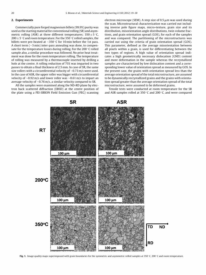
2 e and
2
um2bAssmohpsIva
tt
0 S. Biswas et al. / Materials Scienc
. Experiments
Commercially pure forged magnesium billets (99.9%) purity wassed as the starting material for conventional rolling (SR) and asym-etric rolling (ASR) at three different temperatures; 350 ± 5 ◦C,
00 ± 5 ◦C and room temperature. For the 350 ◦C rolled samples, theillets were pre-heated at ∼350 ◦C for 10 min before the 1st pass.
short term (∼3 min) inter-pass annealing was done, to compen-ate for the temperature losses during rolling. For the 200 ◦C rolledample also, a similar procedure was followed. No prior heat treat-ent was done for the room temperature rolling. The temperature
f rolling was measured by a thermocouple inserted by drilling aole at the centre. A rolling reduction of 75% was imparted in twoasses to obtain a final thickness of 2.5 mm. In case of SR, the sameize rollers with a circumferential velocity of ∼0.73 m/s were used.n the case of ASR, the upper roller was bigger with circumferentialelocity of ∼0.92 m/s and lower roller was ∼0.61 m/s to impart an
verage velocity of ∼0.76 m/s, a similar velocity compared to SR.All the samples were examined along the ND-RD plane by elec-ron back scattered diffraction (EBSD) at the centre position ofhe plate using a FEI-SIRION Field Emission Gun (FEG) scanning
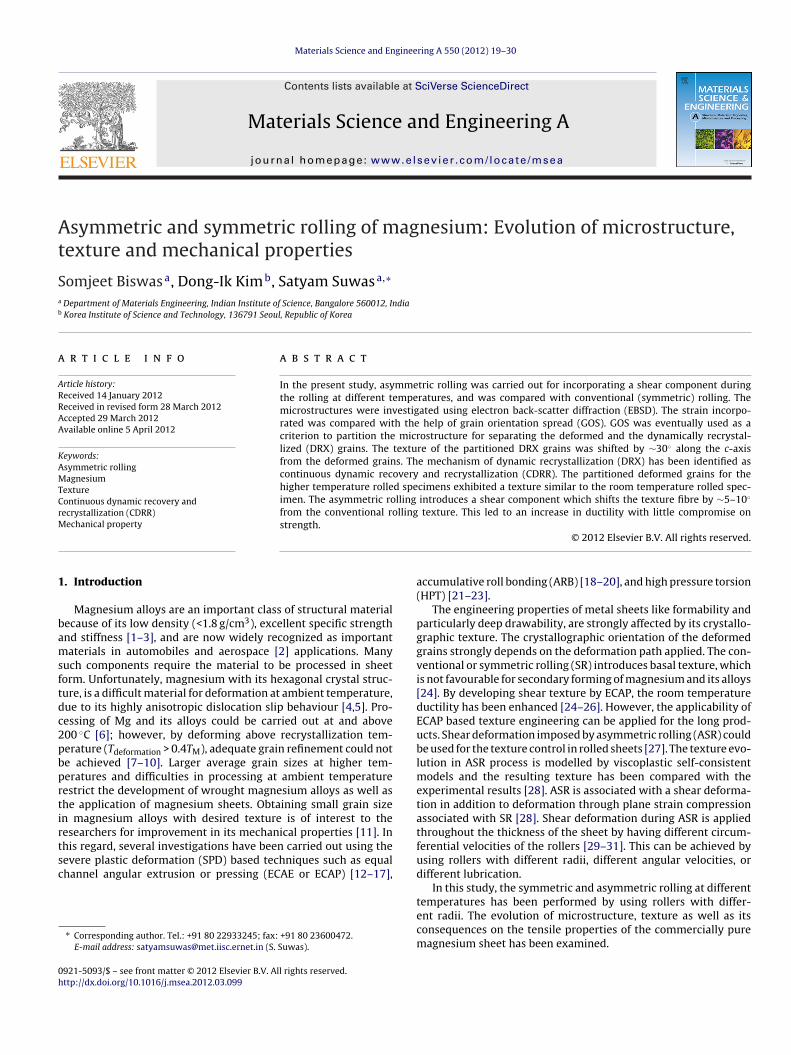
Fig. 1. Image quality maps superimposed with grain boundaries for the symmetr
Engineering A 550 (2012) 19– 30
electron microscope (SEM). A step size of 0.5 �m was used duringthe scan. Microstructural characterization was carried out includ-ing inverse pole figure maps, micro-texture, grain size and itsdistribution, misorientation angle distributions, twin volume frac-tions, and grain orientation spread (GOS), for each of the samplesand was compared. The partitioning of the microstructures wascarried out using the criteria of grain orientation spread (GOS).This parameter, defined as the average misorientation betweenall pixels within a grain, is used for differentiating between thetwo types of regions. A high value of orientation spread indi-cates a high geometrically necessary dislocation (GND) contentand more deformation in the sample whereas the recrystallizedsamples are characterized by low dislocation content and a corre-sponding lower value of orientation spread as measured by GOS. Inthe present case, the grains with orientation spread less than theaverage orientation spread of the total microstructure, are assumedto be dynamically recrystallized grains and the grains with orienta-
tion spread greater than the average orientation spread of the totalmicrostructure, were assumed to be deformed grains.Tensile tests were conducted at room temperature for the SRand ASR samples rolled at 350 ◦C and 200 ◦C, and were compared
ic and asymmetric rolled samples at 350 ◦C, 200 ◦C and room temperature.
S. Biswas et al. / Materials Science and Engineering A 550 (2012) 19– 30 21
Table 1Average grain size for different treatments and the grain size of partitioned deformed and recrystallized fractions with corresponding criteria of partition.
Temperature Symmetric rolling Asymmetric rolling
Avg. grain size (�m) Grain size for the partitioned fraction (�m) Avg. grain size (�m) Grain size for the partitioned fraction (�m)
Room temperature 3.4GOS > 1.39 GOS ≤ 1.39
2.3GOS > 1.66 GOS ≤ 1.66
3.8 3.1 3.1 1.6
200 ◦C 3.8GOS > 1.59 GOS ≤ 1.59
4.0GOS > 1.16 GOS ≤ 1.16
2.9GOS ≤5.7
vtrs
3
3
warwatephsts
chat
Fsea
4.4
350 ◦C 5.6GOS > 1.06
5.2
is-à-vis their microstructure and texture. The specimens wereested at the strain rate 5 × 10⁻³ s−1. For the room temperatureolled samples no mechanical testing could be conducted as theamples were having micro-cracks.
. Results
.1. Microstructural analysis
The initial microstructure was characterized by equiaxed grainsith ∼14 �m grain size and a weak texture. The microstructures,
fter rolling under different temperature conditions and both theoutes, are presented in Fig. 1 in the form of image quality (IQ) mapsith superimposed grain boundaries. The samples rolled at 350 ◦C
nd 200 ◦C contained mostly equiaxed grains. However, the roomemperature rolled samples contain equiaxed grains surroundinglongated grains along RD. The average grain size after rolling isresented in Table 1 and the comparison clearly reveals that it isigher for the ASR than SR samples processed at 350 ◦C, almostimilar in case of 200 ◦C samples and lower for the ASR than SR forhe room temperature conditions. The grain size distribution had aingular peak for all the samples.
The misorientation angle distributions for all the samples are◦
ompared and shown in Fig. 2. A diffused population of (15–180 )igh angle grain boundaries (HAGBs) with smaller peaks at ∼30◦
nd ∼90◦ could be observed in all the cases. It was anticipatedhat these peaks could be due to twin boundaries. The formation
ig. 2. Misorientation angle distribution for the symmetric and asymmetric rolledamples at 350 ◦C, 200 ◦C and room temperature. (For interpretation of the ref-rences to colour in this figure, the reader is referred to the web version of thisrticle.)
3.8 4.1 1.06
6.7GOS > 0.93 GOS ≤ 0.936.8 6.7
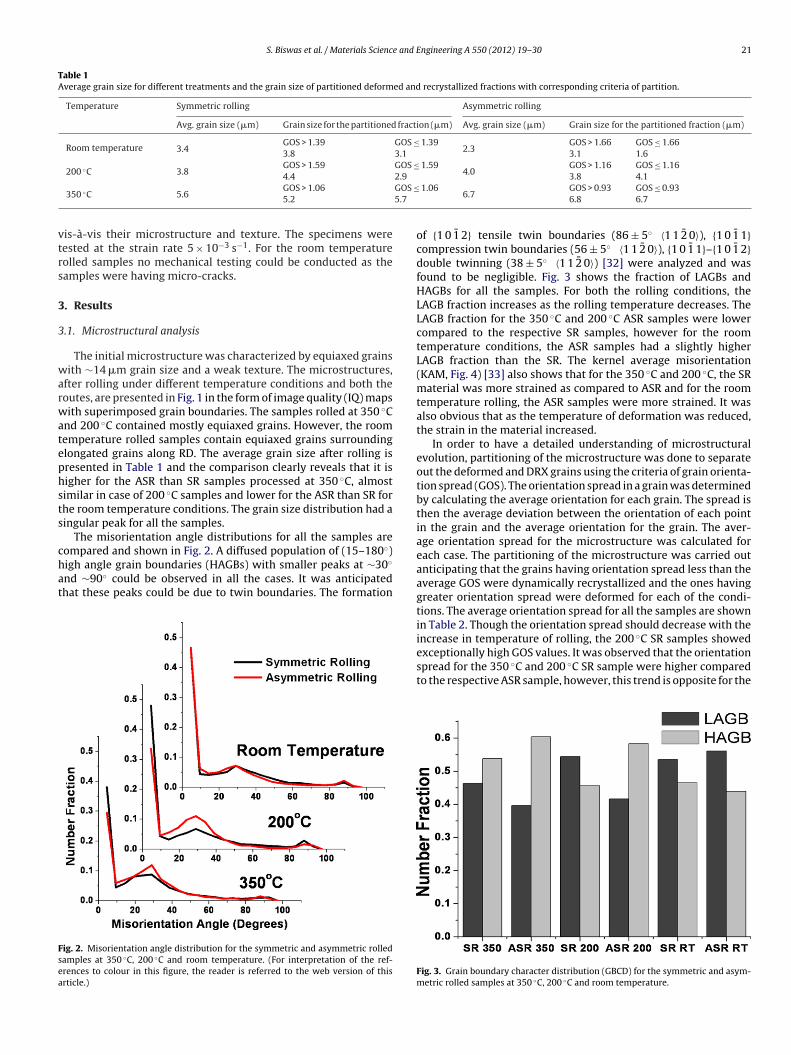
of {1 0 1̄ 2} tensile twin boundaries (86 ± 5◦ 〈1 1 2̄ 0〉), {1 0 1̄ 1}compression twin boundaries (56 ± 5◦ 〈1 1 2̄ 0〉), {1 0 1̄ 1}–{1 0 1̄ 2}double twinning (38 ± 5◦ 〈1 1 2̄ 0〉) [32] were analyzed and wasfound to be negligible. Fig. 3 shows the fraction of LAGBs andHAGBs for all the samples. For both the rolling conditions, theLAGB fraction increases as the rolling temperature decreases. TheLAGB fraction for the 350 ◦C and 200 ◦C ASR samples were lowercompared to the respective SR samples, however for the roomtemperature conditions, the ASR samples had a slightly higherLAGB fraction than the SR. The kernel average misorientation(KAM, Fig. 4) [33] also shows that for the 350 ◦C and 200 ◦C, the SRmaterial was more strained as compared to ASR and for the roomtemperature rolling, the ASR samples were more strained. It wasalso obvious that as the temperature of deformation was reduced,the strain in the material increased.
In order to have a detailed understanding of microstructuralevolution, partitioning of the microstructure was done to separateout the deformed and DRX grains using the criteria of grain orienta-tion spread (GOS). The orientation spread in a grain was determinedby calculating the average orientation for each grain. The spread isthen the average deviation between the orientation of each pointin the grain and the average orientation for the grain. The aver-age orientation spread for the microstructure was calculated foreach case. The partitioning of the microstructure was carried outanticipating that the grains having orientation spread less than theaverage GOS were dynamically recrystallized and the ones havinggreater orientation spread were deformed for each of the condi-tions. The average orientation spread for all the samples are shownin Table 2. Though the orientation spread should decrease with the
increase in temperature of rolling, the 200 ◦C SR samples showedexceptionally high GOS values. It was observed that the orientationspread for the 350 ◦C and 200 ◦C SR sample were higher comparedto the respective ASR sample, however, this trend is opposite for theFig. 3. Grain boundary character distribution (GBCD) for the symmetric and asym-metric rolled samples at 350 ◦C, 200 ◦C and room temperature.
22 S. Biswas et al. / Materials Science and Engineering A 550 (2012) 19– 30
Fatv
rw
da
Table 2Average value of grain orientation spread (GOS).
Orientation spread (◦)
Symmetric rolling Asymmetric rolling
F2
ig. 4. Comparison of kernel average misorientation (KAM) between symmetric andsymmetric rolled samples for 350 ◦C, 200 ◦C and room temperature. (For interpre-ation of the references to colour in this figure, the reader is referred to the webersion of this article.)
oom temperature condition. The analysis of the GOS corroborates
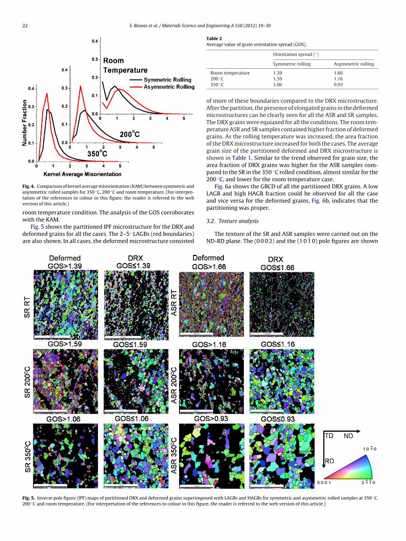
ith the KAM.Fig. 5 shows the partitioned IPF microstructure for the DRX andeformed grains for all the cases. The 2–5◦ LAGBs (red boundaries)re also shown. In all cases, the deformed microstructure consisted
ig. 5. Inverse pole figure (IPF) maps of partitioned DRX and deformed grains superimpos00 ◦C and room temperature. (For interpretation of the references to colour in this figure
Room temperature 1.39 1.66200 ◦C 1.59 1.16350 ◦C 1.06 0.93
of more of these boundaries compared to the DRX microstructure.After the partition, the presence of elongated grains in the deformedmicrostructures can be clearly seen for all the ASR and SR samples.The DRX grains were equiaxed for all the conditions. The room tem-perature ASR and SR samples contained higher fraction of deformedgrains. As the rolling temperature was increased, the area fractionof the DRX microstructure increased for both the cases. The averagegrain size of the partitioned deformed and DRX microstructure isshown in Table 1. Similar to the trend observed for grain size, thearea fraction of DRX grains was higher for the ASR samples com-pared to the SR in the 350 ◦C rolled condition, almost similar for the200 ◦C, and lower for the room temperature case.
Fig. 6a shows the GBCD of all the partitioned DRX grains. A lowLAGB and high HAGB fraction could be observed for all the caseand vice versa for the deformed grains, Fig. 6b, indicates that thepartitioning was proper.
3.2. Texture analysis
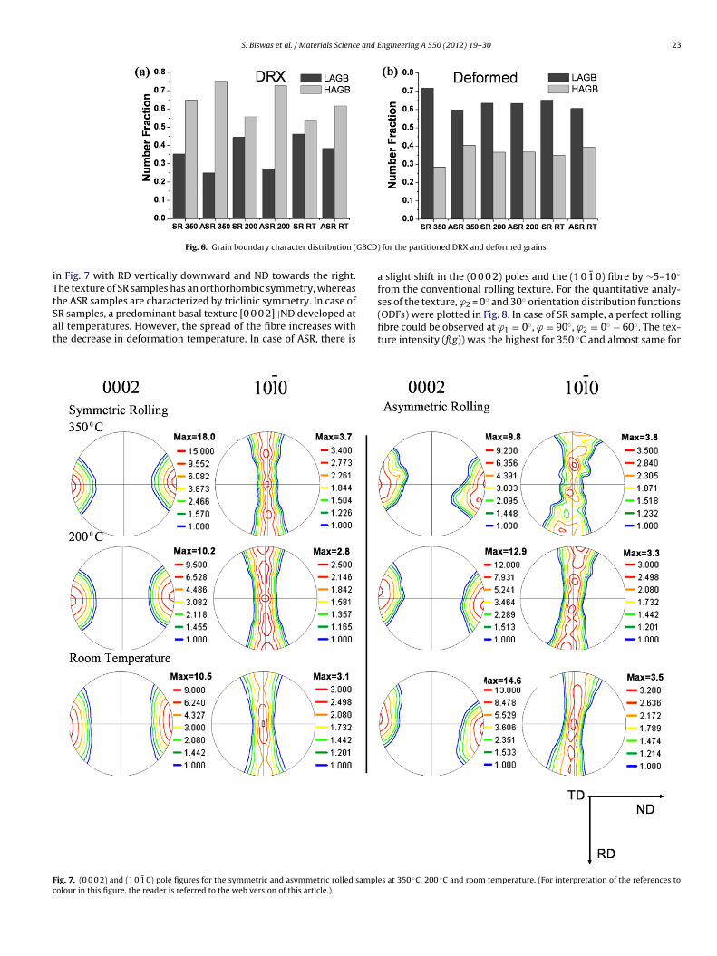
The texture of the SR and ASR samples were carried out on theND-RD plane. The (0 0 0 2) and the (1 0 1̄ 0) pole figures are shown
ed with LAGBs and HAGBs for symmetric and asymmetric rolled samples at 350 ◦C,, the reader is referred to the web version of this article.)
S. Biswas et al. / Materials Science and Engineering A 550 (2012) 19– 30 23
GBCD)
iTtSat
Fc
Fig. 6. Grain boundary character distribution (
n Fig. 7 with RD vertically downward and ND towards the right.he texture of SR samples has an orthorhombic symmetry, whereashe ASR samples are characterized by triclinic symmetry. In case of
R samples, a predominant basal texture [0 0 0 2]||ND developed atll temperatures. However, the spread of the fibre increases withhe decrease in deformation temperature. In case of ASR, there isig. 7. (0 0 0 2) and (1 0 1̄ 0) pole figures for the symmetric and asymmetric rolled samplolour in this figure, the reader is referred to the web version of this article.)
for the partitioned DRX and deformed grains.
a slight shift in the (0 0 0 2) poles and the (1 0 1̄ 0) fibre by ∼5–10◦
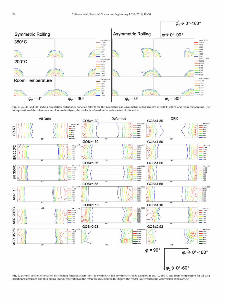
from the conventional rolling texture. For the quantitative analy-ses of the texture, ϕ2 = 0◦ and 30◦ orientation distribution functions
(ODFs) were plotted in Fig. 8. In case of SR sample, a perfect rollingfibre could be observed at ϕ1 = 0◦, ϕ = 90◦, ϕ2 = 0◦ − 60◦. The tex-ture intensity (f(g)) was the highest for 350 ◦C and almost same fores at 350 ◦C, 200 ◦C and room temperature. (For interpretation of the references to
24 S. Biswas et al. / Materials Science and Engineering A 550 (2012) 19– 30
Fig. 8. ϕ2 = 0◦ and 30◦ section orientation distribution function (ODFs) for the symmetric and asymmetric rolled samples at 350 ◦C, 200 ◦C and room temperature. (Forinterpretation of the references to colour in this figure, the reader is referred to the web version of this article.)
Fig. 9. ϕ2 = 90◦ section orientation distribution function (ODFs) for the symmetric and asymmetric rolled samples at 350 ◦C, 200 ◦C and room temperature for all data,partitioned deformed and DRX grains. (For interpretation of the references to colour in this figure, the reader is referred to the web version of this article.)
S. Biswas et al. / Materials Science and Engineering A 550 (2012) 19– 30 25
Fig. 10. Engineering stress–strain curves for the symmetric and asymmetric rolledsfi
2atfiϕtwaa
tpwa
3
ia3Dtes(pr3rhIea
TTn
amples at 350 ◦C and 200 ◦C. (For interpretation of the references to colour in thisgure, the reader is referred to the web version of this article.)
00 ◦C and RT. A shift of texture fibre by ∼5–10◦ along ϕ1 couldlso be observed from the ODFs of all the ASR samples. The tex-ure intensity and the spread of texture fibre remain almost sameor all the temperatures. In order to observe the positions of max-mum intensity of texture fibre that runs along ϕ2 = 0◦ − 60◦, the
= 90◦ sections of ODFs were plotted (Fig. 9). It was observed thathe distribution of the fibre depends upon the test temperature,ith maximum intensity at ϕ2 = 0◦ for the room temperature and
t ϕ2 = 30◦ for the 350 ◦C and 200 ◦C rolled samples for both the SRnd ASR.
Fig. 9 also shows the ϕ = 90◦ ODF corresponding to the parti-ioned DRX and deformed grains separately. For all the cases theartitioned DRX grains had the maximum intensity at ϕ2 = 30◦,hereas the partitioned deformed grains had a maximum intensity
t ϕ2 = 0◦ and 60◦.
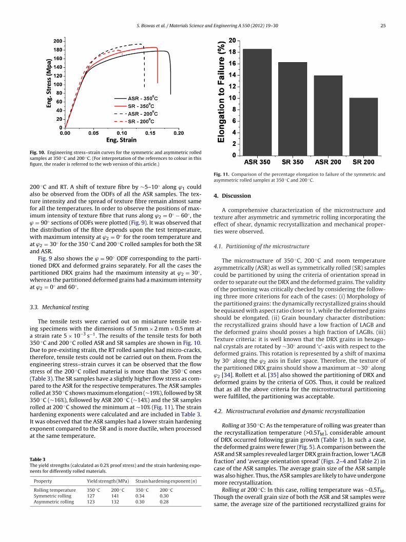
.3. Mechanical testing
The tensile tests were carried out on miniature tensile test-ng specimens with the dimensions of 5 mm × 2 mm × 0.5 mm at
strain rate 5 × 10⁻³ s−1. The results of the tensile tests for both50 ◦C and 200 ◦C rolled ASR and SR samples are shown in Fig. 10.ue to pre-existing strain, the RT rolled samples had micro-cracks,
herefore, tensile tests could not be carried out on them. From thengineering stress–strain curves it can be observed that the flowtress of the 200 ◦C rolled material is more than the 350 ◦C onesTable 3). The SR samples have a slightly higher flow stress as com-ared to the ASR for the respective temperatures. The ASR samplesolled at 350 ◦C shows maximum elongation (∼19%), followed by SR50 ◦C (∼16%), followed by ASR 200 ◦C (∼14%) and the SR samplesolled at 200 ◦C showed the minimum at ∼10% (Fig. 11). The strainardening exponents were calculated and are included in Table 3.
t was observed that the ASR samples had a lower strain hardening
xponent compared to the SR and is more ductile, when processedt the same temperature.able 3he yield strengths (calculated as 0.2% proof stress) and the strain hardening expo-ents for differently rolled materials.
Property Yield strength (MPa) Strain hardening exponent (n)
Rolling temperature 350 ◦C 200 ◦C 350 ◦C 200 ◦CSymmetric rolling 127 141 0.34 0.30Asymmetric rolling 123 132 0.30 0.28
Fig. 11. Comparison of the percentage elongation to failure of the symmetric andasymmetric rolled samples at 350 ◦C and 200 ◦C.
4. Discussion
A comprehensive characterization of the microstructure andtexture after asymmetric and symmetric rolling incorporating theeffect of shear, dynamic recrystallization and mechanical proper-ties were observed.
4.1. Partitioning of the microstructure
The microstructure of 350 ◦C, 200 ◦C and room temperatureasymmetrically (ASR) as well as symmetrically rolled (SR) samplescould be partitioned by using the criteria of orientation spread inorder to separate out the DRX and the deformed grains. The validityof the portioning was critically checked by considering the follow-ing three more criterions for each of the cases: (i) Morphology ofthe partitioned grains: the dynamically recrystallized grains shouldbe equiaxed with aspect ratio closer to 1, while the deformed grainsshould be elongated. (ii) Grain boundary character distribution:the recrystallized grains should have a low fraction of LAGB andthe deformed grains should posses a high fraction of LAGBs. (iii)Texture criteria: it is well known that the DRX grains in hexago-nal crystals are rotated by ∼30◦ around ‘c’-axis with respect to thedeformed grains. This rotation is represented by a shift of maximaby 30◦ along the ϕ2 axis in Euler space. Therefore, the texture ofthe partitioned DRX grains should show a maximum at ∼30◦ alongϕ2 [34]. Rollett et al. [35] also showed the partitioning of DRX anddeformed grains by the criteria of GOS. Thus, it could be realizedthat as all the above criteria for the microstructural partitioningwere fulfilled, the partitioning was acceptable.
4.2. Microstructural evolution and dynamic recrystallization
Rolling at 350 ◦C: As the temperature of rolling was greater thanthe recrystallization temperature (>0.5TM), considerable amountof DRX occurred following grain growth (Table 1). In such a case,the deformed grains were fewer (Fig. 5). A comparison between theASR and SR samples revealed larger DRX grain fraction, lower ‘LAGBfraction’ and ‘average orientation spread’ (Figs. 2–4 and Table 2) incase of the ASR samples. The average grain size of the ASR samplewas also higher. Thus, the ASR samples are likely to have undergone
more recrystallization.Rolling at 200 ◦C: In this case, rolling temperature was ∼0.5TM.Though the overall grain size of both the ASR and SR samples weresame, the average size of the partitioned recrystallized grains for
26 S. Biswas et al. / Materials Science and Engineering A 550 (2012) 19– 30
F AGB
u nces
o
tTcair
gbDmtoonoerloitt∼fnh
4
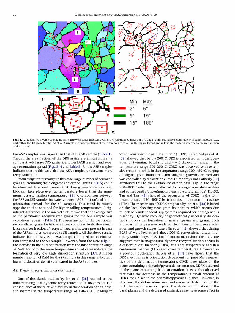
ucs
ig. 12. (a) Magnified inverse pole figure (IPF) map with superimposed LAGB and Hnit cell on the TD plane for the 350 ◦C ASR sample. (For interpretation of the referef this article.)
he ASR samples was larger than that of the SR sample (Table 1).hough the area fraction of the DRX grains are almost similar, aomparatively larger DRX grain size, lower LAGB fraction and aver-ge orientation spread (Figs. 2–4 and Table 2) for the ASR samplesndicate that in this case also the ASR samples underwent moreecrystallization.
Room temperature rolling: In this case, large number of equiaxedrains surrounding the elongated (deformed) grains (Fig. 5) coulde observed. It is well known that during severe deformation,RX can take place even at temperature lower than the mini-um recrystallization temperature [36]. A comparison between
he ASR and SR samples indicates a lower ‘LAGB fraction’ and ‘grainrientation spread’ for the SR samples. This trend is exactlypposite to that obtained for higher rolling temperatures. A sig-ificant difference in the microstructure was that the average sizef the partitioned recrystallized grains for the ASR sample wasxceptionally small (Table 1). The area fraction of the partitionedecrystallized grains for ASR was lower compared to SR. However, aarge number fraction of recrystallized grains were present in casef the ASR samples, compared to SR samples. All the above resultsndicate that in this case, the ASR sample contained more deforma-ion compared to the SR sample. However, from the KAM (Fig. 4),he increase in the number fraction from the misorientation angle0.5–0◦ for both the room temperature rolled cases indicate the
ormation of very low angle dislocation structure [37]. A higherumber fraction of KAM for the SR sample in this range indicates aigher dislocation density compared to the ASR samples.
.3. Dynamic recrystallization mechanism
One of the classic studies by Ion et al. [38] has led to thenderstanding that dynamic recrystallization in magnesium is aonsequence of the relative difficulty in the operation of non-basallip systems in the temperature range of 150–330 ◦C leading to
grain boundary and (b and c) grain boundary colour map with superimposed h.c.p.to colour in this figure legend and in text, the reader is referred to the web version
‘continuous dynamic recrystallization’ (CDRX). Later, Galiyev et al.[39] showed that below 200 ◦C, DRX is associated with the oper-ation of twinning, basal slip and 〈c + a〉 dislocation glide. In thetemperature range 200–250 ◦C, CDRX was observed with exten-sive cross-slip, while in the temperature range 300–450 ◦C, bulgingof original grain boundaries and subgrain growth occurred andwas controlled by dislocation climb. Humphreys and Hatherly [40]attributed this to the availability of non basal slip in the range300–400 ◦C which eventually led to homogeneous deformationand consequently ‘discontinuous dynamic recrystallization’ (DDRX).Tan and Tan [41] showed the occurrence of CDRX in the tem-perature range 250–400 ◦C by transmission electron microscopy(TEM). The mechanism of CDRX proposed by Ion et al. [38] is basedon the local shearing near grain boundaries, which occurs dueto lack of 5 independent slip systems required for homogeneousplasticity. Dynamic recovery of geometrically necessary disloca-tions induces the formation of new subgrains and grains. Sucha process is progressive, with no clear division between nucle-ation and growth stages. Later, Jin et al. [42] showed that duringECAE of Mg-alloys at and above 200 ◦C, conventional discontinu-ous dynamic recrystallization did not occur. In short, the literaturesuggests that in magnesium, dynamic recrystallization occurs ina discontinuous manner (DDRX) at higher temperature and in acontinuous manner (CDRR) at lower temperatures. However, ina previous publication Biswas et al. [17] have shown that theDRX mechanism is orientation dependent for pure Mg irrespec-tive of the deformation temperature. CDRR takes place on theplane containing prismatic/pyramidal orientation. DDRX occurredin the plane containing basal orientation. It was also observedthat with the decrease in the temperature, a small amount of
DDRX took place in the prismatic/pyramidal planes. However, inthis case, the deformation was continuous with decrease in theECAE temperature in each pass. The strain accumulation in thebasal planes and the decreased grain size may have some effect in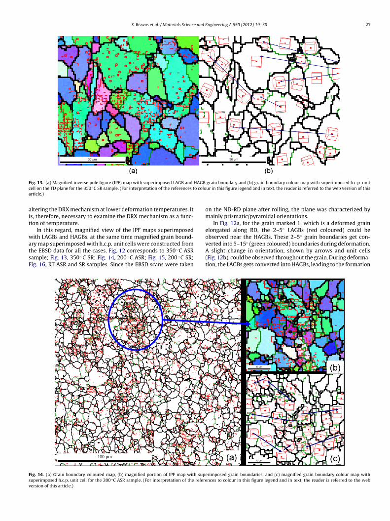
S. Biswas et al. / Materials Science and Engineering A 550 (2012) 19– 30 27
F HAGBc o coloa
ait
watsF
Fsv
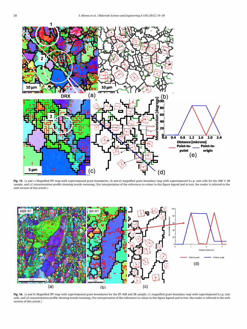
ig. 13. (a) Magnified inverse pole figure (IPF) map with superimposed LAGB and
ell on the TD plane for the 350 ◦C SR sample. (For interpretation of the references trticle.)
ltering the DRX mechanism at lower deformation temperatures. Its, therefore, necessary to examine the DRX mechanism as a func-ion of temperature.
In this regard, magnified view of the IPF maps superimposedith LAGBs and HAGBs, at the same time magnified grain bound-
ry map superimposed with h.c.p. unit cells were constructed fromhe EBSD data for all the cases. Fig. 12 corresponds to 350 ◦C ASRample; Fig. 13, 350 ◦C SR; Fig. 14, 200 ◦C ASR; Fig. 15, 200 ◦C SR;ig. 16, RT ASR and SR samples. Since the EBSD scans were taken
ig. 14. (a) Grain boundary coloured map, (b) magnified portion of IPF map with supeuperimposed h.c.p. unit cell for the 200 ◦C ASR sample. (For interpretation of the refereersion of this article.)
grain boundary and (b) grain boundary colour map with superimposed h.c.p. unitur in this figure legend and in text, the reader is referred to the web version of this
on the ND-RD plane after rolling, the plane was characterized bymainly prismatic/pyramidal orientations.
In Fig. 12a, for the grain marked 1, which is a deformed grainelongated along RD, the 2–5◦ LAGBs (red coloured) could beobserved near the HAGBs. These 2–5◦ grain boundaries get con-
verted into 5–15◦ (green coloured) boundaries during deformation.A slight change in orientation, shown by arrows and unit cells(Fig. 12b), could be observed throughout the grain. During deforma-tion, the LAGBs gets converted into HAGBs, leading to the formationrimposed grain boundaries, and (c) magnified grain boundary colour map withnces to colour in this figure legend and in text, the reader is referred to the web
28 S. Biswas et al. / Materials Science and Engineering A 550 (2012) 19– 30
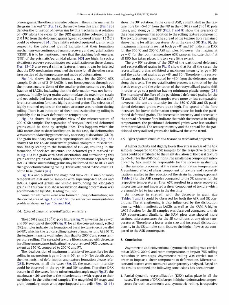
Fig. 15. (a and c) Magnified IPF map with superimposed grain boundaries, (b and d) magnified grain boundary map with superimposed h.c.p. unit cells for the 200 ◦C SRsample, and (e) misorientation profile showing tensile twinning. (For interpretation of the references to colour in this figure legend and in text, the reader is referred to theweb version of this article.)
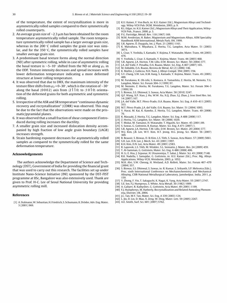
Fig. 16. (a and b) Magnified IPF map with superimposed grain boundaries for the RT ASR and SR sample, (c) magnified grain boundary map with superimposed h.c.p. unitcells, and (d) misorientation profile showing tensile twinning. (For interpretation of the references to colour in this figure legend and in text, the reader is referred to the webversion of this article.)
e and E
otdo〈crm((sFti
stfgafhrp
2gDwTstfigHto
tHga
tp
4
a(ttpie
rt[comng
S. Biswas et al. / Materials Scienc
f new grains. The other grains also behave in the similar manner. Inhe grain marked “2” (Fig. 12a), the arrow from this grain (Fig. 12b)enotes the formation of new grains by this mechanism. A rotationf ∼30◦ along the c-axis for the DRX grains (blue coloured grains1 0 1̄ 0〉) from the deformed grains (green coloured grains 〈1 1 2̄ 0〉)ould be observed [34]. The slightly rotated equiaxed grains (withespect to the deformed grains) indicate that their formationechanism was continuous dynamic recovery and recrystallization
CDRR). It is to be mentioned here that the stacking fault energiesSFE) of the prismatic/pyramidal planes [43] are high. In such aituation, recovery predominates recrystallization on these planes.igs. 13–15 also reveal similar features, hence it can be inferredhat the DRX mechanism remained the same for all the other casesrrespective of the temperature and mode of deformation.
Fig. 14a shows the grain boundary map for the 200 ◦C ASRample. Division of 2–5◦ LAGBs is not homogeneous through outhe microstructure. Some of the smaller grains contains very highraction of LAGBs, indicating that the deformation was not homo-eneous. Initially larger grains accommodate the maximum strainnd get subdivided into several grains. There is no particular (dif-erent) orientation for these highly strained grains. The selection ofighly strained regions on the microstructure was random duringolling. There is an indication of shear localization during rolling isrobably due to lower deformation temperature.
Fig. 15a shows the magnified view of the microstructure of00 ◦C SR sample. The separation of recrystallized and deformedrains could be done by straight lines. This happens when theRX occurs due to shear localization. In this case, the deformationas accommodated by geometrically necessary dislocations (GND).
he grain boundary map with superimposed unit cells (Fig. 15b)hows that the LAGBs underwent gradual changes in misorienta-ion, finally leading to the formation of HAGBs, resulting in theormation of necklace structure. The deformed grain marked “1”n Fig. 15a is a grain with basal orientation, and surrounding thisrain are the grains with totally different orientations separated byAGBs. These surrounding grains may be formed due to DDRX and
hen got deformed during rolling. This is attributed to the lower SFEf the basal planes [43].
Fig. 16a and b shows the magnified view of IPF map of roomemperature ASR and SR samples with superimposed LAGBs andAGBs. Equiaxed grains are visible surrounding the elongatedrains. In this case also shear localization during deformation wasccommodated by GND, leading to CDRR.
Some tensile twins were also formed during deformation; seehe circled area of Figs. 15c and 16b. The respective misorientationrofile is shown in Figs. 15e and 16d.
.4. Effect of dynamic recrystallization on texture
The (0 0 0 2) and (1 0 1̄ 0) pole figures (Fig. 7) as well as the ϕ2 = 0◦
nd 30◦ sections of the ODF (Fig. 8) for all the conventionally rolledSR) samples indicate the formation of basal texture (c-axis parallelo ND), which is the typical rolling texture of magnesium. At 350 ◦C,he texture intensity was higher than that for 200 ◦C and room tem-erature rolling. The spread of texture fibre increases with decrease
n rolling temperature, indicating the occurrence of DRX to a greaterxtent at 350 ◦C, compared to 200 ◦C and RT.
The ideal position of maximum intensity of texture fibre for theolling in magnesium is ϕ1 = 0◦, ϕ = 90◦, ϕ2 = 0◦ (for details abouthe mechanism of deformation and texture formation please refer28]). However, in all the cases (Fig. 8), the maximum intensityould be observed in the ϕ2 = 0◦ and 30◦ section. Therefore DRX
ccurs in all the cases. In the misorientation angle map (Fig. 2), theaxima at ∼30◦ are due to the misorientation with respect to theireighbour in the deformed samples. The magnified IPF maps andrain boundary maps with superimposed unit cells (Figs. 12–16)
ngineering A 550 (2012) 19– 30 29
show the 30◦ rotation. In the case of ASR, a slight shift in the tex-ture fibre by ∼5–10◦ from the ND in the (0 0 0 2) and (1 0 1̄ 0) polefigure, and along ϕ1 in ODF (Figs. 7 and 8) show the presence ofthe shear component in addition to the rolling texture component.The texture intensity and the spread of the texture fibre remainedalmost same for all temperatures. As in the case of SR (Fig. 9), themaximum intensity is seen at both ϕ2 = 0◦ and 30◦ indicating DRXfor the 350 ◦C and 200 ◦C ASR samples. However, the maxima atϕ2 = 0◦ for the room temperature ASR samples indicate that if atall DRX has taken place; it is to a very little extent.
The ϕ = 90◦ sections of the ODF of the partitioned deformedand recrystallized grains in Fig. 9 show that for all the cases, therecrystallized grains exhibited a maximum intensity at ϕ2 = 30◦
and the deformed grains at ϕ2 = 0◦ and 60◦. Therefore, the recrys-tallized grains have got rotated by ∼30◦ from the deformed grainsalong the c-axis. The recrystallization process is controlled by theplastic energy and the orientation of the recrystallized grains shiftin order to go to a position having minimum plastic energy [28].The intensity of the fibre of the partitioned deformed grains for theRT and 200 ◦C ASR and SR samples were more or less comparable;however, the texture intensity for the 350 ◦C ASR and SR parti-tioned deformed grains were quite high. The spread of the fibreincreased for lower deformation temperature for both the parti-tioned deformed grains. The increase in intensity and decrease inthe spread of texture fibre indicate that with the increase in rollingtemperatures, the partitioned deformed grains were less strainedor rather relaxed. The texture intensity and the spread for the par-titioned recrystallized grains also followed the same trend.
4.5. Effect of microstructure and texture on mechanical properties
A higher ductility and slightly lower flow stress in case of the ASRsamples compared to the SR samples for the respective tempera-tures could be attributed to the slight deviation of the basal textureby ∼5–10◦ for the ASR conditions. The small shear component intro-duced by ASR might be responsible for the increase in ductilityfor the samples processed at the same deformation temperature.A combined effect of shear component of texture and recrystal-lization resulted in the reduction of the strain hardening exponent(Table 3) for the ASR samples compared to the SR samples for therespective temperatures. Thus ASR resulted in a more recoveredmicrostructure and imparted a shear component of texture whichpresumably led to increase in the ductility.
An increase in strength with the decrease in grain size(Tables 1 and 3) could be observed for both the ASR and SR con-ditions. The strengthening is also influenced by the dislocationdensity, which manifests as LAGBs as well as the KAM. A higherLAGB fraction for the SR samples was observed compared to theirASR counterparts. Similarly, the KAM plots also showed morestrained microstructures for the SR conditions at any given tem-peratures. Therefore, a lower grain size and increased dislocationdensity in the SR samples contribute to the higher flow stress com-pared to the ASR counterparts.
5. Conclusion
Asymmetric and conventional (symmetric) rolling was carriedout at 350 ◦C, 200 ◦C and room temperature, to impart 75% rollingreduction in two steps. Asymmetric rolling was carried out inorder to impose a shear component to deformation. Microstruc-ture and texture were measured and rigorously analyzed. Based onthe results obtained, the following conclusions has been drawn:
1. Partial dynamic recrystallization (DRX) takes place in all thecases. The extent of DRX is larger in higher deformation temper-ature for both asymmetric and symmetric rolling. Irrespective
3 e and
2
3
4
5
6
7
8
A
ntIpga
R
[[[[[
[
[
[[
[
[[
[[[[[[
[[[[[[[
[
[
[[[[40] F.J. Humphreys, M. Hatherly, Recrystallization and Related Annealing Phenom-
0 S. Biswas et al. / Materials Scienc
of the temperature, the extent of recrystallization is more inasymmetrically rolled samples compared to their symmetricallyrolled counterparts.
. An average grain size of ∼2.3 �m has been obtained for the roomtemperature asymmetrically rolled sample. The room tempera-ture symmetrically rolled sample has a larger average grain size,whereas in the 200 ◦C rolled samples the grain size was simi-lar, and for the 350 ◦C, the symmetrically rolled samples havesmaller average grain size.
. A predominant basal texture forms along the normal direction(ND) after symmetric rolling, while in case of asymmetric rollingthe basal texture is ∼5–10◦ shifted from the ND or along ϕ1 inthe ODF. Texture intensity decreases and spread increases withlower deformation temperature indicating a more deformedstructure at lower rolling temperature.
. It was observed that due to DRX, the maximum intensity of thetexture fibre shifts from ϕ2 = 0–30◦, which is the rotation of ∼30◦
along the basal {0 0 0 2} axis from 〈2 1̄ 1̄ 0〉 to 〈1 0 1̄ 0〉 orienta-tion of the deformed grains for both asymmetric and symmetricrolling.
. Irrespective of the ASR and SR temperature “continuous dynamicrecovery and recrystallization” (CDRR) was observed. This maybe due to the fact that the observations were made on the pris-matic/pyramidal planes.
. It was observed that a small fraction of shear component if intro-duced during rolling increases the ductility.
. A smaller grain size and increased dislocation density accom-panied by high fraction of low angle grain boundary (LAGB)increases strength.
. Strain hardening exponent decreases for asymmetrically rolledsamples as compared to the symmetrically rolled for the samedeformation temperature.
cknowledgements
The authors acknowledge the Department of Science and Tech-ology (DST), Government of India for providing the financial granthat was used to carry out this research. The facilities set up undernstitute Nano-Science Initiative (INI) sponsored by the DST-FISTrogramme at IISc, Bangalore was also extensively used. Thank areiven to Prof. H-C. Lee of Seoul National University for providingsymmetric rolling mill.
eferences
[1] A. Stalmann, W. Sebastian, H. Friedrich, S. Schumann, K. Dröder, Adv. Eng. Mater.3 (2001) 969.
[[[
Engineering A 550 (2012) 19– 30
[2] K.U. Kainer, F. Von Buch, in: K.U. Kainer (Ed.), Magnesium Alloys and Technol-ogy, Wiley-VCH Pub. DGM, Weinheim, 2003, p. 9.
[3] R.L. Edgar, in: K.U. Kainer (Ed.), Magnesium Alloys and Their Application, Wiley-VCH Pub., France, 2000, p. 3.
[4] P.G. Partridge, Metall. Rev. 118 (1967) 169.[5] M.M. Avedesian, H. Baker, Magnesium and Magnesium Alloys, ASM Speciality
Handbook ASM International, Metals Park, OH, 1999.[6] S.R. Agnew, Ö. Duygulu, Int. J. Plast. 21 (2005) 1161.[7] K. Matsubara, Y. Miyahara, Z. Horita, T.G. Langdon, Acta Mater. 51 (2003)
3073.[8] L. Cisar, Y. Yoshida, S. Kamado, Y. Kojima, F. Watanabe, Mater. Trans. 44 (2003)
476.[9] Y. Yoshida, L. Cisar, S. Kamado, Y. Kojima, Mater. Trans. 44 (2003) 468.10] S.R. Agnew, J.A. Horton, T.M. Lillo, D.W. Brown, Scr. Mater. 50 (2004) 377.11] J.A. del Valle, F. Penalba, O.A. Ruano, Mater. Sci. Eng. A 467 (2007) 165.12] M. Eddahbi, O.A. Ruano, Revista de Metal. 42 (2) (2006) 146.13] K. Mathis, J. Gubicza, N.H. Nam, J. Alloys Compd. 394 (2005) 194.14] S.Y. Chang, S.W. Lee, K.M. Kang, S. Kamado, Y. Kojima, Mater. Trans. 45 (2005)
488.15] M. Furukawa, K. Oh-ishi, S. Komura, A. Yamashita, Z. Horita, M. Nemoto, T.G.
Langdon, Mater. Sci. Forum 304–3 (1999) 97.16] M. Nemoto, Z. Horita, M. Furukawa, T.G. Langdon, Mater. Sci. Forum 304–3
(1999) 59.17] S. Biswas, S.S. Dhinwal, S. Suwas, Acta Mater. 58 (2010) 3247.18] Q.F. Wang, X.P. Xiao, J. Hu, W.W. Xu, X.Q. Zhao, S.J. Zhao, J. Iron Steel Res. Int.
14 (2007) 167.19] J.A. del Valle, M.T. Pérez-Prado, O.A. Ruano, Mater. Sci. Eng. A 410–411 (2005)
353.20] M.T. Pérez-Prado, J.A. del Valle, O.A. Ruano, Scr. Mater. 51 (2004) 1093.21] Y. Harai, M. Kai, K. Kaneko, Z. Horita, T.G. Langdon, Mater. Trans. 49 (2008)
76.22] K. Masaaki, Z. Horita, T.G. Langdon, Mater. Sci. Eng. A 488 (2008) 117.23] Z. Horita, T.G. Langdon, Scr. Mater. 58 (2008) 1029.24] T. Mukai, M. Yamanoi, H. Watanabe, T. Higashi, Scr. Mater. 45 (2001) 89.25] S. Suwas, G. Gottstein, R. Kumar, Mater. Sci. Eng. A 471 (2007) 1.26] S.R. Agnew, J.A. Horton, T.M. Lillo, D.W. Brown, Scr. Mater. 20 (2004) 377.27] W.J. Kim, J.B. Lee, W.Y. Kim, H.T. Jeong, H.G. Jeong, Scr. Mater. 56 (2007)
309.28] B. Beausir, S. Biswas, D. Ik Kim, L.S. Tóth, S. Suwas, Acta Mater. 57 (2009) 5061.29] S.H. Lee, D.N. Lee, J. Mech. Sci. 43 (2001) 1997.30] K.H. Kim, D.N. Lee, Acta Mater. 49 (2001) 2583.31] R. Lapovok, L.S. Tóth, M. Winkler, S.L. Semiatin, J. Mater. Res. 24 (2009) 459.32] T. Al-Samman, G. Gottstein, Mater. Sci. Eng. A 488 (2008) 406.33] H. Li, E. Hsu, J. Szpunar, H. Utsunomiya, T. Sakai, J. Mater. Sci. 43 (2008) 7148.34] R.K. Nadella, I. Samajdar, G. Gottstein, in: K.U. Kainer (Ed.), Proc. Mg. Alloys
Applications, Wiley-VCH, Weinheim, 2003, p. 1052.35] M.H. Alvi, S.W. Cheong, H. Weiland, A.D. Rollett, Mater. Sci. Forum 467–470
(2004) 357.36] S. Biswas, S.S. Dhinwal, S. Suwas, in: R. Kumar, S. Srikanth, S.P. Mehrotra (Eds.),
Proc. sixth International Conference on Mechanochemistry and MechanicalAlloying, CSIR-National Metallurgical Laboratory, Jamshedpur, India, 2011, p.159.
37] Y. Zhong, F. Yin, T. Sakaguchi, K. Nagai, K. Yang, Acta Mater. 55 (2007) 2747.38] S.E. Ion, F.J. Humpreys, S. White, Acta Metall. 30 (1982) 1909.39] A. Galiyev, R. Kaibyshev, G. Gottstein, Acta Mater. 49 (2001) 1199.
ena, Elsevier, UK, 2004.41] J.C. Tan, M.Y. Tan, Mater. Sci. Eng. A 339 (2003) 124.42] L. Jin, D. Lin, D. Mao, X. Zeng, W. Ding, Mater. Lett. 59 (2005) 2267.43] A.E. Smith, Surf. Sci. 601 (2007) 5762.