
EMUTECHNOLOGY - Rolling Stock Knowledge Resource
300
GOVERNMENT OF INDIA MINISTRY OF RAILWAYS EMU TECHNOLOGY IRIEEN, NASIK
-
Upload
khangminh22 -
Category
Documents
-
view
0 -
download
0
Transcript of EMUTECHNOLOGY - Rolling Stock Knowledge Resource

GOVERNMENT OF INDIA
MINISTRY OF RAILWAYS
EMU TECHNOLOGY
IRIEEN, NASIK

EMU TECHNOLOGY
IN
INDIAN RAILWAYS

FOREWORD
Indian Railways is a very vibrant railway system of 64,600 route kilometers serving as India’s life
line for the movement of its people and goods. Indian Railways have to mechanize and modernize at a
pace appropriate to their needs. Thus, the motive power technology got upgraded and the Indian
Railways has introduced new technology AC/DC EMU rakes in passenger services.
It is quite essential that maintenance staff working in sheds and shops require entirely different
technical knowledge and skills for satisfactory operation and proper maintenance of these rakes. Efforts
have been made in the direction by IRIEEN/Nashik Road to develop the first edition of this technical
publication “Evolution of EMU Technology”
The publication covers in a very comprehensive manner, the entire spectrum of EMU
Technology. It is a work that not only a supervisor working in EMU units finds useful for his day to day
work but also engineers as a referral work and guide.
Shri N P Singh, Senior Professor of this Institution deserves credit for his dedicated and sincere
efforts for bringing out this book. I am glad to note that latest trends and technologies on EMUS’ have
been included in this book.
I am sure that this technical guide book will help to upgrade the technical knowledge and skills
of staff associated with EMU units
D. RAMASWAMY DIRECTOR Place : IRIEEN, Nasik Road Date : April 2014

PREFACE
The Indian Railway is in the midst of a transportation transformation as a result
of a renewed public commitment to invest and grow regional transit. The Big Move ‐ a
compelling integrated, multi‐modal vision strengthen the economic, social and
environmental sustainability of the country and profoundly change how people and
goods are transported. EMU services are playing a decisive part in this transformation.
The means by which Indian Railway system grows and develops is therefore essential to
realizing the ambitious vision for transportation network.
This book on “Evolution of EMU Technology” is prepared for providing basic
awareness with technological up gradation and to assess & identify an optimal
technology, or combination of technologies, that would be able to attain the system
performance goals identified in the Big Move and further enhance the quality, reliability,
accessibility and environmental sustainability of commuter rail services in the India.
This book contains advancement in the transport system up to IGBT based three
phase technology, brief description of rake and various mechanical as well as electrical
equipment provided in the different type of EMUs. HT power circuit and auxiliary circuit
are also described in this book.
It is clarified that this book does not supersede any existing provisions laid down
by RDSO, Railway Board or concerned Railways. It is for guidance only and it is not a
statutory document.
I am thankful to my I C course participant shri R D Bhargav AEE/TRS/JHS for
his help in typing & preparing this book. It will remain incomplete without my sincere
thanks to Shri D Ramaswami, Director, IRIEEN and IRIEEN faculty for cooperation and
a constant source of inspiration. I am also thankful to Mahalaxmi workshop instructors
for their cooperation.
Last but not the least, to all whom, I have failed to acknowledge.
IRIEEN, NASIK
Date:
N P SINGH
Sr.Prof EMU IRIEEN Nasik

CONTENTS
Sr.No. Description Page
Chapter 1 Introduction
Various Stages of Development
Brief Description of EMU
Chapter 2 Electrical
DC EMU
Conventional AC EMU
Major Equipment’s MEMU/EMU
Power and Auxiliary circuits
Main Control Circuits
Chapter 3 Mechanical
Bogie equipments and under gear
Air springs
Brake equipments and pneumatic circuit
Chapter 4 AC EMU Siemens Rake
General Description
Major Equipments
Other Electrical Equipments
Control Equipments
Brake Equipments and Passenger Amenities
Chapter 5 AWS
Train sets

CHAPTER 1
INTRODUCTION
Evolution of any technology is the resultant of the requirement for the
social as well as professional development of the human being.
Subsequently with growing demand of the faster transportation in India, the
historical day 16 April 1853 arrived when the first train ran at 3:35 pm
between BoriBunder (now ChhatrapatiShivaji Terminus) and Thane. The
14-coach train took 57 minutes to complete the 32 km journey, with a halt at
Sion for taking in water. Since that, it has faced rapid expansion. In 1904,
the idea was proposed to electrify the Great Indian Peninsula Railway and
the Bombay Baroda and Central India Railway (now known as CR and WR
respectively). In 1920, a committee was formed for expanding railway
network.
The first-ever electric train in India also ran on February 3, 1925
between Bombay (Victoria Terminus) and Kurla, a distance of 16 kms,
along the city’s harbour route heralding the era of electric traction in the
country. The section was electrified on a 1,500 volts DC because at that
time, DC traction was the only modern system available in the London
Underground.
In order to exploit the full commercial potential and to commute the
growing demand of passenger traffic, planners realized to extend the electric
based transport system. In early 1930, the government decided to electrify
the lines, including the mainline.The Mumbai Suburban Railway is an
offshoot of the first railway to be built by the British in India, and is also the
oldest railway system in Asia.

Gradually, the EMU services were introduced on other zonal
Railways as indicated below :
Western Railway: Chruchgate–Borivali section on 05.01.1928 and
gradually extended uptoVirar.
Southern Railway:Madras Beach-Tambaram meter gauge section on
11.03.1931 and Madras Central– Gummidipundy broad
gauge section on 14.04.1979.
Eastern Railway: Howrah–Bandel section of Howrah Division on
01.02.1957. Services were gradually extended to
Bardhaman in the year 1963. The EMU services were
also introduced on Sealdah – Ranaghat Section.
South Eastern Railway: Howrah– Mecheda section of Kharagpur division
on 01.05.1968.
Northern Railway: Circular Ring Route from Nizamuddin to
Nizamuddin on 15.08.1982.
South Central Railway: Secunderabad-Lingampallion 09.08.2003.
South Western Railway: Namma Metro also known as Bangalore
Metro:
Baiyyappanahalli- M.G. Road on 20 October
2011.
Today, the EMU services are in operation in all the 6 Metropolitan
cities viz. Mumbai, Delhi, Chennai, Kolkata, Hydrabad and Bangalore.
Electric multiple units are better for train service than locomotives
hauling unpowered cars when the consists are short because their energy
consumption is much lower, potential for more powered axles per train
leads to faster acceleration and less maintenance. EMUs are self‐propelled
electric vehicles that rely on energy provided by a traction power supply and
distribution systems. EMUs can be dc‐ or ac‐powered which is collected,
conditioned, and supplied to run axle mounted traction motors. Tractive
effort is typically applied to every axle, providing high acceleration rates
that are consistent across all possible consist. Traction motor torque is
compatible with local axle loading, making the system very tolerant of low
adhesion levels. EMUs are also equipped with regenerative braking. EMUs

are popular on commuter and suburban rail networks around the world due
to their fast acceleration and pollution-free operation.

VARIOUS STAGES OF DEVELOPMENT
The phenomenal increase in population, anticipation of passengers and operating conditions leads to introduce various models of EMUs as well as evolution of technologies with time. Periodic Induction of various EMU stock in India is summarised below:
DC EMU
The Mumbai region with 1.5kV DC traction had several models of EMUs, classified from WCU-1 through WCU-15 and WCU16. Most models had DC traction motors with rheostatic control (resistance banks to vary the input power supply).
In 1928 WCU2, 1500V DC EMU rakes from Cammell-Laird / BTH were
used on WR.
In 1956-57, a few Hitachi and Nippon SSK WCU6 & WCU7, 1500V DC EMU rakes were put in service. These early EMUs were all vacuum-braked and in use until 1974.
Birmingham Railway Carriage and
Wagon Co. supplied 24 trailer cars for WR, and 32 for CR in the early 1950s. These were air-braked. These coaches were in use until the early 1980s. Some EMUs from SIG (SIG-Fiat joint venture) were run in the 1950s but they had rather different operational procedures for isolating defective motors, etc. and were withdrawn from service in the 1960s.
Kolkata EMUs were from ICF, as were the MG Madras EMUs. Early MG EMUs running on the Madras-Tambaram line were 3-car rigid units from Metro Cammell. The ICF-built MG EMUs in the Chennai system that ran until June 2004 were notable for their brisk acceleration and crisp braking. They were equipped with vacuum brakes. They were also different

from the EMUs in Mumbai and other places as they had a right-hand side seating position for the motorman. In the layout of controls, the master controller was on the left and the brake controller on the right.
In 1960's Madras received a couple of 2-car EMUs. Following the
conversion of the traction from DC to AC, the 3-car EMUs (which were built for DC) were coupled with a single AC power car to make hybrid 4-car formations. More recently 12-car (4+4+4) formations have been common. In these, the power car is usually one of the middle cars in a 4-car unit.
In the late 1960s, WR introduced a "standees" train with far fewer
seats. In this rake, one of the unused driving trailer in the middle was replaced by a power car. This 9 coach rake therefore had four power cars. Further this standee train was changed to run with only 3 power cars and later this train was taken out of service.
In 1956, the government decided to adopt 25kV AC single-phase
traction as a standard for the Indian Railways to meet the challenge of the growing traffic. An organisation called the Main Line Electrification Project, which later became the Railway Electrification Project and still later the Central Organisation for Railway Electrification, was established. The first 25kV AC traction section in India is Burdwan-Mughalsarai via the Grand Chord.
AC EMU
EMUs for the 25kV AC sections have classifications WAU-1 through WAU-4 and beyond.
WAU-1 BG EMU Stock
Sixteen 2-coach units with one spare motor coach were put into service on the Eastern Railway in 1959-60 for working at 3000V dc normally two/three such units form a rake. A driving cab has been provided at each end of the unit. An

emergency driving cab has been provided in the motor coach.
These 3000V dc units had been converted for dual voltage operation and the converted EMUs were put into service in June 1964. These units now operate only on 25 kV ac, consequent to conversion of 3 kV dc traction to 25 kV ac traction.
WAU-2 BG EMU Stock
Sixteen 3-coach units with one spare motor coach were put into service on the Eastern Railway in 1958-59. Normally two/three units form a rake. One unit was converted for 1500V dc operation and was running on Western Railway since 1960-61 to 2012.
Remaining units have been converted for dual voltage (3000V dc/ 25 kV ac) operation by Kanchrapara Workshops. The conversion equipment are installed in two new compartments; one next to the existing MT compartment and the other at the other end of the motor coach. These units now operate only on 25 kV ac, consequent to the conversion of 3 kV de traction to 25 kV ac traction. The units are provided with Westinghouse Electro-pneumatic brakes.
WAU-3 BG EMU Stock
Thirty-one 4-coach units and one spare motor coach were put into service on Eastern Railway in 1966. Two units together are powered to haul a plain trailer interposed between them. Nineteen units and the spare motor coach are provided with Saxby & Farmer Electro Pneumatic brakes. The remaining twelve units are provided with Knorr Electro-pneumatic brakes.
WAU-4 BG EMU Stock

Seventy-four coach units were initially put into service on Eastern and South Eastern Railways during the period May 1967 to July 1969. Subsequently, more units were manufactured by ICF with BHEL traction equipment and added to Eastern and South Eastern Railway and also introduced in Southern Railway.
Two units together with an additional motor coach interposed between then is being utilised on Eastern Railway and South Eastern Railways. On Northern and Southern Railways, two 4-car units are operating and form a rake. These units are provided with Westinghouse Saxby & Farmer/ Knorr- Bremse Electro-pneumatic brakes.
MEMU
MEMUs were first produced in 1993 by ICF. The recent development of the Main-line EMU (MEMU), was intended to allow EMU operations in more areas. MEMUs run on 25kV AC power. Driving motor coach and the trailer coach of a MEMU have 76 and 108 seats respectively. Earlier versions of MEMUs had a top speed of 60 km/h. RDSO has improved on these by increasing the horsepower of the traction motors and providing a weak-field arrangement in them for higher speeds. Now they have a rated top speed of about 105 km/h and are equipped with electro-pneumatic brakes. The trailer coaches weigh about 33.6 tonnes and the motor coaches weigh about 60 tonnes.
MEMUs are now in operation in many sections such as Kanpur-
Shikohabad, Asansol-Jhajha, Jhajha-Kiul, Purulia-Barddhaman, Durg-Raipur-Bilaspur, Vijayawada-Kakinada, Kakinada-Vishakhapatnam, Arakkonam-Jolarpettai (classified as an 'express' in SR timetables!), Bankura-Midnapore, Sonarpur-Sealdah, Kazipet-Dornakal-Vijayawada, Purulia-Adra, Bilaspur-Nagpur, Kanpur-Shikohabad, Bilaspur-Raigarh, Bally-Bandel etc. There are extensive services in the New Delhi and Hyderabad-Secunderabad metro regions as well. WR has extensive MEMU services from Ahmedabad to Virar and some MEMU services to Panvel as well.
CHOPPER EMU
In 1981, IR contracted with the Bhabha Atomic Research Centre (BARC) to develop energy-efficient control systems for the Mumbai EMUs.

The BARC design included chopper (thyristor) control of the motor power supply instead of rheostatic control, thereby eliminating the waste of power in the resistance grids. The EMUs were also provided with the capability for regenerative braking to convert the kinetic energy of the rake back to electrical energy fed to the catenary when braking.
The first chopper rake was introduced in July 1993. By 1994, 5 such
chopper rakes were brought into service. Serial production was never taken up as the AC-DC EMUs for the Mumbai area were anticipated to come into service.

AC-DC EMU
The AC-DC EMU (Electrical Multiple Unit) is a newly designed train equipped with three phase control technology. These trains are especially designed for running over DC as well as AC territory in Mumbai sub-urban area to cater growing demand of passenger traffic. IR has gradually switched over from old DC traction technology to GTO and subsequently to IGBT based three phase propulsion technology along with usage of Train Control & Management System (TCMS).
There are following two types of AC-DC rakes are in service:
1. GTO based:
a. ALSTOM (WR) - 9 rakes
b. BHEL (CR) - 11 rakes
GTO based AC-DC EMU introduced on 19.02.2006 with three phase electrics from BHEL and Alostom. In WR some of the 1.5kV DC EMUs were also converted by Alstom to operate with both AC and DC traction. The first such rakes were already in regular use in 2001-2002. These Alstom AC-DC EMUs have retrofitted pneumatic secondary suspension, a new feature in Indian locos or EMUs.

2. IGBT based:
SIEMENS - 129 rakes
IGBT based AC-DC EMU introduced on 21.02.2008 with three phase electrics from Siemens, coach and bogie from ICF.
3. Retrofitted rakes
Resistance control - 17 rakes
IGBT based AC EMU introduced in 2013 with three phase electrics from Bombardier, coach and bogie from ICF.
Following are the main advantages of IGBT based Converter
compared to GTO based Converter Technology:
Simplified heat sink design due to elimination of snubber circuits.
Simplified gate drive units.
Lower switching losses in IGBT enabling higher pulse frequencies, thus, leading to lower harmonic distortion.
Due to higher switching frequencies of IGBT, the signaling circuits operating at frequencies 1.7 kHz - 2.6 kHz and 5.0 kHz onwards are not affected.
Higher power efficiency. THREE PHASE AC EMU
All suburban routes of Indian Railway now have been electrified on 25 kV AC power supply from overhead lines except some sections of CR working on 1500V DC and under conversion into 25kV AC. Rakes with IGBT-based three phase propulsion system have inherent advantages of lower specific energy consumption due to regeneration of

energy during braking, low maintenance, higher acceleration/ deceleration and improved reliability.
EMU stock fitted with Alstom, BHEL and Siemens three phase
electrics are running on both, Western & Central Railways. Western Railway has now completely switched over to 25kV AC traction, whereas in Central Railway some of the DC EMU coaches having residual life have been retrofitted with AC equipment for making them suitable to work on AC also.
New EMU stock has been provided with Train Control &
Management System (TCMS), which has the following advantages:
IP and MVB network for train communication
Microprocessor based fault diagnostics and event recorder
Control of major functions from Human Machine Interface (HMI)
Reduction in cabling due to use of digital and analog I/O devices.
Down loading of events and fault data at remote control centre
Automatic train configuration
Redundant drive & brake control unit
Recording of energy regeneration and consumption data
Diagnostics software tools for parametric changes & recording of environmental data for a specific event
Emergency Brake Loop & Emergency Off Loop for safe operation of train
Ventilation, tractive & braking effort control based on weight sensor feedback.
The bulk of the current fleet of both the Western and Central railways features old rakes built by Jessop (Kolkata) and ICF (Perambur) which were capable of a maximum speed of 85 km/h in regular service have been replaced with recently introduced AC/DC rakes (with modern motors in the existing carriage designs) are capable of 100 km/h under light traffic conditions. The actual average speed of the rakes on the slow lines is about 35 km/h, while rakes on fast lines average about 45–50 km/h on a typical run.

A nine-car train has a seating capacity of 876 and 1,752 standees – a total of 2,628. A 12-car train can seat 1,168 and accommodate 2,336 standees that is a total of 3,504 passengers and a 33% rise in carrying capacity compared to a nine-car train. To alleviate the problems of overcrowding, the 9 coach trains have been phased out and replaced with 12-coach trains.
On 12 November 2007, the first of 129 new 12-coach rakes with
upgraded facilities was inducted into the fleet of the Western Railways under the MUTP project. The coaches are built of stainless steel, and have non-cushioned seats, emergency fluorescent lights, bigger windows with polycarbonate panes, better suspension systems, roof mounted forced ventilation to reduce carbon dioxide levels in packed trains, and GPS based passenger information systems in all coaches. The new rakes are much more cool and airy than the old EMUs. The motors of the new rakes also make less noise than the older ones. These rakes have been procured under the project at a total cost of Rs 19 billion (US$ 431.0 million).
15-coach trains were introduced on 21
November 2009. However, these are few in number. Since 2010 the front of these EMUs have been painted yellow, so that the maintenance workers on the tracks can see the train easily.
As on Sep 2010, 102 out of 129 new trains have been delivered to
Mumbai Suburban Railway. Total cost of this project is 53 billion (US$ 850 million)
On 25 July 2012, Central Railway announced to introduce trains with
cushion seats in second class compartments. Cushion seats have been fixed on all the white and purple coloured EMU rakes by an in-house team of Matunga workshop. The only difference between first and second class seats is that they have four-inch density and two-inch density respectively.
The cushion has been made of rubberised coir material which is fire
retardant. The seat cover is made of artificial leather similar to ones used in

the first class compartment. Coir is tough, durable and can spring back to shape even after constant use. Coir is cheaper compared to rubber foam or polyurethane material, which is being used for making cushion seats in first class compartments.

BRIEF DESCRIPTION OF EMU
The cars that form a complete EMU
set can usually be separated by function into four types viz. power car, motor car, driving car, and trailer car. Each car can have more than one function, such as a motor-driving car or power-driving car.
A power car carries the necessary equipment to draw power from the electrified infrastructure, such as pickup shoes for third rail systems and pantographs for overhead systems, and transformers.
Motor cars carry the traction motors to move the train, and are often combined with the power car to avoid high-voltage inter-car connections.
Driving cars are similar to a cab car, containing a driver's cab for controlling the train. An EMU will usually have two driving cars at its outer ends.
Trailer cars are any cars that carry little or no traction or power related equipment, and are similar to passenger cars in a locomotive-hauled train. On third rail systems the outer vehicles usually carry the pickup shoes, with the motor vehicles receiving the current via intra-unit connections.
Basic Units There are two types of basic units
End basic unit
Middle basic unit. End Basic Unit It consists of three coaches viz.
Motor Coach (MC)
Driving Trailer coach (DTC)

Trailer Coach (TC)

End Basic Unit
Motor-Coach This is the coach responsible for the movement of the EMU as
desired by the driver command. This consists of propulsion equipment viz. transformer, traction motor, traction converters, (Four quadrant chopper), PWM inverters, brake chopper etc.
Driving Trailer Coach
This is non-powered coach with facilities for driving. These coaches
are equipped with Master/ Brake Controller, Drivers Desk, Passenger Information System, Light & Fans etc.
Trailer Coach
This is also non-powered coach but without Drivers desk. Passenger
Information System and Light & Fans are provided in this coach. Middle Basic Unit
It consists of three coaches viz.
Motor Coach (MC)
Non Driving Trailer coach (NDTC)
Trailer Coach (TC)
Middle Basic Unit


Non Driving Trailer Coach
This is non-powered coach without facilities for driving. These coaches are equipped with Light & Fans etc.
RAKE FORMATION
Following train formations are possible for EMU:
Nine Car Rake It comprises of 3 basic units
CCG VR (WR) KYN CSTM (CR) Twelve Car Rake
It comprises of 4 basic units
CCG VR (WR) KYN CSTM (CR) Fifteen Car Rake
It comprises of 5 basic units (Only in WR)
CCG VR (WR)
Nine Car Rake
Twelve Car Rake
Fifteen Car Rake

There are a limited number of dc‐powered EMU cars available working in CR.Currently, ac‐powered EMU cars are available in single‐level designs.
AIR CONDITIONED RAKES
In the 2012 Rail Budget, railway minister Dinesh Trivedi announced a token contribution of 100,000. The Research Design and Standards Organization (RDSO), Lucknow has designed AC suburban trains for Mumbai. On 23 January 2012, the Railway Board approved an air conditioned rake for the Western Line because it is a comparatively straight line and is completely powered by alternating current. The air conditioned rake have longitudinal seating and a design similar to the ones operating on Kolkata and Delhi metros.
MUMBAI RAILWAY VIKAS CORPORATION (MRVC)
To enable the Mumbai Suburban Railway to meet the demands of the ever-growing passenger traffic, the federal Government of India's Ministry of Railways and the state Government of Maharashtra have jointly envisioned the constitution of a separate corporate entity to operate the system.
MRVC is a public sector unit of the Government of India under the
Ministry of Railways which was incorporated under the (Indian) Companies Act, 1956 on 12 July 1999, with an equity capital of 250 million (US$4.0 million) to implement the rail component of an integrated rail-cum-road urban transport project, called Mumbai Urban Transport Project (MUTP). The cost of the rail component of the project is to be shared equally by Ministry of Railways and Government of Maharashtra.
OVERCROWDING AND FATALITIES
On an average, about 600 people die annually on the Mumbai Suburban Rail network. Over the past 10 years (2002–2012), more than 36,152 lives have been lost on tracks and 36,688 people have been injured. A record 17 people died every weekday on the city's

suburban railway network in 2008. One of the reason for accidents and deaths is overcrowding (see figures). Another cause of death is passengers crossing the tracks on foot to avoid footbridges. Some passengers die when they sit on train roofs to avoid the crowds and are electrocuted by the overhead electric wires, or fall while hanging from doors and window bars.
However, the fatality rates have declined recently. To reduce the risk of such fatalities, automatic doors will be installed on all rakes by 2016 along with longer platforms and more frequent trains.
In mid-2011 a viral video depicted a
youth performing stunts while dangling from the compartment of a Harbour Line train. Following this, a boy was killed while imitating the actions performed in the video.
FUTURE EXPANSION
Due to the geographical spread of
the population and location of business
areas, the rail network is the principal
mode of mass transport in Mumbai. As
Mumbai's population has swelled,
frequent overcrowding has become a
serious issue. A metro system and a
monorail system are under construction in
Mumbai to ease the travelling conditions
on the suburban railway, in addition to plans to expand the railway itself. In
phase 1 this service has been recently started between Wadala to
Chemburon 01.02.2014.In Monorail system, the track consists of a single
rail, typically elevated & with trains suspended over it.
Advantages of Monorail
Construction- Monorail beamway can be installed far faster than other
alternatives.

Cost- Obtains electricity (750V DC) from track structure,
eliminating costly overhead power lines & poles.
Safety- Derailment virtually impossible, extremely low
opportunities for collision.
Environment friendly- Much quiter than other alternatives.
Navi Mumbai is expected to get approximately 180 km of railway
tracks in the near future. Surveys by the MMRDA showed that passenger density in the satellite city was growing at a faster rate than both Western Railway and Central Railway’s main line. Navi Mumbai is expected to have a population of 4.8 million by 2021 and about 80% of the population will travel by train.
Mumbai Rail Vikas Corporation plans to extend the Harbour Lines up
to Goregaonunder Project-IIand up to Borivali underProject-III.
EMU TRAIN SET
Indian Railways is fast losing its competitive edge vis-à-vis Airlines due to its
inability to run trains faster and reduce the run time. The developments in Traction
Technology has increased the speed of trains running at 350 kmph plus. The maximum
permissible speed of fastest Rajdhani, Shatabdi trains is 150 kmph, but average speed is
as low as 90 kmph.
Main reasons for lower average speed of IR passenger trains are:
Heavy congestion on major trunk routes.
Large number of permanent and temporary speed restrictions on trunk routes. On
date there are as many as 135 speed restrictions on NDLS- HWH section.
Differential speeds of trains. Freight trains, commuter trains and passenger trains run
on the same track.
Longer trains being driven by single loco. These Important trains having 21 to 24
coaches are being hauled by single loco
Absence of Electrical brakes
The need today is to optimally utilize the existing infrastructure and increase the
average speed of the trains and carry more passengers by utilizing the modern traction
technology. Recently a paper “An energy efficient, cost effective, modern technological
solution for increasing average train speeds and throughput of Rajdhani, Shatabdi

and other Mail/Express Trains” has been presented by Shri R. K. Bhatnagar, Advisor
Electrical (G) and Shri Jaideep Director Electrical Engineering (G), Railway Board.
(Annexure-A).
The inherent characteristic of EMU, Faster Acceleration and Retardation evolves
a new concept of “EMU TRAIN SET”. It will herald a new era in operation of fastest
trains by reducing journey time.

IMPORTANT EVENTS AT A GLANCE
The first electric train in India ran on 03.02.1925 between Victoria Terminus and Kurla, heralding the era of electric traction in the country.
The first 25kV AC traction section in India was brought into operation on 01.02.1957 between Burdwan-Mughalsarai.
Manufacturing of indigenous EMU stock started in 1961-62 by M/s Jessop & in 1970 by M/s ICF.
First 12 car service started on 08.09.1985 on thorough line.
Auxiliary warning system (AWS) was introduced in the year 1989.
Central railway crossed 1000 services/ day mark on 13.05.1989.
1st Ladies Special was introduced on 01.07.1992.
Main-line EMU (MEMU) were first produced in 1993 by ICF, intended to allow EMU operations on main line.
Accommodation for handicapped provided in middle driving trailer coach since March 1993.
Chopper rake service started on 31.07.1993.
12 car service started on local line on 15.08.2000.
Delhi Metro was inaugurated on 24.02.2002.
AC-DC EMU with M/s BHEL electrics introduced on 19.02.2006.
AC-DC EMU with M/s Siemens electrics introduced on 21.02.2008.
1st ladies special introduced in Harbour line on 05.08.2009.
AC-DC EMU with M/s BHEL electrics introduced on 22.09.09 in PA- LNL section.
Three phase AC EMUs were introduced on 21 November 2009.
1st fast service introduced in Trans Harbour line (Thane-Panvel) on 05.02.2010.
1st ladies special introduced in Trans Harbour line (Vashi-Thane &Panvel -Thane) on 29.05.2010.Mumbai Monorail was inaugurated on 01.02.2014, connecting Wadala to Chembur.

CHAPTER 2
ELECTRICAL
DESCRIPTION OF DC EMU
1500V DC BG Electrical Multiple Unit take power at an average line voltage of
1400 volts DC varying under normal working conditions between 1200 volts and 1600
volts. The equipment may also operate at a line voltage of 800 volts, under the condition
of a sub-station being temporarily out of action.
The train unit consists of a driving trailer coach, a motor coach and a non-driving
trailer coach, in sequence. The motor coach has a small emergency driving cab for
shunting in yards. These-coach units may be coupled together to form trains of nine,
twelve or fifteen coaches.
Leading Particulars of the equipment are as follows:
Nominal voltage : 1,500 VDC
Number of traction motors per motor coach : 4
Total horsepower, 1 hour rating at : 210 kw X 4
750 volts, 310 Amp, 1050 RPM
Total horsepower, continuous rating at : 187 kw X 4
750 volts, 275 Amp, 1100 RPM
Wheel diameter : 952 mm.
Length over headstocks : 20,726 mm
Bogie wheelbase : 2,896 mm
Bogie centres : 14,630 mm
Width over body : 3,658 mm
Pantograph height (locked down position) : 4,381.5 mm


Electro-pneumatic type control equipment are housed in the high-tension
compartment, and controlled from a master controller in any one of the driving cabs. The
main switch group frames can be easily disconnected through the side of the coach for
inspection or repair.
The auxiliary and control supply is obtained from a motor generator set mounted
on the under frame. The motor of this set is driven on 1,500 volt DC to generate 110
volts DC. In case of failure of this set, an 110V/70 Ah battery supplies power for 3 hours
normal service operation.
An under frame mounted compressor, driven by an integral 1500 volt d.c. motor,
supplies air for electro-pneumatic brakes and control equipment. A speedometer is fitted
in the trailer driving cab.
POWER CIRCUIT
Current is collected from the overhead line by the pantograph from where it is
connected to the main isolating switch through the roof fuse (which protects the line
switches under fault conditions). Lighting and surge protection apparatus which consists
of a gap and non linear resistor with a capacitor in parallel is also connected between the
negative side of the roof fuse and earth.
From the main isolation switch the supply is extended to traction-isolation switch
and further to line switches LS1 and LS2. These switches connect the supply to the
starting resistors and traction motors and disconnect under following conditions:
Normal switch-off of power as well as overload
Failure of power supply
Failure of the air supply to the control or brake equipment
The motors are arranged in two circuits, each with two motors permanently
connected in series and connection for series-parallel control, the “Bridge” method of
transition being employed for changing from:-
Series - all motor in series, to parallel - two parallel Circuits, each with two
motors in series. An overload relay coil is connected in the positive side of motors 1 and
2, and is in circuit in both the series and parallel combinations. In the parallel
combination another overload relay coil is connected in the positive side of the resistors
associated with motors 3 and 4. Combination of contactors JR1, P and G1 connect the
two circuits in series and parallel respectively with G2 contactor connected in circuit all
the time. Transition contactor J1 is connected in each circuit in the last series notch and
during transition from series to parallel.
Starting resistors limit the current taken by the motors during starting and ensure
smooth acceleration. They are gradually cut out by contactor R1 to RS and RR4 in both
the series and parallel combinations.
Over load relay limits the current in the motors 3 & 4 and controls the automatic
acceleration of the motors. It has three settings i.e. 395 amps, 460 amps and 490 amps.

The 395 and 460 amps. setting are for parallel and series operation respectively. The
highest setting of 490 amps. is brought into operation when increased acceleration is
required i.e. on a steep gradient.

The acceleration of the train is obtained as follows:-
Shunting - Series notch 1
After selection of forward or reverse direction by the reverser key on the master
controller, the main handle is moved to notch 1 so that switches LS1, LS2, G2 and JR1
are closed. The current passing through the traction motors is small and the tractive effort
being low, a smooth start is made. Then close contactor RS to establish shunting notch.
Series notch 2
In addition to above contactors, close remaining resistance contactors in the
sequence as set out in the sequence chart. Current limit relay ensures their correct
sequence.
Transition
When the full series notch is reached, contactors P and G1 closed and open
contactor J1. The motors are now in the parallel combination with all the resistance in
series.
Parallel - notch
Resistance contactors associated with motors 1 and 2 does not affect the current
limit relay, hence RR1 will close followed by R1. If the current rises sufficiently high
enough to cause current limit relay picked up, hold this notch until current has fallen and
current limit relay initiates closing of the next pair of resistance contactors (RR2 and
R2). When all the resistance has been cutout then motors are connected in parallel notch
and runs at full speed.
Motor-cut-out
Any one of the defective motor can be isolated, thus permitting the train to
complete its schedule service without serious delay to traffic. The control circuit the
defective unit is so arranged that the train cannot be held in the series notch 2, because
there will be only two motors in the circuit and resistance contactors will not notch up as
quickly as those of a unit with four motors has reached the parallel running notch.

SAFETY DEVICES
The following are the protective devices provided in the power circuit of every DC
EMU.
1. Roof Fuse
It is physically situated at the roof and electrically connected in between
pantograph and main isolating switch. It is rated for 900 Amps. It protects both
traction and auxiliary circuit against earth fault or short circuit due to any reason.
When the circuit draws more than 900 Amps due to any fault, this fuse will
blow and separate the OHE supply to the motor coach.
2. Overload Relay
It is an electro-magnetic relay, consists of a few turns of copper wire wound
on a magnetic core. It protects the traction motors against over loading. If relay
draws more than 700 Amps it operates by magnetising its core sufficiently to attract a
magnetic substance, or flap which is spring loaded and disconnecting the T/Ms from
OHE supply. It works instantaneously.
3. Current Balance Relay find
It works on Halls principle. When circuit current find some other passage to
flow it buildup difference of current in the positive side cable and negative side cable
which forces the contact to close. Auxiliary relay finally opens the line switch and
disconnects the OHE supply to the traction circuit. This may cause due to earthing at
any portion or leakage of current through insulation etc.
4. No-current Relay
This relay operates when OHE supply goes OFF. Initially there is no
sufficient back emf in traction motors to protect against inrush of current but as soon
as it develops the current drawn by the TMs also goes down and resistance gets by
passed. At this stage if OHE supply goes off and resumes back after some time, then
the traction motors has to suffer a high rush of current and subsequent damage.
5. Thermal Relay
DC EMU employs starting - resistance for initial protection and speed control
of the motors. It may remain in circuit due to defective control circuit or defective
current limit relay and over heating may cause fire. A bimetallic thermal relay is
provided over the resistance to disconnect the circuit by dropping the line switches,
when temperature of resistance compartment goes beyond 190 C.
6. CLR - Current Limit Relay
It is an indirect protective device. This relay is provided to bypass the
resistance according to current drawn by TMs in a sequence manner. If the resistance
gets bypassed rapidly before TMs develops rated speed as well as back emf, it will
cause damage to the motors. This relay supervises the elimination of resistance and
controls current to 395A from TMs.
Equipment Governor
This is provided in the control circuit of line switch and governs control
reservoir pressure, cut in 5 Kg/cm2, cut-out 3.8 Kg/cm2.
Control Governor
When BP drops due to any reason, such as parting of train or application of
emergency brakes by the guard this governor will trip and disconnect the LT supply
to line switches and finally TMs out of power.

RETROFITMENT OF DC EMU
The existing DC EMU stock which were having long service life particularly
their bogie frames were in good condition have been retrofitted with AC-DC equipment
to make them suitable for operation both on 1500 V DC and 25000 V AC. First
Retrofitted rake was commissioned on 25.03.2011.
The following major work was involved in retrofitment
1. Design of 1250 KVA Traction Transformer.
2. Design of Main Silicon Rectifier.
3. Design and development of control system for Dual Voltage operation.
4. Preparation of HT & LT cable layout.
5. Roof modification of Motor coaches to fit AC equipments.
6. Mechanical & Electrical modification in High Tension compartment.
7. Under gear modification of Motor coaches.
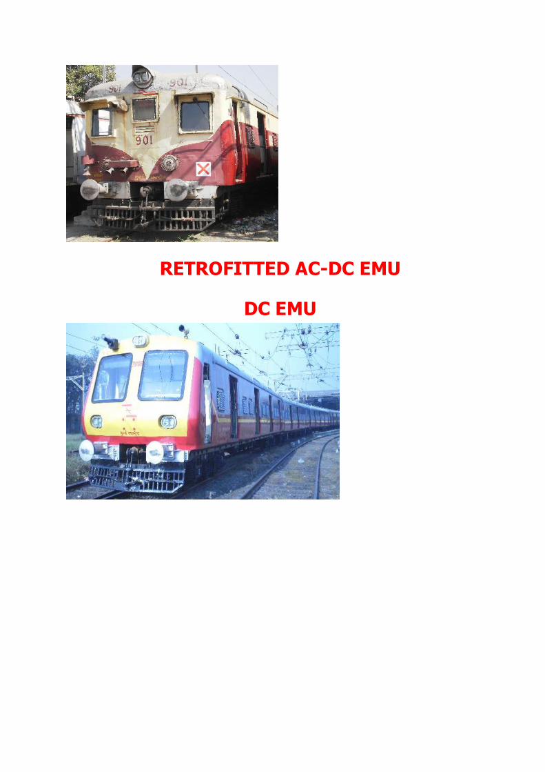
RETROFITTED AC-DC EMU
DC EMU

POWER CIRCUIT

PT

Panto set trip valve
Pneumatic pressure
VSD
Transformer
Rectifier
TM


DESCRIPTION AC EMU
25 KV AC BG Electric Multiple Units EMUs and MEMUs are having similar
technical characteristics but differ in dimensions, layout and uses. EMU/MEMUs are
specially designed for high rate of acceleration and deceleration with frequent stop.

COMMON FEATURES OF EMU/MEMU TYPE, WAU4
Bogies drive arrangements : Single reduction through spur gearing.
Wheel arrangement : Bo - Bo
Gear Ratio : 20:91
Axle Capacity : 20 tones
Type of Brake : Electro pneumatic
Continuous rating of TFR : 1000 kVA at 25 KV.
Traction motor per unit : 4 nos.
Traction motor HP (one hour rating) : 251 HP
Traction motor HP (continuous) : 224 HP
TM Current (continuous) : 340 Amps.
TM Current (one hour) : 380 Amps
TM Voltage : 535 volts.
Battery : Lead Acid, 50 cells
Battery Ah rating : 90 AH. 5 hour rating
SALIENT FEATURES OF MEMU TYPE, WAU4
Motor Coach
Seating Capacity
No of seats : 81
No of Standing passengers : 162
Total No of passengers : 243
No of doors aside : 3
Length over body : 21337 mm
Distance between bogie centers : 14783 mm
Wheel base : 2896 mm
Width : 3245 mm
Height : 3886 mm
Height of roof equipment : 4255 mm
Height of buffer from rail level : 1105 mm
Height of floor level from rail level : 1278 mm
Distance between buffer centers : 1956 mm
No of fans : 38
No of lights (fluorescent sunk type) : 8
Emergency openable windows : 2
No of ventilators : 7

Trailer Coach
No of seats : 108
No of standing passengers : 216
Total no of passengers : 324
No of doors aside : 3
Passengers for doors aside : 108
Length over body : 21337 mm
Distance between bogie centers : 14783 mm
Wheel base : 2896 mm
Width : 3245 mm
Height : 3886 mm
Height of over buffer rail level : 1035 mm
Axle capacity : 13 tones
No of fans(400 mm sweep) : 37
No of lights (fluorescent sunk type) : 28
No of emergency light (sunk type) : 7
Emergency operable window : 4
No of ventilators : 10
Height of floor level from rail level : 1192 mm
Height of panto (locked down) : 4398 mm
Min. Clearance to rail level : 1145 mm
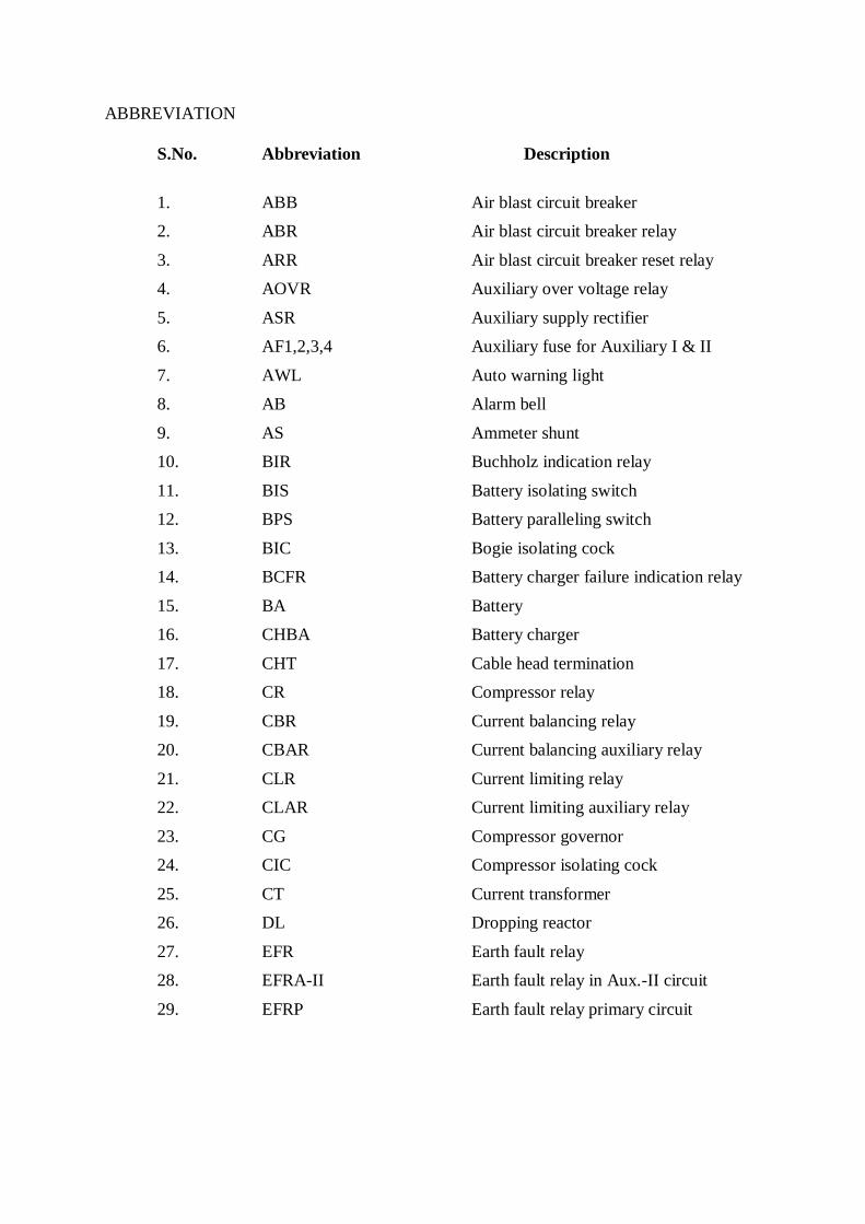
ABBREVIATION
S.No. Abbreviation Description
1. ABB Air blast circuit breaker
2. ABR Air blast circuit breaker relay
3. ARR Air blast circuit breaker reset relay
4. AOVR Auxiliary over voltage relay
5. ASR Auxiliary supply rectifier
6. AF1,2,3,4 Auxiliary fuse for Auxiliary I & II
7. AWL Auto warning light
8. AB Alarm bell
9. AS Ammeter shunt
10. BIR Buchholz indication relay
11. BIS Battery isolating switch
12. BPS Battery paralleling switch
13. BIC Bogie isolating cock
14. BCFR Battery charger failure indication relay
15. BA Battery
16. CHBA Battery charger
17. CHT Cable head termination
18. CR Compressor relay
19. CBR Current balancing relay
20. CBAR Current balancing auxiliary relay
21. CLR Current limiting relay
22. CLAR Current limiting auxiliary relay
23. CG Compressor governor
24. CIC Compressor isolating cock
25. CT Current transformer
26. DL Dropping reactor
27. EFR Earth fault relay
28. EFRA-II Earth fault relay in Aux.-II circuit
29. EFRP Earth fault relay primary circuit

S.No. Abbreviation Description
30. EPIC Electro Pneumatic brake isolating cock
31. GD Grounding
32. GTB Gear teeth broken
33. HOBA Earthing switch for battery negative
34. HEFRA-II Switch for Earth fault relay in Aux.-II circuit
35. HL Head light
36. HC Head code
37. ICA Isolating cock for auto brake
38. KF-1 & 2 Radiator fan motor 1 & 2
39. K1 & 2 Reverser 1 & 2
40. LTR Low tension proving relay
41. MCS Motor cut out switch
42. MSWL Motor switch white light
44. MCB Miniature circuit breaker
45. MP Master controller
46. NVR No volt relay
47. NR1 & 2 Notching relay 1 & 2
48. NC1,2,3,4 Negative contactor 1,2,3,4
49. OLP Over load Primary
50. OVR Over voltage relay
51. OP Oil pump
52. OL1,2,3,4 Over load relay for TM 1,2,3,4
53. OL5,6 Over load relay for tap changer
54. PB Parking brake
55. PTB Pinion teeth broken
56. Panto Pantograph
57. RF Rectifier fan motor
58. RFR Rectifier fan relay
59. RFAR Rectifier fan Aux. relay
60. SL Smoothing reactor
61. SR Starting relay
62. SB Signal bell

S.No. Abbreviation Description
63. TL Tapping reactor
64. TT Transformer thermostat
65. TTR Transformer thermostat relay
66. TSS Test sequence switch
67. TLC Train line cable
68. T1 to T9 Tap changing contactor 1 to 9
69. TR Transition resistor
70. UFL Unit fault light
71. VCB Vacuum circuit breaker
72. WGR Winding grouping relay
73. WCO Winding change over switch

JUMPER & COUPLER:
Four inter vehicular jumper/couplers are used for communicating the electrical
feed from driving unit to all its trailer coaches for control & light, fan circuit. These four
jumper/coupler arrangements are named as ‘A’, ‘B’, ‘C’, ‘D’. New coaches (with air
spring) are provided with 5th jumper named as ‘E’.
JUMPER ‘A’
Pin No. Wire No. Concerning Circuit
1. 14. Control +ve / BA +ve
2. 14 -do-
3. 14. -do-
4. 9. ABB Close
5. 44. Fan Phase for row – 1
6. 45. Fan Phase for row – 2
7. 10. ABB Trip
8. 12. CR Set
9. 42. CR Trip
10. 1452. Audio Visual ckt.
11. 7. Panto Raise
12. 40. EP Brake circuit negative
13. 8. Panto Lower
14. 36. EP Brake supply positive
15. 37. EP Unit holding positive
16. 38. EP Unit application positive
17. 3904. Parking Brake release in 20034-20035, 20036-20037 and
20038-20039
1404C Auto Flasher circuit in 653-654-655 and Spare in other rakes.
18. 39. Parking brake indication 20034-20035, 20036-20037 and
20038-20039.
19. 40. EP Brake circuit negative

JUMPER ‘B’
Pin No. Wire No. Concerning Circuit
1. 5. Forward
2. 6. Reverse
3. 1. Shunt
4. 2. Half Power
5. 3. Full Power
6. 25 Alarm bell in air spring rakes.
7. 3A AOVR coil’s positive
8. A261. AC N/L Neutral
9. A226. AC N/L Phase
10. A226. AC N/L Phase
11. 33. Driving cab emergency light positive
12. 46. Fan circuit Neutral
13. 46. -do-
14. 11. Overload Reset coil’s positive
15. A261. AC N/L Neutral
16. 13. Main Compressor Synchronizing
17. 3604 Parking Brake application in all MEMU rakes.
UFL communication in EMU rakes with air spring.
Spare in other rakes.
18. 1501 PFD fuse blown indication in EMU coaches provided
with air spring rakes.
4 Weak field in MEMU rake 20038-20039. Spare in other
rakes.
19. 14A. Control Changeover feed (BPS).

JUMPER ‘C’
Pin No. Wire No. Concerning Circuit
1. 16. ABB open indication
2. 19. Rectifier fuse blown indication
3. 18. Motor Switch white light
4. 17. Aux. Rect. Fuse blown indication
5. 15. Indication ckt. positive
6. 17A. Battery charger failure indication
7. A261. AC N/L Neutral
8. A261. AC N/L Neutral
9. A226. AC N/L Phase
10. A226. AC N/L Phase
11. 15A AWL ckt. in EMU HWH end driving coaches.
12 15A AWL ckt in EMUs in KGP end driving coaches.
3605 Indication for Parking brake application in MEMUs
except 20034-20035, 20036-20037 and 20038-20039
13. 31. Emergency light positive
14. 31. Emergency light positive
15. 25. Alarm bell positive
16. 26. Signal bell positive
17. 14B. BPS positive for Battery paralleling
18. 14B. BPS positive for Battery paralleling
19. 20. Guard’s supply positive

JUMPER ‘D’
Pin No. Wire No. Concerning Circuit
1. A226. AC N/L Phase
2. A226. AC N/L Phase
3. 44. Fan Phase for row – 1
4. 45. Fan Phase for row – 2
5. 21. Light ‘ON’ positive
6. 22A 50% light relay ckt. in air spring rakes.
7. 22. Light ‘OFF’ positive
8. 23. Fan ‘ON’ positive
9. 24. Fan ‘OFF’ positive
10. 20. Guard’s supply positive
11. 41. DC 110V negative
12. 41. -do-
13. A261. AC N/L Neutral
14. A261. AC N/L Neutral
15. 46. Fan ckt. Neutral
16. 41. DC 110V negative
17. 41. DC 110V negative
18. 32. Intercom in EMUs without Air spring & MEMUs
JUMPER ‘E’
Pin No. Wire No. Concerning Circuit
1. Spare Intercom in EMUs with Air spring
2. 1404A Auto Flasher light circuit in 653-654-655. Spare in other
rakes.
3. 3606 Parking brake release in EMUs with Air spring
4. 3604 Parking brake application in EMU coaches with Air spring
5. 3605 Parking brake application indication in EMU coaches with
Air spring

MAJOR EQUIPMENT OF EMU/MEMU
PANTOGRAPH
Pantograph acts as mobile current
carrying equipment which is mounted on the
roof. It collects power from the overhead
equipment under both static and dynamic
conditions and transfers it to EMU. The whole
assembly of pantograph is mounted on the four
foot insulators on roof. It is operated for its
raising/ lowering positions with compressed air
through servomotor.
Its frame is made of several metallic tubes & springs. Ball bearings are provided
for easy movement of articulation at each joint. Flexible shunts are provided to give
continuous flow of current. The design of pantograph and its electromechanical
interaction with OHE contact wire is very significant. To improve the reliability of the
pantograph, life of the OHE contact wire and to reduce the cases of panto entanglements
with OHE, RDSO has carried out continuous study and issued various modification
sheets, special maintenance instructions and technical circulars etc. In the panto pan, two
wearing strips are provided. They will be replaced in case of worn out or grooved.
Normally the panto is in the lower position by the tension of the lowering springs
provided inside the servomotor.
When the compressed air is admitted inside the servomotor, its piston is
operated and compresses the lowering spring. The piston rod is attached to the rocker
arm and releases the actuating rod, there by the cam is released and operates the lower
articulation arm. When the lower articulation arm is operated by the action of rising
spring, the lower articulation rod is raised upwards. The upper articulation arm which is
connected to the lower articulation arm at the free end will also raise by the action of the
push rod there by the upper articulation arm will raise and touches the contact wire.
Since the tension of the lowering spring is more than the raising spring, so it is
necessary to admit compressed air inside the servomotor. There by, with the action of
lowering spring the operating rod is operated in other direction, this in turn operates the
lower articulation rod against the tension of the raising spring. Due to this action the
lower articulation is pulled down and also upper articulation is pulled down
simultaneously by the action of pull rod.
Make : Stone India Ltd
Type : AM12
Min. Air pressure required : 4.5 kg/cm2
to 7 kg/cm2
For upward trust
Weight without foot insulators : 205 kg

VACUUM CIRCUIT BREAKER
It is the most important switching and
protecting equipment which connects &
disconnects the 25 kV OHE power supply to the
EMU through pantograph. It is a single
interrupter type vacuum circuit breaker.
Vacuum has excellent insulating
properties and therefore a small contact gap can
withstand high voltages. The most beneficial
characteristic of switching in vacuum is that it
allows high fault current during interruption
with minimal contact wear.
TECHNICAL DATA
Type : 22 CB
Make : ALSTOM (AREVA)
Rated voltage : 25kV, Single phase
Rated continuous current : 1000 Amps (rms)
Rated frequency : 50 Hz
Rated short time current : 16 kA rms/ 3 seconds
Rated short circuit breaking current (sym) : 16 kA rms (400 MVA)
Rated short circuit making current : 40 kA peak
Rated lightening impulse voltage withstand : 175 kV peak
Rated power frequency voltage (Dry & Wet) : 75 kV rms
Number of phases : One
Total weight : 125 kg (approx.)
Life time
Mechanical : 3,00,000 operations
(Under no load conditions)
Electrical : 1,00,000 operations
It is located on the roof of the EMU to control the 25 kV supply from the panto to
entire equipment. It can be closed or opened by control circuit from the driver’s cabin. It
trips automatically due to the operation of various protective devices.

MAIN TRANSFORMER
Transformer is one of the most
important traction equipment of AC
EMU/MEMU. It is double wound with primary
and secondary windings interleaved together to
give a sandwich construction. It is a under gear
mounted step down transformer and have three
separate secondary windings, 1st traction, 2nd
Aux-I and 3rd Aux-II.
Current at 25 kV is taken from OHE to
its primary winding via the pantograph, the
vacuum circuit breaker and the high tension
main bushing. The return path for this current is
via the earthing brushes mounted in the axle cap of each traction motor and running rails.
The secondary winding of the transformer is in two sections, one section having
five tapped sections, other being untapped. This arrangement gives a total twenty-two
voltage steps by various connections of transformer tappings and voltage dropping
reactors. This voltage, which is controlled by the tap-changing switchgroup, is applied to
the silicon rectifiers, the full wave output of which is fed to the traction motors via the
smoothing reactor.
Two tertiary windings, auxiliary I and II are provided. Auxiliary I, 266 V
winding feeds the single phase AC auxiliary machines. Auxiliary II, 141 V winding
supplies power to normal lights & fans, head lights stabilizer, the auxiliary rectifier for
main compressor motor. The transformer is oil-immersed type and oil is forced
circulated and cooled in radiator by blower set.
TECHNICAL DETAILS
Make : BHEL
Continuous Rating : 1000 KVA at 25 kV
Primary winding : 25 kV/40 Amp.
Secondary winding : 782 Volt/ 1280 Amp.
Auxiliary winding I : 266 Volt/55 Amp.
Auxiliary winding II : 141 Volt/250 Amp.
Frequency : 50 Hz
Cooling : OFAF
Rating : 1000 KVA at 25 KV.
Traction secondary : 782 V.
Aux. I : 266V/55 Amps.
Aux. II : 141V/250 Amps.
The transformer oil circuit consists of a main transformer tank, a reactor tank
(including smoothing, tapping and dropping reactors), oil pump and a radiator. The
cooling air for the radiator is drawn through the radiator block from the coach sole-bar

level by two axial flow fans mounted behind the radiator. The direction of oil flow is
from the main transformer through the oil pump to the radiator inlet. From the radiator
oil flows to the reactor tank and back to the transformer oil inlet. The oil supply to the
transformer is maintained by a conservator tank mounted in the HT Compartment and
which is connected to the transformer via. the Buchholz Protection relay, also located in
the HT compartment. A newly developed Pressure Relieve Valve is fitted in the
transformer body itself.
RECTIFIER
In AC EMU/MEMU, DC
Traction Motor is used. Silicon
rectifier converts Alternating
current into Direct current. In this
unidirectional current also there
may be some AC Ripples.
Smoothening reactors are
provided to reduce these ripples.
Additional smoothening reactors
are also provided to obtain pure
DC.
TRACTION MOTOR
Traction motor is one of the
most important equipment of AC
EMU/MEMU. In AC EMU/MEMU,
Traction Motor type 4601
AZ/BZ/BY/BX manufactured by BHEL
is used. It is a D.C. series wound, four
poles, self ventilated motor arranged for
axle mounting on sleeve bearings and
supported on the opposite side by
resilient suspension unit. The flanges of
the axle suspension bearings limit transverse movement. Since this is a D.C. series
motor, it is having commutator and brush assemblies, therefore it requires regular
maintenance.
Changing direction of rotation of traction motor is achieved by changing the
direction of flow of armature current in traction motors by reversal of field terminals. It
is done by one electro pneumatic equipment called as reverser.

TECHNICAL DATA
Rating
Continuous One hour
Voltage 535 V 535 V
Current 340 A 380 A
RPM 1260 rpm 1182 rpm
Power 167 KW 187 KW
Resistance Values (Average at 25 deg. C in ohms)
Armature winding 0.0186
Series field winding 0.0103
Commutating field winding 0.009
Weights (Approximate)
Motor complete with gear & gear case 2035 Kg
Motor complete including axle caps, axle bearings & pinion 1812 Kg
but without gear wheel gear case
Armature 520 Kg
Gear case 85 Kg
Pinion 9 Kg
AUXILIARY MOTORS
There are 4 auxiliary motors used in the EMU.
1. Oil Pump 2. Rectifier fan 3. The Radiator fan 1 4. Radiator fan 2
Oil Pump motor (OP) is used to circulate the TFR oil from the transformer tank
to choke box (SL, DL, TL) and radiator.
Rectifier fan motor (RF) is used to cool the main rectifier 6 bridges and one
ASR bridge.
Radiator fan motors 1 & 2 (KF1 & KF2) are used to cool the TFR oil by forced air.
BATTERY CHARGER
In EMU, 266 V AC battery charger is connected in the auxiliary I circuit with
35A MCB and 32 A fuse in the neutral side. It charges the battery and feeds supply to
the control circuit. Battery charger failure relay (BCFR) is connected across the battery
charger out put supply. In case of any failure in charger circuit, this relay will de-
energise & BCFR light will glow.
BATTERY
Battery feeds necessary supply to operate baby compressor and control circuit.
Total capacity of the battery in each motor coach of EMU is 110 V 90 AH. 10 batteries
are connected in series. Each Battery consists of 5 cells. Maximum volt produced by
each cell is 2.2 V. Specific gravity of the battery should be maintained at 1260.
AUXILIARY COMPRESSOR
Auxiliary compressor works at 110 V DC and produces compressed air initially
required to raise the pantograph and to operate the circuit breaker or to test the tap
changer operation (LT test). This compressed air is stored in an auxiliary reservoir up to
7.0-kg\cm².
When the pressure is raised to 6.3 Kg/ cm² the AUX Comp governor stops the
working of the Auxiliary/ Baby compressor. If the governor fails to stop the Baby
Compressor the safety valve will blow at 7.0 Kg/ cm².
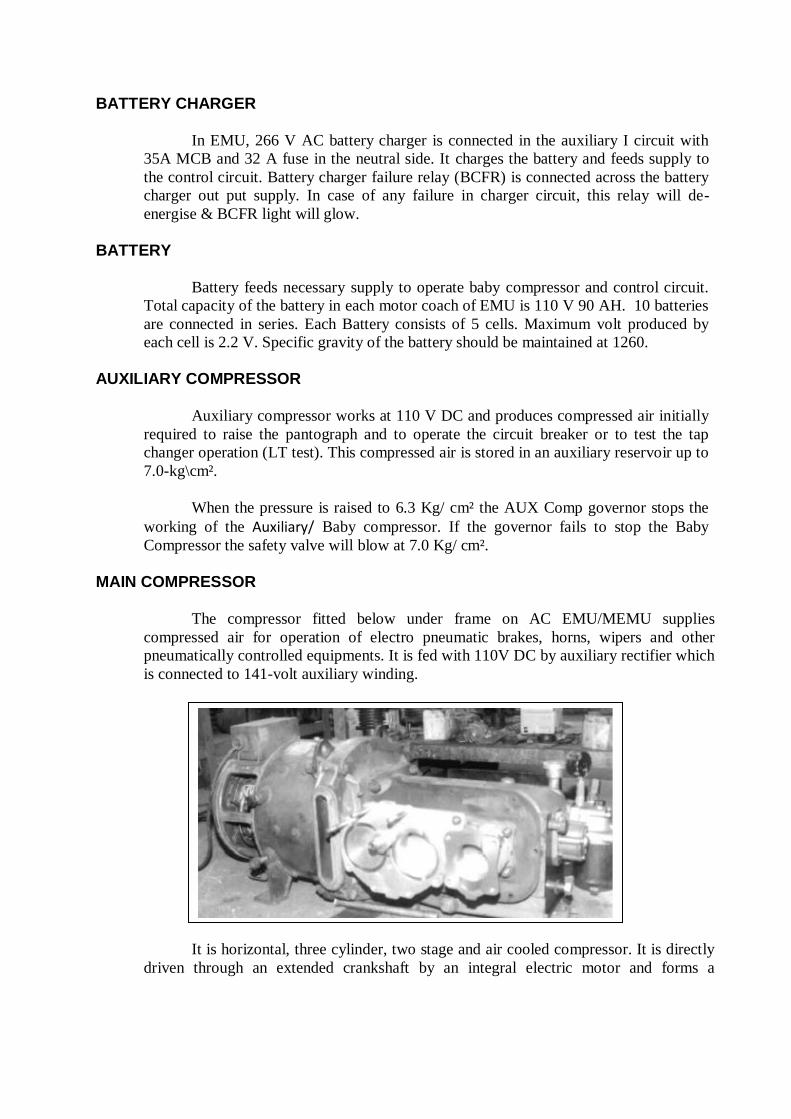
MAIN COMPRESSOR
The compressor fitted below under frame on AC EMU/MEMU supplies
compressed air for operation of electro pneumatic brakes, horns, wipers and other
pneumatically controlled equipments. It is fed with 110V DC by auxiliary rectifier which
is connected to 141-volt auxiliary winding.
It is horizontal, three cylinder, two stage and air cooled compressor. It is directly
driven through an extended crankshaft by an integral electric motor and forms a

monoblock. The cylinders and cylinder heads are covered by an aluminium shroud and
cooled by air drawn in by the common fan to cool the motor and the compressor.
At present in BG AC EMU/MEMU KPC’s 3HC-55 and ELGI’s TRC-1000 DCM
are in use.
MASTER CONTROLLER
Master controller is used to close the motor contactors, to operate the tap
changer, to control the notching sequence, and to change the current flowing through
the field of the traction motor with the help of reverser. Thus it controls the operation of
EMU.
In this, dead man’s handle is provided. The function of this handle is to apply
brake and to stop the train, whenever driver took his hand away from the handle; it is
lifted and there by disconnected supply of the tap changer and traction motors. BP
pressure is also exhausted through the pilot valve leads to apply brakes. In the master
controller LT fingers are kept corresponding to the necessary operations. Different types
of cams are present for closing and opening the LT fingers.

TAPCHANGING
SEQUENCE
CHARTNOTCH
(MPT)
W1/W2 TAPCHANGING
CONTACTOR
TRANSFER
SWITCHES
OFF 0 W1 - -
SHUNT 1 W1 T1 T7 & T9
2 W1 T1 T8
HALF 3 W1 T2 T8 & T9
4 W1 T2 T7
5 W1 T3 T7 & T9
6 W1 T3 T8
7 W1 T4 T8 & T9
8 W1 T4 T7
9 W1 T5 T7 & T9
10 W1 T5 T8
11 W1 T6 T8 & T9
12 W1 T6 T7
FULL 13 W2 T1 T7 & T9
14 W2 T1 T8
15 W2 T2 T8 & T9
16 W2 T2 T7
17 W2 T3 T7 & T9
18 W2 T3 T8
19 W2 T4 T8 & T9
20 W2 T4 T7
21 W2 T5 T7 & T9
22 W2 T5 T8

POWER CIRCUIT OF AC EMU TYPE WAU4
Current is collected from 25 KV single phase AC OHE supply by means of
pantograph and enters to transformer primary through circuit breaker (ABB/VCB), surge
diverter and bushing (condenser or cable head type).
The 25 KV is connected to the primary winding of EMU transformer. The
another end of the primary winding is brought out by a negative bushing and an insulated
cable which is connected to the traction motor earth brushes bearing on the four axles.
The earth brushes are insulated from the motor frames thus keeping the transformer
return current independent of the farthing of the equipment cases and under frame.
The transformer secondary output is 700V. The secondary winding consists of
two separate windings each of 350 V. One half is tapped into five sections each of 70 V
whereas the other half is untapped.
Upto half power of the notching sequence, the tapped portion of the winding is
used, while for the remaining notches, the two sections are connected in series. The
changeover is operated by means of contacts W1 and W2 on the winding changeover
switch (WCO). W1 remains closed upto half power and on full power W2 closes and W1
opens. This arrangement gives a total of 10 equal voltage steps by means of 22 regular
notches of tap changer through various connections of transformer tapings and voltage
dropping reactors.
The switching of the transformer sections is carried out by the tap changing
contactors T1 to T9. Contactors T1 to T6 are connected to the transformer tapings and
the required voltage is selected. Tap changing is carried out by means of a reactor TL, in
conjunction with the two contactors T7 and T8 to give alternate notches with and without
the reactor in circuit. The selected output voltage is fed through the overload relay trip
coils OL5 & OL6 to the main rectifier unit.
2 capacitors of 0.05 microfarads are connected between the two secondary
windings and earthed to prevent the build up of high voltages to earth on the windings
when they are not connected to traction circuit earth.
The voltage tapped from TFP secondary by tap-changing contactors is converted
to DC by main rectifiers. This DC voltage is smoothened by the reactor `SL’ and further
smoothening is done by ASL which is connected in series with traction motors.
An ammeter shunt is connected across traction motors 1 & 3 for measuring the
flow of current in the traction motors. Ammeter is deviated through Ammeter Selector
Switch. In the same manner CLR 1 & 2 are connected in traction motors 1 & 3 to control
the current of traction motors. The knife type switches called MCOS 1 to 4 are provided
to isolate the traction motors from negative side. An earth fault relay called EFRP is
provided to protect the circuit from earth fault.

PO
WE
R C
IRC
UIT
OF
BG
AC
EM
U (
WA
U4
)
PA
NT
O
OH
E
AB
BL
A
EA
S
OL
P
M8
M7
M6
M5
M4
T1
T5
T4
T3
T2
M3
0.0
5
Mfd
W.1
W.2
T6
M9
DL
M2
M1
0.0
5
Mfd
M14
SURGE ARRESTER
AU
X-I
266 V
AU
X-I
I 1
41
V
MAIN TRANSFORMER
6
M1
M2
M3
M4
M34
M33
M32
M31
OL
4
M4
M25
4A
4A
A4Y
OL
3
M3
M22
3A
3A
A3
YY
OL
2
M2
M30
2A
2A
A2Y
OL
1
M1
M17
1A
1A
A1
YY
M16
A
AS
S
M19
M29
24 30
1Y
OV
R
VA
RIA
BL
E
RE
SIS
TO
R
SL
2Y
Y3Y
4Y
Y
K1
K2
K2
K1
P F D
P F D
P F D
P F D
540V
MC
OS
1M
CO
S2
MC
OS
3M
CO
S4
CL
R 2
500A
CL
R 1
500A
M35
M36
M37
M38
OV
R
BR
IDG
ER
EC
TIF
IER
500A
500A
HE
FR
P
RP
PE
FR
PC
OIL
G
M27
GP
1
GP
2
GP
3
TO
+V
e 1
10
V D
C
7K
Oh
m
B2
T8
M11
M12
OL
6
400
0A
OL
54
00
0A
T7
M10
TLT9
RTL
M15
M13
CT
P4
(6 N
os)
A S L
A S L
AS
AS
85 O
hm
900A
900A
900A
900A
NF


AUXILIARY CIRCUIT-I, WAU4
After energizing transformer primary 266 V AC is induced in secondary
auxiliary circuit-I. NVR (No Volt Relay) relay ensures the Aux I- 266 V AC supply. If
this relay is not energized SR will not energize and thus unit will not respond. 4 AC induction machines i.e. Oil pump-OP, Rectifier fan motors-RF and
Radiator fan -KF1 & KF2 started immediately. This 266V AC supply is also fed to the static battery charger (SBC) and also to
operate the control circuit like MCP, Tap changer and brake system when the unit is in
energized condition. BCS socket is provided in the battery circuit to perform LT test
from the other battery source.
One BA volt meter is provided in control circuit (DC side), to find out the BA
voltage. 5 Nos emergency hand lamp sockets (HLS), one control change over switch
(CCOS) is provided to get the rear MC’s battery supply when the leading MC’s supply
is below 85 Volts.
One protection device called HOBA is provided to secure the DC side
equipment from earth fault.
AUXILIARY CIRCUIT-II, WAU4
After energizing transformer primary 141 V AC is also induced in secondary auxiliary circuit-II. By this supply through a 300 A fuse Auxiliary Supply Rectifier (ASR)
is energized automatically. The output of ASR i.e. 110 V DC is supplied to start the main
compressor. This supply is monitored by Low Tension Proving relay (LTR). If it is not in
energized condition ABB/VCB will not hold.
Volt meter is connected across the 141 V AC supply to find the OHE voltage. (i.e.
the 141 V AC supply reaches the volt meter the reading will show 25KV). Head light
voltage stabilizer (HLVS) stabilizer is connected through a double pole breaker (5A).
In the EMU the compartment fans are operated in 141 V AC directly through a 63
A fuse by closing the Fans contactors 1&2 (FC 1&2) for ten 60 W fans. 2 circuits are
provided in zig zag connection, each circuit =10x60 W.
Normal lights voltage stabilizer (NLVS) 110 V AC is connected through 63 A fuse
and double pole breaker (15A). Two circuits are provided in zig zag connection, each
circuit=10x40 W.
The fans and lights can operate after switching the guard’s supply ON by using the
guard’s key only.
Across this 110 VAC supply, one emergency lights relay (EML1&2) is connected for the
emergency lights purpose when the ABB tripped condition in neutral section, no tension in OHE

wire or if any other abnormality in the normal lights circuit. After obtained the normal condition,
the EML relay gets deenergised and again the normal lights will glow.
There is one relay is connected for the protection of the circuit that is called EFRA2.
CONTROL CIRCUIT
In EMU, control circuit is fed from 110 volt Battery supply. A 32 amps fuse (control fuse) is
provided for protection of the circuit. Control circuit is charged through wire no. 14 from
Battery positive (BP 14) and negative path is connected to wire no.41.
Important control circuits are as following:
Panto and ABB circuit
MPT, Panto and ABB circuit Motor contactor and ABB circuit
Tap changer circuit


PANTO AND ABB CIRCUIT WAU4
901
15A ( PANTO & ABB MCB)
MPT N/C
PT DNPT UP
701
SET
ABR
ABB
1408
7
1406
PT RAISE
BL KEY
PT LOWER
8
(PRE. RESETTING VALVE)
OL 5&6
EFRA II
OLP/EFRP
BIR
1431
1432A
TSS (RUN)
ABB
1432B
HOLD
10
ABR TRIPARR
41
LTR
10 w500
ABB Gov. BY PASS
ABR
OPEN
HVCB
9
CLOSE
HVCB
1428
1428 A
To W/LV coil
1426
1427
1425
ARR
1433
ARR
ABB
1434
ABBCLOSE
opens at 4.5 kg/cm2
closes at 5.6kg/cm2
1432
GOV ABB
PRV
ABR(SET)
14
To indication Lamp circuit
(ABB FAULT MCB)15A

(TEST)
OL 3&4
CONTROL CIRCUIT OF MOTOR CONTACTOR & ABB
F FR
K1
501
3,2,1, MCS2MCS1
512
R
K2
M1
out1&2
M2
513
out1&2
M4M3
out
515
3&4
511
LS1
601
OL 1&2
514
LS3
RFAR
510
509
TTR
503
MCS2 3&4 INMCS1
1&2 IN
K2
K1
502
'F'
'F'
501
5
CONT. GOV
508
K2 'R'
602
K1 'R'
OUT1&2
1MCS
601
GS1
GS2
507
508OUT3&4
CBAR
2MCS
TSS
EQ. GOV
506
1&2 IN
MCS1
6
503
1427
4,
HV
516
3&4out
LV
10 w500
ABBHOLD
1432B
BIR
CLOSEABB
1434
ABB
1441
505LTR
LV
WGR
HV
1428
TSS (RUN)
ARR
1432A
1432
ARR
1433
GOV ABB
1431
BIR
14
35
41
RF
AR
CB
AR
TT
R
14
37
14
36
14
42
14B (+)
1424
1426B
1426
1425
OLP/EFRP
EFRA II
FA
ST BUD
OL 5&6
ABR
ABB FAULT15A
(B)
RF
R
SL
OW
CB
R
TT

KEY
DRIVER'SA
BB
TR
IP
10
CONTROL CIRCUIT OF MPT, PANTO & ABB
HP
SH
1412A
OFF3 2 1
DMH
PA
NT
O R
AIS
E &
AB
B
FA
UL
T I
ND
IC
AT
IO
N
MA
ST
ER
CO
NT
RO
LL
ER
BIV
(EK only)BY-PASS
L & T
14
12
14
10
14
09
14
06
5A5A 5A
14
11
FP
MPT N/O
PANTO UP
R
14
13
14
14
R F
F
1408
CONTROL
14
15
Spare
AB
B C
LO
SE
PA
NT
O L
OW
ER
PA
NT
O R
AIS
E
14
07
RESETOL
6 75 23 111 15 8 9
OL
P/E
FR
P
OL
5 &
6
C16-OL1 & OL2
C15-OL3 & OL4
C14-OL5 & OL6
C13-EFRP OLP
C12-ABR TRIP
C11-ARR
C10-ABR SET
C9-PANTO DOWN
C8-PANTO UP
C10
GU
AR
D'S
SU
PP
LY
BU
ZZ
ER
EP
BR
AK
E
MA
IN
CO
MP
RE
SS
OR
14
53
14
02
14
04
5A 5A
2.5
A
14
01
15A
C8
C9
COILSRESET
41
C13
C12
C11
C15
C14
C16
EP
SU
PP
LY
ON
14
52
MC
P T
RIP
MC
P S
TA
RT
14
05
14
03
GU
AR
D'S
KE
Y S
WIT
CH
AB
B
12 42 36 40 4141 20 14 7 8
ABR
901
9 10 11

CONTROL CIRCUIT OF TAP CHANGERCONTROL CIRCUIT OF TAP CHANGER.
T5/
T5
W6
CONTROL CIRCUIT OF TAP CHANGER.
155
154
153
152
M4
M3
M2
M1
157
SR
MCS2
WGR
156
MCS2
MCS1
MCS1
T2/
5SR
1371
SR W3
6T1/
T23
41
139W6138
6
6
T3
T3/6
W5
6
T4
T4/5
140
126
M3M1
158
4SR 2
T1
125
1 2
LV
106A
106A
2T9
1064 HV
1T3T2
1
127
2
211
212
T4
128
2 3 2
213
T2/T1/ 6 6 T3/ 4
MCS1 CLOSED 4 OUT 3&4 OUT
MCS1 CLOSED 3 OUT 3&4 OUT
MCS1 CLOSED 2OUT 1&2 OUT
MCS1 CLOSED 1 OUT 1&2 OUT
106A
145MCS2
MCS1
MCS2
MCS1
M2
144
143
M3
M4
142M1
209T71
207
T84
18
3M3NVR
NR2
T7
112
T8
1144 4
CL
R2
141A
141B
W/HV
10
6 3
T6
141
T6/ 6
W/LV
SR2
T1
3
CL
R1
4
41
NR16
T73 6
NR2
3T5
T5
129
1
130
T61
214
131
215
W/LV4
16uf
T4/ 6
210
10T5/133
T86
106
1T8
NR
1
120
121
122
136T62
T4
4T1 T5
4
111
NR
2
116
T2
113
T9
NR
1
NR
2
117
3
T8
T3
NR
1
2
110
OPENMCS2
OPEN
134118
IN1&2
IN3&4
MCS1T7
4
115
109
5
CLR1
107
CLR2
108
AOVRWGR2
T9
151
T5303
149
4T6
T7
150304
T41
T25
2 3
WG
R
148
5
T65
T1
147
146
T35
5
106
T59
OVR
MCS2MCS1
W/HV
WGR
TSSNR2206
205
M1
6T6
NVR
204
W/LV
CLR1
SR
203
CLR2
104
W/LV
TSS102
1&2
IN
CL
101
3&4IN
CL
1 2
MCS2CL
MCS1
202
W/HV
AOVR
202A
301
8T5201
302A
IN1&2
IN
CL
3&4
33

Type of MEMU Coaches
There are following two types of MEMU coaches in service:
Driving Motor Coach (DMC)
It has a driving cab and other equipment including traction motors. It can be driven by itself and can also pull attached coaches.
Trailer Coach (TC)
It does not have any driving cab or traction motors etc. and works as trailer only. It cannot be driven by itself, therefore it is always attached to DMC.
Unit Formation
A MEMU unit is formed by attaching 1 no. of DMC as leading coach followed by 3 no. of TCs in rear to DMC. Thus a MEMU unit is consists of 1-DMC and 3-TCs.
Rake Formation
A MEMU rake is formed by attaching more than one unit. 2 unit and 3 unit formation rake are in service. For a 2 unit formation 2 DMCs are required to attach at both ends of a rake, cab facing outside. However, for a 3 unit formation one more DMC is attached cab facing MCT end as 5th coach counting from MCT end.TCS having electrical sockets at one end and jumper cables at other end for multiple operation are always attached with sockets on MCT end.
a. Two unit Rake Formation
2 no. DMCs at the ends, their cab facing outside are coupled with 6 nos. TCs all having multiple coupler sockets towards MCT side to form a 8 coaches rake (1+3=4 per unit x 2 =8).
b. Three unit Rake Formation
2 no. DMCs at the ends, their cab facing outside are coupled with 6 nos. TCs all having multiple coupler sockets towards MCT side to form a 8 coaches
DMC = TC = TC = TC= TC = TC = TC = DMC
DMC = TC = TC = TC

74
rake (1+3=4 per unit x 2 =8), then 1-unit (i.e. 1-DMC cab facing MCT end attached with 3-TCs) is attached at MCT end of the 8 car rake.
c. Four unit Rake Formation
2 no. DMCs at the ends, their cab facing outside are coupled with 6 nos. TCs all having multiple coupler sockets towards MCT side to form a 8 coaches rake (1+3=4 per unit x 2 =8), then 2-units (i.e. 1-DMC cab facing MCT end attached with 3-TCs and another DMC cab facing outside with 3-TCs) are attached at MCT end of the 8 car rake.
DMC = TC = TC = TC= DMC = TC = TC = TC= TC = TC = TC = DMC
DMC=TC=TC=TC=DMC=TC=TC=TC=DMC=TC=TC=TC=TC=TC=TC=DMC

75 ENERGY CONSERVATION IN EMU/MEMU’S
Role of motorman
1. Improved driving techniques.
2. Adhere the coasting and powering boards strictly for EMU/MEMU’s.
3. Switching OFF power to EMU/MEMU whenever it is stabled / line clear is delayed more than 30
minutes.
4. Switching OFF the rear MC while hauling empties to shed movement.
5. Motorman to run at max. Permissible speed and coasting wherever is possible.
6. Approach foot of the gradient at maximum Permissible speed so as to reduce traction motor
current while negotiating the gradient.
Role of Guard/Maintenance Staff
1. Switching OFF fans and lights in coaches as the service completes.
2. Avoiding brake binding in the formation.
Energy conservation also can be done by
1. Creating awareness among commutaters by display of posters on energy conservation so as to
switch OFF fans and lights when not required in coaches.
2. Provision of fluorescent lights in lieu of incandescent lamps in EMU/MEMU’s.
3. Rail flange lubrication to reduce frictional losses.
4. Providing energy meters in EMU/MEMU’s to monitor specific energy consumption.
5. Counseling of motorman, guards and maintence staff on the need for energy
6. Conservation by intensive monitoring on foot plate
7. Conducting seminars
8. Using Audio-visual aids, display of posters on energy conservation at crew booking points,
running bungalows and maintence sheds.

76
CHAPTER 3
BOGIE& UNDER GEARS
INTRODUCTION
The bogie frame is a welded construction with two longitudinal girders and a cross bar and
two frame ends. The tractive or brake force is transmitted via a bogie pin from the bogie to the
body.
The frame ends are used to take up the brake cylinder and the brake rigging. This vehicle
features tread brakes, which have a direct effect on the wheel.
Furthermore, 4 steel cables are each located between body and bogie. These are used as a
lifting supports.
For primary suspension, buffer height, brake rigging, wheel and axle, hydraulic shock
absorbers of AC EMU, DC EMU, AC-DC EMU bogie referCMI – K001 (April 2000) and amendment slip
Primary
springs
Secondary air
suspension Lifting support
Primary
springs
Secondary air
suspension Lifting support
Figure: Basic design of bogie frame

77
no.1(Feb. 2007)and for maintenance of air suspension refer CMI-9802 (Rev.2) , February 2008
issued byCarriage Directorate, RDSO,Lucknow .
BOGIE FRAME
(Ref: CMI- K001)
Bogies of motor coaches (MC),high carrying capacity coaches (HCC) and trailercoaches (TC)
are of all welded, light weight construction. The axles, with self aligning roller bearings mounted
inside cast steel axle boxes, arerigidly guided by telescopic dash pot and axle box guide assemblies.
Helical springs working in parallel with dashpots are used for primary suspension.
Coachbody is supported on two side bearers located 1700 mm (TC) and 1200 mm (MC & HCC) apart
on a floating bogie bolster which in turn rests on air spring supported on a springplank hung on
swing links from bogie frame. The air springs at each end of bolster are damped by hydraulic shock
absorbers.Side bearers consist of metal slides immersed in oil baths well protected fromdust ingress.
Refer drawing no. ICF/MRVC/M-0-0-001 (sheet 1 &2),AC/DCEMU/D2-0-0-201 (sheet 1 &2)
and AC/DCEMU/C2-0-0-201 (sheet 1 &2) for bogie general arrangement of motor coach,D coach and
C coach respectivelygiven in Annexure for drawings.
Refer drawing no. ICF/MRVC/M-0-3-001 (sheet 1 &2) and ICF/MRVC/D-0-3-001 (sheet 1 &2)
for bogie frame arrangement of motor coach and D/C coach respectivelygiven in Annexure for
drawings.
No weight is transferred through the bogie (center) pivot, which is located in the centre
ofthe bolster. The pivot acts merely as a centre of rotation and serves to transmitacceleration and
retardation forces.
The floating bolster in TC bogie is secured in the longitudinal direction to bogieframe by
means of two anchor links with silent block bushes, located diagonallyopposite to each other and
transmit draw and braking forces between bogieframe and coach body through the centre pivot. The
MC & HCC bogie bolster islocated between bogie transoms and transmits draw and braking forces
throughrubbing plates fixed at the bolster ends.
WHEEL & AXLE
The EMUcoaches are provided with composite design of wheels consisting of rolled steel
wheel centres with renewable tyres. The tyres of TC bogies are fastened to the wheel disc with glut
rings whereas the MC/HCCbogies have, in addition to the glut rings, 4 locking keys to ensure more
positivesecuring.

78
Refer drawing no. ICF/MRVC/M-0-2-001 for axle and wheel set given in Annexure for
drawings.

79 Tyre Profile
1. The new/re-turned tyre profile shall be as per ROSO Sketch No. 91146 atl. 2.
2. The condemning limits for the flange wear, root wear, deep flange, sharpflange, hollowtread wearand flat surface on tyre shall be as per the condemning gauge shown in plate 45 of I.R.CA Part IV.
3. Wheel gauge should be within the tolerance of +2/-1 mm.
Wheel Diameter
Bogie New Condemning Last Shop Issue Size
1. MC 952mm 877mm 885mm
2. TC 952mm 857mm 865mm
3. HCC 952 mm 865mm 873mm
Permissible Variation on Wheel Tread Diameter
The permissible variation in tread diameter of wheels at the time of tyreturning or wheel replacement are as follows:
1. Wheels of the same axle : 0.5mm
2. Wheels of the same bogie : 5.0mm
3. Wheels between two bogies under the same coach : 13.0 mm
No separate service limits are specified as the above figures have beenfixed to allow for the differential wear likely to develop betweensuccessive tyre turnings/ wheel changing. It is, therefore, not necessary towithdraw EMU/MEMU stock from service specifically for restoring thedifferential between wheel diameters to be within the prescribed limits.
Material Specification for Wheel and Axle
The material specification applicable to the wheels and tyres are as follows:
1. Tyres : IRS Specification R-15/95.
2. Axle : IRS Specification R-16/95 for TC bogies

80
IRS Specification R-43/92 for MC & HCC bogies
ROLLER BEARINGS
MC & HCC Bogiesare fitted with direct mounted, double row, self aligningroller bearings No.
22328 C/C3.TC Bogiesare fitted with direct mounted, double row, self aligning roller bearing No.
22326 C/C3.
Under normal service conditions, roller bearing axle boxes do not require any maintenance.
Their maintenance is, therefore normally limited to inspection and re-lubrication when the EMU
coach comes in for POH.
AXLE BOX HOUSING
Double row self-aligning spherical roller bearings are housed in accuratelymachined cast
steel axle boxes. The axle boxes are also provided with lightalloy front and back covers secured by
four bolts.
Refer drawing no. ICF/MRVC/M-0-2-002 (sheet 1 &2)for axle roller bearing housing and
gear-wheel assemblyof motor coachgiven in Annexure for drawings.
Axle boxes and covers shouldbe thoroughly cleaned and checked for cracks particularly at
the holes of thecovers which have shown proneness to failures. The bolts should be examined for
worn threads, straightness, etc. before re-use and should be well tightenedand locked by spring
washers and split pins to ensure that the covers and theaxle box housing form a water tight
assembly and protect bearing from dust andmoisture.
AXLE BOX SPRINGS
Axle box springs are of helical type manufactured from centreless ground chrome vanadium,
silica manganese steel. These springs are also shot-peenedto obtain higher fatigue life. It is
necessary to check these springs for cracks and measure their free height to ensure that they meet
the design requirements.

81
All springs shall be grouped in threecategories and used on bogies as perinstructions
detailed in RDSO Technical Pamphlet No.C-8419 (Rev 1).
LOWER SPRING SEAT
Lower spring seat on the axle box wing in which guide bush of dashpot moves upand down
does not normally wear in service.In the absence of inadequatequantity of oil in the dashpot. the
inside surface is likely to wear. If the surface isworn more than 0.4 mmin diameter or if the surface
is scored or otherwisedamaged, the lower spring seat should be reclaimed.
All lower spring seats should be carefully checked for cracks before reuse.
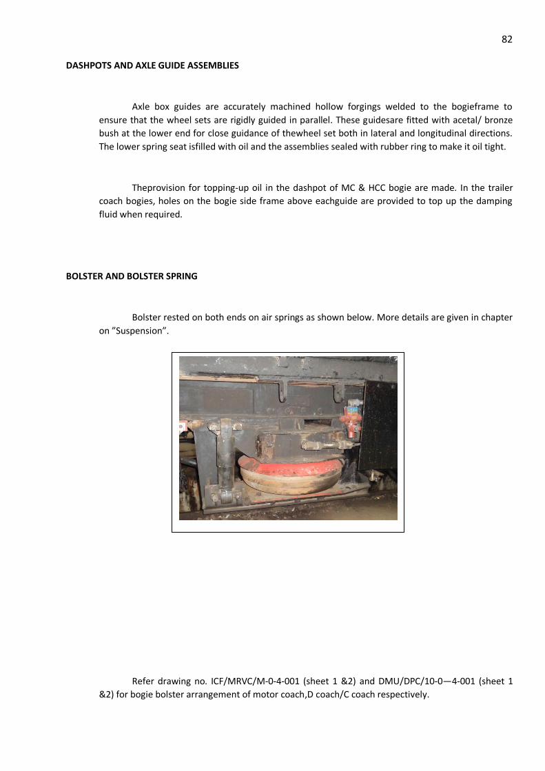
82 DASHPOTS AND AXLE GUIDE ASSEMBLIES
Axle box guides are accurately machined hollow forgings welded to the bogieframe to
ensure that the wheel sets are rigidly guided in parallel. These guidesare fitted with acetal/ bronze
bush at the lower end for close guidance of thewheel set both in lateral and longitudinal directions.
The lower spring seat isfilled with oil and the assemblies sealed with rubber ring to make it oil tight.
Theprovision for topping-up oil in the dashpot of MC & HCC bogie are made. In the trailer
coach bogies, holes on the bogie side frame above eachguide are provided to top up the damping
fluid when required.
BOLSTER AND BOLSTER SPRING
Bolster rested on both ends on air springs as shown below. More details are given in chapter
on ”Suspension”.
Refer drawing no. ICF/MRVC/M-0-4-001 (sheet 1 &2) and DMU/DPC/10-0—4-001 (sheet 1
&2) for bogie bolster arrangement of motor coach,D coach/C coach respectively.

83 LOWER SPRING BEAMS
HYDRAULIC SHOCK ABSORBERS
The hydraulic shock absorbers are fitted to work in parallel with bolster springs.These shock
absorbers normally give trouble-free service and require noattention in between POHs.However,
shock absorbers which are found either leaking or physically damaged should be replaced.

84
As the resistance of these shock absorbers is likely todeteriorate in service, it is necessary to
attend to them as per instructions givenin the manufacturer's maintenance manual.

85
RUBBING PLATE IN MC AND HCC BOGIE
Nylon rubbing plate has been fitted to the bolster which serves as cushion between the
bolster and bogie frame. Initial clearance of 1mm on each side has been provided between the nylon
rubbing plate and steel rubbing plate.
During POH,' this clearance must be maintained by fitting steel packings of suitable
thickness. During service, this clearance should not exceed 3mm on each side. Any higher clearance
may cause excessive longitudinal oscillations and may strain stay tubes (connecting the bolster to
the spring plank) and cause their breakage.
Vertical and Horizontal Shock Absorbers

86 EQUALISING STAYS
Equalising stays connecting thespring plank and bolster, pin jointed at both ends, have been
provided to preventlateral thrust onbolster springs. It is necessary to remove the pins at every
POH,clean and oil them to ensure that they are free to rotate when re-assembled.
Anyrestricted movement at these joints is likely to prevent free movement ofbolster. The
free movement of pins can be ensured by greasing the assembly.
The pins should be provided with washers and split pins to ensure that they donot fall out in
service.
Figures given for Equalising stays of MC / HCC and TC bogies:
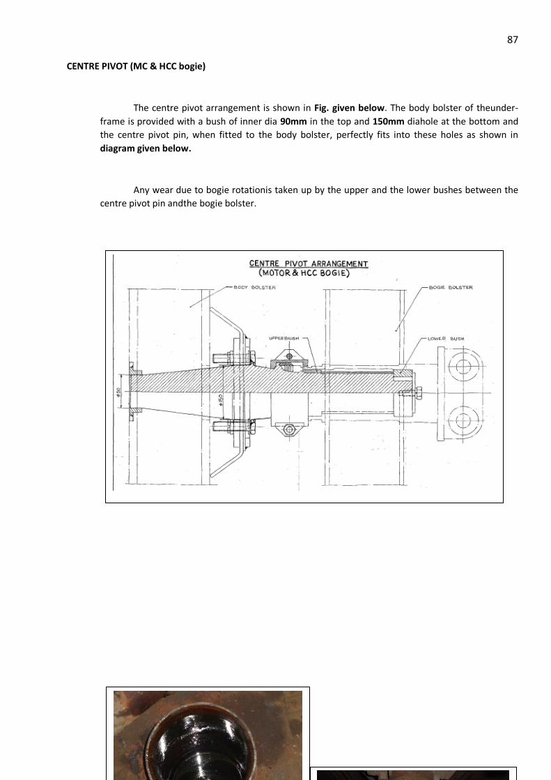
87 CENTRE PIVOT (MC & HCC bogie)
The centre pivot arrangement is shown in Fig. given below. The body bolster of theunder-
frame is provided with a bush of inner dia 90mm in the top and 150mm diahole at the bottom and
the centre pivot pin, when fitted to the body bolster, perfectly fits into these holes as shown in
diagram given below.
Any wear due to bogie rotationis taken up by the upper and the lower bushes between the
centre pivot pin andthe bogie bolster.
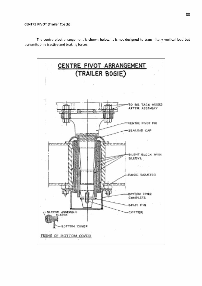
88 CENTRE PIVOT (Trailer Coach)
The centre pivot arrangement is shown below. It is not designed to transmitany vertical load but
transmits only tractive and braking forces.

89 SIDE BEARERS
Side bearers consist of a hard wearing ground steel plate immersed in an oil bath with a
floating bronze wearing piece, which has a self aligning spherical top surface on which the body rests
and transmits the vertical load. The oil well is provided with acover to prevent ingress of dust.
The hard ground plate and the spherical bronze wearing piece are likely to wearin
service.The hard ground plate should be renewed when the wear exceeds 1.5mm orridges are
observed on the plate. The bronze wearing piece should be renewedwhen the wear on the mating
surface reaches 3mm or damages occur to the oilgrooves. Sharp edges which are known to develop
at the periphery of thewearing pieces are likely to impair lubrication and should be rounded off
beforere-using.

90
For filling up oil in side bearer without lifting the coach, oil filling nipples havebeen provided
on the oil well.
Any of the following oils can be used for the side bearers and the quantityrequired per side
bearer is 2.5 litres.
IOC : Servoline-68
HPC : Yantrol-68
BPC : Bharat Univol-68

91 ANCHOR LINKS (Trailer bogies)
Anchor links should be carefully examined for cracks at the weld. The rubber inthe silent
bloc should also be carefully examined for deterioration. Appearance offretting on the edges of the
rubber is an indication of deterioration of rubber.
Whenever a silent bloc is to be replaced, it must be from those that have beenduly tested.
To avoid pre-loading ofthe anchor link while assembling on thebogie, ensure that the assembly can
be done without forcing the link intoposition. This can be done conveniently after lowering the body
on the bogies.
HANGER AND HANGER BLOCKS
Hanger and hanger blocks shown in Fig. given below should be thoroughly cleanedafter
dismantling and examined carefully for cracks /wear and other damages.
The extent of permissible wear on these components is given below:
Trailer bogie
Components Size/New Condemning Wear Shop Issue Size
Hanger block 8 6.5 1.5 7.00
Pin 45 43.5 1.5 44.0
Hanger 354 357 3.0 355.5
Motor Bogie
Hanger block 9.5 8 1.5 8.5
Pin 45 43.5 1.5 44
Hanger 246 249 3 247.5

92

93
BOGIE BRAKE GEAR
Maximum radial clearance of 1 mm between the brake gear pins and bushes is permitted. If
the clearance is more, the worn out part should be replaced and the standard clearance to be
maintained.
Brake block should be replaced when they wear out to thickness of 16mm byremoving the
looped key from the brake head.
An adjusting palm pull rod with holes displaced at regular intervals is provided inthe brake
rigging to take up slack in rigging due to tyre wear. Adjustment should bedone by relocating the pin
in different holes on this palm pull rod.

94
Refer drawing no. EMU-M-3-2-064 (sheet 1 &2) bogie brake arrangement for 20T axle
bogies.

95 BUFFING & DRAW GEAR
The EMU/MEMU coaches are provided with semi permanent/semi automaticschaku
couplers. These are to be maintained as per the instructions contained inthe Maintenance Manual
supplied by the manufacturers.

96
BUFFER HEIGHT ADJUSTMENT
The maximum centre buffercoupler height from rail level is as follows (mm):
Motor HCC Trailer
ICF 1035 1064 1035
Jessop 1035 1064 1041
BEML 1035 1064 1035
Reasons for lowering the buffer height
1. Wear of wheel tyres. 2. Wear on wearing piece and wearing plate of the side bearers.
3. Wear on hanger, hanger block and pins of the secondary suspension
4. Loss in free heights of primary and secondary coil springs
5. Load deflection characteristics of the primary and secondary springs not being within the
prescribed -limits.

97
CHAPTER 2A
AIR SUSPENSION
SUSPENSION
The bogie features two types of suspension, a primary and a secondary. The primary spring
are arranged in parallel as coil springs.
Each coach having two bogies provided with 16 Nos. of metal bonded conical rubber spring
(8 Nos. per bogie) between the bogie frame and axle boxwhich acts as a primary suspension system.
Each metal bonded conical rubberspring is subjectedto variable, heavy dutydynamic loadingin
vertical, lateraland longitudinal directionduring running.
To increase ride comfort, a secondary spring was fitted. This type of suspension is an air
spring suspension. In the event of a defect (mechanical damage), this can be disabled via a shut-off
valve. This is located below the body. The bogie was equipped with an air spring valve. This ensures
that the same body height is maintained independent of additional load.
Fig.: Primary spring suspension

98
Furthermore, additional damping was provided on the secondary spring in the form of an
hydraulic shock absorber to avoid rocking movements.
Fig.: Secondary air spring suspension

99 AIR SUSPENSION
(Ref: CMI-9802 (Rev.2), February 2008)
Carriage Directorate of RDSO has issued CMI-9802 (Rev.2), February 2008 for “Maintenance
Instructions on Air Suspension for DC, AC & AC-DC EMU/HHP DMU Coaches”. This CMI may be
referred for details.
WORKING PRINCIPLE OF PNEUMATIC (AIR) SUSPENSION
Air suspension is a suspension where properties of air are used for cushioning effect
(springiness). Enclosed pressurized air in a pre-defined chamber called air spring, made up of
rubber bellow & emergency rubber spring, provides various suspension characteristics including damping.
Air springs are height-controlled load leveling suspension devices. With changing loads, air
spring reacts initially by changing the distance between air spring support and vehicle body. The
height monitoring valve (called leveling valve) is in turn actuated, either taking the compressed air
pressure to the air spring or releasing air pressure from it to the atmosphere. This process continues
until the original height is restored as shown in figure given below:

100
WORKING PRINCIPLE OF PNEUMATIC (AIR) SUSPENSION

101
This mechanism ensures a constant floor height on coaches provided with air springs,
irrespective of the load. This greatly reduces problems associated with low buffer/coupler heights.
ADVANTAGES OF AIR SUSPENSION
• Capable to sustain Super Dense Crush Loads typical of suburban traffic.
• Maintain constant floor height of coach.
• Provide superior ride comfort.
• Virtually constant natural frequency from tare to full loads, reducing passenger fatigue.
• Isolation of structure borne noise, this improving comfort.
• Improved reliability, reduced maintenance effort.
• Flexibility to choose characteristics as per requirement at design stage.
CHARACTERISTICS FEATURES OF AIR SUSPENSION
• Soft flexible characteristics in vertical direction- Achieved by compression of air.
• Excellent lateral spring characteristics, as desired- Achieved by variation in effective area in lateral
direction.
• Avoids excess air consumption due to instantaneous modes of vehicle oscillation or change in
air pressure - Achieved by designing delayed reaction leveling valve.

102

103 CONSTRUCTION DETAILS
The construction of Air Spring is a
robust design which sustains high static and
dynamic loads. It consists of a thick flexible
neoprene rubber bellow which is
sandwiched between top plate and pedestal.
The shape of rubber bellow is suitably
designed to provide uniform pressure on
supporting surfaces which in turn gives
vertical and lateral stiffness. A vertical
marshmallow spring of high stiffness, which
is popularly known as emergency spring is
provided in series with the air cushion and
housed in series with the rubber bellows.
The emergency spring comes into
action when the air spring gets deflated for
some reason or other viz. bursting of Air
spring. When air spring is installed, the top plate is connected to the bolster whereas the pedestal
holds the spring on to the cradle which is the part of bogie frame. An additional air reservoir of 20
litres capacity is connected to the air spring which acts as a buffer for holding the air. Orifice of
adequate size is provided between air spring and additional air reservoir which provides self-
damping characteristics. During motion air keeps flowing between air spring and 20 litres reservoir
through orifice.
Construction details of air spring are shown in figures given below for air spring withoutside
emergency spring &air spring with inside emergency spring.
CROSS SECTIONAL VIEW OF
AIR SPRING

104
AIR SPRING WITH OUTSIDE EMERGENCY SPRING
AIR SPRING WITH INSIDE EMERGENCY SPRING

105 SCHEMATIC LAYOUT OF PNEUMATIC SUSPENSION CONTROL EQUIPMENTS
A schematic layout of pneumatic suspension control equipments has been provided in Fig.7
atpage no. 17 of CMI 9802 which is reproduced below:
OPERATING INSTRUCTIONS
Motorman to maintain 7 bar pressure in compressor.
In case of heavy leakage of air from air spring system, Isolate the affected bogie andobserve speed restriction at 50 kmph up to the terminal point for maintenance.
INSPECTION &MAINTENANCE OF AIR SPRING
• Inspect for any water collection in rubber bellow of air spring.
• Inspect the air spring for any damage or leakage.
• Inspect air spring seat and top plates for corrosion, if corrosion noticed, paint withprimer &
black paint.
INSPECTION OF PIPE LINE
The air spring piping may be checked for any leakage/damage by soap test and repair ifrequired.

106 INSPECTION & MAINTENANCE OF LOWER SPRING BEAM
Inspect all welding joints of the lower spring beam (cradle) and repair ifrequired.
Inspect air spring fixing holes of lower spring beam for elongation, if elongated buildthem to dia.I3 mm or dia. 22 mm.
Inspect the corrosion on top surface of lower spring beam, Remove the corrosion, paintwith primer and black paint.
TEST FOR LEAKAGE
• Connect the hosepipes on the under frame piping with the leveling valves of the bogies.
• Connect pressure gauges to the drain plug locations of I50-litre reservoir.
• Provide packing in the gap between bolster & bogie frame.
• Connect the 150-litre reservoir on the under frame to the compressed air source ofpressure
9.0 kg/cm2.
• Allow air into the air springs to a value of 9.0 kg/cm2in the pressure gauge by adjustingthe
horizontal lever of the leveling valve and keep it in the same position.
• Close the isolating cock connecting MR pipe with 150 litre reservoir.
• Test all pipe joints for leakages.
• Check the pressure gauge readings after one hour. The pressure drop should be within 1%of
the test pressure 9.0 kg/cm2.
• Release the air completely by dropping the horizontal lever.
• Remove the packing.
AIR SUSPENSION CONTROL SYSTEM (SUPPORTING SYSTEM)
Point Control System
In a vehicle supported at four points by independent spring bellows (4-point support), the
asymmetric centre of gravity location and spring compression travel resulting from manufacturing
variations load to supporting force differences and consequently to unequal bellows pressures and
wheel contact forces. If the deadband of the airspring valves is exceeded during spring compression
as a result of track distortion, the disturbance of the spring height geometry causes improper
regulation of the air springs. During this process, a diagonal pair of bellows is supplied with air while
the other pair is exhausted. In this manner, a supporting moment is built up at each bogie resulting
in additional relief of wheel load.
AIR SPRING ACCESSORIES

107
The pneumatic or air suspension system is an active form of suspension which has the
following accessories:
(a) Leveling valve:
This is a height sensing device provided with each air spring. Relative vertical
displacement between bolster and bogie frame is transformed into angular rotation of
leveling valve arm with the help of installation lever. Positive or negative rotation of
leveling valve arm either allows the air to come in the air spring or go out from it. Air
is allowed to either let in or let out through this valve in a controlled manner. For
small vertical oscillation of air spring air does not flow in or flow out as the valve is
provided with a dead-band in central position. Beyond the dead-band in either
direction air flows in throttled, depending upon the magnitude of the vertical
displacement. The total number of leveling valves required per coach is four.
(b) Reservoir 20 lt. Capacity :
This is an integral part of air spring which is mainly provided to increase the
volume of air cushion. On account of load differential during the vertical oscillatory
motion, the locked air tries to flow between air spring bellows and 20 lt. Reservoir
through an orifice which provides inherent damping properties. The 20 lt. Reservoir
is connected to the air spring through a flexible tube. Total no. of such reservoirs
required per coach is four.
(c ) Reservoir 150 lt. Capacity :
The 150 lt. Capacity reservoir acts as a localised air backup in the pneumatic
suspension system. Air is contained in this reservoir at a pressure of 7.0 kg/cm²
which in turn is supplied to individual air springs. One such air reservoir is provided
in each coach.
(d) Two-way Air Filter:
The two-way air filter is provided in the pneumatic suspension system to provide
clean air to air spring and control system equipments. The filter is located after the
main air reservoir having 150 lt. capacity on the outlet side and supplies dust-free air
to both the bogies. The number of two way air filter required per coach is one.
(e) Check Valve (Non-return valve):
The check valve provided in the system is a non-return valve which allows the air to
flow unidirectionally from feed pipe to main reservoir. In the event of failure or
breakage in the feed pipe, the check valve will not allow the air to flow off the
pneumatic suspension system and thus keep the system operative for some time. The
number of check valve required per coach is one.

108
(f) Isolating Cock:
Isolating cocks are provided in the pneumatic suspension system at pre-determined
locations to stop the air supply in either bogies or in the main reservoir for
undertaking local repairs. The total number of cocks required per coach is three.
(g) Duplex Check Valve:
The duplex check valve is a bi-directional valve which allows the air to flow in either
direction, provided the air pressure difference is more than 1.5 kg/cm². This valve is
provided in series with the pipe line joining the two air springs in the same bogie. The
limiting air pressure differential provides roll stiffness for the coach body.

109
CHAPTER 4
BRAKING SYSTEM
EMU is provided with air brake system. This system is operated by Electro
Pneumatically (EP brake system) and also through direct reduction of BP (auto brake
system). BP pipe runs throughout the rake, all angle cocks in between the coaches are kept
open for the BP continuity. BP charging is done from the leading motor coach by turning on
BIV key.
All coaches are fitted with an EP unit under the bogie frame for brake application.
After charging of BP, the whole system i.e all EP unit and auxiliary reservoirs become ready
for EP and Auto brake application.
Each motor coach is provided with eight brake cylinders and each trailer coach is
provided with four brake cylinders. Brake cylinder pressure is set at 1.5 kg/cm² for motor
coaches and 1.8 kg/cm² for trailer coaches. All trailer coaches are provided with brake
cylinder pressure gauge under the bogie frame.
In every coach one EP isolating cock (EPIC), one auto isolating cock (AIC), and two
bogie isolating cock (BIC) one for each bogie are provided. Each coach is also provided
with a release valve for manual releasing of brake, which can be operated from either side
of the formation ( BRH ).
In every driving cab a duplex gauge is provided for indicating MR and BP pressure.
One brake cylinder pressure gauge and one BP pressure gauge is also provided for guard.
An emergency brake valve is provided in every driving cab. Braking of EMU is
effected by brake rigging arrangement, by wheel clasping or gripping by brake blocks both
sides.
TYPES OF BRAKE IN EMU/MEMU
There are following types of brakes provided in EMU/MEMU:
Electro-pneumatic (EP) brake.
Auto brake.
Driver’s emergency brake.
Guard’s emergency brake.
Dead-man brake.
Hand brake in conventional EMUs.
Parking brake in MEMUs and EMUs fitted with air spring.
MAIN COMPONENTS OF THE BRAKE SYSTEM

110
A main reservoir system consisting of a main compressor in each Motor coach
feeding into main reservoirs on Motor coaches & supplementary reservoirs on Trailer
coaches interconnected from end to end of the train by a main reservoir (MR) pipe with
flexible couplings in between the coaches.
The MR pressure is maintained between 6 to 7 kg/cm2 by means of pressure governor
(MCP Governor) controlling each compressor.
All the main compressors in a train are synchronized to start & stop together.
A brake pipe (BP) from end to end of the train with flexible interconnections between
coaches. The pressure in this pipe is maintained at 5 kg/cm2 to keep the
automatic brakes released.
A brake unit in each coach consisting of the controlling valves for control of
EP & Auto brakes.
The brake cylinders on each bogie with automatic slack-adjusters and
associated brake rigging. Usually the number of brake cylinders are 4 per bogie on
Motor coaches & 2 per bogie on Trailer coaches. However the number of brake
cylinder is 4 in motor and trailer coach bogies fitted with air spring arrangement.
A brake controller in each driving cab. The controller in the driving cab is being
made operative by means of an “isolating valve switch” operated by the
driver’s Brake Isolating Key.
A brake application relay in each driving cab. The one in the operative cab
responding to the operation of the brake controller to control the supply to the brake
control train wires carried along with the other control wires through inter-
vehicular jumpers/couplers.
Five train wires, viz. EP supply wire, brake application wire, brake holding wire,
brake application indication wire & EP return wire.
A pilot valve & emergency valve to operate the brakes if the dead-man’s
device is released.
Isolating cocks, pressure gauges, pressure governors & control switches.
Release valve with pull chain for manual release of brakes in each coach.
DIFFERENT ISOLATING COCKS
The isolating cocks are provided in the different areas of pneumatic pipe lines
to facilitate the isolation of a particular circuit or equipment whenever required. When
the handle of the isolating cock is parallel to the pipe line it indicates the cock is opened
to air supply & when the handle is at 90, the cock is closed to air supply. Various isolating
cocks are:

111
i) CIC – Compressor isolating cock to stop air supply from the main compressor.
ii) BIC – Bogie isolating cock to stop air supply to the brake cylinder of a
particular bogie. Each bogie is having an individual isolating cock.
iii) EPIC – EP unit isolating cock to stop air supply to the EP unit of a particular
coach.
iv) ICA – Isolating cock for auto brake to isolate auto brake of a particular coach.
v) MR Isolating Cock – Provided at both end of each coach for cutout MR
pressure supply to a particular coach whenever required.
vi) BP Isolating Cock – Provided at both end of each coach for cutout BP
pressure supply to a particular coach whenever required.
vii) Horn Isolating Cock – Provided in driving cab to stop air supply to the horn
circuit.
viii) Dead-man Isolating Cock - To stop air supply to the dead-man valve & is provided
on BP pipe line below driving cab.
ix) Isolating Cock for Control circuit - To stop air supply to the pneumatic control
circuit of tap-changer and switch group & is provided in HT compartment.
Generally this cock is known as control cock.
x) Panto Isolating cock - To stop air supply to the Panto circuit.
xi) Air dryer isolating cock – To stop air supply to the air dryer in case of air
leakage/non- functioning of air dryer. There are three cocks viz. ‘A’, ‘B’ & ‘C’.
In normal condition, cock ‘A’ & ‘B’ are to be kept open and cock ‘C’ will
remain closed. In case of isolation of air dryer, cock ‘C’ is to be made open and
cock ‘A’ & ‘B’ are to be made isolated.
xii) Parking brake isolating cock with vent hole (located in driving cab/LT
compartment where parking brake is provided) - To stop air supply to the parking
brake and release the air from parking brake cylinder. Thus parking brake needs
to be uncoupled mechanically when parking brake is isolated since parking
brake gets applied when there is no air in the parking brake cylinder.
In new EMU rakes parking brake isolating cock is provided in each bogie
xiii) Parking brake magnet valve by-pass cock (where parking brake is provided) -
Normally the cock will remain in isolated condition. In case of failure of
parking brake magnet valve, the cock is to be made open so that MR pressure will
directly go to the parking brake cylinder by-passing the magnet valve. The cock
is located in LT compartment/driving cab.
In modified parking brake arrangement, Rotex make magnet valve is provided
which is having two push button, application & release. Therefore by-pass
arrangement is not required in the coaches provided with modified parking brake
arrangement.

112
Following isolating cocks are provided in newly supplied coaches provided
with air spring:
i) Air spring isolating cock (ASIC) – To stop air supply to the Air spring in
entire coach.
ii) Air Spring bogie isolating cock (ASBIC)- To stop air supply to the Air spring
in each bogie.
DRAIN COCK
In the pneumatic system the hot compressed air delivered from compressor
carries moisture particles which in turn get accumulated in the reservoirs & dust-collectors
and pipe lines. It is essential to drain the accumulated water periodically to improve
the reliability of pneumatic equipments. To facilitate periodical draining, drain cock is
provided in main reservoir, supplementary reservoir, horn reservoir, panto reservoir,
ABB reservoir & centrifugal dust collectors. The drain cock handle when remain parallel to
the pipe line indicates cock is closed & when the handle is at 90 indicates cock is 0
open for draining.
DIFFERENT AIR RESERVOIRS
MAIN RESERVOIR
It is located in the under-frame of the Motor coach. Compressed air created by the
main compressor is stored in main reservoir & is called MR pressure. During EP
brake application, compressed air is fed to the brake cylinder from main reservoir
through EP unit.
The main reservoirs are fitted with drain cocks for draining off the condensate.
SUPPLEMENTARY RESERVOIR
Each Trailer coach is provided with two supplementary reservoirs connected in
parallel and located at under-frame. These reservoirs are connected with the main
reservoir of Motor coach meant for storing the compressed air. During EP brake
application, compressed air is fed to the brake cylinder from supplementary reservoir
through EP unit.
AUXILIARY RESERVOIR
This reservoir is a part of brake circuit and is connected to brake pipe through
triple valve of EP unit & remains charged at a pressure of 5 kg/cm when the brakes
are released. During auto brake application, compressed air is fed to the brake cylinder from
auxiliary reservoir through EP unit.
Equalizing Reservoir:
This reservoir is located in the underneath of driving cab and connected with
equalizing discharge valve through isolating valve switch of brake controller & contains
compressed air at a pressure of 5 kg/cm2.
HORN RESERVOIR
113
It is located in the under-frame below the driving cab & is connected
to the MR pipe line. Requisite compressed air supply needed for horn sounding is made
available by this reservoir.
CONTROL & PANTO RESERVOIR
These two reservoirs are provided in HT compartment. Control reservoir is provided
for supplying compressed air to the tap changer & switch groups. Panto reservoir is provided
for supplying compressed air to the Servo motor of pantograph and ABB.
DIFFERENT TYPES OF GOVERNORS
i) ACP (Aux. compressor) governor
This is located at HT compartment and controls the working of aux.
compressor. The governor is set at 5.2 kg/cm2 (cut in)/ 6.7 kg/cm (cut out). There is a
bypass switch (located in driving cab) in parallel with this governor. This is a
normally closed type governor i.e. after building up of requisite pressure it’s inter
lock opens to switch off the ACP.
ii) MCP (main compressor) governor
This is located at HT compartment and controls the working of main
compressor. The governor is set at 6 kg/cm2 (cut in )/7 kg/cm2 (cut out). There is
a bypass switch (located in driving cab) in parallel with this governor. This is a
normally closed type governor i.e. after building up of requisite MR pressure it’s inter
lock opens to switch off MCP.
iii) ABB governor
This is located at HT compartment and prevents the closing of ABB in
low pressure. The governor is set at 4.5 kg/cm2 (cut out) & 5.2 kg/cm2 (cut
in). This is a normally open type governor i.e. after building up requisite
pressure its inter-lock gets closed.
iv) CONTROL governor
It is provided in driving cab on BP pipe line to prevent the closing of
Motor contactors till BP line is charged. This governor is set at 3.2 kg/cm2
(cut-out)/4.2kg/cm2 (cut-in) and is having a bypass switch located in driving
cab. This is a normally open type governor i.e. after building up requisite pressure
its inter-lock gets closed.

114
v) Equipment governor
It is connected to incoming pipe line of tap changer and switch groups
to prevent closing of EP contactor at low pressure and is located in HT
compartment. This governor is set at 3.2kg/cm2 (cut-out)/4.2kg/cm2 (cut-in) and is
having a bypass switch located in driving cab). This is a normally open type governor
i.e. after building up requisite pressure its inter-lock gets closed.
vi) Parking Brake governor
This is provided in newly received motor coaches and MEMUs in
which provision of parking brake is made. It prevents closing of motor contactors
and extends feed to indication lamp if parking brake is in applied condition.
This governor is set at 3kg/cm2 (cut in) and 2kg/cm2 (cut out).
DIFFERENT SAFETY VALVES
The safety valves are provided in pneumatic circuit to protect the related circuit from
building up of excessive pressure in the system.
ACP Safety Valve
This is provided in control circuit and located in HT compartment. The safety valve is
set at 7.75kg/cm2
MCP Safety Valve
This is provided in main compressor pipe line and is set at 7.75kg/cm2.
Low pressure Safety Valve
This is provided in LP delivery of main compressor and is set at 3.5kg/cm2.
Brake cylinder
This is provided in EP unit of each motor coach and trailer coach. Safety Valve is set
at 2.7kg/cm2 for motor coach) and 3.5kg/cm2 for trailer coach.

115
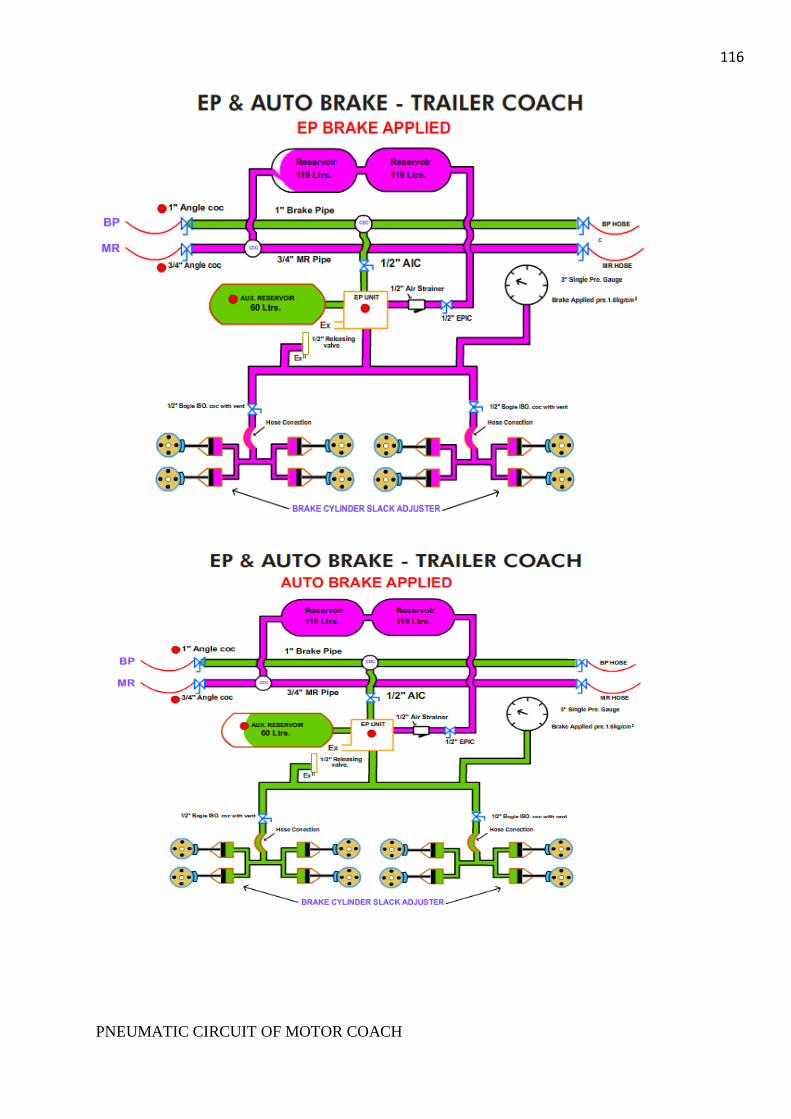
116
PNEUMATIC CIRCUIT OF MOTOR COACH

117
Auxiliary compressor and its associated pipe line in HT compartment is
responsible for creating air pressure initially to raise the pantograph, closing of ABB
and operating the EP contactors. The ACP will cut off automatically at 6.7 kg/cm2 pressure
through ACP 2 governor. The governor can be bypassed by a switch called ACP bypass
switch. A safety valve is provided which acts whenever air pressure rises beyond 7.75
kg/cm2. Air produced by ACP is stored in three reservoirs, called control reservoir,
panto & ABB reservoir.
The pressure required to raise the pantograph and to keep it in raised condition,
is fed to servomotor from panto reservoir through panto operating valve and throttle
valve. A panto isolating cock is provided before panto operating valve to isolate the
concerned pneumatic circuit whenever necessary. The raising and lowering of
pantograph is controlled by means of two latch type operating valves (called raising valve
and lowering valve) which are operated from driving cab through BL switch, fed from 110V
DC supply.
The minimum air pressure required to raise the pantograph is 4.5 kg/cm2. The throttle
valve regulates the raising time (6 to 10 seconds) and the lowering time (10 seconds) of
pantograph. The required air pressure for closing the circuit breaker goes from ABB
reservoir. The ABB reservoir is fed from ACP through a non-return valve for protection
against any loss of pressure in its preceding circuit. A pressure switch called ABB governor is
connected with ABB reservoir to prevent the closing of ABB in low pressure.
The pressure required for operation of EP contactors (in tap-changer and switch
group cubicle) is fed from control reservoir. This reservoir is initially fed from ACP
through a limiting valve which reduces the pressure to 5 kg/cm2. An isolating cock (named
control cock) is provided before control limiting valve to isolate control circuit whenever
necessary. A pressure switch called Equipment governor is provided in control reservoir
pipe line after the limiting valve which prevents the closing of EP contactors at less
air pressure to avoid unwanted flashing and welding of the contactors.
The pneumatic circuit in HT compartment is interconnected with the main reservoir
air supply through a non-return valve so that once coach is energized and MCP starts
working, ACP will not work further. Thus the whole pneumatic circuit is fed from main
compressor.

118

119 AUXILIARY COMPRESSOR
Auxiliary compressor is provided in each motor coach for building up air pressure for
initial energizing of EMU. This air pressure is stored in panto reservoir, ABB reservoir and
control reservoir. It is used to raise the pantograph and to close ABB initially. It is also used
for low-tension test conducted by maintenance staff.
COMPRESSOR
Make : ElgiFesto
Type : Single cylinder, Reciprocating,
Monoblock
Power required : 1 H.P.
Maximum operating pressure : 8 kg/cm
Piston Displacement : 150 lpm
Speed at 8kg/cm : 1500 rpm
Crank case lubrication : 300ml
MOTOR
Make : Elgi Electic
Type : Open TYPE, Screen protected
Power Supply : 110V DC
Current : 8.5A

120 MAIN COMPRESSOR
MCP is a horizontal three cylinders, two stage, pipe ventilated and flood-
proofed machine of light weight construction, directly driven through an extended crank shaft
by an integral electric motor. MCP sucks atmospheric air through oil bath suction
filter, compresses it to a pressure of about 3kg/cm2 in low pressure (LP) stage.
This hot and compressed air passes through inter cooler where it gets cooled and then
enters the high pressure (HP) suction side. In HP stage of the MCP, the air is finally
compressed to a pressure of 6 to7 kg/cm2 and passes through after cooler and finally
gets delivered into 2 main reservoir through a non-return valve.
Presently two types of main compressor are used in EMU/MEMU motor
coaches. These are KPC 3HC55 and ELGI TRC 1000 DCM.
Specification of KPC make compressor:
Model : KPC 3HC 55
Type : Reciprocating, Air Cooled, Forced Feed
Lubricated,
Mono-block.
No. of Cylinders : 3 (LP-2 & HP-1)
No. of Stages : 2
Nominal Speed : 1150 rpm.
Swept Volume : 1560 lts/min.
Free Air Delivered : 1075 lts/min.
Power Input at 7 kg/cm2 : 8.5 KW
Sump Capacity : 6.24 lts. Max. & 3.12 lts. Min.
Recommended Lubricant : Servo System 68 or Enklo 68.
Specification of ELGI Compressor:
Model : ELGI TRC 1000 DCM
Type : Reciprocating, Air Cooled, Forced Feed
Lubricated,
Mono-block.
No. of Cylinders : 3 (LP-2 & HP-1)
No. of Stages : 2
Nominal Speed : 1160 rpm.
Free Air Delivered : 1100 lts/min.
Power Input at 7 kg/cm2 : 9 KW
Sump Capacity : 6.25 lts. Max. & 3.25 lts. Min.
Recommended Lubricant : Servo System 68 or Enklo 68.
Specification for Motor for ELGI Compressor:
Model : 160 EMC/1
Voltage : 110V DC
Current : 99A

121
Output : 9.12 KW
RPM : 1160
Weight : 265 kgs (Approx.)
Make : Elgi Electric & Industries Ltd.,
Specification for Motor for KPC Compressor:
Model : To suit 3HC 55 KPC compresor
Voltage : 10V DC
Current : 96 A
Output : 11.38/9.12 KW
RPM : 1150
Weight : 245 kgs (Approx.)
Make : Laxmi Hydraulics Pvt. Ltd.
Twin tower heatless regenerative type Air dryer is provided in EMUs/MEMUs
to ensure supply of clean & dry air and does not allow any condensation of the moisture in
the system for trouble free operation of electro-pneumatic and pneumatic equipments. It is
light weight (not exceeding 100 Kg.) equipment, mounted in under frame on
compressor delivery pipe line. The air dryer is capable to work at nominal MR pressure
between 6-8 kg/cm2in EMUs/MEMUs.
IMPORTANCE OF AN AIR
DRYER IN PNEUMATIC
CIRCUIT
Moisture in a
compressed air system can
corrode air pipe lines and
equipments, wash away

122
equipment lubrication, decrease reservoir volumes. Moisture & oil may disturb
specified timing of air brake valves. Moisture & oil may also cause damage to the rubber
components of air brake valves & other equipments.
Major components of air dryer:
1. Coalescing filter assembly
2. Drain valve
3. Desiccant housing
4. Purge valve
5. Humidity indicator
6. Electronic control module
7. Solenoid valve
8. Pressure switch
Coalescing filter assembly functions to remove volume moisture, oil aerosols
and debris from compressed air before entering desiccant element.
Drain valve is pneumatically operated & piloted by air furnished by solenoid valve. It
is a double seated valve which operates to exhaust the coalescing filter housing air
upon each cycle of the dryer.
Desiccant housing contents desiccant element with cap screw. Desiccant element is
cylindrical shaped nylon felt bag, approximately 11” L X 4” dia. Each bag contains just less
than 5 pound of air brake quality molecular sieve desiccant.
Purge valve is located at the bottom of the desiccant tower. The purge valve
acts to direct the volume in the desiccant tower to atmosphere by tenderization of
solenoid valve.
Humidity indicator is used to determine the operating condition of the dryer. A
litmus paper is provided, with the change of its colour condition of the air dryer can
be determine as follows:
Blue - Satisfactory
123
Pink - Approaching saturation
White - Saturated
Brown - Desiccant element is saturated with oil & needs replacement.
Electronic control module alternately energizes & de-energizes the solenoid
valve to provide purging & regenerative cycles of the desiccant tower.
Solenoid valve is provided in each side of the dryer for its controlling. One
valve is energized at a time. On energization of solenoid valve air is sent to inlet check
valve, outlet check valve, purge valve & drain valve.
Pressure switch is the component of electronic controls. It delays the operation of
dryer until the main reservoir system pressure reaches to 7 bar.
Normally by-pass cock ‘C’ will remain isolated, cock ‘A’ & ‘B’ will remain open. In
case of failure of air dryer due to air leakage or non-functioning cock ‘C’ to be made open
to by- pass the air dryer and cock ‘A’ & ‘B’ are to be isolated.
In no case cock ‘A’ or ‘B’ & ‘C’ are to be kept isolate simultaneously since it will
stop the passage of air flow generated by the compressor and thus air pressure will be
excessive high in compressor delivery pipe line between the isolating cocks and compressor
which may cause bursting of after cooler/ inter cooler pipe line. To prevent the same
an additional safety valve (set at 8 Kg. /cm) has been provided 2 after the air cooler to blow
out the excess pressure in the pipe line at said zone.
Inter cooler and after cooler are provided to reduce the temperature of the compressed
air. In general, they are lengths of plain pipes and are exposed to a definite flow of
external cool air.
The compressed air coming out of main reservoir is called MR pressure and is
at a pressure of 7 kg/cm2. This MR pressure is utilized for feeding following circuit:-
For feeding entire pneumatic circuit in HT compartment when the motor coach is
energized.
For feeding supplementary reservoirs in trailer coaches and MR reservoir in
motor coach required for supplying compressed air to brake cylinders during EP brake
application.
For feeding horn reservoir in driving cab required for horn sounding.
For feeding entire BP pipe line and its associated reservoirs in the rake
through reducing valve in brake controller.
Brake pipe pressure is obtained through reducing valve of Brake Controller
which reduces incoming MR pressure to a pressure of 5kg/cm. Aux. reservoirs in motor
coach 2 and trailer coach are connected to brake pipe through triple valve of EP unit
and is maintained at a pressure of 5kg/cm. This brake pipe pressure is utilized to
supply 2 compressed air to brake cylinder during ‘Auto’ brake application, Dead-man-
brake application, Guard’s emergency brake application. During Driver’s emergency
brake application BP pressure is destroyed to actuate Auto brake application with EP
brake simultaneously.

124
Brake pipe is 1 inch. in diameter and green in colour, whereas MR pipe is ¾ inch in
diameter and red in colour.
Pipe line air filters with drain cocks are fitted in the MR pipe at the junctions
of the branch pipes leading to the brake controller. The purpose of these filters is to
prevent water and possibly other impurities from entering the brake controller.
Duplex pressure gauge and single pressure gauge are mounted near the brake
controller in the driver’s compartment. The former indicates the pressure in the main air
reservoir pipe and in the automatic brake pipe, while the later shows the pressure in
the brake cylinder.
Isolating cocks are fitted in the supply pipes leading to the EP brake unit.
These isolating cocks may be used in the event of a defect occurring in the EP circuit, to cut
off the air supply. Isolating cocks are also provided in the brake cylinder pipe leading to the
bogies. In the event of failure of brake in one of the bogies for instance rupture of
hose connection, the pipe leading to that bogie can thus be isolated, while the brake in other
bogie continues to operate. The passage of brake cylinder pipes from bogie frame to the
brake cylinder is connected through rubber hose.
BRAKE CONTROLLER
Electro-pneumatic brake controller is installed in the driving cab of the train to control
the application and release of both the EP and Automatic brakes. Presently two types of
brake controller are used in EMU/MEMU and these are:
ED-6 type brake controller of Westinghouse make
Modular brake controllers of Escorts make (Type- ESBC-II, ESBC-III, ESBC-III M).
Each type of brake controller is provided with a controlling handle with following
positions:-
Position I - Release & Running
Position II - Full service EP
Position III - LAP
Position IV - Service Automatic
Position V - Emergency
Selection of type of brake to be applied is decided by Motorman by keeping the handle in
desired position. The EP brake is controlled in between position I and II while the
automatic brake in positions I, III and IV. Both EP & Auto brakes are applied in position V
(Emergency position).
WESTING HOUSE BRAKE SYSTEM (WSF)
The parts of the brake controller are
1. Brake controller handle,
2. Self-lapping cylinder,
3. Puppet valve group, (A, B, C & D)
4. Equalizing discharge valve,

125 5 Pressure reducing valve,
6. Equalizing reservoir
7. Brake isolating valve switch key operated.
8. Application and holding contacts.
EQUALISING
ISOLATING VALVE SWITCH
REDUCING VALVE
DISCHARGE VALVE
PUPPET VALVE GROUP
SELF LAPPING CYLINDER
EXIT
BPBCMR
ER
5 KG/SQ.CM
7 KG/SQ.CM
B
C
DIAGRAM OF BRAKE CONTROLLER
RELEASE AND RUNNING POSITION
D
M.R. GAUGE
A & B VALVES OPENEDC & D VALVES CLOSED
CLOSEDCLOSED
OPENED OPENED
(NO ACTION)
A

126
Main
parts of
Modular
brake
controlle
r:
T
he ‘C’
bracket
T
he Auto
valve
unit
H
and
operated
isolating
valve
M
R
isolating
valve
R
educing
valve
E
qualising
Discharge Valve
BC feedback cylinder isolating valve
In each type of brake controller, above parts are mounted on the controller pipe bracket.
Pneumatic connection between the valves and pipe bracket are made through
ports in the fixing flanges and bolting faces. The connections are sealed by synthetic
gaskets.
The external pipe work is permanently connected to the pipe bracket and
compressed air is distributed within the controller by passages in the pipe bracket casting.

127 EP UNIT
Each motor coach and trailer coach in a rake is provided with an EP brake unit,
through which, depending on the pre-controlling action of the brake controller, air is
admitted to or exhausted from the brake cylinders. This EP unit is connected to the MR pipe
as well as to the BP pipe. Centrifugal filters with drain cocks are provided at the
junction of branch pipes, for the separation of condensate.
Presently two types of EP units are used namely WSF type and EK (Escorts-Knorr)
type EP unit.
Main parts of WSF EP unit
• Triple valve:
The diaphragm operated triple valve is part of the automatic brake
equipments and controls the application and release of the brakes in conjunction
with the auxiliary reservoir when the air pressure in the brake pipe varies. This valve
consists of:-
i. Graduating valve- This valve connects the auxiliary reservoir to BC
line when the brake pipe pressure is reduced during auto brake application.
After recharging of BP pipe, when BP pressure and auxiliary reservoir’s
pressure becomes equal then this valve disconnects the aux. resv. supply to BC
line.
ii. Quick Service valve - This valve connects the brake pipe to the triple
valve bulb and causes a local reduction in brake pipe pressure. This
decreases the time required for the brake pipe pressure to reduce sufficiently
to actuate operation of the triple valve on the next vehicle to the rear, when a
similar local brake pipe pressure reduction occurs. The action of successive
triple valves in increasing the rate of brake pipe pressure (which was
reduced during auto brake application) ensures an even and nearly
simultaneous response of the brakes throughout the train.
iii. Bulb Exhaust valve – Through this valve the brake pipe pressure
temporarily stored in triple valve bulb gets exhausted to atmosphere when the
triple valve is in release condition. This empty bulb then ensures storing of
brake pipe pressure (thus ensuring additional drop in BP pressure) through
quick service valve during next auto brake application.
iv. BC Exhaust valve- This valve closes the exhaust port of BC line to atmosphere
during auto valve application and connects the same during release of auto
brake.
• Magnet Valve Unit (EP portion) consists of:
i. Holding Magnet valve - During EP brake application this valve closes the
BC exhaust port to atmosphere and during release connects BC pipe to
atmosphere.
ii. Application Magnet valve- During EP brake application this valve connects
MR line to BC line and thus supplies compressed air to brake cylinder required
for brake application

128
iii. Application Check valve- This valve retains the compressed air in the brake
cylinders while the brake is held at constant pressure with the application
magnet valve de-energized.
• Stabilizing valve- This valve and its associated bulb ensures that the triple valve is
always in the ‘Release’ position when the EP brake is being used.
• Limiting valve- The maximum brake cylinder pressure which can be obtained during
EP service brake application is determined by the setting of the limiting valve.
• Safety valve- Safety valve releases any excessive pressure, which may arise in the
brake cylinders under abnormal conditions.
Main parts of EK type EP unit:
• Holding magnet valve- During EP brake application this valve closes the BC
exhaust port to atmosphere and during release connects BC pipe to atmosphere.
• Application magnet valve – During EP brake application this valve connects MR line
to BC line and thus supplies compressed air to brake cylinder required for brake
application.
• Triple valve –This valve is responsible for auto brake application and supplies
compressed air to brake cylinder by connecting the auxiliary reservoir to BC line
when there is a drop in brake pipe pressure.
• Stabilizing valve- This valve is used in conjunction with the EP brake. The
purpose of this valve is to reduce the pressure in the auxiliary reservoir to about 0.2
kg/cm (3psi) below the pressure reigning in the automatic brake pipe. This
reduction is necessary in order to prevent the direct-release triple valve connected to
the EP brake unit from being moved out of release position into lap position by pressure
fluctuation that may occur. The stabilizing valve reduces the pressure in the auxiliary
reservoir by connecting it with a bulb in the valve support. The pressure in the
brake cylinder controls this valve.
• Limiting valve- The function of the pressure limiting valve is to limit the air
pressure in BC pipe line to a specified value (3.2kg/cm).
• Safety valve- This valve protects the brake cylinder line from over-pressure thus
preventing consequent damage on brake-block and wheel.
• Check valve- During purely pneumatic application, the check valve prevents the
escape of air from the brake cylinders through the exhaust port of holding magnet valve.

129 ELECTRO-PNEUMATIC (EP) BRAKE:
The EP brake is an electrically controlled and pneumatically applied straight
air brake which admits compressed air to the brake cylinders under the control of two
magnet valves i.e. holding magnet valve and application magnet valve on each coach of the
train.
It is referred as service brake for EMU.
All the magnet valves and brake controller are connected by train wires
(usually with contactors included in the ckt.). Movement of the brake controller handle
between position I (Release and Running) and position II (Full EP) connects the
holding contact first. This in turn closes the holding contact of EP relay and energizes
wire no. 37. As a result holding coil of each EP unit provided in each coach is
energized and brake cylinder exhaust port to atmosphere is closed. The system is now
ready to hold the pressure. Further movement of the brake controller handle closes the
application contact which in turn closes application contact in EP relay thereby energizing
wire no. 38. Charging of wire no. 38 actuates application magnet valve in each EP
unit and allows MR pressure to brake cylinder line through limiting valve which is
set at 1.6 kg/cm in motor coach and 2 kg/cm in trailer coach. In HCC bogies fitted
with air spring the brake cylinder pressure in trailer coach is 1.2 kg/cm whereas the
brake cylinder pressure in motor coach remains same i.e. 1.6 kg/cm
Gradual application of EP brake is determined by the amount of handle
movement of brake controller from position I and is controlled through self lapping
mechanism in brake controller. Maximum EP service braking is obtained with the handle in
position II.
During release of EP brake, brake controller handle is moved towards position
I. As a result application contact gets opened de-energizing wire no. 38. Consequently
application magnet valve in each coach gets de-energized stopping further supply of MR
pressure to brake cylinder line. Further movement of brake controller handle at position

130
SIMPLIFIED CIRCUIT OF PNEUMATIC SYSTEM IN WAU4

131
I open the holding contacts and thus cut the feed to wire no 37 resulting in
de-energization of holding magnet valve in each coach. This results in opening of
exhaust port and connects compressed air of brake cylinder to atmosphere. Hence release
of EP brake is achieved.
AUTOMATIC BRAKE:
This is a purely pneumatic brake and during parting of train this brake comes
into action automatically and hence the term AUTO BRAKE is coined to it. Automatic
brake is controlled by varying the air pressure in the brake pipe which a continuous
pipe is carried through out the length of the train. The brake pipe is charged with
compressed air delivered at constant pressure of 5kg/cm by the reducing valve
mounted on the brake controller pipe bracket. The high-pressure air supply to the
reducing valve is obtained from main reservoir system.
LIMITING VALVE
LIMITING VALVE
WHEEL BC
BRH
BIC
ADDITIONAL
3.5 KG/CM2
BC WHEEL
SV 2.0 KG/CM2
HMV
Ex Port
1.5/1.8 KG/CM2
BIC
Ex Port
BLOCK DIAGRAM OF EP.BRAKE
EPIC
MCP
38
MR
37
AMV
7.0 KG/CM2
7.0 KG/CM2
EP.UNIT
CONTROLLER BRAKE
BIV KEY
BC
1.5/1.8 KG/CM2
BCWHEEL
BRH
AUX. RESERVOIR
BIC BIC
Ex Port
ALV
prk
WHEEL
SV 2.0 KG/CM2
BLOCK DIAGRAM AUTO BRAKE
5.0 KG/CM2
BRAKE CONTROLLER
EP.UNIT
7.0 KG/CM2MCP
VALVE
TRIPPLE
AIC
MR
Ex Port
BIV KEY

132
The automatic brake is applied by discharging air from the brake pipe and
released by restoring the air pressure in the brake pipe.
A triple valve on each vehicle is connected to the brake pipe and applies or
releases the automatic brake in response to the brake pipe pressure variations.
Graduated application of auto brake is achieved through graduated destruction of
equalizing pressure of brake controller. Bringing the brake controller handle first to
‘Auto’ position and then to ‘Lap’ position can do this. Equalizing reservoir in driving
cab is charged to brake pipe pressure. The reduction of pressure in the equalizing
reservoir is reproduced in the brake pipe by the equalizing discharge valve, which
closes slowly and prevents pressure surges from being set up in the brake pipe.
During AUTO brake application BP pressure is reduced by bringing the brake
controller handle to AUTO position. This pressure reduction acts on the triple valve in
the EP brake units, through which the auxiliary reservoirs are connected to the brake
cylinders.
Depending on the degree of pressure reduction, a corresponding pressure rise is
produced in the brake cylinders. By reducing the pressure in the automatic brake pipe
step by step, the brake cylinder pressure can be increased step by step, until, in the full
application position, the maximum brake cylinder pressure is reached. This is limited by a
safety valve in the EP brake unit to 4kg/cm .When the handle is moved back towards
running position, for release the pressure in the automatic brake pipe is raised again,
whereupon the brake cylinders are fully exhausted. Thus graduated release is not
possible when using the automatic brake. During release, the auxiliary reservoirs are
simultaneously recharged with air pressure from the automatic brake pipe.
DRIVER’S EMERGENCY BRAKE:
This brake is provided to the driver to initiate brake application in case of an
emergency and driver has no time to opt for a particular type of brake e.g. EP brake or AUTO
brake.
To affect emergency brake application, the brake controller handle is to be
kept in emergency position.
In the emergency application position the automatic brake pipe is rapidly and
directly exhausted via the brake controller, so that when the electrically controlled
brake is in operation the automatic air brake also comes to action. Thus rapid application
brake is ensured.

133 DEAD-MAN BRAKE:
As EMU/MEMU train is single man’s drive, it is necessary to provide a device
of brake application as well as cut off the traction feed to bring the train to a stop in the
event of incapacitation of the driver. This is arranged by means of a dead-man device
associated with the master controller. With the reverser key thrown in the either
position (forward or reverse), the MP handle has to be kept under continuous pressure. If
the pressure on the handle is released for any reason, power for traction control circuit
is interrupted and brake is applied automatically.
The application of brake is being done through the pilot valve and dead-man
valve. The dead-man valve has two chamber-upper and lower chambers. The upper
chamber is connected to the pilot valve of MP, while the lower chamber is connected to
exhaust. In normal condition the pressure in both chambers are equal. The pilot valve
is fitted on MP and mechanically coupled with MP handle. If the MP handle is
released while reverser is thrown in either direction then the pilot valve will vent BP pressure
slightly.
This will cause an imbalance of pressure in two chambers of dead-man valve
resulting rapid exhaust of BP pressure through dead-man valve lower chamber
connected with exhaust. This reduction of BP pressure causes auto brake application.
GUARD’S EMERGENCY BRAKE:
This brake is provided to guards for application of brake under emergency.
This is a kind of auto brake actuated by rapid destruction of BP pressure through a
guard’s emergency valve provided at guard’s side in the driving cab.
This valve is basically an isolating cock, one end of which is connected to brake pipe
and the other end to atmosphere. Normally this valve is kept closed. In case of an emergency
the guard operates the handle to make it ‘ON’ which results in rapid exhaust of BP
pressure to atmosphere, thus causing auto brake application.
PARKING BRAKE:
This system of brake is provided in all the MEMU motor coaches and EMU
motor coaches provided with air spring in secondary suspension. Parking brake is
applied while the rake is stabled and thus to prevent rolling. Hence parking brake is a
substitute of hand brake.
Four numbers of parking brake cylinders have been provided in each motor
coach adjacent to wheel number 1, 3, 5 and 7. These cylinders are mechanically coupled
with existing brake cylinders’ piston through lever arrangement. Function of parking
brake cylinder is just opposite to the normal brake cylinder.
When the air pressure is applied to parking brake cylinder, the brake gets
released and when there is no pressure in the parking brake cylinder the brake is
applied by the spring action. The spring is provided inside the parking brake cylinder.
Working of the cylinder is being controlled by a magnet valve provided in MR pipe line
and is located in driving cab. The magnet valve is energized through a switch in BL
box in driving cab.
134
During running condition the switch will remain in ‘ON’ position and thus air
will be supplied to the parking brake cylinder through a limiting valve (known as parking
brake limiting valve set at 5 kg/cm and is provided in driving cab) and parking brake will
be in released condition. In stable condition, the parking brake switch is to be put ‘off’
and thus brake will be applied.
A governor is provided on parking brake cylinder line. This governor has two
interlocks- one N/O contact connected in motor contactor control circuit and one N/C
contact provided for indication of parking brake application in driver’s LED indication
panel.
When parking brake is applied, there is no air in the parking brake cylinder. Then
N/O contact of the governor will be opened causing non-closing of motor contactor and at the
same time parking brake application indication will glow through its N/C interlock.
During release of parking brake air will be available in parking brake cylinder line.
This will cause closing of N/O contact resulting in closing of motor contactor and
opening of N/C contact to extinguish the parking brake application indication. A
bypass switch is connected in parallel with parking brake governor, so that in case of non-
functioning of governor, the switch is to be put ‘ON’ to bypass the governor. A
manual release device (release handle) is provided in the system to uncouple the
parking brake manually if required.
A bypass isolating cock is provided in parallel to parking brake magnet valve
and is normally kept isolated. In case of failure of magnet valve, this cock is to be made
normal to supply air to the parking brake cylinder bypassing the magnet valve.
During shunting work in dead condition of motor coach, it is required to
release the parking brake. So the release handle is to be operated to uncouple the
parking brake lever which is coupled with the brake cylinder piston.

135

136

137
Conditions warranting for mechanical release of Parking Brake.
1. Parking brake not released by putting PB switch in ‘on’ position
due to any electrical fault or defect in magnet valve.
2. Non-availability of MR pressure.
3. Disconnection of ‘B’ jumper (parking brake in rear M/C to be
released manually).
4. For movement of loose M/C in dead condition.
5. Any mechanical fault in the system.
Instructions for motormen & maintenance staff for mechanical release of parking
brake on line due to any of the reasons mentioned above.
1. Provide skid, release EP & Auto brake.
2. Keep the parking brake switch ‘on’ in BL box.
3. Ensure parking brake MCB in driving desk is ‘on’.
4. Isolate parking brake isolating cock in affected M/C.
5. Manually release the parking brake on wheel no. 1,3,5,7 in affected
M/C & ensure brake blocks are released from wheels.
6. Put the parking brake governor bypass switch ‘on’ in affected M/C.
Note: In case of manual release of parking brake, ‘parking brake on’ LED indication
in driver’s desk will remain glowing.
Improved version of Parking brake
In improved version (modified arrangement) of parking brake system, if there
is a pressure drop in MR, PB system will not be affected as there is a 3/2 way selector
valve & this valve will not allow the PB cylinder to exhaust until PB application
valve is operated. Also there is an 9 ltr. capacity auxiliary reservoir which will keep
the PB released in case of MR pressure drop. In case this air reservoir also gets exhausted
then only PB are to be released manually by manual release mechanism.
In modified system electrical failure will not cause PB application or release
because unlike earlier the present magnet valves used are energize to apply & energize to
release (two separate 3/2 way magnet valves are provided).
138
In modified arrangement air will always be in PB system for keeping the PB in
released condition. But if this air also leaks out then manual release mechanism has
to be operated. This will happen in case of extreme emergency only.
A current pulse has to be given to the release magnet valve, which will shift the spool
in the selector valve so the air supply from MR is connected to the PB cylinder to
release. Similarly for application of PB the application magnet valve is to be made energized.
This will shift the spool in the selector valve so the air in PB cylinder will be
connected to atmosphere through exhaust port & PB will be applied. The magnet
valves are not always energized.
There is an electrical signal in the driver’s cab. Whenever there is a pressure drop in
the PB system due to bursting of air pipe or any air leakage & PB gets applied this
indication will glow in driver’s desk. At the same time there will be traction cut through
the pressure switch (set at cut in 3Kg./cm & cut out 2 Kg./ cm) provided in PB circuit.
A separate MCB is provided in PB circuit.
In modified arrangement PB application is independent of power failure as it has
energized to apply & energize to release type magnet valves. In case of disconnection
of ‘A’ jumper PB is to be released manually in rear M/coaches.
Mechanical arrangement is same as in earlier PB system. Quality of manual
locking/ release mechanism has been improved.
In conventional non-HCC trailer bogies 60 mm. stroke Brake cyl. are to be used
& in case of HCC bogie 40 mm. stroke Brake cylinders should be provided.
SPRING-LOADED BRAKE

139
Figure: Overview of spring-loaded brake
The spring-loaded brake is suitable for securing the units. It acts on the two bogies of
the DTC / NDTC. Compressed air is required to release the brake. In the case of a broken or
defective hose, the spring-loaded brake is applied automatically. However, this fault can be
eliminated via the emergency release device, i.e. one funicular traction per spring-loaded
brake on the bogie. It is no longer possible to apply the spring-loaded brake after a fault of
this kind. In addition, the shut-off cock of the spring-loaded brake must always be shut-off
for an emergency release.
Air
reservoir
Emergency
release
device
Holding
valve
Compressed-
air brake
cylinder
Spring-loaded
brake cylinder
BP connection
Solenoid valve
Manometer in
the driver's
cab
Figure: Shut-off cock of the spring-loaded brake and emergency release device
Release device
Shut-off cock of the
spring-loaded brake

140 HORN
Diaphragm type horn is provided at both side in front of driving cab (in new
coaches position of horn is provided in under gear behind the cattle guard). It is
connected to horn reservoir through a three way cock & double check valve. A horn padel
is provided to sound the horn. Presently both the horns are being shifted to cab roof for
better sound effect.
WIPER
Wiper is provided in EMUs &
MEMUs to wipe out the rain water/dew drops
from front look out glasses. Movement of wiper
is achieved through a servomotor which is
operated by MR pressure. A switch with
regulator is provided on driver’s desk to switch
‘ON’/’OFF’ and regulate the wiper
movement.
Since failure rate of pneumatic wiper
is high, electrical wiper has been
developed.
Provision of sprinkler arrangement in
wiper is under development to avoid
scratches on look out glass occur due to
movement of wiper blade on dry surface of
glasses during testing. All the existing
pneumatic wipers shall be replaced by electrical wiper for better reliability.
SOME MUST FOR BRAKE EQUIPMENTS
While carrying out works on pipe lines or valves, make sure that the relevant ckt.
has been properly isolated and there is no air pressure in the parts to be attended.
While isolating CIC of a motor coach, always disconnect electrically MCP governor
of that motor coach through MCP control MCB. Otherwise NC interlock of the
governor will not open in absence of air pressure and will keep MCPs of other
motor coaches working through synchronization. This will result in excessive
building up of air pressure and MCP safety valve will blow continuously.
If ICA cock is to be kept isolated for leakages etc., also isolate EPIC and release
BC pressure and then isolate both BICs. Isolation of ICA cock alone will result in brake
binding and if not instantly then during EP brake application afterwards.
Draining of condensate from coolers and relevant reservoirs should be carried out
to the extent possible as this enhances the reliable operation of brake equipment.
While isolating cocks during brake binding, first isolate ICA & EPIC, then release BC
pressure by pulling release chain and then isolate both BICs.
Never left MCP governor-isolating cock in isolate position alone. If it is to be kept
isolated then disconnect the concerned governor electrically.

141
During replacement of brake block, the lever arrangement of PB system has to be
open to adjust the service brake cylinders.
SOME IMPORTANT GUIDELINES OF RDSO
1. Permissible brake power in EMU stock as per RDSO’s letter no. MC/EMU/AVB dtd.
23/24.08.2004:
Rakes leave car shed should have 95% effective brake cylinder.
Rakes leave night stabling points should have 90% effective brake cylinders.
During the day’s service if the number of effective brake cylinders goes below
90% but above 85% the service may be continued at a restricted speed of 75 kmph.
If the number of effective brake cylinder goes below 85% the motor man
should operate at the restricted speed of 70 kmph or which he feels is safe
and the rake should be withdrawn from service after the completion of the service.

142
GENERAL DESCRIPTION
1.0 INTRODUCTION
The AC-DC EMU (Electrical Multiple Unit) is a newly designed train equipped with state-of-
art IGBT control technology. These trains are especially designed for running over DC as well as AC
territory in Mumbai sub-urban area to cater growing demand of passenger traffic. These vehicles are
equipped with a driver’s friendly diagnostic display (MMI) unit.
This Maintenance Manual for AC-DC EMU (Siemens Rake) is prepared for the use and
reference for maintenance staff of EMU Car Sheds and Workshops. Maintenance and overhauling
procedures of various electrical, mechanical equipment and all other accessories of Siemens Rake
are briefly described in this manual.
1.1 ABBREVIATIONS
ACU - Auxiliary Control Unit
ADC/COS - AC/DC Changeover Switch
AFB - Automatic Traction/ Brake Control (Cruise Control
AM - Shut Off Valve (Parking Brake Circuit)
AWS - Auxiliary Warning System
BCU - Brake Control Unit
BW - Braking Resister
CCU - Central Control Unit
DCS - Driver’s control switch (Master key)
DM - Diagnostic Message
DTC Driving Trailer Coach

143
EBU - End Basic Unit
EBL - Emergency Brake Loop
ES - Electronic Cabinet
FML - Traction Motor Fan
GTO - Gate Turn Off Thyristor
HB - Main Air Compressor
HBL - Main MR Pipe
HL - Main Brake Pipe
HSCB - High Speed Circuit Breaker
HTC - High Tension Compartment
IGBT - Insulated Gate Bi-Polar Transistor
MBU - Middle Basic Unit
MMI - Man Machine Interface
MPS - Motor protective switch
MS - Main Switch
MVB - Multi Vehicle Bus
NDTC - Non Driving Trailer Coach
PBC - Power brake controller
PIS - Passenger Information System
PT - Potential Transformer
PTS - Position of Train System
RDM - Rescue Drive Mode
SB - Signal Bell
SC - Shunting Cab
SIBAS - Siemens Bahn Automatisierungs System
SKS - SIBAS KLIP Station.
SW - Software
TCC - Traction converter cabinet
TCU - Traction Control Unit
VCB - Vacuum Circuit Breaker
VSD - Voltage Sensing Device
VVVF - Variable Voltage Variable Frequency
1.2 THREE-PHASE TECHNOLOGY
The vehicle is equipped with a state-of-the-art three-phase drive with asynchronous motor. The
advantages over direct current drives are as follows:
Smooth (Step-less) acceleration.
Reduced weight
Wear-resistant drives hence less maintenance and high level of reliability as no wearable part like carbon brushes and commutator.

144
Good starting properties
High tractive force over the whole speed range
Wear-free regenerative brake for reduced maintenance, increased wheel and other mechanical component life and energy conservation as well
Easy starting even on gradients
The stator winding of the asynchronous motor consists of coils, which are electrically offset by
120°. If these are connected to a three-phase network, they generate a rotating magnetic field, also
known as rotating field.
The rotor consists of one winding which is designed with rods whose ends are short-circuited
by means of rings. This kind of rotor is therefore called short-circuit rotor.
A rotating magnetic field induces an electromagnetic force into the rotor winding. The electric
circuit of the short-circuit rotor is always closed, thus creating a current flow which generates
another magnetic field (rotor magnetic field). The rotor magnetic field attempts to catch up with the
rotating field in the process. If the rotor rotates faster than the rotating magnetic field, the engine
automatically switches into braking mode. This means that by changing the voltage and the
frequency, the output (torque) and the speed (number of revolutions per minute) can be altered.
The frequencies and the voltages are generated in the current converter. The main components are
the four-quadrant converter, the intermediate circuit and the pulse width modulation inverter.
In DC mode, the voltage is fed into the intermediate circuit via a line filter. The transformer
and the four-quadrant converter are therefore not required. After an automatic commutation from
AC to DC, the transformer cooling is automatically switched off.
In braking mode, the vehicle can feed the generated energy back into the contact line
network. This is only possible if the network is able to receive the generated energy. If the network is
not able to do this, the pneumatic brake is activated.
1.3 CONTROL TECHNOLOGY
There are two central control units called CCU. These are located in the driver's cab. Apart
from the control of the entire train, the CCU also controls the display. The vehicles of one unit and
the units themselves are connected to each other via an MVB bus. The MVB is designed redundantly
with line A and line B. If the MVB bus is not available despite of this fallback, the vehicle can be
operated in degraded operation via the rescue drive mode. This function is only used for clearing the
track. In this operating mode, the display is switched off and the auxiliary tell-tale lamps are
switched on. All switches, buttons and devices which are controlled via the control technology are
connected to a KLIP station.
1.4 DISPLAY SUPPORT

145
The MMI (Man-Machine Interface) is installed in the driver's cab in the DTC and informs the
driver of the current state of all important functions in the train. The states of functions are
indicated to the driver by means of coloured icons. The driver can detect faults at a glance. The
display assists the driver during the subsequent error detection. For information on further actions,
the driver can call up the corresponding remedy for the error message. Automatic vigilance device
has been implemented via the master controller. If the driver releases the vigilance monitoring
button during the journey, the brakes are applied automatically and the power of the train is
switched off. This only happens during the journey. If the speed is below 5 km/h, this function is
disabled. In rescue drive mode, the automatic application of the brakes is immediately initiated even
if the vigilance monitoring switch is not actuated and if the speed is below 5 km/h.
1.5 AUXILIARY EQUIPMENT
The three-phase auxiliary equipments are supplied by an auxiliary inverter. The inverter for
auxiliary equipment generates the following voltages:
415 Volt AC for fans / main air compressor and pumps
110 Volt AC for passenger compartment fans and lighting
110 Volt DC for the auxiliary air compressor, plugs, battery bus bar, instrument and emergency lighting.
The inverter for auxiliary equipment supplies the three-phase components with a fixed
frequency (50Hz) and voltage. The auxiliary equipment is connected by means of contactors.

146 1.6 UNIT & RAKE FORMATION OF EMU
There are two types of basic units
o End basic unit
o Middle basic unit.
1.6.1 End Basic Unit
It consists of three coaches viz.
Motor Coach (MC)
Driving Trailer coach (DTC)
Trailer Coach (TC)
Motor-Coach
This is the coach responsible for the movement of the EMU as desired by the driver command.
This consists of propulsion equipments viz. transformer, traction motor, traction converters, (Four
quadrant chopper), PWM inverters, brake chopper etc.
Driving Trailer Coach
This is non-powered coach with facilities for driving. These coaches are equipped with Master/
Brake Controller, Drivers Desk, Passenger Information System, Light & Fans etc.
Trailer Coach
This is also non-powered coach but without Drivers desk. Passenger Information System and
Light & Fans are provided in this coach.
1.6.2 Middle Basic Unit
It consists of three coaches viz.
Motor Coach (MC)
Non Driving Trailer coach (NDTC)
Trailer Coach (TC)
Figure 1 : End Basic Unit

147
Non Driving Trailer Coach
This is non-powered coach without facilities for driving. These coaches are equipped with Light
& Fans etc.
1.6.3 Train Formation
For the EMU, following train formations are possible:
(i) Nine Car Rake : It comprises of 3 basic units
(ii) Twelve Car Rake : It comprises of 4 basic units
(iii) Fifteen Car Rake : It comprises of 5 basic units (Only in WR)
Figure 3: Nine Car Rake
Figure 4: Twelve Car Rake
Figure 5: Fifteen Car Rake
Figure 2 : Middle Basic Unit

148
1.7 MAJOR EQUIPMENT OF DTC
1.7.1 Driving Cab
1 Side panel left + RDM signal lights 7 Speedometer
2 Signal lights 8 Radio /PIS panel
3 Display, MMI 9 Side panel right
4 Pressure panel 10 Pneumatic control valve (master brake
controller)
5 Key switch and master controller 11 Wiper valve
6 Power brake controller 12 Horn valve
1.7.1.1 Driving Desk
a. Brake controller
b. Master controller
c. Left hand side panel for push buttons, rotary switches and indications.
d. MMI
e. Different gauges
Figure 6: Driving cab

149
f. PIS
g. TMS (Train management system)
h. Foot operated valve for hooter
i. AWS indication panel
j. Analog speedometer
k. ESMON
l. SIBAS KLIP Station (12 & 13)
m. Cocks for AWS
1.7.1.2 Guard’s Desk
a. Brake pipe pressure gauge
b. Panel for push buttons
1.7.1.3 Electronic Cabinet
a. CCU
b. Push buttons
c. Rotary switches
d. MCBs (1st layer & 2nd layer)
1.7.1.4 Driving Cab Front View
a. Head Light
b. Flasher Light
c. Tail light
d. Blinker
e. Marker light
f. Electronic head code
g. Look out glass
h. Cattle guard
i. Buffer & couplers
1.7.1.5 Panel in Passenger Area of DTC
a. SIBAS KLIP Station (11)
b. Different rotary switches MCBs, MPS for MCP, Ventilation fans, light & fans for passengers.
Figure 7 : Driving Cab Front View

150 1.7.1.6 Roof Equipment:
a. Ventilation fans
1.7.1.7 Under-frame Equipments
a. Main compressor
b. Battery box
c. Different reservoirs
d. Combined brake unit
e. Parking brake equipments
f. Air suspension equipments
g. Mechanical weight transfer equipments
1.7.2 Indication Panels
1.7.2.1 Control Elements in the Driver's Desk on the Left-Hand Side
Figure 8: Control Elements in the Driver's Desk on the Left-Hand Side

151
1. Mounting Plate 11. SB I (Signal Bell)
2. Flasher Push Button 12. Emergency Brake
3. Head Light Main / Auxiliary. 13. Emergency Off
4. Head Light On / Off 14. RDM Active
5. Audio visual push button 15. Fire Alarm
6. SB II Alarm bell (HW) 16. Spare
7. Head Light Bright / Dim 17. Minimum 1 Brake applied
8. Fire Alarm (Buzzer 18. Minimum 1 Panto up
9. Audio Visual (Buzzer) 19. Minimum 1 CB On
10. AWS vigilance 20. Lamp Test Driver
A. All switches/push buttons on this panel have metallic border
B. All indications on this panel have black border 1.7.2.2 Auxiliary Tell-Tale Lamps
Figure 9: Auxiliary Tell-Tale Lamps

152
A 1 Not all Pantos up B 1 Emergency brake
A 2 Not all main switches on B 2 Emergency OFF
A 3 Spare B 3 Spare
A 4 Min. 1 brake applied B 4 Fire Alarm
A 5 Spare B 5 Spare
A 6 Spare B 6 Spare
A 7 Spare B 7 Spare
1.7.2.3 Pressure Panel
1. Brake Cylinder Gauge 2. MR/BP/Duplex Gauge
3. Panto Up / Down 4. Main Circuit Breaker On / Off
5. Cruise Control 6. Neutral Section Push Button
Figure 10: Pressure Panel

153 1.7.2.4 Man Machine Interface (General View)
1 Display ON / OFF
2 Not Connected
3 Legends of Symbols (Meaning)
4 Event Overview
5 Trouble Shooting Guidelines for Motorman
6 Not Connected
Figure 11: Man Machine Interface (General View)

154
7 Brightness Control Dialog
8 Not Connected
9 Not Connected
10 Clear
11 Cursor Up
12 Cursor Down
13 Curser Left
14 Curser Right
15 Enter
16 to 25 Soft keys 0 to 9

155 1.7.2.5 Train Radio and Passenger Information System
1.7.2.6 Control elements in the driver's desk on the right-hand side
1 PIS MMI
2 Train radio hands-free
module
3 Train Radio MMI
4 Pressure Gauge Parking
Brakes
5 Train radio Handset
Figure 12: Train Radio and Passenger Information System

156
1 Mounting plate
2 Cab tube light for driver
3 Cab spot light for driver
4 Cab emergency light for driver
5 Cab fan for driver
6 Parking brake release
7 Parking brake apply
8 PIS release button for microphone
9 PIS Microphone
Figure 12: Control elements in the driver's desk on the right-hand side

157 1.7.2.7 Guard Panel Right-Hand Side
1 Mounting Plate
2 Ventilation Release Off
3 Fan Release Off
4 Spare
5 Train Light 100 % Off
10 Flasher Light On / Off (Guard)
11 Tail Light On / Off
12 SB I Signal Bell (Guard) SW
13 SB II Alarm Bell (Guard) HW
18 Spare
Figure 13: Guard Panel Right-Hand Side

158
19 Spare
20 Spare
21 Train Light 50 % Off
26 Cab Spot Light (Guard)
27 Cab Tube Light (Guard)
28 Cab Fan (Guard)
29 Lamp Test

159 1.7.3 Electronics Cabinet Dtc
1.7.3.1 Level 1
Figure 14: Electronics Cabinet DTC level 1

160 1.7.3.2 Level 2
Figure 15: Electronics Cabinet DTC level 2

161 1.8 MAJOR EQUIPMENT OF MOTOR COACH
1.8.1 SHUNTING CAB
1.8.1.1 Shunting Desk
a. Brake controller
b. Master controller
c. Shunting desk, rotary switches and indications.
d. Different gauges
e. Foot operated valve for hooter
f. SIBAS KLIP Station (21)
g. Shunting desk control panel
1 Mounting Plate 11 Lamp Test
Figure 16: Shunting Desk

162
2 Panto is Up 12 Parking Brake Released
3 MC is On 13 Panto Up / Down
4 OHE is available 14 Main Switch On / Off
5 Emergency Brake 15 HTC Tube
6 Min. 1 Brake Applied 16 HTC Fan
7 Summary Fault 17 Battery Volt Meter
8 Cab Tube Light 18 Test battery Voltage
9 Cab Emergency Light 19 Parking Brake Applied
10 Cab Fan 20 Start Fire Extiguishing
1.8.1.2 Electronic Cabinet
a. DC earthing switch
b. Push buttons
c. Rotary switches
d. MCBs
1.8.2 HT COMPARTMENT
a. TCC
i. AC-DC converter (4Quadrant Chopper)
ii. DC-AC converter (Pulse width modulated inverter)
iii. Traction Control Unit
iv. Converter cooling blowers
v. Various contactors and relays
vi. Voltage & current sensors
b. Electronic Cabinet: Brake Electronics Control Unit (BECU)
Electronics cabinet MC (top)

163
Figure 17: Electronics cabinet MC (top)

164 Electronics cabinet MC (bottom)
c. Aux. converter unit
d. Aux. compressor
Figure 18: Electronics cabinet MC (bottom)

165
e. HSCB
f. VSD

166 1.8.3 ROOF EQUIPMENT
a. Pantograph
b. Surge Arrestor
c. AC-DC change over switch
d. Brake resister
e. PT
f. HVCB
g. CT
h. Ventilation fans
1.8.4 UNDER FRAME EQUIPMENT
a. Traction Motors
b. Traction Transformer
c. Different reservoirs
d. Combined brake unit
e. Air suspension equipments
f. Mechanical weight transfer equipments
1.8.5 PANEL IN PASSENGER AREA OF Motor Coach
a. SIBAS KLIP Station (21)
b. Different rotary switches, MCBs, MPS for, Ventilation fans, light & fans for passengers.
1.9 ELECTRICAL EQUIPMENT IN MOTOR COACH
1.9.1 PRE-CHARGING AC CONTACTOR
This is AC contactor working under AC OHE supply. The traction transformer has two secondary
windings. This contactor is connected in one of the circuit. One resistor is connected across the HT
contact of the pre-charging AC contactor. Initially this contactor remains open, keeping pre-charging
resistor in power circuit of four quadrant chopper module. As a result, initial inrush of charging
current for DC link is reduced considerably which ensures the safety of semiconductor devices of the
four quadrant chopper module.
1.9.2 PRE-CHARGING DC CONTACTOR
This is DC contactor working under DC OHE supply. Its function is to connect the equipment to
power supply under DC condition. One resistor is connected across the HT contact of the pre-charging
DC contactor. Initially this contactor remains open, keeping pre-charging resistor in power circuit of

167
DC link. As a result, initial inrush of charging current for DC link is reduced considerably which ensures
the safety of semiconductor devices in the HT circuit.

168 1.9.3 TRACTION CONVERTER CUBICAL
The traction converter cubicle is a completely assembled unit installed in the HT compartment of the
motor coach. The traction control unit (TCU) is situated inside the cabinet. It consists following
modules:
i. Four Quadrant Chopper Module (4 QC)
ii. Pulse Width Modulated Inverter
iii. Brake Chopper
1.9.4 EARTH FAULT DETECTOR
It is connected across the circuit of 4-QC module for protection of 4-QC module against the
Earth Fault in AC side i.e. Transformer side of the HT circuit.
1.9.5 LINE FILTER
This is an inductor connected in series with DC link capacitor. This is LC (resonance) circuit to
suppress the harmonics or ripples of DC supply to obtain pure DC supply across the DC link.
1.9.6 AUXILIARY CONVERTER UNIT
Auxiliary converter unit basically consists of two PWM inverter modules with two primary
windings. Input supply for inverter modules is obtained from DC bus-link. There are three different
secondary windings for different purposes.
i. Three Phase AC 415V 50Hz Output
One secondary of auxiliary converter having 3 Ø AC, 415V, 50 Hz (121A/ 87kVA) supply is
used for Main compressor & other auxiliaries.
ii. Single Phase 110V AC 50 Hz Output
One secondary of auxiliary converter having 1Ø AC, 110V (20 kVA) supply is used
for light & fans in the passenger compartment. One tapping is taken out for
redundancy lines of supply for adjacent units.
iii. DC 110 V Output
One secondary of auxiliary converter having 3 Ø AC supply for battery charging
equipments is used. Battery having 110 V DC supply is connected across this battery
charging equipments to charge continuously. This 110 V DC supply is used for
control supply as well as for emergency light supply when normal light & fan supply
of 110 V AC is failed due to any reason.

169 1.9.7 PANTOGRAPH (TYPE AM-1882)
It is provided to collect H.T. Supply from OHE contact wire. The OHE supply may be 1500 VDC or
25 KV AC, 50Hz. This is fitted on foot insulator on the top of the roof of the motor coach.
1.9.8 SURGE ARRESTOR
It is provided on the top of the roof of the motor coach to protect the coach from lightening.

170 1.9.9 LINE VOLTAGE TRANSFORMER
It is provided on the roof of the motor coach. It is a step down transformer for voltage sensing (AC or
DC)
1.9.10 LINE CURRENT TRANSFORMER
It is provided on the roof of the motor coach. It senses the current through primary winding of
traction transformer. It provides over current protection by opening VCB.
1.9.11 VOLTAGE SENSING DEVICE
The voltage sensing device is provided to sense whether the OHE supply is AC or DC.
1.9.12 CHANGE OVER SWITCH AC/DC
It is provided on the roof of the motor coach. It is an air operated switch with two positions i.e. AC
and DC. Default position of the switch is AC. It changes its position to either AC or DC depending
upon the OHE voltage.
1.9.13 BRAKING RESISTER RS 25.10
1.9.14 High voltage AC Circuit Breaker (HVCB)
This is an air operated single pole AC circuit breaker. It is used as a line circuit breaker to open/ close
the power circuit and also to break the circuit under overload and short circuit conditions. It is
provided on the roof of the motor coach.
1.9.15 High Speed DC Circuit Breaker
This circuit breaker works under DC catenaries.
1.9.16 AC EARTHING SWITCH

171
It is provided across the VCB. During off position of VCB it is connected to Earth primary side of the
traction transformer while opening H.T. compartment.
1.9.17 DC EARTHING SWITCH
It is provided across the HSCB. During off position of HSCB it is connected to Earth DC link while
opening H.T. compartment.
1.9.18 SURGE ARRESTOR AC
These are two in numbers. It is provided on the roof of the motor coach to arrest AC surges during
AC operation.
1.9.19 SURGE ARRESTOR DC
It is provided on the roof of the motor coach to arrest DC surges during DC operation.

172 1.9.20 TRACTION MOTORS
Four number of traction motors are provided in one motor coach. Two pairs of traction motors are
connected across two different PWM inverters.
1.9.21 TRACTION TRANSFORMER
The transformer is designed for a nominal rating of 1250 kVA. It consists of a primary winding and 2
secondary windings. Therefore, 625 kVA is available at each secondary. This corresponds to a
secondary side nominal current of 731 A at a secondary voltage of 855 Volt (22.5 kV mains voltage).
1.10 TRAILER COACH
1.10.1 PANEL IN PASSENGER AREA OF TC
a. SIBAS KLIP Station (31)
b. Different rotary switches, MCBs, MPS for Ventilation fans, light & fans for passengers.
1.10.2 ROOF EQUIPMENT
Ventilation fans
1.10.3 UNDER FRAME EQUIPMENTS
a. Different reservoirs
b. Combined brake unit
c. Air suspension equipments
d. Mechanical weight transfer equipments
1.11 NON DRIVING TRAILER COACH
1.11.1 PANEL IN PASSENGER AREA OF NDTC
a. SIBAS KLIP Station (41)
b. Different rotary switches, MCBs, MPS for MCP, Ventilation fans, light & fans for passengers.
1.11.2 ROOF EQUIPMENT
Ventilation fans

173 1.11.3 UNDER FRAME EQUIPMENTS
a. Main compressor
b. Battery box
c. Different reservoirs
d. Combined brake unit
e. Parking brake equipments
f. Air suspension equipments
g. Mechanical weight transfer equipments

174 1.12 TRANSDUCERS AND SENSORS
Transducers are the equipments which are utilised for converting the electrical or mechanical
quantities into suitable electrical signals so that these signals can be processed by the control
electronics for efficient control of the system. Following transducers and sensors are used in Siemens
AC-DC EMU:
a. Voltage transducer
b. current transducer
c. pressure transducer
d. speed sensor
e. oil flow sensor
f. oil level sensor
1.13 BRIEF DESCRIPTION OF HT POWER CIRCUIT
The pantograph receives the supply voltage of either 25 kV catenary or 1500 V DC catenary. The
detection of AC or DC voltage is achieved through voltage sensing device which includes PT
(potential transformer) for AC voltage detection & in series resistors for DC voltage detection. In case
of AC voltage detection or no voltage detection, changeover switch AC/DC remains in the AC position
thus connecting VCB (Vacuum circuit breaker) to the pantograph. This is a failsafe method of
protecting the DC equipments against high voltage AC. For DC catenary, changeover switch AC/DC
moves to DC position connecting HSCB (High speed circuit breaker) to pantograph.

175
Figure : Overview of AC/DC electric circuit
A spark gap lightening arrestor is mounted directly on the pantograph to protect the complete
circuit from extreme over voltages.
The VCB is the main circuit breaker in case of AC catenary & the HSCB acts as the same for DC
catenary.
Each motor coach is equipped with a main transformer. The main transformer converts the 25 KV
overhead line voltages to lower operating voltages. There are two secondary windings each of 950V
(corresponding to 25 kV), 625 kVA. The transformer is oil cooled.
For AC catenary, as the VCB closes, the main transformer steps down the voltage & feed the 4-QC
(Four Quadrant Chopper Module) through two secondary winding of 950 V each (corresponding to a
ratio of 25 kV/ 950 V). The initial charging of the 4-QC is done through a pre-charging resistor (AC)
which is in series with secondary winding-1 of the main transformer. Once the voltage at the 4-QC
output is build up to certain voltage level of DC using rectification process, the contactor across the
pre-charging resistor are closed & the 4-QC builds up a fixed voltage of 1800 V DC to feed the PWM
inverter & the auxiliary converter through DC link capacitor.

176
Main functions of 4-QC’s are to maintain a fixed DC voltage at its output irrespective of the
catenary voltage variations & to maintain a near unity power factor for the current consumed from
or fed back to the AC catenary. It achieves these functions through two pairs of IGBT based modules.
An LC filter circuit is provided at the output of the 4-QC, to filter out the second harmonic
components from the rectified voltage & smoothen the DC link voltage.
The AC circuit is protected against surge voltages through gapless surge arrestors (AC). Similarly DC
circuit is protected through gapless surge arrestors (DC).
For DC catenary, Changeover switch AC/DC is in DC position. As the HSCB closes the DC link
capacitor is charged through pre-charging resistor (DC) to avoid heavy inrush current. After some
time delay Line Contactor is closed to bypass the pre-charging resistor & the full catenary voltage is
applied across the DC link.
Fig. 19: Current converter (AC operation)
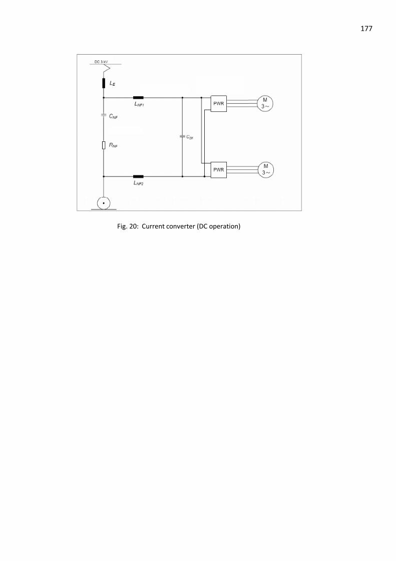
177
Fig. 20: Current converter (DC operation)

178
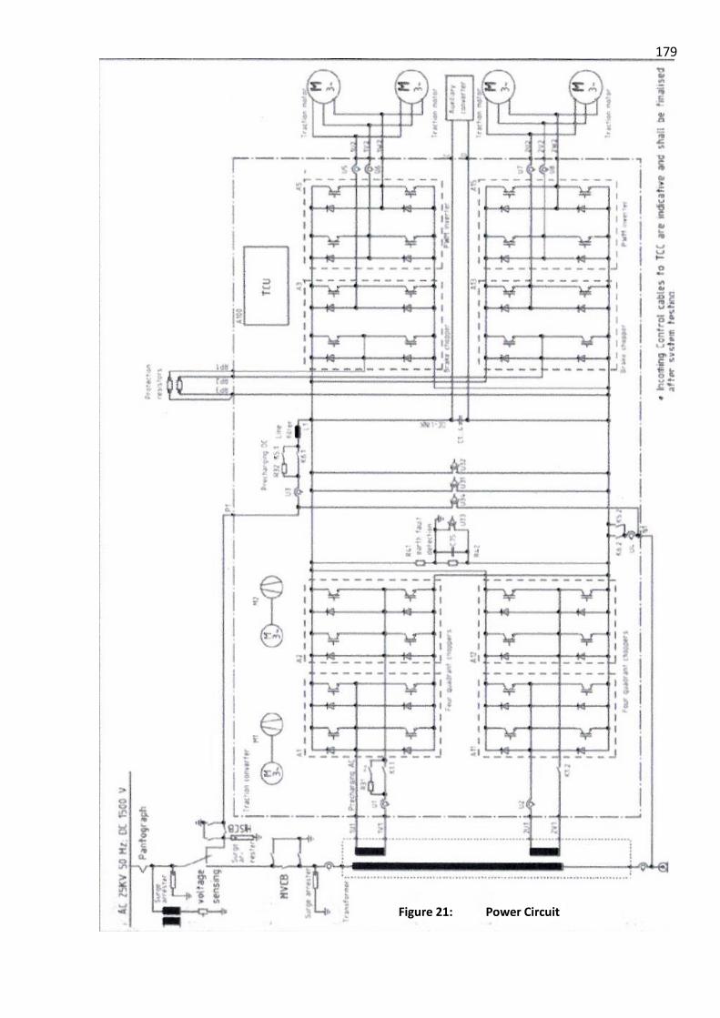
179
Figure 21: Power Circuit
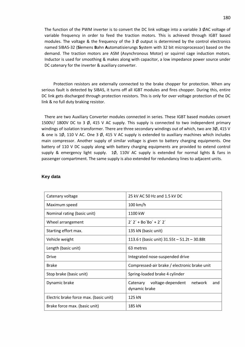
180
The function of the PWM inverter is to convert the DC link voltage into a variable 3 ØAC voltage of
variable frequency in order to feed the traction motors. This is achieved through IGBT based
modules. The voltage & the frequency of the 3 Ø output is determined by the control electronics
named SIBAS-32 (Siemens Bahn Automatisierungs System with 32 bit microprocessor) based on the
demand. The traction motors are ASM (Asynchronous Motor) or squirrel cage induction motors.
Inductor is used for smoothing & makes along with capacitor, a low impedance power source under
DC catenary for the inverter & auxiliary converter.
Protection resistors are externally connected to the brake chopper for protection. When any
serious fault is detected by SIBAS, it turns off all IGBT modules and fires chopper. During this, entire
DC link gets discharged through protection resistors. This is only for over voltage protection of the DC
link & no full duty braking resistor.
There are two Auxiliary Converter modules connected in series. These IGBT based modules convert
1500V/ 1800V DC to 3 Ø, 415 V AC supply. This supply is connected to two independent primary
windings of isolation transformer. There are three secondary windings out of which, two are 3Ø, 415 V
& one is 1Ø, 110 V AC. One 3 Ø, 415 V AC supply is extended to auxiliary machines which includes
main compressor. Another supply of similar voltage is given to battery charging equipments. One
battery of 110 V DC supply along with battery charging equipments are provided to extend control
supply & emergency light supply. 1Ø, 110V AC supply is extended for normal lights & fans in
passenger compartment. The same supply is also extended for redundancy lines to adjacent units.
Key data
Catenary voltage 25 kV AC 50 Hz and 1.5 kV DC
Maximum speed 100 km/h
Nominal rating (basic unit) 1100 kW
Wheel arrangement 2´ 2´ + Bo´Bo´ + 2´ 2´
Starting effort max. 135 kN (basic unit)
Vehicle weight 113.6 t (basic unit) 31.55t – 51.2t – 30.88t
Length (basic unit) 63 metres
Drive Integrated nose-suspended drive
Brake Compressed-air brake / electronic brake unit
Stop brake (basic unit) Spring-loaded brake 4 cylinder
Dynamic brake Catenary voltage-dependent network and
dynamic brake
Electric brake force max. (basic unit) 125 kN
Brake force max. (basic unit) 185 kN

181 PANTOGRAPH CONTROL
Compressed-air release
The compressed air for raising the pantograph is released via the key valve on the rear panel of the shunting
cab. If the key valve is closed, the pantograph cannot be raised because the air supply to the lifting cylinders
of the pantograph is blocked, irrespective of whether the solenoid valve is activated.
If the pantograph is raised and the valve is closed, the air supply line to the lifting cylinders of the
pantograph is bled and the pantograph is lowered automatically.
Control for raising the pantographs
The pantograph can be raised and lowered via a rotary switch in the driver's cab. The pre-requisite for this is
a sufficient supply of compressed air in the compressed-air reservoir. If no sufficient compressed air is
available, it is generated by the auxiliary air compressor. It is supplied by the battery.
The following conditions must be met to raise the pantograph:
* MCB switched ON
* Control voltage 110 V DC available
* Emergency stop switch not activated
* A shunting desk or driver's desk occupied / active
* Release via TCU
* Key valve open
* Release via push switch in the auxiliary air circuit
Change of driver's cab
In the case of a change of driver's cab, the pantograph may remain raised. The change of driver's cab does
not affect the pantograph control.
Lowering the pantograph
Figure: Pantograph valve
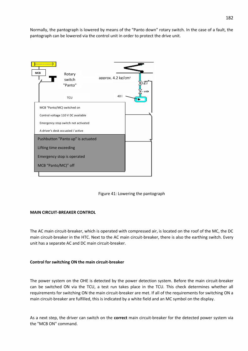
182 Normally, the pantograph is lowered by means of the "Panto down" rotary switch. In the case of a fault, the
pantograph can be lowered via the control unit in order to protect the drive unit.
Figure 41: Lowering the pantograph
MAIN CIRCUIT-BREAKER CONTROL
The AC main circuit-breaker, which is operated with compressed air, is located on the roof of the MC, the DC
main circuit-breaker in the HTC. Next to the AC main circuit-breaker, there is also the earthing switch. Every
unit has a separate AC and DC main circuit-breaker.
Control for switching ON the main circuit-breaker
The power system on the OHE is detected by the power detection system. Before the main circuit-breaker
can be switched ON via the TCU, a test run takes place in the TCU. This check determines whether all
requirements for switching ON the main circuit-breaker are met. If all of the requirements for switching ON a
main circuit-breaker are fulfilled, this is indicated by a white field and an MC symbol on the display.
As a next step, the driver can switch on the correct main circuit-breaker for the detected power system via
the "MCB ON" command.
MCB “Panto/MC) switched on
Control voltage 110 V DC available
Emergency stop switch not activated
A driver's desk occupied / active
Release via control technology
Key valve open
Release via push switch
40 l
approx. 4.2 kg/cm² Rotary
switch
"Panto"
up/down
Pushbutton "Panto up" is actuated
Lifting time exceeding
Emergency stop is operated
MCB “Panto/MC)” off
Pantograph key valve is closed
Panto down via control technology
Drop of pressure, pressure below 3.4 kg/cm²
Power system not recognised
TCU
MCB

183
In the process, the system selection switch is switched to the AC or DC position by the detected power
system. Depending on the position of the system selector switch, the corresponding main circuit-breaker is
released for connection and switched ON.
In the case of malfunctions as a result of system detection or the system selection switch, the main current
components are protected against dangerous overvoltage by means of lightning arresters.
Change of driver's cab
In the case of a change of driver's cab, the main circuit-breaker may remain switched ON. The change of
driver's cab does not affect the main circuit-breaker control.
Opening the main circuit-breaker
In the event of an emergency, the main circuit-breaker is opened via the rotary switch "MC OFF". In the case
of a fault, the main circuit-breaker can be opened via the control unit in order to protect the drive unit.
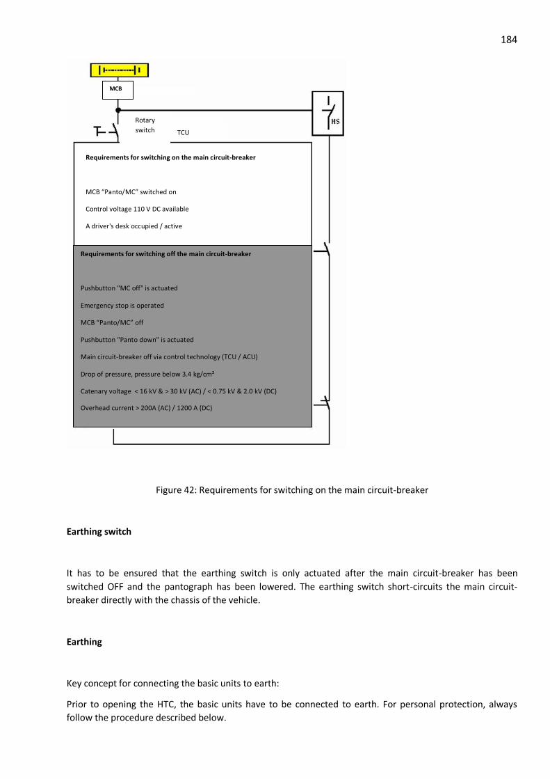
184
Figure 42: Requirements for switching on the main circuit-breaker
Earthing switch
It has to be ensured that the earthing switch is only actuated after the main circuit-breaker has been
switched OFF and the pantograph has been lowered. The earthing switch short-circuits the main circuit-
breaker directly with the chassis of the vehicle.
Earthing
Key concept for connecting the basic units to earth:
Prior to opening the HTC, the basic units have to be connected to earth. For personal protection, always
follow the procedure described below.
Requirements for switching on the main circuit-breaker
MCB “Panto/MC” switched on
Control voltage 110 V DC available
A driver's desk occupied / active
Emergency stop switch not activated
Release via control technology (ACU / TCU)
Correct position of the COS (AC / DC)
The main circuit-breaker of the other power system is switched off
Rotary
switch
MC on/off
TCU
Requirements for switching off the main circuit-breaker
Pushbutton "MC off" is actuated
Emergency stop is operated
MCB “Panto/MC” off
Pushbutton "Panto down" is actuated
Main circuit-breaker off via control technology (TCU / ACU)
Drop of pressure, pressure below 3.4 kg/cm²
Catenary voltage < 16 kV & > 30 kV (AC) / < 0.75 kV & 2.0 kV (DC)
Overhead current > 200A (AC) / 1200 A (DC)
MCB

185 Opening the door to the HTC with the green key
* Secure vehicles against un-intentional movement
* Switch OFF the main circuit-breaker
* Lower pantograph
* Remove the key for the pantograph (blue)
* Visual check ensuring that the pantograph of the unit to be
connected to earth has been lowered
* Use the blue key to connect the AC main circuit-breaker to earth and remove the yellow key
* Use the yellow key to connect the current converter and the DC main circuit-breaker and
remove the green key
* Use the green key to open the door to the HTC
Please take good care of the keys as these are the only one which fit here. To disconnect the basic units from
earth, proceed in reverse order.
Figure: Earthing switch, AC main
circuit-breaker Figure: Earthing switch, DC main
circuit-breaker
Figure: Lock to the HTC

186

187
AUXILIARY CONVERTER UNIT (ACU)
2.0 INTRODUCTION
The Auxiliary Converter Unit (ACU) contains all components needed to supply the power system load
including battery charger. The ACU is installed in the middle car (motor coach) of a basic train unit
and is designed for an input voltage of DC 1500V. It receives this from the traction link.
2.1 INSTALLATION POSITION
Every three-part basic train unit contains an Auxiliary Converter Unit. This is installed in the
HT compartment in the middle car (Motor Coach).
TC Trailer Car HT High Tension Compartment
TPC Transformer Power Car NDMC Non Driving Motor Car
2.2 SUPPLY SYSTEM
The input of the Auxiliary Converter Unit is connected to the traction link.
During AC operation of the driving train, the ACU is fed from the four quadrant regulators of the drive power converter.
During DC operation, the ACU is supplied via the input filter of the traction system from the contact line.
The rotary current output (3 phase AC 415V) of the Auxiliary Converter Unit feeds the rotary
current drives, e.g. for the primary air compressor or the components fan/blower.
The AC output (AC 110V) supplies the passenger compartment fan and the primary lighting.

188
The DC output (DC 110V) serves to charge the battery and feed the DC equipment, such as
electronic control devices, protective equipment and emergency lighting.
In normal operation, an Auxiliary Converter Unit supplies one three-part basic train unit. If
an ACU fails, the AC 110V and DC 110V equipment of the affected unit are supplied by a neighboring
unit.
2.3 COMPONENT LAYOUT IN THE CABINET
The following diagrams show the position of the major components in the Auxiliary Converter Unit.
Figure - Block diagram of one train basic unit

189 T1 Pulse-width-modulated inverter
T2 Pulse-width-modulated Inverter
T3 Battery charger
A1 Mounting plate A1 A2 Mounting plate A2
A3 Mounting plate A3 A4 Mounting plate A4
A5 Diode module A5 A6 Capacitor assembly A6
A8 Pivoting frame A8 R9 Sine filter resistor
R13 Ovp resistor R14 Ovp resistor
V6
Capacit
or
assembly Q7 Decoupling diode
Figure - Position of the power modules in the cabinet
Figure - Position of mounting plates and components in the cabinet

190
M1 Fan M2 Internal fan
M3 Internal fan R4 Line choke
R15 BC line choke R20 Air intake temperature sensor
T4 Main transformer
FUNCTIONS OF MAJOR COMPONENTS IN AUXILIARY CONVERTER UNIT
Sr.
No.
Component Designation Brief description and application in the Converter
1 PWMI Module T1,T2 These Pulse width modulated Inverter modules are
used for the basic inverter operation in the Auxiliary
converter. They are fed with DC supply and the
PWM outputs of these modules are then fed to the
transformer which connects them in series for high
DC link voltage operation.
2 Battery
Charger
Module
T3 The Battery charger is used to charge the battery in
the train. It is fed with DC voltage which is derived
form the main Transformer (3 Phase AC) through the
Battery charger rectifier and filter.
Figure - Back side of the cabinet

191
3 Master
Controller
K1 The M1300 SIBCOS Main controller is used to
control the overall operation of the Auxiliary
Converter and to take the feedback signals for fault
detection and preventive actions.
4 CAN Bus
Controller
K2 The M9000 CAN bus Communication card is used
for the communication between Auxiliary converter
and external devices.
5 Line Filter
Choke
R4 The DC Line choke is used to filter out the ripple in
the DC link voltage fed to the PWMI modules.
Sr.
No.
Component Designation Brief description and application in the Converter
6 Main
Transformer
T4 The PWM inverter Outputs are connected to the main
transformer, which has two 3 phase primary winding
and three secondary windings for 3 phase 415 volts
output, 1 phase 110 Volts output and 3 phase 500
Volts output.
7 BC Line Filter
Choke
R15 The Battery Charger filter choke is used to filter out
the DC voltage fed to the Battery charger module
after rectification from 3 phase supply from the
transformer secondary.
8 Main Blower M1 The Main blower is used for cooling of the modules
and transformer and line choke. It takes Air from the
duct and forces it on the module heatsinks, this air is
then forced on the main transformer and line choke
and goes out from bottom of the converter.
9 Aux. Blower M2, M3 The auxiliary Blowers are used for internal cooling
of
2.4 Cooling
The Auxiliary Converter Unit is forced-air cooled.
The cabinet contains one main fan and two internal fans.
2.4.1 External air flow
The Auxiliary Converter Unit receives its cooling air
from the auxiliary operator console. The cooling air is drawn in
via an intake air grate on the top of the cabinet.
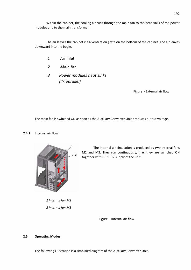
192
Within the cabinet, the cooling air runs through the main fan to the heat sinks of the power
modules and to the main transformer.
The air leaves the cabinet via a ventilation grate on the bottom of the cabinet. The air leaves
downward into the bogie.
The main fan is switched ON as soon as the Auxiliary Converter Unit produces output voltage.
2.4.2 Internal air flow
The internal air circulation is produced by two internal fans
M2 and M3. They run continuously, i. e. they are switched ON
together with DC 110V supply of the unit.
1 Internal fan M2
2 Internal fan M3
2.5 Operating Modes
The following illustration is a simplified diagram of the Auxiliary Converter Unit.
Figure - External air flow
Figure - Internal air flow
1 Air inlet
2 Main fan
3 Power modules heat sinks
(4x parallel)
4 Main transformer
5 Air outlet

193

194 CKT DIAGRAM
2.5.1 Normal Operation
The Auxiliary Converter Unit is fed via the traction converter link. The nominal link voltage is
DC 1500V.
The prerequisites for operation of the Auxiliary Converter Unit are:
The ACU receives the activation signal from the vehicle control.
The input voltage lies within the valid range (see para 2.10.5.1).
No errors occur in the ACU.
If the activation conditions are met, the DC input voltage is fed to the PWMI modules via the
input fuses A2-F1 / A2-F2, the line choke R4 and the input diode A5-Q1. The two PWMI modules
connected in series are switched ON and started up. If the voltage at the PWMI output is in the
specified range, the output fuses A1-Q2 / A1-Q3 are closed. The ACU control sends a message to the
vehicle control that the 3phase AC output is ready for operation. Then the battery charger is
switched ON and a message is sent to the vehicle control.
The AC 110V and 3 phase AC 415V output is fed via the main transformer T4, sinus filter,
EMV filter and output fuses behind the PWMI modules.
EM
I
EMI
Battery
Output
Q-5 Battery Main Contactor
EMI

195
The battery charger operated via the main transformer and the battery charger input
rectifier A5-Q10 generates a DC 110V voltage at the output and supplies the DC 110V rail of the train
unit and charges the train battery with this.
Battery charging characteristic
The batteries used in the train are Lead acid batteries with a nominal voltage of DC 110V.
The load program corresponds to a IU-characteristic.
• Maximum device current: 82A
• Maximum battery charging current: I5=30A
• Charging voltage: U1= 115V
The battery is charged with the maximum battery charging current of I5=18A until U1=110V
is achieved. Then the charge continues with a constant charging voltage U1 (with decreasing
charging current).
2.6 Operating the Auxiliary Converter Unit
2.6.1 Switching-ON in Normal Operating
Special operation of the Auxiliary Converter Unit is not necessary. The ACU
automatically switches ON when
High voltage is present at the traction link,
The activation signal from the train signal is sent and
No error exists on the ACU.
2.6.2 Switching-off in Normal Operating
The Auxiliary Converter Unit automatically switches OFF itself when the activation signal is
withdrawn by the vehicle control.

196 2.7 Electrical Data
2.7.1 Input DC 1500V
Requirements Values Comments
Nominal input voltage 1500 V DC mode
1800 V AC mode
Voltage range, stationary 1000 - 1800 V DC mode
1700 - 1800 V AC mode
Short time minimum 800 V DC mode
Occasional maximum 2000 V DC mode
2100 V AC mode
Ripple 4% DC mode
+/- 135 V AC mode
2.7.2 Three Phase AC 415V 50Hz Output
One secondary of auxiliary converter having 3 Ø AC, 415V, 50 Hz (121A/ 87 kVA) supply is used
for Main compressor & other auxiliaries.
Output frequency 50 Hz ± 1 %
Output voltage 415 V AC, 3-phase
Static tolerance of output voltage ± 5 %
Dynamic tolerance of output voltage ± 15 %
Max. voltage rise of output voltage < 10 V/s
Total harmonic distortion < 10 %
Output filter EMC filter/ sinusoidal filter, isolation
transformer
Output nominal power: 87 kVA
at Cos = 0.85
Unsymmetrical load: ≤ 10 % of nominal power
2.7.3 Single Phase 110V AC 50 Hz Output

197
One secondary of auxiliary converter having 1Ø AC, 110V (20 kVA) supply is used for
light & fans in the passenger compartment. One tapping is taken out for redundancy lines of
supply for adjacent units.
Output frequency 50 Hz ± 1 %
Output voltage: 110 VAC, 1-phase
Static tolerance of output voltage: ± 10 %
Dynamic tolerance of output voltage: ± 15 %
Max. voltage rise of the output voltage: < 10 V/s
Total harmonic distortion: < 10 %
Output filter: EMC filter / sinusoidal filter, isolation
transformer
Output nominal power: 20 kVA at cos = 0.89
2.7.4 DC 110 V Output
One secondary of auxiliary converter having 3 Ø AC supply for battery charging
equipments is used. Battery having 110 V DC supply is connected across this battery charging
equipments to charge continuously. This 110 V DC supply is used for control supply as well as
for emergency light supply when normal light & fan supply of 110 V AC is failed due to any
reason.
Output Voltage 110 V DC ( Pay attention to battery charging
characteristic)
Static tolerance of output voltage: +20%, -30 %
Output nominal power 9 kW At nominal output voltage
Max. output current (continuous) 82 A
Control precision of battery voltage: ± 1.5 % At voltage detection point.
(Detection point = battery charger
output)
Control precision of the current
limiter:
± 5 %
Ripple on output voltage: ≤1 % RMS At Nominal output voltage
Output filter: EMC filter
2.8 SAFETY REGULATIONS FOR WORK ON THE ACU
Whenever working on the cabinet the following five operations must be completed.
1. De-energize the ACU
De-energize the Auxiliary Converter Unit according to the instructions of the person responsible for the train.

198
Then switch OFF the battery power. You can only disconnect the connection between the battery charger and car battery by pulling the battery plug or by removing the car battery fuse.
Switch off the master control SIBCOS-M1300 by interrupting the DC 110V supply. To do this, pull the plug "X040" from the control.
2. Ensure ACU cannot be switched ON again
Ensure power cannot be switched ON again and pantographs cannot be raised.
Mark points that have been switched to voltage free with a warning sign.

199 3. Check that the installation is dead on both parts of ACU
Measure the absence of voltage at the following points. The measured voltage should not be more than 60V.
DC 1500V
Component Measuring points
Spherical grounding electrode -E1
-E2
-E3
DC 650V (Input to battery charger)
Component Measuring points
Battery charger T3 T3: -X4 (+650V)
T3: -X5 (0V)
DC 110V (Output to battery charger)
Component Measuring points
Battery charger T3 T3: -X3:1 (0V)
T3: -X3:2 / -X3:3 (+110V)
4. Ground and short-circuit the ACU
Short-circuit the spherical grounding electrodes E1, E2 and E3 (refer to Figure 1)
using a suitable ground short-circuiting kit in order to ground and short-circuit the DC link of
the ACU.
NOTE
Use a three-terminal grounding and short circuit device (with short-circuit ropes and earthing cable) for ball fixed-points Ø20mm.
Note the correct order. First connect E3 to the grounding / short circuit device, then E1 and E2.

200
5. Cover or isolate parts
After opening the hatches, cover or isolate parts nearby that are live.
TRCTION CONVERTER CUBICLE
TRACTION CONVERTER CUBICAL
The traction converter cubicle is a completely assembled unit installed in the HT compartment of the
motor coach. The traction control unit (TCU) is situated inside the cabinet. The technical details are as
following:
Nominal input voltage 2 x 950 V AC, 50 Hz / 1500V DC
Input voltage range in AC mode 627 V – 1083 V AC
Which is related to a line voltage from
16.5 – 28.5 kV
Input frequency range in AC mode 46Hz – 54 Hz
Input voltage range in DC mode 800 V – 1800 V DC
Nominal DC link circuit voltage
traction operation
AC Mode 1800 V
DC Mode 1500 V
Power factor in AC at different loads
and line voltages
Approx. unity
Figure 1 – Position of the spherical grounding electrodes in the cabinet
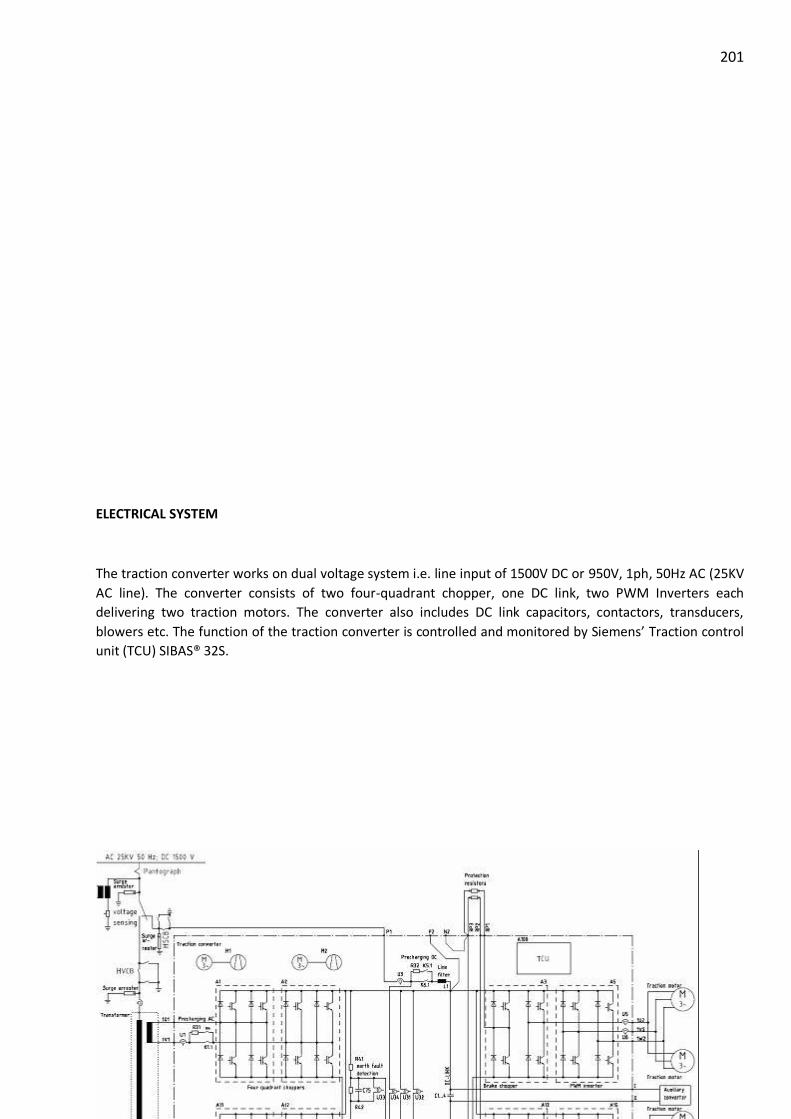
201
ELECTRICAL SYSTEM
The traction converter works on dual voltage system i.e. line input of 1500V DC or 950V, 1ph, 50Hz AC (25KV
AC line). The converter consists of two four-quadrant chopper, one DC link, two PWM Inverters each
delivering two traction motors. The converter also includes DC link capacitors, contactors, transducers,
blowers etc. The function of the traction converter is controlled and monitored by Siemens’ Traction control
unit (TCU) SIBAS® 32S.

202
Functional sections of the traction converter in AC Mode
The traction converter consists of the following functional sections in the AC Mode operation:
• Input and pre-charging
• Four-quadrant chopper
• DC link circuit
• Capacitive earth-fault registration
• Pulse width modulated inverter & Braking chopper
Schematic of the converter

203
Input section in AC mode of operation

204 Input and pre-charging
Refer to Figure for the schematic of the functional input section in AC Mode. Two poles (K1.1 and K1.2) of a
double pole contactor (K1) isolate the transformer and 4QC module from each traction winding of the
transformer. A pre-charging unit is connected in parallel to this main contactor. The pre-charging unit
consists of a single pole pre-charging contactor (K4), One pole K4.1 connected in series with a pre-charging
resistor (R31). The pre-charging resistor comprises of two resistors R31.1 and R31.2 in parallel.
When the converter is put into operation, first the DC link capacitor of the inverter is pre-charged before the
main contactor is closed using diodes in 4QC modules. This prevents the high inrush current, which would
result if the input voltage was suddenly switched onto the empty converter. The main contactor is switched
on after the DC link voltage has reached 90 % of the theoretical final charge.
Four Quadrant Chopper Module (4 QC)
A four-quadrant chopper consists of a bridge as shown below in Figure. The purpose of the 4QC is to
transform the input voltage (generally single phase AC from the transformer) into a controlled direct
voltage for the DC link circuit. The term 4QC signifies that the phase angle between voltage and
current is freely adjustable while driving as well as while braking. Through the combination of phase
situation and mode of operation all four operational quadrants can be obtained.
The IGBT’s are used as switches with a high closing sequence. The function is described
exemplarily for rectifier-operation starting from a current less situation. To build up a current in the
self-inductance of the transformer LN one of the two IGBT’s A2 or A3 (positive half-wave, A1 or A4 at
the negative half-wave) is triggered. During this the secondary side of the transformer is short
circuited. As soon as the current has reached the desired value the IGBT is blocked. The current
continues to flow via the freewheeling diode into the DC link circuit and is reduced by this (UD UN).
Afterwards the process starts again and during it the IGBT’s are used alternately to put equal thermal
burdens on them.
Number of 4 QC per Traction
Converter Cubical (TCC)
2
Semiconductor IGBT
Type of phase module SIBAC BB S P 1500 FL
Pulse frequency 750 Hz

205
Pulse Width Modulated Inverter
The IGBT’s can be essentially defined as basic switches with a high clock frequency. This means
it is possible to connect 3 output terminals U, V, W as required to the + or of the voltage DC link Cd.
The switching sequences are selected so that a sinusoidal current is obtained. The voltages between
two output terminals are now observed. The maximum possible amplitude of the phase to phase
output voltage is a function of the magnitude of the DC link voltage Ud.
The RMS value of the output voltage can be reduced by clocking. This clocking comprises brief
turn-off operations within a basic fundamental. The frequency, with which the output waveform is
repeated, is the same as the PWM inverter output frequency.
When braking, the motor torque direction opposes the direction of rotation. There is
considerable phase shift between the voltage and current. By entering the basic fundamental, the
PWM inverter adjusts the phase between the voltage and current.

206
Figure: Pulse Width Modulated Inverter
Number of PWMI per TCC 2
Number of traction motors
per PWMI
2
Semiconductor IGBT
Type of phase module SIBAC BB S P 1500 FL
Pulse frequency Variable, up to 800Hz
Brake Chopper
Protection resistors are externally connected to the brake chopper for protection. When
any serious fault is detected by SIBAS, it turns off all IGBT modules and fires chopper. During
this, entire DC link gets discharged through protection resistors. This is only for over voltage
protection of the DC link & no full duty braking resistor.
Number per TCC
(per PWM inverter a double module (PWM inverter,
brake chopper)
2
Semiconductor IGBT
Type of phase module SIBAC BB S P 1500 FL
Pulse frequency 250 Hz
Capacity of DC link circuit 12 mF -0 % 10 %
Inductance of line reactor 6 mH -0 % to10 %
Control Voltage
Control voltage range
Max operating current at nominal voltage
110 V DC
77 V to 137.5 V DC, 10 Amp.
Auxiliary supply voltage
Continuous power demand
3AC, 415V, 50Hz
approx. 6.2 kW
Power rating

207
Parameter Continuous
rating
Short time rating
(2 min)
Input Power per 4QC 620 kW 720 kW
Input Current per 4QC 764 A 903 kW
Output Power per PWMI ( AC & DC) 535 kW 630 kW
Output Current
per PWMI
AC 322 A 371 A
DC 400 A 446 A
Out put voltage
(L-L)
AC 1217 V 1217 V
DC 986 V 1024 V
Capacity of DC link circuit : 12 mF -0 % +10% ( 4 X 3 mF)
Inductance of line reactor: 6 mH 0 % to +10 %
Air Flow: 1.9 m3/s ( 0.95 m3/s per blower)
Air Flow required: 1.6 m3/s

208
Forced Ventilation
Traction Converter Cabinet is a forced air-cooled system. The airflow direction is shown in
figure given below.
Fig. Principle of forced ventilation

209 List of Components
Type Number Description Functional
Unit
Designation
in cabinet
Quantity
per TCC
Part no
SP1500FL IGBT Module –
Single Parallel
4 Quadrant
Choppers
A1, A2, A11,A12 4 A5E00281205
SD1500FL IGBT Module –
Double
PWM
Inverters
A3, A5, A13,A15 4 A5E00281211
4PK9904-7AB Line Filter
Choke
DC Line L1 1 A5E00465421
LTHS-1250-2P Line Contactor
DC
DC Main-
/Line-
Contactor
K6 1 A5E00422750
LTHS-800-2P Line Contactor
AC
AC Main-
/Line-
Contactor
K1 1 A5E00307978
LTC-250-2P Pre-charging
Contactor DC
DC –
Precharging
Circuit
K5 1 1012253
LTC-250-1P Pre-charging
Contactor AC
AC Pre-
charging
Circuit
K4 1 A5E00406971
2CS7-410-
1RG11-0KK3
Main Blower Main blowers
for cooling
M1, M2 2 A5E00296015
148DH9LM
18230
Auxiliary
Blower
Auxiliary
blowers for
churning air
M11, M12,M13 3 1000263
DCMKP 2.2/
3mF or
E56.M45-
305680
DC Link
Capacitor
DC Link C1, C2, C3,C4 4 A5E00374704
P354.1-IGBT DC/DC Power
Supply
IGBT Driver
card power
supply
A91, A92 2 A5E00296016
CS1000BRVE or
LTC600-SFC-
SPxx
Current
Transducers
AC/ DC Input
output
currents
U1, U2, U3, U4, U5,
U6,U7, U8
8 A5E00307975
A5E00303286 Voltage
Transducers
DC Voltage
monitoring
U31, U32,U33, U34 4 A5E00303286
TV 1164 (CT) Intermediate
Transformer
Current
System
current
monitoring
T4, T5 2 A5E00422663

210
Type Number Description Functional
Unit
Designation
in cabinet
Quantity
per TCC
Part no
TV 1162 (VT) Intermediate
Transformer
Voltage
System
Voltage
monitoring
T3 1 A5E00422668
BNV 05.110.d/
0.5 X2
SIBAS Filter SIBAS Power
Supply Filter
Z1 1 621961
31138210 Temperature
Sensor – Air
Inlet
Air Inlet
Temperature
B1 1 279729
PVR900T or
GBS 60/370
60R +/-5%
Pre-charging
Resistor
AC/ DC Pre
charging
Circuit
R31.1,R31.2,R
32.1,R32.2
4 A5E00422669
PVR160 or
GWS 300 SB
33K +/-5%
Discharge
Resistor DC
Link
Discharge
and Earth
Fault
Detection
R42 1 A5E00422670
PVR160 or
GWS 300 SB
99K +/-5%
Discharge
Resistor DC
Link
Discharge
and Earth
Fault
Detection
R41 1 A5E00422672
B25835-
S2224-K057
Grounding
Capacitor
DC Link
Discharge
and Earth
Fault
Detection
C75 1 A5E00122720
3RT10172KF4
20LA0
Contactors
forBlower
Blower
Circuit
K92, K95 2 1012617
3RH11222KF4
00LA0
Auxiliary
Contactors
Auxiliary
Circuit
K51-K53 3 1010736
6FH4742-1A SIBAS 32 S Traction
Control Unit
A100 1 A5E00299514
343434 EMC capacitor DC link
circuit
C71 1 343434
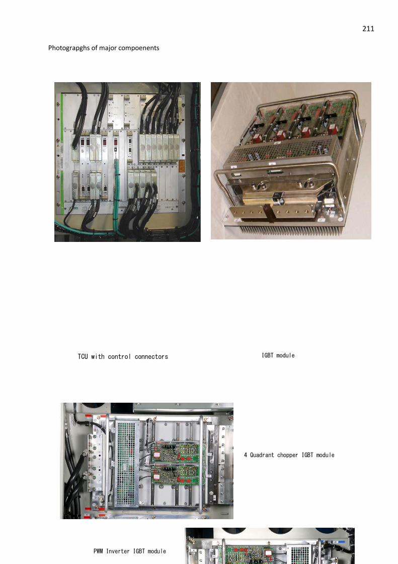
211 Photograpghs of major compoenents
TCU with control connectors
IGBT module
4 Quadrant chopper IGBT module
PWM Inverter IGBT module

212
Position of K1 and K6 contactor
Assembly of C1 and C2 seen from
contactor side of cabinet
Assembly of C3 and C4
seen from SIBAS side of
cabinet
Fig. showing location of main blowers

213
Main blower motor cable connectors
Current transducers with bus bar
Auxiliary transducer
Auxiliary contactors

214
Pre-charging resistor plate
assembly
Auxiliary blowers

215
TRACTION MOTOR
TRACTION MOTOR
Four number of traction motors are provided in one motor coach. Two pairs of traction motors
are connected across two different PWM inverters.
TECHNICAL DETAILS
Type Designation : 1TB2022-0TA03
Make : M/s Siemens
Electrical data
Number of Poles : 6
Specific Electric Loading : 476 A/cm
Flux Density in Air Gap : 0.8 T
Flux Density in Stator Yoke : 1.0 T
Flux Density in Rotor Yoke : 0.75 T
Thermal Class : 200
Connection : Star
Supply cable : 1 x 35 mm2 per phase
Mechanical Data
Air gap: : 1.5 mm
Air ventilation: : 0.25 m2/s

216
Stator bore dia: : 325 mm
Rotor diameter: : 322 mm
Length of the core : 350 mm
Maximum rating
Max. Motor speed (fully worn wheel) : 3452 rpm
Max. torque (new wheel) : 2903 Nm
Max. Power (at tractive effort curve) : 84 kW
Gear ratio
: 5.71 (97 teeth gear wheel / 17 teeth
pinion)
Torque Fundamental
motor current
Cos Φ
(Power Factor)
Efficiency
DC-Mode 1147 Nm 167 A 0.81 95 %
AC-Mode 1147 Nm 150 A 0.79 95 %
Ratings
Parameter Continuous Operation One Hour Rating Two Minute Rating
Voltage 932 V 993 V 1043 V
Current 200A 211A 223A
Power 240 kW 270 kW 300 kW
Power Factor 0.79 0.79 0.79
Frequency 101.5 Hz 101.5 Hz 101.5 Hz
Speed 2000 rpm 2000 rpm 2000 rpm
Torque 1147 Nm 1290 Nm 1434 Nm
Efficiency 94% 93.5% 93.5%
Maximum Starting Current (0 to 950 rpm up to 14 seconds):
New wheel : 276A
Half worn wheel : 267 A
Motor Bearings:
DE : Cylindrical-Roller Bearing F-809035.01.NU-J20AA
Oil Lubricated/ Electrically Insulated)

217
Make : FAG
Lubrication oil : Gear Oil
Min qty required : 10 mm3/h
NDE : Deep Groove Ball Bearing
DIN 43283-6316.808916.J20AA
(Grease Lubricated/ Electrically Insulated)
Make : FAG
Bearing Grease : Shell RetinaxLX2
Motor Suspension Unit (Nose-Suspension) Bearings:
DE : Tapered Roller Bearing 566566.J20AA
(Grease Lubricated/ Electrically Insulated)
Make : FAG
Bearing Grease : Shell RetinaxLX2
NDE : Tapered Roller Bearing 809055.J20AA (with flange)
(Grease Lubricated/ Electrically Insulated)
Make : FAG
Bearing Grease : Shell RetinaxLX2
Gear& Pinion:
Make : M/s Flender
Type: Single slant toothed spur gear
2LB6095-3AA57
Material of pinion and gearwheel : 17rNiMo6
Material of gear case : casting material GGG40
Gear Ratio : 97/17
Gear Oil : Shell Spirax AX 80W-90 or A 85W-145
Maintenance Check List:
Stator Resistance : 85.35 mΩ + 5% at 20° C
With 10 A DC
Insulation Resistance : 2 MΩ with 500 V DC (Used)
10 MΩ with 500 V DC (commissioning)

218 High Voltage Test : 2100 V(AC 50/60 Hz) /1 min (Used)
3680 V(AC 50/60 Hz) /5sec (commissioning)
Oil Level:
Initial Quantity Refilling Quantity
Motor NDE Bearing 0.15 kg/Bearing 26 g/Bearing
Nose Suspension Bearing 1.2 Kg/Bearing 300 g/Bearing
Gear Oil 2.8 litre (approx) 2.5 litre (approx)

219 Earth Return Brush
Make : M/s Shunk metal and Carbon (India ) Pvt. Ltd.
Type : B 1726 10
No of working brushes : 2
No of safety brushes : 2
Brush Measurement : 20x40x55mm
Brush grade : BSQR
Nominal Brush pressure : 300 cN/cm2 (4.35 PSI)
Continuous load :
Effective working current: : 520 A (with 2 brushes)
Max. short term overload:
1 hour load(1.5 x) : 780 A
100 ms Load (15 x) : 5200A
Average brush wear : 3.5 mm/1,00,000 km
Wear Height : 33mm

220

221
TRACTION TRANSFORMER
TRACTION TRANSFORMER
The transformer is designed for a nominal rating of 1250 kVA. It consists of a primary
winding and 2 secondary windings. Therefore, 625 kVA is available at each secondary. This
corresponds to a secondary side nominal current of 731 A at a secondary voltage of 855 Volt (22.5
kV mains voltage). The transformer is cooled with a total of 530 litres of oil.
TECHNICAL DATA
Manufacturer : ABB Secheron SA
Type : LOT1250, Oil Immersed transformer
Identification No : XCH000000-AUC
Nominal Line Voltage : 25 kV (19 to 27.5 kV)
Line voltage min (2s < t < 10min) : 16.5 kV
Line Voltage max (2s < t < 5 min) : 30 kV
Traction Transformer Fitted Under Slung

222
Frequency : 50 Hz (46 to 54 Hz)
Installation point : Under slung
Dimensions (length x width x height) : App. 2800 x 2000 x 850 mm
Total weight, including oil : App. 3.3 t
Cooling : ODAF- mineral oil cooled
Installation point : Under slung
Technical data Primary Side
Rated power : 1250 kVA
Nominal primary Voltage : 22.5 kV
Rated current voltage : 58 A at 22.5 kV
Technical data Traction Winding
Number : 2
Rated power : 625 kVA
Secondary Voltage : 855 V
Standard current per winding : 731 A at 855 V (prim. 22.5 kV)
Leakage inductance : 1.465 mH 10% related to the secondary
Transformation ratio : 26.32: 1
Resistance : 50 m - Related to secondary side
Magnetisation Current : 0.17 A ± 30% , Under 22.5 kV
Efficiency : 96%
Cooling surface area : 4.37 m2
Turns Ratio : 26.294
Total Oil Volume at 20° C : 560 dm3
Winding Details
HV Winding Traction Winding
No of windings 1 2
Conductor Material Copper Copper
No of parallel conductors 1 per HV Coil associate to
traction winding, 2 Coils in
parallel
2 on each traction winding
Total X-section 8.74 mm2 128.35 mm2
Rated current at 22.5 kV 55.55 A 731 A
Current Density 6.4 A/ mm2 5.69 A/ mm2
Number of layers 18 layer winding 6 layer winding

223
Winding Resistance (DC) at 85° C 9.135Ω 15.4 mΩ
No of Turns 2682 102

224 MAJOR COMPONENTS OF TRANFORMER

225
i. Transformer oil pump
Flow-well Oil Pump for transformer is glandless Mono-bloc Centrifugal type suitable for circulating the oil. The pump has inline suction and delivery flanges. The pump-set is driven by 3 Phase, 50 Hz, 415 V AC supply.
General specifications:
Motor H.P. 3
Discharge in LPM 700
Total Head in Meters 10.8 Mtrs (0.9 bar)
Speed 2850 RPM
Class of Insulation `H'
Suction X Delivery 80 x 80 mm
Total Weight 39 Kgs.
Type 1530
Fabricant FLOWWELL PUMPS & METERS
ii. Air Dryer (Breather)
The transformer is equipped with two air driers. One is to dry the air in the oil expansion tank. The second one (smaller) is to dry the air in the bushing box.
The upper and lower parts of air drier consist of compact casting in aluminium alloy and the transparent hose, which contains the salts (Silica-gel) and it is protected by a stainless steel cylinder drilled in such a way as to allow the visual control of salts.
The air sucked into the transformer (due to thermal contractions of oil mass) passes through these drier.
In the lower part there is a closing system which prevents the contact between air and salts. This closing system allows the air passage in the two directions (inlet and outlet) only when there is a pressure difference between the inside and the outside of the transformer.

226 Silica-gel air dries are transparent tanks of salts of silicon chemically pure, with cobalt indicator or without cobalt. Silicagel has the purpose to absorb the air humidity signaling the reached degree of saturation by change of colour:
With cobalt Without cobalt
BLUE = completely dry ORANGE = completely dry
PINK = =completely saturated COLORLESS = completely saturated
The salts contained in the dehumidifier can be taken off and regenerated by heating them at 120-150°C until they get their original colour again. When more than the half of silicagel is became pink (or colorless) (water satured) it has to be fully changed or regenerated.
iii. Heat Exchanger (Radiator)
The aim of the cooling system is to transfer
the electrical losses created within the
transformer to the outside air. Two fans
provide the necessary airflow to cool down
the circulating oil through the cooler. The
oil is pushed through the cooler by the
circulating pump.
iv. High Voltage Bushing ( HT terminal)
The main insulation of the HV bushing, Elastimold 750 S, 18/30kV is a core of solid insulation with condenser layers for field control. The plug is particularly characterized by its space saving construction and simple assembly and disassembly.
The external cone of execution for the plug connection is always protected by a cap when the plug is not attached.
Before the HV plug is connected, the cone of bushing must be cleaned. No foreign bodies may be gotten jammed. While the plug is connected, it should make certain that no air is included.

227
v. Earth Terminal
vi. Butterfly Valves (Drain & Filling cock)
This valve is built with a aluminium casing. Sealing is realized with NBR gasket. The valve is equipped with a locking plate that indicated also the position (open or close). To operate the valve use a 19mm wrench. To lock the valve use M6 bolt or cadenas diameter 6 mm.
Ball valve
The ball valve is built in stainless steel with PTFE gasket. It is fixed by 4 screws M10 to
the tank. The exit is closed by a 1"1/4 plug. The operating arm is fixed to the tank to
insure the closed position
vii. Marshaling Box (Low voltage terminal)
The connection box is IP67 box equipped with IP 68 cable gland. All electrical devices are connected in the connection box to terminal blocks.
ADO terminal block provided to avoid wire
stripping and to have good safety and reliability. The
main point for ABB terminal blocks are:
• Elimination of conductor preparation risks
• No retightening
• Vibration resistant
• Corrosion resistant
• A tool which guarantees a safe connection

228
• Procedures simplification
viii. Name Plate
ix. Suspension Arrangement
The transformer is fixed under the coach body using rubber dampers. The rubber dampers are mounted to the transformer suspension arms by ABB Rubber dampers are chosen for their properties to limit the transmission of vibration from the transformer to the coach body and to absorb part of choc that coach body can transmit to the transformer. The arrangement also allows compensate flatness default,
x. Bellow (Flexible Coupling)
Bellow made from ductile metallic materials allows misalignment and thermal expansion of

229 piping. The basic element, which is a thin-walled cylindrical tube, is formed into parallel corrugations with hydraulic or mechanical pressure.
The bellows are protected against object projection (stones etc.) with stainless plates
placed in the exposed side around the bellows.
xi. Thermometer Sensor
The thermometer sensor is composed of 2
platinum resistance thermometers PT100.
The sensor is placed in oil. The thermometer
sensor is used to measure the oil temperature
in the transformer.
The sensor is screwed in a pocket, and it is possible to change the sensor without oil draining. For a good heat transmission, the pocket is filled with oil. Enough space is keep free of oil to allow dilatation.
xii. Pressure Relief Valve
The pressure relief valve (or over pressure valve) limit the
pressure in the transformer tank. The valve open when the
pressure over-pass 0.8 bar.
When the valve operates it causes a central rod to protrude from the protective casing commuting immediately the switch and giving an electrical and visual signal. When the over-pressure falls down, a spring closes the valve. But the signal returns to its initial position only by manually pushing inwards.
xiii. Oil Level Indicator
The oil level indicator is located at the expansion tank. The indicator shows the height of the oil level. The minimum and maximum Oil levels are displayed and also the oil level when the oil is 30°C.
The transformer is filled 100% with oil. The expansion of the oil is taken up by the expansion tank, which is connected to the transformer. The expansion tank is installed on the side of the transformer.
The min. mark is corresponding to an oil temperature of -20°C and max. mark is
corresponding to an oil temperature of +120°C.

230
Oi1 level detector
The oil level detector measures minimum level in the expansion tank using floats. If the oil level becomes too low, the oil level detector switches and the transformer has to de-energized.
Oi1 flow sensor
The flow sensor detects a minimum oil flow. A paddle moves related to flow volume and actuates a micro-switch.
New Oil Characteristics:
Requested Value Typical Value
Density at 20° C 1.0 kg/dm3(Max) 0.876 kg/dm3
Kinematic Viscosity at 40 35 mm2/s (Max) 7.6 mm2/s
Flash Point Min 250° C 144° C
Pour Point Max -45° C -63° C
Water content Max 200 mg/kg < 20 mg/kg
Neutralisation Value Max 0.03 mg KOH/g < 0.01 mg KOH/g
Total Acidity Max 0.3 mg KOH/g 0.04 mg KOH/g
Total Sludge Max 0.05 %/mass < 0.02 %/mass
Break Down voltage Min 45 kV 40-60 kV
>70 kv after treatment
Dissipation Factor at 90° C, 50 Hz Max 0.03 < 0.001
DC Resistivity at 90° C Min 2 G Ωm 5 G Ωm
Dissolved Gas Analysis:
Sr. No Gas Limit value in ppm ( Max)
1 CO2 12000
2 CO 1000
3 H2 400
4 CH4 (Methane) 200
5 C2H6 (Ethane) 200
6 C2H4(Ethylene) 300
7 C2H2(Acetylene) 30

231 TRANSFORMER OIL COOLING CIRCUIT
Figure: Cooling circuit diagram
Cooling System:
Make :
Type : Aluminium Plate Exchanger
Oil Volume : 20 litre
Case : Steel
Thermal data :
Air inlet Temperature : 50° C
Air outlet Temperature: 77.7° C
Oil inlet Temperature : 85° C
Oil outlet Temperature: 81.9° C
Oil flow : 655 lpm
Fan Data:
Numbers: 2
Transformer
Heat exchanger
Oil
pump

232 Type: Entry from Front,
Exit to the bottom.
Power consumption at rated capacity: 2 X 2.2 kVA (3.2 A)
Motor Data:
Make: ABB
Type: HX100 LB1004/2
Voltage: 3 Phase, 415 V
Low Speed High Speed
Starting Current/ Torque 450%/160% (4P) 600%/200% (2P)
Continuous Rating 0.4 kW 1.6 kW
Speed 1405 2825
Power Factor/ Slip 0.83/6.3% 0.92/5.8%
Monitoring System
Equipment Type Make Limit
Pressure Relief Valve T3(DN80) Sukrut 0.8 bar
Thermometer sensor Double PT100 Altop
Oil Level Indicator Float arm Sukrut
Oil Level Detector Nivofix RW1016PVK Honsberg (EU)
Oil Flow Detector UB1025HM Honsberg (EU)
Current Transformer Siemens
Maintenance Check List:
1. DGA : As specified above
2. Winding Resistance :
HV Winding : 9.135Ω
TR Winding : 15.4 mΩ

233
3. Insulation resistance :
Voltage Time Admissible Value at 20 ° C
1000V 30 seconds > 100 MΩ
60 seconds > 150 MΩ
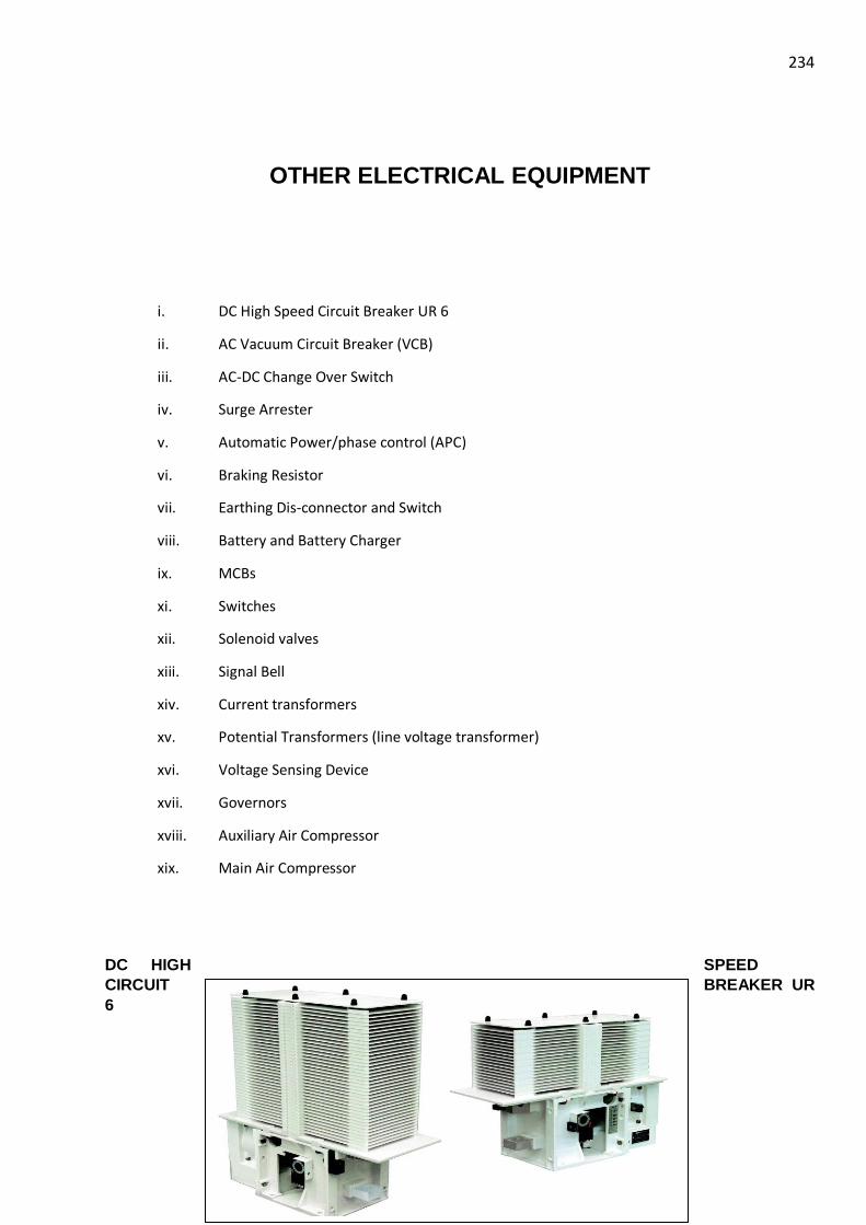
234
OTHER ELECTRICAL EQUIPMENT
i. DC High Speed Circuit Breaker UR 6
ii. AC Vacuum Circuit Breaker (VCB)
iii. AC-DC Change Over Switch
iv. Surge Arrester
v. Automatic Power/phase control (APC)
vi. Braking Resistor
vii. Earthing Dis-connector and Switch
viii. Battery and Battery Charger
ix. MCBs
xi. Switches
xii. Solenoid valves
xiii. Signal Bell
xiv. Current transformers
xv. Potential Transformers (line voltage transformer)
xvi. Voltage Sensing Device
xvii. Governors
xviii. Auxiliary Air Compressor
xix. Main Air Compressor
DC HIGH SPEED
CIRCUIT BREAKER UR
6

235
The UR 6 circuit-breaker is a air cooled DC high-speed current-limiting circuit-breaker. It has
been designed to ensure a trip free, rapid opening of its main contact, on detection of a short circuit,
and to quickly extinguish the arc by generating a constant over-voltage during the whole
interruption process.
The circuit-breaker is made of independent mounted sub-assemblies, corresponding to the
different functions.
1. Fixed insulating frame made of glass-fibre reinforced insulating material.
2. Main circuit, consisting of a lower connection terminal, a moving contact, an upper
connection terminal, a fixed contact with horn (24) and another horn.
3. Over-current release.
4. Arc chute.
5. Closing device and fork.
6. Auxiliary contacts assembly.
Because of its short response time following the detection of an excess current (short-circuit,
over-load detection..), it is particularly suitable for the protection of the electrical equipment in
rolling stock used on DC lines.
Make M/s Secheron
Type U6.32
Rated operational voltage 1800 V
Rated insulation voltage 2000 V

236
Rated operational current 1000 A
Conventional free air thermal current (at Temp. = 40°C) 1000 A
Rated short-circuit breaking and making capacity Iss/T
Rated time constant T1 NA
Rated time constant T2 30 kA/15 ms
Rated time constant T3 30 kA/40 ms
Rated time constant T4 30 kA/100 ms
Direct over-current release 0.45 - 0.9 kA
0.6 - 1.2 kA
0.9 - 1.8 kA
1.2 - 2.4 kA
1.5 - 3.2 kA
Maximum arc voltage 1.5 - 2.1 Ue

237 AC VACUUM CIRCUIT BREAKER (VCB)
Technical Data
Make: M/s Autometers alliance Ltd
Type: VCBA25.10Tr
Maximum rated voltage 30kV
Nominal rated voltage AC (1-Ø) 25kV
Power frequency withstand voltage
(dry & wet) 75 kVrms
Lightning impulse withstand voltage 175 kVrms
Rated current 1000Arms
System frequency 50 Hz
Short circuit rupturing capacity 16kArms (440MVA)
Making current 40 kArms
Short time current capacity 16 kArms(3 sec.)
Opening time < 60 ms
Closing time < 100 ms
Control voltage 110 VDC
Input air supply pressure 4.5 to 10 kg/cm²
Rated operating sequence -- CO-3 min-CO

238 AC-DC CHANGE OVER SWITCH
The single-knife switch is designed to connect power supply from a pantograph to other circuits provided in
a traction vehicle. The advantageous features of this switch are as follows:
- Minimum space required,
- Sturdy structure,
- Minimum maintenance required, and
- Dependable operation under extreme conditions.
The switch ensures switching between two different power supply units. The switch is mounted on a
duralumin base plate of 15 mm thickness, bolted down on a traction vehicle roof. The switch incorporates a
moving contact knife fixed on an insulator and connected to a shaft which extends into a traction vehicle
area and contact springs mounted on the base plate via insulator. Under the plate, fitted on the shaft is a
lever designed to transfer the motion from a pneumatic cylinder, thus ensuring the moving contact knife
turning.
There is a split on the shaft which controls via pin and adapter four auxiliary contact switches. The base plate
contains a bracket connected via pin to the pneumatic cylinder; a switchboard and a pneumatic
electromagnetic valve 5/2 are used for the pneumatic cylinder control. Female panel connector mounted on
the holder is connected to power leads for the electromagnetic valves and cam switches connected.
On the upper side, the plate is provided with an M8 thread for a bolt used for the connection to a traction
vehicle earthing system. Up to position of moving contact are supplied by power from pantograph:

239 - contact C with the pneumatic cylinder piston rod shifted out
- contact B with the pneumatic cylinder piston rod slid in.
The switch is designed to switching power supply from the pantograph by disengaging of moving contact
(knife) from one contact spring, turning in approximately 60° and engaging into second contact
springs.

240 Technical Data
Make: M/s Secheron
Type: RS 25.10
Assembly drawing SP1800259DCZ
Dimensioned sketch SP1820479DCZ
Main circuit
Nominal voltage UN 25 /kV/ AC
Rated insulation voltage UNm 36 /kV/ AC
Rated operating voltage Ue 27.5 /kV/ AC
Frequency f 162/3; 50 or 60 /Hz/
Short-time withstand current: 1s Ik 25 /kArms/
Dynamic withstand current Ip 63 /kA/
Minimum conducting current (gold) 4mA/24V DC
Breaking knife angle of turning ° 60°
Mounting position horizontal
Weight 57 kg
Control circuit
Nominal voltage 110 /V/ DC
Tolerance of auxiliary voltage -30% / +25%
Pneumatic drive
Operating pressure range 0.4 - 1 /MPa/
Dielectric test voltage: control circuit-earth
(AC 50 Hz during 60 s) 1.5 /kV/
Change-over time (at pressure 1MPa) <3sec at
-30°C; +70°C
Breaking capacity of the auxiliary contacts 1A/110V (L/R=5ms)
Breaking knife angle of turning 60°
Rated mechanical durability C3/A4 min. 250 000
operating cycles

241 Inspection of the Contact Spring Force
Contact springs:
Contact pressure 20 to 40 N*
Contact opening 10 mm
* Force required for the knife to be drawn out of contact springs
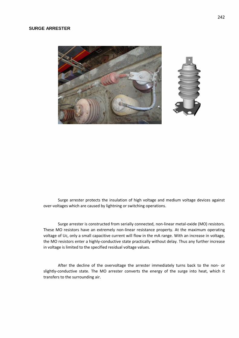
242 SURGE ARRESTER
Surge arrester protects the insulation of high voltage and medium voltage devices against
over-voltages which are caused by lightning or switching operations.
Surge arrester is constructed from serially connected, non-linear metal-oxide (MO) resistors.
These MO resistors have an extremely non-linear resistance property. At the maximum operating
voltage of Uc, only a small capacitive current will flow in the mA range. With an increase in voltage,
the MO resistors enter a highly-conductive state practically without delay. Thus any further increase
in voltage is limited to the specified residual voltage values.
After the decline of the overvoltage the arrester immediately turns back to the non- or
slightly-conductive state. The MO arrester converts the energy of the surge into heat, which it
transfers to the surrounding air.

243

244 DYNAMIC BRAKING RESISTER
Technical Data
Make Heine Gmbh
Type BWD73
Nominal Resistance (Rn) 3Ω + 7% -5%
Maximum Resistance Rmax 3.96 Ω (referred to 600°C)
(Rn+ 7% + resistance rise due to
temperature rise)
Minimum Resistance Rmin 2.85 Ω: (referred to 20°C)
Inductance: 7μH at 1 KHz
Load Case-1 1600 kW (tb = 1s)
0 kW (tb =300 s)
Load Case-2 1240 kW (tb = 2.5s)
0 kW (tb =120 s)
Continuous Load 41 kW
Load Case 400 kJ (tb =100 ms)

245
(Intermediate short circuit) 2X within 10 s
There after shut down.
Creepage Distance ≥ 45 mm
Clearance Distance ≥ 18 mm
Energy Absorption Capacity 2456 kJ
Resistance Material CrNi2521, Strip Material

246 EARTHING DIS-CONNECTOR AND SWITCH
This earthing disconnector is designed to earth the circuits on both sides, i.e. before and
behind the main high-speed air switch in a traction vehicle. It is usually preceded by a control group
switch with a reverse lever and a pantograph locking box.
The following are advantages of this earthing disconnector:
- minimum space required, - sturdy structure, - minimum maintenance requirements, and - reliable operation in extreme conditions.
Description

247
The earthing disconnector ensures safety operation of a traction vehicle and safety of staff members
while performing the traction vehicle inspection and/or maintenance, and curing defects and/or making
repairs.
On the plate face side is a control lever aimed at controlling the move of breaking knife from one
end position (Operation) to other end position (Grounded). Blocked mechanically in a groove, the lever
must first be shifted out of the groove by pulling it towards oneself; only then it is possible to turn the
lever counter-clockwise by 60°.
Mounted on the base plate back side, the switch has the fixed contact knives connected to a traction
vehicle frame through a flexible bond when in the „Grounded“ position. When in the Grounded“ position,
the contact knives slides into the flexible contacts thus making ground connection.

248 BATTERY AND BATTERY CHARGER
Power supply 110V
The EMU features a 110 volt DC on-board supply system. The battery is located under the
DTC and NDTC. The battery charger with 110 volt direct current is accommodated in the ACU. The
battery charger in the ACU only charges the battery in the own basic unit.
The battery main switch is located in the shunting cab. This switch completely isolates the
battery from the on-board supply system. One switch per unit is provided. Before the battery can be
switched ON via the electronics cabinet in the driver's cab, all battery main switches in the shunting
cab must be switched ON. This is located in the cabinet below the shunting desk.
Battery box fitted under slung

249
Figure : Battery main switch, shunting desk
The battery voltage is monitored by a minimum-voltage relay. When a specific voltage is
reached, the driver can override it for the preparation of the unit via the "Isolated Under voltage"
switch on the driver's cab.
In the case of a defective battery, the unit can continue to operate within the train without
any restrictions. This is ensured by a battery bus-bar which leads through the entire train.
The emergency light in the driver's cab is connected directly behind the battery main switch.
Therefore, it has to be ensured that the emergency light is switched OFF when parking the train
(battery main switch is not switched OFF, vehicle is shut-down).
MINIATURE CIRCUIT BREAKERS (MCBS)
SWITCHES
SOLENOID VALVE

250
SIGNAL BELL
CURRENT TRANSFORMERS
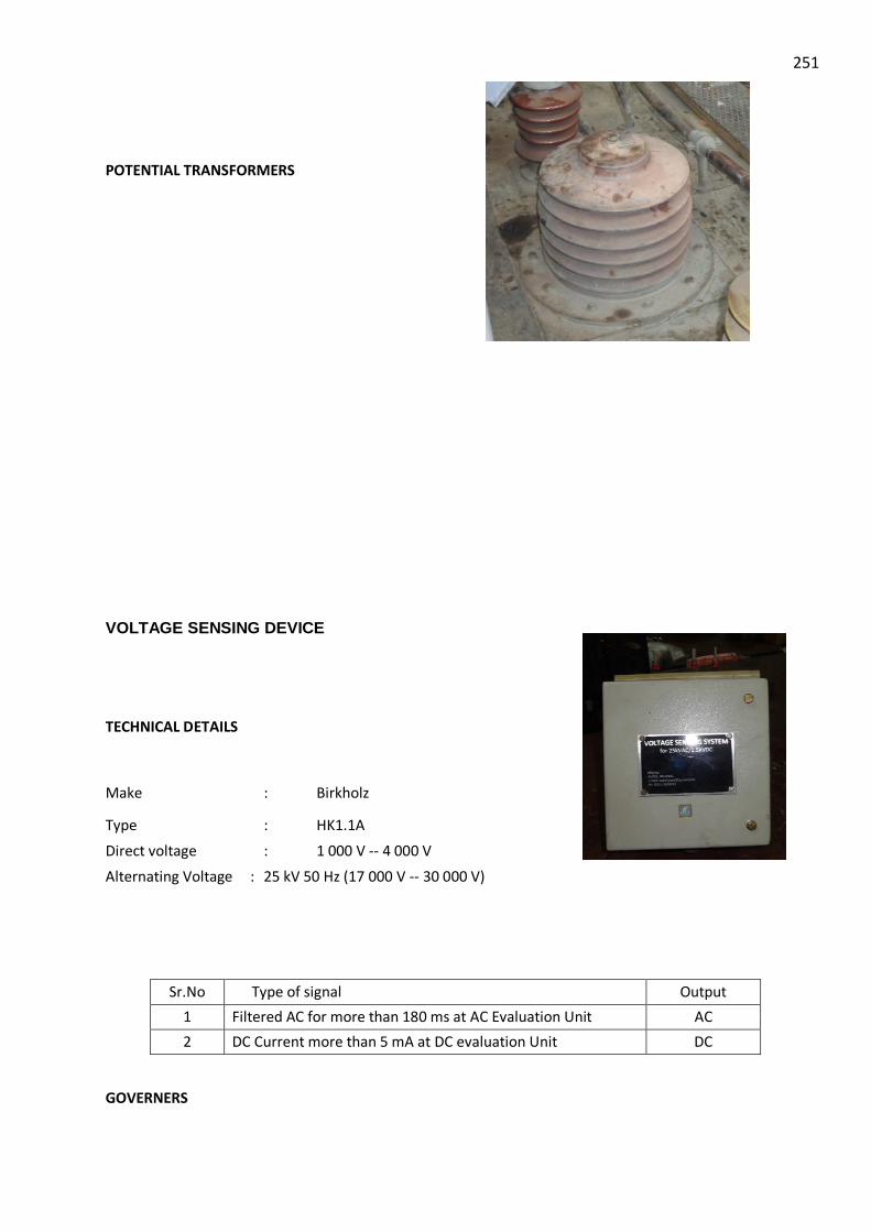
251
POTENTIAL TRANSFORMERS
VOLTAGE SENSING DEVICE
TECHNICAL DETAILS
Make : Birkholz
Type : HK1.1A
Direct voltage : 1 000 V -- 4 000 V
Alternating Voltage : 25 kV 50 Hz (17 000 V -- 30 000 V)
Sr.No Type of signal Output
1 Filtered AC for more than 180 ms at AC Evaluation Unit AC
2 DC Current more than 5 mA at DC evaluation Unit DC
GOVERNERS

252
Sr.
No
Governor Make Type Setting
1 Main Compressor
Governor
Moller MCS-11-SOND910-G Set: 6.0 ksc
Trip: 7.0 ksc
2 Auxiliary Governor Moller
SMC
MCS-11-SOND910-G
ISG120-031-W
Set: 5.3 ksc
Trip: 6.3 ksc
3 Equipment
Governor
Moller
SMC
MCS-11-SOND910-G
ISG120-031-W
Set: 5.6 ksc
Trip: 4.6 ksc
4 Control Circuit
Governor
Moller
SMC
MCS-11-SOND910-G
ISG120-031-W
Set: 4.0 ksc
Trip: 3.2 ksc
5 Parking Brake
Governor
Indfos
Denfos
116X Set: 3.0 ksc
Trip: 2.0 ksc

253 COMPRESSED-AIR UNIT
The compressed-air unit consists mainly of two compressed-air circuits, which are connected
to each other by means of a non-return valve. The pantograph, AC main circuit-breaker and the
voltage change-over switch are located in one of the compressed-air circuits (auxiliary air circuit).
In normal operation, the other compressed-air circuit (main air circuit) supplies the auxiliary
air circuit with compressed air via the non-return valve, the compressed-air brake and parking brake
system, the air suspension, pneumatic horn and windscreen wipers.
AUXILIARY AIR COMPRESSOR
The auxiliary air compressor is located in the HTC and generates the compressed air required
for the operation of the components in the auxiliary air circuit if the pressure from the main air
circuit is not available. This is often the case when the motorised train is being prepared.
The auxiliary air compressor is supplied directly by the battery.
Auxiliary Air Compressor

254 MAIN AIR COMPRESSOR
A three-phase piston air compressor installed underneath the DTC / NDTC supplies the train with
compressed air. It is automatically activated at a pressure of 6.0 bar and deactivated at a pressure of 7.0 bar.
The starting takes place without any pressure.
The compressed air is lead to several air reservoirs via a non-return valve and an air drying system
with automatic drainage. The air reservoirs are also equipped with automatic drainage.
One main air compressor is provided for each unit. All vehicles are equipped with a continuous MRP.
In addition, several compressed-air reservoirs for the brake, the spring-loaded brake, the air
suspension and the horn are provided.
The compressed-air system is protected by a safety valve. This safety valve triggers when a pressure
of 7.8 bar is exceeded.
The motor compressor set consists of the following main assemblies:
Three-phase motor, compressor, resilient mounting and dry-type air filter. The resilient
mounting is available in the form of
rubber shocks,
spring wire shocks and
a combination of rubber and spring wire shocks. The compressor has rubber shocks, the motor is equipped with spring wire shocks.
Main Air Compressor fitted under slung

255 TECHNICAL DETAILS OF MOTOR COMPRESSOR SET
Compressor
Make : Knorr- Bremse
Type : VV120
Three cylinder reciprocating
Low Pressure Stage : 2 nos. Dia 95 mm
High Pressure Stage : 1 no. Dia 75 mm
Stroke : 60 mm
Lubrication : Oil Flash type
Oil Consumption : < 1 c.c. / operating hour
Cooling : inter cooler and after cooler
Oil capacity (Max/ Min) : 3.7 l/ 1.7 l
Max outlet pressure : 10 bar
Allowed duty cycle : 30-100%
Motor
Make : Knorr- Bremse
Type : KB/18-132MB
Voltage : 415V
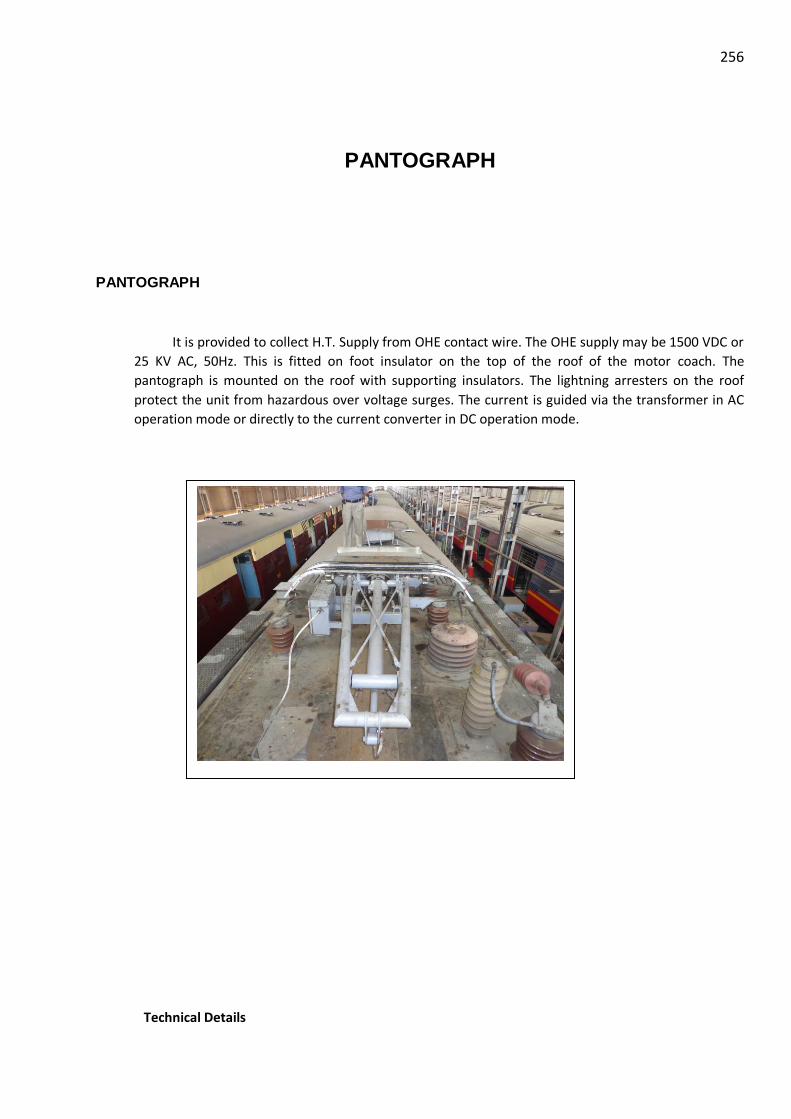
256
PANTOGRAPH
PANTOGRAPH
It is provided to collect H.T. Supply from OHE contact wire. The OHE supply may be 1500 VDC or
25 KV AC, 50Hz. This is fitted on foot insulator on the top of the roof of the motor coach. The
pantograph is mounted on the roof with supporting insulators. The lightning arresters on the roof
protect the unit from hazardous over voltage surges. The current is guided via the transformer in AC
operation mode or directly to the current converter in DC operation mode.
Technical Details

257
Sr.No. Item M/s Shunk M/s SIL
1 Standard UIC 60494-1
2 Type WBL 23.03 AM-18 B2
3 Min. Height with Insulators 575±10 mm 575±10 mm
4 Insulation Distance 250 mm 250 mm
5 Min Height over resting position --------- -----------
6 Max Height in raised position Max. 2290 mm Max. 2290 mm
7 Maximum Extension Max. 2400 mm Max. 2400 mm
8 Operating Range 500-2000 mm 500-2000 mm
9 Width of pan head 1-17110.11856 2032 mm 2032 mm
Sr.No. Item M/s Shunk M/s SIL
10 Total length in resting position 2370±10 mm 2370±10 mm
11 Total weight including insulators ≈ 150 kg ≈ 290 kg
12 Current collecting strips spacing 250 ± 10 mm 250 ± 10 mm
13 Current collector - material Electrolyte copper Electrolyte copper
13 Pan base sheet thickness Old- 1.6 mm
Mod.- 2.0 mm
2.0 mm
14 Nominal Voltage 25kV AC/
1.5 kV DC
25kV AC /
1.5 kV DC
15 Nominal current 60A/1100 A
16 Maximum speed under good OHE 160 kmph 160 kmph
17 Ambient Temperature -10° C to 50° C -10° C to 50° C
18 Propulsion system Air bellow Servo motor
19 Air pressure for continuous operation 7.0 bar 7 bar
(5<b<10 ksc)
20 Contact Pressure 11.5
(11- 14 kg
recommended)
11.5 kg
( 12 kg
recommended)
21 Raising time to maximum working
height
10 second 0 m to 1.5 m in 6-10
s
22 Lowering time from maximum working
height
10 second 1.5 m to o m in 10 s

258

259
CONTROL SYSTEM (SIBAS 32)
i. CCU (Central Control Unit)
ii. TCU (Traction Control Unit)
iii. BCU (Brake Control Unit)
iv. MMI (Man Machine Interface)
v. Multi Vehicle Bus
vi. SKS (SIBAS Klip Station)
Control technology
The control technology was designed redundantly for this vehicle. At the heart of each train,
there are two central control units called CCU. These are located in the driver's cab: Apart from the
control of the entire train, the CCU also controls the display.
The vehicles of one unit and the units themselves are connected to each other via an MVB
bus. The MVB is designed redundantly with line A and line B. If the MVB bus is not available despite
of this fallback, the vehicle can be operated in degraded operation via the rescue drive mode. This
function is only used for clearing the track. In this operating mode, the display is switched off and
the auxiliary tell-tale lamps are switched on.
All switches, buttons and consumers which are controlled via the control technology are
connected to a KLIP station. The KLIP stations are distributed I/O stations for the CCU. They are used
to significantly reduce the length of the control lines to the CCU.
Traction controls
This vehicle is a three-phase vehicle which is controlled via a TCU. The TCU processes the
propulsion and braking commands (electronic brake) and transmits this information to the current
converter. If there is a TCU failure, the unit in question can no longer operate autonomously. This
does not pose a risk if the unit is part of a train, as there may be at least one basic unit failure per
train. This is described below in the "Unit failure concept" overview.
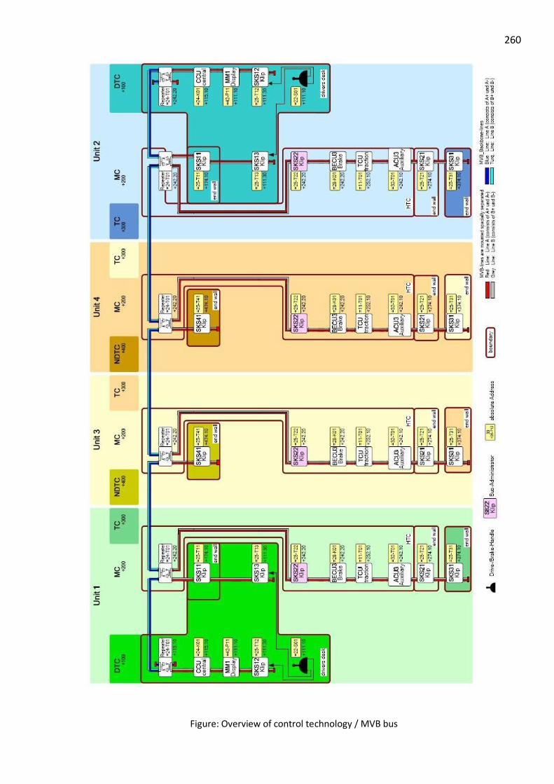
260
Figure: Overview of control technology / MVB bus
261 Brake control
All parts which affect the brake directly, except for the driver's automatic brake valve in the
driver's cab, are connected to the MVB bus. The brake commands from the joystick/brake lever are
thus transmitted to the CCU. The CCU calculates the brake forces for the EP and the ED brake and
transmits the value to the BCUs and TCUs. The EP unit converts the brake value generated by the
current into compressed air.
A pneumatic WSP is not available in this vehicle (sliding/skidding protection is only available
for the driven axles in the motor car). This means that the driver must brake earlier if the rails are
slippery in order to avoid wheel flats.
In the case of a brake malfunction, the driver can always stop the train by moving the
joystick/brake lever into the emergency brake application position. Furthermore, the function of the
driver's automatic brake valve can be used as a fallback at any time.
If there is BCU failure or defect, the TCU takes over all of the functions.
Display support
The MMI (Man-Machine Interface) is installed in the driver's cab in the DTC and informs the
driver of the current state of all important functions in the train. The states of a function are
indicated to the driver by means of coloured icons. The driver can detect faults at one glance. The
display assists the driver during the subsequent error detection. For information on further actions,
the driver can call up the corresponding remedy for the error message.
Automatic vigilance device
The automatic vigilance device has been implemented via the master controller. If the driver
releases the vigilance monitoring button during the journey, the brakes are applied automatically
and the power of the train is switched off. This only happens during the journey. If the speed is
below 5km/h, this function is disabled.
In rescue drive mode, the automatic application of the brakes is immediately initiated even if the vigilance
monitoring switch is not actuated and if the speed is below 5km/h.

262 MMI (MAN-MACHINE INTERFACE)
Man Machine Interface (General View)
1 Display ON / OFF
2 Not Connected
3 Legends of Symbols (Meaning)
4 Event Overview
5 Trouble Shooting Guidelines for Motorman
6 Not Connected
Figure: Man Machine Interface (General View)

263
7 Brightness Control Dialog
8 Not Connected
9 Not Connected
10 Clear
11 Cursor Up
12 Cursor Down
13 Curser Left
14 Curser Right
15 Enter
16 to 25 Soft keys 0 to 9

264 Different MMI Screens.
A. Top level screen
B. Unit Screen
1 Train No. Not commissioned
2 Screen designation
3 Date
4 Time
5 Main screen
6 Massage text
7 Short massage
8 Soft keys
9 Short massage
Figure: Top level screen
Figure: Unit Screen

265
C. Driver / Brake Screen showing percentage traction / Braking
D. Legend of Indications (By pressing ‘i’)
Figure: Driver / Brake Screen showing percentage traction / Braking

266
E. Legend of Indications (By pressing ‘i’ & 2)

267
Figure: Legend of Indications (By pressing ‘i’ & 2)

268
F. Legend of Indications (By pressing ‘i’ & 3)
Figure: Legend of Indications (By pressing ‘i’ & 3)

269
G. Legend of Indications (By pressing ‘i’ & 4)
1 PIS MMI
Figure: Legend of Indications (By pressing ‘i’ & 4)

270
Main Tasks of the TCU
The Train Control Unit (TCU) of the SIBAS 32 S system is used for processing, evaluating, storing and
transferring data and signals in electric rail vehicles. The main tasks of the TCU for the EMU are listed as
follows:
Data exchange via the MVB-Communication Module with the other Basic Units of the train set.
Data exchange via the MVB with ACU, BCU, KLIP etc. of the own 3-car-basic-unit
Control of power switches
Control of the defined tractive and regenerative braking effort
Generation of control signals for the traction converters
Monitoring (power switches, current, voltage, temperatures etc.)
Diagnostics
These tasks are fulfilled by TCU via hardware and software components inside the TCU.
Internal Structure and Method of Operation of the TCU
The TCU consists of a combination of electronic devices in a forced-air cooled rack. The
connection to the vehicle environment is implemented by front plugs.
The TCU SIBAS 32 S of the EMU vehicle consists of a Central Processing Unit (CPU) and three
lower-level sub-computers (signal processors). The CPU fulfils the Higher-level Traction Functions.
The three signal processors implement the Control of the traction converters itself. There
are two signal processors for the two Pulse Width Modulated Inverters (PWMI) and one signal
processor for the two Four Quadrant Choppers (4QC).
MVB-Communication
With the help of the MVB-Communication Module (located on the CPU-card) the CPU
exchanges relevant signals with the other MVB stations of the own Basic Unit (like BCU, ACU, KLIP,
etc.). Also the communication with the other 3-car units in the train set is realized with the MVB-
Communication Module.
2 Train radio hands-free
module
3 Train Radio MMI
4 Pressure Gauge Parking
Brakes
5 Train radio Handset
271
Higher-level Traction Functions
The central processing unit (CPU) also controls the higher-level functions of the traction
system. In response to the driver’s controls (e.g. driving set point) the CPU determines the required
power flows and thus generates set points for the two 4QC (not operated in DC-mode) and the two
PWMIs. The CPU enables closure of the main circuit breakers and controls the state of various
internal breakers and also wired train lines.
Therefore the CPU is able to input and output binary Signals via the internal bus with the
help of Binary Input/ Output Devices. The CPU provides monitoring and protection functions to
detect faults in the system. When a fault is detected appropriate action is taken to ensure the
system remains safe and to limit consequential damage.
Diagnostic information is provided to the train driver and to maintenance staff. With the
help of a Service PC and a special software tool (SIBAS Customer Monitor) the diagnostic information
of the TCU diagnosis memory can be read out and further maintenance tasks can be fulfilled.
Control of the traction converters:
Each of the signal processors implements the software control algorithm required to
generate the power semiconductor firing pulses in response to the set point values from the central
processing unit. Because the signal processors perform all time-critical functions of the traction
closed-loop control and converter open loop control, the CPU is relieved of computationally
intensive tasks.
Each of the signal processors interacts with special interface devices e.g. in order to actuate
the power semiconductors and to read in actual drive values like voltages, currents, temperatures
etc.
SIBAS 32 SYSTEM
(SIEMENS RAILWAY AUTOMATION SYSTEM WITH 32 BIT MICRO-PROCESSOR)
The SIBAS 32 system (Siemens Railway Automation System with 32 bit microprocessor) is
employed for modulating and logic control functions in mass transit rolling stock such as light rail
vehicles (trams), underground railways, suburban rapid transit vehicles and trolleybuses, as well as

272
in long-distance vehicles, for example, high-performance locomotives, high-speed trains diesel-
electric locomotives.
The system controls, monitors and protects the vehicle drive in the area of the converter
equipment and performs the information processing in a control level embracing the whole vehicle
as the central control unit.
The recording and control of digital and analog process signals "locally" at the vehicle control
is realized using SIBAS-KLIP.
SIBAS-KLIP comes from the German for "intelligent terminal for peripheral interfacing".
The peripheral signals in the vehicle are hereby connected to the I/O module of the SIBAS-
KLIP substation (SKS) by means of front connectors and are connected to the multifunction vehicle
bus (MVB) through the AS 318 MVB interface via the vehicle control.
View of a SIBAS-KLIP substation
The following picture shows two SIBAS-KLIP substations arranged above one another:

273
BRAKE SYSTEM
BRAKING SYSTEM
General
The vehicle is equipped with several brake systems. Normally, the joystick/brake lever
(Master Controller) is used for braking the vehicle. This lever can also be used for a rapid application
of the brakes in the event of an emergency.
This system uses the EP brake system. To use this system in the best possible way, one Brake
Control Unit (BCU) is provided per unit. The BCU controls the brake force of the units. If the BCU
fails, the TCU will perform the functions of the BCU.
An indirect brake, which can be operated via two automatic brake valves, serves as a
fallback. One is used by the driver, the second one by the guard.
The vehicle mainly uses the electric brake. With this brake, the generated brake force can be
returned back into the contact line network (OHE). If the brake force cannot be fed into the network,
the brake current is commutated to a brake resistance and the magnetic drag is reduced to 0 kN
within 1 sec. As a next step, the electro-pneumatic brake takes over the magnetic drag.
To secure the parked units, a spring-loaded brake has been installed. It acts on all 4 axles of
the DTC/ NDTC. The brake can be applied or released via push buttons provided in the driver's cab.
In the case of a fault, the spring-loaded brake is locked by an air shut-off cock. In this case, the driver
has to release the brake by hand via the emergency release device.

274
The pneumatic brake is already connected from 15 km/h (due to idle time of the EP brake).
Furthermore, the electronic brake force is reduced depending on the speed (between 15 to 3 km/h).
If the speed drops below 3km/h, the EP brake is automatically reduced.
The term "special brake blending" refers to the proportional reduction of the electronic
brake while the compressed-air brake is increased.
Figure: Set-up of the EP unit
Figure: Special brake blending

275
Figure: Set-up of the brake system DTC – MC – TC

276

277
Figure 32: Set-up of the brake system NDTC – MC – TC
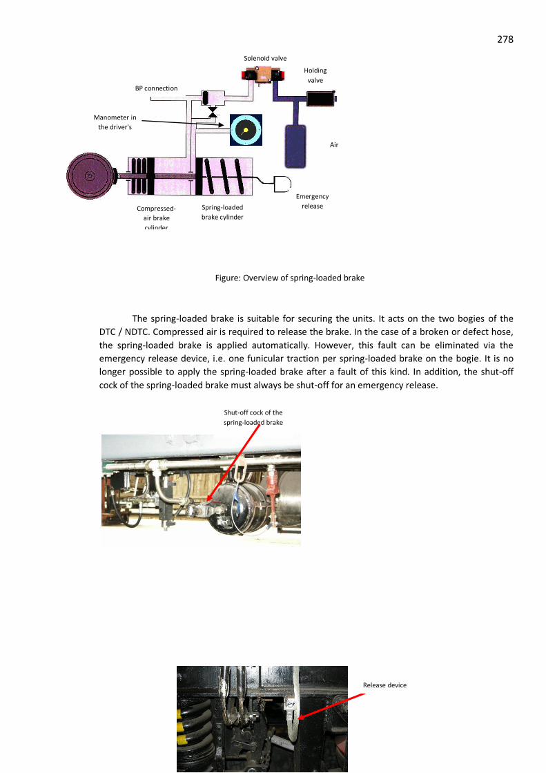
278
Figure: Overview of spring-loaded brake
The spring-loaded brake is suitable for securing the units. It acts on the two bogies of the
DTC / NDTC. Compressed air is required to release the brake. In the case of a broken or defect hose,
the spring-loaded brake is applied automatically. However, this fault can be eliminated via the
emergency release device, i.e. one funicular traction per spring-loaded brake on the bogie. It is no
longer possible to apply the spring-loaded brake after a fault of this kind. In addition, the shut-off
cock of the spring-loaded brake must always be shut-off for an emergency release.
Air
reservoir
Emergency
release
device
Holding
valve
Compressed-
air brake
cylinder
Spring-loaded
brake cylinder
BP connection
Solenoid valve
Manometer in
the driver's
cab
Release device
Shut-off cock of the
spring-loaded brake

279
PASSENGER AMMENITIES
i. Interior & exterior Lights (head light, flasher, signal light) ii. Fans iii. Air ventilation iv. Passenger Information System v. Alarm Chain pulling (wire rope system)
COACH FANS
Technical data
Sr.No. Description : Coach Fan AC-DC EMU
1 Make : M/s Raman Sinha ( Shankar)
2 Voltage : 98-135 V AC, 50 Hz AC
3 Power : 65 W
4 Power factor : 0.9
5 Sweep : 450 mm

280
6 RPM : 1200
7 Air Delivery : 85 m3/ min
8 Wire mesh & Body : Aluminium
9 Fan Blade : Nylon

281 AIR VENTILATION & MAIN BLOWER UNITS
Make Siemens
Type 2CS7 352-8RG11-1EM8
Motor Make Siemens Motor
Type of motor 1PP9083-2LA99ZN03
Nominal voltage 3AC, 415V ±10% @ 50Hz
Starting current and torque 24.4A / 22.0Nm
Continuous rating (at shaft) 1.75kW
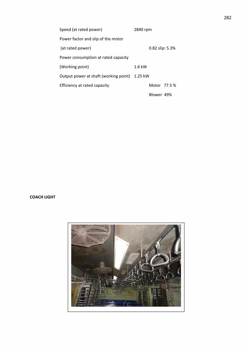
282
Speed (at rated power) 2840 rpm
Power factor and slip of the motor
(at rated power) 0.82 slip: 5.3%
Power consumption at rated capacity
(Working point) 1.6 kW
Output power at shaft (working point) 1.25 kW
Efficiency at rated capacity Motor 77.5 %
Blower 49%
COACH LIGHT

283
PASSENGER INFORMATION SYSTEM
Display unit

284
ANNEXURE - A
Electrical Multiple units (Train sets) for higher train speeds on IR
An energy efficient, cost effective, modern technological solution for increasing average train
speeds and throughput of Rajdhani, Shatabdi and other Mail/Express Trains
By
R.K. Bhatnagar
Adviser Electrical (G)
Railway Board
and
Jaideep
Director Electrical Engineering (G)
Railway Board
The biggest criticism Indian Railways face today is that despite developments in Traction
Technology and high speed trains running at 350 kmph plus, a reality today, average speed of even
the fastest Rajdhani, Shatabdi trains continues to be as low as 90 kmph. Although the maximum
permissible speed of these trains have gone up to 150 kmph.
Main reason for lower average speeds of IR passenger trains are:
Heavy congestion on major trunk routes
Large number of permanent and temporary speed restrictions on trunk routes. On date there
are as many as 135 speed restrictions on NDLS- HWH section.
Differential speeds of trains. Freight trains, commuter trains and passenger trains run on the
same track.
Longer trains being driven by single loco. These Important trains having 21 to 24 coaches are
being hauled by single loco
Absence of Electrical brakes
Indian Railways is fast losing its competitive edge vis-à-vis Airlines due to its inability to run
trains faster and reduce the run time. Various options being considered by IR to systematically
increase the train speeds are:
Dedicated high speed corridors for running trains at speeds above 250 kmph on certain
selected routes under PPP.
Gradually up grading the speed of the existing track infrastructure to run semi high speed
trains at 160 kmph to 200 kmph.
Dedicated Freight Corridor (DFC) for segregating freight traffic and reducing congestion on
trunk routes.
These options are time consuming and highly capital intensive as they are dependent on new
infrastructure or massive up gradation of existing infrastructure. The need today is to optimally
utilize the existing infrastructure and increase the average speed of the trains and carry more
passengers by utilizing the modern traction technology.
Most of the Railways in advanced countries in the world, have progressively switched over their
intercity passenger services from locomotive hauled trains to distributed powered EMU Train sets.
Most of the intercity passenger trainswith operating speeds ranging from 130 to 160 kmph in various

285 countries in Europe, Japan and Asia are Electrical train sets. Chinese Railway is also running train
sets for its overnight services with sleeper coaches. These train sets are highly energy efficient,
faster, provide better comfort and generate line capacity.
IR also need to adopt the latest technology (Distributed Powering) to cut down the running time for
important prestigious Inter city trains for following reasons:
Improvement in Acceleration.
Acceleration plays a major role in achieving higher average speeds. This becomes very
relevant when there are large number of speed restrictions and unscheduled halts and slowing of
trains due to heavy congestion on the routes and differential speeds of the trains. Typical speed vs
distance and speed vs time curves of loco hauled trains is given below

286 Deceleration of Loco hauled Trains
Loco hauled trains are provided with friction brakes which operate on lowering of air
pressure in the brake pipe, which is a very slow process. It takes almost 25 to 30 seconds for the
application of brakes in the last vehicle vis-a-vis first vehicle, due to which brakes have to be applied
very gradually to avoid jerks to passengers. Brake release also similarly takes some time due to
which train acceleration further slows down. Train deceleration is also around 0.2
m/s2:
Sl.No. Speed
Restriction in
kmph
Time Loss in
acceleration
(Seconds)
Time Loss in
braking
(Seconds)
Time loss in
acceleration
and
deceleration in
seconds
1 Halt 72 144 216
2 15 63 126 189
3 30 54 108 162
4 50 42 84 126
5 60 39 72 111
6 80 27 48 75
7 100 15 24 39
8 120 3 6 9
How Train set can help?
Operational Parameters of Train set vis-à-vis Loco hauled trains
Operational Characteristics Loco Hauled 21 coach
Rajdhani Train
Rajdhani run with
EMU Train set
Acceleration (Starting) 0.22 m/s2 1.0 m/s2
Deceleration 0.20 m/s2 1.0 m/s2
Time to achieve 130 kmph 279 seconds 50.3 seconds
Distance required to travel to
attain a speed of 130 kmph
6489 meters 1089.7 meters
Additional time required for
acceleration and deceleration
for a halt with maximum
speed of 130 kmph
216 seconds
41 seconds

287

288
Reduction in run time between New Delhi and Howrah with Train sets
Speed
Restrictions
kmph
Time Loss in Acceleration and
deceleration
Time saved
by Train
sets vis-a-
vis Loco
hauled train
(Sec)
No of speed
restrictions
Total time
Saving
with train
sets(in
sec)
By Loco
hauled
trains
(Seconds)
By Train sets
with acceleration
and deceleration
@ 1 m/s2 (Sec)
Halts 216 41 175 6 1050
10 198 36 162 6 972
20 180 30. 150 13 1950
30 162 24. 138 31 4278
40 144 20 124 6 744
50 126 16 110 6 660
60 111 13 98 4 392
70 93 10 83 19 1577
80 75 7 68 4 272
90 57 5 52 4 208
100 39 3 36 17 612
110 27 2 25 5 125
120 9 1 8 14 112
Total Time savings 135 12952
Savings in run time 216 minutes or 3 hours and 36 minutes
Simulated run of 21 coach Rajdhani Train with WAP7 Loco for 8 hours with Permanent Speed
restrictions only

289
Run with Loco hauled conventional train
Simulated run with Desiro train sets with 1.0 m/s2 acceleration and 1.1 m/s2 deceleration with
permanent speed restrictions alone
Run With Train set
Due to large number of speed restrictions trains hardly achieve the maximum permissible speed of
130 kmph as can be seen from the simulated speed time curve of Howrah- New Delhi Rajdhani.
Actual total time between HWH-New Delhi for 1440 km is 17 hours and 5 minutes, which can easily
be done in 14 hours with Train sets, even with maximum permissible speed of 130 kmph i.e. without
any expenditure on track and signaling infrastructure. A net savings of 3 hours in run time despite
135 speed restrictions.
Energy Efficiency
Train sets are highly energy efficient because of following reasons:
Propulsion equipment is mounted on the coaches, hence locomotives and Power cars in
conventional loco hauled trains get eliminated. Weight of one Loco and two Power car is
almost one third of the train weight, resulting in proportionate savings in energy consumption
Improved aerodynamics compared with older trains (leads to about 25% less energy
consumption)
Regenerative braking leads to substantial energy savings especially in Indian conditions with
large number of speed restrictions requiring frequent braking (17 to 25% energy is recovered)
Savings in diesel fuel in power car
Improved energy efficiency in power supply, partly due to more advanced technologies of the
trains (3-7%)

290
Total energy savings with Train sets is more than 50%. As per UIC report even with increase in
speeds, energy consumption per passenger comes down with train sets vis-à-vis Loco hauled trains.
Rajdhani train consumes 34 thousand units of Electricity and 2000 litres of fuel for a run between
New Delhi and Howrah. Savings in money terms per trip @ Rs 5 per unit for electricity and Diesel
@ Rs 50 per litre works out to Rs 1.85 lakh per day or Rs 6.75 crore per annum.
Enhanced Safety
Regenerative and electro-pneumatic braking leads to higher deceleration and reduced
emergency braking distance leading to enhanced safety
Reduced jerk rate and smoother braking and acceleration due to electro pneumatic braking
vis-à-vis friction brakes in conventional trains
Train sets have automatic door closing leading to improved passenger safety
Micro processor based diagnostic and monitoring system further ensures safety vis-à-vis
alarm chain based system, which has a slow response time
Modern Train sets are provided with Automatic train protection systems
Reduced maintenance of assets
Reduces wear and tear of the track due to elimination of locos and power cars with lighter
coaches and distributed powering and tractive forces.
Train sets are equipped with the modern three-phase IGBT technology with fully suspended
motors, which require very less maintenance.
Regenerative braking leads to reduced wear of brake blocks and tyres
Need for Maintenance facility for passenger locos is eliminated.
Improved reliability
Modern 3 phase technology is highly reliable
Distributed powering has lot of in built redundancy (50% to 60% axles are powered), which
leads to very high reliability
On board diagnostic system reduces dependence on the skills of Pilots, further improving the
reliability
Reduction in Pollution
Reduced noise pollution due to elimination of power cars and locomotive. It is very important
as presently noise norms are being violated on these trains. Average noise levels exceed the
maximum permissible 75 dBA level. Likely to cause hearing loss as per UN norms.
Especially affected persons are power car staff and persons travelling in adjacent coaches.
Reduced carbon emissions and air pollution especially on the station platforms.
Improved Passenger comfort
Modern Train set cars are provided with ergonomic coach design and improved passenger comforts,
with infotainment systems and air craft type mini pantry. Aerodynamic design of the nose,
distributed powering and electrical braking helps in comfortable jerk free ride.

291 Improved throughput
Further with cabs at both ends, turn round time required at terminal stations is less than 15
minutes, leading to improved utilization. A train set running between New Delhi and
Howrah can start From Kolkata at 7:00 pm and reach New Delhi at 9:00 AM and run an extra
trip between New Delhi and Kalka and back between 9:00 AM and 7:00 PM.
Presently 21 car Rajdhani train has only 17 passenger coaches. With train sets Power cars and
locomotive and even pantry car can get replaced by passenger coaches thereby increasing the
throughput per train. Number of coaches can also be further increased to 24 passenger
coaches thus helping in increased revenue and meeting the growing passenger demand.
Improvement in Line capacity
Faster acceleration and deceleration leads to reduction in time required to clear the critical
section thus improving the line capacity on congested routes.
Higher carrying capacity of the trains will reduced the number of trains required for same
through put.
Financial Returns
Capital Cost
Capital cost per car for trains sets running at maximum permissible speed of 140 kmph is around
Rs 8 crore per car(Cost of Cars running on airport express having similar
acceleration/deceleration characteristics) and a 21 car modern train set would cost Rs 175 crore,
(which can be substantially reduced if manufactured indigenously or at RCF) vis-à-vis Rs 75
crore for a loco hauled 21 coach Rajdhani which has only 17 passenger coaches.
Operation and Maintenance Cost
Savings in O&M cost of Train sets vis-à-vis conventional Rajdhani trains will be Rs 5 crore per
annum, mainly on account of savings in energy cost.
Passenger Revenue
Additional passenger revenue from train sets will be around Rs 20 crore per annum due to
additional throughput due to replacement of power cars and loco by passenger earning coaches
and additional trips due to reduction in run time.
IRR
From above it is seen that there will be additional net savings of Rs 25 crore per annum with an
additional investment of only Rs 100 crore on one 21 car train set giving an IRR of more than
25%.

292 Way Forward for IR
There are following options available with IR for increasing the speed of trains running on existing
tracks:
1. Manufacture Train sets at RCF
Existing LHB coaches are fit to run at speeds up to 180 kmph. Three phase propulsion
equipment can be mounted under slung on these coaches to convert them to distributed
powered train sets. In this case, interiors of the trains will remain the same and IR can
continue with existing Class of coaches (3AC, 2AC and FAC). The leading coach will be
converted to driving car with suitable changes in the nose profile. This is the least cost option.
Capital cost will only go up marginally with very high IRR.
2. Import few Train sets through global tendering of modern design with comfortable interiors,
air craft type pantry so that pantry car can be dispensed with and replaced by passenger
coaches. The cost of imported train sets is around Rs 8 to 10 crore per car i.e. Rs 175 crore
for a 21 car train set vis-à-vis Rs 75 crore for a conventional loco hauled 21 coach Rajdhani
train with only 17 revenue earning passenger coaches. With reduction in run time, savings in
fuel and energy cost, increase in passenger revenue, reduced maintenance costs and extra
trips, it will be possible to achieve a very high IRR on Rajdhani, Shatabdi routes.
3. Enter into an MOU with some government, for introduction of modern train set technology
from that country for trials. Swedish Government and French government has shown keen
ness for such an arrangement.
4. Permit Private operators to operate Train sets on PPP basis who will be attracted by the high
IRR
In view of numerous advantages of train sets, Indian Railways must introduce EMU Trains on select
Shatabdi/Rajdhani routes as a trial measure for reducing the journey time without any up gradation
in track and signaling system. An effort in this direction will herald a new era in operation of
Rajdhani and Shatabdi trains. Further for achieving higher speeds, a train set is the only option. As
and when the track is upgraded to 160 kmph, same train sets can be used by adding additional motor
coaches.
With Modern Train sets, it will be possible to make journey between New Delhi and Howrah, a very
comfortable overnight journey and provide the competitive edge to IR vis-à-vis Airlines.

293
ANNEXURE – B
AUXILIARY WARNING SYSTEM
Introduction:- AWS is an aids to Motorman
a) It gives Alarm b) It indicates c) It decelerates d) It stops
It is a microprocessor based control system, which continuously monitors the speed,
direction of traveling, distance traveled aspect of the signal passed and the alertness of the
Motorman. And thus increase the reliability of railway system.
AWS type ZUB-100 designed and developed by M/s. Siemens Ltd, it was introduced in WR
suburban section of Mumbai Division on 24.02.87.
It is a high-grade safety device preventing the accident due to the negligence of human
failure of Motorman. It compels the Motorman to obey the aspect of the signal and maintain
the correct speed. If it is not well acknowledge with in time AWS descelerate the train and
stop the train.
Advantage of AWS:-
i) It prevents accidents ii) It upgrades the safety of passengers and working of train iii) It prevents the damages of railway system iv) Only on aid v) Does not relives driver from his duties.
Track Equipments:-
A. 1. Track Magnet 2. Upto Coupler
B. Cab equipments:-

294
1. Engine or train magnet 2. Tacho generator 3. Coupler 4. Isolating switch unit (ISU) 5. Brake application unit (BAU) Brake actuating unit. 6. Control processing unit (CPU) 7. Hooter 8. Drivers indication panel
a) Taget speed indicator b) Signal failure by pass button c) Signal by pass counter d) Reset push button (Blue) of EBC e) Emergency brake counter f) Vigilance button g) Indication lamp
(i) Blue (ii) White (iii) Yellow (iv) Red
1) Track Magnet: -
It is placed at track near the signal. It is connected to the signal through Opto
coupler card.
Track magnet transmit the information of aspect of signal to CPU track magnet has three chamber.
a) First chamber – Consist of a tuned circuit and 50 H2 coil. b) Second chamber – Certain oscillators tuned frequency to different frequency. The
frequency are as under: - F1- 2800Hz
F2- 2800 HZ + 800 Hz = 3600 Hz
F3- 3600 Hz + 800 Hz = 4400 Hz
F4- 4400 Hz + 800 Hz = 5200 Hz
F4 – B3 + 800 = 5200 Hz
F5 – F4 + 800 = 5000 Hz
F6 – F5 + 800 = 6800 Hz
F7 – F6 + 800 = 7600 Hz
c) The third chamber – consists of power coil modulator card and 100 MHz coil with tuned circuit – 100 KHz frequency is amplitude (Modulated) with a dia frequency in Modulator cords.
Power coil Generate about 12V (AC) received from engine magnet power coil (cord)
Type of Track magnet: -

295 A. Type Magnet – A type magnet is used with normal signal and given frequency F1 to F5
in pair of 2.
B. Type magnet. B type magnet is used for getting fixed frequency like F4 and F5 frequency or F5, F6.
Track magnet are water tight and are tested by feeding 0.5 kg/cm2 air pressure for 1
minute.
By dipping in water no pressure dropped is allowed.
Opto Coupler Card: -
It is placed on the signal post in a metallic box and work as link between signal
aspect and track magnet. It lake the input from the signal transformer output and
connected it to the track magnet.
2. Cab eqipment:-
1. Engine magnet or train magnet :- it is fitted under frame below guard seat when it passes over track magnet it collects the information from track magnet and send to it to CPU through coupler.
2. Engine magnet passes parallel to the track magnet at a distance ( 175 mm ± 0-5mm) in jessop block and ( 183.5mm + 0-5mm) in ICF stock.
1) It acts as a power source for track magnet 2) It dictates the presence of track magnet by clip in current of 50 KHz coil. 3) It received modulated frequency and transmit it to CPU.
Tacho Generator: -
It is fitted on the axle of the front wheel of the train and gives following information to
the CPU. Speed, zero speed distance traveled, direction of travels.
Couplers: -
It conveys the information from Tacho generator to CPU through conducts and also
gives train coil to CPU.
ISOLATING SWITCH UNIT: -

296
Isolating switch unit has manually operated isolation switch and a set of MCBs; it
consists of 110V supply to AWS system provision also exists for counting No of isolation
number. It helps in isolating of AWS in case of Malfunction or due to some other reason,
ISU has eight LED.
a) Yellow – LEDs (I) 110V, (2) 24V, (3) 12V – (4) 5V – Power on supply b) Supply to Master controller - Green LED c) 2 Supply to Magnet Valve - Green LED d) Supply to HMV - Red LED e) Supply to AMV - Red LED
Brake actuating unit (BAU) BAU consists of :-
a) Brake control relay( BCR ) b) Emergency braking reverse relay c) Emergency braking normal relay d) Services braking relay (SBR)
CPU: -
Control processing unit – It process the information received from track magnet and
gives instruction to indication panel., for the action of hooter and brake actuating unit.
Hooter: -
It is an audiser alarm or warning to motorman an passing of signal and will be continued till
it is acknowledged or by passed.
Drivers Indication panel: -
It has many buttons and counters and indication.
Signal failures by pass button (SFBB) It is operate only when trains dead stop. It
must be pressed while manual signal is to be passed at danger on receiving T88B.
Signal failure by pass counter (SFBB) It is a counter and counter the number of
operation of SFBB on pressing SFBP it rotates half and on passing the signal (Track
magnet) it complete its rotation.
Emergency Brake counter (EBC) It is a counter and counts the number of penalty or
emergency brakes applied the EBC rotates half when emergency brakes are applied and
complete when reset push button is pressed.
Reset Push button: -

297 It is operative only in stand still condition of train. It is pressed to release emergency
brakes applied by AWS.
AWS MAGNET VALVE: -
Two magnet valve are used for application of emergency brakes by AWS, these are:
a) Feed cut off magnet valve (FCMV) It is provided on the pipe feeding MR pressure to brake controller. Normally when it is energized it allows the MR pressure to charge BP through ICS. A cock is provided in parallel to this magnet which is opened only when AWS is to be isolated.
b) Exhaust Magnet Valve: - (EMV) It is provided after the EAV and before the pilot valve normally when it is energized, it blocks the BP pressure to exhaust when it is deenergized it opens the path and brakes are applied. A cock is provided in series to these magnet valve, which is closed only when AWS is to be isolated.
COMBINATION OF FREQUENCY:- Out of 7 frequency two are used at a time to communicate a particular signal aspect thus it
information can be feed but all combinations are not used.
Sr.No Combination Function
1. F1 + F2 Absolute Red ®
2. F1 + F3 Double Yellow (YY)
3. F1 + F4 Yellow (Y)
4. F1 + F5 Permissive Red
5. F3 + F4 Green (Signal Off)
6. F2 + F4 Signal at caution (Yellow) with
Inter signals distance more than 700m
7. F2 + F6 No Change in earlier information
8. F5 + F6 Reduced braking distance after next signal
9. F1 + F6 Release the brake curve.
OPERATION INSTRUCTION FOR AWS:-
Switching on of AWS: -
1) Switch ON AWS MCB 2) Close the feed cut off magnet valve cock (90o to big pipe)

298
3) Open the exhaust magnet valve cock (Parallel to small pipe) 4) Switch On AWS ISU 5) Switch On DCS, ICS, Control Key, EP Key. 6) Record ISU EBC and SFBC number in AWS cards, when the AWS is switch ON
following indications are displayed on indication panel. a) Blue and white lamp lit. b) Blue lamp extinguished and relit after 4 and 5 seconds. c) White lamp flashed and relit steady.
FUNCTIONAL TEST OF AWS TO BE DONE AT
1) Starting of trip, (2) Carshed or stabling yard, Taking overcharge at in between station
Procedure: - Keep vigilance button pressed for 10 sec. White lamps (LED1) are flashing,
blue,Red, and yellow lamps (LED) list and steady.
2) Release vigilance button – Hooter sounds for 2 sec. White lamps lit steady, red and yellow lamp extinguished.
Note: - 1) steady white lamp indicate AWS Eqpt in working order.
3) On releasing vigilance button – If white lamps are still flashing means AWS is faulty, then isolate the AWS completely
ISOLATION OF AWS: -
AWS is to be isolated when
a) Non availability of 110V supply b) Malfunctioning of AWS c) Whenever there is some faults in electrical sides or leakage in pneumatic side.
Procedure:- 1) Switch OFF ISU 2) Open the feed cut off Magnet valve cock (Parellel to big pipe). 3) Close the Exhaust magnet valve cock (90 to small pipe). 4) Switch OFF AWS (MCB). 5) Record ISU EBC, SFBC number in AWS Card. 6) Entry in the Failure in unit defact chart Maintained by MUI
CONTROL EXERACISED BY AWS.
Speed > = Speed limit + 1 km -- Audioable Warning
Speed > = Speed limit + 5 km -- EP Brake + Warning

299
Speed > = Speed limit + 10km – Emergency Brake.

300