Aspect ratio effects on three-dimensional incompressible flow in a two-sided non-facing lid-driven...
11
C. R. Mecanique 339 (2011) 655–665 Contents lists available at ScienceDirect Comptes Rendus Mecanique www.sciencedirect.com Aspect ratio effects on three-dimensional incompressible flow in a two-sided non-facing lid-driven parallelepiped cavity Fakher Oueslati ∗ , Brahim Ben Beya, Taieb Lili Laboratoire de mécanique des fluides, Faculté des sciences de Tunis, Département de physique, 2092 El Manar 2, Tunis, Tunisia article info abstract Article history: Received 10 May 2011 Accepted after revision 16 June 2011 Available online 23 July 2011 Keywords: Fluid mechanics Aspect ratio 3D lid-driven cavity Unsteady flow Bifurcation A numerical study of the three-dimensional fluid flow has been carried out to determine the effects of the transverse aspect ratio, A y , on the flow structure in two-sided non-facing lid-driven cavities. The flow is complex, unstable and can undergo bifurcation. The numeri- cal method is based on the finite volume method and multigrid acceleration. Computations have been investigated for several Reynolds numbers and various aspect ratio values. At a fixed Reynolds number, Re = 500, the three-dimensional flow characteristics are analyzed considering four transverse aspect ratios, A y = 1, 0.75, 0.5 and 0.25. It is observed that the transition to the unsteady regime follows the classical scheme of a Hopf bifurcation. An analysis of the flow evolution shows that, at A y = 0.75, the flow bifurcates to a peri- odic regime at (Re = 600) with a frequency f = 0.093 less than the predicted value in the cubical cavity. A correlation is established when A y = 0.5 and gives the critical Reynolds number value. At A y = 0.25, the periodic regime occurs at high Re value beyond 3500, after which the flow becomes chaotic. It is shown that, when increasing A y over the unit, the flow in the cavity exhibits a complex behavior. The kinetic energy transmission from the driven walls to the cavity center is reduced at low A y values. © 2011 Académie des sciences. Published by Elsevier Masson SAS. All rights reserved. 1. Introduction Research concerning the physical model of lid-driven cavity (LDC) flows is an area of continuing interest and was re- garded as a benchmark study in some literature works. The interest is justified by the fact that its flow configuration is relevant to many industrial applications such as boundary layers and vortex of different size with various instabilities. How- ever, despite the simplicity of the geometry, the LDC flow exhibits a number of interesting physical features such as complex instabilities, transitions, bifurcations and turbulence. By far, the most studied configuration is that of two-dimensional one-sided LDC flow set up by constant speed motion of a single wall [1,2]. A recent work has been carried out by Lin et al. [3] who applied the multirelaxation time lattice Boltzmann model to compute two-dimensional LDC flows at three aspect ratio values 1, 1.5 and 4, and for different Reynolds numbers from 100 to 7500. They found steady solutions for square cavity flows, whereas, at the aspect ratios 1.5 and 4 unsteady solutions prevail at Re = 7500 where periodic flow exists manifested by the rapid changes of the shapes and locations of the corner vortices. While some LDC flow phenomena have revealed 2D solutions, many subtleties of third dimensionality are missing. The recent progress in numerical analysis and computer hardware has made it possible to investigate 3D LDC flow simulations [4,5]. Ding et al. [6] discussed the effectiveness of using the local multiquadric differential quadrature method to study the * Corresponding author. E-mail address: [email protected] (F. Oueslati). 1631-0721/$ – see front matter © 2011 Académie des sciences. Published by Elsevier Masson SAS. All rights reserved. doi:10.1016/j.crme.2011.06.002
-
Upload
independent -
Category
Documents
-
view
4 -
download
0
Transcript of Aspect ratio effects on three-dimensional incompressible flow in a two-sided non-facing lid-driven...
C. R. Mecanique 339 (2011) 655–665
Contents lists available at ScienceDirect
Comptes Rendus Mecanique
www.sciencedirect.com
Aspect ratio effects on three-dimensional incompressible flow ina two-sided non-facing lid-driven parallelepiped cavity
Fakher Oueslati ∗, Brahim Ben Beya, Taieb Lili
Laboratoire de mécanique des fluides, Faculté des sciences de Tunis, Département de physique, 2092 El Manar 2, Tunis, Tunisia
a r t i c l e i n f o a b s t r a c t
Article history:Received 10 May 2011Accepted after revision 16 June 2011Available online 23 July 2011
Keywords:Fluid mechanicsAspect ratio3D lid-driven cavityUnsteady flowBifurcation
A numerical study of the three-dimensional fluid flow has been carried out to determinethe effects of the transverse aspect ratio, A y , on the flow structure in two-sided non-facinglid-driven cavities. The flow is complex, unstable and can undergo bifurcation. The numeri-cal method is based on the finite volume method and multigrid acceleration. Computationshave been investigated for several Reynolds numbers and various aspect ratio values. At afixed Reynolds number, Re = 500, the three-dimensional flow characteristics are analyzedconsidering four transverse aspect ratios, A y = 1,0.75,0.5 and 0.25. It is observed thatthe transition to the unsteady regime follows the classical scheme of a Hopf bifurcation.An analysis of the flow evolution shows that, at A y = 0.75, the flow bifurcates to a peri-odic regime at (Re = 600) with a frequency f = 0.093 less than the predicted value in thecubical cavity. A correlation is established when A y = 0.5 and gives the critical Reynoldsnumber value. At A y = 0.25, the periodic regime occurs at high Re value beyond 3500,after which the flow becomes chaotic. It is shown that, when increasing A y over the unit,the flow in the cavity exhibits a complex behavior. The kinetic energy transmission fromthe driven walls to the cavity center is reduced at low A y values.
© 2011 Académie des sciences. Published by Elsevier Masson SAS. All rights reserved.
1. Introduction
Research concerning the physical model of lid-driven cavity (LDC) flows is an area of continuing interest and was re-garded as a benchmark study in some literature works. The interest is justified by the fact that its flow configuration isrelevant to many industrial applications such as boundary layers and vortex of different size with various instabilities. How-ever, despite the simplicity of the geometry, the LDC flow exhibits a number of interesting physical features such as complexinstabilities, transitions, bifurcations and turbulence.
By far, the most studied configuration is that of two-dimensional one-sided LDC flow set up by constant speed motionof a single wall [1,2]. A recent work has been carried out by Lin et al. [3] who applied the multirelaxation time latticeBoltzmann model to compute two-dimensional LDC flows at three aspect ratio values 1, 1.5 and 4, and for different Reynoldsnumbers from 100 to 7500. They found steady solutions for square cavity flows, whereas, at the aspect ratios 1.5 and 4unsteady solutions prevail at Re = 7500 where periodic flow exists manifested by the rapid changes of the shapes andlocations of the corner vortices.
While some LDC flow phenomena have revealed 2D solutions, many subtleties of third dimensionality are missing. Therecent progress in numerical analysis and computer hardware has made it possible to investigate 3D LDC flow simulations[4,5]. Ding et al. [6] discussed the effectiveness of using the local multiquadric differential quadrature method to study the
* Corresponding author.E-mail address: [email protected] (F. Oueslati).
1631-0721/$ – see front matter © 2011 Académie des sciences. Published by Elsevier Masson SAS. All rights reserved.doi:10.1016/j.crme.2011.06.002
656 F. Oueslati et al. / C. R. Mecanique 339 (2011) 655–665
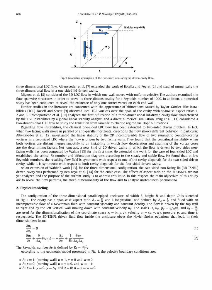
Fig. 1. Geometric description of the two-sided non-facing lid driven cavity flow.
three-dimensional LDC flow. Albensoeder et al. [7] extended the work of Botella and Peyret [2] and studied numerically thethree-dimensional flow in a one sided lid-driven cavity.
Migeon et al. [8] considered the 3D LDC flow in which one wall moves with uniform velocity. The authors examined theflow spanwise structures in order to prove its three-dimensionality for a Reynolds number of 1000. In addition, a numericalstudy has been conducted to reveal the existence of only one corner-vortex on each end-wall.
Further studies in the literature are concerned with the appearance of bifurcations caused by Taylor–Görtler–Like insta-bilities (TGL). Koseff and Street [9] observed local TGL vortices over the span of the cavity with spanwise aspect ratios 1,2 and 3. Chicheportiche et al. [10] analyzed the first bifurcation of a three-dimensional lid-driven cavity flow characterizedby the TGL instabilities by a global linear stability analysis and a direct numerical simulation. Peng et al. [11] considered atwo-dimensional LDC flow to study the transition from laminar to chaotic regime via Hopf bifurcations.
Regarding flow instabilities, the classical one-sided LDC flow has been extended to two-sided driven problem. In fact,when two facing walls move in parallel or anti-parallel horizontal directions the flow shows different behavior. In particular,Albensoeder et al. [12] investigated the linear stability of the 2D incompressible flow of two symmetric counter-rotatingvortices in a two-sided LDC where the flow is driven by two facing walls. They found that the centrifugal instability whenboth vortices are distant merges smoothly to an instability in which flow deceleration and straining of the vortex coresare the determining factors. Not long ago, a new kind of 2D driven cavity in which the flow is driven by two sides non-facing walls has been computed by Wahba [13] for the first time. He extended the work for the case of four-sided LDC andestablished the critical Re number and bifurcation diagrams according to the steady and stable flow. He found that, at lowReynolds numbers, the resulting flow field is symmetric with respect to one of the cavity diagonals for the two-sided drivencavity, while it is symmetric with respect to both cavity diagonals for the four-sided driven cavity.
As an extension of Wahba’s work [13], for the three-dimensional configuration, the two-sided non-facing lid (3D-TSNFL)driven cavity was performed by Ben Beya et al. [14] for the cubic case. The effects of aspect ratio on the 3D-TSNFL are notyet analyzed and the purpose of the current study is to address this issue. In this respect, the main objectives of this studyare to reveal the flow patterns, the three-dimensionality of the flow and to analyze unsteadiness phenomena.
2. Physical modeling
The configuration of the three-dimensional parallelepiped enclosure, of width L, height H and depth D is sketchedin Fig. 1. The cavity has a span-wise aspect ratio A y = D
H and a longitudinal one defined by Ax = LH and filled with an
incompressible flow of a Newtonian fluid with constant viscosity and constant density. The flow is driven by the top wallto right and by the left vertical wall moving down with constant velocity u0. The scales H , u0, p0 = 1
2 ρ0u20, and t0 = H
u0are used for the dimensionalization of the coordinate space xi = (x, y, z), velocity ui = (u, v, w), pressure p, and time t ,respectively. The 3D-TSNFL driven fluid flow inside the enclosure obeys the Navier–Stokes equations that lead, in theirdimensionless form:
∂ui
∂xi= 0 (1)
∂ui
∂t+ ∂
∂x j(uiu j) = − ∂ p
∂xi+ 1
Re
∂ui
∂x j∂x j(2)
The Reynolds number Re is defined by Re = u0 Hv .
According to the geometric model presented in Fig. 1, the velocity boundary conditions are:
• At z = 1: (moving wall) u = 1, v = 0 and w = 0;• At x = 0: (moving wall) u = v = 0, and w = −1;• At x = 1, y = 0, y = A y and z = 0; u = v = w = 0.
F. Oueslati et al. / C. R. Mecanique 339 (2011) 655–665 657
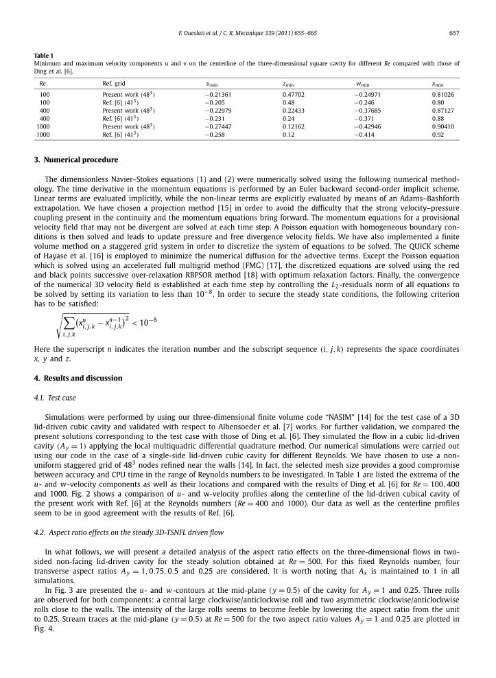
Table 1Minimum and maximum velocity components u and v on the centerline of the three-dimensional square cavity for different Re compared with those ofDing et al. [6].
Re Ref. grid umin zmin wmin xmin
100 Present work (483) −0.21361 0.47702 −0.24971 0.81026100 Ref. [6] (413) −0.205 0.48 −0.246 0.80400 Present work (483) −0.22979 0.22433 −0.37685 0.87127400 Ref. [6] (413) −0.231 0.24 −0.371 0.88
1000 Present work (483) −0.27447 0.12162 −0.42946 0.904101000 Ref. [6] (413) −0.258 0.12 −0.414 0.92
3. Numerical procedure
The dimensionless Navier–Stokes equations (1) and (2) were numerically solved using the following numerical method-ology. The time derivative in the momentum equations is performed by an Euler backward second-order implicit scheme.Linear terms are evaluated implicitly, while the non-linear terms are explicitly evaluated by means of an Adams–Bashforthextrapolation. We have chosen a projection method [15] in order to avoid the difficulty that the strong velocity–pressurecoupling present in the continuity and the momentum equations bring forward. The momentum equations for a provisionalvelocity field that may not be divergent are solved at each time step. A Poisson equation with homogeneous boundary con-ditions is then solved and leads to update pressure and free divergence velocity fields. We have also implemented a finitevolume method on a staggered grid system in order to discretize the system of equations to be solved. The QUICK schemeof Hayase et al. [16] is employed to minimize the numerical diffusion for the advective terms. Except the Poisson equationwhich is solved using an accelerated full multigrid method (FMG) [17], the discretized equations are solved using the redand black points successive over-relaxation RBPSOR method [18] with optimum relaxation factors. Finally, the convergenceof the numerical 3D velocity field is established at each time step by controlling the L2-residuals norm of all equations tobe solved by setting its variation to less than 10−8. In order to secure the steady state conditions, the following criterionhas to be satisfied:√∑
i, j,k
(xn
i, j,k − xn−1i, j,k
)2< 10−8
Here the superscript n indicates the iteration number and the subscript sequence (i, j,k) represents the space coordinatesx, y and z.
4. Results and discussion
4.1. Test case
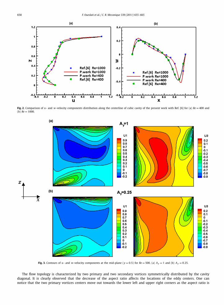
Simulations were performed by using our three-dimensional finite volume code “NASIM” [14] for the test case of a 3Dlid-driven cubic cavity and validated with respect to Albensoeder et al. [7] works. For further validation, we compared thepresent solutions corresponding to the test case with those of Ding et al. [6]. They simulated the flow in a cubic lid-drivencavity (A y = 1) applying the local multiquadric differential quadrature method. Our numerical simulations were carried outusing our code in the case of a single-side lid-driven cubic cavity for different Reynolds. We have chosen to use a non-uniform staggered grid of 483 nodes refined near the walls [14]. In fact, the selected mesh size provides a good compromisebetween accuracy and CPU time in the range of Reynolds numbers to be investigated. In Table 1 are listed the extrema of theu- and w-velocity components as well as their locations and compared with the results of Ding et al. [6] for Re = 100,400and 1000. Fig. 2 shows a comparison of u- and w-velocity profiles along the centerline of the lid-driven cubical cavity ofthe present work with Ref. [6] at the Reynolds numbers (Re = 400 and 1000). Our data as well as the centerline profilesseem to be in good agreement with the results of Ref. [6].
4.2. Aspect ratio effects on the steady 3D-TSNFL driven flow
In what follows, we will present a detailed analysis of the aspect ratio effects on the three-dimensional flows in two-sided non-facing lid-driven cavity for the steady solution obtained at Re = 500. For this fixed Reynolds number, fourtransverse aspect ratios A y = 1,0.75,0.5 and 0.25 are considered. It is worth noting that Ax is maintained to 1 in allsimulations.
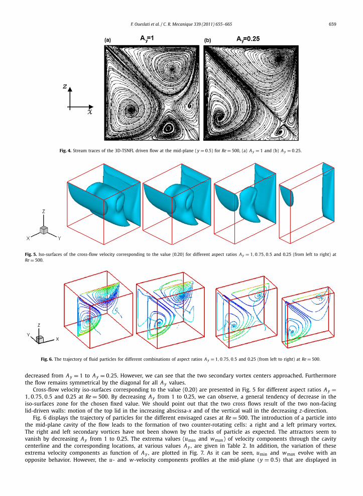
In Fig. 3 are presented the u- and w-contours at the mid-plane (y = 0.5) of the cavity for A y = 1 and 0.25. Three rollsare observed for both components: a central large clockwise/anticlockwise roll and two asymmetric clockwise/anticlockwiserolls close to the walls. The intensity of the large rolls seems to become feeble by lowering the aspect ratio from the unitto 0.25. Stream traces at the mid-plane (y = 0.5) at Re = 500 for the two aspect ratio values A y = 1 and 0.25 are plotted inFig. 4.
658 F. Oueslati et al. / C. R. Mecanique 339 (2011) 655–665
Fig. 2. Comparison of u- and w-velocity components distribution along the centerline of cubic cavity of the present work with Ref. [6] for (a) Re = 400 and(b) Re = 1000.
Fig. 3. Contours of u- and w-velocity components at the mid-plane (y = 0.5) for Re = 500, (a) A y = 1 and (b) A y = 0.25.
The flow topology is characterized by two primary and two secondary vortices symmetrically distributed by the cavitydiagonal. It is clearly observed that the decrease of the aspect ratio affects the locations of the eddy centers. One cannotice that the two primary vortices centers move out towards the lower left and upper right corners as the aspect ratio is
F. Oueslati et al. / C. R. Mecanique 339 (2011) 655–665 659
Fig. 4. Stream traces of the 3D-TSNFL driven flow at the mid-plane (y = 0.5) for Re = 500, (a) A y = 1 and (b) A y = 0.25.
Fig. 5. Iso-surfaces of the cross-flow velocity corresponding to the value (0.20) for different aspect ratios A y = 1,0.75,0.5 and 0.25 (from left to right) atRe = 500.
Fig. 6. The trajectory of fluid particles for different combinations of aspect ratios A y = 1,0.75,0.5 and 0.25 (from left to right) at Re = 500.
decreased from A y = 1 to A y = 0.25. However, we can see that the two secondary vortex centers approached. Furthermorethe flow remains symmetrical by the diagonal for all A y values.
Cross-flow velocity iso-surfaces corresponding to the value (0.20) are presented in Fig. 5 for different aspect ratios A y =1,0.75,0.5 and 0.25 at Re = 500. By decreasing A y from 1 to 0.25, we can observe, a general tendency of decrease in theiso-surfaces zone for the chosen fixed value. We should point out that the two cross flows result of the two non-facinglid-driven walls: motion of the top lid in the increasing abscissa-x and of the vertical wall in the decreasing z-direction.
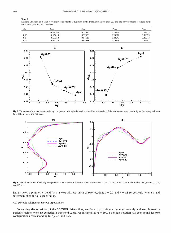
Fig. 6 displays the trajectory of particles for the different envisaged cases at Re = 500. The introduction of a particle intothe mid-plane cavity of the flow leads to the formation of two counter-rotating cells: a right and a left primary vortex.The right and left secondary vortices have not been shown by the tracks of particle as expected. The attractors seem tovanish by decreasing A y from 1 to 0.25. The extrema values (umin and wmax) of velocity components through the cavitycenterline and the corresponding locations, at various values A y , are given in Table 2. In addition, the variation of theseextrema velocity components as function of A y , are plotted in Fig. 7. As it can be seen, umin and wmax evolve with anopposite behavior. However, the u- and w-velocity components profiles at the mid-plane (y = 0.5) that are displayed in
660 F. Oueslati et al. / C. R. Mecanique 339 (2011) 655–665
Table 2Extrema variation of u- and w-velocity components as function of the transverse aspect ratio A y and the corresponding locations at themid-plane (y = 0.5) for Re = 500.
A y umin zmin wmax xmax
1 −0.26344 0.57626 0.26344 0.423730.75 −0.25016 0.57626 0.25012 0.423730.5 −0.23250 0.57626 0.23243 0.432730.25 −0.15730 0.63558 0.15726 0.36441
Fig. 7. Variations of the extrema of velocity components through the cavity centerline as function of the transverse aspect ratio A y at the steady solutionRe = 500, (a) umin and (b) wmax.
Fig. 8. Spatial variations of velocity components at Re = 500 for different aspect ratio values A y = 1,0.75,0.5 and 0.25 at the mid-plane (y = 0.5), (a) u,and (b) w .
Fig. 8 shows a symmetric trend (w + u = 0) with existence of two locations z = 0.7 and x = 0.3 respectively, where u andw remain fixed for all aspect ratios.
4.3. Periodic solutions at various aspect ratios
Concerning the transition of the 3D-TSNFL driven flow, we found that this one became unsteady and we observed aperiodic regime when Re exceeded a threshold value. For instance, at Re = 600, a periodic solution has been found for twoconfigurations corresponding to A y = 1 and 0.75.
F. Oueslati et al. / C. R. Mecanique 339 (2011) 655–665 661
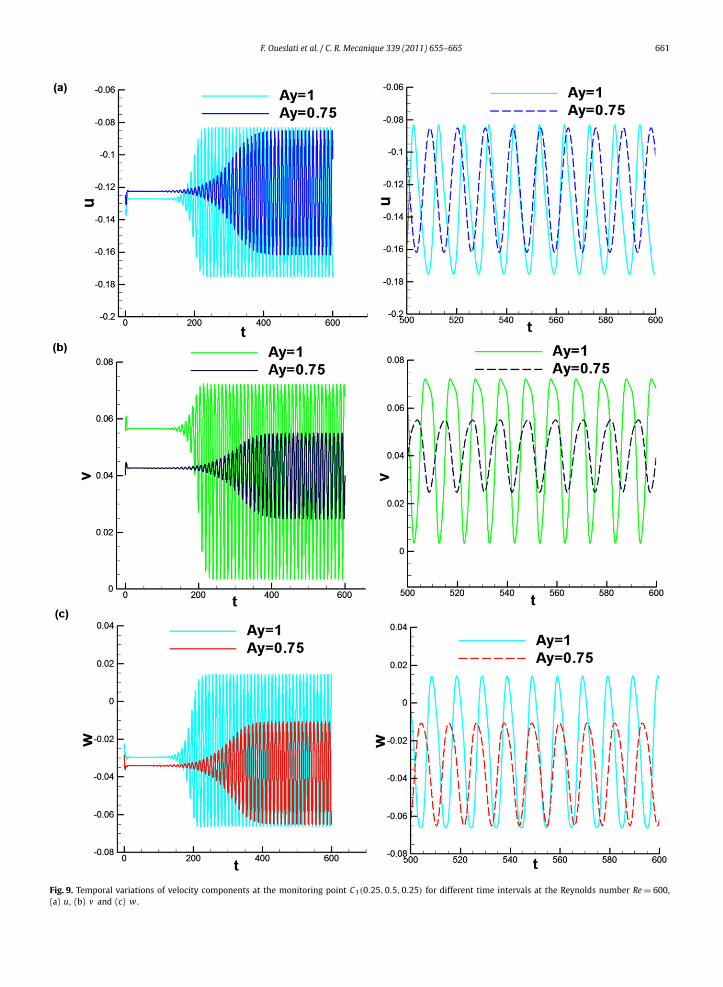
Fig. 9. Temporal variations of velocity components at the monitoring point C1(0.25,0.5,0.25) for different time intervals at the Reynolds number Re = 600,(a) u, (b) v and (c) w .
662 F. Oueslati et al. / C. R. Mecanique 339 (2011) 655–665
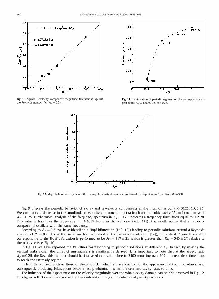
Fig. 10. Square u-velocity component magnitude fluctuations againstthe Reynolds number for (A y = 0.5).
Fig. 11. Identification of periodic regimes for the corresponding as-pect ratios A y = 1,0.75,0.5 and 0.25.
Fig. 12. Magnitude of velocity across the rectangular cavity domain as function of the aspect ratio A y at fixed Re = 500.
Fig. 9 displays the periodic behavior of u-, v- and w-velocity components at the monitoring point C1(0.25,0.5,0.25)
We can notice a decrease in the amplitude of velocity components fluctuation from the cubic cavity (A y = 1) to that withA y = 0.75. Furthermore, analysis of the frequency spectrum in A y = 0.75 indicates a frequency fluctuation equal to 0.0928.This value is less than the frequency f = 0.1015 found in the test case (Ref. [14]). It is worth noting that all velocitycomponents oscillate with the same frequency.
According to A y = 0.5, we have identified a Hopf bifurcation (Ref. [19]) leading to periodic solutions around a Reynoldsnumber of Re = 850. Using the same method presented in the previous work (Ref. [14]), the critical Reynolds numbercorresponding to the Hopf bifurcation is performed to be Rec = 817 ± 2% which is greater than Rec = 540 ± 2% relative tothe test case (see Fig. 10).
In Fig. 11 we have reported the Re values corresponding to periodic solutions at different A y . In fact, by making thevertical walls closer, the onset of unsteadiness is significantly delayed. It is important to note that at the aspect ratioA y = 0.25, the Reynolds number should be increased to a value close to 3500 requiring over 600 dimensionless time stepsto reach the unsteady regime.
In fact, the vortices such as those of Taylor Görtler which are responsible for the appearance of the unsteadiness andconsequently producing bifurcations become less predominant when the confined cavity loses volume.
The influence of the aspect ratio on the velocity magnitude over the whole cavity domain can be also observed in Fig. 12.This figure reflects a net increase in the flow intensity through the entire cavity as A y increases.
F. Oueslati et al. / C. R. Mecanique 339 (2011) 655–665 663
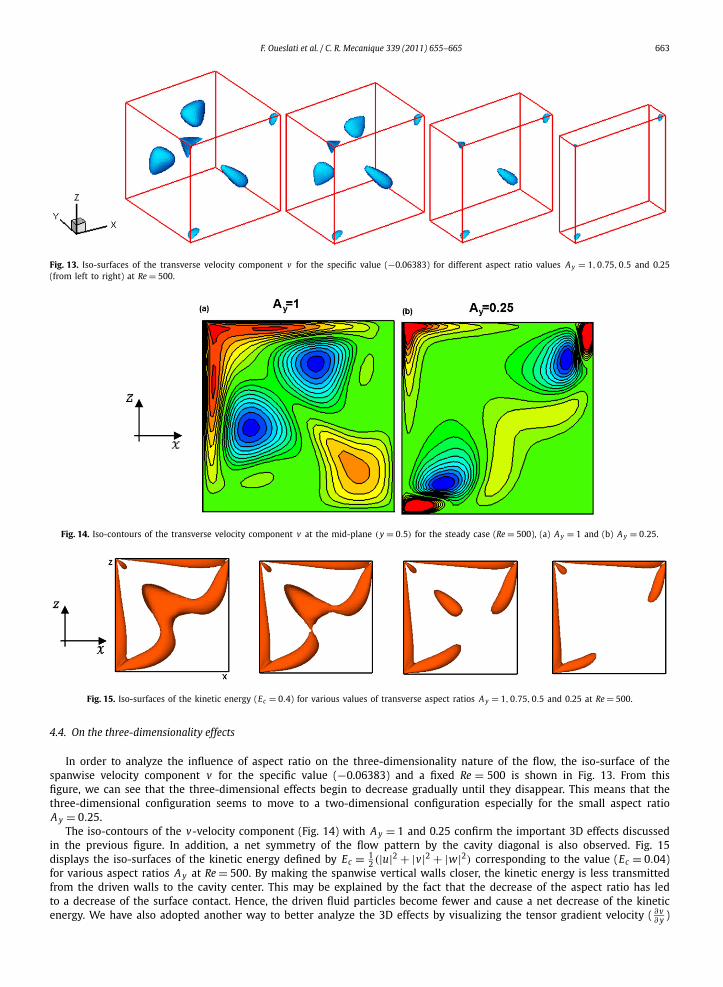
Fig. 13. Iso-surfaces of the transverse velocity component v for the specific value (−0.06383) for different aspect ratio values A y = 1,0.75,0.5 and 0.25(from left to right) at Re = 500.
Fig. 14. Iso-contours of the transverse velocity component v at the mid-plane (y = 0.5) for the steady case (Re = 500), (a) A y = 1 and (b) A y = 0.25.
Fig. 15. Iso-surfaces of the kinetic energy (Ec = 0.4) for various values of transverse aspect ratios A y = 1,0.75,0.5 and 0.25 at Re = 500.
4.4. On the three-dimensionality effects
In order to analyze the influence of aspect ratio on the three-dimensionality nature of the flow, the iso-surface of thespanwise velocity component v for the specific value (−0.06383) and a fixed Re = 500 is shown in Fig. 13. From thisfigure, we can see that the three-dimensional effects begin to decrease gradually until they disappear. This means that thethree-dimensional configuration seems to move to a two-dimensional configuration especially for the small aspect ratioA y = 0.25.
The iso-contours of the v-velocity component (Fig. 14) with A y = 1 and 0.25 confirm the important 3D effects discussedin the previous figure. In addition, a net symmetry of the flow pattern by the cavity diagonal is also observed. Fig. 15displays the iso-surfaces of the kinetic energy defined by Ec = 1
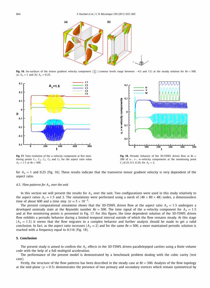
2 (|u|2 + |v|2 + |w|2) corresponding to the value (Ec = 0.04)for various aspect ratios A y at Re = 500. By making the spanwise vertical walls closer, the kinetic energy is less transmittedfrom the driven walls to the cavity center. This may be explained by the fact that the decrease of the aspect ratio has ledto a decrease of the surface contact. Hence, the driven fluid particles become fewer and cause a net decrease of the kineticenergy. We have also adopted another way to better analyze the 3D effects by visualizing the tensor gradient velocity ( ∂v )
∂ y
664 F. Oueslati et al. / C. R. Mecanique 339 (2011) 655–665
Fig. 16. Iso-surfaces of the tensor gradient velocity component ( ∂v∂ y ) (contour levels range between −4.5 and 1.5) at the steady solution for Re = 500,
(a) A y = 1 and (b) A y = 0.25.
Fig. 17. Time evolution of the u-velocity component at five mon-itoring points C1, C2, C3, C4 and C5 for the aspect ratio valueA y = 1.5 at Re = 500.
Fig. 18. Periodic behavior of the 3D-TSNFL driven flow at Re =500 of u-, v-, w-velocity components at the monitoring pointC1(0.25,0.5,0.25) for A y = 2.
for A y = 1 and 0.25 (Fig. 16). These results indicate that the transverse tensor gradient velocity is very dependent of theaspect ratio.
4.5. Flow patterns for A y over the unit
In this section we will present the results for A y over the unit. Two configurations were used in this study relatively tothe aspect ratios A y = 1.5 and 2. The simulations were performed using a mesh of (48 × 80 × 48) nodes, a dimensionlesstime of about 600 and a time step �t = 5 × 10⁻³.
The present computational simulation shows that the 3D-TSNFL driven flow at the aspect ratio A y = 1.5 undergoes adeveloped unsteady state at the Reynolds number Re = 500. The time signal of the u-velocity component for A y = 1.5and at five monitoring points is presented in Fig. 17. For this figure, the time dependent solution of the 3D-TSNFL drivenflow exhibits a periodic behavior during a limited temporal interval outside of which the flow remains steady. At this stage(A y = 1.5) it seems that the flow migrates to a complex behavior and further analysis should be made to get a validconclusion. In fact, as the aspect ratio increases (A y = 2) and for the same Re = 500, a more maintained periodic solution isreached with a frequency equal to 0.116 (Fig. 18).
5. Conclusion
The present study is aimed to confirm the A y effects in the 3D-TSNFL driven parallelepiped cavities using a finite volumecode with the help of a full multigrid acceleration.
The performance of the present model is demonstrated by a benchmark problem dealing with the cubic cavity (testcase).
Firstly, the structure of the flow patterns has been described in the steady case at Re = 500. Analysis of the flow topologyat the mid-plane (y = 0.5) demonstrates the presence of two primary and secondary vortices which remain symmetrical by
F. Oueslati et al. / C. R. Mecanique 339 (2011) 655–665 665
the diagonal for all A y values. Furthermore, maxima of w-velocity component strengthens with the increasing value of A y ,whereas the strength of minima u-velocity component weakens with increasing A y .
When Re exceeds a threshold value the flow exhibits a periodic state. In particular, a critical Re number of 817 ± 2%computed for A y = 0.5 was found to be greater than the one predicted in the test case. Moreover, it is found that bymaking the vertical walls closer, the onset of unsteadiness is significantly delayed.
It is observed that, for small values of A y , the kinetic energy is less transmitted from the driven walls to the cavitycenter. The 3D effects are also reflected in the iso-surfaces of the transverse velocity component and those of the tensorgradient velocity.
Finally, when A y attains the value greater than unit, the flow migrates to a complex behavior which needs to be moreclarified with further studies.
References
[1] E. Erturk, Discussions on driven cavity flow, Internat. J. Numer. Methods Fluids (2009) 275–294.[2] O. Botella, R. Peyret, Benchmark spectral results on the lid-driven cavity flow, Comput. & Fluids 27 (1998) 421–433.[3] L. Lin, Yi-Cheng Chen, Chao-An Lin, Multi relaxation time lattice Boltzmann simulations of deep lid driven cavity flows at different aspect ratios,
Comput. & Fluids (2011).[4] K.L. Wong, A.J. Baker, A 3D incompressible Navier–Stokes velocity-vorticity weak form finite element algorithm, Internat. J. Numer. Methods Fluids 38
(2002) 99–123.[5] Q.T. Li, T. Cheng, T.T.H. Tsang, Transient solutions for three-dimensional lid-driven cavity flows by a least-squares finite element method, Internat. J.
Numer. Methods Fluids 21 (1995) 413–432.[6] H. Ding, C. Shu, K.S. Yeo, D. Xu, Numerical computation of three-dimensional incompressible viscous flows in the primitive variable form by local
multiquadric differential quadrature method, Comput. Methods Appl. Mech. Engrg. 195 (2006) 516–533.[7] S. Albensoeder, H.C. Kuhlmann, Accurate three-dimensional lid-driven cavity flow, J. Comput. Phys. 206 (2005) 536–558.[8] C. Migeon, G. Pineau, A. Texier, Three-dimensionality development inside standard parallelepipedic lid-driven cavities at Re = 1000, J. Fluids Struct. 17
(2003) 717–738.[9] J.R. Koseff, R.L. Street, Visualization studies of a shear driven three-dimensional recirculating flow, ASME J. Fluid Engrg. 33 (1984) 594–602.
[10] J. Chicheportiche, X. Merle, X. Gloerfelt, J.-C. Robinet, Direct numerical simulation and global stability analysis of three-dimensional instabilities in alid-driven cavity, C. R. Mecanique 336 (2008).
[11] Y. Peng, Yuo-Hsien Shiau, Robert R. Hwang, Transition in a 2-D lid-driven cavity flow, Comput. & Fluids 32 (2003) 337–352.[12] S. Albensoeder, H.C. Kuhlmann, Three-dimensional instability of two counter-rotating vortices in a rectangular cavity driven by parallel wall motion,
Europ. J. Mech. B/Fluids 21 (2002) 307–316.[13] E.M. Wahba, Multiplicity of states for two-sided and four-sided lid driven cavity flows, Comput. & Fluids 38 (2008) 247–253.[14] B. Ben Beya, Taieb Lili, Three-dimensional incompressible flow in a two-sided non-facing lid-driven cubical cavity, C. R. Mecanique 336 (2008) 863–872.[15] D.L. Brown, R. Cortez, M.L. Minion, Accurate projection methods for the incompressible Navier–Stokes equations, J. Comput. Phys. 168 (2001) 464–499.[16] T. Hayase, J.A.C. Humphrey, R. Greif, A consistently formulated QUICK scheme for fast and stable convergence using finite-volume iterative calculation
procedures, J. Comput. Phys. 98 (1992) 108–118.[17] N.B. Cheikh, B. Ben Beya, T. Lili, Benchmark solution for time-dependent natural convection flows with an accelerated full-multigrid method, Numer.
Heat Transfer B 52 (2007) 131–151.[18] R. Barrett, M. Berry, T.F. Chan, et al., Templates for the Solution of Linear Systems: Building Blocks for Iterative Methods, SIAM, 1994.[19] J. Shen, Hopf bifurcation of the unsteady regularized driven cavity flow, J. Comput. Phys. 95 (1991) 228–245.