Oilless and frictionless compressor with double-sided ...
14
BULLETIN OF THE POLISH ACADEMY OF SCIENCES TECHNICAL SCIENCES, Vol. 61, No. 2, 2013 DOI: 10.2478/bpasts-2013-0048 Oilless and frictionless compressor with double-sided rotationally oscillating piston W. CHOMCZYK 1 , W. OSTAPSKI 2 * , J. PIOTROWSKI 2 , and T. TATAJ 2 1 Bialystok University of Technology, 45D Wiejska St., 15-351 Bialystok, Poland 2 Institute of Machine Design Fundamentals, Warsaw University of Technology, 84 Narbutta St., 02-524 Warszawa, Poland Abstract. The contents are concerned with a concept of an oilless and frictionless compressor operating without dead movement and having functional parameters superior to compressors of renowned manufacturers. The concept is based on patents No. 68220, 83060, P377851 by W. Chomczyk and patents P394072, P385733 by W. Chomczyk, W. Ostapski and J. Piotrowski. The proposed design of an oilless compressor ensures volumetric efficiency higher than that encountered in conventional compressors. It also generates pure compressed medium without necessity of filtering from oil particles, which is especially desired in food, pharmaceutical, medical, fragrance, chemical and automation industry. Key words: oilless and frictionless compressor, double–sided rotationally oscillating piston. 1. Introduction The principle of working of an oscillatory compressor is giv- en on the scheme in Fig. 1. In cylindrical case (1), there are two alternately placed partition walls (2) equipped with four outlet valves (3). Concentrically mounted shaft (4) has two vanes (5) being an equivalent to the piston. The vanes can ro- tate in the free space between the partition walls by an angular displacement φ R . On the cylindrical case, there are two inlet valves (6) installed. Motion of the shaft compresses the gas in chamber (7) and at the same time decompresses it in chamber (8). At the moment when vanes (5) uncover valve seats (6), the gas suddenly inflows to chamber (8) due to a considerable difference in the pressure. Dead point (1) of rotating shaft is at the distance δ from the barriers. After reaching it, the shaft changes direction of its rotary motion, owing to which in chamber (8) there compression starts and in (7) expansion of the medium. Fig. 1. Scheme of the oscillatory compressor 2. Working cycles of the oscillatory compressor Due to the displacement of the inlet valve at the half of the suction stroke and because of the clearance volume above the inlet valve seat, the ideological cycle of working of the considered compressor slightly differs from a conventional scheme incorporated to piston compressors. Beginning from dead point (1), in which the outlet valve closes, there starts de- compression with a polytropic exponent m 1 . It lasts till vane (5) uncovers by its rear edge the seat of the inlet valve (6), i.e. at the angular displacement ϕ 2 , slightly greater than the angle ϕ R . In Fig. 1, the abscissa depicts the displacement volume. Accordingly, point (2) of the opening of the inlet valve corre- sponds to volume of the decompression chamber (V 1 + V ϕ2 ). At this place, the compressed gas over the inlet valve inflows to suction chamber (8), increasing pressure by Δp ′ 2 . Starting from point (2’), suction chamber (8) is dynamically filled with the gas, which ends at dead point (3). The loss of kinetic en- ergy of the gas makes the chamber pressure near point (3) practically the same as the pressure in the suction collector. Basically, compression goes along a polytropic curve with the exponent m 1 . However, after reaching the angular dis- placement ϕ 1 , the space over the inlet valve ΔV 3 becomes closed from pressure chamber (7) and the compression poly- tropic curve shifts from point 3 ′ to 3 ′′ . Point 4 corresponds to the opening of the outlet valve, which – as in conventional compressors – takes place at a higher pressure than that in the pressure collector p t . Arriving to dead point (1), the velocity of the rotary piston and the resistance of flow through valve (3) approach zero, hence the pressure surplus Δp t over the pres- sure in the outlet collector corresponds to the force produced by the spring supporting the outlet valve. As can be seen here, the thermodynamic cycle of the presented compressor differs from cycles of typical compressors with reciprocating pistons. * e-mail: [email protected] 485
-
Upload
khangminh22 -
Category
Documents
-
view
1 -
download
0
Transcript of Oilless and frictionless compressor with double-sided ...

BULLETIN OF THE POLISH ACADEMY OF SCIENCES
TECHNICAL SCIENCES, Vol. 61, No. 2, 2013
DOI: 10.2478/bpasts-2013-0048
Oilless and frictionless compressor with double-sided rotationally
oscillating piston
W. CHOMCZYK1, W. OSTAPSKI2∗, J. PIOTROWSKI2, and T. TATAJ2
1 Bialystok University of Technology, 45D Wiejska St., 15-351 Bialystok, Poland2 Institute of Machine Design Fundamentals, Warsaw University of Technology, 84 Narbutta St., 02-524 Warszawa, Poland
Abstract. The contents are concerned with a concept of an oilless and frictionless compressor operating without dead movement and having
functional parameters superior to compressors of renowned manufacturers. The concept is based on patents No. 68220, 83060, P377851 by
W. Chomczyk and patents P394072, P385733 by W. Chomczyk, W. Ostapski and J. Piotrowski. The proposed design of an oilless compressor
ensures volumetric efficiency higher than that encountered in conventional compressors. It also generates pure compressed medium without
necessity of filtering from oil particles, which is especially desired in food, pharmaceutical, medical, fragrance, chemical and automation
industry.
Key words: oilless and frictionless compressor, double–sided rotationally oscillating piston.
1. Introduction
The principle of working of an oscillatory compressor is giv-
en on the scheme in Fig. 1. In cylindrical case (1), there are
two alternately placed partition walls (2) equipped with four
outlet valves (3). Concentrically mounted shaft (4) has two
vanes (5) being an equivalent to the piston. The vanes can ro-
tate in the free space between the partition walls by an angular
displacement φR. On the cylindrical case, there are two inlet
valves (6) installed. Motion of the shaft compresses the gas in
chamber (7) and at the same time decompresses it in chamber
(8). At the moment when vanes (5) uncover valve seats (6),
the gas suddenly inflows to chamber (8) due to a considerable
difference in the pressure. Dead point (1) of rotating shaft
is at the distance δ from the barriers. After reaching it, the
shaft changes direction of its rotary motion, owing to which
in chamber (8) there compression starts and in (7) expansion
of the medium.
Fig. 1. Scheme of the oscillatory compressor
2. Working cycles of the oscillatory compressor
Due to the displacement of the inlet valve at the half of the
suction stroke and because of the clearance volume above
the inlet valve seat, the ideological cycle of working of the
considered compressor slightly differs from a conventional
scheme incorporated to piston compressors. Beginning from
dead point (1), in which the outlet valve closes, there starts de-
compression with a polytropic exponent m1. It lasts till vane
(5) uncovers by its rear edge the seat of the inlet valve (6), i.e.
at the angular displacement ϕ2, slightly greater than the angle
ϕR. In Fig. 1, the abscissa depicts the displacement volume.
Accordingly, point (2) of the opening of the inlet valve corre-
sponds to volume of the decompression chamber (V1 +Vϕ2).At this place, the compressed gas over the inlet valve inflows
to suction chamber (8), increasing pressure by ∆p′2. Starting
from point (2’), suction chamber (8) is dynamically filled with
the gas, which ends at dead point (3). The loss of kinetic en-
ergy of the gas makes the chamber pressure near point (3)
practically the same as the pressure in the suction collector.
Basically, compression goes along a polytropic curve with
the exponent m1. However, after reaching the angular dis-
placement ϕ1, the space over the inlet valve ∆V3 becomes
closed from pressure chamber (7) and the compression poly-
tropic curve shifts from point 3′ to 3′′. Point 4 corresponds
to the opening of the outlet valve, which – as in conventional
compressors – takes place at a higher pressure than that in the
pressure collector pt. Arriving to dead point (1), the velocity
of the rotary piston and the resistance of flow through valve (3)
approach zero, hence the pressure surplus ∆pt over the pres-
sure in the outlet collector corresponds to the force produced
by the spring supporting the outlet valve. As can be seen here,
the thermodynamic cycle of the presented compressor differs
from cycles of typical compressors with reciprocating pistons.
∗e-mail: [email protected]
485

W. Chomczyk et al.
The beginning of decompression can be described by the
state of the gas determined by known parameters and condi-
tions: the clearance volume ensuing from the design, pres-
sure pt equal to that in the outlet collector and the surplus
∆pt, which depends on the force closing the check valve. It
amounts to:
∆pt =4δ2
π d2
2
, (1)
where δ2 is the pressure from the spring that pushes the plate
of the valve. By denoting: p1 = pt+∆pt one can find the pres-
sure at point (2) from the polytropic equation. The closed in
chamber (8) gas undergoes quite intensive heat exchange with
the chamber walls during decompression. Assuming, as it is
in piston compressors, that at the ratio pt/p4 ≥ 4 the empir-
ical polytropic exponent of decompression equals m1 = 1.2,
one obtains for V2 = V1 + Vϕ2:
p2 =
(
V1
V2
)1.2
p1. (2)
At this moment, the space covered by vane (5) over valve
(6) exposes. Its volume amounts ∆V3 = hπd21/4. The pres-
sure p′3
is not yet known, however due to its poor influence
on the increment ∆p2 it is assumed that p′3
= 2.9pn. For
isotropic mixing p2V2 + p′3∆V3 = p′2V2, we get:
∆p2 = 2.9pn∆V3
V2
. (3)
Thus the state of the gas at point 2′, being the start of
dynamic filling-in, has been determined.
Let, at any arbitrary point of filling-in (Fig. 2), the vol-
ume of the suction chamber be V1 + Vϕ2 + V , where V ≈0.5VR sinωt. The corresponding to that point pressure differs
from pressure in the suction pipe by ∆p = pn − p. From the
law of momentum conservation, for the cross-section of the
valve gap F and the volume V enclosed in it, yields:
F∆p dt = Vsρ dv, ∆p dt = Lρ dv, (4)
where ρ is the gas density [kg/m3], v – gas velocity in the
gap of the suction valve [m/s], L – length of the acceleration
path in the gap equal to 0.0001 [m].
Fig. 2. Working cycle of the oscillatory compressor
To the drop of pressure by, there corresponds the flow
velocity:
v =
√
√
√
√2χ
χ − 1·p
ρ
[
1 −(
pn
p
)
χ−1
χ
]
.
For simplification of the calculus, Bernoulli’s relationship
∆p = ρ(v2/2)/αwith variable density ρ has been assumed.
Such an approximation gives some insight into dynamics of
the filling-in, especially when the pressure ∆p is less than the
critical one. However, at low values of the outlet pressure, in
point 2′ at the beginning of filling-in, the pressure differs from
the external one by a value greater than the critical, owing to
which the outlet velocity is limited by the speed of sound. This
difference is so fast compensated that it should not consider-
ably affect the ordinate of point 3 at the end of the filling-in.
Too detailed calculations would be unjustified here because
of many factors that cannot be univocally presented in an an-
alytical manner such as disturbances generated by structural
features of the valves, vorticity in the suction chamber, etc.
Therefore, much more reliable value of pressure in the point
of interest (3) could be found from the indicator diagram.
From Bernoulli’s equation, we have: v =√
2α∆p/p and
dv =√
α/(2∆pρ). Having substituted these expressions into
Eq. (4), for the coefficient of loss α = 0.45, one obtains:
10∆p dt =α dp
V∼=
α dp√
ρ√
2α∆p,
dt = 0.0474
√
ρ
∆pdp.
(5)
It is assumed that during the process of filling along states
2′−3, the pressure variation is isothermic, then the corre-
sponding density ρ would be smaller than the real value
for a process close to adiabatic and, consequently, the fi-
nal result of the filling-in would be more disadvantageous
from the real one. This enables introducing a simpler rela-
tionship for ρ, which with respect to [1 cm3] and the gas
constant for air R ≈ 29.3 × 10² at T = 300 K equals
ρ1/2 = const · p1/2 · 294 × 10−4.
In order to replace in (5) the expression dt with known
physical parameters, one introduces a differential volume
brought about by changes in the volume V ≈ 0.5VR sin ωt:
dV ≈ 0.5VRω cosωt · d.t (5a)
For an oscillatory character of the piston motion, we have
ω = 0.5π(V/VR). By denoting: ω = 0.5πVR = K , and ad-
ditionally ωt = KV , that is:
dv = 0.5VRω cos(KV ) · dt. (5b)
In the assumed units of measure, the pressure is expressed
in [kG/cm2], thus one can accept the pressure of filling-in
pn ≈ 1, and the resulting difference ∆pn = 1 − p. After
substituting the above mentioned values into equation (5), the
following formula is obtained:
dV
cos(KV )=
√
p
(1 − p)3dp. (6)
486 Bull. Pol. Ac.: Tech. 61(2) 2013

Oilless and frictionless compressor with double-sided rotationally oscillating piston
Having substituted KV = X and integrated, from the expres-
sion dV/ cos(KV ) one finds:
1
K
∫
dx
cosX=
1
Kln
[
tan
(
π
4+
X
2
)]
=2VR
πln
[
tan
(
π
4
(
1 +V
VR
))]
.
(6a)
The integral I =∫
√
p
(1 − p)3dp can be determined by mak-
ing use of the substitution t = 1−p, which yields p = 1− t2,
dp = −2t dt, and
I =
(
1 + p
1 − p
)
√
p (1 − p) + arcsin√
1 − p.
By assuming that at the end of the filling-in (point 3 in Fig. 2)
p → 1 [kG/cm2], the above integral tends to:
I =
√
p3 − p
1 − p≈ 2V
√
p
1 − p. (6b)
For the boundary condition V = 0 and p = p′2, Eqs. (6a)
and (6b) give the integration constant:
C = 1.6 × 10⁻⁷ωVR
√
1
1 − p′2
as well as the particular solution to (6) in the form:
1
K
∫
dx
cosX=
1
Kln
[
tan
(
π
4+
X
2
)]
=2VR
πln
[
tan
(
π
4
(
1 +V
VR
))]
= 2.53 × 10⁻⁶ ω
[
1√
1 − p−
1√
1 − p′2
]
(7)
In the point of interest (3), the volume V ≈ 0.5VR consti-
tutes the right-hand side of equation (7) equal to 0.88. After
substituting it to (7), the following expression is obtained:
1√
1 − p−
1√
1 − p′2
= 3.48 × 1051
ω. (8)
Because in point 2′ one may come across the absolute pressure
within 0.28 = 0.55 [kG/cm2], the term√
1 − p′2
is slightly
lower than 1 and can be neglected comparing with the value
of the right-hand side of Eq. (8), so that the thus created error
would not exceed 1%. Hence, the pressure in point (3) can be
expressed with sufficient accuracy by the following formula
1√
1 − p= 3.48 × 10⁵
1
ω. (9)
It issues from the above that within limits of practical rotation-
al speed of the crank driving the compressor, p3 is less than
the filling-in pressure pn by barely 10−3 ÷ 10−6 [kG/cm2].
Compressing and forcing-out. Because of irregular
shape of the compressor chamber, and thus a bit enlarged
ratio between the area of the walls and the chamber volume
with respect to the cylindrical shape, an enlarged heat ex-
change between the compressed medium and chamber walls
are expected. A slightly different is also the polytropic curve,
with the exponent m ≈ 1.35 this time, in contrast to high-
speed piston compressors, in which an adiabatic process is
assumed. This remark concerns the second part of the com-
pression curve from point 3′′ to 4. At the same time, along
the path 3 − 3′, compression is less intensive and tempera-
ture growth insignificant. One may assume here an adiabatic
process with the exponent m ≈ 1.4. The pressure in point 3′
results from the volume of pressure chamber (7), which at this
place amounts to V1 + VR + Vϕ1 = V2. Hence, for p3 ≈ pn,
this pressure equals:
p′3
=
(
V1 + VR
V2
)1.4
pn. (10)
Further process goes from point 3′′ displaced by ∆V3 (see
Eq. (3)) to point 4. The pressure at this point is greater than
pt by ∆p4. Approximately, one may assume this pressure sur-
plus as an average value along the passage of the forced-out
medium. It should behave as indicated by the data pertain-
ing to piston compressors, i.e. ∆pt ≈ (0.3 ÷ 0.7)∆psr. It is
further assumed that ∆p4 = 2∆pt, hence:
p4 ≈ pt + 2∆pt. (11)
Because for Vϕ1 + ∆V3 = Vϕ2 we have V ′′
3= V1 + Vϕ1 and
p′′3
= p′3, the sought volume of the compression chamber is:
V4 = (V1 + Vϕ1) ·(
p′3
p4
)0.74
. (12)
The work of forcing through along the path 4−1 corresponds
to the pressure pt+∆psr ≈ pt+2∆pt. The peak pressure has
a bit greater excess ∆pmax ≈ ∆pt/0.3 ≈ 3∆pt. Replacing, at
this place, the pressure curve by empirical values from piston
compressors barely affect the total error of the entire working
cycle, which in other points, has been already simplified.
3. Selection of the driving mechanism
An oscillatory compressor can be driven with an arbitrary way
provided that it produces rotary and oscillatory movement of
the vaned piston. The simplest to incorporate, due to quite
big frequency of working cycles and angular displacement of
the vane, is a mechanical drive system, also used in classical
piston compressors.
There exist many constructional variants of such drive sys-
tems. Two of them, the most promising, have been analysed
and compared in this paper. Their structural solution is very
similar to the crankshaft system widely used in piston com-
pressors as well as internal combustion and steam engines. Its
principle of working illustrates Fig. 3.
The power is transmitted from the shaft through the crank
(eccentric) of radius r and the connecting rod of length L to
the rocker arm directly and rigidly joined with the vane shaft.
The shaft, vanes themselves as well as the rocker arm can be
manufactured as a single part or a multi-element assembly.
In both cases, the angular displacement of the rocker arm is
accompanied with the identical displacement of the shaft and
vanes, hence in kinematical considerations, they all are treated
as a single element of the entire drive system.
Bull. Pol. Ac.: Tech. 61(2) 2013 487

W. Chomczyk et al.
Fig. 3. Scheme of a rock-and-crank linkage (variant I)
There is a following relationship between the maximum
displacement ϕm and the crank radius R:
r = R sin ϕm. (13)
In one technologically justified case, when the bilateral ex-
treme oscillations with respect to the axis of symmetry are
equal to each other, and yield in those positions the same ax-
ial components of the shaft loading, the following condition
must be satisfied so that the coordinates of the rotation axis
O2 would be:{
X0 = L
Y0 = R cosϕm
(14)
The length of the connecting rod L is also a variable para-
meter, which – as it is known – gives the smoothest course
of acceleration at L → ∞. For an arbitrary angular position
, the crank-pin is placed at position A, whereas the pin of
the rocker arm is positioned at B. According to Fig. 3, the
coordinates of both points are:{
XA = X0 + r cosα
YA = Y0 + r sinα(15)
{
XB = R sin ϕ
YB = R cosϕ(16)
Their mutual distance is equal to the length of the connecting
rod
L2 = (XA − XB)2+ (YA − YB)
2. (17)
Or:
XB = XA −√
X0 − r2 sin2 α
= X0 + r cosα −√
X0 − r2 sin2 α
YB = Y0
(18)
arctgXB
YB= ϕ. (19)
By substitute values (15) and (18) into Eq. (19), the following
formula is obtained:
ϕ (α) = arctg
(
X0 + r cosα −√
X0 − r2 sin2 α
Y0
)
. (20)
For a constant speed of the rotation course, speed and the
angular accelerations as a function of the angle of rotation of
the shaft can be obtained by calculating the first and second
derivative of the function (23) to the variable α.
Much faster and precise results can be found by using
any modern CAD system. In this paper, CATIA V5 has been
employed, which enabled modelling of the compressor parts,
defining constraints between them, applying the power drive
to any structural node of the system and, finally, simulating
the displacements, velocities and accelerations of any point
for the given constructional parameters.
The created model (Fig. 4) has been tested in terms of
the graphs of interest. Initially, the basic dimensions were as-
sumed: L = 100 mm, R = 40 mm, ϕm = 60◦ and a constant
rotation speed n = 750 rpm.
n = 750 [rpm] = 4500
[
deg
s
]
= const, α(t) = n t
Fig. 4. Model of the compressor drive system (variant I)
In crankshaft systems used in piston compressors, the ro-
tational motion is converted through the connecting rod into
linear reciprocation motion of the piston. In the case presented
in this paper, the rotational motion of the crank is converted
into an oscillatory movement of the rocker arm with the curva-
ture radius R greater than the crank radius r (Eq. (13)). Such
kind of motion introduces some irregularities to the drive sys-
tem, especially vivid in the diagram of angular velocity ω(α)and acceleration γ(α) – see Figs. 5 and 6.
Fig. 5. Angular displacement ϕ(α)
488 Bull. Pol. Ac.: Tech. 61(2) 2013
Oilless and frictionless compressor with double-sided rotationally oscillating piston
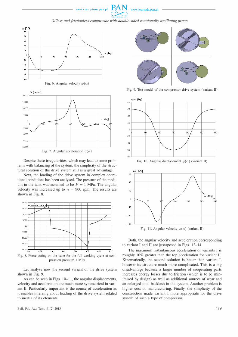
Fig. 6. Angular velocity ω(α)
Fig. 7. Angular acceleration γ(α)
Despite these irregularities, which may lead to some prob-
lems with balancing of the system, the simplicity of the struc-
tural solution of the drive system still is a great advantage.
Next, the loading of the drive system in complex opera-
tional conditions has been analysed. The pressure of the medi-
um in the tank was assumed to be P = 1 MPa. The angular
velocity was increased up to n = 900 rpm. The results are
shown in Fig. 8.
Fig. 8. Force acting on the vane for the full working cycle at com-
pression pressure 1 MPa
Let analyse now the second variant of the drive system
shown in Fig. 9.
As can be seen in Figs. 10–11, the angular displacements,
velocity and acceleration are much more symmetrical in vari-
ant II. Particularly important is the course of acceleration as
it enables inferring about loading of the drive system related
to inertia of its elements.
Fig. 9. Test model of the compressor drive system (variant II)
Fig. 10. Angular displacement ϕ(α) (variant II)
Fig. 11. Angular velocity ω(α) (variant II)
Both, the angular velocity and acceleration corresponding
to variant I and II are juxtaposed in Figs. 12–14.
The maximum instantaneous acceleration of variants I is
roughly 10% greater than the top acceleration for variant II.
Kinematically, the second solution is better than variant I,
however its structure much more complicated. This is a big
disadvantage because a larger number of cooperating parts
increases energy losses due to friction (which is to be min-
imised by design) as well as additional sources of wear and
an enlarged total backlash in the system. Another problem is
higher cost of manufacturing. Finally, the simplicity of the
construction made variant I more appropriate for the drive
system of such a type of compressor.
Bull. Pol. Ac.: Tech. 61(2) 2013 489

W. Chomczyk et al.
Fig. 12. Angular acceleration γ(α) (variant II)
Fig. 13. Comparison of angular velocities for both variants
Fig. 14. Comparison of angular accelerations for both variants
A CAD model was created and thoroughly examined by
numerical simulations. By changing the length of the con-
necting rod L, the effect of the ratio L/R = δ on the course
of angular acceleration was investigated.
As can be seen in Fig. 15, growth of the ratio between the
length of the connecting rod L and length of the rocker arm Rdecreases the maximum positive accelerations and increases
the maximum negative ones, i.e. equalizes both the absolute
maximum values. The most disadvantageous is the acceler-
ation course at δ → ∞. Obviously, the final dimensions Land R are an effect of a compromise between the compact-
ness of the compressor and its strength and reliability, hence
these crucial parameters will be set up at a further stage of
designing.
Fig. 15. Angular accelerations for different values of δ
As far as the dynamics of the drive system is concerned,
according to the model shown in Fig. 16 and the correspond-
ing results of simulation (Figs. 16 and 17), it is seen that the
inertia forces and pressure have different courses and opposite
senses at their maxima. This enables lowering the resultant
reaction on the crank-pin as well as on the compressor shaft
through selection of the masses and geometry of the whole
system.
Fig. 16. Model of the drive system created in ADAMS. Example for
full rotate of engine shaft in time 0.07 [s]
Fig. 17. Course of loadings [N] in the assumed drive system for
given operational conditions
An advantageous distribution of loadings is related to the
given operational conditions. Hence, the optimization should
be made for the limit pressure of the medium in the tank
490 Bull. Pol. Ac.: Tech. 61(2) 2013

Oilless and frictionless compressor with double-sided rotationally oscillating piston
(Fig. 6). The pressure in the cylinder chamber will be slightly
higher.
Fig. 18. Example of optimization of the crank shape in the drive
system
The introduced modifications lowered the reaction on the
vanes by 2000 N at the external position of the crank and
enlarged by 1000 N at the internal position. There are, ad-
mittedly, two maxima of the loading acting on the crankshaft
system (compare Figs. 17 and 19 after modification).
Fig. 19. Forces in the drive system after introducing optimization
modifications
4. Timing gear of the compressor
The timing gear of a compressor is a system which sets
the moment of opening of the valves, time of filling-in and
pressing-out. The fundamental requirements for the timing
gear are: leak tightness, possibly the greatest cross-section of
the flow at the lowest circumference, small flow resistance (in-
duced by the change of flow direction and its cross-section)
low stroke and mass of movable parts of the valves allow-
ing the drive system running really fast, assuring small clear-
ance volume, quiet operation, high durability and low cost of
manufacturing. A self-acting timing has been applied in the
considered compressor: the opening and closing of the valves
is controlled by a spring just after the pressure behind and
in front of the valve is equalized. The drawback of such a
solution is the necessity of keeping low stroke of the valves,
which – for fast-speed compressors – forces the diameter of
the valves to be great enough, which – in turn – enlarges the
clearance volume. In the considered case of a bilateral, oilless
and frictionless compressor, the velocity is reasonably low for
application of a simple by design the self-acting timing gear.
Poppet, plate and ring valves have been analysed. The poppet
valves are characterised by a considerable inertia and com-
plex construction, whereas the plate ones have big clearance
volume which makes the flow slower. That is why the ring
valve has been decided to be incorporated in the prototype of
the compressor (Figs. 20, 21).
Fig. 20. CAD model of the ring valve with the simplified construction
Fig. 21. Prototype of the ring valve worked out for the oscillatory
compressor
An own design has been worked out and optimised in
terms of the compressor efficiency. The limitation was the
overall dimension. The maximum allowable diameter of the
valves placed in the baffles, two for each pressure chamber, is
32 mm. A parametrised CAD model of the valve has been pre-
pared. Dimensions of the valve have been initially assumed,
and then correlated. After that, a relationship for the first and
second cross-section area P1, P2 in function of d and D has
been derived, see Fig. 22.
Bull. Pol. Ac.: Tech. 61(2) 2013 491

W. Chomczyk et al.
Fig. 22. Calculations of cross-sections P1 and P2 made in MathCad
Fig. 23. Optimization diagram for the ring valve with the simplified
construction
Fig. 24. Placement of valves: 1 – outlet valve, 2 – inlet valve
Most piston compressors are equipped with valves mount-
ed in the head, as it is an optimal solution. As far as oscillatory
compressors are concerned, the problem is much more com-
plicated. The place corresponding to the head of reciprocating
compressors is the baffle (partition wall) in oscillatory com-
pressors. Because of a specific construction of such devices,
the space free for mounting the valves in the baffles is not
big indeed. This fact inclines the designer to look for other
solutions for placing the valve in the compressor. Below, the
considered variant is discussed – the pressure valve mount-
ed in the baffles, the suction ones in the chamber. Such a
constructional solution is depicted in Fig. 35. It does howev-
er, affect the course of indication. A considerable drawback
here, is an impulsive character of operation of the suction
valves. Sudden opening of the valves brought about by high
underpressure generates noise and vibration. Additionally, the
possibility of supersonic gas flow is also an undesirable effect.
The main disadvantage of such a solution is the lack of prob-
lems with space for valves, which allows the designer to apply
any kind of valves appropriately selected for the oscillatory
compressor.
Fig. 25. Baffle of the oscillatory compressor with built-in ring type
valves
5. Pressure chamber
The pressure chamber in the oscillatory compressor is com-
prised of several elements. The main dimensions and parts
belonging to it are shown in Fig. 26.
Fig. 26. Pressure chamber of the oscillatory compressor: 1 – cylinder,
2 – vane, 3 – shaft, 4 – baffle, 5 – cover
492 Bull. Pol. Ac.: Tech. 61(2) 2013

Oilless and frictionless compressor with double-sided rotationally oscillating piston
The diameter D and height h as well as the maximum
working angle ϕ are the characteristic dimensions for such
a type of compressor, and have been initially set up at the
beginning of designing the entire mechanism. Other dimen-
sions, such as vane thickness and shaft diameter d result from
strength analysis. It has been initially assumed that the lower
limit of rotation speed would not drop below n = 750 rpm,
and the nominal one would be established during experimen-
tal tests on a real prototype, and – expectedly – would depend
on operational efficiency of the valves.
6. Structural design of the vaned shaft
Technological reasons, more precisely – high demand for
quality of the cylindrical surface of the pressure chamber re-
sponsible for tightness between the shaft and baffles, excluded
in practice the possibility of making use of the shaft and vanes
as a single elements manufactured, e.g. by forging. Contact-
less, labyrinth seal requires precisely distributed gap between
the elements, kept within 0.02–0.04 mm. That is why the out-
er surface of the shaft must be finished by grinding before
the assembling (Fig. 27b). Another problem to be solved was
the way of connecting the shaft with vanes. Among many pro-
posals, like welding or studding, two most promising methods
have been selected. The first one that attracted particular at-
tention was joining the elements through the so-called dovetail
(see Fig. 27a).
a)
b)
Fig. 27. a) Connection between the shaft and vane through a dove-
tail: 1 – shaft, 2 – vane (piston), 3 – ring seal, 4 – bearing; b) Seal
between the shaft and baffles
a)
b)
Fig. 28. a) Reduced stresses in the vane (ANSYS); b) milling of the
socket: with a profile cutter (left), with a plain milling cutter (right)
Unfortunately, such a connection is far from ideal. There
appeared many technological problems with manufacturing
the socket for the vane. One of the possibilities was to mill
the socket with a profile cutter (Fig. 28a). Another one was
to make use of a plain milling cutter (Fig. 28b). The biggest
problem, however, was the question of strength. Investigations
harnessing the finite element method through application of
ANSYS software revealed that the stresses generated by the
maximum pressure acting on the vanes (Pmax = 1 MPa) reach
locally roughly 200 MPa (Fig. 28a), which is far too big even
for materials of highest quality. Obviously, another solution
to the issue was necessary to be found. Finally, it was decid-
ed to employ a forced-in joint between the shaft and vanes
(Fig. 29). For the needs of the prototype, the blade groove
was manufactured by milling. In a series production, such a
method would be too time consuming. In the process of des-
tination, the shaft might be pre-treated by forging, and then
the groove finished by broaching. The assembly would then
require a special holder to ensure appropriate mutual setting
of the parts top be joined. The final surface machining of the
vanes, i.e. grinding to ensure sufficient tightness of the com-
pressor (between the vane and chamber as well as the vane
and baffles) would be done after assembling the shaft with
the vanes.
The stress state for the forced-in joint was calculated by
FEM using ANSYS, and is shown in Fig. 29b. The result-
ing stresses are much less than in the dovetail case – their
maximum did not exceed 120 MPa.
Bull. Pol. Ac.: Tech. 61(2) 2013 493

W. Chomczyk et al.
a)
b)
Fig. 29. a) View to the cross-section of the shaft and the forced-in
vane; b) reduced Huber-Misses stresses
7. Manufacturing of the prototype compressor
On the basis of carried out simulations and analyses, an ini-
tial technical documentation of the prototype oilless and fric-
tionless compressor with a rotary oscillating piston has been
worked out. Because of the peculiarity of the construction, the
following problem required to be overcome and solved: man-
ufacturing technology of the bladed piston (vanes), ensuring
sufficient accuracy of the machining of the crucial surfaces
(chamber, vanes, baffles, cover) in terms of the assumed sym-
metry and gap distribution parameters (0.02 ÷ 0.03) mm.
To achieve this, non-uniform distribution of the working
temperature and the resulting deformations affecting the value
of gap had to be taken into account. The prototype case (the
cylinder with the cover) was decided to be made traditionally
of grey cast iron. The shaft vanes of an alloy steel as sep-
arate parts to be joined by forcing the vanes in the grooved
shaft. The partition walls (baffles) should also be made of an
alloy steel. Similar coefficients of thermal expansion of the
cast iron and steel are expected to maintain the gap within as-
sumed limits in operating conditions. Another issue were the
valves. That was confirmed during experiments. Three ques-
tions can be underlined here: the problem of leakage, drop of
efficiency due to flow chocking at higher rotational speeds,
and the problem of inertia loading at greater working fre-
quency (too big mass of moving elements and out-of-phase
operation of the valves). The authors decided to apply com-
mercial ring valves being used in Polish compressors 3JW60.
Alternately, valves of own design had been worked out as well.
After initial verification of the prototype at the end of exper-
imental investigations, suction valves for pneumatic systems
were incorporated and mounted in the cover. In the baffle, on
the other hand, in the place of the suction valve, an additional
pressure valve was built-in. At the final stage of modifications
introduced to the prototype, there were two pressure and two
suction valves in each chamber of the compressor.
a)
b)
c)
d)
Fig. 30. Physical model of the oilless compressor with a double-sided
piston – assembled and in parts
494 Bull. Pol. Ac.: Tech. 61(2) 2013

Oilless and frictionless compressor with double-sided rotationally oscillating piston
During tests at moderate and high pressure of the medium,
there appeared a problem of momentary loss of the gap and
the occurrence of frictional contact between the vane and the
cover (Fig. 33). This was brought about by a non-uniform ther-
mal loading and mechanical loading from the crankshaft sys-
tem (the unbalanced radial component of the dynamic forces).
The problem was solved by introducing an intermediate sup-
port in the drive system and fan cooling.
In Fig. 30, the elements and the whole assembly of the
considered prototype with pressure and suction valves placed
in the baffles (Fig. 30d) are shown. The crankshaft system
driving the compressor without the intermediate support is
depicted in Figs. 30a,b. Suction pipes and reduction valves in
the pressure ducts are shown in Fig. 30b. The labyrinth seal of
the bladed piston and the baffles is illustrated in Figs. 30c,d.
The final version of the prototype after verification as-
sumes introduction of additional pressure valves in the place
of suction ones in the baffle, and mounting the suction valves
in the cover – see Sec. 9, Fig. 34.
8. Elaboration and manufacturing
of the test stand for experimental
investigation
Into the composition of the test stand, the following elements
and assemblies entered:
• power source – Lenz’s electric motor with a controller en-
abling continuous regulation of the rotation speed within
0–1450 rpm and a torque-meter,
• transmission system reducing the speed,
• crankshaft system,
• the object of study – oilless, frictionless compressor,
• pressure tank for the compressed medium having volume
of 100 dcm3 and being equipped with pipes, valves and a
pressure pick-up,
• measuring apparatus – pressures gauges, thermometers, an-
gular position sensors, flow-meter, computer with ESAM
CF software for data registration,
• vibroinsulating plate with fixing elements.
The test stand enabled investigation of the compressor for
rotation speeds within n = 0–1000 rpm after reduction, or up
to 1450 rpm without it. The engine (electric motor) with a
surplus power and torque allowed examination of compressors
with higher efficiency. The certificated tank stored 100 dcm3
of the medium (air) compressed up to 10 bar. For measure-
ment of pressure in the chambers and baffles, commercial
gauges Johnson Controls P499VBS-401C were used.
The employed software enabled digital registration and
then visualization of the data gathered by the pressure gauge,
angular position sensor and the flow-meter in function of time
or angular displacement (volume after re-scaling). This al-
lowed the investigators to currently draw the indicator dia-
grams. Temperature measurements were realised with help of
thermocouples and a thermovision camera.
Fig. 31. Test stand with the measuring apparatus
9. Qualitative studies on the prototype
Experimental investigations of the prototype compressor were
carried out on the test stand described in the previous Sec-
tion. Tests checking the quality of assembling and operating
were done for small rotation speeds n = 0 − 250 rpm. Next,
after controlling the setting and fixing of the compressor, the
air tank was connected, which was followed by pressure mea-
surement with a dial gauge. At the crankshaft rotation speed
n = 450 rpm, the pressure reached 4.5 bar in 4 minutes.
Further tests were realised after installing pressure gauges in
the chambers and baffles of the compressor. That allowed the
assessment of the operation of the valves. Achievement of
6 bars in the tank did not make any problem. However, the
pressure in the chambers was too big comparing to that in the
tank (see Fig. 35). Also the temperature distribution in the
outlet pipes was very non-uniform – Fig. 32. This bespoke an
excessive chocking of the forced-out air on the valves as well
as leakage in the chambers at the left side.
The drop of pressure in the left outlet pipe was eliminat-
ed by milling the seat having threaded mounting of the check
valve and by eliminating its skeweness. The non-uniformity
of temperature distribution left, however less severe.
The test were continued for increasing rotation speeds up
to n = 0–1000 rpm. Due to pressure asymmetry in the left and
right chamber, which appeared for higher pressures, to conical
pivot of the piston shaft turned with relative to the hub of the
rocker arm (elasto-frictional joint), which consequently led to
the pressing of the vanes against the baffle at the pressure
side. Traces of rubbing are shown in Fig. 33. Rubbing also
occurred on the middle part of the shaft in the contact region
with the labyrinth seal. This was – as precisely measured af-
ter disassembling the prototype – due to deformations brought
about by temperature growth in the thermo-compressed bond-
ing between the shaft and vanes.
Bull. Pol. Ac.: Tech. 61(2) 2013 495

W. Chomczyk et al.
Fig. 32. Temperature distribution in the prototype compressor under
low loading conditions (Ptank = 0.6 MPa) Fig. 33. Visualization of the rubbing traces
Fig. 34. Test stand with the modified compressor fully furnished with measuring apparatus
496 Bull. Pol. Ac.: Tech. 61(2) 2013

Oilless and frictionless compressor with double-sided rotationally oscillating piston
Grinding-in with a specially designed device partly elimi-
nated the asymmetry. At higher speeds, the unbalanced radial
components of dynamical forces bent the shaft and skewed
it within limits of the radial gap of the rolling bearings and
their fit in the cover seats. This generated an axial component
of the dynamic force which shifted the vaned shaft towards
“pressure” baffle. The total clearance amounted 0.025 mm.
Its distribution was manually established while assembling
the system. At those values, the symmetrical distribution dur-
ing operation was unachievable. Consistently, it was decided
to unload the vanes by making use of an intermediate support
taking the direct load from the connecting rod and transfer-
ring pure torque to the vaned shaft – Fig. 34. Following tests
on a modified drive system and dimensional correction of the
shaft revealed better operation of the compressor. There was
no rubbing observed, and the generated pressure in the tank
reached 8 bars – Figs. 35 and 36. The results were better,
however still not fully satisfactory. The working pressure in
the chambers was too still big, and the compressor excessive-
ly heated up. Too low flow capacity of the valves did not
allow developing full efficiency of the compressor. In the giv-
en constructional and technological conditions, an additional
pressure valve in each baffle was installed in the place of
the suction valve, which – in turn – was moved to the only
left area – the cover. Check valves with a considerable cross-
section were used for the suction valves. Unfortunately, the
are characterised by an enlarged inertia. After that modifica-
tion, the compressor generated 5.5 ÷ 6.0 bars in the tank in
3.5 min. at barely n = 220 rpm. Yet a higher pressure was un-
achievable despite augmenting the speed up to n = 450 rpm.
The temperature rapidly grew, but the pressure was increas-
ing very slowly. The reason was too big inertia of the suction
valves. It was decided then to replace these valves once again,
this time with valves having a smaller cross-section and in-
ertia, resembling the construction of the pressure valves. It
was not an optimal solution, but facing the lack of alterna-
tive, it improved the working efficiency for higher rotation
speeds. The pressure in the tank grew up to 8.0 ÷ 8.5 bars
at n = 850 rpm. No rubbing occurred, and the temperature
in the left and right chamber became more evenly distrib-
uted. Still, the theoretical efficiency of the compressor was
not gained. The suction valves did not secure sufficient input.
Admittedly, there was no possibility of improving the prob-
lem essentially because of constructional issues that excluded
the placement of bigger suction valves or making them dou-
ble.
Fig. 35. Courses of pressure in both chambers (colour on-line)
Bull. Pol. Ac.: Tech. 61(2) 2013 497

W. Chomczyk et al.
Fig. 36. Indicator diagrams based on pressure variations in both chambers according to measurements carried out on the test stand shown
in Fig. 34
10. Concluding remarks at the current stage
of investigations
• The fundamental task is the correct selection of valves –
the pressure ones should have greater capacity than that
calculated theoretically on the basis of the chamber vol-
ume.
• The suction valves should have at least the same capacity
as the pressure ones.
• The compressor design should compensate the effect of
unbalanced dynamical forces.
• An optimal solution seems to be the compressor with a
rotating piston and cylinder (patent P385734) allowing re-
duction of mechanical loading and ensuring better filling-in
by giving more space for placing the pressure and suction
valves.
• Introducing a thermo-compressionless joint for the vanes.
• Making use of cer-metals to lower the mass by half and to
decrease the inertia loading.
• Consideration of an alternative design with the pressure
valves mounted in the vanes and the suction ones placed
in the baffles together with self-lubricating seals instead of
the labyrinth ones.
• Optimization of geometrical parameters and stroke of de-
veloped digital model and the analytical relationship of the
proposed suction valve, made it possible to increase the
capacity of the ring valve.
• It should be noted that in the case of displacement ma-
chines with reciprocating piston move, minimize dynamic
forces occurs only in a narrow range of speed and pressure
on the blades of the piston.
• The forces of inertia of rod drive system and force the of
the pressure on the piston have their maxima of opposite
sign. They are closer to each other in absolute value, the
resultant load is less.
• The worked out prototype confirmed the potentiality of
achieving the assumed operational parameters after intro-
ducing the above discussed modifications.
REFERENCES
[1] W. Chomczyk, Multi-chamber Sucking-forcing-out Working Ma-
chine, Bialystok University of Technology, Białystok, (to be pub-
lished), (in Polish).
[2] V. Chlumsky, Piston compressors, PWT, Warszawa, 1961, (in
Polish).
[3] W. Chomczyk, Multi-chamber Working Machine with a Vaned
Piston, Especially as a Compressor, Pump, Engine, Patent No.
68220, 1973, (in Polish).
[4] W. Chomczyk, W. Ostapski, and J. Piotrowski, Frictionless and
Oilless Compressor with a Rotating Piston and Cylinder, Patent
No. P385734, 2008, (in Polish).
[5] W. Chomczyk, W. Ostapski, and J. Piotrowski, Frictionless and
Oilless Compressor with a Fixed Piston and Rotating Cylinder,
Patent No. P385733, 2008, (in Polish).
[6] W. Ostapski and J. Piotrowski, Construction of an Unloaded
Piston for Uplift Machines, Patent No. P394072, 2011, (in Pol-
ish).
[7] M. Hać, J. Łazęcki, and W. Ostapski, “Modeling of driving
mechanism of oscillatory air–compressor”, Machine Dynamics
Problems 33 (3), 13–24 (2009).
[8] T. Tataj, “A design of an oscillatory compressor”, MSc Thesis,
Warsaw University of Technology, Warsaw, 2007, (in Polish).
498 Bull. Pol. Ac.: Tech. 61(2) 2013