Electrochemical hydrogen compressor
6
Electrochemical hydrogen compressor B. Rohland*, K. Eberle, R. Stro¨bel, J. Scholta and J. Garche Center for Solar Energy and Hydrogen Research Baden-Wuerttemberg, Division 3: Energy Storage and Conversion, Helmholtzstr. 8, D-89081 Ulm, Germany (Received 6 February 1998; in revised form 6 February 1998) Abstract—The electrochemical compression of hydrogen is well known since years. But new developments of the polymer electrolyte membrane (PEM) fuel cells make it possible to realize the electrochemical com- pression in a PEM-cell with high eciency. A new cell design of PEM-cells for operation with a high press- ure dierence between anode side and cathode side was developed. The purification of hydrogen from carbon monoxide of the reformer gas can be integrated in the hydrogen compressor cell. Operation par- ameters are presented. # 1998 Published by Elsevier Science Ltd. All rights reserved Key words: hydrogen compression, hydrogen storage, hydrogen purification, fuel cell, PEM-cell. INTRODUCTION Hydrogen can be stored by dierent methods. These are in general the storage of hydrogen gas- eous, liquid or in metal hydrides. Each storage method has its advantages and disadvantages. Though the gaseous hydrogen has a low specific volumetric energy density, compared to the other methods, it is still a preferred way to storage hydro- gen for certain applications, because of eciency and simplicity. To improve the specific volumetric energy density of gaseous hydrogen storage it is necessary to compress the hydrogen to high press- ures. To keep the energy eciency of the system high, it is important to have an ecient hydrogen compressor [1]. Mechanical hydrogen compressors are available for high and low power applications. In the low power application, however, the eciency of the mechanical hydrogen compressors is low in relation to the electrochemical hydrogen compressor in a polymer–electrolyte-membrane (PEM)-cell. Figure 1 shows the specific energy in kW h N 1 m 3 com- pressed hydrogen plotted versus the nominal power of several kinds of compressors. Mechanical compressors (curves represent typical values for 20 and 30 bar) with a nominal power of more than 100 kW are very ecient, but for smaller units the specific energy increases continuously with decreasing power. Because of a higher contribution of the mechanical friction losses. Electrochemical compressors (flat lines, Fig. 1), are more ecient for low power applications than mechanical ones. Because the irreversible energy loss, caused by I 2 R, decreases with the current den- sity (decreasing cell voltage) or decreasing nominal power. About 50% of the total energy consumption of the electrochemical hydrogen compressor counts to the reversible part (Dp*V). PRINCIPLE AND APPLICATION The operating principle of the PEM hydrogen compressor (PEM-HYCO) is shown in Fig. 2. The equilibrium potential of such a unit is given by the NERNST equation U U 0 RT 2F ln p II H2 p I H2 : When an external current is applied, hydrogen of the pressure p H2 I is oxidized at the anode to protons (H + ), which are transported across the PE-mem- brane and reduced at the cathode to hydrogen at p H2 II . This process is selective for hydrogen, inert gas components can not cross the membrane, they are removed from the compressed hydrogen. According Faradays law, the amount of hydrogen transported to the cathode side of the cell is Electrochimica Acta, Vol. 43, No. 24, pp. 3841–3846, 1998 # 1998 Published by Elsevier Science Ltd. All rights reserved Printed in Great Britain 0013–4686/98 $19.00 + 0.00 PII: S0013-4686(98)00144-3 *Author to whom correspondence should be addressed. Tel.: +49 731 9530207; Fax: +49 731 9530666; E-mail: [email protected] 3841
-
Upload
independent -
Category
Documents
-
view
0 -
download
0
Transcript of Electrochemical hydrogen compressor

Electrochemical hydrogen compressor
B. Rohland*, K. Eberle, R. StroÈ bel, J. Scholta and J. Garche
Center for Solar Energy and Hydrogen Research Baden-Wuerttemberg, Division 3: Energy Storage andConversion, Helmholtzstr. 8, D-89081 Ulm, Germany
(Received 6 February 1998; in revised form 6 February 1998)
AbstractÐThe electrochemical compression of hydrogen is well known since years. But new developmentsof the polymer electrolyte membrane (PEM) fuel cells make it possible to realize the electrochemical com-pression in a PEM-cell with high e�ciency. A new cell design of PEM-cells for operation with a high press-ure di�erence between anode side and cathode side was developed. The puri®cation of hydrogen fromcarbon monoxide of the reformer gas can be integrated in the hydrogen compressor cell. Operation par-ameters are presented. # 1998 Published by Elsevier Science Ltd. All rights reserved
Key words: hydrogen compression, hydrogen storage, hydrogen puri®cation, fuel cell, PEM-cell.
INTRODUCTION
Hydrogen can be stored by di�erent methods.
These are in general the storage of hydrogen gas-
eous, liquid or in metal hydrides. Each storage
method has its advantages and disadvantages.
Though the gaseous hydrogen has a low speci®c
volumetric energy density, compared to the other
methods, it is still a preferred way to storage hydro-
gen for certain applications, because of e�ciency
and simplicity. To improve the speci®c volumetric
energy density of gaseous hydrogen storage it is
necessary to compress the hydrogen to high press-
ures. To keep the energy e�ciency of the system
high, it is important to have an e�cient hydrogen
compressor [1].
Mechanical hydrogen compressors are available
for high and low power applications. In the low
power application, however, the e�ciency of the
mechanical hydrogen compressors is low in relation
to the electrochemical hydrogen compressor in a
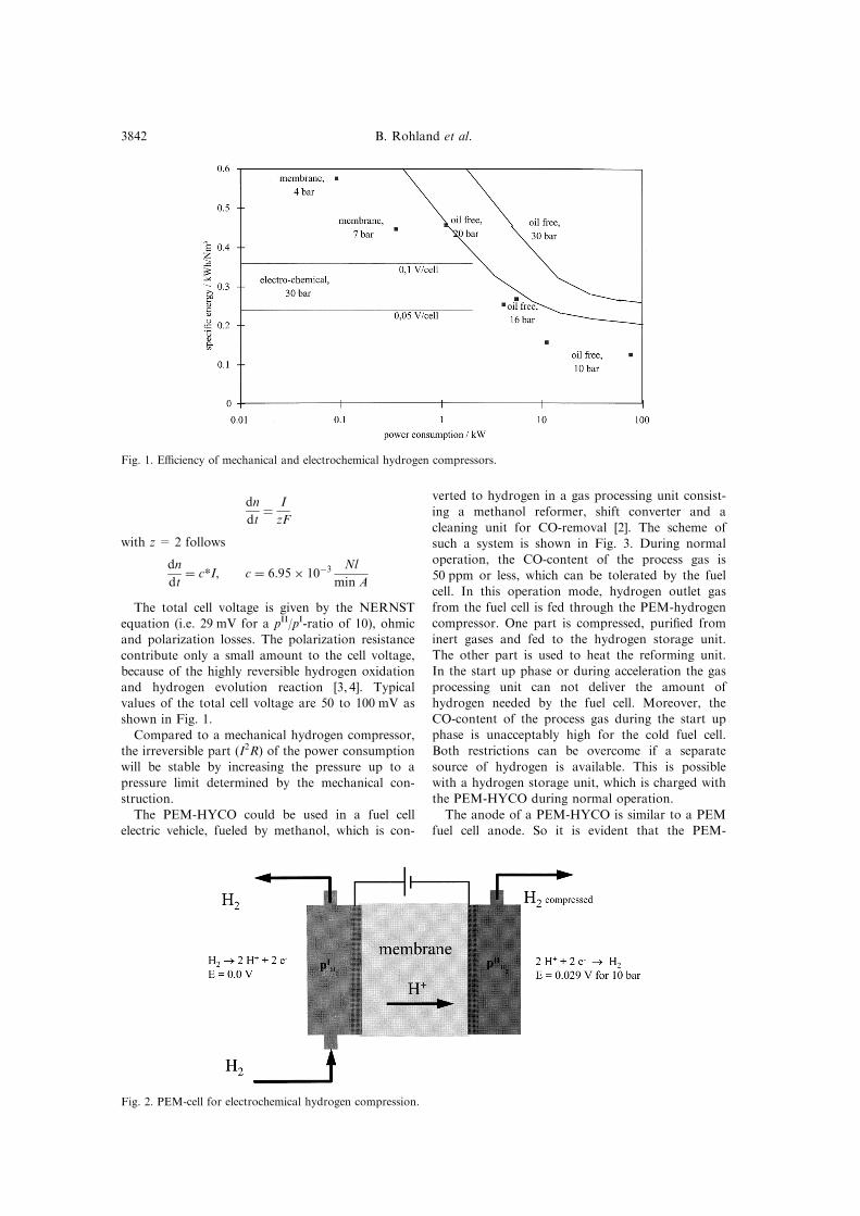
polymer±electrolyte-membrane (PEM)-cell. Figure 1
shows the speci®c energy in kW h Nÿ1 mÿ3 com-
pressed hydrogen plotted versus the nominal power
of several kinds of compressors.
Mechanical compressors (curves represent typical
values for 20 and 30 bar) with a nominal power of
more than 100 kW are very e�cient, but for smallerunits the speci®c energy increases continuously with
decreasing power. Because of a higher contributionof the mechanical friction losses.Electrochemical compressors (¯at lines, Fig. 1),
are more e�cient for low power applications than
mechanical ones. Because the irreversible energyloss, caused by I2R, decreases with the current den-sity (decreasing cell voltage) or decreasing nominal
power. About 50% of the total energy consumptionof the electrochemical hydrogen compressor countsto the reversible part (Dp*V).
PRINCIPLE AND APPLICATION
The operating principle of the PEM hydrogencompressor (PEM-HYCO) is shown in Fig. 2. Theequilibrium potential of such a unit is given by the
NERNST equation
U � U0 � RT
2FlnpIIH2
pIH2
:
When an external current is applied, hydrogen ofthe pressure pH2
I is oxidized at the anode to protons
(H+), which are transported across the PE-mem-brane and reduced at the cathode to hydrogen atpH2II . This process is selective for hydrogen, inert gas
components can not cross the membrane, they areremoved from the compressed hydrogen. AccordingFaradays law, the amount of hydrogen transportedto the cathode side of the cell is
Electrochimica Acta, Vol. 43, No. 24, pp. 3841±3846, 1998# 1998 Published by Elsevier Science Ltd. All rights reserved
Printed in Great Britain0013±4686/98 $19.00+0.00PII: S0013-4686(98)00144-3
*Author to whom correspondence should be addressed.Tel.: +49 731 9530207; Fax: +49 731 9530666; E-mail:[email protected]
3841
dn
dt� I
zF
with z = 2 follows
dn
dt� c*I, c � 6:95� 10ÿ3
Nl
min A
The total cell voltage is given by the NERNST
equation (i.e. 29 mV for a pII/pI-ratio of 10), ohmic
and polarization losses. The polarization resistance
contribute only a small amount to the cell voltage,
because of the highly reversible hydrogen oxidation
and hydrogen evolution reaction [3, 4]. Typical
values of the total cell voltage are 50 to 100 mV as
shown in Fig. 1.
Compared to a mechanical hydrogen compressor,
the irreversible part (I2R) of the power consumption
will be stable by increasing the pressure up to a
pressure limit determined by the mechanical con-
struction.
The PEM-HYCO could be used in a fuel cell
electric vehicle, fueled by methanol, which is con-
verted to hydrogen in a gas processing unit consist-
ing a methanol reformer, shift converter and a
cleaning unit for CO-removal [2]. The scheme of
such a system is shown in Fig. 3. During normal
operation, the CO-content of the process gas is
50 ppm or less, which can be tolerated by the fuel
cell. In this operation mode, hydrogen outlet gas
from the fuel cell is fed through the PEM-hydrogen
compressor. One part is compressed, puri®ed from
inert gases and fed to the hydrogen storage unit.
The other part is used to heat the reforming unit.
In the start up phase or during acceleration the gas
processing unit can not deliver the amount of
hydrogen needed by the fuel cell. Moreover, the
CO-content of the process gas during the start up
phase is unacceptably high for the cold fuel cell.
Both restrictions can be overcome if a separate
source of hydrogen is available. This is possible
with a hydrogen storage unit, which is charged with
the PEM-HYCO during normal operation.
The anode of a PEM-HYCO is similar to a PEM
fuel cell anode. So it is evident that the PEM-
Fig. 1. E�ciency of mechanical and electrochemical hydrogen compressors.
Fig. 2. PEM-cell for electrochemical hydrogen compression.
B. Rohland et al.3842

HYCO has also the CO sensitivity of the fuel cell.
A new developed double layer anode [4] (Fig. 4)does overcome this CO sensitivity problems. The
PEM-HYCO combined with the double layer anodecan oxidize the CO load (00.2%) of the outlet gas
of a methanol reformer chemically to CO2 at the
anode, if 1% oxygen bleed is added. The carbondioxide has to be removed from the anode gas com-
partment through the anode outlet. To avoid masstransportation limitations, the catalyst layer has to
be thin and porous. To realize this catalyst layer, it
is necessary to have a high active selective CO-oxi-dation catalyst on a porous support. The thin layer
makes the back di�usion of the CO2 from the cata-lyst layer into the anode gas compartment possible.
The result is, a decreased CO sensitivity of theHYCO with double layer anode.
A further application for the hydrogen compres-
sor is the combination of an oxygen getter andcompressor for alkaline water electrolysers. The
hydrogen produced in these types of electrolysers
contains traces of oxygen. At the anode this oxygen
will be catalytically reduced with hydrogen towater. The puri®ed hydrogen evolved at the cathode
contains only water vapor from the dehydration ofthe protons. The hydrogen can be compressed in ahydrogen storage connected to the cathode side.
In combination with a hydrogen storage thehydrogen compressor can be used as an electro-chemical actor. The hydrogen ¯ow from the cath-
ode side to the anode side or reverse will move amechanical piston. So electrical energy will be trans-formed into mechanical energy.
EXPERIMENTAL
The cell design of the hydrogen compressor issimilar to the fuel cell arrangement (see Fig. 2). Theuse of a solid polymer electrolyte membrane makesit necessary to keep this membrane hydrated. The
protons are only transported in this types of elec-trolytes if they cross the membrane in the hydratedform. For this reason the membrane has to be satu-
rated with water to have a good ionic conductivity.
Fig. 3. Application of the PEM-HYCO in a fuel cell electric vehicle.
Fig. 4. Principle of the double layer anode of a PEM-HYCO or a PEMFC.
Electrochemical hydrogen compressor 3843

The fact that the PEM-HYCO does not produce
water like a fuel cell does makes it necessary to deli-
ver the water as water vapor through the anode
inlet. Water that crosses the membrane accumulates
at the cathode side, since the protons dehydrate on
account of evolution of hydrogen. Because of the
pressure di�erence this water di�uses to the anode
side. The results is, less water has to be fed through
the anode inlet. Water vapor related to the satur-
ation pressure at cell temperature and transported
by the hydrogen feed is su�cient to keep the mem-
brane in a saturated state.
A special construction of the anode ¯ow ®eld is
necessary to stabilize the membrane electrode
assembly (MEA) combination, because of high
forces against the ¯ow ®eld caused by high press-
ure. Because of high pressure, the deformation of
the MEA is unavoidable, for this reason it is necess-
ary to construct the cathode ¯ow ®eld with a
special ¯exible graphite sheet. The ¯exibility of the
graphite sheet can compensate the deformation of
the MEA, so the electric contact of cell housing,
¯ow ®eld and MEA is almost stabile. In order to
decrease hydrogen di�usion losses and to increase
mechanical stability the cell housing is made from
DIN 1.4404 stainless steel.
The MEA was a commercial ETEK1 unit with a
loading of 2 mg Pt/cm2 made from a Na®on1 117
membrane. The active electrode area was 100 cm2.
The cell voltage and the cathode pressure were
measured galvanostatically at current densities from
100 mA/cm2 up to 350 mA/cm2 vs time (Fig. 8).
For all measurements, the anode was kept at ambi-
ent pressure. The hydrogen storage volume at the
cathode side was kept stable at 13 ml.
The pressure di�erence between anode side and
cathode side causes back di�usion of molecular
hydrogen from the cathode side to the anode side.
The rate of back di�usion is important to evaluate
the e�ciency of the hydrogen compressor. The back
di�usion rate was measured at di�erent cathode
pressures and cell temperatures. The Hydrogenreservoir was isothermally pressurized to the chosen
pressures. After that, the current was switched o�.To measure the back di�usion, the anode inlet wasdisconnected from the hydrogen source and the
inlet was sealed. The anode outlet was connectedwith a transparent tube containing a water column.The back di�using hydrogen increases the pressure
of the anode compartment, which can be monitoredby the water column. The back di�usion rate wasmeasured by the amount of compensating current
to keep the anode pressure constant. The molecularhydrogen back di�usion is obtained by the compen-sation current for constant pressure and theFaraday equation.
RESULTS AND DISCUSSION
In Fig. 5 the measured cell voltage (dotted line) is
compared with the calculated NERNST voltage(solid line) versus the pressure in the cathode com-partment (pH2
II ). The voltage di�erence between the
two curves is caused by the IR-drop and polariz-ation of both electrodes. The IR-resistance wasmeasured with the current interruption method. Inthis cell unit 0.7 O cm2 were obtained. Knowing the
IR-drop and the NERNST-voltage, it is possible tocalculate the polarization loss of both electrodes. Inthis case the polarization loss is 5 mV, with the cur-
rent density of 50 mA/cm2, the polarization resist-ance is 0.1 O cm2.Figure 6 shows the increase of the pressure in the
cathode compartment (pH2II ) vs time. At the
described experimental conditions 43 bar areachieved after 18 min. The potential after switchingon the current (t= 0) raised to 40 mV. From this
40 mV 35 are related to the IR-drop (mainly resist-ance of the polymer membrane cell unit) and 5 mVare contributed from polarization of both electro-
des. The observed potential increase during the ®rst7 min is in accordance with the NERNST-equation
Fig. 5. Cell voltage (U) versus hydrogen pressure (Dp) of a PEM-HYCO-cell (A = 100 cm2; I = 5; R = 0.7 O cm2;
dv/dt = 35 ml/min).
B. Rohland et al.3844

(solid line). From 7 min up to 17 min, a di�erence
between calculated curve and measured curve isobserved, which is caused by MEA compression,
followed by an increasing IR-drop caused byincreasing contact resistance. After 17 min thepressure rise stopped because of a leakage between
the membrane and the seals.Figure 7 shows the molecular hydrogen ¯ux
through the membrane versus the cathode compart-ment pressure at 24 and 708C cell temperature. The
back di�usion rate of hydrogen increases linearlywith increasing pressure di�erence. At 248C cell
temperature the di�usion rate is0.08 ml barÿ1minÿ1 cmÿ2, at 708C cell temperaturethe di�usion rate is 0.27 ml barÿ1minÿ1 cmÿ2. As
expected higher temperature and pressure di�erencewill increase the hydrogen back di�usion.
The back di�usion decreases the e�ciency of thehydrogen compressor. These e�ciency loss is linked
with the pressure di�erence over the membrane.For example, if a e�ciency loss of 5% is accepted,
that means the compensation current for the back
di�usion is 5% of the total current density.Assuming a current density of 0.350 A cmÿ2 the
pressure limit will be 160 bar at 248C and 46 bar at708C.As it is shown in Fig. 8, the electric energy
(U*I*t) (needed to raise the pressure inside thevolume of the cathode side) increases by increasing
the current density. This is caused by the increasedI2R-loss of the PEM-cell. At 43 bar pressure di�er-
ence between anode side and cathode side of thePEM-cell this energy demand increases rapidly,
because of rapid hydrogen loss by leakage over cell-seals. To optimize the HYCO the seals have to beimprove.
The current is the reason for the amount ofhydrogen evolved at the cathode side. To improve
the speci®c ¯ow rate of the electrochemical hydro-gen compressor, the current density has to be
increased. But a increasing current density causesincreasing I2R-loss, that means decreasing energy
Fig. 7. Hydrogen back di�usion for 248C and 708C versus pressure di�erence between anode and cathode.
Fig. 6. Cell voltage and hydrogen pressure (measured and calculated) versus time (A = 100 cm2; I = 5 A;
R = 0.7 O cm2; dv/dt = 35 ml/min).
Electrochemical hydrogen compressor 3845

e�ciency. For these reasons it is important toimprove the contact resistance of the cell unit, to
minimize the irreversible energy loss. Otherwise theapplications of the PEM-HYCO are limited for low¯ow rates, that means low power applications.
CONCLUSIONS
The experimental data demonstrate that the elec-trochemical compression of hydrogen with thePEM-HYCO is a promising option for low power
hydrogen compressors because of process e�ciency,gas puri®cation and noiseless operation.
REFERENCES
1. J. M. Sedlak, J. F. Austin and A. B. LaConti, Int. J.Hydrogen Energy, 1981, 6.
2. F. J. Gardner, GB Patent 2 268 322B, 1995.3. H. Maeda, H. Fukumoto, K. Mitsuda, H. Urushibata,
M. Enami and K. Takasu, FUEL CELL Seminar,Orlando, FL., 1996, pp. 272±275.
4. K. Eberle, B. Rohland, J. Scholta, R. StroÈ bel andV. Plzak, Patent DE 19 615 562.2, 1996.
Fig. 8. Power consumption versus hydrogen pressure at di�erent current densities up to a limit of 43 bar pressure
di�erence.
B. Rohland et al.3846