D-R Compressor Cell - EDGE
19
P13458 RIT Senior Design Team May 10, 2013 10-10:30AM 09-2030 Dresser- Rand, Painted Post http://edge.rit.edu/edge/P13458/public/Home Final Presentation: Compressor Transport System & Layout
-
Upload
khangminh22 -
Category
Documents
-
view
4 -
download
0
Transcript of D-R Compressor Cell - EDGE

P13458 RIT Senior Design Team
May 10, 2013
10-10:30AM
09-2030
Dresser- Rand, Painted Post
http://edge.rit.edu/edge/P13458/public/Home
Final Presentation: Compressor
Transport System & Layout

Agenda Problem Statement
Accomplishments For The Transport System
Design History
Final Design
Summary Of Test Results
Recommendations
Accomplishments For The Layout
Design History
Final Design & Test Results
Recommendations
Reflection On The D-R/RIT Partnership
Reflection On Our Code Of Ethics

Problem Statement
Design a flexible material handling system that is easy to use and incorporates the safest design elements within cost and functionality constraints. This design fully supports the new process layout in Dresser-Rand’s strategic project to increase capacity for the MOS compressor projected sales.
New Shop Floor
6-throw MOS Compressor

Transport System Design History
Design Considerations
Long Beam Caster System
Short Frame Caster System (Yellow Frame)
Air Bearing Technology
Free Support System
Fixed Support System
Modified Support System

Design Considerations
Movement Propulsion

Long Beam Caster System
Assumed entire
compressor assembly
would be loaded, including
cylinders
Assumed massive CG
changes while loaded
Large structural members
necessary

Short Frame Caster System
Yellow Frame Design
Versatile – to account for
multiple product families
Modular – to account for
multiple product sizes
Could not be used at test
station
Was prototyped
Many design flaws
surrounding caster system

Air Bearing Technology
Unidirectional
Nearly frictionless
Reduces horizontal force
required to 1lb per
1000lbs
Air supply is common in
industrial setting
Requires flat, smooth floor
surfaces

Free Support System
Based on the short frame
system
Adapted for air pallet use
Legs fixed to support beam
Concerns regarding
clearance between floor
and legs during movement

Fixed Support System
Vertical “legs” of the Free
system are now fixtures
placed at each station
Eliminates floor clearance
concerns while moving
from station to station
Simplifies manufacturing
Easily integrated into
testing and shipping

Removable Support System Conceptual design
Method of manufacture and
dimensions undetermined
Removable fixture attaches to
beam and acts like a jack
stand
Overcomes flaws that were
revealed during the 3P event
Stress analysis not completed
results should be comparable
to the free system results

Removable Support Qualities Pros
No more fixtures
Resolves ergonomic issues
discovered during the 3P event
Lowers move prep time – no
longer need to configure
fixtures from station to station
Bolt on legs removable for
test and shipping
Cons
Requires the floor to be
leveled
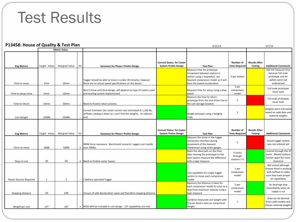
Test Results
EngMetrics TargetValue MarginalValue Dir SummaryforPhaseIPrelimDesign
CurrentStatusforCaster
SystemPrelimDesign TestPlan
Numberof
TestsRequired
ResultsAfter
Testing AdditionalComments
Timetomove 5min 20min -
Tuggershouldbeabletomoveinunder20minutes,however
therearenoactualspeedspecificationsonthedevice
Measuretimeforprototype
movementbetweenstationto
stationusingastopwatch,use
heaviestcompressormodelasitwill
havethelowestacceleration
5perstation
Didnotmeasuretime
becausefullscale
prototypeandAir
palletswerenot
orderedyet
Timetosetupmove 0min 10min -
Won'tknowuntilfinaldesign,willdependontypeofcastersused
andlevelingsystemimplemented
Measuretimeforsetupusingastop
watch
5per
compressor
model
Fullscaleprototype
neverbuilt
Timetoreturn 10min 30min - Needtofinalizereturnprocess
Measurethetimetoreturn
prototypefromtheendofthelineto
thecartstoragelocation
5Fullscaleprototype
neverbuilt
CartWeight 1500lb 2500lb -
CurrentEstimate:(aircasterversionwasestimatedat1,160lbs,
airfloatscatalogisdownsoIcan'tfindtheweights…tosubtract
out)
Weighprotoypeusingahanging
scale
1
Weightswereestimated
basedoncadddataand
materialweights
EngMetrics TargetValue MarginalValue Dir SummaryforPhaseIPrelimDesign
CurrentStatusforCaster
SystemPrelimDesign TestPlan
Numberof
TestsRequired
ResultsAfter
Testing AdditionalComments
Forcetomove 100lb 500lb +
300lbforcenecessary.Benchmarkresearch:tuggerscanhandle
over500lbs
Measurethestraininthetugger
connectioninterfaceduring
movementoftheheaviest
compressorusingstraingauges
5Actualtuggersystem
wasnotorderedyet
StaysinLine 3ft 5ft + Needtofinalizecasterlayout
Marktheidealpathonthefloor,
aftermovingtheprototypetothe
nextstationmeasurethedifference
withatapemeasure
5cycles
through
stations1-5
Coveredthroughthe3P
event.Movedstations
fartherapartformore
clearance
PowerSourcesRequired 1 2 - 1BatteryoperatedTugger
Testcapabilityofasingletugger
systemtomoveeachcompressor
model
1per
compressor
model
Nottestedalthough
DresserRandisworking
withAirfloattomake
suretheyhaveproper
aircapabilities
Stoppingdistance 5ft 10ft - Unsureofsafedecelerationvalueandthereforestoppingdistance
Measurethedistanceittakesfor
eachcompressormodeltocoasttoa
stopfrommaximumvelocityusinga
tapemeasure
5per
compressor
model
Airbearingsstop
immediatelywhenair
supplyiscut
Weightpercart 15T 10T + HOSSWillbeincludedincartdesign.15Tcapabilitiesaremet.
Combinemeasuredcartweightwith
DresserRand'sdataoncompressor
weight
1
Datacanbederived
fromcaddmodelsand
knownmaterialweights
MetricValue
P13458:HouseofQuality&TestPlan 3/15/13 5/7/13

Recommendations
Modify testing station to incorporate free-system design
Possible lifting/attachment to test bed
Determine lifting/loading method
Need 3-axis positioning without a crane
Modified Grey Portable Lifting system for vertical lifting
Back truck under lifted compressor
Air bearings under truck bed
Driver positioning

Layout Design History Took dimensions of required
equipment and space for each
station in the assembly, test, and
paint process in the current state
Created factors of varying
importance
Designed 4 different layouts – 2
straight-line, 2 U-shaped – in the
new shop floor
Conducted a 3P event on a U-
shaped layout using cardboard to
check theoretical values against
actual feedback from operators
and line side managers
3P Event Result Factors Affected Status
Tested U-shape design
Returnability
Flexibility
Pass-by/Pass-through
Added new cylinder assembly flow
line
Space Utilization
Inventory Access
Operators and managers evaluated
the layout and gave feedback on
parts and people flow and
equipment requirements
Inventory Access
Ease of Movement by Operator
Movement Time
Found hidden problems and
constraints i.e. spacing between
stations, jib crane requires oil
pump station next to column
Space Utilization
Maintenance Access
Tested – good outlook
Needs further testing, but predict a good outlook
Needs attention, was not addressed

Final design Top Level
Assembly Level
Flow

Recommendations Re-evaluate test bay requirements for sizing and safety –
retractable blast walls
Add in and test inventory flow and information flow
Understand exact requirements and locations for energy/power/air sources
Full dimensioning of layout
Computer simulation of process flow
Continuous evaluation and improvement
5S taping and marking to indicate specific areas, i.e. operator walking zone inside cell, in-process kanban, visitor aisle way
Identify and allocate future expansion area

Reflection on the DR/RIT
Partnership Overall, very successful learning experience
Design process Iterative in nature – lots of ‘back to the drawing board’ moments
Conceptualization and the funnel of idea development
Understanding fluctuating customer needs
Efficiency of communication
Recommend a “consulting” contract be completed at the start To better establish the needs of Dresser Rand
So the team can better prioritize efforts
Recommend creating a communications protocol to prevent delay in work as the team awaits feedback

Reflection On Our Code Of Ethics
Code of Ethics Components Assessment Recommendations
Expectations for Team Behavior:
Honesty, Respect, Accountability, Professional and
Thorough Communication
Good communication during meetings,
but email communication was not
responded to in a timely manner. Also,
accountability could have been better
during MSD II.
Better individual time management,
check email twice daily and respond
Expectations for Integrity of Assigned Tasks:
Tasks should be completed on-time and with the quality
expected as seen in the MyCourses documentation and as
discussed during assignment of the tasks
Completion of tasks was not always done
on time, therefore resulting in wasted
team meeting time catching up on work.
Better individual time management,
more thorough and clear description
of tasks
Not Meeting Expectations:
Any complaints or inability of meeting expectations
should be shared with the team in order to provide more
resources and/or time, or reassign task to another
member
Many tasks completed last minute and
the individuals did not inform the team
of their status or ask for help as often as
they should have.
Mid-week check-ins, project manager
emphasizes team effort - offer help to
others when your workload is light
3 out of 11 components were not followed satisfactorily