A Double-Sided LC Compensation Circuit for Loosely ...
10
Abstract—This paper proposes a double-sided LC compensation circuit for a loosely-coupled, long-distance capacitive power transfer (CPT) system. A CPT system usually contains two pairs of metal plates as the capacitive coupler. An LC compensation circuit resonates with the coupler to generate high voltages, and corresponding electric fields, to transfer power. When the compensation circuit is used on both the primary and secondary sides, it results in a double-sided LC-compensated CPT system. The working principle and frequency properties of the CPT system are analyzed. The results show a similarity with the series-series (SS) compensated inductive power transfer (IPT) system, which has both constant voltage and constant current working modes. LC compensation is also compared with LCLC compensation in terms of power, frequency properties, and output efficiency. A 150W double-sided LC-compensated CPT prototype is designed and implemented to demonstrate a loosely-coupled CPT system with 2.16% coupling coefficient. For both constant-current and constant-voltage working modes, the experimental results achieve dc-dc efficiencies higher than 70% across an air-gap distance of 180mm with a switching frequency of 1.5MHz. Index Terms—Capacitive power transfer (CPT), double-sided LC compensation, frequency property. I. INTRODUCTION apacitive power transfer technology utilizes multiple metal plates to transfer power without direct metal-to-metal contact via alternating electric fields [1, 2]. Since electric fields can experience metal objects without generating significant power losses, CPT can be used in areas where inductive power transfer (IPT) technology [3, 4] is not convenient. CPT technology has been widely used in short-distance applications, varying from mW to kW levels, including biomedical devices [5, 6], integrated circuits [7], LED drivers [8], and the excitation of a rotor field winding in synchronous This work was supported in part by US Department of Energy Graduate Automotive Technology Education Grant; San Diego State University, the University of Michigan-Ann Arbor. Fei Lu is with the Electrical Engineering and Computer Science Department, University of Michigan, Ann Arbor, MI 48109 USA. F. Lu is also with Department of Electrical and Computer Engineering, San Diego State University, San Diego, CA 92182, USA (email: [email protected]). Chris Mi and Hua Zhang are with the Department of Electrical and Computer Engineering, San Diego State University, San Diego, CA 92182, USA. H. Zhang is also with the School of Automation, Northwestern Polytechnical University, Xi’an, 710072 China (email: [email protected], [email protected]). Heath Hofmann is with the Electrical Engineering and Computer Science Department, University of Michigan, Ann Arbor, MI 48109 USA (email: [email protected]). machines [9]. The transfer distance is usually within the mm range, which results in a coupling capacitance of up to tens of nF. When dielectric material is inserted between the coupler plates, the coupling capacitance is significantly increased [10, 11]. This has been used in a CPT system which charges an electric vehicle via the front bumper [12]. The advantage of short-distance CPT systems is that the electric field flux is confined between the metal plates, and the fringing effect of the electric fields is reduced. Therefore, the electric fields emitted to the nearby environment are limited, and it can be safely used in close proximity to living things. Long-distance CPT technology, where the transfer distance can reach hundreds of mm, has not been well studied. It can be used in electric vehicle charging applications, where the vehicle is charged by a transmitter located underneath the vehicle. It can also be readily extended to dynamic charging, where the vehicle receives power while it is moving [13]. The wheels of the vehicle can also help to enhance the capacitive coupling, as the rubber tires can work as a dielectric material to increase the coupling capacitance [14]. The coupling capacitance in a long-distance CPT system is usually in the pF range, which requires either high frequency or high voltage for high power. The switching frequency can be tens to hundreds of MHz [15, 16]. The class-E converter is a good candidate to realize a high-frequency CPT system [17, 18]. However, the power of high-frequency converters is usually lower than the kW level, which limits the power of CPT systems. Increasing the voltage across the coupling plates can increase system power levels. A straightforward method is to use a step-up a transformer with a large turn-ratio to boost the voltage on the plates [19]. An LCL network at the front end can also increase the voltage [20]. However, both of these topologies require a large series inductor to directly resonate with the small capacitor. To reduce the resonant inductance, large external capacitors are connected in parallel with the plates, which results in the LCLC [21-23] and CLLC [24] compensation circuits. The voltage on the plates can then increase to the kV level, and these CPT systems have been shown to achieve 2.4 kW power transfer across an air-gap distance of 150 mm with a dc-dc efficiency of 90.8% [21]. However, in this case there are eight external components, which increases the system complexity. A double-sided LC compensation circuit topology is proposed in this paper to realize loosely-coupled, long-distance capacitive power transfer [25]. Compared to LCLC compensation, the number of external components is reduced. A Double-Sided LC Compensation Circuit for Loosely-Coupled Capacitive Power Transfer Fei Lu, Student Member, IEEE, Hua Zhang, Student Member, IEEE, Heath Hofmann, Senior Member, IEEE, and Chris Mi, Fellow, IEEE C 'LJLWDO 2EMHFW ,GHQWL¿HU 73(/ ,((( 3HUVRQDO XVH LV SHUPLWWHG EXW UHSXEOLFDWLRQUHGLVWULEXWLRQ UHTXLUHV ,((( SHUPLVVLRQ 6HH KWWSZZZLHHHRUJSXEOLFDWLRQV VWDQGDUGVSXEOLFDWLRQVULJKWVLQGH[KWPO IRU PRUH LQIRUPDWLRQ
-
Upload
khangminh22 -
Category
Documents
-
view
0 -
download
0
Transcript of A Double-Sided LC Compensation Circuit for Loosely ...

Abstract—This paper proposes a double-sided LC
compensation circuit for a loosely-coupled, long-distance capacitive power transfer (CPT) system. A CPT system usually contains two pairs of metal plates as the capacitive coupler. An LC compensation circuit resonates with the coupler to generate high voltages, and corresponding electric fields, to transfer power. When the compensation circuit is used on both the primary and secondary sides, it results in a double-sided LC-compensated CPT system. The working principle and frequency properties of the CPT system are analyzed. The results show a similarity with the series-series (SS) compensated inductive power transfer (IPT) system, which has both constant voltage and constant current working modes. LC compensation is also compared with LCLC compensation in terms of power, frequency properties, and output efficiency. A 150W double-sided LC-compensated CPT prototype is designed and implemented to demonstrate a loosely-coupled CPT system with 2.16% coupling coefficient. For both constant-current and constant-voltage working modes, the experimental results achieve dc-dc efficiencies higher than 70% across an air-gap distance of 180mm with a switching frequency of 1.5MHz.
Index Terms—Capacitive power transfer (CPT), double-sided LC compensation, frequency property.
I. INTRODUCTION apacitive power transfer technology utilizes multiple metal plates to transfer power without direct metal-to-metal
contact via alternating electric fields [1, 2]. Since electric fields can experience metal objects without generating significant power losses, CPT can be used in areas where inductive power transfer (IPT) technology [3, 4] is not convenient.
CPT technology has been widely used in short-distance applications, varying from mW to kW levels, including biomedical devices [5, 6], integrated circuits [7], LED drivers [8], and the excitation of a rotor field winding in synchronous
This work was supported in part by US Department of Energy Graduate
Automotive Technology Education Grant; San Diego State University, the University of Michigan-Ann Arbor.
Fei Lu is with the Electrical Engineering and Computer Science Department, University of Michigan, Ann Arbor, MI 48109 USA. F. Lu is also with Department of Electrical and Computer Engineering, San Diego State University, San Diego, CA 92182, USA (email: [email protected]).
Chris Mi and Hua Zhang are with the Department of Electrical and Computer Engineering, San Diego State University, San Diego, CA 92182, USA. H. Zhang is also with the School of Automation, Northwestern Polytechnical University, Xi’an, 710072 China (email: [email protected], [email protected]).
Heath Hofmann is with the Electrical Engineering and Computer Science Department, University of Michigan, Ann Arbor, MI 48109 USA (email: [email protected]).
machines [9]. The transfer distance is usually within the mm range, which results in a coupling capacitance of up to tens of nF. When dielectric material is inserted between the coupler plates, the coupling capacitance is significantly increased [10, 11]. This has been used in a CPT system which charges an electric vehicle via the front bumper [12]. The advantage of short-distance CPT systems is that the electric field flux is confined between the metal plates, and the fringing effect of the electric fields is reduced. Therefore, the electric fields emitted to the nearby environment are limited, and it can be safely used in close proximity to living things.
Long-distance CPT technology, where the transfer distance can reach hundreds of mm, has not been well studied. It can be used in electric vehicle charging applications, where the vehicle is charged by a transmitter located underneath the vehicle. It can also be readily extended to dynamic charging, where the vehicle receives power while it is moving [13]. The wheels of the vehicle can also help to enhance the capacitive coupling, as the rubber tires can work as a dielectric material to increase the coupling capacitance [14].
The coupling capacitance in a long-distance CPT system is usually in the pF range, which requires either high frequency or high voltage for high power. The switching frequency can be tens to hundreds of MHz [15, 16]. The class-E converter is a good candidate to realize a high-frequency CPT system [17, 18]. However, the power of high-frequency converters is usually lower than the kW level, which limits the power of CPT systems.
Increasing the voltage across the coupling plates can increase system power levels. A straightforward method is to use a step-up a transformer with a large turn-ratio to boost the voltage on the plates [19]. An LCL network at the front end can also increase the voltage [20]. However, both of these topologies require a large series inductor to directly resonate with the small capacitor. To reduce the resonant inductance, large external capacitors are connected in parallel with the plates, which results in the LCLC [21-23] and CLLC [24] compensation circuits. The voltage on the plates can then increase to the kV level, and these CPT systems have been shown to achieve 2.4 kW power transfer across an air-gap distance of 150 mm with a dc-dc efficiency of 90.8% [21]. However, in this case there are eight external components, which increases the system complexity.
A double-sided LC compensation circuit topology is proposed in this paper to realize loosely-coupled, long-distance capacitive power transfer [25]. Compared to LCLC compensation, the number of external components is reduced.
A Double-Sided LC Compensation Circuit for Loosely-Coupled Capacitive Power Transfer
Fei Lu, Student Member, IEEE, Hua Zhang, Student Member, IEEE, Heath Hofmann, Senior Member, IEEE, and Chris Mi, Fellow, IEEE
C
2
This circuit topology is derived from a series compensation circuit presented in [26-28], where two external inductors are connected to a capacitive coupler to create a resonance. In [26], there is no external capacitance connected to the capacitive coupler. As a result, the coupling coefficient is relatively high, and it is not a loosely-coupled CPT system. Although the efficiency of the resonant tank reaches 83.6%, the system total dc-dc efficiency could be much lower due to power losses in the high-frequency (27.12 MHz) power amplifier. In this paper, an LC-compensated CPT system is excited by a full-bridge inverter, which is much easier to realize in practice. The frequency properties of the LC-compensated resonant circuit are studied to determine the relationship between the system power and circuit parameters. A loosely-coupled CPT system with 2.16% coupling coefficient is designed and implemented based on the circuit analysis. Experimental results validate the proposed circuit topology. Finally, the LC and LCLC compensation circuits are compared in terms of power, frequency properties, and output efficiency.
II. A DOUBLE-SIDED LC-COMPENSATED CPT SYSTEM
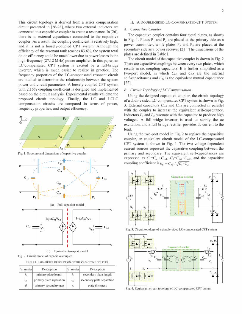
A. Capacitive Coupler The capacitive coupler contains four metal plates, as shown
in Fig. 1. Plates P1 and P2 are placed at the primary side as a power transmitter, while plates P3 and P4 are placed at the secondary side as a power receiver [21]. The dimensions of the plates are defined in Table I.
The circuit model of the capacitive coupler is shown in Fig. 2. There are capacitive couplings between every two plates, which results in six coupling capacitors. It is further simplified as a two-port model, in which Cin1 and Cin2 are the internal self-capacitances and CM is the equivalent mutual capacitance [22].
B. Circuit Topology of LC Compensation Using the designed capacitive coupler, the circuit topology
of a double sided LC-compensated CPT system is shown in Fig. 3. External capacitors Cex1 and Cex2 are connected in parallel with the coupler to increase the equivalent self-capacitance. Inductors L1 and L2 resonate with the capacitor to produce high voltages. A full-bridge inverter is used to supply the ac excitation, and a full-bridge rectifier provides dc current to the load.
Using the two-port model in Fig. 2 to replace the capacitive coupler, an equivalent circuit model of the LC-compensated CPT system is shown in Fig. 4. The two voltage-dependent current sources represent the capacitive coupling between the primary and secondary. The equivalent self-capacitances are expressed as C1=Cin1+Cex1, C2=Cin2+Cex2, and the capacitive coupling coefficient is 21/ CCCk MC .
Fig. 1. Structure and dimensions of capacitive coupler
(a) Full-capacitor model
(b) Equivalent two-port model
Fig. 2. Circuit model of capacitive coupler
TABLE I. PARAMETER DESCRIPTION OF THE CAPACITIVE COUPLER
Parameter Description Parameter Description
l1 primary plate length l2 secondary plate length
ls1 primary plate separation ls2 secondary plate separation
d primary-secondary gap tp plate thickness
Fig. 3. Circuit topology of a double-sided LC-compensated CPT system
Fig. 4. Equivalent circuit topology of LC-compensated CPT system

3
III. WORKING PRINCIPLE OF DOUBLE-SIDED LC-COMPENSATED CPT SYSTEM
A. Output Properties The fundamental harmonics approximation (FHA) method is
used to analyze the circuit working principle, as shown in Fig. 5. The square-wave excitation provided by the full-bridge inverter is approximated by a pure sinusoidal input, and so high-order harmonics are neglected. An equivalent load resistor ac RL is used to represent the output resistor Ro, whose value is RL=Ro×8/ 2.
Instead of impedances, admittances are used in the analysis, which are defined in Table II.
The KCL equations of Fig. 5 indicate that
2222
221222
112111
)()(
)(
VYVVYYVVYVVY
YVVYVVY
RLCL
CCMCL
CCMCL (1)
According to these equations, the voltage gain Gv between the input and output voltage is determined to be,
)(/)( 212
2122
21
21
1
2
LMLLM
MLLv
YYYYYYRYYYYYY
VV
G (2)
Since a resistive load is used on the output side, the transconductance Gi is further expressed as,
LLMLM
MLLRi
RYYYYYYYYYYYY
VI
G)()( 21
2212
221
21
1
(3)
The expressions (2) and (3) show that the output voltage V2 and current IR relate to the admittances of the passive components and the load resistance RL. These two expressions will be used to analyze the system frequency properties, which result in constant-voltage (CV) and constant-current (CC) working modes.
B. Constant-Voltage Working Mode According to (2), the constant voltage condition is
determined by taking dGv/dRL=0, which results in 02
21 MYYY (4) By defining the self-resonant frequencies as,
222
111
1,1CLCL
(5)
the constant-voltage frequencies can be expressed as follows:
)1(2
4)()(2
22
21
2222
21
22
21
2,1C
Cv
k
k (6)
The magnitude of Gv at these frequencies is therefore,
2
122
21
21
22,1
22
22,1
1
2,21 C
CVVG
v
vv
v
(7)
If the self-resonant frequencies at the primary and secondary sides are designed to be the same (i.e., 0= 1= 2), then the constant voltage frequencies are simplified as follows:
02
01
11
11
Cv
Cv
k
k (8)
The magnitude of the voltage gain Gv at these frequencies is further simplified as,
2
1
1
22,1 C
CVV
Gvv
(9)
When the self-capacitances C1 and C2 are equal, the magnitude of the input and output voltage are therefore also equal.
C. Constant-Current Working Mode Using (3), the constant-current frequency is determined by
taking dGi/dRL=0, which results in 021
221 LM YYYYY (10)
Similar to the constant voltage analysis, the constant-current frequency is given by
21
1 C
ck
, (11)
and the transconductance Gi at this frequency is as follows:
2
2
1
)1(
C
CMcRi k
kCjVI
Gc
(12)
In constant current mode, the output current can be increased by decreasing kC. However, it needs to be emphasized that the minimum kC is limited by the voltage and current ratings of the circuit components, and the system efficiency decreases with decreasing kC.
When 0= 1= 2, the output voltage, current, and power of the LC-compensated CPT system at the constant-voltage and constant-current frequencies are expressed as in Table III.
Fig. 5. Fundamental harmonics approximation of LC-compensated CPT system
TABLE II. ADMITTANCES OF THE CIRCUIT COMPONENTS
Parameter Expression Parameter Expression
YL1 1
1j L
YL2 2
1j L
YC1 1j C YC2 2j C
Y1 11
1j Cj L
Y2 22
1j Cj L
YM Mj C YRL 1
LR
TABLE III. OUTPUT VOLTAGE, CURRENT, AND POWER OF THE LC-COMPENSATED CPT SYSTEM, WHEN 0= 1= 2
Conditions Parameters C
vk1
02,1
2
0
1 Cc
k
|V2| 2
11 C
CV LCC
Mc Rkk
CV )1( 221
|IR| 2
11
CC
RV
L
)1( 221 CC
Mc kk
CV
Rout IVP 2 2
12
1
CC
RV
L
LCC
Mc Rkk
CV2
22
21 )1(

4
IV. DESIGN OF A LOOSELY-COUPLED CPT SYSTEMS
A. Circuit Parameters A loosely-coupled CPT system is designed in this section. To
simplify the process, the capacitive coupler is designed to be symmetric, and the dimensions are determined as: l1=l2=300mm, ls1=ls2=150mm, d=180mm, and tp=2mm. Finite element analysis (FEA) by Maxwell is further used to simulate the coupling capacitances between the plates. As shown in [22], the equivalent capacitances in Fig. 2(b) are calculated to be Cin1=Cin2=9.8pF and CM=2.8pF.
According to the resonance relationships in (5) and admittances in Table III, the circuit parameters of the CPT system are designed as shown in Table IV. The parameters are
symmetric from the primary to secondary side. The range of the input dc voltage is 0~64V, and the output load resistance varies between 20~45 . The resonant frequency f0 (f0= 0/2 ) is set to 1.5MHz. The external capacitors Cex1 and Cex2 are both 120pF, which results in a coupling coefficient of 2.16%.
B. Frequency Properties According to the analysis in Section III, the frequency
properties of the designed loosely-coupled LC-compensated CPT system are shown in Fig. 6. When the load resistance RL varies, Fig. 6(a) shows that there are two constant-voltage frequencies, v1 and v2, and Fig. 6(b) shows that there is a constant-current frequency c. It also shows that the constant-voltage gain is 1.0, and the constant-current frequency is between the two constant voltage frequencies.
Fig. 6(c) shows the phase angle of Gv and Gi at different load conditions. The input ac voltage V1 is set as the reference. It is seen that the phases at the three special frequencies are ( = v1)=0°, ( = c)=-90°, and ( = v2)=-180°. Fig. 6
shows that the frequency properties of the double-sided LC-compensated CPT system are similar to the frequency properties of the series-series (SS) compensated IPT system [29].
C. Electric Field Emission Using the circuit parameters in Table IV, the circuit
performance is simulated using LTspice in the constant-current working condition. The RMS value of the voltages across the circuit components and between the metal plates are shown in Table V.
It shows that the RMS value of voltage between P1 and P2 is as high as 2.51 kV, and the voltage between P1 and P3 is 1.73 kV. Since the breakdown voltage of air is about 3kV/mm and the distance between the plates is large sufficiently, there is no concern with arcing in this system. As the coupling capacitance is only 2.8pF and the the coupling coefficient is only 2.16%, the
(a) Magnitude of voltage gain Gv
(b) Magnitude of transonductance Gi
(c) Phase angle of Gv and Gi
Fig. 6. Frequency properties of a loosely-coupled double-sided LC-Compensated CPT system with 2.16% coupling coeffcient
TABLE IV. SYSTEM SPECIFICATIONS AND CIRCUIT PARAMETERS OF A DOUBLE-SIDED LC-COMPENSATED CPT SYSTEM
Parameter Design Value Parameter Design Value
Vin 0~64 V RL 20~40
l1(l2) 300 mm ls1(ls2) 150 mm
d 180 mm Cin1 (Cin2) 9.8 pF
CM 2.8 pF Cex1 (Cex2) 120 pF
kC 2.16 % C1 (C2) 129.8 pF
f0 1.5 MHz L1 (L2) 86.8 H
Fig. 7. Electric fields emission around the capacitive coupler
TABLE V. RMS VALUES OF THE VOLTAGES OF CIRCUIT COMPONENTS AND PLATES IN THE CONSTANT-CURRENT CONDITION
Parameter Voltage Parameter Voltage
VL1 2.50 kV VL2 2.50 kV VP1-P2 2.51 kV VP3-P4 2.51 kV VP1-P3 1.73 kV VP2-P4 1.73 kV

5
compensation circuit is necessary in order to increase the plate voltages to kV to achieve sufficient power transfer. Using the voltages in Table V, Maxwell is used to simulate the electric field emission around the capacitive coupler shown in Fig. 7.
Fig.7 shows that the electric field strength between plates P1 and P3 is about 9.6kV/m, and the maximum field strength close to the plates is about 10.6kV/m. The IEEE C95.1 standard [30] requires that the electric field strength should be lower than 550V/m at 1.5MHz for human safety consideration. Therefore Fig. 7 shows that the safe area being about 350mm away from the coupler in this system.
In this CPT system, if the electric field strength between P1 and P3 were limited below the safety requirement, the plate voltages VP1-P3 and VP2-P4 would be reduced from 1.73kV to 0.1kV. The plate votlages VP1-P2 and VP3-P4 would then be limited to 0.14 kV. According to [31], the maximum achievable power is estimated as,
W51.04321max PPPPMc VVCP (13) In a practical application, the electric fields between P1 and
P3 have to be much larger than the safety limitation to transfer sufficient power. Therefore, a living object detection (LOD) system should be used to protect human and animal safety, which is similar to the protection mechanism required in an inductive power transfer system. In future research, the shielding of leakage electric fields will also be studied to reduce the electric field emissions and hence increase the safety of the CPT system.
V. EXPERIMENTS
A. Experimental Prototype With all the circuit parameters provided in Table IV, an
experimental prototype of the LC-compensated CPT system is implemented as shown in Fig. 8. Four aluminum plates form the capacitive coupler and are placed on a fixture made from wood. The plate length is 300mm, and the air-gap distance is 180mm to realize a loosely coupled CPT system. The external parallel-connected capacitors Cex1 and Cex2 are high-frequency thin-film capacitors. The inductors L1 and L2 have an air core and are made with AWG 46 Litz-wire, thereby reducing both the skin-effect loss and magnetic loss. These inductors resonate with the capacitances to generate high voltages on the plates and transfer power. Since the switching frequency is 1.5MHz,
silicon carbide (SiC) MOSFETs are used in the input inverter, and SiC diodes are used in the output rectifier. A dc supply is connected to the inverter as the power source, and an electronic dc load is connected to the rectifier as the output. The load is set to resistive mode for both the constant-voltage and constant-current working conditions. The measurement of efficiency is from the dc source to the dc load.
B. Constant-Current Mode Experiment Using the designed prototype, experiments are conducted for
both constant-current and constant-voltage working modes. The constant-current mode is investigated first. In this case, the inductor L2 is tuned to 86.1 H in order to achieve constant current operation at 1.5MHz and realize soft-switching of the MOSFETs. The microcontroller TMS320F28335 from Texas Instruments is used to generate the PWM signals for the input inverter. The switching frequency is set to be 1.5MHz, and the dead-time for the full-bridge inverter is approximately 80ns. Experimental results of the constant-current mode are shown in Fig. 9 for a load resistance Ro=33.1 (RL=26.8 ).
Fig. 9(a) shows the input and output waveforms of the constant-current working mode. The input current IL1 is slightly lagging the input voltage V1 to achieve soft-switching of the MOSFETs. It also shows that the output voltage V2 is lagging the input voltage V1 by about 160ns. Since the switching frequency is 1.5MHz, and the corresponding period is about 666.6ns, this agrees with Fig. 6(c), which shows the output voltage V2 should lag the input voltage V1 by 90°. The driver signal Vdrive of a MOSFET is also provided in Fig. 9(a).
Fig. 8. Prototype of a double-sided LC-compensated CPT system
(a) Input and output waveforms
(b) Power and efficiency
Fig. 9. Experimental results of the constant-current working mode, when RO=33.1
6
Although there is some noise in the gate drive voltage, the noise magnitude is lower than the threshold voltage of the MOSFET, which is acceptable for driving the devices.
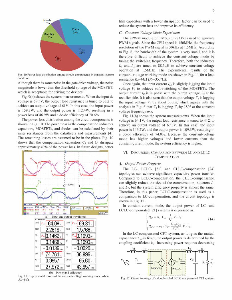
Fig. 9(b) shows the system measurements. When the input dc voltage is 59.5V, the output load resistance is tuned to 33 to achieve an output voltage of 61V. In this case, the input power is 159.3W, and the output power is 112.4W, resulting in a power loss of 46.9W and a dc-dc efficiency of 70.6%.
The power loss distribution among the circuit components is shown in Fig. 10. The power loss in the compensation inductors, capacitors, MOSFETs, and diodes can be calculated by their inner resistances from the datasheets and measurements [4]. The remaining losses are assumed to be in the plates. Fig. 10 shows that the compensation capacitors C1 and C2 dissipate approximately 40% of the power loss. In future designs, better
film capacitors with a lower dissipation factor can be used to reduce the system loss and improve its efficiency.
C. Constant-Voltage Mode Experiment The ePWM module of TMS320F28335 is used to generate
PWM signals. Since the CPU speed is 150MHz, the frequency resolution of the PWM signal is 30kHz at 1.5MHz. According to Fig. 6, the bandwidth of the system is very small, and it is therefore difficult to achieve the constant-voltage mode by tuning the switching frequency. Therefore, both the inductors L1 and L2 are tuned to 88.5 H to achieve constant-voltage operation at 1.5MHz. The experimental results of the constant-voltage working mode are shown in Fig. 11 for a load resistance Ro=44 (RL=35.7 ).
Once again, the input current IL1 is slightly lagging the input voltage V1 to achieve soft-switching of the MOSFETs. The output current IR is in phase with the output voltage V2 at the rectifier side. It is also seen that the output voltage V2 is lagging the input voltage V1 by about 330ns, which agrees with the analysis in Fig. 6 that V2 is lagging V1 by 180° at the constant voltage frequency v2.
Fig. 11(b) shows the system measurements. When the input voltage is 64.1V, the output load resistance is tuned to 44 to achieve an output voltage of 69.3V. In this case, the input power is 146.2W, and the output power is 109.3W, resulting in a dc-dc efficiency of 74.8%. Because the constant-voltage mode has higher voltages and lower currents than the constant-current mode, the system efficiency is higher.
VI. DISCUSSION: COMPARISON BETWEEN LC AND LCLC COMPENSATION
A. Output Power Property The LC-, LCLC- [21], and CLLC-compensation [24]
topologies can achieve significant capacitive power transfer. Compared to LCLC-compensation, the CLLC-compensation can slightly reduce the size of the compensation inductors L1 and L2, but the system efficiency property is almost the same. Therefore, in this paper, LCLC-compensation is used as a comparison to LC-compensation, and the circuit topology is shown in Fig. 12.
In constant-current mode, the output power of LC- and LCLC-compensated [21] systems is expressed as,
2121
21
2121
VVCCCC
CP
VVk
CP
ffMcLCLC
CMcLC (14)
In the LC-compensated CPT system, as long as the mutual capacitance CM is fixed, the output power is determined by the coupling coefficient kC. Increasing power requires decreasing
Fig. 10.Power loss distribution among circuit components in constant current condition
(a) Input and output waveforms
(b) Power and efficiency
Fig. 11. Experimental results of the constant-voltage working mode, when RO=44 Fig. 12. Circuit topology of a double-sided LCLC compensated CPT system

7
kC which reduces the system efficiency, as will be shown in the sequel. In an LCLC-compensated CPT system, the output power can be regulated by adjusting the ratio between Cf1Cf2 and C1C2. This provides the flexibility to design the capacitive coupler to achieve a relatively large coupling coefficient kC, which results in a better system efficiency.
B. Frequency Property As seen in Fig. 6, the working bandwidth of the
LC-compensated CPT system is narrow, and the system power drops quickly when the switching frequency moves away from the resonance frequency. As a comparison, an LCLC-compensated CPT system is designed to transfer the
same power using the same capacitive coupler, except that the coupling coefficient is higher at 5%. The circuit parameters are designed according to [21] and shown in Table VI.
The frequency properties of the LCLC-compensated CPT system are shown in Fig. 13. Since the coupling coefficient kC is larger than the LC-compensated CPT system, the operating bandwidth is significantly increased. The magnitudes of |Gi| and |Gv| are therefore less sensitive to variations in the switching frequency. It is also seen that a constant-current mode exists at the resonant frequency, and the phase angle of Gv and Gi is 90° leading V1.
C. System Efficiency The efficiency of the LC-compensated CPT network (i.e. not
including inverter and rectifier losses) is expressed as
1211
212
222
22
2
2
LLCCCCLLLRL
LRLLC RIRIRIRIRI
RI (15)
where RL2, RC2, RC1, and RL1 are the parasitic resistances of the passive components, and IRL, IL2, IC2, IC1, and IL1 are the currents flowing through these components. The efficiency can be rewritten as,
L
L
RL
L
L
C
RL
C
L
C
RL
C
L
L
RL
L
LC
RR
II
RR
II
RR
II
RR
II 1
2
11
2
12
2
22
2
21
1 (16)
The magnitudes of the current ratios can be approximated using the fundamental harmonics approximation. At the constant-current frequency, it can be shown that the efficiency can be expressed as follows:
212
212
212
11121
1
QQkQQkQQk CC
LC
(17)
where Q1 and Q2 are the quality factors of the primary and secondary resonant circuits, as follows,
L
CLCL
RRRCQRCQ
RRRRRR
/)/(1),/(1
,
2
222111
222111 (18)
It can be further shown that the load resistance which maximizes efficiency is given by
22121 RQQkR CL
(19) and the resulting efficiency is expressed as
212
212
212
max,11221
1
QQkQQkQQk CCC
LC
(20)
To simplify analysis, the quality factor is assumed to be equal for the primary and secondary (i.e., Q=Q1=Q2). The maximum efficiency is then further simplified as
QkQkQk CCC
LC11221
1
22
max,
(21)
The theoretical maximum achievable efficiency of the LC-compensated CPT network is shown in Fig. 14 as a function of quality factor and coupling coefficient. It is seen that the efficiency increases with the increasing quality factor Q and coupling coefficient kC. It is similar to the efficiency of the series-series compensated IPT system [31].
(d) Magnitude of voltage gain Gv
(e) Magnitude of transonductance Gi
(f) Phase angle of Gv and Gi
Fig. 13. Frequency property of a double-sided LCLC-Compensated CPT system with 5% coupling coefficient
TABLE VI. SYSTEM SPECIFICATIONS AND CIRCUIT PARAMETERS OF A DOUBLE-SIDED LCLC-COMPENSATED CPT SYSTEM
Parameter Design Value Parameter Design Value
Vin 0-64 V RL 20-40
l1(l2) 300 mm ls1(ls2) 150 mm
d 180 mm Cin1 (Cin2) 9.8 pF
CM 2.8 pF Cex1 (Cex2) 46 pF
kC 5.0 % C1 (C2) 55.8 pF
Cf1 (Cf2) 2.72 nF Lf1 (Lf2) 4.14 H
f0 1.5 MHz L1 (L2) 196.0 H

8
Fig. 12 is used to analyze the efficiency of the LCLC-compensated CPT network, expressed as (22). The efficiency is further rewritten as (23).
Similarly, the magnitudes of the current ratios in the denominator can be derived using fundamental harmonics analysis. At the constant-current frequency [23], the efficiency can be simplified and expressed as
22
2
12
21
2
1
222121
11
1
CfC
Cf
LCLC
kQQ
kk
(24)
where
222111
212
222111
22221111
222111
222111
/,//,/
)/(1),/(1
,
)/(1),/(1
,
ff
L
CfCLCfCL
ffffff
CfLffCfLff
CCCCCCRR
RCQRCQ
RRRRRRRRRCQRCQ
RRRRRR
(25)
The efficiency is maximized when the load resistance is
2
212
2
122
121321
/
/R
QQk
QQk
kQQ
RfC
fCL
(26)
resulting in the following efficiency:
2
2
2
1
1
2
1
2
21
max,
1121
1
C
f
C
fC
LCLC
kQQk
QQk
(27)
To simplify the analysis, the circuit is assumed to be symmetric, which results in Qf1=Qf2 and Q1=Q2. In this system, Qf1 represent the quality factor of a resonant circuit including Lf1 and Cf1, and Q1 represent the quality factor of a resonant circuit including L1, C1, and Cf1. The inductors Lf1 and L1 can be designed to have air core in order to achieve a high quality factor. Also, the same film capacitors can be used to build Cf1 and C1. Therefore, it can be assumed that Qf1=Q1 to simplify the efficiency analysis. Further assumptions are shown as follows,
1,21
2121 ff QQQQQ (28)
Therefore, the maximum efficiency of the LCLC-compensated system can be further simplified as
2max,
121
1
C
C
LCLC kQk
(29)
The theoretical maximum achievable efficiency of the LCLC-compensated network is shown in Fig. 15 as a function of Q, kC, and . It can be seen that the efficiency increases with increasing values of these parameters.
It is informative to compare the efficiencies of the LC- and LCLC-compensated CPT networks with the same capacitive coupler and the same power level. In the comparison, the coupling coefficients of the LC-compensated and LC-compensated networks are defined as kLC and kLCLC, respectively. According to the power equations in (14), the value of kLC must be set equal to the value of in the LCLC system to achieve equal power. Therefore, based on (21) and (29), the optimum efficiency of the LC-compensated system is less than that of the LCLC-compensated system ( i.e. LC,max <
LLCC,max) when,
01112LCLCLC
LCLCLCLC kk
QkQkk (30)
Based on (30), the efficiencies of the LC- and LCLC-compensated CPT networks are compared in Fig. 16. The area between the curves and the x-axis is the region where the LCLC-compensated system has higher efficiency, and the area between the curves and the y-axis is the region where the LC-compensated system has higher efficiency.
12
112
11211
212
222
222
222
22
2
2
LfLfCfCfLLCCCCLLCfCfLfLfLRL
LRLLCLC RIRIRIRIRIRIRIRIRI
RI (22)
L
Lf
RL
Lf
L
Cf
RL
Lf
L
L
RL
Lf
L
C
RL
Lf
L
C
RL
Lf
L
L
RL
Lf
L
Cf
RL
Lf
L
Lf
RL
LfLCLC
RR
II
RR
II
RR
II
RR
II
RR
II
RR
II
RR
II
RR
II 1
221
221
221
222
222
222
222
221
1 (23)
Fig. 14. Theoretical maximum achievable efficiency of a double-sidedLC-compensated CPT network
Fig. 15. Theoretical maximum achievable efficiency of a double-sidedLCLC-compensated CPT network
Fig. 16. Comparison of efficiencies of LC- and LCLC-compensation systems

9
The capacitive coupler designed in Section V can be used to compare the efficiencies of the LC- and LCLC-compensated CPT networks. In this analysis, the input and output dc votlages are set to 60V, the switching frequency is set to 1.5MHz, and the quality factors of the system resonances are assumed to be 400.
Fig. 17 shows the efficiencies of the two networks as a function of power level. The LCLC-compensated network results are provided for kLCLC=0.02 and kLCLC=0.05. It can be seen that the efficiencies are relatively independent of power level. In the case of the LC-compensated network, kLC must be reduced in order to increase the system power levels, resulting in lower efficiencies. The resulting range of kLC is [0.015, 0.04] in Fig. 17. The results show that the LC-compensated CPT system can achieve an efficiency of 80% at 150W power, not including the inverter and rectifier. When the power electronics circuits are considered, the efficiency agrees with the experimental results in Section V.
VII. CONCLUSION This paper proposes a double-sided LC compensation circuit
for a loosely-coupled CPT system. The frequency properties of the circuit are analyzed, which indicate one constant-current frequency and two constant-voltage frequencies. A prototype of the LC-compensated CPT system is designed and implemented to validate the constant-current and constant-voltage working modes. Finally, the LC and LCLC compensation topologies are compared in terms of power, frequency properties, and efficiency. It shows that both the LC- and LCLC-compensated systems can improve efficiency by increasing the coupling coefficient. In a loosely-coupled CPT system, the LCLC circuit can achieve higher efficiency, as the system power is independent of coupling coefficient.
REFERENCES [1] J. Dai and D. Ludois, “A Survey of Wireless Power Transfer and a
Critical Comparison of Inductive and Capacitive Coupling for Small Gap Applications”, IEEE Trans. Power Electron., vol. 30, no. 11, pp. 6017-6029, 2015.
[2] C. Liu, A.P. Hu, N.C. Nair, “Modelling and Analysis of a Capacitively Coupled Contactless Power Transfer System,” IET Power Electron. vol. 4, no. 7, pp. 808-815, 2011.
[3] S. Li, C. Mi, “Wireless Power Transfer for Electric Vehicle Applications,” IEEE Jour. of Emerg. and Selec. Top. on Power Electr., vol. 3, no. 1 pp. 4-17, 2015.
[4] F. Lu, H. Zhang, H. Hofmann, C. Mi, “A High Efficiency 3.3kW Loosely-Coupled Wireless Power Transfer System without Magnetic
Material,” Proc. IEEE Energy Convers. Congr. Expo. (ECCE), pp. 2282-2286, 2015.
[5] M.E. Karagozler, S.C. Goldstein, D.S. Ricketts, “Analysis and Modeling of Capacitive Power Transfer in Microsystems,” IEEE Trans. Circuit and Systems-I. Regular Papers, vol. 59, no. 7, pp. 1557-1566, 2012.
[6] R. Jegadeesan, Y.X. Guo, M. Je, “Electric Near-Filed Coupling for Wireless Power Transfer in Biomedical Applications,” Proc. IEEE International Microwave Workshop Series for Biomedical and Healthcare Applications (IMWS-BIO), pp. 1-3, 2013.
[7] E. Culurciello, A.G. Andreou, “Capacitive Coupling of Data and Power for 3D Silicon-on-Insulator VLSI,” Proc. IEEE International Symposium on Circuits and Systems (ISCAS), pp. 4142-4245, 2005.
[8] D. Shmilovitz, S. Ozeri, M. Ehsani, “A Resonant LED Driver with Capacitive Power Transfer,” Proc. IEEE Appl. Power Electr. Conf. (APEC), pp. 1384-1387, 2014.
[9] D.C. Ludois, J.K. Reed, K. Hanson, “Capacitive Power Transfer for Rotor Field Current in Synchronous Machines,” IEEE Trans. Power Electron., vol. 27, no. 11, pp. 4638-4645, 2012.
[10] A.Z. Amanci, H.E. Ruda, F.P. Dawson, “Galvanic Isolation for High Frequency Applications Using an Integrated Dielectric Structure,” IEEE Trans. Power Electron., vol. 31, no. 8, pp. 5797-5804, 2016.
[11] B. Ge, D.C. Ludois, R. Perez, “The Use of Dielectric Coatings in Capacitive Power Transfer Systems,” Proc. IEEE Energy Convers. Congr. Expo. (ECCE), pp. 2193-2199, 2014.
[12] J. Dai, D.C. Ludois, “Capacitive Power Transfer Through a Conformal Bumper for Electric Vehicle Charging,” IEEE Jour. of Emerg. and Selec. Top. on Power Electr., 2015, dio: 10.1109/JESTPE.2015.2505622.
[13] A. Kumar, S. Pervaiz, C.K. Chang, S. Korhummel, Z.Popvic, K.K. Afridi, “Investigation of Power Transfer Density Enhancement in Large Air-gap Capacitive Wireless Power Transfer Systems,” Proc. IEEE Wireless Power Transfer Conference. (WPTC), pp. 1-4, 2015.
[14] J. Kim, F. Bien, “Electric Field Coupling Technique of Wireless Power Transfer for Electric Vehicles,” Proc. IEEE TENCON Spring Conference, pp. 267-271, 2013.
[15] A. Bartlett, P. Arsenault, “Wireless Power for Vehicle Lightweighting, Reducing costs, and Improving Manufacturing Efficiencies,” Proc. IEEE Vehicle Technology Conference (VTC), pp. 1-5, 2015.
[16] A. Sepahvand, A. Kumar, K. Afridi, D. Maksimovic, “High Power Transfer Density and High Efficiency 100 MHz Capacitive Wireless Power Transfer System,” Proc. IEEE Control and Modeling for Power Electronics. (COMPEL), pp. 1-4, 2015.
[17] L. Huang, A.P. Hu, A. Swwain, X. Dai, “Comparison of Two High Frequency Converters for Capacitive Power Transfer,” Proc. IEEE Energy Convers. Congr. Expo (ECCE)., pp. 5437-5443, 2014.
[18] B.H. Choi, D.T. Nguyen, S.J. Yoo, J.H. Kim, C.T. Rim, “A Novel Source-side Monitored Capacitive Power Transfer System for Contactless Mobile Charger Using Class-E Converter,” Proc. IEEE Vehicle Technology Conference (VTC), pp. 1-5, 2014.
[19] C.K. Chang, G.G. Silva, A. Kumar, S. Pervaiz, K.K. Afridi, “30 W Capacitive Wireless Power Transfer System with 5.8 pF Coupling Capacitance,” Proc. IEEE Wireless Power Transfer Conference. (WPTC), pp. 1-4, 2015.
[20] M.P. Theodoridis, “Effective Capacitive Power Transfer,” IEEE Trans. Power Electron., vol. 27, no. 12, pp. 4906-4913, 2012.
[21] F. Lu, H. Zhang, H. Hofmann, C. Mi, “A Double-sided LCLC-Compensated Capacitive Power Transfer System for Electric Vehicle Charging,” IEEE Trans. Power Electron., vol. 30, no. 11, pp. 6011-6014, 2015.
[22] H. Zhang, F. Lu, H. Hofmann, W. Liu, C. Mi, “A Four-Plate Compact Capacitive Coupler Design and LCL-Compensated Topology for Capacitive Power Transfer in Electric Vehicle Charging Application,” IEEE Trans. Power Electron., vol. 31, no. 12, pp. 8541-8551, 2016.
[23] F. Lu, H. Zhang, H. Hofmann, C. Mi, “An Inductive and Capacitive Combined Wireless Power Transfer System with LC-Compensated Topology,” IEEE Trans. Power Electron., doi: 10.1109/TPEL.2016. 2519903.
[24] F. Lu, H. Zhang, H. Hofmann, C. Mi, “A CLLC-Compensated High Power and Large Air-Gap Capacitive Power Transfer System for Electric Vehicle Charging Applications,” Proc. IEEE Appl. Power Electr. Conf. (APEC), pp. 1721-1725, 2016.
[25] F. Lu, H. Zhang, H. Hofmann, C. Mi, “A Loosely Coupled Capacitive Power Transfer System with LC Compensation Circuit Topology,” Proc. IEEE Energy Convers. Congr. Expo. (ECCE), pp. 1-5, 2016.
Fig. 17. Efficiencies of LC- and LCLC-compensated CPT networks using the designed capacitive coupler in Section V

10
[26] M. kusunoki, D. Obara, M. Masuda, “Wireless Power Transfer via Electric Field Resonance Coupling,” Proc. IEEE Asia-Pacific Microwave Conference (APMC) , pp. 1360-1362, 2014.
[27] R.D. Fernandes, J.N. Matos, N.B. Carvalho, “Wireless Power Transmission based on Resonant Electrical Coupling,” Proc. IEEE European Microwave Conference (EuMC) , pp. 17-20, 2014.
[28] T. Komaru, H. Akita, “Positional Characteristics of Capacitive Power Transfer as a Resonance Coupling System,” Proc. IEEE Wireless Power Transfer Conference. (WPTC). pp. 218-221, 2013.
[29] Z. Huang, S. Wong, C.K. Tse, “Design Methodology of a Series-series Inductive Power Transfer System for Electric Vehicle Battery Charger Application,” IEEE Energy Conversion Congress and Exposition (ECCE), pp. 1778-1782, 2014.
[30] IEEE Standard for Safety Levels with Respect to Human Exposure to Radio Frequency Electromagnetic Fields, 3kHz to 300 GHz, C95.1, 2005.
[31] S. Li, Z. Liu, H. Zhao, L. Zhu, Z. Chen, “Wireless Power Transfer by Electric Field Resonance and Its Application in Dynamic Charging,” IEEE Trans. Ind. Electron., vol. 63, no. 10, pp. 6602-6612, 2016.
Fei Lu (S’12) received the B.S. and M.S. degree in electrical engineering from Harbin Institute of Technology, Harbin, China, in 2010 and 2012, respectively. He is currently pursuing the PhD degree in electrical engineering from University of Michigan, Ann Arbor, USA.
His research topic focuses on wireless power transfer for the application of electric vehicle charging. He is working on the high power and high efficiency capacitive power transfer through an air-gap distance up to 100’s of millimeters. He is also
working on the application of wide band-gap devices on WPT system. Hua Zhang (S’14) received B.S. and M.S. degree in electrical engineering from Northwestern Polytechnical University, Xi’an, China, in 2011 and 2014, respectively. She is currently pursuing the Ph.D. degree in electrical engineering from the Northwestern Polytechnical University, Xi’an China.
From September 2014 to August 2015, she was a joint Ph.D. student founded by the China Scholarship Council with the University of Michigan, Dearborn. From September 2015, she started to work in San
Diego State University. Her research is about the coupler design of high power IPT and CPT system.
Heath Hofmann (M’89-SM’15) received the B.S. degree in electrical engineering from The University of Texas at Austin, Austin, TX, USA, in 1992 and the M.S. and Ph.D. degrees in electrical engineering and computer science from the University of California, Berkeley, CA, USA, in 1997 and 1998, respectively.
He is currently an Associate Professor with the University of Michigan, Ann Arbor, Michigan, USA. His research interests are the design, analysis, and control of electromechanical systems, and power electronics.
Chunting Chris Mi (S’00–A’01–M’01–SM’03–F’12) received the B.S.E.E. and M.S.E.E. degrees in electrical engineering from Northwestern Polytechnical University, Xi’an, China, and the Ph.D. degree in electrical engineering from the University of Toronto, Toronto, Ontario, Canada, in 1985, 1988, 2001, respectively.
He is a Professor and chair of electrical and computer engineering and the Director of the Department of Energy (DOE) -funded Graduate Automotive Technology Education (GATE) Center for Electric Drive Transportation, San Diego State
University, San Diego, USA. Prior to joining SDSU, he was with with University of Michigan, Dearborn from 2001 to 2015. He was the President and the Chief Technical Officer of 1Power Solutions, Inc. from 2008 to 2011. He is the Co-Founder of Gannon Motors and Controls LLC and Mia Motors, Inc.
His research interests include electric drives, power electronics, electric machines, renewable-energy systems, and electrical and hybrid vehicles. He has conducted extensive research and has published more than 100 journal papers. He has taught tutorials and seminars on the subject of HEVs/PHEVs for the Society of Automotive Engineers (SAE), the IEEE, workshops sponsored by the National Science Foundation (NSF), and the National Society of Professional Engineers. He has delivered courses to major automotive OEMs and suppliers, including GM, Ford, Chrysler, Honda, Hyundai, Tyco Electronics, A&D Technology, Johnson Controls, Quantum Technology, Delphi, and the European Ph.D School. He has offered tutorials in many countries, including the U.S., China, Korea, Singapore, Italy, France, and Mexico. He has published more than 100 articles and delivered 30 invited talks and keynote speeches. He has also served as a panelist in major IEEE and SAE conferences.
Dr. Mi is the recipient of “Distinguished Teaching Award” and “Distinguished Research Award” of University of Michigan Dearborn. He is a recipient of the 2007 IEEE Region 4 “Outstanding Engineer Award,” “IEEE Southeastern Michigan Section Outstanding Professional Award.” and the “SAE Environmental Excellence in Transportation (E2T)”.