Application of water barrier layers in a proton exchange membrane fuel cell for improved water...
14
Application of water barrier layers in a proton exchange membrane fuel cell for improved water management at low humidity conditions Mauricio Blanco a,b,c, *, David P. Wilkinson a,b,c, **, Haijiang Wang c a Department of Chemical and Biological Engineering, University of British Columbia, 2360 East Mall, Vancouver, BC, Canada V6T 1Z3 b Clean Energy Research Center, University of British Columbia, 2360 East Mall, Vancouver, BC, Canada V6T 1Z3 c Institute for Fuel Cell Innovation, National Research Council of Canada, 4250 Wesbrook Mall, Vancouver, BC, Canada V6T 1W5 article info Article history: Received 21 October 2010 Received in revised form 26 November 2010 Accepted 20 December 2010 Available online 21 January 2011 Keywords: Water management Proton exchange membrane fuel cell Dry condition Durability Gas diffusion layer Stainless steel perforated sheets abstract This study discusses the use of an additional layer in the cathode side of a proton exchange membrane fuel cell (PEMFC) for improved water management at dry conditions. The performance of fuel cells deteriorates significantly when low to no gas humidification is used. This study demonstrates that adding a non-porous material with perforations, such as stainless steel, between the cathode flow field plate and the gas diffusion layer (GDL) improves the water saturation in the cathode GDL and catalyst layer, increases the water content in the anode, and keeps the membrane hydrated. The slight voltage drop in the performance as a result of transport limitations is justifiable since the overall durability of the cell at these extreme conditions is enhanced. The results show that the perforated layer(s) enhances the operational life of the PEMFC under completely dry conditions. These extreme conditions (dry gases without humidification, 90 kPa, 75 C) were used to accel- erate the failure modes in the fuel cells. Copyright ª 2011, Hydrogen Energy Publications, LLC. Published by Elsevier Ltd. All rights reserved. 1. Introduction Large-scale commercialization of proton exchange membrane fuel cells (PEMFCs) faces a number of challenges including efficiency, cost, reliability, and durability [1e3]. In addition, a number of applications (e.g., portable back-up power, mate- rial handling, automotive, etc.) require these fuel cell systems to perform efficiently with restricted space limitations [4,5]. Therefore, it is critical for fuel cell systems to perform at conditions in which additional equipment (i.e., balance of plants) can be significantly reduced. One way of performing this task is to run the system at reduced or zero relative humidity (RH) conditions. This will eliminate the use of humidification systems currently used to humidify the reactant gases in order to maintain the necessary hydration level inside the membrane electrode assembly (MEA) for proton conductivity [6]. These humidification systems not only require heat and water supplies, which decreases the overall power density and effi- ciency of the system, but also account for a significant fraction of system’s volume, weight, and cost. However, removing these systems is challenging because the durability and reliability of the overall fuel cell system are normally adversely affected. * Corresponding author. Department of Chemical and Biological Engineering, University of British Columbia, 2360 East Mall, Vancouver, BC, Canada V6T 1Z3. Tel.: þ1 604 827 3190; fax: þ1 604 822 6003. ** Corresponding author. Department of Chemical and Biological Engineering, University of British Columbia, 2360 East Mall, Vancouver, BC, Canada V6T 1Z3. Tel.: þ1 604 822 4888; fax: þ1 604 822 6003. E-mail addresses: [email protected] (M. Blanco), [email protected] (D.P. Wilkinson). Available at www.sciencedirect.com journal homepage: www.elsevier.com/locate/he international journal of hydrogen energy 36 (2011) 3635 e3648 0360-3199/$ e see front matter Copyright ª 2011, Hydrogen Energy Publications, LLC. Published by Elsevier Ltd. All rights reserved. doi:10.1016/j.ijhydene.2010.12.108
-
Upload
sanmartinmedellin -
Category
Documents
-
view
7 -
download
0
Transcript of Application of water barrier layers in a proton exchange membrane fuel cell for improved water...

i n t e r n a t i o n a l j o u r n a l o f h y d r o g e n en e r g y 3 6 ( 2 0 1 1 ) 3 6 3 5e3 6 4 8
Avai lab le a t www.sc iencedi rec t .com
journa l homepage : www.e lsev ier . com/ loca te /he
Application of water barrier layers in a proton exchangemembrane fuel cell for improved water managementat low humidity conditions
Mauricio Blanco a,b,c,*, David P. Wilkinson a,b,c,**, Haijiang Wang c
aDepartment of Chemical and Biological Engineering, University of British Columbia, 2360 East Mall, Vancouver, BC, Canada V6T 1Z3bClean Energy Research Center, University of British Columbia, 2360 East Mall, Vancouver, BC, Canada V6T 1Z3c Institute for Fuel Cell Innovation, National Research Council of Canada, 4250 Wesbrook Mall, Vancouver, BC, Canada V6T 1W5
a r t i c l e i n f o
Article history:
Received 21 October 2010
Received in revised form
26 November 2010
Accepted 20 December 2010
Available online 21 January 2011
Keywords:
Water management
Proton exchange membrane fuel cell
Dry condition
Durability
Gas diffusion layer
Stainless steel perforated sheets
* Corresponding author. Department of ChemBC, Canada V6T 1Z3. Tel.: þ1 604 827 3190; f** Corresponding author. Department of ChemBC, Canada V6T 1Z3. Tel.: þ1 604 822 4888; f
E-mail addresses: [email protected]/$ e see front matter Copyright ªdoi:10.1016/j.ijhydene.2010.12.108
a b s t r a c t
This study discusses the use of an additional layer in the cathode side of a proton exchange
membrane fuel cell (PEMFC) for improved water management at dry conditions. The
performance of fuel cells deteriorates significantly when low to no gas humidification is
used. This study demonstrates that adding a non-porous material with perforations, such
as stainless steel, between the cathode flow field plate and the gas diffusion layer (GDL)
improves the water saturation in the cathode GDL and catalyst layer, increases the water
content in the anode, and keeps the membrane hydrated. The slight voltage drop in the
performance as a result of transport limitations is justifiable since the overall durability of
the cell at these extreme conditions is enhanced. The results show that the perforated
layer(s) enhances the operational life of the PEMFC under completely dry conditions. These
extreme conditions (dry gases without humidification, 90 kPa, 75 �C) were used to accel-
erate the failure modes in the fuel cells.
Copyright ª 2011, Hydrogen Energy Publications, LLC. Published by Elsevier Ltd. All rights
reserved.
1. Introduction task is to run the system at reduced or zero relative humidity
Large-scale commercialization of proton exchange membrane
fuel cells (PEMFCs) faces a number of challenges including
efficiency, cost, reliability, and durability [1e3]. In addition,
a number of applications (e.g., portable back-up power, mate-
rial handling, automotive, etc.) require these fuel cell systems
to perform efficiently with restricted space limitations [4,5].
Therefore, it is critical for fuel cell systems to perform at
conditions in which additional equipment (i.e., balance of
plants) canbesignificantly reduced.Onewayofperforming this
ical and Biological Enginax: þ1 604 822 6003.ical and Biological Enginax: þ1 604 822 6003.(M. Blanco), dwilkinson@2011, Hydrogen Energy P
(RH) conditions. This will eliminate the use of humidification
systems currently used to humidify the reactant gases in order
tomaintain thenecessaryhydration level inside themembrane
electrode assembly (MEA) for proton conductivity [6]. These
humidification systems not only require heat and water
supplies, which decreases the overall power density and effi-
ciency of the system, but also account for a significant fraction
of system’svolume,weight, andcost.However, removing these
systems is challenging because the durability and reliability of
the overall fuel cell system are normally adversely affected.
eering, University of British Columbia, 2360 East Mall, Vancouver,
eering, University of British Columbia, 2360 East Mall, Vancouver,
chbe.ubc.ca (D.P. Wilkinson).ublications, LLC. Published by Elsevier Ltd. All rights reserved.

Nomenclature
PEMFC proton exchange membrane fuel cell
MEA membrane electrode assembly
CCM catalyst coated membrane
GDL gas diffusion layer
MPL micro-porous layer
CFP carbon fiber paper
FF flow field
PS perforated sheet
OA open area
RH relative humidity
HFR high frequency resistance
PC,total total pressure in cathode gas stream, kPa
Pgas partial pressure of the gas inside the cathode
stream, kPa
PAir partial pressure of air inside the cathode stream,
kPa
PH2O;vap partial pressure of the water vapor in the cathode
stream, kPa
mH2O;vap molar flow rate of water vapor, mol s�1 cm�2
mAir molar flow rate of air, mol s�1 cm�2
tmax maximum time that a fuel cell can hold a current
load, s
i n t e rn a t i o n a l j o u r n a l o f h y d r o g e n en e r g y 3 6 ( 2 0 1 1 ) 3 6 3 5e3 6 4 83636
It is a well-known phenomenon that the performance of
a typical PEM fuel cell deteriorates when dry gases are used
due to the drying of the membrane, which increases the
ohmic resistance and reduces the hydrogen proton flux from
the anode to the cathode [7]. Long exposure to these harsh
conditions has a direct impact on the fuel cell’s overall
performance, thus, compromising the longevity of the fuel
cell. Recently, there have been many research studies inves-
tigating the effects of dry conditions on hydrogen fuel cells. It
has been shown that with dry feed, irreversible losses due to
damages of themembrane and catalyst layers are created that
can potentially reduce the fuel cell stack lifetime expectancy
and increase the probability of failure [8e10]. These irrevers-
ible losses aremainly dependent on the cathode side since the
cathode humidity has a stronger impact on the membrane’s
resistance [11]. This indicates that the diffusion of water
through the membrane is a dominant process for water
transport inside the MEA [12]. In addition, the dehydration
rate inside the cell increase significantly with increases in cell
and gas temperatures, large flow stoichiometries, and low gas
pressures [7,13e15]. Another component that is greatly
affected with dry gases is the cathode catalyst layer in which
the ionic, charge-transfer and mass-transfer resistances
increase when there is reduced proton transport and low
levels of humidity at the catalytic sites [4,7].
In order to improve the cell performance at dry conditions
different approaches have been proposed. Self-humidifying
proton exchange membranes have been demonstrated and
have achieved improved performance with dry gases [16e19].
However, the manufacturing process for these membranes is
very complex because they contain Pt or metaleoxide catalyst
particles. Addition of Pt in the membrane increases the
system’s overall cost. Another approach to improve the cell
performance and avoid dehydration at dry conditions is to
design gas diffusion layers (GDLs) with micro-porous layers
(MPLs) (or watermanagement layers) with low hydrophobicity
[14]. In addition, the MPLs can also be designed with PTFE
concentration gradients along the GDL’s area in order to
change the hydrophobicity of the layer [20].
Self-humidifying can also be achieved through the use of
water absorbent wicks that can be located near the inlet and
outlet areas of the flowfield(s) to facilitate absorption of excess
water and to humidify the dry gases that enter the channels
eliminating the need for a humidification system [21e24].
Someof thewickingmaterialsusedareporouspolyester fibers,
polyvinyl alcohol sponges, absorbent cotton cloth, absorbent
cotton paper, and porous stainless steel sheets. Porous flow
field plates have also been proposed as mechanisms that
improve the self-humidifying capabilities of the cell with dry
conditions [5,25]. United Technologies Company (UTC) devel-
oped a fuel cell stack with porous bipolar plates in which the
pores are filled with liquid water [26e28]. These plates have
coolant flow fields filled with water on one side and gas flow
channels on the other that are in contact with the MEA. This
design improved the water management in the cell.
Different flow field designs, mostly for the cathode plate,
have been demonstrated as possible solutions for fuel cell
operation with dry reactant gases. Qi and Kaufman [29]
designed serpentine flow channels with two inlets and two
outlets for both the anode and cathode gases. One inlet was
located near one of the outlets; thus, the exiting gas stream
would humidify the dry gas entering the plate. In general, for
fully humidified operation the parallel flow field design is
considered to have a number of drawbacks related to flow
distribution and water management. However, at dry condi-
tions this design provides better performance and uniform
distribution of water activity, ionic conductivity, and current
density over the active area [30]. Direction of the flow fields,
including the coolant channels, of a fuel cell also influences the
overall water management and performance of the cell. Wil-
kinson et al. operated a fuel cell successfully with dry gases by
using the cathode and coolant flow field in co-flow and the
anode in counter-flow [31]. In addition, a co-flow configuration
between the anode and cathode channels has been proven to
deteriorate the performance at dry conditions since the water
content of the membrane is very low in the inlet region [32].
In this paper we show that at dry (no humidification)
conditions the MPL improves cell durability compared to a GDL
without MPL. However, GDLs with an MPL still have a serious
issue when operating at low humidity conditions for long
periods of time. Therefore, when presented a method to
increase the water accumulation in the cathode GDL and cata-
lyst layers inorder to improve the cell durability at lowhumidity
conditions. This is achieved by placing non-porous perforated
materials between the cathodeflowfield channels and theGDL.
The impact of perforated sheets on the performance and dura-
bility of PEMfuel cellswas examinedat lowhumidity conditions
and results are presented.GDLswith andwithoutmicro-porous
i n t e r n a t i o n a l j o u r n a l o f h y d r o g e n en e r g y 3 6 ( 2 0 1 1 ) 3 6 3 5e3 6 4 8 3637
layers (MPLs) were used. This analysis is performed using pol-
arization curves, voltage stability data, and measurements of
membraneresistance, pressuredrop, andwater transport rates.
2. Experimental
2.1. Materials and equipment
For all the measurements a single cell fuel cell (Tandem
Technologies, Vancouver, Canada) with an active area of
49 cm2 was used. Both anode and cathode plates had single
path serpentine flow fields, and they were used in a co-flow
configuration. This flow channel configuration was chosen
because it increases dehydration when gases with low
humidity areused [32]. The cathodeflowfieldhada trapezoidal
cross-sectional shape with a depth of 1.27 mm, channel width
of 1.57mmat the top and 0.9mmat the bottomof the channel,
draft angle of 15� (this is the angle that the channelwallsmake
with vertical), and landing width (space between channels) of
0.86 mm. The anode flow field had a squared cross-sectional
shape with a depth of 0.55 mm, channel width of 1.05 mm,
landing width of 1.30 mm. Serpentine flow fields were used
because of their larger associated gas pressure drops, which
enhance the water absorption ability of the gas stream [33,34];
thus, drying the fuel cell faster at dry and low humidity
conditions. The cell used a pneumatic piston, located on top of
all the components, for compression in order to distribute the
pressure evenly across the cell. Deionized (DI) water was used
as a coolant in order tomaintain the temperature (and heat) of
the cell constant. All the experiments presented here were
performed with a 2 kW Hydrogenics Fuel Cell Test Station,
which controlled the flow rate, pressure, humidity, and
temperature of the reactant gases. The test station also
controlled the current load to the cell, and the temperature and
flow rate of the DI water used to cool/heat the fuel cell.
Primea�551025mmthick catalyst coatedmembranes (CCM)
from W.L. Gore & Associates were used. These CCM had
a 0.4 mg cm�2 Pt catalyst loading for both the anode and
cathodecatalyst layers. Sigracet�25DCcarbonfiberpaper (CFP)
GDLs from SGL Carbon were used for the anode GDLs. For the
cathode side twodifferent GDLswere used: Sigracet� 25BCand
25BA. Table 1 summarizes the details of the materials used.
In order to improve the cell durability and operation at dry
conditions, perforated stainless steel 316L sheets were used.
The stainless steel 316L sheets were perforated by VACCO
Industries using a photo-etching process. The sheets were not
treated with any hydrophobic agent and their initial contact
angle before testing was found to be approximately 78�, i.e.,hydrophilic especially in their landing areas. Sheets with
different perforation diameters of 10 mm, 1 mm, 0.5 mm and
Table 1 e Properties of gas diffusion layers used for the fuel ce
Material Thickness[mm]
Poros[%]
Sigracet� 25DC GDL (anode) 235 80
Sigracet� 25BC GDL (cathode) 235 80
Sigracet� 25BA GDL (cathode) 190 88
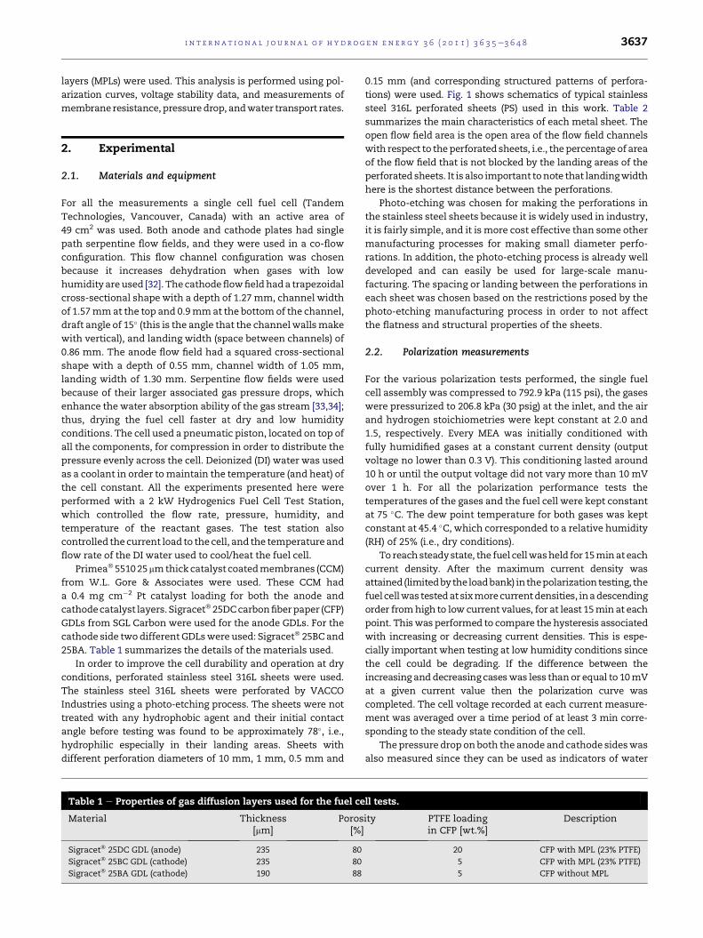
0.15 mm (and corresponding structured patterns of perfora-
tions) were used. Fig. 1 shows schematics of typical stainless
steel 316L perforated sheets (PS) used in this work. Table 2
summarizes the main characteristics of each metal sheet. The
open flow field area is the open area of the flow field channels
with respect to theperforated sheets, i.e., thepercentage of area
of the flow field that is not blocked by the landing areas of the
perforated sheets. It is also important tonote that landingwidth
here is the shortest distance between the perforations.
Photo-etching was chosen for making the perforations in
the stainless steel sheets because it is widely used in industry,
it is fairly simple, and it is more cost effective than some other
manufacturing processes for making small diameter perfo-
rations. In addition, the photo-etching process is already well
developed and can easily be used for large-scale manu-
facturing. The spacing or landing between the perforations in
each sheet was chosen based on the restrictions posed by the
photo-etching manufacturing process in order to not affect
the flatness and structural properties of the sheets.
2.2. Polarization measurements
For the various polarization tests performed, the single fuel
cell assembly was compressed to 792.9 kPa (115 psi), the gases
were pressurized to 206.8 kPa (30 psig) at the inlet, and the air
and hydrogen stoichiometries were kept constant at 2.0 and
1.5, respectively. Every MEA was initially conditioned with
fully humidified gases at a constant current density (output
voltage no lower than 0.3 V). This conditioning lasted around
10 h or until the output voltage did not vary more than 10 mV
over 1 h. For all the polarization performance tests the
temperatures of the gases and the fuel cell were kept constant
at 75 �C. The dew point temperature for both gases was kept
constant at 45.4 �C, which corresponded to a relative humidity
(RH) of 25% (i.e., dry conditions).
To reachsteadystate, the fuel cellwasheld for 15minateach
current density. After the maximum current density was
attained(limitedby theloadbank) inthepolarization testing, the
fuel cellwas testedatsixmorecurrentdensities, inadescending
order fromhigh to low current values, for at least 15min at each
point. Thiswas performed to compare the hysteresis associated
with increasing or decreasing current densities. This is espe-
cially important when testing at low humidity conditions since
the cell could be degrading. If the difference between the
increasing anddecreasing caseswas less thanor equal to 10mV
at a given current value then the polarization curve was
completed. The cell voltage recorded at each current measure-
ment was averaged over a time period of at least 3 min corre-
sponding to the steady state condition of the cell.
The pressure drop onboth the anode and cathode sideswas
also measured since they can be used as indicators of water
ll tests.
ity PTFE loadingin CFP [wt.%]
Description
20 CFP with MPL (23% PTFE)
5 CFP with MPL (23% PTFE)
5 CFP without MPL

Fig. 1 e Schematics of stainless steel perforated sheets (70 mm 3 70 mm) with (a) 1 mm and (b) 0.5 mm diameter holes.
i n t e rn a t i o n a l j o u r n a l o f h y d r o g e n en e r g y 3 6 ( 2 0 1 1 ) 3 6 3 5e3 6 4 83638
flooding given that large pressure drops represent water
accumulation in the MEA and flow field channels [35e37].
However, if the pressure drops of different GDLs are being
compared in order to have an insight on water accumulation
inside the channels, it is important to determine howmuch of
the pressure drop is affected by the GDL itself. Therefore, the
pressure drops of the different GDL configurations used in this
study were also measured at non-active conditions (i.e., no
current) and without humidification. At these conditions, for
the cathode side, the difference in pressure drops between the
25BA and 25BC GDLs was less than 5%. However, with the
active tests (lowhumidity conditions) this change increased to
greater than 12% for flow rates higher than 1.64 SLPM (this
corresponds to 1000 mA cm�2). This confirms that using the
pressure drops of different GDL configurations as indicators of
wateraccumulation inour single fuel cell is agoodassumption.
The high frequency resistance (HFR) of the cell was
measured at 1 kHz using an LCR meter (Instek LCR819). The
HFR corresponds to the cell resistance and consists predomi-
nantly of the membrane ionic resistance, and other residual
resistances arising from electronic and contact resistances [38].
2.3. Water transport rate measurements
In order to understand how the perforated sheets affect the
water transport capability of the cathode GDL, the water
transport rates of differentMEAconfigurationswere estimated
using an experimental technique similar to that presented by
Dai et al. [39,40]. Briefly, humidified air (at 75 �C and 25% RH)
was fed to thecathodeflowfieldplate, anddeionizedwaterwas
fed to the anode and the coolant sides of the cell (at 75 �C). AToray� TGPH-060 carbon fiber paper with no water proofing
wasusedon theanode side in order to givemechanical support
Table 2 e Characteristics of the stainless steel 316L sheets.
Sheet name Area of eachhole [mm2]
Thickness[mm]
Landin[mm
10 mm PS 78.539 0.050 1
1 mm PS 0.785 0.050 0.5
0.5 mm PS 0.196 0.050 0.3
0.15 mm PS 0.018 0.050 0.3
a Open area of the flow field channels with respect to the perforated she
to the membrane and to keep it fully humidified. The air flow
rate, corresponding to a specific current density, was kept
constant for 1 h. The water removed from the cell by the air
streamwas then condensed in a high efficiency, water-cooled
condenser and collected into a reservoir. The collected water
was thenused to calculate the actualwater transport rate from
the anode side to the cathode side with different cathode
configurations. Formoredetail(s) regarding thismethodplease
refer to Dai et al. [39].
2.4. Durability tests at dry conditions
For the durability tests, it was desired to use parameters that
would accelerate the deterioration of the fuel cell perfor-
mance at dry conditions. For these tests we operated at
a current density of 1000 mA cm�2 because it has been shown
to accelerate degradation [2,41]. Therefore, both reactant
gaseswere introducedwith no humidification, the cell and gas
temperatures were increased to 75 �C, and the pressure of the
gases were lowered to 90 kPa (around 13 psig inlet pressure).
Lower pressures and higher temperatures in the flow field
channels increase the ability of the gas stream to carry more
water vapor, thus, drying the cell faster [33,34]. More details
regarding how these specific conditions were chosen are
provided in Section 3.5.
3. Results and discussion
3.1. Effect of dry conditions on fuel cell performance
In order to compare fuel cell performance at low humidity
conditions and how they affect the cell performance, twoMEA
g]
# Of holesper cm2
Open area[%]
Open flow fieldarea [%]a
0.73 67.5 66.4
37.73 34.7 34.5
133.89 30.7 30.1
423.18 8.8 8.5
ets.

i n t e r n a t i o n a l j o u r n a l o f h y d r o g e n en e r g y 3 6 ( 2 0 1 1 ) 3 6 3 5e3 6 4 8 3639
configurations commonly used in fuel cells were tested (see
Fig. 2a). Two different operating conditions were used: 100%
RH and 25% RH. Themain difference between the two cathode
GDLs is that the 25BA does not have an MPL whereas the 25BC
does. The anode GDL used was the same for both cases (i.e.,
25DC). At 100% RH, there is a significant voltage difference
between the GDLs with and without an MPL, in the current
range of 500e1800 mA cm�2. This indicates that the presence
of an MPL on the cathode side has a major role on managing
thewater in PEM fuel cells, and increases the cell performance
by reducing the liquid-water saturation in the GDL pores and
active sites in the catalyst layer, and enhancing oxygen
diffusion. At higher flow rates, i.e., current densities higher
than 1800 mA cm�2, the performance difference between the
twoGDLs is no longer detectable. For the 25BCGDL thismay be
the result of membrane dehydration due to the combination
of higher flow rates, because of higher currents, and the use of
the MPL to remove the product water. On the other hand, at
these high current densities the gas flow rate is high enough
for the 25BA GDL to be able to remove sufficient water toward
the flow field plates, which opens the path for the gases to
diffuse through, and to maintain enough water content near
the membrane to keep it hydrated.
At 25% RH, the performance difference between the two
GDLs is similar to that in the 100% RH condition, however, at
high current densities the GDL without MPL cannot match the
performance of GDLs with MPL at low humidity conditions.
This indicates that at low humidity conditions the MPL also
allows for better water distribution between the GDL and the
Fig. 2 e (a) Cell voltage, (b) high frequency resistance, (c) cathode
density for PEM fuel cells with two different GDLs at fully humidi
RH). 25BA and 25BC refers to SGL 25BA (GDL without MPL) and S
cases was 25DC (with MPL).
catalytic sites, which allows for the hydration of the
membrane. The cell high frequency resistance data also
supports these observations (Fig. 2b). At fully humidified
conditions (100% RH) and high flow rates, the HFR is lower (58
vs. 65 mOhm cm2), which indicates that the membrane is
hydrated (with and without MPL).
At current densities higher than 1000 mA cm�2, the
cathode pressure drop for the 25BA GDL is greater than that of
the 25BC GDL (with an MPL) for both operating conditions (see
Fig. 2c). This could be an indication of less water accumulation
in the flow field channels when the 25BC is used. In addition,
the anode pressure drop for the 25BC is 13e17% (at 100% RH)
and 7e14% (at 25% RH) greater than that for the 25BA GDL due
to the positive impact that theMPL has on the water crossover
from the cathode to anode side of the fuel cell (see Fig. 2d).
Fig. 2c and d shows the cathode and anode pressure drops,
respectively, for the two GDLs at both operating conditions.
The cathode pressure drop of the 25BA CFP is always greater
than that of the GDL without an MPL.
It is important to note that these polarization curves were
performed three times in order to make sure that these results
andobservationswere repeatable. Tooperate for longerperiods
at dry or low humidity conditions, it is important for the
membrane to stay hydrated as long as possible without
affecting the diffusion paths of the reactant gases. Fig. 3 shows
how the fuel cell with 25BA and 25BC cathode GDLs behave
whenoperatedata constant currentdensityof1000mAcm�2 at
dry (no humidification) conditions. As observed, the GDL with
MPLallowsthefuel cell tooperate fora longerperiodof timeand
pressure drop, and (d) anode pressure drop versus current
fied conditions (100% RH) and low humidity conditions (25%
GL 25BC (GDL with MPL), respectively. The anode GDL for all

i n t e rn a t i o n a l j o u r n a l o f h y d r o g e n en e r g y 3 6 ( 2 0 1 1 ) 3 6 3 5e3 6 4 83640
it appears that the MPL acts as a water barrier layer within the
fuel cell that improves themembrane hydration (see Fig. 3b).
Based on the positive effect that the MPL had on the
performance under dry conditions, it was felt that it would be
useful to look at a barrier layer approach for water manage-
ment under dry and low humidity conditions. Barrier layers
have been used in other applications such as direct methanol
fuel cells (DMFCs) to reduce transport of species [42e44]. This
could also be a useful approach for PEM fuel cells.
3.2. Effect of perforated sheet arrangement insidethe MEA
The effect of the location of the perforated sheets in the MEA
as water barriers was examined. The following GDL and
perforated sheet (1 mm dia. holes) configurations were tested
at dry conditions (25% RH): (i) perforated sheet next to the flow
field (FF) and 25BA next to the CCM (FF/1 mmPS/25BA/CCM);
(ii) 25BA paper next to the FF and the perforated sheet next to
the CCM (FF/25BA/1 mmPS/CCM); (iii) perforated sheet next to
the FF and 25BC next to the CCM (FF/1 mmPS/25BC/CCM); and
(iv) 25BC paper next to the FF and the perforated sheet next to
the CCM (FF/25BC/1 mmPS/CCM).
As shown in Fig. 4, the location of the perforated sheets
inside the MEA is critical, since the performance is
Fig. 3 e (a) Cell voltage and (b) high frequency resistance
versus time. For these tests the gases and cell
temperatures were 75 �C, the pressure for both inlet
reactant gases was 70 kPa (approx. 10 psig), the gases were
dry (no humidification), the air/hydrogen stoichiometry
ratio was 2.0/1.5, and the cell was kept at a constant
current density of 1000 mA cmL2. 25BA and 25BC refers to
SGL 25BA (GDL without MPL) and SGL 25BC (GDL with MPL),
respectively. The anode GDL for all cases was SGL 25DC
(with MPL).
significantly lower (cannot reach current densities higher
than 600 mA cm�2) when they are placed next to the CCM and
the GDL is next to the cathode flow field plate. In addition, the
standard deviation of the voltage measurements increases
dramatically compared to the other configurations (see
Fig. 4b). This likely could be a correlation of the increased
water accumulation in the catalyst layers.
The best performance is achievedwith the perforated sheet
placed between the flow field and the GDL. An interesting
point is that with the 25BA CFP (near the CCM) the cell expe-
rienced a reproducible slight improvement in performance
compared to the case with the 25BC (with MPL) material (near
the CCM) at higher current densities. A possible reason for this
is that the water accumulated in the catalyst layer, due to the
smaller porosity of the perforated sheets coupled with the
smaller pore size in the MPL, has likely increased the water
flooding in the cell at higher current densities.
On the other hand, with the 25BA paper, the larger pores
help to improve the overall gas diffusion (and distribution)
along the catalyst layer while still being able to remove some
of the water accumulated in the regions corresponding to the
landing areas of the perforated sheet. It is important to note
that in the case of the baseline tests (see Section 3.1), at
normal conditions the 25BA had similar performance at high
current densities to that of 25BC paper. Differences in
performance behavior seem to have been amplified once the
perforated sheets were used with these carbon fiber papers.
Even though the 25BA paper does not have an MPL, it appears
that at high current densities and flow rates it is capable of
maintaining a better balance between water removal and
humidification of the membrane than the 25BC paper. The
combination of the greater thickness of the paper and the
lower porosity MPL in the 25BC case causes the gas to flow
over a longer path, which increases transport distance and
resistance. In addition, it can be observed that at drying
conditions the voltage stability (i.e., standard deviation) of the
cell improves with the 25BA material compared to the 25BC
(Fig. 4b). This further implies that the PS/25BC combination
has a less desirable water removal capability compared to the
PS/25BA combination.
Thepressuredrops for the cathodeandanode sides in these
cases are similar atmost currentdensities (see Fig. 4c andd). At
large flow rates, the case with the 25BC next to the CCM
experiences greater anode pressure drop compared to the case
with 25BA next to the CCM. This indicates that there is more
water on the anode side when the CFP with MPL was used.
3.3. Effect of perforated sheet open area
The main function of the perforated sheets is to help with the
water management inside the MEA at dry and low humidity
conditions. Thus, it is important for the perforated sheets to
act as a barrier and increase the amount of water saturation in
the GDL and catalyst layer, and improve the membrane
hydration. However, the open area (OA) of these sheets is
smaller than the porosity of the GDLs and this directly affects
the oxygen diffusion and overall fuel cell performance of the
cell. Therefore, it is vital to use a perforated sheet that main-
tains water accumulation in the cell and simultaneously
allows the cell to maintain an acceptable performance level.

Fig. 4 e Effect of perforation sheet location on the cathode side of the MEA: (a) cell voltage, (b) standard deviation of cell
voltage, (c) cathode pressure drop, and (d) anode pressure drop versus current density. 1 mm PS refers to a perforated sheet
with 1 mm diameter holes. FF, CCM, 25BA, and 25BC refer to flow field, catalyst coated membrane, SGL 25BA (GDL without
MPL), and SGL 25BC (GDL with MPL), respectively. All tests were performed at low humidity conditions (25% RH).
i n t e r n a t i o n a l j o u r n a l o f h y d r o g e n en e r g y 3 6 ( 2 0 1 1 ) 3 6 3 5e3 6 4 8 3641
Fig. 5 shows how perforated sheets with different open
areas affect the fuel cell performancewith different GDLs. The
case with no open area is when the entire active area is
covered, and the case with 100% open area corresponds to the
situation where no perforated sheets are used. At low current
densities the performance difference between all open areas
is lower, since water production is low and reactant transport
requirements are not as limiting. However, as the open area
decreases and the current density increases, the performance
of the cell deteriorates because water saturation in the GDL
and catalyst layers creates blockages that hinder the diffusion
of oxidant gas. This performance drop becomes more pred-
ominant as the rate of water generation on the cathode side of
the cell increases. In addition, perforated sheets with lower
open area(s) have a greater negative effect when the GDL has
anMPL because a greater amount of water accumulates inside
the FF and GDL (see Fig. 5a). It is important to note that for the
case with 100% OA (i.e., with no perforated sheets) the initial
performance of the cell is better at all current densities.
However, these values represent the cell voltages after just
15 min of fuel cell operation, which is not long enough to
identify dehydration or degradation issues within the cell.
Therefore, a better comparison of durability between comm-
ercially available GDLs with and without perforated sheets is
presented in Section 3.5.
The difference in performance with and without a perfo-
rated sheet is not as severe when the CFP does not have an
MPL (i.e., 25BA). In fact, with current densities greater than
1000 mA cm�2 the performance difference between the 100%
OA case and the perforated sheet with 34.7% OA is relatively
small (w65 mV). This indicates that there is an optimum open
area where a balance between water accumulation in the
cathode side and the water forced to the anode due to pres-
sure gradients (greater hydraulic pressure on the cathode side)
is achieved. Therefore, a perforated sheet with an open area of
around 34% may be desired for operation at low humidity
conditions due to its acceptable performance and capability to
enhance water saturation near the membrane.
Fig. 6 shows the cathode water transport rate for different
perforated sheets when placed between the cathode flow field
plate and GDL. The different air flow rates correspond to the
flows for current densities between 300 and 1400 mA cm�2 (at
an air stoichiometry of 2). This cathode water transport rate
represents the maximum amount of water that can be
transported through the cathode GDL configuration. There-
fore, an adequate perforated sheet for dry conditions should
decrease this water flux in order to maintain the membrane
hydrated without affecting the fuel cell performance signifi-
cantly. As the open area of the perforated sheets decreases so
does the capability of the cathode side to remove water, thus,
more water accumulation is present in the GDL. The 25BC
(with MPL) experienced lower water fluxes through the GDL
and perforated sheet as expected since the MPL prevents
water from being transported across the carbon fiber paper
[45]. This is due to the smaller pores that the MPL has
compared to a GDL (20e200 nm pores for MPLs [46] versus
0.05e100 mm pores for typical CFP GDLs [47,48]), which
increase the influence of capillary effects on water transport.

Fig. 6 e Effect of perforated sheet open area on the cathode
water transport rate through the GDL at different air flow
rates: (a) perforated sheets with 25BC GDL and (b)
perforated sheets with 25BA GDL. 25BA and 25BC refer to
SGL 25BA (GDL without MPL) and SGL 25BC (GDL with MPL),
respectively. 100% Open area refers to CFP with no
perforated sheet. All tests were performed in non-active
mode, at low humidity conditions (25% RH) and an air
stoichiometry of 2.0.
Fig. 5 e Effect of perforated sheet open area on fuel cell
performance at different current densities: (a) perforated
sheets with 25BC GDL and (b) perforated sheets with 25BA
GDL. 25BA and 25BC refer to SGL 25BA (GDL without MPL)
and SGL 25BC (GDL with MPL), respectively. 100% Open
area refers to CFP with no perforated sheet. All tests were
performed at low humidity conditions (25% RH).
i n t e rn a t i o n a l j o u r n a l o f h y d r o g e n en e r g y 3 6 ( 2 0 1 1 ) 3 6 3 5e3 6 4 83642
In addition, Lu et al. [37] have shown that in GDLs with anMPL
the water paths inside the CFP are not interconnected due to
the blocking effect of the MPL, which reduces the water
saturation inside the GDL and the amount of water break-
through in the GDL/FF interface.
With the 25BA paper (see Fig. 6b) the water transport fluxes
were greater than the 25BC paper since there is not an addi-
tionalMPL layer to impedewater transport. In this figure it can
also be observed that the difference of the water transport
rates between the perforated sheets is not as significant as
observed with the 25BC CFP. For example, when using 25BC
CFPs (Fig. 6a) the difference between the 67.5% OA and 8.8%
OA sheets at a flow rate of 2.3 SLPM is around 0.06 g min�1. On
the other hand, this difference is just 0.035 g min�1 with the
25BC CFP and the same sheets (see Fig. 6b). This is due to the
water drainage mechanisms that GDLs without MPL have
since these CFPs experience more interconnected water
paths, which causes a larger number of water breakthrough
points in the GDL/FF interface [37]. Thus, more water is
transported toward the perforated sheets and flow field
channels. It can also be observed that the perforated sheet
with the lowest open area reduced the water transport rate
across the GDL configuration the most. The perforated sheets
with open areas between 30.7 and 67.5% experienced similar
water transport rates at all air flow rates.
Basedontheseobservations,perforatedsheetswithanopen
areaof34.7% (1mmdia.holes)werechosenfor theexperiments
discussed in the following sections. Perforated sheets with an
OAof 34.7%showedbothacceptableperformanceanda limited
water flux toward the cathode outlet, which is important for
long-term tests at dry conditions to limit performance loss.
3.4. Comparison between perforated metal sheets with25BC and 25BA GDLs
Fig. 7 compares fuel cell performance when a perforated
stainless steel sheet is usedwith 25BC (withMPL) and 25BA (no
MPL) GDLs. Fig. 7a shows that at low current densities (less
than 200 mA cm�2) the performance for all cases was similar
(within 15 mV of each other), with the 25BC GDL showing
a slight improvement in performance. In the mid- to high
current density range the two cases with only CFPs had better
performance due to superior gas diffusion and limited water
saturation in the catalyst layer. The metal sheets reduced the
fuel cell performance; one reason for this is the difference in
contact resistances between the stainless steel sheets, CFPs
and flow field plate (as also observed in the HFR values shown
in Fig. 7b). After correcting the cell voltages for ohmic losses,
the performance difference between the caseswith perforated

Fig. 7 e Comparison of stainless steel perforated sheets with 25BC and 25BA GDLs at dry conditions: (a) cell voltage, (b) high
frequency resistance, (c) resistance corrected cell voltage, (d) standard deviation of cell voltage, (e) cathode pressure drop,
and (f) anode pressure drop versus current density. 1 mm PS refers to a perforated sheet with 1mmdiameter holes. FF, CCM,
25BC, and 25BA refer to flow field, catalyst coated membrane, SGL 25BC (GDL with MPL), and SGL 25BA (GDL with MPL),
respectively. All tests were performed at low humidity conditions (25% RH).
i n t e r n a t i o n a l j o u r n a l o f h y d r o g e n en e r g y 3 6 ( 2 0 1 1 ) 3 6 3 5e3 6 4 8 3643
sheets and without these sheets is reduced. However, there is
still a performance difference, which indicates additional
mass transport resistances for the caseswith themetal sheets
that affect the overall oxygen diffusion (see Fig. 7c). Correcting
for the ohmic resistance means that the concentration and
mass transport are themain losses in performance, especially
atmid- to high current densities. The lower open areawith the
perforated sheets has a direct impact on the gas diffusion
through the GDL toward the catalyst sites.
The standard deviations of the cell voltage (Fig. 7d) are
related to the voltage fluctuations of the cell and are a function
ofwater accumulation in the catalyst layer, GDL, and flowfield
channels. The standarddeviations of theperforated sheetwith
the 25BA GDL are comparable to those of the 25BC and 25BA
CFPs by themselves. However, for the case of the perforated
sheet with the 25BC there were greater voltage fluctuations
(0.004 mV vs. 0.001 mV at 1200 mA cm�2), which lead us to
conclude that for this case water accumulation onside the

i n t e rn a t i o n a l j o u r n a l o f h y d r o g e n en e r g y 3 6 ( 2 0 1 1 ) 3 6 3 5e3 6 4 83644
cathode side has increased. Normally, an increase in the
voltage standard deviation is a sign of greater water accumu-
lation in the cathode side and a greater cathode pressure drop
(due towater in the flow field channels). However, the cathode
pressure drop with the perforated sheet and the 25BC
decreasedcompared to thecaseswithoutadditional layers (see
Fig. 7e). One reason for this observation is that the perforated
metal sheets allow for greater water accumulation inside the
GDL (and catalyst layer) affecting the voltage fluctuations, but
decreasing the amount of water flux toward the flow field
channels, thus, decreasing the cathode pressure drop. The
cathode pressure drop of the stainless steel perforated sheet
with the 25BA was also lower than without the sheet.
On the other hand, the anode pressure drops for both
perforated sheet cases were around 20% larger compared to
the cases with no metal sheets (see Fig. 7f). This shows that
greater amounts of water are being forced from the cathode
toward the anode side when these additional layers are used.
This effect is similar to the effect of the MPL described in
Section 3.1. The case with the 25BC CFP and the metal sheet
had the greatest anode pressure drop since the water cross-
over to the anode side is increased when both MPL and metal
sheet are used in the same cell. In fact, the anode pressure
drop increased by around 32% (at 1400 mA cm�2) compared to
the case with the 25BC GDL by itself.
Another important observation is that when the perforated
sheet is used with the 25BA GDL, the cell outperforms the case
in which the perforated sheet is used with the 25BC GDL at
high current densities (>1300 mA cm�2). Even though this
combination (1mm PS/25BA) does not have anMPL, it appears
that at high flow rates it is capable of maintaining a better
balance between water removal and membrane humidifica-
tion than the other GDL configuration (1 mm PS/25BC). The
greater thickness of the paper and lower porosity of theMPL in
the 25BC case results in a decrease of cell performance since
the gas has to travel a longer distance/path with liquid-water
blockage along the way. Thus, the metal perorated sheet with
the 25BA material has better water removal capability.
However, for longer-term tests at dry or low humidity condi-
tions greater water crossover (cathode to anode) will be more
beneficial in keeping the membrane humidified.
3.5. Durability tests at dry conditions
Initial polarization tests do not provide enough insight
regarding the durability characteristics of a fuel cell extended
periods of operation time. Therefore, long-term tests at
a constant current of 1000 mA cm�2 were performed with the
GDLs and the additional barrier layers. Extreme dry operating
conditions (no humidification, high temperature, low gas
pressure, etc.) can accelerate the membrane dehydration and
performance degradation evenwhen additional layers used to
increase water saturation are present. Temperature, pressure
and gas flow rates (i.e., stoichiometries) in a flow field channel
affect the ability of a gas stream to remove water vapor. In
a cathode flow field channel the total pressure is expressed as:
PC;total ¼ PAir þ PH2O;vap (1)
where PC,total is the total pressure (kPa) in the cathode gas
stream (sum of all the partial pressures), PAir is the partial
pressure of air (or oxidant) (kPa), and PH2O;vap is the partial
pressure of the water vapor (kPa) in the air stream at a specific
temperature. Based on thermodynamic principles, the partial
pressures of the gas and water vapor inside the channel are
related to the amount of air and water vapor present in the
channel. This is shown in the following equation:
mH2O;vap
mAir¼ PH2O;vap
PAir(2)
where mH2O;vap is the molar flow rate of water vapor (mol s�1),
which represents the maximum amount of water that can be
carried in a reactant gas stream at a given temperature and
pressure, and mAir is the molar flow rate of air (mol s�1) in the
flow field. Equations (1) and (2) can be combined in order to
give an expression for the molar flow rate of water vapor in
a gas stream:
mH2O;vap ¼ mAirPH2O;vap
PC;total � PH2O;vap(3)
From this relationship, the average amount of water that
can be carried in a gas stream can be calculated. The molar
flow rate of air at the inlet is equal to the rate of supply air. At
the outlet this molar flow rate is equal to the rate of supply air
minus the amount of oxidant consumed in the reaction. The
use of the molar flow rate of water in a gas stream as a driving
force in water removal inside fuel cells has also being dis-
cussed by St-Pierre [49].
For the rest of the manuscript we use molar flux
(mol s�1 cm�2) instead of molar flow rate, since molar flux is
the molar flow rate per unit area, and the specific area used
here is the active area of the cell.
For the durability tests it was decided to run the cell at
a constant current density of 1000 mA cm�2 where the stain-
less steel sheets had an acceptable performance. Along with
the analysis mentioned above, a number of different oper-
ating conditions (cell and gas temperature, gas pressure and
air stoichiometry) were tested until the fuel cell was not able
to hold the desired current and the output voltage was around
0.1 V. Themaximum time, tmax, is referred to as themaximum
time that the cell was able to hold the current at the specific
conditions and GDL configurations. Fig. 8 presents how the
average molar flux (molar flow rate per active area) of water
vapor in the gas stream of the cathode flow field channel
affects the difference between themaximum times of the fuel
cell with just the 25BC GDL and with the perforated metal
sheet and the GDL (i.e., tmax, 1mm PSþ25 BC � tmax,25 BC). As the
water vapor carrying capacity of the gas stream in the flow
channels increases (due to the cathode pressure drop, air flow
rate, temperature, and relative humidity) so does the dehy-
dration rate in the membrane and catalyst layer ionomer,
which in turn decreases the lifetime of the cell. In fact, when
the gas stream can remove more than 0.020 mmol s�1 cm�2 of
water vapor in the flow field channels, the cathode pressure
drop is so high that it causes severe membrane dehydration;
thus, a desired current density of 1000 mA cm�2 cannot be
maintained even if the perforated sheets are used. It is
important to note that since the gases in these tests were dry,
all the water vapor in the air stream that will be carried out
originates from the fuel cell reaction (0.005 mmol s�1 cm�2 at
1000 mA cm�2). The average molar flux shown in Fig. 8 is

Fig. 8 e Average molar flux of water vapor that can be
removed by the gas stream of the cathode flow field
channel versus the cathode pressure drop and the
difference between the maximum times, tmax, 1mm PSD25
BC L tmax,25 BC , that the fuel cell was able to hold the
current loads at specific conditions and GDL configurations
(25BC GDL and 1 mm perforated sheet placed near the
25BC). The average molar flow rate of water vapor is the
average molar flow rate between the inlet and outlet
streams of the flow field. The tests were performed with
dry gases, a constant current (1000mA cmL2), and different
air stoichiometries, gas pressures and temperatures. The
anode stoichiometry was 1.5 for all the cases.
Fig. 9 e Durability tests with the different GDL
configurations at dry conditions (no humidification): (a) cell
voltage, (b) high frequency resistance (running average
values), and (c) cathode and anode pressure drops versus
time. For these tests the gases and cell temperatures were
75 �C, the pressure for both inlet reactant gases was 90 kPa
(approx. 13 psig), the gases were dry (no humidification),
the air/hydrogen stoichiometry ratio was 3.0/1.5, and the
cell was kept at a constant current density of
1000 mA cmL2. 1 mm PS refers to a perforated sheet with
1 mm diameter holes. 25BC and 25BA refer to SGL 25BC
GDL (with MPL) and SGL 25BA GDL (without MPL),
respectively.
i n t e r n a t i o n a l j o u r n a l o f h y d r o g e n en e r g y 3 6 ( 2 0 1 1 ) 3 6 3 5e3 6 4 8 3645
based on the case without the perforated sheets since it
represents the worse case scenario due to the increase in
pressure drop without perforated sheet. However, the differ-
ence between the molar fluxes for each case is less than 3%,
thus, the pattern observed with the tmax, 1mm PSþ25 BC � tmax,25
BC term still applies with either molar flux.
As it can be observed in Fig. 8, it is evident that there are
conditions that are more favorable than others in order for the
perforated sheet to improve the durability of the cell. For these
specific tests, the largest difference between the twomaximum
times for twoMEA configurations, tmax, 1mm PSþ25 BC� tmax,25 BC,
was obtainedwhen the averagemolar flux ofwater vapor in the
gas stream was around 0.016 mmol s�1 cm�2, which was ach-
ieved with a gas pressure of 90 kPa (13 psig), air/hydrogen stoi-
chiometry ratio of 3.0/1.5, and gas/cell temperatures of 75 �C.These conditions would be less extreme with an optimized cell
design (e.g., flow fields with lower pressure drops) and an opti-
mized perforated sheet (e.g., perforation design based on the
flowfieldchannels). Forexample, inback-uppowerapplications
theoxidantstoichiometry issignificantly larger (>30vs. 2)due to
the use of cooling fans in order to distribute the air in the stacks.
Thus, the flow field used in these fuel cells must have low
pressure drops for the cathode channels. Therefore, the opti-
mized design of the perforated sheets should take these
parameters and operating conditions into account in order to
achieve improved fuel cell durability at dry conditions.
Fig. 9 presents the durability tests at the above-mentioned
conditions, for three cases: a perforated stainless steel sheet
with the 25BC GDL, and 25BA and 25BC GDLs by themselves.
The 25BC and 25BA cases started with better performance, but
both deteriorated quickly so that the current could not be
maintained anymore. In addition, the high frequency
resistance for both cases increases significantly indicating
that membrane dehydration occurs (see Fig. 9b). A decline in
water accumulation in the GDL and flow field channels can
also be observed with the cathode and anode pressure drops
for the 25BC and 25BA cases. Both pressure drops decrease
with time because of the lack of water in the MEA and flow
field plates (see Fig. 9c). Barbir et al. [50] also showed similar
observations regarding the decrease in cathode pressure drop
when reducing the gas temperature humidity. The 25BA had
the worst durability since at extreme dry conditions water
accumulation is limited inside this CFP and the catalyst layer.
On the other hand, the 25BC GDL allowed a slight

i n t e rn a t i o n a l j o u r n a l o f h y d r o g e n en e r g y 3 6 ( 2 0 1 1 ) 3 6 3 5e3 6 4 83646
improvement in water accumulation inside this layer due to
the use of the MPL, thus, keeping the membrane hydrated for
a longer time.
The case with the perforated sheet improved the durability
of the fuel cell andmaintained the set current for approx. 4.6 h
and 5.4 h longer than the 25BC and 25BA CFPs, respectively
(Fig. 9a). Although the resistance for the metal sheets (Fig. 9b)
starts higher than for the 25BC case, it does not increase as
much in the first 2 h of the test. After this, the resistance
values stay constant throughout the test, which is an indica-
tion that the humidity in the membrane does not change
substantially duringmost of the test. This can be corroborated
with the lower cathode and higher anode pressure drops that
the fuel cell experiences with the metal sheet (Fig. 9c). Thus,
less water is accumulated in the cathode flow field, and more
is present in the anode flow field channels. In general, we
attribute the better durability, when using the perforated
sheets, to the greater accumulation of water between the
cathode GDL and the membrane, and to the better water
crossover to the anode side. This improvement in the dura-
bility (andwatermanagement in the cathode and anode sides)
of the fuel cell, when an additional layer is placed between the
cathode flow field and GDL, can be increased considerably
with an optimized design of the cell and the perforated sheet.
4. Conclusions
In this work we studied the performance and durability
capabilities of a PEM fuel cell operating at low humidity to dry
conditions. Our results include an experimental comparison
betweenMEAswith andwithout additional barrier layers used
to improve the water management of the cell under these dry
conditions. Perforated stainless sheets with different hole
diameters, were used in order to understand in detail how
each sheet affected the water accumulation inside the GDL
and flow field. The following conclusions were drawn:
1. Fuel cells at dry conditions experience voltage drops due to
dehydration of the membrane and ionomer in the catalyst
layer. It was demonstrated that a cell at fully humidified
conditions (100% relative humidity) has a better perfor-
mance and lower high frequency resistance values than at
low humidity conditions. In addition, the MPL in the
cathode GDL improves water management and allows the
cell to have a better performance at both fully humidified
and low humidity conditions than the GDL with no MPL.
2. The specific location of an additional barrier layer on the
cathode side is important to effectively improve water
management at low humidity conditions. When the metal
perforated sheetwas located between the flowfield channel
and the GDL, the best performance, voltage stability, and
water crossover from the cathode to the anode were
obtained. When the metal sheet was placed between the
GDL and the catalyst coated membrane, the water flooding
increased significantly, so that current densities greater
than 600 mA cm�2 were not able to be achieved.
3. An acceptable additional barrier layer used to improve
durability at low humidity conditions must have an
acceptable open area so there can be sufficient oxidant
transport to the catalyst layer. In addition, it should
enhance water accumulation in the GDL and water cross-
over toward the anode (i.e., reduce water flux from the GDL
toward the flow field channels) in order for the membrane
and catalyst layer to stay humidified.
4. A perforated metal sheet was tested with the 25BC (with
MPL) and 25BA (no MPL) GDLs. In both cases, the fuel cell
with the metal perforated sheets showed a lower initial
performance mainly due to contact and mass transport
resistances. These resistances can be reduced with imp-
roved surface treatment and an improved design of the
perforations (e.g., shape, size and density) based on the
operating conditions and the flow field design used. After
all the tests, these metal sheets were still intact and were
used a number of times without any mechanical or corro-
sion related problems.
5. The cell with the stainless steel perforated sheet performed
about 5 h longer, at dry conditions and constant current,
than the case with just the 25BC GDL. During this time, the
perforated sheets were able to keep the humidity of the
membrane relatively constant due to the accumulation of
water in the cathode GDL and the increase of water cross-
over to the anode side indicated by higher anode pressure
drop.
These results presented are relevant for fuel cell applica-
tions in which low humidity or dry conditions are desired in
order to reduce the balance of plant costs and parasitic losses,
and improve systemsimplicity. However, it is still necessary to
optimize the perforation design (e.g., size, hole density, cross-
sectional shape, etc.) and surface treatment of these layers
based on the particular application and the cathode flow field
design. Although stainless steel was used in this study, other
materials should also be considered based on their electrical
conductivities and their machinability andmanufacturability.
Acknowledgments
Funding for this project has been provided by the National
Research Council of Canada Institute for Fuel Cell Innovation
(NRC-IFCI), Natural Sciences & Engineering Research Council
of Canada (NSERC) and the University of British Columbia. The
authors would like to thank Dr. Wei (David) Dai for his guid-
ance regarding the water transport rate experiments. The
authors would like to also thank Dr. Arman Bonakdarpour for
his suggestions, and Dr. Titichai Navessin, Dr. Simon Liu, and
Mr. Jonathan Martin for helpful discussions.
r e f e r e n c e s
[1] Hoogers G. Fuel cell technology handbook. Boca Raton: BocaRaton: CRC Press; 2003.
[2] Wilkinson DP, St-Pierre J. Durability. In: Vielstich W,Gasteiger HA, Lamm A, editors. Handbook of fuel cells e
fundamentals, technology and applications. New York: JohnWiley & Sons; 2003. p. 611e26.
[3] Rama P, Chen R, Andrews J. A review of performancedegradation and failure modes for hydrogen-fuelled polymer

i n t e r n a t i o n a l j o u r n a l o f h y d r o g e n en e r g y 3 6 ( 2 0 1 1 ) 3 6 3 5e3 6 4 8 3647
electrolyte fuel cells. Proc IMechE, Part A J Power Energy 2008;222:2941e67.
[4] Kim HT, Song KY, Reshetenko TV, Han SI, Kim TY, Cho SY,et al. Electrochemical analysis of polymer electrolytemembrane fuel cell operated with dry-air feed. J PowerSources 2009;193:515e22.
[5] Litster S, Santiago JG. Dry gas operation of proton exchangemembrane fuel cells with parallel channels: non-porousversus porous plates. J Power Sources 2009;188:82e8.
[6] Zawodzinski TA, Derouin C, Radzinski S, Sherman RJ,Smith VT, Springer TE, et al. Water uptake by and transportthrough Nafion� 117 membranes. J Electrochem Soc 1993;140:1041e7.
[7] Zhang J, Tang Y, Song C, Cheng X, Zhang J, Wang H. PEM fuelcells operated at 0% relative humidity in the temperaturerange of 23e120 �C. Electrochim Acta 2007;52:5095e101.
[8] Herrera O, Merida W, Wilkinson DP. Sensing electrodes forfailure diagnostics in fuel cells. J Power Sources 2009;190:103e9.
[9] Westerlain S, Candusso D, Harel F. Durability test results ofa polymer electrolyte membrane fuel cell operated atovernominal temperature with low humidified reactants.J Fuel Cell Sci Technol 2010;7:0245021e4.
[10] Yan Q, Toghiani H, Wu J. Investigation of water transportthrough membrane in a PEM fuel cell by water balanceexperiments. J Power Sources 2006;158:316e25.
[11] Cai Y, Hu J, Ma H, Yi B, Zhang H. Effect of water transportproperties on a PEM fuel cell operating with dry hydrogen.Electrochim Acta 2006;51:6361e6.
[12] Colinart T, Chenu A, Didierjean S, Lottin O, Besse S.Experimental study on water transport coefficient in protonexchange membrane fuel cell. J Power Sources 2009;190:230e40.
[13] Hogarth WHJ, Benziger JB. Operation of polymer electrolytemembrane fuel cells with dry feeds: design and operatingstrategies. J Power Sources 2006;159:968e78.
[14] Williams MV, Kunz HR, Fenton JM. Operation of Nafion(R)-based PEM fuel cells with no external humidification:influence of operating conditions and gas diffusion layers.J Power Sources 2004;135:122e34.
[15] Rajalakshmi N, Jayanth TT, Thangamuthu R, Sasikumar G,Sridhar P, Dhathathreyan KS. Water transport characteristicsof polymer electrolyte membrane fuel cell. Int J HydrogenEnergy 2005;29:1009e14.
[16] Watanabe M, Uchida H, Emori M. Analyses of self-humidification and suppression of gas crossover inPt-dispersed polymer electrolyte membranes for fuel cells.J Electrochem Soc 1998;145:1137e41.
[17] Watanabe M, Uchida H, Seki Y, Emori M, Stonehart P. Self-humidifying polymer electrolyte membranes for fuel cells.J Electrochem Soc 1996;143:3847e52.
[18] Wang L, Yi BL, Zhang HM, Xing DM. Cs2.5H0.5PWO40/SiO2asaddition self-humidifying composite membrane for protonexchange membrane fuel cells. Electrochim Acta 2007;52:5479e83.
[19] Liu Y, Nguyen T, Kristian N, Yu Y, Wang X. Reinforced andself-humidifying composite membrane for fuel cellapplications. J Membr Sci 2009;330:357e62.
[20] Yoshikawa Y, Matsuura T, Kato M, Hori M. Design of low-humidification PEMFC by using cell simulator and its powergeneration verification test. J Power Sources 2006;158:143e7.
[21] Watanabe M, Satoh Y, Shimura C. Management of the watercontent in polymer electrolyte membranes with porous fiberwicks. J Electrochem Soc 1993;140:3190e3.
[22] Ge SH, Li XG, Hsing IM. Water management in PEMFCs usingabsorbent wicks. J Electrochem Soc 2004;151:B523e8.
[23] Fabian T, O’Hayre R, Litster S, Prinz FB, Santiago JG. Passivewater management at the cathode of a planar air-breathing
proton exchange membrane fuel cell. J Power Sources 2010;195:3201e6.
[24] Sugiura K, Nakata M, Yodo T, Nishiguchi Y, Yamauchi M,Itoh Y. Evaluation of a cathode gas channel with a waterabsorption layer/waste channel in a PEFC by usingvisualization technique. J Power Sources 2005;145:526e33.
[25] MiachonS,AldebertP. InternalhydrationH2/O2100cm2polymer
electrolyte membrane fuel cell. J Power Sources 1995;56:31e6.[26] Yi JS, Yang JD, King C. Water management along the flow
channels of PEM fuel cells. AIChE J 2004;50:2594e603.[27] Meyer AP, Scheffler GW, Margiott PR. Water management
system for solid polymer electrolyte fuel cell power plants.US5503944; 1996.
[28] Reiser CA. Proton exchange membrane fuel cell device withwater transfer separator plates. WO9415377; 1994.
[29] Qi Z, Kaufman A. PEM fuel cell stacks operated under dry-reactant conditions. J Power Sources 2002;109:469e76.
[30] Sinha PK, Wang CY, Beuscher U. Effect of flow field design onthe performance of elevated-temperature polymerelectrolyte fuel cells. Int J Energy Res 2007;31:390e411.
[31] Wilkinson DP, Voss HH, Fletcher NJ, Johnson MC, Pow EG.Electrochemical fuel cell stack with concurrent flow ofcoolant and oxidant streams and countercurrent flow of fueland oxidant streams. US5773160; 1998.
[32] Ge SH, Yi BL. A mathematical model for PEMFC in differentflow modes. J Power Sources 2003;124:1e11.
[33] Voss HH, Wilkinson DP, Watkins DS. Method and apparatusfor removing water from electrochemical fuel cells bycontrolling the temperature and pressure of the reactantstreams. US5441819; 1995.
[34] Voss HH, Wilkinson DP, Pickup PG, Johnson MC, Basura V.Anode water removal: a water management and diagnostictechnique for solid polymer fuel cells. Electrochim Acta 1995;40:321e8.
[35] Hussaini IS, Wang CY. Visualization and quantification ofcathode channel flooding in PEM fuel cells. J Power Sources2009;187:444e51.
[36] Lu Z, Kandlikar SG, Rath C, GrimmM, DomiganW, White AD,et al. Water management studies in PEM fuel cells, Part II: Exsitu investigation of flow maldistribution, pressure drop andtwo-phase flow pattern in gas channels. Int J HydrogenEnergy 2009;34:3445e56.
[37] Lu Z, Daino MM, Rath C, Kandlikar SG. Water managementstudies in PEM fuel cells, part III: dynamic breakthrough andintermittent drainage characteristics from GDLs with andwithout MPLs. Int J Hydrogen Energy 2010;35:4222e33.
[38] Xie Z, Zhao Z, Adachi M, Shi Z, Machio T, Ohma T, et al. Fuelcell cathode catalyst layers from “green” catalyst inks.Energy Environ Sci 2008;1:184e93.
[39] Dai W, Wang H, Yuan XZ, Martin JJ, Luo Z, Pan M.Measurement of the water transport rate in a protonexchange membrane fuel cell and the influence of the gasdiffusion layer. J Power Sources 2008;185:1267e71.
[40] Dai W, Wang H, Yuan XZ, Martin J, Shen J, Pan M, et al.Measurement of water transport rates across the gasdiffusion layer in a proton exchange membrane fuel cell, andthe influence of polytetrafluoroethylene content and micro-porous layer. J Power Sources 2009;188:122e6.
[41] St-Pierre J, Wilkinson DP, Knights S, Bos M. Relationshipsbetween water management, contamination and lifetimedegradation in PEFC. J New Mater Electrochem Syst 2000;3:99e106.
[42] Nakagawa N, Abdelkareem MA, Sekimoto K. Control ofmethanol transport and separation in a DMFC with poroussupport. J Power Sources 2006;160:105e15.
[43] Abdelkareem MA, Morohashi N, Nakagawa N. Factorsaffecting methanol transport in a passive DMFC employinga porous carbon plate. J Power Sources 2007;172:659e65.

i n t e rn a t i o n a l j o u r n a l o f h y d r o g e n en e r g y 3 6 ( 2 0 1 1 ) 3 6 3 5e3 6 4 83648
[44] Lam A. Novel direct liquid fuel cell e membrane lessarchitecture and simple power and fuel crossover control,Ph.D thesis. University of British Columbia; August 2009.
[45] Pasaogullari U, Wang CY, Chen KS. Two-phase transport inpolymer electrolyte fuel cells with bilayer cathode gasdiffusion media. J Electrochem Soc 2005;152:A1574e82.
[46] Gurau V, Bluemle MJ, De Castro ES, Tsou YM,Zawodzinski J, Mann J. Characterization of transportproperties in gas diffusion layers for proton exchangemembrane fuel cells: 2. Absolute permeability. J PowerSources 2007;165:793e802.
[47] Wilson MS, Valerio JA, Gottesfeld S. Low platinum loadingelectrodes for polymer electrolyte fuel cells fabricated usingthermoplastic ionomers. Electrochim Acta 1995;40:355e63.
[48] Wang X, Zhang H, Zhang J, Xu H, Zhu X, Chen J, et al. A bi-functional micro-porous layer with composite carbon blackfor PEM fuel cells. J Power Sources 2006;162:474e9.
[49] St-Pierre J. Simple mathematical model for water diffusion inNafion membranes. J Electrochem Soc 2007;154:B88e95.
[50] Barbir F, Gorgun H, Wang X. Relationship between pressuredrop and cell resistance as a diagnostic tool for PEM fuelcells. J Power Sources 2005;141:96e101.