ANTIMECHANIZED OPERATIONS rU - DTIC
442
FMFM 9-3 ANTIMECHANIZED OPERATIONS rU \VMi3aa, m*f:i&iXl£KAf iff,,. i.'. . ' il4 foif pfiiSiuffi SSSiätCjlSäS* 19960625 043 /H..<-, /? '- ? / 1/ ? ^%/ / U.S. MARINE CORPS tm x >4 vfr >- V o J
-
Upload
khangminh22 -
Category
Documents
-
view
0 -
download
0
Transcript of ANTIMECHANIZED OPERATIONS rU - DTIC

FMFM 9-3
ANTIMECHANIZED OPERATIONS rU
\VMi3aa, m*f:i&iXl£KAf iff,,. i.'. . '
il4 foif pfiiSiuffi SSSiätCjlSäS*
19960625 043 /H..<-, /?'-?
/ 1/ ?
■^%/ /
U.S. MARINE CORPS
tm
x>4 vfr
>- V o
J
DEPARTMENT OF THE NAVY HEADQUARTERS UNITED STATES MARINE CORPS
WASHINGTON, D. C 20380
13 July 1965
FOREWORD
1. PURPOSE
To set forth doctrine, tactics, and techniques for antimechanized operations by Fleet Marine Force units. It is made available to other Services for information and use as desired.
2. SCOPE
Commencing with the organization, command relationships, and planning considerations incident to the conduct of antimechanized oper- ations within the overall framework of the amphibious operation, the organization and employment of the division antitank battalion, as well as other units participating in antimechanized operations, are discussed. Emphasis is placed on communications, logistic considerations, and training guidance for antimechanized operations.
3. SUPERSESSION
This publication supersedes LFM 27, ANTIMECHANIZED TACTICS, dated 25 October I960.; LFB 23, EMPLOYMENT OF THE ANTITANK BATTALION, dated 23 December 1959; and Developmental Bulletin 1-64, LIGHT ANTITANK ASSAULT WEAPON (LAAW), M72.
4. CHANGES
Recommendations for improving this manual are invited and should be addressed to the Coordinator, Marine Corps Landing Force Develop- ment Activities, Marine Corps Schools, Quantico, Virginia 22134.
For sale by the Superintendent of Documents, U.S. Government Printing Office, Washington, D.C., 20402 - Price $2.75.

5. CERTIFICATION
Reviewed and approved this date.
DISTRIBUTION: "TT
L. F. CHAPMpf, JR. Lieutenant General, U. S. Marine Corps
Chief of Staff

FMFM 9-3
RECORD OF CHANGES AND CORRECTIONS
Change No. Date of item Date of entry-
Name of organization Grade Signature

FMFM 9-3
ANTIMECHANIZED OPERATIONS
TABLE OF CONTENTS
CHAPTER 1:
Section I:
Paragraph
1101 1102 1103 1104
Section H:
1201 1202 1203
1204
1205 1206
Section HI:
1301 1302 1303 1304 1305 1306
1307
CHAPTER 2:
Section I:
2101 2102
FUNDAMENTALS OF ANTIMECHANIZED OPERATIONS
INTRODUCTION
Page
General »• • 1 Scope of Antimechanized Operations .... 2 Characteristics of Antimechanized Operations .. 3 Amphibious Considerations 4
HOSTILE MECHANIZED OPERATIONS
General 7 The Hostile Mechanized Threat 7 Characteristics of Major Hostile Mechanized
Organizations . 9 Capabilities and Limitations of Hostile Mech-
anized Forces 13 Hostile Mechanized Tactics 15 Hostile Mechanized Tactical Maneuvers .... 16
ANTIMECHANIZED OPERATIONS
General 19 Antimechanized Objectives 19 Concepts of Antimechanized Operations 20 Concepts of Antimechanized Fires 21 Effectiveness of Antimechanized Fires 24 Antimechanized Measures in the Amphibious
Assault 25 Principles of Antimechanized Operations ....... 27
ANTIMECHANIZED INTELLIGENCE
GENERAL
Introduction 33 Antimechanized Intelligence Requirements
During the Planning Phase 33
in

FMFM 9-3
Paragraph
2103
2104
Section II:
2201 2202 2203 2204 2205
Section IH:
2301 2302 2303 2304
Section IV:
2401 2402 2403 2404 2405 2406
CHAPTER 3:
Section I:
3101 3102
3103
3104 3105 3106
Antimechanized Intelligence Planning Dur- ing Movement to the Objective
Antimechanized Intelligence Planning Dur- ing Operations
Page
34
34
THE INTELLIGENCE ESTIMATE (HOSTILE MECHANIZED ESTIMATE)
General ».. - » 37 Characteristics of the Area of Operations . 37 Enemy Situation ..... 38 Enemy Capabilities = 39 Conclusions .....<. 39
TERRAIN STUDIES
General ■> ° • 40 Content of Terrain Studies 40 Scope of Terrain Studies 41 Format for Terrain Studies 42
ANTIMECHANIZED RECONNAISSANCE
General 43 Amphibious Reconnaissance 43 Aerial Visual Reconnaissance 43 Aerial Photographic Reconnaissance 45 Ground Reconnaissance and Observation 47 Communication Reconnaissance •> 49
PLANNING AND EXECUTION OF ANTIMECH- ANIZED OPERATIONS
GENERAL J
Introduction * 51 Planning Objectives in Antimechanized Oper-
ations 51 Planning Responsibilities in Antimechanized
Operations - • ° 53 Antimechanized Planning Sequence 53 Staff Responsibilities • 54 Antimechanized Planning Considerations » 56
IV

FMFM 9-3
Paragraph
Section II;
3201 3202
3203
3204
3205
Section HI:
3301 3302 3303
3304
3305 3306
Section IV:
3401 3402 3403
3404 3405 3406 3407 3408
Section V:
3501 3502
Page
BASIC ANTIMECHANIZED DECISIONS
General ° 59 Landing Force Objectives and Scheme of
Maneuver in the Antimechanized Operation ... 59 Determination of Requirements for Antimech-
anized Resources 6* Assignment of Tactical Missions and/or Attach-
ment and Allocation of Antimechanized Re- sources ••• 65
Progressive Development of Antimechanized Means Ashore 67
THE ANTIMECHANIZED PLAN(S)
General 73 Scope of Antimechanized Plan(s) 73 Basis for Formulating the Antimechanized
Plan(s) 74 Determining and Evaluating the Landing Force's
Antimechanized Courses of Action 74 Form and Content of the Antimechanized Plan .. 76 Testing and Rehearsal of Antimechanized Plan(s) 78
ANTIMECHANIZED WARNING PROCEDURES
General • • • • 79 Conditions of Antimechanized Readiness 79 Prearranged Plans for Passing Control of
Antimechanized Means - 8° Contact Reports • • • • 80
Amplifying Reports 80
Antimechanized Warning (Tank Alert) 80 Tanks Clear Message 82 Dissemination of Antimechanized Warnings 84
FIRE PLANNING FOR ANTIMECHANIZED OPERATIONS ,,ro
General Objectives of Fire Support Planning in Anti-
mechanized Operations
86
86

FMFM 9-3
Paragraph
3503 3504
Section VI:
3601 3602 3603 3604
3605 3606 3607
Section VII:
3701 3702
3703 3704 3705
3706 3707
3708
Section VIE:
3801 3802 3803 3804 3805 3806 3807
Page
Antimechanized Fire Planning 87 Details of the Antimechanized Fire Support Plan 88
BARRIER PLANNING
General ° 9J Employment of Barriers 91
Authority for Employment of Barriers 92 Responsibility for Planning and Employment of
Barriers • 9^ Planning Considerations • 93
Barrier Instructions 9jj Barrier Construction 96
ORGANIZATION OF THE ANTIMECHANIZED DEFENSE
General 98
Defensive Echelons in the Antimechanized Defense 9j*
Antimechanized Role in the Mobile Defense 99 Area Defense 105
Selection of the Type Defense for Antimech- anized Operations 107
Counterattack Plans 110
Organization of the Ground for Antimechanized Operations 114
Preparation of Positions 114
EXECUTION OF THE ANTIMECHANIZED OPERATION
General , = 116 Pre-D-Day Antimechanized Operations 116 Pre-H-Hour Operations =.. • 116 Landing and Operations Ashore .. 117 Offensive Action by the Landing Force 118 Defensive Actions by the Landing Force 119 Individual and Small Unit Antimechanized
Action o 121
VI

FMFM 9-3
Paragraph Page
Section DC:
3901 3902 3903 3904
3905
CHAPTER 4:
STRIKING FORCE OPERATIONS
General 122 Striking Force Missions 122 Striking Force Organization for Combat 123 The Striking Force in Antimechanized
Planning Involving Linkup Operations ..., 124 The Striking Force in Exploitation and Pursuit . 125
EMPLOYMENT OF ANTIMECHANIZED MEANS
Section I: INTRODUCTION
4101 General 129 4102 Active Antimechanized Means 129 4103 Passive Antimechanized Means and Measures .. 130 4104 Integration of Antimechanized Means .. 131
Section H: INDIVIDUAL MEANS AND MEASURES
4201 General 132 4202 Scope of Individual Employment 132 4203 Individual Protective Measures 132 4204 Individual Antimechanized Means 133 4205 Improvised Antimechanized Means 133 4206 Marine Against Tank 135
Section HI: EMPLOYMENT OF DIRECT FIRE ANTITANK WEAPONS
4301 General 138 4302 Tactical Doctrine 138 4303 Employment of Antitank Weapons 139 4304 Selection and Occupation of Positions 141
Section IV: EMPLOYMENT OF TANKS ,vj
4401 General 145 4402 Tactical Doctrine for Tank Employment 145 4403 Tactical Employment of Tanks 146 4404 Tank Versus Tank Technique 150 4405 Tank Ordnance and Ammunition 150
Vll

FMFM 9-3
Paragraph
4406 4407
Section V:
4501 4502 4503 4504 4505
Section VI:
4601 4602 4603 4604 4605 4606
Section VII:
4701 4702 4703 4704 4705 4706 4707
Section Vm
4801 4802
4803 4804 4805 4806
Page
Distribution of Tank Fires • • • • • • 152 Selection of Tank Targets 152
EMPLOYMENT OF FIELD ARTILLERY
General 154 Field Artillery Organization and Weapons .. 154 Capabilities and Limitations of Field Artillery . 154 Principles of Employment 157 Support of the Antimechanized Operation 159
EMPLOYMENT OF AVIATION
General 162 Aviation Organization 162 Capabilities of Air Support 163 Limitations of Air Support 165 Types of Air Support 166 Support of the Antimechanized Operation 166
EMPLOYMENT OF NAVAL GUNFIRE
General 168 Naval Gunfire Capabilities 168 Limitations of Naval Gunfire 169 Tactical Uses of Naval Gunfire 170 Types of Naval Gunfire 171 Zones of Responsibility 171 Support of the Antimechanized Operation 172
EMPLOYMENT OF NUCLEAR WEAPONS
General i74
Nuclear Missions in the Antimechanized Operation 174
Types of Nuclear Fires ... „ 175 Selection of Weapons • • • • 176 Type of Burst 177 Atomic Demolition Munitions (ADM) 177
vm

FMFM 9-3
Paragraph
Section DC:
4901 4902 4903
4904
4905
4906
Section X:
41001 41002 41003 41004 41005 41006 41007
Section XI:
41101 41102 41103 41104 41105 41106 41107
Section XII:
41201 41202 41203 41204 41205
Page
EMPLOYMENT OF DELIVERY AGENTS
General 180 Chemical Agents 180 Chemical Munition Capabilities and Delivery
Systems - • 180 Limiting Factors in Employment of Chemical
Agents • 182 Nonpersistent Chemical Attacks in the Anti-
mechanized Operation 183 Persistent Chemical Attacks in the Antimech-
anized Operation „........... 184
EMPLOYMENT OF SMOKE
General 185 Types of Smoke 185 Types of Smoke Screens 186 Employment of Smoke 186 Effects of Weather on Smoke 187 Effects of Terrain on Smoke 188 Employment of Smoke in the Antimechanized
Operation 188
EMPLOYMENT OF LAND MINES
General 190 Definitions 191 Types of Land Mines 191 Classification of Minefields 192 Minefield Planning 192 Minefield Design 195 Construction of Minefields ° 199
EMPLOYMENT OF OBSTACLES (■-<■)■■'
General 206 Definitions 206 Antimechanized Obstacles • 206 Antipersonnel Obstacles 211 Employment of Obstacles ° 212
IX

FMFM 9-3
Paragraph
Section XIII:
41301 41302 41303 41304 41305
Section XIV":
41401 41402 41403 41404 41405 41406
CHAPTER 5:
Section I:
5101 5102 5103 5104 5105 5106 5107 5108 5109
Section II:
5201 5202 5203 5204 5205
5206 5207
Page
EMPLOYMENT OF GROUND SURVEILLANCE RADAR
General 213
Equipment Capabilities and Limitations 213 Tactical Employment ; 213 Antimechanized Missions 214 Positioning of Radar Equipment 215
EMPLOYMENT OF ILLUMINATION
General • 217 Battlefield Illumination ..„..„...» 217 Uses in the Antimechanized Operation 217 Antimechanized Employment of Illumination 219 Indirect Illumination „ 219 Direct Illumination ° 220
EMPLOYMENT OF THE ANTITANK BATTALION
GENERAL
Introduction » 223 Mission of the Antitank Battalion 224 Concept of Employment 224 Concept of Organization ° 225 Rifle, Multiple, 106mm SP, M50 Ontos 228 Weapons Performance 228 Capabilities . 232 Limitations ° • • 233
The Ground Mount ° • 235
AMPHIBIOUS OPERATIONS
General ■ • 238 Factors Influencing Planning = 238 Antitank Battalion Intelligence 239 Estimate of the Situation 240 Recommended Plan for Antitank Battalion
Employment 240 Embarkation Plan 241 Landing Plans - • • • 241

FMFM 9-3
Page Paragraph
5208 Embarkation, Rehearsal, and Movement to the Objective Area 242
5209 Landing the Ontos 247
Section III: ORGANIZATION FOR COMBAT
5301 General 248 5302 Organization for Combat Considerations 248 5303 AT Battalion Organization for Combat 248 5304 Limiting Factors 250
Section IV: PREPARATIONS FOR COMBAT
5401 General 254 5402 Command Post Operations . 2 54 5403 Antitank Battalion Reconnaissance . 261 5404 Route Reconnaissance 262 5405 Bivouac and Assembly Areas 263 5406 Control on the March 267 5407 Ontos Firing Positions 271 5408 Security 274
Section V: EMPLOYMENT OF ONTOS
5501 General 276 5502 Principles of Employment 276 5503 Support of the Antimechanized Operation 278 5504 Antitank Capability of the Ontos .... 281 5505 Ambush Techniques 281 5506 Roadblock Techniques 283 5507 Mechanized Task Force 284 5508 Mechanized Patrols 284 5509 Night Operations 285 5510 Combat in Built-Up Areas 285 5511 River Crossings =... 286 5512 Attack on a Fortified Position 286 5513 Emergency Employment 286 5514 Retrograde Action ° 287
Section VI: COMMUNICATIONS
5601 General 288 5602 Responsibility for Communications 288
XI

FMFM 9-3
Paragraph Page
5603 Principles of Ontos Communications 289 5604 Communication Planning 291 5605 Radio Communication Means ...» 292 5606 Wire Communication Means 296 5607 Other Communication Means 296 5808 Ontos-Infantry Communications 297
Section VE: LOGISTICS
5701 General 298 5702 Command Responsibilities 298 5703 Principles of AT Battalion Logistics 298 5704 The AT Logistics Officer (S-4) 299 5705 Related Logistic Responsibilities 301 5706 Logistic Planning 304 5707 Supply Operations 305 5708 Maintenance of the M50A1 311 5709 Medical Evacuation 315
APPENDIXES
A Format for Terrain Studies 317 B Form for an Antimechanized Estimate . „... 319 C Form for an Antimechanized Annex 321 D Example of an Antimechanized Annex 325 E Form for a Barrier Plan ....... 331 F Antitank Grenades 333 G 3. 5-Inch Rocket Launcher, M20A1B1 ...... 337 H The M72 Light Assault Antitank Weapon (LAAW) 353 I 106mm Rifle, M40A1 363 J Basic Ontos Crewman Training Program 391 K Ontos Field Firing Procedures 395 L Prescribed Loads ° • 399
LIST OF REFERENCES • 403
INDEX • ° 407
Xll

FMFM 9-3
x\ /
g^ HU
fa-?1 m^
CHAPTER 1: FUNDAMENTALS OF ANTIMECHANIZED OPERATIONS
Section I: INTRODUCTION
1101. GENERAL
Mechanized forces play an important role in modern warfare. A landing force in an amphibious assault or in subsequent operations ashore must have the capability to contain and destroy an enemy mech- anized force. This manual outlines basic doctrines, standard proce- dures, and tactical concepts designed and employed to detect, counter, and destroy hostile mechanized forces. It is oriented principally to- ward the planning and execution of antimechanized operations in am- phibious operations.
a. General. --The general chapter relates amphibious concepts to operations against a hostile mechanized force and delineates the scope of hostile mechanized and landing force antimechanized operations. Emphasis is placed on antimechanized concepts of operation, objectives, and principles.
b. Antimechanized Intelligence. --Chapter 2 outlines intelligence planning, requirements, and collection in the antimechanized operation. It discusses the mechanized and antimechanized estimates, antimech- anized reconnaissance, and antimechanized warnings. Emphasis is

FMFM 9-3
placed on the necessity for a long range antimechanized warning sys- tem to detect and counter a hostile mechanized threat.
c. Planning and Execution of Antimechanized Operations. --Chapter 3 discusses the planning and execution of antimechanized operations. Principal emphasis is placed on antimechanized aspects of amphibious planning, the determination of antimechanized requirements, the of- fensive employment of massed long range supporting fires to destroy hostile mechanized forces before they can close with and attack the landing force, and the execution of a mobile-type antimechanized defense.
d. Employment of Antimechanized Means, --Chapter 4 outlines the active and passive antimechanized resources available to the landing force. Emphasis is placed upon their tactical employment to counter varying types and degrees of hostile mechanized threats.
e. Employment of the Antitank Battalion. —Chapter 5 presents the mission, organization, and tactical employment of the division anti- tank battalion in the antimechanized operation. Emphasis is placed on requirements for coordinating the employment of the antitank battalion with the landing force's other antimechanized resources; e.g., infantry antitank weapons, tanks, and supporting arms.
1102. SCOPE OF ANTIMECHANIZED OPERATIONS
The antimechanized operation is principally an action against tanks. However, it encompasses actions against any type or com- bination of types of enemy armored vehicles. These include scout cars, armored cars, armored personnel carriers, track-laying armored amphibian vehicles, and self-propelled howitzers, guns, and missiles. In addition to attacks on such vehicles, the antimecahnized operation provides for attacks on:
a. Accompanying troops and overwatching antitank/assault guns supporting hostile mechanized forces.
b. Hostile aircraft providing close support to enemy mechanized forces.
c. Combat support elements of hostile mechanized forces.
d. Service elements accompanying hostile mechanized forces.

1 FMFM 9-3
e. Logistic areas and installations supporting the enemy's mech- anized forces.
f. Areas, facilities, and structures such as bridges, defiles, narrow passes, communication routes, etc., which may be used to canalize, stop, delay, or restrict the movement of hostile mechanized forces.
1103. CHARACTERISTICS OF ANTIMECHANIZED OPERATIONS
Antimechanized operations may be either offensive or defensive in nature. They form an integral part of the landing force's overall tactical operations and cannot be isolated and treated separately. Char- acteristics of antimechanized operations which require special con- sideration in the development of landing force plans include:
a. Absence of Clearly Defined Tactical Areas.—Mechanized forces seek out a battlefield which is extensive and porous with wide gaps between units. In such a situation, a landing force would be in con- tinuing danger from a tank attack from any direction that provides good mechanized trafficability. Further, in the development of the operation, friendly and hostile mechanized elements tend to bypass or outflank one another and become intermingled, so that smaller scale antimechanized actions may take place throughout the battle area at any time.
b. Key Importance of Terrain. --As in no other operation, terrain is a limiting factor. It dictates when and where friendly and hostile mechanized forces can be used and is an important consideration in their employment. The successful conduct of an antimechanized oper- ation depends, to a large degree, upon the capability of the landing force or its threatened elements to use terrain intelligently.
c. Rapid Massing of Combat Power. --The antimechanized oper- ation imposes an increased requirement for mobility on elements of the landing force so that antimechanized resources can be massed rapidly against an attacking hostile mechanized force.
d. Minimal Reaction Time. --The capability of enemy mechanized forces to mass an attack rapidly allows the landing force a minimum of reaction time. There is no time for lengthy studies, plans, or staff elaboration. The assessment of the hostile mechanized threat and the response to it are accomplished quickly. Speed and simplic- ity are paramount. The most expeditious means of communications

FMFM 9-3
are employed to alert and maneuver the landing force's antimech- anized resources.
e. Increased Organizational Flexibility. --The tactical arrangement and distribution of the landing force's antimechanized resources are continuously tailored to meet the specific hostile mechanized threats confronting the landing force. This arrangement remains dynamic throughout the conduct of the operation. Antimechanized means are shifted as required to counter shifts or changes in the mechanized threat. Indiscriminate attachment or the stereotyped distribution of supporting antimechanized means to assault elements is avoided.
f. Centralized Control and Coordination. --Antimechanized operations are controlled and coordinated centrally insofar as practicable. Prior to the determination of the enemy's time and place of attack control and coordination are retained at division or higher level. After the location of the main threat has been determined, control and coordina- tion are then passed to the commander of the threatened element of the landing force. The antimechanized operation is based upon massing the bulk of available antimechanized means in depth along the most proba- ble avenues of approach for hostile armor and backing them up with a tank-heavy striking force capable of defeating any enemy mechanized units that penetrate the battle area»
g. Total Commitment of Antimechanized Resources. --Antimechanized means used piecemeal against a well organized enemy will fail to pro- vide or support an adequate antimechanized offense or defense. The antimechanized operation is designed to provide for massing all availa- ble antimechanized resources in the critical area as rapidly as possi- ble. .. It focuses all available antimechanized weapons at the point of decision.
h. Avoidance of Stereotyped Doctrine. --The antimechanized re- sponse is varied to meet the hostile mechanized threat imposed. It requires daring and imaginative leadership. The variety of antimech- anized situations that may confront the landing force generate a continu- ing evolution of new doctrine on the battlefield. Employment of stereo- typed procedures or predictable tactical patterns invites destruction.
1104. AMPHIBIOUS CONSIDERATIONS
Organizing and executing an effective antimechanized operation against an enemy capable of large-scale mechanized operations is a challenge under the most ideal conditions. Antimechanized operations within the framework of an amphibious assault are particularly difficult

FMFM 9-3
because of inherent amphibious considerations which tend to increase the vulnerability of the landing force to a large-scale mechanized attack. Among these amphibious considerations are the following:
a. The Initial Absence of Depth on the Battlefield. --In the amphi- bious assault the landing force initially has no land area to defend. The purely offensive nature of its operations makes the landing force particularly vulnerable to attack by hostile mechanized forces. This situation continues until the momentum of the initial assault carries the landing force far enough inland to provide the depth which is a prerequisite to the execution of a conventional antimechanized defense.
b. The Initial Absence of Antimechanized Means, --In the early stages of the amphibious/helicopterborne assault, assault elements depend on organic antitank/assault weapons and air and naval gunfire. Tanks and Ontos may be landed in the first assault waves to support the assault or to counter an immediate enemy tank threat in the land- ing area. However, their landing may be delayed by beach and off- shore obstacles and/or enemy antitank weapons in the landing area. Ontos and other antimechanized resources lacking the armor protec- tion, shockpower, and firepower of tanks are normally landed after the tanks. The landing force remains in a precarious position until it realizes its full antimechanized capability with the landing and in- tegration of all available antimechanized means.
c. Restrictions on Landing Force Maneuver. --In the initial stages of the amphibious assault a landing force will normally present a good target to hostile mechanized forces. In addition, its maneuver may be restricted by manmade obstacles to its front and the sea at its back. Until the landing force breaches obstacles to its front and gains depth on the battlefield, its capability to introduce and maneuver its heavy antitank means on the battlefield is severely restricted.
d. Lack of Battlefield Reconnaissance. --The employment of the landing force's mobile antimechanized resources is initially hampered by unfamiliarities with the landing area which can be resolved only by on-the-ground reconnaissance. These elements remain vulnerable to hostile mechanized forces until detailed battlefield reconnaissance is completed and adequate mechanized trafficability plans are developed.
e. Absence of Artificial Barriers. —During the early stages of the amphibious operation the landing force has no artificial barrier sys- tem to restrict, disrupt, or canalize the maneuver of hostile mech- anized forces.

FMFM 9-3
f. Decentralization of Control. --During the ship-to-shore move- ment antimechanized elements of the landing force are deployed and may become separated. Furthermore, control is, of necessity, de- centralized. These elements are vulnerable to piecemeal destruction by hostile mechanized forces until centralized control and unity of command are reestablished.
g. Vulnerability of Supporting Elements. --The landing force is composed of two elements, the mobile tactical elements and the rela- tively immobile support elements. The latter elements such as fuel farms, aviation installations, and logistic facilities are attractive targets for hostile mechanized forces and possess only limited num- bers of infantry antitank weapons.
h. Vulnerability of Helicopterborne Troops. --Elements landed by helicopter in the initial stages of the amphibious operation are ex- tremely vulnerable to hostile mechanized attack since they are iso- lated from major elements of the landing force and possess a limited antimechanized capability. Helicopterborne forces remain vulnerable until a linkup is effected with other elements of the landing force and they are reinforced with heavy antitank weapons.
i. Unit Separation During Nuclear Threat. --The threat of enemy nuclear weapons often dictates a significant degree of separation for the subordinate units of the landing force. Separation lessens the commander's capability to mass his antimechanized means rapidly in order to defeat a counterattack by a hostile mechanized force. The gaps resulting from such separation can be exploited by rapid thrusts of hostile mechanized forces.

FMFM 9-3
Section H: HOSTILE MECHANIZED OPERATIONS
1201. GENERAL
Well organized hostile mechanized operations are characterized by suddenness, surprise, and tremendous shockpower concentrated quickly at points of enemy selection on a relatively narrow front. Attacking tanks are followed by infantry, covered by infantry, assisted by infantry and by infantry weapons, and supported by direct support artillery and tactical aircraft. Hostile tanks seek to concentrate their trememdous firepower on elements of the landing force in the re- stricted beachhead. This unusually great concentration of firepower and fighting power in a local sector is designed to overcome all land- ing force resistance in a decisive phase of short duration. The ob- jective of the hostile mechanized fire is decisive while the local elements of the landing force are greatly outmatched in terms of fire and maneuver capabilities and before the landing force anti- mechanized reserves and supporting fires can react. The employ- ment of such tactics by a mechanized enemy on a large scale con- stitues a real and continuing danger to a landing force. This danger is better overcome when the landing force is aware of the capabilities and limitations of hostile mechanized forces and the tactics and tech- niques they employ.
1202. THE HOSTILE MECHANIZED THREAT
The threat which hostile mechanized forces pose to a landing force varies with size of the enemy's mechanized force, the terrain over which it is operating, and the antimechanized capability of the landing force. While a platoon of hostile tanks may pose a localized threat to one of the landing force's rifle platoons, it does not seriously endanger the overall operation. On the other hand, a hostile tank division may pose a serious threat to a division and to the landing force as a whole, particularly if the terrain over which it is employed permits complete freedom of maneuver. The degree of the hostile mechanized threat in an amphibious operation differs at successive phases of the operation and is evaluated in terms of the relative cap- abilities of the opposing forces during each phase.
a. Prior to the landing, the threat in the landing area normally consists of the enemy's local defense forces reinforced by tanks. The seriousness of such a threat varies with the number of tanks available

FMFM 9-3
and the enemy's capability to reinforce them with other mechanized means.
b. During the landing, the threat decreases or increases depending upon the enemy tank strength relative to the total strength of landing force antimechanized resources ashore. Where the enemy has a cap- ability to mass a superior strength in armored units outside the objective area and move them to the landing area in time to interfere with the landing force mission, he may place operations of the landing force in jeopardy.
c. Subsequent to the initial landing, a threat is posed by local counterattacks reinforced by armor. In the case of a major mechanized enemy, the commitment of strong armored striking forces initially deployed in great depth and unable to react to the initial landing must be anticipated. Hostile reserve mechanized forces in such strength pose a serious threat to all landing force operations.
d. In prolonged operations ashore, particularly on a large land mass where the enemy retains a significant mechanized potential, the probability of an enemy tank attack increases as:
(1) Operations move considerable distances inland.
(2) The depth of the landing force's area increases.
(3) Communication and logistic support lines are extended.
e. The threat posed by the hostile mechanized forces is signifi- cantly increased when the enemy possesses the capability to employ nuclear weapons. In such a case the landing force concept of oper- ations dictates employment of widely separated landing beaches, verti- cal assault techniques, and unit separation. This increases the vul- nerability of the landing force to hostile mechanized attack because it limits the landing force's ability to mass antitank means to meet a large-scale attack.
f. From the landing force point of view, it is most vulnerable during the initial phase of the landing when the full weight of its anti- mechanized weapons have not been deployed ashore.
g. From the enemy point of view, the landing force is most vul- nerable when the enemy can engage it with massed mechanized forces on terrain which affords complete trafficability. Such a situation may
8

FMFM 9-3
not exist in the landing area. When it does not, and the enemy has sufficient terrain extending inland from the landing area, major hostile mechanized forces may adopt a mobile-type defense and yield ground in order to lure landing force elements into areas of good trafficability where hostile armored striking forces can realize their full potential.
1203. CHARACTERISTICS OF MAJOR HOSTILE MECHANIZED ORGANIZATIONS
Major hostile mechanized organizations are built around tank elements. Typical organizations for hostile tank and motorized divi- sions are depicted in figure 1.
a. Hostile Motorized Division. --The typical hostile motorized division is completely motorized and is a well balanced tank-infantry - artillery team. It has sufficient firepower to execute its principal role of assault and exploitation. Tactics for the tactical employment of the hostile motorized division are characterized by the following:
(1) The mission assigned to a motorized division to counter an amphibious landing will normally be to break through the defenses of the landing force. The objective of the hostile motorized division will be to destroy the tactical integrity of the landing force, divide it into small isolated groups, destroy each group in turn, and overrun its artillery.
(2) The division will normally attack in two echelons. The first echelon will usually consist of two motorized rifle regiments reinforced with tank battalions, antitank companies, and assault guns. The second echelon will consist of one reinforced motorized rifle regi- ment. The tank regiment minus will be kept in reserve for commit- ment when the initial penetration has been made.
(3) In the attack, the width of the attack zone of the hostile motorized division in the main effort will normally be about 10 to 16 kilometers. The depth of the division tactical formation may be up to 30 to 35 kilometers when fully deployed.
(4) The division can be expected to move by organic means into assembly areas about 20 to 30 kilometers from its attack posi- tions. The stay in assembly area will be limited to the time necessary to assign missions to subordinate units, check preparations, and or- ganize combat groups for the attack. On the night preceeding the
9

FMFM 9-3
attack, the division will move by vehicle to attack positions in battal- ion and regimental columns. March columns will be preceded by antitank units. Wherever possible, attack positions and assembly areas will be prepared with subsurface shelters before occupancy. Arrival at the attack positions will be timed to just precede the start of nuclear preparatory fires. The division medium tank regiment will move after the preparation has started so that the noise of its movement is masked.
TANK DIVISION XX
XX
CD
CD J1L CD CD
HV
CO CO ASLT GUN
~l
ES II
111 ^D •*• $ CD SVC
XX 350-400 TANKS
MOTORIZED RIFLE DIVISION*
|g| Igt XX
CO m
•x* X SVC
»300 TANKS
10
Figure 1. —Organization of Hostile Tank and Motorized Divisions. M

FMFM 9-3
(5) Covered by the artillery preparation, motorized rifle units and their accompanying tank and assault guns will move into previous- ly prepared areas to close with the landing force. Assault units will move within 100 meters of the artillery impact areas and take advan- tage of any limited visibility and surprise achieved to close with the landing force. During the assault antitank guns and mortars will be under control of the assaulting units. Organic regimental artillery, reinforced by regimental artillery groups, will support the assault in depth and prepare to displace forward promptly. Extended fire duels with landing force centers of resistance will be avoided. Small de- tachments will be left to contain bypassed elements.
(6) Supporting artillery units will concentrate their fires on landing force antitank defenses. Riflemen and engineers will be em- ployed to protect the hostile tanks from infantry elements of the land- ing force, neutralize antitank minefields and other antitank obstacles, and help evacuate damaged tanks. Tanks will normally not outdistance their supporting motorized rifle units by more than 400 meters.
(7) If the enemy is able to advance through landing force posi- tions, special antitank groups composed of antitank guns and engineers armed with flamethrowers will follow in rear of assault groups. The antitank groups will be employed to block frontal counterattacks by landing force elements while enemy tanks engage the landing force from the flanks and the engineers assist in reducing landing force positions.
(8) If the first echelon can drive through landing force positions to the depth of the landing force artillery, widening of the breach, destruction of the bypassed centers of resistance, and exploitation of the breakthrough will be undertaken by the second echelon assisted by some of the assault group. The remainder of the first echelon will attempt to consolidate captured positions and prepare to repel counterattacks or regroup and continue the advance.
(9) The second echelon will be used to provide direct support to the first echelon, protect flanks, repel counterattacks, maintain the impetus of the assault, mop up centers of resistance bypassed by assault units, and exploit the breakthrough. It may also be used to replace or reinforce first echelon units weakened or destroyed by the actions of the landing force. The second echelon normally follows the first echelon by 6 to 18 kilometers and will usually be committed from the march.
11

FMFM 9-3
(10) The medium tank regiment may be employed in the first echelon but, as the division's main striking force, it will normally be kept in reserve to exploit the initial penetration. The tank battal- ions may be used to reinforce the motorized rifle regiments of the first echelon. In this case the tank regiment will regain control over them when it is committed.
(11) Normal antitank, engineer, and antiairborne reserves will be retained for later engagement at a decisive time.
b. Hostile Tank Division. --Hostile tank divisions are comprised primarily of tank units designed to provide great shock action and are capable of deep penetration into landing force areas. The tank division is not as well suited for independent operations as the motor- ized rifle division. Its tactical employment is generally characterized by the following:
(1) The tank division will usually attack in two echelons. The first echelon will usually consist of two medium tank regiments rein- forced. It may consist of a medium tank regiment and the motorized rifle regiment reinforced. The second echelon will normally consist of the heavy tank regiment and the remaining regiment. No tank re- serves as such are retained by the tank division commander.
(2) The tank division may organize combat teams based on the two medium tank regiments by attaching to each a motorized rifle battalion and a heavy tank battalion. It may also organize combat teams around the motorized rifle regiment and the heavy tank regiment if appropriate to the situation.
(3) The tank division will normally be assigned a frontage of 12 to 15 kilometers in the main attack and 25 to 30 kilometers in a secondary attack. Its attack zone is normally 12 to 15 kilometers re- gardless of its frontage. In breakthrough operations its attack zone will be about 12 kilometers. Once through landing force defenses, the width of the attack zone may be extended.
(4) The tank division will be used to create and maintain shock deep in the landing force rear; prevent or break up the formation of hasty rear defense positions; and disrupt landing force command, com- munication, and logistic installations. Its operation will be closely coordinated with the operations of the motorized rifle division.
12

FMFM 9-3
(5) In the breakthrough the tank division will advance rapidly with the first echelon in two parallel columns about 4 to 6 kilometers apart. The columns will be preceded by advance detachments rein- forced with infantry and assault guns. Flanks of the column will be protected by reconnaissance units or security detachments. Radio- logical reconnaissance will be continuous by all units. Deployment of columns only takes place when necessary to overcome resistance that is holding up the advance and which cannot be bypassed. The second echelon will follow in dispersed battalion columns at a distance of up to 20 kilometers.
(6) When the landing force's forward defenses can be bypassed, attacks will be made on the flanks and rear of landing force positions wherever they are assailable. Moving rapidly, the hostile tanks will attempt to overrun and destroy isolated landing force elements. When resistance is too great, the assault will be broken off, containing forces will be left to await the arrival of motorized rifle units, and the tank forces will move on. Crossroads, bridges, and other terrain features that can be used to cut off landing force elements are seized. Where possible, landing force command posts and logistic facilities will be overrun. The tank division will make every effort to retain the initia- tive and maintain the impetus of the attack. The tank division concen- trates on rapid, slashing attacks, and leaves the destruction of strong centers of resistance to the following motorized rifle divisions. If the landing force commits sizeable reserves, the tank division will attempt to block them with motorized rifle forces or by nuclear fires prior to continuing the advance.
1204. CAPABILITIES AND LIMITATIONS OF HOSTILE MECHANIZED FORCES
Successful planning and execution of antimechanized operations dictate a thorough understanding of the capabilities and limitations of a hostile mechanized force that may threaten a landing force.
a. CapabilitieSo --Hostile mechanized forces are characterized by the capability to provide mobility, firepower, armor protection and shockpower to an enemy force.
(1) Mobility. --The overall mobility of hostile mechanized forces permits their rapid concentration. Armored forces can rein- force the enemy's local security forces in the area of the landing from great distances inland to launch their counterattack against the landing force from a direction chosen by the enemy. Once committed to the
13

FMFM 9-3
counterattack, this inherent mobility permits a hostile mechanized force to change its direction of attack at will and to take maximum advantage of the situation as it develops»
(2) Firepower» --Hostile mechanized forces possess a tremen- dous firepower potential in the forms of direct fire tank and antitank weapons, self-propelled field and antiaircraft artillery, and missiles. If the enemy is allowed to mass this firepower at critical points, the landing force's ability to accomplish its mission will be jeopardized.
(3) Armor Protection --All elements of hostile mechanized forces possess some degree of armor protection from small arms fire and artillery air bursts and a degree of protection from nuclear fires. The frontal armor of hostile tanks can be penetrated only by a direct hit from armor penetrating munitions.
(4) Shockpower. --The devastating firepower, mobility, and armor protection of hostile mechanized forces enhance their ability to strike rapidly, to continue their advance through withering artill- ery and small arms fire, force, and to crush anything in their path. The psychological impact of such shockpower tends to demoralize or panic all but the most highly disciplined and trained troops.
b. Limitations. --Hostile mechanized forces are characterized by limitations involving their sensitivity to terrain, weak spots in armor protection, ease of detection, combat support requirements, and logis- tic support requirements.
(1) Sensitivity to Terrain» --Hostile mechanized forces are sen- sitive to terrain and generally can be employed effectively in an area only after complete and detailed reconnaissance of the ground. Nat- ural obstacles are as effective in stopping tanks as the most powerful antitank weapons and are incorporated into the landing force's overall barrier system as a means to delay, disrupt, and canalize the advance of hostile armor»
(2) Weak Spots in Armor Protection. --The degree of armor protection provided hostile mechanized tanks and mechanized vehicles is significantly reduced on their sides and rear. Landing force anti- mechanized fires are designed to engage them at such points.
(3) Ease of Detection. --Large-scale, hostile, mechanized forces require significant maneuver space and present an extremely large target concentration, both laterally and in depth. This factor,
14

FMFM 9-3
combined with the noise of operation, track pattern, and dust clouds created by their movement, makes them easily detectable by the air and ground surveillance systems of the landing force.
(4) Combat Support Requirements. --Hostile mechanized forces require extensive ground combat and reconnaissance support by mech- anized infantry elements. When separated from this support, they become vulnerable to terrain and to the fire and maneuver of landing force elements. The support train also provides ideal antimechanized targets for the landing force.
(5) Logistic Support Requirements. --Hostile mechanized forces require continuous supply, maintenance, and ordnance support. The tanks themselves have a high rate of fuel and ammunition consumption. They require daily maintenance checks and continuing replenishment of critical spare parts to keep them combat ready. Since their on vehicle load of fuel and ammunition is limited, and the tank crew can perform only minor repairs, they become vulnerable when cut off from their combat service units.
1205. HOSTILE MECHANIZED TACTICS
Hostile mechanized tactics are based upon a combination of main and supporting attacks. Normally, the main attack is more heavily weighted and is directed at the most decisive objectives. The support- ing attack may be launched before, simultaneously, or after the main attack. Its primary purpose is to cause the landing force to commit its antimechanized reserve striking force prematurely or to deploy them in the wrong direction. It strives to divert the landing force's antimechanized resources away from the more heavily weighted main attack, thereby providing the main attack with a greater opportunity for success. On occasion, hostile mechanized forces weight their main attack as the situation develops. In this case, the enemy may launch two mechanized attacks simultaneously, then throw the full weight of mechanized reserves and supporting arms in the direction which offers the most promise of success. The tactics employed by hostile mechanized forces normally evolve around either a deep envel- oping tank attack or a "blast-through" type of penetration.
a. Deep Envelopment. —The deep enveloping tank attack by hostile forces is based upon an envelopment or turning movement in depth. In this instance, the hostile mechanized forces seek out weaknesses in an attempt to outflank the landing force's assault elements and to strike at its weaker elements in the landing area. Once these elements are
15

FMFM 9-3
overrun, the hostile attack may change its direction in order to hit the landing force's assault elements from the rear. Such an attack relies on speed, deception, and surprise. The hostile mechanized force generally commences its movement to contact under the cover of darkness or reduced visibility. Prolonged supporting fires are mini- mized and artillery and air support are timed to hit the landing force units just minutes before the hostile mechanized assault is launched.
b. "Blast-Through" Penetration. —Hostile mechanized forces may employ a "blast-through" type of penetration tactic. In this situation the enemy makes no attempt to gain surprise and can be expected to establish close and immediate contact with the landing force elements. The enemy aggressively employs a wide assortment of antitank weapons at relatively short range. These enemy weapons are placed in over- watching positions, within 300 meters of landing force positions, in an attempt to neutralize tanks, strongpoints, and other weapons or to destroy obstacles delaying the hostile tankunits. The "blast-through" technique relies heavily on massed supporting fires. It attempts to literally smother the landing force elements under attack. The enemy tank attack is preceded by extensive air strikes and massive artillery preparation fires. Such fires are designed to isolate landing force elements from the balance of the force and to neutralize their anti- mechanized defenses. Such fires may extend over a considerable period of time and provide close cover to the hostile tanks as they assault landing force positions.
1206. HOSTILE MECHANIZED TACTICAL MANEUVERS
In its efforts to engage and destroy the landing force, an enemy mechanized force may employ any of the five basic maneuvers described below. See figure 2. The multiple penetrations and double pincer maneuvers are normally used only by large-scale mechanized forces operating on an extended land mass with excellent overall mechanized trafficability. The other tactical maneuvers may be used by hostile mechanized forces of varying sizes whenever the size of the landing force and the distance to it are within the opposing capabilities of the hostile force.
a. Double Envelopment. --Large-scale mechanized forces normally resort to the double envelopment whenever possible. It has proven to be the most decisive maneuver and contributes most effectively to the enemy's attempt to encircle and destroy a landing force. Since this maneuver requires a preponderance of force, hostile mechanized for- ces use it only when the balance between forces involved is such that there is little risk of their own defeat in detail.
16

FMFM 9-3
DOUBLE ENVELOPMENT b. PENETRATION
^POK^^
c SINGLE ENVELOPMENT
d- MULTIPLE PENETRATION " e. DOUBLE PINCERS
Figure 2. --Five Basic Hostile Mechanized Tactical Maneuvers.
bo Single Envelopment. --This maneuver permits the enemy to con- centrate its effort in one direction to ensure superiority of means in the decisive area. The ultimate aim of the single envelopment is seizing objectives behind frontlines. This task is made easier because with the sea to its rear and only a limited beachhead the landing force has very little maneuver room«
17

FMFM 9-3
c. Penetration. --An enemy penetration on a relatively narrow front with subsequent widening of the gap and exploitation may be attempted to split the landing force. Elements of the landing force on the flanks of the penetration are marked for envelopment, isolation, and destruc- tion. This maneuver is especially well suited to an enemy's mech- anized concept of employing mass since it permits concentration of hostile forces in one direction designed for possible defeat of the land- ing force in detail.
d. Multiple Penetration. --Hostile mechanized forces may use the multiple penetration if they are of sufficient strength. This maneuver consists of a series of penetrations intended to drive through to the depth of the landing force reserve with subsequent encirclement and destruction of the resulting landing force segments. Large forces are required by an enemy to employ this maneuver, for encirclement of a landing force after it has been divided leads to considerable dispersion. This maneuver is designed to destroy the continuity of landing force defenses. Its use by hostile mechanized forces can lead to the collapse of defenses in areas large enough to provide maneuver space for further mechanized operations and reduce the effectiveness of mechanized countermeasures by the landing force. The availability of large num- bers of nuclear weapons to the enemy or the wide separation of land- ing force units, facilitate his employment of this maneuver.
e. Double Pincers. --A hostile mechanized force may use the double pincers maneuver when a double envelopment is not possible because the flanks of the landing force are unassailable. Two penetrations are made initially to create interior flanks that are assailable. Enemy mobile forces attack through the gaps and attempt to make a deep en- velopment to a depth great enough to include landing force reserves. The hostile mobile forces, upon linkup, form outer elements of the pincers to prevent landing force reinforcements from reaching the surrounding units. The enemy may employ nuclear fires to help accomplish this action. Other hostile forces, forming the inner pin- cers, operate within this perimeter to destroy and divide the isolated elements of the landing force. Inner pincers may be employed to com- press the encircled landing force units into nuclear targets.
18

FMFM 9-3
Section HI: ANTIMECHANIZED OPERATIONS
1301. GENERAL
Antimechanized operations encompass any action, large or small, taken by a landing force to counter hostile mechanized forces or ele- ments« Such operations may be conducted on a large scale against a completely mechanized enemy, or they may be lesser included parts of a normal amphibious operation in which an element(s) of the landing force is threatened by hostile forces supported by tanks. The anti- mechanized operation has some of the aspects of both the offensive and the defensive* The attack of hostile tanks dictates that either the landing force as a whole or its threatened elements adopt a form of the defense to counter and destroy the threat. During early phases of the amphibious assault antimechanized defensive measures are of an emergency nature. Once the landing force has developed sufficient depth on the battlefield, it can react to the threat of hostile tanks by adopting a normal mobile or area-type defense compatible with the terrain and the situation. This section discusses the objectives and concepts of antimechanized operations, the types of defensive measures adopted to counter and destroy a hostile mechanized threat, and the general tactical principles that apply in such situations.
1302. ANTIMECHANIZED OBJECTIVES
a. Basic Objectives. --The antimechanized operation is a defense against tanks. It is primarily concerned with integrating all available antimechanized resources to destroy the enemy's tanks. Tactically, it strives to provide a strong counterconcentration of nuclear and/or conventional tank stopping power that can be applied immediately against hostile tanks whenever and wherever they are located. Its basic objec- tives are to:
(1) Locate and engage the enemy's tanks as far forward of the landing force's positions as possible using air, naval gunfire, and artillery.
(2) As a minimum, reduce the enemy tank strength prior to its engagement with assault units.
(3) Disable or destroy surviving tank elements assaulting the landing force with all available weapons.
19

FMFM 9-3
b. Related Requirements. --To achieve these basic objectives, landing force antimechanized operations are designed to fulfill the following related requirements:
(1) Establish an efficient long range antimechanized surveillance, warning, and attack system to facilitate the engagement and destruc- tion of hostile armor as far forward of the landing force's positions as possible,,
(2) Give consideration to natural barriers in selecting beaches for the landing. Such barriers provide protection to the landing force and restrict, disrupt, and canalize the maneuver of hostile mechanized forces.
(3) Plan and execute the landing so that the landing force can achieve sufficient depth on the battlefield to permit the organization of a strong antimechanized defense prior to contact with major hostile mechanized forces. Where this cannot be done, the landing force re- quires an overall fire support superiority that permits it to dominate operations to the extent that hostile mechanized forces are completely destroyed and/or neutralized in the area of the landing.
(4) As part of the isolation of the battlefield, provide adequate long range antimechanized means to delay, destroy, damage, neutralize, or severely reduce hostile mechanized elements well forward of landing force positions.
(5) Provide adequate short range antimechanized means to ensure close-in protection of the landing force.
(6) Provide a tank-heavy reserve or striking force with suffi- cient mobility to retake the initiative and deploy rapidly to contain and destroy any hostile mechanized penetration of the landing force.
1303. CONCEPTS OF ANTIMECHANIZED OPERATIONS
Basic antimechanized concepts provide for locating, engaging, and destroying hostile tanks as far forward of the landing force posi- tions or objectives as possible. Hostile mechanized forces entering the landing force objective area are subjected to ever increasing re- sistance as they approach friendly forward units. This resistance is designed to continuously disrupt, delay, and canalize the enemy attack and reduce its effectiveness. Landing force tactics are designed to force the enemy mechanized forces to deploy and maneuver in the
20

FMFM 9-3
ARTILLERY AND NAVAL GUNFIRE
HEAVY INFANTRY WEAPONS
INFANTRY WEAPONS
Figure 3. --Concentric Circles of Fire Support.
terrain most suitable for the employment of friendly antimechanized means, and where the enemy forces are most susceptible to counter- attack by the landing force's mobile reserve/striking force. Every effort is made to force enemy armor to fight on the terrain and terms dictated by the landing force.
1304. CONCEPTS OF ANTIMECHANIZED FIRES
There are three general concepts for planning antimechanized fires in the antimechanized operation: concentric circles of fire support, ever increasing volume of fire, and ever increasing kill probability. All three concepts rely on engaging the enemy's attacking tank elements with long range air, naval gunfire, and artillery as far forward of the landing force's positions as possible. They differ principally as to the techniques used in employing direct fire antitank weapons in the close- in protection of landing force elements.
a. Concentric Circles of Fire Support. --This concept, illustrated in figure 3, implies that each direct fire antitank (AT) weapon opens fire as attacking tanks come within the maximum effective range of the landing force's direct fire AT weapons. A technique for achieving depth of positioning by this concept is created by positioning AT wea- pons as illustrated in figure 4. While this concept provides for effective engagement of tanks by air, naval gunfire, and artillery, it places undue reliance on the maximum effective range of direct fire antitank weapons. Since the hit probability of most antitank weapons at
21

FMFM 9-3
LAAW »
Figure 4. --Technique for Achieving Depth Using Concentric Circles of Fire Support.
maximum effective range is extremely low, this concept diminishes the prospects of obtaining first round hits.
b. Ever Increasing Volume of Fire. —This technique, illustrated in figure 5, visualizes that all AT weapons are employed along the same line. The approaching tanks are taken under attack by air, naval gunfire, and artillery at the greatest possible distance from the landing force's positions. Those hostile tanks that escape destruction and continue the attack are taken under fire by the longest range direct fire antitank weapons. As the hostile tanks come within range, other direct fire antitank weapons open fire. The last remaining hostile tanks to reach the landing force positions are engaged by all friendly antitank weapons. While this technique provides for effective long range attack of hostile tanks, it is normally resorted to only when the depth of the landing force's position is extremely shallow; i. e., during the early stages of the landing or within a blocking position of strong- point in the mobile defense. The principal weakness of this technique is that it results in piecemeal disclosure of the landing force direct fire AT weapons and possible loss of surprise. As a result, there is a high probability that the landing force's antitank weapons will be des- troyed by enemy tanks and overwatching AT guns before they seriously damage the enemy tanks or other mechanized targets.
22

FMFM 9-3
«• P^f Figure 5. --Ever Increasing Volume of Fire.
c. Ever Increasing Kill Probability. —This technique, illustrated in figure 6, visualizes that the assault echelon of enemy tanks or mechanized targets arrive simultaneously at a "kill" line and/or range where all direct fire antitank weapons possess a reasonably good hit probability. Antitank weapons are emplaced in depth with shorter range weapons forward and longer range weapons to the rear to achieve this end. As a result, the attacking enemy tanks are exposed to the massed surprise fires and full shock of the entire antimechanized system, and a greater percentage of targets escaping destruction from the initial antimechanized fires can be subsequently destroyed. When sufficient antimechanized resources are available, greater depth to the antimechanized defense may be achieved by establishing successive kill lines in depth. This technique provides for effective utilization of long and short range AT weapons. Its principal limitation is that it requires considerable depth of position plus long range and unobstructed fields of fire. It is more readily adaptable to an area-type defense than to mobile defense.
23

FMFM 9-3 HIT
PROBABILITY
TKS
106
LAAW y
40% HIT
PROBABILITY
I
20% HIT
PROBABILITY
KILL LINE
KILL LINE
AIR, ARTILLERY,
AND NAVAL GUNFIRE CONDUCT ATTACKS ON
'^ ENEMY TANKS ^AS FAR FORWARD ^OF LANDING y FORCE POSITIONS • AS POSSIBLE
Figure 6. --Ever Increasing Kill Probability.
1305. EFFECTIVENESS OF ANTIMECHANIZED FIRES
The effectiveness of the landing force direct fire antitank wea- pons is evaluated and measured in terms of hit probability; i. e., the percent probabilty that a single round fired from an individual anti- tank weapon at a given range will hit a hostile tank. The hit proba- bilities of the landing force antitank weapons are comparatively low at their rated maximum effective ranges. As a result, the planning and coordination of antimechanized fires strive to integrate the fires of available antitank weapons so as to ensure that they open fire at ranges that provide reasonable good hit probabilities. Among the factors considered in determining when an antitank weapon should commence firing are the following:
a. Range. --Hit probability varies inversely with the range to the target. As the range to a hostile tank decreases, the hit probability increases.
b. Nature of the Target. --Hit probability is significantly greater against hostile tanks operating in open terrain. It drops sharply when engaging hostile tanks in well concealed and/or hull-defiladed positions.
c. Position of the Antitank Weapon. --An antitank weapon in the open with little available cover or concealment may be compelled to
24

FMFM 9-3
adopt hit and run tactics; i. e., open fire at ranges with relatively low hit probability and then displace to ensure its survival.
d. Mission of the Antitank Weapon. --Antitank weapons employed with security forces or in delaying actions normally open fire at greater ranges than when employed in blocking positions or the defense of strongpoints.
e. Effect of Firing First. --In an antimechanized operation, the force which fires first; i. e., gets off massed, well aimed, and effec- tive fires, normally gains a significant tactical advantage. Accord- ingly, the advantage of holding fire to gain increased hit probabilities is weighed against this factor.
1306. ANTIMECHANIZED MEASURES IN THE AMPHIBIOUS ASSAULT
a. General. —During the amphibious assault the primary means available to protect the landing force from the attack of hostile tanks are the offensive tactics of the combined-arms team of the amphibious task force. Antimechanized measures in the amphibious assault are predicated upon the following:
(1) Destroying and/or neutralizing hostile mechanized forces in the area of the landing as part of isolation of the battle area prior to the assault.
(2) Denying reinforcing hostile mechanized forces access to the area.
(3) Accelerating the development of the landing force's anti- mechanized resources ashore.
(4) Rapidly seizing inland objectives that facilitate the develop- ment of an effective antimechanized defense,,
(5) Maintaining the momentum of the amphibious assault by continuing development of the scheme of maneuver ashore.
(6) Planning successive antimechanized phase lines which faci- litate the rapid assumption of an effective antimechanized defense in case of a large-scale hostile mechanized attack.
25

FMFM 9-3
(7) Instituting an effective antimechanized reconnaissance/ counterreconnaissance screen well forward of the landing force's posi- tions.
(8) Executing aggressive offensive actions against small-scale hostile mechanized threats.
(9) Adopting an area or mobile-type defense when a large-scale hostile mechanized attack becomes imminent.
b. Offensive Action. --The landing force cannot permit minor hostile mechanized threats to deter its rapid development of the situation ashore. Seizure of the landing force objectives remains paramount and provides the best basis for an antimechanized defense. Accordingly, the landing force exploits every opportunity to commit its antimechanized resources in aggressive offensive action. In such operations principal reliance is placed upon supporting arms, mechanized reserves, and helicopterborne antimechanized forces. Such forces accomplish the following:
(1) Fix the hostile mechanized force with massed nuclear or conventional fires.
(2) Flank the hostile force by the vertical maneuver of heli- copterborne antimechanized elements or the surface maneuver of mech- anized task force elements which establish blocking positions to the enemy's rear. Where possible, they conduct route mining operations, to include mines sowed from aircraft, in order to contain the hostile mechanized elements and restrict their maneuver. Care is taken in such mining operations to ensure that the landing force's future off- ensive maneuvers are not unduly restricted.
(3) Fight the hostile tanks with the tank-heavy elements of the landing force supported by mobile antitank weapons and all available supporting arms. These elements strike at the flanks or rear of the enemy tanks and drive them into the fires of the antimechanized fix- ing force.
c. Emergency Measures. --While the landing force as a whole per- mits nothing to deter it from the rapid seizure of its assigned objec- tives, the attack of elements of the landing force by hostile tanks in strength during the early stages of the amphibious assault requires that such landing force elements adopt the following emergency anti- mechanized measures:
26

FMFM 9-3
(1) Landing force elements under attack establish strongpoints on the most defensible terrain and engage hostile tanks with their organic antitank weapons.
(2) The on call landing of antitank weapons is expedited.
(3) Helicopterborne elements of the reserve/striking force are landed and positioned to counter the hostile threat.
(4) Massed air attacks and naval gunfire are directed against the hostile tanks to destroy and/or neutralize them and permit the landing force to regain the initiative and resume the offense.
1307. PRINCIPLES OF ANTIMECHANIZED OPERATIONS
Antimechanized operations are generally conducted in accordance with the following principles:
a. Selection of Objectives. --Terrain that presents no advantage to attacking enemy mechanized forces is selected. Ideal terrain provides natural defensive barriers for protection of the landing force flanks, compels the enemy to attack frontally, and minimizes the number of hostile tanks that may be massed in critical areas.
b. Organization for Combat. --The landing force is task organized and provided antimechanized resources to the degree required for operations against the enemy.
c. Distribution and Allocation of Means. --Antimechanized means are distributed to landing force elements on the basis of the specific hostile mechanized threat confronting individual elements.
(1) The bulk of the landing force's antimechanized means are massed in selected areas to cover principal avenues of hostile mech- anized approach.
(2) Control of the bulk of mechanized means is centralized. Initially, this control is exercised at the division level. As the hos- tile mechanized attack develops, it is passed to the commander of the threatened area. Planning for control of these forces is a continuous process and the threatened commander makes requests for assistance required in the normal manner. Training for an antimechanized oper- ation includes extensive field exercises designed to standardize and expedite procedures for passing control of antimechanized means.
27

FMFM 9-3
d. Security and Warning Plan. --A continuing estimate of hostile mechanized capabilities is maintained in order to keep all elements of the landing force appraised of the enemy capability to mount an armored attack. Security elements provide antimechanized security at all times. The basis for continuous antimechanized security is to provide for the early detection of hostile armor. Ideally such forces should be detected at distances great enough to give warning to land- ing force units and to initiate orders to ensure their destruction or neutralization. An adequate security and warning plan ensures the following:
(1) A positive and effective antimechanized warning system is maintained.
(2) All target acquisition agencies and reporting means are utilized to detect and report hostile mechanized activity.
(3) The most rapid means possible are employed to transmit information of enemy mechanized activity, to expedite evaluation of the information, and to issue orders and warnings to affected units.
(4) All tank alerts are transmitted in the clear when there is a possibility that encryption and decryption will delay the required action.
(5) Tank alerts provide for automatic passage of control of centralized antimechanized means to the effected commander.
e. Scheme of Maneuver. --The scheme of maneuver is influenced by the hostile mechanized threat. Careful planning ensures that the landing force can accomplish its assigned amphibious assault mission in spite of the hostile mechanized force. In this respect, considera- tion is given to the following:
(1) Initial objectives ashore providing natural antimechanized defense features.
(2) Early landing and progressive buildup of antimechanized means.
(3) Emplacing antimechanized resources in depth on the battle- field as rapidly as possible.
(4) Phasing of objectives inland to provide for the rapid as- sumption of the antimechanized defenses at each phase line.
28

FMFM 9-3
(5) Shiftily the landing force emphasis from the amphibious assault role to the antimechanized defense role whenever the force as a whole or its major elements are threatened by a large-scale enemy tank attack.
f. Control and Coordination. —Normal control and coordination pro- cedures for offensive and defensive combat are applicable to antimech- anized tactics as indicated below:
(1) Higher echelons provide and coordinate fires in areas be- yond the range of weapons organic to subordinate units.
(2) Higher echelons coordinate the defense plans of organic units for protection of the command as a whole. Protection of the landing force lies in the integration, coordination, and effective employ- ment of all means.
(3) Subordinate units are responsible for their own zones of action. Their requirements for local protection are generally met by the use of organic means. When the armored attack comes within range of the organic weapons of subordinate units, they coordinate and control the delivery of all available fires as necessary.
(4) There is constant liaison and coordination between adjacent and subordinate units to ensure integration of antimechanized fires, barriers, position areas, etc.
g. Passive Measures. --All elements of the landing force take maxi- mum advantage of cover and concealment in order to mislead the enemy and to contribute to an effective antimechanized plan by ensuring that the following are accomplished:
(1) Direct fire weapons fire from covered and concealed posi- tions.
(2) Sites for administrative installations take full advantage of terrain and protection afforded by the location of combat units.
(3) Maximum use is made of natural and manmade obstacles. An effective antimechanized barrier system is preplanned and its con- struction is executed on order when it is required.
29

FMFM 9-3
h. Active Measures. --All active antimechanized means capable of attacking hostile mechanized elements are coordinated and controlled to the extent that:
(1) Fires of antitank weapons are under centralized control of the affected unit in order to provide for immediate massed fires and to gain the tactical advantage of firing first. Such fires are held in check until there is reasonable probability of attaining a disabling hit with the first shot fired.
(2) Hostile tanks are always given first priority on the anti- mechanized target list. They are engaged by all units and weapons capable of delivering fires. Direct fire antitank fires are directed against hostile tanks where they are most vulnerable; i. e., from the flanks and/or rear.
(3) The employment of friendly tanks is rigidly economized. They are held under centralized control while the hostile mechanized force is engaged by all available supporting arms and antitank weapons. «Mien these weapons have disrupted, delayed, and canalized the hostile mechanized forces, friendly tanks strike the final blow as part of a mechanized striking force.
(4) Gaps created by hostile mechanized penetrations into the battle area are sealed by planned fires to separate hostile tanks from their supporting infantry, combat, and service elements and to disrupt the continuity of the attack.
(5) Friendly units on the flanks of a hostile mechanized pene- tration "shoulder the gap" by adopting a perimeter type or strongpoint defense. They are "boxed in" by friendly supporting artillery fires.
(6) Fire support plans and barrier systems are designed to canalize advancing hostile mechanized forces into natural killing zones/ areas where they may be contained by massed surprise fires and ob- stacles to their maneuver; and destroyed by a tank-heavy counterattack.
i. The Counterattack. --Counterattack plans are prepared for poss- ible hostile mechanized penetrations.
(1) Where possible, the counterattack is not launched until the hostile mechanized penetration has been contained.
30

FMFM 9-3
(2) The counterattacking force strikes deep at the rear and flanks of the hostile mechanized penetration.
(3) Unity of command is essential and is maintained within the striking force.
(4) Where hostile force effects more than one penetration of the landing force positions, priority for counterattack is given to the penetration which poses the greatest threat to the landing force.
31

FMFM 9-3
•
CHAPTER 2: ANTIMECHANIZED INTELLIGENCE
Section I: GENERAL
2101. INTRODUCTION
Antimechanized intelligence is required for basic decision making at the outset of antimechanized planning in the amphibious operation and for subsequent detailed planning. It is necessary for the prepar- ation of the initial operation plan, its antimechanized annex, and for the execution of antimechanized operations ashore. The fulfillment of antimechanized intelligence requirements and the means for collection, evaluation, and dissemination are a part of the overall intelligence effort of the landing force. Detailed treatment of these aspects of intelligence are presented in FMFM 2-1, Landing Force Intelligence; FM 30-5, Combat Intelligence; and FM 30-10, Terrain Intelligence. This section discusses the specific aspects of intelligence planning and operations applicable to the antimechanized operation.
2102o ANTIMECHANIZED INTELLIGENCE REQUIREMENTS DURING THE PLANNING PHASE
Antimechanized intelligence provides factual information that may be used as a basis to estimate the enemy's mechanized capabilities and
33

FMFM 9-3
other information relative to terrain, weather, and hydrography in the objective area. Antimechanized intelligence is required from the out- set of planning in order to permit basic decisions for determination of landing force objectives, beachheads, and landing beaches and for the development of the landing force concept of operations ashore. After the basic decisions have been reached, increasingly detailed intelligence of hostile mechanized capabilities is required for subsequent detailed planning. The requirement is primarily for intelligence concerning enemy armored capabilities expected during early phases of the assault and for intelligence concerning the area of operation; i. e., terrain, weather, and hydrography, that have a bearing on the commander's decisions.
2103. ANTIMECHANIZED INTELLIGENCE PLANNING DURING MOVEMENT TO THE OBJECTIVE
Movement and concentration of enemy mechanized forces can be accomplished rapidly, thus changing the enemy mechanized situation in the objective area up to the last minute prior to landing. Intelligence collection plans are designed to provide dissemination of antimechanized intelligence during the movement to the objective area. Intelligence is obtained through advance force and amphibious task force surveillance resources. Dissemination is complicated by the fact that emission control is mandatory. Planning normally provides for circumventing this problem by employing helicopterborne messengers, airdrops, visual signals, etc., for dissemination of the information obtained.
2104. ANTIMECHANIZED INTELLIGENCE PLANNING DURING OPERATIONS
The nature of antimechanized operations is such that the acquisi- tion of targets and the production of antimechanized intelligence is cyclical throughout the operation. Selection of a sound course of action is based, in part, on consideration of existing antimechanized intelli- gence. After selection of a course of action, the commander has a continuing requirement for revised and updated antimechanized intelli- gence.
a. Requirements,, --During the assault and subsequent operations ashore, the landing force has a basic need for an antimechanized intelligence system which provides for early detection of enemy armor. It should be designed to operate at great distances from the landing force and furnish rapid reports to appropriate fire support agencies for action. This intelligence system is primarily concerned with
34

FMFM 9-3
the generation of target information that can be utilized by the fire support coordination center to select appropriate means for a coordin- ated and integrated attack of approaching hostile armor. A second requirement is for intelligence of the enemy mechanized capabilities and an estimate of the relative probability of the enemy's adopting each of the alternative capabilities available to him.
b. Collection Planning. --The collection plan at each echelon of the landing force is designed to coordinate and integrate the acquisi- tion agencies and sources available at a particular level to permit early detection of hostile mechanized forces so that they can be engaged by fire well forward of the landing force positions. Complete planning for collection of hostile mechanized intelligence is not limited to armoured forces but extends to hostile mechanized combat support and service elements and probable assembly areas and attack positions. Addition- ally, collection plans provide for terrain and weather intelligence as a basis for making deductions and conclusions regarding the influence of terrain and weather on hostile mechanized and friendly antimechanized capabilities.
c. Landing Force Level Collection. --The earliest possible destruc- tion of the enemy's mechanized forces and their reinforcing elements requires distant antimechanized reconnaissance and surveillance. Before the landing the continuing landing force requirement for this information from external sources is the subject of requests by the amphibious task force commander to the higher commands. After the landing the following procedures apply:
(1) Plans for collection of information at the landing force level provide for reconnaissance and surveillance to the limit of the objective area (and by special arrangement, beyond) by appropriate units under landing force control or by requests to the ATF.
(2) Distant reconnaissance is primarily a task for landing force aviation. Plans provide for aerial, visual, and electronic reconnaisance of possible avenues of approach for hostile mechanized forces. Such reconnaissance efforts are concentrated in areas where enemy tank activity is indicated or from which the enemy may launch a large- scale tank attack. While landing force aviation performs the major role in early detection of hostile mechanized forces, plans provide for the coordinated employment of aircraft and ground reconnaissance units and the introduction of small observation posts at considerable depths along more favorable avenues of approach. Such activities are partic- ularly necessary in hours of darkness and reduced visibility when
35

FMFM 9-3
enemy mechanized forces are most likely to close for an attack.
(3) Communication reconnaissance employing monitoring and intercept techniques is a lucrative means of acquiring enemy mech- anized information because of the dependence of armored forces on radio communications.
d. Division Level Collection. --The division collection plan provides for detection of hostile mechanized forces to the limit of reconnaissance and surveillance capabilites of those elements organic or available to the division. Collection efforts are directed toward avenues of approach, likely assemble areas, and defiles leading from the assemble areas. The division collection plan provides guidance and direction for the information collecting efforts of air observers, ground observation elements, organic electronic means, and units.
e. Processing Antimechanized Intelligence. --The critical importance of time in the antimechanized operation dictates that information con- cerning hostile mechanized forces be handled expeditiously. Within a unit headquarters of the landing force, plans provide for transmitting information on hostile mechanized forces directly by flash procedures to the fire support coordination center and/or other designated command and control agencies. All such messages are transmitted in the clear if encryption and decryption might cause delay. Where information of immediate significance is concerned, the normal intelligence process is of lesser importance than warning affected units of the hostile mech- anized threat. While target information is required primarily by fire support agencies, such information is also subjected to general intelli- gence processing in order to assist the intelligence officer in his deter- mination of enemy capabilities. Accordingly, a continuing evaluation of enemy capabilities is made as new information and intelligence is re- ceived and processed.
36

FMFM 9-3
Section II: THE INTELLIGENCE ESTIMATE (HOSTILE MECHANIZED ESTIMATE)
2201. GENERAL
In operations against an enemy with a significant mechanized potential, sound planning may require the preparation of a separate estimate of the hostile mechanized situation to be evolved jointly by the force intelligence and antimechanized officers. This mechanized estimate is part of the commander's overall estimate and may be incorporated in the intelligence estimate or prepared separately as an appendix. It brings together characteristics of the area of operations, the enemy situation and enemy capabilities and draws conclusions relative to possible friendly and hostile courses of action. The fac- tors discussed in the estimate (terrain and enemy mechanized situ- ation) are analyzed in relation to one another and are considered as a whole in deriving the estimate of the hostile mechanized threat. The estimate states the mission of the force and analyzes the antimech- anized operations in terms of the characteristics of the area of oper- ations, the enemy situation, enemy capabilities, and pertinent con- clusions. This section analyzes these pertinent parts of this estimate. For a more detailed discussion of the intelligence estimate, see FMFM 2-1, Landing Force Intelligence; FM 30-5, Combat Intelligence; and FMFM 3-1, Command and Staff Action.
2202. CHARACTERISTICS OF THE AREA OF OPERATIONS
In describing the characteristics of the area of operations in the antimechanized operation, the estimate places principal emphasis on the military aspects of terrain as they affect the movement and maneuver of hostile and friendly mechanized traffic. Factors dis- cussed include:
a. Observation and Fields of Fire. --This section of the estimate graphically depicts and/or describes the effects of weather, relief, vegetation, surface, materials, manmade features, and other pertinent aspects of the area. Effects of and on nuclear fires, chemical agents, etc., are included as are any marked effects on surveillance devices, equipment based on line of sight and fire delivery means. Effects on fire include effects on delivery means, fields of fire, and effective- ness of fires particularly as they relate to direct fire antitank type weapons.
37

FMFM 9-3
b. Concealment and Cover. --This portion of the estimate is orien- ted toward terrain factors that affect the protection of friendly forces and provide cover and concealment to hostile mechanized forces. It is largely devoted to the effect of existing cover and concealment on the operations of friendly and hostile tanks.
c. Obstacles. --This section analyzes obstacles in the area and the influence they exert on the maneuver of friendly and hostile mechanized forces. This analysis is indicated graphically on an overlay or described briefly in appropriate subparagraphs covering natural and artificial ob- stacles in the area. When obstacles are of significant influence on friendly and hostile mechanized operations, the effect of each obstacle on possible friendly and enemy courses of action is indicated.
d. Key Terrain Features. --The estimate analyzes key terrain fea- tures which affect antimechanized operations in terms of observation and fields of fire, concealment and cover, antimechanized obstacles, and the mission. In selecting key terrain features for analysis, empha- sis is directed toward terrain features that will assist in containing, restricting, and canalizing the movement of hostile and friendly mech- anized means. Stress is placed on identifying natural killing areas and/or containing zones and deducing their effect on friendly and hos- tile forces.
e. Avenues of Approach. --Avenues of approach are identified and analyzed in respect to other tactical aspects of the terrain. Avenues of approach are listed or graphically portrayed on an overlay. When published as a list, enemy avenues of approach into the landing or battle area are listed first, followed by a list of the landing force's avenues of apporach into the enemy battle area. Each listed avenue of approach is accompanied by a brief discussion describing its traffic- ability to tracked and wheeled vehicles in order to provide a basis for analysis of possible friendly and enemy courses of action.
2203. ENEMY SITUATION
This portion of the estimate gives information of the hostile mechanized forces that permits the subsequent determination of enemy capabilities into specific courses of action and their relative probability of adoption. Factors discussed include the following:
a. Enemy Disposition. --Presentation of enemy mechanized forces is made by overlay and discussion with reference to enemy situation maps or previously published and disseminated intelligence documents.
38

FMFM 9-3
b. Enemy Strength. --Enemy strength is discussed in this sub- paragraph and is categorized as committed forces, reinforcements, supporting arms, and nuclear, biological, and chemical warfare re- sources.
c. Enemy Composition. --This subparagraph lists all hostile units that can interfere with the accomplishment of the landing force mission In determining which hostile forces are most likely to interfere with the landing force mission, time and space factors are considered.
d. Recent and Present Significant Enemy Activities. --This sub- paragraph lists items of information that provide a basis for analysis in order to determine relative probability of the enemy adopting speci- fic courses of action and to derive enemy vulnerabilities.
2204. ENEMY CAPABILITIES
This portion of the estimate enumerates a listing of all possi- ble courses of action within the capability of the enemy's mechanized forces which can affect the accomplishment of the commander's mis- sion. An analysis and discussion of each capability is made stating the factors which favor or militate against its adoption by the enemy.
2205. CONCLUSIONS
The estimate states conclusions as to the relative probability of adoption of the enemy's mechanized forces capabilities, the effects of these capabilities on the commander's mission, and enemy vulnera- bilities that may be exploited by the landing force.
39

FMFM 9-3
Section HI: TERRAIN STUDIES
2301. GENERAL
Antimechanized operations against an enemy with a significant mechanized potential may necessitate the preparation of special terrain studies as part of the analysis of the area of operations. Such studies analyze the impact of terrain in the objective area on antimechanized/ mechanized operations in more detail than the characteristics of the objective area normally described in the intelligence estimate. Such a terrain study presents an analysis and interpretation of the natural and manmade characteristics of the area and their effect on antimech- anized/mechanized operations. It is prepared by the antimechanized officer in conjunction with the G-2, tank officer, and the engineer officer. It provides backup data for the intelligence estimate and is used by command and staff officers for the planning and execution of antimechanized operation. The preparation of an analysis of an area of operations is discussed in detail in FM 30-5, Combat Intelligence. This section discusses the aspects of terrain studies pertinent to antimechanized operations.
2302. CONTENT OF TERRAIN STUDIES
a. The terrain study in the antimechanized operation is not a com- pilation of all the terrain intelligence available of some particular area, but only that information that will have a significant impact on the conduct of antimechanized/mechanized operations. It is principally concerned with military aspects of the terrain and the influence they exert upon the fire and maneuver of hostile and friendly mechanized and antimechanized resources to include:
(1) Mechanized trafficability throughout the area of operations.
(2) Principal routes of approach and communications for mech- anized traffic.
(3) Observation and fields of fire for hostile mechanized and landing force antimechanized fires.
(4) Cover and concealment available to hostile mechanized and friendly antimechanized forces.
40
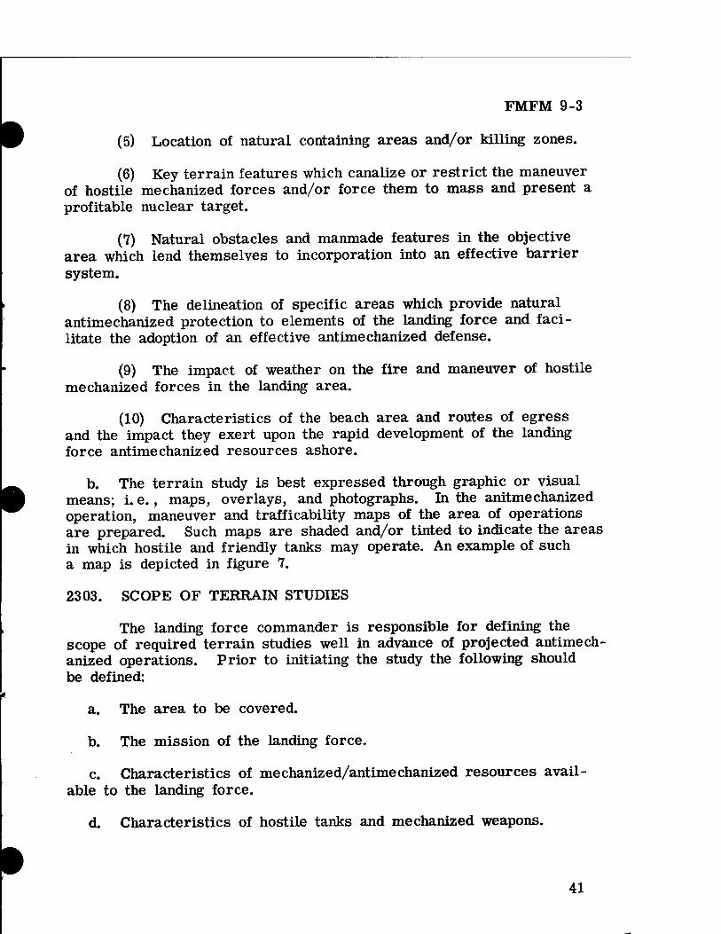
FMFM 9-3
(5) Location of natural containing areas and/or killing zones.
(6) Key terrain features which canalize or restrict the maneuver of hostile mechanized forces and/or force them to mass and present a profitable nuclear target.
(7) Natural obstacles and manmade features in the objective area which lend themselves to incorporation into an effective barrier system.
(8) The delineation of specific areas which provide natural antimechanized protection to elements of the landing force and faci- litate the adoption of an effective antimechanized defense.
(9) The impact of weather on the fire and maneuver of hostile mechanized forces in the landing area.
(10) Characteristics of the beach area and routes of egress and the impact they exert upon the rapid development of the landing force antimechanized resources ashore.
b. The terrain study is best expressed through graphic or visual means; i. e., maps, overlays, and photographs. In the anitmechanized operation, maneuver and trafficability maps of the area of operations are prepared. Such maps are shaded and/or tinted to indicate the areas in which hostile and friendly tanks may operate. An example of such a map is depicted in figure 7.
2303. SCOPE OF TERRAIN STUDIES
The landing force commander is responsible for defining the scope of required terrain studies well in advance of projected antimech- anized operations. Prior to initiating the study the following should be defined:
a. The area to be covered.
b. The mission of the landing force.
c. Characteristics of mechanized/antimechanized resources avail- able to the landing force.
d. Characteristics of hostile tanks and mechanized weapons.
41

FMFM 9-3
Figure 7, —Maneuver and Trafficability Map„
e. The specific information required.
f. The time period to be covered.
2304. FORMAT FOR TERRAIN STUDIES
Appendix A presents an outline form for a terrain study. It is annotated to indicate military aspects of the terrain which are critical to the conduct of mechanized/antimechanized operations. The primary requirement for a terrain study is that it presents the intelligence in a form that can be easily used by landing force elements. The study should be concise, presenting only pertinent information. Written description is kept to a minimum, and intelligence is graphically repre- sented wherever possible.
42

FMFM 9-3
Section IV: ANTIMECHANIZED RECONNAISSANCE
2401. GENERAL
Antimechanized operations require integrated long range recon- naissance, surveillance, and communication systems to detect hostile mechanized forces, alert landing force elements of their approach, and provide for bringing enemy tanks under attack as far forward of the landing area as possible. Distant reconnaissance and early warn- ing generate a requirement for an aggressive air-ground reconnaissance and surveillance effort. This section discusses the nature, planning, and execution of the reconnaissance effort in the antimechanized oper- ation. For a more detailed discussion of reconnaissance plans and operations see FMFM 2-1, Landing Force Intelligence; and FMFM 2-2, Amphibious Reconnaissance.
2402. AMPHIBIOUS RECONNAISSANCE
Antimechanized reconnaissance is initiated by advance force surface and air reconnaissance and surveillance elements. It includes amphibious reconnaissance conducted by personnel landed from seaward to collect information on enemy mechanized forces in the objective area. Extensive and continuing high altitude photoreconnaissance missions are conducted in depth throughout the objective area well in advance of the landing and are continued through the operation. When the objective area is large and the hostile mechanized threat significant, amphibious reconnaissance personnel augmented with ground radar and listening equipment may be landed in depth to maintain surveillance over probable avenues of hostile mechanized approach in order to pro- vide timely warning of hostile mechanized attack. Planning for amphi- bious reconnaissance is completed far enough in advance of the landing operations to ensure adequate time for executing units to make necessary preparations, conduct the reconnaissance, and report the information. Plans provide for transmission of information from within the objective area and for interrogation of personnel after a reconnaissance is com- pleted. Such plans are normally delineated in a reconnaissance plan which is published as an annex to the operation plan.
2408. AERIAL VISUAL RECONNAISSANCE
Aerial visual reconnaissance is conducted from high performance aircraft, helicopters, and fixed-wing light observation aircraft. Such aircraft are the primary means available for long range reconnaissance
43

FMFM 9-3
and surveillance and constitute the backbone of the landing force anti- mechanized warning system. Aerial visual reconnaissance provides a rapid means of acquiring current information on hostile mechanized activity and installations as well as terrain features which affect mech- anized and antimechanized operations. It supplements and extends ground visual reconnaissance and observation and is necessary to pro- vide an effective antimechanized warning system in the objective area.
a. The quantity and quality of information obtained by aerial visual reconnaissance are restricted by weather enemy countermeasures, and the visual acuity of the pilot or observer, particularly pilots in fighter and attack-type aircraft. Night aerial visual reconnaissance is practical in the antimechanized operation, particularly against moving hostile mechanized forces. It is generally restricted to searching and reporting on specific routes and areas.
b. There are three types of aerial visual reconnaissance employed in the antimechanized operation:
(1) Area Search. --Area search is reconnaissance conducted at intervals over a prescribed area for a specified period of time. It is employed during the initial phase of the amphibious assault and con- tributes to the antimechanized operation by locating hostile mechanized forces. Thereafter, it can be conducted in great depth to locate, track, and provide for the engagement of the enemy's mechanized re- serves.
(2) Specific Search. --Specific search is reconnaissance of specific activities or terrain features. Such search is most frequently directed in the followup of information derived by area search or other means. Specific searches as part of the antimechanized warning system are directed against possible hostile mechanized assembly areas, attack positions, and key terrain features which canalize the maneuver of hos- tile mechanized forces.
(3) Route Reconnaissance. --Route reconnaissance is visual ob- servation along likely hostile routes of communications or over probable avenues of approach. It is specifically directed against hostile mech- anized forces on the move and is conducted in considerable depth from the landing force positions.
c. Aerial visual reconnaissance is planned to meet the specific requirements of the antimechanized operation. During the planning phase the landing force commander submits requests and
44

FMFM 9-3
recommendations for aerial visual reconnaissance required to main- tain an effective antimechanized warning system to the amphibious task force commander for inclusion in the overall air plan for the operation. Deep aerial visual reconnaissance required by antimechanized operations is normally flown in attack or fighter aircraft. Such missions are integrated with armed reconnaissance and interdiction missions. When operating against an enemy with considerable mechanized forces, appropriate aerial ordnance for attack of armored targets is carried. The landing force aviation commander may be assigned responsibility for developing detailed recommendations for such missions. Accord- ingly, the landing force commander provides guidance to the aviation commander as to specific areas and routes where antimechanized reconnaissance is required. He also monitors plans to ensure that they are in consonance with his requirements for information of hos- tile mechanized forces.
d. Light observation aircraft, either fixed or rotary wing, with trained observers are most effective for close-in battlefield aerial visual reconnaissance and observation support of ground combat units. They fill the gap between ground reconnaissance and deep air recon- naissance. Accordingly, plans provide for the availability of such air- craft at the earliest practicable time in the amphibious assault.
e. Air observation nets are established for reporting information and for assignment of missions. Rapid response to immediate infor- mation requirements is best obtained by establishing the net control station in the intelligence section area. Additional stations are located in the operations section area and in the fire support coordination center.
f. When aircraft equipped with moving target indicators, infrared detection equipment, or other types of all weather observation means are available, they are used to supplement aerial visual reconnaissance at night and under adverse weather conditions. Guidelines for the employment of visual reconnaissance aircraft are applicable to the employment of aircraft equipped with such devices.
2404. AERIAL PHOTOGRAPHIC RECONNAISSANCE
Aerial photographic reconnaissance provides a major means for developing information of the enemy's mechanized forces and of terrain conditions in the objective area that will influence the maneuver of enemy and friendly mechanized forces. It is particularly valuable prior to the assault phase of the amphibious operation when close visual reconnaissance is usually not feasible.
45

FMFM 9-3
a. Capabilities and Limitations. --Aerial photography possesses the capability to subject areas to day-by-day and week-by-week analysis. In addition, aerial photos yield accurate, recorded information that can be reproduced in quantity. Aerial photographic reconnaissance can obtain information on otherwise inaccessible areas. With proper film, camouflaged mechanized forces can be revealed. The limitations of aerial photographic reconnaissance are similar to those of aerial visual reconnaissance since both rely on optical means. Weather and light conditions must be satisfactory. Photography must be of proper scale to permit interpretation for specific items, and there is a time lag between the request for and final delivery and interpretation of required photographs.
b. Photographic Agencies. --Prior to the assault, theater air for- ces, attack carrier striking forces, and shore-based Navy and Marine photographic squadrons provide the bulk of aerial photography in the objective area. Subsequently, their efforts are augmented by photo- graphic aircraft, Navy and Marine, from the support carrier group and by Marine photographic aircraft phased into the objective area. Observation aircraft assigned to support of ground forces also provide limited aerial photography.
c. Photographic Plan, --The photographic plan for the amphibious task force is prepared jointly by the amphibious task force and landing force commanders. This plan reflects the photographic requirements of subordinate landing force units and is adjusted to the capabilities of the photographic reconnaissance agencies. The landing force commander provides guidance to subordinate units concerning the availability of photographic reconnaissance means. Based on this guidance, subordinate units submit requests to the landing force commander for aerial photo- graphy. These requests are consolidated into the overall photographic plan.
d. Photographic Requirements. --The following types of aerial photo- graphy are normally required in the antimechanized operation:
(1) Basic Cover. --Basic cover is one time vertical coverage of the entire objective area or of selected areas within the objective area. It serves primarily for terrain analysis and assists in isolating and defining the areas in which friendly and hostile mechanized forces may operate. Additionally, it detects areas of major interest to the enemy's mechanized forces.
46

FMFM 9-3
(2) Beach Photography. --Beach photography may include both vertical and oblique coverage at varying scales of the area from off- shore inland to a depth of 10,000 to 15,000 meters. Beach photo- graphy is used for detailed beach and terrain analysis. It assists in identifying enemy defensive installations, obstacles, minefields, and antitank weapons that may impede the development of the landing force's antimechanized resources ashore.
(3) Helicopter Landing Zone Photography. --Helicopter landing zone photography usually includes vertical coverage at medium scales radiating 10,000 to 15,000 meters from the centers of the zones and large-scale coverage of the zones proper, plus selected oblique pho- tography. This photography is used for the same purposes as beach photography. Landing zone photography is supplemented by maneuver photography of helicopter approach and retirement lanes.
(4) Surface Assault. Force Maneuver Photography. --Surface assault maneuver photography is support of elements moving overland routes of approach. It is used for terrain analysis and for detection and identification of enemy mechanized forces along the route of ad- vance. Such photography is particularly valuable in planning mech- anized/striking force operations and analyzing possible attack and counterattack routes.
(5) Enemy Maneuver Photography. --Enemy maneuver photo- graphy is photography of possible routes of apporach to enemy mech- anized forces. Since principal movement of such forces may nor- mally be anticipated at night, this photography is flown at the earliest time light conditions permit in order to detect enemy units before they are well camouflaged and off roads. Additionally, when a night photo- graphic capability is available, it is exploited to the maximum extent possible.
(6) Special Cover. --Special cover is photography of specific targets or objectives. Special cover is flown to obtain specific in- formation derived by other means.
2405. GROUND RECONNAISSANCE AND OBSERVATION
Intensive reconnaissance and observation of the objective area by ground elements of the landing force commence with the assault and continue throughout the operation, providing intelligence and in- formation to fulfill requirements for anticipated antimechanized oper- ations. Whether or not there is initial contact between the landing force
47

FMFM 9-3
and hostile mechanized forces, the possible inadequacy of preliminary intelligence concerning enemy mechanized capabilities dictates that the reconnaissance and observation in the assault phase be carefully plan- ned and aggressively executed.
a. Initially, assault units can be assigned areas or zones of ob- servation within which they are responsible for ground reconnaissance and observation. These areas generally coincide with zones of action, sectors, or area of responsibility. Subsequently, additional specific reconnaissance and observation missions are assigned as necessary in order to obtain sufficient or needed antimechanized intelligence. The landing force is responsible for the planning and conduct of ground reconnaissance and the observation of areas not assigned to subordinate units. Such reconnaissance and observation may be conducted by re- connaissance units retained under landing force control or by reserve units of the landing force. Observation and surveillance of the battle- field are delineated by the organization of observation (0-0) line to delineate the depth of responsibility for the division ground observation.
b. The major reconnaissance and observation effort for antimech- anized operations is concentrated on determining the location of enemy tank formations. In order to avoid dissipation of effort, landing force observation and surveillance agencies concentrate along principal ave- nues of hostile mechanized approach and tank trafficable areas that may be used for assembly areas or attack positions. The ground re- connaissance and observation effort is integrated with that of other collection means. Aerial reconnaissance by helicopters and light air- craft is used to increase the depth of ground reconnaissance. They permit prompt establishment and rapid shifting of observation to provide continuous surveillance and detection of hostile mechanized forces. Ground reconnaissance and surveillance agencies deployed with security forces are positioned in greater depth at night and in periods of reduced visibility. This prevents hostile mechanized units from closing rapidly and penetrating or enveloping landing force positions. Electronic, seismic, and infrared surveillance equipment is used to supplement visual observation during such periods.
(1) Based on his knowledge of the area of operations and the composition and disposition of the hostile mechanized forces, the in- telligence officer recommends the points for the establishment of deep observation over logical avenues of hostile mechanized approach early in the landing. Observation posts may be established by helicopter or parachute-landed troops.
48

FMFM 9-3
(2) Communications are provided between these deep observa- tion posts, supporting air elements, and the landing force and other headquarters to ensure that once hostile forces are detected, alerts and warnings can be immediately disseminated, antimechanized pre- parations implemented, and attack of approaching hostile armor initi- ated.
2406. COMMUNICATION RECONNAISSANCE
Communication reconnaissance is the interception and analysis of transmissions over hostile signal communications, primarily radio communications. The control and coordination of hostile mechanized forces require significant transmission of radio traffic. The monitoring of such communications can provide detailed information on enemy order of battle, composition, strength, and disposition. Under favorable conditions, it may provide information on enemy plans. Information derived by communication reconnaissance is given limited distribution; i. e., key staff officers and commanders involved. Under no circum- stance is the source of such information divulged to other than spec- ifically authorized personnel. Operations of landing force communica- tion reconnaissance units are planned to supplement the area, fleet, and amphibious task force communication reconnaissance effort. Most effective results are obtained by centralized control and direction of the communication reconnaissance effort. Depending on the means available to exploit communication reconnaissance at lower levels, communication reconnaissance unit(s) may be assigned in direct support of subordinate landing force units. Intercept units, particularly those designed to operate against enemy voice radio circuits, are often assigned to support infantry regiments and even battalions.
a. Communication reconnaissance units are assigned specific mis- sions. In antimechanized operations the priority of effort of such units under landing force control is to determine the location and identifica- tion of hostile tank units. Other appropriate missions include deter- mining the composition, strength, and disposition of hostile mechanized forces in prescribed areas or checking on the movements of specific mechanized units.
b. Provision is made for the early landing of communication re- connaissance elements when a major hostile mechanized threat exists. Appropriate security of the installations is ensured by attaching them to appropriate assault unit(s) headquarters. In order to exploit the communications of the enemy's approaching or reserve mechanized
49

FMFM 9-3
units, communication reconnaissance units can be landed by helicop- ter deep within the objective area at suitable locations for intercepting hostile mechanized signal transmissions. Also, airborne means may be used to intercept hostile mechanized signal communications.
50

FMFM 9-3
CHAPTER 3: PLANNING AND EXECUTION OF ANTIMECHANIZED OPERATIONS
Section I: GENERAL
3101. INTRODUCTION
Marine Corps doctrine for the planning and execution of the amphibious assault is presented in LFM 01, Doctrine for Amphib- ious Operations; LFM 02, Doctrine for Landing Forces; FMFM 8-1, Marine Division: and FMFM 3-1, Command and Staff Action. The basic concepts and principles for the planning and execution of am- phibious operations prescribed in these publications remain valid and are specifically applicable to planning and executing the antimechanized operation. Antimechanized operations within the frame- work of the amphibious assault rely heavily on offensive measures to eliminate any mechanized threat to the landing force. A defensive posture is assumed only to counter an imminent enemy tank attack. This chapter describes their planning and execution. It is principally concerned with the development of specific antimechanized plans, dis- cussing other amphibious plans only to the extent that they relate to antimechanized operations.
3102. PLANNING OBJECTIVES IN ANTIMECHANIZED OPERATIONS
Throughout the amphibious planning cycle planners are concerned with providing the prerequisite antimechanized measures and means re- quired to counter the specific hostile mechanized threat confronting the
51

FMFM 9-3
landing force. Antimechanized planning by the landing force is essen- tially a problem of coordinating and integrating antimechanized re- sources. Concurrent and parallel planning ensures effective employ- ment of antimechanized means by the amphibious task force and land- ing force commanders. The basic objectives of antimechanized plan- ning are to provide for the following:
a. Estimating the enemy's mechanized capabilities prior to the amphibious assault and throughout the execution of operations ashore.
b. Determining the mechanized trafficability of the area of oper- ations.
c. Selecting terrain which facilitates antimechanized operations.
d. Developing a scheme a maneuver which facilitates the movement of the force across the beach, and ensures the rapid development of antimechanized means ashore.
e. Determining and procuring adequate antimechanized resources for prelanding operations, the assault landing, and operations ashore.
f. Distributing and/or allocating available antimechanized means to ensure the best possible all-round antimechanized defense.
g. Instituting an effective distant antimechanized surveillance, warn- ing, and attack system.
h. Prescribing antimechanized conditions of readiness and pre- arranged plans for passing control of antimechanized resources.
i. Restricting, destroying, and/or neutralizing hostile mechanized forces in the area of landing.
j. Accelerating the development of antimechanized means ashore.
k. Providing for emergency antimechanized measures during the early phases of an amphibious assault.
1. Integrating all available fire support resources into an effective antimechanized weapons system.
m. Preparing specific antimechanized defense and antimechanized fire plans to counter specific hostile mechanized threats that are likely to be encountered during the operation.
52 «

FMFM 9-3
n. Constructing an integrated natural and artificial barrier system,
o. Rehearsing antimechanized plans.
3103. PLANNING RESPONSIBILITIES IN ANTIMECHANIZED OPER- ATIONS
In the amphibious operation normal command responsibilites apply to antimechanized planning. The amphibious task force comman- der is responsible for coordination of the planning of overall antimech- anized means and the preparation of coordinated antimechanized fire support plans for the initial phase of the operation. The landing force commander is responsible for clearly delineating the antimechanized responsibilities at each command level of the landing force. In addi- tion, he is responsible for the following:
a. Determining the landing force requirements for antimechanized means and ensuring that the resources are integrated within the plan- ned scheme of maneuver.
b. Presenting and coordinating requests for additional antimech- anized means for the landing force with the amphibious task force commander and/or appropriate Fleet Marine Force agencies.
c. Preparing the landing force overall antimechanized plan(s).
3104. ANTIMECHANIZED PLANNING SEQUENCE
Antimechanized planning is carried out concurrently with other planning for the operation. It is normally conducted in accordance with the following sequence:
a. The basic directive for the operation is received by the landing force commander. After receipt of this directive, the commander, assisted by his staff, goes through the usual sequence of steps in arriving at a decision and formulating the commander's concept of the operation.
b. The intelligence estimate (hostile mechanized estimate) is pre- pared by the intelligence officer with the assistance of the antimech- anized officer. The enemy's mechanized capabilites may be determined as part of the overall enemy strength and capability within the
53

FMFM 9-3
intelligence estimate or by a separate hostile mechanized estimate as described in chapter 2 of this manual.
c. An estimate of the antimechanized situation is prepared under the staff cognizance of the operations officer by the antimechanized officer. The preparation of such an estimate is outlined in paragraph 3303 of this chapter.
d. When the commander's decision has been reached and his con- cept of operations issued to the staff, detailed staff estimates are pre- pared for the purposes of determining accurate antimechanized require- ments and formulating necessary antimechanized plans. These anti- mechanized staff estimates are prepared by appropriate staff sections with the assistance of the antimechanized officer. Antimechanized information which is essential to parallel and subordinate planning agencies involved in antimechanized planning is disseminated as early as practicable.
e. Based upon detailed staff estimates, the landing force command- er develops his antimechanized requirements for preassault operations, assault operations, and subsequent operations ashore. He coordinates these requirements with the amphibious task force commander.
f. When sufficient detailed instructions are firm, the operations officer, assisted by the antimechanized officer, prepares the anti- mechanized plan(s) based on the commander's decision, instructions from higher headquarters, the tactical plan, the detailed special staff estimates, and recommendations from other staff officers. After the antimechanized plan(s) is approved by the commander, it is issued an annex to the operation plan.
g. Subsequently, the antimechanized plan(s) is revised as necessary to reflect the actual availability of antimechanized resources, provided on the basis of previously submitted requirements.
3105. STAFF RESPONSIBILITIES
Appropriate staff officers at all levels have specific responsi- bilities with respect to antimechanized operations. These antimech- anized responsibilities are an inherent part of normal staff duties during the planning and execution of amphibious operations.
a. Operations Officer. --The operations officer considers enemy mechanized tactics in the preparation of estimates, plans, and orders.
54 «

FMFM 9-3
He continually appraises the tactical situation and recommends and prepares orders for tactical employment of antimechanized means as appropriate.
b. Antimechanized Officer. --A specific staff officer appointed for this purpose or the commanding officer of the organic, attached, or supporting antitank unit normally performs special duties as antimech- anized officer. He assists in the preparation of staff estimates and orders by providing detailed technical information on antimechanized matters. He maintains a detailed current situation map as to the location and capabilities of all antimechanized means and recommends their use.
c. Intelligence Officer. —The intelligence officer collects and dis- seminates information and intelligence relative to the hostile mech- anized threat. He includes this information in intelligence estimates and annexes, and appraises interested staff officers of changes in the enemy mechanized situation.
d. Tank Officer. --In the event a tank unit is attached or in support, the commanding officer of that unit normally performs special staff duties as tank officer. He recommends the employment of tanks in support of antimechanized operations.
e. Engineer Officer. --The engineer officer is responsible for pre- paring a barrier plan. He also gives technical advice on engineer employment in antimechanized actions and makes provision for the necessary heavy equipment to emplace and dig in antimechanized weapons.
f. Air, Naval Gunfire, and Artillery Special Staff Officers. --Air, naval gunfire, and artillery officers develop detailed and coordinated recommendations for fires to support antimechanized operations. In- dividual antimechanized fire plans are developed to cover avenues of approach into the landing force battle areas and to mass antimech- anized fires in designated killing zones.
g. Fire Support Coordinator. --The fire support coordinator, ad- vised and assisted by supporting arms special staff officers, the anti- mechanized officer, and the target information officer is responsible for coordinating the fires of artillery, naval gunfire, and air support in antimechanized actions.
55

FMFM 9-3
h. Communication-Electronics Officer. --The communication-elec- tronics officer makes recommendations pertaining to and coordinates communications required in antimechanized action. The communication- electronics officer ensures that communication facilites are available to control all antimechanized resources. Frequencies are assigned for special nets as required for prompt execution of antimechanized oper- ations.
3106. ANTIMECHANIZED PLANNING CONSIDERATIONS
Basic antimechanized planning considerations are derived from the commander's estimate of his antimechanized situation; i. e., mission, enemy, terrain and weather, and troops and fire support available (METT). In making his estimate of the situation, the commander takes into consideration all factors that influence the employment of his antimechanized resources and affect the execution of antimechanized operations. The estimate of the situation is essentially a problem- solving process designed to select the antimechanized course of action which offers the greatest possibility of success. Consideration of the factors of METT is begun prior to the operation and continues through- out. It encompasses the following aspects of these factors:
a. Mission. —The mission of the landing force in the antimech- anized operation is considered in terms of the following:
(1) Scope and extent of advance force operations.
(2) Projected assault operations and fire support requirements.
(3) Front and depth of main and supporting attacks.
(4) Relative concentration and/or dispersion of the landing force.
(5) Extent of the battle area, laterally and in depth. ^
(6) Projected length of the operation.
b. Enemy. --The capabilities of the hostile mechanized force are considered in terms of the following:
(1) Overall strength of the hostile mechanized force.
(2) Composition, strength, and disposition of hostile I mechanized forces in the area of the landing. ^k
56 ^

FMFM 9-3
• (3) Composition, strength, and disposition of hostile mechanized reserves, and projected estimates as to when and where these forces can be expected to engage the landing force.
(4) Air support and anti-air warfare capabilities of the hostile mechanized force and/or available from other enemy forces in the objective area.
(5) Fire support capability of the hostile mechanized force.
(6) Number, type, and characteristics of tanks and mechanized vehicles available to the hostile force.
(7) Tactics and techniques employed by the hostile force.
(8) Nuclear, biological, and chemical capabilities of the hostile force.
(9) Antitank weapon capabilities of the hostile force.
c. Terrain and Weather. --Terrain and weather in the objective area and their probable effects on the employment of hostile mechanized and friendly antimechanized resources are considered in terms of the following:
(1) The probable effects of weather on landing force and hostile air support elements.
(2) The effect of terrain and weather on the progressive dev- elopment of antimechanized resources ashore.
(3) Trafficability within the objective area.
(4) Natural obstacles and/or barriers existing in the objective area.
(5) Number, extent, and disposition of probable avenues of approach for the advance of hostile tanks.
(6) Number, extent, and relative location of natural containing areas which restrict and/or delay the advance of hostile mechanized tanks or force the enemy to mass and present a profitable nuclear target.
57

FMFM 9-3
(7) Number, extent, and relative location of natural antimech- anized killing zones.
(8) Overall capacity of terrain in the objective area to provide antimechanized protection to the landing force and facilitate the adop- tion of an effective antimechanized defense.
(9) Time and space factors and the restrictions they impose upon the fire and maneuver capabilites of the landing force and the hostile force.
(10) Extent and capacity of existing road nets to support hostile mechanized and landing force antimechanized operations.
d. Troop and Antimechanized Resources Available. —Troops and antimechanized resources available to the landing force to conduct antimechanized operations are considered in terms of the following:
(1) Overall antimechanized capability of the landing force.
(2) Antimechanized capabilities of component elements of the landing force and requirements for reinforcements.
(3) Availability of tanks, Ontos, antitank weapons, and support- ing arms.
(4) Antimechanized resources available from the amphibious task force and higher headquarters.
(5) Availability of aircraft.
(6) Availability of anti-air warfare resources.
(7) Status and availability of nuclear, biological, and chemical weapons.
(8) Availability of mechanized and helicopter-lifted elements to support antimechanized operations.
(9) Availability of antitank munitions.
(10) Availability of engineer units, land mines, material, and heavy equipment for barrier construction and preparation of antitank weapon positions.
58 «

FMFM 9-3
Section II: BASIC ANTIMECHANIZED DECISIONS
3201. GENERAL
The development of specific antimechanized plans in the amphi- bious planning cycle depends upon sound and timely decisions as to the landing force's objectives ashore and its subsequent scheme of maneuver, the determination of requirements for antimechanized resources, the assignment of tactical missions to these antimechanized resources, and the methods and means for rapidly developing antimechanized resources ashore. This section discusses the nature of these decisions and the planning factors that are considered.
3202. LANDING FORCE OBJECTIVES AND SCHEME OF MANEUVER IN THE ANTIMECHANIZED OPERATION
The need for defensible terrain is given careful consideration during each phase of an amphibious assault against an enemy possessing a significant mechanized potential. To compensate for the inherent scarcity of antimechanized resources in the initial stage of the amphi- bious assault, landing force planners select initial objectives and evolve a scheme of maneuver that exploits the terrain characteristics of the objective area and provides natural protection against attack by hostile tanks.
a. Selection of Objectives. --Wherever possible, landing force plan- ning strives to avoid engaging a mechanized enemy on ground of his own choosing; i. e., terrain which permits the hostile force complete freedom of maneuver.
(1) Beach characteristics and exits in the landing area should facilitate the rapid development of the landing force's antimechanized resources ashore.
(2) Terrain in the area of the landing should provide natural obstacles to the flanks of the landing force which restrict the number of avenues of approach for hostile mechanized traffic into the landing area and limit the number of enemy tanks that can engage the landing force in any specific locality.
(3) Terrain at the force beachhead line (FBHL) should facilitate the establishment of a strong antimechanized defense by presenting a natural barrier system to the enemy's mechanized forces and com- pelling them to attack frontally.
59

FMFM 9-3
(4) It is highly desirable that intervening terrain provide read- ily identifiable natural phase lines and antimechanized killing zones which provide antimechanized protection, expedite the rapid adoption of an effective antimechanized defense, and facilitate the massing of antimechanized fires.
b. Terrain Considerations. --In analyzing the operational area, planners consider the beachhead and the terrain to the flanks, paying special attention to obstacles and potential obstacles such as built-up areas. Terrain with natural obstacles that canalizes and/or forces hostile armor units to mass along routes of approach into the beach- head or defensive area is highly desirable. Planning provides for maximum use of such terrain in order to provide a greater degree of antimechanized protection and more effective employment of antimech- anized resources. When dispersion of landing force elements is nec- essary to provide protection against enemy nuclear weapons, the re- quirement for an extensive analysis of terrain is emphasized. Dis- persed forces generally dictate a decentralization of the antimechanized resources available to the landing force. Accordingly, such landing force elements are compelled to rely more heavily upon the natural antimechanized protection provided by terrain than when they are con- centrated and provided with highly mobile and centralized antimech- anized reserves.
c. Desirable Terrain Features. --The most attractive terrain feature for planning and executing antimechanized operations is dominating ground that offers natural cover and concealment, clearly defined anti- mechanized killing areas, and abstacles to hostile mechanized maneuver such as swamps, unfordable streams, steep ridges, and narrow defiles. Such terrain facilitates the integrated employment of the landing force's antimechanized resources without impeding the impetus of the landing force's assault. In this respect, the landing force's primary mission is to seize its assigned objectives. No terrain can be considered desirable which detracts from this purpose.
d. Antimechanized Scheme of Maneuver. --In the development of the landing force scheme of maneuver ashore, planners give continuing consideration to the selection of terrain which complements antimech- anized plans and operations. Successive antimechanized phase lines may be used to break down the overall operation into a number of logical and manageable planning and operational parts. As such, they serve as ready reference points to orient planners as to the status of the landing force, and at the same time, indicate when prearranged plans for successive stages of the antimechanized operation should be executed. Such phase lines are selected to delineate natural
60

FMFM 9-3
antimechanized killing zones and to establish successive firm bases from which projected antimechanized operations may be conducted. These bases move inland as successive objectives and phase lines are seized. Antimechanized plans are developed and/or modified as necessary to provide for the execution of an effective full scale anti- mechanized defense at each succeeding antimechanized phase line. (See fig. 8.)
3203. DETERMINATION OF REQUIREMENTS FOR ANTIMECHANIZED RESOURCES
a. General. --The determination of the landing force's requirements for antimechanized resources, especially aircraft, tanks, and Ontos, and their subsequent procurement, establishes the landing force's antimechanized capabilites. The final decision in the determination of requirements for antimechanized resources is based on a continuing evaluation of the hostile mechanized threat in specific terms to deter- mine the following:
(1) When and where the landing force will come in contact with the hostile mechanized force.
(2) What tank strength the enemy is capable of massing at specific points.
(3) What means the landing force requires to counter this threat.
b. Scope of Antimechanized Requirements. --In the amphibious assault against an enemy possessing a significant mechanized potential, the evaluation, analysis, and determination of specific antimechanized requirements are designed to provide adequate resources, to include:
(1) A combined air and naval gunfire capability sufficient to destroy and/or neutralize any hostile mechanized forces in the area of the landing.
(2) Sufficient aircraft to maintain a significant degree of air superiority in the objective area and to:
(a) Conduct long range reconnaissance, counterreconnaissance, and antimechanized missions.
61

FMFM 9-3
T^^^KILL ZONE 7 <^ S^ >^KILL ZONEJ << = / ""^»^ ^
Figure 8. --Phasing Antimechanized Operations Within the Amphibious Operation.
62 t

FMFM 9-3
(b) Restrict, delay, and canalize the movement of hostile mechanized reinforcing elements.
(c) Destroy such forces or attrite them by fire to the degree that the landing force is able to destroy surviving tanks with organic antitank weapons and other antimechanized resources.
(3) A combined artillery and naval gunfire capability sufficient to provide for massing of fires along principal avenues of hostile mechanized approach and into predesignated killing zones forward of and within the battle area.
(4) Light antitank assault weapons to all infantry units on an individual basis.
(5) Mechanized direct fire antitank weapons (tanks and Ontos) to provide direct support to landing force elements operating along principal avenues of hostile mechanized approach.
(6) A mobile tank-heavy striking force of combined arms that can deploy rapidly to designated killing areas and possesses sufficient combat power to contain and destroy and hostile mechanized penetration into the landing force's positions.
(7) Adequate antitank munitions for the landing force's weapons and the weapons of all supporting elements external to the landing force.
(8) Adequate nuclear delivery agencies and nuclear munitions in size and type to destroy hostile mechanized forces in depth and/or engage them forward of or within the battle area.
(9) Adequate chemical munitions to lay persistent toxic barriers in depth inland along probable avenues of approach and in hostile mech- anized assembly areas to inhibit the maneuver of reinforcing hostile tanks and their supporting elements and to delay tanks and mechanized forces from reaching the landing area.
(10) Adequate engineer support, heavy equipment, and mines to facilitate the rapid construction of an effective barrier system and to construct defiladed positions for the landing force's antitank weapons.
c. Interrelationship of Antimechanized Resources. --The availability and requirements for one antimechanized means affects the availability
63

FMFM 9-3
and requirements for all others. In this respect, the ability of the force commander to substitute one antimechanized means for another determines the degree of flexibility that may be incorporated into his antimechanized plans. All important in this matter is the balance that the commander strikes between his air antimechanized resources and ground antitank resources. The following are considered in determining this balance:
(1) Knowing the total number of hostile tanks opposing him and the kill capabilities of available air support, the commander can determine his requirements for antitank weapons in the antimechanized operation.
(2) Conversely, knowing the kill capabilities of his ground anti- tank weapons and other antimechanized resources, the commander can determine his requirements for air support.
d. Requirements Planning. —During the planning cycle staff officers include in the preparation of estimates consideration of the adequacy of the antimechanized means within their concern or under their cogni- zance. Specific requirements for countering hostile mechanized threats during all phases of the operation are determined on the basis of the antimechanized considerations applicable to the operation. Analysis of requirements is a continuing responsibility requiring careful screening and study to prevent the omission of any essential items or unnecessary inclusion of equipment, personnel, or materiel. Provision is made for loss of antimechanized means due to enemy action, the characteristics of the area, and any foreseen contingencies involved in the operation. When the overall antimechanized requirements have been determined, they are weighed against the antimechanized means available within the landing force to determine any additional landing force antimech- anized requirements.
e. Availability of Antimechanized Resources. --As soon as the total antimechanized resources are known, antimechanized plans are devel- oped to reflect the actual availability of those resources. When suffi- cient antimechanized resources are not available from higher authority for assignment to the ATF to enable it to ensure the landing force of the required preponderance of combat power to overcome the hostile mechanized force, one of the following actions is necessary:
(1) Fleet theater air may reduce the hostile mechanized force to enable the ATF to achieve the required combat superiority in the objective area.
64 «

FMFM 9-3
(2) The landing may be changed to a different locality.
(3) The operation may be canceled-
3204. ASSIGNMENT OF TACTICAL MISSIONS AND/OR ATTACHMENT AND ALLOCATION OF ANTIMECHANIZED RESOURCES
The assignment of tactical missions and/or attachment of anti- mechanized resources is reflected in the organization for combat of the landing force and its component elements. The principal problem in planning assignment of missions to these resources is to strike a balance between the requirements of the landing force as a whole and its subordinate elements. It is uneconomical and impracticable to provide all landing force units with all the antimechanized resources they might require to offset all possible antimechanized contingencies. Therefore, principal reliance is placed upon massing antimechanized resources along principal avenues of approach and maintaining a highly mobile and tank-heavy striking force/reserve capable of immediate deployment to any point in the landing force's area of operations. Plan- ners seek to provide centralized control of antimechanized resources insofar as practicable to ensure their integrated and mass employment.
a. Forms of Support. —Antimechanized resources may be assigned missions of general support, direct support, or attachment. They may also be employed in combinations of these three types of support. Gen- eral support and direct support are the preferred types of support in the antimechanized operation. Attachment is resorted to only in cases of extreme dispersion or to support independent operations.
b. Factors Influencing Employment of Resources. --The factors of METT delineated in paragraph 3106 of this chapter are analyzed in planning the assignment of missions to antimechanized resources. In addition, particular attention is given to the following considerations:
(1) Duality of Function. --The dual functions of many antimech- anized resources in initially supporting the amphibious assault and subsequently supporting antimechanized operations may dictate an ini- tial decentralization of control. Tanks in direct support of a regiment in the initial assault of beach objectives may revert to a general support role or become an element of the striking force/reserve once the ini- tial objectives are seized. Plans provide for rapid reversion of such units to central antimechanized control when a hostile mechanized th threat is imminent.
65

FMFM 9-3
(2) Intentions of the Enemy. --When no information of the time ^ and location of hostile armored elements or their intention can be ob- tained, the antimechanized means are held under centralized control. Consideration is given to the enemy's capability of massing his mech- anized forces, and any assignment of tactical missions must comple- ment a plan developed to counteract this capability.
(3) Unit Separation. --Separation between units as opposed to concentration of forces is a crucial factor in planning the assignment of tactical missions to antimechanized resources. The separation of one major groupment from another is often dictated as a tactical measure against the threat of nuclear attack or by the characteristics of the objective area. Separation affords the enemy the opportunity to attack any single groupment from any of several different directions. Separation also invites the enemy to attempt an attack between units into the rear area. Specific antimechanized precautions are necessary to counter this threat. Generally, dispersed operations generate a requirement for more antimechanized resources than the landing force requires in a conventional type amphibious operation. In such instances, it may be necessary to attach antitank and tank units to widely separated elements.
(4) Concentration of Antimechanized Resources. --Antimechanized ^ plans provide for concentrating antimechanized resources to counter a large-scale mechanized attack. Such plans are designed to concentrate and centralize control of antimechanized units and reserve elements in the critical area. They are executed once the enemy has revealed his intentions as to where he will launch his tank attack. Concentration cannot be accomplished under threat of nucelar attack to the extent that a mass of units and means forms a lucrative nuclear target.
(5) Reinforcement of Forward Elements. --In situations involving wide frontages, numerous routes of tank approach, or when control is difficult, it may be necessary to assign tanks and Ontos missions in direct support of forward elements to prevent forward units being * overrun. In such situation, time/space factors prolong the reaction time of mobile antimechanized reserves and delay their support of critical areas under attack. Accordingly, forward elements require additional antimechanized resources to contain the enemy until they can be reinforced.
(6) Defense in Depth. --Mechanized attack is characterized by deep penetrations and wide encirclements. Antimechanized defenses, to be effective, are organized in depth. Each echelon ensures that its
« 66

FMFM 9-3
prescribed antimechanized defensive depth has been achieved with or- ganic weapons. The landing force provides supplementary means to subordinate elements.
(7) Mobile (Self-Propelled) Units. —To provide for the contin- gency that hostile armor may succeed in breaking through the battle position, sufficient antimechanized resources are retained in mobile (self-propelled) units. These units are capable of effective employ- ment against armor and are held in readiness for counterattack.
(8) Time/Space Factors. --Time/space factors affecting the employment of friendly and hostile mechanized forces are considered in positioning and placing antimechanized resources. Open terrain with good trafficability for the landing force's mobile antimechanized resources generally dictates centralized control, Terrain with poor mechanized trafficability generally dictates antimechanized resources in direct support of, or attached to, units in the most critical antimech- anized areas of operation.
3205. PROGRESSIVE DEVELOPMENT OF ANTIMECHANIZED MEANS ASHORE
In the antimechanized operation the need for antimechanized means ashore commences as soon as the initial wave of assault troops land. Plans provide for equipping assault units with increased allowances of light antitank assault weapons. Reserve elements equip- ped with increased allowances of antitank assault weapons are retained in an on call status for immediate deployment by helicopter to critical points in the landing area. Plans also provide for landing tanks and Ontos at the earliest practicable time. When a beach is undefended by antitank weapons, minefields, and obstacles, they may be landed in advance of, or with the assaulting infantry. A strongly defended beach with extensive antitank weapons and obstacles delays their landing.
a. Landing Considerations. --Among the basic considerations in planning given to the development of antimechanized means ashore during the assault phase are the following:
(1) Tanks may be required ashore early in the operation to assist the infantry with shock action and direct fire to overcome beach fortifications in rapid seizure of objectives.
(2) Tanks and Ontos are particularly valuable weapons to counter an early attack by hostile mechanized forces and are landed in sufficient time to counter any hostile mechanized threat existing in the landing area.
67

FMFM 9-3
(3) The maneuverability of hostile mechanized forces and the short duration of the critical phases of their attack may dictate that the landing force land helicopterborne antitank assault elements at critical points without delay.
(4) The early landing of antimechanized weapons tends to reduce casualties among the assualting infantry and is a morale factor in the early stages of the amphibious assault.
(5) Antimechanized weapons must be landed without excessive losses.
b. Factors Influencing the Landing of Antimechanized Resources. — Planning the progressive build-up of antimechanized means ashore is based upon consideration of the following factors:
(1) Mission. --The mission of the landing force determines the general landing area for antimechanized means and the tank-heavy striking force/reserve. The determination of the general area for landing is based on time and space factors involved in securing the initial objectives ashore and the time available to organize an effective antimechanized operation, as compared with the time and space factors involved in the movement of enemy armor to the landing area.
(2) Scheme of Maneuver. —The scheme of maneuver is designed to provide for rapid seizure of initial objectives and to counter the hostile mechanized threat in the landing area. Thereafter, it is dev- eloped to maintain the momentum of the amphibious assault while at the same time facilitating the adoption of effective antimechanized defense measures at successive antimechanized phase lines as the force moves inland. A time and place for landing tanks, Ontos, and the reserve/striking force is selected that most satisfactorily supports the scheme of maneuver.
(3) Shipping. --The type and number of ships and landing craft available to transport tanks and Ontos have a major influence on the capability of landing these units where and when they are required. Planning factors for available ships and craft and their beaching characteristics are presented in figure 9. For a more detailed dis- cussion see FMFM 4-2, Embarkation; and FMFM 9-1, Tank Employ - ment.
68

FMFM 9-3
(4) Landing Beach. --The beach gradient, offshore reefs or sandbars, the navigability of the approach lanes, and the waters of the objective area influence the choice of landing sites. A beach for land- ing tanks and Ontos should be selected where the beach soil is trafficable and the beach gradient is not too steep. A good beach has an ample number of exits. It should be located so that it supports the overall scheme of maneuver of the landing force ashore. The landing of tanks and Ontos is delayed when:
(a) Offshore reefs bar passage of landing craft.
(b) Beach gradients do not permit dry ramp beaching.
(c) Soil trafficability is poor.
(d) It is necessary to emplace causeways.
(5) Obstacles. --Beach minefields and obstacles are normally breached or overcome before landing antimechanized weapons« Obstacles, offshore and on the beach, are avoided wherever possible. Where avoidance is impracticable, a landing site is selected where they can be most easily breached. Plans provide for landing obstacle breach- ing teams with the initial assault waves to ensure the early develop- ment of landing force heavy antimechanized means ashore.
c. Reconnaissance. --Plans provide for tank and antitank recon- naissance personnel to accompany the assualt infantry ashore to amplify unknown aspects of hostile resistance, to note characteristics of the terrain that can be exploited, and to ensure earliest possible landing of antimechanized means. When such personnel cannot be landed, a list of information required for the decisions necessary to land and employ antimechanized units is submitted to assault units so as to secure the needed intelligence. Reconnaissance tasks accomplished for tank and antitank units are concerned principally with the below listed items:
(1) Landing points and beach gradients.
(2) Trafficability in the beach area.
(3) Beach exits and routes of egress.
(4) Location and extent of enemy AT weapons, obstacles, and minefields.
69

FMFM 9-3
LCM LCU LST «»» LSD «*** C-130 6 8
MEDIUM TANK 1 3 MAX 3 BEACHING
20 MAX 10 BEACHING
40 (DRY) or 3 LCUor 9 LCM-8
HEAVY TANK 1 3 MAX 3 BEACHING
16 MAX 8 BEACHING
23 (DRY) or 3 LCUor 9 LCM-8
LIGHT TANK 1 5 MAX 5 BEACHING
23 MAX 20 BEACHING
67 (DRY) or 3 LCUor 9 LCM-«
ONTOS 2 3 13» 10»»
50 93 (DRY) or 3 LCU or 9 LCM-8
1
1466 CLASS 1610 CLASS 1156 CLASS (PREDICATED ON A 500 TON BEACHING CAPACITY FOR LSTs)
Figure 9. --Beaching Characteristics and Planning Factors for Available Ships and Craft
d. Planned Obstacle Clearing and Breaching. --Plans provide for rapid clearance of beach and underwater mines and obstacles to per- mit the early landing and employment of the force's antimechanized means. Clearance of underwater obstacles seaward of the high water mark is the responsibility of the Navy and is usually accomplished during the preassault phase. Mines and obstacles inland of the high water mark are cleared by the landing force. Time seldom permits removal of all mines and obstacles.
(1) Only certain routes across the beach are cleared for passage early in the landing. Therefore, it is often necessary to alter the prescribed landing formation and submit to a degree of canalization in the beach passage. Information from reconnaissance parties is relayed immediately to commanders of LSTs and appropriate control vessels to ensure that units can be landed as close as practicable to the cleared lanes. The location of lanes is determined primarily from operational requirements for the landing, beach passage, the mission, and the scheme of maneuver of tank and antitank units ashore. The lanes selected are located so as to ensure the accomplishment of the fol- lowing:
of a tank. (a) Sufficient breadth is provided to accommodate the width
70

FMFM 9-3
(b) Sufficient lanes are provided to permit rapid egress from the beach.
(c) Access is provided to a road net or area that is traf- ficable so as to facilitate immediate maneuver in support of assault troops or movement to predesignated assembly areas and blocking positions.
(d) Lanes correspond to the planned landing points of the tank and antitank units.
(e) A minimum of lateral movement is necessary after the units have landed.
(f) Landing points leading to cleared lanes are identifiable from seaward.
(2) Plans normally provide that personnel from tank and anti- tank units assist in the clearance of lanes. Such personnel are inte- grated with engineers in the formation of teams and assist in the tasks of demolition and removal, selection, and marking of the lanes, and the guidance of vehicles through the lanes. Plans are generally made to provide for supporting such teams with the tank-mounted dozers for obstacle removal as well as with gun tanks for obstacle destruction and team protection. When landed with the breaching teams, the tanks can serve as logistical vehicles for the team, carrying bulky items ashore. Organization of mine and obstacle breaching teams is based on an analysis of the situation to evolve specific tasks to be encountered.
(a) Breaching teams are organized to land with the leading scheduled waves, often with the first wave of assault troops.
(b) Each team clears at least one vehicle lane 18 to 24 feet wide.
(c) The scope of a breaching team's missions is clearly delineated in planning and provides for the reversion of its components to parent control as early as possible.
e. Guiding Vehicles Ashore. —Landing conditions may require units to cross reefs, tidal flats, or other areas covered by shallow water. In such cases vehicles are guided around obstacles and potholes that might cause trouble. An amphibian tractor may be employed for this purpose. If this method is used, guide vehicles are designated
71

FMFM 9-3
sufficiently far in advance of the landing to allow for briefing and communication planning.
(1) A crewman may dismount and act as a guide by wading ahead of the vehicles. However, this method is slow when the water is deep and the bottom is rough. Since guides are vulnerable to hostile fire, this method is only satisfactory in areas cleared of snip- ers and enemy defenders.
(2) Reconnaissance personnel may mark lanes on the beach and approaches thereto. However, marking devices such as buoys are easily destroyed by enemy action, landing force elements, or by accidental sinking by naval landing craft.
72

FMFM 9-3
Section m: THE ANTIMECHANIZED PLAN(S)
3301. GENERAL
Antimechanized planning within the larger framework of the amphibious operation culminates in the landing force commander's pre- paration of a specific antimechanized plan(s) to counter the hostile mechanized threat existing in the objective area. The scope and signi- ficance of this plan(s) varies directly with the degree of projected anti- mechanized operations. When the hostile mechanized threat is negli- gible, plans for the tactical employment of antimechanized means and measures may be contained in the operation plan. When the hostile mechanized threat is significant, the antimechanized plan is published as an annex to the operation plan. This section discusses the char- acteristics of antimechanized plans, the steps in their development, and their content and format. For a more detailed discussion of plan- ning see FMFM 3-1, Command and Staff Action.
3302. SCOPE OF ANTIMECHANIZED PLAN(S)
The antimechanized plan(s) encompasses both offensive and de- fensive operations. It delineates offensive measures to destroy and/or neutralize the hostile mechanized threat in the objective area. It also provides for the temporary assumption of a defensive position and the execution of a mobile or area-type antimechanized defense to counter any large-scale hostile mechanized attack.
a. Specific Nature of Operation Plan. --The tentative plan(s) is prepared to defeat the hostile mechanized force at a predetermined time and place after landing. To prevent the landing force from being surprised while moving or to prevent it from remaining in a defensive position for a prolonged period of time, it may be necessary to prepare separate plans for defeating an enemy mechanized attack at several different points or antimechanized phase lines within the objective area. To be of any value the antimechanized plan(s) is prepared for a speci- fic locality, and the landing force's scheme of maneuver places the force in position to execute the antimechanized plan at the appropriate time and place.
b. Requirements for Simplicity and Flexibility. --Tactical plans to defeat a hostile mechanized force are most effective when they are simple and flexible» Complex and formal antimechanized plans are usually inflexible and do not lend themselves to rapid adjustment in fast moving antimechanized situations. Seldom are detailed prearranged
73

FMFM 9-3
plans adaptable to the situations which develop. In most cases, com- manders can react more decisively and effectively by intelligent ap- praisal of the current situation than by readjusting a detailed plan pre- viously issued. Adequate provision for the hostile threat or mechanized capability in the plan being executed leads to the most effective action.
3303. BASIS FOR FORMULATING THE ANTIMECHANIZED PLAN(S)
The development of the landing force antimechanized plan(s) is based upon a detailed analysis of the factors of METT delineated in paragraph 3106. The commander's objective is to provide for the most effective use of his available antimechanized resources to destroy the hostile mechanized force. Principal staff assistance available to the commander in formulating his antimechanized plans is provided by the antimechanized officer. He, in conjunction with the G-2, prepares the intelligence estimate (hostile mechanized estimate) and, in conjunc- tion with the G-3, the antimechanized estimate. This assistance may be presented either as a document or an oral estimate.
a. Intelligence Estimate (Hostile Mechanized Estimate). —A detailed discussion of the intelligence estimate (hostile mechanized estimate) is contained in section H of chapter 2. In assessing the enemy mech- anized capability and the possible threats imposed, the antimechanized checklist delineated in figure 10 may be used as a guide.
b. Antimechanized Estimate. —The antimechanized estimate is prepared by the antimechanized officer under direct staff supervision of the operations officer and in coordination with the intelligence offi- cer, fire support coordinator, tank officer, and engineer officer. Its form follows that of a typical staff estimate. The antimechanized estimate develops landing force and enemy courses of action, analyzes these opposing courses of action, compares the landing force's own courses of action, and recommends a decision as to the employment of the landing force's antimechanized resources. A sample format for the antimechanized estimate is depicted in appendix B.
3304. DETERMINING AND EVALUATING THE LANDING FORCE'S ANTIMECHANIZED COURSES OF ACTION
a. General. --In developing his antimechanized plan(s), the landing force commander considers the hostile mechanized capability, its possible influence on his mission, and the approximate point at which this influence can be exerted against him. In addition, he considers the effect of anti-air operations on the availability of ATF aircraft to
74

FMFM 9-3
ANTIMECHANIZED CHECKLIST
In assessing the enemy mechanized capability and possible threats imposed, the following checklist may be used as a guide:
1. Does terrain favor mechanized employment?
2. Does weather favor mechanized employment?
3. What is the enemy mechanized strength?
4. How are the enemy mechanized forces employed?
5. Where are the likely routes of approach?
6. What location will most favor enemy employment of armor ?
7. Does the enemy have mechanized reserves available ?
8. Where are enemy mechanized reserves located?
9. Can the enemy logistically support mechanized operations in the area considered?
10. What are the possible enemy courses of action?
11. Are enemy mechanized forces vulnerable to air attack?
12. Are means available to keep enemy mechanized forces under continuous surveillance?
13. Does terrain favor antimechanized action?
14. What antimechanized means and potential do we possess ?
15. How and when will these means be landed?
It. Where will our means be employed?
17. When will we achieve our full antimechanized potential ?
18. What routes of egress are there from the beach inland?
19. Do these routes provide passive defense against enemy mechanized action?
20. What is the relative combat power of enemy armor and friendly antimechanized action?
21. What are your own possible courses of action?
22. What are the probable effects of enemy mechanized capabilities on each course of action?
23. In the light of terrain, enemy capabilities, own mission, and scheme of maneuver, which course of antimechanized action is most desirable?
Figure 10.—Antimechanized Checklist.
75

FMFM 9-3
attack mechanized forces and the capability of these aircraft to oper- ate in a highly developed antiaircraft environment.
b. Basic Estimates. --Based upon his evaluation of the situation, the landing force commander estimates the following:
(1) Where the landing force will probably engage the hostile mechanized force.
(2) Where the force must stop the attack.
(3) The number of enemy tanks he is capable of destroying with the ground element of the landing force.
(4) The antimechanized effort required by elements exterior to the landing force such as ATF/fleet/theater air.
c. Antimechanized Courses of Action. —The landing force commander then determines the alternative courses of antimechanized action avail- able to him and his expected rate of advance ashore with each alter- native. He measures each alternative course of antimechanized action in terms of the factors that limit the effectiveness of his avail- able antimechanized resources and selects a course of action based upon its overall desirability. His overall amphibious mission may cause him to select a course of action that is not the most desirable from an antimechanized point of view. However, if the magnitude of the hostile mechanized threat is critical, he gives extra weight to his analysis of the alternatives and selects a course of action which pro- vides the highest probability of defeating the enemy's mechanized force. The commander then prepares his plan(s) to destroy the hos- tile mechanized force.
3305. FORM AND CONTENT OF THE ANTIMECHANIZED PLAN
The antimechanized plan is prepared in five paragraph form. Its format is depicted in appendix C. An illustrative example is de- picted in appendix D.
a. Paragraph 1. --Paragraph 1 usually contains a reference to paragraph 1 of the operation plan. In addition, it lists the antimech- anized force in detail. Specifically, it details those missions perform- ed by the advance force, fire support groups, and supporting air forces. It also indicates the likely routes of armor approach into the area of operations.
76

FMFM 9-3
b. Paragraph 2. --Paragraph 2 prescribes the overall mission. In the event there are multiple tasks involved, the priorites are stated here.
c. Paragraph 3. --Paragraph 3 states the commander's concept of the antimechanized operation and the tasks to be performed by subor- dinate elements. Comprehensive control and coordination measures are included. Paragraph 3 provides the following:
(1) Sectors of responsibility.
(2) Conditions of readiness.
(3) Use of mines.
(4) Identification of friendly arms.
(5) Passage of control of active antimechanized means.
d. Paragraph 4. --Paragraph 4 contains the logistic and adminis- trative instructions related to antimechanized defense. It also indicates road priorities for mobile antimechanized means.
e. Paragraph 5. —Paragraph 5 provides communication-electronics instructions, location of the command post, axis of communications, and relevant instructions pertaining to the employment of the antimech- anized warning communication system.
f- Appendixes. --The multiplicity of detail required for a proper antimechanized plan dictates the frequent use of appendixes to the annex. The following are normal appendixes:
(1) Barrier plan.
(2) Antimechanized fire support plan.
(3) Antimechanized overlay.
g. Counterattack Plans. —Counterattack plans as part of the anti- mechanized plan are referred to only in general terms. Detailed counterattack plans are developed separately by the commander of the striking force/reserve. For a detailed discussion of such plans see paragraph 3606.
77

FMFM 9-3
3306. TESTING AND REHEARSAL OF ANTIMECHANIZED PLAN(S) ^
When the hostile mechanized threat is significant, it is manda- tory that amphibious training for the landing force provide adequate time for the testing and rehearsal of antimechanized plans. Such training accentuates the need for flexibility in antimechanized oper- ations and goes beyond the testing and rehearsal of any one specific antimechanized plan. All landing force elements should participate in a variety of antimechanized field exercises to test the reliability of antimechanized plans, procedures, and communications. These exer- cises should emphasize the need for all landing force elements to be able to develop fragmentary (overlay-type) antimechanized plans rapid- ly in fast-moving situations; test the landing force's capabilities to maneuver and mass the fires of its antimechanized resources; and give all landing force elements experience in organizing and executing an antimechanized defense to include the organization and construction of effective barrier systems. See FMFM 3-2, Amphibious Training, for more detailed information.
78

FMFM 9-3
W Section IV: ANTIMECHANIZED WARNING PROCEDURES
3401. GENERAL
Successful implementation of the antimechanized warning system provides for minimal reaction time in placing mass antimechanized fires on hostile mechanized targets. This dictates that antimechanized conditions of readiness, prearranged plans for passing control of anti- mechanized resources, and standardized reporting, warning, and com- munication procedures be established. This section discusses the planning and execution of these procedures in the antimechanized operation. For further details see ATP 7, Procedure for Naval Carrier Air Support of Amphibious and Land Forces; and NWP 16(A), Basic Operational Communication Doctrine (U),
3402. CONDITIONS OF ANTIMECHANIZED READINESS
In order to expedite the antimechanized defense, certain con- ditions of antimechanized readiness are normally established as stand- ing operating procedures. Upon the setting of any one of these con- ditions, prearranged antimechanized plans are put into effect to counter the hostile mechanized threat. These conditions of readiness are nor- mally set by agencies at division or higher level. While their nature and format vary in different operations, it is important that they be agreed upon and disseminated to all landing force elements well in advance of the projected operation. Normally, they are published in the antimechanized annex to the operation plan. The following exam- ples represent typical antimechanized conditions of readiness:
a. Condition IV:--The hostile armored force is detected but con- tact is not imminent.
b* Condition HI:--The hostile armored force is approaching our force and contact is imminent. The time and place of contact can be predicted with reasonable accuracy.
c. Condition H: --Friendly units are under attack by hostile armored forces.
d. Condition I:--The landing force is seriously endangered by the hostile armored attack in progress.
79

FMFM 9-3
3403. PREARRANGED PLANS FOR PASSING CONTROL OF ANTI- MECHANIZED MEANS
In order to expedite the execution of mechanized plans, pre- arranged procedures to provide for control of the landing force anti- mechanized resources; i. e., tanks, Ontos, etc., are established. They may provide for activating an antimechanized striking force and for passing the control of antimechanized resources to lower echelons. Normally, they are related to prescribed conditions of antimechanized readiness and provide for automatically shifting the control of antimech- anized resources to meet the immediate hostile mechanized threat. A typical example of such prearranged plans is illustrated in figure 11.
3404. CONTACT REPORTS
Upon sighting an enemy mechanized force, the agency or indi- vidual making the sighting transmits immediately to the senior landing force commander by the most rapid means available, information, as to what has been sighted--its location, distance, and speed--and the time the sighting was made. Flash precedence is used, and contact mess- ages are relayed immediately to the landing force headquarters. Such messages normally are authenticated, but lack of authentication does not delay their retransmission or relay. A typical example of an initial contact message is depicted in figure 12.
3405. AMPLIFYING REPORTS
Amplifying reports contain as much of the information specified for contact messages as may be required by the situation which exists at the time the amplifying message is prepared. If the responsible commander so desires, the full form of the contact message may be used for the amplifying reports, but flash precedence is used if, in the opinion of the originator, the development of the attack makes such precedence necessary. A typical example of an amplifying report is depicted in figure 12.
3406. ANTIMECHANIZED WARNING (TANK ALERT)
a. General. —An antimechanized warning (tank alert) includes both intelligence on hostile mechanized activity and instructions to friendly units as to the actions to be taken to counter a mechanized attack. It is in the nature of a fragmentary operation order. When the situation warrants action, the commander issues orders as nec- essary to counter the threat. Such an order is called an antimechanized
80

FMFM 9-3
CONTROL SHIFTS FOR EACH CONDITION OF ANTIMECHANIZED READINESS
CONDITION IV: The hostile armored force is detected but contact is not imminent.
a. Aircraft, naval gunfire general support ships, and artillery within range carry out long range fire missions as requested by the landing force. Fires delivered at this time cause the attacking force to button up and slow down their speed of movement. Also, a part of the enemy force may be destroyed.
b. Tanks and Ontos are landed, if not already on the beach, and are alerted.
CONDITION HI: The hostile armored force is approaching our force and contact is imminent. The time and place of attack can be predicted with reasonable accuracy.
a. Aircraft and naval gunfire general support ships continue fire missions as requested by the landing force. Artillery continues support under the landing force commander.
b. Force tanks are placed in direct support of the threatened division.
c. Division antitank battalion shifts positions in accordance with plans for antimechanized operations.
CONDITION II: Landing force units are under attack by hostile armored forces.
a. Control of aircraft missions and naval gunfire general support ship fires are passed to the division under attack.
b. The landing force commander may retain control of part of the general support means in order to counter any subsequent attacks.
c. Division headquarters passes control of a suitable proportion of supporting arms to the commander of the threatened regiment and thereby shifts control of tanks, artillery, aircraft, and naval gunfire support ships to the echelon of command best suited to direct the support.
CONDITION I: The landing force is seriously endangered by the hostile armored attack in progress.
a. Available direct support means of adjacent divisions may be assigned by the landing force commander to support the threatened division.
b. The threatened division passes control of a suitable proportion of the foregoing supporting arms to the threatened regiment.
c. Direct support tank elements of units not threatened are withdrawn and moved to the threatened area.
d. The regimental commander may pass control of all supporting arms and tanks to the commander charged with executing the counterattack.
Figure 11. —Example of Prearranged Plans for Passing Control of Antimechanized Means.
81

FMFM 9-3
warning (tank alert). The intelligence officer is responsible only for those portions of the antimechanized warning (tank alert) messages which are of an intelligence nature. To compensate somewhat for the time lag inherent in the preparation of operation- al instructions and to permit units to take appropriate action, the intelligence officer disseminates intelligence regarding hostile armor separately as an armored advisory message with high precedence if the situation requires it.
b. Content. —Antimechanized warning messages contain the following information:
(1) The phrase "tank alert" to indicate that the message pertains to an imminent hostile mechanized attack.
(2) A designating letter (or other designator) to indicate the antimechanized condition of readiness or the antimechanized defense plan which is to be put into effect by the originator of the warning message, if any. Antimechanized warning messages are sent with flash precedence to all major commanders within the command of the originator and to adjacent and next higher commanders.
(3) Voice call(s) of the unit(s) against which it appears that the hostile mechanized forces will strike.
(4) Size or strength of the hostile mechanized force which is making the attack.
(5) Location of the hostile tanks and direction of travel.
(6) Time at which it is anticipated the hostile mechanized attack will strike.
c. Example. —A typical example of a tank alert message is depicted in figure 12.
3407. TANKS CLEAR MESSAGE
When the danger of hostile mechanized forces is no longer imminent because the hostile force has withdrawn or has been destroyed, a message is sent notifying all units which have been alerted that the imminent threat from hostile armor has passed.
82 i

FMFM 9-3
CONTACT REPORT
FLASH FLASH FLASH X THIS IS LONGHORN X FIVE ZERO MEDIUM TANKS X TARGET AREA TWO SIX TWO X MOVING NORTHWEST X TWO ZERO MILES PER HOUR X TIME ONE SIX TWO ZERO X OVER
AMPLIFYING REPORT
THIS IS LONGHORN X EMERGENCY X MY ONE SEX TWO ZERO X NOW SIX ZERO TANKS X MOVING NORTHWEST X TWO FIVE MILES PER HOUR X ONE SIX FOUR FOUR X TIME ONE SIX FIVE ZERO X OVER
TANK ALERT
FLASH FLASH FLASH X THIS IS STATESIDE X TANK ALERT X AM BRAVO X LONGHORN X SDK ZERO TANKS X TIME ONE SEVEN ZERO ZERO X OVER
TANKS CLEAR MESSAGE
THIS IS STATESIDE X IMMEDIATE X TANKS CLEAR X TIME ONE SEVEN THREE ZERO X QUEBEC DELTA ECHO X OVER
Figure 12.--Examples of a Contact Report, Amplifying Report, Alert Message, and Tanks Clear Message.
Tank
» 83

FMFM 9-3
a. The message contains the following information:
(1) The phrase "tanks clear."
(2) Immediate precedence (under normal circumstances).
(3) Time.
(4) Authentication.
b. Only the originator of the initial warning (tank alert) . message pertaining to a specific hostile mechanized tank attack transmits a "tanks clear" message. A typical example of a "tanks clear" message is depicted in figure 12.
3408. DISSEMINATION OF ANTIMECHANIZED WARNINGS
Communications for the antimechanized warning system are generally provided through existing wire and radio nets established within the landing force plus such special nets as are required to provide direct communications with nonorganic antimechanized means. A suitable method of warning the individual Marine may be established and made part of the division SOP. A standard audible signal warning system such as three long blasts on a whistle, horn, or siren supplemented by pointing and passage of the alert by word of mouth is generally prescribed. The communi- cation means selected for transmission of prescribed antimechanized warnings are standardized insofar as practicable.
a. Information obtained from contact and amplifying reports is immediately distributed prior to evaluation if the information is considered to be sufficiently reliable or the attack to be imminent. Normally, if the report indicates a safe margin of time, it is more desirable to process the information received from reporting agencies and to distribute the resulting intelligence by armor advisory messages.
b. Antimechanized warning (tank alert) messages are broadcast when the nature and extent of the threat indicate a need for action by subordinate commands. It includes action taken by the command and missions assigned the various components of the landing force and its supporting organization.
84 f

•
FMFM 9-3
c. Tanks clear messages may be distributed either on a selective or broadcast basis in accordance with the desires of the commander and the distribution which has been made by armor advisory and anti- mechanized warning (tank alert) messages. All antimechanized warnings are transmitted in the clear if encryption and decryption delay use of information.
» 85

FMFM 9-3
Section V: FIRE PLANNING FOR ANTIMECHANIZED OPERATIONS
3501. GENERAL
Fire planning in the antimechanized operation is an integral and continuing part of antimechanized planning. The fire support annex to the antimechanized plan provides for massed supporting fires to restrict and/or neutralize hostile mechanized forces in the area of the landing, and provides for defensive fires to protect the landing force from the attack of hostile tanks. The fire support annex includes separate air, naval gunfire, and artillery fire plans. The nuclear fire plan may be integrated into these plans or published separately. This section dis- cusses the objective and development of antimechanized fire support plans. For further details see FMFM 7-1, Fire Support Coordination; FMFM 7-2, Naval Gunfire Support; FMFM 7-3, Air Support; and FMFM 7-4, Field Artillery Support.
3502. OBJECTIVES OF FIRE SUPPORT PLANNING IN ANTIMECHANIZED OPERATIONS
Planning for antimechanized fires is essentially a problem of coordinating the various fire support means of the antimechanized re- sources into a highly integrated and responsive fire support system. The antimechanized fire support plan of the landing force integrates the fire plans for air, naval gunfire, artillery, tanks, and other anti- mechanized fires so as to provide the following:
a. Prearranged delineation of areas of responsibility for air, naval gunfire, artillery, tank, and other antimechanized fires to attack hostile mechanized forces. These areas normally correspond to or fall within the areas assigned for normal support tasks and/or tactical areas of responsibility.
b. Rapid concentration of fire on critical points considered vital to the antimechanized operations of the landing force.
c. Rapid massing of available fires to intercept hostile mechanized forces as their attack progresses into the battle area or beachhead.
d. Assignment of authority to appropriate troop commanders to shift the fires of gunfire support ships from their primary assignments to selected killing zones or target areas to impede, stop, or repel enemy mechanized attacks.
86

FMFM 9-3
3503. ANTIMECHANIZED FIRE PLANNING
Air, naval gunfire, and artillery staff officers develop coordi- nated recommendations for the antimechanized fire support plan to complement the scheme of maneuver and anticipated antimechanized requirements. The fire support plan includes provisions for any spe- cial instructions on the coordination of fires, restrictive fire plans, special antitank ammunition allowances, and the assignment of forward air controllers, forward observers, and naval gunfire spotters to tank units and armored communication vehicles.
a. The antimechanized requirements are included in prearranged scheduled fire preparations in the pre-D-day bombardment plans of the amphibious task force. These fires are directed against enemy tanks and mechanized targets in the objective area. They may also be directed against bridges, defiles, and road junctions to create ob- stacles which will delay and hinder the maneuver of enemy tanks. The locations of these target areas are generally determined by the intelli- gence, operations, and antimechanized officers.
b. On call antimechanized fires on targets of the type indicated above may be planned for future attack by the most suitable supporting weapon(s). Plans include procedures whereby these fires may be placed on targets of opportunity with a minimum of delay. Although the plotted concentrations indicate which arm is scheduled to fire; air, artillery, and naval gunfire agencies are prepared to attack all concentrations within their individual capabilities. Every battalion computes firing data for concentrations that its guns are able to bear on. Concentra- tions may be arranged in groups or series to facilitate their location and designation. The on call fires may include provisions to fire des- ignated concentrations or groups of concentrations by time-on-target (TOT) methods or as programs of fires. Those concentrations which lie beyond the range of artillery and naval gunfire are normally covered by aircraft. Both close and deep supporting fires are planned. The naval gunfire support plans related to antimechanized fires clearly set forth and define the conditions under which special authority is dele- gated to appropriate troop commanders to shift naval gunfire support ships from their primary support assignments for the purpose of attack- ing enemy tanks. Continuous fire planning is necessary to maintain an effective antimechanized fire support plan.
c. The fire support coordinator, advised and assisted by the sup- porting arms representatives in the FSCC, the antimechanized officer, and target information personnel, is responsible for planning and
87

FMFM 9-3
coordinating the fires of artillery, naval gunfire, and air in support of antimechanized operations.
d. When completed, the antimechanized fire support plan may be incorporated as an overlay appendix to the antimechanized annex with appropriate positions reflected in individual fire plans or as an appendix to the landing force fire support plan. The completed antimechanized annex always indicates the antimechanized tactical missions and respon- sibilities assigned each supporting arm as well as those of other tacti- cal, combat support, and service support elements comprising the anti- mechanized resources.
3504. DETAILS OF THE ANTIMECHANIZED FIRE SUPPORT PLAN
The fire support plan is coordinated and integrated to provide for the employment of all fires, nuclear and nonnuclear, organic and supporting, available to the commander at each echelon. Components of the fire support plan include detailed plans for the fires of antitank weapons, tanks, and all available fire support agencies. Planning for the employment of fires is continuous and is as detailed as the situa- tion and the time available permit. Each landing force element develops plans for the employment of its organic antitank weapons. It also makes plans for supporting fires, and the request for these supporting fires is included in the unit fire support plan which is submitted to the next higher headquarters. Subordinate fire support plans are incorpor- ated in the next higher echelon's fire support plan. Fires are inte- grated in the overall antimechanized plan of defense with special em- phasis on the support of counterattacks and the application of fire and maneuver by all echelons. Planned fires for the antimechanized defense are classified as long range, close defensive, final protective, and fires within the battle area.
a. Long Range Fires. --Long range fires of air, naval gunfire, and artillery are planned to engage the enemy as early as possible to knock out tanks, to delay his advance, and to disrupt his organization and force him to use up fuel and ammunition. The employment of long range fires is carefully planned.
(1) Long range fires may initially be employed in support of the security forces.
(2) As the enemy advances, the direct fires of the covering force engage the hostile armor. Forward air controllers, naval gun- fire spotters, and artillery observers adjust long range fire on enemy mechanized forces as soon as they are observed.
88

FMFM 9-3
(3) As the enemy's mechanized forces continue their advance and come within the range of additional weapons, they are brought under an increasingly heavy volume of fire.
(4) Long range fires are also directed against killing zones, contained enemy forces, and to support a counterattack.
b. Close Defensive Fires. —Close defensive fires are planned to disorganize the attacking mechanized force before the enemy can assault a position by knocking out the greatest possible number of tanks; by disrupting command, control, and communications; by denying obser- vation; and by neutralizing his supporting fires. Close supporting fires are massed on a designated killing line or in killing zones and in support of any subsequent counterattacks that are made immediately in front of the strongpoints, in the forward defense positions, or with- in the battle area.
c. Final Protective Fires. --Final protective fires are designed to break up the hostile mechanized attack. Such fires normally consist of organic antitank weapons engaging hostile mechanized forces with massed surprise fires along principal avenues of approach. Organic infantry weapons fire final protective fires, and artillery, naval gun- fire, and mortar barrages are delivered as planned. Tanks and Ontos within the position engage mechanized targets of opportunity with a volume of surprise fires. All available supporting arms fires are brought to bear on hostile forces.
d. Fires Within the Battle Area. --Fires within the battle (forward defense) area are planned to cover designated killing zones so as to contain, limit, and destroy all possible penetrations of the defensive areas. Fires are planned to seal off the penetrating mechanized force so that it is cut off from its supporting infantry, combat support, and service elements and cannot be reinforced. Plans are made for fires of adjacent units to support the penetrated units by firing on the flanks and rear of the penetrating force. Fires within the position are planned to support the counterattack plans. In addition, fires are planned to cover the intervals between blocking positions.
e. Air Support. —Air support remains a vital factor throughout the conduct of antimechanized operations. It is integrated into the overall fire support plan. Deck alert, ground alert, and/or air alert aircraft are used to engage mechanized targets of opportunity with nuclear and nonnuclear fires as far out from the landing force positions as possible.
89

FMFM 9-3
Preplanned on call missions for aircraft with antitank ordnance are planned on locations where enemy mechanized concentrations are likely to occur during the conduct of his attack. Preplanned missions are requested to cover the maneuver of the striking force and to support counterattack plans. These preplanned missions strike to destroy hostile tank(s), seal off enemy forces that have penetrated the defense, and prevent the enemy from reinforcing these forces.
<
90

FMFM 9-3
Section VI: BARRIER PLANNING
3601. GENERAL
The successful conduct of an antimechanized operation may be influenced to a large degree by the landing force capability to utilize natural and artificial obstacles to its advantage. The extent to which the landing force may plan, construct, and employ barriers and/or barrier systems varies at successive stages of the amphibious oper- ation and is often dictated by the tactical situation and the mission of the force. In the early stages of the amphibious assault barrier oper- ations are, of necessity, restricted. They are generally limited to mining and demolition operations designed to supplement and improve natural cover and obstacles provided by existing terrain and are not carried out unless there is imminent danger of a large-scale enemy tank attack. Normally, barrier planning in the amphibious operation is directed towards the defense of the force beachhead line (FBHL) where extensive minefields and antitank obstacles may be constructed. More extensive barrier systems are seldom planned unless the landing force is compelled to assume the defense for a long period of time. In such cases the landing force requires additional engineer and con- struction support since it has a limited capability for constructing large-scale defensive barriers. This section discusses the employ- ment, planning, and construction of barriers normally within the cap- abilities of a landing force in an antimechanized operation. For a more detailed discussion of barriers and barrier planning see FM 31-10, Barrier and Denial Operations; FM 5-15, Field Fortifications; and FM 5-34, Engineer Field Data.
3602. EMPLOYMENT OF BARRIERS
Barriers may be employed in the antimechanized operations to accomplish the following:
a. Contribute to flank security of the landing force.
b. Impede a hostile mechanized counterattack.
c. Provide additional protection for a section of the beach area which is not strongly manned.
d. Assist in trapping the enemy.
e. Delay initial hostile mechanized advance toward the front or flanks.
91

FMFM 9-3
f. Delay and/or limit hostile mechanized movements of penetration or envelopment.
g. Canalize the enemy's mechanized forces into killing zones where they can be defeated or destroyed.
h. Separate the enemy's armor from its supporting infantry and combat support and service elements.
i. Achieve economy of force.
3603. AUTHORITY FOR EMPLOYMENT OF BARRIERS
Natural obstacles are used whenever feasible in an antimechanized operation. They considerably strengthen and reinforce the defense for all elements of the landing force. In addition, natural obstacles may be augmented by artificial obstacles of all types within the scope and area of the commander's authority and capability. In extreme cases, where the landing force is required to develop an extensive barrier system, such operations are directed by the landing force or division.
3604. RESPONSIBILITY FOR PLANNING AND EMPLOYMENT OF BARRIERS
The formulation of barrier plans and the employment of barriers in antimechanized operations are command responsibilities. Specific staff responsibilities are as follows:
a. Assistant Chief of Staff, G-3. --The G-3 has general staff re- sponsibility for the tactical employment of barriers and their integra- tion with the scheme of maneuver and the fire support plan.
b. Assistant Chief of Staff, G-2. --The G-2 provides information concerning the terrain, weather, enemy situation, and capabilities. He establishes counterintelligence and security procedures applicable to barrier plans.
c. Assistant Chief of Staff, G-4. --The G-4 coordinates the logistics of barrier employment to include priorities and allocation of equipment, supplies, labor, and transportation.
d. Assistant Chief of Staff, G-l. --The G-l procures the necessary working force.
92

FMFM 9-3
e. Engineer. —The engineer has primary special staff responsibility for barrier planning. He prepares terrain and barrier studies for the G-2. He advises the G-3 of the means whereby and the extent to which artificial obstacles may be used to augment natural obstacles. He plans and supervises the technical aspects of barrier employment and furnishes assistance to the G-3 by preparing the barrier plan annex under the direction of the G-3. He recommends assignment of tasks to engineer units.
f. NBC Officer. --The NBC officer plans and recommends to the G-3 the most effective employment of toxic chemical agents, smoke, flame, and incendiaries. Toxic chemical agents are used as either chemical barriers or as a means to increase the effectiveness of other barriers by contamination.
3605. PLANNING CONSIDERATIONS
a. General. --The employment of barriers is integrated with the overall landing force scheme of maneuver and fire support plan. Prior to preparing barrier plans the following factors are among those considered:
forces.
(1
(2
(3
(4
(5
(6
(7
(8
(9
Mission of the command.
Avenues of approach for mechanized forces.
Natural obstacles.
Weather.
Composition and disposition of both enemy and friendly
Enemy capabilities.
Enemy limitations.
Limitations imposed by higher headquarters.
Safe lanes and gaps that must be provided for maneuver of friendly forces.
(10) Time, materials, labor, and equipment available as op- posed to results to be obtained from the construction of barriers.
93

FMFM 9-3
b. Location of Barriers. --Barriers are located to take maximum advantage of natural obstacles and should impede hostile mechanized movement along favorable avenues of approach, divert or canalize enemy mechanized movement to routes of the commander's own choosing, or compel the enemy's mechanized forces to concentrate or disperse. Limited tactical capabilities may preclude coverage of an entire barrier by fire. In this case provision is made for constant observation to permit rapid shifting of mobile forces or fire support. Among other considerations for effective location of barriers are the following:
(1) Obstacles are placed preferably under friendly observation. Whenever possible, they should be defiladed from enemy observation.
(2) Obstacles placed in depth and in killing areas located within the battle area retain the element of surprise and block the enemy's mechanized forces at a critical phase of their attack.
(3) Obstacles are most effective when covered by AT fire.
(4) Coordinating the fire support plan and the barrier plan increases the effectiveness of both. The fire support plan should provide fire to cover obstacles without damaging or impairing the effec- tiveness of the obstacles.
(5) Under conditions of nuclear warfare, barrier systems are so organized as to force the enemy's mechanized elements to concen- trate and present a remunerative target for nuclear weapons. Care is taken so that the landing force barriers do not impair the ability of the landing force to disperse in the event of nuclear attack.
c. Depth of Barriers. --Any obstacle may eventually be surmounted. Nonetheless, a series of coordinated obstacles located in depth consti- tutes a formidable barrier. Such barriers should be constructed in cellular arrangements rather than along a straight line. (See fig. 13.) Successive barriers in a cellular pattern form a far more effective barrier system than one linear barrier. They slow enemy penetration, provide time for counterattacking forces to meet the mechanized threat, and force the enemy to expend strength and time at each barrier. Ef- fective barrier systems may compel the enemy to concentrate in force, thus offering a lucrative target for massed artillery or nuclear weapons. Route mining and demolitions in depth compel the enemy to deploy re- peatedly. They slow his advance by forcing him to adopt less favor- able approaches for his mechanized units or to accept high casualty rates. In some cases it may be desirable that a barrier be as
94

FMFM 9-3
WRONG: STRAIGHT THIN LINE RIGHT: CELLULAR BOX-TYPE ARRANGEMENTS
Figure 13. --Barrier Construction.
difficult to bypass as it is to breach. However, when a barrier is used to canalize hostile mechanized forces, the intent is just the oppo- site. The barrier is built to force the enemy to bypass it, and is de- signed to canalize the hostile tanks into a killing zone where they can be destroyed by massed antimechanized fires or a counterattack.
d. Labor Requirements. --The tremendous requirements for labor in barrier construction demand maximum utilization of indigenous labor to supplement troop effort. Security, availability of laborers, the nature of construction tasks, and time available influence the utilization of indigenous labor.
3606. BARRIER INSTRUCTIONS
Instructions for the planning and employment of barriers are normally issued as an annex (barrier plan) to the antimechanized plan (or order). In a fast moving antimechanized operation the division barrier plan is normally issued in overlay form. A typical example of such a plan is depicted in appendix E. At landing force or higher headquarters a letter of instruction may be used. It is the responsibility of the higher headquarters to determine restrictions
95

FMFM 9-3
on types of obstacles, restrictions on employment of barriers, and gaps to be left as dictated by plans for future operations. Commanders at all levels are expected to make the fullest possible use of barriers unless restricted by specific orders of higher headquarters. Barrier instructions include the following:
a. Applicable portions of plans of higher headquarters, including pertinent portions of denial operations.
b. The designation of barrier systems vital to the landing force.
c. Assignment of priorities for tasks performed by subordinate units.
d. The location of minefields of major tactical importance, with gaps and lanes, and the location, extent, and type of contamination, if any.
e. Schedule of preparation and extent of demolitions, with the execution clearly stated. Routes to be kept open are indicated.
f. Allocation of engineer support, labor (both troop and indigenous), materials, equipment, and transportation.
g. Limitations on the employment of certain types of obstacles (such as minefields or chemicals), if any.
h. Instructions relative to the security of the plan and its execu- tion.
i. Reporting instructions.
j. When appropriate, detailed plans are prepared for normal demo- litions, nuclear demolition munitions, chemical contamination, and minefield locations.
k. Pertinent barrier instructions below the division level are issued as fragmentary orders, overlays, or sketches.
3607. BARRIER CONSTRUCTION
a. General Responsibility. --The construction of obstacles for close-in defense is the responsibility of the tactical unit commander.
96

FMFM 9-3
Generally, each tactical unit is responsible for the construction of that part of a barrier which lies within its area. Normally, engineer assistance in the form of effort, advice, and technical supervision is furnished when needed, when available, or when so directed.
b. Engineer Responsibility. --Engineers are assigned responsibility for the siting and construction of obstacles which require or accomplish the following:
(1) Require special skill and equipment.
(2) Protect exposed flanks or rear.
(3) Benefit the command as a whole.
(4) Must be prepared before the arrival of troops who are to occupy the position.
(5) Lie outside the area of responsibility of any particularly subordinate unit.
c. Priorities. --First priority normally is assigned to barriers designed to block mechanized avenues of approach along the front of the battle position and those which protect the flanks, especially an exposed or threatened flank where mechanized trafficability is good. The improvement of natural obstacles and the construction of posi- tions to cover barriers by fire are normally the most economical in terms of time, materials, and manpower, and the most rewarding in results. Artificial obstacles are constructed in priority based on the extent to which they contribute to the defense in terms of the time, materials, and effort required.
d. Assignment of Tasks. --The assignment of tasks for the construc- tion of barriers can be made by use of area, task, or combination assignments.
(1) An area assignment gives a unit responsibility for all ob- stacles in a given area.
(2) A task assignment assigns a unit to a given obstacle.
(3) A combination area and task assignment gives a unit an area assignment in another area.
97

FMFM 9-3
Section VII: ORGANIZATION OF THE ANTIMECHANIZED DEFENSE
3701. GENERAL
The basic concept of the antimechanized operation provides for the mass offensive employment of antimechanized resources to kill the enemy's tanks and destroy his mechanized forces as far forward of the landing force's positions as possible. Ideally, these offensive operations would prevent any enemy tanks from directly engaging the landing force. Realistically, such results will rarely, if ever, be achieved on the battlefield, and the landing force must be pre- pared to execute defensive-type antimechanized operations to with- stand, counter, and defeat the assault of hostile tanks. This section discusses defensive echelons in the antimechanized operation, the types of antimechanized defense; i.e., mobile and area, and the organization of the defense. For a more detailed discussion of defensive operations, see LFM 02, Doctrine for Landing Forces; FMFM 6-1, Marine Division; FMFM 6-2, Marine Infantry Regiment; and FMFM 6-3, Marine Infantry Battalion.
3702. DEFENSIVE ECHELONS IN THE ANTIMECHANIZED DEFENSE
Defensive echelons in the antimechanized defense include the security areas, the forward defense area, and the striking force/re- serve area. (See fig. 14.) Each of these areas is allocated forces and fires as part of the overall antimechanized defense plan.
a. Security Area. --The security area begins at the forward edge of the battle area and extends to whatever distance to the front and flanks that security elements are employed. In addition, it includes any area to the rear of the force in which security forces are oper- ating.
b. Forward Defense Area. —The forward defense area extends rearward from the forward edge of the battle area to include the area organized by the forward committed units. The composition of the force in the forward defense area depends on the nature of the enemy's mechanized forces and the form of defense employed against the attack- er.
c. Striking Force/Reserve Area. —The striking force/reserve area consists of those uncommitted torces held under force or division con- trol. It is the principal means by which the commander influences the antimechanized action and regains the initiative against an armored
98

FMFM 9-3
. •• .•• v .*-•. I.-. ..•:•. :•;; •:.] ' SECURITY AREA .' •".••""
SECURITY ECHELON
FORWARD DEFENSE / ECHELON \
STRIKING FORCE RESERVE ECHELON
NOTE: NOT TO SCALE
Figure 14. --Defensive Echelons (Schematic).
attacker. The combat power of the reserve may consist of nuclear weapons, conventional firepower, and maneuver elements.
3703. ANTIMECHANIZED ROLE IN THE MOBILE DEFENSE
The primary purpose of the antimechanized effort in the mobile defense is the destruction of the hostile mechanized force. It empha- sizes maximum mobile combat power in preference to fixed defensive positions. In this type defense, minimum necessary forces occupy forward positions to canalize attacking mechanized forces into planned killing zones, while the bulk of the defending force is held in reserve as a striking force. (See fig. 15.) The objective of the mobile de- fense is to destroy enemy tanks by a combination of defensive and offensive actions. Principal reliance is placed on mobility and the capability of executing bold and vigorous action. The success of mobile defense depends upon commanders retaining freedom of action to com- mit a tank-heavy striking force at the time and place of their choosing.
99

FMFM 9-3
* RECON AIRCRAFT
FDA<
STRIKING FORCE Counterattack action is taken by fire and uncommitted units
Figure 15. --The Mobile Defense.
a. Forward Defense Area. --The forward defense area is that portion of the defensive sector forward of the striking force area.
(1) Limits. --The forward edge of the forward defense area is determined by the line of contact and by coordinating points between divisions as established by the landing force commander. Its rearward limit is based on considerations of the area required, by forward defense forces to accomplish their mission and on provisions for security against enemy infiltration, reconnaisance, and surveillance of the landing force defensive sector.
100

FMFM 9-3
TANKTRAFFICABLE AREA
STRONG POINTS
ATOMIC DEMOLITION MUNITIONS
BARRIERS AND OBSTACLES
_•_ SUPPORTING ARMS CONCENTRATIONS i
Figure 16. —Strongpoints in the Mobile Defense (Schematic).
101

FMFM 9-3
(2) Organization. —The forward defense area may consist of strongpoints and/or observation posts. Strongpoints may or may not be mutally supporting and may vary in size from a squad to a battal- ion. (See fig. 16.) They should not be of such size or so concentra- ted as to present the enemy a profitable nuclear target. They are organized to enable observation of all probable mechanized approaches to warn of impending attack, to delay, to disorganize, to inflict maxi- mum damage, to canalize the enemy into less favorable terrain, and to block or impede the advance of enemy tanks along principal avenues of approach. Landing force elements manning strongpoints are assigned missions to hold important tactical localities and are prepared to:
(a) Conduct an all-round defense.
(b) Conduct limited offensive actions that assist in canal- izing the hostile tanks into the killing zone.
(c) Occupy blocking positions to prevent the widening of the penetration at its base.
(d) Warn the landing force of the attack of hostile tanks.
(3) Employment of Elements. —Within the overall plan for a mobile defense, elements of the forward defense forces employ some variation of the area defense in order to hold terrain essential to the establishment of a killing zone. Other landing force elements, when directed and in keeping with the defense plan, conduct tactical oper- ations by moving forward laterally or withdrawing to previously selected and prepared positions to form the perimeter of the killing zone. The conduct of operations by units holding terrain and units effecting tacti- cal movements is supported adequately by supporting arms. They em- ploy deception measures and offensive action designed to canalize the enemy into the killing zone.
b. Killing Zone. --A killing zone is an area within the forward de- fense area into which the commander plans to canalize the enemy mech- anized force for destruction by a counterattack in strength. The selec- tion of the killing zone(s) is based on assumed enemy penetrations(s) along likely avenue(s) of approach that are trafficable to hostile armor within the defensive sector. The following factors are considered in the designation of killing ^zones:
(1) Avenues of approach for mechanized forces.
102

FMFM 9-3
(2) Obstacles, both natural and artificial, which will assist in pocketing the hostile mechanized force.
(3) Terrain within the killing zone of sufficient size to permit employment of all supporting fires including nuclear weapons.
(4) Adequate mobility and covered routes for use by the strik- ing force in executing the counterattack.
(5) Helicopter landing zones within or on the periphery of the killing zone.
(6) Time-space factors for moving striking force and antimech- anized elements into positions.
c. Striking Force. --The striking force is a large and highly mobile mechanized force having mobile infantry and tank units as a base. The means for ensuring mobility should be immediately available to the striking force commander. Provisions are made for highly integrated and strong artillery and air support for the striking force during counter- attack of the enemy penetration. The striking force is highly flexible and, in order to be responsive to changing situations, prepares counter- attack plans to meet several contingencies. Success of the mobile de- fensive is enhanced by thorough reconnaissance and rehearsals invol- ving, at a minimum, the key personnel of the striking force. For a more detailed descussion of the striking force and its operations see paragraphs 3901 through 3906.
(1) Preparation of the Counterattack. —The striking force may launch its counterattack beyond the forward defense area, within the forward defense area, or to the rear of the forward defensive area. The point of impact is normally made at the base or shoulder of the hostile mechanized penetration to take advantage of an assailable flank of the penetration. This prevents enemy forces from exploiting the penetration and permits the destruction of enemy tanks within the kill- ing zone. (See fig. 17.) Speed of execution is essential in order to permit the immediate withdrawal of the striking force for possible commitment in other areas. When employment of nuclear weapons is authorized, the point of impact is generally placed at the apex of the penetration for greater destruction of the enemy and to permit greater exploitation of the effects of nuclear weapons.
103

FMFM 9-3
Figure 17. —The Counterattack.
(2) Command and Control. --Unity of command is essential to the accomplishment of a mobile defense. When the striking force is committed, its command must have the facilities, freedom of action, and the requisite authority to make and implement decisions immedi- ately. The striking force is prepared for immediate response to accom- plish the striking force mission. For this reason the striking force normally will not be assigned other missions while uncommitted. This does not preclude elements of the striking force being employed in limited offensive action. However, such employment should not be permitted to result in critically weakening the combat power of the striking force.
104

FMFM 9-3
3704. AREA DEFENSE
Antimechanized operations generally rely on an area type defense in the early stages of the amphibious assault when adequate mechanized forces are not available for a striking force and sufficient terrain is not available for a mobile defense. It may also be employed when the terrain is such that hostile mechanized forces are restricted to a sin- gle avenue of approach that facilitates the emplacement of antimech- anized defenses in depth. Emphasis is placed on retaining control over specific terrain and reliance is placed on antimechanized forces deployed in position and in great depth with planned supporting fires designed to stop and destroy hostile tanks at a designated kill line. Sufficient forces are disposed in the forward area to dominate the terrain being defended. (See fig. 18.) It may not be possible or advisable to physically occupy all key terrain in the defended area; however, suf- ficient combat power must be made available to ensure domination of the area. A reserve is employed to block and destroy hostile tanks, to eliminate mechanized penetrations if they occur, or to reinforce threat- ened elements of the landing force. Therefore, as contrasted with the mobile defense, the forward defense area normally is occupied by the bulk of the landing force's tactical elements with a limited but adequate reserve as compared to the assignment of the bulk of the forces to the striking force/reserve in the mobile defense.
a. Decision. —The Marine division commander's decision to organize and conduct an area defense is made when it is specified by the land- ing force headquarters or when the mission of the division requires the retention of specific terrain.
b. Organization. --The area defense is organized basically to provide security, to prevent surprise, to stop and repel an enemy attack, and to destroy or eject a penetration of the defended area. Therefore, the commander provides for defensive echelons to include security forces, forward defense forces to occupy and organize the forward defense area, and a reserve force.
c. FEBA. —The forward edge of the battle area (FEBA) normally is controlled by higher headquarters through establishment of coordin- ating points. Coordinating points for the covering force or general out- post line (GOPL) are also designated to ensure coordination with
105

FMFM 9-3
GOP( -S" Kl RECON"Z_
COP'
\
iGOPL
COP
r^ r> O Q_C^ (9) FEBAS
rCOPL>SECUEITY FORCES
»fö o es ° ° r\ JFEBA o / )
X //—
II
FORWARD BATTALION
4
-in
•ii-
iii
f BATTLE
AREA REGIMENTAL
RESERVE
<
K DIVISION RESERVE
/
Figure 18. --The Area Defense (Schematic).
adjacent units. Based on the mission of the landing force and a de- tailed reconnaissance to determine avenues of approach and key terrain, the commander:
(1) Designates defensive areas.
(2) Establishes boundaries and coordinating points for major subodinate units.
106

FMFM 9-3
(3) Designates the location of the reserve.
d. Covering Force/GOP. —The landing force uses a covering force or general outpost (GOP), as appropriate. The covering force or GOP is initially positioned to take advantage of natural obstacles that deny ground to the enemy. It is accompanied by artillery capable of en- gaging approaching enemy elements and is designed to mislead the enemy as to the true location of the defense area.
e. Combat Outpost. --The combat outpost is a security element of the infantry regiment in the forward defense area. It is located to provide timely warning of enemy approach, to deny the enemy close ground observation, and to limit direct fires into the forward defense area. The division commander prescribes the general location of com- bat outposts to the extent necessary to ensure the provision for security of his overall force.
f. Forward Defense Area. —The forward defense area is organized into a series of defensive position areas which provide good observa- tion and natural terrain barriers which enhance defensive strength. Positions are selected and prepared to block avenues of approach at the FEBA and in depth to ensure control of the battle area. The bulk of the landing force's combat power is committed to defending the for- ward defense area. The natural defensive characteristics of the ter- rain are increased as time permits by the use of artificial obstacles, mines, fortifications, and barriers.
3705. SELECTION OF THE TYPE DEFENSE FOR ANTIMECHANIZED OPERATIONS
Selection of the type defense to be used when antimechanized operations are contemplated depends on the mission of the landing force; the size of beachhead; composition, relative strength, and combat power of the landing force and the hostile mechanized forces; the nature of the terrain and weather; the relative air situation; and the disposition and planned employment of all friendly forces. In some situations the actual antimechanized measures adopted by the landing force will not always be entirely a mobile or entirely an area defense but are likely to produce a variation or combination of the two types of defense dic- tated by requirements and the means available. (See fig. 19.) The typical mobile defense generally requires a concentration of armor and mobility beyond the organic capabilities of the Marine division. None- theless, the division, with appropriate Fleet Marine Force augmentation, can plan and execute a modified form of the mobile defense. This
107

FMFM 9-3
FEBA _ —. I c FEBA 0 _ -/Oi
# £? cpjcpj <
q^
Ä^
AREA DEFENSE EXTENDED VARIATION
MOBILE DEFENSE INCREASED FORCES ON FEBA
Figure 19. —Defensive Variations.
augmentation is a prerequisite in the antimechanized operation in order to provide adequate antimechanized resources and the maneuver capa- bility required to destroy a mechanized enemy force.
a. Factors Influencing the Selection of the Mobile Defense. —The mobile defense is generally the preferred defense for employment against hostile mechanized forces. The employment of the mobile de- fense is generally dependent on the landing force's seizure of adequate terrain to conduct contemplated antimechanized operations ashore. Its adoption is considered when:
(1) The landing force mission and the size and characteristics of of the area of operations permit the defense to be organized and fought in sufficient depth.
(2) There are numerous possible enemy avenues of approach into the objective area, and the overall trafficability for hostile armor is good or excellent.
(3) There are insufficient antimechanized means to cover all possible avenues of approach on the ground in sufficient depth to block the attack of hostile mechanized forces at all possible points.
108

FMFM 9-3
(4) Terrain permits relatively free movement by landing force mechanized and antimechanized means.
(5) The mobility of the landing force and, in particular, a task organized striking force compares favorably with that of the enemy.
(6) The enemy has the capability of employing nuclear weapons, and the landing force is required to effect maximum dispersion and mobility to decrease its vulnerability to nuclear attack.
(7) The air situation permits relatively free movement of ele- ments of the landing force.
(8) Minimum time is available for deployment of forces and organization of the ground and defensive positions.
b. Factors Influencing the Selection of the Area Defense. --The area defense may be employed by the landing force as an emergency meas- ure to counter a mass tank attack in the early stages of the amphi- bious assault or to defend a force beachhead line or area inland when employment of this type defense best fits the overall scheme of plan- ned antimechanized operations. It is generally dictated by the avail- ability of antimechanized means, size of the beachhead, the terrain, and the situation. The area defense is particularly suited to opera- ations against a mechanized opponent when the characteristics of the area limit the hostile mechanized force to a single avenue of approach. Normally, the adoption of the area defense is considered when:
(1) The avenues of approach for hostile mechanized forces into the landing force's positions are limited, and the disposition of such avenues of approach facilitates a well organized defense in depth.
(2) Specific terrain features; i. e., landing area or force beach- head, must be held rather than to permit penetration into the battle area as in the mobile defense.
(3) The terrain complex to the rear of the FEBA restricts the ability of a striking force to maneuver freely, restricts rapid penetra- tion by enemy mechanized forces, and permits defense of the FEBA.
(4) The enemy possesses local air superiority which would hinder the maneuver of a striking force.
109

FMFM 9-3
(5) The enemy possesses no nuclear capability, or the terrain is such that the protection afforded reduces dispersion.
(6) The mobility of the landing force is markedly inferior to that of the enemy, and a striking force in the mobile defense could not be sufficiently augmented to ensure success.
(7) Adequate time and resources are available for deployment of sufficient forces and antimechanized resources, effective organiza- tion of the ground, and construction of a large-scale barrier system.
3706. COUNTERATTACK PLANS
The counterattack is a basic and essential part of planning in the antimechanized defense. Counterattack planning is begun early and developed concurrently. It is an integral part of other defensive plan- ning. The conduct of the counterattack varies with the form of defense adopted; however, planning techniques in both the mobile and area de- fenses are essentially the same.
a. Counterattack plans are prepared, as a minimum, to counter assumed major hostile mechanized penetrations along each principal avenue of approach into the battle area. The priority for the prepar- ation of these plans is based on the threat presented by each penetra- tion and the effect it may have on the landing force mission.
b. Basic counterattack plans are prepared by division and dissemin- ated to lower echelons in sufficient time to permit detailed plannning by subordinate commanders. Detailed counterattack planning is the responsibility of the striking force/reserve commander to include re- connaissance, selection of routes, determination of time and space factors, and coordination with elements of the forward defense forces.
c. The counterattack plan normally includes:
(1) Assumptions. —The assumed enemy mechanized penetration, the strength of the enemy in the penetration, location and strength of the hostile mechanized reserve, and other necessary assumptions.
(2) Control Measures. —Control measures normally employed in counterattack are depicted in figures 20 and 21.
(a) Line of Departure (LD). --For planning purposes the line of departure (LD) may be used when it will contribute to the
110

FMFM 9-3
FEBA FEBA FEBA
Figure 20. --Control Measures in the Counterattack (Mobile Defense).
Ill

FMFM 9-3
NEW BOUNDARY ASSIGNED FOR UNITY OF COMMAND IN COUNTERATTACK.
ORIGINAL BOUNDARY
£
X X
-III-
&=>)(-> Ö
NOTE:
FORCES INDICATED MAY BE PLACED UNDER RESERVE COMMANDER TO PROVIDE UNITY OF EFFORT IN THE COUNTERATTACK.
-XX
Figure 21. --Control Measures in the Counterattack (Area Defense).
success of the counterattack. However, a counterattack is generally planned to be made from an assembly area and is directed against the flank of the enemy contained in a killing zone/containing area by ele- ments of the landing force in predesignated blocking positions. The LD is usually along a recognizable terrain feature adjacent to the pre- designated killing zone and close to a flank of the assumed penetration.
(b) Objective. --The objective is the hostile mechanized force and its combat and combat service support elements.
(c) Direction of Attack/Axis of Advance. —When required, a direction of attack or axis of advance is shown from the line of depar- ture into the designated killing zone or containing area to indicate the direction in which the striking force/reserves is to attack.
112

FMFM 9-3
(d) Boundaries. --Boundaries may be used in the counter- attack when additional control is needed. Such boundaries assist in controlling the passage and maneuver of the striking force/reserve and in controlling fires during the counterattack. Combat support units within the boundaries of the counterattack force are often given tactical missions of direct support of the striking force/reserve as they pass through or, when required, may be attached to the counterattack force.
(3) Organization for Combat. --The striking force/reserve is task organized for each specific mission.
(4) Orders to Major Subordinate Units. --Missions and task assignments reflect each unit's responsibility.
(5) Fire Support. --Detailed fire support plans are prepared for each counterattack plan. Nuclear fires are planned for probable routes of hostile mechanized approach in front of and within the battle area. The number of nuclear weapons available to support each counterattack is normally specified in the plan.
d. The success of the counterattack against a hostile mechanized force depends upon the ability of the commander and staff to visualize all probable antimechanized situations that may exist and, if a hostile mechanized attack occurs, to select a suitable course of action to de- feat it. Basic counterattack plans are highly flexible so that they can be modified to meet the demands of the actual antimechanized situation. The counterattack will normally be a variation of one of the counter- attack plans. Particular attention is given to the possibility of multi- ple hostile mechanized penetrations. Each plan includes preparatory instructions to the counterattacking force and other landing force ele- ments in the event of minor penetrations occurring simultaneously with a major penetration.
e. Plans for the striking force/reserve should include spoiling attacks to impair or delay enemy attacks. The spoiling attack, nor- mally forward of the FEBA, is launched against hostile mechanized forces which are forming for or assembling for an attack. Nuclear weapons, including the used of radioactive fallout, are particularly valuable in the execution of a spoiling attack against a hostile mech- anized force.
113

FMFM 9-3
3707. ORGANIZATION OF THE GROUND FOR ANTIMECHANIZED OPERATIONS
When defensive antimechanized operations are to be undertaken, the integration, coordination, protection of the landing force's antitank weapons, and the fire and maneuver plan of the tank-heavy striking force/reserve take precedence over all other activity. The objective is to provide mass surprise antitank fires from well-covered positions to contain and seriously damage the attacking hostile mechanized forces at a killing line or to canalize them into predesignated killing zones. Communication systems, with emphasis on warning of the enemy's approach, will be installed concurrently with other tasks. The normal priority of work provides for preparation of:
a. Well-covered (hull defilade) primary positions for the landing force's antitank weapons with routes into and out of each.
b. Individual positions.
c. Alternate and supplementary positions for antitank weapons.
d. Barriers, obstacles, and mines to block principal avenues of approach.
e. Counterattack routes.
1 Successive positions in depth throughout the battle area for the landing force's antitank weapons.
g. Defensive positions in designated killing zones.
h. Covered (hull defilade) firing positions for tanks and AT wea- pons killing zones.
i. Obstacles and barriers in predesignated killing zones,
j. Dummy positions.
3708. PREPARATION OF POSITIONS
As soon as possible after the landing force assumes a defensive posture, defensive positions for antimechanized operations are occupied by designated landing force elements. Positions occupied include those selected to provide direct antimechanized fires on a killing line,
114

FMFM 9-3
blocking positions selected to canalize enemy armor into a killing zone, and those selected within killing zones to contain and destroy enemy armor. Fields of fire are cleared, tanks and heavy antitank weapons are placed in hull defilade, and emplacements are dug for crew-served weapons. Foxhole and slit trenches are dug for all other personnel. Range cards are prepared for all weapons. All vehicles, weapons, and emplacements are camouflaged. Every effort is made to deceive the enemy as to the type and location of the defensive positions. When landing force elements have been assigned defense areas, imme- diate action is taken to camouflage antimechanized means against air and ground observation. Movement of individuals and vehicles within the defense area is kept to a minimum.
a. The preparation of the counterattack route for a striking force receives high priority. A reconnaissance is conducted for each counter- attack plan to determine the requirements for improving the route so as to facilitate the movement of the striking force/reserve. This task includes the reconnaissance and improvement of routes to supplemen- tary positions and the preparation of routes and helicopterborne landing zones to facilitate the rapid movement of troops to blocking positions.
b. Strengthening the position provides for construction of obstacles and minefields and, when directed, the planned use of chemical wea- pons. Landing force units use protective-type obstacles and mines to provide close-in defense for each blocking position. Extensive route mining is normally conducted along principal avenues of approach when time permits.
115

FMFM 9-3
Section VIE: EXECUTION OF THE ANTIMECHANIZED OPERATION ^
3801. GENERAL
The execution of the antimechanized operation provides for both offensive and defensive actions on the part of the landing force. Of- fensive type actions are conducted to prevent enemy mechanized forces from interfering with the landing force in the accomplishment of its basic amphibious mission. Defensive type actions; i. e., mobile or area defense, are conducted by the landing force to counter the assault of enemy tanks. This section discusses both type operations in their normal sequence of development.
3802. PRE-D-DAY ANTIMECHANIZED OPERATIONS
Prior to the arrival of the amphibious task force in the amphi- bious objective area, the principal means available to attack hostile mechanized forces are fast naval striking forces and theater air forces. When such operations have been requested by the amphibious task force commander, they are ordered by higher authority. Destruction of hostile mechanized forces is conducted in coordination with supporting opera- tions such as feints and demonstrations, interdiction operations, and air operations designed to gain or maintain air, ground, or naval supremacy. M In situations where it appears that the enemy armored strength will ^ present a marked threat, the theater commander coordinates with the ATF commander and initiates aggressive action against hostile armored forces. Theater and fleet air continue to attack hostile armor in the vicinity of the objective area until such time as the attack aircraft of the amphibious task force are able to conduct their own antitank strikes. Air- craft, while carrying out antimechanized missions, attack hostile armored forces, fuel dumps, and repair installations. Isolation of the objective area is aided by bridge destruction, road cutting, route mining, and establishment of chemical barrier systems in depth. During pre-D-day bombardment by fire support ships, naval gunfire performs antitank missions similar to those discussed above. ,
3803. PRE-H-HOUR OPERATIONS
Once the amphibious task force is in the objective area, the destructive power of naval gunfire against hostile tanks augments air- craft efforts. During the preparatory naval bombardment, fire support ships give priority of fire to mechanized targets that come within their zone of responsibility and attempt to isolate the battle area.
116

FMFM 9-3
3804. LANDING AND OPERATIONS ASHORE
As the landing force proceeds ashore, air and naval gunfire continue their antitank efforts, receiving targets initially from aerial observers and from forward air controllers and naval gunfire spotters with the assault troops.
a. During the early stages of the landing attack, the principal de- fense against hostile tanks continues to be aircraft supplemented by naval gunfire. They attack hostile mechanized targets which appear, destroying or dispersing them and delaying the enemy buildup. This action facilitates the rapid seizure of initial objectives by elements of the landing force thus permitting the early landing of additional antitank weapons. During this period units may be landed by helicop- ter to delay and harass hostile mechanized units. They can assist in canalizaing any future hostile mechanized effort by route mining and obstacle construction. While the landing force is only beginning to develop its full antimechanized capability during this period, the enemy reaction is also normally limited. The enemy is generally limited to local forces which are already present in the landing area. Usually major mechanized forces are not committed by the enemy until he confirms which is the principal landing.
b. Amphibious task force and landing force air elements continue their antitank search and attack missions throughout the conduct of the entire operation. Theater and fleet air elements may assist as required and requested both within and beyond the objective area. Air attack missions are carried out from the forward elements in contact to the limit of the aircraft's respective combat radius or the limits of the objective area. Naval gunfire ships reorient their antitank efforts as the forward elements of the landing force pass beyond the effective range of their weapons. At that time they direct their antimechanized efforts to the flanks of the landing force.
c. As the strength of the landing force builds up ashore, its capa- bility to defeat a hostile mechanized force increases. During the pro- gress of the landing, there is an increase in the number and effective- ness of the antimechanized weapons ashore. The assault infantry, both vertical envelopment and beach assault units, possess organic antitank weapons which have a high kill probability at short ranges. Tanks are landed as early as possible for the dual purpose of adding combat power to the assault and providing antitank protection for the landing force. As soon as possible, the antitank battalion is brought ashore and placed in positions in depth astride probable avenues of hostile
117

FMFM 9-3
mechanized approach. Added antitank strength accrues from the land- ing of the artillery.
d. If the mechanized threat in the landing area is of serious pro- portions, the heavy antitank weapons such as tanks and Ontos are land- ed in the early waves. Tanks may be landed in the first wave of the beach assault if circumstances permit and indicate the desirability of this course of action. In the case of units landed by helicopter, these units land only in areas which will not place them in imminent danger of an enemy tank attack. Successful operations of such forces require that the landing zone be free of enemy mechanized forces long enough for them to organize and provide for their defense.
3805. OFFENSIVE ACTION BY THE LANDING FORCE
All antimechanized actions open to the landing force are not of a defensive nature. Air and supporting arms are employed to attack enemy tanks as far out from the landing force as possible. In addi- tion the helicopter fires the landing force a versatile vehicle for the conduct of aggressive antitank actions throughout the area of operations at times and places of the landing force's choosing. Such offensive actions serve to relieve the pressures of hostile mechanized attack against the landing force.
a. Helicopters can readily transport forces with a mission to strike at the highly vulnerable support elements of the hostile mechanized force. These strikes are aimed at fuel dumps, maintenance shops, ration stores, and ammunition supplies.
b. Similar small units, skilled in demolitions and mining, cut routes used by hostile mechanized forces by mining roads and blowing bridges. This serves either to impede the entry of hostile armor into the land- ing force objective area or to cut the armor off from its combat sup- port troops and logistic train.
c. When feasible, these small raiding parties conduct ambush operations against the hostile armor itself or its logistic train.
d. Helicopterborne antimechanized units are employed whenever practicable within the range of friendly supporting fires. Their em- ployment is closely coordinated with friendly aircraft.
118

FMFM 9-3
3806. DEFENSIVE ACTIONS BY THE LANDING FORCE
The attack of enemy tanks in force normally compels the land- ing force to assume the defense. When the landing force as a whole is forced to adopt a mobile or area-type defense, immediate steps are taken to execute prearranged defensive plans to include barrier plans. Thereafter, in the execution of the defense, the commander takes as positive and aggressive action as is feasible. In the execu- tion of the antimechanized defense he considers the following:
a. Unless surprise offers a greater opportunity for success, ad- vancing hostile mechanized forces are taken under fire as early as possible, at first by air, then by other supporting arms. As the enemy advances, he is taken under fire by the security forces who warn, deceive, and execute maximum damage and delay within their capabilities, without becoming decisively engaged. They attempt to in inflict maximum casualties on the advancing hostile mechanized forces and force them to deploy. Elements of the security force, such as stay-behind patrols, may remain in the area after passage of the enemy as a means of collecting information and to direct friendly sup- porting fires against followup enemy forces.
b. The attacker's strength and disposition during the engagement with the security forces and the destructive effect of the landing force's long range antimechanized resources on the hostile force may be such as to favor the counterattack by the striking force/reserve forward of the FEBA to destroy the enemy. When considering such a counter- attack, the commander carefully weighs the risks involved in terms of their effects on the accomplishment of the landing force's overall mission.
c. Consideration is given to the execution of a spoiling attack to distrupt the hostile mechanized attack during its formative stages. Care is exercised in the selection of this force to preclude piecemeal commitment of the striking force/reserve or of component elements to the detriment of the landing force's overall mission.
d. As the security forces withdraw through landing force elements in the forward battle area, the enemy is taken under fire by all wea- pons within effective range. Forces occupying positions within the forward battle area conduct their portion of the antimechanized action essentially as a delaying action extending over considerable depth. As the attack develops, commanders of landing force elements are able to judge the degree to which specific terrain features must be held.
119

FMFM 9-3
Forces and fires not affected by the attack are shifted to establish supplementary blocking positions along the axis of the hostile mech- anized attack and to concentrate massed fires against the enemy. Landing force elements may occupy defensive blocking positions from company to battalion size along the path or flanks of the hostile attack- ing force or the force beachhead line (FBHL) to compel the enemy to mass or become canalized. No attempt is made to hold terrain for its own sake; it is held only for that period of time during which its retention contributes to the overall plan. When circumstances dictate, landing force elements may be given the mission of occupying strong- points to be defended at all cost. Such actions must be essential to the accomplishment of the mission since forces in a strongpoint lose free- dom of maneuver by the nature of their mission. Forces within the forward battle area may be employed in limited offensive action when opportunities occur to inflict damage on the enemy.
e. If the enemy penetrates the landing force's positions, the gap created by such a penetration is immediately sealed by fire. Massed air, naval gunfire, and artillery are employed to separate the enemy's tanks from their supporting infantry and combat support elements so as to destroy the continuity of the hostile attack. Landing force units on the flanks of the penetration "shoulder the gap" and mass all avail- able antitank fires against the enemy force. Such units are "boxed in" with artillery and naval gunfire when necessary to counter the followup assault of the enemy's mechanized infantry.
f. The decision as to when and where the counterattack should be launched by the striking force/reserve is made as the situation develops. Normally, the counterattack is made when the enemy attack has been slowed, stopped, or disorganized. However, these are not essential prerequisites to the counterattack. Criteria for determining where and when the counterattack should be launched are primarily those for assessing offensive maneuver. Success depends, among other things, on determination, surprise, boldness, speed, shock effect and firepower. For a more detailed discussion of counterattack planning see the "6" series of Fleet Marine Force Manuals.
g. The striking force/reserve is normally committed as a unit to destroy the hostile mechanized force. The counterattack plan may include terrain objectives for control purposes, but the goal of the striking force/reserve is destruction of the enemy, not seizure of terrain to restore the battle position. The striking force/reserve seeks to employ the principles of offensive action to destroy enemy mech- anized units, reserves, command facilities, fire support elements, and
120

FMFM 9-3
combat service support. Commanders at all levels employ all means to increase the violence of their attacks.
h. In dealing with multiple penetration, the most effective method is the elimination of hostile mechanized forces in the order of the seriousness of the threats. Simultaneous counterattacks by elements of the striking force/reserve divide combat power and are avoided.
3807. INDIVIDUAL AND SMALL UNIT ANTIMECHANIZED ACTION
If enemy tanks succeed in penetrating the blanket of heavy anti- tank fire and make contact with elements of the landing force, it is possible for the individuals of such elements to repulse the attack. The variety and number of antitank weapons organic to every unit, coupled with the individual's antimechanized training and his will to stay and fight, provide an excellent capability to defeat hostile mech- anized forces. The skilled use of demolitions, thermite and white phosporus grenades, flamethrowers, antitank rifle grenades, light assault antitank weapons, rocket launchers, and recoilless rifles is a major requirement for the conduct of successful antitank action.
121

FMFM 9-3
Section IX: STRIKING FORCE OPERATIONS
3901. GENERAL
Antimechanized planning provides for appropriate antimechanized resources to satisfy the basic requirement for a tank-heavy striking force/reserve at the division level. The size, composition, and or- ganization of a division striking force/reserve, when employed, is derived from its mission, the hostile mechanized situation, traffica- bility in the area of operations, and the landing force scheme of ma- neuver. The employment of the striking force in offensive operations is similar to employment of the striking force in mobile defensive operations. An infantry regiment reinforced with antimechanized re- sources, principally tanks and Ontos, may constitute the striking force/reserve. It employs helicopters and amphibian tractors and is provided motor transport support as required to make it completely mobile and/or motorized.
a. When assigned such a mission, the infantry regiment normally is reinforced to form a task organization of combined arms suitable for tank-killing operations. Planning for the operations of such a striking force is extensive due to the individual characteristics of the units involved.
(1) Tanks, Ontos, and amphibian tractors are relatively sen- sitive to certain types of terrain and require considerable logistic and service support when operating over extended distances.
(2) To provide the necessary fuel, spare parts, and mainte- nance for these vehicles, ground supply routes must be available. It may be possible to mobile load sufficient supplies and include mainte- nance elements within the force. In addition, air resupply is planned to facilitate striking force operations.
3902. STRIKING FORCE MISSIONS
Plans for the employment of the striking force/reserve are flexible, and its missions are generally designed to provide for the accomplishment of the following operations:
a. Counterattack operations to limit, contain, and destroy hostile mechanized forces forward of or within the battle area.
122

FMFM 9-3
b. Linkup operations to support separate task groupments under attack by hostile mechanized forces, and to assist isolated landing force elements that have been cut off by hostile mechanized penetrations.
c. Pursuit and exploitation operations against withdrawing hostile mechanized elements.
3903. STRIKING FORCE ORGANIZATION FOR COMBAT
A typical organization for combat of the striking force/reserve generally includes tanks, mechanized-motorized infantry, and mobile and flexible combat and combat service support elements.
a. Tanks are the principal shock element of the striking force. They are employed to deliver the "knockout" blow against hostile tanks contained in a killing zone by infantry blocking positions, supporting arms fires, and barriers. They are supported by appropriate mech- anized-motorized infantry, antitank elements, and supporting arms. Other combat support is provided as required.
b. Helicopterborne infantry elements, Ontos, and mobile antitank weapons may be used in containing missions by the striking force. They are employed to move rapidly to designated killing zones where they organize the area to block and contain the penetration of hostile mechanized forces.
c. When a contained hostile force is in a killing zone which is within the range of emplaced artillery, fire support is normally pro- vided by external artillery assigned a tactical mission of direct sup- port of the strike force rather than to form an attached fire support group for the striking force. This ensures immediate availability of fires and reduces logistic requirements of the striking force. If the killing zone is outside the range of artillery fire, self-propelled artil- lery or amphibian howitzers are generally attached to the striking force,
d. Engineer support is required to breach minefields and obstacles that impede the advance of mechanized elements of the striking force. Engineer support also organizes and constructs antitank barriers within designated killing zones. They also construct covered positions for the striking force's heavy antitank weapons.
e. Close air support is vital to the striking force to cover the advance of the striking force or its organic groups moving separately.
123

FMFM 9-3
It locates and attacks hostile mechanized elements well forward of friendly advance elements in order to ensure the uninterrupted ad- vance of the striking force and supports the attack of the striking force. Tactical air control parties with the force may operate from command amphibian tractors. Aerial observation is provided the striking force to search in depth, to the front and to the flanks in order to locate, provide early warning of hostile mechanized forces, and to report location of barriers that will impede the advance of the striking force. Mobile antiaircraft vehicles are included in the force if they are available and if air opposition is expected.
f. All elements attached to or supporting the striking force must be capable of a high degree of mobility. This mobility, particularly for the service support and combat support groups, is attained by the use of organic or attached motor transport and amphibian vehicles.
3904. THE STRIKING FORCE IN ANTIMECHANIZED PLANNING INVOLVING LINKUP OPERATIONS
The conduct of antimechanized operations within the framework of the amphibious assault may necessitate the execution of linkup oper- ations. This normally occurs when it is necessary that surface forces link up with helicopter landed forces or whenever the striking force or elements thereof link up with assault elements on the battlefield that are isolated by a hostile mechanized action. The period imme- diately prior to and during the linkup of the two forces is critical. Substantial hostile mechanized forces pose a serious threat to a heli- copterborne force or other isolated forces and may be interposed be- tween the two friendly forces. Careful planning and detailed coordina- tion involving the two forces are essential to ensure timely and effec- tive linkup operations and to provide adequate antimechanized resources to preclude annihilation or capture of the threatened force. Fires placed on targets between two friendly forces involved in linkup oper- ations necessitate close supervision to ensure the safety of the con- verging forces.
a. Plans for the linkup operations ensure coordinated employment of the two forces when concerted action is necessary. A common commander is designated by the headquarters directing the operation.
b. To accomplish the linkup of forces, prearranged plans are made for:
124

FMFM 9-3
(1) Linkup of forces.
(2) Mutual identification and recognition of units and personnel.
(3) Easy identification of positions.
(4) Fire coordination measures. (See fig. 22.)
(5) Maximum use of helicopters and fixed-wing aircraft for liaison, control, and communications between the two forces during the linkup.
c. When operations involve a coordinated helicopter and mechanized surface movement of a striking force, the plans for linkup are prepared and confirmed for execution on order, and any final arrangements are made when the force nears the stationary force. Plans for linkup of forces specify when command or control of all forces involved comes under the designated commander.
3905. THE STRIKING FORCE IN EXPLOITATION AND PURSUIT
During the conduct of antimechanized operations, landing force elements remain constantly alert for the opportunity to exploit any successes by employing offensive tactics. A mobile-type striking force is best suited to conduct such operations. Accordingly, the striking force plans to exploit and pursue hostile mechanized forces that have been decisively defeated or damaged or that attempt to disengage from the landing force and make a withdrawal from action.
a. Objectives deep to the rear of the hostile mechanized force are selected. (See fig. 23.) Their seizure is designed to deny the hostile mechanized forces routes of escape and to establish powerful blocking positions to their rear along their probable routes of withdrawal. It permits the landing force to encircle the enemy mechanized remnants and to subject him to increasing massed supporting fires in depth. Plans are executed to destroy his communication centers and logistical installations to impede, confuse, and slow his attempted withdrawal.
b. Tank-infantry elements of the striking force may be employed to maintain pressure against withdrawing enemy forces. A containing group employing helicopter-lifted infantry antitank elements may be utilized to occupy deep blocking positions. Artillery is attached to facilitate the exploitation. Full use is made of tactical air for fire support and reconnaissance.
125

FMFM 9-3
•^ , NO FIRE LINE
V \ ALTERNATE LINKUP POINT
LINKUP POINT
.* / BOMB LINE AND FIRE • * COORDINATION LINE MAY
-—-^ Sj / BE OUTLINED ON SAME U^y TERRAIN FEATURES
FIRE COORDINATION LINE (EFFECTIVE ON ORDER)
<& & D^^DUMNG^^c^
\ LINE DESIGNATED DURING
J>, - -^
Figure 22. --Fire Coordination Measures in Linkup Operations.
126

FMFM 9-3
EXTENSIVE AIRBORNE ROUTE MINING CONDUCTED ALONG ENEMY'S ROUTE OF WITHDRAWAL
¥ ¥ ¥¥¥ ¥¥¥
MASSED SUPPORTING FIRES CONCENTRATED ON ENEMY'S TANKS
HELICOPTERBORNE FORCES SEIZE DEFILES DEEP TO ENEMY'S REAR TO BLOCK WITHDRAWAL
DIRECT PRESSURE FORCE DRIVES WITHDRAWING ENEMY FORCE INTO FIRES OF HELICOPTERBORNE FORCE, ENCIRCLES ENEMY'S TANKS AND ATTACK? ENEMY'S FLANK
Figure 23. --Pursuit of Withdrawing Mechanized Forces.
c. Resumption of the offensive and/or exploitation may be initiated on order upon containment of hostile mechanized forces forward of the FEBA or upon containment and/or destruction of the hostile mechanized force within predesignated killing zones within the battle area.
d. With adequate nuclear support the planned exploitation can be launched with the counterattack of the hostile mechanized force or at any time thereafter. It depends primarily upon the effectiveness of the planned antimechanized fires in destroying and stopping the advance of the hostile mechanized force.
e. Once the exploitation is begun, planning provides that it be carried out without letup to the seizure of the final objective. The planning ensures that the hostile mechanized force is given no relief from offensive pressure and is constantly attacked with all available antimechanized resources.
127

FMFM 9-3
CHAPTER 4: EMPLOYMENT OF ANTIMECHANIZED MEANS
Section I: INTRODUCTION
4101. GENERAL
Antimechanized means include all means, both active and passive, which can be employed effectively against hostile mechanized forces. This chapter discusses the antimechanized means normally available to a landing force in the amphibious assault. It delineates antimechanized means organic to the Marine division and those avail- able from force and external sources. The approach to the subject is general in nature and comments are restricted to types of weapons rather than any one specific individual weapon. Principal emphasis is placed on the tactical employment and integrated control and employ- ment of the various antimechanized means. Appendixes F through I contain detailed discussions of the antitank grenade, 3. 5-inch rocket launcher, M72 light assault antitank weapon (LAAW), and 106mm rifle, M40A1.
4102, ACTIVE ANTIMECHANIZED MEANS
The active antimechanized means, those capable of killing or disabling tanks, which are available to the landing force include:
129

FMFM 9-3
a. Individual antitank weapons.
b. Ground-mounted and self-propelled antitank/assault weapons.
c. Rocket launchers.
d. Mines.
e. Demolitions.
f. Tanks.
g. Artillery.
h. Amphibian howitzers.
i. Naval gunfire.
j. Aircraft.
k. Nuclear, biological, and chemical weapons.
4103. PASSIVE ANTIMECHANIZED MEANS AND MEASURES
Passive antimechanized defense includes all measures other than active which are designed to minimize the effects of a hostile mechanized attack. They include the use of:
a. Cover.
b. Concealment.
c. Camouflage.
d. Obstacles and barriers.
e. Smoke.
f. Illumination.
g. Radio jamming/electromagnetic radiations.
130

FMFM 9-3
4104. INTEGRATION OF ANTIMECHANIZED MEANS
In view of the many antimechanized situations which may be encountered in the amphibious assault, the successful employment of landing force antimechanized resources does not place undue reliance on any single antimechanized means. It integrates, coordinates, and controls a balanced system of complementary weapons. In an anti- mechanized operation there is a time and place for the effective employ- ment of each weapon in the landing force's antimechanized arsenal. Success on the battlefield depends upon the commander's ability to employ each weapon in its proper place at the proper time.
131

FMFM 9-3
Section H: INDIVIDUAL MEANS AND MEASURES
4201. GENERAL
Ingenuity, courage, and intensive training can make every Marine a tank killer. This is particularly necessary during the early stages of an amphibious operation when the heavier antitank weapons organic to the landing force either are not available or are restricted in the beach area. During the buildup of such forces the Marine infantryman assumes a significant share of the landing force's antimech- anized defenses. This section discusses the antimechanized means and measures employed by the individual Marine and the techniques he uses to engage hostile tanks.
4202. SCOPE OF INDIVIDUAL EMPLOYMENT
Any antitank weapon is no better than the Marine who employs it. Killing tanks involves more than developing more effective wea- pons. It requires highly trained, disciplined, and self confident per- sonnel. In particular, it requires Marines who have sufficient intes- tinal fortitude to engage tanks by fire at ranges close enough to ensure first shot hits. Such a spirit requires a degree of confidence and skill which can only be instilled by a sound training program. Accord- ingly, training for the antimechanized operation is designed to teach the individual Marine the following:
a. The capabilities and limitations of enemy tanks and armored vehicles.
b. How to employ his organic antitank weapons effectively.
c. How to design and improvise weapons to stop tanks.
d. How to take advantage of available cover and concealment.
e. How to engage tanks in the offense and defense.
f. How to close in on the blind spot behind the tank gun.
4203. INDIVIDUAL PROTECTIVE MEASURES
Individual protection against tanks on the battlefield begins with the Marine accepting the fact that no matter how terrifying a tank
132

FMFM 9-3
attack may be, there is no running away from it. The only real source of protection against tanks is to stay and fight. A well dug in posi- tion such as that depicted in figure 24, when properly concealed and camouflaged, provides maximum protection. Individual training stresses the skills necessary to build such positions and provides the opportunity for all Marines to occupy them while tanks drive overhead.
4204. INDIVIDUAL ANTIMECHANIZED MEANS
Principal antimechanized means available to the individual Marine include grenades, rocket launchers, and the M72 light assault antitank weapon (LAAW). Tactical employment of these weapons is similar to that for other antitank weapons and is delineated in paragraph 4303 of this manual. The principal difference results from their characteristically shorter effective ranges.
4205. IMPROVISED ANTIMECHANIZED MEANS
In exceptional cases the individual Marine may be compelled to improvise antitank weapons from materials which are readily available to him. Examples of such weapons are:
a. Fire Bomb. —The fire bomb is an improved Molotov cocktail. A bottle is filled with gasoline and securely corked. An HC (smoke) or white phosphorous (WP) grenade is taped to the bottle's side. At 50 feet from the tank the pin is pulled and the bottle is heaved so as to smash it against the turret or deck. It does the double job of smoking and setting fire to the tank.
b. Fire Ball. —The fire ball is made from an empty machinegun ammunition box filled with napalm. An incendiary burster, a WP grenade, or trip flare inside the box may be used to cause detonation. This charge will burn fiercely after exploding, dripping down into the engine and blocking air intake for both crew and engine. The crew is smothered and the tank stops. Rubber track and suspension components also can be set afire by this charge.
c. Pole and Satchel Charges. —Pole and satchel charges are effec- tive, improvised tank stoppers. They can jam the turret or blow off drive sprockets and treads.
d. Rocket Ambush. —The rocket ambush was developed in World War IL A rocket round is buried in a roadside bank and connected
133

FMFM 9-3
with a radio battery so that a tank will fire it by touching a trip wire laid across the road. The rocket round is aimed to strike the side of the tank firing it.
e« Daisy Chain. —The daisy chain is another device employed in World War II. It consists of three mines joined together by a detona- ting cord with approximately 5 feet between mines. The Marine conceals this beside the road, attaches a long wire or cord to the chain of mines, conceals himself 50 to 100 feet away, and pulls the chain of mines across the road just as the enemy tanks reach the position.
MINIMUM 2 FEET CLEARANCE REQUIRED TO PROTECT AGAINST TANK TRACKS
Minimum Clearance
2 Feet
^^^
Figure 24. --Individual Antitank Position.
134

FMFM 9-3
*• Bolo Bomb. --The bolo bomb was developed from World War n captured German training films. This device is made up of two AT mines, a detonating cord connecting both mines, blasting cap, time fuze, igniter, and a rope long enough to hang on each side of the tank. One mine is thrown over the tank while the other one with the igniter is held and actuated. The Marine then moves out and takes cover. The effect of the double detonation is devastating.
g. The 40-Pound Shaped or Cratering Charge. —The 40-pound shaped or cratering charge, usually used to destroy bunkers, can be effective against tanks. The Marine digs the charge into a road bed with the base of the cone of the shaped charge up. It is then rigged with a trip wire system so that the tank, when directly over the charge, fires it into its own belly armor. This may blow the turret completely off.
h. String Mine. --The string mine consists of a line attached to a standard antitank mine. The mine is emplaced forward of the individ- ual positions and dragged under hostile tanks as they pass nearby.
i. Other Improvised AT Weapons. --Artillery rounds, air bombs, etc., may be dug in and activated by a fuzing device or other means to destroy tanks and vehicles.
4206. MARINE AGAINST TANK
a. In the defense against a supported tank attack in force, the individual Marine engages hostile tanks from covered and concealed positions. Such positions are mutually supported and arranged laterally and in depth. The key to success in such an engagement is to remain cool and wait it out.
(1) Fire control procedures call for holding fire of light assault antitank weapons until the tank has closed to the sure kill range.
(2) Antitank fire is directed at the flanks and rear of hostile tanks.
(3) Defensive positions are not abandoned when overrun. Each Marine remains in his foxhole and permits hostile tanks to pass over- head. When the hostile tank has cleared his position, the Marine rises out and engages it with the light assault antitank weapon (LAAW) or improvised antitank weapons.
135

FMFM 9-3
b. When enemy tanks are unsupported or become isolated from one another, the individual Marine armed with the LAAW, smoke, antitank grenades, or enough ingenuity to improvise an effective anti- tank weapon, can engage and kill them.
c. Small unit planning to attack a hostile tank is simple and flex- ible. The attack encompasses the basic principles of fire and maneuver. Essentially, the attack follows the pattern depicted in figure 25.
(1) A base of fire element--individual, fire team, or squad- engages the hostile tank with M72s and small arms fire from concealed and covered positions to disable the tank and/or cause it to button up.
(2) A maneuver element—individual, fire team, or squad-- approaches the tank from its blind side and engages it with its organic and/or improvised antitank weapons to complete the destruction of the enemy tank.
(3) The base of fire element covers the withdrawal of the maneu- ver element with fire and smoke.
d. The individual Marine on combat patrols may also operate offensively against tanks. The best plan for such patrols is to hide in areas impassable to armor such as swamps and woods. They remain concealed during daytime, emerging at night in guerrilla fashion to prey on unsuspecting tanks and to conduct aggressive small-scale raids on POL dumps, tank parks, and maintenance and logistic facilities.
136

FMFM 9-3
BASE OF FIRE ELEMENT ENGAGES ENEMY TANK WITH LAAW; DISABLING IT.
MANEUVER ELEMENTS ASSAULTS TANK FROM BLIND SIDE; COMPLETES KILL WITH THERMITE AND WP GRENADES.
Figure 25. —Small Unit Attack of Tank.
137

FMFM 9-3
Section HI: EMPLOYMENT OF DIRECT FIRE ANTITANK WEAPONS ^
4301. GENERAL
The antitank (AT) weapons available to the landing force include rocket launchers, light assault antitank weapons (LAAWs), and ground- mounted and self-propelled antitank guns. This section discusses the tactical doctrine, characteristics, and employment of these AT weapons. For a detailed discussion of antitank weapons organic to the Marine division, see appendixes F through I.
4302. TACTICAL DOCTRINE
The primary tactic in the employment of antitank weapons in < the antimechanized operations is ambush. Antitank weapons are em- placed where they can fire at enemy tanks from concealed and covered positions. This technique is designed to surprise the enemy tanks and to gain the tactical advantage of firing first. Such actions are most effective when fires are arranged to strike the flanks of the enemy tanks. Where practicable, these flanking fires are delivered from firing posi- tions which cannot be observed by overwatching antitank guns or enemy observation posts while the fire mission is being executed. Tactical doctrine for the employment of antitank weapons conforms to the fol- lowing general principles:
a. Maximum utilization is made of available camouflage and con- cealment.
b. Weapons are arranged to mutually support one another.
c. Weapons are echeloned in depth.
d. Weapons are sited so as to get a flanking shot.
e. Weapons are employed in mass. (Piecemeal commitment serves no purpose.)
f. The fires of all weapons are coordinated.
g. Weapons are not emplaced independently,
h. Weapons are provided infantry protection.
138

FMFM 9-3
4303. EMPLOYMENT OF ANTITANK WEAPONS
The distinguishing characteristic of all antitank weapons is that they are fired by direct observation. An important consideration in their employment is to get a hit with the first round fired. Tactical rules for employing antitank weapons provide for the following:
a. Avoiding Frontal Fires. —Generally, frontal fires are avoided except when covering a sunken road. In this situation an antitank wea- pon is sited above the road, shooting down and along it.
b. Emplacing AT Weapons to the Flank. —The antitank weapon is emplaced to the flank. This provides an advantage since the crew of an attacking tank generally directs their vision to the front. When buttoned up, the occupants can tell only on which side it has been hit.
c. Aiming AT Weapons to the Rear of Tanks. --The antitank weapon is aimed so that it will hit the side of the enemy tang towards its left or right rear at an impact angle of not more than 30 from the per- pendicular. The proper manner for aiming an antitank weapon is illustrated in figure 26.
d. Echeloning AT Weapons. —Antitank weapons are echeloned lat- erally and in depth to support one another from the attack of following tanks. Echelonment ensures adequate supporting fires to cover the dis- placement of weapons that have been fired and are moving to alternate or supplementary positions.
(1) Tactical Layouts. --Tactical layouts for antitank weapons are coordinated to eliminate gaps and to ensure that at least two wea- pons are assigned the same responsibility.
(2) Overlap. —All weapons are sited to ensure overlap of fires and provide cover of blind or defiladed areas of adjacent weapons.
(3) Reverse Slope.—Weapons may be employed on reverse slopes to engage enemy tanks which are extremely vulnerable as they cross the intervening military crests. (See fig. 27.)
e. Siting AT Weapons in Covered Positions. —AT weapons are sited so that they are defiladed from the direction of the enemy. Conceal- ment of flash and/or backblast is essential. In particular:
139

FMFM 9-3
RIGHT WAY: AT weapon is sighted to engage tank from flank at a 0° angle of obliquity.
ANGLE OF OBLIQUITY
THE ANGLE AT WHICH THE PROJECTILE STRIKES TANK. 0° OBLIQUITY IS PERPEN- DICULAR TO THE TARGET. AT WEAPONS ARE AIMED TO STRIKE WITHIN 30<> TO THE PERPENDICULAR.
IDI
./i
-\ so"
4-°°- 30°
■o
imiiiHiiui)
WRONG WAY: AT weapon is sighted to engage tank from front. This requires maximum armor penetration for a kill Sloping armor of tank and/or high angle of obliquity may cause projecticle to bounce off.
Figure 26. --Aiming Procedures for Antitank Weapons.
140

FMFM 9-3
(1) Siting of AT weapons in exposed positions on forward slopes is avoided excepting those weapons assigned long range fires.
(2) AT weapons are located off the skyline.
(3) AT weapons avoid obvious landmarks.
f. Establishing Positive Fire Control Procedures. —Positive fire control procedures are maintained to ensure that weapons do not fire prematurely and that firepower is restricted to tank-type targets and not dissipated on lesser threats. Fires are held in check until there is a reasonable ensurance of getting a hit with the first shot.
g. Protecting AT Weapons. --Antitank weapons are covered with supporting fires. All means of antimechanized defenses are combined to provide an overall coordinated defense.
h. Employing Ambush Techniques. --When practicable, antitank weapons may employ ambush techniques. Such techniques, illustrated in figure 28, are based on:
(1) Deploying a number of antitank weapons laterally and in depth along suitable terrain to form a natural container.
(2) Permitting hostile tanks to advance well into the container.
(3) Withholding fires to the last possible moment and, on order, engaging the enemy tanks by massed surprise fires.
4304. SELECTION AND OCCUPATION OF POSITIONS
a. Selection of Positions.--The selection of positions for antitank weapons is based upon complete and thorough reconnaissance. In choosing a position, the eyes of the individual selecting it are kept on the same level as that of the antitank weapon after the position is occupied. Complete reconnaissance includes getting out and taking a good look at the position from the enemy's point of view. Familiarity with all aspects of the terrain is vital. Such a position should:
(1) Cover a principal avenue of approach.
(2) Provide suitable cover and concealment.
141

FMFM 9-3
AT WEAPON m DEPTH, SIGHTED TO COVER FORWARD CREST
ENEMY TANK IS VULNERABLE WHEN CROSSING A CREST; CANNOT BRING GUN TO BEAR ON TARGET AT SAME OR LOWER LEVEL
Figure 27. —Placing of Antitank Weapons.
AT WEAPONS ARE SITED ALONG THE PERIMETER OF A NATURAL AREA RESTRICTING OR CANALIZING THE MANEUVER OF ENEMY TANKS.
--Jar
Jig -y»
«<
ENEMY TANKS ARE PERMITTED WELL INTO THE CONTAINING AREA AND ARE THEN ENGAGED BY THE MASSED SURPRISE FIRES OF ALL AT WEAPONS.
&m
^<,
'ff» & _ --«
Figure 28. --Ambush Techniques.
142

FMFM 9-3
(3) Provide protected routes to alternate and supplementary positions.
(4) Be mutally supporting with other antitank weapons laterally and in depth.
b. Occupation of Position. --Occupation and organization of the posi- tion is normally executed in the following manner:
(1) Personnel manning the weapon are brought forward to a covered position to the rear of the selected position.
(2) Personnel are thoroughly briefed on the situation. Specific questions of importance include:
(a) Where is the enemy?
(b) What are we going to do to get him?
(c) How much time do we have?
(3) The weapon position is pointed out.
(4) The weapon is emplaced in emergency action covering the most likely avenue of approach.
(5) Local security is posted.
(6) Positions to be dug in are outlined.
(7) Digging is begun and is progressive, consisting of:
(a) Digging in the position for the weapons primary field of fire first.
(b) Developing alternate and supplementary firing positions.
(c) Constructing crawl trenches and foxholes.
(d) Building ammunition trenches and personnel pits.
(e) Camouflaging the position.
143

FMFM 9-3
(8) Range cards are prepared for primary, alternate, and ™ supplementary positions.
(9) All ammunition is checked.
(10) Mutual support is checked.
(11) Fire control procedures are established.
(12) Movement and camouflage discipline is strictly enforced.
144

FMFM 9-3
Section IV: EMPLOYMENT OF TANKS
4401. GENERAL
There are no tanks in the Marine division. Tanks to support a Marine division are located in the force tank battalion and, when organized, separate tank companies. Unless augmented with additional tank units, the division normally possesses an inferior tank strength when operating against a mechanized enemy. This section discusses the tactical doctrine, employment, and antimechanized role of the tanks and tank units available to the landing force. For a more detailed discussion of tanks see FMFM 9-1, Tank Employment; and FM 17-1, Armor Operations, Small Units.
4402. TACTICAL DOCTRINE FOR TANK EMPLOYMENT
The primary mission of tank units is to provide close support to infantry units in the amphibious assault. While extremely effective in a defensive role as a tank killer, armor's role in such actions is secondary to its employment in an offensive role, either in support of an infantry attack or as a striking force. When employed in an anti- mechanized operation, tactical doctrine for tanks conforms to the following general principles:
a. Tanks operate offensively against mechanized forces wherever possible. Success in a tank action depends upon retention of the initiative.
b. The deliberate tank against tank battle is delayed as long as possible. Tanks are held in a centralized area until an enemy mech- anized force is partially dissipated by supporting fires, mines, and direct fire weapons.
c. Tank actions are preceded by complete and detailed reconnaissance of the area of operations. Tank units seek out terrain which is traf- ficable and which will give them a tactical advantage over hostile mechanized forces.
d. Tanks are employed in mass. Centralized control and coordin- ation are utilized to focus the maximum number of friendly tanks possible at the point of decision.
e. Tank units generally seek out situations in which they can capitalize on their inherent mobility. Static positioning is considered as a last resort and then done only when dictated by tactical necessity.
145

FMFM 9-3
f. Tank units constantly strive to surprise the enemy in order to gain the tactical advantage of massed surprise fires.
g. Tank units employ fire and maneuver in the attack.
h. Tank attacks are closely coordinated with all available antitank weapons. Tanks attract tanks and, if skillfully employed, can be used to lure hostile mechanized forces into the prearranged killing areas for attack by the landing force's antitank weapons. When possible, direct fire antitank weapons provide covering fires for tank employment.
i. Tanks are covered with all available supporting fires.
j. Tanks are accompanied by mobile infantry and engineers.
4403. TACTICAL EMPLOYMENT OF TANKS
a. Missions. —The tank unit is assigned antimechanized missions in which it can use its mobility and shockpower to delay, block, and destroy enemy tanks. Such missions, depicted in figure 29, include:
(1) Long range direct fire support.
(2) Establishment of blocking, delaying, or containing positions.
(3) Delaying actions.
(4) Limited objective attacks.
(5) Execution of a counterattack as part of a tank-heavy strik- ing force.
b. Employment Considerations. --The terrain of the beachhead and the composition of the enemy force have a decisive influence on the employment of tanks in antimechanized operations. The tank unit may be used to increase the counterattack strength of the supported infantry unit or to ensure adequate defense against enemy mass tank attacks. Terrain which affords good fields of fire and observation permits the concentration of armor in positions to the rear. In the disposition of the tank unit, care is taken to ensure that terrain corridors and other avenues of approach for enemy tanks can be reached by tanks and are covered by fire and observation.
146

FMFM 9-3
^^ X LONG RANGE
DIRECT FIRE SUPPORT
®
BLOCK/DELAY
BLOCK/COUNTERATTACK
SEQUENCE OF WITHDRAWAL AT EACH STAGE
Figure 29. --Tank Missions in Antimechanized Operations.
147

FMFM 9-3
c. Organization for Antimechanized Employment. —There are a number of possibilities for the employment of tank units in an anti- mechanized operation. Among these are the following:
(1) The entire tank unit may be in the reserve.
(2) One or more tank elements of the unit may be in direct support of the landing team assaulting the most probable sector for enemy armor attack with the remaining tank elements in the reserve.
(3) One or more elements of the tank unit may be in direct support of each of two or more landing teams, and the remaining ele- ments remain in the reserve.
(4) The reinforced tank unit may be employed as the reserve.
(5) The entire tank unit may be in direct support of a landing team assaulting a beach or area defended by a mechanized force.
d. Defensive Employment. --In most cases tank units assist in the antimechanized defense by providing fire support and by employing offensive tactics. Every effort is made to avoid static emplacement of tanks. When employed in static positions, tanks are placed and utilized in a manner similar to other direct fire antitank weapons. They take a position with at least hull defilade and take maximum advantage of camouflage and concealment. (See fig. 30.) All tanks, regardless of their mission, are positioned so that they have clear fields of fire and can be readily maneuvered. The commander of a forward infantry unit in defense against a mechanized attack employs supporting tanks to provide antitank protection for his area of respon- sibility, to furnish direct fire within the battle area, and to support the counterattack.
(1) A portion of the tanks may be placed in positions from which they can fire forward of the forward edge of the battle area (FEBA). Tanks so situated are emplaced to be able to maneuver; e.g., to withdraw and rejoin the remainder of tanks in the counter- attack. These tanks should be protected by supported infantry elements.
(2) The remaining tanks may be placed in depth to cover possi- ble enemy tank approaches. Tanks positioned in depth are prepared to assist the reserve in counterattcks and are generally attached to the reserve when it is committed.
148

FMFM 9-3
AFTER OBSERVING FROM TURRET DEFILADE TANKS MOVE INTO HULL DEFILADE TO ENGAGE ENEMY TANKS
Figure 30. --Tanks Fire From Hull Defilade.
e. Striking Force Employment.—The tank unit is most often em- ployed as a component of a striking force. In this role it is used to destroy any enemy tanks which may penetrate the battle area. The capabilities of tank units to function effectively as part of a striking force decrease as the number of tank elements detached from the parent tank unit increase. Accordingly, when employed as part of the striking force, tanks are retained as a unit whenever possible.
f. Reserve Employment. —Supporting tank units may be used as the reserve when the commander is so forced because of the width of his sector or a depletion of his strength to commit all of his infantry elements. In this situation the tank unit, reinforced with provisional infantry, may be used to form a reserve. When the reserve performs the mission of general outpost for the landing force, one of its normal attachments will be an appropriate tank unit. When tank units are on outpost duty, they are located within the outguard position. They engage enemy armor and mechanized elements at maximum range. Tanks facilitate the rapid withdrawal of infantry elements. The tanks with- draw over previously selected routes to their designated reserve areas.
149

FMFM 9-3 M
4404. TANK VERSUS TANK TECHNIQUE ™
In an attack against enemy armor tank units use fire, maneuver, and deception to permit the deployment of their weapons at the most effective positions. (See fig. 31.) Normally, a thorough reconnaissance is conducted prior to the engagement so as to take maximum advantage of available cover and concealment. Smoke is employed to blind the enemy and to screen friendly movements. Surprise is best attained by launching a tank attack against enemy tank elements when and where they least expect to be attacked. By constant and thorough reconnais- sance it is possible to determine the location of the least secure por- tion of the enemy formation.
a. Artillery and naval gunfire support are used in conjunction with , the tank versus tank attack. The tank attack is directed against the hostile flanks. Aggressive maneuvering and accurate fire by friendly tanks, supporting weapons, and troops are combined into a furious and continuous attack. Requests are submitted for airstrikes on known enemy tank concentrations and are carefully coordinated with other supporting fires and the attack of the maneuvering force.
b. It is sometimes possible for a tank unit to ambush enemy tanks £ with flanking fire from covered or concealed positions. On such V occasions each tank is assigned a definite target. All tanks open fjre simultaneously on order. Each tank strives to:
(1) Get off several aimed shots before the enemy can recover and return the fire.
(2) Employ fire and maneuver against the surviving tanks as soon as the first effect of surprise is over. The initial part of the fight is planned in advance so that the attack is concentrated and violent.
4405. TANK ORDNANCE AND AMMUNITION
When the guns of the enemy tanks are infereior, friendly tanks keep just beyond their effective range to attack and destroy them. In the attack of an enemy whose armament is superior, supporting arms can be employed to fire HE and smoke ammunition while the tanks fire WP ammunition to blind and confuse the enemy. During this period the striking force closes rapidly to effective range to attack hostile armor.
150

FMFM 9-3
»
Figure 31. --Tanks Employ Fire and Maneuver in the Attack.
a. High Velocity Armor Piercing (HVAP). —HVAP or armor pierc- ing-tracer (AP-T) ammunition is fully effective only if it completely penetrates the enemy armor. Therefore, whenever possible, enemy tanks are engaged at a range which ensures penetration. The sides and rear of the enemy tank provide less thickness than its frontal plates and can be penetrated at greater ranges.
b. High Explosive (HE). —HE ammunition may be effective against the tracks and suspension systems of hostile tanks at maximum effec- tive range. HEP-T, high explosive plastic is extremely effective against tanks at all angles of obliquity.
c. White Phosphorous (WP). --White phosphorous (WP) ammunition has a demoralizing effect upon the enemy's tank crews. It may be used to blind and disorient individual tanks and to set fire to those that have already been damaged.
» 151

FMFM 9-3
d. High Explosive Antitank (HEAT). --High explosive antitank (HEAT) ammunition is effective at maximum range since its penetration does not decrease with a loss in velocity.
e. Concentrations of Fire. —When enemy tanks are engaged at a range that does not ensure penetration, a concentration of fire can be placed on individual tanks to retard their advance, to set fires, to make maneuver difficult, and to provide opportunity for friendly tanks to take advantageious positions. HE, WP, and small arms fire are employed to harass the tanks and their crews, to force them to button up, and to blind and disorient them. AP-T or HVAP projectiles can jam the enemy tank's turret ring or damage the gun when such hits are obtained. While the enemy tanks are being engaged with fire, friendly tanks maneuver close enough to destroy them.
4406. DISTRIBUTION OF TANK FIRES
When the enemy's tanks are numerically superior, friendly tanks in flanking positions fire on the enemy's flank initially, then shift their fire towards the enemy's center. Center positioned tanks initially fire on the enemy's center tanks and them shift their fires to the hostile flanks. This technique of distributing fires ensures that all hostile tanks are taken under fire and kept under continuous fire. Another method is to smoke some of the enemy's tanks and concentrate fire on the others. If the enemy is outnumbered, fire should be massed upon his tanks. Fire distribution may be accomplished by:
a. Ordering several friendly tanks to engage each hostile tank until it is destroyed.
b. Engaging each enemy tank with one friendly tank while concen- trating the fire of the remaining friendly tanks on successive enemy tanks.
4407. SELECTION OF TANK TARGETS
In an antimechanized operation tanks attempt to fire before hostile tanks can fire on them. While sufficient fire must be delivered to ensure destruction or neutralization of a target in the shortest possible time, fires are controlled to ensure that ammunition is not expended carelessly and ineffectively. Tank unit commanders select targets and control the volume and distribution of fire in consideration of the following factors:
152

FMFM 9-3
a. Number of Tanks in Position of Fire. —When more tanks are in position to fire than are needed to destroy a single target, only those in the most favorable positions fire. A tank company may have only one tank platoon in action while the remaining tanks are concealed until other targets appear. Such techniques of control may lead the enemy to underestimate the tank force opposing him, thereby producing the opportunity for surprise.
b. Supporting Units Available. —When supporting units are available to protect his flanks, the tank commander concentrates fire on targets to the front. Otherwise, certain tanks are designated to watch for targets of opportunity to the flanks and rear. Supporting arms (air, artillery, naval gunfire, etc.) are employed against distant and/or large area targets. This leaves the tanks free to engage close-in hostile armor which poses an immediate threat to the landing force.
c* Target Range. —As the range to hostile targets increases, there is a decrease in accuracy. This requires that a greater volume of fire be delivered to ensure neutralization.
d. Number of Targets. —When there is more than one important target, fire is distributed to engage as many targets as possible. Should a more dangerous target appear at a moment when the tank unit is fully engaged, certain tanks are designated to take it under fire. When a tank unit does not have sufficient firepower to engage all available targets, it requests assistance. Such a request includes a statement of the type of fire support (artillery, naval gunfire, or air) which appears most desirable. Meanwhile, the unit continues to attack the most dangerous targets.
e. Types of Targets. --Generally, the more dangerous a target the more fire is concentrated upon it. A target which is hard to see is hard to hit and therefore requires a greater volume of fire than one in the open. A well concealed tank may be difficult to destroy or neutralize even though its general location is known.
f. Surprise. —When the tank unit is able to surprise an enemy force, each platoon is given a definite sector of fire. The platoon commanders, in turn, designate definite sectors of fire for each indi- vidual tank. All tanks fire together on the commander's order. If the tank unit is attacked suddenly, each tank commander immediately engages the most dangerous targets in his assigned sector of fire. The platoon commanders and company commanders determine the point or points where additional fires should be concentrated.
153

FMFM 9-3
Section V: EMPLOYMENT OF FIELD ARTILLERY
4501. GENERAL
Once emplaced ashore, field artillery becomes a major means of ground fire support for the landing force. Proper artillery organi- zation and employment play a key role in the successful conduct of the antimechanized operation. This section discusses the capabilities and limitations of artillery means available to the landing force and their employment against hostile mechanized forces. For a more detailed discussion of the employment of field artillery, see FMFM 7-4, Field Artillery Support.
4502. FIELD ARTILLERY ORGANIZATION AND WEAPONS
In the antimechanized operations the landing force is supported by organic division artillery units and force artillery elements. This organization is flexible with the artillery organization for combat specifically tailored to meet the antimechanized requirement imposed upon it. The variety of artillery weapons available to support the landing force are depicted in figure 32. An example of a task organi- zation for landing force artillery is contained in figure 33.
4503. CAPABILITIES AND LIMITATIONS OF FIELD ARTILLERY
Marine artillery units are equipped with mobile cannons and the means for fire control, movement, surveillance, and communications.
a. Capabilities. —Marine field artillery units possess the ability to:
(1) Maneuver nuclear fires and massed nonnuclear fires rapidly against fixed and moving mechanized targets.
(2) Mass the fires of many weapons on one or a series of mechanized targets.
(3) Deliver fire on mechanized forces without exposing the artillery unit to direct observation or counterfire.
(4) Deliver accurate fires with appropriate ammunition on mechanized forces under all conditions of weather and visibility from artillery emplacements throughout the zone of action.
154

TABLE OF FIELD ARTILLERY WEAPONS
FMFM 9-3
i
Weapons Characteristics
105mm How M101A1
107mm (4.2") Mortar M98
155mm How M114A1
155mm How Carriage M109
155mm Gun Carriage M53
8-inch How Carriage M55
Organization Div Arty Btry, DS Bn
Div Arty Btry, DS Bn
Div Arty Sep Btry/USMCR
Div Arty Btry, GS Bn
Force Arty Sep Btry/FAG
Force Arty Sep Btry/FAG
Classification Light Arty (Towed)
Light Arty (Towed)
Medium Arty (Towed)
Medium Arty (Self-Propelled)
Medium Arty (Self-Propelled)
Heavy Arty (Self-Propelled)
Maximum Range (Meters)
11, 000 5,500 14,600 14. 600 18,500»
23.300 16, 800
Maximum Elevation (Mils)
-89 to + 1156
+ 117 to + 1184
Oto + 1156
-53 to + 1333
-89 to + 1156
-89 to + 1156
Traverse Limits (Mils)
409 Right & 400 Left
63 Right & 63 Left
448 Right & 418 Left
6400 534 Right & 534 Left
533 Right & 5?3 Left
Weight (Lbs) 4,980 1,300 12.950 52,461 96,000 98, 000
Landing Craft LCM LCVP/LCM LCM LCU LCU LCU
Airlift Capability & Air Transport Phase
Helicopter Phase I
Helicopter Phase I
C124A Phase II
C133A Phase m
C133A Phase III
C133A Phase III
Sustained Rate of Fire (Rds/Min)
1 1 1/2 1 1 1/2 1/2
Emplacing Time (Mins)
7 7 12 9 12 12
Surf Capability With & Without Fording Kit
72" W/Kit 30" Wo/Kit
70" W/Kit 15" Wo/Kit
78" W/Kit 30" Wo/Kit
Amphibious 42" Wo/Kit
72" W/Kit 48" Wo/Kit
72" W/Kit 48" Wo/Kit
Type Primemover & Max Speed
2 1/2 Ton Trk 58MPH
3/4 Ton Trk 55 MPH
5 Ton Trk 53 MPH
(Self-Propelled) 35 MPH
(Self-Propelled) 30 MPH
(Self-Propelled) 30 MPH
Fuel Capacity (Gas) Cruising Range
50 Gals 300 Miles
25 Gals 225 Miles
78 Gals 214 Miles
130 Gals** 220 Miles
380 Gals 160 Miles
380 Gats 160 Miles
* Extended Range Arnim ** Diesel
nition (HE, M470).
r
Figure 32„ --Characteristics of Artillery Weapons Available to the Landing Force.
(5) Deliver fire on mechanized units, assembly areas, and attack positions even when they are located in defiladed areas.
(6) Deliver fires without adjustment to enhance the element of shock and surprise and to attack the highly mobile and armored con- centrations when and where they are most vulnerable.
(7) Displace rapidly to new positions to employ additional artillery in order to deliver greater firepower on hostile mechanized concentrations in assembly areas or in rapidly shifting containing areas and killing zones.
b. Limitations. --The principal limitation of field artillery in anti- mechanized operations is that, except for close range direct fire, artillery does not possess the pinpoint accuracy required for a one
155

FMFM 9-3
LEGEND:
> • i Force (Corps) Arty Units
| • | Div Arty Units
Command Fire Control
MEC Marine Expeditionary Corps
FAG Field Arty Group
AI ■MEC
L*jARTY
rJU.f
4) • I 11 • i 31 • I /
I • II FAG
NOTE: FAG may control 3 to 6 Field Artillery Units.
i i i i if 8" ,|, 155
I 1 / * 155 /
/ I
/ /
/ , / /
i-■*"/--- I XX
12 FAG
i|. 155/7 it 155 * ""
r-L/ 2L*J 4 8"
JLLL T
_xx
11
11 2 / ^J
12
11 3 11 4 11 12 2 12 3 7 12 4
7^7 12 6[«J
♦ 155
rj_Y rJ_Y 51 • I II • i
I I 1 1 !|i 155 || 8"
Figure 33. —Example of a Task Organization for Landing Force Artillery.
round hit, and a direct hit is required to knock out a hostile tank. Other limitations include:
(1) The weight of artillery weapons limits the amount of artil- lery employed in support of antimechanized elements that can be lifted by helicopter.
(2) The surface mobility of the majority of the landing force's artillery means generally is not equal to that of hostile mechanized elements. It may be difficult to reposition artillery units in time to meet a hostile antimechanized threat.
156

FMFM 9-3
(3) Artillery's requirement for maneuvering and positioning space ashore and its vulnerability to hostile direct fire weapons re- strict its time of landing and entry into combat and its availability in support of antimechanized operations.
(4) Artillery is vulnerable to enemy air attack while displacing.
(5) Artillery generates logistical problems; e. g., complex fire requirements in engaging mechanized targets, the necessity for rapid displacement, the weight and bulk of ammunition expended against mechanized concentrations, and the requirement for large quantities of HEAT rounds.
4504. PRINCIPLES OF EMPLOYMENT
Since the rapid concentration of artillery fires is essential to both offensive and defensive action in the antimechanized operation, centralized control of the supporting artillery is necessary. Every effort is made to engage enemy mechanized forces with massed artillery fires. Deceptive measures are employed to mislead the enemy. Artillery movements are coordinated with the artillery and supported commands. Position areas are selected to provide continuous and effective artillery employment thoughout the action. In the early stages of the amphibious assault, such positions will be well forward to support the attack. When the landing force is compelled to conduct defensive operations to counter an enemy tank attack, artillery is positioned in depth throughout the battle area. In addition, the follow- ing fundamentals for the tactical employment of artillery apply:
a. Artillery is located where it can accomplish assigned missions. All locations are based on consideration of mechanized routes of approach into the landing force's battle area.
b. Heavy and medium artillery are located so that they can effec- tively cover the entire forward defensive area and deliver accurate nuclear and nonnuclear fires with a minimum of displacement on likely avenues of armor approach.
c. Artillery is echeloned in depth to provide continuous supporting fire in the event of an enemy mechanized penetration.
d. Artillery should be capable of firing immediately forward of the entire battle area. The bulk of division artillery should be able to fire within the battle area. Some artillery is located in forward
157

FMFM 9-3
positions to attack enemy mechanized forces as a part of the GOPk. Other artillery occupying positions throughout the remainder of the battle area cover the withdrawal of friendly forces and continue to execute antimechanized fires.
e. Some medium or heavy artillery units are placed in forward positions to accomplish counterfire operations and long range harassing and interdiction fire of hostile mechanized columns.
f. Artillery in support of the GOPL includes the minimum personnel and equipment essential to firing, fire direction, and communications. The remainder of personnel are utilized to prepare primary, alternate, and supplementary positions in the battle area. The alternate and supplemen- tary positions are used to resume antimechanized operations in the event that displacement is forced from the primary position by mechanized attack.
g. A high degree of coordination is required to ensure the timely and rapid displacement of artillery and the continuation of adequate antimechanized fire support for elements under attack in the forward defense area.
h. Artillery units with nuclear capability are positioned laterally and in depth to provide the most effective continuous support and are ideally suited to prevent the enemy's concentrating mechanized forces against the landing force.
i. Defensive positions are selected which take advantage of natural defensive features of the terrain and protection afforded by other units in order to reduce the possibility of being overrun by enemy armor.
j. Separation of artillery positions, consistent with the attainment of effective fire support, is dictated by the enemy capabilities to de- liver counterbattery fires and air attacks and to employ nuclear weap- ons in support of hostile mechanized attacks.
k. Artillery units maintain secrecy in the occupation of the position insofar as possible. Position areas are organized as completely as the situation permits. All units prepare their positions for defense against a direct mechanized attack.
1. If the artillery missions assigned in support of planned counter- attacks cannot be accomplished from the occupied positions, additional supplementary or temporary positions must be selected to support the counterattack.
158

FMFM 9-3
m. Fires in the counterattack are planned assist in containing and destroying the hostile mechanized forces and restoring the original defensive positions.
4505. SUPPORT OF THE ANTIMECHANIZED OPERATIONS
Field artillery, mortars, and amphibian howitzers, when properly employed, are very effective against certain types of targets comprising a mechanized force. Both nuclear and nonnuclear as well as chemical, smoke, and illumination fires may be used to engage mechanized enemy forces. The artillery capability to deliver long range interdiction fires on likely avenues of approach under all conditions of visibility enhances its value in the antimechanized defense. The probability of direct hits on vehicles is low, and large amounts of ammunition must be expended to destroy individual vehicles. Normally, large quantities of antitank ammunition are not available, and ordinary high explosive rounds by indirect fire from light and medium artillery will not seri- ously damage or destroy medium and heavy tanks. Nevertheless, such fires serve to separate tanks from supporting infantry and other support elements and to disrupt, delay, and cause general confusion, particularly when smoke shells as well as high explosive with mixed fuze types are employed.
a. Indirect Fire. --Artillery employed in the attack of mechanized forces by indirect fire is best suited to targets such as personnel and unarmored vehicles. These targets are attacked with high explosive munitions using air burst and impact fuzes to cause casualties to personnel, to destroy, and to stop vehicles. They impede movement of enemy tanks by limiting visibility. The employment of smoke or WP is coordinated with adjacent units, and consideration is given to restriction imposed on friendly observation. Indirect fire may be used to mark targets for attack by close air support.
b. Direct Fire. --Direct fire of light artillery weapons with antitank ammunition is effective against tanks and armored vehicles. Medium and heavy artillery can disable most tanks and armored vehicles with high explosive ammunition using direct fire techniques. Artillery crews are trained to attack moving as well as stationary vehicles. Direct fire using time fuzed rounds is effective against unarmored vehicles and personnel in a mechanized attack and forces armor to button up. Direct fire technique is generally used as a means of local position defense against mechanized attack; however, proper em- placement to meet a mechanized attack of the landing force may be employed in rare instances. When the enemy can observe the crew
159

FMFM 9-3
during direct fire, the assault fire techniques may be used. This technique enables the crew to fire without being observed by the enemy. Although the assault fire technique provides protection to the crew, accuracy against moving targets is limited.
c. Fire Mission. --Fire missions assigned to artillery in the anti- mechanized operation are illustrated in figure 34. They include:
(1) Long range fire against hostile mechanized forces in assem- bly areas and attack positions.
(2) Long range fires against enemy mechanized forces approaching the landing force.
(3) Covering gaps between elements of the landing force by fire.
(4) Covering an exposed flank by fire.
(5) Close-in protective fires and barrages against a hostile mechanized assault.
(6) Sealing the gap created by a mechanized penetration by fire; i. e., disrupting the continuity of the hostile mechanized attack by separating enemy armor from its following infantry combat support and service elements.
(7) Boxing in landing force elements shouldering the flanks of an enemy mechanized penetration.
(8) Executing containing fires anywhere within the battle area to block, canalize, and limit the hostile mechanized penetration.
(9) Supporting the striking force in its counterattack with mass destructive fires in a killing zone.
(10) Engaging hostile mechanized forces by direct fire.
160

FMFM 9-3
Long Range Fires As Enemy Forms For Attack
Battalion Strong Point I Blocks Attack, Accepts |
^Temporary Encirclement!
FEBA
Battalion Strong Points, Artillery Fires Blocks and Canalizes Attack
FEBA
MORTAR
Artillery Planning Provides Fires to Stop, Limit, Destroy, and Eject the Enemy Penetration.
Striking Force Takes Offensive Action Utilizing
Maximum Fire Support Mobility, and Shock Action
Figure 34. --Field Artillery Missions in the Conduct of the Mobile Defense.
161

FMFM 9-3
Section VI: EMPLOYMENT OF AVIATION
4601. GENERAL
Aviation plays a number of roles in an antimechanized operation. Aircraft are extremely effective antitank weapons and play a vital role in the early stages of the amphibious assault and during the buildup of antimechanized means ashore. They constitute the primary means available to a landing force to fulfill its long range antimechanized reconnaissance, surveillance, and attack requirements. This section discusses the employment of aircraft means available to the landing force in the antimechanized operation. For a more detailed discussion of aviation, see FMFM 7-3, Air Support, and FMFM 5-1, Marine Air Wing.
4602. AVIATION ORGANIZATION
In the antimechanized operation the landing force is supported from the resources (of the amphibious task force (ATF) aviation, in- cluding the Marine aircraft wing(s) and appropriate force units. The aviation element is an appropriate task organization in the air-ground task force (MEU, MEB, MEF, or MEC). Its composition is tailored to the conduct of tactical air operations against a mechanized enemy. It includes combat units, combat support units (control agencies), and combat service support units. Aircraft provide the capability to deliver a variety of weapons against mechanized targets. Principal among these are the following:
a. General Purpose Bombs. --General purpose, low drag bombs are available ranging in size from 250 to 2, 000 pounds and are specifically designed for high performance aircraft. The problem of getting a direct hit on a maneuvering tank with such a bomb is considerable. These bombs are most effective against hostile mechanized targets when blast damage is desired to disorient the attackers, knockoff tracks, roll vehicles over and cause personnel casualties.
b. Fire Bombt. --The fire bombs most often used are those con- taining napalm. The napalm bomb produces an intensely hot flame covering the target with a pattern from 27 to 45 meters wide and 45 to 90 meters long. The flame burns for approximately 1 minute and is effective against tanks and other vehicles. Maximum effect is achieved by dropping bombs at a low altitude in a very low angle attack to spread the burning napalm over a large area. Details of other fire
162

FMFM 9-3
(incendiary) bombs which may be employed in antimechanized opera- tions are contained in NWEP 20-1, Naval Weapons Selection-Air craft.
c. Aircraft Rockets. --Rockets can be delivered with greater accu- racy than general purpose bombs and are well suited for use against individual mechanized vehicles. This weapon can be assembled with selective explosive heads for employment in various situations and against various types of mechanized targets. The high explosive anti- tank (HEAT) warhead is specifically designed for use against armor. Rockets can also be equipped with an illuminating flarehead for use in night close air support missions, for illumination of hostile mechanized columns, and for friendly troops operation.
d. Guided Missiles. --Aircraft are capable of delivering air-to- surface missiles in close support of ground forces. These missiles are effective against tank type targets. They are designed with a simple radio control guidance system and are very accurate. Good visibility and high or unlimited cloud ceilings are usually required for optimum effectiveness in the use of these weapons aganist enemy mechanized forces.
e- Chemical Tank. --Nerve agents--GB, HD, and VX—may be dis- seminated by chemical spray devices mounted on aircraft. A toxic chemical agent spray mission is most effective when released simul- taneously by a number of aircraft flying at the most desirable altitude to achieve optimum coverage. Smoke screens may be dispensed by aircraft with a high degree of accuracy and reliability to delay and disorient enemy mechanized movement or to cover friendly counter- action. Under normal conditions a smoke screen approximately 400 meters long by 80 meters high and a persistency of 10 minutes can be provided by one aircraft.
4603. CAPABILITIES OF AIR SUPPORT
Aircraft supporting the antimechanized operation possess the following capabilities:
a. Superior Observation. --Aircraft are vital to the landing force antimechanized warning system. They are capable of maintaining continuous observation over large areas and of reporting progress and maneuver of mechanized forces. This observation is relatively unre- stricted in range and is not greatly affected by variations in terrain.
163

FMFM 9-3
b. Attack of Defiladed Targets. —Aircraft can strike hostile mech- ^ anized attack positions and assembly areas that are masked from artil- lery and naval gunfire. Attacks may be made from any direction.
c. Speed and Maneuverability. —The high speed of support aircraft enables them to concentrate rapidly aganist approaching mechanized formations and to deliver attacks with a great measure of surprise. Hostile mechanized forces are generally unable to disperse for con- cealment and cover from air attack.
d. Destruction and Shock Effect. —Aircraft are extremely effective in the direct attack of mechanized targets. They can deliver heavy concentrations of firepower that will disrupt and defeat a mechanized attack. They are capable of delivering effective antitank ordnance to destroy disabled tanks and other weapons that are capable of neutralizing the armored and unarmored vehicles in a mechanized formation. Per- sonnel casualty effect for air delivered ordnance is particularly im- pressive.
e. Area Neutralization. --Because of the ability of support aircraft to operate in dispersed formations with great speed and a wide variety of weapons, they are capable of neutralizing large areas for limited periods of time and thereby retarding enemy movement of mechanized forces.
f. Accuracy. —Rocket attacks may be delivered with great accuracy against mechanized targets that are well defined. Bombing attacks, although somewhat less accurate, may be used effectively against well defined mechanized targets. Minimum altitude attacks such as those normally employed in the delivery of napalm are particularly accurate and effective against both stationary and moving mechanized targets.
g. Long Range. --Support aircraft can operate from bases located at a considerable distance from the landing force's objectives and carry out attacks on enemy mechanized concentrations beyond the range of other supporting arms.
h. Mobility and Flexibility. —The character of supporting air units permits the use of small flights of aircraft against individual targets or large groups of aircraft against mechanized targets of great extent or importance. The variety of armament that aircraft are capable of carrying permits flexibility of armament selection.
164

FMFM 9-3
4604. LIMITATIONS OF AIR SUPPORT
Aircraft supporting the antimechanized operation have the fol- lowing limitations:
a. Weather and Visibility. --Inclement weather may restrict aircraft operations making the location and attack of mechanized forces more difficult. Weather may also limit the types of attacks that may be made.
b. Aircraft Endurance. --Fuel capacity and the distance to the target affect the amount of time that aircraft may remain on station for neutralization of areas, observation, or search and attack operations.
c. Ammunition Capability. --Aircraft return to base for rearming after two or three rocket or bombing attacks. Selective ordnance for antimechanized operations is not always available. Consequently, this requires employment of less effective means.
d. Communications. --The effectiveness of all air support is influ- enced by the efficiency of voice radio nets in air-to-air and air-to- ground communications. Antimechanized warnings and information of enemy mechanized movements and concentration must be relayed through air support agencies.
e. Aerial Identification of Targets and Frontlines. --The difficulty of identifying well concealed and camouflaged hostile mechanized forces and frontlines from high-speed aircraft can delay the delivery of attacks and can produce inaccurate results.
f. Ordnance Dispersal Patterns. --Multiple aircraft attacks generally have a larger impact pattern than single aircraft attacks. Since the attack of mechanized targets is along the axis of the vehicles, close control and precise adjustment are required for missions near friendly troops and can prolong the time necessary to accomplish the attack. These patterns may require employment of less effective techniques in order to provide for adequate troop safety.
g. Direction of attack. --Aerial attacks are more accurate in de- flection than in range. Consequently, close support attacks are made parallel to friendly frontlines whenever possible. This restriction may limit the effectiveness of antimechanized attack on targets close to the FEBA.
165

FMFM 9-3
h. Space-Time Restrictions. --Under optimum conditions of terrain and configuration of frontlines, it is possible to execute no more than two simultaneous aerial attacks over a mile of troop frontage. The interval of time between a troop unit's request for air support and the delivery of the support attack is a critical factor when engaging mech- anized targets. The coordination of the air mission with the maneuver and supporting fires of the troops, the briefing of the pilots, and the location of the target by the flight leader is a time consuming process. Therefore, the element comprising the greatest hostile mechanized threat is generally the primary target of air support in antimechanized operations.
4605. TYPES OF AIR SUPPORT
Air support is defined as all means of support given by air forces to forces on land and sea. In Marine Corps aviation this con- sists of support given by attack and fighter aircraft and helicopter transport. It also includes fixed-wing transport, reconnaissance and observation support, and the air control and surveillance means em- ployed.
a. Tactical Air Support. —Tactical air support consists of those operations carried out in coordination with surface forces which direct- ly assist the land or naval battle. Tactical air support may be further categorized as:
(1) Close Air Support. --Close air support is air action against enemy mechanized forces and other hostile targets which are in close proximity to friendly forces and which require detailed integration of each air mission with the fire and movement of these forces.
(2) Deep Air Support. —Deep air support is air action conducted at such a distance from friendly forces that detailed integration of each air mission with the fire and movement of these forces is not required.
b. Strategic Air Support. --Strategic air warfare is designed to strike directly at the enemy's warmaking capacity. It is not a direct factor in the conduct of the antimechanized operation and is not dis- cussed in this manual.
4606. SUPPORT OF THE ANTIMECHANIZED OPERATION
The first mission of aircraft in the antimechanized operation is accomplished when they provide complete control of the skies.
166

FMFM 9-3
Friendly aviation separates the hostile mechanized forces from the support of their own aircraft and ensures adequate cover and protection to the landing force's antimechanized operations. Aircraft provide continuous, close, and deep searches to locate and report hostile mech- anized elements and their movements and engage hostile mechanized elements whenever and wherever they appear. Such missions commence deep in enemy territory and continue until the hostile mechanized force is destroyed. Aircraft assigned such missions are armed with the most effective AT ordnance available. Specific missions which may be assigned to aviation units in the antimechanized operation include:
a. Area Denial. --Attack and fighter aircraft are employed to isolate the objective area from hostile mechanized forces and to disrupt their communication and logistic support.
b. Support of the Assault. --Aircraft support the amphibious assault with nuclear and nonnuclear fires.
c. Striking Force Cover. --Aircraft support the employment of the striking force by fire and observation.
d. Killing Zone Fires. —Fires of supporting aircraft are closely coordinated into the overall fire plan for the counterattack and for fires in the designated killing zones.
e. Pursuit. --Aircraft are employed to pursue disorganized and fleeing hostile mechanized units by fire in order to destroy damaged vehicles and to discourage future mechanized attacks.
f- Vertical Lift. --Helicopters provide mobility to antimechanized elements of the striking force in countering the mobility of hostile mechanized forces.
g. Close Protective Support. --Aircraft provide close support of all elements of the landing force and particularly to landing force units cut off by an enemy armor penetration which are shouldering the gap.
h. Logistic Support. --Aircraft can be used to provide logistic resupply for units on the extended mechanized battlefield. Additionally, aircraft are employed to reposition antimechanized forces and to with- draw or evacuate threatened or mauled units.
167

FMFM 9-3
Section VE: EMPLOYMENT OF NAVAL GUNFIRE
4701. GENERAL
Naval gunfire supports the antimechanized operation in the early stages of the amphibious assault and as long thereafter as any enemy mechanized targets are within range. These operations are particularly vital at the outset of the operation when the landing force is without its organic field artillery. During this period naval gunfire means possess the capability to deliver tank-killing direct and indirect fires on enemy mechanized forces. This section discusses the naval gun- fire support means, their capabilities and limitations, and their em- ployment against hostile mechanized forces. For a more detailed discussion of naval gunfire support see FMFM 7-2, Naval Gunfire Support.
4702. NAVAL GUNFIRE CAPABILITIES
Naval gunfire possesses the following capabilities in the anti- mechanized operation:
a. Direct Fire Means. —Naval gunfire support provides direct fire guns in a wide variety of calibers. The 3-inch guns are effective against unarmored vehicles, but a 5-inch or greater caliber is required to destroy tanks and other armored vehicles.
b. Ammunition. —The different types of projectiles, charges, and fuzes provided within each caliber permit selection of specific armor piercing and antitank munitions to kill tanks.
c. Rates of Fire. —The relatively high rate of fire of which the naval gun is capable permits rapid concentration of large volumes of tank-killing fires against mechanized forces.
d. High Initial Velocity. —The high initial velocity of the naval gun projectile makes it suitable for the penetration and destruction of mechanized targets.
e. Flat Trajectory. —The relative flat trajectory of the naval gun projectile enhances accuracy and increases effectiveness in the direct engagement of mechanized targets.
168

FMFM 9-3
f. Deflection Pattern. —The normal projectile pattern of the naval gun is narrow in deflection and long in range. Very close supporting fire can be delivered when the line of fire is parallel to the front lines. This pattern permits especially effective coverage of mechanized targets moving along roads and restricted avenues of approach when the ship can maneuver to fire down the long axis.
g. Fire Control Equipment. --Fire control equipment permits accurate fire whether or not the ship and the target are moving.
h. Mobility. —Within the limits imposed by hydrographic conditions, the firing ship may be positioned for best support of the landing force and also maneuver against a mechanized enemy.
i. Ammunition Capacity and Replacement. —Provision is usually made for fire support ships to replenish ammunition without leaving the objective area, thus permitting their quick return to action.
4703. LIMITATIONS OF NAVAL GUNFIRE
Naval gunfire possesses the following limitations in the anti- mechanized operation:
a. Flat Trajectory. --The flat trajectory renders the delivery of fire on defiladed targets difficult.
b. Communications. --All communications with shore agencies or air spot must be conducted by radio and/or visual means.
c. Fixing Ship's Position. —The difficulty of determining the exact position of the ship under adverse navigating conditions may result in inaccuracies of the initial salvo of indirect fire.
d. Changing Gun-Target Line. —When the ship is firing while under- way, the line of fire may change relative to the frontlines, and the range pattern of the naval gun is comparatively long. When firing over friendly frontlines, greater safety limitations are required than when firing parallel to the front.
e. Effect of Hydrography. --Unfavorable hydrographic conditions such as shallow waters, reefs, shoals, etc., may force the ship to take an undesirable position and prohibit required maneuver to engage mech- anized targets.
169

FMFM 9-3
f Effect of Weather and Visibility. —Since naval gunfire must be observed for maximum effectiveness, unfavorable weather can have an adverse effect on the delivery of naval gunfire support.
g. Magazine Capacity. —Ammunition available for naval gunfire support is limited by fixed magazine capacities and the necessity for retaining a reserve on board for protection against enemy air or surface attack.
h. Effects of Enemy Air or Naval Attack. —Action of enemy air or naval forces can cause a reduction or complete discontinuation of naval gunfire support by requiring the fire support ships to engage this threat.
4704. TACTICAL USES OF NAVAL GUNFIRE
The tactical uses of naval gunfire in support of antimechanized operations include:
a. Close Supporting Fires. —Close supporting fires are delivered on mechanized targets in close proximity to friendly forces and re- quire detailed integration with the movement of supported units and positive control by naval gunfire spotters or other landing force agencies.
b. Deep Supporting Fires. —Deep supporting fires are delivered to neutralize or destroy enemy mechanized reserves and long range weap- ons and to interdict enemy command, communication, supply, and other support facilities not in the immediate vicinity of friendly forces. Naval gunfire employment is coordinated with other antimechanized fires- however, positive control by NGF spotters is not necessary since no threat exists to friendly troops in employing deep supporting fires.
c Call Fire. —Call fire is planned on a specific mechanized target and is delivered in response to a request from the supported unit.
d. Opportunity Fires. —Opportunity fires are delivered on newly discovered mechanized targets or targets of a transient nature. Enemy mechanized means are normally taken under fire when discovered within range.
170

FMFM 9-3
e. Prearranged Fires. —Prearranged fires are delivered on known or suspected mechanized targets on a scheduled time or on call basis. Antimechanized programs of fire to support barrier plans are pre- arranged as a part of the overall requirement of defensive fire support.
4705. TYPES OF NAVAL GUNFIRE
The following types of fire support are provided by naval gunfire means:
a. Area Fire. --Area fire is a volume of fire suited to delivery into a prescribed antimechanized area. In the antimechanized oper- ation it is generally used as a neutralization fire to restrict or canalize mechanized traffic into designated killing zones and to neutralize likely enemy mechanized assembly areas and forward positions.
b. Precision Fire. —Precision fire is suited for registration and for attack and destruction of individual tanks, mechanized vehicles, and control facilities; i. e., overlooking guns and OPs.
c. Defilade or Reverse Slope Fire.--Defilade or reverse slope fire is suited for use against mechanized assembly areas and attack positions located on the reverse slope of a hill or behind a ridge. Due to the flat trajectory of high velocity naval projectiles, the hill or ridge can mask a mechanized target necessitating opening the range and/or the use of re- duced charges. This provides a trajectory capable of delivering fires on such defiladed targets.
d. Enfilade Fire. --Enfilade fire is suited to delivery on a target when it is possible to position the ship so that the range dispersion pattern of naval gunfire is generally aligned with the long axis of a mechanized concentration.
4706. ZONES OF RESPONSIBILITY
The beachhead and the area of operations adjacent to it are divided, as required, into naval gunfire zones of responsibility based on consideration of range capability, tactical mission, and gunfire ships available. Fire support ship(s) are assigned zones of responsi- bility and are responsible for destroying or neutralizing known enemy installations and for attacking targets of opportunity in their zones. The size and shape of the zone of responsibility will depend upon the factors described in the following subparagraphs:
171

FMFM 9-3
a. Boundaries. —In order to permit ready identification by the spotter and/or fire support ship, the boundaries of the zone of responsi- bility must be recognizable both on the terrain and on the chart.
b. Size. --The size of each zone should be such that the fire sup- port ship(s) assigned to observe and/or destroy targets will be able to accomplish the mission in the time allotted.
c. Zones of Action. --The boundaries of zones of responsibility of direct support ships should correspond to the boundaries of the zones of action of the landing force units supported.
d. Accessibility to Fire. --The zone of responsibility must be within range of the fire support ship(s) assigned to the zone.
4707. SUPPORT OF THE ANTIMECHANIZED OPERATION
Prior to and during the landing and buildup of the landing force antimechanized means ashore, naval gunfire provides the bulk of sur- face antimechanized fire support to the landing force. Subsequent to the landing, it provides area neutralizing fires to restrict any hostile mechanized movement in the objective area and destructive fires against individual mechanized targets in known enemy assembly areas and attack positions.
a. By virtue of its rapid rate of direct fire, high velocity destruc- tive firepower, and ability to attack moving targets, naval gunfire is effective against armored attacks within range. Naval gunfire is par- ticularly valuable for delivering direct fire to the flanks of the landing areas beyond the range of organic landing force direct fire weapons. Concentrations are planned to include expected routes of approach, assembly areas, and attack positions. VT (variable time) fuzed pro- jectiles can be mixed with PD (point detonating) fuzed projectiles to force tanks to button up and to destroy accompanying infantry. Smoke (WP) can be used to inflict casualties on accompanying troops and to slow up and disrupt the armor units. Armor piercing (AP) rounds fired from 6-inch and larger caliber naval guns are capable of destroy- ing enemy tanks.
b. Naval gunfire is employed to provide close in protective fire against hostile armor elements assaulting the beachhead positions and in designated killing zones. During the landing, fire support ships continuously observe their assigned sectors for evidence of hostile mechanized activity. When mechanized movements are sighted ships
172

»
FMFM 9-3
attack the targets using air spotting procedures when available. Plans specify that, ships render a complete flash report on armor sighted using appropriate radio nets. After evaluation of the target informa- tion the amphibious task force (ATF) commander assigns the additional fire support ships or aircraft necessary to engage the targets. In addition to attacking enemy mechanized forces, fire support ships attack all installations capable of supporting such forces. In the effort to isolate the beachhead naval gunfire executes such missions as des- troying bridges and blocking defiles.
P 173

FMFM 9-3
Section VIE: EMPLOYMENT OF NUCLEAR WEAPONS
4801. GENERAL
A sizable portion of the potential combat power of the landing force lies in its organic nuclear support capability and in the addition- al nuclear support available from higher headquarters. The combat power of nuclear weapons and the great ranges at which they must be employed permit them to fulfill the basic criteria for antimechanized operations; i.e., to obliterate the enemy's tanks and mechanized forces before they can attack the landing force. This section discusses the types of nuclear fires available to the landing force and their employ- ment in antimechanized operations. For additional discussion of nu- clear warfare refer to FMFM 11-1, NBC Operations in the Fleet Marine Force, and other appropriate manuals in the FMFM 11 series (to be approved).
4802. NUCLEAR MISSIONS IN THE ANTIMECHANIZED OPERATION
In the antimechanized operation nuclear weapons may be employ- ed to carry out the following missions:
a. To reduce enemy forces by prelanding destructive fires.
b. To attack hostile mechanized assembly areas inland from the landing force objectives.
c. To disrupt hostile communication and transportation means.
d. To attack enemy mechanized forces concentrated to launch an assault against landing force elements ashore.
e. To fire protective concentrations against attacking mechanized forces.
f. To cover gaps between widely deployed units.
g. To cover exposed flanks.
h. To destroy contained hostile mechanized forces in killing zones.
i. To create obstacles that restrict the maneuver of hostile mech- anized forces.
174

FMFM 9-3
4803. TYPES OF NUCLEAR FIRES
Nuclear fires, like nonuclear fires, are classified as scheduled, on call, or fires on targets of opportunity. The fleeting nature of mechanized targets in the antimechanized operation necessitates an acceleration of the nuclear planning and decision making process and places special emphasis upon on call and target of opportunity fires.
a. Scheduled Fires. —The frequency with which scheduled fires are used in antimechanized operations may be limited by the availa- bility of intelligence concerning hostile mechanized targets and the rapid movement of such forces. Targets selected for scheduled nu- clear fires are kept under constant surveillance to ensure necessary adjustment of cancellation of the fires in case the target moves or otherwise changes its vulnerability. Scheduled nuclear fires are in- cluded in the nuclear fire plan. Priorities for antimechanized fire are assigned according to their relative importance to the accomplish- ment of the antimechanized operation.
b. On Call Fires. --The nuclear target analysis and weapon delivery data, exclusive of employment time, are calculated for antimechanized on call fires and included in the nuclear fire plan as appropriate. The number of planned antimechanized targets is limited by the availability of time and personnel. The on call fires are planned for areas where mechanized forces are likely to develop in stength. To the degree possible, plans are made to use multiple types of delivery means. It is often possible to obtain on call nuclear fires within a very short time after they have been requested and approved. Minor changes in dis- tance or direction can usually be made with little loss in time, pro- vided the same planned delivery means are used; however, major changes can cause a considerable delay.
c. Targets of Opportunity. --Targets of opportunity are analyzed, and the employment data is calculated as rapidly as possible consis- tent with the need for accuracy and the time available. Unconfirmed targets are not attacked by nuclear fire. In planning nuclear fires on targets of opportunity, the most rapid means of delivery consistent with troop safety and obtaining satisfactory results are generally em- ployed. Nonnuclear fires may be used to fix fleeting antimechanized targets until nuclear fires can be employed. Difficulties and delays in attacking targets of opportunity highlight the need for adequate target information and careful planning of on call fires for antimech- anized operations.
175

FMFM 9-3
4804. SELECTION OF WEAPONS
In determining what nuclear weapons to employ, the commander considers the number, type, and characteristics of the warheads avail- able, delivery means available, extent of damage desired, troop safety requirements, characteristics of the target, and means available to exploit the effect.
a. The number and type of warheads available are detemined and allocated by higher headquarters. This does not preclude requests for specific weapons not included in such allocations. From the weap- ons available, the commander exploits the various capacities of avail- able warheads by proper target analysis, selectivity in the choice of targets, and maximum exploitation of the weapon effects.
b. Air delivery of a nuclear weapon permits a greater range and wider choice of weapons. Air is used when the hostile mechanized force is beyond the range of ground delivery units or when ground delivery means within range of the target are indequate because of yield or other limitations.
c. The extent of damage required to destroy hostile mechanized forces is determined by the commander who plans or requests the fire. To establish the amount of damage desired, he considers his overall mission, the enemy situation (to include his state of combat training and his defenses against nuclear weapons), the terrain and the weather, and the safety of his troops. His decision constitutes the basis for weapons planning. Total destruction of hostile mech- anized means may not always be feasible since other tactical consider- ations affect the commander's decision.
d. Troop safety is a prime consideration in selecting nuclear weap- ons. Commanders determine the safety criteria desired and inform nuclear weapons employment officers and operational planners. Com- manders must approve any deviation from this safety criteria.
e. The mobility and armor of a mechanized target can be the deciding factor as to how to attack it. Intelligence processing of target information and confirmation reports concerning enemy mech- anized targets are expedited.
f. Both large and small yield nuclear weapons are considered for attacking mechanized targets. A large yield weapon tends to increase the problems of troop safety and coordination with adjacent and
176

FMFM 9-3
supporting units. On the other hand, it provides greater coverage of a particular area than do several smaller weapons, and its size may compensate for errors in delivery and intelligence.
g. A linear target (mechanized column) generally is less vulnerable to a nuclear strike than a circular target (mechanized assembly area). Several small yield weapons delivered on line are generally superior to one or several large yield weapons for attack of a linear target.
4805. TYPE OF BURST
The type of burst (subsurface, surface, or air) selected for attack of hostile mechanized means requires one that exploits maximum casualties or damage to the target consistent with the mission, troop safety, and schemes of maneuver.
a. Air Burst. --The air burst exploits the maximum of all effects except residual radiation.
b. Surface Burst. --The surface burst limits blast effect since a great deal of the energy goes into forming a crater. Thermal effect will be slowed and reduced in range, and gamma radiation will be partially absorbed. A large area is normally contaminated by radio- active material.
c. Subsurface Burst. --When it is desired to deny the enemy mech- anized forces an area that will not be used by friendly forces, a sur- face or subsurface burst may be used to contaminate it with residual radiation and to form a crater. This may be particularly useful in areas where routes for movement are few or pass through defiles. Wind velocity and direction with respect to the location of friendly forces are critical to a decision to employ a surface or subsurface burst.
4806. ATOMIC DEMOLITION MUNITIONS (ADM)
The atomic demolition munition (ADM) provides an explosive capability contained in a relatively small package equivalent to many tons of conventional explosives. This capability may be used to de- molish natural or manmade features or to create obstacles. Types of burst other than surface burst may make use of existing structures or require preparation of platforms or excavations.
177

FMFM 9-3
a. Employment. —Instructions relative to the employment of atomic demolition munitions (ADM) are provided when they are to be employed. ADMs may be employed effectively to create barriers and are particu- larly useful in effecting denial to the enemy of strategic areas by con- tamination or by creating obstacles. The atomic demolition plan may be issued as an annex to the barrier plan or denial plan or as a part of the fire support annex appendix in the operation plan.
b. Tactical Uses. —Atomic demolitions have tactical significance in an antimechanized operation as a nuclear weapon or as a demolition charge.
(1) Amphibious Assault. --ADM may be tactically employed to protect a flank; i. e., create a landside, crater, or an obstacle in the form of tree blowdown or rubble that precludes an enemy penetra- tion and that can disrupt vehicular trafficability. The ADM may also be utilized to obstruct a withdrawing mechanized force so that it can be destroyed by the landing force antimechanized resources.
(2) Area and/or Mobile Defense. —In defensive operations ADM may be employed to achieve the following:
(a) Block constructed avenues of approach.
(b) Sever lateral routes of communication that may be utilized by hostile armor forward of friendly positions by clandestine emplacement.
(c) Canalize the enemy mechanized means.
(d) Inhibit enemy mechanized movement.
(e) Demolish key tactical targets affecting antimechanized operations.
c. Tactical Characteristics. --ADM is characterized by the follow- ing tactical characteristics:
(1) There is no delivery error. The ADM is emplaced exactly. This allows use of minimum yields to accomplish the assigned mission.
(2) Target acquisition for ADM present no significant problem. Targets such as prominent terrain features or manmade installations
178

FMFM 9-3
are determined easily and do not move. The emplacement site may be selected as part of the plan of maneuver. If the ADM is not fired, it can be recovered.
(3) The method of ADM delivery is flexible depending on the type ADM used and the location of the target. Transport can be accomplished by armored personnel carrier (LVT), helicopter (either internally or externally), truck, or manpack.
(4) Its mass destruction capability permits the ADM to do jobs not practicable with conventional explosives. Since less time and lo- gistical effort are required, it is suited for employment in the amphi- bious assault. It has the capability of moving quantities of earth not previously possible. Missions such as blocking major passes and destroying major installations can normally be accomplished in the time available in most tactical situations. It can also be employed to destroy targets or items that cannot be attacked by other nuclear means.
(5) Generally the employment of ADMs requires that the imme- diate area of an ADM emplacement be under friendly control for the time required to emplace and assemble the components. Provision must be made to protect an emplaced ADM from the time of emplace- ment until the time of detonation. An ADM normally requires a maxi- mum of 2 hours to emplace and prepare for firing if the emplacement site is in friendly held terrain. The munition normally can be fired within 5 minutes or less after the tactical commander makes the de- cision to fire and the necessary warnings and troop safety are effected. The number of successive rounds that may be fired is limited by the available engineering effort. An engineering squad supplemented with technically qualified atomic ordnance personnel is the smallest size unit capable of performing an ADM mission.
(6) The demolition of antimechanized targets can be accomplish- ed quickly and effectively with an ADM, whereas use of conventional explosives consumes considerable manpower and time.
179

FMFM 9-3
Section DC: EMPLOYMENT OF DELIVERY AGENTS
4901. GENERAL
Chemical agents may be employed effectively against hostile mechanized forces. This section presents the chemical agents avail- able to the landing force, and discusses their capabilities and tactical employment. For additional discussion see FMFM 11-1, NBC Oper- ations in the Fleet Marine Force, and other appropriate manuals in the FMFM 11 series (to be approved).
4902. CHEMICAL AGENTS
Standard toxic chemical agents of value against a hostile mech- anized attack include:
a. Nerve Agent GB. —The nerve agent GB is a quick acting chem- ical agent that, in liquid or vapor form, produces casualties ranging from incapacitation to death by paralyzing respiratory muscles of exposed personnel. Inhalation of GB vapors can cause casualties within minutes. Contact of GB liquid with the skin can also cause casualties quickly.
b. Nerve Agent VX. --In liquied forms, the nerve agent VX is a delayed acting chemical agent that produces physiological effects similar to those produced by GB. In aerosol form, VX can cause casualties quickly.
c. Blister Agent HP. —The blister agent HD is a delayed acting chemical agent that in liquid or vapor form produces casualties among exposed personnel by its blistering action on the eyes, skin, or parts of the respiratory system. Initial symptoms of HD exposure to the skin and lungs usually appear in 4 to 6 hours; eyes may be affected within minutes.
4903. CHEMICAL MUNITION CAPABILITIES AND DELIVERY SYSTEMS
Chemical munition capabilities and delivery systems available to the landing force are illustrated in figure 35. Chemical agents are dispersed by means of bursting, thermal, and aerial spray type muni- tions.
a. Bursting Type Munitions. --Bursting type munitions include cannon and mortar projectiles, rockets, bombs and bomblets, grenades,
180

FMFM 9-3
Line Munition Agent
Delivery System
Range (Meters) Fuse
(Capability) Time for Delivery Organization
Rate or Fire Per Weapon
Height Of Burst
Dia. (Meters) of Impact Area
(single rd) Max. Min.
1 Shell, M2A1 HD 4.2-inch Mortar 3,930 180 M8PD 6 Mort/Btry 30 Rds/2 min GND 16
2 Shell, M360 GB 105-mm Howitzer, M2A1, M2A2. M4: M4A2, M52
11,140 862 M508PD 1-3 min 6 How/Btry 6 Rds/1/2 min 18 Rds/4 min GND 27
3 Shell, M60 HD 105-mm Howitzer, M2A1. M2A2, M4, M4A2, M52
11,140 M51A5PD 1-3 min 6 How/Btry 6 Rds/1/2 min 18 Rds/4 min
GND 11
4 Shell, M121 GB 155-mm Howitzer. Ml. M1A1, M44
14,950 M508PD 1-5 min 6 How/Btry 3 Rds/1/2 min 12 Rds/4 min GND 49
5 Shell, MHO HD 155-mm Howitzer, Ml M1A1, M44
14,950 M51A5PD 1-5 min 6 How/Btry 3Rds/l/2 min 12 Rds/4 min GND 20
6 Shell, T(M121) VX 155-mm Howitzer, Ml M1A1, M44
14,950 T76E6VT* 1-5 min 6 How/Btry 3Rds/l/2 min 12 Rds/4 min 20m
7 Shell, Ml22 GB 155-mm Gun, M2, M53 23, 500 M503PD 1-5 min 6 Gun/Btry 2 Rds/1/2 min 8 Rds/4 min GND 49
e Shell, M104 HD 155-mm Gun, M2, M53 M51A5PD 1-5 min 6 Gun/Btry 2 Rds/1/2 min 8 Rds/4 min
GND 22
9 Shell, T174 GB 8-inch Howitzer, M2 M2A1, M55
16,930 M51A5PD 1/2-6 hr 6 How/Btry 6 Rds/4 min 10 Rds/10 min
GND 76
10 Shell, T174 VX 8-inch Howitzer, M2, M2A1, M55 16, 930
T2061VT 1/2-6 hr 6 How/Btry 6 Rds/4 min 10 Rds/10 min
20m
11 Projectile, 5"54, MK54, MOD 0
GB 5-inch Gun 16, 450 MK29MOD3PD ----- GND 35
12 Projectile, 5"38, MK53, MOD 0
GB 5-inch Gun 19,200 MK30MOD3PD GND 40
13 Warhead, Rocket, 5" MK40, MOD 0 GB
Launcher, MK105, Rocket, M40, MOD 0
4,200 MK30MOD3PD 48/Rkt/ Lehr/1 min
GND 49
14 Warhead, Rocket, 5" MK40, MOD O
HD Launcher, MK105, Rocket, M40, MOD 0
4,200 MK30MOD3PD
48/Rkt/ Lchr/1 min
GND
15 Bomb, MK44, MOD 0
GB Fighter, bomber Range of aircraft "--
AN-M103AIND M195BD (IMPACT)
GND 90
ie Bomb, M70A1 HD Fighter, bomber Range of aircraft
AN-M158ND (IMPACT)
GND 29
17 Spray Tank VX GB HD
Fighter, bomber Range of aircraft
Figure 35. --Chemical Munitions and Delivery Systems.
and land mines. They may be fused to detonate by ground or air burst.
b. Thermal Type Munitions and Devices. —Thermal type munitions and devices employ heat to disseminate chemical agents. They include grenades and generators.
c. Aerial Spray Type Delivery System. --Aerial spray type delivery systems may be used to disseminate large quantities of chemical agents over target areas employed by hostile mechanized forces. Spray tanks mounted on aircraft can disseminate chemical agents as liquid droplets or micropulverized particles. The drop-sized distribution of the particles varies with the physical properties of the agent, the
181

FMFM 9-3
aircraft speed, and the design of the spray device and nozzle used. The effectiveness of spray tanks is influenced by the release altitude of the chemical agent and by wind velocity and direction.
4904. LIMITING FACTORS IN EMPLOYMENT OF CHEMICAL AGENTS
Principal factors limiting the employment of chemical agents are the method and speed of dissemination, the weather, the terrain in the target area, the protection available to hostile mechanized forces, and the state of training amd materiel readiness of enemy troops.
a. Method of Dissemination. —Chemical agents may be disseminated in bursting type munitions or spray devices.
(1) Bursting Type. —When chemical filled projectiles burst, the liquid chemical agent filling is dispersed in all directions. As the cloud travels downwind, it loses its effectiveness because of dilution by the air. Such munitions should be placed directly windward of mechanized gargets.
(2) Spray Devices. —Spray resulting from aircraft disseminated chemical agents covers a large area downward so that accuracy in employment against rapidly moving targets is not as vital as in the case of bursting type munitions.
b. Temperature. --High temperatures increase the rate of evapora- tion of TiqüicTtöxic" chemical agents, whereas low temperatures decrease the rate.
c. Temperature Gradient —Vertical variations in temperature affect air stability which, in turn, affects the formation of vertical air currents.
d. Wind Speed and Direction. —High wind speed increases the rate of evaporation of liquid chemical agents and quickly dissipates chemical clouds. Large area nonpersistent chemical attacks can best be made if the wind speed is not over 17 knots.
e. Humidity and Precipitation. —High humidity coupled with high temperature increases the effectiveness of blister agent HD but does not increase the effectiveness of nerve agent GB. Heavy or lasting rains wash away liquid chemical agent contamination but may not nec- essarily destroy the agent. Snow reduces the rate of evaporation of liquid chemical agents.
182

FMFM 9-3
f. Terrain. --Under stable conditions chemical agent clouds tend to flow over rolling terrain and down valleys. Dangerous concentrations may persist in hollows and low ground depressions. Chemical agents tend to go around obstacles such as hills. Rough ground, including ground covered with tall grass or brush, retards the movement of chemical clouds. Flat country promotes an even, steady movement.
4905. NONPERSISTENT CHEMICAL ATTACKS IN THE ANTIMECH- ANIZED OPERATION
Nonpersistent chemical attacks may be made against targets occupied by hostile mechanized forces, or they may be made to in- crease the effectiveness of other supporting fires. They are most effective when made to circumvent the enemy's protection against conventional high explosive munitions. A nonpersistent chemical attack is especially useful when a nuclear attack against a close-in target would create obstacles to friendly troop maneuver or create friendly troop safety problems.
a. Amphibious Assault. --Nonpersistent chemical attacks are made against targets occupied by enemy troops. They are normally integrated into preparatory fires against known or suspected hostile mechanized targets. GB may be used to:
(1) Produce casualties among hostile mechanized forces in the landing area and assist the landing force in establishing the beachhead. GB may also be employed against hostile mechanized reserves.
(2) Produce casualties in occupied targets or in those areas suspected of being occupied by enemy troops prior to the attack.
(3) Deliberately harass enemy troops by intermittent chemical fires maintained over long periods of time.
(4) Mislead the enemy as to the landing forces intentions by conducting chemical attacks in areas other than the designated landing area.
b. Antimechanized Defense. --Nonpersistent chemical attacks may be made against enemy mechanized forces concentrating for the attack to support landing force elements along the FEBA or to assist the. counterattack or striking force. GB may be used:
183

FMFM 9-3
(1) On hostile mechanized targets and target areas in front of the FEBA prior to the time the enemy attack develops. Profitable targets include known or suspected hostile mechanized concentrations, reserves, assembly areas, attack positions, command posts, and artil- lery positions.
(2) At night against known or suspected hostile mechanized concentrations and along principal avenues of mechanized approach to the landing force's positions in order to produce casualties in the tar- get area and to harass extensive areas downwind.
4906. PERSISTENT CHEMICAL ATTACKS IN THE ANTIMECHANIZED OPERATION
Persistent chemical attacks can be made against targets occupied or unoccupied by enemy troops. Under favorable weather conditions a persistent chemical attack can produce delayed casualties among masked enemy troops.
a. Amphibious Assault. —Persistent chemical attacks may be made on target areas which the landing force does not intend to enter imme- diately because the resulting contamination restricts the maneuver of assault units. HD or VX may be used to help protect the flanks of the landing force. Persistent chemical attacks are especially effective against enemy reserves and may be conducted in depth inland along principal avenues of hostile mechanized approach to delay hostile mech- anized forces deployed in depth from reinforcing the landing area.
b. Antimechanized Defense. —Persistent chemical attacks may be made to contaminate terrain that is important to the hostile mechanized force's scheme of maneuver such as avenues of approach, assembly areas, attack positions, observation points, and positions for over- watching antitank guns. Persistent chemical attacks have special de- fensive value since contamination established before the enemy attack may remain effective throughout the attack. Persistent chemical attacks contaminate critical targets which have been damaged by high explosives or nuclear weapons, thereby delaying repairs. Persistent chemical attacks may be used to canalize hostile mechanized attacks along avenues of approach favorable to the landing force and to compel the enemy to move into areas that facilitate friendly counterattack. Persistent chemical attacks may also be used to cover gaps between landing force elements and to protect flanks, especially when the land- ing force is deployed over wide frontages.
184

FMFM 9-3
Section X: EMPLOYMENT OF SMOKE
41001. GENERAL
In an antimechanized operation the landing force employs smoke to screen its own movements and to blind, confuse, and delay the enemy's mechanized forces. This section discusses the types of smoke available to the landing force, their uses, characteristics, and tactical employment. For more detailed information concerning the employ- ment of smoke, see FM 3-5, Chemical, Biological, and Radiological (CBR) Operations, and FM 3-10, Chemical and Biological Weapons Employment.
41002. TYPES OF SMOKE
Smoke agents produce fine particles, solid or liquid, suspended in the air to cause an obscuring effect. Smoke agents available to the landing force include the following:
a. Fog Oil (SGF). —Fog oil (SGF) is a special petroleum oil that produces a very dense white smoke when vaporized and condensed. It does not normally cause any adverse physiological reaction when personnel are exposed to it in field concentrations, and it has no ad- verse effect on materiel.
b. White Phosphorous (WP). —White phosphorous (WP) is a solid that burns when exposed to air, forming a very dense white smoke. Plasticized white phosphorous (PWP) is a mixture of WP and rubber gel. Burning particles of the WP and PWP agents scattered by burst- ing type ammunition cause personnel casualties by burns which are painful and slow healing.
c. Hexachloroethane Mixture (HC). —Hexachloroethane mixture (HC) is a solid that, when burning, produces a grayish white smoke slightly less dense than that produced by WP. Long exposure of this smoke to field concentrations may irritate or incapacitate unprotected personnel.
d. Sulfur Trioxide-Chlorosulfonic Acid Solution (FS). —Sulfur trioxide- chlorosulfonic acid solution (FS) is a liquid which, when exposed to air, forms white smoke less dense than that formed by WP. This acid smoke irritates the skin of exposed personnel and is highly corrosive to some types of materials.
185

FMFM 9-3
41003. TYPES OF SMOKE SCREENS
Screening agents may be employed to produce the following types of smoke series: (See fig. 36.)
a. Smoke Blanket. --A smoke blanket is a dense concentration suited to employment over an avenue of approach so as to disrupt and blind attacking enemy mechanized forces. Visibility in a smoke blanket is restricted, allowing limited friendly counteractions to take place.
b. Smoke Haze. —A smoke haze is a light smoke concentration suited to establishment over an area to reduce enemy visual observa- tion during daylight or moonlight Enemy observation by drivers, crews, and accompanying infantry is reduced, whereas friendly forces can generally operate easily within the haze in' conformance to previously planned antimechanized operations. Visibility in a smoke haze is normally from 135 to 180 meters.
c. Smoke Curtain. --A smoke curtain is a vertical smoke screen suited to establishment between enemy observation and friendly anti- mechanized units to obscure the enemy's ground visual observation and his ability to neutralize friendly counterfire installations.
d. Blinding Smoke. --Blinding Smoke is a smoke concentration suited for placement directly on enemy positions and to obscure enemy visual observation into friendly territory to obscure the location, movement, and displacement of antimechanized means. Blinking smoke is deliv- ered by ground or air fire support means.
41004. EMPLOYMENT OF SMOKE
The purposes of smoke employed in the antimechanized operation are to:
a. Blind advancing enemy mechanized forces.
b. Blind enemy observation posts.
c. Blind enemy's overwatching antitank guns.
d. Screen the redeployment of friendly antitank weapons on the battlefield.
186

FMFM 9-3
SMOKE BLANKET - prevents aerial visual observation
SMOKE HAZE - reduces enemy visual observation
SMOKE CURTAIN - obscures enemy ground visual observation
BLINDING SMOKE - obscures enemy ground visual observation
Figure 36. --Types of Smoke Screens.
e. Screen the movement of landing force elements launching attacks or counterattacks against a mechanized enemy.
41005. EFFECTS OF WEATHER ON SMOKE
Wind speed and direction have a major influence on the effective- ness of a smoke screen. Other weather factors have little affect on smoke produced by smoke generators and a moderate affect on smoke produced by other means.
a. Wind Speed. --The optimum wind speed for the establishment and maintenance of a smoke screen varies with the type of smoke being used. Smoke is not generally effective in wind speeds above 17 knots since strong winds disperse smoke clouds rapidly.
187

FMFM 9-3
(1) HC smoke is most effective at wind speeds from 5 to 13 knots. At wind speeds below 5 knots, HC smoke drifts too slowly . and rises too high to be effective.
(2) WP smoke is most effective at wind speeds from 9 to 17 knots. At wind speeds below 9 knots, WP pillars excessively, whereas PWP smoke does not.
(3) SGF smoke is most effective at wind speeds from 5 to 11 knots. At wind speeds below 5 knots, it is difficult to produce a smoke screen of any appreciable depth.
b. Wind Direction. —Wind direction influences the location of em- placed smoke generators and of the selected impact area(s) for pro- jected smoke. Since no long range forecast of local winds is entirely reliable, smoke operation plans must provide for coverage in all wind directions. When WP is used for a blinding or casualty effect, the rounds are impacted directly on the target regardless of wind direction.
c. Air Stability. --Smoke clouds are effected by temperature gradi- ent conditions. In general, smoke can be used effectively under all but extreme conditions of air stability.
d. Humidity. —The obscuring power and persistency of smoke are generally most effective under conditions of high humidity.
41006. EFFECTS OF TERRAIN ON SMOKE
Smoke can be employed on any type of terrain. Level, unbroken terrain is the most favorable for smoke screens although smoke takes longer to spread out and merge than on rough terrain. Structures and terrain variations tend to disperse smoke, causing it to cover a larger area and to create a more uniform smoke screen. Smoke tends to be evenly dispersed in wooded areas and remains longer in woods than in open areas. Very rugged terrain consisting of large hills breaks up smoke and causes holes in the screen.
41007. EMPLOYMENT OF SMOKE IN THE ANTIMECHANIZED OPERATION
The best method of disseminating smoke in an antimechanized operation is influenced by the tactical situation, desired results, con- ditions of weather and terrain, and availability of smoke munitions.
188 <

FMFM 9-3
M a. Large area coverage to the rear of the FEBA is best accom- ^ plished by the use of mechanical smoke generators.
b. Small area coverage forward of the FEBA; i. e., enemy OPs and overwatching AT guns, is best achieved by the use of PWP and HC projected by mortars, artillery, or rockets. The antipersonnel qualities of WP and PWP provide a bonus effect by producing casualties.
c. Large area coverage forward of the FEBA; i. e., large deploy- ment of advancing enemy mechanized forces, is best delivered by air. High performance aircraft with smoke tanks are capable of laying smoke screens quickly and accurately in enemy territory.
d. The mixture of smoke with concentrations of HE is particularly effective. It forces the attacking unit's tanks to slow their pace in an effort to avoid obstacles, mines, and antitank guns. Exposed infantry- men cannot guide the tanks due to HE air burst and disorientation. Overwatching guns are blinded. To continue the attack can result in the hostile tanks' being destroyed individually or in small groups as they emerge from the smoke. Antitank weapons can dominate the field in such a situation.
e. The Fleet Marine Force capability to deliver smoke by aircraft has been tremendously improved with the Mark 12 smoke tank. This smoke tank produces a smoke blanket that drops to cover the ground rapidly regardless of the weather. Selective smoke concentrations can be delivered by artillery and mortars without degrading the air supported antimechanized effort.
189

FMFM 9-3
Section XI: EMPLOYMENT OF LAND MINES
41101. GENERAL
a. A minefield is both a weapon and an obstacle. Mines are considered active obstacles because they are capable of inflicting casualties, although this is not their primary purpose. Minefields are employed to strengthen a series of natural and artificial obstacles across a likely avenue of hostile mechanized approach. A minefield is the most practical device to close gaps between such obstacles. Mines are invaluable to the landing force in antimechanized operations in as much as they are the principal artificial obstacle that can be employed readily in the early stages of the amphibious assault.
b. In the antimechanized operation mines are laid to accomplish at least one of the following:
(1) Block all probable avenues of hostile mechanized approach.
(2) Delay hostile mechanized forces.
(3) Protect the front, flanks, and rear of security forces and facilitate their withdrawal.
(4) Establish barriers forward of and to rear of the FEBA to slow down the hostile mechanized attack and/or limit the scope of a penetration.
(5) Canalize or divert the hostile mechanized forces into selected killing zones.
(6) Establish containing barriers within designated killing zones.
(7) Provide additional protection to elements defending the logis- tical support area.
(8) Harass and/or demoralize the enemy.
(9) Supplement other obstacles or weapons.
c. All troops of the landing force are trained to lay and remove mines and breach enemy minefields. They breach or clear mines only to the extent mecessary for their continued movement and operation.
190 <

FMFM 9-3
d. This section discusses land mines available to the landing force, and the design and construction of land mines in the antimechanized operations. For a more complete discussion of land mine warfare see FM 20-32, Land Mine Warfare, and FM 5-34, Engineer Field Data.
41102. DEFINITIONS
a. Mine. --An encased explosive or other material designed to destroy or damage vehicles, boats, and aircraft or to wound, kill, or otherwise incapacitate personnel.
b. Minefield. —An area of ground containing mines laid with or without pattern.
c. Density. --The average number of mines per yard of minefield front.
d. Lane. --A single lane is normally 8 meters wide, a double lane is normally 16 meters wide. Both are a clear route through an ob- stacle.
e. Gap. —A clear portion of an obstacle or barrier designed to permit a friendly force to pass through in tactical formation. It is normally in excess of 16 meters and seldom less than 100 meters in width. In a minefield it is a portion in which no mines have been laid.
f. Minefield Record. --A complete written record of all pertinent information concerning a minefield.
g. Minefield Report. --Any message, oral or written, concerning friendly use of mines or the use of mines by the enemy.
41103. TYPES OF LAND MINES
Land mines available to the landing force are depicted in figure 37. These mines consist of a charge of high explosives contained in a metallic or nonmetallic casing fitted with either a fuze and/or a firing device for actuation by enemy vehicles or personnel.
a. Antitank Mines. --Antitank mines are designed to immobilize or destroy a tank. They consist of a charge of high explosive in a metallic or nonmetallic case and require pressure of 300 to 400 pounds to actuate them. Firing devices are employed in secondary fuze wells of antitank mines for boobytrapping.
191

FMFM 9-3
b. Antipersonnel Mines. —Antipersonnel mines are designed to cause casualties to personnel. They consist of a small amount of high ex- plosive in a container fitted with a detonating fuze arranged for actuation by pressure, release of tension (cutting) of a taut trip wire, and elec- trical or electronic impulse. Two general types of antipersonnel mines are the bounding fragmentation type and the blast type.
41104. CLASSIFICATION OF MINEFIELDS
All minefields are classified functionally as protective, defensive, barrier, nuisance, or phony. Definition, function, employment, and characteristics of each classification are depicted in figure 38.
41105. MINEFIELD PLANNING
a. The commanding officer authorized to employ a minefield nor- mally furnishes the officer in charge of laying the minefield the follow- ing information:
(1) Tactical purpose of the field.
(2) General location.
(3) Lanes and gaps required by tactical plans (additional lanes, but not gaps, may be added as desired by the subordinate commander).
(4) Restrictions as to the types of mines or fuzes to be used.
(5) Specific information as to the supporting fires (the commander laying the minefield plans the fire support of his own organic weapons).
(6) Information as to the mines available, sources, and trans- portation.
(7) Time by which the field must be completed.
(8) Reports and records required.
b. The small unit commander plans his portion of the minefield, sites it on the ground, completes the task within the prescribed time, and provides for detailed and close integration of the minefield with other elements of the antimechanized defense as far as his unit is con- cerned. He is responsible for the security of his unit while laying and maintaining the minefields.
192

(I MINE FLARF DESCRIPTION
Metal AT Weight 3D lbs w/22 lbs explos Press 300-400 lbs Fuze M-603
INSTALLING AND ARMING
Non Metalic AT approx 28 lbs w/21 lbs Explosive Press 350-500 lbs Fuze M606
Remove 606 built-in pressure Fuze
Remove & Inspect shipping plug
Remove safety
Remove safety fork
Replace plug in safe position
Turn dial to arm
Metal AP Fragmentation Shell Weight 5.3 lbs w/0.34 lbs explos Press 8-30 lbs Pull 3- 10 lbs Fuze M6A1 Comb
Pressure installation Trip wire installation Remove safeties
M 49 TRIP
FLARE
Metal AP Fragmentation Weight 8.25 lbs w/1. 15 lbs explos Press 8-20 lbs Pull 3-8 lbs Fuze M-605 Comb
Test Positive Safety Attach Fuze Pressure installation Trip wire installation Installing t/wires Remove safeties
Plastic AP blast Weight 3. 29 oz w/1 oz explos Press 20-35 lbs Fuze built in
Turn to arm
Metal AT (killer mine) Weight 18 1/2 lbs Explos 10. 5 lbs Press 340 lbs Tilt Rod 19° Fuze M607
Remove Protective Covering
Static candle flare Weight 14 lbs Press 2-9 lbs on trip wire Light for 1 min Can be thrown simi lar to hand gren- ade
Fasten holder to Tree,
(3) Remove safety fork Inspect plug fr well
Remove shipping plug
-Jfe*^
Insert hexagon detonator
•uuifr Bury & remove safety
Insert Fuze Replace Camouflage
Fasten t/wire taut Withdraw safety
'~ Alternately installed with
loose t/wlre to safety-pin ring
Plastic AP blast Weight 3 1/3 oz w/1/3 oz tetryl Press 17-22 lbs M-46 detonator built in
Fmplace mine jfli
Alternately emplace Mine Remove dust cap Remove safety clip
.^gags»
Plastic AP Fragmentation Weight 3. 5 lbs
Backblast to 16 meters Secondary missile hazard to 100 meters
Aim Weapon Remove shipping
plug; primer Adaptei Insert blasting cap and shipping plug-primer
Adapter
Connect blasting cap Safety bail into Assembly to M-57 Safe position I firing devlce
Figure 37. --Land Mines.

FMFM 9-3
Turn dial to ami
$M
2 Boooyt rapping wells Bury with top pressure plate even #/or slightly above ground level Camouflage Disables any tank known
2 Boobyt rapping wells Disables any tank known Bury with top pressure plate even w/or slightly above ground level Camouflage
Remove safeties
Cas red - 10 yds Shell explodes 6-8 ft in air Remove Locking Safety before removing Positive Safety
Remove safeties
Cas Red equal to M2A4 Explodes 2-4 ft in air Remove positive safety lock
Bury & remove safety
Replace Camouflage
Tie down mine using carrying cord Use issued M22 arming tool to turn pressure plate or unscrew shipping plug Pressure plate slightly above groui
Pressure or tilt rod operation Type of terrain determines operation. In pressure operation
bury »1th top pressure plate even with or slightly above ground level. Seil must be firm and sides of excavation must be perpendicular for tilt rod operation. Disables any tank
Alternately installed with
loose t/wire to Bafety-pin ring
Warning device in minefields Similar to hand grenade
Badly injures foot of man. Will penetrate 12 ply vehicle tire and tube.
Backblast to 16 meters Secondary missile hazard to 100 meters
Highly effective effects 50 meters Moderately effective 100 meters Dangerous 250 meters
193

FMFM 9-3
c. In case the officer in charge of the minefield is not responsible for the defense of the area, he furnishes details of the minefield to the responsible officer or his representative at the minefield site.
41106. MINEFIELD DESIGN
a. General. --In the design of a minefield, the controlling factor is the tactical purpose of the field. In the antimechanized operation it may be intended to accomplish the following:
(1) Provide warning to elements of the landing force.
(2) Slow up and disorganize the advance of hostile mechanized units by its surprise effect.
(3) Restrict the enemy's freedom of maneuver.
(4) Canalize the enemy's mechanized attack or separate tanks and accompanying infantry.
b. Planning Factors. --The following factors affect the decision as to the type of mines to be used:
(1) The time and personnel available and the state of training of the personnel.
(2) Whether mines should be readily detectable, as in the pro- tective minefield, or hard to detect, as in the barrier or nuisance minefield.
(3) The desirability of employing both antipersonnel and antitank mines.
(4) The desirability of boobytrapping mines. In this respect the availability of trained personnel and the possibility of future breach- ing and clearing are considered. The ratio of boobytrapped mines to antitank mines varies from a minmum of 1 to 20 for a defensive mine- field to a minimum of 1 to 5 for a barrier minefield. Lack of time and personnel usually prevents boobytrapping all mines, though it would be desirable.
(5) Whether the tactical purpose of the minefield would be fur- thered by using chemical, flame, directional, controlled, and improvised mines.
195

FMFM 9-3
(6) The degree of concealment of the area by vegetation.
(7) Whether the highly developed techniques in breaching by the enemy dictate the use of more sophisticated mines and boobytraps.
c. Density of Minefields. --The density of the minefield is the average number of mines per meter to the minefield front. The mini- mum density standard pattern minefield consists of three strips of mines plus an irregular outer edge (IOE).
(1) The minimum effective density of antitank mines in an anti- tank or mixed minefield where cover is provided is approximately one mine per meter of minefield front. It is estimated that this density will stop three out of four tanks. It is highly desirable that at least two antipersonnel mines per meter of minefield front be included to delay enemy infantry and retard breaching operations.
(2) A barrier minefield should be laid with an initial density of not less than three antitank mines, four bounding fragmentation mines, and eight blasting antipersonnel mines per meter of front.
(3) Most minefields should contain both antipersonnel and anti- tank mines. Tanks can pass through antipersonnel fields without dam- age, and an antitank minefield can be easily breached.
(4) An increase in density is normally acheived by increasing the number of strips or rows of mines at the standard spacing and interval and not by reducing the distance between individual mines.
(5) Scattered minefields laid without patterns are effective along routes of mechanized advance. They add to the difficulty in breaching by the enemy and also increase the hazard of removal by friendly troops. Therefore, scattered mines are used only when it is unlikely that the area will have to be cleared.
d. Depth of Minefields. --The depth of a minefield is the distance between its front and rear elements. The greater the depth, the more difficult it is to breach by hand or explosives. The depth of a defen- sive minefield should not be less than 100 meters, and a depth of 300 to 500 meters is more desirable. However, the depth in hundreds of meters should not greatly exceed the depth in antitank mines per meter of minefield front.
196 4

& CONSI
Type of field Required authority Tactical employment Type of mine Density
Protective
Defensive
Barrier
Nuisance
Phony
Regiment and Battalion, Com- mander or higher. May not be delegated to lower than com- pany commanders.
Division or higher, cannot delegate below regiment.
Division Commander or higher. Can not be delegated.
Landing Force Commander or higher, may be delegated to Division Commander.
The Commander who has the authority to install the type mine- field simulated.
Close-in protection and warning to small units in the battle position, in a rear area, or an isolated mission such as outposts, or defense of road- blocks. A protective minefield is normally laid on short notice for a limited time.
Installed in accordance with the divi- sional plan to strengthen the defensive position in the front, rear, and on the flanks, to disorganize enemy attacks; and to canalize enemy movements. They are not laid on short notice.
To cover intervals between strongly defended localities to deflect the enemy into chosen killing grounds, and to protect flanks and rear of posi ■ tions against envelopment. May be planned and installed prior to out- break of hostilities, when it appears that war is imminent and that pro- longed defense is necessary.
To delay, disorganize and lower mo- rale of advancing enemy; to hinder his use of an area or route. Parti- cularly effective in retrograde move- ment, denial operations and during evacuation.
To deceive the enemy into thinking that an area contains mines. Used in conjunction with live minefields to supplement or extend them; will sel- dom be used alone. Used to camou- flage gaps in live fields; these gaps may be used as counterattack routes.
All mines must be readily detectable. No boobytraps. AT, Apers and im- provised mines may be used. Trip flares should also be used.
All types of AT and Apers mines. If feasible, at least 5% of AT mines should be boobytrapped. Trip flares should be included.
All types of AT and Apers mines, to include toxic chemical mines if authorized and ap- propriate to the field. If feasible, at least 20% of AT mines should be boobytrapped. Trip flares should be included.
All types of AT and Apers mines, boobytraps and dirty trick de- vices, to include toxic chemical mines if authori- zed and appro- priate to the pur- pose of the field. If time permits all AT mines should bs boobytrapped.
Normally does not contain live mines. A few mines may be installed to in- crease deception.
None specified.
Initially 1 AT & 2 or 3 Apers and 1 - 4 - 8 on com- pletion.
Minimum required density: 3 AT, 4 frag Apers and 8 Blast Apers mines per yd of front.
None specified.
Figure 38.

%
CONSOLIDATED MINEFIELD REQUIREMENTS
lensity Pattern Marking Reports required Records required Removal required
specified. None specified. Marked and/or guards 1. Intention to lay. Standard form with at least minimum Yes, removal required by posted as required to 2. Initiation of information. Exception: urgency of laying unit unless reliev- protect friendly troops. laying. tactical situation may sometimes pre- ing unit commander speci-
3. Completion of clude recording at time of laying. fically requests them to laying. Forward record if ordered. be left in place. Certifi- 4. Report of change, cate of transfer sent to if any. lowest commander having 5. Report of removal. command over both units Forward all reports involved. to Div Hq or equivalent Hq.
y 1 AT & Normally the standard As required to protect 1. Intention to lay. Standard form with at least minimum No, if responsibility is
Apers and pattern will be used. friendly troops and 2. Initiation of laying. information. Forward to at least transferred, certificate
8 on com- civilians. Normally 3. Completion of laying. Div Hq. A record of change is re- will be completed as for a
the standard marking 4. Progress (if large quired if field is altered. protective minefield.
fence with markers is field). used. 5. Report of change.
Forward completion report of Landing Force Hq.
tim required Standard, nonstandard As required to protect 1. Intention to lay. Standard form with at least minimum No. r. 3 AT, 4 patterns and scattered friendly troops. Nor- 2. Initiation of laying. information. Forward to Landing pers and 8 mining is authorized. mally the standard 3. Progress (if large Force Hq. Record of change is Vpers mines marking fence w/mark- field). required. of front. ers is used. 4. Completion of laying.
5. Change of field. Completion report to Landing Force Hq.
e specified. None specified. None, unless initially 1. Intention to lay. Standard form. Forward to Landing No. protect friendly troops. 2. Initiation of laying.
3. Progress of laying. 4. Completion of lay- ing. 5. Change of field.
Force Hq.
Completion report to Landing Force Hq.
SAME AS FOR THE TYPE FIELD SI MULATED. Live mines (if used).
Figure 38. —Consolidated Minefield Data.

FMFM 9-3
Records required Removal required Remarks
ndard form with at least minimum >rmation. Exception: urgency of tical situation may sometimes pre- de recording at time of laying, •ward record if ordered.
Yes, removal required by laying unit unless reliev- ing unit commander speci- fically requests them to be left in place. Certifi- cate of transfer sent to lowest commander having command over both units involved.
1. Must be covered by fire. 2. Several men should know exact location of each mine.
ndard form with at least minimum jrmation. Forward to at least
Hq. A record of change is re- red if field is altered.
No, if responsibility is transferred, certificate will be completed as for a protective minefield.
1. Min depth of 100 yds, 300-500 yds is desirable. 2. Must be covered with fire.
ndard form with at least minimum irmation. Forward to Landing ■ce Hq. Record of change is uired.
No. 1. Air and ground obser- vation is required. 2. Mobile fire units usually used to defend field.
indard form. Forward to Landing irce Hq.
No. 1. Abandoned fields be- come nuisance fields. 2. May or may not be cov- ered by fire. 3. A boobytrapped area is considered a nuisance minefield.
Live mines (if used). 1. Planning & coordina- tion for laying & fire cov- erage must be done with same care as for type field being simulated.
197

FMFM 9-3
41107. CONSTRUCTION OF MINEFIELDS
a. Basic Considerations. --The following factors are among those generally considered when locating and constructing a minefield:
(1) Overall plan of operation.
(2) Terrain.
(3) Location of other obstacles.
(4) Likely avenues of hostile mechanized approach.
(5) Provisions for future expansion of the field.
(6) Making the field more hazardous for the enemy to breach than to flank.
(7) The location of the field relative to designated killing zones.
(8) Arrangement of patterns so that penetration of the foremost field is contained by other fields located in depth in the landing force's barrier system.
(9) Enemy capabilities.
(10) Availability of mines and any restrictions on their employ- ment.
b. Patterns and Techniques. --The following patterns and techniques are employed in constructing minefields:
(1) A standard pattern minefield is depicted in figure 39. It consists of a minimum of three regular mine strips which are designa- ted in alphabetical order beginning with the one nearest the enemy, the front strip. In addition, there is an irregular strip on the enemy side of strip A called the irregular outer edge (IOE).
(2) A mine cluster is the basic unit of the standard pattern. It may contain from one to five mines. (See fig. 40.)
(3) Two rows of clusters make a mine strip as depicted in figure 40. The clusters in each strip are numbered from the right end of the strip when facing the enemy. (See fig. 40.) The cluster number is the first cluster on the right when looking down the strip.
199

FMFM 9-3
K
it MINEFIELD
WIDTH (FRONT)
(EXPRESSED IN METERS) -I t
N
MINE
STRIP
6 PACES
MINE ROW
STRIP
^ CENTERLINE
MINE
STRIP MARKER
WOODEN STAKE
a
t—< M
MARKING FENCE
REFERENCE LINES (DISTANCE & AZIMUTH)
2ND LANDMARK - NE CORNER OF BLDG
RJ 682954 LANDMARK-ROAD JUNCTION
Figure 39. —Standard Minefield.
(4) When tripwires are used, they are placed on antipersonnel mines on the enemy side of the strip centerline row. Not more than one tripwire activated mine is installed in a cluster or emplaced closer than every third cluster. (See fig. 40.)
(5) The arrangement of the strips is not always parallel. A center line may have as many turning points as desired. (See fig. 40)
(6) Rear area minefields are completely fenced with two strands of barbed wire at the time of laying. The fence does not follow the exact boundary of the field, is placed where it does not indicate the boundary, and is at least 20 paces from the nearest mine. Standard markers are hung on the upper strand so that the word "mine" or in the case of a
200 1

• A CLUSTER MAY CONSIST OF ONE ANTITANK MINE
OR ONE ANTITANK MINE PLUS SEVERAL ANTIPERSONNEL MINES WITHIN A 2-PACE SEMICIRCLE FROM THE ANTITANK MINE
• OR ONE ANTIPERSONNEL MINE.
OR SEVERAL ANTIPERSONNEL MINES WITHIN A 2-PACE SEMICIRCLE OF THE BASE ANTIPERSONNEL MINE
a. Mine Cluster.
3. BASE MINE IN LAST CLUSTER OF A STRIP SECTION
4. BASE MINE IN FIRST CLUSTER OF A STRIP SECTION
TUB LAST BASE MINE WILL NEVER BE LAID CLOSER THAN 3 PACES TO END OF A STRIP SECTION
IF NECESSARY TO TURN ANGLES SHARPER THAN THOSE SHOWN, OMIT A CLUSTER TO ASSURE BASE MINES BEING 6 PACES APART, AND NO CLUSTER AREA CLOSER THAN 3 PACES FROM ANY CENTERLINE TAPE
TURNING POINT
DIRECTION * OF LAVING
3 3 | 3
THE FIRST MINE LAID ON A SECTION OF A STRIP WILL ALWAYS BE 3 PACES FROM THE TURNING POINT AND ON THE OPPOSITE SIDE OF STRIP CENTERLINE FROM PREVIOUS CLUSTER LOCATION
^
d. Turning Points.
*£y ri? <d? & & SAFETY LINE; MINIMUM 10 PACES REAR OF STRIP CENTER LINE
A
^^^^ • Minimum v >^ \
i j i J—i—■—1 1—"i— i , i i
**<> & **? <ö7 *J>
SAFETY LIM]
»^ OUTER ROW
STRIP I 1
NO TRIP WIRES PEKMTTTEI
„♦rSNÄEKH°WOrSTRIP
•7 V» »*/
b. Use of Trip Wires.
o <3
c>
37 35 33 31 29 27 25 23 21 19 17 15
i~i •.;* cT-i .r,} cp c.-Ti ^ ■-V-' «V-1 «V* «-V» Q lTi tTi ufi i,J ^} t,S ._,} Ml i,i tfi cj-i <rT.i ^
i ■ i ■■'■'''■''' i '■'■'■' i ' sJ" -^ «i7 O ti7 «^ r.^ e.' ej> r.'7 r1;. rH & r.1.? rtVw c- D
* 10E ?
38 36 34 32 30 28 26 24 22 20 18 16 , ?i> f^Cjfi -S
*? CA o «.-- ■to
^ C> C? ^lit^-^C? 'H « ^ .. CLUCTEE C
e. Numbering Clusters.
Figure 40. --Minefield Techniques

FMFM 9-3
r-Dj
-n< SAFETY LIMIT—2 PACES
* \ »J OUTER ROW
STRIE
NO TRIP WIRES PERMITTED ,SSSR BOW OF STRIP
ENEMY
CLUSTERS ARE LAID UN BOTH SIDES OF STRIP CENTER LINE
THE CENTRAL MINE IN EACH CLUSTER MAY BE EITHER ANTITANK OR ANTIPERSONNEL
ADDITIONAL MINES, ANTIPERSONNEL ONLY, ARE PLACED WITHIN EACH CLUSTER (SHADED AREA) IF DESIRED
c- Mine Strip.
CLUSTER
18 PACE MMMUM
18 PACE MINIMUM
YELLOW YELLOW GREEN m> ENTRANCE MARKER
YELLOW GREEN GREEN
iJt\ EXIT YELLOW GREEN
B5> BACKGROUND RED AND WHITE (ALL 3)
f. Lane Marking.
aid Techniques.
201

FMFM 9-3
chemical field agent the word "gas" face away from the field. Lanes are marked as illustrated in figure 40.
(7) Forward area minefields are marked as described above with the exception of the following:
(a) Minefields forward of the FEBA are sometimes fenced only on the friendly side or on the friendly side and flanks.
(b) Lanes in forward areas are marked inconspicuously by placing wire, tape, or closely spaced objects on each side of the lane. The lane entrance is identified by markers such as stakes marked with tape or piles of stones. Lane exits are not marked on the enemy side.
(8) The basic principals of camouflage apply to all aspects of mine laying. The decision to bury mines is based upon the type of mine, terrain, and mine laying technique. When AT mines are buried by hand, they are buried flush with or slightly above ground level. Mounds of dirt over each mine as well as the distinctive trace of the mechanical planter and tracks of vehicles pose special problems. An acceptable method of burying and camouflaging mines is illustrated in figure 41.
(9) Step by step development of a standard minefield is illus- trated in figure 42.
203

FMFM 9-3
CROSS SECTION OF BURIED MINE
CROSS SECTION OF BURIED MINE
SOD CUT IN 60 Cm CROSS
\
Figure 41. —Camouflage and Concealment of Mines.
204

FMFM 9-3
MINE DUMP
e. Minefield completely taped, including safety and traffic lines, and safety lanes.
Figure 42. --Development of a Minefield.
205

FMFM 9-3
Section XH: EMPLOYMENT OF OBSTACLES
41201. GENERAL
Obstacles play an important role in antimechanized operations by restricting the movement of hostile mechanized forces, by delaying them, and by forcing them to concentrate or regroup. In addition, the landing force may employ obstacles offensively to screen its attack and/or to anchor flank(s) of advancing units in the amphibious assault. This section discusses the obstacles employed in the antimechanized operation, with emphasis being placed on hasty or field expedient type obstacles that can be constructed quickly in a fast-moving situation. For a more detailed description and discussion of antimechanized ob- stacles and their employment, see: FM 5-15, Field Fortifications, FM 5-6, Engineer Troop Organization and Operation, and FM 5-34, Engineer Field Data.
41202. DEFINITIONS a. Obstacle. —An obstruction (natural terrain feature, condition of
soil or climate, or manmade object of work) that stops, delays, or diverts movement.
b. Natural Obstacle. —A steep slope, river, gully, heavy woods, deep snow, and manmade objects such as buildings or walls which were not built as obstacles but may be employed as such.
c. Artificial Obstacle. —An obstacle which is manmade and is used to stop or impede military movement. Artificial obstacles include works of construction and destruction such as demolished bridges, road craters, abatis, flooded areas, minefields, contaminated areas, wire entanglements, roadblocks, antitank ditches, and log, steel, and con- crete structures.
d. Demolition. —Destruction of structures, materiel, or terrain features to render them unusable or to increase their obstacle value. It may be accomplished by means of explosives, nuclear devices, fire, water, mechanical means, aerial bombs, or weapons fire.
41203. ANTIMECHANIZED OBSTACLES
Principal antimechanized obstacles available to the landing force and pertinent characteristics of their construction are illustrated in figures 43 and 44. These include:
206

(D (End holes always 7 foot.) Resulting crater approx- imately 8 feet deep and 25 feet wide.
Placement ol charges for deliberate road craters.
Holes of equal depth spaced at 5 ft. inter- vals. Use 10 pounds of explosives per foot of depth. Resulting crate depth approx. v 1 1/2 times depth of boreholes. Width r5^ approx. 5 times depth of boreholes.
Placement of charges for hasty road craters.
CONSTRUCTION
1. Trees should be at least 2 feet or more in diameter and at least 20 feet long.
2. To block a road, an abatis at least 75 yards deep Is required.
3. Abatis may be constructed by use of explosives, handtools, or by a combina- tion of notching and explosives.
4. Bushy topped trees with heavy branches and thick foliage should be used.
5. Trees should be felled so that the trunk remains attached to the stump.
7. The tree Is strained Co fall in the required direction and the butt cut 2/3 through on the opposite side.
8. Effectiveness of the abatis is increased by interlacing barbed wire in the branches of the trees.
6-8'
ENEMY
" , A
"A
8-12'
w? 8-12M
'^N^ « ROADWAY *
POSITION OF OBSTACLE
EMPLOYMENT OF STAGGARD EMPLOYMENT OF 18" 6-8' HURDLES LOGS AS HURDLES
(3-10" LOGS or 1-18" LOG)
LOGS WIRED WIRE LASHING "T~2"^^—'^ffa TOGETHER
GROUND LEVEL
SECURING 3 LOG
HURDLE SECTION A-A
4" - 6" STAKES
777777?
SECURTNG 18" LOG
HURDLE SECTION B-B
|SPOv ENEMY ,
■!-■" '-* '" '
REVETTED TRIANGULAR DITCH
SIDEHILLCL'T
HURDLE OBLIQUE TO LINE OF DITCH
Abalis used as a roadblock.
TRAI-'EDZOIDAL DITCH
d.Antimechanized Ditches.
ENEMY fT\
/ ®
Figure 43. —Antimechanized Obstacles.

FMFM 9-3
Rectangular log crib used as a roadblock.
EARTH * ) .. „. M^=T ENEMY
D a-«» DQ a Cross section ol rectangular log crib.
NOTE: ALL LOGS 81' DIAMETER (MIN).
Plan view of rectangular log crib.
INTERIOR OF CRIB SHOULD BE FILLED WITH EARTH
LOGS 8" DIAMETER (MIN).
207

FMFM 9-3
STEEL TETRAHEDRON
-1 LOG POST STEEL HEDGEHOG
SMALL DRAGON'S TOOTH
TETRAHEDRON
NOTE: Antimechanized obstacles depicted here would normally be employed only in prolonged defensive opera- tions. A typical landing force would require construction and engineer augmentation to execute said obstacles.
Figure 44. --Antimechanized Obstacles.
209

FMFM 9-3
a. Antitank Minefields. --Landmines are the best of all artificial obstacles because they are portable, easily and quickly installed and camouflaged, and easily removed if carefully charted. They are em- ployed to slow down or stop enemy mechanized forces by providing obstacles which restrict hostile mechanized movement and cause the enemy to come under planned fires. Their casualty producing effect is secondary.
b. Antitank Ditches. --In prepared defensive positions, antitank ditches supplement natural obstacles. They are usually employed in conjunction with wire entanglements and minefields, particularly in flat open terrain, just inland of beaches, or in other locations where the terrain and situation warrant the expenditure of the necessary time and labor. Although antitank ditches seldom stop a tank attack, they can delay or canalize it.
c. Abatis. —An abatis is constructed by felling trees at an angle of 45° to the enemy's path of approach. The trees are left attached to the stumps. The trees should be at least 3 feet in diameter to stop tanks but may be smaller to stop wheeled vehicles. The abatis should be at least 75 meters deep.
d. Log Hurdles and Cribs. —Although antitank mines are generally used to block mechanized routes, rectangular or triangular log hurdles and cribs are used occasionally to block earth or gravel roads. Unless substantially built, log hurdles and cribs will not stop heavy tanks.
e. Log Posts. --A properly constructed and emplaced log post ob- stacle when covered by fire is almost invulnerable to tank assault and is an unprofitable target for artillery. However, it requires hardwood posts 9 feet long and at least 12 inches in diameter. The posts are placed in rows with each post 2 to 3 feet above the ground and placed several feet apart.
f. Demolitions. —The purpose of military demolitions is to destroy or make unusable objects and facilities such as defiles, bridges, roads, railroads, tunnels, ports, canals, dams, industrial facilities, and im- portant items of equipment abandoned by the enemy. Demolition is accomplished by fire, water, mechanical means, weapons fire, aerial bombing, nuclear devices, or hand-placed explosive charges. Demoli- tion by explosive charges is the most rapid, certain, and economical. For targets or great size, demolition by nuclear devices may be more effective.
210

FMFM 9-3
g. Craters. --Craters are effective obstacles on roads or trails if the areas on the flanks of the crater are mined or covered by anti- tank fire or both. Craters are most effective if the road shoulders slope sharply or rise steeply as in mountainous terrain.
h. Steel and Concrete Obstacles. —Steel beams, ramps, tetrahedrons, hedgehogs, walls, and concrete obstacles are usually part of permanent defensive installations. They are difficult to prepare and, in some instances, beyond the capabilities of tactical units to fabricate.
41204. ANTIPERSONNEL OBSTACLES
Antipersonnel obstacles are important in antimechanized oper- ations inasmuch as they provide protection for and delay the removal of antimechanized obstacles. Antipersonnel obstacles employed in the antimechanized operation include the following types:
a. Barbed Wire Entanglements. --Barbed wire entanglements are designed to impede the movement of foot troops and to slow down or stop the movement of vehicles. They are classified by mission as tactical, protective, or supplementary. The following are the principal types of wire entanglements.
(1) Four strand fences.
(2) Concertina fences.
(3) Double-apron fences.
b. Antipersonnel Mines. --Antipersonnel mines are used primarily around forward positions and outposts to break up or hinder enemy patrol action and to slow down enemy infantry assaults. They are also used with antitank mines to delay infantry-supported mechanized attacks and to hinder the removal of antitank mines.
c. Boobytraps and Dirty-Trick Devices. —A boobytrap is a concealed explosive charge hidden in such a way that it will be set off by unsus- pecting enemy personnel. The dirty-trick device is a manufactured boobytrap designed to imitate some useful article that appeals to the enemy soldier's cupidity.
d. Chemical Contamination. --Toxic chemical agents may be used in the form of antipersonnel mines, in belts of agents that have a persistent
211

FMFM 9-3
effect, and to contaminate other types of obstacles. Contamination of an area does not constitute an absolute barrier in itself. However, it forces the enemy either to accept casualties or to decontaminate and take protective measures which reduce his combat efficiency. Chemicals are not normally authorized in protective or defensive minefields unless integrated into a barrier system.
41205. EMPLOYMENT OF OBSTACLES
Obstacles are constructed laterally and in depth and are coor- dinated with tactical plans. All obstacles should contribute to the success of the plans, and all units concerned should know the location of and understand the purpose and type of obstacles employed. In addition, all units concerned should know when the obstacle plan is to be executed and for how long each obstacle is to be defended. Coor- dination with all elements is required to prepare an integrated plan to ensure that natural obstacles are used to best advantage against a mechanized enemy. In constructing obstacles, the following general principles apply:
a. All obstacles are concealed and camouflaged.
b. All obstacles are kept under observation.
c. Whenever feasible, obstacles are covered by fire.
d. Antimechanized obstacles are covered by the fires of antitank weapons.
e. Obstacles are made as difficult to breach as possible.
f. Obstacles are so constructed that they will not provide protection and cover to an attacking enemy.
g. Lanes and gaps provided in obstacle systems to facilitate future operations of the landing force are concealed and covered by fire.
212

FMFM 9-3
m Section XHI: EMPLOYMENT OF GROUND SURVEILLANCE RADER
41301. GENERAL
Ground surveillance radar equipment provides the landing force with an all-weather capability for battlefield surveillance in the antimech- anized operation. It is a principal means for the detection of hostile mechanized forces massing to launch a mechanized assault at night or in bad weather. This section delineates the capabilities and limitations of radar equipment and its limitations in antimechanized operations.
41302. EQUIPMENT CAPABILITIES AND LIMITATIONS
a. Radar energy produced by ground surveillance equipment can penetrate light camouflage, smoke, haze, light rain, light snow, dark- ness, and light foliage to detect mechanized targets. It does not pene- trate dense undergrowth, trees, and heavy foliage. Heavy rain or snow seriously restricts radar detection capabilities. Other than as explained above, radar sets have a line of sight capability.
b. Ground surveillance radar is generally ineffective against air targets unless the air target is flying close to the ground to permit background echoes. The radar is vulnerable to jamming and electronic and other deception means. Noise of operation may give positions away.
41303. TACTICAL EMPLOYMENT
In the antimechanized operation, radars are employed to main- tain surveillance over avenues of approach for enemy mechanized forces, possible enemy attack positions, and assembly areas. The surveillance effort is directed principally forward of the FEBA but is also used by ground units throughout the battle area. Particular attention is given to gaps between units and exposed flanks. To this end, alternate and supplementary positions are established to provide complete surveillance coverage of the battle area.
a. Radars may support one echelon or any combination of the three echelons of defense. They may be employed with the security forces to extend their surveillance capability. Teams employed with the security force normally revert to their primary mission when the se- curity force is withdrawn.
213

FMFM 9-3
b. The uses of radar in the antimechanized operation are limited only' by the capabilities of the equipment and the imagination and in- genuity of the tactical commander. Radar teams may be employed in conjunction with barrages and final protective fires. They assist in determining when mechanized forces are approaching or when they are in specified areas. Radars may also be used in conjunction with em- placed antitank and antipersonnel weapons, and they may be used to determine the optimum time for detonation of explosives, chemicals, or nuclear demolition munitions.
41304. ANTIMECHANIZED MISSIONS
The principal tactical missions normally assigned to radar with the landing force to assist antimechanized operations include the fol- lowing:
a. Searching avenues of approach, possible attack positions, assembly areas, or other sectors or areas on a time schedule, at random, or continuously; to report location, size, compositions, and nature of enemy activity.
b. Monitoring point targets such as bridges, defiles, or road junc- tions which canalized the movement of hostile mechanized forces.
c. Monitoring and searching final protective fire areas or barrage locations to permit timely firing.
d. Searching areas of nuclear and conventional fires to detect enemy activity immediately after firing as an indication of firing effect.
e. Extending the observation capabilities of patrols by enabling them to survey distant points or areas of special interest.
f. Assisting the visual observation of units during daylight hours by making initial detection of partially obscured targets at long ranges.
g. Assisting in the control of units during limited visibility oper- ations.
h. Increasing the effectiveness of fire support.
(1) When targets have been detected with reasonable certainty by radar, the fire support means may immediately take the target under fire.
214 <

FMFM 9-3
(2) When the type of target cannot be established definitely, the radar team can furnish location information of the target so that illumination may then be employed accurately to establish which type of fire can be best used.
(3) Since well trained radar operators can estimate the density of enemy activity in a given area and the rate of enemy movement, radar equipment may be used to assist in determining the optimum weapons system for employment.
i. Determining the rate of movement of a target by plotting the location of the target at two known points and the time it took the tar- get to move from one point to the other.
41305. POSITIONING OF RADAR EQUIPMENT
Radars are normally positioned on the forward slopes of domin- ating terrain (military crest). A radar site and an observation post may be located together; however, radar personnel are not employed as ground observers except in emergency. To take advantage of the maximum range of the sets, radars are employed as far forward as possible. As with a crew-served weapon, radar is dug in and camou- flaged, consistent with the requirements for operating the equipment. It is positioned so that its employment is coordinated closely with the disposition and employment of other surveillance means. The specific location of the radar equipment is in the general location designated by the unit commander and meets the criteria of a position for a crew- served weapon. Main, alternate, and supplementary positions are selected and prepared if time permits. The radar sites should have as many of the following characteristics as possible:
a. Permit maximum radar coverage of the assigned area.
b. Provide concealment for the team and its equipment.
c. Facilitate communications.
d. Take advantage of routes for displacement.
e. Be relatively free of close ground clutter objects such as trees, bushes, or buildings. If these objects are directly in the radar beam, the resulting clutter tends to distort the radar beam resulting in inaccurate range, azimuth, and elevation data.
215

FMFM 9-3
f. Take advantage of security provided by combat elements while avoiding interference with their operations. If possible, a position is located within a well-defended area; however, since the enemy may be capable of detecting radar signals and firing in that area, locating radar equipment in the vicinity of troop positions may be undesirable.
216 I

FMFM 9-3
Section XIV: EMPLOYMENT OF ILLUMINATION
41401. GENERAL
Illumination can be of considerable value in protecting the land- ing force against hostile mechanized attacks at night by exposing enemy mechanized preparations and movements. This section discusses the employment of those illuminating means available to the landing force. For a more detailed discussion of illumination see FM 20-60, Battle- field Illumination.
41402. BATTLEFIELD ILLUMINATION
Battlefield illumination is an active system for illuminating friendly and hostile activities in tactical operations. It uses artificial white light from a manmade source for illumination. The efficiency of the system is greatly reduced by fog, haze, rain, and snow. Ex- amples of efficient area battlefield illuminating means include artillery, naval gunfire, mortar, and air rocket delivered illuminating flares, tank and general purpose searchlights, and improvised illuminating means. Limited illumination is also provided by ground signals, illuminating grenades, and trip flares. The illuminating means avail- able to the landing force in the antimechanized operation and their capabilities and delivery systems are illustrated in figure 45.
41403. USES IN THE ANTIMECHANIZED OPERATION
In antimechanized operations illumination is used to accomplish the following:
a. Illuminate key terrain features to the front and flanks of the battle area that tend to canalize or restrict the maneuver of hostile mechanized forces; i. e., defiles and bridges.
b. Illuminate and search likely assembly areas and attack positions for hostile mechanized forces.
c. Provide close-in protective illumination during an enemy mech- anized assault at night.
d. Adjust night fires by artillery and naval gunfire and illuminate targets for air support.
217

FMFM 9-3
CHARACTERISTICS OF ARTTLLER Y AND MORTAR ILLUMINATING SHELLS
ITEMS SHELL, ILLU- MINATING SIMM M301 A2
SHELL, ILLU- MINATING 4.2 inch M335
SHELL, ILLU- MINATING 105-MM M314 A2
SHELL, ILLU- MINATING 155-MMM118 A2
Weight Aprox (lbs) 11 28 46 102
Classification Standard Substitute Standard Standard
Candle Power 500,000 500,000 450, 000
Burning time (seconds) 75 70 60 70
Rate of descent (feet per second) 12 30 35 35
Dia. of area illuminated by one shell (meters)
1150 750 1000 2000
W/o observing instruments. - illumination for aimed fire. Distance from weapons to targets (meters)
1600 1250 1550 3200
W/observing instruments. - illumination for surveillance or adjusted fire from observer to lllu-
5300 3550 5100 10, 950
Recommended height of burst 392 564 752 690*
Maximum Range of Projectile (meters) 2100 3650 9150 13,700
Fuze and fuze time
M84 0-25 seconds variable
MTSQ, M501 0-75 seconds
MTSQ M501 and M501 Al 0-75
seconds
MTSQ, M501 Al 0-75 seconds
Continuous Illu- mination (rounds per minute)
2 2 2 2
*155mro illumination is authorized for use with the 155mm pin when fired with NORMAL charge only.
CHARACTERISTICS OF AIRCRAFT ILLUMINATING FLARES
ITEM FLARE, A/C MX. 6-Mod-6
FLARE, A/C PARACHUTE MK. 8-Mod.2
FLARE, A/C PARACHUTE M24
Weight (lbs) 30 20 23
Classification Standard (NAVY) Standard Standard
Candle power 1,000,000 500,000 About 2,500,000
Burning time (minutes) 3.5 3 2
Rate of discent (feet per sec.) 7.5 8 10
Dia. of area illuminated (mtrs) 2,300 1,150 3,500-4,000
W/O observing instruments- illumination for aimed fire. Distance from observer to targets (mtrs)
2,300 5,500
Optimum height for activation of flare (feet)* 1,900 1,600 2,500
Maximum usable range Same as range of the aircraft limited by battlefield visibility conditions.
Fuze time 300-12,000 feet of free fall
120 seconds delay 3, 5,10,15, 20, 25, and 30 seconds delay
Munition required lor continuous illumination (per hr) 20 25 30
Projector Bomb racks or MK. 1 Mod. O Container
Bomb racks Bomb rack or Aero 5A-1 A/C Flame Launcher
• Based on burn-out of flare 100 feet above ground
CHARACTERISTICS OF NAVAL ILLUMINATING SHELLS
ITEM 5-inch 38 Cal 6-inch 47 Cal
Classification Standard Standard
Candle power 330,000 800,000
Burning time (seconds) 50 50
Rate of discent (foot per second) 30 40
Fuze time (seconds) 45 (Maximum) 45 (Maximum)
Maximum usuable range (full charge) (meters) 14,100 18, 200
Diameter of area illuminated (meters) 360-550 480-640
Figure 45. —Illumination Systems.
218

FMFM 9-3
41404. ANTIMECHANIZED EMPLOYMENT OF ILLUMINATION
Active systems in antimechanized operations can be detected by the enemy; therefore, they are controlled and coordinated closely by the commander directing the tactical operation. In addition to normal planning for combat operations, commanders accomplish the following:
a. Prepare an illumination plan and ensure its integration into the plans of fire support of artillery, naval gunfire, and/or the mortar illumination means that are employed in the antimechanized operation.
b. Prepare a surveillance plan for the employment of visual and electronic observation devices and techniques to ensure the coverage of likely enemy mechanized approaches.
c. Consider the use of all appropriate night vision equipment in the illumination and surveillance plans including infrared light and ob- servation means. Consistent with all other tactical considerations, the commander ensures that the most efficient use is made of these illu- minating and observation capabilities.
d. Ensure the provision of an adequate communication network in order to warn troops and alert antimechanized defenses.
e. Consider the need for alternate observation means that may be necessary due to the effects of supporting fires and mechanized action since dust may diffuse the illumination to the disadvantage of friendly forces.
f. Control all illunination in the commander's area of the operation. Coordinate with adjacent commanders, as required, to effect illumination of mutual secondary areas and areas of common interest.
41405. INDIRECT ILLUMINATION
Indirect illumination may be obtained through diffusion or re- flection. (See fig. 46.) In this technique the light source employed may be a single searchlight positioned behind a terrain mask or several searchlights emplaced as required by the area being illuminated. The light is reflected from low clouds or diffused over the crest of a mask. The location of a light source is difficult to detect; therefore, the position need not be changed frequently. Tank searchlights are rarely used for indirect illumination since they limit the use of tank weapons.
219

FMFM 9-3
The primary source of indirect illumination is the artillery adjusted general purpose searchlight.
41406. DIRECT ILLUMINATION
In planning the use of direct illumination, the commander ensures that the illuminating means can illuminate the enemy position or mech- anized formation. He ensures that effective fire can be placed on en- emy mechanized concentrations while friendly forces remain unexposed. Techniques used in direct illumination depend largely on the character- istics of the area to be illuminated, the atmospheric conditions, and the illuminating means available, as well as the tactical situation.
a. Pyrotechnics. --The employment of pyrotechnics is based on the same considerations affecting the illuminating means. In addition, the following are considered:
(1) Range of weapon or aircraft.
(2) Duration and area of effective light.
(3) Temporary loss of supporting fires during illumination firing.
b. Searchlights. —Searchlights employed in direct illumination give more intense illumination on a target area than when used indirectly. (See fig. 46.) The intensity of the light on the ground decreases grad- ually as the range from the searchlight increases. Minute atmospheric particles reflect the beam and reduce the ability of the observer to see the target area. This effect can be reduced by positioning the observer to the flank of the light. Mechanized forces and other objects silhouetted between an observer and the light beam are clearly visible to a range of several hundred meters. Direct illumination and the visual obser- vation employed with it are affected by atmospheric conditions, natural light, the reflectivity of the illuminated surfaces, and shadows. Search- lights employed in direct illumination are operated intermittently and moved to alternate and supplementary positions frequently. Tank-mount- ed searchlights are operated in groups of tow or more when using flicker illuminating techniques. The duration of each flicker is about 15 seconds. As one tank searchlight is flicked off, the other tank searchlights are alternately flicked on and then off.
c. Aircraft. --Aircraft are capable of continuous accurate flare illumination up to 1 1/2 hours per sortie. When conditions permit,
220

FMFM 9-3
■•.■:■■■•,:********
eq} «318«^ .ttet
Dftoon
1. ^*^j*^jc*rw-
tfjDV ̂Ct B^ 8**^
'ccios
ITEM
^sassss&am
CANDLEPOWER TYPE BEAM
MAXIMUM USABLE RANGE
(METERS)
SEARCHLIGHT, 30 inch General Purpose
435,000,000 Variable 3 to 6 10,000
SEARCHLIGHT, 18 inch Fixed Focus
2, 500,000 Focused 8 wide 1,400
Figure 46. —Employment of Illumination.
221

FMFM 9-3
flare-loaded aircraft may fly continuous cover for the landing force and deliver on call illumination. Aircraft flares provide sufficient light for aimed fire and surveillance under conditions approximating daylight.
(1) The use of aircraft flares in battlefield illumination should be adequately covered in standing operating procedures and operation orders to ensure coordination, control, and time availability. Even when on call illumination is available from aircraft on air-alert status, coordination is required to prevent possible exposure of adjacent unit operations.
(2) Effective ground control of aircraft must be exercised to achieve accuracy of delivery and to make prompt adjustments in the placing of illumination as required by changes in the ground tactical situation.
222 <

FMFM 9-3
C
CHAPTER 5: EMPLOYMENT OF THE ANTITANK BATTALION
Section I: GENERAL
5101. INTRODUCTION
a. The division antitank (AT) battalion is the principal organic unit available to the principal organic unit available to the division commander for the antimechanized protection of his organization. The AT battalion is equipped to employ 45 rifles, multiple, 106mm self-propelled (SP) M50A1 Ontos. The Ontos is specifically designed for antimechanized operations and is characterized by:
(1) The ability to penetrate the armor of any tank currently known to be in existence. The HEAT shell of the 106mm RR will penetrate 16 to 20 inches of armor plate.
(2) Mobility generally equal to that of tanks and wheeled vehi- cles.
(3) A limited degree of armor protection against small arms and shrapnel.
(4) Flexibility in combat organization.
b. Scope. --This chapter covers the organization, mission, weapons, command relationships, tactical employment, communications, and logistics of the antitank battalion.
223

FMFM 9-3
c. Terminology. --The term Ontos used throughout this chapter describes the primary weapon of the antitank battalion designated as the rifle, multiple, 106mm self-propelled, M50A1.
5102. MISSION OF THE ANTITANK BATTALION
The primary mission of the antitank battalion is to provide anti- mechanized support to the division for the destruction of hostile tanks and other gun or personnel carrying, armored or tracked vehicles. The battalion's secondary mission is to provide direct fire support to infantry units and to motorized reconnaissance patrols when enemy mechanized attack is not probable.
5103. CONCEPT OF EMPLOYMENT
a. Primary Mission. —In the execution of their primary mission of antimechanized support, the Ontos are employed in the greatest possible mass and echeloned in depth consistent with the situation. In view of the number of tanks and Ontos available to a Marine division, the question of mass on occasion becomes nebulous. Under normal circumstances tanks are employed in supporting the offensive missions of the assault regiments while Ontos support the defensive aspects of the assault. The employment of mass is appropriate when an armored attack can be predicted and sufficient reaction time and routes of approach to blocking positions are present. The principle of mass employment is equated to the practical employment of available anti- mechanized resources. The antitank vehicle's primary mission may be successfully executed through proper use of its firepower, mobility, and speed.
b. Secondary Mission. --In the execution of thier secondary mission, the M50s are used as close support vehicles and not as armored spear- head vehicles.
c. Coordination Control, —the antitank battalion is employed as } part of the division antimechanized defense system and is closely coor- dinated with other fire support means such as air, artillery, and tanks. The battalion's most probable employment is in general support or re- serve under division control. When required by the situation and the scheme of maneuver, antitank elements of the battalion may be placed in support of or attached to infantry regiments.
•
224

FMFM 9-3
5104. CONCEPT OF ORGANIZATION
a. General. --The antitank battalion consists of a headquarters and service company and three antitank companies. (See fig. 47.) The 45 M50 antitank vehicles mount a total of 270 160mm recoilless rifles.
(1) Headquarters and Service Company. —The headquarters and service company consists of a battalion headquarters section composed of the command and staff sections, a company headquarters, an ordnance repair platoon, a communication platoon, a motor transport platoon, a supply platoon, and a medical section. There are no Ontos in the company headquarters. The company commander controls the employ- ment of his unit from his radio vehicle. (See fig. 48.)
ANTITANK BATTALION
HEADQUARTERS AND
SERVICE COMPANY
1 1 S
1 / ANTITANK COMPANY
(15 ONTOS)
Figure 47. —Antitank Battalion.
(2) Antitank Company. --Each antitank company consists of a company headquarters containing the company headquarters section, maintenance section, fuel/ammunition supply section, and three anti- tank platoons. (See fig. 49.)
(3) Antitank Platoon. --The antitank platoon consists of a platoon headquarters and two Ontos sections, each with two Ontos. The fifth Ontos in the platoon headquarters is normally employed with one of the sections. The platoon leader is not embarked in an Ontos, but he con- trols the employment of his unit from his radio vehicle.
b. Command and Staff Relationships. —Command and staff functions are exercised through a compact operational command group consisting of the commander and the executive staff. The executive staff includes per- sonnel for liaison during combat as well as personnel for reconnaissance.
225

FMFM 9-3
The CO of the antitank battalion is normally the division antimechanized officer. In this capacity he provides direct and continuing liaison with the division staff regarding the development of antimechanized plans and the employment of the AT battalion. The battalion S-3(A) effects continuous liaison with the division G-3 section, while the battalion S-2 effects liaison with the division G-2 section on an as required basis.
c. Communications. --Communication means are provided to main- tain reliable and continuous communication channels to subordinate units and higher headquarters. The primary method of communications is radio. Alternate methods of communications are messenger, wire, and visual and sound signals.
d. Intelligence. —The organic intelligence section of battalion head- quarters is capable of limited intelligence collection and processing. The battalion depends upon division for much of the intelligence pre- requisite to its employment. To ensure that ISOMs and SITREPs reach the battalion expeditiously, the battalion S-2 maintains close liaison with the division G-2. Rapid transmission of information is then pro- vided to subordinate units. The battalion intelligence effort is con- cerned with enemy armored capabilities and the area of operations having a bearing on the mechanized threat. Standing operating proce- dures within the battalion provide for the S-2 maintaining an armor workbook of all known hostile armor. The S-2 provides instruction in armor recognition for battalion personnel as required.
i HEADQUARTERS
AND SERVICE COMPANY
S-2 SECTION
S-3 SECTION
ORDNANCE REPAIR
PLATOON
ANTITANK VEHICLE REPAIR SECTION
VEHICLE REPAIR TEAMS
MOTOR TRANSPORT
PLATOON
MOTOR TRANSPORT
REPAIR TEAM
GENERAL SUPPLY SECTION
ORDNANCE MOTOR TRANSPORT
SUPPLY SECTION
FUEL AMMUNITION
SUPPLY SECTION
Figure 48. --Headquarters and Service Company.
3
226

FMFM 9-3
COMPANY HEADQUARTERS
HEADQUARTERS SECTION
MAINTENANCE SECTION
FUEL/AMMO SUPPLY SECTION
ANTITANK COMPANY
ANTITANK PLATOON
(5 ONTOS)
PLATOON HEADQUARTERS
(1 ONTOS)
ANTITANK SECTION
(2 ONTOS)
(2 ONTOS)
Figure 49. —Antitank Company.
e. Administrative Capabilities. --The battalion is capable of self- administration.
f. Logistic Capabilities. —The antitank battalion possesses the following logistic capabilities:
(1) Maintenance. —The battalion performs organizational main- tenance (1st echelon) of all material authorized the battalion, and or- ganizational maintenance (2nd echelon) of motor transport, ordnance, and electronics equipment authorized the battalion.
(2) Medical. --The battalion provides emergency treatment and preparation for evacuation by external means of all casualties requiring hospitalization. It maintains a battalion aid station for treatment of minor illnesses and exercises technical supervision of measures for the prevention and control of disease.
(3) Transportation. --Motor transport equipment organic to the battalion provides transportation for command, staff, and liaison per- sonnel; communication equipment; limited emergency medical evacua- tion; and normal supply distribution. Such motor transport is limited, and the organization is capable of organically moving only 75 percent of its basic load of ammunition.
(4) Supply. --The battalion is capable of perforning organic supply functions. The normal supply method is supply point distribution at bat- talion level with unit distribution by battalion to the antitank companies.
227

FMFM 9-3
5105. RIFLE, MULTIPLE, 106MM SP, M50 ONTOS ^
The Ontos is a full-tracked, lightly armored, mobile carrier, mounting six 106mm recoilless rifles, M40A1C; four caliber . 50 spotting rifles, M8; and one caliber .30 machinegun, M1919A4. It is operated by a crew of three. Detailed characteristics of the Ontos are contained in figure 50.
a. The six 106mm recoilless rifles, four caliber . 50 spotting rifles, and the caliber . 30 machinegun on the Ontos are all externally mounted. The 106mm rifles are numbered clockwise 1 through 6 starting with the lower left-hand rifle as viewed from the rear. (See fig. 51.) Recoilless rifles 3 and 4 have spotting rifles attached. Rifles 2 and 5 (upper outboard) each have a spotting rifle and direct fire sight attached and may be removed, if desired, and installed on portable ^ mounts. The spotting rifle attached to rifle 3 is designated left spot- ting rifle; the one attached to rifle 4, right. All weapons are aligned and controlled from inside the vehicle using a periscopic sight with an etched reticle pattern.
b. Normally, all weapons are fired electrically; however, they may be fired manually by lanyard. Safety features prevent premature firing. The rifle cannot be fired until breeches are changed from safe (travel) M to closed (firing) position. Hydraulic actuators close the breeches ^ from inside the vehicle. Rifles may be fired singly or in any combin- ation of 2 to 6 rifles simultaneously. When firing in two-rifle salvos, the firing order is 1 and 6, 2 and 5, and 3 and 4. To ensure that the maximum number of two-rifle salvos are available at all times, the firing order when fired singly is 1, 6, 2, 5, 3, and 4. A lighted panel indicates when rifles are loaded and when misfires occur.
c. Due to the close proximity of the paths of the projectiles and the air turbulence immediately behind the projectile as it leaves the muzzle, it is not a safe practice to fire all six rounds simultaneously. They have been known to hit each other and cause premature detonation or be thrown off target.
5106. WEAPONS PERFORMANCE
a. Target Engagement. --Since the six 106mm rifles are controlled through a single system, only one target may be engaged at a time. Engagement of successive targets may be accomplished rapidly. Rifle elevation limits are from 10 to +20°. They can be traversed manually 40° right or left of center. Target engagement is slowed when the
i 228

1. GENERAL DATA
a Armament six (6) 106-mm rifles M40A1C, one (1) cal. .30 machinegun M1919A4, four (4) cal. .50 spotting riflesM8C, in 106-mm rifle mount T149E5
Crew three (3)
Engine Chrysler 8-cylinder V type, valve-in-head, liquid cooled, model HT-3 61-318
d. Weight.
Gross (fighting) (approx) Note 1 19, 050 lb Net (approx) Note 2 16, 400 lb Payload (approx) Note 3 2, 650 lb
e. Dimensions.
Length 151 in Width 102 1/4 in Height (lowest operable) 86 in Ground clearance 14 5/8 in Shipping cubic 747 cu ft
f. Electrical System 24 volts
g. Number of Batteries 2
h. Track Width 20 in
i. Tread Width 93 in
j. Track Ground Contact Length 94 3/16
k. Unit Ground Pressure 4. 7 psi
1. Capacities.
Fuel tank 47 gal Cooling system 7 1/2 gal Transmission (including oil cooler) 7 gal Final drive housing (each) 5 pt Engine crankcase (including filter) 7 qt Wheel hub, rear (each) 2 pt Wheel hub, front and intermediate (each) 1 pt
2. POWER PLANT
a. Engine
Type
Displaceme Bore Stroke Compressic Gross horsi Fuel
b. Transmission...
3. ARMAMENT
a. 106-mm Rifle.
Weight, cor Rifle only , Length (con Muzzle velc Firing mecl Breechblocl
b. Ammunition
4. COMMUNICATION S
Radio set AN/PRC- ] age antennas serve as thi
5. PERFORMANCE
a. Maximum Allow;
Low High Reverse ..
b. Maximum Vehicl
c. Cruising Range (
d. Fuel Consumptio
Figure

3E=a
POWER PLANT
a. Engine Chrysler HT-361-318
Type 8 cylinder, V type, valve-in-head, liquid cooled
Displacement 360.8 cu in Bore 4. 125 in Stroke 3. 375 in Compression ratio 7. 8 to 1 Gross horsepower at 3450 rpm 180 Fuel 80-87 octane
b. Transmission Allison XT90-5 cross-drive
ARMAMENT
a. 106-mm Rifle.
Weight, complete (with spotting rifle and accessories).... 228 lb Rifle only 251 lb Length (complete) 134. 02 in Muzzle velocity 1, 650 fps Firing mechanism, type percussion and electrical Breechblock, type interrupted thread
b. Ammunition See Appendix I
COMMUNICATION SYSTEM
Radio set AN/PRC-10, radio set AN/VRC-8, intercommunication equipment AN/U1C1, and appropri- ;e antennas serve as the communication system for the vehicle.
PERFORMANCE
a. Maximum Allowable Speed.
Low 7 mph High 30 mph Reverse 10 mph
b. Maximum Vehicle Speed 30 mph
c. Cruising Range (approx) 125 miles
d. Fuel Consumption (approx) 2.5 mpg
Figure 50. --Ontos and Its Characteristics.
e. Gross Horsepower to Weight Rat
f. Obstacle Limits.
Grade ascending or descend Vertical obstacle (max with
removed) Width of ditch vehicle will c Fording depth (max without Fording depth (max with dei
g. Depression of Rifles (max)
h. Elevation of Rifles (max)
i. Traverse of Turret (max)
NOTES:
1. Gross Weight. --Weight of vehicle fu maximum allowable payload of cargc
2. Net Weight. --Weight of fully equipp« without crew or payload.
3. Payload. --Weight of cargo or passei

FMFM 9-3
e. Gross Horsepower to Weight Ratio ... 19 HP/ton
f. Obstacle Limits.
Grade ascending or descending (max) 60% Vertical obstacle (max with front towing shackles
removed) 28 in Width of ditch vehicle will cross (max) 54 in Fording depth (max without deep water fording kit) 24 in Fording depth (max with deep water fording kit) 60 in
g. Depression of Rifles (max) 10°
h. Elevation of Rifles (max) 20°
i. Traverse of Turret (max) 40° left or right
NOTES:
1. Gross Weight. --Weight of vehicle fully equipped and serviced for operation including crew, plus maximum allowable payload of cargo or passengers.
2. Net Weight. --Weight of fully equipped vehicle in operating condition with lubricants and water, but without crew or payload.
3. Payload. --Weight of cargo or passengers, including crew, which may be safely imposed on vehicle.
229

FMFM 9-3
Figure 51. --Numbering of Ontos Rifles.
Ontos must move to engage a target which is beyond the limits of its traverse. The six rifles are loaded from outside the vehicle. The average trained loader is exposed less than 2 minutes in this oper- ation. Loading time may be reduced to 1 minute if the gunner assists the loader.
b. Use of Spotting Rifles. —The caliber . 50 spotting rifle and the 106mm recoilless rifle are ballistically matched at ranges up to 1,000 meters. Beyond 1, 000 meters the mismatch is so slight that the spotting rifle can still be used up to 1,400 meters. At ranges over 1,400 meters spotting is accomplished by the "burst-on-target" method described in detail in appendix I of this manual.
c- Salvo Fire. --The probability of achieving a first-round hit is slightly greater when firing a two-round salvo as compared to firing a single round. This gain in first-round hit probability is considered
231

FMFM 9-3
against the rapid expenditure of loaded rounds and the more frequent requirements for reloading. Salvo firing of more than two rounds does not materially increase the hit probability. In two-round firing the order set forth in paragraph 5105 is recommended to maintain turret balance. As a general rule, single-round firing is used against sta- tionary targets. Two-round salvos are desirable at ranges of 1,000 or more meters against moving targets.
d. Training. —The training of Ontos crewmen in the operation and firing of the M50A1 is a significant problem and is accomplished solely within the AT battalion. The objective of the battalion's basic training program is to qualify each crewmember in the dutes of loader, driver, and vehicle commander. An example of a cyclical Ontos basic crewman training program is contained in appendix J. An example of standing operating procedures for the conduct of field firing exercises is con- tained in appendix K.
5107. CAPABILITIES
The Ontos possesses distinct capabilities which permit it to function as an effective tank killer. Among these are the following:
a. Firepower. --The Ontos can engage targets rapidly and accurately with an initial high rate of fire. It has a high tank-killing capability. The rifle's ammunition is capable of penetrating any known armor, and the weapon has a very high hit probability at ranges up to 1,200 meters.
b. Mobility. --The self-propelled M50 antitank vehicle possesses excellent mobility in terms of speed, range, cross-country trafficability, and a high degree of agility. The M50A1 has a maximum speed of 30 mph and a range of approximately 70 miles. It can cross a ditch of 56 inches, surmount vertical obstacles of 30 inches and turn in a small radius. These characteristics and capabilities permit rapid concentration and maneuver of the vehicle prior to and during the en- gagement of enemy armor. In terms of mobility, the Ontos does not have the range or speed of the tanks which it opposes. Further, the M50A1 lacks the mass and shockpower of tanks. It is more easily slowed down by natural and artificial obstacles such as trees and anti- tank barriers. On the other hand, the Ontos has superior hill climb- ing ability; it can move through mud and snow that would bog down tanks, its narrow width permits it to move through defiles and along narrow trails that would hinder or stop tanks, and its treads outlast the tank treads during prolonged operations on extremely rocky terrain.
232
-i

FMFM 9-3
c. Protection. --The Ontos affords some protection for the crew, engine, and the on-vehicle load of ammunition. This enables it to be emplaced in advanced positions where it can be prepared to engage enemy tanks with a degree of protection from small arms fire and shell fragments.
d. Flexibility. --Two 106mm recoilless rifles, numbers 2 and 5, are mounted with . 50 caliber spotting rifles and can be removed from the vehicle for employment on the ground mount. The ground-mounted rifle, including the associated fire control equipment and mount, weighs a total of 405 pounds. The rifle and fire control equipment weigh 288 pounds, the mount weighs 117 pounds. Eighteen ground mounts are organic to the battalion. Three men are required to dismount a rifle. They can accomplish this operation in about 1 minute. A detailed description of the employment of the ground mount is contained in appendix I of this manual.
e. Ease of Operation. —The Ontos is extremely easy to drive and shoot. This facilitates troop training and fosters a high degree of proficiency.
f. Ease of Camouflage. —The low and broken silhouette of the M50A1 and its overall small dimensions facilitate camouflage. This complements the weapon's defensive role and ensures its adaptability to employment for ambush of enemy armor.
5108. LIMITATIONS
The Ontos has limitations which affect its survival as well as its success in performing its antimechanized role. These limitations include the following:
a. Visibility. --The field of vision from within the Ontos is 355° when all hatches are closed. The blind area is to the right rear. Visibility forward through the gunner's and driver's periscopes is good but is subject to the limitations inherent in periscope vision. When operating with all hatches closed, effective all-round vision is difficult to achieve, not only because of the above limitations, but also because of the general compactness of the vehicle's interior. (See fig. 52.) Operation at reduced speeds or making prior reconnaissance of the terrain can reduce the effects of the visibility limitations.
b. Vulnerability. --The overall armor of the Ontos does not provide a significant degree of protection. The frontal armor of the vehicle
233

FMFM 9-3
-^
Figure 52. --Ontos Interior.
can withstand small arms fire at normal angles of attack. The capa- bility of the armor on the remainder of the vehicle to withstand small arms fire ranges from approximately 100 to 1, 000 meters. Artillery fire bursting overhead may cause severe damage to the 106mm rifle barrels and to the external fire control equipment. However, the Ontos is so designed that damage to one or more of the 106mm rifles does not render the remaining rifles inoperable.
c. Reloading. —The necessity of reloading the rifles from outside the vehicle limits the effective sustained rate of fire, particularly when rapid and numerous displacements are undertaken.
d. On-Vehicle Ammunition Capacity. —The on-vehicle ammunition capacity is limited to four rounds in the crew compartment, eight rounds under the rear deck of the crew compartment, and one round in each of the six rifles. The limitation may be reduced by stowing additional ammunition at selected firing positions or dumps.
234

FMFM 9-3
e. Backblast. --The backblast area in rear of the Ontos at the tiriie of firing is extensive. (See fig. 53.) When a single rifle is fired, the danger area due to blast and flying particles comprises a triangle with its apex at the breech. This danger area is increased when two or more rifles are fired simultaneously. The weapons should be fired only when the danger zone is clear of troops and other obstructions.
(1) Overpressures capable of damaging windows and light struc- tures up to 300 feet to the rear are produced by firing this weapon.
(2) The backblast is capable of starting fires to the rear of the vehicle; therefore, care is exercised in the selection of firing positions.
(3) The backblast and resulting dust may also aid the enemy in locating firing positions. This limitation necessitates frequent and rapid changes of firing positions as normal procedure.
(4) Early reconnaissance and preselection of main and alternate firing positions assist in overcoming this limitation.
f. Obstacles. —The effect of natural and artificial obstacles on the employment of the M50 antitank vehicle is a limiting factor. Manmade obstacles; i. e., antitank barriers and minefields, seriously limit the employment of the AT battalion unless they can be bypassed or removed. The battalion has no organic capability for the removal of obstacles and must depend upon supporting engineers or supported infantry to do this job when it is required.
g. Weather. --Extreme weather has an adverse effect on the fire and maneuver of AT units. Maneuver is restricted by heavy mud and snow. Both fire and maneuver are severely restricted by fog and/or reduced visibility. Under conditions of reduced visibility guides on foot must be employed and the speed of the AT unit is reduced accord- ingly.
5109. THE GROUND MOUNT
a. A crew of seven men is desirable for one ground-mounted 106mm rifle. The crew comprises three men to carry the weapon, two men to carry the mount, and two ammunition carriers. A three-man crew is adequate when the 1/4-ton truck or a similar vehicle is avail- able to transport the rifle and its ammunition. The antitank battalion is not provided with sufficient personnel for complete gun crews when all ground-mounted weapons are employed. Consequently, when such
235

FMFM 9-3
OVER-PRESSURE AREA (UP TO 300 FT TO THE REAR OF THE WEAPON)
350 FT
300 FT _J
Figure 53. --Backblast Area of the Ontos.
employment is contemplated, the augmentation of personnel from other units for this purpose is necessary. The number of men the antitank battalion can furnish for each crew varies with the situation.
b. Either the antitank unit commander or the supported unit com- mander may recommend or request the employment of ground-mounted rifles. Approval for such requests rests with the task force commander or with the supported unit commander if the antitank units is attached. Concurrence in the recommendation for such employment by the anti- tank unit commander is desirable prior to authorization.
c. Employment of ground-mounted rifles is authorized only in un- usual circumstances. Generally, ground-mounted rifles are not em- ployed when the vehicular-mounted weapons can accomplish the desired mission. Situations which may indicate the employment of ground- mounted rifles occur when the following factors exist:
236

FMFM 9-3
(1) The M50 vehicle is inoperable.
(2) Excellent antitank positions are available but are inaccessi- ble to the Ontos.
(3) Helicopterborne or other operations render employment of the Ontos impracticable.
(4) Extensive areas of responsibility require more widely de- ployed antitank protection than can be attained by the employment of vehicular-mounted multiple rifles.
d. Disadvantages of employing ground-mounted rifles include the following:
(1) The reduction of antitank vehicle fire capability.
(2) The reduced mobility as a result of ground-mounted and emplaced weapons.
(3) The difficulty of providing logistical support for individually dispersed ground-mounted weapons.
(4) The inability of the antitank battalion to provide all personnel required for ground-mounted weapon crews.
237

FMFM 9-3
Section Hi AMPHIBIOUS OPERATIONS
5201. GENERAL
Successful employment of the antitank battalion in antimechanized operations within the larger framework of the amphibious assault re- quires advanced preparations and detailed planning. This section dis- cusses the following aspects of such planning and preparations:
a. Factors influencing antitank unit planning.
b. Intelligence.
c. Estimate of the situation.
d. Plans for employment.
e. Embarkation plan.
f. Landing plans.
g. Embarkation, rehearsal, and movement to the objective area,
h. Landing the Ontos.
5202. FACTORS INFLUENCING PLANNING
The following factors are among those considered in planning for the employment of the antitank battalion in the amphibious oper- ation:
a. Mission and concept of employment of the landing forces.
b. Enemy disposition and capabilities with particular emphasis on the enemy's mechanized forces.
c. Terrain, weather, and hydrography of the landing area.
d. Antitank forces available.
e. Shipping available.
238

FMFM 9-3
5203. ANTITANK BATTALION INTELLIGENCE
The broad concept of landing force operations and the initial concept of antimechanized tactics determine intelligence requirements for the antitank battalion. Detailed intelligence is needed for prepar- ation of the initial operation plan and its annexes. Intelligence of the area of operations, as it affects the antimechanized situation, and intelligence of enemy mechanized capabilities are prime requirements during planning.
a. Terrain Intelligence. —Terrain intelligence needed by the anti- tank battalion during the planning phase includes such information as relief features, compartmentation, obstacles, vegetation, and communi- cations. Terrain has a significant influence on the employment of the antitank battalion and its organization for combat. Terrain intelligence discloses probable routes of enemy attack, thus permitting selection of positions from which the battalion can best meet the enemy mech- anized threat.
b. Weather Intelligence. --During planning, the antitank battalion requires intelligence of forecasted effects of weather on movement, visibility, and camouflage. The differing effects of weather on enemy armor and Ontos employment are also required for planning intelligence.
c. Intelligence of Enemy Capabilities. —Planning for the amphibious assault requires a sound appreciation of the enemy's armored capabil- ities. Effective employment of the antitank battalion is assisted materi- ally by accurate, timely intelligence of enemy strength, disposition and composition, enemy strategy and armored tactics, and of enemy equip- ment.
(1) Accurate intelligence of enemy armored strength, disposi- tion, and composition assists the antitank battalion during planning in selection of sound courses of action to defeat or contain enemy tank attacks during the initial assault.
(2) Knowledge of the enemy situation, particularly time and space factors, may permit employment of the Ontos in direct fire support of infantry units during the early buildup of combat power ashore.
(3) Intelligence of enemy tactics and equipment capabilities and limitations assists the antitank battalion in selecting the most suitable courses of action to meet the hostile mechanized threat.
239

FMFM 9-3
5204. ESTIMATE OF THE SITUATION
Based on available intelligence and the guidance of the commander's preliminary estimate, the antimechanized officer with other staff officers submits recommendations for Ontos employment. Recommendations in- clude preferred date and hour of landing, tentative allocation of Ontos, selection of landing sites to support each course of action, and the need for additional antimechanized units. Based on these requirements, re- quests are made for shipping and additional antimechanized units. As the planning progresses, these requests are confirmed or modified as necessary.
5205. RECOMMENDED PLAN FOR ANTITANK BATTALION EMPLOY- MENT
When the commander's estimate has been completed and a de- cision made, preparation of the tentative plan for the operation begins. The AT unit officers participate in the preparation of tentative plans by advising the staff of the organization which they are supporting. After higher headquarters completes its tentative plan, the staff of the AT battalion has a basis for its own planning. The staff then prepares detailed operation and administrative plans which, when approved by the commander, are implemented and supervised throughout the operation. Among the factors which the AT battalion staff considers in submitting recommendations and preparing plans are the following:
a. Total number of AT units to be employed.
b. Allocation of AT units.
c. Ontos missions.
d. Command relationships.
e. Place and manner of landing.
f. Time of landing Ontosf
g. Coordination with naval gunfire, air, artillery, infantry, and engineer units.
h. Method of employment.
i. Special measures to be taken for communications, supply, and maintenance.
240
J

FMFM 9-3
5206. EMBARKATION PLAN
The need for specialized landing craft and ships and the time required for loading and unloading demand detailed planning for the embarkation and subsequent landing of AT units. Planning is further complicated by the need for the same shipping by other heavy weapons and equipment. The selection of shipping and landing craft is greatly influenced by the availability of ships and craft, by the scheme of maneuver ashore, by beach characteristics, and by the presence of offshore obstacles. When shipping assignment has been made, planning begins with the preparation of embarkation forms to include the number of AT personnel, vehicles, and equipment to be transported by each vessel.
5207. LANDING PLANS
The landing plan for the AT battalion is designed to support the antimechanized plans of the landing force ashore. Among the paramount considerations in landing the AT battalion are the following:
a. The Enemy Mechanized Threat Ashore. —If it appears that the enemy tank threat will develop early in the assault, Ontos are landed early. This is of prime importance if enemy tanks are of sufficient strength to overcome lighter or less effective antimechanized means which have been landed earlier. Landing craft availability and beach clearance progress are the main factors limiting the early landing of the Ontos. When the need is evident, the craft available, and the beach clear, the Ontos are landed in scheduled waves. Ontos may be boated and on call for landing as soon as conditions ashore permit or when an emergency requirement presents itself.
b. Other Antimechanized Means Available, --hi determining the need for landing Ontos, consideration is given to the other antitank means ashore and on call. If organic weapons of the units ashore, in con- junction with other available on call means, are capable of defeating the anticipated tank threat, there is no need to expedite the landing of Ontos. They may be either boated and on call or nonscheduled.
c. Employment of Friendly Tanks. —The great striking power and antitank capabilities of tanks normally necessitate their being assigned a priority for landing with or before Ontos.
241

FMFM 9-3
5208. EMBARKATION, REHEARSAL, AND MOVEMENT TO THE OBJECTIVE AREA
a. Preparation of Equipment. —Prior to embarkation, supplies and equipment are prepared for loading. They are crated, marked, and waterproofed as required, and the Ontos are prepared for deepwater fording. Equipment of the AT battalion used in a landing operation must be in first class operating condition. Operating personnel ensure the adequacy and serviceability of all organic equipment through the medium of technical inspections and services prior to embarkation. Scheduled preembarkation inspections are comprehensive and pay great attention to details. Particular attention is given to every part of the equipment with emphasis on waterproofing. Fording kits are inspected for completeness and serviceability.
b. Movement to the Embarkation Area. --Movement of the AT battalion to embarkation points is accomplished in accordance with movement orders prescribed in embarkation plans. When the antitank battalion embarks as a single embarkation team, the embarkation plan is issued by the battalion commander. If elements of the AT battalion are integrated into other embarkation teams with other division elements, orders for movement are issued in the appropriate embarkation plans of the embarkation team commander concerned. The movement order of the embarkation plan includes the following items:
(1) Time and date at which each embarkation serial departs for embarkation points.
(2) Composition and commander of each serial.
(3) Route to be used by each serial.
(4) Communication matters and location of each command post (CP) at embarkation points.
(5) Security measures.
(6) Details for moving AT personnel and equipment to be em- barked in ships loaded by other AT battalion personnel.
c. Loading. --In most cases vehicle crews and/or operators are embarked with their equipment. Once aboard ship they assume respon- sibility for inspection and maintenance as well as for initial slinging, loading, and storage. Adequate AT unit supervisory personnel are
242
1

FMFM 9-3
located at the ship once loading of equipment begins. Normally, ships personnel handle slings on the dock and aboard ship. However, when an Ontos or other equipment is slung, the vehicle commander or oper- ator assists and ensures that slings are attached so as not to damge equipment. As early as practicable after loading, the AT battalion commander ensures that AT unit commanders, assisted by technical personnel of the ordnance repair platoon and motor transport platoon, conduct a complete inspection of all embarked equipment. An officer or senior NCO is designated to carry out this function when AT units are embarked upon more than one ship.
d. Shipping. --Ontos may be transported to the objective area by LSTs, LSPs, LPDs, AKAs, or APAs. On the LSD they may be dry loaded in the well deck or preloaded in landing craft utility (LCU) and/ or landing craft mechanized (LCM) or in a combination of both dry and preloaded. Loading Ontos on an AKA is the least desirable. Vehi- cles so loaded complicate the problems of landing and maintenance and necessitate the use of slings. This is inherently dangerous since a normal taut sling can damage the turret of the Ontos and ruin its bore- sighting. When Ontos must be lifted by sling, this problem can be alleviated by employing the M-series sling and the expedient sling spreader bar illustrated in figure 54. Ontos may also be transported by air or air dropped, though air dropping is considered only as a last resort. Air dropping normally damages boresighting to the extent the effectiveness of the M50A1 is severely restricted. The particular method selected is determined by the landing plans. Figure 9 shows the capabilities of the various means for transporting the Ontos.
e* Rehearsal. --A rehearsal of the operation is conducted to famil- iarize AT personnel with the details of tactical and logistical plans. Rehearsals provide an opportunity to detect and correct errors or in- adequacies in plans. Key Ontos personnel participate in the rehearsal to test antitank and communication plans and equipment. Antitank reconnaissance and liaison personnel, including supporting communication personnel and equipment, participate fully in the rehearsals even if conditions prohibit participation of the vehicles. Arrival of the Ontos in the objective area in proper operating condition is of great impor- tance. For this reason the vehicles rehearse only if facilities and time for repairs are available ashore or aboard ship after embarkation.
f. Movement to the Objective Area. --During the movement to the objective area, AT personnel are thoroughly briefed on all aspects of the operation, and all equipment is checked to ensure its combat readi- ness.
243

FMFM 9-3
H
"i&e -~ >*f^-;^v-'%^«Tt ■>.- "■ . ~_2^
Figure 54. --Ontos Elevated by Crane Using Sling Spreader.
244

FMFM 9-3
(1) Briefing of Personnel. --Security regulations usually preclude detailed briefing of all personnel prior to embarkation. Therefore, AT personnel are informed of operational details during the movement to the objective area. Each man in the AT unit must understand his duties and be thoroughly familiar with the overall plan. He should know the relationship of his mission to the plans of other antimechanized units and forces within the landing force. Briefings of AT personnel emphasize the following:
(a) Mission.
(b) Scheme of Maneuver.
(c) Details of the beach assault.
(d) Procedure for the ship to-shore movement.
(e) Locations and methods of communications with AT com- mand and liaison personnel and the naval control organization.
(f) Beach conditions, nature of obstacles, beach exits, terrain inland, and overall terrain trafficability.
(g) Plans for breaching beach obstacles.
(h) Details of missions and objectives of infantry units which Ontos will support.
(i) Tentative location of initial Ontos assembly area and details of de waterproofing.
(j) Plans for location of maintenance and supply facilities ashore.
(k) Enemy situation with particular attention to armored formations and antitank defenses.
(2) Care of Equipment. --Ontos are loaded so that they are accessible for servicing during the movement to the objective area. Daily servicing and final preparation for combat are planned, scheduled, and carried out in great detail to include the below listed items:
(a) Prestarting checks.
245

FMFM 9-3
(b) Running engines daily for approximately 10 minutes.
(c) Checking Batteries.
(d) Checking control and linkage to ensure free movements.
(e) Final application of waterproof sealing compound on D-day minus one.
(f) Constant preventive maintenance on communication equip- ment.
(g) Constant preventive maintenance on armament equipment.
(3) Preparations for Rough Weather. --Ships embarking Ontos are equipped with securing chains and/or clover leaves. Chocking timber is placed on deck between Ontos and used in conjunction with securing chains to stabilize the vehicles. Dunnage is placed under vehicles to prevent slippage. In heavy seas, a continuous watch is needed to ensure that chains and chocking remain in place.
(4) Test Firing. --All removable vehicular weapons are test fired during the voyage. Fire control equipment is also tested.
(5) Precautions. --The following precautions are observed during the movement to the objective area:
(a) Engines are run or refueled only with the permission of the ship's captain.
(b) Ontos in LSTs are not started, nor are refueling oper- ations conducted below decks unless blowers are operating.
(c) Vehicles are fueled one at a time.
(d) Fire extinguishers are kept at hand and fire precautions observed when fueling.
(e) Personnel move between vehicles with caution when the ship is underway, particularly in rough seas.
(f) Large tarpaulins are used to ensure that vehicles are protected from salt spray.
(g) Vehicle radio transmitters are tested only after radio silence has been lifted.
246

FMFM 9-3
(6) Final Preparations. --Final preparations for unloading and operations ashore are completed early enough before landing to allow AT personnel to accomplish the following:
(a) Top-off oil and fuel tanks.
(b) Secure oil and water cans to be carried on Ontos.
(c) Check for presence of all on-vehicle maintenance (OEM) equipment.
(d) Check turret fire control mechanisms.
(e) Install final waterproof sealing.
(f) Check oil reservoir, traverse, and elevation systems.
(g) After radio silence is lifted, test radio equipment.
(h) Equipment operators are briefed concerning the debarka- tion of their equipment. They must be prepared to go with their equip- ment. They must be prepared to go with their equipment once it is off loaded. Chocks must be placed to prevent equipment from shifting in landing craft. Chocks are removed prior to hitting the beach. As craft approach the beach, operators must be in their vehicles, have engines running, and apply brakes to prevent movement as the craft is beached.
5209. LANDING THE ONTOS
a. Landing on Undefended Beaches. --When making unopposed or lightly opposed landings, unloading is accelerated to reduce the exposure time of shipping. This may be accomplished by the expedited landing of assault troops and equipment. Ontos may debark directly from LSTs onto the beach or cross platoon causeways.
b. Landing on Defended Beaches. --Against defended beaches it is necessary to conduct a waterborne deployment of combat units. If Ontos are needed ashore early in the operation, they may be landed in small craft. If there is no immediate need for the vehicles ashore, they may be unloaded during the general unloading period.
247

FMFM 9-3
Section ÜI: ORGANIZATION FOR COMBAT A
5301. GENERAL
Effective employment of the antitank battalion in an antimech- anized operation depends primarily on the tactical missions assigned to the battalion and its component elements. In this respect, AT battalion control is always positive regardless of the command level at which it is exercised. Initially, control over the AT battalion is centralized to the degree possible, consistent with the situation. Upon determination of an impending armored attack, control of the antitank battalion may be passed to the commander in the threatened area(s). The commander of the threatened area can thus exercise positive centralized control over the AT battalion in the execution of his antimechanized plans. This section discusses the battalion's organization for combat and the factors which influence it.
5302. ORGANIZATION FOR COMBAT CONSIDERATIONS
The organization for combat of the antitank battalion is j influenced by the organization for combat of the division. It is ^ further influenced by the objectives, the scheme of maneuver, terrain, H the enemy armored situation, and the availability of friendly tanks. | Close and continuous liaison with the division G-2 and with the com- mander of the division reconnaissance battalion is maintained by the antitank battalion commander to ensure the timely receipt of pertinent information concerning the terrain and the enemy situation. The antitank battalion commander may request the assignment of specific reconnaissance missions to the division reconnaissance battalion and air observers.
5303o AT BATTALION ORGANIZATION FOR COMBAT
The antitank (AT) battalion is administratively organized to permit its employment as an integral unit or to permit assignment of companies or other units to support infantry regiments or smaller task groups. However, the AT company requires augmentation of personnel and equipment from the battalion H&S company to provide maintenance capability in sustained operations. Basically, there are three prime methods of assigning tactical missions to elements of the antitank battalion« These are direct support, general support and attachment. The determination of which method to be used is predicated on the concept of the landing force antimechanized operations.
248 *

FMFM 9-3
a. Direct Support. --An antitank unit in direct support is responsive to the desires of the supported unit commander in the employment of the Ontos. The command and logistic support of an antitank unit in direct support remains within its normal channels. Direct support is normally utilized for a specific antimechanized plan of operation or a specified period of time.
(1) When elements of the antitank battalion are placed in direct support of a unit, there is no transfer of command to the supported unit. The supported unit commander is responsible for the coordination of the antimechanized defense of his area, His antimechanized requirements are met except when the overall antitank requirements of the division take precedence and a change of mission is directed by the division commander.
(2) Direct support employment provides more flexibility than does the attachment of antitank units. It also permits a more rapid readjustment to meet enemy armored threats as they develop.
b. General Support. --The antitank battalion or its organic units may be assigned a mission in general support of the division. The battalion is then responsive to the division commander's orders to counter an enemy armored threat to the division regardless of where it might occur.
(1) In general support, elements of the antitank battalion may be held in reserve or assigned specific antitank missions and tasks in support of the division. This method of employment, where the battalion or a portion of it remains under division control, provides maximum flexibility and permits the integrated and massed employ- ment of the battalion against the most dangerous overall armored threat.
(2) When force tank units assigned to the division are sup- porting an attack, the bulk of the antitank battalion may be held under division control and assigned general support antitank missions. In such situations the tanks supporting the attacking infantry provide the direct support antitank protection within the infantry zones of action.
c. Attachment. --When attached, the antitank battalion or its individual companies are assigned to appropriate infantry units under the command of the infantry commander. This commander is re- sponsible for the operations of the antitank unit attached to him and
249

FMFM 9-3
for their required logistic support. When the responsible infantry commander is the regimental commander, he may further place antitank units in direct support of or attached to, the battalions of his regiment. This applies also to an infantry battalion commander who may place his antitank units in direct support of, or attached to, his rifle companies. The antitank unit commander acts additionally as a special staff officer (antimechanized officer) on the staff of the unit to which he is attached.
(1) Attachment of antitank units tends to reduce flexibility in the application of the total combat power of the antitank battalion. It places an additional burden on the commander of the supported unit for administrative and logistic support. Accordingly, antitank units are generally attached only when the following exist:
(a) The supported unit is involved in an independent operation.
(b) The supported unit is widely separated from the re- mainder of the force of which it is a part.
(c) The supported unit requires antitank protection for an extended period of time.
(2) When antitank units are attached to other units, the re- lation ship with the attached unit headquarters is the same as with organic headquarters. The commander of an attached antitank unit is assigned additional special staff duty as antimechanized officer, and his command post is normally located in the vicinity of the command post of the supported unit. The antitank officer makes recommendations for the coordination of the antimechanized fires of his unit with the antimechanized means of the support unit.
5304. LIMITING FACTORS
The type of control selected for antitank units is directly related to the echelon of command being supported. Tactical miss- ions of general support or direct support and attachment could be used simultaneously by the landing force as a means to influence the overall antimechanized operations. The battalion may be placed in general support of the division. One or more AT companies may be attached to an infantry regiment. Further, platoons of such companies can be placed in direct support or further attached to specified infantry battalions. At each echelon of command the type of control
250

FMFM 9-3
selected is based on the mission, objectives, scheme of maneuver, terrain, known enemy intelligence, and the availability of friendly tanks and other antimechanized means. Among the factors which influence and/or limit the type of control selected are the following:
a. Influence of Enemy Threat. --In situations where nuclear attack is highly probable, a greater degree of separation of antitank battalion elements is maintained. Where a mechanized attack is likely even though a nuclear threat exists, concentration of AT battal- ion resources is increased to a degree capable of coping with the enemy threat. The degree of separation of tactical units within the landing force is a crucial factor in antimechanized planning and a major consideration in planning the organization for combat of the antitank battalion. The Ontos is most effective when employed in mass. Greater numbers of weapons employed together provide depth and mutual support between vehicles or other antimechanized means. When employing the Ontos it is necessary to make a basic decision as to the amount of separation which is desirable or required. This deci- sion is based upon the disposition of the force as a whole and the threat.
(1) Antitank (AT) units may be attached to infantry units when the units are separated so that intervening terrain makes it difficult to shift antitank units from one zone of action to another. AT units may also be attached when terrain limits enemy armor employ- ment in strength in the zone of a single infantry unit.
(2) When the enemy has the capability of employing armor at a point not immediately determinable, if separation between units permits and if it is consistent with the requirements of the terrain, Ontos units may be employed in direct support. An Ontos unit in di- rect support is employed as directed by the supported unit commander who is responsible for the antimechanized defense of the area. Direct support employment provides flexibility by permitting a rapid readjust- ment to meet enemy armored threats as they develop and by permit- ting overall direction of effort.
(3) When the enemy possesses the capability to employ armor in strength over a wide frontage, it is generally advisable to retain antitank units in general support of the ground element. The antitank battalion retained under division control permits the employ- ment of its resources throughout the division zone of action to counter enemy armored threats. A general support mission assumes that routes of communications between units permit the antitank battalion freedom of movement required to accomplish its assigned mission.
251

FMFM 9-3
b. influence of Terrain. —Terrain usually has the greatest single influence on the antitank battalion's organization for combat.
(1) If the terrain affords good trafficability for enemy tanks throughout the division zone, the bulk of the antitank battalion is usually centrally located under division control. It is then pre- pared to move rapidly to predetermined blocking or firing positions when enemy armor threatens a particular area. Employment of the antitank battalion depends upon the distance involved, relative posi- tions of the main battle units, the enemy situation, and trafficability of available routes.
(2) If the terrain is trafficable for enemy armor in one portion only, units of the antitank battalion may be positioned in that zone in direct support or attached to the infantry unit responsible for the zone.
(3) Terrain throughout the depth of the division area of operations influences the location of antitank units. AT units are positioned in order to provide depth for the defense of hostile armor approaches utilized by the enemy during its attack or counterattack of the landing force.
(4) Ontos are generally employed in platoon or larger sized units since this affords the capability for mutual support for massed surprise fires and for depth to the antimechanized defense. However, in some terrain employment of AT sections may be neces- sary to permit coverage of multiple avenues of approach.
c. Influence of Available Antimechanized Means. --The availability of tank units and other antimechanized means has a con- siderable influence on the organization of the antitank battalion for combat. When tanks are available, they are normally assigned a tactical mission such as direct or general support. They are well suited to the counterattack or other type missions in executing anti- mechanized operations. Employment of the Qitos in its secondary role of direct fire support of the infantry at the expense of its being available to destroy mechanized vehicles should be fully justified. To ensure the availability of Ontos for their primary missions, only the minimum number of them are engaged in the secondary mission at any given time. The availability of tanks may tend to dictate the role of the antitank battalion by limiting its employment to its pri- mary mission of antimechanized defense.
252
i

FMFM 9-3
(1) The overall plan of maneuver is considered in terms of the main attack, the supporting attack, and the reserve. The main attack is provided sufficient antitank protection in consideration of the terrain and enemy situation. In some situations, the main attack may be made over terrain which is not trafficable to enemy tanks or the Ontos, while the secondary attack may be made over terrain which is trafficable. In this instance, the secondary attack requires more antitank support than the main attack.
(2) If the scheme of maneuver calls for the employment of the reserve/striking force as an exploitation force, the bulk of the antitank battalion may be held in reserve or general support and subsequently committed as antitank protection for the reserve/striking force.
253

FMFM 9-3
Section IV: PREPARATIONS FOR COMBAT
5401. GENERAL
The success of the antitank battalion depends largely on its preparations for combat. The sensitivity of the Ontos to terrain and its lack of any armor comparable to that of a tank dictate that it engage enemy armor with massed surprise fires from covered and concealed positions. Accordingly, the employment of antitank units is predicated upon ambush and surprise tactics. To achieve this end, antitank units carry out detailed and extensive reconnaissance to de- termine the mechanized trafficability of the area of operations; exercise care in the selection and occupation of bivouac and/or assem- bly areas; provide for security, control, and secrecy on the march; select and/or prepare numerous possible firing positions; and place special emphasis on security measures. Such actions are necessary to ensure that Ontos units are never surprised by the enemy's mecha- nized and/or air forces. This section discusses the nature of these operations in detail.
5402. COMMAND POST OPERATIONS
The antitank battalion's command post is the unit's headquar- ters where the commander and his staff perform their activities. The AT battalion CP encompasses the facilities required to control tactical operations and to provide administrative, logistic, and maintenance support for the battalion. It normally consists of a single echelon which displaces in three separate groups. It is operated in accord- ance with the procedures delineated in this paragraph. For a more detailed discussion of command post operations, see FMFM 3-1, Command and Staff Action.
a. Ship-to-Shore Movement. --The ship-to-shore movement of the AT battalion is normally accomplished by waterborne means. However, it is conceivable that portions of the CP may be moved ashore by helicopter. To this end, a skeletonized staff is prepared to move ashore by helicopter when directed. The waterborne dis- placement normally moves ashore in two elements, the commanding officer's group and the executive officer's group.
b. Location. —The command post is established where the battalion commander can best control his units in the execution of their assigned missions. Normally, it is near the division CP and
254

FMFM 9-3
displaces when the division CP displaces. Factors which influence the selection of the CP area include:
(1) Availability of cover, concealment, and hardstand.
(2) The ability to communicate with subordinate and higher units.
(3) Presence of necessary access roads for the battalion's normal supply, resupply, service, and maintenance requirements; and helicopter landing sites for communications, reconnaissance, dis- placement of CP elements, evacuation, and emergency delivery of supplies.
(4) Defensible terrain which facilitates the employment of security elements.
(5) Location of other unit CPs in the vicinity of the division CP.
c. Internal Arrangement.- -A schematic diagram of the general arrangement of the antitank battalion CP is presented in figure 55. The S-l establishes the internal arrangement based on the advice of the communications officer and the headquarters commandant. In the process, the following factors are considered:
(1) Dismount points, message drops, pick up points, and heli- copter landing sites are within the CP's local security lines or within a readily accessible distance outside the lines where they can be cov- ered by direct fire.
(2) Maintenance facilities are located in concealed and covered areas with good hardstand.
(3) Supply and medical facilities are located near the CP en- trance.
(4) Bivouac areas are situated so as to add depth to local security arrangements.
(5) Principal staff sections are arranged so as to facilitate the coordination of their activities during hours of daylight and darkness.
255

FMFM 9-3
OPERATING AREA
COMMANDING OFFICER/EXECUTIVE OFFICER
COMMUNICATION EQUIPMENT
AID STATION
COMMUNICATION EQUIPMENT
HEADQUARTERS COMPANY
n
MESS SECTION
MOTOR TRANSPORT
Figure 55. --Example of Arrangement of an Antitank Battalion Command Post.
256

FMFM 9-3
(6) Remote communications and integrated wire/radio equip- ment are as distant from the CP operating area as possible but within the CP's local security lines.
(7) The message center is located at the natural or most accessible entrance to the CP.
(8) Facilities are dispersed and dug in to diminish the hazard from a single round of artillery or mortar fire. For further protec- tion from higher explosive rounds and in the event of an actual attack on the CP, fighting holes are constructed adjacent to each operating tent for those personnel not directly manning the local security lines.
d. Displacement. --The AT battalion CP displaces when required to ensure effective tactical control in a manner involving the least possible interruption of operations. The S-3 recommends the new general location and an appropriate time for displacement. The head- quarters commandant designates the specific time and place for vehicles to stage. The motor transport officer stages vehicles. Vehi- cles normally stage on the primary exit road or immediately adjacent thereto. Three echelons are normally employed: the advance party, the main command group, and the rear command group. (See fig. 56.)
(1) Advance Party. --The advance party is under the command of the headquarters commandant. It proceeds to the new CP site, designates the assigned operating areas, and prepares to receive the main command group. Guides and signs are posted to facilitate the movement of the main group into the CP without halts on roads.
(2) Main Command Group.—The main command group is the battalion commander's party. Prior to the departure of this group, the S-2/3 brief the battalion executive officer on the latest friendly and enemy situations. Upon departure from the old CP, the executive officer assumes those command functions designated by the battalion commander. When the new CP site is in operation, the executive officer closes the old CP as directed by the commanding officer.
(3) Rear Command Group. --The rear command group is the executive officer's party. It consists of alternate communication facilities and the administrative and logistic support facilities of the battalion.
257

FMFM 9-3
COMPOSITION OF ADVANCE PARTY, MAIN COMMAND GROUP,
AND REAR COMMAND GROUP.
Minimum requirements are indicated which may vary as the situation dictates.
ADVANCE PARTY
Hdqs Cmdt -1
H&S Clerk/Driver -1
Security Sec. -3
Bn Adj -1
Comm 0-1
Fid Rad Op/Driver -1
Corpsman -1
S-l Clerk/Driver -1
MAIN CMP GROUP
BnCmdr -1
SgtMaj -1
Admin Chief -1
S-l Clerk -1
S-2 0-1
S-3 0 -1
Opns Chief -1
Fid Music/Driver -1
S-3 Clerk/Driver -1
S-4Log Chief -1
Driver S-4 -1
Med Sec. (-)
Comm Pit (-)
H&S Co Hdqs (-)
Maint Chief -1
Track Veh Rep Tm -4
MTO -1
MT/Driver -1
Supply 0-1
Mess Sec. -8
REAR CMP GROUP
BnXO -1
S-l Clerk/Driver -1
S-2 Asst -1
Asst S-3 0-1
Corpsman -1
Comm Chief -1
Radio Ops -5
S-4 0 -1
Radio Rep -2
Maint 0-1
Maint Pit (-)
Mt Pit (-)
Sup Pit (-)
Figure 56. --Composition of Echelons of Antitank Battalion CP Displacing.
258 I

FMFM 9-3
e. Operation of the Command Post. --The command post is organ- ized for continuous operation. Staff sections establish watches to provide an opportunity for all personnel to obtain necessary rest and ensure efficient operation. Within the CP staff, sections are respon- sible for the execution of their normally assigned functions and for: installation, operation, and first echelon maintenance of equipment they employ; immediate and continuing digging in and concealment of their installations; and striking of tents and loading of equipment when displacement is ordered.
(1) Headquarters Commandant. --The headquarters commandant is responsible for:
(a) Organization and control of the battalion advance party.
(b) Security of the command post to include: supervision of proper camouflage and blackout discipline, digging of installations; dissemination of password and countersign; and instruction of all security personnel as to their correct use.
(c) Provision of sanitation and messing facilities.
(d) Posting sentries to control traffic and guide visitors from the dismount point or the helicopter landing site.
(e) Marking the landing site and providing ground guidance means for landing and launching helicopters.
(f) Selection of new CP sites at or near coordinates des- ignated by S-3. He coordinates this selection with the S-l and the communication officer.
(2) Communication Officer. --The communication officer is responsible for the operation of the communication center and the expeditious routing of all messages.
f„ Security. —The headquarters commandant is normally respon- sible for local security and defense of the command post. Local security is furnished by headquarters personnel within the CP and, whenever possible, by contiguous elements of the battalion. When other AT units are available to assist in the defense of the CP, the CP area is normally divided into sectors. The headquarters comman- dant is responsible for one sector, and the AT unit commander is responsible for the other. On such occasions, overall responsibility
259

FMFM 9-3
for security of the CP passes from the headquarters commandant to the battalion commander.
(1) Passive Defense Measures. --Passive defense measures employed in providing security for the CP include:
(a) Careful selection of terrain.
(b) Individual, vehicle, and facility camouflage.
(c) Digging in and/or sandbagging of facilities.
(d) Employment of guides in place of signs whenever practicable.
(e) Rigid traffic control practices. No vehicles are per- mitted in the CP except when urgently required, and under no circum- stances to deliver passengers.
(f) Concealment of dismount points from direct observation.
(g) Parking of vehicles in designated areas within the local security perimeter.
(h) Remoting of radios and removal of communication equipment from the center of the CP.
(i) Screening and diversionary actions to conceal the dis- placement of the CP. When helicopters are employed, a circuitous route is selected and diversionary touchdowns may be made if the approach to the new area is not concealed.
(2) Active Defense Measures. —Active defense measures employed in providing security for the CP include:
(a) The posting of security forces by the headquarters commandant in a perimeter around the CP at such a distance as to deny enemy small arms fires from being directed into the CP and prevent ground observation of CP activities by hostile forces.
(b) Supplementing CP security with elements of other AT units whenever available. Such units retain their organizational integ- rity and are controlled and employed by their designated unit com - mander.
260

FMFM 9-3
(c) Heads of staff sections ensure that personnel in their sections are available to augment regularly assigned security forces and to construct positions as planned by the headquarters commandant or sector commander.
(3) Conditions of Readiness.—Conditions of readiness are normally established within the AT battalion CP to control the execu- tion of security operations. Typical conditions may include:
(a) Condition NORMAL-Attack Improbable
L Normal operations are conducted during daylight hours. Interior perimeter positions are partially manned during hours of darkness by off-duty personnel.
2. During hours of darkness, roving patrols are established by the headquarters commandant to challenge unidentified personnel, enforce blackout discipline, and prevent unnecessary noise.
(b) Condition ALERT-Attack Possible With Warning
L The decision to set condition ALERT is made by the battalion commander on recommendation of the S-3. The head- quarters commandant is responsible for disseminating the condition to all concerned in the CP.
2. Essential work within staff sections continues. All personnel not absolutely required for staff duties man defensive positions.
(c) Condition DANGER-Attack Imminent or in Progress
L Condition DANGER is set when information of impending attack is received prior to the actual attack or an actual attack without warning is indicated.
2. All security, plus designated staff section person- nel, report to their assigned defensive position. Staff sections retain only the minimum number of personnel needed to keep the executive staff sections and communications operative.
5403. ANTITANK BATTALION RECONNAISSANCE
Reconnaissance for the antitank battalion is effected concurrently by the AT battalion, company, and platoon commanders. Normally, the
261

FMFM 9-3
reconnaissance is conducted in organic transportation. The AT unit commander brings his Ontos forward to a covered and concealed assembly area. He then takes his subordinate leaders forward to evaluate the terrain on which positions will be selected. The recon- naissance can be expedited when observation aircraft are available to AT commanders and staff officers. Aircraft can be employed for visual reconnaissance of assembly areas and firing positions and for detection of hostile mechanized activity* When time permits, numer- ous positions are selected laterally and in depth. Emphasis is placed on selecting areas and firing positions for Ontos which are concealed and which would not be readily accessible to approaching tanks. In conjunction with AT positions, adequate routes for entry and egress as well as movement between position areas are considered. The AT commander studies and evaluates the ground, noting possible avenues of hostile mechanized approach and potential firing positions. Bridges are noted, and fords are selected to be used in the event bridges may be demolished. The AT commander contacts friendly commanders within each area to learn their disposition and plans to coordinate fires to exploit the terrain. The commander notes sites suitable for friendly observation, prepositioned dumps, and individual ground- mounted AT weapons.
5404. ROUTE RECONNAISSANCE
Route reconnaissance includes reporting on road surfaces, gradients, condition of bridges and fords, probable bottlenecks, detours and bypasses subject to shelling, minefields, and other obstacles. Route reconnaissance is continuous. It is effected concurrently with other requirements of the commander's reconnaissance. Reconnaissance for routes is initated in advance of the landing of the Ontos and is executed in detail to ensure efficient entry into combat. Complete familiarity with all aspects of the terrain over which the AT unit is to operate is vital.
a0 A good route for Ontos employment causes minimum conflict with infantry units, offers rapid transit, permits travel at night or day, provides cover and concealment, and allows for redeployment should the enemy threat be altered.
b. To control Ontos movement, a series of thrust lines or pre- determined checkpoints for position reports, routes, and likely avenues of approach may be utilized. Changed frequently, such a system precludes extensive use of coordinates, reduces the necessity for communications, and offers maximum security.
262

FMFM 9-3
5405. BIVOUAC AND ASSEMBLY AREAS
A bivouac is a rear assembly area where AT units rest and pre- pare for further movement. Although in a bivouac area the possibility of contact with the enemy, except by air, is relatively remote, normal security measurers are taken. An assembly area is an area where AT units assemble to organize and complete preparations for an anti- mechanized operation. In this area, the AT unit services and repairs vehicles, effects resupply, and feeds troops.
a. Desirable Characteristics. --Desirable characteristics of assem- bly areas for AT units include the following items: (See figs. 57 and 58.)
(1) Concealment from air and ground observation.
(2) Cover from direct fire.
(3) Hardstand and drainage.
(4) Good exits and entrances and adequate internal roads or trails.
(5) Space for dispersion of organic elements.
(6) Ready access to logistical support and service units.
Figure 57. --Requirements for an Antitank Assembly Area.
263

FMFM 9-3
^
Figure 58c --Size of an Antitank Assembly Area»
b. Occupation of Assembly Areas. --Upon the arrival of the AT battalion at an assembly area, it is essential that units move off the road and clear the route of march without halting. (See fig. 59.) The posting of guides, the selection of routes, and the allocation of areas are all done with this in mind. This requires aggressive action on the part of guides and close supervision by commanders and staff officers. Entrances into and routes within the assembly area are improved insofar as practicable. In designating locations within the area, the positions of AT units within the march column is an impor- tant consideration. Areas are arranged so that antitank units can coil up, if necessary. (See fig. 60.) Measures are taken to ensure that stalled vehicles can be quickly bypassed.
264

FMFM 9-3
.. ONTOS ENTER ASSEMBLY AREA WITHOUT HALTING OR REDUCING SPEED MORE THAN NECESSARY
Figure 59. --Movement into Assembly Areas.
c. Security in Assembly Areas.—Security in assembly areas is ob- tained by tactical disposition of troops, use of natural and artifical obsta- cles (including mines), local security measures, reconaissance, and the establishment of blocking positions and observation or listening posts covering all key terrain features and likely avenues of enemy approach. It may be desirable for AT units to establish liaison with frontline units.
265

FMFM 9-3
Figure 60. --Coiling Up.
d. Communications in Assembly Areas. --Communications for AT units in a bivouac or assembly area consist of messenger, wire, radio, and visual means. Normally, radio operation is minimized. For security purposes, greater dependence is placed on wire and messen- gers.
e. Resupply. —In bivouacs resupply of all classes of supply is ac- complished if sufficient time is available. In an assembly area empha- sis is placed on resupply of ammunition, fuel, and lubricants. This
266 «

FMFM 9-3
resupply is closely supervised to ensure that all Ontos have pre- scribed levels of supply prior to combat operations. When an assem- bly area is occupied for an extended period of time, additional re- supply is effected.
(1) Ammunition is brought forward by organic vehicles, and all Ontos are replenished. When it is necessary for the battalion to have its full basic load, a turnaround will have to be made or addi- tional vehicles provided as required. In such cases, ammunition dumps must be established in the projected area of operations and all personnel indoctrinated as to their location.
(2) Company refuelers meet Ontos in the assembly area and top off all vehicles. Refuelers then proceed to the refueling point, top off themselves, and return to their respective companies.
f. Maintenance and Evacuation. --When the AT unit is in a bivouac or assembly area, Ontos inspection and maintenance are among its primary considerations. All commanders, Ontos crews, and main- tenance personnel do everything possible to ensure efficient vehicular operation. Maximum effort is devoted to completing those mainten- ance checks and repairs that cannot be properly accomplished during periods of combat. All engines and systems are thoroughly checked. All weapons and communication equipment are inspected, cleaned, and put in the best possible condition. Vehicle crews accomplish required 1st echelon maintenance. Contact teams from the ordnance repair platoon move forward to perform required organizational (2nd echelon) maintenance. Vehicles beyond the capabilities of such teams are evacuated to the service battalion by the most expeditious means available. Three M62 wreckers are available in the motor transport platoon for this purpose. When the tactical situation permits an Ontos may be used to recover another Ontos.
g. Departure From Assembly Area. --When the AT unit is to move from an assembly area, its commander issues a warning order. Care is taken so that AT units do not move out too early. The commander plans the departure so that the IP may be crossed at the proper time without halting. Individual Ontos move directly from the assembly area to their proper place in column and keep moving. (See fig. 61.)
5406. CONTROL ON THE MARCH
Antitank units are normally directed to march to their next desig- nation on a designated route within a specified period of time. In order to ensure completion of the march within the allotted period of
267

FMFM 9-3
ONTOS MOVE FROM ASSEMBLY AREAS AND CROSS IP WITHOUT HALTING
Figure 61. --Departing From Assembly Area.
time, traffic control personnel are posted at key points along the route to keep all antitank elements on the proper route and to mini- mize delays caused by other columns, civilian or refugee traffic, congested areas, or difficult stretches of road. A maximum speed is prescribed for Ontos in a march column. Normally this would be 10 miles per hour. This speed may be included in the AT unit SOP or may be published as part of the unit march order. This prescribed maximum speed is based on the maximum sustained speed of the slowest vehicle in the column. It is not normally exceeded by any vehicle in the column, even when closing gaps or making up for lost time. M50s which drop out of the column for any reason regain their position in column only by passing units which have halted and not by passing or doubling moving columns.
a. Vehicle Commander. --Each Ontos vehicle commander is respon- wible for the proper conduct and movement of his vehicle. His re- sponsibilities include the following:
(1) Ensuring that the vehicle maintains proper position in the column.
(2) Designating a crew member to control traffic and to assist passing traffic when his vehicle is halted.
<
268

FMFM 9-3
(3) Ensuring that his Ontos does not pass any moving vehicle or column in regaining its position after being required to stop for maintenance.
(4) Supervising maintenance and service of the Ontos at halts.
(5) Repeating signals passed back along the column.
b. March Procedures. --The following rules assist Ontos comman- ders in ensuring proper procedures on the march:
(1) Start the engine on signal from the AT unit commander and keep alert for the command to move out.
(2) Move out slowly and allow the vehicle ahead to gain its proper distance before normal speed is reached.
(3) Keep within the lane of the column unless required to give way or to pass other traffic.
(4) Maintain an even driving pace, increasing and decreasing speed gradually.
(5) Regain proper distance from the Ontos ahead by gradual changes in speed.
(6) Watch the Ontos ahead for changes in direction, traffic hazards, column signals, etc.
(7) Shift into the proper gear when approaching a hill or a slow stretch of road.
(8) Keep position in column unless ordered or signalled to pass other units.
(9) Obey traffic signals, signs, and markers except when otherwise instructed.
(10) If possible, move a disabled vehicle off the road to the right and signal the succeeding vehicles to pass.
(11) Move as far as possible off the road or to the right side of the road before halting.
269

FMFM 9-3
(12) Stop the engine on proper signal or if the vehicle is to stand longer than a few minutes.
(13) Wait for the command before dismounting at halts.
(14) Keep to the off-road side of the vehicle and off the traveled side of the road when dismounted.
c. Procedures During Halts. --At halts, Ontos unit commanders ensure that the following are accomplished:
(1) Traffic control personnel are posted to the front and rear.
(2) Correct distance between vehicles is maintained since AT units should not close up at the halt.
(3) All vehicles and personnel remain well on the right side of the road and keep the traveled portion of the road clear at all times.
(4) Ground and air security is maintained.
(5) Crew maintenance is performed by the crew of each Ontos.
(6) Ontos personnel are alert to receive and relay signals for the resumption of the march.
(7) Maintenance personnel check the mechanical condition of the Ontos as appropriate.
(8) All Ontos move out at the same time after the halt.
d. Security Procedures. --The intentions of the antitank battalion to move are concealed from the enemy if at all possible. Routine opera- tions are maintained up to the time of movement with no apparent decrease or increase in activity. Radio transmissions continue at average rates unless radio silence has been directed. Movement of vehicles is kept to a minimum.
(1) The commander of the march column is responsible for maintaining security throughout the movement. Prior to movement, he ensures the projected route has been thoroughly reconnoitered for psssible enemy activity. Security on the march may be provided by covering forces and advance, flank, and rear guards or by other elements of the landing force. Airborne observers are employed when
270

FMFM 9-3
available to assist in preventing enemy mechanized forces from surprising Ontos units on the march.
(2) While on the march and at halts, each Ontos vehicle is assigned a primary sector of responsibility for observation. Such sectors are assigned in a pattern to provide all-round observation by the vehicles of the AT unit.
(3) March outposts and blocking positions may have to be established when AT units halt for considerable periods of time.
5407. ONTOS FIRING POSITIONS
a. General. —In the execution of the antimechanized operation, Ontos may employ ready, cover, primary, alternate, and supplemen- tary positions. (See fig. 62.)
(1) Ready Position. —A ready position is a protected area occupied by an AT platoon or section while the battle is developing. It is located so that the AT unit can move quickly to the problem area or to assigned firing positions. The employment of ready positions provides flexibility and permits the rapid massing of fires.
(2) Cover Position. --Cover positions are positions providing cover and concealment to the individual Ontos or AT section at or near the firing position. The Ontos moves from a ready position to its cover position when it appears that an enemy tank attack is imminent. Normally, a minimum of one crewmember dismounts at an observation point, and the crew remains in readiness to move the M50 into a firing position when a target within range has been sighted.
(3) Primary Position. —The primary firing position is the position from which the Ontos plans to execute its assigned fire mission.
(4) Alternate Position. --The alternate firing position is another position from which the Ontos may execute its assigned fire mission. The fluid nature of antimechanized operations may necessitate the selection of more than one alternate firing position.
(5) Supplementary Position. --The Supplementary firing position is a position from which the Ontos can execute a fire mission other than its primary fire mission. Normally, such a position is designed to provide additional AT protection to the flanks and rear.
271
FMFM 9-3
PRIMARY POSITION: Assigned for execution of primary fire mission.
SUPPLEMENTARY POSITION: As- signed for execution of a fire mission other than the primary fire mission
Permits execution of primary fire mission.
Provide cover and concealment to Ontos section to rear of firing positions.
Protected area to rear for AT platoon or section.
^
ASSEMBLY AREA
Figure 62. --Types of Ontos Positions.
b. Selection of Positions. --The attainment of mutual support, flanking fire, and depth is sought in the selection of Ontos unit positions. The employment of M50s in pairs will ensure a better overall antitank performance.
(1) Mutual Support. --Mutual supporting M50s cover terrain irregularities and provide covering fire for each other during displace- ments. Additionally, the demountable feature of the recoilless rifles provides the capability of additional depth and wider coverage.
272

FMFM 9-3
(2) Flanking Fire. --Positions affording flanking fire are desirable because of the surprise factor, the increased vulnerability of the enemy tank target, and the difficulty on the enemy's part in locating such fire and maneuvering against it.
(3) Depth. --AT units deployed in depth provide protection from flanking maneuvers by the enemy's tanks and assist in providing mutual support. Such deployment of Ontos may cause a hostile tank attack to spend itself before accomplishing a break through.
c. Extent of Position Selection. --Whenever practicable, numerous primary, alternate, and supplementary firing positions are selected. These should extend both laterally and in depth. (See fig. 63.) Successive series of positions in depth permit Ontos to intially engage the enemy's tanks from the AT units most forward positions. Sub- sequently the Ontos employ fire and maneuver to displace to successive positions. Such tactics are designed to inflict maximum damage to the enemy's tanks without forcing Ontos units to become fixed or decisively engaged.
d. Factors Influencing Selection of Positions. --The selection of Ontos firing positions is influenced by the most critical routes of approach for the enemy armor, the availability of sufficient alternate and supplementary firing positions, the nature of the terrain, the mission, security requirements, and the feasibility of adequate logis- tic support. In selecting AT positions, the AT commander maintains the closest possible coordination with infantry commanders to ensure that positions are integrated into the overall antimechanized plan for the area. In addition, the AT commander takes steps to ensure that the following are accomplished:
(1) AT positions are chosen prior to the contemplated action so that they may be properly prepared.
(2) Individual vehicle and unit positions take maximum advan- tage of cover and concealment.
(3) Positions afford a back blast area free of troops and obstructions.
(4) Positions selected for Ontos complement the plans for supporting fires and reinforce natural and manmade obstacles.
273

FMFM 9-3
Figure 63. --Ontos. Employed Laterally and in Depth.
5408. SECURITY.
a. Local Security. —Battalion or company-sized AT units are capable of maintaining their own security. However, individual Ontos crews are incapable of providing the required degree of local security against enemy infantry. Therefore, other units in the area assist in maintaining local security for individual section or platoon-size units. This assistance is critical when AT units occupy positions on the flanks or forward of the battle position of defending troops. When so deployed, extensive illumination and preplanned protection fires are generally requested.
274

FMFM 9-3
b. Security Measures. --An AT unit exercises security measures such as camouflage, obstacles, and observation against hostile ground and/or air attack. Ontos must be prepared to take evasive action at all times and to employ passive defense measures to escape detection and attack by hostile air.
275

FMFM 9-3
Section V: EMPLOYMENT OF ONTOS
5501. GENERAL
In an antimechanized operation, Ontos are employed in the greatest possible mass and echeloned in depth consistent with the situation. They utilize speed, mobility, and flanking firepower in the execution of their antitank missions. They avoid frontal engagements of hostile tanks which have heavier armor and longer range weapons. The anti- tank battalion is employed as part of the division antimechanized system. Its operations are coordinated with those of the other combat support means such as air, artillery, naval gunfire, and tanks. The Ontos firing positions and assembly areas are coordinated with the infantry in order to provide close-in-protection for vehicles. This section outlines the tactical principles and discusses the employment of the antitank battalion on the battlefield in the antimechanized operation.
5502. PRINCIPLES OF EMPLOYMENT
All AT units are landed as soon as possible after the beach area is cleared of obstacles which would hinder their movement regardless of whether armor is reported in the area or not. Ontos can perform the role of counterlanding weapons, carry out close direct fire support missions against targets inland, and protect the beach from hostile armor during the critical period of the initial phase of the amphibious assault.
a. The capabilities and limitations of the Ontos dictate that its employment be basically defensive in nature. The Ontos is not an armored spearhead vehicle.
b. Since hostile mechanized forces attack in mass, it is necessary that they be met with massed fires. Accordingly, Ontos are employed in a manner which permits the weight of the defensive effort to be placed in the path of the approaching attacks. This ability to achieve mass is influenced largely by the quality and timeliness of intelligence upon which a decision can be made to move sufficient Ontos units to positions of advantage and the ability of subordinate units to move, select and occupy positions, and shoot.
276

FMFM 9-3
c. Ontos movements are preceded by as detailed and as complete reconnaissance of the operating area as is possible. The AT battal- ion S-3 is responsible for reconnoitering routes well in advance of Ontos movements and ensuring that obstacles are removed and that selected routes are trafficable. Normally, this reconnaissance is effected by S-3 personnel employing organic transportation. When available, aircraft may be employed. Time permitting, ground means are preferred and produce more detailed and reliable results. Selec- tion of firing positions is based upon as complete a ground reconnais- sance as possible by AT unit commanders.
d. The vulnerability of the Ontos and the requirement for exposing the loader favor targets being engaged from well concealed and covered positions. Preselected primary, alternate, and supplementary posi- tions, accessible over covered and concealed routes, should be available.
e. When an Ontos fires, it must be ready to execute a rapid dis- placement to new firing positions. When an Ontos engages enemy tanks from the front, it must displace immediately after firing its salvo. When it engages tanks from the flank, it is normally still concealed and may take the calculated risk of firing other salvos be- fore displacing. Alternate positions, previously prepared and supplied, afford the Ontos an excellent opportunity to rearm and refuel from prepositioned supplies.
f. Ontos are placed to deliver fires against the flanks of hostile mechanized vehicles whenever possible. Ontos fire is readily discern- able, and the threat which they present to tanks is such that they will be brought under immediate attack. For this reason positions selected are more secure when intervening terrain complicates the fire and maneuver of enemy tanks«
g. Mutual support and depth are sought for Ontos positions- Mutual support lets one vehicle cover the other's dead space caused by terrain irregularities. Depth provides flank protection and mutual support and can limit a penetration before it reaches vital areas. Assignment of the same sector of fire to two Ontos employed in depth is generally advisable» This provides for the following:
(1) Improved communications.
(2) Better control.
277

FMFM 9-3
(3) Easier recovery.
(4) Added depth.
(5) Massed fires.
(6) Organic fire and maneuver.
h. Tying down all units to specific locations before a threat has developed is poor employment. Indiscriminate attachment is avoided.
i. When the hostile mechanized threat is remote, Ontos are not employed as roadblocks. (Such periods provide excellent opportunity for preventive maintenance.)
j. In the attack, Ontos platoons follow the attacking forces by bounds, taking advantage of covered and concealed areas.
k. When advancing, Ontos sections displace so that individual M50s can cover one another by fire and maneuver.
1. Ontos in firing positions are integrated into the supported units defensive plan. Ontos and infantry units provide mutual support to one another.
m. The employment of Ontos is integrated with other antimechan- ized means such as tanks, antitank barriers, naval gunfire support, and air and artillery as well as with organic antitank means of infantry elements.
5503. SUPPORT OF THE ANTIMECHANIZED OPERATION
Support that the antitank battalion provides the Marine division in its antimechanized operation may be considered in terms of the am- phibious assault or a mobile or area-type defense.
a. The Amphibious Assault.--Ontos are landed as early as pos- sible in the amphibious assault to protect the landing force against hostile mechanized attack. Once ashore, they generally occupy posi- tions to protect the flanks of the landing force and the beach area from hostile mechanized attack. As the landing force progresses inland, attacking infantry are followed by the supporting antitank unit(s) which are prepared to counter enemy armored attacks. When the threat of hostile armor attack is not imminent, the Ontos may perform its secondary mission and be employed as an assault gun.
278

FMFM 9-3
Ontos are capable of delivering effective direct fire against pillboxes and bunkers. If enemy armor threatens the beachhead while Ontos are engaged in the assault fire role, they revert immediately to their primary mission.
b. Mobile Defense. --When hostile mechanized attack is imminent, the division may adopt a variation of the mobile defense to repel it. The Ontos may be employed in the security echelon, in the forward defense/fixing area, or with the reserve/striking force.
(1) Security Echelon. --When used with the security echelon, Ontos are employed in blocking positions to delay the advance of hostile mechanized forces. Such positions must be selected with ex- treme care to ensure that terrain does not permit hostile armor to bypass or outflank AT units. The Ontos with its firepower and mobility is adaptable to such employment. It possesses the capability to engage enemy tanks at long ranges and can then withdraw rapidly to the main battle area. It can also cover the withdrawal of security force elements by fire. The vulnerability of Ontos to enemy infantry dictates that it be provided close infantry support during the execution of such missions.
(2) Forward Defense. --Antitank units supporting forces in the forward defense have a containing/destructive mission. They engage hostile mechanized forces from covered and concealed positions and assist in destroying and canalizing the movement of enemy armor into predetermined killing zones where the enemy may be attacked by the reserve/striking force. Other missions for Ontos in the forward defense area include the following:
(a) Assuming a blocking position to cover the flank of a supported unit.
(b) Blocking natural avenues of approach that would restrict advancing mechanized troops; i. e., bridge or defile.
(c) Covering gaps between units by fire.
(d) Participating as part of a mechanized patrol to cover extended gaps between landing force units.
(e) Establishing a firm fire support base to cover friendly tanks as they move forward to engage the enemy.
279

FMFM 9-3
(f) Covering an area within a killing zone where their fires assist in containing the enemy and permit the reserve/striking force to launch its counterattack.
(3) Striking Force. --The employment of antitank unit(s) in support of the reserve/striking force is similar to other offensive operations. Antitank unit(s) may provide antimechanized protection for the reserve/striking force and its elements in assembly areas and while moving to contact. Ontos units may:
(a) Precede the advance of other reserve/striking force elements to the killing zone. In such a case AT units occupy posi- tions from which their fires assist in containing, delaying, and re- stricting the advance of enemy tanks.
(b) Advance simultaneously with the reserve/striking force unit engaged. In this instance Ontos provide a base of fire to the flanks of the reserve/striking force and cover the maneuver of friendly tanks.
(c) Follow the advance of the reserve/striking force. When this is done, AT units provide fire support and protect the flanks and rear of the reserve/striking force.
c. Area Defense. --When the force beachhead line (FBHL) has been reached, the landing force may execute an area-type defense prelimi- nary to subsequent operations ashore. When employed in support of such operations, antitank units are disposed laterally and in depth. Positions extend from well forward to the beach in the rear. From these positions Ontos may move into any area to oppose enemy armor as a part of the following elements:
(1) Security Forces. --When the enemy possesses armor and the situation permits, AT units are assigned to the security forces. Ontos employ ambush and blocking tactics to delay the advance of the enemy. They participate in mechanized patrols forward of the security forces to locate the enemy. When the hostile force attacks, Ontos engage them at maximum range and cover by fire the withdrawal of security force elements to the main battle position.
(2) Battle Position. --Positions are occupied that cover avenues of approach into and within the battle position. Some antitank units can be initally assigned forward positions while the bulk of the units protect the flanks and rear. These AT units are ready to move into prepared positions to fire on hostile armored penetrations.
280

FMFM 9-3
(3) Reserve. --Antitank units may be assigned to support reserve elements. Additionally, they may be assigned a tactical mission of general support to provide antitank protection for the divi- sion as a whole and to increase the flexibility of employment of anti- mechanized means. In this case, Ontos are centrally controlled. They are held in assembly areas, deployed laterally and in depth, and pre- pared to occupy previously organized positions that support the plan of the reserve infantry unit.
5504. ANTITANK CAPABILITY OF THE ONTOS
a. The disparity between the armor and armament of a tank and that of an Ontos is an important factor influencing the antitank tactics employed against hostile mechanized forces. This factor of armament disparity emphasizes the importance of taking maximum advantage of cover, concealment, and supplementary and alternate firing positions and employing the elements of surprise and mass. Exchange of fire with tanks from exposed positions is avoided when practicable.
b. When engaging hostile tanks, AT units distribute selective fires among the attacking tanks, destroying or immobilizing as many as possible. Immobilization of a tank is usually easier to accomplish than total destruction. Total destruction frequently depends on pene- tration of heavy armor while immobilization can be achieved by attacking the more vulnerable tracks and suspension system. The pri- mary objective is to defeat a large number of tanks rather than to destroy a few. Once stopped, a tank can be dealt with at a conven- ient time by any of a wide choice of weapons.
5505. AMBUSH TECHNIQUES
a. The Ontos may be employed as an effective ambush weapon. In the ambush there is no requirement to hold an assigned position or a piece of terrain for any given period of time. Employment of the Ontos is based on hit and run tactics designed to inflict maximum damage without fixing the Ontos unit or causing it to become decisively engaged. The successful ambush requires suitable terrain and a good plan. Such terrain should provide the following:
(1) Commanding ground with good cover and concealment.
(2) Natural obstacles.
(3) Limited road nets for enemy use.
281

FMFM 9-3
(4) Limited cross-country movement for enemy tanks.
(5) Defiles which hamper the enemy.
(6) Good observation of the enemy's approach.
(7) Long fields of fire for antitank weapons.
(8) Opportunities for placing obstacles and employing demoli- tions.
(9) Opportunities to employ massed supporting fires of air, artillery, and naval gunfire.
(10) Adequate alternate and supplementary positions.
(11) More than one withdrawal route.
(12) Opportunity for further delay if it is necessary to fall back to avoid the loss of an ambush force.
b. Antimechanized ambushes are most effective when set in defiles where the surrounding ground affords adequate cover and concealment for the ambush force. The most suitable defiles are those that can be easily blocked at both ends. The sides of the defile should be suffi- ciently impassable to prevent the enemy from circumventing the killing zone or from mounting an attack from some other direction against the ambush site.
c. The commander of the ambush unit requires excellent observa- tion of the killing zone and the approaches to it in order to determine the appropriate time to issue orders to commence fire, cease fire, or withdraw.
d. For an ambush to be successful, surprise must be complete. This demands strict fire discipline as well as camouflage. The need for fire discipline demands that fire control measures be employed. The first element necessary is radio discipline that ensures clear transmissions of fire commands and orders. Prearranged signals such as pyrotechnics and hand and arm signals can be planned for use in the event of radio failure. Preplanned and reconnoitered routes, rendezvous points, and alternate positions aid control during displace- ment from primary ambush positions.
282

FMFM 9-3
ec Security is maintained throughout the ambush operation and during the displacement. Security forces, coupled with the proper use of barriers, are utilized to prohibit enemy entry into the ambush site at points other than those leading into the killing zone. Infantry ele- ments may be required to provide adequate local security for ambushes established beyond the battle area. During displacements, units provide their own route security by leapfrogging vehicles and units from one covering position to another. All elements of the ambush require mo- bility comparable to that of the Ontos. Supporting infantry may be taken to the position in tracked vehicles and withdrawn by the same means or by helicopter. The helicopter is not generally desirable in establishing an ambush inasmuch as it may compromise the element of surprise.
f. Naval gunfire, artillery, and close air support employed in con- junction with direct fire antitank weapons enhance the effectiveness of the ambush. Supporting air possesses the capability to intercept enemy reinforcements and prevent their interference with the ambush operation. Supporting arms may be especially important in providing fires to cover the withdrawal from the ambush.
5506. ROADBLOCK TECHNIQUES
a. Roadblocks are in many ways similar to ambushes. In the ambush there is seldom an intention to hold the ground whereas the roadblock is a position which is to be held for the purpose of denying ground or routes to the enemy for brief or extended periods. Accord- ingly, positions are organized in greater detail and increased emphasis is placed upon obstacles. Roadblocks include mines, abatis, tetrahe- drons, or similar devices. All barriers and obstacles are covered by both small arms, and antitank fire.
b. Roadblocks are organized laterally and in depth to prevent envelopment of the overall position. Infantry is interspersed through- out the position while the Ontos are positioned where they can fire on approaching vehicles. These positions take advantage of concealment when possible and permit attack of the flanks of the enemy. The critical area immediately in front of the roadblock is covered by available naval gunfire, artillery, and air in conjunction with other available antitank means. Provision is made for illumination to ensure that the position is not overrun by a surprise night attack.
283

FMFM 9-3
5507. MECHANIZED TASK FORCE
Composition of mechanized task forces vary with specific operations according to mission, terrain, enemy situation, and units available. When conditions favor the employment of mechanized task forces, a platoon or company of Ontos may be assigned to provide antimechanized protection to the force. Ontos operating on an independent mission of this type require appropriate fuel, ammunition, supply, and mainte- nance services. When so employed, the AT company is accompanied by a refueller, wrecker, and a vehicle repair team from the ordnance repair platoon. Ammunition moves with the company in organic trans- portation. During marches, Ontos move with the main body or may be employed as flank security. When the force deploys, antitank units seek positions from which they can provide protection against hostile armor envelopments. When the task force is stationary, Ontos are deployed to add depth and breath to the antitank defense. In the antimechanized operation mechanized task forces may be employed to accomplish the following:
a. Conduct a rapid or spoiling attack on forward enemy elements.
b. Linkup with helicopterborne troops.
c. Effect a breakthrough to landing force elements cut off by a hostile armor penetration.
d. Act as a screening force to cover the landing force.
5508. MECHANIZED PATROLS
a. The antimechanized battlefield is porous, creating an extensive requirement for reconnaissance and counterreconnaissance. Units assigned to active reconnaissance or counterreconnaissance missions should be mobile and strong in firepower since they may take part in meeting engagements. Ontos are not normally used in extensive patrolling when tanks are available; however, they may be employed as part of a reconnaissance in force carried out by a mechanized task force. If the patrolling unit is sufficiently large and strong in tanks, the Ontos can be assigned to the patrol to lend additional antimechan- ized strength. Mechanized patrols are employed in these roles to accomplish the following:
(1) Maintain contact with the enemy forward of the security forces.
284 J

FMFM 9-3
(2) Cover the flanks and rear of the landing force.
(3) Cover gaps between separated units on the battlefield.
(4) Maintain contact with friendly elements.
b. The Ontos is well suited to the counter reconnaissance mission. By use of ambush tactics it engages enemy forces infiltrating the friendly battle area. When performing counterreconnaissance and screening missions, it is necessary to integrate Ontos with the anti- mechanized operations of infantry, engineers, and tanks. This inte- grated antimechanized force should have on call air support for de- struction and observation missions as well as artillery and naval gunfire to attack hostile mechanized forces.
5509. NIGHT OPERATIONS
The basic fundamentals involved in the offense and the defense at night are the same as those that prevail for daylight; however, at night the problem of control and coordination is greater. Infantry and other units are positioned closer together, and movement is slower. Target acquisition and hit probability for antitank weapons are drasti- cally reduced. These difficulties can be overcome, to a degree, by skillful employment of illumination. When illumination is not available, the Ontos attacks only known or suspected point targets on which the weapons have previously registered. When an armored threat exists, illumination should be made available on an on call basis for Ontos units covering the likely avenues of approach.
5510. COMBAT IN BUILT-UP AREAS
Antitank units assist the entry of rifle elements into built-up areas by occupying positions to fire overhead or through gaps in friendly lines. During fighting within built-up areas, antitank units occupy positions outside of the city to assist in isolating the area. They pre- vent enemy armored vehicles from entering or leaving the city. If the far edge of town cannot be covered by fire from positions outside the town, Ontos may be moved through the town in support of the attack. Within built-up areas they are not normally used without close cover- ing support by infantry.
285

FMFM 9-3
5511. RIVER CROSSINGS
In the attack of a river line, elements of the antitank battalion are usually attached to, or in direct support of, regiments making the crossing. Platoons may be further attached or used in direct support of assault battalions. Antitank weapons support an assault crossing by firing on enemy targets on the opposite bank. Priority of fire is given to hostile armor and crew-served weapons. Specific target areas are assigned to each weapon. Following the crossing of friendly armor, high priority is given to the crossing of antitank units. Once antitank units are on the far shore and the initial objective is seized, these units are employed to provide antimechanized pro- tection to the attacking force. The river crossing operation is exec- uted in a manner similar to the beach assault.
5512. ATTACK ON A FORTIFIED POSITION
Some situations may permit employment of Ontos in the attack of fortified positions. Ontos, firing from covered and concealed posi- tions, provide cover to assault elements. When the enemy has the capability to employ tanks to assist in the defense of its strongpoints, antitank units are deployed in depth to react readily to the hostile tank attack. Where sally ports exist through which the enemy may launch armored counterattacks, Ontos are positioned to counter these likely avenues of approach. They may also be used to cover the exposed flanks of infantry units assaulting a fortified position.
5513. EMERGENCY EMPLOYMENT
In emergency situations when tank support for friendly forces is not available, Ontos may fulfill, to a limited degree, the landing force's requirements for mobile firepower and shock action. This emergency use, however, is adoped only after careful consideration of the situation. In the face of enemy armor the employment of Ontos in other than from the hull-defilade position is under sirable. The Ontos cannot be expected to carry out offensive missions against long range direct fire antitank weapons or against enemy tanks. They can be effective against such weapons, however, if employed from covered and concealed flank positions wherein surprise is exploited to the maximum. If the enemy troops are poorly trained and equipped, the Ontos may be used in a limited tank role. The Ontos can be air- dropped and this capability may be exploited in support of isolated units operating at a distance from the remainder of the landing force. When Ontos are airdropped, provisions for boresighting the weapons after the drop are required.
286

FMFM 9-3
5514. RETROGRADE ACTION
During withdrawals and retirements antitank units may be employed to cover tank approaches that threaten lines of communications. Some Ontos are generally integrated with tank or infantry elements and used in the security forces with detachments in contact or as part of the rear guard. A delaying action seeks to trade space for time and inflict maximum damage to the enemy without the participating friendly forces becoming so heavily engaged that freedom of action is lost. Delaying action requires maximum firepower in support of units in contact with the enemy. It also dictates that units in contact be highly mobile so that they may disengage rapidly. Ontos are best employed to support the rear elements, maintaining contact with the enemy where they cause the enemy to deploy early, thereby creating maximum delay.
»
287

FMFM 9-3
Section VI: COMMUNICATIONS
5601. GENERAL
The primary means of communications within the antitank battalion are radios supplemented by wire, messenger, and visual and sound signals. Control of Ontos is largely dependent upon the continued operation of radio equipment. The use of radio communications is limited by the range of the equipment employed, the capability of the type of equipment available to different units in the net, the number of transmitters operating within a net, and the tactical requirements for observing radio restrictions» The communication system of the antitank battalion is compatible with the principles of mobility and flexibility and the requirements of dispersed operations. It is fast, reliable, and secure.
5602. RESPONSIBILITY FOR COMMUNICATIONS
Communications is the command responsibility of the battalion commander. The antitank commander at each level of command is responsible for the efficient operation of the Ontos communication system and for its efficient operation as part of the overall communi- cation system. The antitank battalion commander, company commanders, and platoon commanders require systems that are adequate to ensure command and control in accomplishing their mission.
a. Communication Officer. --Technical control of antitank battalion communications is delegated to the battalion communication officer who is kept informed of the existing and proposed tactical, command, administrative, and liaison situations. The communication officer:
(1) Is responsible to the commanding officer for effecting rapid, reliable, and secure electrical, visual, sound, and messenger communications within the scope of the responsibilities of the command. He should be technically qualified and acquainted with communication publications and doctrine.
(2) Performs the duties of cryptographic security officer.
(3) Conducts and supervises communication training for the battalion. This is particularly significant in the antitank battalion, an organization in which there are few communicators designated by MOS but where all crew personnel are required to use and maintain organic radio systems. The communication officer arranges training through
288

FMFM 9-3
company commanders and provides for scheduling through the battalion S-3. An effective battalion training program provides for extensive practical work for all personnel in radio operation, procedures, and maintenance. All crew personnel are given periodic practical and written tests to ensure that they are efficient.
(4) Directs and supervises the performance of preventive maintenance (2nd echelon) on all communication equipment organic to the AT battalion.
k* Procedures.— Communication procedures have a direct bear- ing on the efficiency and effectiveness of a communication system. Proper procedures speed transmissions. Attention is given to the proper use of call signs, authentications, and shackle ciphers. Nonessential traffic is eliminated.
c. Equipment. -- Communication-electronics equipment is utilized in the manner for which intended. Misuse and abuse result in a lack of communications at a crucial point in operations.
d. Planning. --Communication planning supports the tactical plans of the AT unit and the supported unit. Planning of Ontos communi- cations is continuous in order to ensure continued command, control, and support.
e. Security. --Since AT units are normally widely deployed, their transmissions provide valuable information to the enemy. Accordingly, communication security for Ontos is essential to the security of the entire force«,
5603. PRINCIPLES OF ONTOS COMMUNICATIONS
AT units achieve a fast, secure and reliable communication system by exercising the following basic communication principles and funda- mentals:
a. Command Responsibility. --Command responsibility is the under- lying principle of antitank communications. The AT commander is responsible for the establishment of the communication system of his unit. He ensures that his communication means are utilized effec- tively to enhance the control and coordination of AT units.
b. Higher to Lower. --The senior unit is responsible for communi- cations between senior and subordinate units.
289

FMFM 9-3
c. Attached Units. --An attached unit enters the communication system of the unit to which attached and maintains only essential communications with its parent organization. For communication purposes the attached unit then comes under control of the organiza- tion to which attached, and the higher to lower rule applies to the task force headquarters. Frequently, due to incompatible systems, alternate or adjusted means of radio communications have to be established. Augmentation of required types of equipment and person- nel may be necessary.
d. Supporting Units. --A supporting unit establishes communica- tions with the supported unit and maintains normal communications with its parent organization.
e. Adjacent Units. --Communications between adjacent units is established from left to right, or as specified by the next higher common commander.
f. Units in Column. --Communications between units in column is established from rear to front, or as specified by the next higher common commander.
g. During Movement. --Communications during movement are maintained as directed by the officer in charge or other designated authority.
h. Disrupted Communications. --If there is a disruption in commu- nications, the units involved are responsible for taking immediate action to see that communications are restored. Both the senior and subordinate commanders are responsible to initiate the required action to rectify the disruption.
i. Succession of Communication Control. —In case of destruction of any headquarters an order of communication control is established in the battalion's communication standing operating procedures (COMMSOP).
j. Communication Support. --The responsibility for communication support is from higher headquarters to subordinate units.
k. Integration. --Each communication system is integrated into adjacent, higher, and lower systems where it is necessary or desir- able that the systems join. In addition, this fundamental implies that interference between systems is eliminated or held to a minimun by proper and well planned frequency and equipment assignment.
290

FMFM 9-3
1. Cooperation. —In order for the communication system to work well, it is necessary for all units to cooperate regardless of who may normally be required to take action.
m. Security. --In order to maintain security, it is mandatory that everyone who uses the communication system strictly adhere to com- munication security regulations and directives.
n. Reliability. --The Reliability of the radio system is enhanced by ensuring that operators are throughly trained in the employment of the radios they use, that they understand the radio's capabilities and limitations, and that the radio equipment is maintained in workable order.
5604. COMMUNICATION PLANNING
Planning for antitank communications is continuous throughout the planning process. Communication planning should not be unnecessarily involved since the antitank communication system is basic in nature; however, every possible contingency is anticipated, and plans are made to cope with them. For a detailed discussion of communication planning, see FMFM 10-1, Communications. The communication plan for the antitank battalion normally consists of the standing operating procedure for communications (COMMSOP), the communication oper- ation instructions (COI), portions of paragraph 5 of the operation plan, and the communication-electronics annex of the operation plan.
a. Communication Standing Operating Procedure (COMMSOP).--The COMMSOP is an order published by the antitank battalion which pre- scribes the routine method of installation, operation, and maintenance of the battalion communication system. It implements communication doctrine as contained in approved publications. The instructions con- tained in the COMMSOP are flexible to provide for minor changes by subordinate units to fit the needs of a given tactical situation. It is the responsibility of the commander, based on the advice of the com- munication officer, to maintain the COMMSOP up-to-date and in keep- ing with the state of training of the battalion and the equipment avail- able.
b. Communication Operation Instructions (COI). --The COI is issued for the technical control and coordination of communication agencies. It contains such items as assigned radio call signs, frequencies, and telephone directory names. Normally, the antitank battalion employs extracts from the COI of the force, the division, or other unit to which it is attached. An index for the COI shows the title of each
291

FMFM 9-3
item, the item's serial numbers, the date and hour the COI becomes effective, and other remarks that are essential«
c. Paragraph 5 of the Operation Plan. —Paragraph 5 of an opera- tion plan contains instructions for the establishment and maintenance of a communication system for a particular operation. It may also include command post (CP) locations, an axis of communications, locations and times of opening and closing communication centers, code names and words, and command relationships.
d. Communication-Electronics Annex. --The communication- electronics annex of an operation plan coordinates the establishment and operation of the communication system of the antitank battalion based on the tactical and logistical plan. The annex amplifies the instructions contained in paragraph 5 of the operation plan and instruc- tions not found in the COMMSOP or the COL
5605. RADIO COMMUNICATION MEANS
The AT battalion organization and equipment allowances provide for communications with higher, supported, and subordinate units. The internal Ontos radio provides the necessary communications for control of individual Ontos and the exchange of information between all AT units including liaison and reconnaissance teams» (See fig. 64.) Antitank units are equipped with unmounted radios which may be used by AT liaison teams for coordination with supported units. Additional communication flexibility exists in AT units through organic, vehicular- mounted radio equipment capable of communicating with higher, sup- ported, and organic units.
a. Internal Radio Nets. --The following internal radio nets are established by the AT battalion. (See fig. 65.)
(1) Antitank Battalion Command Net. —The AT battalion com- mand net furnishes the commander with a circuit to exercise command and control of his subordinate units. Stations on this net include the battalion CP, the battalion commander when away from the CP, the antitank companies, and any liaison personnel located at the division main or alternate CP. This net employs the AN/MRC-36 and the AN/PRC-8.
(2) Antitank Company Command Net. --The AT company com- mand net furnishes the company commander with a circuit to exercise command and control of his subordinate units. Stations on the net
292

FMFM 9-3
Figure 64. --Internal Ontos Communication Equipment.
include the company CP, the company commander when away from the CP, the antitank platoon, and any liaison personnel with a supported infantry unit. This net employs the AN/PRC-8 and the AN/MRC-36.
(3) Antitank Company Common Net. —The AT company common net provides the AT commander a secondary circuit between the AT unit and the supported infantry unit. This net employs the AN/PRC-6 and the AN/PRC-10.
(4) Antitank Platoon Command Net. --The AT platoon command net furnishes each platoon commander with a circuit to exercise com- mand and control of his platoon. Stations on the net include the pla- toon commander, each Ontos, and any liaison personnel with a sup- ported unit. Since there are only two radios mounted in the Ontos, the platoon commander may enter only two nets at one time.
293

FMFM 9-3
HSiS COMPANY COMPANY B COMPANY C
THE AT BATTALION COMMAND NET
1ST PLATOON 2D PLATOON 3D PLATOON
THE AT COMPANY COMMAND NET
THE AT PLATOON COMMAND NET
Figure 85. --Radio Nets.
b. External Radio Nets. —The antitank battalion establishes stations on the following external radio nets to higher headquarters:
(1) Division Command Net #1. --Division command net #1 is a high frequency, voice/cw net linking division with major combat and combat support units. It employs the AN/MRC-83 and the AN/GRC-9.
294

FMFM 9-3
(2) Division Alert Broadcast Net. —The division alert broad- cast net is a high frequency, voice/cw net to provide alert messages (enemy air or armored movement) and other administrative and tacti- cal messages of interest to more than one unit. It employs the AN/GRC-9 and receiver AN/URI-23.
(3) Division Tactical Net. —The division tactical net is a very high frequency, voice net to provide a secondary circuit to the division commander and to exercise control of his major combat and combat support units. It employs the AN/MRC-38 and the AN/PRC-10.
(4) Division Damage Control Net. --The division damage control net provides a net for reporting relevant information subsequent to an enemy nuclear attack. It employs the AN/MRC-83 and the AN/GRC-9.
c. Displacement Nets. --The antitank battalion has sufficient radio equipment to displace in two echelons and maintain communications on the following nets:
(1) Division command net #1.
(2) Division tactical net.
(3) Division alert net.
(4) Antitank battalion command net.
d. Supported Units. --When an antitank company or platoon is at- tached to or in support of another unit, communications may be established in two ways:
(1) One method is for liaison personnel of the antitank company or platoon to be located with the supported unit CP and with equipment provided, to enter the appropriate antitank company or platoon command net.
(2) A second method is to place appropriate equipment at the antitank unit CP or to use a radio mounted in the Ontos to enter the supported unit's net.
e. Supporting Units. --When AT units require support from logistic elements, artillery, aviation, or naval gunfire, communications are established where compatible equipment exists. Communications are frequently maintained by AT units with supporting units through their
295

FMFM 9-3
liaison teams«, When artillery forward observers, naval gunfire spotters, or forward air controllers accompany Ontos in forward areas, they communicate directly with their parent organization using organic radio equipment or Ontos-mounted equipment. Using organic equip- ment on the Ontos, air controllers and NGF spotters relay requests through AT liaison teams having access to the appropriate supporting arms headquarters while artillery FOs communicate directly with the artillery FDCs.
5606. WIRE COMMUNICATION MEANS
The AT battalion can install, operate, and maintain a switching central and an internal wire system. The usefulness of wire com- munications is lessened by the requirement for the frequent separa- tion of components of the battalion. In defensive situations, wire may be installed within and between AT units and supported units. When the AT battalion CP is located in the immediate vicinity of a major unit already connected to the division wire and radio relay system, trunk lines are run between the switching centrals of this unit and the AT battalion.
5607. OTHER COMMUNICATION MEANS
a* Messengers. --Messengers are used whenever practicable to augment other means of communications.
b. Visual. --Hand and arm signals are extensively used in the control of AT formations. Panels are used as a means of identifi- cation both for ground and air observation. Pyrotechnics are used for signals and for emergency identification. To be effective, prearranged signals must be understood and practiced. Their use is restricted by distance, visibility, security, and the nature of the signal.
c. Sound. --The use of whistles, horns, sirens, weapons, and the racing of engines to convey special meaning must be prearranged and frequently rehearsed.
5608. ONTOS-INFANTRY COMMUNICATIONS
Communications between Ontos and supporting infantry must be rapid and reliable. Radio communications in themselves are not enough and are supplemented by visual and sound signals and the use of guides. Figure 66 illustrates some of the means employed in effecting Ontos-infantry communications and the clock method of target designation employed by infantry to point out targets.
296

FMFM 9-3
~k \ •■
FLARE
SMOKE GRENADE
RADIO
SYSTEM
Figure 68. --Ontos-Infantry Communications.
297

FMFM 9-3
Section VII: LOGISTICS
5701. GENERAL
Sustaining Ontos in combat requires extensive and timely logistic support. Since organic antitank elements are normally employed in support of infantry units, the AT battalion commander and his staff focus a great deal of attention on the logistic situation of subordinate units. Displacements, distances, cross-country movements, dispersed deployment of individual AT units, and the requirement for immediate tactical responsiveness contribute to the battalion's logistic support problems. The overall principles and techniques employed in the Fleet Marine Force logistic system are presented in FMFM 4-1, Logistic and Personnel Support. This section discusses aspects of AT logistic planning and supply, maintenance, and evacuation procedures.
5702. COMMAND RESPONSIBILITIES
The AT battalion commander is responsible for all aspects of logis- tics within the battalion. He requires an integrated and positive supply, maintenance, and service program which enlists and capitalizes on the abilities of all personnel in the battalion. The nature of the AT bat- talion organization is such that logistics, and, in particular, mainte- nance is an "all hands" effort. It cannot be limited strictly to techni- cians. The commanding officer can produce such a program only through continuous and carefully thought out plans and procedures, by setting high standards for logistic operations, and by ensuring through daily checks, formal command inspections, and technical inspections that these standards are met. Personnel liaison with the service battalion regarding methods of expediting supply, service, and mainte- nance pays dividends to the AT battalion commander. The principal assistants to the commander in establishing such a program and carrying it out are the S-4, supply officer, ordnance/maintenance officer, motor transport officer, communication officer, and the company commander.
5703. PRINCIPLES OF AT BATTALION LOGISTICS
Each commander, regardless of the size of his command, is directly involved in the logistic support of his unit. The individual antitank unit commander is as involved with logistics as the battalion commander. Each commander ascertains his logistic requirements, submits timely requirements, ensures support received is adequate, and provides for the proper and economical use of material. The
298

FMFM 9-3
battalion commander's primary assistant in this function is the S-4. The company commander utilizes his executive officer to supervise his logistic requirements.
a. Impetus of Logistics. --The overall impetus of logistics is from rear to front. Agencies providing logistic support to the antitank battalion should be located within reach of the battalion. This is extremely difficult when great distances are involved. Lower eche- lons normally receive their logistic support directly from the antitank battalion.
b. Logistic Planning. --Logistic planning is based on tactical plans and is designed to be simple, flexible, and complete. It should facil- itate future AT operations.
c. Prescribed Load. --The prescribed load for the AT battalion consists of those combat essential items of equipment, supplies, and ammunition to be landed and carried in combat. This load does not exceed the carrying capacity of individuals and organic vehicles. An example of the prescribed load for the AT battalion is presented in appendix L.
5704. THE AT LOGISTICS OFFICER (S-4)
The logistics officer (S-4) has primary staff cognizance over the functional fields of logistics. He coordinates the activities of the supply officer, medical officer, motor transport officer, and ordnance repair platoon commander. His specific duties in the AT battalion include the following:
a. Status of Supplies. --The S-4 reviews the status of supplies within the AT battalion and the location of supply installations that assist the battalion. He informs the battalion commander of the lo- gistic status of the unit and the overall force. The S-4 anticipates and plans the need for supplies in order to make early requests that ensure continuous support. He makes recommendations to the battal- ion commander as to policies for supply operations.
b. Requisition of Supplies. --The S-4 monitors the requests for supplies as they are submitted.
c. Issue of Supplies. --The supply officer under the supervision of the S-4 receives and issues all classes of supplies which are normally picked up at supply points by vehicles organic to the battalion.
299

FMFM 9-3
d Maintenance. —The S-4 exercises overall staff supervision of the 'battalion's maintenance program. He determines requirements; develops plans, programs, and policies; and coordinates the activities of special staff officers and the AT unit commanders in implementing the battalion maintenance program.
e. Ammunition Plan. —The S-4 plans for ammunition resupply, based on estimated requirements received from the S-3, and super- vises its distribution. Requirements are ascertained by determining the amount of ammunition on hand, the types required, their expected rate of expenditure, and the available supply rate» Information con- cerning the types required and expected rate of expenditure is ob- tained from the S-3.
f. Vehicle Status. --The S-4 maintains current information concern- ing the status of all the battalion vehicles. This information, by vehicle type and organization, includes those that are servicable, de- tached with duration specified, and lost to enemy action. From this the S-4 determines vehicle replacement requirements and directs the maintenance effort.
g. Daily Logistic Reports. —The S-4 prepares daily logistic re- ports required by higher authority based on reports received from the staff officers and organic companies.
h. S-4 Journal. —The S-4 maintains an S-4 journal.
i. Periodic Report. --Based on the information contained in the S-4 journal, the S-4 prepares the logistic portion of the battalion periodic report. These reports contain information concerning the situation for a given period of time. The time of submission is normally covered in the unit SOPs or specified in orders or directions of higher headquarters.
j. Supply Information. —The S-4 recommends details of supply in- formation to be included in the AT battalion operation orders. These operation orders include any information regarding reserve supplies of ammunition and fuel and the location of supporting installations.
k. Salvage. —The S-4 supervises the collection, disposition, or reporting of the location of friendly or enemy salvage. Equipment worn out in service is evacuated through normal supply channels. Equipment damaged in combat may be salvaged by the battalion and evacuated through channels or its location reported to higher
300

FMFM 9-3
headquarters for salvage. Normally the requirements for salvage are set forth in directives by higher headquarters.
1. Transportation.—The S-4 plans for and supervises the ad- ministrative movement and transport of all vehicles of the battalion, whether by road, rail, or water. Control of movements and the means and routes employed are coordinated with the S-3. He main- tains information on available road nets, the traffic measures re- quired, and prepares a traffic circulation plan when required for the use of road nets. A circulation plan is required so that battalion supply points and bulk refueling points are accessible without traffic problems and delays that interfere with operations.
m. Technical Inspections. --The S-4 schedules technical in- spections of all materiel. These inspections are conducted by techni- cal and service personnel of the battalion. Frequent technical inspec- tions provide each commander with an estimate of the readiness of his unit. The S-4 monitors the inspection critique.
n. Services. --The S-4 determines the battalion requirements for logistic services and, when acquired, supervises their activities.
o. Supply Economy. --The S-4 proposes policies and programs to ensure that each item of equipment employed by the battalion is used properly in order to gain maximum service from its initial receipt until its final distribution. He ensures that excesses of supplies are avoided, material is not abandoned, and that existing supplies are conserved.
P* Embarkation. --The S-4 keeps an accurate file on embarkation data of the AT battalion. He supervises the preparation of embarka- tion data and ensures its timely submission. He coordinates embar- kation requirements with the embarkation officer and other staff agencies of the battalion and force.
5705. RELATED LOGISTIC RESPONSIBILITIES
a. Unit Commanders. --Each AT company commander and platoon commander is responsible for ascertaining his logistic needs and mak- ing his needs known to his commander. Planning and requests for logistic support should be timely so that resupply can be coordinated with the tactical situation. AT unit commanders recommend methods of logistic support to meet existing tactical situations and ensure that the supplies, services, and equipment placed at their disposal are
301

FMFM 9-3
properly and fully utilized. Each AT company and platoon commander accomplishes this requirement by training, establishing proper mate- riel practices and procedures, exercising proper supervision over the operation and first echelon maintenance of organic M50Als, and en- forcing supply discipline and economy. The responsibility of each company commander in matters relating to his organic equipment includes:
(1) Supervising the use of organic equipment.
(2) Training personnel in the proper operation and preventive maintenance of the M50A1 and other organic ordnance equipment.
(3) Effenting first echelon maintenance of all organic equip- ment.
(4) Maintaining OEM in a constant state of readiness.
(5) Conducting frequent inspections of equipment and personnel.
(6) Providing the battalion ordnance/maintenance officer with necessary data relative to the records of their organic equipment.
b. Supply Officer. —The battalion supply officer works directly under the staff supervision of the S-4 in the planning and execution of supply operations to include:
(1) The determination of supply requirements.
(2) Procurement, storage, maintenance, and issue of required supplies.
(3) Establishment and operation of supply dumps in designated locations.
(4) Submission of required supply reports.
(5) Establishment of field messing facilities when directed and coordinating all functions of messing.
c. Ordnance/Maintenance Officer. —The ordnance/maintenance officer is a staff assistant to the S-4 and the platoon leader of the ordnance repair platoon. He is charged with direct supervision of all second echelon maintenance of ordnance material within the antitank battalion. Specific responsibilities of the ordnance/maintenance officer include:
302

FMFM 9-3
(1) Directing all ordnance preventive maintenance programs.
(2) Assisting subordinate units in all first echelon mainte- nance as required and through inspections; ensuring compliance with established repair and preventive maintenance procedures.
(3) Performing all 2d echelon maintenance plus limited 3d echelon maintenance, when authorized, to ensure combat readiness of equipment.
(4) Coordinating and assisting visiting maintenance contact teams to ensure job completion.
(5) Submitting required reports concerning ordnance tracked vehicles.
d. Ordnance Repair Platoon. --The ordnance repair platoon, under the command of the ordnance/maintenance officer, performs the following services for the battalion:
(1) 2d echelon maintenance on tracked vehicles.
(2) Scheduled quarterly and annual services.
(3) Assists and advises the antitank company maintenance sections.
(4) Assists in the recovery and evacuation of disabled tracked vehicles.
(5) Conducts periods of instruction on 1st echelon maintenance for company personnel as directed.
e. Motor Transport Officer. --The motor transport officer works directly under the battalion S-4 in the planning and execution of all motor transport operations to include:
(1) Establishing and operating the battalion motor transport pool.
(2) Establishing traffic control points within the command post areas and enforcing prescribed speed limits.
(3) Driver training, instruction, and safety programs.
303

FMFM 9-3
(4) Developing motor transport maintenance procedures and programs, to include on-the-job and formal school training of motor transport maintenance personnel.
(5) Executing required organizational maintenance.
(6) Assisting subordinate units in all 1st echelon maintenance. Through inspections he ensures compliance with established repair and preventive maintenance procedures.
f. Communication Officer. --The communication officer works under the supervision of the S-4 in regard to supply and maintenance of communication equipment.
g. Embarkation Officer. --The embarkation officer works under the direct supervision of the S-4. He assists in the preparation of em- barkation plans and orders.
5706. LOGISTIC PLANNING
Logistic planning commences with the receipt of a warning order and is continuous until the completion of the operation. Logistic plans prepared by the AT battalion are detailed, yet flexible. These plans are designed to meet the demands of varying tactical situations. The S-4 is responsible for seeing that the logistic plans are understood and complied with. He ensures that these plans are kept current and that new orders are written as necessary. In developing logistic plans, the AT battalion S-4 carefully considers the following factors:
a. Mission of the Battalion and Subordinate Units. --The attachment of AT units to infantry necessitates a requirement for additional serv- ice support and the prepositioning of certain supplies with the supported unit prior to attachment. AT units placed in direct support of infantry units remain under AT battalion's control and are provided their nor- mal resupply through the AT battalion's resources. Missions involving mechanized-motorized operations pose specific logistic problems. The size and complexity of the problems vary with the duration, the distances involved, and the size of the force.
b. Terrain and Weather. --Terrain and weather influence the con- dition and quantities of supplies maintained at battalion. They also influence type of resupply that is to be conducted.
304

FMFM 9-3
c. Condition of Beaches and Road Nets. --The amount of supplies carried by subordinate units and the battalion is based on the ability to effect resupply.
d. Distance of Movement. --As the distance from the battalion to supply points increases, additional emphasis is placed on vehicle allocation and movement security. Tactical and administrative marches present unique problems during combat operations and in special situations.
e. Enemy Capability to Disrupt Supply. --K normal supply channels are disrupted or can be disrupted, special planning is required for the development of special resupply means. It may be necessary to resupply at night or during periods of reduced visibility, or it may be necessary to resupply by air. When it is contemplated that supply lanes may be disrupted, larger than usual amounts of supplies are kept by the AT battalion and subordinate units.
f. Logistic Plans of Higher Headquarters.—The plans of higher headquarters are considered in all AT planning. The S-4 makes every effort to satisfy his unit's needs based on these plans. When the AT unit's needs cannot be satisfied, the higher headquarters is notified so that possible readjustments can be made in their logistic plans to ensure continued Ontos support for the force.
g. Probable Duration of Operations. --The probable duration of operations has a definite bearing on the quantity of supplies required. Requisition of supplies is based on valid time and usage factors.
5707. SUPPLY OPERATIONS
Each Ontos enters combat fully loaded with fuel, ammunition, water, rations, selected spare parts, and accesories. Vehicles are replen- ished as often as required. Resupply of fuel and ammunition com- prises the major portion of the supply effort. Refueling is accom- plished in much the same manner as ammunition is replenished. Supply can be simplified by providing it through the unit which the Ontos is supporting. Inadequacy of ground supply means may neces- sitate supply by air. Supplies may also be delivered by free drop, parachute, or helicopter. Helicopters, when available, facilitate landing supplies in close proximity to the using antitank units.
a. Supply Levels. —Adequate supplies are required to ensure effec- tive operation of the AT battalion. Supply procedures are designed to
305

FMFM 9-3
provide for the establishment and maintenance of authorized levels of supply, accurate usage data, and timely requisitioning. Authorized levels of supply within the battalion may be categorized as mountout and operating levels:
(1) Mountout. --Mountout supplies are maintained by the bat- talion supply officer. They are designed to support the AT unit for a specified number of days in combat. Normally, a mountout block of supplies is embarked with each company. The supplies in these blocks are not expended unless the unit to which they are assigned is authorized to use them by higher authority.
(a) Regularly and prior to each deployment, mountout supplies are inspected for completeness and serviceability. Normally, the supply officer and the maintenance officer are responsible for this inspection and for correcting discrepancies noted.
(b) Antitank unit commanders make pertinent recommen- dations as to supplies to be added to or deleted from mountout as necessary and appropriate.
(2) Operating Level. --The operating level of supplies is de- signed to support the AT unit in day-to-day operations. Like mount- out, it is specified in terms of a set number of days. The operating level of supplies is inspected through regular spot checks and com - mand and technical inspections. An adequate operating level of supplies and, in particular, spare parts can be maintained only when proper procedures are followed. Valid usage data is the first require- ment. Accurate records at the point of use are required to serve as a basis for establishing the battalion's authorized allowances. Detailed procedures for the establishment of such allowances are contained in current Marine Corps directives. Once realistic allowances are established, efficient implementation of the system depends upon timely reordering and careful supervision of the requisitioning, receiving, and issuing processes.
b. Supply Distribution. —A typical system of supply for AT bat- talion units is illustrated in figure 67. The supply system is designed to be rapid and flexible to support the inherent mobility of the Ontos. It is adaptable to rapid and unexpected changes in the situation.
(1) When the antitank battalion is operating under centralized control, supplies are displaced forward along the division main supply route. In such a situation supply point distribution is normally in
306
4

§ FMFM 9-3
5-2 1/2 T, 6x6 3-2 1/2 T, 6x6 GASOLINE TRUCKS
2-2 1/2 T, 6x6 w/ea. Co. used to resupply Pits.
Figure 67. --Antitank Supply System.
effect at battalion level with unit distribution provided to committed antitank companies.
(2) Operations wherein antitank units are attached to widely separated units with accompanying decentralization, impose additional problems upon the supported unit(s) to ensure adequate logistic support.
(3) When unit distribution is in effect, the AT battalion main- tains a small supply reserve in dumps and, when possible, supporting echelons deliver directly to subordinate using AT units, obviating the necessity of unloading and reloading supplies at the AT battalion dump(s).
(4) Normal conditions involve use of 3/4-ton cargo trucks with the AT platoon. Rolling reserves consisting of supply vehicles loaded with predetermined quantities and types of supplies may follow advanc- ing AT units by bounds. These mobile loaded supplies are kept as
307

FMFM 9-3
close to the area of tactical operations as security conditions permit so as to reduce re supply time to a minimum.
c. Fuel. --Fuel is used by Ontos at predictable rates except dur- ing periods when the tactical situation creates unusual demands. A detailed analysis of the fuel usage rates for the antitank battalion is depicted in figure 68. Despite the predicted rate of usage, the S-4 and company commanders should be constantly aware of their needs. Ontos are refueled in an orderly manner before a shortage of fuel requires them to withdraw from action. The S-4 determines his overall fuel requirements based on the tactical situation. Companies request fuel as it is required,, The AT battalion does not normally establish a class HI supply dump. Establishing a dump necessitates rehandling of fuel, which is kept to a minimum. Normally, fuel is picked up by battalion refuelers at landing force class HI supply points, and the refueler refuels the Ontos. The following are examples of methods of fuel resupply:
(1) During the initial phases of an amphibious operation the AT battalion depends almost completely on its organic sources (prescribed load) for fuel. Each vehicle is topped off with fuel, and the battalion fuel trucks are landed full. The Ontos then have sufficient fuel to operate for 24 hours with 48 hours additional resupply in each company tanker. This company refueler follows the AT company as it moves forward, refueling Ontos as requested. It returns to the division re- fueling point periodically so that it will not normally ever go below a 24-hour supply of mogas. Additional fuel may be loaded in drums aboard trucks. Drum fuel is the least desirable method of fuel re- supply due to the difficulty of handling drums and the time required for refueling. External fuel sources for the AT battalion during this period are LVTPs with fuel ferrying assemblies or emergency heli- copters loaded with drum fuel. Amphibian vehicles are normally not available for this type of employment during a landing; however, they are capable of increasing the battalion's organic fuel handling capability during mechanized-motorized operations»
(2) During later phases of an operation the AT battalion obtains its fuel from class III supply points. As logistic support agencies are further established ashore, the battalion utilizes the amphibious fuel system. Fuel can be acquired by Ontos and motor vehicles directly or by transfer into fuel trucks.
(3) Normally, Ontos are refueled by fuel trucks dispatched from the battalion directly to companies or platoons. When practical, the
308

FMFM 9-3
1. Headquarters and Service Company.
a. Mogas. Diesel and Kerosene.
Consumer
M-35 M-37 M-422A1 MRC-83 MRC-36 M-170 Lube Unit Battery Charger Steani Jenny
Quantity Rate/Consumer/Hr Per Day/Consumer
(5) (2) (7) (1) (1) (1)
8) (2)
Field Range (9) Cooking Outfit (4) Burner, Immersion (9) Lantern, Kerosene (33) Gen. 348/AG (1)
4 2.75 1.5 1.5 1.5 1.5 .5 .5 . 5 Mogas
2.5 Kerosene . 75 Mogas . 67 Mogas . 47 Mogas . 05 Kerosene . 75 Diesel
24 16.5
9 36 36
9 3 3 3
15 4.5 4 3
18
b. Other POLs, Oil & Lubricants - One Day.
30w lOw GAA Hyd Fluid G190
(. 03 total gas) (. 005 total gas) (.01 total gas)
12 gals 2 gals 4 lbs lqt 5 qts
Antitank Company and Platoon,
a. Hourly Consumption Rate By Type Vehicle.
M-35 M-37 M-422 MRC-36 M-50A1 Ontos M-62 M-49
4 gal/hr 2.75gal/hr 1. 5 gal/hr 1. 5 gal/hr 6 gal/hr 9 gal/hr 40 gal/hr
Total
120 gals 33 gals 63 gals 36 gals 36 gals
9 gals 9 gals 3 gals 6 gals
30 gals 40 gals 17 gals 27 gals
2 gals 18 gals
b. Total Consumption of Mogas for One Day. (Based on 6 hr day except MRC-36 24 hrs).
(1) One Platoon.
M50A1 M-37 M-422
(2) One Company
3 pits @ 205 2 M-35 (Co Hq) 1 M-422 (Co Hq) 1 MRC-36 (Co Hq) 1 M-49 1M-62
180 gals/day 16 gals/day 9 gals/day
205 gals/day
615 gals/day 48 gals/day
9 gals/day 36 gals/day 24 gals/day 34 gals/day
786 gals/day
c. Oil and Grease Requirements - One Day.
30w (. 03 total gas) lOw (. 005 total gas) GAA (. 01 total gas)
One Platoon 6 gals lgal
■2 lbs
Company Total 22 gals
4 gals 6 lbs
Figure 68. --Fuel Usage Rates for the Antitank Battalion.
fuel is delivered directly to individual vehicles. K this can't be done, fuel trucks are placed in a central location, and Ontos go to the trucks for refueling.
309

FMFM 9-3
(4) Vehicles on the march are refueled during halts. When halts are planned for refueling, vehicles should posses sufficient fuel to react to sudden emergencies. Again it is desirable that Ontos be refueled in place. If drums are employed, they are dumped off at each vehicle. During extended marches in rear areas the landing force can establish class m supply points along the march route.
d. Ammunition. —Basic allowances, planning figures for expendi- ture of ammunition, and packaging characteristics of the various types of ammunition used by the antitank battalion are illustrated in figure 69. Ammunition supply points are kept well forward so that Ontos can be resupplied and will not be out of action for lengthy periods of time. These ammunition supply points are located in carefully selected covered and concealed positions. Each Ontos commander is kept informed of the location of supply points and their ammunition status at all times. When possible, several ammunition supply points, echeloned in depth, are maintained to ensure adequate ammunition supply in every phase of operations. On occasion, motor transport organic to the AT battalion may be incapable of meeting logistic re- quirements. When this occurs, the AT battalion commander recom- mends to the division commander that:
Rounds Per Percent of Unit Wpn, Per Day
(combat, extended operations assault
ashore)
Units of Fire By Type
Package Data
and Ammunition
Basic Allowance Rds,
Primers, Etc.
Fuses Extra Fuses D-day D-30 D-60 Qty
(each) Wt lbs Ft
Rifle, Multiple, 44 rds. 20 18 15
106-mm, SP, (Ontos) per M50 weapon
33 2 119 2.89 Cartridge, HEAT, 344A1, w/fuse PIBD, M509
2 119 2.78 Cartridge, HEP-T, M346A1, W/fuse BD, M91A1
208 70 0.90 Cartridge, Efcotter- Tracer, M48
* Ratio of 4 cartridges, Sp otter-Tracer, M48 per 1 round each HEAT and HEP-T.
Figure 69. --Ammunition Planning Data.
310

FMFM 9-3
(1) Unit distribution to AT companies be accomplished by division elements other than the AT battalion.
(2) The AT division supply points be displaced forward.
5708. MAINTENANCE OF THE M50A1
The battalion ordnance repair platoon performs backup organiza- tional maintenance for vehicles of the battalion. This platoon is equipped with heavy wreckers to recover and evacuate disabled battalion vehicles. A repair team is often attached to an AT company when that company is attached to a regiment for an extended period of time. Each maintenance unit makes all repairs within its capabilities. Location of vehicles that cannot be repaired by the company mainte- nance section is reported to the battalion maintenance officer for recovery. The battalion ordnance repair platoon repairs the vehicle or evacuates it to the division service battalion.
a. Authorized Levels of Maintenance. —Authorized levels of main- tenance within the capabilities of the AT battalion include operator, or first echelon maintenance, and organizational, or second echelon main- tenance.
(1) Operator/First Echelon Maintenance. --Preventive mainte- nance is the systematic care, inspection, and servicing of the M50A1 and its associated equipment in order to maintain it in a servicable condition and prevent breakdowns. First echelon maintenance is accomplished by vehicle crews under the supervision of their imme- diate commanders. Vehicle crewmen, supervisory personnel, and antitank unit commanders are guided by TM 00545B-10 in the perform- ance of first echelon maintenance. Specific preventive maintenance checks to be performed on the vehicle are listed in Table 1 to TM 00545B-10. The procedures outlined therein are followed each time the Ontos is operated; at required intervals during a day's operation; and, as a minimum, at least once weekly when a vehicle is not oper- ated. Discrepancies which cannot be corrected by vehicle crews are reported promptly to the battalion ordnance/maintenance officer by the AT unit commander concerned. Tactical Equipment Repair Order (NAVMC 10245-SD) is used for this purpose.
(2) Organizational/Second Echelon Maintenance. --The ordnance/ maintenance officer is responsible for the performance of quarterly and annual preventive maintenance services and all 2d echelon repairs. This work is performed under his immediate supervision by the per- sonnel of the ordnance repair platoon. Such repairs are accomplished
311

FMFM 9-3
in accordnance with procedures delineated in TM 00545B-20. Repairs which are beyond the technical or authorized maintenance capability of the AT battalion, as defined in TM 00545B-20, are promptly for- warded to the service battalion for appropriate action» Tactical Equipment Repair Order (NAVMC 10245-SD) is used for this purpose.
b. Maintenance Procedures. —Maintenance procedures within the antitank battalion conform with the principles and concepts delineated in current Marine Corps directives. The ordnance/maintenance officer is responsible for applying and maintaining a system of daily work scheduling to match available skills and resources with pending work in an efficient and economical manner. An example of the processing of a vehicle repair order is depicted in figure 70. When the main- tenance work load precludes timely completion of repairs, he arranges for assistance from maintenance contact teams of the division service battalion.
(1) Ordnance equipment with defects beyond organizational capa- bilities is evacuated to the next higher echelon of maintenance.
(2) Vehicles forwarded for work by higher echelons normally are clean and have all 1st and 2d echelon maintenance performed prior to evacuation.
(3) Cannibalization of equipment is prohibited except when specifically authorized by higher authority.
(4) All tracked vehicles are winterized when required by operating conditions.
(5) Safety practices set forth in the United States Navy Safety Precautions (OPNAV 34P1 ) apply to the antitank battalion. Individ- uals operating special equipment are instructed on safety procedures dealing with the special tool being used.
c. Inspection. --To ensure operational readiness of the AT battalion, inspections are conducted on a continuing basis to include spot checks, formal inspections, and technical inspections.
(1) Spot Checks. —Informal inspections of the antitank battalion ordnance equipment are conducted by the battalion commander, company commanders, platoon commanders, and the ordnance/maintenance officer as a matter of daily routine.
312

FMFM 9-3
Hz OH
Es
o o o
— e
o © 3
S™ o 8|5
ti S
"I = : .6 s
■5Sg IM „Z: cIS-a "|§
ill 1 E
I
0) ft
■£§•
°s
E =
■=3
u £ o «
? o ta « j
£3 h 0)
\ 1 o o
■a cm £ o
i o c o
a at o J5
o
c o
1 £ ft 3
CD
& V
CD öl
1 =3 ■o el
■a c cd co
•sa cd
•a
<D ft •S.S u
o
C! O
1« p. <s
fi o
1 CD
d
e
>• JS
tj. (J O
gS CD « at ■*»
o
>. cd ft B o
1 o
1 ft 3 C • m 55
J
Of *
0 ■a
**
"Sa « « 2
■o ~u oS
■** *« 4< ft
go ft a 3S s C
a
c
o » ■o o
I
1 o
£ el a.
n
ft O
sis tu » £ « ** o
°"*J o. - a> ©
m M U
o e i II
cd
»4 3-0
1 $ Srti o u
5
3 a
i o u
ft£ «5 63 E"
ft E o
o|a JJ
? o ||s & K ■< u K cd
• «t at ji cJ *if3 ri h e g
•a • ■S « "5
St •t E
s IT
s o. *•
CD u
•8 o
s o
•r-l
>
•S (Q CO o Ü o Si ft
3
a>
a cd
0) St
SP
313

FMFM 9-3
(2) Formal Inspections. —Formal inspections of ordnance equipment, including the M50A1, are conducted periodically by company commanders and by the battalion commander. The battalion ordnance/ maintenance officer provides personnel to assist in the technical aspects of these inspections. Immediate action is taken to correct all dis- crepancies noted.
(3) Technical Inspections. —Limited technical inspections are scheduled by the S-4 on an as required basis.
d. Records. —The principal weapons record maintained by the AT battalion are the tracked vehicle log book and weapons record books. The ordnance/maintenance officer performs a detailed audit of these books at each quarterly and annual PM service.
(1) Tracked Vehicle Log Books. —Tracked vehicle log books are maintained by company commanders in accordance with MC TI 4700-15/1. Prior to fractional deployments, these records are normally turned over to the deploying unit commander. It is then the deploying unit commander's responsibility to maintain these records until returned to parent unit control.
(2) Weapon Record Books. —Weapon record books are main- tained by company commanders in accordance with the provisions of MC TI 4700-15/1. Prior to fractional deployments, these records are normally turned over to the deploying unit commander who then becomes responsible for their proper maintenance.
e. Fording. —Fording equipment is installed on each vehicle prior to deployment oh any exercise where deep water fording is anticipated. General procedures and concepts for preparation of ordnance material and the M50A1 for fording operations, fording, and postfording main- tenance are delineated in TM 00545B-10 and TM 9-238.
f. Tools, Equipment, and Publications. —To properly operate and maintain the tracked vehicles of the antitank battalion it is essential that the proper tools, equipment, and publications are readily avail- able to each vehicle crew. To this end, company commanders are responsible for maintaining on-equipment material (OEM) listed in SL 3-00545A for each vehicle. OEM is inventoried and inspected monthly. Missing or defective items are placed on requisition as soon as the requirement becomes known.
g. Recovery Operations. —The antitank battalion with organic recovery vehicles, tools, and equipment is capable of all phases of
314

FMFM 9-3
recovery and evacuation of disabled vehicles« Self-recovery of Ontos is used to the maximum extent to train crews and conserve recovery vehicles for operations requiring winching and lifting. When recovery operations are beyond the capabilities of an individual platoon or con- ditions do not permit utilization of platoon vehicles, recovery is attempted by the company concerned with recovery equipment available to that company. Recovery that is beyond the capability of the com- pany is reported to the battalion S-4. The S-4 notifies the ordnance/ maintenance officer who takes action to recover the vehicle or vehicles.
(1) Hydrostatic Lock. —When an Ontos has been turned on its side at an angle of 40" or more, spark plugs are removed and a check is made for hydrostatic lock.
(2) Submersion. --Ontos that have been submerged and recov- ered from water should be processed immediately. Officers directly in charge of submerged vehicles, when under control of the antitank battalion, should notify the S-4 by the most expeditious means so that appropriate action may be taken, Recovery, evacuation, and correc- tive action are the responsibility of the battalion ordnance/maintenance officer. Processing fo submerged radio and communication equipment is the responsibility of the battalion communication officer.
5709. MEDICAL EVACUATION
Normally, casualties are evacuated through infantry evacuation channels. The organic medical section provides adequate medical support under these conditions. However, AT battalion personnel can be used as stretcher bearers when other evacuation means are imprac- ticable. To provide treatment and evacuation of wounded Ontos crew- men, one hospital corpsman accompanies each recovery vehicle when it is dispatched forward on a recovery mission.
315

FMFM 9-3
APPENDIX A
FORMAT FOR TERRAIN STUDIES
1. PURPOSE AND LIMITING CONSIDERATIONS
2. GENERAL DESCRIPTION OF THE TERRAIN
a. Synopsis.
b. Climatic Conditions.
(1) Temperatures.
*(2) Precipitation.
(3) Winds.
*(4) Visibility.
(5) Cloudiness.
(6) Humidity.
(7) Electrical Disturbances (where applicable).
*c. Topography.
*(1) Relief and Drainage Systems.
*(2) Vegetation.
*(3) Surface Materials.
*(4) Manmade Features.
*(5) Special Features.
*d. Coastal Hydrography.
(1) Sea Approaches.
*(2) Beaches.
(3) Tides and Currents.
(4) Sea and Surf.
317

FMFM 9-3
3. MILITARY ASPECTS OF THE TERRAIN ^
*a. Tactical Aspects of the Terrain.
*(1) Observation.
*(2) Fields of Fire.
*(3) Concealment.
*(4) Cover.
*(5) Obstacles.
*(6) Movement.
*(7) Key Terrain Features.
*(8) Avenues of Approach,
b. Engineering Aspects of the Terrain.
(1) Construction Sites.
(2) Construction Materials.
(3) Water Supply. M
4. MAPS AND CHARTS
*a. Topographic Maps.
*b. Trafficability Maps.
*c. Cross Country Movement Maps.
*d. Movement Maps.
*e. Landing Maps,
f. Special Maps.
"Indicates items of particular significance to antimechanized operations. .>
318

•
FMFM 9-3
APPENDIX B
FORM FOR AN ANTIMECHANIZED ESTIMATE
- -(Classification) - - Copy of copies Issuing headquarters Place of issue Date/time of issue
ANTIMECHANIZED ESTIMATE
Maps and Charts: (Include those needed for an understanding of the estimate.)
1. MISSION
(State the task of the landing force and its purpose. If the mission is multiple, determine priorities. If there are intermediate tasks, prescribed or deduced, necessary to the accomplishment of the mission, list them in this paragraph. In planning for an amphibious operation it is frequently necessary to make several successive estimates at the landing force level. For such estimates, this para- graph should be subdivided as follows:)
a. Basic Mission. —(State the overall landing force's task and its purpose, as assigned or deduced.)
b. Previous Decision(s), If Any. --(State the decisions resulting from other estimates concerning the operation.)
c. Purpose of this Estimate. --(State the specific task within the basic mission with which this particular estimate is concerned.)
2. THE SITUATION AND COURSES OF ACTION
a. Considerations Affecting the Possible Courses of Action.—(Determine and analyze those factors of the situation which will influence the choice of a course of action as well as those which affect the capabilities of the enemy to act ad- versely. Consider the following and such other factors as may be involved:)
(1) Characteristics of the Area of Operations. —(Include effects of terrain, hydrography, weather, and communications on friendly and enemy mecha- nized operations.)
(2) Relative Combat Power. —(Consider the size and composition of the enemy's mechanized force and the effective range, armor penetration, and mobility of his weapons in determining the relative combat power of enemy armor as opposed to that of the landing force's antimechanized weapons.)
--(Page number)-- —(Classification) —
319

FMFM 9-3
—(Classification) —
b Enemv Mechanized Capabilities. - - (Note all the possible courses of action within the capabilities of the enemy which can affect the accomplishment of the assigned mission.)
c Landing Force Courses of Action. -(Note all practicable courses of action open to the landing force which will permit accomplishment of the assigned mission.)
3. ANALYSIS OF OPPOSING COURSES OF ACTION
(Determine the probable effect of each enemy capability on the success of each of the landing force courses of action.)
4. COMPARISON OF LANDING FORCE COURSES OF ACTION
(Weigh the advantages of each course of action and decide which course of action promises to be the most successful in accomplishing the landing force's mission.)
5. CONCLUSION
(Translate the course of action selected into a concise statement of recommended employment of the force's antimechanized means.)
—(Signature) —
Name Rank and Service
Commanding
ANNEXES.
—(Page number) --
--(Classification) —
A
320

FMFM 9-3
APPENDIX C
FORM FOR AN ANTIMECHANIZED ANNEX
(To an operation plan)
- -(Classification) - - C opy of copie s Issuing headquarters Place of issue Date/time of issue Message reference number
Annex (Letter) (Antimechanized) to Operation Plan (Number) (Code Name)
Ref: Maps, charts, or photos: (List those needed for an understanding of the annex.)
Time Zone:
1. SITUATION
(Give such information of the overall situation as may be essential to the under- standing of the antimechanized operation. Reference may be made to pertinent operation plans, annexes, and appropriate military reports.)
a. Enemy Forces. --(Detailed information on enemy mechanized elements, to includeTöcätiön, type, and number of vehicles, capabilities of enemy mecha- nized elements operating independently or in conjunction with motorized forces, and most favorable routes of approach for enemy mechanized vehicles.)
b. Friendly Forces. --(Information of measures to be taken by other friendly forces prior to the landing and during subsequent operations ashore to accomplish destruction of enemy mechanized forces and to establish a coordinated defense against hostile mechanized attack. The participation of aircraft, naval gunfire, and other adjacent or supporting forces, such as artillery, engineers, tanks, and LVTHs should be briefly covered.)
2. MISSION
(The general mission of the arms and services in antimechanized operations, together with a statement of areas or routes of approach for enemy mechanized units, if any, which will be accorded priority in the organization of the antimech- anized operations.)
--(Page number)—
- -(Classification) - -
321

FMFM 9-3
—(Classification) —
3. EXECUTION
a. (In separate lettered subparagraphs (a, b, c, etc.), assign specific tasks to each subordinate unit or major grouping capable of participating in the anti- mechanized operation.)
b. (The following points should be covered, making reference to the antimech- anized overlay, as appropriate.)
c.
(1
(2
(3
(4
(5
(6
(7
(8
(9
(10
(11
(12
(13
(H:
(Mission.)
(Zone of responsibility.)
(Primary and alternate position areas.)
(Antimechanized conditions of readiness and warning system.)
(Coordination with adjacent units.)
(Areas in which prearranged indirect fires will be massed.)
(Reinforcing mission, to include mobile antimechanized means.)
(Antimechanized responsibility for rear or beach areas.)
(Priority for defense of enemy mechanized approach routes.)
(Reconnaissance of routes for the movement of mobile antimechanized means.)
(Instructions relative to breaching of enemy obstacles.)
(Location of obstacles to be installed.)
(Instructions relative to protection to be provided for surveillance or obstacles.)
(Reconnaissance.)
(Tactical instructions applicable to two or more units or to the entire command which are necessary for coordination of the general conduct of the operation, the repetition of which in the other subparagraphs of paragraph 3 would be cumber- some. References may be made to other pertinent annexes of appendixes to the operation order.)
-(Page number) --
-(Classification)-
322

FMFM 9-3
—(Classification) - -
(1) (Reconnaissance.)
(2) (Local security.)
(3) (Reinforcing fires.)
(4) (Reinforcement by mobile antimechanized means.)
(5) (Instructions relative to the use of smoke.)
(6) (Control and coordination of antimechanized means when the axis of an enemy mechanized attack is along the boundary between units.)
(7) (Special provisions in the event of multiple mechanized attacks. )
(8) (Target priorities.)
(9) (Laying of mine fields.)
(10) (Reporting hostile mine fields.)
(11) (Provision of tankborne artillery, naval gunfire spotters, and forward air controllers.)
(12) (Air-ground identification to be displayed by friendly vehicles.)
(13) (Display of frontline marking panels during mechanized attack.)
(14) (Reporting information relative to terrain trafficability, bridges, fording sites, and roads.)
(15) (Provision for illumination.)
(16) (Essential elements of information (EEIs).)
4. ADMINISTRATION AND LOGISTICS
a. (instructions relative to supply and traffic.)
b. (Minimum loads of armor piercing ammunition.)
5. COMMAND AND COMMUNICATIONS-ELECTRONICS
a. (Reference to communication annex, COI, and COMMSOP.)
b. (Command Post.)
—(Page number) — - -(Classification) ■
323

FMFM 9-3
- -(Classification) —
c. (Axis of Communication.)
d. (Commanding instructions relevant to the implementation of the antimechanized warning system.)
BY COMMAND OF ... Rank and Name
—(Signature)--
Name Rank and Service
Chief of Staff APPENDIXES:
1 - Barrier Plan (Omitted)
2 - Antimechanized Overlay and Fire Support Plan (Omitted)
DISTRIBUTION:
Authentication: (On copies not bearing above signature.)
-(Page number) —
- -(C las sif ication) - -
324

FMFM 9-3
APPENDIX D
EXAMPLE OF AN ANTIMECHANIZED ANNEX
- -(Classification) - - Copy of copies 1st Marine Division LETHE 291100 Aug 63
Annex F (Antimechanized) to Operation Plan 11-63
Ref: Map: LETHE, 1:25,000, sheets E-24, E-25, E-26, E-27
Time Zone: W
1. SITUATION
a. Enemy Forces. --Appendix 2 to Annex B (Intelligence) to Operation Plan 11-63.
b. Friendly Forces.
(1) From D-60 to D-day, land-based aircraft conduct operations to exert maximum effort to prevent movement of enemy armored forces into objective area.
(2) From D-60 to D-day, land-based aircraft conduct photo reconnaissance of objective area to locate enemy tanks and vehicles.
(3) From the beginning of morning nautical twilight D-day, air attacks will be conducted against enemy armored concentrations within 200 miles of landing area.
(4) Between 0630-0645 D-day, support air conducts pattern bombing on objec- tives in selected lanes on beaches RED and BLUE and landing zones WHITE and GREEN, Appendix 3 (Breaching Plan) to Annex H (Engineer).
(5) On D-day scheduled aircraft on station to conduct strikes against enemy tanks and vehicles.
(a) 0630-1730: 36 VF for deep support missions. 3 VA for tactical air observers (Intelligence and Opera-
tions Observers) Landing Force, 1st and 2d Marine Divisions.
(b) H-30 minutes to 1730: 24 VFA for close support missions.
—(Page number)— --(Classification)—
325

FMFM 9-3
--(Classification) ~
(6) During night of D-day/D+1, from 1730-0630 and during periods of bad weather, 8 VA will be maintained on station for reconnaissance of armored approach to beachhead.
(7) During night of D-day/D+1 "from 1730-0630 and during periods of bad weather, 16 VA will be maintained on station to attack enemy armor.
(8) Schedule of air operations after D-day: Appendix 2 (Post D-day Air Plan) to Annex F (Air Support) to Operation Plan 11-63.
(9) At the beginning of morning nautical twilight D-day, Northern Fire Support Group commences destructive and neutralization fires against located enemy tanks and vehicles and delivers direct support and general support missions throughout D-day. Appendix 3 (Antimechanized Overlay). Annex E (Naval Gunfire Support) to Operation Plan 11-63.
(10) All artillery with the landing force prepared to execute antimechanized fires in 1st Marine Division zone.
2. MISSION
a. All units 1st Marine Division capable of delivering antimechanized fires exert maximum effort to detect, disrupt, and destroy enemy armored forces in division zone.
b. Zones of responsibility for antimechanized warning and control and coordi- nation. Appendix 3 (Antimechanized Overlay).
3. EXECUTION
a. Concept of Operation.
(1) Engage hostile armor when sighted with air, naval gunfire, and artillery at maximum ranges.
(2) Canalize, delay, and deny enemy forces access to landing force objectives by means of natural obstacles and barriers (see Barrier Plan).
(3) Organize blocking positions laterally and in depth. Roadblocks, hasty minefields, artillery, and naval gunfire will be employed in conjunction with antitank weapons. Responsibilities for the organization and coordi- nation of these positions rest with the commander in whose zone of action the enemy armor threat is imposed.
--(Page number) —
—(Classification)-
326
i
«

FMFM 9-3
-(Classification)--
b. RLT-5. —Establish antimechanized warning and defense within zone and ensure protection of division south (right) flank, with priority to enemy armored ap- proach routes 1, 2, 3, and 4. Be prepared to furnish one rifle company rein- forced (Div AM SOP) for helicopter lift to AM position 1. -Appendix 3 (Anti- mechanized Overlay). Execute, on order, obstacles assigned in Appendix 1 (Barrier Plan). Cover all obstacles with observation and/or AT fires.
c. RLT-7. --Establish antimechanized warning and defense within assigned zone with priority to enemy armored approach routes 4, 6, and 7. Be prepared to furnish one rifle company reinforced (Div AM SOP) for helicopter lift to AM position 2. Appendix 3 (Antimechanized Overlay). Coordinate defense of route 4 with RLT-5. Execute, on order, obstacles assigned in Appendix 1 (Barrier Plan). Cover all obstacles with observation and/or AT fires.
d. 11th Marines (Reinforced).—Be prepared to mass fires in division zone. Appendix 2 (Antimechanized Fire Support Plan).
e. 1st Antitank Battalion.—Be prepared to occupy firing positions along the enemy armored approach routes. Appendix 3 (Antimechanized Overlay). Be prepared on order to assist RLT-5 and RLT-7 in their antimechanized defense. Provide direct support to division reserve/striking force on order.
f. 1st Tank Battalion.—Be prepared for employment in division zone against enemy armored elements. Conduct reconnaissance to determine most suitable enemy routes of approach. Be prepared to assume control and local coordina- tion of fires of air, naval gunfire, and artillery. Provide direct support to division reserve/striking force on order.
g. Separate Tank Company. --Be prepared for employment in division zone against enemy armored elements. Provide direct support to division reserve/striking force on order.
h. Amphibian Howitzer Company.—On order, assemble in vicinity 516728. Attached to division reserve/striking force.
i. 1st Engineer Battalion. --Clear and mark two lanes, through obstacles on beach of each assault RLT, to permit early landing of tanks. Location of lanes, Annex C (Operation Overlay). Prepare to install, on order, obstacles indicated in Appendix 1 (Barrier Plan). Provide support to division reserve/striking force on order.
j. Division Reserve/Striking Force. --Be prepared, on order, to execute counter- attacks against possible enemy tank penetrations. One battalion reinforced prepared, on order, for helicopter lift to AM positions, 3, 4, or 5 (Div AM SOP). Appendix 3 (Antimechanized Overlay).
—(Page number) —
—(Classification)--
327

FMFM 9-3
—(Classification) —
k. Coordinating Instructions.
(1) Antimechanized warning plan (Div AM SOP).
(2) Assault RLTs be prepared to employ direct support naval gunfire ships and close support aircraft against enemy armored attack.
(3) Engage enemy mechanized forces within range with direct fire of field artillery and LVTH.
(4) Prepare for timely movement of antitank means to blocking positions to vital rear installations and beaches.
(5) Forward air controller requests priority air strikes against enemy armored forces. Annex F (Air Support) to Operation Plan 11-63.
(6) Naval Gunfire Officer masses general support ships on enemy armored forces without delay. Appendix 1 (Schedule of Fires, D-day) to Annex E (Naval Gunfire Support) to Operation Plan 11-63.
(7) First target priority to enemy tanks for all weapons capable of bearing.
(8) Report all enemy minefields and AT obstacles, including location of gaps and/or lanes cleared.
(9) Tactical air observers, pilots, and general aerial observers be prepared to assist in directing support aircraft against enemy armored elements.
(10) Artillery air observers be prepared to conduct fires of 3d Amphibian Howitzer Company against enemy armored elements prior to landing direct support artillery.
(11) Frontline units display panels during antimechanized alerts except when enemy aircraft are in immediate vicinity.
(12) Display following panels on hoods of trucks and turrets of tanks:
(a) D-day- Yellow
(b) D+l Red
(c) D+2 -White
(d) D+3 ----Orange
(e) D+4 and thereafter To be announced
-(Page number) - --(Classification) -
328

FMFM 9-3
-(Classification) --
(13) All units take maximum advantage of available natural cover from enemy armor.
(14) All units stress training of personnel in use of organic weapons in antitank defense, in laying antitank minefields, and in vehicle recognition.
(15) Provide liaison personnel (observer parties, air controllers, and gunfire spotters) for operations of tank and AT units in accordance with Div AM SOP.
4. ADMINISTRATION AND LOGISTICS
a. Administrative Plan 11-63.
b. Minimum quantity armor piercing ammunition to be carried at all times.
(1) Tanks: 20 rounds per vehicle.
(2) LVTH: 15 rounds per vehicle.
(3) Field artillery: 10 rounds per piece.
c. Light assault antitank weapons (LAAWs): initial issue to assault units in accordance with Div AM SOP. On call resupply by air.
d. Mines carried as per Annex H (Engineer) to Operation Plan 11-63.
e. Administrative Plan 11-63.
5. COMMAND AND COMMUNICATIONS-ELECTRONICS
a. Reports of actual sighting of enemy armored vehicles by fastest means available.
-(Page number)—
—(Classification)—
329

FMFM 9-3
- -(C lassif ication) - -
b. Annex K (Communications-Electronics) to Operation Plan 11-63.
BY COMMAND OF MAJOR GENERAL CHAPPELL
R. T. EATON Colonel, U. S. Marine Corps
Chief of Staff
APPENDIXES. (All Omitted)
1 - Barrier Plan
2 - Antimechanized Fire Support Plan
3 - Antimechanized Overlay
DISTRIBUTION: Annex X to Operation Plan 11-63
OFFICIAL:
—(Signature)--
J. R. MC GILLICUDDY
Colonel
U. S. Marine Corps
G-3
-(Page number)-
-(Classification)—
330

FMFM 9-3
APPENDIX E
FORM FOR A BARRIER PLAN
-(Classification) - - Issuing headquarters Place of issue Date/time of issue
Appendix 1 (Barrier Plan) to Annex (Letter) (Antimechanized) to Operation Plan (Number)
Ref: Maps, charts, or photos: (List those needed for an understanding of the annex.)
Time Zone:
1. SITUATION
(Information of the overall situation essential to understanding the current situation and the relationship of the barrier plan to the tactical plans.)
a. Enemy Forces. —(Pertinent information regarding composition, disposition, location, movements, estimated strengths, identifications, and capabilities. Frequently shown by reference to an intelligence plan or annex.)
b. Friendly Forces. --(Pertinent information on the responsibilities of commanders of friendly forces which may affect the execution of the barrier plan.)
c. Assumptions. --(Give assumptions required to provide a common basis for planning.)
2. MISSION
(A clear concise statement of the barrier task to be accomplished by the command and its purpose.)
3. EXECUTION
(In separate lettered paragraphs, give the specific task or responsibility of each subordinate command. List each barrier, the priority of preparation, target date for completion, and appropriate remarks. In the final paragraph, titled "Coordinat- ing Instructions, " give details of coordination and control measures applicable to the command as a whole or to two or more elements of the command. These may include restrictions on the type of obstacles, restrictions on the employment of barriers, routes to be kept open, denial instructions, and instructions relative to the security of the command. This subparagraph will refer to appendixes such as nuclear demolition appendix, minefield location appendix, chemical contaminants
—(Page number)— - -(Classification) - -
331

FMFM 9-3
—(C lassif ication) - -
appendix, and demolitions appendix, if applicable.)
\ ADMINISTRATION AND LOGISTICS
(Instructions concerning administrative matters including logistical arrangements for the execution of the barrier plan. These may include allocation of indigenous labor, material, and transportation.)
5. COMMAND AND COMMUNICATIONS-ELECTRONICS
(Instructions conerning communications and command including reference to a standard plan or annex. Instructions for reports of intended location, extent and type of minefields, demolitions to include nuclear demolitions, contaminants, and other obstacles will be included.)
BY COMMAND OF... Rank and Name
--(Signature)--
Name Rank and Service
Chief of Staff APPENDLXES. (All Omitted)
1 - Barrier Overlay
2 - Minefield Location Plan
3 - Demolition Plan
DISTRIBUTION:
OFFICIAL:
—(Signature)—
Name
Rank and Service
G-3
--(Page number)-
-(Classification) - -
332

FMFM 9-3
APPENDIX F
ANTITANK GRENADES
1. M28, HEAT RIFLE GRENADE
The M28 is commonly known as the energa grenade. It weighs 1.42 pounds and has a filler of 9.9 ounces of composition B. It is constructed of a light weight aluminium alloy. (See fig. 71.)
— FUZE (FUZE CAP REMOVED)
O
a Mti&fllf
Figure 71.--M28 HEAT Rifle Grenade and M29 Practice Rifle Grenade.
» 333

FMFM 9-3
a. Characteristics. --The energa grenade is primarily an antimechanized defense weapon. It has an armor penetrating capability of 8 inches at 0 degrees obliquity; i. e., at right angles to the target. It uses the shaped charge principle to obtain armor pene- tration. Upon impact, a fuse in the nose of the grenade causes base detonation of the shaped charge. This charge focuses a small, powerful jet which penetrates the armor, spreading particles and molten armor inside. The projectile is fin stabilized in flight and has an effective range of 91 meters. It is effective against armor at any range from which a hit can be made.
b. Safety Features. --The rubber nose cap is the only external safety feature of the energa grenade. It is provided primarily to prevent damage to the nose fuse during shipment. It must be removed prior to firing and can be removed at any time and replaced. The tungsten carbide tip of the nose fuse is designed to bite into a target and prevent ricochets. Should the grenade be fired with the cap on, the chance of a deto- nation is small unless there is little or no angle of obliquity at the point of impact. Internally, the grenade has been designed so that the flash barrier assembly can be cleared only by setback action. See figure 72. This barrier stays closed until the grenade has traveled at least 5 feet from the launcher. When the flash barrier assembly
NOSE FUZE
EXPLOSIVE CHARGE
FLASH BARRIER ASSEMBLY
BOOSTER
BASE DETONATOR
Figure 72. --Cross Section of the M28 HEAT Rifle Grenade.
334 4

FMFM 9-3
is clear the grenade detonates upon impact.
c. Safety Precautions. --An energa grenade can become partially armed during handling. This happens if the grenade is subjected to an impact equivalent to a 12-foot drop, tail first, to a solid surface. To guard against firing a partially armed grenade, follow the below listed procedures prior to firing any energa grenade:
(1) Grasp the grenade firmly by the tail and raise it to a horizontal position at arms length from the body.
(2) Rotate the grenade alternately clockwise and counterclockwise. Listen for any noise to indicate that the flash barrier assembly is rolling around inside the ogive of the grenade.
(3) If such a noise is heard, the grenade must be replaced in its fiber con- tainer, plainly marked "armed flash barrier/' and turned in to the appropriate activity for disposal.
.A,Vi
i
Figure 73. -M31 HEAT Rifle Grenade.,.
Figure 74. --M19A1 White Phosphorous Rifle Grenade.
335

FMFM 9-3
2. M29 PRACTICE (TRAINING) GRENADE
The M29 corresponds in size, shape, and flight characteristics to the M28 rifle grenade. It is inert with a cast iron body and stabilizer tube and fin assembly made of sheet metal. Since this practice grenade is intended to be used repeatedly, the fins and ogives may be replaced when damaged. The maximum range (direct fire) of this grenade is about 150 meters. (See fig. 71.)
3. M31 RIFLE GRENADE
The M31 is a high explosive antitank rifle grenade using the shaped charge effect for armor penetration. It has the same purpose as the M28 energa but has a maximum effective range of 115 meters. It will penetrate in excess of 10 inches of armor or 20 inches of reinforced concrete. (See fig. 73.)
4. M19A1 WHITE PHOSPHOROUS RIFLE GRENADE
The M19A1 WP rifle grenade, shown in figure 74, consists of a body, stabilizer tube, and fin assembly made of sheet metal. It is fired in the same manner as the other grenades. The grenade has a wire safety pin inserted in the stabilizer tube which must be removed prior to firing. It has an impact type fuse which detonates the gre- nade when it strikes the ground or any other object. When it bursts, it throws burning white phosphorous over an area about 20 meters in diameter. The WP grenade is used to produce casualties, to set fire to inflammable objects, to signal, and to screen the movements of small units. It may be employed effectively by infantry elements in the close in assault of disabled enemy tanks.
336

FMFM 9-3
APPENDIX G
3. 5-INCH ROCKET LAUNCHER, M20A1B1
GENERAL
The 3. 5-inch rocket launcher is a two-piece, smooth-bore, open-tube antitank weapon. See figure 75. The rocket launcher is primarily an antimechanized defense weapon. However, it has capabilities as a potent assault weapon against pillboxes, bunkers, crew served weapons, and troops in the open. It can be fired from the stand- ing, sitting, kneeling, and prone positions. In comparison with other weapons, the rocket launcher is a simple weapon. It guides the rocket in the initial part of its flight to the target.
REFLECTOR SIGHT
;. iFIRING MECHANISM,
Figure 75. --M20A1B1 3. 5-Inch Rocket Launcher (Left Side View).
2. ORGANIZATION
The rocket launcher is located in the assault section of the weapons platoon of a rifle company. The section consists of three squads of two assault teams each. Each team consists of a team leader /gunner, an assistant gunner, and an ammunition carrier. Within each rifle company there are a total of six rocket launchers. There are eight additional rocket launchers available in the headquarters and service company of each infantry battalion.
3. ROCKET FUNCTIONING
When a rocket is loaded into the breech end, an electrical circuit is completed. A magneto-type firing device in the trigger grip provides the current for igniting the rocket. When ignited, the rocket is propelled through the launcher tube by the jet action of the rocket motor. There is no recoil. The barrel is only strong enough to prevent denting or bending when being handled.
337

FMFM 9-3
4. GENERAL DATA
Pertinent general data for the 3. 5-inch rocket launcher consists of the following:
a. Length (assembled for firing) 60 in.
b. Types of rockets
c. Weight
d. Weight of rockets
e. Maximum rate of fire, rds per min
f. Sustained rate of fire, rds per min
g. Maximum range
h. Maximum effective range against point targets
i. Maximum effective range against moving targets
j. Penetration (homogeneous armor plate)
3. 5-INCH ROCKET AMMUNITION
-WP, HEAT, practice
13 ib.
9 ib.
8
4
900 yds.
300 yds.
200 yds.
11 in.
Ammunition is fixed and issued as a complete rocket. See figures 76 and 77. The complete rocket consists of a rocket head, a fuse, and a rocket motor. A nozzle and fin assembly are rigidly attached to the rear of the motor. The fuse body, threaded at both
Figure 76. --3.5-Inch Rockets.
338

FMFM 9-3 SAFETY BAND
NOZZLE AND FIN ASSEMBLY
IGNITER LEADS
MOTOR
PROPELLANT GRAINS FUZE
Figure 77. --Components of the 3. 5-Inch HEAT Rocket.
ends, serves also as a coupling for the rocket head and motor. Ammunition is classified according to the type of rocket head. It includes high explosive antitank (HEAT), white phosphorous (WP), and practice rockets. Each rocket is about 23 1/2 inches long, weighs about 9 pounds, has a maximum velocity of 334 feet per second, and is accurate against point targets up to ranges of 300 yards.
6. SIGHTING EQUIPMENT
a. General. --The equipment used for sighting the launcher consists of a reflecting sight assembly and an elevation plate shown in figures 78 and 79. These are mounted on the left side of the rear barrel assembly.
»USSEfl EVE SHIELD
REFLECTING SIGHT
ASSEMBLY7
Figure 78. --Reflecting Sight Assembly in Figure 79. the Firing Position.
--Reflecting Sight Assembly in Folded Position Showing Elevation Plate.
339

FMFM 9-3
LIMIT OF FIELD OF VIEW
Figure 80. --Ladder Type Reticle Pattern.
b- Sight Assembly. --The lens of the sight has a ladder type reticle pattern. See figure 80. This pattern is superimposed on objects seen through the sight. The pattern consists of a dashed vertical centerline, a dashed horizontal zero line, four dashed horizontal range lines, and two stadia lines.
(1) The length of each sector of the vertical centerline and the distance between the sectors each represent 50 yards of range. See figure 81.
(2) The length of the sectors of the horizontal range line and the distance between the sectors represent an angular lead of 5 mils or 5 miles per hour for various estimated target speeds.
(3) The zero range line is marked 0 at each end, and the range lines are each marked to represent the range in yards.
(4) The stadia lines are used to obtain an approximate range setting on 10 by 20 foot targets such as tanks, self-propelled artillery, and trucks. For broadside (20 ft.) targets, the elevation of the weapon is adjusted until the ends of the target image touch both stadia lines. See figure 82. For head on (10 ft.) targets, the edges of the target must be made to touch one stadia line and the vertical centerline of the reticle. See figure 83.
340

FMFM 9-3
NORMAL LINE
ESTIMATED SPEE] 30 MILES/HR
—25 MILES/HR — 20 MILES/HR —15 MILES/HR ßMILES/HR-,
ÄILES/HR I
100
200
300
400
THE LENGTH OF EACH SECTOR AND EACH SPACE BETWEEN SEC- TORS OF THE VERTICAL CENTER- LINE ON THE RECTICLE REPRE- SENTS 50 YARDS
100
-ZONE FORTGT. MOVING FROM LEFT TO RIGHT
200
300
400
STADIA LINE
-CENTERLINE OF RECTICLE
ZONE FOR TGT. MOVING FROM RIGHT TO LEFT
Figure 81. --Ladder Type Reticle Pattern.
c. Elevation Plate. -A range scale is engraved on the elevation plate. It is used It has a notch marked 0 to 450. It also has notches numbered with the sight assembly.
from 5 to 9. A spring-loaded projection on the indicator arm pointer engages these notches, holding it at the desired range setting.
(1) If the range is less than 450 yards, set the indicator arm at the 0 to 450 notch on the range scale and select the proper range on the sight reticle.
(2) If the range to the target is over 450 yards, move the indicator arm to the
341

FMFM 9-3
Figure 82. --Stadia Line Range Estimation. Side View Target 100 Yards Away.
notch on the range scale corresponding to the desired range. Use the zero line of the sight reticle to obtain a sight picture. For example, if the range is estimated to be 600 yards, set the indicator arm at 6 on the range scale. Looking through the sight, set the zero line and the vertical centerline of the sight reticle on the target.
d. Aiming the Lead Determination. --Instruction on the proper method for aiming and determining leads is contained in paragraph 7.
7. AIMING THE. 3. 5-INCH ROCKET LAUNCHER
a. Stationary Targets. --To fire the rocket launcher at a stationary target, estimate the range using the stadia lines and set the indicator arm in the correct position. Then find the point where the vertical and horizontal lines for the desired range cross. Place
Figure 83. --Stadia Line Range Estimation. Head-on Target 50 Yards Away.
342 «

FMFM 9-3
Figure 84. --Target, 100 Yards Away, Moving 30 mph From Right to Left.
Figure 85. --Target, 100 Yards Away, Moving 20 mph From Left to Right.
this aiming point on the center of mass of the target. At close ranges, the aim may be shifted to the most vulnerable spot on the target such as the lightly armored part of a tank. Use the horizontal and vertical lines to avoid canting the launcher when aiming.
b. Moving Targets. --To hit a moving target, estimate its speed, range, and angle of approach or departure. Place the indicator arm in the correct position. Then position the target in the reticle.
(1) For targets moving directly across the front, determine the number of leads from the estimated speed of the target. Position the target in the sight so that the proper lead graduation of the selected horizontal range line is on the center of mass of the tar- get. The vertical centerline should be in front of the target. See figures 84 and 85.
300
Figure 86. --Target, 100 Yards Away, Moving Directly Toward the Gunner.
400
Figure 87. —Target, 100 Yards Away, Moving Directly Away From the Gunner.
343

FMFM 9-3
(2) For targets moving directly toward or away from the gunner, position the target on the reticle so that the vertical center line passes through the center of mass of the target If the target is moving toward the gunner, place the selected horizontal range line on the bottom of the target. If the target is moving away from the gunner place the selected horizontal range line on the top of the target. See figures 86 and 87.
(3) When engaging targets that are moving at an angle, the gunner positions the target on the reticle to account for both the movement toward or away from his position and also for the lateral movement of the target. If the angle is from 0° to 44 , the gunner disregards the speed and places the selected range line either on top or at the bottom of mass to compensate for movement toward or away from his position. He places the center vertical line on the leading edge to allow for the lateral movement of his target. See figure 88. If the angle is 45° to 90°, the gunner again places the se- lected horizontal range line to compensate for range change. He allows for lateral move- ment by dividing the speed in half and applying the appropriate lead. See figure 89.
Figure 88. —Target, 200 Yards Away, Approaching From the Left Front at an Angle of 30 Degrees.
Figure 89. --Target, 200 Yards Away, Approaching From the Right Front at an Angle of 45 De- grees and a Speed of 20 mph.
8. LOADING THE 3. 5-INCH ROCKET LAUNCHER
During loading, aiming, and firing the loader is to the side and slightly forward of the breech end of the launcher. The gunner is in command of the rocket team. Training in loading and immediate action is conducted concurrently. The loading procedure is explained below:
a. Gunner
(1) Check the bore of the launcher to make sure it is clean.
(2) Assume the prone, sitting, kneeling, or standing position.
344

FMFM 9-3
(3) Place the proper range setting on the elevation plate.
(4) Place the launcher on the right shoulder and point it at the target area.
(5) Set the safety in the safe position.
(6) Remove the right hand from the trigger and support the launcher with the left hand under the trigger guard.
(7) Tap the loader with the right hand and at the same time command: LOAD. Do not squeeze the trigger while the launcher is being loaded. During early training periods and until personnel are thoroughly familiar with the launcher, place the right hand on the helmet to make sure that the trigger is not squeezed.
b. Loader
(1) Take up a position similar to the gunner's but on the opposite side of the launcher, facing and within easy reach of the breech. During loading, aiming, and firing do not stand behind the launcher.
(2) Repeat the command: LOAD.
(3) Without changing position, pick up the rocket with the left hand, the palm up, and the head of the rocket pointed toward the target.
(4) Check the rocket for a loose nozzle closure by grasping the red and green ignition wire leads which pass through the closure and gently pulling while observing the closure. Any movement of the closure indicates that it has been sealed improperly.
Figure 90. --Removing the Shorting Clip.
345

FMFM 9-3
A loose nozzle closure may result in the rocket falling short or chuffing (intermittent) burning with a puffing noise) when fired. A chuffing rocket may fall to the ground a short distance from the launcher, smolder, and then resume burning and be propelled in an unpredictable direction. Rockets with loose nozzle closures must not be fired. Special attention must be given to examining the nozzle closure during wet or freezing weather.
(5) Remove the shorting clip from the contact ring assembly. See figure 90.
(6) Remove the safety band from the rocket. See figure 91.
Figure 91. —Removing the Safety Band.
(7) Rotate the control handle forward to the LOAD position.
(8) Hold the control handle in the LOAD position and insert the rocket in the launcher tube until it is stopped in position by the right and left-hand stops. Never ram the rocket into the launcher. Precise, unhurried loading prevents the stops from over- riding the fin assembly or allowing the rocket to move too far into the barrel. See figures 92 and 93.
(9) Rotate the control handle rearward to the fire position. The launcher is now ready to be fired. See figure 94.
(10) Observe to the rear to see that the backblast area is clear.
(11) Tap the gunner and call: UP.
346 <

FMFM 9-3
yf*)v 'J*•••■' ■< isst ""--je,'- iM 'IS 7 SS« ^ ' * ™ wm^^^F .% .guides ,: iff ~&£lt. <rt*?& m^ * -* i1** raw1 ~ •*
Figure 92. --Control Handle in the LOAD Position and Rocket Partially Inserted.
Figure 93. --Control Handle in the LOAD Position and Rocket Completely Seated.
347

FMFM 9-3
Figure 94. --Control Handle in the FIRE Position.
9. FIRING THE 3. 5-INCH ROCKET LAUNCHER
a General. --After the loader has called UP, the gunner checks the range setting and moves the safety to the FIRE position. He places the first and second fingers of his right hand on the trigger and aligns the sight on the target. While holding his breath, he squeezes the trigger with a smooth, steady, rearward pressure. He maintains sight picture until after the rocket has left the launcher. Care must be exercised when firing through brush and trees as impact with a twig or branch may deflect the rocket. A heavy branch may detonate the rocket.
Figure 95. --Standing Positions.
348

FMFM 9-3
b. Positions. --The rocket launcher is fired from positions which are similar to those used to fire other shoulder weapons. The gunner must make certain that he is comfortable, relaxed, and steady. Figures 95 through 100 show correct firing positions.
\ - ...»-,,V",.;''*-i -,v\
Figure 96. --Sitting Position for Firing at a Stationary Target.
Figure 97. —Sitting Position for Firing at a Moving Target.
■" ~T in ■■ ■—■PP. ' . T "• 4 "^
Figure 98. —Kneeling Position for Firing at a Stationary Target.
Figure 99. —Kneeling Position for Firing at a Moving Target.
349

FMFM 9-3
c. Moving Targets. --The launcher is fired at moving targets up to 200 yards. When firing at moving targets, the gunner keeps his body flexible and his arms and upper body free to rotate at the waist. The elbows should not rest on the knees. For this type of firing, the sitting position as shown in figure 97 and the kneeling position as shown in figure 99 are preferable to the alternate sitting and kneeling positions. They give the gunner a smooth, steady, easy swing in the direction of the movement of the target to obtain the desired lead. For this reason, the prone position, although offering a low silhouette, is not suitable for firing at moving targets.
, :*w«ifur:v>*- * ••»«
. 1C ■ -■£
Figure 100. --Prone Position.
d. Area Targets.
(1) For firing at stationary or area targets, the steadiest position is the best position. In this case, rest the elbows and body if possible. For ranges beyond 300 yards, the prone position is not recommended because of the extreme elevation of the launcher.
(2) When assuming any position, the launcher points naturally at the target. The gunner, therefore, shifts the body, as with the rifle, until the launcher points naturally at the target. He must avoid canting the launcher.
10. IMMEDIATE ACTION FOR THE 3. 5-INCH ROCKET LAUNCHER
If the launcher fails to fire, apply immediate action as follows:
a. Check to see if the safety is in the FIRE position.
b. Attempt to fire again, keeping the launcher sighted on the target.
c. If the rocket still does not fire, the loader waits 15 seconds to allow for a possible hang fire, then rotates the control handle to the LOAD position.
d. Check the detent to see that it is correctly engaged in the unpainted groove of the rocket fin assembly.
e. Press down on the rear of the detent latch and rotate the rocket clockwise to ensure electrical contact between the rocket and the detent.
350

FMFM 9-3
f. Rotate the control handle rearward to the FIRE position, tap the gunner, and call: UP.
g. The gunner aims and attempts to fire. If the launcher still fails to fire, repeat the procedure.
h. If the rocket still does not fire, remove it from the launcher.
11. UNLOADING THE 3. 5-INCH ROCKET LAUNCHER
a. Move the safety button to the SAFE position.
b. If a misfire has occurred and if, after applying immediate action, the rocket has failed to fire, wait at least 15 seconds before attempting to unload.
c. Rotate the control handle forward to the LOAD position. Raise the detent spring assembly and withdraw the rocket from the launcher tube carefully, holding the ejection pin in place. Install the safety band over the ejection pin and replace the shorting clip. Repack the rocket in its original container. WARNING: Without the ejection pin in place, the rocket is armed and must be handled, nose up, with extreme care. If the ejection pin cannot be installed, the rocket must be destroyed as soon as practicable in accord- ance with current instructions.
12. SAFETY PRECAUTIONS
a. Before assuming any firing position, it must be determined that the area behind the launcher within a distance of 50 yards is clear of personnel and inflammable material. The danger zone is designated as a triangular area with a base and height of 50 yards. See figure 101.
b. The gunner and loader wear steel helmets. They should also wear face masks for protection against a possible backblast from the rocket propellant as the rocket leaves the muzzle of the launcher.
c. The safety band should be removed immediately prior to loading.
d. When the propellant in the rocket is ignited, gases and flames are blown from the breech of the launcher. Therefore, to avoid injury when firing from the prone position shown in figure 100, the gunner must place his body so that it is at angle of 45° to the line of aim.
e. During loading, the gunner must keep the muzzle of the launcher pointed toward the target.
f. Always set the safety to SAFE before attempting to unload the launcher.
g. Boxes containing rockets should not be dropped, thrown, tumbled, or dragged.
h. The waterproof seal of the fiber containers should not be broken until ready to use the ammunition.
351

FMFM 9-3
REAR OF LAUNCHER
DANGER IN THIS AREA FROM BLAST OF FLAME AND FROM FLIGHT OF NOZZLE CLOSURES AND/OR IGNITER WIRES.
ZONE "B"
DANGER IN THIS AREA PRINCI- PALLY FROM FLIGHT OF NOZZLE CLO- SURES AND/OR IGNITER WIRES.
Figure 101. --Danger Zone to the Rear of the 3. 5-Inch Rocket Launcher.
i. Rockets should be protected against moisture and extremes of temperatures. They should not be stored where temperatures are over 120° F.
j. Do not expose rockets to the direct rays of the sun. Keep them in their con- tainers in shaded places until ready to use them.
k. Rockets must not be allowed to remain in a hot launcher. In other words, do not load a rocket into a hot launcher unless immediate firing is anticipated.
1. Do not fire rockets at temperatures beyond the limits marked thereon. These are -20° F. and +120° F. 3. 5-inch rocket ammunition is not fired at temperatures below 70° F. unless the gunner is adequately protected from blowback of unburned pro- pellant and igniter wires by a face mask.
m. Examine each round for looseness of the head by grasping the fuse with one hand and the rocket head with the other and twist it. Any round in which the fuse moves with respect to the head or having a gap between the head and the fuse is not to be fired.
n. When applying immediate action, the round must be rotated in a clockwise direction only to eliminate the possibility of unthreading the head from the fuse.
o. Rockets with damaged fins should not be fired since they will result in unstable flight and erratic ranges. Care must be taken when loading rockets into the launcher to prevent damage to tail assembly blades.
p. Rockets must not be disassembled.
q. Do not handle duds.
352

»
FMFM 9-3
APPENDIX H
THE M72 LIGHT ASSAULT ANTITANK WEAPON (LAAW)
1. GENERAL
The LAAW is an extremely lightweight rocket and rocket launcher issued as a com- plete weapon. See figures 102 and 103. It is carried and employed by a single individual in addition to his individual weapon. It is considered a munition rather than an individual arm and is designed to supplement organic antitank weapons. Although it is primarily an antimechanized defense weapon, the LAAW is effective against fortified positions, crew- served weapons, and troops in the open. The LAAW is issued on an as-required basis. Once it is fired, the launcher is discarded.
Figure 102. --M72, LAAW in the Carry Position.
2. CHARACTERISTICS
The LAAW possesses the following characteristics:
a. Launcher
(1) Length (firing position) 35 inches
(2) Length (carrying position) 25 inches
(3) Weight (launcher) 2. 5 lbs.
(4) Weight (rocket and launcher) 4.5 lbs.
ft 353

FMFM 9-3
REAR SIGHT COVER
SAFETY PIN
FLASH TUBE
TRIGGER MECHANISM
REAR SIGHT
FIRING PIN HOUSING
TRIGGER BAR
TRIGGER SAFETY FRONT SIGHT
RECOCKING LATCH
LONGITUDINAL GROOVES
"O" RING SEAL
REAR TUBE LOCK
DETENT
" REAR COVER
FRONT TUBE
REAR COVER
FRONT COVER
ADJUSTABLE SLING ASSEMBLY
Figure 103. --Nomenclature of the M72, LAAW Rocket Launcher.
b. Ammunition
(1) Type used
(2) Muzzle velocity
(3) Maximum range
(4) Maximum effective range (point target) -■
(5) Maximum effective range (moving target) ■
(6) Weight of rocket
(7) Length of rocket
(8) Armor penetration (0 degrees obliquity) --
3. LAUNCHER
HEAT
500 fps
1000 meters
325 meters
250 meters
2.2 lbs.
20 inches
11 inches
The launcher is a telescoping tube of fiber and aluminum construction. When collapsed, it serves as a waterproof packing case for the rocket. When extended, the tube is a rocket launcher capable of providing ignition and initial guidance to the rocket. It is a smooth-bore, shoulder-fired weapon and uses a percussion type primer. The
354 I

FMFM 9-3
launcher is provided with front and rear covers and an adjustable sling assembly for carrying the weapon when it is in the collapsed position. The sling is not used for firing.
4. CONTROLS
a. Trigger Mechanism. --The trigger mechanism is located on the top surface of the front tube and is a squeeze bar type. When the trigger is squeezed, tension on the firing pin cable is released. This action allows the firing pin to strike the primer.
b. Firing Pin Housing Assembly. --The firing pin housing assembly is attached to the top rear surface of the rear tube. It contains the firing pin, primer, and a plastic flash tube filled with black powder which extends from the rear of the assembly to the rocket motor igniter. When the weapon is cocked, the firing pin is held behind the primer by tension on the firing pin cable. The primer is located in line with the firing pin. A safety pin intersects the line of travel of the firing pin and provides a positive barrier between it and the primer. This safety pin must be removed before the weapon can be fired.
c. Trigger Safety. --The trigger safety is located on the front surface of the trigger housing. It must be pulled forward to the release position before the trigger can be actuated.
d. Recocking Latch. --The recocking latch is located under the trigger safety. If a misfire has occurred or if an attempt to fire has been made with the safety pin still in position, the recocking latch can be used to recock the trigger mechanism.
e. Detent. --The detent is located on the right rear surface of the front tube. It holds the rear tube in position when the launcher is extended. To collapse the launcher, it is necessary to depress the detent.
5. SIGHTING EQUIPMENT
a. Front Sight. --The front sight springs up when the front cover is removed. It is constructed of clear plastic with a stamped reticle as shown in figure 104. The reticle has a vertical center line with ranges between 100 and 325 meters indicated in 25 meter increments. Fifteen mph lead marks are also incorporated on the reticle for engaging moving targets.
b. Rear Sight. --The rear sight is protected by the rear sight cover and springs up when the rear tube is extended. It is a metallic peephole type with a temperature adjust- ment slide. See figure 104. Position (A) is used for temperatures above 32 F. and position (C) for temperatures below 32° F. The front and rear sights are boresighted with the launcher when manufactured and require no further adjustment.
6. AMMUNITION
The rocket consists of a 66mm warhead, a fuse which is drop and bore safe, and a rocket motor which contains the propellant and its igniter. A nozzle and fin assembly is rigidly attached to the rear of the motor. The fins are folded forward in the tube and are actuated by spring pressure. As the rocket leaves the launcher, the fins spring out and stabilize the rocket in flight. See figure 105.
355

FMFM 9-3
TEMPERATURE ADJUSTMENT SLIDE
REAR SIGHT COVER
Figure 104. --M72, LAAW Open Sight Assembly.
a. HEAT Rocket. --This rocket is olive drab with markings in yellow. It uses the shaped charge principle to penetrate armor.
b. Training Rocket. --This is a completely inert round painted black with white markings.
c. Practice Weapon (Launcher). --This launcher may be identified by a blue ring around the forward end of the launcher. The absence of this blue ring indicates that the weapon contains a HEAT rocket.
7. PREPARING THE WEAPON FOR FIRING
Firing instructions are pasted on the left side of the tube. See figure 106.
a. Remove the Sling. --Remove the rear cover retaining pin (with ring). Grasp the rear cover at the tip and pull it down. This frees the sling assembly and the front and rear covers.
b. Extend the Tube. —Grasp the bail handle and pull it to the rear until the rear tube is locked into position. The launcher is fully extended when the detent clicks into position. The trigger mechanism will already be cocked.
c. Remove the Rear Safety Pin. --The rear safety pin is removed by pulling the
356

FMFM 9-3
TYPE AND MODEL OF ROCKET
FOLDING FINS / LOT NO
ROUND LOCK TYPE AND MODEL OF ROCKET
HE, ROCKET OLIVE DRAB WITH MARKINGS IN YELLOW
PRACTICE ROCKET r OLIVE DRAB
-*-
\ BLUE WITH MARKINGS IN WHITE
20" MAXIMUM
Figure 105.--M72, LAAW 66MM Rocket.
cord which is attached between it and the bail handle. CAUTION: THE REAR SAFETY PIN MUST NOT BE REMOVED UNTIL THE LAUNCHER IS FULLY EXTENDED.
PULL THIS RING
© PULL SAFETY PIN
PLACE WEAPON ON SHOULDER
FIRING INSTRUCTIONS
GRASP HERE & OPEN
I SLING DISENGAGES
®
PULL BAIL HANDLE TO EXTEND AND LOCK
© PULL SAFETY SQUEEZE TO FIRE TO RELEASE
© Figure 106.--Firing Instructions, M72.
357

FMFM 9-3
8. FIRING
a. Positions. --The LAAW is fired in the prone, sitting, kneeling, and standing positions similar to those used to fire other shoulder-fired weapons. See figures 107 through 110. It may be fired from the right or left shoulder. Make sure the launcher is positioned on the shoulder, not against the shoulder as in rifle firing. The rear cover, which hangs freely from the center of the tube when it is extended, is not a shoulder rest. When firing at moving targets, the arms and upper body must be free to rotate. There- fore, the prone position is not suitable for firing at moving targets.
b. Sighting. --The LAAW is sighted in the manner described in appendix G for the ladder type sight reticle.
c. Firing. --To fire the LAAW, the following must be accomplished:
Figure 107. --M72, LAAW Standing Position.
358

FMFM 9-3
Figure 108.—M72, LAAW Sitting Position.
Figure 109.--M72, LAAW Kneeling Position.
359

FMFM 9-3
Figure 110. --M72, LAAW Prone Position.
(1) Check the backblast area. CAUTION: THE DANGER AREA DUE TO BACKBLAST IS DESCRIBED BY A TRIANGLE 60 METERS IN BASE AND HEIGHT TO THE REAR OF THE LAUNCHER. SINCE THE WEAPON IS EMPLOYED BY A SINGLE INDIVIDUAL, THE FIRER MUST ENSURE BACKBLAST CLEARANCE BEFORE FIRING.
(2) Remove the rear safety pin and place the launcher on the shoulder.
(3) Push the trigger safety to the release position.
(4) Aim and squeeze the trigger.
(5) After firing, the launcher is discarded.
9. RETURNING TO THE CARRY POSITION
a. If the weapon is prepared for firing but is not fired, it can be uncocked and returned to the carry position. This is accomplished as follows:
(1) Reengage the trigger safety.
(2) Replace the rear safety pin. CAUTION: THE REAR SAFETY PIN MUST BE REPLACED BEFORE THE LAUNCHER IS COLLAPSED OR THE WEAPON MAY BE ACCIDENTALLY FIRED.
(3) Depress the detent and collapse the tube.
360
I
4

FMFM 9-3
(4) Replace the front and rear covers and the sling assembly.
b. The launcher is no longer waterproof after it has been prepared for firing and returned to the carry position.
10. RECOCKING
To recock the trigger mechanism the following are performed:
a. Replace the rear safety pin.
b. Depress the detent and collapse the tube at least two inches.
c. Grasp the recocking latch and pull it forward until a definite click is heard.
d. Release the recocking latch and extend the rear tube.
11. MALFUNCTIONS
a. Failure of the Primer to Detonate. --If the primer does not detonate, hold the launcher down range at a safe angle for one minute. After this waiting period, take the launcher off the shoulder and check to see if the rear safety pin has been removed. If it has not, recock the weapon, remove the rear safety pin, and attempt to fire. If the launcher still fails to fire, it must be destroyed.
b. Failure of the Propellant to Ignite. --If the primer detonates but fails to ignite the propellant, again execute the one minute waiting period. The launcher is then con- sidered safe for handling. It should be treated as an ammunition malfunction and des- troyed.
361

FMFM 9-3
APPENDIX I
106MM RIFLE, M40A1
1. GENERAL
The 106mm rifle is the most powerful antimechanized defense weapon organic to the infantry battalion. See figure 111. It can destroy any tank in existence at a long enough range to minimize the effect of the tank. Although its primary mission is anti- mechanized defense, the 106mm rifle does have a secondary mission of providing direct fire support. It is particularly effective in reducing point targets such as pillboxes and bunkers.
2. 106-MM RECOILLESS RIFLE PLATOON, INFANTRY BATTALION
The eight 106mm rifles available within the infantry battalion are located in the headquarters and service company. See figure 112.
3. GENERAL DATA
a. The 106mm rifle and the . 50 caliber spotting rifle comprise a weapons system of two separate weapons. They operate, together with the M92D optical sight, to ensure a high first round hit probability. The 106mm rifle is an aircooled, breech-loaded, single shot rifle that fires fixed ammunition. It is equipped with a manually operated breech mechanism and a percussion type firing mechanism. Within the infantry battalion, it is mounted on the M92 ground mount. It may also be mounted on a multiple 106mm full tracked self-propelled rifle M50 (Ontos) or a light infantry weapons carrier M274 (mechanical mule). The accuracy of the weapons systems is not affected by the type of
REACTOR CHAMBER
Figure 111. — 106MM Rifle, M40A1, on M92 Ground Mount and M27 Tripod.
363

FMFM 9-3
mount from which it is fired.
b. Weights
106mm rifle w/sight brackets, cables, si? ;ht mount, anc 1 .... 251 lbs.
EACH 4Snj^^^^ ^ *£■ ^fw V^jw ^C-
106-MM ■ I.
AMMUNITION jkjk MAN DRIVER V|\f 0351 PVT ■ ■ ♦1 w tt
ASS'T A A 106-MM GUNNER¥ W 0351 PVT 1 1 tt tt tt
106-MM X * GUNNER 0351 Iff LCPL 1 1<& ft* tt* tU SQUAD LEADER kk 0351 CPL j|^ w* tt«. H* SECTION LEADER ± 0351 SGT q^ ♦« 1* i*
PLT SGT
106 A OF
i* A ' L06-MM MAINT J KAN 0351
MSNGR/DRIVER PVT 0311
t.
-MM PLATOON F ENL TOTAL
39 40
0369 jk ARMED WITH ^ M-14
PLT CMDR 0302
W ARMED WITH 1 PISTOL
Figure 112. — 106MM Recoilless Rifle Platoon, Headquarters and Service Company
364
i

FMFM 9-3
Rifle, Cal. .50, M8C, w/magazine 26 lbs.
M92D sight and instrument light 3 lbs.
M92 mount and M27 tripod 117 lbs.
c. Dimensions
Overall length 134 in.
Height on M92 mount and M27 tripod 41 in.
Width (legs spread) 57 in.
d. 106mm Rifle
Maximum range 8, 400 yds.
Maximum effective range (stationary target) 1, 500 yds.
Maximum effective range (moving target) 1, 200 yds.
Muzzle velocity 1, 650 ft/sec.
e. Spotting Rifle, . 50 Cal. M8C
Capacity of magazines 10 or 20 rds.
Maximum range 3, 400 yds.
Range of tracer element 1, 700 yds.
Muzzle velocity 1, 753 ft/sec.
4. AMMUNITION
Ammunition for the 106mm rifle comes in fixed rounds weighing approximately 37 pounds. The cartridge case is perforated. The propellant is held by a nylon bag and polyethylene liner. The rounds are packed in moisture proof, fiber board con- tainers and should be kept in these containers until ready for use. Two rounds in their containers and wood packing crate weigh approximately 123 pounds. There are two types of 106mm rounds.
a. High Explosive Antitank (HEAT). —This round uses a shaped charge and is designed to penetrate armor plate. See figure 113. The unique feature of this round is that it is a fin stabilized round fired through a rifled bore. (The round does not engage the rifling.) The fins are housed within the cartridge case and fan out under pressure of the propellant gases after the round leaves the muzzle. See figure 114. The round is painted olive drab with yellow markings. It is effective against armor, reinforced concrete, or other targets which require deep penetration.
365

FMFM 9-3
AMMUNITION LOT NUMBER (IN WHITE]
MODEL OF CARTRIDGE (IN WHITE]
MODEL OF WEAPON (IN WHITE]
FILLER PLUG
MODEL OF CARTRIDGE
TYPE OF PROJECTILE
CALIBER AND TYPE OF WEAPON
OLIVE DRAB (MARKING IN YELLOW)
39.31 MAX
Figure 113. —Cartridge, 106MM High Explosive Antitank (HEAT).
b. High Explosive Plastic-Tracer (HEP-T). --This round is not designed to pene- trate armor plate. The walls of the projectile are thin and contain a pliable explosive filler. See figure 114. On impact, the round spreads out over the armor plate and then explodes. This action sets up shock waves and knocks out a portion of the metal on the inside of the plate. These chunks of metal are thrown throughout the interior of the tank,
Figure 114. — 106MM Projectiles - HEP-T Left, HEAT Right (Fins in Post-Firing Position).
366

»
FMFM 9-3
AMMUNITION LOT NUMBER (IN WHITE]
MODEL OF CARTRIDGE (IN WHITE]
MODEL OF WEAPON (IN WHITE]
MODEL OF CARTRIDGE
KIND OF FILLER
TYPE OF PROJECTILE
CALIBER AND
TYPE OF WEAPON
INDEX PIN
ROTATING BAND
37.8 MAX
OLIVE DRAB (MARKING IN YELLOW] -
Figure 115.—Cartridge, 106MM High Explosive Plastic-Tracer (HEP-T).
damaging equipment and killing the crew. The process of blowing out a portion of the armor plate with shock waves is called spalling. The round is not affected by the obliquity of the surface it strikes. The rotating band engages the rifling in the bore and gives the round its stabilizing spin. The index pins engage the rifling before the rotating band and align the band with the rifling. The rotating band and index pins on the HEP-T cartridge are the primary means used to distinguish it externally from the HEAT. The round is painted olive drab with yellow markings. It is effective against armor, per- sonnel, and concrete, log, or earth emplacements. See figure 115.
Figure 116. --The Caliber . 50 Spotter-Tracer Shown/Here With the 7. 62MM (Left) and the Caliber . 50 M2 (Right) For Comparison.
367

FMFM 9-3
c. Spotter-Tracer Cartridge, Caliber . 50 M48. —The caliber . 50 spotting rifle employs a specially designed spotter-tracer round. The propellent charge is somewhat smaller than that of conventional caliber . 50 ammunition. This is necessary in order to reduce the muzzle velocity of the round to the point where its trajectory will nearly match the trajectory of the 106mm round. See figure 116. The conventional caliber . 50 ammunition cannot be used in the spotting rifle, and the spotter-tracer round cannot be used in the conventional caliber . 50 weapon. The tracer element of the cartridge is ignited by the propellent gases and gives a trace for approximately 1700 yards. The spotting element in the forward portion of the projectile is phosphorous which is ignited by a primer in the nose upon impact with the target. This produces a puff of smoke, enabling the gunner to readily adjust on the target. SPOTTER-TRACCER AMMUNITION MUST BE HANDLED WITH EXTREME CAUTION. EVEN A LIGHT BLOW TO THE PRIMER IN THE NOSE OF THE PROJECTILE MAY DETONATE THE PRIMER AND EXPLODE THE PHOSPHOROUS FILLER.
5. WEAPONS SYSTEM ALIGNMENT
a Boresighting. —The first step in aligning the weapons system is boresighting. This is the process of making the axis of the .106mm bore (extended) and the telescopic line of sight convergent on a distant aiming point. To do this the following must be accomplished:
(1) Place cross threads over the muzzle using the four boresight notches. See figure 117. This marks the axis of the bore at the muzzle end of the weapon.
(2) Insert the boresight disk, shown in figure 118, in the chamber. This marks the axis of the bore at the breech.
Figure 117. —Boresighting Cross Threads in Place on 106MM Rifle.
368

FMFM 9-3
COMBINATION TOOL
Figure 118. —Accessories.
(3) Select an aiming point beyond the range to any likely target. Sighting along the axis of the bore, set the weapon on the aiming point by elevating and traversing the rifle.
(4) Level the sight by using the level bubble and cant correction knob.
Figure 119. —Adjusting Spotting Rifle Elevation Aligning Cam.
369

FMFM 9-3
(5) Look through the elbow telescope and align the boresight cross of the sight reticle on the same aiming point. To do this, the gunner looks through the sight while the loader adjusts the boresight correction screws on the sight mount.
b. Zeroing the Spotting Rifle. --The next step in the alignment of the weapons sys- tem is zeroing the spotting rifle. This is the process of aligning the spotting rifle with the sight. To do this the following must be accomplished:
(1) Select a target at approximately 1200 yards which can withstand a hit from the 106mm rifle.
(2) Fire a round of service ammunition to achieve a hit on the target.
(3) Fire the spotting rifle with the same sight picture used in achieving a ser- vice round hit on the target.
(4) Adjust the strike of the spotting round until it coincides with the major caliber projectile strike. To do this, the loader uses the combination tool to adjust the elevation and azimuth cams on the front mounting bracket of the spotting rifle. See figure 119.
c. Alternate Method. --The alternate method of zeroing the spotting rifle is as follows:
- ■• -v-
Figure 120. —Loading and Aiming the 106MM Rifle.
370

FMFM 9-3
(1) Set the sight on a target at a known distance of 1200 yards.
(2) Fire the spotting rifle.
(3) If the spotting round does not strike the target at the aiming point, adjust the strike of the round until it does. Use the elevation and azimuth cams, as previously described.
6. FIRING THE WEAPONS SYSTEM
Firing is accomplished by two men, a gunner and a loader. The gunner aims and fires the 106mm and the spotting rifle. The loader loads the 106mm rifle and ensures that the backblast area is clear. The weapon is fired as follows:
a. The gunner raises the center knob, swings the rifle to the target, and re- engages the center knob. He inserts the spotter magazine and chambers a round. The sight is then leveled by the cant correction knob, and the gunner is ready to take up firing position. Any comfortable position is acceptable. Figure 120 shows one which may be used. The hands are placed as shown in figure 121. Notice that the right hand may make fast elevation changes on the hand wheel and then make minor adjustments while pulling or pushing the firing knob. The gunner takes a sight picture as outlined earlier.
b. The loader removes a round from its container. He takes a position beside the breech. See figure 120. He then loads and closes the breech with the left hand. The loader checks the backblast area. He then takes a position abreast of the gunner where he is clear of ejecting spotter cartridge cases, taps the gunner on the helmet, and calls. UP.
Figure 121. —The Gunner's Hands in the Firing Position.
371

FMFM 9-3
c. The weapon is now ready to fire. When the gunner has the correct sight picture, he fires the spotting rifle and observes the shot throught the sight. Remembering the point on the reticle pattern where the spotter hit, he then adjusts to bring this point directly over the target. This process is continued until the spotter gives a direct hit (normally two or three rounds). Then, holding the same sight picture, he fires the 106mm rifle.
d. The loader now unloads. As he opens the breech, the cartridge is partially extracted. He then grasps the base of the cartridge case and pulls it from the chamber. When the gunner unloads the spotting rifle, great care must be exercised to prevent detonation of the round. It must always be remembered that a safe condition does not exist until both rifles of the weapons system have been cleared and checked.
7. IMMEDIATE ACTION
In the event of a misfire the following actions are taken:
a. Spotting Rifle. — Gunner pulls the bolt to the rear, taps the magazine, releases the bolt, relays, and attempts to fire. If the rifle still fails to fire, he will clear it by first removing the magazine and then the round from the chamber. He must then in- spect the round and the weapon for the source of trouble. THE GUNNER MUST EXER- CISE EXTREME CARE TO CATCH THE ROUND WHEN IT IS REMOVED FROM THE CHAMBER.
b. 106mm Rifle. —Gunner calls MISFIRE, loader calls MISFIRE, wait 1 minute, loader recocks the breech and calls UP, gunner relays the rifle and attempts to fire. Should the rifle still fail to fire, the gunner and loader again call MISFIRE and wait 1 minute. The round is then unloaded from the chamber and examined. If the primer is dented, the ammunition is at fault. If the primer is not dented, the rifle is at fault. Appropriate corrective action is taken.
8. SAFETY PRECAUTIONS
The 106mm weapons system must be handled at all times with the normal pre- cautions due any weapon. Below are listed some additional precautions which are peculiar to this weapons system:
a. Backblast. —This is a very real and extreme danger. Figure 122 shows the backblast area. The danger area is that area in which death or serious injury would result from the high pressure and the force of the hot propellent gases. Personnel are not permitted in this area under any condition. Personnel are permitted in the caution area provided they are well protected from flying debris. Furthermore, under no con- dition whatever may the weapon be fired from a confined space or in front of a solid object such as a wall or vehicle.
b. Noise. —Due to the sharp report and concussion produced when the 106mm rifle is fired, all personnel in the immediate vicinity of the rifle should be equipped with ear plugs.
c. Burning Residue.,—It is possible that pieces of burning nylon bag or polyethelene liner may remain in the chamber after firing. This residue could ignite the succeeding
372

FMFM 9-3
DIRECTION OF FIRE
Figure 122. --Backblast Area.
round through the perforations in the cartridge case, inspect and clear the chamber after each shot.
It is therefore necessary to
d. Cook-Off. —If the 106mm rifle is fired continuously, its heat could ignite the propellant or detonate the explosive. This situation may require that rounds be fired immediately on loading or that firing be stopped until the weapon cools.
e. Breech Mechanism. --If the 106mm rifle fails to fire because the breech was' not fully locked, DO NOT LOCK THE BREECH. To prevent an accidental firing, recock the firing pin by unlocking and relocking the breechblock.
f. Spotter-Tracer Ammunition. —The danger in handling this ammunition must be reemphasized. The phosphorous in the nose, if ignited, could severly burn personnel.
g. Weapons System. —Finally, it must be restated that the weapons system con- sists of two separate rifles. The system cannot be considered clear until both weapons have been checked.
9. CHARACTERISTICS OF FIRE
a. Trajectory. —The 106mm rifle is classified as a flat trajectory weapon. The muzzle velocity and the weight of the projectile are the most important factors in determining the flatness of the trajectory. However, because of the action of the force of gravity the trajectory of any projectile is always a curve and not a straight line.
b. Dispersion. —When firing a large number of rounds from a rifle, the points of impact of the projectiles are slightly scattered in both range and deflection. This scattering is called dispersion. The greatest concentration of points of impact is near the center of the group. Approximately as many points of impact are short of the center
373

FMFM 9-3
as there are beyond, and as many to the right as to the left. Among the factors that cause dispersion are: range, variations in weight and composition of the propellant, weight and balance of the projectile, and atmospheric conditions.
10. RANGE DETERMINATION
a. General. --The ability to determine range accurately may decide whether the target will be hit with the first major caliber round fired. The length of time available to fire from a direct fire position may be limited. Rapid, accurate determination of ranges is of vital importance with this type of weapon. The primary range finding method used with the 106mm weapons system is the spotting rifle. Other range finding methods discussed in this paragraph may be used to estimate the initial range to fire the spotting rifle.
b. Spotting Rifle. --The spotting rifle, when properly zeroed, has a trajectory that closely matches the 106mm trajectory up to 1200 yards. This is the crossover point of the two trajectories. When a spotting round hits the target, the 106mm rifle is fired with reasonable ensurance that a first round hit will be attained. Besides accuracy, this method is also the fastest method of adjusting on target. In some cases it is possible to fire the spotting rifle at likely points in a sector prior to contact with the enemy. After achieving a hit with the spotting rifle, the range and direction are recorded. The gunner may then fire the 106mm on targets that appear near those points at a later time without disclosing the weapon's position. However, if major temperature or atmospheric changes occur between registration with the spotting rifle and firing of the 106mm rifle, the gunner should readjust with the spotting rifle before firing the 106mm rifle.
(1) At ranges between 1200 and 1500 yards the spotting rifle is still used to determine ranges. The gunner gets a hit at the base of the target with the spotting rifle. Since the trajectory of the 106mm rifle is above that of the spotting rifle at these ranges, a shot with the 106mm rifle strikes near the center of mass of the target.
(2) At ranges from 1500 to 2000 yards the spotting rifle, in many cases, gives a more accurate approximation of the range to the target then can be achieved by esti- mation by eye. Experienced gunners can estimate ranges using their knowledge of the difference in trajectories at these ranges.
c. Stadia Lines. —The stadia lines on the M92D sight reticle assist in estimating the range to armored targets or to any other target whose approximate dimensions are known. They are not used in determining leads. As a basis for construction of the stadia lines, all tanks are considered to be 20 feet long and 10 feet wide. These dimen- sions are not exact for all tanks, but the variation between different types of tanks is not enough to materially affect the accuracy of this method of range estimation. The stadia lines are placed on the sight reticle so that they represent a distance of 20 feet between the lines at any range.
(1) A tank placed broadside on the sight reticle, with the forward end touching one stadia line and the rear end touching the other stadia line, has its range automatically estimated. The gunner need only look to the side of the sight reticle and read the range from the figures there.
374

FMFM 9-3
Figure 123. —Use of Stadia Lines When Tank is Broadside.
RANGE 500 YDS — — 6
22— — — > — — —22 ,,.'il.,.,,,.,,,.,.,,,.,,|1'.|.'»V,,,'»,.,.,.,i,.*.,.',,l
Figure 124. —Use of Stadia Lines When Tank is Facing Directly Towards or Away From Weapon.
(2) The range to a tank facing head-on is estimated in almost the same manner. The difference is that one side of the tank is placed on one of the stadia lines while the other side is placed on the center vertical line. Since the vertical center line cuts the stadia lines exactly in half, this method will estimate the range to targets with a visible dimension of 10 feet.
(3) Stadia lines are also used to estimate ranges to other targets of known size. For example, assume that the average width of the enemy's bunkers is 15 feet. By placing the bunker over three-quarters of the distance between the two stadia lines, the approximate range may be estimated.
(4) Rules for applying stadia measurements are as follows:
(a) When the tank is broadside to the rifle location, position the ends of the tank between the stadia lines. See figure 123.
(b) When the tank is facing directly toward or away from the weapon, position it between either stadia line and the vertical center line. See figure 124.
(c) When the tank is at the oblique and the length appears greater than the width, position the entire outline of the tank between the two stadia lines. See figure 125. In this case, the two points of tangency of the target to the stadia lines are not in the same horizontal plane. Use the midpoint of the two points of tangency in estimating the range. If width and length appear equal, use the full stadia line width on the outer extremities of the tank.
375

FMFM 9-3
Figure 125. --Use of Stadia Lines With Tank at the Oblique and the Length Appears Greater Than the Width.
Figure 126. —Use of Stadia Lines With Tank at Oblique and the Width Appears Greater Than the Length.
(d) At the oblique, when the width appears greater than the length, position the width of the front or rear of the tank between either stadia line and the vertical center line. See figure 126. In this situation, read the range to the target directly opposite the point where the tank touches the stadia line.
(5) Stadia lines assist in estimating range only. They do not give the proper sight picture to engage the target. They may be used in conjunction with the spotting rifle. After the range has been estimated by using the stadia lines, position the target correctly in the sight reticle for range and leads. Then fire the spotting rifle to confirm the range prior to firing the major caliber weapon.
d. Map Distance. —The accuracy of ranges determined from a map depends on the skill of the map reader and the accuracy of the map. The gun-target distance is meas- ured on the map and then converted to meters of range by use of the map scale.
e. By Eye. —In some cases, the only possible means of determing range is by eye. The degree of accuracy depends on the observer's degree of training and experience. Accuracy can be attained by observing measured 100-meter spans from various angles and distances. After attaining a mental picture of what a 100-meter span is like, the observer estimates the unknown distance. He does this by applying a mental 100-meter yardstick to the range being estimated. This method is relatively accurate to ranges of 500 meters. Beyond 500 meters a midpoint between the observer and the target is se- lected. The range to that point is then estimated and doubled. The observer must be aware of the effects of light and terrain in estimating ranges by eye.
3V6

FMFM 9-3
f. From Other Units. —Units relieved from combat positions often possess range cards and other information useful to the relieving unit. Other weapons may have been fired at targets in the vicinity of the target to be engaged by the 106mm rifle. Their range data may be used to determine the desired range.
g. Firing the 106mm Rifle or Other Weapons. —The 106mm rifle is rarely fired to determine the range to a target. If it is absolutely necessary to use the 106mm rifle to initially determine range to a target, fire at the estimated range and adjust the fire until it is brought to bear on the target. Then read the correct range from the sight reticle. This method, as well as firing other large caliber weapons, has the disadvan- tage of forfeiting surprise. It alerts the target and discloses the 106mm rifle position. The fire of smaller caliber weapons, such as the M14 rifle using tracer ammunition, does not readily disclose the position and is effective up to midranges (600-750).
h. Binoculars. —Binoculars are useful in determining range. To use this method, an object of known size is selected. Using the mil scale in the binoculars, the height or width of the object is measured. Then, by substitution of known values in the mil re- lation formula (^L= M), the range to the target can be determined. For example:
R
W equals the height or width of the target in yards.
R equals the range to the target in thousands of yards.
M equals the height or width of the target in mils.
An enemy tank with a known length of 21 feet is observed to the front. Its length is measured with the binocular mil scale and found to be 14 mils. By substitution:
W equals 7 (21 feet equals 7 yards).
M equals 14.
7_ equals 14; R equals 7 R 14 or 0. 5.
Since R equals range in thousands of yards, multiply 1000. The range is found to be 500 yards.
11. APPARENT SPEED ESTIMATION AND LEAD DETERMINATION
a. General. —Apparent speed estimation and lead determination are closely allied since the correct number of leads cannot be determined without having first correctly estimated the speed of the target.
b. Apparent Speed Estimation. —The speed at which a target seems to move toward or away from the line of sight is called the apparent speed. A target moving directly away from or directly toward the gunner (parallel to the line of sight) would have no apparent speed. If a target is moving across your front (perpendicular to your line of sight), it would have apparent speed equal to its actual speed. However, in the majority
377

FMFM 9-3
■f
i
APPARENT SPEED MEASURED ALONG THIS LINE
GUN POSITION GUN POSITION GUN POSITION TANK A TANK B TANK C
APPARENT SPEED-APPARENT SPEED-APPARENT SPEED ZERO ACTUAL LESS THAN ACTUAL
Figure 127. —Determining Apparent Speed.
of cases, the target will be moving at an oblique angle to the gunner's line of sight. In this instance, the apparent speed of the target is less than its actual speed. See figure 127. There is no rule for estimating the apparent speed of targets moving at oblique angles. Practice and experience enables gunners to attain proficiency in their estima- tions under these conditions.
c. Lead Determination. --Once the apparent speed of a target has been estimated, it is necessary to determine the number of leads to use with the M92D sight in order to hit the target. A moving target is led by the distance it travels from the time the rifle is fired until the projectile crosses the path of the target. Angular leads are measured with the direct fire sight M92D, 5 mils being equal to one lead. The number of leads varies with the apparent speed of the target. They do not vary with the range. The ballistic characteristics of both the spotting rifle and the 106mm rifle are such that one lead (5 mils) is applied on the sight reticle for each five miles per hour of apparent speed of the target. Figure 128 is an example of using proper lead determination. Once the correct number of leads is determined to a moving target by use of the spotting rifle, the gunner uses the same sight picture to hit the target with the 106mm rifle.
d. Common Lead Rule. --The method of determining leads for untrained personnel is the common lead rule. The telescopic sight provides a measure of angular leads. The number of leads required are determined based on the direction the target is moving in relation to the gun position. See figure 129. Speed is not considered. If the target is moving directly toward or away from the gun position, no leads are required. If the target is moving from 1 or 11 o'clock, one lead is used; from 2 or 10 o'clock, two leads; and from 3 or 9 o'clock, three leads.
12. FIRE COMMANDS
a. General. —Fire commands are instructions issued to enable a weapons crew to engage a desired target. The squad leader normally issues the fire command to the
37£

FMFM 9-3
crew. However, in some cases the gunner may be directed to issue an abbreviated command. A standard, direct fire command sequence is followed which trains the crew to execute instructions in a definite order. It includes all the elements necessary to accomplish the fire mission. A correct fire command is as brief as clarity permits. All unnecessary elements are omitted. It is transmitted at a rate that permits receipt and application of the instructions without confusion. Fire commands are usually given orally. When this is not practicable, they may be sent by any available means. The two types are the initial and the subsequent fire commands.
(1) Initial fire commands include the data necessary for laying, loading, and firing the weapon.
(2) Subsequent fire commands are issued to adjust, shift, cease, or suspend fire. They normally include only those elements necessary to accomplish these actions.
b. Elements of Initial Fire Commands. —The following sequence of elements is prescribed for initial fire commands. Any element which does not pertain to a specific fire mission is omitted from the fire command.
(1) Alert. --The alert is always the first element of the initial fire command. It consists of the command FIRE MISSION for a stationary target or the command MOVING TARGET for a moving target. The alert puts the crew in readiness to execute a fire command with a minimum of delay.
2
6
10
14
18
22
^/.'.'.'iV.'iV,',1,1.', E| I'J/,',V.,,VI,.,I,,7|
Figure 128. —Correct Sight Picture, Tank Moving Left to Right, 20 mph (4 Leads), Range 1000 Yards.
379

FMFM 9-3
0 LEAD 1 LEAD 1 LEAD
2 LEADS ^ \& 0 s* LEADS «K111? 1 &
3 LEADS ^^J^LL g-Ä 3 LEADS
LEADS (5 MILS) FOR ANGLES OTHER THAN 90° MUST BE ESTIMATED ON THE SIGHT RETICLE
Figure 129. --Common Lead Rule.
(2) Type of Ammunition. --Ammunition is announced as follows: H-E-A-T (enunciating each letter) for the high explosive, antitank round; HE PLASTIC for the high explosive, plastic-tracer round. This element is announced immediately after the alert to give the loader time to prepare and load the round,
(3) Direction. --Direction is given orally, by pointing, or by a combination of these methods. It may be given by laying the sight on or by firing on reference points. Direction is indicated orally as FRONT, RIGHT OR LEFT FRONT, RIGHT OR LEFT FLANK, RIGHT OR LEFT REAR, AND REAR.
(4) Target Description. —The target is described as quickly and simply as is consistent with clarity. When the target is obscure, it may be necessary to lead the gunner to the target by means of successive reference points.
(5) Range. —Range is announced in yards. When announced orally, numbers are given as illustrated in the following examples:
10 ONE ZERO
55 FIVE FIVE
300 THREE HUNDRED
875 EIGHT SEVEN FIVE
1400 ONE FOUR HUNDRED
1925 ONE NINE TWO FIVE
3000 THREE THOUSAND
4050 FOUR ZERO FIVE ZERO
380
FMFM 9-3
(6) Leads. —Leads are announced in units of 5 mil angular leads, the unit on the sight reticle! For example, TWO LEADS, FOUR LEADS, etc. This element is included in the fire command only for moving targets.
(7) Control. —This element is always last in the fire command. It tells the gunner when to fire the weapon. To fire immediately, the command FIRE is given. When a delay is necessary, the command AT MY COMMAND is given. The latter command is followed at the desired time by the command FIRE.
c. Examples of Squad Leader's Initial Fire Commands
(1) Stationary target at 650 yards: FIRE MISSION, H-E-A-T, RIGHT FRONT, BUNKER, SIX FIVE ZERO, FIRE.
(2) Stationary target at 900 yards (obscured): FIRE MISSION; H-E PLASTIC; FRONT; REFERENCE: HEDGE, RIGHT CORNER OF HEDGE, PINE TREE, BASE OF PINE TREE, TARGET: PILLBOX; NINE HUNDRED; AT MY COMMAND FIRE.
(3) Moving target at 800 yards with an apparent speed of 15 miles per hour: MOVING TARGET, H-E-A-T, RIGHT FRONT, TANK, EIGHT HUNDRED, THREE LEADS, FIRE.
d. Subsequent Fire Commands.—Subsequent fire commands contain only those elements in which there islTchange-from the previous fire command. However, the elements of range and control are always included. Subsequent fire commands are announced as corrections to the sight picture used in firing the last round. The following terms are used to announce these corrections:
Fire at the same range REPEAT RANGE
Increase range ADD
Decrease range DROP
Move the burst or the strike to the right RIGHT
Move the burst or the strike to the left LEFT
Increase leads MORE
Decrease leads LESS
(1) Announcing Corrections in Deflection. —When firing on stationary targets, corrections in deflection are given in mils as RIGHT FIVE, LEFT TWO ZERO, etc. When the deflection element is correct, it is omitted from the subsequent fire command.
(2) Announcing Corrections in Leads. --When firing at moving targets, correc- tions are given in leads rather than deflection. If a lead correction is necessary,
381

FMFM 9-3
announce it as TWO MORE, ONE LESS, etc. This element is also omitted from the subsequent fire command when the number of leads used initially is correct.
(3) Announcing Corrections in Range. --This element is always included in the subsequent fire command. Range corrections are announced as ADD FIVE ZERO, DROP TWO HUNDRED, etc. If the range is correct, the element is given as REPEAT RANGE.
e. Examples of Squad Leader's Subsequent Fire Commands
(1) Stationary Target. —The burst is observed 20 mils left and 200 yards short of the target: RIGHT TWO ZERO, ADD TWO HUNDRED, FIRE.
(2) Stationary Target. —The burst is observed on-target in deflection, and 100 yards over: DROP ONE HUNDRED, FIRE.
(3) Stationary Target. —The burst is observed 5 mils to the right of the target and correct in range: LEFT FIVE, REPEAT RANGE, FIRE.
(4) Moving Target. —The burst is observed two leads behind and 50 yards short of the target: ADD FIVE ZERO, TWO MORE, FIRE.
(5) Moving Target. —The burst is observed three leads ahead of the target and at the correct range REPEAT RANGE, THREE LESS, FIRE.
f. Repeating. —If any member of the weapons crew fails to understand any element of the fire command, he requests a repetition of that element. "What was the RANGE?"
"DEFLECTION?". . . "AMMUNITION?" The element of the command is then repeated. It is prefaced with the phrase, "THE COMMAND WAS etc. " This phrase is used only when repeating an element of an un- executed fire command.
g. Correcting. —An erroneous fire command is corrected by saying CORRECTION and then~glving the corrected element of the command. To correct an erroneous range command of 500 yards to a correct command of 600 yards, the procedure is: CORREC- TION, SIX HUNDRED, FIRE. To correct a subsequent fire command, the squad leader says "CORRECTION" and repeats the entire command correctly.
h. Control
(1) Cease Firing. —The command CEASE FIRING is announced when the squad leader desires to discontinue firing on a particular target. It indicates the completion of firing with the data in the gunner's possession. To renew firing, a new initial fire com- mand must be issued.
(2) Suspend Firing. —If the squad leader desires that fire being brought to bear on a particular target be temporarily halted, he gives the command SUSPEND FIRING. Given the command COMMENCE FIRING after SUSPEND FIRING, the crew will continue to fire the mission under the previous fire command.
382

FMFM 9-3
(3) Termination of Alert. —The command CEASE FIRING, END OF MISSION terminates the alert. This allows the crew to relax between missions so that its response to subsequent alerts is more complete.
13. FIRE CONTROL
a. General. —Fire control implies the ability of the leader to accomplish the following:
(1) Open fire at the instant he desires.
(2) Adjust the fire on the target.
(3) Shift fire.
(4) Regulate the rate of fire.
(5) Cease firing at will.
The leader exercises this control promptly if the fire is to be effective. Lack of fire control results in loss of surprise, premature disclosure of position, and fire on un- important targets. It also results in a loss of time in securing adjustment and a waste of ammunition. Frequently, 106mm rifle squads fire from semi-isolated positions. Noise and limited visibility may add confusion. Opportunities for effective fire may be fleeting. Fire control must be simple to ensure effective execution of the mission and the engagement of new and unexpected targets.
b. Chain of Fire Control. —The commander responsible for the employment of the rifle issues his orders directly to the platoon commander. He, in turn, gives fire commands to his section leaders who communicate their own commands to their squad leaders. The squad leader is responsible for the ultimate control of the squad and the accomplishment of its mission.
14. ADJUSTMENT OF FIRE
Adjustment of fire is one of the most important phases of fire control. If a first round hit is not achieved, rapid adjustments of fire must be made with subsequent rounds.
a. Sensing. —Target misses are sensed prior to issuance of subsequent corrective fire adjustments. The term sensing means that the person controlling the fire notes where the projectile bursts or where the tracer passed in relation to the target. His sensing includes both range and deflection (or leads) observations. After the observer has made his sensing, he determines the corrections necessary to obtain a target hit. He then gives the appropriate subsequent fire command. For example, if a miss is sensed 10 mils to the left and 100 yards over the target, the correct subsequent fire command would be RIGHT ONE ZERO, DROP ONE HUNDRED, FIRE.
b. Methods of Adjustment.—Several different methods of adjustment of fire are used with the 106mm weapons system. These methods are grouped into two general catagories: adjustment by observation of burst and adjustment by observation of tracer.
383

FMFM 9-3
The selection of a method to fulfill a specific mission will depend upon the following:
(1) Range to the target.
(2) Visibility.
(3) Type of ammunition.
(4) Who is adjusting; i. e., the gunner or an observer.
c. Adjustment by Observation of Burst.
(1) Burst-on-Target Method. —This method is primary with the 106mm weapons system. It may be used up to the maximum graduation on the sight reticle. It is the most rapid and accurate method of fire adjustment. In using this method, the gunner has complete control over the adjustment of his own fire. This method cuts the time lag between rounds. It eliminates the time required for the observer to sense the burst and formulate and issue a fire command. It also eliminates the time required by the crew to interpret and execute the fire command. The squad leader, after issuing the initial fire command, remains silent. The gunner makes his own sensings and applies the corrected data to the rifle. For example: the squad leader issues the following initial fire command, FIRE MISSION, H-E-A-T, FRONT, TANK NINE FIVE ZERO, FIRE. The gunner then takes the following action:
(a) Fires the spotting rifle using a sight picture from the elements of the initial fire command. See figure 130. While the projectile is still on the way to the target,he checks his sight picture and makes any corrections necessary because of the recoil of the spotting rifle.
(b) He notes the point on the sight reticle where the burst appears. He must choose some mark on the sight reticle in the center of the burst before the burst indication disappears. This mark may be a lead line, a range graduation, or an inter- polation between lines.
(c) He then moves the sight (thus the weapon) so that the point of burst is on the center of mass of the target. See figure 131.
(d) He again fires the spotting rifle. This should give him a target hit. If so, he immediately fires the major caliber. A miss with the second spotting round normally indicates an inaccurate movement of the center of burst. If the gunner fails to achieve a hit with the second spotting round, he repeats the process. He moves the new center of burst each time until a hit is attained.
(2) Bracketing Method. —The other method of fire adjustment in the observation of burst catag-oryisbracketiHgT This method may be used at extreme ranges where the trajectory mismatch is too great to ensure a first round hit. It may also be used when visibility or the nature of the target does not permit use of the bursts-on-target method. The following procedure is used to bracket with the 106mm weapons system.
384

FMFM 9-3
14 — . 50 CAL. SPOTTER 14 14 — — — 1 j /— — — 14 TRACER ROUND I I I I
18— — — i — — —18 18— — — j — — —18
22— — — u — — —22 22— — — *. — — —22
,,i,i,i,i,,,,,i,.V,Vi,ili|i,i,i,i,|,«l',»,',|,«,il»,i'| ,'I,,I.,I,,,I,I,.,II|,I'I,I,I|I,I,I,I,|VI,I,.VI,I,I,I,|
Figure 130.—Burst-on-Target Figure 131.—Burst-on-Target Method. Method.
(a) When possible, the gunner uses the burst-on-target method to obtain a hit with the spotting rifle.
(b) He then fires the major caliber. Normally, this round will be over the target since its trajectory is higher than that of the spotting rifle at long ranges.
(c) The initial range change to bracket the target should not be less than 200 yards. Depending upon where he sensed the 106mm burst, the gunner adds or drops 200 yards to ensure a bracket. He also corrects deflection based on his sensing.
(d) When a bracket is achieved, the gunner continues to fire, splitting the bracket each time. For example: if the first round was over and the second round short (after the 200-yard initial range change), the gunner would add 100 yards for his next bracket. This procedure continues until the target is hit or a 25-yard range change is made.
(e) If a 25-yard range change is made without getting a target hit, the gunner repeats his last firing. The miss may have been due to dispersion.
(f) It may not be possible to use the burst-on-target method to get an initial hit with the spotting rifle. The squad leader can then adjust fire using the bracketing method. He uses direct readings from his binoculars for deflection changes, and he brackets for range only.
385

FMFM 9-3
d. Adjustment by Observation of Tracer. —The below listed methods are used only when firing spotter-tracer or HEP-T ammunition since they both contain a tracer element.
(1) Tracer-on-Target Method. —The gunner may be required to use this method when adjusting his own fire on a vertical type target. The techniques of this method are essentially the same as for the burst-on-target method. The difference is that if the tracer passes beyond the target, the gunner does not sense the burst. Instead, he senses the point on the reticle and moves it to the center of mass of the target to fire his sub- sequent round. The tracer-on-target method is used primarily for rounds that pass over the target.
(2) Adjustment by the Squad Leader. —When the squad leader adjusts fire with spotter-tracer ammunition, a different method is used. Since the squad leader uses binoculars, he makes his sensings in the vertical plane of the target rather than in the horizontal plane of the ground. As the tracer passes over the target, the squad leader uses his binoculars to measure the height of the tracer, in mils, above the center of mass of the target. See figure 132. He must drop the trajectory of the next round the number of mils required to move the strike to the center of the target from A to B. The observer needs some means to convert this mil measurement to hundreds of yards. This is the graduation the gunner uses with his sight reticle. It is also the element used in the subsequent fire command. This conversion from mils to yards is made by using the "C" factor for the 106mm weapons system. The "C" factor is defined as the change in trajectory height, in mils, that will occur for a 100-yard change in range on the ground. This "C" equals 3 mils for both rifles at ranges from 0 to 1500 yards. That is, a 100- yard range change will raise or lower the trajectory 3 mils at the target. The observer solves the problem of adjusting for rounds that pass over the target as follows:
(a) In figure 132, the tracer is sensed as passing over the center of mass of the target by 15 mils. The 15 mils are then divided by the "C" factor, (3), the quotient being 5. The subsequent fire command is therefore: DROP FIVE HUNDRED, FIRE.
BINOCULAR RETICLE
Figure 132. —Observation of Tracer Method (Tracer Over the Target).
« 386

FMFM 9-3
BURST ON GROUND
Figure 133. —Observation of Burst of Tracer by Squad Leader.
(b) The method varies slightly for rounds that land short of the target. Here the squad leader estimates the distance from the burst on the ground to the target. See figure 133. In this example, assume the distance to be 50 yards. He then measures the height to the center of mass of the target in mils. Assuming that the target is 6 mils in height, the height to the center of mass is 3 mils. Converting this height to a range change: 3 mils divided by 3 ("C" factor) equals 1, or 100 yards. Add the two range increases: 50 yards to get to the base of the target, and 100 yards to get to the center of mass. The subsequent fire command given by the squad leader is then: ADD ONE FIVE ZERO, FIRE.
e. Moving Targets. —Thus far, in considering adjustment of fire, the assumption has been made that the target remained stationary when the weapon was fired. To sur- vive on the battlefield, an armored vehicle must either be hidden or in motion. Conse- quently, it is necessary to consider leads as well as range to obtain effective hits on moving targets.
(1) Leads on the sight reticle are angular measurements equal to 5 mils. They are in no way related to target length. In leading a target, the vertical range line in the center of the reticle is always kept ahead of the target. This ensures that the weapon, which is represented by the vertical range line, is leading the target.
(2) The spotting rifle is habitually used in determining leads as well as ranges. To engage a moving target, the gunner initially uses one of the methods of adjustment described above. He must then maintain the same sight picture to fire the major caliber. This involves keeping the sight moving ahead of the target by the correct number of leads, as determined from the spotting rifle.
15. NEUTRALIZATION FIRE
it. It may be desirable to place a number of rounds on a target to destroy or neutralize To accomplish this, the squad leader estimates the number of rounds needed for
387

FMFM 9-3
neutralization or destruction, checks the ammunition available, and issues a subsequent fire command for each additional cartridge to be fired, for example, REPEAT RANGE, FIRE. The command FIRE FOR EFFECT is NOT used with the 106mm weapons system.
16. OVERHEAD FIRE
The gunner is responsible for mask clearance when firing over the heads of friendly troops. He establishes mask clearance for each round fired by checking his line of sight for obstructions. The line of sight is established by laying on the target with the proper sight picture to hit it. The weapon has mask clearance if the line of sight is not obstructed. The weapon's trajectory is above the line of sight.
17. RANGE CARDS
a. figure
General. —A range card is an oriented sketch prepared for each rifle. See 134. It shows the position of the rifle, magnetic north, ranges, elevations, and
directions to prominent terrain features and probable targets. Thus, it is possible to fire the 106mm during periods of poor visibility. The range card is always made in at least two copies. One copy is retained by the crew and the other is forwarded to the next higher echelon.
1ST AT SQD CO "A" 12 JULY 64
LEFT _LIMIT OF_SECTOR
MAG AZ 1925
LEFT LIMITING STAKE
GUN POSITION
Figure 134. —Range Card.
388 4

FMFM 9-3
b. Construction of Range Cards
(1) The unit designation and the date are written in the lower left-hand corner of a piece of paper of suitable size.
(2) A dot is placed in the approximate center of the paper to designate the rifle position.
(3) A straight line is drawn through the dot, representing magnetic north.
(4) The rifle position is then oriented. To do this: determine the range and magnetic azimuth to some prominent terrain feature, plot the location of this feature on the range card and make a simple sketch of it, and draw a straight line from it to the rifle and record the azimuth and range along the line.
(5) The rifle is then laid for range and deflection on likely targets and key terrain features. To do this:
(a) Select a target near the center of the sector of fire.
(b) Use the spotting rifle to determine the exact range of the target.
(c) With the weapon laid to hit the selected target, place the aiming stake. The aiming stake is placed in the ground in fornt of the weapon by the loader while the gunner sights. It is driven in so that its top-left edge is aligned with the 2200 yard graduation on the sight reticle, at the center vertical line. Thus, the gunner can hit the same target during periods of reduced visibility simply by aligning his sight with the stake in the manner described above.
(d) Make a simple sketch of the target (feature) on the range card. Draw a line between it and the gun position.
(e) Record the correct range and magnetic azimuth to the target. In paren thesis, record the range graduation used to lay on the stake. In this case it is 2200 yards.
(f) Plot and record remaining likely targets and key terrain features in the same manner. Designate the stakes on the range card as "ZERO" (center of sector) "1st LS" (first left stake), "2d RS" (second right stake), etc.
(g) If there are friendly troops in the vicinity of the assigned sector, place right or left limiting stakes, or both, beside the tube. Record the azimuth of these limiting stakes on the range card.
389

FMFM 9-3
APPENDIX J
BASIC ONTOS CREWMAN TRAINING PROGRAM*
Hours: Subject:
0-1 Introduction: Organization and mission of the antitank battalion.
1-2 M50A1: Nomenclature and data.
2-4 Drivers Compartment: Controls, instruments, and hull.
4-5 Echelons of Maintenance.
5-6 Special Tools and Equipment.
6-7 Suspension System: Nomenclature
7 - 10
11 - 12
12 - 13
13 - 14
14 - 15
15 - 16
16 - 19
Suspension System: Track disassembly, assembly, and adjustment.
10-11 M50A1, Suspension System: Road wheels and final drives.
Suspension System: Sprockets.
Suspension System: Shock absorbers.
Suspension System: Skids and arms.
Starting: Distributor, starter, battery, warmup stopping procedure, and slave cable.
Track Vehicle Log Book.
Internal Combustion Engine: Nomenclature, cooling, lubrication system, carburetor, air breather, exhaust, governor, and primer.
19-21 Transmission: Nomenclature, mounting, service, and shifting.
21-22 Basic Driving: Formations.
22 - 23 Visual Signals: Day and night.
391

FMFM 9-3
23 _ 24 Rules of the Road and Accident Prevention.
24 _ 25 Checks: Preoperational, operational, and post- operational.
25 - 28 Driving the Ontos.
28-31 Fording Preparations and Maintenance.
31 _ 34 Basic Night Driving and Visual Signals.
34 _ 38 Basic Driving: Obstacles and cross country driving.
38 - 40 A Services.
40 - 41 B Services.
41_42 Turret: General
42 _ 43 Elevation and Traversing Mechanism^
43 _ 44 Breech Actuators, Solonoid, and Hydraulic_ System.
44 _ 45 Weapons Control Panel.
45 _ 46 Periscope, M20A3C: Care, cleaning, operation, and adjustment.
46 - 47 Written Drivers Test.
47 _ so Practical Drivers Test.
50 _ 51 106mm RR: Nomenclature.
51 _ 53 106mm RR: Operation, disassembly, and assembly.
53 _ 54 106mm RR: Arms and identification charac- teristics,- capabilities, and leading procedures.
54 _ 55 106mm _RR_: Stoppages and immediate action.
55 . 56 106mm RR: Preventive maintenance.
56 - 57 .50 Cal. Rifle M8c: Nomenclature.
57 . 59 . 50 Cal. Rifle M8c: Operation and assembly.
392 4

64 - 65
65 - 66
66 - 68 t
FMFM 9-3
59 - 61 . 50 Cal.Rifle M8c: Ammunition handling, storage, and safety.
61 - 62 . 50 Cal.Rifle M8c: Magazine and safety features.
62 - 63 . 50 Cal. Rifle M8c: Immediate action, stoppages, and preventive maintenance.
63 - 64 . 30 Cal.MG: Characteristics, operation, assembly, and disassembly.
. 30 Cal. MG: Mounting and dismounting.
. 45 Cal. SubMG: Nomenclature, dissassembly, operation, and assembly.
• 45 Cal.Pistol: Nomenclature, disassembly, operation, and assembly.
68 - 70 106mm RR and . 50 Cal. Rifle M8c: Boresighting and zeroing.
70-71 Range Cards and Gunners Quadrant.
71-72 Adjustment of Fire.
72 - 73 Fire Procedures.
73 _ 74 Conduct of Fire and Fire Commands.
74 - 75 Introduction to Communication Equipment.
75 - 76 Voice Radio Procedure.
76 - 77 Receiver/Transmitter (RT-66) and Power Supply (PP-112")
77 - 78 UIC-1 and Helmet MC-1 and MC-2.
78 - 79 Ontos Radio Systems.
79 - 80 Maintenance^^Supply ^ublications.
80 - 82 AN/PRC-8 and AN/PRC-10.
82 - 83 Maintenance Procedures and Forms for Communications.
83 - 84 Recovery, Towing, and Maintenance after Submersion.
393

FMFM 9-3
84-85 Embarkation.
85-86 Maintenance Aboard Ship.
86 - 87 Emergency Destruction Procedures.
87 - 90 Review.
90-94 FFEX: Sub caliber devices: . 50 cal. spotting rifle, and first aid for burns.
94 - 98 FFEX: 106mm RR and . 50 cal. spotting decontamination of the M50A1.
98 - 100 Final Written Examination.
* Basic Ontos crewman training program is conducted in accordance with procedures contained in TM 00545B-10 and TM 00545B-20.
394

FMFM 9-3
APPENDIX K
ONTOS FIELD FIRING PROCEDURES
GENERAL
This appendix delineates procedures for field firing exercises. All such exercises are controlled and coordinated by the officer in charge, the range safety officer, and the communication officer.
a. Officer in Charge. —The officer in charge is responsible for:
(1) Conduct of the firing exercise.
(2) Presence of the following personnel:
(a) 1 Ontos mechanic.
(b) 1 ammunition technician.
(c) 1 medical corpsman with emergency vehicle.
(3) Positive communications and control during firing.
(4) Conduct of required instruction prior to each firing exercise to include:
(a) Boresighting.
(b) Safety.
(c) Firing procedures.
(d) Fire commands.
(5) Submission of required reports.
(6) Checking in with the designated range officer before and after firing.
(7) Providing red flags, streamers, and night firing lights as required.
(8) Ensuring that Ontos crews comply with applicable portions of the crews firing checklist.
b. Range Safety Officer. --The range safety officer is responsible for:
(1) Compliance with prescribed safety precautions and requirements.
(2) Enforcement of safety measures at the firing point.
395

FMFM 9-3
(3) Organizing and equipping a fire fighting detail.
c. The Communication Officer. --The communication officer assists the officer in charge with range communications and is responsible for communications between firing positions and the battalion CP.
2. GENERAL SAFETY PRECAUTIONS
The officer in charge supervises the handling of all ammunition failures, accidents, and malfunctions. Upon completion of a field firing exercise, he causes all broken cases and all nonexpended ammunition to be turned into the FAD to ensure that no am- munition is in the hands of troops or in weapons breeches. In case of malfunction in communications or explosives he:
a. Ceases fires.
b. Notifies the S-30
c. Determines the lot number of ammunition and suspends it from use.
d. Places security on the weapon in which the malfunction occurred and ensures it is not moved or tampered with pending further investigation.
3. ONTOS SAFETY PRECAUTIONS
a. The following communications are required for all firing exercises:
(1) Wire from the firing point to range guards.
(2) Wire from the firing point to each Ontos on the firing line.
(3) Wire or radio from the firing line to the battalion CP.
(4) Wire from the firing line to the range office.
b. Each Ontos engaged in firing displays a red flag from the turret.
c. No portion of the body is placed directly behind the weapon when opening and closing the 106mm RR breech block.
d. Salvos of more than 2 rounds are not fired.
e. Fire is not directed over the heads of, or adjacent to, personnel.
f. Boresighting is conducted at points 1, 000 or more meters distant.
g. Personnel and equipment are positioned well outside the backblast configura- tion of the firing Ontos and a minimum of 50 meters to the flank and 600 meters from the impact area.
h. All personnel wear helmets.
396 <

FMFM 9-3
i. All Ontos in motion with ammunition in a rifle have their breeches on SAFE.
j. Ontos do not fire while moving.
k. 106mm RR rifles are not fired at targets less than 350 meters from the firing line.
1. The minimum distance between Ontos on the firing line is 35 meters.
4. FIELD FIRING PROCEDURES
a. Firing Procedures. --The following firing procedures are followed during field firing exercises:
(1) Manually load 106mm.
(2) Close breech to SAFE.
(3) Load . 50 cal. magazines in spotting rifle.
(4) Charge spotting rifle.
(5) Display red flags.
(6) OIC signals OK when ready.
(7) Close and button all hatches on order of the OIC.
(8) Turn on weapons control panel.
(9) Pump 106mm RR breeches closed on OIC order.
(10) Turn arming switches to ARM.
(11) Fire on command of OIC.
b. Posturing Procedures. --The following postfiring procedures are followed after firing is completed:
(1) Elevate gun tubes.
(2) Turn arming switch to SAFE.
(3) Pump breech to SAFE.
(4) Turn off weapons control panel.
(5) Unbutton hatches on command of OIC.
(6) Remove . 50 cal. magazines.
397

FMFM 9-3
(7) Check spotting rifle chambers.
(8) Strike red flag; display green flag.
(9) Manually open 106mm RR breeches and remove exploded cartridge cases.
(10) Put breeches in SAFE position.
c. Fire Command Sequence. --The following fire command sequence is normally followed on field firing exercises:
(1) Fire mission.
(2) Unit to fire.
(3) Ammunition type (HE-PT), (HEAT).
(4) Type fire (autosingle, autodouble).
(5) Range.
(6) Target direction.
(7) Target description.
(8) Leads.
(9) Commence firing.
(10) Normal necessary sensing and adjustments should follow.
d. Firing Safety. —Ontos do not leave the firing line until:
(1) Guns are cleared.
(2) Breeches are in SAFE position.
(3) Firing panel is OFF.
(4) Rifles are in travel lock.
398 «

FMFM 9-3
APPENDIX L
PRESCRIBED LOADS
1. CLASS I
a. Meal Combat Individual with Trixone-6 Meals.
(1) Individuals carry two meals.
(2) Units carry four meals.
k* Ration, Small Detachment (5 in 1). --As prescribed.
2. WATER
a. Individuals. - -Two full canteens.
b. Units
(1) Water trailers full.
(2) One 5-gallon can full per track and wheeled vehicle.
3. CLASS n COMBAT SUPPLIES AND EQUIPMENT
a. Equipment
(1) Individuals
(a) T/E weapon prescribed by table of organization.
(b) Individual equipment and baggage as prescribed by current administrative plan/order.
(2) Units. --Minimum essential T/E and T/A combat equipment. (Tailored under supplies and equipment to be embarked.)
b. Supplies
(1) Battalion
(a) Battalion mountout block spare parts-30 DOS.
(b) Operating stock spare parts 30 DOS.
(c) Class II, type 2--5 DOS.
399

FMFM 9-3
(d) NBC supplies.
(e) Batteries, all types—15 DOS.
(f) Stationary supplies, 30 DOS.
(g) Twenty complete sets of individual equipment (782 gear).
(2) Antitank Company
(a) One mountout block spare parts--30 DOS.
(b) One operating block spare parts 30 DOS.
(c) Class II type 2--5 DOS.
(d) NBC supplies.
(e) Batteries, all types for rated T/E comm-elect equipment--15 DOS.
(f) Stationary supplies--30 DOS.
(g) Five (5) complete sets of individual equipment (782 gear).
(3) Medical Section. --Unit supply block of medical supplies 10 DOS.
4. CLASS m
a. Mogas (fuel)
(1) Vehicle tanks filled to safety limit.
(2) M422A1 (mighty mite) vehicle carry one full 5-gallon expeditionary can.
(3) 3/4 ton vehicles and larger except fuel tankers two 5-gallon expeditionary cans.
(4) Fuel tankers filled to safety limit.
b. Other POLs. —10 DOS.
5. CLASS IV
Fortification Materials
a. 3/4 ton or larger vehicle carry one roll of concertina or barbed wire fastened to hood or front bumper.
b. One bale of fifty sandbags and wire stakes in each 1 1/2 ton cargo trailer.
c. Additional amounts may be prescribed.
400

FMFM 9-3
6. CLASS V
a. Headquarters & Service Company
(1) Individual. --Basic allowance T/O weapons.
(2) Co. Hdqtrs. --Basic allowance for all T/E organic weapons.
b. Antitank Company
(1) All T/O and T/E organic weapons except M50A1 (106mm RR). Basic Allowance.
(2) M50AL, --Modified B/A of 27 rds per vehicle.
NOTE: B/A of 106mm RR ammunition is modified for mobile loading purposes to be compatible with available organic transportation.
401

FMFM 9-3
LIST OF REFERENCES
1. LANDING FORCE MANUALS
LFM-0 1, LFM-02,
T?T?Ti MADTKT
FMFM 2-1, FMFM 2-2, FMFM 2-3, FMFM 3-1, FMFM 4-2, FMFM 4-4, FMFM 6-1, FMFM 6-2, FMFM 6-3, FMFM 7-1, FMFM 7-2, FMFM 7-3, FMFM 7-4, FMFM 9-1, FMFM 9-2, FMFM 10-1, FMFM 11-1,
Doctrine for Amphibious Operations Doctrine for Landing Forces
Landing Force Intelligence Amphibious Reconnaissance Signal Intelligence/Electronic Warfare Operations Command and Staff Action Embarkation Marine Engineer Operations Marine Division Marine Infantry Regiment Marine Infantry Battalion Fire Support Coordination Naval Gunfire Support Air Support Field Artillery Support Tank Employment Amphibian Vehicles Communications NBC Operations in the Fleet Marine Force
3. U. So NAVY PUBLICATIONS
NWD? 20-1, Naval Weapons Selection-Aircraft NWIP 22-1, Amphibious Task Force Planning NWIP 22-2, Naval Gunfire Support in Amphibious Operations NWIP 22-3, Employment of Aviation in Amphibious Operations NWIP 22 -7(A), Coordination of Supporting Arms NWP 11, Naval Operations Planning NWP 16(A), Basic Operational Communications Doctrine (U)
4. U. So ARMY FIELD MANUALS
FM 3-5, Chemical, Biological and Radiological (CBR) Operations
FM 3-10, Biological and Chemical Weapons Employment FM 3-10A, Biological Weapons Employment
403

FMFM 9-3
FM 5-6, Engineer Troop Organization and Operation FM 5-15, Field Fortifications FM 5-25, Explosives and Demolitions FM 5-34, Engineer Field Data FM 6-20-1, Field Artillery Tactics FM 6-41, Organization, Mission, and Employment of
Armored, Infantry, and Airborne Units FM 7-30, Infantry, Airborne, and Mechanized Division
Brigades FM 7-40, Infantry and Airborne Division Battle Groups FM 7-100, Infantry Division FM 17-1, Armor Operations, Small Units FM 17-12, Tank Gunnery FM 17-15, Tank Units, Platoon, Company, and Battalion FM 17-20, Armored Infantry Units FM 17-30, The Armored Division Brigade FM 17-33, Tank Units, Platoon, Company, and Battalion FM 17-35, Armored Cavalry, Platoon, Troop, and Squadron FM 17-50, Armor Logistics FM 17-95, The Armored Cavalry Regiment FM 17-100, The Armored Division and Combat Unit FM 20-32, Land Mine Warfare FM 20-60, Battlefield Illumination FM 24-67, Combat Training of the Individual Soldier and
Patrolling FM 30-5, Combat Intelligence FM 30-7, Combat Intelligence Battle Group Combat Command
and Smaller Units FM 30-10, Terrain Intelligence FM 30-20, Aerial Surveillance Reconnaissance, Field Army FM 30-102, Handbook on Aggressor Military Forces FM 31-10, Barriers and Denial Operations
5. TECHNICAL PUBLICATIONS
TM 00545B-10, Rifle, Self-Propelled, Full Tracked, Multiple 106MM, M50A1
TM 00545B-20, Rifle, Self-Propelled, Full Tracked, Multiple 106MM, M50A1
TM 9-238, Deep Water Fording of Ordnance Materiel TI 4700-15/1, Records, Marine Corps Tactical Equipment
404

FMFM 9-3
6. ALLIED TACTICAL PUBLICATIONS
ATP 7, Procedure for Naval Carrier Air Support of Amphibious and Land Forces
7, SUPPLY PUBLICATIONS
SL 3-0545, Rifle, Self-Propelled, 106mm, M50A1
405

FMFM 9-3
INDEX Paragraph Page
A
Abatis 41203c 210 Aerial photographic reconnaissance 2404 45 Aerial spray type, delivery systems 4903c 181 Aerial visual reconnaissance 2403 43 Air nuclear burst 4805a 177 Air officer 3105f 55 Air rockets 4602c 163 Air support:
Close 4605a(l) 166 Deep 4605a(2) 166 Strategic 4605b 166 Tactical 4605a 166
Air support fire 3504e 89 Aircraft - see aviation Aircraft, use in illumination 41406c 220 Alternative firing position, Ontos 5407a(4) 271 Ambush, rocket 4205d 133 Ambush techniques, Ontos 5505 281 Ammunition, tank:
High explosive 4405b 151 High explosive antitank 4405d 152 High velocity armor piercing 4405a 151 White phosphorous 4405c 151
Amphibious considerations 1104 4 Amphibious operation - see antitank battalion Amphibious reconnaissance 2402 43 Amphibious task force 3103 53 Amplifying reports 3405 80 Annex, antimechanized:
Example App. D 325 Form App. C 321
Annex, fire support 3501 86 Antimechanized defense, defensive echelons 3702 98 Antimechanized estimate:
Form App. B 319 Preparation 3303b 74
Antimechanized fire planning 3503 87 Antimechanized fire support plan, details:
Air support 3504e 89 Close defensive fires 3504b 89
407

FMFM 9-3 Paragraph Page
Antimechanized fire support plan, details: (continued) Final protective fires 3504c 89 Fires within battle area 3504d 89 Long range fires 3504a 88
Antimechanized fires: Concept 1304 21 Effectiveness 1305 24
Antimechanized means: Active 4102 129 Improvised 4205 133 Individual 4204 133 Integration 4104 131 Passive 4103 130
Antimechanized measures in amphibious assault 1306 25 Antimechanized obstacles, types 41203 206 Antimechanized officer 3105b 55 Antimechanized operations:
Air support 4606 166 Amphibious considerations 1104 4 Characteristics 1103 3 Concepts of antimechanized fires 1304 21 Concepts of operations 1303 20 Execution:
Defensive action 3806 119 Individual and small unit action 3807 121 Offensive action 3805 118 Operations ashore 3804 117 Pre-D-day 3802 116 Pre-H-hour 3803 116
Illumination: Employment 41404 219 Uses 41043 217
Individual Marine against tank 4206 135 Land mines, employment 41101 190 Naval gunfire support 4707 172 Nonpersistent chemical attacks 4905 183 Nuclear mission 4802 174 Objectives 1302 19 Ontos in support, employment:
Dissemination 41007 188 Purposes 41004 186
Persistent chemical attacks 4906 184
408

FMFM 9-3
Paragraph Page Antimechanized operations: (continued)
Planning: Objectives 3102 51 Responsibilities 3103 53
Principles 1307 27 Radar:
Employment 41303b 214 Mission 41034 214
Scope 1102 2 Smoke, employment 41004 186 Staff responsibilities 3105 54 Tank organization 4403c 146
Antimechanized planning: Considerations 3106 56 Sequence 3104 53
Antimechanized plans: Development 3303 74 Form and content 3305 76 Scope 3302 73 Testing and rehearsal 3306 78
Antimechanized readiness, conditions 3402 79 Antimechanized resources:
Available, evaluation 3106d 58 Availability 3203e 64 Determination of requirements 3203 61 Development ashore:
Factors influencing landing 3205b 68 Landing considerations 3205a 67
Employment: Concentration 3204b(4) 66 Depth defense 3204b(6) 66 Influencing factors 3204b 65 Mobile 3204b(7) 67 Reinforcing forward elements 3204b(5) 66 Separation of units 3204b(3) 66 Support, forms 3204a 65
Interrelationship 3203c 63 Antimechanized support, antitank battalion 5503 278 Antimechanized warning (tank alert) 3406 80
Dissemination 3408 84 Antipersonnel mines:
Description 41103b 192 Utilization 41204b 211
409

FMFM 9-3
Paragraph Page
Antipersonnel obstacles 41204 211 Antitank battalion:
Amphibious operations: Briefing personnel 5208f(l) Embarkation plan 5206 Embarkation, rehearsal, and movement to
objective area 5208 242 Estimate of situation 5204 240 Intelligence 5203 Landing, Ontos 5209 Landing plans 5207 Planning factors 5202 Recommended employment 5205 240 Rehearsal 5208e 243
Communications: Antitank battalion command net 5605a(l) 292 Antitank company command net 5605a(2) 292 Antitank platoon command net 5605a(4) 293 Bivouac and assembly areas 5405 263 Communication operation instructions (COI) .. 5604b 291 Communication standing operating procedure
(COMMSOP) 5604a 291 Communication-electronics annex 5604d 292 Displacement nets 5605c 295 External radio nets 5605b 294 Internal radio nets 5605a 292
245 241
239 247 241 238
Messengers 5607a 296 * 296
292 291 289
Ontos-infantry communications 5608 Operation plan, par. 5 5604c Planning 5604 Principles of Ontos communications 5603 Radio means 5605 292 Responsibility 5602 288 Sound 5607c 296 Supported units 5605d 295 Supporting units 5605e 295 Visual means 5607b 296 Wire means 5606 296
Concept of employment 5103 224 Concept of organization 5104 225 Control of march 5406 267
410

FMFM 9-3
Paragraph Page Antitank battalion: (continued)
Logistics: Ammunition 5707d 310 AT logistics officer (S-4) 5704 299 Command responsibilities 5702 298 Fuel 5707c 308 Maintenance, Ontos 5708 311 Medical evacuation 5709 315 Planning 5706 304 Principles of logistics 5703 298 Related responsibilities 5705 301 Salvage 5704k 300 Supply distribution 5707b 306 Supply operations 5707 305
Mission 5102 224 Organization for combat:
Attachment 5303c 249 Basic considerations 5302 248 Direct support 5303a 249 General support 5303b 249 Influences:
Antimechanized means 5304c 252 Enemy thrust 5304a 251 Terrain 5304b 252
Limiting factors 5304 2 50 Organization, antitank battalion 5303 248
Preparation for combat 5402 254 Reconnaissance 5403 261 Route reconnaissance 5404 262
Antitank company, antitank battalion 5104a(2) 225 Antitank ditches 41203b 210 Antitank grenades App„ F 333 Antitank minefield. 41203a 210 Antitank mines 41103a 191 Antitank platoon, antitank battalion 5104a(3) 225 Antitank weapons:
Light assault, M72 App0 H 353 Occupation of position 4304b 143 Selection of position 4304a 141
Area defense: Combat outpost 3704e 107 Covering force/GOP 3704d 107 FEBA 3704c 105 Forward defense area 3704f 107 Organization 3704b 105
411

FMFM 9-3
Paragraph Page
Area of operations, characteristics JJffi 37 Area search 2403b(l) 44 Areas, defensive echelon:
Forward defense ö'UZD x° Security 3702a 98 Striking force/reserve 3702c 98
Artificial obstacle 41202c 206 Artillery: ti_nn
Capabilities 4503a J5* Direct fire 4505b 159 Fire missions 4505c 160 Indirect fires 4505a 159 Limitations 4503b 155 Organization and weapons 4502 154 Principles of employment 4504 157 Support antimechanized operation 4505 159
Artillery officer 3105f 55
Assistant chief of staff: £._! 3604d 92 G 2 \. 3604b 92 G_3 \'. 3604a 92
G-4 '.'.'.'.'.'.'.'.'.'.'.'. 3604c 92
Atomic demolition munitions • • • 4806 177 Attachment, antitank battalion • 5303 c 249 Attacking fortified positions, Ontos 5512 286 Aviation:
Capabilities 4603 lbd Limitations 4604 165 Ordnance 4602 162 Organization 4602 162 Support of antimechanized operation 4606 166 Types of air support 4605 166
B
Backblast, Ontos 5108e ?35 Ball, fire 4205b 133 Barbed wire 41204a 211 Barrier minefield 41104 192 Barrier plan, form App. E 331
412

FMFM 9-3
Paragraph Page
Barriers: Assignment of tasks «• 3607d 97 Authority for use 3603 92 Considerations, planning 3605 93 Construction 3607 96 Depth • 3605c 94 Employment • • • • 3602 91 Engineer responsibility 3607b 97 Instructions for planning and employment • 3606 95 Labor requirements 3605d 95 Location 3605b 94 Priorities ••- 3607c 97 Staff responsibilities 3604 92
Basic Ontos crewman training program App„ J 391 Battlefield illumination 41402 217 Beach photography 2404d(2) 47 Bivouac and assembly areas, antitank battalion:
Communications 5405d 266 Departure 5405g 267 Desirable characteristics 5405a 263 Maintenance and evacuation 5405f 267 Occupation 5405b 264 Resupply 5405e 266 Security 5405c 265
Blanket, smoke 41003a 186 Blinding smoke 41003d 186 Blister agent HD 4902c 180 Bolo bomb 4205f 135 Bomb:
Bolo 4205f 135 Fire 4205a 133 General purpose 4602a 162
Booby traps 41204c 211 Boundaries, counterattack 3706c(2)(d) 113 Breaching teams - 3205d(2) 71 Bursting type, dissemination method 4904a(l) 182 Bursting type munitions, delivery systems 4903a 180
413

FMFM 9-3
Paragraph Page
Call fires, NGF 4704c 170 Camouflage and concealment, minefields 41107b(8) 203 Capabilities:
Air support 4603 163 Enemy 2204 39 Naval gunfire 4702 168 Ontos ............,.....,.................". 5107 232
Chain, daisy .................................... 4205e 134 Characteristics of area of operations ............. 2202 37 Charge:
Forty-pound shaped or cratering , ............ 4205g 135 Pole and satchel 4205c 133
Chemical agents: Delivery systems < < ■ 4903 180 Factors limiting employment 4904 182 Limiting factors in employment . . 4904 182 Types 4902 180
Chemical attacks: Nonpersistent ................................ 4905 183 Presistent ................................... 4905 183
Chemical contamination ,.. , . .................... 41204d 211 Classification minefields ............ 41104 192 Close air support 4605a(l) 166 Close defensive fires 3504b 89 Close supporting fires, NGF 4704a 170 Clusters, mine .. 41107b 199 Collection planning, intelligence .................. 2104b 35 Combat outpost, area defense .................... 3704e 107 Commander, landing force 3103 53 Communication:
Antitank battalion - see antitank battalion Officer, antitank battalion 5602a 288 Operation instructions, antitank battalion ...... 5604b 291 Planning, antitank battalion ................... 5604 291 Radio Means ................ . . . • • - • • 5605 292 Reconnaissance < 2406 49 Responsibility, antitank battalion 5602 288 Standing operating procedure 5604a 291
Communication-electronics annex, antitank battalion • 5604d 292 Communication-electronics officer 3105h 56
414

FMFM 9-3
Paragraph Page
Concentric circles of fire support 1304a 21 Concepts:
Antimechanized fire 1304 21 Antimechanized operation , 1303 20
Considerations: Amphibious 1104 4 Antimechanized readiness 3402 79 Tank employment 4403b 146 Terrain 3202b 60
Construction, minefields 41107 199 Contact reports 3404 80 Coordinator, fire support 3105g 55 Counterattack in antimechanized operations 1307i 30 Counterattack plans:
Assumption 3706c 110 Boundaries 3706c(2)(d) 113 Control measures 3706c(2) 110 Fire support 3706c(5) 113 Organization for combat 3706c(3) 113
Cover position, Ontos 5407a(2) 271 Craters 41203g 211 Cribs, log 41203d 210 Curtain, smoke 41003c 186
D
Daisy chain 4205e 134 Deep air support 4605a(2) 166 Deep supporting fires, NGF 4704b 170 Defense, area 3704 105 Defense, mobile 3703 99 Defense, selection - see selection of defense Defensive actions, landing force 3806 119 Defensive echelons 3702 98 Defilade fire 4705c 171 Delivery systems:
Aerial spray type 4903c 181 Bursting type 4903a 180 Thermal type 4903b 181
Demolition, obstacles: Definition 41202d 206 Purpose and employment 41203f 210
415

FMFM 9-3
Paragraph Page
Density, minefield 41106c 196 Departure, line of 3706c(2)(a) 110 Depth:
Barriers 3605c 94 Minefield 41106d 196
Design, minefield 41106 194 Determination, antimechanized resources 3203 61 Direct fire, antitank weapons:
Employment 4303 139 Positions, selection and occupation 4304 141 Tactical doctrine 4302 138
Direct fire, artillery 4505b 159 Direct illumination 41406 220 Direct support, antitank battalion 5303a 249 Dirty trick devices 41204c 211 Displacement radio nets 5605c 295 Dissemination methods, chemical agents 4904a 182 Distribution of fires, tank 4406 152 Ditches, antitank 41203b 210 Division, hostile:
Motorized 1203a 9 Tank 1203b 12
Double envelopment, hostile 1206a 16 Double pincers, hostile 1206e 18
E
Echelons, defensive 3702 98 Embarkation officer, antitank battalion 5705g 304 Emergency employment, Ontos 5513 286 Employment:
Antitank weapon 4303 139 Atomic demolition munitions 4806 177 Chemical agents, limiting factors 4904 182 Ontos - see Ontos employment Principles of artillery 4504 157 Radar 41303 213 Smoke, antimechanized operations:
Dissemination 41007 188 Purposes 41004 186
416 I

FMFM 9-3
Paragraph Page
Tank: Tactical doctrine 4402 145 Tactics 4403 146
Antimechanized organized 4403c 148 Considerations 4403b 146 Defensive 4403d 148 Missions 4403a 146 Reserve 4403f 149 Striking force 4403e 149
Enemy: 3106b 56 Capabilities 2204 39 Maneuver photography 2404d(5) 47 Situation 2203 38
Enfilade fire 4705d 171 Engineer:
Barrier planning 3604e 93 Responsibility, barrier construction 3607b 97
Engineer officer 3105e 55 Envelopment, hostile:
Double 1206a 16 Single 1206b 17
Estimate: Antimechanized - see antimechanized estimate Antimechanized, form App. B 319 Intelligence - see intelligence estimate Situation 3106 56
Ever increasing kill probability 1304c 22 Ever increasing volume of fire 1304b 22 Exploitation and pursuit, striking force 3905 125 External radio nets 5605b 294
Factor of METT 3106 56 FEBA 3704c 105 Fencing, minefield 41107b(6) 200 Field artillery - see artillery Final protective fire 3504c 89 Fire:
Ball 4205b 133
417

FMFM 9-3
Paragraph Page
Fire: (continued) General 4205a 133 Napalm containing 4602b 162
Defilade 4705c 171 Direct, artillery 4505b 159 Enfilade 4705d 171 Increasing volume of 1304b 22 Indirect, artillery 4505a 159
Fire mission, artillery 4505c 160 Fires, antimechanized 1304 21 Fires, antimechanized support:
Air support 3504e 89 Close-defensive 3504b 89 Final protective 3504c 89 Inside battle area 3504d 89 Long range 3 504a 88
Fires, distribution of tank 4406 152 Fires, frontal, avoiding 4303a 139 Fires, naval gunfire:
Area 4705a 171 Defilade or reverse slope 4705c 171 Enfilade 4705d 171 Precision 4705b 171
Fires, nuclear: On call 4803b 175 Scheduled 4803a 175 Targets of opportunity 4803c 175
Fire support: Annex 3501 86 Concentric circles 1304a 21 Coordinator 3105g 55 Counterattack 3706c(5) 113 Plan, details 3504 88 Planning, objectives 3502 86
Firing procedure, field, Ontos App. K 395 Fog oil (SGF) 41002a 185 Force beachhead line 3806d 119 Form:
Antimechanized annex App. C 321 Antimechanized estimate App. B 319 Barrier plan App. E 331
Format, terrain studies App. A 317
418
i
4

FMFM 9-3
Paragraph Page
Forward defense area: Area defense 3704f 107 Defense echelons 3702b 98 Mobile defense 3703a 100
FS, sulfur trioxide-chlorosulfonic acid solution 41002d 185
G
Gap, definition 41102e 191 GB, nerve agent 4902a 180 General purpose bombs 4602a 162 General support, antitank battalion 5303b 249 Grenades:
Antitank App. F 333 HEAT, rifle, M28, see M28 rifle grenade App. F 333 Practice (training), M29 App. F 336 Rifle, M31 App. F 336 Rifle, white phosphorous, M19A1 App. F 336
Grenades, antitank App. F 333 Ground mount, Ontos 5109 235 Ground, organization of 3707 114 Ground reconnaissance and observation 2405 47 Ground surveillance radar, see radar Guided missiles 4602d 163 Guiding vehicles ashore 3205e 71
H
Halts, procedures, Ontos 5406c 270 Haze, smoke 41003b 186 HC, hexachloroethane mixture 41002c 185 HD, blister agent 4902c 180 Headquarters and service company, antitank
battalion 5104a(l) 225 Headquarters commandant, antitank battalion 5402e(l) 259 Helicopter landing zone photography 2404d(3) 47 Hexachloroethane mixture, HC 41002c 185 High explosive (HE) 4405b 151 High explosive antitank (HEAT) 4405d 152
419

FMFM 9-3 _ , _ ä Paragraph Page
High velocity armor piercing (HVAP) 4405a 151 Hostile mechanized estimate - see intelligence estimate Hostile mechanized forces:
Capabilities and limitations 1204 13 Characteristics 1203 9 Motorized division 1203a 9 Tactical maneuvers 1206 16 Tactics 1205 15 Tank division 1203b 12
Hostile mechanized threat 1202 7 Hurdles, log 41203d 210
Illumination: Aircraft 41406c 220 Battlefield 41402 217 Direct 41406 220 Employment, antimechanized 41404 219 ; Indirect 41405 219 M Pyrotechnics. 41406a 220 ^ Searchlights 41406b 220 Uses, antimechanized operation 41403 217
Improvised antimechanized means 4205 133 Improvised weapons, antitank 4205i 135 Increasing volume of fire 1304b 22 Indirect fire, artillery 4505a 159 Indirect illumination 41405 219 Individual means and measures:
Antimechanized means 4204 133 Antimechanized means, improvised 4205 133 Marine against tank 4206 135 Protective measures 4203 132 Scope of employment 4202 132
Instructions, barrier 3606 95 Intelligence, antimechanized:
Collection, division 2104d 36 Collection, landing force 2104c 35 Collection, planning 2104b 35 Planning, during operations 2104 34 Planning, movement to objective 2103 34 Planning, requirements 2102 33 A Processing 2104e 36 J
420

FMFM 9-3
Paragraph Page
Intelligence estimate: Characteristics of area of operations 2202 37 Conclusions 2205 39 Enemy capabilities 2204 39 Enemy situation 2203 38
Intelligence officer 3105c 55 Internal radio net 5605a 292 Irregular outer edge (IOE) 41107b(l) 199
K
Kill line 1304c 22 Kill probability, increasing 1304c 22 Killing zone, mobile defense 3703b 102
LAAW, light assault antitank weapon, M72 App. H 353 Landing antimechanized resources, influencing
factors 3205b 68 Landing force commander 3103 53 Landing zone photography, helicopter 2404d(3) 47 Lane marking, mines 41107b(7)(b)203 Lane, minefield 41102d 191 Lanes, selection during landing 3205d 70 Light assault antitank weapon, M72 (LAAW) App. H 353 Limitations:
Air support • 4604 165 Naval gunfire 4703 169 Ontos •• 5108 233
Limiting factors in employment of chemical agents ... 4904 182 Line, departure 3706c(2)(a) 110 Line, kill 1304c 22 Linkup operations, striking force in antimechanized
planning 3904 124 Loads, prescribed App„ L 399 Location of barriers 3605b 94 Log hurdles and cribs 41203d 210 Log posts, obstacles 41203e 210
421

FMFM 9-3
Paragraph Page
Logistics, antitank battalion - see antitank battalion Logistics officer (S-4) 5704 299 Long range fires 3 504a 88
M
M19A1 white phosphorous rifle grenade App. F 336 M28 HEAT rifle grenade App. F 333
Characteristics App. F 334 Safety features App. F 334 Safety precautions App. F 335
M29 practice (training) grenade App. F 336 M31 rifle grenade App. F 336 M40A1, rifle, 106mm App. I 363 M72, light assault antitank weapon (LAAW) App. H 353 Maintenance, Ontos 5708 311 Maneuver photography:
Enemy 2404d(5) 47 Surface assault force 2404d(4) 47
Maneuver, scheme in antimechanized operation .... 1307e 28 Maneuvers, hostile:
Double envelopment 1206a 16 Double pincers 1206e 18 Mechanized 1206 16 Multiple penetration 1206d 18 Penetration 1206c 17 Single envelopment 1206b 17
March, antitank units: Halt procedures 5406c 270 Procedures 5406b 269 Security procedures 5406d 270 Vehicle commander 5406a 268
Marine against tank 4206 135 Mark 12, smoke tank ; 41007e 189 Means, antimechanized - see antimechanized means Means, antimechanized ashore, development 3205 67 Means, antimechanized, improvised 4205 133 Means, individual - see individual means Measures, antimechanized in amphibious assault ... 1306 25 Mechanized:
Estimate, intelligence, hostile 2201 37 Maneuvers 1206 16
422
«

FMFM 9-3
Paragraph Page Mechanized: (continued) ~
Patrol 5508 284 Tactics, hostile 1205 15 Task force, Ontos 5507 284 Threat, hostile 1202 7
Medical evacuation, antitank battalion logistics 5709 315 Message, tanks clear 3407 82 METT:
Application 3303 74 Factors 3106 56
Minefields: Antitank 41203a 210 Camouflage and concealment 41107b(8) 203 Classification 41104 192 Construction 41107 199 Definition 41102b 191 Density 41106c 196 Depth 41106d 196 Design 41106 194 Fencing 41107b(6) 200 Gap ,... 41102e 191 Lane markers 41107b(6) 200 Nuisance 41104 192 Patterns and techniques 41107b 199 Phony 41104 192 Planning 41105 192 Records 41102f 191 Report 41102g 191 Trip wires 41107b(4) 200 Turning points 41107b(5) 200
Mines: Antimechanized operation, employment 41101 190 Antipersonnel 41103b 192 Antitank 41103a 191 Cluster 41107b(2) 199 Definition 41102a 191 Numbering 41107b(3) 199 String 4205h 135 Types 41103 191
Missiles, guided 4602d 163 Missions:
Fire, artillery 4505c 160 Landing force, consideration terms 3106 56 Nuclear, antimechanized operation 4802 174 Radar, antimechanized operation 41304 214 Striking force 3902 122 Tank employment 4403a 146
423

FMFM 9-3 Paragraph Page
102
102 102 103
9 303
Mobile defense: Employment of elements 3703a(3) Forward defense area 3703a 100 Killing zone 3703b Organization 3703a(2) Striking force 3703c
Motorized division, hostile 1203a Motor transport officer, antitank battalion 5705e Movement to objective, intelligence planning 2103 34 Multiple penetration, hostile maneuvers 1206d 18
N
Natural obstacle 41202b 206 Naval gunfire:
Capabilities 4702 168
Limitations 4703 169 Support of antimechanized operations 4707 172 Tactical uses 4703 169
Types 4705 171 Zones of responsibility 4706 171
Naval gunfire officer 3105f 55 NBC officer 36°4f 93
Nerve agent 4602e 163 Nerve agent, GB 4902a Nerve agent, VX •. 4902b Night operations, Ontos 5509
Nonpersistent chemical attacks 4905 Nuclear bursts:
Air 4805a 177 Subsurface 4805c 177 Surface 4805b 177
Nuclear fires, types 4803 175 Nuclear weapons, employment:
Atomic demolition munitions 4806 177 Missions in antimechanized operations 4802 174 Selection of weapons 4804 Type of burst 4805 Types of fires 4803 175
Nuisance minefield 41104 192 Numbering, mines 41107b(3)
424
180 180 285 183
176 177
199

FMFM 9-3
» Paragraph Page O
Objectives: Antimechanized 1302 19 Fire support planning 3502 86 Landing force 3202 59 Planning in antimechanized operations 3102 51 Selection in antimechanized operations 1307a 27
Observation, ground reconnaissance 2405 47 Obstacles:
Antimechanized 41203 206 Antipersonnel 41204 211 Boobytraps 41204c 211 Chemical contamination 41204d 211 Clearing and breaching 3205b(5) 69 Definition 41202a 206 Effect on Ontos 5108f 235 Employment 41205 212 Purposes of employment 41201 206 Types 41202 206
Occupation of position, antitank weapons 4304b 143 Officers, staff - see staff officers On call nuclear fires 4803b 175 Ontos:
Ammunition 5707d 310 Backblast 5108e 235 Basic crewman training programs App. J 391 Capabilities 5107 232 Characteristics 5101a 223 Description 5105 228 Employment:
Ambush techniques 5505 281 Amphibious assault 5503a 278 Antitank capability 5504 281 Area defense . .• 5503c 280 Attack on fortified position 5512 286 Combat in built-up areas 5510 285 Emergency employment 5513 286 Mechanized patrols 5508 284 Mechanized task force 5507 284 Mobile defense 5503b 279 Night operations 5509 285 Principles 5502 276 Retrograde action 5514 287 .River crossings 5511 286
425

FMFM 9-3
Paragraph Page
Ontos: (continued) Employment: (continued)
Roadblock techniques 5506 283 Support, antimechanized operations 5503 278
Field firing procedure App. K 295 Firing positions:
Factors influencing selection 5407d 273 Selection 5407b 272 Types 5407a 271
Fording 5708e 314 Fuel 5707c 308 Ground mount 5109 235 Halt procedures 5406c 270 Hydrostatic lock 5708g(l) 315 Infantry communications 5608 297 Inspection 5708c 312 Landing:
Defended beaches 5209b 247 Undefended beaches 5209a 247
Limitations 5108 233 Loading 5208c 242 Maintenance 5708 311 March procedures 5406b 269 On-vehicle ammunition capacity 5108d 234 Principles of communications 5603 289 Security:
Local 5408a 274 Measures 5408b 275
Shipping 5208d 243 Submersion 5708g(2) 315 Supply operations 5707 305 Vehicle commander 5406a 268 Visibility • 5108a 233 Vulnerability 5108b 233 Weapons 5105 228 Weapons performance • 5106 228
Operations: Ashore 3804 117 Intelligence planning , 2104 34 Linkup, striking force 3904 124 Officer 3105a 54 Pre-D-day antimechanized • 3802 116 Pre-H-hour • 3803 99
426

FMFM 9-3
Paragraph Page
Opportunity fires, NGF 4704d 170 Ordnance and ammunition, tank 4405 150 Ordnance/maintenance officer, antitank battalion ... 5705c 302 Organization, area defense 3704b 105 Organization, artillery 4502 154 Organization, ground 3707 114
Passive antimechanized means and measures 4103 130 Patterns and techniques, minefield construction 41107b 199 Penetration, multiple 1206d 18 Persistent, chemical attacks 4906 184 Phony minefields 41104 192 Photography, aerial reconnaissance 2404 45 Photography, landing zone 2404d 46 Pincers, double 1206e 18 Placing radar equipment 41305 215 Plan, barrier, format App„ E 331 Planning:
Antimechanized fire 3503 87 Antimechanized operation:
Considerations, basic 3106 56 Objectives 3102 51 Responsibilities 3103 53 Sequence 3104 53
Barriers 3601 91 Factors, minefield design 41106b 194 Logistics 5706 304 Minefield 41105 192
Plans: Antimechanized 3301 73 Counterattack - see counterattack plan
Pole charge 4205c 133 Positions:
Antitank weapons: Occupation 4304b 143 Selection 4304a 141
Defensive: Preparation 3708 114 Protective measures, individual 4203 132
427

FMFM 9-3
Paragraph Page ™
Positions: (continued) Defensive: (continued)
Pursuit and exploitation 3905 125 Strengthening 3708b 115
Posts, log 41203e 210 Practice training grenade M29 App. F 336 Prearranged fires, NGF 4704e 171 Precision fire 4705b 171 Prescribed loads App. L 399 Primary position, Ontos 5407a(3) 271 Principles, antimechanized operations 1307 27 Principles, logistic 5703 298 ^ Principles of employment:
Artillery 4504 157 Ontos 5502 276
Principles, Ontos communication 5603 289 Probability, Mil 1304c 22 Procedures, march, Ontos 5406b 269 j Procedures, Ontos, field firing App0 K 395 j Processing, antimechanized intelligence 2104e 36 ^ Protective measures, individual 4203 132 ^ Protective minefield 41104 192 Pyrotechnics 41406a 220
R
Radar, ground surveillance: Capability 41302a 213 Limitations 41302b 214 Position of equipment 41305 215 Purpose 41301 213 Tactical employment 41303 213
Ready position, Ontos 5407a(l) 271 Re connaissance:
Aerial photographic 2404 45 Aerial visual 2403 43 Amphibious 2402 43 Antitank battalion 5403 261 Communication 2406 49 Ground 2405 47 Route 2403b(3) 44 M
428

FMFM 9-3
Paragraph Page
Record, minefield 41102f 191 Report, minefield 41102g 191 Reports, amplifying 3405 80 Reports, contact 3404 80 Requirements, antimechanized intelligence 2102 33 Requirements for antimechanized resources, deter-
mination 3203 61 Reserve, tank employment 4403f 149 Resources, antimechanized:
Availability 3203e 64 Employment - see antimechanized resources Interrelationship 3203c 63
Responsibility, engineer, barrier construction 3607b 97 Responsibility, zones of 4706 171 Re sponsibilitie s:
Logistic command 5702 298 Planning in operations 3103 53 Staff, antimechanized operations 3105 54
Retrograde action, Ontos 5514 287 Reverse slope fire, naval gunfire 4705c 171 Rifle, 106mm, M40A1 App. I 363 River crossings, Ontos 5511 286 Roadblock techniques, Ontos 5506 283 Rocket ambush 4205d 133 Rocket launcher, 3. 5-inch, M20A1B1 App. G 337 Rockets, aircraft 4602c 163 Route reconnaissance 2403b(3) 44
Satchel charge 4205c 133 Scheduled nuclear fires 4803a 175 Scheme of maneuver 1307e 28 Scope of antimechanized operations 1102 2 Searchlights, illumination 41406b 220 Security area 3702a 98 Security, Ontos:
Local 5408a 274 Measures 5408b 275
429

FMFM 9-3
Paragraph Page
Selection of defense: Area defense 3705b 109 Mobile defense 3705a 108
Selection of objectives, antimechanized operations ... 1307a 27 Selection of objectives, landing force planning 3202a 59 Selection of positions, antitank weapons 4304a 141 Sequence, planning, antimechanized 3104 53 SGF, fog, oil 41002a 185 Shaped charge 4205g 135 Ship-to-shore movement 5402a 254 Single envelopment 1206b 17 Situation, enemy 2203 38 Situation, estimate 3106 56 Small unit tactics 4206 135 Smoke:
Effects of terrain 41006 188 Effects of weather 41005 187 Employment, antimechanized operations 41007 188 Employment, general 41003 186 Types of screens 41003 186 Types of smoke 41002 185 White phosphorous (WP) 41002b 185
Smoke screen, types: Blanket •. 41003a 186 Blinding ••• 41003d 186 Curtain 41003c 186 Haze 41003b 186
Special cover, photography 2404d(6) 47 Specific search 2403b(2) 44 Spray devices, dissemination method 4904a(2) 182 Staff officers:
Air, naval gunfire, and artillery special 3105f 55 Antimechanized 3105b 55 Communication-electronics 3105h 56 Engineer 3105e 55 Fire support coordinator • 3105g 55 Intelligence 3105c 55 Operations 3105a 54 Tank 3105d 55
Staff responsibilities • 3105 54 Steel and concrete obstacles 41203h 211 Strategic air support • • • • 4605b 166
430

FMFM 9-3
Paragraph Page
Striking force: Exploitation and pursuit 3905 125 Linkup operations 3904 124 Missions 3902 122 Mobile defense 3703c 103 Organization for combat • 3903 123 Reserve area 3702c 98 Support of:
Air, close 3903e 123 Attached elements 3903f 124 Engineer 3903d 123 Fire 3903c 123
Tank employment 4403e 149 String mine 4205h 135 Strip mine 41107b(3) 199 Studies, terrain - see terrain studies Subsurface nuclear burst 4805c 177 Sulfur trioxide-chlorosulfonic acid solution (FS) ... 41002d 185 Supplementary position, Ontos 5407a(5) 271 Supply officer, antitank battalion 5705b 302 Supply operations, Ontos 5707 305 Support, air - see air support Surface assault force maneuver photography 2404d(4) 47 Surface nuclear burst 4805b 177
T
Tactical air support 4605a 166 Tactical characteristics, atomic demolition munitions 4806c 178 Tactical doctrine, employment:
Antitank weapons 4302 138 Tanks 4402 145
Tactical uses, atomic demolition munitions 4806b 178 Tactics, hostile, mechanized 1205 15 Tactics, small unit 4206 135 Tank division, hostile 1203b 12 Tank officer 3105d 55 Tanks*
Ammunition 4405 150 Distribution of fires 4406 152 Missions 4403a 146
431

FMFM 9-3
Paragraph Page
Tanks: (continued) Ordnance 4405 150 Selection of tank targets 4407 152 Tactical doctrine 4402 145 Tactical employment 4403 146 Tank versus tank technique 4404 150
Tanks clear, message 3407 82 Targets of opportunity, nuclear fires 4803c 175 Targets, tank, selection:
Number 4407d 153 Number tanks in firing position 4407a 153 Range 4407c 153 Types
U
4407e 153 71 Teams, breaching 3205d(2)
Terrain considerations 3202b 60 Terrain, evaulation 3106c 57 Terrain features, desirable 3202c 60 Terrain studies:
Content 2302 40 Format 2304 42 Scope 2303 41
Theater commander 3802 116 Thermal type munitions, delivery systems 4903b 181 Threat, mechanized 1202 7 Training program, basic, Ontos crewman App„ J 391 Tripwires, minefield 41107b(4) 200 Troops available to landing force, evaluation 3106d 58 Turning points, minefield 41107b(5) 200 Types of nuclear bursts 4805 177 Types of smoke screen 41003 186
Unit commander, antitank battalion 5705a 301
Vehicle commander, Ontos 5406a 268 Vehicles, guiding ashore 3205e 71 M
432

FMFM 9-3
Paragraph Page
W
Warning, antimechanized (tank alert) 3406 80 Warnings, antimechanized, dissemination 3408 84 Weapon, antitank, light assault, M72 App. H 353 Weapons, antitank, employment:
Aiming to tanks* rear 4303c 139 Ambush techniques 4303h 141 Echeloning 4303d 139 Emplacing to flank 4303b 139 Establishing position, fire control procedures • 4303f 141 Protecting 4303g 141
Weapons, antitank, improvised 4205i 135 Weapons, nuclear - see nuclear weapons Weapons, Ontos 5105 228 Weather, evaluation 3106c 57 White phosphorous, antitank ammunition 4405c 151 White phosphorous rifle grenade, M19A1 App. F 336 White phosphorous, smoke agent 41002b 185 Wire, barbed 41204a 211 Wire communication means 5606 296
Zones of responsibility, NGF 4706 171 Zones, killing 3703b 102
433 ■fr U.S. GOVERNMENT PRINTING OFFICE: 1965 O—792-409