
An isolated bi-directional soft-switched high-frequency-ac link DC-AC converter using SiC MOSFETs
6
An Isolated Bi-directional Soft-switched High- frequency-AC Link DC-AC Converter Using SiC MOSFETs Mengqi Wang, Suxuan Guo, Qingyun Huang, Wensong Yu and Alex Q. Huang Department of Electrical and Computer Engineering North Carolina State University Raleigh, USA [email protected] Abstract—An isolated bi-directional soft-switched DC-AC converter with high-frequency-AC (HFAC) link using Silicon Carbide (SiC) MOSFETs is presented in this paper. A unipolar-SPWM oriented modulation technique is proposed to enable the full-bridge (FB) stage to realize zero-voltage- switching (ZVS) and the cycloconverter stage to realize zero- current-switching (ZCS). Furthermore, the proposed modulation technique allows half of the switches in cycloconverter to work at line frequency (LF) instead of switching frequency, which significantly reduces switching loss. Because of SiC MOSFET’s low on-resistance and great switching performance under high frequency conditions, they are used for all the switches such to further reduce the switching loss and conduction loss. Thus the switching frequency can be pushed to a much higher level, i.e. 50-100 kHz, which largely reduces the profile of the transformer and inductor. Therefore, the power-density of the converter is highly improved. The advantages of utilizing SiC MOSFETs are validated by simulation and experimental results. Keywords—HFAC link, DC-AC converter, soft-switching, SiC MOSFET I. INTRODUCTION Wide-Bandgap (WBG) devices, such as Silicon Carbide (SiC) MOSFETs, have emerged as a promising alternative that pushes the limits of the power semiconductors [1]. The SiC material has superior performances in electrical breakdown field, thermal conductivity, electron saturated drift velocity, and irradiation tolerance [2]. Those remarkable advantages enable the SiC devices to work at higher voltage, frequency and temperature. Therefore, SiC device-based converters is expected to achieve high efficiency and high power-density as well [3], [4]. In present isolated AC grid-fed UPS, distributed renewable energy systems and propulsion systems, when low profile and weight are required, the power conversion is usually realized by a two-stage DC-AC converter: full-bridge (FB) stage convert DC to HFAC power, and cycloconverter enables the HFAC power to fed to utility grid through a HFAC transformer link [5], [6]. The power conversion is usually realized by full-bridge (FB) stage cascaded by cycloconverter stage through a HFAC transformer link [7]. Most common devices used for the AC switches in cycloconverter are Silicon-controlled rectifier (SCR) and Insulated-gate bipolar transistor (IGBT). SCR and IGBT switches are only suitable for medium frequency, i.e., 5 kHz, because of high switching losses and conduction losses. Si MOSFETs should be a better option to operate under high frequency, but for high voltage applications, the reverse recovery issue is still severe thus the switching frequency is quite limited [8]. In order to mitigate the reverse recovery loss of the Si MOSFET body diode, people suggest paralleling Schottky diode to the device. However, problem still exists even with Schottky diode. Section II will address this issue in detail. Thus we proposed to use SiC MOSFETs for the DC-AC converter. Voltage spikes introduced by the HF transformer leakage inductance is another important issue. Adding an RC snubber branch to the HFAC side of cycloconverter is a straightforward and widely used approach, which is easy to carry out. But its effectiveness depends on different conditions. Moreover, the power dissipation on the snubber resistor lowers the efficiency. Sree and Mohan proposed adding an energy recovery circuit to clamp the voltage spikes [9]. The energy is recovered to the DC source by a transformer plus a diode rectifier bridge. This approach comprises additional four diodes and a transformer which leads to power loss due to the energy circulating in the system. In reference [10], the authors proposed an active clamp approach. A pair of bidirectional AC switch with a snubber capacitor are adopted to absorb the energy stored in the leakage inductance. However, additional AC switch and driver circuit result in circulating energy and increase the 88 978-1-4799-5493-3/14/$31.00 ©2014 IEEE
Transcript of An isolated bi-directional soft-switched high-frequency-ac link DC-AC converter using SiC MOSFETs
An Isolated Bi-directional Soft-switched High-frequency-AC Link DC-AC Converter Using SiC
MOSFETs
Mengqi Wang, Suxuan Guo, Qingyun Huang, Wensong Yu and Alex Q. Huang Department of Electrical and Computer Engineering
North Carolina State University Raleigh, USA
Abstract—An isolated bi-directional soft-switched DC-AC converter with high-frequency-AC (HFAC) link using Silicon Carbide (SiC) MOSFETs is presented in this paper. A unipolar-SPWM oriented modulation technique is proposed to enable the full-bridge (FB) stage to realize zero-voltage-switching (ZVS) and the cycloconverter stage to realize zero-current-switching (ZCS). Furthermore, the proposed modulation technique allows half of the switches in cycloconverter to work at line frequency (LF) instead of switching frequency, which significantly reduces switching loss. Because of SiC MOSFET’s low on-resistance and great switching performance under high frequency conditions, they are used for all the switches such to further reduce the switching loss and conduction loss. Thus the switching frequency can be pushed to a much higher level, i.e. 50-100 kHz, which largely reduces the profile of the transformer and inductor. Therefore, the power-density of the converter is highly improved. The advantages of utilizing SiC MOSFETs are validated by simulation and experimental results.
Keywords—HFAC link, DC-AC converter, soft-switching, SiC MOSFET
I. INTRODUCTION Wide-Bandgap (WBG) devices, such as Silicon Carbide
(SiC) MOSFETs, have emerged as a promising alternative that pushes the limits of the power semiconductors [1]. The SiC material has superior performances in electrical breakdown field, thermal conductivity, electron saturated drift velocity, and irradiation tolerance [2]. Those remarkable advantages enable the SiC devices to work at higher voltage, frequency and temperature. Therefore, SiC device-based converters is expected to achieve high efficiency and high power-density as well [3], [4].
In present isolated AC grid-fed UPS, distributed renewable energy systems and propulsion systems, when low profile and weight are required, the power conversion is usually realized by a two-stage DC-AC converter: full-bridge
(FB) stage convert DC to HFAC power, and cycloconverter enables the HFAC power to fed to utility grid through a HFAC transformer link [5], [6]. The power conversion is usually realized by full-bridge (FB) stage cascaded by cycloconverter stage through a HFAC transformer link [7]. Most common devices used for the AC switches in cycloconverter are Silicon-controlled rectifier (SCR) and Insulated-gate bipolar transistor (IGBT). SCR and IGBT switches are only suitable for medium frequency, i.e., 5 kHz, because of high switching losses and conduction losses.
Si MOSFETs should be a better option to operate under high frequency, but for high voltage applications, the reverse recovery issue is still severe thus the switching frequency is quite limited [8]. In order to mitigate the reverse recovery loss of the Si MOSFET body diode, people suggest paralleling Schottky diode to the device. However, problem still exists even with Schottky diode. Section II will address this issue in detail. Thus we proposed to use SiC MOSFETs for the DC-AC converter.
Voltage spikes introduced by the HF transformer leakage inductance is another important issue. Adding an RC snubber branch to the HFAC side of cycloconverter is a straightforward and widely used approach, which is easy to carry out. But its effectiveness depends on different conditions. Moreover, the power dissipation on the snubber resistor lowers the efficiency. Sree and Mohan proposed adding an energy recovery circuit to clamp the voltage spikes [9]. The energy is recovered to the DC source by a transformer plus a diode rectifier bridge. This approach comprises additional four diodes and a transformer which leads to power loss due to the energy circulating in the system. In reference [10], the authors proposed an active clamp approach. A pair of bidirectional AC switch with a snubber capacitor are adopted to absorb the energy stored in the leakage inductance. However, additional AC switch and driver circuit result in circulating energy and increase the
88978-1-4799-5493-3/14/$31.00 ©2014 IEEE
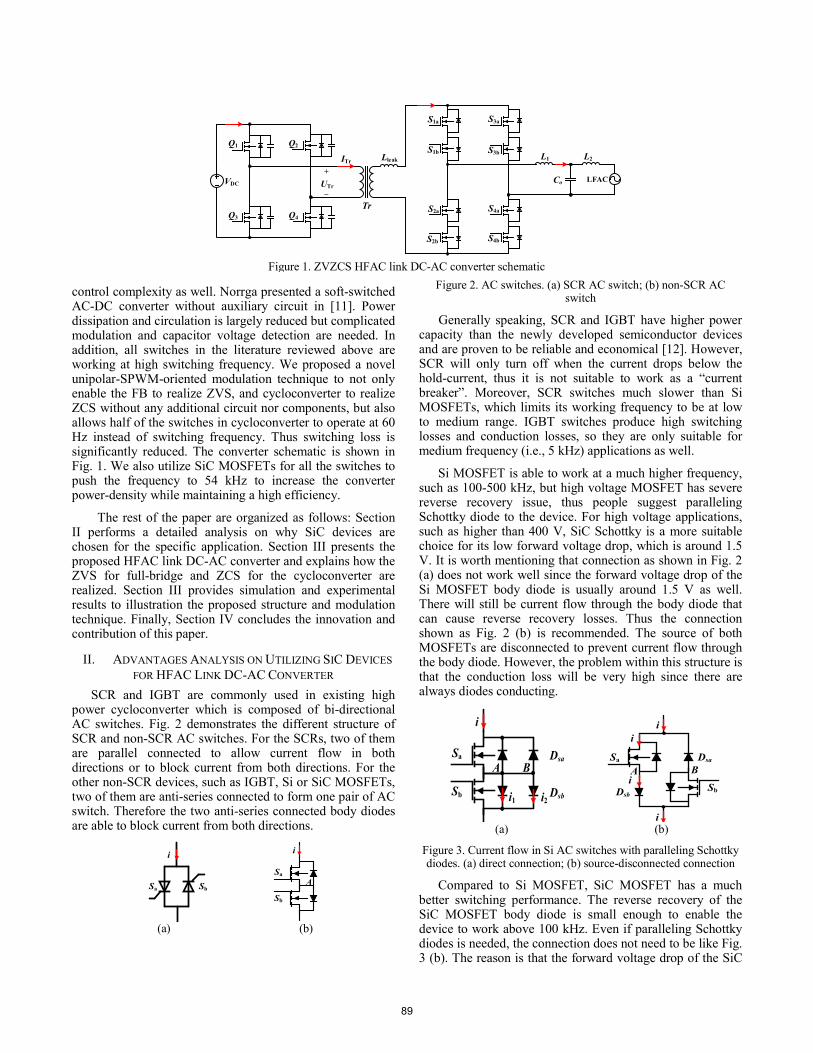
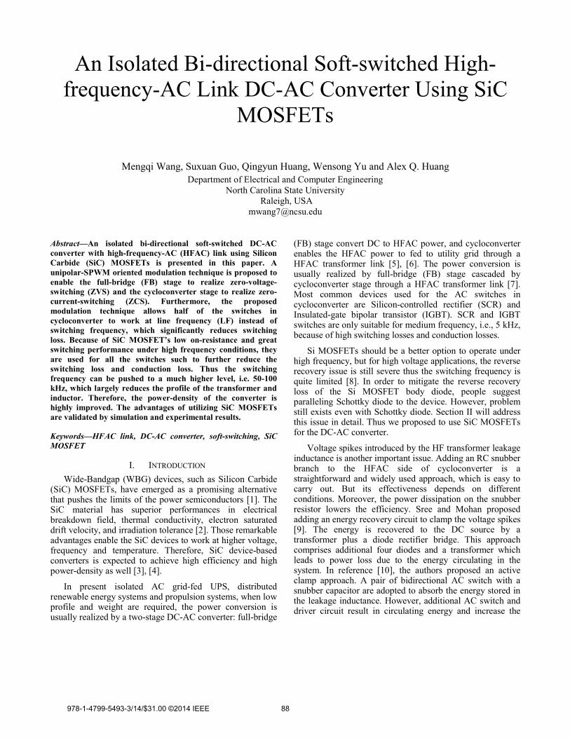
Figure 1. ZVZCS HFAC link DC-AC converter schematic
LFAC
Q1 Q2
Q3 Q4
S1a
S1b
S2a
S2b
S3a
S3b
S4a
S4b
L1 L2
CoVDC
Tr
LleakITr
+
_UTr
control complexity as well. Norrga presented a soft-switched AC-DC converter without auxiliary circuit in [11]. Power dissipation and circulation is largely reduced but complicated modulation and capacitor voltage detection are needed. In addition, all switches in the literature reviewed above are working at high switching frequency. We proposed a novel unipolar-SPWM-oriented modulation technique to not only enable the FB to realize ZVS, and cycloconverter to realize ZCS without any additional circuit nor components, but also allows half of the switches in cycloconverter to operate at 60 Hz instead of switching frequency. Thus switching loss is significantly reduced. The converter schematic is shown in Fig. 1. We also utilize SiC MOSFETs for all the switches to push the frequency to 54 kHz to increase the converter power-density while maintaining a high efficiency.
The rest of the paper are organized as follows: Section II performs a detailed analysis on why SiC devices are chosen for the specific application. Section III presents the proposed HFAC link DC-AC converter and explains how the ZVS for full-bridge and ZCS for the cycloconverter are realized. Section III provides simulation and experimental results to illustration the proposed structure and modulation technique. Finally, Section IV concludes the innovation and contribution of this paper.
II. ADVANTAGES ANALYSIS ON UTILIZING SIC DEVICES FOR HFAC LINK DC-AC CONVERTER
SCR and IGBT are commonly used in existing high power cycloconverter which is composed of bi-directional AC switches. Fig. 2 demonstrates the different structure of SCR and non-SCR AC switches. For the SCRs, two of them are parallel connected to allow current flow in both directions or to block current from both directions. For the other non-SCR devices, such as IGBT, Si or SiC MOSFETs, two of them are anti-series connected to form one pair of AC switch. Therefore the two anti-series connected body diodes are able to block current from both directions.
(a) (b)
Figure 2. AC switches. (a) SCR AC switch; (b) non-SCR AC switch
Generally speaking, SCR and IGBT have higher power capacity than the newly developed semiconductor devices and are proven to be reliable and economical [12]. However, SCR will only turn off when the current drops below the hold-current, thus it is not suitable to work as a “current breaker”. Moreover, SCR switches much slower than Si MOSFETs, which limits its working frequency to be at low to medium range. IGBT switches produce high switching losses and conduction losses, so they are only suitable for medium frequency (i.e., 5 kHz) applications as well.
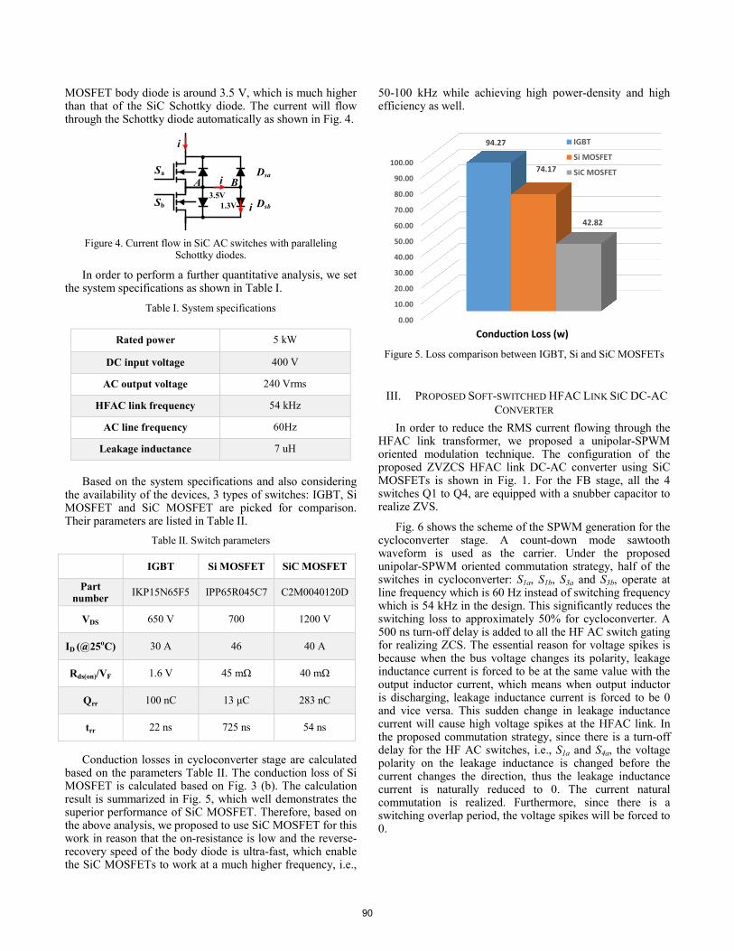
Si MOSFET is able to work at a much higher frequency, such as 100-500 kHz, but high voltage MOSFET has severe reverse recovery issue, thus people suggest paralleling Schottky diode to the device. For high voltage applications, such as higher than 400 V, SiC Schottky is a more suitable choice for its low forward voltage drop, which is around 1.5 V. It is worth mentioning that connection as shown in Fig. 2 (a) does not work well since the forward voltage drop of the Si MOSFET body diode is usually around 1.5 V as well. There will still be current flow through the body diode that can cause reverse recovery losses. Thus the connection shown as Fig. 2 (b) is recommended. The source of both MOSFETs are disconnected to prevent current flow through the body diode. However, the problem within this structure is that the conduction loss will be very high since there are always diodes conducting.
(a) (b)
Figure 3. Current flow in Si AC switches with paralleling Schottky diodes. (a) direct connection; (b) source-disconnected connection
Compared to Si MOSFET, SiC MOSFET has a much better switching performance. The reverse recovery of the SiC MOSFET body diode is small enough to enable the device to work above 100 kHz. Even if paralleling Schottky diodes is needed, the connection does not need to be like Fig. 3 (b). The reason is that the forward voltage drop of the SiC
Sa Sb
i
Sa
Sb
i
A
Sa
Sb
i
i1 i2
Dsa
Dsb
A B
i
i
i
i
Sa
Sb
Dsa
Dsb
A B
89
MOSFET body diode is around 3.5 V, which is much higher than that of the SiC Schottky diode. The current will flow through the Schottky diode automatically as shown in Fig. 4.
Figure 4. Current flow in SiC AC switches with paralleling
Schottky diodes.
In order to perform a further quantitative analysis, we set the system specifications as shown in Table I.
Table I. System specifications
Rated power 5 kW
DC input voltage 400 V
AC output voltage 240 Vrms
HFAC link frequency 54 kHz
AC line frequency 60Hz
Leakage inductance 7 uH
Based on the system specifications and also considering the availability of the devices, 3 types of switches: IGBT, Si MOSFET and SiC MOSFET are picked for comparison. Their parameters are listed in Table II.
Table II. Switch parameters
IGBT Si MOSFET SiC MOSFET
Part number IKP15N65F5 IPP65R045C7 C2M0040120D
VDS 650 V 700 1200 V
ID (@25oC) 30 A 46 40 A
Rds(on)/VF 1.6 V 45 mΩ 40 mΩ
Qrr 100 nC 13 μC 283 nC
trr 22 ns 725 ns 54 ns
Conduction losses in cycloconverter stage are calculated
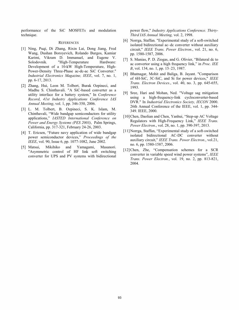
based on the parameters Table II. The conduction loss of Si MOSFET is calculated based on Fig. 3 (b). The calculation result is summarized in Fig. 5, which well demonstrates the superior performance of SiC MOSFET. Therefore, based on the above analysis, we proposed to use SiC MOSFET for this work in reason that the on-resistance is low and the reverse-recovery speed of the body diode is ultra-fast, which enable the SiC MOSFETs to work at a much higher frequency, i.e.,
50-100 kHz while achieving high power-density and high efficiency as well.
Figure 5. Loss comparison between IGBT, Si and SiC MOSFETs
III. PROPOSED SOFT-SWITCHED HFAC LINK SIC DC-AC CONVERTER
In order to reduce the RMS current flowing through the HFAC link transformer, we proposed a unipolar-SPWM oriented modulation technique. The configuration of the proposed ZVZCS HFAC link DC-AC converter using SiC MOSFETs is shown in Fig. 1. For the FB stage, all the 4 switches Q1 to Q4, are equipped with a snubber capacitor to realize ZVS.
Fig. 6 shows the scheme of the SPWM generation for the cycloconverter stage. A count-down mode sawtooth waveform is used as the carrier. Under the proposed unipolar-SPWM oriented commutation strategy, half of the switches in cycloconverter: S1a, S1b, S3a and S3b, operate at line frequency which is 60 Hz instead of switching frequency which is 54 kHz in the design. This significantly reduces the switching loss to approximately 50% for cycloconverter. A 500 ns turn-off delay is added to all the HF AC switch gating for realizing ZCS. The essential reason for voltage spikes is because when the bus voltage changes its polarity, leakage inductance current is forced to be at the same value with the output inductor current, which means when output inductor is discharging, leakage inductance current is forced to be 0 and vice versa. This sudden change in leakage inductance current will cause high voltage spikes at the HFAC link. In the proposed commutation strategy, since there is a turn-off delay for the HF AC switches, i.e., S1a and S4a, the voltage polarity on the leakage inductance is changed before the current changes the direction, thus the leakage inductance current is naturally reduced to 0. The current natural commutation is realized. Furthermore, since there is a switching overlap period, the voltage spikes will be forced to 0.
Sa
Sb
i
i
Dsa
Dsb
A B3.5V
1.3V
i
0.00
10.00
20.00
30.00
40.00
50.00
60.00
70.00
80.00
90.00
100.00
Conduction Loss (w)
94.27
74.17
42.82
IGBT
Si MOSFET
SiC MOSFET
90

Figure 6. SPWM generation for cycloconverter
IV. SIMULATION AND EXPERIMENTAL VERIFICATION A simulation model for the DC-AC inverter has been
built in PSIM. Fig. 7 shows the gating for S2b, AC link voltage, cycloconverter line-frequency AC (LFAC) voltage before the output filter, and filter inductor current. Fig. 8 is a zoomed-in of gating, FB output voltage and HFAC link current waveforms. As can be seen from Fig. 8, S1a, S1b, S3a and S3b operate at 60 Hz instead of switching frequency. S2a and S4b are not switching during this period of time because it is during the LFAC negative output interval. In other words, there are only 2 switches operating at one time for the cycloconverter.
Figure 7. Simulation waveforms
Figure 8. Zoomed-in simulation waveforms
A prototype for the FB stage and cycloconverter has been developed as shown in Fig. 9. DSP controller and the two stages are built in separate board for flexibility and scalability purposes. Each of the SiC MOSFET is equipped with an isolated driver circuit to mostly protect the gating signal from being intervened by the power stage. The major components used for the converter are listed in Table III. The current test conditions are 200 V DC input with 20 Ω load resistor. The HFAC link frequency is 54 kHz. Fig. 10 shows the experimental waveforms of gating, HFAC link voltage and current, and the output current, which demonstrate the functionality of the FB stage and cycloconverter. Fig. 11 (a) shows the zoomed-in experimental waveforms of FB and cycloconverter gating, HFAC link voltage and current, which match with the simulation results and theoretical analysis. Fig. 11 (b) and (c) further demonstrate the cycloconverter zero-current turning-off transition, and FB zero-voltage turning-on transition, respectively. The experimental results match with the simulation and well validate the proposed commutation strategy.
Table III. Component list
SiC MOSFET CMF10120D
DSP controller F28335
Isolated power supply RP2424S
Digital isolator ADuM1100
Gate driver IC UCC27531
Gq1
Gs4a
Gs2b
Gs2a
Gs4b
Gs1a & Gs3b
Gs1b & Gs3a
Vcontr ol-Vcontrol
Vcarrier
91

Figure 9. Prototype of the FB and cyclo
Figure 10. Experimental waveforms at
(a)
oconverter
t 54 kHz
(b)
(c)
Figure 11. Zoomed-in experimental wzoomed-in waveforms in one switchin
zero-current turning-off transition; (turning-on transi
V. CONCLU
In order to increase the frequenconverter using FB cascaded with at 400 V or higher applications, SiCbecause of the low on-resistancperformance under high voltage, hiA unipolar-SPWM-oriented moproposed in this paper as well. Tstrategy enables the FB to realize to realize ZCS, which largely recurrent stresses on the device. Furtstrategy allows half of the switchwork at 60 Hz instead of switcsignificantly reduces the switchinexperimental results are provi
waveforms at 54 kHz. (a) g cycle; (b) cycloconverter c) FB stage zero-voltage ition.
USION ncy of traditional DC-AC
cycloconverter topology C MOSFETs are utilized ce and great switching gh frequency conditions.
odulation technique is he proposed modulation ZVS and cycloconverter educes the voltage and thermore, the modulation hes in cycloconverter to ching frequency, which ng loss. Simulation and ided to validate the
92
performance of the SiC MOSFETs and modulation technique.
REFERENCES [1] Ning, Puqi, Di Zhang, Rixin Lai, Dong Jiang, Fred
Wang, Dushan Boroyevich, Rolando Burgos, Kamiar Karimi, Vikram D. Immanuel, and Eugene V. Solodovnik. "High-Temperature Hardware: Development of a 10-kW High-Temperature, High-Power-Density Three-Phase ac-dc-ac SiC Converter." Industrial Electronics Magazine, IEEE, vol. 7, no. 1, pp. 6-17, 2013.
[2] Zhang, Hui, Leon M. Tolbert, Burak Ozpineci, and Madhu S. Chinthavali. "A SiC-based converter as a utility interface for a battery system," In Conference Record, 41st Industry Applications Conference IAS Annual Meeting, vol. 1, pp. 346-350, 2006.
[3] L. M. Tolbert, B. Ozpineci, S. K. Islam, M. Chinthavali, “Wide bandgap semiconductors for utility applications,” IASTED International Conference on Power and Energy Systems (PES 2003), Palm Springs, California, pp. 317-321, February 24-26, 2003.
[4] T. Ericsen, “Future navy application of wide bandgap power semiconductor devices,” Proceedings of the IEEE, vol. 90, Issue 6, pp. 1077-1082, June 2002.
[5] Matsui, Mikihiko and Yamagami, Masanori. "Asymmetric control of HF link soft switching converter for UPS and PV systems with bidirectional
power flow," Industry Applications Conference. Thirty-Third IAS Annual Meeting, vol. 2, 1998.
[6] Norrga, Staffan. "Experimental study of a soft-switched isolated bidirectional ac–dc converter without auxiliary circuit," IEEE Trans. Power Electron., vol. 21, no. 6, pp. 1580-1587, 2006.
[7] S. Manias, P. D. Ziogas, and G. Olivier, “Bilateral dc to ac convertor using a high frequency link,” in Proc. IEE B, vol. 134, no. 1, pp. 15–23, 1987.
[8] Bhatnagar, Mohit and Baliga, B. Jayant. "Comparison of 6H-SiC, 3C-SiC, and Si for power devices," IEEE Trans. Electron Devices., vol. 40, no. 3, pp. 645-655, 1993.
[9] Sree, Hari and Mohan, Ned. "Voltage sag mitigation using a high-frequency-link cycloconverter-based DVR." In Industrial Electronics Society, IECON 2000. 26th Annual Conference of the IEEE, vol. 1, pp. 344-349. IEEE, 2000.
[10] Chen, Daolian and Chen, Yanhui, “Step-up AC Voltage Regulators with High-Frequency Link,” IEEE Trans. Power Electron., vol. 28, no. 1, pp. 390-397, 2013.
[11] Norrga, Staffan, “Experimental study of a soft-switched isolated bidirectional AC-DC converter without auxiliary circuit,” IEEE Trans. Power Electron., vol.21, no. 6, pp. 1580-1587, 2006.
[12] Chen, Zhe, “Compensation schemes for a SCR converter in variable speed wind power systems”, IEEE Trans. Power Electron., vol. 19, no. 2, pp. 813-821, 2004.
93