
CRC®-55t (R/PET/W) - Radioisotope Dose Calibrator - Capintec
Upload
independentCategory
view
3download
0
Nuclear Instruments and Methods 179 (1981) 171-180 © North-Holland Publishing Company
AN ION INJECTION SYSTEM FOR USE IN TANDEM ACCELERATOR RADIOISOTOPE DATING DEVICES *
D.E. LOBB Physics Department, University of Victoria, Victoria, BC, Canada V8W 2Y2
J.R. SOUTHON, D.E. NELSON Archaeology Department, Simon Fraser University, Burnaby, BC, Canada V5A 1S6
W. WlESEHAHN Physics Department, Simon Fraser University, Burnaby, BC, Canada V5A 1S6
and
R.G. KORTELING Chemistry Department, Simon Fraser University, Burnaby, BC, Canada V5A 1S6
ReceNed 23 June 1980
A system designed to accept ion beams from a Cs sputter source and inject them into a Tandem Van de Graaff accelerator is described. Several modes of operation of the device are possible, including simultaneous injection of two or more isotopes, contin- uous injection of two isotopes with pulsed injection of a third, and sequential injection. The application of the system to radioiso- tope dating studies is discussed.
1. Introduction
Nuclear accelerators have recently been proposed for use as mass spectrometers of such high sensitivity that direct measurements of the concentrations of many naturally-occurring radionuclides can be made. These systems function by ionizing a sample, acceler- ating the particles to several tens of MeV, separating the accelerated particles into beams of the same mass to charge ratio with an analyzing magnet, and identi- fying and counting the ions of interest with an energy telescope. A review of this technique is given by Muller [1], and in the references contained in that paper.
In order to adapt such accelerators for practical isotopic measurements, specialized methods must be developed to enable these systems to measure the iso- topic concentrations in a sample with an acceptable accuracy. For example, to use these systems for
* Work supported by grants from the National Science and Engineering Research Council (Canada) and the National Science Foundation (USA).
radiocarbon dating, we would wish to measure the ratio of the concentrations of 14C to 12C in an un- known sample with respect to that in a calibration standard to an accuracy of about 1% for routine sam- ples, and in special cases it would be desirable to achieve an accuracy of about 0.1%.
Tandem electrostatic accelerators (Van de Graaff and similar types) have many advantages for these systems. In general, two methods of operating these accelerators for such measurements have been pro- posed. In the first [2], the suggestion was made that the system could be operated in a fashion entirely analogous to that used in conventional isotope-ratio mass spectroscopy. Both the stable and the rare iso- topic species of the element of interest (e.g. 12C, 13 C and 14C) would be simultaneously ionized, accele- rated and analyzed. In this case, changes in the ion production and transmission efficiencies would, to a good approximation, affect all the isotopes equally and therefore not affect the measurement of the con- centration ratios. An accurate knowledge of the abso- lute efficiency would not be necessary since the un- known sample and the calibration standard would be
171
172 D.E. Lobb et al. / A n ion injection system
alternatively measured to provide a high relative accu- racy. This technique has the additional practical advantage that the Tandem accelerator could be stabi- lized by monitoring the beam of a stable isotope with a set of slits placed after the analyzing magnet, as is normally done with these accelerators. A potential disadvantage is that if even a small proportion of the ions from one of the stable ion beams is scattered by some mechanism into the detector system for the rare isotope, the sensitivity for detection of the rare iso- tope may be decreased unless the unwanted ions can be eliminated.
The second proposed method [3] is to sequen- tially select, accelerate and detect the different iso- topes of interest individually. This technique has the advantage of eliminating any inter-beam interferences since only one isotope will be in the system at any given time, but it requires that the ion production and transmission efficiencies remain very stable if accurate results are to be obtained. Absolute measure- ments would again be avoided by alternating between unknown sample and standard. Since the stable iso- tope beam(s) will be transmitted and detected only infrequently, the normal method of accelerator stabi- lization will not be possible, and some other means must be devised.
Whatever method is used, it will be desirable to transmit the most intense beams possible through the accelerator in order to attain maximum sensitivity and to keep measurement time to a minimum. The Cs sputter sources that are presently favoured for these systems are already capable of producing beams of some ions at intensities that strain Tandem Van de Graaff beam load capacities. It will thus be valuable to provide a method for reducing the beam load, if necessary, by reducing the numbers of the most abun- dant ion to be transmitted. It is not necessary to know the reduction factor since absolute concentra- tion measurements are not required; it suffices that this factor remains constant between unknown and standard.
For the simultaneous detection mode, some means must then be found to accept the ions from the ion source, selectively reduce, if necessary, the beam intensity of the most abundant isotope, and then inject the ions into the accelerator. For the sequential detection mode, the beams of the different isotopes must be sequentially selected from the source and injected into the accelerator. Purser and Hanley [3] suggest one method for doing this. In this mode, an effective intensity reduction of the beam of any iso-
tope is achieved by limiting the frequency and dura- tion of injection into the accelerator. A potential pro- blem is that this varying beam load on the accelerator could cause stabilization difficulties with the accelera- tor.
It is not yet clear which, if either, of these two methods will ultimately prove most useful. For this reason, we have attempted to design an injection sys- tem which will allow a Tandem to be operated in either of the above modes or in a combination of these modes. Our particular interest are in radiocar- bon and radioberyllium measurements, so the system has been designed primarily for the measurement of these isotopes. At present only radiocarbon measure- ments require an injection facility that provides the capability of beam reduction since only ~2C beams have intensities thast may overload tire accelerator. Ion sources producing beams of Be ions that will overload the accelerator are not presently available and therefore the major requirement for an injection system for Be measurements is that it remain stable. In the following three sections, we give first a general description of our proposed system, then a detailed description of the ion optics, and finally a discussion of the practical operational modes.
2. General description of the injection system
The system proposed here functions by accepting all the ions produced by an ion-source (e.g. 12C, 13C, 14C), separating these ions into beams of the different mass/charge ratios and processing these individual beams appropriately before recombining them for injection into the accelerator. A schematic diagram of the proposed system is presented in fig. 1. The ions of interest have different masses but the same energies; magnets B1 and B2 are used to separate and recom- bine the beams in the horizontal plane. Electrostatic quadrupole lenses have been used since we wish to provide identical focusing for all masses. (For clarity these are omitted in fig. 1.) Four pairs of electrostatic deflector plates (D1-D2 and D3-D4) can be used to displace the beams either upwards or downwards. By placing different sets of apertures at the focus point between the magnets, several different modes of op- eration can be chosen:
(1) the separate beams can be transmitted through apertures [see fig. 2(a)] with no use of the deflector plates, such that all beams would be injected simulta- neously into the accelerator. The intensity of one or

D.E. Lobb et al. / An ion injection system 173
-W o2 - - , . . . j o3 o4
A
Fig. 1. A general schematic of the injection system. The figure shows a 3D projection of the dipole magnets, deflector plates, and an aperture plate suitable for injection of t~o isotopes. For clarity only the principal rays are shown, and all quadrupoles have been omitted. Refer to figs. 3 and 4 for folded-out views of the complete system.
more of the beams can be reduced, if required, by the use of small apertures, movable slits, or screens.
At an extreme, one of the beams can be eliminated entirely. This may prove to be a practical mode for
( o ) Deflection ] ~ ~
0 mode --
14 C ~3 C 12 C
Transmitted Beam
12C, maC 14 C
(b)
+ mode
0 mode
'"c '3c '2c
~2c, '3c, ,4 c
'3c, "~c
(c)
0 mode m4 C
- mode ~ - - '~c
'4c '~: '2 c
Fig. 2. Aperture plates to be placed in the plane AA' for (a) simultaneous injection of 12C, 1 a C and 14C; (b) continuous injection of laC and 14C with pulsed injection of 12C; and (c) sequential injection.
radiocarbon measurements since 13C/12C concent ra -
t ion ratios can be determined to an accuracy of <0.1%o using conventional mass spectrometers. This measurement would simply not be a t tempted with the accelerator and none of the intense 12C beam would be injected. The 14Cfl3C measurement would
be done with the acclerator, with simultaneous injec- tion of laC and 14C, and the 13C/12C measurement would be done separately on a conventional spectro- meter. The laC beams are not intense enough to require much, if any, reduction. A disadvantage of this method is that an additional, but very small, sam- ple is required for the laC/12C measurement:
(2) If the aperture shown in fig. 2(b) were used, the beams could be displaced using the deflection plates such that one or more of the isotopes of inter- est (e.g. 13C and 14C) could be injected full-time while another (12C) was injected in pulses. The length and duration of these pulses could be chosen to achieve an effective transmission from 0 - 1 0 0 % for this isotope. Of course, it may prove useful to com- bine this technique with apertures of different sizes as discussed in (1) above.
(3) By using the aperture set shown in fig. 2(c), it would be possible to inject any one of the isotopes for any desired length of time, to achieve a sequential analysis system. Again, some beam reduction by means of apertures of different sizes could be achieved if desired.
(4) The system could also be operated as an injec- tor for single isotopes. If desired, this beam could be pulsed. While this mode of operation is of no im- mediate interest to this study, such a capability might prove to be of value to other users of a Tandem accel- erator.
174 D.E. Lobb et al. / An ion injection system
3. Detailed design
3.1. The initial beam
For the design of this injection system we assume that a reflected beam sputter source will produce the desired beams of C- or BeO- ions at an energy of 30 keV. The energy spread of the beam from such a source is very small (<~0.1%) [4] and will have a negli- gible effect on the optical properties of a downstream system. The relevant properties of these ion beams are given in table 1.
The data recently reported by Hedges et al. [5] indicate that 75% of the beam from the ion source will be contained within a phase-space of 107r mm mrad, and 90% within 17rr mm rad. (This indicates an improvement in source performance compared with that reported by Brand [6]). For these calculations, we assume a conservative source beam size of 2 mm radius with a half-divergence of 16 mrad in the hori- zontal plane (32~ mm rad). For the vertical plane, a scraper downstream will limit (if necessary) the accepted beam to a half divergence of 9 mrad.
3.2. The steady state beam optical sys tem
As was described in section 2, the injection system functions by separating the ion beams with a dipole magnet, processing them and then recombining them with an identical magnet. Appropriate focusing is pro- vided by electrostatic qt~adrupoles. The beam param- eter which determines the focusing strength of these quadrupoles is the ratio 3"](7 + 1), where
(Bandord [7]). For a non-relativistic beam this ratio is very close to i regardless of the ion type (30 keV C ions have (v/c) = 0.002 and 3' = 1.000002), so all 30
keV ions will be focused in the same manner by these elements.
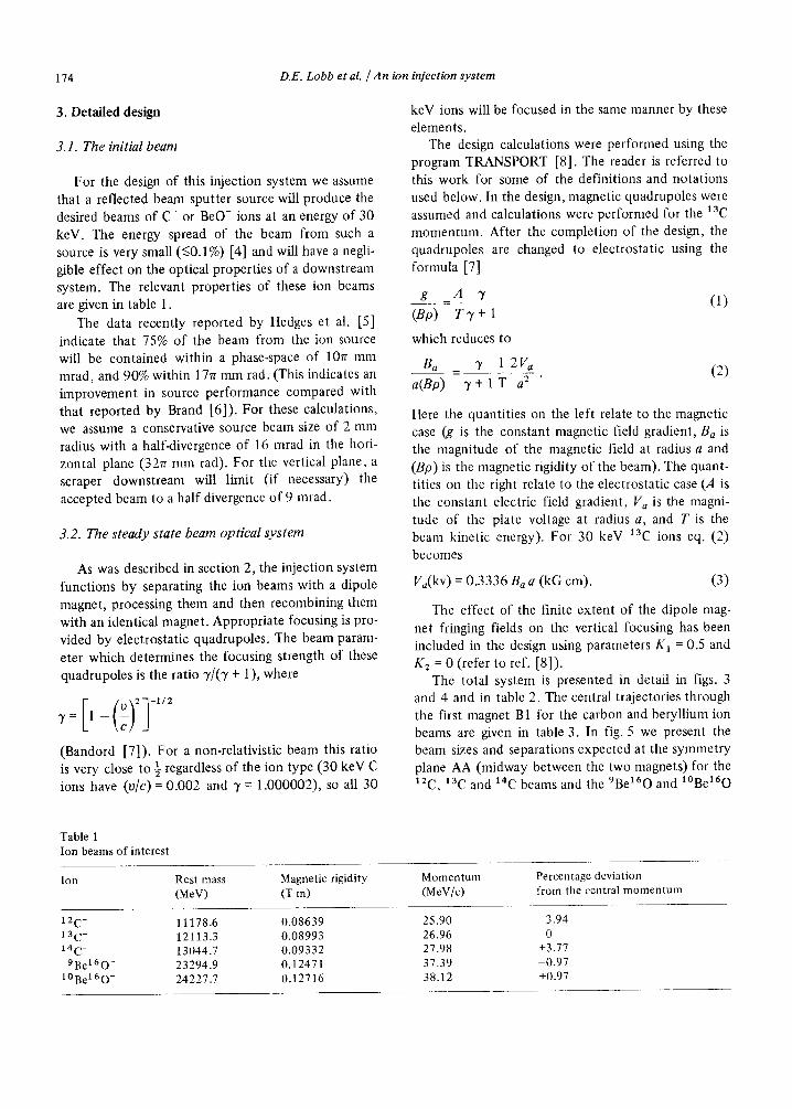
The design calculations were performed using the program TRANSPORT [8]. The reader is referred to this work for some of the definitions and notations used below. In the design, magnetic quadrupoles were assumed and calculations were performed for the 13C momentum. After the completion of the design, the quadrupoles are changed to electrostatic using the formula [7]
g A 3' - ( 1 )
(Bp) T 3 ' + l
which reduces to
Ba 3" 1 2 V a - ( 2 )
a(Bp) 3" + l T a z "
ttere the quantities on the left relate to the magnetic case (g is the constant magnetic field gradient, Ba is the magnitude of the magnetic field at radius a and (Bp) is the magnetic rigidity of the beam). The quant- titles on the right relate to the electrostatic case (A is the constant electric field gradient, V a is the magni- tude of the plate voltage at radius a, and T is the beam kinetic energy). For 30 keV 13C ions eq. (2) becomes
Va(kv) = 0.3336 B a a (kG cm). (3)
The effect of the finite extent of the dipole mag- net fringing fields on the vertical focusing has been included in the design using parameters K~ = 0.5 and K2 = 0 (refer to ref. [8]).
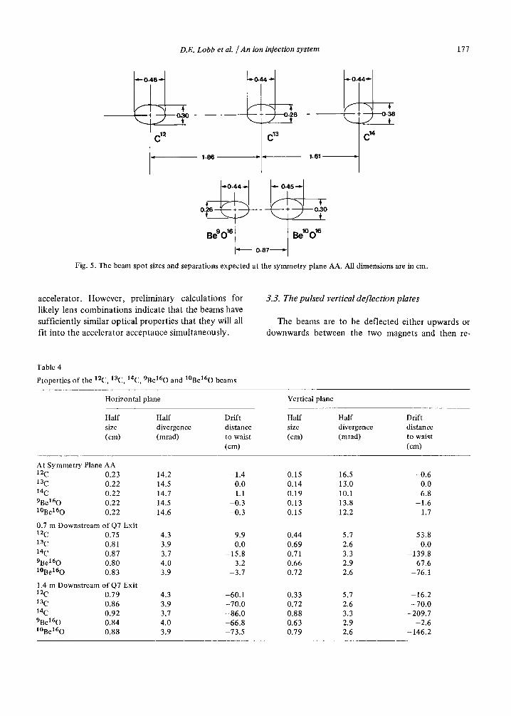
The total system is presented in detail in figs. 3 and 4 and in table 2. The central trajectories through the first magnet B1 for the carbon and beryllium ion beams are given in table 3. In fig. 5 we present the beam sizes and separations expected at the symmetry plane AA (midway between the two magnets) for the 12C, 13C and 14C beams and the 9Be160 and l°Be160
Table 1 Ion beams of interest
Ion Rest mass Magnetic rigidity Momentum Percentage deviation (MeV) (T m) (MeV/c) from the central momentum
12 C- 11178.6 0.08639 25.90 3.94 13 C- 12113.3 0.08993 26.96 0 14C- 13044.7 0.09332 27.98 +3.77
9 B e 1 6 0 - 23294.9 0.12471 37.39 -0.97 t°Be 160- 24227.7 0.12716 38.12 +0.97
D.E. Lobb et al. / An ion in/ection system 175
Q1 Q 2 Q3
k2Z
A
X
"-~ Q6
7Q7
[4 25 ----~1 c m
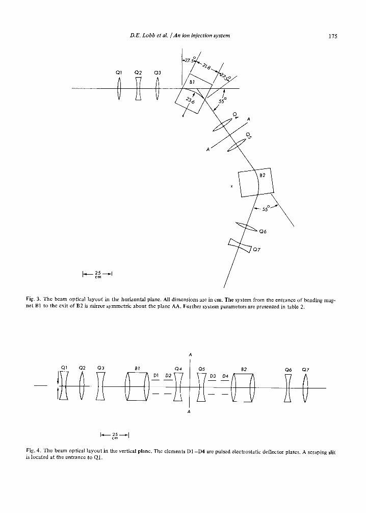
Fig. 3. The beam optical layout in the horizontal plane. All d imensions are in cm. The system from the entrance o f bending mag- ne t B1 to the exit of B2 is mirror symmetr ic about the plane AA. Further sys tem parameters are presented in table 2.
Q1 Q2 Q3 B1 Q4
A
Q5
D4
A
B2 Q6 Q7
ZO Iq 25
c m
Fig. 4. The beam optical layout in the vertical plane. The elements D1 - D 4 are pulsed electrostatic deflector plates. A scraping slit is located at the entrance to Q1.
176 D.E. LoOb et al. / An ion injection system
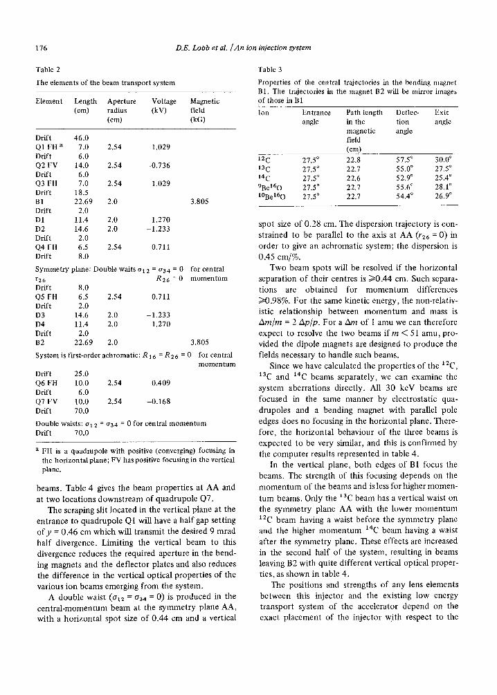
Table 2
The elements of the beam transport system
Element Length Aperture Vol tage Magnetic (cm) radius (kV) field
(cm) (kG)
Drift 46.0 Q1 FH a 7.0 2.54 1.029 Drift 6.0 Q2 FV 14.0 2.54 -0.736 Drift 6.0 Q3 FH 7.0 2.54 1.029 Drift 18.5 B1 22.69 2.0 Drift 2.0 D1 11.4 2.0 1.270 D2 14.6 2.0 -1.233 Drift 2.0 Q4 FH 6.5 2.54 0.711 Drift 8.0
3.805
Symmetry plane: Double waits 012 = o34 = 0 for central r 2 6 R26 = 0 momentum Drift 8.0 Q5 FH 6.5 2.54 0.711 Drift 2.0 D3 14.6 2.0 -1.233 D4 11.4 2.0 1.270 Drift 2.0 B2 22.69 2.0 3.805
System is first-order achromatic: R 16 = R 26 = 0 for central momentum
Drift 25.0 Q6 FH 10.0 2.54 0.409 Drift 6.0 Q7 FV 10.0 2.54 -0.168 Drift 70.0
Double waists: a 12 = 034 = 0 for central momentum Drift 70.0
a FH is a quadrupole with positive (converging) focusing in the horizontal plane; FV has positive focusing in the vertical plane.
beams. Table 4 gives the beam properties at AA and at two locations downstream of quadrupole Q7.
The scraping slit located in the vertical plane at the entrance to quadrupole Q1 will have a half gap setting o f y = 0.46 cm which will transmit the desired 9 mrad half divergence. Limiting the vertical beam to this divergence reduces the required aperture in the bend- ing magnets and the deflector plates and also reduces the difference in the vertical optical properties of the various ion beams emerging from the system.
A double waist (a12 = 034 = 0) is produced in the central-momentum beam at the symmetry plane AA, with a horizontal spot size of 0.44 cm and a vertical
Table 3
Properties of the central trajectories in the bending magnet B1. The trajectories in the magnet B2 will be mirror images of those in B1
Ion Entrance Path length Deflec- Exit angle in the tion angle
magnetic angle field (cm)
lZc 27.5 ° 22.8 57.5 ° 30.0 ° 13C 27.5 ° 22.7 55.0 ° 27.5 ° 14C 27.5 ° 22.6 52.9 ° 25.4 ° 9Be160 27.5 ° 22.7 55.6 ° 28.1 ° l°Bel60 27.5 ° 22.7 54.4 ° 26.9 °
spot size of 0.28 cm. The dispersion trajectory is con- strained to be parallel to the axis at AA (/'26 ---- 0) in order to give an achromatic system; the dispersion is 0.45 cm/%.
Two beam spots will be resolved if the horizontal separation of their centres is i>0.44 cm. Such separa- tions are obtained for momentum differences />0.98%. For the same kinetic energy, the non-relativ- istic relationship between momentum and mass is A m / m = 2 Ap/p . For a Am of 1 ainu we can therefore expect to resolve the two beams i f m < 51 amu, pro- vided the dipole magnets are designed to produce the fields necessary to handle such beams.
Since we have calculated the properties of the 12C, 13C and 14C beams separately, we can examine the
system aberrations directly. M1 30 keV beams are
focused in the same manner by electrostatic qua- drupoles and a bending magnet with parallel pole edges does no focusing in the horizontal plane. There- fore, the horizontal behaviour of the three beams is expected to be very similar, and this is confirmed by the computer results represented in table 4.
In the vertical plane, both edges of B1 focus the beams. The strength of this focusing depends on the momentum of the beams and is less for higher momen-
tum beams. Only the 13C beam has a vertical waist on the symmetry plane AA with the lower momentum 12C beam having a waist before the symmetry plane and the higher momentum 14C beam having a waist
after the symmetry plane. These effects are increased in the second half of the system, resulting in beams leaving B2 with quite different vertical optical proper- ties, as shown in table 4.
The positions and strengths of any lens elements between this injector and the existing low energy transport system of the accelerator depend on the exact placement of the injector with respect to the
D.E. Lobb et al. / An ion injection system 177
- - 8 •
,, 1 C 14
1.86 1 6 1 ~
o. ~ o~
Bego 'e BetOo 18 - 0.87
Fig. 5. The beam spot sizes and separations expected at the symmetry plane AA. All dimensions are in cm.
acce lera tor . However , p re l imina ry ca lcu la t ions for
l ikely lens c o m b i n a t i o n s ind ica te t h a t the beams have
suff ic ient ly similar op t ica l p rope r t i e s t h a t t hey will all
fit i n to the acce le ra tor accep t ance s imul t aneous ly .
3.3. The pulsed vertical deflection plates
The beams are to be def lec ted e i the r upwards or
d o w n w a r d s be tween the two magne t s and t hen re-
Table 4
Properties of the 12C, 13C, 14C, 9Be160 and l°Be160 beams
Horizontal plane Vertical plane
Half Half Drift Half Half Drift size divergence distance size divergence distance (cm) (mrad) to waist (cm) (mrad) to waist
(cm) (cm)
At Symmetry Plane AA 12C 0.23 13C 0.22 14C 0.22 9Be160 0.22 l°Be160 0.22
0.7 m Downstream of Q7 12C 0.75 13C 0.81 14C 0.87 9Be160 0.80 lOBe160 0.83
1.4 m Downstream of Q7 12C 0.79 13C 0.86 14C 0.92 9Be160 0.84 I°BeI60 0.88
Exit
Exit
14.2 14.5 14.7 14.5 14.6
-1 .4 0.15 16.5 -0 .6 0.0 0.14 13.0 0.0 1.1 0.19 10.1 6.8
-0 .3 0.13 13.8 -1 .6 -0 .3 0.15 12.2 1.7
4.3 -60.1 0.33 5.7 -16.2 3.9 -70 .0 0.72 2.6 -70 .0 3.7 -86 .0 0.88 3.3 -209.7 4.0 -66.8 0.63 2.9 -2 .6 3.9 -73.5 0.79 2.6 -146.2
4.3 9.9 0.44 5.7 53.8 3.9 0.0 0.69 2.6 0.0 3.7 -15 .8 0.71 3.3 -139.8 4.0 3.2 0.66 2.9 67.6 3.9 -3 .7 0.72 2.6 -76.1
178 D.E. Lobb et al. / An ion injection system
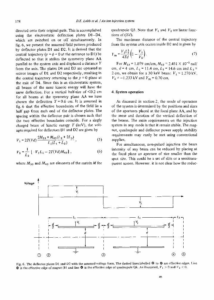
directed onto their original path. This is accomplished using the electrostatic deflection plates D 1 - D 4 , which are switched on or off simultaneously. In fig. 6, we present the assumed field pattern produced by deflector plates D1 and D2. It is desired that the central trajectory (v = ~ = 0 at the entrance to D1) be deflected so that it strikes the symmetry plane AA parallel to the system axis and displaced a distance Y from the axis. The plates D4 and D3 are operated as mirror images of D1 and D2 respectively, resulting in the central trajectory returning to the y = 0 plane at the exit of D4. Since this is an electrostatic system, all beams of the same kinetic energy will have the same deflection. For a vertical half-size of <0.2 cm for all beams at the symmetry plane AA we have chosen the deflection Y = 0.6 cm. It is assumed in fig. 6 that the effective boundaries of the field lie a half gap from each end of the deflector plates. The spacing within the deflector pair is chosen such that the two effective boundaries coincide. For a singly charged beam of kinetic energy T (keV), the volt- ages required for deflectors D1 and D2 are given by
2/1433 + M 4 3 ( L 2 + 2 L 3 ) ( 5 ) V 1 = 2 T ( Y d ) L I ( L 1 + L 2 ) '
1 V= L2 [-V1L1 - 2T(Yd)M43] , (6)
where Ms3 and M43 are elements of the mat r ixM for
quadrupole Q3. Note that V 1 and V 2 a r e linear func- tions of (Yd).
The maximum distance of the central trajectory from the system axis occurs inside D2 and is given by
V1L2 (1 V1) Y m - 4Td - V 2 " (7 )
For Maa = 1.079 cm/cm, M43 = 2.451 X 10 -2 rad/ cm, d = 4 cm, LI = 11.4 cm, L2 = 14.6 cm andL3 = 2 cm, we obtain for a 30 keV beam: V1 = 1.270 kV, 112 = -1 .233 kV and Ym = 0.70 cm.
4. System operation
As discussed in section 2, the mode of operation of the system is determined by the positions and sizes of the apertures placed at the focal plane AA, and by the sense and duration of the vertical deflection of the beams. The main requirements on the injection system in any mode is that it remain stable. The mag- net, quadrupole and deflector power supply stability requirements may easily be met using conventional supplies.
For simultaneous, non-pulsed injection the beam intensity of any beam can be reduced by placing at the focal plane an aperture of size smaller than the spot size. This could be a set of slits or a semitrans- parent screen. However, it is not clear how the reduc-
Voltage t vt I
I v2 +
I I I
I
I
@
I" LI ~ j~ L2 I ' l s
t d +
i I
. r L3--,-I I
I i I i t - [ I i i I 1 I i i _L
® ® - ® @
Fig. 6. The deflector plates D1 and D2 with the assumed voltage form. The dashed lines labelled • to O are effective edges. Line • is the effective edge of magnet B1 and line O is the effective edge of quadrupole Q4. As illustrated, V l > 0 and V 2 < 0.
m
D.E. Lobb et al. / An ion injection system 179
tion factor achieved will vary with time during the course of an experiment, as the stability of this reduc- tion factor depends on the stability and reproducibil- ity of the distribution of the ions within the focused beam. This will in turn depend on the stability and reproducibility of the distribution of ions in the beam from the ion source. (It should be stressed that it is the stability of the distribution, and not the intensity, that is important here.) The stability of this ion distri- bution is an unknown factor, and could depend strongly on the specific design of the ion source. It will be necessary to investigate this operational mode experimentally to determine the amount of reduction that can be usefully obtained.
In practice, such reduction will only be necessary for carbon measurements for which 13C/12C concen- tration ratios are to be determined. For beryllium measurements and for 14C/13C ratio measurements the beams will not be sufficiently intense to require reduction, and the aperture will be chosen to pass all of the beams of interest and to eliminate those of undesired mass.
The alternative procedure for 14C/13C/12C ratio measurements is to inject the 12C beam in pulses of appropriate duration and repetition rate while the IaC and 14C beams are injected full-time. This will allow the accelerator to be stabilized using the accele- rated laC beam. The stability of the ion source can also be monitored using this beam. It will be neces- sary to ensure that the switching times for the deflec- tion system will be short compared with the duration of the deflection, and that the repetition rate will be stable. It is unlikely that pulses of duration less than, say, 10 ms will be used, and since the switching time is expected to be of the order of 1 ~ts, the transition from one state to the other should not cause a pro- blem.
These last requirements must also be met if the system is to be operated in the sequential injection mode. In this mode, it is most important that the intensities of the beams of the different isotopes and the efficiency of the total measurement system remain very stable over a time period which is long compared with the repetition rate. In this mode, it will not be possible to stabilize the accelerator using an accelerated beam of one of the stable isotopes, and some other means will be necessary. This could be a problem since the effect of repetitively injecting a short, intense beam of ions into the accelerator may cause stabilization difficulties.
Whichever mode of operation is chosen, methods
for setting up the injection system will be necessary. Beam scanners will be required to monitor the posi- tions and shapes of the beams at the focal plane AA and at the entrance and exit of the injection system. However, the beam current of the rare isotope will be too low to be measured by any conventional device. One method to ensure that the system is functioning properly is to use a beam of some other isotope of the same mass to substitute for the rare isotopic species. A sample containing both the stable iso- tope(s) of interest and the substitute isotope can be placed in the ion source and the entire measurement system (not only the injector) can be set up using the beams of these ions. Measurements of this sample between the measurements of the unknowns will monitor the stability of the system. For example, we have found that a sample containing equal parts of B and BeO yields approximately equally intense beams of l°BO- and 9BeO- which we can use to set up the accelerator for l°Be/gBe measurements. This tech- nique may not work for carbon, since 14N- ions are too unstable to be accelerated. However, it may prove possible to use 7Li2 ions as a substitute beam.
Failing that, it will be possible to adjust the injec- tion system by placing a measurable 13C or 12C beam in the 14C channel. This requires a change in the fields of the magnets. Once the operator is assured the system is working properly, the field strengths can be returned to their proper values.
Although this system has been designed specifi- cally to meet our requirements for radiocarbon and radioberyUium measurements, the system should be useful for other isotopes as well. As discussed in sec- tion 2, the system is capable of separating and resolv- ing beams of ions up to about mass 50. It should therefore prove useful for 26Al, 325i ' 36C1 and 41Ca measurements if these become of interest in our pro- gram. Of course, it may not prove necessary in all cir- cumstances to actually process the beams of the iso- topes of interest separately, and in such cases the sys- tem could be extended for use on ions of higher mass. The maximum mass that may be injected will be determined by the magnetic field strengths attainable from the chosen magnets and supplies.
This system is thus very flexible, and will allow us to experiment with these different proposed modes of operation so that we can choose the mode that yields the optimum measurement accuracy in each circumstance.
The authors wish to thank Dr. Esko Hammaran for

180 D.E. Lobb et aL / An ion injection system
his assistance, and the s taff o f the McMaster Univer-
sity Tandem Accelera tor Labora tory for many valu-
able discussions and suggestions.
References
[1] R.A. Muller, Phys. Today 32 (1979) 23. [2] D.E. Nelson, R.G. Korteling and W.R. Stott, Science 198
(1977) 507. [3] K.H. Purser and P.R. Hanley, in: Proc. 1st Conf. on
Radiocarbon Dating with Accelerators, ed., H.E. Gove, Univ. of Rochester, (1978) p. 165.
[4] G. Doucas, Rev. Phys. Appl. 12 (1977) 1465. [5] R.E.M. Hedges, N.R. White, J.O. Wand and E.T. Hall,
Proc. 10th Intl. Radiocarbon Conf., Berne and Heidel- berg, Aug., 1979; to be published by Radiocarbon.
[6] K. Brand, Rev. Phys. Appl. 12 (1977) 1453. [7] A.P. Banford, The Transport of Charged Particle Beams
(E. and F.N. Spon, 1966). [8] K.L. Brown and S.K. Howry, Transport/360, Stanford
Linear Accelerator Centre Report SLAC 91 (1970). [9] A.H. Wapstra and N.B. Gove, Nuclear Data Tables 9
(1971) 267.
Copyright © 2022 FDOKUMEN