Multichannel Calibrator PASCAL ET, ET-P, ET/IS, ET-P/IS GB ... - WIKA
Upload
khangminh22Category
view
2download
0
CRC®-55t (R/PET/W) Radioisotope Dose Calibrator
Manual Stock No. 9250-0137 March 21, 2021 Rev. S 2021/03/21
OWNER’S MANUAL
Mirion Technologies (Capintec), Inc. 7 Vreeland Road
Florham Park, NJ 07932 USA Phone (800) ASK-4CRC
Fax (201) 825-1336
Atlantico Systems Ltd. 34 Oldfield, Kingston, Galway, Republic of Ireland
Copyright© 2020 Capintec, Inc. ®CRC is a registered trademark of Capintec, Inc.
.
ALL RIGHTS RESERVED

CAPINTEC, INC. CRC®-55t
April 2021 TABLE OF CONTENTS TOC-1
TABLE OF CONTENTS PREFACE
SAFETY ............................................................................................................................. 1-1 GENERAL ...................................................................................................................... 1-1 SYMBOL DEFINITIONS ................................................................................................. 1-1 WARNING AND CAUTION LABELS ............................................................................... 1-2 CAUTIONS AND NOTES................................................................................................ 1-3 GENERAL SAFETY TIPS ............................................................................................... 1-6
FUNCTIONAL & TECHNICAL DESCRIPTION .................................................................. 2-1 INTENDED USE ............................................................................................................. 2-1
INCIDENT REPORTING CONTRAINDICATIONS
OPERATOR PROFILE ................................................................................................... 2-1 OPERATOR TRAINING .................................................................................................. 2-2 FUNCTIONAL DESCRIPTION ........................................................................................ 2-2 FUNCTIONS ................................................................................................................... 2-4
Overall Program Flow .................................................................................................. 2-5 TECHNICAL DESCRIPTION .......................................................................................... 2-6
On / Off Switch ............................................................................................................ 2-6 Warm Up Period .......................................................................................................... 2-6 Environment Requirements ......................................................................................... 2-6 Power Requirements ................................................................................................... 2-7 Dimensions ................................................................................................................. 2-8 Performance ................................................................................................................ 2-8 Regulatory Listings ...................................................................................................... 2-9
LIFE TIME (End of Life)
GENERAL OPERATING INSTRUCTIONS ........................................................................ 3-1 GENERAL ...................................................................................................................... 3-1 CHAMBER MEASUREMENT SCREEN .......................................................................... 3-2
Chamber Home Screen Hotkeys 1 ............................................................................. 3-2 Nuclide Button 2 ......................................................................................................... 3-2 CAL # Button 3 ........................................................................................................... 3-3 Date/Time Button 4 .................................................................................................... 3-3 Test Buttons 5 ............................................................................................................ 3-3 SETUP Button 6 ......................................................................................................... 3-3 PRINT Button 7 .......................................................................................................... 3-3 Measurement Button 8 ............................................................................................... 3-3 Units Button 9 ............................................................................................................ 3-3 WELL/CH (CHAMBER) Button 10 .............................................................................. 3-4 CH Button 11 ............................................................................................................. 3-4 Dose Decay Button 12 ............................................................................................... 3-4

CAPINTEC, INC. CRC®-55t
TOC-2 TABLE OF CONTENTS April 2021
Remote Display Indicator 13 (LEGACY PRODUCTS ONLY) ...................................... 3-4 ENTERING DATA ........................................................................................................... 3-5
Numeric Keypad Screen .............................................................................................. 3-5 Alphanumeric Keypad Screen ...................................................................................... 3-6 List Screen ................................................................................................................... 3-7 Date/Time Screen ........................................................................................................ 3-7
SYSTEM SETUP ................................................................................................................ 4-1 GENERAL ....................................................................................................................... 4-1 RECEIVING CONDITION EXAMINATION ...................................................................... 4-1 UNPACKING AND INSTALLATION ................................................................................ 4-1 ASSEMBLY ..................................................................................................................... 4-2
Readout/Stand Base .................................................................................................... 4-2 System Assembly ........................................................................................................ 4-4 Liner, Dipper, and Optional Holders ............................................................................. 4-7
ENVIRONMENT REQUIREMENTS ................................................................................ 4-8 POWER REQUIREMENTS ............................................................................................. 4-8
Readout ....................................................................................................................... 4-8 Printers (optional) ......................................................................................................... 4-8
TURN ON PROCEDURES .............................................................................................. 4-9 GENERAL OPERATIONAL SETUP .............................................................................. 4-10 ACCEPTANCE TESTING .............................................................................................. 4-11
Chamber Tests .......................................................................................................... 4-11 Well Counter Test ...................................................................................................... 4-11
SYSTEM INITIALIZATION.................................................................................................. 5-1 GENERAL ....................................................................................................................... 5-1 SET DATE AND TIME ..................................................................................................... 5-1 CHOOSING Ci or Bq ....................................................................................................... 5-3 CHOOSING DATE FORMAT .......................................................................................... 5-5 PRINTING ....................................................................................................................... 5-7
Printer Power Requirements ........................................................................................ 5-7 Printer Selection........................................................................................................... 5-8 Okidata Menu Set-Up .................................................................................................. 5-9 Epson LX-300+II Menu Set-Up .................................................................................. 5-12
USB PC DRIVER .......................................................................................................... 5-18 LANGUAGE .................................................................................................................. 5-19 SCREEN ADJUSTMENTS ............................................................................................ 5-22
Sleep Timeout ............................................................................................................ 5-22 Sleep Brightness ........................................................................................................ 5-23 Brightness .................................................................................................................. 5-23 Screen Calibration ..................................................................................................... 5-24
SPEAKER VOLUME ..................................................................................................... 5-25
CHAMBER INITIALIZATION .............................................................................................. 6-1 GENERAL ....................................................................................................................... 6-1 CHAMBER HOTKEY ASSIGNMENT .............................................................................. 6-2
Home Screen Hotkeys ................................................................................................. 6-2

CAPINTEC, INC. CRC®-55t
April 2021 TABLE OF CONTENTS TOC-3
Select Nuclide Screen Hotkeys ................................................................................... 6-8 TEST SOURCE SETUP ................................................................................................. 6-9
Adding a Source ........................................................................................................ 6-13 Editing Source Data .................................................................................................. 6-17 Deleting a Source ...................................................................................................... 6-17 Constancy Test Source ............................................................................................. 6-18 Constancy Channels ................................................................................................. 6-18
MOLY ASSAY SETUP .................................................................................................. 6-20 Selecting Moly Assay Method .................................................................................... 6-22 Moly Assay Limit ....................................................................................................... 6-22 Streamlined Test ....................................................................................................... 6-23
NUCLIDES ................................................................................................................... 6-23 Adding a Nuclide ....................................................................................................... 6-23 Deleting a Nuclide ..................................................................................................... 6-27
CALIBRATION NUMBERS ........................................................................................... 6-28 Restoring Original Calibration Numbers .................................................................... 6-29
LINEARITY TEST DEFINITION .................................................................................... 6-31 Standard Linearity Test ............................................................................................. 6-35 Lineator Test ............................................................................................................. 6-38 Calicheck Test ........................................................................................................... 6-43
PASSWORD ................................................................................................................. 6-48 Change the Password ............................................................................................... 6-52
REMOTE DISPLAY NUCLIDE ASSIGNMENT (LEGACY PRODUCTS ONLY) ............. 6-53 Adding or Changing Nuclides .................................................................................... 6-57 Deleting Nuclides ...................................................................................................... 6-59
ACCEPTANCE & QUALITY ASSURANCE TESTS ........................................................... 7-1 GENERAL ...................................................................................................................... 7-1 ACCEPTANCE TESTS ................................................................................................... 7-1
Diagnostic Test ........................................................................................................... 7-2 Chamber Daily Test ..................................................................................................... 7-2 Accuracy Test ............................................................................................................. 7-2 Linearity Test ............................................................................................................... 7-2 Well Counter Test ........................................................................................................ 7-3
DAILY QUALITY ASSURANCE TESTS .......................................................................... 7-3 Chamber Daily Tests ................................................................................................... 7-3 Accuracy Test ............................................................................................................. 7-3 Well Counter Test ........................................................................................................ 7-4 Contamination Test ..................................................................................................... 7-4
QUARTERLY TESTS ..................................................................................................... 7-5 Diagnostic Test ........................................................................................................... 7-5
YEARLY TESTS ............................................................................................................. 7-5 Linearity Test ............................................................................................................... 7-5
CHAMBER TESTS ............................................................................................................ 8-1 GENERAL ...................................................................................................................... 8-1 BACKGROUND .............................................................................................................. 8-1 CHAMBER DAILY TEST ................................................................................................ 8-6
Auto Zero .................................................................................................................... 8-6

CAPINTEC, INC. CRC®-55t
TOC-4 TABLE OF CONTENTS April 2021
Background .................................................................................................................. 8-7 Chamber Voltage ......................................................................................................... 8-9 Data Check .................................................................................................................. 8-9 Accuracy and Constancy Test in Daily Test ............................................................... 8-10
CHAMBER VOLTS ........................................................................................................ 8-11 ACCURACY TEST ........................................................................................................ 8-12
Constancy Test .......................................................................................................... 8-17
DIAGNOSTICS ................................................................................................................... 9-1 GENERAL ....................................................................................................................... 9-1 DIAGNOSTICS ................................................................................................................ 9-1
CHAMBER MEASUREMENT PROCEDURES ................................................................. 10-1 GENERAL ..................................................................................................................... 10-1 MEASUREMENT PROCEDURES ................................................................................. 10-3
General Activity Measurement Procedure .................................................................. 10-3 Optimizing Low Activity Measurements ...................................................................... 10-3 Specifying Nuclide ..................................................................................................... 10-4 Entering Calibration Number ...................................................................................... 10-4 Selecting Measurement Precision .............................................................................. 10-5 Units Button ............................................................................................................... 10-5
DOSE DECAY ............................................................................................................... 10-6 Dose Decay Entry Modes .......................................................................................... 10-6 Entering Dose Decay Date/Time ................................................................................ 10-7
CHANGING CHAMBER .............................................................................................. 10-10 PRINTING A RECORD OF THE MEASUREMENT ..................................................... 10-11
OKIDATA Printer ...................................................................................................... 10-11 Epson LX-300+II Printer ........................................................................................... 10-11 Epson Label Printer ................................................................................................. 10-11 Roll Printer ............................................................................................................... 10-11 Slip Printer ............................................................................................................... 10-12
MOLY ASSAY ............................................................................................................. 10-12 Mo99 Background .................................................................................................... 10-13 Mo99 Assay ............................................................................................................. 10-16 Tc99m Assay ........................................................................................................... 10-18 Enter Volume ........................................................................................................... 10-19 Moly Assay Results .................................................................................................. 10-19
CHAMBER ENHANCED TESTS ...................................................................................... 11-1 GENERAL ..................................................................................................................... 11-1 GEOMETRY TEST ........................................................................................................ 11-4
Measurement Results .............................................................................................. 11-10 PERFORMING LINEARITY TEST ............................................................................... 11-11
AutoLinearity ............................................................................................................ 11-12 Standard Test .......................................................................................................... 11-32 Lineator Test ............................................................................................................ 11-35 Calicheck Test ......................................................................................................... 11-37
HALF-LIFE CALCULATOR .......................................................................................... 11-40

CAPINTEC, INC. CRC®-55t
April 2021 TABLE OF CONTENTS TOC-5
Setting Interval ........................................................................................................ 11-40 Setting Total ............................................................................................................ 11-41 Starting the Measurements ..................................................................................... 11-42 Stopping the Measurements Early ........................................................................... 11-44 Calculated Half-life .................................................................................................. 11-44 Printing Results ....................................................................................................... 11-45 Clear Current Half-Life Result for New Half-Life Calculation .................................... 11-45
QUALITY CONTROL (QC) ......................................................................................... 11-46 Single Strip Test ...................................................................................................... 11-46 Two Strip Test ......................................................................................................... 11-49 HMPAO Test ........................................................................................................... 11-52 MAG3 Test .............................................................................................................. 11-54
INVENTORY .................................................................................................................... 12-1 GENERAL .................................................................................................................... 12-1 ADDING TO THE INVENTORY .................................................................................... 12-3
Select Nuclide ........................................................................................................... 12-4 Study ......................................................................................................................... 12-6 Input ID ..................................................................................................................... 12-7 Input Lot Number ....................................................................................................... 12-8 Volume ...................................................................................................................... 12-9 Activity ..................................................................................................................... 12-10 Date ........................................................................................................................ 12-12 Mo/Tc ...................................................................................................................... 12-14 Save Item to Inventory............................................................................................. 12-15
MAKING A KIT ............................................................................................................ 12-16 Kit Study .................................................................................................................. 12-18 Kit ID ....................................................................................................................... 12-19 Kit Lot Number ........................................................................................................ 12-19 Kit Activity................................................................................................................ 12-20 Kit Volume ............................................................................................................... 12-21 Measure Kit Activity ................................................................................................. 12-22
WITHDRAWING FROM INVENTORY ........................................................................ 12-23 Withdraw Activity ..................................................................................................... 12-24 Time of Use ............................................................................................................. 12-25 Measure Activity ...................................................................................................... 12-26
PRINTING THE INVENTORY ..................................................................................... 12-27 DELETING FROM INVENTORY ................................................................................. 12-28
Delete Individual Items ............................................................................................ 12-28 Delete All Items ....................................................................................................... 12-29
DOSE TABLE .................................................................................................................. 13-1 GENERAL .................................................................................................................... 13-1 NUCLIDE ...................................................................................................................... 13-3 ACTIVITY ..................................................................................................................... 13-5 VOLUME ...................................................................................................................... 13-5 DOSE ........................................................................................................................... 13-6 RESULTS ..................................................................................................................... 13-7 INTERVAL .................................................................................................................... 13-7

CAPINTEC, INC. CRC®-55t
TOC-6 TABLE OF CONTENTS April 2021
PRINTING THE RESULTS ............................................................................................ 13-8
REPORTS ........................................................................................................................ 14-1 GENERAL ..................................................................................................................... 14-1 DAILY TESTS REPORT ................................................................................................ 14-4
Set Date ..................................................................................................................... 14-5 Search ....................................................................................................................... 14-6 Viewing an Individual Test Report .............................................................................. 14-7
ZERO MEASUREMENTS REPORT ............................................................................ 14-12 Set Date ................................................................................................................... 14-12 Search ..................................................................................................................... 14-13 Viewing an Individual Test Report ............................................................................ 14-14
CHAMBER VOLTAGE REPORT ................................................................................. 14-18 Set Date ................................................................................................................... 14-18 Search ..................................................................................................................... 14-18 Viewing an Individual Test Report ............................................................................ 14-20
ACCURACY TEST REPORT ...................................................................................... 14-24 Set Date ................................................................................................................... 14-24 Search ..................................................................................................................... 14-24 Viewing an Individual Test Report ............................................................................ 14-26
BACKGROUND MEASUREMENTS REPORT ............................................................ 14-30 Set Date ................................................................................................................... 14-30 Search ..................................................................................................................... 14-30 Viewing an Individual Test Report ............................................................................ 14-32
CALCULATION UTILITIES .............................................................................................. 15-1 GENERAL ..................................................................................................................... 15-1 CONVERSION BETWEEN Ci AND Bq .......................................................................... 15-2 DECAY CALCULATOR ................................................................................................. 15-4
Select Nuclide ............................................................................................................ 15-4 Date and Activity ........................................................................................................ 15-5 Results ....................................................................................................................... 15-9
CLEANING AND MAINTENANCE ................................................................................... 16-1 GENERAL ..................................................................................................................... 16-1 CLEANING and DISINFECTING ................................................................................... 16-2
Cleaning Instructions ................................................................................................. 16-2 Disinfecting Instructions ............................................................................................. 16-3
PREVENTATIVE MAINTENANCE ................................................................................ 16-3 DISPOSAL .................................................................................................................... 16-4 SERVICING................................................................................................................... 16-5 FUSE SERVICING ........................................................................................................ 16-5
Readout Fuses .......................................................................................................... 16-5 Printer Fuse ............................................................................................................... 16-6
BATTERY REPLACEMENT .......................................................................................... 16-6 TROUBLESHOOTING ................................................................................................ 16-13 RELATED PRODUCTS ............................................................................................... 16-14 SHIPPING ................................................................................................................... 16-15

CAPINTEC, INC. CRC®-55t
April 2021 TABLE OF CONTENTS TOC-7
APPENDIX I – Principle of the Calibrator
APPENDIX II – R Calibration Numbers
APPENDIX III – PET Calibration Numbers
APPENDIX IV – Multiplication Factors for Non-Equilibrium Radioisotopes
INDEX
WARRANTY
DECLARATION OF CONFORMITY – CRC®-55tR
DECLARATION OF CONFORMITY – CRC®-55tPET

CAPINTEC, INC. CRC®-55t
April 2021 PREFACE p-1
PREFACE
GENERAL ........................................................................................................ 1 SYSTEM DESCRIPTION .................................................................................. 1 MEDICAL EQUIPMENT SAFETY CLASSIFICATION ...................................... 2 ELECTROMAGNETIC INTERFERENCE POTENTIAL .................................... 3 IMPORTANT SAFETY INFORMATION ............................................................ 3
GENERAL Thank you for purchasing the Capintec, Inc. CRC®-55t Radioisotope Dose Calibrator. Every effort has been made to insure that the information in this document is complete, accurate, and up-to-date. Capintec, Inc. assumes no responsibility for the results of errors beyond its control. Mention of products manufactured by other companies does not necessarily constitute endorsement by Capintec, Inc. Please address any comments pertaining to this manual to:
Mirion Technologies (Capintec), Inc. 7 Vreeland Road Florham Park, NJ 07932 USA Phone (800) ASK-4CRC Fax (201) 825-1336
CRC®-55t and CII are registered trademarks of Capintec, Inc. Note: Federal Law restricts this device to sale by or on the order of a physician,
pharmacist or other licensed professional.
SYSTEM DESCRIPTION The CRC®-55t Radioisotope Dose Calibrator consists of the following:
• Display Unit (Readout) • Chamber(s) (up to 2 “R” or 2 “PET”) • Well Counter (optional) • Power Cord • Printer (optional)

CAPINTEC, INC. CRC®-55t
p-2 PREFACE April 2021
The CRC®-55t has the following capabilities: • “R” Chamber
o perform dose calibration • “PET” Chamber
o precisely measure PET nuclides • Dose Table • Inventory Functions (“R” or “W” versions only) • Geometry Test • Linearity Tests
o AutoLinearity o Standard Test o Lineator o Calicheck
• Half-life Calculator • QC Tests (“R” or “W” versions only)
o Single Strip o Two Strips o Tc99m HMPAO o Tc99m MAG3
• Well Counter (optional) o perform wipe tests
MEDICAL EQUIPMENT SAFETY CLASSIFICATION • CLASS I EQUIPMENT energized from an external power source.
• TYPE B EQUIPMENT with no applied parts to the patient.
• Ordinary EQUIPMENT without protection against the ingress of water or particulates (IP00).
• Suitable for CONTINUOUS OPERATION.
• NOT suitable for use in an OXYGEN or a FLAMMABLE ENVIRONMENT.

CAPINTEC, INC. CRC®-55t
April 2021 PREFACE p-3
ELECTROMAGNETIC INTERFERENCE POTENTIAL • This equipment complies fully with interference immunity requirements of the
standard IEC 60601-1-2 “Medical electrical equipment: Part 1: General safety requirements; 2. Supplementary standard: Electromagnetic compatibility”.
This equipment generates radio frequency energy and, if not installed and used in accordance with the instructions, may cause harmful interference to nearby devices. However, there is no guarantee that interference will not occur in a particular installation. If this equipment does cause harmful interference, the user is encouraged to try to correct the interference by one of the following measures:
• Increase the separation between the equipment and the affected device.
• Plug the unit into an outlet on a circuit different from that which the affected device is connected.
If this fails to correct the problem, please contact Capintec’s only Authorized Service Center.
IMPORTANT SAFETY INFORMATION The CRC®-55t measurement system has been carefully designed to provide years of safe and reliable performance. As with all electrical equipment, however, there are basic precautions that must be observed to avoid injuring yourself, the patient or damaging the equipment.
• Follow the unpacking and assembly instructions as explained in CHAPTER 4: SYSTEM SETUP, and read this manual carefully before using this equipment. Be sure to save all provided documents for future reference.
• Understand all warning and caution labels as explained in CHAPTER 1: SAFETY before operating this equipment.

CAPINTEC, INC. CRC®-55t
April 20211 SAFETY 1-1
CHAPTER 1
SAFETY
GENERAL ....................................................................................................... 1-1 SYMBOL DEFINITIONS .................................................................................. 1-1 WARNING AND CAUTION LABELS .............................................................. 1-3 CAUTIONS AND NOTES ................................................................................ 1-4 GENERAL SAFETY TIPS .............................................................................. 1-10
GENERAL These warnings and instructions for use form an integral part of the CRC®-55t and must therefore be kept available for consultation at all times. Precise compliance with the instructions is an essential condition for normal use, correct application and thus safety of the user.
SYMBOL DEFINITIONS
Dangerous Voltage Present
Operator should consult accompanying documents
Follow instructions for use
General Warning
AC Voltage (Laptop computer, Power over Ethernet (PoE) Power Module)
“ON” (power) (Laptop computer)
“OFF” (power) (Laptop computer)
Date of manufacture
CE Mark 0413

CAPINTEC, INC. CRC®-55t
1-2 SAFETY April 2021
Waste in Electrical and Electronic Equipment (WEEE) – This symbol indicates that the waste of electrical and electronic equipment must not be disposed as unsorted municipal waste and must be collected separately.
Environmentally Friendly Use Period (EFUP) – 20 years from the date of manufacture – Toxic or hazardous substances or elements contained in the unit will not leak or mutate under normal operating conditions resulting in any environmental pollution, bodily injury or damage to assets.
Protective Earth Ground
Fuse
DC Voltage
2017/745/EU symbol for Medical Device
Manufacturer
Serial number Authorized representative in the European Community
Indicates the manufacturer's catalogue number to identify the medical device
2017/745/EU symbol for hazardous substance. Contains lead.

CAPINTEC, INC. CRC®-55t
April 20211 SAFETY 1-3
WARNING AND CAUTION LABELS The system power requirements and the replacement fuse values for power line voltages are located on the back of the Readout Unit (Figure 1-1).
Figure 1-1
CAUTION: Please reference CHAPTER 16: CLEANING AND MAINTENANCE, SECTION: FUSE SERVICING for instructions on how to change the fuses of the CRC®-55t.
CAUTION: A fire hazard may exist if the wrong size of fuse is installed.
The bottom of the Chamber contains the following labels:
• Figure 1-2 contains statements denoting not to remove the cover because there are no adjustments that the user can perform in the Chamber.

CAPINTEC, INC. CRC®-55t
1-4 SAFETY April 2021
Figure 1-2
• Figure 1-3 pertains to the electrical safety of the Chamber. It is necessary because of
the high voltage present (approximately 180 Volts DC for an “R” Chamber and approximately 500 Volts DC for a “PET” Chamber) on the PC board installed in the Chamber. A screwdriver is necessary to remove the cover.
Figure 1-3
WARNING, CAUTIONS AND NOTES
WARNING: Only qualified/trained personnel should operate or service this unit.
WARNING: Use of this equipment adjacent to or stacked with other equipment should be avoided because it could result in improper operation. If such use is necessary, this equipment and the other equipment should be observed to verify that they are operating normally.
WARNING: Use of accessories, transducers and cables other than those specified or provided by the manufacturer of this equipment could result in increased electromagnetic emissions or decreased electromagnetic immunity of this equipment and result in improper operation.
WARNING: Portable RF communications equipment (including peripherals such as antenna cables and external antennas) should be used no closer than 30 cm (12 inches) to any part of the Well Counter, including cables specified by the manufacturer. Otherwise, degradation of the performance of this equipment could result.
CAUTION: If the equipment is used in a manner not specified in this manual, the
protection provided by the equipment may be impaired.
HAUTE TENSIONMISE EN GARDE

CAPINTEC, INC. CRC®-55t
April 20211 SAFETY 1-5
CAUTION: Do not store high activity radioactive samples in the CRC®-55t Chamber(s). The Chamber is carefully designed for accurate and precise measurements of high activity radioactive materials. It was not designed to function as a long term storage vessel. Prolonged storage of high activity radioactive samples in the Chamber may cause premature failure of the unit.
CAUTION: In order to obtain a correct reading for a Test Source (Standard Source)
Vial, the supplied liner and dipper must be used to achieve the correct geometry. The CRC®-55t is not designed to use syringe Test Sources in any application.
CAUTION: Capintec, Inc. does not provide the calibration number for any type of
Brachytherapy source. The user should have the source calibrated by a regional Accredited Dosimetry Calibration Laboratory (ADCL) site or obtain a calibrated source from the manufacturer and perform your own in-house calibration (All Brachytherapy sources used in IVBT applications must be calibrated in an ADCL facility).
CAUTION: In order to obtain a correct reading for any Brachytherapy sources
including HDR & LDR, use the appropriate source holder for the source type being measured to achieve the correct geometry. (e.g. I125 Seed Holder, Ir192 Ribbon Holder, etc). When making a measurement, use the same source holder that was used in determining the calibration number. Verify that the liner has been removed from the chamber before making the measurement. If additional information is needed, contact Capintec, Inc. for further assistance.
CAUTION: In order to obtain a correct reading for any Brachytherapy sources used
in IVBT, use the appropriate source holder (Note that IVBT source holders are individually serialized) for the source type being measured to achieve the correct geometry. (e.g. Novoste Seed Holder). When making a measurement, use the same source holder (same serial number) that was used in determining the calibration number. Verify that the liner has been removed from the Chamber before making the measurement. If additional information is needed, contact Capintec, Inc. for further assistance.
CAUTION: IVBT source calibration is only to verify source output and is not to be
used in treatment planning.
CAUTION: High voltage is present inside the Chamber(s) (up to 180 Vdc for an “R” Chamber and 500 Vdc for a “PET” Chamber). Due to the presence of these high voltages, opening the covers with the system plugged in may be hazardous. Refer all servicing to qualified personnel.

CAPINTEC, INC. CRC®-55t
1-6 SAFETY April 2021
CAUTION: No internal adjustments inside the Readout or Chamber(s) may be performed by the user within the conditions of the warranty, except for changing the fuse. Due to the presence of high voltages, opening the cover with the system plugged in may be hazardous. Refer all servicing to qualified personnel.
CAUTION: Except for Brachytherapy, never use the calibrator without the Chamber
liner(s) in place. Liners are inexpensive and easy to replace. A contaminated Chamber is a very costly mistake. If the unit becomes contaminated, remove the liner and clean the unit as stated in CHAPTER 16: CLEANING AND MAINTENANCE, SECTION: CLEANING and DISINFECTING before operating.
CAUTION: Care must be exercised when moving the instrument or when
maintenance is performed. The shielded cylinder is heavy (“R” Chamber: 13.6 kg or 30 lb; “PET” Chamber: 14.5 kg or 32 lb). In order to provide the required sensitivity, the wall of the ionization chamber is extremely thin and the chamber is filled with pressurized gas. It is therefore, essential to avoid mechanical shock or vibration of any kind.
CAUTION: When working with a heavy sample (especially a CapMac or Moly Assay
Canister) always lower it gently into the Chamber. Dropping any heavy object into the Chamber can cause permanent, expensive damage.
CAUTION: The use of multiplication and division factors in Calibration Numbers is
only to maintain a degree of consistency with other Capintec Dose Calibrators. The CRC®-55t is a direct reading instrument. If multiplication or division is required, the arithmetic will be done by the system. The actual activity is displayed. DO NOT apply these factors to the displayed activity yourself.
CAUTION: It is desirable to leave the unit powered at all times in order to prevent
moisture absorption and to maintain the stability of the instrument (especially if the instrument is subjected to high humidity or low temperature).
CAUTION: The sensitivity of the Chamber is somewhat dependent upon the vertical
position of the sample within the well. All calibrations were done with a Standard Sample placed in the supplied sample holder (dipper). It should be noted that in this configuration, the sample is not quite at the bottom of the well. If, for any reason, you make a measurement without using the dipper, be sure that the sample is in the correct vertical position. Both the CapMac and the Standard Moly Assay Canister maintain the same position as the dipper.
CAUTION: This equipment generates radio frequency energy and, if not installed
and used in accordance with the instructions, may cause harmful Electromagnetic Interference (EMI) to nearby devices. However, there is no guarantee that interference will not occur in a particular installation.

CAPINTEC, INC. CRC®-55t
April 20211 SAFETY 1-7
CAUTION: Other devices located in the same general area as the Chamber may affect the operation of the system. The high background noise measurements may indicate a degradation in performance due to EMI.
NOTE: The emissions characteristics of this equipment make it suitable for use
in industrial areas and hospitals (CISPR 11 class A). If it is used in a residential environment (for which CISPR 11 class B is normally required) this equipment might not offer adequate protection to radio-frequency communication services. The user might need to take mitigation measures, such as relocating or re-orienting the equipment.
CAUTION: If any printer other than one of the models supplied by Capintec is used,
the safety of the unit may be compromised or Electromagnetic Interference (EMI) may be introduced into other devices located in the same general area as the CRC®-55t or the CRC®-55t may become susceptible to EMI.
CAUTION: The unit contains lead. Appropriate caution should be taken if the interior
of the unit is exposed. The unit should be disposed of in accordance with local and national regulations.
CAUTION: The unit contains a Lithium Battery. This should be disposed of in
accordance with local and national regulations.
CAUTION: The user should always verify the validity of any measurement or test result in order to minimize measurement errors.
Note: It is recommended that periodic (every five years) re-calibration of the unit be
performed only by Capintec’s only Authorized Service Center (reference CHAPTER 16: CLEANING AND MAINTENANCE) to guarantee that the instrument's high reliability is maintained).
ELECTROMAGNETIC COMPLIANCE The following standards and test levels have been used to reduce the likelihood of EMI.
Test Standard
Test Level
CISPR 11 Radiated and Conducted Emissions
Group 1 Class A
IEC61000-3-2 Harmonics Class A IEC61000-3-3 4% dmax
IEC61000-4-2 ± 8 kV contact ± 2 kV, ± 4 kV, ± 8 kV, ± 15 kV air
IEC61000-4-3 3 V/m 80 MHz – 2,7 GHz

CAPINTEC, INC. CRC®-55t
1-8 SAFETY April 2021
80 % AM at 1 kHz IEC61000-4-4 ± 2 kV, 100 kHz repetition frequency
IEC61000-4-5 Line to Line: ± 0,5 kV, ± 1 kV Line to Ground: ± 0,5 kV, ± 1 kV, ± 2 kV
IEC61000-4-6
3 V 0,15 MHz – 80 MHz 6 V in ISM bands between 0,15 MHz and 80 MHz 80 % AM at 1 kHz
IEC61000-4-8 30 A/m, 50 Hz and 60 Hz
IEC61000-4-11
0 % UT; 0,5 cycle At 0°, 45°, 90°, 135°, 180°, 225°, 270° and 315° 0 % UT; 1 cycle and 70 % UT; 25/30 cycles Single phase: at 0° 0 % UT; 250/300 cycle
IEC60601-1-2, Clause 8.10 See Table 9 below Table 9 – Test specifications for ENCLOSURE PORT IMMUNITY to RF wireless communications equipment
Test frequency Band a) Service a) Modulation b)
Maximum power Distance
IMMUNITY TEST LEVEL
(MHz) (MHz) (W) (m) (V/m)
385 380 –390 TETRA 400 Pulse
modulation b) 18 Hz
1,8 0,3 27
450 430 – 470 GMRS 460, FRS 460
FM c) ± 5 kHz deviation
1 kHz sine
2 0,3 28
710 704 – 787 LTE Band 13, 17
Pulse modulation b)
217 Hz 0,2 0,3 9 745
780 810
800 – 960 GSM 800/900, TETRA 800, iDEN 820,
CDMA 850, LTE Band 5
Pulse modulation b)
18 Hz 2 0,3 28 870
930 1 720
1 700 – 1 990
GSM 1800; CDMA 1900; GSM 1900;
DECT;
Pulse modulation b)
217 Hz 2 0,3 28 1 845
1 970

CAPINTEC, INC. CRC®-55t
April 20211 SAFETY 1-9
LTE Band 1, 3, 4, 25; UMTS
2 450 2 400 – 2 570
Bluetooth, WLAN,
802.11 b/g/n, RFID 2450,
LTE Band 7
Pulse modulation b)
217 Hz 2 0,3 28
5 240 5 100 – 5 800
WLAN 802.11 a/n
Pulse modulation b)
217 Hz 0,2 0,3 9 5 500
5 785 NOTE If necessary to achieve the IMMUNITY TEST LEVEL, the distance between the transmitting antenna and the ME EQUIPMENT or ME SYSTEM may be reduced to 1 m. The 1 m test distance is permitted by IEC 61000-4-3. a) For some services, only the uplink frequencies are included. b) The carrier shall be modulated using a 50 % duty cycle square wave signal.
c) As an alternative to FM modulation, 50 % pulse modulation at 18 Hz may be used because while it does not represent actual modulation, it would be worst case.

CAPINTEC, INC. CRC®-55t
1-10 SAFETY April 2021
GENERAL SAFETY TIPS • Unplug the equipment before cleaning it. Use only a damp cloth; do not use solvents
or aerosol cleaners.
• To protect the equipment from overheating, do not use the equipment directly in front of a radiator or heat register.
• Do not use the equipment near water, or spill liquids of any kind into the equipment.
• Be sure that your power source matches the rating listed on the CRC®-55t Calibrator.
• The CRC®-55t power cord has a grounded, 3-prong plug as a safety feature, and it will only fit into a grounded outlet. Do not use an adapter to defeat the grounding.
• To avoid damaging the power cord, do not place anything on it or place it where it will be stepped on. If the cord becomes damaged, replace it immediately.
• Aside from the routine maintenance described in this manual, do not try to service this equipment yourself. Do not make any adjustments other than those outlined in this manual, as you may in-validate the calibration or cause damage requiring extensive repair work. Refer servicing to qualified service personnel.

CAPINTEC, INC. CRC®-55t
April 2021 FUNCTIONAL & TECHNICAL DESCRIPTION 2-1
CHAPTER 2
FUNCTIONAL & TECHNICAL DESCRIPTION
INTENDED USE .............................................................................................. 2-1 INCIDENT REPORTING .................................................................................. 2-1 CONTRAINDICATIONS .................................................................................. 2-1 OPERATOR PROFILE .................................................................................... 2-2 OPERATOR TRAINING .................................................................................. 2-2 FUNCTIONAL DESCRIPTION ........................................................................ 2-2 FUNCTIONS .................................................................................................... 2-4
Overall Program Flow ................................................................................ 2-5 TECHNICAL DESCRIPTION ........................................................................... 2-6
On / Off Switch............................................................................................ 2-6 Warm Up Period ......................................................................................... 2-6 Environment Requirements ....................................................................... 2-6 Power Requirements .................................................................................. 2-7 Dimensions ................................................................................................. 2-7 Performance ............................................................................................... 2-8 Regulatory Listings .................................................................................... 2-9
LIFE TIME (END OF LIFE) .............................................................................. 2-9
INTENDED USE The CRC®-55t is intended to be used by trained Nuclear Medicine Technologists and Physicians, for measuring the activity of a radioisotope samples for Nuclear Medicine and Brachytherapy. Also using the system are Health Physicists with expertise in nuclear medicine and radiation safety – typically used for assessing reproducibility of counting instruments with various Quality Assurance procedures (Linearity, Constancy, Accuracy, etc.).
INCIDENT REPORTING Any serious incidents occurring with the use of this device should be reported to the manufacturer and appropriate local regulatory agency by end user, operator, or patient. Examples of local regulatory agency are USFDA, EU competent authority, or country specific Health Agency.
CONTRAINDICATIONS In general, there are no known contraindications, as the dose calibrator is not associated with any specific disease state of clinical procedure. The user must decide procedural

CAPINTEC, INC. CRC®-55t
2-2 FUNCTIONAL & TECHNICAL DESCRIPTION April 2021
contraindications from their perspective, but the manufacturer (Mirion Technologies (Capintec), Inc.) makes the device safe for use in all patient groups. Women who are pregnant or breastfeeding should not undergo tests involving radioactive materials in order to protect both the mother and child.
OPERATOR PROFILE The operator profile for the Nuclear Medicine Technologists, Physicians and Health physicists is as follows:
• Education: o Minimum: at least an Associate Degree o No maximum
• Knowledge:
o Minimum: Understands the basic concepts of nuclear medicine. o No maximum
• Language Understanding: o English o Other languages are available for instructions for use
• Experience:
o Minimum: Has minimum training or is under surveillance by a trained user. o No maximum
OPERATOR TRAINING This Owner’s Manual contains all of the information required to operate the CRC®-55t.
FUNCTIONAL DESCRIPTION The CRC®-55tR includes Chamber(s) that provide a precise, accurate, fast and very convenient method of measuring the activity of a radioisotope sample for Nuclear Medicine and Brachytherapy. The CRC®-55tPET includes Chamber(s) that are dedicated to the measurement of PET nuclides. The PET Chambers provide a precise, accurate, fast and very convenient method of measuring the activity of a radioisotope sample for Positron Emitting Tomography imaging (PET). The activity of the sample will be displayed with a proper unit when a sample of unknown strength (activity) of a known radioisotope is placed in one of the detectors (ionization chamber or counter) and the correct calibration number is selected. The sample must be placed in the same geometry as the reference source used to determine the calibration number by using the appropriate source holder.

CAPINTEC, INC. CRC®-55t
April 2021 FUNCTIONAL & TECHNICAL DESCRIPTION 2-3
Note: For a detailed description of the basic principles of the calibrator, reference
APPENDIX I: PRINCIPLE OF THE CALIBRATOR. Most radioisotopes can be measured in the Chamber. Eight preset nuclide keys (Chamber Hotkeys) are provided on the Chamber Measurement screen for the most often used radioisotopes. Twenty user assignable nuclide keys (Nuclide Screen Hotkeys) are provided for commonly used radioisotopes that do not have a preset nuclide key. For R Chambers, assays may be made reliably from as low as 1 microcurie (0.037 megabequerel) for most radioisotopes to as high as 6.6 curies [244 giga (109) Becquerels] of Tc99m. For PET Chambers, assays may be made reliably from as low as 10 microcurie (0.37 megabequerel) for most radioisotopes to as high as 20 Curies [740 giga (109) Becquerels] of F18. The 6cm diameter and 25cm deep ionization chamber well allows convenient measurements of virtually any radioisotope geometry in clinical use including whole generators, syringes and seed trains. The external shield of the ionization chamber protects users from exposure to intensive radiation and reduces the effects from background radiation on low-level measurements. If the system is equipped with two Chambers:
• Simultaneous reading of both Chambers (i.e., both Chambers always active in measurement mode).
• The Chamber Measurement screen switches between Chambers with the touch of a single button.
• The Chamber number is displayed on the Chamber Measurement screen.
CAPINTEC, INC. CRC®-55t
2-4 FUNCTIONAL & TECHNICAL DESCRIPTION April 2021
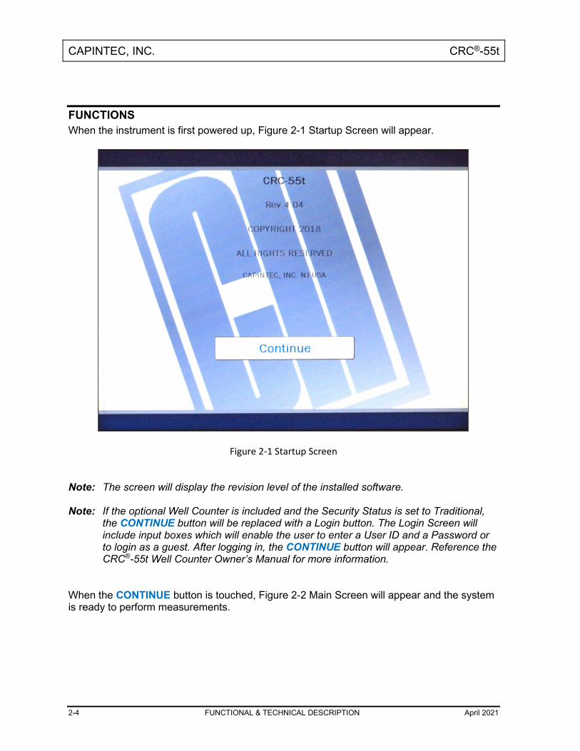
FUNCTIONS When the instrument is first powered up, Figure 2-1 Startup Screen will appear.
Figure 2-1 Startup Screen
Note: The screen will display the revision level of the installed software. Note: If the optional Well Counter is included and the Security Status is set to Traditional,
the CONTINUE button will be replaced with a Login button. The Login Screen will include input boxes which will enable the user to enter a User ID and a Password or to login as a guest. After logging in, the CONTINUE button will appear. Reference the CRC®-55t Well Counter Owner’s Manual for more information.
When the CONTINUE button is touched, Figure 2-2 Main Screen will appear and the system is ready to perform measurements.

CAPINTEC, INC. CRC®-55t
April 2021 FUNCTIONAL & TECHNICAL DESCRIPTION 2-5
Figure 2-2 Main Screen
Overall Program Flow When the power is turned on, the Startup Screen appears. When the CONTINUE button is pressed, the Chamber Measurement Screen is displayed and the CRC®-55t begins measuring the activity in the Chamber. All Chamber measurements and system functions are accessed from this screen. If the optional Well Counter is attached to the system, a button labeled WELL will be displayed in the upper left corner of the screen. The WELL button is used to access measurements and functions for the optional Well Counter. The main system functions pertaining to the Chamber(s) and optional Well Counter consist of setting date and time, choosing Curie or Becquerel operation, printing, screen setup, Curie-Becquerel calculations, Decay calculations and Diagnostics. The functions for the Chamber are accessed from the Chamber Measurement Screen. These consist of Inventory, Nuclide Key (Chamber Hotkey) assignment, Test Source information, Moly Assay testing, Linearity testing, Chamber testing, Geometry testing, and QC testing. The functions for the optional Well Counter are accessed from the Well Main Screen and relate only to the Well Counter. These consist of making measurements, Auto Calibration, Lab Tests and Quality Assurance tests. The Well Counter setup provides access to the Test Source information, nuclide assignment, nuclide efficiencies and Detector Setup. Refer to the CRC®-55t Well Counter Owner’s Manual for more information.

CAPINTEC, INC. CRC®-55t
2-6 FUNCTIONAL & TECHNICAL DESCRIPTION April 2021
TECHNICAL DESCRIPTION On / Off Switch The on/off switch (I = on; = off) is located on the back of the instrument. Warm Up Period Approximately 30 minutes should be allowed for the instrument to stabilize. While the instrument is warming up, it is strongly recommended that you become familiar with the CRC®-55t. Environment Requirements Indoor use only. Pollution Degree 2, Altitude, and Installation Cat. II.
Operational The instrument should be located where the level of the background radiation is as low and as constant as possible. The instrument should be located where the temperature is stable within a range of +50°F to +85°F (+10°C to +30°C) and the maximum relative humidity is 90% non-condensing to warrant maximum reliability and accuracy. The instrument should be located where the barometric pressure is within a range of 27 – 31 inches of mercury (91 – 105 kilopascals).
Storage The instrument should be stored where the temperature is stable and the range is from +39°F to +110°F (+4°C to +43°C) and the maximum relative humidity is 90% non-condensing to warrant maximum reliability. The instrument should be stored where the barometric pressure is within a range of 15 – 33 inches of mercury (51 – 112 kilopascals).
CAUTION: If these environmental requirements are not followed, the instrument may display erroneous readings

CAPINTEC, INC. CRC®-55t
April 2021 FUNCTIONAL & TECHNICAL DESCRIPTION 2-7
Power Requirements
CAUTION: If the input voltage to the following items is not within the stated limits, the unit may not function correctly or may be damaged
Line Voltage
Readout 100-240Vac, 50/60Hz, 230mA
Printers
Epson LX-300+II printer (optional) 99-132Vac, 50/60Hz, 0.6A (maximum 1.4A depending on the character type) 198-264Vac, 50/60Hz, 0.3A (maximum 1.4A depending on the character type)
Epson TM-295II Slip Printer (optional) Input: 100-240Vac, 50/60Hz, 1.2A; Output: +24Vdc, 0.8A
Epson TM-U220D Roll Printer (optional) Input: 100-240Vac, 50/60Hz, 1.0A max; Output: 24Vdc, 1.5A
HP DeskJet 6000/8000 Series Inkjet (or equivalent) Printer (optional) 100-240Vac, 50/60Hz, 1.5A
Epson TM-L90 Thermal Label Printer (optional) 100-240Vac, 50/60Hz, 1.3A
Line Filter
Line filter is provided internally. Use of a filtered line is recommended if excessive line noise is anticipated.
Ground Current Less than .5mA
Power Connector and Cable A grounded 3-prong plug cord for the instrument that is approved for use at the user's site must be used. Interconnection of devices must be made using the cables supplied with the instrument.
Dimensions Console
Height ....................... 42.0cm .......... (9.5in) Width ........................ 23.0cm .......... (9.0in) Depth ........................ 27.0cm .......... (10.5in)

CAPINTEC, INC. CRC®-55t
2-8 FUNCTIONAL & TECHNICAL DESCRIPTION April 2021
Weight ....................... 3.4kg .............. (7.5lb)
Chamber Height ........................ 43.8cm ........... (17.25in) Diameter .................... 17.2cm ........... (6.76in) Weight ....................... 13.6/14.5kg .... (30/32lb) Well Diameter ............ 6.1cm ............. (2.4in) Well Depth ................. 25.4cm ........... (10.0in) Cable Length1............ 3.7m .............. (12ft) Lead Shielding ........... 3.2mm............ (1/8”)
Well Counter (optional) Height ........................ 23.8cm ........... (9.38in.) Diameter .................... 15.2cm ........... (6in.) Weight ....................... 6.9kg .............. (15.2lb.) Lead Shielding ........... 1.3cm ............. (1/2”) Well Diameter ............ 1.7cm ............. (.67in.) Well Depth ................. 3.8cm ............. (1.5in.) Cable Length ............. 2.7m .............. (9ft.)
Cables Power ........................ 1.8m .............. (6ft) Printer2 ...................... 1.8m .............. (6ft)
Performance R Chamber Performance
Measurement Range: Maximum Activity (Co60) ............................. 37.4 GBq (1.00 Ci) Maximum Activity (Co57) ............................. 206. GBq (5.57 Ci)
Resolution ............................................................... 0.001 MBq (.01 µCi) Electrometer Accuracy3 ........................................... better than ±2% System Precision ..................................................... better than ± 0.1% of FSD System Linearity ...................................................... within ±2% Response Time
Below 20µCi ................................................ within 25 seconds Above 20µCi ................................................ within 4 seconds
1 Longer cables are available. Consult factory. 2 Optional 3 Overall accuracy is determined by the calibration for the specific nuclide and the sample configuration and the accuracies of the standard sources used for calibration of the electrometer.

CAPINTEC, INC. CRC®-55t
April 2021 FUNCTIONAL & TECHNICAL DESCRIPTION 2-9
PET Chamber Performance Measurement Range:
Maximum Activity (Co60) ..............................374 GBq (10.1 Ci) Maximum Activity (Co57) ..............................2337 GBq (20.0 Ci)
Resolution ................................................................0.01 MBq (0.1 µCi) Electrometer Accuracy .............................................better than ±2% System Precision .....................................................better than ± 0.1% of FSD System Linearity ......................................................within ±2% Response Time
Below 220µCi ...............................................within 25 seconds Above 220µCi...............................................within 4 seconds
Regulatory Listings The CRC®-55t has been independently tested and is manufactured in compliance with the following Standards:
• ANSI/AAMI ES60601-1: 2005 / I2012 – Medical Electrical Equipment –
General Requirements for Basic Safety and Essential Performance
• CAN/CSA-C22.2 No. 60601-1:14, Third Edition– Medical Electrical Equipment – General Requirements for Basic Safety and Essential Performance
• CENELEC EN 60601-1: 2006 + A1: 2013– Medical Electrical Equipment –
General Requirements for Basic Safety and Essential Performance
• IEC 60601-1: 2005 + A1: 2012, Third Edition– Medical Electrical Equipment – General Requirements for Basic Safety and Essential Performance
• IEC 60601-1-2 ed 4.0 (2014-02), Medical Electrical Equipment - Part 1-2:
General Requirements for Basic Safety and Essential Performance – Collateral Standard: Electromagnetic Disturbances – Requirements and Tests
LIFE TIME (END OF LIFE) The CRC 55t Family of Dose Calibrators life time (End of Life) is considered to be ten years after date of shipment. Service, support, and spare parts will be provided for this time. After ten years, the system is no longer considered “state of the art” and should be replaced.

CAPINTEC, INC. CRC®-55t
April 2021 GENERAL OPERATING INSTRUCTIONS 3-1
CHAPTER 3
GENERAL OPERATING INSTRUCTIONS
GENERAL ....................................................................................................... 3-1 CHAMBER MEASUREMENT SCREEN .......................................................... 3-2
Chamber Home Screen Hotkeys 1 ........................................................... 3-2 Nuclide Button 2 ....................................................................................... 3-2 CAL # Button 3 .......................................................................................... 3-3 Date/Time Button 4 ................................................................................... 3-3 Test Buttons 5 ........................................................................................... 3-3 SETUP Button 6 ........................................................................................ 3-3 PRINT Button 7 .......................................................................................... 3-3 Measurement Button 8 ............................................................................. 3-3 Units Button 9 ........................................................................................... 3-3 WELL/CH (CHAMBER) Button 10 ............................................................. 3-4 CH Button 11 ............................................................................................. 3-4 Dose Decay Button 12 .............................................................................. 3-4 Remote Display Indicator 13 (LEGACY PRODUCTS ONLY) ................... 3-4
ENTERING DATA ........................................................................................... 3-5 Numeric Keypad Screen ............................................................................ 3-5 Alphanumeric Keypad Screen ................................................................... 3-6 List Screen .................................................................................................. 3-7 Date/Time Screen ....................................................................................... 3-7
GENERAL This section describes general operating procedures, the touch screen, and how to access all other tests and screens

CAPINTEC, INC. CRC®-55t
3-2 GENERAL OPERATING INSTRUCTIONS April 2021
CHAMBER MEASUREMENT SCREEN The CRC®-55t Chamber Measurement screen is shown below.
Figure 3-1 Chamber Measurement Screen
General usage of touchable buttons is briefly described. Specific button usage will be given in the appropriate sections. Chamber Home Screen Hotkeys 1 These are the eight user-definable buttons located at the left edge of the screen. Touching one of the Hotkeys selects the programmed nuclide for measurement. The factory default Hotkeys are listed below.
• R Chambers: ....... F18, Ga67, In111, Tc99m, I123, I131, Xe133, TI201
• PET Chambers: ... F18, C11, N13, O15, Tc99m, Cs137, Co60, I131 Nuclide Button 2 This button is located below the measurement and displays the currently selected nuclide, nuclide name and half-life. Touching this button allows the user to select any nuclide in memory (including nuclides added by the user).
1
2
3
4
5
6
7
8
9
10
11
12
13

CAPINTEC, INC. CRC®-55t
April 2021 GENERAL OPERATING INSTRUCTIONS 3-3
CAL # Button 3 This is the Calibration Number button and is located below the Nuclide button and displays the currently selected nuclide’s Calibration Number or the currently selected Calibration Number. Touching this button allows the user to input a Calibration Number to be used for the current measurement. Date/Time Button 4 Touching the date/time will display a screen allowing the setting of the current date/time. A password is required to change the date and/or time. Test Buttons 5 The bottom of the screen holds 8 buttons that are composed of DAILY, BACKGROUND, CHAMBER VOLTS, ACCURACY, ENHANCED TESTS, MOLY ASSAY, INVENTORY, and UTIL. Each of these buttons is addressed throughout the manual. SETUP Button 6 The lower right part of the screen contains the SETUP button. This button allows for setting up the system for activity units, date format, type of printer, display adjustments, Staff Member setup and printers as explained in later chapters. PRINT Button 7 Note: If the system is not set up for use with the optional Printer, this button will not be
displayed. The PRINT button will be displayed in the lower right part of the screen. It allows printing of data displayed on the screen. Measurement Button 8 The central part of the screen contains the measurement. Touching the measurement (x.xx) allows the user to change the precision of the measurement. Units Button 9 The central part of the screen contains the measurement unit. Touching the unit (Ci/Bq) allows the user to toggle between Curies and Becquerel if so chosen in Setup.

CAPINTEC, INC. CRC®-55t
3-4 GENERAL OPERATING INSTRUCTIONS April 2021
WELL/CH (CHAMBER) Button 10 Note: If the optional Well Counter is not attached to the system, this button will not be
displayed. When the instrument is first powered up, it is in Chamber mode. That is, it is set up to make measurements using the Chamber. The WELL button is located in the upper left part of the Chamber Measurement screen. Pressing the WELL button will put the instrument in Well mode, which means it will be set up to make measurements using the Well Counter. Once the system is in Well mode, the WELL button will change to the CH (CHAMBER) button. Pressing the CH button will put the instrument in Chamber mode, which means it will be set up to make measurements using the Chamber. CH Button 11 Note: If only one Chamber is attached to the system, the CH button will not be displayed. When the instrument is in Chamber mode, if more than one Chamber is connected to the system, the CH (Chamber) button will be displayed and is located in the lower left part of the Chamber Measurement screen. Pressing the CH button allows the selection of which Chamber’s measurement will be displayed on the Chamber Measurement screen. Dose Decay Button 12 This button is located to the right of the preset nuclide keys (Chamber Hotkeys) in the upper portion of the Chamber Measurement screen. This button allows the entry of a future date and time for the current sample being measured. After the date and time are input, the Dose Decay button will display the activity of the current sample at the specified time in red. Remote Display Indicator 13 (LEGACY PRODUCTS ONLY) Note: This section is only included for legacy systems. Remote Displays are no longer
available as an option. If an optional Remote Display is attached to the selected Chamber, an asterisk symbol will appear on the screen as shown indicating that a Remote Display is attached to that Chamber.

CAPINTEC, INC. CRC®-55t
April 2021 GENERAL OPERATING INSTRUCTIONS 3-5
ENTERING DATA Numeric Keypad Screen When a numeric only data entry is required, Figure 3-2 Numeric Keypad Screen will appear as shown below. This keypad is touchable for entering the data.
Figure 3-2 Numeric Keypad Screen
If units of measure are also required, such as Ci, mCi, µCi, GBq, MBq, kBq for activity or Yr, Hr, Day, Min, Sec for half-life, they will appear on the keypad between the number pad and the data entry box.

CAPINTEC, INC. CRC®-55t
3-6 GENERAL OPERATING INSTRUCTIONS April 2021
Alphanumeric Keypad Screen When an alphanumeric data entry is required, Figure 3-3 Alphanumeric Keypad Screen will appear as shown below. This keypad is also touchable for entering the data.
Figure 3-3 Alphanumeric Keypad Screen
Pressing the SHIFT key on the alphanumeric keyboard will cycle between 4 modes:
• Lock/Upper Case – If “Lock” is displayed above the SHIFT key and upper case letters are displayed on the keys, the keyboard is locked in upper case letters. All selected letters will be in upper case.
• 1Chr/Lower Case – If “1Chr” is displayed above the SHIFT key and lower case letters are displayed on the keys, the first letter selected will be in lower case and the keyboard will change to Lock/Upper case mode.
• Lock/Lower Case – If “Lock” is displayed above the SHIFT key and lower case letters are displayed on the keys, the keyboard is locked in lower case letters. All selected letters will be in lower case.
• 1Chr/Upper Case – If “1Chr” is displayed above the SHIFT key and upper case letters are displayed on the keys, the first letter selected will be in upper case and the keyboard will change to Lock/Lower case mode.

CAPINTEC, INC. CRC®-55t
April 2021 GENERAL OPERATING INSTRUCTIONS 3-7
List Screen When an item is to be selected from a group, a list appears showing the available selections. Figure 3-4 List Screen is an example of a List Screen.
Figure 3-4 List Screen
If there are more items on the list than can fit on one page, a DOWN ARROW (▼) button will appear on the first page. Touching the DOWN ARROW (▼) button will display the next page. If there is a previous page of the list, an UP ARROW (▲) button will appear. Touching the UP ARROW (▲) button will display the previous page. The number of pages (or screens) will be shown in the upper right corner of the screen indicating the length of the list. Quickly touching any line will highlight that line, selecting the information on that line. Note: When touching the screen on a list, you should withdraw your finger quickly. If you
hold your finger down too long, the touched line will be blanked until your finger is removed. Moving your finger down the list will make it appear that the line has vanished. To restore the data to the screen, simply touch the line quickly again.
Date/Time Screen When a Date and/or Time entry is required, Figure 3-5 Date/Time Screen will appear as shown below.

CAPINTEC, INC. CRC®-55t
3-8 GENERAL OPERATING INSTRUCTIONS April 2021
Figure 3-5 Date/Time Screen
The screen displays the currently set date and time. The date and time are divided into the following fields:
• mm .......... Month (1-12) • d .............. first digit of the Day (0-3) • d .............. second digit of the Day (0-9) • yyyy ........ Year (1970-2030) • h .............. first digit of the Hour (0-2) • h .............. second digit of the Hour (0-9) • m ............. first digit of the Minute (0-5) • m ............. second digit of the Minute (0-9)
Above and below each of the fields are + and – buttons, respectively. To adjust the displayed value for a specific field, touch the + button to increase the displayed value or the – button to decrease the displayed value. For the year, +10 and -10 buttons are provided to quickly change the tens column of the years.

CAPINTEC, INC. CRC®-55t
April 20211 SYSTEM SETUP 4-1
CHAPTER 4
SYSTEM SETUP
GENERAL ....................................................................................................... 4-1 RECEIVING CONDITION EXAMINATION ...................................................... 4-1 UNPACKING AND INSTALLATION ............................................................... 4-1 ASSEMBLY ..................................................................................................... 4-2
Readout/Stand Base................................................................................... 4-2 System Assembly ....................................................................................... 4-4 Liner, Dipper, and Optional Holders ......................................................... 4-8
ENVIRONMENT REQUIREMENTS ................................................................. 4-9 POWER REQUIREMENTS .............................................................................. 4-9
Readout ....................................................................................................... 4-9 Printers (optional) ...................................................................................... 4-9
TURN ON PROCEDURES ............................................................................. 4-10 GENERAL OPERATIONAL SETUP ............................................................... 4-11 ACCEPTANCE TESTING ............................................................................... 4-12
Chamber Tests .......................................................................................... 4-12 Well Counter Test ...................................................................................... 4-12
GENERAL Initial installation and checkout procedures are described in this section.
RECEIVING CONDITION EXAMINATION Be sure to verify that the shipping carton(s) is received in good condition, i.e., no damage should be visible and the box(es) should be dry and clean. Should the instrument be received in a damaged condition, save the shipping container(s) and the packing materials and request an immediate inspection by the carrier. Capintec, Inc. is not responsible for the damage, which occurs during shipment but will make every effort to help obtain restitution from the carrier.
UNPACKING AND INSTALLATION The instrument is packed and shipped as a complete unit. All the accessories are contained in the cartons. (If more than one Chamber or an optional Well Counter or printer is included, they will be in separate cartons.)

CAPINTEC, INC. CRC®-55t
4-2 SYSTEM SETUP April 2021
The instrument is shipped in a plastic bag in order to provide a dry and clean environment during shipment.
CAUTION: Be sure the instrument has reached room temperature prior to opening the bag. (Leave the box in the room 24 hours before opening it.)
1. Remove all outer packing materials and tapes. The shipping and packing materials
should be saved for future use. 2. The following equipment should be found upon unpacking:
• Readout Unit with Stand Base • Chamber(s) and Liner(s)/Dipper(s) • Well Counter (optional) • Power Cord • Printer (optional)
o Okidata Microline 320, or o Epson LX-300+II, or o Epson Slip printer, or o Epson Roll printer, or o HP DeskJet 6000/8000 Series Inkjet (or equivalent) printer, or o Epson TM-L90 Thermal Label printer
The Printer should have the following accessories:
• Power Supply • Printer Ribbon • Communications Cable • Roll Paper (If Roll printer ordered) • Tickets (If Ticket printer ordered) • Labels (If Label printer ordered)
Note: If Test Sources are ordered, they will be shipped separately.
3. Be sure to remove all tape and protective materials from the instrument prior to connecting to the power line.
ASSEMBLY Readout/Stand Base Attach the Readout to the Stand Base using the following instructions. Reference Figure 4-1 Readout/Stand Base Assembly for assembly details.
1. On the sides of Readout (A), remove both of the knobs and all (4) of the washers. 2. Place Stand Base (B) on a flat, sturdy surface. 3. Slide washer (C) over the shaft of knob (D). 4. Insert knob (D) through one side of the Stand Base (B) and place another washer (E)
over the shaft of knob (D) (on the inside of the Stand Base).

CAPINTEC, INC. CRC®-55t
April 20211 SYSTEM SETUP 4-3
5. With the front of Readout (A) facing the same direction as the front of Stand Base (B), place the Readout onto the Stand Base.
6. Insert the shaft of knob (D) into mounting hole (F) located on the side of Readout (A). Loosely tighten the knob.
7. Slide washer (G) over the shaft of knob (H). 8. Insert knob (H) through the other side of the Stand Base (B) and place another
washer (J) over the shaft of knob (H) (on the inside of the Stand Base). 9. Insert the shaft of knob (H) into the mounting hole located on the other side of
Readout (A). Note: The sides of the Stand Base (B) may need to be spread apart a small amount to get the second knob to insert into the mounting hole.
10. Verify on each side that there is a washer located between the knob and the Stand Base (on the outside of the Stand Base), and the Stand Base and the Readout (on the inside of the Stand Base).
11. The knobs can now be fully tightened.
Figure 4-1 Readout/Stand Base Assembly
D
E
C B
A
F G
H
J
Front of Stand Base
Front of Readout

CAPINTEC, INC. CRC®-55t
4-4 SYSTEM SETUP April 2021
System Assembly Reference Figure 4-2 Complete System and Figure 4-3 Readout Back Panel for assembly details.
Figure 4-2 Complete System

CAPINTEC, INC. CRC®-55t
April 20211 SYSTEM SETUP 4-5
Figure 4-3 Readout Back Panel
1. Verify that all power switches (Readout and Printer) are in the “OFF” or “0” position.
CAUTION: Position the device such that access the supply mains disconnect switch on the rear of the CRC®-55t Readout is not obstructed.
CAUTION: Only specified or certified accessories shall be used and connected to
the CRC®-55t.
2. Connect the Chamber Cable to the connector on the rear of the CRC®-55t Readout labeled “CHAMBER 1”.
CAUTION: To avoid damage, do not over-tighten the screws on the Cable connector. The screws should be finger-tightened only!
Note: If two Chambers are part of the system, connect the second Chamber to the
connector on the rear of the CRC®-55t Readout labeled “CHAMBER 2”.
3. If the system is a CRC®-55tW, connect the Well Counter Cable to the connector at the rear of the CRC®-55t Readout labeled “WELL COUNTER”. Note: Do not attach the Well Counter cable to the “CHAMBER 1” or CHAMBER 2”
connectors.

CAPINTEC, INC. CRC®-55t
4-6 SYSTEM SETUP April 2021
Note: To avoid damage, do not over-tighten the screws on the Cable connector. The screws should be finger-tightened only!
4. Attach the Power Cable to the receptacle on the Power Module located on the back of the Readout Unit. Note: Do not place the Readout unit against a wall or other object so that the power
cord can be detached from the back of the Readout unit.
Figure 4-4 Optional RS-232 Printers
5. If the optional printer is an RS-232 (serial) version, attach the printer cable (one end
has a 9 pin “D” connector, the other end has a 25 pin “D” connector) to the 9 pin “D” connector at the rear of the CRC®-55t Readout marked “PRINTER”. Attach the other end to the printer. Note: To avoid damage, do not over-tighten the screws on the Cable connectors.
The screws should be finger-tightened only! Note: Do not attach the printer cable to the 9 pin “D” connector labeled “RS232”.
If the optional printer is a USB version, attach the printer cable to the USB connector on the rear of the CRC®-55t Readout marked “PRINTER”. Attach the other end to the printer. Note: Do not attach the printer cable to the “PC” connector.
For each printer type, verify that the correct paper is installed. (Note: The Slip-Ticket printer paper is manually inserted at the time of printing.)
CAUTION: Only Capintec recommended printers shall be used and connected to the Well Counter printer port.
6. The system can be connected to a computer or Nuclear Management software
system via RS-232 or USB interface.

CAPINTEC, INC. CRC®-55t
April 20211 SYSTEM SETUP 4-7
If the system is being connected using the RS-232 interface, connect the cable to the 9 pin “D” connector at the rear of the CRC®-55t Readout marked “RS232”. Attach the other end to the computer or Nuclear Management software system. If the system is being connected using the USB interface, connect the cable to the USB connector at the rear of the CRC®-55t Readout marked “PC”. Attach the other end to the computer or Nuclear Management software system.
7. Connect the power cable to the power entry module on the rear of the CRC®-55t Readout.
Note: The power entry module switch located on the rear of the CRC®-55t provides a
quick and easy method to disconnect supply mains.

CAPINTEC, INC. CRC®-55t
4-8 SYSTEM SETUP April 2021
Liner, Dipper, and Optional Holders The supplied Chamber Liner and Dipper are shown below.
Figure 4-5 Liner and Dipper
The Chamber Liner provides protection against spills. It is made of clear, tough Plexiglass for improved durability. It is recommended that the Liner be installed inside the Chamber at all times.
CAUTION: Never use the calibrator without the Chamber Liner in place. Liners are inexpensive and easy to replace. A contaminated Chamber is a very costly mistake.
The Dipper (Vial/Syringe sample holder) is specially designed to hold syringes and vials of various sizes. It provides a safe, convenient way to hold a vial or syringe during activity measurement. Proper placement in the Chamber is assured every time. The cup portion will accommodate up to a 30ml vial. The Syringe Guide will accommodate 3, 5 and 10cc syringes. An adapter (7310-1109) is available to accommodate a tuberculin syringe (1cc). For seed measurements, use the appropriate source holder for the source type being measured in order to obtain a correct reading. If additional information is needed, contact Capintec, Inc. for further assistance.
Figure 4-6 Optional Holders
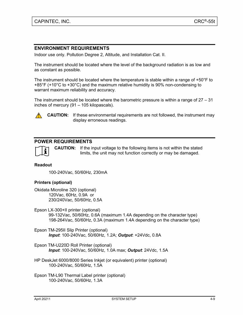
CAPINTEC, INC. CRC®-55t
April 20211 SYSTEM SETUP 4-9
ENVIRONMENT REQUIREMENTS Indoor use only. Pollution Degree 2, Altitude, and Installation Cat. II. The instrument should be located where the level of the background radiation is as low and as constant as possible. The instrument should be located where the temperature is stable within a range of +50°F to +85°F (+10°C to +30°C) and the maximum relative humidity is 90% non-condensing to warrant maximum reliability and accuracy. The instrument should be located where the barometric pressure is within a range of 27 – 31 inches of mercury (91 – 105 kilopascals).
CAUTION: If these environmental requirements are not followed, the instrument may display erroneous readings.
POWER REQUIREMENTS
CAUTION: If the input voltage to the following items is not within the stated limits, the unit may not function correctly or may be damaged.
Readout
100-240Vac, 50/60Hz, 230mA Printers (optional) Okidata Microline 320 (optional)
120Vac, 60Hz, 0.9A or 230/240Vac, 50/60Hz, 0.5A
Epson LX-300+II printer (optional) 99-132Vac, 50/60Hz, 0.6A (maximum 1.4A depending on the character type) 198-264Vac, 50/60Hz, 0.3A (maximum 1.4A depending on the character type)
Epson TM-295II Slip Printer (optional) Input: 100-240Vac, 50/60Hz, 1.2A; Output: +24Vdc, 0.8A
Epson TM-U220D Roll Printer (optional) Input: 100-240Vac, 50/60Hz, 1.0A max; Output: 24Vdc, 1.5A
HP DeskJet 6000/8000 Series Inkjet (or equivalent) printer (optional) 100-240Vac, 50/60Hz, 1.5A
Epson TM-L90 Thermal Label printer (optional) 100-240Vac, 50/60Hz, 1.3A

CAPINTEC, INC. CRC®-55t
4-10 SYSTEM SETUP April 2021
TURN ON PROCEDURES 1. Be sure the interconnecting cable from the Chamber and optional Well Counter
assemblies are properly plugged into the back of the Readout unit. 2. Confirm the power requirements of the instrument. 3. Be sure the power switch is off. (Push lower part of the rocker switch next to the
power receptor located on the rear of the main unit.) 4. Plug the power plug into a grounded three-wire outlet of the specified power line. 5. Turn on the Readout Unit using the power switch located at the rear of the unit. 6. After a few seconds, Figure 4-7 Startup Screen will appear.
Note: After powering up, the screen may be white or have colored lines for up to 30 seconds before Figure 4-7 Startup Screen appears.
CAUTION: Accidental connection of the power plug into a DC line or to an AC line which exceeds the specified voltage may result in catastrophic damage to the instrument's circuits.
Figure 4-7 Startup Screen

CAPINTEC, INC. CRC®-55t
April 20211 SYSTEM SETUP 4-11
Note: The screen will display the revision level of the installed software. Note: If the optional Well Counter is included and the Security Status is set to Traditional,
the CONTINUE button will be replaced with a Login button. The Login Screen will include input boxes which will enable the user to enter a User ID and a Password or to login as a guest. After logging in, the CONTINUE button will appear. Reference the CRC®-55t Well Counter Owner’s Manual for more information.
GENERAL OPERATIONAL SETUP There are several things that must be done before using the CRC®-55t Radioisotope Dose Calibrator for the first time. The following briefly describes these steps:
• Verify or set the date/time: Although the date and time are set at the factory, you should verify that the date and time are correct for your location. Reference CHAPTER 5: SYSTEM INITIALIZATION, SECTION: SET DATE AND TIME.
• Select proper units: Ci or Bq. Although the system can be changed at any time, it is recommended that the proper units be set prior to using the unit to prevent confusion. Reference CHAPTER 5: SYSTEM INITIALIZATION, SECTION: CHOOSING Ci or Bq.
• Input Test Source Data: Test Sources (Standard Sources) are used for the Accuracy and Constancy tests. The Accuracy may be tested using Co57, Co60, Ba133, Cs137 or Na22. There can be a Test Source for each of these nuclides. One or more of the Test Sources must be designated as the source(s) to be used in the Daily Test. Reference CHAPTER 6: CHAMBER INITIALIZATION, SECTION: TEST SOURCE SETUP.
• Input Constancy Test Source: The base source for the Constancy Test is chosen from the sources designated as Daily Sources. Reference CHAPTER 6: CHAMBER INITIALIZATION, SECTION: TEST SOURCE SETUP.
• Verify correct printer setting: The CRC®-55t may be used with one of the following printers. Reference CHAPTER 5: SYSTEM INITIALIZATION, SECTION: PRINTING.
o Okidata Microline 320 o Epson LX-300+II o Epson TM-U295 Slip Printer o Epson TM-U200D Roll Printer o USB HP Inkjet o USB Epson Label
• Adding a Nuclide: The CRC®-55t contains nuclide data (name, half-life, calibration
number) for 84 nuclides. The user may add up to 10 nuclides: the name, half-life and calibration number will be added for each one. Reference CHAPTER 6: CHAMBER INITIALIZATION, SECTION: NUCLIDES.
• Changing Calibration Numbers: The user is allowed to change the calibration number of up to 10 built-in nuclides. Reference CHAPTER 6: CHAMBER INITIALIZATION, SECTION: CALIBRATION NUMBERS.

CAPINTEC, INC. CRC®-55t
4-12 SYSTEM SETUP April 2021
• Selecting Moly Assay Method: Moly Assay can only be performed using R Chamber with the CAPMAC or CANISTER. Reference CHAPTER 6: CHAMBER INITIALIZATION, SECTION: MOLY ASSAY SETUP.
• Setting Mo/Tc Limit: The Mo/Tc limit is set at the factory to 0.15µCi/mCi. The user can change this value. Reference CHAPTER 6: CHAMBER INITIALIZATION, SECTION: MOLY ASSAY SETUP.
ACCEPTANCE TESTING The following tests should be performed prior to operational use of the unit. Chamber Tests
Diagnostics Test Reference CHAPTER 9: DIAGNOSTICS for instructions on how to perform this test.
Daily Test Reference CHAPTER 8: CHAMBER TESTS, SECTION: CHAMBER DAILY TEST for instructions on how to perform this test.
Accuracy Test Reference CHAPTER 8: CHAMBER TESTS, SECTION: ACCURACY TEST for instructions on how to perform this test.
Well Counter Test If the optional Well Counter is included with your system, reference the CRC®-55t Well Counter Owner’s Manual for instructions on how to perform these tests.

CAPINTEC, INC. CRC®-55t
April 2021 SYSTEM INITIALIZATION 5-1
CHAPTER 5
SYSTEM INITIALIZATION
GENERAL ....................................................................................................... 5-1 SET DATE AND TIME ..................................................................................... 5-1 CHOOSING Ci or Bq ...................................................................................... 5-3 CHOOSING DATE FORMAT .......................................................................... 5-5 PRINTING ....................................................................................................... 5-7
Printer Power Requirements ..................................................................... 5-7 Printer Selection ......................................................................................... 5-8 Okidata Menu Set-Up ................................................................................. 5-9 Epson LX-300+II Menu Set-Up .................................................................. 5-12
USB PC DRIVER ............................................................................................ 5-18 LANGUAGE ................................................................................................... 5-19 SCREEN ADJUSTMENTS ............................................................................. 5-22
Sleep Timeout ............................................................................................ 5-22 Sleep Brightness ....................................................................................... 5-23 Brightness ................................................................................................. 5-23 Screen Calibration ..................................................................................... 5-24
SPEAKER VOLUME ...................................................................................... 5-25
GENERAL This section describes initialization and parameter setup, which are common to the Chamber(s) and the optional Well Counter. All of these functions are accessed via the Chamber Measurement screen.
SET DATE AND TIME The system date and/or time can be set from the Chamber Measurement screen or the Well Main Screen (if the optional Well Counter is included). To change the date and/or time, touch the displayed date/time in the upper-right part of the screen. A numeric keypad will appear to allowing the user to input a password as shown in Figure 5-1 Enter Password: Screen.
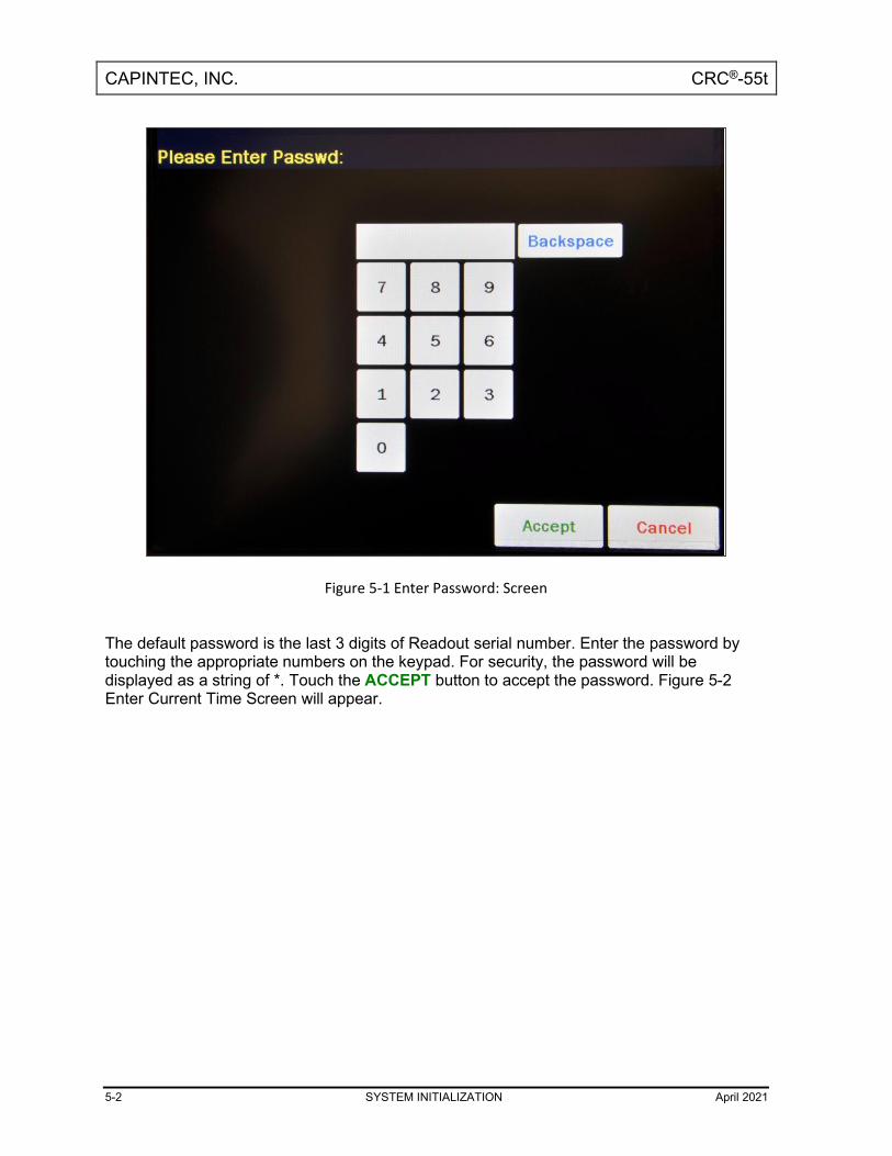
CAPINTEC, INC. CRC®-55t
5-2 SYSTEM INITIALIZATION April 2021
Figure 5-1 Enter Password: Screen
The default password is the last 3 digits of Readout serial number. Enter the password by touching the appropriate numbers on the keypad. For security, the password will be displayed as a string of *. Touch the ACCEPT button to accept the password. Figure 5-2 Enter Current Time Screen will appear.

CAPINTEC, INC. CRC®-55t
April 2021 SYSTEM INITIALIZATION 5-3
Figure 5-2 Enter Current Time Screen
The screen displays the currently set date and time. Above and below each of the fields are + and – buttons, respectively. To adjust the displayed value for a specific field, touch the + button to increase the displayed value or the – button to decrease the displayed value. For the year, +10 and -10 buttons are provided to quickly change the tens column of the years. Touch the ACCEPT button to accept the new date/time or the CANCEL button to cancel any changes. The Chamber Measurement screen will re-appear.
CHOOSING CI OR BQ Measurements can be displayed in Curies or Becquerels. When the system arrives, it is set up to display in Ci and Bq. Touching the measurement unit on the Chamber Measurement screen will switch the measurement result between Ci and Bq. In some facilities, it may be decided to disable this feature and allow measurements to be displayed only in Curies or only in Becquerels. To enable or disable Ci/Bq switching, touch the SETUP button located on the Chamber Measurement screen. Figure 5-3 Setup Screen will appear.

CAPINTEC, INC. CRC®-55t
5-4 SYSTEM INITIALIZATION April 2021
Figure 5-3 Setup Screen
In the Activity Unit: section at the top of the Setup Screen, touch the radio button next to the preferred unit for measurements:
• Ci/Bq ............. allows the user to switch between Curies and Becquerels,
• Ci Only .......... the system will be set to display measurements in Curies only,
• Bq Only ......... the system will be set to display measurements in Becquerels only. Verify that the desired radio button is selected. Press the HOME or BACK button to save the changes and return to the Chamber Measurement screen.

CAPINTEC, INC. CRC®-55t
April 2021 SYSTEM INITIALIZATION 5-5
CHOOSING DATE FORMAT The date can be entered, displayed and printed in 3 formats:
• Month Day Year (mm/dd/yyyy)
• Day Month Year (dd/mm/yyyy)
• Year Month Day (yyyy/mm/dd) In the Activity Unit: section at the top of Figure 5-3 Setup Screen, the current date format is displayed in the upper right hand corner. The default date format is Month Day Year. This format will be shown throughout the manual. To change the date format, touch the Date Format: field box. Figure 5-4 Date Format Selection Screen will appear.
Figure 5-4 Date Format Selection Screen
Touch the desired date format button. The Setup Screen will re-appear showing the selected date format. If Day Month Year has been selected, Figure 5-5 Setup Screen after Day Month Year Selected will be displayed. If Year Month Day has been selected, Figure 5-6 Setup Screen after Year Month Day Selected will be displayed.

CAPINTEC, INC. CRC®-55t
5-6 SYSTEM INITIALIZATION April 2021
Figure 5-5 Setup Screen after Day Month Year Selected
Figure 5-6 Setup Screen after Year Month Day Selected

CAPINTEC, INC. CRC®-55t
April 2021 SYSTEM INITIALIZATION 5-7
PRINTING CAUTION: If any printer other than one of the models supplied by Capintec is used,
Electromagnetic Interference (EMI) may be introduced into other devices located in the same general area as the CRC®-55t.
The system does not need a printer to function properly. When a printer is set up to work with the system, a PRINT button will appear on all screens in which results can be printed from. If the PRINT button is not displayed, then the system is either not set up to work with a printer or printing is not permitted from that particular screen. The CRC®-55t may be used with the following printers:
• USB printers o HP DeskJet 6000/8000 Series Inkjet (or equivalent) printer o Epson TM-L90 Thermal Label printer
• RS-232 printers o Epson TM-295II Slip printer o Epson TM-U220D Roll printer o Okidata Microline 320 o Epson LX-300+II
Note: If the Okidata Microline 320 or the Epson LX-300+II are used, the Chamber
measurement can be printed on a ticket or as a single line on regular paper. Note: If the Epson TM-90L Label printer is used, the PRINT button will only appear on the
Chamber Measurement Screen allowing the measurement to be printed on a label. Other printer models may be used. Please contact the factory for information on which printers can be utilized. Printer Power Requirements HP DeskJet 6000/8000 Series Inkjet (or equivalent) Printer (optional)
100-240Vac, 50/60Hz, 1.5A Epson TM-L90 Thermal Label Printer (optional)
100-240Vac, 50/60Hz, 1.3A Epson TM-295II Slip Printer (optional)
Input: 100-240Vac, 50/60Hz, 1.2A; Output: +24Vdc, 0.8A
Epson TM-U220D Roll Printer (optional) Input: 100-240Vac, 50/60Hz, 1.0A max; Output: 24Vdc, 1.5A
Okidata Microline 320 Printer (optional)
120Vac, 60Hz or 230/240Vac, 50/60Hz

CAPINTEC, INC. CRC®-55t
5-8 SYSTEM INITIALIZATION April 2021
Epson LX-300+II Printer (optional) 99-132Vac, 50/60Hz, 0.6A (maximum 1.4A depending on the character type) 198-264Vac, 50/60Hz, 0.3A (maximum 1.4A depending on the character type)
Printer Selection If a printer was included with the CRC®-55t, the system will already be set to use the included printer. If a printer is being added or the system did not include a printer at the time of purchase, then the CRC®-55t must be set to use the printer in order to provide printed data. To view and/or change the selected printer, touch the SETUP button located on the Chamber Measurement screen. Figure 5-3 Setup Screen will appear. In the Printer section on the Setup Screen, the following options are available:
• NONE ........................ if no printer is attached to the system: the calibrator will continue to function properly but without the ability to print.
• USB/HP ..................... USB printer port, HP DeskJet 6000/8000 Series Inkjet (or equivalent) printer: prints all data on regular paper.
• USB/EPSONLABEL .. USB printer port, Epson TM-L90 Thermal Label printer: prints measurements on self-adhesive labels.
• “Feed EpsonLabel After Printing”…Automatically feed the label to the “peel” position after printing. This option is only for the USB/EPSONLABEL printer.
• 232/SLIP ................... RS-232 printer port, Epson TM-295II Slip Printer: prints measurements on tickets or regular paper and all other data on regular paper.
• 232/ROLL .................. RS-232 printer port, Epson TM- U220D Roll Printer: prints all data on roll paper.
• 232/OKI-TICKET ....... RS-232 printer port, Okidata Microline 320 printer: prints measurements on tickets or regular paper and all other data on regular paper.
• 232/OKI-LINE ............ RS-232 printer port, Okidata Microline 320 printer: prints measurements in a single line on regular paper and all other data on regular paper.
• 232/LX300-TICKET ... RS-232 printer port, Epson LX-300+II printer: prints measurements on tickets or regular paper and all other data on regular paper.
• 232/LX300-LINE ........ RS-232 printer port, Epson LX-300+II printer: prints measurements in a single line on regular paper and all other data on regular paper.
The Okidata Microline 320 and Epson LX-300+II printers and can print measurements on a ticket or on regular paper. If the printing will be done on tickets, select the printer with the TICKET option. If printing will not be done on tickets, select the printer with the LINE option.
CAPINTEC, INC. CRC®-55t
April 2021 SYSTEM INITIALIZATION 5-9
To select the desired printer, touch the radio button next to the preferred printer type. Verify that the desired radio button is selected. Press the HOME or BACK button to save the changes and return to the Chamber Measurement screen. Okidata Menu Set-Up If an Okidata Microline 320 printer was ordered with the CRC®-55t system, the Okidata printer should be set up to function properly when received. Should you experience printer difficulties, such as not printing, improper print spacing, printing the wrong characters, etc., make sure that the printer Setup is exactly as indicated in Figure 5-7 Listing of the Turbo OKIDATA 320 Printer Setup Data. If any differences are found, they must be corrected. The buttons referred to are all located on the front panel of the printer. The Paper Lever is on the right side of the top surface of the printer near the paper roller. To print and correct the Setup:
1. Make sure that the form paper is properly loaded in the printer. 2. Press the SEL button (to take printer off-line). 3. Press SHIFT + MENU (SEL) to enter the Setup Menu. 4. Press the PRINT button and the entire Setup listing will print. 5. If there are no differences between what just printed and Figure 5-7 Listing of the
Turbo OKIDATA 320 Printer Setup Data go to step 10. 6. Press the GROUP button. The first line of the first group of lines of the Setup will
print. 7. If all lines in the group just printed match the corresponding lines in Figure 5-7 Listing
of the Turbo OKIDATA 320 Printer Setup Data, repeat step 6 for the next group. 8. If any line in the group just printed does not match the corresponding line in Figure
5-7 Listing of the Turbo OKIDATA 320 Printer Setup Data, it must be corrected. For example, to change the Baud Rate to 4800:
a. Press the GROUP button until Serial I/F is printed. b. Press the ITEM button until Baud Rate is printed. c. Press the SET button until 4800 BPS is printed.
9. If any differences remain, return to step 6 for the next group. 10. Press the SHIFT + MENU (SEL) buttons to return to SEL (on-line).
Note: The Setup printout shown in Figure 5-7 Listing of the Turbo OKIDATA 320 Printer
Setup Data is for example only. Your printer Setup may differ slightly from that shown.

CAPINTEC, INC. CRC®-55t
5-10 SYSTEM INITIALIZATION April 2021
Verify that the settings, which are the same between your Setup and that shown, concur.

CAPINTEC, INC. CRC®-55t
April 2021 SYSTEM INITIALIZATION 5-11
Printer Control Emulation Mode IBM PPR Font Print Mode Utility Font DRAFT Mode HSD Font Pitch 10 CPI Font Proportional Spacing No Font Style Normal Font Size Single Symbol Sets Character Set Set I Symbol Sets Language Set American Symbol Sets Zero Character Slashed Symbol Sets Code Page USA Rear Feed Line Spacing 6 LPI Rear Feed Form Tear-Off Off Read Feed Skip Over Perforation No Rear Feed Page Length 11” Bottom Feed Line Spacing 6 LPI Bottom Feed Form Tear-Off Off Bottom Feed Skip Over Perforation No Bottom Feed Page Length 11” Top Feed Line Spacing 6 LPI Top Feed Bottom Margin Valid Top Feed Page Length 11” Top Feed Wait Time 1 sec Top Feed Page Length Control by Actual Page Length Set-Up Graphics Uni-directional Set-Up Receive Buffer Size 64K Set-Up Paper Out Override No Set-Up Print Registration 0
||||||||||||||||||||||||||||||||||||||||||||| SET |||||| SHIFT+SET ||||||||||||||||||| Set-Up Operator Panel Functions Full Operation Set-Up Reset Inhibit Yes Set-Up Print Suppress Effective No Set-Up Auto LF No Set-Up Auto CR No Set-Up SI Select Pitch (10CPI) 17.1 CPI Set-Up SI Select Pitch (12CPI) 12 CPI Set-Up Time Out Print Valid Set-Up Auto Select No Set-Up Centering Position DEFAULT Set-Up ESC SI Pitch 17.1 CPI Parallel I/F I-Prime Buffer Print Parallel I/F Pin 18 +5v Parallel I/F Bi-Direction Enable Serial I/F Parity None Serial I/F Serial Data 7/8 Bits 8 bits Serial I/F Protocol X-ON/X-OFF Serial I/F Diagnostic Test No Serial I/F Busy Line SSD- Serial I/F Baud Rate 4800 BPS Serial I/F DSR Signal Invalid Serial I/F DTR Signal Ready on Power Up Serial I/F Busy Time 200 ms
Figure 5-7 Listing of the Turbo OKIDATA 320 Printer Setup Data
<----- ----->

CAPINTEC, INC. CRC®-55t
5-12 SYSTEM INITIALIZATION April 2021
Epson LX-300+II Menu Set-Up If an Epson LX-300+II printer was ordered with the CRC®-55t system, the printer should be set-up to function properly when received. Should you experience printer difficulties, such as not printing, improper print spacing, printing the wrong characters, etc., make sure that the printer Setup is exactly as shown in Figure 5-9 Epson LX-300+II Printer Current Settings. If any differences are found, they must be corrected. Follow the steps below to enter Default Setting mode. If single sheets are used, a new sheet of paper will need to be loaded each time the printer ejects a printed page. The buttons referred to are all located on the front panel of the printer.
1. Make sure that the paper is properly loaded and the printer is off. 2. Hold down the TEAR OFF (FONT) button and then turn on the printer.
The printer enters Default Setting mode and prints instructions (as shown in Figure 5-8 Epson LX-300+II Printer Language Selection Instructions) for selecting the language. The current language is indicated by which control panel lights are on. (For English, only the Pause light is on.)
3. If a different language is desired, press the LF/FF button until the lights show the preferred language.
4. Press the TEAR OFF (FONT) button to print a list of all the current settings as shown in Figure 5-9 Epson LX-300+II Printer Current Settings.

CAPINTEC, INC. CRC®-55t
April 2021 SYSTEM INITIALIZATION 5-13
Figure 5-8 Epson LX-300+II Printer Language Selection Instructions

CAPINTEC, INC. CRC®-55t
5-14 SYSTEM INITIALIZATION April 2021
Figure 5-9 Epson LX-300+II Printer Current Settings
5. If there are no differences between what just printed and Figure 5-9 Epson LX-300+II
Printer Current Settings, turn off the printer to exit Default Setting mode. If changes are needed, proceed to step 6.
6. Press the TEAR OFF (FONT) button. The printer prints instructions for changing the settings as shown in Figure 5-10a Epson LX-300+II Printer Changing Settings Instructions.

CAPINTEC, INC. CRC®-55t
April 2021 SYSTEM INITIALIZATION 5-15
Figure 5-10a Epson LX-300+II Printer Changing Settings Instructions

CAPINTEC, INC. CRC®-55t
5-16 SYSTEM INITIALIZATION April 2021
Figure 5-10b Epson LX-300+II Printer Changing Settings Instructions

CAPINTEC, INC. CRC®-55t
April 2021 SYSTEM INITIALIZATION 5-17
Figure 5-10c Epson LX-300+II Printer Changing Settings Instructions
7. Press the LF/FF button to scroll through the options for the selected setting until the
desired setting is printed. Then press the TEAR OFF (FONT) button to select the next setting to be changed.
8. When all changes are complete, turn off the printer to exit Default Setting mode.
The new settings will remain in effect until they are changed again or the printer is reset to the default settings. Note: The Setup printout shown in Figure 5-9 Epson LX-300+II Printer Current Settings is
for example only. Your printer Setup may differ slightly from that shown. Verify that the settings, which are the same between your Setup and that shown, concur.

CAPINTEC, INC. CRC®-55t
5-18 SYSTEM INITIALIZATION April 2021
USB PC DRIVER This selection is provided for adjusting the USB port settings when connecting the Calibrator to a Nuclear Management software system. The USB PC Communications protocol can either be Legacy (HID (Human Interface Device)) or CDC (Communications Device Class). By default, the USB PC Driver is set to “Legacy”. The default will work with Capintec’s Communications software. This setting may need to be changed if the Calibrator is connected to some other Nuclear Management software system. To change the USB PC Driver protocol, from Figure 5-3 Setup Screen, touch the box containing LEGACY. Figure 5-11 USB PC Driver Select Screen will appear.
Figure 5-11 USB PC Driver Select Screen
Touch the CDC button to select the CDC protocol. Figure 5-3 Setup Screen will appear with CDC displayed in the USB PC Driver box. To select Legacy, from Figure 5-3 Setup Screen, touch the box containing CDC and then touch the LEGACY button on Figure 5-11 USB PC Driver Select Screen.
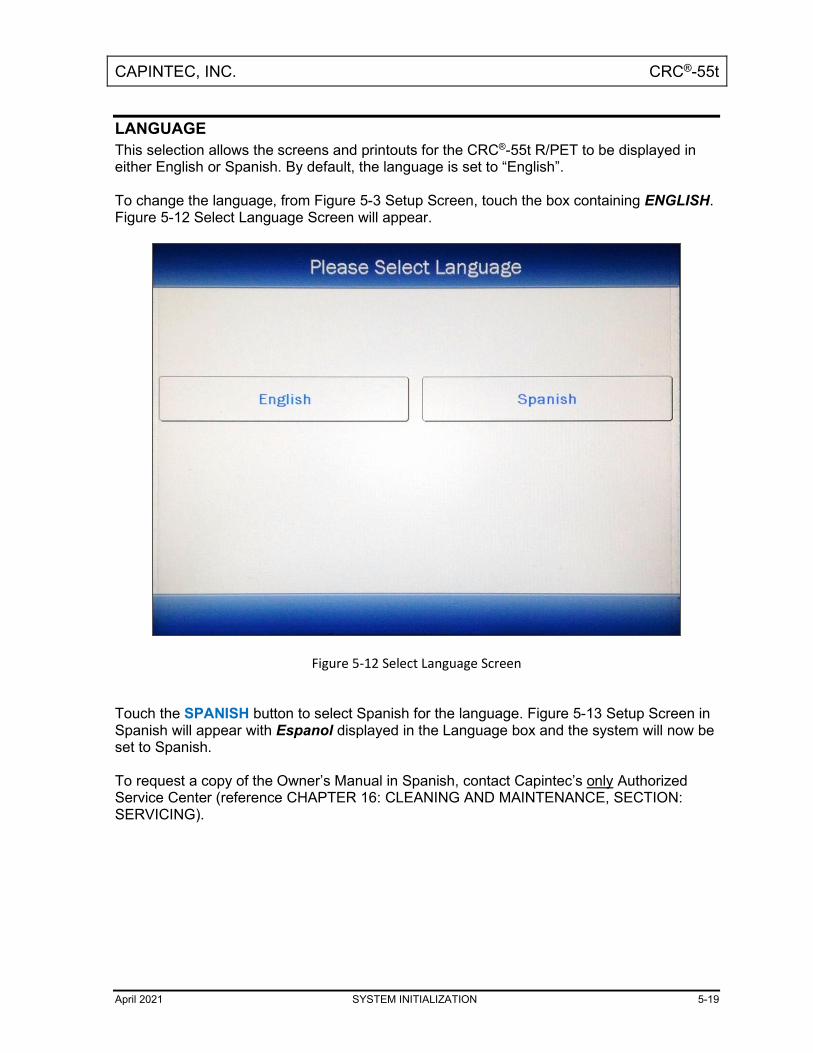
CAPINTEC, INC. CRC®-55t
April 2021 SYSTEM INITIALIZATION 5-19
LANGUAGE This selection allows the screens and printouts for the CRC®-55t R/PET to be displayed in either English or Spanish. By default, the language is set to “English”. To change the language, from Figure 5-3 Setup Screen, touch the box containing ENGLISH. Figure 5-12 Select Language Screen will appear.
Figure 5-12 Select Language Screen
Touch the SPANISH button to select Spanish for the language. Figure 5-13 Setup Screen in Spanish will appear with Espanol displayed in the Language box and the system will now be set to Spanish. To request a copy of the Owner’s Manual in Spanish, contact Capintec’s only Authorized Service Center (reference CHAPTER 16: CLEANING AND MAINTENANCE, SECTION: SERVICING).
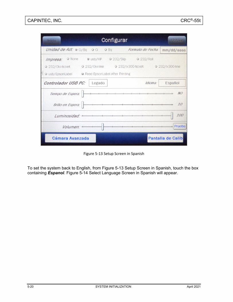
CAPINTEC, INC. CRC®-55t
5-20 SYSTEM INITIALIZATION April 2021
Figure 5-13 Setup Screen in Spanish
To set the system back to English, from Figure 5-13 Setup Screen in Spanish, touch the box containing Espanol. Figure 5-14 Select Language Screen in Spanish will appear.

CAPINTEC, INC. CRC®-55t
April 2021 SYSTEM INITIALIZATION 5-21
Figure 5-14 Select Language Screen in Spanish
Touch the INGLES button to select English for the language. Figure 5-3 Setup Screen will appear with English displayed in the Language box and the system will now be set to English.
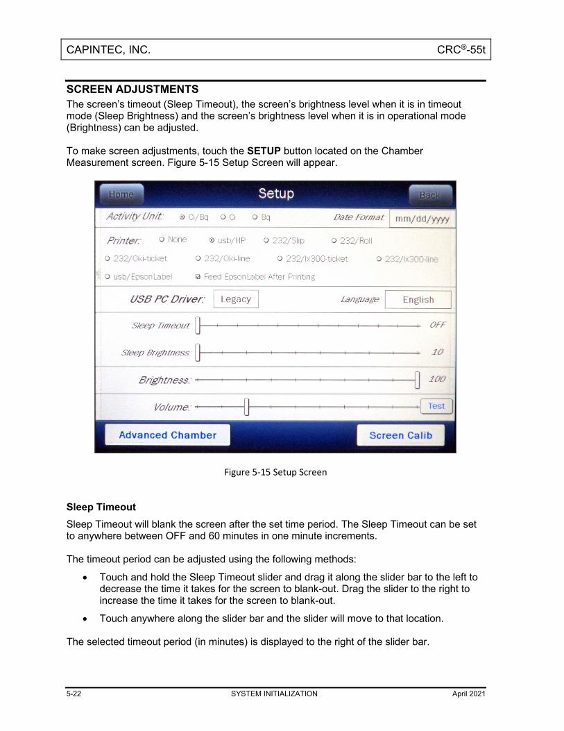
CAPINTEC, INC. CRC®-55t
5-22 SYSTEM INITIALIZATION April 2021
SCREEN ADJUSTMENTS The screen’s timeout (Sleep Timeout), the screen’s brightness level when it is in timeout mode (Sleep Brightness) and the screen’s brightness level when it is in operational mode (Brightness) can be adjusted. To make screen adjustments, touch the SETUP button located on the Chamber Measurement screen. Figure 5-15 Setup Screen will appear.
Figure 5-15 Setup Screen
Sleep Timeout Sleep Timeout will blank the screen after the set time period. The Sleep Timeout can be set to anywhere between OFF and 60 minutes in one minute increments. The timeout period can be adjusted using the following methods:
• Touch and hold the Sleep Timeout slider and drag it along the slider bar to the left to decrease the time it takes for the screen to blank-out. Drag the slider to the right to increase the time it takes for the screen to blank-out.
• Touch anywhere along the slider bar and the slider will move to that location. The selected timeout period (in minutes) is displayed to the right of the slider bar.

CAPINTEC, INC. CRC®-55t
April 2021 SYSTEM INITIALIZATION 5-23
When done making screen adjustments, press the HOME or BACK button to save the changes and return to the Chamber Measurement screen. Sleep Brightness Sleep Brightness adjusts the brightness (intensity) of the screen when the screen is in Sleep Timeout mode. The Sleep Brightness level can be set to anywhere between 10 and 100 in increments of 1. The level can be adjusted using the following methods:
• Touch and hold the Sleep Brightness slider and drag it along the slider bar to the left to decrease the brightness level. Drag the slider to the right to increase the brightness level.
• Touch anywhere along the slider bar and the slider will move to that location. The selected Sleep Brightness level is displayed to the right of the slider bar. When done making screen adjustments, press the HOME or BACK button to save the changes and return to the Chamber Measurement screen. Brightness The Screen Brightness (intensity) adjusts the brightness (intensity) of the screen when in operational mode. The Brightness can be changed to conform to lighting conditions and can be set to anywhere between 10 and 100 in increments of 1. The intensity can be adjusted using the following methods:
• Touch and hold the Brightness slider and drag it along the slider bar to the left to decrease the brightness level. Drag the slider to the right to increase the brightness level.
• Touch anywhere along the slider bar and the slider will move to that location. The selected Screen Brightness level is displayed to the right of the slider bar. When done making screen adjustments, press the HOME or BACK button to save the changes and return to the Chamber Measurement screen.

CAPINTEC, INC. CRC®-55t
5-24 SYSTEM INITIALIZATION April 2021
Screen Calibration The touch screen was calibrated at the factory. However, over time, the calibration of the touch screen may drift slightly. In order to use the touch screen correctly, it needs to be calibrated properly. Without the right calibration, the touches will be off center and may inadvertently select the wrong button. The CRC®-55t has a built-in touch screen calibration utility. To perform a screen calibration, touch the SCREEN CALIB button. Figure 5-16 Touchscreen Calibration Screen will appear displaying a target in the upper left corner. Touch the center of the target. After the target is touched it will disappear and another target will appear in the lower right corner of the screen. Touch the center of this target. After this target is touched it will disappear and another target will appear in the center of the screen. Touch the center of this target. After the target is touched, Figure 5-15 Setup Screen will re-appear. The touch screen calibration procedure is complete.
Figure 5-16 Touchscreen Calibration Screen

CAPINTEC, INC. CRC®-55t
April 2021 SYSTEM INITIALIZATION 5-25
SPEAKER VOLUME The volume of the system speaker can be varied. The TEST button located to the right of the Volume slider bar provides a continuous audible tone at the set volume level so that the volume of the speaker can be heard while adjusting the slider. Touch the TEST button to hear the tone. Touch the TEST button again to turn off the tone. The speaker volume can be adjusted using the following methods:
• Touch and hold the Volume slider and drag it along the slider bar to the left to decrease the volume level. Drag the slider to the right to increase the volume level.
• Touch anywhere along the slider bar and the slider will move to that location. When done making volume adjustments press the HOME or BACK button to save the changes and return to the Chamber Measurement screen.

CAPINTEC, INC. CRC®-55t
April 2021 CHAMBER INITIALIZATION 6-1
CHAPTER 6
CHAMBER INITIALIZATION
GENERAL ............................................................................................................ 6-1 CHAMBER HOTKEY ASSIGNMENT ................................................................... 6-2
Home Screen Hotkeys ..................................................................................... 6-2 Select Nuclide Screen Hotkeys ...................................................................... 6-8
TEST SOURCE SETUP ....................................................................................... 6-9 Adding a Source ............................................................................................. 6-13 Editing Source Data ....................................................................................... 6-17 Deleting a Source ........................................................................................... 6-17 Constancy Test Source .................................................................................. 6-18 Constancy Channels ...................................................................................... 6-18
MOLY ASSAY SETUP ........................................................................................ 6-20 Selecting Moly Assay Method ....................................................................... 6-22 Moly Assay Limit ............................................................................................ 6-22 Streamlined Test ............................................................................................ 6-23
NUCLIDES .......................................................................................................... 6-23 Adding a Nuclide ............................................................................................ 6-23 Deleting a Nuclide .......................................................................................... 6-27
CALIBRATION NUMBERS ................................................................................. 6-28 Restoring Original Calibration Numbers ...................................................... 6-29
LINEARITY TEST DEFINITION ........................................................................... 6-31 Standard Linearity Test .................................................................................. 6-35 Lineator Test ................................................................................................... 6-38 Calicheck Test ................................................................................................ 6-43
PASSWORD........................................................................................................ 6-48 Change the Password .................................................................................... 6-52
REMOTE DISPLAY NUCLIDE ASSIGNMENT (LEGACY PRODUCTS ONLY) .. 6-53 Adding or Changing Nuclides ....................................................................... 6-57 Deleting Nuclides ........................................................................................... 6-59
GENERAL This section describes initialization and parameter setup for the Chamber(s). All of these functions are accessed via the Chamber Measurement screen.

CAPINTEC, INC. CRC®-55t
6-2 CHAMBER INITIALIZATION April 2021
Figure 6-1 Chamber Measurement Screen
CHAMBER HOTKEY ASSIGNMENT Hotkeys are nuclide shortcut keys that are preconfigured from the factory but are user definable. There are two separate Hotkey sets:
• Home screen ........................ These are the eight isotope buttons located at the left edge of Figure 6-1 Chamber Measurement Screen. Touching one of these buttons selects the programmed nuclide for measurement.
• Select Nuclide screen ........... These are the 20 buttons on the left half of Figure 6-7 Select Nuclide Screen. Touching one of these buttons selects the programmed nuclide.
Home Screen Hotkeys The Home Screen Hotkeys on Figure 6-1 Chamber Measurement Screen are populated by default with the following nuclides:
• For R Chambers: ....... F18, Ga67, In111, Tc99m, I123, I131, Xe133, and TI201
• For PET Chambers: ... F18, C11, N13, O15, Tc99m, Cs137, Co60 and I131
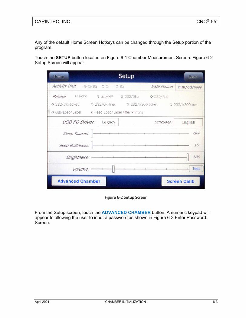
CAPINTEC, INC. CRC®-55t
April 2021 CHAMBER INITIALIZATION 6-3
Any of the default Home Screen Hotkeys can be changed through the Setup portion of the program. Touch the SETUP button located on Figure 6-1 Chamber Measurement Screen. Figure 6-2 Setup Screen will appear.
Figure 6-2 Setup Screen
From the Setup screen, touch the ADVANCED CHAMBER button. A numeric keypad will appear to allowing the user to input a password as shown in Figure 6-3 Enter Password: Screen.

CAPINTEC, INC. CRC®-55t
6-4 CHAMBER INITIALIZATION April 2021
Figure 6-3 Enter Password: Screen
The default password is the last 3 digits of Readout serial number. Enter the password by touching the appropriate numbers on the keypad. For security, the password will be displayed as a string of *. Touch the ACCEPT button to accept the password. Figure 6-4 Advanced Chamber Setup Screen will appear.

CAPINTEC, INC. CRC®-55t
April 2021 CHAMBER INITIALIZATION 6-5
Figure 6-4 Advanced Chamber Setup Screen
To change the Hotkeys for a CRC®-55tR System, touch the SETUP R CHAMBER HOTKEYS button. Figure 6-5 Setup R Chamber Hotkeys Screen will appear. To change the Hotkeys for a CRC®-55tPET System, touch the SETUP PET CHAMBER HOTKEYS button. Figure 6-6 Setup PET Chamber Hotkeys Screen will appear. All examples given will be for an R Chamber.

CAPINTEC, INC. CRC®-55t
6-6 CHAMBER INITIALIZATION April 2021
Figure 6-5 Setup R Chamber Hotkeys Screen
Figure 6-6 Setup PET Chamber Hotkeys Screen

CAPINTEC, INC. CRC®-55t
April 2021 CHAMBER INITIALIZATION 6-7
The left side of the screen displays a list of isotopes titled “Home Screen”. These are the eight Chamber Hotkeys that are displayed on the left side of Figure 6-1 Chamber Measurement Screen. The isotopes shown under the title “Nuclide Screen” are the 20 preset NUCLIDE buttons that are displayed on Figure 6-7 Select Nuclide Screen. To change the assignment of a Home Screen Hotkey, touch the desired isotope field box in the Home Screen column. Figure 6-7 Select Nuclide Screen will appear.
Figure 6-7 Select Nuclide Screen
The left half of the Select Nuclide screen contains 20 preset NUCLIDE buttons (these are the Select Nuclide Screen Hotkeys). The right half of the screen displays a listing of nuclides stored in the calibrator’s memory (both default and user added nuclides) that have a Calibration Number assigned to them (Refer to the CALIBRATION NUMBERS section on page 6-28) – 10 at a time. The nuclide list is in alphabetical order. User added nuclides are displayed at the top of the list. The length of the list will vary depending on which nuclides have a Calibration Number assigned to them (Refer to the CALIBRATION NUMBERS section on page 6-28). The number of pages shown in the upper right corner of the screen indicates the length of the list. To scroll through the list, touch the DOWN ARROW (▼) button. The next group of 10 nuclides will be displayed and the UP ARROW (▲) button will appear allowing the user to scroll up in the list.
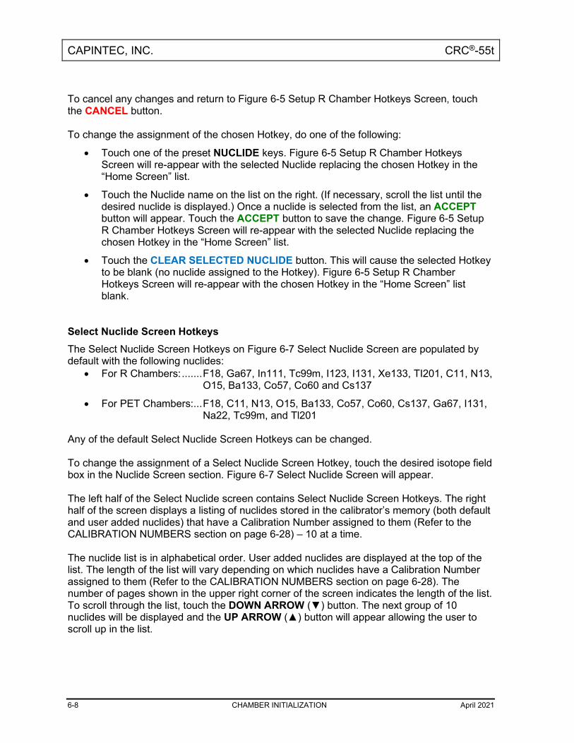
CAPINTEC, INC. CRC®-55t
6-8 CHAMBER INITIALIZATION April 2021
To cancel any changes and return to Figure 6-5 Setup R Chamber Hotkeys Screen, touch the CANCEL button. To change the assignment of the chosen Hotkey, do one of the following:
• Touch one of the preset NUCLIDE keys. Figure 6-5 Setup R Chamber Hotkeys Screen will re-appear with the selected Nuclide replacing the chosen Hotkey in the “Home Screen” list.
• Touch the Nuclide name on the list on the right. (If necessary, scroll the list until the desired nuclide is displayed.) Once a nuclide is selected from the list, an ACCEPT button will appear. Touch the ACCEPT button to save the change. Figure 6-5 Setup R Chamber Hotkeys Screen will re-appear with the selected Nuclide replacing the chosen Hotkey in the “Home Screen” list.
• Touch the CLEAR SELECTED NUCLIDE button. This will cause the selected Hotkey to be blank (no nuclide assigned to the Hotkey). Figure 6-5 Setup R Chamber Hotkeys Screen will re-appear with the chosen Hotkey in the “Home Screen” list blank.
Select Nuclide Screen Hotkeys The Select Nuclide Screen Hotkeys on Figure 6-7 Select Nuclide Screen are populated by default with the following nuclides:
• For R Chambers: ....... F18, Ga67, In111, Tc99m, I123, I131, Xe133, TI201, C11, N13, O15, Ba133, Co57, Co60 and Cs137
• For PET Chambers: ... F18, C11, N13, O15, Ba133, Co57, Co60, Cs137, Ga67, I131, Na22, Tc99m, and Tl201
Any of the default Select Nuclide Screen Hotkeys can be changed. To change the assignment of a Select Nuclide Screen Hotkey, touch the desired isotope field box in the Nuclide Screen section. Figure 6-7 Select Nuclide Screen will appear. The left half of the Select Nuclide screen contains Select Nuclide Screen Hotkeys. The right half of the screen displays a listing of nuclides stored in the calibrator’s memory (both default and user added nuclides) that have a Calibration Number assigned to them (Refer to the CALIBRATION NUMBERS section on page 6-28) – 10 at a time. The nuclide list is in alphabetical order. User added nuclides are displayed at the top of the list. The length of the list will vary depending on which nuclides have a Calibration Number assigned to them (Refer to the CALIBRATION NUMBERS section on page 6-28). The number of pages shown in the upper right corner of the screen indicates the length of the list. To scroll through the list, touch the DOWN ARROW (▼) button. The next group of 10 nuclides will be displayed and the UP ARROW (▲) button will appear allowing the user to scroll up in the list.

CAPINTEC, INC. CRC®-55t
April 2021 CHAMBER INITIALIZATION 6-9
To cancel any changes and return to Figure 6-5 Setup R Chamber Hotkeys Screen, touch the CANCEL button. To change the assignment of the chosen Hotkey, do one of the following:
• Touch one of the preset NUCLIDE keys. Figure 6-5 Setup R Chamber Hotkeys Screen will re-appear with the selected Nuclide replacing the chosen Hotkey in the “Nuclide Screen” list.
• Touch the Nuclide name on the list on the right. (If necessary, scroll the list until the desired nuclide is displayed.) Once a nuclide is selected from the list, an ACCEPT button will appear. Touch the ACCEPT button to save the change. Figure 6-5 Setup R Chamber Hotkeys Screen will re-appear with the selected Nuclide replacing the chosen Hotkey in the “Nuclide Screen” list.
• Touch the CLEAR SELECTED NUCLIDE button. This will cause the selected Hotkey to be blank (no nuclide assigned to the Hotkey). Figure 6-5 Setup R Chamber Hotkeys Screen will re-appear with the chosen Chamber Hotkey in the “Nuclide Screen” list blank.
TEST SOURCE SETUP Test Sources (Standard Sources) are used for the Chamber Accuracy and Constancy Tests. The Chamber Accuracy and Constancy may be tested using Co57, Co60, Ba133, Cs137 or Na22. There can be a Test Source for each of these nuclides. One or more of the Test Sources can be designated as the source(s) to be used in the Accuracy part of the Daily Test. One of the sources designated as a Daily source can be chosen as the base source to be used for the Constancy Test. To input Test Source data, touch the SETUP button located on the Chamber Measurement screen. Figure 6-8 Setup Screen will appear.

CAPINTEC, INC. CRC®-55t
6-10 CHAMBER INITIALIZATION April 2021
Figure 6-8 Setup Screen
Touch the ADVANCED CHAMBER button. A numeric keypad will appear to allowing the user to input a password as shown in Figure 6-9 Enter Password: Screen.

CAPINTEC, INC. CRC®-55t
April 2021 CHAMBER INITIALIZATION 6-11
Figure 6-9 Enter Password: Screen
The default password is the last 3 digits of Readout serial number. Enter the password by touching the appropriate numbers on the keypad. For security, the password will be displayed as a string of *. Touch the ACCEPT button to accept the password. Figure 6-10 Advanced Chamber Setup Screen will appear.

CAPINTEC, INC. CRC®-55t
6-12 CHAMBER INITIALIZATION April 2021
Figure 6-10 Advanced Chamber Setup Screen
Touch the SETUP SOURCES button. Figure 6-11 Setup Sources Screen will appear.

CAPINTEC, INC. CRC®-55t
April 2021 CHAMBER INITIALIZATION 6-13
Figure 6-11 Setup Sources Screen
The Setup Sources screen allows data to be input for each Test Source and to choose which Test Source(s) will be used for the Accuracy part of the Daily Test and which source will be used as the base source for the Constancy Test. The Constancy Channels section allows nuclides to be selected for use in the Constancy Test. Adding a Source Note: All fields (S/N:, Activity:, Date:) for the selected source must be completed before
exiting the Setup Sources screen or the entered information for that source will not be saved.
To input information for the desired Test Source, touch the field’s box and input the appropriate data for that source.
Serial Number (S/N) Field For the Test Source Serial Number (S/N) data, Figure 6-12 Enter Serial Number Screen will appear.

CAPINTEC, INC. CRC®-55t
6-14 CHAMBER INITIALIZATION April 2021
Figure 6-12 Enter Serial Number Screen
Input the serial number data of the Test Source and touch the ACCEPT button. The Setup Sources screen will re-appear with S/N field box populated with the entered serial number. The serial number can contain up to 10 characters To cancel any changes and return to Figure 6-11 Setup Sources Screen, touch the CANCEL button.
Activity Field For the Test Source Activity data, Figure 6-13 Enter Activity Screen will appear.

CAPINTEC, INC. CRC®-55t
April 2021 CHAMBER INITIALIZATION 6-15
Figure 6-13 Enter Activity Screen
The Calibration activity must be less than 1 Curie. The current activity (calibration activity decayed to the present time) must be greater than the activity in the table below. Note: Capintec strongly recommends replacing the Test Source when the activity
decays below the recommended “Minimum at Current Time” limits
Minimum at Current Time Maximum Source Ci Bq Ci Bq Co57 50.0 µCi 1.85 MBq 1.0 Ci 37000 MBq
Co60 50.0 µCi 1.85 MBq 1.0 Ci 37000 MBq
Ba133 50.0 µCi 1.85 MBq 1.0 Ci 37000 MBq
Cs137 50.0 µCi 1.85 MBq 1.0 Ci 37000 MBq
Na22 50.0 µCi 1.85 MBq 1.0 Ci 37000 MBq
Table 6-1 Test Source Calibration Activity Limits

CAPINTEC, INC. CRC®-55t
6-16 CHAMBER INITIALIZATION April 2021
Input the activity value using the keypad and touch the appropriate radio button for the unit of measure of the Test Source. Note: The available units will change depending on which unit of measurement is in
use on the Chamber Measurement screen. i.e. if set for Curies, the available units will be Ci, mCi and µCi; if set for Becquerels, the available units will be GBq and MBq.
Touch the ACCEPT button. The Setup Sources screen will re-appear with Activity field box populated with the entered activity. To cancel any changes and return to Figure 6-11 Setup Sources Screen, touch the CANCEL button.
Date Field For the Test Source calibration Date, Figure 6-14 Date/Time Screen will appear.
Figure 6-14 Date/Time Screen
The screen displays the currently set date and time. Above and below each of the fields are + and – buttons, respectively. To adjust the displayed value for a specific field, touch the + button to increase the displayed value or the – button to decrease the displayed value.

CAPINTEC, INC. CRC®-55t
April 2021 CHAMBER INITIALIZATION 6-17
For the year, +10 and -10 buttons are provided to quickly change the tens column of the years. Adjust the displayed date and time to show the calibration date/time of the Test Source. Touch the ACCEPT button to accept the set calibration date and time. The Setup Sources screen will re-appear with Date field box populated with the entered calibration date. To cancel any changes and return to Figure 6-11 Setup Sources Screen, touch the CANCEL button.
Daily Field By default, the Daily checkbox is checked (refer to Figure 6-11 Setup Sources Screen). At least one source must be designated as a Daily Test source for the Accuracy Test. If the selected source is not going to be used as a Daily Test source, touch the checkbox next to the selected source to remove the check from the checkbox.
Editing Source Data Any data for any source can be edited simply by touching the desired field box and inputting the new data as described in the Adding a Source section above beginning on page 6-13. Deleting a Source Test Sources are removed in one of two ways: by touching the CLEAR button to the right of the Test Source to be deleted or by erasing the data from either the S/N field box or the Activity field box for the desired source. To erase a selected source by erasing the data from either the S/N field box or the Activity field box,
1. Touch either the S/N or the Activity field box of the particular source. 2. When the data entry screen appears, verify that the data entry box contains no data. 3. Touch the ACCEPT button. 4. The Setup Sources screen will re-appear with the selected field box blank. 5. Touch the ACCEPT button in the lower part of the Setup Sources screen. Figure 6-10
Advanced Chamber Setup Screen will appear. 6. Touch the SETUP SOURCES button. Figure 6-11 Setup Sources Screen will re-
appear with the particular source’s information blank. The selected Test Source is now erased from the system.

CAPINTEC, INC. CRC®-55t
6-18 CHAMBER INITIALIZATION April 2021
Constancy Test Source The Constancy may be tested using Co57, Co60, Ba133, Cs137 or Na22. There can be a Test Source for each of these nuclides. One or more of the Test Sources can be designated as the source(s) to be used in the Accuracy part of the Daily Test. One of the sources designated as a Daily source must be chosen as the base source to be used for the Constancy Test.
Figure 6-15 Setup Sources Screen
To select the Daily source to use as the base Constancy source, touch the associated radio button in the Const column. In the example above, Cs137 is set as the Constancy base source. Constancy Channels The Constancy Channels are the nuclides that will be tested during the automated Constancy Test during the Accuracy Test. Up to 12 nuclides may be selected. When the Accuracy Test for the base Constancy source is complete, an AUTOCONSTANCY button will appear next to the results of the base source. The automated Constancy Test is then performed by touching the AUTOCONSTANCY button. The test will automatically run and will display the results at the completion of the test.

CAPINTEC, INC. CRC®-55t
April 2021 CHAMBER INITIALIZATION 6-19
Adding Nuclides
To select nuclides for use in the Constancy Test, touch the desired Constancy Channels field box. Figure 6-16 Select Nuclide Screen will appear.
Figure 6-16 Select Nuclide Screen
The left half of the Select Nuclide screen contains the 20 preset NUCLIDE buttons (these are the Select Nuclide Screen Hotkeys). The right half of the screen displays a listing of nuclides stored in the calibrator’s memory (both default and user added nuclides) that have a Calibration Number assigned to them (Refer to the CALIBRATION NUMBERS section on page 6-28) – 10 at a time. The nuclide list is in alphabetical order. User added nuclides are displayed at the top of the list. The length of the list will vary depending on which nuclides have a Calibration Number assigned to them (Refer to the CALIBRATION NUMBERS section on page 6-28). The number of pages shown in the upper right corner of the screen indicates the length of the list. To scroll through the list, touch the DOWN ARROW (▼) button. The next group of 10 nuclides will be displayed and the UP ARROW (▲) button will appear allowing the user to scroll up in the list. To cancel any changes and return to Figure 6-15 Setup Sources Screen, touch the CANCEL button.

CAPINTEC, INC. CRC®-55t
6-20 CHAMBER INITIALIZATION April 2021
To assign a nuclide for use as a Constancy Channel, do one of the following:
• Touch one of the preset NUCLIDE keys (Select Nuclide Screen Hotkeys). Figure 6-15 Setup Sources Screen will re-appear with the selected nuclide shown in the chosen Constancy Channel field box.
• Touch the Nuclide name on the list on the right. (If necessary, scroll the list until the desired nuclide is displayed.) Once a nuclide is selected from the list, an ACCEPT button will appear. Touch the ACCEPT button to save the selected nuclide. Figure 6-15 Setup Sources Screen will re-appear with the selected nuclide shown in the chosen Constancy Channel field box.
Removing Nuclides To remove a nuclide from the Constancy Channels, touch the desired Constancy Channels field box to delete from the Constancy Channels. Figure 6-16 Select Nuclide Screen will appear. Touch the CLEAR SELECTED NUCLIDE button. Figure 6-15 Setup Sources Screen will re-appear. The selected Constancy Channels field box will now be blank.
MOLY ASSAY SETUP Note: Moly Assay can only be performed using an R Chamber. Moly Assay can be performed using a CAPMAC or CANISTER. When the Moly Assay button is touched from the Chamber Measurement screen, Figure 6-17 Moly Assay Method Selection Screen will appear. However, if only one method is always used (either a CAPMAC or a CANISTER), the Moly Assay Method Selection screen can be omitted by selecting either CAPMAC or CANISTER from the Moly Setup.

CAPINTEC, INC. CRC®-55t
April 2021 CHAMBER INITIALIZATION 6-21
Figure 6-17 Moly Assay Method Selection Screen
Moly Setup can be accessed in two ways:
1. From Figure 6-1 Chamber Measurement Screen, touch the MOLY ASSAY button. Figure 6-17 Moly Assay Method Selection Screen will appear. Touch the SETUP button. A numeric keypad will appear to allowing the user to input a password as shown in Figure 6-9 Enter Password: Screen. The default password is the last 3 digits of Readout serial number. Enter the password by touching the appropriate numbers on the keypad. For security, the password will be displayed as a string of *. Touch the ACCEPT button to accept the password. Figure 6-18 Setup Moly Screen will appear.
2. From Figure 6-1 Chamber Measurement Screen, touch the SETUP button. Figure 6-8
Setup Screen will appear. Touch the ADVANCED CHAMBER button. A numeric keypad will appear to allowing the user to input a password as shown in Figure 6-9 Enter Password: Screen. The default password is the last 3 digits of Readout serial number. Enter the password by touching the appropriate numbers on the keypad. For security, the password will be displayed as a string of *. Touch the ACCEPT button to accept the password. Figure 6-10 Advanced Chamber Setup Screen will appear. From the Advanced Chamber Setup Screen, touch the SETUP MOLY button. Figure 6-18 Setup Moly Screen will appear.

CAPINTEC, INC. CRC®-55t
6-22 CHAMBER INITIALIZATION April 2021
Figure 6-18 Setup Moly Screen
Selecting Moly Assay Method In the Moly Method: section, the current selections are displayed (default is all are selected). Select the desired method(s) by touching the appropriate checkbox. Each touch will toggle the check between on or off. Moly Assay Limit The Moly Assay default limit is set to 0.150 µCi/mCi (or 0.150 MBq/GBq). This value can be changed. Note: The minimum value that can be input is 0.001 µCi/mCi (0.001 MBq/GBq). The
maximum value that can be input is 9.99 µCi/mCi (9.99 MBq/GBq). Touch the Mo/Tc Limit: field box. A numeric keypad will appear allowing for the entry of a new value. Input the new Mo/Tc value using the keypad and touch the ACCEPT button. The Setup Moly screen will re-appear with Mo/Tc Limit: field box populated with the entered value. To cancel changing the Mo/Tc Limit, touch the CANCEL button on the numeric keypad.

CAPINTEC, INC. CRC®-55t
April 2021 CHAMBER INITIALIZATION 6-23
Streamlined Test The Moly Assay consists of three measurements, 1) Background, 2) Moly Measurement, and 3) Tc99m Measurement. Enabling the “Streamlined Test” checkbox allows the calibrator to start the Moly Measurement immediately after the Background Measurement. Also it allows the calibrator to start the Tc99m Measurement after the Moly Measurement. When the “Streamlined Test” checkbox is disabled, a “Start Measurement” button is displayed before the Moly and Tc99m Measurements. The respective measurements are not started until the “Start Measurement” is clicked.
NUCLIDES Adding a Nuclide The CRC®-55t contains nuclide data (name, half-life, calibration number) for over 80 nuclides. Up to 10 nuclides can be added to the system. To add a nuclide, touch the SETUP button located on the Chamber Measurement screen. Figure 6-8 Setup Screen will appear. Touch the ADVANCED CHAMBER button. A numeric keypad will appear to allowing the user to input a password as shown in Figure 6-9 Enter Password: Screen. The default password is the last 3 digits of Readout serial number. Enter the password by touching the appropriate numbers on the keypad. For security, the password will be displayed as a string of *. Touch the ACCEPT button to accept the password. Figure 6-10 Advanced Chamber Setup Screen will appear. Touch the SETUP NUCLIDE button. Figure 6-19 Setup Nuclide Screen will appear.

CAPINTEC, INC. CRC®-55t
6-24 CHAMBER INITIALIZATION April 2021
Figure 6-19 Setup Nuclide Screen
The following parameters are input for each of the added nuclides: Nuclide, Element, Half-life, Cal#(R) and/or Cal#(P). Each of these parameters is described in the sections below. To input information for the desired nuclide, touch the desired field box and input the appropriate data for the nuclide. All field boxes (Nuclide, Element, Half-life and at least one Cal# - R or P) for the nuclide being added must be completed before touching the ACCEPT button to exit the Setup Nuclide screen or the message “Setup Nuclide Error Please complete partial Nuclide entry. Row(s): X” will appear. Touch the OK button to dismiss the message and input the missing Nuclide information. After all necessary Nuclide information is input for all added nuclides, touch the ACCEPT button on Figure 6-19 Setup Nuclide Screen. The added nuclide(s) is/are now saved in the system. To cancel adding Nuclides, touch the CANCEL button.

CAPINTEC, INC. CRC®-55t
April 2021 CHAMBER INITIALIZATION 6-25
Nuclide Field This field is the nuclide designation (i.e. Tc99m, Cs137) and consists of up to 6 alphanumeric characters. For the Nuclide data, the alphanumeric keyboard will appear. Input the data and touch the ACCEPT button. To cancel any changes and return to Figure 6-19 Setup Nuclide Screen, touch the CANCEL button.
Element Field This field is the nuclide element name (i.e. Technetium, Cesium) and consists of up to 14 alphanumeric characters. For the Element data, the alphanumeric keyboard will appear. Input the data and touch the ACCEPT button. To cancel any changes and return to Figure 6-19 Setup Nuclide Screen, touch the CANCEL button.
Half-life Field This field is the half-life of the nuclide (i.e. 6.01 hr, 30.00 yr) and consists of up to 6 characters (5 digits and a decimal). For the Half-life data, the numeric keypad will appear. Input the value using the keypad and touch the appropriate radio button for the time unit of the nuclide. The available time units for half-life are: Yr (year), Hr (hour), Day, Min (minute) and Sec (second). Touch the ACCEPT button when the value and time unit are correctly set. To cancel any changes and return to Figure 6-19 Setup Nuclide Screen, touch the CANCEL button.
Cal#(R)/Cal#(P) Fields These fields are the Calibration Number for the nuclide for R Chambers (i.e. 080, 220), Cal#(R), and/or PET Chambers (i.e. 090, 243), Cal#(P). At least one these fields must contain a Calibration Number. For the Calibration Number data, the numeric keypad will appear as shown in Figure 6-20 Enter Cal# Screen.
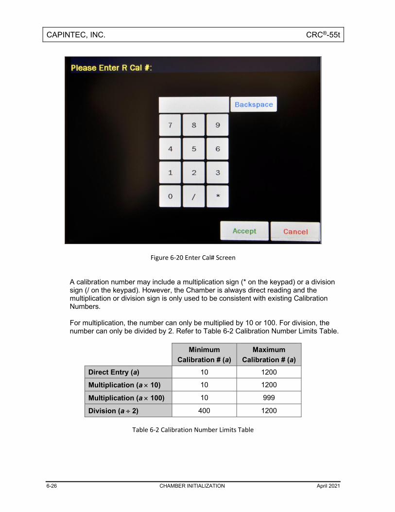
CAPINTEC, INC. CRC®-55t
6-26 CHAMBER INITIALIZATION April 2021
Figure 6-20 Enter Cal# Screen
A calibration number may include a multiplication sign (* on the keypad) or a division sign (/ on the keypad). However, the Chamber is always direct reading and the multiplication or division sign is only used to be consistent with existing Calibration Numbers. For multiplication, the number can only be multiplied by 10 or 100. For division, the number can only be divided by 2. Refer to Table 6-2 Calibration Number Limits Table.
Minimum
Calibration # (a) Maximum
Calibration # (a) Direct Entry (a) 10 1200
Multiplication (a × 10) 10 1200
Multiplication (a × 100) 10 999
Division (a ÷ 2) 400 1200
Table 6-2 Calibration Number Limits Table

CAPINTEC, INC. CRC®-55t
April 2021 CHAMBER INITIALIZATION 6-27
If the Calibration Number is known for the nuclide, input the number and touch the ACCEPT button. If the Calibration Number is not known, input 450 and the ACCEPT button. The Calibration Number can then be determined using the following procedure. To cancel any changes and return to Figure 6-19 Setup Nuclide Screen, touch the CANCEL button. Determining Calibration Numbers An initial Calibration Number (as an initial starting point, choose 450) must be input into the CRC®-55t for the nuclide. Note: In order to obtain a correct reading for a Vial or Syringe, the supplied liner and
dipper must be used to achieve the correct geometry. If the source is contained in a different type of container, then contact Capintec, Inc. for further assistance.
1. Place the standard source of the nuclide in the chamber and record the
displayed activity. 2. If the displayed activity is higher than the measured/calculated activity of the
standard source, increase the Calibration Number. If the displayed activity is lower than the measured/calculated activity of the standard source, decrease the Calibration Number.
3. Re-measure the activity of the standard source. 4. Continue to increase or decrease the Calibration Number (e.g. repeat steps 2
and 3) until the displayed activity matches the measured/calculated activity of the standard source.
5. Record the Calibration Number of the nuclide for future reference. 6. Input the Calibration Number following the instructions in section
CALIBRATION NUMBERS on page 6-28.
Deleting a Nuclide Any nuclide added by the user may be deleted. Nuclides are removed by touching the CLEAR button to the right of the Nuclide to be deleted. Touch the ACCEPT button on Figure 6-19 Setup Nuclide Screen. The selected nuclide is now erased from the system.

CAPINTEC, INC. CRC®-55t
6-28 CHAMBER INITIALIZATION April 2021
CALIBRATION NUMBERS Calibration Numbers may be added or changed for up to 40 nuclides. To add a calibration number to a nuclide that does not have a calibration number, change an existing calibration number or restore the original calibration number, touch the SETUP button located on the Chamber Measurement screen. Figure 6-8 Setup Screen will appear. Touch the ADVANCED CHAMBER button. A numeric keypad will appear to allowing the user to input a password as shown in Figure 6-9 Enter Password: Screen. The default password is the last 3 digits of Readout serial number. Enter the password by touching the appropriate numbers on the keypad. For security, the password will be displayed as a string of *. Touch the ACCEPT button to accept the password. Figure 6-10 Advanced Chamber Setup Screen will appear. Touch the SETUP CALNUM button. Figure 6-21 Setup CalNum Screen will appear.
Figure 6-21 Setup CalNum Screen
Select a nuclide by touching the Nuclide: field box. Figure 6-16 Select Nuclide Screen will appear. The left half of the Select Nuclide screen contains the 20 programmable NUCLIDE Hotkeys. To use one these nuclides, touch the desired key. Figure 6-21 Setup CalNum Screen will re-

CAPINTEC, INC. CRC®-55t
April 2021 CHAMBER INITIALIZATION 6-29
appear with the chosen nuclide displayed in the Nuclide: field box along with the Default Calibration Numbers for both R and PET Chambers. The right half of the screen displays a listing of nuclides stored in the calibrator’s memory – 10 at a time. The nuclide list is in alphabetical order. The number of pages shown in the upper right corner of the screen indicates the length of the list. To scroll through the list, touch the DOWN ARROW (▼) button. The next group of 10 nuclides will be displayed and the UP ARROW (▲) button will appear to allow scrolling up in the list. To select a nuclide in the list, touch the desired nuclide and the entire line for the selected nuclide will become highlighted and an ACCEPT button will appear. Touch the ACCEPT button to select the highlighted nuclide. Figure 6-21 Setup CalNum Screen will re-appear with the chosen nuclide displayed in the Nuclide: field along with the Default Calibration Numbers for both R and PET Chambers. To abort selecting a nuclide and return to Figure 6-21 Setup CalNum Screen, touch the CANCEL button. To input a new calibration number, touch the desired Cal#: field box (User R Cal#: or User P Cal#:). The numeric keypad will appear. Input the new calibration number by touching the appropriate numbers on the keypad. Touch the ACCEPT button to accept the Cal#. Touch the CANCEL button to abort any changes. A calibration number may include a multiplication sign (* on the keypad) or a division sign (/ on the keypad). However, the Chamber is always direct reading and the multiplication or division sign is only used to be consistent with existing Calibration Numbers. For multiplication, the number can only be multiplied by 10 or 100. For division, the number can only be divided by 2. Refer to Table 6-2 Calibration Number Limits Table on page 6-26. If the Calibration Number change is accepted, in the Nuclide database list, the Nuclide will now appear with an * (asterisk) in front of the nuclide name indicating that the Cal # has been changed from the default value. Restoring Original Calibration Numbers To restore the default calibration number for a nuclide that had its number changed, touch the Nuclide: field box. From the Select Nuclide screen, choose the desired nuclide by touching one of the preset nuclide buttons or selecting the nuclide from the list. When the Setup CalNum screen re-appears, touch the desired Cal#: field box (User R Cal#: or User P Cal#:). The numeric keypad will appear. Verify that the data entry box is blank and touch the ACCEPT button. The Setup CalNum screen will re-appear with the selected Cal#: field box (User R Cal#: or User P Cal#:) blank. The selected nuclide will now use the original (default) calibration number(s).

CAPINTEC, INC. CRC®-55t
6-30 CHAMBER INITIALIZATION April 2021
To exit the Setup CalNum screen, touch the BACK button at the top of the screen and Figure 6-10 Advanced Chamber Setup Screen will appear or touch the HOME button at the top of the screen and Figure 6-1 Chamber Measurement Screen will appear.

CAPINTEC, INC. CRC®-55t
April 2021 CHAMBER INITIALIZATION 6-31
LINEARITY TEST DEFINITION Four methods of performing Linearity Tests are available: AutoLinearity, Standard (Decay), Lineator and Calicheck. This section describes the setup of the Standard, Lineator and Calicheck tests. How to perform the Linearity Tests is described in CHAPTER 11: CHAMBER ENHANCED TESTS, SECTION: PERFORMING LINEARITY TEST. In order to perform a Linearity Test, at least one Linearity Test Method must be defined. All three test methods can be defined. If a Linearity Test Method is not defined, Figure 6-22 Linearity Test Message Screen will appear.
Figure 6-22 Linearity Test Message Screen
To define the Linearity Test Method, touch the SETUP button located on the Chamber Measurement screen. Figure 6-23 Setup Screen will appear.

CAPINTEC, INC. CRC®-55t
6-32 CHAMBER INITIALIZATION April 2021
Figure 6-23 Setup Screen
Touch the ADVANCED CHAMBER button. A numeric keypad will appear to allowing the user to input a password as shown in Figure 6-24 Enter Password: Screen.

CAPINTEC, INC. CRC®-55t
April 2021 CHAMBER INITIALIZATION 6-33
Figure 6-24 Enter Password: Screen
The default password is the last 3 digits of Readout serial number. Enter the password by touching the appropriate numbers on the keypad. For security, the password will be displayed as a string of *. Touch the ACCEPT button to accept the password. Figure 6-25 Advanced Chamber Setup Screen will appear.

CAPINTEC, INC. CRC®-55t
6-34 CHAMBER INITIALIZATION April 2021
Figure 6-25 Advanced Chamber Setup Screen
Touch the SETUP LINEARITY button. Figure 6-26 Setup Linearity Screen will appear.

CAPINTEC, INC. CRC®-55t
April 2021 CHAMBER INITIALIZATION 6-35
Figure 6-26 Setup Linearity Screen
Refer to the following sections for instructions for defining the desired Linearity Test. Standard Linearity Test
Defining a Standard Linearity Test For an R Chamber, the Standard Test is normally performed by tracking the decay of a strong Tc99m source. However, any nuclide can be selected. For a PET Chamber, the Standard Test is performed by tracking the decay of a user selected nuclide. Note: The selected nuclide must have a Calibration Number assigned to it.
(Reference CALIBRATION NUMBERS on page 6-28) If the desired nuclide does not have a Calibration Number, it will not be displayed in the Select Nuclide list.
The Standard Test measures the activity of the selected nuclide over a defined period of time. When the defined number of measurements have been made, a least-squares fit is performed and the deviation of the results from this fit are reported.

CAPINTEC, INC. CRC®-55t
6-36 CHAMBER INITIALIZATION April 2021
To set up a Standard Linearity Test, touch the STANDARD R CHAMBER button if setting up for an R Chamber or touch the STANDARD PET CHAMBER button if setting up for a PET Chamber. Figure 6-27 Setup Linearity Standard Screen will appear. Note: The example shown is for an R Chamber using 6 measurements of Tc99m.
Figure 6-27 Setup Linearity Standard Screen
Select Nuclide Tc99m is set as the default nuclide. To select a different nuclide, touch the Nuclide: field box. Figure 6-16 Select Nuclide Screen will appear. The left half of the Select Nuclide screen contains the preset NUCLIDE Hotkeys. To use one these nuclides, touch the desired key. Figure 6-27 Setup Linearity Standard Screen will re-appear with the chosen nuclide displayed in the Nuclide: field box. The right half of the screen displays a listing of nuclides stored in the calibrator’s memory that have a Calibration Number assigned – 10 at a time. The nuclide list is in alphabetical order with user added nuclides at the top of the list. The number of pages shown in the upper right corner of the screen indicates the length of the list. To scroll through the list, touch the DOWN ARROW (▼) button. The next group of 10 nuclides will be displayed and the UP ARROW (▲) button will appear to allow scrolling up in the list.

CAPINTEC, INC. CRC®-55t
April 2021 CHAMBER INITIALIZATION 6-37
To select a nuclide in the list, touch the desired nuclide and the entire line for the selected nuclide will become highlighted and an ACCEPT button will appear. Touch the ACCEPT button to select the highlighted nuclide. Figure 6-27 Setup Linearity Standard Screen will re-appear with the chosen nuclide displayed in the Nuclide: field box. To abort selecting a nuclide and return to Figure 6-27 Setup Linearity Standard Screen, touch the CANCEL button. Number of Measurements The Standard Test can be performed with a minimum of 5 to a maximum of 12 measurements. Touch the Num of Measurements: field box. A numeric keypad will appear allowing for the entry of the total number of measurements to be performed. Input the number of measurements using the keypad and touch the ACCEPT button. Figure 6-27 Setup Linearity Standard Screen will re-appear with an empty field box beside the second measurement through the total number of measurements input. Time Interval For each measurement (starting with the measurement 2), the nominal time (in hours) with respect to the first measurement that the measurement will be performed is input. The minimum time (in hours) is 1 and the maximum time (in hours) is 999. The example shown in Figure 6-27 Setup Linearity Standard Screen represents 6 measurements. The first measurement is 0 hours and is the base time of when the first measurement is made. Measurements 2 through 6 are the times from the first measurement that the next measurement is scheduled. Once all 6 measurement times are input, touch the ACCEPT button. The Standard Test definition will be saved. Figure 6-26 Setup Linearity Screen will re-appear. If the set times are not in ascending order, the message “Setup Linearity Error Please enter hours in ascending order” will appear. Touch the OK button to correct the error. To abort setting up the Standard Test, touch the CANCEL button. Figure 6-26 Setup Linearity Screen will re-appear. To exit the Setup Linearity screen, press the BACK button on the top of the screen and return to Figure 6-25 Advanced Chamber Setup Screen or touch the HOME button to return to Figure 6-1 Chamber Measurement Screen.

CAPINTEC, INC. CRC®-55t
6-38 CHAMBER INITIALIZATION April 2021
Deleting a Standard Linearity Test Definition The Standard Linearity Test definition may be deleted. The definition is removed by touching the CLEAR button on Figure 6-27 Setup Linearity Standard Screen. Next, touch the ACCEPT button. Figure 6-27 Setup Linearity Standard Screen will re-appear and the definition is now erased from the system.
Lineator Test Defining a Lineator Test
The Lineator Test requires 8 measurements using a strong Tc99m source along with a Lineator Test tube set. A Lineator Calibration procedure must be performed before any Lineator tests. The purpose of this test is to perform linearity quickly and not have to wait the time required to perform the Standard Linearity test. This is accomplished by measuring the attenuation of the tubes surrounding the source and storing the results. At any later time, the tubes are used to confirm that the attenuation has not changed. To set up for a Lineator linearity test, from Figure 6-26 Setup Linearity Screen, touch the LINEATOR button. Figure 6-28 Setup Linearity Lineator Screen will appear.

CAPINTEC, INC. CRC®-55t
April 2021 CHAMBER INITIALIZATION 6-39
Figure 6-28 Setup Linearity Lineator Screen
Lineator Serial Number The Lineator Serial Number must be input. To input the serial number, touch the Lineator Serial: field box. The alphanumeric keyboard will appear. Input the serial number and touch the ACCEPT button. Figure 6-28 Setup Linearity Lineator Screen will re-appear with Lineator Serial: field box populated with the entered serial number. The serial number can contain up to 10 characters To cancel any changes and return to Figure 6-28 Setup Linearity Lineator Screen, touch the CANCEL button. Calibration Procedure The Tubes must be inserted in the order indicated, i.e. Tube #1 first, then Tube #2, etc… Remove the Dipper from the Chamber (leaving the Liner in place) and place the Tc99m test source into Tube 1 and then place Tube 1 into the Chamber. Touch the Tube #1 (1): field box to perform a measurement. A measurement window will appear as shown in Figure 6-29 Lineator Test Measurement Screen.

CAPINTEC, INC. CRC®-55t
6-40 CHAMBER INITIALIZATION April 2021
Figure 6-29 Lineator Test Measurement Screen
To abort the measurement, touch the CANCEL button. Figure 6-28 Setup Linearity Lineator Screen will re-appear without saving the measurement. To save the measurement, touch the ACCEPT button. Figure 6-28 Setup Linearity Lineator Screen will re-appear with the Tube #: (1): field box populated with the accepted measurement. Repeat the above steps for the remaining combination of tubes as indicated by touching the appropriate measurement field box. Once all 8 tubes are measured, Figure 6-30 Setup Linearity Lineator Results Screen will appear.

CAPINTEC, INC. CRC®-55t
April 2021 CHAMBER INITIALIZATION 6-41
Figure 6-30 Setup Linearity Lineator Results Screen
If a printer is attached to the system, a PRINT button will appear on the screen. Touch the PRINT button to print the Lineator Calibration results. To save the Lineator Calibration results, touch the ACCEPT button. Figure 6-26 Setup Linearity Screen will re-appear. The results will be stored and used as the reference when performing the Lineator test. Note: If all measurements have not been performed when the ACCEPT button is
touched, the message “Setup Lineator Error Please fill in all measurements” will appear. Touch the OK button to return to Figure 6-28 Setup Linearity Lineator Screen and continue the calibration procedure.
To exit the Lineator Calibration without saving the results, touch the CANCEL button. Figure 6-26 Setup Linearity Screen will re-appear without saving the results.
Deleting a Lineator Definition The Lineator Test definition may be deleted. From Figure 6-26 Setup Linearity Screen, touch the LINEATOR button. Figure 6-31 Setup Linearity Lineator View Results Screen will appear showing the current factor

CAPINTEC, INC. CRC®-55t
6-42 CHAMBER INITIALIZATION April 2021
under each Tube #. There will also be a DELETE CURRENT SETTINGS button in the lower left of the screen.
Figure 6-31 Setup Linearity Lineator View Results Screen
The definition is removed by touching the DELETE CURRENT SETTINGS button. Figure 6-32 Delete Lineator Settings Screen will appear.

CAPINTEC, INC. CRC®-55t
April 2021 CHAMBER INITIALIZATION 6-43
Figure 6-32 Delete Lineator Settings Screen
To abort deleting the Lineator Calibration, touch the NO button. Figure 6-31 Setup Linearity Lineator View Results Screen will re-appear. To delete the Lineator Calibration, touch the YES button. Figure 6-28 Setup Linearity Lineator Screen will re-appear and the definition is now erased from the system. Touch the CANCEL button. Figure 6-26 Setup Linearity Screen will re-appear.
Calicheck Test Defining a Calicheck Test
The Calicheck test requires 5 to 12 measurements. A Calicheck calibration procedure must be performed before any Calicheck tests. The purpose of this test is to perform linearity quickly and not have to wait the time required to perform the Standard Linearity test. This is accomplished by measuring the attenuation of the tubes surrounding the source and storing the results. At any later time, the tubes are used to confirm that the attenuation has not changed. To set up for Calicheck linearity, from Figure 6-26 Setup Linearity Screen, touch the CALICHECK button. Figure 6-33 Setup Linearity Calicheck Screen will appear.

CAPINTEC, INC. CRC®-55t
6-44 CHAMBER INITIALIZATION April 2021
Figure 6-33 Setup Linearity Calicheck Screen
Calicheck Serial Number The Calicheck Serial Number must be input. To input the serial number, touch the Calicheck Serial: field box. The alphanumeric keyboard will appear. Input the serial number and touch the ACCEPT button. Figure 6-33 Setup Linearity Calicheck Screen will re-appear with Calicheck Serial: field box populated with the entered serial number. The serial number can contain up to 10 characters To cancel any changes and return to Figure 6-33 Setup Linearity Calicheck Screen, touch the CANCEL button. Number of Measurements The Calicheck Test can be performed with a minimum of 5 to a maximum of 12 measurements. Touch the Num: field box. A numeric keypad will appear allowing for the entry of the total number of measurements to be performed. Input the number of measurements using the keypad and touch the ACCEPT button. Figure 6-33 Setup Linearity Calicheck Screen will re-appear with an empty field box beside the number of measurements input.

CAPINTEC, INC. CRC®-55t
April 2021 CHAMBER INITIALIZATION 6-45
Calibration Procedure The Tubes must be inserted in the order indicated, i.e. 1) Black: first, then 2) Black + Red:, etc… Place the Linearity Test Source in the calibrator with Black Tube. Touch the 1) Black: field box to perform a measurement. A measurement window will appear as shown in Figure 6-34 Calicheck Test Measurement Screen.
Figure 6-34 Calicheck Test Measurement Screen
To abort the measurement, touch the CANCEL button. Figure 6-33 Setup Linearity Calicheck Screen will re-appear without saving the measurement. To save the measurement, touch the ACCEPT button. Figure 6-33 Setup Linearity Calicheck Screen will re-appear with the selected measurement’s field box populated with the accepted measurement. Repeat the above steps for the remaining combination of tubes as indicated by touching the appropriate measurement field box.

CAPINTEC, INC. CRC®-55t
6-46 CHAMBER INITIALIZATION April 2021
Once all tubes are measured, Figure 6-35 Setup Linearity Calicheck Results Screen will appear.
Figure 6-35 Setup Linearity Calicheck Results Screen
If a printer is attached to the system, a PRINT button will appear on the screen. Touch the PRINT button to print the Calicheck Calibration results. To save the Calicheck Calibration results, touch the ACCEPT button. Figure 6-26 Setup Linearity Screen will re-appear. The results will be stored and used as the reference when performing the Calicheck test. Note: If all measurements have not been performed when the ACCEPT button is
touched, the message “Setup Calicheck Error Please fill in all measurements” will appear. Touch the OK button to return to Figure 6-33 Setup Linearity Calicheck Screen and continue the calibration procedure.
Also, if the Calicheck Serial has not been entered when the ACCEPT button is touched, the message “Setup Calicheck Error Please fill in Calicheck Serial Number” will appear. Touch the OK button to return to Figure 6-33 Setup Linearity Calicheck Screen and input the Calicheck Serial number.
To exit the Calicheck Calibration without saving the results, touch the CANCEL button. Figure 6-26 Setup Linearity Screen will re-appear without saving the results.

CAPINTEC, INC. CRC®-55t
April 2021 CHAMBER INITIALIZATION 6-47
Deleting a Calicheck Definition The Calicheck Test definition may be deleted. From Figure 6-26 Setup Linearity Screen, touch the CALICHECK button. Figure 6-36 Setup Linearity Calicheck View Results Screen will appear showing the current factor under each Tube #. There will also be a DELETE CURRENT SETTINGS button in the lower left of the screen.
Figure 6-36 Setup Linearity Calicheck View Results Screen
The definition is removed by touching the DELETE CURRENT SETTINGS button. Figure 6-37 Delete Calicheck Settings Screen will appear.

CAPINTEC, INC. CRC®-55t
6-48 CHAMBER INITIALIZATION April 2021
Figure 6-37 Delete Calicheck Settings Screen
To abort deleting the Calicheck Calibration, touch the NO button. Figure 6-36 Setup Linearity Calicheck View Results Screen will re-appear. To delete the Calicheck Calibration, touch the YES button. Figure 6-33 Setup Linearity Calicheck Screen will re-appear and the definition is now erased from the system. Touch the CANCEL button. Figure 6-26 Setup Linearity Screen will re-appear.
PASSWORD The default password is the last 3 digits of Readout serial number. The password can be changed from the default setting to enhance security. To set up the Password, touch the SETUP button located on the Chamber Measurement screen. Figure 6-38 Setup Screen will appear.

CAPINTEC, INC. CRC®-55t
April 2021 CHAMBER INITIALIZATION 6-49
Figure 6-38 Setup Screen
Touch the ADVANCED CHAMBER button. A numeric keypad will appear to allowing the user to input a password as shown in Figure 6-39 Enter Password: Screen.

CAPINTEC, INC. CRC®-55t
6-50 CHAMBER INITIALIZATION April 2021
Figure 6-39 Enter Password: Screen
The default password is the last 3 digits of Readout serial number. Enter the password by touching the appropriate numbers on the keypad. For security, the password will be displayed as a string of *. Touch the ACCEPT button to accept the password. Figure 6-40 Advanced Chamber Setup Screen will appear.
CAPINTEC, INC. CRC®-55t
April 2021 CHAMBER INITIALIZATION 6-51
Figure 6-40 Advanced Chamber Setup Screen
Touch the SETUP PASSWORD button. Figure 6-41 Setup Password Screen will appear.

CAPINTEC, INC. CRC®-55t
6-52 CHAMBER INITIALIZATION April 2021
Figure 6-41 Setup Password Screen
The setup password screen requires entering current password, before the new password can be accepted. Passwords (current, new, confirm) are always displayed as a string of *. The new password has to match the confirm password. Change the Password To enter the current password, touch the Current Password field box. The Numeric Keypad Screen is displayed. Enter the current password into the keypad. The keypad display will show a string of *. Touch the Accept button and the Figure 6-41 Setup Password Screen will appear with a string of * in the Current Password field box. To enter the new password, touch the New Password field box. The Numeric Keypad Screen is displayed. Enter the new password into the keypad. The keypad display will show a string of *. Touch the Accept button and the Figure 6-41 Setup Password Screen will appear with a string of * in the New Password field box. To enter the confirm password, touch the Confirm Password field box. The Numeric Keypad Screen is displayed. Enter the new password into the keypad for confirmation. The keypad display will show a string of *. Touch the Accept button and the Figure 6-41 Setup Password Screen will appear with a string of * in the Confirm Password field box. Touch the ACCEPT button to set the new password.

CAPINTEC, INC. CRC®-55t
April 2021 CHAMBER INITIALIZATION 6-53
To abort setting the password and return to Figure 6-40 Advanced Chamber Setup Screen, touch the CANCEL button. Set Password to the last 3 digits of the unit S/N To enter the current password, touch the Current Password field box. The Numeric Keypad Screen is displayed. Enter the current password into the keypad. The keypad display will show a string of *. Touch the Accept button and the Figure 6-41 Setup Password Screen will appear with a string of * in the Current Password field box. Press Use last 3 SN digits button to set the new password. To abort setting the password and return to Figure 6-40 Advanced Chamber Setup Screen, touch the CANCEL button.
REMOTE DISPLAY NUCLIDE ASSIGNMENT (LEGACY PRODUCTS ONLY) Note: This section is only included for legacy systems. Remote Displays are no longer
available as an option. If a Remote Display unit was part of a legacy CRC®-55t system, up to 8 nuclides can be assigned to the Remote for R Chambers and another 8 for the PET Chambers. This allows the user to select any one of the assigned nuclides from the Remote Display without having to return to the Main Readout. To set up Remote nuclides, touch the SETUP button located on the Chamber Measurement screen. Figure 6-42 Setup Screen will appear.

CAPINTEC, INC. CRC®-55t
6-54 CHAMBER INITIALIZATION April 2021
Figure 6-42 Setup Screen
Touch the ADVANCED CHAMBER button. A numeric keypad will appear to allowing the user to input a password as shown in Figure 6-43 Enter Password: Screen.

CAPINTEC, INC. CRC®-55t
April 2021 CHAMBER INITIALIZATION 6-55
Figure 6-43 Enter Password: Screen
The default password is the last 3 digits of Readout serial number. Enter the password by touching the appropriate numbers on the keypad. For security, the password will be displayed as a string of *. Touch the ACCEPT button to accept the password. Figure 6-44 Advanced Chamber Setup Screen will appear.

CAPINTEC, INC. CRC®-55t
6-56 CHAMBER INITIALIZATION April 2021
Figure 6-44 Advanced Chamber Setup Screen
Touch the SETUP REMOTE button. Figure 6-45 Setup Remote Nuclides Screen will appear.

CAPINTEC, INC. CRC®-55t
April 2021 CHAMBER INITIALIZATION 6-57
Figure 6-45 Setup Remote Nuclides Screen
The following is a list of the default nuclides for each Chamber type.
• R Chambers:............. Tc99m, In111, Ga67, F18, I123, I131, Xe133, and TI201
• PET Chambers: ........ O15, N13, C11, and F18 Adding or Changing Nuclides To add a new nuclide or change the current assignment of the nuclides, touch the desired nuclide field box. Figure 6-46 Select Nuclide Screen will appear.

CAPINTEC, INC. CRC®-55t
6-58 CHAMBER INITIALIZATION April 2021
Figure 6-46 Select Nuclide Screen
The left half of the Select Nuclide screen contains the preset NUCLIDE buttons (these are the Select Nuclide Screen Hotkeys). To use one these nuclides, touch the desired button. Figure 6-45 Setup Remote Nuclides Screen will re-appear with the chosen nuclide displayed in the selected nuclide field box. The right half of the screen displays a listing of nuclides stored in the calibrator’s memory that have a Calibration Number assigned to them (Refer to the CALIBRATION NUMBERS section on page 6-28) – 10 at a time. The nuclide list is in alphabetical order. User added nuclides are displayed at the top of the list. The length of the list will vary depending on which nuclides have a Calibration Number assigned to them (Refer to the CALIBRATION NUMBERS section on page 6-28). The number of pages shown in the upper right corner of the screen indicates the length of the list. To scroll through the list, touch the DOWN ARROW (▼) button. The next group of 10 nuclides will be displayed and the UP ARROW (▲) button will appear to allow scrolling up in the list. To select a nuclide in the list, touch the desired nuclide and the entire line for the selected nuclide will become highlighted and an ACCEPT button will appear. Touch the ACCEPT button to select the highlighted nuclide. Figure 6-45 Setup Remote Nuclides Screen will re-appear with the chosen nuclide displayed in the selected nuclide field box. To abort selecting a nuclide and return to Figure 6-45 Setup Remote Nuclides Screen, touch the CANCEL button.

CAPINTEC, INC. CRC®-55t
April 2021 CHAMBER INITIALIZATION 6-59
Deleting Nuclides To remove nuclides from the Remote Display, touch the desired nuclide field box. Figure 6-46 Select Nuclide Screen will appear. Touch the CLEAR SELECTED NUCLIDE button. Figure 6-45 Setup Remote Nuclides Screen will re-appear. The selected nuclide field box will now be blank.

CAPINTEC, INC. CRC®-55t
April 2021 ACCEPTANCE & QUALITY ASSURANCE TESTS 7-1
CHAPTER 7
ACCEPTANCE & QUALITY ASSURANCE TESTS
GENERAL ....................................................................................................... 7-1 ACCEPTANCE TESTS ................................................................................... 7-1
Diagnostic Test........................................................................................... 7-2 Chamber Daily Test .................................................................................... 7-2 Accuracy Test ............................................................................................. 7-2 Linearity Test .............................................................................................. 7-2 Well Counter Test ....................................................................................... 7-3
DAILY QUALITY ASSURANCE TESTS .......................................................... 7-3 Chamber Daily Tests .................................................................................. 7-3 Accuracy Test ............................................................................................. 7-3 Well Counter Test ....................................................................................... 7-4 Contamination Test .................................................................................... 7-4
QUARTERLY TESTS ...................................................................................... 7-5 Diagnostic Test........................................................................................... 7-5
YEARLY TESTS .............................................................................................. 7-5 Linearity Test .............................................................................................. 7-5
GENERAL To insure proper operation of the CRC®-55t, the following tests should be performed at the indicated intervals.
ACCEPTANCE TESTS The following tests must be performed in the following order before the initial use of the CRC®-55t:
• Diagnostics – reference CHAPTER 9: DIAGNOSTICS.
• Chamber Daily Test – reference CHAPTER 8: CHAMBER TESTS.
• Accuracy (for those nuclides that are not used in the Daily Test) – reference CHAPTER 8: CHAMBER TESTS.
• Linearity – The linearity should be checked over the entire range of activities which are reasonably anticipated to be used.
• Geometry – A geometry test should be performed to determine the effect of volume changes or container variation for isotopes of interest.

CAPINTEC, INC. CRC®-55t
7-2 ACCEPTANCE & QUALITY ASSURANCE TESTS April 2021
• Well Counter Test (if the optional Well Counter is included) – reference the CRC®-55t Well Counter Owner’s Manual.
Diagnostic Test When Diagnostics is selected, the instrument's memories and the programs are checked and the results are displayed. If a printer is attached to the system, the results will also be printed. If any of the tests fail, contact Capintec’s only Authorized Service Center at (800) ASK-4CRC. (Reference CHAPTER 9: DIAGNOSTICS) Chamber Daily Test The Daily Test should be conducted at the beginning of each working day on each Chamber individually (if 2 Chambers are attached to the system), prior to measuring any samples which will be administered to patients. These tests consist of an Auto Zero operation, a Background adjustment, a Chamber Voltage test, a Data Check, an Accuracy Test, and a Constancy Test. (reference CHAPTER 8: CHAMBER TESTS) When the test is complete, if a printer is attached to the system, a report can be printed. The results of the Daily Test (Auto Zero, Background, Chamber Voltage and Accuracy/Constancy tests) are automatically saved to the database. Accuracy Test If your Accuracy Test setup includes nuclides that are not used in the Daily Tests, the Accuracy Test should be performed with those nuclides. It will not be necessary to repeat the test for those nuclides that were included in the Daily Test. (reference CHAPTER 8: CHAMBER TESTS) If a printer is attached to the system, the test results can be printed at the end of all source measurements. The results of the Accuracy test are automatically saved to the database. Linearity Test The linearity of the CRC®-55t should be checked over the entire range of activities which are reasonably anticipated to be used. The initial linearity should be performed using decay method of measuring a short lived isotope over time. Thereafter, use of calibrated sleeves is acceptable.

CAPINTEC, INC. CRC®-55t
April 2021 ACCEPTANCE & QUALITY ASSURANCE TESTS 7-3
Well Counter Test If the optional Well Counter is included with the system, the Well Counter System Test should be performed every day. It cannot be performed unless Well Background and Auto Calibration have been measured for the current day. (Reference the CRC®-55t Well Counter Owner’s Manual) If a printer is attached to the system, the test results can be printed at the end of the source measurement.
DAILY QUALITY ASSURANCE TESTS Chamber Daily Tests The Daily Test should be conducted at the beginning of each working day on each Chamber individually (if 2 Chambers are attached to the system), prior to measuring any samples, which will be administered to patients. These tests consist of an Auto Zero operation, a Background adjustment, a Chamber Voltage test, a Data Check, an Accuracy Test, and a Constancy Test. (reference CHAPTER 8: CHAMBER TESTS) Accuracy Test If your Accuracy Test includes nuclides that are not used in the Daily Tests, the Accuracy Test should be performed with those nuclides as a part of the Daily Test. This test is the same as the Accuracy Test described in CHAPTER 8: CHAMBER BACKGROUND AND TESTS, SECTION: ACCURACY and CONSTANCY TEST IN DAILY TEST. This test is performed independently from the other portions of the Daily Test sequence. The Accuracy Tests cannot be conducted until the Test Source data has been entered (reference CHAPTER 6: CHAMBER INITIALIZATION, SECTION: TEST SOURCE SETUP). If a printer is attached to the system, the test results will automatically be printed at the end of all source measurements. Note: Accuracy test requires a dedicated check source of known activity which is measured
on a daily basis. This test provides both an accuracy value as well as a long term reproducibility check of the instrument.
Note: There is no need to perform a constancy test on alternate calibration (nuclide)
settings. This provides no value in terms of instrument operation. However, due to numerous procedures which reference this test, operators who prefer to include this test should refer to CHAPTER 8: BACKGROUND AND TESTS.

CAPINTEC, INC. CRC®-55t
7-4 ACCEPTANCE & QUALITY ASSURANCE TESTS April 2021
Well Counter Test If the optional Well Counter is included with the system, the Well Counter System Test should be performed every day. It cannot be performed unless Well Background and Auto Calibration have been measured for the current day. (Reference the CRC®-55t Well Counter Owner’s Manual) If a printer is attached to the system, the test results can be printed at the end of the source measurement. Contamination Test This tests the Dipper(s) and/or Liner(s) for contamination and is normally performed at the end of each workday. At the very least, it should be performed once per week. To perform a contamination test:
1. Make sure that the Dipper is in the Chamber and there is no source in the Dipper. 2. From the Chamber Measurement screen, select Co57 as the nuclide. This is done by
touching the NUCLIDE button located below the measurement and selecting Co57 from the Nuclide List.
3. Record the displayed activity. 4. Remove the Dipper from the Chamber and record the displayed activity. 5. Subtract the activity in step 4 from the activity in step 3. This is the amount of
contamination of the Dipper. 6. Remove the Liner from the Chamber and record the displayed activity. 7. Subtract the activity in step 6 from the activity in step 4. This is the amount of
contamination of the Liner. 8. Should either the Dipper or the Liner exhibit contamination greater than 3 µCi or 0.1
MBq, they should be decontaminated or replaced. 9. Return the Liner to the Chamber.
CAUTION: Never use the calibrator without the Chamber liner in place. Liners are
inexpensive and easy to replace. A contaminated Chamber is a very costly mistake.

CAPINTEC, INC. CRC®-55t
April 2021 ACCEPTANCE & QUALITY ASSURANCE TESTS 7-5
QUARTERLY TESTS Diagnostic Test The Diagnostics Test should be performed as a part of the Quarterly Tests. When DIAGNOSTICS is selected, the instrument's memories and the programs are checked and the results are displayed. If a printer is attached to the system, the results can be printed. If any of the tests fail, contact Capintec’s only Authorized Service Center at (800) ASK-4CRC. (Reference CHAPTER 9: DIAGNOSTICS)
YEARLY TESTS Linearity Test The linearity of the CRC®-55t should be checked over the entire range of activities which are reasonably anticipated to be used. The initial linearity should be performed using decay method of measuring a short lived isotope over time. Thereafter, use of calibrated sleeves is acceptable. This can be done by any of several methods. The three most common methods are described in CHAPTER 6: CHAMBER INITIALIZATION, SECTION: LINEARITY TEST DEFINITION and CHAPTER 11: CHAMBER ENHANCED TESTS, SECTION: PERFORMING LINEARITY TEST.

CAPINTEC, INC. CRC®-55t
April 2021 CHAMBER TESTS 8-1
CHAPTER 8
CHAMBER TESTS
GENERAL ....................................................................................................... 8-1 BACKGROUND .............................................................................................. 8-1 CHAMBER DAILY TEST ................................................................................. 8-6
Auto Zero .................................................................................................... 8-6 Background ................................................................................................ 8-7 Chamber Voltage ........................................................................................ 8-9 Data Check .................................................................................................. 8-9 Accuracy and Constancy Test in Daily Test ............................................ 8-10
CHAMBER VOLTS......................................................................................... 8-11 ACCURACY TEST ......................................................................................... 8-12
Constancy Test.......................................................................................... 8-17
GENERAL This section describes the tests of the Chamber. The results of the Daily Test (Auto Zero, Background, Chamber Voltage and Accuracy/Constancy tests) and each test performed individually are automatically saved to the database. The Enhanced Tests are described in CHAPTER 11: CHAMBER ENHANCED TESTS. Moly Assay is described in CHAPTER 10: CHAMBER MEASUREMENT PROCEDURES; SECTION: MOLY ASSAY.
BACKGROUND Background measurements are performed by touching the BACKGROUND button from Figure 8-1 Chamber Measurement Screen for the selected Chamber (Background measurement is also part of the Daily Test – reference the Background section on page 8-7). Figure 8-2 Background Remove Sources Screen will appear.

CAPINTEC, INC. CRC®-55t
8-2 CHAMBER TESTS April 2021
Figure 8-1 Chamber Measurement Screen
Figure 8-2 Background Remove Sources Screen

CAPINTEC, INC. CRC®-55t
April 2021 CHAMBER TESTS 8-3
Remove all sources from the vicinity of the Chamber and touch the CONTINUE button. A progress bar will appear until a measurement is available. When the measurement is available, Figure 8-3 Background Measurement Screen will appear.
Figure 8-3 Background Measurement Screen
If the background is high but still acceptable (“R” Chambers: > 16.9µCi [0.625MBq] to < 500µCi [18.5MBq]; “PET” Chambers: 191.4µCi [7.08MBq] to 5.66mCi [209.4MBq]), the message “HIGH” will appear next to the measurement. Although the value is acceptable, the reason for the high value should be investigated. If any sources are found nearby, repeat the measurement. If the background is above the acceptable range (“R” Chambers: > 500µCi [18.5MBq]; “PET” Chambers: 5.66mCi [209.4MBq]), the measurement will not be shown but Figure 8-4 Background Too High Screen will appear.

CAPINTEC, INC. CRC®-55t
8-4 CHAMBER TESTS April 2021
Figure 8-4 Background Too High Screen
This “TOO HIGH” background cannot be accepted by the CRC®-55t. Touch the OK button to acknowledge the message. If the cause of the high reading (nearby source, contaminated well etc.) cannot be found, contact Capintec’s only Authorized Service Center at (800) ASK-4CRC. Touch the OK button to accept the result. Figure 8-5 Background Results Screen will appear.

CAPINTEC, INC. CRC®-55t
April 2021 CHAMBER TESTS 8-5
Figure 8-5 Background Results Screen
Touch the HOME or BACK button to accept the result and return to Figure 8-1 Chamber Measurement Screen.

CAPINTEC, INC. CRC®-55t
8-6 CHAMBER TESTS April 2021
CHAMBER DAILY TEST The Chamber Daily Test consists of:
• Auto Zero • Background • Chamber Voltage • Data Check • Accuracy Test • Constancy Test
To perform the Daily Test, touch the DAILY button from Figure 8-1 Chamber Measurement Screen for the selected Chamber. Figure 8-6 Daily Test Screen will appear.
Figure 8-6 Daily Test Screen
Auto Zero The first part of the Daily Test is the Auto Zero. Remove all sources from the vicinity of the Chamber and touch the CONTINUE button. A progress bar will appear until a measurement is available. When the measurement is available, Figure 8-7 Auto Zero Measurement Results Screen will appear.

CAPINTEC, INC. CRC®-55t
April 2021 CHAMBER TESTS 8-7
Figure 8-7 Auto Zero Measurement Results Screen
If the measured value has drifted more than ±0.30mV since the last measurement, the message “ZERO DRIFT” will be displayed. Check to make sure that no sources are in the area. If any sources are found, remove them and verify the measurement. If the measured value is out of range (>±10mV), the message “ZERO OUT OF RANGE” will be displayed. Check to make sure that no sources are in the area. If any sources are found, remove them and verify the measurement. If no sources were found, contact Capintec’s only Authorized Service Center at (800) ASK-4CRC. Background The second part of the Daily Test is Background measurement. Touch the OK button to accept the Auto Zero result and continue the Daily Test. A progress bar will appear until a measurement is available. When the measurement is available, Figure 8-8 Background Measurement Results Screen will appear.

CAPINTEC, INC. CRC®-55t
8-8 CHAMBER TESTS April 2021
Figure 8-8 Background Measurement Results Screen
If the background is high but still acceptable (“R” Chambers: > 16.9µCi [0.625MBq] to < 500µCi [18.5MBq]; “PET” Chambers: 191.4µCi [7.08MBq] to 5.66mCi [209.4MBq]), the message “HIGH” will appear next to the measurement. Although the value is acceptable, the reason for the high value should be investigated. If any sources are found nearby, repeat the measurement. If the background is above the acceptable range (“R” Chambers: > 500µCi [18.5MBq]; “PET” Chambers: 5.66mCi [209.4MBq]), the measurement will not be shown but Figure 8-4 Background Too High Screen will appear. This “TOO HIGH” background cannot be accepted by the CRC®-55t. Touch the OK button to acknowledge the message. If the cause of the high reading (nearby source, contaminated well etc.) cannot be found, contact Capintec’s only Authorized Service Center at (800) ASK-4CRC.

CAPINTEC, INC. CRC®-55t
April 2021 CHAMBER TESTS 8-9
Chamber Voltage The third part of the Daily Test is the Chamber Voltage test. Touch the OK button to accept the Background result and continue the Daily Test. A progress bar will appear until the measurement is available. When the measurement is complete, Figure 8-9 Daily Test Results Screen will appear.
Figure 8-9 Daily Test Results Screen
The Chamber Voltage measurement is compared with the value input at the factory. If the results are out of range, the message “FAIL” appears. If this occurs, contact Capintec’s only Authorized Service Center at (800) ASK-4CRC. Data Check The next part of the Daily Test is a check of the built-in nuclide data. The results of the Data Check are indicated in Figure 8-9 Daily Test Results Screen. If this test fails, turn the power off and then back on. This will reload the program and data into memory. Repeat the Daily Test. If the Data Check test continues to fail, contact Capintec’s only Authorized Service Center at (800) ASK-4CRC.

CAPINTEC, INC. CRC®-55t
8-10 CHAMBER TESTS April 2021
Accuracy and Constancy Test in Daily Test The next part of the Daily Test is the Accuracy Test. The Accuracy Test shows that the CRC-55t is providing correct readings over the entire energy scale. The Test Sources that were entered in Setup and chosen as a Daily Test Source (reference CHAPTER 6: CHAMBER INITIALIZATION, SECTION: TEST SOURCE SETUP), are measured in the Chamber. The measured activity is then compared to the calibrated activity corrected for decay. If no sources were designated as Daily Test sources, then the message “NO DAILY SOURCE DATA” will appear and the Daily Test will be completed. The Accuracy and Constancy tests are not performed. At this point, the following options are available:
• If a Daily Test Source(s) has been setup, the Accuracy Test can be performed by touching the ACCURACY button. Refer to the ACCURACY TEST section on page 8-12 for detailed information.
• If it desired to input or change Test Source information, touch the SETUP button to enter the Setup utility. (Note: When the BACK button is pressed from the Setup screen, the Daily Test must be repeated),
• If a printer is attached to the system, the Daily Test results can be printed by touching the PRINT button, or
• Touch the HOME button to exit the Daily Test and return to Figure 8-1 Chamber Measurement Screen.

CAPINTEC, INC. CRC®-55t
April 2021 CHAMBER TESTS 8-11
CHAMBER VOLTS To perform the Chamber Voltage Test, touch the CHAMBER VOLTS button from Figure 8-1 Chamber Measurement Screen for the selected Chamber. A progress bar will appear until the measurement is available. When the measurement is complete, Figure 8-10 Chamber Voltage Measurement Results Screen will appear.
Figure 8-10 Chamber Voltage Measurement Results Screen
The Chamber Voltage measurement is compared with the value input at the factory. If the results are out of range, the message “FAIL” appears. If this occurs, contact Capintec’s only Authorized Service Center at (800) ASK-4CRC. Touch the HOME or BACK button to accept the result. Figure 8-1 Chamber Measurement Screen will re-appear.

CAPINTEC, INC. CRC®-55t
8-12 CHAMBER TESTS April 2021
ACCURACY TEST The Accuracy Test shows that the CRC®-55t is providing correct readings over the entire energy scale. All Test Sources that were entered in Setup (reference CHAPTER 6: CHAMBER INITIALIZATION, SECTION: TEST SOURCE SETUP) are measured in the selected Chamber. The measured activity is then compared to the calibrated activity corrected for decay. Note: The Accuracy Tests cannot be conducted until the Test Source data has been
entered (reference CHAPTER 6: CHAMBER INITIALIZATION, SECTION: TEST SOURCE SETUP). If no Test Sources have been entered, Figure 8-11 Accuracy Test No Source Data Screen will appear.
Figure 8-11 Accuracy Test No Source Data Screen
The Accuracy Test can be made directly from Figure 8-1 Chamber Measurement Screen for the selected Chamber by touching the ACCURACY button and duplicates the Accuracy Test performed in the Daily Test. Figure 8-12 Accuracy Test Screen will appear. The actual Test Sources and serial numbers will, of course, depend upon how the test was initially defined.

CAPINTEC, INC. CRC®-55t
April 2021 CHAMBER TESTS 8-13
Figure 8-12 Accuracy Test Screen
Begin the test by inserting the check source into the well. Touch the Measured: field box next to the Test Source to be measured. A display similar to that illustrated in Figure 8-13 Accuracy Test Measurement Screen will appear.

CAPINTEC, INC. CRC®-55t
8-14 CHAMBER TESTS April 2021
Figure 8-13 Accuracy Test Measurement Screen
The displayed measurement is the measured activity. The “Calc:” number is the anticipated actual activity of the check source based upon the initial calibration of the source, corrected for decay. The “Dev:” number is the percent deviation of the measured activity from the anticipated activity. If the deviation is greater than ±20%, the reading will be replaced by “ERROR” and the entire line will be displayed in red as shown in Figure 8-14 Accuracy Test Measurement Error Screen. Deviations greater than ±5% should be investigated. If the deviation is greater than 10%, contact Capintec’s only Authorized Service Center. Note that higher than expected deviations may be within the limit of error, depending the accuracy of the check source being used.

CAPINTEC, INC. CRC®-55t
April 2021 CHAMBER TESTS 8-15
Figure 8-14 Accuracy Test Measurement Error Screen
Touch the CANCEL button to abort the measurement and return to Figure 8-13 Accuracy Test Measurement Screen. Touch the ACCEPT button to accept the measurement. The screen will be similar to that shown in Figure 8-15 Accuracy Test Results Screen.

CAPINTEC, INC. CRC®-55t
8-16 CHAMBER TESTS April 2021
Figure 8-15 Accuracy Test Results Screen
If there is data for more than one Test Source, repeat the above the test sequence as many times as required. When all Test Sources have been measured, the following options are available:
• If Constancy Channels have been setup (reference CHAPTER 6: CHAMBER INITIALIZATION, SECTION: TEST SOURCE SETUP), the Constancy Test can be performed by touching the AUTOCONSTANCY button. Refer to the Constancy Test section on page 8-17 for detailed information.
• If it desired to input or change Test Source information, touch the SETUP button to enter the Setup utility. (Note: When returning from the Setup screen, the Accuracy Test must be repeated),
• If a printer is attached to the system, the Accuracy Test results can be printed by touching the PRINT button, or
• Touch the HOME button to exit the test and return to Figure 8-1 Chamber Measurement Screen.
• If performing the Accuracy Test from within Daily Test, touch the BACK button to exit the Accuracy Test and return to Figure 8-6 Daily Test Screen.

CAPINTEC, INC. CRC®-55t
April 2021 CHAMBER TESTS 8-17
Constancy Test The Constancy Test measures precision. This test shows that when using a source with a long half-life (the base Constancy Source (reference CHAPTER 6: CHAMBER INITIALIZATION, SECTION: TEST SOURCE SETUP)), readings are repeatable over time on any isotopes that are used on a daily basis. The Constancy Channel nuclides’ activities are then calculated based on the base Constancy Source. The calculated values are compared with previously recorded values to determine if constancy is being maintained. The Constancy Test is automated. From Figure 8-15 Accuracy Test Results Screen, touch the AUTOCONSTANCY button. The CRC®-55t will be step through all of the Constancy Sources (channels) without user intervention. Figure 8-16 Constancy Test Results Screen will appear.
Figure 8-16 Constancy Test Results Screen
When the Constancy Test is complete, the following options are available:
• If a printer is attached to the system, the Constancy Test results can be printed by touching the PRINT button, or
• Touch the HOME button to exit the test and return to Figure 8-1 Chamber Measurement Screen.
• Touch the BACK button to exit the Auto Constancy Test and return to Figure 8-15 Accuracy Test Results Screen.

CAPINTEC, INC. CRC®-55t
April 2021 DIAGNOSTICS 9-1
CHAPTER 9
DIAGNOSTICS
GENERAL ....................................................................................................... 9-1 DIAGNOSTICS ................................................................................................ 9-1
GENERAL Diagnostics performs functions to test the integrity of the system. If a printer is attached to the system, a report will be printed containing the system configuration information.
DIAGNOSTICS From Figure 9-1 Chamber Measurement Screen, touch the UTIL button. Figure 9-2 Utility Screen will appear.
Figure 9-1 Chamber Measurement Screen

CAPINTEC, INC. CRC-55t
9-2 DIAGNOSTICS April 2021
Figure 9-2 Utility Screen
Touch the DIAGNOSTICS button. The system diagnostic testing will begin. The instrument's memories and the programs are checked. If a printer is attached to the system, the results will be printed. The following data is printed on the report:
• A list of the nuclides, their half-lives and calibration numbers. • User Added Nuclide information. • The Test Source data. • Chamber System Parameters.
When the test is complete, the message “PROGRAM INTEGRITY – PASS: xxxx” will be displayed as shown in Figure 9-3 Utility Screen with Diagnostics PROGRAM INTEGRITY PASS. Note: The value displayed after PASS is for example only and is not a real value. The value
displayed will depend upon the current revision of the installed software.

CAPINTEC, INC. CRC®-55t
April 2021 DIAGNOSTICS 9-3
Figure 9-3 Utility Screen with Diagnostics PROGRAM INTEGRITY PASS
If the Diagnostics test fails, the message “PROGRAM INTEGRITY – FAIL: xxxx” will appear. At power-up, the CRC®-55t’s program is copied from the SD card into RAM memory. If the Diagnostics fails, restart the unit and perform the test again. If it fails again, contact Capintec’s only Authorized Service Center (reference CHAPTER 16: CLEANING AND MAINTENANCE, SECTION: SERVICING) for more information, since this will indicate a SD card error or a system malfunction. To exit the Utility screen, touch the HOME or BACK button. Figure 9-1 Chamber Measurement Screen will re-appear.

CAPINTEC, INC. CRC®-55t
April 2021 MEASUREMENT PROCEDURES 10-1
CHAPTER 10
CHAMBER MEASUREMENT PROCEDURES
GENERAL ...................................................................................................... 10-1 MEASUREMENT PROCEDURES .................................................................. 10-3
General Activity Measurement Procedure ............................................... 10-3 Optimizing Low Activity Measurements .................................................. 10-3 Specifying Nuclide .................................................................................... 10-4 Entering Calibration Number .................................................................... 10-4 Selecting Measurement Precision............................................................ 10-5 Units Button ............................................................................................... 10-5
DOSE DECAY ................................................................................................ 10-6 Dose Decay Entry Modes .......................................................................... 10-6 Entering Dose Decay Date/Time ............................................................... 10-7
CHANGING CHAMBER ................................................................................ 10-10 PRINTING A RECORD OF THE MEASUREMENT ....................................... 10-11
OKIDATA Printer ...................................................................................... 10-11 Epson LX-300+II Printer ........................................................................... 10-11 Epson Label Printer ................................................................................. 10-11 Roll Printer ................................................................................................ 10-11 Slip Printer ................................................................................................ 10-12
MOLY ASSAY ............................................................................................... 10-12 Mo99 Background .................................................................................... 10-13 Mo99 Assay .............................................................................................. 10-16 Tc99m Assay ............................................................................................ 10-18 Enter Volume ............................................................................................ 10-19 Moly Assay Results .................................................................................. 10-19
GENERAL Instructions for measuring a source with the Chamber are given in this section. The Chamber Measurement Screen is shown below along with a description of each section.

CAPINTEC, INC. CRC®-55t
10-2 MEASUREMENT PROCEDURES April 2021
Figure 10-1 Chamber Measurement Screen
1. Home Screen Hotkeys 2. NUCLIDE button – displays the currently selected nuclide. 3. CAL# button – displays the Calibration Number of the selected nuclide. 4. DATE/TIME button – displays the current Date and Time. 5. TEST buttons – provides access to system functions. 6. MEASUREMENT button – displays the measured activity of the selected nuclide. 7. DOSE DECAY button – allows the entry of a future date and time. 8. UNITS button – allows toggling between Curies and Becquerels if chosen in setup. 9. PRINT button – appears only if the system is set to use a printer. 10. WELL button – appears only if the optional Well Counter is part of the system. 11. CH button – appears only if the optional 2nd Chamber is part of the system. 12. The “R” indicates that the selected Chamber is an R Chamber. If a PET Chamber is
selected, “PET” will appear in that position. 13. The “1” indicates the number of the selected Chamber. 14. The “∗” indicates that a Remote Display is attached to the Chamber. If there is not a
Remote Display connected to the Chamber, this symbol will not be displayed. Note: This applies only to legacy systems. Remote Displays are no longer available as an option.
1
2
3
4
5
6
8
7
12 13
14
9
10
11

CAPINTEC, INC. CRC®-55t
April 2021 MEASUREMENT PROCEDURES 10-3
If the message “No detectors found No Chamber attached No Well attached” appears on the screen, verify that the Chamber/Well Counter (optional) cable(s) is/are attached securely to the connectors on the Readout and Chamber (and optional Well Counter). If the error message continues to appear, contact Capintec’s only Authorized Service Center (reference CHAPTER 16: CLEANING AND MAINTENANCE, SECTION: SERVICING) for more information.
MEASUREMENT PROCEDURES Note: In order to obtain a correct reading for a Vial or Syringe, the supplied liner and dipper
must be used to achieve the correct geometry. If the source is housed in a different type of container, then contact Capintec, Inc. for further assistance.
General Activity Measurement Procedure To measure the activity of a sample:
• Insert the sample into the Chamber. • Specify the Nuclide via a Home Screen Hotkey, the NUCLIDE button or input a
Calibration Number via the CAL# button. To print a record of the measurement (if a printer is attached to the system):
• Touch the PRINT button. To determine what the activity will be at a different time:
• Touch the DOSE DECAY button. Optimizing Low Activity Measurements Note: This section applies only to the R/W versions of the CRC®-55t Calibrators. The R/W versions of the CRC®-55t Calibrators have a stated resolution of 0.01µCi, which means that they are capable of detecting activities in the range of a few hundredths of a microcurie. However, in order to perform meaningful measurements at such a low level, the following conditions must be met:
• The calibrator must be in excellent (as new) working condition (without excessive low end noise or fluctuations),
• The measurement must be made in a low background area, with constant ambient background rate, and
• The measurement should be made over a 2 minute period, taking measurements every 5-10 seconds and the final value averaged.
A low activity rod source for a long-lived isotope (0.05µCi) would be very useful as a QC source to confirm measurement capabilities at low activities.

CAPINTEC, INC. CRC®-55t
10-4 MEASUREMENT PROCEDURES April 2021
Specifying Nuclide A nuclide may be specified via one of the Home Screen Hotkeys or via the NUCLIDE button.
Home Screen Hotkeys Touch one of the 8 Home Screen Hotkeys (defaults are listed):
• R Chambers: ............. F18, Ga67, In111, Tc99m, I123, I131, Xe133, TI201 • PET Chambers: ........ F18, C11, N13, O15, Tc99m, Cs137, Co60, I131
NUCLIDE Button Other Nuclides can be selected by touching the NUCLIDE button and selecting the Nuclide from 20 NUCLIDE Hotkeys on the left side of the screen or from the Nuclide List on the right half of the screen as shown in Figure 10-2 Select Nuclide Screen.
Figure 10-2 Select Nuclide Screen
Entering Calibration Number A measurement may also be made by entering a Calibration Number instead of selecting a nuclide. From Figure 10-1 Chamber Measurement Screen, touch the CAL# button. A numeric keypad will appear.

CAPINTEC, INC. CRC®-55t
April 2021 MEASUREMENT PROCEDURES 10-5
Input the desired Calibration Number by touching the appropriate numbers on the keypad. Touch the ACCEPT button to accept the entry. Figure 10-1 Chamber Measurement Screen will re-appear showing the new Calibration Number. A calibration number may include a multiplication sign (* on the keypad) or a division sign (/ on the keypad). However, the Chamber is always direct reading and the multiplication or division sign is only used to be consistent with existing Calibration Numbers. For multiplication, the number can only be multiplied by 10 or 100. For division, the number can only be divided by 2. Refer to Table 10-1 Calibration Number Limits Table.
Minimum
Calibration # (a) Maximum
Calibration # (a) Direct Entry (a) 10 1200
Multiplication (a × 10) 10 1200
Multiplication (a × 100) 10 999
Division (a ÷ 2) 400 1200
Table 10-1 Calibration Number Limits Table
If the CAL# button was accidentally pressed, touch the CANCEL button. Figure 10-1 Chamber Measurement Screen will re-appear showing the previously entered Calibration Number. Selecting Measurement Precision The central part of the screen contains the measurement. Touching the MEASUREMENT (x.xx) button will change the precision of the measurement. The measurement can display up to 5 digits and a decimal point. Units Button The central part of the screen contains the measurement unit. Touching the UNITS (Ci/Bq) button allows the user to toggle between Curies and Becquerel if so chosen in the setup.

CAPINTEC, INC. CRC®-55t
10-6 MEASUREMENT PROCEDURES April 2021
DOSE DECAY Note: This feature is only available when a nuclide is specified because the half-life of the
nuclide must be known. It is often desirable to know the activity of the sample at another time (usually in the future). When another date/time is chosen, the specified date and time will be displayed on the DOSE DECAY button along with the calculated activity at that time based on the half-life of the nuclide being measured. Dose Decay Entry Modes The Date/Time for the Dose Decay can be entered in one of two ways: Quick or Full. The “Quick” mode employs a numeric keypad and only the changed information needs to be entered. The “Full” mode employs the same screen used to enter the date/time in all other places. “Quick” is the default mode. The mode is selected from Figure 10-3 Advanced Chamber Setup Screen.
Figure 10-3 Advanced Chamber Setup Screen
To change the mode, touch the Dose Decay Entry: field box. Figure 10-4 Dose Decay Entry Mode Selection Screen will appear.

CAPINTEC, INC. CRC®-55t
April 2021 MEASUREMENT PROCEDURES 10-7
Figure 10-4 Dose Decay Entry Mode Selection Screen
Touch the QUICK button to select the Quick mode. Touch the FULL button to select the Full mode. Figure 10-3 Advanced Chamber Setup Screen will re-appear with the selected mode displayed in the Dose Decay Entry: field box. Entering Dose Decay Date/Time To determine the activity at a different time,
1. Insert the sample into the Chamber. 2. Specify the nuclide via a Home Screen Hotkey or the NUCLIDE button. 3. Touch the DOSE DECAY button. If the Dose Decay mode is set to “Quick”, Figure
10-5 Date/Time Screen for Quick Entry Mode will appear. If Full mode was selected, Figure 10-3 Advanced Chamber Setup Screen will appear.

CAPINTEC, INC. CRC®-55t
10-8 MEASUREMENT PROCEDURES April 2021
Figure 10-5 Date/Time Screen for Quick Entry Mode
Figure 10-6 Date/Time Screen for Full Entry Mode

CAPINTEC, INC. CRC®-55t
April 2021 MEASUREMENT PROCEDURES 10-9
4. When using Quick Entry Mode, only the minimum necessary data has to be entered.
If the date is the same as “today”, only hours and minutes need to be entered. Seconds is optional. Seconds is set to 00, if it is not present. If the future time is sometime the next day, then all that needs to be input is the time (hhmm) and the day (DD). The year must be 2 digits. If you want the day to be the same as “today” but want to change the month or year, just enter a slash. Similarly for the month.
5. In Full Entry Mode, the screen displays the currently set date and time. Above and below each of the fields are + and – buttons, respectively. To adjust the displayed value for a specific field, touch the + button to increase the displayed value or the – button to decrease the displayed value. For the year, +10 and -10 buttons are provided to quickly change the tens column of the years.
6. Touch the ACCEPT button to accept the set date and time. Figure 10-7 Chamber Measurement Screen with Dose Decay will appear with the Dose Decay button populated with the calculated future activity at the specified date and time.
Figure 10-7 Chamber Measurement Screen with Dose Decay
If a printer is attached to the system, touch the PRINT button to print the Dose Decay results.

CAPINTEC, INC. CRC®-55t
10-10 MEASUREMENT PROCEDURES April 2021
CHANGING CHAMBER If there is more than one chamber in the system, the readout can display measurements from either of the chambers attached to the system. Note: If only one Chamber is attached to the system, the CH button will not be displayed. When the instrument is in Chamber mode, the CH button is located in the lower left section of the Chamber Measurement screen. Pressing the CH button allows the selection of which Chamber’s measurement will be displayed on the Chamber Measurement screen. To select a specific chamber, touch the CH button. Figure 10-8 Select Chamber Screen will appear.
Figure 10-8 Select Chamber Screen
Touch the desired Chamber button. Figure 10-1 Chamber Measurement Screen will re-appear displaying the selected chamber next to the CH button.

CAPINTEC, INC. CRC®-55t
April 2021 MEASUREMENT PROCEDURES 10-11
PRINTING A RECORD OF THE MEASUREMENT To print a record of a measurement, a printer must be set up as described in CHAPTER 5: SYSTEM INITIALIZATION; SECTION: PRINTING. Follow the directions below for the selected printer: OKIDATA Printer
Ticket Chosen: • If the printer is set up for continuous feed, press PARK (on printer). • Move the right hand lever back to single-sheet. • Place the ticket between the guides with CAPINTEC, INC down and facing away
from you. The ticket will automatically be advanced into the printer. • Press the SEL pad on the printer so that the SEL light is lit. • Touch the PRINT button.
Single Line Chosen: • Touch the PRINT button.
Epson LX-300+II Printer Ticket Chosen:
• If the printer is set up for continuous feed, press LOAD/EJECT (on printer). • Move the paper release lever back to single-sheet. • Slide the left edge guide until it locks in place at the guide mark. • Adjust the right edge guide to match the width of the ticket. • Insert the ticket between the guides with CAPINTEC, INC down and facing away
from you. The ticket will automatically be advanced into the printer. • Touch the PRINT button.
Single Line Chosen: • Touch the PRINT button.
Epson Label Printer • Touch the PRINT button.
Roll Printer • Touch the PRINT button.

CAPINTEC, INC. CRC®-55t
10-12 MEASUREMENT PROCEDURES April 2021
Slip Printer • If the RELEASE light (on printer) is not lit, press RELEASE (on printer). • Place Ticket in printer, face up. • Slide the ticket under the mechanism until the PAPER OUT light is off. • Touch the PRINT button.
Note: Tickets cannot be printed using an Inkjet printer.
MOLY ASSAY The CRC®-55t steps the user through a Moly Assay procedure. The assay may be performed in the CapMac or the Canister. Note: Moly Assay can only be performed with an R Chamber. If the MOLY ASSAY button is
touched when using a PET Chamber, the message “PET Chamber – The PET Chamber cannot run a Moly Assay” will appear. Touch the OK button to close the message window.
If one method (CAPMAC or CANISTER) is to be used all the time, choose the method in Setup. (Reference CHAPTER 6: CHAMBER INITIALIZATION, SECTION: MOLY ASSAY SETUP) To perform a Moly Assay, touch the MOLY ASSAY button from Figure 10-1 Chamber Measurement Screen. If the assay method has not been uniquely specified, Figure 10-9 Moly Assay Method Selection Screen will appear. The method must be chosen first.

CAPINTEC, INC. CRC®-55t
April 2021 MEASUREMENT PROCEDURES 10-13
Figure 10-9 Moly Assay Method Selection Screen
Select the method to be used for the current test only by touching the appropriate method button. If only one method has been chosen in Moly Setup, Figure 10-9 Moly Assay Method Selection Screen will be skipped and Figure 10-10 Moly Assay Background Choice Screen will appear (example shown is for CAPMAC – Mallinckrodt). Mo99 Background Measuring the background for Mo99 is optional. This background will only be used for the current assay. If it is skipped, the previously measured background will be used. Note: The following examples are for CAPMAC. CANISTER will be exactly the same except
that the screens will prompt for measurements in the CANISTER.
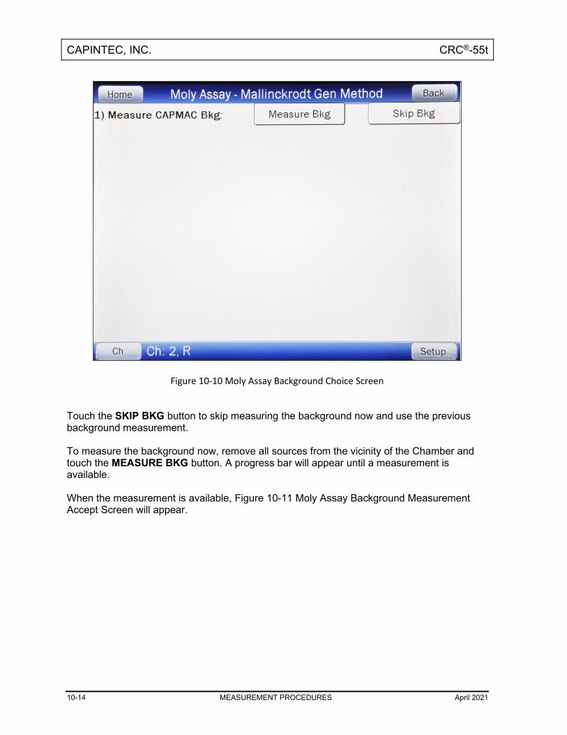
CAPINTEC, INC. CRC®-55t
10-14 MEASUREMENT PROCEDURES April 2021
Figure 10-10 Moly Assay Background Choice Screen
Touch the SKIP BKG button to skip measuring the background now and use the previous background measurement. To measure the background now, remove all sources from the vicinity of the Chamber and touch the MEASURE BKG button. A progress bar will appear until a measurement is available. When the measurement is available, Figure 10-11 Moly Assay Background Measurement Accept Screen will appear.

CAPINTEC, INC. CRC®-55t
April 2021 MEASUREMENT PROCEDURES 10-15
Figure 10-11 Moly Assay Background Measurement Accept Screen
If the background is high but still acceptable (>100.9µCi [3.73MBq] to 2.98mCi [110.3MBq]), the message “HIGH” will appear instead of “OK”. Although the measurement is acceptable, the reason for the high measurement should be investigated. If any sources are found nearby, repeat the measurement. If the background is above the acceptable range, the measurement will not be shown but Figure 10-12 Moly Assay Background Measurement Too High Screen will appear.

CAPINTEC, INC. CRC®-55t
10-16 MEASUREMENT PROCEDURES April 2021
Figure 10-12 Moly Assay Background Measurement Too High Screen
This “TOO HIGH” background cannot be accepted by the CRC®-55t. If the cause of the high reading (nearby source, contaminated well etc.) cannot be found, contact Capintec’s only Authorized Service Center at (800) ASK-4CRC. Touch the OK button to dismiss the Background Too High message window. Press any key to terminate the Mo99 background measurement. The Tests Menu will re-appear. Mo99 Assay The next step is to measure the eluate in the CapMac or Canister. Touch the ACCEPT button to accept the background measurement and continue on to the Mo99 Assay. If the “Streamlined Test” is enabled, a progress bar will appear until a measurement is available. If the “Streamlined Test” is disabled, the “Start Measurement” button will appear. Press the “Start Measurement” button will display a progress bar until a measurement is available. When the measurement is available, Figure 10-13 Moly Assay Eluate Accept Screen will appear.

CAPINTEC, INC. CRC®-55t
April 2021 MEASUREMENT PROCEDURES 10-17
Figure 10-13 Moly Assay Eluate Accept Screen
Since this is also a measurement of a very low activity, the screens are similar to background. Note: The activity will be tested to see if it's too high the same way that Mo99 Background
is tested.

CAPINTEC, INC. CRC®-55t
10-18 MEASUREMENT PROCEDURES April 2021
Figure 10-14 Mo High screen
Tc99m Assay The Tc99m Assay is performed next. Touch the ACCEPT button to accept the Mo99 Assay measurement. If the “Streamlined Test” is enabled, it will continue to the Tc99m Assay. If the “Streamlined Test” is disabled, then the “Start Measurement” button will appear. Press on the “Start Measurement” button to continue to the Tc99m Assay. Figure 10-15 Moly Assay Tc99m Accept Screen will appear.

CAPINTEC, INC. CRC®-55t
April 2021 MEASUREMENT PROCEDURES 10-19
Figure 10-15 Moly Assay Tc99m Accept Screen
Enter Volume Touch the ACCEPT button to accept the Tc99m Assay measurement. A numeric keypad will appear allowing for the entry of the volume of the elution in milliliters. Note: The minimum value that can be input is 1.000. The maximum value that can be input
is 100.0. Input the volume using the keypad and touch the ACCEPT button. The concentration of the elution is calculated and displayed on the Moly Assay Results Screen. Moly Assay Results If the measured Tc99m activity is below 1.0 mCi, the message “ACTIVITY TOO LOW ERROR” will appear on the screen in red. Touch the HOME or BACK button to return to Figure 10-1 Chamber Measurement Screen. The Mo99/Tc99m ratio is calculated and compared to the allowable value (which can be changed in Moly Setup – Reference CHAPTER 6: CHAMBER INITIALIZATION, SECTION: MOLY ASSAY SETUP).

CAPINTEC, INC. CRC®-55t
10-20 MEASUREMENT PROCEDURES April 2021
If the calculated Mo/Tc ratio is higher than the allowable limit, the message “MO TOO HIGH – DO NOT USE” will appear as shown in Figure 10-16 Moly Assay Eluate Measurement Too High Screen. Touch the HOME or BACK button to return to Figure 10-1 Chamber Measurement Screen.
Figure 10-16 Moly Assay Eluate Measurement Too High Screen
If the calculated Mo/Tc ratio is within the allowable limit, the time when the ratio will exceed this limit is also calculated. If the calculated usable time is less than 12 hours, a usage caution message is displayed depending upon the useable time for the elution. An example of such a case is shown in Figure 10-17 Moly Assay Results – Less than 12 hours Screen.

CAPINTEC, INC. CRC®-55t
April 2021 MEASUREMENT PROCEDURES 10-21
Figure 10-17 Moly Assay Results – Less than 12 hours Screen
If the calculated usable time is more than 12 hours, no message is displayed as shown in Figure 10-18 Moly Assay Results – More than 12 hours Screen.

CAPINTEC, INC. CRC®-55t
10-22 MEASUREMENT PROCEDURES April 2021
Figure 10-18 Moly Assay Results – More than 12 hours Screen
If a printer is attached to the system, touch the PRINT button to print a ticket with the details of the assay. Touch the HOME or BACK button to return to Figure 10-1 Chamber Measurement Screen.

CAPINTEC, INC. CRC®-55t
April 2021 CHAMBER ENHANCED TESTS 11-1
CHAPTER 11
CHAMBER ENHANCED TESTS
GENERAL ...................................................................................................... 11-1 GEOMETRY TEST ......................................................................................... 11-4
Measurement Results .............................................................................. 11-10 PERFORMING LINEARITY TEST ................................................................. 11-11
AutoLinearity ............................................................................................ 11-12 Standard Test ........................................................................................... 11-32 Lineator Test ............................................................................................. 11-35 Calicheck Test .......................................................................................... 11-37
HALF-LIFE CALCULATOR ........................................................................... 11-40 Setting Interval ......................................................................................... 11-40 Setting Total ............................................................................................. 11-41 Starting the Measurements ...................................................................... 11-42 Stopping the Measurements Early .......................................................... 11-44 Calculated Half-life ................................................................................... 11-44 Printing Results ........................................................................................ 11-45 Clear Current Half-Life Result for New Half-Life Calculation ................ 11-45
QUALITY CONTROL (QC) ............................................................................ 11-46 Single Strip Test ....................................................................................... 11-46 Two Strip Test .......................................................................................... 11-49 HMPAO Test ............................................................................................. 11-52 MAG3 Test ................................................................................................ 11-54
GENERAL This section describes the tests that are accessed via the ENHANCED TESTS button located on the Chamber Measurement screen.

CAPINTEC, INC. CRC®-55t
11-2 CHAMBER ENHANCED TESTS April 2021
Figure 11-1 Chamber Measurement Screen
From the Chamber Measurement screen, touch the ENHANCED TESTS button. If the Chamber is an R Chamber, Figure 11-2a Enhanced Tests Screen for R Chambers will appear. If the Chamber is a PET Chamber, Figure 11-2b Enhanced Tests Screen for PET Chambers will appears. The QC Tests are not available for PET Chambers.

CAPINTEC, INC. CRC®-55t
April 2021 CHAMBER ENHANCED TESTS 11-3
Figure 11-2a Enhanced Tests Screen for R Chambers
Figure 11-2b Enhanced Tests Screen for PET Chambers

CAPINTEC, INC. CRC®-55t
11-4 CHAMBER ENHANCED TESTS April 2021
If more than one Chamber is connected to the system, the CH (Chamber) button will be displayed and is located in the lower left part of the Enhanced Tests screen. Each test must be performed on each Chamber. Pressing the CH button allows the choice of which Chamber the selected test will be performed on.
GEOMETRY TEST The Geometry Test determines the effect of volume changes on the calibrator’s accuracy. It is carried out using Tc99m and should be performed upon installation of the CRC®-55t. An example Geometry Test would be to place 1ml of Tc99m (~25 mCi) in a 10 ml syringe. Place the sample in the Chamber and record the measurement. The sample is then diluted with water to 2 ml, 3 ml, 5 ml, and 10 ml. After each dilution, a measurement is performed and recorded. The data are reviewed to reveal the effect of sample geometry on the CRC®-55t’s reading. If the Chamber is geometry-dependent, it may be necessary to routinely correct the readings. To begin the Geometry Test, touch the GEOMETRY button. Figure 11-3 Geometry Test Screen will appear.
Figure 11-3 Geometry Test Screen

CAPINTEC, INC. CRC®-55t
April 2021 CHAMBER ENHANCED TESTS 11-5
The test can be performed using a syringe or a vial. A minimum of 2 samples must be measured. The maximum number of samples is 10. From Figure 11-3 Geometry Test Screen, touch either the Syringe or Vial radio button. Figure 11-4 Geometry Test Initial Volume Entry Screen will appear. The examples shown are for testing using a Vial but are identical if using a Syringe.
Figure 11-4 Geometry Test Initial Volume Entry Screen
Input the initial volume of the sample by touching the appropriate numbers on the keypad. Touch the ENTER (<--) key to accept the entered volume. Figure 11-5 Geometry Measurement Screen will appear for each measurement. Note: The minimum value that can be input is 0.1 ml. The maximum value that can be input
is 98.9 ml. The overall volume of the sample cannot be greater than 98.9ml; i.e. when the Initial Volume of the sample and all Added Volumes are added together, they cannot total more than 98.9ml.

CAPINTEC, INC. CRC®-55t
11-6 CHAMBER ENHANCED TESTS April 2021
Figure 11-5 Geometry Measurement Screen
Place the sample in the Chamber. The syringe’s activity will be displayed as shown in Figure 11-5 Geometry Measurement Screen. Touch the ACCEPT button to accept the measurement. Figure 11-6 Geometry Test Added Volume Entry Screen will appear for the second measurement.

CAPINTEC, INC. CRC®-55t
April 2021 CHAMBER ENHANCED TESTS 11-7
Figure 11-6 Geometry Test Added Volume Entry Screen
A minimum of 2 samples must be measured. Input the first volume added to the sample by touching the appropriate numbers on the keypad. Touch the ENTER (<--) key to accept the entered volume. Figure 11-7 Geometry Measurement with Added Volume Screen will appear.

CAPINTEC, INC. CRC®-55t
11-8 CHAMBER ENHANCED TESTS April 2021
Figure 11-7 Geometry Measurement with Added Volume Screen
Touch the ACCEPT button to accept the measurement. After the 2nd and subsequent measurements, Figure 11-8 Geometry Test More Measurements / Finished Screen will appear allowing more samples to be measured or finishing the test.

CAPINTEC, INC. CRC®-55t
April 2021 CHAMBER ENHANCED TESTS 11-9
Figure 11-8 Geometry Test More Measurements / Finished Screen
If the previous sample was not the last sample to be measured, touch the MORE MEASUREMENTS button. Figure 11-6 Geometry Test Added Volume Entry Screen will re-appear. Note: The maximum number of samples is 10. Input the next volume added to the sample by touching the appropriate numbers on the keypad. The total volume input for all samples must be less than 99.0ml; if it is not less, the message “VALID RANGE IS XX.XXXml TO 0.1ml” will appear. (XX.XXX is the maximum volume remaining after subtracting the current total volume from the maximum of 99.0ml.) Touch the ENTER (<--) key to accept the entered volume. Figure 11-7 Geometry Measurement with Added Volume Screen will appear. Touch the ACCEPT button to accept the measurement. If the previous sample was the last sample to measured, touch the FINISHED button. Figure 11-9 Geometry Report Screen will appear.

CAPINTEC, INC. CRC®-55t
11-10 CHAMBER ENHANCED TESTS April 2021
Measurement Results After the last sample has been measured, Figure 11-9 Geometry Report Screen will appear. The first measurement made is considered the Base Measurement. The base measurement is the measurement that all other measurements will be compared to. The variance is calculated using the base measurement.
Figure 11-9 Geometry Report Screen
If a printer is attached to the system, the Geometry Report can be printed by touching the PRINT button Touch the BACK button to exit the Geometry Report and return to Figure 11-3 Geometry Test Screen. Touch the HOME button to exit the Geometry Report and return to Figure 11-1 Chamber Measurement Screen.

CAPINTEC, INC. CRC®-55t
April 2021 CHAMBER ENHANCED TESTS 11-11
PERFORMING LINEARITY TEST The available Linearity Tests are: AutoLinearity, Standard Linearity, Lineator and Calicheck. AutoLinearity does not need any previous setup. In order to perform a Linearity Test other than AutoLinearity, at least one of the other Linearity Test Method must be defined. All three methods can be defined. From the Enhanced Tests screen, touch the LINEARITY button. If a Linearity Test Method is not defined, Figure 11-10 Default Linearity Tests Screen will appear. Touch the SETUP button and reference CHAPTER 6: CHAMBER INITIALIZATION, SECTION: LINEARITY TEST DEFINITION.
Figure 11-10 Default Linearity Tests Screen
If Linearity Test Method(s) have been defined, the Linearity screen will display the defined Linearity test(s).

CAPINTEC, INC. CRC®-55t
11-12 CHAMBER ENHANCED TESTS April 2021
AutoLinearity AutoLinearity is an automated version of the Standard Linearity Test. The predicted activity is calculated in the same way. In addition, the results are stored in the database and reports can be printed. This test is persistent. It can be paused and then resumed. If the power is turned off during the test, the data will not be lost. Touch the AUTOLINEARITY button. Figure 11-11 Start AutoLinearity Screen will appear.
Figure 11-11 Start AutoLinearity Screen
To begin the test, touch the START TEST button. Figure 11-12 AutoLinearity Setup Screen will appear.

CAPINTEC, INC. CRC®-55t
April 2021 CHAMBER ENHANCED TESTS 11-13
Figure 11-12 AutoLinearity Setup Screen
Selecting Nuclide
To select the nuclide to use for the Linearity Test, touch the Nuclide: field box. Figure 11-13 Select Nuclide Screen will appear.

CAPINTEC, INC. CRC®-55t
11-14 CHAMBER ENHANCED TESTS April 2021
Figure 11-13 Select Nuclide Screen
The left half of the Select Nuclide screen contains the 20 preset NUCLIDE buttons. The right half of the screen displays a listing of nuclides stored in the calibrator’s memory (both default and user added nuclides) that have a Calibration Number assigned to them (Reference CHAPTER 6: CHAMBER INITIALIZATION, SECTION: CALIBRATION NUMBERS) – 10 at a time. The nuclide list is in alphabetical order. User added nuclides are displayed at the top of the list. The length of the list will vary depending on which nuclides have a Calibration Number assigned to them (Reference CHAPTER 6: CHAMBER INITIALIZATION, SECTION: CALIBRATION NUMBERS). The number of pages shown in the upper right corner of the screen indicates the length of the list. To scroll through the list, touch the DOWN ARROW (▼) button. The next group of 10 nuclides will be displayed and the UP ARROW (▲) button will appear allowing the user to scroll up in the list. To cancel the nuclide selection and return to Figure 11-12 AutoLinearity Setup Screen, touch the CANCEL button. To select a nuclide for measurement, do one of the following:
• Touch one of the preset NUCLIDE keys. Figure 11-12 AutoLinearity Setup Screen will re-appear with the selected nuclide name shown in the Nuclide: field box.

CAPINTEC, INC. CRC®-55t
April 2021 CHAMBER ENHANCED TESTS 11-15
• Touch the Nuclide name on the list on the right. (If necessary, scroll the list until the desired nuclide is displayed.) Once a nuclide is selected from the list, an ACCEPT button will appear. Touch the ACCEPT button to use the selected nuclide. Figure 11-12 AutoLinearity Setup Screen will re-appear with the selected nuclide name shown in the chosen Nuclide: field box.
Setting Interval The Interval is the time between measurements in minutes. To set the desired Interval, touch the Interval: field box. Figure 11-14 Numeric Keypad Screen will appear.
Figure 11-14 Numeric Keypad Screen
Input the desired Interval (in minutes) by touching the appropriate numbers on the keypad. Touch the ACCEPT button to accept the entered time. Figure 11-12 AutoLinearity Setup Screen will re-appear with the entered time shown in the Interval: field box. Note: The minimum Interval that can be input is 5 minutes. The maximum Interval
that can be input is 60 minutes.

CAPINTEC, INC. CRC®-55t
11-16 CHAMBER ENHANCED TESTS April 2021
Setting Total The Total is the total time for the test in hours. To set the desired total time for the test, touch the Total: field box. Figure 11-14 Numeric Keypad Screen will appear. Input the desired Total time (in hours) by touching the appropriate numbers on the keypad. Touch the ACCEPT button to accept the entered time. Figure 11-12 AutoLinearity Setup Screen will re-appear with the entered time shown in the Total: field box. Note: The minimum Total Time that can be input is 1 hour. The maximum Total
Time that can be input is 100 hours.
Starting the Test Once all of the values have been entered, touch the START button. Figure 11-15 AutoLinearity Screen After Measurements Begin will appear.
Figure 11-15 AutoLinearity Screen After Measurements Begin

CAPINTEC, INC. CRC®-55t
April 2021 CHAMBER ENHANCED TESTS 11-17
The Elapsed Minutes and the Remaining Minutes are displayed at the upper right corner of the screen. There is a two minute wait to allow the measurement to stabilize before the test begins. This is indicated by the Elapsed Minutes showing -2. After each measurement is made, the following information will be displayed:
• Date Time / Elapsed: This is the date and time of the measurement and the elapsed time since the test began.
• Measured Activity: This is the actual activity measured at the time of the measurement.
• Predicted Activity: This is the predicted decayed activity (based on the first measured value) at the time of the measurement.
• % Variation: This is the percentage variation of the measured value from the predicted value.
Pausing the Test If it is required to use the Calibrator for other measurements while performing AutoLinearity, the test can be paused by touching the BACK or HOME button. The test data will be saved and the test can be resumed. When the BACK button is touched, Figure 11-16 Pause AutoLinearity Test Screen – Back Button will appear.
Figure 11-16 Pause AutoLinearity Test Screen – Back Button

CAPINTEC, INC. CRC®-55t
11-18 CHAMBER ENHANCED TESTS April 2021
Touch the YES button to proceed to Figure 11-18 AutoLinearity Menu Screen after Pause. Touch the NO button to return to Figure 11-15 AutoLinearity Screen After Measurements Begin. When the HOME button is touched, Figure 11-17 Pause AutoLinearity Test Screen – Home Button will appear.
Figure 11-17 Pause AutoLinearity Test Screen – Home Button
Touch the YES button to proceed to the Chamber Measurement screen. Touch the NO button to return to Figure 11-15 AutoLinearity Screen After Measurements Begin. After the test has been paused, the Chamber Measurement screen will display the message “AutoLinearity Paused!!!“ on the bottom of the screen as a reminder to resume the test. Resuming the Test When AutoLinearity is selected after the test has been paused, Figure 11-18 AutoLinearity Menu Screen after Pause will appear.

CAPINTEC, INC. CRC®-55t
April 2021 CHAMBER ENHANCED TESTS 11-19
Figure 11-18 AutoLinearity Menu Screen after Pause
To continue the test, touch the RESUME TEST button. Figure 11-19 Resume AutoLinearity Test Screen will appear.

CAPINTEC, INC. CRC®-55t
11-20 CHAMBER ENHANCED TESTS April 2021
Figure 11-19 Resume AutoLinearity Test Screen
Touch the YES button to proceed to Figure 11-15 AutoLinearity Screen After Measurements Begin. Touch the NO button to return to Figure 11-18 AutoLinearity Menu Screen after Pause. When the measurement screen reappears, any missed measurements will be marked as “Paused” in the Measured column. The measurements marked “Paused” are lost and cannot be recovered.

CAPINTEC, INC. CRC®-55t
April 2021 CHAMBER ENHANCED TESTS 11-21
Aborting a Test Aborting an In-progress Test A test in-progress can be aborted by touching the ABORT button while the test is still in-progress. Figure 11-20 Abort AutoLinearity Test In-progress Screen will appear.
Figure 11-20 Abort AutoLinearity Test In-progress Screen
Touch the YES button to erase the current test data. The data will be erased and Figure 11-12 AutoLinearity Setup Screen will re-appear. Touch the NO button to return to the test in-progress. Aborting a Finished Test A finished test can be aborted by touching the ABORT button after the test has finished. Figure 11-21 Abort AutoLinearity Test After Finished Screen will appear.

CAPINTEC, INC. CRC®-55t
11-22 CHAMBER ENHANCED TESTS April 2021
Figure 11-21 Abort AutoLinearity Test After Finished Screen
Touch the YES button to erase the current test data. The data will be erased and Figure 11-12 AutoLinearity Setup Screen will re-appear. Touch the NO button to return to the finished test as shown in Figure 11-24 AutoLinearity Test Finished Screen.

CAPINTEC, INC. CRC®-55t
April 2021 CHAMBER ENHANCED TESTS 11-23
Saving the Test After 5 measurements have been made, a SAVE button will appear as shown in Figure 11-22 AutoLinearity Screen with Save Button.
Figure 11-22 AutoLinearity Screen with Save Button
Saving an In-progress Test A test in-progress can be saved by touching the SAVE button while the test is still in-progress. Figure 11-23 Save AutoLinearity Test In-progress Screen will appear.

CAPINTEC, INC. CRC®-55t
11-24 CHAMBER ENHANCED TESTS April 2021
Figure 11-23 Save AutoLinearity Test In-progress Screen
If so desired, input a comment. Touch the YES button to save the current test data. The data will be saved and Figure 11-12 AutoLinearity Setup Screen will re-appear. The test will be finished and cannot be restarted. Touch the NO button to return to Figure 11-15 AutoLinearity Screen After Measurements Begin. Saving a Finished Test When the test is finished, the message “Finished!!!” will appear in the upper right of the screen as shown in Figure 11-24 AutoLinearity Test Finished Screen.

CAPINTEC, INC. CRC®-55t
April 2021 CHAMBER ENHANCED TESTS 11-25
Figure 11-24 AutoLinearity Test Finished Screen
A finished test can be saved by touching the SAVE button after the test has finished. Figure 11-25 Save AutoLinearity Test After Finished Screen will appear.

CAPINTEC, INC. CRC®-55t
11-26 CHAMBER ENHANCED TESTS April 2021
Figure 11-25 Save AutoLinearity Test After Finished Screen
If so desired, input a comment. Touch the YES button to save the current test data. The data will be saved and Figure 11-12 AutoLinearity Setup Screen will re-appear. The test will be finished and cannot be restarted. Touch the NO button to return to Figure 11-24 AutoLinearity Test Finished Screen.
Power Failure If the power goes off during a test, the data will not be lost. On power-up, the system will automatically return to the AutoLinearity Test that was in-progress. Any measurements missed while the power was off will be marked as “Power Failure” in the Measured column. The measurements marked “Power Failure” are lost and cannot be recovered.

CAPINTEC, INC. CRC®-55t
April 2021 CHAMBER ENHANCED TESTS 11-27
AutoLinearity Reports To view or print a report of a desired AutoLinearity Test, touch the REPORTS button from Figure 11-11 Start AutoLinearity Screen or Figure 11-18 AutoLinearity Menu Screen after Pause. Figure 11-26 Search AutoLinearity Tests Screen will appear.
Figure 11-26 Search AutoLinearity Tests Screen
Set Date The AutoLinearity Test results are searchable by using a date range. The default From: and To: dates are “today”. To change the From date, touch the From: field box. The Enter Start Date screen will appear. The screen displays the currently set date. Above and below each of the fields are + and – buttons, respectively. To adjust the displayed value for a specific field, touch the + button to increase the displayed value or the – button to decrease the displayed value. For the year, +10 and -10 buttons are provided to quickly change the tens column of the years. Touch the ACCEPT button to accept the set date or the CANCEL button to cancel any changes. Figure 11-26 Search AutoLinearity Tests Screen will re-appear showing the set From: date.

CAPINTEC, INC. CRC®-55t
11-28 CHAMBER ENHANCED TESTS April 2021
To change the To date, touch the To: field box. The Enter End Date screen will appear. The screen displays the currently set date. Above and below each of the fields are + and – buttons, respectively. To adjust the displayed value for a specific field, touch the + button to increase the displayed value or the – button to decrease the displayed value. For the year, +10 and -10 buttons are provided to quickly change the tens column of the years. Touch the ACCEPT button to accept the set date or the CANCEL button to cancel any changes. Figure 11-26 Search AutoLinearity Tests Screen will re-appear showing the set To: date. Search When the From and To dates are correct, touch the SEARCH button. The screen displays a listing of the data for the AutoLinearity Tests performed within the specified date range. Note: If the search results in more than 100 items, the message “Search
AutoLinearity Test Error More than 100 items have been returned Please refine criteria” will appear. Refine the search by narrowing the date range to search for.
To exit Figure 11-26 Search AutoLinearity Tests Screen,
• touch the BACK button – Figure 11-11 Start AutoLinearity Screen or Figure 11-18 AutoLinearity Menu Screen after Pause will re-appear or
• touch the HOME button – the Chamber Measurement screen will appear. The listing is in reverse chronological order (newest at the top of the list). The length of the list will vary depending on how many AutoLinearity Tests have been performed between the selected dates. If there are more than 10 results, the number of pages (or screens) will be shown in the upper right corner of the screen indicating the length of the list. To scroll through the list, touch the DOWN ARROW (▼) button. The next group of 10 results will be displayed and the UP ARROW (▲) button will appear allowing the user to scroll up in the list.

CAPINTEC, INC. CRC®-55t
April 2021 CHAMBER ENHANCED TESTS 11-29
View Test Details To obtain a detailed report for a particular AutoLinearity Test result, touch the desired result on the list. The result will become highlighted and a VIEW button will appear on the screen similar to that shown in Figure 11-27 Search AutoLinearity Tests Screen with Test Highlighted. (If necessary, scroll the list until the desired result is displayed.)
Figure 11-27 Search AutoLinearity Tests Screen with Test Highlighted
Touch the VIEW button. Figure 11-28 AutoLinearity Report Screen will appear displaying the detailed report for the selected AutoLinearity Test result.

CAPINTEC, INC. CRC®-55t
11-30 CHAMBER ENHANCED TESTS April 2021
Figure 11-28 AutoLinearity Report Screen
The following sections describe the functions that are available from Figure 11-28 AutoLinearity Report Screen. Print Results If a printer is attached to the system, the detailed report of the selected AutoLinearity Test result can be printed by touching the PRINT button.
Inactivate an AutoLinearity Test An AutoLinearity Test result can be inactivated. Reasons for doing this can be:
• the test was a simulation for training,
• a mistake was made doing the test, etc. The AutoLinearity Test result will still be saved in the database. When the test is displayed on the list, it will be shown with a line through the characters. When the individual report is printed, “INACTIVE” and the optional comment will appear. To inactivate the selected AutoLinearity Test, touch the INACTIVATE button. Figure 11-29 Inactivate Record Screen will appear.
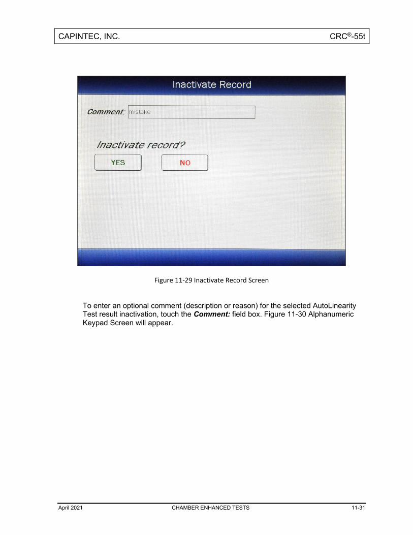
CAPINTEC, INC. CRC®-55t
April 2021 CHAMBER ENHANCED TESTS 11-31
Figure 11-29 Inactivate Record Screen
To enter an optional comment (description or reason) for the selected AutoLinearity Test result inactivation, touch the Comment: field box. Figure 11-30 Alphanumeric Keypad Screen will appear.

CAPINTEC, INC. CRC®-55t
11-32 CHAMBER ENHANCED TESTS April 2021
Figure 11-30 Alphanumeric Keypad Screen
Input the desired comment (description or reason) for the invalidation and touch the ACCEPT button. Figure 11-29 Inactivate Record Screen will re-appear with the Comment: field box populated with the entered comment. The comment can contain any combination of 22 alphanumeric characters maximum. To cancel any changes and return to Figure 11-29 Inactivate Record Screen, touch the CANCEL button. To complete the inactivation of the selected AutoLinearity Test result, touch the YES button. If it is decided not to inactivate the selected AutoLinearity Test result, touch the NO button.
Standard Test If the Standard Linearity Test has been defined, the STANDARD button will be displayed on the screen. For an R Chamber, the Standard Test is normally performed by tracking the decay of a strong Tc99m source. However, the required nuclide was defined in the setup. For a PET Chamber, the Standard Test is performed by tracking the decay of the user selected nuclide that was defined in the setup.
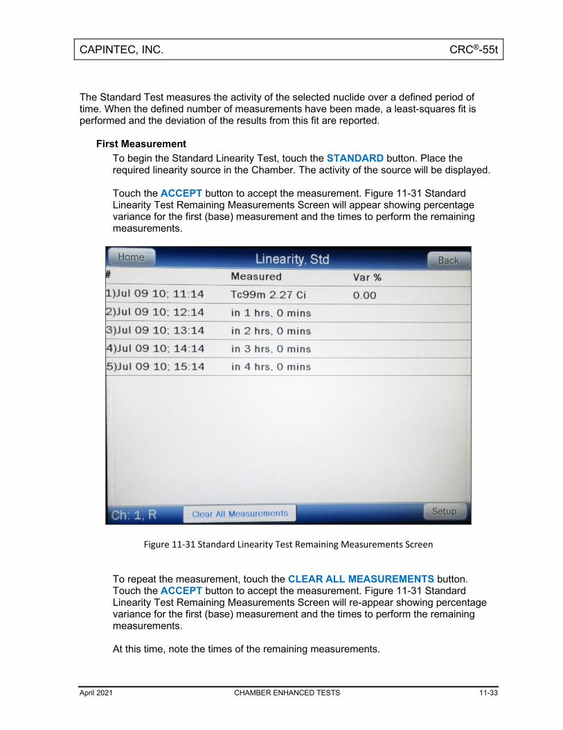
CAPINTEC, INC. CRC®-55t
April 2021 CHAMBER ENHANCED TESTS 11-33
The Standard Test measures the activity of the selected nuclide over a defined period of time. When the defined number of measurements have been made, a least-squares fit is performed and the deviation of the results from this fit are reported.
First Measurement To begin the Standard Linearity Test, touch the STANDARD button. Place the required linearity source in the Chamber. The activity of the source will be displayed. Touch the ACCEPT button to accept the measurement. Figure 11-31 Standard Linearity Test Remaining Measurements Screen will appear showing percentage variance for the first (base) measurement and the times to perform the remaining measurements.
Figure 11-31 Standard Linearity Test Remaining Measurements Screen
To repeat the measurement, touch the CLEAR ALL MEASUREMENTS button. Touch the ACCEPT button to accept the measurement. Figure 11-31 Standard Linearity Test Remaining Measurements Screen will re-appear showing percentage variance for the first (base) measurement and the times to perform the remaining measurements. At this time, note the times of the remaining measurements.

CAPINTEC, INC. CRC®-55t
11-34 CHAMBER ENHANCED TESTS April 2021
Second through Last Measurements
Perform the remaining measurements at time intervals close those entered when the test was defined. The actual elapsed time will be used in the calculations. From Figure 11-1 Chamber Measurement Screen, touch the ENHANCED TESTS button. The Enhanced Tests screen will appear. Touch the LINEARITY button. The Linearity screen will appear. Touch the STANDARD button. Figure 11-32 Standard Linearity Test Results Screen will appear.
Figure 11-32 Standard Linearity Test Results Screen
The percentage variance from the base measurement is displayed after each measurement. To repeat all measurements and start the test over, touch the CLEAR ALL MEASUREMENTS button. All measurements will be cleared. If a printer is attached to the system, the Standard Linearity Test report can be printed by touching the PRINT button
CAPINTEC, INC. CRC®-55t
April 2021 CHAMBER ENHANCED TESTS 11-35
Touch the BACK button to exit the Standard Linearity Test results and return to the Linearity screen. Touch the HOME button to exit the Standard Linearity Test results and return to Figure 11-1 Chamber Measurement Screen.
Lineator Test If the Lineator Linearity Test has been defined, the LINEATOR button will be displayed on the screen. The Lineator Test requires 8 measurements using a strong Tc99m source along with a Lineator Test tube set. The purpose of this test is to perform linearity quickly and not have to wait the time required to perform the Standard Linearity test. This is accomplished by measuring the attenuation of the tubes surrounding the source and storing the results. At any time, the tubes are used to confirm that the attenuation has not changed. The Lineator Test steps the user through the measurement of each tube. To begin the Lineator Linearity Test, touch the LINEATOR button. Figure 11-33 Lineator Linearity Test First Measurement Screen will appear.

CAPINTEC, INC. CRC®-55t
11-36 CHAMBER ENHANCED TESTS April 2021
Figure 11-33 Lineator Linearity Test First Measurement Screen
Remove the Dipper from the Chamber (leaving the Liner in place) and place the Tc99m test source into Tube 1 and then place Tube 1 into the Chamber. The activity of the source will be displayed as shown in Figure 11-33 Lineator Linearity Test First Measurement Screen. Touch the ACCEPT button to accept the measurement. Figure 11-33 Lineator Linearity Test First Measurement Screen will now show the factor and the ratio for the first tube. The factor will be always 1.00 and the ratio will always be 100.00% since this is the first (base) measurement. Place the requested tube(s) into the Chamber. Touch the ACCEPT button to accept the measurement. Figure 11-33 Lineator Linearity Test First Measurement Screen will now show the current factor and the current ratio for the measured tube(s). Repeat the above steps for the remaining combination of tubes as indicated. Review the % Ratio column. This is the ratio of the current factor to the initial factor determined when performing the Lineator Calibration procedure (reference CHAPTER 6: CHAMBER INITIALIZATION, SECTION: LINEARITY TEST DEFINITION, Lineator Test). Verify that each ratio is within the specified limits for the facility’s license. If a printer is attached to the system, a PRINT button will appear on the screen. Touch the PRINT button to print the Lineator Linearity Test results.

CAPINTEC, INC. CRC®-55t
April 2021 CHAMBER ENHANCED TESTS 11-37
Touch the BACK button to exit the Lineator Linearity Test results and return to the Linearity screen. Touch the HOME button to exit the Lineator Linearity Test results and return to Figure 11-1 Chamber Measurement Screen. Calicheck Test If the Calicheck Linearity Test has been defined, the CALICHECK button will be displayed on the screen. The Calicheck Test requires between 5 and 12 measurements (as defined in the Calicheck Setup – reference CHAPTER 6: CHAMBER INITIALIZATION, SECTION: LINEARITY TEST DEFINITION, Lineator Test) using a strong Tc99m source along with a Calicheck Test tube set. The purpose of this test is to perform linearity quickly and not have to wait the time required to perform the Standard Linearity test. This is accomplished by measuring the attenuation of the tubes surrounding the source and storing the results. At any later time, the tubes are used to confirm that the attenuation has not changed. The Calicheck Test steps the user through the measurement of each tube. To begin the Calicheck Linearity Test, touch the CALICHECK button. Figure 11-34 Calicheck Linearity Test First Measurement Screen will appear for the first measurement. The examples shown are for 5 tubes.

CAPINTEC, INC. CRC®-55t
11-38 CHAMBER ENHANCED TESTS April 2021
Figure 11-34 Calicheck Linearity Test First Measurement Screen
Remove the Dipper from the Chamber (leaving the Liner in place). Place the Tc99m test source into the Black Tube and then place the Tube into the Chamber. The activity of the source will be displayed as shown in Figure 11-34 Calicheck Linearity Test First Measurement Screen. Touch the ACCEPT button to accept the measurement. Figure 11-35 Calicheck Linearity Test Next Measurement Screen will now show the measurement result and the Percent Variance from the Mean for the Black Tube. The Percent Variance will always be 0.00 since this is the first measurement.

CAPINTEC, INC. CRC®-55t
April 2021 CHAMBER ENHANCED TESTS 11-39
Figure 11-35 Calicheck Linearity Test Next Measurement Screen
Place the requested tube(s) into the Chamber. Touch the ACCEPT button to accept the measurement. Figure 11-35 Calicheck Linearity Test Next Measurement Screen will now show the measurement result and the current Percent Variance from Mean for the measured tube(s) and the adjusted Percent Variance from Mean for the previously measured tube(s). Repeat the above steps for the remaining combination of tubes as indicated. Review the Result and % Var columns. The screen shows the Result and the Percent Variation from Mean for each tube. The Result is the actual measurement for the selected tube multiplied by the corresponding Calibration Factor that was determined when the Calicheck Calibration procedure was performed (reference CHAPTER 6: CHAMBER INITIALIZATION, SECTION: LINEARITY TEST DEFINITION, Calicheck Test). The Mean is the sum of the Results divided by the total number of measurements performed. The Percent Variance is the ratio of the Result to the Mean. Verify that each Percent Variance is within the specified limits for the facility’s license. If a printer is attached to the system, a PRINT button will appear on the screen. Touch the PRINT button to print the Calicheck Linearity Test results. Touch the BACK button to exit the Calicheck Linearity Test results and return to the Linearity screen.

CAPINTEC, INC. CRC®-55t
11-40 CHAMBER ENHANCED TESTS April 2021
Touch the HOME button to exit the Calicheck Linearity Test results and return to Figure 11-1 Chamber Measurement Screen.
HALF-LIFE CALCULATOR The Half-life Calculator calculates the half-life of a nuclide from a series of sequential measurements. The half-life is determined thru the least squares linear regression method. To begin the Half-life Calculator, touch the HALF-LIFE CALCULATOR button. Figure 11-36 Half-life Calculator Screen will appear.
Figure 11-36 Half-life Calculator Screen
Setting Interval The Interval is the time between measurements in seconds. To set the desired Interval, touch the Interval: field box. Figure 11-37 Numeric Keypad Screen will appear.

CAPINTEC, INC. CRC®-55t
April 2021 CHAMBER ENHANCED TESTS 11-41
Figure 11-37 Numeric Keypad Screen
Input the desired Interval (in seconds) by touching the appropriate numbers on the keypad. Touch the ACCEPT button to accept the entered time. Figure 11-36 Half-life Calculator Screen will re-appear with the entered time shown in the Interval: field box. Note: The minimum Interval that can be input is 1 second. The maximum Interval that can
be input is 300 seconds. Setting Total The Total is the total time for the series of measurements in minutes. To set the desired total time, touch the Total: field box. Figure 11-38 Numeric Keypad Screen will appear.

CAPINTEC, INC. CRC®-55t
11-42 CHAMBER ENHANCED TESTS April 2021
Figure 11-38 Numeric Keypad Screen
Input the desired Total time (in minutes) by touching the appropriate numbers on the keypad. Touch the ACCEPT button to accept the entered time. Figure 11-36 Half-life Calculator Screen will re-appear with the entered time shown in the Total: field box. Note: The minimum Total time that can be input is 1 minute. The maximum Total time that
can be input is 6000 minutes. Starting the Measurements Once all of the values have been entered, touch the START button. Figure 11-39 Half-life Calculator Screen After Measurements Begin will appear. Note: An error screen will be displayed if the number of measurements is less than 5. Note: An error screen will be displayed if the number of measurements is larger than 1201.
The error screen will suggest changes to Total time or Interval time, which will correct the error.
Note: The normal 20 seconds running average is disabled for half-life measurements.
Increase the number of measurements to get a more accurate half-life result.

CAPINTEC, INC. CRC®-55t
April 2021 CHAMBER ENHANCED TESTS 11-43
Note: If the initial measurement is too low, the measurements will automatically stop and Figure 11-40 Half-life Calculator Screen After Measurements Finished will appear. The message “Activity Too Low Error” will be displayed in the upper right corner.
Figure 11-39 Half-life Calculator Screen After Measurements Begin
The Elapsed time and Remaining time are displayed in the upper right corner of the screen. The time format is minutes:seconds and is refreshed after each measurement. After each measurement is made, the following information will be displayed in the grid:
• Elapsed time in seconds • Measured voltage from Chamber
Note: “Under Range” will be displayed if the voltage is zero or negative. Under Range
measurements are not used in the calculation of the half-life. Note: “Over Range” will be displayed if the voltage is larger than the upper range of the
ADC chip. Over Range measurements are not used in the calculation of the half-life. Measurements will stop when the Total time has elapsed. After measurements have stopped, Figure 11-40 Half-life Calculator Screen After Measurements Finished will appear.

CAPINTEC, INC. CRC®-55t
11-44 CHAMBER ENHANCED TESTS April 2021
Stopping the Measurements Early To stop the measurements before the total time has elapsed, press the STOP button. The half-life will be calculated with the measurements taken. After pressing STOP, Figure 11-40 Half-life Calculator Screen After Measurements Finished will appear. Calculated Half-life After completing the measurements, the half-life is calculated with the least squares linear regression method. Figure 11-40 Half-life Calculator Screen After Measurements Finished will appear.
Figure 11-40 Half-life Calculator Screen After Measurements Finished
The calculated half-life value is displayed in the upper right corner. The following measurement information will be displayed:
• Elapsed time in seconds, • Measured voltage from Chamber, • The predicted voltage from the linear least squares regression, • % Variation of the Measured voltage from the Predicted voltage.

CAPINTEC, INC. CRC®-55t
April 2021 CHAMBER ENHANCED TESTS 11-45
Note: If the initial measurement is too low, then “Activity Too Low Error” will be displayed in the upper right corner.
Note: If the number of valid measurements is less than 5, then the “Less than 5
measurements” message will be displayed in the upper right corner. Note: If the calculated half-life is negative, then the “Half-life is negative” message will be
displayed in the upper right corner. Note: If the calculated half-life is too small, then the “Half-life is too short” message will be
displayed in the upper right corner. Note: If the range of the measurements is within the noise of the instrument, then the “Half-
life is too long” message will be displayed in the upper right corner. Printing Results If a printer is attached to the system, the half-life results can be printed by touching the PRINT button. The Print Summary checkbox can be used to exclude the measurements from the printout. This setting persists between successive half-life calculations. The Nuclide can be included on the printout by touching the Nuclide: textbox and selecting a Nuclide. This setting persists between successive half-life calculations. The Lot Number can be included on the printout by touching the Lot: textbox and entering the lot number using the alphanumeric keyboard screen. This setting is cleared between successive half-life calculations. Clear Current Half-Life Result for New Half-Life Calculation The current half-life result can be cleared by pressing the CLEAR button. The results will be removed from Figure 11-36 Half-life Calculator Screen. The Interval time and the Total time will be the retained from the previous calculation.

CAPINTEC, INC. CRC®-55t
11-46 CHAMBER ENHANCED TESTS April 2021
QUALITY CONTROL (QC) Note: The Quality Control function can only be accessed with an R Chamber. Radiochromatography Quality Control tests can be performed using four methods. From the Enhanced Tests screen, touch the QC button. Figure 11-41 QC Test Selection Screen will appear.
Figure 11-41 QC Test Selection Screen
Single Strip Test Note: The Single Strip Test can only be accessed with an R Chamber. The Single Strip Test consists of 2 measurements: the top of the strip and then the bottom of the strip. To begin the Single Strip Test, touch the SINGLE STRIP TEST button. Figure 11-42 Single Strip Test – Top of Strip Measurement Screen will appear.

CAPINTEC, INC. CRC®-55t
April 2021 CHAMBER ENHANCED TESTS 11-47
Figure 11-42 Single Strip Test – Top of Strip Measurement Screen
Place the Top of Strip into the Chamber. The activity will be displayed as shown in Figure 11-42 Single Strip Test – Top of Strip Measurement Screen. Touch the ACCEPT button to accept the measurement. The screen will show the Top of Strip measurement result and the Bottom Of Strip measurement as shown in Figure 11-43 Single Strip Test – Bottom of Strip Measurement Screen.

CAPINTEC, INC. CRC®-55t
11-48 CHAMBER ENHANCED TESTS April 2021
Figure 11-43 Single Strip Test – Bottom of Strip Measurement Screen
Place the Bottom of Strip into the Chamber. The activity will be displayed as shown in Figure 11-43 Single Strip Test – Bottom of Strip Measurement Screen. Touch the ACCEPT button to accept the measurement. The screen will display the Top and Bottom of Strip measurements and the results as shown in Figure 11-44 Single Strip Test Results Screen.

CAPINTEC, INC. CRC®-55t
April 2021 CHAMBER ENHANCED TESTS 11-49
Figure 11-44 Single Strip Test Results Screen
If a printer is attached to the system, a PRINT button will appear on the screen. Touch the PRINT button to print the Single Strip Test measured values and results. Touch the BACK button to exit the Single Strip Test and return to Figure 11-41 QC Test Selection Screen. Touch the HOME button to exit the Single Strip Test and return to Figure 11-1 Chamber Measurement Screen. Two Strip Test Note: The Two Strip Test can only be accessed with an R Chamber. The Two Strip Test consists of 4 measurements: the top and then the bottom of strip A, and the top and then the bottom of strip B. To begin the Two Strip Test, touch the TWO STRIP TEST button. The screen will appear similar to that shown in Figure 11-42 Single Strip Test – Top of Strip Measurement Screen. Place the Top of Strip A into the Chamber. The activity will be displayed similar to that shown in Figure 11-42 Single Strip Test – Top of Strip Measurement Screen.

CAPINTEC, INC. CRC®-55t
11-50 CHAMBER ENHANCED TESTS April 2021
Touch the ACCEPT button to accept the measurement. The screen will now show the Top of Strip A measurement result and the Bottom of Strip A measurement as shown in Figure 11-45 Two Strip Test – Bottom of Strip A Measurement Screen.
Figure 11-45 Two Strip Test – Bottom of Strip A Measurement Screen
Place the Bottom of Strip A into the Chamber. The activity will be displayed. Touch the ACCEPT button to accept the measurement. The screen will now show the Bottom of Strip A measurement result and the Top of Strip B measurement as shown in Figure 11-46 Two Strip Test – Top of Strip B Measurement Screen.

CAPINTEC, INC. CRC®-55t
April 2021 CHAMBER ENHANCED TESTS 11-51
Figure 11-46 Two Strip Test – Top of Strip B Measurement Screen
Repeat the above steps to measure the Top and Bottom of Strip B. After accepting the Bottom of Strip B measurement, the results will appear as shown in Figure 11-47 Two Strip Test Results Screen.

CAPINTEC, INC. CRC®-55t
11-52 CHAMBER ENHANCED TESTS April 2021
Figure 11-47 Two Strip Test Results Screen
If a printer is attached to the system, a PRINT button will appear on the screen. Touch the PRINT button to print the Two Strip Test measured values and results. Touch the BACK button to exit the Two Strip Test and return to Figure 11-41 QC Test Selection Screen. Touch the HOME button to exit the Two Strip Test and return to Figure 11-1 Chamber Measurement Screen. HMPAO Test Note: The HMPAO Test can only be accessed with an R Chamber. The Tc99m HMPAO Test consists of 6 measurements: the top and then the bottom of strip A, the top and then the bottom of strip B, and the top and then the bottom of strip C. To begin the HMPAO Test, touch the HMPAO TEST button. The screen will appear similar to that shown in Figure 11-42 Single Strip Test – Top of Strip Measurement Screen. Place the Top of Strip A into the Chamber. The activity will be displayed similar to that shown in Figure 11-42 Single Strip Test – Top of Strip Measurement Screen.

CAPINTEC, INC. CRC®-55t
April 2021 CHAMBER ENHANCED TESTS 11-53
Touch the ACCEPT button to accept the measurement. The screen will now show the Top of Strip A measurement result and the Bottom of Strip A measurement similar to that shown in Figure 11-45 Two Strip Test – Bottom of Strip A Measurement Screen. Place the Bottom of Strip A into the Chamber. The activity will be displayed. Touch the ACCEPT button to accept the measurement. The screen will now show the Bottom of Strip A measurement result and the Top of Strip B measurement similar to that shown in Figure 11-46 Two Strip Test – Top of Strip B Measurement Screen. Repeat the above steps to measure the Top and Bottom of Strips B and C. After accepting the Bottom of Strip C measurement, the results will appear as shown in Figure 11-48 HMPAO Test Results Screen.
Figure 11-48 HMPAO Test Results Screen
If a printer is attached to the system, a PRINT button will appear on the screen. Touch the PRINT button to print the HMPAO Test measured values and results. Touch the BACK button to exit the HMPAO Test and return to Figure 11-41 QC Test Selection Screen. Touch the HOME button to exit the HMPAO Test and return to Figure 11-1 Chamber Measurement Screen.

CAPINTEC, INC. CRC®-55t
11-54 CHAMBER ENHANCED TESTS April 2021
MAG3 Test Note: The MAG3 Test can only be accessed with an R Chamber. The Tc99m MAG3 Test consists of 3 measurements: Fraction #1, Fraction #2 and the Cartridge. To begin the MAG3 Test, touch the MAG3 TEST button. The screen will appear as shown in Figure 11-49 MAG3 Test – Fraction #1 Measurement Screen.
Figure 11-49 MAG3 Test – Fraction #1 Measurement Screen
Place the Fraction #1 into the Chamber. The activity will be displayed similar to that shown in Figure 11-49 MAG3 Test – Fraction #1 Measurement Screen. Touch the ACCEPT button to accept the measurement. The screen will now show the Fraction #1 measurement result and the Fraction #2 measurement. Place the Fraction #2 into the Chamber. The activity will be displayed. Touch the ACCEPT button to accept the measurement. The screen will now show the Fraction #2 measurement result and the Cartridge measurement as shown in Figure 11-50 MAG3 Test – Cartridge Measurement Screen.

CAPINTEC, INC. CRC®-55t
April 2021 CHAMBER ENHANCED TESTS 11-55
Figure 11-50 MAG3 Test – Cartridge Measurement Screen
Touch the ACCEPT button to accept the measurement. The results will appear as shown in Figure 11-51 MAG3 Test Results Screen.

CAPINTEC, INC. CRC®-55t
11-56 CHAMBER ENHANCED TESTS April 2021
Figure 11-51 MAG3 Test Results Screen
If a printer is attached to the system, a PRINT button will appear on the screen. Touch the PRINT button to print the MAG3 Test measured values and results. Touch the BACK button to exit the MAG3 Test and return to Figure 11-41 QC Test Selection Screen. Touch the HOME button to exit the MAG3 Test and return to Figure 11-1 Chamber Measurement Screen.

CAPINTEC, INC. CRC®-55t
April 2021 INVENTORY 12-1
CHAPTER 12
INVENTORY
GENERAL ...................................................................................................... 12-1 ADDING TO THE INVENTORY ...................................................................... 12-3
Select Nuclide ............................................................................................ 12-4 Study .......................................................................................................... 12-6 Input ID ....................................................................................................... 12-7 Input Lot Number ...................................................................................... 12-8 Volume ....................................................................................................... 12-9 Activity ...................................................................................................... 12-10 Date ........................................................................................................... 12-12 Mo/Tc ......................................................................................................... 12-14 Save Item to Inventory ............................................................................. 12-15
MAKING A KIT .............................................................................................. 12-16 Kit Study ................................................................................................... 12-18 Kit ID .......................................................................................................... 12-19 Kit Lot Number ......................................................................................... 12-19 Kit Activity ................................................................................................ 12-20 Kit Volume ................................................................................................ 12-21 Measure Kit Activity ................................................................................. 12-22
WITHDRAWING FROM INVENTORY ........................................................... 12-23 Withdraw Activity ..................................................................................... 12-24 Time of Use ............................................................................................... 12-25 Measure Activity ....................................................................................... 12-26
PRINTING THE INVENTORY ........................................................................ 12-27 DELETING FROM INVENTORY .................................................................... 12-28
Delete Individual Items ............................................................................. 12-28 Delete All Items......................................................................................... 12-29
GENERAL This section describes the use of the Inventory feature. Up to 30 items can be stored in Inventory. Inventory is accessed via the INVENTORY button located on the Chamber Measurement screen. Note: Inventory can only be used with an R Chamber. If the INVENTORY button is touched
when using a PET Chamber, the message “PET Chamber The PET Chamber can not access inventory functions” will appear. Touch the OK button to dismiss the message window.

CAPINTEC, INC. CRC®-55t
12-2 INVENTORY April 2021
Figure 12-1 Chamber Measurement Screen
From the Chamber Measurement screen, touch the INVENTORY button. Figure 12-2 Inventory Main Screen will appear.

CAPINTEC, INC. CRC®-55t
April 2021 INVENTORY 12-3
Figure 12-2 Inventory Main Screen
ADDING TO THE INVENTORY To add an item to the Inventory, touch the ADD ITEM button located on the lower left part of Figure 12-2 Inventory Main Screen. Figure 12-3 Add Inventory Item Screen will appear.

CAPINTEC, INC. CRC®-55t
12-4 INVENTORY April 2021
Figure 12-3 Add Inventory Item Screen
The required fields (Nuclide, Volume, Activity and Date) flash pink. The fields not flashing (ID, Lot and Mo/Tc) are not required. To exit Figure 12-3 Add Inventory Item Screen without saving any data input and return to Figure 12-2 Inventory Main Screen, touch the BACK button. To exit Figure 12-3 Add Inventory Item Screen without saving any data input and return to Figure 12-1 Chamber Measurement Screen, touch the HOME button. If more than one Chamber is attached to the system, the CH button will be displayed on the lower left part of Figure 12-3 Add Inventory Item Screen. Touch this button to switch between the Chambers. To input information for the Inventory Item, touch the desired field box and input the appropriate data for the nuclide. Select Nuclide Note: The Nuclide: field box is required. To select the desired nuclide to add to Inventory, touch the Nuclide: field box. Figure 12-4 Select Nuclide Screen will appear.
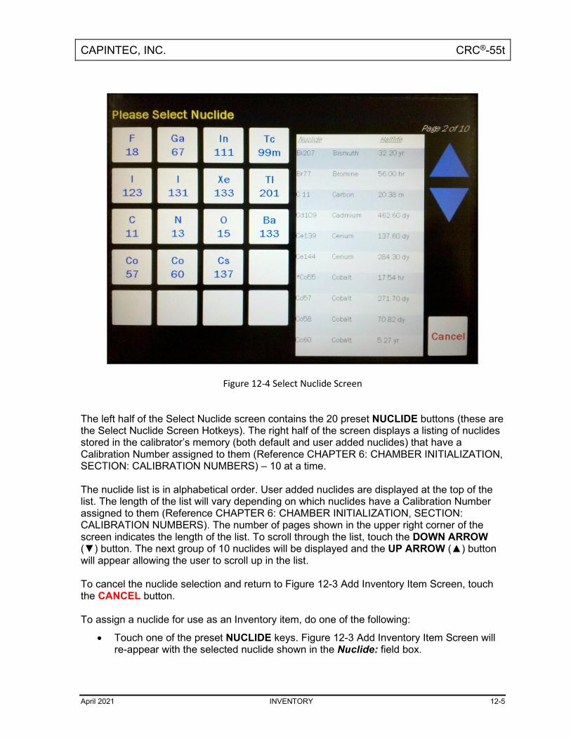
CAPINTEC, INC. CRC®-55t
April 2021 INVENTORY 12-5
Figure 12-4 Select Nuclide Screen
The left half of the Select Nuclide screen contains the 20 preset NUCLIDE buttons (these are the Select Nuclide Screen Hotkeys). The right half of the screen displays a listing of nuclides stored in the calibrator’s memory (both default and user added nuclides) that have a Calibration Number assigned to them (Reference CHAPTER 6: CHAMBER INITIALIZATION, SECTION: CALIBRATION NUMBERS) – 10 at a time. The nuclide list is in alphabetical order. User added nuclides are displayed at the top of the list. The length of the list will vary depending on which nuclides have a Calibration Number assigned to them (Reference CHAPTER 6: CHAMBER INITIALIZATION, SECTION: CALIBRATION NUMBERS). The number of pages shown in the upper right corner of the screen indicates the length of the list. To scroll through the list, touch the DOWN ARROW (▼) button. The next group of 10 nuclides will be displayed and the UP ARROW (▲) button will appear allowing the user to scroll up in the list. To cancel the nuclide selection and return to Figure 12-3 Add Inventory Item Screen, touch the CANCEL button. To assign a nuclide for use as an Inventory item, do one of the following:
• Touch one of the preset NUCLIDE keys. Figure 12-3 Add Inventory Item Screen will re-appear with the selected nuclide shown in the Nuclide: field box.

CAPINTEC, INC. CRC®-55t
12-6 INVENTORY April 2021
• Touch the Nuclide name on the list on the right. (If necessary, scroll the list until the desired nuclide is displayed.) Once a nuclide is selected from the list, an ACCEPT button will appear. Touch the ACCEPT button to save the selected nuclide. Figure 12-3 Add Inventory Item Screen will re-appear with the selected nuclide shown in the chosen Nuclide: field box.
If Tc99m is the selected nuclide, Study: and Mo/Tc: field boxes will appear as shown in Figure 12-5 Inventory – Added Tc99m with Study: Field Box Screen.
Figure 12-5 Inventory – Added Tc99m with Study: Field Box Screen
Study Note: The Study: field box is not required. If Tc99m is the selected nuclide, the Study: field box will be displayed. Touch the Touch the Study: field box. Figure 12-6 Inventory – Tc99m Select Study Screen will appear.

CAPINTEC, INC. CRC®-55t
April 2021 INVENTORY 12-7
Figure 12-6 Inventory – Tc99m Select Study Screen
If plain Tc99m (not a kit) is being added, touch the NONE radio button. If the Tc99m being added is for a kit, touch the corresponding radio button to the study for which the kit is intended. Figure 12-5 Inventory – Added Tc99m with Study: Field Box Screen will re-appear with the chosen study name in the Study: field box. Input ID Note: The ID: field box is not required. A 2-digit ID number may be input to distinguish the item being added from another one with the same nuclide and study. For the ID data, a numeric keypad will appear. Input the ID number and touch the ACCEPT button. Figure 12-7 Inventory – ID: Field Box Screen will appear with the ID: field box populated with the entered ID number.
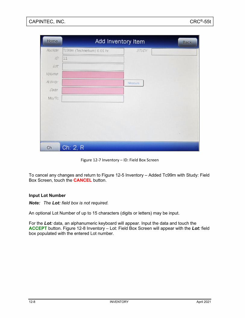
CAPINTEC, INC. CRC®-55t
12-8 INVENTORY April 2021
Figure 12-7 Inventory – ID: Field Box Screen
To cancel any changes and return to Figure 12-5 Inventory – Added Tc99m with Study: Field Box Screen, touch the CANCEL button. Input Lot Number Note: The Lot: field box is not required. An optional Lot Number of up to 15 characters (digits or letters) may be input. For the Lot: data, an alphanumeric keyboard will appear. Input the data and touch the ACCEPT button. Figure 12-8 Inventory – Lot: Field Box Screen will appear with the Lot: field box populated with the entered Lot number.

CAPINTEC, INC. CRC®-55t
April 2021 INVENTORY 12-9
Figure 12-8 Inventory – Lot: Field Box Screen
To cancel any changes and return to Figure 12-5 Inventory – Added Tc99m with Study: Field Box Screen, touch the CANCEL button. Volume Note: The Volume: field box is required. For the Volume: data, a numeric keypad will appear. Input the volume of the item using the keypad and touch the ACCEPT button. Figure 12-9 Inventory – Volume: Field Box Screen will appear with the Volume: field box populated with the entered volume. Note: The minimum value that can be input is 1.00. The maximum value that can be input is
1000.00.

CAPINTEC, INC. CRC®-55t
12-10 INVENTORY April 2021
Figure 12-9 Inventory – Volume: Field Box Screen
Activity Note: The Activity: field box is required. The activity of the item may be measured or it may be input if the activity and time of a previous measurement are known.
Input Activity To input the item’s activity, touch the Activity: field box. Figure 12-10 Enter Activity Screen will appear.

CAPINTEC, INC. CRC®-55t
April 2021 INVENTORY 12-11
Figure 12-10 Enter Activity Screen
Input the activity value using the keypad and touch the appropriate radio button for the unit of measure of the item. Note: The available units will change depending on which unit of measurement is in
use on the Chamber Measurement screen. i.e. if set for Curies, the available units will be Ci, mCi and µCi; if set for Becquerels, the available units will be GBq and MBq.
Touch the ACCEPT button. The Add Inventory screen will re-appear with Activity: field box populated with the entered activity. To cancel any changes and return to the Add Inventory screen, touch the CANCEL button.

CAPINTEC, INC. CRC®-55t
12-12 INVENTORY April 2021
Measure Activity To measure the item’s current activity, touch the MEASURE button next to the Activity: field box. Figure 12-11 Inventory – Measure Activity Screen will appear.
Figure 12-11 Inventory – Measure Activity Screen
Place the Inventory item into the Chamber. To save the measurement, touch the ACCEPT button. The Add Inventory screen will re-appear with the Activity: field box populated with the accepted measured activity and the Date: field box will be populated with the measurement’s date and time. To abort the measurement, touch the CANCEL button. The Add Inventory screen will re-appear without saving the measurement.
Date Note: The Date: field box is required. If the activity of the item was measured as described above, the Date: field box will be populated with the accepted activity measurement’s date and time. However, if the activity of the item was input, the Date: field box will be blank and therefore must be input.

CAPINTEC, INC. CRC®-55t
April 2021 INVENTORY 12-13
To input the date for an item whose activity was input, touch the Date: field box. Figure 12-12 Date/Time Screen will appear.
Figure 12-12 Date/Time Screen
The screen displays the currently set date and time. Above and below each of the fields are + and – buttons, respectively. To adjust the displayed value for a specific field, touch the + button to increase the displayed value or the – button to decrease the displayed value. For the year, +10 and -10 buttons are provided to quickly change the tens column of the years. Adjust the displayed date and time to show the calibration date/time of the item being added to Inventory. Touch the ACCEPT button to accept the set date and time. The Add Inventory screen will re-appear with Date field box populated with the entered calibration date. To cancel any changes and return to the Add Inventory screen, touch the CANCEL button.

CAPINTEC, INC. CRC®-55t
12-14 INVENTORY April 2021
Mo/Tc Note: The Mo/Tc: field box is not required and will only appear if Tc99m is being added to
the Inventory (with or without a study). Note: The minimum value that can be input is 0.01 µCi/mCi (0.01 MBq/GBq). The maximum
value that can be input is 99.00 µCi/mCi (99.00 MBq/GBq). By default, the system will use the preset Mo/Tc limit that is set in the Moly Assay setup. (Reference CHAPTER 6: CHAMBER INITIALIZATION, SECTION: MOLY ASSAY SETUP). To use the default setting, leave this field blank. If it is preferred to use a custom Mo/Tc limit for the item added to the Inventory, touch the Mo/Tc: field box. A numeric keypad will appear allowing for the entry of a new value. Input the new Mo/Tc value using the keypad and touch the ACCEPT button. The Add Inventory Item screen will re-appear with Mo/Tc: field box populated with the entered value. To cancel changing the Mo/Tc limit, touch the CANCEL button on the numeric keypad. The new value will only affect to the associated Tc99m Inventory item. Each Tc99m item added to Inventory can have a custom Mo/Tc limit.

CAPINTEC, INC. CRC®-55t
April 2021 INVENTORY 12-15
Save Item to Inventory After all of the required field boxes have been entered, a SUBMIT button will appear on the screen as shown in Figure 12-13 Inventory – Add Item with Submit Button.
Figure 12-13 Inventory – Add Item with Submit Button
If any of the displayed information is incorrect, touch the appropriate field box and make the necessary corrections. When all of the displayed information is correct, touch the SUBMIT button. The screen will appear similar to that shown in Figure 12-14 Inventory Main Screen with Added Item.

CAPINTEC, INC. CRC®-55t
12-16 INVENTORY April 2021
Figure 12-14 Inventory Main Screen with Added Item
MAKING A KIT A kit can only be made from plain Tc99m. In other words, a kit can only be made from Tc99m Inventory item that is not used for a study. To make a kit, select a plain Tc99m Inventory item in the list by touching the item. The entire line for the selected item will become highlighted and the MAKE KIT button will appear on the lower part of the screen as shown in Figure 12-15 Select Tc99m for Kit Screen.

CAPINTEC, INC. CRC®-55t
April 2021 INVENTORY 12-17
Figure 12-15 Select Tc99m for Kit Screen
Touch the MAKE KIT button. Figure 12-16 Make Inventory Kit Screen will appear.

CAPINTEC, INC. CRC®-55t
12-18 INVENTORY April 2021
Figure 12-16 Make Inventory Kit Screen
The required fields (Kit Study, Kit Activity, and Kit Volume) flash pink. The fields not flashing (Kit ID and Kit Lot) are not required. To exit Figure 12-16 Make Inventory Kit Screen without saving any data input and return to Figure 12-2 Inventory Main Screen, touch the BACK button. To exit Figure 12-16 Make Inventory Kit Screen without saving any data input and return to Figure 12-1 Chamber Measurement Screen, touch the HOME button. Kit Study Note: The Kit Study: field box is required. Touch the Touch the Kit Study: field box. Figure 12-6 Inventory – Tc99m Select Study Screen will appear.

CAPINTEC, INC. CRC®-55t
April 2021 INVENTORY 12-19
Figure 12-17 Make Kit – Please Select Study Screen
A study must be selected for the kit. Touch the corresponding radio button to the study for which the kit is intended. Figure 12-16 Make Inventory Kit Screen will re-appear with the chosen study name in the Kit Study: field box. Kit ID Note: The Kit ID: field box is not required. A 2-digit ID number may be input to distinguish the item being added from another one with the same nuclide and study. For the ID data, a numeric keypad will appear. Input the ID number and touch the ACCEPT button. Figure 12-16 Make Inventory Kit Screen will appear with the Kit ID: field box populated with the entered ID number. To cancel any changes and return to Figure 12-16 Make Inventory Kit Screen, touch the CANCEL button. Kit Lot Number Note: The Kit Lot: field box is not required.

CAPINTEC, INC. CRC®-55t
12-20 INVENTORY April 2021
An optional Lot Number of up to 15 characters (digits or letters) may be input. For the Kit Lot: data, an alphanumeric keyboard will appear. Input the data and touch the ACCEPT button. Figure 12-16 Make Inventory Kit Screen will appear with the Kit Lot: field box populated with the entered Lot number. To cancel any changes and return to Figure 12-16 Make Inventory Kit Screen, touch the CANCEL button. Kit Activity Note: The Kit Activity: field box is required. The required activity of the item must be input. To input the required activity, touch the Kit Activity: field box. Figure 12-18 Enter Activity Screen will appear.
Figure 12-18 Enter Activity Screen
Input the activity needed using the keypad and touch the appropriate radio button for the unit of measure of the item.
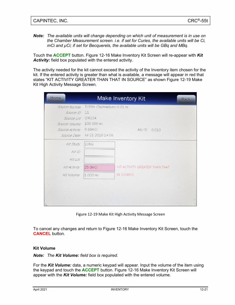
CAPINTEC, INC. CRC®-55t
April 2021 INVENTORY 12-21
Note: The available units will change depending on which unit of measurement is in use on the Chamber Measurement screen. i.e. if set for Curies, the available units will be Ci, mCi and µCi; if set for Becquerels, the available units will be GBq and MBq.
Touch the ACCEPT button. Figure 12-16 Make Inventory Kit Screen will re-appear with Kit Activity: field box populated with the entered activity. The activity needed for the kit cannot exceed the activity of the Inventory item chosen for the kit. If the entered activity is greater than what is available, a message will appear in red that states “KIT ACTIVITY GREATER THAN THAT IN SOURCE” as shown Figure 12-19 Make Kit High Activity Message Screen.
Figure 12-19 Make Kit High Activity Message Screen
To cancel any changes and return to Figure 12-16 Make Inventory Kit Screen, touch the CANCEL button. Kit Volume Note: The Kit Volume: field box is required. For the Kit Volume: data, a numeric keypad will appear. Input the volume of the item using the keypad and touch the ACCEPT button. Figure 12-16 Make Inventory Kit Screen will appear with the Kit Volume: field box populated with the entered volume.

CAPINTEC, INC. CRC®-55t
12-22 INVENTORY April 2021
Note: The minimum value that can be input is 1.00. The maximum value that can be input is
100.00. The kit volume selected must be enough to accommodate the activity needed. If the entered volume not sufficient enough to draw the required activity, a message will appear in red that states “KIT VOLUME LESS THAN THE XX.XXX ml DRAW FROM SOURCE” as shown Figure 12-20 Make Kit Too Little Volume Message Screen. The XX.XXX ml is the minimum volume needed to fulfill the activity requested.
Figure 12-20 Make Kit Too Little Volume Message Screen
Measure Kit Activity When the Kit Volume is sufficient, withdraw the required volume that is displayed on the screen from the Tc99m Inventory item used for the kit. To measure the kit’s activity, touch the MEASURE ACTIVITY button. Figure 12-21 Kit Please Measure Withdrawal Screen will appear.

CAPINTEC, INC. CRC®-55t
April 2021 INVENTORY 12-23
Figure 12-21 Kit Please Measure Withdrawal Screen
Place the kit into the Chamber. To save the measurement, touch the ACCEPT button. The Inventory Main screen will re-appear with the added kit shown in the Inventory List. To abort the measurement, touch the CANCEL button.
WITHDRAWING FROM INVENTORY To withdraw activity from an item in Inventory to be used for a patient (not for a kit), select an Inventory Item from the list by touching the desired item. The entire line for the selected item will become highlighted and the WITHDRAW button will appear on the lower part of the screen as shown in Figure 12-22 Inventory Screen with All Buttons.

CAPINTEC, INC. CRC®-55t
12-24 INVENTORY April 2021
Figure 12-22 Inventory Screen with All Buttons
Touch the WITHDRAW button. Both fields are required (Withdraw Activity and Time of Use) and flash pink. To exit without saving any data input and return to Figure 12-22 Inventory Screen with All Buttons, touch the BACK button. To exit without saving any data input and return to Figure 12-1 Chamber Measurement Screen, touch the HOME button. Withdraw Activity Touch the Touch the Withdraw Activity: field box. Figure 12-23 Enter Activity Screen will appear.

CAPINTEC, INC. CRC®-55t
April 2021 INVENTORY 12-25
Figure 12-23 Enter Activity Screen
Input the activity value using the keypad and touch the appropriate radio button for the unit of measure of the item. Note: The available units will change depending on which unit of measurement is in use on
the Chamber Measurement screen. i.e. if set for Curies, the available units will be Ci, mCi and µCi; if set for Becquerels, the available units will be GBq and MBq.
Touch the ACCEPT button. The Withdraw Activity: field box will be populated with the entered activity. To cancel any changes, touch the CANCEL button. Time of Use Input the date and time that the item withdrawn will be used by touching the Time of Use: field box. Figure 12-24 Date/Time Screen will appear.

CAPINTEC, INC. CRC®-55t
12-26 INVENTORY April 2021
Figure 12-24 Date/Time Screen
The screen displays the currently set date and time. Above and below each of the fields are + and – buttons, respectively. To adjust the displayed value for a specific field, touch the + button to increase the displayed value or the – button to decrease the displayed value. For the year, +10 and -10 buttons are provided to quickly change the tens column of the years. Adjust the displayed date and time to show the calibration date/time of use of the item being withdrawn. Touch the ACCEPT button to accept the set date and time. The Add Inventory screen will re-appear with Date field box populated with the entered calibration date. To cancel any changes and return to the Add Inventory screen, touch the CANCEL button. Measure Activity Withdraw the required volume that is displayed on the screen from the Tc99m Inventory item. To measure the activity, touch the MEASURE ACTIVITY button. Figure 12-25 Please Measure Withdrawal Screen will appear.

CAPINTEC, INC. CRC®-55t
April 2021 INVENTORY 12-27
Figure 12-25 Please Measure Withdrawal Screen
Place the sample into the Chamber. To save the measurement, touch the ACCEPT button. The Inventory Main screen will re-appear with the added kit shown in the Inventory List. To abort the measurement, touch the CANCEL button. The measured activity amount will be subtracted from the selected Inventory item.
PRINTING THE INVENTORY If a printer is attached to the system, a PRINT button will appear on the screen. Touch the PRINT button to print the Inventory List. The contents of the Inventory will be printed, showing the current volume, current activity and for Tc99m, the current Mo to Tc ratio (unless no value was entered).

CAPINTEC, INC. CRC®-55t
12-28 INVENTORY April 2021
DELETING FROM INVENTORY Items can be deleted from inventory in two ways: individually or all items Delete Individual Items To delete individual items, select an Inventory Item from the list by touching the desired item. The entire line for the selected item will become highlighted and the DELETE ITEM button will appear on the lower part of the screen as shown in Figure 12-26 Inventory Screen with All Buttons.
Figure 12-26 Inventory Screen with All Buttons
Touch the DELETE ITEM button. To delete the selected Inventory item, touch the DELETE INVENTORY button. Figure 12-26 Inventory Screen with All Buttons will re-appear with the selected item removed from the Inventory List. To exit without deleting the selected item and return to Figure 12-26 Inventory Screen with All Buttons, touch the BACK button. To exit without deleting the selected item and return to Figure 12-1 Chamber Measurement Screen, touch the HOME button.

CAPINTEC, INC. CRC®-55t
April 2021 INVENTORY 12-29
Delete All Items To delete all items in the Inventory, touch the DELETE ALL button located on the lower part of the screen as shown in Figure 12-26 Inventory Screen with All Buttons. To delete the all Inventory items, touch the YES button. Figure 12-26 Inventory Screen with All Buttons will re-appear with all of the Inventory items removed from the Inventory List. To exit without deleting all Inventory items and return to Figure 12-26 Inventory Screen with All Buttons, touch the NO or BACK button. To exit without deleting all Inventory items and return to Figure 12-1 Chamber Measurement Screen, touch the HOME button.

CAPINTEC, INC. CRC®-55t
April 2021 DOSE TABLE 13-1
CHAPTER 13
DOSE TABLE
GENERAL ...................................................................................................... 13-1 NUCLIDE ........................................................................................................ 13-3 ACTIVITY ....................................................................................................... 13-5 VOLUME ........................................................................................................ 13-5 DOSE ............................................................................................................. 13-6 RESULTS ....................................................................................................... 13-7 INTERVAL ...................................................................................................... 13-7 PRINTING THE RESULTS ............................................................................. 13-8
GENERAL The Dose Table function is used to print a table showing the volume to be withdrawn from a measured sample to obtain a desired dose at future times for the activity that is being measured. From Figure 13-1 Chamber Measurement Screen, touch the UTIL button. Figure 13-2 Utility Screen will appear.
Figure 13-1 Chamber Measurement Screen
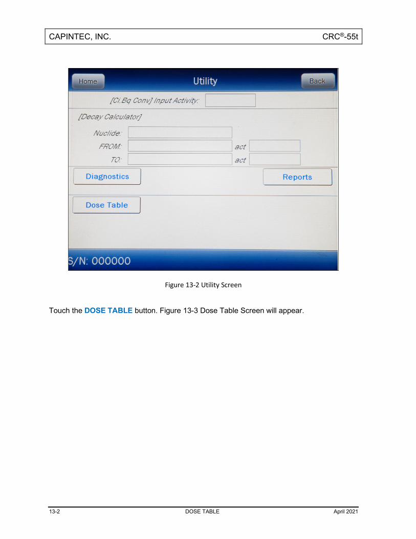
CAPINTEC, INC. CRC®-55t
13-2 DOSE TABLE April 2021
Figure 13-2 Utility Screen
Touch the DOSE TABLE button. Figure 13-3 Dose Table Screen will appear.

CAPINTEC, INC. CRC®-55t
April 2021 DOSE TABLE 13-3
Figure 13-3 Dose Table Screen
To exit without saving any data input and return to Figure 13-2 Utility Screen, touch the BACK button. To exit without saving any data input and return to Figure 13-1 Chamber Measurement Screen, touch the HOME button.
NUCLIDE When entering the Dose Table function, the nuclide that was being measured on Figure 13-1 Chamber Measurement Screen will be set as the default nuclide. To select a different nuclide, touch the Nuclide field box. Figure 13-4 Select Nuclide Screen will appear.

CAPINTEC, INC. CRC®-55t
13-4 DOSE TABLE April 2021
Figure 13-4 Select Nuclide Screen
The left half of the Select Nuclide screen contains the 20 preset NUCLIDE buttons (these are the Select Nuclide Screen Hotkeys). The right half of the screen displays a listing of nuclides stored in the calibrator’s memory (both default and user added nuclides) that have a Calibration Number assigned to them (Reference CHAPTER 6: CHAMBER INITIALIZATION, SECTION: CALIBRATION NUMBERS) – 10 at a time. The nuclide list is in alphabetical order. User added nuclides are displayed at the top of the list. The length of the list will vary depending on which nuclides have a Calibration Number assigned to them. The number of pages shown in the upper right corner of the screen indicates the length of the list. To scroll through the list, touch the DOWN ARROW (▼) button. The next group of 10 nuclides will be displayed and the UP ARROW (▲) button will appear allowing the user to scroll up in the list. To cancel the nuclide selection, touch the CANCEL button. To assign a nuclide for use for the Dose Table, do one of the following:
• Touch one of the preset NUCLIDE keys. Figure 13-3 Dose Table Screen will re-appear with the Nuclide field box populated with the selected nuclide and its half-life.
• Touch the Nuclide name on the list on the right. (If necessary, scroll the list until the desired nuclide is displayed.) Once a nuclide is selected from the list, an ACCEPT button will appear. Touch the ACCEPT button to select nuclide. Figure 13-3 Dose

CAPINTEC, INC. CRC®-55t
April 2021 DOSE TABLE 13-5
Table Screen will re-appear with the Nuclide field box populated with the selected nuclide and its half-life.
ACTIVITY To measure the nuclide’s current activity, touch the Activity field box. Figure 13-5 Measure Activity Screen will appear.
Figure 13-5 Measure Activity Screen
Place the nuclide into the Chamber. To save the measurement, touch the ACCEPT button. Figure 13-3 Dose Table Screen will re-appear with the Activity field box populated with the accepted measured activity. To abort the measurement, touch the CANCEL button.
VOLUME To input the volume of the sample that the dose will be drawn from in ml, touch the Volume field box. A numeric keypad will appear. Input the volume using the keypad and touch the ACCEPT button. Figure 13-3 Dose Table Screen will re-appear with the Volume field box populated with the entered volume.

CAPINTEC, INC. CRC®-55t
13-6 DOSE TABLE April 2021
Note: The minimum value that can be input is 1.00 ml. The maximum value that can be
input is 1000.00 ml. To abort the entering the volume, touch the CANCEL button.
DOSE To input the desired activity of the dose, touch the Dose field box. Figure 13-6 Enter Activity Screen will appear.
Figure 13-6 Enter Activity Screen
Input the desired activity of the dose using the keypad and touch the appropriate radio button for the unit of measure of the item. Note: The available units will change depending on which unit of measurement is in use on
the Chamber Measurement screen. i.e. if set for Curies, the available units will be Ci, mCi and µCi; if set for Becquerels, the available units will be GBq and MBq.
To cancel any changes, touch the CANCEL button. Touch the ACCEPT button. Figure 13-3 Dose Table Screen will re-appear with the Dose field box populated with the entered activity.

CAPINTEC, INC. CRC®-55t
April 2021 DOSE TABLE 13-7
RESULTS After all field boxes are filled in, the calculated results will be displayed with the time and required volume for the desired dose at the specified time intervals appropriate to the nuclide (based on the half life) for up to 30 time intervals as shown in Figure 13-7 Dose Table Results Screen.
Figure 13-7 Dose Table Results Screen
If there is not enough volume for the dose, the last time will show the message “EXCEEDS INTIAL”. This indicates that the volume required for the dose at that time exceeds the sample’s initial volume that was entered.
INTERVAL The Interval field box is the time in minutes from the current time that will be used for calculating the required volume for the dose at the times specified. The default interval is 30 minutes. To change the default time interval, touch the Interval field box. A numeric keypad will appear. Input the time interval using the keypad and touch the ACCEPT button. Figure 13-7

CAPINTEC, INC. CRC®-55t
13-8 DOSE TABLE April 2021
Dose Table Results Screen will appear with the Interval field box populated with the entered time. Note: The minimum time interval that can be input is 1 minute. The maximum time interval
that can be input is 999 minutes. The Interval can be changed repeatedly to obtain new results based on the entered interval.
PRINTING THE RESULTS If a printer is attached to the system, a PRINT button will appear on the screen. Touch the PRINT button to print the results.

CAPINTEC, INC. CRC®-55t
April 2021 REPORTS 14-1
CHAPTER 14
REPORTS
GENERAL ...................................................................................................... 14-1 DAILY TESTS REPORT ................................................................................. 14-4 ZERO MEASUREMENTS REPORT .............................................................. 14-12 CHAMBER VOLTAGE REPORT ................................................................... 14-18 ACCURACY TEST REPORT ........................................................................ 14-24 BACKGROUND MEASUREMENTS REPORT .............................................. 14-30
GENERAL When the Daily, Background, Chamber Voltage and Accuracy/AutoConstancy tests are performed, the results of the tests are saved to a database. The Reports module is used to view and print reports of the saved tests.
Figure 14-1 Main Screen

CAPINTEC, INC. CRC®-55t
14-2 REPORTS April 2021
From Figure 14-1 Main Screen, touch the UTIL button. Figure 14-2 Utility Screen will appear.
Figure 14-2 Utility Screen
To access the Reports module, touch the REPORTS button from Figure 14-2 Utility Screen. Figure 14-3 Reports Screen will appear.

CAPINTEC, INC. CRC®-55t
April 2021 REPORTS 14-3
Figure 14-3 Reports Screen
To exit Figure 14-3 Reports Screen,
• touch the BACK button – Figure 14-2 Utility Screen will re-appear or
• touch the HOME button – Figure 14-1 Main Screen will appear.

CAPINTEC, INC. CRC®-55t
14-4 REPORTS April 2021
DAILY TESTS REPORT From Figure 14-3 Reports Screen, touch the DAILY TEST button. Figure 14-4 Search Daily Tests Screen will appear.
Figure 14-4 Search Daily Tests Screen
To exit Figure 14-4 Search Daily Tests Screen,
• touch the BACK button – Figure 14-3 Reports Screen will re-appear or
• touch the HOME button – Figure 14-1 Main Screen will appear.

CAPINTEC, INC. CRC®-55t
April 2021 REPORTS 14-5
Set Date The Daily Test results are searchable by using a date range. The default From: and To: dates are “today”. To change the From date, touch the From: field box. The Enter Start Date screen will appear. The screen will display the currently set date. Above and below each of the fields are + and – buttons, respectively. To adjust the displayed value for a specific field, touch the + button to increase the displayed value or the – button to decrease the displayed value. For the year, +10 and -10 buttons are provided to quickly change the tens column of the years. Touch the ACCEPT button to accept the set date or the CANCEL button to cancel any changes. Figure 14-4 Search Daily Tests Screen will re-appear showing the From: set date. To change the To date, touch the To: field box. The Enter End Date screen will appear. The screen will display the currently set date. Above and below each of the fields are + and – buttons, respectively. To adjust the displayed value for a specific field, touch the + button to increase the displayed value or the – button to decrease the displayed value. For the year, +10 and -10 buttons are provided to quickly change the tens column of the years. Touch the ACCEPT button to accept the set date or the CANCEL button to cancel any changes. Figure 14-4 Search Daily Tests Screen will re-appear showing the To: set date.

CAPINTEC, INC. CRC®-55t
14-6 REPORTS April 2021
Search When the From and To dates are correct, touch the SEARCH button. The screen will display a listing of the Daily Tests performed within the specified date range as shown in Figure 14-5 Search Daily Tests Screen after Searching.
Figure 14-5 Search Daily Tests Screen after Searching
Note: If the search results in more than 100 items, the message “Search Daily Tests Error
More than 100 items have been returned Please refine criteria” will appear. Refine the search by narrowing the date range to search for.
To exit Figure 14-5 Search Daily Tests Screen after Searching,
• touch the BACK button – Figure 14-3 Reports Screen will re-appear or
• touch the HOME button – Figure 14-1 Main Screen will appear. The listing is in reverse chronological order (newest at the top of the list). The length of the list will vary depending on how many Daily Tests have been performed between the selected dates. If there are more than 10 results, the number of pages (or screens) will be shown in the upper right corner of the screen indicating the length of the list. To scroll through the list, touch the DOWN ARROW (▼) button. The next group of 10 results will be displayed and the UP ARROW (▲) buttonwill appear allowing the user to scroll up in the list.

CAPINTEC, INC. CRC®-55t
April 2021 REPORTS 14-7
Print Search Results If a printer is attached to the system, a report of the search results can be printed by touching the PRINT button. This report will contain the detailed results for all tests listed on the Search screen.
Viewing an Individual Test Report To obtain a detailed report for an individual Daily Test result, from Figure 14-5 Search Daily Tests Screen after Searching, touch the desired result on the list. The result will become highlighted and a VIEW button will appear on the screen as shown in Figure 14-6 Search Daily Tests Screen with Highlighted Test Result. (If necessary, scroll the list until the desired result is displayed.)
Figure 14-6 Search Daily Tests Screen with Highlighted Test Result
Touch the VIEW button. Figure 14-7 Daily Test Report Screen will appear displaying the detailed report for the selected Daily Test result.

CAPINTEC, INC. CRC®-55t
14-8 REPORTS April 2021
Figure 14-7 Daily Test Report Screen
To exit Figure 14-7 Daily Test Report Screen,
• touch the BACK button – Figure 14-5 Search Daily Tests Screen after Searching will re-appear or
• touch the HOME button – Figure 14-1 Main Screen will appear.
Accuracy Test If an Accuracy Test was performed as part of the selected Daily Test, an Accuracy Test button will be displayed as shown in Figure 14-7 Daily Test Report Screen. If an Accuracy Test was not performed as part of the Daily Test, the Accuracy Test button will not be displayed. To view the Accuracy Test results, touch the ACCURACY TEST button. A screen similar to Figure 14-20 Accuracy Test Result Screen will appear. To exit the Accuracy Test Result screen,
• touch the BACK button – Figure 14-7 Daily Test Report Screen will re-appear or
• touch the HOME button – Figure 14-1 Main Screen will appear.

CAPINTEC, INC. CRC®-55t
April 2021 REPORTS 14-9
AutoConstancy Test If an AutoConstancy Test was performed as part of the Accuracy Test of the selected Daily Test, an AutoConstancy button will be displayed on the Accuracy Test Results screen. If the AutoConstancy Test was not performed as part of the Accuracy Test of the Daily Test, the AutoConstancy button will not be displayed. To view the AutoConstancy results, touch the AUTOCONSTANCY button. The AutoConstancy Results screen will appear. To exit the AutoConstancy Result screen,
• touch the BACK button – the Accuracy Test Result screen will re-appear or
• touch the HOME button – Figure 14-1 Main Screen will appear.
Print Individual Results If a printer is attached to the system, a detailed report of the selected Daily Test result can be printed. Touching the PRINT button on any of the results screens (Daily Test, Accuracy or AutoConstancy) will print the entire Daily Test report.
Inactivate a Daily Test A Daily Test result can be inactivated. Reasons for doing this can be:
• the test was a simulation for training,
• a mistake was made doing the test, etc. It is important to note that once a Daily Test has been inactivated, it cannot be reactivated. The Daily Test result will still be saved in the database. When the inactivated Daily Test is displayed on the list, it will be shown with a line through the characters. When the report is printed, the word “INACTIVE” and the optional comment will appear below the data. When inactivating a Daily Test, all tests associated with that Daily Test will also be inactivated (Zero, Background, Chamber Voltage and Accuracy/Constancy). To inactivate the selected Daily Test, touch the INACTIVATE button. Figure 14-8 Inactivate Record Screen will appear.

CAPINTEC, INC. CRC®-55t
14-10 REPORTS April 2021
Figure 14-8 Inactivate Record Screen
To enter an optional comment (description or reason) for the selected Daily Test result inactivation, touch the Comment: field box. Figure 14-9 Alphanumeric Keypad Screen will appear.

CAPINTEC, INC. CRC®-55t
April 2021 REPORTS 14-11
Figure 14-9 Alphanumeric Keypad Screen
Input the desired comment (description or reason) for the invalidation and touch the ACCEPT button. Figure 14-8 Inactivate Record Screen will re-appear with the Comment: field box populated with the entered comment. The comment can contain any combination of 22 alphanumeric characters maximum. To cancel any comment changes and return to Figure 14-8 Inactivate Record Screen, touch the CANCEL button. If it is decided not to inactivate the selected Daily Test result, touch the NO button. Figure 14-7 Daily Test Report Screen will re-appear. To complete the inactivation of the selected Daily Test result, touch the YES button. Figure 14-5 Search Daily Tests Screen after Searching will re-appear with a line through the characters of the inactivated Daily Test.

CAPINTEC, INC. CRC®-55t
14-12 REPORTS April 2021
ZERO MEASUREMENTS REPORT From Figure 14-3 Reports Screen, touch the ZERO button. Figure 14-10 Search Zero Measurements Screen will appear.
Figure 14-10 Search Zero Measurements Screen
Set Date The Zero Measurement results are searchable by using a date range. The default From: and To: dates are “today”. To change the From date, touch the From: field box. The Enter Start Date screen will appear. The screen will display the currently set date. Above and below each of the fields are + and – buttons, respectively. To adjust the displayed value for a specific field, touch the + button to increase the displayed value or the – button to decrease the displayed value. For the year, +10 and -10 buttons are provided to quickly change the tens column of the years. Touch the ACCEPT button to accept the set date or the CANCEL button to cancel any changes. The Search Zero Measurements Screen will re-appear showing the From: set date.

CAPINTEC, INC. CRC®-55t
April 2021 REPORTS 14-13
To change the To date, touch the To: field box. The Enter End Date screen will appear. The screen will display the currently set date. Above and below each of the fields are + and – buttons, respectively. To adjust the displayed value for a specific field, touch the + button to increase the displayed value or the – button to decrease the displayed value. For the year, +10 and -10 buttons are provided to quickly change the tens column of the years. Touch the ACCEPT button to accept the set date or the CANCEL button to cancel any changes. The Search Zero Measurements Screen will re-appear showing the To: set date. Search When the From and To dates are correct, touch the SEARCH button. The screen displays a listing of the data for the Zero Measurements performed within the specified date range as shown in Figure 14-11 Search Zero Measurements Screen after Searching.
Figure 14-11 Search Zero Measurements Screen after Searching
Note: If the search results in more than 100 items, the message “Search Zero
Measurements Error More than 100 items have been returned Please refine criteria” will appear. Refine the search by narrowing the date range to search for.

CAPINTEC, INC. CRC®-55t
14-14 REPORTS April 2021
To exit Figure 14-11 Search Zero Measurements Screen after Searching,
• touch the BACK button – Figure 14-3 Reports Screen will re-appear or
• touch the HOME button – Figure 14-1 Main Screen will appear. The listing is in reverse chronological order (newest at the top of the list). The length of the list will vary depending on how many Zero Measurements have been performed between the selected dates. If there are more than 10 results, the number of pages (or screens) will be shown in the upper right corner of the screen indicating the length of the list. To scroll through the list, touch the DOWN ARROW (▼) button. The next group of 10 results will be displayed and the UP ARROW (▲) button will appear allowing the user to scroll up in the list.
Print Search Results If a printer is attached to the system, a report of the search results can be printed by touching the PRINT button. This report will contain the detailed results for all tests listed on the Search screen.
Viewing an Individual Test Report To obtain a detailed report for a particular Zero Measurement result, from Figure 14-11 Search Zero Measurements Screen after Searching, touch the desired result on the list. The result will become highlighted and a VIEW button will appear on the screen similar to that shown in Figure 14-6 Search Daily Tests Screen with Highlighted Test Result. (If necessary, scroll the list until the desired result is displayed.) Touch the VIEW button. Figure 14-12 Zero Measurement Result Screen will appear displaying the detailed report for the selected Zero Measurement test.

CAPINTEC, INC. CRC®-55t
April 2021 REPORTS 14-15
Figure 14-12 Zero Measurement Result Screen
To exit Figure 14-12 Zero Measurement Result Screen,
• touch the BACK button – Figure 14-11 Search Zero Measurements Screen after Searching will re-appear or
• touch the HOME button – Figure 14-1 Main Screen will appear.
Print Individual Results If a printer is attached to the system, a detailed report of the selected Zero measurement result can be printed. Touching the PRINT button on the results screen will print the selected Zero Measurement report.
Inactivate a Zero Measurement Note: This section is only included for legacy systems. Remote Displays are no
longer available as an option. The INACTIVATE button will be displayed on Figure 14-12 Zero Measurement Result Screen only if a Zero measurement was performed using the optional legacy Remote

CAPINTEC, INC. CRC®-55t
14-16 REPORTS April 2021
Display. If the selected Zero Measurement was part of a Daily Test, the INACTIVATE button will not be displayed. Only a Zero measurement that was made using the optional legacy Remote Display can be inactivated. Reasons for doing this can be:
• the test was a simulation for training,
• a mistake was made doing the test, etc. It is important to note that once a Zero measurement has been inactivated, it cannot be reactivated. The Zero measurement result will still be saved in the database. When the inactivated Zero measurement is displayed on the list, it will be shown with a line through the characters. When the report is printed, the word “INACTIVE” and the optional comment will appear below the data. To inactivate the selected Zero measurement, touch the INACTIVATE button. Figure 14-13 Inactivate Record Screen will appear.
Figure 14-13 Inactivate Record Screen
To enter an optional comment (description or reason) for the selected Zero measurement result inactivation, touch the Comment: field box. Figure 14-14 Alphanumeric Keypad Screen will appear.

CAPINTEC, INC. CRC®-55t
April 2021 REPORTS 14-17
Figure 14-14 Alphanumeric Keypad Screen
Input the desired comment (description or reason) for the invalidation and touch the ACCEPT button. Figure 14-13 Inactivate Record Screen will re-appear with the Comment: field box populated with the entered comment. The comment can contain any combination of 22 alphanumeric characters maximum. To cancel any comment changes and return to Figure 14-13 Inactivate Record Screen, touch the CANCEL button. If it is decided not to inactivate the selected Zero Measurement result, touch the NO button. Figure 14-12 Zero Measurement Result Screen will re-appear. To complete the inactivation of the selected Zero Measurement result, touch the YES button. Figure 14-11 Search Zero Measurements Screen after Searching will re-appear with a line through the characters of the inactivated Zero measurement.

CAPINTEC, INC. CRC®-55t
14-18 REPORTS April 2021
CHAMBER VOLTAGE REPORT From Figure 14-3 Reports Screen, touch the CHAMBER VOLTAGE button. The Search Chamber Voltage Tests Screen will appear and be similar to that shown in Figure 14-10 Search Zero Measurements Screen. Set Date The Chamber Voltage Test results are searchable by using a date range. The default From: and To: dates are “today”. To change the From date, touch the From: field box. The Enter Start Date screen will appear. The screen will display the currently set date. Above and below each of the fields are + and – buttons, respectively. To adjust the displayed value for a specific field, touch the + button to increase the displayed value or the – button to decrease the displayed value. For the year, +10 and -10 buttons are provided to quickly change the tens column of the years. Touch the ACCEPT button to accept the set date or the CANCEL button to cancel any changes. The Search Chamber Voltage Tests Screen will re-appear showing the From: set date. To change the To date, touch the To: field box. The Enter End Date screen will appear. The screen will display the currently set date. Above and below each of the fields are + and – buttons, respectively. To adjust the displayed value for a specific field, touch the + button to increase the displayed value or the – button to decrease the displayed value. For the year, +10 and -10 buttons are provided to quickly change the tens column of the years. Touch the ACCEPT button to accept the set date or the CANCEL button to cancel any changes. The Search Chamber Voltage Tests Screen will re-appear showing the To: set date. Search When the From and To dates are correct, touch the SEARCH button. The screen displays a listing of the data for the Chamber Voltage Tests performed within the specified date range as shown in Figure 14-15 Search Chamber Voltage Tests Screen after Searching.

CAPINTEC, INC. CRC®-55t
April 2021 REPORTS 14-19
Figure 14-15 Search Chamber Voltage Tests Screen after Searching
Note: If the search results in more than 100 items, the message “Search Chamber Voltage
Test Error More than 100 items have been returned Please refine criteria” will appear. Refine the search by narrowing the date range to search for.
To exit Figure 14-15 Search Chamber Voltage Tests Screen after Searching,
• touch the BACK button – Figure 14-3 Reports Screen will re-appear or
• touch the HOME button – Figure 14-1 Main Screen will appear. The listing is in reverse chronological order (newest at the top of the list). The length of the list will vary depending on how many Chamber Voltage Tests have been performed between the selected dates. If there are more than 10 results, the number of pages (or screens) will be shown in the upper right corner of the screen indicating the length of the list. To scroll through the list, touch the DOWN ARROW (▼) button. The next group of 10 results will be displayed and the UP ARROW (▲) button will appear allowing the user to scroll up in the list.
Print Search Results If a printer is attached to the system, a report of the search results can be printed by touching the PRINT button. This report will contain the detailed results for all tests listed on the Search screen.

CAPINTEC, INC. CRC®-55t
14-20 REPORTS April 2021
Viewing an Individual Test Report To obtain a detailed report for a particular Chamber Voltage measurement result, from Figure 14-15 Search Chamber Voltage Tests Screen after Searching, touch the desired result on the list. The result will become highlighted and a VIEW button will appear on the screen similar to that shown in Figure 14-6 Search Daily Tests Screen with Highlighted Test Result. (If necessary, scroll the list until the desired result is displayed.) Touch the VIEW button. Figure 14-16 Chamber Voltage Test Result Screen will appear displaying the detailed report for the selected Chamber Voltage Test result.
Figure 14-16 Chamber Voltage Test Result Screen

CAPINTEC, INC. CRC®-55t
April 2021 REPORTS 14-21
To exit Figure 14-16 Chamber Voltage Test Result Screen,
• touch the BACK button – Figure 14-15 Search Chamber Voltage Tests Screen after Searching will re-appear or
• touch the HOME button – Figure 14-1 Main Screen will appear. The results screen displays the following:
• Chamber Voltage: This is the actual Chamber Voltage measurement that was recorded when the test was performed.
• Nominal Voltage: This is what the Chamber Voltage measurement was when the system was calibrated at the factory.
• Min Voltage: This is the minimum Chamber Voltage allowed before the system will indicate “FAIL” during the Chamber Voltage test. This is the Nominal Voltage minus 5%.
• Max Voltage: This is the maximum Chamber Voltage allowed before the system will indicate “FAIL” during the Chamber Voltage test. This is the Nominal Voltage plus 5%.
Print Individual Results If a printer is attached to the system, a detailed report of the selected Chamber Voltage test result can be printed. Touching the PRINT button on the results screen will print the selected Chamber Voltage report.
Inactivate a Chamber Voltage Measurement The INACTIVATE button will be displayed on Figure 14-16 Chamber Voltage Test Result Screen if a Chamber Voltage test was performed using the Chamber Voltage button on Figure 14-1 Main Screen or by using the optional legacy Remote Display (Note: This applies only to legacy systems. Remote Displays are no longer available as an option.). If the selected Chamber Voltage measurement was part of a Daily Test, the INACTIVATE button will not be displayed. Only a Chamber Voltage measurement that was made using the Chamber Voltage button on Figure 14-1 Main Screen or by using the optional legacy Remote Display can be inactivated. To inactivate a Chamber Voltage measurement that was part of a Daily Test, the entire corresponding Daily Test must be inactivated. Reasons for doing this can be:
• the test was a simulation for training,
• a mistake was made doing the test, etc. It is important to note that once a Chamber Voltage measurement has been inactivated, it cannot be reactivated. The Chamber Voltage measurement result will still be saved in the database.

CAPINTEC, INC. CRC®-55t
14-22 REPORTS April 2021
When the inactivated Chamber Voltage measurement is displayed on the list, it will be shown with a line through the characters. When the report is printed, the word “INACTIVE” and the optional comment will appear below the data. To inactivate the selected Chamber Voltage measurement, touch the INACTIVATE button. Figure 14-17 Inactivate Record Screen will appear.
Figure 14-17 Inactivate Record Screen
To enter an optional comment (description or reason) for the selected Chamber Voltage measurement result inactivation, touch the Comment: field box. Figure 14-18 Alphanumeric Keypad Screen will appear.

CAPINTEC, INC. CRC®-55t
April 2021 REPORTS 14-23
Figure 14-18 Alphanumeric Keypad Screen
Input the desired comment (description or reason) for the invalidation and touch the ACCEPT button. Figure 14-17 Inactivate Record Screen will re-appear with the Comment: field box populated with the entered comment. The comment can contain any combination of 22 alphanumeric characters maximum. To cancel any comment changes and return to Figure 14-17 Inactivate Record Screen, touch the CANCEL button. If it is decided not to inactivate the selected Chamber Voltage measurement result, touch the NO button. Figure 14-16 Chamber Voltage Test Result Screen will re-appear. To complete the inactivation of the selected Chamber Voltage result, touch the YES button. Figure 14-15 Search Chamber Voltage Tests Screen after Searching will re-appear with a line through the characters of the inactivated Chamber Voltage measurement.

CAPINTEC, INC. CRC®-55t
14-24 REPORTS April 2021
ACCURACY TEST REPORT From Figure 14-3 Reports Screen, touch the ACCURACY TEST button. The Search Accuracy Tests Screen will appear and be similar to that shown in Figure 14-10 Search Zero Measurements Screen. Set Date The Accuracy Test results are searchable by using a date range. The default From: and To: dates are “today”. To change the From date, touch the From: field box. The Enter Start Date screen will appear. The screen will display the currently set date. Above and below each of the fields are + and – buttons, respectively. To adjust the displayed value for a specific field, touch the + button to increase the displayed value or the – button to decrease the displayed value. For the year, +10 and -10 buttons are provided to quickly change the tens column of the years. Touch the ACCEPT button to accept the set date or the CANCEL button to cancel any changes. The Search Accuracy Tests Screen will re-appear showing the From: set date. To change the To date, touch the To: field box. The Enter End Date screen will appear. The screen will display the currently set date. Above and below each of the fields are + and – buttons, respectively. To adjust the displayed value for a specific field, touch the + button to increase the displayed value or the – button to decrease the displayed value. For the year, +10 and -10 buttons are provided to quickly change the tens column of the years. Touch the ACCEPT button to accept the set date or the CANCEL button to cancel any changes. The Search Accuracy Tests Screen will re-appear showing the To: set date. Search When the From and To dates are correct, touch the SEARCH button. The screen displays a listing of the data for the Accuracy Tests performed within the specified date range as shown in Figure 14-19 Search Accuracy Tests Screen after Searching.

CAPINTEC, INC. CRC®-55t
April 2021 REPORTS 14-25
Figure 14-19 Search Accuracy Tests Screen after Searching
Note: If the search results in more than 100 items, the message “Search Accuracy Test
Error More than 100 items have been returned Please refine criteria” will appear. Refine the search by narrowing the date range to search for.
To exit Figure 14-19 Search Accuracy Tests Screen after Searching,
• touch the BACK button – Figure 14-3 Reports Screen will re-appear or
• touch the HOME button – Figure 14-1 Main Screen will appear. The listing is in reverse chronological order (newest at the top of the list). The length of the list will vary depending on how many Accuracy Tests have been performed between the selected dates. If there are more than 10 results, the number of pages (or screens) will be shown in the upper right corner of the screen indicating the length of the list. To scroll through the list, touch the DOWN ARROW (▼) button. The next group of 10 results will be displayed and the UP ARROW (▲) button will appear allowing the user to scroll up in the list.
Print Search Results If a printer is attached to the system, a report of the search results can be printed by touching the PRINT button. This report will contain the detailed results for all tests listed on the Search screen.
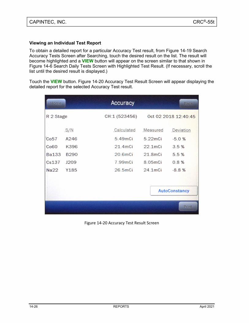
CAPINTEC, INC. CRC®-55t
14-26 REPORTS April 2021
Viewing an Individual Test Report To obtain a detailed report for a particular Accuracy Test result, from Figure 14-19 Search Accuracy Tests Screen after Searching, touch the desired result on the list. The result will become highlighted and a VIEW button will appear on the screen similar to that shown in Figure 14-6 Search Daily Tests Screen with Highlighted Test Result. (If necessary, scroll the list until the desired result is displayed.) Touch the VIEW button. Figure 14-20 Accuracy Test Result Screen will appear displaying the detailed report for the selected Accuracy Test result.
Figure 14-20 Accuracy Test Result Screen

CAPINTEC, INC. CRC®-55t
April 2021 REPORTS 14-27
To exit Figure 14-20 Accuracy Test Result Screen,
• touch the BACK button – Figure 14-19 Search Accuracy Tests Screen after Searching will re-appear or
• touch the HOME button – Figure 14-1 Main Screen will appear.
AutoConstancy Test If an AutoConstancy Test was performed as part of the selected Accuracy Test, an AutoConstancy button will be displayed on the Accuracy Test Results screen. If the AutoConstancy Test was not performed as part of the Accuracy Test of the Daily Test, the AutoConstancy button will not be displayed. To view the AutoConstancy results, touch the AUTOCONSTANCY button. The AutoConstancy Results screen will appear. To exit the AutoConstancy Result screen,
• touch the BACK button – Figure 14-20 Accuracy Test Result Screen will re-appear or
• touch the HOME button – Figure 14-1 Main Screen will appear.
Print Individual Results If a printer is attached to the system, a detailed report of the selected Accuracy test result can be printed. Touching the PRINT button on either the Accuracy Test results screen or the AutoConstancy Test results screen will print the selected Accuracy Test report. If the selected Accuracy/AutoConstancy Test is part of a Daily Test, the report will contain all of the Daily Test data. If an AutoConstancy was performed as part of the selected Accuracy Test, the AutoConstancy results will also be included on the printout.
Inactivate an Accuracy/AutoConstancy Test The INACTIVATE button will be displayed on Figure 14-20 Accuracy Test Result Screen if the selected Accuracy Test was performed using the Accuracy button on Figure 14-1 Main Screen. If the selected Accuracy Test was part of a Daily Test, the INACTIVATE button will not be displayed. Only an Accuracy Test that was made using the Accuracy button on Figure 14-1 Main Screen can be inactivated. To inactivate an Accuracy Test that was part of a Daily Test, the entire corresponding Daily Test must be inactivated. Reasons for doing this can be:
• the test was a simulation for training,

CAPINTEC, INC. CRC®-55t
14-28 REPORTS April 2021
• a mistake was made doing the test, etc. It is important to note that once an Accuracy Test has been inactivated, it cannot be reactivated. The Accuracy Test result will still be saved in the database. When the inactivated Accuracy Test is displayed on the list, it will be shown with a line through the characters. When the report is printed, the word “INACTIVE” and the optional comment will appear below the data. To inactivate the selected Accuracy Test, touch the INACTIVATE button. Figure 14-21 Inactivate Record Screen will appear.
Figure 14-21 Inactivate Record Screen
To enter an optional comment (description or reason) for the selected Accuracy Test result inactivation, touch the Comment: field box. Figure 14-22 Alphanumeric Keypad Screen will appear.

CAPINTEC, INC. CRC®-55t
April 2021 REPORTS 14-29
Figure 14-22 Alphanumeric Keypad Screen
Input the desired comment (description or reason) for the invalidation and touch the ACCEPT button. Figure 14-21 Inactivate Record Screen will re-appear with the Comment: field box populated with the entered comment. The comment can contain any combination of 22 alphanumeric characters maximum. To cancel any comment changes and return to Figure 14-21 Inactivate Record Screen, touch the CANCEL button. If it is decided not to inactivate the selected Accuracy Test result, touch the NO button. Figure 14-20 Accuracy Test Result Screen will re-appear. To complete the inactivation of the selected Accuracy Test result, touch the YES button. Figure 14-19 Search Accuracy Tests Screen after Searching will re-appear with a line through the characters of the inactivated Accuracy Test.

CAPINTEC, INC. CRC®-55t
14-30 REPORTS April 2021
BACKGROUND MEASUREMENTS REPORT From Figure 14-3 Reports Screen, touch the BACKGROUND button. The Search Background Measurements Screen will appear and be similar to that shown in Figure 14-10 Search Zero Measurements Screen. Set Date The Background Measurement results are searchable by using a date range. The default From: and To: dates are “today”. To change the From date, touch the From: field box. The Enter Start Date screen will appear. The screen will display the currently set date. Above and below each of the fields are + and – buttons, respectively. To adjust the displayed value for a specific field, touch the + button to increase the displayed value or the – button to decrease the displayed value. For the year, +10 and -10 buttons are provided to quickly change the tens column of the years. Touch the ACCEPT button to accept the set date or the CANCEL button to cancel any changes. The Search Background Measurements Screen will re-appear showing the From: set date. To change the To date, touch the To: field box. The Enter End Date screen will appear. The screen will display the currently set date. Above and below each of the fields are + and – buttons, respectively. To adjust the displayed value for a specific field, touch the + button to increase the displayed value or the – button to decrease the displayed value. For the year, +10 and -10 buttons are provided to quickly change the tens column of the years. Touch the ACCEPT button to accept the set date or the CANCEL button to cancel any changes. The Search Background Measurements Screen will re-appear showing the To: set date. Search When the From and To dates are correct, touch the SEARCH button. The screen displays a listing of the data for the Background Measurements performed within the specified date range as shown in Figure 14-23 Search Background Measurements Screen after Searching.

CAPINTEC, INC. CRC®-55t
April 2021 REPORTS 14-31
Figure 14-23 Search Background Measurements Screen after Searching
Note: If the search results in more than 100 items, the message “Search Background
Measurements Error More than 100 items have been returned Please refine criteria” will appear. Refine the search by narrowing the date range to search for.
To exit Figure 14-23 Search Background Measurements Screen after Searching,
• touch the BACK button – Figure 14-3 Reports Screen will re-appear or
• touch the HOME button – Figure 14-1 Main Screen will appear. The listing is in reverse chronological order (newest at the top of the list). The length of the list will vary depending on how many Background Measurements have been performed between the selected dates. If there are more than 10 results, the number of pages (or screens) will be shown in the upper right corner of the screen indicating the length of the list. To scroll through the list, touch the DOWN ARROW (▼) button. The next group of 10 results will be displayed and the UP ARROW (▲) button will appear allowing the user to scroll up in the list.
Print Search Results If a printer is attached to the system, a report of the search results can be printed by touching the PRINT button. This report will contain the detailed results for all tests listed on the Search screen.

CAPINTEC, INC. CRC®-55t
14-32 REPORTS April 2021
Viewing an Individual Test Report To obtain a detailed report for a particular Background Measurement result, from Figure 14-23 Search Background Measurements Screen after Searching, touch the desired result on the list. The result will become highlighted and a VIEW button will appear on the screen similar to that shown in Figure 14-6 Search Daily Tests Screen with Highlighted Test Result. (If necessary, scroll the list until the desired result is displayed.) Touch the VIEW button. Figure 14-24 Background Measurement Result Screen will appear displaying the detailed report for the selected Background Measurement result.
Figure 14-24 Background Measurement Result Screen

CAPINTEC, INC. CRC®-55t
April 2021 REPORTS 14-33
To exit Figure 14-24 Background Measurement Result Screen,
• touch the BACK button – the Search Background Measurements screen will re-appear or
• touch the HOME button – Figure 14-1 Main Screen will appear.
Print Individual Results If a printer is attached to the system, a detailed report of the selected Background measurement result can be printed. Touching the PRINT button on the results screen will print the selected Background Measurement report.
Inactivate a Background Measurement The INACTIVATE button will be displayed on Figure 14-24 Background Measurement Result Screen if a Background measurement was performed using the Background button on Figure 14-1 Main Screen or by using the optional legacy Remote Display (Note: This applies only to legacy systems. Remote Displays are no longer available as an option.). If the selected Background measurement was part of a Daily Test, the INACTIVATE button will not be displayed. Only a Background measurement that was made using the Background button on Figure 14-1 Main Screen or by using the optional legacy Remote Display can be inactivated. To inactivate a Background measurement that was part of a Daily Test, the entire corresponding Daily Test must be inactivated. Reasons for doing this can be:
• the test was a simulation for training,
• a mistake was made doing the test, etc. It is important to note that once a Background measurement has been inactivated, it cannot be reactivated. The Background measurement result will still be saved in the database. When the inactivated Background measurement is displayed on the list, it will be shown with a line through the characters. When the report is printed, the word “INACTIVE” and the optional comment will appear below the data. To inactivate the selected Background measurement, touch the INACTIVATE button. Figure 14-25 Inactivate Record Screen will appear.

CAPINTEC, INC. CRC®-55t
14-34 REPORTS April 2021
Figure 14-25 Inactivate Record Screen
To enter an optional comment (description or reason) for the selected Background measurement result inactivation, touch the Comment: field box. Figure 14-26 Alphanumeric Keypad Screen will appear.

CAPINTEC, INC. CRC®-55t
April 2021 REPORTS 14-35
Figure 14-26 Alphanumeric Keypad Screen
Input the desired comment (description or reason) for the invalidation and touch the ACCEPT button. Figure 14-25 Inactivate Record Screen will re-appear with the Comment: field box populated with the entered comment. The comment can contain any combination of 22 alphanumeric characters maximum. To cancel any comment changes and return to Figure 14-25 Inactivate Record Screen, touch the CANCEL button. If it is decided not to inactivate the selected Background measurement result, touch the NO button. Figure 14-24 Background Measurement Result Screen will re-appear. To complete the inactivation of the selected Background measurement result, touch the YES button. Figure 14-23 Search Background Measurements Screen after Searching will re-appear with a line through the characters of the inactivated Background measurement.

CAPINTEC, INC. CRC®-55t
April 2021 CALCULATION UTILITIES 15-1
CHAPTER 15
CALCULATION UTILITIES
GENERAL ...................................................................................................... 15-1 CONVERSION BETWEEN Ci AND Bq .......................................................... 15-2 DECAY CALCULATOR ................................................................................. 15-4
Select Nuclide ............................................................................................ 15-4 Date and Activity ....................................................................................... 15-5 Results ....................................................................................................... 15-9
GENERAL Two calculation utilities are provided with the CRC®-55t:
• Conversion between Curie and Becquerel and
• Decay Calculation. To access the calculation utilities, touch the UTIL button from Figure 15-1 Chamber Measurement Screen. Figure 15-2 Utility Screen will appear.
Figure 15-1 Chamber Measurement Screen

CAPINTEC, INC. CRC®-55t
15-2 CALCULATION UTILITIES April 2021
Figure 15-2 Utility Screen
CONVERSION BETWEEN CI AND BQ Located in the top section of Figure 15-2 Utility Screen is the Curie/Becquerel converter. An activity is input in Curies and the value is displayed in Becquerels or an activity is input in Becquerels and the value is displayed in Curies. To perform a conversion, touch the [Ci,Bq Conv] Input Activity: field box. Figure 15-3 Enter Activity Screen will appear.

CAPINTEC, INC. CRC®-55t
April 2021 CALCULATION UTILITIES 15-3
Figure 15-3 Enter Activity Screen
Input the activity to be converted using the keypad and touch the appropriate radio button for the unit of measure. To exit the Curie/Becquerel converter and return to Figure 15-2 Utility Screen, touch the CANCEL button. Once the activity and units are correct, touch the ACCEPT button. Figure 15-2 Utility Screen will re-appear with the [Ci,Bq Conv] Input Activity: field box populated with the entered activity. The result of the conversion is located next to the field box. To perform another conversion, touch the [Ci,Bq Conv] Input Activity: field box. Figure 15-3 Enter Activity Screen will appear.

CAPINTEC, INC. CRC®-55t
15-4 CALCULATION UTILITIES April 2021
DECAY CALCULATOR Located in the center section of Figure 15-2 Utility Screen is the Decay Calculator. This utility is used to calculate the activity of a source at a different time (either in the past or the future). Select Nuclide To select the desired nuclide, touch the Nuclide: field box. Figure 15-4 Select Nuclide Screen will appear.
Figure 15-4 Select Nuclide Screen
The left half of the Select Nuclide screen contains the 20 preset NUCLIDE buttons (these are the Select Nuclide Screen Hotkeys). The right half of the screen displays a listing of nuclides stored in the calibrator’s memory (both default and user added nuclides) that have a Calibration Number assigned to them (Reference CHAPTER 6: CHAMBER INITIALIZATION, SECTION: CALIBRATION NUMBERS) – 10 at a time. The nuclide list is in alphabetical order. User added nuclides are displayed at the top of the list. The length of the list will vary depending on which nuclides have a Calibration Number assigned to them (Reference CHAPTER 6: CHAMBER INITIALIZATION, SECTION: CALIBRATION NUMBERS). The number of pages shown in the upper right corner of the screen indicates the length of the list. To scroll through the list, touch the DOWN ARROW (▼) button. The next group of 10 nuclides will be displayed and the UP ARROW (▲) button will appear allowing the user to scroll up in the list.

CAPINTEC, INC. CRC®-55t
April 2021 CALCULATION UTILITIES 15-5
To cancel the nuclide selection and return to Figure 15-2 Utility Screen, touch the CANCEL button. To select a nuclide for calculation, do one of the following:
• Touch one of the preset NUCLIDE keys (Select Nuclide Screen Hotkeys). Figure 15-2 Utility Screen will re-appear with the selected nuclide name and half-life shown in the Nuclide: field box.
• Touch the Nuclide name on the list on the right. (If necessary, scroll the list until the desired nuclide is displayed.) Once a nuclide is selected from the list, an ACCEPT button will appear. Touch the ACCEPT button to use the selected nuclide. Figure 15-2 Utility Screen will re-appear with the selected nuclide name and half-life shown in the chosen Nuclide: field box.
Date and Activity The beginning (From) and ending (To) date, time and activity must be input to perform the calculation.
Beginning Date and Time To input the beginning date and time for the calculation, touch the FROM: field box. Figure 15-5 Date/Time Screen will appear.
Figure 15-5 Date/Time Screen

CAPINTEC, INC. CRC®-55t
15-6 CALCULATION UTILITIES April 2021
The screen displays the currently set date and time. Above and below each of the fields are + and – buttons, respectively. To adjust the displayed value for a specific field, touch the + button to increase the displayed value or the – button to decrease the displayed value. For the year, +10 and -10 buttons are provided to quickly change the tens column of the years. Adjust the displayed date and time as required to show the beginning date/time of the calculation. To cancel any changes and return to the Figure 15-2 Utility Screen, touch the CANCEL button. Touch the ACCEPT button to accept the set date and time. Figure 15-2 Utility Screen will re-appear with FROM: field box populated with the entered date and time.

CAPINTEC, INC. CRC®-55t
April 2021 CALCULATION UTILITIES 15-7
Beginning Activity To input the beginning activity for the calculation, touch the FROM: act field box. Figure 15-6 Enter Activity Screen will appear.
Figure 15-6 Enter Activity Screen
Input the beginning activity to be converted using the keypad and touch the appropriate radio button for the unit of measure. To cancel any changes and return to the Figure 15-2 Utility Screen, touch the CANCEL button. Touch the ACCEPT button to accept entered activity. Figure 15-2 Utility Screen will re-appear with FROM: act field box populated with the entered activity.

CAPINTEC, INC. CRC®-55t
15-8 CALCULATION UTILITIES April 2021
Ending Date and Time To input the ending date and time for the calculation, touch the TO: field box. Figure 15-7 Date/Time Screen will appear.
Figure 15-7 Date/Time Screen
The screen displays the currently set date and time. Above and below each of the fields are + and – buttons, respectively. To adjust the displayed value for a specific field, touch the + button to increase the displayed value or the – button to decrease the displayed value. For the year, +10 and -10 buttons are provided to quickly change the tens column of the years. Adjust the displayed date and time as required to show the ending date/time of the calculation. To cancel any changes and return to the Figure 15-2 Utility Screen, touch the CANCEL button. Touch the ACCEPT button to accept the set date and time. Figure 15-2 Utility Screen will re-appear with TO: field box populated with the entered date and time.

CAPINTEC, INC. CRC®-55t
April 2021 CALCULATION UTILITIES 15-9
Results After the FROM:, FROM: act and TO: field boxes are filled in, the calculated ending activity results will be displayed and highlighted in green as shown in Figure 15-8 Decay Calculator Results Screen.
Figure 15-8 Decay Calculator Results Screen

CAPINTEC, INC. CRC®-55t
April 2021 CLEANING AND MAINTENANCE 16-1
CHAPTER 16
CLEANING AND MAINTENANCE
GENERAL ...................................................................................................... 16-1 CLEANING and DISINFECTING .................................................................... 16-2
Cleaning Instructions ................................................................................ 16-2 Disinfecting Instructions .......................................................................... 16-3
PREVENTATIVE MAINTENANCE ................................................................. 16-3 DISPOSAL ..................................................................................................... 16-4 SERVICING .................................................................................................... 16-5 FUSE SERVICING.......................................................................................... 16-5
Readout Fuses........................................................................................... 16-5 Printer Fuse ............................................................................................... 16-6
BATTERY REPLACEMENT ........................................................................... 16-6 TROUBLESHOOTING .................................................................................. 16-13 RELATED PRODUCTS ................................................................................. 16-14 SHIPPING ..................................................................................................... 16-15
GENERAL This chapter provides the information necessary for the user to perform the basic maintenance of instrument cleaning, fuse replacement, battery replacement and general preventative maintenance. There are no internal adjustments or calibration settings that may be done by the user within the conditions of the warranty.
CAUTION: REFER ALL SERVICING TO A QUALIFIED SERVICE REPRESENTATIVE!
It is recommended that periodic (every five years) re-calibration of the CRC®-55t be performed only by Capintec’s Authorized Service Center to guarantee the instrument’s high reliability is maintained. Contact Capintec’s only Authorized Service Center for servicing or re-calibration at (800) ASK-4CRC.

CAPINTEC, INC. CRC®-55t
16-2 CLEANING AND MAINTENANCE April 2021
CLEANING AND DISINFECTING CAUTION:
• DISCONNECT THE POWER BEFORE CLEANING. • TO AVOID ELECTRICAL SHOCK OR DAMAGING OF THE CRC®-55t,
NEVER ALLOW WATER OR LIQUIDS TO PENETRATE THE CHAMBER OR THE READOUT ENCLOSURE.
• DO NOT USE AEROSOL DISPENSERS TO SPRAY THE EQUIPMENT WITH CLEANING SOLUTIONS OR LIQUIDS.
• TO AVOID DAMAGING THE CASE OR DISPLAY SCREEN, DO NOT USE AROMATIC HYDROCARBONS, CHLORINATED SOLVENTS OR METHANOL-BASED CLEANING SOLUTIONS.
• PRIOR TO CLEANING OR DISINFECTING THE LINER AND/OR DIPPER, THEY MUST BE REMOVED FROM THE CHAMBER. CAUTION: NEVER USE THE CALIBRATOR WITHOUT THE CHAMBER LINER IN PLACE. LINERS ARE INEXPENSIVE AND EASY TO REPLACE. A CONTAMINATED CHAMBER IS A VERY COSTLY MISTAKE.
Cleaning Instructions
Readout Unit and Chamber Wipe the surfaces clean using a damp, non-abrasive cloth or sponge and a mild detergent and water; do not use solvents or aerosol cleaners. After cleaning, wipe all surfaces dry with a soft, non-abrasive cloth. To avoid scratches, do not use abrasive pads.
Liner/Dipper Remove the Liner and/or Dipper from the Chamber and wipe the surfaces clean using a damp, non-abrasive cloth or sponge and a mild detergent and water; do not use solvents or aerosol cleaners. After cleaning, wipe all surfaces dry with a soft, non-abrasive cloth. To avoid scratches, do not use abrasive pads. Replace the Liner and Dipper in the Chamber.
CAUTION: Never use the calibrator without the Chamber liner in place. Liners are inexpensive and easy to replace. A contaminated Chamber is a very costly mistake.
Printer If a printer was included with the system, refer to the printer owner’s manual for proper cleaning procedures.

CAPINTEC, INC. CRC®-55t
April 2021 CLEANING AND MAINTENANCE 16-3
Remote Display If a Remote Display Unit was included with a legacy system, refer to the Remote Display owner’s manual for proper cleaning procedures. Note: This applies only to legacy systems. Remote Displays are no longer available as an option.
Disinfecting Instructions All surfaces can be disinfected with bleach using a mixture of 1 cup of bleach per gallon of water. Wipe all surfaces using a non-abrasive cloth lightly dampened with the bleach mixture. After disinfecting, wipe dry with a soft, non-abrasive cloth. All surfaces can also be wiped with soft cloth lightly dampened with alcohol, such as an alcohol prep pad. After wiping, the surface can be left to air dry.
Liner/Dipper Remove the Liner and/or Dipper from the Chamber and disinfect as directed above. Replace the Liner and Dipper in the Chamber.
CAUTION: Never use the calibrator without the Chamber liner in place. Liners are inexpensive and easy to replace. A contaminated Chamber is a very costly mistake.
PREVENTATIVE MAINTENANCE The following preventative maintenance should be performed at the specified intervals. General cleaning is at the discretion of the user (see Cleaning Instructions above). It is recommended to periodically perform the Quality Assurance Tests as described in CHAPTER 7: ACCEPTANCE & QUALITY ASSURANCE TESTS. Tests must be performed in an environment where the temperature is stable within a range of +50°F to +85°F (+10°C to +30°C) and the maximum relative humidity is 90% non-condensing. The unit should be powered-up for at least one-half hour prior to performing any measurements. No other precautions need to be observed.
CAUTION: If these environmental requirements are not followed, the instrument may display erroneous readings.
The Quality Assurance Tests should be immediately performed if:
• The equipment has been subjected to extreme physical stress,
• Liquids enter the Readout Unit, and/or Chamber, or
• Any cable shows signs of damage.

CAPINTEC, INC. CRC®-55t
16-4 CLEANING AND MAINTENANCE April 2021
DISPOSAL The following items should be taken into consideration before disposing. These items should be disposed of in accordance with local and national regulations. Please contact Capintec, Inc. or an authorized disposal company to decommission your equipment.
Figure 16-1
No. Recycling/Material Code Important Information
1 External Electrical Cables
2 Lithium Battery Contained on the Main printed circuit board inside of the readout unit.
3 Printed Circuit Boards Iometer, Main, Power Supply, LCD Controller
4 Electrolytic Capacitor Power Supply Printed Circuit Board
5 Lead Lead Shielding around Chamber
5
3
3
2
1
4
1

CAPINTEC, INC. CRC®-55t
April 2021 CLEANING AND MAINTENANCE 16-5
SERVICING The system is covered by a two year limited warranty, under normal conditions of use. Other than the Readout Unit fuses (reference FUSE SERVICING on page 16-5) and internal Lithium Coin Battery (reference BATTERY REPLACEMENT on page 16-6), there are no user serviceable parts contained in the system. Every five years, the system should be returned to Capintec’s only Authorized Service Center for a complete verification.
CAPINTEC, Inc. 7 Vreeland Road Florham Park, NJ 07932 Phone (800) ASK-4CRC Fax (201) 825-1336
FUSE SERVICING Readout Fuses
CAUTION: FOR CONTINUED PROTECTION, REPLACE ONLY WITH SAME TYPE AND RATING OF FUSE(S). A FIRE HAZARD MAY EXIST IF THE WRONG SIZE OF FUSE IS INSTALLED.
Two fuses are located in the power entry module next to the power cord connector on the back panel of the Readout Unit. These fuses are rated at 2.0A 250Vac delayed type as specified on the label located directly below the power entry module. To change these fuses:
1. Turn off the CRC®-55t power switch and unplug the line cord from the power entry module.
2. Insert the tip of a small flat bladed screwdriver into the notch of the power entry module just to the left of the switch. Twist the screwdriver to open the fuse cover door. (Refer to Figure 16-2 Readout Fuse Replacement).
3. To remove the first of the two fuse carriers, insert the tip of the screwdriver behind the arrow and pull it out. Repeat this process for the second fuse.
4. Remove the blown fuse(s) from the carrier and replace it (them) with T 2.0AL 250 Volt fuse(s).
5. Re-insert the fuse carriers with the arrows pointing up.

CAPINTEC, INC. CRC®-55t
16-6 CLEANING AND MAINTENANCE April 2021
Figure 16-2 Readout Fuse Replacement
6. Close the fuse cover door and snap it into place. 7. Replace the line cord and turn on the power switch for the CRC®-55t. 8. Verify the CRC®-55t System is functioning correctly by performing the Daily Test as
specified in CHAPTER 7: ACCEPTANCE & QUALITY ASSURANCE TESTS. Printer Fuse The printer fuse is not accessible from the outside of the printer case and must be replaced by a qualified service representative.
BATTERY REPLACEMENT CAUTION: The replacement battery must be a CR2032 3 volt Lithium Coin.
When the internal 3 Volt Lithium Coin Battery falls below 2.75 Volts, the “Low Battery” message will appear on the screen as shown in Figure 16-3 Main Screen showing Low Battery. This indicates that the battery needs to be replaced. If the battery voltage level falls low enough, the date and time will reset to January 1, 2000, 00:00 as shown in Figure 16-3 Main Screen showing Low Battery.

CAPINTEC, INC. CRC®-55t
April 2021 CLEANING AND MAINTENANCE 16-7
Figure 16-3 Main Screen showing Low Battery
The procedure outlined below describes how to remove and install the battery. Only qualified service personnel should perform this procedure. If there are any questions, please contact Capintec’s only Authorized Service Center at (800) ASK-4CRC.
1. Remove Readout Unit From Stand Base a. Turn off the power switch on the back of the Readout Unit and disconnect the
power cord and ALL other cables. b. Remove the Readout from the Stand Base by removing the two knobs located
on the sides of the Stand Base. Note that there are also two washers on each knob – 1 goes between the knob and the Stand Base and the other goes between the Stand Base and the Readout Unit.
2. Battery Removal a. Lay the Readout Unit face-down on a flat surface. A soft cloth can be used to
avoid damaging the face of the unit. b. Using a 3/32” Allen Wrench, remove the 4 black hex-head screws securing
the Back Case to the Front Case as shown in Figure 16-4.

CAPINTEC, INC. CRC®-55t
16-8 CLEANING AND MAINTENANCE April 2021
Figure 16-4
CAUTION: There are several Flat-Flex cables inside the Readout Unit that connect
the Back Case to the Front Case. Exercise care while performing the following steps to avoid disconnecting any of the cables.
c. Once the 4 screws are removed, gently lift up the Back Case approximately
½” above the Front Case and carefully move the Back Case to the left approximately 3” to expose the battery as shown in Figure 16-5.

CAPINTEC, INC. CRC®-55t
April 2021 CLEANING AND MAINTENANCE 16-9
Figure 16-5
d. Gently press the battery in the direction of the arrow (toward the end of the
battery holder with the three prongs) as shown in Figure 16-6.
Figure 16-6

CAPINTEC, INC. CRC®-55t
16-10 CLEANING AND MAINTENANCE April 2021
e. Lift the other end of the battery up and slide it out. The battery holder will appear as shown in Figure 16-7.
Figure 16-7
3. Battery Installation a. Locate the new battery and verify the proper orientation as shown in Figure
16-8 – the positive (+) side of the battery must face up.
Figure 16-8

CAPINTEC, INC. CRC®-55t
April 2021 CLEANING AND MAINTENANCE 16-11
b. Slide the battery into the battery holder under the three prongs as shown in Figure 16-9.
Figure 16-9
c. Press down on the other side of the battery as shown in Figure 16-10 until a click is heard.
Figure 16-10
d. Verify that the battery is secure in the connector and not loose.

CAPINTEC, INC. CRC®-55t
16-12 CLEANING AND MAINTENANCE April 2021
e. Verify that none of the Flat Flex cables are loosened from their connectors. f. Gently lift up the Back Case approximately ½” above the Front Case and
carefully move the Back Case to the right and line up the Back Case with the Front Case.
g. Replace the 4 hex-head screws. 4. Re-attach the Stand Base
Note: Reference CHAPTER 4:SYSTEM SETUP; SECTION:ASSEMBLY for illustration.
a. On the previously removed 2 knobs, verify that a washer is over the shaft of each knob.
b. Insert one of the knobs through one side of the Stand Base and place another washer over the shaft of the knob (on the inside of the Stand Base).
c. With the front of the Readout facing the same direction as the front of the Stand Base, place the Readout onto the Stand Base.
d. Insert the shaft of the knob into the mounting hole located on the side of the Readout Unit. Loosely tighten the knob.
e. Insert the other knob with washer through the other side of the Stand Base and place the other washer over the shaft of the knob (on the inside of the Stand Base).
f. Insert the shaft of the knob into the mounting hole located on the other side of the Readout Unit. Note: The sides of the Stand Base may need to be spread apart a small amount to get the second knob to insert into the mounting hole.
g. Verify on each side that there is a washer between the knob and the Stand Base (on the outside of the Stand Base), and the Stand Base and the Readout (on the inside of the Stand Base).
h. The knobs can now be fully tightened. 5. System Power-Up
a. Reconnect the power cord and ALL other cables. b. Turn on the power to the Readout Unit and verify that the “Low Battery”
message does not appear on the display. 6. Set the date and time as described in CHAPTER 5: SYSTEM INITIALIZATION.
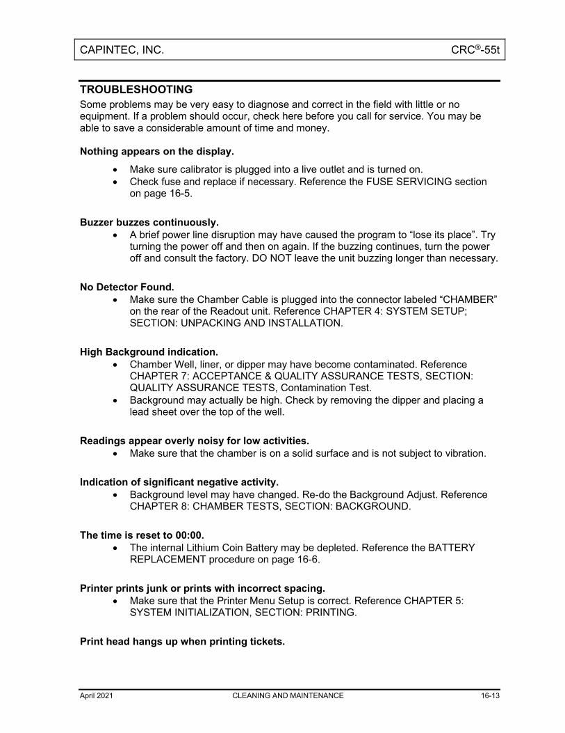
CAPINTEC, INC. CRC®-55t
April 2021 CLEANING AND MAINTENANCE 16-13
TROUBLESHOOTING Some problems may be very easy to diagnose and correct in the field with little or no equipment. If a problem should occur, check here before you call for service. You may be able to save a considerable amount of time and money. Nothing appears on the display.
• Make sure calibrator is plugged into a live outlet and is turned on. • Check fuse and replace if necessary. Reference the FUSE SERVICING section
on page 16-5.
Buzzer buzzes continuously. • A brief power line disruption may have caused the program to “lose its place”. Try
turning the power off and then on again. If the buzzing continues, turn the power off and consult the factory. DO NOT leave the unit buzzing longer than necessary.
No Detector Found.
• Make sure the Chamber Cable is plugged into the connector labeled “CHAMBER” on the rear of the Readout unit. Reference CHAPTER 4: SYSTEM SETUP; SECTION: UNPACKING AND INSTALLATION.
High Background indication.
• Chamber Well, liner, or dipper may have become contaminated. Reference CHAPTER 7: ACCEPTANCE & QUALITY ASSURANCE TESTS, SECTION: QUALITY ASSURANCE TESTS, Contamination Test.
• Background may actually be high. Check by removing the dipper and placing a lead sheet over the top of the well.
Readings appear overly noisy for low activities.
• Make sure that the chamber is on a solid surface and is not subject to vibration.
Indication of significant negative activity. • Background level may have changed. Re-do the Background Adjust. Reference
CHAPTER 8: CHAMBER TESTS, SECTION: BACKGROUND.
The time is reset to 00:00. • The internal Lithium Coin Battery may be depleted. Reference the BATTERY
REPLACEMENT procedure on page 16-6.
Printer prints junk or prints with incorrect spacing. • Make sure that the Printer Menu Setup is correct. Reference CHAPTER 5:
SYSTEM INITIALIZATION, SECTION: PRINTING.
Print head hangs up when printing tickets.

CAPINTEC, INC. CRC®-55t
16-14 CLEANING AND MAINTENANCE April 2021
• On the Okidata Microline 320 printer, the lever on left side of print head must be set to position 2.
Printer will not respond.
• Make sure printer is plugged into a live outlet, turned on, and “selected”. • Make sure that either paper or a ticket is in the paper path. • Run the Diagnostic Test and make sure that the system expects to have a printer.
If not, Make sure that the Printer Menu Setup is correct. Reference CHAPTER 5: SYSTEM INITIALIZATION, SECTION: PRINTING.
RELATED PRODUCTS The following products are available from Capintec. Call Capintec’s only Authorized Service Center at (800) ASK-4CRC for answers to your questions or to place an order.
• CAPMAC Moly Assay Kit (specify generator) ................................... CALL • Dose Calibrator Reference Sources ................................................ CALL • Shielded products for PET ............................................................... CALL • Standard Moly Assay Kit .............................................................. 5130-0006 • Calicheck Linearity Test Kit .......................................................... 5120-2144 • Ionization Chamber Well Inserts (liners) ...................................... 7300-2004 • Plastic Sample Holders (dippers) ................................................. 7300-2005 • Syringe Dipper Adaptor (to 1cc) ................................................... 7310-1109 • Environmental Shield ................................................................... 7300-2450 • Flush Mount Mounting Flange ..................................................... 7310-2307 • Shielded Platform with 2mm shielded glass ................................. 5150-3010 • Shielded Platform with 4mm shielded glass ................................. 5150-3011 • CAP-Lift remote lowering/raising of syringes or vials .................. 5130-30251 • Okidata 320 Ticket and Report Printer ......................................... 5110-1150 • Epson LX-300+II Ticket and Report Printer .................................. 5110-0126 • Epson Roll Printer ........................................................................ 5430-0058 • Epson Ticket Printer .................................................................... 5430-0100 • Epson Label Printer ..................................................................... 5430-0139 • HP Inkjet Printer .......................................................................... 5430-0146 • Printer Ribbons ................................................................................ CALL • Inkjet Cartridges .............................................................................. CALL • Multi-part Tickets, Paper, etc. .......................................................... CALL • Fuse: T 2 Amp. 250 Volts. (Readout Unit) 2 Req. ...................... 2110-0083 • 3V Lithium Coin Battery (CR2032) ............................................... 0500-0039 • English translation of Owner’s Manual ......................................... 9250-0137 • Spanish translation of Owner’s Manual ........................................ 9250-0145
Note: Circuit diagrams, component parts lists, descriptions and calibration instructions are
available to appropriately qualified personnel.

CAPINTEC, INC. CRC®-55t
April 2021 CLEANING AND MAINTENANCE 16-15
SHIPPING If for any reason the CRC®-55t must be returned to Capintec, the shipping carton must contain the following or equivalent labeling as shown in Figure 16-11 and Figure 16-12. Label stipulating the maximum environmental conditions for safe storage and shipment.
Figure 16-11
RANGEZ L'APPAREIL DANS UN ENDROIT DONT LA TEMPÉRATUREVARIE ENTRE +4 °C (+39 °F) ET +43 °C (+110 °F)
RANGEZ L'APPAREIL DANS UN ENDROIT DONT L'HUMIDITÉ ESTINFÉRIEURE À 90 % SANS CONDENSATION ET DONT
LA PRESSION BAROMÉTRIQUE SE SITUE ENTRE15 ET 33 PO DE MERCURE (ENTRE 51 ET 112 kPa)
ÉVITEZ TOUT CHOC THERMIQUE ET MÉCANIQUELAISSEZ RÉCHAUFFER À TEMPÉRATURE AMBIANTE PENDANT UNE PÉRIODE DE24 HEURES AVANT DE DÉSEMBALLER ET DE METTRE L'APPAREIL EN MARCHE

CAPINTEC, INC. CRC®-55t
16-16 CLEANING AND MAINTENANCE April 2021
Figure 16-12
In order to ship this product, all appropriate Department of Transportation (DOT) and, if shipped by air, the International Aviation and Transportation Administration (IATA) requirements for the shipment of the pressurized (12 Atmosphere) Ionization Chamber Detector must be met.
CAPINTEC, INC. CRC®-55t
April 2021 APPENDIX I – PRINCIPLE OF THE CALIBRATOR I-1
APPENDIX I
PRINCIPLE OF THE CALIBRATOR
GENERAL ....................................................................................................... I-1 DEFINITION OF ACTIVITY ............................................................................. I-1
Activity ........................................................................................................ I-1 Types of Transformations ......................................................................... I-2
MEASUREMENT OF ACTIVITY ...................................................................... I-3 α-Particle Radiation .................................................................................... I-3 β+ Radiation ................................................................................................ I-3 β- Radiation ................................................................................................. I-3 Electron Capture ........................................................................................ I-4 Photon Radiation ........................................................................................ I-4
PHOTONS ....................................................................................................... I-4 γ-Rays .......................................................................................................... I-4 X-Rays ......................................................................................................... I-4 Bremsstrahlung .......................................................................................... I-5 Interactions of Photons with Matter .......................................................... I-5
IONIZATION CHAMBER MEASURING PROCESS ........................................ I-6 DETAILED DISCUSSIONS ............................................................................. I-6
Effects of the Integral Shield ..................................................................... I-6 Effects of the Container ............................................................................. I-7 Effects of Impurities ................................................................................... I-7
GENERAL The definition of activity, the basic principle of the calibrator, and the detailed discussion on the calibration are presented in this section.
DEFINITION OF ACTIVITY Activity Activity is defined as: The activity, A, of a quantity of a radioactive nuclide is the quotient of dN by dt, where dN is the number of spontaneous nuclear transformations which occur in this quantity in time interval dt.
dtdNA =
CAPINTEC, INC. CRC®-55t
I-2 APPENDIX I – PRINCIPLE OF THE CALIBRATOR April 2021
The special unit of activity is Curie (Ci): 1 Ci = 3.7 x 10¹⁰ s-1 (exactly) Note: The term nuclear transformation is meant to designate a change of nuclide of an
isomeric transition. (ICRU REPORT 19, 1971) The SI (International System of Units) unit for activity is the reciprocal second, s-1, and is named the Becquerel (Bq), i.e. 1 Bq = 1 Nuclear Transformation per second 1 Ci = 3.7 x 10¹⁰ Bq Types of Transformations
α-decay The nucleus emits a helium nucleus (α-particle).
Electron Capture (ε-decay) The nucleus captures one of its own orbital electrons, usually from the K shell, and a neutrino is emitted.
β- Decay The nucleus emits an electron (β- particle), and a neutrino.
β+ decay The nucleus emits a positron (β+ particle) and a neutrino.
Nuclear Transition A photon (electromagnetic radiation, γ-decay), electron (Internal Conversion Electron Emission, CE) or electron-positron pair (Internal-pair emission, e±) is emitted by a nucleus in a transition from a higher to lower energy state. No nuclear transformation occurs if there is no change in the atomic number or the mass number. The de-excitation of a nucleus in its unstable state (metastable state) is, however, included in the definition of activity.

CAPINTEC, INC. CRC®-55t
April 2021 APPENDIX I – PRINCIPLE OF THE CALIBRATOR I-3
MEASUREMENT OF ACTIVITY A Nuclear Transformation is always associated with one or more of the following types of radiation:
α, β+, β- and γ Photons We can, therefore, measure activity by detecting one or more of the above radiations. α-Particle Radiation The most energetic α-particle emitted by a radionuclide has an energy of less than 10MeV, which corresponds to a range of about 10mg/cm2 (8cm in air). Because of its short range, an α-particle from a radionuclide cannot penetrate to the ionization chamber's sensitive volume and therefore, cannot be detected. All α-decays, however, are accompanied by photon radiation as the daughter nucleus decays to its ground state. The activity of a nuclide that decays through α radiation can therefore, be measured by detecting the associated photon radiation. β+ Radiation β+ particle (positron) emitted from a nucleus comes to rest in the media by losing its kinetic energy mainly by direct ionization processes and then annihilates with an electron to produce two photons of 511keV each. These photons are easily detected by the ionization chamber. De-excitation photons are also associated with β+ decay. β- Radiation The ejected electron loses kinetic energy in matter mainly by direct ionization. The range of most emitted β's is very short. It should be noted that in β+ and β-emission, the emitted electron or positron has a continuous energy spectrum, which ranges from Emax to zero, where Emax is the maximum transition energy. β-rays (with the exception of a small portion of very high energy βs) will be stopped in the sample, in the chamber liner, and in the chamber wall. As the electron decelerates, it also produces continuous low energy photon emission called Bremsstrahlung (stopping or braking radiation). Many radionuclides that decay by β emission also emit de-excitation photons (x-rays, γ-rays), which can be detected by the ionization chamber.

CAPINTEC, INC. CRC®-55t
I-4 APPENDIX I – PRINCIPLE OF THE CALIBRATOR April 2021
Electron Capture The actual electron capture process cannot be detected since the electron is not emitted but is captured by the nucleus. The capture of the orbital electron, however, leaves a vacancy in the atomic orbital shell, resulting in x-rays as the atom de-excites. The energy of K x-ray is approximately
keV 100ZE
2
k ≅
where Z is the atomic number of the daughter nucleus. γ-rays are also often given off as the daughter nucleus de-excites. Photon Radiation Photon radiation is associated with most nuclear transformations. A high-energy photon interacts with matter very weakly. Photon intensity is therefore, not altered substantially by the surrounding media, i.e., measurement of activity can be accomplished with a minimum of disturbance from the sample configuration. As can be seen from the above, in all cases we are detecting photons. We will therefore, discuss photons and their interactions with matter in detail.
PHOTONS Photon is the general term for a quantum of radiation. Photons are classified according to their method of production. γ-Rays Photons resulting from nuclear transitions, nuclear reaction or annihilation of particles (e.g., electron-positron annihilation) are called Gamma-rays (γ-rays). Radioisotope sources (radionuclides) are the most common means of γ-ray production. Radioisotope γ-sources emit photons of one or more discrete energies. X-Rays X-rays are associated with the deceleration of electrons or with orbital electron transitions in atoms. The radiation from a γ-source is often accompanied by characteristic x-rays from transitions of the orbital electrons in the daughter atom.

CAPINTEC, INC. CRC®-55t
April 2021 APPENDIX I – PRINCIPLE OF THE CALIBRATOR I-5
Bremsstrahlung When very fast electrons are brought to rest in a medium (or pass through media) a continuous low energy photon spectrum occurs. This is called Bremsstrahlung (“stopping or braking radiation”). The intensity and the energy spectrum of Bremsstrahlung are highly dependent upon the source configuration and media surrounding the sample. In this manual, the term photon will be used when the method of production of the radiation has no bearing on the discussion. Interactions of Photons with Matter There are three mechanisms by which photons can interact with matter and, thus, deposit their energy. These mechanisms are: Photoelectric effect, Compton Effect, and, pair production. The energy of the photon determines which process (or processes) is possible.
Photoelectric Effect The photoelectric effect is an interaction between a photon and an electron that is bound to an atom. In the photoelectric process, the photon is absorbed by the atom and a bound electron is ejected. The kinetic energy of the ejected electron is equal to the photon energy minus the binding energy of the electron. The binding energy of an electron is the energy that must be supplied in order to remove the electron from the atom. In nuclear medicine, we are interested in photon energies of 20keV or greater. At these energies, all the electrons in the materials used for the chambers are able to participate in the photoelectric process. The photoelectric effect is the most important process at low energies. However, for photon energies much greater than electron binding energies, the processes described below become more important and the number of photoelectric interactions occurring becomes small. At a given energy, the number of photoelectric interactions per unit mass varies as the 4th power of the atomic number and is inversely proportional to the atomic weight of the medium (Z4/A).
Compton Effect The Compton Effect is a collision between a photon and an electron that can be considered unbound. An electron can be considered to be unbound (or “free”) if the energy of the incident photon is much greater than the binding energy of the electron. The kinetic energy of the scattered electron is not constant, but is a function of the angle through which it is scattered. The scattered photon must interact again in order to impart all of its energy to the medium. The Compton Effect is the dominant process for photon energies from 100keV to about 10MeV in the region of the atomic numbers for detector materials. At 100keV, the maximum kinetic energy of the scattered electron is about 30 percent of that of the incident photon; at 1MeV, it is about 80 percent; and at 10MeV, it is about 98%.

CAPINTEC, INC. CRC®-55t
I-6 APPENDIX I – PRINCIPLE OF THE CALIBRATOR April 2021
The number of Compton interactions per unit mass varies directly as the atomic number and inversely as the atomic weight of the medium (Z/A).
Pair Production The process of pair production is difficult to comprehend because it is strictly a relativistic quantum mechanical effect. What is observed to take place is that in the presence of the electric field of a nucleus, the incident photon disappears and an electron and a positron appear. (A positron is a particle with the same properties as an electron, except that it has a positive charge.) In order to produce an electron-positron pair, the incident photon must have an energy of at least twice the mass of an electron, i.e., 1.022MeV. This process dominates for very high energies, that is, above about 10MeV. The number of pair production interactions per unit mass is proportional to the square of the atomic number and inversely proportional to the atomic weight of the medium (Z2/A).
IONIZATION CHAMBER MEASURING PROCESS An ionization chamber consists of two or more electrodes. The electrodes confine a volume of gas and collect the charge (ions) produced by radiation within the volume. Thus, ionization chambers can be used to measure radiation fields if the relationship between the radiation field and the charge produced is known. The radiation enters the chamber through the chamber wall and interacts with the gas in the chamber or with the chamber wall. It must be pointed out that photons cannot produce ionization directly, but must first interact with the chamber material (gas and wall) producing electrons. That is, through a series of interactions, the photon transfers its energy to one or more electrons. The electron is slowed down through collisions with the chamber gas (argon). The collisions knock electrons off the molecules producing positive ions (this is the ionization process). The collection voltage across the chamber sets up an electric field. The positive ions will drift towards the negative electrode and the electron (and negative ions if they are formed) will drift towards the positive electrode, thus producing a current. The electronic circuitry then measures either the current or the total charge produced during the period of interest. The number of ions produced in the chamber is directly related to the energy deposited in the chamber by the radiation.
DETAILED DISCUSSIONS Effects of the Integral Shield The advantage of the shield is the reduction of radiation exposure to the personnel handling the radioisotopes, as well as reduction of the background effects on the activity measurements.

CAPINTEC, INC. CRC®-55t
April 2021 APPENDIX I – PRINCIPLE OF THE CALIBRATOR I-7
It is important to note, however, that if a shield is placed around or near a calibrator, the sensitivity of the ionization chamber is enhanced due to backscattering of photons by the shielding. Above about 250keV, the scattering of photons is mainly forward and at the low energy region, attenuation of photons by the outer wall of the chamber becomes significant. For a CRC calibrator, the backscattering effects are more significant for photons of energies between 70keV and 250keV than photons in other energy regions. Effects of the Container The radioactive standard materials in the ampoules now being provided by NIST are a good approximation to an assay of a radiopharmaceutical in a plastic syringe or in a glass syringe (a wall thickness of about 1.2mm), even for radioisotopes that decay with a significant abundance of low-energy photons. The user should select, whenever possible, a standardized procedure, volume, and container for all radioactivity measurements. The plastic syringe is convenient since it represents the delivery vehicle to the patient in most clinical situations. Significant errors will occur in some instances, e.g., if the radioisotope is assayed in an appreciably different material and/or wall thickness than that of the standards. The ampoules of recently available standards from NIST are uniform. Plastic syringes also have a rather uniform wall thickness and absorption is low. However, a random sampling of 5, 10, 25, 50, and 125ml size multi-injection dose vials from several sources indicated that the wall thickness varied randomly from 1 to 3mm quite independently of the volume of glass vial. The assay of radioisotopes having a significant abundance of low- energy gamma-, x-, and/or high-energy beta-ray radiation may be affected by changes in the sample configuration used to assay the radio-pharmaceutical if the samples are severely different from the standard source. In such cases, an independent check or determination of a calibration appropriate to a user's needs is advised. Fortunately, most radioisotopes can be accurately assayed independently of the sample size. Effects of Impurities An Ionization chamber itself does not have intrinsic energy- discrimination capability. The presence of radioisotope impurities will affect the reading of the instrument unless the effect of impurities is eliminated by photon filtration as is done with Mo99 breakthrough in Tc99m. However, the presence of low-level radionuclide impurity does not negate the usefulness of a radioisotope calibrator, if the user is aware of its presence and has an independently determined calibration including photons arising from the impurities.

CAPINTEC, INC. CRC®-55t
April 2021 APPENDIX II – R CHAMBER CALIBRATION NUMBERS II-1
APPENDIX II
R CHAMBER CALIBRATION NUMBERS
DETERMINING CALIBRATION SETTING NUMBERS ................................... II-1
Response and Sensitivity .......................................................................... II-1 Calibration Setting Numbers ..................................................................... II-2
CALIBRATION SETTING NUMBERS ............................................................. II-4 ABBREVIATIONS USED IN TABLE I ............................................................. II-5 UNCERTAINTY DUE TO SYRINGE CORRECTION ....................................... II-5 UNCERTAINTY DUE TO PUBLISHED DATA ................................................. II-5 HALF-LIFE ...................................................................................................... II-6 REFERENCES ................................................................................................ II-6 TABLE I ........................................................................................................... II-7
DETERMINING CALIBRATION SETTING NUMBERS A method of determining a calibration setting number is described in this section.1 Response and Sensitivity It is very convenient to express the response of the detector to a radioisotope, A, relative to that of a standard reference material, e.g. Co60.
≡
Co60 SRM ofActivity CertifiedCo60 SRM todueOutput Detector
A Sample ofActivity A Sample todueOutput Detector
R A (1)
The sensitivity of the detector for a photon of energy Ei is defined as:
Co60 of Curie one todueOutput Detector
E of Photons 103.7 todueOutput Detector S i10
i×
≡ (2)
The detector response and the sensitivity have the following relation: ∑≡
iii SIiR (3)
1 See Suzuki, A., Suzuki M.N., and Weis A.M.: Analysis of a Radioisotope Calibrator; Journal of Nuclear Medicine Technology Dec. 1976 for more detailed discussions.

CAPINTEC, INC. CRC®-55t
II-2 APPENDIX II – R CHAMBER CALIBRATION NUMBERS April 2021
Where Ii is the intensity of the photon whose energy is Ei. The procedure is to measure the response of the detector to all the available primary standard samples and to establish the sensitivity of the detector as a function of photon energy so as to satisfy equation (3) for all standards. Once the sensitivity curve has been determined, the response of the detector to any radioisotope may be calculated using equation (3), provided that the decay data are known. The sensitivity curve for a CRC® Ionization Chamber is given in Figure II-1. The figure depicts the sensitivity of the ionization chamber as a function of photon energy up to 1.9MeV. Above a photon energy of 200keV, the ionization in the chamber is mainly due to electrons resulting from Compton scattering of photons by the filling gas (argon) and the chamber walls (aluminum). The peak in the low-energy region of the sensitivity curve is due to the rapid increase in photoelectric effect as photon energy decreases and to the attenuation of low energy photons by the sample holder, the chamber liner and the chamber walls, as well as the absorption of photons in the sample material and its container. Although a significant fraction of photons with energies below 50keV are stopped in the chamber wall, some photons could enter the sensitive volume of the chamber and could, therefore, contribute to the activity measurement. All photons with energies below about 13keV are stopped before they reach the sensitive volume of the chamber and, therefore, these photons do not contribute to the activity measurement. Calibration Setting Numbers The relationship between the response of the detector and the gain setting (relative to that for Co60, in order for the instrument to give a direct reading of the activity) is given by:
AR
1G A ≡ (4)
The calibration setting number is linearly related to the chamber response. All the calibrators are calibrated with certified Cobalt 60 and Cobalt 57 standard source. A calibration setting number of 990 was assigned to Co60 and 112 was chosen for Co57. The calibration setting number of CRC® Calibrator for radioisotope A, NA, is given by:
( )( )
( )( )5760
576060
5760
5760AA -1R N
CoCo
CoCoCo
CoCo
CoCo
RRNN
NNNRR
−−
∗
∗
−−
−= (5)

CAPINTEC, INC. CRC®-55t
April 2021 APPENDIX II – R CHAMBER CALIBRATION NUMBERS II-3
Entering numerical values:
( )0.080R1076N :obtains one
2%0.189R 1.000R112N 990N
AA
Co57Co60
Co57Co60
−=±==
== (6)
The accuracy of the sensitivity curve and the calibration number determination was tested by calculating calibration numbers for all the radioisotope standards used for the studies of the sensitivity. The agreement between the calculated and the observed responses were all within ±3%. The accuracy of the chamber response calculation for a particular radioisotope, hence the accuracy which can be attained by using a calculated Calibration Setting Number depends not only on the accuracy of the available primary standards used to determine Figure II-1, on the nuclear data, on the variation in the chamber sensitivity and electrometer gain setting, but also on the sample configuration due to low energy photon absorption. The calibration Setting Numbers for pure and equilibrium state radioisotopes for the CRC® Calibrators are listed in this Appendix. Appendix IV contains tables of multiplication factors for obtaining the activity of a parent nuclide when it is not in equilibrium with the daughter nuclide. A general equation for this situation is also given in that appendix. Since the determination of the Calibration Numbers and the calibrations (normalization) of the instrument are performed using standard reference materials issued by the NIST and/or the LMR, the Calibration Numbers for radioisotopes are given for sample configuration similar to those issued by the NIST. All of the NIST standards, with the exception of Xe133, were of the liquid solution form. Approximately 5g of radioactive liquid were sealed in borosilicate glass ampoules having a diameter of about 17mm, a length of 40mm, and a wall thickness of 0.6mm. The Xe133 standard was sealed together with inactive xenon gas in a borosilicate glass ampoule having a volume of about 5ml, a length of 45mm, a diameter of 15mm, and a wall thickness of 1.3mm.

CAPINTEC, INC. CRC®-55t
II-4 APPENDIX II – R CHAMBER CALIBRATION NUMBERS April 2021
CAPINTEC RADIOISOTOPE DOSE CALIBRATOR CHAMBER SENSITIVITY
Y 88
Co 60 Na 22
Co 60 Bi 207
Y 88 Cs 134
Cs 137 Cs 134
Bi 207 Na 22
Sn 113 : In 113m Cr 51
Hg 203
Am 241 Bi 207 Hg 203 Xe 133
Co 57 Tc 99m
Ce 139
Sn 113
I 125
Ce 139 Xe 133
Am 241, Co 57
500 1000 1500
0.1
0.2
0.3
0.4
0.5
0.6
PHOTON ENERGY (keV)
Co60 = 1.00
Figure II-1
CALIBRATION SETTING NUMBERS The Calibration Setting Numbers in Table I are applicable to the Capintec Radioisotope Calibrator only. The CRC®-55t is a direct reading instrument. No manual multiplication or division should be performed, even if the Calibration Setting Number is followed by a multiplication sign "×" or a division sign “÷” and a number. If the sample contains radioactive impurities, the meter indication will always be higher than the actual activity of the principal isotope. It will not, however, be the total activity of the principal isotope and the impurities. If a Radium Needle is measured, the reading will be lower than the true activity in the needle due to the shielding effects (filtration) of the needle. To estimate the true activity in a needle, increase the reading obtained with a calibration number for Ra226 (778) by 2% for each 0.1mm of platinum wall thickness. For example, add 10% to the reading for a 0.5mm wall platinum needle and add 20% to the reading for a 1.0mm wall platinum needle to estimate the true Radium activity.

CAPINTEC, INC. CRC®-55t
April 2021 APPENDIX II – R CHAMBER CALIBRATION NUMBERS II-5
ABBREVIATIONS USED IN TABLE I Abbreviation Meaning Abbreviation Meaning
eqb. equilibrium D days S seconds Y years H hours E exponential, i.e., M minutes 3E5 = 3 × 10⁵
UNCERTAINTY DUE TO SYRINGE CORRECTION The Calibration Setting Numbers are given for approximately 5 grams of radioactive solution in a standard source ampoule made of about 0.6mm thick borosilicate glass. The standard radioactive source in the ampoule is, however, a good approximation for a radiopharmaceutical in a plastic syringe or a glass syringe (wall thickness about 1.2mm) for most radioisotopes. In general, the attenuation of radiation by a plastic syringe is less than for the standard ampoule, while for most glass syringes, the attenuation will be greater than for the standard ampoule. The anticipated syringe corrections are listed on the table under the column "Uncertainty Due to Syringe Correction". For example, the required correction for I125 activity is estimated to be about, ±25%. This means that you should add 25% to the meter reading if the I125 is in a glass syringe or subtract 25% if it is in a plastic syringe. Since the attenuation of low energy radiation is very dependent upon the material of the container, the value given in the syringe correction column should be used mainly as a guide giving relative magnitude. If a measurement of activity in a glass vial is anticipated, the container correction for low energy isotopes will be substantial. It could be about 3 to 5 times that for a syringe. If no value is given in this column, the correction is not significant, except for a container differing greatly from the standard ampoule (e.g. very thick glass container, vial made of glass which contains lead, etc.).
UNCERTAINTY DUE TO PUBLISHED DATA This is the uncertainty on the value of the activity. From calibration numbers calculated from decay data, the uncertainty given is calculated using only the reported errors on the intensity of the γ and/or x-rays. For calibration numbers measured from NBS standard reference materials (known as SRM;s), the uncertainty given is the reported uncertainty on the activity of the SRM. For these numbers, the reference is given as NBS (NIST) (or LMR - Laboratoire de Metrologie de la Radioactivite - France), and year of source.

CAPINTEC, INC. CRC®-55t
II-6 APPENDIX II – R CHAMBER CALIBRATION NUMBERS April 2021
HALF-LIFE The number before the letter is the value of the half-life. The number following the letter is the reported uncertainty on the half-life. Examples: 12.34 D1 means 12.34 days ±0.01 days 12.34 D11 means 12.34 days ±0.11 days 12.340 D1 means 12.340 days ±0.001 days 1.234 D1 means 1.234 days ±0.001 days
REFERENCES This is the source of the data from which the calibration number was calculated. NBS (NIST) or LMR means that the calibration number was obtained by measuring a standard reference material (SRM). NM75 (Nuclear Medicine 75): L.T. Dillman and F.C. Von Der Lage, Radionuclide Decay Schemes and Nuclear Parameters for Use in Radiation-Dose Estimation. NM/MIRD Pamphlet No. 10, 1975. ORNL76: M.J. Martin Ed., Nuclear Decay Data for Selected Radionuclides. ORNL-5114, Oak Ridge National Laboratory, March 1976. NDT70: M.J. Martin and P.H. Blichert-Toft. Radioactive Atoms: Auger-Electrons, α-, β-, γ- and X-Ray Data. Nuclear Data Tables A, Vol. 8, Nos.1, 2. October, 1970 NDS: Nuclear Data Sheets, Academic Press. Martin: M. J. Martin. Evaluated Nuclear Data File. Nuclear Data Project. Oak Ridge National Laboratory. NCRP-58: National Council on Radiation Protection and Measurement., Report No.58 A HANDBOOK OF RADIOACTIVITY MEASUREMENTS PROCEDURE. NUCLIDES and ISOTOPES: Chart of the nuclides. Fourteenth Edition. General Electric Company Nuclear Energy Operations. Rev. 1989 NIST, Radionuclide Calibrator Measurements of F18 in a 3ml Plastic Syringe. Applied Radiation and Isotopes. 66, 988-993, J.T. Cessna, M.K. Schultz, T. Leslie, N. Bores, 2008 NMC18, An update on “dose calibrator” settings for nuclides used in nuclear medicine, Nuclear Medicine Communications 39, Denis E. Bergeron, Jeffrey T. Cessna, 2018

CAPINTEC, INC. CRC®-55t
April 2021 APPENDIX II – R CHAMBER CALIBRATION NUMBERS II-7
TABLE I – R CHAMBER CALIBRATION NUMBERS CAUTION: The calibration numbers given in this table are based upon the NIST SRM geometry (5ml of solution in glass ampoule with 0.6mm wall thickness). Listed numbers should provide an accuracy of ±5% when compared to a NIST SRM. Different source geometries (e.g. capsules, seeds, ribbons) may require geometry correction factors or different calibration numbers. However, no warranty of any kind can be made as to their accuracy, since there are many other uncontrollable factors (as well as the accuracy of the published data) involved in the determination of the overall accuracy of an assay. Reference previous sections of this manual for a discussion of some of the conditions under which the calibration numbers are valid.
Radioisotopes Calibration
Setting Number
Uncertainty Due to Half-Life (NCRP-58) Ref. Comments Syringe
Corr. % Published
Data % 7Be Beryllium 179 x 10 53.284 D 4 NM75 11C Carbon 457 20.38 M 2 ORNL76 13N Nitrogen 457 9.965 M 4 ORNL76 15O Oxygen 462 122.24 S 14 ORNL76 18F Fluorine 450 109.71 M 2 NMC18 22Na Sodium 957 1.7 2.602 Y 1 NBS73 Ref. for 0.51, 1.27
MeV 24Na Sodium 658 ÷ 2 14.959 H 4 ORNL76 26Al Aluminum 481 ÷ 2 7.2E5 Y 3 ORNL76 27Mg Magnesium 331 9.458 M 12 ORNL76 28Mg Magnesium 719 3 4 20.91 H 3 ORNL76 Pure; NOTE: NM75
yields a Cal. No. of 804
28Al Aluminum 583 2.244 M 3 ORNL76 Pure 28Mg Magnesium
(Eqb. 28Al) 656 ÷ 2 3 4 20.91 H 3 ORNL76 Reading gives 28Mg
Act. in eqb. sample. Teqb after 15 minutes.
28Al Aluminum (Eqb. 28Mg)
656 ÷ 2 2.244 M 3 ORNL76 Reading gives 28Al Act. in eqb. sample. Teqb. after 15 minutes
28Mg 28Al
Magnesium Eqb. Aluminum
656
3
ORNL76
Reading gives sum of 28Mg & 28Al activity in equilibrium sample.
32P Phosphorus 750 × 100 1.2 14.29 D 2 NBS76 Estimation use only. 38Cl Chlorine 470 2 36.51 M 4 NDT70 40K Potassium 520 × 10 1.28E9 Y 1 NM75 41Ar Argon 468 1.827 H 7 ORNL76 42K Potassium 033 or
152 × 2 3 12.36 H 1 ORNL76
43K Potassium 430 2 22.3 H 1 ORNL76 44Sc Scandium 938 3.927 H 8 ORNL76

CAPINTEC, INC. CRC®-55t
II-8 APPENDIX II – R CHAMBER CALIBRATION NUMBERS April 2021
Radioisotopes Calibration
Setting Number
Uncertainty Due to Half-Life (NCRP-58) Ref. Comments Syringe
Corr. % Published
Data % 44Ti Titanium 514 2 2 47.3 Y 12 ORNL76 46Sc Scandium 822 83.79 D 2 ORNL76 47Ca Calcium 373 4.536 D 2 ORNL76 Pure; 47Ca decays to
47Sc. Eqb. in 90 days. 47Sc Scandium 026 or
618 × 2 3.351 D 2 ORNL76 Pure; see App. IV for
non-eqb.
48V Vanadium 569 ÷ 2 15.974 D 3 ORNL76 49Ca Calcium 956 2 8.72 M 2 NDT70 Pure; decays to 49Sc 51Cr Chromium 100 × 10 1.25 27.702 D 4 NBS76 Ref. for 320 keV 52Mn Manganese 676 ÷ 2 5.591 D 3 ORNL76 52mMn Manganese 461 ÷ 2 21.1 M 2 ORNL76 Decays to 52Mn 52Fe Iron 374 8.275 H 8 ORNL76 52mMn will contribute to
dose. 54Mn Manganese 309 312.14 D 5 ORNL76 55Fe Iron 374 2.72 Y 2 ORNL76 55Co Cobalt 481 7 17.54 H NDS76 56Co Cobalt 648 ÷ 2 77.9 D 12 NDT70 56Ni Nickel 844 4 6.1 D 3 NDT70 Decays to 56Co;
See App. IV 56Mn Manganese 627 2 2.577 H 1 ORNL76 57Co Cobalt 112 1.9 271.7 D 2 NBS76 Ref. for 122 keV
Capintec Low Energy Reference.
58Co Cobalt 389 70.82 D 3 ORNL76 59Fe Iron 430 44.51 D 2 ORNL76 60Co Cobalt 990 1.0-NBS
1.5-LMR 5.2714 Y 5 NBS75 Ref. for 1.17, 1.33
MeV Capintec High Energy Reference
62Cu Copper 448 9.74 M 2 NM75 Pure 62Zn Zinc 217 9.22 H NM75 Pure 62Zn Zinc
(Eqb. 62Cu) 760 Reading gives 62Zn
Act. in eqb. sample. Eqb. after 1.5 hours.
62Cu Copper (Eqb. 62Zn)
745 Reading gives 62Cu Act. in eqb. sample. Eqb. after 1.5 hours.
62Zn 62Cu
Zinc Eqb. Copper
333
NM75
Reading gives sum of 62Zn & 62Cu activity in equilibrium sample.

CAPINTEC, INC. CRC®-55t
April 2021 APPENDIX II – R CHAMBER CALIBRATION NUMBERS II-9
Radioisotopes Calibration
Setting Number
Uncertainty Due to Half-Life (NCRP-58) Ref. Comments Syringe
Corr. % Published
Data % 64Cu Copper 015 or
115 × 2 12.701 H 2 ORNL76
65Zn Zinc 172 243.9 D 1 ORNL76 66Ga Gallium 903 2 9.40 H 7 ORNL76 67Cu Copper 052 4 2.575 D 3 ORNL76 67Ga Gallium 100 1.4 3.261 D 1 NBS78 68Ga Gallium 442 68.0 M 2 NMC18 69mZn Zinc 143 13.76 H 3 ORNL76 72As Arsenic 795 26.0 H 1 ORNL76 72Ga Gallium 470 ÷ 2 2 14.10 H 1 ORNL76 73As Arsenic 324 × 10 4 3 80.30 D 6 ORNL76 73Se Selenium 748 7.15 H 8 ORNL76 Decays to 73As. 74As Arsenic 304 5 17.78 D 3 ORNL76 75Se Selenium 258 2.5 119.8 D 1 NBS75 76As Arsenic 110 6 26.32 H 7 ORNL76 77As Arsenic 481 × 100 26 38.8 H 3 ORNL76 Estimation use only. 77Br Bromine 091 3 56 H 2 ORNL76 79Kr Krypton 050 3 35.04 H 10 ORNL76 81Rb Rubidium 174 4.58 H NM75 Pure 81mKr Krypton 915 × 10 13 S 1 NM75 Pure 81Rb 81mKr
Rubidium Eqb. Krypton
270
NM75
Reading gives act. of 81Rb or 81mKr in equilibrium sample. Eqb. after 2 minutes.
82Br Bromine 536 ÷ 2 2 35.34 H 2 ORNL76 82Rb Rubidium 504 1.273 M 2 NM75 84Rb Rubidium 347 32.77 D 4 NM75 85mKr Krypton 065 1 4.480 H 8 ORNL76 Decays to 85Kr 85Kr Krypton 031 × 100 2 10.72 Y 1 ORNL76 85Sr Strontium 193 1.0 64.854 D 3 NBS75 86Rb Rubidium 411 × 10 18.64 D 2 ORNL76 86Y Yttrium 711 ÷ 2 14.74 H 2 ORNL76 86Zr Zirconium 167 18 3 16.5 H 1 ORNL76 87Kr Krypton 250 6 76.3 M 5 ORNL76 87mSr Strontium 095 2.805 H 3 ORNL76 Pure 87Y Yttrium 170 1 80.3 H 3 ORNL76 Pure

CAPINTEC, INC. CRC®-55t
II-10 APPENDIX II – R CHAMBER CALIBRATION NUMBERS April 2021
Radioisotopes Calibration
Setting Number
Uncertainty Due to Half-Life (NCRP-58) Ref. Comments Syringe
Corr. % Published
Data % 87Y Yttrium
(Eqb. 87mSr) 357 ORNL76 Reading gives 87Y Act.
in eqb. sample. Eqb. after 18 hours.
87Y 87mSr
Yttrium Eqb. Strontium
341
2
ORNL76
Reading gives sum of 87Y & 87mSr activity in equilibrium sample.
88Rb Rubidium 189 14 17.8 M 1 ORNL76 88Y Yttrium 465 ÷ 2 1.8 106.61 D 2 NBS73 89Rb Rubidium 768 1 15.2 M 1 ORNL76 90Y Yttrium 48 × 10 64.0 H 1 NIST92 Estimation use only. 91Y Yttrium 850 × 10 58.5 D 4 NDT70 Almost pure β decay.
Estimation use only. 94Nb Niobium 673 2.03E4 Y 16 ORNL76 95Nb Niobium 285 34.97 D 1 NDT70 Pure 95Zr Zirconium 271 64.02 D 5 NDT70 Pure 95Zr 95m95Nb
Zirconium Eqb. Niobium
145
95mNb 3.61 D 1
NDT70
Reading gives sum of 95mNb & 95Nb activity in equilibrium sample. Eqb. after 2 years.
97Nb Niobium 249 72.1 M 7 ORNL76 97Zr 97mNb
Zirconium Eqb. Niobium
341
12
16.90 H 5
ORNL76
Reading gives sum of 97Zr & 97mNb activity in equilibrium sample. Eqb. after 10 minutes.
97mNb Niobium 271 60 S 1 ORNL76 97Ru Ruthenium 116 15 2 2.9 D 1 ORNL76 Decays to 97mTc 97mTc Technetium 256 × 10 65 91.0 D NM75 Estimation use only. 99Mo Molybdenum
(in Std. Mo Kit) 080 × 5 or 246× 10 or 030 × 3.5
NTS78
99Mo Molybdenum (in CAP-MAC)
030 × 4 or 204 × 10
NBS78
99Mo Molybdenum (in MAC-S)
030 × 4 or 204 × 10
NBS78
99Mo Molybdenum (Eqb. 99mTc)
165 2 1.9 65.92 H 2 NBS78
99mTc Technetium 080 2 2.1 6.007 H 1 NBS76 99mTc Technetium
(in CAP-MAC) 042 2.1 6.007 H 1 NBS76

CAPINTEC, INC. CRC®-55t
April 2021 APPENDIX II – R CHAMBER CALIBRATION NUMBERS II-11
Radioisotopes Calibration
Setting Number
Uncertainty Due to Half-Life (NCRP-58) Ref. Comments Syringe
Corr. % Published
Data % 99mTc Technetium
(Eqb. 99Mo) 175 2 NBS78
99Mo 99mTc
Molybdenum Eqb. Technetium
145
2
NBS78
Reading gives sum of 99Mo & 99mTc activity in equilibrium sample.
103Pd Palladium 562 × 10 50 4 16.97 D 2 ORNL76 Pure 103Pd 103mRh
Palladium Eqb. Rhodium
634 × 10
50
5
ORNL76
Reading gives sum of 103Pd & 103mRh activity in equilibrium sample. Eqb. after 9 hours.
103mRh Rhodium 631 × 100 50 5 56.114 M 6 ORNL76 103Ru Ruthenium 165 50 3 39.26 D 2 ORNL76 103Ru 103mRh
Ruthenium Eqb. Rhodium
172
50
ORNL76
Reading gives sum of 103Ru & 103m,Rh activity in equilibrium sample. Eqb. after 9 hours.
106Ru Ruthenium (Eqb. 106Rh)
027 or 140 × 2
369 D 2 NDT70 Reading gives 106Ru Act. in eqb. sample. Eqb. after 5 minutes.
106Ru 106Rh
Ruthenium Eqb. Rhodium
480 × 10
369 D 2
NDT70
Reading gives sum of 106Ru & 106Rh activity in equilibrium sample.
108mAg Silver 830 3 127 Y 21 ORNL76 108Ag Silver 099 × 10 6 15 2.37 M 1 ORNL76 Large β contribution. 109Cd 109mAg
Cadmium Eqb. Silver
047 or 180 × 2
40 4 462.6 D 4 39.8 S
Reading gives act of 109Cd, 109mAg, or Total Act. in eqb. sample. Eqb. after 6 minutes.
109Pd 109mAg
Palladium Eqb. Silver
435 × 10
13.427 H 14 39.8 S
Reading gives act of 109Pd, 109mAg, or Total Act. in eqb. sample. Eqb. after 6 minutes.
110mAg Silver 554 ÷ 2 2 249.8 D 1 ORNL76 111Ag Silver 054 × 10 30 7.45 D 1 ORNL76 111In Indium 303 10 1.36 2.805 D 1 NBS77 113Sn Tin 022 or
129 × 2 35 5 115.08 D 3 MARTIN77 For pure 113Sn.
113mIn Indium 076 7 2 1.658 H 1 Separated for pure 113mIn.
113Sn 113mIn
Tin Eqb. Indium
180
15
3.2
NBS73,77
Reading gives act. of 113Sn, 113mIn, or Total Act. in eqb. sample. Eqb. after 15 hours.
115mIn Indium 058 15 2 4.486 H 4 ORNL76

CAPINTEC, INC. CRC®-55t
II-12 APPENDIX II – R CHAMBER CALIBRATION NUMBERS April 2021
Radioisotopes Calibration
Setting Number
Uncertainty Due to Half-Life (NCRP-58) Ref. Comments Syringe
Corr. % Published
Data % 116mIn Indium 974 3 54.15 M 6 ORNL76 117mSn Tin 180 15 2 13.61 D 4 ORNL76 117Sb Antimony 082 3 2 2.80 H 1 ORNL76 119mSn Tin 657 × 10 35 4 293.0 D 13 ORNL76 121mTe Tellurium 187 12 9 154 D 7 ORNL76 Pure 121Te Tellurium 373 10 3 17 D 1 ORNL76 Pure 121mTe 121Te
Tellurium Eqb. Tellurium
645
Reading gives act. of 121mTe or 121Te in eqb. sample. Eqb. in 120 days. See App. IV for non-eqb. samples.
121mTe 121Te
Tellurium Eqb. Tellurium
572
Reading gives sum of 121mTe or 121Te in eqb. sample.
122Sb Antimony 146 6 2.70 D 1 ORNL76 123I Iodine 277 15 1.9 13.221 H 3 NBS77 Ref. for 28 keV x-ray. 123mTe Tellurium 177 12 119.7 D 1 NDT70 124Sb Antimony 720 60.20 D 3 ORNL76 124I Iodine 570 5 4.18 D 2 ORNL76 125I Iodine 319 25 1.45 59.6 D 2 NBS76 125Sb Antimony 289 10 2.758 Y 1 NDT70 Pure 125Sb Antimony
(Eqb. 125mTe) 371 12 2.758 Y 1 NDT70 Reading gives 125Sb
Act. in eqb. sample. Eqb. after 1 year.
125Sb 125mTe
Antimony Eqb. Tellurium
364
12
NDT70
Reading gives sum of 125Te and 125mTe in eqb. sample. See App. IV for non-eqb. activity.
125mTe Tellurium 259 25 57.40 D 5 NDT70 126I Iodine 240 10 18 13.02 D 7 ORNL76 127Xe Xenon 371 12 5 36.4 D 1 ORNL76 129mTe Tellurium 817 × 10 20 5 33.6 D 1 ORNL76 Pure 129Te Tellurium 679 × 10 15 13 69.6 M 2 ORNL76 Pure
129mTe 129Te
Tellurium Eqb. Tellurium
054
Reading gives act. of 129mTe or total act. in eqb. sample. Eqb. in 10 hours.
129Cs Cesium 397 15 20 32.06 H 6 ORNL76 NM75 gives 488 129I Iodine 166 20 1.57E7 Y 4 ORNL76 129mXe Xenon 362 20 3 8.0 D 2 ORNL76

CAPINTEC, INC. CRC®-55t
April 2021 APPENDIX II – R CHAMBER CALIBRATION NUMBERS II-13
Radioisotopes Calibration
Setting Number
Uncertainty Due to Half-Life (NCRP-58) Ref. Comments Syringe
Corr. % Published
Data % 130I Iodine 984 12.36 H 1 ORNL76 131I Iodine 151 1.65 8.021 D 1 NBS76 Decays to 131mXe.
1.1% feeding. 131mXe Xenon 089 20 3 11.9 D 1 ORNL76 131Cs Cesium 148 20 3 9.69 D 1 ORNL76 131Ba Barium 505 10 7 11.8 D 2 ORNL76 132Te Tellurium 315 10 5 76.3 H 2 ORNL76 Pure 132I Iodine 999 2.30 H 3 ORNL76 Pure 132Te Tellurium
(Eqb. 132I) 675 ÷ 2 Reading gives 132Te
Act. in eqb. sample. Eqb. after 1 day.
132I Iodine (Eqb. 132Te)
653 ÷ 2 Reading gives 132I Act. in eqb. sample.
132Te 132I
Tellurium Eqb. Iodine
663
ORNL76
Reading gives sum of 132Te and 132I in eqb. sample.
132Cs Cesium 485 10 2 6.475 D 10 ORNL76 133I Iodine 225 20.8 H 1 ORNL76 Decays to 133mXe. 133mXe Xenon 100 20 3 2.19 D 1 Decays to 133Xe. See
App. IV. 133Xe Xenon 188 12 1.95 5.243 D 1 NBS76 133mBa Barium 132 12 3 38.9 H 1 ORNL76 Decays to 133Ba. 133Ba Barium 626 10 3 10.5 Y 1 NIST14 134Te Tellurium 533 3 6 41.8 M 8 ORNL76 134mCs Cesium 037 or
160 × 2 15 2.91 H NM75 Decays to 134Cs.
134Cs Cesium 726 2.3 2.065 Y 1 NBS73 135mXe Xenon 181 3 15.29 M 3 ORNL76 Decays to 135Xe. See
App. IV. 135Xe Xenon 085 2 9.09 H 1 ORNL76 135mBa Barium 130 15 4 28.7 H 2 ORNL76 136Cs Cesium 489 ÷ 2 4 13.1 D 1 ORNL76 137Cs 137mBa
Cesium Eqb. Barium
227
2.0 30.0 Y 2 2.553 M 1
NIST12
Ref: 661.6 & 32.9 keV. Reading gives 137Cs or Total Activity of eqb. sample. Often referred to as "Cs-137" Source.
139Ba Barium 445 × 10 5 12 82.8 M 2 ORNL76 139Ce Cerium 352 5 2.6 137.64 D 2 NBS73 Ref: 36.8 keV 141Ce Cerium 061 5 5 32.50 D 1 ORNL76

CAPINTEC, INC. CRC®-55t
II-14 APPENDIX II – R CHAMBER CALIBRATION NUMBERS April 2021
Radioisotopes Calibration
Setting Number
Uncertainty Due to Half-Life (NCRP-58) Ref. Comments Syringe
Corr. % Published
Data % 142Pr Praseodymium 226 × 10 14 19.13 H 4 ORNL76 144Pr Praseodymium 137 × 10 5 17.28 M 5 ORNL76 Estimation use only. β
dominant. 144Ce 144Pr
Cerium Eqb. Praseodymium
387 × 10
5
2.8
285.0 D 1
NBS73
Ref: 36.7 & 133.5 keV. Reading gives sum of 144Ce & 144Pr Act. in equilibrium sample. Eqb. after 2 hours.
145Pm Promethium 207 10 3 17.7 Y 4 ORNL76 147Nd Neodymium 213 5 4 10.98 D 1 ORNL76 157Dy Dysprosium 424 5 8.1 H 1 NM75 169Yb Ytterbium 948 3 2.5 32.03 D 1 NBS78 171Tm Thulium 292 × 100 4 1.92 Y 1 NM75 175Yb Ytterbium 308 × 10 2 13 4.19 D 1 ORNL76 177Lu Lutetium 450 × 10 2 7 6.71 D 1 ORNL76 181Hf Hafnium 387 6 42.4 D 1 ORNL76 181W Tungsten 165 3 11 121.2 D 3 ORNL76 188W Tungsten 111 × 100 69.4 D 5 NM75 Decays to 188Re. Eqb.
after 7 days. See App. IV
188Re Rhenium 496 × 10 16.98 H 2 NM75 188W Tungsten
(Eqb. 188Re) 522 × 10 Reading gives 188W
Act. in eqb. sample. Eqb. after 5 days.
188Re Rhenium (Eqb. 188W)
516 × 10 Reading gives 188Re Act. in eqb. sample.
188W 188Re
Tungsten Eqb. Rhenium
217 × 10
Reading gives sum of 188W & 188Re activity in equilibrium sample.
190mOs Osmium 858 9.90 M NM75 191Os Osmium 250 2 13 15.4 D 2 ORNL76 192Ir Iridium 408 73.83 D 1 NDS73 194Ir Iridium 469 × 10 18 19.15 H 3 ORNL76 197Pt Platinum 686 × 10 2 6 18.3 H 3 ORNL76 197Hg Mercury 197 2 2.9 64.1 H 1 NBS76 Ref. for 70 & 77 keV. 198Au Gold 149 1.65 2.696 D 2 NBS78 199Au Gold 053 6 3.139 D 7 ORNL76 201Tl Thallium 205 2 2.0 72.91 H 2 NBS76 203Hg Mercury 093 1.1 46.60 D 1 NBS73 203Pb Lead 344 2 51.88 H 1 ORNL76

CAPINTEC, INC. CRC®-55t
April 2021 APPENDIX II – R CHAMBER CALIBRATION NUMBERS II-15
Radioisotopes Calibration
Setting Number
Uncertainty Due to Half-Life (NCRP-58) Ref. Comments Syringe
Corr. % Published
Data % 204Tl Thallium 420 × 100 2 2 3.78 Y 2 NDT70 207Bi Bismuth 846 1.7 32.2 Y 9 NBS73 Ref. for 1064, 569.7,
76.7, & 1772 keV. 208Tl Thallium 571 ÷ 2 3.053 M 4 NM75 212Pb Lead 101 10.64 H 1 NM75 Decays to 212Bi. Eqb.
after 1 hr. See App. IV. 212Bi Bismuth 489 × 10 60.55 M 6 NM75 212Pb Lead
(Eqb. 212Bi) 158 Reading gives 212Pb
Act. in eqb. sample. Eqb. after 8 hours.
212Bi Bismuth (Eqb. 212Pb)
135 Reading gives 212Bi Act. in eqb. sample.
212Pb 212Bi
Lead Eqb. Bismuth
030 or 146 × 2
Reading gives sum of 212Pb & 212Bi activity in equilibrium sample.
224Ra Radium 646 × 100 3.66 D 4 NM75 226Ra Radium
+ chain of daughters
778 0.5 1600 Y 7 NBS73 Reading in grams. Commonly referred to as "Radium "Source. 1.025 g/Ci of Ra-226.
239Np Neptunium 147 6 2.355 D 4 ORNL76 241Am Americium 055 4 1 432.2 Y 5 LMR69 Ref. for 59.5 & 14 keV.

CAPINTEC, INC. CRC®-55t
April 2021 APPENDIX III – PET CHAMBER CALIBRATION NUMBERS III-1
APPENDIX III
PET CHAMBER CALIBRATION NUMBERS
CALIBRATION SETTING NUMBERS The Isotope Calibration Numbers in Table I are applicable to the Capintec CRC®-55t PET Chamber(s) only. The CRC®-55t is a direct reading instrument. No manual multiplication or division should be performed, even if the Calibration Setting Number is followed by a multiplication sign “× “ or a division sign “÷ “ and a number. If the sample contains radioactive impurities, the meter indication will always be higher than the actual activity of the principal isotope. It will not, however, be the total activity of the principal isotope and the impurities.
UNCERTAINTY DUE TO SYRINGE CORRECTION The Calibration Setting Numbers are given for approximately 5 grams of radioactive solution in a standard source ampoule made of about 0.6 mm. thick borosilicate glass. The standard radioactive source in the ampoule is, however, a good approximation for a radiopharmaceutical in a plastic syringe or a glass syringe (wall thickness about 1.2 mm) for most radioisotopes.
RADIOISOTOPE TABLE – PET CHAMBER CALIBRATION NUMBER
Radioisotopes Calibration
Setting Number
Half-Life (NCRP-58) Ref.
11C Carbon 11 467 20.38 Minutes See Note 15O Oxygen 15 474 122.24 Seconds See Note 13N Nitrogen 13 470 9.965 Minutes See Note 18F Fluorine 18 455 109.71 Minutes NIST 57Co Cobalt 57 112 271.7 Days NIST 60Co Cobalt 60 990 5.271 Years NIST 133Ba Barium 133 650 10.5 Years NIST 137Cs Cesium 137 243 30.0 Years NIST 68Ga Gallium 68 448 67.83 Minutes NIST 64Cu Copper 64 038 12.7 Hours NIST

CAPINTEC, INC CRC®-55t
III-2 APPENDIX III April 2021
Note: These Calibration Numbers were determined by inter-comparison with a standard Capintec CRC®-15R Dose Calibrator. No NIST standards are yet available. They should be used for estimation purposes only.

CAPINTEC, INC. CRC®-55t
April 2021 APPENDIX IV – MULTIPLICATION FACTORS FOR NON-EQUILIBRIUM RADIOISOTOPES IV-1
APPENDIX IV
MULTIPLICATION FACTORS FOR NON-EQUILIBRIUM RADIOISOTOPES
Ca47 Measurements ..................................................................................... IV-2 Ni56 Measurements ...................................................................................... IV-2 Zn62 Measurements ..................................................................................... IV-3 Y87 Measurements ....................................................................................... IV-3 Zr95 Measurements ...................................................................................... IV-4 Te121m Measurements ................................................................................ IV-4 Sb125 Measurements ................................................................................... IV-5 Te129m Measurements ................................................................................ IV-5 Te132 Measurements .................................................................................... IV-6 Xe133m Measurements ................................................................................ IV-6 Xe135m Measurements ................................................................................ IV-7 W188 Measurements .................................................................................... IV-7 Pb212 Measurements ................................................................................... IV-8
Note: These Multiplication Factors apply to the R Chamber only. The activity in a non-equilibrium sample can be determined by using the following equation:
A
B
BA
BA
BA
A
RRn21t
T TT T- exp - 1
T TT F + 1
A"" Purefor Number Cal. with ReadingMeter = A"" ofActivity
××
×−
−
where “A” and “B” are parent and daughter nuclide respectively, T's are half-lives, and RA and RB are the chamber responses to the isotopes A and B, “t” is the elapsed time after the pure parent isotope was produced, and “F” is the decay branching ratio. The chamber response, ”R,” may be obtained from the calibration number “N,” using the following equation:
0797.01075.8
N=R +
When the half-life of the parent nucleus (TA) is much shorter than that of the daughter nucleus (TR), the parent decays down to the daughter. After about 10 × TA, we can assume that only the daughter is left (except if the original activity of the parent was exceptionally high). The equation above for the Activity of “A” can be used to obtain the activity of the parent while it has measurable activity.

CAPINTEC, INC. CRC®-55t
IV-2 APPENDIX IV – MULTIPLICATION FACTORS FOR NON-EQUILIBRIUM RADIOISOTOPES April 2021
Multiplication factors obtained by using the equation are given in the following tables for selected isotopes.
CA47 MEASUREMENTS Use a Calibration Number of 373 and a multiplication factor as indicated in the following table to obtain Ca47 activity at time “t” days after an initially pure source of Ca47 is obtained.
Ca47 t
[days] Multiplication
Factor t
[days] Multiplication
Factor 0 1.000 12 0.672 1 0.950 14 0.648 2 0.906 16 0.627 3 0.869 18 0.609 4 0.836 20 0.594 5 0.806 25 0.566 6 0.781 30 0.545 7 0.757 40 0.519 8 0.737 50 0.496 9 0.718 100 0.485 10 0.701 150 0.484
NI56 MEASUREMENTS Use a Calibration Number of 844 and a multiplication factor as indicated in the following table to obtain Ni56 activity at time “t” days after an initially pure source of Ni56 is obtained.
Ni56 t
[days] Multiplication
Factor t
[days] Multiplication
Factor 0 1.000 9 0.824 1 0.985 10 0.799 2 0.969 12 0.745 3 0.952 15 0.659 4 0.934 20 0.508 5 0.915 25 0.366 6 0.894 30 0.249 7 0.872 40 0.101 8 0.849 60 0.013

CAPINTEC, INC. CRC®-55t
April 2021 APPENDIX IV – MULTIPLICATION FACTORS FOR NON-EQUILIBRIUM RADIOISOTOPES IV-3
ZN62 MEASUREMENTS Use a Calibration Number of 217 and a multiplication factor as indicated in the following table to obtain Zn62 activity at time “t” minutes after an initially pure source of Zn62 is obtained.
Zn62 t
[minutes] Multiplication
Factor t
[minutes] Multiplication
Factor 0 1.000 45 0.368 10 0.526 60 0.361 20 0.425 75 0.359 30 0.389 90 0.358
Y87 MEASUREMENTS Use a Calibration Number of 170 and a multiplication factor as indicated in the following table to obtain Y87 activity at time “t” hours after an initially pure source of Y87 is obtained.
Y87 t
[hours] Multiplication
Factor t
[hours] Multiplication
Factor 0 1.000 5 0.664
0.25 0.960 6 0.644 0.50 0.926 8 0.618 0.75 0.893 10 0.602 1.00 0.866 12 0.593 1.5 0.820 18 0.582 2.0 0.784 24 0.580 3.0 0.729 48 0.579 4.0 0.691 ∞ 0.579

CAPINTEC, INC. CRC®-55t
IV-4 APPENDIX IV – MULTIPLICATION FACTORS FOR NON-EQUILIBRIUM RADIOISOTOPES April 2021
ZR95 MEASUREMENTS Use a Calibration Number of 271 and a multiplication factor as indicated in the following table to obtain Zr95 activity at time “t” days after an initially pure source of Zr95 is obtained.
Zr95 t
[days] Multiplication
Factor t
[days] Multiplication
Factor 0 1.000 40 0.592 2 0.961 50 0.548 4 0.925 60 0.513 6 0.893 80 0.462 8 0.863 100 0.426 10 0.836 150 0.374 15 0.776 200 0.347 20 0.727 300 0.322 25 0.685 600 0.309 30 0.650 ∞ 0.308
TE121M MEASUREMENTS Use a Calibration Number of 187 and a multiplication factor as indicated in the following table to obtain Te121m activity at time “t” days after an initially pure source of Te121m is obtained.
Te121m t
[days] Multiplication
Factor t
[days] Multiplication
Factor 0 1.000 40 0.437 1 0.943 50 0.415 2 0.895 60 0.401 5 0.782 70 0.392 10 0.661 80 0.386 15 0.586 90 0.382 20 0.535 100 0.379 25 0.499 120 0.376 30 0.472 140 0.374

CAPINTEC, INC. CRC®-55t
April 2021 APPENDIX IV – MULTIPLICATION FACTORS FOR NON-EQUILIBRIUM RADIOISOTOPES IV-5
SB125 MEASUREMENTS Use a Calibration Number of 289 and a multiplication factor as indicated in the following table to obtain Sb125 activity at time “t” days after an initially pure source of Sb125 is obtained.
Sb125 t
[days] Multiplication
Factor t
[days] Multiplication
Factor 0 1.000 90 0.878 10 0.977 120 0.861 20 0.958 150 0.849 30 0.941 180 0.841 40 0.927 360 0.824 50 0.914 540 0.822 60 0.903 ∞ 0.821
TE129M MEASUREMENTS Use a Calibration Number of 817 and a multiplication factor as indicated in the following table to obtain Te129m activity at time “t” hours after an initially pure source of Te129m is obtained.
Te129m t
[hours] Multiplication
Factor t
[hours] Multiplication
Factor 0 10.0 6 6.55 1 8.04 8 6.50 2 7.25 10 6.49 4 6.701 12 6.48 Equilibrium

CAPINTEC, INC. CRC®-55t
IV-6 APPENDIX IV – MULTIPLICATION FACTORS FOR NON-EQUILIBRIUM RADIOISOTOPES April 2021
TE132 MEASUREMENTS Use a Calibration Number of 315 and a multiplication factor as indicated in the following table to obtain Te132 activity at time “t” hours after an initially pure source of Te132 is obtained.
Te132 t
[hours] Multiplication
Factor t
[hours] Multiplication
Factor 0 1.000 4 0.342
0.25 0.836 5 0.318 0.50 0.725 10 0.275 1.00 0.586 15 0.266 2.00 0.447 20 0.265 3.00 0.380 24 0.264
Equilibrium
XE133M MEASUREMENTS Use a Calibration Number of 100 and a multiplication factor as indicated in the following table to obtain Xe133m activity at time “t” days after an initially pure source of Xe133m is obtained.
Xe133m t
[days] Multiplication
Factor t
[days] Multiplication
Factor 0 1.000 4 0.465 1 0.824 5 0.385 2 0.680 10 0.151 3 0.562 20 0.024

CAPINTEC, INC. CRC®-55t
April 2021 APPENDIX IV – MULTIPLICATION FACTORS FOR NON-EQUILIBRIUM RADIOISOTOPES IV-7
XE135M MEASUREMENTS Use a Calibration Number of 181 and a multiplication factor as indicated in the following table to obtain Xe135m activity at time “t” minutes after an initially pure source of Xe135m is obtained.
Xe135m t
[minutes] Multiplication
Factor t
[minutes] Multiplication
Factor 0 1.000 60 0.807 10 0.990 75 0.676 20 0.975 90 0.514 30 0.952 120 0.217 45 0.897 180 0.019
W188 MEASUREMENTS Use a Calibration Number of 111 and a multiplication factor as indicated in the following table to obtain W188 activity at time “t” hours (or days) after an initially pure source of W188 is obtained.
W188 t
[hours] Multiplication
Factor t
[days] Multiplication
Factor 0 100.0 1 5.09 1 45.6 2 3.75 2 29.9 3 3.40 4 18.2 4 3.30 6 13.4 5 3.26 12 8.0 6 3.25 18 6.0 7 3.24
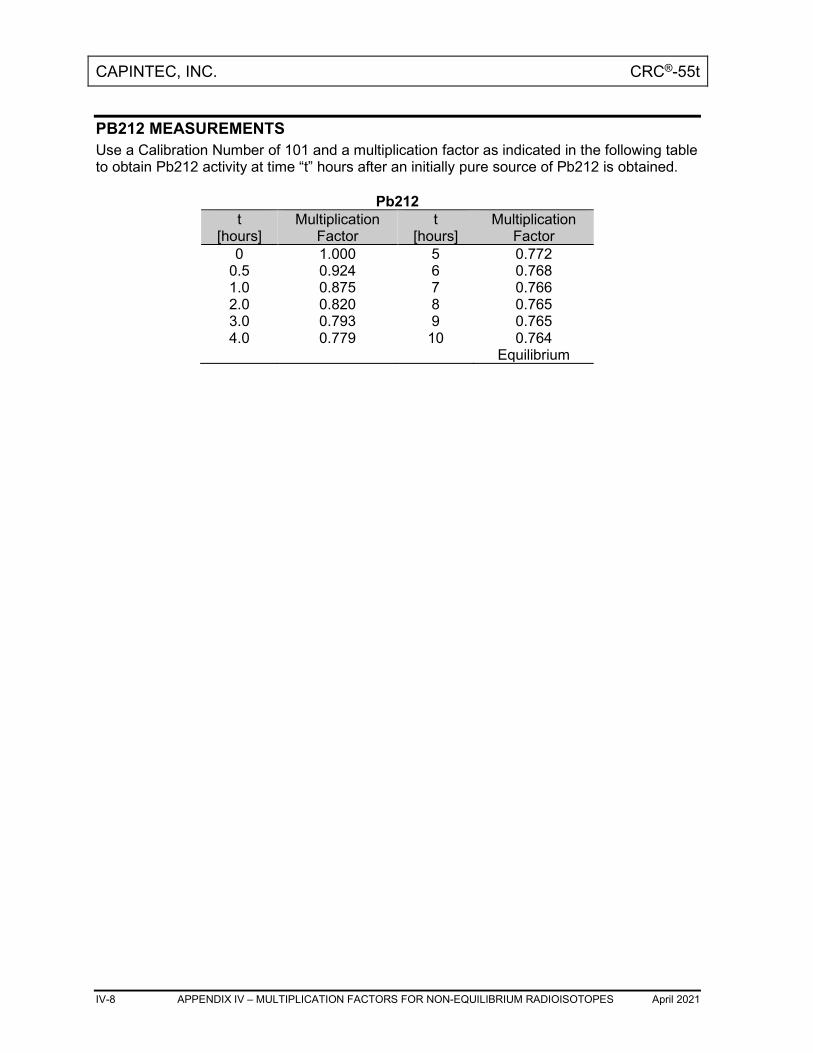
CAPINTEC, INC. CRC®-55t
IV-8 APPENDIX IV – MULTIPLICATION FACTORS FOR NON-EQUILIBRIUM RADIOISOTOPES April 2021
PB212 MEASUREMENTS Use a Calibration Number of 101 and a multiplication factor as indicated in the following table to obtain Pb212 activity at time “t” hours after an initially pure source of Pb212 is obtained.
Pb212 t
[hours] Multiplication
Factor t
[hours] Multiplication
Factor 0 1.000 5 0.772
0.5 0.924 6 0.768 1.0 0.875 7 0.766 2.0 0.820 8 0.765 3.0 0.793 9 0.765 4.0 0.779 10 0.764
Equilibrium

CAPINTEC, INC. CRC®-55t
April 2021 INDEX i - 1
INDEX A ABORT button, 11-21 ACCEPT button, 6-4 Acceptance Testing, 4-11, 7-1 Accredited Dosimetry Calibration
Laboratory, 1-3 ACCURACY button, 8-10, 8-12 Accuracy Test, 7-2, 7-3, 8-12
in Daily Test, 8-10 Individual Results Report, 14-27 Report, 7-2 Search Results Report, 14-25 View an Individual Test Report, 14-26
ACCURACY TEST button, 14-8 Accuracy Test Report, 14-24
from Daily Test, 14-8 ACCURACY TEST Report button, 14-24 Accuracy/AutoConstancy
Inactivate, 14-27 ADCL, 1-3 ADD ITEM button, 12-3 Adding to Inventory, 12-3 adjustments, 1-4 ADVANCED CHAMBER button, 6-3, 6-10 Alphanumeric Data
entering, 3-6 Assembly, 4-2 asterisk
Remote Display indicator, 3-4 Auto Zero, 8-6 AUTOCONSTANCY button, 6-18, 8-16,
14-9, 14-27 AutoConstancy Test Report
from Accuracy Test, 14-27 from Daily Test, 14-9
AutoLinearity, 11-12 Aborting a Test, 11-21 Pausing the Test, 11-17 Power Failure, 11-26 Reports, 11-27 Resuming the Test, 11-18 Saving the Test, 11-23 Selecting Nuclide, 11-13 Setting Interval, 11-15 Setting Total, 11-16
Starting the Test, 11-16 AUTOLINEARITY button, 11-12 AutoLinearity Test
Detailed Report, 11-29 Inactivate, 11-30
B Background, 8-1, 8-7
Inactivate, 14-33 BACKGROUND button, 8-1 Background Measurements
Individual Results Report, 14-33 Search Results Report, 14-31 View an Individual Test Report, 14-32
Background Measurements Report, 14-30 BACKGROUND Report button, 14-30 Battery, 16-13
Low, 16-6 Replacement, 16-6
Brachytherapy, 1-3, 1-4 Brightness, 5-23 button
ABORT, 11-21 ACCEPT, 6-4 ACCURACY, 8-10, 8-12 ACCURACY TEST, 14-8 ACCURACY TEST Report, 14-24 ADD ITEM, 12-3 ADVANCED CHAMBER, 6-3, 6-10 AUTOCONSTANCY, 6-18, 8-16, 14-9,
14-27 AUTOLINEARITY, 11-12 BACKGROUND, 8-1 BACKGROUND Report, 14-30 CAL#, 3-3, 10-2, 10-4 CALICHECK, 6-43, 11-37 CANCEL, 6-8 CDC, 5-18 CH, 3-4, 10-2, 10-10, 12-4 CH (CHAMBER)/WELL, 3-4 CHAMBER, 10-10 CHAMBER VOLTAGE Report, 14-18 CHAMBER VOLTS, 8-11 CLEAR, 6-17, 6-27, 6-38, 11-45 CLEAR ALL MEASUREMENTS, 11-33

CAPINTEC, INC. CRC®-55t
i - 2 INDEX April 2021
CLEAR SELECTED NUCLIDE, 6-8, 6-9, 6-20, 6-59
CONTINUE, 2-4, 8-3, 8-6 DAILY, 8-6 DAILY TEST Report, 14-4 DATE FORMAT, 5-5 DATE/TIME, 3-3, 10-2 DELETE ALL, 12-29 DELETE CURRENT SETTINGS, 6-42,
6-47 DELETE INVENTORY, 12-28 DELETE ITEM, 12-28 DIAGNOSTICS, 9-2 DOSE DECAY, 3-4, 10-2, 10-3, 10-6,
10-7 DOSE TABLE, 13-2 DOWN ARROW (▼), 3-7, 6-7, 6-8, 6-
19, 6-29, 6-36, 6-58, 11-14, 11-28, 12-5, 13-4, 14-6, 14-14, 14-19, 14-25, 14-31, 15-4
ENGLISH, 5-19 ENHANCED TESTS, 11-1 ESPANOL, 5-21 FINISHED, 11-9 FULL, 10-7 GEOMETRY, 11-4 HALF-LIFE CALCULATOR, 11-40 HMPAO TEST, 11-52 INACTIVATE, 11-30, 14-9, 14-16, 14-
22, 14-28, 14-33 INGLES, 5-21 INVENTORY, 12-2 LEGACY, 5-18 LINEARITY, 11-11 LINEATOR, 6-38, 11-35 LOGIN, 2-4, 4-10 MAG3 TEST, 11-54 MAKE KIT, 12-16 MEASURE ACTIVITY, 12-22, 12-26 MEASUREMENT, 3-3, 10-2, 10-5 MOLY ASSAY, 6-21, 10-12 MORE MEASUREMENTS, 11-9 NO, 6-43, 11-32, 14-11, 14-17, 14-23,
14-29, 14-35 NUCLIDE, 3-2, 6-7, 10-2, 10-4 PRINT, 3-3, 5-7, 10-2, 11-30, 11-45, 14-
7, 14-9, 14-14, 14-15, 14-19, 14-21, 14-25, 14-27, 14-31, 14-33
QC, 11-46 QUICK, 10-7
REPORTS, 14-2 RESUME TEST, 11-19 SAVE, 11-23, 11-25 SCREEN CALIB, 5-24 SEARCH, 11-28, 14-6, 14-13, 14-18,
14-24, 14-30 SETUP, 3-3, 6-3, 6-9, 6-21 SETUP CALNUM, 6-28 SETUP LINEARITY, 6-34 SETUP MOLY, 6-21 SETUP PET CHAMBER HOTKEYS, 6-
5 SETUP R CHAMBER HOTKEYS, 6-5 SETUP REMOTE, 6-51, 6-56 SETUP SOURCES, 6-12 SINGLE STRIP TEST, 11-46 SPANISH, 5-19 STANDARD, 11-33 STANDARD PET CHAMBER, 6-36 STANDARD R CHAMBER, 6-36 START, 11-16, 11-42 START TEST, 11-12 STOP, 11-44 SUBMIT, 12-15 TEST, 3-3, 5-25, 10-2 TWO STRIP TEST, 11-49 UNITS, 3-3, 10-2, 10-5 UP ARROW (▲), 3-7, 6-19, 6-29, 6-36,
6-58, 11-14, 11-28, 12-5, 13-4, 14-6, 14-14, 14-19, 14-25, 14-31, 15-4
UTIL, 9-1, 13-1, 14-2, 15-1 VIEW, 11-29, 14-7, 14-14, 14-20, 14-26,
14-32 WELL, 2-5, 10-2 WELL/CH (CHAMBER), 3-4 WITHDRAW, 12-23, 12-24 YES, 6-43, 11-32, 14-11, 14-17, 14-23,
14-29, 14-35 ZERO Report, 14-12
C CAL# button, 3-3, 10-2, 10-4 Cal#(P), 6-25 Cal#(R), 6-25 Calculation Utilities, 15-1
Ci /Bq Conversion, 15-2 Decay Calculator, 15-4
Calibration Numbers, 6-26, 6-28, 6-29, 10-5 adding, 6-28

CAPINTEC, INC. CRC®-55t
April 2021 INDEX i - 3
changing, 4-10, 6-28 determining, 6-27 entering, 6-25, 10-4 Limits, 6-26 new, 6-28 restoring, 6-29
CALICHECK button, 6-43, 11-37 Calicheck Linearity Test, 11-37
defining, 6-43 Report, 11-39
CANCEL button, 6-8 Canister, 4-11, 10-12 CapMac, 4-11, 10-12 Caution Labels, 1-2 CDC, 5-18 CDC button, 5-18 CH (CHAMBER)/WELL button, 3-4 CH button, 3-4, 10-2, 10-10, 12-4 CHAMBER button, 10-10 Chamber Hotkeys, 2-2
Assignment, 6-2 Chamber Initialization, 6-1 Chamber Measurement
Procedures, 10-3 Screen, 3-2
Chamber Voltage, 8-9, 8-11 Inactivate, 14-21 Individual Results Report, 14-21 Report, 14-18 Search Results Report, 14-19 View an Individual Test Report, 14-20
CHAMBER VOLTAGE Report button, 14-18
CHAMBER VOLTS button, 8-11 Changing Chamber, 10-10 Ci / Bq
Choosing, 5-3 Conversion, 15-2
Cleaning, 16-1, 16-2 Instructions, 16-2
CLEAR ALL MEASUREMENTS button, 11-33
CLEAR button, 6-17, 6-27, 6-38, 11-45 CLEAR SELECTED NUCLIDE button, 6-
8, 6-9, 6-20, 6-59 Communications Device Class, 5-18 Constancy Channels, 6-18
adding nuclides, 6-19 removing nuclides, 6-20
Constancy Test, 8-10, 8-17
Source, 4-10, 6-18 Contamination Test, 7-4 CONTINUE button, 2-4, 8-3, 8-6 D DAILY button, 8-6 Daily Chamber Test, 7-2 Daily Test, 7-3, 8-6
Accuracy Test, 8-10 Auto Zero, 8-6 Background, 8-7 Chamber Voltage, 8-9 Constancy Test, 8-10 Data Check, 8-9 Inactivate, 14-9 Individual Results Report, 14-9 Report, 7-2, 14-4 Search Results Report, 14-7 View an Individual Test Report, 14-7
DAILY TEST Report button, 14-4 Data Check, 8-9 Date
choosing format, 5-5 entering, 5-1
DATE FORMAT button, 5-5 DATE/TIME
button, 3-3, 10-2 Screen, 3-7
Decay Calculator, 15-4 Activity, 15-5 Date, 15-5 Results, 15-9 Select Nuclide, 15-4
DELETE ALL button, 12-29 Delete All Items, 12-29 DELETE CURRENT SETTINGS button, 6-
42, 6-47 Delete Individual Items, 12-28 DELETE INVENTORY button, 12-28 DELETE ITEM button, 12-28 Deleting from Inventory, 12-28 Description
Functional, 2-2 Technical, 2-6
Detailed Report AutoLinearity Test, 11-29
Diagnostics, 9-1 Test, 7-2, 7-5
DIAGNOSTICS button, 9-2 Dimensions, 2-8

CAPINTEC, INC. CRC®-55t
i - 4 INDEX April 2021
Cables, 2-8 Chamber, 2-8 Console, 2-8
Dipper, 4-7 cleaning, 16-2 disinfecting, 16-3
Disinfecting, 16-2 Instructions, 16-3
Disposal, 16-4 division factors, 1-4 Dose Decay, 10-6
Entering Date/Time, 10-7 Entry Modes, 10-6
DOSE DECAY button, 3-4, 10-2, 10-3, 10-6, 10-7
Dose Table, 13-1 Activity, 13-5 Dose, 13-6 Interval, 13-7 Nuclide, 13-3 printing, 13-8 report, 13-8 Results, 13-7 Volume, 13-5
DOSE TABLE button, 13-2 DOWN ARROW (▼) button, 3-7, 6-7, 6-8,
6-19, 6-29, 6-36, 6-58, 11-14, 11-28, 12-5, 13-4, 14-6, 14-14, 14-19, 14-25, 14-31, 15-4
E Electromagnetic Interference, 1-5 Element, 6-25 EMC, 2-9 EMI, 1-5, 5-7 English, 5-19 ENGLISH button, 5-19 Enhanced Tests, 11-1 Environment Requirements, 2-6, 4-8 Error Message
Moly Assay Activity Too Low, 10-19 Caution, 10-20 MO Too High, 10-20
ESPANOL button, 5-21 ETL Listed, 2-9 F FINISHED button, 11-9 FULL button, 10-7
Functional Description, 2-2 functions, 2-4 Fuse Servicing, 16-5 G general operating instructions, 3-1 Geometry, 7-1 GEOMETRY button, 11-4 Geometry Test, 11-4
Measurement Results, 11-10 Report, 11-10
Ground Current, 2-7 H Half-life, 6-25 Half-life Calculator, 11-40
Calculated Half-life, 11-44 Clear Current Half-Life Result, 11-45 Setting Interval, 11-40 Setting Total, 11-41 Starting the Measurements, 11-42 Stopping the Measurements Early, 11-
44 HALF-LIFE CALCULATOR button, 11-40 HID, 5-18 HMPAO Test, 11-52
report, 11-53 HMPAO TEST button, 11-52 Holders, optional, 4-7 Home Screen Hotkeys, 3-2, 6-2, 10-4 Hotkeys
Home Screen, 3-2, 6-2, 10-4 Select Nuclide Screen, 6-8
Human Interface Device, 5-18 I Inactivate
Accuracy/AutoConstancy Test, 14-27 AutoLinearity Test, 11-30 Background Measurement, 14-33 Chamber Voltage Measurement, 14-21 Daily Test, 14-9 Zero Measurement, 14-15
INACTIVATE button, 11-30, 14-9, 14-16, 14-22, 14-28, 14-33
INGLES button, 5-21 Installation, 4-1 Intended Use, 2-1 Inventory, 12-1
Activity, 12-10

CAPINTEC, INC. CRC®-55t
April 2021 INDEX i - 5
Input, 12-10 Measure, 12-12, 12-26 Measure Kit, 12-22
adding to, 12-3 Date, 12-12 Delete All Items, 12-29 Delete Individual Items, 12-28 deleting from, 12-28 ID, 12-7 Kit Activity, 12-20 Kit ID, 12-19 Kit Lot Number, 12-19 Kit Study, 12-18 Kit Volume, 12-21 Lot Number, 12-8 Make Kit, 12-16 Mo/Tc, 12-14 printing, 12-27 Save Item, 12-15 Select Nuclide, 12-4 Study, 12-6 Time of Use, 12-25 Volume, 12-9 Withdraw Activity, 12-24 withdrawing activity from, 12-23
INVENTORY button, 12-2 Inventory List Report, 12-27 IVBT, 1-3, 1-4 K Kit
Activity, 12-20 ID, 12-19 Lot Number, 12-19 making, 12-16 measure activity, 12-22 Study, 12-18 Volume, 12-21
L Labels
Caution, 1-2 High Voltage, 1-3 Shipping, 16-15 Warning, 1-2
Language, 5-19 Legacy, 5-18 LEGACY button, 5-18 Line Filter, 2-7 LINEARITY button, 11-11
Linearity Test, 7-1, 7-2, 7-5 Calicheck, 6-43 Calicheck-defining, 6-43 Calicheck-deleting definition, 6-47 Calicheck-Number of Measurements, 6-
44 Calicheck-Serial Number, 6-44 definition, 6-31 Lineator, 6-38 Lineator-Calibration Procedure, 6-39 Lineator-defining, 6-38 Lineator-deleting definition, 6-41 Lineator-Serial Number, 6-39 performing, 11-11 Standard, 6-35 Standard- Time Interval, 6-37 Standard-defining, 6-35 Standard-deleting definition, 6-38 Standard-Number of Measurements, 6-
37 Standard-Select Nuclide, 6-36
LINEATOR button, 6-38, 11-35 Lineator Linearity Test
report, 11-36 Lineator Test, 11-35
Calibration Procedure, 6-45 defining, 6-38
Liner, 1-4, 4-7 cleaning, 16-2 disinfecting, 16-3
liners, 16-2 List Screen, 3-7 LOGIN button, 2-4, 4-10 Low Activity Measurements, 10-3 Low Battery, 16-6 M MAG3 Test, 11-54
report, 11-56 MAG3 TEST button, 11-54 maintenance, 16-1 Make Kit, 12-16 MAKE KIT button, 12-16 MEASURE ACTIVITY button, 12-22, 12-
26 Measurement
Calibration Number, 10-4 Nuclide Specification, 10-4 Procedures:, 10-3
MEASUREMENT button, 3-3, 10-2, 10-5

CAPINTEC, INC. CRC®-55t
i - 6 INDEX April 2021
Mo/Tc Inventory, 12-14 Limit, 4-11
Mo99 Assay, 10-16 Background, 10-13
Moly Assay, 4-11, 10-12 CapMac or Canister, 6-20 Limit, 6-22, 6-23 Results, 10-19 Selecting Method, 6-22 Setup, 6-20 Volume Entry, 10-19
MOLY ASSAY button, 6-21, 10-12 MORE MEASUREMENTS button, 11-9 multiplication factors, 1-4 N NO button, 6-43, 11-32, 14-11, 14-17, 14-
23, 14-29, 14-35 Nuclide, 6-25
specification, 10-4 NUCLIDE button, 3-2, 6-7, 10-2, 10-4 Nuclide Screen Hotkeys, 2-2 Nuclides, 6-23
adding, 4-10, 6-23 deleting, 6-27
Numeric Data entering, 3-5
O On / Off Switch, 2-6 Operational Setup, General, 4-10 Operator
Profile, 2-1 Training, 2-2
P Performance, 2-8 Power Requirements, 4-8 Precision
Selecting Measurement, 10-5 Preventative Maintenance, 16-3
Quality Assurance Tests, 16-3 PRINT button, 3-3, 5-7, 10-2, 11-30, 11-
45, 14-7, 14-9, 14-14, 14-15, 14-19, 14-21, 14-25, 14-27, 14-31, 14-33
printers, 4-10 power requirements, 5-7 selection, 5-8
Printing, 5-7 Dose Table, 13-8 Inventory, 12-27 Record of measurment, 10-11
Profile Operator, 2-1
Program Flow, 2-5 Q QC button, 11-46 QC Tests, 11-46
HMPAO Test, 11-52 MAG3 Test, 11-54 Single Strip Test, 11-46 Two Strip Test, 11-49
Quality Assurance Tests, 7-3, 16-3 Quality Control, 11-46
HMPAO Test, 11-52 MAG3 Test, 11-54 Single Strip Test, 11-46 Two Strip Test, 11-49
Quarterly Tests, 7-5 QUICK button, 10-7 R Radiochromatography, 11-46 Range
limits, 2-8, 2-9 recalibration, 1-5 Receiving Condition Examination, 4-1 Regulatory Listings, 2-9
Electrical, 2-9 EMC, 2-9 ETL Listed, 2-9
Related Products, 16-14 Remote Display
Indicator, 3-4 Remote Display (Legacy Systems Only)
Adding or Changing Nuclides, 6-52, 6-57
Deleting Nuclides, 6-59 Nuclide Assignment, 6-48, 6-53
report Accuracy Test, 14-24 Accuracy Test from Daily Tests, 14-8 Accuracy Test Individual Results, 14-27 Accuracy Test Search Results, 14-25 AutoConstancy Test from Accuracy
Test, 14-27

CAPINTEC, INC. CRC®-55t
April 2021 INDEX i - 7
AutoConstancy Test from Daily Tests, 14-9
AutoLinearity Test Detailed, 11-29 Background Measurements, 14-30 Background Measurements Individual
Results, 14-33 Background Measurements Search
Results, 14-31 Calicheck Linearity Test, 11-39 Chamber Voltage, 14-18 Chamber Voltage Search Results, 14-19 Chamber Voltage Test Individual
Results, 14-21 Daily Test Individual Results, 14-9 Daily Test Search Results, 14-7 Daily Tests, 14-4 Diagnostics, 9-2 Dose Decay, 10-9 Dose Table, 13-8 Geometry, 11-10 HMPAO Test, 11-53 Inventory List, 12-27 Lineator Linearity Test, 11-36 MAG3 Test, 11-56 Moly Assay, 10-22 Single Strip Test, 11-49 Standard Linearity Test, 11-34 Two Strip Test, 11-52 Zero Measurement Search Results, 14-
14 Zero Measurements, 14-12 Zero Measurements Individual Results,
14-15 REPORTS button, 14-2 Reports Module, 14-1 Requirements
Environment, 2-6, 4-8 Power, 2-7, 4-8
RESUME TEST button, 11-19 S Safety, 1-1 Safety Tips, 1-6 SAVE button, 11-23, 11-25 Screen
Abort AutoLinearity Test After Finished, 11-22
Abort AutoLinearity Test In-progress, 11-21
Accuracy Test, 8-13
Accuracy Test Measurement, 8-14 Accuracy Test Measurement Error, 8-15 Accuracy Test No Source Data, 8-12 Accuracy Test Results, 8-16, 14-26 Add Inventory Item, 12-4 Advanced Chamber Setup, 6-5, 6-12, 6-
34, 6-51, 6-56, 10-6 Alphanumeric Keypad, 3-6, 11-32, 14-
11, 14-17, 14-23, 14-29, 14-35 Auto Zero Measurement Results, 8-7 AutoLinearity After Measurements
Begin, 11-16 AutoLinearity Menu Screen after Pause,
11-19 AutoLinearity Report, 11-30 AutoLinearity Setup, 11-13 AutoLinearity Test Finished, 11-25 AutoLinearity with Save Button, 11-23 Background Measurement, 8-3 Background Measurement Results, 8-8,
14-32 Background Remove Sources, 8-2 Background Results, 8-5 Background Too High, 8-4 Calicheck Linearity Next Measurement,
11-39 Calicheck Linearity Test First
Measurement, 11-38 Calicheck Test Measurement, 6-45 Chamber Measurement, 3-2, 6-2, 8-2, 9-
1, 10-2, 11-2, 12-2, 13-1, 15-1 Chamber Measurement Screen with
Dose Decay, 10-9 Chamber Voltage Measurement
Results, 8-11 Chamber Voltage Test Results, 14-20 Constancy Test Results, 8-17 Daily Test, 8-6 Daily Test Report, 14-8 Daily Test Results, 8-9 Date Format Selection, 5-5 Date/ Time, 3-8 Date/Time, 6-16, 12-13, 12-26, 15-5, 15-
8 Date/Time for Full Entry Mode, 10-8 Date/Time Quick Entry Mode, 10-8 Decay Calculator Results, 15-9 Default Linearity Tests, 11-11 Delete Calicheck Settings, 6-48 Delete Lineator Settings, 6-43

CAPINTEC, INC. CRC®-55t
i - 8 INDEX April 2021
Dose Decay Entry Mode Selection, 10-7 Dose Table, 13-3 Dose Table Results, 13-7 Enhanced Tests for PET Chambers, 11-
3 Enhanced Tests for R Chambers, 11-3 Enter Activity, 6-15, 12-11, 12-20, 12-
25, 13-6, 15-3, 15-7 Enter Cal#, 6-26 Enter Current Time, 5-3 Enter Password, 5-2, 6-4, 6-11, 6-33, 6-
50, 6-55 Enter Serial Number, 6-14 Geometry Measurement, 11-6 Geometry Measurement with Added
Volume, 11-8 Geometry Report, 11-10 Geometry Test, 11-4 Geometry Test Added Volume Entry,
11-7 Geometry Test Initial Volume Entry, 11-
5 Geometry Test More Measurements /
Finished, 11-9 Half-life Calculator, 11-40 Half-life Calculator After Measurements
Begin, 11-43 Half-life Calculator After Measurements
Finished, 11-44 HMPAO Test Results, 11-53 Inactivate Record, 11-31, 14-10, 14-16,
14-22, 14-28, 14-34 Inventory – Add Item with Submit
Button, 12-15 Inventory – Added Tc99m with Study
Field Box, 12-6 Inventory – ID
Field Box, 12-8 Inventory – Lot
Field Box, 12-9 Inventory – Measure Activity, 12-12 Inventory – Tc99m Select Study, 12-7 Inventory – Volume
Field Box, 12-10 Inventory Main, 12-3 Inventory Main with Added Item, 12-16 Inventory with All Buttons, 12-24, 12-28 Kit Please Measure Withdrawal, 12-23 Linearity Test First Measurement, 11-36 Linearity Test Message, 6-31
Lineator Test Measurement, 6-40 List, 3-7 MAG3 Test – Cartridge Measurement,
11-55 MAG3 Test – Fraction #1 Measurement,
11-54 MAG3 Test Results, 11-56 Main, 2-5, 14-1 Main showing Low Battery, 16-7 Make Inventory Kit, 12-18 Make Kit – Please Select Study, 12-19 Make Kit High Activity Message, 12-21 Make Kit Too Little Volume Message,
12-22 Measure Activity, 13-5 Moly Assay Background Choice, 10-14 Moly Assay Background Measurement
Accept, 10-15 Moly Assay Background Measurement
Too High, 10-16 Moly Assay Eluate Accept, 10-17 Moly Assay Method Selection, 6-21, 10-
13 Moly Assay Results – Less than 12
hours, 10-21 Moly Assay Results – More than 12
hours, 10-22 Moly Assay Tc99m Accept, 10-19, 10-
20 Numeric Keypad, 3-5, 11-15, 11-41, 11-
42 Pause AutoLinearity Test – Back Button,
11-17 Pause AutoLinearity Test – Home
Button, 11-18 Please Measure Withdrawal, 12-27 QC Test Selection, 11-46 Reports, 14-3 Resume AutoLinearity Test, 11-20 Save AutoLinearity Test After Finished,
11-26 Save AutoLinearity Test In-progress, 11-
24 Search Accuracy Tests after Searching,
14-25 Search AutoLinearity Tests, 11-27 Search AutoLinearity Tests with Test
Highlighted, 11-29 Search Background Measurements after
Searching, 14-31

CAPINTEC, INC. CRC®-55t
April 2021 INDEX i - 9
Search Chamber Voltage Tests after Searching, 14-19
Search Daily Tests, 14-4 Search Daily Tests after Searching, 14-
6 Search Daily Tests with Highlighted Test
Result, 14-7 Search Zero Measurements, 14-12 Search Zero Measurements after
Search, 14-13 Select Chamber, 10-10 Select Language, 5-19 Select Language – Spanish, 5-21 Select Nuclide, 6-7, 6-19, 6-53, 6-58,
10-4, 11-14, 12-5, 13-4, 15-4 Select Tc99m for Kit, 12-17 Setup, 5-4, 5-22, 6-3, 6-10, 6-32, 6-49,
6-54 Setup – after Day Month Year Selected,
5-6 Setup – after Year Month Day Selected,
5-6 Setup – Spanish, 5-20 Setup CalNum, 6-28 Setup Linearity, 6-35 Setup Linearity Calicheck, 6-44 Setup Linearity Calicheck Results, 6-46 Setup Linearity Calicheck View Results,
6-47 Setup Linearity Lineator, 6-39 Setup Linearity Lineator Results, 6-41 Setup Linearity Lineator View Results,
6-42 Setup Linearity Standard, 6-36 Setup Moly, 6-22 Setup Nuclide, 6-24 Setup PET Chamber Hotkeys, 6-6 Setup R Chamber Hotkeys, 6-6 Setup Remote Nuclides, 6-52, 6-57 Setup Sources, 6-13, 6-18 Single Strip Test – Bottom of Strip
Measurement, 11-48 Single Strip Test – Top of Strip
Measurement, 11-47 Single Strip Test Results, 11-49 Standard Linearity Test Remaining
Measurements, 11-33 Standard Linearity Test Results, 11-34 Start AutoLinearity, 11-12 Startup, 2-4, 4-9
Touchscreen Calibration, 5-24 Two Strip Test – Bottom of Strip A
Measurement, 11-50 Two Strip Test – Top of Strip B
Measurement, 11-51 Two Strip Test Results, 11-52 USB PC Driver Select, 5-18 Utility, 9-2, 13-2, 14-2, 15-2 Utility Screen with Diagnostics System
Test PASS, 9-3 Zero Measurement Results, 14-15
Screen Adjustments, 5-22 Brightness, 5-23 Calibrarion, 5-24 Sleep Brightness, 5-23 Sleep Timeout, 5-22
SCREEN CALIB button, 5-24 Screen Calibration, 5-24 SEARCH button, 11-28, 14-6, 14-13, 14-
18, 14-24, 14-30 Select Nuclide Screen Hotkeys, 6-8 Selecting Measurement Precision, 10-5 Servicing, 16-5
Fuse, 16-5 Setup
General Operational, 4-10 SETUP button, 3-3, 6-3, 6-9, 6-21 SETUP CALNUM button, 6-28 SETUP LINEARITY button, 6-34 SETUP MOLY button, 6-21 SETUP PET CHAMBER HOTKEYS
button, 6-5 SETUP R CHAMBER HOTKEYS button,
6-5 SETUP REMOTE button, 6-51, 6-56 SETUP SOURCES button, 6-12 Shipping, 16-15 Single Strip Test, 11-46
report, 11-49 SINGLE STRIP TEST button, 11-46 Sleep Brightness, 5-23 Sleep Timeout, 5-22 Spanish, 5-19 SPANISH button, 5-19 Speaker Volume, 5-25 STANDARD button, 11-33 Standard Linearity Test, 11-32
Defining, 6-35 report, 11-34
STANDARD PET CHAMBER button, 6-36
CAPINTEC, INC. CRC®-55t
i - 10 INDEX April 2021
STANDARD R CHAMBER button, 6-36 START button, 11-16, 11-42 START TEST button, 11-12 STOP button, 11-44 SUBMIT button, 12-15 Symbol Definitions, 1-1 System Initialization, 5-1 System Setup, 4-1 T Table
Calibration Number Limits, 6-26, 10-5 Disposal Information, 16-4 Test Source calibration activity limits, 6-
15 Tc99m
Assay, 10-18 Technical Description, 2-6 Test
Report, 7-3 TEST button, 3-3, 5-25, 10-2 Test Source, 4-10
Activity Field, 6-14 adding, 6-13 Constancy, 6-18 Constancy Field, 6-18 Daily Field, 6-17 Date Field, 6-16 deleting, 6-17 editing, 6-17 S/N Field, 6-13 Setup, 6-9
Testing Acceptance, 4-11, 7-1 Accuracy, 7-2, 7-3, 8-12 Chamber Daily, 7-2 Contamination, 7-4 Daily, 7-3, 8-6 Diagnostics, 7-2, 7-5 Linearity, 7-2, 7-5 Quality Assurance, 7-3 Quality Control (QC), 11-46 Quarterly, 7-5 Well, 7-3, 7-4 Yearly, 7-5
Time entering, 5-1
Time of Use, 12-25 Training
Operator, 2-2
Troubleshooting, 16-13 Two Strip Test, 11-49
Report, 11-52 TWO STRIP TEST button, 11-49 U UNITS button, 3-3, 10-2, 10-5 Unpacking, 4-1 UP ARROW (▲) button, 3-7, 6-19, 6-29,
6-36, 6-58, 11-14, 11-28, 12-5, 13-4, 14-6, 14-14, 14-19, 14-25, 14-31, 15-4
USB PC driver, 5-18 UTIL button, 9-1, 13-1, 14-2, 15-1 V VIEW button, 11-29, 14-7, 14-14, 14-20,
14-26, 14-32 View Individual Test Report
Accuracy, 14-26 Background Measurements, 14-32 Chamber Voltage, 14-20 Daily Test, 14-7 Zero Measurements, 14-14
Voltage High, 1-3, 1-4
W Warm Up Period, 2-6 Warning Labels, 1-2 WELL button, 2-5, 10-2 Well Counter System Test
Report, 7-3, 7-4 Well Test, 7-3, 7-4 WELL/CH (CHAMBER) button, 3-4 Withdraw Activity, 12-24 WITHDRAW button, 12-23, 12-24 Withdrawing activity from Inventory, 12-23 Y Yearly Tests, 7-5 YES button, 6-43, 11-32, 14-11, 14-17, 14-
23, 14-29, 14-35 Z Zero Measurements
Inactivate, 14-15 Individual Results Report, 14-15 Report, 14-12 Search Results Report, 14-14 View an Individual Test Report, 14-14

CAPINTEC, INC. CRC®-55t
April 2021 INDEX i - 11
ZERO Report button, 14-12

CAPINTEC, INC. CRC®-55t
NEW PRODUCT WARRANTY
Conditions and Limitations
CAPINTEC warrants our products to be free from defects in material and workmanship for a period of 24 months after delivery to the original buyer (unless indicated otherwise). Our obligation under this warranty is limited to servicing or adjusting products returned to our factory for that purpose promptly upon any claim under this warranty, provided our examination discloses to our satisfaction that the affected parts were originally defective and have not been subjected to misuse, abuse, mishandling or improper operation. This warranty extends to every part of the product except batteries, fuses, ink, magnetic storage media, toner, transistors, tubes or any other normally consumable item. In no event shall we liable for transportation, installation, adjustment or any other expenses which may arise in connection with such products or their servicing or adjustment. This warranty is expressly in lieu of any other express or implied warranties, and we make no warranty that the products sold herein are merchantable or are suitable for any particular purpose. The benefits of this warranty shall extend only to the buyer and to none other. We shall have no liability of any nature arising out of the use or application of the product in conformity with this warranty. If the product shall fail to perform in conformity with the warranty made herein, we shall be liable solely for the repair and replacement of the product as provided hereinabove, and shall have no other liability in respect of such failure or performance, or any consequences therefrom, including, without limitation, business impairment or loss, personal injury or property damage. No agent, employee, or representative of ours has any authority to bind us to any representation or warranty concerning the product sold herein, and unless a representation or warranty made by an agent, employee or representative is specifically included herein, it shall not be enforceable by the buyer. No waiver, alteration or modification of the foregoing conditions shall be valid, unless made in writing and signed by an executive officer of our corporation.

Copyright © 2022 FDOKUMEN