Performance analysis of coated plutonia particle fuel compact for radioisotope heater units
35
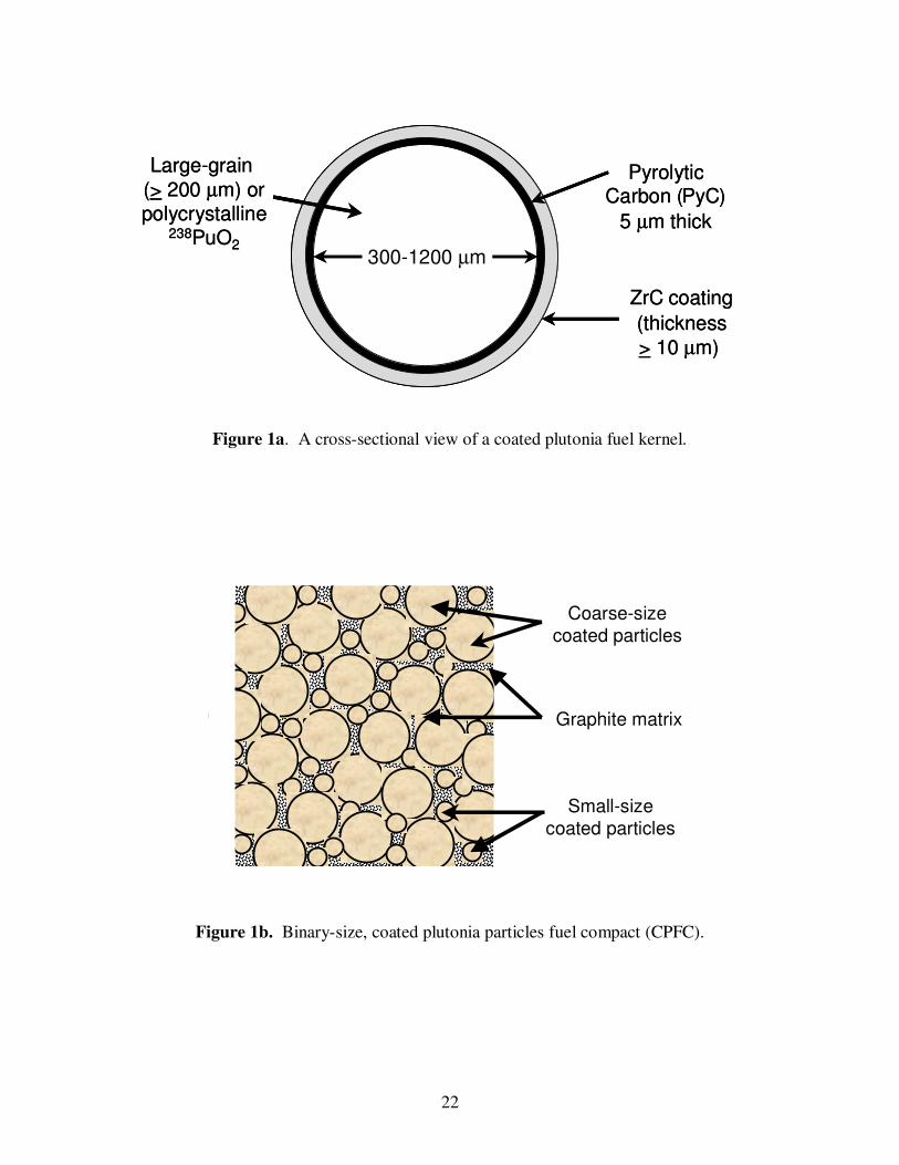
1 PERFORMANCE ANALYSIS OF COATED PLUTONIA PARTICLE FUEL COMPACT FOR RADIOISOTOPE HEATER UNITS 1 Mohamed S. El-Genk 2 and Jean-Michel Tournier Institute for Space and Nuclear Power Studies and Dept. of Chemical and Nuclear Engineering The University of New Mexico, Albuquerque, NM, U.S.A. (505) 277–5442, Fax: –2814, Email: [email protected] Abstract. Coated plutonia particle fuel has been proposed recently for use in Radioisotope Power Systems (RPSs) and Radioisotope Heater Units (RHUs) for a variety of space missions requiring power levels from mWs to tens or even hundreds of watts. The 238 PuO 2 fuel kernels are coated with a strong layer of ZrC designed to fully retain the helium gas generated by the radioactive decay of 238 Pu. A recent investigation has concluded that helium retention in large-grain (> 200 μm) granular and polycrystalline fuel kernels is possible even at high temperatures (> 1700 K). Results of performance analysis showed that this fuel form could increase by 2.3 – 2.4 times the thermal power output of a Light Weight Radioisotope Heater Unit (LWRHU). These figures are for a single-size (500 μm) particles compact, assuming 10% and 5% helium gas release, respectively, and a fuel temperature of 1723 K, following 10 years of storage. A binary-size (300 and 1200 μm) particles compact increases the thermal power output of the RHU by an additional 15%. 1.0 INTRODUCTION Recently, a coated plutonia particle fuel compact was proposed for potential use in advanced radioisotope heater units (RHUs) and radioisotope power systems (RPSs) (Sholtis et al., 1999). The fuel compact consists of ZrC-coated 238 PuO 2 fuel kernels dispersed into a graphite matrix with a packing density for single size particles of up to 62.5% by volume. This packing density increases to ~ 73% when two particle sizes with a diameter ratio of 4 are used. The 238 PuO 2 fuel kernels are covered with a 5-μm thick, pyrolytic graphite (PyC) inner coating for protection during the application of the outer ZrC coating by Chemical Vapor Deposition (CVD). The CVD process is also used to apply the inner PyC coating. The ZrC, a very strong material that is ductile at temperatures in excess of 2000 K (Storms, 1962; Ramgopal, 1974), serves as the primary containment vessel of the plutonia fuel kernel and the helium gas generated by the radioactive decay of 238 Pu. The thickness of the ZrC coating depends not only on the fuel temperature, the helium gas release fraction, and the storage time, but also on the plutonia fuel microstructure. Polycrystalline plutonia kernels fabricated using Sol-Gel ot thermal plasma processes offer great promise for almost full helium retention, even at high temperatures in excess of 1700 K (El-Genk and Tournier, 2000). Figure 1a shows a cross-sectional view of a coated plutonia fuel particle and Figure 1b shows an illustration of a binary-size coated particle fuel compact (CPFC). 1 Accepted for publication in the Journal of Nuclear Engineering and Design, 2001. 2 Corresponding author.
Transcript of Performance analysis of coated plutonia particle fuel compact for radioisotope heater units

1
PERFORMANCE ANALYSIS OF COATED PLUTONIA PARTICLE FUEL
COMPACT FOR RADIOISOTOPE HEATER UNITS1
Mohamed S. El-Genk2 and Jean-Michel Tournier
Institute for Space and Nuclear Power Studies and Dept. of Chemical and Nuclear Engineering
The University of New Mexico, Albuquerque, NM, U.S.A.
(505) 277–5442, Fax: –2814, Email: [email protected]
Abstract. Coated plutonia particle fuel has been proposed recently for use in Radioisotope
Power Systems (RPSs) and Radioisotope Heater Units (RHUs) for a variety of space
missions requiring power levels from mWs to tens or even hundreds of watts. The 238
PuO2
fuel kernels are coated with a strong layer of ZrC designed to fully retain the helium gas
generated by the radioactive decay of 238
Pu. A recent investigation has concluded that
helium retention in large-grain (> 200 µm) granular and polycrystalline fuel kernels is
possible even at high temperatures (> 1700 K). Results of performance analysis showed that
this fuel form could increase by 2.3 – 2.4 times the thermal power output of a Light Weight
Radioisotope Heater Unit (LWRHU). These figures are for a single-size (500 µm) particles
compact, assuming 10% and 5% helium gas release, respectively, and a fuel temperature of
1723 K, following 10 years of storage. A binary-size (300 and 1200 µm) particles compact
increases the thermal power output of the RHU by an additional 15%.
1.0 INTRODUCTION
Recently, a coated plutonia particle fuel compact was proposed for potential use in advanced
radioisotope heater units (RHUs) and radioisotope power systems (RPSs) (Sholtis et al., 1999).
The fuel compact consists of ZrC-coated 238
PuO2 fuel kernels dispersed into a graphite matrix
with a packing density for single size particles of up to 62.5% by volume. This packing density
increases to ~ 73% when two particle sizes with a diameter ratio of 4 are used. The 238
PuO2 fuel
kernels are covered with a 5-µm thick, pyrolytic graphite (PyC) inner coating for protection
during the application of the outer ZrC coating by Chemical Vapor Deposition (CVD). The
CVD process is also used to apply the inner PyC coating. The ZrC, a very strong material that is
ductile at temperatures in excess of 2000 K (Storms, 1962; Ramgopal, 1974), serves as the
primary containment vessel of the plutonia fuel kernel and the helium gas generated by the
radioactive decay of 238
Pu. The thickness of the ZrC coating depends not only on the fuel
temperature, the helium gas release fraction, and the storage time, but also on the plutonia fuel
microstructure. Polycrystalline plutonia kernels fabricated using Sol-Gel ot thermal plasma
processes offer great promise for almost full helium retention, even at high temperatures in
excess of 1700 K (El-Genk and Tournier, 2000). Figure 1a shows a cross-sectional view of a
coated plutonia fuel particle and Figure 1b shows an illustration of a binary-size coated particle
fuel compact (CPFC).
1 Accepted for publication in the Journal of Nuclear Engineering and Design, 2001. 2 Corresponding author.

2
The graphite or carbon-carbon composite matrix of the fuel compact is designed to accommodate
the thermal expansion of the fuel particles and is spongy and structurally weaker than the ZrC
coating. Thus, upon impact on solid surfaces following a launch abort or re-entry accident,
cracking of the coated particles fuel compact (CPFC) is likely to occur through the graphite,
leaving the coated fuel particles intact. The design concept of the CPFC is analogous to that of
the "pomegranate" fruit, in which the holding structure is spongy as well as weak under applied
tensile stress to protect the fruit seeds. In addition, the carbon-based matrix of the compacts is
perfectly compatible with the aeroshell material of radioisotope heater units (Schock, 1980 and
1981).
In addition to their structure strength, the coated plutonia fuel particles offer a promise for
enhanced safety. The fuel kernels are intentionally sized (> 300 µm) to prevent any adverse
radiological effects. They are non-respirable, non-inhalable, and if ingested, would simply be
excreted with no radiological effects (Hoover, 1999). In addition, this coated fuel form offers
excellent design flexibility as the CPFC could be made into different shapes and sizes to provide
thermal power from milli-watts to tens or even hundreds of watts.
1.1 Potential Applications
The CPFC can be made into heating tapes, buttons, or paints as RHUs or miniaturized RPSs for
satellites, spacecraft, and planetary exploration probes. For example, a button-like CPFC heat
source could be used with miniaturized thermoelectrics (TEs) to provide electrical power in the
mWe range for more than 10 years. The heat rejected by the TE couples could be used for
thermal management of the space probes, thus achieving 100% energy utilization. Larger size
CPFC in the form of pellets or disks could be used in higher power RHUs as well as in RPSs to
produce power in the range from one to tens or even hundreds of watts.
One could envision fabricating thin CPFC wafers the size of an Oreo cookie or smaller in which
a thin layer of Fine-Weave Pierced Fabric (FWPF, a carbon-carbon weave used in re-entry
aeroshells) is used on both sides of the fuel compact for thermal protection. These “cookies” like
CPFCs could be attached to surfaces more readily than the more bulky, present-day LWRHUs.
Figure 2a shows an example of a miniaturized CPFC-RHU for thermal management of
electronics circuit boards. The CPFC fuel, used in conjunction with low-temperature
thermoelectric couples (Caillat et al. 2000), could be used in milliwatt CPFC-RPSs. These RPSs
provide both thermal and electric power for circuit boards, as shown in Figure 2b.
The proposed CPFC design offers four basic barriers to prevent potential release of the fuel and
the helium gas. The first barrier is the large-grain or polycrystalline plutonia fuel matrix; the
second is the multi-layer coating of the plutonia fuel particles; the third barrier is the fuel
compact matrix; and the fourth barrier is the FWPF aeroshell (Figures 1 and 2).
High performance, reliable, low mass, and long operation lifetime (5-10 years) RHUs and RPSs
are required for several new NASA missions planned over the next few years. Examples include
the Saturn Rings Observer, Solar probe, Europa Lander, Cryobot and Hydrobot, and the Titan
Explorer missions which call for electrical power requirements in the 20 to 200 watts range and 6
3
to 10 years mission duration. CPFC-RPSs could meet these power requirements and present
several advantages such as scalability, reliability, and retention of helium gas. Modular CPFC-
RHUs could be developed for a variety of thermal and electrical applications up to 20 W thermal
or electric, that are 30-50% lighter than current LWRHUs (Schock, 1981; Johnson, 1997). The
CPFC-RHUs could be used either by themselves, or in conjunction with low-temperature
thermoelectric (TE) converters having an efficiency of 4-6%, currently under development at the
Jet Propulsion Laboratory, to provide up to 150 mWe at power densities > 100 mWe/kg (Figure
2b).
The CPFC-RHUs are easily scalable to meet mission power requirements ranging from a few
watts to hundreds of watts, or even a few kilowatts. They could be coupled with advanced, 18%
efficient vapor anode, multi-tube Alkali-Metal Thermal-to-Electric Converter (AMTEC) cells
(Figure 2c). Higher efficiencies and specific powers could be obtained by cascading the
AMTEC cells with segmented thermoelectrics (TE) (Caillat et al., 2000) for the bottom cycle
(Figure 2c). For example, a CPFC-RPS which cascades an 18%-efficient AMTEC cells (El-
Genk and King, 2000) operating between 1100 K and 650 K, with a 9%-efficient segmented TE
converter (Caillat et al., 2000) operating between 650 K and 350 K, would have an effective
conversion efficiency of about 25%. The CPFC-RHUs could also be used in conjunction with
high temperature segmented TE (η ~ 15%) (Caillat et al., 2000), Stirling engine units (η ~ 23–
30%) (Mason, 2000), or even a He-Xe Brayton engine (η ~ 23–28%) (El-Genk, 2000),
depending on the electric power and mass requirements for the power system. CPFC-RPSs with
higher energy conversion efficiency are quite attractive because they require a smaller amount of 238
PuO2 fuel.
The coated plutonia particle fuel form is also ideal for use in scientific probes requiring both
thermal and electric powers and in which the appropriate type and shape of the RHU can be
fabricated to optimize the design, operation, and the functionality of the probe. Some of the
space missions that employ planetary probes for in-situ analysis of surface materials require that
the He gas be fully retained in order to avoid contaminating the environment and skewing the
sensitive measurements. Such an option and design flexibility are not attainable using the
current LWRHU (Schock, 1981; Johnson, 1997) and General Purpose Heat Source (GPHS)
designs (Schock, 1980).
The coated fuel particles could also be compacted into a brick form for high power CPFC-RHUs
that could be lighter than current GPHSs (Schock, 1980). In current LWRHUs, the refractory
cladding of the plutonia fuel pellets is kept at relatively high temperatures (> 1173 K) to ensure
sufficient ductility when impacting solid surfaces. In addition to being very heavy, these
claddings (platinum-30%rhodium in LWRHUs and iridium in GPHSs) must be kept well below
their melting temperatures and those of any eutectics that could form in a solid propellant fire.
These temperatures are maintained with the aid of multi-layered, low conductivity, PyC
insulation sleeves (Figure 3). Conversely, the CPFC has no temperature constraint: the
zirconium carbide coating forms an eutectic with carbon at the very high temperature of 3123 K
(Storms, 1962). Thus, most of the internal thermal insulation sleeves and the refractory cladding
in the LWRHU (Figure 3) could be replaced with CPFC. This would result in higher thermal
power, at lower or same mass, or in smaller size and lower mass, for the same thermal power.
4
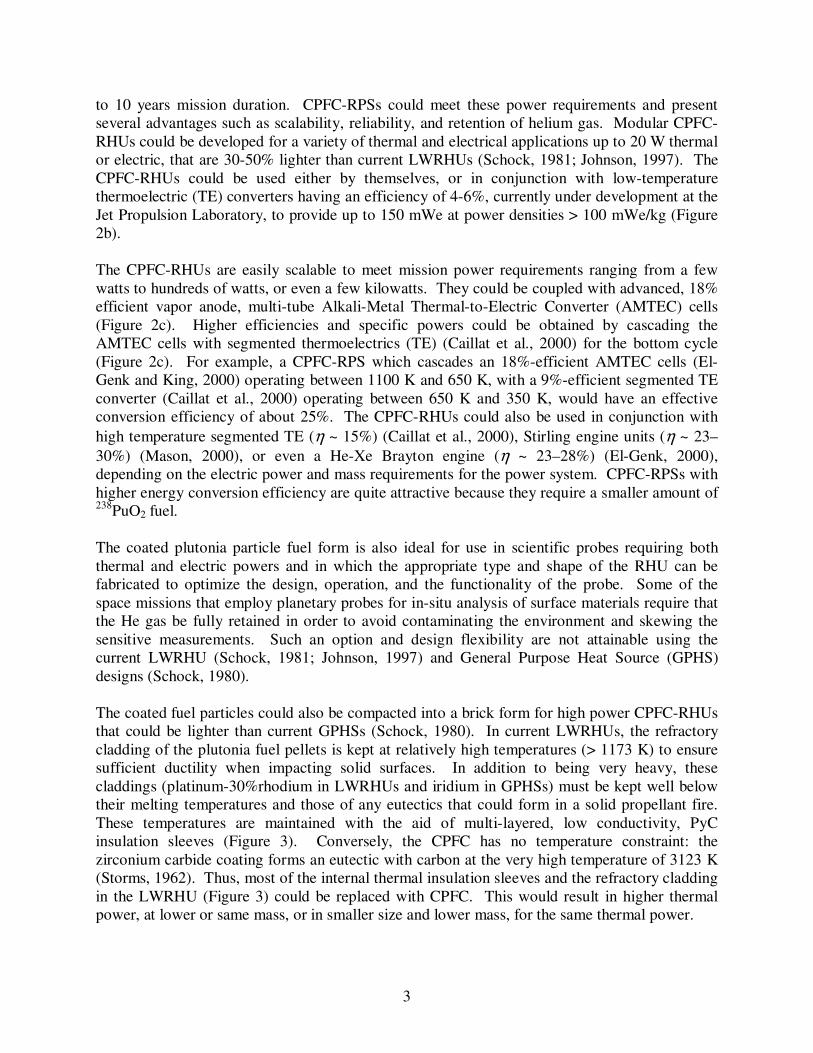
1.2 Objectives
During FY 99, an exploratory effort sponsored by the Department of Energy was initiated to
investigate the potential of the coated plutonia particles fuel form for RHUs and address
fabrication and performance issues. The specific tasks investigated were to:
(a) Review the fabrication technology of coated plutonia fuel particles;
(b) Review the release mechanisms of helium gas in small grain (7-40 µm) granular plutonia
pellets in GPHSs and LWRHUs, and examine the applicability of these mechanisms to the
He release from large grain (> 200 µm) and polycrystalline fuel kernels (El-Genk and
Tournier, 2000);
(c) Review the spectrum of credible launch and re-entry accident environments that the coated
particle fuel could potentially experience. Based on this review, design and functional
requirements for coated particle fuel were established (Sholtis, 2001);
(d) Develop a design and performance model of coated fuel particles to investigate the impact
of using single-size and binary-size CPFC on the thermal power output of a RHU. Also
quantify the effects on the RHU thermal power of the helium gas release fraction, fuel
temperature, and storage time before launch; and
(e) Identify future research and testing needs to confirm the coated particle fuel’s potential
operation and safety promise.
This paper provides a summary of the work done under this joint exploratory research effort and
presents and discusses in details results on the performance of the CPFC-RHU.
2.0 NOMENCLATURE
a Average fuel grain radius (m)
b Coefficient (Equation (11)), 2105121.1
−×=b (m3/kg)
D Gas mass diffusion coefficient in fuel matrix (m2/s)
D’ Effective gas diffusion coefficient in fuel, D’ = D/a2 (s
-1)
Df Diameter of fuel kernel (m)
Dg Average diameter of fuel grain (m)
Dp Outer diameter of coated fuel particle (m)
F Fraction of helium gas released from the fuel matrix that exerts pressure on outer coating
F* Release-to-birth rate ratio of radioisotope
M Molecular weight (kg/mole)
n Number of moles (moles)
Na Avogadro number (Na = 6.0225 x 10²³
atoms/mole)
No Pu-238 atom density of as-fabricated plutonia fuel kernel (atoms/kg)
P Pressure (Pa)
q Thermal power (Wth)
q ′′′ Volumetric thermal power (Wth / m3)
Rg Perfect gas constant (Rg = 8.3143 J / mole.K)
Rinner Inner radius of ZrC coating (m)
ℜ Dimensionless stress factor of a spherical shell
5
Sp Geometrical surface area of as-fabricated fuel kernel (m2)
SR Effective gas release area in fuel kernel (m2)
T Temperature (K)
t Time (s)
tPyC Thickness of pyrolytic carbon inner layer (m)
tZrC Thickness of ZrC coating (m)
T1/2 Radioactive decay half life (s)
VOL Volume (m3)
YZrC Yield strength of ZrC (Pa)
Greek
α Fraction of coarse spheres in a binary mixture at maximum packing
β Maximum packing volume fraction of 2-size spheres in compact
γ Open grain boundary porosity
εf As-fabricated porosity of fuel kernel openfε Amount of open porosity in fuel kernel
εPyC As-fabricated porosity of pyrolytic carbon layer
λ Radioactive decay constant (s-1
) η Thermal-to-electric conversion efficiency ρ Density (kg / m
3)
σT Maximum tangential tensile stress in ZrC coating layer (Pa)
Ψ Thermal power ratio, LWRHURHUCPFC qq /−
Subscript/Superscript
f PuO2 fuel
He Helium gas
max Maximum
Pu Plutonium
TD Theoretical density
1 Coarse particles in a binary mixture fuel-compact
2 Fine particles in a binary mixture fuel-compact
3.0 FABRICATION TECHNIQUES AND FUEL MICROSTRUCTURE
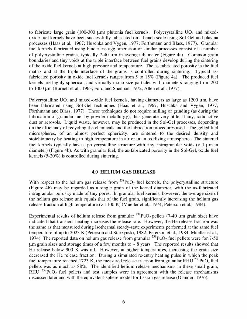
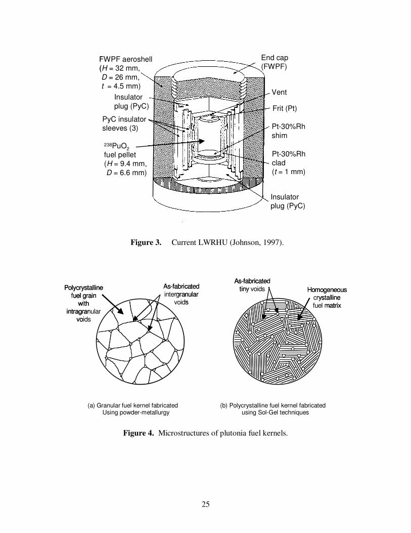
There are two basic microstructures of the fuel kernels (Figure 4): granular and polycrystalline.
No data were found on the fabrication of granular or polycrystalline 238
PuO2 fuel kernels using
the binderless agglomeration or the Sol-Gel techniques. The data on the fabrication of
monocrystalline fuel kernels using thermal plasma processes are also nil (Silver, 1999).
Granular UO2 and mixed-oxide fuel kernels with small grain sizes (7-40 µm) have been
successfully fabricated on a large scale using the binderless agglomeration process (Burnett et
al., 1963; Ford and Shennan, 1972; Allen et al., 1977). This process, however, has not been used
6
to fabricate large grain (100-300 µm) plutonia fuel kernels. Polycrystalline UO2 and mixed-
oxide fuel kernels have been successfully fabricated on a bench scale using Sol-Gel and plasma
processes (Haas et al., 1967; Huschka and Vygen, 1977; Förthmann and Blass, 1977). Granular
fuel kernels fabricated using binderless agglomeration or similar processes consist of a number
of polycrystalline grains, typically 7-40 µm in average diameter (Figure 4a). Common grain
boundaries and tiny voids at the triple interface between fuel grains develop during the sintering
of the oxide fuel kernels at high pressure and temperature. The as-fabricated porosity in the fuel
matrix and at the triple interface of the grains is controlled during sintering. Typical as-
fabricated porosity in oxide fuel kernels ranges from 5 to 15% (Figure 4a). The produced fuel
kernels are highly spherical, and virtually mono-size particles with diameters ranging from 200
to 1000 µm (Burnett et al., 1963; Ford and Shennan, 1972; Allen et al., 1977).
Polycrystalline UO2 and mixed-oxide fuel kernels, having diameters as large as 1200 µm, have
been fabricated using Sol-Gel techniques (Haas et al., 1967; Huschka and Vygen, 1977;
Förthmann and Blass, 1977). These techniques do not require milling or grinding (as during the
fabrication of granular fuel by powder metallurgy), thus generate very little, if any, radioactive
dust or aerosols. Liquid waste, however, may be produced in the Sol-Gel processes, depending
on the efficiency of recycling the chemicals and the fabrication procedures used. The gelled fuel
microspheres, of an almost perfect sphericity, are sintered to the desired density and
stoichiometry by heating to high temperature in air or in an oxidizing atmosphere. The sintered
fuel kernels typically have a polycrystalline structure with tiny, intragranular voids (< 1 µm in
diameter) (Figure 4b). As with granular fuel, the as-fabricated porosity in the Sol-Gel, oxide fuel
kernels (5-20%) is controlled during sintering.
4.0 HELIUM GAS RELEASE
With respect to the helium gas release from 238
PuO2 fuel kernels, the polycrystalline structure
(Figure 4b) may be regarded as a single grain of the kernel diameter, with the as-fabricated
intragranular porosity made of tiny pores. In granular fuel kernels, however, the average size of
the helium gas release unit equals that of the fuel grain, significantly increasing the helium gas
release fraction at high temperature (> 1100 K) (Mueller et al., 1974; Peterson et al., 1984).
Experimental results of helium release from granular 238
PuO2 pellets (7-40 µm grain size) have
indicated that transient heating increases the release rate. However, the He release fraction was
the same as that measured during isothermal steady-state experiments performed at the same fuel
temperature of up to 2023 K (Peterson and Starzynski, 1982; Peterson et al., 1984; Mueller et al.,
1974). The reported data on helium gas release from granular 238
PuO2 fuel pellets were for 7-50
µm grain sizes and storage times of a few months to ~ 8 years. The reported results showed that
He release below 900 K was nil. However, at higher temperatures, increasing the grain size
decreased the He release fraction. During a simulated re-entry heating pulse in which the peak
fuel temperature reached 1723 K, the measured release fraction from granular RHU 238
PuO2 fuel
pellets was as much as 88%. The identified helium release mechanisms in these small grain,
RHU 238
PuO2 fuel pellets and test samples were in agreement with the release mechanisms
discussed later and with the equivalent-sphere model for fission gas release (Olander, 1976).

7
According to the equivalent-sphere model (Olander, 1976), the fractional release, F*, of the
radioactive fission gases that attained steady-state concentrations in the fuel, equals the release-
to-birth rate ratio, BR && / , and can be expressed as (El-Genk and Tournier, 2000):
2/1)(
1)(/* TT
Ta
TDD
VOL
SBRF
f
R γ
λλ∝
′∝×
≈≡ && . (1)
This equation shows that F* is inversely proportional to the average fuel grain radius, a, but
directly proportional to the square root of the half-life, T1/2. As the half-life increases, F*
approaches the release fraction of non-radioactive species (Figure 5). Thus, for the same fuel
material and microstructure, temperature, T, and grain size, F* increases exponentially with the
half-life of the gas species, approaching an asymptote corresponding to the release fraction of
non-radioactive gases, such as helium in granular 238
PuO2 fuel. The effective diffusion
coefficient, D' (s-1
) = D/a2, which increases exponentially with the fuel temperature, accounts for
the increases in both the gas mass diffusion coefficient, D (m2/s), and the effective release area,
SR (m2). This release area is a function of temperature and includes any developed cracks in the
fuel matrix and open porosity at the grain boundaries.
Neglecting the contribution of the as-fabricated open porosity in the fuel, the normalized surface
area for helium gas release from granular plutonia fuel kernels can be expressed as (El-Genk and
Tournier, 2000):
g
f
p
R
D
D
S
Sγγ +−=
)1( . (2)
The coefficient γ (0 < γ < 1.0) depends on the effective surface area available for He gas release
from the fuel matrix, SR.
4.1 Helium Gas Release Mechanisms
Below ~ 900 K, He release occurs by atomic diffusion from the fuel matrix, and SR equals the
geometrical surface area of the as-fabricated fuel kernel (i.e. γ = 0). Between 900 K and 1150
K, 0 < γ < 1 and SR in granular fuel increases slowly with temperature, due to the formation and
the coalescence of grain boundary bubbles. Above ~1150 K, SR increases rapidly with
temperature as γ approaches unity, due to the formation of open porosity at the grain boundaries.
At ~1450 K, SR reaches its maximum value ( γ = 1.0), as the formation of the open porosity at the
grain boundaries is complete. Above this temperature, He gas release in granular fuel is no
longer limited by the surface area available for release, SR, but rather by the atomic and volume
diffusion of the gas in the fuel grains.
Therefore, for the same fuel temperature and kernel diameter, increasing the grain size from 10
µm to 200 µm could reduce the He gas release in plutonia fuel at high temperatures (>1450 K)
by more than one order of magnitude (El-Genk and Tournier, 2000). As indicated earlier, a
polycrystalline fuel kernel may be regarded as a single grain with a size equal to the diameter of
the kernel. Thus, the effective surface area for the He gas release in large grain (> 200 µm) or

8
polycrystalline fuel is essentially equal to the geometrical surface area of the kernel. This
surface area is significantly smaller than the effective area available for the He gas release in
small-grain fuel at temperatures > 900 K.
4.2 Estimates of Helium Gas Release
Gas release data have been reported for UO2 fuel particles irradiated at isothermal conditions in a
fission reactor by Friskney et al. (1977 and 1979). These authors investigated the effects of grain
size, radioactive decay constant, fuel burnup (up to 6.4 at. %), and fuel temperature (up to 2023
K) on the release-to-birth rate ratio of various noble fission gases and volatile isotopes. The UO2
fuel particles used included small-grain (average grain size of 10 µm) and large-grain (effective
grain size of 300-600 µm) spheres and were irradiated up to a 6.4 at. % burnup. In addition,
monocrystal right cylinders of natural (0.72 wt. % 235
U) stoichiometric UO2 were irradiated at
the same conditions in the experiments. The released amounts of various fission gaseous species
were measured by γ-spectroscopy, after correcting for their respective radioactive decay. The
release rates of noble fission gases and volatile fission products were calculated based on these
measurements, while their birth rates by fission and radioactive decay were calculated using
computer codes (Friskney and Turnbull, 1979).
Results showed that when irradiated at 1723 K and up to 4.0 at.% burnup, the small-grain fuel
particles (7-40 µm) released essentially all fission gases and volatile products (~ 70–80%
release), whereas only ~ 7% were released from the large-grain (~ 300-600 µm) fuel particles. It
is worth noting that the release fraction from the small-grain UO2 particles is in agreement with
the experimental data generated at LANL for GPHS and LWRHU granular plutonia pellets
(Mueller et al., 1974; Land, 1980; Peterson and Starzynski, 1982; Peterson et al., 1984). The
data showing the effect of half-life on the release fraction of noble fission gases and volatile
products from various UO2 fuel samples at 1723 K is presented in Figure 5 (El-Genk and
Tournier, 2000). According to Equation (1), the release-to-birth rate ratio is proportional to the
square root of the half-life, for the relatively short-lived isotopes that reach equilibrium early in
time. Such dependence of the release-to-birth rate ratio on the half-life is evident in Figure 5; the
gas release data exhibited an exponential increase with half-life, reaching asymptotic values at
large half-lives. These asymptotic values are representative of the release fractions of stable,
noble fission gases in granular UO2 fuel, and should equal that of helium in plutonia fuel
particles of the same average grain sizes at the same fuel temperature.
Based on these experimental data and the above argument, helium gas release from small-grain
(7-40 µm) plutonia fuel at 1723 K is expected to be ~ 70–80%. However, for large-grain (> 300
µm) and polycrystalline fuel microspheres, when heated up to 1723 K, the helium gas release
could be more than an order of magnitude lower (< 7%) (Figure 5). The gas release data for UO2
particles (Friskney et al., 1977 and 1979) showed that, at 1042 K, less than 1% of the noble
fission gases and volatile fission products were released from the large-grain fuel particles. A
similar release fraction would be expected for helium in plutonia fuel particles having large grain
sizes (> 200 µm). Even lower helium release fractions are expected in polycrystalline fuel
kernels. Therefore, the helium gas release in coated, large-grain or polycrystalline 238
PuO2 fuel
kernels at the nominal operating temperature in a RHU (~ 800 K) would be practically nil. The
release of He from large-grain (> 200 µm) 238
PuO2 fuel kernels at > 1723 K, however, could be ~

9
7%, decreasing to ~ 0.8% at 1042 K. In polycrystalline plutonia fuel kernels fabricated using
Sol-Gel processes, the helium release fraction could be even lower than the estimates for the
large-grain 238
PuO2 kernels (< 7% at 1723 K and < 0.8% at 1042 K).
5.0 PERFORMANCE MODEL OF COATED PARTICLE FUEL
A performance and stress analysis model of coated 238
PuO2 fuel kernels was developed to
calculate the required thickness of ZrC coating to fully retain the He gas as a function of fuel
temperature, release fraction, and storage time of CPFC before launch. At 1723 K, the model
assumes conservatively that the fuel kernel is constrained solely by the ZrC coating. No credit
was taken in the model for the strength of PyC inner coating or the constraint by the graphite
matrix in the CPFC. The induced tangential tensile stress in the ZrC coating is calculated using
the spherical shell model (Kaae, 1966). This model is applicable to the coated plutonia fuel
particles since the thickness of the ZrC coating is much smaller than the diameter of the fuel
kernel.
5.1 Particles Packing and Plutonia Volume Fraction in Fuel Compact
For fuel kernel diameters Df1 and Df2, as-fabricated fuel volume porosities εf1 and εf2, and coated
particles’ diameters Dp1 and Dp2, respectively, the maximum packing volume fraction of the 2-
size particles in the compact, β, and the corresponding fraction of the coarse particles (Dp1), α,
can be calculated as:
)1/(03127.0625.0 21 −×+= pp DDβ for 1 < Dp1/Dp2 < 6.5 ,
02.1/0.281
91.0/0.239
21
21
−×
−×=
pp
pp
DD
DDβ for 6.5 < Dp1/Dp2 < 19.1 , (3)
and
)8.4(log
)/(log247.00.1
10
2110 pp DD×−=α for 1 < Dp1/Dp2 < 4.8 ,
)8.4(log)1.19(log
)8.4(log)/(log033.00.753
1010
102110
−
−×−= pp DD
α for 4.8 < Dp1/Dp2 < 19.1 . (4)
As shown in Figure 6, β increases linearly with Dp1/Dp2, up to 6.5, then increases slowly beyond
this value. Therefore, for a CPFC of a total of N spherical coated particles, of which αN are
coarse (subscript 1) and (1-α)N are fine (subscript 2), the total volume of plutonia (238
PuO2) fuel
in the compact can be calculated as:
2211 )1()1()1( ffffTDf VOLNVOLNVOL ×−−+×−= εαεα . (5)
The total volume of the coated particles in the compact is given by:
10
compactppspheres VOLVOLNVOLNVOL ×=×−+×= βαα 21 )1( . (6)
The volume fraction of the 238
PuO2 fuel in the compact is then given by:
.)1(
)1)(1()1(
32
31
322
311
pp
ffff
spheres
TDf
compact
TDf
DD
DD
VOL
VOL
VOL
VOL
×−+×
×−−+×−×==
αα
εαεαββ (7)
Note that Equation (7) developed for a binary mixture also applies to mono-size particles when
substituting α = 1, as:
3
3)1(
625.0)1(
p
ff
p
ff
compact
TDf
D
D
VOL
VOL
VOL
VOL ×−×=
×−×=
εεβ . (8)
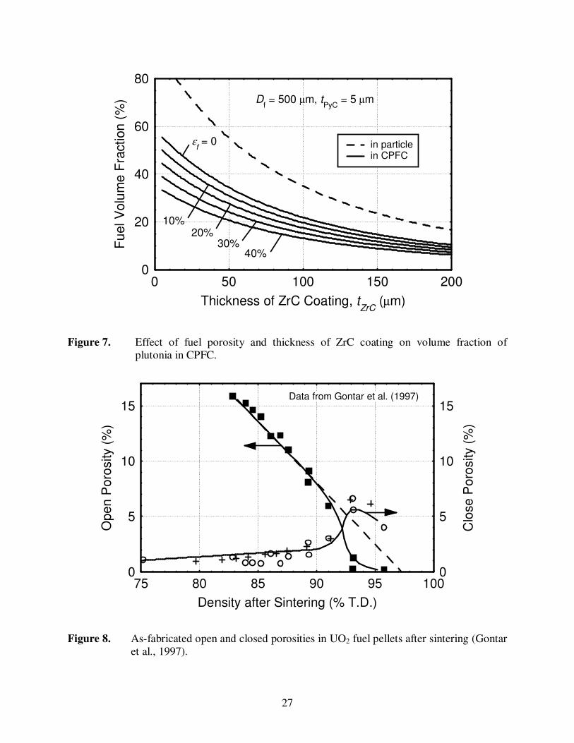
Figure 7 shows the effect of as-fabricated fuel porosity and ZrC coating thickness on the volume
fraction of plutonia in the base case, single-size CPFC. The plutonia loading in the CPFC
decreases as either the as-fabricated fuel porosity or tZrC increases. The fuel loading in Figure 7
is used next to calculate the thermal source strength of the CPFC in which the ZrC coating
thickness is determined from the stress analysis shell model (Section 5.3).
5.2 Helium Gas Pressure in Fuel Kernel
To determine the thickness of the ZrC coating needed to accommodate the internal pressure of
the helium gas released from the plutonia fuel matrix, the helium gas pressure inside the particle
must be calculated. Since the decay of a 238
Pu atom produces one alpha particle (4He atom), the
instantaneous moles of helium gas generated in a coated 238
PuO2 particle can be calculated as:
)1()1(
6)(
2383t
a
oTDfff
He eN
NDtn λρεπ −−×
×−×= . (9)
At low temperatures (< 900–1000 K), most of the helium gas generated by radioactive decay of 238
Pu in the coated fuel particles will be retained within the fuel matrix. Therefore, only the
released fraction, F, will exert pressure on the PyC and ZrC coatings. The density of the released
helium gas depends on F and the available volume within the ZrC-coated fuel particle, VOLHe,
and can be calculated as:
He
HeHeHe
VOL
MnF ××=ρ . (10)
Since the perfect gas law underpredicts the gas pressure at the high densities encountered in
coated plutonia particles, the following equation, developed based on the work of Rowlinson
(1964) and Ronchi (1981), was used to determine the helium gas pressure in the present study:

11
bM
TRP
Heb
He
gHe
e 1−×=
ρ . (11)
This equation reduces to the perfect gas law at low densities.
The helium gas pressure in the coated fuel particles, obtained by Equation (11), is used next to
determine the appropriate thickness of the ZrC coating. The latter is then used to calculate the
thermal power density of the CPFC.
5.3 Stress Model
The stress model calculates the thickness of ZrC coating required to withstand the helium gas
pressure in the coated plutonia particles. The specific thermal power of the CPFC is then
calculated as a function of storage time prior to launch, operation time after launch, and the fuel
temperature.
The inner pyrolytic carbon (PyC) layer in the coated particle fuel is a low-temperature isotropic
(LTI) layer deposited by Chemical-Vapor-Deposition at temperature > 1673 K (Kaae, 1971). It
is 5-µm thick and has a density < 1.7 g/cm3 (or a volume porosity > 25%). The zirconium
carbide coating is deposited typically near 1773 K (Ogawa et al., 1981), and its thickness is taken
to be at least 10 µm. Since the operating fuel temperature in a CPFC-RHU is expected to be
< 1000 K (at which most of the helium gas generated will be retained within the fuel matrix), the
most stringent condition will occur during a potential re-entry heat pulse following a launch
abort (Schock, 1981), after a relatively long storage time. A long storage time (10 to 20 years)
translates into a large helium inventory in the fuel. Reaching a fuel temperature of up to 1723 K
during a re-entry accident (Schock, 1981) results in a higher release fraction of helium from the
fuel matrix (see Section 4.0). Therefore, it is advantageous to deposit the PyC and ZrC coatings
onto the fuel kernels at the maximum possible temperature of ~ 1723 K. It just so happens that
CVD of PyC and ZrC coatings at 1700–1800 K produces preferred mechanical properties (Kaae,
1971; Ogawa et al., 1981).
As the PyC and ZrC coatings are deposited onto the plutonia fuel kernel near 1723 K, they are in
contact with the fuel kernel and thermally unconstrained. After the coated fuel particle cools
down, the fuel kernel shrinks faster than the PyC and ZrC coatings (PuO2 has higher thermal
expansion coefficient than PyC and ZrC). The shrinking of the fuel kernel produces a void space
within the coated fuel particle that is large compared to the as-fabricated open porosity in the fuel
kernel. The present stress model does not take credit for this void volume, and is therefore
conservative at temperature < 1723 K. The model assumes that the helium gas released from the
fuel matrix occupies a volume that is comprised of the as-fabricated open porosities in the fuel
kernel and the PyC layer (which is relatively small). The volume available in the coated fuel
particle to accommodate the released helium gas is then given as:
−
+×+×= 1
21
6
33
f
PyCPyC
openf
fHe
D
tDVOL εε
π . (12)

12
The PyC layer is assumed in the model to be 25% porous (εPyC = 0.25), which is also
conservative, considering that PyC with a porosity as high as 50% has been used successfully in
TRISO-coated fuel particles. The as-fabricated open and closed porosities in the plutonia fuel
kernel depend on the fuel density achieved during the sintering process, and are assumed to
follow that of commercial UO2 fuel pellets (Gontar et al., 1997). The as-fabricated porosity in
the fuel pellets is typically between 5% and 20%. As shown in Figure 8, a dense fuel pellet with
95% TD has essentially no open porosity. The entire 5% porosity appears as tiny voids within
the fuel grains. Most of these intragranular voids are < 1 µm in size (Gontar et al., 1997). On
the other hand, most of the as-fabricated porosity in a 85% TD fuel pellet is mostly present at the
grain boundaries as an open porosity (~ 13% open porosity).
In this work, the as-fabricated open porosity in the plutonia fuel is assumed to follow the dashed
straight line in Figure 8, expressed mathematically as:
03.0067.1 −×= fopenf εε . (13)
The helium gas released from the plutonia fuel matrix exerts pressure onto the PyC inner layer
and the ZrC coatings. In this study, it is assumed that the ZrC layer alone must withstand the
pressure of the released helium gas within the coated plutonia particles. The induced, maximum
tangential stress in the ZrC layer is calculated using a two-dimensional spherical shell model
(Prados and Scott, 1966; Kaae, 1966) as:
HeT P×ℜ=σ , (14)
where the dimensionless stress factor, ℜ , is related to the thickness of the ZrC coating as:
112
223/1
−
−ℜ+ℜ
=inner
ZrC
R
t . (15)
The thickness of the ZrC coating must be greater than the failure threshold value given by
Equation (15). The design thickness of the ZrC coating is that in which the maximum tangential
stress does not exceed 80% of the yield strength of the ZrC material (i.e.
ZrCHeT YP ×≤×ℜ= 80.0σ ) at the fuel temperature.
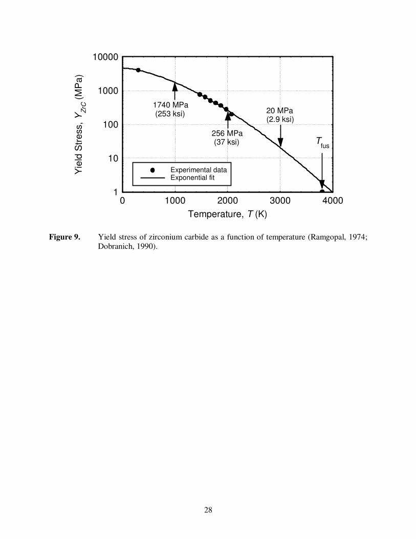
The experimental data of the yield strength of ZrC (Ramgopal, 1974; Dobranich, 1990) plotted in
Figure 9 show that the yield stress decreases exponentially with temperature. Since no data exist
above 2073 K, a yield stress of zero was assumed at the ZrC melting temperature of 3800 K
(Storms, 1962). The yield stress data are correlated as:
[ ]55.1591017.2exp10657.4)( TPaYZrC ××−××= −
. (16)
At the predicted maximum fuel temperature during a re-entry accident of 1723 K (Schock,
1981), zirconium carbide has a very high yield strength of 475 MPa.

13
6.0 PERFORMANCE RESULTS OF CPFC-RHU
The CPFC-RHU’s performance results presented in this section are for a storage time of up to 20
years, and a fuel temperature of 1723 K (Schock, 1981). At such temperature, the He gas
fractional release from large-grain (> 200 µm) and polycrystalline Sol-Gel fuel kernels could be
less that 10% (El-Genk and Tournier, 2000). Nonetheless, parametric calculations were
performed for release fractions of 1.0, 0.10 and 0.05.
Figure 10a shows the calculated ZrC coating thickness to withstand the helium gas pressure at
1723 K, assuming full release (F = 1.0). Figure 10b presents the ratio of the thermal power of
the CPFC-RHU to that of LWRHU (Figure 3), when replacing the fuel pellet (0.287 cm3) and the
Pt-alloy clad (0.370 cm3) in the latter (Table 1) with 500-µm single-size CPFC (Design I). Note
that the upper envelop of the curves in Figure 10b corresponds to the maximum thermal power of
the CPFC-RHU. The plateaux at small storage times before launch correspond to the specified
minimum ZrC coating thickness of 10 µm.
6.1 CPFC Thermal Source Strength and Specific Power
In the present study, the composition of the PuO2 fuel is assumed identical to that of the pellet in
Light Weight Radioisotope Heater Units (Johnson, 1997). The plutonia fuel contains 80.05 at.% 238
Pu, has a theoretical density =TDfρ 11,460. kg/m
3 (Johnson, 1997), a Beginning-Of-Life
(BOL) activity of 448 GBq/g (12.1 Ci/g), and a specific thermal power of 0.40 W/g. For 238
Pu,
the decay constant, 110105048.2 −−×= sλ , the molar weight, PuM = 238.24 g/mole, and the
atom density in the as-fabricated plutonia fuel, atoms/kg10784.124238 ×=oN . The specific
thermal source strength of this fuel decreases with storage time according to the relation:
40.0)/gW( thteq
λ−×= . (17)
The other isotopes present in the plutonia fuel (239
Pu and 240
Pu) also undergo alpha decay, but
their half-lives of 24,131 years and 6,569 years, respectively, are much longer than that of 238
Pu
(87.75 years). Therefore, they contribute insignificantly to the specific thermal power of the
plutonia fuel. In a typical LWRHU, the plutonia fuel pellet has an as-fabricated porosity of 15%
and a thermal power density at Beginning Of Life (BOL) of LWRHUq ′′′ = 3.9 W/cm3. For
comparison, a fuel compact using base-case coated fuel particles (Figure 1) with same as-
fabricated fuel porosity (εf = 0.15) and tZrC = 30 µm provides 1.65 W/cm3 at BOL, or 42% of
LWRHUq ′′′ (Figure 7). This lower thermal power density of the CPFC is a disadvantage which can
be more than compensated by increasing the CPFC volume within the aeroshell of the current
LWRHU, and hopefully at no or little mass penalty. As shown in Figures 7 and 10, the volume
fraction and specific thermal power of the CPFC decreases with increasing fuel kernel porosity
and increasing ZrC coating thickness. The specific thermal power of CPFC depends on the
storage time of the RHU prior to launch and the maximum fuel temperature that could be
achieved during a re-entry accident.
14
6.2 Thermal Analysis of CPFC-RHU
In the current LWRHU (Figure 3), the Pt-30%Rh cladding occupies a 29% larger volume than
the fuel pellet itself (Table 1; Tate, 1982). Thus, replacing both the fuel pellet and the cladding
in Figure 3 with CPFC provides more than a two-fold increase (a factor of 2.29) in the RHU
thermal power. As shown in Figure 10b, for this design option I, the CPFC-RHU thermal power
is 80% that of the LWRHU, assuming full He release after a 10-year storage.
The three PyC insulation sleeves in the current LWRHU occupy a relatively large volume
(Figure 3 and Table 1). They are designed to maintain the Pt-alloy temperature below its
eutectic point (Sholtis et al., 1999) during an accidental re- entry heat pulse (Pt-30%Rh forms an
eutectic with carbon at 2033 K). A portion of the insulation sleeves could be replaced with
CPFC (Figure 11), without risking overheating the CPFC. To confirm this statement, a thermal
analysis of the CPFC-RHU is performed to calculate the temperature of the CPFC during a re-
entry heating pulse.
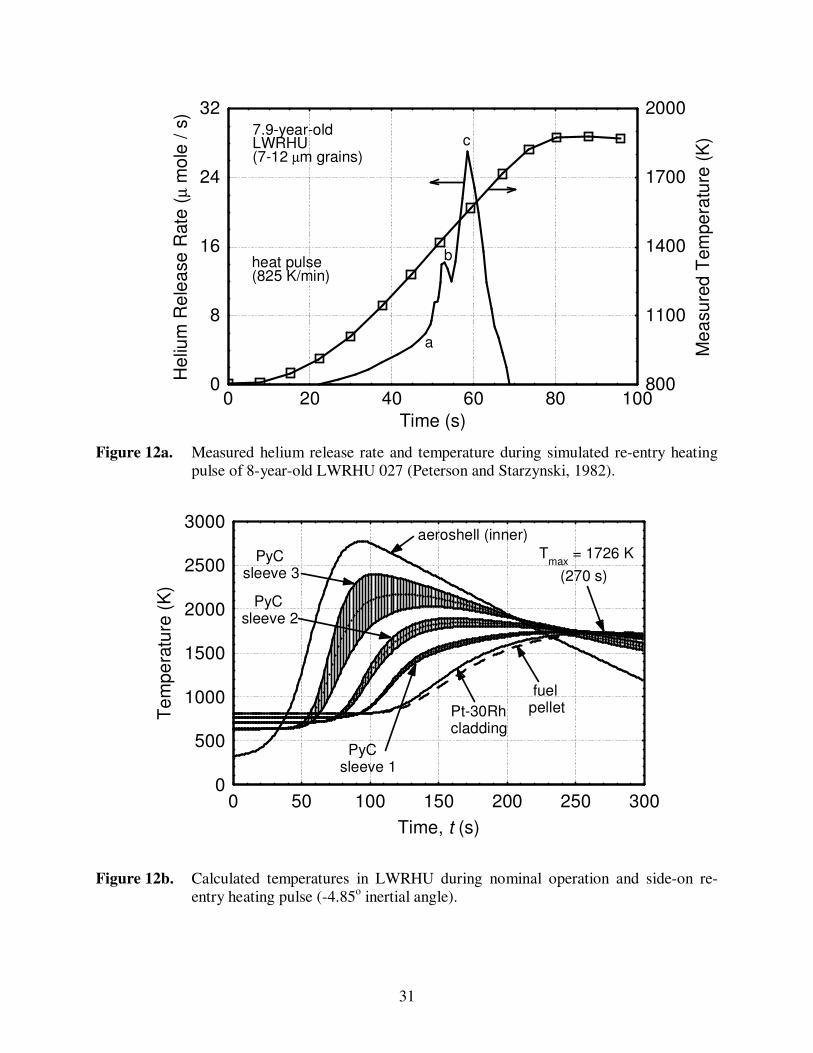
To estimate the maximum temperature of the CPFC during a re-entry heating pulse (Figure 12a),
a one-dimensional, transient thermal model of the RHU was developed. This model was
benchmarked against the LWRHU thermal response results reported by Schock (1981) during
the worst-case re-entry accident (inertial angle of –4.85o). This author used a comprehensive 3-
D transient model to simulate the LWRHU thermal response during re-entry. The present
thermal model simulates transient heat flow in a radial section along the mid-plane of the RHU.
The radial heat flow occurs by conduction and radiation. In the LWRHU, the plutonia fuel pellet
(19% porous) is assumed to be in perfect contact with the Pt-30%Rh clad, which has an
emissivity of 0.53. The Pt-Rh cladding is surrounded by three PyC insulation sleeves (of 25%
porosity), separated by thin radiation gaps, and a thick aeroshell consisting of Fine Weave
Pierced Fabric (FWPF, 90% porous) (Schock, 1980 and 1981). The heat capacities, thermal
conductivities and radiative emissivities of these various layers are calculated as functions of
temperature.
In addition to conduction and radiation heat transfers, contact resistances between the various
layers are accounted for. The LWRHU is designed with radial gaps between the fuel capsule, the
three PyC insulation sleeves and the FWPF aeroshell, to facilitate assembly and increase the
thermal resistance between the fuel capsule and the aeroshell. However, during a side-on, stable
re-entry, all LWRHU components are in contact along their stagnation line, due to aerodynamic
forces (Schock, 1981). The present analysis assumes a total circumferential contact of 30o
between all adjacent components. The contact resistance between the PyC sleeves is taken equal
to 11.4 K / (W/cm2), and 5.7 K / (W/cm
2) between the aeroshell and the third PyC sleeve
(Schock, 1981). Thermal analyses performed by Schock (1981) have shown that the effect of
helium gas conduction in the LWRHU during re-entry was negligible. This is because the pre-
activated vent of the LWRHU fuel capsule steadily releases the helium gas during re-entry. In
addition, the relatively high porosity of the FWPF aeroshell does not allow the helium gas to
accumulate inside the LWRHU aeroshell.
The transient heat balance equation is solved in each radial layer simultaneously, subject to a
zero heat flux at the fuel pellet centerline, and a time-dependent temperature at the aeroshell

15
outer surface. The latter is obtained from Schock’s results (1981). The model’s predictions in
Figure 12b of the thermal response of the LWRHU during the worst-case re-entry accident
(inertial angle of –4.85o) agreed reasonably well with those reported by Schock (1981). The
present 1-D transient model reproduced the 3-D results of Schock (1981) to within + 30 K over
the full 300 s re-entry transient, and the Pt-30%Rh cladding maximum temperature (1726 K)
within 3 K and 5 s (at 270 s), see Figures 12b and 13.
The present thermal model was then used to predict the temperatures in designs I and II of
CPFC-RHUs during both normal operation and a re-entry heating pulse (Figure 12a). The
surface emissivity of the CPFC graphite matrix was taken equal to 1.0. During re-entry heating,
the aeroshell surface temperature was assumed the same as for the LWRHU. This assumption is
justified because: (a) the overall thermal masses of the LWRHU (35.7 J/K), the Design I,
CPFC-RHU (36.0 J/K) and the Design II, CPFC-RHU (36.7 J/K) are almost identical; and (b) the
FWPF aeroshell is the largest component in the RHUs (it weights 23 g compared to the overall
RHUs mass of ~ 40 g each). The aeroshell contributes 63% to the overall thermal mass of each
RHU, and its temperature is mostly controlled by aero-ablation, and is not affected by the
components design inside the RHUs. The present analysis showed that in the CPFC-RHU
design I, the maximum temperature of CPFC is 1688 K after 278 s into the re-entry transient
(Figure 13). The calculated initial (operating) fuel temperature in the CPFC-RHU is 709 K, or
100 K lower than in the LWRHU (Figure 13). When the inner PyC insulation was removed and
replaced with CPFC (Design II, Figure 11), the calculated initial CPFC temperature is slightly
higher (735 K), and a maximum CPFC temperature of 1734 K is reached after 255 s into the re-
entry transient (see Figure 13). The CPFC temperature of 1723 K is used in the subsequent
stress analyses of the CPFC-RHU.
6.3 Effect of Helium Release on CPFC-RHU Performance
In the present study, when the inner PyC insulation sleeve in the LWRHU is also replaced with
CPFC (Design II, Figure 11), the thermal power of the CPFC-RHU is 1.83 times that of Design
I, in which only the fuel pellet and the Pt-30%Rh clad in the LWRHU (Figure 3) are replaced
with CPFC. The total volume enclosed by the inner insulation sleeve is 1.20 cm3, which
amounts to 12% of cavity between the Pt-30%Rh clad and the aeroshell (Table 1). Results show
that a Design II CPFC-RHU designed for a peak fuel temperature of 1723 K and storage time
before launch of 10 years, assuming full He release, provides 46% more thermal power than the
LWRHU, at only 95% of the total mass. Using a binary-size CPFC with 300 and 1200 µm
diameter fuel kernels increases the thermal power of the CPFC-RHU by an additional 15% to 1.7
times that of the LWRHU, at essentially the same total mass of the LWRHU (~ 40 g).
To investigate the effect of He gas release on the performance of the CPFC-RHU, calculation are
performed for F = 0.1 and F = 0.05. The predicted CPFC-RHU thermal power relative to that of
the LWRHU is delineated in Figure 14 for F = 0.1 and a fuel temperature of 1723 K. In a CPFC
with 11% as-fabricated fuel porosity and Df = 500 µm, a 11-µm ZrC coating is needed to
withstand the pressure of the released He after 10 years of storage. When the fuel pellet and the
Pt-30%Rh clad in the LWRHU are replaced with a single-size CPFC, the RHU provides 25%
more thermal power than the LWRHU (Figure 14), a 56% increase over the CPFC-RHU
assuming full He release (F = 1.0).

16
When the inner insulation sleeve in the LWRHU is also replaced with single-size CPFC (Design
II in Figure 11), an RHU stored for 10 years would provide 2.3 times the thermal power of a
LWRHU. Using binary-size (300 and 1200 µm fuel kernel diameters) CPFC increases the
thermal power of the CPFC-RHU by an additional 15%, to 2.6 times that of the LWRHU (Figure
14), at essentially the same total mass (~ 40 g).
The effect of He release fraction on the performance of Design II CPFC-RHU is best illustrated
in Figure 15. In this RHU design, the fuel pellet, Pt-30%Rh clad and inner PyC insulation sleeve
in the LWRHU are replaced with a single-size CPFC. After a storage time of 10 years, a
decrease in He release from 100% to 10% increases the fuel loading in the CPFC-RHU and
hence the thermal power by 56%. However, a decrease in the He release from 10% to 5% results
in only ~ 5% increase in the CPFC-RHU’s thermal power (Figure 15). These results suggest that
He release in excess of 10% strongly impacts the thermal power density of the CPFC-RHU, but
has little impact below 10%.
The results, summarized in Table 2, demonstrate the potential of the CPFC-RHU for achieving
specific thermal powers as high as 60 Wth/kg, or 2.3 times that of LWRHU. When a binary-size
CPFC of 300 and 1200 µm particles is used, the thermal power of the CPFC-RHU increases by
an additional 15% to ~ 2.6 W (Table 2), at essentially the same total mass as the LWRHU (~ 40
g). These calculations are conducted at a CPFC temperature of 1723 K and 11% as-fabricated
fuel porosity, assuming a 10% He gas release from the fuel kernel. The calculated thickness of
the ZrC coating to withstand the internal He gas pressure at these conditions is 10, 11, and 24 µm
for 300, 500, and 1200 µm diameter fuel kernel, respectively. As indicated earlier, using large
grain (> 200 µm) or polycrystalline 238
PuO2 fuel kernels could reduce the He release fraction at
1723 K to below 7% (El-Genk and Tournier, 2000). When the assumed He release fraction is
only 5%, the calculated thermal power of the single-size, Design II, CPFC-RHU is 2.4 Wth,
increasing to 2.76 Wth for the binary-size CPFC-RHU. Such good performance, together with
the potential for enhanced safety and design flexibility, make the CPFC an attractive fuel form.
6.4 Specific Thermal Power of CPFC
Figures 16 and 17 demonstrate the effects of fuel temperature and kernel diameter on the specific
thermal power and thermal power density of single-size CPFC, respectively. Initially, the CPFC
specific thermal power increases rapidly with the kernel diameter, reaching an asymptote at
about 500 µm. Beyond this value, the specific thermal power increases slowly with increasing
fuel kernel diameter, as the volume contribution of the inner PyC layer (5 µm thick) becomes
vanishingly small. At small fuel kernel diameter, the specified, minimum design thickness of
ZrC coating (10 µm) is greater than that needed to withstand the internal pressure of helium
released, resulting in a relatively low CPFC specific power. When the needed ZrC coating
thickness is beyond 10 µm, it increases proportionally with the fuel kernel diameter (see
Equations (14) and (15)).
Figures 16 and 17 show the CPFC performance results for three different operating conditions.
The first conditions are a maximum temperature of 1723 K (which may occur during a re-entry
into the atmosphere following a launch abort accident) and full helium gas release after 10-year
storage. This CPFC uses plutonia fuel of 25% as-fabricated porosity and has a relatively low

17
specific thermal power of 0.23 Wth/g (power density = 1.25 Wth/cm3), or 57% that of a typical
LWRHU fuel pellet. The second conditions are a maximum temperature of 1723 K and 10%
helium gas release after 10-year storage. As shown in Figures 16 and 17, a CPFC of plutonia
fuel with 11% as-fabricated porosity achieves a specific thermal power of 0.303 Wth/g (power
density = 2.0 Wth/cm3). Finally, the third conditions for the single-size CPFC are a maximum
fuel temperature of 1000 K, 5% helium gas release after 10-year storage, and single-size plutonia
particles with 5% as-fabricated fuel porosity. This CPFC uses a 10 µm-thick ZrC coating and
can achieve a specific thermal power as high as 0.325 Wth/g (power density = 2.3 Wth/cm3).
7.0 FUTURE RESEARCH NEEDS
The previous results showed that CPFC-RHUs could provide significantly higher thermal power
than a LWRHU, with no increase in total mass. Several technical issues remain, however, that
are worthy of further investigations. The first is related to demonstrating the fabrication
technology of large grain (> 200 µm) and polycrystalline 238
PuO2 fuel kernels (300-1200 µm in
diameter) using either state-of-the art Sol-Gel and/or thermal plasma processes. The potential,
and the cost of production, decontamination, and of mastering each of these technologies need to
be investigated and compared. This is a priority that supersedes any of the following issues.
Given that the outcome of the first issue is positive, the second issue in order of priority would
be to confirm the potential of the fuel kernels for retaining helium gas. The retention of the He
gas generated in the 238
PuO2 fuel kernels depends strongly on the fuel microstructure (El-Genk
and Tournier, 2000). Almost full He release is expected in small grain (7-40 µm) fuel kernels at
1723 K, making them a poor selection for the CPFC-RHUs. Large-grain or polycrystalline 238
PuO2 fuel kernels, which are the primary choice for CPFC-RHUs, could retain as much as 93-
95% of the He gas generated in the fuel matrix at temperatures in excess of 1700 K. The small,
needed thickness of the ZrC coating would increase the fuel loading and, hence, the thermal
output of the CPFC-RHU, well in excess of that of the current state-of-the-art LWRHU.
Therefore, future experimental investigations to confirm the He gas release estimates in the
present paper are recommended. These investigations should involve both coated and uncoated,
large-grain (> 200 µm) and polycrystalline, 238
PuO2 fuel kernels (El-Genk and Tournier, 2000).
Experiments could also be performed to investigate the effects of storage time, fuel temperature,
and heating mode (steady-state and ramped heating transient) on both the release rate and release
fraction of He from uncoated and coated fuel particles. These experiments may also investigate
potential failure modes and the threshold temperature for a ZrC coating failure, if any.
The third issue in order of priority is to confirm that coating 238
PuO2 fuel kernels on a large scale
is possible. The coating of UO2 and mixed-oxide fuel kernels with PyC and ZrC has been
demonstrated successfully for many years for commercial, high temperature gas cooled reactors
(HTGRs) with SiC outer coating and recently with ZrC coating for operation at higher
temperature and fuel burnup (Minato et al., 1997). Owing to the relatively shorter half-life of 238
Pu (86 years), however, the alpha particles released by the radioactive decay of 238
Pu could
affect the quality of the coating in two ways. The heat dissipated in the decay process and the
bombardment of the deposited coating by the emitted alpha particles could affect the quality of
the PyC and ZrC coatings during the CVD processes.

18
The positive outcome of the aforementioned issues would suggest addressing the fourth and final
issue, which is related to the fabrication and strength of the CPFC. The later is related to the
fracture strength of the CPFC upon impacting solid surfaces. Both fracture and impact tests
involving CPFC and detailed stress analysis are recommended. The results could guide future
development of the graphite matrix of the CPFC, which can protect the coated fuel particles
during handling, re-entry heating, as well as during impact on solid surfaces. As indicated
earlier, the graphite matrix should be structurally strong and of low density to accommodate
thermal expansion of the coated fuel particles during a re-entry heating pulse. It has also to
fracture upon impact with solid surfaces in order to protect the coated fuel kernels, "the
pomegranate concept." Ultimately, mechanical, thermal, and aeroablation testing of the coated
particle fuel in simulated accident environments will subsequently be needed.
8.0 SUMMARY AND CONCLUSIONS
The potential of coated 238
PuO2 fuel particles compact for future use in advanced RHUs and
RPSs is investigated. A stress and design model of the coated plutonia fuel particle was
developed and used to investigate the performance of both single-size and binary-size CPFC-
RHUs as a function of the helium gas release fraction, for a 10-year storage before launch and
fuel temperature up to 1723 K. This fuel temperature corresponds to the predicted peak value
during an accidental re-entry heating pulse.
Results indicated that large grain (> 200 µm) or polycrystalline 238
PuO2 fuel kernels would retain
most of the helium gas generated by the radioactive decay of 238
Pu. Recent estimates of the He
gas release from large-grain and polycrystalline 238
PuO2 fuel kernels showed that He release in
large-grain (> 200 µm) 238
PuO2 fuel kernels at 1723 K could be less than 7% and even lower in
polycrystalline fuel kernels. At fuel temperatures < 1000 K, the He release will be nil. Large-
grain fuel kernels could be fabricated using binderless agglomeration or similar processes, while
the polycrystalline fuel kernels could be fabricated using Sol-Gel or thermal plasma processes.
Although these processes have successfully been used in the fabrication of UO2 and mixed-oxide
fuel kernels, they have not been demonstrated for the fabrication of 238
PuO2 fuel kernels. In
addition, using CVD techniques to apply the PyC and ZrC coatings on plutonia kernels is yet to
be demonstrated.
Performance analyses of a conservatively designed CPFC-RHU indicate that its thermal power
could be 2.3 and 2.4 times that of the LWRHU, at essentially the same total mass. The CPFC-
RHU uses the same Fine-Weave Pierced Fabric (FWPF) aeroshell, and two of the three inner
PyC insulation sleeves of the LWRHU. These performance figures of the CPFC-RHU are for a
single-size (500 µm) coated 238
PuO2 fuel particle compact, 11% and 7% as-fabricated fuel
porosity, and 10% and 5% helium gas release, respectively. In the CPFC-RHU, the fuel pellet
and its refractory cladding and the inner PyC insulation sleeve in the LWRHU are replaced with
CPFC. Using a binary-size (300 and 1200 µm) CPFC increases the thermal power of the CPFC-
RHUs by an additional 15%.
19
The CPFC is a promising fuel form for use in advanced RHUs and RPSs. In addition to
enhancing the thermal power output, it offers enhanced safety and unique design flexibility,
since it could be fabricated in different sizes and shapes. CPFC-RHUs and RPSs could meet the
thermal and electric power needs for future spacecraft and planetary exploration in the range
from a few milli-watts to tens and even hundreds of watts, for more than ten years. Several
issues for future research, given in order of priority and order of conduct, are recommended:
(a) Investigate and demonstrate the fabrication techniques of large-grain (> 200 µm) and
polycrystalline plutonia fuel kernels and the application of the PyC and ZrC coatings using
CVD processes;
(b) Perform helium gas release tests from large grain and polycrystalline fuel kernels, both
coated and uncoated, to confirm the recent estimates of the He gas release (El-Genk and
Tournier, 2000); and
(c) Fabricate CPFC-RHUs and perform fracture impact tests and analysis to provide data to
benchmark models. These data and analysis results could also be used to guide the
development and the selection of the most appropriate graphite matrix material for CPFCs.
Ultimately, mechanical, thermal, and aero-ablation testing of coated particle fuel in
simulated accident environments will subsequently be needed.
9.0 ACKNOWLEDGMENTS
This research was funded by Sandia National Laboratories (SNL), Kirtland Air Force Base,
Albuquerque, NM, under contracts No. BE-2543, to the University of New Mexico’s Institute for
Space and Nuclear Power Studies, and BE-2544, to Sholtis Engineering & Safety Consulting,
Tijeras, NM. The opinions expressed in this paper are solely those of the authors.

20
LIST OF FIGURES
Figure 1a. A cross-sectional view of a coated plutonia fuel kernel.
Figure 1b. Binary-size, coated plutonia particles fuel compact (CPFC).
Figure 2a. A miniaturized CPFC-RHU for supplying thermal power to circuit boards on board
of spacecraft.
Figure 2b. Milliwatt CPFC-RPS and RHU for supplying both thermal and electric power to
circuit boards on board of spacecraft.
Figure 2c. Conceptual design of a high-efficiency (~ 25%) CPFC-RPS for space exploration
missions.
Figure 3. Current LWRHU (Johnson, 1997).
Figure 4. Microstructures of plutonia fuel kernels.
Figure 5. Release fraction of noble gases and volatile fission products in UO2 fuel particles,
versus half-life (El-Genk and Tournier, 2000).
Figure 6. Volume fraction of two-size spheres in CPFC as a function of coarse-to-fine
diameter ratio (data from McGeary, 1961).
Figure 7. Effect of fuel porosity and thickness of ZrC coating on volume fraction of plutonia
in CPFC.
Figure 8. As-fabricated open and closed porosities in UO2 fuel pellets after sintering (Gontar
et al., 1997).
Figure 9. Yield stress of zirconium carbide as a function of temperature (Ramgopal, 1974;
Dobranich, 1990).
Figure 10a. Calculated ZrC coating thickness for full helium retention in CPFC.
Figure 10b. Ratio of thermal power of CPFC-RHU (Design I) and LWRHU.
Figure 11. Proposed CPFC-RHU (Design II).
21
Figure 12a. Measured helium release rate and temperature during simulated re-entry heating
pulse of 8-year-old LWRHU 027 (Peterson and Starzynski, 1982).
Figure 12b. Calculated temperatures in LWRHU during nominal operation and side-on re-
entry heating pulse (-4.85o inertial angle).
Figure 13. Calculated fuel temperatures in CPFC-RHU designs I and II during nominal
operation and side-on re-entry heating pulse, and comparison with calculated Pt-
30%Rh cladding temperature in LWRHU.
Figure 14. Comparison of CPFC-RHU thermal power with that of LWRHU assuming 10%
helium gas release.
Figure 15. Effect of helium gas release on thermal power of CPFC-RHU for Tf = 1723 K in
design II, in which single-size CPFC replaces LWRHU fuel pellet, Pt-alloy clad and
inner PyC insulation sleeve.
Figure 16. Effects of fuel temperature, He gas release fraction and fuel kernel diameter on the
specific thermal power of CPFC, after 10 years of storage.
Figure 17. Effects of fuel temperature, He gas release fraction and fuel kernel diameter on the
thermal power density of CPFC, after 10 years of storage.
LIST OF TABLES
Table 1. Volumes and mass breakdown of various components of a LWRHU (Tate, 1982;
Figure 3).
Table 2. Thermal power estimates of CPFC-RHU designed for a peak fuel temperature of
1723 K after 10 years of storage.
22
PyrolyticCarbon (PyC)
5 µm thick
ZrC coating
(thickness
> 10 µm)
300-1200 µm
Large-grain
(> 200 µm) orpolycrystalline
238PuO2
PyrolyticCarbon (PyC)
5 µm thick
ZrC coating
(thickness
> 10 µm)
300-1200 µm
Large-grain
(> 200 µm) orpolycrystalline
238PuO2
Figure 1a. A cross-sectional view of a coated plutonia fuel kernel.
Coarse-size
coated particles
Small-size
coated particles
Graphite matrix
Figure 1b. Binary-size, coated plutonia particles fuel compact (CPFC).

23
Circuit board
AeroshellCPFC heat
source
Heat pipe shellThermal
insulation
Metal support plate
Circuit board
AeroshellCPFC heat
source
Heat pipe shellThermal
insulation
Metal support plate
Figure 2a. A miniaturized CPFC-RHU for supplying thermal power to circuit boards on
board of spacecraft.
Circuit Board
AeroshellCPFC heat
source
TE-Couples Heat pipe
plate
+_
Thermal
Insulation
Circuit Board
AeroshellCPFC heat
source
TE-Couples Heat pipe
plate
+_
Thermal
Insulation
Figure 2b. Milliwatt CPFC-RPS and RHU for supplying both thermal and electric power to
circuit boards on board of spacecraft.

24
AMTEC cells, η = 18%
(Thot = 1100 K, Tcold = 650 K)
Hybrid insulation
(Min-K, Multifoil)
Heat pipe housing and
radiator (~ 350 K)
Segmented TE couples, η = 9%
(Thot = 650 K, Tcold = 350 K)
CPFC heatsource
AMTEC cells, η = 18%
(Thot = 1100 K, Tcold = 650 K)
Hybrid insulation
(Min-K, Multifoil)
Heat pipe housing and
radiator (~ 350 K)
Segmented TE couples, η = 9%
(Thot = 650 K, Tcold = 350 K)
CPFC heatsource
Figure 2c. Conceptual design of a high-efficiency (~ 25%) CPFC-RPS for space exploration
missions.
25
FWPF aeroshell
(H = 32 mm,
D = 26 mm,
t = 4.5 mm)
End cap
(FWPF)
Insulator
plug (PyC)
PyC insulator
sleeves (3)
238PuO2
fuel pellet
(H = 9.4 mm,
D = 6.6 mm)
Insulator
plug (PyC)
Pt-30%Rh
clad
(t = 1 mm)
Pt-30%Rh
shim
Vent
Frit (Pt)
FWPF aeroshell
(H = 32 mm,
D = 26 mm,
t = 4.5 mm)
End cap
(FWPF)
Insulator
plug (PyC)
PyC insulator
sleeves (3)
238PuO2
fuel pellet
(H = 9.4 mm,
D = 6.6 mm)
Insulator
plug (PyC)
Pt-30%Rh
clad
(t = 1 mm)
Pt-30%Rh
shim
Vent
Frit (Pt)
Figure 3. Current LWRHU (Johnson, 1997).
Homogeneouscrystalline
fuel matrix
As-fabricated
tiny voidsAs-fabricated
intergranular
voids
Polycrystalline
fuel grain
with
intragranular
voids
Homogeneouscrystalline
fuel matrix
As-fabricated
tiny voidsAs-fabricated
intergranular
voids
Polycrystalline
fuel grain
with
intragranular
voids
(a) Granular fuel kernel fabricated (b) Polycrystalline fuel kernel fabricated
Using powder-metallurgy using Sol-Gel techniques
Figure 4. Microstructures of plutonia fuel kernels.

26
0.01
0.1
1
10
100
0 1 2 3 4 5 6
7 µm (0.4 at%, 2023 K) 10 µm (4.0 at%, 1723 K) 40 µm (0.4 at%, 2023 K)300-600 µm (4.0 at%, 1723 K) 2500 µm (1.6 at%, 1723 K)
72%
6%T = 1723 K
√T1/2
(years1/2
)
Rele
ase
-to-B
irth
Rate
Ratio (
%)
Figure 5. Release fraction of noble gases and volatile fission products in UO2 fuel particles,
versus half-life (El-Genk and Tournier, 2000).
60
65
70
75
80
85
5 10 15 20
Experiment (McGeary, 1961)Model
62.5% packing limit for one-size spheres
triangular pore path(D
p1/D
p2 = 1/(2√3 - 1)
Spheres' diameter ratio (Dp1
/Dp2
)
Pa
ckin
g V
olu
me
Fra
ctio
n
in C
PF
C,
β (%
)
Figure 6. Volume fraction of two-size spheres in CPFC as a function of coarse-to-fine
diameter ratio (data from McGeary, 1961).
27
0
20
40
60
80
0 50 100 150 200
in particlein CPFC
Df = 500 µm, t
PyC = 5 µm
40%30%
20%10%
εf = 0
Thickness of ZrC Coating, tZrC
(µm)
Fu
el V
olu
me
Fra
ction
(%
)
Figure 7. Effect of fuel porosity and thickness of ZrC coating on volume fraction of
plutonia in CPFC.
0
5
10
15
75 80 85 90 95 1000
5
10
15Data from Gontar et al. (1997)
Density after Sintering (% T.D.)
Op
en
Po
rosity (
%)
Clo
se
Po
rosity (
%)
Figure 8. As-fabricated open and closed porosities in UO2 fuel pellets after sintering (Gontar
et al., 1997).
28
1
10
100
1000
10000
0 1000 2000 3000 4000
Experimental dataExponential fit
20 MPa(2.9 ksi)
256 MPa (37 ksi)
1740 MPa (253 ksi)
Tfus
Temperature, T (K)
Yie
ld S
tre
ss,
YZ
rC (
MP
a)
Figure 9. Yield stress of zirconium carbide as a function of temperature (Ramgopal, 1974;
Dobranich, 1990).

29
0
20
40
60
80
100
0 5 10 15 20
(a)
F = 1.0T
f = 1723 K
4035
3025
20
15
10
εf= 5%
(single-size CPFC,D
f=500 µm, t
PyC=5 µm)
Time to Launch (years)
ZrC
Co
atin
g T
hic
kn
ess,
t ZrC
(µm
)
Figure 10a. Calculated ZrC coating thickness for full helium retention in CPFC.
0.5
1.0
1.5
0 5 10 15 20
(b)
30
40
35
3025201510εf = 5%
F = 1.0T
f = 1723 K
Time to Launch (years)
Ψ
Figure 10b. Ratio of thermal power of CPFC-RHU (Design I) and LWRHU.

30
FWPF aeroshell
(H = 32 mm,
D = 26 mm,
t = 4.5 mm)
End cap
(FWPF)
Insulator
plug (PyC)
PyC insulator
sleeves (2)
238PuO2 CPFC
(H = 14.1 mm,
D = 10.4 mm)
Insulator
plug
(PyC)
FWPF aeroshell
(H = 32 mm,
D = 26 mm,
t = 4.5 mm)
End cap
(FWPF)
Insulator
plug (PyC)
PyC insulator
sleeves (2)
238PuO2 CPFC
(H = 14.1 mm,
D = 10.4 mm)
Insulator
plug
(PyC)
Figure 11. Proposed CPFC-RHU (Design II).
31
0
8
16
24
32
0 20 40 60 80 100800
1100
1400
1700
2000
c
b
a
heat pulse(825 K/min)
7.9-year-oldLWRHU(7-12 µm grains)
Time (s)
He
lium
Re
lea
se
Rate
(µ
mo
le /
s)
Me
asu
red
Tem
pe
ratu
re (
K)
Figure 12a. Measured helium release rate and temperature during simulated re-entry heating
pulse of 8-year-old LWRHU 027 (Peterson and Starzynski, 1982).
0
500
1000
1500
2000
2500
3000
0 50 100 150 200 250 300
Tmax
= 1726 K
(270 s)
fuelpelletPt-30Rh
cladding
PyC sleeve 1
PyC sleeve 2
PyC sleeve 3
aeroshell (inner)
Time, t (s)
Te
mp
era
ture
(K
)
Figure 12b. Calculated temperatures in LWRHU during nominal operation and side-on re-
entry heating pulse (-4.85o inertial angle).

32
500
1000
1500
2000
0 50 100 150 200 250 300
Pt-30Rh cladding in LWRHU
CPFC inDesign I
CPFC inDesign II
1688 K
1726 K
1734 K
709 K
735 K810 K
Time, t (s)
Te
mp
era
ture
(K
)
Figure 13. Calculated fuel temperatures in CPFC-RHU designs I and II during nominal
operation and side-on re-entry heating pulse, and comparison with calculated Pt-
30%Rh cladding temperature in LWRHU.
1
2
3
0 5 10 15 20
Single-size CPFC replaces pellet,clad and inner PyC sleeve in LWRHU (Design II)
Single-size CPFC replaces pelletand clad in LWRHU (Design I)
Binary-particle fuel (Dp1
/Dp2
= 4)
in Design II CPFC-RHU
tPyC
=5 µm, F = 0.10, Tf = 1723 K
Time to Launch (years)
Ψ
Figure 14. Comparison of CPFC-RHU thermal power with that of LWRHU assuming 10%
helium gas release.

33
1.0
1.5
2.0
2.5
0 5 10 15 20
F = 1.0
F = 0.1
F = 0.05
Single-size CPFC
Df = 500 µm, t
PyC=5 µm, T
f = 1723 K
Time to Launch (years)
Ψ
Figure 15. Effect of helium gas release on thermal power of CPFC-RHU for Tf = 1723 K in
design II, in which single-size CPFC replaces LWRHU fuel pellet, Pt-alloy clad and
inner PyC insulation sleeve.
0.20
0.25
0.30
0.35
0 500 1000 1500
tZrC
= 10 µm
1723 K, F = 1.0, εf = 25%
1000 K, F = 0.05, ε
f = 5% (t
ZrC= 10 µm)
1723 K, F = 0.10, εf = 11%
Fuel Kernel Diameter, Df (µm)
Sp
ecific
Th
erm
al P
ow
er
(Wth
/g)
Figure 16. Effects of fuel temperature, He gas release fraction and fuel kernel diameter on the
specific thermal power of CPFC, after 10 years of storage.

34
1.0
1.5
2.0
2.5
0 500 1000 1500
tZrC
= 10 µm
1723 K, F = 1.0, εf = 25%
1000 K, F = 0.05, ε
f = 5% (t
ZrC= 10 µm)
1723 K, F = 0.10, εf = 11%
Fuel Kernel Diameter, Df (µm)
Th
erm
al P
ow
er
De
nsity (
Wth
/cm
3)
Figure 17. Effects of fuel temperature, He gas release fraction and fuel kernel diameter on the
thermal power density of CPFC, after 10 years of storage.

35
Table 1. Volumes and mass breakdown of various components of a LWRHU (Tate, 1982;
Figure 3).
Region
Density (g/cm3)
Mass
(gram)
Volume (cm3)
Normalized
volume
Cumulated
volume
PuO2 fuel pellet 9.27 2.66 0.287 1 x 1.00
Pt-30Rh cladding 17.6 6.51 0.370 1.29 x 2.29
Inner PyC sleeve
Other PyC sleeves
–
–
–
–
0.537
3.938
1.87
13.72
x 4.16
x 17.88
Total insulation 1.75 7.83 4.475 15.59 –
Inner cavity 17.0 5.132 17.88 –
FWPF aeroshell 1.96 23.0 11.74 – –
LWRHU capsule 40.0 16.87 – –
Table 2. Thermal power estimates of CPFC-RHU designed for a peak fuel temperature of
1723 K after 10 years of storage.
x 1
.83
x 1
.15
x 1.56 x 1.05
Helium gas release fraction, F
CPFC-Type (Design Option)
1.0
0.10
0.05
Single-size a
(Df =500 µm)
ψψψψ = 0.80 (0.83 W)
[21 Wth/kg]
(εf = 25%, tZrC = 36 µm)
ψψψψ = 1.25 (1.30 W)
[33 Wth/kg]
(εf = 11%, tZrC = 11 µm)
ψψψψ = 1.31 (1.36 W)
[34 Wth/kg]
(εf = 7%, tZrC = 10 µm)
Single-size b
(Df =500 µm)
ψψψψ = 1.46 (1.52 W)
[38 Wth/kg]
ψψψψ = 2.29 (2.38 W)
[59 Wth/kg]
ψψψψ = 2.40 (2.50 W)
[62 Wth/kg]
Binary-size b
(Df1 = 1200 µm,
Df2 = 300 µm)
ψψψψ = 1.68 (1.75 W)
[43 Wth/kg]
(tZrC1=86 µm, tZrC2=22 µm)
ψψψψ = 2.63 (2.74 W)
[68 Wth/kg]
(tZrC1=24 µm, tZrC2=10 µm)
ψψψψ = 2.76 (2.87 W)
[71 Wth/kg]
(tZrC1=19 µm, tZrC2=10 µm)
x 1
.83
x 1
.15
x 1.56 x 1.05
Helium gas release fraction, F
CPFC-Type (Design Option)
1.0
0.10
0.05
Single-size a
(Df =500 µm)
ψψψψ = 0.80 (0.83 W)
[21 Wth/kg]
(εf = 25%, tZrC = 36 µm)
ψψψψ = 1.25 (1.30 W)
[33 Wth/kg]
(εf = 11%, tZrC = 11 µm)
ψψψψ = 1.31 (1.36 W)
[34 Wth/kg]
(εf = 7%, tZrC = 10 µm)
Single-size b
(Df =500 µm)
ψψψψ = 1.46 (1.52 W)
[38 Wth/kg]
ψψψψ = 2.29 (2.38 W)
[59 Wth/kg]
ψψψψ = 2.40 (2.50 W)
[62 Wth/kg]
Binary-size b
(Df1 = 1200 µm,
Df2 = 300 µm)
ψψψψ = 1.68 (1.75 W)
[43 Wth/kg]
(tZrC1=86 µm, tZrC2=22 µm)
ψψψψ = 2.63 (2.74 W)
[68 Wth/kg]
(tZrC1=24 µm, tZrC2=10 µm)
ψψψψ = 2.76 (2.87 W)
[71 Wth/kg]
(tZrC1=19 µm, tZrC2=10 µm)
a: Replace LWRHU pellet and Pt-alloy clad with CPFC (Design I).
b: Replace LWRHU pellet, clad and inner insulation sleeve with CPFC (Design II).