Water heater Thermo Top E additional heating system Thermo ...
25
Water heater Thermo Top E additional heating system Thermo Top - Z/C additional heating system Approval code ~~~ S 316 / ~~~ S 292 Legend for Figure 1 1 Thermo Top Z/C-B or E-B heater 2 Blade-type fuse holder and blower relay 3 Digital timer 4 Exhaust silencer 5 Combustion air intake line 6 Dosing pump Table of contents 1 3 2 1 5 6 4 Installation instructions Audi A4 1.8T petrol Left-hand drive models only All equipment versions Tested vehicles, see page 2 The vehicle types, engine types and equipment versions not listed in these installation instructions have not been tested. It may nevertheless be possible to install the system using these installation instructions. Compliance with the licensing regulations set out on page 2 is essential. NOTE: An application for the general model licence (ABG) has been submitted to the German Federal Department of Transport but the licence has not yet been issued. Audi A4 1 Heater / Installation kit 2 Validity 2 Foreword 2 Special tools 3 General information 3 Preparations 3 Installation site for the heater 4 Blade-type fuse holder and blower relay 4 Digital timer and optional summer/winter switch 9 To install the heater 10 Combustion air intake line 11 Integration in the water system 12 Integration in the fuel system 15 Exhaust system 20 Exhaust passage 22 Concluding work 22 Operating instructions for the end customer 23 Ident. No. 13 007 59A Printed in Germany 11/01 Printed by: Steffen © Webasto Thermosysteme International GmbH Germany
-
Upload
khangminh22 -
Category
Documents
-
view
1 -
download
0
Transcript of Water heater Thermo Top E additional heating system Thermo ...

Water heater
Thermo Top E additional heating systemThermo Top - Z/C additional heating systemApproval code ~~~ S 316 / ~~~ S 292
Legend for Figure 1
1 Thermo Top Z/C-B or E-B heater2 Blade-type fuse holder and blower relay3 Digital timer4 Exhaust silencer5 Combustion air intake line6 Dosing pump
Table of contents
1 32
1
5
64
Installation instructions
Audi A4
1.8T petrol
Left-hand drive models only
All equipment versions
Tested vehicles, see page 2
The vehicle types, engine types and equipmentversions not listed in these installationinstructions have not been tested.It may nevertheless be possible to install thesystem using these installation instructions.Compliance with the licensing regulations setout on page 2 is essential.
NOTE:An application for the general model licence(ABG) has been submitted to the GermanFederal Department of Transport but the licencehas not yet been issued.
Audi A4 1Heater / Installation kit 2Validity 2Foreword 2Special tools 3General information 3Preparations 3Installation site for the heater 4Blade-type fuse holder and blower relay 4Digital timer andoptional summer/winter switch 9To install the heater 10Combustion air intake line 11Integration in the water system 12Integration in the fuel system 15Exhaust system 20Exhaust passage 22Concluding work 22Operating instructions for the end customer 23
Ident. No. 13 007 59A Printed in Germany 11/01 Printed by: Steffen © Webasto Thermosysteme International GmbH Germany
Thermo Top Z/C, E Audi A4
2
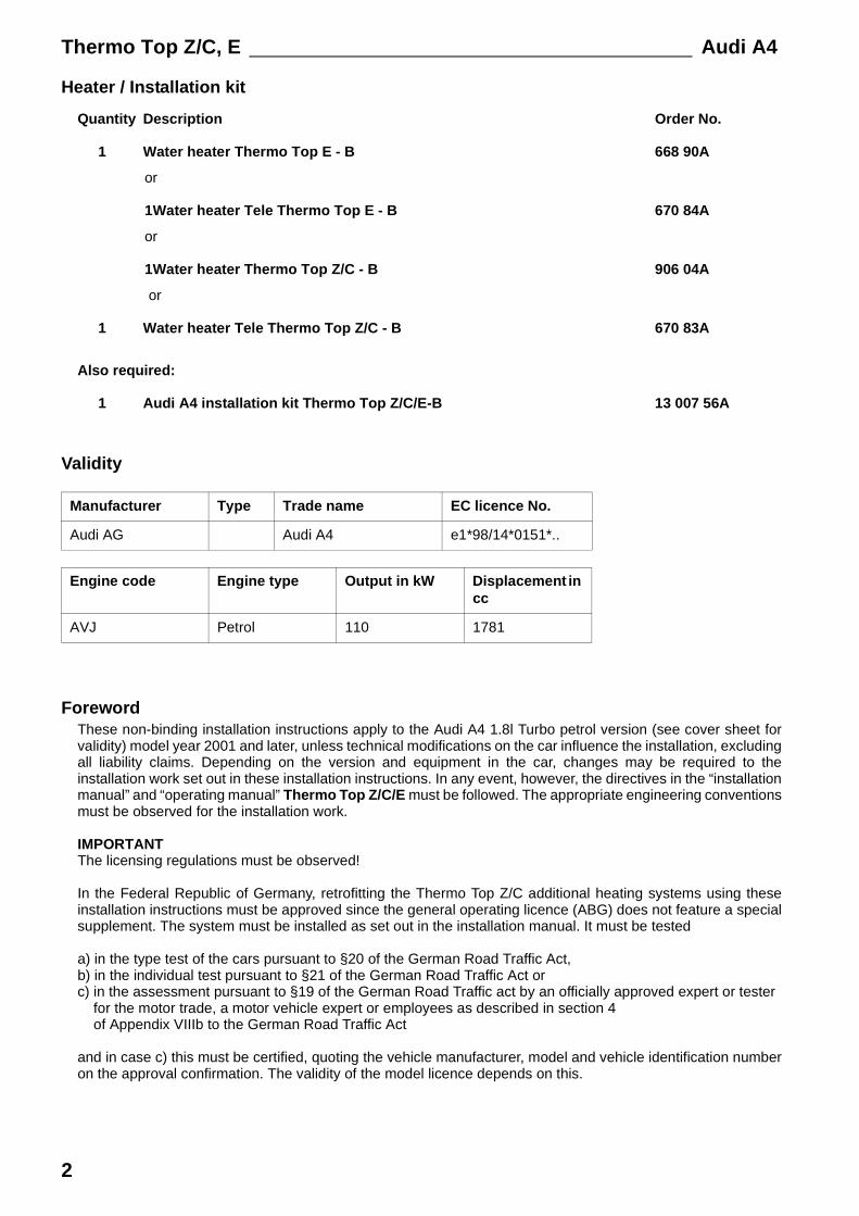
Heater / Installation kit
Quantity Description Order No.
1 Water heater Thermo Top E - B 668 90A
or
1Water heater Tele Thermo Top E - B 670 84A
or
1Water heater Thermo Top Z/C - B 906 04A
or
1 Water heater Tele Thermo Top Z/C - B 670 83A
Also required:
1 Audi A4 installation kit Thermo Top Z/C/E-B 13 007 56A
Validity
ForewordThese non-binding installation instructions apply to the Audi A4 1.8l Turbo petrol version (see cover sheet forvalidity) model year 2001 and later, unless technical modifications on the car influence the installation, excludingall liability claims. Depending on the version and equipment in the car, changes may be required to theinstallation work set out in these installation instructions. In any event, however, the directives in the “installationmanual” and “operating manual” Thermo Top Z/C/E must be followed. The appropriate engineering conventionsmust be observed for the installation work.
IMPORTANTThe licensing regulations must be observed!
In the Federal Republic of Germany, retrofitting the Thermo Top Z/C additional heating systems using theseinstallation instructions must be approved since the general operating licence (ABG) does not feature a specialsupplement. The system must be installed as set out in the installation manual. It must be tested
a) in the type test of the cars pursuant to §20 of the German Road Traffic Act,b) in the individual test pursuant to §21 of the German Road Traffic Act orc) in the assessment pursuant to §19 of the German Road Traffic act by an officially approved expert or tester
for the motor trade, a motor vehicle expert or employees as described in section 4of Appendix VIIIb to the German Road Traffic Act
and in case c) this must be certified, quoting the vehicle manufacturer, model and vehicle identification numberon the approval confirmation. The validity of the model licence depends on this.
Manufacturer Type Trade name EC licence No.
Audi AG Audi A4 e1*98/14*0151*..
Engine code Engine type Output in kW Displacement incc
AVJ Petrol 110 1781

Audi A4 Thermo Top Z/C, E
3
Special toolsClamping clawTorque wrench for 2.0 – 10 NmTorx E5 nut
Special Audi toolsClamping pliers V.A.G. 1275Tool to open the locking ring on the fuel tank fittings
General information- Bare body parts, for example around drilled holes,
must be treated with anti-corrosive coating.- Secure hoses, cables and wiring harnesses with
cable ties and fit protective hoses around them atchafing points
- Fit edge protectors (opened fuel hose) to sharpedges
Preparations- Remove the inapplicable year number from the
duplicate plate- Fit the duplicate plate (model plate) in a suitable
position where it is visible
Exterior- Open the filler cap, release the pressure from the
fuel tank system and close the filler cap again- Remove the underride guard- Remove the underbody guard on the right in full- Remove both front wheel arch trims- Remove the propeller shaft cover on the right
Under-bonnet compartment- Remove the engine cover
IMPORTANTDisconnect the battery!
- Remove the battery- Open the radiator cap and release the pressure- Close the radiator cap again- Release the coolant expansion tank and move it to
one side- Remove the radiator tank cover- Remove the top windscreen washer tank
Interior- Remove the rear seat bench- Remove the bottom dashboard trim on the driver
side- Remove the sill / sill covers on the left- Remove the service flap from the tank fittings- Release the central electrical system- Remove the air-conditioning control module-
Thermo Top Z/C, E Audi A4
4
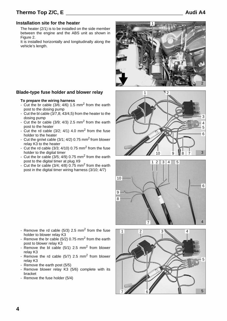
Installation site for the heaterThe heater (2/1) is to be installed on the side memberbetween the engine and the ABS unit as shown inFigure 2.It is installed horizontally and longitudinally along thevehicle’s length.
Blade-type fuse holder and blower relay
To prepare the wiring harness- Cut the br cable (3/6; 4/6) 1.5 mm2 from the earth
post to the dosing pump- Cut the bl cable (3/7,8; 43/4,5) from the heater to the
dosing pump- Cut the br cable (3/9; 4/3) 2.5 mm2 from the earth
post to the heater- Cut the rd cable (3/2; 4/1) 4.0 mm2 from the fuse
holder to the heater- Cut the gn/wt cable (3/1; 4/2) 0.75 mm2 from blower
relay K3 to the heater- Cut the rd cable (3/3; 4/10) 0.75 mm2 from the fuse
holder to the digital timer- Cut the br cable (3/5; 4/9) 0.75 mm2 from the earth
post to the digital timer at plug X9- Cut the br cable (3/4; 4/8) 0.75 mm2 from the earth
post in the digital timer wiring harness (3/10; 4/7)
- Remove the rd cable (5/3) 2.5 mm2 from the fuseholder to blower relay K3
- Remove the br cable (5/2) 0.75 mm2 from the earthpost to blower relay K3
- Remove the bl cable (5/1) 2.5 mm2 from blowerrelay K3
- Remove the rd cable (5/7) 2.5 mm2 from blowerrelay K3
- Remove the earth post (5/5)- Remove blower relay K3 (5/6) complete with its
bracket- Remove the fuse holder (5/4)
3
2
6
10 8 7
1
3
54
9
2
1
5
32
7
1
6
5
4
4
4
10
6
7
51 2
9
8
3

Audi A4 Thermo Top Z/C, E
5
- Connect the prepared heater wiring harness (6/1,2;7/3) to the heater (6/3) as shown in Figure 6
- Lay the heater wiring harness (7/3) as shown inFigure 2 and Figure 3 along the standard wiringharness (7/2) in the wheel arch to the passage hole(7/1) and into the interior.
- Lay the digital timer wiring harness (8/2) startingwith plug X9 through the passage hole (7/1) and intothe interior
- Follow it with the heater wiring harness (8/1; 7/3) asshown in Figure 7
- Lay the heater wiring harness (9/1; 8/1) as shown inFigure 9 to the central electrical system
61
2
3
82 1
9
1
73 2 1

Thermo Top Z/C, E Audi A4
6
- Connect the bl cable (10/6) from the heater and thebl cable (10/2) to the dosing pump with buttconnectors (10/1) as shown in Figure 10 (squeezeand shrink)
- Connect the gn/wt cable (10/5) from the heater tothe enclosed gn/wt cable (10/3) with butt connectors(10/4) as shown in Figure 10 and Figure 11(squeeze and shrink)
- Lay the gn/wt cable (12/1; 10/3) to the air-conditioning control module and crimp on thesupplied microtimer
- Connect the gn/wt cable (12/1) to plug D (12/2) asshown in Figure 12 and Figure 11
- Connect the br earth cables coming from the heater(13/1), going to the digital timer (13/5) (plug X9),coming from the digital timer wiring harness (13/6)and going to the dosing pump (13/4) to the br earthcable (13/2) 4.0 mm2 using blade connectors (13/3)
10
23
5
4
6
1
12
1
2
11
airconditioningcontrol modul
gn/wt gn/wt
Plug D
13
3
6
1
2
45
Audi A4 Thermo Top Z/C, E
7
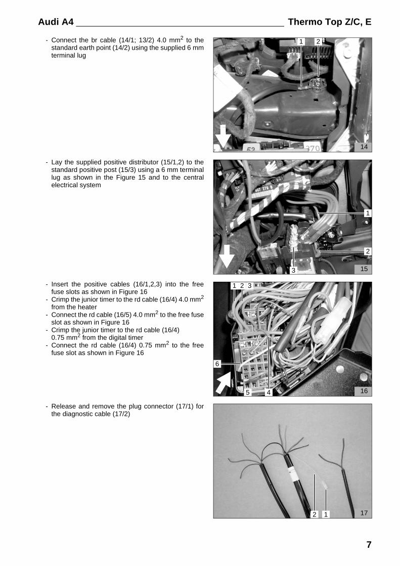
- Connect the br cable (14/1; 13/2) 4.0 mm2 to thestandard earth point (14/2) using the supplied 6 mmterminal lug
- Lay the supplied positive distributor (15/1,2) to thestandard positive post (15/3) using a 6 mm terminallug as shown in the Figure 15 and to the centralelectrical system
- Insert the positive cables (16/1,2,3) into the freefuse slots as shown in Figure 16
- Crimp the junior timer to the rd cable (16/4) 4.0 mm2
from the heater- Connect the rd cable (16/5) 4.0 mm2 to the free fuse
slot as shown in Figure 16- Crimp the junior timer to the rd cable (16/4)
0.75 mm2 from the digital timer- Connect the rd cable (16/4) 0.75 mm2 to the free
fuse slot as shown in Figure 16
- Release and remove the plug connector (17/1) forthe diagnostic cable (17/2)
14
21
153
1
2
21
16
3
5 4
6
1712
Thermo Top Z/C, E Audi A4
8
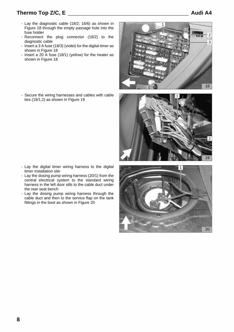
- Lay the diagnostic cable (18/2; 16/6) as shown inFigure 18 through the empty passage hole into thefuse holder
- Reconnect the plug connector (18/2) to thediagnostic cable
- Insert a 3 A fuse (18/3) (violet) for the digital timer asshown in Figure 18
- Insert a 20 A fuse (18/1) (yellow) for the heater asshown in Figure 18
- Secure the wiring harnesses and cables with cableties (19/1,2) as shown in Figure 19
- Lay the digital timer wiring harness to the digitaltimer installation site
- Lay the dosing pump wiring harness (20/1) from thecentral electrical system to the standard wiringharness in the left door sills to the cable duct underthe rear seat bench
- Lay the dosing pump wiring harness through thecable duct and then to the service flap on the tankfittings in the boot as shown in Figure 20
20
1
19
1
2
18
2
3
1

Audi A4 Thermo Top Z/C, E
9
Digital timer andoptional summer/winter switch
IMPORTANTDo not press on the LCD display as you install thedigital timer
NOTE:The installation site for the digital timer (21/1) shownin the figure is only a recommendation. Beforeinstallation, please agree the installation site with yourcustomer
- Affix the drilling template for the digital timer (21/1)in the required position
- Drill two holes using the template- Remove the template- Install the mounting sleeve using a self-tapping
screw
NOTE:Check the direction of the locking teeth (seeinstallation manual). Fit a chafing guard when youinstall the wiring harness.
- Thread the digital timer wiring harness through thehole and connect the plug to the digital timer
- Connect the digital timer
- Mark the holes for the summer/winter switch in therequired position and drill the holes with a diameterof 12 mm
- Draw the nut and toothed washer over both cables- Thread the brown and violet cables through the hole
and connect them to the switch (bottom contacts) asshown in Figure 22
- Secure the summer/winter switch with a toothedwasher and nut
21
1
2
22

Thermo Top Z/C, E Audi A4
10
To install the heater
To prepare the installation site- Remove the standard cable clip from position (23/2)- Enlarge the existing hole (23/2) to a diameter of
9 mm as shown in Figure 23- Insert a rivet nut M6 (23/2)- Undo the standard screw M6 from position (23/1)
(the screw will be reused)
- Undo the standard screw M6 from position (24/1)(the screw will be reused)
- Secure the 30 mm spacer nut (24/2) with a screwM6x20 (24/1), spring ring A6 and body washer A7.4to the existing threaded hole as shown in Figure 24
- Align the 30 mm retaining bracket (24/3) with ascrew M6x12, spring ring A6 and body washer A7.4as shown in Figure 24 and secure it to the spacernut (24/2)
To pre-install the heater
IMPORTANTOnly use the special screws and special EJOT PTstud bolt supplied to secure the heater.(tightening torque 10 Nm)
NOTE:Place a washer in position (25/3) and three washers inposition (25/2) between the heater and the holder
- Screw the Ejot stud bolt (25/1) into the heater (25/2)(tightening torque 10 Nm)
- Secure the holder (25/4) to the heater (25/5) usingtwo Ejot screws (25/2,3), placing a washer inposition (25/3) and two washers in position (25/2)between the heater (25/5) and the holder (25/4)(tightening torque 10 Nm)
232 1
24
1
2
3
25
5
4
3 2 1

Audi A4 Thermo Top Z/C, E
11
- Connect the supplied shaped hose (26/3) (internaldiameter rising from 3.5 mm to 4.5 mm) to theheater (26/1) using the end with an internal diameterof 4.5 mm as shown in Figure 26 and secure it witha 10 mm Cailau clip (26/2)
Combustion air intake line
NOTE:Check the installation site of the air intake silencer,see “installation manual”
- Punch out the perforation in the heater cover andinsert the clip (27/5) for the combustion air intakesilencer as shown in Figure 27
- Connect the combustion air intake lie (27/2) with theslotted side on the heater combustion air port andsecure it with a hose clip (27/4)
- Lay the combustion air intake line as shown inFigure 27
- Screw the combustion air intake silencer (27/1) asfar as possible into the combustion air intake line
- Insert the combustion air intake silencer into theretaining clip (27/5) as shown in Figure 27
- Insert the pre-installed heater (28/1) as shown inFigure 28
- Secure the Ejot stud bolt (29/6; 27/3) to the retainingbracket (29/4) as shown in Figure 29 with a flangednut M6 (29/5)
- Secure the holder (29/2; 27/6) to the existingthreaded hole using the standard screw M6 (29/3)as shown in Figure 9
- Secure the holder (29/2) using the standard screwM6 (29/1) as shown in Figure 29
295 4
1
6
2 3
27
1
4
2
5
3
6
281
263
1
2

Thermo Top Z/C, E Audi A4
12
Integration in the water system
NOTE:Catch escaping coolant water using a suitablecontainer!Install the water hoses with no kinks!
The following describes how to integrate the heaterinto the car’s coolant water system in an inline version(Figure 30)
Legend for Figure 301 Expansion tank2 Radiator thermostat3 Car engine4 Circulating pump (heater)5 Heater6 Heating system heat exchanger (car)7 Radiator
To prepare the water hoses
- Cut two lengths off the water hose supplied in the kitas shown in Figure 31:
1 x 390 mm (31/1)(from the standard water hose at the engine outlet tothe heater water inlet)
1 x 330 mm (31/2)(from the heater water to the standard hose sectionto the heat exchanger)
- Remove the standard water hose (32/1,2,3) fromthe engine outlet to the heat exchanger water inlet
- Cut the standard water hose (32/1,2,3) at themarkings (arrows)
ϑ
30
31
390
1
330
2
Cut off
Cut off
32
1 2 3

Audi A4 Thermo Top Z/C, E
13
- Connect the standard hose section (33/2; 32/2) andthe 330 mm water hose (33/5) as shown in Figure33 using a connection pipe 20 x 20 and space-saving clips (33/3,4)
- Connect the standard hose section (33/10; 32/1)and the 390 mm water hose (33/6) as shown inFigure 33 using a connection pipe 20 x 20 andspace-saving clips (33/8,9)
- Push the black rubber section (34/1; 33/1) on to thestandard hose section (33/2) as shown in Figure 34and Figure 33
- Push the black rubber section (34/4; 33/7) on to the390 mm water hose (33/6) as shown in Figure 34and Figure 33
To install the water hoses- Lay the prepared water hoses as shown in Figure 34
from the engine outlet to the heater water inlet andfrom the heat exchanger water inlet to the heaterwater outlet in the under-bonnet compartment
- Connect the pre-installed water hose (35/1,2;33/6,10) from the engine outlet to the heater waterinlet with a quick-release clip on the engine outlet,align it with the heater water inlet as shown inFigure 29 and secure it with a quick-release clip
- Connect the 390 mm water hose (36/1; 35/2) asshown in Figure 36 to the heater water inlet andsecure it with a spring strip clip (36/2)
33
1 2 5
10
3 4
8 67
9
34
1 2
34
35
1 2
3612

Thermo Top Z/C, E Audi A4
14
- Connect the standard hose section (37/3; 38/1) tothe heat exchanger water inlet (37/1), align it asshown in Figure 37 and secure it using the standardspring strip clip (37/2)
- Lay the pre-installed water hose (37/5; 33/2,5)through the standard passage hole (37/6) in theradiator tank to the standard hose section (37/3)
- Connect the standard water hose (37/5) and thestandard hose section (37/3) as shown in Figure 37using a connection pipe 20 x 20 and spring stripclips (37/4)
- Connect the 330 mm water hose (39/1; 33/5) to theheater water outlet and secure it with a spring stripclip (36/2) as shown in Figure 39
- Position the black rubber section (40/1; 34/4) asshown in Figure 40
- Position the black rubber section (34/1) under theradiator tank on the bulkhead
38
1
37
1 2 3
6
45
39
1
2
401

Audi A4 Thermo Top Z/C, E
15
- Insert the supplied spacer (41/3) between the 330mm water hose (41/1) and the 390 mm water hose(41/2) as shown in Figure 41
Integration in the fuel system
IMPORTANTOpen the filler cap, release the pressure from the fueltank system and close the filler cap again!Lay the fuel lines so that they are protected fromstones and heat!Fit a chafing guard on the fuel lines around sharpedges!Install the fuel lines with no kinks!
Dosing pump
NOTE:Check the installation site of the dosing pump, see“installation manual”
- Secure the bracket (42/5) to the existing screw M8(42/1) as shown in Figure 42
- Secure the dosing pump (42/3) to the bracket (42/5)using an anti-vibration mount (42/2), rubberisedpipe clip (42/4) and flanged nuts as shown inFigure 42
- Connect the supplied 90° shaped hose (43/3)(internal diameter rising from 3.5 mm to 4.5 mm) tothe outfeed from the dosing pump (43/1) (side withthe plug) using the end with an internal diameter of4.5 mm
- Align the 90° shaped hose (43/3) as shown in Figure43 and secure it to the dosing pump using a 10 mmCailau clip
- Insert the metal fuel line (43/4) into the end of the90° shaped hose (43/3) with an internal diameter of3.5 mm and secure it with an 8 mm Cailau clip
- Lay the dosing pump wiring harness (43/2) to thedosing pump and cut it to length
- Push a rubber grommet on to the dosing pumpwiring harness, crimp on a blade terminal, completethe plug casing and connect the wiring harness tothe dosing pump as shown in Figure 43
413 2
1
42
1 2
4
3
5
3
2
1
43
45

Thermo Top Z/C, E Audi A4
16
To install the metal fuel line- Lay the metal fuel line from the dosing pump to the
heater as shown in Figure 43 to Figure 50- Cut the supplied 80 mm plastic hose into eight
equal sections of 10 mm, push them on to the metalfuel line and position them level with the standardholders for the fuel line
- Open the holder (44/2,4,5,6) for the standard fuelline and insert the metal fuel line (44/3) with theattached plastic hoses
- Close the holders (44/2,4,5,6) again- Secure the metal fuel line to the standard fuel line
using the clips supplied (43/5; 44/1)
- Secure the metal fuel line (45/2,4) to the standardfuel line using the clips supplied (45/1,3,5,6)
- Secure the metal fuel line (46/2,3) to the standardfuel line using the clip supplied (46/1)
- Open the holder (47/5) for the standard fuel line andinsert the metal fuel line (47/1,6) with the attachedplastic hoses
- Close the holder (47/5) again- Insert the supplied guide rubber (47/4) as shown in
Figure 45- Lay the metal fuel line (45/1,6) through the standard
passage into the under-bonnet compartment- Secure the metal fuel line (47/1.6) to the standard
fuel line using the clip supplied (47/3)
44
2 3 4 5 61
45
1 2 3
6 5 4
46
3
1 2
47
2
4
56
1
3

Audi A4 Thermo Top Z/C, E
17
- Open the holder (48/3) for the standard fuel line andinsert the metal fuel line (48/1) with the attachedplastic hoses
- Close the holder (48/3) again- Secure the metal fuel line (48/1) to the standard fuel
line using the clip supplied (48/2)
- Open the holders (49/3,4) for the standard fuel lineand insert the metal fuel line (49/1,2) with theattached plastic hoses
- Close the holders (49/3,4) again- Secure the metal fuel line (49/2,3) to the standard
fuel line using the clip supplied (49/1)- Secure the metal fuel line (49/1,2) to the standard
fuel line using the clip supplied (49/5)
- Insert the metal fuel line (50/5) into the end of theshaped hose with an internal diameter of 3.5 mm(50/3) and secure it with an 8 mm Cailau clip (50/4)
- Secure the metal fuel line (50/5) to the standard fuelline using the clips supplied (50/1,2)
- Secure the metal fuel line to the standard fuel lineafter the fuel filter using the remaining clip
48
2
1
3
49
12
345
50
1
3
45
2

Thermo Top Z/C, E Audi A4
18
Fuel extraction
The fuel is extracted using the tank extracting devicefrom the tank fittings
- Cut the supplied tank extracting device (51/1) tolength as shown in Figure 51
- Cut the supplied fuel hose (51/2) to length as shownin Figure 51 (150 mm extended length)
- Cut the supplied riser pipe (51/3) to length as shownin Figure 51
IMPORTANTOpen the car’s filler cap, vent the tank and close thefiller cap again!
Catch escaping fuel using a suitable container!
- Remove the tank fittings (52/1) following themanufacturer’s instructions
- Drill a 6.0 mm hole in position (52/2) in the tankfittings
- Secure the tank extracting device (53/6; 54/6) in thetank fittings (53/1; 54/1) as described in the suppliedinstallation manual
- Push the fuel hose (53/4; 54/4) on to the tankextracting device as shown in Figure 53 andFigure 54
- Secure the fuel hose using the supplied 6.6 mmhose clip (53/5; 54/3) as shown in Figure 53 andFigure 54
51
tank extracting device (1)
fuel hose (2)
extended length 150 mm
riser pipe (3)
53
1
6
5
4
2
3
52
2
1

Audi A4 Thermo Top Z/C, E
19
- Insert the riser pipe (54/3; 53/3) into the tank fittingsas shown in Figure 54 and Figure 53
- Push the fuel hose (54/4; 53/4) on to the riser pipe- Secure the fuel hose using the supplied 8.0 mm
hose clip (54/2; 53/2) as shown in Figure 54 andFigure 53
- Connect the supplied 90° shaped hose (55/1)(internal diameter rising from 3.5 mm to 4.5 mm) tothe tank extracting device (55/3) using the end withan internal diameter of 3.5 mm
- Secure the 90° shaped hose using the supplied9 mm Cailau clip (55/2) as shown in Figure 55
- Install the tank fittings again as described by themanufacturer
- Insert the Mecanyl fuel line (66/3) into the 90°shaped hose (66/1; 65/1) and secure it with a 10 mmCailau clip as shown in Figure 66
- Lay the Mecanyl fuel line (57/1; 56/3) to the intakeside of the dosing pump (57/3) and cut it to length
- Connect the Mecanyl fuel line (57/1) as shown inFigure 57 with the hose section (57/2) 10 mmCailau clips
- Secure all cables and wiring harnesses with cableties
54
165
42
3
55
1
23
563 2 1
2
1
57
3

Thermo Top Z/C, E Audi A4
20
Exhaust system
IMPORTANTEnsure that you leave sufficient space to hoses andcables when you install the exhaust system!
- Secure the servo hose (58/1) to the standard studbolt using a 25 mm rubberised pipe clip (58/3) and aplastic nut (58/2) as shown in Figure 58
- Cut the exhaust pipe and exhaust pipe end piece asshown in Figure 59
- Secure the supplied bracket (60/2) using thestandard screw (60/1) as shown in Figure 60
- Secure the exhaust silencer (61/1) to the bracket(61/3; 60/2) using the screw M6x20 (61/2) andflanged nut M6 as shown in Figure 61
581
3
2
Exhaust pipe
450 210
Cut off
Heater silencer End piece
59
60
2
1
61
2
3
1

Audi A4 Thermo Top Z/C, E
21
- Connect the 450 mm exhaust pipe (62/2) to theheater and secure it with a hose clip as shown inFigure 62
- Shape the 450 mm exhaust pipe (63/3; 62/2) asshown in Figure 63 and Figure 62, connect it to theexhaust silencer (63/1) and secure it with a hose clip(63/2)
- Connect the 210 mm exhaust pipe (63/5) to theexhaust silencer (63/1) heater and secure it with ahose clip (63/4)
- Connect the exhaust passage (63/6) to the 210 mmexhaust pipe (63/5) and secure it with a hose clip
62
1
2
635
1 2 3
46

Thermo Top Z/C, E Audi A4
22
Exhaust passage- Place the supplied template on the underride guard
as shown in Figure 64 and mark the holes(64/1,2,3,5) on the underride guard
- Drill three 5.0 mm holes (64/1,2,5) as shown inFigure 64
- Drill 27 mm holes (64/3)- Install the underride guard- Secure the exhaust passage (63/6) to the underride
guard using three screws M5x20 and body washers
64
1 2
5
3
4
Concluding work- Install and connect the battery- Install all the removed parts in reverse- Check that all hose lines, hose and pipe clips and all electrical connections are secure- Secure all loose lines and cables with cable ties- Take all tools, such as clamping claws, etc. out of the under-bonnet compartment- Spray the heater components with anti-corrosive wax (Tectyl ML, order No. 111329)
IMPORTANTOnly use genuine Audi coolant!
- Start the engine, bleed the water system as described in the repair guidelines, top up thecoolant- Set the car’s heating system to “DEF” and the blower to II with the ignition switched on- Switch on the Webasto heating system, see “operating manual/installation manual”

Audi A4 Thermo Top Z/C, E
23
Operating instructions for the endcustomer
NOTE:Please cut out and hand this page to the endcustomer!
IMPORTANTThis car is fitted with a Webasto additional heatingsystem!The installation site of the heater mean that access tothe oil filter is more difficult!
Additional heating system fuse assignment
- Heating system fuse (65/1)20 A (yellow)
- Digital timer fuse (65/3)3 A (violet)
- Webasto diagnostic plug (65/2)
To operate the additional heating system
- Set the car’s heating system to “DEF”, the blower toII and the temperature to max. 28°C with theignition switched on
65
2
3
1

Thermo Top Z/C, E Audi A4
24
Webasto Thermosysteme International GmbHPostfach 80 - D-82132 Stockdorf - Hotline 0 18 05 / 93 22 78Hotfax (0395) 55 92-353 - http://www.webasto.de