Water Heater Unit Installation Instructions Citroen C6 2.2 l HDI
26
WARNING! Hazard warning: Incorrect installation or repair of Webasto heating systems may cause a fire or result in the emission of carbon monoxide, which can be fatal. Serious or fatal injuries can be caused as a result. Specialist company training, technical documentation, specialized tools and equipment are required to install and repair Webasto heating and cooling systems. NEVER attempt to install or repair Webasto heating or cooling systems if you have not successfully completed the company training and thereby acquired the required technical skills, or if you do not have access to the required technical documentation, tools and equipment needed to carry out correct installation and repairs. ALWAYS follow all Webasto installation and repair instructions and observe all warnings. Webasto does not accept any liability for defects and damage that are attributable to installation by untrained staff. Water Heater Unit Installation Instructions Ident. No.:1312356A_EN Fee Euro 10.00 © Webasto AG Citroen C6 2.2 l HDI Diesel from Model Year 2006 Left-hand drive vehicle Feel the drive Thermo Top E Additional Heater e1 00 0003 Thermo Top C Additional Heater e1 00 0002 Thermo Top P Additional Heater e1 00 0104
-
Upload
khangminh22 -
Category
Documents
-
view
0 -
download
0
Transcript of Water Heater Unit Installation Instructions Citroen C6 2.2 l HDI

WARNING!
Hazard warning:
Incorrect installation or repair of Webasto heating systems may cause a fire or result in the emission of carbon monoxide, which can be fatal. Serious or fatal injuries can be caused as a result.
Specialist company training, technical documentation, specialized tools and equipment are required to install and repair Webasto heating and cooling systems.
NEVER attempt to install or repair Webasto heating or cooling systems if you have not successfully completed the company training and thereby acquired the required technical skills, or if you do not have access to the required technical documentation, tools and equipment needed to carry out correct installation and repairs.
ALWAYS follow all Webasto installation and repair instructions and observe all warnings.
Webasto does not accept any liability for defects and damage that are attributable to installation by untrained staff.
Water Heater Unit
Installation Instructions
Ident. No.:1312356A_EN Fee Euro 10.00 © Webasto AG
Citroen C6 2.2 l HDIDieselfrom Model Year 2006Left-hand drive vehicle
Feel the drive
Thermo Top E Additional Heatere1
00 0003
Thermo Top C Additional Heatere1
00 0002
Thermo Top P Additional Heatere1
00 0104

Citroen C6 2.2 l HDI
Table of Contents
Validity
Vehicle and engine types, equipment variants and national specifications not listed in these installation instructions have not been tested. However, installation according to these installation instructions may be possible.
The installation location of a digital timer and summer/winter switch should be confirmed with the end customer before installation.
Manufacturer Model Type EG-BE No./ABECitroen C6 2.2 l HDI e1 * 2001/116 * 0320
Engine type Engine model Output in kW Displacement in cm³4HT Diesel 125 2179
Validity 2Heater Unit/Installation Kit 3Foreword 3General Instructions 3Special Tools 3Explanatory Notes on Document 4Preliminary Work 5Heater unit installation location 5Preparing electrical system 6Electrical Connections 7Fan controller 8Remote option (Telestart) 10Remote option (Thermo Call) 11
Preparing heater unit and bracket 12Preparing installation location 12Installing heater unit 14Coolant connection 15Fuel Connection 19Exhaust system 22Combustion air 23Final Work 24Operating Instructions for End Customer 25Template for Fuel Standpipe 26
1312356A_EN 2
Citroen C6 2.2 l HDI
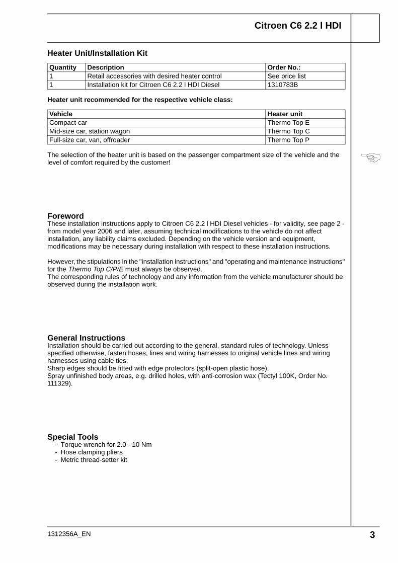
Heater Unit/Installation Kit
Heater unit recommended for the respective vehicle class:
The selection of the heater unit is based on the passenger compartment size of the vehicle and the level of comfort required by the customer!
ForewordThese installation instructions apply to Citroen C6 2.2 l HDI Diesel vehicles - for validity, see page 2 - from model year 2006 and later, assuming technical modifications to the vehicle do not affect installation, any liability claims excluded. Depending on the vehicle version and equipment, modifications may be necessary during installation with respect to these installation instructions.
However, the stipulations in the "installation instructions" and "operating and maintenance instructions" for the Thermo Top C/P/E must always be observed.The corresponding rules of technology and any information from the vehicle manufacturer should be observed during the installation work.
General InstructionsInstallation should be carried out according to the general, standard rules of technology. Unless specified otherwise, fasten hoses, lines and wiring harnesses to original vehicle lines and wiring harnesses using cable ties.Sharp edges should be fitted with edge protectors (split-open plastic hose).Spray unfinished body areas, e.g. drilled holes, with anti-corrosion wax (Tectyl 100K, Order No. 111329).
Special Tools- Torque wrench for 2.0 - 10 Nm- Hose clamping pliers- Metric thread-setter kit
Quantity Description Order No.:1 Retail accessories with desired heater control See price list1 Installation kit for Citroen C6 2.2 l HDI Diesel 1310783B
Vehicle Heater unitCompact car Thermo Top EMid-size car, station wagon Thermo Top CFull-size car, van, offroader Thermo Top P
1312356A_EN 3

Citroen C6 2.2 l HDI
Explanatory Notes on Document
To provide you with a quick overview of the individual working steps, you will find an identification mark on the outside top right corner of the page in question.
Special features are highlighted using the following symbols:
Mechanical system
Electrical system
Coolant connection
Fuel connection
Exhaust system
Combustion air
The arrow in the vehicle icon indicates the position on the vehicle and the viewing angle.
Specific risk of injury or fatal accidents.
Specific risk of damage to components.
Specific risk of fire or explosion.
Reference to general installation instructions of Webasto components or to the manufacturer's vehicle-specific documents.
Reference to a special technical feature.
1312356A_EN 4

Citroen C6 2.2 l HDI
Preliminary Work
WARNING!
- Depressurize the cooling system.- Copy the factory number from the original type label to the duplicate type label.- Remove years that do not apply from the duplicate label.- Attach the duplicate label (type label) in the appropriate place.- Move right-hand rear seat toward front and remove (3 bolts)- Open the right-hand fuel sender service lid.- Remove the fuel-tank sending unit in accordance with the manufacturers specifications.- Disconnect and completely remove the battery.- Remove the cover of the central electrical box in the engine compartment.- Detach the control units in the central electrical box- Remove the air filter together with the intake hose.- Open the fuel tank cap, ventilate the tank.- Close the tank cap again.- Remove the front underride protection.- Remove the rear right underride protection.- Remove the bumper.- Remove the left-hand headlight- Remove the left-hand wheel well trim- Remove the center section of the rear seat bench (unclip).- Remove the left-hand instrument panel trim.- Remove the A/C control panel according to the manufacturer's specifications.
Remove page 25 "Operating Instructions for End Customer" and add to the vehicle operating instructions.
Installation location
Heater unit installation location
1 Heater unit
1
1
1312356A_EN 5

Citroen C6 2.2 l HDI
Cutting wires to length
Preparing additional relay K3.1
Installing K3.1
Installing K3 and fuse holder
Preparing electrical system
Produce connections as shown in wiring diagram. Install wire section 2 and 3 in protective sleeving.
Cut mounting tab off K3.1 relay 1 and fasten with Velcro strip 2 on housing of central electrical box.
Drill out mounting tab of K3 relay 4 to 6 mm dia.
1 Retaining plate for fuse holder2 4 mm dia. hole, 5.5x9.5 self-tapping screw3 M6 flanged nut on original vehicle bolt5 Fuse holder
2500
rt 0,75²1
500
2
sw 0,75²
2500
br 0,75²
900
3
4
K3.1
87a8786
85 30
rt
br
rt1 2
sw34
2
1 2
3
4
2
3
1
5
1312356A_EN 6

Citroen C6 2.2 l HDI
Wiring harness installation diagram
Electrical ConnectionsFuse holder, relay K3
1 K3 relay2 Fuse holder
Digital timer and summer/winter switch option
1 Digital timer2 Summer/winter switch, drilled hole 12 mm dia.
Positive and ground connection
1 Original vehicle ground support point2 Ground wire3 Positive wire4 Original vehicle positive support point
Wiring harness pass through
1 Protective rubber plug
4
1
2 5
1
2
rt sw
rt
sw
rt
br
bl
Do not install the metering pump cable harness until later together with fuel pipe along the original vehicle fuel lines on the underbody
63
1
2
4 7
1
1312356A_EN 7

Citroen C6 2.2 l HDI
1312356A_EN
Fan controller
Wiring diagram
Webasto components Citroen components Colors and symbols
Legend
HG Heater unit TT-C/E 8050 Fan motor rt redX1 6-pin heater unit
connector8025 Air-conditioning control
elementws white
F3 Fuse, 25 A PSF Main power supply sw blackK3 Fan relay BSI Central switching unit br brownK3.1 Additional relay 6V NR 6-pin connector gn greenBAS Operating mode switch
option2V NR 2-pin connector ge yellow2V GR 2-pin connector Insulate wire end and tie
back8V NR 8-pin connector10V NR 10-pin connector X Cutting pointPF2 Main fuse
Note!
The operating mode switch (OMS) option is used to switch over the A/C control unit into the standard or heating mode.If the heating mode is desired, the switch (OMS) must be set to the "Heat" symbol.In the standard mode, the changing of the flap control and the resetting of the control unit is prevented.
The installation location of the operating mode switch must be coordinated with the end customer prior to installation.
gn/ws
sw
br
rt/ws
rt
Webasto
31
3015
Citroen C6
rt
sw
rt
br
1
2
3
4
HG4 X1
F3
86
85 30
87a87
K3.1
86
85 30
87a87
K3
rt
PF2BSI
F14
R7
22V GR 6 10V NR
PSF
F11R7
MF7
22V NR 88V NR
8025
6V NR 1
8050
6V NR 6
M
ge
ge
BAS
!
Webasto
4²4²
4²
0,72²
0,75²rt
i
8

Citroen C6 2.2 l HDI
Con-necting central electrical box
Con-necting fan motor
Con-necting A/C control panel
Measure out directly switched terminal 15 without switch-off delay on connector 28V GR 3. Connector assignment may vary.Produce connections as shown in wiring diagram.
1 Yellow (ge) wire of terminal 15 [2x]2 Red (rt) wire from K3.1/86
Produce connections as shown in wiring diagram.
1 Red (rt) wire to fan motor [2x]2 3x distributor3 Black (sw) wire from K3/304 Isolate red (rt) wire and tie back
Connection on 6-pin connector 6V NR 4 from A/C control panel 5.Produce connections as shown in wiring diagram.
1 Yellow (ge) wire [2x]2 Red (rt) wire from K3.1/873 Black (sw) wire from K3.1/30
8
1
1
3
2
9
1 3
4
1
2
10
1
4
3
2
1
5
1312356A_EN 9

Citroen C6 2.2 l HDI
Installing receiver
Installing antenna
Remote option (Telestart)
1 Receiver2 Bracket3 5.5 mm dia. hole, M5x12 bolts, M5 flanged
nuts [2x each]
1 Antenna
1
3
2
11
1
12
1312356A_EN 10

Citroen C6 2.2 l HDI
Installing receiver
Installing antenna
Installing push button
Remote option (Thermo Call)
1 Receiver2 M 5.5x13 self-tapping screws [4x]3 Glove compartment
1 Antenna
1 Pushbutton
1
2 2
133
1
14
1
15
1312356A_EN 11

Citroen C6 2.2 l HDI
Preassem-bling heater unit
Preparing perforated bracket
Preassem-bling bracket
Changing line routing
Preparing heater unit and bracket
Tighten EJOT screws to 10 Nm!
1 Combustion-air intake pipe2 27 mm dia. hose clamp3 Perforated bracket4 Ejot screw5 M6x20 bolt, flanged nut6 Exhaust muffler
1 Shorten perforated bracket
Discard section X
1 Bracket2 M6x12 bolt, flanged nut [2x each]
Preparing installation location
1 Ground wire2 Rubber-coated p-clamp turned 180°3 Positive wire
1 2 3
4
5
6 16
X
1
17
1
2
18
1
3
2
1312356A_EN 12

Citroen C6 2.2 l HDI
Copying hole pattern
Installing bracket
Installing edge protection
Loosely install bracket and align.
1 Original vehicle hole, M6x35 bolt, 20 mm shim, M6 flanged nut
2 Copy hole pattern [3x]
When drilling, watch components located behind!
1 Original vehicle hole, M6x35 bolt, 20 mm shim, M6 flanged nut
2 7 mm dia. hole, M6x35 bolt, 20 mm shim, M6 flanged nut [2x each]
3 9.1 mm dia. hole, M6 rivet nut, M6x35 bolt, spring lockwasher, 20 mm shim
1 Wiring harness of heater unit2 Edge protection
19
2
1 2
2
30 mm
20
3
2
2
1
21
1
2
1312356A_EN 13
Citroen C6 2.2 l HDI
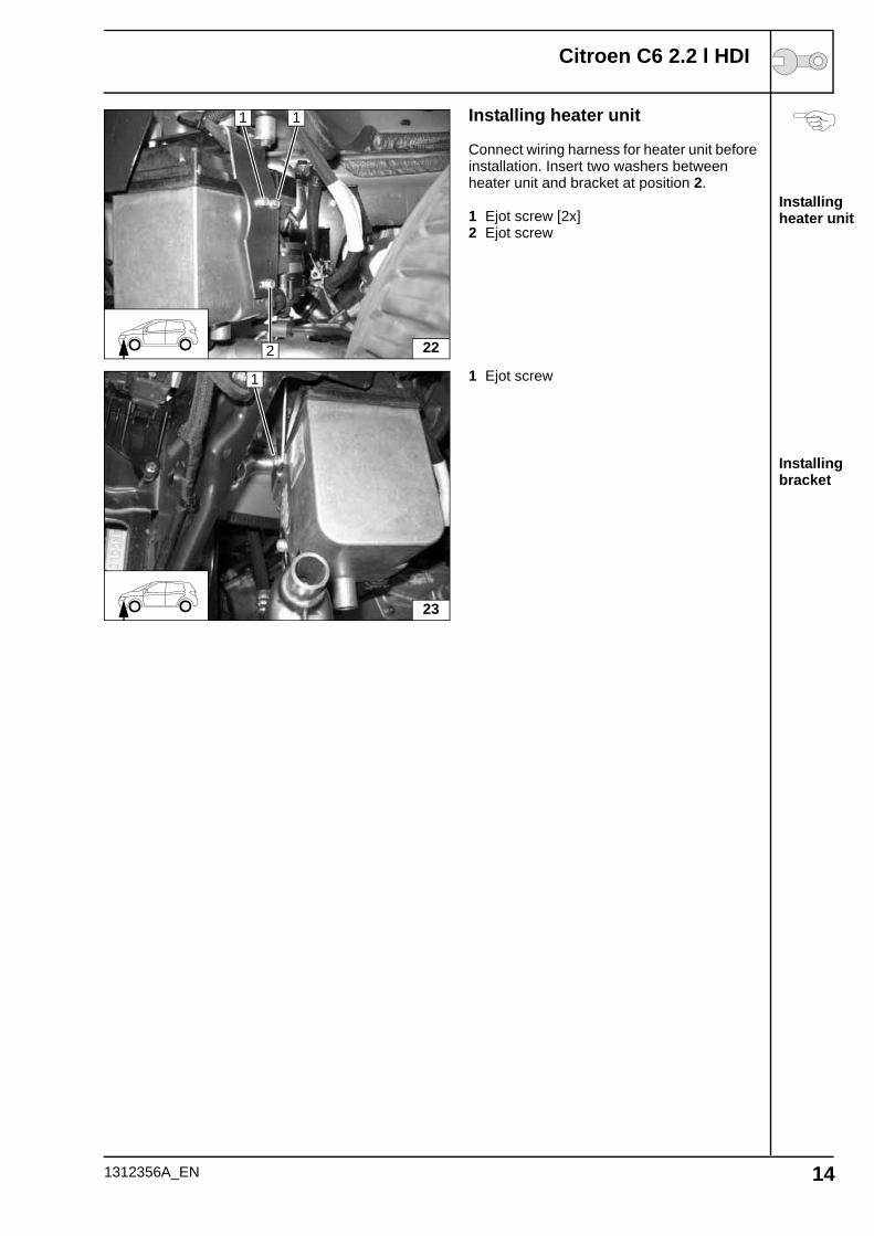
Installing heater unit
Installing bracket
Installing heater unit
Connect wiring harness for heater unit before installation. Insert two washers between heater unit and bracket at position 2.
1 Ejot screw [2x]2 Ejot screw
1 Ejot screw
22
1 1
2
23
1
1312356A_EN 14

Citroen C6 2.2 l HDI
Coolant routing diagram
Coolant connection
WARNING!Tighten all hose clamps to 2.0 + 0.5 Nm. Any coolant running off should be collected using an appropriate container. Install hoses so that they are kink-free. Unless specified otherwise, always fasten using cable ties. Position hose clamps and spring band clamps so that no other hose can be damaged. When installing the coolant hose, the heater unit must be filled with coolant. The connection should be "inline" based on the following diagram:
All connecting pipes without a specific designation = dia. 18x20. All hose clamps = 20-27 mm dia.! 1 = Connecting pipe = dia. 20x20
A
B
C
1
1312356A_EN 15

Citroen C6 2.2 l HDI
Cutting coolant hoses to length
Preparing coolant hoses
Preparing coolant
Cutting point
b = 640 mmc = 800 mm
Discard section X
Push braided protection hoses onto hose B and C and cut to length.Cut heat shrink plastic tubing to length.
1 25 mm heat shrink plastic tubing [4x]
1 Remove original vehicle hose from engine outlet to heat exchanger inlet
1 Hose section of heat exchanger inlet2 Hose section on engine outlet3 Discard section
B X C
X Xb c
B
C
1 1
1 1
24
1
25
1
23
1312356A_EN 16

Citroen C6 2.2 l HDI
Preparing coolant hoses
Preparing coolant hoses
Con-nection on heat exchanger inlet
Con-nection on engine outlet
1 Hose section of heat exchanger inlet2 Hose section on engine outlet
1 Black (sw) rubber profile [2x]2 Spacer bracket3 Cable tie
1 Heat exchanger inlet
1 Engine outlet
26
A
1
2
27C
A
B
28C 1
29A
B
C
1
1312356A_EN 17
Citroen C6 2.2 l HDI
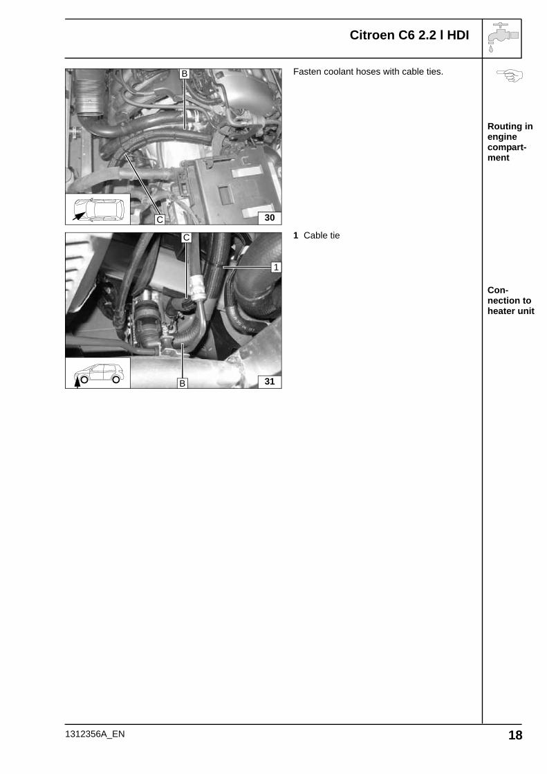
Routing in engine compart-ment
Con-nection to heater unit
Fasten coolant hoses with cable ties.
1 Cable tie
30
B
C
31B
1
C
1312356A_EN 18
Citroen C6 2.2 l HDI
Con-nection to heater unit
Installing lines
Installation location of metering pump
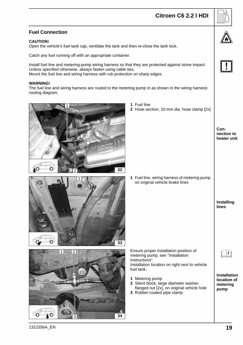
Fuel Connection
CAUTION!Open the vehicle's fuel tank cap, ventilate the tank and then re-close the tank lock.
Catch any fuel running off with an appropriate container.
Install fuel line and metering-pump wiring harness so that they are protected against stone impact. Unless specified otherwise, always fasten using cable ties.Mount the fuel line and wiring harness with rub protection on sharp edges.
WARNING!The fuel line and wiring harness are routed to the metering pump in as shown in the wiring harness routing diagram.
1 Fuel line2 Hose section, 10 mm dia. hose clamp [2x]
1 Fuel line, wiring harness of metering pump on original vehicle brake lines
Ensure proper installation position of metering pump, see "Installation Instructions“.Installation location on right next to vehicle fuel tank.
1 Metering pump2 Silent block, large diameter washer,
flanged nut [2x], on original vehicle hole3 Rubber-coated pipe clamp
32
1
2
33
1
34
1 2
3
1312356A_EN 19

Citroen C6 2.2 l HDI
Con-necting to metering pump
Removing fuel
Installing fuel standpipe
Installing fuel standpipe
Fuel line 1 from heater unit on pressure side of metering pump [side with connector].Check the position of the components; adjust if necessary. Check that they have free clearance.
2 Wiring harness of metering pump, connector mounted
3 Hose section, 10 mm dia. hose clamp [2x]
Remove and dismantle fuel-tank sending unit 1 according to manufacturer's instructions.
2 5 mm dia. large diameter washer3 Copy hole pattern, 6 mm dia. hole
Shape fuel standpipe 1 according to template, cut to length and install, see "installation instructions".
Position large diameter washer 1 between flanged nut and cover of fuel-tank sending unit!
35
1 2 3
36
1
3
2
37
1
38
1
3
1312356A_EN 20
Citroen C6 2.2 l HDI
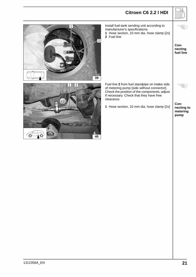
Con-necting fuel line
Con-necting to metering pump
Install fuel-tank sending unit according to manufacturer's specifications.1 Hose section, 10 mm dia. hose clamp [2x]2 Fuel line
Fuel line 2 from fuel standpipe on intake side of metering pump [side without connector].Check the position of the components; adjust if necessary. Check that they have free clearance.
1 Hose section, 10 mm dia. hose clamp [2x]
39
2
1
40
1 2
1312356A_EN 21

Citroen C6 2.2 l HDI
Preparing exhaust pipe
Installing muffler
Installing exhaust end section
Exhaust system
1 Exhaust pipea = 200 mm
2 Exhaust end sectionb = 350 mm
Discard section X
1 Hose clamp [2x]2 Exhaust pipe
1 Exhaust end section2 Hose clamp3 Red (rt) rubber isolator with groove
a b
1 2
X
41
1
2
1
1 2
3
42
1312356A_EN 22

Citroen C6 2.2 l HDI
Installing intake pipe
Installing muffler
Combustion air
1 Combustion-air intake pipe
1 Combustion-air intake muffler2 48 mm dia. p-clamp; rubber coating
removed3 Combustion-air intake pipe4 M6x20 bolt, original vehicle hole, M6
flanged nut
1
43
44
2
1
34
1312356A_EN 23
Citroen C6 2.2 l HDI
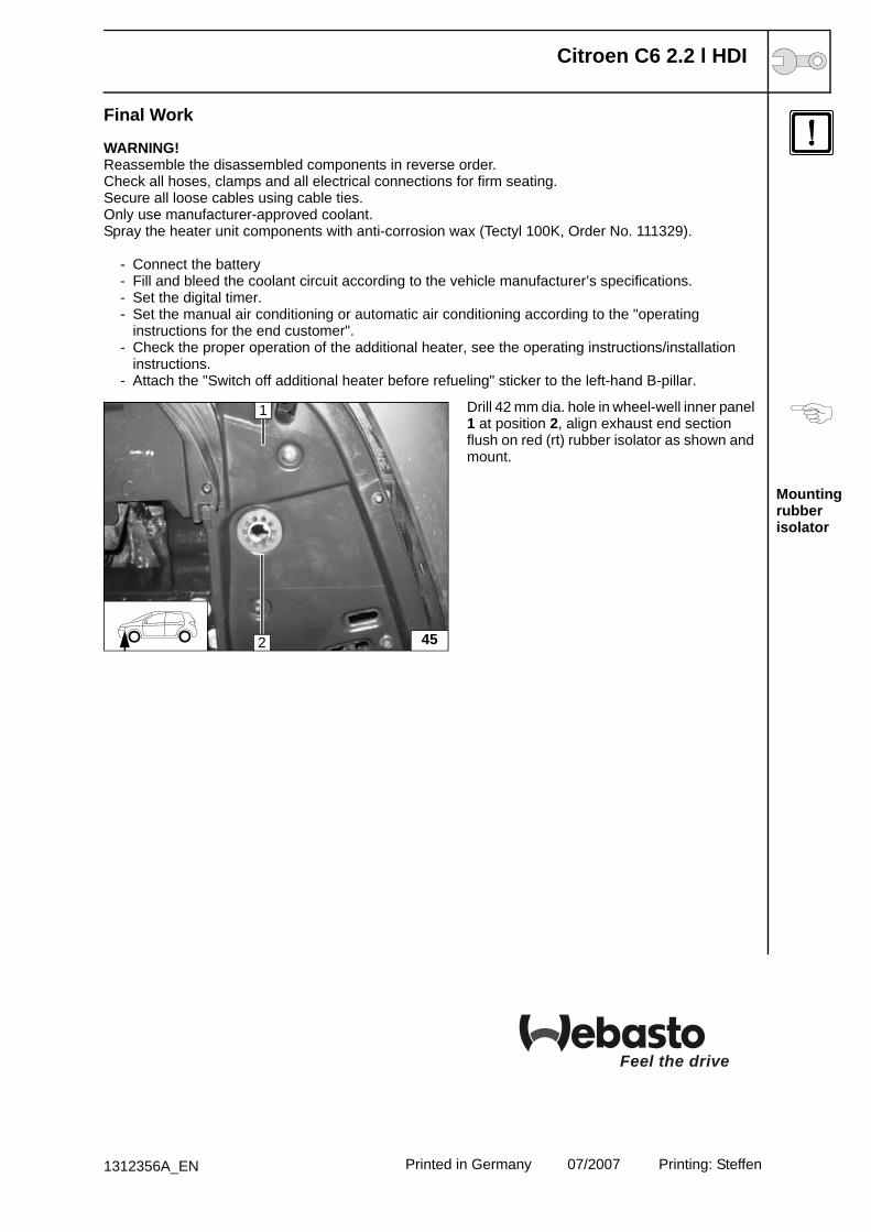
Mounting rubber isolator
Final Work
WARNING!Reassemble the disassembled components in reverse order.Check all hoses, clamps and all electrical connections for firm seating.Secure all loose cables using cable ties.Only use manufacturer-approved coolant.Spray the heater unit components with anti-corrosion wax (Tectyl 100K, Order No. 111329).
- Connect the battery- Fill and bleed the coolant circuit according to the vehicle manufacturer’s specifications.- Set the digital timer.- Set the manual air conditioning or automatic air conditioning according to the "operating
instructions for the end customer".- Check the proper operation of the additional heater, see the operating instructions/installation
instructions.- Attach the "Switch off additional heater before refueling" sticker to the left-hand B-pillar.
Drill 42 mm dia. hole in wheel-well inner panel 1 at position 2, align exhaust end section flush on red (rt) rubber isolator as shown and mount.
45
1
2
Feel the drive
Printed in Germany 07/2007 Printing: Steffen1312356A_EN

Citroen C6 2.2 l HDI
Adjusting automatic air-condition-ing
Automatic air-condition-ing
Operating Instructions for End Customer
Please remove page and add to the vehicle operating instructions.
Note:We recommend matching the heating time to the driving time.Heating time = driving timeExample:For a driving time of approx. 20 min. (in one direction), we recommend not exceeding a switch-on time of 20 min.
If the summer/winter switch option has been installed, this must be switched in accordance with the time of year. The heater unit will then only switch on the vehicle fan to ventilate the vehicle interior in the position Winter heat and in the position Summer .
Before parking the vehicle, make the following settings:
Following adjustment, be sure to wait approx. 30 seconds until switching off engine!
1 Temperature to "max.“ [2x]2 Air outlet to windshield3 Deactivate passenger compartment
monitoring
After ignition switch is actuated, A/C control panel starts in automatic mode
46
1 2
3
1
47
1312356A_EN 25
Citroen C6 2.2 l HDI
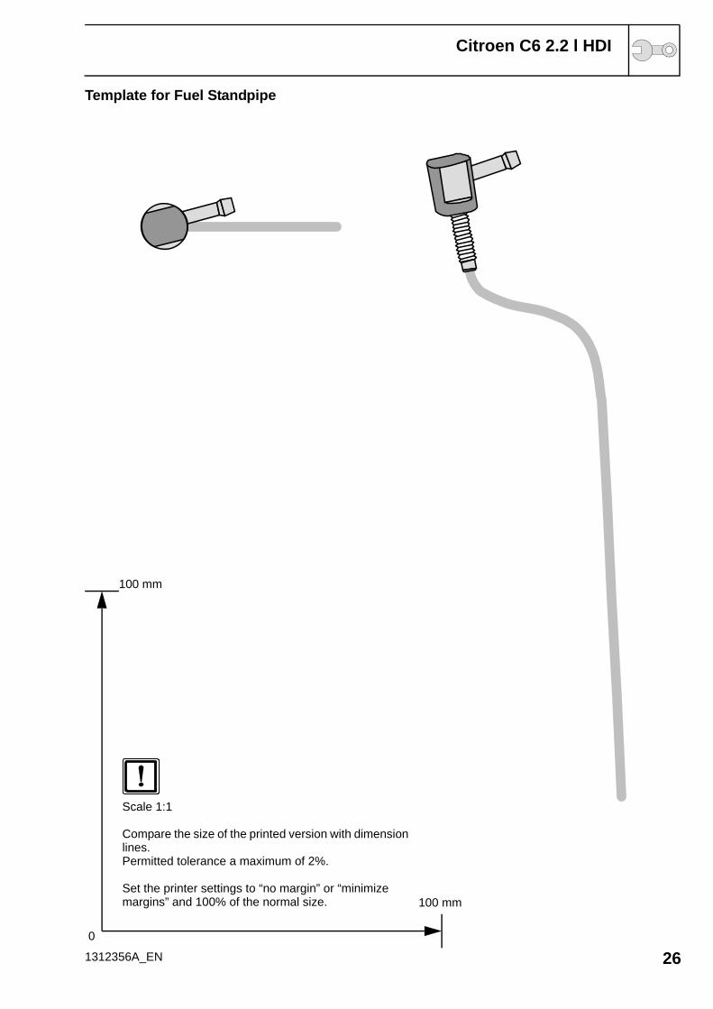
Template for Fuel Standpipe
1312356A_EN 260
100 mm
100 mm
Scale 1:1
Compare the size of the printed version with dimension lines.Permitted tolerance a maximum of 2%.
Set the printer settings to “no margin” or “minimize margins” and 100% of the normal size.