MELDAS C6/C64/C64T PLC INTERFACE MANUAL
342
CNC C6/C64/C64T PLC INTERFACE MANUAL BNP-B2261E(ENG)
-
Upload
khangminh22 -
Category
Documents
-
view
1 -
download
0
Transcript of MELDAS C6/C64/C64T PLC INTERFACE MANUAL

CNCC6/C64/C64T
PLC INTERFACE MANUAL
BNP-B2261E(ENG)

MELDAS is a registered trademark of Mitsubishi Electric Corporation. Other company and product names that appear in this manual are trademarks or registered trademarks of the respective company.
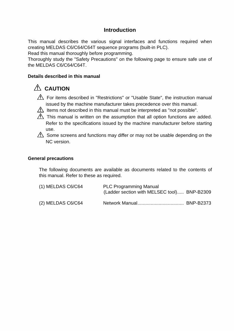
Introduction This manual describes the various signal interfaces and functions required when creating MELDAS C6/C64/C64T sequence programs (built-in PLC). Read this manual thoroughly before programming. Thoroughly study the "Safety Precautions" on the following page to ensure safe use of the MELDAS C6/C64/C64T. Details described in this manual CAUTION
For items described in "Restrictions" or "Usable State", the instruction manual issued by the machine manufacturer takes precedence over this manual.
Items not described in this manual must be interpreted as "not possible".
This manual is written on the assumption that all option functions are added. Refer to the specifications issued by the machine manufacturer before starting use.
Some screens and functions may differ or may not be usable depending on the NC version.
General precautions
The following documents are available as documents related to the contents of this manual. Refer to these as required. (1) MELDAS C6/C64 PLC Programming Manual
(Ladder section with MELSEC tool)..... BNP-B2309
(2) MELDAS C6/C64 Network Manual................................... BNP-B2373

Precautions for Safety Always read the specifications issued by the machine manufacturer, this manual, related manuals and attached documents before installation, operation, programming, maintenance or inspection to ensure correct use. Understand this numerical controller, safety items and cautions before using the unit. This manual ranks the safety precautions into "DANGER", "WARNING" and "CAUTION".
When there is a great risk that the user could be subject to fatalities or serious injuries if handling is mistaken. When the user could be subject to fatalities or serious injuries if handling is mistaken. When the user could be subject to injuries or when physical damage could occur if handling is mistaken.
Note that even items ranked as " CAUTION" may lead to major results depending on the situation. In any case, important information that must always be observed is described.
DANGER
There are no "Danger" items in this manual.
WARNING
1. Items related to prevention of electric shocks Do not operate the switches with wet hands, as this may lead to electric shocks. Do not damage, apply excessive stress, place heavy things on or sandwich the
cables, as this may lead to electric shocks.
CAUTION
1. Items related to product and manual For the items described in the "Restrictions" and "Usable State", the instruction
manual issued by the machine manufacturer takes a precedence over this instruction manual.
Items not described in this manual must be interpreted as "not possible". This instruction manual has been written on the assumption that all options are
provided. Check the specifications issued by the machine manufacturer before starting use. Some screens and functions may differ or may not be usable depending on the
NC system version. 2. Items related to connection When using an inductive load such as relays, always contact a diode in parallel to
the load as a noise measure. When using a capacitive load such as a lamp, always connect a protective
resistor serially to the load to suppress rush currents.
DANGER
WARNING
CAUTION

CAUTION
3. Items related to design
Always turn the spindle phase synchronization complete signal ON before chucking both ends of the workpiece to the basic spindle and synchronous spindle. If the spindle phase synchronization signal is turned ON when both ends of the workpiece are chucked to the basic spindle and synchronous spindle, the chuck or workpiece could be damaged by the torsion that occurs during phase alignment.
If the temperature rise detection function is invalidated with the parameters, the control could be disabled when the temperature is excessive. This could result in machine damage or personal injuries due to runaway axis, and could damage the device. Enable the detection function for normal use.

i
CONTENTS 1. OUTLINE ......................................................................................................... 1-1 2. SYSTEM CONFIGURATION .......................................................................... 2-1 2.1 Relation of RIO Unit and Devices .......................................................... 2-2 2.1.1 DIO Specification Setting Switch ............................................... 2-3 2.1.2 Rotary Switch for Channel No. Setting ...................................... 2-4 2.1.3 Relation of Connector Pins and Devices ................................... 2-5 2.2 Outline of Digital Signal Input Circuit ..................................................... 2-7 2.3 Outline of Digital Signal Output Circuit .................................................. 2-9 2.4 Outline of Analog Signal Output Circuit ................................................. 2-10 2.5 Outline of Analog Signal Input Circuit...................................................... 2-10 2.6 Fixed Signals ......................................................................................... 2-11 2.6.1 Ignoring Fixed Signals ............................................................... 2-11 2.6.2 Changing the Addresses of Fixed Signals ................................. 2-12 2.7 Flow of Signals ...................................................................................... 2-13 2.8 List of Devices Used .............................................................................. 2-14 2.9 File Register General Map ..................................................................... 2-15 3. INPUT/OUTPUT SIGNALS WITH MACHINE ................................................. 3-1 3.1 How to Read Input/Output Signal Table ................................................ 3-1 3.2 Classification of Machine Input/Output Signals ..................................... 3-2 3.3 Allocation of Machine Input/Output Signals ........................................... 3-2 4. TABLE OF INPUT/OUTPUT SIGNALS WITH CONTROLLER ...................... 4-1 4.1 How to Read Input/Output Signal Table ................................................ 4-1 4.2 Classification of Input/Output Signals with Controller ............................ 4-2 5. OTHER DEVICES ........................................................................................... 5-1 5.1 Devices .................................................................................................. 5-1 6. EXPLANATION OF INTERFACE SIGNALS .................................................. 6-1-1 6.1 PLC Input Signals (Bit Type: X***) ......................................................... 6-1-2 6.2 PLC Input Signals (Data Type: R***) ..................................................... 6-2-1 6.3 PLC Output Signals (Bit Type: Y***) ...................................................... 6-3-1 6.4 PLC Output Signals (Data Type: R***) .................................................. 6-4-1 6.5 Explanation of Special Relay/Register Signals (SM**, SD**) ................. 6-5-1 6.6 Signals Related to Communication ......................................................... 6-6-1 7. SPINDLE CONTROL ...................................................................................... 7-1 7.1 Outline of Functions ............................................................................... 7-1 7.1.1 Related Parameters .................................................................. 7-1 7.1.2 Connection Method ................................................................... 7-1 7.1.3 Flow of Spindle (S) Data ............................................................. 7-2

1. OUTLINE
1-1
1. OUTLINE
This manual is prepared to assist you to understand the various control signals necessary for creating the built-in sequence for the MELDAS C6/C64/C64T.
The manual is composed as shown below. Refer to related sections as necessary to gain the maximum benefit from the manual.
(Caution)
Please note that the specifications referred to in the text represents the maximum specifications which include also those under development.
Spindle control
Explanation of interface signals
Device Input : X, ROutput : Y, R Others: SM,SD,B,W
Explanation of devices Blank tables for user
Table for input/output signals with controller
Table for input/ output signals with machine
System configuration
PLC Interface Manual
(cover)

2. SYSTEM CONFIGURATION
2-1
2. SYSTEM CONFIGURATION
DC2 4VINS ERVO1 S ERVO2
ENC HA NDLE
SIO TE RMI NAL
ICC ARD
SKIP
DC2 4VINS ERVO1 S ERVO2
ENC HA NDLE
SIO TE RMI NAL
ICC ARD
SKIP
(Note) Refer to the following document for details on the PLC development with the MELSEC PLC development tool. MELDAS C6/C64 PLC Programming Manual
(Ladder section with MELSEC tool) .................... BNP-B2309
Remote I/O unit DX1**
ROM built inmain unit
C6/C64 Control unit
Max. 8 units
Machine control signals
Sensor
Max. 4 channels(X418 to X41B)
Remote I/O unit DX1**
Machine control signals
Max. 8 units
Max. input: 256 points (X000 to X0FF)
Max. output: 256 points (Y000 to Y0FF)
Manual pulse generator
MELSEC PLC development tool
RS-232C or
RS-422
Built-in DI : 16 points(X400 to X40F)Built-in DO : 1 point (Y400) Expansion DI: 32 points Expansion DO: 32 points Analog output: 1 point
(Note) The expansion DIO unit is an option.
RIO-M
RIO-M/S
Extension DIO card Max. 2 cards
Max. input: 256 points (X100 to X1FF)
Max. output: 256 points (Y100 to Y1FF)
Remote I/O unit DX1**
Personal computer Display/Commu-nication Communication
terminal
Operation panel, etc.
Other C6/C64 control unit
Personal computer
…………
…………
Ethernet

2. SYSTEM CONFIGURATION 2.1 Relation of RIO Unit and Devices
2-2
2.1 Relation of RIO Unit and Devices The remote I/O units (hereafter RIO unit) connected to the RIO-M or RIO-M/S have different
specifications respectively as shown below. Each unit has a rotary switch for setting the unit No., and for establishing a relation with the device No. (X, Y).
DS
FCUA-DX10
Front view
FCUA-DX11 /FCUA-DX12 FCUA-DX13 FCUA-DX14
5
6
7
(Front)
Bottom view
5
6
7
5
6
7
5
6
7
11
3
1
2
3
4
1
2
3
4
8
3
9
1
2
3
4
10
3
1
2
3
4
1 DI-L (machine input signal connector)
2 DS (baud rate changeover switch)
3 CS (station No. changeover switch)
4 DO-L (machine output signal connector)
5 RIO1 (serial connection connector #1)
6 RIO2 (serial connection connector #2)
7 DCIN (24VDC(+) power input connector)
8 DI-R (machine input signal connector)
9 DO-R (machine output signal connector)
10 HANDLE (manual pulse generator signal input connector)
11 AIO (analog signal input/output connector)
CS
For changeover of baud rate.Normally set to left side. Not used
Selection of station No.
Enlarged drawing of DS and CS
1
42 5
67
AD9
B
FE
0
C
8
3
Front view Front view Front view
(Front) (Front) (Front)
Bottom view
Bottom view
Bottom view
(Back) (Back) (Back) (Back)

2. SYSTEM CONFIGURATION 2.1 Relation of RIO Unit and Devices
2-3
No. of remote I/O unit input/output points
Unit model Compatible machine control signal Left Right Total DX10* (FCUA-DX10*)
Digital input signal (DI) (Photocoupler insulation) Digital output signal (DO) (Non-insulated)
32 points 32 points
— 32 points 32 points
DX11* (FCUA-DX11*)
Digital input signal (DI) (Photocoupler insulation) Digital output signal (DO) (Non-insulated)
32 points 32 points
32 points 16 points
64 points 48 points
DX12* (FCUA-DX12*)
Digital input signal (DI) (Photocoupler insulation) Digital output signal (DO) (Non-insulated) Analog output (AO)
32 points 32 points —
32 points 16 points 1 point
64 points 48 points 1 point
DX14* (FCUA-DX14*)
Digital input signal (DI) (Photocoupler insulation) Digital output signal (DO) (Non-insulated) Analog input (AI) Analog output (AO)
32 points 32 points — —
— — 4 points 1 point
32 points 32 points 4 points 1 point
(Note) The * mark in the table is 0 when the output is a sink type, and is 1 when the output is a source type. The input is changeable.
2.1.1 DIO Specification Setting Switch This switch is not used currently, and must always be set to OFF.
OFF
Front view
A
View from A direction
* Use at OFF.
2
DIO specification setting switch

2. SYSTEM CONFIGURATION 2.1 Relation of RIO Unit and Devices
2-4
2.1.2 Rotary Switch for Channel No. Setting Rotary switch for setting No. of channels (3)
Set between 0 and 7.
The device used by the PLC is determined by the setting of the rotary switch for setting the No. of
channels.
Device No. read in Output device No. Rotary switch No. RIO-M RIO-M/S RIO-M RIO-M/S
Analog output (AO)
0 X00~X1F X100~X11F Y00~Y1F (Y0F) Y100~Y11F (Y10F) 1 X20~X3F X120~X13F Y20~Y3F (Y2F) Y120~Y13F (Y12F) 2 X40~X5F X140~X15F Y40~Y5F (Y4F) Y140~Y15F (Y14F) 3 X60~X7F X160~X17F Y60~Y7F (Y6F) Y160~Y17F (Y16F) 4 X80~X9F X180~X19F Y80~Y9F (Y8F) Y180~Y19F (Y18F) 5 XA0~XBF X1A0~X1BF YA0~YBF (YAF) Y1A0~Y1BF (Y1AF) 6 XC0~XDF X1C0~X1DF YC0~YDF
(YCF) Y1C0~Y1DF (Y1CF)
7 XE0~XFF X1E0~X1FF YE0~YFF (YEF) Y1E0~Y1FF (Y1EF)
The rotary switches correspond to the file registers R100 to R103 in order of small numbers.
The values shown in parentheses are the device range when mounted to the right side of the unit. No. of channels occupied by each unit
No. of occupied channels Unit name
1 DX100/DX101
2 DX110/DX111, DX120/DX121, DX140/DX141
Several remote I/O units can be used in combination. Make sure that the total of stations possessed by the serial link connection (MC link B) is 8 stations or less. Set a unique station No. for each unit and make sure that these station numbers are not duplicated. There is one station No. setting rotary switch on the DX10* unit, and two on the DX11*/12*/14* unit. Set as shown below when connected to the communication terminal (CR05).
Rotary switch No. Device No. read in Output device No. 0 R90, R91 R190, R191 1 R92, R93 R192 2 R94, R95 R193, R194 3 R96, R97 R195

2. SYSTEM CONFIGURATION 2.1 Relation of RIO Unit and Devices
2-5
2.1.3 Relation of Connector Pins and Device (1) Input (DI) signal ((1)/(8))
B20 pin
Connector for contact input (DI)((1)/(8))
A20 pin
B01 pin A01 pin
B AX00
X3F
12
3
Signal DC+24V IN
0VFG
+24V0V
Stabilized power supply
FG
Connection for contact common = GND
Connection for contact common = DC+24V
1 2 3
(7)
Set rotary switch to 0 Set rotary switch to 1
(1) (8)2019181716151413121110987654321
X00 X01 X02 X03 X04 X05 X06 X07 X08 X09 X0A X0B X0C X0D X0E X0F
X10X11X12X13X14X15X16X17X18X19X1AX1BX1CX1DX1EX1F
2019181716151413121110987654321
B AX30X31X32X33X34X35X36X37X38X39X3AX3BX3CX3DX3EX3F
X20X21X22X23X24X25X26X27X28X29X2AX2BX2CX2DX2EX2F
COM+24V+24V
0V0V 0V
0V+24V+24V
COM COMCOM
(Note 1) The No. of points (devices) will differ according to the RIO unit type. (Note 2) The devices shown here show an example for when the rotary switch for channel No.
setting on the RIO unit is set to 0 and set to 1. Refer to section "2.1.2 Rotary Switch for Channel No. Setting" for details on the relation of
the rotary switch and device No.

2. SYSTEM CONFIGURATION 2.1 Relation of RIO Unit and Devices
2-6
(2) Output (DO) signal ((4)/(9))
B20 pin A20 pin
Connector for contact input (DO) ((4)/(9))
B01 pin A01 pin
Set rotary switch to 0 Set rotary switch to 1
(4) (9)B A B AY00 Y01 Y02 Y03 Y04 Y05 Y06 Y07 Y08 Y09 Y0A Y0B Y0C Y0D Y0E Y0F +24V+24V
Y10Y11Y12Y13Y14Y15Y16Y17Y18Y19Y1AY1BY1CY1DY1EY1F 0V 0V
X20X21X22X23X24X25X26X27X28X29X2AX2BX2CX2DX2EX2F
(7) 12 3
12
3
Signal DC+24V IN
0VFG
Connection for contact common = GND
Connection for contact common = DC+24V
+24V0VFG
Stabilized power supply
2019181716151413121110987654321
2019181716151413121110987654321
+24V+24V
0V 0V
Y00 L
Y2F L
AO* AO
Analog output (For DX120/1 only)
(Note 1) The No. of points (devices) will differ according to the RIO unit type. (Note 2) The devices shown here show an example for when the rotary switch for channel No.
setting on the RIO unit is set to 0 and set to 1. Refer to section "2.1.2 Rotary Switch for Channel No. Setting" for details on the relation of
the rotary switch and device No. (Note 3) The A4 and B4 pin analog output (AO, AO*) in the output connector (5) is found only on
the RIO unit DX120/DX121.

2. SYSTEM CONFIGURATION 2.2 Outline of Digital Signal Input Circuit
2-7
2.2 Outline of Digital Signal Input Circuit There is a sink type digital signal input circuit and source type digital signal input circuit. Either
method can be selected with each unit's card unit.
Controlcircuit
COM
0V
24VDC(+)
(Machine side) DI-L/DI-R ((1)/(8))
A3,B3
Input circuit
COM
Sink type
2.2kΩ
2.2kΩ
2.2kΩ
2.2kΩ
2.2kΩ
Controlcircuit
2.2kΩ
2.2kΩ
2.2kΩ
2.2kΩ
2.2kΩ
(Machine side)
Source type
A3,B3 0V
24VDC(+)
24VDC(+)
24VDC(+)
24VDC(+)
24VDC(+)
0V
0V
0V
0V
DI-L/DI-R ((1)/(8))

2. SYSTEM CONFIGURATION 2.2 Outline of Digital Signal Input Circuit
2-8
Input conditions
The input signal must be used within the conditions shown below.
Sink type Input voltage when external contact is ON 6V or less Input current when external contact is ON 9mA or more Input voltage when external contact is OFF 20V or more, 25.2V or less Input current when external contact is OFF 2mA or less
Tolerable chattering time 3ms or less (Refer to T1 in drawing below)
Input signal hold time 40ms or more (Refer to T2 in drawing below)
Input circuit operation delay time 3ms ≤ T3 = . . T4 ≤ 16ms
Machine side contact capacity +30V or more, 16mA or more
T1 T1
T2
T3 T4
Source type Input voltage when external contact is ON 18V or more, 25.2V or less Input current when external contact is ON 9mA or more Input voltage when external contact is OFF 4V or less Input current when external contact is OFF 2mA or less
Tolerable chattering time 3ms or less (Refer to T1 in drawing below)
Input signal hold time 40ms or more (Refer to T2 in drawing below)
Input circuit operation delay time 3ms ≤ T3 =. . T4 ≤ 16ms Machine side contact capacity +30V or more, 16mA or more
T1 T1
T2
T3 T4
(Note) The input signal hold time 40ms or more is a reference. The input signal will not be recognized unless the input signal is held for longer than the ladder process cycle time.

2. SYSTEM CONFIGURATION 2.3 Outline of Digital Signal Output Circuit
2-9
2.3 Outline of Digital Signal Output Circuit There is a sink type (DX1*0) digital signal output circuit and source type (DX1*1) digital signal
output circuit. Use this circuit within the range shown below. Output circuit
24VDC(+)
R
24VDC(+) RA
PL
(Machine side) DO-L/DO-R ((4)/(9))
Controlcircuit
Control circuit
Sink type (DX1*0)
(Machine side)
Source type (DX1*0)
RA
PLR
DO-L/DO-R ((4)/(9))
Output conditions
Insulation method Non-insulating
Rated load voltage +24VDC
Max. output current 60mA/point
Output delay time 40µs
<Caution> * When using a conductive load such as a relay, always connect a diode (withstand voltage 100V
or more, 100mA or more) parallel to that load. * When using a capacity load such as a lamp, connect a protective resistance (R=150ohm)
serially to that load to limit the rush current. (Make sure that the current is lower than the tolerable current including the momentary current.)
When using a conductive load such as relays, always contact a diode in parallel to the load as a noise measure.
When using a capacity load such as a lamp, always connect a protective resistor serially to the load to suppress rush currents.
CAUTION

2. SYSTEM CONFIGURATION 2.4 Outline of Analog Signal Output Circuit
2-10
2.4 Outline of Analog Signal Output Circuit The analog signal circuit can be used only with the FCUA-DX120/DX121/DX140/DX141 unit. Output circuit
DAC
R
220Ω RA0
A0*
Output conditions
Output voltage 0V to ±10V (±5%)
Resolution 12 bit (±10V x n/4096) (Note)
Load conditions 10kΩ load resistance (standard)
Output impedance 220Ω (Note) n = (20 ~ 211) 2.5 Outline of Analog Signal Input Circuit
The analog signal input circuit can be used only for the FCUA-DX140/DX141.
Input circuit
ADC150ΩAI
AI*
Input conditions
Max. input rating ±15V
Resolution 10V/2000 (5mV)
Precision Within ±25mV
AD input sampling time 14.2ms (AI0)/42.6ms (AI1 to 3)

2. SYSTEM CONFIGURATION 2.6 Fixed Signals
2-11
2.6 Fixed Signals The connector pin Nos. in the input signals that are fixed are shown below. The pin No. cannot be changed because the signals are fixed in the controller.
Signal name Connector Signal name Connector
Emergency stop X407 Stroke end –1 X408
Reference point return near-point detection 1 X400 Stroke end –2 X409
Reference point return near-point detection 2 X401 Stroke end –3 X40A
Reference point return near-point detection 3 X402 Stroke end –4 X40B
Reference point return near-point detection 4 X403 Stroke end –5 X405
Reference point return near-point detection 5 X404 Stroke end +1 X40C
Sensor signal 1 X418 Stroke end +2 X40D
Sensor signal 2 X419 Stroke end +3 X40E
Sensor signal 3 X41A Stroke end +4 X40F
Sensor signal 4 X41B Stroke end +5 X406
2.6.1 Ignoring Fixed Signals The fixed signals can be used as other signals by ignoring them with file registers. (Refer to the
following table.) Note that the emergency stop signal (X407) can not be ignored with the following registers.
File register
Part system Ignore stroke end signals
Ignore near-point detection signals
$1 R920 R921
$2 R1020 R1021
$3 R1120 R1121
$4 R1220 R1221
$5 R1320 R1321
$6 R1420 R1421
$7 R1520 R1521
F E D C B A 9 8 7 6 5 4 3 2 1 0
File register (R920) Bit
1st axis OT ignored
2nd axis OT ignored
: 14th axis OT ignored
(Note 1) The signal is applicable to (+) and (-) motion at the same time (ignored when "ON").
F E D C B A 9 8 7 6 5 4 3 2 1 0
File register (R921) Bit
1st near-point ignored
2nd near-point ignored:
14th near-point ignored

2. SYSTEM CONFIGURATION 2.6 Fixed Signals
2-12
2.6.2 Changing the Addresses of Fixed Signals The fixed devices can be allocated arbitrarily with the following parameters. The parameters #2073 to #2075 are valid when 1 is set in #1226 aux10 bit 5. When the parameters #2073 to #2075 are valid, do not set the same device number. If the same
device number exists, an emergency stop occurs. However, no device number check is performed for an axis to which a signal (R920~) that ignores the fixed signal is input.
When the arbitrary allocation is valid, the fixed signals (X400 to X40F) can be used as other signals.
# Items Details Setting range (unit)1226 aux10
(bit5) Arbitrary allocation of dog·OT signal valid
Specify whether to enable the arbitrary allocation parameter for the origin dog and H/W OT.
0: Disable arbitrary allocation. (Fixed device) 1: Enable arbitrary allocation. (Device specified
by the parameters #2073 to #2075)
0/1
2073 zrn_dog Origin dog arbitrary allocation device
When it is desired to assign the origin dog signal to a position other than the fixed device, specify the input device in this parameter.
00 to FF (HEX)
2074 H/W_OT+ H/W OT+ arbitrary allocation device
When it is desired to assign the OT (+) signal to a position other than the fixed device, specify the input device in this parameter.
00 to FF (HEX)
2075 H/W_OT- H/W OT- arbitrary allocation device
When it is desired to assign the OT (-) signal to a position other than the fixed device, specify the input device in this parameter.
00 to FF (HEX)

2. SYSTEM CONFIGURATION 2.7 Flow of Signals
2-13
2.7 Flow of Signals
Controller PLC
Signal in controller D.D.B.
Y**
X**
Signal incontroller
Input/output signal withcontroller and machine(X, Y)
Input
Output
Sequence program
High-speed program (per 7.1ms)
Main program
(Scan time with program size) Transfer at head of
main program
Machine/machine operation board
X**
X**
Y**
Y**
Input/output signal with machine (X, Y)
Transfer at head of high-speedprocessing program (per 7.1ms)
Internal relay, latch relay, etc. (M, F, L, • • •)

2. SYSTEM CONFIGURATION 2.8 List of Devices Used
2-14
2.8 List of Devices Used The devices used by the PLC are shown below. Device No. of device X, Y, B, W and H are indicated with hexadecimal, the others with decimal.
Device Device range Units Details X* X0 to XAFF 2816 points 1-bit Input signals to the PLC. Machine input, etc. Y* Y0 to YE7F 3712 points 1-bit Output signals from the PLC. Machine output, etc.M M0 to M8191 8192 points 1-bit For temporary memory L L0 to L255 256 points 1-bit Latch relay (Backup memory) F F0 to F127 128 points 1-bit For temporary memory. Alarm message interface
SB SB0 to SB1FF 512 points 1-bit Special relay for links B B0 to B1FFF 8192 points 1-bit Link relay
SM* SM0 to SM127 128 points 1-bit Special relay V V0 to V255 256 points 1-bit Edge relay
SW SW0 to SW1FF 512 points 16-bit Special register for links SD SD0 to SD127 128 points 16-bit Special register
T0 to T15 16 points 1-bit/16-bit 10ms unit timer T16 to T95 80 points 1-bit/16-bit 100ms unit timer T96 to T103 8 points 1-bit/16-bit 100ms incremented timer T104 to T143 40 points 1-bit/16-bit 10ms unit timer (Fixed timers) T144 to T239 96 points 1-bit/16-bit 100ms unit timer (Fixed timers) T240 to T255 16 points 1-bit/16-bit 100ms incremented timer (Fixed timers) T0000 to T0255 256 points 1-bit T1: Timer coil T1000 to T1255 256 points 1-bit T0: Timer contact T2000 to T2255 256 points 16-bit TS: Timer setting value
T
T3000 to T3255 256 points 16-bit TA: Timer current value C0 to C23 24 points 1-bit/16-bit Counter C24 to C127 104 points 1-bit/16-bit Counter (Fixed counters) C0000 to C0127 128 points 1-bit C1: Counter coil C1000 to C1127 128 points 1-bit C0: Counter contact C2000 to C2127 128 points 16-bit CS: Counter setting value
C
C3000 to C3127 128 points 16-bit CA: Counter current value D D0 to D8191 8192 points 16-bit/32-bit Data register R* R0 to R8191 8192 points 16-bit/32-bit File register. CNC word I/F W W0 to W1FFF 8192 points 16-bit/32-bit Link register Z Z0 to Z13 14 points 16-bit Address index N N0 to N7 Master control's nesting level
P* P0 to P255 P360 to P379 Conditional jump, subroutine call label
K-32768 to K32767 Decimal constant for 16-bit command K K-2147483647 to
K2147483647 Decimal constant for 32-bit command
H0 to HFFFF Hexadecimal constant for 16-bit command H H0 to HFFFFFFFF Hexadecimal constant for 32-bit command
(Note 1) Device marked with * in the device column have designated applications. Do not use
such devices for other purposes. (Note 2) The fixed timer and fixed counter can not be changed with the numerical setting. Note
that those can be changed with the numerical setting when D or R device is specified. (Note 3) D0 to D8191 can be used with the software version D0 and above.

2. SYSTEM CONFIGURATION 2.9 File Register General Map
2-15
2.9 File Register General Map R0 System common NC -> PLC R4000 R100 System common PLC -> NC R4100 R200 Part system control NC -> PLC R4200
User area (non-backup)
R300 Max. 7 part systems R4300 R400 R4400 R500 R4500 PLC constant R600 R4600 Bit select R700 R4700 R800 R4800 R900 Part system control PLC -> NC R4900
M type: Tool registration L type: Tool life management I
R1000 Max. 7 part systems R5000 R1100 R5100 R1200 R5200 R1300 R5300 R1400 R5400 R1500 R5500 R1600 Axis control NC -> PLC R5600
L type: Tool life management II
R1700 Max. 14 axes R5700 R1800 R5800 R1900 R5900 R2000 R6000
R2100 R6100 R2200 R6200 R2300 Axis control PLC -> NC R6300 R2400 Max. 14 axes R6400 M type: Tool life management R2500 R6500 L type: Tool life management I, II R2600 R2700
R6600
(Note) These registers are available in the 2nd part system or above.
R2800 R6700 R6720 R2900 R6800 R3000 Spindle control NC -> PLC R6900 User area (backup) R3100 Max. 7 spindles R7000 R3200 Spindle control PLC -> NC R7100 R3300 Max. 7 spindles R7200 R3400 R7300 R3500 MR-J2-CT NC -> PLC (Max. 7 axes) R7400 R3600 MR-J2-CT PLC -> NC (Max. 7 axes) R7500 R3700 (Do not use.) R7600 R3800 R7700 R3900 R7800
R7900 R8000
R8100
System reserve (Note) The system reserve area is used
for function expansion by Mitsubishi, and must not be used by the user.

3. INPUT/OUTPUT SIGNALS WITH MACHINE 3.1 How to Read Input/Output Signal Table
3-1
3. INPUT/OUTPUT SIGNALS WITH MACHINE 3.1 How to Read Input/Output Signal Table The method of reading the input/output signal table is shown below. Each card mounted on the RIO unit uses 32 points. Thus, even the 16 point output card has 32 points,
and the head of the next card number will be a serial No. on the assumption that there are 32 points.
No.0:First cardTable 3-1-1
X0X1X2X3X4X5X6X7
B20B19B18B17B16B15B14B13
X8X9XAXBXCXDXEXF
B12B11B10B09B08B07B06B05
X10X11X12X13X14X15X16X17
A20A19A18A17A16A15A14A13
X18X19X1AX1BX1CX1DX1EX1F
A12A11A10A09A08A07A06A05
X20 X21 X22X23 X24X25X26X27
B20B19B18B17B16B15B14B13
X28X29X2AX2BX2CX2DX2EX2F
B12B11B10B09B08B07B06B05
X30X31X32X33X34X35X36X37
A20A19A18A17A16A15A14A13
X38X39X3AX3BX3CX3DX3EX3F
A12A11A10A09A08A07A06A05
Card No. determined by remote RIO unit rotary switch.The 0 in No. is the rotary switch No.The card for which the rotary switch setting is 0 will bethe 1st card.
Connector Pin. No.
Remote I/O connection destination of C64 main unit
Input Signal Table from Machine
Device Abbreviation Signal name Connector Device Abbreviation Signal name Connector
RIO-M No.1:Second card Table 3-1-2
Interface Table
Device Abbreviation Signal name Connector Device Abbreviation Signal name Connector
Device Abbreviation Signal name Connector Device Abbreviation Signal name Connector
Device Abbreviation Signal name Connector Device Abbreviation Signal name Connector
RIO-M
(Note 1) are 1 word (16-bit) data. (Note 2) Signals marked with in the column for the 2nd part system indicate there is no
signal corresponding to the 2nd part system, or the signal for the 1st part system side is used commonly.
(Note 3) D0 to D8191 can be used with the software version D0 and above.

3. INPUT/OUTPUT SIGNALS WITH MACHINE 3.2 Classification of Machine Input/Output Signals
3-2
3.2 Classification of Machine Input/Output Signals The signals handled by the PLC are classified as shown below. Refer to the following table when making allocations during design.
Signal type Allocation table
Explanation
RIO-M Table 3-1-1 to
3-1-8 RI
RIO-M/STable 3-2-1 to
3-2-8
EXT -
DI Table 3-3
(1) Allocated to device X. (2) Some connector pin allocations are determined.
1) Stroke end signal (+, -) 2) Reference point return near-point detection signal
(3) The high-speed processing input is set with the parameters. (Read in at the head of the high-speed processing scan.) (4) The device used for EXT differs according to the network
type and specifications. Refer to section "6.6 Network related functions" for details.
Inpu
t
AI (Analog input)
Table 4-2-1 (1) The connector pin allocation is determined. (2) Allocated to the file register (R).
RIO-M Table 3-4-1 to
3-4-8 RO
RIO-M/STable 3-5-1 to
3-5-8
EXT -
DO Table 3-6
(1) Allocated to device Y. (2) The high-speed processing output is set with the parameters. (Output at end of the high-speed processing scan.) (3) The device used for EXT differs according to the network
type and specifications. Refer to section "6.6 Network related functions" for details. O
utpu
t
AO (Analog Output)
Table 4-4-1 (1) The connector pin allocation is determined. (2) Data to be D/A converted and output can be output by
reading it into the file register (R).
Oth
ers
CR05 Table 3-7 (1) This is the operation board remote I/O connection device. (2) Allocated to the file register (R).
3.3 Allocation of Machine Input/Output Signals The signals are allocated to the devices of machine input/output signals X and Y, and the device
Nos. are determined automatically depending on the connection destinations. The connection destinations and allocated device Nos. are as below:
Destination Input device Output device Points Remarks RIO-M X0~XFF Y0~YFF 256 Remote I/O connection RIO-M/S X100~X1FF Y100~Y1FF 256 Remote I/O connection EXT1 X200~X27F Y200~Y27F 128 Expansion slot 1 EXT2 X280~X2FF Y280~Y2FF 128 Expansion slot 2 EXT3 (Note 1) X300~X37F Y300~Y37F 128 Expansion slot 3 (External slot) EXT4 (Note 1) X380~X3FF Y380~Y3FF 128 Expansion slot 4 (Not used) DIO X400~X40F Y400~Y40F 16 Built-in DIO CR05 (Note 2) R90~R97 R190~R195 128/96 Operation board remote I/O connection
(Note 1) Another unit for extension is necessary to use the expansion slot 3 and 4. (Note 2) This is connected to the communication terminal. (Note 3) The unused I/O can be used as input/output device of each type network. Furthermore,
the input/output devices of slot with the expansion cards (Ethernet cards, etc.) which do not need the input/output devices is also unused, and that can be used.

3. INPUT/OUTPUT SIGNALS WITH MACHINE Table of Input Signal (X) from Machine
3-3
Input Signal Table from Machine RIO-M No.0: First card Table 3-1-1 Device Abbreviation Signal name Connector Device Abbreviation Signal name Connector X0 B20 X8 B12 X1 B19 X9 B11 X2 B18 XA B10 X3 B17 XB B09 X4 B16 XC B08 X5 B15 XD B07 X6 B14 XE B06 X7 B13 XF B05 Device Abbreviation Signal name Connector Device Abbreviation Signal name Connector X10 A20 X18 A12 X11 A19 X19 A11 X12 A18 X1A A10 X13 A17 X1B A09 X14 A16 X1C A08 X15 A15 X1D A07 X16 A14 X1E A06 X17 A13 X1F A05 RIO-M No.1: Second card
Table 3-1-2
Device Abbreviation Signal name Connector Device Abbreviation Signal name Connector X20 B20 X28 B12 X21 B19 X29 B11 X22 B18 X2A B10 X23 B17 X2B B09 X24 B16 X2C B08 X25 B15 X2D B07 X26 B14 X2E B06 X27 B13 X2F B05 Device Abbreviation Signal name Connector Device Abbreviation Signal name Connector X30 A20 X38 A12 X31 A19 X39 A11 X32 A18 X3A A10 X33 A17 X3B A09 X34 A16 X3C A08 X35 A15 X3D A07 X36 A14 X3E A06 X37 A13 X3F A05

3. INPUT/OUTPUT SIGNALS WITH MACHINE Table of Input Signal (X) from Machine
3-4
Input Signal Table from Machine RIO-M No.2: Third card
Table 3-1-3
Device Abbreviation Signal name Connector Device Abbreviation Signal name Connector X40 B20 X48 B12 X41 B19 X49 B11 X42 B18 X4A B10 X43 B17 X4B B09 X44 B16 X4C B08 X45 B15 X4D B07 X46 B14 X4E B06 X47 B13 X4F B05 Device Abbreviation Signal name Connector Device Abbreviation Signal name Connector X50 A20 X58 A12 X51 A19 X59 A11 X52 A18 X5A A10 X53 A17 X5B A09 X54 A16 X5C A08 X55 A15 X5D A07 X56 A14 X5E A06 X57 A13 X5F A05 RIO-M No.3: Fourth card
Table 3-1-4
Device Abbreviation Signal name Connector Device Abbreviation Signal name Connector X60 B20 X68 B12 X61 B19 X69 B11 X62 B18 X6A B10 X63 B17 X6B B09 X64 B16 X6C B08 X65 B15 X6D B07 X66 B14 X6E B06 X67 B13 X6F B05 Device Abbreviation Signal name Connector Device Abbreviation Signal name Connector X70 A20 X78 A12 X71 A19 X79 A11 X72 A18 X7A A10 X73 A17 X7B A09 X74 A16 X7C A08 X75 A15 X7D A07 X76 A14 X7E A06 X77 A13 X7F A05

3. INPUT/OUTPUT SIGNALS WITH MACHINE Table of Input Signal (X) from Machine
3-5
Input Signal Table from Machine RIO-M No.4: Fifth card
Table 3-1-5
Device Abbreviation Signal name Connector Device Abbreviation Signal name Connector X80 B20 X88 B12 X81 B19 X89 B11 X82 B18 X8A B10 X83 B17 X8B B09 X84 B16 X8C B08 X85 B15 X8D B07 X86 B14 X8E B06 X87 B13 X8F B05 Device Abbreviation Signal name Connector Device Abbreviation Signal name Connector X90 A20 X98 A12 X91 A19 X99 A11 X92 A18 X9A A10 X93 A17 X9B A09 X94 A16 X9C A08 X95 A15 X9D A07 X96 A14 X9E A06 X97 A13 X9F A05 RIO-M No.5: Sixth card
Table 3-1-6
Device Abbreviation Signal name Connector Device Abbreviation Signal name Connector XA0 B20 XA8 B12 XA1 B19 XA9 B11 XA2 B18 XAA B10 XA3 B17 XAB B09 XA4 B16 XAC B08 XA5 B15 XAD B07 XA6 B14 XAE B06 XA7 B13 XAF B05 Device Abbreviation Signal name Connector Device Abbreviation Signal name Connector XB0 A20 XB8 A12 XB1 A19 XB9 A11 XB2 A18 XBA A10 XB3 A17 XBB A09 XB4 A16 XBC A08 XB5 A15 XBD A07 XB6 A14 XBE A06 XB7 A13 XBF A05

3. INPUT/OUTPUT SIGNALS WITH MACHINE Table of Input Signal (X) from Machine
3-6
Input Signal Table from Machine RIO-M No.6: Seventh card
Table 3-1-7
Device Abbreviation Signal name Connector Device Abbreviation Signal name Connector XC0 B20 XC8 B12 XC1 B19 XC9 B11 XC2 B18 XCA B10 XC3 B17 XCB B09 XC4 B16 XCC B08 XC5 B15 XCD B07 XC6 B14 XCE B06 XC7 B13 XCF B05 Device Abbreviation Signal name Connector Device Abbreviation Signal name Connector XD0 A20 XD8 A12 XD1 A19 XD9 A11 XD2 A18 XDA A10 XD3 A17 XDB A09 XD4 A16 XDC A08 XD5 A15 XDD A07 XD6 A14 XDE A06 XD7 A13 XDF A05 RIO-M No.7: Eighth card
Table 3-1-8
Device Abbreviation Signal name Connector Device Abbreviation Signal name Connector XE0 B20 XE8 B12 XE1 B19 XE9 B11 XE2 B18 XEA B10 XE3 B17 XEB B09 XE4 B16 XEC B08 XE5 B15 XED B07 XE6 B14 XEE B06 XE7 B13 XEF B05 Device Abbreviation Signal name Connector Device Abbreviation Signal name Connector XF0 A20 XF8 A12 XF1 A19 XF9 A11 XF2 A18 XFA A10 XF3 A17 XFB A09 XF4 A16 XFC A08 XF5 A15 XFD A07 XF6 A14 XFE A06 XF7 A13 XFF A05

3. INPUT/OUTPUT SIGNALS WITH MACHINE Table of Input Signal (X) from Machine
3-7
Input Signal Table from Machine RIO-M/S No.0: First card
Table 3-2-1 Device Abbreviation Signal name Connector Device Abbreviation Signal name Connector X100 B20 X108 B12 X101 B19 X109 B11 X102 B18 X10A B10 X103 B17 X10B B09 X104 B16 X10C B08 X105 B15 X10D B07 X106 B14 X10E B06 X107 B13 X10F B05 Device Abbreviation Signal name Connector Device Abbreviation Signal name Connector X110 A20 X118 A12 X111 A19 X119 A11 X112 A18 X11A A10 X113 A17 X11B A09 X114 A16 X11C A08 X115 A15 X11D A07 X116 A14 X11E A06 X117 A13 X11F A05 RIO-M/S No.1: Second card
Table 3-2-2
Device Abbreviation Signal name Connector Device Abbreviation Signal name Connector X120 B20 X128 B12 X121 B19 X129 B11 X122 B18 X12A B10 X123 B17 X12B B09 X124 B16 X12C B08 X125 B15 X12D B07 X126 B14 X12E B06 X127 B13 X12F B05 Device Abbreviation Signal name Connector Device Abbreviation Signal name Connector X130 A20 X138 A12 X131 A19 X139 A11 X132 A18 X13A A10 X133 A17 X13B A09 X134 A16 X13C A08 X135 A15 X13D A07 X136 A14 X13E A06 X137 A13 X13F A05

3. INPUT/OUTPUT SIGNALS WITH MACHINE Table of Input Signal (X) from Machine
3-8
Input Signal Table from Machine RIO-M/S No.2: Third card
Table 3-2-3
Device Abbreviation Signal name Connector Device Abbreviation Signal name Connector X140 B20 X148 B12 X141 B19 X149 B11 X142 B18 X14A B10 X143 B17 X14B B09 X144 B16 X14C B08 X145 B15 X14D B07 X146 B14 X14E B06 X147 B13 X14F B05 Device Abbreviation Signal name Connector Device Abbreviation Signal name Connector X150 A20 X158 A12 X151 A19 X159 A11 X152 A18 X15A A10 X153 A17 X15B A09 X154 A16 X15C A08 X155 A15 X15D A07 X156 A14 X15E A06 X157 A13 X15F A05 RIO-M/S No.3: Fourth card
Table 3-2-4
Device Abbreviation Signal name Connector Device Abbreviation Signal name Connector X160 B20 X168 B12 X161 B19 X169 B11 X162 B18 X16A B10 X163 B17 X16B B09 X164 B16 X16C B08 X165 B15 X16D B07 X166 B14 X16E B06 X167 B13 X16F B05 Device Abbreviation Signal name Connector Device Abbreviation Signal name Connector X170 A20 X178 A12 X171 A19 X179 A11 X172 A18 X17A A10 X173 A17 X17B A09 X174 A16 X17C A08 X175 A15 X17D A07 X176 A14 X17E A06 X177 A13 X17F A05

3. INPUT/OUTPUT SIGNALS WITH MACHINE Table of Input Signal (X) from Machine
3-9
Input Signal Table from Machine RIO-M/S No.4: Fifth card
Table 3-2-5
Device Abbreviation Signal name Connector Device Abbreviation Signal name Connector X180 B20 X188 B12 X181 B19 X189 B11 X182 B18 X18A B10 X183 B17 X18B B09 X184 B16 X18C B08 X185 B15 X18D B07 X186 B14 X18E B06 X187 B13 X18F B05 Device Abbreviation Signal name Connector Device Abbreviation Signal name Connector X190 A20 X198 A12 X191 A19 X199 A11 X192 A18 X19A A10 X193 A17 X19B A09 X194 A16 X19C A08 X195 A15 X19D A07 X196 A14 X19E A06 X197 A13 X19F A05 RIO-M/S No.5: Sixth card
Table 3-2-6
Device Abbreviation Signal name Connector Device Abbreviation Signal name Connector X1A0 B20 X1A8 B12 X1A1 B19 X1A9 B11 X1A2 B18 X1AA B10 X1A3 B17 X1AB B09 X1A4 B16 X1AC B08 X1A5 B15 X1AD B07 X1A6 B14 X1AE B06 X1A7 B13 X1AF B05 Device Abbreviation Signal name Connector Device Abbreviation Signal name Connector X1B0 A20 X1B8 A12 X1B1 A19 X1B9 A11 X1B2 A18 X1BA A10 X1B3 A17 X1BB A09 X1B4 A16 X1BC A08 X1B5 A15 X1BD A07 X1B6 A14 X1BE A06 X1B7 A13 X1BF A05

3. INPUT/OUTPUT SIGNALS WITH MACHINE Table of Input Signal (X) from Machine
3-10
Input Signal Table from Machine RIO-M/S No.6: Seventh card
Table 3-2-7
Device Abbreviation Signal name Connector Device Abbreviation Signal name Connector X1C0 B20 X1C8 B12 X1C1 B19 X1C9 B11 X1C2 B18 X1CA B10 X1C3 B17 X1CB B09 X1C4 B16 X1CC B08 X1C5 B15 X1CD B07 X1C6 B14 X1CE B06 X1C7 B13 X1CF B05 Device Abbreviation Signal name Connector Device Abbreviation Signal name Connector X1D0 A20 X1D8 A12 X1D1 A19 X1D9 A11 X1D2 A18 X1DA A10 X1D3 A17 X1DB A09 X1D4 A16 X1DC A08 X1D5 A15 X1DD A07 X1D6 A14 X1DE A06 X1D7 A13 X1DF A05 RIO-M/S No.7: Eighth card
Table 3-2-8
Device Abbreviation Signal name Connector Device Abbreviation Signal name Connector X1E0 B20 X1E8 B12 X1E1 B19 X1E9 B11 X1E2 B18 X1EA B10 X1E3 B17 X1EB B09 X1E4 B16 X1EC B08 X1E5 B15 X1ED B07 X1E6 B14 X1EE B06 X1E7 B13 X1EF B05 Device Abbreviation Signal name Connector Device Abbreviation Signal name Connector X1F0 A20 X1F8 A12 X1F1 A19 X1F9 A11 X1F2 A18 X1FA A10 X1F3 A17 X1FB A09 X1F4 A16 X1FC A08 X1F5 A15 X1FD A07 X1F6 A14 X1FE A06 X1F7 A13 X1FF A05

3. INPUT/OUTPUT SIGNALS WITH MACHINE Table of Input Signal (X) from Machine
3-11
DIO Built-in DI Table of Input Signal from Machine
The X400 to X40F signal assignments are fixed. Table 3-3 (1) When power failure backup module is not mounted
Device Abbreviation Signal name Device Abbreviation Signal name
X400 DI0 *Built-in DI reference point return near-point detection 1
X408 DI8 *Built-in DI stroke end -1
X401 DI1 *Built-in DI reference point return near-point detection 2
X409 DI9 *Built-in DI stroke end -2
X402 DI2 *Built-in DI reference point return near-point detection 3
X40A DIA *Built-in DI stroke end -3
X403 DI3 *Built-in DI reference point return near-point detection 4
X40B DIB *Built-in DI stroke end -4
X404 DI4 *Built-in DI reference point return near-point detection 5
X40C DIC *Built-in DI stroke end +1
X405 DI5 *Built-in DI stroke end -5 X40D DID *Built-in DI stroke end +2
X406 DI6 *Built-in DI stroke end +5 X40E DIE *Built-in DI stroke end +3
X407 DI7 *Built-in DI emergency stop X40F DIF *Built-in DI stroke end +4
(2) When power failure backup module is mounted
IO mounted on C6/C64 unit (hotline) Device Abbreviation Signal name Device Abbreviation Signal name
X400 DI0 ACFAIL X408 DI8 *Built-in DI stroke end -1
X401 DI1 X409 DI9 *Built-in DI stroke end -2
X402 DI2 Invalid X40A DIA *Built-in DI stroke end -3
X403 DI3 X40B DIB *Built-in DI stroke end -4
X404 DI4 X40C DIC *Built-in DI stroke end +1
X405 DI5 *Built-in DI stroke end -5 X40D DID *Built-in DI stroke end +2
X406 DI6 *Built-in DI stroke end +5 X40E DIE *Built-in DI stroke end +3
X407 DI7 *Built-in DI emergency stop X40F DIF *Built-in DI stroke end +4
(3) Relation with dog and OT arbitrary assignment
Condition
Power failure backup module
#1226 qaux10/Bit5(dog, OT arbitrary
assignment)
X400 meaning Handling of dog and OT signal
ON Dog and OT arbitrary assignment valid Mounted
OFF ACFAIL Dog signal invalid for all axes
OT fixed assignment valid
ON Arbitrary Dog and OT arbitrary assignment valid Not mounted
OFF *DOG1 Dog and OT fixed assignment

3. INPUT/OUTPUT SIGNALS WITH MACHINE Table of Output Signal (Y) to Machine
3-12
Output Signal Table to Machine RIO-M No.0: First card
Table 3-4-1 Device Abbreviation Signal name Connector Device Abbreviation Signal name Connector Y0 B20 Y8 B12 Y1 B19 Y9 B11 Y2 B18 YA B10 Y3 B17 YB B09 Y4 B16 YC B08 Y5 B15 YD B07 Y6 B14 YE B06 Y7 B13 YF B05 Device Abbreviation Signal name Connector Device Abbreviation Signal name Connector Y10 A20 Y18 A12 Y11 A19 Y19 A11 Y12 A18 Y1A A10 Y13 A17 Y1B A09 Y14 A16 Y1C A08 Y15 A15 Y1D A07 Y16 A14 Y1E A06 Y17 A13 Y1F A05 RIO-M No.1: Second card
Table 3-4-2
Device Abbreviation Signal name Connector Device Abbreviation Signal name Connector Y20 B20 Y28 B12 Y21 B19 Y29 B11 Y22 B18 Y2A B10 Y23 B17 Y2B B09 Y24 B16 Y2C B08 Y25 B15 Y2D B07 Y26 B14 Y2E B06 Y27 B13 Y2F B05 Device Abbreviation Signal name Connector Device Abbreviation Signal name Connector Y30 A20 Y38 A12 Y31 A19 Y39 A11 Y32 A18 Y3A A10 Y33 A17 Y3B A09 Y34 A16 Y3C A08 Y35 A15 Y3D A07 Y36 A14 Y3E A06 Y37 A13 Y3F A05

3. INPUT/OUTPUT SIGNALS WITH MACHINE Table of Output Signal (Y) to Machine
3-13
Output Signal Table to Machine RIO-M No.2: Third card
Table 3-4-3
Device Abbreviation Signal name Connector Device Abbreviation Signal name Connector Y40 B20 Y48 B12 Y41 B19 Y49 B11 Y42 B18 Y4A B10 Y43 B17 Y4B B09 Y44 B16 Y4C B08 Y45 B15 Y4D B07 Y46 B14 Y4E B06 Y47 B13 Y4F B05 Device Abbreviation Signal name Connector Device Abbreviation Signal name Connector Y50 A20 Y58 A12 Y51 A19 Y59 A11 Y52 A18 Y5A A10 Y53 A17 Y5B A09 Y54 A16 Y5C A08 Y55 A15 Y5D A07 Y56 A14 Y5E A06 Y57 A13 Y5F A05 RIO-M No.3: Fourth card
Table 3-4-4
Device Abbreviation Signal name Connector Device Abbreviation Signal name Connector Y60 B20 Y68 B12 Y61 B19 Y69 B11 Y62 B18 Y6A B10 Y63 B17 Y6B B09 Y64 B16 Y6C B08 Y65 B15 Y6D B07 Y66 B14 Y6E B06 Y67 B13 Y6F B05 Device Abbreviation Signal name Connector Device Abbreviation Signal name Connector Y70 A20 Y78 A12 Y71 A19 Y79 A11 Y72 A18 Y7A A10 Y73 A17 Y7B A09 Y74 A16 Y7C A08 Y75 A15 Y7D A07 Y76 A14 Y7E A06 Y77 A13 Y7F A05

3. INPUT/OUTPUT SIGNALS WITH MACHINE Table of Output Signal (Y) to Machine
3-14
Output Signal Table to Machine RIO-M No.4: Fifth card
Table 3-4-5
Device Abbreviation Signal name Connector Device Abbreviation Signal name Connector Y80 B20 Y88 B12 Y81 B19 Y89 B11 Y82 B18 Y8A B10 Y83 B17 Y8B B09 Y84 B16 Y8C B08 Y85 B15 Y8D B07 Y86 B14 Y8E B06 Y87 B13 Y8F B05 Device Abbreviation Signal name Connector Device Abbreviation Signal name Connector Y90 A20 Y98 A12 Y91 A19 Y99 A11 Y92 A18 Y9A A10 Y93 A17 Y9B A09 Y94 A16 Y9C A08 Y95 A15 Y9D A07 Y96 A14 Y9E A06 Y97 A13 Y9F A05 RIO-M No.5: Sixth card
Table 3-4-6
Device Abbreviation Signal name Connector Device Abbreviation Signal name Connector YA0 B20 YA8 B12 YA1 B19 YA9 B11 YA2 B18 YAA B10 YA3 B17 YAB B09 YA4 B16 YAC B08 YA5 B15 YAD B07 YA6 B14 YAE B06 YA7 B13 YAF B05 Device Abbreviation Signal name Connector Device Abbreviation Signal name Connector YB0 A20 YB8 A12 YB1 A19 YB9 A11 YB2 A18 YBA A10 YB3 A17 YBB A09 YB4 A16 YBC A08 YB5 A15 YBD A07 YB6 A14 YBE A06 YB7 A13 YBF A05

3. INPUT/OUTPUT SIGNALS WITH MACHINE Table of Output Signal (Y) to Machine
3-15
Output Signal Table to Machine RIO-M No.6: Seventh card
Table 3-4-7
Device Abbreviation Signal name Connector Device Abbreviation Signal name Connector YC0 B20 YC8 B12 YC1 B19 YC9 B11 YC2 B18 YCA B10 YC3 B17 YCB B09 YC4 B16 YCC B08 YC5 B15 YCD B07 YC6 B14 YCE B06 YC7 B13 YCF B05 Device Abbreviation Signal name Connector Device Abbreviation Signal name Connector YD0 A20 YD8 A12 YD1 A19 YD9 A11 YD2 A18 YDA A10 YD3 A17 YDB A09 YD4 A16 YDC A08 YD5 A15 YDD A07 YD6 A14 YDE A06 YD7 A13 YDF A05 RIO-M No.7: Eighth card
Table 3-4-8
Device Abbreviation Signal name Connector Device Abbreviation Signal name Connector YE0 B20 YE8 B12 YE1 B19 YE9 B11 YE2 B18 YEA B10 YE3 B17 YEB B09 YE4 B16 YEC B08 YE5 B15 YED B07 YE6 B14 YEE B06 YE7 B13 YEF B05 Device Abbreviation Signal name Connector Device Abbreviation Signal name Connector YF0 A20 YF8 A12 YF1 A19 YF9 A11 YF2 A18 YFA A10 YF3 A17 YFB A09 YF4 A16 YFC A08 YF5 A15 YFD A07 YF6 A14 YFE A06 YF7 A13 YFF A05

3. INPUT/OUTPUT SIGNALS WITH MACHINE Table of Output Signal (Y) to Machine
3-16
Output Signal Table to Machine RIO-M/S No.0: First card
Table 3-5-1 Device Abbreviation Signal name Connector Device Abbreviation Signal name Connector Y100 B20 Y108 B12 Y101 B19 Y109 B11 Y102 B18 Y10A B10 Y103 B17 Y10B B09 Y104 B16 Y10C B08 Y105 B15 Y10D B07 Y106 B14 Y10E B06 Y107 B13 Y10F B05 Device Abbreviation Signal name Connector Device Abbreviation Signal name Connector Y110 A20 Y118 A12 Y111 A19 Y119 A11 Y112 A18 Y11A A10 Y113 A17 Y11B A09 Y114 A16 Y11C A08 Y115 A15 Y11D A07 Y116 A14 Y11E A06 Y117 A13 Y11F A05 RIO-M/S No.1: Second card
Table 3-5-2
Device Abbreviation Signal name Connector Device Abbreviation Signal name Connector Y120 B20 Y128 B12 Y121 B19 Y129 B11 Y122 B18 Y12A B10 Y123 B17 Y12B B09 Y124 B16 Y12C B08 Y125 B15 Y12D B07 Y126 B14 Y12E B06 Y127 B13 Y12F B05 Device Abbreviation Signal name Connector Device Abbreviation Signal name Connector Y130 A20 Y138 A12 Y131 A19 Y139 A11 Y132 A18 Y13A A10 Y133 A17 Y13B A09 Y134 A16 Y13C A08 Y135 A15 Y13D A07 Y136 A14 Y13E A06 Y137 A13 Y13F A05

3. INPUT/OUTPUT SIGNALS WITH MACHINE Table of Output Signal (Y) to Machine
3-17
Output Signal Table to Machine RIO-M/S No.2: Third card
Table 3-5-3
Device Abbreviation Signal name Connector Device Abbreviation Signal name Connector Y140 B20 Y148 B12 Y141 B19 Y149 B11 Y142 B18 Y14A B10 Y143 B17 Y14B B09 Y144 B16 Y14C B08 Y145 B15 Y14D B07 Y146 B14 Y14E B06 Y147 B13 Y14F B05 Device Abbreviation Signal name Connector Device Abbreviation Signal name Connector Y150 A20 Y158 A12 Y151 A19 Y159 A11 Y152 A18 Y15A A10 Y153 A17 Y15B A09 Y154 A16 Y15C A08 Y155 A15 Y15D A07 Y156 A14 Y15E A06 Y157 A13 Y15F A05 RIO-M/S No.3: Fourth card
Table 3-5-4
Device Abbreviation Signal name Connector Device Abbreviation Signal name Connector Y160 B20 Y168 B12 Y161 B19 Y169 B11 Y162 B18 Y16A B10 Y163 B17 Y16B B09 Y164 B16 Y16C B08 Y165 B15 Y16D B07 Y166 B14 Y16E B06 Y167 B13 Y16F B05 Device Abbreviation Signal name Connector Device Abbreviation Signal name Connector Y170 A20 Y178 A12 Y171 A19 Y179 A11 Y172 A18 Y17A A10 Y173 A17 Y17B A09 Y174 A16 Y17C A08 Y175 A15 Y17D A07 Y176 A14 Y17E A06 Y177 A13 Y17F A05

3. INPUT/OUTPUT SIGNALS WITH MACHINE Table of Output Signal (Y) to Machine
3-18
Output Signal Table to Machine RIO-M/S No.4: Fifth card
Table 3-5-5
Device Abbreviation Signal name Connector Device Abbreviation Signal name Connector Y180 B20 Y188 B12 Y181 B19 Y189 B11 Y182 B18 Y18A B10 Y183 B17 Y18B B09 Y184 B16 Y18C B08 Y185 B15 Y18D B07 Y186 B14 Y18E B06 Y187 B13 Y18F B05 Device Abbreviation Signal name Connector Device Abbreviation Signal name Connector Y190 A20 Y198 A12 Y191 A19 Y199 A11 Y192 A18 Y19A A10 Y193 A17 Y19B A09 Y194 A16 Y19C A08 Y195 A15 Y19D A07 Y196 A14 Y19E A06 Y197 A13 Y19F A05 RIO-M/S No.5: Sixth card
Table 3-5-6
Device Abbreviation Signal name Connector Device Abbreviation Signal name Connector Y1A0 B20 Y1A8 B12 Y1A1 B19 Y1A9 B11 Y1A2 B18 Y1AA B10 Y1A3 B17 Y1AB B09 Y1A4 B16 Y1AC B08 Y1A5 B15 Y1AD B07 Y1A6 B14 Y1AE B06 Y1A7 B13 Y1AF B05 Device Abbreviation Signal name Connector Device Abbreviation Signal name Connector Y1B0 A20 Y1B8 A12 Y1B1 A19 Y1B9 A11 Y1B2 A18 Y1BA A10 Y1B3 A17 Y1BB A09 Y1B4 A16 Y1BC A08 Y1B5 A15 Y1BD A07 Y1B6 A14 Y1BE A06 Y1B7 A13 Y1BF A05

3. INPUT/OUTPUT SIGNALS WITH MACHINE Table of Output Signal (Y) to Machine
3-19
Output Signal Table to Machine RIO-M/S No.6: Seventh card
Table 3-5-7
Device Abbreviation Signal name Connector Device Abbreviation Signal name Connector Y1C0 B20 Y1C8 B12 Y1C1 B19 Y1C9 B11 Y1C2 B18 Y1CA B10 Y1C3 B17 Y1CB B09 Y1C4 B16 Y1CC B08 Y1C5 B15 Y1CD B07 Y1C6 B14 Y1CE B06 Y1C7 B13 Y1CF B05 Device Abbreviation Signal name Connector Device Abbreviation Signal name Connector Y1D0 A20 Y1D8 A12 Y1D1 A19 Y1D9 A11 Y1D2 A18 Y1DA A10 Y1D3 A17 Y1DB A09 Y1D4 A16 Y1DC A08 Y1D5 A15 Y1DD A07 Y1D6 A14 Y1DE A06 Y1D7 A13 Y1DF A05 RIO-M/S No.7:Eighth card
Table 3-5-8
Device Abbreviation Signal name Connector Device Abbreviation Signal name Connector Y1E0 B20 Y1E8 B12 Y1E1 B19 Y1E9 B11 Y1E2 B18 Y1EA B10 Y1E3 B17 Y1EB B09 Y1E4 B16 Y1EC B08 Y1E5 B15 Y1ED B07 Y1E6 B14 Y1EE B06 Y1E7 B13 Y1EF B05 Device Abbreviation Signal name Connector Device Abbreviation Signal name Connector Y1F0 A20 Y1F8 A12 Y1F1 A19 Y1F9 A11 Y1F2 A18 Y1FA A10 Y1F3 A17 Y1FB A09 Y1F4 A16 Y1FC A08 Y1F5 A15 Y1FD A07 Y1F6 A14 Y1FE A06 Y1F7 A13 Y1FF A05

3. INPUT/OUTPUT SIGNALS WITH MACHINE Table of Output Signal (Y) to Machine
3-20
Table of Output Signal to Machine DIO Built-in DO
The Y400 to Y40F signal assignments are fixed. Table 3-6
Device Abbreviation Signal name Device Abbreviation Signal name Y400 SA Servo ready complete Y408 Not used Y401 Not used Y409 Not used Y402 Not used Y40A Not used Y403 Not used Y40B Not used Y404 Not used Y40C Not used Y405 Not used Y40D Not used Y406 Not used Y40E Not used Y407 Not used Y40F Not used

3. INPUT/OUTPUT SIGNALS WITH MACHINE Operation board remote I/O input/output signal table
3-21
CR05 Communication terminal Operation board remote I/O
input/output signal table Table 3-7
Device Abbreviation Signal name Device Abbreviation Signal name R90 R190 R91 R191
R92
Expansion operation board input #1 (R90 Bit8: board reset signal) R192
Expansion operation board output #1
R93 R193 R94 R194 R95 R195
Expansion operation board output #2
R96 R97
Expansion operation board input #2

4. TABLE OF INPUT/OUTPUT SIGNALS WITH CONTROLLER 4.1 How to Read Input/Output Signal Table
4-1
4. TABLE OF INPUT/OUTPUT SIGNALS WITH CONTROLLER 4.1 How to Read Input/Output Signal Table How to read input/output signal table is shown below.
R 2 0R 2 1R 2 2R 2 3R 2 4R 2 5R 2 6R 2 7R 2 8R 2 9
Interface table Input R
Y440Y441Y442Y443Y444Y445Y446Y447
Y471Y472Y473Y474Y475Y476Y477
Y4A1Y4A2Y4A3Y4A4Y4A5Y4A6Y4A7
Y4D1Y4D2Y4D3Y4D4Y4D5Y4D6Y4D7
Y501Y502Y503Y504Y505Y506Y507
Y531Y532Y533Y534Y535Y536Y537
Y561Y562Y563Y564Y565Y566Y567
Y591Y592Y593Y594Y595Y596Y597
Y5C1Y5C2Y5C3Y5C4Y5C5Y5C6Y5C7
Y5F1Y5F2Y5F3Y5F4Y5F5Y5F6Y5F7
Y621Y622Y623Y624Y625Y626Y627
Y651Y652Y653Y654Y655Y656Y657
Y681Y682Y683Y684Y685Y686Y687
Y6B1Y6B2Y6B3Y6B4Y6B5Y6B6Y6B7
Y470 Y4A0 Y4D0Y500 Y530 Y560 Y590 Y5C0Y5F0 Y620 Y650 Y680 Y6B0
Head device of each card
R 4 0R 4 1R 4 2R 4 3R 4 4R 4 5R 4 6R 4 7R 4 8R 4 9
R 3 0R 3 1R 3 2R 3 3R 3 4R 3 5R 3 6R 3 7R 3 8R 3 9
R 5 0R 5 1R 5 2R 5 3R 5 4R 5 5R 5 6R 5 7R 5 8R 5 9
B
*
*****
Controller -> PLC (system)
Device Abbrev. Signal details Device Abbrev. Signal details
Device Abbrev. Signal details Device Abbrev. Signal details
PLC main scan timeEmergency stop causeDIO card information
User macro input #1032(PLC -> Controller)User macro input #1033(PLC -> Controller)User macro input #1034(PLC -> Controller)
User macro input #1035(PLC -> Controller)CNC software version code
PLC switch (#1~16)PLC switch (#17~32)
Battery drop causeTemperature warning causeRemote I/O communication stop channel
(CT100 connection status)(Chara-gene-error)
Clock data Month/YearHour/DateSecond/Minute
PLC High-speed process time
Interface table Output Y
PLC -> Controller (Axis state signal)2ndaxis
1staxis
3rdaxis
4thaxis
5thaxis
6thaxis
7thaxis
8thaxis
9thaxis
10thaxis
11thaxis
12thaxis
13thaxis
14thaxis Signal details
Control axis removalServo OFFMirror imageExternal deceleration +External deceleration -Auto interlock +Auto interlock -Auto interlock +
Table 4-3-2
(Note 1) is 1 word (16-bit) data. (Note 2) Signals marked with * in the abbreviation column or B column are handled as B contacts.

4. TABLE OF INPUT/OUTPUT SIGNALS WITH CONTROLLER 4.2 Classification of Input/Output Signals with Controller
4-2
4.2 Classification of Input/Output Signals with Controller There are 1-bit unit, and 16-bit or 32-bit unit controller input/output signals, which are classified as
shown below. Refer to the following allocation tables for the signal allocations.
Signal type Allocation table Explanation
DI Table 4-1-
(1) Allocated to device X410 and following. (2) Data calculated in bit units are allocated as a
principle.
Inpu
t
Data Table 4-2-
(1) Allocated to device R. (2) Data handled in 16-bit or 32-bit units is allocated
as a principle.
DO Table 4-3-
(1) Allocated to device Y410 and following. (2) Data calculated in bit units are allocated as a
principle.
Out
put
Data Table 4-4-
(1) Allocated to device R. (2) Data handled in 16-bit or 32-bit units is allocated
as a principle.
Special relay Special register
Table 4-5-
(1) Allocated to device SM and SD. (2) The sequence command calculation state, results
and the signals with special operations are allocated.
Oth
ers
Slot information Table 4-6-
(1) This device is used for the expansion slot. The meaning and operation of the device differ
according to the application. Refer to section"6.6 Network related functions" for
details on the assignments.

4. TABLE OF INPUT/OUTPUT SIGNALS WITH CONTROLLER Interface Table Input X
4-3
Controller->PLC (Common to system) Table 4-1-1Device Abbrev. Signal name Device Abbrev. Signal name X410 X418 SKIP0 Input signal state X411 X419 SKIP1 Input signal state X412 X41A SKIP2 Input signal state X413 X41B SKIP3 Input signal state X414 X41CX415 X41DX416 X41E X417 X41F
Device Abbrev. Signal name Device Abbrev. Signal name X420 MA Controller ready complete X428 X421 SA Servo ready complete X429 DROPNS Door open enable X422 X42A SPSYN1 In spindle synchronous control X423 X42B FSPRV Spindle rotation speed
synchronization complete X424 X42C FSPPH Spindle phase synchronization
complete X425 X42D SPCMP Chuck close confirmation X426 X42E BATWR Battery warning X427 X42F BATAL Battery alarm
Device Abbrev. Signal name Device Abbrev. Signal name X430 AL1 NC alarm 1 X438 WNG In door interlock X431 AL2 NC alarm 2 (Servo alarm) X439 X432 X43A X433 X43B X434 X43C X435 X43D X436 X43E X437 BRST Board reset X43F

4. TABLE OF INPUT/OUTPUT SIGNALS WITH CONTROLLER Interface Table Input X
4-4
Controller->PLC (Axis state signal) Table 4-1-2
1st axis
2nd axis
3rd axis
4th axis
5th axis
6th axis
7th axis
8th axis
9th axis
10th axis
11th axis
12th axis
13th axis
14th axis Signal details
X440 X460 X480 X4A0 X4C0 X4E0 X500 X520 X540 X560 X580 X5A0 X5C0 X5E0 Servo ready X441 X461 X481 X4A1 X4C1 X4E1 X501 X521 X541 X561 X581 X5A1 X5C1 X5E1 Axis select output X442 X462 X482 X4A2 X4C2 X4E2 X502 X522 X542 X562 X582 X5A2 X5C2 X5E2 Plus motion+ X443 X463 X483 X4A3 X4C3 X4E3 X503 X523 X543 X563 X583 X5A3 X5C3 X5E3 Minus motion - X444 X464 X484 X4A4 X4C4 X4E4 X504 X524 X544 X564 X584 X5A4 X5C4 X5E4 1st reference point reached X445 X465 X485 X4A5 X4C5 X4E5 X505 X525 X545 X565 X585 X5A5 X5C5 X5E5 2nd reference point reached X446 X466 X486 X4A6 X4C6 X4E6 X506 X526 X546 X566 X586 X5A6 X5C6 X5E6 3rd reference point reached X447 X467 X487 X4A7 X4C7 X4E7 X507 X527 X547 X567 X587 X5A7 X5C7 X5E7 4th reference point reached X448 X468 X488 X4A8 X4C8 X4E8 X508 X528 X548 X568 X588 X5A8 X5C8 X5E8 Near 1st reference point X449 X469 X489 X4A9 X4C9 X4E9 X509 X529 X549 X569 X589 X5A9 X5C9 X5E9 Up-to-speed X44A X46A X48A X4AA X4CA X4EA X50A X52A X54A X56A X58A X5AA X5CA X5EA Zero point initialization completedX44B X46B X48B X4AB X4CB X4EB X50B X52B X54B X56B X58B X5AB X5CB X5EB Zero point initialization error completed
X44C X46C X48C X4AC X4CC X4EC X50C X52C X54C X56C X58C X5AC X5CC X5EC In zero point initialization X44D X46D X48D X4AD X4CD X4ED X50D X52D X54D X56D X58D X5AD X5CD X5ED Zero point initialization incompleteX44E X46E X48E X4AE X4CE X4EE X50E X52E X54E X56E X58E X5AE X5CE X5EE In current limit X44F X46F X48F X4AF X4CF X4EF X50F X52F X54F X56F X58F X5AF X5CF X5EF Current limit reached
1st axis
2nd axis
3rd axis
4th axis
5th axis
6th axis
7th axis
8th axis
9th axis
10th axis
11th axis
12th axis
13th axis
14th axis Signal details
X450 X470 X490 X4B0 X4D0 X4F0 X510 X530 X550 X570 X590 X5B0 X5D0 X5F0 Unclamp command X451 X471 X491 X4B1 X4D1 X4F1 X511 X531 X551 X571 X591 X5B1 X5D1 X5F1 In-position X452 X472 X492 X4B2 X4D2 X4F2 X512 X532 X552 X572 X592 X5B2 X5D2 X5F2 X453 X473 X493 X4B3 X4D3 X4F3 X513 X533 X553 X573 X593 X5B3 X5D3 X5F3 X454 X474 X494 X4B4 X4D4 X4F4 X514 X534 X554 X574 X594 X5B4 X5D4 X5F4 X455 X475 X495 X4B5 X4D5 X4F5 X515 X535 X555 X575 X595 X5B5 X5D5 X5F5 X456 X476 X496 X4B6 X4D6 X4F6 X516 X536 X556 X576 X596 X5B6 X5D6 X5F6 X457 X477 X497 X4B7 X4D7 X4F7 X517 X537 X557 X577 X597 X5B7 X5D7 X5F7 X458 X478 X498 X4B8 X4D8 X4F8 X518 X538 X558 X578 X598 X5B8 X5D8 X5F8 X459 X479 X499 X4B9 X4D9 X4F9 X519 X539 X559 X579 X599 X5B9 X5D9 X5F9 X45A X47A X49A X4BA X4DA X4FA X51A X53A X55A X57A X59A X5BA X5DA X5FA X45B X47B X49B X4BB X4DB X4FB X51B X53B X55B X57B X59B X5BB X5DB X5FB X45C X47C X49C X4BC X4DC X4FC X51C X53C X55C X57C X59C X5BC X5DC X5FC X45D X47D X49D X4BD X4DD X4FD X51D X53D X55D X57D X59D X5BD X5DD X5FD X45E X47E X49E X4BE X4DE X4FE X51E X53E X55E X57E X59E X5BE X5DE X5FE X45F X47F X49F X4BF X4DF X4FF X51F X53F X55F X57F X59F X5BF X5DF X5FF

4. TABLE OF INPUT/OUTPUT SIGNALS WITH CONTROLLER Interface Table Input X
4-5
Controller->PLC (Part system state signal) Table 4-1-3
1st system
2nd system
3rd system
4th system
5th system
6th system
7th system Abbrev. Signal details
X600 X680 X700 X780 X800 X880 X900 JO In jog mode X601 X681 X701 X781 X801 X881 X901 HO In handle mode X602 X682 X702 X782 X802 X882 X902 SO In incremental mode X603 X683 X703 X783 X803 X883 X903 PTPO In manual random feed mode X604 X684 X704 X784 X804 X884 X904 ZRNO In reference point return mode X605 X685 X705 X785 X805 X885 X905 ASTO In automatic initialization mode X606 X686 X706 X786 X806 X886 X906 X607 X687 X707 X787 X807 X887 X907 X608 X688 X708 X788 X808 X888 X908 MEMO In memory mode X609 X689 X709 X789 X809 X889 X909 X60A X68A X70A X78A X80A X88A X90A X60B X68B X70B X78B X80B X88B X90B DO In MDI mode X60C X68C X70C X78C X80C X88C X90C X60D X68D X70D X78D X80D X88D X90D X60E X68E X70E X78E X80E X88E X90E X60F X68F X70F X78F X80F X88F X90F
1st
system 2nd
system 3rd
system4th
system 5th
system6th
system7th
system Abbrev. Signal details X610 X690 X710 X790 X810 X890 X910 X611 X691 X711 X791 X811 X891 X911 X612 X692 X712 X792 X812 X892 X912 OP In auto operation "run" X613 X693 X713 X793 X813 X893 X913 STL In auto operation "start" X614 X694 X714 X794 X814 X894 X914 SPL In auto operation "pause" X615 X695 X715 X795 X815 X895 X915 RST In "reset" X616 X696 X716 X796 X816 X896 X916 CXN In manual random feed X617 X697 X717 X797 X817 X897 X917 RWD In rewind X618 X698 X718 X798 X818 X898 X918 DEN Motion command complete X619 X699 X719 X799 X819 X899 X919 TINP All-axis in-position X61A X69A X71A X79A X81A X89A X91A TSMZ All-axis smoothing zero X61B X69B X71B X79B X81B X89B X91B X61C X69C X71C X79C X81C X89C X91C CXFIN Manual random feed complete X61D X69D X71D X79D X81D X89D X91D X61E X69E X71E X79E X81E X89E X91E X61F X69F X71F X79F X81F X89F X91F
1st
system 2nd
system 3rd
system4th
system 5th
system6th
system7th
system Abbrev. Signal details X620 X6A0 X720 X7A0 X820 X8A0 X920 RPN In rapid traverse X621 X6A1 X721 X7A1 X821 X8A1 X921 CUT In cutting feed X622 X6A2 X722 X7A2 X822 X8A2 X922 TAP In tapping X623 X6A3 X723 X7A3 X823 X8A3 X923 THRD In thread cutting X624 X6A4 X724 X7A4 X824 X8A4 X924 SYN In synchronous feed X625 X6A5 X725 X7A5 X825 X8A5 X925 CSS In constant circumferential speed X626 X6A6 X726 X7A6 X826 X8A6 X926 SKIP In skip X627 X6A7 X727 X7A7 X827 X8A7 X927 ZRNN In reference point return X628 X6A8 X728 X7A8 X828 X8A8 X928 INCH In inch unit select X629 X6A9 X729 X7A9 X829 X8A9 X929 X62A X6AA X72A X7AA X82A X8AA X92A F1DN F1-digit commanded X62B X6AB X72B X7AB X82B X8AB X92B TLFO In tool life management X62C X6AC X72C X7AC X82C X8AC X92C X62D X6AD X72D X7AD X82D X8AD X92D X62E X6AE X72E X7AE X82E X8AE X92E TLOV Tool life over X62F X6AF X72F X7AF X82F X8AF X92F

4. TABLE OF INPUT/OUTPUT SIGNALS WITH CONTROLLER Interface Table Input X
4-6
Controller->PLC (Part system state signal) Table 4-1-4
1st system
2nd system
3rd system
4th system
5th system
6th system
7th system Abbrev. Signal details
X630 X6B0 X730 X7B0 X830 X8B0 X930 X631 X6B1 X731 X7B1 X831 X8B1 X931 X632 X6B2 X732 X7B2 X832 X8B2 X932 AL3 Alarm 3 (Program error) X633 X6B3 X733 X7B3 X833 X8B3 X933 AL4 Alarm 4 (Operation error) X634 X6B4 X734 X7B4 X834 X8B4 X934 X635 X6B5 X735 X7B5 X835 X8B5 X935 SSE Search & start (error) X636 X6B6 X736 X7B6 X836 X8B6 X936 SSG Search & start (search) X637 X6B7 X737 X7B7 X837 X8B7 X937 ASLE Illegal axis selected X638 X6B8 X738 X7B8 X838 X8B8 X938 F11 F1-digit No.1 X639 X6B9 X739 X7B9 X839 X8B9 X939 F12 F1-digit No.2 X63A X6BA X73A X7BA X83A X8BA X93A F14 F1-digit No.4 X63B X6BB X73B X7BB X83B X8BB X93B X63C X6BC X73C X7BC X83C X8BC X93C In synchronization X63D X6BD X73D X7BD X83D X8BD X93D X63E X6BE X73E X7BE X83E X8BE X93E X63F X6BF X73F X7BF X83F X8BF X93F
1st
system 2nd
system 3rd
system4th
system 5th
system6th
system7th
system Abbrev. Signal details X640 X6C0 X740 X7C0 X840 X8C0 X940 DM00 M code independent output M00 X641 X6C1 X741 X7C1 X841 X8C1 X941 DM01 M code independent output M01 X642 X6C2 X742 X7C2 X842 X8C2 X942 DM02 M code independent output M02 X643 X6C3 X743 X7C3 X843 X8C3 X943 DM30 M code independent output M30 X644 X6C4 X744 X7C4 X844 X8C4 X944 MF1 M function strobe 1 X645 X6C5 X745 X7C5 X845 X8C5 X945 MF2 M function strobe 2 X646 X6C6 X746 X7C6 X846 X8C6 X946 MF3 M function strobe 3 X647 X6C7 X747 X7C7 X847 X8C7 X947 MF4 M function strobe 4 X648 X6C8 X748 X7C8 X848 X8C8 X948 X649 X6C9 X749 X7C9 X849 X8C9 X949 MMS Manual numerical command X64A X6CA X74A X7CA X84A X8CA X94A X64B X6CB X74B X7CB X84B X8CB X94B TCP Tool change position return complete X64C X6CC X74C X7CC X84C X8CC X94C TCRQ New tool change X64D X6CD X74D X7CD X84D X8CD X94D X64E X6CE X74E X7CE X84E X8CE X94E X64F X6CF X74F X7CF X84F X8CF X94F
1st
system 2nd
system 3rd
system4th
system 5th
system6th
system7th
system Abbrev. Signal details X650 X6D0 X750 X7D0 X850 X8D0 X950 TF1 T function strobe 1 X651 X6D1 X751 X7D1 X851 X8D1 X951 TF2 T function strobe 2 X652 X6D2 X752 X7D2 X852 X8D2 X952 TF3 T function strobe 3 X653 X6D3 X753 X7D3 X853 X8D3 X953 TF4 T function strobe 4 X654 X6D4 X754 X7D4 X854 X8D4 X954 BF1 2nd M function strobe 1 X655 X6D5 X755 X7D5 X855 X8D5 X955 BF2 2nd M function strobe 2 X656 X6D6 X756 X7D6 X856 X8D6 X956 BF3 2nd M function strobe 3 X657 X6D7 X757 X7D7 X857 X8D7 X957 BF4 2nd M function strobe 4 X658 X6D8 X758 X7D8 X858 X8D8 X958 SF1 S function strobe 1 X659 X6D9 X759 X7D9 X859 X8D9 X959 SF2 S function strobe 2 X65A X6DA X75A X7DA X85A X8DA X95A SF3 S function strobe 3 X65B X6DB X75B X7DB X85B X8DB X95B SF4 S function strobe 4 X65C X6DC X75C X7DC X85C X8DC X95C SF5 S function strobe 5 X65D X6DD X75D X7DD X85D X8DD X95D SF6 S function strobe 6 X65E X6DE X75E X7DE X85E X8DE X95E SF7 S function strobe 7 X65F X6DF X75F X7DF X85F X8DF X95F

4. TABLE OF INPUT/OUTPUT SIGNALS WITH CONTROLLER Interface Table Input X
4-7
Controller->PLC (Part system state signal) Table 4-1-5
1st system
2nd system
3rd system
4th system
5th system
6th system
7th system Abbrev. Signal details
X660 X6E0 X760 X7E0 X860 X8E0 X960 PSW1 Position switch 1 X661 X6E1 X761 X7E1 X861 X8E1 X961 PSW2 Position switch 2 X662 X6E2 X762 X7E2 X862 X8E2 X962 PSW3 Position switch 3 X663 X6E3 X763 X7E3 X863 X8E3 X963 PSW4 Position switch 4 X664 X6E4 X764 X7E4 X864 X8E4 X964 PSW5 Position switch 5 X665 X6E5 X765 X7E5 X865 X8E5 X965 PSW6 Position switch 6 X666 X6E6 X766 X7E6 X866 X8E6 X966 PSW7 Position switch 7 X667 X6E7 X767 X7E7 X867 X8E7 X967 PSW8 Position switch 8 X668 X6E8 X768 X7E8 X868 X8E8 X968 X669 X6E9 X769 X7E9 X869 X8E9 X969 X66A X6EA X76A X7EA X86A X8EA X96A X66B X6EB X76B X7EB X86B X8EB X96B X66C X6EC X76C X7EC X86C X8EC X96C X66D X6ED X76D X7ED X86D X8ED X96D TRVE Tap retract possible X66E X6EE X76E X7EE X86E X8EE X96E PCNT No. of work machining over X66F X6EF X76F X7EF X86F X8EF X96F ABSW Absolute position warning
1
system 2
system 3
system4
system 5
system6
system7
system Abbrev. Signal details X670 X6F0 X770 X7F0 X870 X8F0 X970 PSW9 Position switch 9 X671 X6F1 X771 X7F1 X871 X8F1 X971 PSW10 Position switch 10 X672 X6F2 X772 X7F2 X872 X8F2 X972 PSW11 Position switch 11 X673 X6F3 X773 X7F3 X873 X8F3 X973 PSW12 Position switch 12 X674 X6F4 X774 X7F4 X874 X8F4 X974 PSW13 Position switch 13 X675 X6F5 X775 X7F5 X875 X8F5 X975 PSW14 Position switch 14 X676 X6F6 X776 X7F6 X876 X8F6 X976 PSW15 Position switch 15 X677 X6F7 X777 X7F7 X877 X8F7 X977 PSW16 Position switch 16 X678 X6F8 X778 X7F8 X878 X8F8 X978 X679 X6F9 X779 X7F9 X879 X8F9 X979 X67A X6FA X77A X7FA X87A X8FA X97A X67B X6FB X77B X7FB X87B X8FB X97B X67C X6FC X77C X7FC X87C X8FC X97C X67D X6FD X77D X7FD X87D X8FD X97D X67E X6FE X77E X7FE X87E X8FE X97E X67F X6FF X77F X7FF X87F X8FF X97F

4. TABLE OF INPUT/OUTPUT SIGNALS WITH CONTROLLER Interface Table Input X
4-8
PLC->Controller (Spindle state signal) Table 4-1-6
1st spindle
2nd spindle
3rd spindle
4th spindle
5th spindle
6th spindle
7th spindle Abbrev. Signal details
X980 X9B0 X9E0 XA10 XA40 XA70 XAA0 X981 X9B1 X9E1 XA11 XA41 XA71 XAA1 X982 X9B2 X9E2 XA12 XA42 XA72 XAA2 X983 X9B3 X9E3 XA13 XA43 XA73 XAA3 X984 X9B4 X9E4 XA14 XA44 XA74 XAA4 SIGE S-analog gear No. illegal X985 X9B5 X9E5 XA15 XA45 XA75 XAA5 SOVE S-analog max. /min. command value over X986 X9B6 X9E6 XA16 XA46 XA76 XAA6 SNGE S-analog no gear selected X987 X9B7 X9E7 XA17 XA47 XA77 XAA7 X988 X9B8 X9E8 XA18 XA48 XA78 XAA8 X989 X9B9 X9E9 XA19 XA49 XA79 XAA9 X98A X9BA X9EA XA1A XA4A XA7A XAAA X98B X9BB X9EB XA1B XA4B XA7B XAAB SUPP Spindle speed upper limit over X98C X9BC X9EC XA1C XA4C XA7C XAAC SLOW Spindle speed lower limit over X98D X9BD X9ED XA1D XA4D XA7D XAAD GR1 Spindle gear shift 1 X98E X9BE X9EE XA1E XA4E XA7E XAAE GR2 Spindle gear shift 2 X98F X9BF X9EF XA1F XA4F XA7F XAAF
1st
spindle 2nd
spindle 3rd
spindle 4th
spindle 5th
spindle6th
spindle7th
spindle Abbrev. Signal details X990 X9C0 X9F0 XA20 XA50 XA80 XAB0 X991 X9C1 X9F1 XA21 XA51 XA81 XAB1 CDO Spindle current detect X992 X9C2 X9F2 XA22 XA52 XA82 XAB2 VRO Spindle speed detect X993 X9C3 X9F3 XA23 XA53 XA83 XAB3 FLO In spindle alarm X994 X9C4 X9F4 XA24 XA54 XA84 XAB4 ZSO Spindle zero speed X995 X9C5 X9F5 XA25 XA55 XA85 XAB5 USO Spindle up-to-speed X996 X9C6 X9F6 XA26 XA56 XA86 XAB6 ORAO Spindle in-position X997 X9C7 X9F7 XA27 XA57 XA87 XAB7 LRSO In L coil selected X998 X9C8 X9F8 XA28 XA58 XA88 XAB8 SMA Spindle ready-ON X999 X9C9 X9F9 XA29 XA59 XA89 XAB9 SSA Spindle servo-ON X99A X9CA X9FA XA2A XA5A XA8A XABA SEMG Spindle emergency stop X99B X9CB X9FB XA2B XA5B XA8B XABB SSRN Spindle forward run X99C X9CC X9FC XA2C XA5C XA8C XABC SSRI Spindle reverse run X99D X9CD X9FD XA2D XA5D XA8D XABD SZPH Z-phase passed X99E X9CE X9FE XA2E XA5E XA8E XABE SINP Position loop in-position X99F X9CF X9FF XA2F XA5F XA8F XABF STLQ Torque limit
1st
spindle 2nd
spindle 3rd
spindle 4th
spindle 5th
spindle6th
spindle7th
spindle Abbrev. Signal details X9A0 X9D0 XA00 XA30 XA60 XA90 XAC0 M1SEL In motor1 select X9A1 X9D1 XA01 XA31 XA61 XA91 XAC1 M2SEL In motor2 select X9A2 X9D2 XA02 XA32 XA62 XA92 XAC2 X9A3 X9D3 XA03 XA33 XA63 XA93 XAC3 X9A4 X9D4 XA04 XA34 XA64 XA94 XAC4 X9A5 X9D5 XA05 XA35 XA65 XA95 XAC5 X9A6 X9D6 XA06 XA36 XA66 XA96 XAC6 X9A7 X9D7 XA07 XA37 XA67 XA97 XAC7 X9A8 X9D8 XA08 XA38 XA68 XA98 XAC8 SZPF Spindle zero point memory complete X9A9 X9D9 XA09 XA39 XA69 XA99 XAC9 X9AA X9DA XA0A XA3A XA6A XA9A XACA X9AB X9DB XA0B XA3B XA6B XA9B XACB X9AC X9DC XA0C XA3C XA6C XA9C XACC X9AD X9DD XA0D XA3D XA6D XA9D XACD X9AE X9DE XA0E XA3E XA6E XA9E XACE X9AF X9DF XA0F XA3F XA6F XA9F XACF

4. TABLE OF INPUT/OUTPUT SIGNALS WITH CONTROLLER Interface Table Input R
4-9
Controller->PLC (System) Table 4-2-1Device Abbrev. Signal details Device Abbrev. Signal details
R0 AI1 Analog input R10 R1 AI2 Analog input R11 R2 AI3 Analog input R12 R3 AI4 Analog input R13 R4 R14 R5 R15 (Display release) R6 R16 Display information R7 R17 R8 KEY IN 1 R18 R9 (Full key) R19
Device Abbrev. Signal details Device Abbrev. Signal details
R20 PLC main scan time R30 User macro input #1035 R21 Emergency stop cause R31 (PLC −> controller) R22 DIO card information R32 CNC software version code R23 R33 R24 User macro input #1032 R34 R25 (PLC −> controller) R35 R26 User macro input #1033 R36 R27 (PLC −> controller) R37 R28 User macro input #1034 R38 R29 (PLC −> controller) R39
PLC switch
Device Abbrev. Signal details Device Abbrev. Signal details
R40 Battery drop cause R50 Clock data Month/Year R41 Temperature warning cause R51 Hour/Date R42 Remote I/O communication
stop channel R52 Second/Minute
R43 (CT100 connection status) R53 PLC high-speed process time R44 (Chara-gene-error) R54 R45 R55 Spindle synchronization phase
error output R46 R56 Spindle synchronization phase
error monitor R47 R57 Spindle synchronization phase
error monitor (lower limit value) R48 Spindle synchronization
phase error 1 R58 Spindle synchronization phase
error monitor (upper limit value)R49 Spindle synchronization
phase error 2 R59 Spindle synchronization phase
offset data Device Abbrev. Signal details Device Abbrev. Signal details
R80 TOYOPUC status (Updated error details) R90 R81 TOYOPUC status (Updated error memo) R91 R82 TOYOPUC status (PC -> NC complete) R92 R83 TOYOPUC status (NC -> PC complete) R93
Add-on (expansion) operation board input#1 (R90 Bit8:Communication terminal board reset signal) Refer to section "3.3 Allocation of machine input/output signals" for details.
R84 TOYOPUC status (Updated error memo hold)
R94
R85 Modal task data update synchronization R95 R86 R96 R87 R97
Add-on (expansion) operation board input#2 (R90 Bit8:Communication terminal board reset signal) Refer to section "3.3 Allocation of machine input/output signals" for details.
R88 R98
R89 R99

4. TABLE OF INPUT/OUTPUT SIGNALS WITH CONTROLLER Interface Table Input R
4-10
Controller->PLC (Data per part system) Table 4-2-2
1st system
2nd system
3rd system
4th system
5th system
6th system
7th system Signal details
R200 R300 R400 R500 R600 R700 R800 R201 R301 R401 R501 R601 R701 R801 R202 R302 R402 R502 R602 R702 R802 R203 R303 R403 R503 R603 R703 R803 R204 R304 R404 R504 R604 R704 R804 M code data 1 R205 R305 R405 R505 R605 R705 R805 R206 R306 R406 R506 R606 R706 R806 M code data 2 R207 R307 R407 R507 R607 R707 R807 R208 R308 R408 R508 R608 R708 R808 M code data 3 R209 R309 R409 R509 R609 R709 R809
1st
system 2nd
system 3rd
system4th
system 5th
system6th
system7th
system Signal details R210 R310 R410 R510 R610 R710 R810 M code data 4 R211 R311 R411 R511 R611 R711 R811 R212 R312 R412 R512 R612 R712 R812 S code data 1 R213 R313 R413 R513 R613 R713 R813 R214 R314 R414 R514 R614 R714 R814 S code data 2 R215 R315 R415 R515 R615 R715 R815 R216 R316 R416 R516 R616 R716 R816 S code data 3 R217 R317 R417 R517 R617 R717 R817 R218 R318 R418 R518 R618 R718 R818 S code data 4 R219 R319 R419 R519 R619 R719 R819
1st
system 2nd
system 3rd
system4th
system 5th
system6th
system7th
system Signal details R220 R320 R420 R520 R620 R720 R820 T code data 1 R221 R321 R421 R521 R621 R721 R821 R222 R322 R422 R522 R622 R722 R822 T code data 2 R223 R323 R423 R523 R623 R723 R823 R224 R324 R424 R524 R624 R724 R824 T code data 3 R225 R325 R425 R525 R625 R725 R825 R226 R326 R426 R526 R626 R726 R826 T code data 4 R227 R327 R427 R527 R627 R727 R827 R228 R328 R428 R528 R628 R728 R828 2nd M function data 1 R229 R329 R429 R529 R629 R729 R829
1st
system 2nd
system 3rd
system4th
system 5th
system6th
system7th
system Signal details R230 R330 R430 R530 R630 R730 R830 2nd M function data 2 R231 R331 R431 R531 R631 R731 R831 R232 R332 R432 R532 R632 R732 R832 2nd M function data 3 R233 R333 R433 R533 R633 R733 R833 R234 R334 R434 R534 R634 R734 R834 2nd M function data 4 R235 R335 R435 R535 R635 R735 R835 R236 R336 R436 R536 R636 R736 R836 Tool No. R237 R337 R437 R537 R637 R737 R837 Machining program exists or not R238 R338 R438 R538 R638 R738 R838 Group No. in tool life management R239 R339 R439 R539 R639 R739 R839

4. TABLE OF INPUT/OUTPUT SIGNALS WITH CONTROLLER Interface Table Input R
4-11
Controller->PLC (Data per part system) Table 4-2-3
1st system
2nd system
3rd system
4th system
5th system
6th system
7th system Signal details
R240 R340 R440 R540 R640 R740 R840 No. of work machining (current value) R241 R341 R441 R541 R641 R741 R841 R242 R342 R442 R542 R642 R742 R842 Near reference point R243 R343 R443 R543 R643 R743 R843 (For each reference point) R244 R344 R444 R544 R644 R744 R844 Tool life usage data R245 R345 R445 R545 R645 R745 R845 R246 R346 R446 R546 R646 R746 R846 R247 R347 R447 R547 R647 R747 R847 R248 R348 R448 R548 R648 R748 R848 SKIP 1 R249 R349 R449 R549 R649 R749 R849 SKIP 2
1st
system 2nd
system 3rd
system4th
system 5th
system6th
system7th
system Signal details R250 R350 R450 R550 R650 R750 R850 SKIP 3 R251 R351 R451 R551 R651 R751 R851 Droop invalid axis R252 R352 R452 R552 R652 R752 R852 R253 R353 R453 R553 R653 R753 R853 R254 R354 R454 R554 R654 R754 R854 R255 R355 R455 R555 R655 R755 R855 R256 R356 R456 R556 R656 R756 R856 Error code output R257 R357 R457 R557 R657 R757 R857 R258 R358 R458 R558 R658 R758 R858 R259 R359 R459 R559 R659 R759 R859
1st
system 2nd
system 3rd
system4th
system 5th
system6th
system7th
system Signal details R260 R360 R460 R560 R660 R760 R860 R261 R361 R461 R561 R661 R761 R861 R262 R362 R462 R562 R662 R762 R862 R263 R363 R463 R563 R663 R763 R863 R264 R364 R464 R564 R664 R764 R864 S code data 5 R265 R365 R465 R565 R665 R765 R865 R266 R366 R466 R566 R666 R766 R866 S code data 6 R267 R367 R467 R567 R667 R767 R867 R268 R368 R468 R568 R668 R768 R868 S code data 7 R269 R369 R469 R569 R669 R769 R869

4. TABLE OF INPUT/OUTPUT SIGNALS WITH CONTROLLER Interface Table Input R
4-12
Controller->PLC (Data per part system) Table 4-2-4
1st system
2nd system
3rd system
4th system
5th system
6th system
7th system Signal details
R270 R370 R470 R570 R670 R770 R870 R271 R371 R471 R571 R671 R771 R871
Macro interface output for each part system #1132 Controller → PLC (Up to three part systems for C64T)
R272 R372 R472 R572 R672 R772 R872 R273 R373 R473 R573 R673 R773 R873
Macro interface output for each part system #1133 Controller → PLC (Up to three part systems for C64T)
R274 R374 R474 R574 R674 R774 R874 R275 R375 R475 R575 R675 R775 R875
Macro interface output for each part system #1134 Controller → PLC (Up to three part systems for C64T)
R276 R376 R476 R576 R676 R776 R876 R277 R377 R477 R577 R677 R777 R877
Macro interface output for each part system #1135 Controller → PLC (Up to three part systems for C64T)
R278 R378 R478 R578 R678 R778 R878 R279 R379 R479 R579 R679 R779 R879
1st
system 2nd
system 3rd
system4th
system 5th
system6th
system7th
system Signal details R280 R380 R480 R580 R680 R780 R880 R281 R381 R481 R581 R681 R781 R881 R282 R382 R482 R582 R682 R782 R882 R283 R383 R483 R583 R683 R783 R883 R284 R384 R484 R584 R684 R784 R884 R285 R385 R485 R585 R685 R785 R885 R286 R386 R486 R586 R686 R786 R886 R287 R387 R487 R587 R687 R787 R887 R288 R388 R488 R588 R688 R788 R888 R289 R389 R489 R589 R689 R789 R889
1st
system 2nd
system 3rd
system4th
system 5th
system6th
system7th
system Signal details R290 R390 R490 R590 R690 R790 R890 R291 R391 R491 R591 R691 R791 R891 R292 R392 R492 R592 R692 R792 R892 R293 R393 R493 R593 R693 R793 R893 R294 R394 R494 R594 R694 R794 R894 R295 R395 R495 R595 R695 R795 R895 R296 R396 R496 R596 R696 R796 R896 R297 R397 R497 R597 R697 R797 R897 R298 R398 R498 R598 R698 R798 R898
(Reserved for system)
R299 R399 R499 R599 R699 R799 R899

4. TABLE OF INPUT/OUTPUT SIGNALS WITH CONTROLLER Interface Table Input R
4-13
Controller->PLC (Axis data) Table 4-2-51st axis
2nd axis
3rd axis
4th axis
5th axis
6th axis
7thaxis
8thaxis
9thaxis
10thaxis
11thaxis
12thaxis
13th axis
14th axis Signal details
R1600 R1650 R1700 R1750 R1800 R1850 R1900 R1950 R2000 R2050 R2100 R2150 R2200 R2250 Thermal displacement compensation amount
R1601 R1651 R1701 R1751 R1801 R1851 R1901 R1951 R2001 R2051 R2101 R2151 R2201 R2251 R1602 R1652 R1702 R1752 R1802 R1852 R1902 R1952 R2002 R2052 R2102 R2152 R2202 R2252 R1603 R1653 R1703 R1753 R1803 R1853 R1903 R1953 R2003 R2053 R2103 R2153 R2203 R2253 R1604 R1654 R1704 R1754 R1804 R1854 R1904 R1954 R2004 R2054 R2104 R2154 R2204 R2254 R1605 R1655 R1705 R1755 R1805 R1855 R1905 R1955 R2005 R2055 R2105 R2155 R2205 R2255 R1606 R1656 R1706 R1756 R1806 R1856 R1906 R1956 R2006 R2056 R2106 R2156 R2206 R2256 R1607 R1657 R1707 R1757 R1807 R1857 R1907 R1957 R2007 R2057 R2107 R2157 R2207 R2257 R1608 R1658 R1708 R1758 R1808 R1858 R1908 R1958 R2008 R2058 R2108 R2158 R2208 R2258 R1609 R1659 R1709 R1759 R1809 R1859 R1909 R1959 R2009 R2059 R2109 R2159 R2209 R2259
1st axis
2nd axis
3rd axis
4th axis
5th axis
6th axis
7thaxis
8thaxis
9thaxis
10thaxis
11thaxis
12thaxis
13th axis
14th axis Signal details
R1610 R1660 R1710 R1760 R1810 R1860 R1910 R1960 R2010 R2060 R2110 R2160 R2210 R2260 R1611 R1661 R1711 R1761 R1811 R1861 R1911 R1961 R2011 R2061 R2111 R2161 R2211 R2261 R1612 R1662 R1712 R1762 R1812 R1862 R1912 R1962 R2012 R2062 R2112 R2162 R2212 R2262 R1613 R1663 R1713 R1763 R1813 R1863 R1913 R1963 R2013 R2063 R2113 R2163 R2213 R2263 R1614 R1664 R1714 R1764 R1814 R1864 R1914 R1964 R2014 R2064 R2114 R2164 R2214 R2264 R1615 R1665 R1715 R1765 R1815 R1865 R1915 R1965 R2015 R2065 R2115 R2165 R2215 R2265 R1616 R1666 R1716 R1766 R1816 R1866 R1916 R1966 R2016 R2066 R2116 R2166 R2216 R2266 R1617 R1667 R1717 R1767 R1817 R1867 R1917 R1967 R2017 R2067 R2117 R2167 R2217 R2267 R1618 R1668 R1718 R1768 R1818 R1868 R1918 R1968 R2018 R2068 R2118 R2168 R2218 R2268 R1619 R1669 R1719 R1769 R1819 R1869 R1919 R1969 R2019 R2069 R2119 R2169 R2219 R2269
1st axis
2nd axis
3rd axis
4th axis
5th axis
6th axis
7thaxis
8thaxis
9thaxis
10thaxis
11thaxis
12thaxis
13th axis
14th axis Signal details
R1620 R1670 R1720 R1770 R1820 R1870 R1920 R1970 R2020 R2070 R2120 R2170 R2220 R2270 R1621 R1671 R1721 R1771 R1821 R1871 R1921 R1971 R2021 R2071 R2121 R2171 R2221 R2271 R1622 R1672 R1722 R1772 R1822 R1872 R1922 R1972 R2022 R2072 R2122 R2172 R2222 R2272 R1623 R1673 R1723 R1773 R1823 R1873 R1923 R1973 R2023 R2073 R2123 R2173 R2223 R2273 R1624 R1674 R1724 R1774 R1824 R1874 R1924 R1974 R2024 R2074 R2124 R2174 R2224 R2274 R1625 R1675 R1725 R1775 R1825 R1875 R1925 R1975 R2025 R2075 R2125 R2175 R2225 R2275 R1626 R1676 R1726 R1776 R1826 R1876 R1926 R1976 R2026 R2076 R2126 R2176 R2226 R2276 R1627 R1677 R1727 R1777 R1827 R1877 R1927 R1977 R2027 R2077 R2127 R2177 R2227 R2277 R1628 R1678 R1728 R1778 R1828 R1878 R1928 R1978 R2028 R2078 R2128 R2178 R2228 R2278 R1629 R1679 R1729 R1779 R1829 R1879 R1929 R1979 R2029 R2079 R2129 R2179 R2229 R2279

4. TABLE OF INPUT/OUTPUT SIGNALS WITH CONTROLLER Interface Table Input R
4-14
Controller->PLC (Axis data) Table 4-2-61st axis
2nd axis
3rd axis
4th axis
5th axis
6th axis
7thaxis
8thaxis
9thaxis
10thaxis
11thaxis
12thaxis
13th axis
14th axis Signal details
R1630 R1680 R1730 R1780 R1830 R1880 R1930 R1980 R2030 R2080 R2130 R2180 R2230 R2280 R1631 R1681 R1731 R1781 R1831 R1881 R1931 R1981 R2031 R2081 R2131 R2181 R2231 R2281 R1632 R1682 R1732 R1782 R1832 R1882 R1932 R1982 R2032 R2082 R2132 R2182 R2232 R2282 R1633 R1683 R1733 R1783 R1833 R1883 R1933 R1983 R2033 R2083 R2133 R2183 R2233 R2283 R1634 R1684 R1734 R1784 R1834 R1884 R1934 R1984 R2034 R2084 R2134 R2184 R2234 R2284 R1635 R1685 R1735 R1785 R1835 R1885 R1935 R1985 R2035 R2085 R2135 R2185 R2235 R2285 R1636 R1686 R1736 R1786 R1836 R1886 R1936 R1986 R2036 R2086 R2136 R2186 R2236 R2286 R1637 R1687 R1737 R1787 R1837 R1887 R1937 R1987 R2037 R2087 R2137 R2187 R2237 R2287 R1638 R1688 R1738 R1788 R1838 R1888 R1938 R1988 R2038 R2088 R2138 R2188 R2238 R2288 R1639 R1689 R1739 R1789 R1839 R1889 R1939 R1989 R2039 R2089 R2139 R2189 R2239 R2289
1st axis
2nd axis
3rd axis
4th axis
5th axis
6th axis
7thaxis
8thaxis
9thaxis
10thaxis
11thaxis
12thaxis
13th axis
14th axis Signal details
R1640 R1690 R1740 R1790 R1840 R1890 R1940 R1990 R2040 R2090 R2140 R2190 R2240 R2290 R1641 R1691 R1741 R1791 R1841 R1891 R1941 R1991 R2041 R2091 R2141 R2191 R2241 R2291 R1642 R1692 R1742 R1792 R1842 R1892 R1942 R1992 R2042 R2092 R2142 R2192 R2242 R2292 R1643 R1693 R1743 R1793 R1843 R1893 R1943 R1993 R2043 R2093 R2143 R2193 R2243 R2293 R1644 R1694 R1744 R1794 R1844 R1894 R1944 R1994 R2044 R2094 R2144 R2194 R2244 R2294 R1645 R1695 R1745 R1795 R1845 R1895 R1945 R1995 R2045 R2095 R2145 R2195 R2245 R2295 R1646 R1696 R1746 R1796 R1846 R1896 R1946 R1996 R2046 R2096 R2146 R2196 R2246 R2296 R1647 R1697 R1747 R1797 R1847 R1897 R1947 R1997 R2047 R2097 R2147 R2197 R2247 R2297 R1648 R1698 R1748 R1798 R1848 R1898 R1948 R1998 R2048 R2098 R2148 R2198 R2248 R2298 R1649 R1699 R1749 R1799 R1849 R1899 R1949 R1999 R2049 R2099 R2149 R2199 R2249 R2299

4. TABLE OF INPUT/OUTPUT SIGNALS WITH CONTROLLER Interface Table Input R
4-15
Controller−>PLC (Spindle command) Table 4-2-7
1st spindle
2nd spindle
3rd spindle
4th spindle
5th spindle
6th spindle
7th spindle Signal details
R3000 R3030 R3060 R3090 R3120 R3150 R3180 Spindle command rotation speed input R3001 R3031 R3061 R3091 R3121 R3151 R3181 R3002 R3032 R3062 R3092 R3122 R3152 R3182 Spindle command final data R3003 R3033 R3063 R3093 R3123 R3153 R3183 (Rotation speed) R3004 R3034 R3064 R3094 R3124 R3154 R3184R3005 R3035 R3065 R3095 R3125 R3155 R3185
Spindle command final data (12-bit binary)
R3006 R3036 R3066 R3096 R3126 R3156 R3186 Spindle actual speed R3007 R3037 R3067 R3097 R3127 R3157 R3187 R3008 R3038 R3068 R3098 R3128 R3158 R3188 R3009 R3039 R3069 R3099 R3129 R3159 R3189
1st
spindle 2nd
spindle 3rd
spindle4th
spindle 5th
spindle6th
spindle7th
spindle Signal details
R3010 R3040 R3070 R3100 R3130 R3160 R3190 Spindle load R3011 R3041 R3071 R3101 R3131 R3161 R3191 R3012 R3042 R3072 R3102 R3132 R3162 R3192 R3013 R3043 R3073 R3103 R3133 R3163 R3193 R3014 R3044 R3074 R3104 R3134 R3164 R3194 R3015 R3045 R3075 R3105 R3135 R3165 R3195 R3016 R3046 R3076 R3106 R3136 R3166 R3196 R3017 R3047 R3077 R3107 R3137 R3167 R3197 R3018 R3048 R3078 R3108 R3138 R3168 R3198 R3019 R3049 R3079 R3109 R3139 R3169 R3199
1st
spindle 2nd
spindle 3rd
spindle4th
spindle 5th
spindle6th
spindle7th
spindle Signal details
R3020 R3050 R3080 R3110 R3140 R3170 R3200 R3021 R3051 R3081 R3111 R3141 R3171 R3201 R3022 R3052 R3082 R3112 R3142 R3172 R3202 R3023 R3053 R3083 R3113 R3143 R3173 R3203 R3024 R3054 R3084 R3114 R3144 R3174 R3204 R3025 R3055 R3085 R3115 R3145 R3175 R3205 R3026 R3056 R3086 R3116 R3146 R3176 R3206 R3027 R3057 R3087 R3117 R3147 R3177 R3207 R3028 R3058 R3088 R3118 R3148 R3178 R3208 R3029 R3059 R3089 R3119 R3149 R3179 R3209

4. TABLE OF INPUT/OUTPUT SIGNALS WITH CONTROLLER Interface Table Input R
4-16
Controller->PLC (MR-J2-CT control status) Table 4-2-8
1st axis
2nd axis
3rd axis
4th axis
5th axis
6th axis
7th axis Signal details
R3500 R3504 R3508 R3512 R3516 R3520 R3524 J2CT control status 4 R3501 R3505 R3509 R3513 R3517 R3521 R3525 J2CT control status 3 R3502 R3506 R3510 R3514 R3518 R3522 R3526 J2CT control status 2 R3503 R3507 R3511 R3515 R3519 R3523 R3527 J2CT control status 1
R3556 Another control status (common to all axes)
Controller->PLC (Index control axis status) 1st axis
2nd axis
3rd axis
4th axis
5th axis
6th axis
7th axis Signal details
R3560 R3565 R3570 R3575 R3580 R3585 R3590 Control status 1 R3561 R3566 R3571 R3576 R3581 R3586 R3591 Control status 2 R3562 R3567 R3572 R3577 R3582 R3587 R3592 Control status 3 R3563 R3568 R3573 R3578 R3583 R3588 R3593 Control status 4 R3564 R3569 R3574 R3579 R3584 R3589 R3594 Control status 5

4. TABLE OF INPUT/OUTPUT SIGNALS WITH CONTROLLER Interface Table Output Y
4-17
PLC->Controller (Common to system) Table 4-3-1Device Abbrev. Signal details Device Abbrev. Signal details Y410 Y418 *KEY1 Data protect key 1 Y411 Y419 *KEY2 Data protect key 2 Y412 Y41A *KEY3 Data protect key 3 Y413 Y41B Y414 RHD1 Integration time input 1 Y41CY415 RHD2 Integration time input 2 Y41D CRTFN CRT changeover complete Y416 Y41E DISP1 Display changeover $1 Y417 TMAC T macro ignore Y41F DISP2 Display changeover $2
Device Abbrev. Signal details Device Abbrev. Signal details Y420 TSTIN Tool Registration screen setting
prohibited Y428 DOOR1 Door open
Y421 Y429 DOOR2 Door open II Y422 Y42A SPVC (Spindle speed monitor) Y423 Y42B Y424 Y42C RPN Remote program input Y425 Y42D PCH1 PLC axis 1st handle valid Y426 Automatic power OFF Y42E PCH2 PLC axis 2nd handle valid Y427 QEMG PLC emergency stop Y42F PCH3 PLC axis 3rd handle valid
Device Abbrev. Signal details Device Abbrev. Signal details Y430 SPSYC Spindle synchronization cancel Y438 *PCD1 PLC axis near point detect 1 Y431 SPCMPC Chuck close Y439 *PCD2 PLC axis near point detect 2 Y432 SPSY Spindle synchronous control Y43A *PCD3 PLC axis near point detect 3 Y433 SPPHS Spindle phase synchronous
control Y43B *PCD4 PLC axis near point detect 4
Y434 SPSDR Spindle synchronous rotation direction
Y43C *PCD5 PLC axis near point detect 5
Y435 SSPHM Phase shift calculation request Y43D *PCD6 PLC axis near point detect 6 Y436 SSPHF Phase offset request Y43E *PCD7 PLC axis near point detect 7 Y437 SPDRPO Error temporary cancel Y43F

4. TABLE OF INPUT/OUTPUT SIGNALS WITH CONTROLLER Interface Table Output Y
4-18
PLC->Controller (Axis state signal) Table 4-3-21st axis
2nd axis
3rd axis
4th axis
5th axis
6th axis
7th axis
8thaxis
9thaxis
10thaxis
11thaxis
12thaxis
13thaxis
14th axis B Signal details
Y440 Y470 Y4A0 Y4D0 Y500 Y530 Y560 Y590 Y5C0 Y5F0 Y620 Y650 Y680 Y6B0 Control axis removal Y441 Y471 Y4A1 Y4D1 Y501 Y531 Y561 Y591 Y5C1 Y5F1 Y621 Y651 Y681 Y6B1 * Servo OFF Y442 Y472 Y4A2 Y4D2 Y502 Y532 Y562 Y592 Y5C2 Y5F2 Y622 Y652 Y682 Y6B2 Mirror image Y443 Y473 Y4A3 Y4D3 Y503 Y533 Y563 Y593 Y5C3 Y5F3 Y623 Y653 Y683 Y6B3 * External deceleration + Y444 Y474 Y4A4 Y4D4 Y504 Y534 Y564 Y594 Y5C4 Y5F4 Y624 Y654 Y684 Y6B4 * External deceleration - Y445 Y475 Y4A5 Y4D5 Y505 Y535 Y565 Y595 Y5C5 Y5F5 Y625 Y655 Y685 Y6B5 * Auto interlock + Y446 Y476 Y4A6 Y4D6 Y506 Y536 Y566 Y596 Y5C6 Y5F6 Y626 Y656 Y686 Y6B6 * Auto interlock - Y447 Y477 Y4A7 Y4D7 Y507 Y537 Y567 Y597 Y5C7 Y5F7 Y627 Y657 Y687 Y6B7 * Manual interlock + Y448 Y478 Y4A8 Y4D8 Y508 Y538 Y568 Y598 Y5C8 Y5F8 Y628 Y658 Y688 Y6B8 * Manual interlock - Y449 Y479 Y4A9 Y4D9 Y509 Y539 Y569 Y599 Y5C9 Y5F9 Y629 Y659 Y689 Y6B9 Auto machine lock Y44A Y47A Y4AA Y4DA Y50A Y53A Y56A Y59A Y5CA Y5FA Y62A Y65A Y68A Y6BA Manual machine lock Y44B Y47B Y4AB Y4DB Y50B Y53B Y56B Y59B Y5CB Y5FB Y62B Y65B Y68B Y6BB Feed axis select + Y44C Y47C Y4AC Y4DC Y50C Y53C Y56C Y59C Y5CC Y5FC Y62C Y65C Y68C Y6BC Feed axis select - Y44D Y47D Y4AD Y4DD Y50D Y53D Y56D Y59D Y5CD Y5FD Y62D Y65D Y68D Y6BD Manual/Auto simultaneous validY44E Y47E Y4AE Y4DE Y50E Y53E Y56E Y59E Y5CE Y5FE Y62E Y65E Y68E Y6BE Control axis removal 2 Y44F Y47F Y4AF Y4DF Y50F Y53F Y56F Y59F Y5CF Y5FF Y62F Y65F Y68F Y6BF
1st axis
2nd axis
3rd axis
4th axis
5th axis
6th axis
7th axis
8thaxis
9thaxis
10thaxis
11thaxis
12thaxis
13thaxis
14th axis B Signal details
Y450 Y480 Y4B0 Y4E0 Y510 Y540 Y570 Y5A0 Y5D0 Y600 Y630 Y660 Y690 Y6C0 Current limit changeover Y451 Y481 Y4B1 Y4E1 Y511 Y541 Y571 Y5A1 Y5D1 Y601 Y631 Y661 Y691 Y6C1 Droop release request Y452 Y482 Y4B2 Y4E2 Y512 Y542 Y572 Y5A2 Y5D2 Y602 Y632 Y662 Y692 Y6C2 Zero point initialization mode Y453 Y483 Y4B3 Y4E3 Y513 Y543 Y573 Y5A3 Y5D3 Y603 Y633 Y663 Y693 Y6C3 Zero point initialization start Y454 Y484 Y4B4 Y4E4 Y514 Y544 Y574 Y5A4 Y5D4 Y604 Y634 Y664 Y694 Y6C4 Each axis reference point returnY455 Y485 Y4B5 Y4E5 Y515 Y545 Y575 Y5A5 Y5D5 Y605 Y635 Y665 Y695 Y6C5 Unclamp complete Y456 Y486 Y4B6 Y4E6 Y516 Y546 Y576 Y5A6 Y5D6 Y606 Y636 Y666 Y696 Y6C6 Y457 Y487 Y4B7 Y4E7 Y517 Y547 Y577 Y5A7 Y5D7 Y607 Y637 Y667 Y697 Y6C7 Y458 Y488 Y4B8 Y4E8 Y518 Y548 Y578 Y5A8 Y5D8 Y608 Y638 Y668 Y698 Y6C8 Y459 Y489 Y4B9 Y4E9 Y519 Y549 Y579 Y5A9 Y5D9 Y609 Y639 Y669 Y699 Y6C9 Y45A Y48A Y4BA Y4EA Y51A Y54A Y57A Y5AA Y5DA Y60A Y63A Y66A Y69A Y6CA Y45B Y48B Y4BB Y4EB Y51B Y54B Y57B Y5AB Y5DB Y60B Y63B Y66B Y69B Y6CB Y45C Y48C Y4BC Y4EC Y51C Y54C Y57C Y5AC Y5DC Y60C Y63C Y66C Y69C Y6CC Y45D Y48D Y4BD Y4ED Y51D Y54D Y57D Y5AD Y5DD Y60D Y63D Y66D Y69D Y6CD Y45E Y48E Y4BE Y4EE Y51E Y54E Y57E Y5AE Y5DE Y60E Y63E Y66E Y69E Y6CE Y45F Y48F Y4BF Y4EF Y51F Y54F Y57F Y5AF Y5DF Y60F Y63F Y66F Y69F Y6CF
1st axis
2nd axis
3rd axis
4th axis
5th axis
6th axis
7th axis
8thaxis
9thaxis
10thaxis
11thaxis
12thaxis
13thaxis
14th axis B Signal details
Y460 Y490 Y4C0 Y4F0 Y520 Y550 Y580 Y5B0 Y5E0 Y610 Y640 Y670 Y6A0 Y6D0 Y461 Y491 Y4C1 Y4F1 Y521 Y551 Y581 Y5B1 Y5E1 Y611 Y641 Y671 Y6A1 Y6D1 Y462 Y492 Y4C2 Y4F2 Y522 Y552 Y582 Y5B2 Y5E2 Y612 Y642 Y672 Y6A2 Y6D2 Y463 Y493 Y4C3 Y4F3 Y523 Y553 Y583 Y5B3 Y5E3 Y613 Y643 Y673 Y6A3 Y6D3 Y464 Y494 Y4C4 Y4F4 Y524 Y554 Y584 Y5B4 Y5E4 Y614 Y644 Y674 Y6A4 Y6D4 Y465 Y495 Y4C5 Y4F5 Y525 Y555 Y585 Y5B5 Y5E5 Y615 Y645 Y675 Y6A5 Y6D5 Y466 Y496 Y4C6 Y4F6 Y526 Y556 Y586 Y5B6 Y5E6 Y616 Y646 Y676 Y6A6 Y6D6 Y467 Y497 Y4C7 Y4F7 Y527 Y557 Y587 Y5B7 Y5E7 Y617 Y647 Y677 Y6A7 Y6D7 Y468 Y498 Y4C8 Y4F8 Y528 Y558 Y588 Y5B8 Y5E8 Y618 Y648 Y678 Y6A8 Y6D8 Y469 Y499 Y4C9 Y4F9 Y529 Y559 Y589 Y5B9 Y5E9 Y619 Y649 Y679 Y6A9 Y6D9 Y46A Y49A Y4CA Y4FA Y52A Y55A Y58A Y5BA Y5EA Y61A Y64A Y67A Y6AA Y6DA Y46B Y49B Y4CB Y4FB Y52B Y55B Y58B Y5BB Y5EB Y61B Y64B Y67B Y6AB Y6DB Y46C Y49C Y4CC Y4FC Y52C Y55C Y58C Y5BC Y5EC Y61C Y64C Y67C Y6AC Y6DC Y46D Y49D Y4CD Y4FD Y52D Y55D Y58D Y5BD Y5ED Y61D Y64D Y67D Y6AD Y6DD Y46E Y49E Y4CE Y4FE Y52E Y55E Y58E Y5BE Y5EE Y61E Y64E Y67E Y6AE Y6DE Y46F Y49F Y4CF Y4FF Y52F Y55F Y58F Y5BF Y5EF Y61F Y64F Y67F Y6AF Y6DF

4. TABLE OF INPUT/OUTPUT SIGNALS WITH CONTROLLER Interface Table Output Y
4-19
PLC->Controller (Part system state signal) Table 4-3-3
1st system
2nd system
3rd system
4th system
5th system
6th system
7th system Abbrev. Signal details
Y700 Y7E0 Y8C0 Y9A0 YA80 YB60 YC40 J Jog mode Y701 Y7E1 Y8C1 Y9A1 YA81 YB61 YC41 H Handle mode Y702 Y7E2 Y8C2 Y9A2 YA82 YB62 YC42 S Incremental mode Y703 Y7E3 Y8C3 Y9A3 YA83 YB63 YC43 PTP Manual random feed mode Y704 Y7E4 Y8C4 Y9A4 YA84 YB64 YC44 ZRN Reference point return mode Y705 Y7E5 Y8C5 Y9A5 YA85 YB65 YC45 AST Auto initialization mode Y706 Y7E6 Y8C6 Y9A6 YA86 YB66 YC46 Y707 Y7E7 Y8C7 Y9A7 YA87 YB67 YC47 Y708 Y7E8 Y8C8 Y9A8 YA88 YB68 YC48 MEM Memory mode Y709 Y7E9 Y8C9 Y9A9 YA89 YB69 YC49 Y70A Y7EA Y8CA Y9AA YA8A YB6A YC4A Y70B Y7EB Y8CB Y9AB YA8B YB6B YC4B D MDI mode Y70C Y7EC Y8CC Y9AC YA8C YB6C YC4C Y70D Y7ED Y8CD Y9AD YA8D YB6D YC4D Y70E Y7EE Y8CE Y9AE YA8E YB6E YC4E Y70F Y7EF Y8CF Y9AF YA8F YB6F YC4F
1st
system 2nd
system 3rd
system4th
system 5th
system6th
system7th
system Abbrev. Signal details Y710 Y7F0 Y8D0 Y9B0 YA90 YB70 YC50 ST Auto operation "start" command Y711 Y7F1 Y8D1 Y9B1 YA91 YB71 YC51 *SP Auto operation "pause" command Y712 Y7F2 Y8D2 Y9B2 YA92 YB72 YC52 SBK Single block Y713 Y7F3 Y8D3 Y9B3 YA93 YB73 YC53 *BSL Block start interlock Y714 Y7F4 Y8D4 Y9B4 YA94 YB74 YC54 *CSL Cutting block start interlock Y715 Y7F5 Y8D5 Y9B5 YA95 YB75 YC55 DRN Dry run Y716 Y7F6 Y8D6 Y9B6 YA96 YB76 YC56 Y717 Y7F7 Y8D7 Y9B7 YA97 YB77 YC57 ERD Error detect Y718 Y7F8 Y8D8 Y9B8 YA98 YB78 YC58 NRST1 NC reset 1 Y719 Y7F9 Y8D9 Y9B9 YA99 YB79 YC59 NRST2 NC reset 2 Y71A Y7FA Y8DA Y9BA YA9A YB7A YC5A RRW Reset & rewind Y71B Y7FB Y8DB Y9BB YA9B YB7B YC5B *CDZ Chamfering Y71C Y7FC Y8DC Y9BC YA9C YB7C YC5C ARST Auto restart Y71D Y7FD Y8DD Y9BD YA9D YB7D YC5D Y71E Y7FE Y8DE Y9BE YA9E YB7E YC5E FIN1 M function finish 1 Y71F Y7FF Y8DF Y9BF YA9F YB7F YC5F FIN2 M function finish 2
1st
system 2nd
system 3rd
system4th
system 5th
system6th
system7th
system Abbrev. Signal details Y720 Y800 Y8E0 Y9C0 YAA0 YB80 YC60 TLM Tool length measurement 1 Y721 Y801 Y8E1 Y9C1 YAA1 YB81 YC61 TLMS Tool length measurement 2 (L system) Y722 Y802 Y8E2 Y9C2 YAA2 YB82 YC62 Synchronized correction mode Y723 Y803 Y8E3 Y9C3 YAA3 YB83 YC63 Y724 Y804 Y8E4 Y9C4 YAA4 YB84 YC64 Y725 Y805 Y8E5 Y9C5 YAA5 YB85 YC65 UIT Macro interrupt Y726 Y806 Y8E6 Y9C6 YAA6 YB86 YC66 RT Rapid traverse Y727 Y807 Y8E7 Y9C7 YAA7 YB87 YC67 Reverse run Y728 Y808 Y8E8 Y9C8 YAA8 YB88 YC68 ABS Manual absolute Y729 Y809 Y8E9 Y9C9 YAA9 YB89 YC69 Y72A Y80A Y8EA Y9CA YAAA YB8A YC6A Y72B Y80B Y8EB Y9CB YAAB YB8B YC6B CRQ Recalculation request Y72C Y80C Y8EC Y9CC YAAC YB8C YC6C PDISP Program display during operation Y72D Y80D Y8ED Y9CD YAAD YB8D YC6D BDT1 Optional block skip Y72E Y80E Y8EE Y9CE YAAE YB8E YC6E Y72F Y80F Y8EF Y9CF YAAF YB8F YC6F

4. TABLE OF INPUT/OUTPUT SIGNALS WITH CONTROLLER Interface Table Output Y
4-20
PLC->Controller (Part system state signal) Table 4-3-4
1st system
2nd system
3rd system
4th system
5th system
6th system
7th system Abbrev. Signal details
Y730 Y810 Y8F0 Y9D0 YAB0 YB90 YC70 ZSL1 Reference point position select 1 Y731 Y811 Y8F1 Y9D1 YAB1 YB91 YC71 ZSL2 Reference point position select 2 Y732 Y812 Y8F2 Y9D2 YAB2 YB92 YC72 Y733 Y813 Y8F3 Y9D3 YAB3 YB93 YC73 Y734 Y814 Y8F4 Y9D4 YAB4 YB94 YC74 Y735 Y815 Y8F5 Y9D5 YAB5 YB95 YC75 Y736 Y816 Y8F6 Y9D6 YAB6 YB96 YC76 Y737 Y817 Y8F7 Y9D7 YAB7 YB97 YC77 M Reference point position select method Y738 Y818 Y8F8 Y9D8 YAB8 YB98 YC78 Y739 Y819 Y8F9 Y9D9 YAB9 YB99 YC79 Y73A Y81A Y8FA Y9DA YABA YB9A YC7A Y73B Y81B Y8FB Y9DB YABB YB9B YC7B Y73C Y81C Y8FC Y9DC YABC YB9C YC7C Y73D Y81D Y8FD Y9DD YABD YB9D YC7D Y73E Y81E Y8FE Y9DE YABE YB9E YC7E Y73F Y81F Y8FF Y9DF YABF YB9F YC7F
1st
system 2nd
system 3rd
system4th
system 5th
system6th
system7th
system Abbrev. Signal details Y740 Y820 Y900 Y9E0 YAC0 YBA0 YC80 HS11 1st handle axis No. 1 Y741 Y821 Y901 Y9E1 YAC1 YBA1 YC81 HS12 1st handle axis No. 2 Y742 Y822 Y902 Y9E2 YAC2 YBA2 YC82 HS14 1st handle axis No. 4 Y743 Y823 Y903 Y9E3 YAC3 YBA3 YC83 HS18 1st handle axis No. 8 Y744 Y824 Y904 Y9E4 YAC4 YBA4 YC84 HS116 1st handle axis No. 16 Y745 Y825 Y905 Y9E5 YAC5 YBA5 YC85 Y746 Y826 Y906 Y9E6 YAC6 YBA6 YC86 Y747 Y827 Y907 Y9E7 YAC7 YBA7 YC87 HS1S 1st handle axis valid Y748 Y828 Y908 Y9E8 YAC8 YBA8 YC88 HS21 2nd handle axis No. 1 Y749 Y829 Y909 Y9E9 YAC9 YBA9 YC89 HS22 2nd handle axis No.2 Y74A Y82A Y90A Y9EA YACA YBAA YC8A HS24 2nd handle axis No. 4 Y74B Y82B Y90B Y9EB YACB YBAB YC8B HS28 2nd handle axis No. 8 Y74C Y82C Y90C Y9EC YACC YBAC YC8C HS216 2nd handle axis No. 16 Y74D Y82D Y90D Y9ED YACD YBAD YC8D Y74E Y82E Y90E Y9EE YACE YBAE YC8E Y74F Y82F Y90F Y9EF YACF YBAF YC8F HS2S 2nd handle axis valid
1st
system 2nd
system 3rd
system4th
system 5th
system6th
system7th
system Abbrev. Signal details Y750 Y830 Y910 Y9F0 YAD0 YBB0 YC90 HS31 3rd handle axis No. 1 Y751 Y831 Y911 Y9F1 YAD1 YBB1 YC91 HS32 3rd handle axis No. 2 Y752 Y832 Y912 Y9F2 YAD2 YBB2 YC92 HS34 3rd handle axis No. 4 Y753 Y833 Y913 Y9F3 YAD3 YBB3 YC93 HS38 3rd handle axis No. 8 Y754 Y834 Y914 Y9F4 YAD4 YBB4 YC94 HS316 3rd handle axis No. 16 Y755 Y835 Y915 Y9F5 YAD5 YBB5 YC95 Y756 Y836 Y916 Y9F6 YAD6 YBB6 YC96 Y757 Y837 Y917 Y9F7 YAD7 YBB7 YC97 HS3S 3rd handle axis valid Y758 Y838 Y918 Y9F8 YAD8 YBB8 YC98 OVC Override cancel Y759 Y839 Y919 Y9F9 YAD9 YBB9 YC99 OVSL Manual override valid Y75A Y83A Y91A Y9FA YADA YBBA YC9A AFL Miscellaneous function lock Y75B Y83B Y91B Y9FB YADB YBBB YC9B Y75C Y83C Y91C Y9FC YADC YBBC YC9C TRV Tap retract Y75D Y83D Y91D Y9FD YADD YBBD YC9D RTN Reference point retract Y75E Y83E Y91E Y9FE YADE YBBE YC9E Y75F Y83F Y91F Y9FF YADF YBBF YC9F

4. TABLE OF INPUT/OUTPUT SIGNALS WITH CONTROLLER Interface Table Output Y
4-21
PLC->Controller (Part system state signal) Table 4-3-5
1st system
2nd system
3rd system
4th system
5th system
6th system
7th system Abbrev. Signal details
Y760 Y840 Y920 YA00 YAE0 YBC0 YCA0 *FV1 Cutting feedrate override 1 Y761 Y841 Y921 YA01 YAE1 YBC1 YCA1 *FV2 Cutting feedrate override 2 Y762 Y842 Y922 YA02 YAE2 YBC2 YCA2 *FV4 Cutting feedrate override 4 Y763 Y843 Y923 YA03 YAE3 YBC3 YCA3 *FV8 Cutting feedrate override 8 Y764 Y844 Y924 YA04 YAE4 YBC4 YCA4 *FV16 Cutting feedrate override 16 Y765 Y845 Y925 YA05 YAE5 YBC5 YCA5 Y766 Y846 Y926 YA06 YAE6 YBC6 YCA6 FV2E 2nd cutting feedrate override valid Y767 Y847 Y927 YA07 YAE7 YBC7 YCA7 FVS Cutting feedrate override method select Y768 Y848 Y928 YA08 YAE8 YBC8 YCA8 ROV1 Rapid traverse speed override 1 Y769 Y849 Y929 YA09 YAE9 YBC9 YCA9 ROV2 Rapid traverse speed override 2 Y76A Y84A Y92A YA0A YAEA YBCA YCAA Y76B Y84B Y92B YA0B YAEB YBCB YCAB Y76C Y84C Y92C YA0C YAEC YBCC YCAC Y76D Y84D Y92D YA0D YAED YBCD YCAD Y76E Y84E Y92E YA0E YAEE YBCE YCAE Y76F Y84F Y92F YA0F YAEF YBCF YCAF ROVS Rapid traverse speed override method select
1st
system 2nd
system 3rd
system4th
system 5th
system6th
system7th
system Abbrev. Signal details Y770 Y850 Y930 YA10 YAF0 YBD0 YCB0 *JV1 Manual feedrate 1 Y771 Y851 Y931 YA11 YAF1 YBD1 YCB1 *JV2 Manual feedrate 2 Y772 Y852 Y932 YA12 YAF2 YBD2 YCB2 *JV4 Manual feedrate 4 Y773 Y853 Y933 YA13 YAF3 YBD3 YCB3 *JV8 Manual feedrate 8 Y774 Y854 Y934 YA14 YAF4 YBD4 YCB4 *JV16 Manual feedrate 16 Y775 Y855 Y935 YA15 YAF5 YBD5 YCB5 Y776 Y856 Y936 YA16 YAF6 YBD6 YCB6 Y777 Y857 Y937 YA17 YAF7 YBD7 YCB7 JVS Manual feedrate method select Y778 Y858 Y938 YA18 YAF8 YBD8 YCB8 PCF1 Feedrate least increment 1 Y779 Y859 Y939 YA19 YAF9 YBD9 YCB9 PCF2 Feedrate least increment 2 Y77A Y85A Y93A YA1A YAFA YBDA YCBA JSYN Jog synchronous feed valid Y77B Y85B Y93B YA1B YAFB YBDB YCBB JHAN Jog•handle simultaneous Y77C Y85C Y93C YA1C YAFC YBDC YCBC Y77D Y85D Y93D YA1D YAFD YBDD YCBD ILMT1 Current limit mode 1 Y77E Y85E Y93E YA1E YAFE YBDE YCBE ILMT2 Current limit mode 2 Y77F Y85F Y93F YA1F YAFF YBDF YCBF
1st
system 2nd
system 3rd
system4th
system 5th
system6th
system7th
system Abbrev. Signal details Y780 Y860 Y940 YA20 YB00 YBE0 YCC0 MP1 Handle feed/incremental feed multiplication 1 Y781 Y861 Y941 YA21 YB01 YBE1 YCC1 MP2 Handle feed/incremental feed multiplication 2 Y782 Y862 Y942 YA22 YB02 YBE2 YCC2 MP4 Handle feed/incremental feed multiplication 4 Y783 Y863 Y943 YA23 YB03 YBE3 YCC3 Y784 Y864 Y944 YA24 YB04 YBE4 YCC4 Y785 Y865 Y945 YA25 YB05 YBE5 YCC5 Y786 Y866 Y946 YA26 YB06 YBE6 YCC6 MPP Multiplication independent Y787 Y867 Y947 YA27 YB07 YBE7 YCC7 MPS Handle feed/incremental feed multiplication
method select Y788 Y868 Y948 YA28 YB08 YBE8 YCC8 TAL1 Tool alarm 1/Tool-skip tool Y789 Y869 Y949 YA29 YB09 YBE9 YCC9 TAL2 Tool alarm 2 (M system) Y78A Y86A Y94A YA2A YB0A YBEA YCCA TCEF Data count valid Y78B Y86B Y94B YA2B YB0B YBEB YCCB TLF1 Tool life management input (M system) Y78C Y86C Y94C YA2C YB0C YBEC YCCC TRST Tool change reset (L system) Y78D Y86D Y94D YA2D YB0D YBED YCCD Y78E Y86E Y94E YA2E YB0E YBEE YCCE Y78F Y86F Y94F YA2F YB0F YBEF YCCF

4. TABLE OF INPUT/OUTPUT SIGNALS WITH CONTROLLER Interface Table Output Y
4-22
PLC->Controller (Part system state signal) Table 4-3-6
1st system
2nd system
3rd system
4th system
5th system
6th system
7th system Abbrev. Signal details
Y790 Y870 Y950 YA30 YB10 YBF0 YCD0 CX11 Manual random feed 1st axis Axis No.1 Y791 Y871 Y951 YA31 YB11 YBF1 YCD1 CX12 Manual random feed 1st axis Axis No.2 Y792 Y872 Y952 YA32 YB12 YBF2 YCD2 CX14 Manual random feed 1st axis Axis No.4 Y793 Y873 Y953 YA33 YB13 YBF3 YCD3 CX18 Manual random feed 1st axis Axis No.8 Y794 Y874 Y954 YA34 YB14 YBF4 YCD4 CX116 Manual random feed 1st axis Axis No.16 Y795 Y875 Y955 YA35 YB15 YBF5 YCD5 Y796 Y876 Y956 YA36 YB16 YBF6 YCD6 Y797 Y877 Y957 YA37 YB17 YBF7 YCD7 CX1S Manual random feed 1st axis valid Y798 Y878 Y958 YA38 YB18 YBF8 YCD8 CX21 Manual random feed 2nd axis Axis No.1 Y799 Y879 Y959 YA39 YB19 YBF9 YCD9 CX22 Manual random feed 2nd axis Axis No.2 Y79A Y87A Y95A YA3A YB1A YBFA YCDA CX24 Manual random feed 2nd axis Axis No.4 Y79B Y87B Y95B YA3B YB1B YBFB YCDB CX28 Manual random feed 2nd axis Axis No.8 Y79C Y87C Y95C YA3C YB1C YBFC YCDC CX216 Manual random feed 2nd axis Axis No.16 Y79D Y87D Y95D YA3D YB1D YBFD YCDD Y79E Y87E Y95E YA3E YB1E YBFE YCDE Y79F Y87F Y95F YA3F YB1F YBFF YCDF CX2S Manual random feed 2nd axis valid
1st
system 2nd
system 3rd
system4th
system 5th
system6th
system7th
system Abbrev. Signal details Y7A0 Y880 Y960 YA40 YB20 YC00 YCE0 CX31 Manual random feed 3rd axis Axis No.1 Y7A1 Y881 Y961 YA41 YB21 YC01 YCE1 CX32 Manual random feed 3rd axis Axis No.2 Y7A2 Y882 Y962 YA42 YB22 YC02 YCE2 CX34 Manual random feed 3rd axis Axis No.4 Y7A3 Y883 Y963 YA43 YB23 YC03 YCE3 CX38 Manual random feed 3rd axis Axis No.8 Y7A4 Y884 Y964 YA44 YB24 YC04 YCE4 CX316 Manual random feed 3rd axis Axis No.16 Y7A5 Y885 Y965 YA45 YB25 YC05 YCE5 Y7A6 Y886 Y966 YA46 YB26 YC06 YCE6 Y7A7 Y887 Y967 YA47 YB27 YC07 YCE7 CX3S Manual random feed 3rd axis valid Y7A8 Y888 Y968 YA48 YB28 YC08 YCE8 CXS1 Smoothing off Y7A9 Y889 Y969 YA49 YB29 YC09 YCE9 CXS2 Axis independent Y7AA Y88A Y96A YA4A YB2A YC0A YCEA CXS3 EX.F/MODAL.F Y7AB Y88B Y96B YA4B YB2B YC0B YCEB CXS4 G0/G1 Y7AC Y88C Y96C YA4C YB2C YC0C YCEC CXS5 MC/WK Y7AD Y88D Y96D YA4D YB2D YC0D YCED CXS6 ABS/INC Y7AE Y88E Y96E YA4E YB2E YC0E YCEE *CXS7 Stop Y7AF Y88F Y96F YA4F YB2F YC0F YCEF CXS8 Strobe
1st
system 2nd
system 3rd
system4th
system 5th
system6th
system7th
system Abbrev. Signal details Y7B0 Y890 Y970 YA50 YB30 YC10 YCF0 ZRIT 2nd reference point return interlock Y7B1 Y891 Y971 YA51 YB31 YC11 YCF1 WM Workpiece measurement Y7B2 Y892 Y972 YA52 YB32 YC12 YCF2 RSST Search & start Y7B3 Y893 Y973 YA53 YB33 YC13 YCF3 MGEN Magazine index complete valid Y7B4 Y894 Y974 YA54 YB34 YC14 YCF4 SINPI Orient complete ignore Y7B5 Y895 Y975 YA55 YB35 YC15 YCF5 ZIGN Z axis compensation ignore Y7B6 Y896 Y976 YA56 YB36 YC16 YCF6 Y7B7 Y897 Y977 YA57 YB37 YC17 YCF7 Y7B8 Y898 Y978 YA58 YB38 YC18 YCF8 Y7B9 Y899 Y979 YA59 YB39 YC19 YCF9 Y7BA Y89A Y97A YA5A YB3A YC1A YCFA Y7BB Y89B Y97B YA5B YB3B YC1B YCFB Y7BC Y89C Y97C YA5C YB3C YC1C YCFC Y7BD Y89D Y97D YA5D YB3D YC1D YCFD Y7BE Y89E Y97E YA5E YB3E YC1E YCFE Y7BF Y89F Y97F YA5F YB3F YC1F YCFF

4. TABLE OF INPUT/OUTPUT SIGNALS WITH CONTROLLER Interface Table Output Y
4-23
PLC->Controller (Part system state signal) Table 4-3-7
1st system
2nd system
3rd system
4th system
5th system
6th system
7th system Abbrev. Signal details
Y7C0 Y8A0 Y980 YA60 YB40 YC20 YD00 Y7C1 Y8A1 Y981 YA61 YB41 YC21 YD01 Y7C2 Y8A2 Y982 YA62 YB42 YC22 YD02 Y7C3 Y8A3 Y983 YA63 YB43 YC23 YD03 Y7C4 Y8A4 Y984 YA64 YB44 YC24 YD04 Y7C5 Y8A5 Y985 YA65 YB45 YC25 YD05 Y7C6 Y8A6 Y986 YA66 YB46 YC26 YD06 Y7C7 Y8A7 Y987 YA67 YB47 YC27 YD07 Y7C8 Y8A8 Y988 YA68 YB48 YC28 YD08 Y7C9 Y8A9 Y989 YA69 YB49 YC29 YD09 Y7CA Y8AA Y98A YA6A YB4A YC2A YD0A Y7CB Y8AB Y98B YA6B YB4B YC2B YD0B Y7CC Y8AC Y98C YA6C YB4C YC2C YD0C Y7CD Y8AD Y98D YA6D YB4D YC2D YD0D Y7CE Y8AE Y98E YA6E YB4E YC2E YD0E Y7CF Y8AF Y98F YA6F YB4F YC2F YD0F
1st
system 2nd
system 3rd
system4th
system 5th
system6th
system7th
system Abbrev. Signal details Y7D0 Y8B0 Y990 YA70 YB50 YC30 YD10 Y7D1 Y8B1 Y991 YA71 YB51 YC31 YD11 Y7D2 Y8B2 Y992 YA72 YB52 YC32 YD12 Y7D3 Y8B3 Y993 YA73 YB53 YC33 YD13 Y7D4 Y8B4 Y994 YA74 YB54 YC34 YD14 Y7D5 Y8B5 Y995 YA75 YB55 YC35 YD15 Y7D6 Y8B6 Y996 YA76 YB56 YC36 YD16 Y7D7 Y8B7 Y997 YA77 YB57 YC37 YD17 Y7D8 Y8B8 Y998 YA78 YB58 YC38 YD18 Y7D9 Y8B9 Y999 YA79 YB59 YC39 YD19 Y7DA Y8BA Y99A YA7A YB5A YC3A YD1A Y7DB Y8BB Y99B YA7B YB5B YC3B YD1B Y7DC Y8BC Y99C YA7C YB5C YC3C YD1C Y7DD Y8BD Y99D YA7D YB5D YC3D YD1D Y7DE Y8BE Y99E YA7E YB5E YC3E YD1E Y7DF Y8BF Y99F YA7F YB5F YC3F YD1F

4. TABLE OF INPUT/OUTPUT SIGNALS WITH CONTROLLER Interface Table Output Y
4-24
PLC->Controller (Spindle state signal) Table 4-3-8
1st spindle
2nd spindle
3rd spindle
4th spindle
5th spindle
6th spindle
7th spindle Abbrev. Signal details
YD20 YD50 YD80 YDB0 YDE0 YE10 YE40 YD21 YD51 YD81 YDB1 YDE1 YE11 YE41 YD22 YD52 YD82 YDB2 YDE2 YE12 YE42 YD23 YD53 YD83 YDB3 YDE3 YE13 YE43 YD24 YD54 YD84 YDB4 YDE4 YE14 YE44 YD25 YD55 YD85 YDB5 YDE5 YE15 YE45 YD26 YD56 YD86 YDB6 YDE6 YE16 YE46 GFIN Gear shift finish YD27 YD57 YD87 YDB7 YDE7 YE17 YE47 YD28 YD58 YD88 YDB8 YDE8 YE18 YE48 SP1 Spindle override 1 YD29 YD59 YD89 YDB9 YDE9 YE19 YE49 SP2 Spindle override 2 YD2A YD5A YD8A YDBA YDEA YE1A YE4A SP4 Spindle override 4 YD2B YD5B YD8B YDBB YDEB YE1B YE4B YD2C YD5C YD8C YDBC YDEC YE1C YE4C YD2D YD5D YD8D YDBD YDED YE1D YE4D YD2E YD5E YD8E YDBE YDEE YE1E YE4E YD2F YD5F YD8F YDBF YDEF YE1F YE4F SPS Spindle override method select
1st
spindle 2nd
spindle 3rd
spindle 4th
spindle 5th
spindle6th
spindle7th
spindle Abbrev. Signal details YD30 YD60 YD90 YDC0 YDF0 YE20 YE50 GI1 Spindle gear select 1 YD31 YD61 YD91 YDC1 YDF1 YE21 YE51 GI2 Spindle gear select 2 YD32 YD62 YD92 YDC2 YDF2 YE22 YE52 YD33 YD63 YD93 YDC3 YDF3 YE23 YE53 YD34 YD64 YD94 YDC4 YDF4 YE24 YE54 SSTP Spindle stop YD35 YD65 YD95 YDC5 YDF5 YE25 YE55 SSFT Spindle gear shift YD36 YD66 YD96 YDC6 YDF6 YE26 YE56 SORC Oriented spindle speed command YD37 YD67 YD97 YDC7 YDF7 YE27 YE57 YD38 YD68 YD98 YDC8 YDF8 YE28 YE58 SRN Spindle forward run start YD39 YD69 YD99 YDC9 YDF9 YE29 YE59 SRI Spindle reverse run start YD3A YD6A YD9A YDCA YDFA YE2A YE5A TL1 Spindle torque limit 1 YD3B YD6B YD9B YDCB YDFB YE2B YE5B TL2 Spindle torque limit 2 YD3C YD6C YD9C YDCC YDFC YE2C YE5C WRN Spindle forward run index YD3D YD6D YD9D YDCD YDFD YE2D YE5D WRI Spindle reverse run index YD3E YD6E YD9E YDCE YDFE YE2E YE5E ORC Spindle orient command YD3F YD6F YD9F YDCF YDFF YE2F YE5F LRSL L coil selection
1st
spindle 2nd
spindle 3rd
spindle 4th
spindle 5th
spindle6th
spindle7th
spindle Abbrev. Signal details YD40 YD70 YDA0 YDD0 YE00 YE30 YE60 M1SL 1st spindle motor select YD41 YD71 YDA1 YDD1 YE01 YE31 YE61 M2SL 2nd spindle motor select YD42 YD72 YDA2 YDD2 YE02 YE32 YE62 YD43 YD73 YDA3 YDD3 YE03 YE33 YE63 YD44 YD74 YDA4 YDD4 YE04 YE34 YE64 YD45 YD75 YDA5 YDD5 YE05 YE35 YE65 YD46 YD76 YDA6 YDD6 YE06 YE36 YE66 YD47 YD77 YDA7 YDD7 YE07 YE37 YE67 YD48 YD78 YDA8 YDD8 YE08 YE38 YE68 ZPM Spindle zero point memory YD49 YD79 YDA9 YDD9 YE09 YE39 YE69 YD4A YD7A YDAA YDDA YE0A YE3A YE6A YD4B YD7B YDAB YDDB YE0B YE3B YE6B YD4C YD7C YDAC YDDC YE0C YE3C YE6C YD4D YD7D YDAD YDDD YE0D YE3D YE6D YD4E YD7E YDAE YDDE YE0E YE3E YE6E YD4F YD7F YDAF YDDF YE0F YE3F YE6F

4. TABLE OF INPUT/OUTPUT SIGNALS WITH CONTROLLER Interface Table Output Y
4-25
As for the following signals, initial values at power ON are different depending on the model. C6/C64 : “1” is set when the power is turned ON. If the following signals are not used,
processing by PLC is not necessary. C64T : “0” is set when the power is turned ON. If necessary, do process using PLC.
(1) Axis state signal 1st axis
2nd axis
3rd axis
4th axis
5th axis
6th axis
7th axis
8thaxis
9thaxis
10thaxis
11thaxis
12thaxis
13thaxis
14th axis B Signal details
Y441 Y471 Y4A1 Y4D1 Y501 Y531 Y561 Y591 Y5C1 Y5F1 Y621 Y651 Y681 Y6B1 * Servo OFF Y443 Y473 Y4A3 Y4D3 Y503 Y533 Y563 Y593 Y5C3 Y5F3 Y623 Y653 Y683 Y6B3 * External deceleration + Y444 Y474 Y4A4 Y4D4 Y504 Y534 Y564 Y594 Y5C4 Y5F4 Y624 Y654 Y684 Y6B4 * External deceleration - Y445 Y475 Y4A5 Y4D5 Y505 Y535 Y565 Y595 Y5C5 Y5F5 Y625 Y655 Y685 Y6B5 * Auto interlock + Y446 Y476 Y4A6 Y4D6 Y506 Y536 Y566 Y596 Y5C6 Y5F6 Y626 Y656 Y686 Y6B6 * Auto interlock - Y447 Y477 Y4A7 Y4D7 Y507 Y537 Y567 Y597 Y5C7 Y5F7 Y627 Y657 Y687 Y6B7 * Manual interlock + Y448 Y478 Y4A8 Y4D8 Y508 Y538 Y568 Y598 Y5C8 Y5F8 Y628 Y658 Y688 Y6B8 * Manual interlock -
(2) Part system state signal 1st
system 2nd
system 3rd
system4th
system 5th
system6th
system7th
system Abbrev. Signal details
Y711 Y7F1 Y8D1 Y9B1 YA91 YB71 YC51 *SP Auto operation "pause" command Y713 Y7F3 Y8D3 Y9B3 YA93 YB73 YC53 *BSL Block start interlock Y714 Y7F4 Y8D4 Y9B4 YA94 YB74 YC54 *CSL Cutting block start interlock Y71B Y7FB Y8DB Y9BB YA9B YB7B YC5B *CDZ Chamfering Y728 Y808 Y8E8 Y9C8 YAA8 YB88 YC68 ABS Manual absolute Y760 Y840 Y920 YA00 YAE0 YBC0 YCA0 *FV1 Cutting feedrate override 1 Y762 Y842 Y922 YA02 YAE2 YBC2 YCA2 *FV4 Cutting feedrate override 4 Y764 Y844 Y924 YA04 YAE4 YBC4 YCA4 *FV16 Cutting feedrate override 16 Y774 Y854 Y934 YA14 YAF4 YBD4 YCB4 *JV16 Manual feedrate 16 Y7AE Y88E Y96E YA4E YB2E YC0E YCEE *CXS7 Stop

4. TABLE OF INPUT/OUTPUT SIGNALS WITH CONTROLLER Interface Table Output R
4-26
PLC->Controller (System) Table 4-4-1Device Abbrev. Signal details Device Abbrev. Signal details R100 AO1 Analog output R110 Part system designation for TSRH
command R101 AO2 Analog output R111 R102 AO3 Analog output R112 KEY OUT 1 R103 AO4 Analog output R113 (Full key) R104 R114 (Base key) R105 R115 Power OFF indication device
No. R106 R116 Data link stop R107 R117 Display part system changeoverR108 R118 Alarm message I/F 1 R109 R119 Alarm message I/F 2
Device Abbrev. Signal details Device Abbrev. Signal details R120 Alarm message I/F 3 R130 User macro output #1135 R121 Alarm message I/F 4 R131 (Controller -> PLC) R122 Operator message I/F R132 User PLC version code R123 Response monitor timer R133 R124 User macro output #1132 R134 R125 (Controller -> PLC) R135 R126 User macro output #1133 R136 NC changeover R127 (Controller -> PLC) R137 Part system changeover R128 User macro output #1134 R138 R129 (Controller -> PLC) R139
PLC switch
Device Abbrev. Signal details Device Abbrev. Signal details R140 1st axis index R150 11th axis index R141 2nd axis index R151 12th axis index R142 3rd axis index R152 13th axis index R143 4th axis index R153 14th axis index R144 5th axis index R154 R145 6th axis index R155 R146 7th axis index R156
R147
8th axis index R157 Spindle synchronous function
basic spindle select
R148
9th axis index R158 Spindle synchronous function
synchronous spindle select
R149
10th axis index R159 Spindle synchronous function
phase shift amount

4. TABLE OF INPUT/OUTPUT SIGNALS WITH CONTROLLER Interface Table Output R
4-27
PLC->Controller (System) Table 4-4-2Device Abbrev. Signal details Device Abbrev. Signal details R160 R170 R161 R171 R162
User PLC version code (method 2)
R172 R163 R173 R164 R174 R165 R175 R166 R176 R167 R177 R168 R178 R169 R179
Device Abbrev. Signal details Device Abbrev. Signal details R180 R190 R181 (APLC version) R191 R182 R192
Add-on (expansion) operation board output #1 Refer to Section "3.3 Allocation of machine input/output signals" for details.
R183 R193 R184 R194 R185 R195
Add-on (expansion) operation board output #2 Refer to Section "3.3 Allocation of machine input/output signals" for details.
R186 R196 Direct display Command R187 R197 Function menuR188 R198 Page R189 R199 Screen type

4. TABLE OF INPUT/OUTPUT SIGNALS WITH CONTROLLER Interface Table Output R
4-28
PLC->Controller (Data per part system) Table 4-4-3
1st system
2nd system
3rd system
4th system
5th system
6th system
7th system Signal details
R900 R1000 R1100 R1200 R1300 R1400 R1500 1st cutting feedrate override R901 R1001 R1101 R1201 R1301 R1401 R1501 2nd cutting feedrate override R902 R1002 R1102 R1202 R1302 R1402 R1502 Rapid traverse override R903 R1003 R1103 R1203 R1303 R1403 R1503 R904 R1004 R1104 R1204 R1304 R1404 R1504 Manual feedrate R905 R1005 R1105 R1205 R1305 R1405 R1505 R906 R1006 R1106 R1206 R1306 R1406 R1506 R907 R1007 R1107 R1207 R1307 R1407 R1507 R908 R1008 R1108 R1208 R1308 R1408 R1508R909 R1009 R1109 R1209 R1309 R1409 R1509
Handle 1 feed random multiplication/ Incremental feed random multiplication
1st
system 2nd
system 3rd
system4th
system 5th
system6th
system7th
system Signal details
R910 R1010 R1110 R1210 R1310 R1410 R1510 2nd handle feed random multiplication R911 R1011 R1111 R1211 R1311 R1411 R1511 R912 R1012 R1112 R1212 R1312 R1412 R1512 3rd handle feed random multiplication R913 R1013 R1113 R1213 R1313 R1413 R1513 R914 R1014 R1114 R1214 R1314 R1414 R1514R915 R1015 R1115 R1215 R1315 R1415 R1515
Manual random feed 1st axis movement data
R916 R1016 R1116 R1216 R1316 R1416 R1516R917 R1017 R1117 R1217 R1317 R1417 R1517
Manual random feed 2nd axis movement data
R918 R1018 R1118 R1218 R1318 R1418 R1518R919 R1019 R1119 R1219 R1319 R1419 R1519
Manual random feed 3rd axis movement data
1st
system 2nd
system 3rd
system4th
system 5th
system6th
system7th
system Signal details
R920 R1020 R1120 R1220 R1320 R1420 R1520 OT ignored R921 R1021 R1121 R1221 R1321 R1421 R1521 Near-point ignored R922 R1022 R1122 R1222 R1322 R1422 R1522 R923 R1023 R1123 R1223 R1323 R1423 R1523 R924 R1024 R1124 R1224 R1324 R1424 R1524 R925 R1025 R1125 R1225 R1325 R1425 R1525 R926 R1026 R1126 R1226 R1326 R1426 R1526 R927 R1027 R1127 R1227 R1327 R1427 R1527 R928 R1028 R1128 R1228 R1328 R1428 R1528 R929 R1029 R1129 R1229 R1329 R1429 R1529
1st
system 2nd
system 3rd
system4th
system 5th
system6th
system7th
system Signal details
R930 R1030 R1130 R1230 R1330 R1430 R1530 Tool group number designation R931 R1031 R1131 R1231 R1331 R1431 R1531 Tool tip No. R932 R1032 R1132 R1232 R1332 R1432 R1532 Synchronized control operation method R933 R1033 R1133 R1233 R1333 R1433 R1533 Droop put out valid axis R934 R1034 R1134 R1234 R1334 R1434 R1534 R935 R1035 R1135 R1235 R1335 R1435 R1535 R936 R1036 R1136 R1236 R1336 R1436 R1536 R937 R1037 R1137 R1237 R1337 R1437 R1537 R938 R1038 R1138 R1238 R1338 R1438 R1538 Search & start program No. R939 R1039 R1139 R1239 R1339 R1439 R1539

4. TABLE OF INPUT/OUTPUT SIGNALS WITH CONTROLLER Interface Table Output R
4-29
PLC->Controller (Data per part system) Table 4-4-4
1st system
2nd system
3rd system
4th system
5th system
6th system
7th system Signal details
R940 R1040 R1140 R1240 R1340 R1440 R1540R941 R1041 R1141 R1241 R1341 R1441 R1541
No. of work machining (maximum value)
R942 R1042 R1142 R1242 R1342 R1442 R1542 Load meter display interface 1 R943 R1043 R1143 R1243 R1343 R1443 R1543 R944 R1044 R1144 R1244 R1344 R1444 R1544 Load meter display interface 2 R945 R1045 R1145 R1245 R1345 R1445 R1545 R946 R1046 R1146 R1246 R1346 R1446 R1546R947 R1047 R1147 R1247 R1347 R1447 R1547
Workpiece coordinate offset measurement compensation No.
R948 R1048 R1148 R1248 R1348 R1448 R1548 Selection tool No. R949 R1049 R1149 R1249 R1349 R1449 R1549
1st
system 2nd
system 3rd
system4th
system 5th
system6th
system7th
system Signal details
R950 R1050 R1150 R1250 R1350 R1450 R1550 Skip retract valid R951 R1051 R1151 R1251 R1351 R1451 R1551 R952 R1052 R1152 R1252 R1352 R1452 R1552 Skip retract speed R953 R1053 R1153 R1253 R1353 R1453 R1553 R954 R1054 R1154 R1254 R1354 R1454 R1554 Skip retract amount R955 R1055 R1155 R1255 R1355 R1455 R1555 R956 R1056 R1156 R1256 R1356 R1456 R1556 R957 R1057 R1157 R1257 R1357 R1457 R1557 R958 R1058 R1158 R1258 R1358 R1458 R1558 R959 R1059 R1159 R1259 R1359 R1459 R1559
1st
system 2nd
system 3rd
system4th
system 5th
system6th
system7th
system Signal details
R960 R1060 R1160 R1260 R1360 R1460 R1560 R961 R1061 R1161 R1261 R1361 R1461 R1561 R962 R1062 R1162 R1262 R1362 R1462 R1562 R963 R1063 R1163 R1263 R1363 R1463 R1563 R964 R1064 R1164 R1264 R1364 R1464 R1564 R965 R1065 R1165 R1265 R1365 R1465 R1565 R966 R1066 R1166 R1266 R1366 R1466 R1566 R967 R1067 R1167 R1267 R1367 R1467 R1567 R968 R1068 R1168 R1268 R1368 R1468 R1568 R969 R1069 R1169 R1269 R1369 R1469 R1569
1st
system 2nd
system 3rd
system4th
system 5th
system6th
system7th
system Signal details
R970 R1070 R1170 R1270 R1370 R1470 R1570R971 R1071 R1171 R1271 R1371 R1471 R1571
Macro interface output for each part system #1032 PLC → controller (Up to three part systems for C64T)
R972 R1072 R1172 R1272 R1372 R1472 R1572R973 R1073 R1173 R1273 R1373 R1473 R1573
Macro interface output for each part system #1033 PLC → controller (Up to three part systems for C64T)
R974 R1074 R1174 R1274 R1374 R1474 R1574R975 R1075 R1175 R1275 R1375 R1475 R1575
Macro interface output for each part system #1034 PLC → controller (Up to three part systems for C64T)
R976 R1076 R1176 R1276 R1376 R1476 R1576R977 R1077 R1177 R1277 R1377 R1477 R1577
Macro interface output for each part system #1035 PLC → controller (Up to three part systems for C64T)
R978 R1078 R1178 R1278 R1378 R1478 R1578 R979 R1079 R1179 R1279 R1379 R1479 R1579

4. TABLE OF INPUT/OUTPUT SIGNALS WITH CONTROLLER Interface Table Output R
4-30
PLC->Controller (Data per part system) Table 4-4-5
1st system
2nd system
3rd system
4th system
5th system
6th system
7th system Signal details
R980 R1080 R1180 R1280 R1380 R1480 R1580 R981 R1081 R1181 R1281 R1381 R1481 R1581 R982 R1082 R1182 R1282 R1382 R1482 R1582 R983 R1083 R1183 R1283 R1383 R1483 R1583 R984 R1084 R1184 R1284 R1384 R1484 R1584 R985 R1085 R1185 R1285 R1385 R1485 R1585 R986 R1086 R1186 R1286 R1386 R1486 R1586 R987 R1087 R1187 R1287 R1387 R1487 R1587 R988 R1088 R1188 R1288 R1388 R1488 R1588 R989 R1089 R1189 R1289 R1389 R1489 R1589
1st
system 2nd
system 3rd
system4th
system 5th
system6th
system7th
system Signal details
R990 R1090 R1190 R1290 R1390 R1490 R1590 R991 R1091 R1191 R1291 R1391 R1491 R1591 R992 R1092 R1192 R1292 R1392 R1492 R1592 R993 R1093 R1193 R1293 R1393 R1493 R1593 R994 R1094 R1194 R1294 R1394 R1494 R1594 R995 R1095 R1195 R1295 R1395 R1495 R1595 R996 R1096 R1196 R1296 R1396 R1496 R1596 R997 R1097 R1197 R1297 R1397 R1497 R1597 R998 R1098 R1198 R1298 R1398 R1498 R1598 R999 R1099 R1199 R1299 R1399 R1499 R1599

4. TABLE OF INPUT/OUTPUT SIGNALS WITH CONTROLLER Interface Table Output R
4-31
PLC->Controller (Axis data) Table 4-4-61st axis
2nd axis
3rd axis
4th axis
5th axis
6th axis
7thaxis
8thaxis
9thaxis
10thaxis
11thaxis
12thaxis
13thaxis
14th axis Signal details
R2300 R2350 R2400 R2450 R2500 R2550 R2600 R2650 R2700 R2750 R2800 R2850 R2900 R2950 External machine coordinate system compensation data
R2301 R2351 R2401 R2451 R2501 R2551 R2601 R2651 R2701 R2751 R2801 R2851 R2901 R2951 Each axis reference point select
R2302 R2352 R2402 R2452 R2502 R2552 R2602 R2652 R2702 R2752 R2802 R2852 R2902 R2952 Thermal expansion offset compensation amount
R2303 R2353 R2403 R2453 R2503 R2553 R2603 R2653 R2703 R2753 R2803 R2853 R2903 R2953 Thermal expansion max. compensation amount
R2304 R2354 R2404 R2454 R2504 R2554 R2604 R2654 R2704 R2754 R2804 R2854 R2904 R2954 R2305 R2355 R2405 R2455 R2505 R2555 R2605 R2655 R2705 R2755 R2805 R2855 R2905 R2955 R2306 R2356 R2406 R2456 R2506 R2556 R2606 R2656 R2706 R2756 R2806 R2856 R2906 R2956 R2307 R2357 R2407 R2457 R2507 R2557 R2607 R2657 R2707 R2757 R2807 R2857 R2907 R2957 R2308 R2358 R2408 R2458 R2508 R2558 R2608 R2658 R2708 R2758 R2808 R2858 R2908 R2958 R2309 R2359 R2409 R2459 R2509 R2559 R2609 R2659 R2709 R2759 R2809 R2859 R2909 R2959
1st axis
2nd axis
3rd axis
4th axis
5th axis
6th axis
7thaxis
8thaxis
9thaxis
10thaxis
11thaxis
12thaxis
13thaxis
14th axis Signal details
R2310 R2360 R2410 R2460 R2510 R2560 R2610 R2660 R2710 R2760 R2810 R2860 R2910 R2960 R2311 R2361 R2411 R2461 R2511 R2561 R2611 R2661 R2711 R2761 R2811 R2861 R2911 R2961 R2312 R2362 R2412 R2462 R2512 R2562 R2612 R2662 R2712 R2762 R2812 R2862 R2912 R2962 R2313 R2363 R2413 R2463 R2513 R2563 R2613 R2663 R2713 R2763 R2813 R2863 R2913 R2963 R2314 R2364 R2414 R2464 R2514 R2564 R2614 R2664 R2714 R2764 R2814 R2864 R2914 R2964 R2315 R2365 R2415 R2465 R2515 R2565 R2615 R2665 R2715 R2765 R2815 R2865 R2915 R2965 R2316 R2366 R2416 R2466 R2516 R2566 R2616 R2666 R2716 R2766 R2816 R2866 R2916 R2966 R2317 R2367 R2417 R2467 R2517 R2567 R2617 R2667 R2717 R2767 R2817 R2867 R2917 R2967 R2318 R2368 R2418 R2468 R2518 R2568 R2618 R2668 R2718 R2768 R2818 R2868 R2918 R2968 R2319 R2369 R2419 R2469 R2519 R2569 R2619 R2669 R2719 R2769 R2819 R2869 R2919 R2969
1st axis
2nd axis
3rd axis
4th axis
5th axis
6th axis
7thaxis
8thaxis
9thaxis
10thaxis
11thaxis
12thaxis
13thaxis
14th axis Signal details
R2320 R2370 R2420 R2470 R2520 R2570 R2620 R2670 R2720 R2770 R2820 R2870 R2920 R2970 R2321 R2371 R2421 R2471 R2521 R2571 R2621 R2671 R2721 R2771 R2821 R2871 R2921 R2971 R2322 R2372 R2422 R2472 R2522 R2572 R2622 R2672 R2722 R2772 R2822 R2872 R2922 R2972 R2323 R2373 R2423 R2473 R2523 R2573 R2623 R2673 R2723 R2773 R2823 R2873 R2923 R2973 R2324 R2374 R2424 R2474 R2524 R2574 R2624 R2674 R2724 R2774 R2824 R2874 R2924 R2974 R2325 R2375 R2425 R2475 R2525 R2575 R2625 R2675 R2725 R2775 R2825 R2875 R2925 R2975 R2326 R2376 R2426 R2476 R2526 R2576 R2626 R2676 R2726 R2776 R2826 R2876 R2926 R2976 R2327 R2377 R2427 R2477 R2527 R2577 R2627 R2677 R2727 R2777 R2827 R2877 R2927 R2977 R2328 R2378 R2428 R2478 R2528 R2578 R2628 R2678 R2728 R2778 R2828 R2878 R2928 R2978 R2329 R2379 R2429 R2479 R2529 R2579 R2629 R2679 R2729 R2779 R2829 R2879 R2929 R2979

4. TABLE OF INPUT/OUTPUT SIGNALS WITH CONTROLLER Interface Table Output R
4-32
PLC->Controller (Axis data) Table 4-4-71st axis
2nd axis
3rd axis
4th axis
5th axis
6th axis
7thaxis
8thaxis
9thaxis
10thaxis
11thaxis
12thaxis
13thaxis
14th axis Signal details
R2330 R2380 R2430 R2480 R2530 R2580 R2630 R2680 R2730 R2780 R2830 R2880 R2930 R2980 R2331 R2381 R2431 R2481 R2531 R2581 R2631 R2681 R2731 R2781 R2831 R2881 R2931 R2981 R2332 R2382 R2432 R2482 R2532 R2582 R2632 R2682 R2732 R2782 R2832 R2882 R2932 R2982 R2333 R2383 R2433 R2483 R2533 R2583 R2633 R2683 R2733 R2783 R2833 R2883 R2933 R2983 R2334 R2384 R2434 R2484 R2534 R2584 R2634 R2684 R2734 R2784 R2834 R2884 R2934 R2984 R2335 R2385 R2435 R2485 R2535 R2585 R2635 R2685 R2735 R2785 R2835 R2885 R2935 R2985 R2336 R2386 R2436 R2486 R2536 R2586 R2636 R2686 R2736 R2786 R2836 R2886 R2936 R2986 R2337 R2387 R2437 R2487 R2537 R2587 R2637 R2687 R2737 R2787 R2837 R2887 R2937 R2987 R2338 R2388 R2438 R2488 R2538 R2588 R2638 R2688 R2738 R2788 R2838 R2888 R2938 R2988 R2339 R2389 R2439 R2489 R2539 R2589 R2639 R2689 R2739 R2789 R2839 R2889 R2939 R2989
1st axis
2nd axis
3rd axis
4th axis
5th axis
6th axis
7thaxis
8thaxis
9thaxis
10thaxis
11thaxis
12thaxis
13thaxis
14th axis Signal details
R2340 R2390 R2440 R2490 R2540 R2590 R2640 R2690 R2740 R2790 R2840 R2890 R2940 R2990 R2341 R2391 R2441 R2491 R2541 R2591 R2641 R2691 R2741 R2791 R2841 R2891 R2941 R2991 R2342 R2392 R2442 R2492 R2542 R2592 R2642 R2692 R2742 R2792 R2842 R2892 R2942 R2992 R2343 R2393 R2443 R2493 R2543 R2593 R2643 R2693 R2743 R2793 R2843 R2893 R2943 R2993 R2344 R2394 R2444 R2494 R2544 R2594 R2644 R2694 R2744 R2794 R2844 R2894 R2944 R2994 R2345 R2395 R2445 R2495 R2545 R2595 R2645 R2695 R2745 R2795 R2845 R2895 R2945 R2995 R2346 R2396 R2446 R2496 R2546 R2596 R2646 R2696 R2746 R2796 R2846 R2896 R2946 R2996 R2347 R2397 R2447 R2497 R2547 R2597 R2647 R2697 R2747 R2797 R2847 R2897 R2947 R2997 R2348 R2398 R2448 R2498 R2548 R2598 R2648 R2698 R2748 R2798 R2848 R2898 R2948 R2998 R2349 R2399 R2449 R2499 R2549 R2599 R2649 R2699 R2749 R2799 R2849 R2899 R2949 R2999

4. TABLE OF INPUT/OUTPUT SIGNALS WITH CONTROLLER Interface Table Output R
4-33
PLC->Controller (Spindle command) Table 4-4-8
1st axis
2nd axis
3rd axis
4th axis
5th axis
6th axis
7th axis Signal details
R3210 R3240 R3270 R3300 R3330 R3360 R3390 Spindle command rotation speed output R3211 R3241 R3271 R3301 R3331 R3361 R3391 R3212 R3242 R3272 R3302 R3332 R3362 R3392 R3213 R3243 R3273 R3303 R3333 R3363 R3393 R3214 R3244 R3274 R3304 R3334 R3364 R3394 R3215 R3245 R3275 R3305 R3335 R3365 R3395 R3216 R3246 R3276 R3306 R3336 R3366 R3396 R3217 R3247 R3277 R3307 R3337 R3367 R3397 R3218 R3248 R3278 R3308 R3338 R3368 R3398 R3219 R3249 R3279 R3309 R3339 R3369 R3399
1st axis
2nd axis
3rd axis
4th axis
5th axis
6th axis
7th axis Signal details
R3220 R3250 R3280 R3310 R3340 R3370 R3400 S analog override R3221 R3251 R3281 R3311 R3341 R3371 R3401 Multi-point orientation position data R3222 R3252 R3282 R3312 R3342 R3372 R3402 R3223 R3253 R3283 R3313 R3343 R3373 R3403 R3224 R3254 R3284 R3314 R3344 R3374 R3404 R3225 R3255 R3285 R3315 R3345 R3375 R3405 R3226 R3256 R3286 R3316 R3346 R3376 R3406 R3227 R3257 R3287 R3317 R3347 R3377 R3407 R3228 R3258 R3288 R3318 R3348 R3378 R3408 R3229 R3259 R3289 R3319 R3349 R3379 R3409
1st axis
2nd axis
3rd axis
4th axis
5th axis
6th axis
7th axis Signal details
R3230 R3260 R3290 R3320 R3350 R3380 R3410 R3231 R3261 R3291 R3321 R3351 R3381 R3411 R3232 R3262 R3292 R3322 R3352 R3382 R3412 R3233 R3263 R3293 R3323 R3353 R3383 R3413 R3234 R3264 R3294 R3324 R3354 R3384 R3414 R3235 R3265 R3295 R3325 R3355 R3385 R3415 R3236 R3266 R3296 R3326 R3356 R3386 R3416 R3237 R3267 R3297 R3327 R3357 R3387 R3417 R3238 R3268 R3298 R3328 R3358 R3388 R3418 R3239 R3269 R3299 R3329 R3359 R3389 R3419

4. TABLE OF INPUT/OUTPUT SIGNALS WITH CONTROLLER Interface Table Output R
4-34
PLC->Controller (MR-J2-CT control command) Table 4-4-9
1st axis
2nd axis
3rd axis
4th axis
5th axis
6th axis
7th axis Signal details
R3600 R3606 R3612 R3618 R3624 R3630 R3636 J2CT control command 4 R3601 R3607 R3613 R3619 R3625 R3631 R3637 J2CT control command 3 R3602 R3608 R3614 R3620 R3626 R3632 R3638 J2CT control command 2 R3603 R3609 R3615 R3621 R3627 R3633 R3639 J2CT control command 1 R3604 R3610 R3616 R3622 R3628 R3634 R3640 J2CT command coordinate Low order R3605 R3611 R3617 R3623 R3629 R3635 R3641 J2CT command coordinate High order
R3684 Another control command (Common to all axes)
PLC−>Controller PLC (Index control axis command) 1st axis
2nd axis
3rd axis
4th axis
5th axis
6th axis
7th axis Signal details
R3650 R3654 R3658 R3662 R3666 R3670 R3674 Control command 1 R3651 R3655 R3659 R3663 R3667 R3671 R3675 Control command 2 R3652 R3656 R3660 R3664 R3668 R3672 R3676 Control command 3 R3653 R3657 R3661 R3665 R3669 R3673 R3677 Control command 4

4. TABLE OF INPUT/OUTPUT SIGNALS WITH CONTROLLER Interface Table Special Relay SM
4-35
Special relay Table 4-5-1Device Abbrev. Signal name Device Abbrev. Signal name SM0 SM8 SM1 SM9 SM2 SM10SM3 SM11SM4 SM12 CARRY Carry flag SM5 SM13SM6 SM14SM7 SM15
Device Abbrev. Signal name Device Abbrev. Signal name SM16 THER Temperature rise warning SM24 SM17 Remote I/O communication stop SM25SM18 SM26SM19 SM27SM20 SM28SM21 SM29SM22 CLE Calculation error SM30SM23 QSTOP PLC STOP SM31
Device Abbrev. Signal name Device Abbrev. Signal name SM32 ON Always ON SM40 2NCLK 2n-second clock SM33 OFF Always OFF SM41SM34 BSCN Only 1 scan ON after RUN SM42SM35 ASCN Only 1 scan OFF after RUN SM43SM36 01CLK 0.1-second clock SM44SM37 02CLK 0.2-second clock SM45SM38 1CLK 1-second clock SM46SM39 2CLK 2-second clock SM47
Device Abbrev. Signal name Device Abbrev. Signal name SM48 SM56 SM49 SM57SM50 SM58SM51 SM59SM52 SM60SM53 SM61SM54 SM62SM55 SM63

4. TABLE OF INPUT/OUTPUT SIGNALS WITH CONTROLLER Interface Table Special Relay SM
4-36
Special relay Table 4-5-2Device Abbrev. Signal name Device Abbrev. Signal name SM64 DSPRQ Tool registration and Life
screen display request SM72
SM65 LSTIN Life management data setting prohibited
SM73
SM66 SM74 SM67 SM75 SM68 SM76 PDISP Program display during
operation SM69 SM77SM70 API protect avoidance SM78SM71 TSTIN Tool registration screen setting
prohibited SM79
Device Abbrev. Signal name Device Abbrev. Signal name SM80 SWALT1 PLC switch for reverse #1 SM88 SWALT9 PLC switch for reverse #9 SM81 SWALT2 PLC switch for reverse #2 SM89 SWALT10 PLC switch for reverse #10 SM82 SWALT3 PLC switch for reverse #3 SM90 SWALT11 PLC switch for reverse #11 SM83 SWALT4 PLC switch for reverse #4 SM91 SWALT12 PLC switch for reverse #12 SM84 SWALT5 PLC switch for reverse #5 SM92 SWALT13 PLC switch for reverse #13 SM85 SWALT6 PLC switch for reverse #6 SM93 SWALT14 PLC switch for reverse #14 SM86 SWALT7 PLC switch for reverse #7 SM94 SWALT15 PLC switch for reverse #15 SM87 SWALT8 PLC switch for reverse #8 SM95 SWALT16 PLC switch for reverse #16
Device Abbrev. Signal name Device Abbrev. Signal name SM96 SWALT17 PLC switch for reverse #17 SM104 SWALT25 PLC switch for reverse #25 SM97 SWALT18 PLC switch for reverse #18 SM105 SWALT26 PLC switch for reverse #26 SM98 SWALT19 PLC switch for reverse #19 SM106 SWALT27 PLC switch for reverse #27 SM99 SWALT20 PLC switch for reverse #20 SM107 SWALT28 PLC switch for reverse #28 SM100 SWALT21 PLC switch for reverse #21 SM108 SWALT29 PLC switch for reverse #29 SM101 SWALT22 PLC switch for reverse #22 SM109 SWALT30 PLC switch for reverse #30 SM102 SWALT23 PLC switch for reverse #23 SM110 SWALT31 PLC switch for reverse #31 SM103 SWALT24 PLC switch for reverse #24 SM111 SWALT32 PLC switch for reverse #32
Device Abbrev. Signal name Device Abbrev. Signal name SM112 DLSMS In data link master channel stop SM120SM113 DLSS1 In data link slave 1 channel stop SM121SM114 DLSS2 In data link slave 2 channel stop SM122SM115 DLSS3 In data link slave 3 channel stop SM123SM116 DLSS4 In data link slave 4 channel stop SM124SM117 SM125SM118 SM126SM119 SM127

4. TABLE OF INPUT/OUTPUT SIGNALS WITH CONTROLLER Interface Table Special Register SD
4-37
Special register Table 4-5-3Device Abbrev. Signal name Device Abbrev. Signal name SD0 SD8 SD1 SD9 SD2 SD10 SD3 SD11 SD4 SD12 SD5 SD13 SD6 SD14 SD7 SD15
Device Abbrev. Signal name Device Abbrev. Signal name SD16 SD24 SD17 SD25 SD18 SD26 SD19 SD27 SD20 SD28 SD21 SD29 SD22 CLES Calculation error code SD30 SD23 QSTOPS PLC STOP cause SD31
Device Abbrev. Signal name Device Abbrev. Signal name SD32 SD40 2NS 2n-second clock set SD33 SD41 SD34 1S 1-second counter SD42 SD35 SCAN Scan counter SD43 SD36 SD44 SD37 SCTCR Current scan time SD45 SD38 SCTMI Minimum scan time SD46 SD39 SCTMX Maximum scan time SD47
Device Abbrev. Signal name Device Abbrev. Signal name SD112 DLER1 Data link Error number between
master and slave 1 channels SD120
SD113 DLER2 Data link Error number between master and slave 2 channels
SD121
SD114 DLER3 Data link Error number between master and slave 3 channels
SD122
SD115 DLER4 Data link Error number between master and slave 4 channels
SD123
SD116 SD124SD117 SD125SD118 SD126SD119 SD127

5. OTHER DEVICES 5.1 Devices
5-1
5. OTHER DEVICES 5.1 Devices In addition to X, Y, and R, SM, SD devices described above, the following devices exist:
Name Symbol Description
Internal relay Latch relay
M F L
(1) Internal and latch relays are auxiliary relays in the sequence that cannot directly be output to the external.
(2) The latch relay L will be backed up even if the power is turned OFF.
(3) The internal relay F may be used as the interface for the alarm message display.
Timer T (1) Timer T is count-up timer. (2) Timer T can set the timer value from either the sequence
program or display. (3) The 100ms, 10ms and 100ms integral timer are available.
Counter C (1) Addition system counter C. (2) Counter C can set the counter value from either the
sequence program or screen.
Data register D (1) The data register stores sequence data. (2) One data register consists of 16 bits and can be read or
written in 16-bit units. To handle 32-bit data, two data registers are used. The data register addressed by a 32-bit instruction is used as the low-order 16 bits; the data register addressed by the specified data register number +1 is used as the high-order 16 bits.
File register R (1) The file register release area can be used in the same manner as the data register.
(2) The file register uses a 16-bit structure for 1 point, and reads and writes in 16-bit units.
Two points are used to handle 32-bit data. The file register No. designated with the 32-bit command is the low-order 16-bit, and the designated file register plus one is the high-order 16-bit.
Refer to section "2.9 File Register General Map" for details on the release area of file register.
The assignment tables for the above tables are on the following pages. Copy and use them as necessary.

5. OTHER DEVICES 5.1 Devices
5-2
<Format 1> <Internal relay>
Device Abbreviation Signal name Device Abbreviation Signal name M M M M M M M M M M M M M M M M Device Abbreviation Signal name Device Abbreviation Signal name M M M M M M M M M M M M M M M M Device Abbreviation Signal name Device Abbreviation Signal name M M M M M M M M M M M M M M M M Device Abbreviation Signal name Device Abbreviation Signal name M M M M M M M M M M M M M M M M

5. OTHER DEVICES 5.1 Devices
5-3
<Format 2> <Internal relay>
Device Abbreviation Signal name Device Abbreviation Signal name F F F F F F F F F F F F F F F F Device Abbreviation Signal name Device Abbreviation Signal name F F F F F F F F F F F F F F F F Device Abbreviation Signal name Device Abbreviation Signal name F F F F F F F F F F F F F F F F Device Abbreviation Signal name Device Abbreviation Signal name F F F F F F F F F F F F F F F F

5. OTHER DEVICES 5.1 Devices
5-4
<Format 3> <Latch relay>
Device Abbreviation Signal name Device Abbreviation Signal name L L L L L L L L L L L L L L L L Device Abbreviation Signal name Device Abbreviation Signal name L L L L L L L L L L L L L L L L Device Abbreviation Signal name Device Abbreviation Signal name L L L L L L L L L L L L L L L L Device Abbreviation Signal name Device Abbreviation Signal name L L L L L L L L L L L L L L L L

5. OTHER DEVICES 5.1 Devices
5-5
<Format 4> <Timer>
Device Abbreviation Signal name Device Abbreviation Signal name T T T T T T T T T T T T T T T T Device Abbreviation Signal name Device Abbreviation Signal name T T T T T T T T T T T T T T T T Device Abbreviation Signal name Device Abbreviation Signal name T T T T T T T T T T T T T T T T Device Abbreviation Signal name Device Abbreviation Signal name T T T T T T T T T T T T T T T T

5. OTHER DEVICES 5.1 Devices
5-6
<Format 5> <Timer numerical value setting data output>
Device Abbreviation Signal name Device Abbreviation Signal name T T T T T T T T T T T T T T T T Device Abbreviation Signal name Device Abbreviation Signal name T T T T T T T T T T T T T T T T Device Abbreviation Signal name Device Abbreviation Signal name T T T T T T T T T T T T T T T T Device Abbreviation Signal name Device Abbreviation Signal name T T T T T T T T T T T T T T T T
16-bit unit

5. OTHER DEVICES 5.1 Devices
5-7
<Format 6> <Counter>
Device Abbreviation Signal name Device Abbreviation Signal name C0 C8 C1 C9 C2 C10 C3 C11 C4 C12 C5 C13 C6 C14 C7 C15
Device Abbreviation Signal name Device Abbreviation Signal name C16 C17 C18 C19 C20 C21 C22 C23 <Format 7>
<Counter numerical value setting data>
Device Abbreviation Signal name Device Abbreviation Signal name C0 C8 C1 C9 C2 C10 C3 C11 C4 C12 C5 C13 C6 C14 C7 C15
Device Abbreviation Signal name Device Abbreviation Signal name C16 C17 C18 C19 C20 C21 C22 C23
16-bit unit

5. OTHER DEVICES 5.1 Devices
5-8
<Format 8> <Data register>
Device Abbreviation Signal name Device Abbreviation Signal name D D D D D D D D D D D D D D D D Device Abbreviation Signal name Device Abbreviation Signal name D D D D D D D D D D D D D D D D Device Abbreviation Signal name Device Abbreviation Signal name D D D D D D D D D D D D D D D D Device Abbreviation Signal name Device Abbreviation Signal name D D D D D D D D D D D D D D D D
16-bit unit

5. OTHER DEVICES 5.1 Devices
5-9
<Format 9> <File register>
Device Abbreviation Signal name Device Abbreviation Signal name R R R R R R R R R R R R R R R R Device Abbreviation Signal name Device Abbreviation Signal name R R R R R R R R R R R R R R R R Device Abbreviation Signal name Device Abbreviation Signal name R R R R R R R R R R R R R R R R Device Abbreviation Signal name Device Abbreviation Signal name R R R R R R R R R R R R R R R R
16-bit unit

6. EXPLANATION OF INTERFACE SIGNALS
6-1-1
6. EXPLANATION OF INTERFACE SIGNALS The signals are explained in order of the tables of input/output signals with the controller as shown
below. 6.1 PLC input signals (bit type: X***) 6.2 PLC input signals (data type: R***) 6.3 PLC output signals (bit type: Y***) 6.4 PLC output signals (data type: R***) 6.5 Special relay/register signals (SM**, SD**) 6.6 Signals related to communication
B con-
tact Signal name Signal abbreviation 1st system 2nd system 3rd system
* PLC AXIS NEAR POINT DETECT nTH AXIS *PCDn Y438~43E — —
B con-
tact Signal name Signal abbreviation 1st axis 2nd axis 3rd axis
— AXIS SELECT OUTPUT AX1~AX14 X441 X461 X481
How to read the signals
Device No. for 1st part system Device No. for 3rd part system
Device No. for 2nd part system — indicates that there is no corresponding device.
Indicates (B contact) signal that is valid when PLC -> controller signal is OFF.
Device No. for 1st axis Device No. for 3rd axis
Device No. for 2nd axis — indicates that there is no corresponding device.
Refer to the list for device Nos. of 4th part system andfollowing.
Refer to the list for device Nos. of 4th axis and following.

6-1-2
6.1 PLC Input Signals (Bit Type: X***)

6. EXPLANATION OF INTERFACE SIGNALS 6.1 PLC Input Signals (Bit Type: X***)
6-1-3
B con-
tact Signal name Signal abbreviation 1st system 2nd system 3rd system
— CONTROLLER READY COMPLETE MA X420 — —
[Function] This signal indicates that the controller is ready for normal operation. [Operation] The signal turns ON when: (1) The controller starts working successfully after it is turned ON or when no OFF-condition exists. The signal turns OFF when: (1) The controller is turned OFF. (2) Trouble occurs with the controller (such as failure in the CPU, memory, etc.). (3) "Servo alarm" which cannot be reset without turning OFF the power supply of the controller
occurs. B con-
tact Signal name Signal abbreviation 1st system 2nd system 3rd system
— SERVO READY COMPLETE SA X421 — —
[Function] This signal indicates that the servo system is ready for normal operation. In other words, the servo
system (position control) is not working when the signal is OFF. [Operation] The signal turns ON when: (1) The diagnosis on the servo system is completed successfully after the control unit is turned ON. (2) "Servo alarm", if occurs, is reset. (Resetting may not be possible depending on the servo alarm
contents.) (3) "Emergency stop" input is removed. The signal turns OFF when: (1) "Servo alarm" occurs. (2) "Emergency stop" is input. (3) The power supply of controller is turned OFF. (4) Trouble occurs with the controller (such as failure in the CPU or memory, etc.). (Note 1) This signal (SA) cannot be turned OFF only with the servo OFF (*SVFn) signal.

6. EXPLANATION OF INTERFACE SIGNALS 6.1 PLC Input Signals (Bit Type: X***)
6-1-4
B con-
tact Signal name Signal abbreviation 1st system 2nd system 3rd system
— DOOR OPEN ENABLE DROPNS X429 — —
[Function] This signal notifies the PLC that the drive power to all axes is turned OFF due to "Door open" signal,
or that the same status is canceled. [Operation] This signal turns ON when the drive power to all axes is turned OFF due to "Door open" signal
turning ON. This signal turns OFF at all axes ready ON and at all servo axes servo ON, due to "Door open"
signal turning OFF. Release of the door lock is enabled at the rising edge of "Door open enable" signal. The operation is in a READY status at the falling edge of "Door open enable" signal. [Caution] (1) Handling of the PLC axis
Set so a "Door open" signal is output to the NC after the PLC axis is stopped by the PLC. If a "Door open" signal is input without stopping the PLC axis, the axis will stop with a dynamic brake method due to the ready OFF state. The remaining distance will be held in the R register being used in the DDB.
(2) Handling of the analog spindle
When an analog spindle is connected, it is not possible to confirm that the spindle has completely stopped with the NC. Thus, confirm that the spindle has completely stopped using the PLC, before opening the door. Because the spindle may start rotating again immediately after the door is closed, for safety turn the forward run and reverse run signals OFF when the door is open.
(3) Opening the door during ATC operation
When opening the door during ATC operation, apply an interlock with the user PLC. [Related signals] Door open (DOOR1, DOOR2: Y428, 429)

6. EXPLANATION OF INTERFACE SIGNALS 6.1 PLC Input Signals (Bit Type: X***)
6-1-5
B con-
tact Signal name Signal abbreviation 1st system 2nd system 3rd system
— IN SPINDLE SYNCHRONOUS CONTROL SPSYN1 X42A — —
[Function] This signal informs that the spindle synchronous control mode has been entered. [Operation] The signal turns ON when:
• The G114.1 is commanded, and spindle synchronous control is entered. (Spindle synchronous control I)
• The spindle synchronous control signal (Y432) turns ON. (Spindle synchronous control II) The signal turns OFF when:
• Spindle synchronous control is canceled with the G113 command. Or, when the spindle synchronization cancel signal (Y430) turns ON. (Spindle synchronous control I)
• When the spindle synchronous control signal (Y432) turns OFF. (Spindle synchronous control II) [Related signal] Spindle rotation speed synchronization complete (FSPRV: X42B) Spindle phase synchronization complete (FSPPH: X42C) Spindle synchronous control (SPSY: Y432) Spindle phase synchronous control (SPPHS: Y433) Spindle synchronization cancel (SPSYC: Y430) B con-
tact Signal name Signal abbreviation 1st system 2nd system 3rd system
—
SPINDLE ROTATION SPEED SYNCHRONIZATION COMPLETE
FSPRV X42B — —
[Function] This signal informs that the spindle synchronization state mode is entered. [Operation] The signal turns ON when:
• The difference of the rotation speeds of the basic spindle and synchronous spindle reaches the value set for the spindle rotation speed attainment level during the spindle synchronous control mode.
The signal turns OFF when:
• The actual rotation speed of the synchronous basic spindle or synchronous spindle, in respect to the spindle synchronous rotation speed command value, widely exceeds or deviates value set for the spindle synchronization rotation speed attainment level during the rotation synchronization mode.
• The spindle synchronous control mode is canceled. [Related signal] In spindle synchronous control (SPSYN1: X42A) Spindle phase synchronization complete (FSPPH: X42C) Spindle synchronous control (SPSY: Y432) Spindle phase synchronous control (SPPHS: Y433)

6. EXPLANATION OF INTERFACE SIGNALS 6.1 PLC Input Signals (Bit Type: X***)
6-1-6
B con-
tact Signal name Signal abbreviation 1st system 2nd system 3rd system
— SPINDLE PHASE SYNCHRONIZATION COMPLETE
FSPPH X42C — —
[Function] This signal informs that the spindle synchronization state is entered. [Operation] The signal turns ON when:
• The phase alignment of the basic spindle and synchronous spindle is completed during the phase synchronization mode.
The signal turns OFF when:
• The phase difference of the basic spindle and synchronous spindle exceeds the value set for the spindle synchronization phase attainment level during the phase synchronization mode.
• The spindle synchronous control mode is canceled.
CAUTION Always turn the spindle phase synchronization complete signal ON before chucking both ends of
the workpiece to the basic spindle and synchronous spindle. If the spindle phase synchronization signal is turned ON when both ends of the workpiece are chucked to the basic spindle and synchronous spindle, the chuck or workpiece could be damaged by the torsion that occurs during phase alignment.
Spindle synchronous control (Y432)
Spindle rotation speed synchronization complete (X42B)
In spindle synchronous control (X42A)
Spindle rotation speed synchronization complete ON
Spindle synchronous control ON Spindle synchronous control OFF
Spindle phase synchronous control (Y433)
Spindle phase synchronization complete (X42C)
Spindle phase synchronous control ON
Spindle phase synchronization complete ON
Spindle phase synchronous control OFF
(Note1)
(Note1) Temporary OFF to change the rotation speed during the phase synchronization.
[Related signals] In spindle synchronous control (SPSYN1: X42A) Spindle rotation speed synchronization complete (FSPRV: X42B) Spindle synchronous control (SPSY: Y432) Spindle phase synchronous control (SPPHS: Y433)

6. EXPLANATION OF INTERFACE SIGNALS 6.1 PLC Input Signals (Bit Type: X***)
6-1-7
B con-
tact Signal name Signal abbreviation 1st system 2nd system 3rd system
— CHUCK CLOSE CONFIRMATION SPCMP X42D — —
[Function] This signal informs that chuck close (SPCMPC: Y431) is input during spindle synchronous control. [Operation] This signal turns ON when the "Chuck close" (Y431) is ON. This signal turns OFF when the "Chuck close" (Y431) is OFF. This signal turns OFF when the spindle synchronous control is canceled.
Chuck open Chuck close Chuck close
Spindle synchronous control (Y432)
Error temporary cancel (Y437)
In spindle synchronous control (X42A)
In error cancel
Synchronous spindle chuck
Spindle rotation speed synchronization complete (X42B)
Basic spindle chuck Chuck close Chuck close Chuck openChuck close confirmation
Chuck open confirmation
Chuck close (Y431)
(Note) Use "Error temporary cancel" signal only when the position error between two spindles still occurs even after the "Chuck close" signal is turned ON.
[Related signal] Chuck close (SPCMPC: Y431)

6. EXPLANATION OF INTERFACE SIGNALS 6.1 PLC Input Signals (Bit Type: X***)
6-1-8
B con-
tact Signal name Signal abbreviation 1st system 2nd system 3rd system
— BATTERY ALARM BATAL X42F — —
[Function] This signal notifies that the voltage of the data storage battery in the controller or the battery
supplying to the absolute position detector has dropped below the specified value. [Operation] The signal turns ON when: (1) The voltage of the data storage battery is checked when the power is turned ON and is below
the specified voltage (approx. 2.6V). At this time, the system alarm "Z52 BATTERY FAULT" will display.
(2) A fault is detected in the power voltage supplied to the absolute position detector. At this time, "Z73 ABS. WARNING 0001" and "S52 SERVO WARNING 9F" will display. (3) A fault is detected in the power voltage for the speed detector in the absolute position detector. At this time, "Z71 DETECTOR ERR 0001" and "S01 SERVO ALARM" will display. In the case of (1) and (2), automatic starting is possible. The signal turns OFF when: (1) For alarms caused by ON condition (1), the signal can be turned OFF by resetting the setting
and display unit. However, if the battery voltage is still below the specified value when the controller power is turned OFF and ON, the signal will turn ON again.
(2) For alarms caused by ON conditions (2) and (3), the signal can be turned OFF by removing the power voltage fault and then turning the power ON again.
[Related signal] (1) Battery drop cause (R40) [Caution] If this battery alarm occurs (especially in the "ON" conditions (1)) assume that the data which
should be registered, such as the machining programs, has been damaged, and take suitable measure.
Always make a back up of the data in the controller as a safeguard for when this alarm occurs.

6. EXPLANATION OF INTERFACE SIGNALS 6.1 PLC Input Signals (Bit Type: X***)
6-1-9
B con-
tact Signal name Signal abbreviation 1st system 2nd system 3rd system
— ALARM 1 AL1 X430 — —
[Function] This signal informs that system error occured in the controller. [Operation] If "watch dog error", "memory parity check error", etc. occurs on the controller side, the signal turns
ON. The system error can be reset by turning OFF. (Note 1) Alarm 1 (AL1) may not be detected as signal. (Note 2) For details of system alarms, refer to the relevant Instruction Manual. B con-
tact Signal name Signal abbreviation 1st system 2nd system 3rd system
— ALARM 2 (SERVO ALARM) AL2 X431 — —
[Function] This signal informs that the controller is in servo alarm condition. If servo alarm occurs, "servo
ready complete output" signal (SA) turns OFF. [Operation] The signal turns ON when: (1) Servo alarm occurs. Servo alarms include the following:
• Servo failure 1 (no signal, overcurrent, overvoltage, etc.) • Servo failure 2 (motor overheat, excessive error, amplifier external emergency stop, etc.) • Initial parameter error (parameter transferred to amplifier when the power is turned ON is
illegal) • Amplifier not mounted (cable is not connected between controller and servo controller). • Parameter error (a parameter that will disrupt movement of the control axis was found).
Alarm can be reset by turning OFF the power, or using controller reset, or by setting parameter
again, etc., depending on type of alarm. For details of alarm resetting, and servo alarm, refer to the relevant Instruction Manual.

6. EXPLANATION OF INTERFACE SIGNALS 6.1 PLC Input Signals (Bit Type: X***)
6-1-10
B con-
tact Signal name Signal abbreviation 1st axis 2nd axis 3rd axis
— SERVO READY nTH AXIS RDY1~14 X440 X460 X480
[Function] This signal indicates that the drive section of the nth axis is ready for operation. [Operation] The signal turns ON when: (1) The power supply of the controller is turned ON and the diagnosis on the servo system has
been completed successfully. (2) Servo alarm has been reset. (3) Emergency stop has been reset. (4) "Servo OFF" signal is reset. The signal turns OFF when: (1) Servo alarm occurs. (2) Emergency stop is issued. (3) "Servo OFF" signal is input. [Operation sequence]
Controller power supply
Controller READY
Servo "ready",nth axis
3s 0.5s
0.7s0.5s0.5s0.7s0.7s
Reset
Emergency stop
Servo alarm
Reset & rewind
[Related signal] (1) Servo ready complete (SA: X421)

6. EXPLANATION OF INTERFACE SIGNALS 6.1 PLC Input Signals (Bit Type: X***)
6-1-11
B con- tact Signal name Signal
abbreviation 1st axis 2nd axis 3rd axis
— AXIS SELECT OUTPUT AX1~AX14 X441 X461 X481
[Function] This signal indicates that motion command is issued to the control axis. [Operation] This signal turns ON and OFF as follows: (1) Automatic operation The signal is ON while the motion command is issued to the end of movement, or to when
automatic operation pause turns ON. (2) Manual operation • For JOG mode The signal is ON while "Feed axis select" signal (+Jn and -Jn) is ON. • For HANDLE mode When "Handle axis No." signal (HS11 to 116) and "Handle valid" signal (HS1S) have been
selected, "Axis select output" signal for the axis specified by the "Handle axis No." signal is ON.
• For INCREMENTAL mode The signal turns ON when "Feed axis select" signal turns ON, and turns OFF when the
specified motion is completed. • For MANUAL RANDOM FEED mode The signal turns ON when "Strobe" signal (CXS8) turns ON, and turns OFF when the
specified motion is completed. • For REFERENCE POINT RETURN mode The signal is ON while "Feed axis select" signal (+Jn and -Jn) is ON. After "Reference point
return near-point detect" signal is detected, and the motion speed changes to approach (creeping) speed, the "Axis select output" signal remains ON until the motion stops at the reference point, even when "Feed axis select" signal turns OFF.
(3) Other conditions • The signal can turn ON even during machine lock (Z-axis is in cancellation). However, it
does not turn ON during machine lock in manual operation mode. • The signal remains ON even when motion stops due to feedrate override set at 0%, manual
control feedrate set at 0 mm/min, or 0 inch/min. • Interlock does not affect status of this signal (the signal remains ON, or turns ON). • "Servo OFF" signal does not affect status of this signal. • The signal cannot be turned ON by G04 and G92. • The signal turns OFF with controller reset & rewind, or emergency stop. (Example)
Axial motion
Feed axis select signal
Axis select output signal

6. EXPLANATION OF INTERFACE SIGNALS 6.1 PLC Input Signals (Bit Type: X***)
6-1-12
B con-
tact Signal name Signal abbreviation 1st axis 2nd axis 3rd axis
— PLUS MOTION (+) MVP1~14 X442 X462 X482
[Function] This signal indicates that the specified axial motion is in plus (+) direction. This signal is available per control axis, and the last number of the signal abbreviation indicates the
control axis No. M V P n
1 : 1st axis in motion 2 : 2nd axis in motion
: : 14 : 14th axis in motion
P : In motion to plus direction M : In motion to minus direction
[Operation] The signal turns ON when: (1) The specified axial component starts moving in the plus direction or when moving. The signal turns OFF when: (2) The specified control axis stops moving or moves in the minus direction. An example of the time chart for the jog mode is shown below.
Feed axis select -(-J1)
1st axis motion [+]
Feed axis select +(+J1)
1st axis motion [-]
Plus motion + (MVP1)
Minus motion - (MVM1)
(Note 1) This signal operates regardless of the operation mode. (Note 2) The real movement direction is indicated. (Note 3) The signal does not turn ON during machine lock. [Related signals] Minus motion (-) (MVMn: X443) B con-
tact Signal name Signal abbreviation 1st axis 2nd axis 3rd axis
— MINUS MOTION ( - ) MVM1~14 X443 X463 X483
[Function] This signal indicates that the control axis is moving in the minus direction.
[Operation] This motion direction is the reverse of the plus motion, and the operation is the same as "Plus
motion + (MVPn)".
[Related signals] Plus motion (+) (MVPn: X442)

6. EXPLANATION OF INTERFACE SIGNALS 6.1 PLC Input Signals (Bit Type: X***)
6-1-13
B con-
tact Signal name Signal abbreviation 1st axis 2nd axis 3rd axis
— 1ST REFERENCE POINT REACHED, nTH AXIS ZP11~ZP114 X444 X464 X484
[Function] This signal indicates that the axial component of the nth axis is ON the 1st reference point. This signal is available per control axis, and the last number of the signal abbreviation indicates the
control axis No. ZP1n
1 : 1st reference point reached, 1st axis 2 : 1st reference point reached, 2nd axis
: : 14 : 1st reference point reached, 14th axis
[Operation] (1) The signal turns ON when:
• 1st reference point reached is attained with reference point return mode in manual operation. Refer to the REFERENCE POINT RETURN (ZRN) section for details on returning. • 1st reference point reached is attained with G28 command in automatic operation.
(Note) If 1st reference point reached is achieved in other operation mode, or by other command, the signal does not turn ON.
(2) The signal turns OFF when:
• The axial component in position is relocated from the 1st reference point by motion command. • "Emergency stop" signal is input or servo alarm occurs, causing stop to the machine.
(3) Reference point return operation pattern
(Note) Reference point return will be the high-speedreturn when the basic machine coordinate system is established (2nd time and following).
• When basic machine coordinate system is not established.
• When dog-type return is selected with setup parameters, basic specification parameter "#1063 mandog" in the manual mode.
Dog-type reference point return
Near-point dog
Reference point
High-speed reference point return
Near-point dog
Reference point
• When basic machine coordinate system is established.
• When high-speed return is selected with setup parameters, basic specification parameter "#1063 mandog" in the manual mode.
[Related signals] 2nd reference point reached (ZP21~ZP214: X445~X5E5) 3rd reference point reached (ZP31~ZP314: X446~X5E6) 4th reference point reached (ZP41~ZP414: X447~X5E7)

6. EXPLANATION OF INTERFACE SIGNALS 6.1 PLC Input Signals (Bit Type: X***)
6-1-14
B con-
tact Signal name Signal abbreviation 1st axis 2nd axis 3rd axis
— 2ND REFERENCE POINT REACHED, nTH AXIS ZP21~ZP214 X445 X465 X485
[Function] This signal indicates that the axial component of the nth axis is ON the 2nd reference point. This signal is available per control axis, and the last number of the signal abbreviation indicates the
control axis No. ZP2n
1 : 2nd reference point reached, 1st axis 2 : 2nd reference point reached, 2nd axis
: : 14 : 2nd reference point reached, 14th axis
[Operation] (1) The signal turns ON when:
• 2nd reference point reached is attained with G30 command in automatic operation. (Note) If 2nd reference point reached is achieved in other operation mode, or by other command,
the signal does not turn ON. (2) The signal turns OFF when:
• The axial component in position is relocated from the 2nd reference point by motion command.
• "Emergency stop" signal is input or servo alarm occurs, causing stop to the machine. [Related signals] 1st reference point reached (ZP11~ZP114: X444~X5E4) 3rd reference point reached (ZP31~ZP314: X446~X5E6) 4th reference point reached (ZP41~ZP414: X447~X5E7) B con-
tact Signal name Signal abbreviation 1st axis 2nd axis 3rd axis
— 3RD REFERENCE POINT REACHED, nTH AXIS ZP31~ZP314 X446 X466 X486
[Function] [Operation] The function and operation of this signal are the same as those of "2nd reference point reached"
signal, except for 2nd and 3rd reference points and G command (G30P3 is used instead of G30P2 Xx Yy ...).
B con-
tact Signal name Signal abbreviation 1st axis 2nd axis 3rd axis
— 4TH REFERENCE POINT REACHED, nTH AXIS ZP41~ZP414 X447 X467 X487
[Function] [Operation] The function and operation of this signal are the same as those of "2nd reference point reached"
signal, except for 2nd and 4th reference points and G command (G30P4 is used instead of G30P2 Xx Yy ...).

6. EXPLANATION OF INTERFACE SIGNALS 6.1 PLC Input Signals (Bit Type: X***)
6-1-15
B con-
tact Signal name Signal abbreviation 1st axis 2nd axis 3rd axis
— NEAR 1ST REFERENCE POINT nTH AXIS NRFn X448 X468 X488
[Function] This signal indicates that the control axis is near the 1st reference point in the absolute position
detection system. [Operation] This signal turns ON when the control axis is in the range of the parameter set using the 1st
reference point as a base point, and turns OFF when the range is exceeded. The parameter is set with #2057 (nrefp) and #2058 (nrefn) in the [ABS. POSI PARAM] screen.
+ direction - direction
#2057 setting value
1st reference point
#2058 setting value
Near 1st reference point (NRFn)
(Note 1) "Near 1st reference point" signal is output even while the axis is moving, but there may be
a slight deviation with the actual machine position. Rapid traverse : Approx. 19mm at 20m/min. Cutting feed : Approx. 9.5mm at 10m/min.
Note that this signal may not be output when the setting value is too small. (Note 2) This signal is valid only with the absolute position detection system. (Note 3) When 0 is set for #2057 (nrefp) and #2058 (nrefn) in the [ABS. POSI PARAM] screen, it
will be same as when the grid width is set.

6. EXPLANATION OF INTERFACE SIGNALS 6.1 PLC Input Signals (Bit Type: X***)
6-1-16
B con-
tact Signal name Signal abbreviation 1st axis 2nd axis 3rd axis
— UP-TO-SPEED nTH AXIS ARRFn X449 X469 X480
[Function]
This signal is indicates that the actual axis feedrate has reached the feedrate commanded for each axis.
ARRFn 0: 1st axis speed reached
1: 2nd axis speed reached 2: 3rd axis speed reached : 13: 14th axis speed reached
[Operation]
This signal turns ON when the difference of the speed commanded for each axis and the motor feedback feedrate is within a set range (approx. ±15%). This signal turns OFF when the speed difference exceeds the set range.
±15%
Axis start Axis feedrate Up-to-speed
Plus motion + Minus motion -
[Related signals]
Plus motion + (MVPn: X442 to) Minus motion - (MVMn: X443 to)

6. EXPLANATION OF INTERFACE SIGNALS 6.1 PLC Input Signals (Bit Type: X***)
6-1-17
B con-
tact Signal name Signal abbreviation 1st axis 2nd axis 3rd axis
— ZERO POINT INITIALIZATION COMPLETED nTH AXIS ZSFn X44A X46A X48A
[Function] This signal notifies that the basic machine coordinate system has been set (established) during
zero point initialization using the marked point alignment method in the absolute position detection system.
[Operation] This signal is valid when "TYPE" on the [ABS. POSI PARAM] screen is set to "2", and turns ON
when the basic machine coordinate system is set (established). This signal will turn OFF if initialization is carried out again or if the power is turned ON again.
<Zero point initialization method using marked point alignment method, and time chart>
[Time chart] ( to in the figure correspond to to above)
1
2
4
5
3
5
3
5
1 2
[Outline of zero point initialization method]
Start pointMachine basic position
Completion
(Note) The axis movement for 2 and 4 is carried outwith jogging or handle operation. Basic machine coordinate system
zero point
Reference point return parameter
4
Grid point (absolute positionbasic point)
Screen "TO END" display value
Either one is the "#2 ZERO"value set on the screen
1 5 1 5
Zero point initialization mode (AZSn: Y452, Y482 ...)
In zero point initialization (X44C)
Zero point initialization start (ZSTn: Y453, Y483 ...)
Zero point initialization completed (ZSFn: Y44A, Y46A ...)
Zero point initialization incomplete (X44D)
(#2037 G53ofs)
1st reference point
[Related signals] (1) Zero point initialization error completed (ZSEn: X44B) (2) In zero point initialization (X44C) (3) Zero point initialization incomplete (X44D) (4) Zero point initialization mode (AZSn: Y452) (5) Zero point initialization start (ZSTn: Y453)

6. EXPLANATION OF INTERFACE SIGNALS 6.1 PLC Input Signals (Bit Type: X***)
6-1-18
B con-
tact Signal name Signal abbreviation 1st axis 2nd axis 3rd axis
— ZERO POINT INITIALIZATION ERROR COMPLETED nTH AXIS
ZSEn X44B X46B X48B
[Function] This signal is output when initialization is not possible during the marked point alignment method of
the absolute position detection system. [Operation] This signal turns ON when the initialization is not possible at the rising edge of the "Zero point
initialization start (ZSTn)" signal. This signal is invalidated in the following cases:
• During emergency stop • During reset • When "Zero point initialization start (ZSTn)" signal is turned ON before the "Zero point initialization mode (AZSn)" • When grid has not been passed even once after the power has been turned ON. (Depends on the detector type)
[Related signals] (1) Zero point initialization completed (ZSFn: X44A) (2) In zero point initialization (X44C) (3) Zero point initialization incomplete (X44D) (4) Zero point initialization mode (AZSn: Y452) (5) Zero point initialization start (ZSTn: Y453)

6. EXPLANATION OF INTERFACE SIGNALS 6.1 PLC Input Signals (Bit Type: X***)
6-1-19
B con-
tact Signal name Signal abbreviation 1st axis 2nd axis 3rd axis
— IN ZERO POINT INITIALIZATION X44C X46C X48C
[Function] This signal is output when zero point initialization is being carried out in the absolute position
detection system. [Operation] The axis for which "1" is set in #0 INIT. SET on the [ABS. POSITION SET] screen is set to "1", and
is held until the power is turned OFF. The stored stroke limit and stroke end signals are invalid while this signal is set to "1", and the
current limit during initialization is valid. This signal is also set to "1" when the zero point initialization mode (AZS1~14) signal is ON. B con-
tact Signal name Signal abbreviation 1st axis 2nd axis 3rd axis
— ZERO POINT INITIALIZATION INCOMPLETE X44D X46D X48D
[Function] This signal is output when the absolute position is not established in the absolute position detection
system. [Operation] This signal indicates that the zero point initialization has not been established once or that the
absolute position has been lost. The stored stroke limit of the axis for which this signal is set to "1" in the absolute position detection
system is invalid.

6. EXPLANATION OF INTERFACE SIGNALS 6.1 PLC Input Signals (Bit Type: X***)
6-1-20
B con-
tact Signal name Signal abbreviation 1st axis 2nd axis 3rd axis
— UNCLAMP COMMAND X450 X470 X490
[Function]
This signal is output when movement of the axis selected as the index table indexing axis is commanded.
[Operation]
When this signal turns ON, the index table indexing axis clamp is released by the ladder, and the unclamp complete signal is set. This signal turns OFF when movement of the index table indexing axis is completed. The signal turns ON when:
• Movement of the indexing axis is commanded during automatic operation. This signal turns OFF when:
• Movement of the indexing axis is completed during automatic operation. • The axis movement is forcibly ended with reset or emergency stop, etc.
(Note 1) The index command will not turn OFF if the axis movement is interrupted with an interlock or automatic operation pause, etc.
(Note 2) This signal is turned ON and OFF when the index table indexing axis acceleration/deceleration has completed. Thus, if the in-position has to be confirmed during the clamp/unclamp operation, confirm with the PLC.
[Related signals]
Unclamp complete (Y455) B con-
tact Signal name Signal abbreviation 1st axis 2nd axis 3rd axis
— IN-POSITION nTH AXIS X451 X471 X491
[Function]
This signal informs the PLC that the control axis is in the in-position state. [Operation]
This signal turns ON when: (1) The control axis' acceleration/deceleration delay is zero, and the servo error (droop pulse) is
within the range set with the parameters. This signal turns OFF when: (1) The control axis' acceleration/deceleration delay is not zero. (2) The servo error (droop pulse) is not within the range set with the parameters.

6. EXPLANATION OF INTERFACE SIGNALS 6.1 PLC Input Signals (Bit Type: X***)
6-1-21
B con-
tact Signal name Signal abbreviation 1st system 2nd system 3rd system
— IN JOG MODE JO X600 X680 X700
[Function] This signal indicates that JOG mode is selected. [Operation] Mode is changed to JOG mode from other mode after "All-axis smoothing zero" (command
acceleration/deceleration delay is zero) is verified. JOG mode Other mode Mode input
All-axis smoothing zero (X61A)
Other mode
Jog mode (X600)
B con-
tact Signal name Signal abbreviation 1st system 2nd system 3rd system
— IN HANDLE MODE HO X601 X681 X701
[Function] This signal indicates that HANDLE mode is selected. [Operation] Mode is changed to HANDLE mode from other mode after "All-axis smoothing zero" (command
acceleration/deceleration delay is zero) is verified. Handle mode Other mode Mode input
All-axis smoothing zero (X61A)
Other mode
Handle mode (X601)

6. EXPLANATION OF INTERFACE SIGNALS 6.1 PLC Input Signals (Bit Type: X***)
6-1-22
B con-
tact Signal name Signal abbreviation 1st system 2nd system 3rd system
— IN INCREMENTAL MODE SO X602 X682 X702
[Function] This signal indicates that INCREMENTAL mode is selected. [Operation] Mode is changed to INCREMENTAL mode from other mode after "All-axis smoothing zero"
(command acceleration/deceleration delay is zero) is verified. Incremental mode Other mode Mode input
All-axis smoothing zero (X61A)
Other mode
Incremental mode (X602)
B con-
tact Signal name Signal abbreviation 1st system 2nd system 3rd system
— IN MANUAL RANDOM FEED MODE PTPO X603 X683 X703
[Function] This signal indicates that MANUAL RANDOM FEED mode is selected. [Operation] Mode is changed to MANUAL RANDOM FEED mode from other mode after "All-axis smoothing
zero" (command acceleration/deceleration delay is zero) is verified. Manual random feed mode Other mode Mode input
All-axis smoothing zero (X61A)
Other mode
Manual random feed mode (X603)

6. EXPLANATION OF INTERFACE SIGNALS 6.1 PLC Input Signals (Bit Type: X***)
6-1-23
B con-
tact Signal name Signal abbreviation 1st system 2nd system 3rd system
— IN REFERENCE POINT RETURN MODE ZRNO X604 X684 X704
[Function] This signal indicates that REFERENCE POINT RETURN mode is selected. [Operation] Mode is changed from other mode to REFERENCE POINT RETURN mode after "All-axis
smoothing zero" (command acceleration/deceleration delay is zero) has been verified. Reference point return mode Other mode Mode input
All-axis smoothing zero (X61A)
Other mode
Reference point return mode (X604)
B con-
tact Signal name Signal abbreviation 1st system 2nd system 3rd system
— IN AUTOMATIC INITIALIZATION MODE ASTO X605 X685 X705
[Function] This signal indicates that AUTOMATIC INITIAL SETTING MODE is selected. [Operation] Mode is changed over from other mode to AUTOMATIC INITIALIZATION mode after "All-axis
smoothing zero" (command acceleration/deceleration delay is zero) has been verified. Automatic initialization mode Other mode Mode input
All-axis smoothing zero (X61A)
Other mode
Automatic initialization mode (X605)

6. EXPLANATION OF INTERFACE SIGNALS 6.1 PLC Input Signals (Bit Type: X***)
6-1-24
B con-
tact Signal name Signal abbreviation 1st system 2nd system 3rd system
— IN MEMORY MODE MEMO X608 X688 X708
[Function] This signal indicates that MEMORY mode is selected. [Operation] Mode is changed from other mode to MEMORY mode after "All-axis smoothing zero" (command
acceleration/deceleration delay is zero) is verified. Memory mode Other mode Mode input
All-axis smoothing zero (X61A)
Other mode
Memory mode (X608)
B con-
tact Signal name Signal abbreviation 1st system 2nd system 3rd system
— IN MDI MODE DO X60B X68B X70B
[Function] This signal indicates that MDI mode is selected. [Operation] Mode is changed from other mode to MDI mode when "All-axis smoothing zero" (command
acceleration/deceleration delay is zero) occurs. MDI mode Other mode Mode input
All-axis smoothing zero (X61A)
Other mode
MDI mode (X60B)

6. EXPLANATION OF INTERFACE SIGNALS 6.1 PLC Input Signals (Bit Type: X***)
6-1-25
B con-
tact Signal name Signal abbreviation 1st system 2nd system 3rd system
— IN AUTO OPERATION "RUN" OP X612 X692 X712
[Function] This signal indicates that the controller is in automatic operation caused by "Automatic operation
"start" command" signal. [Operation] This signal stays ON from when automatic operation starts with "Automatic operation "start"
command" signal (ST) in the memory or MDI mode, until the operation is reset.
Automatic operation"start" command (ST) In automatic operation"run" (OP)
Reset conditions
(1) Reset conditions include the followings: • Reset & REWIND (RRW) is input. • "Emergency stop" signal is input or servo alarm occurs, causing stop the machine.
(2) Signals related to automatic operation (OP) include "In auto operation "start" (STL)", "In auto operation “pause” (SPL)", etc.
The ON/OFF state of these signals in each state are shown below.
In auto operation
"RUN" (OP) In auto operation "START" (STL)
In auto operation "PAUSE" (SPL)
Reset condition 0 0 0 Auto operation stop condition 1 0 0
Auto operation pause condition 1 0 1
Auto operation start condition 1 1 0
The outline of each condition is as follows: • Reset condition Automatic operation is stopped by one of reset conditions
described above. (All states not in automatic operation are this state.)
• Auto operation stop condition Automatic operation is stopped after completion of one block. (This state is entered during single block stop.)
• Auto operation pause condition Automatic operation suspended in the course of execution of one block. (This state is entered when the "Automatic operation pause" signal (*SP) is OFF.)
• Auto operation start condition Automatic operation is being executed. [Related signals] In auto operation "start" (STL: X613) In auto operation "pause" (SPL: X614)
• • • • • • • • • • • • • • •
• • • • • •
• • • • •
• • • • • •

6. EXPLANATION OF INTERFACE SIGNALS 6.1 PLC Input Signals (Bit Type: X***)
6-1-26
B con-
tact Signal name Signal abbreviation 1st system 2nd system 3rd system
— IN AUTO OPERATION "START" STL X613 X693 X713
[Function] This signal informs the PLC that the controller is started by automatic operation start and motion
command or M, S, T processing is in execution. [Operation] The signal turns ON by "Automatic operation "start" command" (ST) in memory or MDI, and OFF
when auto operation pause, block stop or reset condition occurs. The "In auto operation "start"" signal (STL) time chart, including automatic operation "pause" and
block stop, is shown below.
Automatic operation "start" command (ST)
STL is OFF after the block was completed.
In auto operation "run" (OP)
In auto operation "start" (STL)
In auto operation "pause" (SPL)
Automatic operation "pause" command (*SP)
Single block (SBK)
Reset conditions (Reset & rewind (RRW))
(Note 1) For reset conditions, refer to the section on "In auto operation "RUN"" (OP). [Related signals] In auto operation "run" (OP: X612) In auto operation "pause" (SPL: X614) Automatic operation "start" command (ST: Y710)

6. EXPLANATION OF INTERFACE SIGNALS 6.1 PLC Input Signals (Bit Type: X***)
6-1-27
B con-
tact Signal name Signal abbreviation 1st system 2nd system 3rd system
— IN AUTO OPERATION "PAUSE" SPL X614 X694 X714
[Function] This signal informs that the controller operation has been stopped due to "Automatic operation
"pause" command" signal, etc., during motion command or miscellaneous function command. [Operation] "Automatic operation "pause" command" signal (SPL) turns ON with the following factors during
automatic operation using the memory or MDI mode. (1) When "Automatic operation "pause" command" signal (*SP) turns OFF. (2) When mode changes to manual operation mode (jog, handle, incremental, reference point
return mode, etc.). This signal will turn ON even during machine lock or a miscellaneous function (M, S, T) command.
This signal will turn OFF in the following cases. (1) When "Automatic operation "start" command" signal (ST) turns from ON to OFF. However, this
will be invalid if the "Automatic operation "pause" command" signal (*SP) is not turned back ON or if the mode is not automatic operation (memory, MDI).
(2) When reset conditions are input.
The timing chart for the "In auto operation "pause"" signal (SPL) is shown below.
Automatic operation "start" command (ST)
G00X100 ··· G00X100 ···
In auto operation "start" (STL)
In auto operation "pause" (SPL) Automatic operation "pause" command (*SP)
Axis motion
Reset condition (Reset & rewind (RRW))
Invalid
(Note 1) Refer to the section on in automatic operation "run" (OP) for the rest conditions. [Related signals] In auto operation "run" (OP: X612) In auto operation "start" (STL: X613) Automatic operation "start" command (ST: Y710) Automatic operation "pause" command (*SP: Y711)

6. EXPLANATION OF INTERFACE SIGNALS 6.1 PLC Input Signals (Bit Type: X***)
6-1-28
B con-
tact Signal name Signal abbreviation 1st system 2nd system 3rd system
— IN "RESET" RST X615 X695 X715
[Function] This signal informs that the controller is in reset condition. [Operation] The signal turns ON: (1) For about 4~5 sec after the power is turned ON. (2) While "Reset and rewind" signal (RRW) is ON, and for about 0.5~1sec after "Reset and rewind"
signal (RRW) turns OFF. (3) While "Emergency stop" signal is being input, and for 1~1.5 sec after "Emergency stop" signal
turns OFF. (4) During "Servo alarm", and for 1~1.5 sec after "Servo alarm" is removed. B con-
tact Signal name Signal abbreviation 1st system 2nd system 3rd system
— IN MANUAL RANDOM FEED CXN X616 X696 X716
[Function] This signal is output during execution of manual random feed command. [Operation] The signal turns ON when "Strobe" signal (Y7AF) turns ON during MANUAL RANDOM FEED
mode. The signal turns OFF when commanded feed has been completed, and when "Reset & Rewind"
signal is input during execution of manual random feed command. [Timing chart] Strobe (Y7AF)
In manual random feed (X616)
Manual random feed complete (X61C)
Rise of strobe signal is detected and "In manual random feed " signal (CXN)turns ON.
When the specified feed is completed successfully, "In manual random feed" signal turns off and "Manual random feed complete" signal turns ON.

6. EXPLANATION OF INTERFACE SIGNALS 6.1 PLC Input Signals (Bit Type: X***)
6-1-29
B con-
tact Signal name Signal abbreviation 1st system 2nd system 3rd system
— IN REWIND RWD X617 X697 X717
[Function] This signal informs that the controller is indexing the memory mode. [Operation] The signal turns ON when "Reset & rewind" signal (RRW) is turned ON by the PLC in memory
mode (with M02 or M30 command), and turns OFF when the controller completes indexing the program in execution.
(Note 1) Since indexing of program in memory mode ends immediately, it may not be verified by
user PLC. [Related signals] Reset & rewind (Y71A)

6. EXPLANATION OF INTERFACE SIGNALS 6.1 PLC Input Signals (Bit Type: X***)
6-1-30
B con-
tact Signal name Signal abbreviation 1st system 2nd system 3rd system
— MOTION COMMAND COMPLETE DEN X618 X698 X718
[Function] This signal notifies that the commanded motion has been completed by the controller. In the machining program when the motion command and miscellaneous function (M, S, T)
command are specified in the same block, this signal can be used as a synchronization signal to determine whether miscellaneous function command is executed simultaneously with or after the motion command.
[Operation] The signal turns ON when: (1) The system is initialized after the power is turned ON. (2) Execution of motion command is completed in automatic operation. (3) Reset condition occurs. (For reset conditions, refer to the section on "In auto operation "run"" signal (OP).) The timing chart for "Motion command complete" signal (DEN) is shown below. G00X100.;Command program G00X200.M08;
Axis motion state
Axis motion command Complete (DEN)
M function strobe (NF)
M code data
M code decode (user process)
M function complete (FIN1)
Detection notpossible
Machine side control
DEN process
(Note 1) "Motion command complete" signal is output even during machine lock. (Note 2) Unless commanded motion is completed, this signal does not turn ON even when motion
is suspended by interlock function or "Automatic operation "pause" command" signal.

6. EXPLANATION OF INTERFACE SIGNALS 6.1 PLC Input Signals (Bit Type: X***)
6-1-31
B con-
tact Signal name Signal abbreviation 1st system 2nd system 3rd system
— ALL-AXIS IN-POSITION TINP X619 X699 X719
[Function] This signal informs the PLC that the all axes components of the controller are in commanded
positions. [Operation] The signal turns ON when:
(1) There is no acceleration/deceleration delay in all control axes and servo errors (remaining pulses) in positioning are within the specified range.
The signal turns OFF when:
(1) Acceleration/deceleration motion is delayed in a control axis. (2) Servo positioning error (remaining pulses) for a control axis exceeds the specified range.
(Note 1) The signal may turn ON even during motion if the motion is an extremely low speed. (Note 2) The condition where the servo errors must be in a specific range to turn ON the signal can
be invalidated with parameters. In this case, the signal will turn ON/OFF by the condition whether there is any delay in the acceleration/deceleration.
Accel./decel time constant
Positioning loop time constant
Smoothing circuit Servo amplifer
Accel./decel. delay Motor servo control error
Motor
[Related signal] All-axis smoothing zero signal (TSMZ: X61A)

6. EXPLANATION OF INTERFACE SIGNALS 6.1 PLC Input Signals (Bit Type: X***)
6-1-32
B con-
tact Signal name Signal abbreviation 1st system 2nd system 3rd system
— ALL-AXIS SMOOTHING ZERO TSMZ X61A X69A X71A
[Function] This signal informs the PLC that there is no delay (caused by the acceleration/deceleration time
constants) in any of the controller control axis command system. The PLC axis is not included in the control axis. [Operation] The signal turns ON when the motion commanded in automatic or manual operation is completed
successfully including delay amount of acceleration/deceleration time constant. The signal turns OFF during execution of motion command, or if delay in execution of command occurs.
Feed axis select (+J1)
Axis motion (Position loop delay isnot included.)
All-axis smoothing zero
Acceleration/deceleration time constant
(Note 1) The signal can turn ON even during machine lock. (Note 2) The signal may turn ON during motion if the motion is an extremely low speed. [Related signals] (1) All-axis in-position signal (TINP) (2) Plus motion +1st axis through +14th axis (MVP1~MVP14) (3) Minus motion -1st axis through -14th axis (MVM1~MVM14)
"All-axis smoothing zero" signal turns ON when these signals are OFF.

6. EXPLANATION OF INTERFACE SIGNALS 6.1 PLC Input Signals (Bit Type: X***)
6-1-33
B con-
tact Signal name Signal abbreviation 1st system 2nd system 3rd system
— MANUAL RANDOM FEED COMPLETE CXFIN X61C X69C X71C
[Function] This signal is output when motion commanded in manual random feed mode is completed. [Operation] The signal turns ON when:
(1) Motion commanded in manual random feed mode is completed. The signal turns OFF when: (1) During motion in manual random feed mode. (The signal stays OFF when motion is interrupted by "Reset & rewind" signal.) (2) The power is turned ON. [Timing chart] Strobe (Y7AF)
In manual random feed (X616)
Manual random feed complete (X61C)
Rising of "Strobe" signal is detected and "In manual random feed" signal is output. "Manual random feed complete" signal turns off.
When manual random feed is completed successfully, "Manual random feed complete" signal turns on.

6. EXPLANATION OF INTERFACE SIGNALS 6.1 PLC Input Signals (Bit Type: X***)
6-1-34
B con-
tact Signal name Signal abbreviation 1st system 2nd system 3rd system
— IN RAPID TRAVERSE RPN X620 X6A0 X720
[Function] This signal is output during rapid traverse motion in automatic operation (memory, MDI). [Operation] (1) The signal is ON when: • Rapid traverse motion is executed in automatic operation. Fixed cycle positioning and reference point return (G28), etc., are included in the automatic
operation rapid traverse besides the motion command by the G00 command. (2) The signal turns OFF when: • The block in rapid traverse motion is completed during automatic operation. • Rapid traverse motion is stopped by "Automatic operation "pause" command" signal (*SP)
during automatic operation. • Rapid traverse motion axis is stopped by interlock during automatic operation. • The ratio of the cutting feedrate override (*FV1~*FV16) becomes 0% during automatic rapid
traverse operation. • A stroke end (hardware or software) occurs during automatic rapid traverse operation. • Reset condition occurs. (Note 1) "In rapid traverse" signal (RPN) can turn ON and OFF even during machine lock. (Note 2) The signal is not output in manual operation. (Note 3) For reset condition, refer to the section on "In auto operation "run"" signal (OP). The timing chart for rapid traverse signal (RPM) is shown below.
Command program
Axis motion state
In rapid traverse (RPN)
G00X100.; M08 ;

6. EXPLANATION OF INTERFACE SIGNALS 6.1 PLC Input Signals (Bit Type: X***)
6-1-35
B con-
tact Signal name Signal abbreviation 1st system 2nd system 3rd system
— IN CUTTING FEED CUT X621 X6A1 X721
[Function] This signal informs that given motion command is executed for cutting feed in automatic operation
(memory, MDI). [Operation] The signal turns ON when: (1) Cutting feed is executed in automatic operation. The signal turns OFF when: (1) The block in cutting feed in automatic operation is completed. (2) Execution of cutting feed is suspended by "Automatic operation "pause" command" signal
(*SP). (3) Execution of cutting feed is stopped by interlock during automatic operation. (4) The ratio of the cutting feedrate override becomes 0% during automatic cutting feed operation. (5) A stroke end (hardware or software) occurs during automatic cutting feed operation. (6) Reset condition occurs.
(Note 1) The signal (CUT) can be turned ON and OFF even during machine interlock. (Note 2) Cutting feed commands in automatic operation include G01, G02, G03 and G31. (Note 3) The signal is not output in manual operation. (Note 4) For reset condition, refer to the section on "In automatic operation "run"" signal (OP).
In cutting feed (CUT)
Axis motion
Cutting feed (G01)

6. EXPLANATION OF INTERFACE SIGNALS 6.1 PLC Input Signals (Bit Type: X***)
6-1-36
B con-
tact Signal name Signal abbreviation 1st system 2nd system 3rd system
— IN TAPPING TAP X622 X6A2 X722
[Function] This signal informs that commanded motion in automatic operation (memory, MDI) is executed in
canned tapping cycle, or tapping mode is selected for execution of commanded motion. [Operation] (1) The signal turns ON when: • Fixed tapping cycle is executed in automatic operation.
• Commanded motion is in tapping mode (G63) in automatic operation. (2) The signal turns OFF when:
• Commanded motion is not being executed in fixed tapping cycle, nor in tapping mode. The signal is reset by G80 or "01" group G command (G00, G01, G02, G03, G33) during fixed tapping cycle, and by G61, G62 and G64 during tapping mode.
Motion command
In tapping (TAP)
(Note 1) This signal is output even during machine lock.
G00 G84 ···; G80; G63; G01 ···; G61;
B con-
tact Signal name Signal abbreviation 1st system 2nd system 3rd system
— IN THREAD CUTTING THRD X623 X6A3 X723
[Function] This signal is output during execution of thread cutting command. [Operation] The signal turns ON when: (1) Thread cutting command is given. The signal turns OFF when: (1) Motion command other than thread cutting command is given. (2) Reset condition occurs during thread cutting. (Note) Spindle override is invalid (100%) during thread cutting.

6. EXPLANATION OF INTERFACE SIGNALS 6.1 PLC Input Signals (Bit Type: X***)
6-1-37
B con-
tact Signal name Signal abbreviation 1st system 2nd system 3rd system
— IN SYNCHRONOUS FEED SYN X624 X6A4 X724
[Function] This signal is output during execution of synchronous feed command. [Operation] The signal turns ON when: (1) Synchronous feed command (G94) is given. The signal turns OFF when: (1) Asynchronous feed command (G95) is given. B con-
tact Signal name Signal abbreviation 1st system 2nd system 3rd system
— IN CONSTANT SURFACE SPEED CSS X625 X6A5 X725
[Function] This signal informs that automatic operation is under constant circumferential (surface) speed
control. [Operation] The signal turns ON when: (1) Constant surface speed control mode (G96) is selected during automatic operation. The signal turns OFF when: (1) Constant surface speed control OFF command (G97) is given.
G0Z-10.;G00 Motion command
In constant surface speed (CSS)
G96 G1 X30. S30; G0 X- ; G97 G01· · · ·
(Note 1) This signal (CSS) is output even during machine lock.

6. EXPLANATION OF INTERFACE SIGNALS 6.1 PLC Input Signals (Bit Type: X***)
6-1-38
B con-
tact Signal name Signal abbreviation 1st system 2nd system 3rd system
— IN SKIP SKIP X626 X6A6 X726
[Function] This signal is output while skip command (G31) is being executed. [Operation] The signal turns ON when: (1) Skip command (G31) is being executed with automatic operation. The signal turns OFF when: (1) Block having a skip command is completed. B con-
tact Signal name Signal abbreviation 1st system 2nd system 3rd system
— IN REFERENCE POINT RETURN ZRNN X627 X6A7 X727
[Function] This signal is output while reference point return command is being executed. [Operation] The signal turns ON when: (1) G28 command is executed. (2) G30 command is executed. (3) Manual reference point return mode is selected. The signal turns OFF when: (1) All cases other than above. B con-
tact Signal name Signal abbreviation 1st system 2nd system 3rd system
— IN INCH UNIT SELECT INCH X628 X6A8 X728
[Function] This signal informs that the controller uses inch unit for data input. [Operation] This signal turns ON when inch unit is selected. The inch unit mode is established when setup parameter [#1041 I_inch] is set and the power is
turned ON.
(Note 1) With G20 command (inch unit command) or G21 command (metric unit command), the signal (INCH) does not change.

6. EXPLANATION OF INTERFACE SIGNALS 6.1 PLC Input Signals (Bit Type: X***)
6-1-39
B con-
tact Signal name Signal abbreviation 1st system 2nd system 3rd system
— F1-DIGIT COMMANDED F1DN X62A X6AA X72A
[Function] This signal informs that the controller uses F1-digit commands (F1~F5) to control operation. [Operation] The signal turns ON when: (1) F1-digit command (F1~F5) is selected for feedrate command currently being executed. The signal turns OFF when: (1) Block having a motion command specified with F1-digit code is completed. (2) Operation is stopped by "Automatic operation "pause" command" signal (*SP) during execution
of F1-digit feedrate command. (3) Operation is stopped by "Interlock" signal during execution of F1-digit feedrate command, or (4) Reset condition occurs. (For details of reset conditions, refer to the description about "In auto operation "run"" signal
(OP).) (Note 1) The setup parameter, base specification parameter "#1079 F1digt" must be validated and
"#1185~#1189 speed during F1-digit command" must be set to use the F1-digit command. [Related signal] (1) F1-digit No. (F11~F14) B con-
tact Signal name Signal abbreviation 1st system 2nd system 3rd system
— IN TOOL LIFE MANAGEMENT TLFO X62B X6AB X72B
[Function] This signal is output while tool life is being managed. [Operation] The signal turns ON when the parameter "#1103 T_Life" is ON.

6. EXPLANATION OF INTERFACE SIGNALS 6.1 PLC Input Signals (Bit Type: X***)
6-1-40
B con-
tact Signal name Signal abbreviation 1st system 2nd system 3rd system
— TOOL LIFE OVER TLOV X62E X6AE X72E
[Function] This signal notifies the PLC that the lives of all tools in the same group have reached (usage data ≥
life data). Note that for tool life management I, the data is controlled with tool units. [Operation] <For L system tool life management I>
This signal turns ON when the usage data of the tool matches or exceeds the life data. Note that this signal is only output, and the automatic operation of the controller, etc., will not stop.
<For L system tool life management II>
This signal turns ON when the usage data of the tool matches or exceeds the life data. Note that this signal is only output, and the automatic operation of the NC, etc., will not stop.
The signal turns ON when: (1) The final tool of the group current selected has reached the life (usage data ≥ life data). (Same
timing as the count up of usage data.) (2) When "Tool change reset (TRST)" signal has been input in respect to the last tool in the
currently selected group. (3) If a group is selected, when the lives of all tools in the group have reached the life. (Same timing
as tool function strobe 1 (TF1) signal.)
The signal turns OFF when: (1) When the group selection has been completed. (At T command. Note that if the selected group
is a life group, the signal will remain ON.) (2) When usage data of currently selected group is cleared. (When "Tool change reset (TRST)"
signal is input, etc.) <For M system tool life management II>
This signal turns ON when the life of all tools in the group mounted on the spindle is reached, or when erroneous tools are selected. Note that this signal is output only, and the automatic operation of the control unit, etc., will not stop.
This signal turns ON when: (1) When the usage data ≥ life data of the final tool in the group mounted on the spindle. (Same timing as the count up of usage data) (2) When a tool error signal is input for the final tool in the group mounted on the spindle. (3) When the lives have been reached of all the tools in the mounted group when the tools are
mounted on the spindle.
This signal turns OFF when: (1) When a tool from another group is mounted on the spindle. (Note that if the life of all the tools in the mounted group is reached, the signal will remain ON.) (2) When the usage data of the group mounted on the spindle is cleared. (3) When the tool life management is invalidated. [Caution]
When this signal is used in M system tool life management II, refer to the ladder cycle after the spindle tool is changed. (This signal will not change in the same cycle in which the spindle tool was changed.)

6. EXPLANATION OF INTERFACE SIGNALS 6.1 PLC Input Signals (Bit Type: X***)
6-1-41
[Related signals] (1) Tool change reset (TRST: Y78C) (2) Tool function strobe 1 (TF1: X650) (3) In tool life management (TLFO: X62B) (4) New tool change (TCRQ: X64C) (5) Tool life management group (R238) (6) Tool life usage data (R244, 245) B con-
tact Signal name Signal abbreviation 1st system 2nd system 3rd system
— ALARM 3 (PROGRAM ERROR) AL3 X632 X6B2 X732
[Function] This signal informs that the controller is in program error condition. [Operation] This type of alarm occurs during automatic operation in memory or MDI mode, mainly due to use of
faulty machining program, or program incompatible with the controller specifications. Some typical examples of program error are shown below. For details, refer to the relevant
Instruction Manual. (1) Illegal address (address not covered by the specifications is used) (2) Absence of F command (3) Arc end point excessive deviation (4) Return incomplete axis found (a motion command was issued to an axis that has not completed
reference point return) (5) Program end error (M02 or M30 command is not inserted or reset & rewind process has not
been performed) B con-
tact Signal name Signal abbreviation 1st system 2nd system 3rd system
— ALARM 4 (OPERATION ERROR) AL4 X633 X6B3 X733
[Function] This signal informs that the controller is in operation error condition. [Operation] The signal turns ON in case of operation alarm, and OFF when the alarm condition is removed. Some typical examples of operation errors are shown below: For details, refer to the relevant Instruction Manual. (1) Hardware axis motion stroke end (2) Software axis motion stroke end (3) No operation mode set (4) Cutting feedrate override set to "zero" (5) Manual feedrate zero (6) External interlock axis found (7) Warning regarding absolute position detection

6. EXPLANATION OF INTERFACE SIGNALS 6.1 PLC Input Signals (Bit Type: X***)
6-1-42
B con-
tact Signal name Signal abbreviation 1st system 2nd system 3rd system
— SEARCH & START (ERROR) SSE X635 X6B5 X735
[Function] This signal is output when the program No. to be searched with search & start is illegally
designated. [Operation] This signal is output when the No. of the program to be searched with search & start is illegal.
Automatic operation start will not be carried out if this signal is output. This signal will turn OFF if the program No. is correctly input and search & start is executed again, or when the "Reset" signal is issued.
Refer to the "Search & start" signal (Y7B2) for details. B con-
tact Signal name Signal abbreviation 1st system 2nd system 3rd system
— SEARCH & START (SEARCH) SSG X636 X6B6 X736
[Function]
Output when searching for a program with search & start. [Operation]
Informs the PLC that the NC is searching for the program with search & start. Hold search & start signal until the search & start (start) signal turns ON. If the No. of the program to be searched is illegal, the search & start (error) signal (SSE) will be output.
[Related signals]
(1) Search & start program No. (R938/939) (2) Search & start (error) (SSE: X635) (3) Search & start (RSST: Y7B2)
B con-
tact Signal name Signal abbreviation 1st system 2nd system 3rd system
— ILLEGAL AXIS SELECTED ASLE X637 X6B7 X737
[Function] This signal is output if axis (No.) selected in handle mode or manual random feed mode is illegal. [Operation] The signal turns ON when: (1) For handle mode If specified handle axis No. is beyond the maximum number of axes. (2) For manual random feed mode If specified manual random feed axis No. is beyond the maximum number of axes.

6. EXPLANATION OF INTERFACE SIGNALS 6.1 PLC Input Signals (Bit Type: X***)
6-1-43
B con-
tact Signal name Signal abbreviation 1st system 2nd system 3rd system
— F1-DIGIT NO. (1, 2, 4) F11~F14 X638~63A X6B8~6BA X738~73A
[Function] F1-digit feed function No. is output. [Operation] When F1-digit feed command specified in memory or MDI operation is executed, No. of that F1-digit
feed function is set with a code. B con-
tact Signal name Signal abbreviation 1st system 2nd system 3rd system
— IN SYNCHRONIZATION X63C X6BC X73C
[Function]
This signal indicates the in synchronization state. [Operation]
This signal turns ON when the synchronization command is issued from one part system, and retains ON until the corresponding synchronization command is issued from the other part system. This signal turns OFF when synchronization is completed. This signal remains OFF when synchronization is not used.

6. EXPLANATION OF INTERFACE SIGNALS 6.1 PLC Input Signals (Bit Type: X***)
6-1-44
B con-
tact Signal name Signal abbreviation 1st system 2nd system 3rd system
— M CODE INDEPENDENT OUTPUT M00
DM00 X640 X6C0 X740
[Function] This signal informs that a special miscellaneous function (M00) is selected and commanded. When
a special M function is specified, "Normal miscellaneous function strobe" signal and "M code data" are output.
M code single outputs include M01, M02 and M30. [Operation] When M00, M01, M02 or M30 is specified during auto operation (memory or MDI), or by manually
set numerical command, this signal turns ON. The signal turns OFF if "M function finish" signal or "Reset & rewind" signal is given.
Machining program
M independent output
Abbr. Answer back to controller
M00 M00 DM00 FIN 1 or FIN 2
M01 M01 DM01 FIN 1 or FIN 2
M02 M02 DM02 Reset & rewind signal ("FIN" is not sent back)
M30 M30 DM30 Reset & rewind signal ("FIN" is not sent back) If motion command and/or dwell is present in the same block, the signal turns ON after completion
of dwell. However, the signal is not output if "M function finish" signal turns ON before completion of motion
command or dwell. Generally, each M code is used for the following purpose: M00 ..... Program stop M01 ..... Optional stop M02, M30 ..... Program end
(1) For M00 When M00 is input, "Single block" signal (SBK) is turned ON and "M function finish" signal (FIN
1 or FIN 2) is sent back. (2) For M01 When M01 is input, optional stop switch setting (ON or OFF) is checked. If the setting is "ON",
"Single block" signal is turned ON and "M function finish" signal is sent back, like the case with M00. If the setting is "OFF", "M function finish" signal is sent back immediately.
(3) For M02, M30 When motion where M02 or M30 was input (spindle stop, coolant stop, etc.) is completed,
"Reset & rewind" signal (RRW) is sent back instead of "M function finish" signal. If "M function finish (FIN 1, FIN 2)" signal is sent back, "program error" may occur.
[Related signals] (1) M code independent output M01 (DM01: X641) (2) M code independent output M02 (DM02: X642) (3) M code independent output M30 (DM30: X643)
• Operation on user PLC side

6. EXPLANATION OF INTERFACE SIGNALS 6.1 PLC Input Signals (Bit Type: X***)
6-1-45
B con-
tact Signal name Signal abbreviation 1st system 2nd system 3rd system
— M CODE INDEPENDENT OUTPUT M01 DM01 X641 X6C1 X741
[Function] [Operation] Refer to "M CODE INDEPENDENT OUTPUT M00". B con-
tact Signal name Signal abbreviation 1st system 2nd system 3rd system
— M CODE INDEPENDENT OUTPUT M02
DM02 X642 X6C2 X742
[Function] [Operation] Refer to "M CODE INDEPENDENT OUTPUT M00". B con-
tact Signal name Signal abbreviation 1st system 2nd system 3rd system
— M CODE INDEPENDENT OUTPUT M30
DM30 X643 X6C3 X743
[Function] [Operation] Refer to "M CODE INDEPENDENT OUTPUT M00".

6. EXPLANATION OF INTERFACE SIGNALS 6.1 PLC Input Signals (Bit Type: X***)
6-1-46
B con-
tact Signal name Signal abbreviation 1st system 2nd system 3rd system
— M FUNCTION STROBE 1 MF1 X644 X6C4 X744
[Function] This signal informs that the 1st set of miscellaneous functions (M code) is commanded with the
automatic operation (memory, MDI) machining program or manual numerical command input. The miscellaneous function is also called the M function, and is used to issue miscellaneous functions
such as ON/OFF of the cutting oil, and normal/reverse/stop of the spindle, etc., for the target machine. [Operation] This signal turns ON when: (1) The 1st set of M function (M code) is specified in automatic operation (memory or MDI). (2) M function (M code) is specified by manual numerical command input. The signal turns OFF when: (1) "M function finish 1" signal (FIN1) or "M function finish 2" signal (FIN2) turns ON. (2) Reset condition occurs. Refer to the "In auto operation" signal (OP) section for details on the reset conditions. (Note 1) When built-in PLC is used, four sets of M functions can be specified at the same time the
relation of the machining program and M function strobe is shown below.
Machining program ..... M03 M08 M10 M18 (1st set) (2nd set) (3rd set) (4th set)
Corresponds to M function strobe 1 (MF1),1st set of M code Corresponds to M function strobe 2 (MF2),2nd set of M code Corresponds to M function strobe 3 (MF3),3rd set of M code Corresponds to M function strobe 4 (MF4),4th set of M code
(Note 2) During operation with miscellaneous function lock (AFL signal ON), the M function strobe
(MF1, MF2, MF3, MF4) will not be output. However, this signal will be output when the M code is commanded independently (M00, M01, M02, M30).
(Note 3) Since M98 (subprogram call), M99 (return from subprogram), etc. are handled within the controller, M function strobe is not output.
(Note 4) The M function strobe will not be output when the M function is output if the "M function finish 1" signal (FIN1) or "M function finish 2" signal (FIN 2) is ON.

6. EXPLANATION OF INTERFACE SIGNALS 6.1 PLC Input Signals (Bit Type: X***)
6-1-47
An example of the timing chart for the "M function strobe" signal (MF1, MF2 and MF3) is shown below.
Command program
M code data 1
M code data 2
M function strobe 1 (MF1)
M function strobe 2 (MF2)
M code data 3
M function strobe 3 (MF3)
M function finish 1 (FIN1)
M22; M03M08; M10M25M05;
22 3 10
8 25
5
PC control
G00· · · ;
Point The following points must be observed in the sequence process.
(1) When the M function is commanded, the MFn and M code data n is output. (2) MFn is always the trigger in the sequence process to start the M function process. (3) When the designated M function process is completed, the M function finish signal is
returned to the controller. (4) The controller waits for the rising of the M function finish signal and then turns MFn OFF. (5) MFn OFF is confirmed in the sequence process and then the M function finish signal is
turned OFF. This completes the series of M function processes.
Handshaking with the controller and an accurate sequence process possible if the Mfn conditions are inserted at the M function start and completed signals.
M decode circuit
MFn
M1
Designated M function process
M function finish confirmation
MFn M2Y71E
M2
M1Relay meaning a designated M function
Relay meaning completion of a designated M function
M function finish 1
[Related signals] M function strobe 2 (MF2: X645) M function strobe 3 (MF3: X646) M function strobe 4 (MF4: X647) M function finish 1 (FIN1: Y71E) M function finish 2 (FIN2: Y71F)

6. EXPLANATION OF INTERFACE SIGNALS 6.1 PLC Input Signals (Bit Type: X***)
6-1-48
B con-
tact Signal name Signal abbreviation 1st system 2nd system 3rd system
— M FUNCTION STROBE 2 MF2 X645 X6C5 X745
[Function] This signal informs that the 2nd set of M function (M code) is specified in automatic operation. [Operation] The signal turns ON when: (1) Two or more M function commands (M code) are specified in one block in automatic operation
(memory or MDI). The signal turns OFF when: (1) "M function finish 1" signal (FIN1) or "M function finish 2" signal (FIN2) turns ON. (2) Reset condition occurs. Other details are the same as those of "M function strobe 1" signal (MF1). Refer to "M function
strobe 1". B con-
tact Signal name Signal abbreviation 1st system 2nd system 3rd system
— M FUNCTION STROBE 3 MF3 X646 X6C6 X746
[Function] This signal informs that the 3rd set of M function (M code) is specified in automatic operation. [Operation] The signal turns ON when: (1) Three or more M function commands (M code) are specified in one block in automatic operation
(memory or MDI). The signal turns OFF when: (1) "M function finish 1" signal (FIN1) or "M function finish 2" signal (FIN2) turns ON. (2) Reset condition occurs. Other details are the same as those of "M function strobe 1" signal (MF1). Refer to "M function
strobe 1".

6. EXPLANATION OF INTERFACE SIGNALS 6.1 PLC Input Signals (Bit Type: X***)
6-1-49
B con-
tact Signal name Signal abbreviation 1st system 2nd system 3rd system
— M FUNCTION STROBE 4 MF4 X647 X6C7 X747
[Function] This signal informs that the 4th set of M function (M code) is specified in automatic operation. [Operation] The signal turns ON when: (1) Four or more M function commands (M code) are specified in one block in automatic operation
(memory or MDI). The signal turns OFF when: (1) "M function finish 1" signal (FIN1) or "M function finish 2" signal (FIN2) turns ON. (2) Reset condition occurs. Other details are the same as those of "M function strobe 1" signal (MF1). Refer to "M function
strobe 1".

6. EXPLANATION OF INTERFACE SIGNALS 6.1 PLC Input Signals (Bit Type: X***)
6-1-50
B con-
tact Signal name Signal abbreviation 1st system 2nd system 3rd system
— MANUAL NUMERICAL COMMAND MMS X649 X6C9 X749
[Function] This signal informs that M, S, T or B (2nd miscellaneous function) command is given on the setting
and display unit. With the signal, user PLC discriminates the command from that given in normal automatic
operation. [Operation] The signal turns ON when M, S, T or B signal is specified on the setting and display unit in manual
or automatic operation (other than auto start). Like "M function strobe" signal, the signal turns OFF when "M function finish 1 or 2" signal turns ON, or in case of reset.
Example)
M03 manual numerical command
Manual numerical command (MMS)
M function strobe 1 (MF1)
M function finish 1
[Related signals] (1) M function strobe (MFn: X644~) (2) S function strobe (SFn: X658~) (3) T function strobe (TFn: X650~) (4) 2nd M function strobe (BFn: X654~) (5) M function finish 1 (Fin 1: Y71E) (6) M function finish 2 (Fin 2: Y71F)

6. EXPLANATION OF INTERFACE SIGNALS 6.1 PLC Input Signals (Bit Type: X***)
6-1-51
B con-
tact Signal name Signal abbreviation 1st system 2nd system 3rd system
— TOOL CHANGE POSITION RETURN COMPLETE TCP X64B X6CB X74B
[Function] This signal notifies that the axis commanded with the tool change position return command has
completed return to the tool change position. [Operation] This signal turns ON when all axes commanded with the tool change position return command
(G30.3) have moved to the tool change position. This signal turns OFF when even one of the axes moved to the tool change position with the command has moved from the tool change position.
Refer to the Programming Manual for details on the tool change return command. [Time chart]
(Example) When G30.3 command, additional axis tool change position return is valid
Machining program
Z axis tool change position reached
X, Y axis tool change position reached
Additional axis tool change position reached
Tool change position returncomplete (TCP)
G30.3; G00 X-100. ··· T02;
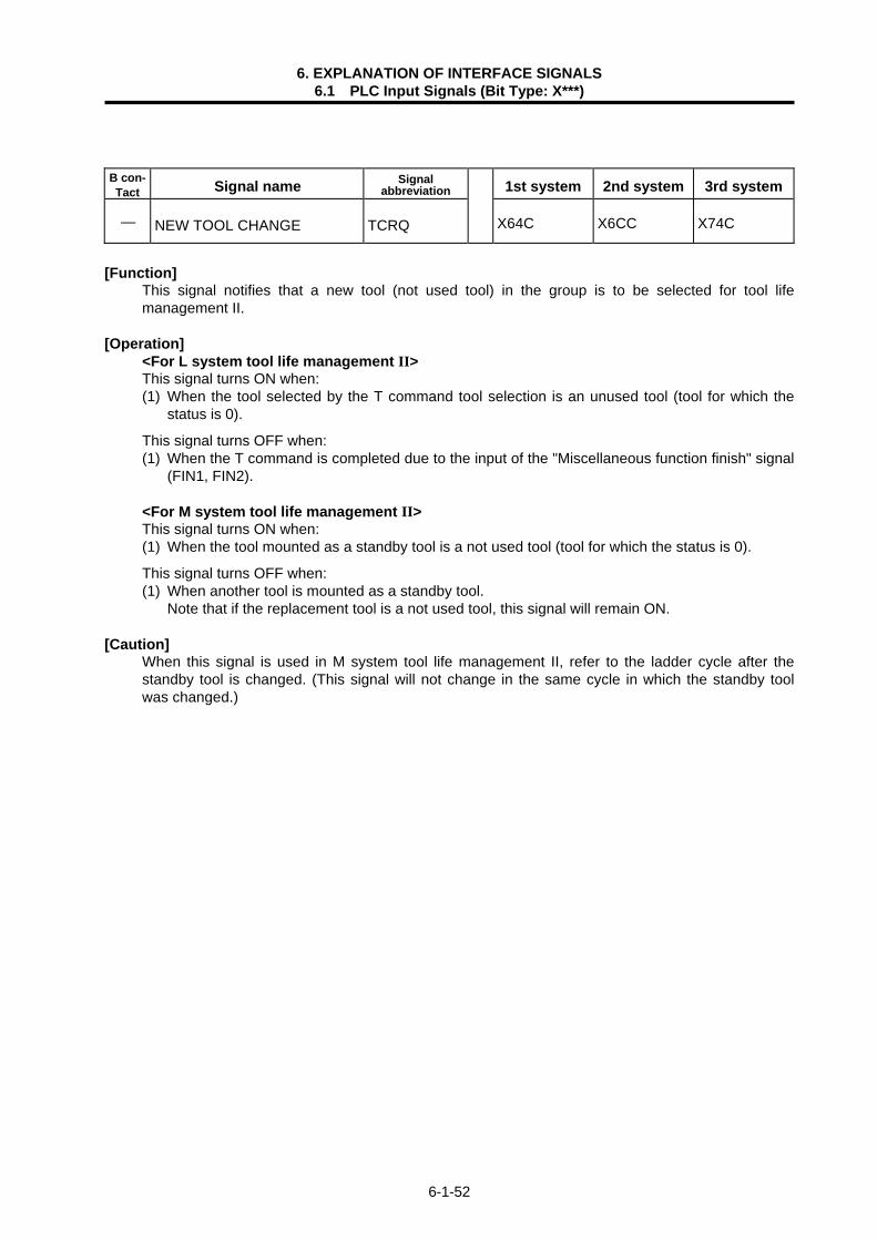
6. EXPLANATION OF INTERFACE SIGNALS 6.1 PLC Input Signals (Bit Type: X***)
6-1-52
B con- Tact Signal name Signal
abbreviation 1st system 2nd system 3rd system
— NEW TOOL CHANGE TCRQ X64C X6CC X74C
[Function] This signal notifies that a new tool (not used tool) in the group is to be selected for tool life
management II. [Operation] <For L system tool life management II> This signal turns ON when: (1) When the tool selected by the T command tool selection is an unused tool (tool for which the
status is 0).
This signal turns OFF when: (1) When the T command is completed due to the input of the "Miscellaneous function finish" signal
(FIN1, FIN2). <For M system tool life management II> This signal turns ON when: (1) When the tool mounted as a standby tool is a not used tool (tool for which the status is 0).
This signal turns OFF when: (1) When another tool is mounted as a standby tool. Note that if the replacement tool is a not used tool, this signal will remain ON. [Caution] When this signal is used in M system tool life management II, refer to the ladder cycle after the
standby tool is changed. (This signal will not change in the same cycle in which the standby tool was changed.)

6. EXPLANATION OF INTERFACE SIGNALS 6.1 PLC Input Signals (Bit Type: X***)
6-1-53
B con-
tact Signal name Signal abbreviation 1st system 2nd system 3rd system
— T FUNCTION STROBE 1 TF1 X650 X6D0 X750
[Function] This signal informs that the tool function (T code) is specified in automatic operation (memory or
MDI), machining program or by manual numerical command input. The tool function is also called the T function, and is used to command the tool No. in the lathe
specification controller, the tool compensation (tool length offset, tool nose wear compensation) Nos. are also indicated.
The user PLC receives the T code data 1 with this signal. [Operation] The signal turns ON when: (1) The T function (T code) is specified in automatic operation (memory or MDI). (2) T function (T) is specified by manual numerical command input.
The signal turns OFF when: (1) "M function finish 1" signal (FIN1) or "M function finish 2" signal (FIN2) turns ON. (2) Reset condition occurs. (Refer to the "In auto operation" signal (OP) section for details on the reset conditions.)
(Note 1) The T function strobe (TF) is not output during operation with the M function lock (AFL signal ON).
An example of the timing chart for the "T function strobe" signal (TF1) is shown below.
Command program
T code data
T function strobe (TF)
M function finish (FIN1)
T01; G00X100.;
1
[Related signals] T code data (R220 to 227) M function finish 1 (FIN1: Y71E) M function finish 2 (FIN2: Y71F)

6. EXPLANATION OF INTERFACE SIGNALS 6.1 PLC Input Signals (Bit Type: X***)
6-1-54
B con-
tact Signal name Signal abbreviation 1st system 2nd system 3rd system
— 2ND M FUNCTION STROBE 1 BF1 X654 X6D4 X754
[Function] This signal informs that the 1st set of 2nd M function is selected in automatic operation (memory or
MDI) machining program or by manual numerical command input. The 2nd M function is also called the B function. With the signal (BF1), user PLC reads 2nd M function data 1. [Operation] The signal turns ON when: (1) The 1st set of 2nd M function (B code) is specified in automatic operation (memory or MDI). (2) 2nd M function (B code) is issued by manual numerical command input. The signal turns OFF when: (1) "M function finish 1" signal (FIN1) or "M function finish 2" signal (FIN2) is sent back. (2) Reset condition occurs. (Refer to the "In auto operation" signal (OP) section for details on the reset conditions.) (Note 1) Only one 2nd M function can be issued in one block at a time.
The relation of the machining program and 2nd M function strobe is shown below. Machining program ..... B03 B08 ;
(1st set) (2nd set)
Ignored.
2nd M function strobe (BF1) Corresponding to 1st of 2nd M functions
(Note 2) The 2nd M function strobe (BF1) is not output during operation with M function lock (AFL
signal ON). (Note 3) In the case of manual numerical command input, outputs are in accordance with 2nd M
function strobe 1 (BF1). (Note 4) Address for 2nd M function can be selected from addresses A, B and C by using Setup
parameter. Set so that the address is different from the axis address. [Related signals] M function finish 1 (FIN1: Y71E) M function finish 2 (FIN2: Y71F)

6. EXPLANATION OF INTERFACE SIGNALS 6.1 PLC Input Signals (Bit Type: X***)
6-1-55
B con-
tact Signal name Signal abbreviation 1st system 2nd system 3rd system
— S FUNCTION STROBE 1 SF1 X658 X6D8 X758
[Function] This signal informs that S (spindle) function (S code) is specified in automatic operation (memory or
MDI) machining program or by manual numerical command input. The spindle function is also called the S function, and is used to command the spindle speed. With the signal (SF1), user PLC reads S code data 1.
[Operation] The signal turns ON when: (1) S function (S code) is specified in automatic operation (memory or MDI). (2) S function is specified by manual numerical command input.
The signal turns OFF when: (1) "M function finish 1" signal (FIN1) or "M function finish 2" signal (FIN2) turns ON. (2) Reset condition occurs. (Refer to the "In auto operation" signal (OP) section for details on the reset conditions.)
(Note 1) The S function strobe (SF) is not output during operation with M function lock (AFL signal ON).
(Note 2) When the S function is commanded, the "Spindle gear shift command" signal (GR1, GR2) and "Spindle no gear selected" signal (SNGE) are output in addition to this signal (SF1). Refer to the sections of each signal for details.
(Note 3) By combining this signal (SF1), "Spindle gear select input" signal (GI1, GI2) and "Gear shift completed" signal (GFIN), the data can be converted into S-analog data.
(Data is transferred when the spindle controller is the high-speed serial connection specification type.)
An example of the timing chart for the S function strobe signal (SF1) is shown below.
Command program
S code data
S function strobe 1 (SF1)
M function finish 1 (FIN1)
S1000; G00X100.;
1000
[Related signals] S code data (R212 to 219, R264 to 269) Spindle gear shift command (GR1, GR2: X98D, X98E) Spindle no gear selected (SNGE: X986) Spindle gear selection input (GI1, GI2: YD30, YD31) Spindle gear shift complete (GFIN: YD26) M function finish 1 (FIN1: Y71E) M function finish 2 (FIN2: Y71F)

6. EXPLANATION OF INTERFACE SIGNALS 6.1 PLC Input Signals (Bit Type: X***)
6-1-56
B con-
tact Signal name Signal abbreviation 1st system 2nd system 3rd system
— POSITION SWITCH 1~16 PSWn X660~667 X670~677
X6E0~6E7 X6F0~6F7
X760~767 X770~777
[Function] This signal notifies that the machine position is within the area set by the parameters. [Operation] This signal turns ON when the control axis machine position reaches the range set by the
parameters, and turns OFF when the range is left. The axis name and range are set in parameters #7501 to #7653.
The validity of this signal differs in the following manner depending on the absolute position detection or incremental detection.
<For absolute position detection system>
This signal is valid when the power is turned ON after zero point initialization is completed.
<For incremental position detection system>
This signal is not validated until the first zero point return is completed after the power is turned ON. (PSW1 to PSW16 will all remain OFF until this signal is validated.)
[Example of signal output]
PSW1: ON
PSW2: OFF
PSW3: OFF
PSW4: OFF
PSW5: ON
Machine position
dog1 dog2
dog1 dog2
dog2dog1
dog1dog2
dog1dog2
The setting range of the position switch uses the basic machine coordinate system as a reference. The dog1 and dog2 setting values are available even if which of them is lager, and the area
between the smaller setting and the larger setting will be used as the signal output range. A slight delay will occur in the output signal fluctuation due to the actual machine position. The
maximum delay time is as follows.
tmax = 0.06 - TP [s]
TP: Position loop time constant ( [s]) 1 PGN

6. EXPLANATION OF INTERFACE SIGNALS 6.1 PLC Input Signals (Bit Type: X***)
6-1-57
B con-
tact Signal name Signal abbreviation 1st system 2nd system 3rd system
— TAP RETRACT POSSIBLE TRVE X66D X6ED X76D
[Function] This signal informs that tap retract is possible, and is output if operation is stopped during tap cycle
execution. The tap retract signal (TRV) will be valid when this signal (TRVE) is ON. [Operation] (1) This signal turns ON when tap cycle is stopped in the cutting feed area (between c-d-e in the
drawing) due to the following causes: • Emergency stop. • Reset stop. • Power OFF (only in absolute position detection system).
(2) This signal turns OFF in the following cases:
• Tap retract is executed and completed. • Tap axis is moved manually or with manual mode.
Tap cycle command
f Initial point
e R point
a b
c
(Spindle reverse run)
Tap feed (spindle normal run)
dTap base
[Related signal] Tap retract (TRV: Y75C)

6. EXPLANATION OF INTERFACE SIGNALS 6.1 PLC Input Signals (Bit Type: X***)
6-1-58
B con-
tact Signal name Signal abbreviation 1st system 2nd system 3rd system
— NO. OF WORK MACHINING OVER PCNT X66E X6EE X76E
[Function] This signal is output when the No. of work machining matches or exceeds the maximum No. of
work machining. [Operation] This signal turns ON when the No. of work machining matches or exceeds the maximum work value
(WRK LIMIT) set in the [Process parameter] screen.
(Note 1) This signal turns ON when the No. of work machining matches or exceeds the maximum work value regardless of the count up by the controller or user PLC.
(Note 2) This signal is not output when "0" is set for the maximum work value. [Related signals] (1) No. of work machining (current value) (R240) (2) No. of work machining (maximum value) (R940) B con-
tact Signal name Signal abbreviation 1st system 2nd system 3rd system
— ABSOLUTE POSITION WARNING ABSW X66F X6EF X76F
[Function] This signal notifies that the amount moved while the power is OFF has exceeded to the tolerable
amount when using the absolute position detection system. [Operation] This signal turns ON when the difference of the machine position at power OFF and at power ON
exceeds the tolerable value ([ABS. POSI PARAM] #2051 (check) setting value) when using the absolute position detection system.
(Note) The movement amount during power OFF depends on the "PON POS (power ON position)" and "POF POS (power OFF position)" on the [ABS SERVO MONITOR (absolute position monitor)] screen.

6. EXPLANATION OF INTERFACE SIGNALS 6.1 PLC Input Signals (Bit Type: X***)
6-1-59
B con-
tact Signal name Signal abbreviation 1st spindle 2nd spindle 3rd spindle
— S-ANALOG GEAR NO. ILLEGAL SIGE X984 X9B4 X9E4
[Function] This signal is output if specified gear No. is illegal. [Operation] The signal turns ON if gear No. specified by user is beyond the maximum system gear No. B con-
tact Signal name Signal abbreviation 1st spindle 2nd spindle 3rd spindle
— S-ANALOG MAX./MIN. COMMAND VALUE OVER SOVE X985 X9B5 X9E5
[Function] This signal is output when S-analog command value is clamped to the maximum or minimum value. [Operation] The signal turns ON if S-analog command value is larger than machine parameter (Smax) value, or
smaller than machine parameter (Smin) value. B con-
tact Signal name Signal abbreviation 1st spindle 2nd spindle 3rd spindle
— SPINDLE NO GEAR SELECTED SNGE X986 X9B6 X9E6
[Function] This signal is output if gear is not present for S function (S code) issued by automatic operation. [Operation] This signal will turn ON when the S function (S code) is issued during automatic operation, and the
S code does not match any gear set in the parameters. This signal (SNGE) is output simultaneously with spindle function strobe signal (SFn). [Related signals] Spindle function strobe (SFn: X658 to) Spindle gear shift command (GR1, GR2: X98D, X98E)

6. EXPLANATION OF INTERFACE SIGNALS 6.1 PLC Input Signals (Bit Type: X***)
6-1-60
B con-
tact Signal name Signal abbreviation 1st spindle 2nd spindle 3rd spindle
— SPINDLE SPEED UPPER LIMIT OVER SUPP X98B X9BB X9EB
[Function] This signal notifies that the feedback of the spindle motor has exceeded the maximum speed. [Operation] This signal turns ON when the spindle motor's feedback exceeds the maximum speed regardless of
the commanded speed.
Spindle speed (Feedback)
Spindle rotation upper limit over (SUPP)
Maximum speed (parameter setting value)
B con-
tact Signal name Signal abbreviation 1st spindle 2nd spindle 3rd spindle
— SPINDLE SPEED LOWER LIMIT OVER SLOW X98C X9BC X9EC
[Function] This signal notifies that the feedback of the spindle motor has dropped below the minimum speed. [Operation] This signal turns ON when the spindle motor's feedback drops below the minimum speed
regardless of the commanded speed.
Minimum speed (parameter setting value)
Spindle speed (Feedback)
Spindle rotation lower limit over (SLOW)

6. EXPLANATION OF INTERFACE SIGNALS 6.1 PLC Input Signals (Bit Type: X***)
6-1-61
B con-
tact Signal name Signal abbreviation 1st spindle 2nd spindle 3rd spindle
— SPINDLE GEAR SHIFT GR1, GR2 X98D, 98E X9BD, 9BE X9ED, 9EE
[Function] This signal informs which gear stage in the spindle applies to the S command (S code) issued in the
automatic operation (memory, MDI) machining program. For machines that have gear stage shift, the gear will be shifted on the machine side when this
signal is received. [Operation] When the S command (S code) is issued in automatic operation, the gear stage for the commanded
S code is output with a 2-bit (GR1, GR2) code from the preset parameters (spindle max. speed). The relation of the spindle max. speed parameter (Smax1 to Smax4) and the spindle gear shift
command (GR1, GR2) signal output is shown below.
Spindle gear shift command
Gear stage
Max. spindle speed
GR2 GR1
1 Smax 1 0 0 Range "S0 to S (Smax1)" 2 Smax 2 0 1 Range "S (Smax1)+1 to S (Smax2)" 3 Smax 3 1 0 Range "S (Smax2)+1 to S (Smax3)" 4 Smax 4 1 1 When range over "S (Smax3)+1" is specified.
This signal (GR1, GR2) is output simultaneously with the spindle function strobe (SFn). (Note 1) If the commanded S code does not match any of the gear stages, the "Spindle no gear
selected (SNGE)" signal will be output separately from this signal. [Related signals] Spindle function strobe (SFn: X658 to) Spindle no gear selected (SNGE: X986)

6. EXPLANATION OF INTERFACE SIGNALS 6.1 PLC Input Signals (Bit Type: X***)
6-1-62
B con-
tact Signal name Signal abbreviation 1st spindle 2nd spindle 3rd spindle
— SPINDLE CURRENT DETECT CDO X991 X9C1 X9F1
[Function] This signal is output from the high-speed serial connection specification spindle controller (spindle
drive) and informs that drive motor current is about to reach the permissible maximum current. The signal can be used to prevent stabbing of cutter into workpiece, for example.
[Operation] The signal (CDO) turns ON if motor current goes up to a level (110% output) close to the
permissible maximum current (120%). (Note 1) This signal is valid only for the system that is high-speed serially connected with the
spindle controller. B con-
tact Signal name Signal abbreviation 1st spindle 2nd spindle 3rd spindle
— SPINDLE SPEED DETECT VRO X992 X9C2 X9F2
[Function] This signal is output from the high-speed serial connection specification spindle controller (spindle
drive) and informs that motor speed drops below the speed specified by parameter. [Operation] The signal (VRO) turns ON when motor speed (motor rotation speed) drops below the speed
specified by parameter "#3220 SP020 (speed detection set value)". The speed level at which the signal is output can be set within range from 1% to 120% (standard
setting: 10%) with the spindle parameters.
Spindle motor speed
Spindle speed detect (VRO)
Speed command level (SP020)
(Note 1) This signal is valid only for the system that is high-speed serially connected with the
spindle controller.

6. EXPLANATION OF INTERFACE SIGNALS 6.1 PLC Input Signals (Bit Type: X***)
6-1-63
B con-
tact Signal name Signal abbreviation 1st spindle 2nd spindle 3rd spindle
— IN SPINDLE ALARM FLO X993 X9C3 X9F3
[Function] This signal is output from the high-speed serial connection specification spindle controller (spindle
drive) and informs that failure occurs in spindle controller. [Operation] The signal turns ON if alarm which occurs in the spindle controller is detected.
To cancel alarm, reset the controller (by reset & rewind), turn the controller power OFF or turn the spindle controller power supply OFF. Note that reset method depends on type of alarm.
Typical examples of alarm are listed below. For details of alarm (contents and cancel procedures) and reset methods, refer to the Spindle Controller specifications and maintenance manual.
(1) Overcurrent (2) Breaker trip (3) Motor overheat (Note 1) This signal is valid only for the system that is high-speed serially connected with the
spindle controller. B con-
tact Signal name Signal abbreviation 1st spindle 2nd spindle 3rd spindle
— SPINDLE ZERO SPEED ZSO X994 X9C4 X9F4
[Function] This signal is output from the high-speed serial connection specification spindle controller (spindle
drive) and informs that motor speed has dropped below the set speed level. [Operation] This signal turns ON when the actual spindle motor speed drops below the speed set in the spindle
parameter #3218 (zero speed detection speed).
Spindle zero speed (ZS0)
Spindle motor speed
Zero speed detect range
(Note 1) The signal is output, no matter whether direction of rotation is forward (SRN) or reverse
(SRI). (Note 2) Minimum output pulse width of the signal is about 200ms. (Note 3) Speed at which the signal is output can be set within range from 1r/min to 1000r/min with
the spindle parameters. (Note 4) This signal is valid only for the system that is high-speed serially connected with the
spindle controller.

6. EXPLANATION OF INTERFACE SIGNALS 6.1 PLC Input Signals (Bit Type: X***)
6-1-64
B con-
tact Signal name Signal abbreviation 1st spindle 2nd spindle 3rd spindle
— SPINDLE UP-TO-SPEED USO X995 X9C5 X9F5
[Function] This signal is output from the high-speed serial connection specification spindle controller (spindle
drive) and informs that actual spindle motor speed reaches the range designated with the parameter SP048.
This signal is used for the S command complete conditions or control axis interlock during automatic operation.
[Operation] The spindle up-to-speed signal (USO) turns ON when an alarm is detected on the spindle controller
side.
Spindle motor speed
Spindle up-to-speed (US0)
Up-to-speed detect range
When the operation is changed from spindle forward run to spindle reverse run, the spindle motor
starts to decelerate, and the spindle up-to-speed signal turns OFF. When the motor enters the detection range again, the spindle up-to-speed signal turns ON again.
Spindle forward run start (SRN)
Spindle reverse run start (SRI)
Spindle motor speed
Spindle up-to-speed (US0)
Up-to-speed detect range
Up-to-speed detect range
(Note 1) This signal is not output unless the "spindle forward run start" (SRN) signal or "spindle
reverse run start" (SRI) signal is ON. (Note 2) This signal is not output when operating with a command that is not a speed command
such as synchronous tap. (Note 3) This signal is valid only for the system that is high-speed serially connected with the
spindle controller.

6. EXPLANATION OF INTERFACE SIGNALS 6.1 PLC Input Signals (Bit Type: X***)
6-1-65
B con-
tact Signal name Signal abbreviation 1st spindle 2nd spindle 3rd spindle
— SPINDLE IN-POSITION ORAO X996 X9C6 X9F6
[Function] This signal is output from the high-speed serial connection specification spindle controller (spindle
drive) and informs that the spindle is positioned in the set range in accordance with spindle orient command.
[Operation] When the spindle positioning in the set range completes, this signal will turn ON. The spindle
orientation is stored by "Spindle orient command" signal (ORC). (1) The in-position range is set with the spindle parameters. (2) While the spindle is in position, it is under servo lock condition. However, if the spindle is rotated
by external force, the signal (ORAO) may be turned OFF. (3) The signal is turned OFF when the "Spindle orient command" (ORC) is turned OFF.
Spindle orient command (ORC)
Spindle motor speed
Spindle in-position (ORAO)
(Note 1) When spindle orient command is given, orientation starts regardless of the "Spindle
forward run start (SRN)" or "Spindle reverse run start (SRI)". (Note 2) Range of in-position can be set within range from 0.001 to 99.999 degrees. (Note 3) This signal is valid only for the system that is high-speed serial connected with the
controller.

6. EXPLANATION OF INTERFACE SIGNALS 6.1 PLC Input Signals (Bit Type: X***)
6-1-66
B con-
tact Signal name Signal abbreviation 1st spindle 2nd spindle 3rd spindle
— IN L COIL SELECTED LRSO X997 X9C7 X9F7
[Function] This signal informs that the L coil select function is being executed. This function changes the
spindle motor coil to attain constant output characteristics over a wide range including low speed ranges.
[Operation]
Turn the "L coil selection" (LRSL) ON after attaining a speed (parameter SP020) at which the rotation speed can be changed. When "L coil selection" (LRSL) turns ON and the coil is changed, "In L coil selected" (LRSO) will be output to the PLC.
(Note 1) L coil selection control can be selected when the following parameter is set.
Parameter SP034/bit2 is set to "1". (Note 2) This signal is valid for a system having a control unit high-speed serially connected with
the spindle controller and a coil changeover specification spindle motor. As a principle, the built-in type is the target.
[Related signal]
L coil selection (LRSL: YD3F)

6. EXPLANATION OF INTERFACE SIGNALS 6.1 PLC Input Signals (Bit Type: X***)
6-1-67
B con-
tact Signal name Signal abbreviation 1st spindle 2nd spindle 3rd spindle
— SPINDLE READY-ON SMA X998 X9C8 X9F8
[Function] This signal is output from the high-speed serial connection specification spindle controller (spindle
drive) and informs that the spindle is ready for operation. [Operation] This signal (SMA) turns ON when the spindle controller is ready for operation. The signal turns OFF
(ready OFF) in the following conditions. (1) A spindle alarm is generated. (2) "Spindle ready-ON" signal (internal signal) from controller is OFF. (3) The machine ready-ON signal that is an external interface (DIO input) signal of the Spindle
controller is OFF. (The machine ready signal can be invalidated with the spindle controller parameters.)
Controller ready-ON (Note1)
Spindle ready-ON (SMA)
Spindle alarm
Machine ready-ON (External interface signal) Max. 1 s Max. 1 s Max. 1 s
(Note 1) The ready ON signal is output from the controller to the spindle controller. (Note 2) This signal is valid only for the system that is high-speed serially connected with the
spindle controller.

6. EXPLANATION OF INTERFACE SIGNALS 6.1 PLC Input Signals (Bit Type: X***)
6-1-68
B con-
tact Signal name Signal abbreviation 1st spindle 2nd spindle 3rd spindle
— SPINDLE SERVO-ON SSA X999 X9C9 X9F9
[Function] This signal is output from the high-speed serial connection specification spindle controller (spindle
drive) and informs that the spindle is under the position control state (synchronous tap control, etc.). [Operation] The "Spindle servo-ON" signal (SSA) turns ON when the spindle is ready (SMA signal is ON), the
servo-ON command has been transferred from the controller to the spindle controller, and the spindle controller is in the servo-ON state.
This signal (SSA) turns OFF when the servo-ON command is canceled.
Spindle servo-ON (SSA)
Spindle servo-ON command (Note 1)
(Note 1) The "Spindle servo-ON" command is output from the controller to the spindle controller,
and is mainly output during synchronous tap control. (Note 2) While the "Spindle servo-ON" signal is ON, all input signals for “Spindle forward run start
(SRN)", "Spindle reverse run start (SRI)", and "Spindle orient command (ORC)" are ignored.
(Note 3) This signal is valid only for the system that is high-speed serially connected with the spindle controller.

6. EXPLANATION OF INTERFACE SIGNALS 6.1 PLC Input Signals (Bit Type: X***)
6-1-69
B con-
tact Signal name Signal abbreviation 1st spindle 2nd spindle 3rd spindle
— SPINDLE FORWARD RUN SSRN X99B X9CB X9FB
[Function] This signal is output from the high-speed serial connection specification spindle controller (spindle
drive) and informs that the spindle is rotating in the forward direction. [Operation] This signal (SSRN) turns ON when the spindle motor is rotating in the forward direction. It also turns
ON even during oriented motion or synchronous tap if the spindle rotates in the forward direction.
Spindle motor speed
Spindle forward run (SSRN)
(Note 1) The "SSRN" signal turns ON and OFF while the spindle motor is in the stop state with
servo features during oriented motion or synchronous tap. (Note 2) This signal is valid only for the system that is high-speed serially connected with the spindle
controller. B con-
tact Signal name Signal abbreviation 1st spindle 2nd spindle 3rd spindle
— SPINDLE REVERSE RUN SSRI X99C X9CC X9FC
[Function] This signal is output from the high-speed serial connection specification spindle controller (spindle
drive) and informs that the spindle motor is rotating in the reverse direction. [Operation] This signal (SSRI) turns ON when the spindle motor rotates in the reverse direction. It also turns
ON even during oriented motion or synchronous tap if the spindle rotates in the reverse direction.
Spindle motor speed
Spindle reverse run (SSRI)
(Note 1) The "SSRI" signal turns ON and OFF while the spindle motor is in the stop state with
servo features during oriented motion or synchronous tap. (Note 2) This signal is valid only for the system that is high-speed serially connected with the
spindle controller.

6. EXPLANATION OF INTERFACE SIGNALS 6.1 PLC Input Signals (Bit Type: X***)
6-1-70
B con-
tact Signal name Signal abbreviation 1st spindle 2nd spindle 3rd spindle
— Z-PHASE PASSED SZPH X99D X9CD X9FD
[Function]
This signal is output from the spindle controller (spindle drive) for MELDAS AC spindle drive high-speed serial connection specification, and informs that the encoder's Z phase has been passed when changing the spindle from speed control to positioning control during C axis control.
[Operation] The signal turns ON when: (1) The Z phase is passed during C axis control. The signal turns OFF when: (1) The "Spindle servo-ON" signal turns OFF. (2) The "Spindle ready-ON" signal turns OFF.
Spindle ready-ON
Spindle servo-ON
Z phase
Z-phase passed
(Note) This signal is valid only for a system having a control unit high-speed serially connected
with the spindle controller.

6. EXPLANATION OF INTERFACE SIGNALS 6.1 PLC Input Signals (Bit Type: X***)
6-1-71
B con-
tact Signal name Signal abbreviation 1st spindle 2nd spindle 3rd spindle
— POSITION LOOP IN-POSITION SINP X99E X9CE X9FE
[Function] If the spindle controller is connected with high-speed serial connection, this signal will inform that
the spindle is in the in-position state during synchronous tap. [Operation] The signal will turn ON when: (1) The droop amount (servo tracking delay error) is within the in-position range during
synchronous tap control (servo ON). (2) Synchronous tap control is not commanded. ( A in following drawing) The signal will turn OFF when: (1) The droop amount (servo tracking delay error) has exceeded the in-position range during
synchronous tap control (servo ON).
A
Servo-on command
Motor speed Forward run
Reverse run
A
Position loop in-position
B con-
tact Signal name Signal abbreviation 1st spindle 2nd spindle 3rd spindle
— TORQUE LIMIT STLQ X99F X9CF X9FF
[Function] This signal is output from the high-speed serial connection specification spindle controller (spindle
drive) and informs that the spindle is in position under C-axis control or synchronous tap control. [Operation] The "STLQ" signal turns ON when: (1) "Torque limit 1" signal (TL1) or "Torque limit 2" signal (TL2) is ON. The "STLQ" signal turns OFF when: (1) "Torque limit 1" signal (TL1) and "Torque limit 2" signal (TL2) are both OFF. (Note 1) This signal is valid only for the system that is high-speed serially connected with the spindle
controller. [Related signals] Torque limit 1 signal (TL1: YD3A) Torque limit 2 signal (TL2: YD3B)

6-2-1
6.2 PLC Input Signals (Data Type: R***)

6. EXPLANATION OF INTERFACE SIGNALS 6.2 PLC Input Signals (Data Type: R***)
6-2-2
B con-
tact Signal name Signal abbreviation 1st system 2nd system 3rd system
— KEY IN 1 R8 — —
[Function] Operator's key operation can be monitored on the user PLC side. [Operation] While operator is using the keyboard, the corresponding data is set to KEY-IN 1. Refer to the "User PLC key operation" section of "PLC Programming Manual" for details on the set
key data. [Related signals] (1) KEY OUT 1 (R112)

6. EXPLANATION OF INTERFACE SIGNALS 6.2 PLC Input Signals (Data Type: R***)
6-2-3
B con-
tact Signal name Signal abbreviation 1st system 2nd system 3rd system
— DISPLAY INFORMATION R16~19 — —
[Function] This signal notifies which screen is currently being displayed by the controller. [Operation] The screen information changes in the following cases. Note that the information will not change
when a screen that has already been displayed is re-displayed. (1) When a function select key is pressed. (2) When a menu key is pressed. (3) When a page key is pressed. The relation of each key operated and the screen information is as follows.
File register Operated key Screen information
MONITOR 00
cmdtyp is 1, 2 0C TOOL•PARAM
cmdtyp is 3, 4 12
EDIT•MDI 0D
R17 bit F ~ 8
Function No. DIAGN•IN/OUT 10
SFG 08
F0 09
R17 bit 7 ~ 0 Menu No.
00~13 Menu changeover (0~19: decimal)
R16 bit F ~ 8 Page No.
01~n Change by next page key or previous page key
R16 bit 7 ~ 0 ——— Not set.
The data is not set. (Note) File registers R18 and 19 are invalid.
00 01 02 03 04
05 06 07 08 09
0A 0B 0C 0D 0E
0F 10 11 12 13

6. EXPLANATION OF INTERFACE SIGNALS 6.2 PLC Input Signals (Data Type: R***)
6-2-4
B con-
tact Signal name Signal abbreviation 1st system 2nd system 3rd system
— PLC MAIN SCAN TIME R20 — —
[Function] Time taken for scanning in user PLC can be monitored. [Operation] Scanning time for user PLC main processing is continuously updated and set. <File register contents and time calculation>
File register F E D C B A 9 8 7 6 5 4 3 2 1 0 Time calculation × 7.1 + × 7.1 (ms) (Example)
F E D C B A 9 8 7 6 5 4 3 2 1 0 0 0 0 0 0 1 1 0 1 1 0 1 0 0 0 0
× 7.1 + × 7.1 (ms) (Note 1) For this data, mean scanning time is about 1.8sec. (Note 2) I/O processing time for PLC control software (PLC BASIC) is included in this data
processing time.
Lower-order dataUpper-order data
Upper-order data
Lower-order data
256
Upper-order data=6
Lower-order data=208
256

6. EXPLANATION OF INTERFACE SIGNALS 6.2 PLC Input Signals (Data Type: R***)
6-2-5
B con-
tact Signal name Signal abbreviation 1st system 2nd system 3rd system
— EMERGENCY STOP CAUSE R21 — —
[Function] The causes of emergency stop are shown with bit correspondence. [Operation] The cause of the emergency stop state is shown as follows with bit correspondence. If there are multiple causes, the multiple bits corresponding to each cause are output. The bit of this signal that is set to "0" is the emergency stop cause.
File register (R) F E D C B A 9 8 7 6 5 4 3 2 1 0
Ser
vo d
rive
unit
emer
genc
y st
op o
utpu
t S
pind
le d
rive
unit
emer
genc
y st
op o
utpu
t D
oor
inte
rlock
, do
g/O
T ar
bitra
ry a
lloca
tion
devi
ce i
llega
l
PLC
hig
h-sp
eed
proc
essi
ng e
rror
Use
r P
LC I
llega
l co
des
exis
t B
uilt-
in P
LC S
oftw
are
emer
genc
y st
op o
utpu
t de
vice
Y42
7 is
"1 "
Ext
erna
l P
LC E
mer
genc
y st
op o
utpu
t E
xter
nal
PLC
Com
mun
icat
ion
erro
r E
xter
nal
PLC
Not
rea
dy
Ext
erna
l P
LC N
o ha
rdw
are
Bui
lt-in
PLC
Sof
twar
e st
op s
tate
Bit

6. EXPLANATION OF INTERFACE SIGNALS 6.2 PLC Input Signals (Data Type: R***)
6-2-6
B con-
tact Signal name Signal abbreviation 1st system 2nd system 3rd system
— DIO CARD INFORMATION R22 — —
[Function] The remote I/O unit connected to the controller can be found with the user PLC. The user PLC finds the connection state of the remote I/O unit with this data. [Operation] (1) When a remote I/O card is connected "1" is set, and when not connected "0" is set. Note that for
DX100/101, DX110/111, DX120/121 and DX140/141, two cards are used per unit, so the two bits corresponding to the connected unit will be set to "1".
F E D C B A 9 8 7 6 5 4 3 2 1 0 Bit File register (R)
1st card 2nd card : : : 8th card
1st card 2nd card : : : 8th card
Channel 1
Channel 2
(2) No. of cards mounted in remote I/O unit (DX***)
Unit No. of cards
DX100/101 One-card unit
DX110/111, DX120/121, DX140/141 Two-card unit (3) The position of the bit that turns ON depends on the rotary switch on the remote I/O unit.

6. EXPLANATION OF INTERFACE SIGNALS 6.2 PLC Input Signals (Data Type: R***)
6-2-7
B con-
tact Signal name Signal abbreviation 1st system 2nd system 3rd system
— USER MACRO INPUT #1032 (PLC → Controller) R24, 25 — —
[Function] This is interface function used to coordinate user PLC to user macro. (Note) The other signals from R0 to R99 are PLC inputs, but this signal is output to the controller
from PLC.
[Operation] The data set in file registers Rn and Rn+1 with the user PLCs, can be referred to on the user macro
side with the user macro system variables #1000 to #1031 or #1032. The relationship between system variable and file register is as follows:
System variable
Points Interface input signal System variable
Points Interface input signal
#1000 #1001 #1002 #1003 #1004 #1005 #1006 #1007 #1008 #1009 #1010 #1011 #1012 #1013 #1014 #1015
1 1 1 1 1 1 1 1 1 1 1 1 1 1 1 1
Register R24 bit 0 Register R24 bit 1 Register R24 bit 2 Register R24 bit 3 Register R24 bit 4 Register R24 bit 5 Register R24 bit 6 Register R24 bit 7 Register R24 bit 8 Register R24 bit 9 Register R24 bit 10 Register R24 bit 11 Register R24 bit 12 Register R24 bit 13 Register R24 bit 14 Register R24 bit 15
#1016 #1017 #1018 #1019 #1020 #1021 #1022 #1023 #1024 #1025 #1026 #1027 #1028 #1029 #1030 #1031
1 1 1 1 1 1 1 1 1 1 1 1 1 1 1 1
Register R25 bit 0 Register R25 bit 1 Register R25 bit 2 Register R25 bit 3 Register R25 bit 4 Register R25 bit 5 Register R25 bit 6 Register R25 bit 7 Register R25 bit 8 Register R25 bit 9 Register R25 bit 10 Register R25 bit 11 Register R25 bit 12 Register R25 bit 13 Register R25 bit 14 Register R25 bit 15
System variable
Points Interface input signal
#1032 #1033 #1034 #1035
32 32 32 32
Register R24, R25 Register R26, R27 Register R28, R29 Register R30, R31
File registers R24 and R25 correspond to system variables #1000~#1031, and #1032 (32-bit data). [Related signals] (1) User macro input #1033, #1034, #1035 (R26/27, R28/29, R30/31) (2) User macro output #1132, #1133, #1134, #1135 (R124/125, R126/127, R128/129, R130/131)
This correspondence table shows the example for file registers R24 and R25.

6. EXPLANATION OF INTERFACE SIGNALS 6.2 PLC Input Signals (Data Type: R***)
6-2-8
B con-
tact Signal name Signal abbreviation 1st system 2nd system 3rd system
— USER MACRO INPUT #1033 (PLC → Controller) R26, 27 — —
[Function] This provides interface function used to coordinate user PLC to user macro. (Note) The other signals from R0 to R99 are PLC inputs, but this signal is output to the controller
from PLC.
[Operation] The data set in file registers Rn and Rn+1 with the user PLCs, can be referred to on the user macro
side with the user macro system variables #1033. (Example)
[Related signals] (1) User macro input #1032, #1034, #1035, #1000~#1031 (R24/25, R28/29, R30/31) (2) User macro output #1132, #1133, #1134, #1135, #1100~#1131 (R124/125, R126/127,
R128/129, R130/131) B con-
tact Signal name Signal abbreviation 1st system 2nd system 3rd system
USER MACRO INPUT #1034 (PLC → Controller) R28, 29 — —
[Function] [Operation] The function, operation, etc. are the same as those of "USER MACRO INPUT #1033". B con-
tact Signal name Signal abbreviation 1st system 2nd system 3rd system
USER MACRO INPUT #1035 (PLC → Controller) R30, 31 — —
[Function] [Operation] The function, operation, etc. are the same as those of "USER MACRO INPUT #1033".
DMOV K1000 R26
ACT
ACT WOR R24 K1 R24
Set 1 in #1000.
IF [#1000 EQ 0] GOTO 100
#100 = #1033
N100
The #1033 (R26, R27) data is read into #100 other than when #1000 is set to 0.
Sequence program User macro program

6. EXPLANATION OF INTERFACE SIGNALS 6.2 PLC Input Signals (Data Type: R***)
6-2-9
B con-
tact Signal name Signal abbreviation 1st system 2nd system 3rd system
— CNC SOFTWARE VERSION CODE R32~5 — —
[Function] This indicates the version of the CNC software. [Operation] The version of the software for controller is set.
[S/W MODULE TREE] ALARM/DIAGN 8.1/2
MP BND – 377W000 – A0 SV1 BND- OFFM
The file registers R32 to 35 are set to the following data. (Example) BND-377W000-A 0 (1) (2) (3)
Item File register Type Example
(1) Mode function No. R35 Binary 377=179AH (2) Serial No. R34 Binary 000=0000H Bits F~8 of R33 ASCII code A=41H
(3) Version Bits 7~0 of R33 ASCII code 0=30H Bits F~8 of R32 ASCII code Blank=00H
— ——— Bits 7~0 of R32 Always FFH (Note 1) If the version is a 2-digit No., bits F~8 of R32 are set to "00H". (Note 2) Bits 7~0 on the R32 are always "FFH". B con-
tact Signal name Signal abbreviation 1st system 2nd system 3rd system
— BATTERY DROP CAUSE R40 — —
[Function] This notifies a drop in the battery voltage. [Operation] A drop in voltage of the data storage battery located on the front door of the controller is checked
when the power is turned ON. If the voltage is below the specified voltage (approx. 2.6V), the "Battery alarm (BATAL)" signal turns ON, and bit 0 of this data is set to "1".
(Note) This data will not change until the battery voltage is recovered to a normal value. [Related signal] (1) Battery alarm (BATAL: X42F)

6. EXPLANATION OF INTERFACE SIGNALS 6.2 PLC Input Signals (Data Type: R***)
6-2-10
B con-
tact Signal name Signal abbreviation 1st system 2nd system 3rd system
— TEMPERATURE WARNING CAUSE R41 — —
[Function] If the alarm is displayed when an overheat alarm is detected in the control unit or communication terminal‚ the overheat signal will be output simultaneously. If the machine is in automatic operation‚ the operation will be continued‚ but restarting will not be possible after resetting or stopping with M02/M30. (Starting will be possible after block stop or feed hold.) The alarm will be reset and the overheat signal will turn OFF when the temperature drops below the specified temperature. The alarm of overheat occurs when the temperature in the control unit is above 80°C, and when the ambient temperature of the communication terminal is above 70°C.
Overheat Detection
Overheat Detection
Control unit
Communication terminal
ParameterThermal
alarm
User PLC
Message indication
Cooling fan rotationWarning with lampEmergency stopOthers
Bit device (SM16,R41)
Parameter
(70°C)
(80°C)
(Default valid)
(Z53 TEMP. OVER)(Default valid)
[Operation]
(1) If the internal temperature of control unit rises above 80°C (the ambient temperature of control unit is about 60°C) or the ambient temperature of communication terminal rises above 70°C, the overheat will be detected.
(2) The overheat detection will be the thermal alarm when the parameter is set to the thermal detection valid (default). If the machine is in automatic operation, the automatic operation will be continued until the machine is stopped with M02/M30 or the reset. In case of the thermal alarm in the control unit, if the automatic start signal is input in that state, the alarm will be “T01 CAN’T CYCLE ST 0113”. When only the overheat of communication terminal occurs, the operation start is possible.
(3) The alarm message of “ Z53 TEMP. OVER” is indicated because of the thermal alarm. (4) The state that the overheat occurs is informed to the built-in PLC with the bit device. (5) The thermal alarm is released because of the temperature dropping. The alarm message and
bit device to the built-in PLC are reset by the release.

6. EXPLANATION OF INTERFACE SIGNALS 6.2 PLC Input Signals (Data Type: R***)
6-2-11
Device Signal name Details SM16 Temperature rise warning OFF: Normal
ON: Overheat
Device Signal name Details
Bit0 Control unit overheat OFF: Normal ON: Overheat
R41 Temperature warning cause
Bit1 Communication terminal overheat
OFF: normal ON: Overheat
SM16
Control unit internal temperature
Alarm occurrencetemperature
Alarm occurrencetemperature
Communication terminal ambient temperature
R41 Bit0
R41 Bit1
80°C
70°C
The device output is turned ON when: • The internal temperature of control unit rises over 80°C or the ambient temperature of
communication terminal rises over 70°C. The device output is turned OFF when:
• The internal temperature of control unit drops below 80°C and the ambient temperature of communication terminal drops below 70°C.
PLC bit select parameter
# Items Details Setup range (unit)6449 bit7
Control unit overheat detection
Designate whether to detect the control unit overheat alarm or not.
0: Detection valid 1: Detection invalid
6449 bit6
Communication terminaloverheat detection
Designate whether to detect the communication terminal overheat alarm or not.
0: Detection valid 1: Detection invalid
CAUTION When setting the parameter (#6449/bit6, 7) not to check the overheat, the control unit and the
communication terminal may not be controlled because of overheat. In such case, axis runaway may cause a machine breakage, an accident resulting in injury or death, or device breakage. To prevent the serious results, ordinarily set the parameters so that the overheat check is valid.
[Related signal] (1) Temperature rise warning (SM16)

6. EXPLANATION OF INTERFACE SIGNALS 6.2 PLC Input Signals (Data Type: R***)
6-2-12
B con-
tact Signal name Signal abbreviation 1st system 2nd system 3rd system
— REMOTE I/O COMMUNI- CATION STOP CHANNEL R42 — —
[Function]
The channel No. in the remote I/O communication stop can be read.
[Operation]
7 6 5 4 3 2 1 Bit0
Remote I/O communication stop (SM17)
Remote I/O communication stop channel (R42)
OFF : Normal
ON : Communication stop
Remote I/O 1st channelcommunication stop
:
Remote I/O 8th channelcommunication stop
[Related signal] Remote I/O communication stop (SM17)
B con-
tact Signal name Signal abbreviation 1st system 2nd system 3rd system
—
SPINDLE SYNCHRONOUS CONTROL PHASE ERROR 1 (degree) (including phase shift calc.)
R48 — —
[Function]
This signal informs the phase error (value including the phase error memorized with the spindle synchronization phase shift calculation function) when the phase synchronization (with R command) or the "Phase shift calculation request" signal (Y435) is ON. The phase error is output by 1° increment. The data has no meaning in cases other than above.
[Operation]
When the phase synchronization (with R command) or the "Phase shift calculation request" signal (Y435) is ON, and when the speeds of the basic spindle and the synchronous spindle are constant, the phase error between the basic spindle and the synchronous spindle is output.

6. EXPLANATION OF INTERFACE SIGNALS 6.2 PLC Input Signals (Data Type: R***)
6-2-13
B con-
tact Signal name Signal abbreviation 1st system 2nd system 3rd system
—
SPINDLE SYNCHRONOUS CONTROL PHASE ERROR 2 (degree) (excluding phase shift calc.)
R49 — —
[Function]
This signal informs the phase error (value excluding the phase error memorized with the spindle synchronization phase shift calculation function) when the phase synchronization (with R command) or the "Phase shift calculation request" signal (Y435) is ON. The phase error is output by 1° increment. The data has no meaning in cases other than above.
[Operation]
When the phase synchronization (with R command) or the "Phase shift calculation request" signal (Y435) is ON, and when the speeds of the basic spindle and the synchronous spindle are constant, the phase error between the basic spindle and the synchronous spindle is output.
B con-
tact Signal name Signal abbreviation 1st system 2nd system 3rd system
— CLOCK DATA R50~52 — —
[Function] The year, month, date, hour, minute and second data is informed by the controller to the PLC as the
current clock information. [Operation] The date and time data is output as shown below. The data is output as binary data.
F 87 0 R50 Month Year
R51 Hour Date
R52 Second Minute (Example) For October 26, 2002, 14:56:36.
R50 ... 0 0 0 0 1 0 1 0 0 0 0 0 0 0 1 0 = 0A02H
October 2002
R51 ... 0 0 0 0 1 1 1 0 0 0 0 1 1 0 1 0 = 0E1AH
14 hundred hours 26th day
R52 ... 0 0 1 0 0 1 0 0 0 0 1 1 1 0 0 0 = 1438H
36 seconds 56 minutes (Note 1) The time is displayed with the 24-hour system. (Note 2) The data and time are set with the [TIME] screen on the setting and display unit.

6. EXPLANATION OF INTERFACE SIGNALS 6.2 PLC Input Signals (Data Type: R***)
6-2-14
B con-
tact Signal name Signal abbreviation 1st system 2nd system 3rd system
— SPINDLE SYNCHRONOUS CONTROL PHASE ERROR OUTPUT
R55 — —
[Function] The synchronous spindle delay to the basic spindle is output in the spindle synchronous function. [Operation] The synchronous spindle delay to the basic spindle is output.
Unit: 360°/4096 (Note 1) If the phase cannot be calculated because, for instance, the basic spindle or synchronous
spindle has not passed the Z-phase, "-1" will be output. (Note 2) This data is output only during the phase shift calculation or the spindle phase
synchronization. [Related signals] Phase shift calculation request (SSPHM: Y435) Phase offset request (SSPHF: Y436) Spindle synchronous control phase offset data (R59) B con-
tact Signal name Signal abbreviation 1st system 2nd system 3rd system
— SPINDLE SYNCHRONOUS CONTROL PHASE ERROR MONITOR
R56 — —
[Function] The phase error during the spindle phase synchronous state can be monitored. [Operation] The phase error during the spindle phase synchronous control is output by the pulse unit. [Related signals] Spindle synchronous control phase error monitor (lower limit value) (R57) Spindle synchronous control phase error monitor (upper limit value) (R58)

6. EXPLANATION OF INTERFACE SIGNALS 6.2 PLC Input Signals (Data Type: R***)
6-2-15
B con-
tact Signal name Signal abbreviation 1st system 2nd system 3rd system
—
SPINDLE SYNCHRONOUS CONTROL PHASE ERROR MONITOR (lower limit value)
R57 — —
[Function] The phase error during the spindle phase synchronous state can be monitored. [Operation] The lower limit value of the phase error during the spindle phase synchronous control is output by
the pulse unit. [Related signals] Spindle synchronous control phase error monitor (R56) Spindle synchronous control phase error monitor (upper limit value) (R58) B con-
tact Signal name Signal abbreviation 1st system 2nd system 3rd system
—
SPINDLE SYNCHRONOUS CONTROL PHASE ERROR MONITOR (upper limit value)
R58 — —
[Function] The phase error during the spindle phase synchronous state can be monitored. [Operation] The upper limit value of the phase error during the spindle phase synchronous control is output by
the pulse unit. [Related signals] Spindle synchronous control phase error monitor (R56) Spindle synchronous control phase error monitor (lower limit value) (R57)

6. EXPLANATION OF INTERFACE SIGNALS 6.2 PLC Input Signals (Data Type: R***)
6-2-16
B con-
tact Signal name Signal abbreviation 1st system 2nd system 3rd system
— SPINDLE SYNCHRONOUS CONTROL PHASE OFFSET DATA
R59 — —
[Function] With the spindle phase shift amount calculation function, the phase error of the basic spindle and
synchronous spindle is obtained and memorized by turning the PLC signal ON at executing the spindle synchronization. The synchronous spindle can be rotated with the handle during the spindle phase shift calculation, so the relation between spindles can be adjusted by seeing. If the "Spindle phase synchronous control" (SPPHS) signal is input while the "Phase offset request" signal (SSPHF) is ON, the phase error will be aligned based on the position shifted by the memorized phase shift amount. Such operation makes the phase alignment easy when clamping an irregular material over.
[Operation] The phase error memorized by the phase shift calculation is output.
Unit: 360°/4096 (Note 1) This data is output only during the spindle synchronous control. [Related signals] Spindle phase synchronous control (SPPHS: Y433) Phase shift calculation request (SSPHM: Y435) Phase offset request (SSPHF: Y436) Spindle synchronous control phase error output (R55)

6. EXPLANATION OF INTERFACE SIGNALS 6.2 PLC Input Signals (Data Type: R***)
6-2-17
B con-
tact Signal name Signal abbreviation 1st system 2nd system 3rd system
— ADD-ON (EXPANSION) OPERATION BOARD INPUT
#1: R90~93 #2: R94~97 — —
[Function] By adding the remote I/O unit to the communication terminal, the add-on (expansion) operation
board input/output signals can be input and output with the communication terminal control signals. R90 bit8 is used as the communication terminal board reset signal. [Operation] The signals are read together with other input signals at start of PLC main processing (medium
speed).
<Hardware block diagram>
Controller
Communicationterminal Machine operation board
(switches, lamps, etc.)
(Channel setting 0)# 1
# 2
RemoteI/O unit
RemoteI/O unit
(Channel setting 2)
(Note 1) Since these signals are based on bit unit, they must be once transferred to buffer (M), etc.
Sequential control program example:
X0
< >Y710
•• • •
• •
• •
X0
M512
Contents stored in R90 and R91 are transferred to M512~M543.
Contents stored in R92 and R93 are transferred to M544~M575.
Sequence processing as bit data
DMOV R92 K8M544
DMOV R90 K8M512
(Note 2) Refer to the section "2.1 Relation of RIO unit and devices" for the relation of the remote
I/O channel setting switch and device. [Related signals] (1) Add-on (expansion) operation board output (#1: R190~192, #2: R193~195)

6. EXPLANATION OF INTERFACE SIGNALS 6.2 PLC Input Signals (Data Type: R***)
6-2-18
B con- tact Signal name Signal
abbreviation 1st system 2nd system 3rd system
— M CODE DATA 1 R204, 205 R304, 305 R404, 405
[Function] When M function is specified, value following address "M" can be identified. The M code data
output from the controller is a max. 8-digit BCD code. [Operation] "M code data 1" are updated when: (1) "M**" is issued in automatic operation (memory or MDI). (2) "M**" in fixed cycle causes motion during execution of the fixed cycle. (3) "M**" is executed by manual numerical command input. "M code data 1" is also updated when an "M single output command" is issued even during M
function lock. The data is kept unchanged after "M function finish" signal (FIN1, FIN2) is sent back. "Reset" or "Emergency stop" does not clear the data.
[Cautions] (1) Commands can be defined up to four in a block with parameters. (One command for the system
when the built-in PLC is not available.) When plural M functions are placed in one block, the signals are output in the order at programming.
M03 M08 M80 M82;
Output to M code data 1
Output to M code data 2
Output to M code data 3
Output to M code data 4
(2) M98 (call subprogram), M99 (return to main program), etc. are processed within the CNC, and
not output as M code data. [Related signals] (1) M function strobe 1∼4 (MF1~MF4: X644~X647) (2) M code data 2, 3, 4 (R206/207, R208/209, R210/211) B con-
tact Signal name Signal abbreviation 1st system 2nd system 3rd system
— M CODE DATA 2 R206, 207 R306, 307 R406, 407
[Function] When M function is specified, value following address "M" can be identified. The M code data
output from the controller is a max. 8-digit BCD code. [Operation] "M code data 2" are updated when: (1) Two or more M functions are placed in one block in automatic operation (memory or MDI). For other details, refer to the section on "M CODE DATA 1".

6. EXPLANATION OF INTERFACE SIGNALS 6.2 PLC Input Signals (Data Type: R***)
6-2-19
B con-
tact Signal name Signal abbreviation 1st system 2nd system 3rd system
— M CODE DATA 3 R208, 209 R308, 309 R408, 409
[Function] When M function is specified, value following address "M" can be identified. The M code data
output from the controller is a max. 8-digit BCD code. [Operation] "M code data 3" are updated when: (1) Three or more M functions are placed in one block in automatic operation (memory or MDI). For other details, refer to the section on "M CODE DATA 1". B con-
tact Signal name Signal abbreviation 1st system 2nd system 3rd system
— M CODE DATA 4 R210, 211 R310, 311 R410, 411
[Function] When M function is specified, value following address "M" can be identified. The M code data
output from the controller is a max. 8-digit BCD code. [Operation] "M code data 4" are updated when: (1) Four or more M functions are placed in one block in automatic operation (memory or MDI). For other details, refer to the section on "M CODE DATA 1".

6. EXPLANATION OF INTERFACE SIGNALS 6.2 PLC Input Signals (Data Type: R***)
6-2-20
B con-
tact Signal name Signal abbreviation 1st system 2nd system 3rd system
— S CODE DATA (1 to 7) R212, 213 R312, 313 R412, 413
[Function] When S function is specified, value following address "S" can be identified. The S code data output
from the controller is binary code with a sign. [Operation] "S code data" are updated when: (1) "S**" is specified in automatic operation (memory or MDI). (2) "S**" is executed by manual numerical command input. Data remain unchanged when M function finish signal (FIN1 or FIN2) is sent back. "Reset" and
"Emergency stop" does not cause clear to data. The S code data is assigned in the following manner.
Signal name Register (1st part system) S code data 1 R212, 213 S code data 2 R214, 215 S code data 3 R216, 217 S code data 4 R218, 219 S code data 5 R264, 265 S code data 6 R266, 267 S code data 7 R268, 269
[Caution] (1) Seven S codes can be placed in one block. If the number of S codes defined exceeds the
specified number, the S codes defined last is valid. [Related signal] (1) S function strobe (SFn: X658 to)

6. EXPLANATION OF INTERFACE SIGNALS 6.2 PLC Input Signals (Data Type: R***)
6-2-21
B con-
tact Signal name Signal abbreviation 1st system 2nd system 3rd system
— T CODE DATA (1 to 4) R220, 221 R320, 321 R420, 421
[Function] When T function is specified, value following address "T" can be identified. The T code data output
from the controller is a max. 8-digit BCD code. [Operation] "T code data" are updated when: (1) "T**" is specified in automatic operation (memory or MDI). (2) "T**" is executed by manual numerical command input. Data remain unchanged when "M function finish" signal (FIN1 or FIN2) is sent back. "Reset" and
"Emergency stop" does not cause clear to data. The T-code data is issued in the following manner.
Signal name Register (1st part system) T code data 1 R220, 221 T code data 2 R222, 223 T code data 3 R224, 225 T code data 4 R226, 227
[Cautions] (1) Only one T code can be commanded in one block. The latter code will be valid if more than one
code is commanded in one block.
T05 T15;
Output to T code data 1 This T code data is invalid.
[Related signals] (1) Tool function strobe (TFn: X650 to)

6. EXPLANATION OF INTERFACE SIGNALS 6.2 PLC Input Signals (Data Type: R***)
6-2-22
B con-
tact Signal name Signal abbreviation 1st system 2nd system 3rd system
— 2ND M FUNCTION DATA (1 to 4)
R228, 229 R328, 329 R428, 429
[Function] When 2nd M function is specified, value following address "B" can be identified. The 2nd M function
data output from the controller is a max. 8-digit BCD code. (Note 1) Select an address for the 2nd M function address from the setup parameters basic
specification parameter "#1170 M2name" A, B or C address that is not being used for "#1013 axname" or "#1014 incax".
[Operation] "2nd M function data" are updated when: (1) "B (A, C)**" is specified in automatic operation (memory or MDI). (2) "B (A, C)**" is executed by manual numerical command input. Data remain unchanged even after "M function finish" signal (FIN1 or FIN2) is sent back. Data
cannot be cleared by "Reset" or "Emergency stop". The 2nd M function data is issued in the following manner.
Signal name Register (1st part system)2nd M function data 1 R228, 229 2nd M function data 2 R230, 231 2nd M function data 3 R232, 233 2nd M function data 4 R234, 235
[Cautions] (1) Only one 2nd M function can be placed in one block. The latter code will be valid if more than
one code is commanded in one block.
B05 B15 ;
Output to 2nd M function data 1 This 2nd M function data is invalid.
[Related signals] (1) 2nd M function strobe (BFn: X654 to)

6. EXPLANATION OF INTERFACE SIGNALS 6.2 PLC Input Signals (Data Type: R***)
6-2-23
B con-
tact Signal name Signal abbreviation 1st system 2nd system 3rd system
— GROUP IN LIFE MANAGEMENT R238 R338 R438
[Function] The No. of the group currently in life management with the lathe system's tool life management II is
output. [Operation] The No. of the group currently in life management is output. B con-
tact Signal name Signal abbreviation 1st system 2nd system 3rd system
— NO. OF WORK MACHINING (CURRENT VALUE) R240, 241 R340, 341 R440, 441
[Function] The No. of work machining current value and maximum value are notified by the controller to the
PLC. [Operation] If data is set in the No. of work machining (WRK COUNT M) and work machining maximum value
(WRK LIMIT) of the [Process parameters], the current value or maximum value of the No. of work machining is output.
R240 No. of work machining Low-order side
R241 Current value High-order side
R940 No. of work machining Low-order side
R941 Maximum value High-order side (Note 1) If data is not set in "WRK COUNT M" and "WRK LIMIT" on the [Process Parameter]
screen, data will not be output to the file register. (Note 2) If the No. of work machining matches or exceeds the work maximum value, the "No. of
work machining over" signal (X66E) turns ON. <Counting of No. of work machining using user PLC>
(1) Set "0" in "WRK COUNT M" on the [Process Parameter] screen. With this setting, the controller side will not count up.
(2) Add "1" to R240, 241 with the user PLC. (3) The controller will display R240, 241 as the No. of work machining on the [COORDINATE]
screen. Even in this case, if the No. of work machining matches or exceeds the work maximum value, the "No. of work machining over" signal (X66E) will turn ON.

6. EXPLANATION OF INTERFACE SIGNALS 6.2 PLC Input Signals (Data Type: R***)
6-2-24
B con-
tact Signal name Signal abbreviation 1st system 2nd system 3rd system
— NEAR REFERENCE POINT (FOR EACH REFERENCE POINT)
R242, 243 R342, 343 R442, 443
[Function]
This signal indicates that the control axis is near the reference point when using the absolute point detection system. This signal is output for the 1st reference point to the 4th reference point. Near the 1st reference point, the time for outputting the signal is shorter than the “near reference point nth” signal (the ON/OFF timing accuracy during axis movement is improved).
[Operation]
(1) Using the nth reference point as a reference, when the control axis is in the range set with the parameters, this signal turns ON, and turns OFF when the axis is not within the range.
(2) The near reference point signal is output with four bits for each axis. (a) R register and corresponding axes
R242 F E D C B A 9 8 7 6 5 4 3 2 1 0
1st axis output value 2nd axis output value3rd axis output value 4th axis output value
R243
F E D C B A 9 8 7 6 5 4 3 2 1 0
5th axis output value6th axis output value
(b) Output value and near nth reference point
High-order bit Low-order bit Near n-th reference point
0 0 0 1 Near 1st reference point 0 0 1 0 Near 2nd reference point 0 1 0 0 Near 3rd reference point 1 0 0 0 Near 4th reference point
(Note 1) The near reference point signal device has X devices (X448 to) which output signal only
for the 1st reference point, and the R registers (R242 to) which outputs a signal for each reference point (1st reference point to 4th reference point).
(Note 2) The near reference point signal output width is set with the absolute point parameters "#2057 nrefp" and "#2058 nrefn". The near reference point signal output width is the same width for the 1st reference point to the 4th reference point.
(Note 3) Near the 1st reference point, the signals are output to the conventional X device (X448 to) and the R registers (R242 to) which output signals to each reference point.
[Related signals]
Near reference point nth axis (NRFn: X448 to)

6. EXPLANATION OF INTERFACE SIGNALS 6.2 PLC Input Signals (Data Type: R***)
6-2-25
B con-
tact Signal name Signal abbreviation 1st system 2nd system 3rd system
— TOOL LIFE USAGE DATA R244, 245 R344, 345 R444, 445
[Function] The usage data of the tool currently being used with the lathe-system tool life management II is
output. (When multiple compensation Nos. are used, the total of usage data per compensation No. is output.)
[Operation] The relation of the usage data of the tool currently being used and the output file register is as
follows.
Details File register
R244 Tool life usage data (1st part system) R245
R344 Tool life usage data (2nd part system) R345
R444 Tool life usage data (3rd part system) R445

6. EXPLANATION OF INTERFACE SIGNALS 6.2 PLC Input Signals (Data Type: R***)
6-2-26
B con-
tact Signal name Signal abbreviation 1st system 2nd system 3rd system
— ERROR CODE OUTPUT R256~258 R356~358 R456~458
[Function] With this function, the NC alarms and errors which are normally output to NC screen are partially coded and output to PLC I/F device. Thus, the contents of alarms and errors can be confirmed without NC screen.
[Operation] The following output will be made when an alarm occurs. The message displayed in NC screen is not converted. (Example) When servo alarm S03 occurs
S03 SERVO WARNING 0052 XZ
Axis name
Alarm No.
Alarm message
Alarm type
The output is as shown above on the NC screen. However, this can be coded and output to PLC I/F device as shown below using this function.
Alarm type ·················· Converted into a 2-digit numeral code. (Refer to the code table.) Alarm message ·········· Not coded, and not output. Alarm No. ··················· The No. is output as HEX. Axis name ·················· Error occurrence axis is expressed as a bit, and the bit of servo and
spindle are output separately. The head digit of the alarm without axis name will be “0”.

6. EXPLANATION OF INTERFACE SIGNALS 6.2 PLC Input Signals (Data Type: R***)
6-2-27
The output to PLC I/F device is as follows.
0 0 0 0 0 0 0 0 0 0 1 1 0 0 1 1 0 0 0 0 0 0 0 0 0 1 0 1 0 0 1 0 0 0 0 0 0 1 0 1 0 0 0 0 0 0 0 0
bit
7 6 5 4 3 2 1 0
1st axis 0 0 0 0 0 0 0 1
2nd axis 0 0 0 0 0 0 1 0
3rd axis 0 0 0 0 0 1 0 0
4th axis 0 0 0 0 1 0 0 0
5th axis 0 0 0 1 0 0 0 0
6th axis 0 0 1 0 0 0 0 0
7th axis 0 1 0 0 0 0 0 0
8th axis 1 0 0 0 0 0 0 0
Alarm type Servo axis name Alarm No. Spindle namePLC axis name
As for the servo axis name and spindle name, the bit corresponding to the No. of axis in which the alarm occurs is turned on. The max servo axis Nos. in the 1st part system are 6, and the max spindle Nos. in the 1st part system are 7. The spindle alarm is output to the 1st part system. The PLC axis name is output to the 1st part system.
R258 (Higher side) R258 (Lower side) R257 (Higher side) R257 (Lower side) R256 (Higher side) R256 (Lower side)
Axis name is added for the messages such as some of M01, S01 to S52, and Z70 to Z73. The following 48 bits are used as the output PLC I/F devices.
1st part system: R256 (Lower and Higher), R257 (Lower and Higher), R258 (Lower and Higher)
2nd part system: R356 (Lower and Higher), R357 (Lower and Higher), R358 (Lower and Higher)

6. EXPLANATION OF INTERFACE SIGNALS 6.2 PLC Input Signals (Data Type: R***)
6-2-28
Code table The alarm type is coded as the contents of following code table.
Alarm code table
Alarm Contents Alarm type Axis name Order of priority
Operation error M01 OPERATION ERROR 11 Some are added.
8
Stop code T01 T02 T03 T04 T10
CAN’T CYCLE ST FEED HOLD BLOCK STOP COLLATION STOP FIN WAIT
21 22 23 24 26
Not added. 9
S01 S02 S03 S04
SERVO ALARM:PR INIT PARAM ERR SERVO ALARM:NR SERVO ALARM:AR
31 32 33 36
Added. 2 Servo/spindle alarm
S51 S52
PARAMETER ERROR SERVO WARNING
34 35
Added. 6
MCP alarm Y02 Y03 Y10 Y51 Y90
SYSTEM ALARM AMP. UNEQUIPPED AMPLIFIER MISMATCHPARAMETER ERROR SP. NON SIGNAL
41 42 48 45 47
Some are added.
3
Z52 Z53 Z55 Z59
BATTERY FAULT TEMP. OVER RIO NOT CONNECT TIME CONSTANT
52 53 54 59
Not added. 7
Z70 Z71 Z72 Z73
ABS. ILLEGAL DETECTOR ERROR COMPARE ERROR ABS. WARNING
55 56 57 58
Added. 1
System alarm
P990 PREPRO S/W ERR 61 Not added. 5 Program error POOO (Program error) 71 Not added. 5
M00 M01
AUX OPER. ALM AUX OPER. ALM
81 82
Added. 8
S01 S02 S03 S52
AUX SERVO ALM AUX SERVO ALM AUX SERVO ALM AUX SERVO. WRN
83 84 85 86
Added. 2
Y02 Y03 EMG
AUX SYSTEM ALM AUX AMP UNEQU. EMERGENC
87 88 89
Some are added.
3
Auxiliary axis (MR-J2-CT) alarm (Note 1)
Z70 Z71 Z73
AUX POS. ERR AUX DETEC. ERR AUX SYSTEM WRN
8A 8B 8C
Added. 1
Emergency stop message
EMG EMERGENC 01 Not added. 4
The NC alarm is given priority when the NC alarm of same order of priority occurs. The auxiliary axis name is output to the servo axis name area.

6. EXPLANATION OF INTERFACE SIGNALS 6.2 PLC Input Signals (Data Type: R***)
6-2-29
The message at emergency stop is displayed in NC screen shown below. (Example) EMG EMERGENCY STOP PLC
When the emergency stop occurs, the message is coded and an alarm No. is output.
Emergency stop code list
Error message Details Alarm No. EMG EMERGENCY EXIN External emergency stop 0000
PLC User PLC emergency stop 0001
SRV Servo Amp not ready 0002
STOP User PLC not running 0003
SPIN Spindle Amp not ready 0004
PC_H PLC high-speed process error 0005
PARA Door-open II fixed device setting illegal 0006
LINK Communication error 0007
WAIT Waiting connection 0008
XTEN External emergency stop 0009
LAD User PLC illegal code 0010
(Note 1) If the MCP alarm "Y02 SYSTEM ALARM" occurs, part of the data will not be coded. Confirm the data on the display unit. (Example) Y02 SYSTEM ALARM 0051 0104 In this case, only "Y02" and "0051" are coded and output to the PLC I/F device.
(Note 2) If an alarm without an alarm No. occurs, "0" will be set as the alarm No. and output to the PLC I/F device.
(Note 3) If an alarm that does not have an axis name occurs, "0" will be set as the axis name and output to the PLC I/F device.
(Note 4) Alarms not shown in the code table are not output to the PLC I/F device.
(Note 5) If multiple alarms occur simultaneously, only the alarm with the highest order of priority in the code table will be output.
(Note 6) The "OOO" section of the program error "POOO" is output to the alarm No. area. (Example) "P34 G-CODE ERROR 0 0"
The code output becomes 71003400, and the output to PLC I/F devices is as follows.
0 1 1 1 0 0 0 1 0 0 0 0 0 0 0 0 0 0 1 1 0 1 0 0 0 0 0 0 0 0 0 0 0 0 0 0 0 0 0 0
Alarm type Alarm No. Axis name

6. EXPLANATION OF INTERFACE SIGNALS 6.2 PLC Input Signals (Data Type: R***)
6-2-30
B con-
tact Signal name Signal abbreviation 1st system 2nd system 3rd system
—
USER MACRO INTERFACE OUTPUT FOR EACH PART SYSTEM #1132 to 1135
R270, 271 R370, 371 R470, 471
[Function]
This interface is used between the user PLC and user macro program. The interface output signal can be sent by substituting a value in the variables #1100 to #1135 and #1300 to #1395. Only 0 and 1 are used as the output signals. Output here refers to outputting from the NC to the PLC.
[Operation]
When a value is substituted in variable #1132 with the user macro, all output numbers between #1100 and #1131 are sent out at once. These values can be referred to with the user PLC. When a value is substituted in variables #1133 to #1135, the #1300 to #1331, #1332 to #1363 and #1364 to #1395 output signals can be sent. The status of the writing and output signals can be read to offset the #1100 to #1135 and #1300 to #1395 output signals (20 to 231). The bit selection parameter (#6454/bit0) must be set to use the macro interface function for each part system. Refer to R24, 25 (#1032: PLC → controller) and R124, 125 (#1132: controller → PLC) for details on the user macro interface signals common for the part systems. (Note 1) The last system variable #1100 to #1135 values sent are saved as 1 or 0.
(These are not cleared with reset.) (Note 2) The following applies when any number other than 1 or 0 is substituted into #1100 to
#1131. <Blank> is treated as 0. Any number other than <Blank> or 0 is treated as 1. Any value less than 0.00000001 is indefinite.

6. EXPLANATION OF INTERFACE SIGNALS 6.2 PLC Input Signals (Data Type: R***)
6-2-31
(Note) This function's input and output signals are valid for up to three part systems when using the C64T system. Interface output signal System
variable No. of points 1st system 2nd system 3rd system 4th system 5th system 6th system 7th system
R270 R370 R470 R570 R670 R770 R870 #1100 1 bit0 bit0 bit0 bit0 bit0 bit0 bit0 #1101 1 bit1 bit1 bit1 bit1 bit1 bit1 bit1 #1102 1 bit2 bit2 bit2 bit2 bit2 bit2 bit2 #1103 1 bit3 bit3 bit3 bit3 bit3 bit3 bit3 #1104 1 bit4 bit4 bit4 bit4 bit4 bit4 bit4 #1105 1 bit5 bit5 bit5 bit5 bit5 bit5 bit5 #1106 1 bit6 bit6 bit6 bit6 bit6 bit6 bit6 #1107 1 bit7 bit7 bit7 bit7 bit7 bit7 bit7 #1108 1 bit8 bit8 bit8 bit8 bit8 bit8 bit8 #1109 1 bit9 bit9 bit9 bit9 bit9 bit9 bit9 #1110 1 bit10 bit10 bit10 bit10 bit10 bit10 bit10 #1111 1 bit11 bit11 bit11 bit11 bit11 bit11 bit11 #1112 1 bit12 bit12 bit12 bit12 bit12 bit12 bit12 #1113 1 bit13 bit13 bit13 bit13 bit13 bit13 bit13 #1114 1 bit14 bit14 bit14 bit14 bit14 bit14 bit14 #1115 1 bit15 bit15 bit15 bit15 bit15 bit15 bit15
Interface output signal System
variable No. of points 1st system 2nd system 3rd system 4th system 5th system 6th system 7th system
R271 R371 R471 R571 R671 R771 R871 #1116 1 bit0 bit0 bit0 bit0 bit0 bit0 bit0 #1117 1 bit1 bit1 bit1 bit1 bit1 bit1 bit1 #1118 1 bit2 bit2 bit2 bit2 bit2 bit2 bit2 #1119 1 bit3 bit3 bit3 bit3 bit3 bit3 bit3 #1120 1 bit4 bit4 bit4 bit4 bit4 bit4 bit4 #1121 1 bit5 bit5 bit5 bit5 bit5 bit5 bit5 #1122 1 bit6 bit6 bit6 bit6 bit6 bit6 bit6 #1123 1 bit7 bit7 bit7 bit7 bit7 bit7 bit7 #1124 1 bit8 bit8 bit8 bit8 bit8 bit8 bit8 #1125 1 bit9 bit9 bit9 bit9 bit9 bit9 bit9 #1126 1 bit10 bit10 bit10 bit10 bit10 bit10 bit10 #1127 1 bit11 bit11 bit11 bit11 bit11 bit11 bit11 #1128 1 bit12 bit12 bit12 bit12 bit12 bit12 bit12 #1129 1 bit13 bit13 bit13 bit13 bit13 bit13 bit13 #1130 1 bit14 bit14 bit14 bit14 bit14 bit14 bit14 #1131 1 bit15 bit15 bit15 bit15 bit15 bit15 bit15
Interface output signal System
variable No. of points 1st
system 2nd
system 3rd
system 4th
system 5th
system 6th
system 7th
system
Sent variable
No.
#1132 32 R270, R271
R370, R371
R470, R471
R570, R571
R670, R671
R770, R771
R870, R871
#1100 to 1131
#1133 32 R272, R273
R372, R373
R472, R473
R572, R573
R672, R673
R772, R773
R872, R873
#1300 to 1331
#1134 32 R274, R275
R374, R375
R474, R475
R574, R575
R674, R675
R774, R775
R874, R875
#1332 to 1363
#1135 32 R276, R277
R376, R377
R476, R477
R576, R577
R676, R677
R776, R777
R876, R877
#1364 to 1395

6. EXPLANATION OF INTERFACE SIGNALS 6.2 PLC Input Signals (Data Type: R***)
6-2-32
B con-
tact Signal name Signal abbreviation 1st axis 2nd axis 3rd axis
— THERMAL DISPLACEMENT COMPENSATION AMOUNT R1600 R1650 R1700
[Function]
During ball screw thermal expansion compensation, the compensation amount calculated based on the "thermal expansion offset compensation amount" (R2302) and "thermal expansion max. compensation amount" (R2303) is set in this register by the NC.
[Operation]
The "thermal expansion offset compensation amount" and the "thermal displacement max. compensation amount" is set as a set for each axis in the R register. The current compensation amount is set by the NC into the "thermal displacement compensate amount" (R1600). The thermal expansion compensation is invalid for the axis if the "thermal expansion offset compensation amount" and "thermal expansion max. compensation amount" are set to 0. These R registers are cleared to zero when the power is turned ON.
Thermal expansion offset compensation amount
(PLC → NC) Unit: Minimum command unit/2
Thermal expansion max. compensation amount
(PLC → NC) Unit: Minimum command unit/2
Thermal displacement compensation amount
(NC → PLC) Unit: Minimum command unit/2
No.1 axis R2302 R2303 R1600 No.2 axis R2352 R2353 R1650 No.3 axis R2402 R2403 R1700 No.4 axis R2452 R2453 R1750 No.5 axis R2502 R2503 R1800 No.6 axis R2552 R2553 R1850 No.7 axis R2602 R2603 R1900 No.8 axis R2652 R2653 R1950 No.9 axis R2702 R2703 R2000
No.10 axis R2752 R2753 R2050 No.11 axis R2802 R2803 R2100 No.12 axis R2852 R2853 R2150 No.13 axis R2902 R2903 R2200 No.14 axis R2952 R2953 R2250
A unit half of the minimum command unit is the setting unit. If the minimum command unit is 1µm and 100 is set, for example, the compensation amount will be 50µm.

6. EXPLANATION OF INTERFACE SIGNALS 6.2 PLC Input Signals (Data Type: R***)
6-2-33
Setting example
Data Setting value Data Setting value
bscmp- -100.000 bscmp- 120.000 bscmp+ 120.000 bscmp+ -100.000 Offset compensation amount (R2302) -40 Offset compensation
amount (R2302) 40
Max. compensation amount (R2303) 180 Max. compensation
amount (R2303) 100
Machine position (mm)
Compensation amount (µm)
Offset compensation amount (R2302)
-100.000 120.000
70
-20
(1) When the compensation basic point is in the minus area, and the plus area is to be compensated.
(2) When the compensation basic point is in the plus area, and the minus area is to be compensated.
Machine position (mm)
Compensation amount (µm)
Max. compen- sation amount (R2303)
-100.000 120.000
20
70
Offset compensation amount (R2302)
Max. compensation amount (R2303)
(R1600) (R1600)
[Caution]
The compensation amount calculated with this compensation function is added to the machine error compensation amount and output to the servo system. Make sure that the ball screw thermal expansion compensation amount + machine error compensation amount does not exceed -32768 to +32767.
[Related signals]
Thermal expansion compensation offset compensation amount (R2302) Thermal expansion compensation maximum compensation amount (R2303)

6. EXPLANATION OF INTERFACE SIGNALS 6.2 PLC Input Signals (Data Type: R***)
6-2-34
B con-
tact Signal name Signal abbreviation 1st spindle 2nd spindle 3rd spindle
— SPINDLE COMMAND ROTATION SPEED INPUT R3000, 3001 R3030, 3031 R3060, 3061
[Function] This signal informs the value of S function (S) data specified in automatic operation (memory or MDI)
or by manual numerical data input. "Spindle command rotation speed" output from the controller is binary data. The data can be monitored in the "S display" on the command value screen. (For type A, the "S display" displays the contents of file registers R212 and R213.)
[Operation] Set "Spindle command rotation speed input" is renewed when: (1) "S**" is specified in automatic operation (memory or MDI) and "M function finish 1 or 2" signal
(FIN1 or FIN2) or "Gear shift complete" signal (GFIN) is sent back to the controller. (2) "S**" is specified by manual numerical command input and "M function finish 1 or 2" signal
(FIN1 or FIN2) or "Gear shift complete" signal (GFIN) is sent back to the controller.
(Note 1) Data cannot be cleared by "reset" or "emergency stop".
S func. strobe 1
Spindle controller
Always
Spindle command rotation speed input
S function command S code data 1 +
+
Spindle command final data
Spindle gear select (GI1, GI2)Spindle stop (SSTP) Spindle gear shift (SSFT) Spindle orient (SORC) Spindle override
Tran
sfer
tim
ing Spindle command
rotation speed output
<Data flow>
S function strobe 1 (SF1) turns onand the following signals rise: M func. complete 1, 2 (FIN1, FIN2)Gear shift complete (GFIN) Reset & rewind (RRW) or during synchronous tapping
When the system is under constant surface speed control, constant surface speed data is set for "Spindle command rotation speed input".
(Note 2) "Spindle command rotation speed input" directly denotes spindle speed (r/min) specified as S function command.
[Related signals] (1) Spindle command rotation speed output (R3210, R3211) (2) Spindle command final data (R3002, R3003) (R3004, R3005) (for D/A output method)

6. EXPLANATION OF INTERFACE SIGNALS 6.2 PLC Input Signals (Data Type: R***)
6-2-35
B con-
tact Signal name Signal abbreviation 1st spindle 2nd spindle 3rd spindle
— SPINDLE COMMAND FINAL DATA R3002, 3003 R3032, 3033 R3062, 3063
[Function] The command value is indicated to the spindle controller. [Operation] The spindle command rotation speed input indicates the value for the spindle function (S) data
commanded with the automatic operation or manual numeric value command, whereas this data indicates a value to which the spindle override, "Spindle gear select input" (GI1, GI2), "Spindle stop" (SSTP), "Spindle gear shift" (SSFT) and "Oriented spindle speed command" (SORC) conditions have been considered.
[Related signals] (1) Spindle command rotation speed input (R3000, R3001) (2) Spindle command rotation speed output (R3210, R3211) B con-
tact Signal name Signal abbreviation 1st spindle 2nd spindle 3rd spindle
— SPINDLE ACTUAL SPEED R3006, 3007 R3036, 3036 R3066, 3066
[Function] When the system has spindle equipped with encoder, spindle actual speed can be monitored. [Operation] Spindle actual speed is always set by feedback signal from spindle encoder. Data are multipled by 1000, and stored. B con-
tact Signal name Signal abbreviation 1st axis 2nd axis 3rd axis
— J2CT CONTROL STATUS CTST1 to 4 R3500 to 3503
R3504 to 3507
R3508 to 3511
[Function]
The MR-J2-CT link function connects the NC and MR-J2-CT (auxiliary axis), and controls up to 7 axis (C6: Maximum 5 axis) MR-J2-CT axes using command signals from the NC.
[Operation]
Signal name J2CT status 4 J2CT status 3 J2CT status 2 J2CT status 1 Abbrev. CTST4 CTST3 CTST2 CTST1
J2CT 1st axis R3500 R3501 R3502 R3503 J2CT 2nd axis R3504 R3505 R3506 R3507 J2CT 3rd axis R3508 R3509 R3510 R3511 J2CT 4th axis R3512 R3513 R3514 R3515 J2CT 5th axis R3516 R3517 R3518 R3519 J2CT 6th axis R3520 R3521 R3522 R3523 J2CT 7th axis R3524 R3525 R3526 R3527

6. EXPLANATION OF INTERFACE SIGNALS 6.2 PLC Input Signals (Data Type: R***)
6-2-36
J2CT status 4 (R3500: CTST4) J2CT status 3 (R3501: CTST3)
bit Abbrev. Name bit Abbrev. Name bit0 PSW1 Position switch 1 bit0 ST01 Station position 1 bit1 PSW2 Position switch 2 bit1 ST02 Station position 2 bit2 PSW3 Position switch 3 bit2 ST04 Station position 4 bit3 PSW4 Position switch 4 bit3 ST08 Station position 8 bit4 PSW5 Position switch 5 bit4 ST016 Station position 16 bit5 PSW6 Position switch 6 bit5 ST032 Station position 32 bit6 PSW7 Position switch 7 bit6 ST064 Station position 64 bit7 PSW8 Position switch 8 bit7 ST0128 Station position 128 bit8 PMV In positioning operation bit8 ST0256 Station position 256 bit9 PFN Positioning complete bit9 Spare
bit10 PSI In stopper bit10 Spare bit11 Spare bit11 Spare bit12 Spare bit12 Spare bit13 Spare bit13 Spare bit14 Spare bit14 Spare bit15 Spare bit15 Spare
J2CT status 2 (R3502: CTST2) J2CT status 1 (R3503: CTST1)
bit Abbrev. Name bit Abbrev. Name bit0 AUTO In automatic operation mode bit0 RDY Servo ready bit1 MANO In manual operation mode bit1 INP In-position bit2 JO In jog mode bit2 SMZ Smoothing zero bit3 ARNN In reference position return bit3 AX1 Axis selection output
bit4 ZRNO In reference position return mode
bit4 MVP In axis movement +
bit5 bit5 MVM In axis movement -
bit6 AZSO In zero point initialization mode
bit6 TLQ Reaching torque limit
bit7 SO In incremental mode bit7 ADJ Adjusting machine bit8 AL1 MC alarm 1 bit8 ZP Reference position reached bit9 AL2 MC alarm 2 bit9 RST Resetting
bit10 AL4 MC alarm 4 bit10 HO In handle mode bit11 BAL Battery low bit11 MA Controller preparation complete
bit12 ABS Absolute position power shutoff movement over
bit12 SA Servo preparation complete
bit13 ZSN Absolute position loss bit13 JSTA Automatic set position reached bit14 ZSF Initialization complete bit14 JST Set position reached bit15 ZSE Initialization error complete bit15 NEAR Near set position Refer to the "MR-J2-CT Specifications and Instruction Manual" for detailed explanations and operation of the control signal.
[Related signals]
J2CT In operation adjustment mode (R3556) J2CT Control command (CTCM1 to 4, L, H: R3600 to 3603, 3604, 3605) J2CT Operation adjustment mode valid (common for all axes) (R3684)

6. EXPLANATION OF INTERFACE SIGNALS 6.2 PLC Input Signals (Data Type: R***)
6-2-37
B con-
tact Signal name Signal abbreviation 1st axis 2nd axis 3rd axis
— J2CT IN OPERATION ADJUSTMENT MODE
R3556 — —
[Function] [Operation]
J2CT In operation adjustment mode (R3556) bit Abbrev. Name bit0 - J2CT in 1st axis operation adjustment mode
bit1 - J2CT in 2nd axis operation adjustment mode
bit2 - J2CT in 3rd axis operation adjustment modebit3 - J2CT in 4th axis operation adjustment modebit4 - J2CT in 5th axis operation adjustment modebit5 - J2CT in 6th axis operation adjustment modebit6 - J2CT in 7th axis operation adjustment mode
[Related signals]
J2CT Control status (CTST1 to 4: R3500 to 3527) J2CT Control command (CTCM1 to 4, L, H: R3600 to 3603, 3604, 3605) J2CT Operation adjustment mode valid (common for all axes) (R3684)

6-3-1
6.3 PLC Output Signals (Bit Type: Y***)

6. EXPLANATION OF INTERFACE SIGNALS 6.3 PLC Output Signals (Bit Type: Y***)
6-3-2
B con-
tact Signal name Signal abbreviation 1st system 2nd system 3rd system
— INTEGRATION TIME INPUT 1 RHD1 Y414 — —
[Function] The total duration of a signal specified by a user PLC can be counted and displayed. For this,
integration time input 1 and 2 are available. [Operation] The INTEGRAL TIME during this signal (RHD1) has been ON is displayed in hours, minutes, and
seconds. The counted (integrated) time is held even when the power is turned OFF. The integration time can
be preset or reset. B con-
tact Signal name Signal abbreviation 1st system 2nd system 3rd system
— INTEGRATION TIME INPUT 2 RHD2 Y415 — —
[Function] [Operation] Both functions and operations are the same as those of "Integration time input 1 (RHD1)". See the
descriptions on "integration time input 1 (RHD1)". B con-
tact Signal name Signal abbreviation 1st system 2nd system 3rd system
* DATA PROTECT KEY 1 *KEY1 Y418 — —
[Function] Data pertinent to tool functions, and coordinate data (origin reset) can be protected with this signal. [Operation] When this signal is turned OFF (set to "0"), the tool data setting operation is prohibited. [Caution] (1) If a setting is changed while the signal (KEY1) is OFF, DATA PROTECT appears in the
message display area of screen. Manual numerical command input is not applicable in "TOOL/OFFSET" display mode. (2) In C6/C64, the signal (KEY1) is ON (set to "1") when the power is turned ON (data are not
protected). Therefore, if the signal is not turned OFF in sequential control program, it remains turned ON ("1").
[Related signals] Data protect key 2 (*KEY2: Y419) Data protect key 3 (*KEY3: Y41A)

6. EXPLANATION OF INTERFACE SIGNALS 6.3 PLC Output Signals (Bit Type: Y***)
6-3-3
B con-
tact Signal name Signal abbreviation 1st system 2nd system 3rd system
* DATA PROTECT KEY 2 *KEY2 Y419 — —
[Function] Data pertinent to user parameters and common variables can be protected. [Operation] When this signal (KEY2) is turned OFF (0), the parameter and common variable setting operation is
prohibited. [Cautions] (1) If a setting is changed while the signal (KEY2) is OFF (0), DATA PROTECT appears in the
message display area of screen. (2) In C6/C64, the signal (KEY2) is ON (set to "1") when the power is turned ON (data are not
protected). Therefore, if the signal is not turned OFF in sequential control program, it remains turned ON ("1").
[Related signals] Data protect key 1 (*KEY1: Y418) Data protect key 3 (*KEY3: Y41A) B con-
tact Signal name Signal abbreviation 1st system 2nd system 3rd system
* DATA PROTECT KEY 3 *KEY3 Y41A — —
[Function] Data pertinent to machining program can be protected. [Operation] When this signal (KEY3) is turned OFF (0), the editing of the machining program is prohibited. [Cautions] (1) If data is edited when the data protect key 3 is OFF (0), DATA PROTECT will appear in the
message display area of screen. (2) In C6/C64, the signal (KEY3) is ON (set to "1") when the power is turned ON (data are not
protected). Therefore, if the signal is not turned ON in sequential control program, it remains turned ON ("1").
[Related signals] Data protect key 1 (*KEY1: Y418) Data protect key 2 (*KEY2: Y419)

6. EXPLANATION OF INTERFACE SIGNALS 6.3 PLC Output Signals (Bit Type: Y***)
6-3-4
B con-
tact Signal name Signal abbreviation 1st system 2nd system 3rd system
— CRT CHANGEOVER COMPLETE CRTFN Y41D — —
[Function] When using one setting and display unit as the display unit for multiple control units, this signal is
used to inform the control unit that it has been changed as the local display unit. [Operation] When this signal turns ON, the currently selected screen reappears at the rising edge of the signal.
The setting and display unit's screen is still showing the display screen for the control unit before the changeover, so the local screen display is changed by inputting this signal.
[Time chart]
CRT changeover
CRT changeover complete (CRTFN)
Screen display
Other controller Local At least 100 ms Or more required
Screen display on other controller Local screen display
B con-
tact Signal name Signal abbreviation 1st system 2nd system 3rd system
— DISPLAY CHANGEOVER $1, $2 DISPn Y41E, 41F — —
[Function] The display part system of a dual part system can be changed. [Operation] The display part system is changed at the rising edge of each display changeover signal. The screen display for a dual part system is a screen for displaying one of the part systems. Thus,
which part system to be displayed is determined by these signals. If both of these signals are started up simultaneously, they will be invalid. [Time chart]
Display part system
Display changeover $1 mode (DISP1)
Display changeover $2mode (DISP2)
$1 display $2 display $1 display

6. EXPLANATION OF INTERFACE SIGNALS 6.3 PLC Output Signals (Bit Type: Y***)
6-3-5
B con-
tact Signal name Signal abbreviation 1st system 2nd system 3rd system
— PLC EMERGENCY STOP QEMG Y427 — —
[Function] The controller can be set to emergency stop condition, like the case where emergency stop signal
is given by user PLC. [Operation] Emergency stop occurs in the controller when the signal (QEMG) is turned ON. In this case, "Servo
ready (SA)", etc. are turned OFF.
(Note) Since this signal is processed in software, response is somewhat slower, as compared with external emergency stop signal. Approximate response is equal to 1 scan by user PLC plus 100msec.
B con-
tact Signal name Signal abbreviation 1st system 2nd system 3rd system
— DOOR OPEN DOOR1 Y428 — —
[Function] This signal stops all axes, and cuts off contactor power. [Operation] The NC carries out the following operations when the "Door open" signal turns ON. (1) A deceleration stop is carried out for all axes (servo axes and spindles). (2) A ready OFF state occurs after all axes stop, and the contactor power of each amplifier is cut
off. (3) The "Door open enable" signal turns ON. The NC carries out the following operations when the "Door open" signal turns OFF. (1) A ready ON and servo ON state occurs for all axes. (2) The "Door open enable" signal turns OFF. [Caution] (1) Handling of the PLC axis
Set so a "Door open" signal is output to the NC after the PLC axis is stopped by the PLC. If a "Door open" signal is input without stopping the PLC axis, the axis will stop with a dynamic brake method due to the ready OFF state. The remaining distance will be held in the R register being used in the DDB.
(2) Handling of the analog spindle
When an analog spindle is connected, it is not possible to confirm that the spindle has completely stopped with the NC. Thus, confirm that the spindle has completely stopped using the PLC, before opening the door. Because the spindle may start rotating again immediately after the door is closed, for safety turn the forward run and reverse run signals OFF when the door is open.
(3) Opening the door during ATC operation
When opening the door during ATC operation, apply an interlock with the user PLC. [Related signals] Door open enable signal (X429)

6. EXPLANATION OF INTERFACE SIGNALS 6.3 PLC Output Signals (Bit Type: Y***)
6-3-6
B con-
tact Signal name Signal abbreviation 1st system 2nd system 3rd system
— DOOR OPEN II DOOR2 Y429 — —
[Function] This signal stops all axes, and cuts off contactor power. [Operation] The NC carries out the following operations when the "Door open II" signal turns ON. (1) A deceleration stop is carried out for all axes (servo axes and spindles). (Axis interlock) (2) After all axes stop, the contactor power of each drive unit is cut off. The servo READY signal
does not turn OFF. (3) The "Door open enable" signal turns ON. (4) Automatic operation start is valid during door interlock. Note that an interlock is applied on the
axis movement. (5) If the door interlock (door open signal) turns ON during axis movement, the axis will decelerate
to a stop. The axis movement will resume when the door interlock (door open signal) turns OFF. The NC carries out the following operations when the "Door open II" signal turns OFF. (1) A ready ON and servo ON state occurs for all axes. (2) The "Door open enable" signal turns OFF. [Caution] (1) Handling of the PLC axis
Set so a "Door open" signal is output to the NC after the PLC axis is stopped by the PLC. If a "Door open" signal is input without stopping the PLC axis, the axis will stop with a dynamic brake method due to the ready OFF state. The remaining distance will be held in the R register being used in the DDB.
(2) Handling of the analog spindle
When an analog spindle is connected, it is not possible to confirm that the spindle has completely stopped with the NC. Thus, confirm that the spindle has completely stopped using the PLC, before opening the door. Because the spindle may start rotating again immediately after the door is closed, for safety turn the forward run and reverse run signals OFF when the door is open.
(3) Opening the door during ATC operation
When opening the door during ATC operation, apply an interlock with the user PLC. [Related signals] Door open enable signal (X429)

6. EXPLANATION OF INTERFACE SIGNALS 6.3 PLC Output Signals (Bit Type: Y***)
6-3-7
B con-
tact Signal name Signal abbreviation 1st system 2nd system 3rd system
— PLC CONTROL AXIS nTH HANDLE VALID PCHn Y42D~42F — —
[Function] This is designated when handle feed is to be carried out with the PLC axis. [Operation] Designate with the following devices when carrying out handle feed with the PLC axis.
Device No. Signal name Y42D PCH1 PLC control axis 1st handle valid Y42E PCH2 PLC control axis 2nd handle valid Y42F PCH3 PLC control axis 3rd handle valid
(Note 1) When this signal is ON, each handle will be exclusive for the PLC axis. The handle will not
be valid for the NC control axis. The 1st handle axis No. (HS11~HS116, HS11S), the 2nd handle axis No. (HS21~HS216,
HS21S) and the 3rd handle axis No. (HS31~HS316, HS31S) are used to select each handle axis.
(Note 2) The handle feed magnification is common with that for the NC control axis. B con-
tact Signal name Signal abbreviation 1st system 2nd system 3rd system
— SPINDLE SYNCHRONIZATION CANCEL
SPSYC Y430 — —
[Function] This signal is used to cancel the spindle synchronous control with the G114.1 command.
The spindle synchronous control with the "Spindle synchronous control" (Y432) is not canceled. [Operation] The spindle synchronous control mode can be canceled by turning this signal ON. [Related signals] In spindle synchronous control (SPSYN1: X42A) Spindle rotation speed synchronization complete (FSPRV: X42B) Spindle phase synchronization complete (FSPPH: X42C) Spindle phase synchronous control (SPPHS: Y433) Spindle synchronous control phase error 1 (degree) (R48) Spindle synchronous control phase error 2 (degree) (R49)

6. EXPLANATION OF INTERFACE SIGNALS 6.3 PLC Output Signals (Bit Type: Y***)
6-3-8
B con-
tact Signal name Signal abbreviation 1st system 2nd system 3rd system
— CHUCK CLOSE SPCMPC Y431 — —
[Function] This signal is turned ON while the basic spindle and synchronous spindle clamp the same
workpiece. [Operation] The "Spindle chuck close confirmation" signal is turned ON when the "Chuck close" signal is ON. The "Spindle chuck close confirmation" signal is turned OFF when the "Chuck close" signal is OFF.
Chuck open Chuck close Chuck close
Spindle synchronous control (Y432)
Error temporary cancel (Y437)
In spindle synchronous control (X42A)
In error cancel
Synchronous spindle chuck
Spindle rotation speed synchronization complete (X42B)
Basic spindle chuck Chuck close Chuck close Chuck open
Chuck close confirmation
Chuck open confirmation
Chuck close (Y431)
(Note) Use "Error temporary cancel" signal only when the position error between two spindles still
occurs even after the "Chuck close" signal is turned ON. [Related signals] "Chuck close confirmation" signal (SPCMP: X42D)

6. EXPLANATION OF INTERFACE SIGNALS 6.3 PLC Output Signals (Bit Type: Y***)
6-3-9
B con-
tact Signal name Signal abbreviation 1st system 2nd system 3rd system
— SPINDLE SYNCHRONOUS CONTROL
SPSY Y432 — —
[Function] The spindle synchronous control mode is entered by turning this signal ON. [Operation] The spindle synchronous control mode is entered by inputting the "Spindle synchronous control"
signal (SPSY). During the spindle synchronous control mode, the synchronous spindle is controlled in synchronization with the rotation speed commanded for the basic spindle. Set the basic spindle, synchronous spindle and rotation direction beforehand.
Device No. Signal name Abbrev. Explanation
R157 Spindle synchronous control Basic spindle select
– Select a serially connected spindle to be controlled as the basic spindle. (0: 1st spindle), 1: 1st spindle, 2: 2nd spindle ... 7: 7th spindle (Note 1) Spindle synchronization control will not take
place if a spindle not connected in serial is selected.
(Note 2) If "0" is designated, the 1st spindle will be controlled as the basic spindle.
R158 Spindle synchronous control Synchronous spindle select
– Select a serially connected spindle to be controlled as the synchronous spindle. (0: 2nd spindle), 1: 1st spindle, 2: 2nd spindle ... 7: 7th spindle (Note 1) Spindle synchronization control will not take
place if a spindle not connected in serial is selected or if the same spindle as the basic spindle is selected.
(Note 2) If "0" is designated, the 2nd spindle will be controlled as the synchronous spindle.
Y434 Spindle synchronous rotation direction
– Designate the basic spindle and synchronous spindle rotation directions for spindle synchronous control. 0: The synchronous spindle rotates in the same
direction as the basic spindle. 1: The synchronous spindle rotates in the reverse
direction of the basic spindle. [Related signals] In spindle synchronous control (SPSYN1: X42A) Spindle rotation speed synchronization complete (FSPRV: X42B) Spindle synchronous rotation direction (SPSDR: Y434) Spindle phase synchronous control (SPPHS: Y433) Spindle phase synchronization complete (FSPPH: X42C) Spindle synchronous control Basic spindle select (R157) Spindle synchronous control Synchronous spindle select (R158)

6. EXPLANATION OF INTERFACE SIGNALS 6.3 PLC Output Signals (Bit Type: Y***)
6-3-10
B con-
tact Signal name Signal abbreviation 1st system 2nd system 3rd system
— SPINDLE PHASE SYNCHRONOUS CONTROL
SPPHS Y433 — —
[Function] Spindle phase synchronization starts this signal is turned ON during the spindle synchronous
control mode. [Operation] Spindle phase synchronization starts when the "Spindle phase synchronous control" signal
(SPPHS) is input during the spindle synchronous control mode. The "Spindle phase synchronization complete" signal is output when the spindle phase synchronization attainment level setting value (#3051 spplv) is reached.
(Note 1) This signal will be ignored even if it is turned ON during a mode other than the spindle synchronous control mode.
Spindle synchronous control (Y432)
Spindle rotation speed synchronization complete ON
In spindle synchronous control ON
Spindle synchronous control (Y432) OFFIn spindle synchronous control (X42A) OFF
Spindle phase synchronous control ON
Spindle phase synchronization complete ON
Spindle phase synchronous control OFF
(Note1)In spindle synchronous control (X42A)
Spindle rotation speed synchronization complete (X42B)
Spindle phase synchronous control (Y433)
Spindle phase synchronization complete (X42C)
(Note 2) This is turned OFF once to change the rotation speed during phase synchronization. [Related signals] In spindle synchronous control (SPSYN1: X42A) Spindle rotation speed synchronization complete (FSPRV: X42B) Spindle synchronous control (SPSYC: Y432) Spindle synchronous rotation direction (SPSDR: Y434) Spindle phase synchronization complete (FSPPH: X42C) Spindle synchronization phase shift amount (R159)

6. EXPLANATION OF INTERFACE SIGNALS 6.3 PLC Output Signals (Bit Type: Y***)
6-3-11
B con-
tact Signal name Signal abbreviation 1st system 2nd system 3rd system
— SPINDLE SYNCHRONOUS ROTATION DIRECTION
SPSDR Y434 — —
[Function] The synchronous spindle's rotation direction is designated with this signal. Select whether the
direction is the same as or the reverse of the basic spindle. [Operation] Designate the rotation direction for the basic spindle and synchronous spindle during spindle
synchronous control. 0: Synchronous spindle rotates in same direction as basic spindle. 1: Synchronous spindle rotates in reverse direction of basic spindle. [Related signals] In spindle synchronous control (SPSYN1: X42A) Spindle rotation speed synchronization complete (FSPRV: X42B) Spindle synchronous control (SPSY: Y432) Spindle phase synchronous control (SPPHS: Y433) Spindle phase synchronization complete (FSPPH: X42C) Spindle synchronization phase shift amount (R159)

6. EXPLANATION OF INTERFACE SIGNALS 6.3 PLC Output Signals (Bit Type: Y***)
6-3-12
B con-
tact Signal name Signal abbreviation 1st system 2nd system 3rd system
— PHASE SHIFT CALCULATION REQUEST
SSPHM Y435 — —
[Function] This signal calculates the phase error of the basic spindle during rotation synchronization, and save
it in the NC memory. [Operation] The phase error of the basic spindle and synchronous spindle is saved in the NC memory when this
signal is ON and the rotation synchronization command's (with no R address command) spindle synchronization is completed (when "Spindle rotation speed synchronization complete" signal is ON).
This signal turns ON when the spindle rotation is stopped before the rotation synchronization command.
(Note 1) The phase cannot be aligned when calculating the phase shift. (Note 2) If the handle mode is selected as the manual operation mode, the synchronous spindle
cannot be rotated with the handle.
Spindle synchronous control ON
Phase shift calculation request ON Phase shift calculation request OFF
Spindle synchronous control OFF
Phase shift calculation request (Y435)
The phase error occurred in this interval is saved.(Synchronous spindle can be controlled with handle.)
Spindle synchronous control (Y432)
In spindle synchronous control (X42A)
Spindle rotation speed synchronization complete (X42B)
[Related signals] Phase offset request (SSPHF: Y436) Spindle synchronous control phase error output (R55) Spindle synchronous control phase offset data (R59)

6. EXPLANATION OF INTERFACE SIGNALS 6.3 PLC Output Signals (Bit Type: Y***)
6-3-13
B con-
tact Signal name Signal abbreviation 1st system 2nd system 3rd system
— PHASE OFFSET REQUEST SSPHF Y436 — —
[Function] This signal requests that the phase be aligned to the value obtained by adding the value
commanded with the phase synchronization command's R address to the phase error of the basic spindle and synchronous spindle saved with the "Phase shift calculation request" signal (Y435).
[Operation] If phase synchronization is commanded (with R address command) while this signal is ON, the
basic spindle and synchronous spindle phases will be aligned to attain the phase error obtained by adding the value commanded with the R address command to the phase error of the basic spindle and synchronous spindle saved in the NC memory.
[Related signals] Phase shift calculation request (SSPHM: Y435) Spindle synchronous control phase error output (R55) Spindle synchronous control phase offset data (R59)

6. EXPLANATION OF INTERFACE SIGNALS 6.3 PLC Output Signals (Bit Type: Y***)
6-3-14
B con-
tact Signal name Signal abbreviation 1st system 2nd system 3rd system
— ERROR TEMPORARY CANCEL
SPDRPO Y437 — —
[Function] This signal temporarily cancels the error caused by the speed fluctuation when the chuck is closed. When the chuck is closed, the speed will fluctuate due to external causes. An error will occur
between the basic spindle's position and the synchronous spindle's position due to this speed fluctuation. This signal is used to cancel this error. (If spindle synchronization is attempted when closing the chuck without canceling this error, torsion could occur.)
[Operation] The error between the basic spindle's position and synchronous spindle's position is saved when
this signal changes from OFF to ON. The saved error is canceled and the spindle is synchronized while this signal is ON. (Even if the chuck close signal is OFF, the error will be canceled while the "Error temporary cancel" signal is ON.)
(Note 1) Turn this signal ON after the chucks on both the basic spindle side and synchronous spindle side have closed and grasped the chuck.
(Note 2) Turn this signal OFF when the either the basic spindle side or synchronous spindle side chuck is open.
(Example) (1) Close the basic spindle side chuck. (2) Start spindle synchronization (G114.1). (3) Close the synchronous spindle side chuck.
(The speed will fluctuate due to external causes at this time, and an error will occur.) (4) Using the "Chuck close confirmation" signal (SPCMP), check that the chucks are closed. (5) Turn the "Error temporary cancel" signal (SPDRPO) ON, and cancel the error. (6) Execute machining with spindle synchronous control. (7) Open the chuck on the synchronous spindle side. (8) Using the "Chuck close confirmation" signal (SPCMP), check that the chuck is opened. (9) Turn the "Error temporary cancel" signal (SPDRPO) OFF, and stop the error cancellation.
[Related signals] In spindle synchronous control (SPSYN1: X42A) Spindle rotation speed synchronization complete (FSPRV: X42B) Spindle phase synchronization complete (FSPPH: X42C) Chuck close confirmation (SPCMP: X42D) Chuck close (SPCMPC: Y431)

6. EXPLANATION OF INTERFACE SIGNALS 6.3 PLC Output Signals (Bit Type: Y***)
6-3-15
B con-
tact Signal name Signal abbreviation 1st system 2nd system 3rd system
* PLC CONTROL AXIS NEAR-POINT DOG nTH AXIS *PCDn Y438~43E — —
[Function] The PLC axis reference point near-point dog signal is input. [Operation] The PLC axis reference point near-point dog signal is set in the following devices by the PLC.
Device No. Signal name Y438 PCD1 PLC control axis near-point dog 1st axis
: : : Y43E PCD7 PLC control axis near-point dog 7th axis
(Note) If the dog signal is set during the PLC middle-speed process, the response will be poorer
than when the dog signal is set with the PLC high-speed process. B con-
tact Signal name Signal abbreviation 1st axis 2nd axis 3rd axis
— CONTROL AXIS REMOVAL nTH AXIS DTCHn Y440 Y470 Y4A0
[Function] Desired control axis can be specified to be exempted from control function. Each control axis is provided with this signal. The last numeric of signal name indicates axis No. to
be removed. DTCHn
1 : 1st axis is removed 2 : 2nd axis is removed
: : 14 :14th axis is removed
[Operation] When control axis removal signal (DTCHn) turns ON, the corresponding axis is exempted from
control. (1) Specified axis is not under any positioning control. (2) "Servo alarm", "Stroke end alarm" and other alarms are not applied to specified axis. (3) Interlock signal applied to specified axis is deemed to be ON. (4) Specified axis is displayed by the screen. (Note 1) The same function can be used by setting parameter on the screen. (See below) The control axis removal is valid when the following are valid:
Control axis removal n-th axis (DTCHn)
or
Basic specification parameter "#1070 axoff" (independent axis), and Machining parameter and axis parameter "#8201 AX. RELEASE" (independent axis)

6. EXPLANATION OF INTERFACE SIGNALS 6.3 PLC Output Signals (Bit Type: Y***)
6-3-16
B con-
tact Signal name Signal abbreviation 1st axis 2nd axis 3rd axis
* SERVO OFF nTH AXIS *SVFn Y441 Y471 Y4A1
[Function] Control axis (axis motion under control) can be set to "Servo OFF" (i.e., servo motor remains still). In servo OFF condition, positioning control is impossible but the position detect function is alive. Each control axis is provided with this signal. The last numeric of signal name indicates No. of
control axis. *SVFn
1 : 1st axis in "Servo OFF" 2 : 2nd axis in "Servo OFF"
: : 14 :14th axis in "Servo OFF"
[Operation] When servo OFF signal (*SVn) turns OFF, the corresponding control axis is set to servo OFF
condition. Whether displacement which was caused during servo OFF by external force is corrected when
"Servo ON" signal is given, or not, can be determined by setting parameter. (1) When displacement is corrected (follow-up) ... • An amount of motion equal to the displacement is commanded so that positioning error
becomes zero. • In this case, machine position remains deviated from in-position when servo OFF signal is
restored. The current position read by position counter is corrected and the machine position is
corrected when the next absolute motion command is given ("manual absolute" signal (ABS) is turned ON when manual operation is selected).
(2) When displacement is not corrected ... • In this case, machine position should be corrected when servo OFF signal is restored. Example) Servo-OFF during motion
Servo OFF (*SVFn)
Axis motion
Servo ready nth axis
*2
*1
*3
Approx.0.7 s
*1: Servo turns OFF after deceleration and stopping during axis motion. *2, 3: Controller internal interlock by servo OFF (axis motion not possible)
[Caution] These signals are all handled as B contacts.

6. EXPLANATION OF INTERFACE SIGNALS 6.3 PLC Output Signals (Bit Type: Y***)
6-3-17
B con-
tact Signal name Signal abbreviation 1st axis 2nd axis 3rd axis
* EXTERNAL DECELERATION + nTH AXIS *+EDTn Y443 Y473 Y4A3
[Function] The feedrate when the control axis is moving in the + direction can be forcibly controlled while this
signal (*+EDTn) is OFF, at a constant speed set with the parameters. This signal is present for each control axis. The end numbers in the signal name indicate the control
axis No. *+EDTn
1 : The 1st axis is decelerated. 2 : The 2nd axis is decelerated.
: : 14 : The 14th axis is decelerated.
[Operation] During manual mode when the "External deceleration" signal (*+EDTn) turns OFF, each axis
decelerates independently. However, during automatic mode, all axes will decelerate at the same deceleration speed when even one axis matches the external deceleration conditions. The deceleration occurs when the movement axis direction matches the external deceleration signal direction of the corresponding axis.
(1) The external deceleration speed can be randomly set with the parameters. (#1216 extdcc) (2) When the speed is less than the external deceleration speed, it will not be affected even if this
signal is OFF. (3) The deceleration speed during automatic operation will be the combined deceleration speed, if
the deceleration conditions match and the external deceleration speed is exceeded. (4) When returning in the reverse direction, the speed will immediately return to the correct
command speed. (5) For G28, G29 and G30 commands, the speed will become the external deceleration speed for
that axis only, even in automatic operation. (6) The speed will become the external deceleration speed even in rapid traverse during
synchronous tapping.
Axis movement + direction movement
External deceleration speed
External deceleration (*+EDTn)
External deceleration (*-EDTn) *-EDTn is invalid during + direction movement
[Caution] (1) The external deceleration signal is handled as a B contact (*) signal, but changes to 1 (ON) in
C6/C64 when the power is turned ON. When not being used, it is not necessary be concerned with external deceleration when programming.
B con-
tact Signal name Signal abbreviation 1st axis 2nd axis 3rd axis
* EXTERNAL DECELERATION - nTH AXIS *-EDTn Y444 Y474 Y4A4
[Function] [Operation] The functions and operations of this signal are the same as those of "External deceleration (+) nth
axis" signal (*+EDTn). The deceleration occurs when the movement is in the minus direction and the "External deceleration (-) nth axis" signal (*-EDTn) is OFF.

6. EXPLANATION OF INTERFACE SIGNALS 6.3 PLC Output Signals (Bit Type: Y***)
6-3-18
B con-
tact Signal name Signal abbreviation 1st axis 2nd axis 3rd axis
* AUTO INTERLOCK (+) nTH AXIS *+AITn Y445 Y475 Y4A5
[Function] All axis motions of machine can be decelerated and stopped immediately during automatic
operation when motion of a specific axis (nth axis) in plus direction activates the interlock function. These signals are for each control axis, and the number at the end of the signal name indicates the
control axis No. *+AITn
1 : Automatic interlock (+) 1st axis 2 : Automatic interlock (+) 2nd axis
: : 14 : Automatic interlock (+) 14th axis
[Operation] When this signal turns OFF for a specific axis in motion in the plus direction under automatic
operation mode (memory, MDI), motion of all axis decelerates and stops with "M01 operation error code 0004" displayed. With this signal set OFF from the beginning, the system completes calculation for axis motion but makes it remain stopped with the same operation error code displayed. In either case, setting the signal on resumes or starts axis motion.
[Related signals] Auto interlock, (-) nth axis (Y446) Manual interlock, (+)/(-) nth axis (Y447/Y448) [Cautions] (1) All automatic interlock signals are for B contact. (2) In C6/C64, the automatic interlock signal is set to 1 when the power is turned ON, so an
interlock cancel state in the sequence program does not need to be created for the axis not being used.
B con-
tact Signal name Signal abbreviation 1st axis 2nd axis 3rd axis
* AUTO INTERLOCK (−) nTH AXIS *-AITn Y446 Y476 Y4A6
[Function] [Operation] The details are the same as the automatic interlock +nth axis, except that the direction is opposite. The automatic interlock +nth axis signal is valid for the axis moving in the plus direction, and this
signal is valid for the axis moving in the minus direction. These signals are for each control axis, and the number at the end of the signal name indicates the
control axis No. *-AITn
1 : Automatic interlock (-) 1st axis 2 : Automatic interlock (-) 2nd axis
: : 14 : Automatic interlock (-) 14th axis
[Related signals] Auto interlock, (+) nth axis (Y445) Manual interlock, (+)/(-) nth axis (Y447/Y448)

6. EXPLANATION OF INTERFACE SIGNALS 6.3 PLC Output Signals (Bit Type: Y***)
6-3-19
B con-
tact Signal name Signal abbreviation 1st axis 2nd axis 3rd axis
* MANUAL INTERLOCK (+) nTH AXIS *+MITn Y447 Y477 Y4A7
[Function] When the corresponding axis is moving in the plus direction with manual operation (jog, manual,
incremental, reference point return), only the corresponding axis can be decelerated and stopped by turning OFF this signal that corresponds to that axis.
These signals are for each control axis, and the number at the end of the signal name indicates the control axis No. *+MITn
1 : Manual interlock (+) 1st axis 2 : Manual interlock (+) 2nd axis
: : 14 : Manual interlock (+) 14th axis
[Operation] When this signal turns OFF (0) for a specific axis in motion in the plus direction under manual
operation mode (jog, handle, incremental, reference point return), motion of the axis decelerates and stops with NC alarm "M01 OPERATION ERROR 0004" displayed. With this signal set OFF from the beginning, the system completes calculation for axis motion but makes it remain stopped with the same operation error code displayed. In either case, setting the signal on (1) resumes or starts axis motion.
[Related signals] Manual interlock, (-) nth axis (Y448) Auto interlock, (+)/(-) nth axis (Y445/Y446) [Cautions] (1) All interlock signals are for B contact. (2) In C6/C64, the "Manual interlock" signal is set to 1 when the power is turned ON, so an interlock
cancel state in the sequence program does not need to be created for the axis not being used. B con-
tact Signal name Signal abbreviation 1st axis 2nd axis 3rd axis
* MANUAL INTERLOCK (-) nTH AXIS *-MITn Y448 Y478 Y4A8
[Function] [Operation] The details are the same as the "Manual interlock +nth axis", except that the direction is opposite. The "Manual interlock +nth axis" signal is valid for the axis moving in the plus direction, and this
signal is valid for the axis moving in the minus direction. These signals are for each control axis, and the number at the end of the signal name indicates the
control axis No. *-MITn
1 : Manual interlock (-) 1st axis 2 : Manual interlock (-) 2nd axis
: : 14 : Manual interlock (-) 14th axis
[Related signals] Manual interlock, (+) nth axis (Y447) Auto interlock, (+)/(-) nth axis (Y445/446)

6. EXPLANATION OF INTERFACE SIGNALS 6.3 PLC Output Signals (Bit Type: Y***)
6-3-20
B con-
tact Signal name Signal abbreviation 1st axis 2nd axis 3rd axis
— AUTO MACHINE LOCK nTH AXIS AMLKn Y449 Y479 Y4A9
[Function] During automatic operation, current position (counter) can be changed without actual machine
motion to check program. These signals are for each control axis, and the number at the end of the signal name indicates the
control axis No. AMLKn
1 : Automatic machine lock 1st axis 2 : Automatic machine lock 2nd axis
: : 14 : Automatic machine lock 14th axis
[Operation] In the automatic operation (memory or MDI), when this signal is ON, the current position (counter)
can be changed on a specific axis (for which the signal is ON) without actual machine motion. If the signal turns ON in the middle of a block (during motion), block termination occurs after the completion of that block, and then the machine lock will be valid for the following blocks.
[Related signal] Manual machine lock, n-th axis (MMLKn: Y44A) [Cautions] (1) If auto machine lock signal changes during automatic operation, block stop occurs after
completion of the block in execution. (2) To move only the table without drilling to confirm the drilling position, turn ON the signal for the
3rd axis (AMLK3) if the drilling axis is the 3rd axis. (Equivalent to Z axis cancel) B con-
tact Signal name Signal abbreviation 1st axis 2nd axis 3rd axis
— MANUAL MACHINE LOCK nTH AXIS MMLKn Y44A Y47A Y4AA
[Function] During manual operation, current position (counter) can be changed without actual machine motion
to check program. [Operation] When this signal is ON, current position can be changed on a specific axis (nth axis) without actual
machine motion. If the signal turns ON or OFF during execution of a block, the operation continues until it is completed. It is required to stop motion of all axes to validate the machine lock.
These signals are for each control axis, and the number at the end of the signal name indicates the control axis No. MMLKn
1 : Manual machine lock 1st axis 2 : Manual machine lock 2nd axis
: : 14 : Manual machine lock 14th axis
[Related signal] Auto machine lock, nth axis (AMLKn: Y44A)

6. EXPLANATION OF INTERFACE SIGNALS 6.3 PLC Output Signals (Bit Type: Y***)
6-3-21
B con-
tact Signal name Signal abbreviation 1st axis 2nd axis 3rd axis
— FEED AXIS SELECT (+) nTH AXIS +Jn Y44B Y47B Y4AB
[Function] This signal is used to start motion (jog feed, incremental feed or reference point return mode) in
plus direction during manual operation. These signals are for each control axis, and the number at the end of the signal name indicates the
control axis No. +Jn
1 : 1st axis is selected for feed motion 2 : 2nd axis is selected for feed motion
: : 14 : 14th axis is selected for feed motion
+ ... Feed motion in + direction - ... Feed motion in - direction
[Operation] When feed axis select signal (+Jn) turns ON, the following motion occurs. (1) When jog feed, incremental feed or reference point return is possible, motion in plus direction
occurs on the selected axis. (2) In jog feed, motion continues while the signal is ON.
Jog mode(J)
Feed axis select (+J1)
1st axis motion [+]
(3) In incremental feed, amount (length) of motion depends on setting of "Handle/incremental feed
multiplication". The motion is in plus direction. Even when signal (+Jn) turns OFF during motion, the motion (feed) does not stop. To start the motion again, turn ON the signal after the preceding motion has been completed.
Incremental feed mode (S)
Feed axis select (+J1)
1st axis motion [+] (4) After reference point return mode is decelerated to approach speed by the near point detect
dog, the motion continues, even after the feed axis select signal is turned OFF, until motion reaches the reference point.

6. EXPLANATION OF INTERFACE SIGNALS 6.3 PLC Output Signals (Bit Type: Y***)
6-3-22
(Note 1) If "Feed axis select" plus [+] and minus [-] signals turn ON at the same time, neither plus signal nor minus signal is selected (same as the case where "Feed axis select" signal is OFF.)
(Note 2) If "Feed axis select" signal turns ON before jog, incremental or reference point return mode is selected, the "Feed axis select" signal is ignored. In this case, the signal should be turned OFF and then ON.
(Note 3) If reset is exerted while "Feed axis select" signal is ON, or "Feed axis select" signal turns ON during reset, the signal is ignored even when the reset condition is canceled. In this case, the "Feed axis select" signal should be turned OFF and then ON.
(Note 4) The "Feed axis select" signal will be invalid even if turned ON while the corresponding axis is decelerating (when command output is not completed). The signal must be turned OFF and ON again after the deceleration has completed completely (command output is completed). Special care is required when the feed axis direction changes.
(Note 5) When two or more part systems are used, even if the 1st part system and 2nd part system feed axis select turn ON in the same cycle (scan) of the sequence, the start up may not be completely simultaneous.
[Related signal] (1) Feed axis select (-) nth axis (-Jn: Y44C) B con-
tact Signal name Signal abbreviation 1st axis 2nd axis 3rd axis
— FEED AXIS SELECT (-) nTH AXIS -Jn Y44C Y47C Y4AC
[Function] This signal is used to feed the axis in the minus (-) direction during jog feed, incremental feed or
reference point return mode in manual operation. These signals are for each control axis, and the number at the end of the signal name indicates the
control axis No. (Refer to the Feed axis selection (+) nth axis for details.) [Operation] The operation is the same as the "Feed axis select (+)". Use this signal to move in the minus (-) direction. [Related signals] Feed axis select (+) nth axis (+Jn: Y44B)

6. EXPLANATION OF INTERFACE SIGNALS 6.3 PLC Output Signals (Bit Type: Y***)
6-3-23
B con-
tact Signal name Signal abbreviation 1st axis 2nd axis 3rd axis
— MANUAL/AUTO SIMUL- TANEOUS VALID nTH AXIS MAEn X44D X47D X4AD
[Function] The automatic mode (MDI, memory) and manual mode (handle, step, jog, manual reference point
return) can be simultaneously selected allowing manual operation during automatic operation. (Random feed with the PLC is also possible.)
[Operation] The manual/auto simultaneous mode is entered when the automatic mode and manual mode are
selected simultaneously. The manual operation axis is selected with this signal during the manual/auto mode. The manual operation axis is selected individually with (MAE1~14) for the 1st to 14th axes.
The axis selected with this signal can be operated in the manual mode during automatic operation.
(Note 1) If an axis command is issued to a manual operation axis from the automatic mode, the "M01 OPERATION ERROR 0005" will occur. The automatic operation will be interlocked until the operation error is canceled.
(Note 2) During the automatic mode (when manual is not selected and manual/auto simultaneous mode is not entered), this signal will be invalid and the interlock will not be applied.
(Note 3) If this signal turns ON in respect to an axis commanded with automatic during the manual/auto simultaneous mode, an interlock will be applied on the axis, and the axis will immediately decelerate and stop. (The "M01 OPERATION ERROR 0005" will occur.)
After decelerating and stopping, operation with the manual mode will be possible. Note that the interlock will also be applied during the tap modal.
(Note 4) During the manual/auto simultaneous mode and the automatic mode, the manual axis command will be invalid toward an axis for which this signal is OFF. Note that interruption with the manual handle will be possible.
(Note 5) The feedrates for the automatic command axis and the manual command axis are different. The acceleration/deceleration mode (rapid traverse, cutting feed) are also independent.
(Note 6) The rapid traverse override, cutting feed override and 2nd cutting override are valid for both the automatic command axis and manual command axis. (Note that the cutting and 2nd cutting overrides to the manual command axis are valid when the manual cutting override is valid.) Override cancel is valid for the automatic command axis.
(Note 7) The manual interlock is valid for the manual command axis, and the automatic interlock is valid for the automatic command axis.
(Note 8) The in-cutting feed and in-rapid traverse signals will follow the automatic command axis movement mode.
(Note 9) The axis moving with manual movement will not stop with single block stop or feed hold. (Note 10) If the G92 and G53 commands are issued in the manual mode to an axis for which this
signal is ON, the G92 and G53 commands will be executed after the manual axis movement stops. (An axis command with G53 will cause an operation error after the manual axis movement stops.)
(Note 11) If a soft limit or OT is applied on the manual command axis during the manual/auto simultaneous mode, the automatic command axis will also decelerate to a stop, and will enter the feed hold state.

6. EXPLANATION OF INTERFACE SIGNALS 6.3 PLC Output Signals (Bit Type: Y***)
6-3-24
<Relation with manual handle interrupt>
The operation of the automatic handle interruption during the manual/auto mode is as follows.
Axis for which manual/
auto valid signal is ON Axis for which manual/ auto valid signal is OFF
Handle mode selection
Automatic handle interrupt
The specifications of the manual/auto simultaneous mode will be followed. The automatic axis command will cause an operation error, and only the manual axis command will be valid.
The specifications of the automatic handle interruption will be followed. Interruption with the handle can be applied in respect to the automatic axis movement.
Manual mode other than handle
Same as above Same as above
B con-
tact Signal name Signal abbreviation 1st axis 2nd axis 3rd axis
— CONTROL AXIS REMOVAL 2 nTH AXIS DTC2n Y44E Y47E Y4AE
[Function] A control axis can be excluded from the control targets with this function. This signal is present for each control axis. The end numbers in the signal name indicate the control
axis No. DTC2n
1: The 1st axis is set as axis removal 2. 2: The 2nd axis is set as axis removal 2. 3: The 3rd axis is set as axis removal 2.
: : 14: The 14th axis is set as axis removal 2.
[Operation] When the control axis removal 2 signal (DTC2n) turns ON, the corresponding axis is excluded from
the control targets. (1) Position control cannot be carried out, but the position is not lost because the position detection
is valid. (2) The interlock signal of the corresponding axis is considered turned ON. (3) The corresponding axis also appears in the screen. [Related signals] Control axis removal n-th axis (DTCHn: Y440)

6. EXPLANATION OF INTERFACE SIGNALS 6.3 PLC Output Signals (Bit Type: Y***)
6-3-25
B con-
tact Signal name Signal abbreviation 1st axis 2nd axis 3rd axis
— ZERO POINT INITIALIZATION SET MODE nTH AXIS AZSn Y452 Y482 Y4B2
[Function] This selects the zero point initialization mode with the marked point alignment method in the
absolute position detection system. [Operation] The zero point initialization mode is selected with this signal. Refer to the section on "Zero point initialization set complete (ZSFn)" signal for details on the
operations.
(Note 1) This signal is a function signal for zero point initialization, and is not a signal that selects the operation mode. Select the jog mode or handle mode to move the axis to a required position.
(Note 2) This signal is valid for the following specifications. When servo detection specification (motor detector, servo system) is the absolute position detection system. When "TYPE" on the [ABS. POSI PARAM] screen is set to "2".
[Related signals] (1) Zero point initialization set complete (ZSFn: X44A) (2) Zero point initialization set error complete (ZSEn: X44B) (3) In zero point initialization set (X44C) (4) Zero point initialization set incomplete (X44D) (5) Zero point initialization set start (ZSTn: Y453)

6. EXPLANATION OF INTERFACE SIGNALS 6.3 PLC Output Signals (Bit Type: Y***)
6-3-26
B con-
tact Signal name Signal abbreviation 1st axis 2nd axis 3rd axis
— ZERO POINT INITIALIZATION SET START nTH AXIS ZSTn Y453 Y483 Y4B3
[Function] This is used to set a random position as the origin during zero point initialization using the marked
point alignment method in the absolute position detection system. [Operation] This signal turns ON when a random position is to be used as the zero point after moving the
relevant axis in the zero point initialization mode. Refer to the section on "Zero point initialization set complete (ZSFn)" signal for details on the
operations.
(Note 1) This signal is a function signal for zero point initialization, and is not a signal that selects the operation mode. Select the jog mode or handle mode to move the axis to a required position.
(Note 2) This signal is valid for the following specifications. When servo detection specification (motor detector, servo system) is the absolute position detection system. When "TYPE" on the [ABS. POSI PARAM] screen is set to "2".
(Note 3) This signal will be invalid in the following states. During emergency stop During reset When the "Zero point initialization set start (ZSTn)" signal is turned ON before the "Zero point initialization set mode (AZSn)" signal. In this case, turn this signal OFF once, and then turn it ON again. When the grid (Z-phase signal provided per motor rotation) has not been passed once after the power is turned ON.
[Related signals] (1) Zero point initialization set complete (ZSFn: Y44A) (2) Zero point initialization set error complete (ZSEn: X44B) (3) In zero point initialization set (X44C) (4) Zero point initialization set incomplete (X44D) (5) Zero point initialization set mode (AZSn: Y452)

6. EXPLANATION OF INTERFACE SIGNALS 6.3 PLC Output Signals (Bit Type: Y***)
6-3-27
B con-
tact Signal name Signal abbreviation 1st system 2nd system 3rd system
— JOG MODE J Y700 Y7E0 Y8C0
[Function] JOG operation mode (manual operation) is selected. [Operation] When JOG mode signal (J) turns ON, JOG operation mode is selected. Axis motion is started by turning ON the feed axis select plus (+J1~+J14) or minus (-J1~-J14)
signal after turning ON the jog mode and setting the manual feedrate (*JV1~*JV16). For rapid traverse, rapid traverse command signal (RT) is turned ON together with this signal (J). If the operation mode duplicates the other mode or if it is removed, the NC alarm "M01
OPERATION ERROR 0101" will occur. [Related signals] Feed axis select (+Jn, -Jn: Y44B, Y44C) Manual feedrate (*JV1~*JV16: Y770~774) Rapid traverse (RT: Y726) B con-
tact Signal name Signal abbreviation 1st system 2nd system 3rd system
— HANDLE MODE H Y701 Y7E1 Y8C1
[Function] "Handle feed operation" mode (manual operation) is selected. [Operation] When HANDLE mode signal (H) is turned ON, HANDLE FEED mode is selected. Axis motion starts when the manual pulse generator handwheel is rotated after axis is selected by
handle axis select code (HS11~HS116, HS1S) and this signal is turned ON. Speed of the axis motion depends on setting of feedrate multiplication (MP1~4).
If the operation mode duplicates the other mode or if it is removed, the NC alarm "M01 OPERATION ERROR 0101" will occur.
[Related signals] (1) 1st handle axis No. (HS11~HS116: Y740~744), 1st handle axis valid (HS1S: Y747) (2) 2nd handle axis No. (HS21~HS216: Y748~74C), 2nd handle axis valid (HS2S: Y74F) ..... For
2-axis handle specification (3) 3rd handle axis No. (HS31~HS316: Y750~754), 3rd handle axis valid (HS3S: Y757) ..... For
3-axis handle specification (4) Handle feedrate/incremental feedrate multiplication (MP1~MP4: Y780~782)

6. EXPLANATION OF INTERFACE SIGNALS 6.3 PLC Output Signals (Bit Type: Y***)
6-3-28
B con-
tact Signal name Signal abbreviation 1st system 2nd system 3rd system
— INCREMENTAL MODE S Y702 Y7E2 Y8C2
[Function] INCREMENTAL FEED mode (manual operation) is selected. [Operation] When incremental mode command signal (S) is turned ON, INCREMENTAL FEED mode is
selected. Each time feed axis select signal (+J1~+J14, -J1~-J14) for desired axis is turned ON, axis motion
starts. Speed of the axis motion (incremental feed) depends on setting of feedrate multiplication (MP1~MP4).
When rapid traverse command signal (RT) is ON, speed is the rapid traverse speed. When signal (RT) is OFF, speed is equal to manual feedrate (*JV1~*JV16).
If the operation mode duplicates the other mode or if it is removed, the NC alarm "M01 OPERATION ERROR 0101" will occur.
(Note 1) The incremental mode is also called the step mode. [Related signals] (1) Handle feedrate/incremental feedrate multiplication (MP1~MP4: Y780~782) (2) Feed axis select (+Jn, -Jn: Y44B, Y44C) (3) Manual feedrate (*JV1~*JV16: Y770~774) (4) Rapid traverse (RT: Y726)

6. EXPLANATION OF INTERFACE SIGNALS 6.3 PLC Output Signals (Bit Type: Y***)
6-3-29
B con-
tact Signal name Signal abbreviation 1st system 2nd system 3rd system
— MANUAL RANDOM FEED MODE PTP Y703 Y7E3 Y8C3
[Function] MANUAL RANDOM FEED mode in manual operation is selected. [Operation] MANUAL RANDOM FEED mode is selected when this signal is turned ON ("1"). [Caution] To turn the MANUAL RANDOM FEED mode ON, the rest of the manual modes and the automatic
mode must be OFF (0). Otherwise, this mode cannot be selected. Note that this mode can be selected simultaneously when manual/automatic simultaneous is valid.
[Related signals] (1) Signals from PLC to controller
Device No. Device No. 1st
system 2nd
system Abbreviation Signal name 1st
system2nd
systemAbbreviation Signal name
Y790 Y870 CX11 Y798 Y878 CX21 Y791 Y871 CX12 Y799 Y879 CX22 Y792 Y872 CX14 Y79A Y87A CX24 Y793 Y873 CX18 Y79B Y87B CX28 Y794 Y874
Manual random feed, 1st axis Axis No.
Y79C Y87C CX216
Manual random feed, 2nd axis Axis No.
Y795 Y875 Y79D Y87D Y796 Y876 Y79E Y87E Y797 Y877 CX1S Manual random feed 1st axis valid Y79F Y87F CX2S Manual random feed 2nd axis valid
Device No. Device No. 1st
system 2nd
system Abbreviation Signal name 1st
system2nd
systemAbbreviation Signal name
Y7A0 Y880 CX31 Y7A8 Y888 CXS1 Smoothing OFF
Y7A1 Y881 CX32 Y7A9 Y889 CXS2 Independent axis
Y7A2 Y882 CX34 Y7AA Y88A CXS3 EX. F/MODAL.F
Y7A3 Y883 CX38 Y7AB Y88B CXS4 G0/G1
Y7A4 Y884 CX316
Manual random feed, 3rd axis Axis No.
Y7AC Y88C CXS5 MC/WK
Y7A5 Y885 Y7AD Y88D CXS6 ABS/INC
Y7A6 Y886 Y7AE Y88E *CXS7 Stop
Y7A7 Y887 CX3S Manual random feed 3rd axis valid Y7AF Y88F CXS8 Strobe
Device No. 1st
system 2nd
system Abbreviation Signal name
R908 R1008
R909 R1009
R914 R1014
R915 R1015
Manual random feed The 1st axis movement data
R916 R1016
R917 R1017
Manual random feed The 2nd axis movement data
R918 R1018
R919 R1019
Manual random feed The 3rd axis movement data
(2) Signals from controller to PLC 1) Manual random feed mode (PTPO: X603) 2) In manual random feed (CXN: X616) 3) Manual random feed complete (CXFIN: X61C)
(3) Other:
1) Feed rate unit (PCF1, PCF2: Y778, 779) 2) Manual/automatic simultaneous valid
nth axis (MAEn: Y44D)

6. EXPLANATION OF INTERFACE SIGNALS 6.3 PLC Output Signals (Bit Type: Y***)
6-3-30
B con-
tact Signal name Signal abbreviation 1st system 2nd system 3rd system
— REFERENCE POINT RETURN MODE
ZRN Y704 Y7E4 Y8C4
[Function] REFERENCE POINT RETURN mode is selected. "Reference point return" is that axis motion component (tool, table, etc.) is returned to the position
previously determined for individual machine. [Operation] The reference point return mode is selected when the reference point return mode signal (ZRN) is
turned ON. Select the reference point return mode, and turn ON the designated feed axis select signal
(+J1~+J14, -J1~-J14) to return to the reference point. If the operation mode duplicates the other mode or if it is removed, the NC alarm "M01
OPERATION ERROR 0101" will occur. The first reference point return after the controller power is turned ON is the dog-type return
(excluding when the basic machine coordinate system is established for the absolute position detection specifications). After the second manual reference point return (when basic machine coordinate system is established), the dog-type or high-speed return is selected with the setup parameters, base specification parameter "#1063 mandog".
(1) Dog-type reference point return pattern The return pattern is determined by the final entry method of the setup parameter zero point
return.
1) Operation when axis is moved in same direction as the final entry method, and dog is tripped.
2) When axis is moved in opposite direction from final entry method, and dog is tripped.
Parameter’s finalentry method
Parameter’s finalentry method
Near-point dog Near-point dog Reference pointReference point
• After the near-point dog is detected and the approach speed is applied, the axis will move to
the reference point even if the feed axis select signal is turned OFF. Thus, after the approach speed is applied, another axis can be switched to and reference point return executed.
• The entry direction (final entry direction) after the near-point dog is tripped is set with parameters.
• The feedrate before the approach speed is the zero point return feedrate if the feedrate signal (RT) is ON, and the manual feedrate (*JV1~*JV16) is OFF.
• The approach speed is set with the parameters. • When the reference point is reached, the movement will stop even if the feed axis select
signal is ON, and the 1st reference point reached signal (ZP1n) will turn ON.

6. EXPLANATION OF INTERFACE SIGNALS 6.3 PLC Output Signals (Bit Type: Y***)
6-3-31
(2) High-speed return, reference point return • The axis will move toward the reference point. The motion speed will be rapid traverse if the
rapid traverse signal is ON, and manual feedrate if OFF. • When the reference point is reached, the movement will stop even if the feed axis select
signal is ON, and the 1st reference point reached signal (ZP1n) will turn ON. • The feed axis select signal for high-speed return is valid only in the reference point direction.
If the opposite direction signal is designated, the NC alarm "M01 Operation error 0003" will occur.
[Related signals] (1) Feed axis select (+Jn, -Jn: Y44B, Y44C) (2) Manual feedrate (*JV1~*JV16: Y770~774) (3) Rapid traverse (RT: Y726) (4) 1st reference point reached (ZP11~ZP114: X444~X5E4) B con-
tact Signal name Signal abbreviation 1st system 2nd system 3rd system
— AUTOMATIC INITIALIZATION MODE AST Y705 Y7E5 Y8C5
[Function] The automatic initialization mode is selected. [Operation] This mode is selected when automatic initialization is to be carried out with the machine end
stopper method of absolute position detection. The initialization is started when the automatic initialization mode is selected, and the feed axis
select (+Jn, -Jn) signal in the direction of the machine end of the axis to be initialized is turned ON.
(Note 1) The automatic initialization mode is invalid when the absolute position detector is not provided and when the machine end stopper method is not selected for the absolute position detection.
(During feed axis selection, "M01 OPERATION ERROR 0024" will occur.) (Note 2) This mode will not start in the following cases of the machine end stopper method
absolute position detection. (The message "Start not possible" will display.) • When "#0 INIT. SET" on the [ABS. POSITION SET] screen is not set to "1". • When "#2 ZERO" on the [ABS. POSITION SET] screen has not been set. • When "#2055 pushf" on the [ABS. POSI PARAM] screen has not been set. • When "Z71 DETECTOR ERROR 0005" has occurred.

6. EXPLANATION OF INTERFACE SIGNALS 6.3 PLC Output Signals (Bit Type: Y***)
6-3-32
B con-
tact Signal name Signal abbreviation 1st system 2nd system 3rd system
— MEMORY MODE MEM Y708 Y7E8 Y8C8
[Function] MEMORY mode of automatic operation is selected. In this mode of operation, automatic operation is based on programs stored in the memory. [Operation] • MEMORY mode is selected when MEMORY mode signal (MEM) turns ON. • The program is started with the "Auto operation "start" command" signal (ST). • If the automatic operation mode is duplicated or canceled during automatic operation, the NC
alarm "M01 OPERATION ERROR 0101" will occur, and the block will stop. • If the manual operation mode is entered or the program is duplicated with the manual operation
mode during automatic operation, the NC alarm will occur, and automatic operation will stop. However, the manual and automatic programs can be duplicated if manual/automatic simultaneous operation is valid.
(Note 1) Even when operation mode is other than automatic operation, illegal mode, if selected, causes operation error.
[Related signals] Auto operation "start" command (ST: Y710) Auto operation "pause" command (*SP: Y711) B con-
tact Signal name Signal abbreviation 1st system 2nd system 3rd system
— MDI MODE D Y70B Y7EB Y8CB
[Function] MDI (Manual Data Input) mode of automatic operation is selected. Automatic operation is performed with the program set in the MDI screen. [Operation] • MDI mode is selected when MDI mode (D) signal turns ON. • The program is started with the "Auto operation "start" command" signal (ST). • If the automatic operation mode is duplicated or canceled during automatic operation, the NC
alarm "M01 OPERATION ERROR 0101" will occur, and the block will stop. • If the manual operation mode is entered or the program is duplicated with the manual operation
mode during automatic operation, the NC alarm will occur, and automatic operation will stop. However, the manual and automatic programs can be duplicated if manual/automatic simultaneous operation is valid.
(Note 1) Even when operation mode is other than automatic operation, illegal mode, if selected, causes operation error.
[Related signals] Auto operation "start" command (ST: Y710) Auto operation "pause" command (*SP: Y711)

6. EXPLANATION OF INTERFACE SIGNALS 6.3 PLC Output Signals (Bit Type: Y***)
6-3-33
B con-
tact Signal name Signal abbreviation 1st system 2nd system 3rd system
— AUTO OPERATION "START" COMMAND (Cycle start) ST Y710 Y7F0 Y8D0
[Function] This signal is used to start automatic operation in MEMORY mode or MDI mode, or to restart after
automatic operation pause (halt) or block stop. [Operation] (1) "Auto operation "start" command" (ST) signal arises when the pressed "auto operation start"
pushbutton is released (i.e. at the time the signal turns OFF). The signal must be ON for a min. of 100ms.
(2) "In auto operation start" signal (status signal "STL") turns ON when the pressed "auto operation start" pushbutton is released, and turns OFF when "auto operation pause (or halt)" pushbutton is pressed or block stop occurs in single-block operation.
(3) Signal (ST) is invalid when: • Automatic operation has started. • "Auto operation pause command" (*SP) signal is OFF. • During reset ("Reset & rewind" signal is ON). • During alarm. • Sequence No. is being searched for. (4) Automatic operation stops or is suspended or block stops when: • "Auto operation pause command" (*SP) signal turns OFF. • Reset occurs ("Reset & rewind" signal turns ON). • Alarm which causes stop to automatic operation occurs. • Automatic operation mode is changed to manual operation mode. • Mode is changed to other automatic operation mode and then the block in execution is
completed. • Block in execution is completed after "Single-block (SBK)" signal turns ON. • Block in execution is completed after "Machine lock" signal (MKL) turns ON. • Program specified in MDI mode has been executed completely. [Related signals] Memory mode (MEM: Y708) MDI mode (D: 70B)

6. EXPLANATION OF INTERFACE SIGNALS 6.3 PLC Output Signals (Bit Type: Y***)
6-3-34
B con-
tact Signal name Signal abbreviation 1st system 2nd system 3rd system
* AUTO OPERATION "PAUSE" COMMAND (Feed hold) *SP Y711 Y7F1 Y8D1
[Function] During automatic operation, axis motion can be decelerated and stopped with this command signal.
To restart, press "automatic operation start" pushbutton ((ST) signal).
[Operation] (1) When "Auto operation "pause" command" (*SP) signal turns OFF, automatic operation stops. • During automatic operation, the operation stops. Automatic stop (SPL) occurs. • Restart with the automatic start (ST) button. (Press after turning *SP signal.) (2) In the following cases, automatic operation does not immediately stop. • During tapping in fixed cycle. Automatic operation stops when tapping is completed and the tool returns to "R" point. • During thread cutting. Automatic operation stops when a block for axis motion (other than thread cutting), which
comes first after the signal (*SP) turns OFF, is completed. If the signal (*SP) remains OFF, however, automatic operation stops immediately after a block (other than thread cutting) is given.
• When control variable "feed hold invalid" has been set by user macro. Automatic operation stops immediately after a block where the control variable "feed hold
invalid" is cleared starts. (3) "Auto operation "pause" command" (*SP) signal is valid even during machine lock. [Related signals] Memory mode (MEM: Y708) MDI mode (D: Y70B) Auto operation "start" command (ST: Y710)

6. EXPLANATION OF INTERFACE SIGNALS 6.3 PLC Output Signals (Bit Type: Y***)
6-3-35
B con-
tact Signal name Signal abbreviation 1st system 2nd system 3rd system
— SINGLE BLOCK SBK Y712 Y7F2 Y8D2
[Function] Machining program can be executed block by block in automatic operation. [Operation] (1) When single block signal (SBK) turns ON, operation of controller is as follows: • During automatic operation After the block in execution has been completed, automatic operation stops. To start execution
of the next block, "Auto operation "start" command" (ST) must be turned ON to OFF. • There will be no operation when automatic operation is not being executed but if automatic
operation is started with SBK signal ON, one block will be executed and then will stop. This allows the commanded program to be executed one block at a time.
(2) If SBK is ON at the end of a block, operation will normally stop immediately. However, in the following case, operation will continue to where stopping is possible, and then will stop.
• During cycle operation such as a fixed cycle. The block where single block is being received will differ according to each cycle. Refer to the cycle sections in the Programming Manual.
<Example of operation pattern>
Single block signal (SBK)
Auto operation "start"command signal (ST)
Axis motion block
SBK turns on at start(INVALID)
SBK switches during axis motion(VALID)
SBK turns on after completionof block
(VALID)
G00 X100 … G01 Y100 … G01 X10 Y20 …
B con-
tact Signal name Signal abbreviation 1st system 2nd system 3rd system
* BLOCK START INTERLOCK BSL Y713 Y7F3 Y8D3
[Function] This signal prohibits start of the next block in automatic operation (memory or MDI). [Operation] While the signal (*BSL) is OFF, execution of the next block may not be started in automatic
operation. When the signal is given during execution of a block, the execution of the block continues until it is completed. Since the signal does not cause stop or suspension of automatic operation, execution of program starts when the *BSL signal turns ON.
(Note 1) This signal is valid to all blocks including blocks internally generated in controller by canned cycle, etc.
(Note 2) In C6/C64, the signal (*BSL) is ON when the power is turned ON. When the signal is not used, programming on the PLC is not required for this signal.
[Related signal] (1) Cutting block start interlock (*CSL: Y714)

6. EXPLANATION OF INTERFACE SIGNALS 6.3 PLC Output Signals (Bit Type: Y***)
6-3-36
B con-
tact Signal name Signal abbreviation 1st system 2nd system 3rd system
* CUTTING BLOCK START INTERLOCK *CSL Y714 Y7F4 Y8D4
[Function] This signal prohibits start of an axis motion command block other than that for positioning in
automatic operation (memory or MDI). [Operation] While the signal (*CSL) is OFF, execution of an axis motion command block other than that for
positioning may not be started in automatic operation. When the signal is given during execution of a block, the execution of the block continues until it is completed. Since the signal does not cause stop or suspension of automatic operation, execution of program starts when the signal is turned ON.
(Note 1) This signal is valid to all blocks including blocks internally generated by fixed cycle, etc. (Note 2) In C6/C64, the signal (*CSL) is ON when the power is turned ON. When the signal is not
used, programming on the PLC is not required for this signal. [Related signal] (1) Block start interlock (*BSL: Y713) B con-
tact Signal name Signal abbreviation 1st system 2nd system 3rd system
— DRY RUN DRN Y715 Y7F5 Y8D5
[Function] Feedrate in automatic operation is specified by manually set value instead of program command
value (F value). [Operation] (1) DRY RUN signal given during cutting feed • When "Rapid traverse command" (RT) signal is ON, the cutting feedrate is equal to the
maximum cutting feedrate. In this case, "cutting feedrate override" and "rapid traverse override" are ignored. • When "Rapid traverse command" (RT) signal is OFF, the set manual feedrate (*JV1~*JV16)
will apply. Cutting feed override will also be valid if the manual override valid (OVSL) signal is ON.
(2) Dry run signal given during rapid traverse • The parameter must be turned ON to validate dry run for rapid traverse (G0, G27, G28, G29,
G30). • When "Rapid traverse command" (RT) signal is ON, the DRY RUN signal is ignored. • When "Rapid traverse command" (RT) signal is OFF, the speed is equal to manually set
speed.
(Note 1) Dry run is not applicable to manual operation. (Note 2) Dry run is valid even during G84 or G74 operation. [Related signals] (1) Manual feedrate (*JV1~*JV16: Y770~774) (2) Rapid traverse command signal (RT: Y726) (3) Manual feedrate override valid signal (OVSL: Y759)

6. EXPLANATION OF INTERFACE SIGNALS 6.3 PLC Output Signals (Bit Type: Y***)
6-3-37
B con-
tact Signal name Signal abbreviation 1st system 2nd system 3rd system
— ERROR DETECT ERD Y717 Y7F7 Y8D7
[Function] Machine motion is stopped momentarily in transition from a cutting feed block to other block during
automatic operation to provide time for determination whether in-position check is made or not before start of the next block.
Block-to-block transition may cause rounding in cutting because of delay caused by acceleration or
deceleration, and servo response delay. Rounding can be eliminated by stopping the machine motion between the blocks by turning the "Error detect" signal (ERD) ON.
[Operation] When this "Error detect" signal (ERD) is ON in block-to-block transition during cutting in automatic
operation, in-position check is accomplished. If the signal is OFF, the next block starts after completion of the preceding block without stop.
Error detect (ERD)
Axis motion X axis cutting feed Y axis cutting
feedX axis cutting feed
OFF ON X axis X axis
Y axisY axisThe next motion startsafter stop.
The next motion starts without stop.
(Note 1) In general practice, the signal (ERD) is turned ON and OFF using an appropriate
miscellaneous function (M code, etc.) so that command program can determine whether machine motion should be stopped or not. When the signal is ON, the status is same as the case where G09 is specified by the command program. Consequently, it is recommended to use G function unless otherwise required especially.

6. EXPLANATION OF INTERFACE SIGNALS 6.3 PLC Output Signals (Bit Type: Y***)
6-3-38
B con-
tact Signal name Signal abbreviation 1st system 2nd system 3rd system
— NC RESET 1 NRST1 Y718 Y7F8 Y8D8
[Function]
This signal is used to reset the control unit.
[Operation] When this signal (NRST1) is turned ON, the control unit can be reset. Generally, the signal for the reset button of the NC operation board is set to "NC reset 1" (NRST1). At this time, the control unit will take the following actions. (1) The G command modal will be held. (2) The tool compensation data will be held. (3) The memory will be indexed. (4) The error/alarm will be reset. (5) The MST code output will be held. (6) The M code independent output (M00, M01, M02, M30) will turn OFF. (7) The axis movement will stop. (8) The "In reset" signal (RST) will be output.
NC reset 1 (NRST1)
In reset (RST)
[Related signals]
NC reset 2 (NRST2: Y719) Reset & rewind (RRW: Y71A) In "reset" (RST: X615)

6. EXPLANATION OF INTERFACE SIGNALS 6.3 PLC Output Signals (Bit Type: Y***)
6-3-39
B con-
tact Signal name Signal abbreviation 1st system 2nd system 3rd system
— NC RESET 2 NRST2 Y719 Y7F9 Y8D9
[Function]
This signal is used to reset the control unit.
[Operation] When this signal (NRST2) is turned ON, the control unit can be reset. Generally, this is turned ON when the miscellaneous function M02 or M30 is executed. In some cases, the "Reset & Rewind" (RRW) explained later is used. At this time, the control unit will take the following actions. (1) The G command modal will be initialized. (2) The tool compensation data will be canceled. (Will not be applied.) (3) The memory will not be indexed. (4) The error/alarm will be reset. (5) The MST code output will be held. (6) The M code independent output (M00, M01, M02, M30) will turn OFF. (7) The axis movement will stop. (8) The "In reset" signal (RST) will be output.
NC reset 2 (NRST2)
In reset (RST)
[Related signals]
NC reset 1 (NRST1: Y718) Reset & rewind (RRW: Y71A) In "reset" (RST: X615)

6. EXPLANATION OF INTERFACE SIGNALS 6.3 PLC Output Signals (Bit Type: Y***)
6-3-40
B con-
tact Signal name Signal abbreviation 1st system 2nd system 3rd system
— RESET & REWIND RRW Y71A Y7FA Y8DA
[Function] This signal resets the controller. During memory operation, the head of the machining program currently being run can be called out. The reset key in the communication terminal is also set to Y71A by the sequence program. [Operation] When this signal (RRW) turns ON: (1) Ongoing axis motion is decelerated and stopped. (2) CNC is reset after axis motion stops. In about 0.5 second after CNC is reset, reset output signal
(status signal RST) turns ON. (3) At the same time as CNC is reset, "rewind" (RWD) signal turns ON. • In memory operation mode, the head of program in execution is read (memory index). (4) While the signal (RRW) is ON, automatic operation and manual operation are impossible. (5) G command modal is initialized. (6) Tool compensation (offset) data are canceled (no motion). (7) Error/alarm is reset. (8) MST code outputs are held. (strobe signal turns OFF) (9) M code independent output (M00, M01, M02 and M30) is turned OFF.
<Operation example> The process when M02 or M30 are commanded in the program is shown below. Generally, when M02 (or M30) is executed by the program, this signal (RRW) will be returned when
the designated operation is completed. M function finish 1 (FIN1) and M function finish 2 (FIN2) will not be returned.
(Refer to *1 in the following drawing.)
M02 (M02), M30 (M30)
Reset & rewind (RRW)
Reset & output (RST)
Rewind output (RWD)
M function complete (FIN1, FIN2)
This interval is unknown.
About 0.5 s
*1
[Related signals] In "reset" (RST: X615) In rewind (RWD: X617)

6. EXPLANATION OF INTERFACE SIGNALS 6.3 PLC Output Signals (Bit Type: Y***)
6-3-41
B con-
tact Signal name Signal abbreviation 1st system 2nd system 3rd system
* CHAMFERING *CDZ Y71B Y7FB Y8DB
[Function] In thread cutting cycle, chamfering can be ignored. [Operation] Status of this signal is determined at start of thread cutting cycle. (1) CHAMFERING (*CDZ) is OFF. Chamfering (at end of thread cutting) is accomplished.
Chamfer section
Thread section
Tool nose path
(2) CHAMFERING (*CDZ) is ON. Chamfering is not accomplished (signal is ignored).
Thread section
Tool nose path

6. EXPLANATION OF INTERFACE SIGNALS 6.3 PLC Output Signals (Bit Type: Y***)
6-3-42
B con-
tact Signal name Signal abbreviation 1st system 2nd system 3rd system
— AUTO RESTART ARST Y71C Y7FC Y8DC
[Function] If this signal is turned ON after the end of the machining program execution, the same machining
program will be restarted. [Operation] The same machining program will restart if this signal is turned ON during automatic start.
[Time chart]
N03 … ;
Program example
Machining program
M code
In auto operation start (STL)
M code independent output
In rewind (RWD)
Auto restart (ARST)
N04 … ; N05 M02 ; N01 … ; N02 … ;
M02
N04 …… ; N05 M02 ;
Miscellaneous function strobe
Head block
*1
*2
*1:Rewind time during memory operation …approx. 0.1 [s] + α (α is the PC cycle time) *2:Refer to (Note 8).
N01 …… ; Program head
Auto restart
(Note 1) The modal is initialized with this signal. (Note 2) This signal is valid only during automatic start. (Note 3) This signal is valid during the memory and MDI automatic operation modes. (Note 4) Normally, the M02 or M30 single output signal is input into this signal, but in this case, do
not input the M02 or M30 completion signal (FIN1, FIN2). (Note 5) If the automatic operation halt (*SP) signal is valid, the auto restart signal will be invalid. (Note 6) This signal is invalid during single block stop. (Note 7) Note that if an M command other than M02 or M30 is input into this signal, the program
will return to the start point without completing the program, and the program will be restarted.
(Note 8) If reset & rewind (RRW) are applied during the auto restart process (*2 section in time chart above), the modal will be initialized and the tape will be rewound, but the auto restart signal will be invalid.

6. EXPLANATION OF INTERFACE SIGNALS 6.3 PLC Output Signals (Bit Type: Y***)
6-3-43
B con-
tact Signal name Signal abbreviation 1st system 2nd system 3rd system
— M FUNCTION FINISH 1 FIN1 Y71E Y7FE Y8DE
[Function] This status signal informs the controller that specified miscellaneous (M) function, spindle (S)
function, tool (T) function or 2nd miscellaneous function (A, B or C) is accomplished on the PLC side.
[Operation] If the M, S, T or 2nd M function command is executed during automatic operation, the code and
each function strobe (MF1 to MF4, SF1 to 7, TF1 to 4, BF1 to BF4) will turn ON. When the PLC verifies that one or more M, S, T and/or B function has been specified, it performs
that function(s) and, after completion of the function(s), "M function finish 1" (FIN1) signal turns OFF.
When the controller verifies that signal FIN1 turns ON, it turns OFF strobe signal of corresponding function.
The PLC checks that each strobe signal turns OFF, then turns OFF FIN1. With the signal FIN1 turned OFF, the controller proceeds to the next block.
An example of timing chart, where M function is specified, is as follows:
Command program
M function strobe (MF1)
M function finish 1 (FIN1)
M08 Next block
There are two "M function finish" signals, namely, "M function finish 1" and "M function finish 2"
(Refer to the next page). The only difference is if the next block is proceeded to at the falling edge or at the rising edge. These can be used separately per operation in one PLC.
(Note 1) "M function finish (FIN1)" signal is common to M, S, T and B functions. (Note 2) The "M function finish 1" signal is also the signal for upgrading the spindle speed output (S
analog data, etc.) during S function execution. (Note 3) If signal FIN1 has been ON before M, S, T or B function is specified, data pertinent to M, S,
T or B function are not output. To output, the signal FIN1 should be turned OFF once. (Note 4) When "Reset & rewind" (RRW) signal is sent to the controller by M02 or M30, "M function
finish" 1 or 2 signal should not be sent back. If the M function finish 1 (2) signal is return with the M02 command at the end of the machining program, the NC alarm "P36 PROGRAM END ERR" will occur.
[Related signals] (1) M function finish 2 (FIN2: Y71F) (2) M, S, T, B function strobe (MF1 to MF4, SF1 to 7, TF1 to 4, BF1 to 4: X644 to 647, X658 to 65E,
X650 to 653, X654 to 657) (3) M, S, T, B function data (output to file register R) (4) Reset & rewind (RRW: Y71A)

6. EXPLANATION OF INTERFACE SIGNALS 6.3 PLC Output Signals (Bit Type: Y***)
6-3-44
B con-
tact Signal name Signal abbreviation 1st system 2nd system 3rd system
— M FUNCTION FINISH 2 FIN2 Y71F Y7FF Y8DF
[Function] This status signal informs the controller that specified miscellaneous (M) function, spindle (S)
function, tool (T) function or 2nd miscellaneous function (A, B or C) is accomplished on the PLC side. When too much signals FIN1 must be used, this signal can be used instead of signal FIN1 to save time.
[Operation] If the M, S, T or 2nd M function command is executed during automatic operation, the code and
each function strobe (MF1 to MF4, SF1 to 7, TF1 to 4, BF1 to BF4) will turn ON. When the PLC verifies that one or more M, S, T and/or 2nd M function has been specified, it
performs that function(s) and, after completion of the function(s), "M function finish 2 (FIN2)" signal turns ON.
When the controller verifies that signal FIN2 turns ON, it turns OFF strobe signal of corresponding function.
When each strobe signal turns OFF, the PLC turns OFF signal FIN2. With the signal FIN2 turned OFF, the controller proceeds to the next block.
An example of timing chart, where M function is specified, is as follows:
Command program
M function strobe (MF1)
M function finish 2 (FIN2)
M08 Next block
There are two types of M function finish signals, namely, "M function finish 1" (refer to the previous
page) and "M function finish 2". The only difference is if the next block is proceeded to at the falling edge or at the rising edge. These can be used separately per operation in one PLC.
(Note 1) "M function finish 2 (FIN2)" signal is common to M, S, T and B functions. (Note 2) The M function finish 2 signal is also the signal for upgrading the spindle speed output (S
analog data, etc.) during S function execution. (Note 3) If signal FIN2 has been ON before M, S, T or B function is specified, data pertinent to M, S,
T or B function are not output. (Note 4) When "Reset & rewind" signal (RRW) is sent to the controller by M02 or M30, "M function
finish" 2 or 1 signal should not be sent back. If the "M function finish 2 (1)" signal is return with the M02 command at the end of the machining program, the NC alarm "P36 PROGRAM END ERR" will occur.
[Related signals] (1) M function finish 1 (FIN1: Y71E) (2) M, S, T, B function strobe (MF1 to MF4, SF1 to 7, TF1 to 4, BF1 to 4: X644 to 647, X658 to 65E, X650 to 653, X654 to 657) (3) M, S, T, B function data (output to file register R) (4) Reset & rewind (RRW: Y71A)

6. EXPLANATION OF INTERFACE SIGNALS 6.3 PLC Output Signals (Bit Type: Y***)
6-3-45
B con-
tact Signal name Signal abbreviation 1st system 2nd system 3rd system
— TOOL LENGTH MEASUREMENT TLM Y720 Y800 Y8E0
[Function] "Tool length measurement 1" is selected by this signal. [Operation] When the signal (TLM) is turned ON (1), amount of tool length to be corrected is calculated
automatically in the controller. [Caution] (1) This signal is invalid if the tool length data screen is not selected. (2) The calculation result is read when entry key is pressed. B con-
tact Signal name Signal abbreviation 1st system 2nd system 3rd system
— TOOL LENGTH MEASUREMENT 2 (L ONLY) TLMS Y721 Y801 Y8E1
[Function] "Tool length measurement 2" is selected by this signal. [Operation] When the signal (TLMS) is turned ON, tool length measurement mode is established. When skip
signal is input during tool length measurement, amount of tool length to be corrected is calculated. [Cautions] (1) To use the tool length measurement 2 function, select manual operation mode. Otherwise, tool length measurement mode cannot be established. (2) Tool length measurement 2 can be used with a machine equipped with tool measurement
sensor. The sensor for tool length measurement is connected to the connector "SENSOR" No. 2 pin on
the controller unit. (3) The calculation result is read automatically inside the controller. [Related signals] R4720 ... Tool No. of tool to be measured is specified (T 4-digit BCD). [Timing chart]
Measurement mode
Manual mode
Tool length measurement 2 (TLMS)
Manual feed
Tool measurement sensor
Controller internal interlock

6. EXPLANATION OF INTERFACE SIGNALS 6.3 PLC Output Signals (Bit Type: Y***)
6-3-46
B con-
tact Signal name Signal abbreviation 1st system 2nd system 3rd system
— SYNCHRONIZATION CORRECTION MODE Y722 Y802 Y8E2
[Function] When the OPERATION ERROR 51 (Synchronization error too large) occurs, the occurring error is
corrected without changing the operation method with this mode. [Operation] In the correction mode, the operation is as follows. (1) Synchronous control is not carried out even for the synchronous axis, and the basic axis and
synchronous axis are handled as two independent axis by each control section. Thus, basic axis and synchronous axis can be move moved individually.
(2) If the zero point has established, the synchronization error check is carried out. (3) If the correction mode switch is turned ON during selecting the mode except the handle or
manual random feed mode, the OPERATION ERROR 120 (Synchronization correction mode ON) will occur.
In the handle or manual random feed mode, if the correction mode switch (1st part system: Y722, 2nd part system: Y802 … 7th part system: YC62) is turned ON, the correction mode can be set and "CORRECTION MODE" will be displayed in the operation mode display position.
The operation procedure is shown below.
Correction mode ON
Handle or manual random feed mode?
No
Yes
Start
Select the handle or manual random feed mode.
Select the axis to be moved between the basic axis and synchronous axis.
Move the axis
Correction mode OFF
End
Display the message "M01 OPERATION ERROR 0120"(in the synchronization correction).
"CORRECTION MODE" is displayed in the operation mode display position.
Only the axis selected between the basic axis and synchronous axis is moved.
The mode returns to the Synchro-nization mode, and the mode display becomes "HANDLE" or "MANUAL RANDOM".
[Related signal] Synchronization control operation method (R932)

6. EXPLANATION OF INTERFACE SIGNALS 6.3 PLC Output Signals (Bit Type: Y***)
6-3-47
B con-
tact Signal name Signal abbreviation 1st system 2nd system 3rd system
— MACRO INTERRUPT UIT Y725 Y805 Y8E5
[Function] When the controller is ready for user macro interrupt, the program being in execution can be
interrupted, or other program can be executed after the former program has been executed, by turning ON "Macro interrupt (UIT)".
[Operation] When "Macro interrupt (UIT)" signal turns ON within time interval starting with M96 command and
ending with M97 command or reset, the program being in execution can be interrupted for execution of other program.
"Macro interrupt (UIT)" signal becomes valid when: (1) Memory or MDI is selected. (2) Automatic operation is selected (signal STL is ON). (3) Other user macro is not being executed. (4) Parameter "user macro interrupt valid" is selected. "Macro interrupt (UIT)" signal is accepted in "status trigger" method or "edge trigger" method, either
one of which can be selected by parameter. (1) Status trigger method While "Macro interrupt (UIT)" signal is ON, the signal can be accepted. When M96 is used to make acceptable user macro interrupt, the inserted program is executed
when the signal (UIT) turns ON. With the signal (UIT) kept turned ON, inserted program can be executed repeatedly. (2) Edge trigger method The signal (UIT) is accepted when its status changes from "OFF" to "ON" (i.e., with rise edge of
signal). This method is advantageous when inserted program is executed only once.
<Command format> M96 P_ H_ ; User macro interrupt valid Interrupt sequence No. Interrupt program No. M97 : User macro interrupt invalid
Refer to the relevant "Programming Manual" for details on the user macro interrupt function such as interrupt method and call method for when the "Macro interrupt (UIT)" signal is ON.
(Note 1) M96 and M97 can be changed to other M code by using a parameter. (Note 2) User macro interrupt control M code is processed internally and not output to an external
source (PLC).
• • • • • • • • • • •
• • • • • • • • • • • • • • • • • •
•••••••

6. EXPLANATION OF INTERFACE SIGNALS 6.3 PLC Output Signals (Bit Type: Y***)
6-3-48
B con-
tact Signal name Signal abbreviation 1st system 2nd system 3rd system
— RAPID TRAVERSE RT Y726 Y806 Y8E6
[Function] Speed or feedrate of axis motion in "JOG" mode, "incremental feed" mode or "reference point
return" mode can be changed to rapid traverse speed. [Operation] When the signal (RT) is turned ON. (1) The jog and incremental feedrate will be the rapid traverse feedrate set with parameters. (2) The speed until the near-point detection dog signal is detected during dog-type reference point
return will be the reference point return rapid traverse feedrate set with parameters. (3) Speed or feedrate is changed at the same time as the signal is turned ON. When the signal (RT) is turned OFF, rapid traverse speed changes to the previous speed or
feedrate. "Feed axis select" signal (±J1~±J14) may be kept turned ON. (4) The speed will be the rapid traverse feedrate until the near point dog signal is detected during
jog, incremental feed or reference point return. The rapid traverse override will also be valid. (5) The "Rapid traverse override" (ROV1, ROV2) will be validated when the rapid traverse signal is
ON.
JOG mode (J)
Feed axis select (+J1)
Rapid traverse (RT)
1st axis motion [+]
Manual feedrate speed Manual feedrate speed
Rapid traversespeed
Rapid traverse speed
(Note 1) "Rapid traverse (RT)" signal does not act as mode signal, but serves as interrupt signal for
"JOG" mode, "INCREMENTAL FEED" mode, etc. (Note 2) This signal can be used likewise during machine lock. (Note 3) For handling of "Rapid traverse (RT)" signal during dry run, refer to the description about
dry run signal (DRN). [Related signals] (1) Rapid traverse override (ROV1, ROV2: Y768, 769)

6. EXPLANATION OF INTERFACE SIGNALS 6.3 PLC Output Signals (Bit Type: Y***)
6-3-49
B con-
tact Signal name Signal abbreviation 1st system 2nd system 3rd system
— MANUAL ABSOLUTE ABS Y728 Y808 Y8E8
[Function] This signal selects whether to update the program coordinate system the amount moved with
manual operation (jog, handle, etc.). [Operation] (1) When "Manual absolute (ABS)" signal is OFF: The amount moved with manual operation is not added to the absolute position register in the
controller. Thus, if manual is used during automatic operation, the axis will move in parallel the amount moved manually at the end point of the block and the end point of the following blocks. (The axis will move in parallel regardless of the absolute value/incremental value command in the machining program.)
X axis
Z axis
Stop caused by feed hold Programmed path (absolute values)
Start after manual interrupt
Locus shifts the amount movedwith manual interrupt.
Interrupt by manual operation
(2) When "Manual absolute (ABS)" signal is ON: The amount moved by manual operation is added to the absolute position register in the
controller, and the coordinate system is not changed. Thus, if manual operation is used during automatic operation by absolute value command, the axis will return to the position commanded at the end of the inserted block and following blocks. However, if the manual interrupt is an incremental value command, the axis will move in parallel the amount moved manually. (The axis will move in parallel regardless of the absolute value/incremental value command at the end of the inserted block.)
Stop caused by feed hold Programmed path (absolute values)
Interrupt by manual operation
Start after manual interrupt
Pass the same path as commanded inthe machining program
Z axis
X axis

6. EXPLANATION OF INTERFACE SIGNALS 6.3 PLC Output Signals (Bit Type: Y***)
6-3-50
B con-
tact Signal name Signal abbreviation 1st system 2nd system 3rd system
— RECALCULATION REQUEST CRQ Y72B Y80B Y8EB
[Function] This signal is turned ON if a calculated block (next block) is recalculated during operation of the
machining program. [Operation] For example, to operate mirror image, etc., with the miscellaneous (M) command in the program. N1 M45; To apply mirror image with this M command
N2 G0X100; When the N1 block is reached in the above program example, the "Recalculate request" signal will
turn ON before FIN is output or simultaneously with FIN. This will validate the mirror image from the N2 block.
N1 M45; Execution block
M function strobe (MF)
Recalculate request (CRQ)
Auxiliary function finish (FIN)
Calculate next block
Mirror image N2 G0X100 calculation start Recalculate N2 G0X100
N2 G0X100;N1 M45;
ON
Control unit latches rising edge
[Caution] The CRQ signal latches the rising edge in the controller. Thus, even if the CRQ signal is ON (1), the
"recalculation" will not take place unless at the rising edge.
~~

6. EXPLANATION OF INTERFACE SIGNALS 6.3 PLC Output Signals (Bit Type: Y***)
6-3-51
B con-
tact Signal name Signal abbreviation 1st system 2nd system 3rd system
— PROGRAM DISPLAY DURING OPERATION PDISP Y72C Y80C Y8EC
[Function] This signal is used to display a program on the Word Edit screen during operation. [Operation] When the "Program display during operation" signal (PDISP) turns ON, the program being operated
will appear in the program display of the EDIT screen. B con-
tact Signal name Signal abbreviation 1st system 2nd system 3rd system
— OPTIONAL BLOCK SKIP BDT1 Y72D Y80D Y8ED
[Function] Block accompanying "/" (slash) can be skipped. By creating a machining program with a "/" code inserted, a different part can be machined with one
program. [Operation] (1) When a program having a block with "/" (slash code) placed at the head of block is executed
with "Optional block skip (BDT1)" signal turned ON, the block is skipped. The block with the "/" code in the middle instead of at the head will be executed.
When the signal (BDT1) is OFF, block with "/" is executed.
N1G90G00Z3. M03S1000 ; N2G00X50. ;
G01Z-20. F100 ; G00Z3. ;
/N3G00X30. ; / G01Z-20. F100 ; / G00Z3. ; N4G00X10. ;
G01Z-20. F100 ; G00Z3. ;
N5G28X0Z0M05 ; N6M02 ;
When the optional block skip signal (BDT1) is on, the block with "/" will not be executed.

6. EXPLANATION OF INTERFACE SIGNALS 6.3 PLC Output Signals (Bit Type: Y***)
6-3-52
B con-
tact Signal name Signal abbreviation 1st system 2nd system 3rd system
— REFERENCE POINT POSITION SELECT 1, 2 ZSL1, 2 Y730, 731 Y810, 811 Y8F0, 8F1
[Function] It is also possible to return to the nth reference point in the manual reference point return mode.
This signal is used to select the number of the reference point (n) to return to. Normally both the reference point position select signals 1 and 2 are turned OFF, so 1st point reference return is performed.
[Operation] Reference point position select signal 1, 2 is valid when: (1) Reference point return mode is ON ("1"). (2) Manual start condition is held.
Reference point position select 2
Reference point position select 1
Return point
0 0 1st reference point
0 1 2nd reference point
1 0 3rd reference point
1 1 4th reference point (Note 1) Returning to the first reference point must be performed before returning to the second,
third or forth reference point. [Operation sequence]
Reference point return mode
Reference point select
Manual start (Feed axis select (+)/(-))
Axis motion
Nth reference point reached
Even when "Reference point select" signal changes, point selected at start of motion is held.
Nth reference point return request
Goes to nth reference point
No change
[Related signals] (1) Reference point return mode (ZRN: X604) (2) Feed axis select (+Jn, -Jn: Y44B, Y44C) (3) N-th reference point reached (ZP11~ZP41: X444~X447)

6. EXPLANATION OF INTERFACE SIGNALS 6.3 PLC Output Signals (Bit Type: Y***)
6-3-53
B con-
tact Signal name Signal abbreviation 1st system 2nd system 3rd system
— REFERENCE POINT SELECT METHOD
M Y737 Y817 Y8F7
[Function] This signal selects whether the reference point selection is common for all axes (Y730, Y731) or
independent for each axis (R2301). [Operation]
When this signal is OFF, the reference point selection is common for all axes, and Y730 and Y731 are valid. When this signal is ON, the reference point selection is independent for each axis, and R2301 is valid.
[Related signals] Reference point select 1, 2 (ZSL1, 2: Y730, Y731) Each axis reference point select (R2301)

6. EXPLANATION OF INTERFACE SIGNALS 6.3 PLC Output Signals (Bit Type: Y***)
6-3-54
B con-
tact Signal name Signal abbreviation 1st system 2nd system 3rd system
— 1ST HANDLE AXIS NO. HS11~HS116 Y740~744 Y820~824 Y900~904
[Function] In HANDLE mode (handwheel is operated), axis component to be moved is selected. In the case of 2-axis handle specification, axis is selected for the 1st handle. [Operation] For axis motion in HANDLE mode: 1) Select HANDLE mode. 2) Specify axis No. for 1st handle axis No. 3) Turn ON "1st handle valid (HS1S)" signal (later described). 4) Turn the handle (handwheel) ... motion will start. The relationship between "handle axis No." and "motion axis" is as follows:
Handle axis No. Motion axis
HS 1S
— — HS 116
HS 18
HS 14
HS 12
HS 11
X axis (1st axis) selected 1 — — 0 0 0 0 1Y axis (2nd axis) selected 1 — — 0 0 0 1 0Z axis (3rd axis) selected 1 — — 0 0 0 1 1#4 axis (4th axis) selected 1 — — 0 0 1 0 0
"1st handle valid" signal 1st handle 2nd handle
1st handle axis No. 2nd handle axis No.
Set the No. of the axis to be moved with the nth handle.
3rd handle
3rd handle axis No.
[Related signals] (1) 2nd handle axis No. (HS21~HS216: Y748~74C) 2nd handle valid (HS2S: Y74F) (2) 3rd handle axis No. (HS31~HS316: Y750~754) 3rd handle valid (HS3S: Y757)

6. EXPLANATION OF INTERFACE SIGNALS 6.3 PLC Output Signals (Bit Type: Y***)
6-3-55
B con-
tact Signal name Signal abbreviation 1st system 2nd system 3rd system
— 1ST HANDLE VALID HS1S Y747 Y827 Y907
[Function] In HANDLE mode, axis No. of axis motion component to be moved is set for 1st handle axis No.
(HS11~HS116). To make valid the specified handle axis No., this signal is used. [Operation] Axis motion does not start when the 1st handle (handwheel) is rotated after HANDLE mode is
selected and the desired axis No. is set for the 1st handle axis No. if this signal (HS1S) is not given. Although either the "1st handle axis No." signal or the "1st handle valid" signal can be given first, these two signals are to be given when manual axis motion is started.
[Related signal] (1) 1st handle axis No. (HS11~HS116: Y740~744) B con-
tact Signal name Signal abbreviation 1st system 2nd system 3rd system
— 2ND HANDLE AXIS NO. HS21~HS216 Y748~74C Y828~82C Y908~90C
[Function] This signal selects which handle to move with the 2nd handle when using the 2-axis or 3-axis
handle specifications (when two or three handles are required). [Operation] For axis motion controlled by the 2nd handle: (1) Select HANDLE mode. (2) Specify axis No. for 2nd handle axis No. (3) Turn ON "1st handle valid" signal (HS2S). (4) Turn the handle (handwheel) ... motion will start.

6. EXPLANATION OF INTERFACE SIGNALS 6.3 PLC Output Signals (Bit Type: Y***)
6-3-56
The relationship between "handle axis No." and "motion axis" is as follows:
Handle axis No. Motion axis
HS 2S
— — HS 216
HS 28
HS 24
HS 22
HS 21
X axis (1st axis) selected 1 — — 0 0 0 0 1Y axis (2nd axis) selected 1 — — 0 0 0 1 0Z axis (3rd axis) selected 1 — — 0 0 0 1 1#4 axis (4th axis) selected 1 — — 0 0 1 0 0
"2nd handle valid" signal
1st handle 2nd handle
1st handle axis No. 2nd handle axis No.
Set the No. of the axis to be moved with the nth handle.
3rd handle
3rd handle axis No.
[Related signals] (1) 1st handle axis No. (HS11~HS116: Y740~744) 1st handle valid (HS1S: Y747) (2) 3rd handle axis No. (HS31~HS316: Y750~754) 3rd handle valid (HS3S: Y757) B con-
tact Signal name Signal abbreviation 1st system 2nd system 3rd system
— 2ND HANDLE VALID HS2S Y74F Y82F Y90F
[Function] [Operation] This signal is the same as "1st handle valid" signal in function and operation, except that it is
applicable only to 2-axis or 3-axis handle specification (two or three handles are required). Refer to the above table for the relation with the "2nd handle axis No." (HS21~HS216). [Related signal] (1) 2nd handle axis No. (HS21~HS216: Y748~74C)

6. EXPLANATION OF INTERFACE SIGNALS 6.3 PLC Output Signals (Bit Type: Y***)
6-3-57
B con-
tact Signal name Signal abbreviation 1st system 2nd system 3rd system
— 3RD HANDLE AXIS NO. HS31~HS316 Y750~754 Y830~834 Y910~914
[Function] This signal selects which handle to move with the 3rd handle when using the 3-axis handle
specifications (when three handles are required). [Operation] For axis motion controlled by the 3rd handle: (1) Select HANDLE mode. (2) Specify axis No. for 2nd handle axis No. (3) Turn ON "1st handle valid" signal (HS2S). (4) Turn the handle (handwheel) ... motion will start. The relationship between "handle axis No." and "motion axis" is as follows:
Handle axis No. Motion axis
HS 3S
— — HS 316
HS 38
HS 34
HS 32
HS 31
X axis (1st axis) selected 1 — — 0 0 0 0 1Y axis (2nd axis) selected 1 — — 0 0 0 1 0Z axis (3rd axis) selected 1 — — 0 0 0 1 1#4 axis (4th axis) selected 1 — — 0 0 1 0 0
"3rd handle valid" signal
1st handle 2nd handle
1st handle axis No. 2nd handle axis No.
Set the No. of the axis to be moved with the nth handle.
3rd handle
3rd handle axis No.
[Related signals] (1) 1st handle axis No. (HS11~HS116: Y740~744) 1st handle valid (HS1S: Y747) (2) 2nd handle axis No. (HS21~HS216: Y748~74C) 2nd handle valid (HS2S: Y74F)

6. EXPLANATION OF INTERFACE SIGNALS 6.3 PLC Output Signals (Bit Type: Y***)
6-3-58
B con-
tact Signal name Signal abbreviation 1st system 2nd system 3rd system
— 3RD HANDLE VALID HS3S Y757 Y837 Y917
[Function] [Operation] This signal is the same as "1st handle valid" signal in function and operation, except that it is
applicable only to 3-axis handle specification (three handles are required). Refer to the above table for the relation with the "3rd handle axis No." (HS31~HS316). [Related signal] (1) 3rd handle axis No. (HS31~HS316: Y757) B con-
tact Signal name Signal abbreviation 1st system 2nd system 3rd system
— OVERRIDE CANCEL OVC Y758 Y838 Y918
[Function] With this signal, override to cutting feedrate input to the controller during automatic operation is
ignored. [Operation] When the signal (OVC) turns ON ... (1) Cutting feedrate override (*FV1~*FV16) is ignored and feedrate specified by F command is
selected. (2) When feedrate override is set at "0%", the signal (OVC) is not valid (feedrate is zero and no
motion occurs). (3) The signal does not affect to "Manual feedrate override" and "Rapid traverse override". [Related signals] Cutting override (*FV1~*FV16: Y760~764)

6. EXPLANATION OF INTERFACE SIGNALS 6.3 PLC Output Signals (Bit Type: Y***)
6-3-59
B con-
tact Signal name Signal abbreviation 1st system 2nd system 3rd system
— MANUAL OVERRIDE VALID OVSL Y759 Y839 Y919
[Function] Override can be exerted on "Manual feedrate" (feedrate in JOG feed, incremental feed, etc. during
manual operation). [Operation] When this signal (OVSL) is turned ON when manual feedrate has been set, the previously set
cutting feedrate override (%) is applied to that feedrate.
×
=
× Manual feedrate (1) Code mode (*JV1~*JV16) (2) File register mode
Cutting federate override (1) Code mode (*FV1~*FV16)(2) File register mode
ON
OFF
OVSL
2nd cutting feedrate override
(Type A and C only)
Actual manual feedrate
(Note) For details of "Manual feedrate", "Cutting feedrate override" and "2nd cutting feedrate
override", refer to the relevant descriptions. B con-
tact Signal name Signal abbreviation 1st system 2nd system 3rd system
— MISCELLANEOUS FUNCTION LOCK AFL Y75A Y83A Y91A
[Function] Strobe signal for miscellaneous function (M, S, and T) specified during automatic operation cannot
be output when this signal is used. The signal (AFL) can be used to check machining program, for example.
[Operation] When the signal (AFL) turns ON ... (1) Miscellaneous function (M, S, and T) specified in automatic operation cannot be executed, i.e.
output of code data and function strobe signal (MF1~MF4, SF1, TF1) are withheld. (2) If the signal turns ON after code data is output, that output is accepted and the corresponding
function can be completed (FIN1 or FIN2 is received and strobe signal is set to "0"). (3) Miscellaneous function M00, M01, M02 or M30 is, however, accepted and realized even when
the signal (AFL) is ON ... code data and M function strobe signal are output. (4) Miscellaneous function which is executed within the controller and not output, such as M98 and
M99, is executed even when the signal is ON. [Related signals]
M function strobe (MF1~MF4: X644~647) M code data (R204~211) S function strobe (SF1~SF7: X658~65E) S code data (R212~219, R264~269) T function strobe (TF1~TF4: X650~653) T code data (R220~227)

6. EXPLANATION OF INTERFACE SIGNALS 6.3 PLC Output Signals (Bit Type: Y***)
6-3-60
B con-
tact Signal name Signal abbreviation 1st system 2nd system 3rd system
— TAP RETRACT TRV Y75C Y83C Y91C
[Function] This function is used to remove the tap from the workpiece when tap cycle has been stopped due to
emergency stop, etc. [Operation] If the "Tap retract" signal (TRV) is turned ON while the "Tap retract possible" signal (TRVE) is ON
due to an interruption in the tap cycle, the tap retract operation can be started. (1) The following items are conditions for tap retract. (The "Tap retract possible" signal will turn ON
at this time.) Emergency stop during tap cycle Reset during tap cycle Power OFF during tap cycle (Only for absolute position detection system)
(2) Tap retract is executed as follows: Execute the synchronous tap cycle command. (1) Stop the tap cycle with emergency stop. (2) The "Tap retract possible" signal (TRVE) turns ON. (3) Release the emergency stop. (The "Servo-ready" signal (SA) turns ON.) (4) Turn ON the "Tap retract" signal (TRV). (5) The spindle will rotate in reverse, and the tap axis will move toward the tap cycle's initial point. The feedrate is the tap cycle feedrate. (6) When the tap axis reaches the tap cycle initial point, the spindle and tap axis will stop, and tap retract will be completed. (7) The "Tap retract possible" signal (TRVE) will turn OFF.
Tap cycle command
f Initial point
e R point
a b
c
(Spindle reverse run)
Tap feed (spindle normal run)
dTap base
Normal tap cycle
Tap cycle command
f Initial point a b
1
Tap retract operation
Stop 7
R point cTap feed(spindle normalrotation) 2
Emergency stop
3 Stop
6 Tap retract operation(spindle reverse rotation)
dTap base
5
Tap retract Emergency stoprelease
4
(Note 1) The area between "c" and "e" above is the tap cycle. The "Tap retract possible" signal will
not be output if the operation is not stopped in this area. (Note 2) This signal is valid only during rising in the tap cycle. (Note 3) When this signal turns ON during emergency stop or reset state, tap retract will not be
executed. [Related signals]
Tap retract possible (TRVE: X66D)

6. EXPLANATION OF INTERFACE SIGNALS 6.3 PLC Output Signals (Bit Type: Y***)
6-3-61
B con-
tact Signal name Signal abbreviation 1st system 2nd system 3rd system
— REFERENCE POINT RETRACT RTN Y75D Y83D Y91D
[Function] This function returns immediately to a set reference point when the retract signal is input. This
function is used to return to a set position for changing the tool. [Operation] Reference point return is executed when this signal is turned ON. At the rising edge of the signal,
the program is automatically reset (reset & rewind) and then reference point return is executed. During the automatic or MDI operation, the operation is interrupted and stopped by the reset, and
reference point return is executed. If this signal is input during execution of a tap cycle in the automatic or MDI operation modes, the
"Tap retract possible" signal will be output by the reset interruption, and the retract operation will be the tap retract operation. The tap retract is completed at the initial point, and after that the reference point return will be carried out.
(1) If there are two or more axes, set the retract order with parameter (#2019 revnum). (2) When the reference point is reached, the corresponding "Reference point reached" signal will
be output. (3) This signal must be held until the "Reference point reached" signal is output. If it is turned OFF
midway, the return operation will be interrupted and stop. If the signal is input again, the operation will restart from execution of resetting.
(4) The reference point return speed is handled in the same manner as the normal reference point return speed.
(5) The reference point returned to by "Reference point retract" depends on the Y730 and Y731 zero point position selection.
(6) Even if the retract signal is input during the thread cutting cycle, it will be invalid. However, if the retract signal is executed in a block other than the thread cutting block, the return operation will be executed.
(7) The retract signal is invalid if the coordinate system is not established. An operation error will occur when the retract signal is input. (M01 OPERATION ERROR 0020)
[Time chart]
Reference point retract (RTN)
In reset (RST)
Automatic operation
Reference point reached (ZP1n)
Reference point returnReset stop
Approx.100ms
[Related signals] Tap retract possible (TRVE: X66D) Tap retract (TRV: Y75C)

6. EXPLANATION OF INTERFACE SIGNALS 6.3 PLC Output Signals (Bit Type: Y***)
6-3-62
B con-
tact Signal name Signal abbreviation 1st system 2nd system 3rd system
* CUTTING FEEDRATE OVERRIDE *FV1~*FV16 Y760~764 Y840~844 Y920~924
[Function] Override (multiplication) can be exerted to cutting feedrate (F feedrate) during automatic operation
with this signal. [Operation] When the signal is valid, true feedrate is the product obtained by multiplying referenced speed by
override ratio (%) specified by the signal. Override is 100%, even when the signal is given, in the following cases: (1) When "Override cancel" (OVC) signal is ON (2) During tapping mode (3) During thread cutting These signals (*FV1~*FV16) are set with the code method. The relation is shown below.
*FV16 *FV8 *FV4 *FV2 *FV1 Cutting feedrate override
1 1 1 1 1 0% 1 1 1 1 0 10% 1 1 1 0 1 20% 1 1 1 0 0 30% 1 1 0 1 1 40% 1 1 0 1 0 50% 1 1 0 0 1 60% 1 1 0 0 0 70% 1 0 1 1 1 80% 1 0 1 1 0 90% 1 0 1 0 1 100% 1 0 1 0 0 110% 1 0 0 1 1 120% 1 0 0 1 0 130% 1 0 0 0 1 140% 1 0 0 0 0 150% 0 1 1 1 1 160% 0 1 1 1 0 170% 0 1 1 0 1 180% 0 1 1 0 0 190% 0 1 0 1 1 200% 0 1 0 1 0 210% 0 1 0 0 1 220% 0 1 0 0 0 230% 0 0 1 1 1 240% 0 0 1 1 0 250% 0 0 1 0 1 260% 0 0 1 0 0 270% 0 0 0 1 1 280% 0 0 0 1 0 290% 0 0 0 0 1 300%
[Related signals] (1) Override cancel (OVC: Y758) (2) 2nd cutting feedrate override valid (FV2E: Y766) (3) Cutting feedrate override method select (FVS: Y767)
Generally, the rotary switch (5-step, 21-notch, compliment binary code output) is connected to the operation board, and used between 0 and 200%.
If *FV1 to *FV16 are all off, the previous value will be maintained. The value will change to 0% when the power is turned OFF.

6. EXPLANATION OF INTERFACE SIGNALS 6.3 PLC Output Signals (Bit Type: Y***)
6-3-63
B con-
tact Signal name Signal abbreviation 1st system 2nd system 3rd system
— 2ND CUTTING FEEDRATE OVERRIDE VALID FV2E Y766 Y846 Y926
[Function] Override normally exerted on cutting feedrate in automatic operation is within a range from 0% to
300%. When this signal is used, another override (ranging from 0% to 327.67%) can be exerted on overridden feedrate.
[Operation] When the signal (FV2E) is ON, override can be exerted on feedrate previously overridden in code
method (*FV1~*FV16), or file register method (by setting numerals manually). Applicable range of the 2nd override is 0%~327.6% (0.01% increment). Value (override ratio) is set to file register in binary code.
FV2E
Code methd override (*FV1~*FV16)
File register methd override (File register)
×
ON
OFF
2nd override
True override= or
B con-
tact Signal name Signal abbreviation 1st system 2nd system 3rd system
— CUTTING FEEDRATE OVERRIDE METHOD SELECT
FVS Y767 Y847 Y927
[Function] When override is exerted on cutting feedrate in automatic operation, override method can be
selected between "code method" and "file register method". [Operation] When the signal (FVS) is OFF, code method *FV1~*FV16 is selected. When the signal (FVS) is ON, file register method is selected.
× = Cutting feedrate (Fmm/min)
FVS
OFF: Code method
ON: File register method
*FV1~*FV16 (0~300%, 10% increment)
File register (0~300%, 1% increment) True feedrate
(Note) For details of code method and file register method, refer to the relevant descriptions.

6. EXPLANATION OF INTERFACE SIGNALS 6.3 PLC Output Signals (Bit Type: Y***)
6-3-64
B con-
tact Signal name Signal abbreviation 1st system 2nd system 3rd system
— RAPID TRAVERSE SPEED OVERRIDE ROV1, ROV2 Y768, 769 Y848, 849 Y928, 929
[Function] This signal is used to exert override on rapid traverse speed set by parameter (for rapid traverse) in
automatic operation (memory or MDI) or manual operation. [Operation] The true rapid traverse speed is that obtained by multiplying rapid traverse speed (set by
parameter) by override ratio specified by this signal. This signal is invalid if the "Rapid traverse" signal (RT) is OFF during cutting feed during automatic
operation or during manual operation.
These signals (ROV1~ROV2) are set with the code method. The relation is shown below.
ROV2 ROV1 Rapid traverse speed override
0 0 100% 0 1 50% 1 0 25% 1 1 1%
[Related signal] (1) Rapid traverse speed override method select (ROVS: Y76F) B con-
tact Signal name Signal abbreviation 1st system 2nd system 3rd system
— RAPID TRAVERSE SPEED OVERRIDE METHOD SELECT
ROVS Y76F Y84F Y92F
[Function] When speed override is exerted on rapid traverse speed specified in automatic operation or manual
operation, override method is selected between code method and file register method (manually set).
[Operation] When the signal (ROVS) is OFF, ROV1 to ROV2 code method is selected. When the signal (ROVS) is ON, file register method is used.
Rapid traverse speed (parameter setting)
ROVS
OFF: Code method
ON: File register method
ROV1~ROV2 (1, 25, 50, 100%)
File register (0~100%, 1% increment)
True rapid Traverse speed= ×
(Note) For details of "code method" and "file register method", refer to the respective description.

6. EXPLANATION OF INTERFACE SIGNALS 6.3 PLC Output Signals (Bit Type: Y***)
6-3-65
B con-
tact Signal name Signal abbreviation 1st system 2nd system 3rd system
* MANUAL FEEDRATE *JV1~*JV16 Y770~774 Y850~854 Y930~934
[Function] Feedrate in manual operation (JOG mode, INCREMENT mode, etc.) or in dry run of automatic
operation (memory or MDI) is selected. [Operation] This signal is valid in the following cases, but will be invalid when the rapid traverse signal (RT) is
ON. (1) Jog mode, incremental mode or reference point return mode is ON. (2) During cutting feed in automatic operation and "dry run" signal (DRN) is ON. (3) Dry run signal is ON during rapid traverse in the automatic operation. Note that parameter "G00
dry run" must be ON.
These signals (*JV1~*JV16) are set with the code method. The relation is shown below. Manual feedrate
Machine parameter set in meters Machine parameter set in inches*JV16 *JV8 *JV4 *JV2 *JV1 Metric mode
(mm/min) Inch mode (inch/min)
Metric mode (mm/min)
Inch mode (inch/min)
1 1 1 1 1 0.00 0.000 0.00 0.0001 1 1 1 0 1.00 0.040 0.51 0.0201 1 1 0 1 1.40 0.054 0.71 0.0281 1 1 0 0 2.00 0.079 1.02 0.0401 1 0 1 1 2.70 0.106 1.37 0.0541 1 0 1 0 3.70 0.146 1.88 0.0741 1 0 0 1 5.20 0.205 2.64 0.1041 1 0 0 0 7.20 0.283 3.66 0.1441 0 1 1 1 10.00 0.394 5.08 0.2001 0 1 1 0 14.00 0.551 7.11 0.2801 0 1 0 1 20.00 0.787 10.16 0.4001 0 1 0 0 27.00 1.060 13.72 0.5401 0 0 1 1 37.00 1.460 18.80 0.7401 0 0 1 0 52.00 2.050 26.42 1.0401 0 0 0 1 72.00 2.830 36.58 1.4401 0 0 0 0 100.00 3.940 50.80 2.0000 1 1 1 1 140.00 5.510 71.12 2.8000 1 1 1 0 200.00 7.870 101.60 4.0000 1 1 0 1 270.00 10.600 137.16 5.4000 1 1 0 0 370.00 14.600 187.96 7.4000 1 0 1 1 520.00 20.500 264.16 10.4000 1 0 1 0 720.00 28.300 365.76 14.4000 1 0 0 1 1000.00 39.400 508.00 20.0000 1 0 0 0 1400.00 55.100 711.20 28.0000 0 1 1 1 2000.00 78.700 990.60 39.0000 0 1 1 0 2700.00 106.000 1371.60 54.0000 0 1 0 1 3700.00 146.000 1879.60 74.0000 0 1 0 0 5200.00 205.000 2641.60 104.0000 0 0 1 1 7200.00 283.000 3657.60 144.0000 0 0 1 0 10000.00 394.000 5080.00 200.0000 0 0 0 1 14000.00 551.000 7112.00 280.000
If *JV 1 to *JV16 are all OFF, the previous value will be maintained. The value will be set to 0 when the power is turned OFF.
(Note 1) In JOG mode, true feedrate changes if this signal changes during feed motion. (Note 2) In incremental feed mode, true feedrate does not change if this signal changes during feed
motion.
[Related signal] (1) Manual feedrate method select (JVS: Y777) (2) Manual override valid (OVSL: Y759)

6. EXPLANATION OF INTERFACE SIGNALS 6.3 PLC Output Signals (Bit Type: Y***)
6-3-66
B con-
tact Signal name Signal abbreviation 1st system 2nd system 3rd system
— MANUAL FEEDRATE METHOD SELECT JVS Y777 Y857 Y937
[Function] When feedrate is specified in manual operation (JOG mode, incremental feed mode, etc.) or dry run
(automatic operation), feedrate command method is selected between code method and file register method.
[Operation] When the signal (JVS) is OFF, code method (*JV1~*JV16) is selected. When the signal (JVS) is ON, file register method is selected. JVS
OFF: Code method
ON: File register method
= *JV1~*JV16 (0~14000mm/min) Feedrate in automatic operation or
dry run (automatic operation) File register (0~24000mm/min)
(Note) For details of "code method" and "file register method", refer to the relevant description. B con-
tact Signal name Signal abbreviation 1st system 2nd system 3rd system
— FEEDRATE LEAST INCREMENT PCF1, 2 Y778, 779 Y858, 859 Y938, 939
[Function] When manual feedrate is specified in file register mode (JVS: "ON") or in random manual feed
mode, file registers R (R904 and R905) are used. In this case, least increment of feedrate entered into file registers R904 and R905 is specified by this signal.
[Operation] The relationship between PCF1/PCF2 and least feed increment is as follows:
PCF2 PCF1 Least increment (mm/min or inch/min) Operation
0 0 10 10mm/min (inch/min) when "1" is set in file registers. 0 1 1 1mm/min (inch/min) when "1" is set in file registers. 1 0 0.1 0.1mm/min (inch/min) when "1" is set in file registers. 1 1 0.01 0.01mm/min (inch/min) when "1" is set in file registers.

6. EXPLANATION OF INTERFACE SIGNALS 6.3 PLC Output Signals (Bit Type: Y***)
6-3-67
B con-
tact Signal name Signal abbreviation 1st system 2nd system 3rd system
— JOG SYNCHRONOUS FEED VALID JSYN Y77A Y85A Y93A
[Function] This is used when the manual feedrate designation is to be per rotation feed (feed rate per spindle
rotation). [Operation] (1) The following operation mode feedrates will immediately become per rotation feed when the
"Jog synchronous feed valid" signal is turned ON. Jog mode Incremental feed mode Reference point return mode When EX.F/MODAL.F is OFF and G0/G1 is ON in the manual random feed mode.
(2) Even if the "Jog synchronous feed valid" signal is ON, the per minute feed will be used in the following states. When the dry run signal is ON. When the "Rapid traverse" signal is ON in the jog, incremental or reference point return modes.
[Designation of feedrates] The designation of the per rotation feedrate is the same as the per minute feed input. The cutting override will be valid when the "Manual override valid" signal is ON. (a) Code method (*JV1~*JV16)
Feed per minute Feed per rotation *JV16 (Y774)
*JV8 (Y773)
*JV4 (Y772)
*JV2(Y771)
*JV1(Y770) mm/min inch/min mm/rev inch/rev
1 1 1 1 1 0.00 0.000 0.0000 0.00000 1 1 1 1 0 1.00 0.040 0.0100 0.00040 1 1 1 0 1 1.40 0.054 0.0140 0.00054 1 1 1 0 0 2.00 0.079 0.0200 0.00079 1 1 0 1 1 2.70 0.106 0.0270 0.00106 1 1 0 1 0 3.70 0.146 0.0370 0.00146 1 1 0 0 1 5.20 0.205 0.0520 0.00205 1 1 0 0 0 7.20 0.283 0.0720 0.00283 1 0 1 1 1 10.00 0.394 0.1000 0.00394 1 0 1 1 0 14.00 0.551 0.1400 0.00551 1 0 1 0 1 20.00 0.787 0.2000 0.00787 1 0 1 0 0 27.00 1.060 0.2700 0.01060 1 0 0 1 1 37.00 1.460 0.3700 0.01460 1 0 0 1 0 52.00 2.050 0.5200 0.02050 1 0 0 0 1 72.00 2.830 0.7200 0.02830 1 0 0 0 0 100.00 3.940 1.0000 0.03940 0 1 1 1 1 140.00 5.510 1.4000 0.05510 0 1 1 1 0 200.00 7.870 2.0000 0.07870 0 1 1 0 1 270.00 10.600 2.7000 0.10600 0 1 1 0 0 370.00 14.600 3.7000 0.14600 0 1 0 1 1 520.00 20.500 5.2000 0.20500 0 1 0 1 0 720.00 28.300 7.2000 0.28300 0 1 0 0 1 1000.00 39.400 10.0000 0.39400 0 1 0 0 0 1400.00 55.100 14.0000 0.55100 0 0 1 1 1 2000.00 78.700 20.0000 0.78700 0 0 1 1 0 2700.00 106.000 27.0000 1.06000 0 0 1 0 1 3700.00 146.000 37.0000 1.46000 0 0 1 0 0 5200.00 205.000 52.0000 2.05000 0 0 0 1 1 7200.00 283.000 72.0000 2.83000 0 0 0 1 0 10000.00 394.000 100.0000 3.94000 0 0 0 0 1 14000.00 551.000 140.0000 5.51000

6. EXPLANATION OF INTERFACE SIGNALS 6.3 PLC Output Signals (Bit Type: Y***)
6-3-68
(b) File register method (R904, 905) The feedrate when the "Manual feedrate method select" (JVS: ON) is selected will be set in
R904 and R905 with the binary value. However, the designation unit will be as follows according to the feedrate unit (PCF1, PCF2).
Feed per minute Feed per rotation PCF2 (Y779)
PCF1 (Y778) Speed unit mm/min.
or inch/min. Speed unit mm/rev. or inch/rev.
0 0 10 0.1 0 1 1 0.01 1 0 0.1 0.001 1 1 0.01 0.0001

6. EXPLANATION OF INTERFACE SIGNALS 6.3 PLC Output Signals (Bit Type: Y***)
6-3-69
B con-
tact Signal name Signal abbreviation 1st system 2nd system 3rd system
— JOG • HANDLE SIMULTANEOUS JHAN Y77B Y85B Y93B
[Function] Jog feed and handle feed can be carried out without changing the operation mode. [Operation] If the "Jog mode (J)" signal and this signal are input simultaneously, the "jog•handle synchronous
mode" will be entered. If the "Rapid traverse (RT)" signal is turned ON during the "jog•handle synchronous mode", the jog
feed will be carried out at the rapid traverse feedrate. When the rapid traverse feedrate turns OFF, the jog feed will be carried out at the manual feedrate.
Operation mode
Jog•handle synchronous signal (Y77B)
Rapid traverse signal (Y726)
Operation during jog feed
Handle feed
ON Rapid traverse feedrate Possible ON
OFF Manual feedrate Possible
ON Rapid traverse feedrate Impossible
Jog feed
OFF OFF Manual feedrate Impossible
(1) During "jog•handle synchronous mode", jog feed and handle feed can be carried out randomly. However, jog feed and handle feed cannot be carried out simultaneously on the same axis. If
carried out simultaneously, the jog feed will have a priority. The changeover between jog feed and handle feed on the same axis is carried out when the relevant axis has stopped.
• If handle feed is carried out on an axis that is
being jog fed, the jog feed will have a priority,so after movement with jog feed has completed(the axis has stopped), handle feed movementwill start.
• If jog feed is carried out on an axis that is beinghandle fed, the handle feed movement willstop at the rising edge of the jog feedcommand. After the axis stops, the jog feedmovement will start.
Jog feed command
Handle pulse
Axis movement
Handle pulses as thissection are ignored.
Jog movement Handle movement
Jog feed command
Handle pulse
Axis movement
Jog movement Handle movement
Handle pulses as this section are ignored.
(Note) If only the jog•handle synchronous signal is output, "OPERATION ERROR 0101 (NO
OPERATION MODE ERROR)" will occur. If the jog•handle synchronous signal is input simultaneously with an operation mode signal other than the jog mode, the "Jog•handle synchronous" signal will be ignored.

6. EXPLANATION OF INTERFACE SIGNALS 6.3 PLC Output Signals (Bit Type: Y***)
6-3-70
B con-
tact Signal name Signal abbreviation 1st system 2nd system 3rd system
—
HANDLE/INCREMENTAL FEED MULTIPLICATION (Code method)
MP1~MP4 Y780~782 Y860~862 Y940~942
[Function] Amount of feed motion per pulse from the manual pulse generator in HANDLE feed mode, or
amount of feed motion per shot in incremental feed mode (±J1~±J14: "ON") is multiplied by this signal.
[Operation] This signal (MP1~4) is set with the code method. When this code mode is selected, the true amount of feed motion (per pulse feed in handle feed
mode, and per ON/OFF of ±Jn value in incremental feed mode) is the product obtained by multiplying originally set amount of feed by multiplier MP1, MP2, MP4.
The relationship between multiplier code (MP1~4) and multiplication in each feed mode is as
follows.
MP4 MP2 MP1 Multiplication in HANDLE feed
Multiplication in INCREMENTAL feed
0 0 0 1 1 0 0 1 10 10 0 1 0 100 100 0 1 1 1000 1000 1 0 0 1 5000 1 0 1 10 10000 1 1 0 100 50000 1 1 1 1000 100000
[Related signal]
Handle mode (H: Y701) Incremental mode (S: Y702)

6. EXPLANATION OF INTERFACE SIGNALS 6.3 PLC Output Signals (Bit Type: Y***)
6-3-71
B con-
tact Signal name Signal abbreviation 1st system 2nd system 3rd system
—
HANDLE/INCREMENTAL FEED RANDOM MULTIPLICATION METHOD SELECT
MPS Y787 Y867 Y947
[Function] Feed multiplication mode in handle feed or incremental feed is selected between "code method"
and "file register method" by this signal. [Operation] When the signal (MPS) is OFF, "code method of MP1, MP2 or MP4" is selected. When the signal (MPS) is ON, "file register multiplication method" is selected. MPS
×OFF: Code method
ON: File register method
Basic amount of feed (1µm) Multiplier by MP1, MP2, MP4
Multiplier by value set to file register = True amount
of motion
(Note) For details of code method and file register method, refer to the relevant descriptions. B con-
tact Signal name Signal abbreviation 1st system 2nd system 3rd system
— TOOL ALARM 1/ TOOL SKIP TOOL TAL1 Y788 Y868 Y948
[Function] Sets "1" to the tool alarm status during tool life management. [Operation] When the signal (TAL1) is turned ON (for tool life management specification), status of tooling data
is changed to status "3". This signal is valid when "In tool life management input" signal (Y78B) is ON. [Related signals] In tool life management input (TLF1: Y78B), tool alarm 2 (TAL2: Y789) and data count valid (TCEF:
Y78A) B con- Tact Signal name Signal
abbreviation 1st system 2nd system 3rd system
— TOOL ALARM 2 (M SYSTEM) TAL2 Y789 Y869 Y949
[Function] Sets "2" to the tool alarm status during tool life management. [Operation] When the signal (TAL2) is turned ON (for tool life management specification), status of tooling data
is changed to status "4". This signal is valid when "In tool life management input" (Y78B) is ON. [Related signals] In tool life management input (TLF1: Y78B), tool alarm 1/tool skip tool (TAL1: Y788) and data count
valid (TCEF: Y78A)

6. EXPLANATION OF INTERFACE SIGNALS 6.3 PLC Output Signals (Bit Type: Y***)
6-3-72
B con-
tact Signal name Signal abbreviation 1st system 2nd system 3rd system
— DATA COUNT VALID TCEF Y78A Y86A Y94A
[Function] Tool life counter becomes applicable when this signal is used during tool life control. [Operation] When tool life control function is available, counter (count of tool service time or cycles) becomes
valid. This signal becomes valid when "In tool life management input" (Y78B) is ON. [Related signals] In tool life management input (TLF1: Y78B), tool alarm 1/tool skip tool (TAL1: Y788) and tool alarm
2 (TAL2: Y789) B con-
tact Signal name Signal abbreviation 1st system 2nd system 3rd system
— TOOL LIFE MANAGEMENT INPUT (M SYSTEM) TLF1 Y78B Y86B Y94B
[Function] Tool life management function becomes valid when this signal is given. [Operation] When tool life management function is available, tool life can be controlled with this signal turned ON. [Related signals] Tool alarm 1/tool skip tool (TAL1: Y788), tool alarm 2 (TAL2: Y789) and data count valid (TCEF:
Y78A) B con-
tact Signal name Signal abbreviation 1st system 2nd system 3rd system
— TOOL CHANGE RESET (L SYSTEM) TRST Y78C Y86C Y94C
[Function] This signal is used to clear all tool usage data in the group of the lathe system tool life management
II function. [Operation] Select whether the group to be cleared is all groups which have exceeded the life or specific group
with the tool group No. designation (file register R930). When the next group is selected after this signal is input, the head tool of that group will be
selected.
(Note) The usage data will be counted in respect to the tool used when the signal is input until the tool change is reset or until the next tool is selected when tool skip is carried out on the currently selected group. Thus, when changing the selected tool along with the signal input, select the group beforehand. However, if there is no movement command up to the next group selection after this signal is input, a tool may not be selected because of the preceding process. In this case, turn the "Recalculation request (CRQ)" signal ON before selecting the group to invalidate the details of the preceding process.
[Related signals] (1) Recalculation request (CRQ: Y72B) (2) Tool group No. designation (R930)

6. EXPLANATION OF INTERFACE SIGNALS 6.3 PLC Output Signals (Bit Type: Y***)
6-3-73
B con-
tact Signal name Signal abbreviation 1st system 2nd system 3rd system
— MANUAL RANDOM FEED 1ST AXIS NO. CX11~CX116 Y790~794 Y870~874 Y950~954
[Function] This signal specifies a number of the axis component to move in manual random feed mode. Components of up to three axes can be moved simultaneously in manual random feed mode. This
signal is used to specify one of them. [Operation] (1) The "Manual random feed 1st axis number" (CX11~CX116) must be set before strobe signal
CXS8 is turned ON. An attempt to set it during motion shall fail. (2) Besides this signal (CX11~CX116), there are two signals, "Manual random feed 2nd axis
number" (CX21~CX216) and "Manual random feed 3rd axis number" (CX31~CX316). The axis numbers need not be specified in ascending order.
(3) The "Manual random feed 1st axis number" is validated by turning ON the "Manual random feed 1st axis valid (CX1S)" signal explained later. Similarly, the validity signals (CX2S and CX3S) are also provided for the 2nd and 3rd axis number signals.
(4) Axis numbers can be specified as follows: n: 1 to 3
SignalAxis specification
CXnS
—
—
CXn16
CXn8
CXn4
CXn2
CXn1
1st axis 1 — — 0 0 0 0 1 2nd axis 1 — — 0 0 0 1 0 3rd axis 1 — — 0 0 0 1 1 4th axis 1 — — 0 0 1 0 0
Valid signal Axis number
(5) Motion of the specified axis component is as follows: (a) The motion of the axis component specified by the "Manual random feed 1st axis number"
signal corresponds to the contents of manual random feed 1st axis movement data (R914 and R915).
(b) The motion of the axis component specified by the "Manual random feed 2nd axis number" signal corresponds to the contents of manual random feed 2nd axis movement data (R916 and R917).
(c) The motion of the axis component specified by the "Manual random feed 3rd axis number" signal corresponds to the contents of manual random feed 3rd axis movement data (R918 and R919).
[Related signal] For related signals, see the section "Manual random feed mode (PTP)."

6. EXPLANATION OF INTERFACE SIGNALS 6.3 PLC Output Signals (Bit Type: Y***)
6-3-74
B con-
tact Signal name Signal abbreviation 1st system 2nd system 3rd system
— MANUAL RANDOM FEED 1ST AXIS VALID CX1S Y797 Y877 Y957
[Function] This signal is used to validate the axis specified by the "Manual random feed 1st axis number"
signal so that the axis component can move in manual random feed mode. [Operation] (1) The specification of the axis by the "Manual random feed 1st axis number" signal explained
earlier is validated only when the "CX1S" signal is turned ON. [Related signal] For related signal, see the section "Manual random feed mode (PTP)." B con-
tact Signal name Signal abbreviation 1st system 2nd system 3rd system
— MANUAL RANDOM FEED 2ND AXIS NUMBER CX21~CX216 Y798~79C Y878~87C Y958~95C
[Function] [Operation] See the descriptions on the "Manual random feed 1st axis number" signal (CX11~CX116)
explained above. B con-
tact Signal name Signal abbreviation 1st system 2nd system 3rd system
— MANUAL RANDOM FEED 2ND AXIS VALID CX2S Y79F Y87F Y95F
[Function] [Operation] See the descriptions on the "Manual random feed 1st axis valid" signal (CX1S). B con-
tact Signal name Signal abbreviation 1st system 2nd system 3rd system
— MANUAL RANDOM FEED 3RD AXIS NUMBER CX31~CX316 Y7A0~7A4 Y880~884 Y960~964
[Function] [Operation] See the descriptions on the "Manual random feed 1st axis number" signal (CX11~CX116)
explained above. B con-
tact Signal name Signal abbreviation 1st system 2nd system 3rd system
— MANUAL RANDOM FEED 3RD AXIS VALID CX3S Y7A7 Y887 Y967
[Function] [Operation] See the descriptions on the "Manual random feed 1st axis valid" signal (CX1S).

6. EXPLANATION OF INTERFACE SIGNALS 6.3 PLC Output Signals (Bit Type: Y***)
6-3-75
B con-
tact Signal name Signal abbreviation 1st system 2nd system 3rd system
— SMOOTHING OFF CXS1 Y7A8 Y888 Y968
[Function] This signal is used to move an axis component under the condition where the acceleration/
deceleration time constant is 0 is manual random feed mode. [Operation] With the "Smoothing OFF (CXS1)" signal set off, axis motion in manual random feed mode is
performed under the same conditions as when the acceleration/deceleration time constant is set to 0.
(Note 1) When using this signal to move an axis component under the condition where the acceleration/deceleration time constant is 0, move it at a slow speed. Otherwise, a servo alarm (excess error) may occur.
[Related signal] For related signal, see the section "Manual random feed mode (PTP)". B con-
tact Signal name Signal abbreviation 1st system 2nd system 3rd system
— AXIS INDEPENDENT CXS2 Y7A9 Y889 Y969
[Function] When moving two or more axis components simultaneously in "Manual random feed" mode, this
signal can be used to position each axis independently without performing interpolation. [Operation] When a manual random feed is executed for two or more axes at the same time with CXS2 on,
each axis is positioned independently without being subjected to interpolation. The "CXS2" signal is generally used when the "G0/G1 select" signal (CXS4) explained later is OFF
(G0 selected). The following is an example where the rapid traverse speeds of X-axis and Z-axis are both set to
9,600 mm/min, and the amounts of movement of X-axis and Z-axis are set to 300mm and 200mm respectively.
(Example 1)
End point
Z-axis
X-axis
200
300
f z
f x
X-axis effective speed: 9600 mm/min
Start point
Z-axis effective speed:9600 mm/min
End point
(Example 2) Z-axis
X-axis
300
200
Z-axis effective speed:6400 mm/min
f z
f x
Start point
X-axis effective speed: 9600 mm/min
[Related signal] For related signal, see the section "Manual random feed mode (PTP)".

6. EXPLANATION OF INTERFACE SIGNALS 6.3 PLC Output Signals (Bit Type: Y***)
6-3-76
B con-
tact Signal name Signal abbreviation 1st system 2nd system 3rd system
— EX. F/MODAL. F CXS3 Y7AA Y88A Y96A
[Function] This signal selects whether a manual random feed in G1 mode is done at manual feed rate or at
modal speed in automatic operation. [Operation] When the "G0/G1 select" (CXS4) signal explained later is ON, the "CXS3" signal works as follows: (1) When EX.F/MODAL.F (CXS3) is OFF: When the "Manual feedrate (JVS)" signal is OFF, the speed selected by the manual feed rate
(*JV1~*JV16) applies. When the "Manual feedrate (JVS)" signal is ON, the applicable speed is determined by the
relation between the contents of the corresponding file register (R) and the feed rate unit (PCF1 or PCF2).
(2) When EX.F/MODAL.F (CXS3) is ON: Manual random feed is done at a modal speed (F***) set in automatic operation. However,
manual random feed will not be done, if no F command has been executed before.
× File register (R)
Manual feedrate *JV1~*JV16
PCF1, PCF2
F command modal (F***)
OFF
ON
JVS
OFF
ON
EX. F/MODAL. F
Moving speed
[Related signal] For related signal, see the section "Manual random feed mode (PTP)". B con-
tact Signal name Signal abbreviation 1st system 2nd system 3rd system
— G0/G1 CXS4 Y7AB Y88B Y96B
[Function] This signal selects a manual feed speed or rapid traverse speed in manual random feed mode. [Operation] This signal operates as shown below depending on the status of the G0/G1 select (CXS4) signal. (1) When the G0/G1 select signal is OFF: The rapid traverse speed originally set to the corresponding axis applies. Rapid traverse
override is also valid. The rapid traverse speed applicable when moving two or more axis components at the same time varies with the status of the "Axis independent (CXS2)" signal. See the descriptions on the "Axis independent (CXS2)" signal.
(2) When the G0/G1 select signal is ON: The manual feed speed or the speed specified by the F command in automatic operation apply.
For details, see the description on the EX.F/MODAL.F (CXS3). [Related signal] For related signal, see the section "Manual random feed mode (PTP)".

6. EXPLANATION OF INTERFACE SIGNALS 6.3 PLC Output Signals (Bit Type: Y***)
6-3-77
B con-
tact Signal name Signal abbreviation 1st system 2nd system 3rd system
— MC/WK CXS5 Y7AC Y88C Y96C
[Function] This signal selects a machine coordinate system or a modal workpiece coordinate system on which
positioning is done in manual random feed mode. [Operation] The "MC/WK (CXS5)" signal becomes valid when the "ABS/INC (CXS6)" signal explained later is
OFF in manual random feed mode. (1) When the "MC/WK" signal is OFF: "Manual random feed nth axis movement data" set in a file register (R) is used for positioning on
the machine coordinate system. Amount of motion = Manual random feed nth movement data- Coordinate value on machine coordinate system
(2) When the MC/WK signal is ON: "Manual random feed n-th axis movement data" set in a file register (R) is used for positioning
on the modal workpiece coordinate system. Amount of motion = Manual random feed nth movement data- Coordinate value on modal workpiece coordinate system [Related signal] For related signal, see the section "Manual random feed mode (PTP)". B con-
tact Signal name Signal abbreviation 1st system 2nd system 3rd system
— ABS/INC CXS6 Y7AD Y88D Y96D
[Function] This signal selects whether motion data is given in an absolute value or incremental value for
manual random feed. [Operation] (1) When the ABS/INC (CXS6) signal is OFF: "Manual random feed n-th axis movement data" set in a file register (R) is handled as an
absolute value. For details, see the "Descriptions on the MC/WK (CXS5)" signal explained before.
(2) When the ABS/INC signal is ON: "Manual random feed n-th axis movement data" set in a file register (R) is handled as a real
movement value. [Related signal] For related signal, see the section "Manual random feed mode (PTP)".

6. EXPLANATION OF INTERFACE SIGNALS 6.3 PLC Output Signals (Bit Type: Y***)
6-3-78
B con-
tact Signal name Signal abbreviation 1st system 2nd system 3rd system
* STOP *CXS7 Y7AE Y88E Y96E
[Function] This signal stops an ongoing axis component halfway in manual random feed mode. The function of this signal is equivalent to those of the "Manual interlock +nth axis (*+MITn) and
–nth axis (*-MITn)" signals. [Operation] Turning the stop signal (*CXS7) OFF (0) causes the following: (1) Motion of axis in manual random feed mode is decelerated and stopped. (2) The axis component which is going to move in manual random feed mode remains stopped. When the STOP (*CXS7) signal is turned ON (1) while an axis component is in the stop state, it
immediately resumes the operation.
(Note 1) In C6/C64, when the power is turned ON, the STOP (*CXS7) signal is automatically set to "1". If the stop signal is not to be used, there is no need to make a sequence program for it.
[Related signal] For related signal, see the "Manual random feed mode (PTP)".

6. EXPLANATION OF INTERFACE SIGNALS 6.3 PLC Output Signals (Bit Type: Y***)
6-3-79
B con-
tact Signal name Signal abbreviation 1st system 2nd system 3rd system
— STROBE CXS8 Y7AF Y88F Y96F
[Function] This signal is a trigger signal for moving an axis component in manual random feed mode. The axis
component starts moving at the rising edge of this signal. [Operation] The STROBE (CXS8) should be turned ON after all signal values necessary for manual random
feed are set appropriately. (1) The following signals must be appropriately set before turning ON the strobe signal: (a) Manual random feed mode (b) Manual random feed nth axis number (CXn1~CXn16) and manual random feed nth axis
valid (CXnS) (c) Manual random feed nth axis movement data (file registers R914~R919) (d) Smoothing OFF (CXS1) (e) Axis independent (CXS2) (f) EX.F/MODAL.F (CXS3) (g) G0/G1 (CXS4) (h) MC/WK (CXS5) (i) ABS/INC (CXS6) (2) The following signals can be changed even after the strobe signal is turned ON: (a) Manual feed speed (b) Rapid traverse override for a rapid traverse speed when the G0/G1 signal (CXS4) is OFF. (c) Stop (*CXS7)
(Note 1) The STROBE signal can be accepted even when the "stop" signal (*CXS7) is OFF (0).
The following shows a timing chart of an example of operation. Manual random feed mode, etc. ((a) to (i) above )
Strobe (CXS8)
Axis motion
Axis select output (AXn)
Stop (*CXS7)
In manual random feed (CXN)
Manual random feed complete (CXFIN)
(Note 2) The strobe signal (CXS8) must be ON for at least 100ms. [Related signals] Refer to signals (1) (a) to (i) and (2) (a) to (c) above for the related signals.

6. EXPLANATION OF INTERFACE SIGNALS 6.3 PLC Output Signals (Bit Type: Y***)
6-3-80
B con-
tact Signal name Signal abbreviation 1st system 2nd system 3rd system
* 2ND REFERENCE POINT RETURN INTERLOCK *ZRIT Y7B0 Y890 Y970
[Function]
The axis is interlocked at a designated position during manual 2nd reference position return. [Operation]
During 2nd reference point return while this signal is valid (base specification parameter #1505 ckref2 "1"), if this signal turns OFF, movement of axes that have reached the designated position will stop, and an interlock will be applied. Axes that have not reached the designated position will be interlocked after reaching the designated position. When this signal is ON, the axis movement will not stop, and the 2nd reference point return will continue.

6. EXPLANATION OF INTERFACE SIGNALS 6.3 PLC Output Signals (Bit Type: Y***)
6-3-81
B con-
tact Signal name Signal abbreviation 1st system 2nd system 3rd system
— SEARCH & START RSST Y7B2 Y892 Y972
[Function] This signal is input into the controller when executing operation search in the memory mode and
carrying out automatic start up. [Operation] If this signal is input when the memory operation mode is selected, an operation search of the
machining program with the designated No. (R938/939) will be carried out. After the search, the program will be automatically started.
If this signal is input during automatic operation, the program will be reset before the search. After the resetting is completed, the search and automatic start operations will be executed.
Hold the search & start signal until the search & start (start) signal turns ON. (Example) The O900 machining program is designated and search & start is executed in a state
other than automatic operation. O900 Program No.
In automatic operation
Search & start (search)
Search & start
(Example) When O900 machining program is designated during operation of the O1 machining program, and search & start is executed.
O900 Program No.
In automatic operation
Search & start (search)
Search & start
O1
In "reset"
(Note 1) This signal is valid only when the memory mode is selected. (Note 2) An error signal will be output if the machining program No. is not designated or if the
designated program No. is illegal (0 or exceeding 99999999). (Note 3) This signal is valid at the rising edge. (Note 4) If this signal is input during resetting, the search & start will not be executed. [Related signals] (1) Search & start program No. (R938/939) (2) Search & start error (SSE: X635) (3) Search & start (search) (SSG: X636)

6. EXPLANATION OF INTERFACE SIGNALS 6.3 PLC Output Signals (Bit Type: Y***)
6-3-82
B con-
tact Signal name Signal abbreviation 1st spindle 2nd spindle 3rd spindle
— GEAR SHIFT FINISH GFIN YD26 YD56 YD86
[Function] This signal changes the spindle speed to the speed (S command) specified in the machining
program. This signal is used to smoothly perform the spindle speed (S analog, etc.) control. [Operation] To change the spindle speed to the speed specified by the S command during automatic operation
(memory or MDI), it is needed to turn ON the "Gear shift finish (GFIN)" signal, or "M function finish 1 (FIN1, FIN2)" signal.
S command + Spindle command speed Spindle
Rising edge of GFIN, FIN1, or FIN2
When using the "Gear shift finish" signal, the following two conditions should be considered: Whether gear shift (gear change) is applicable (whether there are two or more states of gear
shift). Whether "spindle up-to-speed" signal output from the spindle controller is used for verification of
spindle speed. Operation example (1) There is no gear shift and the "Spindle up-to-speed" signal is not used.
Command program
S function strobe (SFn)
M function finish (FIN1)
Spindle speed
S100 Next block
Operation example (2) There is no gear shift, but the "Spindle up-to-speed" signal is used.
Command program
S function strobe (SFn)
Gear shift finish (GFIN)
M function finish (FIN1)
Spindle up-to-speed signal
Spindle speed
S100 Next block

6. EXPLANATION OF INTERFACE SIGNALS 6.3 PLC Output Signals (Bit Type: Y***)
6-3-83
Operation example (3) There is gear shift, but the "Spindle up-to-speed" signal is not used.
Command program
S function strobe (SFn)
Spindle gear shift(GR1, GR2)
Spindle stop (SSTP)
Spindle gear shift (SSFT)
Spindle gear select (GI1, GI2)
Spindle gear shift finish (GFIN)
M function finish (FIN1)
Spindle speed
The same operation will beexecuted even If gear shiftfinish signal is not used.
S100 Next block
Operation example (4) There is gear shift and "Spindle up-to-speed" signal are used.
Command program
S function strobe (SFn)
Spindle gear shift (GR1, GR2)
Spindle stop (SSTP)
Spindle gear shift (SSFT)
Spindle gear shift finish (GFIN)
M function finish (FIN1)
Spindle up-to-speed signal
Spindle speed
Spindle gear select (GI1, GI2)
S100 Next block
[Related signals] (1) S function strobe (SF1~SF7: X658~65E) (2) Spindle gear shift (GR1, GR2: X98D, 98E) (3) M function finish (FIN1, FIN2: Y71E, 71F) (4) Spindle gear selection (GI1, GI2: YD30, D31) (5) Spindle stop (SSTP: YD34), Spindle gear shift (SSFT: YD35)

6. EXPLANATION OF INTERFACE SIGNALS 6.3 PLC Output Signals (Bit Type: Y***)
6-3-84
B con-
tact Signal name Signal abbreviation 1st spindle 2nd spindle 3rd spindle
— SPINDLE OVERRIDE SP1~SP4 YD28~D2A YD58~D5A YD88~D8A
[Function] This signal applies override (multiplication) on the S command issued in the automatic operation
(memory, MDI) for type B and C. [Operation] By selecting "Spindle override (SP1~4)" signal, override ratio can be selected within range from
50% to 120% (increment: 10%). Override cannot be set when: (1) "Spindle stop input" signal is ON. (2) TAP mode is selected. (3) Thread cutting mode is selected. This signal (SP1~SP4) is set with the code method. The relation is shown below.
SP4 SP2 SP1 Spindle override 1 1 1 50% 0 1 1 60% 0 1 0 70% 1 1 0 80% 1 0 0 90% 0 0 0 100% 0 0 1 110% 1 0 1 120%
[Related signal] (1) Spindle override method select (SPS: YD2F) B con-
tact Signal name Signal abbreviation 1st spindle 2nd spindle 3rd spindle
— SPINDLE OVERRIDE METHOD SELECT SPS YD2F YD5F YD8F
[Function] When speed override is exerted on spindle speed specified by S command (S5-digit analog
specification) in automatic operation (memory or MDI) for types B or C either "code method" or "file register method" is selected for override method.
[Operation] When the signal (SPS) is OFF, SP1~SP4 code is selected. When the signal (SPS) is ON, value set in file register is selected.
S command = ×
SP1~SP4 (50~120%, 10% increment) OFF: Code method
ON: File register method
SPS File register (0~200%, 1% increment)
Spindle speed
(Note 1) For details of "code method override" and "file register method override", refer to the
respective description.

6. EXPLANATION OF INTERFACE SIGNALS 6.3 PLC Output Signals (Bit Type: Y***)
6-3-85
B con-
tact Signal name Signal abbreviation 1st spindle 2nd spindle 3rd spindle
— SPINDLE GEAR SELECT 1, 2 GI1, GI2 YD30, D31 YD60, D61 YD90, D91
[Function] This signal informs the controller which spindle gear has been selected on the machine side. [Operation] This "Spindle gear select input" signal (GI1, GI2) is set according to the machine's spindle gear
stage. The controller calculates the S analog data (data is transferred when the spindle controller is the high-speed serial connection specification) based on this "Spindle gear selection input" signal (GI1, GI2).
The flow after the S command is executed and output to the spindle is shown below.
S command Spindle speed output Calculation S analog data Spindle
Spindle speed output Spindle gear select input (GI1, GI2) Spindle parameter (Slimit1~4, Smax1~4) Spindle override (SP1~SP4)
The relation of the gear stage, spindle gear select input signal and spindle limit speed is as shown below.
Spindle gear select signal Gear
stage GI2 GI1
Spindle speed limit
1 0 0 Slimt1 2 0 1 Slimt2 3 1 0 Slimt3 4 1 1 Slimt4
(1) Slimt1~4 are set with parameters. The spindle speed for when the S analog data is the max. (the motor is run at the max. speed) is set.
This setting is used for each gear unit, and is determined by the deceleration ratio (gear ratio) of the motor and spindle.
For example, if the max. motor speed is 6000 r/min, and the 1st gear stage is decelerated to half, "3000" will be set in parameter Slimit1.
(2) The controller calculates the spindle speed output data as shown below. For example, if S command is issued, gear selection input is the 2nd stage (GI1=ON, GI2=OFF),
spindle override value (%) is SOVR, and S analog data's max. value is "10": S analog data = x x 10
100 SOVR
Slimt2 S command
(3) If S1300 is executed when using S analog output (max. 10V), Slimt2 = "2000", and spindle
override "100%": S analog output = x x 10 (V)
100 100
2000 1300
= 6.5 (V) (4) The S command is clamped with the Smaxn (n=1~4). If Smax2="1000" in the above state, the S analog output will be:
S analog output = x x 10 (V) 100 100
2000 1000
= 5.0 (V)

6. EXPLANATION OF INTERFACE SIGNALS 6.3 PLC Output Signals (Bit Type: Y***)
6-3-86
B con-
tact Signal name Signal abbreviation 1st spindle 2nd spindle 3rd spindle
— SPINDLE STOP SSTP YD34 YD64 YD94
[Function] In spindle control, S analog data (spindle speed) can be set to "0" by using this signal (SSTP).
Usually, the signal is not used alone, but combined with "Spindle gear shift" signal (SSFT) explained later.
[Operation] When the signal (SSTP) is turned ON, S analog data is set to "0". Analog data is restored when the
signal is turned OFF. When "Spindle gear shift (SSFT)" signal turns ON while the signal is ON, S analog data which
corresponds to speed set by the spindle speed parameter is output. "Spindle override (SP1~SP4)" is ignored while the signal is ON. B con-
tact Signal name Signal abbreviation 1st spindle 2nd spindle 3rd spindle
— SPINDLE GEAR SHIFT SSFT YD35 YD65 YD95
[Function] This signal is used to run the spindle motor at low speed, when spindle gear is shifted, so that
spindle gear can be engaged smoothly. [Operation] When the signal (SSFT) turns ON, the S analog data equivalent to the low speed previously set by
parameter is output. If gears are not engaged properly, the signal is turned ON. It should be noted that "Spindle stop"
(SSTP) signal should be ON beforehand to use the signal (SSFT). Spindle gear shift speed is selected by "Spindle gear select" input (GI1, GI2). The relation is as follows:
Spindle gear select signal Gear
stage GI2 GI1
Spindle speed at gear shift
Spindle speed limit
1 0 0 Ssift1 Slimt1 2 0 1 Ssift2 Slimt2 3 1 0 Ssift3 Slimt3 4 1 1 Ssift4 Slimt4
S analog data (spindle speed data) while "Spindle gear shift (SSFT)" signal is ON can be
determined from the formula shown below. For example, if the gear selection input is the 1st stage (GI1= OFF, GI2= OFF), and the S analog
data max. value is "10":
S analog data for gear shift = Ssift1Slimt1 × 10

6. EXPLANATION OF INTERFACE SIGNALS 6.3 PLC Output Signals (Bit Type: Y***)
6-3-87
B con-
tact Signal name Signal abbreviation 1st spindle 2nd spindle 3rd spindle
— ORIENTED SPINDLE SPEED COMMAND
SORC YD36 YD66 YD96
[Function] This signal is used to run the spindle motor at low speed when executing mechanical orientation
during spindle control.
<Supplement> Since most spindle drive/control units recently marketed are equipped with spindle orient
command function, and therefore this signal is rarely used for mechanical orientation. The signal (SORC) can be used for other application such as constant rotation.
[Operation] When the signal (SORC) turns ON, spindle speed is changed to the low speed previously set by
parameter. It should be noted that "Spindle stop" signal (SSTP) must be ON to use the signal (SORC). The relation of spindle orientation rotation speed and "Spindle gear select input" signal is as follows.
Gear select signal Gear
stage GI2 GI1
Spindle speed limit
Oriented spindle stop speed
1 0 0 Slimt1 2 0 1 Slimt2 SORI 3 1 0 Slimt3 4 1 1 Slimt4
Spindle speed data while "Oriented spindle speed command" signal is ON can be determined from
the formula shown below. When "Spindle gear select" signal combination is GI2=0 and GI1=1 and maximum spindle speed is
10, for example.
Oriented spindle speed command speed data
SORISlimt2 × 10=

6. EXPLANATION OF INTERFACE SIGNALS 6.3 PLC Output Signals (Bit Type: Y***)
6-3-88
B con-
tact Signal name Signal abbreviation 1st spindle 2nd spindle 3rd spindle
— SPINDLE FORWARD RUN START SRN YD38 YD68 YD98
[Function] This signal is issued to the high-speed serial connection specification spindle controller (spindle
drive). When the signal turns ON, the spindle motor starts rotating in normal direction (CCW as viewed from the shaft side).
[Operation] Spindle motor starts running at speed specified by S command (S analog data) when the spindle
forward run start signal (SRN) is turned ON. When the spindle forward run start signal is turned OFF, spindle motion decelerates and stops
(transistor base current is shut off).
(1) Spindle motor stops if "Spindle forward run start" signal (SRN) and "Spindle reverse run start" signal (SRI) are turned ON at the same time. To resume forward run, both signals OFF once and then turn the spindle forward run start signal ON.
(2) The operation may stop during forward run due to emergency stop, spindle alarm or resetting. Turn the spindle forward run start signal OFF and ON once after the "Servo ready" signal (SA) turns ON.
(3) The motor will not run if the S analog data is 0. The motor will run at the corresponding rotation speed when the S analog data changes.
(4) When "Spindle orient command" signal (ORC) is turned ON at the same as "Spindle forward run start" signal (SRN) is turned ON, priority is given to the former signal.
[Related signals] (1) Spindle reverse run start (SRI: YD39) (2) Spindle orient command (ORC: YD3E)

6. EXPLANATION OF INTERFACE SIGNALS 6.3 PLC Output Signals (Bit Type: Y***)
6-3-89
B con-
tact Signal name Signal abbreviation 1st spindle 2nd spindle 3rd spindle
— SPINDLE REVERSE RUN START SRI YD39 YD69 YD99
[Function] This signal is issued to the high-speed serial connection specification spindle controller (spindle
drive). When the signal turns ON, the spindle motor starts rotating in inverse direction (CW as viewed from the shaft side).
[Operation] Spindle motor starts running at speed specified by S command (S analog data) when the spindle
reverse run start signal (SRI) is turned ON. When the spindle reverse run start signal is turned OFF, spindle motion decelerates and stops
(transistor base current is shut off).
(1) Spindle motor stops if "Spindle reverse run start" signal (SRI) and "Spindle forward run start" signal (SRN) turn ON at the same time. To resume reverse run, both signals OFF once and then turn the spindle reverse run start signal ON.
(2) The operation may stop during reverse run due to emergency stop, spindle alarm or resetting. Turn the spindle reverse run start signal OFF and ON once after the "Servo ready" signal (SA) turns ON.
(3) The motor will not run if the S analog data is 0. The motor will run at the corresponding rotation speed when the S analog data changes.
(4) When "Spindle orient command" signal (ORC) is turned ON at the same time "Spindle reverse run start" signal (SRI) is turned ON, priority is given to the former signal.
[Related signals] (1) Spindle forward run start (SRN: YD38) (2) Spindle orient command (ORC: YD3E) B con-
tact Signal name Signal abbreviation 1st spindle 2nd spindle 3rd spindle
— SPINDLE TORQUE LIMIT 1, 2 TL1, TL2 YD3A, D3B YD6A, D6B YD9A, D9B
[Function] This signal is issued to the high-speed serial connection specification spindle controller (spindle
drive). When the signal turns ON, spindle motor torque is reduced temporarily. The signal is used in mechanical spindle orientation, or gear shift. [Operation] There are a spindle torque limit 1 (TL1) and spindle torque limit 2 (TL2) signal. The spindle torque limit ratio is set to the spindle parameter. The spindle torque limit ratio parameter which is used is determined by the combination of spindle
torque limit 1 (TL1) and spindle torque limit 2 (TL2).
TL2 TL1 Selected spindle torque limit ratio parameter
Standard set value Setup range (unit)
0 1 SP021 10 1~120(%) 1 0 SP049 20 1~120(%) 1 1 SP050 30 1~120(%)
(Note 1) These signals are valid only for systems that are high-speed serially connected with the spindle controller.

6. EXPLANATION OF INTERFACE SIGNALS 6.3 PLC Output Signals (Bit Type: Y***)
6-3-90
B con-
tact Signal name Signal abbreviation 1st spindle 2nd spindle 3rd spindle
— SPINDLE FORWARD RUN INDEX WRN YD3C YD6C YD9C
[Function] Forward run indexing of the spindle is carried out. [Operation] (1) This signal turns ON after the "Spindle in-position (ORAO)" signal is output. (2) Continuous indexing can be carried out by turning this signal ON and OFF while the "Spindle
orient command (ORC)" signal is ON. (3) If this signal is turned ON before the "Spindle orient command (ORC)" signal is turned ON and
the "In-position (ORAO)" signal is output, first the "Spindle orient command (ORC)" signal will turn ON, and the orientation will be completed at the position command value (R3221) read in. Then, the spindle will be indexed to the position command value read in when this signal is turned ON. If the position command value is the same when the "Spindle orient command (ORC)" turns ON and this signal turns ON, the indexing operation will not be carried out.
(4) The index position command value (12-bit) is read in at the rising edge of this signal. Thus, even if the index position command value is changed after this signal is input, the stop position will not change.
(5) Even if this signal is turned OFF while the "Spindle orient command (ORC)" is ON, the spindle will continue to stop at the position before this signal was turned OFF. Even if this signal is turned OFF during the indexing operation, the spindle will stop at the position command value read at the rising edge of this signal.
(6) If the stop point and index position command value are close (within the in-position range), the "Spindle in-position (ORAO)" signal may not turn OFF and the indexing may be carried out.
(7) If the "Spindle orient command (ORC)" signal is turned OFF during indexing or when stopped, the servo lock will turn OFF and the motor will coast. Orientation must be carried out again when executing indexing again.
Multi-point orient position data (index) (R3221)
Spindle orient command (ORC)
Spindle in-position (ORAO)
Spindle forward run index(WRN)
Spindle speed waveform Index stop Index stop
Orienting operation Indexing operation Indexing operation
Orient stop

6. EXPLANATION OF INTERFACE SIGNALS 6.3 PLC Output Signals (Bit Type: Y***)
6-3-91
[Indexing operation according to encoder installation direction]
Case 1 Case 2
Installation method
Encoder
BeltMotor View A
Encoder
Belt View A Motor
Indexing
Forward run Reverse run0
C00H(270°)
400H (90°)
800H (180°)
See from the axis end (view A) Forward run Reverse run 0
400H (90°)
C00H(270°)
800H (180°)
See from the axis end (view A)
Orienting
Forward run Reverse run0
C00H(270°)
400H (90°)
800H (180°)
See from the axis end (view A) Forward run Reverse run 0
400H (90°)
C00H(270°)
800H (180°)
See from the axis end (view A)
(Note) Case 1 above applies when using the motor built-in encoder with Z-phase. [Related signals] (1) Multi-point orient position data (File register) (2) Spindle in-position (ORAO: X996) (3) Spindle orient command (ORC: YD3E) B con-
tact Signal name Signal abbreviation 1st spindle 2nd spindle 3rd spindle
— SPINDLE REVERSE RUN INDEX WRI YD3D YD6D YD9D
[Function] Reverse run indexing of the spindle is carried out. [Operation] The operation is the same as spindle forward run indexing, except that the direction is different.
Refer to the section on spindle forward run indexing. [Related signal] (1) Spindle forward run index (WRN: YD3C)

6. EXPLANATION OF INTERFACE SIGNALS 6.3 PLC Output Signals (Bit Type: Y***)
6-3-92
B con-
tact Signal name Signal abbreviation 1st spindle 2nd spindle 3rd spindle
— SPINDLE ORIENT COMMAND ORC YD3E YD6E YD9E
[Function] This signal is issued to the high-speed serial connection specification spindle controller (spindle
drive). When the signal is turned ON, the spindle is indexed in position. [Operation] If the "Spindle orient command" signal (ORC) turns ON during spindle rotation or when stopped, the
spindle will start orientation (stopping at set position). When positioning at the set position is completed, the spindle in-position signal (ORA0) will be output, and orientation will stop.
During oriented spindle stop, the control system is under "servo lock" condition. Servo lock is released when the signal (ORC1) is turned OFF during oriented spindle stop. When servo lock must be maintained, the signal, therefore, should be kept turned ON.
The encoder or magnetic sensor method can be used for orientation. The orientation rotation direction is determined with the parameters. The orientation stop position is determined by the Z-phase for the encoder method, and by the
sensor installation position for the magnetic sensor method. The stopping position can be changed with the following items when using the encoder method.
(1) By parameters (position shift amount) (2) By multi-point orientation data (data specification) value The timing chart for basic orientation is shown below.
Spindle orient command (ORC)
Motor speed
Spindle in-position (ORA0)
(Note 1) The spindle orient command (ORC) takes precedence over the spindle forward run start
(SRN) and spindle reverse run start (SRI) commands. (Note 2) This signal is valid only for systems that are high-speed serially connected with the spindle
controller. [Related signals] (1) Multi-point orientation specification data (File register) (2) Spindle in-position (ORA0: X996)
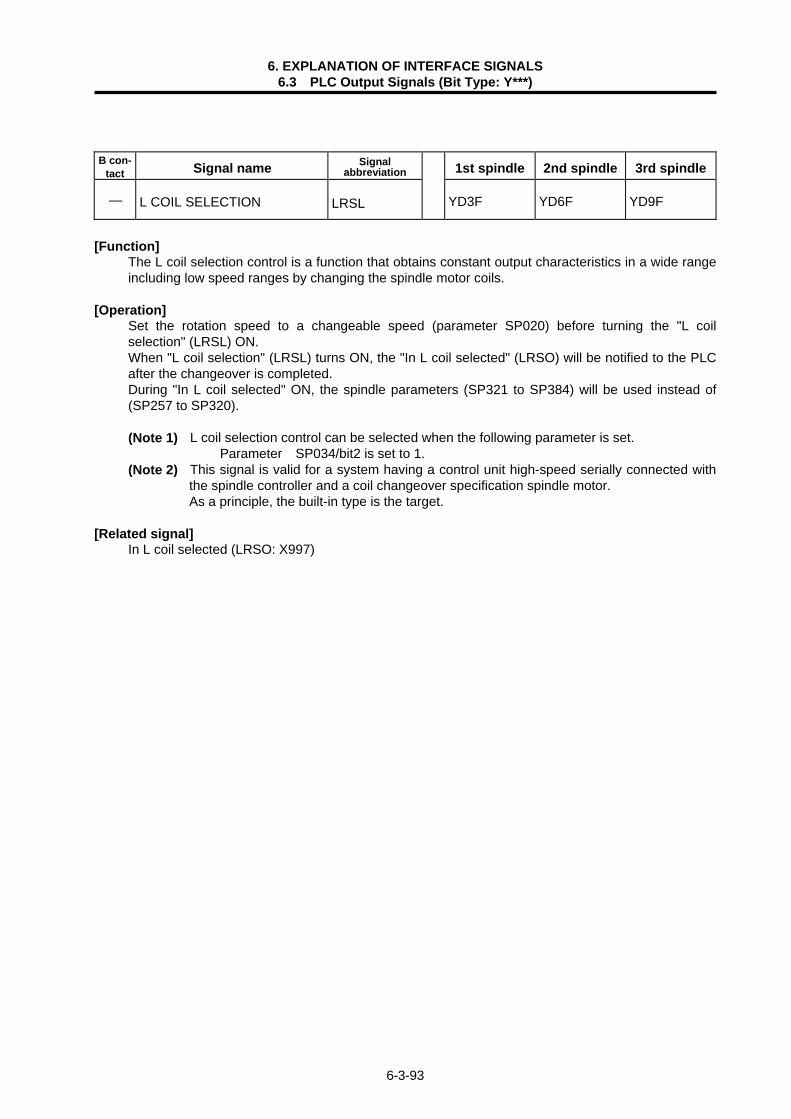
6. EXPLANATION OF INTERFACE SIGNALS 6.3 PLC Output Signals (Bit Type: Y***)
6-3-93
B con-
tact Signal name Signal abbreviation 1st spindle 2nd spindle 3rd spindle
— L COIL SELECTION LRSL YD3F YD6F YD9F
[Function] The L coil selection control is a function that obtains constant output characteristics in a wide range
including low speed ranges by changing the spindle motor coils. [Operation]
Set the rotation speed to a changeable speed (parameter SP020) before turning the "L coil selection" (LRSL) ON. When "L coil selection" (LRSL) turns ON, the "In L coil selected" (LRSO) will be notified to the PLC after the changeover is completed. During "In L coil selected" ON, the spindle parameters (SP321 to SP384) will be used instead of (SP257 to SP320). (Note 1) L coil selection control can be selected when the following parameter is set.
Parameter SP034/bit2 is set to 1. (Note 2) This signal is valid for a system having a control unit high-speed serially connected with
the spindle controller and a coil changeover specification spindle motor. As a principle, the built-in type is the target.
[Related signal]
In L coil selected (LRSO: X997)

6-4-1
6.4 PLC Output Signals (Data Type: R***)

6. EXPLANATION OF INTERFACE SIGNALS 6.4 PLC Output Signals (Data Type: R***)
6-4-2
B con-
tact Signal name Signal abbreviation 1st system 2nd system 3rd system
— ANALOG OUTPUT AOn R100~103 — —
[Function] An analog voltage can be output from the designated connector pins (see below) on the remote I/O
unit DX120/DX121 by setting designated data in the file registers. [Operation] "Analog voltage" signal (for speed control) can be output by setting signed binary data to the
corresponding file register. The analog output interface is explained below.
Channel File register (R)
Remote I/O unit DX120/DX121 output destination
A01 R100 Channel setting switch is set to 1st card B04, A04 (Common) A02 R101 Channel setting switch is set to 3rd card B04, A04 (Common) A03 R102 Channel setting switch is set to 5th card B04, A04 (Common) A04 R103 Channel setting switch is set to 7th card B04, A04 (Common)
<Relation of file register details and analog output voltage> Analog output (V)
-4095
4095
-1000 0
10
-2.44
-10
File register details
<Relation of file register details and output voltage>
Rn n = 100~103
215 214 213 212 211 210 29 28 27 26 25 24 23 22 21 20
1 1 1 1 1 1 0 0 0 0 0 1 1 0 0 0
The data is input as binary coded data.
(1) Output voltage : -10V~+10V (±5%) Resolution : 212 (1/4095) × Fullscal Load conditions : 10kohm resistance load (standard) Output impedance : 220ohm
Output voltage = × 10V = -2.44V
-1000 4095
The output voltage is
When -1000 (FC18 with hexadecimal)

6. EXPLANATION OF INTERFACE SIGNALS 6.4 PLC Output Signals (Data Type: R***)
6-4-3
B con-
tact Signal name Signal abbreviation 1st system 2nd system 3rd system
— KEY OUT 1 R112 — —
[Function] When this signal is used, key data can be entered on the user PLC side instead of the CNC
keyboard. [Operation]
1
2
3
4 Key data processing (CNC)
User PLC
R8
R112
For monitor
KEY IN 1
KEY OUT 1
(1) Key data is set to file registers R8 and R112 at the head of user PLC main program. (2) The user PLC refers to the key data, and performs required processing. (3) The user PLC sets the key data which meets the keyboard currently in use to register R112. (4) The controller processes the effective key data after the main program of user PLC has been
processed, referring to the settings of R8 and R112.
(Note 1) For details of key data and processing timing, refer to the Instruction Manual for "PLC programming" ("key operation using user PLC").
[Related signals] (1) KEY IN 1 (R8)

6. EXPLANATION OF INTERFACE SIGNALS 6.4 PLC Output Signals (Data Type: R***)
6-4-4
B con-
tact Signal name Signal abbreviation 1st system 2nd system 3rd system
— ALARM MESSAGE I/F 1~4 R118~121 — —
[Function] PLC development tool or alarm message prepared can be displayed in ALARM DIAGNOSIS screen
when values (binary code) is set to alarm interface file registers (Rn, Rn+1, Rn+2, Rn+3). [Operation] When table No. of previously prepared alarm message table has been set to alarm interface file
registers, alarm message, if alarm occurs, can be displayed in ALARM DIAGNOSIS screen. Maximum 4 alarm messages can be displayed at the same time. Alarm message can be cleared by setting "0" to alarm interface file registers. For details of alarm message display, refer to the "PLC Programming Manual". [Caution] (1) Set setup parameter PLC "#6450 bit 0" to 1 to display the alarm messages. (2) For alarm message interface, file register (R) or temporary storage (F) can be used. The
selection is made with Setup parameter PLC "#6450 bit 1". (3) In both file register method and temporary storage method, alarm does extend to the controller. When it is desirous to stop controller operation in case of alarm, "Auto operation "pause"
command (*SP)" signal, "Single block" (SBK) signal or interlock signal should be prepared on the PLC side.
B con-
tact Signal name Signal abbreviation 1st system 2nd system 3rd system
— OPERATOR MESSAGE I/F R122 — —
[Function] Desired operator message prepared by PLC development tool can be displayed by setting value
(binary code) to operator message interface file register (Rn). Operator message appears in ALARM DIAGNOSIS screen.
[Operation] When table No. of previously prepared operator message table is set to operator message interface
file register, operator message can be displayed in ALARM DIAGNOSIS screen. Operator message can be cleared by setting "0" to operator message interface file register. For details of operator messages, refer to the "PLC Programming Manual". [Caution] (1) Set setup parameter PLC "#6450 bit 2" to 1 to display the operator messages. (2) Display of operator message does not cause alarm on the controller side. When it is desirous to
stop controller operation in case of operator message display, "Auto operation "pause" command (*SP)" signal, "Single block" (SBK) signal or interlock signal should be prepared on the PLC side.

6. EXPLANATION OF INTERFACE SIGNALS 6.4 PLC Output Signals (Data Type: R***)
6-4-5
B con-
tact Signal name Signal abbreviation 1st system 2nd system 3rd system
— RESPONSE MONITOR TIMER R123 — —
[Function]
The maximum time to wait, after the data is transmitted, for a response from the client device to which data was sent is set.
[Operation]
When the send connection is opened with "procedural", once the data is sent, the system will wait for a response from the client device to which the data was sent. Set the maximum value for this wait time as the response monitor timer value. If a response is not received within the set timer, the BUFSND command will end as an error. (The control data complete status will become C022H.) The setting range is 2 to 32767 (0.5s unit). The default is "60".

6. EXPLANATION OF INTERFACE SIGNALS 6.4 PLC Output Signals (Data Type: R***)
6-4-6
B con-
tact Signal name Signal abbreviation 1st system 2nd system 3rd system
— USER MACRO OUTPUT #1132 (Controller -> PLC)
R124, 125 — —
[Function] This is interface function used to coordinate user PLC to user macro. (Note) The other signals from R100 to R199 are PLC outputs, but this signal is the PLC input
signal. [Operation] When a value is set in the system variables #1100~#1131 or #1132 with the user macro system,
the user PLC output to the file register Rn and Rn+1 corresponding to the user PLC can be referred to with that value.
The relationship between system variable and file register is as follows:
System variable
Points Interface output signal System variable
Points Interface output signal
#1100 #1101 #1102 #1103 #1104 #1105 #1106 #1107 #1108 #1109 #1110 #1111 #1112 #1113 #1114 #1115
1 1 1 1 1 1 1 1 1 1 1 1 1 1 1 1
Register R124 bit 0 Register R124 bit 1 Register R124 bit 2 Register R124 bit 3 Register R124 bit 4 Register R124 bit 5 Register R124 bit 6 Register R124 bit 7 Register R124 bit 8 Register R124 bit 9 Register R124 bit 10 Register R124 bit 11 Register R124 bit 12 Register R124 bit 13 Register R124 bit 14 Register R124 bit 15
#1116 #1117 #1118 #1119 #1120 #1121 #1122 #1123 #1124 #1125 #1126 #1127 #1128 #1129 #1130 #1131
1 1 1 1 1 1 1 1 1 1 1 1 1 1 1 1
Register R125 bit 0 Register R125 bit 1 Register R125 bit 2 Register R125 bit 3 Register R125 bit 4 Register R125 bit 5 Register R125 bit 6 Register R125 bit 7 Register R125 bit 8 Register R125 bit 9 Register R125 bit 10 Register R125 bit 11 Register R125 bit 12 Register R125 bit 13 Register R125 bit 14 Register R125 bit 15
System variable
Points Interface output signal
#1132 #1133 #1134 #1135
32 32 32 32
Register R124, R125 Register R126, R127 Register R128, R129 Register R130, R131
File registers R124 and R125 correspond to system variables #1100~#1131, and #1132 (32-bit
data). [Related signals] (1) User macro output #1133, #1134, #1135 (R126/127, R128/129, R130/131) (2) User macro input #1032, #1033, #1034, #1035, #1000~#1031 (R24/25, R26/27, R28/29,
R30/31)
This correspondence table shows the examplefor file registers R124 and R125.

6. EXPLANATION OF INTERFACE SIGNALS 6.4 PLC Output Signals (Data Type: R***)
6-4-7
B con-
tact Signal name Signal abbreviation 1st system 2nd system 3rd system
— USER MACRO OUTPUT #1133 (Controller -> PLC)
R126, 127 — —
[Function] This provides interface function used to coordinate user PLC to user macro. (Note) The other signals from R100 to R199 are PLC outputs, but this signal is the PLC input
signal. [Operation] When a value is set in the system variable #1133 with the user macro system, the user PLC output
to the file register Rn and Rn+1 corresponding to the user PLC can be referred to with that value. (Example)
ACT DMOV
User macro program Sequence program
R126 D100#1133 = 1000
1000 is input in D100 and 101 when the ACT signal turns on.
? ?
[Related signals] (1) User macro output #1132, #1134, #1135, #1100~#1131 (R124/125, R128/129, R130/131) (2) User macro input #1032, #1033, #1034, #1035, #1000~#1031 (R24/25, R26/27, R28/29,
R30/31) B con-
tact Signal name Signal abbreviation 1st system 2nd system 3rd system
USER MACRO OUTPUT #1134 (Controller -> PLC)
PC R128, 129 — —
[Function] [Operation] The function operation, etc. are the same as those of "USER MACRO OUTPUT #1133". B con-
tact Signal name Signal abbreviation 1st system 2nd system 3rd system
USER MACRO OUTPUT #1135 (Controller -> PLC)
PC R130, 131 — —
[Function] [Operation] The function operation, etc. are the same as those of "USER MACRO OUTPUT #1133".

6. EXPLANATION OF INTERFACE SIGNALS 6.4 PLC Output Signals (Data Type: R***)
6-4-8
B con-
tact Signal name Signal abbreviation 1st system 2nd system 3rd system
— USER PLC VERSION CODE R132~135 — —
[Function] The user PLC version can be displayed with the software version that controls the other controller
on the setting and display unit (communication terminal) DIAGN/IN/OUT -> menu changeover configuration (menu).
[Operation] Characters to be displayed are placed in ASCII code. <Display format> PLCu BND − W − <Interface> BND − 4 1 2 W 3 4 5 − A 0 <Program example>
? ? ?
?
ACT
DMOV H34 31 32 33 R134
Always turn ON at the first scan of the user PLC (constant also possible).
DMOV H34 35 41 30 R132
: Alphabet is used. : Numeric is used.
Version code ("A0" for 1st version) : Renewed at major revision A~Z
(I and O should not be used.) : Renewed at minor revision 0~9
3 digits can be used (no restriction).
3 digits can be used (no restriction).
R132 (41 30)
R133 (34 35)
R134 (32 33)
R135 (34 31)
"HIGH" side of R* "LOW" side of R*
InterfaceASCII code
•••••
•••••
•••••
•••••

6. EXPLANATION OF INTERFACE SIGNALS 6.4 PLC Output Signals (Data Type: R***)
6-4-9
B con-
tact Signal name Signal abbreviation 1st axis 2nd axis 3rd axis
— AXIS INDEX R140 R141 R142
[Function] PLC I/F of each axis is allocated from the 1st axis of 1st part system in order, but if the axis
structure of each part system is changed, PLC I/F corresponding to that will be changed. In that case, the PLC I/F’s allocation of each axis is set randomly to make the PLC program in common with the I/F.
[Operation] In the following example, when the 1st part system is a two or three-axes structure and the 2nd part
system is a one-axis structure, it is impossible to make the PLC program in common because the axis I/F of 2nd part system is changed by the axis structure of 1st part system. Then, by changing the allocation with the axis index, the allocation of 2nd part system is fixed and the PLC program can be made in common.
Axis index
Axis I/F after the allocation ischanged with the axis index.
1st part system 2 axes • 2nd system part 1 axis
1st part system 3 axes • 2nd part system 1axis
X440 $1 1st axis Y440
$1 1st axis X460
$1 2nd axis
X480 $2 1st axis
Y470 $1 2nd axis
Y4A0 $2 1st axis
X440 $1 1st axis Y440
$1 1st axis X460
$1 2nd axis
X480 $1 3rd axis
Y470 $1 2nd axis
X4A0 $2 1st axis
Y4A0
$1 3rd axis
Y4D0
$2 1st axis
X440 $1 1st axis Y440
$1 1st axisX460
$1 2nd axis
X480 $2 1st axis
Y470 $1 2nd axis
X4A0 $1 3rd axis
Y4A0
$2 1st axis
Y4D0 $1 3rd axis
Axis index
R140 0
R141 0
R142 0
R140 0
R141 0
R142 4
R143 3
Move 3rd axis to 4th axis. Move 4th axis to 3rd axis.

6. EXPLANATION OF INTERFACE SIGNALS 6.4 PLC Output Signals (Data Type: R***)
6-4-10
B con-
tact Signal name Signal abbreviation 1st system 2nd system 3rd system
— SPINDLE SYNCHRONOUS FUNCTION BASIC SPINDLE SELECT
R157 — —
[Function] Select the basic spindle to be used for synchronous control from the PLC. [Operation] Select the spindle to be controlled as the basic spindle from the serially connected spindles. (0: 1st spindle), 1: 1st spindle, 2: 2nd spindle … 7: 7th spindle (Note 1) If a spindle that is not serially connected is selected, spindle synchronous control will not
be executed. (Note 2) If "0" is designated, the 1st spindle will be controlled as the basic spindle. B con-
tact Signal name Signal abbreviation 1st system 2nd system 3rd system
—
SPINDLE SYNCHRONOUS FUNCTION SYNCHRONOUS SPINDLE SELECT
R158 — —
[Function] Select the synchronous spindle to be used for synchronous control from the PLC. [Operation] Select the spindle to be controlled as the synchronous spindle from the serially connected spindles. (0: 2nd spindle), 1: 1st spindle, 2: 2nd spindle … 7: 7th spindle (Note 1) If a spindle that is not serially connected is selected or if the same spindle as the basic
spindle is selected, spindle synchronous control will not be executed. (Note 2) If "0" is designated, the 2nd spindle will be controlled as the synchronous spindle. B con-
tact Signal name Signal abbreviation 1st system 2nd system 3rd system
— SPINDLE SYNCHRONOUS FUNCTION PHASE SHIFT AMOUNT
R159 — —
[Function] The synchronous spindle's phase shift amount can be designated from the PLC. [Operation] Designate the phase shift amount for the synchronous spindle. Unit: 360°/4096 [Related signals] In spindle synchronous control (SPSYN1: X42A) Spindle rotation speed synchronization complete (FSPRV: X42B) Spindle phase synchronization complete (FSPPH: X42C) Spindle synchronous control (SPSY: Y432) Spindle phase synchronous control (SPPHS: Y433) Spindle synchronous rotation direction (SPSDR: Y434)

6. EXPLANATION OF INTERFACE SIGNALS 6.4 PLC Output Signals (Data Type: R***)
6-4-11
B con-
tact Signal name Signal abbreviation 1st system 2nd system 3rd system
— USER PLC VERSION CODE 2 R160~166 — —
[Function] This signal enables the user PLC version to be displayed, together with the software version
controlling another control unit, in the DIAGN/IN/OUT configuration display (menu) of the setting display unit (communication terminal).
[Operation] The ASCII code that corresponds to the character to be displayed in the version display interface is
set. <Display format and usage example> P L C u : Random alphanumeric Total of 14 characters characters are used. <Display example> P L C u 6 L 8 4 0 1 2 3 4 5 6 7 8 9 <Program example>
DMOV H36 37 38 39 R160
DMOV H32 33 34 35 R162
DMOV H38 34 30 31 R164
MOV H36 4C R166
ACT
Always turn ON at the 1st scan of the user PLC. (Can be left ON constantly.)
"HIGH" side of R* "LOW" side of R*
R160 (38 39)
R161 (36 37)
R162 (34 35)
R163 (32 33)
R164 (30 31)
R165 (38 34)
R166 (36 4C)
InterfaceASCII code
••••
••••
••••
••••
••••
••••
••••

6. EXPLANATION OF INTERFACE SIGNALS 6.4 PLC Output Signals (Data Type: R***)
6-4-12
B con-
tact Signal name Signal abbreviation 1st system 2nd system 3rd system
— ADD-ON (EXPANSION) OPERATION BOARD OUTPUT
#1:R190~192#2:R193~195 — —
[Function] By adding the remote I/O unit to the communication terminal, the machine operation board
input/output signals can be input and output with the communication terminal control signals. [Operation] The signals are output together with other output signals at start of PLC main processing (medium
speed).
<Hardware block diagram>
#1
Controller
Communicationterminal Remote
I/O unit
RemoteI/O unit
#2
(Channel setting 0)
(Channel setting 2)
Machine operation board(switches, lamps, etc.)
(Note 1) This is conventionally a bit unit signal, so create it in the temporary memory (M) and then
transfer it to the corresponding file register (R) before using.
<Sequential control program example>
M576< >• • • • • • • •
X0
X0
?
?
? ?
?
?
Contents stored in M576 ~ M607 aretransferred to R190 and R191.
Contents stored in M608 ~ M623 aretransferred to R192.
DMOV K8M576 R190
DMOV K4M608 R192
(Note 2) Refer to the section "2.1 Relation of RIO Unit and Devices" for the relation of the remote
I/O channel setting switch and device. [Related signals] (1) Add-on (expansion) operation board input (#1: R90~93, #2: R94~97)

6. EXPLANATION OF INTERFACE SIGNALS 6.4 PLC Output Signals (Data Type: R***)
6-4-13
B con-
tact Signal name Signal abbreviation 1st system 2nd system 3rd system
— 1ST CUTTING FEEDRATE OVERRIDE (File register method)
R900 R1000 R1100
[Function] When "Cutting feedrate override method select " (FVS) is set to "file register method", override
(0~300%, 1% increment) can be exerted on the cutting feedrate. Desired value is set to file register (R) in binary code.
[Operation] When override is exerted to the preset feedrate, the true feedrate is the product obtained by
multiplying the preset feedrate by the specified override ratio (provided that "2nd cutting feedrate override" is not valid).
The override ratio is fixed to 100%, irrespective of 1st cutting feedrate override setting, under the following condition:
(1) "Override cancel" (OVC) signal is ON (2) During tapping in fixed cycle (3) During TAPPING mode (4) During thread cutting
(Note) Only when override setting is 0%, override is exerted even on rapid traverse speed in automatic operation. That is, cutting feed as well as rapid traverse stop if the 1st cutting feedrate override is set to 0% during automatic operation. When override setting is 0%, "M01 OPERATION ERROR" appears in the alarm display section of screen, and "M01 OPERATION ERROR 0102" in the ALARM DIAGNOSIS display.
[Related signals] (1) Cutting feedrate override (*FV1~*FV16: Y760~764) (2) Cutting feedrate override method select (FVS: Y767) (3) 2nd cutting feedrate override valid (FV2E: Y766) (4) 2nd cutting feedrate override (file register method)
For relationship among these signals, refer to the description the cutting feedrate override. B con-
tact Signal name Signal abbreviation 1st system 2nd system 3rd system
— 2ND CUTTING FEEDRATE OVERRIDE (File register method)
R901 R1001 R1101
[Function] When the 2nd cutting feedrate override valid function (FV2E) is used, another override can be
exerted on feedrate overrided by "Cutting feedrate override" (*FV1~*FV16) in code feedrate method, or by "1st cutting feedrate override (file register method)". The 2nd cutting feedrate override can be set within range from 0% to 327.67% with 0.01% increment. Value of override ratio is set in binary code system to file register.

6. EXPLANATION OF INTERFACE SIGNALS 6.4 PLC Output Signals (Data Type: R***)
6-4-14
[Operation] When this override function is used, the true feedrate is the product obtained by multiplying
commanded feedrate (F) by "1st cutting feedrate override" ratio and "2nd cutting feedrate override" ratio.
Since the least increment of 2nd cutting feedrate override is 0.01%, override setting "10000" corresponds to 100%.
The override ratio is fixed to 100%, irrespective of 1st cutting feedrate override setting, under the following condition:
(1) "Override cancel" (OVC) signal is ON (2) During tapping in fixed cycle (3) During TAPPING mode (4) During thread cutting
(Note) Only when override setting is 0%, override is exerted even on rapid traverse speed in automatic operation. That is, cutting feed as well as rapid traverse stop if the 1st override feedrate is set to 0% during automatic operation. When override setting is 0%, "M01 OPERATION ERROR" appears in the alarm display section of CRT screen, and "M01 OPERATION ERROR 0102" in the ALARM DIAGNOSIS display.
[Related signals] (1) Cutting feedrate override (*FV1~*FV16: Y760~764) (2) Cutting feedrate override method select (FVS: Y767) (3) 2nd cutting feedrate override (file register) (4) 2nd cutting feedrate override valid (FV2E: Y766)
For relationship among these signals, refer to the description about the cutting feedrate override. B con-
tact Signal name Signal abbreviation 1st system 2nd system 3rd system
— RAPID TRAVERSE OVERRIDE (File register method)
R902 R1002 R1102
[Function] The rapid traverse override specified with values (ROVS) provides the override control within the
range of 0% to 100% by 1% increments in addition to the normal override specified with codes (ROV1, ROV2). The value is set in the file register (R) in binary.
[Operation] During rapid traverse in the automatic or manual operation, the actual feed rate will be the result of
multiplying this override ratio by the rapid traverse speed set in a parameter.
(Note 1) The override will be clamped at 100%. (Note 2) No operation error messages are indicated even if the value is set to 0%. [Related signals] (1) Rapid traverse speed override (code method: ROV1, ROV2: Y768, 769) (2) Rapid traverse override method select (ROVS: Y76F)

6. EXPLANATION OF INTERFACE SIGNALS 6.4 PLC Output Signals (Data Type: R***)
6-4-15
B con-
tact Signal name Signal abbreviation 1st system 2nd system 3rd system
— MANUAL FEEDRATE (File register method) R904, 905 R1004, 1005 R1104, 1105
[Function] When file register method (JVS) is selected for feedrate setting, feedrate can be specified, besides
code method (*JV1~JV16) setting, by setting desired feedrate ratio manually (value is set to file register (R)).
[Operation] This method of feedrate setting can be used in JOG feed, incremental feed, reference point return
feed and manual random feed mode. For JOG, INCREMENTAL and reference point return mode, "Rapid traverse speed" (RT) signal should be OFF. For manual random feed mode, "EX.F/MODAL.F" signal (CXS3) should be OFF. Feedrate specified in this method can be applied to feed motion in dry run (automatic operation).
The use of this signal is conditioned as follows: (1) When "Manual feedrate override valid" signal (OVSL) is OFF, the originally set feedrate is
applied. (2) When "Manual feedrate override valid" signal (OVSL) is ON, the feedrate override ratios of "1st
cutting feedrate override" and "2nd cutting feedrate override" are applied to the originally set feedrate.
(3) Manual feedrate is set to file registers Rn and Rn+1. The feedrate depends on "feedrate least increment" (PCF1, PCF2) as listed below.
PCF2 PCF1 Least increment (mm/min or inch/min)
Operation
0 0 10 10mm/min (inch/min) when "1" is set in file registers. 0 1 1 1mm/min (inch/min) when "1" is set in file registers. 1 0 0.1 0.1mm/min (inch/min) when "1" is set in file registers. 1 1 0.01 0.01mm/min (inch/min) when "1" is set in file registers.
(4) Feedrate clamp (max. feedrate) depends on setting of axis parameter (cutting feedrate clamp)
... when "Rapid traverse" signal (RT) is OFF.
(Note 1) During incremental feed mode, the true feedrate does not change even when the manual feedrate setting is changed while feed motion is going on.
(Note 2) As for file registers (Rn and Rn+1), Rn is of lower order. Of the file registers Rn and Rn+1 which designate the feedrate, if the value is 2-bytes (one
word), the high-order side does not need to do anything. [Related signals] (1) Manual feedrate (code method: *JV1~*JV16: Y770~774) (2) Manual feedrate method select (JVS: Y777)

6. EXPLANATION OF INTERFACE SIGNALS 6.4 PLC Output Signals (Data Type: R***)
6-4-16
B con-
tact Signal name Signal abbreviation 1st system 2nd system 3rd system
—
HANDLE 1 HANDLE FEED RANDOM MULTIPLICATION/ INCREMENTAL FEED RANDOM MULTIPLICATION (File register method)
R908, 909 R1008, 1009 R1108, 1109
[Function] When "Handle 1 handle feed random multiplication/incremental feed random multiplication mode
(MPS)" signal is used, amount of feed per pulse or command signal can be multiplied by value set to file register. Multiplication value (multiplier) is set in binary code to file register (R).
[Operation] Multiplication is applied to amount of feed per pulse in handle feed mode (output from manual pulse
generator), or to amount of feed per signal in incremental feed mode (+J1, −J1, etc.). When multiplier is "500" and one pulse is given in handle feed mode, for example, 500µm of feed
motion occurs. When multiplier is "30000" and one feed command signal is given in incremental feed mode, 30mm of feed motion occurs (time constant for feed motion is equal to time constant for rapid traverse or step).
(Note 1) Change of multiplication setting during feed motion is ignored. (Note 2) Since considerably large multiplication can be used, the signal should be used carefully. [Related signals]
(1) Handle feed multiplication/Incremental feed multiplication (code method: MP1, MP2, MP4: Y780, 781, 782)
(2) Handle/incremental feed multiplication method select (MPS: Y787) B con- Tact Signal name Signal
abbreviation 1st system 2nd system 3rd system
—
HANDLE 2 HANDLE FEED RANDOM MULTIPLICATION HANDLE 3 HANDLE FEED RANDOM MULTIPLICATION (File register method)
2: R910, 9113: R912, 913
R1010, 1011 R1012, 1013
R1110, 1111R1112, 1113
[Function]
When the random multiplication setting method (MPS) is selected for the handle feed multiplication, a random multiplication can be designated separately from the multiplication using the normal code method. The multiplication value is set as a binary in the file register (R). The random multiplication for handle 2 and handle 3 is designated here.
[Operation] The amount moved when one pulse is sent with handle 2 or handle 3 is the rate following this feed multiplication. For example, if the multiplier is set as "500", the axis will move 500µm when one pulse is fed with the handle mode. (The time constant for movement is the cutting feed time constant or stop.)
(Note 1) Change of multiplication setting during feed motion is ignored. (Note 2) Since considerably large multiplication can be used, the signal should be used carefully. [Related signals]
(1) Handle feed multiplication/Incremental feed multiplication (code method: MP1, MP2, MP4: Y780, 781, 782)
(2) Handle 1 handle feed random multiplication/ Incremental feed multiplication (R908) (3) Handle/incremental feed multiplication method select (MPS: Y787)

6. EXPLANATION OF INTERFACE SIGNALS 6.4 PLC Output Signals (Data Type: R***)
6-4-17
B con-
tact Signal name Signal abbreviation 1st system 2nd system 3rd system
— MANUAL RANDOM FEED 1ST AXIS MOVEMENT DATA R914, 915 R1014, 1015 R1114, 1115
[Function] This data specifies the amount of movement or positioning point in manual random feed mode. [Operation]
"Manual random feed 1st axis movement data" is for the axis whose number is specified by "Manual random feed 1st axis axis number (CX11~CX116)". "Manual random feed 1st axis movement data" (R914, R915) means differently depending on the statuses of the "MC/WK (CXS5)" and "ABS/INC (CXS6)" signals.
(1) When the ABS/INC (CXS6) signal is ON: This file register (R914, R915) specifies the amount of movement (increment). (2) When the "ABS/INC (CXS6)" signal is OFF, it depends on the status of the "MC/WK (CXS5)"
signal as follows: 1) When the MC/WK (CXS5) signal is OFF: This file register (R914, R915) specifies a coordinate value (positioning point) of the
machine coordinate system. 2) When the MC/WK (CXS5) signal is ON: This file register (R914, R915) specifies a coordinate value (positioning point) of the
modal workpiece coordinate system. This file register (R914, R915) is written in binary notation with a sign. The unit of the specified value matches that of data entered.
Ex.: When (R915, R914)=1 is specified in micro meter system, axis motion is one µm (at incremental specification).
[Caution] MANUAL RANDOM FEED 1ST AXIS MOVEMENT DATA forms a data item by R914 and R915 or
R1014 and R1015. Handle negative data carefully. [Related signals] For related signals, see the descriptions on "Manual random feed mode (PTP)." B con-
tact Signal name Signal abbreviation 1st system 2nd system 3rd system
— MANUAL RANDOM FEED 2ND AXIS MOVEMENT DATA R916, 917 R1016, 1017 R1116, 1117
[Function] [Operation] "Manual random feed 2nd axis movement data" is for the axis whose number is specified by
"Manual random feed 2nd axis axis number (CX21~CX216)." The other conditions are the same as for "Manual random feed 1st axis movement data" explained
in the previous section.

6. EXPLANATION OF INTERFACE SIGNALS 6.4 PLC Output Signals (Data Type: R***)
6-4-18
B con-
tact Signal name Signal abbreviation 1st system 2nd system 3rd system
— MANUAL RANDOM FEED 3RD AXIS MOVEMENT DATA R918, 919 R1018, 1019 R1118, 1119
[Function] [Operation]
"Manual random feed 3rd axis movement data" is for the axis whose number is specified by "Manual random feed 3rd axis axis number (CX31~CX316)."
The other conditions are the same as for "Manual random feed 1st axis movement data" explained in the previous section.
B con-
tact Signal name Signal abbreviation 1st system 2nd system 3rd system
— OT IGNORED R920 R1020 R1120
[Function] When this signal is used, stroke end error can be avoided without eternal wiring for stroke end
signal (remote I/O connector pin No. fixed singal) provided for each axis. "Stroke end" signal ON axis for which the "OT ignored" signal is set can be used for other purpose.
[Operation] "Stroke end" signal associated with a specific axis motion can be ignored. The interface for this signal is as follows:
File register (R) F E D C B A 9 8 7 6 5 4 3 2 1 0 (Note 1) The signal is applicable to (+) and (-) motion at the same time (ignored when "ON"). (Note 2) "OT" is abbreviation of "Over Travel".
Bit
1st axis OT ignored 2nd axis OT ignored
: 14th axis OT ignored

6. EXPLANATION OF INTERFACE SIGNALS 6.4 PLC Output Signals (Data Type: R***)
6-4-19
B con-
tact Signal name Signal abbreviation 1st system 2nd system 3rd system
— NEAR-POINT DOG IGNORED R921 R1021 R1121
[Function] When this signal is used, "Near-point detected" signal (remote I/O connector pin No. fixed signal)
which is used for dog type reference point return can be ignored (tripping of near switch can be ignored).
The selection of two or more near-point dogs with conditions, or the activation of the "Near-point detected" signal at a position not desirable due to the machine structure can seemingly be ignored. Furthermore, the "Near-point detected" signal for an axis to which the "Near-point dog ignored" signal is set can be used for other applications.
[Operation] When the signal is turned ON, "Near-point detected" signal corresponding to the control axis can be
ignored. The interface is shown below:
File register (R) F E D C B A 9 8 7 6 5 4 3 2 1 0 B con-
tact Signal name Signal abbreviation 1st system 2nd system 3rd system
— TOOL GROUP NUMBER DESIGNATION R930 R1030 R1130
[Function] The group number is designated when the usage data of the group of which the tool life has been
exceeded with tool life management II is to be cleared, or when the tool being used is to be forcibly changed.
[Operation] The group designation range is as follows. For group designation: 1 ~ 9999 of group number For all groups : 65535 (all 1) [Related signal] (1) Tool change reset (TRST)
Bit
1st near point ignored 2nd near point ignored
: 14th near point ignored

6. EXPLANATION OF INTERFACE SIGNALS 6.4 PLC Output Signals (Data Type: R***)
6-4-20
B con-
tact Signal name Signal abbreviation 1st system 2nd system 3rd system
— SYNCHRONIZATION CONTROL OPERATION METHOD SELECTION
R932 R1032 R1132
[Function] The synchronization control’s ON/OFF can be changed over by operating the bit corresponding to
each axis of this signal. NC changes over the operation at the point when all axes enter in-position state.
7 6 5 4 3 2 1 0
[Operation] (1) Designation of the synchronization operation method
Turn ON both the bits corresponding to the basic axis and synchronous axis with the base specifications parameters “slavno”.
(Example) When the 2nd axis (basic axis) and 3rd axis (synchronous axis) are operated by the synchronous operation… 7 6 5 4 3 2 1 0 HEX
R932 o o o o o o o o 00 o o o o o 1 1 o 06
(2) Designation of the independent operation method
Turn ON the bit corresponding to only one of the axes to be moved with the basic axis command.
(Example) When only the 2nd axis (synchronous axis) is moved... 7 6 5 4 3 2 1 0 HEX
R932 o o o o o o o o 00 o o o o o 1 o o 04
For the machine structure reasons, if the synchronous state must always be kept from immediately after the power is turned ON, set R932 register when the ladder power is turned ON at the first time.
Example of the ladder creation
• • •
1st axis 2nd axis 3rd axis 4th axis 5th axis 6th axis
Synchronization control operation method selection (R932)
MOV H0C R932
Only turning the power ON atthe first time

6. EXPLANATION OF INTERFACE SIGNALS 6.4 PLC Output Signals (Data Type: R***)
6-4-21
When changing the operation with the R932 register during automatic operation, calculate the coordinates again.
After synchronous axis independent operation is carried out, the end point coordinates of the synchronous axis are substituted in the program end point coordinates for the basic axis. Thus, if the coordinates are not recalculated, the basic axis' movement command will not be created properly.
Request recalculation immediately after the R932 register is changed. <Example of ladder creation> Basic axis: 2nd axis Synchronous axis: 3rd axis When M code is assigned to each:
M10: Asynchronous operation M20: Independent operation M40: Synchronous operation
X230 = H10 R20 M2000 Miscellaneous function strobe (MF1) ON
and M10 commanded → M2000 ON
= H20 R20 M2001X230
= H40 R20 M2002X230
M2000 X1F8MOV H00 M2000 ON and motion command complete (DEN)
→ Asynchronous operation signal set M2001 X1F8
MOV H04 R932
M2002 X1F8MOV H06 R932
M2000
M2001
M2002
Y72B M2000 or M2001 or M2002 ON → Recalculation request (CRQ) set
Miscellaneous function strobe (MF1) ON and M20 commanded → M2001 ON
Miscellaneous function strobe (MF1) ON and M40 commanded → M2002 ON
M2001 ON and motion command complete (DEN) → Independent operation signal set
M2002 ON and motion command complete (DEN) → Synchronous operation signal set
Execution block
MF
DEN
Operation methodselection (R435)
All axes in-position
Operation method
Recalculationrequest (CRQ)
FIN
Calculation of nextblock
Movement (1)
Asynchronous
Synchronous
Recalculation
NC latchesat rising edge
Movement (2)
Asynchronous
Synchronous
M2002;(synchronization designation)

6. EXPLANATION OF INTERFACE SIGNALS 6.4 PLC Output Signals (Data Type: R***)
6-4-22
[Cautions] (1) During synchronous operation or independent operation, the basic axis signals are valid for
the "Interlock" and "Machine lock" signals, etc. (2) The synchronous axis will return to the reference position in synchronization with the basic
axis if G27, G28 or G30 is commanded during synchronous operation. If the synchronous axis is at the reference position when the basic axis completes reference position return, the reference position return will be completed. If the synchronous axis is not at the reference position when the basic axis completes reference position return, the "Reference position reached" signal for the basic axis will not be output.
(3) The position switches are processed independently for the basic axis and synchronous axis. (4) Input the same OT signal for the basic axis and synchronous axis.
Set the same soft limit value for the basic axis and synchronous axis. If the above settings cannot be made because of the machine specifications, observe the following points. • If OT or soft limit occurs during the manual operation mode, an alarm will occur only for the
synchronous axis, and the basic axis will not stop. Thus, make sure that the basic axis alarm turns ON before the synchronous axis.
• OT during the manual operation mode will cause the synchronous axis to stop when the OT signal for only the basic axis turns ON. The basic axis is stopped by the position controller, and the synchronous axis is stopped by the NC control unit. Thus, there may be a difference in the stop positions. If an excessive error alarm occurs because of OT, enter the editing mode, and cancel the alarm.
(5) The basic axis independent operation is handled as asynchronous, so the PLC input/output signal is not reflected on the synchronous axis.
(6) The error offset amount "∆" of "FB error (synchronous axis FB value, basic axis FB value, error offset amount "∆")" displayed on the screen: The error offset amount "∆" is made when the operation method is changed because the R932 register is changed. Note that if the zero point has not established, the error offset amount "∆" is made immediately after the zero point is established.
[Related signals] Synchronized correction mode (Y722) Recalculation request (CRQ: Y72B)

6. EXPLANATION OF INTERFACE SIGNALS 6.4 PLC Output Signals (Data Type: R***)
6-4-23
B con-
tact Signal name Signal abbreviation 1st system 2nd system 3rd system
— SEARCH & START PROGRAM NO. R938, R939 R1038, 1039 R1138, 1139
[Function] The No. of the program to be searched with search & start is designated. [Operation] Set the No. of the program to be searched with search & start with a binary value.
(Note 1) The program No. must be set before the search & start signal is input. (Note 2) If a machining program No. is not designated or if an illegal No. is designated, and error
signal will be output when the search operation is executed. [Related signals] (1) Search & start (SS: Y7B2) (2) Search & start error (SSE: X635) B con-
tact Signal name Signal abbreviation 1st system 2nd system 3rd system
— NO. OF WORK MACHINING (MAXIMUM VALUE) R940, R941 R1040, 1041 R1140, 1141
[Function] The No. of work machining maximum value are notified by the controller to the PLC. [Operation] Refer to the No. of work machining current value (R240, 241). B con-
tact Signal name Signal abbreviation 1st system 2nd system 3rd system
— LOAD METER 1, 2 R942~945 R1042~1045 R1142~1145
[Function] [Operation] The load meter can be displayed on the coordinate value screen just be setting a value in the
corresponding file register. Refer to the section on "load meter display" in the "PLC Programming Manual" for details.

6. EXPLANATION OF INTERFACE SIGNALS 6.4 PLC Output Signals (Data Type: R***)
6-4-24
B con-
tact Signal name Signal abbreviation 1st system 2nd system 3rd system
— USER MACRO INTERFACE INPUT FOR EACH PART SYSTEM #1032 TO 1035
R970, 971 R1070, 1071 R1170, 1171
[Function]
This interface is used between the user PLC and user macro program. The state of the interface input signal can be seen by reading the values for variables #1000 to #1035 and #1200 to #1295. Only 1 or 0 (1 = contact closed, 0 = contact open) is read as variable value. "Input" here refers to input from the PLC to NC.
[Operation]
All input signals from #1000 to #1031 can be read at once on the user macro side by reading the variable #1032 value. Similarly, the #1200 to #1231, #1232 to #1263 and #1264 to #1295 input signals can be read by reading the variable #1033 to #1035 values. #1000 to #1035 and #1200 to #1295 are read-only, and cannot be set on the left side of a calculation expression. Bit selection parameter (#6454/bit0) must be set to use the macro interface function for each part system. Refer to R24, R25 (#1032: PLC → controller) and R124, 125 (#1132: controller → PLC) for details on the user macro interface signals common for the part system.

6. EXPLANATION OF INTERFACE SIGNALS 6.4 PLC Output Signals (Data Type: R***)
6-4-25
(Note) This function's input and output signals are valid for up to three part systems when using the C64T system. Interface input signal System
variable No. of points 1st system 2nd system 3rd system 4th system 5th system 6th system 7th system
R970 R1070 R1170 R1270 R1370 R1470 R1570 #1000 1 bit0 bit0 bit0 bit0 bit0 bit0 bit0 #1001 1 bit1 bit1 bit1 bit1 bit1 bit1 bit1 #1002 1 bit2 bit2 bit2 bit2 bit2 bit2 bit2 #1003 1 bit3 bit3 bit3 bit3 bit3 bit3 bit3 #1004 1 bit4 bit4 bit4 bit4 bit4 bit4 bit4 #1005 1 bit5 bit5 bit5 bit5 bit5 bit5 bit5 #1006 1 bit6 bit6 bit6 bit6 bit6 bit6 bit6 #1007 1 bit7 bit7 bit7 bit7 bit7 bit7 bit7 #1008 1 bit8 bit8 bit8 bit8 bit8 bit8 bit8 #1009 1 bit9 bit9 bit9 bit9 bit9 bit9 bit9 #1010 1 bit10 bit10 bit10 bit10 bit10 bit10 bit10 #1011 1 bit11 bit11 bit11 bit11 bit11 bit11 bit11 #1012 1 bit12 bit12 bit12 bit12 bit12 bit12 bit12 #1013 1 bit13 bit13 bit13 bit13 bit13 bit13 bit13 #1014 1 bit14 bit14 bit14 bit14 bit14 bit14 bit14 #1015 1 bit15 bit15 bit15 bit15 bit15 bit15 bit15
Interface input signal System
variable No. of points 1st system 2nd system 3rd system 4th system 5th system 6th system 7th system
R971 R1071 R1171 R1271 R1371 R1471 R1571 #1016 1 bit0 bit0 bit0 bit0 bit0 bit0 bit0 #1017 1 bit1 bit1 bit1 bit1 bit1 bit1 bit1 #1018 1 bit2 bit2 bit2 bit2 bit2 bit2 bit2 #1019 1 bit3 bit3 bit3 bit3 bit3 bit3 bit3 #1020 1 bit4 bit4 bit4 bit4 bit4 bit4 bit4 #1021 1 bit5 bit5 bit5 bit5 bit5 bit5 bit5 #1022 1 bit6 bit6 bit6 bit6 bit6 bit6 bit6 #1023 1 bit7 bit7 bit7 bit7 bit7 bit7 bit7 #1024 1 bit8 bit8 bit8 bit8 bit8 bit8 bit8 #1025 1 bit9 bit9 bit9 bit9 bit9 bit9 bit9 #1026 1 bit10 bit10 bit10 bit10 bit10 bit10 bit10 #1027 1 bit11 bit11 bit11 bit11 bit11 bit11 bit11 #1028 1 bit12 bit12 bit12 bit12 bit12 bit12 bit12 #1029 1 bit13 bit13 bit13 bit13 bit13 bit13 bit13 #1030 1 bit14 bit14 bit14 bit14 bit14 bit14 bit14 #1031 1 bit15 bit15 bit15 bit15 bit15 bit15 bit15
Interface input signal System
variable No. of points 1st
system 2nd
system 3rd
system 4th
system 5th
system 6th
system 7th
system
Read variable
No.
#1032 32 R970, R971
R1070, R1071
R1170, R1171
R1270, R1271
R1370, R1371
R1470, R1471
R1570, R1571
#1000 to 1035
#1033 32 R972, R973
R1072, R1073
R1172, R1173
R1272, R1273
R1372, R1373
R1472, R1473
R1572, R1573
#1200 to 1231
#1034 32 R974, R975
R1074, R1075
R1174, R1175
R1274, R1275
R1374, R1375
R1474, R1475
R1574, R1575
#1232 to 1263
#1035 32 R976, R977
R1076, R1077
R1176, R1177
R1276, R1277
R1376, R1377
R1476, R1477
R1576, R1577
#1264 to 1295

6. EXPLANATION OF INTERFACE SIGNALS 6.4 PLC Output Signals (Data Type: R***)
6-4-26
B con-
tact Signal name Signal abbreviation 1st axis 2nd axis 3rd axis
— EXTERNAL MACHINE COORDINATE COMPENSATION DATA
R2300 R2350 R2400
[Function] This data compensates the basic machine coordinate system. The axis moves the amount equivalent to the set data (interpolation unit). The entire coordinate system value, including the basic machine coordinate system, will not change.
[Operation] When the "External machine coordinate compensation data" (R2300) is set, the axis will move the amount equivalent to that set value. The entire coordinate system value, including the basic machine coordinate system, will not change. <Data range> 8000 (HEX) to 7FFF (HEX) (Absolute compensation amount –32768 to 32767) Unit: Interpolation unit (0.5µm (0.05µm when using sub-micrometer specifications.)
B con-
tact Signal name Signal abbreviation 1st system 2nd system 3rd system
— EACH AXIS REFERENCE POINT SELECT R2301 — —
[Function]
Select the each axis reference point return position for manual reference point return. [Operation]
(1) This signal is valid when the reference point select method (Y207/W87) is ON. (2) Two bits are used for each axis to select the reference point.
(a) R register and corresponding axis R2301
F E D C B A 9 8 7 6 5 4 3 2 1 0
1st axis setting value
2nd axis setting value 3rd axis setting value 4th axis setting value 5th axis setting value 6th axis setting value
(b) Setting value and reference point No.
High-order bit Low-order bit Return position 0 0 1st reference point 0 1 2nd reference point 1 0 3rd reference point 1 1 4th reference point
[Related signals]
Reference point select method (M: Y737)

6. EXPLANATION OF INTERFACE SIGNALS 6.4 PLC Output Signals (Data Type: R***)
6-4-27
B con-
tact Signal name Signal abbreviation 1st axis 2nd axis 3rd axis
— THERMAL EXPANSION OFFSET COMPENSATION AMOUNT
R2302 R2352 R2402
[Function] [Operation] Set the compensation amount for the axis feed error caused by the ball screw's thermal expansion. Set "thermal expansion offset compensation amount" and "thermal expansion max. compensation amount" as a set for each axis. Refer to "thermal displacement compensation amount" (R1600) for details.
[Related signals] Thermal expansion max. compensation amount (R2303) Thermal displacement compensation amount (R1600)
B con-
tact Signal name Signal abbreviation 1st axis 2nd axis 3rd axis
— THERMAL EXPANSION MAX. COMPENSATION AMOUNT R2303 R2353 R2403
[Function] [Operation] Set the maximum compensation amount of the axis feed error caused by the ball screw's thermal expansion. Set "thermal expansion offset compensation amount" and "thermal expansion max. compensation amount" as a set for each axis. Refer to "displacement expansion compensation amount" (R1600) for details.
[Related signals] Thermal expansion offset compensation amount (R2302) Thermal displacement compensation amount (R1600)

6. EXPLANATION OF INTERFACE SIGNALS 6.4 PLC Output Signals (Data Type: R***)
6-4-28
B con-
tact Signal name Signal abbreviation 1st spindle 2nd spindle 3rd spindle
— SPINDLE COMMAND ROTATION SPEED OUTPUT R3210 R3240 R3270
[Function] By setting data of desired spindle speed to this signal, the spindle can be run at that speed. [Operation] When this signal is used, operation is same as the case where usual "Spindle command rotation
speed input" signal (R8, 9) is given. Difference is that when data is set by user PLC, priority is given to that data over spindle (S) command data specified in automatic operation, or by manual command setting.
User PLC main (medium-speed) operation pattern
(1) "Spindle command rotation speed input" is set at the head of user PLC main program (controller process).
(2) "Spindle command rotation speed output" data is rewritten by user PLC within this interval if necessary (PLC process).
(3) "Spindle command rotation speed output" data is processed at the end of user PLC and signal is given to spindle controller (controller process).
• • • •
(Note 1) "Spindle command rotation speed output" data is rewritten by user PLC for each scan
(constant). (Note 2) "Spindle override", "Spindle gear select input (GI1, GI2)", "Spindle stop (SSTP)", "Spindle
gear shift (SSFT)" and "Oriented spindle speed command (SORC)" conditions are added to spindle command rotation speed output data and sent to the spindle controller.
(Note 3) For flow of spindle (S) function command data, data update timing, etc., refer to the section for "Spindle command rotation speed input (R3000, 1)".
[Related signals]
(1) Spindle command rotation speed input (R3000, 3001) (2) Spindle command final data (R3002, 3003) (R3004, 3005) (D/A output method)

6. EXPLANATION OF INTERFACE SIGNALS 6.4 PLC Output Signals (Data Type: R***)
6-4-29
B con-
tact Signal name Signal abbreviation 1st spindle 2nd spindle 3rd spindle
— S ANALOG OVERRIDE (File register method) R3220 R3250 R3280
[Function] When "S analog override" signal (SPS) is used, override can be exerted on S analog speed
reference in file register method instead of the rapid traverse override with the code method (SP1~SP4). Override can be exerted within range of 0% to 200% (1% increment). Value is set in binary code to file register (R).
[Operation] When this function is used, the spindle actual speed is the product obtained by multiplying the
originally set spindle speed by override ratio set with this signal. Clamp spindle speed is the maximum or minimum speed which depends on "Spindle gear select
input" signal (GI1, GI2) ... clamp spindle speed is set by a parameter. Even when spindle speed exceeds the maximum or minimum speed, due to change of override setting, "Spindle gear select input" signal (GR1, GR2) does not automatically change.
0 Smini Smax1 Smax2 Smax3
G10
G20
G30
Applicable override range at gear stage 3
GR10 : Applicable override range at gear stage GR20 : Applicable override range at gear stage GR30 : Applicable override range at gear stage Smini : Minimum spindle speed (parameter) Smax1 : Maximum spindle speed at gear stage 1 (parameter) Smax2 : Maximum spindle speed at gear stage 2 (parameter) Smax3 : Maximum spindle speed at gear stage 3 (parameter)
(Note) Override is not valid (100%) under the following condition: (1) "Spindle stop" signal (SSTP) is ON. (2) During tapping mode (3) During thread cutting [Related signals] (1) S analog override is invalid (100%) (2) Spindle override method select (SPS: YD2F) (3) Spindle gear select input (GI1, GI2: YD30, D31) (4) Spindle stop (SSTP: YD34), Spindle gear shift (SSFT: YD35), Oriented spindle speed
command (SORC: YD36)

6. EXPLANATION OF INTERFACE SIGNALS 6.4 PLC Output Signals (Data Type: R***)
6-4-30
B con-
tact Signal name Signal abbreviation 1st spindle 2nd spindle 3rd spindle
— MULTI-POINT ORIENTATION POSITION DATA R3221 R3251 R3281
[Function] This signal notifies the orientation position to the controller (spindle controller). [Operation] The orient position at when the "Spindle orient command (ORC)" turns ON is input. The command is a 12-bit binary, and the command unit is as follows.
Command unit = 360/4096 [deg.]
This signal must be validated before the "Spindle orient command" signal turns ON (at least 30 ms before).
Orientation position (R3221)
Spindle orient command(ORC) At least 30 ms required.
[Related signal] (1) Spindle orient command (ORC: YD3E)

6. EXPLANATION OF INTERFACE SIGNALS 6.4 PLC Output Signals (Data Type: R***)
6-4-31
B con-
tact Signal name Signal abbreviation 1st spindle 2nd spindle 3rd spindle
— J2CT CONTROL COMMAND CTCM1~4, L, H
R3600~3603R3604, 3605
R3606~3609 R3610, 3611
R3612~3615R3616, 3617
[Function]
The MR-J2-CT link function connects the NC and MR-J2-CT (auxiliary axis), and controls up to 7 axis (C6: Maximum 5 axis) MR-J2-CT axes using command signals from the NC.
[Operation]
Signal name
J2CT control command 4
J2CT control command 3
J2CT control command 2
J2CT control command 1
J2CT control command L
J2CT control command H
Abbrev. CTCM4 CTCM3 CTCM2 CTCM1 CTCML CTCMH J2CT 1st axis R3600 R3601 R3602 R3603 R3604 R3605
J2CT 2nd axis R3606 R3607 R3608 R3609 R3610 R3611
J2CT 3rd axis R3612 R3613 R3614 R3615 R3616 R3617
J2CT 4th axis R3618 R3619 R3620 R3621 R3622 R3623
J2CT 5th axis R3624 R3625 R3626 R3627 R3628 R3629
J2CT 6th axis R3630 R3631 R3632 R3633 R3634 R3635
J2CT 7th axis R3636 R3637 R3638 R3639 R3640 R3641
J2CT control command 4 (R3600: CTCM4) J2CT control command 3 (R3601: CTCM3)
bit Abbrev. Name bit Abbrev. Name bit0 OV1 Override 1 bit0 ST1 Station selection 1 bit1 OV2 Override 2 bit1 ST2 Station selection 2 bit2 OV4 Override 4 bit2 ST4 Station selection 4 bit3 OV8 Override 8 bit3 ST8 Station selection 8 bit4 OV16 Override 16 bit4 ST16 Station selection 16 bit5 OV32 Override 32 bit5 ST32 Station selection 32 bit6 OV64 Override 64 bit6 ST64 Station selection 64 bit7 OV Override valid bit7 ST128 Station selection 128 bit8 Spare bit8 ST256 Station selection 256 bit9 Spare bit9 Spare
bit10 Spare bit10 Spare bit11 Spare bit11 Spare bit12 Spare bit12 Spare bit13 Spare bit13 Spare bit14 Spare bit14 Spare bit15 Spare bit15 Spare

6. EXPLANATION OF INTERFACE SIGNALS 6.4 PLC Output Signals (Data Type: R***)
6-4-32
J2CT control command 2 (R3602: CTCM2) J2CT control command 1 (R3603: CTCM1) bit Abbrev. Name bit Abbrev. Name bit0 ST Operation start bit0 *SVR Servo OFF bit1 DIR Rotation direction bit1 QEMG PLC emergency stop
bit2 STS Random point feed command valid
bit2 *PRT1 Data protect 1
bit3 PUS Stopper positioning command valid
bit3 MRST MC reset
bit4 MP1 Incremental feed magnification 1
bit4 *IT+ Interlock +
bit5 MP2 Incremental feed magnification 2
bit5 *IT- Interlock -
bit6 PR1 Operation parameter selection 1
bit6 RDF Ready OFF
bit7 PR2 Operation parameter selection 2
bit7 H Handle mode
bit8 Spare bit8 AUT Automatic operation mode bit9 Spare bit9 MAN Manual operation mode bit10 Spare bit10 J Jog mode bit11 Spare bit11 ZRN Reference point mode bit12 Spare bit12 bit13 Spare bit13 AZS Zero point initialization mode bit14 Spare bit14 ZST Reference position set bit15 Spare bit15 S Incremental mode
Control command coordinate L
(R3604: CTCML) Control command coordinate H
(R3605: CTCMH) bit Abbrev. Name bit Abbrev. Name
bit0 to bit15
Random coordinate (low-order) 1/1000mm (°) unit
bit0 to bit15
Random coordinate (high-order) 1/1000mm (°) unit
Refer to the "MR-J2-CT Specifications and Instruction Manual" for detailed explanations and operation of the control signal.
[Related signals]
J2CT Control status (CTST1 to 4: R3500 to 3503) J2CT Operation adjustment mode valid (common for all axes) (R3684) J2CT In operation adjustment mode valid (common for all axes) (R3556)

6. EXPLANATION OF INTERFACE SIGNALS 6.4 PLC Output Signals (Data Type: R***)
6-4-33
B con-
tact Signal name Signal abbreviation 1st spindle 2nd spindle 3rd spindle
— J2CT OPERATION ADJUSTMENT MODE VALID
R3684/bit0
[Function]
J2CT operation adjustment mode valid (R3684) bit Abbrev. Name bit0 - J2CT operation adjustment mode valid signal (common for all axes)
[Related signals]
J2CT Control status (CTST1 to 4: R3500 to 3503) J2CT Control command (CTCM1 to 4, L, H: R3600 to 3603, 3604, 3605) J2CT In operation adjustment mode valid (common for all axes) (R3556)

6-5-1
6.5 Explanation of Special Relay/Register Signals (Data Type: SM**, SD**)

6. EXPLANATION OF INTERFACE SIGNALS 6.5 Explanation of Special Relay/Register Signals (Data Type: SM**, SD**)
6-5-2
B con-
tact Signal name Signal abbreviation 1st system 2nd system 3rd system
— TEMPERATURE RISE WARNING SM16 — —
[Function]
If the alarm is displayed when an overheat alarm is detected in the control unit or communication terminal‚ the overheat signal will be output simultaneously. If the machine is in automatic operation‚ the operation will be continued‚ but restarting will not be possible after resetting or stopping with M30. (Starting will be possible after block stop or feed hold.) For details on the operation, etc., refer to "Temperature warning cause (R41)".
CAUTION If the temperature rise detection function is invalidated with the parameters, the control could be
disabled when the temperature is excessive. This could result in machine damage or personal injuries due to runaway axis, and could damage the device. Enable the detection function for normal use.
[Related signals] (1) Temperature warning cause (R41) B con-
tact Signal name Signal abbreviation 1st system 2nd system 3rd system
— REMOTE I/O COMMUNICATION STOP SM17 — —
[Function] The communication state of remote I/O can be read. [Operation]
7 6 5 4 3 2 1 Bit0
Remote I/O communication stop (SM17)
Remote I/O communication stop channel (R42)
OFF : Normal
ON : Communication
Remote I/O 1st channelcommunication stop
:
Remote I/O 8th channelcommunication stop
[Related signals] Remote I/O communication stop channel (R42)

6. EXPLANATION OF INTERFACE SIGNALS 6.5 Explanation of Special Relay/Register Signals (Data Type: SM**, SD**)
6-5-3
B con-
tact Signal name Signal abbreviation 1st system 2nd system 3rd system
— SEQUENCER SYSTEM CLOCK/COUNTER
SM32~SM40SD34, SD35, SD40
— —
[Function] The system clock/counter of sequencer can be read. [Operation]
Signal Name Operation Operation details Set time
SM32 Always ON ON OFF • Always ON
Every timeEND
SM33 Always OFF ON OFF • Always OFF
Every timeEND
SM34 After Run, turned ON by only 1 scan
ONOFF
1 scan • After RUN, turned ON by only 1 scan.Every timeEND
SM35 After Run, turned OFF by only 1 scan
ONOFF 1 scan • After RUN, turned OFF by only 1
scan. Every timeEND
SM36 0.1-second clock 0.05 s 0.05 s
SM37 0.2-second clock 0.1 s 0.1 s
SM38 1-second clock 0.5 s 0.5 s
SM39 2-second clock 1 s1 s
• ON/OFF is repeated by the specified time.
• The clock operation is continued even in STOP.
• Starts from OFF at the power OFF or the reset.
State change
SM40 2n-second clock n sn s • ON/OFF is repeated according to the
specified second.
SD34 1-second counter Count Nos. of 1 second unit
• After sequencer CPU RUN, 1 is added by a second.
• With the count, 0→32767→-32768→ 0 is repeated.
State change
SD35 Scan counter Count Nos. by 1 scan
• After sequencer CPU RUN, 1 is added by 1 scan.
• With the count, 0→32767→-32768→ 0 is repeated.
Every timeEND
SD40 2n-second clock set 2n-second clock unit
• Stores the n of 2n-second clock. (The default is 30.)
• The setting range is from 1 to 32767.

6. EXPLANATION OF INTERFACE SIGNALS 6.5 Explanation of Special Relay/Register Signals (Data Type: SM**, SD**)
6-5-4
B con-
tact Signal name Signal abbreviation 1st system 2nd system 3rd system
— SEQUENCER SCAN INFORMATION SD37~SD39 — —
[Function] The scan information of sequencer can be read. [Operation]
Signal Name Operation Operation details Set time
SD37 Sequencer current scan time
Current scan time (1ms unit)
• Stores the current scan time. (1ms unit) • Range from 0 to 65535
Every timeEND
SD38 Sequencer minimum scan time
Minimum scan time(1ms unit)
• Stores the minimum value of scan time. (1ms unit)
• Range from 0 to 65535
Every timeEND
SD39 Sequencer maximum scan time
Maximum scan time (1ms unit)
• Stores the maximum value of scan time except 1st scan. (1ms unit)
• Range from 0 to 65535
Every timeEND
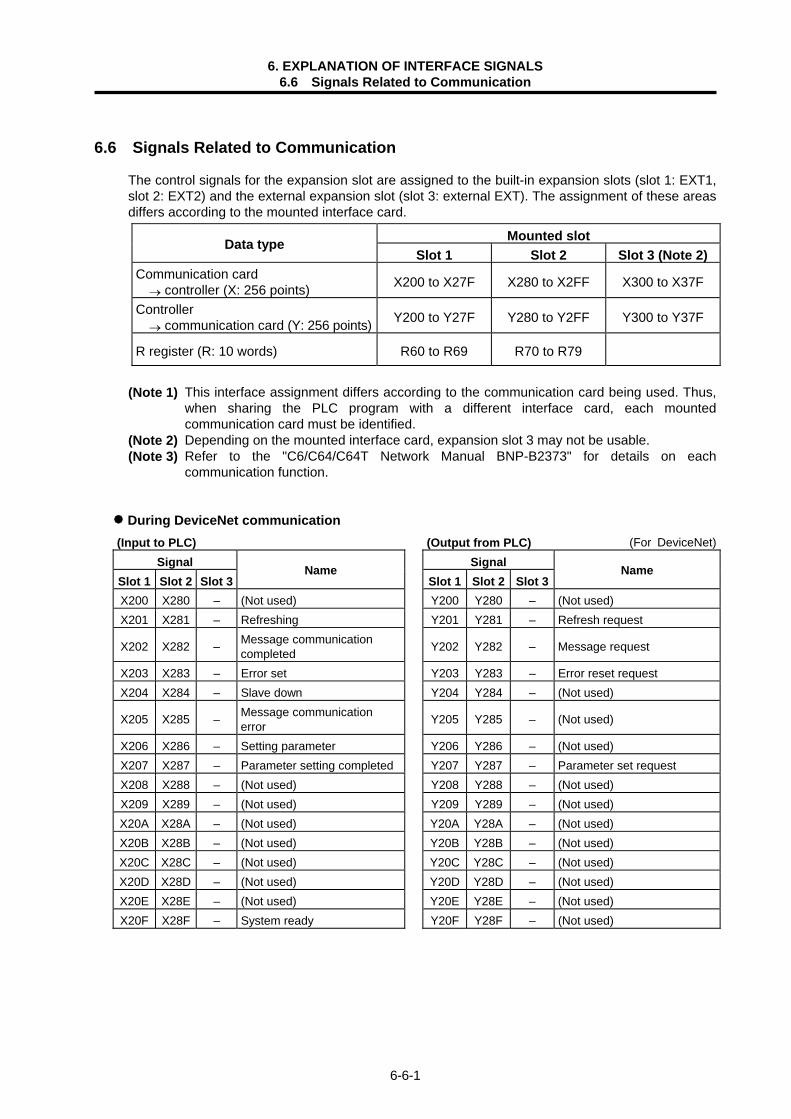
6. EXPLANATION OF INTERFACE SIGNALS 6.6 Signals Related to Communication
6-6-1
6.6 Signals Related to Communication
The control signals for the expansion slot are assigned to the built-in expansion slots (slot 1: EXT1, slot 2: EXT2) and the external expansion slot (slot 3: external EXT). The assignment of these areas differs according to the mounted interface card.
Mounted slot Data type Slot 1 Slot 2 Slot 3 (Note 2)
Communication card → controller (X: 256 points) X200 to X27F X280 to X2FF X300 to X37F
Controller → communication card (Y: 256 points) Y200 to Y27F Y280 to Y2FF Y300 to Y37F
R register (R: 10 words) R60 to R69 R70 to R79
(Note 1) This interface assignment differs according to the communication card being used. Thus,
when sharing the PLC program with a different interface card, each mounted communication card must be identified.
(Note 2) Depending on the mounted interface card, expansion slot 3 may not be usable. (Note 3) Refer to the "C6/C64/C64T Network Manual BNP-B2373" for details on each
communication function.
During DeviceNet communication (Input to PLC) (Output from PLC) (For DeviceNet)
Signal Signal Slot 1 Slot 2 Slot 3
Name Slot 1 Slot 2 Slot 3
Name
X200 X280 – (Not used) Y200 Y280 – (Not used) X201 X281 – Refreshing Y201 Y281 – Refresh request
X202 X282 – Message communication completed
Y202 Y282 – Message request
X203 X283 – Error set Y203 Y283 – Error reset request X204 X284 – Slave down Y204 Y284 – (Not used)
X205 X285 – Message communication error
Y205 Y285 – (Not used)
X206 X286 – Setting parameter Y206 Y286 – (Not used) X207 X287 – Parameter setting completed Y207 Y287 – Parameter set request X208 X288 – (Not used) Y208 Y288 – (Not used) X209 X289 – (Not used) Y209 Y289 – (Not used) X20A X28A – (Not used) Y20A Y28A – (Not used) X20B X28B – (Not used) Y20B Y28B – (Not used) X20C X28C – (Not used) Y20C Y28C – (Not used) X20D X28D – (Not used) Y20D Y28D – (Not used) X20E X28E – (Not used) Y20E Y28E – (Not used) X20F X28F – System ready Y20F Y28F – (Not used)

6. EXPLANATION OF INTERFACE SIGNALS 6.6 Signals Related to Communication
6-6-2
(For DeviceNet) Signal
Slot 1 Slot 2 Slot 3Name
R60 R70 – Mounted card information (0871H) R61 R71 – Master communication status R62 R72 – Error information R63 R73 – (Not used) R64 R74 – Head register No. of set parameter R65 R75 – Number of set parameters R66 R76 – R67 R77 – Down station detection prohibit setting R68 R78 – R69 R79 –
Signal Signal
Slot 1 Slot 2 Slot 3Name
Slot 1 Slot 2 Slot 3Name
SD48 SD80 – Master communication status SD64 SD96 – (Not used) SD49 SD81 – Error information SD65 SD97 – (Not used) SD50 SD82 – Bus error counter SD66 SD98 – (Not used) SD51 SD83 – Bus OFF counter SD67 SD99 – (Not used) SD52 SD84 – SD68 SD100 – (Not used)
SD53 SD85 – Each station configuration state
SD69 SD101 – (Not used)
SD54 SD86 – SD70 SD102 – (Not used) SD55 SD87 – SD71 SD103 – (Not used) SD56 SD88 – SD72 SD104 –
SD57 SD89 – Each station communication state
SD73 SD105 –
SD58 SD90 – SD74 SD106 – Communication PCB version information
SD59 SD91 – SD75 SD107 – (ASCII) SD60 SD92 – SD76 SD108 – SD61 SD93 – Each station disturbance state SD77 SD109 – SD62 SD94 – SD78 SD110 – SD63 SD95 – SD79 SD111 –
HR871 mounting slot Data type
Expansion slot 1 Expansion slot 2 External slot Input data : 2048 points B0000 to B07FF B1000 to B17FF Input/output data Output data : 2048 points B0800 to B0FFF B1800 to B1FFF Message communication command (16word, W) W0000 to W000F W1000 to W100F
Message communication results (16word, R) W0010 to W001F W1010 to W101F
Message communication
Message communication data (120word, R/W) W0020 to W0097 W1020 to W1097

6. EXPLANATION OF INTERFACE SIGNALS 6.6 Signals Related to Communication
6-6-3
(For DeviceNet) Signal Signal
Slot 1 Slot 2 Slot 3Name
Slot 1 Slot 2 Slot 3Name
W0000 W1000 – Command No. W0020 W1020 Slave status W0001 W1001 – Slave station No./Class ID W0021 W1021 (Not used) W0002 W1002 – Instance ID W0022 W1022 Communication error W0003 W1003 – Attribute ID/Data length W0023 W1023 General error code W0004 W1004 – W0024 W1024 Additional error code
W0005 W1005 – W0025 W1025 Number of heartbeat timeout times
W0006 W1006 – W0026 W1026 – W0007 W1007 – W0027 W1027 – W0008 W1008 – W0028 W1028 – W0009 W1009 – W0029 W1029 – W000A W100A W002A W102A W000B W100B W002B W102B W000C W100C W002C W102C W000D W100D W002D W102D W000E W100E W002E W102E W000F W100F W002F W102F
Signal Signal
Slot 1 Slot 2 Slot 3Name
Slot 1 Slot 2 Slot 3Name
W0010 W1010 – Command No. W0030 W1030 – W0011 W1011 – Execution error code W0031 W1031 – W0012 W1012 – Slave station No./Class ID W0032 W1032 – W0013 W1013 – Instance ID W0033 W1033 – W0014 W1014 – Attribute ID/Data length W0034 W1034 – W0015 W1015 – W0035 W1035 – W0016 W1016 – W0036 W1036 – W0017 W1017 – W0037 W1037 – W0018 W1018 – W0038 W1038 – W0019 W1019 – W0039 W1039 – W001A W101A W003A W103A W001B W101B W003B W103B W001C W101C W003C W103C W001D W101D W003D W103D W001E W101E W003E W103E W001F W101F W003F W103F

6. EXPLANATION OF INTERFACE SIGNALS 6.6 Signals Related to Communication
6-6-4
During MELSECNET/10 communication (Input to PLC) (Output from PLC) (For MELSECNET/10)
Signal Signal Slot 1 Slot 2 Slot 3
Name Slot 1 Slot 2 Slot 3
Name
X200 X280 – (Not used) Y200 Y280 – X201 X281 – Y201 Y281 – X202 X282 – Y202 Y282 – X203 X283 – Y203 Y283 – X204 X284 – Y204 Y284 – X205 X285 – Y205 Y285 – X206 X286 – Y206 Y286 – X207 X287 – Y207 Y287 – X208 X288 – Y208 Y288 – X209 X289 – Y209 Y289 – X20A X28A – Y20A Y28A – X20B X28B – Y20B Y28B – X20C X28C – Y20C Y28C – X20D X28D – Y20D Y28D – X20E X28E – Y20E Y28E – X20F X28F – Y20F Y28F –
Signal
Slot 1 Slot 2 Slot 3Name
R60 R70 – R61 R71 –
R62 R72 – Error information R63 R73 – R64 R74 – R65 R75 – R66 R76 – R67 R77 – R68 R78 – R69 R79 –
Signal Signal
Slot 1 Slot 2 Slot 3 Name
Slot 1 Slot 2 Slot 3 Name
SB0000 SB0100 – SW0000 SW0100 – : : – : : – : : – : : –
SB00FF SB01FF –
(Refresh range)
SW00FF SW01FF –
(Refresh range)

6. EXPLANATION OF INTERFACE SIGNALS 6.6 Signals Related to Communication
6-6-5
During Ethernet communication
(Input to PLC) (Output from PLC) (For Ethernet)Signal Signal
Slot 1 Slot 2 Slot 3Name
Slot 1 Slot 2 Slot 3Name
X200 X280 X300 Initialization normal completion
Y200 Y280 Y300 (Not used)
X201 X281 X301 (Not used) Y201 Y281 Y301 (Not used) X202 X282 X302 (Not used) Y202 Y282 Y302 (Not used) X203 X283 X303 (Not used) Y203 Y283 Y303 (Not used) X204 X284 X304 (Not used) Y204 Y284 Y304 (Not used) X205 X285 X305 (Not used) Y205 Y285 Y305 (Not used) X206 X286 X306 (Not used) Y206 Y286 Y306 (Not used) X207 X287 X307 (Not used) Y207 Y287 Y307 (Not used) X208 X288 X308 (Not used) Y208 Y288 Y308 (Not used) X209 X289 X309 (Not used) Y209 Y289 Y309 (Not used) X20A X28A X30A (Not used) Y20A Y28A Y30A (Not used) X20B X28B X30B (Not used) Y20B Y28B Y30B (Not used) X20C X28C X30C (Not used) Y20C Y28C Y30C (Not used) X20D X28D X30D (Not used) Y20D Y28D Y30D (Not used) X20E X28E X30E (Not used) Y20E Y28E Y30E (Not used) X20F X28F X30F (Not used) Y20F Y28F Y30F (Not used)
Signal Signal
Slot 1 Slot 2 Slot 3Name
Slot 1 Slot 2 Slot 3Name
X210 X290 X310 Connection 1 open completed Y210 Y290 Y310 (Not used) X211 X291 X311 Connection 2 open completed Y211 Y291 Y311 (Not used) X212 X292 X312 Connection 3 open completed Y212 Y292 Y312 (Not used) X213 X293 X313 Connection 4 open completed Y213 Y293 Y313 (Not used) X214 X294 X314 Connection 5 open completed Y214 Y294 Y314 (Not used) X215 X295 X315 Connection 6 open completed Y215 Y295 Y315 (Not used) X216 X296 X316 Connection 7 open completed Y216 Y296 Y316 (Not used) X217 X297 X317 Connection 8 open completed Y217 Y297 Y317 (Not used) X218 X298 X318 (Not used) Y218 Y298 Y318 (Not used) X219 X299 X319 (Not used) Y219 Y299 Y319 (Not used) X21A X29A X31A (Not used) Y21A Y29A Y31A (Not used) X21B X29B X31B (Not used) Y21B Y29B Y31B (Not used) X21C X29C X31C (Not used) Y21C Y29C Y31C (Not used) X21D X29D X31D (Not used) Y21D Y29D Y31D (Not used) X21E X29E X31E (Not used) Y21E Y29E Y31E (Not used) X21F X29F X31F (Not used) Y21F Y29F Y31F (Not used)

6. EXPLANATION OF INTERFACE SIGNALS 6.6 Signals Related to Communication
6-6-6
(For Ethernet)
Signal Signal Slot 1 Slot 2 Slot 3
Name Slot 1 Slot 2 Slot 3
Name
X220 X2A0 X320 Connection 1 Data received Y220 Y2A0 Y320 (Not used) X221 X2A1 X321 Connection 2 Data received Y221 Y2A1 Y321 (Not used) X222 X2A2 X322 Connection 3 Data received Y222 Y2A2 Y322 (Not used) X223 X2A3 X323 Connection 4 Data received Y223 Y2A3 Y323 (Not used) X224 X2A4 X324 Connection 5 Data received Y224 Y2A4 Y324 (Not used) X225 X2A5 X325 Connection 6 Data received Y225 Y2A5 Y325 (Not used) X226 X2A6 X326 Connection 7 Data received Y226 Y2A6 Y326 (Not used) X227 X2A7 X327 Connection 8 Data received Y227 Y2A7 Y327 (Not used) X228 X2A8 X328 (Not used) Y228 Y2A8 Y328 (Not used) X229 X2A9 X329 (Not used) Y229 Y2A9 Y329 (Not used) X22A X2AA X32A (Not used) Y22A Y2AA Y32A (Not used) X22B X2AB X32B (Not used) Y22B Y2AB Y32B (Not used) X22C X2AC X32C (Not used) Y22C Y2AC Y32C (Not used) X22D X2AD X32D (Not used) Y22D Y2AD Y32D (Not used) X22E X2AE X32E (Not used) Y22E Y2AE Y32E (Not used) X22F X2AF X32F (Not used) Y22F Y2AF Y32F (Not used)

6. EXPLANATION OF INTERFACE SIGNALS 6.6 Signals Related to Communication
6-6-7
During CC-Link communication (Input to PLC) (Output from PLC) (For CC-Link)
Signal Signal Slot 1 Slot 2 Slot 3
Name Slot 1 Slot 2 Slot 3
Name
X200 X280 X300 Unit error Y200 Y280 Y300 Refresh command
X201 X281 X301 Data link state at host station Y201 Y281 Y301
X202 X282 X302 Parameter setting status Y202 Y282 Y302
X203 X283 X303 Data link status at other
station
Y203 Y283 Y303
(Prohibited to use)
X204 X284 X304 Unit reset acceptance completed
Y204 Y284 Y304 Unit reset request
X205 X285 X305 (Prohibited to use) Y205 Y285 Y305 (Prohibited to use)
X206 X286 X306 Data link startup normal completion
Y206 Y286 Y306 Data link start request
X207 X287 X307 Data link startup error completion
Y207 Y287 Y307 (Prohibited to use)
X208 X288 X308 Data link startup by EEPROM parameter normal completion
Y208 Y288 Y308 Data link startup request from EEPROM parameter
X209 X289 X309 Data link startup by EEPROM parameter error completion
Y209 Y289 Y309 (Prohibited to use)
X20A X28A X30A Parameter registration to EEPROM normal completion
Y20A Y28A Y30A Parameter registration request to EEPROM
X20B X28B X30B Parameter registration to EEPROM error completion
Y20B Y28B Y30B
X20C X28C X30C Y20C Y28C Y30CX20D X28D X30D Y20D Y28D Y30DX20E X28E X30E
(Prohibited to use)
Y20E Y28E Y30EX20F X28F X30F Unit ready Y20F Y28F Y30F
(Prohibited to use)
Signal Signal
Slot 1 Slot 2 Slot 3Name
Slot 1 Slot 2 Slot 3Name
X210 X290 X310 (Not used) Y210 Y290 Y310 (Not used) X211 X291 X311 (Not used) Y211 Y291 Y311 (Not used) X212 X292 X312 (Not used) Y212 Y292 Y312 (Not used) X213 X293 X313 (Not used) Y213 Y293 Y313 (Not used) X214 X294 X314 (Not used) Y214 Y294 Y314 (Not used) X215 X295 X315 (Not used) Y215 Y295 Y315 (Not used) X216 X296 X316 (Not used) Y216 Y296 Y316 (Not used) X217 X297 X317 (Not used) Y217 Y297 Y317 (Not used) X218 X298 X318 (Not used) Y218 Y298 Y318 (Not used) X219 X299 X319 (Not used) Y219 Y299 Y319 (Not used) X21A X29A X31A (Not used) Y21A Y29A Y31A (Not used) X21B X29B X31B (Not used) Y21B Y29B Y31B (Not used) X21C X29C X31C (Not used) Y21C Y29C Y31C (Not used) X21D X29D X31D (Not used) Y21D Y29D Y31D (Not used) X21E X29E X31E (Not used) Y21E Y29E Y31E (Not used) X21F X29F X31F (Not used) Y21F Y29F Y31F (Not used)

6. EXPLANATION OF INTERFACE SIGNALS 6.6 Signals Related to Communication
6-6-8
(For CC-Link)
Signal Signal Slot 1 Slot 2 Slot 3
Name Slot 1 Slot 2 Slot 3
Name
SB0000 SB0100 SW0000 SW0100: : : :
SB002F SB012F
Refresh range (C64 → CC-Link)
SW003F SW013F
Refresh range (C64 → CC-Link)
SB0030 SB0130 SW0040 SW0140: : : :
SB00FF SB01FF
(Note 1)
Refresh range (CC-Link → C64)
SW00FF SW01FF
(Note 1)
Refresh range (CC-Link → C64)
(Note 1) The assigned devices differ according to the system.

6. EXPLANATION OF INTERFACE SIGNALS 6.6 Signals Related to Communication
6-6-9
Input/output intelligent function (For input/output intelligent function)
Intelligent unit Input device Output device FL-net unit 1 X000 to X01F Y000 to Y01F AS-i master unit X020 to X03F Y020 to Y03F
FL-net unit 1
Device Abbrev. Signal name Device Abbrev. Signal name X0 Message send normal completed X8 X1 Message send error completion X9 X2 Receiving message XA X3 XB X4 XC X5 XD X6 XE X7 XF
Device Abbrev. Signal name Device Abbrev. Signal name
X10 Network parameter write completed X18 Parameter setting status X11 Network parameter read completed X19 Token participation status X12 X1A X13 Device profile read completed X1B X14 Log information clear completed X1C Unit ready X15 Log information read completed X1D X16 X1E X17 X1F Watch dog timer error detection
AS-i master unit
Device Abbrev. Signal name Device Abbrev. Signal name X20 X28 X21 X29 X22 X2A X23 X2B X24 X2C X25 X2D X26 X2E X27 X2F
Device Abbrev. Signal name Device Abbrev. Signal name
X30 X38 X31 X39 X32 X3A X33 X3B X34 X3C X35 X3D X36 X3E X37 X3F

6. EXPLANATION OF INTERFACE SIGNALS 6.6 Signals Related to Communication
6-6-10
(For input/output intelligent function) FL-net unit 1
Device Abbrev. Signal name Device Abbrev. Signal name Y0 Message send request Y8 Y1 Y9 Y2 Message reception completed YA Y3 YB Y4 YC Y5 YD Y6 YE Y7 YF
Device Abbrev. Signal name Device Abbrev. Signal name
Y10 Network parameter write request Y18 Y11 Network parameter read request Y19 Y12 Y1A Y13 Device profile read request Y1B Y14 Log information clear request Y1C Y15 Log information read request Y1D Y16 Y1E Y17 Y1F
AS-i master unit
Device Abbrev. Signal name Device Abbrev. Signal name Y20 Y28 Y21 Y29 Y22 Y2A Y23 Y2B Y24 Y2C Y25 Y2D Y26 Y2E Y27 Y2F
Device Abbrev. Signal name Device Abbrev. Signal name
Y30 Y38 Y31 Y39 Y32 Y3A Y33 Y3B Y34 Y3C Y35 Y3D Y36 Y3E Y37 Y3F

7. SPINDLE CONTROL 7.1 Outline of Functions
7-1
7. SPINDLE CONTROL 7.1 Outline of Functions Spindle speed can be directly controlled by a 6-digit S code command. When the S analog function specifications are valid, the controller selects an appropriate spindle
speed corresponding to the 6-digit command following the S code and outputs (spindle gear shift command) it to the machine side (PLC). The controller also outputs S command data (analog voltage or serial connection data) corresponding to the gear input (spindle gear select input) and spindle speed specified by the machine side (PLC).
7.1.1 Related Parameters The PLC can have up to four gear stages. The table below lists the four gear stages and the corresponding parameters.
Parameters
Output signal Input signal Parameter name
Gear stage
Spindle limit
speed
Spindle maximum
speed
Spindle shift
speed
Tap cycle maximum
speed
Oriented speed
Minimum speed GR2 GR1 GI1 GI2
1 Slimt1 #3001
Smax1 #3005
Ssift1 #3009
Stap1 #3013
0 0 0 0
2 Slimt2 #3002
Smax2 #3006
Ssift2 #3010
Stap2 #3014
0 1 0 1
3 Slimt3 #3003
Smax3 #3007
Ssift3 #3011
Stap3 #3015
1 0 1 0
4 Slimt4 #3004
Smax4 #3007
Ssift4 #3012
Stap4 #3016
Sori #3021
Smin #3023
1 1 1 1
(Note 1) The upper line shows the parameter name, and the bottom line shows the parameter No. (Note 2) Set the parameter for the gear stage not being used to 0. 7.1.2 Connection Method (1) To serially connect the controller and spindle controller
Control unit
[Spindle forward run, reverse run, orientation command,etc.]
[Zero speed, up-to-speed,orientation complete signal, etc.]
High-speed serial connection
CN1A
Axis drive unit Spindle drive unit
SERVO
CN1B

7. SPINDLE CONTROL 7.1 Outline of Functions
7-2
(2) To analog connect the controller and spindle controller
Rel
ay b
ox
Control unit
Remote I/O unitDX110 DX120
[Spindle forward run, reverse run, orientation command, etc.]
[Zero speed, up-to-speed, orientation complete signal, etc.]
Inverter, etc.
RIO-M
7.1.3 Flow of Spindle (S) Data
Part system 1
Operation program
• • •
• • • •
S100 ;
S150 ;
•
• • • •
Part system 2
S200 ;
Fin1 (Y71E), Fin2 (Y71F) or GFIN (YD26)
S command completion process with sequence program (ladder)
SF1(X6D8)SF1(X658)
R312, 3R212, 3
+R3000
(For monitoring ofcommand data)
R3210 +
[Spindle override Spindle gear selection Spindle stop Spindle gear shift Spindle orientation, etc.]
Spindle parameter (SOUT)
0: No output
1: Serial output
2: Analog output 1
3: Analog output 2
4: Analog output 3
5: Analog output 4
R210, 1Spindle final command (for monitoring)
R100
R101
R102
R103
Remote I/O unit DX120
Spindle drive unitinverter, etc.
Outline explanation
(1) The "Spindle command start" signal (SF1) is output when the spindle (S) command is issued. (2) After the designated processes is executed by SF1 with the sequence program, the "M function
finish" or "Gear shift complete" signal is returned to the controller. (3) Data corresponding to the S command is output to file registers R3000 or R3210 with the
completion signal. The speed is output to R3000 and R3210. (4) The R3210 data is transferred to the spindle amplifier with serial communication according to
the spindle parameter SOUT value or is transferred to the inverter, etc., as analog voltage via the remote I/O unit.
(Note) If the spindle command is issued from both the 1st and 2nd part systems, the command issued later will be applied.

Revision History
Date of revision Manual No. Revision details
Jan. 2002 BNP-B2261C First edition created.
May 2004 BNP-B2261E Details for system software version D provided. Explanation on interface signals added. The section “6.6 Signals Related to Communication” added. Mistakes corrected.

©2004 MITSUBISHI ELECTRIC CORPORATION ALL RIGHTS RESERVED

BNP-B2261E(ENG)
MITSUBISHI ELECTRIC CORPORATION HEAD OFFICE : MITSUBISHI DENKI BLDG., 2-2-3, MARUNOUCHI, CHIYODA-KU, TOKYO 100-8310, JAPAN
MC6/C64/C64T
008-178
(0405) MEE
Specifications subject to change without notice.Printed in Japan on recycled paper.
MODEL
Manual No.
MODELCODE