[FINAL RADIOISOTOPE CORING STUDY FIELD SAMPLING PLAN ...
151
FINAL RADIOISOTOPE CORING STUDY FIELD SAMPLING PLAN SAN JACINTO RIVER WASTE PITS SUPERFUND SITE Prepared for McGinnes Industrial Maintenance Corporation International Paper Company U.S. Environmental Protection Agency, Region 6 Prepared by Anchor QEA, LLC 614 Magnolia Avenue Ocean Springs, Mississippi 39564 Integral Consulting Inc. 411 First Avenue South, Suite 550 Seattle, Washington 98104 May 2011 023452
-
Upload
khangminh22 -
Category
Documents
-
view
2 -
download
0
Transcript of [FINAL RADIOISOTOPE CORING STUDY FIELD SAMPLING PLAN ...

FINAL RADIOISOTOPE CORING STUDY
FIELD SAMPLING PLAN
SAN JACINTO RIVER WASTE PITS SUPERFUND SITE
Prepared for
McGinnes Industrial Maintenance Corporation
International Paper Company
U.S. Environmental Protection Agency, Region 6
Prepared by
Anchor QEA, LLC
614 Magnolia Avenue
Ocean Springs, Mississippi 39564
Integral Consulting Inc.
411 First Avenue South, Suite 550
Seattle, Washington 98104
May 2011
023452

FINAL RADIOISOTOPE CORING STUDY FIELD SAMPLING PLAN
SAN JACINTO RIVER WASTE PITS
SUPERFUND SITE
Prepared for
McGinnes Industrial Maintenance Corporation
International Paper Company
U.S. Environmental Protection Agency, Region 6
Prepared by
Anchor QEA, LLC
614 Magnolia Avenue
Ocean Springs, Mississippi 39564
Integral Consulting Inc.
411 First Avenue South, Suite 550
Seattle, Washington 98104
May 2011
023453

Final Radioisotope Coring Study Field Sampling Plan May 2011 San Jacinto River Waste Pits Superfund Site i 090557-01
TABLE OF CONTENTS
1 INTRODUCTION .................................................................................................................. 1
1.1 Overview ..........................................................................................................................3
1.2 Project Organization ........................................................................................................3
1.3 Laboratories ......................................................................................................................4
1.4 Document Organization ..................................................................................................6
2 SAMPLING PROCEDURES .................................................................................................. 8
2.1 Schedule ............................................................................................................................8
2.2 Sampling Methods ............................................................................................................8
2.2.1 Sampling Vessel, Field Equipment, and Supplies .....................................................8
2.2.1.1 Sampling Vessel ................................................................................................ 8
2.2.1.2 Field Equipment and Supplies ......................................................................... 9
2.2.2 Sampling Location Selection ....................................................................................11
2.2.3 Station Location Positioning ....................................................................................12
2.2.4 Sediment Coring .......................................................................................................13
2.2.5 Sediment Sample Processing ....................................................................................15
2.2.6 Equipment Decontamination ..................................................................................16
2.3 Field and Laboratory Quality Control Samples ............................................................16
2.4 Sample Packaging and Shipping ....................................................................................17
2.5 Investigation-Derived Waste Handling ........................................................................18
3 FIELD DOCUMENTATION ................................................................................................ 19
3.1 Field Logs ........................................................................................................................19
3.2 Chain-of-Custody Procedures .......................................................................................20
3.3 Station Numbering .........................................................................................................22
3.4 Sample Identifiers ...........................................................................................................22
3.5 Field Changes .................................................................................................................22
4 FIELD DATA MANAGEMENT AND REPORTING PROCEDURES ................................ 23
5 DATA VALIDATION AND USABILITY ............................................................................ 24
5.1 Criteria for Data Review, Verification, and Validation ...............................................24
5.2 Verification and Validation Methods ...........................................................................24
6 REFERENCES ...................................................................................................................... 25
023454

Table of Contents
Final Radioisotope Coring Study Field Sampling Plan May 2011 San Jacinto River Waste Pits Superfund Site ii 090557-01
List of Tables
Table 1 Proposed Radioisotope Core Locations and Sediment Sampling Matrix
Table 2 Quality Control Samples
List of Figures
Figure 1 Site Map
Figure 2 Radioisotope Core Locations
List of Attachments
Attachment 1 Standard Operating Procedures
Procedure TBE-2015 for 210Pb (Teledyne Brown 2010)
Procedure TBE-2007 for 137Cs (Teledyne Brown 2008)
SOP AP-01 Sample Packaging and Shipping
SOP AP-02 Field Documentation
SOP AP-03 Sample Custody
SOP AP-04 Sample Labeling
SOP AP-05 Investigation-Derived Waste Handling
SOP AP-06 Navigation and Station Positioning
SOP SD-01 Decontamination of Sediment Sampling Equipment
SOP SD-02 Preparation of Field Quality Control Samples for Sediments
SOP SD-12 Logging of Sediment Cores
SOP SD-13 Field Classification of Sediment
SOP-BESI-511 Extruding Sediment Cores Using Water Pressure
SOP PISTON CORE Sediment Piston Core Collection
Attachment 2 Field Forms
Sediment Core Log
Field Change Request
Corrective Action Record
Chain of Custody/Laboratory Analysis Request Form
Custody Seal Sample
Attachment 3 USEPA Comments and Responses Matrix
023455

Table of Contents
Final Radioisotope Coring Study Field Sampling Plan May 2011 San Jacinto River Waste Pits Superfund Site iii 090557-01
LIST OF ACRONYMS AND ABBREVIATIONS
Anchor QEA Anchor QEA, LLC
COC Chain-of-Custody
DGPS Differential Global Positioning System
FSP Field Sampling Plan
GPS Global Positioning System
HASP Health and Safety Plan
Integral Integral Consulting Inc.
MARLAP Multi-Agency Radiological Laboratory Analytical Protocols
MS/MSDs matrix spikes/matrix spike duplicates
NAD83 North American Datum 1983
NAVD88 North American Vertical Datum 1988
NOAA National Oceanic and Atmospheric Administration
NRC Nuclear Regulatory Commission
PM Project Manager
PPE personal protection equipment
QA/QC Quality Assurance/Quality Control
RI/FS Remedial Investigation and Feasibility Study
RPD relative percent difference
SAP Sampling and Analysis Plan
Site San Jacinto River Waste Pits Superfund Site
SJRWP San Jacinto River Waste Pits
SOP Standard Operating Procedure
TPWD Texas Parks and Wildlife Division
UAO Unilateral Administrative Order
USCG U.S. Coast Guard
USEPA U.S. Environmental Protection Agency
USGS U.S. Geological Survey
023456

Final Radioisotope Coring Study Field Sampling Plan May 2011 San Jacinto River Waste Pits Superfund Site 1 090557-01
1 INTRODUCTION
This document provides a Field Sampling Plan (FSP) for the radioisotope coring study at the
San Jacinto River Waste Pits (SJRWP) Superfund Site (the Site) located in Harris County,
Texas (Figure 1). This FSP was prepared as a supplement to the Final Sampling and Analysis
Plan Addendum Chemical Fate and Transport Modeling Study (Fate and Transport
Addendum; Anchor QEA and Integral 2010b), which is an Addendum to the Sampling and
Analysis Plan, Sediment Study (Sediment SAP; Integral and Anchor QEA 2010). The
Chemical Fate and Transport Modeling Study is required by the Remedial Investigation and
Feasibility Study (RI/FS) Work Plan (Anchor QEA and Integral 2010a) and describes the
sampling and fate and transport modeling efforts to be undertaken in support of achieving
the overall RI/FS goals. Together with the Sediment SAP and the Fate and Transport
Addendum, this FSP provides information on field activities and related documentation to
meet the requirements of the U.S. Environmental Protection Agency (USEPA) guidance
(USEPA 1988, 1992, 2001, and 2002) and as required by the Unilateral Administrative Order
(UAO) (USEPA 2009). Additional information about the Site history and a summary of
existing data are provided in the RI/FS Work Plan (Anchor QEA and Integral 2010a) and
Sediment SAP (Integral and Anchor QEA 2010). Information on the geology, physiography,
hydrology, and cultural and natural resources of the Site and information on the fate and
transport is provided in the RI/FS Work Plan (Anchor QEA and Integral 2010a).
Six field studies are being conducted to provide information and data for the chemical fate
and transport modeling study: 1) bathymetric survey; 2) current velocity study; 3) bed
property study; 4) upstream sediment load study; 5) Sedflume study; and 6) radioisotope
coring study. The flow chart that follows illustrates the relationships between the field
studies and the specific models for which each field study will provide data. The focus of this
FSP is the radioisotope coring study, which is highlighted in red on the flow chart. The
hydrodynamic model provides transport information (e.g., current velocity, water depth) to
both the sediment transport and chemical fate and transport models. The sediment transport
model provides erosion and deposition flux information to the chemical fate and transport
model.
023457

Introduction
Final Radioisotope Coring Study Field Sampling Plan May 2011 San Jacinto River Waste Pits Superfund Site 2 090557-01
The objective of the radioisotope coring study is to obtain sediment cores from representative
cohesive sediment bed areas in the Study Area for use in a geochronology (age-dating)
analysis. Specifically, the cores will be obtained to provide sediment suitable for lead-210
(210Pb) and cesium-137 (137Cs) laboratory analyses in accordance with Teledyne Brown
Procedure TBE-2015 (Lead-210 Activity in Various Matrices) for 210Pb (Teledyne Brown
Engineering Environmental Services 2008) and Teledyne Brown Procedure TBE-2007
(Gamma Emitting Radioisotope Analysis) for 137Cs (Teledyne Brown Engineering
Environmental Services 2010). The results of the radioisotope coring study will be used to
estimate net sedimentation rates for the sediment transport model.
023458

Introduction
Final Radioisotope Coring Study Field Sampling Plan May 2011 San Jacinto River Waste Pits Superfund Site 3 090557-01
1.1 Overview
The objective of the radioisotope coring study is to obtain sediment cores from representative
cohesive1 sediment bed areas in the Study Area for use in a geochronology (age-dating)
analysis. Ten cores will be collected for radioisotope analyses and the locations of these cores
will be selected based on the results of the bed property study (i.e., cohesive bed areas).
Specifically, the cores will be obtained to provide sediment suitable for lead-210 (210Pb) and
cesium-137 (137Cs) laboratory analyses in accordance with Procedure TBE-2015 for 210Pb
(Teledyne Brown Engineering Environmental Services 2010) and Procedure TBE-2007 for
137Cs (Teledyne Brown Engineering Environmental Services 2008). The results of the
radioisotope coring study will provide calibration data for the sediment transport model, as
described in the Fate and Transport Addendum (Anchor QEA and Integral 2010b). Figure 2
depicts the selected coring locations.
1.2 Project Organization
Detailed project organization is provided in the Sediment SAP (Integral and Anchor QEA
2010). The names and quality assurance (QA) responsibilities of key task-specific personnel
are provided below.
FSP Personnel Quality Assurance Responsibilities
Title Responsibility Name Contact Information
Project
Coordinator
Coordination of project information and
related communications on behalf of IPC
and MIMC with USEPA; liaison between
USEPA project managers and respondent
project managers
David Keith Anchor QEA, LLC
614 Magnolia Avenue
Ocean Springs, MS 39564
(228) 818‐9626
Task
Coordinator
Coordination of task project information
and related communications with Project
Coordinator
Kirk Ziegler Anchor QEA, LLC
305 W. Grand Avenue
Suite 300
Montvale, NJ 07645‐1813
(201) 571‐0949
1 Radioisotopes sorb preferentially to finer grained sediments and soils such as clays. Additional information
regarding this behavior and age dating of sediments can be found in Bolt et al. 1976, Tamura and Jacobs 1960,
Jetter 2000, Holmes 1998, Van Metre et al. 2004 and Mahler and Metre 2003.
023459

Introduction
Final Radioisotope Coring Study Field Sampling Plan May 2011 San Jacinto River Waste Pits Superfund Site 4 090557-01
Field Lead
Anchor QEA
Field data collection and implementation
of the Health and Safety Plan in the field
Daleel
Nangju
Anchor QEA, LLC
10707 Corporate Drive, Ste. 230
Stafford, TX 77477
(281) 565‐1133
Laboratory
QA
Coordinator
and Manager
Completeness of QA
documentation and procedures;
liaison between project personnel,
testing laboratories, and
data validators and for related QA
communications with USEPA
Delaney
Peterson
Anchor QEA, LLC
720 Olive Way, Suite 1900
Seattle, WA 98101
(206) 287‐9130
Laboratory
Project
Manager
Processing and QA/QC of Laboratory
Samples
Kim
Thurman
Teledyne Brown Engineering
2508 Quality Lane
Knoxville, TN 37931‐3133
(865) 934‐0376
1.3 Laboratories
The following responsibilities apply to the laboratory project manager (PM) and quality
assurance (QA) manager at the analytical laboratories used for this task. Teledyne Brown of
Knoxville, Tennessee has been selected as the analytical laboratory. Analytical methods that
will be used are TBE-2015 for 210Pb and TBE 2007 for 137Cs. The analytical methodology is
summarized below and the detailed laboratory methods are provided in Attachment 1.
210Pb activity in samples will be analyzed by separating the 210Bi daughter product and
assaying its beta activity. The method used will measure the 210Pb fraction from which 210Bi
may be dissolved by leaching with hydrochloric acid. A general summary of the method is
as follows. Stable lead and bismuth carriers will be added to the dried sample and it is
leached with 6 M hydrochloric acid. The sample is then filtered and the filtrate is
evaporated, oxidized with nitric acid, and finally dissolved in 1.8 M hydrochloric acid. The
solution is passed through an anion exchange column. Lead is eluted with 2 M sulfuric acid.
The bismuth is precipitated as the oxychloride and is collected by vacuum filtration on a
glass fiber disc. The bismuth yield is determined gravimetrically. The filter disc is assayed
for beta activity in a low level, gas-flow proportional counter.
023460

Introduction
Final Radioisotope Coring Study Field Sampling Plan May 2011 San Jacinto River Waste Pits Superfund Site 5 090557-01
137Cs will be analyzed by placing a dried and homogenized aliquot in a calibrated geometry
container and submitting the sample for gamma spectroscopy analysis in accordance with
Method 901.1 (USEPA 1980).
Detection levels for both 210Pb and 137Cs analyses will be at or below 0.2 pCi/g.
The laboratory PM is responsible for the successful and timely completion of the sample
analyses, and for performing the following tasks:
Ensure that samples are received and logged in correctly, that the correct methods
and modifications are used, and that data are reported within specified turnaround
times.
Review analytical data to ensure that procedures were followed as required in the
Sediment SAP (Integral and Anchor QEA 2010), the cited methods, and the
laboratory standard operating procedures (SOPs).
Keep the task coordinator apprised of the schedule and status of sample analyses and
data package preparations.
Notify the task coordinator if problems occur in sample receiving, analysis, or
scheduling, or if control limits cannot be met.
Take appropriate corrective action as necessary.
Report data and supporting QA information as specified in the Sediment SAP
(Integral and Anchor QEA 2010).
The laboratory QA manager is responsible for overseeing the QA activities in the laboratory
and ensuring the quality of the data for this project. Specific responsibilities include the
following:
Oversee and implement the laboratory’s QA program.
Maintain QA records for each laboratory production unit.
Ensure that QA and quality control (QC) procedures are implemented as required for
each method and provide oversight of QA/QC practices and procedures.
Review and address or approve nonconformity and corrective action reports.
Coordinate response to any QC issues that affect this project with the laboratory PM.
023461

Introduction
Final Radioisotope Coring Study Field Sampling Plan May 2011 San Jacinto River Waste Pits Superfund Site 6 090557-01
1.4 Document Organization
This FSP describes the field methods that will be used to collect sediment cores for the
radioisotope coring study. The background, rationale, data quality objectives, and overall
study design are described in detail in the Chemical Fate and Transport Addendum (Anchor
QEA and Integral 2010b). Section 2 of this FSP describes the sampling procedures that will
be followed by the technical team during the field study. Section 3 summarizes field
documentation and chain-of-custody (COC) procedures. Field data management and
reporting procedures are discussed in Section 4.
The following documents are provided as attachments to the FSP:
Standard Operating Procedures (SOPs). The SOPs are provided in Attachment 1. All
SOPs included in this document are also provided in the Sediment SAP (Integral and
Anchor QEA 2010). They are included here for the convenience of the field team.
These include the SOPs developed for:
o TBE-2015 for 210Pb
o TBE 2007 for 137Cs
o Sample Packaging and Shipping
o Field Documentation,
o Sample Custody
o Sample Labeling
o Investigation-Derived Waste Handling
o Navigation and Station Positioning
o Decontamination of Sediment Sampling Equipment
o Preparation of Quality Control Samples for Sediments
o Logging of Sediment Cores
o Field Classification of Sediment
o Extruding Sediment Cores Using Water Pressure
o Sediment Piston Core Collection
Field Forms. Attachment 2 contains examples of various forms that will be used
during field sampling, including: Sediment Core Log, Field Change Request Form,
Corrective Action Record, Chain-of Custody/Laboratory Analysis Request Form, and
Custody Seal Sample.
023462

Introduction
Final Radioisotope Coring Study Field Sampling Plan May 2011 San Jacinto River Waste Pits Superfund Site 7 090557-01
USEPA Comments and Responses Matrix. Attachment 3 contains the USEPA
Comments and Responses Matrix for the Draft Radioisotope Coring Study Field
Sampling Plan.
023463

Final Radioisotope Coring Study Field Sampling Plan May 2011 San Jacinto River Waste Pits Superfund Site 8 090557-01
2 SAMPLING PROCEDURES
The following sections describe the detailed procedures and methods that will be used during
the radioisotope coring study, including the schedule, sampling and processing procedures,
record keeping, sample handling, storage, and field QC procedures. All field activities will be
conducted in accordance with the Health and Safety Plan (HASP) (Anchor QEA 2009),
which will be amended as needed to support the radioisotope coring FSP tasks, and
Addendum 1 to the Overall HASP: Sediment HASP (Integral 2010).
2.1 Schedule
The start date for the radioisotope coring study will be determined following USEPA
approval of this FSP, as well as the completion of the bed property study data analysis.
However, for planning purposes, it is anticipated that the sampling event and laboratory
analyses will be conducted during May 2011.
2.2 Sampling Methods
The following sections describe the vessel and field equipment, coring methods, sample
processing, and equipment decontamination.
2.2.1 Sampling Vessel, Field Equipment, and Supplies
Access to sub-tidal and to some of the inter-tidal locations (particularly at high tide) will
require the use of a boat.
2.2.1.1 Sampling Vessel
The sampling vessel will have enough space to accommodate a minimum of five people –
three sampling team members, the vessel’s operator, and one USEPA oversight individual, (if
required) – and the following equipment: coring apparatus; sample coolers modified to
contain upright, undisturbed cores; and multiple sampling equipment boxes containing
sample jars and other ancillary equipment. The vessel will be equipped with a mechanical
winch system to be used for lowering and retrieving the sediment cores. The vessels used for
sampling will have navigational lights, anchors, basic sonar, and all safety equipment (i.e.,
personal floatation devices, whistle or horn, and fire extinguisher) as required by the U.S.
023464

Sampling Procedures
Final Radioisotope Coring Study Field Sampling Plan May 2011 San Jacinto River Waste Pits Superfund Site 9 090557-01
Coast Guard (USCG) and Texas Parks and Wildlife (TPWD 2006). The vessel operator will
be thoroughly familiar with the area of the river to be navigated and will coordinate with the
USCG Vessel Traffic System and Port of Houston security notification procedures, as
applicable.
Weather, stream elevation, and tides, will be monitored using the following websites:
Weather conditions and forecasts: National Oceanic and Atmospheric
Administration (NOAA) site for the Houston/Galveston area
(http://www.weather.gov/forecasts/wfo/sectors/hgx.php#tabs).
Real-time stream elevation: U.S. Geological Survey (USGS) 08072050 San Jacinto
River near Sheldon, 10 miles upstream from the Site.
Real-time data on wind direction, wind speed, and water elevation: USGS 08077637
Clear Lake Second Outflow Channel at Kemah, 22 miles south of Site
(http://waterdata.usgs.gov/nwis/uv?site_no=08077637).
Tides: NOAA site at Morgan’s Point, Texas, Station Id: 8770613, located 10 miles
southeast of the Site. (http://tidesandcurrents.noaa.gov/geo.shtml?location=8770613).
If needed, supplementary tidal information may be obtained from staff gauges SG01
and SG02, located just offshore, east and west of the former impoundments. Top of
gauges are 3.66 and 3.38 feet (NAVD88), respectively. Coordinates are 3216594.63 E,
13857474.61 N and 3217261.16 E, 13857107.46 N (US State Plane 1983, Texas South
Central 4204), respectively.
2.2.1.2 Field Equipment and Supplies
Field equipment and supplies include: sampling equipment, utensils, decontamination
supplies, sample containers, coolers, shipping containers, log books and forms, personal
protection equipment (PPE), and personal gear. Protective wear (e.g., gloves) will be used as
required in the HASP (Anchor QEA 2009).
Radioisotope sediment cores sampled to refusal will be collected using the following
equipment: a 3-inch diameter polycarbonate liner for core collection in conjunction with a
manual push piston corer for retrieval will be used during this study. This type of corer is
023465

Sampling Procedures
Final Radioisotope Coring Study Field Sampling Plan May 2011 San Jacinto River Waste Pits Superfund Site 10 090557-01
preferable over the gravity core method, as it minimizes the potential for compaction and
disruption of the sample, and is typically easier to use.
Piston corers are hollow tubes with an internal sliding seal (the piston) that produces a weak
vacuum in the tube. This vacuum causes the sediment being cored to enter and move up the
tube without disturbing the sediment layers. The piston corer is lowered to just above the
sediment-water interface, with the piston at the top of the core barrel and a core liner
within. The piston corer is fixed in one place by a cable while a weight pushes the core
barrel into the sediment. Because the core barrel is moving, but the piston is not, a vacuum
develops between the core barrel and liner and the sediment. This vacuum allows the
sediment to rise easily into the core liner despite the friction which would otherwise cause
the sediment to drag along the sides of the liner. A diagram of a typical piston corer is
provided below.
Sample jars, coolers, and packaging material for the samples will be supplied by the analytical
laboratory. The field lead and field personnel in charge of sample handling in the field will
023466

Sampling Procedures
Final Radioisotope Coring Study Field Sampling Plan May 2011 San Jacinto River Waste Pits Superfund Site 11 090557-01
use a sample matrix table (Table 1) as a QC check to ensure that all samples have been
collected at a given station. This table includes the total number and type of sample jars
required for each analysis and each sampling station.
Commercially available, pre-cleaned 4 oz. jars with Teflon-lined lids will be used for the
samples, and the testing laboratory will maintain a record of certification from the suppliers.
The bottle shipment documentation will include batch numbers. With this documentation,
jars can be traced to the supplier, and bottle-wash analysis results can be reviewed. The
bottle-wash certificate documentation will be archived in the project file. The option for
Whirl-Paktm bags is also available to store the sediment samples. Whirl-Paktm bags are
transparent and sterile sample bags that are constructed of durable polyethylene and provide
safe, spill-free use for liquid, semisolid, and solid samples.
Sample containers will be clearly labeled at the time of sampling. Labels will include the
task name, location ID, sample number, sampler’s initials, analysis to be performed, and
sample date and time. Sample numbering and identification procedures are described in
detail in Sections 3.3 and 3.4.
2.2.2 Sampling Location Selection
Radioisotope cores will be obtained from cohesive sediment bed areas at 10 locations within
the study area with the following general spatial distribution: two locations upstream of the
impoundments; four locations in the vicinity of the Site; and four locations downstream of
the impoundments. Outside of the preliminary RI/FS Site perimeter, the results of the Bed
Property Study were used to determine locations of cohesive bed sediment. Inside the
preliminary RI/FS Site perimeter, surface and sub-surface grain size distribution data
collected in 2010 were used to identify cohesive bed areas. After potential sampling
locations were identified (i.e., cohesive sediment bed areas), the 10 sampling locations were
selected using these general criteria: adequate spatial distribution; river morphology; local
hydrodynamics; potential recovery depth of at least 2 feet; and professional judgment. The
locations of the 10 radioisotope cores are presented in Figure 2.
023467

Sampling Procedures
Final Radioisotope Coring Study Field Sampling Plan May 2011 San Jacinto River Waste Pits Superfund Site 12 090557-01
2.2.3 Station Location Positioning
The vessel position for sediment core sampling will be performed as described in SOP AP-06
(Navigation and Station Positioning). Sampling locations for the cores (Figure 2) will be
located using differential global positioning system (DGPS). The DGPS unit will be mounted
on a winch arm used to collect the sediment cores. The GPS unit will receive GPS signals
from satellites to produce horizontal positioning accuracy to within ±2 meters. Texas State
Plane South Central FIPS 4204 coordinates (feet, North American Datum [NAD] 83) will be
used for the horizontal datum. The core sample will be collected as close to the target
position as possible. The vessel will be maneuvered to within 5 feet of the pre-programmed
target coordinates. Best efforts will be made to position activities at the station coordinates
listed. A list of the radioisotope core sampling locations and coordinates can be found in
Table 1.
Field conditions, however, may preclude accessing the planned locations. As such, northing
and easting coordinates will be obtained at the locations where the sediment coring will
occur and sediment samples will be collected. If the planned location is not accessible, the
coring location will be moved to a nearby cohesive bed area. A map of the distribution of
cohesive bed sediments in the Study Area will be provided to the field crews to be used as a
guide in selecting the alternate coring location. The alternate coring location must be
located well inside the boundary of the cohesive sediment bed areas.
023468

Sampling Procedures
Final Radioisotope Coring Study Field Sampling Plan May 2011 San Jacinto River Waste Pits Superfund Site 13 090557-01
Table 1
Proposed Radioisotope Core Locations and Sediment Sampling Matrix
Core ID Eastinga Northinga Elevation(ft MSL)b
Sample Matrix
137Cs 210Pb
SJRI001 3209197.33601 13862420.36606 ‐11.5 Sediment X X
SJRI002 3213031.34395 13861425.23688 ‐3.7 Sediment X X
SJRI003 3215251.26400 13860004.27000 ‐12.9 Sediment X X
SJRI004 3216254.07900 13861008.27000 ‐13.8 Sediment X X
SJRI005 3217240.06100 13859998.44000 ‐18.8 Sediment X X
SJRI006 3217253.68200 13858495.01000 ‐3.9 Sediment X X
SJRI007 3211060.73825 13853824.80553 ‐4.6 Sediment X X
SJRI008 3207298.93014 13852889.28209 ‐3.9 Sediment X X
SJRI009 3213904.74788 13851905.58096 ‐13.1 Sediment X X
SJRI010 3213781.76129 13849992.83546 ‐10.7 Sediment X X
Notes:
a Texas State Plane South Central FIPS 4204 coordinates (feet, North American Datum [NAD] 83) b Elevation is approximate. Estimated from current bathymetry data.
2.2.4 Sediment Coring
Sediment cores will be collected using a piston corer as specified in the Sediment Piston Core
Collection SOP (Attachment 1). A 3-inch diameter tube will be used for all cores. Cores will
be collected to refusal at each location (Figure 2). The core will be supported by a bracing
structure and will be manually advanced into the sediment to achieve a target penetration
depth of at least 2 feet. Extension bars will be used as needed with the piston corer to reach
the sediment bed at locations with deeper water.
At each coring location, if less than the minimum 2 feet of core length is achieved on the
first coring attempt, another attempt to recover a sediment core at the same location will be
conducted. If the specified core length is not achieved after two attempts, the station will be
relocated to a new position that is within 50 feet of the original position and still within the
cohesive bed area. If a minimum core length of 2 feet cannot be achieved after two coring
attempts at the new position (i.e., total of four attempts at this coring location), this coring
location will be abandoned. A new coring location in a cohesive bed area will be selected
after consultation with the PM for this field study.
023469

Sampling Procedures
Final Radioisotope Coring Study Field Sampling Plan May 2011 San Jacinto River Waste Pits Superfund Site 14 090557-01
At each sample location, total water depth, penetration depth, and total sediment recovered
will be measured and recorded in the field logbook. The time and date of core collection will
also be recorded.
The core’s position will be monitored by observing the angle of the winch line while the
corer is being lowered in the water column. When the inlet of the corer reaches the
sediment bed, the corer will stop being lowered, the boat location confirmed, and the angle
of the hydrowire determined. When the angle of the hydrowire is less than 5 degrees, the
corer will be lowered into the sediment bed and manually pushed using reasonable single-
human force. If the weather is windy or tidal conditions warrant it, the boat will be
anchored before the core is lowered, a cable will be released through the winch until there is
slack in the line. If the boat drifts significantly (e.g., because of wind or tidal conditions),
slack in the line will be permitted only briefly to prevent pulling the corer out at an angle.
The corer will be retrieved at a controlled rate to minimize agitation of the core. Retrieval
will be stopped as soon as the top of the corer reaches the water surface. If a core catcher is
not installed at the bottom end of the core, a plug may be inserted in the bottom end of the
corer prior to removal of the core bottom from the water to prevent the core from slipping
out when the corer is raised out of the water. The corer will be brought on board the
sampling vessel and immediately stabilized to prevent it from tipping or falling. Care will be
taken at all times to keep the corer in a vertical position.
After the corer is secured onboard the sampling vessel, the polyethylene liner that contains
the sample will be removed from the corer barrel and inspected.
Each core will be visually inspected for acceptability using the following criteria:
The sediment surface is relatively undisturbed
Any overlying water is not excessively turbid
A minimum of 2 feet of core length is achieved
If a sediment core fails to meet the above criteria, it will be rejected.
023470

Sampling Procedures
Final Radioisotope Coring Study Field Sampling Plan May 2011 San Jacinto River Waste Pits Superfund Site 15 090557-01
After the cores have been collected, both ends of the cores will be securely capped; labeled
with the station identifier, core section, and sediment orientation; and fastened in an upright
position. The overlying water will be siphoned or drained off.
2.2.5 Sediment Sample Processing
Processing of the core will occur at a specified location onshore as specified in SOP-BESI-511
(Extruding Sediment Cores Using Water Pressure). At the processing area, the core liner will
be positioned vertically on a clean work surface to keep the core undisturbed. Depending on
the length of the core, the core can also be processed attached alongside the boat. Cores will
be inspected for physical characteristics and described on a core profile form (see
Attachment 2: SOP SD-12 and SOP SD-13). A plunger powered by a peristaltic pump will
be used to extrude the core. If sediment consistency prevents extruding the cores into the
open air, extrusion into a calibrated core liner will be conducted and sediment sectioning
will proceed.
The first 2.5 cm of sediment will be extruded beyond the end of the tube and sliced off using
a clean metal putty knife. Subsequent lengths of core will be extruded in 2.5 cm increments,
separated with a stainless steel putty knife, and placed in containers. The sediments will be
placed in a clean, labeled container. If the sediment surface is uneven, the core will be sliced
such that the same volume of material as contained in a full 2.5 cm slice is obtained. Each
2.5 cm slice will produce approximately 200 grams of sample material2, which is sufficient
mass for the laboratory analysis. The laboratory requires a sediment sample to contain 50 to
100 grams of mass for the 210Pb and 137Cs analyses.
The sample will be placed in a labeled 4 oz. glass container equipped with a Teflon-lined lid,
and then the containers will be placed in re-sealable plastic bags. The bags will be placed
into a cooler, chilled with ice, and delivered to the laboratory. As discussed below, select
samples will be analyzed for 210Pb and 137Cs activity. The remaining samples will be archived
by the laboratory, cooled in a freezer and stored for potential radioisotope or chemical
analyses in the future.
2 Based on a mud wet density of 1.74 grams per cubic centimeter.
023471

Sampling Procedures
Final Radioisotope Coring Study Field Sampling Plan May 2011 San Jacinto River Waste Pits Superfund Site 16 090557-01
A total of 36 samples will be obtained from the top 3 feet (approximately 90 cm) of a core.
However, only 8 to 11 of those samples will be submitted for radioisotope analysis based on
the following sampling strategy. The radioisotope analysis samples will be selected from the
every third 2.5 cm interval, starting with the 0 to 2.5 cm interval (e.g., 0 to 2.5 cm, 7.5 to 10
cm, 15 to 17.5 cm samples), in the top two feet (approximately 60 cm) of the sediment core.
For the section of the core between 2 and 3 feet (approximately 60 to 90 cm) in depth,
radioisotope analysis samples will be selected from every fourth 2.5 cm interval (e.g., 60 to
62.5 cm, 70 to 72.5 cm). This sampling strategy will produce a minimum of 8 and a
maximum of 11 samples per core which will be submitted to the laboratory for radioisotope
analysis. All 2.5 cm samples from a core that are not submitted for laboratory analysis will
be archived.
2.2.6 Equipment Decontamination
All non-dedicated sampling equipment that comes into contact with the sediment samples
(e.g., core catchers, stainless-steel bowls, utensils) will be decontaminated prior to use and
between samples. Non-dedicated sampling equipment will be decontaminated following
procedures in SOP SD-01 (Attachment 1), except that no solvent rinse will typically be used.
Core liners will be new and will not be used.
2.3 Field and Laboratory Quality Control Samples
Field and laboratory quality control samples will be collected and analyzed at a minimum 5
percent frequency. Field duplicates (also known as field split samples) are generally used to
evaluate the variability associated with sample processing and laboratory variability.
Samples will be assigned unique numbers and will not be identified as field splits to the
laboratory. To achieve the required laboratory processing volumes, samples above and below
the target sample interval can be consolidated and used to augment the sediment volumes.
023472

Sampling Procedures
Final Radioisotope Coring Study Field Sampling Plan May 2011 San Jacinto River Waste Pits Superfund Site 17 090557-01
Table 2
Frequency of Quality Control Samples
Parameter Field
Duplicate
Method
Blank
Matrix
Replicates
Laboratory
Control
Standard
Matrix Spike Matrix Spike
Duplicate
210Pb 1/20 1/20 1/20 1/20 1/20 1/20 137Cs 1/20 1/20 1/20 1/20 1/20 1/20
Laboratory QC procedures, where applicable, include initial and continuing instrument
calibrations, standard reference materials, laboratory control samples, matrix replicates,
matrix spikes/matrix spike duplicates (MS/MSDs), and method blanks. Laboratory control
limits for recovery of matrix spikes, replicates, and laboratory control standards will be used
to evaluate the data. Results of the QC samples from each sample group will be reviewed by
the analyst immediately after a sample group has been analyzed. The QC sample results will
then be evaluated to determine if laboratory control limits have been exceeded. If laboratory
control limits are exceeded in the sample group, the QA manager will be contacted
immediately, and corrective action (e.g., method modifications followed by reprocessing the
affected samples) will be initiated prior to processing a subsequent group of samples.
2.4 Sample Packaging and Shipping
As mentioned above, sample coolers and packing materials will be supplied by the analytical
laboratories. Individual sample jars will be labeled and placed into plastic bags and sealed.
Samples will be packed in a cooler lined with a large plastic bag. Glass jars will be packed to
prevent breakage and separated in the cooler by bubble wrap or other shock absorbent
material. Ice in sealed plastic bags will then be placed in the cooler to maintain a
temperature of approximately 4°C (±2°C). When the cooler is full the COC form will be
placed into a zip-locked bag and taped to the inside lid of the cooler. Each cooler will be
sealed with two COC seals, one each on the front and side of the cooler. Labels indicating
“This End Up” with an arrow and “Fragile” will be attached to each cooler.
The shipping containers will be clearly labeled (i.e., name of task, time and date container
was sealed, person sealing the cooler, and company name and address) for positive
identification. These packaging and shipping procedures are in accordance with U.S.
023473

Sampling Procedures
Final Radioisotope Coring Study Field Sampling Plan May 2011 San Jacinto River Waste Pits Superfund Site 18 090557-01
Department of Transportation regulations (49 CFR 173.6 and 49 CFR 173.24). Coolers
containing samples for radionuclide analyses will be transported to the laboratory by the
sampling crew, courier or overnight shipping service.
After the radionuclide samples have been received by the laboratory, they will be stored
under refrigeration (4±2°C). Archive sediment samples collected from each composite
sample for possible future analysis will be stored frozen at –20°C.
2.5 Investigation‐Derived Waste Handling
Any excess phosphate-free, detergent-bearing liquid wastes from decontamination or any
sample remaining after processing will be containerized for subsequent off-site disposal. Any
dry waste (e.g., contaminated boots, bibs, Tyvek™ suits, contaminated sediments) present at
the end of the sampling event will be segregated and containerized (e.g., 50-gallon drums)
and disposed of by a subcontractor specialized in hazardous waste removal. The
subcontractor will be required to have, at a minimum, a drum management service that
provides the following:
Proper waste identification including full analytical capability
Pick up and disposal of a broad range of hazardous wastes
Safe and proper transportation
Environmentally sound treatment and disposal
Regularly scheduled service visits with manifest and label preparation
All disposable materials used for sample collection and processing, such as paper towels and
gloves, will be placed in heavyweight garbage bags or other appropriate containers.
Disposable supplies that do not contain Site sediment will be removed from the Site by
sampling personnel and placed in a normal refuse container for disposal at a solid waste
landfill.
023474

Final Radioisotope Coring Study Field Sampling Plan May 2011 San Jacinto River Waste Pits Superfund Site 19 090557-01
3 FIELD DOCUMENTATION
The integrity of each sample from the time of collection to the point of data reporting must
be maintained. Proper record-keeping and COC procedures will allow samples to be traced
from collection to final disposition. Representative photographs will be taken of each area
where samples are collected. A photograph will be taken of each surface sediment sample
collected and retained for analysis as described in Section 2.2.4. In addition, a photograph of
the entire core will be taken prior to sub-sampling. Site photos from various angles and
close-up views of the overall conditions will also be collected.
3.1 Field Logs
All field activities and observations will be recorded as described by SOP AP-02. The field
log book will be a bound document and will contain individual field and sample log forms
(Attachment 2). Information will include personnel, date, time, station designation, sampler,
types of samples collected, and general observations. Any changes that occur during
sampling (e.g., personnel, responsibilities, or deviations from the FSP) and the reasons for
these changes will be documented in the log book. The log book will identify on-site
visitors, in any, and the number of photographs taken at each sampling location. Each field
lead is responsible for ensuring that their respective field log book and all field data forms are
correct. Requirements for log book entries are described in detail in SOP AP-02.
In addition to those requirements, the person recording the information must initial and date
each page of the field log book. If more than one individual makes entries on the same page,
each recorder must initial and date each entry. The bottom of the page must be signed and
dated by the individual who made the last entry.
Log book corrections will be made by drawing a single line through the original entry,
allowing the original entry to be read. The corrected entry will be written alongside the
original. Corrections will be initialed and dated and may require a footnote for explanation.
The type of information that may be included in the field log book and/or surface sediment
collection field data forms includes the following:
Task name, task location, and task number
023475

Field Documentation
Final Radioisotope Coring Study Field Sampling Plan May 2011 San Jacinto River Waste Pits Superfund Site 20 090557-01
Task start date and end date
Weather conditions
Name of person making entries and other field staff
On-site visitors, if any
Sampling vessel, if any
Station number and location
Data collection and time of each sample
The sample number for each sample to be submitted for laboratory analysis
The specific date and time with corresponding station number associated with the
sampling location coordinates derived from the DGPS
Specific information on each type of sampling activity
The sample number, date and time of collection, equipment type, and the lot number
for the box of filter papers used for field QC samples
Observations made during sample collection, including weather conditions,
complications, and other details associated with the sampling effort
Sample description (source and appearance, such as sediment type, color, presence of
anthropogenic material, and presence and type of biological structures, other debris,
oil sheens, and odor)
Sediment penetration depth (nearest 0.25 foot)
Recovery depth (nearest 0.25 foot)
Any visible debris near any of the sampling locations
Any surface vegetation that is removed from the sampling location prior to sampling
The number of photographs taken at each sampling location
A record of Site health and safety meetings, updates, and related monitoring
Any deviation from the FSP and reasons for deviation.
All log books must be completed at the time that any observations are made. Copies of all
log books and forms will be retained by the technical team.
3.2 Chain‐of‐Custody Procedures
Samples are in custody if they are in the custodian’s view, stored in a secure place with
restricted access, or placed in a container secured with custody seals (see SOP AP-03). A
023476

Field Documentation
Final Radioisotope Coring Study Field Sampling Plan May 2011 San Jacinto River Waste Pits Superfund Site 21 090557-01
COC record will be signed by each person who has custody of the samples and will
accompany the samples at all times. Copies of the COC will be included in laboratory and
QA/QC) reports. Attachment 2 contains an example of the COC form that will be used
during this study.
At a minimum, the form will include the following information:
Site name
Field leader’s name and team members responsible for collection of the listed samples
Collection date and time for each sample
Sample type (i.e., sample for immediate analysis or archive)
Number of sample containers shipped
Requested analyses
Sample preservation information (if any)
Name of the carrier relinquishing the samples to the transporter, noting date and time
of transfer, and the designated sample custodian at the receiving facility
Anchor QEA’s field leader (or delegate) will be the designated field sample custodian for
their respective sampling events and will be responsible for all sample tracking and COC
procedures for the samples that their respective teams collected in the field. The field sample
custodian will be responsible for final sample inventory and will maintain sample custody
documentation. The field sample custodian will complete COC forms prior to removing
samples from the field. Upon transferring samples to the laboratory sample custodian (if a
local laboratory is selected) or shipping courier (as appropriate), the field sample custodian
will sign, date, and note the time of transfer on the COC form. The original COC form will
be transported with the samples to the laboratories. All samples will be shipped to the
testing laboratories in either coolers or shipping containers sealed with custody seals.
Each laboratory will designate a sample custodian who will be responsible for receiving
samples and documenting their progress through the laboratory analytical process. The
sample custodian for each laboratory will establish the integrity of the custody seals upon
sample arrival at the laboratory. The laboratory sample custodian will also ensure that the
COC and sample tracking forms are properly completed, signed, and initialed upon receipt of
the samples.
023477

Field Documentation
Final Radioisotope Coring Study Field Sampling Plan May 2011 San Jacinto River Waste Pits Superfund Site 22 090557-01
When the laboratory receives the samples, the laboratory sample custodian will conduct an
inventory by comparing sample labels to those on the COC document. The custodian will
enter the sample number into a laboratory tracking system by task code and sample
designation. The custodian will assign a unique laboratory number to each sample and will
be responsible for distributing the samples to the appropriate analyst or for storing samples at
the correct temperature in an appropriate secure area.
3.3 Station Numbering
All stations will be assigned a unique identification code based on a designation scheme
designed to suit the needs of the field personnel, data management, and data users. Station
numbers will include “SJ” to indicate San Jacinto River followed by “RI” to indicate the
radioisotope field study, followed by a three-digit number (e.g., 001, 002). The station
numbers will increase as the stations move upstream. An example station number for the
radioisotope coring study would be SJRI007.
3.4 Sample Identifiers
A sample identifier for each sediment radioisotope coring station will be created as follows:
the station number (e.g., SJRI007), followed by a two-letter code for the kind of sample
collected at a given location (Pb = 210Pb sample, Cs = 137Cs), followed by the depth interval.
Finally, a one letter code designating if the sample collected was a duplicate or normal
sample (D = duplicate, N = normal) will be included. For example, a normal sample from the
0- to 2.5-cm section for 210Pb analysis would be SJRI007-Pb1_0-2.5-N.
3.5 Field Changes
Substantial changes during field activities that may impact scope or schedule will be
documented in the field log book and on the Field Change Request (Attachment 2 – Field
Forms). Use of this form allows formal documentation of changes in the field and agreement
between the field crew and regulatory oversight.
023478

Final Radioisotope Coring Study Field Sampling Plan May 2011 San Jacinto River Waste Pits Superfund Site 23 090557-01
4 FIELD DATA MANAGEMENT AND REPORTING PROCEDURES
During field operations, effective data management is critical to providing consistent,
accurate, and defensible data and data products. Field data management will be performed as
described in the Sediment SAP, and in Section 6.2 of Appendix A of the RI/FS Work Plan.
Daily field records (a combination of field log books, field forms, if any, and COC forms) will
make up the main documentation for field activities. Upon completion of sampling, field
notes, data sheets (if any), and COC forms will be scanned to create an electronic record.
Field data will be manually entered into the project database. One hundred percent of the
transferred data will be verified based on hard copy records. Electronic QA checks to
identify anomalous values will also be conducted following entry.
023479

Final Radioisotope Coring Study Field Sampling Plan May 2011 San Jacinto River Waste Pits Superfund Site 24 090557-01
5 DATA VALIDATION AND USABILITY
Data generated in the field and at the laboratories will be verified and validated according to
criteria and procedures described in this section.
5.1 Criteria for Data Review, Verification, and Validation
Data review and verification will be performed as described in the Sediment SAP (Integral
and Anchor QEA 2010) and as summarized below.
Radioisotope data will be validated in accordance with guidance specified by the U.S.
Nuclear Regulatory Commission’s (NRC’s) Regulatory Guide 4.15 – Quality Assurance for
Radiological Monitoring Programs (NRC 2006), by the Multi-Agency Radiological
Laboratory Analytical Protocols Manual (MARLAP; USEPA et al. 2004), and in accordance
with Guidance on Environmental Data Verification and Validation (USEPA 2002b).
Performance-based control limits established by the laboratories and control limits provided
in the method protocols will be used to evaluate data quality and determine the need for data
qualification.
Results for field splits will be evaluated against a control limit of 50 percent relative percent
difference (RPD). Data will not be qualified as estimated if this control limit is exceeded, but
RPD results will be tabulated. Equipment wipe blanks will be evaluated and data qualifiers
will be applied in the same manner as method blanks, as described in the functional
guidelines for data review (USEPA 2004).
5.2 Verification and Validation Methods
Radioisotope data will be verified and validated as described for physical properties tests in
section 4.2.2 of the Sediment SAP (Integral and Anchor QEA 2010).
023480

Final Radioisotope Coring Study Field Sampling Plan May 2011 San Jacinto River Waste Pits Superfund Site 25 090557-01
6 REFERENCES
Anchor QEA, 2009. Health and Safety Plan San Jacinto River Waste Pits Superfund Site.
Prepared for McGinnes Industrial Maintenance Corporation, International Paper
Company, and U.S. Environmental Protection Agency, Region 6. Anchor QEA,
Ocean Springs, MS.
Anchor QEA and Integral Consulting Inc., 2010a. Remedial Investigation/Feasibility Study
Work Plan San Jacinto River Waste Pits Superfund Site. Prepared for McGinnes
Industrial Maintenance Corporation, International Paper Company, and U.S.
Environmental Protection Agency, Region 6. Anchor QEA, Ocean Springs, MS and
Integral Consulting, Inc., Seattle, WA.
Anchor QEA and Integral Consulting Inc., 2010b. Sampling and Analysis Plan Addendum
Chemical Fate and Transport Modeling Study San Jacinto River Waste Pits Superfund
Site. Prepared for U.S. Environmental Protection Agency, Region 6, McGinnes
Industrial Maintenance Corporation, and International Paper Company. Anchor
QEA, Ocean Springs, MS and Integral Consulting, Inc., Seattle, WA.
Bolt, G.H., Bruggenwert, M.G.M., and Kamphorst, A., (1976). Adsorption of cations by soil,
In: (G.T. Bolt and M.G.M. Bruggenwert, eds.) Soil Chemistry A: Basic Elements,
Elsevier Sci. Publ. Co., New York, NY, p. 54-90.
Holmes, C., 1998. Short-Lived Isotopic Chronometers-A Means of Measuring Decadal
Sedimentary Dynamics, U.S. Geological Survey Fact Sheet FS-073-98, 2 pp/
Integral Consulting Inc., 2010. Addendum 1 to the Overall Health and Safety Plan: Sediment
Sampling Health and Safety Plan. Prepared for McGinnes Industrial Maintenance
Corporation and International Paper Company. Integral Consulting, Inc., Seattle,
WA.
Integral Consulting Inc. and Anchor QEA, 2010. Sampling and Analysis Plan: Sediment
Study. San Jacinto River Waste Pits Superfund Site. Prepared for McGinnes
Industrial Maintenance Corporation, International Paper Company, and U.S.
Environmental Protection Agency, Region 6. Integral Consulting, Inc., Seattle, WA
and Anchor QEA, Ocean Springs, MS.
023481

References
Final Radioisotope Coring Study Field Sampling Plan May 2011 San Jacinto River Waste Pits Superfund Site 26 090557-01
Jetter, H.W., 2000. Determining the ages of recent sediments using measurements of trace
radioactivity, Terra et Aqua 78, pp. 21-28.
Mahler, B. and Van Metre, P.C., 2003. A Chronicle of Organochlorine Contamination in
Clear Creek, Galveston and Harris Counties, Texas, 1960–2002, as Recorded in
Sediment Cores, U.S. Geological Survey Fact Sheet 088-03, 6 pp.
NRC, 2006. U.S. Nuclear Regulatory Commission Regulatory Guide 4.15 – Quality Assurance
for Radiological Monitoring Programs (Inception through Normal Operations to
License Termination) Effluent Streams and the Environment. U.S. Nuclear
Regulatory Commission, Office of Nuclear Regulatory Research, Washington, D.C.
Tamura, T. and Jacobs, D.G. (1960). Structural implications in cesium sorption: Health
Physics, v. 2, p. 391-398.
Texas Parks and Wildlife, 2006. Safety Requirements for Vessels.
http://www.tpwd.state.tx.us/fishboat/boat/safety/vessel_requirements/
USEPA, EMSL. 1980. "Method 901.1: Gamma Emitting Radionuclides in Drinking Water."
Prescribed Procedures for Measurement of Radioactivity in Drinking Water,
EPA/600/4/80/032.
USEPA, 1988. Interim Final Guidance for Conducting Remedial Investigations and
Feasibility Studies under CERCLA. U.S. Environmental Protection Agency, Office of
Emergency and Remedial Response, Washington, DC.
USEPA, 1992. Guidance for Data Usability in Risk Assessment. Parts A and B. Final.
Publication 9285.7-09. U.S. Environmental Protection Agency, Office of Emergency
and Remedial Response, Washington, DC.
USEPA, 2001. EPA Requirements for Quality Assurance Project Plans. EPA QA/R-5.
EPA/240/B-01/003. U.S. Environmental Protection Agency, Office of Environmental
Information, Washington, DC.
USEPA, 2002. Guidance for Quality Assurance Project Plans. EPA QA/G-5. EPA/240/R-
02/009. U.S. Environmental Protection Agency, Office of Environmental
Information, Washington, DC.
023482

References
Final Radioisotope Coring Study Field Sampling Plan May 2011 San Jacinto River Waste Pits Superfund Site 27 090557-01
USEPA, 2002b. Guidance on Environmental Data Verification and Validation. EPA AQ/G-8.
U.S. Environmental Protection Agency, Office of Environmental Information,
Washington, DC.
USEPA, 2004. USEPA Contract Laboratory Program National Functional Guidelines for
Inorganic Data Review. U.S. Environmental Protection Agency, Office of Emergency and
Remedial Response, Washington, DC.
USEPA, DOD, DOE, FDA, DHS, NRC, FDA, USGS, and NIST, 2004. Multi-Agency
Radiological Laboratory Analytical Protocols Manual Volume II. EPA 402-B-04-001B.
NTIS PB2004-105421. U.S. Environmental Protection Agency, U.S. Department of
Defense, U.S. Department of Energy, U.S. Department of Homeland Security, U.S.
Nuclear Regulatory Commission, U.S. Food and Drug Administration, U.S. Geological
Survey, and National Institute of Standards and Technology, Washington, DC.
USEPA, 2009. Unilateral Administrative Order for Remedial Investigation/Feasibility Study.
U.S. EPA Region 6 CERCLA Docket No. 06-03-10. In the matter of: San Jacinto River
Waste Pits Superfund Site Pasadena, Texas. International Paper Company, Inc. &
McGinnes Industrial Management Corporation, Respondents.
Van Metre, P.C., Wilson, J. T., Fuller, C.C., Callender, E., and Mahler, B., 2004. Collection,
Analysis, and Age-Dating of Sediment Cores From 56 U.S. Lakes and Reservoirs
Sampled by the U.S. Geological Survey, 1992–2001, U.S. Geological Survey Scientific
Investigation Report 2004-5185, 180 pp.
023483

FIGURES
023484

10
90
SheldonRd
MainSt
Decker Dr
BaywayDr
Wallisville Rd
Fm 1942 Rd
Jones Rd
Baker Rd
Garrett Rd
ThompsonRd
CrosbyLynchburgRd
Battlegr
oundRd
Farm
ToMarketRoad2100
Lynchburg
Rd
Decker Dr
MainSt
CrosbyLynchburgRd
MainSt
MainSt
CrosbyLynchburgRd
StateSpur
DN-\\Daleel\G_DRIVE\San_Jacinto\Analysis\Model_Inputs\Site\layout_fsp_radioisotope_110422.m
xd
Houston
Legend
Original (1966) Perimeter of the Impoundments
Preliminary Site Perimeter
Interstate
Highway
Major Road
Local Road
Minor Road
Other Road
Ramp
Ferry
Pedestrian Way
Figure 1Site Map
Radioisotope Coring Study Field Sampling PlanSJRWP Superfund/ MIMC and IPC
LAKE HOUSTON
HOUSTON SHIPCHANNEL
0 10.5Miles
San Jacinto River
023485

10
MainSt
Battlegro
undRd
CrosbyLynchburgRd
Lynchburg
Rd
SJRI005
SJRI004
SJRI003
SJRI006
SJRI008 SJRI007
SJRI010
SJRI009
SJRI001
SJRI002
DN-\\Daleel\G_DRIVE\San_Jacinto\Analysis\Model_Inputs\G
rain_Size\layout_fsp_ric_locs_110425.m
xd
Houston
Figure 2Radioisotope Core Locations
Radioisotope Coring Study Field Sampling PlanSJRWP Superfund/ MIMC and IPC
HOUSTON SHIPCHANNEL
0 3,0001,500Feet
San Jacinto River
Legend
Original (1966) Perimeter of the Impoundments
Preliminary Site Perimeter
Interstate
Highway
Major Road
Local Road
Minor Road
Other Road
Ramp
Ferry
Pedestrian Way
Radioisotope Core Locations
Sediment Thickness (ft)
0 - 1
1 - 3
3 - 5
5 - 7
7 - 9
> 9
Bed Elevation (ft MSL)
< -35
-35 - -30
-30 - -25
-25 - -20
-20 - -15
-15 - -10
-10 - -5
-5 - 0
> 0
023486

ATTACHMENT 1
STANDARD OPERATING PROCEDURES
023487

Procedure Responsible Individual:
Subject:
Prepared by:
Reviewed by:
Approved by:
Number: TBE-2015 Revision: Issue Date: 12/05/03 (reissue) Revision Date: Laboratory Production Manager Review Date:
Lead-210 Activity in Various Matrices
TELEDYNE BROWN ENGINEERING ENVIRONMENTAL SERVICES
TBE-2015
Revision 3
Lead-210 Activity in Various Matrices
~/J (_j;/ ~ ' ··LynnePer7
Quality Assurance Manager
Date:
Date:
Date:
age 0 P 1 f 1 5 3 09/09/2008 09/09/2011
023488

P 2 f1 age 0 5
Procedure Number: TBE-2015 Revision: 3 Issue Date: 12/05/03 (reissue) Revision Date: 09/09/2008
Responsible Individual: Laboratory Production Manager Review Date: 09/09/2011
Subject: Lead-21 0 Activity in Various Matrices
Table of Contents
Pae
1.0 SCOPE AND APPLICABILITY ..................................................................................................... 4
2.0 SUMMARY OF METHOD ............................................................................................................. 4
3.0 DEFINITIONS ............................................................................................................................... 4
4.0 HEAL TH AND SAFETY ................................................................................................................ 4
5.0 CAUTIONS ................................................................................................................................... 5
6.0 INTERFERENCES ....................................................................................................................... 5
7.0 PERSONNEL QUALIFICATIONS ................................................................................................ 5
8.0 EQUIPMENT AND SUPPLIES ..................................................................................................... 6
8.1 Apparatus and Materials ..................................................................................................... 6
8.2 Standards and Reagents .................................................................................................... 7
9.0 PROCEDURE ............................................................................................................................... 7
9.1 Detection Capability ............................................................................................................ 7
9.2 Sample Selection ................................................................................................................ 8
9.3 Sample Preparation ............................................................................................................ 8 ( 9.4 Chemical Separation and Purification ................................................................................ 9
9.5 Mounting of Precipitate ..................................................................................................... 11
9.6 Sample Counting .............................................................................................................. 12
9.7 Calculation of the Sample Activity or of the MDA ............................................................. 13
10.0 DATA AND RECORD MANAGEMENT ...................................................................................... 14
11.0 QUALITY CONTROL AND QUALITY ASSURANCE ................................................................. 14
12.0 REFERENCES ........................................................................................................................... 15
(
023489

aQe 0 P 3 f 15
Procedure Number: TBE-2015 Revision: 3 Issue Date: 12/05/03 (reissue) Revision Date: 09/09/2008
Responsible Individual: Laboratory Production ManaQer Review Date: 09/09/2011
Subject: Lead-210 Activity in Various Matrices
DOCUMENT ISSUE AND REVISION CONTROL FORM
DOCUMENT: TBE-2015 1 Lead-210 Activity in Various Matrices
SECTION: Environmental Analysis Department
COVERAGE: Environmental Analysis Program
ISSUE
AND PREPARED EFFECTIVE APPROVED
REVISIONS PAGES BY DATE DATE BY
Revision 1 Revised 2.2, 4.3, 7.3, 9.2.1, 9.2.2, 10/20/05 11/09/05 Bill Meyer 10.1, 11.1, 11.3 thru 11.7, and deleted 11.8 thru 11.10 Bill Meyer
Revision 2 Sections 3.4, 6.2, 6.3, 8.2, 9.3.6 11/15/07 11/15/07 Keith Jeter Lynne Perry
Revision 3 Sections 8.1, 8.2, MDA table 9.3.5, 09/09/08 09/09/08 Keith Jeter 9.3.6, 9.4.5, 9.4.8, 9.5.4, 9.5.5, 9.5.7, 9.5.9, 9.5.10, 9.5.11, 9.6.3, 9.6.4, 9.7.2, 10.1, 10.3, 11.7, 12.2
Lynne Perry
023490

age 0 P 4 f 15
Procedure Number: TBE-2015 Revision: 3 Issue Date: 12/05/03 (reissue) Revision Date: 09/09/2008
Responsible Individual: Laboratory Production Manager Review Date: 09/09/2011
Subject: Lead-210 Activity in Various Matrices
1.0 SCOPE AND APPLICABILITY
1.1 This procedure presents the radiochemical beta assay method for determining the leachable
lead-210 activity in sediments and soils.
2.0 SUMMARY OF METHOD
2.1 The Pb-210 activity of soils and sediments is determined radiochemically by separating the
daughter product Bi-210 and assaying its beta activity. The method presented here measures
the Pb-210 fraction from which Bi-210 may be dissolved by leaching with hydrochloric acid;
activity in the interior of mineral grains may be excluded.
2.2 Stable lead and bismuth carriers are added to the dried sample and it is leached with 6 M
hydrochloric acid. The sample is then filtered and the filtrate is evaporated, oxidized with nitric
acid, and finally dissolved in 1.8 M hydrochloric acid. The solution is passed through an anion
exchange column. Lead is eluted first with 9 M hydrochloric acid and with deionized water, then
bismuth is eluted with 2 M sulfuric acid. The bismuth is precipitated as the oxychloride and is
collected by vacuum filtration on a glass fiber disc. The bismuth yield is determined
gravimetrically. The filter disc is mounted on a nylon planchet and covered with 3 mg/cm2
aluminum absorber for beta assay in a low level, gas-flow proportional counter.
3.0 DEFINITIONS
3.1 MSDS Material Safety Data Sheet
3.2 NIST National Institute of Standards and Technology
3.3 TBE-ES Teledyne Brown Engineering - Environmental Services
3.4 See procedure TBE-1004.
4.0 HEAL TH AND SAFETY
4.1 At a minimum, personnel performing this procedure are required to wear the following protective
equipment: laboratory coats, safety glasses, and disposable gloves.
(
(
023491

aQe 0 P 5 f 15
Procedure Number: TBE-2015 Revision: 3 Issue Date: 12/05/03 (reissue) Revision Date: 09/09/2008
Responsible Individual: Laboratory Production ManaQer Review Date: 09/09/2011
Subject: Lead-210 Activity in Various Matrices
4.2 When using or preparing reagents that consist of concentrated caustic or acidic materials, or
solutions producing excessive heat, the analyst is required to wear an apron over his/her
laboratory coat and an appropriate face shield over his/her safety glasses.
4.3 All potentially hazardous chemicals or hazardous reagents must be prepared and used only in a
hood.
4.4 MSDS are available in locations convenient to the laboratories and from the Safety Manager.
Refer to these for other specific safety instructions for chemicals and reagents.
4.5 Appropriate precautions, as specified in the TBE-ES Radiation Protection Program Manual, will
be followed when handling radioactive material.
4.6 Before commencing any laboratory work activities at TBE-ES, all employees receive orientation
and training on the TBE Knoxville Facility Safety Manual, and TBE Radiation Worker Training, as
applicable.
5.0 CAUTIONS
5.1 When adding concentrated acids particularly sulfuric acid to water, do so very slowly since
significant heat of solution is generated. Prepare acid solution in a hood and wear an apron and
face shield.
6.0 INTERFERENCES
6.1 NA.
7 .0 PERSONNEL QUALIFICATIONS
7.1 It is the responsibility of the analyst to heed any precautions noted by the procedure, to adhere to
the instructions contained in the procedure, to report any deviation from this procedure, and to
perform this procedure independently only when formally qualified.
7.2 It is the responsibility of the analyst performing this procedure to inspect worksheets and/or
logbooks for accuracy and completeness, samples for correct volume and size, labels and tags
for accuracy, equipment for correct operation, and to ensure that all calibrations for equipment
used are current and not expired.
023492

age 0 P 6 f15
Procedure Number: TBE-2015 Revision: 3 Issue Date: 12/05/03 (reissue) Revision Date: 09/09/2008
Responsible Individual: Laboratory Production Manager Review Date: 09/09/2011
Subject: Lead-210 Activity in Various Matrices
7.3 Analysts performing this procedure must be trained, qualified, and certified in accordance with the
TBE-ES Quality Assurance Manual and procedure TBE-1007. Procedure specific training
documentation for designated analysts is maintained in the QA office.
7.4 Analysts in training may perform this procedure only under the direct supervision or observation
of a technician certified to perform this procedure.
8.0 EQUIPMENT AND SUPPLIES
8.1 Apparatus and Materials
• Logbooks, worksheets, marking pens, labels, scissors and/or razor blades
• Assorted beakers (400 ml, 250 ml, etc.)
• Appropriate volumetric pipettes
• Magnetic stirring apparatus with stirring bars
• pH meter and pH 4 and pH 7 buffer solutions, or appropriate range pH paper
• Spatula, stirring rods, watch glasses, glass wool
• 100 ml graduated cylinders
• Hot plate
• 2.8 cm fiberglass filter discs
• Vacuum filtering apparatus
• 4-Way partitioned petri dishes
• Hot-air drying oven
• Desiccator
• Analytical balance
• Nylon planchets, retaining rings
• Low level gas flow proportional counting system
• Top loading balance
• 15 cm fiberglass or paper filter discs
• 4" diameter funnel
• Filter rack
• Ion exchange column with 200 ml reservoir
• Aluminum foil absorber (3 mg/cm2)
(
(
023493

P f1 age 7o
Procedure Number: TBE-2015 Revision: 3 Issue Date: 12/05/03 (reissue} Revision Date: 09/09/2008
Responsible Individual: Laboratory Production Manager Review Date: 09/09/2011
Subject: Lead-21 0 Activity in Various Matrices
8.2 Standards and Reagents
• Amberlite IRA-400 C.P. Anion exchange resin, or equivalent
• Concentrated nitric acid (HNO3>: 16 M, 69% acid of sp. gr. 1.42
• Concentrated hydrochloric acid (HCI): 12 M, 36% acid of sp. gr. 1.19
• Ethanol, reagent grade
• 6 M hydrochloric acids (HCI): dilute 500 ml of concentrated acid to 1 liter with deionized
water
• 1.8 M hydrochloric acid (HCI): dilute 300 ml of 6 M hydrochloric acid to 1 liter with deionized
water
5
• 9 M hydrochloric acid (HCI): dilute 750 ml of concentrated acid to 1 liter with deionized water
• Concentrated sulfuric acid (H2SO4): 18 M, 93% acid of sp. gr. 1.84
• 2 M sulfuric acid (H2SO4): dilute 110 ml of concentrated acid to 1 liter with deionized water
(Add acid to water with great care).
• Concentrated ammonium hydroxide (NH4OH): 15 M, 29% solution of sp. gr. 0.90
• Bismuth carrier (nominal value 30 mg Bi/ml), standardized. See procedure TBE-2025,
Preparation and Standardization of Carrier Solutions
• Lead carrier (nominally 20 mg Pb/ml), standardized is not required. See TBE-2025,
Preparation and Standardization of Carrier Solutions
8.3 Use appropriate graduated cylinders and transfer pipettes during the preparation of the solutions
cited above.
9.0 PROCEDURE
9.1 Detection Capability
Detection capability depends upon initial sample size, chemical yield, counting interval, and the
background and efficiency of the counting instrument. Lower detection limits may be obtained by
increasing the sample size or the counting interval.
023494

aQe 0 P 8 f15
Procedure Number: TBE-2015 Revision: 3 Issue Date: 12/05/03 {reissue) Revision Date: 09/09/2008
Responsible Individual: Laboratory Production Manager Review Date: 09/09/2011
Subject: Lead-210 Activity in Various Matrices
Lead-210 Minimum Detectable Activity
Sigma Sample Chem Counting Counting Bkgd Matrix MDA Level a Volume Yield Interval Efficiency (cpm)
(minutes) (cpm)
Sediments & Soils b 0.2 pCi/gm 4.66 10 gm 0.5 100 0.23 0.3
a Sigma multiplier will be 4.66 unless otherwise specified by the customer
b A representative decay factor of 0.9 allows for one day delay in counting the planchet after lead separation.
c Efficiency of 0.23 for Bi-210 counting using a 3 mg/cm2 aluminum absorber.
9.2 Sample Selection
9.3
9.2.1 Using the Request for Analysis with the LIMS number, locate the sample (or sample
group) in the sample receiving and storage room. Log the samples out of the Receiving
Room and return with them to the laboratory.
9.2.2 Begin entering into LIMS and/or the laboratory logbook the customer name, the sample
ID numbers in order, the desired analyses, sample type, the sample preparation date and
the initials of the analyst.
Sample Preparation
9.3.1 Write the sample ID number on the outside of a glass beaker using a laboratory marking
pen.
9.3.2 Using a clean spatula add approximately 25 grams of sample into the beaker. (If
analyses other than Pb-210 are required, additional sample may be decanted to
accommodate them.)
9.3.3 Place the beaker in a hot air oven (105-120°C) overnight to dry.
9.3.4 After sample is dry, remove and allow to cool.
9.3.5 Write the sample ID number on a clean 150 ml beaker. Weigh the beaker using a
balance and enter this tare weight in LI MS/and or the laboratory logbook. Transfer
approximately 2-10 grams of the dried sample to the beaker. Different sample weights
may be used as necessary to meet customer requirements. Enter the aliquot weight in
LIMS and/or the laboratory logbook.
9.3.6 Add 6 M HCI to the beaker, filling to the 100 ml mark. Using separate carrier pipettes,
add 1.00 ml standardized Bi carrier and 1 ml Pb carrier to the sample beaker.
(
(
(
023495

P 9 f 15 age 0
Procedure Number: TBE-2015 Revision: 3 Issue Date: 12/05/03 (reissue) Revision Date: 09/09/2008
Responsible Individual: Laboratory Production ManaQer Review Date: 09/09/2011
Subject: Lead-210 Activity in Various Matrices
9.3.7 Cover the beaker with a watch glass and place on a moderate (approximately 200°F) hot
plate. Allow the sample to leach for approximately 2 hours. Remove from the hot plate
and allow to cool.
9.3.8 Fold a 15 cm fiberglass or paper filter disc in quarters to make a cone and place it in a
4-inch diameter funnel. Write the sample ID number on a clean 400 ml beaker and
place it under the funnel in a filter rack. Gravity filter the sample. Rinse the solids with
deionized water and collect the washings with the filtrate. Discard the filter and solids.
9.3.9 Add approximately 5 ml HN03 to the sample. Place the sample beaker on a moderate
(approximately 200°F) hot plate and evaporate to dryness. Check that the sample does
not spatter during evaporation and reduce hot plate temperature if necessary.
9.3.10 Add approximately 20 ml concentrated HCI to the sample. Place the sample beaker on
a moderate (approximately 200°F) hot plate and evaporate to dryness. Check that the
sample does not spatter during evaporation and reduce hot plate temperature if
necessary.
9.3.11 Add 1.8 ·M HCI to the sample beaker, filling to the 150 ml mark. Warm gently on a low
(approximately 100°F) hot plate to dissolve solids.
9.3.12 Remove the beaker from the hot plate and allow to cool. Stir the sample with a glass rod
to homogenize the sample.
9.3.13 Further filtration may be required.
9.4 Chemical Separation and Purification
9.4.1 Obtain a ½-inch diameter 12-inch glass column surmounted by a 200 ml reservoir and
equipped with a stopcock at the bottom. Insert a small wad of glass wool above the
stopcock.
9.4.2 Make a slurry of anion exchange resin (e.g. Amberlite IRA-400 C.P.) and deionized water
in a beaker. With the column stopcock open, pour the slurry into the column until the
resin occupies approximately 1 O inches of the column.
NOTE: New resin is used for each sample.
023496

age 0 P 10 f 1
Procedure Number: TBE-2015 Revision: 3 Issue Date: 12/05/03 (reissue) Revision Date: 09/09/2008
Responsible Individual: Laboratory Production Manager Review Date: 09/09/2011
Subject: Lead-21 0 Activity in Various Matrices
9.4.3 Condition the column by passing through approximately 60 ml of 1.8 M HCI. Close the
stopcock when the liquid level reaches the top surface of the resin.
9.4.4 Pass the sample solution through the column with the stopcock fully open. Collect the
effluent in a beaker and discard. Close the stopcock when the liquid level reaches the
top surface of the resin.
9.4.5 Using extreme caution, pass approximately 150 ml of 9 M HCI through the column to
elute the lead. Collect the effluent in a beaker and discard (unless advised to save the
effluent by the Laboratory Operations Manager). Close the stopcock when the liquid
level reaches the top surface of the resin. Enter the midpoint of the elution period in
LIMS and/or the laboratory logbook.
9.4.6 Pass approximately 150 ml of deionized water through the column. Close the stopcock
when the liquid level reaches the top surface of the resin. Discard the effluent.
9.4. 7 Measure 150 ml of 2 M H2SO4 and pass through the column to elute the bismuth.
Collect the effluent in a clean, labeled 400 ml beaker.
5
9.4.8 Adjust the pH of the sample to 5 using a standardized pH meter, or use pH paper. Add
35 ml concentrated NH4OH to the sample beaker and add a magnetic stirring bar. Place
the sample beaker on a magnetic stirring plate. Add NH4OH using a disposable transfer
pipette until a pH of 5 is obtained. If the pH exceeds 5, use 2 M H2SO4 to adjust the pH
to 5. Low range pH paper can be used in place of a pH meter.
9.4.9 Remove the sample beaker from the magnetic stirrer and add 2 ml of 6 M HCI using a
disposable pipette. Dilute with deionized water, filling to the 350 ml mark.
9.4.10 Place the sample beaker on a moderate (approximately 200°F) hot plate and digest until
the white BiOCI precipitate forms and falls to the bottom of the beaker (approximately 2
hours). Remove from the hot plate and allow to cool.
9.5 Mounting of Precipitate
9.5.1 Prepare a 2.8 cm glass fiber filter disc for each sample by mounting it on a vacuum
filtration apparatus and rinsing with deionized water and ethanol.
(
(
(
023497

P 11 f 15 age 0
Procedure Number: TBE-2015 Revision: 3 Issue Date: 12/05/03 (reissue) Revision Date: 09/09/2008
Responsible Individual: Laboratory Production Manager Review Date: 09/09/2011
Subject: Lead-21 0 Activity in Various Matrices
9.5.2 Place the prepared discs in 4-way partitioned petri dishes that have been marked with
sequence numbers (one number per partition, beginning with 1). Enter a corresponding
sequence number beside each sample ID number entry in the laboratory logbook.
9.5.3 Place the petri dishes containing the prepared filters in a hot air oven (105-120°C) for 10
minutes or longer to dry. Remove petri dishes and allow to cool in a desiccator.
9.5.4 Weigh the filter discs on the analytical balance, using a clean spatula to handle them.
Ente·r this tare weight beside the corresponding sequence number and sample ID number
in LIMS and/or the laboratory logbook. Take care to replace each filter after weighing in
the numbered petri dish partition from which it came.
9.5.5 Using a spatula, take the tared filters in sequence number order and transfer to the
vacuum filtration apparatus. Wet with deionized water. Using LIMS and/or the laboratory
logbook to establish the correspondence between sequence number and sample ID
number, transfer each sample from its beaker onto the corresponding filter disc using the
filtration apparatus.
9.5.6 Rinse the precipitate on the filter with deionized water and then with ethanol. Transfer
each filter from the vacuum filtration apparatus back to the numbered petri dish partition
from which it came. Place the petri dish in a hot air oven (105-120°C) for 10 minutes or
longer until the filter is dry.
9.5. 7 Remove the petri dish and allow to cool in a desiccator. Weigh the filters on the
analytical balance and enter the weights beside the corresponding sequence numbers in
LIMS and/or the laboratory logbook. Return each filter to its original partition in the petri
dish. LIMS automatically calculates the mount weight and carrier yield.
9.5.8 Prepare a label for each sample, showing the analysis, the sample ID number and the
customer. Attach each label to a nylon planchet.
9.5.9 Using LIMS and/or the laboratory logbook to establish the correspondence between
sample ID number, and sequence number, transfer each filter to its planchet and fix in
place with a 2-inch piece of 3 mg/cm2 aluminum absorber foil and a nylon ring. Trim
excess aluminum with a razor blade or scissors.
023498

aQe 0 P 12 f 15
Procedure Number: TBE-2015 Revision: 3 Issue Date: 12/05/03 (reissue) Revision Date: 09/09/2008
Responsible Individual: Laboratory Production Manager Review Date: 09/09/2011
Subject: Lead-210 Activity in Various Matrices
9.5.10 After processing all samples within the sample group, enter the pertinent information into
the LIMS database, if required.
9.5.11 Submit finished planchets and worksheets to the counting room for radioassay.
9.6 Sample Counting
Bismuth-210 mounts are counted usually 100 minutes for beta activity in low level, gas flow
proportional counters.
9.6.1 Assign a low level, gas-flow proportional counter to each prepared bismuth mount by
writing the counter number in the space provided on the Radiochemical Worksheet.
9.6.2 Arrange the worksheets in order according to counter number. Take the first sheet,
locate the nylon planchet bearing the indicated sample ID number, and load the planchet
into the detector tray indicated on the sheet.
9.6.3 Set the counter timer to 100 minutes and start the counters (different counting intervals
may be used). Leave the worksheets on the tray in front of the counters
9.6.4 After all samples in the group have been counted, copy the raw data file and transfer to
the appropriate calculation raw data folder. Remove the mounts from the counter trays
and place them in the labeled container.
(
(
(
023499

age 0 P 13 f 15
Procedure Number: TBE-2015 Revision: 3 Issue Date: 12/05/03 (reissue} Revision Date: 09/09/2008
Responsible Individual: Laboratory Production Manager Review Date: 09/09/2011
Subject: Lead-21 0 Activity in Various Matrices
9.7 Calculation of the Sample Activity or of the MDA
9.7.1 Sample activity and the 2-sigma counting error are calculated as follows:
Net pCi on Collection Date ---------- = Net Activity ± Counting Error or, Unit Volume or Weight
Net pCi on Collection Date
Unit Volume or Weight
N_(J 2x ~ = ~t ± ___ V_T_t __
2.22 (v) (y) (DF) (&) 2.22 (v) (y) (DF) (&)
Where: N = total counts from sample (counts)
At = counting time for sample (minutes)
~ = background rate of instrument blank (cpm)
2.22 = dpm/pCi or: 2.22 x 10⁶ dpm/µCi
v or w = volume or mass of sample analyzed
y = yield
DF = decay factor of Bi-210 from the mid-elution time to the mid-count
time
£ = efficiency of the counter for Bi-210 beta counting, using a
3 mg/cm2 aluminum absorber
om = multiples of counting error
9.7.2 If no activity is found, the MDA is reported and calculated as follows unless otherwise
specified by the customer:
4.66 {p MDA = ____ 'f_M~_t --
2.22 (v)(y) (&)(DF)
023500

P 1 f age 4 o 15
Procedure Number: TBE-2015 Revision: 3 Issue Date: 12/05/03 (reissue) Revision Date: 09/09/2008
Responsible Individual: Laboratory Production Manager Review Date: 09/09/2011
Subject: Lead-210 Activity in Various Matrices
10.0 DATA AND RECORD MANAGEMENT
10.1 Data and records management is per procedure TBE-1003.
10.2 All laboratory data and ancillary information shall be documented in LIMS and/or laboratory
logbooks or appropriate worksheets. Appropriate supervisory personnel shall review bound
logbook entries and worksheets as required by the TBE-ES Quality Assurance Manual and
procedure TBE-4015.
10.3 Corrections to recorded data in logbooks or on worksheets shall be noted by drawing through the
incorrect data with a single line and recording the date of the correction and the initials of the
person making the correction. The correct data will be recorded in an unambiguous location in
the immediate proximity of the incorrect data. Unless obvious, an explanation for the change is
also required. Correction to recorded data in the electronic logbook requires a reason in order to
save the change in LIMS.
11.0 QUALITY CONTROL AND QUALITY ASSURANCE
11.1 Sample collection, reagents and standards preparation, quality control and data acceptance,
sample preparation and instrument procedures, calculations, precision and accuracy, reporting of
results, attachments and references, as they apply to this procedure, are discussed in other
procedures.
11.2 From a health and safety perspective, the TBE Knoxville Facility Safety Manual shall guide
execution of this procedure.
11.3 Analysis blanks and spikes shall be run on each batch, as required by the TBE-ES laboratory QC
program.
11.4 Sample duplicates shall be run to meet customer requirements or as required by the TBE-ES
laboratory QC program.
11.5 A matrix spike consisting of a sample spiked with an appropriate standard (NIST traceable when
possible) shall be run to meet customer requirements or as required by the TBE-ES laboratory
QC program.
(
(
023501

P 15 f 15 age 0
Procedure Number: TBE-2015 Revision: 3 Issue Date: 12/05/03 (reissue) Revision Date: 09/09/2008
Responsible Individual: Laboratory Production Manager Review Date: 09/09/2011
Subject: Lead-21 0 Activity in Various Matrices
11.6 If any batch control sample fails laboratory established quality control criteria or fails to meet
specific customer contract requirements, the samples comprising the controlled batch shall be
reanalyzed.
11. 7 Control samples may be statistically analyzed following the guidance of procedure TBE-4011.
12.0 REFERENCES
12.1 TBE Knoxville Facility Safety Manual, current version.
12.2 TBE-ES procedure TBE-3003, Calibration and Control of Alpha and Beta Counting Instruments.
12.3 TBE-ES Quality Assurance Manual, current version.
12.4 TBE-ES Radiation Protection Program Manual, current version.
12.5 U.S. Environmental Protection Agency, August 1980, Prescribed Procedures for Measurement of
Radioactivity in Drinking Water, EPA-600/4-80-032.
12.6 U.S. Nuclear Regulatory Commission, Regulatory Guide 4.15, revision 1, February 1979; Quality
Assurance for Radiological Monitoring Programs (Normal Operations) - Effluent Streams and the
Environment.
023502

Procedure Responsible Individual:
Subject:
Prepared by:
Reviewed by:
Approved by:
Number: TBE-2007 Revision: Issue Date: 03/29/2002 Revision Date: Laboratory Production Manaqer Review Date:
Gamma Emitting Radioisotope Analysis
TELEDYNE BROWN ENGINEERING ENVIRONMENTAL SERVICES
TBE-2007
Revision 5
Gamma Emitting Radioisotope Analysis
Keith 0. J r Laboratory 0perati s Manager
" Lynne Perry z:J, Quality Assurance Manager
Keith 0. Je ~ Laboratory 0perationt Manager
Date:
Date:
Date:
Paoe 1 of 16 5 09/02/2010 09/02/2012
c,/z/;o i
023503

aoe 0 P 2 f16
Procedure Number: TBE-2007 Revision: 5 Issue Date: 03/29/2002 Revision Date: 09/02/2010
Responsible Individual: Laboratory Production Manaoer Review Date: 09/02/2012
Subject: Gamma Emitting Radioisotope Analysis
Intentionally Left Blank
023504

aQe 0 P 3 f 16
Procedure Number: TBE-2007 Revision: 5 Issue Date: 03/29/2002 Revision Date: 09/02/2010
Responsible Individual: Laboratorv Production Manaaer Review Date: 09/02/2012
Subject: Gamma Emitting Radioisotope Analysis
Table of Contents
Pae DOCUMENT ISSUE AND REVISION CONTROL FORM ........................................................... .4
1.0 SCOPE AND APPLICABILITY ..................................................................................................... 5
2.0 SUMMARY OF METHOD ............................................................................................................. 5
3.0 DEFINITIONS ............................................................................................................................... 6
4.0 HEAL TH AND SAFETY ................................................................................................................ 6
5.0 CAUTIONS ................................................................................................................................... 7
6.0 INTERFERENCES ........................................................................................................................ 7
7.0 PERSONNEL QUALIFICATIONS ................................................................................................. 7
8.0 EQUIPMENT AND SUPPLIES ..................................................................................................... 8
8.1 Apparatus and Materials ..................................................................................................... 8
8.2 Evaporation Supplies .......................................................................................................... 8
9.0 PROCEDURE ............................................................................................................................... 9
9.1 Detection Capability ............................................................................................................ 9
9.1.3 1-125 and 1-129 Detection Capability .......................................................................... 11
9.2 Sample Selection .............................................................................................................. 11
9.3 Sample Preparation .......................................................................................................... 11
9.3.1 Milk, Water and Urine ................................................................................................. 12
9.3.2 Water (Larger Volumes) ............................................................................................. 12
9.3.3 AP Filters .................................................................................................................... 13
9.3.4 Vegetation, Biological and Solid Samples .................................................................. 13
9.3.5 Charcoal Cartridges .................................................................................................... 13
9.3.6 Count Room ................................................................................................................ 14
9.4 Calculation of Sample Activity Error and MDA. ................................................................. 14
10.0 DATA AND RECORD MANAGEMENT ...................................................................................... 14
11.0 QUALITY CONTROL AND QUALITY ASSURANCE ................................................................. 15
12.0 REFERENCES ........................................................................................................................... 16
023505

Paoe 4 of 16
Procedure Number: TBE-2007 Revision: 5 Issue Date: 03/29/2002 Revision Date: 09/02/2010
Responsible Individual: Laboratorv Production Manaoer Review Date: 09/02/2012
Subject: Gamma Emitting Radioisotope Analysis
DOCUMENT ISSUE AND REVISION CONTROL FORM
DOCUMENT: TBE-2007 Gamma Emitting Radioisotope Analysis
SECTION: Environmental Analysis Department
COVERAGE: Environmental Analysis Program
ISSUE AND PREPARED EFFECTIVE APPROVED REVISIONS PAGES BY DATE DATE BY
Revision 1 Section 1.0, 2.4 2.5 added 9.1.3, 09/30/04 09/30/04 Bill Meyer Changed 9.3, 9.3, 9.4, 10.1, deleted 9.5, 9.6, & 11.7 Appendix
Revision 2 Revised 10.1, 11.1, 11.3 thru 11.7, & 10/20/05 11/08/05 Keith Jeter deleted 11.8 thru 11.9 Bill Meyer
Revision 3 Sections 3.8, 4.3, 4.7, 11.6, 11.7 11/07/07 11/07/07 Keith Jeter Lynne Perry
Revision 4 Sections 7.3, 9.2.1, 9.6.6.1 & 9.3.6.2 09/02/08 09/02/08 Keith Jeter were combined and revised 10.1, 10.3, 11.7 Lynne Perry
Revision 5 Section 9.3.6.1 Lynne Perry 09/02/10 09/02/10 Keith Jeter I
023506

age 0 P 5 f 16
Procedure Number: TBE-2007 Revision: 5 Issue Date: 03/29/2002 Revision Date: 09/02/2010
Responsible Individual: Laboratory Production Manager Review Date: 09/02/2012
Subject: Gamma Emitting Radioisotope Analysis
1.0 SCOPE AND APPLICABILITY
1.1 This procedure presents the methods for determining gamma or x-ray emitting radioisotopes by
high purity germanium detectors with high resolution spectrometry in specific media: air
particulate filters, charcoal filters, milk, water, vegetation, soil/sediments, biological media, etc.
2.0 SUMMARY OF METHOD
2.1 No chemical separation and purification procedures are required for gamma ray analysis. This is
a nondestructive analysis, and after completion of the assay, the aliquot can be used for other
analyses. However, to identify a specific target gamma or x-ray emitter, chemical separation can
be employed to isolate the desired gamma emitter(s) when other gamma emitters are present in
high concentrations.
2.2 GEOMETRIES. Each sample to be assayed is put into a standard geometry for gamma counting
such as 1-liter wrap-around Marinelli containers, 300 ml or 150 ml bottles, charcoal cartridge or
2-inch filter paper source geometries. Calibration and counting efficiencies of the gamma
counting system for these geometries are determined with standard (known) radionuclide activity
traceable to the National Institute of Standards and Technology.
To improve the sensitivity for measurement of gamma emitting radionuclides in water matrices,
the sample can be evaporated from any known volume and the residue collected in a standard
geometry.
2.3 COUNTING. Samples are counted on a germanium detector connected to dedicated data
acquisition and data computation systems. All resultant spectra are stored electronically.
2.4 CALCULATION. The analysis of each sample consists of calculating the specific activities and
detection limits of all requested radionuclides. Results are calculated using a counting efficiency
curve derived by analyzing multiple nuclide standards prepared in the same counting geometry.
023507

Paoe 6 of 16
Procedure Number: TBE-2007 Revision: 5 Issue Date: 03/29/2002 Revision Date: 09/02/2010
Responsible Individual: Laboratory Production Manaoer Review Date: 09/02/2012
Subject Gamma Emitting Radioisotope Analysis
2.5 CHEMICAL SEPARATION:
• Ce-141 and Ce-144 are separated using TBE-2004, "Cerium-141 and Cerium-144 by Radiochemical Separation".
• Fe-55 is separated using procedure TBE-2006, lron-55 Activity in Various Matrices
• 1-125 and 1-129 are separated using procedure TBE-2012, Radioiodine in Various Matrices.
• Ni-59 is separated using TBE-2013, Radionickel Activity in Various Matrices.
3.0 DEFINITIONS
3.1 HP High Purity
3.2 HPGE High Purity Germanium
3.3 Kev Kilo Electron Volts
3.4 MDA Minimum Detectable Activity
3.5 MSDS Material Safety Data Sheet
3.6 NIST National Institute of Standards and Technology
3.7 TBE-ES Teledyne Brown Engineering - Environmental Services
3.8 See procedure TBE-1004.
4.0 HEAL TH AND SAFETY
4.1 As required when appropriate, personnel performing this procedure are required to wear the
following protective equipment: laboratory coats, safety glasses, and disposable gloves.
4.2 When using or preparing reagents that consist of concentrated caustic or acidic materials, or
solutions producing excessive heat, the analyst is required to wear an apron over his/her
laboratory coat and an appropriate face shield over his/her safety glasses.
4.3 All potentially hazardous chemicals or hazardous reagents must be prepared and used only in a
hood.
023508

P f1 aqe 7 o 6
Procedure Number: TBE-2007 Revision: 5 Issue Date: 03/29/2002 Revision Date: 09/02/2010
Responsible Individual: Laboratory Production Manager Review Date: 09/02/2012
Subject: Gamma Emitting Radioisotope Analysis
4.4 MSDS are available in locations convenient to the laboratories and from the Safety Manager.
Refer to these for other specific safety instructions for chemicals and reagents.
4.5 Appropriate precautions, as specified in the TBE-ES Radiation Protection Program Manual, will
be followed when handling radioactive material.
4.6 Before commencing any laboratory work activities at TBE-ES, all employees receive orientation
and training on the TBE Knoxville Facility Safety Manual, and TBE Radiation Worker Training, as
applicable.
4.7 Gamma detector caves, particularly those on rollers, present a pinch hazard and could result in
partial loss of finger(s). Extreme caution is required when opening and closing gamma detector
caves
5.0 CAUTIONS
5.1 N/A.
6.0 INTERFERENCES
6.1 N/A.
7.0 PERSONNEL QUALIFICATIONS
7.1 It is the responsibility of the analyst to heed any precautions noted by the procedure, to adhere to
the instructions contained in the procedure, to report any deviation from this procedure, and to
perform this procedure independently only when formally qualified.
7.2 It is the responsibility of the analyst performing this procedure to inspect worksheets and/or
logbooks for accuracy and completeness, samples for correct volume and size, labels and tags
for accuracy, equipment for correct operation, and to ensure that all calibrations for equipment
used are current and not expired.
7.3 Analysts performing this procedure must be trained, qualified, and certified in accordance with the
TBE-ES Quality Assurance Manual and procedure TBE-1007. Procedure specific training
documentation for designated analysts is maintained in the QA office.
023509

age 0 P 8 f16
Procedure Number: TBE-2007 Revision: 5 Issue Date: 03/29/2002 Revision Date: 09/02/2010
Responsible Individual: Laboratory Production Manager Review Date: 09/02/2012
Subject: Gamma Emitting Radioisotope Analysis
7.4 Analysts in training may perform this procedure only under the direct supervision or observation
of a technician certified to perform this procedure.
8.0 EQUIPMENT AND SUPPLIES
8.1 Apparatus and Materials
• Gamma-Ray Spectrometer consisting of high resolution germanium detectors connected to data acquisition and computation systems. For each detector, 2048 channels (1 KeV per channel) or 4096 channels (0.5 KeV per channel) are assigned for pulse height analysis).
• Lower energy gamma and x-rays are analyzed using a low energy photon detector
• Electronic balance
• Standard sample container geometries, as appropriate
• Marinelli containers: 1-Liter and 4-Liter
• Bottles: 300 ml or 150 ml
• 2-inch filter paper for air particulates
• Charcoal cartridges
• Nylon planchets
• Graduated cylinder
8.2 Evaporation Supplies
• Beakers: 1, 2, or 4-liter graduated
• Hot plate
• 2-inch stainless steel planchet
• Marking pen, to write on beaker and planchets
• Fiber sample trays
• Heat lamps, heat hood
• Parafilm
• HNO3, concentrated, in a dropping bottle
023510

aqe 0 P 9 f 16
Procedure Number: TBE-2007 Revision: 5 Issue Date: 03/29/2002 Revision Date: 09/02/2010
Responsible Individual: Laboratorv Production Manaqer Review Date: 09/02/2012
Subject: Gamma Emitting Radioisotope Analysis
• Deionized water in a wash bottle
• Laboratory aerosol, dispensable by drop
9.0 PROCEDURE
9.1 Detection Capability
9.1.1 Gamma ray spectroscopy, using a germanium detector, provides a high resolution
method of distinguishing many gamma emitting nuclides in a single sample.
9.1.2 Each of the most commonly observed nuclides listed below has at least one gamma ray
with a unique energy. Consequently, each nuclide in the table may be identified in the
presence of any or all of the others. The table below lists the nominal detectable limits
for three of the standard sample container geometries.
023511

aQe 0 P 10 f16 Number: TBE-2007 Revision: 5 Procedure Issue Date: 03/29/2002 Revision Date: 09/02/2010
Responsible Individual: Laboratory Production ManaQer Review Date: 09/02/2012
Subject: Gamma Emitting Radioisotope Analysis
Gamma Spectroscopy Detection Sensitivities a
by High Resolution Germanium for Environmental Samples
Milk and Water b Animal, Fish, Soil Vegetation, Filters Nuclide
(pCi/L) etc. (pCi/g) (pCi/total filter)
Be-7 50 0.2 20
K-40 80 0.4 50
Mn-54 5 0.2 2
Co-58 5 0.2 2
Fe-59 10 0.4 3
Co-60 5 0.2 2
Zn-65 10 0.4 5
Zr-95-Nb-95 5 0.4 3
Ru-103 5 0.2 2
Ru-106 50 0.2 20
1-131 15 0.1 4
Cs-134 5 0.2 2
Cs-137 5 0.2 2
Ba-140/La-140 10 0.2 3
Ce-141 10 0.1 3
Ce-144 40 0.2 20
Ra-226 80 0.1 10
Th-228 10 0.2 10
a The detection limits are referenced to the count time and are based on two standard deviations of the background statistics. These detection levels assume minimal delay between collection and counting, and appropriate sample size.
b For water samples that have been pre-concentrated by evaporation onto a planchet, divide the values by the volume of water represented in the filter geometry.
Ce-141/Ce-144 Minimum Detectable Activity (MDA)
Sigma Sample Chem Counting Counting Backgd
Matrix MDAa Interval Efficiency Level b Volume Yield (hour) (cpm) (cpm)
Ce-141 c 7x10⁻⁶ µCi/ml 4.66 10 ml 0.80 6
4x10⁻⁵ µCi/g 4.66 2g 0.80 6
Ce-144 d 3x10⁻⁵ µCi/ml 4.66 10 ml 0.80 6
2x10⁻⁴ µCi/g 4.66 2g 0.80 6
a Assumes there is minimal delay between collection and counting
b Sigma multiplier will be 4.66 unless otherwise specified by the customer
c Half-life for Ce-141 is 32.5 days; therefore, delay in counting would significantly increase the MDA
d Half-life for Ce-144 is 284 days; therefore, delay in counting would increase the MDA
023512

age 0 P 11 f16
Procedure Number: TBE-2007 Revision: 5 Issue Date: 03/29/2002 Revision Date: 09/02/2010
Responsible Individual: Laboratory Production Manaaer Review Date: 09/02/2012
Subject: Gamma Emitting Radioisotope Analysis
9.1.3 1-125 and 1-129 Detection Capability
9.1.3.1
9.1.3.2
9.1.3.3
9.1.3.4
9.2 Sample Selection
The minimum detectable activity (MDA) is nominally 1.0 pCi/sample for 1-129
and 0.6 pCi/sample for 1-125 at the 4.66 sigma level. These figures are
based on a counting interval of 100 minutes. Counting efficiencies are
nominally 0.3 for 1-129 and 1-125. The half-life of 1-129 is so long (1.7 x 10⁷
yr) that radioactive decay need not be considered. These detection limits
and counting parameters are nominal values only. For a given sample,
calculations are based on the actual values of each parameter used.
Detection limits may be expressed on a mass or volume basis by dividing the
above MDA values by the sample aliquots represented in the counting vial.
Thus, if 30 ml of liquid is analyzed, the nominal detection limit is 30 pCi/L for
1-129 and 20 pCi/L for 1-125. If 300 ml of environmental water is
concentrated tenfold by evaporation, the nominal MDA is 3 pCi/L for 1-129
and 2 pCi/L for 1-125.
For solid samples, a nominal 20 gram aliquot would result in MDAs of 0.05
pCi/gm for 1-129 and 0. 03 pCi/gm for 1-125. The detection limits for charcoal
air filters may be calculated by dividing the nominal MDA values by the
volume of air passed through the filters.
A limitation on this analysis is that large amounts of other radionuclides in the
sample can obscure the integration region so that the spectrum cannot be
interpreted. In this case, radiochemical separation of iodine must be
performed such as described in procedure TBE-2012.
9.2.1 Using the Request for Analysis with the LIMS number, locate the sample (or sample
group) in the sample receiving and storage room. Log the samples out of the Receiving
Room and return with them to the laboratory.
9.3 Sample Preparation
A laboratory sample for this procedure is defined as the material collected for analysis. A test
source is prepared from laboratory sample material for purpose of determining its radioactive
023513

aae 0 P 12 f16
Procedure Number: TBE-2007 Revision: 5 Issue Date: 03/29/2002 Revision Date: 09/02/2010
Responsible Individual: Laboratory Production Manager Review Date: 09/02/2012
Subject: Gamma Emitting Radioisotope Analysis
constituents. This is accomplished by putting the laboratory sample in a geometry suitable for the
counting instrument, in this case a standard geometry that is user-friendly to the gamma
spectrometer. The geometries used for the test source should be identical to the geometry of the
calibration source, to the extent possible. Important considerations in preparing test sources for
gamma-ray spectrometry are geometry (shape), size, and homogeneity (uniformity) of source. In
general, samples should fill or nearly fill the container used for counting.
9.3.1 Milk, Water and Urine
9.3.1.1
9.3.1.2
Shake the sample container to thoroughly mix the sample. Measure sample
using graduated cylinder, pipette or similar measuring device. If samples are
weighed, tare sample container, add sample, and reweigh. Use appropriate
container for sample size and required detection levels
Enter weight or volume, measuring device ID, date, and initials on LIMS
aliquot screen. Generate gamma data sheet and transfer to the count room.
(See Section 9.4)
9.3.2 Water (Larger Volumes)
9.3.2.1
9.3.2.2
9.3.2.3
9.3.2.4
9.3.2.5
Water samples can be concentrated to achieve lower detection levels.
Mark the sample ID number with a laboratory marking pen onto a clean
beaker.
Shake the sample container to distribute any particulate matter evenly.
Measure the sample using a graduated cylinder or similar device. Decant
the sample into a beaker. Enter the sample volume, measuring device, data
and analyst's initials into LIMS.
Add approximately 1 ml concentrated HNO3 to the sample from a dropping
bottle. Place the beaker on a moderate (approximately 200°F) hot plate.
Evaporate the sample until the volume is reduced to the desired level. Take
care to reduce hot plate temperature as the sample volume decreases in
order to avoid loss by spattering from the beaker. Remove from hot plate
and allow the sample to cool.
023514

Procedure Resoonsible Individual:
Subject:
9.3.2.6
9.3.2.7
9.3.2.8
9.3.3 AP Filters
9.3.3.1
Paae 13 of 16 Number: TBE-2007 Revision: 5 Issue Date: 03/29/2002 Revision Date: 09/02/2010 Laboratorv Production Manager Review Date: 09/02/2012
Gamma Emitting Radioisotope Analysis
Transfer the solution from each sample beaker to its appropriate container
for gamma analysis. Rinse the beaker sparingly with deionized water from a
wash bottle and collect the washings in the container.
When using a planchet as a final container, place the filled planchets in the
fiber sample tray under heat lamps in the Light Hood. Add 1 drop of
laboratory aerosol to each planchet. Evaporate to dryness. Remove and
allow to cool. After the planchet is cool, stretch parafilm over the planchet.
Generate gamma datasheet and transfer to the count room (see
Section 9.4).
Place in petri dish. Enter the volume (100%), date and analyst's initials on
the LIMS aliquot screen. Generate gamma datasheet and transfer to the
count room (see Section 9.4).
9.3.4 Vegetation, Biological and Solid Samples
9.3.4.1
9.3.4.2
9.3.4.3
Check customer specifications to determine if sample should be dried before
analysis. If samples are to be dried, determine percent moisture (see
TBE-2028).
Tare sample counting container. Load sample and weigh. Record weight,
balance ID, date and initials on LIMS Aliquot Screen
Generate gamma data sheet and transfer to count room (see Section 9.4).
9.3.5 Charcoal Cartridges
9.3.5.1 If allowed by customer contract, group charcoal cartridges in groups of up
to 5. Cartridges should be taped to a ring with one cartridge in the center and
or up to 4 cartridges around the center ring, otherwise no prep is necessary.
Generate gamma data sheet and submit cartridges to the count room.
023515

aqe 0 P 14 f16
Procedure Number: TBE-2007 Revision: 5 Issue Date: 03/29/2002 Revision Date: 09/02/2010
Responsible Individual: Laboratory Production Manaoer Review Date: 09/02/2012
Subject: Gamma Emitting Radioisotope Analysis
9.3.6 Count Room
9.3.6.1
9.3.6.2
9:3.6.3
9.3.6.4
9.3.6.5
After receipt of prepared sample place sample on a shielded HPGE detector.
Record detector ID on gamma data sheet. For samples where geometry is
not clearly defined, note the geometry used on the gamma worksheet.
Attach the gamma run log to the raw data for review purposes. Include a
completed copy of the gamma worksheet in the run log notebook. Gamma
count for a period of time that will meet the required sensitivity of
measurement.
After the counting period, the data acquisition system performs a peak
search and identification of nuclides. After entry of the sample volume and
units for volume and activity, the program calculates the activity, error, and
minimum detectable activity of the nuclides in the gamma library. Volume
entry should conform to the following rules:
All volumes should be entered in the reporting units required by the
customer. Convert all volumes to appropriate units before entering into the
gamma system.
For nuclides that are chemically separated before analysis (Fe-55, 1-129,
Ce-144, Ce-141, Ni-59, and occasionally Cs-137), normalized volumes
(volumes corrected for chemical recovery) are entered into the gamma
program.
If required by the customer, volumes are adjusted by the efficiency of the
charcoal cartridge.
9.4 Calculation of Sample Activity Error and MDA
9.4.1 All calculations are from commercial gamma system software.
10.0 DATA AND RECORD MANAGEMENT
10.1 Data and records management is per procedure TBE-1003.
10.2 All laboratory data and ancillary information shall be documented in LIMS and/or laboratory
logbooks or appropriate worksheets. Appropriate supervisory personnel shall review bound
023516

Paqe 15 of 16
Procedure Number: TBE-2007 Revision: 5 Issue Date: 03/29/2002 Revision Date: 09/02/2010
Responsible Individual: Laboratory Production Manaqer Review Date: 09/02/2012
Subject: Gamma Emitting Radioisotope Analysis
logbook entries and worksheets as required by the TSE-ES Quality Assurance Manual and
procedure TSE-1007.
10.3 Corrections to recorded data in logbooks or on worksheets shall be noted by drawing through the
incorrect data with a single line and recording the date of the correction and the initials of the
person making the correction. The correct data will be recorded in an unambiguous location in
the immediate proximity of the incorrect data. Unless obvious, an explanation for the change is
also required. Correction to recorded data in the electronic logbook requires a reason in order to
save the change in LIMS.
11.0 QUALITY CONTROL AND QUALITY ASSURANCE
11.1 Sample collection, reagents and standards preparation, quality control and data acceptance,
sample preparation and instrument procedures, calculations, precision and accuracy, reporting of
results, attachments and references, as they apply to this procedure, are discussed in other
procedures.
11.2 From a health and safety perspective, the TSE Knoxville Facility Safety Manual shall guide
execution of this procedure.
11.3 Analysis blanks and spikes shall be run to meet customer requirements. See procedure TSE-
4005.
11.4 Sample duplicates shall be run to meet customer requirements or as required by the TSE-ES
laboratory QC program.
11.5 A matrix spike consisting of a sample spiked with an appropriate standard (NIST traceable when
possible) shall be run to meet customer requirements or as required by the TSE-ES laboratory
QC program.
11.6 If any batch control sample fails laboratory established quality control criteria or fails to meet
specific customer contract requirements, the samples comprising the controlled batch shall be
reanalyzed.
11.7 Control samples may be statistically analyzed following the guidance of procedure TSE-4011.
023517

aQe 0 P 16 f16
Procedure Number: TBE-2007 Revision: 5 Issue Date: 03/29/2002 Revision Date: 09/02/2010
Responsible Individual: Laboratory Production ManaQer Review Date: 09/02/2012
Subject: Gamma Emitting Radioisotope Analysis
12.0 REFERENCES
12.1 TBE Knoxville Facility Safety Manual, current version.
12.2 TBE-ES Procedure TBE-2004, Cerium-141 and Cerium-144 by Radiochemical Separation.
12.3 TBE-ES Procedure TBE-2006, lron-66 Activity in Various Matrices.
12.4 TBE-ES Procedure TBE-2012, Radioiodine in Various Matrices.
12.5 TBE-ES Procedure TBE-2013, Radionickel Activity in Various Matrices.
12.6 TBE-ES Procedure TBE-2028, Moisture Content of Various Matrices.
12.7 TBE-ES Procedure TBE-3003, Calibration and Control of Alpha and Beta Counting Instruments.
12.8 TBE-ES Quality Assurance Manual, current version.
12.9 TBE-ES Radiation Protection Program Manual, current version.
12.10 U.S. Environmental Protection Agency, EPA-600/4-80-032, Prescribed Procedures for
Measurement of Radioactivity in Drinking Water, Environmental Monitoring and Support
Laboratory, Cincinnati, Ohio, August 1980. Procedures, except SM-19-7110B, are based on
Method 901.1 "Gamma Emitting Radionuclides," augmented for non-aqueous matrices by TBE
ES technical personnel.
12.11 U.S. Nuclear Regulatory Commission, Regulatory Guide 4.15, revision 1, February 1979; Quality
Assurance for Radiological Monitoring Programs (Normal Operations) - Effluent Streams and the
Environment.
023518

SOP AP‐01 Revision: April 2008
STANDARD OPERATING PROCEDURE (SOP) AP-01
SAMPLE PACKAGING AND SHIPPING
SCOPE AND APPLICATION
This SOP describes specific requirements for sample packaging and shipping to ensure the
proper transfer and documentation of environmental samples collected during field
operations. Procedures for the careful and consistent transfer of samples from the field to the
laboratory are outlined herein. This SOP also presents the method to be used when packing
samples that will either be hand delivered or shipped by commercial carrier to the laboratory.
EQUIPMENT AND SUPPLIES REQUIRED
Make sure that you have the equipment and supplies necessary to properly pack and ship
environmental samples, including the following:
• Project‐specific sampling and analysis plan (SAP)
• Project‐specific field logbook
• Sealable airtight bags in assorted sizes (e.g., Ziploc®)
• Wet ice in doubled, sealed bags; frozen Blue Ice®; or dry ice
• Cooler(s)
• Bubble wrap
• Fiber‐reinforced packing tape, clear plastic packing tape, and duct tape
• Scissors or knife
• Chain‐of‐custody (COC) forms
• COC seals
• Large plastic garbage bags (preferably 3 mil [0.003 in.] thick)
• Paper towels
• “Fragile,” “This End Up,” or “Handle With Care” labels
• Mailing labels
• Air bills for overnight shipment
Integral Consulting Inc. 1 023519

SOP AP-01 Revision: April 2008
Integral Consulting Inc. 2
PROCEDURE Customize the logistics for sample packaging and shipping to each study. If necessary, transfer samples from the field to a local storage facility where they can be frozen or refrigerated. Depending on the logistics of the operation, field personnel may transport samples to the laboratory or use a commercial courier or shipping service. In the latter case, Integral field personnel must be aware of any potential limiting factors to timely shipping, such as availability of overnight service and weekend deliveries to specific areas, and shipping regulations regarding “restricted articles” (e.g., dry ice, formalin) prior to shipping the samples. SAMPLE PREPARATION Take the following steps to ensure the proper transfer of samples from the field to the laboratories: At the sample collection site:
1. Document all samples using the proper logbooks or field forms (see SOP AP-02), required sample container identification (e.g., sample labels), and COC form (example provided in Attachment 2). Fill out the COC form as described in SOP AP-03, and use the sample labeling techniques provided in SOP AP-04.
2. Make all applicable laboratory quality control sample designations on the COC forms. Clearly identify samples that will be archived for future possible analysis. Label these samples as follows: “Do Not Analyze: Hold and archive for possible future analysis.” Some laboratories interpret “archive” to mean that they should continue holding the residual sample after analysis.
3. Notify the laboratory contact and the Integral project quality assurance/quality control (QA/QC) coordinator that samples will be shipped and the estimated arrival time. Send copies of all COC forms to Integral’s project QA/QC coordinator or project manager, as appropriate.
4. Keep the samples in the possession of the sampling personnel at all times. Lock and secure any temporary onsite sample storage areas to maintain sample integrity and COC requirements.
5. Clean the outside of all dirty sample containers to remove any residual material that may lead to cross-contamination.
6. Complete the COC form as described in SOP AP-03, and retain the back (pink) copy for project records prior to sealing the cooler. Check sample containers against the COC form to ensure all the samples that were collected are in the cooler.
023520

SOP AP‐01 Revision: April 2008
7. Store each sample container in a sealed plastic bag that allows the sample label
(example provided in SOP AP‐03) to be read. Before sealing the bags, ensure that
volatile organic analyte (VOA) vials are encased in a foam sleeve or in bubble wrap.
8. If the samples require storage at a specific temperature, place enough ice in the sample
cooler to maintain the temperature (e.g., 4°C) throughout the sampling day.
At the sample processing area (immediately after sample collection) take the following steps:
1. If the samples require a specific storage temperature, then cool the samples and
maintain the temperature prior to shipping. For example, place enough ice in each
sample cooler to maintain the temperature at 4°C until processing begins at the testing laboratory.
2. Be aware of holding time requirements for project‐specific analytes and arrange the
sample shipping schedule accordingly.
3. Place samples in secure storage (i.e., locked room or vehicle) or keep them in the
possession of Integral sampling personnel before shipment. Lock and secure any
sample storage areas to maintain sample integrity and COC requirements.
4. Store samples in the dark (e.g., keep coolers shut).
At the sample processing area (just prior to shipping), do the following:
1. Check sample containers against the COC form to account for all samples intended for
shipment.
2. Choose cooler(s) of appropriate size and make sure they are clean of gross
contamination inside and out. If the cooler has a drain, close the drain and secure it
with duct tape.
3. Line the cooler with bubble wrap and place a large plastic bag (preferably with a
thickness of 3 mil), open, inside the cooler.
4. Individually wrap each glass container (which was sealed in a plastic bag at the
collection site) in bubble wrap and secure with tape or a rubber band. Place the
wrapped samples in the large plastic bag in the cooler, leaving room for ice to keep the
samples cold (i.e., 4°C).
5. If temperature blanks have been provided by the testing laboratory, place one
temperature blank in each sample cooler.
6. If the samples require a specific storage temperature, add enough wet ice or Blue Ice®
to maintain that temperature during overnight shipping (i.e., 4°C). Always
overestimate the amount of ice that will be required. Keep ice in a sealed plastic bag,
which is placed in a second sealed plastic bag to prevent leakage. Avoid separating the
samples from the ice with excess bubble wrap because it may insulate the samples
from the ice. After adding all samples and ice to the cooler, use bubble wrap (or other
Integral Consulting Inc. 3 023521

SOP AP‐01 Revision: April 2008
available clean packing material) to fill any empty space and prevent the samples from
shifting during transport.
7. If possible, consolidate all VOA samples in a single cooler and ship them with (a) trip
blank(s) if the project‐specific QA project plan calls for them.
8. Sign, date, and include any tracking numbers provided by the shipper on the COC
form. Remove the back (pink) copy of the original COC form and retain this copy for
the project records.
9. Seal the rest of the signed COC form in a bag and tape the bag to the inside of the
cooler lid. Each cooler should contain an individual COC form for the samples
contained inside it. If time is short and it becomes necessary to combine all the
samples onto a single set of COC forms and ship multiple coolers together, then
indicate on the outside of the appropriate cooler, “Chain‐of‐Custody Inside.”
10. After the cooler is sufficiently packed to prevent shifting of the containers, close the lid and seal it with fiber‐reinforced packing tape. Tape the cooler around the opening,
joining the lid to the bottom, and around the circumference of the cooler at both
hinges.
11. As security against unauthorized handling of the samples, apply two COC seals across
the opening of the cooler lid (provided with example field forms). Place one seal on
the front right portion of the cooler and one on the back left. Be sure the seals are
properly affixed to the cooler to prevent removal during shipment. Additional tape
across the seal may be necessary if the outside of the cooler is wet.
SAMPLE SHIPPING
Hand Delivery to the Testing Laboratory
1. Notify the laboratory contact and the Integral project QA/QC coordinator that samples
will be delivered to the laboratory and the estimated arrival time.
2. When hand‐delivering environmental samples, make sure the testing laboratory
receives them on the same day that they were packed in the coolers.
3. Fax or scan and e‐mail copies of all COC forms to the Integral project QA/QC
coordinator. Note: It may be necessary to photocopy the COC form on a slightly
darker setting so the form is readable after it has been faxed. Never leave the original
COC form in the custody of non‐Integral staff.
Integral Consulting Inc. 4 023522

SOP AP‐01 Revision: April 2008
Integral Consulting Inc. 5
Shipped by Commercial Carrier to the Laboratory
1. Apply a mailing label to the cooler with destination and return addresses, and add
other appropriate stickers, such as “This End Up,” “Fragile,” and “Handle With Care.”
If the shipment contains multiple coolers, indicate on the mailing label the number of
coolers that the testing laboratory should expect to receive (e.g., 1 of 2; 2 of 2). Place
clear tape over the mailing label to firmly affix it to the cooler and to protect it from the
weather. This is a secondary label in case the air bill is lost during shipment.
2. Fill out the air bill and fasten it to the handle tags provided by the shipper (or the top
of the cooler if handle tags are not available).
3. If samples must be frozen (–20°C) during shipping, make sure that dry ice has been
placed in the sample cooler. Be aware of any additional shipping, handling, and
special labeling requirements that the shipper may require.
4. Make sure that benthic infauna samples have been preserved with formalin in the field
prior to shipping. Be aware of any additional shipping, handling, and special labeling
requirements that the shipper may require for these samples.
5. Notify the laboratory contact and the Integral project QA/QC coordinator that samples
will be shipped and the estimated arrival date and time. If environmental samples
must be shipped at 4°C or –20°C, choose overnight shipping for delivery next morning.
Fax or scan and e‐mail copies of all COC forms to the Integral project QA/QC
coordinator. Note: It may be necessary to photocopy the COC form on a slightly
darker setting so the form is readable after faxing. Never leave the original COC form
in the custody of non‐Integral staff.
023523

SOP AP‐02 Revision: July 2008
STANDARD OPERATING PROCEDURE (SOP) AP-02
FIELD DOCUMENTATION
SCOPE AND APPLICATION
This SOP describes the Integral procedure for accurate record‐keeping in the field for the
purposes of ensuring that samples can be traced from collection to final disposition.
Document all information relevant to field operations properly to ensure that activities are
accounted for in written records to the extent that someone not present at the site could
reconstruct the activity without relying on the memory of the field crew. Several types of field
documents are used for this purpose and should be consistently used by field personnel. Field
documentation should include only a factual description of site‐related activities and
observations. Field personnel should not include superfluous comments or speculation
regarding the field activities or observations.
FIELD LOGBOOKS
During field sampling events, field logbooks must be used to record all daily activities. The
purpose of the field logbook is to document events and record data measured in the field to
the extent that someone not present at the site could reconstruct the activity without relying
on the memory of the field crew. The project manager (or designee) should issue a field
logbook to the appropriate site personnel for the direction of onsite activities (e.g.,
reconnaissance survey team leader, sampling team leader). It is this designee’s responsibility
to maintain the site logbook while it is in his or her possession and return it to the project
manager or turn it over to another field team.
Make entries in the field logbook as follows:
1. Document all daily field activities in indelible ink in the logbook and make no
erasures. Make corrections with a single line‐out deletion, followed by the author’s
initials and the date. The author must initial and date each page of the field logbook.
The author must sign and date the last page at the end of each day, and draw a line
through any blank space remaining on the page below the last entry.
Integral Consulting Inc. 1 023524

SOP AP‐02 Revision: July 2008
2. Write the project name, dates of the field work, site name and location (city and state),
and Integral job number on the cover of the field logbook. If more than one logbook is
used during a single sampling event, then annotate the upper right‐hand corner of the
logbook (e.g., Volume 1 of 2, 2 of 2) to indicate the number of logbooks used during the
field event. Secure all field logbooks when not in use in the field. The following is a
list of the types of information that is appropriate for entry in the field notebook:
− Project start date and end date
− Date and time of entry (24‐hour clock)
− Time and duration of daily sampling activities
− Weather conditions at the beginning of the field work and any changes that occur
throughout the day, including the approximate time of the change (e.g., wind
speed and direction, rain, thunder, wave action, current, tide, vessel traffic, air and
water temperature, thickness of ice if present)
− Name and affiliation of person making entries and other field personnel and their
duties, including what times they are present
− The location and description of the work area, including sketches, map references,
and photograph log, if appropriate
− Level of personal protection being used
− Onsite visitors (names and affiliations), if any, including what times they are
present
− The name, agency, and telephone number of any field contacts
− Notation of the coordinate system used to determine the station location
− The sample identifier and analysis code for each sample to be submitted for
laboratory analysis, if not included on separate field data sheets
− All field measurements made (or reference to specific field data sheets used for this
purpose), including the time of collection and the date of calibration, if appropriate
− The sampling location name, date, gear, water depth (if applicable), and sampling
location coordinates, if not included on separate field data sheets
− For aquatic sampling, the type of vessel used (e.g., size, power, type of engine)
− Specific information on each type of sampling activity
− The sample type (e.g., groundwater, soil, surface sediment), sample number,
sample tag number, and any preservatives used, if not included on separate field
data sheets
− Sample storage methods
Integral Consulting Inc. 2 023525

SOP AP‐02 Revision: July 2008
− Cross‐references of numbers for duplicate samples
− A description of the sample (source and appearance, such as soil or sediment type,
color, texture, consistency, presence of biota or debris, presence of oily sheen,
changes in sample characteristics with depth, presence/location/thickness of the
redox potential discontinuity [RPD] layer, and odor) and penetration depth, if not
included on separate field data sheets
− Estimate of length and appearance of recovered cores, if not included on separate
field data sheets
− Photographs (uniquely identified) taken at the sampling location, if any
− Details of the work performed
− Variations, if any, from the project‐specific sampling and analysis plan (SAP) or
standard operating protocols and reasons for deviation
− Details pertaining to unusual events that might have occurred during sample
collection (e.g., possible sources of sample contamination, equipment failure,
unusual appearance of sample integrity, control of vertical descent of the sampling
equipment)
− References to other logbooks or field forms used to record information (e.g., field
data sheets, health and safety log)
− Any field results not appearing on the field data sheets (if used), including station
identification and location, date, and time of measurement
− Sample shipment information (e.g., shipping manifests, chain‐of‐custody (COC)
form numbers, carrier, air bill numbers, time addresses)
− A record of quantity of investigation‐derived wastes (if any) and storage and
handling procedures.
3. During the field day, as listed above, record in the logbook a summary of all site
activities. Provide a date and time for each entry. The information need not duplicate
anything recorded in other field logbooks or field forms (e.g., site health and safety
officer’s logbook, calibration logbook, field data sheets), but should summarize the
contents of the other logbooks and refer to the pages in these logbooks for detailed
information.
4. If measurements are made at any location, record the measurements and equipment
used, or refer to the logbook and page number(s) or field forms on which they are
recorded. All maintenance and calibration records for equipment should be traceable
through field records to the person using the instrument and to the specific piece of
instrumentation itself.
Integral Consulting Inc. 3 023526

SOP AP‐02 Revision: July 2008
5. Upon completion of the field sampling event, the sampling team leader will be
responsible for submitting all field logbooks to be copied. A discussion of copy
distribution is provided below.
FIELD DATA FORMS
Occasionally, additional field data forms are generated during a field sampling event (e.g.,
groundwater monitoring form, sediment core profile form, water quality measurement form)
to record the relevant sample information collected. For instructions regarding the proper
identification of field data forms, sampling personnel should consult the project‐specific SAP.
Upon completion of the field sampling event, the sampling team leader will be responsible for
submitting all field data forms to be copied. A discussion of copy distribution is provided
below.
PHOTOGRAPHS
In certain cases, photographs (print or digital) of sampling stations may be taken using a
camera‐lens system with a perspective similar to the naked eye. Ensure that photographs
include a measured scale in the image, when practical. If you take photographs of sample
characteristics and routine sampling activities, avoid using telephoto or wide‐angle shots,
because they cannot be used in enforcement proceedings. Record the following items in the
field logbook for each photograph taken:
1. The photographer’s name or initials, the date, the time of the photograph, and the
general direction faced (orientation)
2. A brief description of the subject and the field work shown in the picture
3. For print photographs, the sequential number of the photograph and the roll number
on which it is contained
4. For digital photographs, the sequential number of the photograph, the file name, the
file location, and back‐up disk number (if applicable).
Upon completion of the field sampling event, the sampling team leader is responsible for
submitting all photographic materials to be developed (prints) or copied (disks). Place the
prints or disks and associated negatives in the project files (at the Integral project manager’s
location). Make photocopies of photo logs and any supporting documentation from the field
logbooks, and place them in the project files with the prints or disks.
Integral Consulting Inc. 4 023527

SOP AP‐02 Revision: July 2008
Integral Consulting Inc. 5
EQUIPMENT CALIBRATION RECORDS
Record in the field logbook all equipment calibration records, including instrument type and
serial number, calibration supplies used, calibration methods and calibration results, date,
time, and personnel performing the calibration. Calibrate all equipment used during the
investigation daily, at a minimum, in accordance with the manufacturers’ recommendations.
DISTRIBUTION OF COPIES
At Integral offices, make two copies of all field logbooks and additional field data forms.
Stamp the first copy with a “COPY” stamp, and place it in the project file to be available for
general staff use. Stamp the second copy with a “FILE” stamp, and place it in the data
management file with the laboratory data packages, to be used by the data management and
quality assurance staff only. Place the original field logbooks and forms in a locked file
cabinet.
SET-UP OF LOCKING FILE CABINET
Place each project in its own file folder in a locking file cabinet. On the folder label, include
the project name and contract number. Each project folder will include up to six kinds of files:
• Field logbook(s)
• Additional field data forms
• Photographs
• COC forms
• Acknowledgment of Sample Receipt forms
• Archive Record form (to be completed only if samples are archived at an Integral field
storage facility or Integral laboratory).
023528

SOP AP‐03 Revision: April 2008
STANDARD OPERATING PROCEDURE (SOP) AP-03
SAMPLE CUSTODY
SCOPE AND APPLICATION
This SOP describes Integral procedures for custody management of environmental samples.
A stringent, established program of sample chain‐of‐custody will be followed during sample
storage and shipping activities to account for each sample. The procedure outlined herein will
be used with SOP AP‐01, which covers sample packaging and shipping; SOP AP‐02, which
covers the use of field logbooks and other types of field documentation; and SOP AP‐04,
which covers sample labeling. Chain‐of‐custody (COC) forms ensure that samples are
traceable from the time of collection through processing and analysis until final disposition. A
sample is considered to be in a person’s custody if any of the following criteria are met:
1. The sample is in the person’s possession
2. The sample is in the person’s view after being in his or her possession
3. The sample is in the person’s possession and is being transferred to a designated
secure area
4. The sample has been locked up to prevent tampering after it was in the person’s
possession.
At no time is it acceptable for samples to be outside of Integral personnel’s custody unless the
samples have been transferred to a secure area (i.e., locked up). If the samples cannot be
placed in a secure area, then an Integral field team member must physically remain with the
samples (e.g., at lunch time one team member must remain with the samples).
CHAIN-OF-CUSTODY FORMS
The COC form is critical because it documents sample possession from the time of collection
through final disposition. The form also provides information to the laboratory regarding
what analyses are to be performed on the samples that are shipped.
Complete the COC form after each field collection activity and before shipping the samples to
the laboratory. Sampling personnel are responsible for the care and custody of the samples
until they are shipped. The individuals relinquishing and receiving the samples must sign the
Integral Consulting Inc. 1 023529

SOP AP‐03 Revision: April 2008
COC form(s), indicating the time and date of the transfer, when transferring possession of the
samples.
A COC form consists of three‐part carbonless paper with white, yellow, and pink copies. The
sampling team leader keeps the pink copy. The white and yellow sheets are placed in a sealed
plastic bag and secured inside the top of each transfer container (e.g., cooler). Field staff retain
the pink sheet for filing at the Integral project manager’s location. Each COC form has a
unique four‐digit number. This number and the samples on the form must be recorded in the
field logbook. Integral also uses computer‐generated COC forms. If computer‐generated
forms are used, then the forms must be printed in triplicate and all three sheets signed so that
two sheets can accompany the shipment to the laboratory and one sheet can be retained on
file. Alternatively, if sufficient time is available, the computer‐generated forms will be printed
on three‐part carbonless paper.
Record on the COC form the project‐assigned sample number and the unique tag number at
the bottom of each sample label. The COC form also identifies the sample collection date and
time, type of sample, project name, and sampling personnel. In addition, the COC form
provides information on the preservative or other sample pretreatment applied in the field
and the analyses to be conducted by referencing a list of specific analyses or the statement of
work for the laboratory. The COC form is sent to the laboratory along with the sample(s).
PROCEDURES
Use the following guidelines to ensure the integrity of the samples:
1. Sign and date each COC form. Have the person who relinquishes custody of the
samples also sign this form.
2. At the end of each sampling day and prior to shipping or storage, make COC entries
for all samples. Check the information on the labels and tags against field logbook
entries.
3. Do not sign the COC form until the team leader has checked the information for
inaccuracies. Make corrections by drawing a single line through any incorrect entry,
and then initial and date it. Make revised entries in the space below the entries. After
making corrections, mark out any blank lines remaining on the COC form, using single
lines that are initialed and dated. This procedure will prevent any unauthorized
additions.
At the bottom of each COC form is a space for the signatures of the persons
relinquishing and receiving the samples and the time and date of the transfer. The
time the samples were relinquished should match exactly the time they were received
by another party. Under no circumstances should there be any time when custody of
the samples is undocumented.
Integral Consulting Inc. 2 023530

SOP AP‐03 Revision: April 2008
4. If samples are sent by a commercial carrier not affiliated with the laboratory, such as
FedEx or United Parcel Service (UPS), record the name of the carrier on the COC form.
Also enter on the COC form any tracking numbers supplied by the carrier. The time of
transfer should be as close to the actual drop‐off time as possible. After signing the
COC forms and removing the pink copy, seal them inside the transfer container.
5. If errors are found after the shipment has left the custody of sampling personnel, make
a corrected version of the forms and send it to all relevant parties. Fix minor errors by
making the change on a copy of the original with a brief explanation and signature.
Errors in the signature block may require a letter of explanation.
6. Provide a COC form and an Archive Record form for any samples that are archived
internally at Integral.
Upon completion of the field sampling event, the sampling team leader is responsible for
submitting all COC forms to be copied. A discussion of copy distribution is provided in
SOP AP‐02.
CUSTODY SEAL
As security against unauthorized handling of the samples during shipping, affix two custody
seals to each sample cooler. Place the custody seals across the opening of the cooler (front
right and back left) prior to shipping. Be sure the seals are properly affixed to the cooler so
they cannot be removed during shipping. Additional tape across the seal may be prudent.
SHIPPING AIR BILLS
When samples are shipped from the field to the testing laboratory via a commercial carrier
(e.g., FedEx, UPS), the shipper provides an air bill or receipt. Upon completion of the field
sampling event, the sampling team leader will be responsible for submitting the sender’s copy
of all shipping air bills to be copied at an Integral office. A discussion of copy distribution is
provided in SOP AP‐02. Note the air bill number (or tracking number) on the applicable COC
forms or, alternatively, note the applicable COC form number on the air bill to enable the
tracking of samples if a cooler becomes lost.
ACKNOWLEDGMENT OF SAMPLE RECEIPT FORMS
In most cases, when samples are sent to a testing laboratory, an Acknowledgment of Sample
Receipt form is faxed to the project QA/QC coordinator the day the samples are received by
the laboratory. The person receiving this form is responsible for reviewing it, making sure
that the laboratory has received all the samples that were sent, and verifying that the correct
analyses were requested. If an error is found, call the laboratory immediately, and document
Integral Consulting Inc. 3 023531

SOP AP‐03 Revision: April 2008
Integral Consulting Inc. 4
any decisions made during the telephone conversation, in writing, on the Acknowledgment of
Sample Receipt form. In addition, correct the COC form and fax the corrected version to the
laboratory.
Submit the Acknowledgment of Sample Receipt form (and any modified COC forms) to be
copied. A discussion of copy distribution is provided in SOP AP‐02.
ARCHIVE RECORD FORMS
On the rare occasion that samples are archived at an Integral office, it is the responsibility of
the project manager to complete an Archive Record form. This form is to be accompanied by a
copy of the COC form for the samples, and will be placed in a locked file cabinet. The original
COC form remains with the samples in a sealed Ziploc® bag.
023532

SOP AP‐04 Revision: July 2008
STANDARD OPERATING PROCEDURE (SOP) AP-04
SAMPLE LABELING
SCOPE AND APPLICATION
This SOP describes the general Integral procedures for labeling samples, and the three kinds of
labels that can be used on a project (i.e., sample labels, sample tags, and internal sample
labels). Consult the project‐specific sampling and analysis plan (SAP) to determine the exact
sample identifiers and sample labels that are required for a given project. If they are not
specified in the SAP, then follow the designations below.
SAMPLE IDENTIFIERS
Before field sampling begins, establish sample identifiers to be assigned to each sample as it is
collected. Sample identifiers consist of codes designed to fulfill three purposes: 1) to identify
related samples (i.e., replicates) to ensure proper data analysis and interpretation, 2) to
obscure the relationships between samples so that laboratory analysis will be unbiased by
presumptive similarities between samples, and 3) to track individual sample containers to
ensure that the laboratory receives all material associated with a single sample. To accomplish
these purposes, each container may have three different codes associated with it: the sample
identifier, the sample number, and the sample tag number. These codes and their use are
described as follows:
• Sample Identification Code—The sample identification code (Sample ID) is a unique
designation that identifies where and how the sample was collected. The sample
identifier is recorded in the field logbook only and is not provided on the sample label
or chain‐of‐custody (COC) form. The sample identifier is a multiple‐part code. The
first component begins with the letter abbreviation; for example, “SWNS” or “SWNB”
to designate the surface water sample was collected from the near‐surface or near‐
bottom of the water column. The second part could identify the sampling event; for
example, “1” to designate Round 1 sampling. The third part could contain an
abbreviation for whether the station is a single point (SP), a transect (TR), a composite
(CO), or a vertically integrated station (VI). The station number would be the final
component of the sample identifier. Use leading zeros for stations with numbers
below 100 for ease of data management and correct data sorting.
If appropriate, add a supplemental component to the sample identifier to code field
Integral Consulting Inc. 1 023533

SOP AP‐04 Revision: July 2008
duplicate samples and splits. Use a single letter (i.e., a suffix of “A” and “B”) to
indicate field duplicates or splits in the final component of the sample identifiers. For
equipment decontamination blanks, assign sequential numbers starting at 900 instead
of station numbers. Use a sample type code that corresponds to the sample type for
which the decontamination blank was collected. Additional codes may be adopted, if
necessary, to reflect sampling equipment requirements (see project‐specific SAP).
Examples of sample IDs are as follows:
− SWNS‐1‐SP‐002: Surface water sample collected from the near‐surface at a single
point during Round 1 from Station 2.
− SWNB‐1‐TR‐010‐A: Duplicate surface water sample from the near‐bottom transect
during Round 1 from Station 10.
• Sample Number—The sample number is an arbitrary number assigned to each distinct
sample or split that is shipped to the laboratory for separate analysis. The sample
number appears on the sample containers and the COC forms. Each sample will be
assigned a unique sample number. All aliquots of a composited field sample will have
the same sample number. In cases where samples consist of multiple bottles from the
same location, assign each bottle the same sample number and time. However, assign
replicates from the same location different sample numbers and times. Sample
numbers of related field replicates will not necessarily have any shared content.
Each field split of a single sample will also have a different sample number and time.
The sample number is generally a unique six‐digit number that includes a two‐digit
media code and a four‐digit number. The media code may be site‐specific, but the
Integral default codes are as follows:
− SS—Surface soil
− BH—Subsurface soil or rock (typically from borehole)
− GW—Groundwater
− SW—Surface water
− PW—Pore water
− SD—Sediment
− BT—Biota or biological tissue
The exact sample numbering scheme may vary from project to project. Variances
in the sample numbering scheme will be described in the project‐specific SAP for
the field event. Example sample numbers are PW0001, PW0002, PW0003, etc.
Integral Consulting Inc. 2 023534

SOP AP‐04 Revision: July 2008
• Tag Number—Attach a different tag number to each sample container. If the amount
of material (i.e., everything associated with a single sample number) is too large for a
single container, assign each container the same sample number and a different sample
tag. A sample will also be split between containers if a different preservation
technique is used for each container (i.e., because different analyses will be conducted).
The sample tag number is a unique five‐ or six‐digit number assigned to each sample
label (or “tag”) for multiple bottles per sample. Integral sample labels come with a
preprinted sample tag number. The tag number provides a unique tracking number to
a specific sample bottle. This allows for greater flexibility in tracking sample bottles
and assists in field quality control when filling out documentation and shipping.
Sample tags are not used by many other consultants, and there may be resistance from
such firms during teaming situations. However, experience has shown that tags can be
very valuable, both in the field and while processing data from field efforts.
Record tag numbers on the COC form. Laboratories use tag numbers only to confirm
that they have received all of the containers that were filled and shipped. Data are
reported by sample number.
Assign sample numbers sequentially in the field; sample labels are preprinted with sequential
tag numbers.
SAMPLE LABELS
Integral sample labels are designed to uniquely identify each individual sample container that
is collected during a sampling event. Field sampling teams are provided with preprinted
sample labels, which must be affixed to each sample container used. Fill out the labels at the
time the samples are collected, documenting the following information:
• Sample number
• Site name or project number
• Date and time sample is collected
• Initials of the samplers
• Preservatives used, if any
• A unique number (commonly referred to as the “Tag Number”) that is preprinted on
the label consisting of five or six digits; used to identify individual containers.
SAMPLE TAGS
Integral sample tags are designed to be affixed to each container that is used for a sample.
Sample tags are required only for environmental samples collected in certain U.S.
Integral Consulting Inc. 3 023535

SOP AP‐04 Revision: July 2008
Integral Consulting Inc. 4
Environmental Protection Agency (EPA) regions (e.g., EPA Region 5). Field crews are
provided with preprinted sample tags. Attach sample tags to each individual sample
container with a rubber band or wire through a reinforced hole in the tag. Mark all sample tag
entries with indelible ink. Fill out the tags at the time the samples are collected, documenting
the following information:
• Sample number
• Site name or project number
• Date and time sample is collected
• Initials of the samplers
• Preservatives used, if any
• Type of analysis.
A space for the laboratory sample number (provided by the laboratory at log‐in) will also be
provided on the sample tag.
INTERNAL SAMPLE LABELS
For benthic infaunal samples, wash away the sediment from the sample and collect the
remaining benthic infauna into a sample container. Affix sample label (as discussed above) to
the outside of the sample container. In addition, place an internal sample label inside the
sample container. This internal sample label is made of waterproof paper; be sure to make all
internal sample label entries with pencil. Fill out the internal sample labels at the time the
samples are collected, documenting the following information:
• Sample number
• Site name or project number
• Date and time sample is collected
• Initials of the samplers
• Preservative used (e.g., formalin).
023536

SOP AP‐05 Revision: October 2007
STANDARD OPERATING PROCEDURE (SOP) AP-05
INVESTIGATION-DERIVED WASTE HANDLING
SCOPE AND APPLICATION
This SOP presents the method to be used for handling wastes generated during field sampling
activities that could be hazardous. These wastes are referred to as investigation‐derived waste
and are subject to specific regulations.
All disposable materials used for sample collection and processing, such as paper towels and
gloves, are not considered investigation‐derived wastes and will be placed in heavyweight
garbage bags or other appropriate containers. Disposable supplies will be removed from the
site by sampling personnel and placed in a normal refuse container for disposal at a solid
waste landfill.
EQUIPMENT AND REAGENTS REQUIRED
• 55‐gallon drums (or appropriately sized waste container)
• Paint markers
• Tools (to open and close drum)
• Ziploc® bags
• Drum labels.
PROCEDURES
1. Place solid wastes that need to be containerized in properly labeled, DOT‐ approved,
55‐gallon drums.
2. Properly close, seal, label, and stage all filled or partially filled drums before
demobilization. Properly profile full drums and have them shipped off site to a RCRA
Subtitle C facility.
Integral Consulting Inc. 1 023537

SOP AP‐05 Revision: October 2007
Integral Consulting Inc. 2
3. Sampling activities generate personal protective equipment and miscellaneous debris
that require disposal. Remove gross contamination from these items, and place the
items in plastic bags. It is acceptable to store these items in plastic bags as an interim
measure. At the end of each day, dispose of the bags at an appropriate solid waste
facility dumpster.
023538

SOP AP‐06 Revision: April 2008
STANDARD OPERATING PROCEDURE (SOP) AP-06
NAVIGATION AND STATION POSITIONING
SCOPE AND APPLICATION
This SOP describes procedures for accurate station positioning required to ensure quality and
consistency in collecting samples and in data interpretation and analysis. Station positioning
must be both absolutely accurate in that it correctly defines a position by latitude and
longitude, and relatively accurate in that the position must be repeatable, allowing field crew
to reoccupy a station location in the future (e.g., for long‐term monitoring programs).
This SOP describes the most commonly used station positioning method, differential global
positioning system (DGPS). Integral uses a Trimble Pathfinder™ Pro XRS DGPS for station positioning for many field efforts. The Pro XRS offers the submeter accuracy often required
for documenting sampling station locations and for re‐locating previously sampled stations.
A comprehensive discussion of the Trimble Pathfinder™ Pro XRS DGPS is provided in Attachments 1, 2, and 3 of this SOP.
SUMMARY OF METHOD
Global positioning system (GPS) navigation is used to position the sampler at the desired
location. GPS is a satellite‐based system that receives positioning data at 1‐second intervals
from multiple satellites at known positions in space. Standard GPS is calculated to an
accuracy of about 10 m.
One can obtain a higher accuracy of approximately 2 m by applying differential corrections to
the standard GPS positioning data using DGPS. These differential corrections are applied by
sending GPS differential corrections to the GPS receiver via radio transmission. If the
sampling location is near the coastal U.S, the U.S. Coast Guard generates differential
corrections that are transmitted via radio link to the GPS receiver. If a Coast Guard station is
out of range of the sampling area, then a receiver may be set up at a known (i.e., surveyed)
reference point on land, or real‐time satellite differential signals can be purchased from a
private company (e.g., OmniSTAR).
With the Pro XRS, GPS data can be gathered to submeter accuracy using a choice of
differential correction sources (i.e., free beacon differential signals such as Coast Guard
beacons or OmniSTAR) without establishing a reference station. Data must be corrected to
gain submeter accuracy. Free beacon or base station signals allow differential corrections to be
Integral Consulting Inc. 1 023539

SOP AP‐06 Revision: April 2008
performed after data collection by using a nearby beacon or base station logging data files.
(Note: The station must be within 300 miles of the data collection location.) For satellite‐based
signals, a built‐in virtual base station allows for real‐time data correction, eliminating the need
for post‐processing data in some cases. However, postprocessing data corrections can obtain
accuracies in the range of 30–50 cm. These accuracies are for the horizontal (northing and
easting) component only. The vertical component (elevation) accuracy ranges from submeter
to 3 times larger than the horizontal accuracy.
The GPS receiver displays and transmits differentially corrected positioning data to the
computer using an integrated navigation software package (e.g., HYPACK, Terrasync). The
computer data are typically displayed and recorded in World Geodetic System of 1984 (WGS‐
1984) geographic coordinates (latitude/longitude). However, the integrated navigation system
can display and record information in other datums (e.g., UTM, NAD83). The integrated
navigation system, acting as a data manager, displays the sampler’s position relative to a
target station location in plan view on a video screen. The resulting pictorial screen
presentation, as well as numeric navigation data (e.g., range and bearing to the target
sampling location) assists the vessel operator (when sampling on‐water) in approaching and
maintaining the station position while sampling.
SUPPLIES AND EQUIPMENT
• Cable
• GPS antenna
• Telemetry antenna (for differential corrections)
• GPS receiver
• Differential corrections receiver
• Computer and monitor
• Navigation software (e.g., Terrasync)
• Logbook or log sheets.
PROCEDURES
Obtain latitude and longitude coordinates at the locations where samples are collected. An
average positioning objective is to accurately determine and record the positions of all
sampling locations to within 2 m. Positioning accuracies on the order of 1–3 m can be
achieved by avoiding the few minutes per day when the satellites are not providing the same
level of signal. The GPS provides the operator with a listing of the time intervals during the
Integral Consulting Inc. 2 023540

SOP AP‐06 Revision: April 2008
day when accuracies are decreased. Avoiding these times allows for better positioning
accuracy.
On-Land Sampling Event
A backpack DGPS unit may be used to direct the sampling team to the proposed sampling
location. To expedite field activities, enter the target station coordinates into the navigation
system database prior to beginning sampling. Place the DGPS antenna as close as possible to
where the sampling will occur. Once the sample(s) have been collected at the appropriate
location, record the horizontal coordinates of the station in the field logbook.
On-Water Sampling Event
Mount the GPS antenna vertically at the outboard end of the vessel’s boom, with the GPS
antenna cable extended along the boom into the cabin. Mount the telemetry antenna for
receiving differential corrections on a convenient fixture outside the cabin. Locate the GPS
receiver, the differential corrections receiver, and the computer in the cabin. Orient the video
screen for the computer to allow the vessel operator to observe on‐screen positioning data
from the helm.
Alternatively, use a backpack DGPS unit to position the sampling vessel (e.g., barge) over a
proposed sampling location. Place the DGPS beacon as close as possible to where the drilling
will occur (i.e., moon pool). Using the DGPS unit, direct the sampling vessel operator to the
sample station location.
Once the sampling vessel is anchored at the appropriate location, record the horizontal
coordinates of the station in the field logbook. To expedite field activities, enter the target
station coordinates in the navigation system database prior to beginning sampling.
Positioning System Verification
GPS requires no calibration, as all signal propagation is controlled by the U.S. government (the
Department of Defense for satellite signals and the U.S. Coast Guard for differential
corrections). Verifying the accuracy of the GPS requires coordinates to be known for one (or
more) horizontal control point within the study area. The GPS position reading at any given
station can then be compared to the known control point. Verify the GPS accuracy at the
beginning and end of each sampling day.
Station Positioning Activities
Use a consistent routine for each day’s positioning activities. After confirming successful
reception of differential signals, turn on the computer on, and the boot the software. Verify
the accuracy of the system at a horizontal control point, as described in the previous section.
Integral Consulting Inc. 3 023541

SOP AP‐06 Revision: April 2008
Integral Consulting Inc. 4
The sampling team proceeds to a target station location selected by the team leader. That
station location is then selected from a number of preselected station locations that have been
entered into the integrated navigation system database. Once the station has been selected,
the positioning data are displayed on the computer screen or hand‐held unit to assist in
proceeding to the station and in maintaining the station position during sampling. A
confirmed position is recorded electronically each time a sample collection is attempted. (This
means that during sediment grab sampling and coring, the locations of both accepted and
rejected grabs or cores are recorded.) Upon recovery of the sampling device, read the station
position northing (y) and easting (x) coordinates from the archived computer file and record
them in the field logbook or on log sheets as a backup to the computer record. Also record
time and water depth, if applicable. Ancillary information recorded in the field logbook may
include personnel operating the GPS, tidal phase, type of sampling activity, and time when
coordinates were collected.
REFERENCES
Trimble Navigation Limited. 2001. TSC1 Asset Surveyor operation manual. Version 5.20.
http://trl.trimble.com/dscgi/ds.py/Get/File‐8145/Oper.pdf.
Trimble Navigation Limited. 2007. GPS tutorial. Accessed on January 12, 2007.
http://www.trimble.com/gps/index.shtml.
023542

SOP AP‐06 Revision: April 2008
ATTACHMENT 1 PRO XRS DESCRIPTION
The Pro XRS combines a high‐performance GPS receiver and antenna, beacon differential
receiver, and satellite differential receiver in one compact unit. It also includes Trimble’s
advanced Everest™ technology, which allows users to collect accurate position data near
walls, water, vehicles, or other surfaces that reflect satellite signals. Reflected signals, also
called multipath signals, make it difficult for GPS receivers to accurately determine position.
Everest™ uses a patented technique to remove multipath signals before measurements are
used to calculate position.
Equipment Required
The GPS Pathfinder™ Pro XRS consists of the following:
• GPS receiver in backpack casing (with system batteries and cables)
• Hand‐held data logger (TSC1) and cable, or laptop computer with Terrasync software
installed and cable. (Note: Terrasync procedures are described under separate cover.)
• Pro XRS antenna, range poles, and cable
• Compass and tape measure
• Spare 12‐volt camcorder and 9‐volt batteries (minimum of two each) (use only Kodak,
Duracell, or Energizer 9‐volt batteries)
• Battery charger and power cord.
Pro XRS Setup
Follow these procedures for the proper setup of the Pro XRS:
1. Ensure that connections between batteries, receiver, and data logger are correct and
secure. The coaxial antenna cable connects from the GPS receiver port “ANT” to the
base of the antenna. The TSC1 cable (a “pig‐tail”‐type cable) connects from the bottom
or top of the TSC1 to the receiver port “B,” where a 9‐pin serial port dongle is attached.
The dual Y‐clip cables should be connected from the receiver to the batteries.
Alternatively, if AC power is available (e.g., aboard a vessel), then the power cable for
the battery charger can be attached directly to the receiver on some models.
2. Screw the three long antenna poles together (the shorter pole may be added if
necessary for taller users). Screw on the antenna and connect its cable.
3. Put backpack and/or shoulder strap on. The pouch for the data logger should be in
place around the waist strap or in the backpack.
Integral Consulting Inc. A1‐1 023543

SOP AP‐06 Revision: April 2008
4. Screw antenna to the attachments on the top of the backpack. Wind cord around pole,
and ensure the antenna is secure. Please be aware of overhead hazards, especially if
working near low‐hanging power lines. Severe injury or death can result.
Basic Operation of the Pro XRS
Recording a Feature
Before beginning field use, ensure that all GPS configurations and settings are set correctly for
the particular use of the Pro XRS and that an appropriate data dictionary is loaded onto the
TSC1 (see Attachments 2 and 3 for typical settings). These steps outline the basic use of the
GPS to document a sample position or any other defined “feature.” Note that the TSC1 has
both hard and soft keys that allow for its operation. The hard keys comprise all of the keys
(e.g., letters and numbers) on its surface. The soft keys are the F1 through F5 hard keys. The
function of these changes depending upon the context. These keys will be referred to with
brackets around them (<soft‐key>).
1. Turn data logger on outside in an open area. Wait for antenna to receive satellite
signals. The display will read Recording Almanac, Too Few SVs, and PDOP Too High.
Continue to wait until enough satellites (four) are acquired and the PDOP is below 5.0.
2. Ensure that the real‐time settings are correct according to the parameters listed in
Attachment 2.
3. Select Data Collection, and create a new rover file or open an existing file. This file should be named according to the format specified by the project GIS analyst. Note: If
opening an existing file, press <NEW> to access the Antenna Options menu and Start Feature menu.
4. Enter the height of the antenna from the ground to the Measurement Method reference point shown in the Antenna Options menu and then press ENTER to bring up the Start Feature menu.
5. Pick the appropriate data dictionary to use with the rover file. Only one dictionary can
be used with a rover file. Consult with the project GIS analyst to formulate the most
appropriate data dictionary for the type of sampling you wish to perform. The data
dictionary titled Generic contains only a comment field and is appropriate for simple
navigation tasks. If using a data dictionary, make sure to become familiar with its
attributes before recording information in the field.
Integral Consulting Inc. A1‐2 023544

SOP AP‐06 Revision: April 2008
6. Move to the location of the first feature for which you want to record the GPS position.
Select the appropriate feature and press ENTER to begin logging. Log data points in accordance with the feature type. Point features should have at least 10 points collected
at a stationary location. Line features should be collected while moving. If movement
is stopped, press the <PAUSE> key. When movement starts again, press the
<RESUME> key. Area features should be collected with enough points to define the
outline of the area (e.g., a square building would have four single points, collected on
each corner, and the <PAUSE> key would be used between each of the points).
7. Depending on the setup of the data dictionary, each feature may have one or more
feature attributes. An attribute is used to record additional data associated with the
feature. For example, the attributes assigned to a sediment sampling station could be
the sample number, station ID, sampling gear, sediment color, odor, etc.
8. Use the <PAUSE> key while recording feature attributes to avoid too many data points
being collected at one point feature. (Body movements while logging attributes for an
extended time can decrease the accuracy of collection.) The <PAUSE> key must be
used when recording attributes of a line or area feature because only one data point
should be collected in a single location.
9. Once all attributes are entered and the feature data points are logged, press ENTER to complete and save the feature and move on to a new feature. Pressing ESC instead of ENTER will allow the user to abandon the logged feature without saving.
10. When all features in a given area have been recorded, from the Data Collection menu,
press ESC to exit data capture and then press <YES> to close the file. Features are appended and saved to the file after each collection, so there is no need to “save” the
file. When the Pro XRS is not in use, it should be turned off. If you need to come back
to the same rover file later in the day, the rover file may be reopened at that time.
Rover files may not be edited after 7 days from the first feature was created. Please
consult the project GIS analyst for the best way to handle multi‐week sampling
projects.
11. At the end of each day, download the rover file to a PC using Pathfinder Office
software.
Feature Collection Options
Offsets—The Pro XRS can collect a point or line feature while standing at a set distance away
from the feature. This option may be necessary because of obstructions such as tree cover,
buildings, or car traffic. For a point feature, measure the distance between the object you want
recorded and the Pro XRS antenna. Use the compass to determine the bearing (e.g., west is
270°). The bearing is the direction the point should be moved for it to be located in the correct
place (e.g., if you are due north of the feature, the bearing is south, or 180°; i.e., the position
you want recorded is south of where you are standing). Estimate the inclination from the
Integral Consulting Inc. A1‐3 023545

SOP AP‐06 Revision: April 2008
feature to the GPS antenna (if altitude determination is critical, a clinometer should be used).
The inclination is the degree angle up from the feature to the antenna (e.g., if the feature is 5°
below the antenna position, enter −5°). During data capture, from within the feature, press the
<OFFSET> button, and enter the distance, bearing, and inclination. Press OK to complete the
feature. Note: This procedure describes an offset of a single feature. A constant offset may be
applied to all features collected as well.
Nesting—While recording a line feature or an area feature, a point feature may be collected to
avoid backtracking. While recording the line or area feature, press <PAUSE> and then <NEST>. The Pro XRS will prompt for collection of a new feature. Move to the feature, and
collect data as for any other point feature. When the feature is complete, press OK. The Pro XRS is ready to resume collecting data as part of the line/area feature: press <RESUME>. (Remember to continue moving before pressing resume to avoid having multiple positions
recorded in the same place in the line or area feature.)
Segmenting—While moving along a line feature, changing the attributes of that line may be
necessary (e.g., because of a change in surface type from paved to dirt road). This change may
be done without having to begin a new feature by pressing <PAUSE> and then <SEGMENT>. Change the appropriate attributes and then press <RESUME> to continue recording.
Repeat—This function allows the collection of a new feature with the same feature attributes
as the previous feature. If features are not exactly the same, it also allows editing of the
attributes.
Quickmark—Allows collection of point features while moving (e.g., from a car or a boat) by
estimating the exact location. The use of this feature will not result in positionally accurate
locations and is not recommended for most sampling operations.
Reviewing and Editing Features
It is possible to review or edit features collected in the field while still in the data capture
mode. For example, it may be necessary to document the GPS location in the field logbook or
to edit one of the feature’s attributes. Without exiting data capture, press <REVIEW>. (If data capture is already complete, just press <REVIEW> and then select the appropriate rover file.) This step will display a list of data points including each feature collected. Scroll to the
appropriate feature, and follow the steps below depending on the required action:
• To view the GPS location (e.g., lat/lon), press <POS>.
• To edit the attributes, press ENTER. Make any necessary edits to the attributes by
scrolling through.
• To change or add an offset, press <POS> and then <OFFSET>. Make any necessary
changes.
• To delete a feature collected in error, press <DEL>.
Integral Consulting Inc. A1‐4 023546

SOP AP‐06 Revision: April 2008
Navigating to an Existing Location
Waypoints
To use the Pro XRS to navigate to a previously established position, this position must be
loaded into the data logger as a waypoint, present as a feature position in the data files, or
generated in the field using the GPS unit. Waypoints may be entered into the TSC1 by:
• Entering coordinates manually
• Choosing previously recorded locations and importing them into the TSC1 by using
Pathfinder Office
• Defining a location stored in a rover file saved to the TSC1 as a waypoint (see
Reviewing/Editing Features, above)
• Creating a way point from the current position being shown by the operating GPS unit
in the field.
Navigating
Usually you will use the Navigation module (accessed by pressing MENU followed by
Navigation) to guide yourself to a target (waypoint or feature). You can also use the Map module (accessed by pressing MENU followed by Map) to:
1. Orient yourself in the area where you are working.
2. Get a general indication of the location of a feature or waypoint that you want to find.
3. Find or select features or waypoints to which you wish to navigate toward.
4. Plot a course from one place to another.
a. While in the Map screen, the GPS cursor x shows the current position reported by
the receiver and is always shown on the Map screen (Note: it may not always be
within the visible part of the screen when panning or scrolling). The <OPTIONS> key can be used to hide or display the GPS trail (line of dots showing up to
60 previous positions), the heading showing the direction of travel, and other
options on the map display.
b. Select a feature by pressing MENU, Data Collection to reach the Start Feature screen, and then <REVIEW> to access all features contained in the data file. Highlight and select the desired feature by pressing the <Target> key, which adds a
crossed flag to the feature. Reaccess the Map screen by selecting MENU, then Map, which will now show the highlighted feature with a crossed flag symbol on the
Map screen. You can then start moving toward the feature, and the current
position (shown by the x) will move closer to the target position as the user
approaches.
Integral Consulting Inc. A1‐5 023547

SOP AP‐06 Revision: April 2008
c. There are two graphical modes of navigation with the Pro XRS in the TSC1
Navigation module. On both modes, text information appears on the right of the
screen in the Info panels, which can be configured by the user. The graphical
modes available are the Directional Dial screen or the Road screen, which can be
toggled between using the <Mode> key.
d. To navigate, select a target and then a start position. Each of these positions can be
features from an open data file or a waypoint. Access a list of available features or
waypoints by pressing <TARGET> or <START>. Once the item has been chosen as a target, it will show the crossed flags symbol in the list. Once a target has been
selected, Distance to Go appears at the bottom of the Navigation screen, which
indicates the distance from the current GPS position to the target. Select a start
position (not required but useful for calculating crosstrack error and other
navigation information) by pressing <START>. A waypoint of the current GPS
position can be created for use as the Start point by selecting <CREATE>. Once the Start position is selected, a flag symbol will appear next to the item in the list.
e. In the Directional Dial mode, an arrow will appear that will always point at the
target. This is the bearing to go. (Note: You need to be moving for this to be
accurate, as it will lock if you are moving too slowly or have stopped.) The triangle
at the top represents the direction that you are going or heading. This triangle
never moves, but by changing directions, you can line up the arrow with the
triangle. When the two are aligned, you are heading in the direction of the target.
When you are close to the target, a bull’s‐eye (two concentric circles) will appear at
the edge of the screen. This is warning you that the unit will be switching to the
close up screen. A proximity alarm will sound and the directional arrow will be
replaced by the bull’s‐eye on the close up screen. Your current position will be
shown by an x and the target by the bull’s‐eye. Move so that the x is in the same
location as the bull’s‐eye.
f. In the Road mode, navigate by walking down a road. Your position is shown by a
stick figure and is always positioned in the center of the screen. The target (crossed
flags) shows the point to which you are navigating toward. Your heading is shown
by the top center of the screen and the bearing to go is shown by the direction of
the road, which will rotate as you change your heading. Change your heading
until the road is pointing at the top of the screen (Target is also at the top of the screen) and the edges are parallel to the sides of the screen. As you move toward
the target the screen zooms in, so the road appears to get wider.
Downloading Rover Files
Upon returning to the office, download all rover files from the TSC1 to a PC for post‐
processing. You will need the Trimble Pathfinder software installed on your computer. If you
Integral Consulting Inc. A1‐6 023548

SOP AP‐06 Revision: April 2008
Integral Consulting Inc. A1‐7
are not using a field laptop that already has the program installed, contact your project GIS
analyst for instructions on how to install the software.
Connect the TSC1 to your computer using the appropriate cables. In addition to the “pigtail”
cable, you will also need a null modem (a 9‐pin female‐to‐female cable) to plug into a PC serial
port. Once connected, power up the TSC1 unit and navigate to MENU>File Manager>File Transfer. Then, open the Pathfinder software and navigate to the Utilities>Data Transfer… window from the menu bar. Select GIS Datalogger on COM1 (for most computer systems),
and press the green Connect button. Download files from the TSC1 by selecting the Receive tab and choosing the data file type from the Add pulldown menu (Figure 1).
After downloading, remove all rover files and waypoints from the TSC1 to conserve memory.
Rover files may be deleted from the File Manager menu as follows:
1. Select MENU>File Manager>Delete File(s)
2. Select the rover file to be deleted, and press <ENTER>
3. Confirm the deletion of this file by pressing <YES>.
Delete data dictionaries in the same manner by selecting Data Dictionaries from the File Manager menu. Delete waypoints by selecting Utilities from the Main menu and then by
selecting Waypoints, followed by <DEL>.
Figure 1. Transferring File from Terrasync
023549

SOP AP‐06 Revision: April 2008
ATTACHMENT 2 TSC1 SETTINGS
The following are lists of menus that can be accessed through the TSC1 keypad. Please ensure
that settings are correct before proceeding. Do not make changes to the settings unless
necessary. Each menu will list all available subheadings, the correct setting, and the available
<soft‐keys> to access additional menus. Comments are included only where necessary.
GPS Rover Options
To access this menu, select Configuration from the main menu and then select GPS Rover Options. The table below lists logging options and settings.
Logging Options Setting Comment
Logging intervals
Point feature 1s
Line/area feature 2s–5s depending upon speed of movement
Not in feature None
Velocity None
Confirm end feature No
Minimum pos 10
Carrier Mode Off
Carrier phase min. time 10 minutes
Dynamics code Land May be changed to sea or air, as appropriate
Audible click Yes
Log DOP data Yes
Log PPRT data Yes
Log QA/QC data Yes
Allow GPS update Warn First
Warning Distance Any
Position Mode Manual 3D
Elevation Mask 15° Should not go below 13° (accuracy decreases)
SNR Mask 6.0 Can raise to 7 if multi-path filtering is poor
PDOP Mask 5.0 Can be raised up to 8; reduces accuracy
PDOP Switch 6.0
Integral Consulting Inc. A2‐1 023550

SOP AP‐06 Revision: April 2008
Integral Consulting Inc. A2‐2
Real-Time Input Options
Access this menu from the GPS Rover Options menu by selecting Real‐Time Input. The table below shows options and settings for real‐time input.
Options Setting Comment
Preferred Correction Source
Choice 1 Integrated Beacon
Choice 2 Integrated WAAS
Choice 3 Use uncorrected GPS
Correction Age Limit 20s
Antenna Options
Access this menu from the GPS rover Options menu by selecting Antenna Options. The table below shows antenna options and settings.
Option Setting Comment
Height 6 ft Enter correct user antenna height using measurement method indicated below
Measure Uncorrected
Type Integrated GPS/Beacon/Satellite
Confirm Per file Can be changed to “Per feature” if antenna height varies and elevation is critical
Part Number 33580-50 Auto selected based on TYPE selected
Measurement Bottom of Antenna
Method Mount
023551

SOP AP‐06 Revision: April 2008
ATTACHMENT 3 ADDITIONAL SETTINGS FOR THE TSC1
Additional TSC1 settings can be found in the Configuration menu. Items of particular
importance are indicated in italics.
Configuration
This menu can be accessed by selecting Configuration from the main menu. The table below
lists options and descriptions for the Configuration menu.
Options Description
GPS base station options For using a land base station or beacon for real time corrections
NMEA/TSIP output Consult manual
Coordinate system Changes coordinate system among latitude/longitude, UTM, and other coordinate systems. System can be converted, if necessary, after data capture by using Pathfinder Office software.
Map Display options Change layers, scale, background files and items shown on the TSC1 screen during data collection
Navigation options Changes Navigation parameters
Units and display Changes various units, for example: length (e.g., feet, meters), altitude reference (e.g., MSL), North reference (i.e., true or magnetic). Units can be converted, if necessary, after data capture by using Pathfinder Office software.
Time and date Changes to local time, 24-hour clock, date format, and other options
Quickmarks Set-up parameters for use with Quickmarks.
Constant offset Set-up parameters for use with a constant offset.
External sensors Connections with external sensors.
Hardware (TSC1) TSC1 settings such as beep volume, contrast, internal and external battery status, software version, free space.
Contrast and Backlighting
The TSC1 display can be viewed in various light settings. Press FUNC, then L to turn on the display backlight for viewing in dim lighting. Adjust the contrast by pressing FUNC, then E or F.
Integral Consulting Inc. A3‐1 023552

SOP AP‐06 Revision: April 2008
ATTACHMENT 4 PRE-SAMPLING ACTIVITIES BEFORE USE OF THE PRO XRS
Determination of Optimal Satellite-Use Time
Positioning accuracies on the order of ±1 to 3 m can be achieved by avoiding the few minutes
per day when the satellites are not providing the same level of signal. The GPS unit provides
the operator with a listing of the time intervals during the day when accuracies are decreased.
Avoiding these time intervals permits the operator to maintain better positioning accuracy.
Integral Consulting Inc. A4‐1 023553

SOP AP‐06 Revision: April 2008
ATTACHMENT 5 MANAGING GPS DATA FROM TERRASYNC—A TUTORIAL
Currently, positional data collected in the field is most often done with a Trimble GPS unit
(usually rented) interfaced with a laptop via Trimble’s Terrasync software. The Terrasync
software sometimes exhibits quirks that interfere with the smooth operation of data collection
in otherwise stressful field conditions. This tutorial is meant to supplement the Terrasync
software documentation and serve as a guide to field personnel to help them retrieve and
collect geographic data as efficiently as possible with existing software.
Scope
This document is intended to be a reference for procedures involving the following:
• Fixing files that are more than 7 days old so that they can be updated
• Adding features in GPS Pathfinder software (companion to Terrasync) and then
importing them as base files in Terrasync..
This document is not intended to be a comprehensive manual for using Terrasync or
Pathfinder software. It is assumed that the reader has received at least some training on how
to use the basic features of Terrasync and is competent at using MS Windows.
The Basics
GPS data collection currently relies on two pieces of complementary software:
• Terrasync—the interface for GPS navigation and data collection.
• Pathfinder Office—a multiuse piece of software that acts as a conduit between GIS data
files (shape files) and Terrasync GPS files. Pathfinder can also be used as a simple map
editor.
Installing the Correct Versions of Terrasync and Pathfinder
Important Note: This tutorial uses Pathfinder Office v. 3.00 and Terrasync v. 2.50. It is very
important to use the proper versions of this software to avoid compatibility issues. These
software versions should be included in the same folder as this tutorial, or can be obtained
from GIS staff.
http://www.trimble.com/terrasync_ts.asp?Nav=Collection‐4576
Key code for TerraSync
499043‐00110‐05273‐EDD049BC
Pathfinder v.3.00
001533‐00300‐04152‐0ee4d11f
Integral Consulting Inc. A5‐1 023554

SOP AP‐06 Revision: April 2008
Initial Setup of Terrasync/Pathfinder
Certain settings and configuration setups are needed before Pathfinder can talk to Terrasync.
Whether you are installing this software for the first time or have an existing installation,
check to make sure that these settings are in place.
1. Open Pathfinder Office and go to the Utilities>Data Transfer... menu. A dialog box
should appear. This is the interface for communicating with Terrasync.
2. Click the Devices button, and then New… (Figure 1).
3. Click on GIS Folder.
4. Browse to the Terrasync data folder on your computer, which in most cases will be
C:\My Documents\TerraSync\.
5. In the next box, Type will be Terrasync, and Version will be v. 2.1x, v.2.2x, v.2.3x, and v2.4x.
6. At the prompt for a name that will display in the device list, enter Terrasync.
7. Go back to the Data Transfer dialog box, select Terrasync from the dropdown menu,
press the Connect icon, and look for a green check mark indicating success.
Integral Consulting Inc. A5‐2 023555

SOP AP‐06 Revision: April 2008
Figure 2. Selecting Files To Copy to a Different Directory
If this procedure does not work for you, you may have the wrong version of Pathfinder. For
some unknown reason, with each version upgrade of Pathfinder, connectivity to older
versions of Terrasync is lost. You can check what version of Pathfinder you have installed by
going to the Help>About GPS Pathfinder Office... menu. To find out what version of Terrasync
you have, go to C:\Program Files\TerraSync\, right‐click on Terrasync.exe, and choose the Version tab.
Handling Expired Files in Terrasync
One of the most common problems that field personnel will have to deal with is the 1‐week
expiration date when trying to collect data with Terrasync. This is a built‐in function of
Terrasync, and there is no simple way to work around it. The following instructions will
guide you through the process to make the files usable. See Figure 3.
Integral Consulting Inc. A5‐3 023556

SOP AP‐06 Revision: April 2008
Figure 3. Notice That Terrasync File Older Than 1 Week Will Not Allow User To Collect Features (time begins to elapse when first feature is collected in the field, not when file is created)
Two options are available, depending on your needs. If you do not need to see the previously
logged locations and need only to see the targets, use the original files provided by GIS staff
(Option 1). If you need to see previously occupied locations in order to make decisions about
where to go next, then transfer the file to Pathfinder and back again (Option 2).
Option 1: Move and replace logged files with original targets.
At the beginning of the field effort, you should receive a set of files with the target locations,
most likely in a zip archive (.zip file extension). There will be six to eight files with the same
name but with different extensions (Figure 4). These files will have to go into the C:\My Documents\TerraSync\ folder in order to be available to Terrasync.
Integral Consulting Inc. A5‐4 023557

SOP AP‐06 Revision: April 2008
Figure 4. Example of File Set To Be Unzipped into the Terrasync Folder
After you unzip these files to Terrasync, keep this zip archive around in an easy‐to‐find place,
such as your computer desktop, because the 1‐week clock does not start until you begin
collecting your first point in the field. You can use this unadulterated file again, as long as you
make a copy of the work you did the previous week. The detailed steps are as follows:
1. Make sure you have the original files with the target locations available in a handy
place. This will probably be the original zip archive. Also, be sure to close Terrasync
while performing this process.
2. Navigate to C:\My Documents\TerraSync\ in Windows Explorer. Locate the files that
you have been using the previous week. Note: It is crucial to get all of the small files
associated with the data set. While it is useful to sort the files by date modified, you
can miss some of the small files—it is highly recommended that you sort the files
alphabetically.
Integral Consulting Inc. A5‐5 023558

SOP AP‐06 Revision: April 2008
3. Copy all of these files to a different directory, preferably one that is named
appropriately to reflect the data and time period that you were collecting. For
example: C:\Documents and Settings\bpointer\Desktop\lampreyTargets_20060925.
These files contain the data you have collected the previous week and should be
backed up and/or emailed to the appropriate project manager or GIS staff.
4. You can now safely replace the files you just copied with the ones from the original zip
file. Right‐click the zip archive, and click Extract All. When prompted to Select a
folder to extract files to, browse to C:\My Documents\TerraSync. (Figure 5). If
prompted about replacing existing files, select Yes to All. Note: It is crucial to make
copies of the files first (see Step 3 above)—otherwise, you may lose the data.
5. You should now be able to open the file in Terrasync and begin logging as normal.
Figure 5. Extract (or copy) Original Target Files into the Terrasync Directory
Option 2: Transfer files back and forth from Terrasync.
If you need to be able to see the previously occupied positions from last week while
positioning this week, you need to use Pathfinder to reset the file. This process will essentially
combine the targets and actuals from last week into one file. However, this method has its
drawbacks; once converted, the actuals from last week will not be able to be corrected, so a
backup procedure similar to the one in the previous option should be carried out to maintain
data integrity.
Integral Consulting Inc. A5‐6 023559

SOP AP‐06 Revision: April 2008
The steps for file transfer are as follows:
1. For good data management, back up the data files from the previous week using the
procedure laid out in steps 1 through 3 in Option 1 above.
2. Close Terrasync and open up Pathfinder Office.
3. Go to the Utilities>Data Transfer menu or just click the icon on the left (Figure 6).
4. Ensure that the device listed is Terrasync. If not, follow the initial setup instructions at
the beginning of this document. Most of the computers used for GPS logging are
already setup for this.
5. There are two tabs, Receive and Send. Make sure that Receive is selected and then go
to Add>Data File. Select the file(s) that you are using and select Open. The file should
now be in the Files to Receive box. Click Transfer All and wait for the transfer to take
place. If you have made the recommended backups, it is fine to replace any files.
6. Now select the Send tab (Figure 7), and go to Add>Data File. Select the file you just
transferred (it will have the same name as the Terrasync file) and click Open. Now
click Transfer All to move the file back to Terrasync.
By transferring the file back and forth from Terrasync to Pathfinder, you have “reset
the clock” and can now update the file for an additional 7 days. This file will have
your targets and actual positions from the last week, so it is important to be aware of
the features you are selecting for navigation.
Figure 6. Data Transfer Menu
Integral Consulting Inc. A5‐7 023560

SOP AP‐06 Revision: April 2008
Integral Consulting Inc. A5‐8
Figure 7. Sending Data File
023561

SOP SD‐01 Revision: August 2008
STANDARD OPERATING PROCEDURE (SOP) SD-01
DECONTAMINATION OF SEDIMENT SAMPLING EQUIPMENT
SCOPE AND APPLICATION
This SOP describes procedures for decontaminating sampling and processing equipment
contaminated by either inorganic or organic materials. To prevent potential cross
contamination of samples, all reusable sediment sampling and processing equipment is
decontaminated before each use. At the sample collection site, a decontamination area is
established in a clean location that is upwind of actual sampling locations, if possible. All
sediment sampling and processing equipment is cleaned in this location. Decontaminated
equipment is stored away from areas that may cause recontamination. When handling
decontamination chemicals, field personnel must follow all relevant procedures and wear
protective clothing as stipulated in the site‐specific health and safety plan (HSP).
Sampling equipment (e.g., van Veen, Ekman, Ponar, core tubes) may be used to collect samples
that will 1) undergo a full‐suite analysis (organics, metals, and conventional parameters) or
2) be analyzed for metals and conventional parameters only. Decontamination of sampling
equipment used for both analyte groups should follow the order of a detergent wash, site water
rinse, organic solvent rinses, and final site water rinse. Sample processing equipment (e.g.,
bowls, spoons) has a final rinse with distilled/deionized water rinse instead of site water. If the
surface of stainless steel equipment appears to be rusting (possibly due to prolonged contact
with organic‐rich sediment), it should undergo an acid rinse and a site‐water rinse at the end of
each sampling day to minimize corrosion.
EQUIPMENT AND REAGENTS REQUIRED
Equipment required for decontamination includes the following:
• Polyethylene or polypropylene tub (to collect solvent rinsate)
• Plastic bucket(s) (e.g., 5‐gal bucket)
• Tap water or site water
• Carboy, distilled/deionized water (analyte‐free; received from testing laboratory or other
reliable source)
• Properly labeled squirt bottles
Integral Consulting Inc. 1 023562

SOP SD‐01 Revision: August 2008
• Funnels
• Alconox®, Liquinox®, or equivalent industrial detergent
• Pesticide‐grade acetone and hexane (consult the project‐specific field sampling plan
[FSP], as the solvents may vary by EPA region or state)
• 10 percent (v/v) nitric acid (reagent grade) for inorganic contaminants
• Baking soda
• Long‐handled, hard‐bristle brushes
• Extension arm for cleaning core liners
• Plastic sheeting, garbage bags, and aluminum foil
• Core liner caps or plastic wrap and rubber bands
• Personal protective equipment as specified in the health and safety plan.
PROCEDURES
Decontamination Procedures for Full Suite Analysis (Organic, Metal, or Conventional Parameters)
Two organic solvents are used in this procedure. The first is miscible with water (e.g., ethanol)
and is intended to scavenge water from the surface of the sampling equipment and allow the
equipment to dry quickly. This allows the second solvent to fully contact the surface of the
sampler. Make sure that the solvent ordered is anhydrous or has a very low water content (i.e.,
< 1 percent). If ethanol is used, make sure that the denaturing agent in the alcohol is not an
analyte in the samples. The second organic solvent is hydrophobic (e.g., hexane) and is intended
to dissolve any organic chemicals that are on the surface of the equipment.
The exact solvents used for a given project may vary by EPA region or state (see project‐specific
FSP). Integral uses ethanol and hexane as preferred solvents for equipment decontamination. If
specified in the project‐specific FSP, isopropanol or acetone can be substituted for ethanol, and
methanol can be substituted for hexane in the decontamination sequence. The choice of solvents
is also dependent on the kind of material from which the equipment is made (e.g., acetone
cannot be used on polycarbonate), and the ambient temperature (e.g., hexane is too volatile in
hot climates). In addition, although methanol is sometimes slightly more effective than other
solvents, its use is discouraged due to potential toxicity to sampling personnel.
The specific procedures for decontaminating sediment sampling equipment and sediment
compositing equipment are as follows:
Integral Consulting Inc. 2 023563

SOP SD‐01 Revision: August 2008
Integral Consulting Inc. 3
1. Rinse the equipment thoroughly with tap or site water to remove visible sediment.
Perform this step onsite for all equipment, including core liners that will not be used
again until the next day of sampling. After removing visible solids, set aside sampling
equipment that does not need to be used again that day; this equipment should be
thoroughly cleaned in the field laboratory at the end of the day.
2. Pour a small amount of concentrated laboratory detergent into a bucket (i.e., about 1−2
tablespoons per 5‐gal bucket) and fill it halfway with tap or site water. If the detergent is
in crystal form, make sure all crystals are completely dissolved prior to use.
3. Scrub the equipment in the detergent solution using a long‐handled brush with rigid
bristles. For the polycarbonate core liners, use a round brush attached to an extension
arm to reach the entire inside of the liners, scrubbing with a back‐and‐forth motion. Be
sure to clean the outside of core liners, bowls, and other pieces that may be covered with
sediment.
4. Double rinse the equipment with tap or site water and set right‐side‐up on a stable
surface to drain. The more completely the equipment drains, the less solvent will be
needed in the next step. Do not allow any surface that will come in contact with the
sample to touch any contaminated surface.
5. If the surface of stainless steel equipment appears to be rusting (this will occur during
prolonged use in anoxic marine sediments), passivate 1 the surface as follows (if no rust
is present, skip to next step). Rinse with a 10 percent (v/v) nitric acid solution using a
squirt bottle, or wipe all surfaces using a saturated paper towel. Areas showing rust may
require some rubbing with the paper towel. If using a squirt bottle, let the excess acid
drain into the waste container (which may need to be equipped with a funnel). Double‐
rinse equipment with tap or site water and set right‐side‐up on a stable surface to drain
thoroughly.
6. Carefully rinse the equipment with ethanol from a squirt bottle, and let the excess
solvent drain into a waste container (which may need to be equipped with a funnel).
Hold core liners over the waste container and turn them slowly so the stream of solvent
contacts the entire surface. Turn the sample apparatus (e.g., grab sampler) on its side
and open it to wash it most effectively. Set the equipment in a clean location and allow it
to air dry. Use only enough solvent to scavenge all of the water and flow off the surface
of the equipment (i.e., establish sheet flow) into the waste container. Allow equipment to
drain as much as possible. Ideally, the equipment will be dry. The more thoroughly it
drains, the less solvent will be needed in the next step.
1 Passivation is the process of making a material less reactive relative to another material. For example,
before sediment is placed in a stainless‐steel container, the container can be passivated by rinsing it with a
dilute solution of nitric acid and deionized water.
023564

SOP SD‐01 Revision: August 2008
7. Carefully rinse the drained or air‐dried equipment with hexane from a squirt bottle, and
let the excess solvent drain into the waste container (which may need to be equipped
with a funnel). If necessary, widen the opening of the squirt bottle to allow enough
solvent to run through the core liners without evaporating. (Hexane acts as the primary
solvent of organic chemicals. Ethanol is soluble in hexane but water is not. If water
beading occurs, it means that the equipment was not thoroughly rinsed with acetone or
that the acetone that was purchased was not free of water.) When the equipment has
been rinsed with hexane, set it in a clean location and allow the hexane to evaporate
before using the equipment for sampling. Use only enough solvent to scavenge all of the
acetone and flow off the surface of the equipment (i.e., establish sheet flow) into the
waste container.
8. Do a final rinse with site water for the sampling equipment (i.e., van Veen, Ekman,
Ponar, core tubes) and with distilled/deionized water for processing equipment (i.e.,
stainless‐steel bowls and spoons). Equipment does not need to be dried before use.
9. If the decontaminated sampling equipment is not to be used immediately, wrap small
stainless‐steel items in aluminum foil (dull side facing the cleaned area). Seal the
polycarbonate core liners at both ends with either core caps or cellophane plastic and
rubber bands. Close the jaws of the Ekman and Ponar grab samplers and wrap in
aluminum foil.
If the sample collection or processing equipment is cleaned at the field laboratory and
transported to the site, then the decontaminated equipment will be wrapped in
aluminum foil (dull side facing the cleaned area) and stored and transported in a clean
plastic bag (e.g., a trash bag) until ready for use, unless the project‐specific FSP lists
special handling procedures.
10. Rinse or wipe with a wetted paper towel all stainless‐steel equipment at the end of each
sampling day with 10 percent (v/v) normal nitric acid solution. Follow with a freshwater
rinse (site water is okay as long as it is not brackish or salt water).
11. After decontaminating all of the sampling equipment, place the disposable gloves and
used foil in garbage bags for disposal in a solid waste landfill. When not in use, keep the
waste solvent container closed and store in a secure area. The waste should be
transferred to empty solvent bottles and disposed of at a licensed facility per the
procedures listed in the project‐specific FSP. When not in use, keep the waste acid
container closed and store in a secure area. The acid waste should be neutralized with
baking soda and disposed of per the procedures listed in the project‐specific FSP.
Decontamination Procedures for Metals and Conventional Parameters Only
The specific procedures for decontaminating sediment sampling equipment and sediment
processing equipment are as follows:
Integral Consulting Inc. 4 023565

SOP SD‐01 Revision: August 2008
Integral Consulting Inc. 5
1. Rinse the equipment thoroughly with tap or site water to remove the visible sediment.
Perform this step onsite for all equipment, including core liners that will not be used
again until the next day of sampling. Set aside pieces that do not need to be used again
that day; these pieces should be and thoroughly cleaned in the field laboratory at the
end of the day.
2. Pour a small amount of concentrated laboratory detergent into a bucket (i.e., about 1−2
tablespoons per 5‐gal bucket) and fill it halfway with tap or site water. If the detergent is
in crystal form, make sure all crystals are completely dissolved prior to use.
3. Scrub the equipment in the detergent solution using a long‐handled brush with rigid
bristles. For the polycarbonate core liners, use a round brush attached to an extension
arm to reach the entire inside of the liners, scrubbing with a back‐and‐forth motion. Be
sure to clean the outside of core liners, bowls, and other pieces that may be covered with
sediment.
4. Double‐rinse the equipment with tap or site water and set right‐side‐up on a stable
surface to drain. Do not allow any surface that will come in contact with the sample to
touch any contaminated surface.
5. If the surface of stainless steel equipment appears to be rusting (this will occur during
prolonged use in anoxic marine sediments), passivate2 the surface as follows (if no rust
is present, skip to next step). Rinse with a 10 percent (v/v) nitric acid solution using a
squirt bottle, or wipe all surfaces using a saturated paper towel. Areas showing rust
may require some rubbing with the paper towel. If using a squirt bottle, let the excess
acid drain into the waste container (which may need to be equipped with a funnel).
Double‐rinse sampling equipment with tap or site water and set right‐side‐up on a
stable surface to drain. Double‐rinse processing equipment with distilled/deionized
water and allow to drain.
6. If the decontaminated sampling equipment is not to be used immediately, wrap small
stainless‐steel items in aluminum foil (dull side facing the cleaned area). Seal the
polycarbonate core liners at both ends with either core caps or cellophane plastic and
rubber bands. Close the jaws of the Ekman and Ponar grab samplers and wrap in
aluminum foil.
If the sample collecting or processing equipment is cleaned at the field laboratory and
transported to the site, then the decontaminated equipment will be wrapped in
aluminum foil (dull side facing the cleaned area) and stored and transported in a clean
plastic bag until ready for use, unless the project‐specific FSP lists special handling
procedures.
2 Passivation is the process of making a material less reactive relative to another material. For example,
before sediment is placed in a stainless‐steel container, the container can be passivated by rinsing it with a
dilute solution of nitric acid and deionized water.
023566

SOP SD‐01 Revision: August 2008
Integral Consulting Inc. 6
7. After decontaminating all of the sampling equipment, place the disposable gloves and
used foil in garbage bags for disposal in a solid waste landfill. When not in use, keep the
waste acid container closed and store in a secure area. The acid waste should be
neutralized with baking soda and disposed of per the procedures listed in the project‐
specific FSP.
023567

SOP SD‐02 Revision: July 2008
STANDARD OPERATING PROCEDURE (SOP) SD-02
PREPARATION OF FIELD QUALITY CONTROL SAMPLES FOR SEDIMENTS
SCOPE AND APPLICATION
This SOP describes the purpose, preparation, and collection frequency of field duplicate
samples, field replicate samples, matrix spike/matrix spike duplicates, equipment rinsate
blanks, bottle blanks, trip blanks, temperature blanks, environmental blanks, and reference
materials (i.e., a standard reference material, a certified reference material, or other reference
material; for the purposes herein, all types of reference materials are referred to as standard
reference material, or SRM) for sediment sampling efforts. Not all of the field quality control
samples discussed in this SOP may be required for a given project. The specific field quality
control samples will be identified in the project‐specific field sampling plan (FSP) and quality
assurance project plan (QAPP). For most projects, Integral’s recommended field quality
control samples are an equipment rinsate blank, a field duplicate, and trip blanks if samples
are to be analyzed for volatile organic compounds (VOCs). Definitions of all potential quality
control samples are described below.
As part of the quality assurance/quality control (QA/QC) program, all field quality control
samples will be sent to the laboratories “blind.” To accomplish this, field quality control
samples will be prepared and labeled in the same manner as regular samples, with each
quality control sample being assigned a unique sample number that is consistent with the
numbering for regular samples. All of the containers with preservatives that are required to
complete the field quality control sample for the applicable analyte list shall be labeled with
the same sample number. The sample ID for field quality control samples should allow data
management and data validation staff to identify them as such and should be recorded only in
the field logbook. Under no circumstances should the laboratory be allowed to use reference
materials, rinsate blanks, or trip blanks for laboratory quality control analysis (i.e., duplicates,
matrix spike, and matrix spike duplicates). To prevent such an occurrence, regular samples
should be selected and marked on the chain‐of‐custody/sampling analysis request (COC/SAR)
form or the laboratory should be instructed to contact the project QA/QC coordinator to select
appropriate samples for each sample group.
Field quality control samples will be prepared at least once per sampling event, and certain
types will be prepared more often at predetermined frequencies. If the number of samples
taken does not equal an integer multiple of the intervals specified in this SOP, the number of
Integral Consulting Inc. 1 023568

SOP SD‐02 Revision: July 2008
field quality control samples is specified by the next higher multiple. For example, if a
frequency of 1 quality control sample per 20 is indicated and 28 samples are collected,
2 quality control samples will be prepared. Field quality control samples for sediment
sampling activities should be prepared consistent with the requirements discussed below and
at the frequency indicated unless different frequency requirements are listed in the FSP and
QAPP.
The following table lists the quality control sample types and suggested frequencies for
sediment sampling programs. Because sediment quality control sampling may require
assessment of site cross‐contamination, additional blanks may be required. A detailed
explanation of each quality control sample type with the required preparation follows.
Table 1. Field Quality Control Sample Requirements
Preparation Quality Control Sample Name Abbreviation Location Method Frequencya
Duplicate DUP Sampling site Additional natural sample One per 20 samples. May not be applicable if REP is being collected.
Replicate REP Sampling site Additional natural sample One replicate per 20 samples. May not be applicable if DUP is being collected.
Matrix spike/matrix spike duplicate
MS/MSD Sampling site Additional sample bottles filled for laboratory quality control requirements
One per 20 samples.
Equipment rinsate blank
ER Sampling site Deionized water collected after pouring through and over decontaminated equipment
Minimum of one per sampling event per type of sampling equipment used and then 1 per 20 thereafter.
Bottle blank BB Field Unopened bottle One per sample episode or one per bottle type.
Trip blank TB Laboratory Deionized water with preservative
One pair per each VOC sample cooler shipment.
Temperature blank TMB Laboratory Deionized water One per sample cooler.
Environmental blank
EB Field Bottle filled at sample site with deionized water
One per 20 samples.
Standard reference material
SRM Field laboratory or sampling site
SRM ampules or other containers for each analyte group
One set per 50 samples or one per episode.
a Frequencies provided here are general recommendations; specific frequencies should be provided in the project-specific FSP or QAPP.
Integral Consulting Inc. 2 023569

SOP SD‐02 Revision: July 2008
FIELD DUPLICATE SAMPLES
Field duplicate (or split) samples are collected to assess the homogeneity of the samples
collected in the field and the precision of the sampling process. Field duplicates will be
prepared by collecting two aliquots for the sample and submitting them for analysis as
separate samples. Field duplicates will be collected at a minimum frequency of 1 per 20
samples or once per sampling event, whichever is more frequent. The actual number of field
duplicate samples collected during a sampling event will be determined on a case‐by‐case
basis by the project QA/QC coordinator (consult the project‐specific FSP and QAPP, as the
requirements on frequency of field duplicate collection may vary by EPA region or state).
FIELD REPLICATE SAMPLES
Field replicate samples are co‐located samples collected in an identical manner over a
minimum period of time to provide a measure of the field and laboratory variance, including
variance resulting from sample heterogeneity. Field replicates will be prepared by collecting
two completely separate samples from the same station and submitting them for analysis as
separate samples. Field replicates will be collected at a minimum frequency of 1 per 20
samples or once per sampling event, whichever is more frequent. If field duplicate samples
are collected, then it is unlikely that field replicate samples will also be collected during a
sampling event. The actual number of field replicate samples collected during a sampling
event will be determined on a case‐by‐case basis by the project QA/QC coordinator (consult
the project‐specific FSP and QAPP, as the requirements on frequency of field duplicate
collection may vary by EPA region or state).
MATRIX SPIKE/MATRIX SPIKE DUPLICATES
The matrix spike/matrix spike duplicate (MS/MSD) analyses provide information about the
effect of the sample matrix on the design and measurement methodology used by the
laboratory. To account for the additional volume needed by the laboratory to perform the
analyses, extra sample volumes may be required to be collected from designated sediment
stations. MS/MSDs may be collected at a minimum frequency of 1 per 20 samples or once per
sampling event, whichever is more frequent. The actual number of extra bottles collected
during a sampling event will be determined on a case‐by‐case basis by the project QA/QC
coordinator (consult the project‐specific FSP and QAPP, as the requirements may vary by
analyte group).
Integral Consulting Inc. 3 023570

SOP SD‐02 Revision: July 2008
EQUIPMENT RINSATE BLANKS
Equipment rinsate blanks will be used to help identify possible contamination from the
sampling environment and/or from decontaminated sampling equipment. Equipment rinsate
blanks will be prepared by pouring laboratory distilled/deionized water through, over, and
into the decontaminated sample collection equipment, and then transferring the water to the
appropriate sample containers and adding any necessary preservatives. Equipment rinsate
blanks will be prepared for all inorganic, organic, and conventional analytes at least once per
sampling event per the type of sampling equipment used. The actual number of equipment
rinsate blanks prepared during an event will be determined on a case‐by‐case basis by the
project QA/QC coordinator (consult the project‐specific FSP and QAPP, as the requirements
on frequency of equipment rinsate blank collection may vary by EPA region or state).
BOTTLE BLANKS
The bottle blank is an unopened sample bottle. Bottle blanks are submitted along with
sediment samples to ensure that contaminants are not originating from the bottles themselves
because of improper preparation, handling, or cleaning techniques. If required, one bottle
blank per lot of prepared bottles will be submitted for analysis. If more than one type of bottle
will be used in the sampling (e.g., high‐density polyethylene or glass), then a bottle blank
should be submitted for each type of bottle and preservative. The actual number of bottle
blanks analyzed during a project will be determined on a case‐by‐case basis by the project
QA/QC coordinator (consult the project‐specific FSP and QAPP as the requirements on
frequency of bottle blank analysis may vary by EPA region or state).
To prepare a bottle blank in the field, set aside one unopened sample bottle from each bottle
lot sent from the testing laboratory. Label the bottle as “Bottle Blank” on the sample label (and
in the “Remarks” column on the COC/SAR form), and send the empty bottle to the laboratory
with the field samples.
TRIP BLANKS
Trip blanks will be used to help identify whether contaminants may have been introduced
during the shipment of the sediment samples from the field to the laboratory for VOC
analyses only. Trip blanks are prepared at the testing laboratory by pouring distilled/
deionized water into two 40‐mL VOC vials and tightly closing the lids. Each vial will be
inverted and tapped lightly to ensure no air bubbles exist.
The trip blanks will be transported unopened to and from the field in the cooler with the VOC
samples. A trip blank is labeled and placed inside the cooler that contains newly collected
VOC samples and it remains in the cooler at all times. A trip blank must accompany samples
Integral Consulting Inc. 4 023571

SOP SD‐02 Revision: July 2008
Integral Consulting Inc. 5
at all times in the field. One trip blank (consisting of a pair of VOC vials) will be sent with each
cooler of samples shipped to the testing laboratory for VOC analysis.
TEMPERATURE BLANKS
Temperature blanks will be used by the laboratory to verify the temperature of the samples
upon receipt at the testing laboratory. Temperature blanks will be prepared at the testing
laboratory by pouring distilled/deionized water into a vial and tightly closing the lid. The
blanks will be transported unopened to and from the field in the cooler with the sample
containers. A temperature blank shall be included with each sample cooler shipped to the
testing laboratory.
FIELD BLANKS
The field blank is prepared in the field to evaluate potential background concentrations
present in the air and in the distilled/deionized water used for the final decontamination rinse.
If unpreserved bottles are to be used, then the appropriate preservative (i.e., for metals
samples use a 10 percent nitric acid solution to bring sample pH to 2 or less) must be added, as
may be required. Field blanks should be collected at a minimum frequency of 1 in 20 samples.
The actual number of field blanks analyzed during a project will be determined on a case‐by‐
case basis by the project QA/QC coordinator (consult the project‐specific FSP and QAPP, as
the requirements on frequency of field blank analysis may vary by EPA region or state).
To prepare a field blank in the field, open the laboratory‐prepared sample bottle while at a
sample collection site, fill the sample bottle with distilled/deionized water, and then seal it.
Assign the field blank a unique sample number, label the bottle, and then send the bottle to
the laboratory with the field samples.
REFERENCE MATERIALS
SRMs are samples containing known analytes at known concentrations that have been
prepared by and obtained from EPA‐approved sources. The SRMs have undergone multi‐
laboratory analyses using a standard method that provides certified concentrations. When
available for a specific analyte, SRMs provide a measure of analytical performance and/or
analytical method bias (i.e., accuracy) of the laboratory. Several SRMs may be required to
cover all analytical parameters. For all analytes where available, one SRM will be analyzed at
a frequency of one per 50 samples. The actual number of SRMs analyzed during a project will
be determined on a case‐by‐case basis by the project QA/QC coordinator (consult the project‐
specific FSP and QAPP, as the requirements on frequency of SRM analysis may vary by EPA
region or state).
023572

SOP SD-12 Revision: July 2008
Integral Consulting Inc. 1
STANDARD OPERATING PROCEDURE (SOP) SD-12
LOGGING OF SEDIMENT CORES
SCOPE AND APPLICATION
The following procedures for completing the Field Sediment Core Form establish the minimum information that must be recorded in the field to adequately document sediment coring activities. The field sediment core form must be filled out completely. Depending upon project specific requirements, some of the items listed below can be recorded in the observing scientist’s field logbook and/or on the Station Core Log. All field forms must be filled out completely.
All of the information addressed in this standard operating procedure (SOP) should be included in the observing scientist’s field documentation. Additionally, standards presented may need to be supplemented with additional technical descriptions or field test results (see project specific field sampling plan [FSP]).
ACTIVITIES OF THE OBSERVING SCIENTIST DURING CORING
1. Record the name of the coring contractor and personnel performing the coring (lead person and any support staff)
2. Record the type and make of the coring equipment being used 3. Note the weather or any special external conditions that influence the coring 4. Be certain that the coring contractor is informed about the nature of the daily records
that the contractor will keep 5. Check the coring contractor’s daily records to verify their accuracy 6. Note date and time of all activities associated with the coring 7. Make certain that the coring contractor follows all required procedures 8. The observing scientist’s daily record shall include, but may not be limited to, the
following items:
− Date and depth of core − Depth of start and finish of each sampled interval − Depth and size of any casing or core tubing used − Time required to advance the core − Loss of water, mud, or air during sample retrieval
023573

�
�SO��SD12�
Revision�7/2008�
�
Integral�Consulting�Inc.� 2� SOP�SD12.docSD�12��
� Depth�of�overlying�water�� Simplified�description�of�strata�� Total�sample�recovery�(in�inches�or�centimeters)�� Details�of�delays�and�breakdowns.�
�The�observing�scientist�should�also�record�the�coring�start�and�finish�dates�and�times.�For�consecutive�sheets,�provide,�at�a�minimum,�the�project�number,�the�station�number,�and�the�sheet�number.�This�list�excludes�any�special�items�that�may�be�required�for�contractual�record�purposes�or�for�special�tests�(see�project�specific�FSP).�
Data on Field Sediment Core Form
Core�Type/Method:��Provide�the�sampler�type�(e.g.,�GC�=�gravity�corer,�PC�=�piston�corer,�DRCV�=�drive�rod�check�valve�corer,�VC�=�vibracorer,�BC�=�box�corer).��Sample�Number/Tag�Number:��Provide�the�sample�number.�The�sample�numbering�scheme�should�be�established�before�sampling�begins.�Consult�the�project�specific�FSP�for�the�sample�numbering�scheme.�The�depth�of�the�sample�is�the�depth�to�the�top�of�the�recovered�sample�to�the�nearest�centimeter.�Samples�should�be�obtained�from�the�entire�recovered�core�(depending�upon�the�sampling�intervals�specified�in�the�project�specific�FSP).�The�tag�number(s)�and�respective�sample�number(s)�of�the�sample�container(s)�should�also�be�recorded�in�the�field�logbook.��Photograph�Number:��Provide�the�number�of�the�film�roll�and�the�photograph�number.��Odor:��Provide�information�on�presence�of�any�odor�associated�with�the�sediment.�Document�each�interval�in�the�core�at�which�an�odor�is�present.�Describe�the�odor�in�the�Sediment�Description�section�of�the�field�sediment�core�form.��Sheen:��Provide�information�on�presence�of�any�sheen�associated�with�the�sediment.�Document�each�interval�in�the�core�at�which�sheen�is�present.�Also�note�if�sheen�is�present�on�the�water�surface�during�coring�activities.��Blank�Columns:��Two�blank�columns�are�provided�on�the�field�sediment�core�form.�These�columns�can�be�used�for�site�specific�information,�usually�related�to�the�contaminants�of�concern�(e.g.,�sheen,�air�quality�measurements).��Water�Breaks:��Record�the�location�of�any�observed�breaks�in�the�sediment�core.��Depth�Scale:��Enter�the�depth�of�the�core�below�sediment�surface.�Match�the�sediment�descriptions�with�the�depth�scale.��
023574

SO- SD12 Revision 7/2008
Integral Consulting Inc. 3 SOP-SD12.docSD-12
Unified Symbol: If a geologist is providing the sediment descriptions of the core, then the unified symbol code (USC) for different sediment types (e.g., silt, clay, sand) should be placed in this column. The USC name should be identical to the ASTM D-2488-84 Group Name with the appropriate modifiers. Table SD-12(1) presents the USC classification system. The USC system is an engineering properties system that uses grain size to classify soils, it can however also be used by a geologist to characterize the sediment in a core. Table SD-12(1). USC Classification System
Major Divisions Group Symbol
Group Name
Coarse- Grained soils More than 50 Percent retained by No. 200 sieve
Gravel More than 50 percent of coarse fraction retained on No. 4 sieve
Clean Gravel GW Well-graded gravel, fine to coarse gravel GP Poorly graded gravel
Gravel with fines
GM Silty gravel
GC Clayey gravel
Sand More than 50 percent of coarse fraction passes No. 4 sieve
Clean Sand
SW Well-graded sand, fine to coarse sand
SP Poorly graded sand
Sand with fines
SM Silty sand
SC Clayey sand
Fine-grained soils More than 50 percent passes No. 200 sieve
Silt and Clay Liquid limit < 50
Inorganic ML Silt CL Clay
Organic OL Organic silt, organic clay Silt and Clay Liquid limit ³ 50
Inorganic
MH Silt of high plasticity, elastic silt CH Clay of high plasticity, fat clay
Organic OH Organic clay, organic silt
Highly organic soils PT Peat
Note: Field classification is based on visual examination of soil in general accordance with ASTM D-2488-84. Soil classification using laboratory tests is based on ASTM D-2487-83. Descriptions of soil density or consistency are based on interpretation of blow count data, visual appearance of soils, and/or test data. Liquid limit is the water content of soil-water where the consistency changed from plastic to liquid.
Sediment Description: The sediment description should follow the format described in SOP SD-13, Field Classification of Sediment. Information on sediment should include sediment type, approximate moisture content descriptor (e.g., dry, wet, moist) with depth through the core, color, and presence or absence of vegetation or biota. The surface conditions within the core (i.e., overlying water is present, undisturbed sediment/water interface, presence of any vegetation or biota) should also be described. The project-specific FSP should be consulted for any special descriptive items that may be required. Comments: Include all pertinent observations. Coring observations might include coring chatter, core-bounce (hard object hit by corer during penetration), sudden differences in
023575

�
�SO��SD12�
Revision�7/2008�
�
Integral�Consulting�Inc.� 4� SOP�SD12.docSD�12��
coring�speed,�damaged�coring�equipment,�and�malfunctioning�equipment.�Information�provided�by�the�coring�contractor�should�be�attributed�to�the�coring�contractor.�
Data on Station Core Log
Cast�Number:��Record�the�number�of�coring�attempts�at�each�station.��Start/End�Time:��The�time�should�be�recorded�during�coring�to�determine�coring�speed.�Time�should�be�recorded�in�24��hour�mode�(e.g.,�3:00�p.m.�=�1500�hours).��Water�Depth:��Record�the�overlying�water�depth�at�the�station.�Note:�The�overlying�water�depth�can�change�between�coring�attempts�and�therefore�must�be�measured�prior�to�each�attempt.��Core�Penetration�Depth:��Record�the�depth�that�the�core�was�pushed�into�the�sediment.�Note:��If�this�information�is�not�readily�apparent,�it�can�be�obtained�from�the�coring�contractor.��Retrieved�Core�Length:��While�the�sediment�core�is�vertical,�record�the�length�of�the�retrieved�core.��Overlying�Water:��Record�whether�or�not�there�is�water�on�top�of�the�sediment�core�once�the�core�has�been�retrieved.�This�is�necessary�to�determine�measurable�sediment/water�interface.��Coordinates:��Record�the�latitude�and�longitude�(or�geographic)�of�the�station�location.�The�datum�used�to�collect�the�station�location�coordinates�(e.g.,�WGS84)�must�also�be�recorded�in�the�field�notes.���
023576

SOP SD-13 Revision: July 2006
Integral Consulting Inc. 1
STANDARD OPERATING PROCEDURE (SOP) SD-13
FIELD CLASSIFICATION OF SEDIMENT
SCOPE AND APPLICATION
This SOP presents the field classification of sediments to be used by Integral field staff. Sediment descriptions should be precise and comprehensive without being verbose. Assumptions and personal comments should not be included in the sediment descriptions. These descriptions will be used to interpret environmental conditions and other potential properties, rather than the exact mineralogy or tectonic environment.
Sediment descriptions should be recorded in either the observing scientist’s field logbook, or if subsurface sediment is collected, then the sediment description column of the Field Sediment Core Form should be completed for each core collected. If no difference between consecutive sediment samples exists, subsequent descriptions can be noted as “same as above,” or minor changes such as “increasing sand” or “becomes dark brown” can be added.
After the overlying water is removed, characterize the sediment. Sediment characteristics that are often recorded in the field logbook or the Field Sediment Core Form if subsurface sediment is collected, include:
• Sediment type (e.g., silt, sand)
• Texture (e.g., fine grain, coarse, poorly sorted sand)
• Color
• Presence/location/thickness of the redox potential discontinuity layer (a visual
• indication of black is often adequate for documenting anoxia)
• Approximate percentage of moisture
• Presence of biological structures (e.g., chironomids, tubes, macrophytes) and the
• approximate percentage of these structures
• Presence of organic debris (e.g., twigs, leaves) and the approximate percentage of
• debris
• Presence of shells and the approximate percentage of shells
• Stratification, if any
• Presence of a sheen
• Odor (e.g., hydrogen sulfide, oil, creosote).
023577

�
�SOP�SD13�
Revision�7/2008�
�
Integral�Consulting�Inc.� 2� SOP�SD13.docSD�13��
In�addition,�the�project�specific�field�sampling�plan�should�be�reviewed�to�determine�if�there�are�any�project�specific�reporting�requirements.����In�general,�the�similarities�of�consecutive�sediment�samples�should�be�noted.�Examples�of�surface�sediment�descriptions�are�provided�in�Table�SD�13(1).�The�minimum�elements�of�the�sediment�descriptions�are�discussed�below.�The�format�of�sediment�descriptions�for�each�sample�should�be�consistent�throughout�the�logbook.��Table SD-13(1). Example of Surface Sediment Desctiptions StationNo.
Grab No. Example Descriptions
TC01 1 SILT, mottled dark gray (10YR 4/1) with thin layer < 1 cm of very pale brown (10YR 7/4) on surface. Occasional roots, some twigs, and leaves on surface. Slight reducing odor. Sheen on overlying water in grab.
TC02 1 Sandy SILT, fine sand, dark gray (10YR 4/1) throughout grab, with 10 percent medium to coarse sand, trace woody debris. Chironomid on surface.
TC02 2 Same description as first grab at Station TC02.
TC02 3 Same description as first grab at Station TC02, but no sand (SILT only) and color is very dark gray (10YR 3/1) with no chironomid present.
Definition of Sediment Types
Fine��grained�sediments�are�classified�as�either�silts�or�clays.�Field�determinations�of�silts�and�clays�are�based�on�observations�of�dry�strength,�dilatancy,�toughness,�and�plasticity.�Field�procedures�for�these�tests�are�included�in�ASTM�D�2488�84.�If�these�tests�are�used,�the�results�should�be�included�in�the�sediment�description.�Sediments�with�high�plasticity�can�be�emphasized�by�describing�them�as�“silty�CLAY�with�high�plasticity.”�Plasticity�is�an�important�descriptor�because�a�sediment�can�be�dilatant/nonplastic�and�serve�as�a�transport�pathway,�or�it�can�be�highly�plastic�and�very�impervious.��Coarse�grained�sediments�are�classified�as�predominantly�sand.�The�gradation�of�a�coarse�grained�sediment�is�included�in�the�specific�sediment�name�(i.e.,�fine�to�medium�SAND�with�silt).�Estimating�the�percentage�of�size�ranges�following�the�group�name�is�encouraged�for�mixtures�of�silty�sand�and�sand.�If�applicable,�use�the�modifiers�“poorly�graded”�or�“well�graded”�when�describing�the�sand�component�of�the�sediment.�
Color
The�basic�color�of�a�sediment,�such�as�brown�or�gray,�must�be�provided�in�the�description.�The�color�term�can�be�modified�by�adjectives�such�as�light,�dark,�or�very�dark.�Especially�
023578

�
�SOP�SD13�
Revision�7/2008�
�
Integral�Consulting�Inc.� 3� SOP�SD13.docSD�13��
note�streaking�or�mottling.�The�color�chart�designations�provided�in�either�the�Globe�Soil�Color�Book�or�the�Munsell�color�guide�can�be�used.�
Moisture Content
The�degree�of�moisture�present�in�the�sediment�should�be�defined�as�moist,�wet,�or�very�wet.��The�percent�moisture�content�should�be�estimated.�
Other Components
Other�components,�such�as�organic�debris�and�shell�fragments,�should�be�preceded�by�the�appropriate�adjective�reflecting�relative�percentages:�trace�(0–5�percent),�few�(5–10�percent),�little�(15–25�percent),�and�some�(30–45�percent).�The�word�“occasional”�can�be�applied�to�random�particles�of�a�larger�size�than�the�general�sediment�matrix�(i.e.,�occasional�stone,�large�piece�of�wood).�
Additional Descriptions
Features�such�as�sloped�surface�in�the�grab,�root�holes,�odor,�and�sheen�should�be�noted�if�they�are�observed.�Anything�unusual�should�be�noted.�Additional�sediment�descriptions�may�be�made�at�the�discretion�of�the�project�manager�or�as�the�field�conditions�warrant.���
023579

STANDARD OPERATING PROCEDURESOP-BESI-511
TITLE: Extruding Sediment Cores Using Water Pressure
The attached Standard Operating Procedure was revised by:
Neil HenthorneName Signature
03/14/11Date
The attached Standard Operating Procedure was reviewed by:
William Quast, Ph.D.
Name Signature
03/14/11
Date
Revision No. 1
Benchmark Ecological Services, Inc. Page 1 of 4 SOP-BESI-511
023580

Benchmark Ecological Services, Inc. Page 2 of 4 SOP-BESI-511
EXTRUDING SEDIMENT CORES USING WATER PRESSURE 1.0 PURPOSE AND APPLICABILITY To extrude sediment cores using water pressure controlled by a peristaltic pump. 2.0 DEFINITIONS
Extrude Sediment Core – To push or force sediment from a core tube using hydraulic pressure. The core tube is held in a vertical position to reduce loss of liquid sediment at the surface. Hydraulic pressure is applied from the bottom using a peristaltic pump or hand pump. A column of sediment is pushed up and out of the core tube. The emerging sediment column is measured and scraped into a mixing bowl.
3.0 HEALTH AND SAFETY CONSIDERATIONS
3.1 Nitrile gloves and approved safety glasses should be worn when conducting this procedure to protect personnel from possible contaminants that may be present in the water or sediment.
3.2 Respirators may be required when sampling sediment contaminated with volatile chemicals.
Respirators must fit properly and the appropriate cartridges must be available. 3.3 If working from a boat, general boat safety rules should be followed at all times and includes
awareness of other ship activities, wearing life jackets, monitoring marine radio, etc. 4.0 QUALITY ASSURANCE CONSIDERATIONS
This SOP must not be implemented until trained personnel are available to conduct this procedure. All necessary equipment, space, containers, and documentation materials must also be available before this procedure is conducted.
5.0 RESPONSIBILITIES
The project manager must assign a task manager to conduct this procedure and provide all the necessary information and data sheets to conduct the study. The task manager has responsibility for assuring that:
All necessary equipment is available Health and safety precautions are taken Enough information has been provided to locate sample area and sample stations.
6.0 EQUIPMENT AND MATERIALS
Sediment Core (Tube ID 2 7/8” and OD 3”) Core Stoppers (minimum of 2) Yard Stick Bungee Cords 3 inch Hose Clamps Nut Driver or Flat Head Screwdriver Core Tube Cutter Peristaltic Pump Tubing 12 Volt Battery Stainless Steel Spatulas Stainless Steel Spoons Sample Bowl
023581

Benchmark Ecological Services, Inc. Page 3 of 4 SOP-BESI-511
Sample Jar Nitrile gloves Safety glasses Paper towels Data Sheets Sample Platform Tape Measure
7.0 TRAINING
Prior to conducting this SOP, responsible personnel (task manager and technicians) must read and understand this SOP.
8.0 METHODS 8.1 Sediment Core Preparation
8.1.1 The sediment core must be stored and shipped to the processing area in a vertical position. Steps should be taken to reduce disturbing surface sediments when transporting the sediment core.
8.1.2 Insert two core stoppers into the bottom of the core tube. The bottom of the core stopper has a larger diameter than the top of the core stopper. Insert the first core stopper with the top up and the second core stopper should be inserted upside down.
8.1.3 Cut the core tube approximately 6 inches above the surface of the sediment using a core cutter. Discard the empty section of core tube.
8.2 Installing the Core Tube on the Extruder
8.2.1 Place two 3 inch hose clamps loosely around the base of the core tube. 8.2.2 Connect the output tube from the peristaltic pump to the extruder and place the
intake tube into the water over the side of the boat or into a bucket of water. 8.2.3 Connect the peristaltic pump to a 12 volt battery or power source. 8.2.4 Run the pump until the extruder base is completely filled with water. 8.2.5 Place the core tube onto the base of the extruder. The outer diameter of the base is
designed to fit inside the core tube. 8.2.6 Push the core tube down onto the base of the extruder. The core tube should
completely cover the base of the extruder. 8.2.7 Slide the hose clamps down to where the core tube is surrounding the base of the
extruder. 8.2.8 Tighten the hose clamps using a nut driver or flat head screwdriver. It is important
to firmly tighten the hose clamps in order to keep the core tube from being pushed off of the base of the extruder.
8.2.9 Attach the core tube to the PVC support beams of the extruder using bungee cords. 8.2.10 Adjust the peristaltic pump to a low speed. 8.2.11 Start the peristaltic pump slowly to pressurize the system and adjust the speed if
necessary. The water pressure will push the core stoppers and sediment up through the core tube.
8.2.12 Turn the power off when the surface of the sediment reaches the top of the core tube. Approach the top of the core tube slowly to avoid spilling liquid sediment that is often found on the surface.
8.2.13 Measure the length of the sediment core from the top of the core stoppers to the
023582
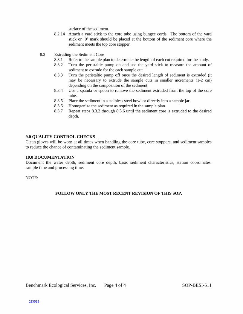
Benchmark Ecological Services, Inc. Page 4 of 4 SOP-BESI-511
surface of the sediment. 8.2.14 Attach a yard stick to the core tube using bungee cords. The bottom of the yard
stick or ‘0’ mark should be placed at the bottom of the sediment core where the sediment meets the top core stopper.
8.3 Extruding the Sediment Core
8.3.1 Refer to the sample plan to determine the length of each cut required for the study. 8.3.2 Turn the peristaltic pump on and use the yard stick to measure the amount of
sediment to extrude for the each sample cut. 8.3.3 Turn the peristaltic pump off once the desired length of sediment is extruded (it
may be necessary to extrude the sample cuts in smaller increments (1-2 cm) depending on the composition of the sediment.
8.3.4 Use a spatula or spoon to remove the sediment extruded from the top of the core tube.
8.3.5 Place the sediment in a stainless steel bowl or directly into a sample jar. 8.3.6 Homogenize the sediment as required in the sample plan. 8.3.7 Repeat steps 8.3.2 through 8.3.6 until the sediment core is extruded to the desired
depth.
9.0 QUALITY CONTROL CHECKS Clean gloves will be worn at all times when handling the core tube, core stoppers, and sediment samples to reduce the chance of contaminating the sediment sample.
10.0 DOCUMENTATION Document the water depth, sediment core depth, basic sediment characteristics, station coordinates, sample time and processing time. NOTE: FOLLOW ONLY THE MOST RECENT REVISION OF THIS SOP.
023583

Standard Operating Procedure
Sediment Piston Core Collection
Revision 12/10/10
1
STANDARD OPERATING PROCEDURE
SEDIMENT PISTON CORE COLLECTION
Introduction
Sediment core samples may be collected in soft sediments using a manually-powered piston
core sampler, which is lowered through the water column using extension rods or placed on
exposed sediments and is pushed into the sediment and retrieve manually. Sediment is
retained in the core barrel during pullout utilizing the suction created by the piston.
The manually operated piston core consists primarily of a 3” diameter clear polycarbonate
core tube with a 1/16th inch wall thickness. The piston head is constructed of solid plastic
with a pass through hole drilled to allow the cable attachment to the top of the piston. The
piston head slips onto the top of the core barrel and is held in place using a stainless steel
hose clamp (See diagram attached).
Prior to deployment, the cable is passed through the core barrel and attached to a ring on the
top of the piston which is then pushed up into the bottom end of the core barrel. The piston
is pushed up into the core barrel so that a space is left at the bottom of the core barrel to
accommodate a small layer of water (4 to 6 inches) between the sediment surface and the
bottom surface of the piston. The coring device is either placed on the exposed sediment
surface or lowered to the bottom vertically by attaching 5 foot extension bars one at a time as
the device is lowered.
The following steps outline the procedure for using a piston corer in the field.
Core Collection Procedures (exposed sediment)
1. Approach the proposed sampling location using the navigation system and deploy a
marker stake at the location.
2. Following decontamination of all piston components, including the core barrel,
assemble the coring device. Check to ensure that the core barrel is securely fastened
to the piston core head.
3. Place the coring device on the sediment surface at the desired location and add an
extension bar..
023584

Standard Operating Procedure
Sediment Piston Core Collection
Revision 12/13/10
2
4. Secure the piston line. With the piston line secured, manually push the piston core
vertically into the sediment. Record the depth of penetration by measuring
movement of the piston top in relation to the sediment surface. Manually push the
core into the sediment until refusal or the project depth has been achieved.
5. Excessive hammering to obtain deeper penetration should be avoided. Hammering in
the piston core may prevent the manual retrieval of the core due to excessive
sediment suction. If very soft sediments are encountered, soft hammering on the top
of the core extension poles can be applied.
6. Exercise proper back care when pulling a stuck core out of the sediments.
Alternatively, use an overhead winch to initiate sediment pull-out. Remove the
extension bar as needed as the core is brought to the surface.
7. As the final extension bar is removed, maintain a vertical alignment with the core and
place a cap over the bottom of the core as soon as the core nose clears the sediment or
water surface to prevent sediment from sliding out the bottom of the core.
8. Remove the piston head and secure the core vertically for measurements. Allow any
disturbed sediment to settle completely within the core tube and measure the
recovered sediment length.
9. Water above the sediment must be drained prior to piston removal. First drain the
water from above the piston by drilling a hole in the core barrel just above the piston.
When the water is drained, drill another set of holes below the piston and just above
the sediment surface. After all head water has been drained, the piston can be
carefully drawn up and out of the top of the core barrel.
10. Cut off the excess plastic tube above the sediment surface and immediately cap the
end and secure the caps on top and bottom with duct tape.
11. Evaluate the appearance and length of the core sample by examination through the
clear plastic core liner. Note any stratigraphic intervals or other salient features on
the core collection log sheet.
12. Fill out a chain-of-custody form for the core section(s) to initiate the tracking process.
13. If chemical analyses will be conducted, store the core sections at 4 2 C in a
refrigerator or iced cooler. Otherwise, store the core at room temperature. Store the
core upright at all times.
Complete any additional entries on the core collection log sheet.
023585

Standard Operating Procedure
Sediment Piston Core Collection
Revision 12/13/10
3
Acceptance criteria for a sediment core sample are as follows:
The core penetrated to and retained material to project depth or refusal
Cored material did not extend out the top of the core tube or contact any part of the
sampling apparatus at the top of the core tube
There are no obstructions in the cored material that might have blocked the
subsequent entry of sediment into the core tube and resulted in incomplete core
collection
If sample acceptance criteria are not achieved, as specified in the project specific sampling
and analysis plan (SAP) the sample may be rejected. If repeated deployment within 20 ft of
the proposed location does not result in a sample that meets the appropriate acceptance
criteria, the Project Manager will make decisions regarding relocating the proposed sample
location.
Core Processing Procedures
Sediment core processing can be conducted aboard a sampling vessel or at a land based
processing facility. It is important to transport and store collected cores in an upright
position up to the time of processing to preserve core sediment integrity. Sediment cores
will be cut into smaller individual core sections and delivered vertically to the geotechnical
laboratory as intact core sections. Core processing consists basically of cutting each core into
field selected intervals (typically 1 to 2 ft sections), and capping both ends for laboratory
delivery. The steps for processing the core sections are listed below:
1. Cores will be secured and cut vertically to avoid mixing within the core barrel
during the cutting process.
2. Using, either a hand or an electric saw, the core will be cut through at the field
determined intervals. The top of the core section to be cut will be capped securely
with a core cap or an expansion plug to provide suction on the material below to
aid in the prevention of material leaking out of the bottom of the section while
the core is cut.
3. To maintain the core integrity following the cut, a stainless steel drywall knife
will be inserted into the cut to aid in placement of a cap onto the bottom of the
newly cut section.
023586
tfreitas
Text Box
Photographs of a piston core setup follow.

023587
ctorell
Group
Peristaltic Pump
ctorell
Callout
Sediment Core
ctorell
Callout
Extrusion Manifold

023588
ctorell
Callout
Peristaltic Pump
ctorell
Callout
Sediment Core
ctorell
Callout
Extrusion Manifold

023589

ATTACHMENT 2
FIELD FORMS
023590

SEDIMENT CORE LOG
PROJECT: San Jacinto River Waste Pits Core ID: pg ___of ____
Collected: Processed:Date: Drive Length: Date:
Time: Tide Level (CRD): Time:
Recovery Length: Mudline Depth: Core Length:
Recovery Efficiency: Vessel: Location:
Crew: Crew:
G S Si/Cl
Core segment breaks at (cm):
/ /2010
Grain Size(%)
Sample IDPhoto IDLithologic Description:
(Grainsize, color, density/consistency, odor, organics, debris)
Depth in Core (cm)
/ /2010
023591
tfreitas
Text Box
tfreitas
Text Box

FIELD CHANGE REQUEST
Project Number:
Field Change No.
Page to
Project Number:
Project Name:
CHANGE REQUEST
Applicable Reference:
Description of Change:
Reason for Change:
Impact on Present and Completed Work:
Requested by:
Date: / /
(Field Scientist)
Acknowledged by:
Date: / /
(Field Task Leader)
FIELD OPERATIONS MANAGER RECOMMENDATION
Recommended Disposition:
Recommendation by:
Date: / /
(Sampling and Analysis Coordinator)
PROJECT MANAGER APPROVAL
Final Deposition:
Approved/Disapprove
d by:
Date: / /
(CERCLA Coordinator)
Approved/Disapproved by:
023592

CORRECTIVE ACTION RECORD Page of Audit Report No. : Date: Report Originator: Person Responsible for Response: DESCRIPTION OF PROBLEM: Date and Time Problem Recognized: By: Date of Actual Occurrence: By: Analyte: Analytical Method: Cause of Problem: CORRECTIVE ACTION PLANNED: Person Responsible for Corrective Action: Date of Corrective Action: Corrective Action Plan Approval: Date: DESCRIPTION OF FOLLOW-UP ACTIVITIES: Person Responsible for Follow-up Activities: Date of Follow-up Activity: Final Corrective Action Approval: Date:
023593

Address:Any Lab
Client Contact:
Lab PM:
E-Mail:
Chain of Custody Record
Sampler:
Phone: Page:Client Information
Carrier Tracking No(s): COC No:
Job #:
City:Seattle
Client Contact: E-Mail:Phone:
Preservation Codes:
M - HexaneN - NoneO - AsNaO2P Na2O4S
TAT Requested (days):
Analysis RequestedAnchor QEA LLC
1423 3rd Avenue, Ste 300Address:
A - HCL B - NaOH C - Zn AcetateD Nitric AcidState Zip:
Due Date Requested:
Company:
Page:Page 1
Email:
Project Name:
WA, 98101Phone:
nta
iner
s
ple
(Y
es o
r N
o)
Yes
or
No
)
Project #:
P - Na2O4SQ - Na2SO3R - Na2S2SO3S - H2SO4T - TSP DodecahydrateU - AcetoneV - MCAAW - ph 4-5Z - other (specify)
PO #:
D - Nitric Acid E - NaHSO4 F - MeOH G - Amchlor H - Ascorbic Acid I - Ice J - DI Water K - EDTA L - EDA
WO #:
State, Zip:
206-287-9130(Tel)
Other:
Sample DateSample
Time
Sample Type
(C=comp, G=grab)Sample Identification
Site:
To
tal N
um
ber
of
con
SSOW#:
Matrix (W=water,
S=solid, O=waste/oil,
BT=Tissue, A=Air)
Preservation Code:
Fie
ld F
ilter
ed S
amp
l
Per
form
MS
/MS
D (
Y
Special Instructions/Note:
G N
G N
G N
G N
Preservation Code:
G N
G N
G N
G N
G N
G N
G N
Non-Hazard Flammable Skin Irritant Poison B Unknown Radiological
Possible Hazard Identification
Return To Client Disposal By Lab Archive For __________ Months
Sample Disposal ( A fee may be assessed if samples are retained longer than 1 month)
Company
Company
C
Time:Date/Time:
Date/Time:
D t /Ti
Relinquished by:
R li i h d b
Company
Method of Shipment:
D t /TiR i d b
Deliverable Requested: I, II, III, IV, Other (specify) Special Instructions/QC Requirements:
Date/Time:Company Received by:
Empty Kit Relinquished by: Date:
Relinquished by: Date/Time:
C
Received by:
Company
Custody Seals Intact: ∆ Yes ∆ No
Date/Time:
Custody Seal No.:
Relinquished by: Date/Time:Received by:
Cooler Temperature(s) oC and Other Remarks:
Company
023594
tfreitas
Text Box
tfreitas
Text Box

CUSTODY SEAL = = -= -=---~--=-=--=---==--=
ENVIRONMENTAL SAMPLING SUPPLY
9601 San Leandro $t. Oakland, CA 800-233-8425
3 8 3 H ----------- :aJn1w61s
l 3 3 d
:a1ea
Date: __________ _
Signature: __________ _
p E E L
H E R E
~i'HtG-008 '1'!:> ·1p1JeP1eo 1s oJpuea, ues ~096 !.1ddns VNfid/A/~ Tu'lN3WNO!:J/.tW3
::::: -;:::;:; -~ === - =- =~
1'13S AOO.LSn:>
023595
tfreitas
Text Box

ATTACHMENT 3
USEPA COMMENTS AND RESPONSES
023596

DRAFT - USEPA Comments and Responses on Draft Radioisotope Coring Study Field Sampling Plan (March 2011)
1
Comment No.
Section Page Line Comment Response to Comment - Proposed Revision
1 General Comment The term “sediment bed” is used throughout the report; we suggest using “bed sediment” as a more appropriate term.
The term “sediment bed” was used in the SAP for Chemical Fate and Transport Modeling, which has been approved by USEPA. Changing the terminology as requested in the comment would produce an inconsistency between the FSP and SAP.
2 List of Attachments Page ii Edits to ensure consistency between section titles and attachment titles, change “Sample Packaging and Shipping” to “Sample Packaging and Transport” to match title of section 2.4, change “Investigation-Derived Waste Handling” to “Study-Derived Waste Handling” to match title of section 2.5
The section titles will be changed appropriately.
3 Figure 1 Please show the approximate coring locations (near waste pits, upstream of waste pits, and downstream of I-10 bridge), but the scale is too large to show them, is it possible to zoom in on the Site area? Please keep the figure to the area view to the size of the model domain (ie bed property FSP). There is no need to show the area up to Lake Houston; label the San Jacinto River; use similar lines for the highways –the red of Highway 90 and the red of the original perimeter is confusing; it’s difficult to read the road names – put a white outline around the characters and enlarge text size; suggest adding a map of Texas showing the Site location in the blank space on the page for those who aren’t familiar with the State; change label in legend from “Original (1966) Perimeter of the impoundments” to “Original (1966) perimeter of the San Jacinto River waste pits”, if appropriate.
Since coring locations had yet to be chosen (selected locations would be based on the then-ongoing Bed Property Study data) at the time of Draft Radioisotope Coring Study submittal, it was not possible to show a map with core locations in the Draft FSP (See Section 1.1.) That study has been completed, and the selected coring locations will be depicted on an appropriately scaled figure in the Revised Radioisotope Coring Study FSP.
Figure 1 will be edited for clarity, considering the comments provided.
4 Section 1. Introduction Page 1 Small changes in wording, change “Additional information of the Site history and summer of existing data are provided in the RI/FS Work Plan…” to “Additional information about the Site history and summer of existing data are provided in the RI/FS Work Plan…”, change “The flow chart shown below ….” to “The flow chart that follows…” because it’s not below, it’s on the next page.
These edits will be made.
5 Section 1. Introduction Page 2 Last sentence in the paragraph says how the results of the coring study will be used and refers the reader to another report, instead of making the reader find another document to find out how the results will be used, summarize that information here, suggested revision: “The results of the radioisotope coring study will be used to estimate net sedimentation rates for the sediment transport model.”
The suggested revision will be made to the text.
6 Section 1.1 Overview Page 2 Suggest mentioning that the radioisotopes sorb to the clays, which is why the cohesive bed sediments (not sandy bed sediments) are being cored. In addition, suggest adding references that details sorption properties and recent sediment age-dating. Below are several references that could be cited.
• Bolt, G.H., Bruggenwert, M.G.M., and Kamphorst, A. (1976) Adsorption of cations by soil, In: (G.T. Bolt and M.G.M. Bruggenwert, eds.) Soil Chemistry A: Basic Elements, Elsevier Sci. Publ. Co., New York, NY, p. 54-90.
• Tamura, T. and Jacobs, D.G. (1960) Structural implications in cesium sorption: Health Physics, v. 2, p. 391-398.
• Jetter H.W. 2000, Determining the ages of recent sediments using measurements of trace radioactivity, Terra et Aqua 78, pp. 21-28.
• Holmes, C., 1998, Short-Lived Isotopic Chronometers-A Means of Measuring Decadal Sedimentary Dynamics, U.S. Geological Survey Fact Sheet FS-073-98, 2 pp/
• Van Metre, P.C., Wilson, J. T., Fuller, C.C., Callender, E., and Mahler, B., 2004 Collection, Analysis, and Age-Dating of Sediment Cores From 56 U.S. Lakes and Reservoirs Sampled by the U.S. Geological Survey, 1992–2001, U.S. Geological Survey Scientific Investigation Report 2004-5185, 180 pp.
• Mahler, B. and Van Metre, P.C., 2003, A Chronicle of Organochlorine Contamination in Clear Creek, Galveston and Harris Counties, Texas, 1960–2002, as Recorded in Sediment Cores, U.S. Geological Survey Fact Sheet 088-03, 6 pp.
Additional information will be added as requested in the comment, including the references.
023597

DRAFT - USEPA Comments and Responses on Draft Radioisotope Coring Study Field Sampling Plan (March 2011)
2
Comment No.
Section Page Line Comment Response to Comment - Proposed Revision
7 Section 1.1 Overview Page 3 Suggest change in wording from “Ten radioisotope cores will be collected and the locations of these cores will be determined from the results of the bed probing study (i.e. cohesive bed areas).” to “Ten cores will be collected for radioisotope analyses and the locations of these cores will be selected based on the results of the bed probing (property??) study (i.e. cohesive bed areas).”
These edits will be made.
8 Section 1.2 Project Organization, FSP Personnel Quality Assurance Responsibilities Table
Page 3 Can you add the Project Coordinator to the table, above the Task Coordinator?
This edit will be made.
9 Section 1.3 Laboratories
Page 4 Keep terminology in the 3rd and 4th bullet points consistent with preceding table by referring to the “task coordinator” instead of the “task QA coordinator”.
These edits will be made.
10 Section 1.3 Laboratories
Page 4 Please clarify which analytical laboratory that is discussed in this section; was Integral Consulting or Mass Spec Services the analytical lab? It is difficult to understand because the laboratory QA coordinator and manager is at Integral Consulting while the laboratory project manager is at Mass Spec Services.
Clarification will be provided. The laboratory QA manager is Delaney Peterson of Anchor QEA. The laboratory project manager is the laboratory’s manager for the project. The analytical laboratory subcontractor has been changed from Mass Spec Services (Orangeburg, New York) to Teledyne Brown (Knoxville, Tennessee) because of analytical capacity issues.
11 Section 1.3 Laboratories
Page 4 Please provide description of the analytical methods in this section – at least one sentence describing procedures GA-01-R and 7.2.3.
Laboratory procedures have been updated to TBE-2015 for 210Pb and TBE-2007 for 137Cs based on changes of the selected lab from Mass Spec Services to Teledyne Brown. Detailed analytical method information will be provided in the Attachments to the FSP and a reference to those added Attachments will be provided in this section of the text. Additional discussion will be added to the text related to the general methodology used in the laboratory procedures.
12 Section 1.4 Document Organization
Page 5 Lists in first paragraph and SOPs don’t match the items in the table of contents either in terminology, order, or some things not mentioned at all.
This section will be edited for consistency.
13 Section 1.4 State purpose (precisely) for this analytical study. (Copy from Chemical F&T, or write one.)
The last two sentences in Section 1 of the FSP will be modified as follows: “The objective of the Radioisotope Coring Study is to obtain sediment cores from representative cohesive sediment bed areas in the Study Area for use in a geochronology (age-dating) analysis. Specifically, the cores will be obtained to provide sediment suitable for cesium-137 (137Cs) and lead-210 (210Pb) laboratory analyses in accordance with Procedure TBE-2007 for 137Cs (Teledyne Brown Engineering Environmental Services 2008) and Procedure TBE-2015 for 210Pb (Teledyne Brown Engineering Environmental Services 2010). The results of the Radioisotope Coring Study will provide calibration data for the sediment transport model, as described in the Fate and Transport Addendum (Anchor QEA and Integral 2010b)”.
14 Section 2.2 Sampling Methods
Page 6 Suggest change in wording from “The following sections describe the vessel and field equipment, sampling methods, sampling handling, and shipping” to “The following sections describe the vessel and field equipment, coring methods, sampling processing, and equipment decontamination”; shipping is in section 2.4.
These edits will be made.
15 Section 2.2.1.1 Sampling Vessel
Page 7 Change “river gauge height” to “stream elevation” to match 2nd bullet point.
This edit will be made.
023598

DRAFT - USEPA Comments and Responses on Draft Radioisotope Coring Study Field Sampling Plan (March 2011)
3
Comment No.
Section Page Line Comment Response to Comment - Proposed Revision
16 Section 2.2.1.2 Field Equipment and Supplies
Page 7 to 8 It took some time to figure out that you’re using a polycarbonate core liner (also called the “tube”) inside of a core barrel. If the parts of the piston corer are referred to by the same terms throughout this section, it would be clearer. Suggest referring to the entire device as the “piston corer”, the inner tube as the “core liner”, and the outer part as the “core barrel”.
Clarifying edits will be made as suggested.
17 Section 2.2.1.2 Field Equipment and Supplies
Page 8 Third paragraph about sample containers, move the description of the jars from p. 12 here: Commercially available, pre-cleaned 4 oz. glass jars with Teflon-lined lids will be used for the samples….”.
The description on page 12 will be duplicated as suggested on page 8.
18 Section 2.2.1.2 Field Equipment and Supplies
Page 8 Last paragraph, will the sample container labels also indicate the sample interval? And, modify last sentence to match table of contents: “Station numbering and sample identification procedures are described in detail in Sections 3.3 and 3.4”; the terms “station numbering” and “sample numbering” and “core ID” seem to be used interchangeably.
The samples will have the interval in the core identification (ID) number. Clarifying edits will be made as suggested.
19 Section 2.2.1.2 Field Equipment and Supplies
Page 8 Suggest including a photo or diagram of a piston corer because they’re difficult to describe and understand; note: SOP PISTON CORE is supposed to include a diagram of a piston corer, but doesn’t have it.
A diagram of the corer will be provided in the section and SOP as suggested and has been transmitted for information with these comment responses. Labels will be added to the photograph of the extruder to identify specific parts.
20 Section 2.2.2 Station Location Positioning
Page 9 If the desired coring locations are known before sampling, why not show on figure 1 and include in table 1?
See response to Comment 3, above.
21 Describe criteria for selection of sample locations.
Clarifying text will be added. As described in the Final Sampling Analysis Plan Addendum (Anchor QEA and Integral 2011), the results of the Bed Property Study will be used to identify cohesive sediment locations. From these locations, the following will be identified for sampling: 2 cores upstream of the impoundments, 4 cores in the vicinity of the site and 4 cores downstream of the site. Coring locations will be selected considering localized spatial distribution, river morphology, general flow regime and professional judgment. Outside of the preliminary RI/FS Site perimeter, the results of the Bed Property Study will be used to determine the core locations. The sediment type descriptions of the surface grab samples as well as the sub-surface sediment type descriptions and probing depths from the bed probing will be used to select areas with primarily surface and sub-surface cohesive sediments. Care will be taken to select locations which have the potential to have recovery depths of at least 2 feet. Inside the preliminary RI/FS Site perimeter, surface and sub-surface grain size distribution data collected in 2010 will be used to assess sediment type. A core will be discarded if it is completely composed of non-cohesive sediment. In that case, an alternate location will be selected.
22 Section 2.2.2 Station Location Positioning
Page 9 Modify this sentence to match first column in table 1, “A preliminary list of the radioisotope coring sample core identifications can be found in Table 1.”
These edits will be made.
23 Section 2.2.3 Sediment Coring
Page 10 Move text from p. 11 about what happens if less than 2 ft of sediment at a coring location to the first paragraph: “The core will be supported by a bracing structure and will be manually advanced into the sediment to achieve a target penetration depth of at least 2 feet. At each coring location, if less than the minimum of 2 feet of core length is achieved on the first coring attempt…(rest of paragraph from bottom of p. 11)”
This edit will be made.
24 Section 2.2.3 Sediment Coring
Page 11 What sediment thicknesses and water depths do you expect at the coring locations? It is assumed this is known from the sediment property study. Sediment must be pretty thin & water pretty shallow to allow the corer to be manually pushed into the mud. Any concerns about having to push the corer down so far that you can’t reach it anymore? Note: When the SOP PISTON CORE was reviewed, information was found about use of an extension bars; suggest adding a brief phrase in this section about the extension bars.
Anticipated sediment thickness and water depths will be provided on the figure depicting the selected sample locations. A reference to extension bars will be added to the text as suggested.
023599

DRAFT - USEPA Comments and Responses on Draft Radioisotope Coring Study Field Sampling Plan (March 2011)
4
Comment No.
Section Page Line Comment Response to Comment - Proposed Revision
25 Section 2.2.3 Sediment Coring
Page 11 You’re able to insert a plug into the bottom of the core when the top of the corer is at the water surface? Do you mean that you insert the plug into the bottom of the core before the bottom of the corer comes out of the water?
The latter is correct. The text will be clarified.
26 Section 2.2.3 Sediment Coring
Page 12 Do you cut off the excess core liner before capping and/or extruding the core?
The excess core liner will be removed either before capping or before processing, depending on obtained sediment thickness and excess core length.
27 Section 2.2.3 Sediment Coring
Page 12 Siphon or drain water before capping? And are the cores stored vertically in a cooler (from p. 6 describing equipment on the boat “sample coolers modified to contain upright, undisturbed cores”)?
The cores will be stored vertically from collection through processing. Excess water will be removed by draining through a hole drilled just above the sediment surface. All water will be containerized and care will be taken to minimize sediment disturbance during draining.
28 Section 2.2.4. Sediment Sample Processing
Page 12 Move last sentence of first paragraph up higher in the paragraph: “A plunger inserted into the bottom of the core liner, powered by a peristaltic pump, will be used to extrude the core. If sediment consistency prevents extruding the cores into open air…”
This edit will be made.
29 Section 2.2.4. Sediment Sample Processing
Page 12 Do you use a putty knife only on the top interval and then a taping knife for the lower intervals? Why the difference?
Both stainless steel putty or taping knives are appropriate tools to separate the sediment segments from the core. The text will be edited to refer to only a putty knife, as this tool will be selected for processing activities.
30 Section 2.2.4. Sediment Sample Processing, p. 12
Page 12 Does lab need 50 to 100 g wet or dry sediment for analyses?
The lab has indicated that 200 g wet weight total sample size is sufficient for both 210Pb and 137Cs analyses.
31 Section 2.2.4. Sediment Sample Processing
Page 12 Only samples from the top 3 feet of the core will be submitted for analysis – how do you know this will go deep enough to get the Cs-137 peak? Are there previous investigations of sedimentation rates that you can cite here? Also, the spacing between samples selected for analysis gets wider below 2 feet – what led you to expect the Cs-137 peak would be in the top 2 feet?
An average net sedimentation rate for the period between 1963 and 2011 of about 1.9 cm/year or less would result in the 137Cs peak occurring in the top 3 feet of the core. Based on professional judgment at other sites, it is likely that net sedimentation rates will be less than 2 cm/year at many cohesive bed locations in the San Jacinto River. However, if the 137Cs peak is not detected in the top 3 feet of a core, then archived samples below 3 feet from that core can be submitted for analysis. Thus, the proposed sampling approach does not preclude detecting 137Cs peaks that may occur deeper than 3 feet in a core.
The difference in spacing between selected samples above and below 2 feet is to provide better resolution of the vertical gradient in 210Pb activity in the upper 2 feet of the core. The 210Pb vertical gradient is used to estimate net sedimentation rate.
32 Section 2.2.4. Sediment Sample Processing
Page 12 Last paragraph, change units of feet to centimeters or meters so this paragraph discusses the core and sample interval lengths in the same units (metric).
This edit will be made.
33 Section 2.2.4. Sediment Sample Processing
Page 12 Last paragraph, it sounds like all of the samples are submitted to the lab but only selected samples are analyzed; if so, modify last two sentences to make this clear.
The sentence will be clarified.
34 Please reconcile the number of sample intervals that will be analyzed for radiometric content -8 to 11, etc.
“8 to 11” accounts for the change in number of subsamples selected as described from cores potentially being between 2 and 3 feet (61 to 91 cm). The text will be clarified to indicate that a minimum of 8 and a maximum of 11 subsamples will be analyzed for each core.
023600

DRAFT - USEPA Comments and Responses on Draft Radioisotope Coring Study Field Sampling Plan (March 2011)
5
Comment No.
Section Page Line Comment Response to Comment - Proposed Revision
35 Section 2.2.5 Equipment Decontamination
Page 13 Are core liners washed only if they’re reused/recycled? Or are all of them washed before use, new ones too? Change “Lexan” to more generic term which was used before (“polycarbonate”, p. 7).
All core liners will be new, and the suggested edit will be made.
36 Section 2.2.5 Equipment Decontamination
Page 13 Second paragraph, it’s Attachment 1 not 2; is solvent rinsed used for anything? If not, remove from SOP SD-01 instead of qualifying it here; a solvent rinse isn’t typically used for radioisotope sampling equipment.
The attachment reference will be corrected.
37 Section 2.3 Field and Laboratory Quality Control Samples
Page 13 Table 2 doesn’t provide a lot of information and that information could be easily stated in the text, instead; for example, “A minimum of 5 percent field duplicate samples will be collected.” Same thing for the lab QC samples on p. 14.
The text will be clarified as suggested.
38 The frequency of QC samples (Table 2) applies to the number of 2.5 cm intervals. Correct?
Yes.
39 Section 2.3 Field and Laboratory Quality Control Samples
Page 13 Suggest modifying last sentence, “To achieve the required laboratory processing volumes, samples above and below the target sample location interval can be consolidated…”
This edit will be made.
40 Section 2.5 Study-Derived Wastes
Page 15 First sentence, is excess detergent and sample deposited at the core collection area or at the sample processing area? Also, can’t tell if excess sample goes into a 50-gallon drum or on the ground (2nd sentence).
All materials contacting sediment (e.g., core liners, decontamination fluids) and excess sediment will be containerized; the section will be clarified.
41 Section 3 Field Documentation
Page 16 Is a photograph taken of just the top interval or the whole core? Suggest documentation of both.
The text will be clarified to indicate that the entire core will be photographed.
42 Section 3.1 Field Logs Page 17 The bulleted list of information contained in the field log book is a repeat of SOP AP-02 but in different order & different terminology; suggest referring to the SOP, instead, for brevity & consistency.
The text list will be edited to be consistent.
43 Section 3.3 Station Numbering
Page 19 Modify “Station numbers will include “SJ” to indicate San Jacinto River…”
The text will be revised as suggested.
44 Section 3.3 Station Numbering
Page 19 Last sentence, SJRI007 is called a station number here but a core ID in table 1, is it both?
Yes.
45 Section 3.4 Sample Identifiers
Page 19 The letter code designated the duplicate/normal sample comes after the depth interval, not before, as written.
Depth identification nomenclature will be added to the text.
46 Section 5.1 Criteria for Data Review, Verification, and Validation
Page 22 Adding one or two sentences about data review and verification, evaluation of field duplicates, and verification and validation of radioisotope data would be very helpful to the reader & not force them to find the Sediment SAP and that information in the Sediment SAP.
Additional text will be added for clarification.
47 SOP AP-01 Sample Packaging and Shipping
Page 2 Sample preparation, #1 mentions tag numbers which were not discussed previously; will you be using tag numbers in addition to sample labels? If so, need to reference SOP AP-04 in the text or in SOP AP-01 so the reader understands.
Tag numbers will not be used; the text in the SOP will be modified to read “(e.g., samples labels…)”.
48 SOP AP-01 Sample Packaging and Shipping
Page 2 Sample preparation, #1, example provided in Attachment 2, not SOP AP-03.
This edit will be made.
49 SOP AP-01 Sample Packaging and Shipping
Page 4 Sample preparation, #11, examples of COC seals are not provided with the example field forms in Attachment 2, as stated
Example COC seals will be provided in Attachment 2.
023601

DRAFT - USEPA Comments and Responses on Draft Radioisotope Coring Study Field Sampling Plan (March 2011)
6
Comment No.
Section Page Line Comment Response to Comment - Proposed Revision
50 SOP SD-12 Logging of Sediment Cores
Page 3 Sediment description – how do you estimate percent moisture with depth in a core? It’s difficult to say much more than very wet, wet, or dry; even “wet” often varies between 70 to 90% water content.
Visual estimation of water content in cores is a qualitative observation. As such, the SOP will be edited to read “approximate moisture content descriptor (e.g., dry, wet, moist)”.
51 SOP-BESI-511 Extruding Sediment cores Using Water Pressure
A photograph of this set up would be very helpful to the reader – again, a complicated set up that’s difficult to understand without a visual aid.
Photographs of the extrusion apparatus will be included in the revised FSP and have been transmitted for information with these draft comment responses.
52 SOP PISTON CORE Page 1 End of 2nd paragraph, no diagram is attached, which would be very useful.
See comment 19 response, above.
53 SOP PISTON CORE Page 1 Core Collection Procedures (exposed sediment) –can you use a piston core with exposed sediment? They’re not too hard or dry? The piston cores may require sediment to be submerged for a vacuum to form. After reading this entire section, it sounds like it’s describing piston coring of submerged sediments, not exposed sediments; maybe it is a misunderstanding what’s meant by the term “exposed sediments”?
Piston cores may be collected in both submerged and exposed sediments with the apparatus. The sediments to be sampled during the Radioisotope Coring Study are submerged.
54 Attachment 2 Field Forms
The use of a field change request form is never discussed; delete from document?
The form will remain, and an appropriate reference will be added in the text.
023602