Quantitative Transcriptomics using Designed Primer-based Amplification
Upload
khangminh22Category
view
2download
0
Abstract—Plasmonic modes provide the potential for routing
information with optical speeds and bandwidth at the nanoscale. The inherent tradeoff between modal energy confinement and energy dissipation, however, makes realizing this potential an extreme challenge. For decades, researchers have investigated compensating losses in plasmonic systems with active gain media. In recent years, progress has increased dramatically, as nanoscale plasmonic amplifiers and lasers have emerged. We review this progress and offer our prospective on the challenges ahead.
Index Terms—Electromagnetic metamaterials, Metal-insulator structures, Optical losses, Optical gain, Plasmons, Semiconductor lasers
I. THE FUNDAMENTAL PROMISE AND CHALLENGE OF PLASMONICS
t is an historical irony that the first explicit theoretical prediction of the existence of surface plasmons (SP) around visible wavelengths arose from an investigation of energy
dissipation in thin metallic films [1]. Since their discovery, much of the technological interest surrounding SP has been overcome by the fact that many of their applications suffer from dissipation losses inherent to the metal films which bring about their existence. In his 2006 review, Ozbay outlined both the fundamental promise and challenge with plasmonics—that it has “the capacity of photonics and the miniaturization of electronics,” with the inherent “…trade-off…between mode confinement and propagation loss” [2]. The fulfillment of the promise of plasmonics, according to Ozbay, required significant research advances, including optical metallic waveguides (WGs) with propagation losses comparable to conventional dielectric WGs, efficient and tunable plasmonic sources, as well as active control of plasmonic signals [2].
In this review we survey the efforts of researchers in advancing the field of plasmonics towards its promise and offer a perspective on future directions and challenges. The review covers fundamental principles and history, but focuses on the most recent advances and obstacles facing the community with respect to loss-compensation of plasmonic signals. In Section II we review amplification of propagating modes, including systems of one, several, and many metal-dielectric (MD) interfaces. This is followed by a review of amplification and lasing of cavity modes in Section III. Lastly, in Section IV we offer our prospective on future directions. Firstly, however, we begin with a brief overview of the basic problem.
Digital Object Identifier 10.1109/JPROC.2016.2582078
According to classical electromagnetic theory, a surface
plasmon-polariton (SPP) is an electromagnetic mode existing at the interface between a metal and dielectric, where the metal and dielectric are represented by electrical permittivity functions whose real parts have different signs [3]. While the existence of surface waves at the interface of dissimilar media was predicted by Zennek [4] and Sommerfeld [5], the relation of electromagnetic surface waves to oscillating electrons came later [1]. From a condensed-matter physics perspective, an SPP is a collective oscillation of the “electron sea” against the stationary positively charged ion background that is excited by incoming radiation that matches the frequency and momentum of the collective oscillation [6]. The beauty of SPPs rest in the fact that their energy may be much more spatially confined relative to modes in purely dielectric media. This is most easily seen through the SPP dispersion relation of a transverse-magnetic (TM) polarized wave for a single MD interface [3],
/SPP M D M Dn (1)
where nSPP is the effective index, and εM and εD are the electrical permittivity of the metal and dielectric, respectively, which are generally complex-valued functions of frequency.
The fundamental problem with SPPs is illustrated by Fig. 1. In Fig. 1(a), the effective index is plotted as function of frequency ω for an SPP at the interface between silver and air, where εM is calculated from the Drude model with interband transitions ignored [5], εM=1-ωP
2/(ω2+jΓω), with ωP and Γ being the plasma and damping frequencies of silver, respectively. In the limit of Γ=0 (green curve, inset of Fig. 1(a)), nSPP is purely real and unbounded, indicating theoretically that the guided energy may be confined to an arbitrarily small distance from the interface. In reality, Γ>0 always, and the real part of nspp (solid blue curve, Fig. 1(a)) has an upper limit. As the real part of nSPP increases, so too does the imaginary part (dashed red curve, Fig. 1(a)), describing the fact that increased energy confinement always comes at the expense of increased energy dissipation. In Fig. 1(b), we consider silver and InGaAsP as the metal and dielectric, respectively. Note that in the absence of external pumping, InGaAsP is absorbing in the near-infrared, as indicated by a large increase in the imaginary part of nSPP at the material bandgap near 1.55μm. Compared to the bulk refractive index of InGaAsP (solid blue curve, Fig. 1(b)), the real part of the SPP index (solid red curve, Fig. 1(b)), is greater, indicating greater confinement of energy. However, the imaginary part of the SPP index (dashed red curve, Fig. 1(b)) is also greater than that of bulk InGaAsP (dashed blue curve, Fig. 1(b)), indicating a greater rate of energy dissipation. For a quantum mechanical description of the inherent tradeoff between modal energy
Amplification and Lasing of Plasmonic Modes Joseph S. T. Smalley, Student Member, IEEE, Felipe Vallini, Qing Gu, and Yeshaiahu Fainman,
Fellow, IEEE
I
0018-9219 © 2016 IEEE. Personal use is permitted, but republication/redistribution requires IEEE permission. See http://www.ieee.org/publications_standards/publications/rights/index.html for more information.
http://ieeexplore.ieee.org/Xplore

2
confinement and dissipation, see [7], which emphasizes that energy confinement is ultimately limited by non-local Landau damping.
Beyond single MD interfaces, scientists and engineers have suggested more complex MD configurations. One example is the dielectric-metal-dielectric (DMD) waveguide, also referred to as insulator-metal-insulator (IMI), in the literature. When the metal layer is sufficiently thin, strong coupling between the adjacent SPPs leads to degeneracy-splitting and the formation of two distinct modes. Both modes exhibit the behavior that greater confinement costs greater dissipation. However, as the metal gap becomes smaller, one mode—the field-symmetric, charge-asymmetric mode—becomes less confined and less dissipative. This so-called long range SPP (LRSPP) was recognized as a compromise between the extreme mode confinement and significant loss, and was recognized as a promising carrier of information in microscale environments (see [8] for a comprehensive review of this particular mode and its applications). One may argue, however, that using the LRSPP does not really solve the fundamental problem. To mitigate the inherent dissipation loss in MD systems, for example if the energy of an SPP may become increasingly confined while the effective rate of dissipation remains constant, then active media, i.e., a dielectric with gain, is required.
In addition to SPPs, which propagate along MD interfaces, localized surface plasmons (LSPs) are non-propagating modes existing in isolated MD systems, such as metal nanoparticles in a dielectric host [3]. Another type of plasmonic mode also emerges when many MD interfaces are placed sufficiently closely together, the Bloch plasmon-polaritons (BPPs), also known as volume plasmon-polariton (VPPs). Generally BPPs exhibit larger real and imaginary effective indices than SPPs [9], which makes the fundamental problem between energy
confinement and dissipation even more pronounced for applications requiring signal transmission.
SPPs, LSPs, and BPPs owe their existence to the unique optical properties of metals. The optical density of states (DOS) in MD systems is greatly increased compared to purely dielectric systems. This is fundamentally related to the fact that plasmonic modes are not limited by diffraction. While a dielectric waveguide or cavity will only support modes on the scale of half the operating wavelength, MD systems support modes to arbitrarily small scales in the limit of no losses. The density of modes may be extremely large and even theoretically infinite in some arrangements, however, the lifetime of these states may be extremely short, which is another way of describing the trade-off between confinement and loss inherent to plasmon-polaritons. Nonetheless, the short lifetime may be useful for applications requiring ultrafast transient effects [10]. The ability to design MD systems and engineer the optical DOS provides unique avenues for active devices that address the fundamental problem of plasmonics.
SPP, LSPs, and BPPs are useful for any application where spatially confined energy is valuable. Major applications include imaging and lithography below the conventional diffraction limit [11]–[13], cancer therapy [14], [15], single-molecule sensing [16], surface-enhanced Raman spectroscopy (SERS) [17], [18], data transmission [19], [20], data storage [21], enhancement of nonlinear processes [22], [23], and the modification of spontaneous emission rates [24]–[26]. For some applications, such as cancer therapy and data storage, conversion of EM energy to heat is essential and dissipation is desirable. Additionally, applications in sensing can afford excessive losses. For other applications however, like telecommunication signal generation and propagation, energy dissipation is unwanted. In this review we focus on the latter problem, which is considered the major roadblock to the use of plasmonics in scaling photonics down to the dimensions of
Fig. 1. Graphic of the fundamental problem: (a) As the real part of the effective index of an SPP at a silver-air interface increases (solid blue line), describing increasing energy confinement, the imaginary part of the index also increases (dashed red line), describing energy dissipation. For applications in data transmission, confinement is desirable but dissipation is unwanted. Silver is modeled as a Drude metal [102]. Note that neither curve actually reaches zero. The inset includes SPP dispersion for the hypothetical case of a lossless metal (green line). (b) Comparison between the wavelength dispersion of an SPP at a single MD interface (inset: schematic of MD interface) and the dispersion of the bulk dielectric. In this case we use silver as the metal with experimentally determined electrical permittivity [103] and InGaAsP as the dielectric with theoretically calculated permittivity [91]. The real part of the effective index of the SPP (solid red curve) always exceeds that of the dielectric (solid blue curve), which enables applications utilizing energy confinement, however, the imaginary part (dashed red) also exceeds that of the dielectric (dashed blue), signifying a greater rate of energy dissipation.

3
electronics while retaining its extraordinary bandwidth and ultra-high speed [2].
II. AMPLIFICATION OF PROPAGATING MODES Besides all possibilities enabled by SPPs, LSPs and VPPs,
most realistic applications—and all applications in signal generation and propagation—suffer from the inherent problem of dissipation losses due to the constituent metal. A strategy to overcome this issue is to introduce optical gain in the dielectric constituent of the structures. Indeed, gain media can reduce the effective propagation loss and increase the SPP propagation length, enable transparent propagation, or over-compensate propagation losses and lead to amplification and even stimulated generation of SPPs. A quantum description of the process involving electrical dipoles and SPPs near a MD interface is well described by P. Berini et al. [27] (and references therein). In the next subsections we discuss amplification of SPPs at a one or several MD interfaces followed by loss-compensation of BPPs in coupled MD systems, respectively.
A. Amplification in Systems of One or Several MD Interfaces The first theoretical study of amplification with SPs was
realized by G. A. Plotz et al. [28]. The authors considered a thin film of Ag over a prism, and in contact with a gain medium (dye solution), to demonstrate enhanced reflectance from an amplified medium due to the SPs excitations. In fact, they estimated the threshold gain (unrealistic at that time) to create a reflection singularity related to the plasmonic resonances. Subsequently, A. N Sudarkin and P. A. Demkovich studied the propagation of SPPs on metal-gain media interfaces for transversally bounded and unbounded optical excitations, proposing for the first time the concept of surface plasmon laser [29]. A more formal description of gain-assisted propagation of SPPs on planar metal waveguides was realized by M. P. Nezhad et al. [30]. The authors considered complete solutions to Maxwell equations to calculate the propagation constants and Poynting vectors for several waveguide geometries, considering InGaAsP as the gain media. They investigated the wavefront behavior for SPPs and theoretically predicted amplification with realistic gain coefficients. In the same year, I. Avrutsky also predicted large amplification of SPPs with extremely large effective refractive indexes (slow-light effect) in nanoscale metallic gratings over an optically amplified gain media [31].
Experimentally, SPP amplification was first used in quantum cascade lasers (QCL) as a substitute for thicker dielectric waveguide cladding layers [32]. The QCL with metal cladding reduced total layer thickness, improved the modal confinement factor for stronger coupling of the mode to the active material, and exhibited low ohmic losses for the emission spectral window of interest [33]. The first experimental demonstration of stimulated emission of SPPs was realized by J. Seidel et al. at the interface between a flat silver film and a solution containing organic dye molecules [34]. Optical pumping created a population inversion in the dye molecules that exchange energy with the plasmonic field while dips in the
reflection probe indicate a signature of the stimulated emission of SPPs. A theoretical description of this system was proposed by I. De Leon and P. Berini [35]. In their model the authors included position-dependent dipole lifetime and non-uniformity of the pumping mechanism to describe adequately the SPP amplification phenomenon. Shortly thereafter, M. A. Noginov et al. suppressed the loss of SPPs propagating at the interface between silver film and optically pumped polymer with dye [36]. The experiment was similar to the one of J. Siegel et al., but separated internal, radiative and total losses, and the propagation length of the SPPs. The following work from the same group, using the same structure, was the demonstration of stimulated emission of SPPs through a distinct threshold in the light-light curve together with the narrowing of the emission spectrum [37]. Additionally, the authors created the term “active” nanoplasmonics in the same time that P. Kumar et al. proposed the control of SPP waves via stimulated electron-hole recombination on a p-n junction interfacing a metallic surface [38].
More complex designs were then proposed to amplify SPPs, including interaction with a resonant gain media composed of quantum dots [39], optical parametric amplification in a nonlinear hybrid waveguide [40], and a plasmonic surface close to a gain medium tethered to a whispering gallery mode resonator with high quality factor [41].
Increasing the number of interfaces to two, considering a thin layer of metal bounded by dielectrics, the SPPs existing in the two interfaces can couple forming so-called SPP supermodes [42], [43]. If the supermode is field-symmetric and charge-asymmetric, the confinement is reduced; however, the attenuation is also reduced, in comparison with an SPP at an isolated interface. These modes are called Long-Range SPPs (LRSPPs) [8]. The field-asymmetric and charge-symmetric supermode has opposite properties and presents a higher confinement with increased attenuation. These modes are called Short-Range SPPs (SRSPPs) [44]. The LRSPPs are of fundamental importance because their smaller attenuation results in a smaller gain requirement for amplification of these surface waves. As discussed before a more interesting design consists of MDM structures, since the mode is strongly confined in the amplified region that support cavity modes.
Amplification of SPPs occurring in coupled MD interfaces (Section II.B.), has led to research on amplification of plasmonic cavity modes, coupled or not to electromagnetic cavity modes (Section III), being of fundamental importance for the development of nanoscale sources of coherent emission of radiation.
B. Amplification in Systems of Many MD Interfaces As a precursor to the description of plasmonic modes in
cavity structures, we first discuss research on strongly coupled SPPs, which arise when many adjacent MD interfaces are separated by distances on the order of the penetration length of the SPP. The literature on the theory of coupled MD systems is substantial (see [9], [42], [43], [45]). In the limit of an infinitely periodic MD system, Bloch’s theorem may be invoked and the photonic bandstructure calculated, which reveals the existence of modes with effective indices significantly greater than the effective index of an SPP at a single MD interface. For MD

4
layer thicknesses much smaller than the operation wavelength, effective medium theory (EMT) may be used [46], [47]. When the elements of the effective permittivity tensor arising from EMT have opposite sign, waves with an electric field component normal to the MD interfaces (TM-polarization) exhibit hyperbolic dispersion. The study and manipulation of these modes, in both engineered and naturally existing materials [48], has led to the burgeoning field of hyperbolic metamaterials (HMMs) [49]–[51]. In the limit of EMT, the optical DOS of HMMs scales with the momentum (neff) and, in the further limit of lossless EMT, is unbounded. For a finitely periodic MD system with losses, the optical DOS (and neff) has an upper bound, and is related to the periodicity, a, of the system, through DOS~kmax=k0neff,max=π/a. Unfortunately, as the real part of the effective index increases so too does the imaginary part. This has naturally led to theoretical investigations of HMMs with gain media, to reduce the imaginary part, ideally to the ultimate limit of zero for the “holy grail,” of a transparent HMM.
Ni et al. considered gain provided by a saturated dye in a MD system composed of silver and a low-index dielectric [52]. Various analytical techniques were compared using EMT, non-local EMT, Bloch’s theorem, and Fourier modal analysis. For modes propagating normal to the plane of the layers, complete loss-compensation was deemed feasible under realistic gain conditions, whereas modes propagating in the plane required unphysical gain levels. Additionally, simulations predicted that gain could improve the resolution of sub-diffraction-limited imaging devices and provide for a smaller phase variation in epsilon-near-zero transmission devices. Dye-doped low-index dielectrics in combination with silver were also analyzed by Agryopolus et al. [53]. Using the transfer matrix method (TMM), factor of two improvements in transmission of negatively refracting waves were predicted, but full loss-compensation was deemed impractical. Savelev et al. invoked Bloch’s theorem to analyze generic MD systems, again resembling silver and a low index dielectric with dye as the gain media [54]. Full loss-compensation was predicted for high-k waves propagating normal to the plane of the layers, useful for improved sub-diffraction-limited imaging. The potential existence of convective instabilities associated with amplified spontaneous emission was also revealed, which could be harmful for practical applications. Savelev et al. later used TMM to look at similar MD systems with a finite number of periods [55]. It was shown that modest transmission improvements were feasible, however, it was predicted that the Purcell effect, i.e., enhanced spontaneous emission rates near the plasma frequency of silver, would degrade the effect of loss-compensation. Smalley et al. presented general conditions for achieving lossless propagation in HMM waveguides under the EMT assumption [56]. Using InGaAsP multiple quantum wells (MQW) as the dielectric, it was shown that the use of silver as a metal allowed for lossless and amplified propagation normal to the layer interfaces. On the other hand, when silver was replaced with a low-loss transparent conducting oxide, loss-compensation could not be achieved with realistic levels of gain. Smalley et al. later used the scattering matrix and finite-difference time-domain methods to analyze InGaAsP-based MD systems with a finite number of periods [57].
Amplification of high-k modes in the silver-InGaAsP system was predicted.
Thus far, experimental demonstration of HMMs with gain media for reducing losses of BPPs remains elusive. However, Galfsky et al. demonstrated that quantum dots (QDs) embedded inside an HMM exhibit spontaneous emission lifetime a factor of 10 smaller than the same QDs on a dielectric surface, as well as intensity enhancement [25]. Additionally, Lu et al., showed spontaneous emission enhancement and decay lifetime shortening of dye molecules on silver-silicon HMMs with grating couplers [24]. While not directly compensating for losses of propagating modes, these proof-of-concept experiments should undoubtedly encourage further work on realizing the “holy grail” of a transparent HMM.
In addition to MD systems that form HMMs, other metamaterial (MM) configurations with amplification have been studied and realized. These include parametric amplification in generalized left-handed media [58], [59] and optical pumping of fishnet metamaterials [60], [61] and 3D periodic arrays of core-shell nanoparticles [62]. Generally, schemes for loss-compensation in MMs usually have improvements of applications of negative refraction in mind, e.g., achieving higher resolution imaging. MD systems, however, may also serve as platforms for extremely compact sources of radiation, the subject of the next section.
III. AMPLIFICATION OF CAVITY MODES AND LASING The previous sections reviewed theoretical and experimental
progress in circumventing the fundamental tradeoff between energy confinement and dissipation of guided plasmonic modes using optical gain media. Achieving efficient nanoscale coherent plasmonic sources additionally requires overcoming radiation loss by the design of clever cavity feedback architectures. In this section we review SPASER, nanowire, and metal-dielectric-metal (MDM) laser architectures, all of which prove the feasibility of nanoscale plasmonic sources. Additionally we review sources based on stop-light, which offer the novel property of lasing in the absence of a physical cavity.
A. SPASER
In 2003, D. J. Bergman. and M. I. Stockman proposed a mechanism to generate temporally coherent surface plasmon modes strongly localized in a V-shaped metallic inclusion plane surrounded by a gain media, shown in Fig. 2a [63]. This mechanism allows the surface plasmon amplification by stimulated emission of radiation (SPASER). The surface plasmon field close to the vicinity of a metal oscillates and induces stimulated transitions in the gain media close to the metal. In turn, the gain media amplifies the localized surface plasmon field leading to their stimulated emission [64] (see [65], [66] for theoretical details). Figure 2(b) illustrates the SPASER mechanism that in principal is similar to a laser in that there is an amplifying medium within a resonant cavity to provide feedback. The difference is that plasmon modes are considered dark modes without out-coupling to the far-field. However, if the dielectric cavity allows, the plasmon oscillations can couple into the photonic modes emitting to the
5
far-field. Our use of the designation SPASER is reserved for devices wherein the lasing wavelength and LSP or SPP resonance are relatively close to one another. In this case, energy injected or photo-excited into the cavity is predominantly exchanged with the dark plasmonic mode, rather than a radiating photonic mode.
The first experimental demonstration of a SPASER was realized by M. A. Noginov et al. [67]. The authors used nanoparticles consisting of a gold core surrounded by a silica shell containing an organic dye and presenting a dipole-like mode. The spectral evolution, the nanoparticles and the mode profile are shown in Fig. 2c. In this case the feedback mechanism is provided by the surface plasmon oscillating modes [68]. Several other researchers claimed to demonstrate SPASERs. N. I. Zheludev proposed the so-called lasing SPASER, a two-dimensional array of asymmetric split-ring resonators (SRRs), with in-phase collective oscillations of anti-symmetric currents, supporting coherent current excitations with high quality factor and capability of emission into the free space [69]. On an integrated platform, the first claimed room temperature spasing was made by R. A. Flynn et al. in 2011, by sandwiching a gold-film plasmonic waveguide between optically pumped InGaAs quantum-well gain media, as shown in Fig. 2(d) [70]. The very large difference between the lasing frequency and SPP resonance make the claim of spasing contentious. Experimental demonstration of spasing was also
claimed by J. Y. Suh et al. in 2012 with a room-temperature nanolaser based on 3D Au bowtie supported by an organic gain material as shown in Fig. 2(e) [71].
The SPASER enabled the development of new classes of light emitting devices, one of which are plasmonic nanowire lasers, to be described in the next section. However, even with the effort to understand the linewidth enhancement of SPASERs [72], reach lower power thresholds [73], obtain tunable surface plasmon resonances [74], and use new materials, such as graphene [75], SPASER devices presented lack the important property of electronic control. Electronically addressable plasmonic lasers will be presented in Section III.C.
B. Nanowire Lasers A plasmonic nanowire laser, theoretically proposed and
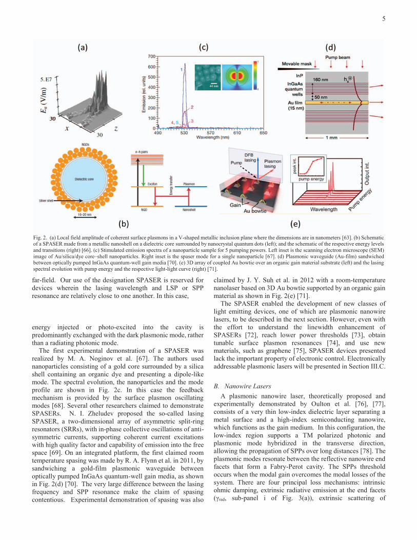
experimentally demonstrated by Oulton et al. [76], [77], consists of a very thin low-index dielectric layer separating a metal surface and a high-index semiconducting nanowire, which functions as the gain medium. In this configuration, the low-index region supports a TM polarized photonic and plasmonic mode hybridized in the transverse direction, allowing the propagation of SPPs over long distances [78]. The plasmonic modes resonate between the reflective nanowire end facets that form a Fabry-Perot cavity. The SPPs threshold occurs when the modal gain overcomes the modal losses of the system. There are four principal loss mechanisms: intrinsic ohmic damping, extrinsic radiative emission at the end facets (γrad, sub-panel i of Fig. 3(a)), extrinsic scattering of
Fig. 2. (a) Local field amplitude of coherent surface plasmons in a V-shaped metallic inclusion plane where the dimensions are in nanometers [63]. (b) Schematic of a SPASER made from a metallic nanoshell on a dielectric core surrounded by nanocrystal quantum dots (left); and the schematic of the respective energy levels and transitions (right) [66]. (c) Stimulated emission spectra of a nanoparticle sample for 5 pumping powers. Left inset is the scanning electron microscope (SEM) image of Au/silica/dye core–shell nanoparticles. Right inset is the spaser mode for a single nanoparticle [67]. (d) Plasmonic waveguide (Au-film) sandwiched between optically pumped InGaAs quantum-well gain media [70]. (e) 3D array of coupled Au bowtie over an organic gain material substrate (left) and the lasing spectral evolution with pump energy and the respective light-light curve (right) [71].

6
propagating SPPs due to surface roughness (γscd, sub-panel ii of Fig. 3(a)) and extrinsic scattering of propagating SPPs at the materials interfaces [79] (γscat, sub-panel iii of Fig. 3(a)). The strong mode confinement and a high-quality high-gain material allowed Oulton et al. to demonstrate deep subwavelength lasing action of SPPs with mode areas as small as λ2/400 (Figures 3c and 3d) [77].
A spatially separated plasmonic cavity would create opportunities for ultrafast modulation of lasers due to the fast relaxation time of plasmon oscillation in metals, down to ~ 10 fs [3], [10]. By near-field coupling of a high-gain CdSe nanowire with a Ag nanowire, Wu X. et al. demonstrated a plasmonic nanowire laser that provides spatially separated photonic far-field output (from the end facet of the CdSe nanowire) and highly localized coherent plasmon modes (from the end facet of the Ag nanowire) (Fig. 3(b)) [80]. In this case, the photonic and plasmonic mode is hybridized along the longitudinal direction allowing the spatial separation.
In terms of tunability, lasing action of plasmonic nanowires over the entire visible spectrum was demonstrated by X. Liu et al. [81]. Tuning is achieved by varying the gain composition rather than the resonator geometry. This leads to another desired property for multifunctional applications, wavelength tunable plasmonic nanowires. By reducing the spacer (low-index dielectric layer) thickness, Liu et al. demonstrated an enhancement of the Burstein-Moss (BM) effect leading to an emission blue-shift from 504 to 483 nm (Fig. 3(e) and 3(f)). The BM effect is the change of the bandgap due to filling of electronic states close to the conduction band [82], [83]. The dependence on the electron carrier concentration that, in principle, can be modulated by SPPs, provides potential efforts for the development of actively tunable nanowire lasers.
None of the described progress on plasmonic nanowire leasers would be possible without the development of special techniques for metal deposition and high quality crystal growth to reduce the damping losses of the cavity. In this context, Y. Lu et al. demonstrated remarkable work developing a smooth epitaxial silver film growth together with the growth of InGaN/GaN core shell hexagonal nanowires with very well defined facets [84]. Their work opens a scalable platform for low-loss nanoplasmonics. Indeed, several works reported plasmonic nanowire lasers operating at room temperature [85], [86]. Recently, Q. Zhang et al. demonstrated an efficient room temperature low-threshold plasmonic nanolaser (Fig. 3(g) and 3(h)) [86]. The laser consists of a triangular GaN nanowire over Al substrate with a SiO2 spacer, providing a larger photonic-plasmonic modal overlap and consequently a more efficient energy transfer channel of exciton-plasmon coupling.
Thus far plasmonic nanowire lasers have been demonstrated at room temperature, offering the possibility of modulation and wavelength tunability. Electrically-pumped plasmonic nanowire lasers remain to be demonstrated, however. To a large extent, this may be attributed to the difficulty of integrating metal contacts with the nanowire for the proper control and injection of charge carriers. In the next section, we discuss the most promising architecture for electrically-pumped plasmonic lasers, the MDM heterostructure. For a comparison of electrically pumped nanolasers to vertical-cavity surface-emitting lasers, see [87].
C. MDM Lasers MDM heterostructures serve as a promising architecture for
nanoscale plasmonic sources, due to their strengths of
Fig. 3. (a) Schematic of the main surface plasmon damping mechanisms and (b) characterization of CdSe nanowire coupled to Ag nanowire [79]. (c) Schematic and (d) oscillation and threshold characteristics of the deeply subwavelength CdS semiconductor nanowire on top of a silver substrate, separated by a MgF2 spacer [77]. (e) Schematic and (f) emission spectrum of all-color InGaN/GaN core-shell nanorod plasmonic laser [84]. (g) Schematic and (h) emission of ultraviolet plasmonic triangular GaN nanolaser device. [86]

7
electronic addressability and mode selectivity. The former enables better pumping control and ability for direct modulation, while the latter feature is required for lasing without a threshold.
In the experimental work of Hill et al. [88], a MDM laser in which a Fabry-Perot cavity is formed by terminating the two ends of an infinite MDM waveguide is demonstrated. The device schematic and the SEM image of a fabricated structure are shown in Fig 4. (a) and (b), respectively. It consists of a rectangular cross-section InP/InGaAs/InP pillar with a conventional double heterostructure in the vertical direction. The pillar is surrounded by a 20nm thick insulating silicon nitride (SiN) layer and is then encapsulated in silver. The InGaAs layer of height h = 300nm forms the gain medium, and the index contrast between InGaAs and the InP confines the light vertically in the waveguide. Electrons are injected via the top of the pillar, and holes are injected via a large area lateral contact at the bottom away from the pillar. The pillars were made in lengths l, of three or six micrometers, and with the semiconductor core width d varying from 90nm to 310nm.
A mode travels in the waveguide along length l until it reaches the end of the waveguide terminated by the encapsulating silver, where the light is reflected back into the waveguide. Although the inhomogeneous waveguide core (SiN/InGaAs/SiN) distorts the propagating gap plasmon mode’s shape somewhat from that in a homogeneous MIM core (in the case of mere InGaAs), this distorted mode can still propagate in waveguides with d far below the diffraction limit. Lasing from the gap plasmon mode were reported in devices with InGaAs width d ranging from 90nm to 130nm (making the total core width 130nm to 170nm). Although lasing was only observed in the temperature range between 10K and 78K due to the elevated material gain and reduced metal loss at cryogenic temperatures compared with the more practical room temperature, it marks the first plasmon laser that is electrically pumped and that operates at telecommunication wavelengths. It’s also worth noting that as the width d increases, the supported mode morphs from the gap plasmon mode, whose energy is concentrated at the metal/dielectric interface, to TE mode, whose energy is concentrated in the dielectric core. The
increase in the mode confinement of TE mode compared to gap plasmon mode is accompanied with the decrease in the modal loss, and as a result, TE mode lasing at room temperature were observed in devices with d = 310nm.
With the knowledge of the mode spacing from emission peaks in measured spectra as well as from eigenmode simulation, an estimation of the group velocity (or group index) of light in the device can be made. Figure 4(c) plots the estimated group index versus d. The shape of the experimental group index curve indicates that, for wider devices the confinement of modal energy in the InGaAs, Γ, is large. Consequently, there is less interaction between the mode and metal cladding and hence lower losses. As a result, compared to devices with narrower width, the semiconductor carrier density and gain required for lasing is less, leading also to a lower dispersion, and finally to a lower group index around 5 for large d. As d decreases, Γ decreases, due in large part to the SiN, as a significant amount of the propagating mode energy can be contained in the SiN [72]. The evolution of group index with increasing semiconductor core width, that is, from divergence at narrow widths to constancy at wide widths, confirms the transition from the gap plasmon mode to TE photonic mode. Evident from the discrepancy between experimental curve and calculated group index without taking into account of gain medium dispersion (green and red) in Fig. 4(c), dispersion should always be included when assessing the possibility of lasing from gap plasmon mode in MIM structures.
The work above established the baseline for realizing MDM plasmonic mode nanolasers. However, the device is several wavelengths long in the wave-guiding direction. The nanolaser by Khajavikhan et al. [89] represents a MDM waveguide – Ag/InGaAsP/Ag with InGaAsP width of 100nm and waveguide length of 1.25μm – but wrapped around with the two end facets of the waveguide connected, as shown schematically and with an SEM micrograph in Fig. 5(a) and (b), respectively. The mode energy is concentrated at the metal-dielectric interface, as is expected from a MDM structure with 100nm core width. The cavity also resembles the conventional coaxial cable that supports the cut-off-free TEM mode, and it is therefore expected that the nanoscale coaxial cavities can support TEM
Fig. 4. Structure of cavity formed by a rectangular semiconductor pillar encapsulated in silver. (a) Schematic showing the device layer structure. (b) Scanning electron microscope image showing the semiconductor core of one of the devices. The scale bar is 1 micron. (c) Spectra and group index, estimated from mode spacing in device spectra versus device semiconductor core width (blue circles: estimates from 6 micron long devices, blue triangles: estimates from 3 micronlong devices. All measurements at 78K except for the two smallest core widths, which were at 10K. Blue, green and red curve: simulated group index. Blue - semiconductor only filled MISIM structures. Green - including the SiN layers. Red – include SiN layers and varying dispersion for the InGaAs core. (Adapted from [88])

8
mode with arbitrarily small volume even when the resonator size becomes deeply subwavelength.
Besides lasing action at 4.5K, this optically pumped cavity also features unity-β behavior, where the spontaneous emission factor, β-factor, is the ratio of spontaneous emission channeled into the lasing mode with respect to total spontaneous emission. The evaluation and control of β-factor has been a sought-after topic in metal-dielectric based nanolasers, due to its link with efficient use of emitted photons and high speed modulation [90], [91]. Thanks to their small size, the modal content of the nano-coaxial cavities is sparse, which is a key requirement to obtain high spontaneous emission coupling into the lasing mode of the resonator. Furthermore, the semiconductor gain material is utilized as a spectrum filter, as schematically depicted Fig. 5(c), because the number of modes supported by the resonator that can participate in the lasing process is ultimately limited to those that occur at frequencies that coincide with the gain medium’s bandwidth. The light-light curve of Fig. 5(d), which follows a straight line with no pronounced kink, agrees with the unity β-factor hypothesis. The unity β-factor property is further evidenced by the spectral evolution, seen in Fig. 5(e), in which a single narrow, Lorentzian-like emission is obtained over the entire five-orders-of-magnitude range of pump power. Since the homogenously broadened linewidth of the gain medium is larger than the linewidth of the observed emission, the emission profile is attributed to the cavity mode. The linewidth evolution of the unity- β laser also show interesting behaviour: at low pump levels, the linewidth depicted in Fig. 5(e) is almost constant, and does not narrow with output power, implying that the linewidth shows no sub-threshold behavior [92], [93]. The lack of variation of linewidth with pump power is most likely the result of the increasing gain-index coupling, which is a well-known around-threshold behavior in semiconductor lasers [93], [94]. This linewidth behavior, though predicted in theory [95], [96], has never been reported experimentally in the past, and may be unique to unity-β lasers. For a recent general discussion on high-β, thresholdless light-emitting devices, see [97].
D. Cavity-Free Laser With the two key aspects of a laser being light amplification
and feedback, cavities typically play an important role in laser design because they are used to enable feedback. In general, laser cavities are constructed such that photons emitted from a source traverse the cavity many times, giving rise to a large photon cavity lifetime (large cavity Q). However, a cavity is not a pre-requisite for enabling feedback. This concept has previously been explored in mircoscale and larger random lasers [98]. In random lasers, feedback arises from multiple random scattering events that lead to the formation of closed optical paths within the disordered medium [99]. A wave making a complete roundtrip in the closed optical path would return to the starting point with the same phase except for some integral multiple of 2π.
Borrowing the design concept from random lasers, cavity-free feedback is possible in plasmonic nanolasers as well. Harnessing the slow/stopped light phenomena to provide local feedback, Pickering et al. designed a cavity-free nanolaser in which photons are trapped and amplified in space at the point of generation, with a theoretically infinite interaction time with the gain medium [100]. Figure 6(a) depicts the laser schematics
in this theoretical work: it is based on a planar metal-dielectric-metal heterostructures (in the y-direction), with the dielectric layer consisting of gain medium (dark blue) sandwiched laterally between a dielectric without gain but with a nearly identical real index of refraction (light blue). At a particular thickness of the dielectric layer, opposing energy flows in the dielectric layer (with positive permittivity) and in the metal layers (with negative permittivity) are balanced exactly. At the stop-light point, the overall energy flow effectively cancels, forming a closed-loop vortex as shown in Fig. 6(a). In the presence of gain, this stop-light feedback mechanism can lead to coherent amplification of the trapped photons via stimulated emission. By choosing transparent conductive oxide as the top metal layer, light can be extracted from the top of the cavity.
In order to form a stop-light point, the dispersion relation needs to be engineered such that the group velocity is zero at a particular k-point, where k denotes the wave-vector. Panel (i) of Fig. 6(b) shows a stop-light point at k=0. However, having only one stop-light point is not sufficient in the laser design. By having two stop-light points, a broader range of k-modes falls within the spectrum window of gain such that the mode becomes more localized, as shown in Panel (ii) of Fig. 6(b). Further, to enable sub-wavelength localization of the lasing mode, it most desirable for the two spot-light points to align in frequency, as shown in Panel (iii) of Fig. 6(b). In this manner, monotonous behavior of dispersion is enforced between the two stop-light points.
The specific design for operation at near-infrared (telecommunication) wavelengths consists of a top 500nm ITO layer that simultaneously functions as a metal and window for allowing light extraction. Depending on whether it is a passive waveguide design or an active laser design, the center dielectric can be either silicon (for waveguide design) or a combination of silicon and InGaAsP (for laser design) with a height of 290 nm, and the bottom layer is a thick ITO substrate. Silicon is used in the laser design to minimize absorption of light to the unpumped InGaAsP. Note that, in the laser design, although the dielectric region is divided into InGaAsP and passive Si sections, no cavity is constructed in the conventional sense because InGaAsP and Si both have refractive index of 3.4 around 1.55 μm. For now, it suffices to restrict to the passive dispersion relation analysis by taking the entire center dielectric “gain” region to be either lossless InGaAsP or Si, shown schematically in Fig. 6(c). Lastly, a 10 nm Si buffer is added

9
atop the metal. The buffer layer is used to reduce gain quenching in close vicinity to the metal.
The choice of structure and materials gives rise to a (weakly) leaky TM2 mode in the dispersion diagram of Fig. 6(d), which, by design, features two stop-light points that lie close in frequency: ω1/2π = 193.8 THz (λ1 = 1546.9 nm) and k1 = 0 and ω2/2π =193.78 THz (λ2 = 1547.06 nm) and k2 = 1.42 μm−1. With both stop-light points situated inside the light-cone, the mode is therein weakly-leaky. Generated photons are expected to couple to free-space radiation perpendicular to the plane, as schematically illustrated in Fig. 6(a). The cavity Q factor and the collectable amount of emission can then be controlled by adjusting the thickness of the top metal cladding. With the top ITO thickness being 290 nm, around 3-4% of generated light can be collected.
The threshold condition can be evaluated with the help of small-signal gain analysis. Figure 6(d) plots the analytical solutions. As the two stop-light points retain their positions and effectively pin down the dispersion between them, no significant change of the modal dispersion is observed with increasing inversion (Fig. 6(e), top). Thanks to the flatness of the dispersion band, an average group velocity of ≈ 3 x10⁻⁴ c is obtained for all inversion levels (Fig. 6(e), center). In contrast, the modal loss displays a strong dependence on the inversion and changes sign at ΔNth ≈ 0.13 (Fig. 6(e), bottom). At this point, the mode becomes amplified and, owing to the flatness of the band, experiences uniform gain over a broad range of k-
values (up to k ≈ 5 μm−1 where the dispersion ω(k) moves out of the spectral window of gain). As the calculated loss rate includes both dissipative and radiative (leakage through the top ITO layer) contributions, ΔNth can be associated with the threshold inversion required for lasing.
In theory, the absence of a cavity enables simpler fabrication compared to other plasmonic laser architectures. Additionally, use of the slow-light effect suggests that the threshold gain may be reduced relative to other plasmonic sources. Experimental demonstrating of the cavity-free plasmonic laser remains an open problem.
IV. PERSPECTIVE ON THE PROMISE AND CHALLENGE Looking back at Ozbay’s requirements for fulfilling the
promise of plasmonics, it is clear that much progress has been made. Sources of radiation based on plasmonic modes continue to improve in performance, as new material systems allow for more of the electromagnetic spectrum to be accessed by plasmonic effects. Room-temperature, continuous wave lasing of photonic modes in metallic cavities with electrical injection of carriers has been demonstrated.
However RT, CW lasing of plasmonic modes under electrical pumping remains a challenge. The larger threshold gains associated with plasmonic modes necessitates pristine sample qualities, with extremely smooth material interfaces and minimal grain boundaries. Interfacing electrical contacts with plasmonic cavities is challenging due to the small surface area
Fig. 5. Nanoscale coaxial laser cavity. (a) Schematic of a coaxial laser cavity. (b) SEM images of the constituent rings. The side view of the rings comprising the coaxial structures is seen. The rings consist of SiO2 on top and a quantum well gain region underneath. (c) Simulation of electromagnetic properties of the nanolaser at 4.5K (d-f) Optical characterization of unity β-factor nanoscale coaxial cavities, light-light curve, linewidth vs. pump power, and spectral evolution diagram for unity β-factor lasing in Structure B. (d) Light-light curve, (e) Spectral evolution, and (f) Linewidth evolution at 4.5 K. The pump power is calculated as the fraction of the power incident on the laser aperture. The solid curve in (d) is the best fit of the rate equation model. The resolution of the monochromator was set to 1.6 nm. (Adapted from [89])

10
of the cavities. Most devices demonstrated to date are proof-of-concept, requiring delicate fabrication techniques not amenable to mass production. Indeed many demonstrated devices are designed without electrical pumping in mind. For example, the unity-β coaxial nanolaser previously described [89] contains an air plug to improve the quality factor. This feature would likely need to be replaced with doped semiconductor layers to enable carrier transport and recombination in the active region.
Nanoplasmonic waveguides operating with losses comparable to purely dielectric guides also still face hurdles. As shown by Kinsey et al. [19], using either noble metals or alternative materials, the lowest loss passive plasmonic waveguides rely upon relatively poorly confined modes that are not truly nanoscopic. Transparent propagation of plasmonic modes with sub-(100 nm)2 cross-sectional area, via parametric amplification or optical or electrical injection is a goal that researchers should try to meet.
Lastly, active control of signal in plasmonic waveguides, e.g., via the electro-optic (EO) effect, has seen substantial progress. High-speed, energy efficient, CMOS compatible EO modulators based on plasmonic slot waveguides have been demonstrated [20]. This topic is however outside the scope of amplification and lasing of plasmonic modes.
What can we expect if gain compensation is practical and not just a proof-of concept experiment? Firstly, if the mode confinement and propagation loss become decoupled through gain compensation, then non-local effects will become increasingly important [7], and field-enhanced nonlinear conversion efficiencies may approach an upper limit. This has implications for all types of modulation, mixing, and higher-harmonic generation processes. Secondly, the density of optical channels on a chip may approach unprecedented levels, as waveguides with cross-section limited only by fabrication
technology. Thirdly, the large optical DOS provided by coupled MD systems may enable extremely fast switching speeds. The combination of these three enabling performances may give way to the next generation of plasmonic devices reaching fJ/bit efficiency, Tb/s speed, and deeply sub-λ3
footprint. The widespread adoption of these devices into commercial products inevitably will require an enormous effort from individuals within the scientific and technical community [101]. Nonetheless, the potential impact remains promising.
AUTHORS AND ACKNOWLEDGMENTS This work was supported by the National Science Foundation (NSF) (ECE3972 and ECCS-1229677), the NSF Center for Integrated Access Networks (EEC-0812072, sub 502629), the Office of Naval Research (N00014-13-1-0678), and the Cymer Corporation. J. S. T. Smalley, F. Vallini, Q. Gu, and Y. Fainman are with the University of California San Diego, La Jolla, CA 92103 USA. (email: [email protected], [email protected], [email protected], [email protected])
REFERENCES
[1] R. Ritchie, “Plasma losses by fast electrons in thin films,” Phys. Rev., vol. 106, pp. 874–881, 1957.
[2] E. Ozbay, “Plasmonics: Merging photonics and electronics at nanoscale dimensions,” Science (80-. )., vol. 311, pp. 189–193, 2006.
[3] S. Maier, Plasmonics: Fundamentals and Applications. New York: Springer, 2007.
Fig. 6. (a) Subwavelength localized vortex-lasing in a stopped-light design, based on a gain-enhanced plasmonic heterostructure. The stopped-light feature of the design allows for the trapping of photons in a closed vortex visualized by paired semi-circular yellow arrows. Exploiting leaky-modes, emission into free space takes place perpendicular to the surface. (b) By engineering the band structure of the metal–dielectric waveguide, several stopped-light (SL) points can be made to fall within the gain spectrum, resulting in a flat dispersion with an average slope of (ω2-ω1)/(k2-k1). (c-d) Geometry and dispersion of the planar stopped-lightstructure in the passive case: (c) The metal-dielectric structure with gain section thickness h = 290 nm and top metal layer thickness t = 500 nm is designed to support a weakly leaky TM2 mode at a wavelength of 1547 nm. (d) The (complex frequency) dispersion of the TM2 mode exhibits two SL points (marked with solid circles) within the light cone (dashed line) that are lined up with the gain spectrum centered around 193 THz. (e) Small-signal gain analysis of the planar stopped-light structure. When gain is introduced into the core the modal dispersion, group velocity and modal loss (top to bottom) will change depending on the gain coefficient ranging from cm−1 (no inversion) to 4180 cm−1 (maximum inversion). The analysis highlights the robustness of the SL points, leading to a flat dispersion of average velocity ≈ 3 x10⁻⁴ c that is practically not affected by the level of inversion. The dashed line in the top panel represents the light line. (Adapted from [100])

11
[4] J. Zenneck, “Über die Fortpflanzung ebener elektromagnetischer Wellen längs einer ebenen Leiterfläche und ihre Beziehung zur drahtlosen Telegraphie,” Ann. Phys., vol. 328, no. 10, pp. 846–866, 1907.
[5] A. Sommerfeld, “Ueber die Fortpflanzung elektrodynamischer Wellen längs eines Drahtes,” Ann. der Phys. und Chemie, vol. 303, no. 2, pp. 233–290, 1899.
[6] C. Kittel, “Plasmons, polaritons, and polarons,” in Introduction to Solid State Physics, John Wiley & Sons, 2005, pp. 393–426.
[7] J. B. Khurgin, “Ultimate limit of field confinement by surface plasmon polaritons.,” Faraday Discuss., vol. 178, pp. 109–22, Jan. 2015.
[8] P. Berini, “Long-range surface plasmon polaritons,” Adv. Opt. Photon., vol. 1, pp. 484–588, 2009.
[9] I. Avrutsky, I. Salakhutdinov, J. Elser, and V. Podolskiy, “Highly confined optical modes in nanoscale metal-dielectric multilayers,” Phys Rev B, vol. 75, p. 241402, 2007.
[10] K. MacDonald, Z. Samson, M. Stockman, and N. Zheludev, “Ultrafast active plasmonics,” Nat. Photon., vol. 3, pp. 55–58, 2009.
[11] J. Pendry, “Negative refraction makes a perfect lens,” Phys Rev Lett, vol. 85, pp. 3966–3969, 2000.
[12] Z. Jacob, L. Alekseyev, and E. Narimanov, “Optical hyperlens: Far-field imaging beyond the diffraction limit,” Opt. Exp., vol. 14, pp. 8247–8256, 2006.
[13] X. Zhang and Z. Liu, “Superlenses to overcome the diffraction limit,” Nat. Mater., vol. 7, pp. 435–441, 2008.
[14] C. Ayala-Orozco, C. Urban, M. Knight, A. Urban, O. Neumann, S. Bishnoi, S. Mukherjee, A. Goodman, H. Charron, T. Mitchell, M. Shea, R. Roy, S. Nanda, R. Schiff, N. Halas, and A. Joshi, “Au nanomatryoshkas as efficient near-infrared photothermal transducers for cancer treatment: Benchmarking against nanoshells,” ACS Nano, vol. 8, no. 6, pp. 6372–6381, 2014.
[15] W. Chen, C. Ayala-Orozco, N. Biswal, C. Perez-Torres, M. Bartels, R. Bardhan, G. Stinnet, X. Liu, B. Ji, A. Deorukhkar, L. Brown, S. Guha, R. Pautler, S. Krishnan, N. Halas, and A. Joshi, “Targeting pancreatic cancer with magneto-fluorescent theranostic gold nanoshells,” Nanomedicine, vol. 9, no. 8, pp. 1209–1222, 2013.
[16] Y. Fu, J. Zhang, and J. Lakowicz, “Plasmonic
enhancement of single-molecule fluorescence near a silver nanoparticle,” J. Fluoresc., vol. 17, no. 6, pp. 811–816, 2007.
[17] T. Vo-Dinh, A. Fales, G. Griffin, C. Khoury, Y. Liu, H. Ngo, S. Norton, J. Register, H. Wang, and H. Yuan, “Plasmonic nanoprobes: from chemical sensing to medical diagnostics and therapy,” Nanoscale, vol. 5, pp. 10127–10140, 2013.
[18] T. Vo-Dinh, M. Hiromoto, G. Begun, and R. Moody, “Surface-enhanced Raman spectroscopy for trace organic analysis,” Anal. Chem., vol. 56, no. 9, pp. 1667–1670, 1984.
[19] N. Kinsey, M. Ferrera, V. Shalaev, and A. Boltasseva, “Examining nanophotonics for integrated hybrid systems: a review of plasmonic interconnects and modulators using traditional and alternative materials,” J. Opt. Soc. Am. B, vol. 32, pp. 121–142, 2015.
[20] A. Melikyan, L. Alloatti, A. Muslija, D. Hillerkuss, P. Schindler, J. Palmer, D. Korn, S. Muehlbrandt, D. Van Thourhout, B. Chen, R. Dinu, M. Sommer, C. Koos, M. Kohl, W. Freude, and J. Leuthold, “High-speed plasmonic phase modulators,” Nat. Photon., vol. 8, pp. 229–233, 2014.
[21] D. O’Connor and A. Zayats, “Data storage: The thrid plasmonic revolution,” Nat. Nanotech., vol. 5, pp. 482–483, 2010.
[22] J. Lee, M. Tymchenko, C. Argyropoulos, P. Chen, F. Lu, F. Demmerle, G. Boehm, M. Amann, A. Alu, and M. Belkin, “Giant nonlinear response from plasmonic metasurfaces coupled to intersubband transitions,” Nature, vol. 511, no. 7507, pp. 65–69, 2014.
[23] O. Wolf, S. Campione, A. Benz, A. Ravikumar, S. Liu, T. Luk, E. Kadlec, E. Shaner, J. Klem, M. Sinclair, and I. Brener, “Phased-array sources based on nonlinear metamaterial nanocavities,” Nat. Comm., vol. 6, p. 7667, 2015.
[24] D. Lu, J. Kan, E. Fullerton, and Z. Liu, “Enhancing spontaneous emission rates of molecules using nanopatterned multilayer hyperbolic metamaterials,” Nat. Nanotechnol., vol. 9, pp. 48–53, 2014.
[25] T. Galfsky, H. Krishnamoorthy, W. Newman, E. Narimanov, Z. Jacob, and V. Menon, “Active hyperbolic metamaterials: enhanced spontaneous emission and light extraction,” Optica, vol. 2, pp. 62–65, 2015.
[26] K. Sreekanth, K. Krishna, A. De Luca, and G. Strangi, “Large spontaneous emission rate enhancement in grating coupled hyperbolic metamaterials,” Sci. Rep.,

12
vol. 4, p. 6340, 2014.
[27] P. Berini and I. De Leon, “Surface plasmon-polariton amplifiers and lasers,” Nat. Photon., vol. 6, pp. 16–24, 2012.
[28] G. Plotz, H. Simon, and J. Tucciarone, “Enhanced total reflection with surface plasmons,” J. Opt. Soc. Am., vol. 69, pp. 419–422, 1979.
[29] A. Sudarkin and P. Demkovich, “Excitation of surface electromagnetic waves on the boundary of a metal with an amplifying medium,” Sov. Phys. Tech. Phys., vol. 34, pp. 764–766, 1988.
[30] M. Nezhad, K. Tetz, and Y. Fainman, “Gain assisted propagation of surface plasmon polaritons on planar metallic waveguides,” Opt. Exp., vol. 12, p. 4072, 2004.
[31] I. Avrutsky, “Surface plasmons at nanoscale relief gratings between a metal and a dielectric medium with optical gain,” Phys. Rev. B, vol. 70, p. 155416, 2004.
[32] A. Tredicucci, C. Gmachl, F. Capasso, A. Hutchinson, D. Sivco, and A. Cho, “Single-mode surface plasmon laser,” Appl. Phys. Lett., vol. 76, pp. 2164–2166, 2000.
[33] C. Sirtori, C. Gmachl, F. Capasso, J. Faist, D. Sivco, A. Hutchinson, and A. Cho, “Long-wavelength (λ ≈ 11.5 μm) semiconductor lasers with waveguides based on surface plasmons,” Opt. Lett., vol. 23, pp. 1366–1368, 1998.
[34] J. Seidel, S. Grafstrom, and L. Eng, “Stimulated emission of surface plasmons at the interface between a silver film and an optically pumped dye solution,” Phys. Rev. Lett., vol. 94, p. 177401, 2005.
[35] I. De Leon and P. Berini, “Theory of surface plasmon polariton amplification in planar structures incorporating dipolar gain media,” Phys. Rev. B, vol. 78, no. 161401, 2008.
[36] M. Noginov, V. Podolskiy, G. Zhu, M. Mayy, M. Bahoura, J. Adegoke, B. Ritzo, and K. Reynolds, “Compensation of loss in propagating surface plasmon polariton by gain in adjacent dielectric medium,” Opt. Exp., vol. 16, p. 1385, 2008.
[37] M. Noginov, G. Zhu, M. Mayy, B. Ritzo, N. Noginova, and V. Podolskiy, “Stimulated emission of surface plasmon polaritons,” Phys. Rev. Lett., vol. 101, p. 226806, 2008.
[38] P. Kumar, V. Tripathi, and C. Liu, “A surface plasmon laser,” J. Appl. Phys., vol. 104, p. 33306, 2008.
[39] P. Bolger, W. Dickson, A. Krasavin, L. Liebscher, S.
Hickey, D. Skryabin, and A. Zayats, “Amplified spontaneous emission of surface plasmon polaritons and limitations on the increase of their propagation length,” Opt. Lett., vol. 35, pp. 1197–1199, 2010.
[40] F. Lu, T. Li, J. Xu, Z. Xie, L. Li, S. Zhu, and Y. Zhu, “Surface plasmon polariton enhanced by optical parametric amplification in nonlinear hybrid waveguide,” Opt. Express, vol. 19, no. 4, pp. 2858–2865, 2011.
[41] M. Gartia, S. Seo, J. Kim, T. Chang, G. Bahl, M. Lu, G. Liu, and J. Eden, “Injection-seeded optoplasmonic amplifier in the visible,” Sci. Rep., vol. 4, p. 6168, 2014.
[42] E. Economou, “Surface plasmons in thin films,” Phys. Rev., vol. 182, pp. 539–554, 1969.
[43] J. Burke, G. Stegeman, and T. Tamir, “Surface-polariton-like waves guided by thin, lossy metal films,” Phys. Rev. B, vol. 33, pp. 5186–5201, 1986.
[44] P. Berini, “Figures of merit for surface plasmon waveguides,” Opt. Express, vol. 14, pp. 13030–13042, 2006.
[45] J. Schilling, “Uniaxial metallo-dielectric metamaterials with scalar positive permeability,” Phys. Rev. E, vol. 74, p. 46618, 2006.
[46] R. Shersby-Harvie, L. Mullett, W. Walkinshaw, J. Bell, and B. Loach, “A theoretical and experimental investigation of anisotropic-dielectric-loaded linear electron accelerators,” Proc Inst Elec Eng, vol. 104B, pp. 273–290, 1957.
[47] V. Agranovich and V. Kratsov, “Notes on crystal optics of superlattices,” Solid State Commun., vol. 55, pp. 85–90, 1985.
[48] J. D. Caldwell, O. J. Glembocki, Y. Francescato, N. Sharac, V. Giannini, F. J. Bezares, J. P. Long, J. C. Owrutsky, I. Vurgaftman, J. G. Tischler, V. D. Wheeler, N. D. Bassim, L. M. Shirey, R. Kasica, and S. A. Maier, “Low-loss, extreme subdiffraction photon confinement via silicon carbide localized surface phonon polariton resonators.,” Nano Lett., vol. 13, no. 8, pp. 3690–7, Aug. 2013.
[49] C. Cortes, W. Newman, S. Molesky, and Z. Jacob, “Quantum nanophotonics using hyperbolic metamaterials,” J. Opt., p. 63001, 2012.
[50] L. Ferrari, C. Wu, D. Lepage, X. Zhang, and Z. Liu, “Hyperbolic metamaterials and their applications,” Prog. Quantum Electron., vol. 40, pp. 1–40, 2015.
[51] A. Poddubny, I. Iorsh, P. Belov, and Y. Kivshar,

13
“Hyperbolic metamaterials,” Nat. Photon., vol. 7, pp. 948–957, 2013.
[52] X. Ni, S. Ishii, M. Thoreson, V. Shalaev, S. Han, S. Lee, and A. Kildishev, “Loss-compensated and active hyperbolic metamaterials,” Opt Exp, vol. 19, pp. 25242–25254, 2011.
[53] C. Argyropoulos, N. Estakhri, F. Monticone, and A. Alu, “Negative refraction, gain, and nonlinear effects in hyperbolic metamaterials,” Opt. Express, vol. 21, no. 12, pp. 15037–15047, 2013.
[54] R. Savelev, I. Shadrivov, P. Belov, N. Rosanov, S. Fedorov, A. Sukhorukov, and Y. Kivshar, “Loss compensation in metal-dielectric layered metamaterials,” Phys Rev B, vol. 87, p. 115139, 2013.
[55] R. Savelev, I. Shadrivov, and Y. Kivshar, “Wave scattering by metal-dielectric multilayer structures with gain,” JETP Lett., vol. 100, pp. 831–836, 2014.
[56] J. Smalley, F. Vallini, B. Kante, and Y. Fainman, “Modal amplification in active waveguides with hyperbolic dispersion at telecommunication frequencies,” Opt. Exp., vol. 22, pp. 21088–21105, 2014.
[57] J. Smalley, F. Vallini, S. Shahin, B. Kante, and Y. Fainman, “Gain-enhanced high-k transmission through metal-semiconductor hyperbolic metamaterials,” Opt. Mat. Express, vol. 5, no. 10, pp. 2300–2312, 2015.
[58] A. Popov and S. Myslivets, “Transformable broad-band transparency and amplification in negative-index films,” Appl Phys Lett, vol. 93, p. 191117, 2008.
[59] A. Popov and V. Shalaev, “Compensating losses in negative-index metamaterials by optical parametric amplification,” Opt. Lett., vol. 31, no. 14, pp. 2169–2171, 2006.
[60] S. Xiao, V. Drachev, A. Kildishev, X. Ni, U. Chettiar, H. Yuan, and V. Shalaev, “Loss-free and active optical negative-index metamaterials,” Nature, vol. 466, pp. 735–740, 2010.
[61] S. Wuestner, A. Pusch, K. Tsakmakidis, J. Hamm, and O. Hess, “Gain and plasmon dynamics in active negative-index metamaterials,” Phil. Trans. R. Soc. A, vol. 369, pp. 3525–3550, 2011.
[62] S. Campione, M. Albani, and F. Capolino, “Complex modes and near-zero permittivity in 3D arrays of plasmonic nanoshells: loss compensation using gain,” Opt. Mat. Express, vol. 1, no. 6, pp. 1077–1089, 2011.
[63] D. Bergman and M. Stockman, “Surface plasmon
amplification by stimulated emission of radiation: Quantum generation of coherent surface plasmons in nanosystems,” Phys. Rev. Lett., vol. 90, no. 2, p. 27402, 2003.
[64] I. De Leon and P. Berini, “Amplification and lasing with surface-plasmon polaritons,” vol. Plasmonics, G. Shvets and I. Tsukerman, Eds. Singapore: World Scientific, 2012, p. 101.
[65] M. I. Stockman, “The spaser as a nanoscale quantum generator and ultrafast amplifier,” J. Opt., vol. 12, no. 2, p. 024004, Feb. 2010.
[66] M. Stockman, “Spasers explained,” Nat. Photon., vol. 2, pp. 327–329, 2008.
[67] M. Noginov, G. Zhu, R. Bakker, V. Shalaev, E. Narimanov, S. Stout, E. Herz, T. Suteewong, and U. Wiesner, “Demonstration of a spaser-based nanolaser,” Nature, vol. 460, pp. 1110–1113, 2009.
[68] J. Gordon and R. Ziolkowski, “The design and simulated performance of a coated nano-particle laser,” Opt. Express, vol. 15, no. 5, pp. 2622–2653, 2007.
[69] N. Zheludev, S. Prosvirnin, N. Papasimakis, and V. Fedotov, “Lasing spaser,” Nat. Photon., vol. 2, pp. 351–354, 2008.
[70] R. A. Flynn, C. S. Kim, I. Vurgaftman, M. Kim, J. R. Meyer, A. J. Mäkinen, K. Bussmann, L. Cheng, F.-S. Choa, and J. P. Long, “A room-temperature semiconductor spaser operating near 1.5 μm.,” Opt. Express, vol. 19, no. 9, pp. 8954–61, Apr. 2011.
[71] J. Y. Suh, C. H. Kim, W. Zhou, M. D. Huntington, D. T. Co, M. R. Wasielewski, and T. W. Odom, “Plasmonic bowtie nanolaser arrays.,” Nano Lett., vol. 12, no. 11, pp. 5769–74, Nov. 2012.
[72] V. Ginzburg and A. Zayats, “Linewidth enhancement in spasers and plasmonic nanolasers,” vol. 21, no. 2, pp. 2147–2153, 2013.
[73] K. Dorfman, P. Jha, D. Voronine, P. Genevet, F. Capasso, and M. Scully, “Quantum coherence-enhanced surface plasmon amplification,” Phys. Rev. Lett., vol. 111, p. 43601, 2013.
[74] X. Meng, A. Kildishev, K. Fujita, K. Tanaka, and V. Shalaev, “Wavelength-tunable spasing in the visible,” Nano Lett., vol. 13, pp. 4106–4112, 2013.
[75] C. Rupasinghe, I. Rukhlenko, and M. Premaratne, “Spaser made of graphene and carbon nanotubes,” ACS Nano, vol. 8, no. 3, pp. 2431–2438, 2014.

14
[76] R. Oulton, V. Sorger, D. Genov, D. Pile, and X. Zhang, “A hybrid plasmonic waveguide for sub-wavelength confinement and long-range propagation,” Nat. Photon., vol. 2, no. 495, p. 500, 2008.
[77] R. Oulton, V. Sorger, T. Zentgraf, R. Ma, C. Gladden, L. Dai, G. Bartal, and X. Zhang, “Plasmon lasers at deep subwavlength scale,” Nature, vol. 461, pp. 629–632, 2009.
[78] M. Alam, J. Meier, J. Aitchison, and M. Mojahedi, “Super mode propagation in low index medium,” Proc. CLEO, p. JThD112, 2007.
[79] Y. Lu, J. Kim, H. Chen, C. Wu, N. Dabidian, C. Sanders, C. Wang, M. Lu, B. Li, X. Qiu, W. Chang, L. Chen, G. Shvets, C. Shih, and S. Gwo, “Plasmonic nanolaser using epitaxially grown silver film,” Science (80-. )., vol. 337, pp. 450–453, 2012.
[80] X. Wu, Y. Xiao, C. Meng, and L. Tong, “Hybrid photon-plasmon nanowire lasers,” Nano Lett., vol. 13, no. 11, pp. 5654–5659, 2013.
[81] X. Liu, Q. Zhang, J. Yip, Q. Xiong, and T. Sum, “Wavelength tunable single nanowire lasers based on surface plasmon polariton enhanced burstein-moss effect,” Nano Lett., vol. 13, pp. 5336–5343, 2013.
[82] E. Burstein, “Anomalous optical absorptiion limit in InSb,” Phys. Rev., vol. 93, no. 3, pp. 632–633, 1954.
[83] S. Moss, “The interpretation of the properties of indium antimonide,” Proc. Phys. Soc. B, vol. 67, p. 775, 1954.
[84] Y. Lu, C. Wang, J. Kim, H. Chen, M. Lu, Y. Chen, W. Chang, L. Chen, M. Stockman, C. Shih, and S. Gwo, “All-color plasmonic nanolasers with ultralow thresholds: Autotuning mechanism for single-mode lasing,” Nano Lett., vol. 14, pp. 4381–4388, 2014.
[85] Y. Chou, B. Chou, C. Chiang, Y. Lai, C. Yang, H. Li, T. Lin, C. Lin, H. Kuo, S. Wang, and T. Lu, “Ultrastrong mode confinement in ZnO surface plasmon nanolasers,” ACS Nano, 2015.
[86] Q. Zhang, G. Li, X. Liu, F. Qian, Y. Li, T. Sum, C. Lieber, and Q. Xiong, “A room temperature low-threshold ultraviolet plasmonic nanolaser,” Nat. Comm., vol. 5, p. 4953, 2014.
[87] J. B. Khurgin and G. Sun, “Comparative analysis of spasers, vertical-cavity surface-emitting lasers and surface-plasmon-emitting diodes,” Nat. Photonics, vol. 8, no. 6, pp. 468–473, May 2014.
[88] M. T. Hill, M. Marell, E. S. P. Leong, B. Smalbrugge, Y. Zhu, M. Sun, P. J. van Veldhoven, E. J. Geluk, F.
Karouta, Y.-S. Oei, R. Nötzel, C.-Z. Ning, and M. K. Smit, “Lasing in metal-insulator-metal sub-wavelength plasmonic waveguides,” Opt. Express, vol. 17, no. 13, p. 11107, Jun. 2009.
[89] M. Khajavikhan, A. Simic, M. Katz, J. Lee, B. Slutsky, A. Mizrahi, and Y. Fainman, “Thresholdless nanoscale coaxial lasers,” Nature, vol. 482, pp. 204–207, 2012.
[90] Q. Gu, B. Slutsky, F. Vallini, J. Smalley, M. Nezhad, N. Frateschi, and Y. Fainman, “Purcell effect in sub-wavelength semiconductor lasers,” Opt. Exp., vol. 21, pp. 15603–15617, 2013.
[91] J. Smalley, Q. Gu, and Y. Fainman, “Temperature dependence of the spontaneous emission factor in subwavelength semiconductor lasers,” IEEE J Quant Elect, vol. 50, pp. 175–185, 2014.
[92] H. Yokoyama and S. Brorson, “Rate equation analysis of microcavity lasers,” J. Appl. Phys., vol. 66, pp. 4801–4805, 1989.
[93] G. Bjork, A. Karlsson, and Y. Yamamoto, “On the linewidth of microcavity lasers,” Appl. Phys. Lett., vol. 60, pp. 304–306, 1992.
[94] C. Henry, “Theory of the linewidth of semiconductor lasers,” IEEE J. Quantum Elect., vol. 18, pp. 259–264, 1982.
[95] P. Rice and H. Carmichael, “Photon statistics of a cavity-QED laser: A comment on the laser-phase transition analogy,” Phys. Rev. A, vol. 50, pp. 4318–4329, 1994.
[96] L. Pedrotti, M. Sokol, and P. Rice, “Linewidth of four-level microcavity lasers,” Phys. Rev. A, vol. 59, no. 3, p. 2295, 1999.
[97] C.-Z. Ning, “What is laser threshold?,” IEEE Sel. Top. Quant Elect, vol. 19, no. 4, p. 1503604, 2013.
[98] H. Cao, J. Xu, D. Zhang, S. Chang, S. Ho, E. Seelig, X. Liu, and R. Chang, “Spatial confinement of laser light in active random media,” Phys. Rev. Lett., vol. 84, no. 24, pp. 5584–5587, 2000.
[99] H. Cao, “Lasing in random media,” Waves in Random Media, vol. 13, pp. R1–R39, 2003.
[100] T. Pickering, J. Hamm, A. Page, S. Wuestner, and O. Hess, “Cavity-free plasmonic nanolasing enabled by dispersionless stopped light,” Nat. Comm., p. 5972, 2014.
[101] Editorial, “Commercializing plasmonics,” Nat. Photon., vol. 9, p. 477, 2015.

15
[102] M. Blaber, M. Arnold, and M. Ford, “Search for the ideal plasmonic nanoshell: The effects of surface scattering and alternatives to gold and silver,” J. Phys. Chem. C, vol. 113, no. 8, pp. 3041–3045, 2009.
[103] P. Johnson and R. Christy, “Optical constants of noblemetals,” Phys Rev B, vol. 6, pp. 4370–4379, 1972.
BIOGRAPHIES
Dr. Joseph S. T. Smalley received the B.S. degree in engineering science from Penn State University, University Park, PA in 2011 and the M.S. and Ph.D. degrees in electrical engineering (nanoscale devices and systems) from the University of California San Diego in 2013 and 2016, respectively. In 2015, he was a visiting researcher at the Center for Integrated Nanotechnologies of Sandia National Laboratory, Albuquerque, NM. Currently, Dr. Smalley is a post-doctoral
researcher at UC San Diego. His research interests include the fundamental theory, design, fabrication, and characterization of nanophotonic devices, such as gain-enhanced metamaterials and nanoscale light sources, as well as the conceptualization and design of photonic systems for Smart City applications.
Dr. Felipe Vallini received the bachelor’ degree in physics from the State University of Campinas, Brazil, in 2007, the M.S. degree in physics from the State University of Campinas, Brazil, in 2009, and the Ph.D. degree in physics from the State University of Campinas, Brazil, in 2013. He has completed research internship as a visiting scholar with University of California, San Diego. Currently, he is a post-doctoral
researcher with the University of California, San Diego. His researcher interests include design, fabrication and characterization of semiconductor nanolasers and plasmonic nanolasers, solid-state physics and nanophotonics.
Dr. Qing Gu joined the Electrical Engineering department at UT Dallas in January 2016, after a postdoc appointment in the Ultrafast & Nanoscale Optics Group at University of California, San Diego. Prof. Gu’s research interests include the design, fabrication and characterization of nano- and micro- scale semiconductor devices (such as lasers, waveguides and sensors), quantum behavior analysis in nanostructures, and
integrated photonic circuits. She is authoring a book “Semiconductor Nanolasers” by Cambridge University Press (to be published in 2016). She is a reviewer for a number of journals including ACS Photonics, Nanophotonics, Laser & Photonics Reviews, Optics Express, IEEE JQE, IEEE JLT and IEEE Photonics Journal.
Professor Yeshaiahu Fainman received M. Sc and Ph. D degrees from Technion, Israel in 1979 and 1983, respectively. Currently he is a Cymer Professor of Advanced Optical Technologies and Distinguished Professor in ECE at UCSD. He is directing research of the Ultrafast and Nanoscale Optics group at UCSD and made significant contributions to near field optical phenomena, nanophotonics and plasmonics, and
non-conventional imaging. The research applications target information technologies and biomedical sensing. He contributed over 250 manuscripts in peer review journals and over 450 conference presentations and conference proceedings. He is a Fellow of OSA, IEEE, and SPIE, and a recipient of the Miriam and Aharon Gutvirt Prize, Lady Davis Fellowship, Brown Award, Gabor Award and Emmett N. Leith Medal.
Copyright © 2022 FDOKUMEN