Symmetrization and Amplification of Germicidal Radiation Flux ...
27
Citation: Kotov, M.A.; Shemyakin, A.N.; Solovyov, N.G.; Yakimov, M.Y. Symmetrization and Amplification of Germicidal Radiation Flux Produced by a Mercury Amalgam UV Lamp in Cylindrical Cavity with Diffusely Reflective Walls. Symmetry 2022, 14, 125. https://doi.org/10.3390/ sym14010125 Academic Editors: Sergei D. Odintsov and Anthony Harriman Received: 8 November 2021 Accepted: 31 December 2021 Published: 10 January 2022 Publisher’s Note: MDPI stays neutral with regard to jurisdictional claims in published maps and institutional affil- iations. Copyright: © 2022 by the authors. Licensee MDPI, Basel, Switzerland. This article is an open access article distributed under the terms and conditions of the Creative Commons Attribution (CC BY) license (https:// creativecommons.org/licenses/by/ 4.0/). symmetry S S Article Symmetrization and Amplification of Germicidal Radiation Flux Produced by a Mercury Amalgam UV Lamp in Cylindrical Cavity with Diffusely Reflective Walls Mikhail A. Kotov * , Andrey N. Shemyakin, Nikolay G. Solovyov and Mikhail Y. Yakimov Ishlinsky Institute for Problems in Mechanics of the Russian Academy of Sciences, Prospekt Vernadskogo, 101-1, 119526 Moscow, Russia; [email protected] (A.N.S.); [email protected] (N.G.S.); [email protected] (M.Y.Y.) * Correspondence: [email protected] Abstract: The study focused on increasing the efficiency of germicidal UV radiation by using highly diffuse reflective materials such as PTFE in irradiated cavities of UV air purifiers. In a conventional cylindrically symmetric cavity with a linear amalgam mercury lamp as UV-radiation source on the axis UV-radiation, flux directed from the lamp to the walls dropped from the axis to the periphery. To increase the UV irradiation, the walls are often made mirror-reflective, but the radiation flux distribution remained radially symmetric with a maximum on the source emitting surface in this case as well. When most of the emitted light is returned to the source after one reflection, the conditions of its operation are disturbed. If the walls are made of highly diffuse reflective materials, the radiation flux density inside the cavity increases on average, and its distribution becomes uniform and highly symmetric. Thus, the effect of amplification of the radiation flux due to the highly diffuse reflectivity of the walls increases with radius and reaches a maximum at the wall. Experiments were performed to demonstrate increasing amplification of germicidal UV radiation flux with a diffuse reflection coefficient in cylindrical cavities with walls of PTFE and ePTFE. The irradiation of the cavity wall was observed to increase up to 20 times at the resonant mercury line of 253.7 nm and up to 40 times at some non-resonant lines of the visible range due to highly diffuse reflectivity of the cavity walls. The flux amplification effect was limited by the diffuse reflectivity value of the walls and absorption coefficient of the radiation emitting surface. A formula for calculating the radiation flux amplification factor in a diffusely reflecting cylindrically symmetric cavity was derived for the case of Lambertian source and reflector, including wall reflectivity and source surface absorption coefficients. The effects of heating and cooling of the mercury lamp amalgam directly affected the amplification, and symmetrization of germicidal irradiation was observed and is discussed in the paper. Numerical calculations were performed by the ray tracing method. The calculated model was verified by comparing the numerical results with those of both the approximate theoretical consideration and experiments. The promising use of diffusely reflecting cylindrical cavities for UV air purifiers is discussed. Designs of air inlet and outlet ports that allow effective locking of germicidal radiation inside the UV air purifiers were considered. The results of this work may be of interest for further developments in the UV disinfection technique. Keywords: diffuse reflection; Lambertian emitter; amalgam UV lamp; PTFE; ePTFE; irradiation amplification; ray tracing; UV air purifier 1. Introduction The germicidal effect of ultraviolet radiation on biological objects (cells, bacteria, viruses, etc.) is well known. It is usually associated with radiation in the wavelength range of 200–300 nm. If we consider the cell as an elementary structural unit of living organisms, then we can say that this radiation is capable of leading to irreversible damage in the cell Symmetry 2022, 14, 125. https://doi.org/10.3390/sym14010125 https://www.mdpi.com/journal/symmetry
-
Upload
khangminh22 -
Category
Documents
-
view
4 -
download
0
Transcript of Symmetrization and Amplification of Germicidal Radiation Flux ...

Citation: Kotov, M.A.; Shemyakin, A.N.;
Solovyov, N.G.; Yakimov, M.Y.
Symmetrization and Amplification of
Germicidal Radiation Flux Produced
by a Mercury Amalgam UV Lamp in
Cylindrical Cavity with Diffusely
Reflective Walls. Symmetry 2022, 14,
125. https://doi.org/10.3390/
sym14010125
Academic Editors: Sergei D.
Odintsov and Anthony Harriman
Received: 8 November 2021
Accepted: 31 December 2021
Published: 10 January 2022
Publisher’s Note: MDPI stays neutral
with regard to jurisdictional claims in
published maps and institutional affil-
iations.
Copyright: © 2022 by the authors.
Licensee MDPI, Basel, Switzerland.
This article is an open access article
distributed under the terms and
conditions of the Creative Commons
Attribution (CC BY) license (https://
creativecommons.org/licenses/by/
4.0/).
symmetryS S
Article
Symmetrization and Amplification of Germicidal RadiationFlux Produced by a Mercury Amalgam UV Lamp in CylindricalCavity with Diffusely Reflective WallsMikhail A. Kotov * , Andrey N. Shemyakin, Nikolay G. Solovyov and Mikhail Y. Yakimov
Ishlinsky Institute for Problems in Mechanics of the Russian Academy of Sciences, Prospekt Vernadskogo, 101-1,119526 Moscow, Russia; [email protected] (A.N.S.); [email protected] (N.G.S.);[email protected] (M.Y.Y.)* Correspondence: [email protected]
Abstract: The study focused on increasing the efficiency of germicidal UV radiation by using highlydiffuse reflective materials such as PTFE in irradiated cavities of UV air purifiers. In a conventionalcylindrically symmetric cavity with a linear amalgam mercury lamp as UV-radiation source on theaxis UV-radiation, flux directed from the lamp to the walls dropped from the axis to the periphery.To increase the UV irradiation, the walls are often made mirror-reflective, but the radiation fluxdistribution remained radially symmetric with a maximum on the source emitting surface in this caseas well. When most of the emitted light is returned to the source after one reflection, the conditions ofits operation are disturbed. If the walls are made of highly diffuse reflective materials, the radiationflux density inside the cavity increases on average, and its distribution becomes uniform and highlysymmetric. Thus, the effect of amplification of the radiation flux due to the highly diffuse reflectivityof the walls increases with radius and reaches a maximum at the wall. Experiments were performedto demonstrate increasing amplification of germicidal UV radiation flux with a diffuse reflectioncoefficient in cylindrical cavities with walls of PTFE and ePTFE. The irradiation of the cavity wall wasobserved to increase up to 20 times at the resonant mercury line of 253.7 nm and up to 40 times at somenon-resonant lines of the visible range due to highly diffuse reflectivity of the cavity walls. The fluxamplification effect was limited by the diffuse reflectivity value of the walls and absorption coefficientof the radiation emitting surface. A formula for calculating the radiation flux amplification factor ina diffusely reflecting cylindrically symmetric cavity was derived for the case of Lambertian source andreflector, including wall reflectivity and source surface absorption coefficients. The effects of heatingand cooling of the mercury lamp amalgam directly affected the amplification, and symmetrizationof germicidal irradiation was observed and is discussed in the paper. Numerical calculations wereperformed by the ray tracing method. The calculated model was verified by comparing the numericalresults with those of both the approximate theoretical consideration and experiments. The promisinguse of diffusely reflecting cylindrical cavities for UV air purifiers is discussed. Designs of air inletand outlet ports that allow effective locking of germicidal radiation inside the UV air purifierswere considered. The results of this work may be of interest for further developments in the UVdisinfection technique.
Keywords: diffuse reflection; Lambertian emitter; amalgam UV lamp; PTFE; ePTFE; irradiationamplification; ray tracing; UV air purifier
1. Introduction
The germicidal effect of ultraviolet radiation on biological objects (cells, bacteria,viruses, etc.) is well known. It is usually associated with radiation in the wavelength rangeof 200–300 nm. If we consider the cell as an elementary structural unit of living organisms,then we can say that this radiation is capable of leading to irreversible damage in the cell
Symmetry 2022, 14, 125. https://doi.org/10.3390/sym14010125 https://www.mdpi.com/journal/symmetry
Symmetry 2022, 14, 125 2 of 27
due to photochemical reactions. Such experiments began to be performed in the first halfof the 20th century [1–3]. More details about these studies can be found in [4,5]. As a rule,this is primarily understood as a violation of the structures of DNA and RNA, as well asproteins and other components of the cell or virus [6–10]. It can be said that the universalnature of the action of ultraviolet radiation on microorganisms leads to the loss of theirability to conduct normal life and reproduce, which ultimately leads to their death. Surfacedoses of germicidal radiation required for inactivation of different microorganisms arepresented in [11,12].
The germicidal effect of light makes it possible to effectively use UV emitters of theappropriate range for sterilizing water [7] and air [5,8]. Low-pressure mercury lampsare most commonly used as the sources. The ozone-free version of these lamps is due tothe radiation of the resonant transition of the 63P1-61S0 mercury atom with a wavelengthof ~253.7 nm. The version of radiation on the two main resonance lines of the mercuryatom, including the 61P1-61S0 transition with a wavelength of ~185 nm, supposes thatthe appearance of ozone-ozone begins to form in an oxygen-containing gas (for example,air) [5,13,14] when exposed to such deep UV radiation. More information about this is inSection 6.2. In some cases, it may be preferable to use broadband radiation sources, such ashigh-pressure mercury lamps and repetitively pulsed xenon lamps [10] as well as excimer(exciplex) lamps [5]. Excimer lamps based on XeBr molecules (~282-nm emission band),XeI (~253 nm), and KrCl (~222 nm) as well as on emission bands of homonuclear Cl2molecules (~259 nm) and Br2 (~289 nm) can be used as a light source of germicidal range.
When disinfecting indoor air, sources of UV light can be used open, i.e., the processingof the premises is carried out in the absence of people. According to this principle, germici-dal sterilization devices usually work in air conditioning and ventilation systems wherethere are no people in the irradiation zone. When processing air directly in rooms withpeople in it, UV light sources are enclosed in a housing in which the germicidal radiation isblocked inside the cavity volume [7]. A germicidal air purifier also includes a power supplyfor the lamp (or lamp system) and at least one fan to pump air through the irradiated cavityand pre-filtering system.
UV air cleaners are widely used for air disinfection. A large number of devicesfor air disinfection of different manufacturers are known, differing in design details andcontrol system [11]. A large number of bactericidal emitters built into ventilation and airconditioning systems are known.
2. Problem of the Effective Use of Germicidal Radiation in UV Air Purifiers
A significant disadvantage of using UV cleaners for air disinfection is that only a neg-ligible fraction of light energy is actually spent on suppressing the vital activity andreproduction of microorganisms, and the bulk of the radiation is absorbed by the surface ofthe emitter body (or by the walls of the room in the case of open emitters). This is due tothe fact that the absorption length of germicidal radiation in the air is orders of magnitudehigher than the dimensions of both the disinfection device cavity and the transverse dimen-sions of air ducts in air conditioning and ventilation systems. Thus, in order to increasethe efficiency of the air purifier, it is advisable to maximize the irradiation produced by thelamp. It is possible to advance in this direction if most of the inner surface of the cavity ishighly reflective for UV radiation. For these purposes, mirror-reflective stainless steel oraluminum is most often used. The increase in irradiation, according to [15], is about 1.3 forthe reflective surface of the emitter housing made of stainless steel and up to 2 times forthe reflecting surface of the emitter housing made of polished aluminum. These values areachieved due to a high reflection coefficient of UV radiation from the materials.
Furthermore, mirror-reflective inner surfaces of the cavity in general cannot ensureuniformity or symmetry of the radiation field inside the cavity due to the inevitable presenceof glare and shadow zones produced by specular reflection. The efficiency of the germicidalaction of the air purifier may be limited by less irradiated “shadow” zones if a considerablepart of circulating air will pass through these zones.
Symmetry 2022, 14, 125 3 of 27
Additionally, in a mirror-reflective cylindrical cavity with a radiation source placed inthe axis the radiation will return to the source after one reflection, violating thermal andradiation conditions of the source operation.
3. Benefits of Using Diffuse Reflective Material
A sharp increase in the efficiency of using germicidal radiation can be realized whenusing a diffusely reflecting inner surface of the irradiated housing or a reflector witha high reflection coefficient of 95–98% [9]. In this case, the entire inner surface of thereflector is made of a material that diffusely reflects radiation with an effective reflectanceof 95% or higher. This makes it possible to multiply the radiation intensity inside thehousing, compared to that of UV air purifiers with an inner surface made of specularlyreflecting materials (stainless steel, aluminum). Additionally, in the case of diffuse reflection,a significantly higher uniformity of radiation is provided [16].
Polytetrafluoroethylene (PTFE, teflon) can be considered as an efficient diffuselyreflecting material. It has a high coefficient of diffuse reflection in the bactericidal spectralregion, above 90–93% depending on a thickness of ~2–4 mm. Expanded PTFE (ePTFE)can be considered as a material with a diffuse reflection coefficient of UV radiation >95%.This is PTFE material with numerous tiny pores quite evenly distributed in it, usuallyoccupying 60–70% of the volume of this material [9]. Light scattering at multiple PTFE–airboundaries with an appropriate material thickness provides an effective diffuse reflectanceof >95%. Here it is fundamentally important that pure PTFE practically does not absorb UVradiation of the bactericidal range (as well as air). Specialized materials such as Spectralonby Labsphere, Inc. with a reflectance of more than 95% for a wavelength of ~250 nmmay also be of interest [17]. Coatings based on particles that are transparent to radiationand distributed in a transparent binder structure (matrix) with a different refractive indexalso have a highly diffuse reflectance in this region of the spectrum. An example of suchmaterials is the barium sulfate coating Spectraflect. The material was also developed byLabsphere, Inc. [17]. With a thickness of 0.5 mm, it provides a diffuse reflectance of at least93% for a wavelength of ~260 nm. When choosing a material, it is important to take intoaccount its technological and cost parameters.
It should be pointed out that the reflection becomes essentially diffuse also in thecase of a metal surface with sufficiently small-scale irregularities (for example, reflectionfrom a rough aluminum surface is essentially diffuse). However, in this case, the effectivecoefficient of diffuse reflection from a rough aluminum surface will not be greater thanthe coefficient of reflection from a smooth mirror surface of aluminum. Accordingly, theuse of a matted (rough) aluminum inner surface of the emitter housing does not providea significant advantage in germicidal efficiency.
In the following sections, using a model cylindrical cavity of a germicidal air purifierwith an amalgam mercury lamp mounted on an axis, we consider theoretically and exper-imentally the amplification effect of the radiation flux inside the cavity and the benefitsfrom radiation flux amplification and symmetrization by using walls of highly diffuse re-flection coefficient materials. Partly parallel consideration of the design of a UV-LED-basedbactericidal air purifier is described in [18]. Our consideration differed significantly in thetype of radiation source used, as well as in the performance analysis of inlet and outlet airports combining high throughput for the air flow with the ability to reflect UV radiationback into the illuminated volume.
4. Radiation Flux Amplification in a Cylindrical Cavity with Highly DiffuseReflective Walls
In this section, the irradiation of the walls of a cylindrical diffusely reflecting cavity iscalculated by being irradiated with a cylindrical Lambertian radiation source located onthe axis (such as a low-pressure Hg vapor quartz lamp). We took into account multiplereflections from the walls of the cylindrical reflector and from the surface of the Lambertianemitter. Let a cylindrical cavity of length L and diameter D have walls with an ideal diffuse

Symmetry 2022, 14, 125 4 of 27
reflection coefficient R. A cylindrical Lambertian emitter with a diameter d is located on theaxis of the cavity (Figure 1a). Edge effects were not taken into account. The end surfaces ofthe cylindrical cavity were treated as being perfectly reflecting mirrors. In this case, theirradiation of the cylindrical surfaces of both the emitter and the reflector along the lengthL will be uniform. Only radiation fluxes in one cross section were of interest. Therefore,we considered a 2D cross section with a source of bactericidal radiation located in thecenter: We needed to find a solution of a two-dimensional cylindrically symmetric problem(Figure 1b).
Symmetry 2022, 14, x FOR PEER REVIEW 4 of 27
4. Radiation Flux Amplification in a Cylindrical Cavity with Highly Diffuse Reflective Walls
In this section, the irradiation of the walls of a cylindrical diffusely reflecting cavity is calculated by being irradiated with a cylindrical Lambertian radiation source located on the axis (such as a low-pressure Hg vapor quartz lamp). We took into account multi-ple reflections from the walls of the cylindrical reflector and from the surface of the Lambertian emitter. Let a cylindrical cavity of length L and diameter D have walls with an ideal diffuse reflection coefficient R. A cylindrical Lambertian emitter with a diameter d is located on the axis of the cavity (Figure 1a). Edge effects were not taken into account. The end surfaces of the cylindrical cavity were treated as being perfectly reflecting mir-rors. In this case, the irradiation of the cylindrical surfaces of both the emitter and the re-flector along the length L will be uniform. Only radiation fluxes in one cross section were of interest. Therefore, we considered a 2D cross section with a source of bactericidal ra-diation located in the center: We needed to find a solution of a two-dimensional cylin-drically symmetric problem (Figure 1b).
(a) (b)
Figure 1. A cylindrical radiation source is located on the axis of the cylindrical diffuse reflector: longitudinal (a) and transverse (b) views.
The central cylindrical surface (Figure 1b, circuit 1) uniformly emits light with an energy flux P (W) in a certain wavelength interval. Then its emissivity is E = P/(πdL). By emissivity we mean the power of the radiation flux per unit surface area. In the cylin-drical case it was convenient to operate with linear values: PL = P/L and EL = PL/(πd). Then, for the linear brightness we can write BL = EL/2. Indeed, in order to calculate the linear emissivity, knowing the linear brightness of the Lambertian source, it is sufficient to calculate the integral: 𝐸 = 𝐵 𝑐𝑜𝑠𝜃𝑑𝜃 = 2𝐵 , (1)
For linear irradiation of the cavity walls (Figure 1b, circuit 2) without taking into account multiple reflections, we can write IL = ELd/D: The entire flux from the central cy-lindrical emitter fell on the wall of the cylindrical diffuse reflector. Let us find the light flux on the surface of the reflector after a single reflection, assuming that there is no ob-stacle in the form of a Lambertian emitter on the axis (if there is no circuit 1). After a sin-gle reflection, the surface of the diffuse reflector can be considered a Lambertian source with a linear emissivity ILR and a corresponding linear brightness ILR/2 = BLR. The factor R < 1 takes into account that the radiation incident on the reflector is partially reflected. To calculate the flux of singly reflected radiation onto the reflector wall in the absence of an obstacle on the axis, one should calculate the integral:
2 2
2 2
cos cos1 cos 2cos 2
L LL L L L
B R D d I RI B R d B R I RD
π π
π πθ θ θ θ θ = 2
θ− −
⋅= = = = ,
(2)
In reality, when observing from any point of the reflector, part of the cylindrical surface is not visible, since it is shaded by the surface of the Lambert emitter (circuit 1), which, on the one hand, does not transmit radiation and, on the other hand, in addition to its own radiation, it re-radiates part of the received radiation. Upon further considera-tion, the radiation is reflected or re-radiated many times.
Figure 1. A cylindrical radiation source is located on the axis of the cylindrical diffuse reflector:longitudinal (a) and transverse (b) views.
The central cylindrical surface (Figure 1b, circuit 1) uniformly emits light with anenergy flux P (W) in a certain wavelength interval. Then its emissivity is E = P/(πdL).By emissivity we mean the power of the radiation flux per unit surface area. In thecylindrical case it was convenient to operate with linear values: PL = P/L and EL = PL/(πd).Then, for the linear brightness we can write BL = EL/2. Indeed, in order to calculate thelinear emissivity, knowing the linear brightness of the Lambertian source, it is sufficient tocalculate the integral:
EL =∫ π/2
−π/2BL cos θdθ = 2BL, (1)
For linear irradiation of the cavity walls (Figure 1b, circuit 2) without taking intoaccount multiple reflections, we can write IL = ELd/D: The entire flux from the centralcylindrical emitter fell on the wall of the cylindrical diffuse reflector. Let us find the lightflux on the surface of the reflector after a single reflection, assuming that there is no obstaclein the form of a Lambertian emitter on the axis (if there is no circuit 1). After a singlereflection, the surface of the diffuse reflector can be considered a Lambertian source witha linear emissivity ILR and a corresponding linear brightness ILR/2 = BLR. The factorR < 1 takes into account that the radiation incident on the reflector is partially reflected.To calculate the flux of singly reflected radiation onto the reflector wall in the absence ofan obstacle on the axis, one should calculate the integral:
I1L =∫ π/2
−π/2
BLR · D cos θ cos θdθ
D cos θ=∫ π/2
−π/2BLR cos θdθ = 2BLR =2
ILR2
= ILR, (2)
In reality, when observing from any point of the reflector, part of the cylindricalsurface is not visible, since it is shaded by the surface of the Lambert emitter (circuit 1),which, on the one hand, does not transmit radiation and, on the other hand, in addition toits own radiation, it re-radiates part of the received radiation. Upon further consideration,the radiation is reflected or re-radiated many times.
To correctly account for this effect, we will make some more assumptions. Let thesource surface diffusely reflect the incident radiation with the exception of a certain fractionk, which it absorbed (k is the absorption coefficient at the emitting surface of the lamp).If we talk about the radiation of the resonant transition of the mercury atom λ = 253.7 nm,the emitting surface absorbs all the received radiation, since the absorption cross sectionof resonance radiation by mercury atoms is high. Nevertheless, most of the atoms excitedin the absorption process almost immediately re-emit quant in an arbitrary direction.Some of the re-emitted quanta are returned to the cavity between the emitter (circuit 1)

Symmetry 2022, 14, 125 5 of 27
and the reflector (circuit 2). The rest of the quanta are reabsorbed and re-emitted later ordie in emission-free energy transitions. The coefficient k takes into account the combinationof the discussed processes.
For simplicity of calculations, we assume that d << D: The diameter of the emitter ismuch smaller than the diameter of the reflector. In order to determine the emissivity ofthe emitter surface in a single reflected light, we determine the irradiation on the emittersurface created by the reflector. It is easy to verify that it is also equal to the ILR, that is,the corresponding emissivity of the emitter surface in the once reflected and re-emittedlight will be ILR(1 − k) with the corresponding linear brightness ILR(1 − k)/2 = BLR(1 − k).
Next, we need to determine to what extent the irradiation created by the shadedpart of the reflector after a single reflection is greater than the irradiation created aftera single re-emission by the source in the center. Note that the irradiation created in a pointof the reflector wall by a cylindrical surface of diameter d with brightness BLR(1 − k),located in the centre of the circular cross section of diameter D, is exactly equal to theirradiation created by a flat strip source of width d with the same linear brightness locatedat a normal distance D/2 to the viewing (Figure 2a,b). Since d << D, the shaded part of thecylindrical surface can also be considered as a stripe with the brightness BLR and the width2d, located at a distance D also perpendicular to the view direction (Figure 2b). From theseconsiderations, it is easy to find the desired difference. Due to the shading, the contributionto the irradiation of any reflector point after a single reflection will be ILR(1− kd/D) insteadof ILR in the absence of shading. Then, the difference is ILR-ILR(1 − kd/D) = ILRkd/D. It isa part of a single reflected radiation that is irrevocably absorbed by the Lambertian source.Further, reasoning similarly, we find that the addition of the irradiation of the reflectorsurface as a result of a second reflection will be ILR2(1 − kd/D)2, the third reflection will beILR3(1 − kd/D)3, and so on.
Symmetry 2022, 14, x FOR PEER REVIEW 5 of 27
To correctly account for this effect, we will make some more assumptions. Let the source surface diffusely reflect the incident radiation with the exception of a certain frac-tion k, which it absorbed (k is the absorption coefficient at the emitting surface of the lamp). If we talk about the radiation of the resonant transition of the mercury atom λ = 253.7 nm, the emitting surface absorbs all the received radiation, since the absorption cross section of resonance radiation by mercury atoms is high. Nevertheless, most of the atoms excited in the absorption process almost immediately re-emit quant in an arbitrary direction. Some of the re-emitted quanta are returned to the cavity between the emitter (circuit 1) and the reflector (circuit 2). The rest of the quanta are reabsorbed and re-emitted later or die in emission-free energy transitions. The coefficient k takes into account the combination of the discussed processes.
For simplicity of calculations, we assume that d << D: The diameter of the emitter is much smaller than the diameter of the reflector. In order to determine the emissivity of the emitter surface in a single reflected light, we determine the irradiation on the emitter surface created by the reflector. It is easy to verify that it is also equal to the ILR, that is, the corresponding emissivity of the emitter surface in the once reflected and re-emitted light will be ILR(1 − k) with the corresponding linear brightness ILR(1 − k)/2 = BLR(1 − k).
Next, we need to determine to what extent the irradiation created by the shaded part of the reflector after a single reflection is greater than the irradiation created after a single re-emission by the source in the center. Note that the irradiation created in a point of the reflector wall by a cylindrical surface of diameter d with brightness BLR(1 − k), located in the centre of the circular cross section of diameter D, is exactly equal to the irradiation created by a flat strip source of width d with the same linear brightness located at a normal distance D/2 to the viewing (Figure 2a,b). Since d << D, the shaded part of the cy-lindrical surface can also be considered as a stripe with the brightness BLR and the width 2d, located at a distance D also perpendicular to the view direction (Figure 2b). From these considerations, it is easy to find the desired difference. Due to the shading, the contribution to the irradiation of any reflector point after a single reflection will be ILR(1 − kd/D) instead of ILR in the absence of shading. Then, the difference is ILR-ILR(1 − kd/D) = ILRkd/D. It is a part of a single reflected radiation that is irrevocably absorbed by the Lambertian source. Further, reasoning similarly, we find that the addition of the irradia-tion of the reflector surface as a result of a second reflection will be ILR2(1 − kd/D)2, the third reflection will be ILR3(1 − kd/D)3, and so on.
(a) (b)
Figure 2. (a) The surface of the center emitter shadows part of the reflector surface when viewedfrom an arbitrary point on the reflector; (b) representation of the Lambertian emitter and part of theLambertian reflector as equivalent flat emitter and reflector.
In exactly the same way as it is done when calculating the irradiation of the surfaceof the integrating spheres [19], we represent the resulting irradiation of the surface of thecylindrical reflector ISL as a result of multiple reflections in the form of a power series,which is summed up in the same way as in the theory of the integrating spheres:

Symmetry 2022, 14, 125 6 of 27
ISL = IL + ILR(
1− kdD
)+ ILR2
(1− kd
D
)2+ ILR3
(1− kd
D
)3+ . . . =
IL1− R(1− kd/D)
, (3)
IL = P/(πDL) is the irradiation created by the central emitter at the distance of thesurface of the cylindrical reflector without taking into account reflections from the surfaceof the reflector, that is, in the absence of a reflector. Then, we get the following formula forthe coefficient of amplification of the radiation flux on the surface of the reflector due tomultiple reflections and re-radiations:
M =1
1− R(1− kd/D), (4)
where M = ISL/IL is the radiation flux amplification factor on the cylinder surface.
5. Balance of Radiation Fluxes from Hg Amalgam Lamp in a Cavity with DiffuseReflective Walls
The output of UV radiation depends on the diameter of the emitting medium (d onFigure 1) and the concentration of mercury atoms due to the effect of imprisonment(trapping) of the radiation of resonance lines [20]. With an increase in the diameter ofthe medium d, the electron temperature decreases, which leads to a decrease in the lampefficiency. In this case, the output of UV radiation also decreases due to the “trapping”effect [20,21]. Inside a highly diffusely reflecting cavity (R on Figure 1), a significant portionof the radiation emitted by the surface of the emitting medium returns back. This isequivalent to an increase in the time of “trapping” of radiation. In this case, the actionof the diffusely reflecting cavity will be equivalent to an increase in the diameter of themedium, that is, it will also cause a decrease in the electron temperature and the efficiencyof radiation generation. In other words, physically returning a significant part of theradiation back to the lamp will lead to an increase in the concentration of atoms in theexcited state of 63P1, an increase in stepwise ionization, and deactivation of excited statesin inelastic collisions of the second kind with electrons [20–23].
Let us consider the balance of radiation fluxes inside a cylindrical diffuse reflector oflength L and diameter D, on the axis of which a mercury amalgam lamp with a diameter ofthe emitting surface d is located (D < L, d < D). We assume that the surface of the cavity isan isotropic diffuse reflector with a diffuse reflectance R close to 1 and R < 1.
For R values sufficiently close to 1, inside such a cavity, the proportion of irradiationof any area created by radiation diffusely reflected by the cavity surface is constant andequal to RE, where E is the irradiation of the cavity surface, created in total by the lampand the diffusely reflecting surface. The emitting medium of the lamp is opaque to its ownradiation. This means that the power of the absorbed radiation flux per unit length of thelamp is:
AL = REπdη, (5)
where η is the transmission of the lamp wall (the fraction of incident radiation minusthe radiation reflected by the wall of the quartz tube). It is known [16] that the reflectioncoefficient of isotropic unpolarized radiation from a surface with a refractive index n = 1.5(fused quartz at a wavelength of 253.7 nm) is 9.2% (for normal directional radiation incidentto the surface, the same value is 4%). To get inside, the radiation passes two surfaces(the outer and inner walls of the lamp). Taking into account the partial anisotropy of theradiation transmitted through the first surface, the total wall transmittance is η ≈ 0.85.
A noticeable fraction of the absorbed radiation (50–60%) is re-emitted by excitedmercury atoms back into the reflector cavity; the rest relaxes into heat in the processes ofinteratomic and electron–atom collisions or collisions of excited atoms with the tube wall.As we noted earlier in Section 4, we denote the share absorbed due to these processes byk. It should be noted here that the imbalance between the radiation incident on the lamp

Symmetry 2022, 14, 125 7 of 27
surface and the radiation emitted by the lamp, resulting from reflections from the lampwall surfaces, both in the direction of the inside of the lamp and in the direction outward,when R is close to 1, is small. This imbalance can be taken into account as a whole witha small correction of the value of the coefficient k. With this in mind, we omit the factor η infurther formulas.
An expression for the total radiation flux onto the surface of the reflector, taking intoaccount the diffusely reflected radiation, can be obtained if the procedure for calculatingthe radiation flux inside the photometric integrating spheres is followed, similar to thatdescribed, for example, in [19,24]. The same expression can be obtained if we proceed fromthe radiative balance in the cavity of a cylindrical diffuse reflector with a tubular lamp onits axis. The simple geometry of the problem simplifies the consideration, allowing simplemethods to obtain a fairly accurate expression, which was derived in Section 4.
Let us equate the radiation flux emitted by a section of the lamp of unit length ELto the total absorption/transmission losses by the walls of the cavity and, in fact, by theemitting surface of the lamp:
EL = E(1− R)S + ERks, (6)
S = πD is the area of the cylindrical surface of the diffuse reflector of unit length and s= πd is the corresponding surface area of the emitting body of the lamp. From here, we get:
E =ELπD
1(1− R(1− kd/D))
, (7)
The first factor EL/(πD) can be interpreted as the fraction of the irradiation of thecavity surface created by the direct radiation of the lamp. With regard to the interpretationof experimental data, this approximation will be more valid if the radiation flux is measuredin the middle of the lamp, placing the sensor at a distance that is small compared to itslength and at a distance from the edges so that edge effects can be neglected. Then thesecond factor takes on the meaning of the irradiation amplification coefficient due to thecontribution of radiation diffusely reflected by the walls:
M(k, R) =1
1− R + kRd/D, (8)
In Section 4, it was shown that a similar expression is obtained from the theory ofintegrating spheres, modified for the cylindrical case (Equation (4)).
6. Experimental Validation6.1. Experimental Procedure
If we talk about the use of a cylindrical cavity made of fluoroplastic as an effectivediffuse reflector of short-wave UV radiation, it is necessary to have data to determine thevalue of the diffuse reflection coefficient. It makes sense to evaluate such characteristicswith a specific material and in a specific experiment. We will not consider possible chemicalreactions caused by structural inhomogeneities of the material and exposure to UV radiationas well as the possible accumulation of biological and organic substances in the air on thefluoroplastic surface.
To experimentally measure the amplification factor of the radiation flux from a tubularmercury amalgam lamp in a cylindrical diffuse reflector, the radiation flux from a lampwithout a reflector was measured first. The flux was measured in the middle of the lamp,with the receiving window of the sensor located at a distance from the lamp axis equal tothe radius of the cylindrical diffuse reflector (Figure 3).
Symmetry 2022, 14, 125 8 of 27
Symmetry 2022, 14, x FOR PEER REVIEW 8 of 27
6. Experimental Validation 6.1. Experimental Procedure
If we talk about the use of a cylindrical cavity made of fluoroplastic as an effective diffuse reflector of short-wave UV radiation, it is necessary to have data to determine the value of the diffuse reflection coefficient. It makes sense to evaluate such characteristics with a specific material and in a specific experiment. We will not consider possible chemical reactions caused by structural inhomogeneities of the material and exposure to UV radiation as well as the possible accumulation of biological and organic substances in the air on the fluoroplastic surface.
To experimentally measure the amplification factor of the radiation flux from a tubular mercury amalgam lamp in a cylindrical diffuse reflector, the radiation flux from a lamp without a reflector was measured first. The flux was measured in the middle of the lamp, with the receiving window of the sensor located at a distance from the lamp axis equal to the radius of the cylindrical diffuse reflector (Figure 3).
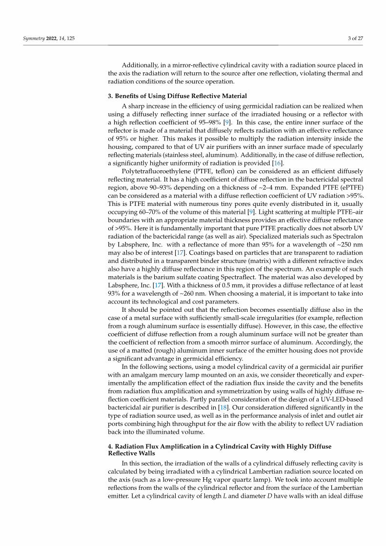
Figure 3. Setup for measuring radiation flux from mercury amalgam lamp: 1, lamp tube; 2, input aperture of cosine corrector; 3, input optical fiber of precalibrated spectral radiometer.
The radiation flux in the 253.7-nm line was measured using a pre-calibrated spec-trometer with fiber-optic radiation input. A spectralon cosine corrector connected to the receiving port of the fiber optic cable was used as the receiving aperture. The device was calibrated complete with a cable and a cosine corrector. The presence of a cosine corrector in the optical scheme made it possible to measure the irradiation by the flux coming from different directions in a solid angle close to 2π. The linewidth of 253.7 nm during meas-urements was determined by spectrometer resolution and was several times larger than the actual line width. To determine the line irradiation, the measured spectral irradiation was integrated over the interval from 250 to 258 nm.
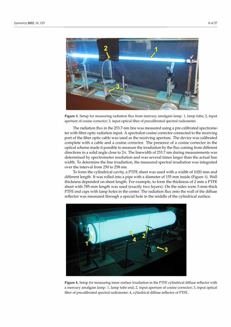
To form the cylindrical cavity, a PTFE sheet was used with a width of 1020 mm and different length. It was rolled into a pipe with a diameter of 155 mm inside (Figure 4). Wall thickness depended on sheet length. For example, to form the thickness of 2 mm a PTFE sheet with 785-mm length was used (exactly two layers). On the sides were 3-mm-thick PTFE end caps with lamp holes in the center. The radiation flux onto the wall of the diffuse reflector was measured through a special hole in the middle of the cylin-drical surface.
Figure 3. Setup for measuring radiation flux from mercury amalgam lamp: 1, lamp tube; 2, inputaperture of cosine corrector; 3, input optical fiber of precalibrated spectral radiometer.
The radiation flux in the 253.7-nm line was measured using a pre-calibrated spectrome-ter with fiber-optic radiation input. A spectralon cosine corrector connected to the receivingport of the fiber optic cable was used as the receiving aperture. The device was calibratedcomplete with a cable and a cosine corrector. The presence of a cosine corrector in theoptical scheme made it possible to measure the irradiation by the flux coming from differentdirections in a solid angle close to 2π. The linewidth of 253.7 nm during measurements wasdetermined by spectrometer resolution and was several times larger than the actual linewidth. To determine the line irradiation, the measured spectral irradiation was integratedover the interval from 250 to 258 nm.
To form the cylindrical cavity, a PTFE sheet was used with a width of 1020 mm anddifferent length. It was rolled into a pipe with a diameter of 155 mm inside (Figure 4). Wallthickness depended on sheet length. For example, to form the thickness of 2 mm a PTFEsheet with 785-mm length was used (exactly two layers). On the sides were 3-mm-thickPTFE end caps with lamp holes in the center. The radiation flux onto the wall of the diffusereflector was measured through a special hole in the middle of the cylindrical surface.
Symmetry 2022, 14, x FOR PEER REVIEW 9 of 27
Figure 4. Setup for measuring inner surface irradiation in the PTFE cylindrical diffuse reflector with a mercury amalgam lamp: 1, lamp tube end; 2, input aperture of cosine corrector; 3, input op-tical fiber of precalibrated spectral radiometer; 4, cylindrical diffuse reflector of PTFE.
6.2. Gain at Different Wavelengths Figure 5 shows a diagram of energy levels and radiative transitions of a mercury
atom. Because in the experiments an ozone-free lamp was used, the emission of 185 nm at the 61P1-61S0 transition was blocked by the quartz wall of the lamp. Figure 6 shows the shapes of the spectral lines of mercury recorded during the experiment.
Figure 5. Diagram of energy levels and radiative transitions of a mercury atom corresponding to spectral lines used to measure the amplification factor of the radiation flux in the presence of a re-flector.
Figure 4. Setup for measuring inner surface irradiation in the PTFE cylindrical diffuse reflector witha mercury amalgam lamp: 1, lamp tube end; 2, input aperture of cosine corrector; 3, input opticalfiber of precalibrated spectral radiometer; 4, cylindrical diffuse reflector of PTFE.

Symmetry 2022, 14, 125 9 of 27
6.2. Gain at Different Wavelengths
Figure 5 shows a diagram of energy levels and radiative transitions of a mercury atom.Because in the experiments an ozone-free lamp was used, the emission of 185 nm at the61P1-61S0 transition was blocked by the quartz wall of the lamp. Figure 6 shows the shapesof the spectral lines of mercury recorded during the experiment.
Symmetry 2022, 14, x FOR PEER REVIEW 9 of 27
Figure 4. Setup for measuring inner surface irradiation in the PTFE cylindrical diffuse reflector with a mercury amalgam lamp: 1, lamp tube end; 2, input aperture of cosine corrector; 3, input op-tical fiber of precalibrated spectral radiometer; 4, cylindrical diffuse reflector of PTFE.
6.2. Gain at Different Wavelengths Figure 5 shows a diagram of energy levels and radiative transitions of a mercury
atom. Because in the experiments an ozone-free lamp was used, the emission of 185 nm at the 61P1-61S0 transition was blocked by the quartz wall of the lamp. Figure 6 shows the shapes of the spectral lines of mercury recorded during the experiment.
Figure 5. Diagram of energy levels and radiative transitions of a mercury atom corresponding to spectral lines used to measure the amplification factor of the radiation flux in the presence of a re-flector.
Figure 5. Diagram of energy levels and radiative transitions of a mercury atom correspondingto spectral lines used to measure the amplification factor of the radiation flux in the presence ofa reflector.
Symmetry 2022, 14, x FOR PEER REVIEW 10 of 27
Figure 6. Recorded mercury spectral lines and their corresponding spectral terms used to observe the wavelength-dependent radiation flux amplification factor.
Figure 7 shows the results of measuring the amplification factor of the radiation flux in the diffuse reflector depending on the material. Solid points and solid line are from three series of measurements and an averaged line with a reflector made of solid PTFE that was 4 mm thick. Hollow points and broken line are from four series of measure-ments and an averaged line with expanded PTFE (ePTFE) reflector that was 1 mm thick.
Figure 7. The recorded dependence of M(λ) for PTFE (solid line) and ePTFE before and after UV annealing (dashed lines). Dots (circles, squares, rhombuses, triangles, crosses) indicate different measurement results and lines represent linear interpolation.
During the experiments, an increase in the gain was observed, especially in the ul-traviolet region, after ePTFE annealing for several hours with ultraviolet radiation at a wavelength of 253.7 nm (crosses and dashed lines in Figure 7). The radiation flux in-creased with several consecutive switchings on of the lamp as the reflector material was annealed under the action of ultraviolet radiation. The increase in flux occurred due to a decrease in the absorption of radiation in the reflector material and a corresponding in-
Figure 6. Recorded mercury spectral lines and their corresponding spectral terms used to observethe wavelength-dependent radiation flux amplification factor.

Symmetry 2022, 14, 125 10 of 27
Figure 7 shows the results of measuring the amplification factor of the radiation fluxin the diffuse reflector depending on the material. Solid points and solid line are fromthree series of measurements and an averaged line with a reflector made of solid PTFEthat was 4 mm thick. Hollow points and broken line are from four series of measurementsand an averaged line with expanded PTFE (ePTFE) reflector that was 1 mm thick.
Symmetry 2022, 14, x FOR PEER REVIEW 10 of 27
Figure 6. Recorded mercury spectral lines and their corresponding spectral terms used to observe the wavelength-dependent radiation flux amplification factor.
Figure 7 shows the results of measuring the amplification factor of the radiation flux in the diffuse reflector depending on the material. Solid points and solid line are from three series of measurements and an averaged line with a reflector made of solid PTFE that was 4 mm thick. Hollow points and broken line are from four series of measure-ments and an averaged line with expanded PTFE (ePTFE) reflector that was 1 mm thick.
Figure 7. The recorded dependence of M(λ) for PTFE (solid line) and ePTFE before and after UV annealing (dashed lines). Dots (circles, squares, rhombuses, triangles, crosses) indicate different measurement results and lines represent linear interpolation.
During the experiments, an increase in the gain was observed, especially in the ul-traviolet region, after ePTFE annealing for several hours with ultraviolet radiation at a wavelength of 253.7 nm (crosses and dashed lines in Figure 7). The radiation flux in-creased with several consecutive switchings on of the lamp as the reflector material was annealed under the action of ultraviolet radiation. The increase in flux occurred due to a decrease in the absorption of radiation in the reflector material and a corresponding in-
Figure 7. The recorded dependence of M(λ) for PTFE (solid line) and ePTFE before and after UVannealing (dashed lines). Dots (circles, squares, rhombuses, triangles, crosses) indicate differentmeasurement results and lines represent linear interpolation.
During the experiments, an increase in the gain was observed, especially in theultraviolet region, after ePTFE annealing for several hours with ultraviolet radiation ata wavelength of 253.7 nm (crosses and dashed lines in Figure 7). The radiation flux increasedwith several consecutive switchings on of the lamp as the reflector material was annealedunder the action of ultraviolet radiation. The increase in flux occurred due to a decreasein the absorption of radiation in the reflector material and a corresponding increase inthe reflection coefficient in the range of 0.95–0.98. A similar effect of increasing the UVreflection coefficient for PTFE was observed in [25].
6.3. Theoretical Assessment
In the experiments, a Heraeus lamp with a diameter of dl = 19 mm and a wall thicknessof δl = 1.2 mm was used.
Consider the irradiation gain of the diffuse reflector for our conditions accordingto the formulas derived in Sections 4 and 5. The radius of the radiating surface isd/2 = (dl − 2δl)/2 = 8.3 mm and the inner diameter of the diffusely reflecting cylindri-cal surface is D = 155 ± 1 mm (154–156 mm, measurement error), that is, the radius of itis D/2 = 77–78 mm and d/D ≈ 9.3–9.4. Let k = 0.5, D = 155 mm, L = 1 m, d = 16.6 mm,and R = 0.95. Then, according to Equation (8), M(0.5, 0.95) ≈ 10. These values roughlycorrespond to the experimental data for PTFE at 253.7 nm (Figure 7). In the case of ePTFEat a given wavelength, an increase can be expected to values R ≈ 0.97 and more.
Figures 8 and 9 show the dependence of the gain separately on R and k in the range ofparameter values realized in the experiments.

Symmetry 2022, 14, 125 11 of 27
Symmetry 2022, 14, x FOR PEER REVIEW 11 of 27
crease in the reflection coefficient in the range of 0.95–0.98. A similar effect of increasing the UV reflection coefficient for PTFE was observed in [25].
6.3. Theoretical Assessment In the experiments, a Heraeus lamp with a diameter of dl = 19 mm and a wall thick-
ness of δl = 1.2 mm was used. Consider the irradiation gain of the diffuse reflector for our conditions according to
the formulas derived in Sections 4 and 5. The radius of the radiating surface is d/2 = (dl − 2δl)/2 = 8.3 mm and the inner diameter of the diffusely reflecting cylindrical surface is D = 155 ± 1 mm (154–156 mm, measurement error), that is, the radius of it is D/2 = 77–78 mm and d/D ≈ 9.3–9.4. Let k = 0.5, D = 155 mm, L = 1 m, d = 16.6 mm, and R = 0.95. Then, ac-cording to Equation (8), M(0.5, 0.95) ≈ 10. These values roughly correspond to the ex-perimental data for PTFE at 253.7 nm (Figure 7). In the case of ePTFE at a given wave-length, an increase can be expected to values R ≈ 0.97 and more.
Figures 8 and 9 show the dependence of the gain separately on R and k in the range of parameter values realized in the experiments.
(a) (b)
Figure 8. Dependences M(k) (a) at three fixed values of R in the range 0.3 < k < 0.6, and M(R) (b) at three fixed values of k in the range 0.75 < R < 0.9. Figure 8. Dependences M(k) (a) at three fixed values of R in the range 0.3 < k < 0.6, and M(R) (b) atthree fixed values of k in the range 0.75 < R < 0.9.
Symmetry 2022, 14, x FOR PEER REVIEW 12 of 27
Figure 9. Dependence M(R) at three different fixed values of k in the range of the reflection coeffi-cient 0.9 < R < 0.98.
7. Amalgam Lamp Performance in a Highly Diffuse Reflective Cavity 7.1. Dependence of Irradiation on Lamp Input Power
To determine the dependence of the irradiation generated by a mercury amalgam lamp at a wavelength of 253.7 nm on the electric power of the alternating current dissi-pated in the lamp, two series of experiments were carried out. In the first case, the irra-diation in free space was recorded at a distance of 68 mm from the lamp wall. For the second series, the lamp was placed on the axis of a cylindrical ePTFE reflector (as in Fig-ure 4). The experimental parameters were similar to those described in Section 6.1. A linear interpolation of the experimental dependence was carried out using the least squares method, and the coefficient of amplification of the light flux due to the diffusely reflecting cavity was found in comparison with the radiation flux at the same distance from the tube axis in free space. The results are shown in Figure 10.
Figure 10. Dependence of irradiation at spectral line 253.7 nm on input electric power of mercury amalgam lamp: red is the radiation flux density E0(W) at a distance 68 mm from lamp surface without reflector; green is the inner wall irradiation E(W) of the ePTFE cylindrical reflector; blue is the calculated amplification factor of the irradiation of the cavity wall M(W). Symbols refer to the
Figure 9. Dependence M(R) at three different fixed values of k in the range of the reflection coefficient0.9 < R < 0.98.
7. Amalgam Lamp Performance in a Highly Diffuse Reflective Cavity7.1. Dependence of Irradiation on Lamp Input Power
To determine the dependence of the irradiation generated by a mercury amalgamlamp at a wavelength of 253.7 nm on the electric power of the alternating current dissipatedin the lamp, two series of experiments were carried out. In the first case, the irradiation infree space was recorded at a distance of 68 mm from the lamp wall. For the second series,

Symmetry 2022, 14, 125 12 of 27
the lamp was placed on the axis of a cylindrical ePTFE reflector (as in Figure 4). The experi-mental parameters were similar to those described in Section 6.1. A linear interpolationof the experimental dependence was carried out using the least squares method, and thecoefficient of amplification of the light flux due to the diffusely reflecting cavity was foundin comparison with the radiation flux at the same distance from the tube axis in free space.The results are shown in Figure 10.
Symmetry 2022, 14, x FOR PEER REVIEW 12 of 27
Figure 9. Dependence M(R) at three different fixed values of k in the range of the reflection coeffi-cient 0.9 < R < 0.98.
7. Amalgam Lamp Performance in a Highly Diffuse Reflective Cavity 7.1. Dependence of Irradiation on Lamp Input Power
To determine the dependence of the irradiation generated by a mercury amalgam lamp at a wavelength of 253.7 nm on the electric power of the alternating current dissi-pated in the lamp, two series of experiments were carried out. In the first case, the irra-diation in free space was recorded at a distance of 68 mm from the lamp wall. For the second series, the lamp was placed on the axis of a cylindrical ePTFE reflector (as in Fig-ure 4). The experimental parameters were similar to those described in Section 6.1. A linear interpolation of the experimental dependence was carried out using the least squares method, and the coefficient of amplification of the light flux due to the diffusely reflecting cavity was found in comparison with the radiation flux at the same distance from the tube axis in free space. The results are shown in Figure 10.
Figure 10. Dependence of irradiation at spectral line 253.7 nm on input electric power of mercury amalgam lamp: red is the radiation flux density E0(W) at a distance 68 mm from lamp surface without reflector; green is the inner wall irradiation E(W) of the ePTFE cylindrical reflector; blue is the calculated amplification factor of the irradiation of the cavity wall M(W). Symbols refer to the
Figure 10. Dependence of irradiation at spectral line 253.7 nm on input electric power of mercuryamalgam lamp: red is the radiation flux density E0(W) at a distance 68 mm from lamp surfacewithout reflector; green is the inner wall irradiation E(W) of the ePTFE cylindrical reflector; blueis the calculated amplification factor of the irradiation of the cavity wall M(W). Symbols refer tothe experiment and lines refer to linear interpolation. Arrows point to the corresponding verticaldata scales.
The squares correspond to the radiation flux E(W) onto the wall of the cylindricaldiffuse ePTFE reflector. The values of the symbols and the straight line drawn through themrefer to the right axis. Circles are the radiation flux E0(W) at a distance of 68 mm from thelamp wall in the absence of a reflector (corresponds to the reflector surface); the values ofthese points and the interpolation line refer to the left axis. The blue curve with a negativeslope is the amplification factor of the radiation flux in the cavity M(W) = E(W)/E0(W)(M(W) = 18.1 ÷ 16.2), which numerically refers to the left axis. Along the axes, the ordinateaxes are the radiation flux in the line λ = 253.7 mW/cm2 at a distance of D/2 = 77.5 mmfrom the lamp axis without a reflector (left axis) and with a reflector (right axis); the abscissaaxis is the electrical power W dissipated in the lamp.
In the experiments, the achieved flux amplification factor decreased from M = 18.1 toM = 16.2 with an increase in the discharge power of the amalgam lamp from W = 50 W toW = 250 W.
7.2. Heating and Cooling the Amalgam
An amalgam lamp is designed to operate at a specific amalgam temperature. At thistemperature, the optimum vapor pressure of mercury and the maximum radiation flux inthe 253.7 nm line are achieved. In experiments with different electric powers of the lampinside the reflector, the temperature of the amalgam had to be controlled; the amalgam wascooled at an excess electric power and heated up at an insufficient one. Radiation returnedby the reflector back to the lamp served as an additional channel for heating the amalgaminside the cylinder with a highly diffuse reflection coefficient. Therefore, to optimize thelong-term operation of the lamp, it was necessary to shield the amalgam from radiation.

Symmetry 2022, 14, 125 13 of 27
The air temperature in the reflector cavity was controlled by pumping the air flow throughthe side walls of the cavity with a small fan.
Nevertheless, during the experiments, the authors found it possible not to maketechnical efforts to ensure long-term optimal operation of the lamp. In most cases, theproblem of determining the radiation flux in the optimal mode could be solved in theprocess of warming up the lamp within 2 min after switching it on at the moment when theradiation flux reached its maximum value, after which it began to decrease due to violationof optimal conditions upon further heating. Figure 11 shows the diagrams of the increasein the radiation flux under various conditions of cooling the amalgam.
Symmetry 2022, 14, x FOR PEER REVIEW 13 of 27
experiment and lines refer to linear interpolation. Arrows point to the corresponding vertical data scales.
The squares correspond to the radiation flux E(W) onto the wall of the cylindrical diffuse ePTFE reflector. The values of the symbols and the straight line drawn through them refer to the right axis. Circles are the radiation flux E0(W) at a distance of 68 mm from the lamp wall in the absence of a reflector (corresponds to the reflector surface); the values of these points and the interpolation line refer to the left axis. The blue curve with a negative slope is the amplification factor of the radiation flux in the cavity M(W) = E(W)/E0(W) (M(W) = 18.1 ÷ 16.2), which numerically refers to the left axis. Along the axes, the ordinate axes are the radiation flux in the line λ = 253.7 mW/cm2 at a distance of D/2 = 77.5 mm from the lamp axis without a reflector (left axis) and with a reflector (right axis); the abscissa axis is the electrical power W dissipated in the lamp.
In the experiments, the achieved flux amplification factor decreased from M = 18.1 to M = 16.2 with an increase in the discharge power of the amalgam lamp from W = 50 W to W = 250 W.
7.2. Heating and Cooling the Amalgam An amalgam lamp is designed to operate at a specific amalgam temperature. At this
temperature, the optimum vapor pressure of mercury and the maximum radiation flux in the 253.7 nm line are achieved. In experiments with different electric powers of the lamp inside the reflector, the temperature of the amalgam had to be controlled; the amalgam was cooled at an excess electric power and heated up at an insufficient one. Radiation returned by the reflector back to the lamp served as an additional channel for heating the amalgam inside the cylinder with a highly diffuse reflection coefficient. Therefore, to op-timize the long-term operation of the lamp, it was necessary to shield the amalgam from radiation. The air temperature in the reflector cavity was controlled by pumping the air flow through the side walls of the cavity with a small fan.
Nevertheless, during the experiments, the authors found it possible not to make technical efforts to ensure long-term optimal operation of the lamp. In most cases, the problem of determining the radiation flux in the optimal mode could be solved in the process of warming up the lamp within 2 min after switching it on at the moment when the radiation flux reached its maximum value, after which it began to decrease due to violation of optimal conditions upon further heating. Figure 11 shows the diagrams of the increase in the radiation flux under various conditions of cooling the amalgam.
Figure 11. Diagrams of the increase in 253.7-nm radiation flux under various conditions of amal-gam cooling.
Figure 11. Diagrams of the increase in 253.7-nm radiation flux under various conditions of amal-gam cooling.
The red curve is closest to the optimal working conditions of the amalgam. The bluecurve corresponds to too much cooling of the amalgam. The pink and green curvescorrespond to different levels of insufficient cooling and overheating of the amalgamduring long-term operation. However, it can be seen that the maximum radiation fluxachieved during the heating process was the same with a high accuracy in all cases, exceptfor the case of excessive cooling. In this case, the faster the maximum value of the radiationflux was reached, the worse the cooling conditions.
Therefore, in most measurements, it was the maximum value of the radiation flux thatwas determined when the lamp was heated under conditions of insufficient cooling of theamalgam. When operating without a reflector at low values of the electric power, the lampwas preheated at a power higher than the nominal until the amalgam overheated; then,the electric power rapidly decreased. The radiation flux also dropped sharply. Then, inthe process of cooling the amalgam to the optimal value, the radiation flux increased, afterwhich it decreased, since the pumping power was insufficient for long-term operation ofthe amalgam at the optimal temperature. The maximum value of the radiation flux wasrecorded as being achieved at the optimal temperature regime of the amalgam.
7.3. UV-Annealing Effect of ePTFE
As mentioned earlier in Section 6.2, an increase in the gain was observed during theexperiments after ePTFE annealing for several hours with UV radiation at a wavelength of253.7 nm (crosses and dashed line in Figure 7). This increase in radiation flux was registeredin several successive lamp switchings on diagrams. The difference between diagrams isexplained by the annealing of the material by UV irradiation for 0.5 h between successivediagrams (Figure 12). Under the influence of UV irradiation, the desorption of impurities

Symmetry 2022, 14, 125 14 of 27
from the pores of ePTFE occurred, which reduced UV radiation absorption in the materialand eventually increased the coefficient of diffuse reflection of UV radiation.
Symmetry 2022, 14, x FOR PEER REVIEW 14 of 27
The red curve is closest to the optimal working conditions of the amalgam. The blue curve corresponds to too much cooling of the amalgam. The pink and green curves cor-respond to different levels of insufficient cooling and overheating of the amalgam during long-term operation. However, it can be seen that the maximum radiation flux achieved during the heating process was the same with a high accuracy in all cases, except for the case of excessive cooling. In this case, the faster the maximum value of the radiation flux was reached, the worse the cooling conditions.
Therefore, in most measurements, it was the maximum value of the radiation flux that was determined when the lamp was heated under conditions of insufficient cooling of the amalgam. When operating without a reflector at low values of the electric power, the lamp was preheated at a power higher than the nominal until the amalgam over-heated; then, the electric power rapidly decreased. The radiation flux also dropped sharply. Then, in the process of cooling the amalgam to the optimal value, the radiation flux increased, after which it decreased, since the pumping power was insufficient for long-term operation of the amalgam at the optimal temperature. The maximum value of the radiation flux was recorded as being achieved at the optimal temperature regime of the amalgam.
7.3. UV-Annealing Effect of ePTFE As mentioned earlier in Section 6.2, an increase in the gain was observed during the
experiments after ePTFE annealing for several hours with UV radiation at a wavelength of 253.7 nm (crosses and dashed line in Figure 7). This increase in radiation flux was registered in several successive lamp switchings on diagrams. The difference between diagrams is explained by the annealing of the material by UV irradiation for 0.5 h be-tween successive diagrams (Figure 12). Under the influence of UV irradiation, the de-sorption of impurities from the pores of ePTFE occurred, which reduced UV radiation absorption in the material and eventually increased the coefficient of diffuse reflection of UV radiation.
Figure 12. The diagrams demonstrate an increase in the irradiance of the inner wall at 253.7 nm of the cylindrical diffuse reflector due to UV annealing effect. The diagrams were taken with several consecutive lamp turns (from red to violet, with time intervals of 0.5 h), while the reflector material was annealed under UV radiation between consecutive diagrams.
Figure 12. The diagrams demonstrate an increase in the irradiance of the inner wall at 253.7 nm ofthe cylindrical diffuse reflector due to UV annealing effect. The diagrams were taken with severalconsecutive lamp turns (from red to violet, with time intervals of 0.5 h), while the reflector materialwas annealed under UV radiation between consecutive diagrams.
8. Numerical Simulation
For describing the result observed in the experiment using numerical methods, we car-ried out estimated calculations of the propagation of radiation in a diffusely reflectingcylindrical cavity. For numerical calculations, the ray tracing method was used in theComsol software [26]. The simulation was carried out in the absence of a cavity and withits presence. For the lamp, a cylinder with dimensions similar to Section 6 was set.
8.1. Calculations with and without Cavity
The distribution of the radiation density on the surface of the source was assumedto be uniform. For this, the radiation from the lamp was approximated by the radiationof a set of Ns diffuse sources located on the surface of the cylinder, with the outwardpropagation of the rays. Ns = 1000 is the normal-emitting diffuse sources that emit withprobability distribution based on Lambert’s cosine law. Nr = 100 rays are released at eachsource, sampled from a hemisphere in wave vector space with probability density basedon the cosine law. The total amount of rays was Ns × Nr = 105.
Assume that the radiation power of an amalgam mercury lamp at 253.7 nm fora numerical case is equal to 50 W. That is, the total radiation power of the set of sourcesNs is equal to E = 50 W. The radiation flux from the lamp enters the receiving area (circlewith a diameter of 4 mm) of the radiation sensor. It is located in the middle of the lamp ata distance of 68 mm from its walls and absorbing all radiation arriving at it (Figure 13a).The average value of the radiation density on the surface of the sensor receiving area wasfound to be equal to Eave = 10.44 mW/cm2.

Symmetry 2022, 14, 125 15 of 27
Symmetry 2022, 14, x FOR PEER REVIEW 15 of 27
8. Numerical Simulation For describing the result observed in the experiment using numerical methods, we
carried out estimated calculations of the propagation of radiation in a diffusely reflecting cylindrical cavity. For numerical calculations, the ray tracing method was used in the Comsol software [26]. The simulation was carried out in the absence of a cavity and with its presence. For the lamp, a cylinder with dimensions similar to Section 6 was set.
8.1. Calculations with and without Cavity The distribution of the radiation density on the surface of the source was assumed to
be uniform. For this, the radiation from the lamp was approximated by the radiation of a set of Ns diffuse sources located on the surface of the cylinder, with the outward propa-gation of the rays. Ns = 1000 is the normal-emitting diffuse sources that emit with proba-bility distribution based on Lambert’s cosine law. Nr = 100 rays are released at each source, sampled from a hemisphere in wave vector space with probability density based on the cosine law. The total amount of rays was Ns × Nr = 105.
Assume that the radiation power of an amalgam mercury lamp at 253.7 nm for a numerical case is equal to 50 W. That is, the total radiation power of the set of sources Ns is equal to E = 50 W. The radiation flux from the lamp enters the receiving area (circle with a diameter of 4 mm) of the radiation sensor. It is located in the middle of the lamp at a distance of 68 mm from its walls and absorbing all radiation arriving at it (Figure 13a). The average value of the radiation density on the surface of the sensor receiving area was found to be equal to Eave = 10.44 mW/cm2.
Figure 13. Computational domain geometry for modeling without (a) and with (b) cavity.
The geometry of the computational domain with the presence of a diffusely reflect-ing cylindrical cavity is shown in Figure 13b. The dimensions of the cavity are similar to those described in Section 6. On the entire inner surface of the cavity (except for the re-ceiving area of the sensor), the condition of diffuse reflection was set: reflection at a sur-face in a random direction, following a probability distribution based on Lambert’s co-sine law. The coefficient of reflection is R = 0.95; the value was chosen according to the data presented in Sections 6.2 and 6.3. An absorbed fraction of the incoming radiation was 1 − R.
The unstructured tetrahedral computational mesh consisted of 269,419 domain el-ements, 91,462 boundary elements, and 3397 edge elements. For the rays reflected from the cavity surface and arriving at the surface of the inner cylinder (lamp), we set the re-flection coefficient as 1 − k. As in the case of the cavity, the diffuse reflection condition was set on the lamp surface with absorbed fraction k of the incoming radiation.
The travel time of the beams was 100 ns (the maximum possible distance of one beam is slightly less than 30 m) and k = 0.5. The average value of the radiation density on
Figure 13. Computational domain geometry for modeling without (a) and with (b) cavity.
The geometry of the computational domain with the presence of a diffusely reflectingcylindrical cavity is shown in Figure 13b. The dimensions of the cavity are similar to thosedescribed in Section 6. On the entire inner surface of the cavity (except for the receivingarea of the sensor), the condition of diffuse reflection was set: reflection at a surface ina random direction, following a probability distribution based on Lambert’s cosine law.The coefficient of reflection is R = 0.95; the value was chosen according to the data presentedin Sections 6.2 and 6.3. An absorbed fraction of the incoming radiation was 1 − R.
The unstructured tetrahedral computational mesh consisted of 269,419 domain ele-ments, 91,462 boundary elements, and 3397 edge elements. For the rays reflected from thecavity surface and arriving at the surface of the inner cylinder (lamp), we set the reflectioncoefficient as 1 − k. As in the case of the cavity, the diffuse reflection condition was set onthe lamp surface with absorbed fraction k of the incoming radiation.
The travel time of the beams was 100 ns (the maximum possible distance of one beamis slightly less than 30 m) and k = 0.5. The average value of the radiation density on thesensor area turned out to be equal to Eave_c = 72.92 mW/cm2. Thus, in the calculation withthe presence of a diffusely reflecting cavity, the radiation flux to the receiving area increasedM = 6.98 times (from 10.44 to 72.92 mW/cm2). According to Equation (8), this value shouldbe equal to M = 9.92. Consider the reasons for the discrepancy.
8.2. Boundary and Initial Conditions
Consider the conditions on the surfaces in more detail. As mentioned above, in thecalculation, the lamp radiation is described by a set of Lambertian sources evenly locatedon the outer surface of the inner cylinder. The probability distribution of the ray directionvector is according to the cosine law (Figure 14a). That is, the probability of a ray propa-gating in a given direction within a solid angle dω is given by cosθdω where θ is the anglebetween the direction of the ray and the normal wall.
Symmetry 2022, 14, x FOR PEER REVIEW 16 of 27
the sensor area turned out to be equal to Eave_c = 72.92 mW/cm2. Thus, in the calculation with the presence of a diffusely reflecting cavity, the radiation flux to the receiving area increased M = 6.98 times (from 10.44 to 72.92 mW/cm2). According to Equation (8), this value should be equal to M = 9.92. Consider the reasons for the discrepancy.
8.2. Boundary and Initial Conditions Consider the conditions on the surfaces in more detail. As mentioned above, in the
calculation, the lamp radiation is described by a set of Lambertian sources evenly located on the outer surface of the inner cylinder. The probability distribution of the ray direction vector is according to the cosine law (Figure 14a). That is, the probability of a ray prop-agating in a given direction within a solid angle dω is given by cosθdω where θ is the angle between the direction of the ray and the normal wall.
The most common misunderstanding associated with the cosine law arises when it is erroneously supposed to state that the probability of a ray leaving the surface within a narrow angle dθ, in a direction making an angle θ to the surface normal, is cosθ. The misinterpretation occurs most often when a system is being modelled in two or more dimensions. The traditional schematic representation of the cosine law for molecules scattered from a surface is misinterpreted as being the polar angular-probability distri-bution, whereas, in fact, it is a projection through the molecular flux distribution. Use of the incorrect polar angle-probability distribution can produce grossly different results to those generated with the correct distribution: This results in a ray distribution that is very strongly peaked along the normal surface [27]. The actual probability distribution func-tion f(θ, ω) for a ray released from a source on the lamp surface is the following:
( ) 1, sin cosf θ ω θ θπ
=,
0, 2πθ ∈ , [ ]0,2ω π∈
(9)
For clarity of the ray propagation conditions, Figure 14b shows distributions of 1000 rays. Diffuse reflection from the walls of the lamp and the cavity is described in the same way.
A series of calculations were performed in the ranges of values k = 0.3, 0.4, and 0.5 and R = 0.95, 0.97, and 0.98 to compare the results obtained with Equation (8)’s theoretical estimates (Figures 8 and 9). The data for Eave_c and M values (M = Eave_c/Eave) are presented in Table 1 and Figure 15.
(a) (b)
Figure 14. (a) Ray direction vector (black); (b) distributions of 1000 rays in a Lambertian release [26].
Figure 14. (a) Ray direction vector (black); (b) distributions of 1000 rays in a Lambertian release [26].
Symmetry 2022, 14, 125 16 of 27
The most common misunderstanding associated with the cosine law arises when itis erroneously supposed to state that the probability of a ray leaving the surface withina narrow angle dθ, in a direction making an angle θ to the surface normal, is cosθ. The misin-terpretation occurs most often when a system is being modelled in two or more dimensions.The traditional schematic representation of the cosine law for molecules scattered froma surface is misinterpreted as being the polar angular-probability distribution, whereas,in fact, it is a projection through the molecular flux distribution. Use of the incorrect polarangle-probability distribution can produce grossly different results to those generated withthe correct distribution: This results in a ray distribution that is very strongly peakedalong the normal surface [27]. The actual probability distribution function f (θ, ω) for a rayreleased from a source on the lamp surface is the following:
f (θ, ω) =1π
sin θ cos θ, θ ∈[0,
π
2
], ω ∈ [0, 2π] (9)
For clarity of the ray propagation conditions, Figure 14b shows distributions of1000 rays. Diffuse reflection from the walls of the lamp and the cavity is described inthe same way.
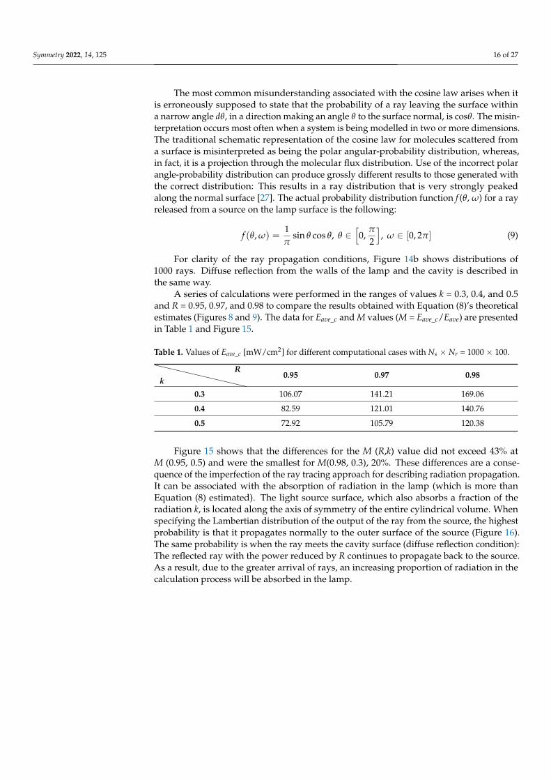
A series of calculations were performed in the ranges of values k = 0.3, 0.4, and 0.5and R = 0.95, 0.97, and 0.98 to compare the results obtained with Equation (8)’s theoreticalestimates (Figures 8 and 9). The data for Eave_c and M values (M = Eave_c/Eave) are presentedin Table 1 and Figure 15.
Table 1. Values of Eave_c [mW/cm2] for different computational cases with Ns × Nr = 1000 × 100.
kR
0.95 0.97 0.98
0.3 106.07 141.21 169.06
0.4 82.59 121.01 140.76
0.5 72.92 105.79 120.38
Figure 15 shows that the differences for the M (R,k) value did not exceed 43% atM (0.95, 0.5) and were the smallest for M(0.98, 0.3), 20%. These differences are a conse-quence of the imperfection of the ray tracing approach for describing radiation propagation.It can be associated with the absorption of radiation in the lamp (which is more thanEquation (8) estimated). The light source surface, which also absorbs a fraction of theradiation k, is located along the axis of symmetry of the entire cylindrical volume. Whenspecifying the Lambertian distribution of the output of the ray from the source, the highestprobability is that it propagates normally to the outer surface of the source (Figure 16).The same probability is when the ray meets the cavity surface (diffuse reflection condition):The reflected ray with the power reduced by R continues to propagate back to the source.As a result, due to the greater arrival of rays, an increasing proportion of radiation in thecalculation process will be absorbed in the lamp.

Symmetry 2022, 14, 125 17 of 27
Symmetry 2022, 14, x FOR PEER REVIEW 17 of 27
Table 1. Values of Eave_c [mW/cm2] for different computational cases with Ns × Nr = 1000 × 100.
R k
0.95 0.97 0.98
0.3 106.07 141.21 169.06 0.4 82.59 121.01 140.76 0.5 72.92 105.79 120.38
Figure 15. M dependences for numerical simulation with 105 rays at three fixed values of R = 0.98, 0.97, and 0.95 in the range of 0.3 < k < 0.5 (a), and at three fixed values of k = 0.3, 0.4, and 0.5 in the range of 0.95 < R < 0.98 (b).
Figure 15 shows that the differences for the M(R,k) value did not exceed 43% at M(0.95, 0.5) and were the smallest for M(0.98, 0.3), 20%. These differences are a conse-quence of the imperfection of the ray tracing approach for describing radiation propaga-tion. It can be associated with the absorption of radiation in the lamp (which is more than Equation (8) estimated). The light source surface, which also absorbs a fraction of the ra-diation k, is located along the axis of symmetry of the entire cylindrical volume. When specifying the Lambertian distribution of the output of the ray from the source, the highest probability is that it propagates normally to the outer surface of the source (Fig-ure 16). The same probability is when the ray meets the cavity surface (diffuse reflection condition): The reflected ray with the power reduced by R continues to propagate back to the source. As a result, due to the greater arrival of rays, an increasing proportion of ra-diation in the calculation process will be absorbed in the lamp.
Figure 15. M dependences for numerical simulation with 105 rays at three fixed values of R = 0.98,0.97, and 0.95 in the range of 0.3 < k < 0.5 (a), and at three fixed values of k = 0.3, 0.4, and 0.5 in therange of 0.95 < R < 0.98 (b).
Symmetry 2022, 14, x FOR PEER REVIEW 18 of 27
Figure 16. Ray propagation conditions on the walls of the lamp and the cavity.
8.3. Ray Distribution The problem described in Section 8.2 can be solved by specifying more rays and
sources, since rays will be more evenly distributed in the cavity volume. With an increase in the number of rays by about an order of magnitude (from Ns × Nr = 1000 × 100 to 3000 × 300), the differences for the M(R,k) value decrease up to several percentage points (Figure 17). Therefore, at M(0.95, 0.5), the value of Eave_c increased from 72.92 to 99.1; at M(0.98, 0.3), Eave_c = 194.77 instead of 169.06 (Table 2). With a further increase in the total number of emitted rays (Ns × Nr), no critical changes will be observed, since the M values ap-proach Equation (8) and the direction of the propagation of a particular ray primarily depends on the reflection condition on the walls of the cavity and the lamp. Closed side walls of the cavity also help it. This is evidenced by other works with ray tracing calcu-lations in closed, diffusely reflected regions [28,29] and in integrating spheres [30–32].
Table 2. Values of Eave_c [mW/cm2] for different computational cases with Ns × Nr = 3000 × 300.
R k
0.95 0.97 0.98
0.3 123.65 163.52 194.77 0.4 110.04 140.24 162.58 0.5 99.1 122.64 139.24
Figure 16. Ray propagation conditions on the walls of the lamp and the cavity.
8.3. Ray Distribution
The problem described in Section 8.2 can be solved by specifying more rays andsources, since rays will be more evenly distributed in the cavity volume. With an increase

Symmetry 2022, 14, 125 18 of 27
in the number of rays by about an order of magnitude (from Ns × Nr = 1000 × 100 to3000 × 300), the differences for the M(R,k) value decrease up to several percentage points(Figure 17). Therefore, at M(0.95, 0.5), the value of Eave_c increased from 72.92 to 99.1;at M(0.98, 0.3), Eave_c = 194.77 instead of 169.06 (Table 2). With a further increase in the totalnumber of emitted rays (Ns × Nr), no critical changes will be observed, since the M valuesapproach Equation (8) and the direction of the propagation of a particular ray primarilydepends on the reflection condition on the walls of the cavity and the lamp. Closedside walls of the cavity also help it. This is evidenced by other works with ray tracingcalculations in closed, diffusely reflected regions [28,29] and in integrating spheres [30–32].
Symmetry 2022, 14, x FOR PEER REVIEW 19 of 27
Figure 17. M dependences for numerical simulation with 9·105 rays at three fixed values of R = 0.98, 0.97, and 0.95 in the range of 0.3 < k < 0.5 (a), and at three fixed values of k = 0.3, 0.4, and 0.5 in the range of 0.95 < R < 0.98 (b).
8.4. Radiation Absorption To make sure that there is no energy dissipation, consider the absorption with a
different number of rays under conditions of (R,k) = 0.98, 0.3, i.e., where absorption is weakest and occurs more slowly (Figure 18).
Figure 17. M dependences for numerical simulation with 9·105 rays at three fixed values of R = 0.98,0.97, and 0.95 in the range of 0.3 < k < 0.5 (a), and at three fixed values of k = 0.3, 0.4, and 0.5 in therange of 0.95 < R < 0.98 (b).
Table 2. Values of Eave_c [mW/cm2] for different computational cases with Ns × Nr = 3000 × 300.
kR
0.95 0.97 0.98
0.3 123.65 163.52 194.77
0.4 110.04 140.24 162.58
0.5 99.1 122.64 139.24
8.4. Radiation Absorption
To make sure that there is no energy dissipation, consider the absorption with a differ-ent number of rays under conditions of (R,k) = 0.98, 0.3, i.e., where absorption is weakestand occurs more slowly (Figure 18).
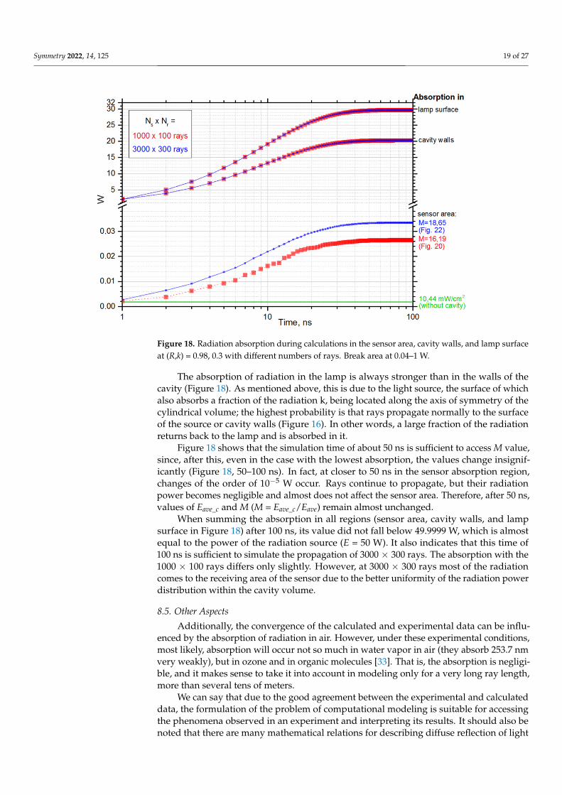
Symmetry 2022, 14, 125 19 of 27
Symmetry 2022, 14, x FOR PEER REVIEW 19 of 27
Figure 17. M dependences for numerical simulation with 9·105 rays at three fixed values of R = 0.98, 0.97, and 0.95 in the range of 0.3 < k < 0.5 (a), and at three fixed values of k = 0.3, 0.4, and 0.5 in the range of 0.95 < R < 0.98 (b).
8.4. Radiation Absorption To make sure that there is no energy dissipation, consider the absorption with a
different number of rays under conditions of (R,k) = 0.98, 0.3, i.e., where absorption is weakest and occurs more slowly (Figure 18).
Figure 18. Radiation absorption during calculations in the sensor area, cavity walls, and lamp surfaceat (R,k) = 0.98, 0.3 with different numbers of rays. Break area at 0.04–1 W.
The absorption of radiation in the lamp is always stronger than in the walls of thecavity (Figure 18). As mentioned above, this is due to the light source, the surface of whichalso absorbs a fraction of the radiation k, being located along the axis of symmetry of thecylindrical volume; the highest probability is that rays propagate normally to the surfaceof the source or cavity walls (Figure 16). In other words, a large fraction of the radiationreturns back to the lamp and is absorbed in it.
Figure 18 shows that the simulation time of about 50 ns is sufficient to access M value,since, after this, even in the case with the lowest absorption, the values change insignif-icantly (Figure 18, 50–100 ns). In fact, at closer to 50 ns in the sensor absorption region,changes of the order of 10−5 W occur. Rays continue to propagate, but their radiationpower becomes negligible and almost does not affect the sensor area. Therefore, after 50 ns,values of Eave_c and M (M = Eave_c/Eave) remain almost unchanged.
When summing the absorption in all regions (sensor area, cavity walls, and lampsurface in Figure 18) after 100 ns, its value did not fall below 49.9999 W, which is almostequal to the power of the radiation source (E = 50 W). It also indicates that this time of100 ns is sufficient to simulate the propagation of 3000 × 300 rays. The absorption with the1000 × 100 rays differs only slightly. However, at 3000 × 300 rays most of the radiationcomes to the receiving area of the sensor due to the better uniformity of the radiation powerdistribution within the cavity volume.
8.5. Other Aspects
Additionally, the convergence of the calculated and experimental data can be influ-enced by the absorption of radiation in air. However, under these experimental conditions,most likely, absorption will occur not so much in water vapor in air (they absorb 253.7 nmvery weakly), but in ozone and in organic molecules [33]. That is, the absorption is negligi-ble, and it makes sense to take it into account in modeling only for a very long ray length,more than several tens of meters.
We can say that due to the good agreement between the experimental and calculateddata, the formulation of the problem of computational modeling is suitable for accessingthe phenomena observed in an experiment and interpreting its results. It should also benoted that there are many mathematical relations for describing diffuse reflection of light

Symmetry 2022, 14, 125 20 of 27
in such closed geometries in terms of cavity parameters. More detailed information aboutthese processes and methods can be found in [33,34].
9. Application in UV Air Purifier
In the presence of a diffusely reflecting cavity, the radiation flux to the receiving areaincreased up to 20 times in the experiment (Figures 7–10), although the data cannot besuitable for describing an air purifier, since there is no pumping of the medium through thecavity. At the same time, the obtained results clearly demonstrated the prospects of usingsuch diffusely reflecting materials as PTFE and ePTFE for internal placement in the purifiercavity. Let us consider some of the features of this possible application.
9.1. Presence of Geometrical Losses
As can be seen from Equation (8), to achieve high values of amplification M, it isnecessary to use a cavity with a small value of radiation loss σ. For the considered casewith a cylindrical geometry, these losses are limited only by the absorption of radiation inthe lamp and are equal to σ = kd/D. However, in the case of the purifier, the presence ofadditional losses is inevitable simply because it is necessary to pump air through the cavity.The cavity has open ends for the inlet and outlet of the air flow through which radiation islost. The fraction of the inner surface through which radiation leaves the cavity is calledgeometric losses. They increase σ by the ratio of the areas of the open ends Sin and Sout tothe area of the diffuser SR and decrease M:
M =1
1− R(1− σ)=
11− R(1− kd/D− (Sin + Sout)/SR)
, (10)
The increase in σ due to geometric losses does not allow the use of materials with a highcoefficient of diffuse reflection of radiation as efficiently as possible. It becomes fundamen-tally important to reduce the value of geometric losses in UV air purifiers and cleaners,which have a highly effective coefficient of diffuse reflection of germicidal radiation.
9.2. Diffuser–Confuser Type of Input and Output Air Ports
There are several options for reducing geometric loss of UV radiation through inputand output air ports. One of them is the use of diffuser–confuser geometry of a UV reflectingcavity (Figure 19). In real conditions, all the elements of the construction inside the cavity(for example, lamp clamps) may also be of diffusely reflecting materials.
Symmetry 2022, 14, x FOR PEER REVIEW 21 of 27
cavity is called geometric losses. They increase σ by the ratio of the areas of the open ends Sin and Sout to the area of the diffuser SR and decrease M:
1 11 (1 ) 1 (1 / ( ) / )in out R
MR R kd D S S Sσ
= =− − − − − + ,
(10)
The increase in σ due to geometric losses does not allow the use of materials with a high coefficient of diffuse reflection of radiation as efficiently as possible. It becomes fundamentally important to reduce the value of geometric losses in UV air purifiers and cleaners, which have a highly effective coefficient of diffuse reflection of germicidal ra-diation.
9.2. Diffuser–Confuser Type of Input and Output Air Ports There are several options for reducing geometric loss of UV radiation through input
and output air ports. One of them is the use of diffuser–confuser geometry of a UV re-flecting cavity (Figure 19). In real conditions, all the elements of the construction inside the cavity (for example, lamp clamps) may also be of diffusely reflecting materials.
Figure 19. The geometry of the cavity with «diffuser–confuser» air ports type.
This geometry allows the implementation of the so-called “optical shutter”, which “locks” UV radiation in the cavity of the emitter, and the reduction of geometric losses with a corresponding decrease in the inlet and outlet sections of the air flow in the cavity of the purifying channel filled with radiation of germicidal range [13]. However, in this case, in the indicated sections, the speed of the air flow increased proportionally and the power consumption for pumping air increased sharply due to the loss of pressure. That is, with a significant decrease in geometric losses and, consequently, a decrease in the power of UV radiation, the power consumption for pumping air increases many times, which significantly reduces (or even completely eliminates) the positive effect of in-creasing irradiation inside the cavity of the purifier. Additionally, in order to reduce pressure losses and flow resistance, in the geometry, it is necessary to observe small values of the angles of the diffuser and confuser (up to ~12–14° for α and β [35], Figure 19.This increases the size of the purifier, the complexity, and cost of its manufacture.
Thus, the main obstacle to the widespread use of air purifiers with a large amplifi-cation of UV radiation is the implementation of a fairly compact “optical shutter” at the inlet and outlet of the air channel. On the one hand, it should provide low radiation losses in the cavity. On the other hand, it should be sufficiently compact and create the lowest possible gas-dynamic losses for the air flow pumped through the channel.
9.3. Air Ports in the Form of Multiple Perforated Holes Another solution of the problem is to use multiple holes perforated in the end walls
of the cylindrical cavity to provide air circulation together with UV radiation trapping (Figure 20). If the walls are made of the same diffusely reflecting material as the cavity, then the dimensions of the channel do not actually change [10,13]. The reduction in ge-
Figure 19. The geometry of the cavity with «diffuser–confuser» air ports type.
This geometry allows the implementation of the so-called “optical shutter”, which “locks”UV radiation in the cavity of the emitter, and the reduction of geometric losses witha corresponding decrease in the inlet and outlet sections of the air flow in the cavity ofthe purifying channel filled with radiation of germicidal range [13]. However, in thiscase, in the indicated sections, the speed of the air flow increased proportionally andthe power consumption for pumping air increased sharply due to the loss of pressure.That is, with a significant decrease in geometric losses and, consequently, a decrease in

Symmetry 2022, 14, 125 21 of 27
the power of UV radiation, the power consumption for pumping air increases many times,which significantly reduces (or even completely eliminates) the positive effect of increasingirradiation inside the cavity of the purifier. Additionally, in order to reduce pressure lossesand flow resistance, in the geometry, it is necessary to observe small values of the angles ofthe diffuser and confuser (up to ~12–14 for α and β [35], Figure 19. This increases the sizeof the purifier, the complexity, and cost of its manufacture.
Thus, the main obstacle to the widespread use of air purifiers with a large amplificationof UV radiation is the implementation of a fairly compact “optical shutter” at the inlet andoutlet of the air channel. On the one hand, it should provide low radiation losses in thecavity. On the other hand, it should be sufficiently compact and create the lowest possiblegas-dynamic losses for the air flow pumped through the channel.
9.3. Air Ports in the Form of Multiple Perforated Holes
Another solution of the problem is to use multiple holes perforated in the end wallsof the cylindrical cavity to provide air circulation together with UV radiation trapping(Figure 20). If the walls are made of the same diffusely reflecting material as the cavity, thenthe dimensions of the channel do not actually change [10,13]. The reduction in geometriclosses here will depend on the ratio of the area of the holes Sh to the area of the cavity SR:
M =1
1− R(1− kd/D− Sh/SR), (11)
Symmetry 2022, 14, x FOR PEER REVIEW 22 of 27
ometric losses here will depend on the ratio of the area of the holes Sh to the area of the cavity SR:
11 (1 / / )h R
MR kd D S S
=− − − ,
(11)
Figure 20. Multiple perforated holes in the end walls of the cavity.
Due to the decrease of the air flow cross section in the perforated holes, there is also an increase in the power consumption for pumping the air flow. In addition, it must be remembered that the total energy consumption of the UV air purifier increases with an increase in its air flow capacity (with an increase in the air flow through the cavity).
9.4. Radiation propagation in perforation channels When the thickness of the perforated walls H is increased to a value several times
higher than the minimum cross-sectional dimension of the holes in the wall dh, the re-sistance to the gas flow does not increase much, since the pressure loss mainly occurs at the inlet and outlet of the holes, but not in the hole channel itself (Figure 21).
Figure 21. The location of the holes in the air flow input/output ports of the cylindrical reflector: transverse (a) and longitudinal (b) views.
Figure 20. Multiple perforated holes in the end walls of the cavity.
Due to the decrease of the air flow cross section in the perforated holes, there is alsoan increase in the power consumption for pumping the air flow. In addition, it must beremembered that the total energy consumption of the UV air purifier increases with anincrease in its air flow capacity (with an increase in the air flow through the cavity).
9.4. Radiation Propagation in Perforation Channels
When the thickness of the perforated walls H is increased to a value several timeshigher than the minimum cross-sectional dimension of the holes in the wall dh, the resistanceto the gas flow does not increase much, since the pressure loss mainly occurs at the inletand outlet of the holes, but not in the hole channel itself (Figure 21).

Symmetry 2022, 14, 125 22 of 27
Symmetry 2022, 14, x FOR PEER REVIEW 22 of 27
ometric losses here will depend on the ratio of the area of the holes Sh to the area of the cavity SR:
11 (1 / / )h R
MR kd D S S
=− − − ,
(11)
Figure 20. Multiple perforated holes in the end walls of the cavity.
Due to the decrease of the air flow cross section in the perforated holes, there is also an increase in the power consumption for pumping the air flow. In addition, it must be remembered that the total energy consumption of the UV air purifier increases with an increase in its air flow capacity (with an increase in the air flow through the cavity).
9.4. Radiation propagation in perforation channels When the thickness of the perforated walls H is increased to a value several times
higher than the minimum cross-sectional dimension of the holes in the wall dh, the re-sistance to the gas flow does not increase much, since the pressure loss mainly occurs at the inlet and outlet of the holes, but not in the hole channel itself (Figure 21).
Figure 21. The location of the holes in the air flow input/output ports of the cylindrical reflector: transverse (a) and longitudinal (b) views.
Figure 21. The location of the holes in the air flow input/output ports of the cylindrical reflector:transverse (a) and longitudinal (b) views.
Taking into account the high coefficient of diffuse reflection of the wall material, whenconsidering the propagation of radiation in such a channel, one can draw an analogy withthe collisionless Knudsen flow of low-pressure gas [13]:
• The propagation of photons of the germicidal range in the channel is collisionless forthe values of the radiation intensity in the emitters.
• The diffuse law describes the reflection of particles on the channel walls: The distri-bution of incident radiation over the angles is Lambertian law, as is the directionaldistribution of particles incident on the channel surface (more information about thisin Sections 4 and 8).
When considering deep holes (H > dh), most of the photons in the germicidal rangedo not pass through the holes but are effectively reflected back. The probability of sucha passage is determined by the geometry of the hole (circle, cone, rectangle, etc.), as well asthe ratio of its minimum transverse dimension to the depth.
To estimate the probability of radiation passing through a channel (slit, groove, hole),one can use Clausing functions. They are determined by the theory of transmissionprobabilities (or Clausing factors) through cylindrical tubes, which was developed byClausing [36–38] and reformulated for conical tubes by Iczkowski [39]. The Clausingfunction, w(x), is the probability of a particle located at position x to escape through theend of the duct. The value η(x) = 1 − w(x) is related with the distribution of collisions ofparticles with the walls of the system.
Consider values of Clausing functions calculated for cylindrical holes in [40]. Then,at the inner boundary of the diffusely reflecting cavity (i.e., at x = 0) η(0) will be equal to theprobability of radiation reflection Rk from the end walls of the cavity with diffuse reflectioncoefficient R = 1. For other values, the formula for Rk takes the form:
Rk = R[1− w(0)], (12)

Symmetry 2022, 14, 125 23 of 27
As mentioned above, to achieve high Rk values, the depth of the holes must be greaterthan their diameter (rh—radius, dh = 2rh, H/dh > 1). Table 3 shows the Rk values forthese holes.
Table 3. Values of Rk for different cylindrical holes.
H/dh w(0) [40]Rk at R =
0.95 0.97 0.98 1
1.0 0.39 0.58 0.59 0.59 0.61
2.0 0.32 0.65 0.66 0.67 0.68
4.0 0.24 0.72 0.74 0.74 0.76
10.0 0.14 0.82 0.83 0.84 0.86
20.0 0.08 0.87 0.89 0.9 0.92
Table 3 shows that the higher the H/dh ratio, the more radiation is returned to the cavitydue to diffuse scattering “back” in the perforation channels. In practice, such a decrease ingeometric loss is equivalent to a decrease in the Sh/SR ratio or a decrease in the fraction ofthe hole area where radiation is lost.
Consider a cylindrical cavity of the air channel with a diffusely reflecting inner surfacewith a coefficient R and input and output ends with multiple perforated holes. The perfo-rated walls at the ends form optical shutters of thickness H, in which circular holes witha diameter dh are made. Let us estimate the value of radiation loss σ for the geometry.The absorption of radiation in the lamp (kd/D) must be taken into account. The totalgeometric radiation loss will contain the ratio of the area of the holes to the area of theentire cavity (Sh/SR) as well as the term describing the radiation incident on the holes in theperforated walls (−Sh/(Sin + Sout)Rk(H/dh)). Here, the minus means the return of radiationfrom the perforated channels back to the cavity of the purifier. The Sh value is the sum ofthe perforation fractions of the inlet and outlet walls of the air channel (Sh = Sh_in + Sh_out).Then, the formula for amplification M will take the form:
M =1
1− R(1− σ)=
11− R[1− kd/D− Sh/SR + Sh/(Sin + Sout)Rk(H/dh)]
, (13)
9.5. Reduction of Gas-Dynamic Loss
For an air flow, the pressure loss is determined by the value of Sh/(Sin + Sout) and,as a first approximation, weakly depends on H for not too small dimensions of an indi-vidual perforation element (i.e., when the pressure drop in the channel (hole) itself can beneglected). For real air flow velocities (up to several meters per second, [9–14]) in a UV airpurifier it is sufficient that the minimum perforation size dh exceeds 1 mm. It can be saidthat such a technical solution makes it possible to effectively separate the geometric lossesfor radiation and gas-dynamic losses for the air flow and thereby significantly increase theintegral productivity and efficiency of the UV air purifier.
In order to further reduce gas-dynamic losses, perforation can be made with a trans-verse dimension that decreases in the direction of the air flow [13]. For example, the perfo-ration holes can be frusto-conical with a preferably small apex angle Ω. This design canfurther reduce the power consumption for pumping air through the air channel (Figure 22).
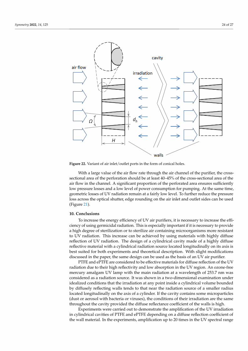
Symmetry 2022, 14, 125 24 of 27
Symmetry 2022, 14, x FOR PEER REVIEW 24 of 27
sum of the perforation fractions of the inlet and outlet walls of the air channel (Sh = Sh_in + Sh_out). Then, the formula for amplification M will take the form:
[ ]1 1
1 (1 ) 1 1 / / / ( ) ( / )h R h in out k hM
R R kd D S S S S S R H dσ= =
− − − − − + + , (13)
9.5. Reduction of Gas-Dynamic Loss For an air flow, the pressure loss is determined by the value of Sh/(Sin + Sout) and, as a
first approximation, weakly depends on H for not too small dimensions of an individual perforation element (i.e., when the pressure drop in the channel (hole) itself can be ne-glected). For real air flow velocities (up to several meters per second, [9–14]) in a UV air purifier it is sufficient that the minimum perforation size dh exceeds 1 mm. It can be said that such a technical solution makes it possible to effectively separate the geometric losses for radiation and gas-dynamic losses for the air flow and thereby significantly in-crease the integral productivity and efficiency of the UV air purifier.
In order to further reduce gas-dynamic losses, perforation can be made with a transverse dimension that decreases in the direction of the air flow [13]. For example, the perforation holes can be frusto-conical with a preferably small apex angle Ω. This design can further reduce the power consumption for pumping air through the air channel (Figure 22).
Figure 22. Variant of air inlet/outlet ports in the form of conical holes.
With a large value of the air flow rate through the air channel of the purifier, the cross-sectional area of the perforation should be at least 40–45% of the cross-sectional area of the air flow in the channel. A significant proportion of the perforated area ensures sufficiently low pressure losses and a low level of power consumption for pumping. At the same time, geometric losses of UV radiation remain at a fairly low level. To further reduce the pressure loss across the optical shutter, edge rounding on the air inlet and outlet sides can be used (Figure 21).
Figure 22. Variant of air inlet/outlet ports in the form of conical holes.
With a large value of the air flow rate through the air channel of the purifier, the cross-sectional area of the perforation should be at least 40–45% of the cross-sectional area of theair flow in the channel. A significant proportion of the perforated area ensures sufficientlylow pressure losses and a low level of power consumption for pumping. At the same time,geometric losses of UV radiation remain at a fairly low level. To further reduce the pressureloss across the optical shutter, edge rounding on the air inlet and outlet sides can be used(Figure 21).
10. Conclusions
To increase the energy efficiency of UV air purifiers, it is necessary to increase the effi-ciency of using germicidal radiation. This is especially important if it is necessary to providea high degree of sterilization or to sterilize air containing microorganisms more resistantto UV radiation. This increase can be achieved by using materials with highly diffusereflection of UV radiation. The design of a cylindrical cavity made of a highly diffusereflective material with a cylindrical radiation source located longitudinally on its axis isbest suited for both experiments and theoretical description. With slight modificationsdiscussed in the paper, the same design can be used as the basis of an UV air purifier.
PTFE and ePTFE are considered to be effective materials for diffuse reflection of the UVradiation due to their high reflectivity and low absorption in the UV region. An ozone-freemercury amalgam UV lamp with the main radiation at a wavelength of 253.7 nm wasconsidered as a radiation source. It was shown in a two-dimensional examination underidealized conditions that the irradiation at any point inside a cylindrical volume boundedby diffusely reflecting walls tends to that near the radiation source of a smaller radiuslocated longitudinally on the axis of a cylinder. If the cavity contains some microparticles(dust or aerosol with bacteria or viruses), the conditions of their irradiation are the samethroughout the cavity provided the diffuse reflectance coefficient of the walls is high.
Experiments were carried out to demonstrate the amplification of the UV irradiationin cylindrical cavities of PTFE and ePTFE depending on a diffuse reflection coefficient ofthe wall material. In the experiments, amplification up to 20 times in the UV spectral range

Symmetry 2022, 14, 125 25 of 27
was observed. The dependences of irradiation at 253.7 nm on input electric power of thelamp were obtained. The experimentally implemented processes of heating and coolingthe amalgam of Hg lamp, which directly affect the amplification in the radiation flux in thecylindrical diffuse reflector, are described.
For the idealized case of cylindrical radiation source and a reflector arranged coaxially,a theory of radiation flux amplification similar to the theory of photometric integratingspheres was developed. Within the framework of the theory, mathematical expression wasobtained for the radiation amplification coefficient depending on the characteristics of thediffusely reflecting material and Lambert radiation source partially absorbing and partiallydiffusely re-emitting the exposing radiation flux. The formula adequately describes theexperimental results.
Numerical calculations performed for the experimental geometry by the ray tracingmethod gave similar results. The features of probability density functions on the surfaces ofthe emitter and the walls of the diffuse cavity were considered. The performed simulationgave a good description of the amplification of irradiation from a UV mercury lamp whenit is used in a cylindrical diffusely reflective cavity. Taking into account the absorption ofradiation, conclusions were drawn about the applicability of the calculation method infurther research and developments in UV germicidal areas.
The resulting significant amplification of the UV irradiation makes it promising to usehighly diffuse reflection materials in the cavities of UV air purifiers. Formulas describing UVirradiation multiplication coefficient in different designs of the UV air purifying channelswere obtained. When considering the propagation of radiation through the holes perforatedin diffuse reflective material of the input and output air purifier ports, the radiationtransport through the holes was considered to be analogous to the collisionless Knudsenmolecular flow. This made it possible to estimate the fraction of radiation returned to thecavity using Clausing coefficients and to refine the multiplication of the irradiation flux.
The results of this work will be in demand among engineers producing equipment forgermicidal applications. It makes sense to focus further research on numerical calculationsof various designs of UV air purifiers with highly diffuse reflecting cavity walls. Similar dataare presented in papers [18,41,42], in which the flow of a medium with particles througha cavity was simulated. These particles simulated harmful microorganisms that died whenthey absorbed a certain dose of UV radiation; after that, the particles disappeared from thecomputational domain. This is also advisable because, as noted in Section 2, in order toincrease the efficiency of the UV air purifier, it is necessary to take into account the costs ofthe power consumed by it for pumping the medium to be cleaned.
Author Contributions: Conceptualization, M.A.K., A.N.S., N.G.S. and M.Y.Y.; Data curation, M.A.K.and M.Y.Y.; Formal analysis, A.N.S.; Funding acquisition, N.G.S.; Investigation, M.A.K., A.N.S.and M.Y.Y.; Methodology, N.G.S. and M.Y.Y.; Resources, N.G.S. and M.Y.Y.; Validation, M.A.K.and M.Y.Y.; Visualization, A.N.S.; Writing—original draft, M.A.K., A.N.S., N.G.S. and M.Y.Y.; Writing—review & editing, M.A.K. and M.Y.Y. All authors have read and agreed to the published version ofthe manuscript.
Funding: This research was funded by the Government program (#AAAA-A20-120011690135-5).
Acknowledgments: The authors are grateful to Arkady M. Soroka and Igor G. Rudoy for theirvaluable contribution to this work and fruitful discussions.
Conflicts of Interest: The authors declare no conflict of interest.
References1. Gates, F.L. A study of the bactericidal action of ultra violet light: II. The effect of various environmental factors and conditions.
J. Gen. Physiol. 1929, 13, 249–260. [CrossRef]2. Hollaender, A.; Claus, W.D. The bactericidal effect of ultraviolet radiation on Escherichia coli in liquid suspensions. J. Gen. Physiol.
1936, 19, 753–765. [CrossRef]3. Rentschler, H.C.; Nagy, R.; Mouromseff, G. Bactericidal Effect of Ultraviolet Radiation. J. Bacteriol. 1941, 41, 745–774.
[CrossRef] [PubMed]
Symmetry 2022, 14, 125 26 of 27
4. Kowalski, W. Ultraviolet Germicidal Irradiation Handbook; Springer: Berlin/Heidelberg, Germany, 2009; p. 503.5. Reed, G. The history of ultraviolet germicidal irradiation for air disinfection. Pubic Health Rep. 2010, 125, 15–27. [CrossRef]6. Available online: https://www.lit-uv.com/technology/ (accessed on 17 December 2021).7. Chatterley, C.; Linden, K. Demonstration and evaluation of germicidal UV-LEDs for point-of-use water disinfection. J. Water
Health 2010, 8, 479–486. [CrossRef]8. Kostyuchenko, S.; Khan, A.; Volkov, S.; Giller, H. UV Disinfection in Moscow Metro Public Transport Systems; IUVA News: Moscow,
Russia, 2009.9. Clark, R.W. Methods and Apparatus for Diffuse Reflective UV Cavity Air Treatment. U.S. Patent 2012/0315184 A1, 13 December 2012.10. Lizotte, T.E. UV PTFE Diffuser Technology. U.S. Patent 2012/0168641 A1, 5 July 2012.11. She, R.C.; Chen, D.; Pak, P.; Armani, D.K.; Schubert, A.; Armani, A.M. Lightweight UV-C disinfection system. Biomed. Opt.
Express 2020, 11, 4326–4332. [CrossRef]12. Welch, D.; Buonanno, M.; Shuryak, I.; Randers-Pehrson, G.; Spotnitz, H.M.; Brenner, D.J. Effect of far ultraviolet light emitted from
an optical diffuser on methicillin-resistant Staphylococcus aureus in vitro. PLoS ONE 2018, 13, e0202275. [CrossRef] [PubMed]13. Rudoy, I.G.; Yakimov, M.Y. Optical Shutter for A Bactericidal Irradiation. Russia Patent 2 738 770 C1, 12 December 2020.14. Rudoy, I.G.; Solovyev, N.G.; Shemyakin, A.N.; Yakimov, M.Y. Bactericidal irradiator. Russia Patent 188 297 U1, 5 April 2018.15. Available online: https://www.howatherm.com/ (accessed on 17 December 2021).16. Judd, D.B. Fresnel Reflection of Diffusely Incident Light. J. Res. Natl. Bur. Stand. 1942, 29, 329–332. [CrossRef]17. A Guide to Reflectance Coatings and Materials. Technical GuideLabsphere Inc. p. 25. Available online: https://www.pro-lite.co.
uk/File/Tech_Guide_-_Coatings_&_Materials.pdf (accessed on 17 December 2021).18. Lombini, M.; Diolaiti, E.; De Rosa, A.; Lessio, L.; Pareschi, G.; Bianco, A.; Cortecchia, F.; Fiorini, M.; Fiorini, G.; Malaguti, G.; et al.
Design of optical cavity for air sanification through ultraviolet germicidal irradiation. Opt. Express 2021, 29, 18688–18704.[CrossRef] [PubMed]
19. Jacquez, J.A.; Kuppenheim, H.F. Theory of the Integrating Sphere. J. Opt. Soc. Am. 1955, 45, 460–470. [CrossRef]20. Waymouth, J.F. Electric Discharge Lamps; The MIT Press: Cambridge, MA, USA, 1971; p. 384.21. Voronov, A.; Arnold, E.; Roth, E. Long Life Technology of High Power Amalgam Lamps. In Proceedings of the Second
International Conference on Ultraviolet Technologies, Vienna, Austria, 9–11 July 2003; International Ultraviolet Association:Ayr, ON, Canada, 2003. PS2.
22. Vasilyev, A.; Vasilyak, L.; Kostyuchenko, S.; Kudryavtsev, N.; Sokolov, D.; Startsev, A.Y. Influence of starting mode on service lifeof low pressure powerful amalgam lamp electrodes. Light Eng. 2009, 17, 66–74.
23. Vasilyak, L.M.; Vasiliev, A.I.; Kostyuchenko, S.V.; Sokolov, D.V.; Startsev, A.Y.; Kudryavtsev, N.N. Determination of the cathodeand anode voltage drops in high power low-pressure amalgam lamps. Plasma Phys. Rep. 2011, 37, 1173–1177. [CrossRef]
24. Keitz, H.A.E. Light Calculations and Measurements: An Introduction to the System of Quantities and Units in Light-Technologyand to Photometry. Available online: https://books.google.com.sg/books?hl=en&lr=&id=PVJdDwAAQBAJ&oi=fnd&pg=PR4&dq=Keitz,+H.A.E.+Light+Calculations+and+Measurements:+An+Introduction+to+the+System+of+Quantities+and+Units+in+Light-technology+and+to+Photometry.+In+Proceedings+of+the+N.V.+Philips%27+Gloeilampenfabrieken,+Eindhoven,+Holland%3B+Cleaver+Hume+Press:+London,+UK&ots=14b3zd6f_9&sig=S6i7zpbvMlotFCU40WxkdqpvYXc#v=onepage&q&f=false (accessed on 17 December 2021).
25. Gibbs, D.R.; Duncan, F.J.; Lambe, R.P.; Goodman, T.M. Ageing of materials under intense ultraviolet radiation. Metrologia 1995,32, 601. [CrossRef]
26. Available online: https://doc.comsol.com/5.4/doc/com.comsol.help.roptics/RayOpticsModuleUsersGuide.pdf (accessed on17 December 2021).
27. Greenwood, J. The correct and incorrect generation of a cosine distribution of scattered particles for Monte-Carlo modelling ofvacuum systems. Vacuum 2002, 67, 217–222. [CrossRef]
28. Lee, U.-H.; Ju, Y.-G. Effects of a Cylindrical Cavity on the Etendue of a Light Source. Jpn. J. Appl. Phys. 2011, 50, 122501. [CrossRef]29. Siegel, R.; Howell, J.R.; Menguc, M.P. Thermal Radiation Heat Transfer, 5th ed.; CRC Press: Boca Raton, FL, USA, 2010.30. Tang, C.; Meyer, M.; Darby, B.L.; Auguié, B.; Le Ru, E.C. Realistic ports in integrating spheres: Reflectance, transmittance,
and angular redirection. Appl. Opt. 2018, 57, 1581–1588. [CrossRef] [PubMed]31. Prokhorov, A.; Hanssen, L.M. Numerical modeling of an integrating sphere radiation source. In Proceedings of the SPIE 4775,
Modeling and Characterization of Light Sources, Seattle, WA, USA, 8–9 July 2002.32. Prokhorov, A.V.; Mekhontsev, S.N.; Hanssen, L.M. Monte Carlo modeling of an integrating sphere reflectometer. Appl. Opt. 2003,
42, 3832–3842. [CrossRef] [PubMed]33. Bergin, S. Pathlength Calibration of Integrating Sphere Based Gas Cells. Ph.D. Thesis, Cranfield University, Cranfield, UK, 2016.34. Silva, C.F.P. Reflection Distribution of the Fluoropolymers for the Xenon Scintillation Ligh. Ph.D. Thesis, Universidade de
Coimbra, Coimbra, Portugal, 2010; p. 244.35. Bloomer, J.J. Practical Fluid Mechanics for Engineering Applications; Marcel Dekker: New York, NY, USA, 2000.36. Clausing, P. Über die Strahlformung bei der Molekularströmung. Z. Phys. 1930, 66, 471–476. [CrossRef]37. Clausing, P. Über die Strömung sehr verdünnter Gase durch Röhren von beliebiger Länge. Ann. Der Phys. 1932, 404, 961–989.
[CrossRef]38. Clausing, P. The flow of highly rarefied gases through tubes of arbitrary length. J. Vac. Sci. Technol. 1971, 8, 636–646. [CrossRef]

Symmetry 2022, 14, 125 27 of 27
39. Iczkowski, R.P.; Margrave, J.L.; Robinson, S.M. Effusion of gases through conical orifices. J. Phys. Chem. 1963, 67, 229–233.[CrossRef]
40. Lobo, P.J.; Becheri, F.; Gómez-Goñi, J. Comparison between Monte Carlo and analytical calculation of Clausing functions ofcylindrical and conical tubes. Vacuum 2004, 76, 83–88. [CrossRef]
41. Keshavarzfathy, M.; Taghipour, F. Computational modeling of ultraviolet light-emitting diode (UV-LED) reactor for watertreatment. Water Res. 2019, 166, 115022. [CrossRef]
42. Li, W.; Li, M.; Bolton, J.R.; Qu, J.; Qiang, Z. Impact of inner-wall reflection on UV reactor performance as evaluated by usingcomputational fluid dynamics: The role of diffuse reflection. Water Res. 2017, 109, 382–388. [CrossRef] [PubMed]