Airodyn, BRair and BRoil Compressed Air Drain Traps
16
1. Safety information 2. General product information 3. Installation 4. Commissioning 5. Operation 6. Maintenance 7. Spare parts © Copyright 2022 Printed in GB 6100550/5 Airodyn, BRair and BRoil Compressed Air Drain Traps Installation and Maintenance Instructions IM-S48-06 CMGT Issue 5
-
Upload
khangminh22 -
Category
Documents
-
view
1 -
download
0
Transcript of Airodyn, BRair and BRoil Compressed Air Drain Traps

IM-S48-06 CMGT Issue 5 1
Airodyn, BRair and BRoil Compressed Air Drain Traps
1. Safety information
2. General product information
3. Installation
4. Commissioning
5. Operation
6. Maintenance
7. Spare parts
© Copyright 2022
Printed in GB
6100550/5
Airodyn, BRair and BRoilCompressed Air Drain Traps
Installation and Maintenance Instructions
IM-S48-06 CMGT Issue 5

IM-S48-06 CMGT Issue 52
Airodyn, BRair and BRoil Compressed Air Drain Traps
Safe operation of these products can only be guaranteed if they are properly installed, commissioned, used and maintained by qualified personnel (see Section 1.11) in compliance with the operating instructions. General installation and safety instructions for pipeline and plant construction, as well as the proper use of tools and safety equipment must also be complied with.
1.1 Intended useReferring to the Installation and Maintenance Instructions, name-plate and Technical Information Sheet, check that the product is suitable for the intended use/application. The products listed below comply with the requirements of the EU Pressure Equipment Directive/UK Pressure Equipment (Safety) Regulations and carry the mark when so required.
Product Group 2 Gases Group 2 Liquids
BRair SEP SEP
BRoil SEP SEP
Airodyn SEP SEP
i) The products have been specifically designed for use on steam, air or condensate which are in Group 2 of the above mentioned EU Pressure Equipment Directive/UK Pressure Equipment (Safety) Regulations. The products’ use on other fluids may be possible but, if this is contemplated, Spirax Sarco should be contacted to confirm the suitability of the product for the application being considered.
ii) Check material suitability, pressure and temperature and their maximum and minimum values. If the maximum operating limits of the product are lower than those of the system in which it is being fitted, or if malfunction of the product could result in a dangerous overpressure or overtemperature occurrence, ensure a safety device is included in the system to prevent such over-limit situations.
iii) Determine the correct installation situation and direction of fluid flow.
iv) Spirax Sarco products are not intended to withstand external stresses that may be induced by any system to which they are fitted. It is the responsibility of the installer to consider these stresses and take adequate precautions to minimise them.
v) Remove protective covers from all connections and protective film from all name-plates, where appropriate, before installation on a steam or other high temperature applications.
1.2 AccessEnsure safe access and if necessary a safe working platform (suitably guarded) before attempting to work on the product. Arrange suitable lifting gear if required.
1.3 LightingEnsure adequate lighting, particularly where detailed or intricate work is required.
1.4 Hazardous liquids or gases in the pipeline Consider what is in the pipeline or what may have been in the pipeline at some previous time. Consider: flammable materials, substances hazardous to health, extremes of temperature.
1. Safety information

IM-S48-06 CMGT Issue 5 3
Airodyn, BRair and BRoil Compressed Air Drain Traps
1.5 Hazardous environment around the productConsider: explosion risk areas, lack of oxygen (e.g. tanks, pits), dangerous gases, extremes of temperature, hot surfaces, fire hazard (e.g. during welding), excessive noise, moving machinery.
1.6 The systemConsider the effect on the complete system of the work proposed. Will any proposed action (e.g. closing isolation valves, electrical isolation) put any other part of the system or any personnel at risk? Dangers might include isolation of vents or protective devices or the rendering ineffective of controls or alarms. Ensure isolation valves are turned on and off in a gradual way to avoid system shocks.
1.7 Pressure systems Ensure that any pressure is isolated and safely vented to atmospheric pressure. Consider double isolation (double block and bleed) and the locking or labelling of closed valves. Do not assume that the system has depressurised even when the pressure gauge indicates zero.
1.8 TemperatureAllow time for temperature to normalise after isolation to avoid danger of burns. If parts made from Viton have been subjected to a temperature approaching 315 °C (599 °F) or higher, they may have decomposed and formed hydrofluoric acid. Avoid skin contact and inhalation of any fumes as the acid will cause deep skin burns and damage the respiratory system.
1.9 Tools and consumablesBefore starting work ensure that you have suitable tools and/or consumables available. Use only genuine Spirax Sarco replacement parts.
1.10 Protective clothingConsider whether you and/or others in the vicinity require any protective clothing to protect against the hazards of, for example, chemicals, high/low temperature, radiation, noise, falling objects, and dangers to eyes and face.
1.11 Permits to workAll work must be carried out or be supervised by a suitably competent person.Installation and operating personnel should be trained in the correct use of the product according to the Installation and Maintenance Instructions.Where a formal 'permit to work' system is in force it must be complied with. Where there is no such system, it is recommended that a responsible person should know what work is going on and, where necessary, arrange to have an assistant whose primary responsibility is safety. Post 'warning notices' if necessary.
1.12 HandlingManual handling of large and/or heavy products may present a risk of injury. Lifting, pushing, pulling, carrying or supporting a load by bodily force can cause injury particularly to the back. You are advised to assess the risks taking into account the task, the individual, the load and the working environment and use the appropriate handling method depending on the circumstances of the work being done.

IM-S48-06 CMGT Issue 54
Airodyn, BRair and BRoil Compressed Air Drain Traps
1.13 Residual hazardsIn normal use the external surface of the product may be very hot. If used at the maximum permitted operating conditions the surface temperature of some products may reach temperatures of 200 °C (392 °F).Many products are not self-draining. Take due care when dismantling or removing the product from an installation (refer to Section 6 'Maintenance instructions').
1.14 FreezingProvision must be made to protect products which are not self-draining against frost damage in environments where they may be exposed to temperatures below freezing point.
1.15 DisposalUnless otherwise stated in the Installation and Maintenance Instructions, this product is recyclable and no ecological hazard is anticipated with its disposal providing due care is taken.
1.15 Returning productsCustomers and stockists are reminded that under EC Health, Safety and Environment Law, when returning products to Spirax Sarco they must provide information on any hazards and the precautions to be taken due to contamination residues or mechanical damage which may present a health, safety or environmental risk. This information must be provided in writing including Health and Safety data sheets relating to any substances identified as hazardous or potentially hazardous.

IM-S48-06 CMGT Issue 5 5
Airodyn, BRair and BRoil Compressed Air Drain Traps
Fig. 1 Airodyn/ BRair air traps
2.1 General descriptionAirodynThe Airodyn is a maintainable thermodynamic type compressed air drain trap. The external body surfaces have electroless nickel plated (ENP) which is oxidation resistant.
Airodyn options
The Airodyn 'S' has been designed for ultra clean applications. This trap has a fine lap disc.
The Airodyn 'HD' has been designed for particularly oil contaminated air systems.
BRairThe BRair is a maintainable thermodynamic type compressed air drain trap, specifically for use on railway rolling stock (British Rail Cat. no. 61/41955). The external body surfaces have electroless nickel preparation (ENP) which is oxidation resistant.
2. General product information

IM-S48-06 CMGT Issue 56
Airodyn, BRair and BRoil Compressed Air Drain Traps
Fig. 3 BRoil air trap complete with optional silencer (British Rail Cat No. 15/07220)
Optional silencer
Fig. 2 BRoil air trap
BRoilThe BRoil is maintainable thermodynamic type compressed air drain trap, specifically designed to remove small quantities of oil contaminated condensate, for use on railway rolling stock.
Note: The Airodyn, BRair and BRoil are not suitable for use on PED group 1 liquids or gases.
StandardsThese products fully comply with the requirements of the EU Pressure Equipment Directive/UK Pressure Equipment (Safety) Regulations.
CertificationThese products are available with certification to EN 10204 3.1. Note: All certification/inspection requirements must be stated at the time of order placement.
Note: For further information see the following Technical Information Sheets: Airodyn TI-P610-05
BRair TI-P610-03
BRoil TI-P610-10

IM-S48-06 CMGT Issue 5 7
Airodyn, BRair and BRoil Compressed Air Drain Traps
The product must not be used in this region.
Body design conditions PN63
PMA Maximum allowable pressure 63 bar g @ 120 °C (913.5 psi g @ 248 °F)
TMA Maximum allowable temperature 400 °C @ 42 bar g (752 °F @ 609 psi g)
Minimum allowable temperature 0 °C (32 °F)
PMO Maximum operating pressure 63 bar g @ 120 °C (913.5 psi g @ 248 °F)
TMO Maximum operating temperature 400 °C @ 42 bar g (752 °F @ 609 psi g)
Minimum operating temperature 0 °C (32 °F)
PMOB Maximum backpressure should not exceed 80% of the inlet pressure under any conditions of operation otherwise the trap may not shut-off.
DPMNMinimum operating differential pressure for correct operation: 0.25 bar (3.6 psi)
Designed for a maximum cold hydraulic test pressure of: 95 bar g (1377.5 psi g)
2.2 Sizes and pipe connections
Airodyn screwed ½" BSP or NPT (Airodyn 'HD' BSP only)
¾" screwed NPT Only
BRair ½" screwed BSP NPT and ISO228-1
BRoil ½" screwed BSP or NPT
2.3 Optional extrasAs an optional extra, a sliencer complete with elbow and reducer is available for the BRoil air trap only.
2.4 Pressure/temperature limits
Tem
pera
ture
°C
Pressure bar g
�
���
���
���
���
� �� �� �� �� �� �� ��
� ��� ��� ��� ��� ��� ��� ��� ������
���������������
������
Pressure psi g
Temperature °F

IM-S48-06 CMGT Issue 58
Airodyn, BRair and BRoil Compressed Air Drain Traps
After installation or maintenance ensure that the system is fully functioning. Carry out tests on any alarms or protective devices.
Note: Before actioning any installation observe the 'Safety information' in Section 1.
Refering to the Installation and Maintenance Instructions, name-plate and Technical Information Sheet, check that the product is suitable for the intended installation:
3.1 Check materials, pressure and temperature and their maximum values. If the maximum operating limit of the product is lower than that of the system in which it is being fitted, ensure that a safety device is included in the system to prevent overpressurisation.
3.2 Determine the correct installation situation and the direction of fluid flow.
3.3 Remove protective covers from all connections and protective film from all name-plates, where appropriate, before installation on steam or other high temperature applications.
3.4 Preferably fitted in a horizontal pipe but can be fitted in vertically downwards pipe.
Note: If the trap is to discharge to atmosphere ensure it is to a safe place, the discharging fluid may be at a temperature of 100 °C (212 °F).
3. Installation
4. Commissioning
IM-S48-06 CMGT Issue 5 9
Airodyn, BRair and BRoil Compressed Air Drain Traps
One side of the disc (Figure 4) is plain with a single scribe towards the outer edge, whereas the other side of the disc has a machined circular groove.
The trap is supplied with the circular grooved side of the disc towards the seating face and is suitable for clean operating conditions with the exception of the 'HD' version which has been designed for particularly contaminated air system having the scribed disc facing the seat.
If the operating conditions are dirty, probably with heavy oil contamination, unscrew the cap, using preferably a ring spanner and turn over the disc so that the plain side with a bleed scribe is towards the seating face.
Replace the cap - no gasket is required but a suitable high temperature anti-sieze grease should be applied to the threads.
Tighten the cap to the recommended torque (see Section 6). Do not use a wrench of the Stillson type which may distort the cap. In extremely dirty conditions it may be necessary to deepen the bleed scribe or to make additional scratches up to a maximum of 3.
NoteOn ultra clean systems, an Airodyn 'S' with fine lap disc is required. The disc will be supplied without a single bleed scratch, but will have a groove machined in one side. The disc will also be supplied with grooved side of the disc on the seat.
In ultra clean environments the disc may operate with a rapid cycling action that may not be acceptable. Turn the disc over so that the fine lapped face is now touching the seat.
Maximum of three bleed scribes
Fig. 4
The scratch should be over the area covered by and extending beyond the outer seat face.
5. Operation

IM-S48-06 CMGT Issue 510
Airodyn, BRair and BRoil Compressed Air Drain Traps
Note: Before actioning any maintenance programme observe the 'Safety information' in Section 1.
6.1 How to service the Airodyn and BRair traps:- Unscrew the cap (2) using a spanner. Do not use Stillsons or a wrench of a similar type which may
cause distortion to the cap.
- If the body seating faces are only slightly worn they can be refaced by lapping individually on a flat surface such as a surface plate. A figure of eight motion and a little grinding compound such as a Carborundum Co's compound I.F. gives the best results. If the wear is too great to be rectified by simple lapping, the seating faces on the body must be ground flat and then lapped. The disc (3) should always be replaced with a new one. The total amount of metal removed in this way should not exceed 0.25 mm.
- When reassembling, the disc is normally placed in position with the grooved side in contact with the body seating face (see Section 5, Operation). Screw on the cap. No gasket is required but a suitable high temperature anti-seize grease should be applied to the threads.
6.1.1 How to clean or replace the strainer screen:- Using a spanner unscrew the strainer cap (5), withdraw the screen (4) and clean it, or if damaged replace
with a new one.
- To reassemble, insert the screen (4) into the cap (5), then screw the cap into place. A fine smear of 'Molybdenum Disulphide' grease should be applied to the first few threads.
Care should be taken to ensure that the gasket and gasket faces are clean. Tighten the cap to the recommended torque - See Table 1 below.
6. Maintenance
Table 1 Recommended tightening torques
Item Part or mm N m (lbf ft)
2 Cap 36 A/F 135 - 150 (99 - 110)
5 Strainer 32 A/F M28 170 - 190 (125 - 140)

IM-S48-06 CMGT Issue 5 11
Airodyn, BRair and BRoil Compressed Air Drain Traps
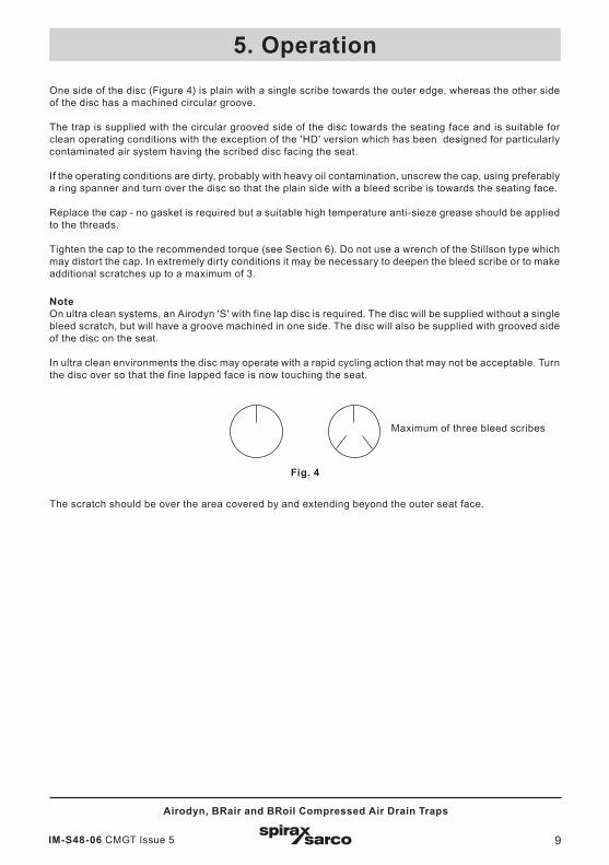
Fig. 5 Airodyn/BRair air traps
2
4Withdrawal distance
85 mm (17/10")
5 Withdrawal distance
41 mm (34/10")
6
3

IM-S48-06 CMGT Issue 512
Airodyn, BRair and BRoil Compressed Air Drain Traps
Note: Before actioning any maintenance programme observe the 'Safety information' in Section 1.
6.2 How to service the BRoil air trap:- Unscrew the cap (2) and remove the disc (3).
- Clean all internal ports and surfaces do not use anything metallic. Please note that on older type BRoil traps there was a groove 'A', see Figure 6, which when apt must be cleaned with a soft lint free cloth, again do not use anything metallic.
- Reassemble the unit by replacing the disc and cap (3 and 2) and apply a fine smear of Molybdenum Disulphide grease to the threads of the body (1) and proceed to tighten to the recommended torque - See Table 2 below.
- Test the unit. On test the unit should operate at a rate 160/220 cycles per minute on a 6 bar g (87 psi g) air system.
Table 2 Recommended tightening torques
Item Part N m (lbf ft)
2 Cap 36 A/F 135 - 150 (99 - 110)
5 32 A/F 170 - 190 (125 - 140)
6 11 A/F 5 - 8 (4 - 6)

IM-S48-06 CMGT Issue 5 13
Airodyn, BRair and BRoil Compressed Air Drain Traps
2
3
Groove 'A'(old models only)
Fig. 6 BRoil air trap
1
The silencer is an optional extra
5
6

IM-S48-06 CMGT Issue 514
Airodyn, BRair and BRoil Compressed Air Drain Traps
7. Spare partsThe spare parts available are shown in solid outline. Parts drawn in a grey line are not supplied as spares.
Available spares
AirodynandBRair
Disc (packet of 3)
Standard Airodyn
3Airodyn 'S'
Airodyn 'HD'
Strainer screen and gasket 4 and 6
Strainer cap gasket (packet of 3) 6
BRoil Disc (packet of 3) 3
How to order sparesAlways order spares by using the description given in the column headed 'Available spares' and state the size and type of trap.
Example 1: 1 - Packet of 3 discs for a ½" Spirax Sarco Airodyn 'S' compressed air drain trap.
Example 2: 1 - Packet of 3 discs for a ½" Spirax Sarco BRoil air trap screwed BSP.

IM-S48-06 CMGT Issue 5 15
Airodyn, BRair and BRoil Compressed Air Drain Traps
Fig. 7 Airodyn/BRair air trap
Fig. 8 BRoil air trap
33
4
6

IM-S48-06 CMGT Issue 516
Airodyn, BRair and BRoil Compressed Air Drain Traps