design and operations manual pressurized irrigation systems ...
Upload
khangminh22Category
view
1download
0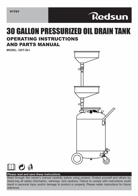
OPERATING INSTRUCTIONSAND PARTS MANUAL
Please read and save these instructions.Read through this owner’s manual carefully before using product. Protect yourself and others by observing all safety information, warnings, and cautions. Failure to comply with instructions could result in personal injury and/or damage to product or property. Please retain instructions for future reference.
MODEL: ODT-30-I
V1701
30 GALLON PRESSURIZED OIL DRAIN TANK

SAFETY
OWNER/OPERATOR RESPONSIBILITYIt is the owner/operator responsibility to properly use and maintain this equipment.The instructions and warning contained in this manual shall be read and understood by the owner/operator prior to operating this equipment.
The owner/operator shall retain this manual for future reference to important warnings, operating and maintenance instructions.
Keep work area clean. Cluttered areas invite injuries.Observe work area conditions. Keep area well lighted.Store idle equipment. When not in use, the oil lift must be stored in a safe and clean location. Always lock up products and keep out of reach of children.Use the right product for the job. There are certain applications for which the oil lift was designed. Do not modify the oil lift and do not use the oil lift for a purpose for which it was not intended.Check for damaged parts. Before using any product, any part that appears damaged should be carefully checked to determine that it will operate properly and perform its intended function. Check for any broken or damaged parts and any other conditions that may affect its operation. Replace or repair damaged or worn parts immediately.Replacement parts and accessories. When servicing, use only identical replacement parts. Use of any other parts will void the warranty.Do not operate product if under the influence of alcohol or drugs. Read warning labels on prescriptions to determine if your judgment or reflexes are impaired while taking drugs. If there is any doubt, do not operate the product.Use eye and hearing protection. Always wear ANSI approved impact safety goggles, full face shield and ANSI approved hearing protection when working with this product.Do not exceed the product’s working pressure of 0.5bar.Only use on a flat surface capable of supporting the Portable Oil Lift and its maximum load of 26 gallons.Dress safely. Non-skid footwear or safety boots should be used when working with the product. Do not wear loose clothing or jewelry as they can become caught in moving parts wear a protective hair covering to prevent long hair from becoming caught in moving parts.Do not allow children in the work area.Always check hardware and assembled parts after assembling. All connections should tight and hardware tightened.Do not overreach. Keep proper footing and balance at all times to prevent tripping, falling and injury.Always secure the wheels and casters in place while operating the oil lift.Know and obey city and state laws for proper disposal of oil. Dispose of oil properly in accordance with all local laws and regulations.WARNING: This product contains or, when used, produces a chemical known to cause an birth defects or other reproductive harm.
2
Read all instruction before using this product!1.2.3.
4.
5.
6.
7.
8.
9.10.
11.
12.13.
14.
15.16.
17.
SAFETY
PRODUCT SPECIFICATION
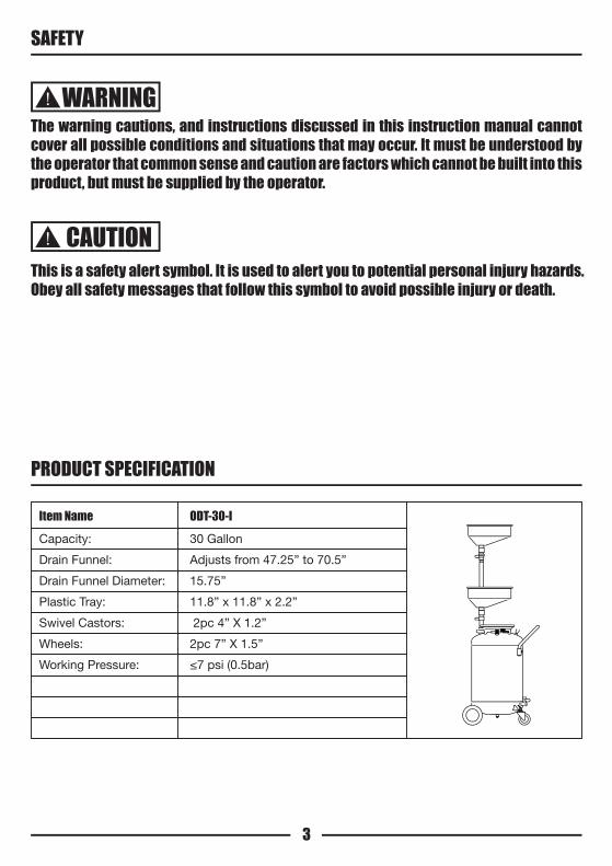
WARNING
CAUTIONThis is a safety alert symbol. It is used to alert you to potential personal injury hazards.Obey all safety messages that follow this symbol to avoid possible injury or death.
3
The warning cautions, and instructions discussed in this instruction manual cannot cover all possible conditions and situations that may occur. It must be understood by the operator that common sense and caution are factors which cannot be built into this product, but must be supplied by the operator.
Item NameCapacity:
Drain Funnel:
Drain Funnel Diameter:
Plastic Tray:
Swivel Castors:
Wheels:
Working Pressure:
30 Gallon
Adjusts from 47.25” to 70.5”
15.75”
11.8” x 11.8” x 2.2”
2pc 4” X 1.2”
2pc 7” X 1.5”
≤7 psi (0.5bar)
ODT-30-I

SPECIFIC PRODUCT WARNING AND PRECAUTIONS
SAFETY INFORMATION
WARNING
WARNING
4
KEEP THIS MANUAL, SALES RECEIPT & APPLICABLE WARRANTY FOR FUTURE REFERENCE.READ ALL INSTRUCTIONS AND WARNINGS BEFORE USING THIS PRODUCT.FOR CONSUMER USE ONLY NOT FOR PROFESSIONAL USE
IMPORTANT SAFETY RULESCOMMON SENSE AND CAUTION ARE FACTORS WHICH CANNOT BE BUILT INTO ANY PRODUCT.THESE FACTORS MUST BE SUPPLIED BY THE OPERATOR.
Keep your work area clean and well lit. Cluttered work benches and dark work areas may causeaccidents or injury.Do not operate the parts washer in explosive areas, such as in the presence of flammable liquids, gases or dust. Power tools create sparks which may ignite the dust or fumes.Keep bystanders, children and visitors away while operating the parts washer. Distractions can cause you to lose control.
Chemicals, including lead includes in this product or its power cord. Wash hands after handling
DANGER
MAX. AIR PRESSURE 0.5 BAR FOR OIL EXHAUST.READ MANUAL CAREFULLY BEFORE OPERATION.NEVER OPERATE WITH LIQUID LIKE STRONG ACID OR ALKALI.CUT OFF AIR RESOURCE BEFORE MAINTENANCE.ALWAYS KEEP MACHINE OUT OF FIRE AND HOT SOURCE.
Failure to heed the following warning may result in personal injury and/or property damage.NEVER LEAVE UNIT UNATTENDED WHEN OPERATING OR EVACUATING.NEVER USE NEAR OPEN FLAME OR HEAT SOURCE.ALWAYS CHECK THAT VALVE BELOW FUNNEL IS CLOSED BDFORE EMPTYING ALWAYS DISCONNECT AIR SUPPLY AFTER EMPTYING.NEVER USE UNIT FOR HANDLING HIGHLY VOLATILE FUELS AND FLUIDS.USE ONLY THE NOZZLE ASSEMBLY PROVIDED.NEVER FILL THE TANK OVER THE MAX. LEVEL GIVEN BY THE LEVEL INDICATOR.
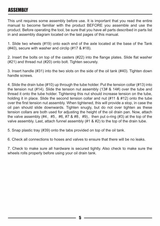
This unit requires some assembly before use. It is important that you read the entire manual to become familiar with the product BEFORE you assemble and use the product. Before operating the tool, be sure that you have all parts described in parts list in and assembly diagram located on the last pages of this manual.
1. Slide two wheels (#19) onto each end of the axle located at the base of the Tank (#40), secure with washer and circlip (#17 & #18).
2. Insert the bolts on top of the casters (#22) into the flange plates. Slide flat washer (#21) and thread nut (#20) onto bolt. Tighten securely.
3. Insert handle (#31) into the two slots on the side of the oil tank (#40). Tighten down handle screws.
4. Slide the drain tube (#10) up through the tube holder. Put the tension collar (#13) into the tension nut (#14). Slide the tension nut assembly (13# & 14#) over the tube and thread it onto the tube holder. Tightening this nut should increase tension on the tube, holding it in place. Slide the second tension collar and nut (#11 & #12) onto the tube over the first tension nut assembly. When tightened, this will provide a stop, in case the oil pan should slide downwards. Tighten snugly, but do not over tighten as these tension collars are both used for adjusting the height of the oil drain pan. Now, attach the valve assembly (#4,#5,#6, #7 & #8,#9),then put o-ring (#3) at the top of the valve assembly. Last, attach funnel assembly (#1 & #2) to the top of the drain tube.
5. Snap plastic tray (#39) onto the tabs provided on top of the oil tank.
6. Check all connections to hoses and valves to ensure that there will be no leaks.
7. Check to make sure all hardware is secured tightly. Also check to make sure the wheels rolls properly before using your oil drain tank.
ASSEMBLY
5

Raise drain bowl to desired height and lock in place with tension adjusting knob (12#). With valve (8#) fully open (Valve handle in vertical position), drain oil into bowl/tank assembly. DO NOT fill the reservoir above the maximum oil level as shown.
Evacuate used oil from tank when maximum oil level is obtained. Raise drain bowl and lock in place. Close the ball valve (8#) fully by turning it to horizontal position. Place hose and nozzle (#27) SECURELY into your used oil collection reservoir and open the ball valve (26#) by turning it to vertical position. Connect air supply to air inlet connector (#33) and discharge oil.
Never leave unit unattended when evacuating oil.
Immediately disconnect air supply when oil is no longer discharging into reservoir.
TO DRAIN OIL
TO EVACUATE OIL
6

With ball valve (#8) fully open (valve handle in vertical position), lower drain bowl to desired height.Always use the tank handle to transport the tank assembly. Always grasp the handle with two hands while moving the load. Do not pull unit by the funnel, tube or hoses.
1. Before each use, examine the general condition of the entire oil drain system. Inspect air hoses for damage. Check for loose screws, misalignment, binding of moving parts, improper mounting, broken parts and any other condition that may affect its safe operation. If abnormal noise or vibration occurs, turn off the air compressor immediately and have the problem corrected before further use. Refer to “Warnings and precautions sections. DO NOT use a damaged product.
2. CAUTION: Always disconnect this product from its air supply, and release all compressed air from the system before performing any cleaning, servicing maintenance.
3. Keep the outside of the equipment free of oil grease. Use only a mild soap and damp cloth when cleaning. DO NOT use a flammable or combustible solvent.
4. Before and during each use, inspect the oil indicator level. DO NOT fill tank above maximum oil level.
PLEASE READ THE FOLLOWING CAREFULLYTHE MANUFACTURER AND/OR DISTRIBUTOR HAS PROVIDED THE PARTS DIAGRAM IN THIS MANUAL AS A REFERENCE TOOL ONLY. NEITHER THE MANUFACTURER NOR DISTRIBUTOR MAKES ANY REPRESENTATION OR WARRANTY OF ANY KIND TO THE BUYER THAT HE OR SHE IS QUALIFIED TO MAKE ANY REPAIRS TO THE PRODUCT OR THAT HE OR SHE IS QUALIFIED TO REPLACE ANY PARTS OF THE PRODUCT. IN FACT, THE MANUFACTURER AND/OR DISTRIBUTOR EXPRESSLY STATES THAT ALL REPAIRS AND PARTS REPLACEMENTS SHOULD BE UNDERTAKEN BY A CERTIFIED AND LICENSED TECHNICIAN AND NOT BY THE BUYER. THE BUYER ASSUMES ALL RISK AND LIABILITY ARISING OUT OF HIS OR HER REPAIRS TO THE ORIGINAL PRODUCT OR REPLACEMENT PARTS THERETO, OR ARISING OUT OF HIS OR HER INSTALLATION OF REPLACEMENT PARTS THERETO.
TO TRANSPORT TANK
CLEANING AND MAINTENANCE
7

PARTS DIAGRAM
8
1
234
6
8
39
3637
35
34
33
32
11
38
14
15
57
9
10
1213
16
17
18
1922
24
27
26
25
21
40
31
30
29
28
20
23

N.O. DESCRIPTION QTY
PARTS DIAGRAM
9
ScreenFunnel Bowl AssemblyO ringConnecterO ringBoltConnecter1" Ball ValveConduit ConnecterOil Drain TubeSmall Tension RingTension KnobTension CollarTension NutClampDrain HoseWasherCirclipWheelAcorn NutWasherCasterDrain PlugDrain Plug WasherTube Connector1/2” Ball valveEvacuation Hose/Nozzle assemblyChainHose PlugRing
113125111111111122222211111112
123456789101112131415161718192021222324252627282930
31323334353637383940
HandleTube ClampAir Inlet Connector1/4" ball valveConnectorHex ConnectorRingBleeder ValvePlastic TrayTank Assembly
1111111111
N.O. DESCRIPTION QTY
Copyright © 2022 FDOKUMEN