RIIWMG203D Drain and Dewater Civil Construction Site
22
www.pertrain.com.au Reference Material RIIWMG203D Drain and Dewater Civil Construction Site
-
Upload
khangminh22 -
Category
Documents
-
view
3 -
download
0
Transcript of RIIWMG203D Drain and Dewater Civil Construction Site
www.pertrain.com.au
Reference Material
RIIWMG203D Drain and Dewater Civil Construction Site

August, 2015 — J/N 9332-3G — © www.pertrain.com.au Page iii
Table of Contents
1.1 Contents
SECTION 1: PLAN AND PREPARE ........................................................................11.1 General Obligations .................................................................................................................2
1.2 Legislation and Site Policies ....................................................................................................2
1.2.1 Comply with Legislation and Site Procedures ..............................................................2
1.2.2 Meet Quality Requirements ..........................................................................................4
1.2.3 Comply with Standards ...............................................................................................4
1.2.4 Roles and Responsibilities ...........................................................................................4
1.3 Work Planning Procedure ........................................................................................................5
1.3.1 AttendWorkBriefings ...................................................................................................5
1.3.2 Obtain Applicable Data .................................................................................................5
1.3.3 Interpret Information .....................................................................................................5
1.3.4 Plan Work .....................................................................................................................6
1.4 Work with Others ......................................................................................................................6
1.4.1 Team Member Coordination .........................................................................................6
1.5 Safety ......................................................................................................................................7
1.5.1 Standard Operating Procedures ...................................................................................7
1.5.2 Site Safety Plan ............................................................................................................7
1.5.3 Workplace Inspections .................................................................................................8
1.5.4 Personal Protective Equipment ...................................................................................8
1.6 Hazards ....................................................................................................................................9
1.6.1 Identifying Hazards .....................................................................................................10
1.6.2 Trench Hazards .......................................................................................................... 11
1.6.3 Electricity Hazards ......................................................................................................12
1.6.4 Petrol and Diesel Engine Hazards ..............................................................................13
1.6.5 Underground Services ................................................................................................13
1.6.6 Job Safety Analysis ....................................................................................................15
1.7 Environmental and Heritage Compliance ..............................................................................15
1.8 Communication ......................................................................................................................16
1.8.1 Verbal Communication ...............................................................................................16
1.8.2 Written Communication ..............................................................................................16
1.8.3 Signals ........................................................................................................................17
DRAIN AND DEWATER CIVIL CONSTRUCTION SITE

© www.pertrain.com.au — J/N 9332-3G — August, 2015Page iv
Drain and Dewater Civil Construction Site
1.9 TrafficManagement ...............................................................................................................18
1.9.1 Signage ......................................................................................................................19
1.10 Selecting Equipment for the Job ............................................................................................19
1.10.1 Equipment Inspections ...............................................................................................20
1.10.2 Safe Shovelling Techniques .......................................................................................20
1.11 InterpretingPlansandSpecifications .....................................................................................21
1.11.1 Orient the Plans and Drawings ...................................................................................22
1.11.2 JobSpecifications .......................................................................................................22
1.12 Summary ................................................................................................................................23
SECTION 2: REMOVE WATER FROM SITE ........................................................252.1 Sedimentation Control Measures ...........................................................................................26
2.1.1 Sediment Barrier Types ..............................................................................................26
2.1.2 Sediment Barrier Locations ........................................................................................29
2.1.3 Installing Sedimentation Control Measures ................................................................29
2.1.4 Sedimentation Barrier Maintenance ...........................................................................30
2.2 Construction Site Drainage ....................................................................................................31
2.2.1 Drainage Principles ....................................................................................................31
2.2.2 Temporary Drainage Systems ....................................................................................31
2.2.3 Constructing Drains ....................................................................................................31
2.2.4 Energy Dissipaters .....................................................................................................33
2.2.5 Level Spreaders .........................................................................................................34
2.2.6 Plastic Piping ..............................................................................................................34
2.2.7 Repairing Potholes .....................................................................................................36
2.3 Surface Dewatering Activities ................................................................................................36
2.3.1 Dewatering System Design ........................................................................................37
2.4 Pumps and Dewatering Equipment .......................................................................................38
2.4.1 Surface, Sludge and Vacuum Pumps .........................................................................38
2.4.2 Submersible Pump .....................................................................................................39
2.4.3 Electric Submersible Pump ........................................................................................40
2.4.4 Pipes, Fittings and Valves ..........................................................................................40
2.4.5 Hand-held Water Removal Equipment .......................................................................42
2.4.6 Wet and Dry Vacuum Cleaners ..................................................................................42
2.5 Sumps and Wells ...................................................................................................................43
2.5.1 Digging a Sump or Well ..............................................................................................43
2.5.2 Multiple Sumps ...........................................................................................................44
August, 2015 — J/N 9332-3G — © www.pertrain.com.au Page v
Table of Contents
2.5.3 Borehole Wells ...........................................................................................................44
2.5.4 Discharge ...................................................................................................................44
2.6 Pump Installation ...................................................................................................................45
2.6.1 Submersible Pump .....................................................................................................45
2.6.2 Surface Pump .............................................................................................................46
2.7 Operating Dewatering Equipment ..........................................................................................46
2.7.1 Dewatering Operations ...............................................................................................46
2.7.2 Monitor Operations .....................................................................................................47
2.7.3 Pump Shutdown Procedure ........................................................................................47
2.7.4 Dismantling Dewatering Equipment ...........................................................................47
2.8 Pump Troubleshooting ...........................................................................................................48
2.9 Summary ................................................................................................................................49
SECTION 3: MAINTENANCE AND CLEAN-UP ....................................................513.1 Equipment Shutdown and Site Clean-up ...............................................................................52
3.1.1 Hazardous Chemicals Disposal ..................................................................................52
3.2 Equipment Maintenance ........................................................................................................53
3.2.1 Shutdown for Servicing ...............................................................................................53
3.2.2 Cleaning the Equipment .............................................................................................53
3.2.3 Equipment Inspection .................................................................................................54
3.2.4 Servicing Requirements .............................................................................................55
3.3 Equipment Storage ................................................................................................................55
3.4 Reports and Documentation ..................................................................................................56
3.4.1 Hazard Reports ..........................................................................................................56
3.4.2 End of Shift Reports ...................................................................................................56
3.5 Summary ................................................................................................................................57
Terms and Acronyms .............................................................................................................58
Supporting Document Register ..............................................................................................60

August, 2015 — J/N 9332-3G — © www.pertrain.com.au Page vii
Safety Prompts
Safety PromptsSpecificsymbolsareusedthroughoutthismoduletohighlightparticularpoints,particularlythosethatinvolve safety. The symbols and their meaning are shown below.
DANGER This prompt is used when there is an immediate hazard that IS LIKELY TO result in severe personal injury or death if proper procedures are not followed.
CAUTION This prompt is used to warn against potentially unsafe practices that COULD result in personal injury or death and/or property damage if correct procedures are not followed.
NOTE Thispromptisusedwhenanoperation,condition,orinformationisofsufficientimportance to warrant highlighting.
Glossary of Terms and AcronymsAllindustrieshavetermsandacronymsthatarespecifictothem.Alistofcommonlyusedtermsandacronyms is included at the end of this training resource
Authorised Use of and Permissions for this Resource
Pertrain Pty Ltd grants the licensee of this Pertrain material, permission to use the resource for purchaser in-house purposes only. The Intellectual Property in, and copyright of, text and graphics provided by Pertrain for the development of this resource remains vested in Pertrain.
Pertrain does not grant ‘the purchaser’ the right to deconstruct these resources or parts thereof to develop other training resources.
Pertrain does not grant ‘the purchaser’ the right to sell work produced by Pertrain to a third party or to allow a third partytouseanycomponentofPertrain’sworkforthethirdparty’sownbenefit.
This training resources or parts thereof must not be distributed, either electronically or in hard copy, outside of the purchaser’s organisation without the written permission of Pertrain Pty Ltd. Permission can be sought by
contacting [email protected].
Disclaimer
This resource has been developed after extensive consultation with industry partners. It is a collaborative view anddoesnotnecessarilyrepresenttheviewofanyspecificbody.Forthesakeofbeingconcise,itmayomitfactors that could be pertinent in particular cases. This product is meant for educational purposes only and is not a substitute or replacement for the workplace's existing policy and procedures.
While care has been taken in the preparation of this resource, Pertrain Pty Ltd does not warrant that any licensing orregistrationrequirementsspecifiedhereareeithercompleteorup-to-dateforyourStateorTerritory.PertrainPty Ltd does not accept liability for any damage or loss (including indirect and consequential loss) incurred by any person as a result of relying on the information contained in this resource.
Pertrain Pty Ltd, does not accept any liability to any person for the information or advice (or the use of such information or advice) which is provided in this resource or incorporated into it by reference. The information is provided on the basis that all persons (responsible RTO, trainers and assessors) accessing this material accept responsibility for assessing the relevance and accuracy of its content. No liability is accepted for any information or services which may appear in any other format. No responsibility is taken for any information or services which may appear on any linked websites.
August, 2015 — J/N 9332-3G — © www.pertrain.com.au Page 1
Section One: Plan and Prepare
SECTION 1: PLAN AND PREPARE
IntroductionCivilconstructionsitesrequireefficientdraininganddewateringespeciallyduringperiodsofhighrainfallorfloodconditions.Thissectionoutlinestheplanningandpreparationprocessfordrainingand dewatering. Emphasis is placed on accessing and applying safe work instructions, selecting the correct equipment for the job and applying environmental protection measures.
On completion of this section you will be able to:
• plan and prepare for draining and dewatering
• read and interpret the work requirements
• identify and address risks and hazards
• identify and select signs and barriers to protect the job site
• select and use the correct tools
• identify and apply environmental protection procedures.
NOTE This training resource is a guide only. Always follow site standard operating procedures when performing work.

© www.pertrain.com.au — J/N 9332-3G — August, 2015Page 2
Drain and Dewater Civil Construction Site
1.1 General ObligationsYou are obliged to act responsibly and perform work safely. You are also expected to take reasonable care to protect the health and safety of yourself and others by:
• reporting to a supervisor or safety representative any unsafe conditions, activities, dangerous occurrences or injuries
• using correct Personal Protective Equipment (PPE)
• using your site lock and tag system (if applicable)
• reporting damaged or defective equipment for repair
• notattemptinganytaskunlessyouarequalified,authorised,competentandconfidenttoperformthetaskinasafemanner.
1.2 Legislation and Site PoliciesYou must access and understand government legislation and site guidelines to perform your work within the regulations. Compliance documentation may include:
• legislative acts and regulations
• employment and workplace health and safety procedures
• organisational and site requirements and procedures
• manufacturerguidelinesandspecifications
• national standards
• codes of practice.
1.2.1 Comply with Legislation and Site ProceduresDuringyourgeneralandsitespecificinductionsyouwouldhavebeenfamiliarised with organisational and site policies and procedures. These have been developed in accordance with legislation and are designed to ensure that work is undertaken safely.
Gather and read all relevant documents and procedures for the task that you are doing. Ensure that you understand the documents and how they apply to your work.
The general hierarchy of statutory and organisational compliance documentation is shown in the following table.
HERE‛S TO A SAFEDAY‛S WORK !
©w
ww.
pertr
ain.c
om.au
©www.pertr
ain.
com
.au

August, 2015 — J/N 9332-3G — © www.pertrain.com.au Page 25
Section Two: Remove Water from Site
SECTION 2: REMOVE WATER FROM SITE
IntroductionThis section outlines the procedures for the removal of water from a construction site using drains, sumps and wells. The section introduces the pumps and other equipment that are used and the techniques that may be applied to drain water from a construction site.
On completion of this section you will be able to:
• establish temporary drainage systems
• remove or drain surface water
• fillholesanddepressions
• construct sumps and wells
• install surface or submersible pumps
• pump and discharge water in accordance with the Environmental Management Plan.

© www.pertrain.com.au — J/N 9332-3G — August, 2015Page 26
Drain and Dewater Civil Construction Site
2.1 Sedimentation Control MeasuresSedimentation control measures are used on construction sites to prevent sand, soil, cement and other building materials from reaching waterways. Even a small amount of pollution fromasitecancausesignificantenvironmentaldamage by killing aquatic life, silting up streams and blocking stormwater pipes.
An Environmental Management Plan is submitted to the local council when the project is proposed. The plan addresses the location, design, scheduling and maintenance of sediment control measures and details of site rehabilitation. Control measures must be applied according to the Environmental Management Plan.
Damage to water systems is prevented by:
• diverting uncontaminated water away from the site
• minimising site disturbance, stabilising disturbed surfaces and securing material stockpiles
• preventing contaminated water leaving the site.
Sediment control results in:
• cleaner waterways
• prevention of oil/fuel spills
• reduced clean-up costs
• improved site conditions
• less spraying of herbicide/pesticide
• improved wet weather working conditions
• reduced wet weather construction delays
• reduced losses from material stockpiles
• fewer mud and dust problems
• fewer public complaints
• fewer breaches of the Environmental Management Plan.
2.1.1 Sediment Barrier TypesVarious types of sediment barriers are in general use on construction sites including:
• geotextile fabric fences
• straw bale fences
• aggregate banks
• dams and weirs
• filtertrenches
• vegetatedfilterstrips
• stormwater traps.
Sediment Control
Fish Kill

August, 2015 — J/N 9332-3G — © www.pertrain.com.au Page 27
Section Two: Remove Water from Site
Geotextile Fabric Fences
Geotextile fabric fences are commonly used to control sediment pollution on construction sites. The fabric holes are designed to trap sediment but allow water through. On small frontage sites with limited access, steel posts and wire tied fences are used so they can be easily unhooked.
Geotextile Fence Construction
Use the following procedure to construct a silt fence using geotextile materials.
1. Ensure that you know where the fence is to be located and what it is meant to achieve. Fences should be located immediately downstream of unstable soils, upstream of grass buffer zones, and on contours.
2. Clearly mark the location of the fence using marker paint orastringline.Ensurethatthefenceisofsufficientlength to achieve its purpose.
3. Drivesupportpostsintothegrounduntilsufficientresistanceisachievedtosupportageotextilefence holding 30% to 40% sediment. Posts should be placed a maximum of 3 metres apart. In poor ground it may be necessary to tie the support posts together with wire.
4. Excavate a 150 mm deep trench on the upstream side of the posts.
5. Tie the geotextile material to the posts using galvanised tie wire. Ensure that the material is tensioned between the posts. Place the material so that the fence is approximately 500 mm high,leavinga300mmflaponthebottomtolinethetrench.
6. Burythe300mmflapinthetrench,backfillingwithsoil.Lightlystampthebackfilltoensurethatthe geotextile is properly anchored.
7. Regularly inspect the fence, especially after rainfall, and remove excessive silt deposits.
Layout of a Silt Fence
© w
ww
.per
train
.com
.au
2.0 m
GeotextileSediment Fence
UndisturbedArea
DisturbedArea
Directionof Flow
500 mm
200 mm
Sediment Control Fence

© www.pertrain.com.au — J/N 9332-3G — August, 2015Page 28
Drain and Dewater Civil Construction Site
Straw Bale Fences
The straw bales are butted close together and set into the ground to prevent water from flowingunderoraroundthem.Securethebales with two stakes per bale. Straw bale fencesarelessefficientthangeotextilesassedimentfilters,especiallyunderhighwaterflowrates.Afteruse,thebalesaredisassembled to provide mulch to stabilise the soil in the drainage area.
Aggregate Banks
Aggregate perimeter banks can be used as an alternativetosedimentfencesonflat,sandysites with stormwater runoff. A perimeter bank consisting of 40 mm to 75 mm diameter aggregate can be piled about 300 mm high on a1metrebaseofflatsandysoil.
Dams and Weirs
Filter dams and weirs are constructed of sandbagsfilledwithgravel,rockgabionsorwashed stone and gravel. They are used to control run-off from small construction sites. In large drainages, construct a more secure weir or dam using a core of hay bales or stone contained in a timber or log framework.
Filter Trenches
Filtertrenchesactasacontinuousfilterforpollutedrun-offinflatsandyareas.Theyarenot used in drainage areas with clay soils. Run-off is captured in the trench and drained to a gully pitthroughagravelfilter.Thetrenchesarelocateddownhillfromthedisturbedarea,generallyalongcontours,withaminimumgradeof0.5%.Trafficisrestrictedoverthetrenchestopreventthemfromclogging. Filter trenches require regular cleaning to maintain their effectiveness.
100 mm
FLOW
Straw Bale Sediment Fence
© w
ww
.per
train
.com
.au
FLOW
Sandy Soil
1000 mm
300
mm
40-75 mm Aggregate
Aggregate Bank
© w
ww
.per
train
.com
.au
Gabion Filter Dam on Small Construction Site

August, 2015 — J/N 9332-3G — © www.pertrain.com.au Page 29
Section Two: Remove Water from Site
Vegetated Filter Strips
Vegetatedfilter(ornature)stripsareusedasasecondarycontrolmeasure,notasasubstituteforsediment barriers. Strips of turf or vegetation are used to trap sediments, and act as a buffer zone between the worksite and the gutter.
Stormwater Traps
Stormwaterinlettrapsareusedtofiltersedimentonlargerdevelopmentsites.Temporaryfilterfencesareconstructedaroundthestormwaterinletgratesandgeotextilefabriciswrappedaroundpostsfittedat each corner of the drainage grate. The base of the fabric should be embedded in the soil.
2.1.2 Sediment Barrier LocationsSediment barriers should not be located outside the property boundaries, particularly at the side of roads. Obtain permission from the council or developer for barriers placed on roadways. Sediment barriers in front of roadside stormwater inlets are rarely effective and usually result in the sediment being washed down the street into the nearest gully inlet. As a last resort, sediment traps made from sand or gravel bags of geotextile fabric can be used to prevent contaminants entering the drain. If traps are installed, check that they do not block the gully inlet and inspect them daily to remove accumulated sediment.
2.1.3 Installing Sedimentation Control MeasuresInstall sedimentation control measures before commencing any construction activity such as excavation or earthmoving. Regularly maintain the barriers until construction has been completed and the site has been stabilised.
On larger sites a diversion channel may be used to divert uncontaminated stormwater around the disturbed area. To install a diversion channel, dig a canal uphill of the disturbed area with a bank on the lower side. Line the channel with erosion control mats or turf to prevent soil erosion, or use check dams constructedfromsandorgravelfilledbags.Uncontaminated stormwater from the channel should discharge to the stormwater system. In some cases discharge onto stabilised land is permissible. Do not allow the stormwater to discharge onto neighbouring properties.
Remove Accumulated Sediment Daily from Traps
Stockpile
Sediment Barrier
Perimeter Bank
DownhillSlope
Flow
Diversion of Runoff from Stockpiles
© w
ww
.per
train
.com
.au

© www.pertrain.com.au — J/N 9332-3G — August, 2015Page 30
Drain and Dewater Civil Construction Site
Largeamountsoftrafficatsiteaccesspoints can result in clay materials building up on paved roadways. To solve this problem, construct an access pad to minimise tracking of sediment onto the roadway.
Construct the pad using a 150 mm thick layer of 40 mm recycled aggregate or crushed rock. A raised hump across the access pad can be used to direct stormwater runoff into a sediment trap to the side of the pad.
Sand and soil stockpiles should be protected from erosion with waterproof coverings. Locate stockpiles of building materials away from drainage paths and uphill of sediment barriers. Divert runoff around stockpiles that must be located in drainage paths using a perimeter bank uphill.
2.1.4 Sedimentation Barrier MaintenanceSedimentation control barriers require constant monitoring and maintenance. Excessive build-up of sediment will result in the failure of the sediment control device, allowing suspended solids and sediment to escape into the environment.
• Check fences and barriers daily and clear them of sediment.
• Treat the removed sediment as waste. Store the sediment on site for removal to a waste dump.
Poorly Maintained Sediment Barrier Failed Sediment Barrier
Stockpile Uphill from Sediment Barrier

© www.pertrain.com.au — J/N 9332-3G — August, 2015Page 40
Drain and Dewater Civil Construction Site
2.4.3 Electric Submersible PumpSubmersible electric powered pumps can handle dirty water but cannot be used to pump heavily contaminated water because grit will quickly block the inlet to the pump. The principal advantage of electric submersible pumps over petrol-operated pumps is that they can be left unattended for long periods of time and will continuously pump water. Filter cages are often installed around the inlet port to prevent debris being sucked into the pump.
Install an electric submersible pump using the following steps.
• Attach a rope to the pump to lower and raise it from the hole.
• Suspend the pump body just above the bottom of the excavation by supporting it with a piece of timber.
• Turn on the electrical mains power.
• Thepumpshouldstartwhenthefloatswitchisactivated.
• Checkthatthefloatisfreelyoperatingandnotobstructedbyfloatingdebris.
2.4.4 Pipes, Fittings and ValvesThefollowingtableprovidesexamplesofthepipes,fittingsandvalvesthatareusedwithdewateringpumps. Refer to the manufacturers instructions for the components that are used to make up the dewatering system onsite.
Type Description and Use Example
Polyethylene pipe (known as Poly pipe)
Two main types used:
• High density polyethylene (HDPE)
• Medium density polyethylene (MDPE)
• Discharges water to designated area
• Connected directly to pump
• Flexible • Easytouseforfieldrepair
andfittingattachments
Layflathose • Discharges water to designated area
• Expandswhenfilledwithwater
• Rolls or coils for transport
Power Cable
ImpellerHousing
Inlet Port
Electric Motor
Outlet Port
Electric Submersible Pump
© w
ww
.per
train
.com
.au

August, 2015 — J/N 9332-3G — © www.pertrain.com.au Page 41
Section Two: Remove Water from Site
Type Description and Use Example
Couplings
Common types used:• Bauer
• Victaulic
• Joins lengths of pipe together
• Components include: - grooved pipe - rubber gasket - coupling housing - nuts/bolts or clamps
Victaulic
Bauer
Poly reducers • Join larger diameter pipe to smaller diameter pipe, e.g. 315mm pipe to 200mm pipe
Strainers • Removes large debris particles from water that may cause pipe line damage
• 'T'typestrainersarefittedto a vertical pipeline
• Basket type strainers are fittedtoahorizontalline
'T' type
Basket type
Hose Clamps • Securesahosetoafitting
© www.pertrain.com.au — J/N 9332-3G — August, 2015Page 42
Drain and Dewater Civil Construction Site
Type Description and Use Example
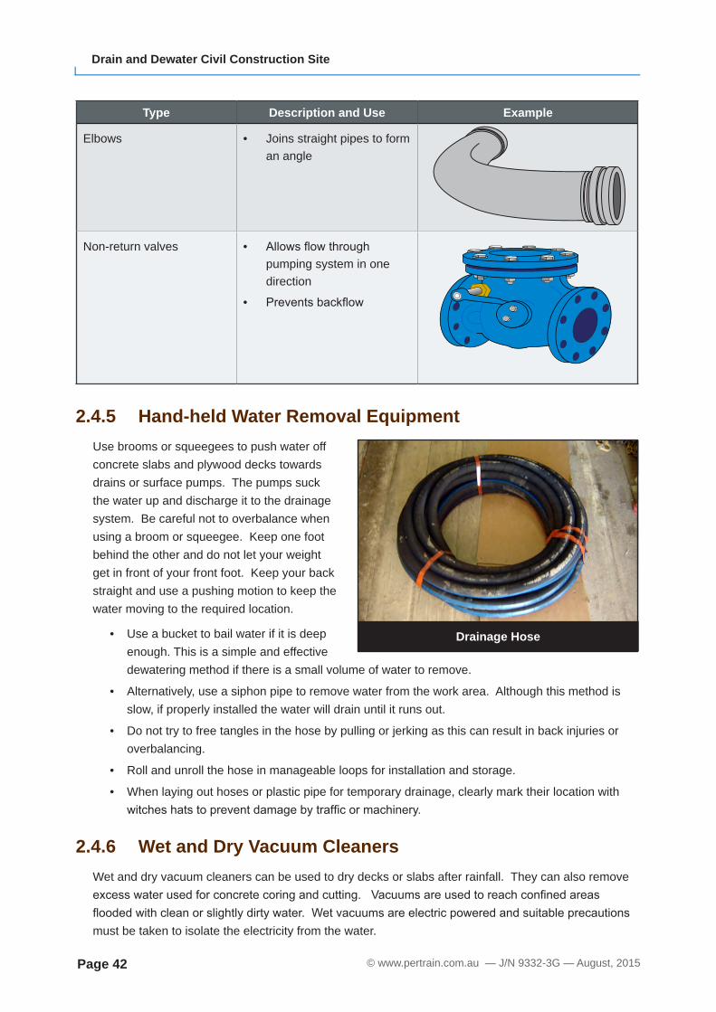
Elbows • Joins straight pipes to form an angle
Non-return valves • Allowsflowthroughpumping system in one direction
• Preventsbackflow
2.4.5 Hand-held Water Removal EquipmentUse brooms or squeegees to push water off concrete slabs and plywood decks towards drains or surface pumps. The pumps suck the water up and discharge it to the drainage system. Be careful not to overbalance when using a broom or squeegee. Keep one foot behind the other and do not let your weight get in front of your front foot. Keep your back straight and use a pushing motion to keep the water moving to the required location.
• Use a bucket to bail water if it is deep enough. This is a simple and effective dewatering method if there is a small volume of water to remove.
• Alternatively, use a siphon pipe to remove water from the work area. Although this method is slow, if properly installed the water will drain until it runs out.
• Do not try to free tangles in the hose by pulling or jerking as this can result in back injuries or overbalancing.
• Roll and unroll the hose in manageable loops for installation and storage.
• When laying out hoses or plastic pipe for temporary drainage, clearly mark their location with witcheshatstopreventdamagebytrafficormachinery.
2.4.6 Wet and Dry Vacuum CleanersWet and dry vacuum cleaners can be used to dry decks or slabs after rainfall. They can also remove excesswaterusedforconcretecoringandcutting.Vacuumsareusedtoreachconfinedareasfloodedwithcleanorslightlydirtywater.Wetvacuumsareelectricpoweredandsuitableprecautionsmust be taken to isolate the electricity from the water.
Drainage Hose
August, 2015 — J/N 9332-3G — © www.pertrain.com.au Page 43
Section Two: Remove Water from Site
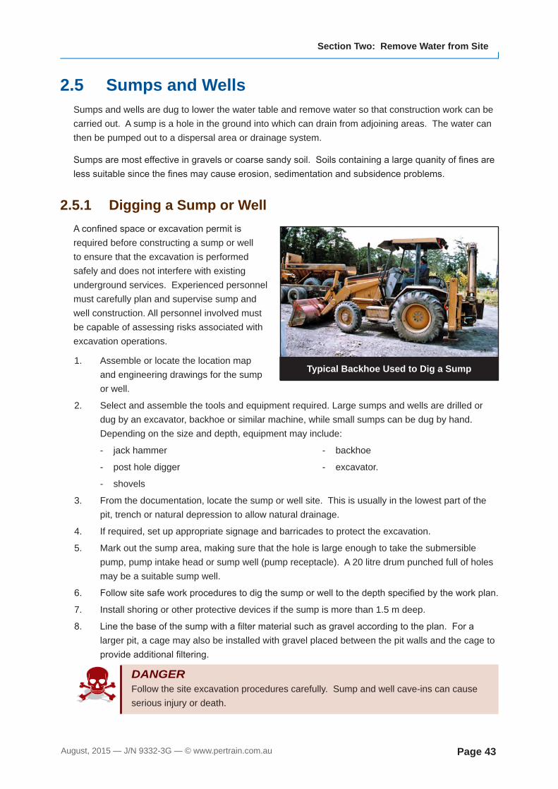
2.5 Sumps and WellsSumps and wells are dug to lower the water table and remove water so that construction work can be carried out. A sump is a hole in the ground into which can drain from adjoining areas. The water can then be pumped out to a dispersal area or drainage system.
Sumpsaremosteffectiveingravelsorcoarsesandysoil.Soilscontainingalargequanityoffinesarelesssuitablesincethefinesmaycauseerosion,sedimentationandsubsidenceproblems.
2.5.1 Digging a Sump or WellAconfinedspaceorexcavationpermitisrequired before constructing a sump or well to ensure that the excavation is performed safely and does not interfere with existing underground services. Experienced personnel must carefully plan and supervise sump and well construction. All personnel involved must be capable of assessing risks associated with excavation operations.
1. Assemble or locate the location map and engineering drawings for the sump or well.
2. Select and assemble the tools and equipment required. Large sumps and wells are drilled or dug by an excavator, backhoe or similar machine, while small sumps can be dug by hand. Depending on the size and depth, equipment may include:
- jack hammer
- post hole digger
- shovels
- backhoe
- excavator.
3. From the documentation, locate the sump or well site. This is usually in the lowest part of the pit, trench or natural depression to allow natural drainage.
4. If required, set up appropriate signage and barricades to protect the excavation.
5. Mark out the sump area, making sure that the hole is large enough to take the submersible pump, pump intake head or sump well (pump receptacle). A 20 litre drum punched full of holes may be a suitable sump well.
6. Followsitesafeworkprocedurestodigthesumporwelltothedepthspecifiedbytheworkplan.
7. Install shoring or other protective devices if the sump is more than 1.5 m deep.
8. Linethebaseofthesumpwithafiltermaterialsuchasgravelaccordingtotheplan.Foralarger pit, a cage may also be installed with gravel placed between the pit walls and the cage to provideadditionalfiltering.
DANGER Follow the site excavation procedures carefully. Sump and well cave-ins can cause serious injury or death.
Typical Backhoe Used to Dig a Sump

© www.pertrain.com.au — J/N 9332-3G — August, 2015Page 44
Drain and Dewater Civil Construction Site
2.5.2 Multiple SumpsMultiple sumps and trenches are an effective method to drain a construction site water table. Place sumps at the corners or along the sides of the work area in wet ground or below the site water table.
Grade the soil surface toward the sumps/trenches and install submersible or surface pumps as appropriate for the site.
2.5.3 Borehole WellsBorehole wells are dug on large construction sites to lower the water table, especially where removal of a high volume of water is necessary. A series of borehole wells is dug below the water table across the site, and pumps are installed in the boreholes to draw down the water table.
Although wells can lower the water table by 4 to 6 metres under ideal conditions, the system is not suitable in all soil types. Unsuitable ground conditions include:
• areas of clay where the seepage is too small for the system to be effective
• silty or clay layers in sand may cause difficultiesindrawingwaterfromthewatertable
• areasofheavyflowinpermeableground,suchasgravel.Thewellsinthisinstancewouldneedto be close together and therefore make the method impractical.
2.5.4 DischargeThe Environmental Management Plan determines how sump and well water is treated before it is discharged to the stormwater system or natural drainages. Generally, discharge sediment-laden water toasettlingpondtoensurethatclearwaterentersstreamsorstormwaterflow.
High Water Table Causes Influx ofGround Water into the Trench
Water pipedaway
Flow Lines
Reduced GroundWater Level
OriginalWater Level
Sump
© w
ww
.per
train
.com
.au
Borehole and Pump Arrangementto Lower the Water Table
Wellpoints
ReducedWater Level
PumpDrawdownat Trench
© w
ww
.per
train
.com
.au

© www.pertrain.com.au — J/N 9332-3G — August, 2015Page 58
Drain and Dewater Civil Construction Site
Terms and AcronymsThe following are terms commonly used on some sites. Space is provided over the page for you to add terms and acronyms common to your site.
Term Meaning
Job Safety Analysis (JSA)
A risk management process that focuses on job tasks to identify potential hazards, assess risks and determine suitable controls to manage risks.
A JSA:
• must be completed before a high risk task commences
• is a written record that could be used in a court of law if a serious incident occurs in the workplace
• must be signed off by all parties who have responsibility for the work to be performed under the JSA.
Also called a Job Step Analysis (JSA), Job Safety and Environment Analysis (JSEA) or Job Hazard Analysis (JHA).
Permits Permits are required for certain jobs that have high risk potential. Some permits used on work sites include Hot Work Permit, Permit to Dig/Penetrate,ConfinedSpaceandWorkatHeightsPermits.
Site Procedures Site procedures are documented ways of working to achieve an acceptable level of risk. A procedure can be a Standard Work Procedure (SWP), Safe Work Instruction (SWI) or Standard Operating Procedure (SOP). Procedures are a legal requirement and outline the workplace method and processes for carrying out tasks safely and in an environmentally sustainable way. Procedures are developed after consultation with workers and are monitored and amended as required. Procedures contain detailed information such as:
• a description of the task
• a list of tools and equipment required
• informationonidentifiedhazardsassociatedwiththetask
• risk controls, including training requirements
• sequentialstepstoperformthetasksafelyandefficiently
• references to applicable workplace health and safety acts, regulations and policies.
Safe Work Method Statement (SWMS)
A SWMS documents a process for identifying and controlling health and safety hazards and risks. A SWMS must be prepared for all high-risk activities and contains detailed information such as:
• the type of high risk work to be performed
• associated hazards and risks
• risk management controls to be put in place
• how the risk controls will be implemented, monitored and reviewed.

August, 2015 — J/N 9332-3G — © www.pertrain.com.au Page 59
Section Three: Maintenance and Clean-up
Term Meaning
NOTE If you hear a term or acronym that you are unfamiliar with, ask your supervisor or co-workers what it means and add it to this list.
P +61 7 5445 2233 F +61 7 5445 2245
PostalPO Box 713
Buderim Qld 4556Australia
Office8 Ure Court
Buderim Qld 4556Australia
Copyright © 2014 Pertrain Pty Limited. All rights reserved.
www.pertrain.com.au