Tank Computer NRM 571
90
BA1005N/08/en/04.08 70105562 Software-Version: 4.01.03 Operating Instructions Tank Computer NRM 571 Multi-function receiver for remote gauging system (Max.40 sensors connectable)
-
Upload
khangminh22 -
Category
Documents
-
view
1 -
download
0
Transcript of Tank Computer NRM 571

BA1005N/08/en/04.08
70105562
Software-Version: 4.01.03
Operating Instructions
Tank Computer NRM 571
Multi-function receiver for remote gauging system
(Max.40 sensors connectable)

Tank Computer NRM 571
2 Endress+Hauser
Function and system design
Fig.1 Tank Computer NRM 57x in Endress+Hauser tank gauge device layout
Measuring SystemThe Tank Computer NRM 571 is a uniquely featured Endress+Hauser tank gauge interface unit designed for
relatively small to medium sized tank farms with connectivity to up to 40 tank sensors.
Tank information (level, temperature, density, etc.) are carried on the field bus via the Proservo NMS 53x or
Tank Side Monitor NRF 590 to the NRM in the control room. Then, the measured and processed information
within the NRM are transmitted to the desired host program
ENDRESS+HAUSER
NRM571GAUGE SET UP
E
ALARM ACK
TANK SELECTION
1 2 3
4 5 6
7 8 9
0 SELECT RESET
LEVEL
INT.FACE1
INT.FACE2
BOTTOM
UP
STOP
DEN1
DEN2
DEN3
SELECT GO
AC
AC
E
1
3
4
2
5
6
7
8
HOST HART
FUSE
2A
Front panel
Power Supply
ToF Tool
Back Panel
HOST
To host program
- Fuels Manager
- NXS310
- OPC server
- other MODBUS host
V1 Bus, bi-serial pulse
max. 40tanks (4 x 10 tanks / loop)
multi-drop HART loop multi-drop HART loop
2 more slave
HART devices4 more slave
HART devicesProservo
NMS53xPromonitor
NRF 560
Prothermo
NMT 539
Prothermo
NMT 539
Tank Side Monitor
NRF 590
Micropilot
FMR 533
Function and system design

Tank Computer NRM 571
Endress+Hauser 3
Table of Contents
Safety instructions . . . . . . . . . . . . . . . . . . . . 4
1.1 Designated use . . . . . . . . . . . . . . . . . . . . . . . . . . . . 4
1.2 Installation, commissioning and operation . . . . . . . . 4
1.3 Note for Handing . . . . . . . . . . . . . . . . . . . . . . . . . . 4
1.4 Operational safety . . . . . . . . . . . . . . . . . . . . . . . . . . 4
1.5 Return . . . . . . . . . . . . . . . . . . . . . . . . . . . . . . . . . . . 5
1.6 Disposal . . . . . . . . . . . . . . . . . . . . . . . . . . . . . . . . . 5
1.7 Software history . . . . . . . . . . . . . . . . . . . . . . . . . . . 5
1.8 Contact addresses of Endress+Hauser . . . . . . . . . . . 5
1.9 Notes on safety conventions and symbols . . . . . . . . . 6
Identification . . . . . . . . . . . . . . . . . . . . . . . . 7
2.1 Nameplate . . . . . . . . . . . . . . . . . . . . . . . . . . . . . . . 7
2.2 Product structure . . . . . . . . . . . . . . . . . . . . . . . . . . 8
2.3 Scope of delivery . . . . . . . . . . . . . . . . . . . . . . . . . . . 8
2.4 Operating Mnual (BA 005N, this booklet) . . . . . . . . 8
2.5 Certificates and Approvals . . . . . . . . . . . . . . . . . . . . 8
2.6 Registered trademark . . . . . . . . . . . . . . . . . . . . . . . . 8
Installation . . . . . . . . . . . . . . . . . . . . . . . . . . 9
3.1 Incoming acceptance, transport, storage . . . . . . . . . . 9
3.2 Installation Conditions . . . . . . . . . . . . . . . . . . . . . . . 9
3.3 Electrical connection . . . . . . . . . . . . . . . . . . . . . . . 10
3.4 Device Connections . . . . . . . . . . . . . . . . . . . . . . . 11
3.5 Wiring . . . . . . . . . . . . . . . . . . . . . . . . . . . . . . . . . 12
Operation . . . . . . . . . . . . . . . . . . . . . . . . . . 13
4.1 Preparing for Operation . . . . . . . . . . . . . . . . . . . . . 13
4.2 Operation . . . . . . . . . . . . . . . . . . . . . . . . . . . . . . . 13
Matrix Table . . . . . . . . . . . . . . . . . . . . . . . 20
Initial Adjustment . . . . . . . . . . . . . . . . . . . 26
6.1 Basic Setting Items and Methods . . . . . . . . . . . . . . 26
6.2 Communication Setting with Sensor . . . . . . . . . . . 29
6.3 Communication Setting with Host . . . . . . . . . . . . . 30
Other Functions . . . . . . . . . . . . . . . . . . . . . 31
7.1 FreeScan List & V1 Communucation specifications 31
Troubleshooting . . . . . . . . . . . . . . . . . . . . . 36
8.1 When setting the same tank No. to different pages . 36
8.2 Tank Data Base of NRM . . . . . . . . . . . . . . . . . . . . . 37
8.3 Development and Spare parts . . . . . . . . . . . . . . . . . 38
Appendix A . . . . . . . . . . . . . . . . . . . . . . . . . 39
9.1 Matrix Details . . . . . . . . . . . . . . . . . . . . . . . . . . . . 39
Appendix B . . . . . . . . . . . . . . . . . . . . . . . . . 53
10.1 Specification for Arithmetic Calculations . . . . . . . . 53
Appendix C . . . . . . . . . . . . . . . . . . . . . . . . . 64
11.1 Specifications for Host Communication . . . . . . . . . 64
Appendix D . . . . . . . . . . . . . . . . . . . . . . . . . 80
12.1 Alarm Processing . . . . . . . . . . . . . . . . . . . . . . . . . . 80
Appendix E . . . . . . . . . . . . . . . . . . . . . . . . . 84
13.1 Value Allowance & Error Retry Setting [372]-[375] . 84
13.2 Error Types . . . . . . . . . . . . . . . . . . . . . . . . . . . . . . 84
13.3 Tank Number List . . . . . . . . . . . . . . . . . . . . . . . . . 86
Table of Contents

Tank Computer NRM 571
4 Endress+Hauser
1 Safety instructions
1.1 Designated use
The Tank Computer NRM 571 is a unique intelligent interface unit, combined with data display, calculation
and gauge operating functions, to meet the tough demands of today's tank gauging requirements. Unlike a
conventional loop connection field interface unit, the Tank Computer NRM 571 is able to display the measured
values of level, interface level, density, pressure and water dip along with gauge status and alarm signals on the
integrated LCD display.
The NRM 571 can be connected to up to 40 sensors via V1 bi-serial communication in order to collect
measured values. These data can be directly transmitted and /or calculated by an integrated
conversion table within the Tank Computer to the host tank gauge program via RS 232C output.
With integrated front panel key pads, an operator can directly command gauges without an auxiliary
remote controller.
1.2 Installation, commissioning and operation
• Mounting, electrical installation, start-up and maintenance of the instrument may only be carried out by
trained personnel authorized by the operator of the facility.
• Personnel must absolutely and without fail read and understand this Operating Manual before carrying out
its instructions.
• The instrument may only be operated by personnel who are authorized and trained by the operator of the
facility. All instructions in this manual are to be observed without fail.
• The installer must make sure that the measuring system is correctly wired according to the wiring diagrams.
The measuring system is to be grounded.
• Please observe all provisions valid for your country and pertaining to the opening and repairing of electrical
devices.
1.3 Note for Handing
Power cable• Use cables recommended by Endress+Hauser.
• Be sure to ground the cables. For details, refer to "Device Connections" and "Installation"
Grounding• Do not remove a ground terminal while power is on.
• For details, refer to "Device Connections"
Handing of NRM• The Tank Computer NRM may be connected to the peripheral devices described in this manual. For use of
these devices, please refer to thire respective operating manuals. To avoid accidents and injury, operate this
device according to guidelines provided.
1.4 Operational safety
Hazardous areaMeasuring systems for use in hazardous environments are accompanied by separate "Ex documentation",
which is an integral part of this Operating Manual. Strict compliance with the installation instructions and
ratings as stated in this supplementary documentation is mandatory.
• Ensure that all personnel are suitably qualified.
• Observe the specifications in the certificate as well as national and local regulations.
1 Safety instructions

Tank Computer NRM 571
Endress+Hauser 5
FCC approval
This device complies with part 15 of the FCC Rules. Operation is subject to the following two conditions: (1)
This device may not cause harmful interference, and (2) this device must accept any interference received,
including interference that may cause undesired operation.
Power source
If the device uses a separate power supply, verify that the power supply voltage matches that of the device
before turning on power.
External connectionIf external connections are required, before connecting the device to an external control circuit, provide
protective grounding
Caution!Changes or modifications not expressly approved by the party responsible for compliance could void the user’s
authority to operate the equipment.
1.5 Return
The following procedures must be carried out before the NRM 57x is sent to Endress+Hauser for repair:
• Always enclose a duly completed "Declaration of Contamination" form. Only then can Endress +Hauser
transport, examine and repair a returned device.
• Enclose special handling instructions if necessary, for example, safety data sheet as per EN 91/155/EEC.
• Remove all residue which may be present. Pay special attention to the gasket grooves and crevices where
fluid may be present. This is especially important if the fluid is dangerous to health, e.g. corrosive, poisonous,
carcinogenic, radioactive, etc.
A copy of the “Declaration of Contamination” is included at the end of this operating manual.
Caution!
• No instrument should be sent back for repair without all dangerous material being completely removed first,
e.g. in scratches or diffused through plastic.
• Incomplete cleaning of the instrument may result in waste disposal or cause harm to personnel (burns, etc.).
Any costs arising from this will be charged to the operator of the instrument.
1.6 Disposal
In case of disposal, please separate the different components according to their material consistency.
1.7 Software history
1.8 Contact addresses of Endress+Hauser
The addresses of Endress+Hauser are given on the back cover of this operating manual. If you have any
questions, please do not hesitate to contact your E+H representative.
Software version / Date Software changes Documentation changes
V 2.00.00 1999 Original software.
V 4.01.03 06.2005 Density profile data from Proservo
removed Rackbus RS-485 input
configuration by ToF Tool (V 4.00)
1 Safety instructions

Tank Computer NRM 571
6 Endress+Hauser
1.9 Notes on safety conventions and symbols
In order to highlight safety-relevant or alternative operating procedures in the manual, the following
conventions have been used, each indicated by a corresponding symbol in the margin.
Safety conventions
Warning!
A warning highlights actions or procedures which, if not performed correctly, will lead to
personal injury, a safety hazard or destruction of the instrument
Caution!
Caution highlights actions or procedures which, if not performed correctly, may lead to
personal injury or incorrect functioning of the instrument
Note!
A note highlights actions or procedures which, if not performed correctly, may indirectly
affect operation or may lead to an instrument response which is not planned
Explosion protection
Device certified for use in explosion hazardous area
If the device has this symbol embossed on its name plate, it can be installed in an explosion
hazardous area
Explosion hazardous areas
Symbol used in drawings to indicate explosion hazardous areas.
– Devices located in and wiring entering areas with the designation
“explosion hazardous areas” must conform with the stated type of
protection
Safe area (non-explosion hazardous area)
Symbol used in drawings to indicate, if necessary, non-explosion hazardous areas.
– Devices located in safe areas still require a certificate if their outputs run into explosion
hazardous areas
Explosion protection
Direct voltage
A terminal to which or from which a direct current or voltage may be applied or supplied
Alternating voltage
A terminal to which or from which an alternating (sine-wave) current or voltage may be
applied or supplied
Grounded terminal
A grounded terminal, which as far as the operator is concerned, is already grounded by
means of an earth grounding system
Protective grounding (earth) terminal
A terminal which must be connected to earth ground prior to making any other
connection to the equipment
Equipotential connection (earth bonding)
A connection made to the plant grounding system which may be of type e.g. neutral star
or equipotential line according to national or company practice
EX
EX
1 Safety instructions

Tank Computer NRM 571
Endress+Hauser 7
2 Identification
2.1 Nameplate
TYPE SUPPLY SOURCESERIAL NO.
Endress + Hauser Japan Co.,Ltd.Made in Japan
NP-2532-1
2 Identification

Tank Computer NRM 571
8 Endress+Hauser
2.2 Product structure
2.3 Scope of delivery
• Instrument according to the version ordered
• ToF Tool (operating program)
• Operating manual (this manual)
2.4 Operating Manual (BA 005N, this booklet)
Describe the installation and commissioning of the Tank Computer NRM 57x .
2.5 Certificates and Approvals
CE mark, declaration of conformityThe instruments is designed to meet state-of-the-art safety requirements, has been tested and left the factory
in a condition in which it is safe to operate. The instrument complies with the applicable standards and
regulations and thus complies with the statutory requirements ofthe EG directives.
Endress+Hauser confirms the successful testing of the instrument by affixing to it the CE mark.
2.6 Registered trademark
HART®
Registered trademark of HART Communication Foundation, Austion, USA
ToF®
Registered trademark of the company Endress+Hauser GmbH+Co.KG, Maulburg, Germany
10 Model type
1 Panel mounted type
2 Desktop type
9 Special version
20 Power supply
1 AC85 ~ 264 V, 50/60Hz
9 Special version
30 Input
D V1 Serial Pluse (software ver. 4.x density Profile)
Y Special version
40 Output
A2 RS232C
Y Special version
50 Tank table
14 Basic version(100 points)
99 Special version
60 Tank data configuration
0 Not required (customer configuration)
1 Required (factory configuration)
NRM571- Complete product designation
2 Identification

Tank Computer NRM 571
Endress+Hauser 9
3 Installation
3.1 Incoming acceptance, transport, storage
3.1.1 Incoming acceptance
Check the packing and contents for any signs of damage.
Check the shipment, make sure nothing is missing and that the scope of supply matches your order.
3.1.2 Transport
Caution!
Follow the safety instructions and transport conditions for instruments of more than 4.5kg
3.1.3 Storage
Pack the measuring instrument so that it is protected against impacts for storage and transport. The original
packing material provides the optimum protection for this.
The permissible storage temperature is
• -10 to +60 °C
3.2 Installation Conditions
3.2.1 Dimensions, Weight
The Tank Computer NRM can be used as a rack mount type or desktop type depending on
installation conditions.
Fig 2. NRM dimension
WeightAbout 4.5 kg
ENDRESS+HAUSER NRM571
269
251
13
2.5
57
.1
22
311
3 Installation

Tank Computer NRM 571
10 Endress+Hauser
3.2.2 Panel Cut
Fig 3. NRM rack mount panel cut dimension
Note!
Thickness of rack mount installation panel shall be more than 2mm.
3.2.3 Installation environment
• Temperature : 0 to +50°C
• Humidity (no condensation) : 20 to 80 %
3.2.4 Electricity
• Input voltage : AC85 to 264V
• Input frequency : 50 / 60 Hz
• Power consumption : 13 VA
• Ground resistance : 10 ohm or less
3.3 Electrical connection
Terminal connections for power, field sensors, service tools and host CPU are located on the back panel of the
NRM.
Fig 4. NRM terminal connection
AC
ACE
1
34
2
5678
HOST HART
FUSE
2A
Field Bus connection
1st loop: 1 &2
2nd loop: 3 & 4
3rd loop: 5 & 6
4th loop: 7 & 8AC 85 ~ 264 VAC RS232C: to Host program
RS232C; to ToF Toolcable clampTerminal cover
3 Installation

Tank Computer NRM 571
Endress+Hauser 11
Fuse: 2A
Terminal cover: Be sure to install this cover after wiring.
Cable clamp: Fix a cable by its shielded portion.
Connector for host: RS 232C connector for host (D-SUB 25S)
Connector for HART maintenance: For maintenance (D-SUB 25S)
3.4 Device Connections
Prepare a separate power supply (AC) for sensors.
Warning!
Be sure to disconnect power to NRM before connecting the devices.
3.4.1 Sensor Communication
3.4.2 V1 Serial bus
Fig 5. V1 Communication
This connection diagram shows a configuration in which 40 sensors (NMS/ TGM/ TMD(MX/MS)) are con-
nected. As for sensor connection, refer to sensors’ operating manual for where cable should be connected.
There are 4 loops (1-2, 3-4, 5-6, 7-8). Each loop can connect 10 sensor maximum. Different types of signals
cannot be mixed but different types of sensors can exist in one loop.
Note!
If the sensor communication is DX, maximum of 1 sensor can be connected per loop.
Sensor type Signal Input Refer to
NMS, TGM, TMD, MX/MS V1 serial bus (V1, MDP) 3.4.2 V1 serial bus communication
1
2
loop0 +
+
-
TK1
NRM571
TB
3
4
5
6
7
8 +
-
TK2
+
-
TK3
+
-
TK11
+
-
TK12
+
-
TK13
+
-
TK21
+
-
TK22
+
-
TK23
+
-
TK31
+
-
TK32
+
-
TK33
-loop1 +
-loop2 +
-loop3 +
-
TK10
TK20
TK30
TK40
3 Installation

Tank Computer NRM 571
12 Endress+Hauser
3.4.3 Host Communication
3.4.3.1 RS232C CommunicationThe RS232C output (host communication) uses the connector (D-SUB25S)
3.4.4 Power Supply
Fig 6. Power Supply
3.5 Wiring
3.5.1 Shield cable Covering
Remove an extra 20 mm of the coating from the shield portion of the shield cable so that it can be fixed to the
rear panel using a cable clamp.
Fig 7. Shield cable covering
After the wirings are completed, install the attached terminal block cover.
commnucation Cable material Recomended
V1 serial bus (sensor to NRM) Twisted pair cable IEC 60708
Power cable (sheath)PVC = Polyvinyl Chloride
PE = Polyethylene
Use wires capable of withstanding
600V
AC
NRM571
TB
AC
E
AC85 - 264V
Ground resistance: 10 ohm or less
TB
Cable clamp
Shield portion
Vinyl covering
20mm
3 Installation

Tank Computer NRM 571
Endress+Hauser 13
4 Operation
4.1 Preparing for Operation
4.1.1 Check before power-on
Caution!
Before power-on please note the following:
• The input power voltage must be within the rated voltage range.
• The cable must be correctly connected to the terminal block.
• The fuse on the rear surface of the Tank Computer NRM 571 has the rated current (2A).
4.1.2 Power-on
Turn on the power to switch or breaker which is provided by user.
4.1.3 Power-off
Turn off the power switch provided by the user.
To disconnect, turn off the power for the Proservo NMS 53x and the Tank Gauging TGM 4000.
4.1.4 Initial Set Values
In the Tank Computer NRM 571, basic data required for operation is registered in the internal matrices. Since
default values are written to the attached matrices before shipment, these settings
should be changed according to the user’s needs.
For basic steps in setting these values, please refer to " Initial Adjustment".
4.2 Operation
Fig 8. NRM Front Panel2
GAUGE SET UP
EALARM
ACK
TANK SELECTION
1 2 3
4 5 6
7 8 9
0 SELECT RESET
LEVEL
INT.FACE1
INT.FACE2
BOTTOM
UP
STOPDEN1
DEN2
DEN3SELECT GO
TANK 0001LEVEL 12358 mmTEMP. 32.5 oCNET-V 34567.765 kl
Matrix Structure and Key Function
"ALARM ACK" key
Tank Selection
NRM 571
Gauge Operation
4 Operation

Tank Computer NRM 571
14 Endress+Hauser
4.2.1 Matrix Structure and Key Function
4.2.1.1 DisplayThe Tank Computer NRM 571 has an illuminated LCD that consists of four lines with 20 characters each.
During normal operation, it shows the level and the temperature of selected tank on the "HOME"
position. The display of HOME position will be explained in "4.2.1.3 HOME position".For the display of the other data and the setting of the parameters for operation, the Tank Computer NRM 571
uses a programming matrix.
4.2.1.2 Main Display
When power is turn on, Main Display appears. You can enter HOME Position by selecting tank number and
press [SELECT] key and go back to Main Display from HOME Position by using [RESET]key.
Note!
Please make sure to go back to Main Display after finishing the data display and setting.
4.2.1.3 HOME Position
HOME Position has two modes. One is maintenance mode , the other one is normal operation mode. NRM
571 is shipped in maintenance mode.
The mode can be swiched at [150] TANK CONDITION.
Data items to be displayed ( in the normal operation mode) can be change by providing settings in the
Programming Matrices. (Refer to "6.1.5 Custom HOME Position Setting")
Tank Computer NRM 571
TANK No. 0001
IN MAINTENANCE
4 Operation

Tank Computer NRM 571
Endress+Hauser 15
Fig. 9 Main display, HOME position & Proframming Matrix
4.2.1.4 Programming MatricesThe programming matrix consists of 6 matrix groups: one "STATIC" matrix group (G0) and 5 "dynamic"
matrices (G1-G5). Fig 8. below shows how the programming matrix is structured.
Fig. 10 Matrix structure
Tank Computer NRM 571
MAIN DISPLAY
TANK No. 0001
IN MAINTENANCE
TANK 0001LEVEL 12368mm TEMP. 32.5°CNET-V 34567.765 kl
HOME POSITION
Maintenancemode
Nomal operation mode
PAGE NO. 0MEASURED VALUE 1
>GROUP SELECT<
PROGRAMMING MATRIX
RESET
RESET
Please select Tank No.
and press
SELECT0
2 31
5 64
8 97
PAGE NO. 4TANK DATA 1
>GROUP SELECT<
PAGE: 3 TANK: 4
NORMAL OPERATIONTANK CONDITION
Press button for 3 sec.
PAGE: 3 TANK: 4
MAINTENANCETANK CONDITION
SELECT button.
+ +Press button 5 times
+ -
Press button for 3 sec.
H
V
LCD ( HOME position)
If you touch on the matrix for 3 sec. or longer, you will return to the HOME position.
MATRIX OF GVH [030]
1 VOL. CALCULATION2 OUTPUT3 SYSTEM DATA4 TANK PROFILE DATA5 I/F PROFILE DATA
0 STATIC MATRIX (G0)
0 1 2 3 4 5 6 7 8 9
0
1
2
3
4
5
6
7
8
9
4
4
4
4
5 I/F PROFILE DATA
1 VOL.CALCULATION
2 OUTPUT (G2)
3 SYSTEM DATA (G3)
4 TANK PROFILE DATA
9876
4 Operation

Tank Computer NRM 571
16 Endress+Hauser
STATIC MATRIX (G0), GVH[000]-[039]Row 0...3 of the programming matrix are called the static matrix.
Major Function: stores measured data (level, temperature, volume, etc.)
Access: available at any time
DYNAMIC MATRICES (G1-G5)Row 4...9 of the programming matrix exist on 5 diffreent dynamic matrices. These matrix groups are labelled
as follows. Access to a matrix is available only when it is seleced at "[030] MATRIX OF".
• VOl. CALCULATION (G1) GVH [140] - [199]
Function : stores registered data such as tank tables related to arithmetic operation.
• OUTPUT (G2) GVH [240] - [299]
Function : stores registered data for alarms.
• SYSTEM [G3] GVH [340] - [399]
Function : stores registered data related to NRM system data.
• TANK PROFILE [G4] GVH [440] - [495]
Function : stores registered data related to Tank Profile data.
• I/F PROFILE [G5] GVH [550] - [595]
Function : stores registered data related to I/F Profile data.
4.2.1.5 Matrix Location CodeThroughout this manual, locations in the matrix are referred to in the format.
[GVH] (Group, Vertical, Horizontal)
For Example: [022]
Fig. 11 STATIC MATRIX Structure
The matrix location [022] for example, refers to the Static Matrix(G0), Alarm Status (V2), Alarm Data (H2).
The Primary Label Column in the matrix does not have a Horizontal reference.
Therefore, MEASURED VALUE 1 is referred to as matrix location [00_].
[STATIC MATRIX] (G0)
Primary
Label
H0 H1 H2 H3
MEASURED V 0 mm 0.0°C 0.000 kl 0.000 kl
VALUE 1 0
MEASURE D LEVEL LIQUID TEMP. GROSS VOLUME NET VOLUME
MEASURED V LEVEL 0 mm 00000000 NOT DEFINED
VALUE 2 1 UP,STOP,BOTTOM
LEVEL, UPPER INT.
LEV. ETC.
OPERATING MODE BOTTOM LEVEL STATUS DATA GAUGE STATUS
ALARM V NN NN NN NN NN NN NN NN
STATUS 2
ALARM DATA 1 ALARM DATA 2 LAST ALARM DATA V1 COMM. ERR
GVH [ 0 2 2 ]Vertical
GroupHorizontal
4 Operation

Tank Computer NRM 571
Endress+Hauser 17
4.2.1.6 Functions of the "GAUGE SET UP" keys
The individual matrix groups, function groups, and functions within the programming matrix can be selected
by three GAUGE SET UP key [E], [-] and [+].
The access code is to ensure the confidentiality of the data setup or data change.
Proper access code input : "EDITING ENABLE"
Improper access code input : "EDITING LOCKED"
will be shown on the screen.
Note!
Once set, the access code is retained. Thus, when setting is finished, set the access code back to "0".
Access code level : Refer to "Appendix A Matrix Details" - colume "Access code"
Access code setting : Refer to "6. 1 Access Code Setting"
4.2.2 Tank Selection
The keys can select a tank using ten keys of [0] to [9] and
the [SELECT] and [RESET] keys. To select a tank number,
enter the number registered in the NRM matrix and press
the [SELECT] key. To delete the data, press the [RESET]
key.
Fig. 12 Tank Selection
EAccess to the programming matrix
Return to the HOME position
(pressing the key for 3 sec. or more)
Moving horizontally within a function group to select functions
Saving parameters or access code
Moving vertically to select function groups
Selecting or setting parameter
setting access code
Key Functions
4 Operation

Tank Computer NRM 571
18 Endress+Hauser
4.2.3 Gauge Operation
The 2 keys enable gauge operation
for the selected NMS/TGM level
gauge.
Gauge operation is available only
when the corresponding single tank
is selected.
Fig. 13 Gauge Operation
4.2.3.1 Operation
Fig. 14 Operation
Note!
Gauge can also be operated by selecting operation type in [010] OPERATING MODE.
UP LEVEL
STOP
DEN1
DEN2
DEN3
INT.FACE1
INT.FACE2
BOTTOM
SELECT GO
UP LEVEL
STOPDEN1
DEN2
DEN3
INT.FACE1
INT.FACE2
BOTTOM
SELECT GO
UP LEVELSTOP
DEN1
DEN2
DEN3
INT.FACE1
INT.FACE2
BOTTOM
SELECT GO
Press [SELECT] to make “ LEVEL” LED
flash.
Press [SELECT] again to shift the flashing
display to the “UP” LED.
In the same way, press the [SELECT] key
to move to the LED corresponding to the
desired level gauge operation item.
UP LEVELSTOP
DEN1
DEN2
DEN3
INT.FACE1
INT.FACE2
BOTTOM
SELECT GO
When the operation item is determined,
press [GO].
Operation of the level gauge is
completed. Since the LEDs show level
gauge condition signals from the sensor,
there is a small lag in displaying
information
Commands for level gauge operation
using [SELECT] are changed in the
following order.
[LEVEL]- [UP]- [STOP]- [DEN.1]- [DEN.2]-
[DEN.3]-[INT.FACE1]- [INT. FACE2]-
[BOTTOM]-return[LEVEL]
4 Operation

Tank Computer NRM 571
Endress+Hauser 19
4.2.3.2 Difference in Operation
Operation items differ depending on sensor type and communication method.
OK : Enabled
* : Depends on SW version
V1 : V1 serial bus communication
MDP : Old bi-directional 2 wire communication
Note!
TMD/MX/MS transmitters : All operations not available
4.2.3.3 "ALARM ACK" key
If a level, temperature, or volume alarm occurs, the buzzer inside
NRM is activated. Press "ALARM ACK" key to turn off the buzzer.
If multiple alarms are simultaneously set off, you can use this key
to delete the alarm display while confirming alarms one by one. In
addition, you can use this key to reconfirm alarm data for the tank,
which is now in alarm condition.
Fig. 15 "ALARM ACK" key
Sensor &
Protocol
Operation
Sensor type
NMS 53x TGM
V1 MDP V1 MDP
LEVEL OK OK OK OK
UP OK OK OK OK
STOP OK OK OK OK
DEN.1 OK *
DEN.2 OK
DEN.3 OK
INT.FACE1 OK *
INT.FACE2 OK
BOTTOM OK
4 Operation

Tank Computer NRM 571
20 Endress+Hauser
5 Matrix Table
NR
M571 M
AT
RIX
[STA
TIC
MA
TRIX
] (G
0)
Pri
mar
yLab
elH
0H
1H
2H
3H
4H
5H
6H
7H
8H
9
MEA
SUR
ED
V0 m
m0.0
°C0.0
00 k
l0.0
00 k
l0.0
00 t
0.0
000 g
/cm
31.0
000 g
/cm
30 m
m0.0
°C1.0
00 k
g/cm
2
V
ALU
E 1
0
MEA
SU
RE
D L
EV
EL
LIQ
UID
TEM
P.
GR
OSS V
OLU
ME
NET
VO
LU
ME
MA
SS
DEN
SIT
YR
EF.
DEN
SIT
YW
AT
ER
LEV
EL
GA
S T
EM
P.
GA
S P
RESSU
RE
MEA
SUR
ED
VLEV
EL
0 m
m00000000
NO
T D
EFIN
ED
BA
LA
NC
ED
0 m
m0.0
000 g
/cm
30.0
000 g
/cm
3
V
ALU
E 2
1U
P,S
TO
P,B
OT
TO
M
LEV
EL,
UPPER
IN
T.
LEV
. ET
C.
OPER
AT
ING
MO
DE
BO
TT
OM
LEV
EL
ST
AT
US D
AT
AG
AU
GE S
TA
TU
SB
ALA
NC
.ST
AT
US
MID
D.I
NT
ER
F.L
EV
.M
IDD
LE D
EN
SIT
YD
EN
SIT
Y B
OT
TO
M
ALA
RM
V N
N
NN
N
N
NN
NN
N
N
NN
N
N4.X
X
ST
AT
US
2
ALA
RM
DA
TA
1A
LA
RM
DA
TA
2LA
ST
ALA
RM
DA
TA
V1 C
OM
M.
ER
RLA
ST
CO
MM
. ER
RSEN
SO
R A
LA
RM
SEN
SO
R E
RR
OR
SO
FT
WA
RE V
ER
.
MA
TR
IX O
FV
VO
L.C
ALC
ULA
TIO
N0
OFF
00
3O
UT
PU
T0
- 39
ON
00
- 99
SYST
EM
DA
TA
TA
NK
PR
OFIL
E
I/F P
RO
FIL
E
MA
TR
IX O
FSELEC
T P
AG
EH
AR
T M
OD
EA
CC
ESS C
OD
E
DEFAU
LT
VALU
E
DIS
PLAY L
AB
EL
Dat
a Ran
ge/
REA
D O
NLY
V1 N
UM
CO
UN
T
5 Matrix Table

Tank Computer NRM 571
Endress+Hauser 21
[VO
L.C
ALC
ULA
TIO
N] (G
1)
Pri
mar
y Lab
elH
0H
1H
2H
3H
4H
5H
6H
7H
8H
9M
AN
UA
L D
AT
AV
-1:
Meas
ure
d d
ata
-100: M
easu
red d
ata
1.0
000 g
/cm
30 m
m0.0
°C1.0
00 k
g/cm
21.0
000 g
/cm
30.0
00 %
40
- 99999 m
m-9
9.9
- +
300.0
°C0.0
001
-9.9
999
0-
99999 m
m-9
9.9
- +
300.0
999.9
99
-0.0
001
-9.9
999
0–
99.9
99 %
g/cm
3-1:
Meas
ure
d d
ata
+99.9
99 k
g/cm
2g/cm
3
-1000:M
eas
ure
d d
ata
-100:
Meas
ure
d d
ata
-1000:
Meas
ure
d d
ata
MA
NU
AL L
EV
EL
MA
NU
AL L
IQ.T
EM
P.
MA
NU
AL D
EN
SIT
YM
AN
U.W
AT
ER
LEV
MA
NU
.GA
ST
EM
P.
MA
NU
. G
AS P
RESS.
MA
NU
.GA
S D
EN
S.
WA
TER
CO
NT
EN
T
TA
NK
DA
TA
1V
MA
INT
EN
AN
CE
NM
S1
V1
0001
- 0039
000
– 3
99
0999999.9
99 k
l0 m
m0.0
00 k
l1.0
000 g
/cm
3
5N
OR
MA
L O
PER
AT
IN
MS2
MD
P0000
- 9999
XYY
0-
99
0.0
00
-0
- 99999 m
m-9
99.9
99
- 9
99.9
99 k
l0.0
001
- 9.9
999
NM
S3
V1
X :
LO
OP N
o.
+999999.9
99 k
lg/cm
3
TG
MT
SM
_V
1YY :
AD
DR
ESS
TM
DT
GM
_V
100
-09
TA
NK
CO
ND
ITIO
NSEN
SO
R T
YPE
SIG
NA
L I
NPU
TT
AN
K N
UM
BER
PO
LLIN
G A
DD
RESS
PU
LSE W
IDT
HT
AN
K C
APA
CIT
YT
AN
KLEV
.CO
RR
EC
VO
L.
CO
RR
EC
TIO
DEN
SIT
Y C
AR
IBR
.
TA
NK
DA
TA
2V
0.0
00000 t
0 m
m0.0
°C0.0
0000000
0.0
0000000
0.0
°C0.0
00
PO
INT
ER
No.0
0 m
m0.0
00 k
l
60.0
00000
-0
– 9
9999 m
m-9
9.9
- +
300
°C0
-±
9.9
9999999
0-±9.9
9999999
99.9
- +
300
°C0.0
00
– 9
9.9
99
PO
INT
ER
: 0
- 29
0-
99999 m
m0.0
00 -
999.9
99999 t
+999.9
99 k
l
FLO
AT
RO
OFW
EIG
HFLO
AT
RO
OF L
EV
.V
CF R
EF.T
EM
P.
VC
FFO
R C
HEM
ICA
LT
AN
KEX
PA
N.C
OEF
EX
PA
N.R
EF.T
EM
P.
MO
L W
EIG
HT
WA
TER
LEV
. T
AB
LST
RA
PW
AT
ER
LEV
.ST
RA
PW
AT
ER
ST
RA
PPIN
GV
PO
INT
ER
No.0
0 m
m0.0
00 k
l00000.
0.0
00 k
l
T
AB
LE
7PO
INT
ER
: 0
– 6
30
- 99999 m
m0.0
00
-0
- 99999
x10-8
kl
0.0
00
- 99.9
99 k
l0
- 99999
x10-8
kl
999999.9
99 k
l
TA
NK
TA
BLE
ST
RA
PPIN
G L
EV
EL
ST
R.V
OL.U
P.D
GT
ST
R.V
OL.L
O.D
GT
NET
AR
EA
UP.D
GT
NET
AR
EA
LO
.DG
T
ST
V0.0
000
0 .
10^
-90.0
00
0.
10^
-8
00.
10^
-6
00 .
10^
-5
TA
NK
TA
BLE
8-9
.9999
- 9.9
999
0-±99999
-999.9
99
-0
-±
99999
-9999
- +
9999
0-±999999
-99999
- +
99999
0-±
99999
+999.9
99
ST
CO
NST
AN
T P
1ST
CO
NST
AN
T P
2ST
CO
NST
AN
T Q
n1
ST
CO
NST
AN
T Q
n2
ST
CO
NST
AN
T R
n1
ST
CO
NST
AN
T R
n2
ST
CO
NST
AN
T S
n1
ST
CO
NST
AN
T S
n2
CA
LC
ULA
TIO
NV
CR
TN
ON
EN
ON
EN
ON
EN
ON
EM
ET
HO
D-1
NO
NE
API
NO
NE
9FR
TM
ET
HO
D-1
GR
OSS V
OL.
GR
OSS V
OL.
AST
M(T
54A
,T54B
,M
ET
HO
D-2
MET
HO
D-1
JAPA
NESE
53A
ST
MET
HO
D-2
NET
VO
L.
NET
VO
L.
54,5
5,6
X,T
2,
MET
HO
D-3
MET
HO
D-2
53B
MET
HO
D-4
MET
HO
D-3
53D
XYLEN
E,e
tc.)
MET
HO
D-4
53
TA
NK
TYPE
GR
OSSV
OL.C
ALC
USU
BT
R.W
AT
ER
LEV
.SU
BT
R.W
AT
ER
CO
NET
VO
L.C
ALC
.TA
BN
ET
VO
L.C
ALC
ULA
TM
ASSC
ALC
ULA
TIO
VO
LU
ME D
AT
AD
15.C
ALC
.TA
B
kl
0.0
00 k
l
5 Matrix Table

Tank Computer NRM 571
22 Endress+Hauser
[OU
TPU
T] (G
2)
Pri
mar
yLab
elH
0H
1H
2H
3H
4H
5H
6H
7H
8H
9
ALA
RM
VPO
INT
ER
No.0
NO
NE
SK
IP I
N D
EFA
ULT
SK
IP I
N D
EFA
ULT
ASS
IGN
MEN
T4
PO
INT
ER
: 0
- 7
LEV
EL,T
EM
P.
DEPEN
D O
N E
AC
HLO
W A
LA
RM
GR
OSS V
OL.,
NET
UN
ITH
IGH
ALA
RM
VO
L.,
MA
SS
ALA
RM
SELEC
TIO
NA
LA
RM
ASIG
NM
EN
TSET
PO
INT
ALA
RM
ASSIG
NM
EN
V 5 V 6 V 7 8 V 9V
5 Matrix Table

Tank Computer NRM 571
Endress+Hauser 23
[SYSTEM
DA
TA
] (G
3)
Pri
mar
yLab
elH
0H
1H
2H
3H
4H
5H
6H
7H
8H
9
CLO
CK
V00/01/01
00:0
000
01
01
00
00
00
NO
RESET
4YY/M
M/D
D00
– 9
901
- 12
01
– 31
00
- 23
00
– 5
900
- 59
RESET
CU
RR
.TA
NK
CU
RR
.TA
NK
RESET
ALL T
AN
KS
CLO
CK
YEA
R S
ET
TIN
GM
ON
TH
SET
TIN
GD
AT
E S
ET
TIN
GH
OU
R S
ET
TIN
GM
INU
TE S
ET
TIN
GSEC
ON
D S
ET
TIN
GD
EFA
ULT
VA
LU
ES
CO
MM
UN
ICA
TIO
NV
NO
NE
19200 B
PS
7 B
ITS
NO
NE
ON
E S
TO
P B
IT0 m
m0.0
°C0.0
00 k
l0.0
00 t
1
5M
DP
2400 B
PS
8 B
ITS
EV
EN
TW
OST
OP B
ITS
0-
999 m
m0.0
– 9
9.9
°C0.0
00
- 99.9
99 k
l0.0
00
- 99.9
99 t
1-
247
BB
B4800 B
PS
OD
D
9600 B
PS
MO
DB
US (
5 m
ap )
CO
MM
UN
ICA
TIO
NB
AU
D R
AT
ED
AT
A L
EN
GT
HPA
RIT
YST
OP B
ITLEV
.ALA
RM
HYST
.T
EM
P.A
LA
RM
HYST
.V
OL.A
LA
RM
HYS
T.
MA
SS A
LA
RM
HYST
.M
OD
BU
S A
DD
RESS
DEV
ICE N
AM
EV
EN
GLIS
H[][][][][][][][][][]
14.X
X1
OFF
6JA
PA
NESE
0-2
10
– 9
99
0- 15
ON
21:
LC
D C
HEC
K
LA
NG
UA
GE
LC
D C
ON
TR
AST
BA
CK
LIG
HT
TIM
EM
PU
1 R
OM
Vers
ion
HA
RT
Poll
ing
Addre
ssSO
FT
RESET
ER
RO
R I
NFO
.V
NO
ER
RO
RN
O E
RR
OR
200 m
m10.0
°C5
5
7V
1/IF
CPU
ER
RO
RM
AIN
CPU
ER
RO
R0
- 999 m
m0
– 9
9.9
°C0
- 999
0– 9
99
MA
IN C
PU
ER
RO
Retc
.
etc
.
SYST
EM
ER
RO
RLA
ST
SYST
EM
ER
R.
LEV
.C
HA
NG
.ALLO
TEM
P.C
HA
NG
.ALLO
LEV
.RET
RY N
OT
EM
P.R
ET
RY N
O
SYST
EM
DA
TA
V6 D
IGIT
Round 0
.1°C
X.X
XX
X00
01
02
810^
-1m
m R
OU
ND
Round 0
.25
°CX
.XX
XX
XX
XY
XY
XY
10^
-1m
m D
ISC
AR
DR
ound 0
.5°C
X:
V
posi
tion
X:
V
posi
tion
X:
V
posi
tion
Y:
H
posi
tion
Y:
H
posi
tion
Y:
H
posi
tion
LEV
ELD
AT
AR
OU
ND
TEM
P.D
AT
AR
OU
ND
V.C
.F.
DIG
ITS
DIS
PLA
Y L
INE 2
DIS
PLA
Y L
INE 3
DIS
PLA
Y L
INE 4
SYST
EM
UN
ITS
Vm
m°C
Kl
Met-to
nkg/cm
2g/cm
3
9m
m°C
Kl
Met-
ton
kg/cm
2g/cm
3
LEN
GT
HU
NIT
TEM
PER
AT
UR
EV
OLU
ME U
NIT
MA
SS U
NIT
PR
ESSU
RE U
NIT
DEN
SIT
Y U
NIT
5 Matrix Table

Tank Computer NRM 571
24 Endress+Hauser
[Tan
k P
rofi
le]
(G4
)
Pri
mar
y L
abel
H0
H1
H2
H3
H4
H5
H6
H7
H8
H9
TA
NK
PR
OF
ILE
VS
PO
T2
0.0
mm
99
.9 m
m0
min
0 m
in0
min
4T
AN
K P
RO
FIL
E2
- 1
60
– 9
99
99
.90
.0–
99
.90
- 3
10
- 3
10
– 3
1
I/F
PR
OF
ILE
MA
N.
I/F
PR
OF
IL
DE
NSIT
Y M
ES.
SE
LM
ES.
PO
INT
SE
LEC
I/F M
AN
U.
LE
VE
LL
EV
EL S
TB
CN
F R
AD
ISP
HO
LD
TIM
EH
OL
D T
IME I
N L
IQU
OP
E.
ST
NB
Y T
IME
TA
NK
PR
OF
ILE
VD
D/
HH
/M
M0
.00
00 g
/cm
30
.0°C
OP
E.
STS
5
OP
E. ST
AT
US
LE
VE
L C
ON
DIT
ION
OPE
.TIM
EA
VE
RA
GE D
EN
SIT
YA
VE
RA
GE
TE
MP
.
DE
NSI
TY
1
-10
V0.0
00
0 g
/cm
30
.00
00
g/
cm3
0.0
00
0 g
/cm
30
.00
00
g/cm
30
.000
0 g
/cm
30.0
00
0 g
/cm
30
.000
0 g
/cm
30
.000
0 g
/cm
30
.00
00
g/cm
30
.00
00
g/
cm3
6
NO
.1
DEN
SIT
YN
O.2
D
EN
SIT
YN
O.3
D
EN
SIT
YN
O.4
D
EN
SIT
YN
O.5
D
EN
SIT
YN
O.6
D
EN
SIT
YN
O.7
D
EN
SIT
YN
O.8
D
EN
SIT
YN
O.9
D
EN
SIT
YN
O.1
0 D
EN
SIT
Y
DE
NSI
TY
11
-16
V0
.00
00
g/cm
30
.000
0 g
/cm
30
.00
00
g/
cm3
0.0
00
0 g
/cm
30
.000
0 g
/cm
30
.00
00
g/cm
3
7
NO
.11 D
EN
SIT
YN
O.1
2 D
EN
SIT
YN
O.1
3 D
EN
SIT
YN
O.1
4 D
EN
SIT
YN
O.1
5 D
EN
SIT
YN
O.1
6 D
EN
SIT
Y
PO
SIT
ION
1
-10
V0
.0 m
m0
.0 m
m0
.0 m
m0.0
mm
0.0
mm
0.0
mm
0.0
mm
0.0
mm
0.0
mm
8
NO
.1 P
OSIT
ION
NO
.2
PO
SIT
ION
NO
.3
PO
SIT
ION
NO
.4
PO
SIT
ION
NO
.5
PO
SIT
ION
NO
.6
PO
SIT
ION
NO
.7
PO
SIT
ION
NO
.8
PO
SIT
ION
NO
.9
PO
SIT
ION
NO
.10
PO
SIT
ION
PO
SIT
ION
11
-16
V0
.0 m
m0
.0 m
m0
.0 m
m0
.0 m
m
9
NO
.11
PO
SIT
ION
NO
.12
PO
SIT
ION
NO
.13
PO
SIT
ION
NO
.14
PO
SIT
ION
NO
.15
PO
SIT
ION
NO
.16
PO
SIT
ION
5 Matrix Table

Tank Computer NRM 571
Endress+Hauser 25
[I/F P
rofi
le]
(G5)
Pri
mary
Label
H0
H1
H2
H3
H4
H5
H6
H7
H8
H9
I/F P
RO
FIL
EV 4
I/F P
RO
FIL
EV
DD
/H
H/M
M0.0
mm
0.0
000 g
/cm
30.0
°C
OPE.
STS
5
OPE.
ST
AT
US
LEV
EL C
ON
DIT
ION
OP.
TIM
EI/
F L
EV
EL
AV
ER
AG
E D
EN
SIT
YA
VER
AG
E T
EM
P.
DEN
SIT
Y
1-1
0V
0.0
000 g
/cm
30.0
000 g
/cm
30.0
000 g
/cm
30.0
000 g
/cm
30.0
000 g
/cm
30.0
000 g
/cm
30.0
000 g
/cm
30.0
000 g
/cm
30.0
000 g
/cm
30.0
000 g
/cm
3
6
NO
.1
DEN
SIT
YN
O.2
D
EN
SIT
YN
O.3
D
EN
SIT
YN
O.4
D
EN
SIT
YN
O.5
D
EN
SIT
YN
O.6
D
EN
SIT
YN
O.7
D
EN
SIT
YN
O.8
D
EN
SIT
YN
O.9
D
EN
SIT
YN
O.1
0 D
EN
SIT
Y
DEN
SIT
Y 1
1-1
6V
0.0
000 g
/cm
30.0
000 g
/cm
30.0
000 g
/cm
30.0
000 g
/cm
30.0
000 g
/cm
30.0
000 g
/cm
3
7
NO
.11 D
EN
SIT
YN
O.1
2 D
EN
SIT
YN
O.1
3 D
EN
SIT
YN
O.1
4 D
EN
SIT
YN
O.1
5 D
EN
SIT
YN
O.1
6 D
EN
SIT
Y
PO
SIT
ION
1
-10
V0.0
mm
0.0
mm
0.0
mm
0.0
mm
0.0
mm
0.0
mm
0.0
mm
0.0
mm
0.0
mm
0.0
mm
8
NO
.1
PO
SIT
ION
NO
.2
PO
SIT
ION
NO
.3
PO
SIT
ION
NO
.4
PO
SIT
ION
NO
.5
PO
SIT
ION
NO
.6
PO
SIT
ION
NO
.7
PO
SIT
ION
NO
.8
PO
SIT
ION
NO
.9
PO
SIT
ION
NO
.10 P
OSIT
ION
PO
SIT
ION
11
-16
V0.0
mm
0.0
mm
0.0
mm
0.0
mm
0.0
mm
0.0
mm
9
NO
.11 P
OSIT
ION
NO
.12 P
OSIT
ION
NO
.13 P
OSIT
ION
NO
.14 P
OSIT
ION
NO
.15 P
OSIT
ION
NO
.16 P
OSIT
ION
5 Matrix Table

Tank Computer NRM 571
26 Endress+Hauser
6 Initial Adjustment
Tank computer NRM 571 requires all basic data required for operations to be registered.
The default value (the initial values) are written in "5. Matrix Table". The set values should be changed as
dictated by user needs. The basic method for setting these values is summarized below. In the description,
[XXX] is the matrix position number.
Please refer to "5. Matrix table" and Appendix A. Matrix Detail
If you register Calculation method, alarm process, and error process setting, please refer to Appendix B
(calculation method setting), Appendix D (alarm process setting), and Appendix E (error process setting).
Power-on
• Turn on power after checking specification and connections.
(refer to delivery specification or "4.1 Preparation for operation")
• When the NRM is powered, the LCD displays "Main display"
6.1 Basic Setting Items and Methods
– ACCESS CODE Setting
– Selecting Dynamic Matrix
– Mode Switch
– Calendar Setting
– Custom HOME Position Setting
6.1.1 ACCESS CODE Setting [039]
Item Procedure Remarks
From Tank 1 Home position
1. Press [E]. (enter matrix)
[00_]MEASURED VALUE 1
2. Press + 3 times. (go down)
[03_]MATRIX OF
3. Press E 3 times. (go right)
[039]ACCESS CODE
4. Set value "99" using + and -.
5. Press E to register the setting.
The screen gose back to
[03_]MATRIX OF
Note!
Remember to put the access
code back to 0 when all the
setting is done.
MEASURED VALUE1
MATRIX OF
V1
V2
V3
V0
H9
ACCESS CODE
H0 H5
Static Matrix
6 Initial Adjustment

Tank Computer NRM 571
Endress+Hauser 27
6.1.2 Selecting dynamic Matrix [030]
6.1.3 Mode Switch [150] え
Item Procedure Remarks
1. At [030]MATRIX OF, select
"VOL.CALCULATION" using
+or -.
2. Press [E] to register the
setting.
The screen moves to
[031]GAUGE MATRIX
Note!
When selecting Dynamic
Matrix, always go to [030]
MATRIX OF to choose the
appropriate Matrix Group.
Dynamic Matrices are;
G1 VOL. CALCULATION
[1XX]
G2 OUTPUT [2XX]
G3 SYSTEM DATA [3XX]
G4 TANK PROFILE DATA
[4XX]
G5 I/F PROFILE DATA
[5XX]
Item Procedure Remarks
From Tank 1 HOME position
1. Press [E]. (enter matrix)
[00_]MEASURED VALUE 1
2. Press + 3 times. (go down)
[03_]MATRIX OF
3. Press E 3 times. (go right)
[039]ACCESS CODE
4. Set value "99" using + and -.
5. Press E to register the setting.
The screen gose back to
[03_]MATRIX OF
Note!
The Matrix has two
modes. One is
maintenance mode, the
other is operation mode.
When the data needs to be
modified, always switch
mode to
"MAINTENANCE"(default
setting is maintenance).
After all the setting,
remember to change mode
to NORMAL OPERATION.
MEASURED VALUE1
MATRIX OF
V1
V2
V3
V0
H9
MATRIX OF
H0 H5
Static Matrix
Dynamic Matrix:
MEASURED VALUE1
V1
V2
V3
V0
V4
V5
V6
TANK DATA 1
MATRIX OF
TANKCONDITION
H0 H9
VOL.CALCULATION
6 Initial Adjustment

Tank Computer NRM 571
28 Endress+Hauser
6.1.4 Calender setting [341] to [346]
6.1.5 Custom HOME Position Setting
Data that appear at HOME position (Normal Operation mode) can be selected by providing Display
Code at the Matrix Positions [384]-[386].
Set display line 2 in [384]
Set display line 3 in [385]
Set display line 4 in [386]
HOME Position Display Code List
Note!
Users can select how to display 10-1 mm and 10-1oC. Refer to Appendix B "1. Data Rounding" for
details.
Item Procedure Remarks
1. At [030]MATRIX OF, select
"VOL.CALCULATION" using
+or -.
2. At [34_] CLOCK, go to [341]
YEAR SETTING, press [E]
twice.
3. Set the last 2 digits of the
current year using + or -.
4. Press [E] to register the
setting.
Then set the month, data,
hour, minute and second in
the same manner.
Note!
Always press [E] after selecting
or setting value.
CODE ITEM LCD SCREEN MEMO
00 LEVEL
LEVEL 99999.9 mm Sensor Data
LEVEL M 99999.9 mm Manual Setting Data
01 TEMPERATURE
TEMP. +/- 999.99oC Sensor Data
TEMP. M+/-999.99oC Manual Setting Data
02 GROSS VOLUME GV C999999.999 kl Calculation data only
03 NET VOLUME NV C999999.999 kl Calculation data only
04 MASS MASS C99999.999t Calculation data only
05 DENSITY DEN t 9.9999 g/cm3 Sensor Data
06 PEF. DENSITY
DEN 9.9999 g/cm3 Sensor Data
DEN M9.9999 g/cm3 Manual Setting Data
07 WATER LEVEL
Wtriv 99999.9 mm Sensor Data
Wtrlv M 99999.9 mm Manual Data
11 BOTTOM LEVEL BOTTOM 99999.9 mm Sensor Data
MEASURED VALUE1
MATRIX OF
V1
V2
V3
V0
H9
MATRIX OF
H0 H5
Static Matrix
6 Initial Adjustment

Tank Computer NRM 571
Endress+Hauser 29
ex. : Select LEVEL, NET VOLUME, <ASS for display line 2,3 and 4.
At [384], select 00 for LEVEL.
At [385], select 03 for NET VOLUME.
At [386], select 04 for MASS.
6.2 Communication Setting with Sensor
Item Procedure Remarks
1. At [030]MATRIX OF, select
"VOL.CALCULATION" using
+or -.
2. At [151] SENSOR TYPE,
select from NMS, TGM or
TMD.
3. At [152] SIGNAL INPUT,
select from MDP, V1,
TSM.V1,or TGM.V1
4. At [153] TANK NUMBER, set
the tank number for selected
tank.
5. Set the [154] POLLING
ADDRESS.
[151] SENSOR TYPE
NMS1: SW ver. 4.0 and
higher
NMS2: SW ver. 2.2 to 3.99
NMS3: SW ver. lower than
2.2
TGM: TGM 4000, 5000
TMD: TMD, MS, MX
[152] SIGNAL INPUT
Values for TGM5000 and
TMD are fixed due to the
ROM in the sensor. Confirm
the sensor communication
(using HHT, Mode 13, Item
5) before setting parameter.
[153]TANK UNMBER
Tank number is set for your
reference. It can be set in 4
digits.
Note!
Do not set the same Tank
Number for different pages!
[154]POLLING ADDRESS
The address can be set from
000 to 399.
[155]PULSE WIDTH
Set appropriate pulse width
for V1 protocol. (V1 is
selected in [152 ]SIGNAL
INPUT) Set value x 4 micro
sec.
Matrix: VOL.CALCULATION
MEASURED VALUE1
MATRIX OF
V1
V2
V3
V0
H9H0 H5
V4
V5
SENSOR TYPE
SIGNAL INPUT
TANK NUMBER
POLLING ADDRESS
PULES WIDTH
TANK DATA 1
Terminal
blockLoop No. Polling Address
1 - 2
3 - 4
5 - 6
7 - 8
0
1
2
3
0 - 99
0 - 99
0 - 99
0 - 99
Polling Address
6 Initial Adjustment

Tank Computer NRM 571
30 Endress+Hauser
6.3 Communication Setting with Host
Item Procedure Remarks
1. At [350]Communication,
select from NONE, MDP,
BBB, or MODBUS then press
E.
2. At [351] BAUD RATE,
select from 19200, 9600,
2400 or 4800 BPS and press
E.
3. At [352] DATA LENGTH,
select 7 or 8 bits and press E.
4. At [353] PARITY,
select from NONE EVEN or
ODD and press E.
5. At [354] STOP BIT,
select either ONE STOP BIT
or TWO STOP BITS and press
E.
6. (For MODBUS Protocol only)
At [359] MODBUS
ADDRESS,
set a value from 1 to 247 and
press E.
Settings in [350] to [354]
should be same as the host’s
setting. For setting detail,
please refer to the host’s
operating manual.
Integration of multiple NRM
is only possible with
MODBUS communivcation.
As for MDP, BBB only 1 NRM
can be connected to PC.
[359]MODBUS ADDRESS,
MODBUS ADDRESS is the
NRM address setting so that
the MODBUS host will
understand which NRM to
send messages.
Usually, address is set 1 for
NRM 1, 2 for NRM 2.
This means that maximum of
247 NRM can be connected
to the host.
Dynamic Matrix:
SYSTEM DATA
MEASURED VALUE1
MATRIX OF
V1
V2
V3
V0
H9H0 H5
V4
V5
COMMUNICATION
BAUD RATE
DATA LENGTH
STOP BIT
MODBUSADDRESS
COMMUNI-CATION
6 Initial Adjustment

Tank Computer NRM 571
Endress+Hauser 31
7 Other Functions
• Reset Function [349] DEFAULT VALUES
Reset function is used when set values want to be reset to default values.
– NO RESET: Usual setting.
– RESET ALL TANKS: Reset all tank’s matrix values to default values.
Enabled if all tanks are in maintenace mode.
– RESET CURR.TANK: Reset current tank’s matrix values to default values.
• Language[360] LANGUAGE
– Select language either English or Japanese.
– Japanese will be displayed in katakana.
• LCD Contrast adjustment function [361] LCD CONTRAST
– LCD contrast function is to adjust the contrast of the display.
– Press [+] to adjust the display to be darker.
– Press [- ] to adjust the display to be lighter.
• LCD CHECK function [361] LCD CONTRAST
LCD check functions is a function to check whether all LCD pixels are properly displayed.
1. press [+] or [- ] to show "LCD CHECK".
2. Press [E]
3. Pixels for all displayed character fonts light for three seconds, then fade in the next three
seconds.
– Diagnosis: LCD is working fine if all pixels are shown.
• Set the back light time [362] BACKLIGHT TIME
Backlight is on when the machine is activated.
The function is to decide how many minutes after the last operation untill the backlight turns itself off. Time
can be set between 0 to 999(minutes).
Set the value with [+] and [- ]key.
LCD display back to HOME position, at the same time the backlight turns itself off.
• SOFT RESET[369]
Turn power off, the on again.
7.1 FreeScan List & V1 Communucation specifications
7.1.1 V1 Communication
In the NRM V1 communication, usually the data is collected using "ZO telegram" FreeScan.
7.1.2 When accessing to the matrix data, R/S telegram is used.
7.1.3 [151] SENSOR TYPE setting and VI Communication
Please setting NMS 1 because above setting is not used in NRM 571 Ver. 4.00.
[151] SENSOR TYPE Contents
NMS 1 SW ver. 4.0 and higher
NMS 2 SW ver. 2.2 to 3.99
NMS 3 SW ver. lower than 2.2
TGM Select when connecting TGM3000, TGM4000
TMD Select when connecting TMD, MS and MX
7 Other funcions

Tank Computer NRM 571
32 Endress+Hauser
7.1.4 [152] SIGNAL INPUT setting and V1 Communication
7.1.4.1 V1 : when communicating with sensor, V1 communication type is used
Scan Interval: every ten ZO FreeScan, the above telegram request is sent.
• Upper Density measurement: During execution of the upper density measurement, when gauge status changed into "STOP" and the mea-
surement is deemed as completed operation, the measuring value is collected by sending level measuring
command and R telegram "Mode 0 : Item 6" (One-shot Issue).
• Middle Density measurement:When measuring the middle density, when gauge status changed into "STOP" and the measurement is
deemed as completed operation, the measuring value is collected by sending level measuring command and
R telegram "Mode 0 : Item 7" (One-shot Issue).
• Lower Density measurement:When measuring the lower density, when gauge status changed into "STOP" and the measurement is
deemed as completed operation, the measuring value is collected by sending level measuring command and
R telegram "Mode 0 : Item 8" (One-shot Issue).
• Upper interface measurement:
During execution of the upper interface measurement, when gauge status is Interface Measurement and
Balance, the measurement is deemed as completed operation, the measuring value is collected by sending
level measuring command and R telegram "Mode 13 : Item 15" (One-shot Issue).
• Middle interface measurement:
During execution of the middle interface measurement, when gauge status is Interface Measurement and
Balance, the measurement is deemed as completed operation, the measuring value is collected by sending
level measuring command and R telegram "Mode 0 : Item 4" (One-shot Issue).
• Lower interface measurement:
During execution of the lower interface measurement, when gauge status is Interface Measurement and
Balance, the measurement is deemed as completed operation, the measuring value is collected by sending
level measuring command and R telegram "Mode 0 : Item 5" (One-shot Issue).
• Density profile and Interface profile:
During execution of profile processing, the following Freestone is executed every ten ZO FreeScan due to
check the processing status.
– Density profile: [450] Mode 48: Item 1
– Interface profile: [550] Mode 54: Item 1
G:V:H Contents
[144]: MANUAL GAS TEMP. When [-100.0] or [-200.0] is set , the data is requested with R telegram in
accordance with the setting of [[148] SELECT GAS TEMP. SCAN).
When other value is set , the data is handled with manual input.
[145] MANUAL GAS PRESS. When [-1000] is set, the data is requested with R telegram in accordance with the
setting of [[149] SELECT GAS PRESS. SCAN).
When other value is set , the data is handled with manual input.
[148] SELECT GAS TEMP. SCAN [Device 1 Step Temp.] : Mode 1 : Item 2
[Gas Average Temp.] : Mod 1 : Item 4
[149] SELECT GAS PRESS. SCAN [GAS PRESS. MO1,I03] : Mode 1 : Item 3
[GAS PRESS. M60, I04] : Mode 60 : Item 4
7 Other funcions

Tank Computer NRM 571
Endress+Hauser 33
• When the profile processing completed normally, measuring data collecting is processed by the
following order.
In R telegram, all data is sent continuously.
• Writing of the profile processing data
When the data writing is requested for the following matrix, setting data for the profile processing is written
by sending S telegram.
In S telegram, all data is sent continuously.
7.1.4.2 MDP : when communicating with Sensor, MDP is used.
7.1.4.3 TSM_V1: when communicating with Tank Side Monitor, V1 is used.
• When set to "TSM_V1", Free Scan collecting is processed for upper density data and interface
data.
7.1.4.4 TGM_V1:Between NRM and the TGM are performed communication using
V1 communication type.
• Upper density measurement
During execution of the upper density measurement, when gauge status changed into "STOP" and the mea-
surement is deemed as completed operation, the measuring value is collected by sending level measuring
command and R telegram "Mode 13 : Item 11" (One-shot Issue).
• Middle density measurement
During execution of the middle density measurement, when gauge status changed into "STOP" and the
measurement is deemed as completed operation, the measuring value is collected by sending level
measuring command and R telegram "Mode 13 : Item 12" (One-shot Issue).
• Upper interface measurement
During execution of the upper interface measurement, when gauge status is Interface Measurement and
Balance, measurement is deemed as completed operation, the measuring value is collected by sending level
measuring command and R telegram "Mode 0 : Item 4" (One-shot Issue).
• Bottom measurement
During execution of the bottom measurement, when gauge status is Interface Measurement and Balance,
measurement is deemed as completed operation, the measuring value is collected by sending level
measuring command and R telegram "Mode 13 : Item 16" (One-shot Issue).
Density profile Interface profile
G:V:H MODE ITEM G:V:H MODE ITEM
450 to 459 48 2 to 6 550 to 559 54 2 to 6
460 to 469 49 1 to 10 560 to 569 51 1 to 10
470 to 475 50 1 to 6 570 to 575 52 1 to 6
480 to 489 55 1 to 10 580 to 589 57 1 to 10
490 to 495 56 1 to 6 590 to 595 58 1 to 6
G:V:H MODE ITEM
440 to 447 47 1 to 8
MODE ITEM
Upper density 13 11
Upper interface 13 15
7 Other funcions

Tank Computer NRM 571
34 Endress+Hauser
Note!After sending "ZO R/Z telegram", if normal data is not received after 10 retries, communication error occurs.
Free Scan Sequence
Fig.16 Free Scan Sequence
Immediately after measurement operation and data write request commands are received, R telegram is sent.
An interrupt scan (Z0 telegram) is done 5 times each for the selected page on display.
7.1.5 TANK No. and Page No.
In the NRM571, basic data, setting value and so on are controlled by "Page No." locked.
"TANK No." is used to select an appropriate tank from HOME display and user-configurable.
FIg.17 TANK NO. and Page No. (Example)
Note!In the above example, "Tank No."is assigned to "Page No. : 01" and registered with [Sensor address: 101].
Please be careful not to assign the same "Tank No" to two or more different pages.
7.1.6 Density profile processing sequence
• Please set up each value for [441] to [447] after selecting [TANK PROFILE or I/F PROFILE or MANU I/F
PROFILE] at [440: DENSITY ME. SELECT].
Note!
Available on when profile specification is enabled in NMS.
• When all of profile beginning conditions for the NMS are met, the measuring operation will start.
• When [OPE. STATUS] turns from "2: IN OPERATION" to "5: END/ABNORMAL", measurement error is
deemed as completed operation and the density profile processing is terminated.
When [OPE. STATUS] turns from "2: IN OPERATION" to "5: END/NORMAL", measurment is deemed as
normally completed operation and writing of each measuring data is started.
Note!
Please input [STOP] operation, when interrupting the processing.
Z0 Z0 Z0 Z0 Z0 Z0 Z0 Z0 Z0 Z0 Z0 Z0R R
TK1 TK2 TK40 TK1 TK40 TK1 TK2 TK3 TK4 TK5 TK6TK1
Scan sequence 10 sequence
TK1 interrupt scan
103
202
201
003
39
00
01
02
03
001
101
002
204
104
004
102
203
04
05
06
07
08
09
10
06 106701
21
1204 0831
1854 25
ADDRESSPAGE
54
12
01
67
21
04
25
06
18
08
31
10
TANK NO.LOOP 0
LOOP 1
LOOP 2
01
01
01
02 03 04
02 03 04
02 03 04
7 Other funcions

Tank Computer NRM 571
Endress+Hauser 35
7.1.7 Other
Initialization of setting data
[369] SOFT RESET: Only "Software Reset" runs and the data initialization is not performed.
[349] DEFAULT VALUES;
– "RESET CURR. TANK" : the selected page data is initialized.
– "RESET ALL TANK" : all page data is initialized.
Note!When turning on the NRM while pressing [SELECT] key and [5] key, all page data is initialized.
Data display page selection
Tank number is usually input at HOME display.
It is possible to move to the previous and next page by pressing [-] or [+] key, while pressing [SELECT] key.
7 Other funcions

Tank Computer NRM 571
36 Endress+Hauser
8 Troubleshooting
8.1 What to do when the same Tank No. is set to 2
different pages
Example: After Tank No. 1 was input, Tank No. 2 was also (incorrectly) set as Tank No. 1
If this is the case, it would be impossible to call up original tank No.2.
Please use the following method to cancel.
• If the wrong number (double setting) is clear
Fig. 18 Troubleshooting
Page Tank No. Correct Tank No. Address
0 1 1 001
1 1 (wrong No.) 2 002
Select1Tank No. 0001
Level 3354mm
Tank No. 0001
In Maintenence
Select Tank No. 0001
In Maintenence+
E
+
E
E
+/- E
E (3 sec.)
Page No. 1
Measured Value 1
Page No. 01
Tank Data 1
Page: 1 Tank: 1
Maintenance
Tank Condition
Page: 1 Tank: 1
0001
Tank Number
Tank No. 0002
In Maintenence
(Hold)
(5 x)
(3 x)
Page: 1 Tank: 1
0001 0002
Tank Number
(display)
(normal operating)
(key operation)
(During doing maintenance)
1. Select Tank 1 (from example)
2. While holding down Select key press + key once
3. Press plus (E) key one time to enter matrix.
4. Press + key 5 times
5. Press E key, check Tank Condition.
Press + key to set “ Maintenance” if necessary.
6. Press E key 3 more times
7. Correct the tank number using the + or - key, then
press E key.
8. Press and hold E key for 3 seconds, return to Home
Position.
Solution 1 (if duplicate, Tank Number is known)
Solution 2 (if duplicate, Tank Number is unknown)
Same as above, except select Tank Number corresponding to Page 0.
Follow steps above to check each tank, one-by-one.
Write the Page Number and Tank Number in the table.
When you have identified the duplicate Tank Number, change it to a non-duplicate Tank Number.
8 Troubleshooting

Tank Computer NRM 571
Endress+Hauser 37
8.2 Tank Data Base of NRM
NRM each have a Tank Data Base consisting of matrix data that is addressed via “Page” number (refer to the
following diagram). The NRM CPU system addresses the Page number (not Tank number) internally. On the
other hand operator addresses matrix data via “Tank Number” for Man-Machine-Interface because of easy
operation. However the tank number data is just a set data by operator in to the matrix G1V5H3 and can be
re-set any time by operator. Only way for the operator to access the matrix is to use tank number data and it
is very important to keep the tank number. If the Tank Number is forgotten or misplaced, you will not be able to access the matrix for that tank.
Fig. 19 Database structure
MANUAL DATA
TANK DATA 1
TANK DATA 2
STRAPPING TABLE
ST TANK TABLE
CALCULATION
VOL.CALCULATION (G1)
TK No.
LARM ASSIGNMENT
OUTPUT (G2)
CLOCK
COMMUNICATION
DEVICE NAME
ERROR INFO.
SYSTEM UNITS
SYSTEM DATA
SYSTEM DATA (G3)
MEASURED VALUE 1
ALARM ATATUS
MEASURED VALUE 2
MATRIX OF
STATIC MATRIX (G0)PAGE 39
MANUAL DATA
TANK DATA 1
TANK DATA 2
STRAPPING TABLE
ST TANK TABLE
CALCULATION
VOL.CALCULATION (G1)
TK No.
LARM ASSIGNMENT
OUTPUT (G2)
CLOCK
COMMUNICATION
DEVICE NAME
ERROR INFO.
SYSTEM UNITS
SYSTEM DATA
SYSTEM DATA (G3)
MEASURED VALUE 1
ALARM ATATUS
MEASURED VALUE 2
MATRIX OF
STATIC MATRIX (G0)PAGE 01
MANUAL DATA
TANK DATA 1
TANK DATA 2
STRAPPING TABLE
ST TANK TABLE
CALCULATION
VOL.CALCULATION (G1)
TK No.
LARM ASSIGNMENT
OUTPUT (G2)
CLOCK
COMMUNICATION
DEVICE NAME
ERROR INFO.
SYSTEM UNITS
SYSTEM DATA
SYSTEM DATA (G3)
MEASURED VALUE 1
ALARM ATATUS
MEASURED VALUE 2
MATRIX OF
STATIC MATRIX (G0)PAGE 00
8 Troubleshooting

Tank Computer NRM 571
38 Endress+Hauser
8.3 Spare parts
The Endress+Hauser repair concept assumes that the measuring devices have a modular design and that cus-
tomers are able to undertake repairs themselves. Spare parts are contained in suitable kits.
They contain the related replacement instructions. For more information on service and spare parts, contact
the Service department at Endress+Hauser Japan.
Fig. 20 NRM spare parts
017805-0032017805-0042
017805-0041017805-0103
017805-0104
017805-0101017805-0102
017805-0031
70106022
017805-0104
017805-0051
017805-0021
017805-0022
017805-0109
017805-011058020193
017805-0024 017805-0003
017805-0108
017805-0023
017805-0107017805-0106
017805-0052
017805-0105
017805-0022
017805-0109
70106023
017805-0021
8 Troubleshooting

Tank Computer NRM 571
Endress+Hauser 39
9 Appendix A
9.1 Matrix DetailsM
atri
x
grou
p
Fu
nct
ion
grou
pIt
emA
cces
s
Code
Sh
ort
des
crip
tion
Def
ault
val
ue
Set
Sel
ect
Dis
pla
y
Poss
ible
set
tin
gs,
sele
ctio
ns,
or
dis
pla
y
Mat
rix
posi
tion
[GV
H]
ST
AT
ICM
AT
RIX
(This
word
is
not
show
n.)
ME
ASU
RE
DV
ALU
E 1
ME
ASU
RE
D L
EV
EL
NO
NE
Dis
pla
y cu
rren
t se
nso
r le
vel
or
the
val
ue
man
ual
ly e
nte
red a
t [1
40].
ME
ASU
RE
DV
ALU
ED
ispla
y0
- 9
99
99
mm
000
LIQ
UID
TE
MP
.N
ON
ED
ispla
y cu
rren
t av
erag
e liquid
tem
per
ature
or
the
val
ue
man
ual
ly e
nte
red a
t [1
41].
ME
ASU
RE
DV
ALU
ED
ispla
y-9
9.9
- +
300.0
o C001
GR
OSS V
OLU
ME
NO
NE
Gro
ss v
olu
me
calc
ula
ted a
t N
RM
.0.0
00 k
lD
ispla
y0.0
00 -
999999.9
99 k
l002
NE
T V
OLU
ME
NO
NE
Net
volu
me
calc
ula
ted a
t N
RM
.0.0
00 k
lD
ispla
y0.0
00 -
999999.9
99 k
l003
MA
SS
NO
NE
MA
SS v
olu
me
calc
ula
ted a
t N
RM
.0.0
00 t
Dis
pla
y0.0
00 -
999999.9
99 t
004
DE
NSIT
YN
ON
ED
ispla
y la
test
mea
sure
d liq
uid
den
sity
. 1.0
000
g/cm
3D
ispla
y0
.00
00
- 9
.99
99
g/cm
3005
RE
F.
DE
NSIT
YN
ON
ED
ispla
y m
anual
ly e
nte
red v
alue
at [142] or
refe
rence
den
sity
con
ver
ted f
rom
mea
sure
d d
ata.
Val
ue
in t
his
mat
rix is
use
d f
or
calc
ula
tion
.
1.0
000
g/cm
3
Dis
pla
y0
.00
00
- 9
.99
99
g/cm
3006
WA
TE
R L
EV
EL
NO
NE
Dis
pla
y cu
rren
t w
ater
lev
el (
upper
inte
rfac
e le
vel
) or
val
ue
man
ual
ly e
nte
red a
t [1
43].
0 m
mD
ispla
y0 -
99999 m
m007
GA
S T
EM
PE
RA
TU
RE
NO
NE
Dis
pla
y cu
rren
t ga
s te
mper
ature
or
val
ue
man
ual
ly
ente
red a
t [1
44].
0.0
o CD
ispla
y0.0
o C008
GA
S P
RE
SSU
RE
NO
NE
Dis
pla
y cu
rren
t ga
s pre
ssure
or
val
ue
man
ual
ly
ente
red a
t [1
45].
1.0
00
kg/
cm2
Dis
pla
y0
- 9
9.9
99
kg/
cm2
009
ME
ASU
RE
D
VA
LU
E 2
OPE
RA
TIN
G M
OD
E99
Oper
ate
NM
S o
r T
GM
lev
el g
auge
.T
he
poss
ible
oper
atio
n c
om
man
ds
dep
end o
n
sen
sor
type
and s
pec
ific
atio
n.
Ref
er t
o "
6.3
.3 D
iffe
rence
in O
per
atio
n"
for
poss
ible
oper
atio
n.
LE
VE
LSel
ect
LE
VE
LU
PST
OP
BO
TT
OM
LE
VE
L
UP
PE
R I
NT
LE
V.
MID
.IN
T.L
EV
EL
UP
PE
R D
EN
SIT
YM
IDD
LE
DE
NSIT
Y
DE
NSIT
Y B
OT
TO
M
010
BO
TT
OM
LE
VE
L99
Dat
a m
easu
red b
y N
MS o
r T
GM
.0
mm
Dis
pla
y011
ST
AT
US D
AT
A99
Sta
tus
dat
a of
equip
men
t co
nnec
ted t
o T
GM
or
TM
D.
Eac
h c
har
acte
r re
pre
sen
ts s
tatu
s (1
-8).
0
mea
ns
OFF,
1 m
ean
s O
N.
In t
he
exam
ple
bel
ow
, st
atus
3 is
ON
.
0
000 0
100
00000000
Dis
pla
y012
9 Appendix A

Tank Computer NRM 571
40 Endress+Hauser
Mat
rix
grou
p
Fu
nct
ion
grou
p
Item
Acc
ess
Code
Short
des
crip
tion
Def
ault
val
ue
Set
Sel
ect
Dis
pla
y
Poss
ible
set
tin
gs,
sele
ctio
ns,
or
dis
pla
y
Mat
rix
posi
tion
[GV
H]
ST
AT
IC
MA
TR
IX(T
his
word
is
not
show
n.)
ME
ASU
RE
D
VA
LU
E 2
GA
UG
E S
TA
TU
SN
ON
EShow
s w
her
e th
e dis
pla
cer
is (
NM
S,
TG
M o
nly
).N
OT
DE
FIN
ED
Dis
pla
yR
EFE
RE
NC
EU
PD
OW
NST
OP
LE
VE
LU
PP
ER
IN
T.L
EV
.M
ID.I
NT
.LE
V.
BO
TT
OM
LE
VE
LU
PP
ER
DE
NSIT
YM
IDD
LE
DE
NSIT
YD
EN
SIT
Y B
OT
TO
MC
ALIB
RA
TIO
N
013
BA
LA
NC
ING
ST
AT
US
NO
NE
Bal
ance
of
the
dis
pla
cer.
BA
LA
NC
ED
Dis
pla
yB
ALA
NC
ED
UN
BA
LA
NC
ED
014
MID
D.
INT
ER
F.L
EV
.99
Mid
dle
inte
rfac
e dat
a m
easu
red b
y N
MS.
0 m
mD
ispla
y016
MID
DLE
DE
NSIT
Y99
Mid
dle
den
sity
dat
a m
easu
red b
y N
MS.
9.9
999
g /cm
3D
ispla
y017
DE
NSIT
Y B
OT
TO
M99
Bott
om
den
sity
dat
a m
easu
red b
y N
MS.
9.9
999
g/cm
3D
ispla
y018
ALA
RM
ST
AT
US
ALA
RM
DA
TA
1N
ON
EC
urr
ent
dat
a 1
0 0
5 L
3 H
N
N
Dat
a fo
r al
arm
4
Typ
e of
alar
m 4
Dat
a fo
r al
arm
3
Typ
e of
alar
m 3
D
ata
for
alar
m 2
Typ
e of
alar
m 2
D
ata
for
alar
m 1
Typ
e of
alar
m 1
NN
NN
NN
NN
Dis
pla
y020
9 Appendix A

Tank Computer NRM 571
Endress+Hauser 41
Mat
rix
grou
p
Fu
nct
ion
grou
p
Item
Acc
ess
Code
Sh
ort
des
crip
tion
Def
ault
val
ue
Set
Sel
ect
Dis
pla
y
Poss
ible
set
tin
gs,
sele
ctio
ns,
or
dis
pla
y
Mat
rix
posi
tion
[GV
H]
ST
AT
IC
MA
TR
IX
(This
word
is
not
show
n.)
ALA
RM
ST
AT
US
ALA
RM
DA
TA
2N
ON
EC
urr
ent
dat
a 2
0 0
5 L
3 H
N
N
Dat
a fo
r al
arm
8
T
ype
of
alar
m 8
Dat
a fo
r al
arm
7
T
ype
of
alar
m 7
D
ata
for
alar
m 6
Typ
e of
alar
m 6
D
ata
for
alar
m 5
Typ
e of
alar
m 5
NN
NN
NN
NN
Dis
pla
y021
LA
ST
ALA
RM
DA
TA
NO
NE
-D
ispla
y022
V1 C
OM
MU
NIC
AT
ION
ER
R.
NO
NE
Dis
pla
y a
curr
ent
erro
r in
com
mu
nic
atio
n
bet
wee
n N
RM
and s
enso
r.
YY
/M
M/D
D H
H :
MM
Yea
r, M
onth
, day
, hour
and m
inute
of
the
issu
e.
ER
RO
R N
o.
eee:
err
ror
code
-D
ispla
y1: st
art
code
err.
2: to
tal m
ark e
rr.
3: dat
a co
mp e
rr.
4: se
lect
err
.
5: le
vel
bcd
err
.
6: le
vel
jum
p e
rr.
7: T
emp. ju
mp e
rr.
8: V
1 S
TX
err
.
9: V
1 p
arit
y er
r.
10: V
1 a
ddre
ss e
rr.
11: V
1 d
ata
addre
ss e
rr.
12: V
1 E
TX
err
.
13: V
1 C
HC
err
.
023
LA
ST
CO
MM
. E
RR
OR
NO
NE
The
[+] an
d [-]
key
s ca
n b
e use
d t
o d
ispla
y up t
o 1
0
pie
ces
of
his
tori
cal dat
a fo
r co
mm
un
icat
ion
err
ors
bet
wee
n N
RM
and s
enso
r.
-D
ispla
ySam
e as
above
024
SE
NSO
R A
LA
RM
NO
NE
Sto
re u
p t
o 1
0 a
larm
s. T
he
[+] an
d [-]
key
s ca
n b
e
use
d t
o d
ispla
y th
e al
arm
s.
YY
/M
M/D
D H
H :
MM
Yea
r, m
on
th,
day
, h
ou
r, a
nd m
inu
te o
f th
e is
sue.
-D
ispla
yE
ven
t N
o.
: co
nte
nts
1:
Ala
rm 1
ON
2:
Ala
rm 2
ON
3:
Ala
rm 1
, A
larm
2 O
N
025
Pre
ss [T
AN
K S
ELE
CT
] key
to c
lear
the
his
tory
9 Appendix A

Tank Computer NRM 571
42 Endress+Hauser
Mat
rix
grou
p
Fu
nct
ion
grou
p
Item
Acc
ess
Code
Short
des
crip
tion
Def
ault
val
ue
Set
Sel
ect
Dis
pla
y
Poss
ible
set
tin
gs,
sele
ctio
ns,
or
dis
pla
y
Mat
rix
posi
tion
[GV
H]
ST
AT
IC
MA
TR
IX
(This
word
is
not
show
n.)
ALA
RM
ST
AT
US
SE
NSO
R E
RR
OR
NO
NE
Sto
res
up t
o 1
0 e
rrors
. [+
] an
d [-]
is
use
d t
o
dis
pla
y th
e al
arm
s.
YY
/M
M/D
D H
H :
MM
Yea
r, m
onth
, day
, hour,
and m
inu
te o
f th
e is
sue
ER
RO
R N
o.
eee
: E
rror
code.
Dis
pla
y0 :
No E
rror
1 :
Over
Ten
sion
2 :
Under
Ten
sion
3 :
Lev
el A
/D
Err
or
4 :
Lev
el E
rror
026
V1
Com
m.
Err
. C
ou
nt
Dis
pla
y
SO
FT
WA
RE
VE
RSIO
NN
ON
ED
ispla
y m
ain s
oft
war
e ver
sion
nu
mber
.#.#
#D
ispla
y-
Pre
ss [ta
nk S
ELE
CT
] key
to c
lear
the
his
tory
.
V1
com
mn
uca
tion
err
or
cou
nt
Num
. of
Req
ues
ts
Num
. of
Err
or
Num
. of
Tim
e out
028
NO
NE
029
ST
AT
IC
MA
TR
IX
(This
word
is
not
show
n.)
MA
TR
IXO
FM
AT
RIX
OF
NO
NE
Sw
itch
Dyn
amic
mat
rix.
VO
L.
CA
LC
U-
LA
TIO
N
Sel
ect
VO
L.
CA
LC
ULA
TIO
N
OU
TPU
TSY
ST
EM
DA
TA
030
NO
NE
AC
CE
SS C
OD
E99
Num
ber
in 2
dig
its
requir
ed t
o c
han
ge N
RM
dat
a.00
Set
51,
99
SE
LE
CT
PA
GE
Pag
e num
ber
for
HA
RT
DIR
EC
T M
OD
E
(Pac
ked
HA
RT
)
0 -
39
Set
HA
RT
DIR
EC
T M
OD
EN
ON
EO
N/O
FF for
HA
RT
DIR
EC
T M
OD
E
Set
Set
00
OFF
ON
/O
FF
VO
L.
CA
LC
U-
LA
TIO
N
MA
NU
AL
DA
TA
MA
NU
AL
LE
VE
L99
Val
ue
can b
e en
tere
d m
anual
ly .
Th
e se
t dat
a is
ref
lect
ed in
[000] M
EA
SU
RE
D L
EV
EL.
"-1m
m" d
ispla
ys t
he
mea
sure
d d
ata.
-1Set
0 -
99
99
9 m
m140
(This
word
is
not
show
n.)
MA
NU
AL
LIQ
UID
TE
MP
.99
Val
ue
can
be
ente
red m
anu
ally
.
Th
e se
t dat
a is
ref
lect
ed in
[0
01
] LIQ
UID
TE
MP
.
"-100
oC
" dis
pla
ys t
he
mea
sure
d v
alue.
-100
Set
-99.9
- +
200.0
oC
141
MA
NU
AL
DE
NSIT
Y99
1.0
000
Set
0.0
00
1 -
9.9
99
9 g
/cm
3142
MA
NU
AL
WA
TE
R L
EV
.99
Val
ue
can
be
ente
red m
anu
ally
.
Th
e se
t dat
a is
ref
lect
ed in
[007] W
AT
ER
LE
VE
L
"-1 m
m"
dis
pla
ys t
he
mea
sure
d v
alu
e.
0Set
0 -
99
99
9 m
m143
MA
NU
AL
GA
S T
EM
P.
99
0.0
Set
-99.9
- +
200.0
144
Val
ue
can
be
ente
red m
anu
aly.
Th
e se
t dat
a is
ref
lect
ed in
[0
06
] R
EF.D
EN
SIT
Y.
Wh
en e
nte
rin
g "-
10
00
", t
emper
atu
re e
qu
ival
ent
con
ver
sion
dat
a fo
r m
easu
rin
g des
ity
is r
efle
cted
in [0
06
].If
th
is is
the
case
, yo
u n
eed
to s
et u
p
Val
ue
can
be
ente
red m
anu
aly.
Wh
en e
nte
rin
g "-
10
0"
man
ual
y, G
as t
emp.
for
NM
S H
AR
T D
EV
ICE
(1
) is
dis
pla
yed.
Wh
en e
nte
rin
g "-
20
0"
man
ual
y, N
MT
aver
age
Gas
tem
p.
is d
ispla
yed
*P
leas
e re
fer
to "
Fre
eSca
n L
ist"
abou
t th
e sc
an in
terv
al.
032
035
[1
99
]15
D .C
ALC
. T
AB
.
039
oC
TA
NK
PR
OFIL
E D
AT
A,
I/F P
RO
FIL
E D
AT
A
*1
: P
ress
[T
AN
K S
ELE
CT
] key
to s
et m
easu
red v
alu
e fr
om
sen
sor
by
on
tou
ch.
*1
*1
*1
*1
*1
(Follow
ing
Err
or)
9 Appendix A

Tank Computer NRM 571
Endress+Hauser 43
Mat
rix
gro
up
Funct
ion
gro
up
Item
Acc
ess
Code
Short
desc
ripti
on
Defa
ult
val
ue
Set
Sele
ct
Dis
pla
y
Poss
ible
sett
ings,
sele
ctio
ns,
or
dis
pla
y
Mat
rix
posi
tion
[GV
H]
VOL.
CALCU-
LATION
TA
NK
DA
TA
1T
AN
K C
ON
DIT
ION
99
MA
INT
EN
AN
CE
: M
ainte
nan
ce m
ode.
Var
ious
dat
a
sett
ings
can
be
chan
ged.
NO
RM
AL O
PE
RA
TIO
N :
Norm
al o
per
atio
n m
ode.
N
o
dat
a ca
n b
e ch
ange
d in
th
is c
on
dit
ion
.
MA
INT
E-
NA
NC
E
Sel
ect
MA
INT
EN
AN
CE
NO
RM
AL O
PE
RA
TIO
N
150
(This word is
not shown.)
SE
NSO
R T
YP
E99
Sel
ect
sen
sor
type.
NM
S1 -
----
----
-- S
W v
er. 4.0
and h
igher
NM
S2 -
----
----
-- S
W v
er. 2.2
to 3
.99
NM
S3 -
----
----
-- S
W v
er.
low
er t
han
2.2
TG
M
----
----
----
TG
M4000, 3000
TM
D
----
----
----
TM
D,
MS,
MX
NM
S1Sel
ect
NM
S1
NM
S2
NM
S3
TG
M
TM
D
151
SIG
NA
L I
NPU
T99
Set
a c
om
mu
nic
atio
n m
eth
od f
or
com
mu
nic
atio
n
bet
wee
n N
RM
and s
enso
r.M
DP
V1
152
TA
NK
NU
MB
ER
99
Set
a t
ank n
um
ber
for
each
gau
ge (
tran
smit
ter)
.0001-0
040
Set
0000 -
9999
153
PO
LLIN
G A
DD
RE
SS
99
Set
a p
ollin
g ad
dre
ss u
sed f
or
com
mu
nic
atio
n w
ith
th
e 000
Set
Sen
sor
com
mu
nic
atio
n
000 -
399
154
PU
LSE
WID
TH
99
Enab
le p
uls
e w
idth
to b
e ch
ange
d if
V
1/M
DP/D
X
is s
et
for
SIG
NA
L I
NPU
T in
[152] SIG
NA
L I
NPU
T.
0Set
0 -
99
155
TA
NK
CA
PA
CIT
Y99
Set
th
e to
tal volu
me
of
the
tan
k.
Use
d t
o c
alcu
late
spher
ical
tan
k w
eigh
t.999999.9
99
kl
Set
0 -
999999.9
99 k
l156
MA
NU
AL
GA
S P
RE
SS.
99
1.0
00
Set
0 -
99
.99
9 k
g/cm
2145
MA
NU
AL
GA
S D
EN
SI.
99
The
set
dat
a is
ref
lect
ed in t
he
calc
ula
tion o
f
spher
ical
tan
k w
eigh
t.
1.0
000
Set
0.0
00
1 -
9.9
99
9 g
/cm
3146
WA
TE
R C
ON
TE
NT
99
Set
the
wat
er c
onte
nt
%.
The
val
ue
will be
use
d
to b
e ded
uct
ed if
GR
OSS V
OL.
or
NE
T V
OL is
sele
cted
in
[193] SU
BT
R.W
AT
ER
CO
NT
0.0
00%
Set
0 -
99.9
99 %
147
MANUAL
Val
ue
can
be
ente
red m
anu
ally
.
Wh
en e
nte
rin
g "-
10
00
" m
anu
aly,
gas
pre
ssu
re f
or
Ple
ase
refe
r to
"Fre
eSca
n L
ist
" ab
ou
t th
e sc
an in
terv
al.
NM
S H
AR
T D
EV
ICE
(2
) is
dis
pla
yed.
DATA
SE
LE
CT
GA
S.
TE
MP
. SC
AN
HA
RT
DE
VIC
E 1
: se
lect
th
e sc
an p
roce
ssin
g fo
r G
as T
emp.
Dev
ice
1 S
pot
Tem
p.
Gas
Aver
age
Tem
p.
Dev
ice
1
Sto
p T
emp.
99
148
SE
LE
CT
GA
S.
PR
ESS.
SC
AN
HA
RT
DE
VIC
E 2
: se
lect
th
e sc
an p
roce
ssin
g fo
r G
as P
ress
ure
. G
AS.
PR
ESS.
M0
1,
I03
GA
S.
PR
ESS.
M6
0,
I04
GA
S.
PR
ESS.
M0
1,
I03
Sel
ect
149
99
Tan
k S
ide
Monit
or
Tan
k S
ide
Monit
or
NR
F590
On
ly w
hen
[1
48
] M
AN
UA
L G
AS T
EM
P is
"Dis
able
",
SLE
CT
GA
S T
EM
P.
SC
AN
is
dis
pla
yed
On
ly w
hen
[1
49
] M
AN
UA
L P
RE
SS T
EM
P is
"Dis
able
",
SLE
CT
GA
S P
RE
SS.
SC
AN
is
dis
pla
yed
TSM
_V
1
TSM
TG
M_V
1
TSM
_V
I : Se
lect
when
connec
ting
Tan
k S
ide
Monit
or
NR
F 5
90.
TG
M_V
I : Se
lect
when
connec
ting
TG
M.
Sel
ect
Set
senso
r.
XY
Y: S
et loop n
um
ber
in X
, se
t se
nso
r ad
dre
ss in Y
Y.
Ple
ase
refe
r to
"C
om
munic
atio
n S
etti
ng
wit
h S
enso
r "
for
addre
ss n
um
ber
.
Set
valu
e x 4
mic
ro s
ec.
*1
*2
*2
: W
hen
con
nec
tin
g w
ith
NR
F5
90
, p
leas
e se
t 2
0 a
nd o
ver
in
Pu
lse
Wid
th.
*
1:
Pre
ss [T
AN
K S
ELE
CT
] key
to s
et m
easu
red v
alu
e fr
om
sen
sor
by
on
tou
ch.
9 Appendix A
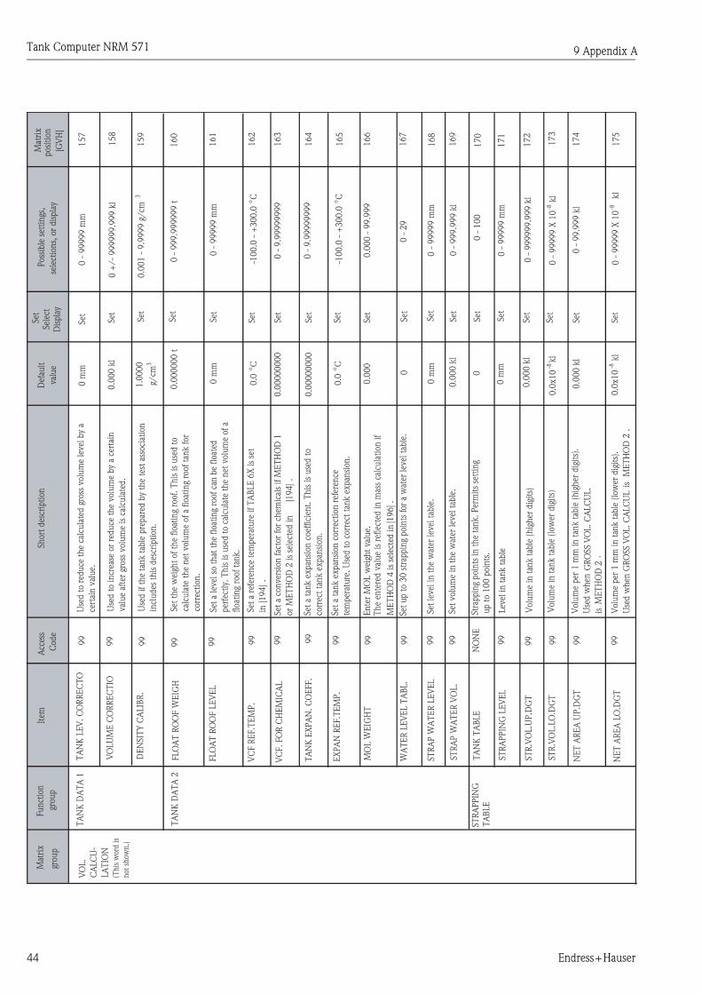
Tank Computer NRM 571
44 Endress+Hauser
Mat
rix
grou
p
Funct
ion
grou
p
Item
Acc
ess
Code
Short
des
crip
tion
Def
ault
val
ue
Set
Sel
ect
Dis
pla
y
Poss
ible
set
tings
,
sele
ctio
ns,
or
dis
pla
y
Mat
rix
posi
tion
[GV
H]
VO
L.
CA
LC
U-
LA
TIO
N
(This
word
is
not
show
n.)
TA
NK
DA
TA
1
VC
F R
EF.T
EM
P.
99
Set
a r
efer
ence
tem
per
ature
if
TA
BLE
6X
is
set
in [194]
.0.0
oC
Set
-100.0
- +
300.0
oC
162
VC
F.
FO
R C
HE
MIC
AL
99
Set
a c
onver
sion f
acto
r fo
r ch
emic
als
if M
ET
HO
D 1
or
ME
TH
OD
2 is
sele
cted
in
[194]
.
0.0
0000000
Set
0 -
9.9
9999999
163
TA
NK
EX
PA
N.
CO
EFF.
99
Set
a t
ank e
xpan
sion c
oef
fici
ent.
This
is
use
d t
o
corr
ect
tank e
xpan
sion.
0.0
0000000
Set
0 -
9.9
9999999
164
EX
PA
N R
EF.T
EM
P.
99
Set
a t
ank e
xpan
sion c
orr
ecti
on r
efer
ence
tem
per
ature
. U
sed t
o c
orr
ect
tank e
xpan
sion.
0.0
oC
Set
-100.0
- +
300.0
oC
165
MO
L W
EIG
HT
99
Ente
r M
OL w
eigh
t val
ue.
The
ente
red v
alue
is r
efle
cted
in m
ass
calc
ula
tion if
ME
TH
OD
4 is
sele
cted
in [1
96] .
0.0
00
Set
0.0
00 -
99.9
99
166
WA
TE
R L
EV
EL T
AB
L.
99
Set
up t
o 3
0 s
trap
pin
g poin
ts f
or
a w
ater
lev
el t
able
.0
Set
0 -
29
167
ST
RA
P W
AT
ER
LE
VE
L99
Set
lev
el in t
he
wat
er lev
el t
able
.0
mm
Set
0 -
99
99
9 m
m168
ST
RA
P W
AT
ER
VO
L.
99
Set
volu
me
in t
he
wat
er lev
el t
able
.0.0
00 k
lSet
0 -
999.9
99 k
l169
ST
RA
PP
ING
TA
BLE
TA
NK
TA
BLE
NO
NE
Str
appin
g poin
ts in
th
e ta
nk.
Per
mit
s se
ttin
g
up t
o 1
00 p
oin
ts.
0Set
0 -
100
170
ST
RA
PP
ING
LE
VE
L99
Lev
el in t
ank t
able
0 m
mSet
0 -
99999 m
m171
ST
R.V
OL.U
P.D
GT
99
Volu
me
in t
ank t
able
(hig
her
dig
its)
0.0
00
kl
Set
0 -
999999.9
99 k
l172
ST
R.V
OL.L
O.D
GT
99
Volu
me
in t
ank t
able
(lo
wer
dig
its)
0.0
x10
-8kl
Set
0 -
99999 X
10
-8 k
l173
NE
T A
RE
A U
P.D
GT
99
Volu
me
per
1 m
m in
tan
k t
able
(h
igh
er d
igit
s).
Use
d w
hen
GR
OSS V
OL.
CA
LC
UL.
is M
ET
HO
D 2
.
0.0
00 k
lSet
0 -
99.9
99 k
l174
NE
T A
RE
A L
O.D
GT
99
Volu
me
per
1 m
m in t
ank t
able
(lo
wer
dig
its)
.
Use
d w
hen
GR
OSS V
OL. C
ALC
UL
is
M
ET
HO
D 2
.
0.0
x10
-8kl
Set
0 -
99999 X
10
-8 k
l175
TA
NK
LE
V.
CO
RR
EC
TO
99
Use
d t
o r
educe
the
calc
ula
ted g
ross
volu
me
level
by
a
cert
ain v
alue.
0 m
mSet
0 -
99
99
9 m
m1
57
VO
LU
ME
CO
RR
EC
TIO
99
Use
d t
o incr
ease
or
reduce
the
volu
me
by
a ce
rtai
n
val
ue
afte
r gr
oss
volu
me
is c
alcu
late
d.
0.0
00
kl
Set
0 +
/-
999999.9
99 k
l158
DE
NSIT
Y C
ALIB
R.
99
Use
d if
the
tank t
able
pre
par
ed b
y th
e te
st a
ssoci
atio
n
incl
udes
th
is d
escr
ipti
on
.
1.0
000
g/cm
3
Set
0.0
01 -
9.9
999 g
/cm
3159
TA
NK
DA
TA
2FLO
AT
RO
OF W
EIG
H99
Set
the
wei
ght
of
the
float
ing
roof. T
his
is
use
d t
o
calc
ula
te t
he
net
volu
me
of
a float
ing
roof
tank f
or
corr
ecti
on.
0.0
00000 t
Set
0 -
999.9
99999 t
160
FLO
AT
RO
OF L
EV
EL
99
Set
a lev
el s
o t
hat
the
float
ing
roof
can b
e float
ed
per
fect
ly.
This
is
use
d t
o c
alcu
late
the
net
volu
me
of
a
float
ing
roof
tank.
0 m
mSet
0 -
99
99
9 m
m161
9 Appendix A

Tank Computer NRM 571
Endress+Hauser 45
Mat
rix
grou
p
Fu
nct
ion
grou
p
Item
Acc
ess
Code
Short
des
crip
tion
Def
ault
val
ue
Set
Sel
ect
Dis
pla
y
Poss
ible
set
tin
gs,
sele
ctio
ns,
or
dis
pla
y
Mat
rix
posi
tion
[GV
H]
VO
L.
CA
LC
U-
LA
TIO
N
ST
TA
NK
TA
BLE
ST
CO
NST
AN
T P
199
Set
Const
ant
P f
or
the
spher
ical
tan
k in t
he
tank
table
up t
o 4
th d
ecim
al p
oin
t.
0.0
000
Set
-9.9
999 -
+9.9
999
180
(This
word
is
not
show
n.)
ST
CO
NST
AN
T P
299
Set
Con
stan
t P
for
the
sph
eric
al t
ank in
th
e ta
nk
table
fro
m 5
th d
ecim
al p
oin
t to
9th
dec
imal
poin
t.
0.1
0^
-9Set
0 -
+/-
99999
181
ST
CO
NST
AN
T Q
n1
99
Set
Con
stan
t Q
(u
pper
dig
its=
up t
o 3
rd d
ecim
al
poin
t )f
or
the
sph
eric
al t
ank.
0.0
00
Set
-999.9
99 -
+999.9
99
182
ST
CO
NST
AN
T Q
n2
99
Set
Con
stan
t Q
(lo
wer
dig
its=
from
4th
dec
imal
poin
t
to 8
th)f
or
the
sph
eric
al t
ank.
0.1
0^
-8Set
0 -
+/-
99999
183
ST
CO
NST
AN
T R
n1
99
Set
Const
ant
R (
upper
dig
its=
inte
ger)
for
the
sph
eric
al t
ank.
0Set
-9999 -
+9999
184
ST
CO
NST
AN
T R
n2
99
Set
Const
ant
R (
low
er d
igit
s=dec
imal
)for
the
sph
eric
al t
ank.
0.1
0^
-6Set
0 -
+/-
999999
185
ST
CO
NST
AN
T S
n1
99
Set
Const
ant
S (
upper
dig
its=
inte
ger)
for
the
sph
eric
al t
ank.
0Set
-99999 -
+99999
186
ST
CO
NST
AN
T S
n2
99
Set
Con
stan
t S (
low
er d
igit
s=dec
imal
)for
the
sph
eric
al t
ank.
0.1
0^
-5Set
0 -
+/-
99999
187
CA
LC
ULA
TIO
NT
AN
K T
YP
E99
Sel
ect
the
tan
k s
hap
e fr
om
CR
T (
Con
e R
oof
Tan
k),
FR
T (
Flo
atin
g R
oof
Tan
k)
and S
T (
Spher
ical
Tan
k).
As
for
DR
T(d
om
e ro
of
tan
k),
an
d c
ylin
dri
cal ta
nk
sele
ct C
RT
. A
s fo
r C
FR
T (
Cone
Flo
atin
g R
oof
Tan
k),
sel
ect
FR
T.
CR
TSel
ect
CR
T,
FR
T,
ST
190
GR
OSS V
OL.
CA
LC
UL.
99
Set
equ
atio
ns
for
gross
volu
me.
NO
NE
--
----
-- n
o c
alcu
lati
on
ME
TH
OD
1 -
-cal
cula
te w
ithout
calc
ula
tion b
ook
ME
TH
OD
2 -
- ca
lcula
te w
ith c
alcu
lati
on b
ook
NO
NE
Sel
ect
NO
NE
ME
TH
OD
1
ME
TH
OD
2
191
SU
BT
R.
WA
TE
R L
EV
.99
Set
wat
er v
olu
me
(VW
) ca
lcu
lati
on
met
hod.
NO
NE
--V
W w
ill n
ot
be
ded
uct
ed.
GR
OSS V
OL.-
- V
W is
ded
uct
ed f
rom
gro
ss v
olu
me.
NE
T V
OL.-
- V
W is
ded
uct
ed f
rom
net
volu
me.
NO
NE
Sel
ect
NO
NE
GR
OSS V
OL.
NE
T V
OL.
192
SU
BT
R.
WA
TE
R C
ON
T99
Set
wat
er c
on
ten
t (V
(BS/
W))
cal
cula
tion
met
hod.
NO
NE
--V
(BS/W
) w
ill n
ot
be
ded
uct
ed.
GR
OSS V
OL.-
- V
(BS/
W)
will be
ded
uct
ed f
rom
gross
volu
me
if v
alue
is s
et in
[147]
.
NE
T V
OL.-
- V
(BS/
W)
will be
ded
uct
ed f
rom
net
volu
me
if v
alue
is s
et in
[147]
.
NO
NE
Sel
ect
NO
NE
GR
OSS V
OL.
NE
T V
OL.
193
9 Appendix A

Tank Computer NRM 571
46 Endress+Hauser
Mat
rix
grou
p
Fun
ctio
n
grou
p
Item
Acc
ess
Cod
e
Shor
t de
scri
ptio
nD
efau
lt
valu
e
Set
Sele
ct
Dis
play
Pos
sibl
e se
ttin
gs,
sele
ctio
ns,
or
disp
lay
Mat
rix
posi
tion
[GV
H]
VO
L.
CA
LCU
-
LAT
ION
CA
LCU
LAT
ION
NE
T V
OL.
CA
LC.T
AB
.9
9Se
lect
equ
atio
n f
or v
olu
me
con
vers
ion
fac
tor.
AR
OM
AT
IC (
300)
= 3
00-3
50
oF
AR
OM
AT
IC (
350)
= 3
50-4
00
oF
NO
NE
Sele
ctN
ON
E
TA
BLE
54
A
TA
BLE
54
B
TA
BLE
54
D
TA
BLE
54
TA
BLE
55
TA
BLE
6X
BE
NZ
EN
E
TO
LUE
NE
, X
YLE
NE
STY
RE
NE
, O
RT
HO
XY
LEN
E
ME
TA
XY
LEN
E
PA
RA
XY
LEN
E
CY
CLO
HE
XA
NE
AR
OM
AT
IC (
300)
AR
OM
AT
IC (
350)
ME
TH
OD
1
ME
TH
OD
2
194
NE
T V
OL.
CA
LCU
LAT
.99
Set
equ
atio
ns
for
the
net
vol
um
e fo
r FR
T.
ME
TH
OD
1 -
- R
efer
to
equat
ion (
15)
in A
pp.
B
ME
TH
OD
2 -
- R
efer
to
equat
ion (
16)
in A
pp.
B
NO
NE
Sele
ctM
ET
HO
D 1
ME
TH
OD
2
ME
TH
OD
3
195
MA
SS C
ALC
ULA
TIO
N99
Set
equat
ions
for
wei
ght.
Thes
e eq
uat
ions
are
mai
nly
use
d fo
r ch
emic
als
and
liqu
efie
d ga
ses.
NO
NE
Set
NO
NE
ME
TH
OD
1
ME
TH
OD
2
ME
TH
OD
3
ME
TH
OD
4
196
VO
LUM
E D
AT
A99
Sets
a m
eth
od f
or p
roce
ssin
g A
STM
T5
4A
, T
54
B,
and
T54D
.
AP
ISe
lect
AP
I
JAP
AN
ESE
198
D15.C
ALC
.TA
B99
Sele
ct a
n a
ppro
pria
te t
able
to
conve
rt t
he
mea
sure
d
densi
ty t
o de
nsi
ty a
t 15
oC
. If
th
e de
nsi
ty a
t 1
5oC
is
man
ual
ly e
nte
red
at [1
42],
choo
se N
ON
E.
NO
NE
Sele
ct5
3A
53B
53D
53
199
9 Appendix A

Tank Computer NRM 571
Endress+Hauser 47
Mat
rix
grou
p
Funct
ion
grou
p
Item
Acc
ess
Code
Short
des
crip
tion
Def
ault
val
ue
Set
Sel
ect
Dis
pla
y
Poss
ible
set
tings
,
sele
ctio
ns,
or
dis
pla
y
Mat
rix
posi
tion
[GV
H]
OU
TPU
T
(This
word
is
not
show
n.)
ALA
RM
ASSIG
NM
EN
TA
LA
RM
SE
LE
CT
ION
99
Reg
iste
r poin
ters
for
alar
m o
utp
uts
. E
ight
types
of
alar
ms
can
be
sele
cted
per
tan
k.
0Sel
ect
0 -
7240
ALA
RM
A
SSIG
NM
EN
T99
Sel
ect
type
of
alar
m.
NO
NE
Sel
ect
NO
NE
LE
VE
L
TE
MPE
RA
TU
RE
GR
OSS V
OLU
ME
NE
T V
OLU
ME
MA
SS
241
SE
T P
OIN
T99
Not
requir
ed if
"N
ON
E",
"T
RA
NSM
ITT
ER
H",
and
"TR
AN
SM
ITT
ER
L"
are
sele
cted
in
[241]
0Set
0 -
99
99
9 m
m242
ALA
RM
ASSIG
NM
EN
T
99
Not
requir
ed if
"N
ON
E",
"T
RA
NSM
ITT
ER
H",
and
"TR
AN
SM
ITT
ER
L"
are
sele
cted
in
[241]
HIG
H
ALA
RM
Sel
ect
LO
W A
LA
RM
HIG
H A
LA
RM
243
SY
ST
EM
DA
TA
CLO
CK
CLO
CK
99
YY
/M
M/D
D/H
H :
MM
-D
ispla
y-
340
(This
word
is
not
show
n. )
YE
AR
SE
TT
ING
99
Set
the
low
er t
wo d
igit
s of
Yea
r.00
Set
00 -
99
341
MO
NT
H S
ET
TIN
G99
Set
th
e cu
rren
t m
on
th.
01
Set
01 -
12
342
DA
TE
SE
TT
ING
99
Set
the
curr
ent
dat
e.01
Set
01 -
31
343
HO
UR
SE
TT
ING
99
Set
the
curr
ent
hour.
00
Set
00 -
23
344
MIN
UT
E S
ET
TIN
G99
Set
th
e cu
rren
t m
inu
te.
00
Set
00 -
59
345
SE
CO
ND
SE
TT
ING
99
Set
the
curr
ent
seco
nd.
00
Set
00 -
59
346
DE
FA
ULT
VA
LU
ES
99
RE
SE
T C
UR
R.T
AN
K m
eans
to r
eset
all t
he
dat
a
regi
ster
ed in c
urr
ent
tank t
o d
efau
lt v
alues
.
RE
SE
T A
LL T
AN
KS m
eans
to r
eset
all t
he
dat
a in
all ta
nks
to d
efau
lt s
etti
ng.
This
is
enab
led w
hen
all
tanks
are
in t
he
mai
nte
nan
ce c
ondit
ion [1
50].
NO
RE
SE
TSel
ect
NO
RE
SE
T
RE
SE
T C
UR
R.
TA
NK
RE
SE
T A
LL T
AN
KS
349
9 Appendix A

Tank Computer NRM 571
48 Endress+Hauser
Mat
rix
grou
p
Fu
nct
ion
grou
p
Item
Acc
ess
Code
Short
des
crip
tion
Def
ault
val
ue
Set
Sel
ect
Dis
pla
y
Poss
ible
set
tin
gs,
sele
ctio
ns,
or
dis
pla
y
Mat
rix
posi
tion
[GV
H]
SY
ST
EM
DA
TA
(This
word
is
not
show
n.)
CO
MM
U-
NIC
AT
ION
CO
MM
UN
ICA
TIO
N0
Sel
ect
a co
mm
un
icat
ion
pro
toco
l w
ith
host
.Sel
ect
350
BA
UD
RA
TE
0Sel
ect
a pro
per
bau
d r
ate.
9600 B
PS
Sel
ect
9600 B
PS
24
00
BP
S
48
00
BP
S
351
DA
TA
LE
NG
TH
0Sel
ect
a dat
a le
ngt
h.
8 B
ITS
Sel
ect
7 B
ITS
8 B
ITS
352
PA
RIT
Y0
Sel
ect
a par
ity
even
or
odd.
OD
DSel
ect
NO
NE
OD
D
EV
EN
353
ST
OP
BIT
0Sel
ect
one
stop b
it o
r tw
o s
top b
it.
ON
E
ST
OP
BIT
Sel
ect
ON
E S
TO
P B
IT
TW
O S
TO
P B
IT
354
LE
V.
ALA
RM
HY
ST
.99
Reg
iste
r a
level
ala
rm h
yste
resi
s val
ue
if lev
el d
ata
is u
sed
to e
xec
ute
ala
rm p
roce
ssin
g.
0 m
mSet
0 -
99
9 m
m355
TE
MP.
ALA
RM
HY
ST
.99
Reg
iste
r an
ala
rm h
yste
resi
s val
ue
if t
emper
ature
dat
a is
use
d t
o e
xec
ute
ala
rm p
roce
ssin
g.0.0
oC
Set
0 -
99.9
oC
356
VO
L.
ALA
RM
HY
ST
.99
Reg
iste
r an
ala
rm h
yste
resi
s val
ue
if (
gross
and/or
net
)
volu
me
dat
a is
use
d t
o e
xec
ute
ala
rm p
roce
ssin
g.
0 k
lSet
0 -
99.9
99 k
l357
MA
SS A
LA
RM
HY
ST
.99
Reg
iste
r an
ala
rm h
yste
resi
s val
ue
if w
eigh
t dat
a is
use
d t
o
exec
ute
ala
rm p
roce
ssin
g.
0.0
00
tSet
0 -
99.9
99 t
on
358
MO
DB
US A
DD
RE
SS
99
Set
a M
OD
BU
S p
roto
col sl
ave
addre
ss f
or
host
com
mu
nic
atio
n (
RS2
32
C).
1Set
1 -
247
359
DE
VIC
E
NA
ME
LA
NG
UA
GE
99
Sel
ect
EN
GLIS
H o
r JA
PA
NE
SE
.E
NG
LIS
HSel
ect
EN
GLIS
H
JAP
AN
ESE
360
LC
D C
ON
TR
AST
99
LC
D c
ontr
ast
funct
ion:
pre
ssin
g +
mak
es L
CD
dar
ker
,
pre
ssin
g -
mak
es L
CD
lig
hte
r.
LC
D c
hec
k f
unct
ion:
when
all t
he
pix
els
are
show
n,
pre
ss E
to s
ee if
all pix
els
are
pro
per
ly d
ispla
yed.
-(C
hec
k)
361
BA
CK
LIG
HT
TIM
E99
Set
a v
alu
e in
min
ute
s. B
ackligh
t tu
rns
itse
lf o
ff
(X)
min
ute
s af
ter
last
oper
atio
n
1Set
0 -
999
362
SO
FT
.VE
R.
SE
R.P
LS
99
Soft
war
e ver
sion f
or
seri
al p
uls
e
(V1 m
odule
)
#.#
#D
ispla
y364
HA
RT
PO
LLIN
G A
DD
RE
SS
99
Set
HA
RT
Dev
ice
Addre
ss u
sed a
t th
e ti
me
of
connec
ting
wit
h
HA
RT
port
ToF T
ool.
Set
365
0: N
ON
E
1: B
BB
2: M
DP
3: M
odbus
(NR
M)
4: M
odbus
(flo
at 1
)
5: M
odbus
(flo
at 2
)
6: M
odbus
(MD
P)
7: M
odbus
(den
sity
)
0 -
15
19
20
0 B
PS
9 Appendix A

Tank Computer NRM 571
Endress+Hauser 49
Mat
rix
grou
p
Funct
ion
grou
p
Item
Acc
ess
Code
Short
des
crip
tion
Def
ault
val
ue
Set
Sel
ect
Dis
pla
y
Poss
ible
set
tings
,
sele
ctio
ns,
or
dis
pla
y
Mat
rix
posi
tion
[GV
H]
SY
ST
EM
DA
TA
(This
word
is
not
show
n.)
ER
RO
R
INFO
.
SY
ST
EM
ER
RO
RN
ON
EShow
s cu
rren
t N
RM
sys
tem
err
or
when
it
hap
pen
s.
Th
is d
ata
can
be
seen
fro
m H
ost
.
Ref
er t
o a
ppen
dix
E f
or
more
info
rmat
ion.
NO
ER
RO
RD
ispla
y V
1 C
PU
ER
RO
R
MA
IN C
PU
ER
RO
R
ST
AR
T: N
om
al s
tart
ST
AR
T in
it:
dat
a in
itia
liza
tion
sta
rt
ST
AR
T w
/d:
wat
chdog
star
t
ST
AR
T r
es.: r
eset
sta
rt
370
LA
ST
SY
ST
EM
ER
R.
NO
NE
Show
s la
test
sys
tem
err
or
occ
urr
ed.
NO
ER
RO
RD
ispla
y-
371
LE
V.
CH
AN
G.
ALLO
W99
Set
s a
per
mit
ted lim
it f
or
level
var
iati
on
. If
th
is s
et
val
ue
is e
xce
eded
, th
e re
try
set
in [374]
is e
xec
ute
d.
20
0 m
mSet
0 -
99
9 m
m372
TE
MP
. C
HA
NG
. A
LLO
W99
Set
s a
per
mit
ted lim
it f
or
tem
per
atu
re v
aria
tion
. If
this
set
val
ue
is e
xce
eded
, th
e re
try
set
in [375]
is
exec
ute
d.
10.0
oC
Set
0 -
99.9
oC
373
LE
V.
RE
TR
Y N
O99
If t
he
num
ber
of
conti
nuous
level
var
iati
ons
exce
eds
this
set
val
ue,
it
is c
onsi
der
ed a
n e
rror.
5Set
0 -
999
374
TE
MP.
RE
TR
Y N
O99
If t
he
num
ber
of
conti
nuous
tem
per
ature
var
iati
ons
exce
eds
this
set
val
ue,
it
is c
onsi
der
ed a
n e
rror.
5Set
0 -
999
375
SY
ST
EM
DA
TA
LE
VE
L D
AT
A R
OU
ND
99
Set
s a
met
hod f
or
pro
cess
ing
the
firs
t dec
imal
pla
ce
of
level
dat
a obta
ined
by
the
senso
r.10
-1 m
m
DIS
CA
RD
Sel
ect
10
-1 m
m D
ISC
AR
D
10
-1 m
m R
OU
ND
ING
NO
NE
380
TE
MP.
DA
TA
RO
UN
D99
Set
a m
eth
od f
or
pro
cess
ing
the
firs
t dec
imal
pla
ce
of
tem
per
ature
dat
a.
0.1
Sel
ect
0.1
0.2
5
0.5
381
V.C
.F.
DIG
IT99
Sel
ect
volu
me
conver
sion f
acto
r dig
it.
X.X
XX
XSel
ect
X.X
XX
X
X.X
XX
XX
X
382
DIS
PLA
Y L
INE
2.
99
Set
the
hom
e posi
tion d
ispla
y fo
r line
2.
VH
val
ue
chan
ge a
s +
or
- is
pre
ssed
. R
efer
"8.1
.5 C
ust
om
HO
ME
Posi
tion S
etti
ng"
for
furt
her
des
crip
tion.
0100
Set
00
: L
EV
EL
01 :
TE
MPE
RA
TU
RE
02 :
GR
OSS V
OLU
ME
03 :
NE
T V
OLU
ME
04 :
MA
SS
05
: D
EN
SIT
Y
06 :
RE
FE
RE
NC
E D
EN
SIT
Y
07
: W
AT
ER
LE
VE
L
08 :
GA
S T
EM
PE
RA
TU
RE
09
: G
AS P
RE
SSU
RE
11 :
BO
TT
OM
LE
VE
L
384
9 Appendix A

Tank Computer NRM 571
50 Endress+Hauser
Mat
rix
grou
p
Funct
ion
grou
p
Item
Acc
ess
Code
Short
des
crip
tion
Def
ault
val
ue
Set
Sel
ect
Dis
pla
y
Poss
ible
set
tings
,
sele
ctio
ns,
or
dis
pla
y
Mat
rix
posi
tion
[GV
H]
SY
ST
EM
DA
TA
(This
word
is
not
show
n.)
SY
ST
EM
DA
TA
DIS
PLA
Y L
INE
399
Set
the
hom
e posi
tion d
ispla
y fo
r line
3.
VH
val
ue
chan
ge a
s +
or
- is
pre
ssed
.
Ref
er "
8.1
.5 C
ust
om
HO
ME
Posi
tion S
etti
ng"
for
furt
her
des
crip
tion.
0100
Set
00
: L
EV
EL
01 :
TE
MPE
RA
TU
RE
02 :
GR
OSS V
OLU
ME
03 :
NE
T V
OLU
ME
04 :
MA
SS
05
: D
EN
SIT
Y
06 :
RE
FE
RE
NC
E D
EN
SIT
Y
07
: W
AT
ER
LE
VE
L
08 :
GA
S T
EM
PE
RA
TU
RE
09
: G
AS P
RE
SSU
RE
11 :
BO
TT
OM
LE
VE
L
385
DIS
PLA
Y L
INE
499
Set
the
hom
e posi
tion d
ispla
y fo
r line
4.
VH
val
ue
chan
ge a
s +
or
- is
pre
ssed
.
Ref
er "
8.1
.5 C
ust
om
HO
ME
Posi
tion S
etti
ng"
for
furt
her
des
crip
tion.
0000
Set
00 :
LE
VE
L
01 :
TE
MPE
RA
TU
RE
02 :
GR
OSS V
OLU
ME
03 :
NE
T V
OLU
ME
04 :
MA
SS
05
: D
EN
SIT
Y
06 :
RE
FE
RE
NC
E D
EN
SIT
Y
07
: W
AT
ER
LE
VE
L
08 :
GA
S T
EM
PE
RA
TU
RE
09
: G
AS P
RE
SSU
RE
11 :
BO
TT
OM
LE
VE
L
386
SY
ST
EM
DA
TA
SY
ST
EM
UN
ITS
LE
NG
TH
UN
ITN
ON
ED
ispla
y only
. m
mD
ispla
y-
390
(This
word
is
not
show
n.)
TE
MPE
RA
TU
RE
UN
ITN
ON
ED
ispla
y only
. oC
Dis
pla
y-
391
VO
LU
ME
UN
ITN
ON
ED
ispla
y only
. kl
Dis
pla
y-
392
MA
SS U
NIT
NO
NE
Dis
pla
y only
. t
Dis
pla
y-
393
PR
ESSU
RE
UN
ITN
ON
ED
ispla
y only
. kg/
cm2
Dis
pla
y-
394
DE
NSIT
Y U
NIT
NO
NE
Dis
pla
y only
. g/
cm3
Dis
pla
y396
-
9 Appendix A

Tank Computer NRM 571
Endress+Hauser 51
Mat
rix
grou
p
Funct
ion
grou
p
Item
Acc
ess
Code
Short
des
crip
tion
Def
ault
val
ue
Set
Sel
ect
Dis
pla
y
Poss
ible
set
tings
,
sele
ctio
ns,
or
dis
pla
y
Mat
rix
posi
tion
[GV
H]
DE
NSIT
Y M
ES.
SE
LE
CT
Sel
ect
the
met
hod f
or
Den
sity
mea
surm
ent
pro
cess
ing
*B
asic
set
ting
rela
ted w
ith D
ensi
ty p
rofile
should
se
t in
[44x] w
hen
sel
ectt
ing
I/F P
RO
FIL
E,
MA
N.
I/
F P
RO
FIL
E.
0: SPO
TSel
ect
0 :
SP
OT
1 :
TA
NK
PR
OFIL
E
2 :
I/F P
RO
FIL
E
3 :
MA
NU
AL I
/F P
RO
FIL
E
440
Set
LE
VE
L C
ON
DIT
ION
Lev
el c
ondit
ion
ME
ASU
RE
PO
INT
SE
LE
CT
Set
the
mea
sure
men
t poin
t fo
r D
ensi
ty p
rofile
pro
cess
ing.
2 -
16
2Set
441
I/F M
AN
UA
L L
EV
EL
Lev
el V
alue
ente
red m
anual
ly
use
d for
sett
ing
MA
NU
AL I
/F P
RO
FIL
E .
443
LE
VE
L S
TB
. C
NF. R
AN
GE
Sta
rt-u
p c
ondit
ion for
Den
sity
pro
file
mea
sure
men
t
Set
"Lev
el s
tabilit
y C
NF R
ange
"
* W
hen
set
ting
99.9
mm
, co
ndit
ion s
etti
ng
is n
ot
nec
essa
ry.
444
DIS
P. H
OLD
TIM
ESet
the
stat
ionar
y ti
me
in a
ir .
HO
LD
TIM
E I
N L
IQU
IDSet
the
stat
ionar
y ti
me
in liq
uid
.
OPE
. ST
NB
Y T
IME
Set
the
tim
e fo
r w
aiti
ng
the
mea
sure
men
t
star
t-up c
ondit
ion.
OPE
. ST
AT
US
Sta
tus
for
den
sity
pro
file
pro
cess
ing
0: A
CC
EPT
ING
1: ST
AN
DB
Y
2: IN
OPE
RA
TIO
N3: E
ND
/N
OR
MA
L4: E
ND
/ L
IQ. U
NST
AB
LE
5: E
ND
/A
BN
OM
AL
0: O
FF L
EV
EL M
EA
S
1: ST
AB
LE
2: U
NST
AB
LE
3: IG
NO
RE
CN
DIT
ION
OPE
. T
IME
Norm
al c
losi
ng
tim
e fo
r den
sity
pro
file
pro
cess
ing
DD
/H
H/M
M
445
446
447
450
451
452
TA
NK
DA
TA
TA
NK
PR
OFIL
E
PR
OFIL
E
TA
NK
PR
OFIL
E
OP
E.S
YS
DE
NSIT
Y D
EN
SIT
Y N
o.
1-1
6 T
he
mea
sure
men
t den
sity
of
each
poin
t0
.00
00
g/cm
34
60
- 4
75
PO
SIT
ION
PO
SIT
ION
No.
1-1
6T
he
den
sity
mea
sure
men
t posi
tion
of
each
poin
t0
.0m
m4
80
- 4
95
0.0
mm
2.0 0 0 0
0 -
99
99
9.9
0.0
- 9
9.9
0 -
31
0 -
31
0 -
31
AV
ER
AG
E D
EN
SIT
Y
AV
ER
AG
E T
EM
P.
453
454
Aver
age
den
sity
Aver
age
tem
per
atu
re
9 Appendix A

Tank Computer NRM 571
52 Endress+Hauser
Mat
rix
grou
p
Funct
ion
grou
p
Item
Acc
ess
Code
Short
des
crip
tion
Def
ault
val
ue
Set
Sel
ect
Dis
pla
y
Poss
ible
set
tings
,
sele
ctio
ns,
or
dis
pla
y
Mat
rix
posi
tion
[GV
H]
OP
E.
ST
AT
US
550
LE
VE
L C
ON
DIT
ION
Lev
el c
ondit
ion
551
552
0: O
FF L
EV
EL M
EA
S
1: ST
AB
LE
2: U
NST
AB
LE
3: IG
NO
RE
CN
DIT
ION
OPE
. T
IME
Norm
al c
losi
ng
tim
e fo
r den
sity
pro
file
pro
cess
ing
553
554
555
I/F
I/F P
RO
FIL
E
OP
E.S
YS
PR
OFIL
ESta
tus
for
den
sity
pro
file
pro
cess
ing
0: A
CC
E`P
TIN
G
1: ST
AN
DB
Y
2: IN
OPE
RA
TIO
N3: E
ND
/N
OR
MA
L4: E
ND
/ L
IQ. U
NST
AB
LE
5: E
ND
/A
BN
OM
AL
I/F L
EV
EL
AV
ER
AG
E D
EN
SIT
Y
AV
ER
AG
E T
EM
P
DE
NSIT
Y D
EN
SIT
Y N
o.
1-1
6 T
he
mea
sure
men
t den
sity
of
each
poin
t0
.00
00
g/cm
35
60
- 5
75
PO
SIT
ION
PO
SIT
ION
No.
1-1
6T
he
den
sity
mea
sure
men
t posi
tion
of
each
poin
t0
.0m
m5
80
- 5
95
Inte
rfac
e le
vel
Aver
age
den
sity
Aver
age
Tem
per
atu
re
DD
/H
H/
MM
9 Appendix A

Tank Computer NRM 571
Endress+Hauser 53
10 Appendix B
10.1 Specification for Arithmetic Calculations
10.1.1 Data Rounding
Set a method for processing the first decimal place of data.
10.1.1.1 Level Data Rounding [380] LEVEL DATA ROUNDThis setting is reflected on :
[000] MEASURED LEVEL [140] MANUAL LEVEL
[143] MANUAL WATER LEV. [161] FLOAT ROOF LEVEL
[168] STRAP WATER LEVEL [171] STRAPPING LEVEL
– When 10-1mm DISCARD is selected, 10-1mm is discarded
– When 10-1mm ROUNDING is selected, 10-1mm is rounded
– When NONE is selected, rounding is not executed.
10.1.1.2 Temperature Data Rounding [381] TEMP. DATA ROUNDThis setting is reflected on [001] LIQUID TEMP. and [008] GAS TEMP.
– When ROUND 0.1 is selected, rounding is not executed.
– When ROUND 0.25 is selected, rounding is executed as follows.
– When ROUND 0.5 is selected, rounding is executed as follows.
10.1.2 Tank Selection and FRT/ ST Setting
10.1.2.1 Tank Type Selection [190] TANK TYPE
Select CRT if the tank is cone roof tank or dome roof tank.
Select FRT if the tank is floating roof or covered floating roof tank.
Select ST if the tank is spherical tank.
10.1.2.2 Setting Items for FRT
• [160] FLOAT ROOF LEVEL
Set the weight of the floating roof if gross volume or net volume needs to be calculated.
• [161] FLOAT ROOF LEVEL
Set floating roof point (FRP)
• [195] NET VOL. CALCULAT
Select equation for net volume calculation. Refer to " Net Volume Calculation".
10.1.2.3 Setting Items for ST
• [156] TANK CAPACITY
Set the tank valume. This value is used to calculate tank weight.
0.0 to 0.1 C 0.00 C
0.2 to 0.3 C 0.25 C
0.4 to 0.6 C 0.50 C0.7 to 0.8 C 0.75 C0.9 to 1.0 C 1.00 C (carry)
0.0 to 0.2 C 0.0 C0.3 to 0.7 C 0.5 C0.8 to 1.0 C 1.00 C (carry)
10 Appendix B

Tank Computer NRM 571
54 Endress+Hauser
10.1.3 Manual Data Setting [140] - [147]
For each piece of level and temperature data, change from manual setting data to sensor data.
If data cannot be collected, stay in manual setting data and set values that are reflected in arithmetic
operations.
1.[140] MANUAL LEVEL
To get data from sensor, set "-1", otherwise, set between 0-99999 (mm)
2.[141] MANUAL LIQ. TEMP.
To get data from sensor, set "-100", otherwise, set between -99.9 - +300.0 (oC)
3.[142] MANUAL DENSITY
To set density data manually, input the density data at 15oC and select NONE at
[199] D15.CALC. TAB.
To use measured data from sensor, set "-1000". And at [199] D15.CALC.TAB, choose which table to use to
convert the measured density data to data density at 15oC. Select the table among Table 53, 53A 53B, 53D.
Note!
Applicable range for Table 53 is 0.420 - 0.595.
4.[143] MANU. WATER LEV
To use measured data from sensor (data in [007] WATER LEVEL = upper interface level), set "-1", otherwise
set between 0 - 99999 (mm).
5.[144] MANU GAS TEMP.
To use measured data from sensor (data in NMS mode 1 [211] DEVEICE (1)), set "-100", otherwise set
between -99.9 - +300.0 (oC).
Note!
Measured gas temperature is available only when the sensor is NMS.
And the device for gas temperature should be set as HART DEVICE 1.
6.[145] MANU GAS PRESS
To use measured data, from sensor (data in NMS mode 1 [312] DEVICE (2)), set "-1000", otherwise set
between -999.999 - +99.999 (kg/cm2).
Note!
Measured gas pressure is available only when the sensor is NMS.
And the device for gas pressure should be set as HART DEVICE 2.
7.[146] MANU. GAS DENS.
Set the gas density data. This data will be reflected in net weight calculation.
8.[147] WATER CONTENT
Set the water content (%) manually. This data will be reflected in gross volume, and net volume calculation.
10 Appendix B

Tank Computer NRM 571
Endress+Hauser 55
10.1.4 Tank Table/Coefficient Setting [170] - [187]
10.1.4.1 Tank Table Setting for CRT or FRT
A Tank Table of up to 100 strapping points is allowed. Prepare the Tank Table and follow the steps below.
"XXX" are the numbers you enter which are taken from "Tank Table Example".
Tank Table Example
1.[170] TANK TABLE
Set the table pointer for 0.
2.[171] STRAPPING LEVEL
Set the LEVEL according to the tank strapping table. (31 in the example above)
(Begin with lowest point)
3.[172] STR. VOL. UP DGT. (strapping volume for the level --- higher digits)
Set the volume for the registered level from tank strapping table (higher digits).
(0.703 (kl) in the example above)
4.[173] STR. VOL. LO DGT. (strapping volume for the level --- lower digits)
Set the volume for the registered level from tank strapping table (lower digits).
((0.703) 04300 (kl) in the example above)
5.[174] NET AREA UP DGT. (net volume per 1 mm ---higher digit)
Set the volume per 1mm in tank strapping table (highter digits).
(0.024(kl) in the example above)
6.[175] NET AREA LO DGT. (net volume per 1 mm --- lower digits)
Set the volume per 1mm in tank strapping table (lower digits).
((0.024)182974(kl) in the example above)
7.[158] VOLUME CORRECTIO(volume correction)
Set a certain value to add or subtract from gross volume after it is calculated
8.[159] DENSITY CALIBR. (density calibration)
Set the value if the tank strapping table includes this description.
9.1.4.2 Tank Coefficient Setting for ST
The tank coefficient can be divided into 8 points for registration.
1. [170] TANK TABLE
Set the table pointer for 0. up to 8 (0 - 7) can be set.
2. [171] STRAPPING LEVEL
Set the LEVEL according to the tank table.
(Set the level from lower level to higher level)
3. [180] ST CONSTANT P1, [181 ST CONSTANT] P2
Set constant for the level from the tank table.
e.g. +/-X.XXXXYYYYY set Xs in [180], Ys in [181]
Resource Tank Table Calculation Book
Table
PointerLevel (mm) Volume (kl) Volume per 1 mm (kl)
0
1
31
950
0.70304300
23.67683600
0.02418294
0.02439797
: : : :
These columns are not shown in a Tank Table.( )
Volume XXXXXX.XXX XXXXX kl
UP. DGT LO. DGT
10 Appendix B

Tank Computer NRM 571
56 Endress+Hauser
4.[182] ST CONSTANT Qn1, [183] ST CONSTANT Qn2
Set constant Q for the level from the tank table.
e.g. +/-XXX.XXXYYYYY set Xs in [182], Ys in [183]
5. [184] ST CONSTANT Rn1, [185] ST CONSTANT Rn2
Set constant S for the level from the tank table.
e.g. +/-XXXX.YYYYYY set Xs in [184], Ys in [185]
6. [186] ST CONSTANT Sn1, [187] ST CONSTANT Sn2
Set constant S for the level from the tank table.
e.g. +/-XXXXX.YYYYY set Xs in [186], Ys in [187]
7. Go back to [170] TANK TABLE and repeat for pointer 1,2,3,4....until TANK Table is complete.
10.1.5 Water Level Table Setting
Water Level Table can be set up to 30 points. prepare the tank table to start.
1.[167] WATER LEVEL TABL.
Set the table pointer for 0.
2. [168] STRAP WATER LEVEL
Set the LEVEL according to the tank table.
3. [169] STRAP WATER VOL.
Set the volume for the registered level.
4. [192] SUBTR. WATER LEV.
Select how water volume is subtracted.
When NONE is selected, water volume will not be substracted.
When GROSS VOL. is selected, water volume will be subtracted from gross volume.
When NET VOL. is selected, water volume will be subtracted from net volume.
10.1.6 Water Volume Calculation in a CRT or FRT
Make sure that CRT or FRT is selected in [190] TANK TYPE
Comparison is carryed out for each step (up to 30 points) using the water level measured by the transmitter
(NMS) or the manually entered value and the water level table registered in the matrix.
VW =LW n+1 LW n-
LW x LW n-+ VW n( VW - VW )n+1 n (1)
LW1 LW n< < LWX < LWn+1 < LW 30
VW: Water volume to be determined
(VW = 0 when NONE is selected in [192])
LWn LWn+1
SUBTR.WATER LEV.)
LWx: Measured water level [007]
, : Water table level ([168] STRAP WATER LEVEL)
VWn VW, n+1 : Strap water volume ([169] STRAP WATER VOL.)
When LWx < LW1 VW = VW1,
When LWx LW30 VW = VW30,>
10 Appendix B

Tank Computer NRM 571
Endress+Hauser 57
10.1.7 Gross volume (VG) Calculation
First calculate temporary gross volume (Vt), then calculate gross volume(VG).
The calculation of Vt varies depends on your tank type and setting in [191] GROSS VOL. CALCUL. and [195]
NET VOL. CALCULAT.
Look at the table below and choose Vt calculation type.
Note!
No matter what is selected for a blank space, calculation will work properly.
10.1.7.1 Temporary Gross Volume (Vt) Calculation
Vt Calculation Type AComparison is carried out for each step (up to 100 points) using the level measured by the transmitter (NMS)
or the manually entered value and tha tank table registered in the matrix.
Vt Calculation Type BComparison is carried out for each step (up to 100 point) using the level measured by the transmitter (NMS)
or the manually entered value and tha tank table registered in the matrix.
Vt calculation type tank type [191] [195]
A
CRT Method 1
FRT Method 1 Method 1/2/3
B
CRT Method 2
FRT Method 2 Method 1/2/3
C FRT Method 1/2 Method 4
D ST
Vt =L n+1 L n-
+ VR( V - V )n+1 n (2)
L 1 Ln< < L x < L100
L : [000] MEASURED LEVEL
Ln L n+1
LR : TANK LEV. CORRECTION ([167] TANK LEV. CORRECT
, : STRAPPING LEVEL ([171] STRAPPING LEVEL
Vn V, n+1 : STR. VOL. ( Sum of [172] UP DGT. and [173] LO DGT. )
+ ) nx LR( L-L
x
VRVR : VOLUME CORRECTION ([158]) VOL. CORRECTIO
+ Vn
Vt = + VR( L - L )x n
L1 Ln< < L x < L100
V : STR. VOL. (Sum of [172] UP DGT. And [173] LO DGT.)
Ln
Lx : [000] MEASURED LEVEL
: STRAPPING LEVEL ([171] STRAPPING LEVEL
: Volume per 1 mm in the calculation book
n
VRVR : VOLUME CORRECTION ([158]) VOL. CORRECTIO
Vn + Vn
Vn
(Sum of [174] UP DGT. and [175]LO DGT.
( 3)
10 Appendix B

Tank Computer NRM 571
58 Endress+Hauser
Vt Calculation Type CComparison is carried out for each step (up to 100 point) using the level measured by the transmitter (NMS)
or the manually entered value and the tank table registered in the matrix.
• When the Floating Roof is not floating (Lx<FRP)Lx : [000] MEASURED LEVEL
FRP : Floating Roof Point ([161] FLOAT ROOF LEVEL)
When [191] is set to METHOD 1, equation (2) is used to calculation Vt.
When [191] is set to METHOD 2, equation (3) is used to calculation Vt.
Volume caused of floating roof weight needs to be deducted from Vt.
Vt CalculationType DThe following calculation is carried out using the level measured by the transmitter (NMS), or the manually
entered value and the tank coefficient registered in the matrix. The tank coefficient can be divided into 8 points
for registration. Register points in [170] TANK TABLE, levels in [171] STRAPPING LEVEL.
Vt = Vt - (BSG
1 1- ) FRW ( 4)
Vt’ : Temporary gross volume to be determined
Vt : if [191] METHOD 1 Vt calculated by equation (2)
: Reference Density at 15°C (g/cm3) ([006] REF. DENSITY
: Calibration density ([159] DENSITY CALIBR.)
: if [191] METHOD 2 Vt calculated by equation (3)
Vcf : Volume conversion factor
(Refer to “ Calculating Volume Conversion Factor”)
ρVcf 15
ρ15
BSG
FRW: Floating Roof Weight ([160] FLOAT ROOF WEIGH.)
<0 L x < L 1 Vt = P (1000Lx+LR
)3 + Q 1(
1000Lx+LR
)2 + R1(
1000x+LR
)L + S1 +
1000VR
<0 L x < L 2
<0 L x < L n
0 L x L 8< <
Vt = P (1000Lx+LR
)3 + Q 2(
1000Lx+LR
)2 + R2(
1000x+LR
)L + S2 +
1000VR
Vt = P (1000Lx+LR
)3 + Q n(
1000Lx+LR
)2 + Rn(
1000x+LR
)L + Sn +
1000VR
Vt = P (1000Lx+LR
)3 + Q 8(
1000Lx+LR
)2 + R8(
1000x+LR
)L + S8+
1000VR
7
n -1
1
Vt : Temporary gross volume rounded to decimal place zero: Measured Level [000] MEASURED LEVEL
: Constant registered in [180] ST CONSTANT P1, [181] ST CONSTANT P2
: Level Correction Value ([157] TANK LEV. CORRECT)L1 to L8 : Levels for pointers registered in [171] STRAPPING LEVEL
ρ
LxLR
Q1 to Q8 : Constant registered in [182] ST CONSTANT Qn1, [183] ST CONSTANT Qn2R1 to R8 : Constant registered in [184] ST CONSTANT Rn1, [185] ST CONSTANT Rn2
VR : Volume correction value registered in [158] VOLUME CORRECTIO
(5)
S1 to S8 : Constant registered in [186] ST CONSTANT Sn1, [187] ST CONSTANT Sn2
10 Appendix B

Tank Computer NRM 571
Endress+Hauser 59
10.1.7.2 Gross volume (VG) Calculation
10.1.8 Volume Conversion Factor (Vcf) Calculation
First, select equation for volume conversion factor in [194] NET VOL.CALC. TAB.
Secondly, select the number of digits for VCF either X.XXXX or X.XXXXXX in [382] V.C.F.DIGIT.
Note!
If a reference temperature for the net volume is other than 15oC, select TABLE6X and set a reference
temperature in [162] VCF. REF. TEMP.
ASTM
D1250-1980
Liquid type Density range
(15°C)
K0 K1 A B
TABLE 54A Crude oil 0.6105-1.0750 613.9723 0.0
TABLE 54B
Automobile gasoline 0.6530-0.7700 346.4228 0.4388 -
Fuel oil 0.7705-0.7875 - - -0.00336312 2680.3206
Kerosene
Industry gasoline
Aircraft turbine fuel oil
0.7880-0.8385 594.5418 0.0 - -
Heavy oil, Light oil 0.8390-1.0750 186.9696 0.4862 - -
TABLE 54D Lubricating oil 0.8000-1.1640 0.0 0.6278
VG = Vt - VW - V(BS / W) (6)
VW : Water volume determined by Equation (1)
( VW = 0 when NONE or NET VOL. is selected in [192] ):
( V(BS/W) = 0 when NONE or NET VOL. is selected in [193])
: Moisture Content (%) manually entered [147] WATER CONTENT
Vt : Temporary gross volume determined by Equation (2)/(3)/(4)/ (5)
BS/W
V(BS/W) : Moisture Content (lit.) Determined as follows
V(BS/W) = (Vt - VW )100
BS/W
Vcf = exp[- T t( 1.0 + 0.8 T t) ]
: Thermal expansion coefficient at 15 C (1/ C)
α α
αα( 15 )2 ρ
( K0 + K1 ) ρ15or T = A +T =
( 15 )2 ρB
αT ° °t : Temperature difference [ t = t - 15]( C)°
: Measured temperature ( C)t °: See the table belowK0,K1
15 ρ : Reference Density at 15 C (g/cm3) registered in [006] REF/ DENSITY°: See the table belowA,B
(7)
10 Appendix B

Tank Computer NRM 571
60 Endress+Hauser
10.1.8.1 ASTM D1250 TABLE 54
For Constants P1, P2, P3 and P4, see Table below.
10.1.8.2 ASTM D1250 TABLE 55
10.1.8.3 ASTM D1250 TABLE 6X
Set a reference temperature in [162] VCF REF. TEMP
10.1.8.4 ASTM D1555 TABLE 2
For temperature conversion, the system internally has ASTM D1555 TABLE2 for BENZENE, TOLUENE,
XYLENE, STYRENE, ORTHO XYLENE, META XYLENE, PARA XYLENE, CYCLO HEXANE, AROMATIC
(300)(=300 to 350°F), and AROMATIC (350)(=350 to 450°F).
Vcf = 1 + Q1 (t - 15) + Q2 (t - 15)2 (8)
Q1 = - 15 ρ
+P1
P2 Q2 = - ρ
+P3
P4
15
(9)
Vcf =Vcf(tb / 15)
Vcf(t / 15)
(10)
Vcf(t/15) : Conversion factor determined from TABLE 54A and 54B at measured temperature t.
Vcf(tb/15) : Conversion factor determined from TABLE 54A and 54B at reference temperature tb.
tb : a reference temperature in [162].
10 Appendix B

Tank Computer NRM 571
Endress+Hauser 61
10.1.8.5 Method 1
Set a temperature conversion factor in [163] VCF FOR CHEMICAL.
10.1.8.6 Method 2
10.1.9 Tank Expansion Coefficient (Kt) Calculation
Set a tank expansion coefficient (1/°C) in [164] TANK EXPAN. COEFF.
Set a tank expansion correction reference temperature in [165] EXPAN REF. TEMP.
10.1.10 Net Volume (VN) Calculation
Then net volume is calculated as follows using gross volume, the volume conversion factor, and the tank
expansion coefficient. Description of the terms are listed at the end of this section.
10.1.10.1 Calculating the Conversion Factor of a CRT
10.1.10.2 Calculating the Conversion Factor of a FRT
• When the Floating Roof is not floating completely (Lx<FRP)Same as Equation (14)
• When the Floating Roof is floating (Lx ≥ FRP)When [195] NET VOL. CALCULAT is METHOD-1
Vcf = 1 + (15 - t)α (11)
t : Measured Temperature [001]
: Temperature conversion factor in [163]α
Vcf = 1 + ( 15 - 1.0011) - (t - 20)α (12)
t : Measured Temperature [001]
: Temperature conversion factor in [163]α
ρ
ρ15 : Reference Density at 15oC (g/cm3) in [006] REF. DENSITY
Kt = 1 + (t - ta) (13)
Kt : Tank expansion coefficient rounded to six decimal place
: Measured temperature (°C) [001] LIQUID TEMP.t
ta : Tank expansion reference temperature (°C) in [165]
β : Tank expansion coefficient (1/°C) in [164]
β
VN = ( VG - VW) Kt Vcf (1-100
BS /W) (14)
VN = ( VG - VW) Kt Vcf (1-100
BS /W) - (15)ρ15
FRW
10 Appendix B

Tank Computer NRM 571
62 Endress+Hauser
When [195] NET VOL. CALCULAT is METHOD-2
When [195] NET VOL. CALCULAT is METHOD-3
When [195] NET VOL. CALCULAT is METHOD-4
Same as Equation (14).
10.1.10.3 Calculating the Conversion Factor of a ST
Same as Equation (14)
Note!
No matter what is selected in [195] for CRT/ST, calculation will work properly.
List of terms
10.1.11 Net Weight (WN) Calculation
The following calculations are based on the setting in [196] MASS CALCULATION.
10.1.11.1 When [196] MASS CALCULATION is NONE
10.1.11.2 When [196] MASS CALCULATION is METHOD-1
VN = ( VG - VW) Kt - (Vcf
) FRW (16)ρ15
1-
BSG
1Vcf ( 1-
100BS/W
)
VN = ( VG - VW) Kt Vcf FRW (17)( 1-100
BS /W ) -ρ15
1-
BSG
1( )
VN : Net volume to be determined
VG : Gross volume determined by Equation (6)
VW : Water volume (lit.) determined by Equation (1)
(VW=0 when NONE or GROSS VOL. is selected in [192])
Kt : Tank expansion coefficient determined by equation (13)
Vcf : Volume Conversion Factor (determined at sect. 4)BS/W : Water content (%) manually entered in [147]
FRW : Floating Roof Weight [160]
(BS/W=0 when NONE or GROSS VOL. is selected in [193]
15 : Reference Density at 15°C (g/cm3) registered in REF. DENSITY [006]ρBSG : Test density (registered in DENSITY CALIBR. [159]
WN = 0
WN = VN 15ρ (18)
VN : Net volume determined by Equations (14)/(15)/(16)/(17)
15 : Reference Density at 15°C (g/cm3) ([006] REF. DENSITY)ρ
10 Appendix B

Tank Computer NRM 571
Endress+Hauser 63
10.1.11.3 When [196] MASS CALCULATION is METHOD-2
10.1.11.4 When [196] MASS CALCULATION is METHOD-3
10.1.11.5 When [196] MASS CALCULATION is METHOD-4
WN = VN 15 - 0.0011 )(ρ (19)
VN : Net volume determined by Equations (14)/(15)/(16)/(17)
15 : Reference Density at 15°C (g/cm3) ([006] REF. DENSITY)ρ
WN = WI + Wg (20)
WN : Weight of the liquid layer
WI : Weight of the gas portion
WI = VN 15ρ
VN : Net volume determined by Equations (14)/(15)/(16)/(17)
15 : Reference Density at 15 °C (g/cm3) [006] REF. DENSITYρ
Wg = ( VMAX - VG ) Dg1
(1 + P)(
273 + tg
273)
1000
1
VMAX : Total tank volume set in [156] TANK CAPACITY
( Set the total volume of the tank in [156])
VG : Gross Volume determined by equation (6)
Dg : Gas density set in [146] MANUAL GAS DENSI
P : Gas pressure in [009] GAS PRESSURE
tg : Gas temperature in [008] GAS TEMPERATURE
WN = WI + Wg (21)
WN : Weight of the liquid layer
WI : Weight of the gas portion
WI = VN( 15 - 0.0011 )ρ
VN : Net volume determined by Equations (14)/(15)/(16)/(17)
15 : Preference Density at 15 °C (g/cm3) ([006] REF. DENSITYρ
Wg = (VMAX - VG ) (273 + tg
273)
1.033
(1.033 + P)
22.4 ρ15M 1 ( 15 - 0.0011)ρ
10001
VMAX : Total tank volume set in [156] TANK CAPACITY
(Set the total volume of the tank in [156])
VG : Gross Volume determined by equation (6)
tg : Gas temperature in [008] GAS TEMPERATURE
P : Gas pressure in [009] GAS PRESSURE
M : MOL weight set in [166] MOL WEIGHT
10 Appendix B

Tank Computer NRM 571
64 Endress+Hauser
11 Appendix C
11.1 Specifications for Host Communication
11.1.1 Transmission Specification
Connection cable
11.1.2 Communication Protocol
In NRM, a communication method is selected from the following four types depending on the communicaton
protocol registered in [350] COMMUNICATION. With all four, the host operates as a master, while NRM
operates as a slave. NRM replies only when issued a request by the host. (NRM cannot initiate a request).
Communication port 1 (for host)
Physical layer EIA RS232C
Synchronization method
Start-stop synchronization(asynchronic)
No procedure
Communication procedure Bi-directional half-duplex communication
Connection Point to point
Transmission speed 2400; 4800; 9600; 19200BPS (set by user)
Frame
Start bit 1 start bit
Data 7 bits; 8 bits
Parity Even number; odd number; none (set by user)
Spot bit 1 stop bit; 2 stop bits (set by user)
Mode
NRM571 side DTE mode
Host side DCE mode
Protocol Detail
MDP Conform to communication specifications between the I/F section
using our MDP-II receiver.
BBB Comform to host communication specifications for our BBB
receiver.
RS232C CABLE
HOST (D-SUB 9S)
CD
RD
SD
ER
FG
DR
RS
CS
NRM571 (D-SUB 25P)
Pin No.
1
2
3
4
5
6
7
8
9
Pin No.
1
2
3
4
5
6
7
8
9
:
:
25
SD
RD
RS
CS
SG
11 Appendix C

Tank Computer NRM 571
Endress+Hauser 65
Communication port 2 (for maintenance)
11.1.3 Protocols
11.1.3.1 MDP Protocols• Request message
The host issues a request message.
The message consists of text with a fixed length of 96 bytes.
Request message (host - NRM)
• Reply message
NRM replies.
A reply message consists of text with a fixed length of 96 bytes.
After error occurs, indicated by [023] V1 COMM. ERR (error information) and [026] SENSOR ERROR (sensor
error information) and TR-1 to 8 in ranks 22 to 29 are output.
MODBUS (Refer to "MODBUS protocol")
Protocol Detail
Software for maintenance (ToF Tool) Connecting port
Protocol Detail
2
1
Rank Signal name Code Contents
Level gauge operation
3
4
5
6
7
8
9
10
93
94
95
STX
Request No. 102
Request No. 101
Request No. 100
Stop
(Return)
Reserved
Reserved
Reserved
ETX
CR
LF
02h
30h to 39h
30h to 39h
30h to 39h
53h or 40h
40h
40h
40h
40h
03h
0dh
0ah
Start code
001 - 002
S: Stop; @: Normal
Terminal code
Terminal code
96
92
Reserved 40h
Terminal code
U: Lift; I: Measurement; G: Density
B: Interface; D:Bottom surface
@: Normal
(R: Return...for future implemenation)
11 Appendix C

Tank Computer NRM 571
66 Endress+Hauser
21順位 信号名 コード 内 容
レベル
34567891011
14151617
ST要求 No. 102
要求 No. 101
要求 No. 10 0
02h30h to 39h30h to 39h30h to 39h
2bh or 2dh
Start code001 - 002
S: 停止; @: 通常
-50.0 - 300°C1213
1819202122232425262728293031
35
32
3433
36
37383940414243444546474849505152
104
レベルレベルレベルレベル
103
102
101
100
液温 ±102
101
100
.10-1
ガス圧 101
100
.10-1
10-2
予備エラー*1 TR-1エラー*2
エラー*3
エラー*4
エラー*5エラー*6
エラー*7
エラー*8
TR-2TR-3TR-4TR-5TR-6TR-7TR-8
警報 THATLA警報
警報警報
1
警報警報
234
液面計状態 1
23
予備
30h to 39h30h to 39h30h to 39h30h to 39h30h to 39h
30h to 39h30h to 39h30h to 39h2eh30h to 39h30h to 39h30h to 39h2eh
30h to 39h30h to 39h40h
40h or 31h40h or 32h40h or 33h40h or 34h40h or 35h40h or 36h40h or 37h40h or 38h40h or 48h40h or 4ch40h or 31h40h or 32h40h or 33h40h or 34h
53h or 40h52h or 40h 40h 40h 40h 40h 40h 40h 40h 40h 40h 40h 40h 40h 40h 40h
001 - 002001 - 0020 -99999 mm
001 - 002
2bh: + 2dh: -
40h: なし 31h: TR-140h: なし 32h: TR-240h: なし 33h: TR-340h: なし 34h: TR-440h: なし 35h: TR-540h: なし 36h: TR-640h: なし 37h: TR-740h: なし 38h: TR-8
40h: なし 48h(H):O N 発信器設定警報40h: なし 4ch(C ): O N40h: なし 31h: ST-1 O N40h: なし 32h: ST-2 O N40h: なし 33h: ST-3 O N40h: なし 34h: ST-4 O N
R: 復帰; @: 通常
U: 巻上; I: 測定; G : 密度;B: 界面; D: 底面
V1 通信エラー*1: 開始コードエラー,V1 STX エラー, VI パリティエラー, V1 ETX エラー, V1 C HC エラー.*2: トータルマーク エラー*3: データ比較エラー*4: 選択エラー*5: レベル bcd エラー., レベルジャンプエラー.
*6: 温度ジャンプエラー*7: オーバーテンション*8: アンダーテンション
予備予備予備予備予備予備予備予備予備予備予備予備予備
11 Appendix C

Tank Computer NRM 571
Endress+Hauser 67
11.1.3.2 BBB Protocol• Request message (host to NRM)
The message consists of text with a fixed length of 10 bytes.
When operating the tank gauge, select "0: No operation instruction" for communication type in rank 2 and set
corresponding operation instructions.
53
Rank Signal name Code Contents
Reserved
Reserved
Gas temperature ±
40h
40h
40h
40h
40h
2bh or 2dh
64
70
71
72
73
74
75
76
77
78
79
80
81
82
83
87
84
86
85
88
89
90
91
92
93
94
95
96
54
55
56
57
58
59
60
61
62
63
65
66
67
68
69
Reserved
Reserved
Reserved
Reserved
Reserved
Reserved
102
101
100
40h
40h
40h
30h to 39h
30h to 39h
30h to 39h
2eh
10-1
Density 100
10-1
10-2
10-3
10-4
Interface 104
103
102
101
100
Bottom surface 103
102
101
100
Reserved
Reserved
Reserved
Reserved
Reserved
Reserved
Reserved
Reserved
Reserved
Reserved
Reserved
Reserved
ETX
CR
LF
30h to 39h
30h to 39h
2eh
30h to 39h
30h to 39h
30h to 39h
30h to 39h
30h to 39h
30h to 39h
30h to 39h
30h to 39h
30h to 39h
30h to 39h
30h to 39h
30h to 39h
30h to 39h
40h
40h
40h
40h
40h
40h
40h
40h
40h
40h
40h
40h
03h
0dh
0ah
Terminal code
Terminal code
Terminal code
2bh: + 2dh: -
11 Appendix C

Tank Computer NRM 571
68 Endress+Hauser
Request message (host - NRM]
• Request message (host to NRM)
A reply message consists of text with a fixed length of 29 bytes.
Reply message (NRM - host)
2
1
Rank Signal name Code Contents
Operation code (*)
3
4
5
6
7
8
9
10
STX
Communication type
Request No. 101
Request No. 100
Reserved
Reserved
LF
02h
30h to 31h
30h to 39h
30h to 39h
30h
30h
30h
0dh
0ah
Start code
01 - 40
Reserved
CR
(*)
0: Only operation instructions1: Tank data request
Terminal code
Terminal code
30h : No operation instructions ; (*) 32h: Lift level gauge
33h : Level gauge measurement ; 34h: Stop level gauge ; 36h: Return
2
1
Rank Signal name Code Contents
Error
3
4
5
6
7
8
9
10
STX
Communication type
Request No. 101
Request No. 100
02h
30h to 31h
30h to 39h
30h to 39h
Start code
01 - 40
Level
0: Only operation instructions1: Tank data request
11
12
13
14
15
16
104
103
102
101
100
Liquid temperature ±
102
101
100
10-1
Alarm
17
18
19
20
21
22
23
24
25
26
27
Operation instruction
in response
28
29
See column at right Returns (*) above
Status
Status
Status
Status
Status
Status
Status
Status
1
2
3
4
5
6
7
8
Reserved
Reserved
CR
LF
30h or 31h
30h to 39h
30h to 39h
30h to 39h
30h to 39h
30h to 39h
2bh or 2dh
30h to 39h
30h to 39h
30h to 39h
30h to 39h
See column at right30h: No alarm; 4ch: Lower limit alarm;
48: Upper limit alarm
30h or 31h
30h to 31h
30h to 31h
30h to 31h
30h to 31h
30h to 31h
30h to 31h
30h to 31h
30h
30h
0dh
0ah
0 to 99999 mm
2bh: + ; 2dh: -
-50.0 to 300 °C
30h: off 31h: on
30h: off
30h: off
30h: off
30h: off
30h: off
30h: off
30h: off
31h: on
31h: on
31h: on
31h: on
31h: on
31h: on
31h: on
Terminal code
Terminal code
0:No Error, 1:Error
11 Appendix C

Tank Computer NRM 571
Endress+Hauser 69
11.1.3.3 MODBUS RTU Protocol
In MODBUS protocol in NRM571, it is possible to select following address maps.
– Address map (NRM) : NRM Standard data map
– Address map (FLOAT1): IEEE, FLOAT data (32 bits)
– Address map (FLOAT2): IEEE, FLOAT data (32 bits)
– Address map (MDP): compatibility data map for MDP receiver
– Address map (DENSITY): density profile data map
• Mode
NRM supports RTU slave mode only.
• Message configuration
Each message is delivered and transmitted in the following sequence.
• Slave address
1 to 247
• Function code
03/04: data read
maximum number of request data capacity per 1 frame (Maximum registers and Coil block pre-request)
– Address map (NRM) : 25 datas
– Address map (FLOAT1): 22 datas
– Address map (FLOAT2): 40 datas
– Address map (MDP): 16 datas
– Address map (DENSITY): 105 datas
06/16: data write
• Error processing
NRM executes the following processing if an error occurs in the transmitted text
1. NRM makes no reply if the following errors are detected.
– Parity error
– Framing error
– Overrun error
– CRC error
– Incorrect slave address requested (outside range of 1 to 247)
2. NRM returns the following error message if an error occurs in the contents of the request
message.
*1: Error code
– 01: Incorrect function code (except 03, 04, 06, 16)
– 02: Incorrect start address specified
– 03: Incorrect request register number requested (data number for MODBUS address map )
• MODBUS Addess list
Please refer to specific "MODBUS MAP"
• Description of each item
1. LEVEL
Data is sent in unit "mm"
Data sent to host is not affected by setting of rounding [380] in NRM.
SLAVE ADDRESS FUNCTION CODE DATA ERROR CHECK CRC
8 bits 8 bits N x 8 bits 16 bits
ADDRESS FUNCTION CODE ERROR CODE CRC
8 bits 8 bits *1 16 bits
11 Appendix C

Tank Computer NRM 571
70 Endress+Hauser
2. TEMP
Data is sent in unit "°C".
Multiple by 10-1 after converted to decimal data because the data is sent up to 1 decimal point.
Data sent to host is not affected by the setting of rounding [381] in NRM.
3. GROSS VOLUME, NET VOLUME
Data is sent in unit "liter".
Note!
Data is divided up by address into two parts and is sent. Please refer to "MODBUS Address map" about the data
placement.
4. MASS
Data is sent in unit "kg".
Note!
Data is divided up by address into two parts and is sent. Please refer to "MODBUS Address map" about the data
placement.
5. REF. DENSITY
Multiple by 10-3 after converted to decimal data because the data is sent up to 3 decimal points.
6. STATUS DATA ( data of equipment connected to Tank gauge or Level transmitter)
7. SENSOR ALARM
Host can receive the transmitter alarms set in sensor up to 2 points (alarm H and L).
8. SENSOR ERROR
When an error occured in sensor, error code is sent in this address.
Data is sent in hexadecimal number.
Please refer to "Errors" for definition of the codes.
9. NRM ALARM
Alarm up to 8 points set in NRM is sent to host.
NRM Alarm (0 - 255)
eg. When 1, 7 or 8 point alarm occured in NRM, [ (193) 1100 0001] is sent.
Please refer to "Alarm Processing" for alarm setting.
10. COMMU ERROR
Sensor communication error is sent to host.
Please refer to "Errors" for definition of error code.
Data (Hex) Alarm H Alarm L
0000 OFF OFF
0001 ON ON
0002 OFF OFF
0003 ON ON
Status
Status
Status
Status
Status
Status
Status
Status
1
2
3
4
5
6
7
8
30h or 31h
30h to 31h
30h to 31h
30h to 31h
30h to 31h
30h to 31h
30h to 31h
30h to 31h
30h: off 31h: on
30h: off
30h: off
30h: off
30h: off
30h: off
30h: off
30h: off
31h: on
31h: on
31h: on
31h: on
31h: on
31h: on
31h: on
STATUS DATA 1
STATUS DATA 2
STATUS DATA 1
0 0 0 0
4 3 2 1Bit
STATUS DATA 2
0 0 0 0
4 3 2 1Bit
11 Appendix C

Tank Computer NRM 571
Endress+Hauser 71
11. GAUGE STATUS
Gauge Operation status is sent to host.
Data in NRM [013] GAUGE STATUS is sent.
12. BALANCE STATUS
Data shows Sensor Balance status.
0000: UNBALANCE
0001: BALANCE
13. WATER LEVEL
Upper interface level
Data is sent in unit "mm"
14. GAS TEMP.
Data entered manually [008] or actual data from sensor is sent to host.
Multiple by 10-1 after converted to decimal data because the data is sent up to 1 decimal points.
15. GAS PRESSURE
Data entered manually [009] or actual data from sensor is sent to host.
Multiple by 10-1 after converted to decimal data because the data is sent up to 1 decimal points.
16. MID INTERF. LEVEL
Middle interface level
Data is sent in unit "mm"
17. MIDDLE DENSITY
Multiple by 10-3 after converted to decimal data because the data is sent up to 3 decimal points.
18. BOTTOM DENSITY
Multiple by 10-3 after converted to decimal data because the data is sent up to 3 decimal points.
19. GAUGE OPERATION
Gauge operation command data is writen from host side.
20. RESERVED
Addresses that are not currently used.
Note!
When selecting MODBUS Address map (FLOAT 1) or (FLOAT 2), data is sent by IEEE 32Bit FLOAT type.
• Communication status
1. Communication time
Fig.21 Communication time
Note!
Communication error may occur depend on communication cable characteristic (cable type, number of
sensers, cable distance etc.).
2. To avoid communication errors, be sure to implement to following error processing at HOST.
– Retry times : Minimum 5 times
– Retry interval : Minimum 1000 ms
Request
Answer
RequestMaster (HOST)
Master (NRM)
: t1 < 500ms
: t2 ≅ 100ms
: t3 > 100ms
t1 t2 t3
11 Appendix C

Tank Computer NRM 571
72 Endress+Hauser
3. Operation command
Writting command for gauge operation must be sent in one shot.
MODBUS address map (NRM)
Address PageFunction
Code ItemTransfer
Range Unit Note
40001 0 03/04 Level 0 to 65535 mm
40002 0 03/04 Temp. -99.9 to 360.0 C * 10-
140003 0 03/04 Gross Volume (L) 0 to 99999 L 999999.999
40004 0 03/04 Gross Volume (H) 0 to 32767 L 327679.999
40005 0 03/04 Net Volume (L) 0 to 99999 L 999999.999
40006 0 03/04 Net Volume (H) 0 to 32767 L 327679.999
40007 0 03/04 MASS (L) 0 to 99999 Kg 999999.999
40008 0 03/04 MASS (H) 0 to 32767 Kg 327679.999
40009 0 03/04 REF.Density 0 to 3.2767 g/Cm3 * 10 -4
40010 0 03/04 Status Data 1 0 to 1111
40011 0 03/04 Status Data 2 0 to 1111
40012 0 03/04 Sensor Alarm 0 to 4
40013 0 03/04 Sensor Error 0 to 999
40014 0 03/04 NRM Alarm 0 to 4
40015 0 03/04 Communication Err. 0 to 999
40016 0 03/04 Gauge Status 0 to 15 0 to F
40017 0 03/04 Balance Status 0 to 1
40018 0 03/04 Water Level 0 to 32767 mm
40019 0 03/04 Gas Temp. -99.9 to 300.0 C * 10 -1
40020 0 03/04 Gas Pressure 0 to 3.2767 kg/Cm2 * 10 -4
40021 0 03/04 Mid. Interface Level 0 to 32767 mm
40022 0 03/04 Mid. Density 0 to 3.2767 g/Cm3 * 10 -4
40023 0 03/04 Bottom Density 0 to 3.2767 g/Cm3 * 10 -4
40024 0 06/16 Gauge Operation 0 to 10 Write Data
40025 0 --- SPARE
40026 1
: :
: :
40050 1
: :
: :
40976 39
: :
: :
41000 39
11 Appendix C

Tank Computer NRM 571
Endress+Hauser 73
NRM HOST Communication MODBUS address map (FLOAT 1)
Address PageFunction
Code ItemTransferRange Unit Note
40001 0 03/04 Level IEEE FLOAT DATA mm
40002 0 03/04 Temp. C
40003 0 03/04 Gross Volume L
40004 0 03/04 Net Volume L
40005 0 03/04 MASS Kg
40006 0 03/04 REF.Density g/Cm3
40007 0 03/04 Status Data 1
40008 0 03/04 Status Data 2
40009 0 03/04 Sensor Alarm
40010 0 03/04 Sensor Error
40011 0 03/04 NRM Alarm
40012 0 03/04 Communication Err.
40013 0 03/04 Gauge Status
40014 0 03/04 Balance Status
40015 0 03/04 Water Level mm
40016 0 03/04 Gas Temp. C
40017 0 03/04 Gas Pressure kg/Cm2
40018 0 03/04 Mid. Interface Level mm
40019 0 03/04 Mid. Density g/Cm3
40020 0 03/04 Bottom Density g/Cm3
40021 0 06/16 Gauge Operation ( 0 to 10 ) Write Data
40022 0 --- SPARE
40023 1
: :
: :
40045 1
: :
: :
40859 39
: :
: :
40880 39
11 Appendix C

Tank Computer NRM 571
74 Endress+Hauser
NRM HOST Communication MODBUS address map (FLOAT 2)
Address Page
Function
Code Item
Transfer
Range Unit Note
40001 0 03/04 Level IEEE FLOAT DATA mm
40002 1 03/04 Level mm
40003 2 03/04 Level mm
40004 3 03/04 Level mm
40005 4 03/04 Level mm
40006 5 03/04 Level mm
40007 6 03/04 Level mm
40008 7 03/04 Level mm
40009 8 03/04 Level mm
40010 9 03/04 Level mm
40011 10 03/04 Level mm
40012 11 03/04 Level mm
40013 12 03/04 Level mm
40014 13 03/04 Level mm
40015 14 03/04 Level mm
40016 15 03/04 Level mm
40017 16 03/04 Level mm
40018 17 03/04 Level mm
40019 18 03/04 Level mm
40020 19 03/04 Level mm
40021 20 03/04 Level mm
40022 21 03/04 Level mm
40023 22 03/04 Level mm
40024 23 03/04 Level mm
40025 24 03/04 Level mm
40026 25 03/04 Level mm
40027 26 03/04 Level mm
40028 27 03/04 Level mm
40029 28 03/04 Level mm
40030 29 03/04 Level mm
40031 30 03/04 Level mm
40032 31 03/04 Level mm
40033 32 03/04 Level mm
40034 33 03/04 Level mm
40035 34 03/04 Level mm
40036 35 03/04 Level mm
40037 36 03/04 Level mm
40038 37 03/04 Level mm
40039 38 03/04 Level mm
40040 39 03/04 Level mm
11 Appendix C

Tank Computer NRM 571
Endress+Hauser 75
40041 0 03/04 Temp. C
: : : : : :
40080 39 03/04 Temp. C
40081 0 03/04 Gross Volume L
: : : : : :
40120 39 03/04 Gross Volume L
40121 0 03/04 Net Volume L
: : : : : :
40160 39 03/04 Net Volume L
40161 0 03/04 MASS Kg
: : : : : :
40200 39 03/04 MASS Kg
40201 0 03/04 REF.Density g/Cm3
: : : : : :
40240 39 03/04 REF.Density g/Cm3
40241 0 03/04 Status Data 1
: : : : : :
40280 39 03/04 Status Data 1
40281 0 03/04 Status Data 2
: : : : : :
40320 39 03/04 Status Data 2
40321 0 03/04 Sensor Alarm
: : : : : :
40360 39 03/04 Sensor Alarm
40361 0 03/04 Sensor Error
: : : : : :
40400 39 03/04 Sensor Error
40401 0 03/04 NRM Alarm
: : : : : :
40440 39 03/04 NRM Alarm
40441 0 03/04 Communication Err.
: : : : : :
40480 39 03/04 Communication Err.
40481 0 03/04 Gauge Status
: : : : : :
40520 39 03/04 Gauge Status
Address PageFunction
Code Item
Transfer
Range Unit Note
11 Appendix C

Tank Computer NRM 571
76 Endress+Hauser
40521 0 03/04 Balance Status
: : : : : :
40560 39 03/04 Balance Status
40561 0 03/04 Water Level mm
: : : : : :
40600 39 03/04 Water Level mm
40601 0 03/04 Gas Temp. C
: : : : : :
40640 39 03/04 Gas Temp. C
40641 0 03/04 Gas Pressure kg/Cm2
: : : : : :
40680 39 03/04 Gas Pressure kg/Cm2
40681 0 03/04 Mid. Interface Level mm
: : : : : :
40720 39 03/04 Mid. Interface Level mm
40721 0 03/04 Mid. Density g/Cm3
: : : : : :
40760 39 03/04 Mid. Density g/Cm3
40761 0 03/04 Bottom Density g/Cm3
: : : : : :
40800 39 03/04 Bottom Density g/Cm3
40801 0 16 Gauge Operation ( 0 to 10 ) Write Data
: : : : : : Write Data
40840 39 16 Gauge Operation ( 0 to 10 ) Write Data
Address PageFunction
Item
Transfer
Range Unit Note
11 Appendix C

Tank Computer NRM 571
Endress+Hauser 77
NRM HOST Communication MODBUS address map (MDP)
NRM HOST Communication MODBUS address map (Density Profile)
Address Page
Function
Code Item
Transfer
Range Unit Note
40001 0 03/04 Page No. 0 to 39
40002 0 03/04 Level 0 to 65535 mm
40003 0 03/04 Temp. -99.9 to 360.0 C * 10-1
40004 0 03/04 Water Level 0 to 32767 L
40005 0 03/04 Gross Volume (L) 0 to 99999 L
40006 0 03/04 Gross Volume (H) 0 to 32767 L
40007 0 03/04 Net Volume (L) 0 to 99999 L
40008 0 03/04 Net Volume (H) 0 to 32767 L
40009 0 03/04 MASS (L) 0 to 99999 Kg
40010 0 03/04 MASS (H) 0 to 32767 Kg
40011 0 03/04 REF.Density 0 to 3.2767 g/Cm3 * 10-4
40012 0 03/04 Gas Temp. -99.9 to 300.0 C * 10-1
40013 0 03/04 Gas Pressure 0 to 3.2767 kg/Cm2 * 10-4
40014 0 --- SPARE
40015 0 --- SPARE
40016 0 --- SPARE
40017 1
: :
40032 1
40625 39
: :
40640 39
Address Page
Function Code Item
TransferRange Unit Note
40001 0 03/04 Level 0 to 65535 mm
40002 0 03/04 Temp. -99.9 to 360.0 C * 10-1
40003 0 03/04 Gross Volume (L) 0 to 99999 L
40004 0 03/04 Gross Volume (H) 0 to 32767 L
40005 0 03/04 Net Volume (L) 0 to 99999 L
40006 0 03/04 Net Volume (H) 0 to 32767 L
40007 0 03/04 MASS (L) 0 to 99999 Kg
40008 0 03/04 MASS (H) 0 to 32767 Kg
40009 0 03/04 REF.Density 0 to 3.2767 g/Cm3 * 10-4
40010 0 03/04 Status Data 1 0 to 1111
40011 0 03/04 Status Data 2 0 to 1111
40012 0 03/04 Sensor Alarm 0 to 4
40013 0 03/04 Sensor Error 0 to 999
40014 0 03/04 NRM Alarm 0 to 4
40015 0 03/04 Communication Err. 0 to 999
40016 0 03/04 Gauge Status 0 to F
40017 0 03/04 Balance Status 0 to 1
40018 0 03/04 Water Level 0 to 32767 mm
40019 0 03/04 Gas Temp. -99.9 to 300.0 C * 10-1
40020 0 03/04 Gas Pressure 0 to 3.2767 kg/Cm2 * 10-4
40021 0 03/04 Mid. Interface Level 0 to 32767 mm
40022 0 03/04 Mid. Density 0 to 3.2767 g/Cm3 * 10-4
40023 0 03/04 Bottom Density 0 to 3.2767 g/Cm3 * 10-4
40024 0 06/16 Gauge Operation 0 to 10 Write Data
40025 0 16 Density Meas. Select 0 to 4 Write Data
40026 0 16 MEAS.POINT SELECT 2 to 16 Write Data
40027 0 16 I/F MANUAL LEVEL 0 to 65535 mm Write Data
40028 0 03/04
Density Profile
datas
Operation Status 0 to 5
40029 0 03/04 Level Condition 0 to 3
40030 0 03/04 Operation Time(DAY) 01 to 31
11 Appendix C

Tank Computer NRM 571
78 Endress+Hauser
40041 0 03/04 Measured Density 07 0 to 3.2767 kg/Cm2 * 10-4
40042 0 03/04 Measured Density 08 0 to 3.2767 kg/Cm2 * 10-4
40043 0 03/04 Measured Density 09 0 to 3.2767 kg/Cm2 * 10-4
40044 0 03/04 Measured Density 10 0 to 3.2767 kg/Cm2 * 10-4
40045 0 03/04 Measured Density 11 0 to 3.2767 kg/Cm2 * 10-4
40046 0 03/04 Measured Density 12 0 to 3.2767 kg/Cm2 * 10-4
40047 0 03/04 Measured Density 13 0 to 3.2767 kg/Cm2 * 10-4
40048 0 03/04 Measured Density 14 0 to 3.2767 kg/Cm2 * 10-4
40049 0 03/04 Measured Density 15 0 to 3.2767 kg/Cm2 * 10-4
40050 0 03/04 Measured Density 16 0 to 3.2767 kg/Cm2 * 10-4
40051 0 03/04 Measured Position 01 0 to 65535 mm
40052 0 03/04 Measured Position 02 0 to 65535 mm
40053 0 03/04 Measured Position 03 0 to 65535 mm
40054 0 03/04 Measured Position 04 0 to 65535 mm
40055 0 03/04 Measured Position 05 0 to 65535 mm
40056 0 03/04 Measured Position 06 0 to 65535 mm
40057 0 03/04 Measured Position 07 0 to 65535 mm
40058 0 03/04 Measured Position 08 0 to 65535 mm
40059 0 03/04 Measured Position 09 0 to 65535 mm
40060 0 03/04 Measured Position 10 0 to 65535 mm
40061 0 03/04 Measured Position 11 0 to 65535 mm
40062 0 03/04 Measured Position 12 0 to 65535 mm
40063 0 03/04 Measured Position 13 0 to 65535 mm
40064 0 03/04 Measured Position 14 0 to 65535 mm
40065 0 03/04 Measured Position 15 0 to 65535 mm
40066 0 03/04 Measured Position 16 0 to 65535 mm
40067 0 03/04
I/F Density profile
datas
Operation Status 0 to 5
40068 0 03/04 Level Condition 0 to 3
40069 0 03/04 Operation Time(DAY) 01 to 31
40070 0 03/04 Operation Time(HOUR) 00 to 24
40071 0 03/04 Operation Time(MIN.) 00 to 59
40072 0 03/04 Average Density 0 to 3.2767 kg/Cm2 * 10-4
40073 0 03/04 Average Temp. -99.9 to 300.0 C * 10-1
40074 0 03/04 Measured Density 01 0 to 3.2767 kg/Cm2 * 10-4
40075 0 03/04 Measured Density 02 0 to 3.2767 kg/Cm2 * 10-4
Address Page
Function Code Item
TransferRange Unit Note
40031 0 03/04 00 to 24
40032 0 03/04 Operation Time(MIN.) 00 to 59
40033 0 03/04 Average Density 0 to 3.2767 kg/Cm2 * 10-4
40034 0 03/04 Average Temp. -99.9 to 300.0 C * 10-1
40035 0 03/04 Measured Density 01 0 to 3.2767 kg/Cm2 * 10-4
40036 0 03/04 Measured Density 02 0 to 3.2767 kg/Cm2 * 10-4
40037 0 03/04 Measured Density 03 0 to 3.2767 kg/Cm2 * 10-4
40038 0 03/04 Measured Density 04 0 to 3.2767 kg/Cm2 * 10-4
40039 0 03/04 Measured Density 05 0 to 3.2767 kg/Cm2 * 10-4
40040 0 03/04 Measured Density 06 0 to 3.2767 kg/Cm2 * 10-4
Operation Time(HOUR)
11 Appendix C

Tank Computer NRM 571
Endress+Hauser 79
40076 0 03/04 Measured Density 03 0 to 3.2767 kg/Cm2 * 10-4
40077 0 03/04 Measured Density 04 0 to 3.2767 kg/Cm2 * 10-4
40078 0 03/04 Measured Density 05 0 to 3.2767 kg/Cm2 * 10-4
40079 0 03/04 Measured Density 06 0 to 3.2767 kg/Cm2 * 10-4
40080 0 03/04 Measured Density 07 0 to 3.2767 kg/Cm2 * 10-4
40081 0 03/04 Measured Density 08 0 to 3.2767 kg/Cm2 * 10-4
40082 0 03/04 Measured Density 09 0 to 3.2767 kg/Cm2 * 10-4
40083 0 03/04 Measured Density 10 0 to 3.2767 kg/Cm2 * 10-4
40084 0 03/04 Measured Density 11 0 to 3.2767 kg/Cm2 * 10-4
40085 0 03/04 Measured Density 12 0 to 3.2767 kg/Cm2 * 10-4
40086 0 03/04 Measured Density 13 0 to 3.2767 kg/Cm2 * 10-4
40087 0 03/04 Measured Density 14 0 to 3.2767 kg/Cm2 * 10-4
40088 0 03/04 Measured Density 15 0 to 3.2767 kg/Cm2 * 10-4
40089 0 03/04 Measured Density 16 0 to 3.2767 kg/Cm2 * 10-4
40090 0 03/04 Measured Position 01 0 to 65535 mm
40091 0 03/04 Measured Position 02 0 to 65535 mm
40092 0 03/04 Measured Position 03 0 to 65535 mm
40093 0 03/04 Measured Position 04 0 to 65535 mm
40094 0 03/04 Measured Position 05 0 to 65535 mm
40095 0 03/04 Measured Position 06 0 to 65535 mm
40096 0 03/04 Measured Position 07 0 to 65535 mm
40097 0 03/04 Measured Position 08 0 to 65535 mm
40098 0 03/04 Mesaured Position 09 0 to 65535 mm
40099 0 03/04 Measured Position 10 0 to 65535 mm
40100 0 03/04 Measured Position 11 0 to 65535 mm
40101 0 03/04 Measured Position 12 0 to 65535 mm
40102 0 03/04 Measured Position 13 0 to 65535 mm
40103 0 03/04 Measured Position 14 0 to 65535 mm
40104 0 03/04 Measured Position 15 0 to 65535 mm
40105 0 03/04 Measured Position 16 0 to 65535 mm
40106 1 page 01
: :
40210 1
44096 39 page 39
: :
44200 39
Address Page
Function Code Item
TransferRange Unit Note
11 Appendix C

Tank Computer NRM 571
80 Endress+Hauser
12 Appendix D
12.1 Alarm Processing
12.1.1 Outline
NRM determines alarm status (an upper or a lower limit) based on set values registered in the matrices and on
measured data (level, temperature, and volume data). Based on this data, it calculates whether the relevant
value exceeds the upper or lower limit, the system definition of an alarm. If an alarm condition does exist, NRM
activates a buzzer while flashing a corresponding LCD indicator. Pressing the [ALARM ACT] key stops the
buzzer and causes the LCD indicator to light.
[022] ALARM HISTORY stores data for up to ten alarm events. Acknowledging an alarm (by pressing the
[ALARM ACK] switch) turns off the LCD indicator, but previous alarms are displayed in [022]ALARM HIS-
TORY. When data for more than 10 alarms accumulates, the oldest data is deleted every time new data is
received.
12.1.2 Alarm setting
12.1.2.1 Alarm Setting [240]-[243]There are 4 matrix positions regarding to alarm settings.
• [240] ALARM SELECTION (alarm output pointer)Input the Point Number (from 0 to 7). You can set an alarm up to 8 points.
• [241] ALARM ASSIGNMENT (alarm output type)Select one from the following alarm types.
– NONE: No alarm processing is executed.
– LEVEL: An alarm calculation is executed based on the level data in [000].
– TEMP.: An alarm calculation is executed based on the temperature data in [001].
– GROSS VOL.: An alarm calculation is executed based on gross volume data in [002].
– NET VOL.: An alarm calculation is executed based on net volume data in [003].
– MASS: An alarm calculation is executed based on weight data in [004].
• [242] SET POINT (alarm set value)This matrix registers an alarm set value (an upper or a lower limit) corresponding to the "alarm output type"
set in [242] SET POINT. the range of the registered value is shown below.
– LEVEL: 0 -99999 mm
– TEMP.: -99.9 - 300.0 oC
– GROSS VOL.: 0-999999.999 kl
– NET VOL.: 0 - 999999.999 kl
– MASS: 0 -999999.999 ton
• [243] ALARM ASSIGNMENT (alarm output made)This matrix registers data indicating whether the alarm at each pointer is treated as an upper or lower limit
alarm.
– HIGH ALARM: An upper limit
– LOW ALARM: A lower limit
• Go back to [240] to set another alarm point. Set up to 8 alarm points following 1-4.
LABEL [240] ALARM
SELECT
[241] ALARM
ASSIGN.
[242] SET POINT [243] ALARM
ASSIGN.
EXAMPLE 1 POINTER No.0 LEVEL 600 mm LOW ALARM
EXAMPLE 2 POINTER No.1 LEVEL 18000 mm HIGH ALARM
12 Appendix D

Tank Computer NRM 571
Endress+Hauser 81
12.1.2.2 Alarm Hysteresis Setting [355]-[358]
Set the hysteresis for alarm setting. In the example above, there are two alarms for level. If the level exceeded
18000 mm, HIGH ALARM will switch on. If you set hysteresis for 2 mm at [355] LEV. ALAM HYST, the alarm
will continue until the level comes back to 18000 - 2 = 17998 mm. This set value is also applied for LOW
ALARM. The alarm switches on after the level passes 602 mm.
You only need to set the hysteresis for alarms that are set. For example, if VOLUME alarm is not set you do not
need to set a hysteresis for [357] VOL. ALARM HYST.
• [355] LEV. ALARM HYST: level alarm hysteresis setting (0 - 999 mm)
• [356] TEMP. ALARM HYST: temperature alarm hysteresis setting (0 - 99.9 oC)
• [357] VOL. ALARM HYST: gross/net volume alarm hysteresis setting (0 - 99.999 kl)
• [358] MASS ALARM HYST: mass alarm hysteresis setting (1 - 99.999 kl)
12.1.3 Alarm Calculations
12.1.3.1 Alarm Hysteresis CalculationThe system provides for a certain latitude in alarm output to prevent alarms repeatedly switching on and off,
due to slight variations as measured quantities approach any of the set limit values.
Example: Upper limit alarm
Fig.22 Limit alarm
12.1.3.2 Level Alarm Calculations• Level upper limit alarm calculation
Lx: Value of measured level in [000] MEASURED LEVEL
Ls: Value registered in [242] SET POINT
Lh: Level alarm hysteresis in [355] LEV. ALARM HYST
• Level lower limit alarm calculation
12.1.3.3 Temperature Alarm Calculations• Upper Limit Alarm calculation
ON Upper limit set value
ONOFF
OFF OFF
Hysteresis set value Hysteresis set value
ON Lower limit set value
ONOFF
OFF OFF
Alarm operation Alarm operation
Rising Lx - Ls
Falling Lx - Ls + Lh < 0
0 : Alarm on
: Alarm off
Falling Lx - Ls
Rising Lx - Ls - Lh > 0
0 : Alarm on
: Alarm off
Rising Tx - Ts
Falling Tx - Ts + Th < 0
0 : Alarm on
: Alarm off
12 Appendix D

Tank Computer NRM 571
82 Endress+Hauser
Tx : Temperature of measured liquid in [001] LIQUID TEMP.
Ts: Value registered in [242] SET POINT
Th: Temperature alarm hysteresis in [356] TEMP. ALARM HYST
• Lower Limit Alarm calculation
12.1.3.4 Gross Volume Alarm Calculations
• Upper Limit Alarm calculation
VGx: Gross volume in [002] GROSS VOLUME
VGs: Value registered in [242] SET POINT
Vh: Gross volume alarm hysteresis in [357] VOL. ALARM HYST
• Lower Limit Alarm Calculation
12.1.3.5 Net Volume Alarm Calculations
• Upper Limit Alarm Calculation
VNx: Net volume in [003] NET VOLUME
VNs: Value registered in [242] SET POINT
• Lower Limit Alarm calculation
12.1.3.6 Net Weight Alarm Calculations
• Upper Limit Alarm Calculation
WNx: Net weight in [004] MASS
WNs: Value registered in [242] SET POINT
Wh: Weight alarm hysteresis in [358] MASS ALARM HYST
Falling Tx - Ts
Rising Tx - Ts - Th > 0
0 : Alarm on
: Alarm off
Rising VGx - VGs
Falling VGx - VGs + Vh < 0
0 : Alarm on
: Alarm off
Falling VGx - VGs
Rising VGx - VGs - Vh > 0
0 : Alarm on
: Alarm off
Rising VNx - VNs
Falling VNx - VNs + Vh < 0
0 : Alarm on
: Alarm off
Falling VNx - VNs
Rising VNx - VNs - Vh > 0
0 : Alarm on
: Alarm off
Rising WNx - WNs
Falling WNx - WNs + Wh < 0
0 : Alarm on
: Alarm off
12 Appendix D

Tank Computer NRM 571
Endress+Hauser 83
• Lower Limit Alarm Calculation
12.1.4 Alarm Display
If any of above alarms occur, the fourth line of the Home
Position displays the following. And the fourth line blinks.
Note!
The Matrix screen displays on alarm (the buzzer is activated).
(*1) : XXXX = tank number registered in [182] TANK NUMBER
12.1.5 Alarm Acknowledgment
If an alarm condition does exist, NRM activates a buzzer while flashing a corresponding LCD indicator. Press-
ing the [ALARM ACK] key stops the buzzer and stops the LCD indicator blinking.
12.1.5.1 At Home Position
• Alarm occurrence
If multiple alarms occur simultaneously, the system can only display data for one event, due to the limited
display space of LCD. The alarms can be sequentially displayed by continuously pressing the [ALARM ACK]
key following acknowledgment of the first alarm.
• Alarm re-acknowledgment
Alarm re-acknowledged,the LCD returns to normal display of data for level, temperature, and volume. If
the [ALARM ACK] key is pressed at this point, the system displays alarm data for the alarm which is current.
Keep pressing [ALARM ACK] key until alarm data is deleted.
12.1.5.2 At Matrix PositionThe Matrix screen displays no alarm data. Only the buzzer is activated when an alarm occurs. To acknowledge
an alarm, return to the Home Position and press the [ALARM ACK] key.
Alarm output type Alarm output
mode
Display format
1. Level 0 : Upper limit XXXX (*1) LEVEL H
1 : Lower limit XXXX LEVEL L
2. Liquid temperature 0 : Upper limit XXXX TEMP. H
1 : Lower limit XXXX TEMP. L
3. Gross volume 0 : Upper limit XXXX G-VOL. H
1 : Lower limit XXXX G-VOL. L
4. Net volume 0 : Upper limit XXXX N-VOL. H
1 : Lower limit XXXX N-VOL. L
5. Net weight 0 : Upper limit XXXX MASS H
1 : Lower limit XXXX MASS L
Falling WNx - WNs
Rising WNx - WNs - Wh > 0
0 : Alarm on
: Alarm off
TANK NO. 0001LEVELTEMP.0001 LEVEL H
15422 mm0.0 C
12 Appendix D

Tank Computer NRM 571
84 Endress+Hauser
13 Appendix E
13.1 Value Allowance & Error Retry Setting [372]-[375]
Set the following matrices to determine how to detect errors.
• [372] LEV.CHANG.ALLOW (Level change allowance)
Using + or -, set the permitted limit for level variation.
• [373] TEMP. CHANG. ALLOW (Temperature change allowance)
Using + or -, set the permitted limit for temperature variation.
• [374] LEV. RETRY NO.(Level Retry number)
Using + or -, set the number of retries for level variation checking.
• [375] TEMP. RETRY NO.(Temperature Retry number)
Using + or -, set the number of retries for temperature variation checking.
13.2 Error Types
If any error is detected during NRM operation, the system displays the following error comment to indicate
that an error has occurred. In general, errors can be classified into the following three types.
• System error: Major error or defect in NRM
• Sensor communication error: Error in communication with sensor
• Sensor error: Error in sensor, communicated to NRM by the sensor
In error processing, priority is given to this order as follows.
1. System errors
2. Sensor communication
3. Sensor errors
13.2.1 System Error
NRM constantly checks internal data and displays an error if it occurs. The system error is continuously dis-
played in both Home Position and Matrix Position.
Error display Contents Action
V1 CPU ERROR Defect in the V1 CPU Replace board
MAIN CPU ERROR Defect in the main CPU Replace board
13 Appendix E

Tank Computer NRM 571
Endress+Hauser 85
13.2.2 V1 Communication Error
NRM constantly collects data through free scanning, and if it detects an error during this operation based on
communication with the sensor, displays that error.
13.2.3 Sensor Error [026]
The sensor detects the errors listed below and communicates them to NRM, which then displays the received
errors. To find error cause and the action be taken, refer to the particular sensor’s operating manual.
Error
number
Contents Action
1 Start code error in old communica-
tion
The cable linking NRM and sensor may be damaged or
shorted
2 Total mark error in old communi-
cation
Noise. Find noise source.
3 Data reading-twice mismatch in
old communication
Noise. Find noise source.
4 Select error in old communication the select code for the sensor is set incorrectly.
5 Level BCD error Repair the level encoder in the sensor
6 Level variation error Noise. Repair the level encoder in the sensor.
7 Temperature variation error Noise. Inspect and repair the temperature sensor.
8 STX cannot be detected in V1 com-
munication
The cable between NRM and the sensor may be dam-
aged and shorted.
9 Parity error in V1 communication Noise. Find noise source.
10 Physical address error in V1
communication
The select code for the sensor is set incorrectly
11 Data address error in V1
communication
Communication protocol error.
12 ETX cannot be detected in V1
communication
Noise. Find noise source
13 CHC error in V1 communication The cable between NRM and the sensor may be
short- circuited due to damage.
No. Contents
0 No. Error
1 Over Tension
2 Under Tension
3 Level A/D Error
4 Level Error (Following Error)
13 Appendix E

Tank Computer NRM 571
86 Endress+Hauser
13.3 Tank Number List
To avoid confusion we strongly recommend that you make a tank number list before operating the
NRM.
Page No. Tank No. Default Tank No. set by Customer Polling Address
00 01
01 02
02 03
03 04
04 05
05 06
06 07
07 08
08 09
09 10
10 11
11 12
12 13
13 14
14 15
15 16
16 17
17 18
18 19
19 20
20 21
21 22
22 23
23 24
24 25
25 26
26 27
27 28
28 29
29 30
30 31
31 32
32 33
33 34
34 35
35 36
36 37
37 38
38 39
39 40
13 Appendix E

��������������� ����
������������ ������������������������������������������������������������������������������������������� ��������������������� �������������������������������������������������������������������������������������������������������������������������������������������������������������������������������������������������������������������������
������������������������������������������������������������������������������������������������������������������������������������������� �������������������������������������!�����������������
��������������������" #��������"
$�����������������" ���������" ��������"
%����������" %��������" &������"
�������������� ���� ������'���!������������������(
��������� �)������ ������ ������ ��������������
�������������*�����
����������� ����
�������������
� ��������
%�����" %���������"
��������"
�������" ����"
+�)����,����"
-����������"
'����������( '%���������������������������������������(
������������������� ������ ��������� �
���� ������ ������ ����
SAFE

Tank Computer NRM 571
88 Endress+Hauser

Tank Computer NRM 571
Endress+Hauser 89

BA1005N/08/en/04.0870105562
FM+SGML 6.0
Endress + Hauser Yamanashi Co., Ltd.862-1 Mitsukunugi Sakaigawa-choFuefuki-shi Yamanashi,406-0846 Japan
Phone: ++81 55 266 4964Fax: ++81 55 266 4969
WWW.endress.com/worldwide