SUCTION STRAINERS SFE In-Tank
7
C2 SUCTION STRAINERS PN#00000000 / 02.21 / ACC2010-2210 SFE In-Tank *Flow ratings listed are nominal flow ratings for typical applications. High velocity/ low temperature applications may require a strainer with a high flow rating. Consult HYDAC Engineering for more information. These strainers are in-tank mounted with NPT ports. Materials are plastic nut caps, stainless steel wire cloth, and plated steel support tubes and end caps. Size Nominal flow* (gpm) Connection NPT Overall Length Bypass SFE 11 3 3/8” 2.7” N/A SFE 15 5 1/2” 4.2” Optional SFE 25 8 3/4” 2.7” Optional SFE 50 10 1” 2.7” Optional SFE 80 20 1 1/4” 3.5” Optional SFE 100 30 1 1/2” 3.5” Optional SFE 180 50 2” 4.0” Optional SFE 280 75 2 1/2” 5.2” Optional SFE 380 100 3” 5.2” Optional
-
Upload
khangminh22 -
Category
Documents
-
view
0 -
download
0
Transcript of SUCTION STRAINERS SFE In-Tank

C2
SUCTION STRAINERS
PN#00000000 / 02.21 / ACC2010-2210
SFE In-Tank
* Flow ratings listed are nominal flow ratings for typical applications. High velocity/ low temperature applications may require a strainer with a high flow rating. Consult HYDAC Engineering for more information.
These strainers are in-tank mounted with NPT ports. Materials are plastic nut caps, stainless steel wire cloth, and plated steel support tubes and end caps.
SizeNominal
flow* (gpm)
Connection NPT
Overall Length Bypass
SFE 11 3 3/8” 2.7” N/A
SFE 15 5 1/2” 4.2” Optional
SFE 25 8 3/4” 2.7” Optional
SFE 50 10 1” 2.7” Optional
SFE 80 20 1 1/4” 3.5” Optional
SFE 100 30 1 1/2” 3.5” Optional
SFE 180 50 2” 4.0” Optional
SFE 280 75 2 1/2” 5.2” Optional
SFE 380 100 3” 5.2” Optional

C3
SUCTION STRAINERS
PN#00000000 / 02.21 / ACC2010-2210
HTMS Hose Barb
* Flow ratings listed are nominal flow ratings for typical applications. High velocity/ low temperature applications may require a strainer with a high flow rating. Consult HYDAC Engineering for more information.
These stainers are externally mounted with SAE threaded tank connection. Materials are plated steel or aluminum nut caps, stainless steel wire cloth, and plated steel support tubes and end caps.
SizeNominal
flow* (gpm)
Connect. Pump Side
Connect. Tank Side
Overall Length
Install Length Bypass
1” HB /SAE-24 8 1" HB 1-7/8"-12 9.3" 7.3" Optional
1.25” HB / SAE-24 12 1.25" HB 1-7/8"-12 8.5" 6.9" N/A
1.25” HB /SAE-32 15 1.25" HB 2-1/2"-12 10.5" 8.5" Optional
1.5” HB /SAE-32 20 1.5" HB 2-1/2"-12 8.5" 6.9" N/A
1.5” HB / SAE-48 25 1.5" HB 3-3/8"-12 10.3" 7.8" Optional
2” HB / SAE-40 30 2" HB 2-7/8"-12 8.2" 6.3" N/A
2” HB / SAE-48 40 2" HB 3-3/8"-12 10.7" 7.7" Optional
2.5” HB /SAE-48 50 2.5" HB 3-3/8"-12 11.1" 8.5" N/A
3” HB /SAE-48 75 3" HB 3-3/8"-12 9.7" 7.1" N/A
C4
SUCTION STRAINERS
PN#00000000 / 02.21 / ACC2010-2210
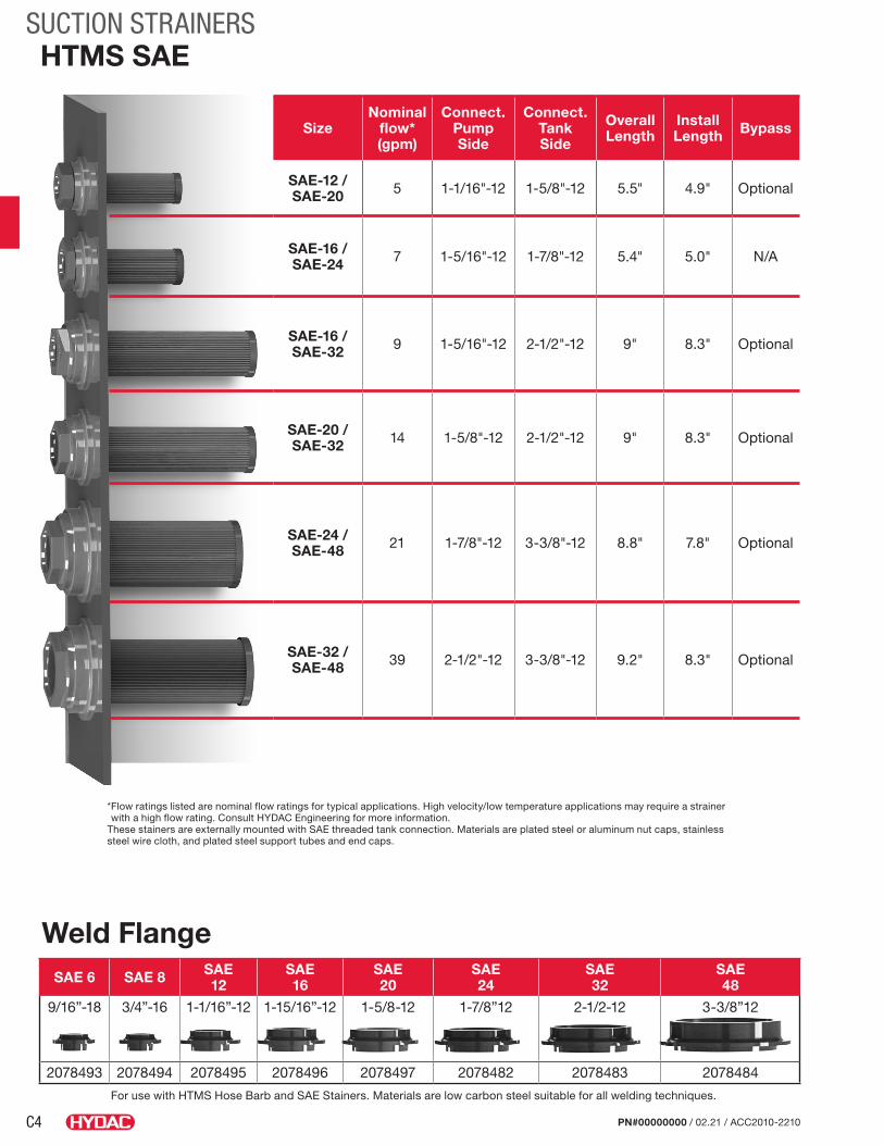
Weld Flange
* Flow ratings listed are nominal flow ratings for typical applications. High velocity/low temperature applications may require a strainer with a high flow rating. Consult HYDAC Engineering for more information.
These stainers are externally mounted with SAE threaded tank connection. Materials are plated steel or aluminum nut caps, stainless steel wire cloth, and plated steel support tubes and end caps.
For use with HTMS Hose Barb and SAE Stainers. Materials are low carbon steel suitable for all welding techniques.
SAE 6 SAE 8 SAE 12
SAE 16
SAE 20
SAE 24
SAE 32
SAE 48
9/16”-18 3/4”-16 1-1/16”-12 1-15/16”-12 1-5/8-12 1-7/8”12 2-1/2-12 3-3/8”12
2078493 2078494 2078495 2078496 2078497 2078482 2078483 2078484
HTMS SAE
SizeNominal
flow* (gpm)
Connect. Pump Side
Connect. Tank Side
Overall Length
Install Length Bypass
SAE-12 / SAE-20 5 1-1/16"-12 1-5/8"-12 5.5" 4.9" Optional
SAE-16 / SAE-24 7 1-5/16"-12 1-7/8"-12 5.4" 5.0" N/A
SAE-16 / SAE-32 9 1-5/16"-12 2-1/2"-12 9" 8.3" Optional
SAE-20 / SAE-32 14 1-5/8"-12 2-1/2"-12 9" 8.3" Optional
SAE-24 / SAE-48 21 1-7/8"-12 3-3/8"-12 8.8" 7.8" Optional
SAE-32 / SAE-48 39 2-1/2"-12 3-3/8"-12 9.2" 8.3" Optional

C5
SUCTION STRAINERS
PN#00000000 / 02.21 / ACC2010-2210
Dimensions
B D Hex
øA
Optional Bypass-Valve
NPT ThreadedConnectionC
Model CodeSFE 11 G 125 A 1 .0 / .
Type of Element SFE = In-Tank Suction
Strainer Element
Size 11 = 3 gpm 15 = 5 gpm 25 = 8 gpm 50 = 10 gpm 80 = 20 gpm 100 = 30 gpm 180 = 50 gpm 280 = 75 gpm 380 = 100 gpm
Type of Connection G = NPT Threaded Connection
Nominal Filtration Rating (micron) 125 = 149 µm – 100 Mesh Screen 74 = 74 µm – 200 Mesh Screen
Clogging Indicator (not applicable) A = No clogging indicator
Type Number 1
Modification Number (latest version always supplied) .0
Bypass Valve (omit) = Without Bypass-Valve BYP = With Bypass Valve (3 psi) (not available for size 11)
SizeNominal
Flow (gpm)
ØA B C (NPT)
D HEX
Media Area (sq. in.)
SFE 11 3 1.95 2.68 3/8 1.00 15SFE 15 5 1.95 4.19 1/2 1.00 25SFE 25 8 2.67 3.55 3/4 1.43 50SFE 50 10 2.67 5.25 1 1.62 90SFE 80 20 3.47 6.62 1 1/4 2.00 135SFE 100 30 3.47 8.01 1 1/2 2.38 195SFE 180 50 4.03 9.88 2 2.78 260SFE 280 75 5.19 10.25 2 1/2 3.25 325SFE 380 100 5.19 11.75 3 3.75 410
Without Bypass-Valve With Bypass-Valve
Description HYDAC Suction Strainer Elements are designed for installation into suction lines of pumps. Extra caution should be taken to ensure that the suction elements are always mounted below the minimum oil level of the reservoir.
The suction strainer elements can be supplied with a bypass valve to reduce high pressure drops caused by contaminated elements or high viscosity fluids during cold starting. The bypass valve opens at 3 psi. For best results, suction strainer elements should be sized for clean element pressure drops of no higher than 0.5 to 0.7 psi.
HYDAC Suction Strainer Elements are manufactured using stainless steel wire screen media, plastic nut caps, and plated steel end caps and support tubes.
Suction strainer elements are only intended to protect hydraulic pumps against catastrophic failure caused by coarse contaminant.
Suction strainer elements should be inspected and cleaned regularly.
Suction strainer elements should not be used as the only filtration elements in a hydraulic system. Pressure filters and return line filters, with reasonable dirt holding capacity, must be installed to provide protection against component damage caused by fine contaminants.
Cleaning Procedure
Remove external build-up of contaminant with cleaning fluid in separate tank.
Flush element with clean solvent and blow through wire screen media with air.
Hydraulic DataPressure Drop vs. Flow:
• Pressure drop will be < 2 psi when strainers are used within the recommended flow range, and with a standard hydraulic fluid with a viscosity of 141 SSU and specific gravity of 0.86.
Temperature:
• 15° to 180°F (-9° to 82°C)
SFE SeriesIn-Tank Suction Strainer Element
Notes:1. Dimensions are in inches (mm).2. Dimensions are for general information only, all critical dimensions should be verified by requesting a certified print.

C6
SUCTION STRAINERS
PN#00000000 / 02.21 / ACC2010-2210
AC
B Connectionsize
Model Number Part No. Connection Size
Max. Flow gpm (lpm)
∆ psi at Max. gpm
Dimensions
A B* C
MSS-1 02082431 1” NPT 15 (55) 0.05 5.25” (133) 3.25” (83) 1.62” (41)
MSS-1 1/4 02082432 1 1/4” NPT 25 (95) 0.05 8.25” (210) 3.50” (89) 3.00” (76)
MSS-1 1/2 02082433 1 1/2” NPT 35 (135) 0.08 8.25” (210) 3.50” (89) 3.00” (76)
MSS-2 02082434 2” NPT 50 (190) 0.10 8.25” (210) 3.50” (89) 3.00” (76)
MSS-3 02082435 3” NPT 100 (380) 0.02 10” (254) 3.50” (89) 4.00” (102)
*B Dimension larger for SS20 versionsNotes:1. Dimensions are in inches (mm).2. Dimensions are for general information only, all critical dimensions should be verified by requesting a certified print.
DescriptionWith the use of HYDAC’s Magnetic Suction Separators, suction line filtration is provided without starving the pump. They offer unique protection for pumps from all sizes of ferrous particles, some of which have the potential of destroying a pump in a single pass. Large ceramic magnets are spaced along the length of the separator. All hydraulic fluid entering the pump must move at low velocity through a powerful magnetic field. This field traps large quantities of micronic ferrous particles. The viscous properties of the fluid can cause some non-ferrous particles to adhere to the magnetically trapped particles.
The MSS series is available in sizes ranging from one to three inches. The chart below shows the part numbers, specifications, and dimensions of available models.
The standard outer screen has adequate open area (0.079 inch diameter perforations) to eliminate the possibility of pump starvation. All models are also available with a pleated 20 mesh screen (850 µ) by adding SS20 to the model number. (Example MSS-1 SS20).
All units have a removable outer screen that can be cleaned and re-used to extend service life and minimize pressure drop.
Dimensions
MSS SeriesMagnetic Suction Separators
Model CodeMSS - 1-1/2 .
Series
Connection Size 1” NPTF 1-1/4” NPTF 1-1/2” NPTF 2” NPTF 3” NPTF
Nominal Filtration Rating (omit) = 74µm - 200 mesh screen SS50 = 300µm - 50 mesh screen SS20 = 850µm - 20 mesh screen
Standard Outer Screen
SS20 Mesh Screen

C7
SUCTION STRAINERS
PN#00000000 / 02.21 / ACC2010-2210
PORT SIZE(PER SAE J514)
C
ØE
D
ØBØA
ø O.D.
L3L2
L
L1
ø E
Thread A(O-Ring Included)
Model CodeHTMS HB 1/1.25 100 .
Series
Connection Type
Connection / Hex Size
Mesh 100 = 100 Mesh (149 micron)
Options (omit) = Standard (no bypass) RV3 = 3 psi bypass valve
Model CodeHTMS SAE 16 100 .
Series
Thread Type
Thread B Size
Mesh Size 100 = 100 Mesh (149 micron)
Options (omit) = Standard (no bypass) RV3 = 3 psi bypass valve
Hose Barb
Weld Flange (SAE)
Model Code Part No. Port SizeDimensions
ØA ØB C D ØEHTMS TWF-6 02078493 9/16”-18 1.50” 0.93” 0.56” 0.31” 1.00”HTMS TWF-8 02078494 3/4”-16 1.50” 0.93” 0.56” 0.31” 1.00”HTMS TWF-12 02078495 1-1/16”-12 2.13” 1.38” 0.69” 0.44” 1.44”HTMS TWF-16 02078496 1-5/16”-12 2.38” 1.66” 0.75” 0.50” 1.75”HTMS TWF-20 02078497 1-5/8”-12 2.69” 2.00” 0.75” 0.50” 2.13”HTMS TWF-24 02078482 1-7/8”-12 3.00” 2.25” 0.75” 0.50” 2.38”HTMS TWF-32 02078483 2-1/2”-12 3.50” 2.63” 0.84” 0.59” 2.88”HTMS TWF-48 02078484 3-3/8”-12 4.63” 3.66” 1.00” 0.81” 3.94
Model Code Part No. Thread A ø O.D. Hex Size GPM*Dimensions
L L1 L2 L3 ø EHTMS HB 1 / SAE 24 100 02078485 1-7/8”-12 1.00” 1.25” 8 9.30” 7.30” 2.00” 1.25” 1.65”HTMS HB 1.25 / SAE 32 100 02078486 2-1/2”-12 1.25” 1.50” 14 10.00” 8.00” 2.00” 1.25” 2.12”HTMS HB 1.5 / SAE 48 100 02078487 3-3/8”-12 1.50” 2.00” 21 10.30” 7.82” 2.48” 1.50” 3.22”HTMS HB 2 / SAE 48 100 02078488 3-3/8”-12 2.00” 2.50” 40 10.80” 7.84” 2.97” 2.00” 3.22”
Model CodePart No.
Per SAEJ514Hex Size GPM* Screen Area
(Sq. In.)Dimensions
THD A THD B C D ØEHTMS SAE 16 100 02078472 2-1/2”-12 1-5/16”-12 2.13 9 90 9.00” 0.75” 2.24”HTMS SAE 20 100 02078473 2-1/2”-12 1-5/8”-12 2.13 14 90 9.00” 0.75” 2.24”HTMS SAE 24 100 02078474 3-3/8”-12 1-7/8”-12 2.50 21 230 8.80” 0.90” 3.22”HTMS SAE 32 100 02078475 3-3/8”-12 2-1/2”-12 3.00 39 230 9.30” 0.98” 3.22”
HTMS SeriesTank Mounted Suction Strainer ElementsSAE O-Ring
ø E
D
C
Thread B
Thread A(O-Ring Included)
* Flow ratings listed are nominal flow ratings for typical applications. High viscosity, low temperature applications may require a strainer with a higher flow rating. Consult HYDAC Engineering for more information.
Notes:1. Dimensions are in inches (mm).2. Dimensions are for general information only, all critical dimensions should be verified by requesting a certified print.

C8
SUCTION STRAINERS
PN#00000000 / 02.21 / ACC2010-2210
Model CodeHTMS NPTM 2 100 .
Series
Thread Type
Thread B Size
Mesh Size 100 Mesh (149 micron)
Options (omit) = Standard (no bypass) RV3 = 3 psi bypass valve
Model CodeHTMS NPT 1/2 100 .
Series
Thread Type
Thread B Size
Mesh 100 Mesh (149 micron)
Options (omit) = Standard (no bypass) RV5 = 5 psi bypass valve
ø E
L2
Thread A
Thread B
L
L1
ø E
D
Thread B
C
Thread A
Male NPT Ports
NPT
Model Code Part No. GPM* THD A THD B Hex SizeDimensions
L L1 L2 ø EHTMS NPTM 2 100 02078480 50 2” NPT 2” NPT 2.75” 13.50” 10.75” 2.70” 2.12”
* Flow ratings listed are nominal flow ratings for typical applications. High viscosity, low temperature applications may require a strainer with a higher flow rating. Consult HYDAC Engineering for more information.
Notes:1. Dimensions are in inches (mm).2. Dimensions are for general information only, all critical dimensions should be verified by requesting a certified print.
Model Code Part No. GPM* Screen Area (Sq. In.) THD A THD B Hex Size
DimensionsC D ø E
HTMS NPT 1/2 100 02078460 5 35 1” NPT 1/2” NPT 1.43 5.38” 1.10” 1.18”HTMS NPT 3/4 100 02078461 10 64 1 1/4” NPT 3/4” NPT 1.81 7.50” 1.20” 1.14”HTMS NPT 1 100 02078462 15 86 1 1/2” NPT 1” NPT 2.00 8.25” 1.30” 1.65”HTMS NPT 1 1/4 100 02078463 25 125 2” NPT 1 1/4” NPT 2.55 10.00” 1.30” 2.12”HTMS NPT 2 100 02078464 50 260 3” NPT 2” NPT 3.30 10.25” 1.70” 3.03”HTMS NPT 3 100 02078465 100 315 4” NPT 3” NPT 5.00 11.30” 1.80” 3.78”


![ER]\d `_ Sfe 4`_X dfcV `W DV_R 8`ge - Daily Pioneer](https://static.fdokumen.com/doc/165x107/631e68b75ff22fc74506ae42/erd-sfe-4x-dfcv-w-dvr-8ge-daily-pioneer.jpg)


![8VY]`e XRZ_d faaVc YR_U Sfe dZefReZ`_ dYR\j - Daily Pioneer](https://static.fdokumen.com/doc/165x107/6320d5eaeb38487f6b0fcb21/8vye-xrzd-faavc-yru-sfe-dzefrez-dyrj-daily-pioneer.jpg)