PARAMETRIC STUDIES OF INTZE TANK
83
PARAMETRIC STUDIES OF INTZE TANK A DISSERTATION Submitted in partial fulfillment of the requirements for the award of the degree of MASTER OF TECHNOLOGY in CIVIL ENGINEERING (With Specialization in Building Science and Technology) By MD. NOMAN s )1 DEPARTMENT OF CIVIL ENGINEERING INDIAN INSTITUTE OF TECHNOLOGY ROORKEE ROORKEE-247 667 (INDIA) JUNE, 2007
-
Upload
khangminh22 -
Category
Documents
-
view
0 -
download
0
Transcript of PARAMETRIC STUDIES OF INTZE TANK

PARAMETRIC STUDIES OF INTZE TANK
A DISSERTATION
Submitted in partial fulfillment of the
requirements for the award of the degree
of
MASTER OF TECHNOLOGY in
CIVIL ENGINEERING (With Specialization in Building Science and Technology)
By
MD. NOMAN s )1
DEPARTMENT OF CIVIL ENGINEERING INDIAN INSTITUTE OF TECHNOLOGY ROORKEE
ROORKEE-247 667 (INDIA)
JUNE, 2007

CANDIDATE'S DECLARATION
I hereby certify that the work, which is being presented in the dissertation entitled
"Parametric Studies of Intze Tank" in partial fulfillment of the requirement for the
award of the degree of Master of Technology in Civil Engineering with specialization
in Building Science & Technology, submitted in the department of Civil Engineering,
Indian Institute of Technology Roorkee, Roorkee, is an authentic record of my own work
carried out during the period from July 2006 to June 2007 under the guidance Dr. Vipul
Prakash, Associate Professor and Dr. Pramod Kumar Gupta, Assistant Professor,
Department of Civil Engineering, Indian Institute of Technology Roorkee, Roorkee,
India:
The matter embodied in this dissertation has not been submitted by me for
the award of any other degree.
Date: 26 June, 2007 vt-As Place: Roorkee Md. Noman
CERTIFICATE
This is to certify that the above statement made by the candidate is true to the best
of our knowledge and belief.
%al rip
(Dr.Pr :■Tod K mar Gupta)
Assistant Professor
.Department of Civil Engineering
Indian Institute of Technology Roorkee
Roorkee (UA)- 247667, INDIA
va. Pvc3cO.AL (Dr. Vipul Prakash)
Associate Professor
Department of Civil Engineering
Indian Institute of Technology Roorkee
Roorkee (UA)- 247667, INDIA

ACKNOWLEDGEMENT
It is a matter of great pleasure for me to express my deep sense of gratitude to my honourable supervisors, Dr. Vipul Prakash, Associate Professor and Dr.Pramod Kumar Gupta, Assistant Professor, Department of Civil Engineering, Indian Institute of Technology Roorkee, for their meticulous guidance and generous help during the course of my work. It was very pleasant and inspiring experience for me to work under their able
and kind guidance.
I am very thankful to my friend Ramesh Kumar Gautam, for their regular help in my work.
Last but not least, I find myself fortunate enough to express my love and gratitude
to my parents, brothers and sisters, who have always been a source of inspiration and
strength to me.
Date: 24 June 2007 j.
Place: Roorkee MD. NOMAN
ii

ABSTRACT
Intze tank is an important overhead water storage tank, there for it is
necessary that it should be constructed keeping in view its economy. To obtain
economical design of tank, the proportion of container such as, staging container
diameter ratio, height of cylindrical wall container diameter ratio and horizontal angle of
dome have been varied as well as no of column for design of staging .To achieve this
objective 6 different capacity of intze tank ranging between 300 KL and 1500 KL has
been investigated. For this purpose a computer program in Microsoft excel has been
developed .In Microsoft excel program continuity correction have been work out .The
design of container is carried out by working stress method but staging is carried out by
using limit state method.
To get the economical design of intze tank horizontal angle of conical dome
should be 'less than 45°, ratio of height of cylindrical wall and container diameter ratio
should be between 0.3 and 0.35.0n the other hand staging container diameter ratio effects
the economy of higher capacity of tank only .As the capacity of tank decreases less than
750 KL its effect diminishes. It is also found that the cost of staging depend upon the
number of column.
iii

LIST OF FIGURES
FIGURE NO TITLE PAGE
1.1 Typical Detail of Intze tank 4
2.1 Forces on conical dome 12
5.1
Quantity of concrete, reinforcement and cost of
container for different Value of Xi where k2=0.3
and a=50° 42
5.2
Quantity of concrete, reinforcement and cost of
container for different value of 2 2 where X1.---0.7 and
a=50° 43
5.3
Quantity of concrete, reinforcement and cost of
container for different value of a where 22=0.3
and Xi =0.7 43
5.4
Quantity of concrete, reinforcement and cost of
staging for different no of column and for height of
staging 15m. 46
iv

LIST OF TABLES
TABLE
NO
TITLE PAGE
1.1 Variation of Parameters 5
5.1 Quantity of concrete, reinforcement and cost of
container for different Value of Xi where X2=0.3
and a=50°
39
5.2 Quantity of concrete, reinforcement and cost of
container for different value of X2 where ki=0.7
and a=50°
40
5.3 Quantity of concrete, reinforcement and cost of
container for different value of a where X2=0.3
and ki =0.7
41
5.4
.
Quantity of concrete, reinforcement and cost of
staging for different no of column and height of
staging ,15m,18m,21m.
45
6.1 Recommended proportion of container and staging 48

LIST OF NOTATION
A Semi central angle of Top dome
al Equivalent radius of cone at top face.
a2 Equivalent radius of cone at bottom face
Agt gross area of top ring beam
Agn, gross area of middle ring beam
Agb gross area of bottom ring beam
Ast total tension reinforcement
Asc total compression reinforcement
btr width of top ring beam
b., width of middle ring beam
brb width of bottom ring beam
bbr width of braces
Cf Force coefficient
D1 internal diameter of cylindrical dome
D2 internal diameter of staging
D., Mean diameter of top ring beam
D,„,m mean diameter of cylindrical wall
D.. Mean diameter of middle ring beam
Dien, Mean diameter of conical dome at top face
Deem Mean diameter of conical dome at bottom face
dip horizontal displacement of member
d20 Angular rotation of member
D2bm Mean diameter of bottom ring beam Dc diameter of column.
d effective depth
vi

Es modulus of elasticity of reinforcement
Ec modulus of elasticity of concrete FER unbalance fixed-edge reaction acting on members
He Rise of conical dome
H1 cylindrical Height of container excluding free board..
He, cylindrical height of container
HD height of water above the apex of bottom dome hbd height of bottom dome
htd height of top dome H horizontal edge load of cylindrical dome
Hs height of staging
ILI clear panel height
Hee center to center panel height
It moment of inertia of top ring beam
Im moment of inertia of middle ring beam
Ib moment of inertia of bottom ring beam
coefficient of lever arm
K1 probability factor (risk coefficient)
K2 terrain height and structure size factor
K3 topography factor
length of conical portion from origin
Lbr length of brace.
m modular ratio
Meb bending moment in bottom beam
Mx bending moment in middle ring beam due to cantilever portion.
Mt moment due to torsion
M. ultimate moment.
Me equivalent bending moment
Mp joint moment column braces.
Mbr hogging moment braces meeting at joint.
Nc no of column
vii

Np no of panel Nb no of braces
NO meridional stress NO hoop stress Neow° differentiation of NO with respect to angle.
differentiation of NO with respect to angle Nx force along length of cylindrical wall from top face Ns force along length of conical dome from top face.
P % reinforcement
Pu factored load. PO force in meridional direction Pr force in normal direction Rmi mean radius of top dome
R1 inner radius of top dome
R2 inner radius of bottom dome
Rm2 mean radius of bottom dome
RW mean radius of cylindrical wall.
Rtm mean radius of top ring beam.
R. mean radius of middle ring beam
Rbm mean radius of bottom ring beam
S= length measured from origin of conical dome in the direction of inclined length
of Conical dome
S 11 Stiffness of member when horizontal displacement of joint is unity
S22 Stiffness of member when angular rotation of joint is unity
ttd thickness of top dome
ttr Thickness of top ring beam
tv, thickness of cylindrical wall
tmr Thickness of middle ring beam
tc thickness of conical dome
tbd thickness of bottom dome
vii'

trb thickness of bottom ring beam
tbr thickness of bracing.
T tb Hoop tension in top ring beam T nib Hoop tension in middle ring beam U1 horizontal displacement of Joint
U2 Angular rotation of Joint
V capacity of tank
X,, vertical distance from top of cylindrical dome
Ye unit weight of concrete. Yw unit weight of water
act Permissible stress in concrete on water face in direct tension
acc Permissible stress in concrete on water face in direct Compression
Est Permissible stress in high yield strength deformed bar
act, Permissible stress in concrete on water face in bending compression
cry characteristic strength of reinforcement.
ack characteristic strength of concrete.
Sarni central angle of bottom dome
a angle of inclination of conical dome
ab • semi central angle subtended by supports at the center. Poisson ratio

CONTENT
CANDIDATE'S DECLARATION
ACKNOWLEDGEMENT ii
ABSTRACT iii
LIST OF FIGURE iv
LIST OF TABLE
LIST OF NOTATIONS vi
CONTENTS
CHAPTER
1. INTRODUCTION 1
1.1 General 1 1.2 Literature Review 1 1.3 Object of Study 2 1.4 Scope and Outline of Study 3
2 ANALYSIS AND DES IGN OF CONTAINER
6
2.1 Dimensions of Container 6 2.2 Top Dome 7 .
2.3 Ton Ring beam 8 2.4 Cylindrical wall 9 2.5 Middle Ring beam 10 2.6 Conical Dome 11 2.7 Bottom Dome 14 2.8 Relevant Parameters 15
3. CONTINUITY PROBLEM 17
3.1 General 17
3.2 Continuity correction 18
3.3 Excel program for capacity 1000 KL 27

4. ANALYSIS AND DESIGN OF STAGING: 28 4.1 Introduction 28 4.2 Bottom Ring Beam 28 4.3 Columns 31 4.4 Braces 34 4.5 Relevant Parameters 36
5. RESULTS 38
5.1 Introduction 38 5.2 Container 38 5.3 Staging 44
6. DISCUSS ION AND CONCLUS IONS 47 6.1 Discussion 47 6.2 Conclusions 48 6.3 Scope of Future Study 48
REFERENCES
xi

CHAPTER 1
INTRODUCTION
1.1 GENERAL Water is an essential part of life of all living beings. Besides drinking and other
day to-day purposes it is also required for fire fighting; industrial and commercial use.
The supply of potable water is on of the top priorities of the government to ensure health of its urban and rural population. To ensure continuous supply of water at specified
pressures overhead reservoirs are necessary. Intze tank cost ten to twenty percent of the
overall cost of the water supply scheme of a town which is quite a substantial amount.
Therefore, any saving in the design of Intze tank would lead to economy in the water
supply scheme. Investigations are also required to find out safe and economic design and
constructional procedures so that scarce constructional materials are used to the optimum
limit.
Intze tank consist of a container at the top, supported on a staging to transfer the
load of the container to the foundation. Container consists of a domical roof, cylindrical
vertical wall, a conical dome and a bottom dome. The staging consists of a frame work of
columns and braces or a thin circular shaft. Generally a column-brace system is preferred as staging for Intze tank.
1.2 LITRATURE REVIEW
Elevated water tank are important civil structures, a lot of work has been done on
the methods of analysis and design. Many attempts have been made by research workers
to optimize the various parameters to obtain economical designs.
Most of the work available on intze tank in existing literature is on the tank where
containers supported on column staging. The earlier formulation for analysis and design
of Intze tanks based on the membrane and continuity analysis was done by Arya [1].
A computer programmed based on the above analysis of the container was developed by
Jain and Singh [2]. A more accurate and tedious analysis has been done using the Finite
1

Element Method [3]. Work has also been done on Intze tanks supported on circular shafts and various optimal proportions have been recommended by Rao. [4, 5]. Sharma [6] has proposed various parameters for Intze tanks stating the percentage share of each member
in the total cost of the container. It has been reported that 70% to80% of the cost of the
container is due to the cylindrical wall and the conical dome.
Damle and other [7, 8] have tried another shape of an intze tank in which .the cylindrical wall has been replaced by a number of segmental cylindrical shells in petal shape. A number of models of circular ground reservoir have been tested and reported to
be structurally safe and feasible. It has also been reported that only replacement of
vertical wall could yield 20% saving in cost of container is further stated that there is
potential of 50% reduction in the cost of the container if the conical dome is also
modified to a shape consisting of a number of inclined conical conoids.
Singh [9] has analyzed column and bracing staging by stiffness matrix method
and compared the results with the tube analogy method applied by Jai Krishna and Jain
[11]. Jain and Singh [10] have shown that the tube analogy method gives reasonably
accurate design forces apart from being simpler. Rao[12] and Kundoo[13] have also
given formulation for analysis of supporting towers acted upon by horizontal forces.
Avadesh Kumar [14] has also analyzed R.C.0 over head reservoirs and proposed a
computer program.
1.3 OBJECT OF STUDY
To judge the correct combination of height and diameter of the vertical
cylindrical wall, conical wall and horizontal angle of conical dome is based on economy.
There for we try to obtained suitable parameters by which design should be economical
for different capacity of intze tank. During design continuity correction have been done at
joints. As far as consideration of continuity effects at joints,we know that the solution
obtained by membrane theory failed to satisfy continuity of displacement at the junction.
We have apply edge loads, consisting of shears and bending moments, in order to correct
the discrepancies between the membrane displacements. For that we use bending theory
for shell of revolution. For simplicity we assume that the meridian of the dome and
cylinder meet at a common point without any eccentricity. For solving continuity
2

problem an Excel program has been developed. Apart from container, the design of the
staging is also taken up for the study in this dissertation work.
1.4 SCOPE AND OUTLINE OF STUDY
To get the optimum values of the various parameters of the container and the staging, the parameters were varied as listed in Table 1.1.
This dissertation is divided into 6 chapters. Chapter 1 introduces the problem and
in chapters 2, 3 and 4 the analysis and design of the container and staging is covered. In chapter 3 an excel sheet has been developed to over come continuity effect and to
calculate redundant forces as well as design the container and staging of capacity
1000 KL. In chapters 5 and 6 the results have been discussed and relevant conclusions
have been reported.
3
CYLINDRICAL WALL
BALCONY CUM
MIDDLE RING BEAM
TOP RING BEAM
CONICAL DOME
BOTTOM RING BEAM
H.
GROUND LEVEL
BRACE
COLUMN
CONTAINER A
Hcw
y
to
FIG 1.1 TYPICAL DETAIL OF INTZE TANK
4

Table 1.1 variations of parameters
S.No Name of parameter Value of parameter No. of values of
each parameter
1 Basic parameter
i. Capacity(V) of container in KL
300,500,750,1000,1250,1500, 6
ii. Lateral forces a) Wind Zones Zone 2
1
2 Geometrical parameter i. Height diameter ratio, A2 Q.20,0.25,0.30,0.35,0.4,0.45,and
0.5 7
ii. Staging-container diameter ratio Ai
0.5,0.55,0.6,0.65 and 0.7,and 0.75
6
iii. Horizontal angle of cone a
350,400.450,500,550,600 6
iv. Height of staging 15m,18m,21m 3
v. Number of panels Minimum .
5

CHAPTER 2 ANALYSIS AND DESIGN OF CONTAINER
2.1 DIMENSIONS OF CONTAINER
The capacity of an Intze tank container can be expressed in terms of the volume of the of water is obtained by summation of water containing by cylindrical wall and conical dome and subtracting the volume of bottom dome lies in conical region
V1=volume of water containing by cylindrical wall.
V2= volume of water containing by conical dome
V3= bottom dome lies in conical region
vi=fn*(R)2 *H0 (2.1) 2
V2={—r1*(1)2 *H2} –{—n *A2 *H3} (2.2) 3 2 3 2
11*R 3 V3= 2 (2 3 *Cos° +Cos30) (2.3) 3
V=V1+V2-V3 (2.4)
Tana 2
H3=2 * Tana
Let
_ 2 D1
- 11
2= D1 For a given capacity the diameter of container
2 D13– 4*V
Other dimensions
6.12 + Tan a (1 – 3) 213 (2 – 3Cos 0 + Cos3 0) Sin3 0
(2.5)
6

Hi= /1.2 *Di =cylindrical height of container containing water.
Free board=0.3 m FIcw= Hi+0.3= cylindrical height of container
D2= Ai *D1 =staging diameter
htd =5' =Rise of top dome
5 .—Rise of bottom dome
He--(H2-H3)= Height of conical dome
2Sin A
R2= D2
2Sint9
2.2 TOP DOME Top dome subjected to live load and dead load. The dome is accessible only for
maintenance purposes and hence live load can be taken as 1 KN/m2 as per
IS: 875-1987 [19]. It is supported by top ring beam and cylindrical dome. The rise of
top dome (htd) is usually kept 0.2 times the diameter of container D1 .
The Radius of top dome is given by
R.17 2sD1 ttd
inA 2 (2.6)
The maximum stress occurs at the edge of the dome. The membrane stresses in the dome
are
Ni:Lotd— Wid * R,,,1 N/m
1+ CosA (2.7)
NOtd= — Wtd. * R * CosA 1 N/m (2.8) 1+ Cosil
Where
Wtd-----(Dead load +live load) per unit area of dome Di
2(Ri — hid ) A= Tan-1 (2.9)
7

The circumferential stress changes from compressive to tensile if Semi central angle of dome exceeds 51.8 degree.
Hence it is desirable to keep Semi central angle less than 45 degree to avoid double form of shuttering for the shell. The thickness of dome for maximum thrust criterion is
ttd NO mrn (2.10) 1000* cr„
Thickness of dome is primary controlled by practical consideration, since the stress is compressive nature and the thickness obtained from equation (2.10) is small. The thickness normally provided is 80 mm. Dome is reinforced by nominal reinforcement of
0.3% mild steel and 0.24% for steel in the form of square mesh.
2.3 TOP RING BEAM
Top ring beam provided to resist horizontal component of the meridional thrust
of top dome. The center line of the ring beam is aligned with center line of the top
dome. The hoop tension is given by
T tb— fd Cos
2 A*Dtin kg.... (2.11)
Area of tension reinforcement is given by
Ast2,_ cm2 (2.12) Est .
The top ring beam is also designed on no crack basis as to avoid possible corrosion of
the reinforcement and also to provide good stiffness to support the roof dome:
Thickness of top ring beam is primary controlled by consideration
Computed tensile stress (at) — Tib < act (2.13) b„ * t„ + (m — 1)* Ast2
ast =Permissible stress in high yield strength deformed bar act =Permissible stress in concrete on water face in direct tension
8

2.4 CYLINDRICAL WALL For membrane analysis, the wall is assumed free to deform at both edges and
thus under a pure hoop tension. Minimum thickness for wall will be taken as 100mm. The effects continuity on wall has been discussed in next chapter (3).
For dead load . W1=Dead load of top ring beam
=2500*ttr*bt kg/m (2.14)
Nx=(N 0 td*sinA+W1)-Y0t,*Xw kg/m (2.15)
Where Nx= Load on cylindrical wall due to its dead load per unit length
NO=0
For water load
Nx=0
Yw*D.*Xw NOw— ....kg/m (2.16) 2
Where
Xw= vertical distance from top of wall
Area of tension reinforcement is given by
AstiNO(avg.)* Ax
CM2
Est
(2.17)
Area of compression reinforcement is given by
Asc3=0.24% bw*tw for steel.
Where .
A x=zone length
bw=100 cm
The cylindrical wall is also designed on no crack basis. Thickness of cylindrical wall is
controlled by consideration
)* Ax Computed tensile stress (at) — NO(avg. c< t •
, * t,s, + (m — 1) * Asti
9

2.5 MIDDLE RING BEAM The purpose of ring beam is to provide a horizontal support to conical wall. It is
provided wide enough so as function as a balcony for inspection purposes. The design of ring beam is governed by hoop tension caused by horizontal component of meridonial
thrust. The effects continuity on conical dome will studies in next chapter (3).
The total load on middle ring beam is
Let W1 =Dead load+Live load of top ring beam ....kg/m
W2 =. Nx(at Xw=11,,,,) ....kg/m
W3 = dead load of middle ring beam.
= (2500*bmr*tmr) kg/m (2.18)
We = (Wl+W2+W3)
Hoop tension in middle ring beam is given by
We * cota * Tmb kg (2.19)
2
Where
a is inclination of conical Dome with horizontal
Area of tension reinforcement is given by
ASt4a= lb o.sl
(2.20)
Thickness of middle ring beam is primary controlled by consideration
Computed tensile stress (at) — < act b.,.* Tmb
+ (m —1)* Ast4c,
Live load on the balcony can be taken as 1.5 KN/m2 as per IS: 875-1987 [19].
Self weight and live load on the balcony ring beam
Wbc=(2500*bmr*tm,-+1.50*tm0
N— 1
1 + cfr m* crcb
J=1-N/3
kg,/m (2.21)
(2.22)
10

Area of tension reinforcement in redial direction.
cm2 Astab= cyst* j*d (2.23)
d=tmr 25-- mm 2 4- W. bc * b 2nir
X 2
Where ast =Permissible stress in high yield strength deformed bar acb=Permissible stress in concrete on water face in bending compression
2.6 CONICAL DOME Conical dome support a uniform vertical wall at it top edge. If this dome is
assumed as consisting of individual slanting strips, then each strip will tend to rotate
outwards about it bottom edge. This will increase the circumference of the circle joining at the top of these strips and each strip will separate out from each other. Since the strips
are joined to each other monolithically and can not separate, a hoop tension will created
at the top of this dome. This hoop tension will exert a radical inward force at each strip
and will oppose it rotation outward. So that the moment about bottom edge of strip,
causing rotation is zero. The resultant force must lie along the slant surface of strip. The
magnitude of radial force created at top edge is so much that on combining with vertical load the resultant lies along the meridian of conical dome. Thus the vertical load at top
edge of the conical dome is supported by it with the creation of meridian thrust and hoop
tension. In the same way water pressure on the conical dome and its own weight acting at
any point give rise to hoop tension at each plane, whose inward reaction, together with
the water pressure and weight of dome, cause a resultant force which is meridoinal.There
is no moment and shear in conical dome.
11

W11+W22+W33+W4
S
r
•****,.
0
*4.41
Fig 2.1: FORCES ON CONICAL DOME
For Dead load
Let
W11= weight of W1
=W1*II* Dtm kg (2.24)
W22=weight of W2
= W2*II*Dw. kg (2.25)
W33= weight of W3
=W3*II* Dm. kg (2.26)
Lc=length of conical portion from origin of conical dome
Dc. Lc= m ... (2.27) 2Cosa r=radius at any height Xc from top face conical dome where Xc He
_( Dc. )( LcSina — Xc m.... 2 LcSina
S=length measured from origin of conical dome in the direction of incline length
= Lc Xc (2.29) Sina W4= weight of conical dome at distance" r "as shown in figure
(2.28)
12

Dan Dcm 11(+ r) (Xc2 + ( r)2 kg 2 2
(2.30)
NsD W11+W22+W33+W4
2*n*r*Since kg/m (2.31)
NODc=circumferential force in conical dome due to dead load.
= Yc* tc * Cosa(Lc* Cota
For Water Load
Xc * Cota )) kg/m ..... Sina
(2.32)
H1=height of water above top of cone
Ns,r=force along length of conical dome from top due to water.
Yw* Cota ( H1 * Lc2 ) ( Lc3 *Sina )+ ( H1 + LcSina)* S) (S2 * Sina Nsw= [
2 6* s 2 3 )
Kg/m (2.33)
NO ,,,= circumferential force in conical dome due to water
Newt Yw(H/ + LcSina S * Sina)S * Cota kg/m (2.34)
Area of tension reinforcement is given by
Ast5— NO(avg.)* AS
(2.35)
Area of compression reinforcement is given by
Asc5=0.24% betc for for steel.
Where
A S=zone length in conical dome
The conical dome is also designed on no crack basis. Thickness of conical dome is
controlled by consideration
AS Computed tensile stress (at) = NO(avg.)* < act - b,* t, + (m —1) * Asts
13

2.7 BOTTOM DOME The bottom dome is of spherical shape and is subjected to the weight of water
over it and self weight. It is supported by a bottom ring beam. The rise of top dome (hbd) is usually kept 0.2 times the diameter of container D2. The Radius of top dome is
given by
Rm2 = D2 + tbd 2Sin0 2
m (2.36)
The thickness normally provided is 80 mm. The maximum stress occurs at the edge of
the dome. The membrane stress resultants in the dome are obtained separately for dead
load and water.
For Dead Load
W bd * Rm2 NODbd- 1 + COS kg/m (2.37)
() NODbd= — Wbd * FL in2 * Cosa 1 kg/m
1+ Cost,
For Water Load:
HD=height of water above the apex of bottom dome= (H1+Hc-hbd)
(2.38)
Yw*Rm2 [H + R Owbd=
Sin 02 2 3 D m2 )* (cos0) 2 — Rm2 * (cos0)3)
2 6 HD Rm 2 N kg/m....(2.39)
1\18wbd=- YW*Rm2 [H D Rm2 (1 — cos 0)] - N 0 wbd kg/m (2.40)
NO= Neorma + NOwbd N0= NODbd+ NeWbd
Thickness of dome is primary controlled by practical consideration, since the stress is
compressive nature and the thickness obtained from equation (2.10) is small, the
thickness normally provided is 100 mm.The dome is reinforced by nominal
reinforcement of 0.3% mild steel and 0.24% for steel in the form of square mesh.
14

2.8 RELEVENT PARAMETER
2.8.1 Volume of concrete
(a) Top Dome
Vtdc— 27r *to * Rna * hId (2 — 3CosA+Cos3 A)
3* (1— Cavil) (b) Top Ring beam
Vtrc=2 7c * Rtm * bfr * t„
(c)Cylindrical Wall
Vcw,c=. 2 * * H c,* 12,,* t
(d) Middle Ring beam
Vmre=2 a.* Rm.* bmr * tmr .....m3
(e)Conical Dome n- * t c * Seca
cdc— 3 (Dl cm )
(f) Bottom Dome 27r* tbd * Rm2 * hbd (2 —3Cost9 +Cos30)
Vbc—
111 3*(1— Cos 0)
Total Volume of oncrete
Vs= Vtdc +Vtrc + Vcwc+ Vmrc+ Vcdc+ Vbc
2.8.2 Volume of reinforcement
(a) Top Dome
Vtds=0.0048 Vtdc m3
(b) Top Ring Beam
Vtrs=71- * D, * Ast2 m3
(c) Conical Wall
VcwS * Dwm * Ast3 + 0.0024 * Ticwc m3
(d) Middle Ring beam
M3
M3
M3
M3
(2.41)
(2.42)
(2.43)
(2.44)
(2.45 )
(2.46 )
(2.47 )
(2.48 )
(2.49 )
15

V.„=71- * Dm m * Ast 4a + Ast 4b * bmr
(e) Conical Dome
-Yeas= 0.0024 * Vcdc E 27r r„„* Ast
Where i=no of zonal length in He
E Ast = Ast,
(f) Vbs=0.0048 Vbc
Total Volume of reinforcement Vs= Vtds +Vtrs + Vows+ Vnus+ Vcds+ Vbs
M3
1113
M3
(2.50 )
(2.51)
(2.52)
(2.53)
2.8.3 Cost of container
On the basis of the present prevailing rates of material the rates of various items are given as under: (1) Cement concrete of grade M25 in superstructure excluding Rs.2900 per cu.m
cost of centering and shuttering (2) Tor steel reinforcement including cutting,bending,placement Rs18000 per ton
and its wastage There for the cost of container =Vc*29000+78.5*18000*Vs Rupees (2.54)
16

CHAPTER 3
CONTINUTY PROBLEM
3.1 GENRAL The pure membrane state of stress will exit so long as each shell is simply
supported at its edges, that is, it is able to undergo resulting displacement without
"restrain, while the supports supply the necessary reaction to balance the meridionally
forces. This however is not possible in practices and the edge displacement is actually restrained. This give to raise secondary stresses in the form of edge moment and hoop
stresses. It will be seen that discontinuity would occur at junction of different shells.
There will, therefore come into play additional joint reaction to maintain continuity. It
will be seen that the angle at corner of top dome ,cylindrical wall and corner of
cylindrical wall and conical dome tend to close resulting in sagging moment, while the
angle at corner of conical dome and bottom ring beam tend to increase to hogging
moment. Also at the joint the edge of top dome and vertical wall are pulled outward,
resulting in tensile hoop stresses, while the top ring beam at that joint is pushed inward
and hoop tension reduced. Similarly the middle ring beam and edges of conical dome at
joint are pushed inward causing reduction of hoop tension while the vertical wall is
pulled outwards with increased hoop tension. At joint of conical dome and bottom dome
the conical dome is pushed inward, the bottom dome and bottom ring beam pulled
outward. This cause a hoop compression in conical dome and cause of reduction of hoop
compression in bottom ring beam and bottom dome.
The complete analysis of intze tank, consist two parts (a) membrane analysis (b)
effect of continuity. The net stress are obtained by adding the stresses due to the above
two cause. The stresses due to continuity are obtained by applying the principle of consist
deformation. the vertical displacement are always consistent at each joint as each shell is
free to deform in this direction and consistency has only to be satisfied for horizontal and
angular displacement between shell meeting at a joint. This will need of stiffness of each
shell at edge for horizontal and angular movements. The stiffness is given by Kelkar V.S
and Sewell R.T," Fundamental of the analysis and design of shell structures"
17

3.2 CONTINUTY CORRECTION The forces due to continuity are obtained by applying equation of compatibility Xi=Si*UFFFERi (3.1) Where
i=symbol of Dome, ring beam, cylindrical wall, conical shell
FER=unbalance fixed- edge reaction acting on the members , corresponding to U1 and U2, acting on different member.
Xland X2 are the redundant forces of members For solving Ul and U2 the governing equation is
(3.2) s21 E s22 FER 2
where
FERi= -(S11*(110+S12*d2o) (3.3) FER2= -(S21*dio+S22*d2o) (3.4) U1= horizontal displacement of Joint
U2= Angular rotation of Joint
dio=horizontal displacement of member
d20=Angular rotation of member
After obtaining U1 ,U2 ,FERI and FER2 of each member, redundant forces X1and X2 of each members obtained by governing equation
[ xl .s11 s12 Ul FER1
x2 s21 s22 U2 - FER2
±
• _
sll E s12 E FER,
(3.5)
18

ASSUMPTION (1) Radial thrust (2) Moment
Out ward positive Clock wise positive
Inward negative (looking at the meridian on the left hand Side of the axis of revolution) Anti clock wise negative
3.2.1 Continuity correction 1: At joint of top dome, cylindrical wall and Top ring beam.
STIFFNESS OF TOP DOME
E* t id
E*tid 2al,2 *sinA
E*t td *R ml
2alt 3
Std=
Rmi * (sinA )2 (3.6)
E * t td
2a11 2 * sinA
Where
E=5000 6a,
4 12(1 — V2) * Rm1 2 4a1, = ttd 2
EMI = Eck, = R,,,i * SinA(NO,d — vN00) tt d
1+ COtA(1+.0(N 0 id 'NOW) = Ed 20 = [N td° VN Old° t tc,
Where 'Ail= horizontal diflection X= angle of rotation
W,, * R , Now_ m. 1+ CosA
(3.7)
(3.8)
(3.9)
(3.10)
19

NOtd= — Wtd * R ml (COSA 1
1+ CosA ) (3.11)
NeOtd°--Wtd* Rmi * SinA (1+ CosA)2
0 Wed * R 1 * SinA * (2 + 2CosA + CosA2) NOtd m (1+ CosA) 2
(3. 1 2)
(3.13)
Where
(0°) indicate differentiation
STIFFNESS OF CYLINDRICAL WALL
Sw=
EAH
Ex
Where
4otiw
E*t w -E*tw
(3.14)
(3.15)
(3.16)
(3.17)
R w *aim, 2a1 2
-E*tw E*t w *R, 2a1„2 2a1,,,
= Ed 10 = H * Ri„3
3
3 2*(K
E " )al
= Ed20 = —H*Rw 2 K 2 2* (E")oti
4 =
12(1—v 2 * R, 2
t w
K — E*tw3 (3.18) iv 12(1—v2 )
H=Neotd*CosA (3.19)
20

Dl cmEquivalent radius at top of cone (al)— 2 *Sina m (3.22)
Equivalent radius at bottom of cone (a2)— D2 cm
2* Sina m (3.23)
STIFFNESS OF TOP RING BEAM
E * Agt 2 R tin
0
(3.20) Str E* It R 2 tm
For top ring beam
EAH = Edio = Tb * Rim
Agt (3.21)
Ex = Ed20 = 0
After getting d10 and d20
Xiand X2 redundant forces of members obtained by governing equation (3.5)
3.2.2 Continuity correction 2: At joint of cylindrical wall, middle ring beam, conical
dome.
For solving continuity effect conical dome is treated as spherical dome whose
equivalent radius is obtained by
STIFFNESS OF CONICAL DOME
E*tc a l *alc *(sina)2
E*tc 2a1,2 * sina
(3.24) E*tc E*tc*a l
2a1 3 2a1c 2 *sina
S c 1 —
21

• NeDci= — Wcd * al ( Cosa 1
+ os a) kg/m
\ 1-Opei 1+ Cosa kg/m Wcd * al
Where
4 = 12(1— V2 )* a l2 4a lc te2
For imaginary conical dome For Dead Load
1\10Dei — o wca * *Sina (1+ Cos a)2
NOpei°— Wca * * Sina * (2 + 2Cos a + Cos a2 ) 0 4- COS00 2
Where
Wca is dead load of imaginary conical dome For Water Load
From definite integral approach
[N0 * r2 * Sin2a10 f(P,.Cos a — Pgina)rl* r2 * Sina * da 0
(3.25)
(3.26)
(3.27)
(3.28)
(3.29)
(3.30)
where
rl=r2=ai
Pc1)=0
Pr= — * Hw + * al (1 Cosa)) = —(Y„, * Hw +1— Cosa)) .. al
(3.31)
and a is dummy variable. Then we get
[— Y.,„ *a/2 [H„ NOwci=- (1 Cos2a) + 4Cos3 a —3Cos2a —1]
Sin 2a 4a/ 12
2 w , w Newel= —Yw * .(
H +1— Cos a) --Ar6 1 a1
(3.32)
(3.33)
22

—Y„,* ai2
Sina 4 6Sin2a * Sin2a —12Cos 2 aSin3 — Sin2a +1.5Sin4a — 4 sin 2aCos 3 a
12 1
NOwci° =
(3.34)
Newc1°= —Y„* al Sin —
No:Dc 1— NODei+ NOwei 1•Tesc1°=NODe1°+N(Dvvel °
Neci=NeDci+ Newci
NOci°=NeDci°+ Newc10
EAI = Ed 10 = al * Sinot(N ci — v * NO.1) tc
Ex = Ed 20 = [NO ci ° - vN ci 0 j+ Cota(1+ v)( N61,1 NOci ) tc
STIFFNESS OF MIDDLE RING BEAM
E*As.
R 2 mm
Smr
E*I. R. 2 m
For middle ring beam
EMI = Ed 10 = Tmb * Rmni 2
_Aga;
Ex = Ed 20 =0
After getting d10 and d20
X1and X2 redundant forces of members obtained by governing equation (3.5)
0 wcl
0
0
(3.35)
(3.36)
(3.37)
(3.38)
(3.39)
23

* a2 * (Cosa 1 + Cosa) Ne D c2
1
3.2.3 Continuity correction 3: at joint of conical dome, bottom Dome, Bottom ring
beam. STIFFNESS OF CONICAL DOME
E*tc E*tc 2c
* (sin a)2 2a2,2 *sina S C2=-- (3.40)
(3.41)
(3.42)
(3.43)
(3.44)
(3.45)
E * tc E*tc*a2 2a2c2 * sina 2a2c 3
Where
4a2, 4
= 12(1—v2 a 2 2
tC 2
For Dead load
NWroc2 = Wed * a2 1 ± Cosa
0 —Wcd *a2 * Sina Nwpc2 _ (1+ Cosa)2
— Wcd
*a2 *Shia * (2Cos a + Cosa 2) NO Dc2°— Cosa)2 For Water Load
From definite integral approach
kg/m
kg/m
[NO *r2*Sin2a]o
where
rl=r2=a2
P(1)=-0
a = f(PrCos a — POSina)r1* r2* Sina * da
o
Pi= — * fl,„ -1-- H c ) Y,„* a2 1—Cosa)) = —(Y„,* a2( (Hw + H e) +1 Cosa)) (3.46) a2
24

and a is dummy variable. Then we get
4Cos3 a — 3Cos2a —11 NOwc2= — .1c * a22 [(H.'
+ Hc) (1 Cos2a) +-
Sin2 a 4a2 12
(3.47)
NeWc2= yw * a22 [ + H3 3 1 Cos a — NO,,c2 a2 (3.48)
NOwc2°
— Yw * a2 2 Sina 4
6Sin2a * Sin2 a —12Cos2 aSin3 a — Sin2a +1.5Sin4a — 4 sin 2aCos3 a 12
(3.49)
— Yw * a22Sina — NOwc2° (3.50)
NiDe2= NODe2+ NOwe2 N4b2= NODei+ NOwe2° Nec2=NeDc2+ Newc2
•Nec2D=NeDc20+ Newc20
EMI = Edio = a2 * Sina(NOG2 — vN0c2) tc
Ex = d20 = [NO 2° vN0,2) Cota(1+ v)( Nec2 - NOc2 ) tc
(3.52)
STIFFNESS OF BOTTOM RING BEAM
E*Agb R bm 2
(3.51)
0
(3.53) E*Ib
R b 2
For bottom ring beam
Sbr=
0
25

EdH
Ex =
Sbd=
4a
For Dead
NIDbd
NODbc =.
= Ed 10 = (Ncobd * Cos° N s * Cosa)* Rb m 2 (3.54)
STIFFNESS
A gb Ed 20 = 0
OF BOTTOM DOME
E*tb E*tb
(3.55)
(2.37)
kg/m (2.38)
R m2 * alb * (sinA)2 2a1b 2 * sinA
E*t b E*t b
2alb 2 * sinA 2a, b 3
4 12(1—v 2 )*Rm22 = lb • 2
tbd
Load
Wbd * Rm2 kg/m 1+ Cos°
* 1 ) Wbd * Rm2 (Cos° I+ Cos°
For Water Load:
HD=height of water above the apex of bottom dome= (HI+Hc-hbd)
Yw R HD + R m2 * * 0)3 ) — HD k/m....2.39*
— Rm2 (cos Rm2 g ( ) Nolwbd— sine 2
( ) (COS [
2 3 2 6
kg/m..... (2.40)
INT(Dobd°— W bd* R7122 * Sin° (3.56)
(1+ Cos0)2
-?„-rn 0_ Wm * R„,2 * Sin° * (2 + 2Cost9 + Cos02 ) (3.57) uDbd (1 + COSO)2
NOwbd= - Yw*Rm22 [H D -4--Rm2 (1— cos 0)] - N 0 Wbd
26

1\1.(pwbd°=
—(11 + R„, * Sin20]+[R.2 * Cos 20* 01+ Sin20 R",2* Cos3 0 + H + R2 )i 2 3 2 [
Y„* R.2 Sin04
(3.58)
Newbd°' —Yw* R.2 2 * Sin° — NO; Now
NelDba + NOwbd
Nebd= NeDbd+ NeWbd NObdt3= NODbd° + NOWbd° NObd°' NODbd0+ NuWbdo
EAFI = Edio . R„,2 * SinU(NObd — vN0bd) tbd
Ex=Ed20 =[NObd° -vN0bd°]+Cot0(1+v)(NObd -N0bd ) tbd
After getting dlo and d20
Xi and X2 redundant forces of members obtained by governing equation (3.5)
(3.59)
(3.60)
(3.61)
3.3 EXCEL PROGRAM FOR CAPACITY OF 1000 KL With the help of above equation a program in Microsoft excel has been developed
which shows complete design of container and staging in wind zone 2nd. As far as staging
is concern required parameter and equation mention in chapter (4). Excel program cover
the codal provision related to design of water storage tank. With the help of excel
program we can predict where is section safe or not, quantity of reinforcement in
container and staging as well as spacing of reinforcement.
27

N a
00
N. co
No of b
ar
calcu
la te
6.
0831
521
4.91
2153
1
6.74
5207
1
CO N-
CO CD T
N.: 5.33
2404
1
CO W
0 ..,
1113
7.17
1
2473
6.77
I
3833
6.37
15. 4
1 1
ar o
n eac
CD 0
Li-
---, 15. co a) Z
30. 7
6018
41.0
1358
24.6
0815
N LC)
CO
Cri r
CO CO
CO N-CO 0)
N N
Nb
(e)
0
fe) 'l .
LO CD CO
L
CO (71 In
`.--r
1.
74.7
7527
4 I
9.87
3428
I
13.55
787
1
14.46
813
1
10.7
1813
1
S in e
0.
6943
78
Tens
ion(K
g
n- n- a) cNi C.0
1481
0.14
'N
-
:
2033
6.8
2170
2.2 N
r•-: C O CO
per u
nit h
eig h
t D
ES
IGN
OF
CO
LU
MN
768.
7 046
i
esoo
.— - CO a) N-- N-
6 1.23
0407
1.23
0407
0.98
4326
.— 4- . N- CO N--
0 0.68
9028
co ci
redi
an CD
r-- coco I's
0
cu CD
Z 5 821
.57
7
1203
6.78
2066
0.64
1
2755
9.7
2
LO
cri cy) Cf" Cr) N
load
of c
olum
n
0.4
OBTA
NING
DIA
MET
ER O
F IN
TZE
TANK
CD 44
ton
by co
ntini
C) 0
W 0 -4- 4 72
45.7
481
2
1682
7.8
11
01 "l-. CO
Ori 0) 4. N .4- 30
625.
981
5
•Cr 0
W 0
co _
X '••••• 0
In 00 I-.
• c) co CD
C3
C ca I—
0
a) (Ni
0) 0)
6
ON cl
7245
.74
8
168 2
7.8
1
2449
3.46
3062
5.9
8
3599
1.94
0 0 co
C co '6 2 2 0.
785
DE
SIG
N O
F CY
LIN
DR
I CA
L W
AL
L
>-
Loan. 1000
1000
1000
1000
1000
75 =
CO
-4-
0 45
D
EGSI
GN
OF
CO
NT
AIN
ER
E 3
0
15. 57
543
1
DE
SIG
N O
F CO
L
-0
Z
l-. 0 --- 1 C7i .<
COCI 0
15.4
0543
I
Np
ch
.•••••■ tE N 0
...t
1.... •
p
1.23
0407
1
2.46
081
5 I
3.44
5141
I
4.23
2601
I
4.92
1629
I
15
>
CO
,C-•
0 J
N.
N 0

Top r
ing
I
bea
m( r
ib) 1
1090
5.49
Ast
for
CI=
10m
m
a) .5 =
.4- o
mem
be r
4.921629
2.30
8975
1.25
in 10
1
co ci
Z -1
942.2
4
e
PR
ESS.
mem
ber
r,syl
in.p
o rtio
r
Con
.
Rin
g B
ean]
E c, ,-. A C7) 0
E a r v 0 0
•—
E LO CV ci.
' C Z CNI
x— 0) cp
N— 0) c)
.,—. 0 ..-
(.0
..-. 0 C•4
'r—
I I
Z
- ,
r-- %- c=i
ght f
rom
gro
t
0 ,- 15
0 c•4
CD cr) 5
0
— N O
CO .. %-
b, ,-.
(sta
g.)
ai Y
co ci
btu CN1
0
DESIG
N OF
CO
LUM
N
17 ..Y v-
AST
( Cal
) (0 LO CV CO CD CD CD
re) Y 1--
chec
k
0 0
>1'0
>10 0
T— r■ 0
..., . 1:)
4.02
9921
8.01
1113
10.7
133
5
11.4
3264
Cr) •.:1" CO CI) co cc
3N
OF CO
LUM
N W
IND
PRESSU
RE
clas
t
<
Act
ual A
st
co Csl c ri.
co c. N
co cp co
co co
12.0
6
terr
ain
cat.
ce) •
Hco
ne Cr)
0 CO C \I a
ctual
bar
co co co oo co
Vb(
m/s
)
47
.- 2
4.6
22
at of ba
r
0.78
5 , c) cNi
,-
N
.-- cp. CV
I 2.01
a) c o N .>

mid
dle
ring
I
E 1– E Ct1 a) co
rrec
tion
c) + U.1 Li-) C°.
.-. U) <
12. 3
5535
25
no
of ba
r
r- •:1- o) co ..–
act
ual s
teel
IX) c) CO
6.86849479
O.K
CO
total
hpr
izon
tal.F
5968
.803
95
2337
.1939 I
1024
.563
44
248.
43183
0 1.--- cn 04
1....-: V)
45.2
3 762
61
Mid
dle
ring
— .0 E
i–
E co a) _a 35
015.241
Ast
for
(D=
16rti
m
DES
IGN
OF CO
LU
MN
forc
e(kg
/m)
1212
.769
88
1012
.221
26
819.
650
748.
CO CO 0, CD co co
oi .4- 43.7
2970
53
75.3
9604
36
Ce) CY,
C:11 1r) ■.1) tri CT .-4
C? 1
.
Ae
1.C) •-•
•;/- I.0 1`.... ID Ili 1– 13
.631
8041
11.3
6380
21
0.58
0.58
CO 0
W3
-625
cf 1.0
6 0.5
0.5
CO 6
CO cz)
0.4
-1731
47
.0 -.
.4- N. •4- o)
c,-)
6 L0.1
7633
0.11
5915
[25.
86207
Cs1
-354
0.34
Vz*
b
804.
7529
791.
310
2
531
.47
11
U)
Cf) 01 CNI 06 CV 26
.543
06
.--4 v.-4
• C.) cD
I. Pz
kg/m
2
LC) 1.0 I's •-•
6 CO •-•
CO N- 00 (N
N LO ,- 14
5.7359
142.
7769
125.6601
.
0
DES
IGN
OF CO
LUM
N
Vz
0 00
CD
LO 50.2
1314
694
49.
2842
48.7
813 0,
01 CO
LO .4-
xN
-354
0.33961
.
CV
Li cp
a)
1.02
7403024
0.99
8471
802
0.98
N- CA
Co
x- CA
Top
rin
g
beam
( Ttb)
corr
ectio
n
CD + W 1.0 r) Ch
C CV
CD 1"-- CO CO in. n
o of ba
r
CD •cr CO CO cf .). -.– a
ct AST
CO CNI C \,1
CI Ce LC) CA a) cr U)
O.K
I hei
ght f
rom
gro
und
I 23
.480
6O5
1
rl 8.55
8975
16.2
5
15
10

Hw
4.62162
9464
0.
009922881
I
0.
013189508
et CI -lc _Y 0 b
M LC) CD CD LO coCO
0 o o
7227.
253081
6743.
908055
6216.
6225721 .."..
N (1)
13 0 CD Z 5381.
75389 r- CO r, CD N. N- co r...... LC) N.
(.0 co C.0 CO N- CD C.0 LO 0.
4
12279423 I
0.63
8939
423
1
0.8655994
23 CD
— " 0 0 ...Y 0
0_=
b
Ns(dead)
-5941.82
-6230.82
-7243.761
-7945.79
-
8367
.48
1
0) CO N N- CO 9
Tota
l
loa d
kg
3833
6.4
I
51936
2473
6.8
tc 00 CO O Mc
3594
.38
5358
.36 CO
CO N CV,
.1- CD Lo LC) N
CN . r--- co L)
CO N N CD lei
CO 4 CN m-
CO a; CO •■-• cp
S M
ax
CO CD LLO ,t-
0 CO Co N N.
r--- Co O CO
7.
601581
DES
IGN
OF
CO
NIC
AL D
OM
E C
ON
TIN
UE
0.87
741
Wj %- N. 0) N-
N C!) 0)
T■
CD
6.53
86
CS) Q CD 0) LO 5.
6604
91
Q.
1051:7711
1680
8 2 I
co T--. 44- C3) CN
11.27
9.243
8.427 co
LO N- O T•-•
CO CD O ..-- 8.
00
2
27870
Sp
botto
m r
ing
1406
5
N-CD 0) 0 CN
Xc
0.
36944
1.43156
CD PL
AN
2.00
881
CO 0) CO 0 CO N
0 -i
11. 2
6864
8
force
on
on column
45.2376261
6857
. 288
83
redian
0.785
4.897803
4-
° o) 0
a)
LO 9-
Cl) N
0 to ..:t.
ring
beam
10636.
30758
forc
e on
con
tain
er
0) C
.5 = 0 c
15.94
26189
ID
cm
ground
21.
01979
IC
G of f
orce
from
01
CD 1- CO 0) CO
T■ N--
141 CN CO 1.6

5 2 8 U ...... —I —I + —I 0 ...-...
•4- 0 4. LEI r- CD ai
CD
Z 6
0903.8
6244
61928.4
0 23 I
CNI NLO 0 N- CN.I C \I CNI CO 6
1584.1
3784 * I
LO 0 DJ V" C.1 •c•—•
C.) CD
30.4
2049965
Ne(
DL+
LL)
59699. 7
81
60903.8
62
61928. 4
02
1
62212.7
05
61584. 1
38
1
60884. 3
77
1
..--, e
..-... -(.17) <
mv. Z.7 1
(NI CO V. Cr)
sv
LN C \I LO c:i 0.
718671
CO Co
0.7
84004 +--
C-- (.0 C CO D
C) 0.424669
requ
ire d
--1
0 >
CO :J76■71
Cl)
J --I o
0. 5
2267
v. co ,
CN N- 2
. 025345
co "CS CN .1- co C \i 3
. 266685
Svc
43. 8
651
8
in r- c) 0 ,
in 0.1
Lc
Lc) (D OD N
11. 2
6865
CO uo OD CC) N
CO co CO N
11.2
6865
11. 2
6865
dia
of
tie
cLa -CD . ti 00
11. 2
6865
10. 7
4598
10.02731
9.243303
C N.1 VI CO CN V. cci 8
. 001963
. C0 ICTJ
5 Cr)
e(D
L+W
5 9700
60904
61928 co .i-
C■1 CO 61584
60884
. DL
20
314
Ns(
DL+
wL)
-
273547. 9
5
-
27514 3
.89
-
2777 2
1.8
2
-28
1090
. 64
LO C Ni 0 co Lo co ci
-287816. 2
8
min
imum
TL) a)
1%
10067. 6
25
Nem
52121
53676. 6
1
55184. 49
55996.0
8 N.
N. co
Lo U) 5
55 0
2.62
C7.. CD CO a CD
cr) Z
1-267606 co
a) co CO N
1-271044
- 273847
- 277357
- 279449
w Cl) D
(0 %—. Cl- U)
_,c 0 0.
LO CN NI-d
I Xc m
ax
2. 3
089753
I d
'/Dc
I 0.
075
I

Ast
(cm
2) I
24.1
2 I
N ■— 4 CV
•1- %-- 06 N 28
.14 I
N N- 4 N V
ubr
8454
.815
1178
6.56
1
ast
(cm
2
n-- C)
CV
mi- CD CV
•■- C:) N
•L- CS N 2
.01 sr
_CD --I
CO CO 0) Cr) CO C)
N
O. K
Y
0 O. K
Y
0
)f.0 D
ESIG
N OF
BRACI
CD >
25 2
5.15
1462
CO -4-
c\Ito
CV C::; CV CO CO
6
10.0
1595
10.7
7219
•cr
-4 . CO rs: ..t- a-
al
CY) CO x- 0•11 %- • 9.
6245
79
r-
brac
e
1- r_.....
631.
2879
880.
0563
I
ac t
ual n
o
of ba
r us
ed
c N I cNi I -4-1 , 1 NI e-1
r, ..,. C =
r.._.Es a a)
o E n
o o f
bar
Bar
on
each
0
E 0 a CLII
) C.) Ca 1
8. 7
111
6032
11.9
7784
54
, 11. 2
0006
33
11. 6
667326
CO N-r-- ,L. cc, ,.... . C) ... N
DES
IGN
OF BRACIN
G
0..
c.c. co • c, .
CV
no
o f b
ar
calc
ula t
ed
10. 7
4610
014
11. 5
5 746
961
12. 7
4 249516
13. 2
3662297
10. 3
2619703
•
As t
(min
) e-
LO CO N CO • CO CO
0) 'Cr 49
1.56
6265
1
.••••■
N E 0
V) <
21.
5996
6128
23. 2
3051392
25.6
1241
5 28
26. 6
0561217
Tr CD CO LO CO CO CO N-- C7 csi
Ast
I
637.
4978
832
907.
2265761 1
.
C) :I > C6 .a::). z 41
039.
3564
3
4413
7.97644
486
63. 5
8902
5055
0.6631
1
3943
5.74
647
mom
e nt
CO
brac
e x co E E
1262
5.75
731
1760
1.12
571
- L_ > co ....-
Z
I 785
18. 7
3334
I 614
16. 1
3237
CO r-(-0 Lo In ci I-- o (..1 co 61
898.
42153
I 9
2862
.300
74
c co :0 a) 1._ (...) a)
I0.
5309
3 787
9
I

I
4.77
3844
348
4.77
3844
3 48
4.77
3 844
348
4.77
3844
348
4.77
3844
348
4.7 7
3844
348
4.77
3844
348
4,77
3844
348
4.77
3844
348
4.77
3844
348
_a in cr) ci
.
as as N v
CD Z
-
1371
. 14
-135
8.1
-
1319
.03
-
1254
.05
-
1163
.34
-
1047
. 15
-
905.
768 oo
CNI 1.0 oi Cr, 1"-- -5
48.7
51
- 378
. 662
1
AS
278
116 -
CV4-
..4- •:,- 1.6 N-
cs.
a)
.9 z
-137
1.13
8557
- 137
3.74
9675
-
1381
. 622
924
-139
4.87
9285
-141
3.72
4804
-
1438
.457
468
-
1469
. 477
383
-150
7.30
0857
Cf) CD C \I
r-- DJ LLoo 7 - 1
594.
7085
77
chec
k
. Y 0
_. 0
cC
-274
2.27
7113
. > KJ,
0.71
6084
743
I
-4. ap co aD ONO CY) 0) O
CNI E
CK
7.83
5077
467
N.JsCl)
0.37
4 129
956
0.43
5112
095
CV 0
10. 7
8380
208
uppe
r lim
it
0.49
CD -4- ci
N.,....,
........
-CD C3 ix) cy)
low
er li
mit
0.36
CO co O
Ire
dian
0.08
7222
0.17
4444
I- CO CD ..t—
CNI ci 0.
3488
89
0.43
6111
tn CO Cf.) Cr) CN CO o::5 0.
6105
561
co N-r•--- N- CD CO ci 0.
7675
56
DES
IGN
OF
BRAC
ING
DD
AL V
ALU
E
0, .8'9
uppe
r lim
it
LO Ci
LO Ci
•
botto
m
13tom
eang
(e
O La co %-
I 1
5
c) N
La N 3
0
CO V' to 'Cr
:.-. E = L... G.) 0
Lo N c;
in N c;
I AST
(CAL
)
LO IL-
•:1"
C;
•
LO
CL
0.27
7173
I
0.39
4446
Ir A
vg
[7. 7
8644
4
CD CO CO r-- •zr co r-: 1 6
.815
902
I 6. 2
4 975
2
I 5.8
1069
81
I ve
I
1646
9.95
2296
0.1
8

CO
NTI
NU
0
15.4
3725
9.78
9649
8.85
707
I
8.8
57
07
I
CO CO O) CO 0.1 r r-
N N-r CO CO CO IL)
>
0.15
96'0 0.15
Lo .- 6
Ls, ,-. ci
Lc) .-- c;
CO
NTIN
UITY
.,... CO C)
0
: 1r—
0 0.17
0.38
co cY) ci
top
ring
beam
0.2
mid
dle
ring
beam
0.25
torn
rin
g be
am
.1) (NI ..c-
•
Rm
( dom
e c- cs) cNi C) r ,-. ,--
r- r-
Lc)O
CO co . r4-
— (1:1
7.78
7716
7.78
7716
1
Con
ical
wal
co CO r- 1,-. N N- ,-•
co CO cfr CO Cs..1 co . r- 7.
8027
16. 1
8.20
271
6 I
1901
1
Vsst
ag C\I
LO N IT
No
o f ba
r
b
oth
dire
c tio
n
Vc s
tag
0) 0) S .
N—
Ast=
.24 %
bd
360
mm
2 8
Vs co
C3 0) CO CO 0 ci
-,-. In CO n-- CO 0 ci
N3<-
b
r o-) N- co
CO ..-
N 0) 0)
CO , 13
.813
41
14.3
5068
15.0
9898
04
16.0
5452
17. 2
1257
18.5
6756
CO CV CO
.-- ci N
N In N
■4 , N
>
0.49
2957
ke( D
L+W
L - 2
0072
. 9
-
2023
4.9
- 207
20. 1
CD N II)
qj - 226
4 8.5
C°. N..
.4"
C.1.1 - 258
18. 9
-
2785
1.3
- 301
69. 8
- 322
23. 8
CD
.1.5
Cl)
0)
CO
00
CN 175.4 I
+ J o
,...).,
-.
-
2007
2.9
- 201
33.8
-
2031
5.7
- 20
61
6
- 210
30.5
- 215
53. 1
-22 1
76.2
- 22
89
0
-
2368
3.1
-
2436
5.7
1. ••••-■
>,
›7‹
N- CA r-- 0) c; r- .4.
I.-
C13
CD
-
1870
1.72
014
-
1887
6.78
085
-194
01. 0
7783
-
2027
1.97
435
Z , L -.
-214
85. 1
3865
-
2303
4.63
989
-
2491
3.08
612
-
2711
1.80
822
- 296
21.0
959
-4- ..;r CO C \ I r
co CY)
i
r
CO CO r ('41 r-- v- cfi CO 1.0
CO 3
$ Z - 1
8701
.7
- 187
60
-
18
93
4
-192
21. 1
C
i f
CO
.- co co cn r
I -201
14. 7
N- CO 0 N--
- 213
82.7
-221
30. 5
-
22
77
1
CD .-
358.
472 1
I
E
7835
. 077
7835
. 077
7835
. 077
7835
. 077
7835
.077'
7835
.077
7835
. 077
7835
. 077
7835
.077.
7835
.077
r MI
I0.
57
5 I

a) E 0
70 300
350
1
CD LO 0)
CD 1.0 0)
by rin
g be
am
Idle
rin
g be
am
om r
ing
beam
top
dom
e
otto
rifido
E 0
73. Co U c.
R
CV N (i)
F302
622.
3
146 1
436
2381
764
238 1
764
1478
5352
1
1797
7344
1
cao cn Co Lri 1-- .4. U) 48
379.
73
7310
203
. CNI ' U")
N LO , CO .4- 0 CO 26
2970
9
-270
8811
-270
8811
13222955
CO NI CO OD •:1" CO C7) x--
0
-
CD CD
. N-- .,- CD
op U) U) v.) ,- N 94
6379
6
6161533
6 161
533
23651320
4251
4495
1
164251
2
9288909
56142363
E=Kg
/m^2
)
2.5E
+09
o 4- tr) N
CO
T A
1.0
36337
N-. CO cn co cn O. 1.
0007
97
1.0
00797
< CN.1 Z CO 0.
9993
63 co
CO (Y)
CT)CO
0) 0
..-. .-
< Z — CO
CO r--- oo .4* 0)
ci cr)
00 r co-- d"
c:i. co03
0. 7
06825]
0.7
06825
CO
S2A
0.03
5678
0.03
5678
co 0) N-CD 0 CD a 0.
0007
96
. CO
SA
0.71
961
0.71
961 co
oo (e) 1*-- CD r-- ci 0
.707388
w IA
or
44 '
44
Lo ..:1- u-.)
.4

a Li= CD Z
co cei N N N C? -5
5807
.7 1
-403
30.3
1
.
Noe
CO N.: cp 0
CO (6 up N CO 28
091.
79
. C -e- Z
-
2314
9.7
CO CD c,, , C?
-
313
30.1
r
c, 3
CD Z
co Cs./ CNI 01 C.
-155
136
-709
80.1
CO
NTIN
UIT
Y E
FFECT CO
NTIN
UE .
NO
„,
-
3184
5.1
5450
3.8
-
3944
8.3
c:)
la Z
-940
3.84
6523
8.5
2984
8.91
43. Z
-227
71
-348
32.9
N bc; -4- .4.c$ M
T =
I n
4.77
3844
0/ 4.
6216
29
LO CD CO CD CO
CD
>- 1000
C:) 0 10
00
D (3i:oo
Z
3103
. 422
16
2548
.120
65
1017
0.442
1
6879
.424
01
40
Z
-784
. 275
-643
.943
r- 1.*.■ 0) In C".1 -1
757.12
I. N
ed CO
v--
COI"
CO CO CO COCO N C? -1
303.85
-881
.939
ET z
I -1
942.
24
-159
4.71
-627
4.93
-424
4.45

LI
Y
0.000419 I
0.00
0419
1
cylin
dric
a l w
all
I FER2 Lo cs) ,—
7 , , 1008
. 322
2835
. 787
2464
. 529
1
c, c, c,
7E
7R1 0
•t- ..-
ci VI 39
29. 1
52
In
7535
.909
CO 1*--
N-CY> CO
CC;
-
1090
5.5
-
3501
5.2
- 208
651
S22*
d20 0
LU cr) .,— i
1- v-
W r—
• .1-
N •t-
W co 6
N ..- W cNi
c6
CI Co c•
Y E
FFECT
CO
NTI
NU
E
s21 *d
0) 0 -I- LU 01 C . I
N -I- N- LLJ 0)
I
co T
4" LU Tzr
I
N T
÷ LU 0)
I .
0 0 00
S12
%12
0
-3.8
E+10
T
-7 W ..t— LI") N:
CV
+ W CO N— co
CV
+ W LO 0
c) .
co a)
O x•-•
co -4E+
10 co
W T
7
co N-
1.11 LO
CI.
Co •t-
W T
fI.
co x-
W COl'''.
oi
co 7 W N- cci
-4- %-- + LLI
N1 CNI Lri
cp CNA 73 Li
..i-r....: c.4 co Ec\31
2855
86. v
l
4657
92. 51
2070
33. 9
CD CD 0
I EX
co CD N: CI Cf) N CO - 2
8558
6
-465
793
- 207034
0 0 CD
Ed10
- 164
12.5
0) 0) CNI N. T T
7 -105
6978
1
- 505572
116
5988
071
9423
938
9291165 I
i a C-1-1
Lo (Ni ;-- CD 7
g c\I rs- %-- 7 -1
056978
-505
572
16598807
9423
9381
9291
165
I
CD Z
I-3
0674
.8
-144
965
-641
00.7

ce Lu u_ I..1
CN CNI N-RI .-- - 6
3471
. 3 I
- 197
743
%-.
"E _ o jo
int 2
join
t 3
FER2 CV
a-
Cf)
(Si;
U-1 U-
•-- -1
397.
65
(3).
LOa) cr) 1
CO
NTI
NU
ITY
EFFE
CT C
ON
TIN
UE s2
2 d2
0
3.07
E+12
cr) 7 tu , r-: a)
0 A-- 1:3
C•4
CV 17 + L1.1
CI -7.9
E+13
C:) V
co
CV C \I + LIJ
Cr;
.— +
c) -0 .— .t— U)
CN + 11.1
• a)
4- , + ILI 00
0 CV V 1.1.1,
1289
9 14
332 1
7464
X L1.1
- 128
9914
-3.3
E+07
0 .— V tu
1134
177
O Ca 0) CD 0 0) C \ I CA
ioriz
onta
l thr
ust
EAH
1134
177
CO CO 0) CD CD CN1 0) CNI
=
1139
7.65
3452
3599
1.93
667

mem
ber
I
Top d
ome
top
ring
bea
rni
cylin
dric
al w
a l.
Mid
dle
ring
beat
' 45
coni
cal w
all
conic
al w
all
bot
tom
dom
e
bot
tom
e rin
g b
e
Cs.I
1".1
-5.3
7E- 1
3 C '1/41 .— Lb
0) CA
7
N ..— di
0)
N X
co 0 + Lu
N .•--
00 C5 + W CNI c"! 7
c) CI + u J , ., CO
cf) C' + IA 0 N..- cci;
0 + ui r, r— cd
co C5 + W a) CO (.
-4- 0 + uj Lo 0 '‘-
v" C5 + W to '4: 7
co 0 + uj 0) CID Cr)
>
0.0
0E+
00
0.0
0E+
00
1"1
.4— ,—. di
CSI
CO
NTIN
UTY C
ORR
ECTIO
N OVER
'-' ----.. 0)
.. ,
`8_,.. , Lu co ..--
-8.5
6E+03
co 0 + Lil 0 •;1'
•zr Cs "I'
11-1 .CD 0
'Tr 0 + U-1 LO (-0.
-4. 0 + ILI COCO
44- 0 + ILI o
00
-8.3
1E+
04
•cf 0 + W 0) 0).
.
N
co
ill N
4L—
cso
Lu N „ ,—.
or)
Lu csi , ‘—.
CO
W CO co 4,—
1
CO
111 CO co 4,—
1
CO
W CO or) .,—
1
CO
L ILI co a) •l•
1
CO
W 00 0) l .
1
CO
W CO 0) '1"
1
''— D
CO 1
W C*1 NI:
CO 1
W Cy, v"
1.4
3E-0
3
2.0
0E03
V) Q
di 0 0 N
CO C.1 Li, 0 0 N 2
. 24E-0
3
CO 9 W .4 N N 2
. 24E-0
3
co. N N
1/.1
2689862
172154 9
6
,26748984
CNI U)
1"1
-210449
6
'4' -4-
Lo cp l- 2
217833 7
. .— ci) Inl
10217597
39101761
00 C) + ILIco cp ,
.
1FE
R2 Lo
0) ,— .7
..-- l- 28
35.7
87
3472.8
51

Hw
or H
e 0) CN CO ..— r-- co
2.30
8975
IME OF CO
NC
RET A
ND
VO
LUM
E O
F R
EIN
FO
RCEM
EN
T I
t --
W
11.1
3297
1
co N.
0 CO N.:
CO %—. ti
CO N-, r--: 8.
2027
16
CS) Co CO
N.- 01 r--: 5.
6604
95
7.83
5077
5.6
819
01
a C) a) u) +
r=1 15.9
4262
1
11.3
2099
1
t) C.) a) N 4,
0.53
7 187
1
0.53
7187
1
I m
omen
t CO C() •t-- O CD 0 ci
M
CN 0
CD 0 ci 0.
0944
01
Are
a
0.04
CO CN O 0.
725
.
TO
FIN
D V
OL
-Q cv 6 ..—
0.58
t(m
) co CD O
CV C;
r— •t— 6
CO CN c-.5
CO C) .6
CO (Y) 6 0.
14
V) (N ..,—
htd
3.08
1086
2.1
5676
C cti
2 0.76
7556
0.767556
a) 0) C'. <
-... 4'
Nr .4. 44
T a
115.4
054315 I
co .,-.- co vi-1.1, c) vt U) •-• 15
.4054315 I
15. 4
0543
15 I
15.4
0543
15
10.7
838
021
10.7
838021
10.7
8380
21

ALL
DIM
EN
SIO
N O
F L
.0 ..- 7-1
751
.0 .0
co in c;
Dc(
dia.
colu
miA
Co
Co
GIN
G CO
NTIN
UE j
Rm
2
■-• C) 0) ,M•
ao
L CD
L._ 2 2,'
CD
cy
i_ ......
5.('
cE
M CO
r.....
ci
STAG
UD
Lon
bott
om
RIN
G B
EAM
ab(a
ngle
)
0.17
4444
FO
R
BOTTOM
no o
f co
lun
00 ..k—
AST
4
1.25
6913
ring
beam
In CO L.0 CO CO 0)
N
L..]
LO CD N—.
• •L--
Vs
0.02
103
0.01
1074
co r--- 0) 0) Ce) ci 0.
0828
33
r-- 0) CDCY) CO CO ci
N... CNI Co ,-. CO ci
E Vc CO
C\I 1"-- 01
'6 >
14.3
8038
3
CNI 0. cp CD 0).
I8.8
407
12.8
7826
35.3
945 8
13.7
7642
2

T) M
- 284
18.1
1
-285
5.68
1
2396
4.55
1
3466
9.5
4250
0.72
1
494 1
2.05
1
Mt
-
5726
.87
-285
5.68
-170
3.23
-
1384
.03
-973
.455
O
2163
51.1
1811
68.7
1272
07.6
,
o coc
U) c) 0) Lr) 64
175.
18
cp
7 I-
-308
5.62
- 33 1
6.02
-289
5.5 -4-
co c.i LC) CO
Cil - 165
4.87
1
c:::,
Mu
-226
91.2
5 0) 0
W 1
CO
C:
CO CO r.... .._ • 1-- CO
CO Co NI 36
053.
531
4347
4.17
8
4941
2.05
1
i
ye
-567
4.71
-
6098
.44
-
5325
.06
-
4327
.07
lf) 'Zr Cr) -zr O
M
0
T(TO
)b
-205
7.08
co CO O .,-. N Cii -1
930.
33
-156
8.56
-110
3.25
CD
M(m
0)
- 151
27.5
-7.2
E- 1
0 CO CO •-• N- N.- N-
CS) CO LO CZ) Nr NI 28
982.
79
3294
1.37
Vu(
s hea
r)
1385
59.4
1146
80.7
794
80.0
2
59
61
0.0
2
39
74
0.0
1
(D
E a) -0 5....? 20
0 469
-0
1812
.5
_EN
GIN
IN M
ETER
o 0 V
CD V o
CD
a) a) N NI U) c) c; 0.
0737
63
r-- CO CO 'Cr CD c- ci
,—
NI NJ .- ci
.a-
0.13
9556
1
nr
NI- Vr r■ 1-- C;
.
Ul rCI ------
D 0 a
CD
C:73 CI) I's NI I.0 CD C;

Ast r
eq.
I u)
1484
.94
1484
.94
I
<
1484
.94
I
1484
.94
-ci-a)
co
,-. 1484
.94
I
CO
DAL
VAL
UE
0 0) CNJ O
CO CO a 0.
49
0.57
•:1' CO c:i 0.
7.
•a- 1.-- ci 0.
78
0.82
0.85
0.88
C .
O
CV CA a
ifi. ,I.g. ' d 0.
25
c i 0.75
•- 14) CV .-
LO • ,-.
in
LO 1...s ,-.
C \I 11, CSI c.,„i
to • 04
2.
75
CO
4.1.. ia- 2 '>-<" 03 E C)
7 cn
no of b
ar O U) a a a a
c=20
mm
-4- .- C)
Ast(M
e2) 0
1484
.94 0 0 0 0
CO
0 0 C
vt V' "zr Nt '' '4'
(DI_
in m
m
25
Ast of b
ar
490.
625
490.
625
490.
625
490.
625 LO
04 co ci cy) -a- 49
0.62
5
C_ E 405 <
1484
.94
1484
.94
1484
.94
1484
.94
1484
.94
1484
.94
---.. ,-- a) 2 .-- u) <
.4- h..4- c\i Lo co 64
.664
08
548.
8721
798.
7775
983.
5332
- _ 1
147.
987
Me2
O
2855
.682
1
a a a a
Mt-M
u
-
1696
4.4
2855
.682
-
2396
4.6
-346
69.5
N. O cp 1.0 Cs4
.,-- CV .— V' C) I

CH
EK
o a)
1...P
0.43
4216
867
I
0.05
2799
23
eve
CO (NI cNi Nr Lo O ir) -4- 0 cri
,
.
uppe
r lim
it
0.57
to
a) N.1,
0.45
1888
.
low
er li
mit
up CO 6
0
:.-. =
ai a_ D.
=
E *sof 0
'St: CZ)
uppe
r lim
it
0 0
0.49
FRO
M FA
CE O
F CO
LUM
N T
O M
AXIM
UM
TO
RSIO
N i.e
AID
=
low
er li
mit
0.36
.--
1-- .--
TV N 1--
6
for 4
c
low
er li
mit
Cr) N
6 0.36
CD
uppe
r lim
it
C:) C)
0.49
CO CO 9 0.
64
0.7
0.74
0.78
..1 CO 6
CO CO 6
o CO 6
o) d 0.
92
0
uppe
r lim
it
1.0 1*--
0
0 ,s j.
0 4-
E = L a)
0
0) CNI
CD 0.36
0 0 0 0 0 0 CI C) 0 0 0
•
0.10
466 7
E = 6- CD
0
LO Cs4 c;
uppe
r lim
it
LO •
0
FRO
M lab =
trai
l for
pt%
uppe
r lim
it
0 0 0.5
4-' E =
o
0.25
•
low
er li
mit
0.15
0.25
c)
trail fo
r pt
% up
per l
imit,
0 0 1.0 • O
to r-- ci ,
to c‘, .1— 1.
5
to I-- 1—
04 to C•1
( \ 1
, ''' '
("Ni
to is-
( \i
ce)
low
er li
mit
LC) 'V"'
6 0.25
P P P P (:) P P 0 CD CD c)
0
0.. ....9. °
U CI r.-
N. CO N 'Tr 6
h-
r--
N CO
,cr 6 0.
4267
07
0.42
6707
r.-- 0 N-
CV CO
nr 6
N- 0 1"--
CVCD
•:1- 6 .

to
I
uppe
r lim
it
LO CD
E
6 0
0.36
I
0) co r- CV 1.0 c, ci lo
wer l
imit
in N d
(0 in Lo
.-- ci
CD ce)
uppe
r lim
it
0 0 0) V ci
FRO
M eb
:
uppe
r lim
it CD 0 0.
5 0.75
‘-- Lo CV .- 1.
5 Lo 1*""; .-
CV u) N c,si
Lo •
CV
Li, N-• csi
cY) to
for
lowe
r lim
it
0) CV Ci 0.
36
0
FOR
%pt
lower
lim
it
L.0 T-
c; 0.25
CD CD ID CD CD 0 0 CD CD 0 0
T .-- .F.4 cs.1 x-- Ci up
per l
imit
LO
CD
FRO
M e
b
:.-• E = i- a)
o
Li, N 6
.8 > Cf)
54.2
522
trail f
or p
t%
uppe
r lim
it
CD 0 LO • 0
..zr >- + .).%
437.
2361
lowe
r lim
it
Lo ,- O 0.
25
c•
T- cv 1--- .4- oi O c■1 T--
e
..-
539.
4721
SV
br CNI
Cs1 "Cr IC) co
rrec t
> (1)
153.
6507
N— N.— Cs!
CO
153.
6507
0.53
Y IA
U
c5
Asv
226
N > 1■1`
c) co co 0).4- CI) T

0.07
3762
974
I
uppe
r limit I
O
(.0 In In in InLO 03 CO •-•
Ci
uppe
r lim
it I
LC)
FRO
M e
b
low
er li
mit
in N 0
..-
= i_ (1)
0
1.0 N 6
trail fo
r pt
% up
per
limit
0 6 0.5
0.75
r Li> N. ..t-
• . ,-.
N LO CNI CNi
F
trai
l for
pt%
upp e
r lim
it
0 0
low
er li
mit
0.15
0.25
0 0 0 0 0 0 0 0 0
low
er li
mit
I.0 .t- 6
LO N 6
c)
w
r- O Lr) 6 r•-: co
But
CD 0 N-Co
CH
EK
ci.
N NJ, IN
0.45
1888
SVbr
311
. 6961
BU
T
uppe
r lim
it
0) 41.
C) CH
EK
low
er li
mit
0.36
4ve
0.90
324
uppe
r lim
it
0 C:) 0) 'a' 6 0.
57
Nr C.0 6 0.
7 NJ-
1.--- 6 0.
78
N CO 6 0.
85
03CO 6
0')
° N O) 6
0.45
1888
10.
0737
63
o 6 a)
0
I 0.29
0.36
0 C) 0 C3 0 0 0 0 0 0 0
uppe
r lim
it!
(3)
0

a)
(
7)
long
itudi
nal
rein
forc
em
er
r)
ch° >
r-- co Lo c•
O
VSi
ort2
O cl N- co .,.- cl ci
c) c) c) c)
,... .fa
LO >
U, r-- CO CO LO 0 O 0.
023376
0.03
446
0.0
19452
0.01
9452
0.03
8904
FIN
AL
Vs
0.4
78178
1
U >
25.8697
U)
CO LO 0 T- 6 0 T-
, = -°
\— •
L O 0 N--
13- > cr)
no n
eed
L beca
use
CH
EK
o LLI i 0 0.k
> I \Js
1.7 9
0395724
a) > p....p
al
a) NJ`
0.45
1887
55
a) NJ
0.4
51
88
8
upp e
r lim
it
CD
44-
O '
upp e
r lim
it
0.4
9
[low
er li
mit
0.3
6
low
er
limit
CO co 6
N. CO CO •,:r cl , ci u
pper
limit
CD 0 CD 'cr ci
N- LO ci
I 0.64
0.7
•zr N- c;
CO N- a;
C\I CO c:5 0.
85
I
CO CO d
0.174444 1
upper
limit'
CD CD
0.4
9
O NJ` M ,_ 0
Ilo
wer
limit
0.29
CO c ) CD
c) c) c) c) CD 0 0 0 0 to KJ'
t5
Ilo
wer
lim
it!
0) CN 0 0.
36
I
0

CHAPTER 4
ANALYSIS AND DESIGN OF STAG ING
4.1 INTRODUCTION The design of container is described in chapter (2). A framework of vertical
circular columns connected by horizontal braces of rectangular cross section having ring beam at top has been proposed for the staging. The analysis for horizontal forces has been carried out by the tube analogy method and the design is based on limit state method.
4.2 BOTTOM RING BEAM The bottom ring beam is considered as a part of the staging because its design is
governed by the number of columns in the staging. The bottom ring beam is subjected to
the total vertical load of the container and the water including self weight in the vertical
direction. In addition it is also subjected to a radial force which is the difference of the
horizontal components of the meridional thrust from the conical dome and bottom dome.
The bottom ring beam is analyzed as a beam curved in plan and continuous over
column supports. In this case, the center of gravity of load lie out side the line joining it
supports. This cause an over turning of the beam which can be prevented if barn fixed at
its ends or continuous over the supports. The design is based on the recommendation of
limit state methods per IS: 456-2000.the number of column is fixed by angle ab so that
the edge beam is connected to the column directly.
4.2.1 Design Forces:
Bending moment in bottom ring beam at any point
Meb= Wrb * Rbm 2 (ab sin 9b ab cot ab cos Ob —1) kg m (4.1)
Torsion moment in bottom ring beam at any angle Ob
Tab= Wrb * Rbm 2 (ab eb — ab cos Bb ab cot ab sin s Bb ) kg m (4.2)
Where Wrb is load per unit length in bottom ring beam which is obtained by governing
equation
28

= NObd sin 0 + Ns sin a kg/m .... (4.3)
Hoop compression in bottom ring beam
Tbb = NObdCOS 0 NsCosa kg/m (4.4)
0/, =angle (radian) at the center that a section make from left support
ab =semi central angle subtended by supports at the center.
Angle between the center of column support and the point of maximum torsion
sin ab 19b1=ab —Cos-1 a (4.5)
(a) longitudinal reinforcement
The code IS 456:2000[17] recommended a simplified skew- bending based formulation
for design of longitudinal reinforcement to resist torsion combined with flexure in beam
With' rectangular cross section. The torsion moment Tu is converted into an effective bending moment Mt defend as follow
I:, (1+ 12Lt) Mt— Ft' kg m (4.6) 1.7
So calculated Mt, is combined with actual bending moment Mu at the section, to give equivalent bending moment Mel and Mee
Mei=Mt+Mu .(4.7)
Me2=Mt-Mu (4.8)
The longitudinal reinforcement area Ast is design to resist the equivalent -rbL1 -S
moment Meband reinforcement is to be located in the flexural tension zone .In
addition if Mez>0, then reinforcement area Astrm2 is to be designed to resist this equivalent moment, and this reinforcement is to be located in the flexural
compression zone. It follow from the above that in the limiting case of pure tension
29

i.e Mu=0 equal to longitudinal reinforcement is required at top and bottom of rectangular beam, each capable of resisting an equivalent bending moment equal to
Mt.
The longitudinal reinforcement should not less than.0.85 brbtrbifY
(b) Transverse reinforcement
Vertical shear force at any angle 9 b
VOrb= Wrb * -Rb. tab — 9b) kgm
Equivalent shear
Vu +1.6 Tu brb
brbt rb
If 'rye exceed 're, max the section has to be suitably redesign by in creasing the cross
sectional area (especially width) and for improving grade of concrete
Spacing of Shear reinforcement at support section
(i)when 0.5; <Tye < tie
0.87fi/ * As, 0.4brb
(ii) when ; <Ty, < ; max
(4.11)
DVC N/mm2 ....
(4.9)
(4.10)
Svrb 0.87.6/ * As" (rye Tc)brb
(4.12)
Where ; is obtained from Table 19 of IS: 456 The shear reinforcement at the point of maximum torsion
A Tu + Vurb * Svrb — sv — kcl i (0.87 fy) 2.5di (0.87f y )
But total transverse reinforcement shall not be less than (1. " cr )b rb * SV rb
0.87fi)
(4.13)
Where A„ is the total area of two legs of the stirrup's is the center to center to
spacing of stirrup; bl and dl are the center to center distance between the corner bars
30
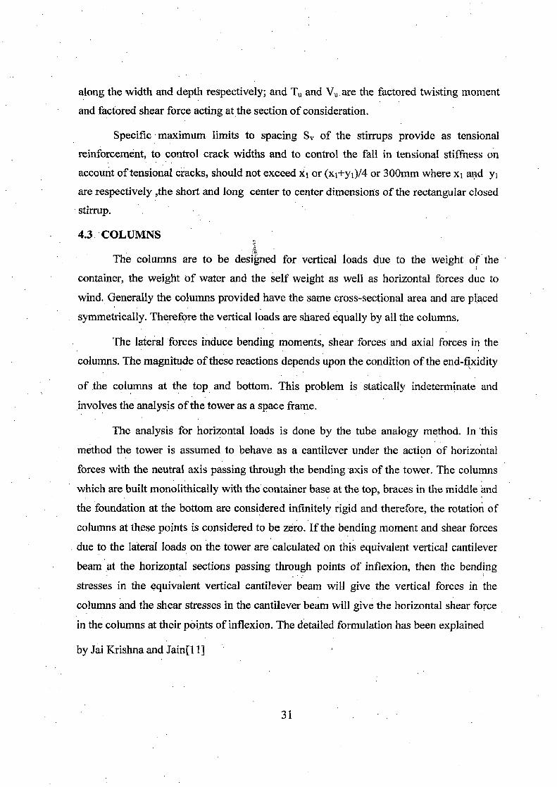
along the width and depth respectively; and T„ and V. are the factored twisting moment and factored shear force acting at the section of consideration.
Specific maximum limits to spacing of the stirrups provide as tensional reinforcement, to control crack widths and to control the fall in tensional stiffness on account of tensional cracks, should not exceed xi or (xi+yi)/4 or 300mm where x1 and 3/1
are respectively ,the short and long center to center dimensions of the rectangular closed stirrup.
4.3. COLUMNS
The columns are to be designed for vertical loads due to the weight of the container, the weight of water and the self weight as well as horizontal forces due to
wind. Generally the columns provided have the same cross-sectional area and are placed symmetrically. Therefore the vertical loads are shared equally by all the columns.
The lateral forces induce bending moments, shear forces' and axial forces in the columns. The magnitude of these reactions depends upon the condition of the end-fixidity
of the columns at the top and bottom. This problem is statically indeterminate and
involves the analysis of the tower as a space frame.
The analysis for horizontal loads is done by the tube analogy method. In this
method the tower is assumed to behave as a cantilever under the action of horizontal
forces with the neutral axis passing through the bending axis of the tower. The columns
which are built monolithically with the container base at the top, braces in the middle and
the foundation at the bottom are considered infinitely rigid and therefore, the rotation of
columns at these points is considered to be zero. If the bending moment and shear forces
due to the lateral loads on the tower are calculated on this equivalent vertical cantilever
beam at the horizontal sections passing through points of inflexion, then the bending
stresses in the equivalent vertical cantilever beam will give the vertical forces in the
columns and the shear stresses in the cantilever beam will give the horizontal shear force
in the columns at their points of inflexion. The detailed formulation has been explained
by Jai Krishna and Jain[11]
31

4.3.1 Dimensions:
The columns are normally designed as short columns and the minimum number of panels
in the staging is given by
H ,
Np- 12*D,
Np is rounded off to the nearest higher number to get whole number
Therefor the number of braces is given by
Nb=Np-1
and clear panel height is obtained from
I-IeL=Hs-Nb*tbr.
The center to center panel height of the column is given by
Elec=HGL+tbr m
The effective length of the brace is obtained from
(D2 +D)*2r Lbe
D, m Arc
And clear length of brace
LbeL=Lbe-De
4.3.2 Wind Loads:
(4.14)
(4.15)
(4.16)
(4.17)
(4.18)
(4.19)
The basic wind pressure is taken as per provision of IS: 875(Part-3)-1987[20] for place
where the structure is suited. The wind load on the container and staging is computed as
follow:
The wind force on container member is given by
Wf cylinderef cylinder*Pd cylinder*Ae cylinder kg..... ( 4.20)
Wf cone=ef cone *Pd cone *Ae cone kg..... ( 4.21)
Wf bottom ring beam =ef bottom ring beam *Pd bottom ring beam *Ac bottom ring beam kg... ( 4.23) Resultant force on container
Wfm= Wf cylinder*Hcw+ Wf cone*Hc+ Wf bottom ring beam* trb kg (4.24)
32

This force acting at the Zs distance from bottom dome portion The Wind force on column of each panel is Wfc=cfc*Pd*(0.5Nc+1)HeL*Dc kg ..... (4.25) Wind load on braces of each panel are
Wthr=cfbr*Pd*(D2+2Dc) Kg (4.26) There for the maximum panel shear at the mid height of first panel from ground level is Sp=Wfen+(Np-0.5)Wfc+(Np-1)Wfbr Kg (4.27) and the panel moment at the mid height of the above panel Mp=
[W f,„{Zs + (Np —1)H + 0.5H ,L }+ 0 .5Wfc{0 .251 + (Np „}+{(Wf, + Wf br )(0 .5Np 2 Np + 0.5. Kgm (4.28)
4.3.3 Forces on Columns:
(a) The gravity forces on each column of the lowest panel is given by
Wc — + 2500(‘ ?I` bb, *H L )* Nb Kgm (4.29) Nc c
(b)Horizontal forces:
Maximum thrust on leeward column of the lowest panel lying farthest from the bending
axis
Tc- 4M p
Kg (4.30) N * (D2 + D ,)
Maximum bending moment on the column of lowest lying on the bending axis
H mc= cL *Sp Nc
Kgm (4.31)
33

4.3.4 Reinforcement in columns
(a) Longitudinal Reinforcement
Each column of the staging is to be designed for the maximum thrust and the combined effect of thrust and moment .The reinforcement is calculated by using design chart (for uniaxial eccentric compression)in SP:16 .In circular column at least six bars are required and they are equally placed
(b) Transverse Reinforcement:
The pitch and diameter of the lateral ties or helical reinforcement is kept as per
clause 26.5.3.2 of IS: 456 2000 [17]. The minimum diameter should be 6mm.
4.4 BRACES
Bending moment in a brace is developed at the junction due to shear force acting
at the mid height of columns. The bending moment has to be resisted by the two braces
meeting at the junction. The bending moment in the brace about the vertical axis of its
section is almost zero and even the twisting moment is negligible. Thus the brace bear the
joint moment mostly by developing bending moment about the horizontal axis of its
section. These moments in the brace can easily be calculated by considering the statically
equilibrium of moments at the joint.
4.4.1 Wind Forces on Braces:
Moment in the lowest brace rigidly connected to the column making an angle Oc with the
bending axis of tower is given by
Mbr 2Sp* H„* Cos 20c* Sin(Oc + ab )
N, * Sin2ab Kgm .(4.32)
For maximum moment in the brace
—3Tanab +11((3Tanab )2 + 8) TanO, =
4 (4.33)
Shear force in the lowest brace lying between the column making angles (0c — ab ) and
Oc with the bending axis of the tower.
34

2S * H c Vbr " tCos20 Sin(19
c + ab ) — Cos 2 (Oc — 2ab)Sin(0, -3ab )} kg....(4.34)
Nc * Sin2ab
For maximum values of shear force 06 = ab I.e. wind blowing parallel to the brace. Hence
maximum shear force
Vbr(Max)— 4S
P * H *
CC Cos20c
kg... .(4.35) Nc
Twisting moment (Tube)=5% Mbr(Max)
Equivalent shear
bbr t br N/mm2.... (4.36)
Iftve exceed rcmax the section has to be suitably redesign by in creasing the cross
sectional area (especially width) and /or improving grade of concrete
4.4.2 Reinforcement in bracing
(a)The longitudinal reinforcement area Ast-brL is i design to resist moment Mbr and
reinforcement is to be located in the flexural tension zone. The moment in braces may be
positive or negative according to the direction of wind .hence the brace must be
reinforced equally. at top and bottom. The longitudinal reinforcement should not less than
0.85 bbrtbr/fY
(b)Spacing of Shear reinforcement at support section
(i) When 0.5tc <Tve <
0.87fy* As 3vbr-
0 .4bbr
(ii) when tie <Tve < "re max
0.87fr * As, 3vb
r (rve — rc )bb ,.
Where is is obtained from Table 19 of IS: 456-2000[17] The shear reinforcement at the point of maximum torsion
(4.37)
(4.38)
rye =
VU br +1.6 T„' br bbr
35

Tub ,. + Vub ,. * Sv bi (0.87fy ) 2.5d1 (0.87fy )
mnri2 (4.39)
But total transverse reinforcement shall not be less than (rve rObb, * S v br
0.87fi,
Where Asv, is the total area of two legs of the stirrups is the center to center to spacing of stirrup; bl and dl are the center to center distance between the corner bars along the width and depth respectively; and Tu and Vu are the factored twisting moment and
factored shear force acting at the section of consideration.
Specific maximum limits to spacing S„ of the stirrups provide as tensional reinforcement,
to control crack widths and to control the fall in tensional stiffness on account of
tensional cracks, should not exceed xi or (xi+yi)/4 or 300mm where xi and yi are
respectively ,the short and long center to center dimensions of the rectangular closed
stirrup.
4.5 RELEVENT PARAMETER 4.5.1 Volume of concrete
VcoL,=— n Dc 2 Hs * Nc m3
4 Vbr= Nc * Nb* Lbr * Bbr * dbr m3
Vrb— II * Db„,r. * t b, * brb m3
VCstaging= VcoL Vbr Vrb m3
4.5.2 Volume of steel (a)Bottom ring beam
VS rbL— rID bmr( Ast rbL1 + ASt rb 1.2)
VS rbt-= Nc(brb t rb - 0.25) * AsvE ei * D2bmr
V Sib' Vs rbL + VS rbt
3
3
3
(4.40)
(4.41)
(4.42)
(4.4.3)
(4.44)
(4.45)
(4.46) (b)Column. VseL=Nc*Hs*Asc
Vset= 2 (Hs )*11* Dc
4 lry
3
3
(4.47)
(4.48)
36

VSC= VSeL, Vsct
(c)Braces VsbiL=Lbr*Astb,-*Nc*Nb*2
b
L r * 2(bbr for
m3
m3.
3
3
3
(4.49)
(4.50)
(4:51)
(4.52) (4.53)
V 0.25)* ASV Sbrt= — br SV br
VSbr= VSbrL+ VSbrt
Vst = VSrb VSC VSrb .
4.5.3 Cost of staging
On the basis of the present prevailing rates of material the rates of various items are given as under:
. (3) Cement concrete of grade M25 in superstructure excluding Rs.2900 per cu.m cost of centering and shuttering
(4) Tor steel reinforcement including cutting,bending,placement Rs18000 per ton and its wastage
There for the cost of staging =V9staging*29000+78.5*18000*Vst Rupees (4.54)
37

CHAPTER 5
RESULTS
5.1 INTRODUCTION The alternative design of container and staging are obtained by using Excel
program which is explain in chapter (3). The effect of various parameters on the cost of
container is studied and design for optimal parameter is given in the form of graph and
table.
5.2 CONTAINER
The effect of following parameters is studies by varying the parameter as per
table-1.1
(1)Staging-container diameter ratio AI (D2/D1)
(2)Height diameter ratio, 22 (H1/D1)
(3)Horizontal angle of cone a
The result are tabulated in tables 5.1 to5.3 and graph plotted between cost of container
and above parameter are drawn for all six different capacities are shown in figure 5.1 to
5.3
38

Table 5:1 Quantity of concrete, reinforcement and cost of container for different value
of .1.1 and A.2=0.3 a=50°
• Capacity
KL .
Al
Volume
of
concrete
(ms) •
Volume
of steel
( m3) \
Cost of
Container
in lac
Capacity
KL
Volume
of
concrete
(ms)
Volume
of steel
On3 )
Cost of
Container
in lac
300
0.5 30.46 0.30671 0.4379844
1 000
133.9 1.2241 1.783845 0.55
30.51 0.30499 0.4361554 131 1.25376 1.809267 0.6
30.59 0.30438 0.4356982 127.9 1.25323 1.7995933 0.65
30.72 0.30053 0.4316843 124.5 1.24948 1.7855015 0.7
30.91 0.32293 0.4577693 120.9 1.20677 1.726183 0.75
31.18 0.33468 0.4719532 116.9 1.18731 1.6924585
500
0.5 51.48 0.48885 0.7065876
1250
194.9 1.76754 2.5803188 0.55
50.97 0.50561 0.7241983 190:1 1.71954 2.511553 0.6
50.43 0.50963. 0.727228 184.8 1.70891 2.4841874 0.65
49.89 0.52192 0.7396584 179.1 1.70429 2.4623788 0.7
49.33 0.52125 0.7372871 172.9 1.6667 2.4015303 0.75
48.78 0.49681 0.7078137 166.2 1.65495 2.3684856
750
0.5 87.74 0.86091 '1.2358695
•
1500
259.6 2.30934 3.385619 0.55
86.26 0.85358 1.2232238 252.5 2.31486 • 3.3710966 0.6
84.67 0.84095 1.2042191 244.7. 2.26603 3.2927989 0.65
82.97 0.83083 1.1877671 236.2 2.1935 3.1854981 0.7
81.16 0.80458 1.1525728 226.9 2.15733 3.1174065 0.75
79.22 0.79965 1.1413354 216.8 2.11148 3.0356828
39

Table 5.2 Quantity of concrete, reinforcement and cost of container for different value
of X2 and Al =0.7 a=50°
Capacity
(KL)
x2
Volume
of
concrete
(m3)
Volume
of steel
(m3)
Cost of
Container,
( lac)
Capacity
(KU)
Volume
of
concrete
(m3)
Volume
of steel
(m3)
Cost of
Container
(lac)
300
0.2 32.811 0.3415 0.48447 0.
.
1000
132.6871 1.2659 1.82795
0.25 31.699 0.3239 0.46117 125.836 1.2022 1.73543
0.3 30.908 0.3229 0.45777 120.8504 1.2068 1.72618
0.35 0. 30.330 0.3234 0.45668 • 121.8994 1.1827 1.70175
0.4 29.899 0.313 0.44357 124.3927 1.2105 1.7407
0.45 29.576 0.3318 0.46401 . 133.4116 1.2034 1.75876
0.5 29.333 0.3233 0.45359 141.0548 1.1964 1.77294
500
0.2 53.702 0.5196 74807 0.74807 .
1250
190.0523 1.6926 2.48073
0.25 51.175 0.5138 0.73419 180.1343 1.6781 2.43548
0.3 49.330 0.5213 0.73729 172.9295 1.6667 2.40153
0.35 47.937 0.5157 0.72693 173.1034 1.6682 2.40376
0.4 46.860 0.5124 0.72003 181.1545 1.6093 2.35991
0.45 48.782 0.4963 0.70727 191.3672 1.6533 2.43976
0.5 50.048 0.5467 0.76839 200.0845 1.6839 2.49992
750
0.2 88.739 0.8839 1. 1.26495
1500
250.5416 2.2733 3.31817
0.25 84.350 0.8243 1.18427 236.8773 2.1869 3.18002
0.3 81.157 0.8046 1.15257 226.9128 • 2.1573 - 3.11741
0.35 0. 78.755 0.8169 1.15968 236.7901 2.0798 3.05769
0.4 81.098 0.816 1.16548 245.5014 2.1223 3.13137
0.45 79.862 0.8083 1.15304 253.2507 2.173 3.21162
0.5 88.157 0.8778 1.25633 266.5529 2.2271 3.31184
40

Table 5.3 Quantity of concrete, reinforcement and cost of container for different value
of a and A2=0.3 Al =0.7
Capacity
KL
a
Volume
of
concrete
(m3)
Volume
of steel
(m3)
Cost of
Container
in lac
Capacity
KL
Volume
of
concrete
(m3)
Volume
of steel
(m3)
Cost of
Container
in lac
300
35 28.7409 0.355435 0.488545
1000
93.17201 1.271578 1.719798
40 29.20365 0.353309 0.487463 99.82198 1.238748 1.701656
45 29.88701 0.337145 0.471017 108.6655 1.190994 1.672864
50 30.90829 0.322926 0.457769 120.8504 1.206769 1.726183
55 32.47002 0.309947 0.447503 138.3493 1.255399 1.832368
60 34.94639 0.311486 0.456438 164.8083 1.299719 1.959623
500
35 41.99098 0.550561 0.749414
1250
129.4937 1.752411 2.37328
40 43.71413 0.535028 0.736703 139.9523 1.726115 2.373633
45 46.05342 0.518818 0.725008 153.8313 1.684742 2.366717
50 49.3304 0.521253 0.737287 172.9295 1.666697 2.40153
55 54.09622 0.526566 0.757164 200.3463 1.676157 2.491823
60 61.36443 0.522186 0.773249 241.8319 1.796442 2.749256
750 •
35 65.25571 0.880233 1.192708
1500
176.4983 2.231715 3.056001
40 69.05107 0.850311 1.169603 191.0981 2.169519 3.027437
45 74.12865 0.820228 1.150033 210.4978 2.112708 3.018931
50 81.15752 0.804575 1.152573 226.9128 2.157333 3.117406
55 91.28529 0.820364 1.199943 275.693 2.161142 3.263211
60 106.6266 0.875638 1.307444 334.0363 2.325848 3.620172
41

• • •
—E-- V-500 ,a=50,A2=0.3 •
—A— V=750 ,a=50,A2=0.3
V=1000 ,a=50,A2=0.3 • •
—s— V=1250 ,a=50,A2=0.3
—•— V-1500 ,a=50,A2=0.3
4
V-250 ,a=50,A2=0.3
3.5
3 ea
2.5
a) c
▪
2
0 1.5 U 5
0 0.5
0
•
Ir A A
0 4 0.45 0.5 0.55 0.6 0.65 0.7 0.75
Staging-container diameter ratio Al
FIG 5.1 VARIATION OF COST OF CONTAINER WITH RATIO X1
42

3.5
—a— V=1500 ,a=50,A 1=0.70 —a—V=1250 ,a=50,A1=0.70 —A—V-1000 ,a=50,h1=0.70 —N— V=750„ a=50.A 1=0.70
3
o m 2.5
._ .
IA c
o il C_) 0 4- 1.5
0 0
0.5
0
.--.1--V=500 , a=50,A 1=0.70 --V=300 ,a=50,A1=0.70
0.15 02 0.25 03 0.35 04 0.45 05
. _ Height-container diameter ratio A2
.FIG 5.2 VARIATION OF COST OF CONTAINER WITH RATIO X2
4
--.--V=1500 ,a=50,A1=0.70 ---+-V=1250 ,a=50,A1=0.70 -a-V=1000 ,a=50,A1=0.70 -a-V=750 ,a=50,A1=0.70 -+-V=500 ,a=50,A1=0.70 -m-V=300 ,a=50,A1=0.70 3.5 ea
-1 e .-
•
6- 2.5 3
2 c...) , 5 .b. 1.5 co U 1 A- —
0.5 •
0 30 35 40 45 50 55 60 - 65
Horizontal angle Of Conical Dome a
FIG 5.3 VARIATION OF COST OF CONTAINER WITH RATIO a
43

5.3 STAGING Obtaining from optimum value of different parameter of container, the design of staging
is done by varying the values of basic parameter such as capacity of tank V, height of staging Hs
and various wind zones .for economical design we have varied no of columns, column diameter,
and minimum no of panels .the design is carried out by limit state approach. The result of cost of
staging are tabulated in table 5.2 for six different capacities and for three height of staging, 15m,
18m, 21m.The table 5.4 graphically presented from Fig 5.4 for staging height 15m. The curves
clearly indicate the effect of column in the cost of staging.
44

Table 5.4 Quantity of concrete, reinforcement and cost of staging for different number of
column and height of staging, 15m, 18m, and 21m.The container has value of a=45° X2=0.3 and
.1./ =0.7
Capacity
KL
Height
of
sta ging
Hs
No
Of
column
Volume
of
concrete
(m3)
Volume
of steel
(m3)
Cost of
Container
in lac
Capacity
KL,
No
of
column
Volume
of
concrete
(m3)
Volume
of steel
(m3)
Cost of
Container
in lac
300
15 10 45.0 1.73 2.57
1000
14 113.5 3.81 5.72 12 49.6 1.67 2.51 16 116.3 .3.63 5.4 14 54.29 1.69 2.55 18 119.7 3.89 ' 5.8
18 10 56.03 .2.42 3.58 14 136.94 5.45 ' 8.09 12 61.54. 2.59 3.85 16 143.39 5.59 ! 8.32 14 67.0 2.74 4.07 18 150.9 5.27 7.89
21 10 68.63 3.31 4.89 14 151.94 7.23 10.66 12 67.26 3.46 5.08 16 159.31 7.54 11.12 14 73.77 3.72 5.47 18 168.85 8.05 , 11.87
500
15 12 65.50 2.28 3.42
1250
20 135.9 4.29 6.462 14 68.41 2.22 3.34 22 139.7 4.37 6.5817 16 72.06 2.42 3.63 24 143.5 4.65 6.98
18 12 72.56 3.09 4.59 20 152.93 6.24 9.26 14 76.65 3.24 4.80 22 158.4 5.95 8.88 16 81.48 3.39 5.03 24 168.54 6.41 . 9.55
21 12 86.89 4.27 6.28 20 169.89 8.63 , 12.69 14 94.94 4.63 6.81 22 177.0 8.73 : 12.85 16 98:76 4.93 7.25 24 188.8 9.39 13.81
750
15 14 99.36 3.06 4.62
1500
20 148.8 4.913; 7.37 16 102.9 2.87 4.36 22 149.8 4.64 , 7.0031 18 111.38 3.15 4.77 24 158.29 4.98 7.50
18 14 111.2 4.58 6.80 20 170.6 6.76 10.0 16 116.56 4.35 6.48 22 16.8.53 6.59 ' 9.8 18 126.6 4.77 7.10 24 178.6 7.06 . 10.49 14 123.1 6.08 8.95 20 182.7 9.19 13.5
21 16 130.12 5.92 8.74 22 187.19 9.18 ' 13.5 18 . 141.90 . 6.57 9.7 24 198.9 9.85 14.5

Cl) 8 w
< 7 _11 Z 6
v-1500 KL,HS=15m
KL,HS=15m
KL,HS=15m
KL,HS=15m
KL,HS=15m
KL,HS=15m
--E-- v=1250
A-- V=1000
-X-- v=750
--X v=500
—0-- v=300
5 z
0 4
3 co
LI- 2 0 (7) 1 0 0.0
8 10 12 14 16 18 20 22 24 26
NO OF COLUMN IN STAGING
FIG 5.4 VARIATION OF COST OF CONTAINER WITH NO OF COLUMN
46

CHAPTER 6
DISCUSSION AND CONCLUSION
6.1 DISCUSSION As the ratio A.1 is increase from 0.5 to 0.75 the cost of container decreases. The
effect is more significant in when water storage capacity is more than 750 KL .For lower
value of X1 the reduction in capacity in conical portion of container which enhance the
container dimensions and hence the cost of container. The curve Fig 5.1 represents
variation of cost of container with value of A,1.
From the result of previous chapter we obtain, as we increase in height —diameter
ratio it reduce the cost of top ring beam and bottom dome. But over all cost of container
increases due to increasing the cost of cylindrical wall effectively which is shown in
Fig 5.2. The cost of container increases rapidly when 2L2 value increases from 0.35. For
0.3 to. 0.35 the curves for all capacity are nearly a straight line which has very less
increment in slope but beyond this slop increases significantly.
Keeping other parameter constant and varying the value of a from 35° to 60°, it is
observed that the value of cost of container decreases when a less than 45°.As the a
increased from 45°, an added capacity is created in conical portion of container which
decreases the dimension of cylindrical wall but over all cost of container increase. The
change of cost of container with a has been shown in Fig 5.3.
From figure 5.4 it is observed that cost of staging increases as the no of column
decreases to a curtain limit because significantly in crease the value of .For ch * D 2
c
safe design as well as economical it is observed that up to 500 KL capacity 12 to 14
column are economical. For capacities between 500 KL and 1000KL 16 column are
economical and beyond 1000KL up to 1500KL 20 to 22 are sufficient.
47

6.2 CONCLUSION The most economical combination of various parameter for the container are
given below 'TABLE 6.1 Recommended proportion of container and staging.
Parameter Optimum value of parameter of container capacity( KL)
Capacity 300 500 750 1000 1250 1500
ill (D2/D1) 0.5 to 0.6 0.6 tO 0.7 0.7 to 0.75 00.7 to 0.75 0.7 to 0.75 0.7 to 0.75
22 (H1/D1) 0.3 to 0.35 0.3 to 0.35 0.3 to 035 0.3 to 0.35 0.35 to 0.4 0.3 to 0.35
Angle(a) 40° to 45° 40° to 45° 40° to 45° 40° to 45° 40° to 45° 40° to 45°
Nc(column) 14 14 - 16 16 20 22
6.3 SCOPE OF FUTURE STUDY
(a) Excel program can extend to design for foundation. After designing of
foundation we can make, a correct combination of parameter for different
capacity of intze tank.
(b) Forces obtained at different location in container and staging can be verified by
software packages.
48

REFERENCES
1. Araya, A. S,"Water tower project (Exact Analysis of intze Tank)", M.E.Thesis submitted to University of Roorkee 1957.
2. Jain, 0.P., and Singh, K. K,"Computer analysis of intze tank", Indian concrete journal, vol.51, August.1977.
3. Singh, K. K., Prakash, A. and Jain, 0. P.,"Finit Element Analysis of Intze tanks". 4. Rao, K., C.V.S. and Raghwan, T.M.S,"Optimum design of intze tank on shafts"
Indian concrete journal, January 1982.
5. Rao, K.,C.V.S.. "Data for rapid calculation of continuity effects in• intze
tanks",Indian concrete journal, August 1982.
6. Sharma, L. D,"On optimal Design of R.C.C. intze tank"M.E thesis submitted to University of Roorkee, 1971.
7. Damle, S. R. and Pathak,, S. P."Water tank with vertical walls curved inward" Indian concrete journal, January 1978.
8. Damle, S. R. and Pathak, S. P.,"Convex petal shaped vertical walls for prototype
water tank", Indian concrete journal, February 1980. 9. Singh, C.,"Matrix analysis of framed staging for water Towers" M.E thesis
submitted to. University of Roorkee 1967. 10. Jain,O.P. and Singh,C."Analysis of R.C.Water Towers frames" journal of the
institution of engineers(India),Jan.1969. 11. Jai Krishna . and Jain 0.P,"plain and reinforcement concrete" Nem Chand and
Bros, Vol.land Vol.2, 2000 12. Rao, K., C.V.S."Analysis of Supporting Tower of overhead Tanks" Indian
concrete journal,October 1983. 13. Kundoo, S. K.,"Distribution of horizontal loads on supporting tower for circular
tank" Indian Concrete Journal.Vol.51.Feb.1977. 14. Avadesh Kumar," Analysis and Design of R.0 over Head Reservoirs" M.E.Thesis
is submitted to University of Roorkee"Roorkee, 1988. 15. Kelkar, V. S., and Sewell, R.T," Fundamental of the analysis and design of shell
structures".
49

16. Macdonald, A. J.,"Wind loading on buildings" Applied . Science Publishers Ltd
London. 17. Indian Standard code of Practice for Plain and Reinforced Concrete IS: 456-2000
Bureau of Indian standards, New Delhi.
18. Indian Standard Code of practice for concrete structures for the storage of liquids IS: 3370(part 1 part 11)-1965 Bureau of Indian standards, New Delhi January
1966, August1976. 19. Indian Standard code of practice for design load (Other than earthquake) for
building and structures, Part 2 imposed loads IS 875(part 2):1987 Bureau of
Indian standards, New Delhi
20. Indian Standard code of practice for design load (Other than earthquake) for
building and structures, Part 3 wind loads IS 875(part 3):1987 Bureau of Indian
standards, New Delhi
21. Explanatory hand Book on Indian Standard code of practice for design load
(Other than earthquake) for building and structures, Part 3 wind loads IS 875(part
3):1987 Bureau of Indian standards, New Delhi.
50