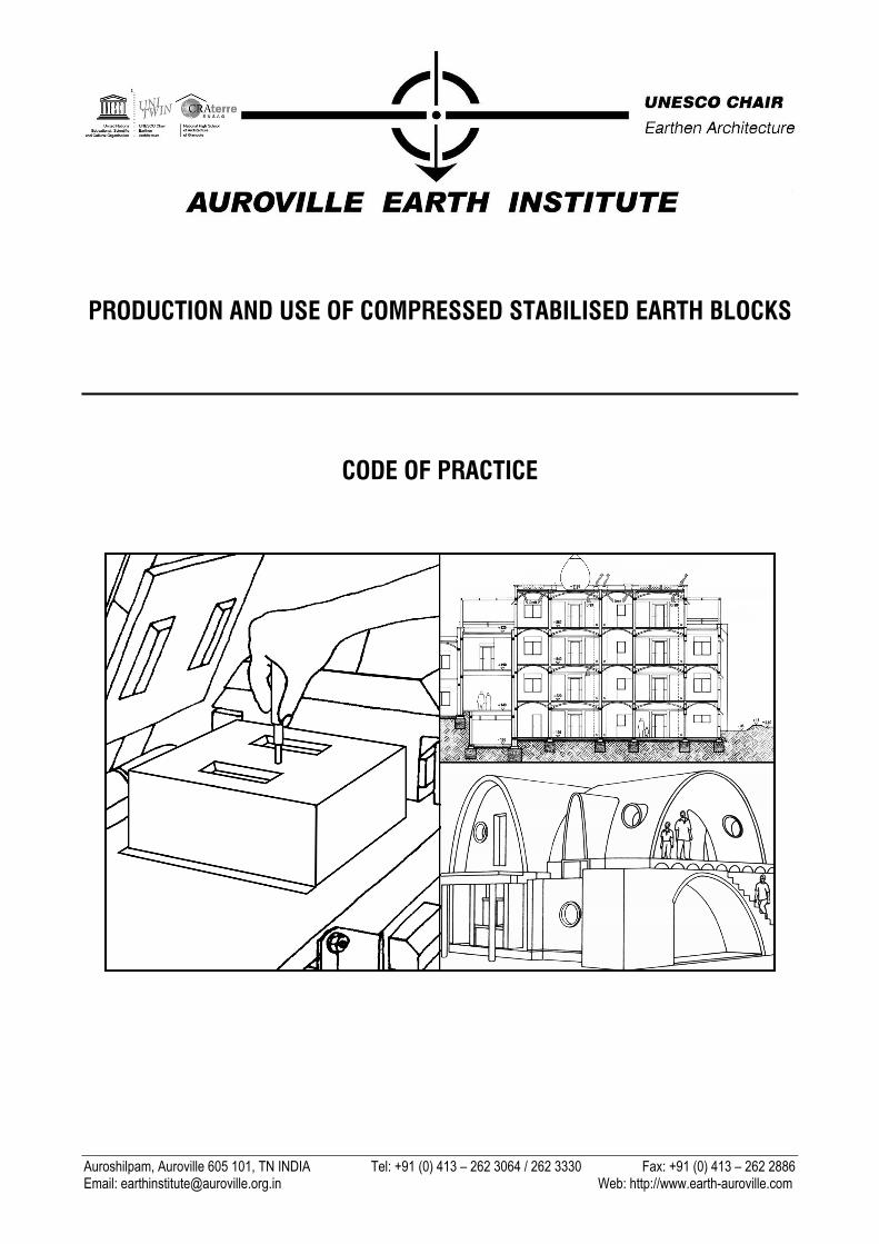
PRODUCTION AND USE OF COMPRESSED STABILISED ...
144
Auroshilpam, Auroville 605 101, TN INDIA Tel: +91 (0) 413 – 262 3064 / 262 3330 Fax: +91 (0) 413 – 262 2886 Email: [email protected] Web: http://www.earth-auroville.com PRODUCTION AND USE OF COMPRESSED STABILISED EARTH BLOCKS CODE OF PRACTICE
-
Upload
khangminh22 -
Category
Documents
-
view
1 -
download
0
Transcript of PRODUCTION AND USE OF COMPRESSED STABILISED ...
Auroshilpam, Auroville 605 101, TN INDIA Tel: +91 (0) 413 – 262 3064 / 262 3330 Fax: +91 (0) 413 – 262 2886 Email: [email protected] Web: http://www.earth-auroville.com
PRODUCTION AND USE OF COMPRESSED STABILISED EARTH BLOCKS
CODE OF PRACTICE

PRODUCTION AND USE OF COMPRESSED STABILISED EARTH BLOCKS
CODE OF PRACTICE
Author: Satprem Maïni
Auroville – December 2010 Revised July 2015
136 pages
AUROVILLE EARTH INSTITUTE
Ref. TM 06
Humanity as a whole No rights reserved!
All parts of this publication may be reproduced without the written permission of the author.
Credit should be given to the Auroville Earth Institute. Feel free to disseminate this information anywhere!

TABLE OF CONTENTS
1. INTRODUCTION _______________________________________________________________ 1 1.1 Foreword ________________________________________________________________________ 1 1.2 Scope __________________________________________________________________________ 1 1.3 Historical background, evolution and basics ______________________________________________ 2 1.4 Advantages and limitations of CSEB ____________________________________________________ 4
1.4.1 Advantages of CSEB __________________________________________________________ 4 1.4.2 Limitations of CSEB ___________________________________________________________ 5
2. EARTH AS A BUILDING MATERIAL _________________________________________________ 7 2.1 Soils ___________________________________________________________________________ 7
2.1.1 Soil characteristics ___________________________________________________________ 7 2.1.2 Soil classification for CSEB _____________________________________________________ 8 2.1.3 Soil suitability and improvement of soils for CSEB ____________________________________ 9 2.1.4 Soil identification ____________________________________________________________ 12 2.1.5 Resource management _______________________________________________________ 21
3. STABILISERS AND SOIL STABILISATION ___________________________________________ 27 3.1 Stabiliser types and suitability _______________________________________________________ 27
3.1.1 Cement ___________________________________________________________________ 27 3.1.2 Lime _____________________________________________________________________ 28
3.2 Stabilisation principles _____________________________________________________________ 30 3.2.1 Definition and aim ___________________________________________________________ 30 3.2.2 Three procedures ___________________________________________________________ 30 3.2.3 Six methods _______________________________________________________________ 31
3.3 Stabilisation calculations ___________________________________________________________ 31
4. PRODUCTS AND CSEB EQUIPMENT _______________________________________________ 35 4.1 Block types, uses and selection criteria ________________________________________________ 35
4.1.1 Block types and uses _________________________________________________________ 35 4.1.2 Block types and mortar thicknesses ______________________________________________ 36 4.1.3 Selection of a block type ______________________________________________________ 36
4.2 CSEB specifications and characteristics ________________________________________________ 37 4.2.1 Block dimensions and tolerances ________________________________________________ 37 4.2.2 Physical requirements and characteristics of CSEB __________________________________ 39
4.3 Press types and selection criteria _____________________________________________________ 39 4.3.1 Categories of equipment ______________________________________________________ 39 4.3.2 Technical requirements of presses _______________________________________________ 40 4.3.3 Selection of equipment _______________________________________________________ 41
4.4 Peripheral equipment ______________________________________________________________ 42 4.4.1 Hand tools _________________________________________________________________ 42 4.4.2 Motorised tools _____________________________________________________________ 42
4.5 Production lines __________________________________________________________________ 43 4.5.1 Types ____________________________________________________________________ 43 4.5.2 Productivity, investment and economics __________________________________________ 43
5. PRODUCTION OF CSEB ________________________________________________________ 45 5.1 Block yard organisation ____________________________________________________________ 45
5.1.1 Infrastructure and built-up premises for a permanent block yard _________________________ 45 5.1.2 Site preparation for a temporary block yard ________________________________________ 46 5.1.3 Manpower requirements ______________________________________________________ 46 5.1.4 Equipment requirements ______________________________________________________ 48 5.1.5 Block yard layout ____________________________________________________________ 49
5.2 Block making process and quality control _______________________________________________ 53 5.2.1 Soil preparation _____________________________________________________________ 53 5.2.2 Measuring and mixing ________________________________________________________ 53 5.2.3 Pressing and quality control ____________________________________________________ 55 5.2.4 Initial curing and stacking _____________________________________________________ 57 5.2.5 Final stacking and curing ______________________________________________________ 58 5.2.6 Quality control during production ________________________________________________ 60 5.2.7 Monitoring the production _____________________________________________________ 61
5.3 Quality control after production ______________________________________________________ 61 5.3.1 Visual appearance after curing __________________________________________________ 61 5.3.2 Example of quality control monitoring sheet ________________________________________ 62 5.3.3 Volumic mass of blocks, Block __________________________________________________ 63 5.3.4 Compressive strength (dry and wet) ______________________________________________ 63 5.3.5 Water absorption ____________________________________________________________ 65
6. BASIC DESIGN GUIDELINES FOR MASONRY WITH CSEB ______________________________ 67 6.1 Design guidelines AND Principles _____________________________________________________ 67
6.1.1 Basic principles _____________________________________________________________ 67 6.1.2 Shear strength ______________________________________________________________ 67 6.1.3 Shrinkage stress ____________________________________________________________ 67 6.1.4 Water absorption ____________________________________________________________ 67
6.2 Compressive strength and safety factors for load bearing walls _______________________________ 68 6.3 Dimensioning buildings ____________________________________________________________ 68 6.4 Example of plan __________________________________________________________________ 69 6.5 Mortar quality and block laying principles _______________________________________________ 70
6.5.1 Mortar quality ______________________________________________________________ 70 6.5.2 Block laying principles for walls _________________________________________________ 70
6.6 Bonds principles for masonry ________________________________________________________ 71 6.7 Examples of bond patterns __________________________________________________________ 73 6.8 Composite techniques with CSEB and stabilised earth techniques ____________________________ 100
6.8.1 Stabilised rammed earth foundation _____________________________________________ 100 6.8.2 Composite basement and plinth beam ___________________________________________ 104 6.8.3 Composite columns _________________________________________________________ 105 6.8.4 Composite beams and lintels __________________________________________________ 107 6.8.5 Arches, Vaults and Domes (AVD) _______________________________________________ 108 6.8.6 Disaster resistant buildings ___________________________________________________ 113
7. BUILDING EXAMPLES WITH CSEB _______________________________________________ 115 7.1 Houses in Auroville ______________________________________________________________ 115 7.2 Apartments in Auroville ___________________________________________________________ 116 7.3 Public buildings in Auroville ________________________________________________________ 117 7.4 Various buildings worldwide ________________________________________________________ 118
8. ANNEXES __________________________________________________________________ 119 8.1 References ____________________________________________________________________ 119 8.2 Terminology for soils, earth related terms and raw materials ________________________________ 120
8.2.1 Terminology for soils and clay types ____________________________________________ 120 8.2.2 Terminology for soil properties, characteristics and earth related terms ___________________ 123 8.2.3 Terminology for rocks and aggregates ___________________________________________ 126
8.3 Terminology for stabilisers and soil stabilisation _________________________________________ 127 8.4 Terminology for products and CSEB equipment _________________________________________ 128
8.4.1 Terminology for products, specifications and terms related to CSEB _____________________ 128 8.4.2 Terminology for CSEB equipment _______________________________________________ 130
8.5 Terminology for production of CSEB __________________________________________________ 132 8.6 Terminology for design guidelines with CSEB and for load bearing masonry ____________________ 133

- 1 -
1. INTRODUCTION
1.1 FOREWORD
The tradition of building with earth is nearly as old as mankind, and earth as a building material has been used all over the world. In the 20th century, a new earth technique has been developed: Compressed Earth Block, globally known as CEB.
In India the initial research on CEB was conducted by CBRI Roorkee. The Indian Institute of Science, Bangalore, has also done commendable work in this field.
CEB have gained popularity not only in India but also in many other countries worldwide. To ensure proper quality of products and buildings, this Code of Practice has been elaborated to present the “State of the Art” in the field.
Most frequently, compressed earth blocks are stabilised with cement or lime. Therefore, today, we prefer to call them Compressed Stabilised Earth Blocks (CSEB), to emphasize that they are both compressed and stabilised. The addition of soil stabilisation allows people to build higher buildings with thinner walls, which have a much better compressive strength and water resistance.
This Code of Practice is the result of research and development done by the Auroville Earth Institute since 1989. Over the years, the Auroville Earth Institute has become one of the world leaders in the field of CSEB technology and stabilised earth techniques. AVEI is the representative for Asia as the UNESCO Chair “Earthen Architecture, Constructive Cultures and Sustainable Development”.
Moreover, the Auroville Earth Institute is part of a world network with CRATerre (The International Centre for Earth Construction), ABC Terra in Brazil and a number of Indian NGO’s. A training agreement has been passed with the School of Architecture of Grenoble, France, to provide long-term training courses to their students.
1.2 SCOPE
This Code of Practice details the state of the art for the production of Compressed Stabilised Earth Blocks, and the basic design and construction with CSEB. The manual has been conceived for the purpose of being easily understandable for laymen, with the aim that the technology can be widely spread with standardised quality and strength.
This Code of Practice is organised in various parts:
After the Introduction, Chapter Two covers specifications for the raw material, which includes the soil identification with sensitive tests. It describes soil suitability and strategies for the improvement of a soil for specified requirements. It also presents examples on how to manage soil resources in a suitable and sustainable way.
Chapter Three covers soil stabilisation, including main stabiliser types and suitability, stabilisation principles and calculations.
Chapter Four covers the product and equipment specifications with the various block types (solid, hollow and interlocking CSEB), their use and selection criteria. It defines CSEB specifications and characteristics, and the minimum performance for CSEB. Press types and selection criteria are also described in this section.
Chapter Five covers all steps of the block making process, including blockyard organisation, monitoring the production and quality control during and after production.
Chapter Six covers basic design guidelines principles, including dimensioning of buildings and recommendations for the structural design of load bearing unreinforced CSEB masonry for houses and buildings up to three floors high. It introduces various building techniques, including composite earth technologies, arches, vault and domes, and disaster resistant building techniques.
Chapter Seven shows examples of buildings, mostly in Auroville, to demonstrate a diversity of architectural style.
Chapter Eight, includes Annexes, which provide various references along with an alphabetic glossary related to the various chapters: see this part if words are new to the reader.

- 2 -
1.3 HISTORICAL BACKGROUND, EVOLUTION AND BASICS
Earth as a building material has been used worldwide since the dawn of mankind. UNCHS Habitat has evaluated that about 1.7 billion people of the world’s population live in earthen houses: About 50 % of the population in developing countries At least 20% of urban and suburban populations. UNESCO states that: 17% of the “world cultural heritage sites” are made of earth. 25% of “world heritage sites in danger” are made of earth.
Ramasseum, Egypt – Built in 1300 BC
The world’s oldest earthen building still standing is about 3,300 years old: the Granaries of the Ramasseum in Egypt, which was built with sun dried bricks (adobe) by Ramses II (19th dynasty) around 1,300 BC in an area called Western Thebes. It can still be seen a few kilometers from the western shore of the Nile, opposite Luxor. In India, the oldest earthen building is Tabo Monastery, in Spiti valley – Himachal Pradesh. It was also built with adobe and it has withstood Himalayan winters since 996 AD.
Tabo Monastery, Spiti, HP – Built in 996 AD Compressed earth block is a modern technological development, which combines the ancestral techniques of sun dried brick and rammed earth. The first attempts at compressed earth blocks were made in the early days of the 19th century in France. The architect François Cointeraux precast small blocks of rammed earth and he used hand rammers to compress the humid soil into a small wooden mould held with the feet. The first steel manual press was the “Cinvaram”, which was the result of a research programme conducted in 1956 by Raul Ramirez from the Colombian Inter-American Housing Centre (CINVA). This press could produce regular blocks in shape and size, denser, stronger and more water resistant than the adobe. Since then many more types of machines have been designed and many laboratories have become specialised and skilled to identify soils which are suitable for building. Many countries in Africa as well as South America, India and South Asia have been using this technique. Europe and USA have also shown a lot of interest in this technology.
Cinvaram, produced in Colombia in 1956
The widest development and implementation of CSEB since the 1960’s has been seen in Africa. Nearly every African country has examples of CSEB building, from social housing to luxurious apartments and government buildings. In India, one of the first institutions to research and develop this technology was the Central Building Research Institute (CBRI) at Roorkee, which has been conducting research since the 1970’s. The Indian Institute of Science of Bangalore (IISc) has also done a lot of research on this subject. The Auroville Earth Institute (AVEI) has done extensive applied research and development on CSEB and various stabilised earth techniques which are being disseminated and used worldwide.

- 3 -
South Asia has also demonstrated a lot of development and use of CSEB. In Thailand, the initial research was undertaken by the Thailand Institute of Scientific and Technological Research (TISTR) in Bangkok in the 1960’s. They used the Cinvaram press and developed a system for interlocking blocks. Sri Lanka has also used this technology more and more, and the Sri Lankan Standard Institution has published a standard on the production and use of CSEB. New Zealand and Australia also have standards related to earth techniques which include compressed stabilised earth blocks. In the USA, the State of New Mexico has published standards including CSEB and other earth techniques. Several other states are also using CSEB and other stabilised earth techniques. Contractors are building with CSEB in Colorado, Texas and New Mexico and the demand is increasing in other US states. Europe has also seen more and more development with earth techniques. There are networks in Germany, France and Switzerland. In France, CRATerre-ENSAG promotes CSEB as well as other earth techniques, and is the centre of excellence of the UNESCO Chair “Earthen Architecture, Constructive Cultures and Sustainable development”. CRATerre-ENSAG had been actively involved in the preparation of norms and standards on CSEB for African countries under a programme with the Industrial Centre for Development. Globally, this material has often been called Compressed Earth Blocks (CEB); however, most frequently, the blocks are both compressed and stabilised. Therefore, we have chosen rather to adopt the term Compressed Stabilised Earth Blocks (CSEB). CSEB can be compressed in many different shapes and sizes. Stabilised soil is slightly moistened, poured into a mould and then compressed either with a manual or motorized press. Machinery for compressed earth blocks has evolved significantly and it is now possible to find manual presses as well as motorised presses, mobile units and completely integrated plants. The addition of soil stabilisation allows blocks to have a higher compressive strength and water resistance, therefore affording the possibility to build higher buildings using thinner walls.
- 4 -
1.4 ADVANTAGES AND LIMITATIONS OF CSEB
1.4.1 Advantages of CSEB A local material
Ideally, blocks are produced on the site itself or in nearby areas, thus saving on transportation, fuel, time and cost of construction.
A bio-degradable material With minimum maintenance, well-designed CSEB houses can withstand heavy rains, snowfall or frost without being damaged. But let us consider a demolished CSEB building and vegetation grown over the debris: Bio-chemicals contained in the humus of the topsoil will destroy the soil cement mix in 10-20 years. CSEB will come back to Mother Earth... No other building material can do that!
Limiting deforestation Unlike the production of fired bricks, firewood is not required to produce CSEB. Hence, building with CSEB can prevent the depletion of forests which otherwise suffer due to short-sighted development and mismanagement of resources.
Local management of resources If planned in advance, on site quarries for soil can be converted into rainwater harvesting tanks, wastewater treatment systems, reservoirs, basement floors or landscaping features. This can be beneficial for the development of a place, provided that planning is judiciously done.
Energy efficiency and eco friendliness Requiring only a little stabiliser (thus little fuel) the energy consumption for one m3 of CSEB is about 4 times less than one m3 of country fired bricks, and about 2 times less than the average brick making industry in India.
Cost efficiency The cost of the block will vary with the local context, but the production of CSEB can be cheaper than buying fired bricks or concrete blocks, because the blocks are produced locally with a natural resource and semi-skilled labour.
An appropriate building material Produced locally, CSEB can be easily adapted to the various needs of local people, e.g. technical, social, cultural habits.
A transferable technology CSEB is a technology that requires only semi-skilled labour. One can learn how to produce CSEB’s in a few weeks’ time. At an organized training course, like the one at the Auroville Earth Institute, a one-week course can guarantee a complete technology transfer.
A job creation opportunity This technology allows otherwise unskilled and unemployed people to learn a new skill, obtain a job and increase their social status.
Market opportunity A feasibility study shall be conducted prior to starting any project. According to the local costs (stabiliser, soil, sand, labour, equipment, etc.) the final price will vary, but in most of the cases it will be cheaper than fired bricks or sand cement blocks.
Reducing imports As CSEB can be produced locally, there is no need to transport expensive and heavy materials from long distances.
Flexible production scale Equipment for CSEB is available, from manual to motorized machinery ranging from village to industry scale. Considering the context and scale of a project, the choice of relevant equipment is crucial for smooth work process.
- 5 -
Dimensional uniformity and flexibility
CSEB have consistent dimensions. Their accuracy and regular dimension save mortar for laying the blocks and for pointing. Blocks can be made in many different types and sizes.
Strength of load bearing structures CSEB can be used for load bearing structure, as they are strong enough and can withstand the load of 4 floors without concrete columns. Arches, vaults and domes can replace concrete beams and slabs, thus bringing the overall cost lower than conventional structures. Furthermore, CSEB don’t necessarily need to be plastered.
Social acceptance CSEB has a demonstrated ability to adapt itself to various needs: from low income to wealthy individuals or governments. Its quality, regularity and finish allow a wide range of final products.
To facilitate social acceptance, the name “stabilised mud blocks” should never be used, when speaking of CSEB. CSEB has benefited from more than half a century of research and development. Mud blocks give an impression of a poor building material to most people. Further the name “mud” refers to a state of the earth which has a lot of water: a mixture of soil and water in a fluid or weak solid-state. CSEB need only to be humid and the mix contains a small quantity of water.
1.4.2 Limitations of CSEB CSEB have many advantages as compared to most building materials, particularly fired bricks. The main limitations are related to the lack of awareness of people and unsuitability of soil. Among these limitations we can note: Lack of suitable soil from the site or nearby area.
Proper soil identification is required as not all soil types can be used.
Bad quality or inappropriate equipment for producing the blocks.
Lack of awareness of the need to manage the resources.
Not being familiar with the basic principles of CSEB production and use.
Untrained teams producing poor quality products.
Proper design is crucial to achieve wide spans or high buildings.
Lower technical performance compared to concrete.
Over-stabilisation due to fear or ignorance, resulting in high costs.
Under-stabilisation resulting in very low-quality products.

- 6 -
- 7 -
2. EARTH AS A BUILDING MATERIAL
2.1 SOILS
2.1.1 Soil characteristics Soil is the result of the transformation of the parent rock under the influence of a range of physical, chemical and biological processes, which are related to biological and climatic conditions and to animal and plant life. It is characterised by four fundamental properties:
2.1.1.1 Four fundamental properties
Gradation or texture The grain size distribution of a soil. It is expressed in percentage by weight of the different grain sizes.
Compressibility The ability of a material to be compressed to a maximum limit. It is related to the energy of compaction and to the moisture content. An Optimum Moisture Content (OMC) will give the maximum compression. The OMC is a percentage by weight of water to the dry soil weight.
Plasticity The property of a soil to be shaped or formed and to be submitted to deformation without elastic failure.
Cohesion The capacity of the soil grains to remain together. It is related to the plasticity of the soil: the more plastic a soil is, the more cohesive it is.
2.1.1.2 Soil composition The components of a soil are solid minerals, water and air. A soil can be considered as an “Earth Concrete”: Cement is the binder for cement concrete; in a soil, the silt and clay are the binders. Thus, it is like a concrete, but silt and clay are not stable with water. Therefore, a wet soil will lose its strength and mechanical properties. In order to make silt and clay stable with water, they can be stabilised to maintain some strength when the blocks get wet. Solid components
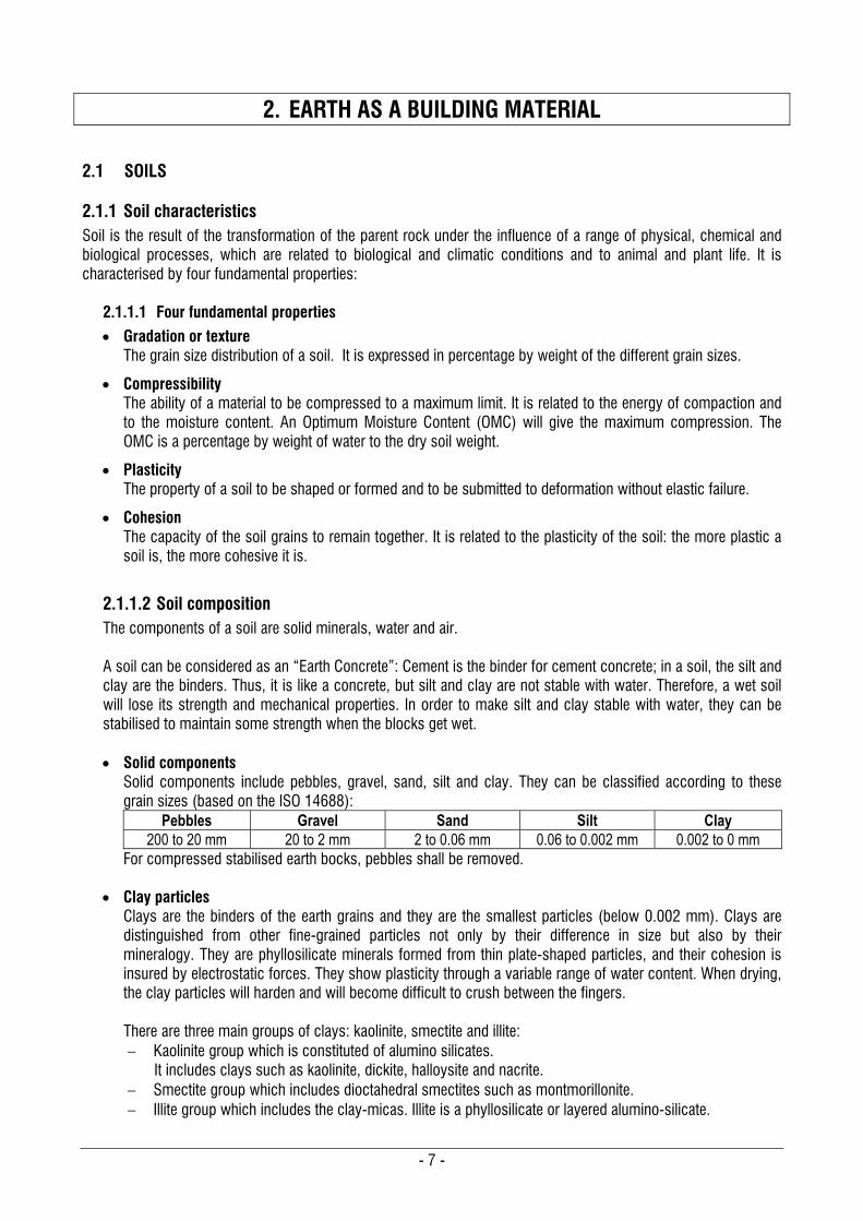
Solid components include pebbles, gravel, sand, silt and clay. They can be classified according to these grain sizes (based on the ISO 14688):
Pebbles Gravel Sand Silt Clay 200 to 20 mm 20 to 2 mm 2 to 0.06 mm 0.06 to 0.002 mm 0.002 to 0 mm
For compressed stabilised earth bocks, pebbles shall be removed.
Clay particles Clays are the binders of the earth grains and they are the smallest particles (below 0.002 mm). Clays are distinguished from other fine-grained particles not only by their difference in size but also by their mineralogy. They are phyllosilicate minerals formed from thin plate-shaped particles, and their cohesion is insured by electrostatic forces. They show plasticity through a variable range of water content. When drying, the clay particles will harden and will become difficult to crush between the fingers. There are three main groups of clays: kaolinite, smectite and illite: Kaolinite group which is constituted of alumino silicates.
It includes clays such as kaolinite, dickite, halloysite and nacrite. Smectite group which includes dioctahedral smectites such as montmorillonite. Illite group which includes the clay-micas. Illite is a phyllosilicate or layered alumino-silicate.
- 8 -
For a compressed stabilised earth block, the clay in the soil acts first as a lubricant. When compressing the soil, clay allows the other inert grains of gravel, sand and the silt to be reorganised differently, and it allows to them to form a different dense matrix. Finally, once compressed, clay will bind the grains with electrostatic forces which are conducted by water.
Silt particles Silts are fine grains (0.06 to 0.002 mm) between sand and clay. Silts are created by a variety of physical processes capable of splitting the generally sand-sized quartz crystals. The main process is abrasion through transport, including fluvial, aeolian and glacial grinding. Silts are not very active particles, however, according to their grain size and mineralogy, they can bind other inert grains (sand and gravel) to a certain extent through capillary forces.
Note on silts and clays: The classification between silts and clays is mainly done on the basis of their grain size. However, there is some overlap in their physical properties and behaviour. Therefore, what shall be evaluated is how they behave in the soil and how they bind the other grains. As an example: The grain size distribution done in a laboratory may indicate a silt with major percentage of grains between 0.06 and 0.002 mm, but the soil could behave like a clayey soil in terms of plasticity, activity and general behaviour.
2.1.2 Soil classification for CSEB In general, soils are either classified on the basis of texture, as is the case in the US, or on the basis of physical and chemical characteristics, as is the case in Australia. The Unified Soil Classification System (USCS) defines three major classification groups: (1) coarse-grained soils (e.g. sands and gravels); (2) fine-grained soils (e.g. silts and clays); and (3) highly organic soils (referred to as "peat"). The Indian standard IS: 1498- 1970, “Classification and Identification of Soils for General Engineering Purposes” retains only two groups: “coarse-grained soils” and “fine-grained soils”. Highly organic soils and other miscellaneous soils are placed in another group and not considered for engineering purposes. Standard classification related to the texture is done using symbols such as GW-GP, GW-GM, SW-SP, SW-SM, CL-Cl, OL-01, Cl-CH, 01-OH, Ml-01, MH-CH, etc. However, these references are not easily understandable for laymen. Gravel, sand, silt and clay are the four components of a soil used for CSEB, and texture is the first criteria to look at for the suitability of a soil for producing CSEB. Therefore, it is preferred to reference the soil classification for CSEB on the basis of the texture of the soil. The names of this classification are given by the component which most influences the behaviour of the soil: i.e. gravely when the gravel influences the most, sandy when sand is more influencing silty or clayey soils. Gravely, sandy, silty and clayey soils are defined as typical soils. Note that the soil has to be evaluated as a whole and not as separate components. Therefore, it is necessary to examine how these various components combine with each other. For example, a soil might have more gravel than normal, but if the clay is very plastic and with the proper proportion, the soil might not be called gravely, but it will probably be a good soil because both components work well together. In fact, soils have a very large range of textures and it is necessary to define more categories of soil classification for CSEB. Often two of the components of the soils are influencing its behaviour. Therefore, more precise categories will use the name of these two components, such as “gravely clay” or “silty sand”. These types of soils are defined as combined soils. The last name is the primary component of the soil which influences it the most. The first name is the secondary component of the soil which influences it to a lesser extent. Examples of names for combined soils: Silty sand = Soil mainly sandy with an influential proportion of silt. Sandy silt = Soil mainly silty with an influential proportion of sand.

- 9 -
2.1.3 Soil suitability and improvement of soils for CSEB 2.1.3.1 Good soil for compressed stabilised earth blocks Note that topsoil, which normally contains humus, shall never be used. It shall be scraped aside and reused later on for agriculture or landscaping. Two parameters shall be considered to define a good soil for compressed stabilised earth block: Compressibility and type of stabiliser.
Good soil for CSEB according to compressibility
As the technology is based on the compression of the soil, the compressibility factor is the first one to consider. In general, one shall look for a proper gradation of the soil and a continuous structure. This means that the soil shall have enough inert particles of gravel and sand (at least 45-50%) to be bound by silt and clay, and also to have a good gradation of the various grain sizes. In general, it is not advisable to use soils with less than 10% of clay or less than 25% of silt and clay. The reason is that there are not enough binders to lubricate the inert grains and to allow them to be reorganised in a dense and cohesive structure. Soils with less percentage of silt and clay will not be easily compressible and the blocks will not be cohesive just after production. Therefore, it will be necessary to stabilise the soil more and to handle the blocks in a very careful way after production.
Good soil for CSEB according to the type of stabiliser The main stabilisers used worldwide for CSEB are cement and lime. These stabilisers will react differently with the type of soil: Portland cement will bind the grains of gravel and sand together to create an inert matrix which restricts
movement. It will work less efficiently with silt and especially with clay. Therefore, a good soil for cement stabilisation will be a sandier soil. Optimal grain size distribution of a good soil for cement stabilisation: More sandy than clayey.
Gravel Sand Silt Clay 15% 50% 15% 20%
Lime will also bind the grains of gravel, sand and silt, but to a lesser extent compared to cement. Lime
will especially have a pozzolanic reaction with clay. It will create stable chemical bonds between clay and sand. Therefore, a good soil for lime stabilisation is rather clayey. Optimal grain size distribution of a good soil for lime stabilisation: More clayey than sandy.
Gravel Sand Silt Clay 15% 30% 20% 35%
Note for the optimal proportions of a good soil for CSEB: The optimal proportions recorded above are idealistic. Often soils do not have such proportions. But it is possible to use soils with other proportions by improving them with the addition of sand, gravel or mixing various different soils: see the next paragraph 2.1.3.2 on the following page. Ideally the gradation obtained after modifying the soil shall be as close as possible to the values given above.
- 10 -
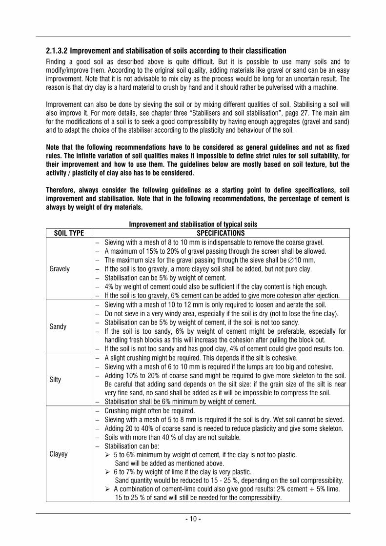
2.1.3.2 Improvement and stabilisation of soils according to their classification Finding a good soil as described above is quite difficult. But it is possible to use many soils and to modify/improve them. According to the original soil quality, adding materials like gravel or sand can be an easy improvement. Note that it is not advisable to mix clay as the process would be long for an uncertain result. The reason is that dry clay is a hard material to crush by hand and it should rather be pulverised with a machine. Improvement can also be done by sieving the soil or by mixing different qualities of soil. Stabilising a soil will also improve it. For more details, see chapter three “Stabilisers and soil stabilisation”, page 27. The main aim for the modifications of a soil is to seek a good compressibility by having enough aggregates (gravel and sand) and to adapt the choice of the stabiliser according to the plasticity and behaviour of the soil. Note that the following recommendations have to be considered as general guidelines and not as fixed rules. The infinite variation of soil qualities makes it impossible to define strict rules for soil suitability, for their improvement and how to use them. The guidelines below are mostly based on soil texture, but the activity / plasticity of clay also has to be considered. Therefore, always consider the following guidelines as a starting point to define specifications, soil improvement and stabilisation. Note that in the following recommendations, the percentage of cement is always by weight of dry materials.
Improvement and stabilisation of typical soils SOIL TYPE SPECIFICATIONS
Gravely
Sieving with a mesh of 8 to 10 mm is indispensable to remove the coarse gravel. A maximum of 15% to 20% of gravel passing through the screen shall be allowed. The maximum size for the gravel passing through the sieve shall be 10 mm. If the soil is too gravely, a more clayey soil shall be added, but not pure clay. Stabilisation can be 5% by weight of cement. 4% by weight of cement could also be sufficient if the clay content is high enough. If the soil is too gravely, 6% cement can be added to give more cohesion after ejection.
Sandy
Sieving with a mesh of 10 to 12 mm is only required to loosen and aerate the soil. Do not sieve in a very windy area, especially if the soil is dry (not to lose the fine clay). Stabilisation can be 5% by weight of cement, if the soil is not too sandy. If the soil is too sandy, 6% by weight of cement might be preferable, especially for
handling fresh blocks as this will increase the cohesion after pulling the block out. If the soil is not too sandy and has good clay, 4% of cement could give good results too.
Silty
A slight crushing might be required. This depends if the silt is cohesive. Sieving with a mesh of 6 to 10 mm is required if the lumps are too big and cohesive. Adding 10% to 20% of coarse sand might be required to give more skeleton to the soil.
Be careful that adding sand depends on the silt size: if the grain size of the silt is near very fine sand, no sand shall be added as it will be impossible to compress the soil.
Stabilisation shall be 6% minimum by weight of cement.
Clayey
Crushing might often be required. Sieving with a mesh of 5 to 8 mm is required if the soil is dry. Wet soil cannot be sieved. Adding 20 to 40% of coarse sand is needed to reduce plasticity and give some skeleton. Soils with more than 40 % of clay are not suitable. Stabilisation can be: 5 to 6% minimum by weight of cement, if the clay is not too plastic.
Sand will be added as mentioned above. 6 to 7% by weight of lime if the clay is very plastic.
Sand quantity would be reduced to 15 - 25 %, depending on the soil compressibility. A combination of cement-lime could also give good results: 2% cement + 5% lime.
15 to 25 % of sand will still be needed for the compressibility.
- 11 -
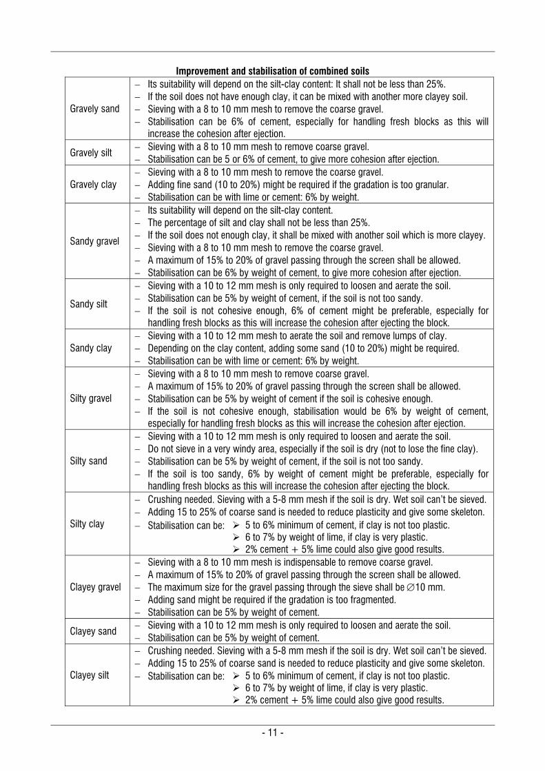
Improvement and stabilisation of combined soils
Gravely sand
Its suitability will depend on the silt-clay content: It shall not be less than 25%. If the soil does not have enough clay, it can be mixed with another more clayey soil. Sieving with a 8 to 10 mm mesh to remove the coarse gravel. Stabilisation can be 6% of cement, especially for handling fresh blocks as this will
increase the cohesion after ejection.
Gravely silt Sieving with a 8 to 10 mm mesh to remove coarse gravel. Stabilisation can be 5 or 6% of cement, to give more cohesion after ejection.
Gravely clay Sieving with a 8 to 10 mm mesh to remove the coarse gravel. Adding fine sand (10 to 20%) might be required if the gradation is too granular. Stabilisation can be with lime or cement: 6% by weight.
Sandy gravel
Its suitability will depend on the silt-clay content. The percentage of silt and clay shall not be less than 25%. If the soil does not enough clay, it shall be mixed with another soil which is more clayey. Sieving with a 8 to 10 mm mesh to remove the coarse gravel. A maximum of 15% to 20% of gravel passing through the screen shall be allowed. Stabilisation can be 6% by weight of cement, to give more cohesion after ejection.
Sandy silt
Sieving with a 10 to 12 mm mesh is only required to loosen and aerate the soil. Stabilisation can be 5% by weight of cement, if the soil is not too sandy. If the soil is not cohesive enough, 6% of cement might be preferable, especially for
handling fresh blocks as this will increase the cohesion after ejecting the block.
Sandy clay Sieving with a 10 to 12 mm mesh to aerate the soil and remove lumps of clay. Depending on the clay content, adding some sand (10 to 20%) might be required. Stabilisation can be with lime or cement: 6% by weight.
Silty gravel
Sieving with a 8 to 10 mm mesh to remove coarse gravel. A maximum of 15% to 20% of gravel passing through the screen shall be allowed. Stabilisation can be 5% by weight of cement if the soil is cohesive enough. If the soil is not cohesive enough, stabilisation would be 6% by weight of cement,
especially for handling fresh blocks as this will increase the cohesion after ejection.
Silty sand
Sieving with a 10 to 12 mm mesh is only required to loosen and aerate the soil. Do not sieve in a very windy area, especially if the soil is dry (not to lose the fine clay). Stabilisation can be 5% by weight of cement, if the soil is not too sandy. If the soil is too sandy, 6% by weight of cement might be preferable, especially for
handling fresh blocks as this will increase the cohesion after ejecting the block.
Silty clay
Crushing needed. Sieving with a 5-8 mm mesh if the soil is dry. Wet soil can’t be sieved. Adding 15 to 25% of coarse sand is needed to reduce plasticity and give some skeleton. Stabilisation can be: 5 to 6% minimum of cement, if clay is not too plastic.
6 to 7% by weight of lime, if clay is very plastic. 2% cement + 5% lime could also give good results.
Clayey gravel
Sieving with a 8 to 10 mm mesh is indispensable to remove coarse gravel. A maximum of 15% to 20% of gravel passing through the screen shall be allowed. The maximum size for the gravel passing through the sieve shall be 10 mm. Adding sand might be required if the gradation is too fragmented. Stabilisation can be 5% by weight of cement.
Clayey sand Sieving with a 10 to 12 mm mesh is only required to loosen and aerate the soil. Stabilisation can be 5% by weight of cement.
Clayey silt
Crushing needed. Sieving with a 5-8 mm mesh if the soil is dry. Wet soil can’t be sieved. Adding 15 to 25% of coarse sand is needed to reduce plasticity and give some skeleton. Stabilisation can be: 5 to 6% minimum of cement, if clay is not too plastic.
6 to 7% by weight of lime, if clay is very plastic. 2% cement + 5% lime could also give good results.
- 12 -
2.1.4 Soil identification Soils can be identified in two ways: laboratory analysis and field tests, also known as sensitive analysis. Laboratory analysis need specialised equipment and chemicals. They cannot be performed by laymen. Sensitive analysis can be performed by anybody after a short training. Of course, sensitive analysis cannot be as accurate as laboratory analysis for determining the grain size distribution or the plasticity. But most of the time they are sufficient to determine the behaviour of a soil and its suitability for an earth technique and CSEB in particular. The tests for the soil identification, either done with laboratory analysis or sensitive analysis, have to check mostly the four fundamental properties (Texture, Compressibility, Plasticity and Cohesion).
2.1.4.1 Sensitive analysis or field tests The aim of sensitive analysis is to define in which category the soil sample belongs: gravely, sandy, silty, clayey or combined soils as like sandy clay, silty sand, etc. According to this classification, it is possible to determine the suitability of the soil and adapt it if necessary as described in the recommendations in paragraph 2.1.3.2 “Improvement and stabilisation of soils according to their classification”, page 10. Note that the soil identification shall be undertaken twice: first on the raw soil, before doing any modification, and also after correcting and improving the soil (i.e. after sieving). The reason for this is that, since some materials have been removed (gravel and lumps), the proportions of the other components have changed. The following tests which are described hereafter can be practiced in the field by anybody and only some water is needed. The interpretations of the following tests are given only for the 4 typical soils, owing to their characteristic behaviour.
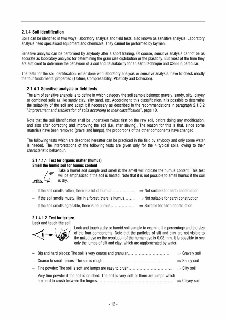
2.1.4.1.1 Test for organic matter (humus) Smell the humid soil for humus content
Take a humid soil sample and smell it: the smell will indicate the humus content. This test will be emphasized if the soil is heated. Note that it is not possible to smell humus if the soil is dry.
If the soil smells rotten, there is a lot of humus……………... Not suitable for earth construction
If the soil smells musty, like in a forest, there is humus…….. Not suitable for earth construction
If the soil smells agreeable, there is no humus……………... Suitable for earth construction
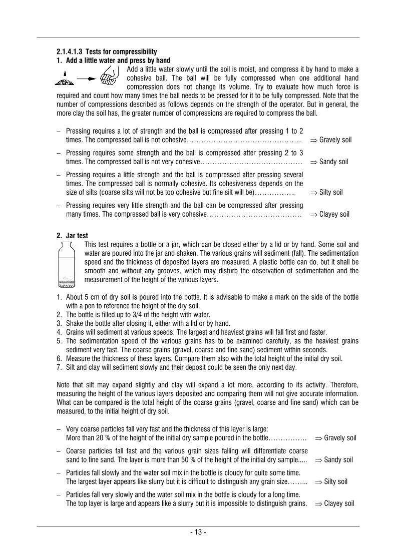
2.1.4.1.2 Test for texture Look and touch the soil
Look and touch a dry or humid soil sample to examine the percentage and the size of the four components. Note that the particles of silt and clay are not visible to the naked eye as the resolution of the human eye is 0.08 mm. It is possible to see only the lumps of silt and clay, which are agglomerated by water.
Big and hard pieces: The soil is very coarse and granular………………………… Gravely soil
Coarse to small pieces: The soil is rough…………………………………………... Sandy soil
Fine powder: The soil is soft and lumps are easy to crush………………………….. Silty soil
Very fine powder if the soil is crushed: The soil is very soft or there are lumps which are hard to crush between the fingers………………………………………………
Clayey soil
- 13 -
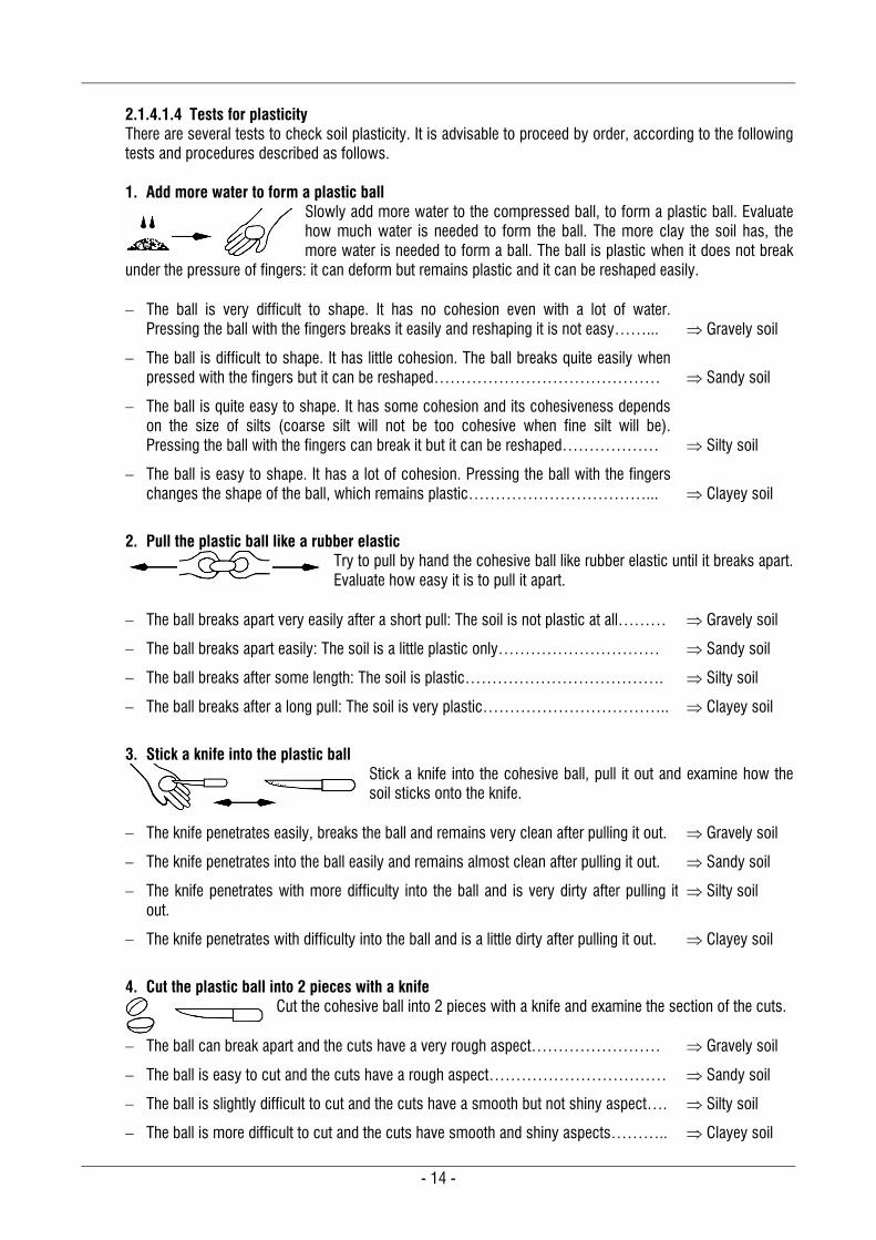
2.1.4.1.3 Tests for compressibility 1. Add a little water and press by hand
Add a little water slowly until the soil is moist, and compress it by hand to make a cohesive ball. The ball will be fully compressed when one additional hand compression does not change its volume. Try to evaluate how much force is
required and count how many times the ball needs to be pressed for it to be fully compressed. Note that the number of compressions described as follows depends on the strength of the operator. But in general, the more clay the soil has, the greater number of compressions are required to compress the ball. Pressing requires a lot of strength and the ball is compressed after pressing 1 to 2
times. The compressed ball is not cohesive………………………………………... Gravely soil
Pressing requires some strength and the ball is compressed after pressing 2 to 3 times. The compressed ball is not very cohesive……………………………………
Sandy soil
Pressing requires a little strength and the ball is compressed after pressing several times. The compressed ball is normally cohesive. Its cohesiveness depends on the size of silts (coarse silts will not be too cohesive but fine silt will be)……………..
Silty soil
Pressing requires very little strength and the ball can be compressed after pressing many times. The compressed ball is very cohesive…………………………………
Clayey soil
2. Jar test
This test requires a bottle or a jar, which can be closed either by a lid or by hand. Some soil and water are poured into the jar and shaken. The various grains will sediment (fall). The sedimentation speed and the thickness of deposited layers are measured. A plastic bottle can do, but it shall be smooth and without any grooves, which may disturb the observation of sedimentation and the measurement of the height of the various layers.
1. About 5 cm of dry soil is poured into the bottle. It is advisable to make a mark on the side of the bottle with a pen to reference the height of the dry soil.
2. The bottle is filled up to 3/4 of the height with water. 3. Shake the bottle after closing it, either with a lid or by hand. 4. Grains will sediment at various speeds: The largest and heaviest grains will fall first and faster. 5. The sedimentation speed of the various grains has to be examined carefully, as the heaviest grains
sediment very fast. The coarse grains (gravel, coarse and fine sand) sediment within seconds. 6. Measure the thickness of these layers. Compare them also with the total height of the initial dry soil. 7. Silt and clay will sediment slowly and their deposit could be seen the only next day. Note that silt may expand slightly and clay will expand a lot more, according to its activity. Therefore, measuring the height of the various layers deposited and comparing them will not give accurate information. What can be compared is the total height of the coarse grains (gravel, coarse and fine sand) which can be measured, to the initial height of dry soil. Very coarse particles fall very fast and the thickness of this layer is large:
More than 20 % of the height of the initial dry sample poured in the bottle……………. Gravely soil
Coarse particles fall fast and the various grain sizes falling will differentiate coarse sand to fine sand. The layer is more than 50 % of the height of the initial dry sample.....
Sandy soil
Particles fall slowly and the water soil mix in the bottle is cloudy for quite some time. The largest layer appears like slurry but it is difficult to distinguish any grain size……...
Silty soil
Particles fall very slowly and the water soil mix in the bottle is cloudy for a long time. The top layer is large and appears like a slurry but it is impossible to distinguish grains.
Clayey soil
- 14 -
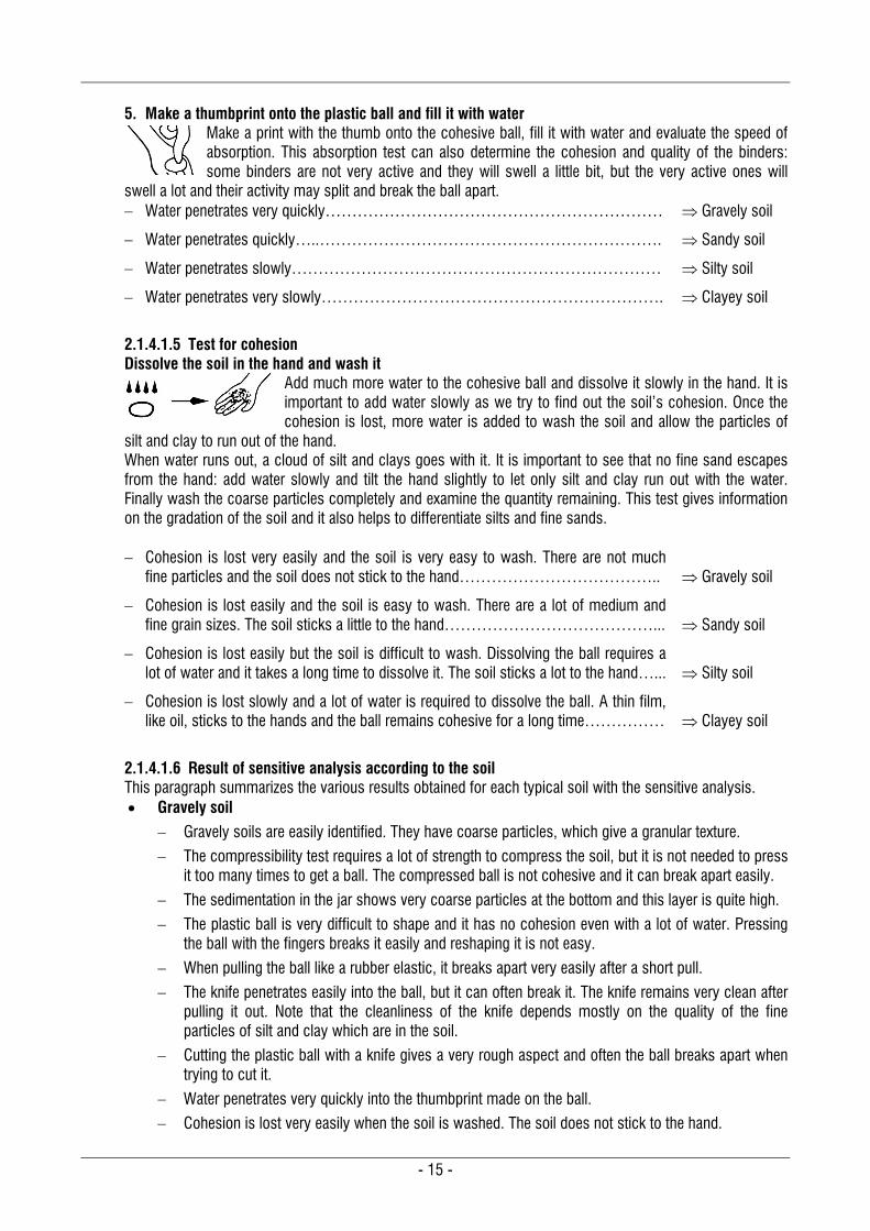
2.1.4.1.4 Tests for plasticity There are several tests to check soil plasticity. It is advisable to proceed by order, according to the following tests and procedures described as follows. 1. Add more water to form a plastic ball
Slowly add more water to the compressed ball, to form a plastic ball. Evaluate how much water is needed to form the ball. The more clay the soil has, the more water is needed to form a ball. The ball is plastic when it does not break
under the pressure of fingers: it can deform but remains plastic and it can be reshaped easily. The ball is very difficult to shape. It has no cohesion even with a lot of water.
Pressing the ball with the fingers breaks it easily and reshaping it is not easy……... Gravely soil
The ball is difficult to shape. It has little cohesion. The ball breaks quite easily when pressed with the fingers but it can be reshaped……………………………………
Sandy soil
The ball is quite easy to shape. It has some cohesion and its cohesiveness depends on the size of silts (coarse silt will not be too cohesive when fine silt will be). Pressing the ball with the fingers can break it but it can be reshaped………………
Silty soil
The ball is easy to shape. It has a lot of cohesion. Pressing the ball with the fingers changes the shape of the ball, which remains plastic……………………………...
Clayey soil
2. Pull the plastic ball like a rubber elastic
Try to pull by hand the cohesive ball like rubber elastic until it breaks apart. Evaluate how easy it is to pull it apart.
The ball breaks apart very easily after a short pull: The soil is not plastic at all……… Gravely soil
The ball breaks apart easily: The soil is a little plastic only………………………… Sandy soil
The ball breaks after some length: The soil is plastic………………………………. Silty soil
The ball breaks after a long pull: The soil is very plastic…………………………….. Clayey soil
3. Stick a knife into the plastic ball
Stick a knife into the cohesive ball, pull it out and examine how the soil sticks onto the knife.
The knife penetrates easily, breaks the ball and remains very clean after pulling it out. Gravely soil
The knife penetrates into the ball easily and remains almost clean after pulling it out. Sandy soil
The knife penetrates with more difficulty into the ball and is very dirty after pulling it out.
Silty soil
The knife penetrates with difficulty into the ball and is a little dirty after pulling it out. Clayey soil
4. Cut the plastic ball into 2 pieces with a knife
Cut the cohesive ball into 2 pieces with a knife and examine the section of the cuts.
The ball can break apart and the cuts have a very rough aspect…………………… Gravely soil
The ball is easy to cut and the cuts have a rough aspect…………………………… Sandy soil
The ball is slightly difficult to cut and the cuts have a smooth but not shiny aspect…. Silty soil
The ball is more difficult to cut and the cuts have smooth and shiny aspects……….. Clayey soil
- 15 -
5. Make a thumbprint onto the plastic ball and fill it with water
Make a print with the thumb onto the cohesive ball, fill it with water and evaluate the speed of absorption. This absorption test can also determine the cohesion and quality of the binders: some binders are not very active and they will swell a little bit, but the very active ones will
swell a lot and their activity may split and break the ball apart. Water penetrates very quickly……………………………………………………… Gravely soil
Water penetrates quickly…..………………………………………………………. Sandy soil
Water penetrates slowly…………………………………………………………… Silty soil
Water penetrates very slowly………………………………………………………. Clayey soil
2.1.4.1.5 Test for cohesion Dissolve the soil in the hand and wash it
Add much more water to the cohesive ball and dissolve it slowly in the hand. It is important to add water slowly as we try to find out the soil’s cohesion. Once the cohesion is lost, more water is added to wash the soil and allow the particles of
silt and clay to run out of the hand. When water runs out, a cloud of silt and clays goes with it. It is important to see that no fine sand escapes from the hand: add water slowly and tilt the hand slightly to let only silt and clay run out with the water. Finally wash the coarse particles completely and examine the quantity remaining. This test gives information on the gradation of the soil and it also helps to differentiate silts and fine sands. Cohesion is lost very easily and the soil is very easy to wash. There are not much
fine particles and the soil does not stick to the hand……………………………….. Gravely soil
Cohesion is lost easily and the soil is easy to wash. There are a lot of medium and fine grain sizes. The soil sticks a little to the hand…………………………………...
Sandy soil
Cohesion is lost easily but the soil is difficult to wash. Dissolving the ball requires a lot of water and it takes a long time to dissolve it. The soil sticks a lot to the hand…...
Silty soil
Cohesion is lost slowly and a lot of water is required to dissolve the ball. A thin film, like oil, sticks to the hands and the ball remains cohesive for a long time……………
Clayey soil
2.1.4.1.6 Result of sensitive analysis according to the soil This paragraph summarizes the various results obtained for each typical soil with the sensitive analysis. Gravely soil
Gravely soils are easily identified. They have coarse particles, which give a granular texture.
The compressibility test requires a lot of strength to compress the soil, but it is not needed to press it too many times to get a ball. The compressed ball is not cohesive and it can break apart easily.
The sedimentation in the jar shows very coarse particles at the bottom and this layer is quite high.
The plastic ball is very difficult to shape and it has no cohesion even with a lot of water. Pressing the ball with the fingers breaks it easily and reshaping it is not easy.
When pulling the ball like a rubber elastic, it breaks apart very easily after a short pull.
The knife penetrates easily into the ball, but it can often break it. The knife remains very clean after pulling it out. Note that the cleanliness of the knife depends mostly on the quality of the fine particles of silt and clay which are in the soil.
Cutting the plastic ball with a knife gives a very rough aspect and often the ball breaks apart when trying to cut it.
Water penetrates very quickly into the thumbprint made on the ball.
Cohesion is lost very easily when the soil is washed. The soil does not stick to the hand.
- 16 -
Sandy soil
The texture of the soil is coarse.
The compressibility requires some strength, and the ball is compressed after pressing for a short time. The compressed ball is not very cohesive.
The sedimentation in the jar shows coarse to fine grains. It is important to note the fine sand falling on the top of the sand layer. This helps to differentiate the fine sands from the silt.
The plastic ball is relatively difficult to shape and it has little cohesion. The ball breaks quite easily when pressed with the fingers, but it can be reshaped.
The ball breaks apart easily when pulled like a rubber elastic, as the soil is a little plastic.
The knife penetrates easily into the plastic ball, and it remains almost clean after pulling it out. Note that the cleanliness of the knife depends mostly on the quality of the fine particles of silt and clay which are in the soil.
The ball is easy to cut and the cuts have a rough aspect.
Water penetrates quickly into the thumbprint made on the plastic ball.
The cohesion is lost easily and the soil is easy to wash. There are a lot of medium and fine grain sizes. The soil sticks a little to the hand. It is important to see that no fine sand escapes from the hand: this will help to differentiate if a soil has very fine sand or if it is silty.
Silty soil
The texture of the soil is fine. It can be like a powder, but it can have some lumps which are easy to crush.
The compressibility requires a little strength, but the ball is compressed after pressing several times. The compressed ball is normally cohesive. Its cohesiveness depends on the size of silts (coarse silt will not be too cohesive when fine silt will be more).
The sedimentation in the jar shows particles falling slowly and the water-soil mix in the bottle is cloudy for quite some time. The layer of silt appears like a slurry, but it is difficult to distinguish any grain size.
The plastic ball is quite easy to shape. It has some cohesion, but its cohesiveness depends on the size of silts (coarse silt will not be too cohesive when fine silt will be). If shaken in the palm of the hand, a part of saturated silt releases enough water to make its surface appear glossy. If the ball is pressed or squeezed between the fingers, its surface again becomes dull.
The ball breaks after some length when pulled like a rubber elastic, as the soil has a little plasticity.
The plastic ball shows some resistance to the penetration of the knife, and it is very dirty after pulling it out.
The ball is slightly difficult to cut and the cuts have a smooth but not shiny aspect. It has a dull aspect.
Water penetrates slowly into the thumbprint made on the plastic ball.
Cohesion is lost easily but the soil is difficult to wash. Dissolving the ball requires a lot of water and it takes a long time to dissolve it. The soil sticks a lot to the hand. This is the typical difference between silty and clayey soil: silty soils stick more to the hand, because they don’t have enough cohesion.
- 17 -
Clayey soil
The texture of the soil is fine, but most of the time it has lumps which are hard to crush between the fingers. Though these lumps can be hard to crush, they should not be confused with gravel.
The compressibility requires very little strength, but the soil needs to be pressed many times to compress it. The compressed ball is very cohesive.
The sedimentation in the jar shows particles falling very slowly, and the water-soil mix in the bottle is cloudy for a very long time. Once clay has totally sedimented, the top layer is large, as it has swollen, and it appears like a slurry. But it is impossible to distinguish grains in this layer.
The plastic ball is easy to shape. It has a lot of cohesion and it is possible to change its shape easily without breaking it.
The ball breaks after a long pull when pulled like a rubber elastic, as the soil is very plastic.
The knife penetrates with some difficulty into the ball as it is cohesive, and the knife is only a little dirty after pulling it out.
The ball presents more resistance to be cut and the cuts have smooth and shiny aspects.
Water penetrates very slowly into the thumbprint on the plastic ball.
Cohesion is lost very slowly and a lot of water is required to dissolve the ball. When trying to dissolve the ball, a thin film like oil sticks to the hands, but the ball remains cohesive for a long time. This is the main difference in behaviour between silt and clay: silt sticks a lot to the hand, whereas clay leaves this oily feeling.
2.1.4.2 Laboratory analysis The information on the laboratory tests given hereafter provides the principles of the tests only. For detailed procedures, please refer to SP 36-Part 1-1987 – Compendium of Indian standards on soil engineering.
2.1.4.2.1 Grain size distribution by wet sieving This test enables one to define the grain size distribution of the coarse particles (gravel and sand). This test is quantitative and does not give an indication of the mineralogical nature of these grains. The test consists of separating the soil’s components with a series of sieves. The masses of the various grains retained within the sieves or those of the various grains passing the sieve are compared to the total mass of the material. The percentages obtained are then given either in their numerical form, or in the form of a graph (Grain size distribution chart). This chart can be drawn only for the coarse grains such as gravel and sand. The part of the chart with the fine particles can be drawn only after doing the sedimentation test. 2.1.4.2.2 Grain size distribution by sedimentation Sedimentation analysis is a test which complements the grain size distribution analysis by sieving. It is applied to the fine elements of less than 0.06 mm, for which it is not possible to use sieves. Some soil is diluted in de-mineralised water or distilled water and a dispersing agent (e.g. sodium hexametaphosphate) is used for slowing down the flocculation. The principle of the test is that grains of soil of differing diameters, placed in homogeneous suspension in a standing liquid, sediment, or "fall", at differing speeds according to their diameters. In the course of this sedimentation, the density of the initially homogenous mixture will increase from the top to the bottom as time passes. These variations of densities are measured with a hydrometer. By measuring times and densities and by using Stokes' law, the diameters of the grains of soil can be defined. 2.1.4.2.3 Examples of grain size distribution charts The following grain size distribution charts show the gradation of different soils and the limits for soils which have to be stabilised either by cement or lime. These charts are drawn from the combined results of the wet sieving and the sedimentation tests.
- 18 -
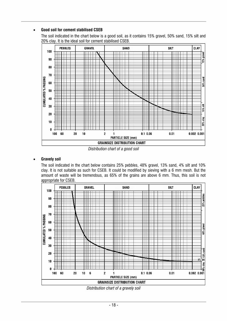
Good soil for cement stabilised CSEB
The soil indicated in the chart below is a good soil, as it contains 15% gravel, 50% sand, 15% silt and 20% clay. It is the ideal soil for cement stabilised CSEB.
Distribution chart of a good soil
Gravely soil
The soil indicated in the chart below contains 25% pebbles, 48% gravel, 13% sand, 4% silt and 10% clay. It is not suitable as such for CSEB. It could be modified by sieving with a 6 mm mesh. But the amount of waste will be tremendous, as 65% of the grains are above 6 mm. Thus, this soil is not appropriate for CSEB.
Distribution chart of a gravely soil
- 19 -
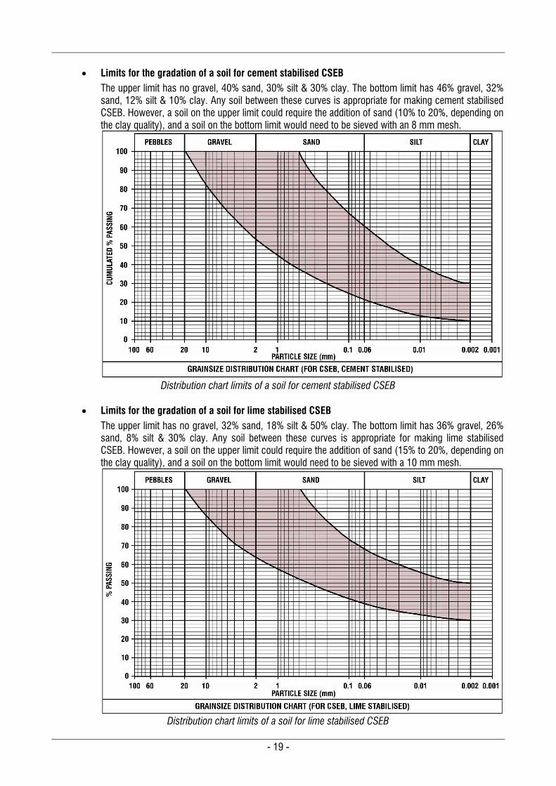
Limits for the gradation of a soil for cement stabilised CSEB
The upper limit has no gravel, 40% sand, 30% silt & 30% clay. The bottom limit has 46% gravel, 32% sand, 12% silt & 10% clay. Any soil between these curves is appropriate for making cement stabilised CSEB. However, a soil on the upper limit could require the addition of sand (10% to 20%, depending on the clay quality), and a soil on the bottom limit would need to be sieved with an 8 mm mesh.
Distribution chart limits of a soil for cement stabilised CSEB
Limits for the gradation of a soil for lime stabilised CSEB
The upper limit has no gravel, 32% sand, 18% silt & 50% clay. The bottom limit has 36% gravel, 26% sand, 8% silt & 30% clay. Any soil between these curves is appropriate for making lime stabilised CSEB. However, a soil on the upper limit could require the addition of sand (15% to 20%, depending on the clay quality), and a soil on the bottom limit would need to be sieved with a 10 mm mesh.
Distribution chart limits of a soil for lime stabilised CSEB
- 20 -
2.1.4.2.4 Plasticity characteristics Plasticity characteristics are defined by the “Atterberg limits”. This a measurement of the behaviour of the fine particles of a soil, which marks the passage of a soil from a solid state to a plastic state (plastic limit, WP) and from a plastic state to a liquid state (liquid limit, WL). These limits indicate the water content of a soil at the state of transition in question, expressed as a percentage of the mass of the dry material. The Atterberg limits are carried out on the fine particles passing through a 0.40 mm sieve. The main Atterberg’s limits are the liquid limit, plastic limit and plasticity index. There are also other limits, such as shrinkage limit, liquidity limit and activity. But they are not often referred to. Liquid limit, WL
The liquid limit is the % of water content in which a soil changes from a plastic state to a liquid state. The test uses a device called a Casagrande apparatus.
Plastic limit, WP The plastic limit is the water content, in which a soil starts to exhibit plastic behaviour. A thread of soil is at its plastic limit when it is rolled to a diameter of 3 mm or begins to crumble.
Plasticity index, IP The plasticity index is a measurement of the plasticity of a soil. It defines the range of water content within which the soil exhibits plastic properties. The plasticity index is the difference between the liquid limit and the plastic limit: IP = WL – WP. Soils with a high IP tend to be clay, those with a lower IP tend to be silt, and those with an IP of zero tend to have little or no silt or clay.
Examples of WL, WP and IP for various soils Typical soils will have Atterberg’s limits within these ranges: Sand 0 % ≤ WL ≤ 10 % 0 % ≤ IP ≤ 5 % Sandy soil 20 % ≤ WL ≤ 30 % 10 % ≤ IP ≤ 20 % Silty soil 20 % ≤ WL ≤ 40 % 10 % ≤ IP ≤ 25 % Clayey soil 25 % ≤ WL ≤ 50 % 15 % ≤ IP ≤ 35 % Clay WL ≥ 50 % IP ≥ 25 %
2.1.4.2.5 Methylene blue test This test measures the capacity of the fines in a soil to adsorb methylene blue on the internal and external surface of the particles under study. The absorption of methylene blue varies with the specific surface area of the fine grains. This test is therefore particularly used to study clays or the clay fractions of a soil, since – depending on their mineralogical composition – these have specific areas which may vary in size. 2.1.4.2.6 Organic matter Soils may contain organic matter (micro-organisms, humus, etc.). Note that roots and leaves, though organic are not considered here as organic matter. Organic matter refers to a material having undergone decomposition, which will be harmful in the event of stabilisation, as they delay or prevent the setting of hydraulic binders. Especially some humid acids (particularly fluidic acid) can be very dangerous. Even if the soil is not intended to be stabilised, it is not advisable to use these kinds of soils, as they cannot be compressed properly and they may continue decomposing in the wall. The procedure consists of heating the soil sample to a high temperature (400°C) in order to burn out the organic matter, and thus to obtain its mass and therefore its percentage in dry mass.
- 21 -
2.1.4.2.7 Optimum moisture content, WOMC (Optimum water content) This test enables one to determine the moisture content with which a soil can be compacted to a maximum. The optimum moisture content is obtained with the Proctor compaction test. A soil sample is subjected to static compaction at various moisture contents and with a standardized energy of compaction. The dry density of every sample with different moisture content is measured. The sample with the maximum dry density will give the optimum moisture content. 2.1.4.2.8 Water content (WC) This test enables one to check the water content of a sample. The water content is expressed as a percentage of the mass of free water (MW) contained in the sample by its dry mass (Md):
d
WC M
.MW
100 in %
Water is driven off from a sample of soil by oven drying at 105°C or on a frying pan. The mass of the humid sample is first measured. Then the sample is dried until all moisture is evaporated, and then the dry soil is measured again. The percentage of moisture content is calculated with the formula above.
2.1.5 Resource management Building with earth has a long history, with countless customs and discoveries throughout the ages, from which we can benefit. Until recent times human development progressed largely in harmony with nature, respecting yet utilizing natural resources. One thing calls for our attention in the history of earth building: all over the world and through the centuries, one has to acknowledge the balance and harmony of these buildings with the surrounding physical environment and landscape. However, in contemporary times, this balance between human development and nature has been lost, resulting in careless exploitation of resources beyond measure. When building with earth, it is our responsibility to manage resources appropriately from the very outset.
2.1.5.1 The challenge: using earth without depleting resources With new developments of CSEB on a semi-industrial scale, one should not overlook the risk of ecological disasters due to mismanagement of resources. On the other hand, a proper management of the earth resources can create a harmonious balance between the natural landscape and buildings, in which each enriches and completes the other. First of all, topsoil has to be scraped away and it can be re-used later for agriculture or gardens. Two types of quarries may be developed: A deep quarry, which can be used later for rainwater harvesting, wastewater treatment, basement floors,
pools, etc. A shallow quarry, which can be used for landscape design, work or play areas, gardens, etc. A proper plan should be drawn up beforehand to prevent discrepancies later on. If co-ordinated well, a decentralised approach could be the most efficient and effective. The use of rainwater harvesting, medium scale wastewater treatment, etc. can be integrated harmoniously into the urban environment. At this point, coordination between the city/village authorities and block manufacturers will profit all sides: urban development always needs earth to be excavated somewhere for some reason or another. These excavations can be made in a judicious manner by producing building materials such as CSEB for the local developments. Therefore, it is indispensable to seek authorization from the mining department and local authorities. Soil for building is a precious material. Don’t waste it. It is possible to take advantage of quarries to create a harmonious development, as exemplified in the following section.
- 22 -
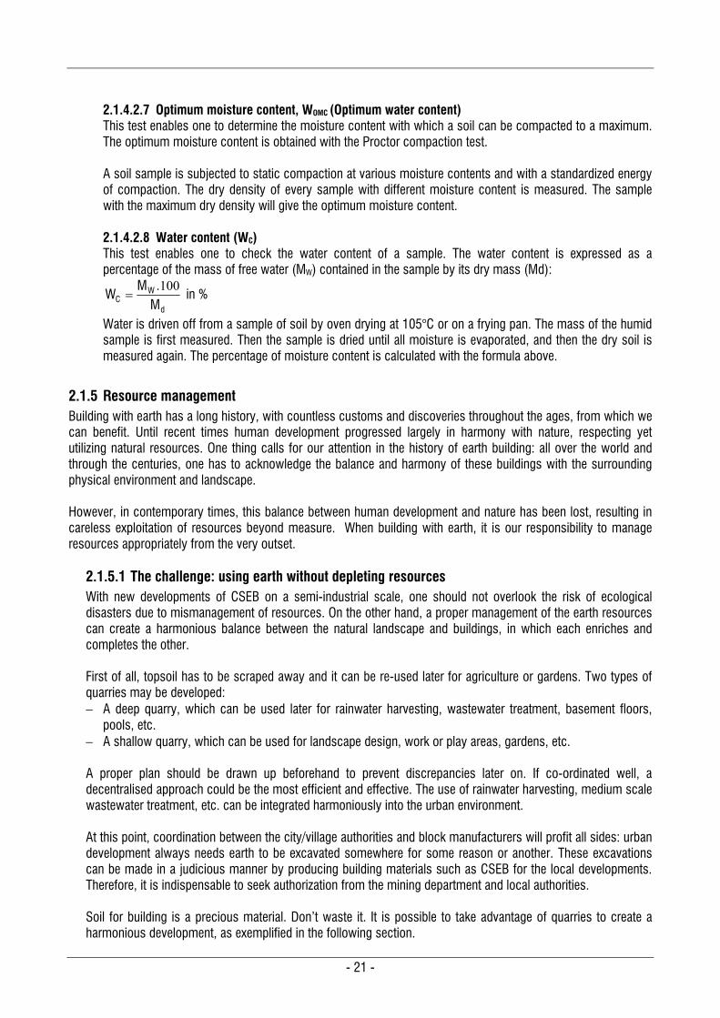
2.1.5.2 Examples of proper resource management There are many ways to use / rehabilitate a quarry from which soil was extracted to make blocks: Rainwater harvesting systems:
Shallow excavation: It can be used as playground area and for landscaping, which can aid percolation. Shallow and deep: For landscape design, used also for percolation of rainwater. Deep: To create ponds and lakes to store huge quantity of water that can be supplied for agriculture. Deep: For underground rainwater tanks.
Basement floor, which can be half underground or more
Wastewater system
Swimming pool The following examples from Auroville show that it is possible to use earth resources in a respectful way and to take advantage of a quarry for the harmonious development of a place.
Wastewater treatment and rainwater harvesting The following four photos show how a wastewater treatment system can be combined with a rainwater harvesting system. The system was totally integrated with the surrounding environment: no trees were cut and the shape of the system was adapted to the landscape and trees. The system was dimensioned in such a way that the volume of soil excavated for 4 houses was sufficient to build them. The wastewater system was combined with a rainwater harvesting system by percolation: the site had a steep slope and it was needed to stop rainwater from running off. Both systems were studied in such a way that the rainwater harvested in the percolation system was lower than the treated wastewater, as it is not advisable to mix harvested rainwater and treated wastewater.
Excavation around the trees according to the design
Laying back the top soil and planting grass
System designed and built around the trees.
Totally integrated system for 4 houses
- 23 -
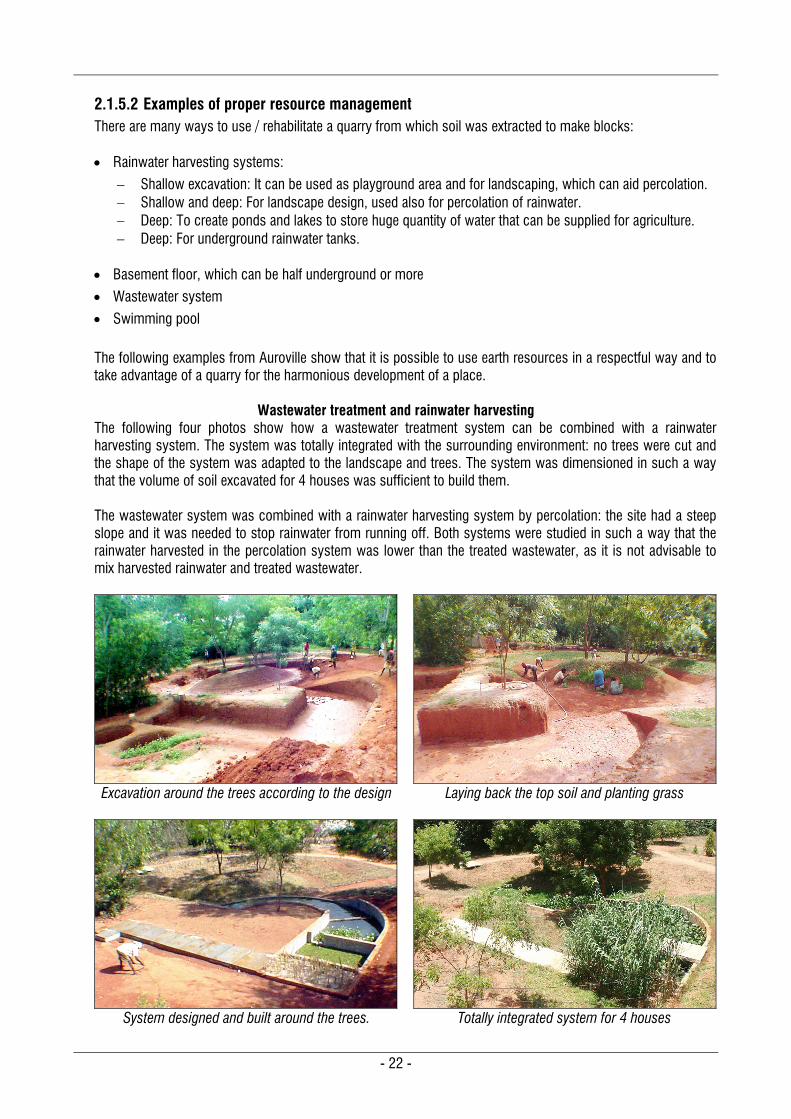
Basement floor and rainwater harvesting
The following example shows the management of soil resources for the construction of 13 apartments on 4 floors in Vikas Community, Auroville. The building was planned with a basement floor, 1.20 m below the original ground level. The volume of this basement floor was calculated to satisfy the need of soil to produce the blocks and build 4 floors. Thus, the amount of soil generated by the basement excavation was enough to build 819 m2 of carpet area, on 4 floors. A rainwater harvesting system by percolation drains the site in case of excessive rainfall. This system has worked perfectly as it harvested 450 m3 of water during a rainfall of 402 mm in 5 days.
Excavation of the basement, 1.2 m below ground level
Section of the building with basement floor
Rainwater harvesting by percolation
13 apartments on 4 floors: 3 floors above the basement
Sections of the building with basement floor and rainwater harvesting system
- 24 -
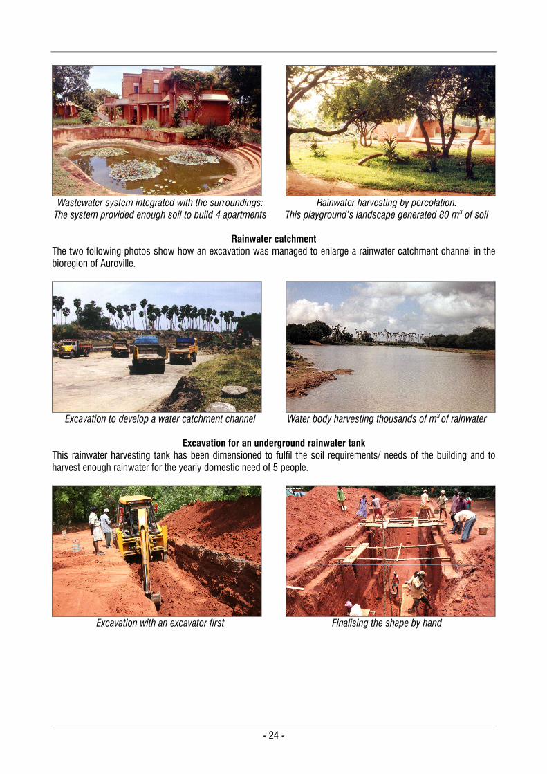
Wastewater system integrated with the surroundings:
The system provided enough soil to build 4 apartments
Rainwater harvesting by percolation:
This playground’s landscape generated 80 m3 of soil
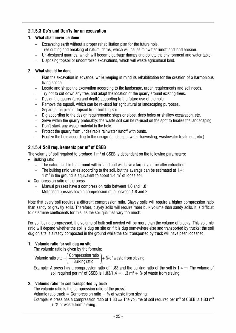
Rainwater catchment The two following photos show how an excavation was managed to enlarge a rainwater catchment channel in the bioregion of Auroville.
Excavation to develop a water catchment channel
Water body harvesting thousands of m3 of rainwater
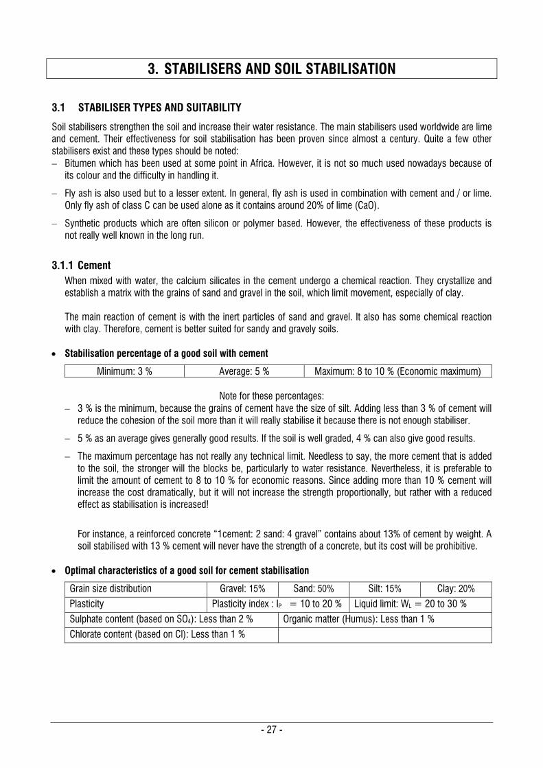
Excavation for an underground rainwater tank
This rainwater harvesting tank has been dimensioned to fulfil the soil requirements/ needs of the building and to harvest enough rainwater for the yearly domestic need of 5 people.
Excavation with an excavator first
Finalising the shape by hand
- 25 -
2.1.5.3 Do’s and Don’ts for an excavation 1. What shall never be done
Excavating earth without a proper rehabilitation plan for the future hole. Tree cutting and breaking of natural dams, which will cause rainwater runoff and land erosion. Un-designed quarries, which will become garbage dumps and pollute the environment and water table. Disposing topsoil or uncontrolled excavations, which will waste agricultural land.
2. What should be done
Plan the excavation in advance, while keeping in mind its rehabilitation for the creation of a harmonious living space.
Locate and shape the excavation according to the landscape, urban requirements and soil needs. Try not to cut down any tree, and adapt the location of the quarry around existing trees. Design the quarry (area and depth) according to the future use of the hole. Remove the topsoil, which can be re-used for agricultural or landscaping purposes. Separate the piles of topsoil from building soil. Dig according to the design requirements: steps or slope, deep holes or shallow excavation, etc. Sieve within the quarry preferably: the waste soil can be re-used on the spot to finalize the landscaping. Don’t stack any waste material in the hole. Protect the quarry from undesirable rainwater runoff with bunts. Finalize the hole according to the design (landscape, water harvesting, wastewater treatment, etc.)
2.1.5.4 Soil requirements per m3 of CSEB The volume of soil required to produce 1 m3 of CSEB is dependent on the following parameters: Bulking ratio
The natural soil in the ground will expand and will have a larger volume after extraction. The bulking ratio varies according to the soil, but the average can be estimated at 1.4:
1 m3 in the ground is equivalent to about 1.4 m3 of loose soil. Compression ratio of the press
Manual presses have a compression ratio between 1.6 and 1.8 Motorised presses have a compression ratio between 1.8 and 2
Note that every soil requires a different compression ratio. Clayey soils will require a higher compression ratio than sandy or gravely soils. Therefore, clayey soils will require more bulk volume than sandy soils. It is difficult to determine coefficients for this, as the soil qualities vary too much. For soil being compressed, the volume of bulk soil needed will be more than the volume of blocks. This volumic ratio will depend whether the soil is dug on site or if it is dug somewhere else and transported by trucks: the soil dug on site is already compacted in the ground while the soil transported by truck will have been loosened. 1. Volumic ratio for soil dug on site
The volumic ratio is given by the formula:
sieving fromwaste of % ratio Bulking
ratio nCompressio site ratio Volumic
Example: A press has a compression ratio of 1.83 and the bulking ratio of the soil is 1.4 The volume of soil required per m3 of CSEB is 1.83/1.4 = 1.3 m3 + % of waste from sieving.
2. Volumic ratio for soil transported by truck
The volumic ratio is the compression ratio of the press: Volumic ratio truck = Compression ratio + % of waste from sieving Example: A press has a compression ratio of 1.83 The volume of soil required per m3 of CSEB is 1.83 m3
+ % of waste from sieving.

- 26 -
- 27 -
3. STABILISERS AND SOIL STABILISATION
3.1 STABILISER TYPES AND SUITABILITY
Soil stabilisers strengthen the soil and increase their water resistance. The main stabilisers used worldwide are lime and cement. Their effectiveness for soil stabilisation has been proven since almost a century. Quite a few other stabilisers exist and these types should be noted: Bitumen which has been used at some point in Africa. However, it is not so much used nowadays because of
its colour and the difficulty in handling it.
Fly ash is also used but to a lesser extent. In general, fly ash is used in combination with cement and / or lime. Only fly ash of class C can be used alone as it contains around 20% of lime (CaO).
Synthetic products which are often silicon or polymer based. However, the effectiveness of these products is not really well known in the long run.
3.1.1 Cement When mixed with water, the calcium silicates in the cement undergo a chemical reaction. They crystallize and establish a matrix with the grains of sand and gravel in the soil, which limit movement, especially of clay. The main reaction of cement is with the inert particles of sand and gravel. It also has some chemical reaction with clay. Therefore, cement is better suited for sandy and gravely soils.
Stabilisation percentage of a good soil with cement
Minimum: 3 % Average: 5 % Maximum: 8 to 10 % (Economic maximum)
Note for these percentages: 3 % is the minimum, because the grains of cement have the size of silt. Adding less than 3 % of cement will
reduce the cohesion of the soil more than it will really stabilise it because there is not enough stabiliser.
5 % as an average gives generally good results. If the soil is well graded, 4 % can also give good results.
The maximum percentage has not really any technical limit. Needless to say, the more cement that is added to the soil, the stronger will the blocks be, particularly to water resistance. Nevertheless, it is preferable to limit the amount of cement to 8 to 10 % for economic reasons. Since adding more than 10 % cement will increase the cost dramatically, but it will not increase the strength proportionally, but rather with a reduced effect as stabilisation is increased!
For instance, a reinforced concrete “1cement: 2 sand: 4 gravel” contains about 13% of cement by weight. A soil stabilised with 13 % cement will never have the strength of a concrete, but its cost will be prohibitive.
Optimal characteristics of a good soil for cement stabilisation
Grain size distribution Gravel: 15% Sand: 50% Silt: 15% Clay: 20%
Plasticity Plasticity index : IP = 10 to 20 % Liquid limit: WL = 20 to 30 %
Sulphate content (based on SO4): Less than 2 % Organic matter (Humus): Less than 1 %
Chlorate content (based on Cl): Less than 1 %
- 28 -
Retention and setting time of cement
After adding water, cement starts to crystallize (to set). The initial setting occurs when cement paste loses its plasticity and starts to stiffen. Final setting occurs when the paste hardens and can sustain minor load. Both times are arbitrary and depend upon the quality of the cement. The initial setting time also varies with the moisture content and the temperature. It can be considered as beginning 20 to 30 minutes after hydration. Therefore, the retention time for cement shall not be more than 30 minutes. CSEB must be compressed before that time after hydration.
Curing time of cement
Once the cement starts to set, the crystallisation process continues for 4 weeks. Therefore, it is indispensable to cure cement for 4 weeks: the cement mix shall never dry for 4 weeks. See for more details paragraphs 5.2.4 & 5.2.5, pages 57 & 58.
3.1.2 Lime Lime has a pozzolanic reaction with clay. This reaction changes the plasticity of clay. Therefore, lime is better suited for clayey soils than sandy soils. Lime will have more effect on clays which have high plasticity, such as clays from the smectite group, which includes montmorillonite and bentonite. The plasticity of kaolinite will not be so much influenced by lime because its plasticity is rather low. Montmorillonite on the contrary will see its plasticity reduced significantly because of its high plasticity, which is synonymous with a high capacity of cation exchange. Illite will react moderately with lime and its plasticity will change a little. Note that quick lime [Calcium oxide (CaO)] cannot be used for CSEB, since the exothermic reaction when it hydrates can be dangerous for workers. It is said that adding quick lime as a powder to a humid clayey soil dries it due to this exothermic reaction. But this is not advisable as quick lime is very caustic and can cause burns. Pozzolanic reaction between lime and clay
The pozzolanic reaction is the first reaction to occur with clay in the soil. The modification of the plasticity of clay is due to the pozzolanic reaction with lime. This process begins when water is added to lime and soil. The pozzolanic reaction varies with the type of clay, as described above. This reaction produces stable calcium silicate hydrates and calcium aluminate hydrates, as the calcium from lime reacts with the alumino-silicates from clay. Lime will establish stable chemical bonds between the particles of clay and between the grains of sand and clay through cation exchange. The pozzolanic reaction occurs only when the blocks are kept humid and when the temperature is high enough. Below a temperature of 4-5C, the pozzolanic reaction will be very much slowed down, but it will begin again later on when the temperature rises. In most cases, the effect of lime on the plasticity of clay in the soil is almost instantaneous. The calcium ions from lime cause reduction in plasticity. The speed and intensity of the change of plasticity of clay is dependent upon the quality of the calcium ions. Kaolinite will undergo a very brief and minor reaction as it is not plastic enough, but montmorillonite or other active clays of the smectite group will have a major change in plasticity. Although they will react instantaneously, they will need a longer time to react fully; it is not really possible to give an accurate time for this on account of the infinite variations in soil quality.
- 29 -
Stabilisation percentage of a good soil with lime
Minimum: 2 % Average: 6 % Maximum: 10 %
Note on these percentages: 2 % is the minimum, because otherwise there will not be enough lime to stabilise active clay. 6 % is an average, which gives generally mechanical characteristics similar to 5% cement stabilisation. 10 % is a maximum, because adding more lime will reduce the density of the block. Lime is a very light
material and as the compressive resistance of the block is directly linked to its volumic mass, the reduction of the density due to an excess of lime will reduce its strength. Over stabilisation with lime does not generally compensate the loss of strength due to the reduction of the volumic mass.
Optimal characteristics of a good soil for lime stabilisation
Grain size distribution Gravel: 15% Sand: 30% Silt: 20% Clay: 35%
Plasticity Plasticity index: IP = 20 to 30 % Liquid limit: WL = 25 to 50 %
Sulphate content (based on SO4): Less than 0.5 % Organic matter (Humus): Less than 2 %
Chlorate content (based on Cl): Less than 0.5 %
Fixation point
With 1 to 3 % of lime added to the soil, the pozzolanic reaction begins and modifies the plasticity of clay. This percentage of lime is the fixation point. Beyond this percentage, any amount of lime added will not change the plasticity, but will increase the strength of the soil through a process called carbonation.
Retention time of lime
Before reacting with carbon dioxide, lime reacts with clay and changes the clay’s plasticity by ionic exchange during the pozzolanic process. Therefore, it is important to keep a certain retention time for lime stabilised soils, in order to let it change the plasticity of clay. The retention time needed varies with the clay quality in the soil: Soils containing kaolinite are not really affected by lime. The retention time can be minimal like cement. Soils containing illite react slightly with lime. As their plasticity is not very high, the retention time can be
short, from 15 minutes to half an hour. Soils containing smectite (i.e. montmorillonite, bentonite) have a high plasticity and will react strongly with
lime. The retention time can be from 15 minutes to 2 hours. During this time the mix shall be covered to limit evaporation.
It is important to note that these durations are indicative as there are so many variations in clay and soil qualities that it is not possible to give rigid rules.
Setting time and curing time of lime
The second reaction with lime is carbonation, which means a reaction between calcium in lime and carbon dioxide of the air. This process occurs only when lime dries. This reaction produces calcium carbonate, which is the main component of limestone used to produce lime. This process is very slow, but nevertheless, lime-soil mixes shall not dry rapidly, as the pozzolanic reaction needs time to be complete. It has been noted with some clays that if the carbonation process starts too early, it can slow down or stop the pozzolanic process. The initial curing is similar to cement, but it can be slightly shorter: lime stabilised soils shall not dry for at least 1 to 2 weeks after production. After that they can dry freely. The setting process will start with the carbonation. For more details regarding curing procedures, see paragraphs 5.2.4 & 5.2.5, pages 57 & 58. Note that the humid curing time necessary for lime stabilised soils can vary considerably. Some soils may require only 1 week of humid curing, some 2 weeks and others up to 4 weeks. After that time, the blocks are left to dry. The full hardening process will continue for several months, though at a lower speed.
- 30 -
3.2 STABILISATION PRINCIPLES
3.2.1 Definition and aim The stabilisation of a soil implies the modification of the properties of the soil-air-water system, in order to obtain lasting properties and strength when the soil gets wet. Silt and clay, which are the binders of earth, are not stable when they are saturated. Therefore, the aim of soil stabilisation is to stabilise silts and clays against water, so that they maintain some mechanical properties when saturated. The objectives of stabilising a soil are: To reduce the volume of interstitial voids, in order to reduce porosity and increase the density. To increase the bond between the grains, especially when the soil is wet. To increase the cohesion and the mechanical characteristics. Stabilising a soil is not only adding chemicals and/or processed products. The first action to stabilise the blocks is to compress the soil, which is in fact the basis of the technology of compressed earth blocks. There are three procedures and six methods to stabilise soil.
3.2.2 Three procedures Mechanical
The soil is compacted. The actions and effect on the soil are: Density and mechanical strength are increased. The water resistance is increased. The permeability and porosity are decreased.
Physical
The texture of the soil is corrected by adding or removing aggregates, which are inert materials. The actions and effect on the soil are: The soil is sieved to remove the coarse particles. Different soils are mixed to improve the texture. Gravel or sand is added to reinforce the skeleton. Clay is added to bind the grains better.
Chemical
Processed products, which are active materials, are added to the soil. There will be either a physico-chemical reaction with the grains or the creation of a matrix which binds the coarse grains. The actions and effect on the soil are: The reaction helps to bind the grains of the soil. The water resistance is increased. The permeability and porosity are decreased.
- 31 -
3.2.3 Six methods Six methods are considered for stabilising a soil. But not all of them are suitable for CSEB. These six methods are:
METHODS DEFINITION EXAMPLES
Densification Establishes a dense medium, blocking pores & capillary Compaction Adding inert components Mixing different soils
Reinforcement Establishes an anisotropic network limiting movement by the addition of fibres Not suitable for CSEB
Cementation Establishes an inert matrix which resists movement Cement Fly ash
Linkage Establishes stable chemical bonds between clay and sand through ionic exchange Lime
Imperviousness Surrounds every earth grain with a waterproof film Bitumen Resins Various chemicals
Waterproofing Prevents water absorption and adsorption by the surface Paints, plaster *
Note: * Avoid bitumen and synthetic paints or plasters for earth walls: any paint or plaster shall allow the wall to breathe.
3.3 STABILISATION CALCULATIONS
Aim
The aim is to define the percentage of stabiliser and the quantities of the different components for the mix.
Principle
The calculations are always done by weight of dry material. As it is impossible to measure weights on site, they have to be transformed into volumes. For that, it is required to know the dry density, .
Formulas
These formulas are used for all kinds of stabilisers. The aggregates are considered as the soil or (soil + sand) or (soil + gravel) and so on. The total percentage of aggregates is always 100 %, as the binder is not yet included: the percentage of stabiliser will be calculated on the basis of the total mix of soil and sand.
1. Density () = Weight per litre
2. Total theoretical weight aggregates = wanted stabiliser %
wanted) stabiliser % - (100x wanted stabiliserWeight
3. Theoretical volume aggregates Use this calculation for each aggregate.
= 100x aggregate particular Density
aggregate particular %x aggregatesweight al theoreticTotal
4. Exact % stabiliser = *weight Total
100x wanted stabiliserWeight
Note: * Total weight = (Approximated volume of each aggregate x its density) + stabiliser weight
- 32 -
Procedure
Follow this procedure to use the formulas and to determine the values:
1. Define the parameters Stabiliser type, percentage and weight of stabiliser, which is wanted. (For cement, weight shall be calculated for not more than 250 litres of aggregates. For 5 %, it often corresponds to max 1/3 of a bag per mix)**.
Percentage of sand, gravel or others, which might need to be added. Volume in litres of the containers available (Wheelbarrows, buckets, etc). Check the density of every aggregate = Weight of 1 litre (Formula 1).
2. Total theoretical weight of aggregates
Calculate the total theoretical weight of aggregates required to get the percentage of stabiliser wanted (Formula 2).
3. Transformation of weights into volumes
Transform the weight of every aggregate into theoretical volume (Formula 3).
4. Approximation Approximate the theoretical volume of aggregates, according to the containers, which are available on site: the aim being to define practical measurements and an accurate process for the site.
5. Exact % stabiliser
Calculate the exact percentage of stabiliser according to the weight of approximated aggregates (Formula 4).
6. Selection Select the result if it is within a tolerance of ~ 3% maximum from the percentage of stabiliser wanted (i.e. 4.85 to 5.15 instead of 5%).
7. Adaptation If the result is not satisfactory, repeat the entire process with another approximation for the volume or with other parameters.
Note: ** Mixes shall not be bigger than 250 litres, because the mix shall be compressed before the cement starts to set. If the volume of mix is larger than 250 litres of aggregates (soil or soil + sand) the compression of the entire mix will be too long and cement will set before being compressed. This will result in loss of strength.
Example 1
1. Parameters: 5% cement wanted and 1/3 bag (16.67 Kg) 200 litres wheelbarrows and 15 litres buckets 100% soil required (no sand added) Dry density checked for the soil: soil = 1.35
2. Theoretical weight of aggregates (Formula 2): Kg733165
51006716Soil .
) - x (.
3. Theoretical volume of aggregates (Formula 3): Litres 234.61100x 1.35
100x 316.73 soil of Volume
4. Approximation: According to the containers available, we choose 230 Litres for the volume of soil:
1 wheelbarrow of 200 Litres + 2 buckets of 15 Litres
5. Exact % of cement (Formula 4): %095.516.67 1.35)x (230
100x 16.67cement %
6. Selection: 5.095% is within the 3% tolerance for the cement percentage and we select it. 7. Adaptation: Repeating the process is not required.
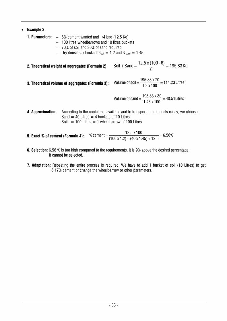
- 33 -
Example 2
1. Parameters: 6% cement wanted and 1/4 bag (12.5 Kg) 100 litres wheelbarrows and 10 litres buckets 70% of soil and 30% of sand required Dry densities checked: soil = 1.2 and sand = 1.45
2. Theoretical weight of aggregates (Formula 2): Kg 83.1956
6) - (100x 12.5 Sand + Soil
3. Theoretical volume of aggregates (Formula 3): Litres 23.114100x 1.2
70x 195.83 soil of Volume
Litres 51.40100x 1.45
30x 195.83 sand of Volume
4. Approximation: According to the containers available and to transport the materials easily, we choose:
Sand = 40 Litres = 4 buckets of 10 Litres Soil = 100 Litres = 1 wheelbarrow of 100 Litres
5. Exact % of cement (Formula 4): %56.612.5 1.45)x (40 1.2)x (100
100x 12.5cement %
6. Selection: 6.56 % is too high compared to the requirements. It is 9% above the desired percentage.
It cannot be selected. 7. Adaptation: Repeating the entire process is required. We have to add 1 bucket of soil (10 Litres) to get
6.17% cement or change the wheelbarrow or other parameters.

- 34 -
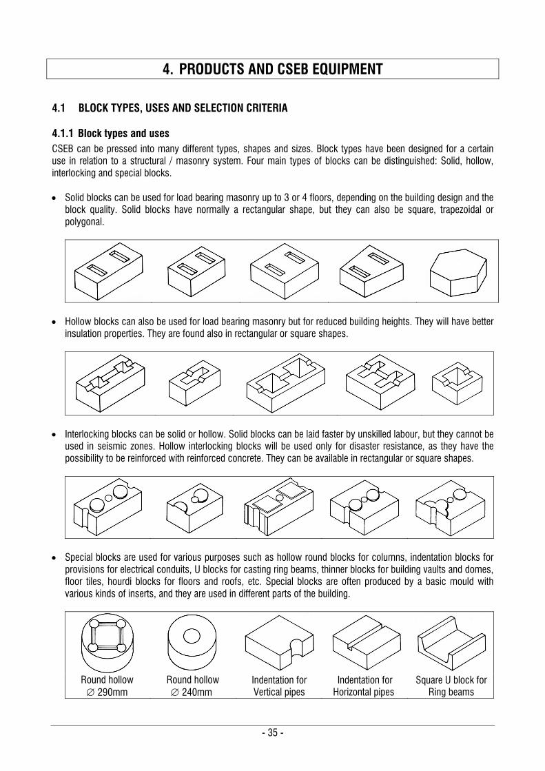
- 35 -
4. PRODUCTS AND CSEB EQUIPMENT
4.1 BLOCK TYPES, USES AND SELECTION CRITERIA
4.1.1 Block types and uses CSEB can be pressed into many different types, shapes and sizes. Block types have been designed for a certain use in relation to a structural / masonry system. Four main types of blocks can be distinguished: Solid, hollow, interlocking and special blocks. Solid blocks can be used for load bearing masonry up to 3 or 4 floors, depending on the building design and the
block quality. Solid blocks have normally a rectangular shape, but they can also be square, trapezoidal or polygonal.
Hollow blocks can also be used for load bearing masonry but for reduced building heights. They will have better
insulation properties. They are found also in rectangular or square shapes.
Interlocking blocks can be solid or hollow. Solid blocks can be laid faster by unskilled labour, but they cannot be
used in seismic zones. Hollow interlocking blocks will be used only for disaster resistance, as they have the possibility to be reinforced with reinforced concrete. They can be available in rectangular or square shapes.
Special blocks are used for various purposes such as hollow round blocks for columns, indentation blocks for provisions for electrical conduits, U blocks for casting ring beams, thinner blocks for building vaults and domes, floor tiles, hourdi blocks for floors and roofs, etc. Special blocks are often produced by a basic mould with various kinds of inserts, and they are used in different parts of the building.
Round hollow 290mm
Round hollow 240mm
Indentation for Vertical pipes
Indentation for Horizontal pipes
Square U block for Ring beams
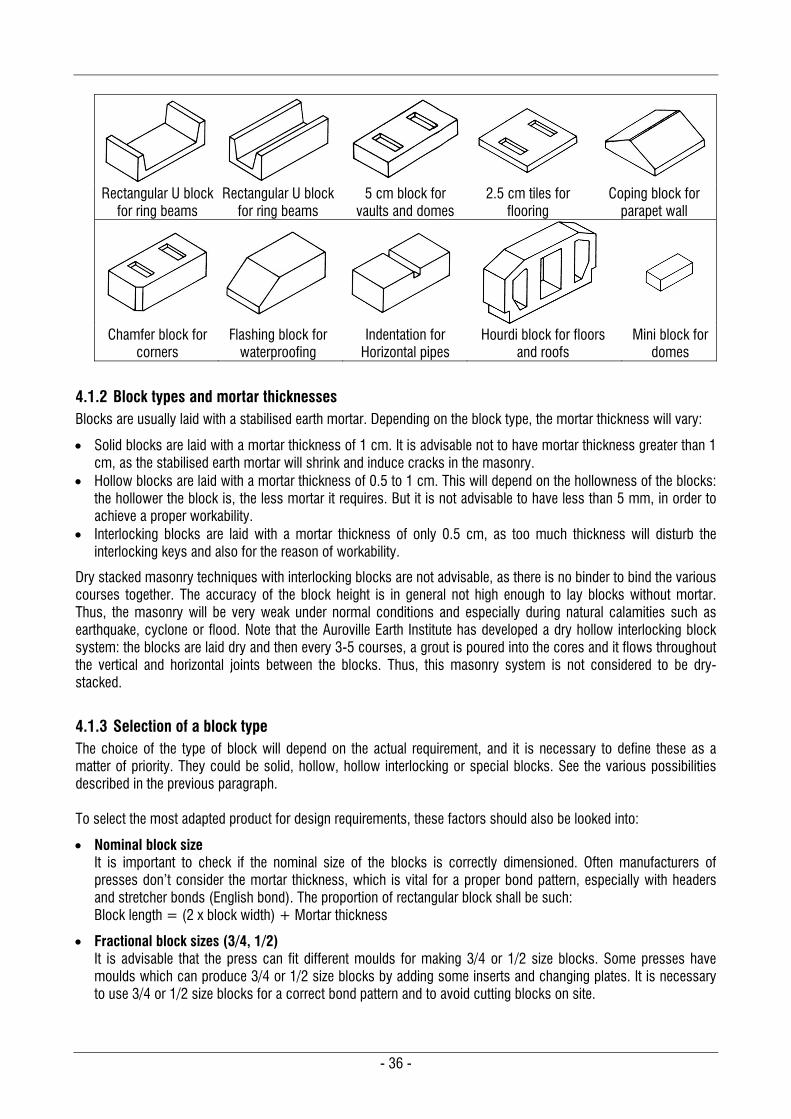
- 36 -
Rectangular U block
for ring beams Rectangular U block
for ring beams 5 cm block for
vaults and domes 2.5 cm tiles for
flooring Coping block for
parapet wall
Chamfer block for corners
Flashing block for waterproofing
Indentation for Horizontal pipes
Hourdi block for floors and roofs
Mini block for domes
4.1.2 Block types and mortar thicknesses Blocks are usually laid with a stabilised earth mortar. Depending on the block type, the mortar thickness will vary:
Solid blocks are laid with a mortar thickness of 1 cm. It is advisable not to have mortar thickness greater than 1 cm, as the stabilised earth mortar will shrink and induce cracks in the masonry.
Hollow blocks are laid with a mortar thickness of 0.5 to 1 cm. This will depend on the hollowness of the blocks: the hollower the block is, the less mortar it requires. But it is not advisable to have less than 5 mm, in order to achieve a proper workability.
Interlocking blocks are laid with a mortar thickness of only 0.5 cm, as too much thickness will disturb the interlocking keys and also for the reason of workability.
Dry stacked masonry techniques with interlocking blocks are not advisable, as there is no binder to bind the various courses together. The accuracy of the block height is in general not high enough to lay blocks without mortar. Thus, the masonry will be very weak under normal conditions and especially during natural calamities such as earthquake, cyclone or flood. Note that the Auroville Earth Institute has developed a dry hollow interlocking block system: the blocks are laid dry and then every 3-5 courses, a grout is poured into the cores and it flows throughout the vertical and horizontal joints between the blocks. Thus, this masonry system is not considered to be dry-stacked.
4.1.3 Selection of a block type The choice of the type of block will depend on the actual requirement, and it is necessary to define these as a matter of priority. They could be solid, hollow, hollow interlocking or special blocks. See the various possibilities described in the previous paragraph. To select the most adapted product for design requirements, these factors should also be looked into:
Nominal block size It is important to check if the nominal size of the blocks is correctly dimensioned. Often manufacturers of presses don’t consider the mortar thickness, which is vital for a proper bond pattern, especially with headers and stretcher bonds (English bond). The proportion of rectangular block shall be such: Block length = (2 x block width) + Mortar thickness
Fractional block sizes (3/4, 1/2) It is advisable that the press can fit different moulds for making 3/4 or 1/2 size blocks. Some presses have moulds which can produce 3/4 or 1/2 size blocks by adding some inserts and changing plates. It is necessary to use 3/4 or 1/2 size blocks for a correct bond pattern and to avoid cutting blocks on site.
- 37 -
Module of the block This is the nominal block size plus the mortar thickness. It is advisable to choose an easy module in the decimal system (such as 30 x 15 x 10 cm or 25 x 25 x 10 cm), to avoid wasting time for the design calculations and dimensioning of the building. It is advisable to select also the module with the thinnest mortar joint possible, as large joints induce shrinkage cracks in stabilised earth mortars.
Possibilities of wall thickness According to the module of a block, various thicknesses of walls can be achieved with easy bond patterns. The possibility of various wall thicknesses is dependent on the nominal size of the block. Blocks shall enable the construction of walls with 1, 1.5 and 2 blocks thickness.
Block bearing area This parameter is important to know for two reasons: 1. The block bearing area is in fact the area of the bottom plate of the mould to be pressed by the piston of the
machine. The larger the area, the weaker the block will be. A large area will require a great energy of compaction: a manual press with a 15 Ton force will not be able to properly compress more than 650 cm2 of block area. This block bearing area has to be considered in relation to the choice of the press.
2. The block load bearing area of hollow blocks is equivalent to the area of the block minus the cores. It is necessary to know this area in order to design the building and its load bearing capacity. Note that the load bearing walls shall not be less than 140 mm wide.
4.2 CSEB SPECIFICATIONS AND CHARACTERISTICS
4.2.1 Block dimensions and tolerances 4.2.1.1 Block proportions CSEB can have many dimensions but the nominal and fractional block sizes (3/4 & 1/2) shall be dimensioned according to these rules:
mj2w block 4/4 Length 4
3x mj/3) - (L block 3/4 Length 4/4
2
mj) - (L block 1/2 Length 4/4
Where L4/4 is the length of the nominal size (full size) block, w is the width and mj is the mortar joint thickness Note that the mortar joint shall be adapted to the block size and it shall not exceed 1 cm thickness, both horizontally and vertically, as the stabilised earth mortar will shrink and induce cracks in the masonry. 4.2.1.2 Block types and dimensions When selecting a block type, one should check that the block dimensions follow the principle above, otherwise these blocks will create difficulties for the bond pattern, as often press manufacturers are not aware of the need for masonry proportions. Manufacturers shall mention the percentage of voids for the hollow blocks. The height of the blocks listed below is the nominal height of the block, but some presses can manufacture blocks of various thicknesses. Special blocks are not listed here, as more detailed dimensioning and specifications are required pertaining to their shapes. The following table gives the main block types which can be manufactured by the Auram Press 3000.

- 38 -
MAIN AURAM BLOCK TYPES
Block name Type Use Void (%) Dimensions (mm)
Length Width Height Plain 240 * Solid Load bearing walls Nil 240 240 90 Plain 290 * Solid Load bearing walls Nil 290 140 90 Plain 190 Solid Partition walls Nil 190 90 90 Mini block Solid Vaults & domes Nil 140 70 50 Round 240 Hollow Columns 14 240 90 Round 290 Hollow Columns 8 290 90 Hollow 240 * Hollow Load bearing walls 21.6 240 240 90 Hollow 290 * Hollow Load bearing walls 19.5 290 140 90 Hollow 390 * Hollow Load bearing walls 29.7 390 190 90 HI 245 * Hollow interlocking Disaster resistance 8 245 245 95 HI 295 * Hollow interlocking Disaster resistance 9.3 295 145 95 HI Dry 300 * Hollow interlocking Disaster resistance 10 300 149 100 HI Dry 250 * Hollow interlocking Disaster resistance 7.5 250 249 100 * Moulds of these blocks can do 3/4 and 1/2 size blocks, according to the guidelines described in 4.2.1.1
4.2.1.3 Block dimensional tolerances The dimensional variations of the block in length, width and height shall be admitted as per the following table.
Block type Maximal deviation from nominal size
Length Width Height Solid block + 1 mm +1 mm 1 mm Hollow block + 1 mm + 1 mm 1 mm Interlocking blocks (Hollow or solid) + 0.5 mm + 0.5 mm 0.5 mm Note that the main deviation in dimensions from the nominal block size will be due to these factors:
Block length and width Variation will occur when the mould gets older: the abrasion of the soil will wear out the steel mould and the block will become slightly larger. The abrasion speed of the mould depends on the soil quality.
Block height This will change according to how the mould is filled, the moisture content of the mix and the type of soil. The wear and tear of the press due to aging can also influence the block height. Some presses can adjust their block height with a micro adjustment, to ensure a 0.5 mm accuracy.
4.2.1.4 Cavities of hollow blocks & frog proportions Volume of voids and material thickness
The volume of voids in the block shall not exceed 30 % of the gross volume of the block. A block having a greater percentage of voids will not be able to properly bear loads.
The minimum thickness of material shall not be less than 3.5 cm. Material thicknesses less than 3.5 cm will crack when the block will be pulled out of the mould, due to expansion of the air just compressed.
Frog proportions and sizes
The depth of frogs shall not be more than 15 mm from the level of the bed face of a block. This is meant to allow the mortar to flow up easily when the block is laid on the mortar.
The total area of all frogs on the bed face shall not be more than 20% of the bed face area.
The side of the frogs shall be chamfered at 45 from the bed face, to allow easy de-moulding and reduce stickiness on the plate.
- 39 -
4.2.1.5 Visual appearance Visual appearance just after production
Blocks shall have homogeneous colour and texture. Vertical edges shall not be damaged due to friction of soil in the mould. Pitting due to adhesion of the block to the top and bottom plates of the mould shall not exceed 10 % of
the area of that face, and the pits shall not be deeper that 3 mm.
Visual appearance after curing Blocks shall be free from cracks, broken edges, honey comb and other defects that would interfere with
the proper placing of blocks or impair the strength or performance of construction. Blocks shall not be crumbly or friable when touching the edges and corners. Efflorescence due to curing on soil cement stabilised blocks shall not exceed 20 % of the side area. Pitting due to curing or weathering shall not exceed 10 % of the total area of the block, and pits shall not
be deeper than 3 mm.
4.2.2 Physical requirements and characteristics of CSEB These physical characteristics for blocks shall apply for blocks tested according to the relevant standards:
After 6 weeks (4 weeks of curing and 2 weeks of drying), for cement stabilised blocks. After 3 months curing, for lime stabilised blocks, because lime needs more time than cement to harden.
Characteristics Class A Class B Class C Dry compressive strength Cd 5 to 7 MPa 4 to 5 MPa 3 to 4 MPa Wet compressive strength Cw 3 to 4 MPa 2 to 3 MPa 1.5 to 2 MPa Dry bending (flexural) strength Bd 0.5 to 1 MPa 0.4 to 0.8 MPa 0.3 to 0.6 MPa Dry shear strength Sd 0.4 to 0.6 MPa 0.3 to 0.5 MPa 0.2 to 0.3 MPa Water absorption by weight 8 to 10 % 10 to 12 % 12 to 15 % Block volumic mass Block 1900 to 2000 Kg/m3 1800 to 1900 Kg/m3 1700 to 1800 Kg/m3 Embodied energy (m3 raw material) * 1,112.36 MJ / m3 The embodied energy and carbon
emission are for 5 % cement blocks Carbon emission (CO2/m3 raw material) ** 110.11 Kg / m3 * Embodied energy value to be compared with:
Kiln fired bricks = 2,247.28 MJ/m3 Country fired bricks = 4,501.25 MJ/m3
** Carbon emission value to be compared with: Kiln fired bricks = 202.25 Kg/m3 Country fired bricks = 441.12 Kg/m3
Notes: Classes A, B and C are defined by the wet compressive strength of the blocks. The other values given in the table above are indicative to give an idea of the characteristics to be expected.
4.3 PRESS TYPES AND SELECTION CRITERIA
Since the 1950’s many presses, both manual and motorized, have been developed worldwide, and today the market offers a wide range of specialised presses for all kinds of production scales. In India, 4 to 5 manufacturers are producing CSEB presses.
Manually operated presses are still the most common and widely used, but more and more, motorised presses have been replacing manual presses due to the varying productivity and high cost of labour.
4.3.1 Categories of equipment Manual presses
These are manually operated and can be categorised into light and heavy manual presses. Light presses are cheap but they will not last long, as in general the durability is related to the size of steel profiles and the quality of designs. The operation of the press will require 4 to 8 labourers (including mixing, pressing and stacking), depending on the productivity of the press, which can vary from 400 to 1,000 strokes per day.
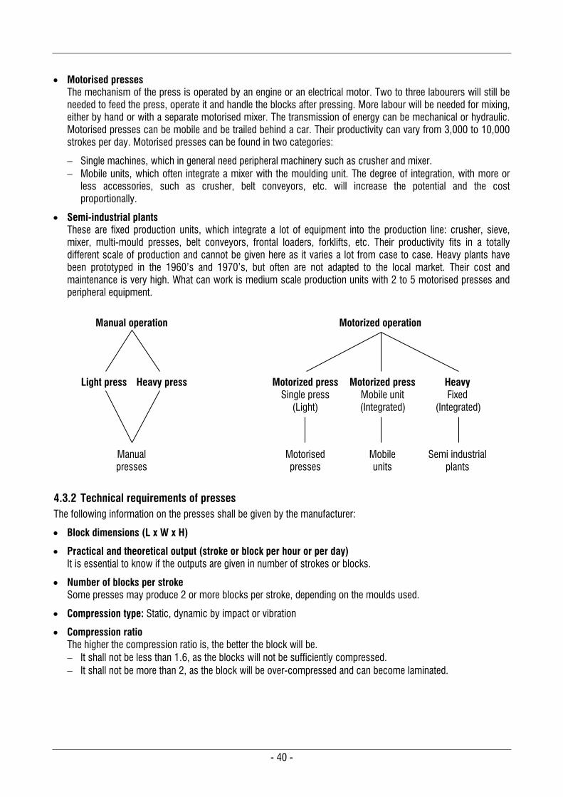
- 40 -
Motorised presses The mechanism of the press is operated by an engine or an electrical motor. Two to three labourers will still be needed to feed the press, operate it and handle the blocks after pressing. More labour will be needed for mixing, either by hand or with a separate motorised mixer. The transmission of energy can be mechanical or hydraulic. Motorised presses can be mobile and be trailed behind a car. Their productivity can vary from 3,000 to 10,000 strokes per day. Motorised presses can be found in two categories:
Single machines, which in general need peripheral machinery such as crusher and mixer. Mobile units, which often integrate a mixer with the moulding unit. The degree of integration, with more or
less accessories, such as crusher, belt conveyors, etc. will increase the potential and the cost proportionally.
Semi-industrial plants These are fixed production units, which integrate a lot of equipment into the production line: crusher, sieve, mixer, multi-mould presses, belt conveyors, frontal loaders, forklifts, etc. Their productivity fits in a totally different scale of production and cannot be given here as it varies a lot from case to case. Heavy plants have been prototyped in the 1960’s and 1970’s, but often are not adapted to the local market. Their cost and maintenance is very high. What can work is medium scale production units with 2 to 5 motorised presses and peripheral equipment.
Manual operation Motorized operation
Light press Heavy press Motorized press Single press
(Light)
Motorized press Mobile unit (Integrated)
Heavy Fixed
(Integrated)
Manual presses
Motorised presses
Mobile units
Semi industrial plants
4.3.2 Technical requirements of presses The following information on the presses shall be given by the manufacturer:
Block dimensions (L x W x H)
Practical and theoretical output (stroke or block per hour or per day) It is essential to know if the outputs are given in number of strokes or blocks.
Number of blocks per stroke Some presses may produce 2 or more blocks per stroke, depending on the moulds used.
Compression type: Static, dynamic by impact or vibration
Compression ratio The higher the compression ratio is, the better the block will be. It shall not be less than 1.6, as the blocks will not be sufficiently compressed. It shall not be more than 2, as the block will be over-compressed and can become laminated.
- 41 -
Nominal compression force The minimum compression force shall be 5 Tons, otherwise the blocks will be under-compressed. The maximum compression force shall be 50 Tons, otherwise the blocks will be laminated. A nominal compression force of 20 Tons is more than sufficient for CSEB. The aim of CSEB is not to
compete with concrete, but to propose a durable building material which has better environmental qualities. Note that when the block is over-compressed, it gains in strength but it loses thermal characteristics and
environmental advantages.
Nominal compression pressure The minimum compression pressure shall not be less than 2 N/mm2, as blocks will be under-compressed. The maximum compression pressure shall be 10 N/mm2, otherwise the blocks will be laminated.
Operating energy: Manual or motorised
Number of labours required to operate only the press
Mobility of the press Manual presses shall have the possibility to be moved on site with small wheels. Motorised presses shall have the possibility to be trailed behind a vehicle.
Net weight, including frame and mould
Working encumbrance of the press
4.3.3 Selection of equipment Cost should not be the only parameter to consider when selecting the equipment. To select the most adapted equipment to one’s needs, one should keep these key points in mind:
Manual or motorized press Manual equipment will require a lot of labour, which is becoming scarcer even in developing countries. Motorised equipment will have more output, but its cost can easily be 5 to 10 times more than of manual
equipment.
Block sizes, mould possibilities and interchange ability of moulds Whether a mould can produce full size, 3/4 or 1/2 block sizes? To build with proper bonds, one needs to use these three sizes in order to achieve a good quality without breaking or cutting the blocks.
Block bearing area and nominal compression force These two parameters can give information about whether the block can be compressed enough by the press: A manual press will not be able to properly compress more than 600 cm2 of block.
Practical output per day Often manufacturers mention only the theoretical output, which can be easily 25 % more than what the press can practically produce daily.
Number of workers working on the press This is an essential parameter to know the actual efficiency of the press, especially for manual presses.
Compression ratio The higher it is, the better the blocks will be.
Net weight of the machine Heavy weight refers to durability due of well dimensioned steel profiles and elaborated design.
Mobility Manual presses would preferably be on wheels, in order to move them easily on the site. Motorised presses normally come on wheels and can be trailed behind a vehicle.
Ease of maintenance and method of greasing
- 42 -
4.4 PERIPHERAL EQUIPMENT
4.4.1 Hand tools Whether the press is manual or motorised, some hand tools will be required. Obviously, a motorised press will need a minimum of hand tools, especially for soil digging and preparation. The following list of hand tools is intended mainly for a manual press. Note that the volume of containers, such as buckets and wheelbarrows, shall be known as they are used to transport and measure materials.
Soil digging and preparation Crow bars, pick-axes, shovels, hoes, pans, buckets, wheelbarrows, sieves and UV stabilised plastic tarpaulins
Soil mixing Buckets, wheelbarrows, hoes, shovels, watering can, barrels and hose pipe
Initial curing Plastic sheet for covering the fresh blocks and watering can or bucket
Final stacking and curing Flat wheelbarrows to move the 2-day old blocks, buckets and strips of jute cloth to cover the blocks.
Quality control Pocket Penetrometre, block height gauge, field block tester
4.4.2 Motorised tools These tools are intended mainly for motorised presses. Though manual presses could have the advantage of using motorised equipment for soil preparation, it is unusual to have a motorised pulveriser or mixer with manual presses, mostly for economic reasons. Depending on the degree of integration of the production line, some hand tools will also be required, as listed in the preceding paragraph.
Soil digging and preparation Excavator, pulveriser or crusher, mechanical sieve (vibrating or rotating), loader, truck
Soil mixing Mixer: Note that mixers for CSEB can be planetary (pan mixer), linear (helical screw) or with horizontal shaft. Concrete mixers are not appropriate for CSEB as the mix is only humid and the rotating drum create balls.
Initial curing Manual forklift and palettes
Final stacking and curing Belt conveyor, motorised forklift and palettes
Quality control Compression testing machine
- 43 -
4.5 PRODUCTION LINES
4.5.1 Types Various types of production lines can be set up depending on the project requirements. Five types of production lines are generally considered, and these are linked with the type of presses, the integration of peripheral motorised machinery and the scale of production:
Type 1 = Totally manual This is the minimum set-up with only 1 manual press, light or heavy. The rest of the equipment is manual. The infrastructure is minimal. This is often the type of production line for a construction site.
Type 2 = Half manual and half motorised Two manual presses are used along with a motorised mixer and more elaborate infrastructure. A motorised crusher/pulveriser or mechanised sieve can also be integrated.
Type 3 = Fully motorised The production unit is totally mechanised but with separate machinery:
A motorised press is used with a motorised crusher/pulveriser or mechanised sieve and a motorised mixer. The built infrastructure is larger.
Type 4 = Mobile unit An automated unit integrates all machinery into a single machine with large infrastructure:
Sieve, motorised mixer, the pressing unit and belt conveyor Note that a motorised crusher/pulveriser can be part of the set-up but it is most commonly separate
equipment on account of the disturbance of noise and dust. Mechanised transport needs also to be integrated with loader, forklift and truck.
Type 5 = Semi-industrial plant These have generally a lot of separate machinery which can include:
Motorised crusher/pulveriser, mechanised sieve, mixers, multi-mould pressing units, belt conveyors, and mechanised transport with loaders, forklifts and trucks.
This has the large infrastructure of a plant.
4.5.2 Productivity, investment and economics The choice to set up one or the other type of production lines is related to these main criteria: productivity, total investment cost, quality & quantity of the labour force and market demand. The table hereafter gives some example analysis of various types of production line, from totally manual to semi-industrial units.
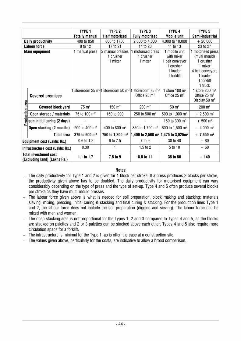
- 44 -
TYPE 1
Totally manual TYPE 2
Half motorised TYPE 3
Fully motorised TYPE 4
Mobile unit TYPE 5
Semi-industrial Daily productivity 400 to 850 800 to 1700 2,000 to 4,000 4,000 to 10,000 + 20,000 Labour force 8 to 12 17 to 21 14 to 20 11 to 13 23 to 27 Main equipment 1 manual press 2 manual presses
1 crusher 1 mixer
1 motorised press 1 crusher 1 mixer
1 mobile unit with mixer
1 belt conveyor 1 crusher 1 loader 1 forklift
1 motorised press (multi mould)
1 crusher 1 mixer
4 belt conveyors 1 loader 1 forklift 1 truck
Prod
uctio
n ar
ea
Covered premises 1 storeroom 25 m2 1 storeroom 50 m2 1 storeroom 75 m2
Office 25 m2 1 store 100 m2
Office 25 m2 1 store 200 m2
Office 25 m2
Display 50 m2
Covered block yard 75 m2 150 m2 200 m2 50 m2 200 m2
Open storage / materials 75 to 100 m2 150 to 200 250 to 500 m2 500 to 1,000 m2 + 2,500 m2
Open initial curing (2 days) - - - 150 to 300 m2 + 500 m2
Open stacking (2 months) 200 to 400 m2 400 to 800 m2 850 to 1,700 m2 600 to 1,500 m2 + 4,000 m2
Total area 375 to 600 m2 750 to 1,200 m2 1,400 to 2,500 m2 1,475 to 3,025m2 + 7,650 m2
Equipment cost (Lakhs Rs.) 0.6 to 1.2 6 to 7.5 7 to 9 30 to 40 + 80
Infrastructure cost (Lakhs Rs.) 0.30 1 1.5 to 2 5 to 10 + 60
Total investment cost (Excluding land) (Lakhs Rs.) 1.1 to 1.7 7.5 to 9 8.5 to 11 35 to 50 + 140
Notes
The daily productivity for Type 1 and 2 is given for 1 block per stroke. If a press produces 2 blocks per stroke, the productivity given above has to be doubled. The daily productivity for motorised equipment can vary considerably depending on the type of press and the type of set-up. Type 4 and 5 often produce several blocks per stroke as they have multi-mould presses.
The labour force given above is what is needed for soil preparation, block making and stacking: materials sieving, mixing, pressing, initial curing & stacking and final curing & stacking. For the production lines Type 1 and 2, the labour force does not include the soil preparation (digging and sieving). The labour force can be mixed with men and women.
The open stacking area is not proportional for the Types 1, 2 and 3 compared to Types 4 and 5, as the blocks are stacked on palettes and 2 or 3 palettes can be stacked above each other. Types 4 and 5 also require more circulation space for a forklift.
The infrastructure is minimal for the Type 1, as is often the case at a construction site. The values given above, particularly for the costs, are indicative to allow a broad comparison.
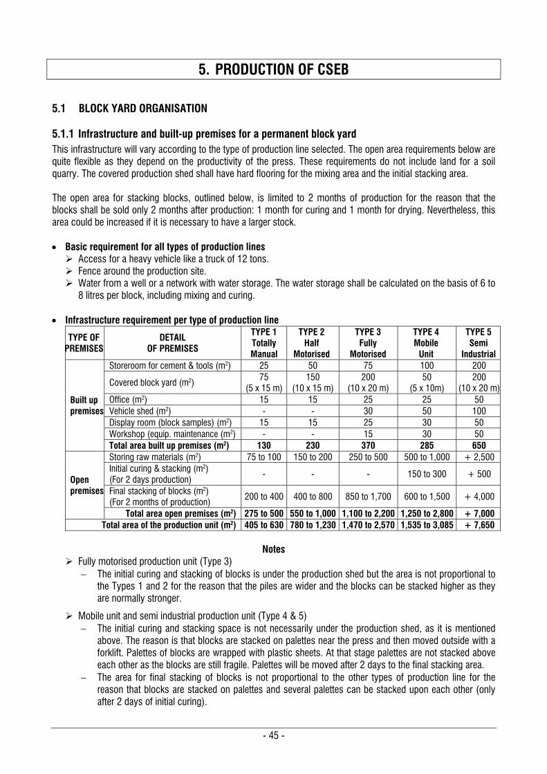
- 45 -
5. PRODUCTION OF CSEB
5.1 BLOCK YARD ORGANISATION
5.1.1 Infrastructure and built-up premises for a permanent block yard This infrastructure will vary according to the type of production line selected. The open area requirements below are quite flexible as they depend on the productivity of the press. These requirements do not include land for a soil quarry. The covered production shed shall have hard flooring for the mixing area and the initial stacking area. The open area for stacking blocks, outlined below, is limited to 2 months of production for the reason that the blocks shall be sold only 2 months after production: 1 month for curing and 1 month for drying. Nevertheless, this area could be increased if it is necessary to have a larger stock. Basic requirement for all types of production lines Access for a heavy vehicle like a truck of 12 tons. Fence around the production site. Water from a well or a network with water storage. The water storage shall be calculated on the basis of 6 to
8 litres per block, including mixing and curing. Infrastructure requirement per type of production line
TYPE OF PREMISES
DETAIL OF PREMISES
TYPE 1 Totally Manual
TYPE 2 Half
Motorised
TYPE 3 Fully
Motorised
TYPE 4 Mobile
Unit
TYPE 5 Semi
Industrial
Built up premises
Storeroom for cement & tools (m2) 25 50 75 100 200
Covered block yard (m2) 75
(5 x 15 m) 150
(10 x 15 m) 200
(10 x 20 m) 50
(5 x 10m) 200
(10 x 20 m) Office (m2) 15 15 25 25 50 Vehicle shed (m2) - - 30 50 100 Display room (block samples) (m2) 15 15 25 30 50 Workshop (equip. maintenance (m2) - - 15 30 50 Total area built up premises (m2) 130 230 370 285 650
Open premises
Storing raw materials (m2) 75 to 100 150 to 200 250 to 500 500 to 1,000 + 2,500 Initial curing & stacking (m2) (For 2 days production)
- - - 150 to 300 + 500
Final stacking of blocks (m2) (For 2 months of production)
200 to 400 400 to 800 850 to 1,700 600 to 1,500 + 4,000
Total area open premises (m2) 275 to 500 550 to 1,000 1,100 to 2,200 1,250 to 2,800 + 7,000 Total area of the production unit (m2) 405 to 630 780 to 1,230 1,470 to 2,570 1,535 to 3,085 + 7,650
Notes
Fully motorised production unit (Type 3) The initial curing and stacking of blocks is under the production shed but the area is not proportional to
the Types 1 and 2 for the reason that the piles are wider and the blocks can be stacked higher as they are normally stronger.
Mobile unit and semi industrial production unit (Type 4 & 5) The initial curing and stacking space is not necessarily under the production shed, as it is mentioned
above. The reason is that blocks are stacked on palettes near the press and then moved outside with a forklift. Palettes of blocks are wrapped with plastic sheets. At that stage palettes are not stacked above each other as the blocks are still fragile. Palettes will be moved after 2 days to the final stacking area.
The area for final stacking of blocks is not proportional to the other types of production line for the reason that blocks are stacked on palettes and several palettes can be stacked upon each other (only after 2 days of initial curing).
- 46 -
5.1.2 Site preparation for a temporary block yard Temporary block yards are normally set up for the duration of construction sites and they use manual presses. Therefore, they need a minimum set-up as described below.
Storage 200 to 400 m2 open storage for raw materials. Earth and sand shall be protected from rain with UV stabilised tarpaulins. 25 m2 storeroom for storing tools and for a weeklong supply of cement and tools. It can be also used as site office. Water connection from the site with barrels for storage.
Production area 75 m2 (5 x 15 m) covered production shed per press. The shed is made with simple means as it will be
dismantled at the end of the construction site: i.e. with granite pillars, casuarinas poles and coconut leaves or UV stabilised tarpaulins.
Mixing and pressing area: The flooring for this area shall have a flat and strong pavement: i.e. CSEB or bricks which are laid on a
sand bed. The height of the shed above the press shall be enough for the encumbrance of the lever rising up and
which shall not touch the roof. It can be nearly 3 m for some manual presses.
Initial curing and stacking area: The pavement for this area can be done only on a thin and levelled bed of sand. The height of the shed above this area can be only 2.20 m for the access of the workers only.
Final curing and stacking area A flat and stable open area near the production shed to stack the blocks for final curing. It shall be calculated
on the basis of 8 to 10 m² per 1,000 blocks.
5.1.3 Manpower requirements The manpower and skill required varies considerably according to the type of press used and the type of production line. The following requirements detail only the production from soil preparation to final curing and stacking. Digging the soil and the supervision / management are not included here. Qualification details per job (Manual process)
Soil sieving This requires only unskilled labour, which can be men or women. The number of people and speed of sieving will vary with the soil: a clayey soil will take a longer time and more labour to sieve than a sandy soil.
Mixing This requires only unskilled labour, which can be men or women. This job includes measuring the various components and mixing them dry first and then again with water.
Pressing The operation of the lever requires semi-skilled labour, which are preferably men. The operator must be skilled and can be a man or woman.
Initial curing and stacking This requires a semi-skilled labourer, which is preferably a man, as strength and stamina are required to move blocks alone all the day long.
Final curing and stacking This requires semi-skilled labourers, which can be men or women or a mixed team.
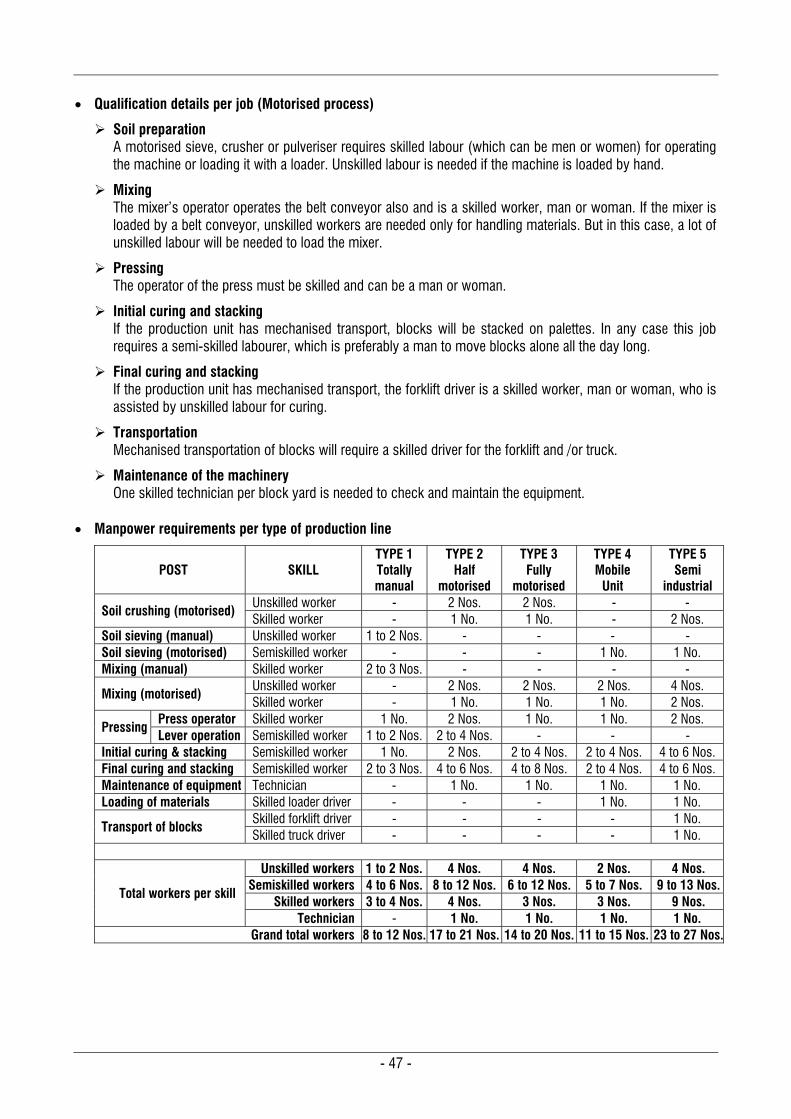
- 47 -
Qualification details per job (Motorised process)
Soil preparation A motorised sieve, crusher or pulveriser requires skilled labour (which can be men or women) for operating the machine or loading it with a loader. Unskilled labour is needed if the machine is loaded by hand.
Mixing The mixer’s operator operates the belt conveyor also and is a skilled worker, man or woman. If the mixer is loaded by a belt conveyor, unskilled workers are needed only for handling materials. But in this case, a lot of unskilled labour will be needed to load the mixer.
Pressing The operator of the press must be skilled and can be a man or woman.
Initial curing and stacking If the production unit has mechanised transport, blocks will be stacked on palettes. In any case this job requires a semi-skilled labourer, which is preferably a man to move blocks alone all the day long.
Final curing and stacking If the production unit has mechanised transport, the forklift driver is a skilled worker, man or woman, who is assisted by unskilled labour for curing.
Transportation Mechanised transportation of blocks will require a skilled driver for the forklift and /or truck.
Maintenance of the machinery One skilled technician per block yard is needed to check and maintain the equipment.
Manpower requirements per type of production line
POST SKILL TYPE 1 Totally manual
TYPE 2 Half
motorised
TYPE 3 Fully
motorised
TYPE 4 Mobile
Unit
TYPE 5 Semi
industrial
Soil crushing (motorised) Unskilled worker - 2 Nos. 2 Nos. - - Skilled worker - 1 No. 1 No. - 2 Nos.
Soil sieving (manual) Unskilled worker 1 to 2 Nos. - - - - Soil sieving (motorised) Semiskilled worker - - - 1 No. 1 No. Mixing (manual) Skilled worker 2 to 3 Nos. - - - -
Mixing (motorised) Unskilled worker - 2 Nos. 2 Nos. 2 Nos. 4 Nos. Skilled worker - 1 No. 1 No. 1 No. 2 Nos.
Pressing Press operator Skilled worker 1 No. 2 Nos. 1 No. 1 No. 2 Nos. Lever operation Semiskilled worker 1 to 2 Nos. 2 to 4 Nos. - - -
Initial curing & stacking Semiskilled worker 1 No. 2 Nos. 2 to 4 Nos. 2 to 4 Nos. 4 to 6 Nos. Final curing and stacking Semiskilled worker 2 to 3 Nos. 4 to 6 Nos. 4 to 8 Nos. 2 to 4 Nos. 4 to 6 Nos. Maintenance of equipment Technician - 1 No. 1 No. 1 No. 1 No. Loading of materials Skilled loader driver - - - 1 No. 1 No.
Transport of blocks Skilled forklift driver - - - - 1 No. Skilled truck driver - - - - 1 No.
Total workers per skill
Unskilled workers 1 to 2 Nos. 4 Nos. 4 Nos. 2 Nos. 4 Nos. Semiskilled workers 4 to 6 Nos. 8 to 12 Nos. 6 to 12 Nos. 5 to 7 Nos. 9 to 13 Nos.
Skilled workers 3 to 4 Nos. 4 Nos. 3 Nos. 3 Nos. 9 Nos. Technician - 1 No. 1 No. 1 No. 1 No.
Grand total workers 8 to 12 Nos. 17 to 21 Nos. 14 to 20 Nos. 11 to 15 Nos. 23 to 27 Nos.
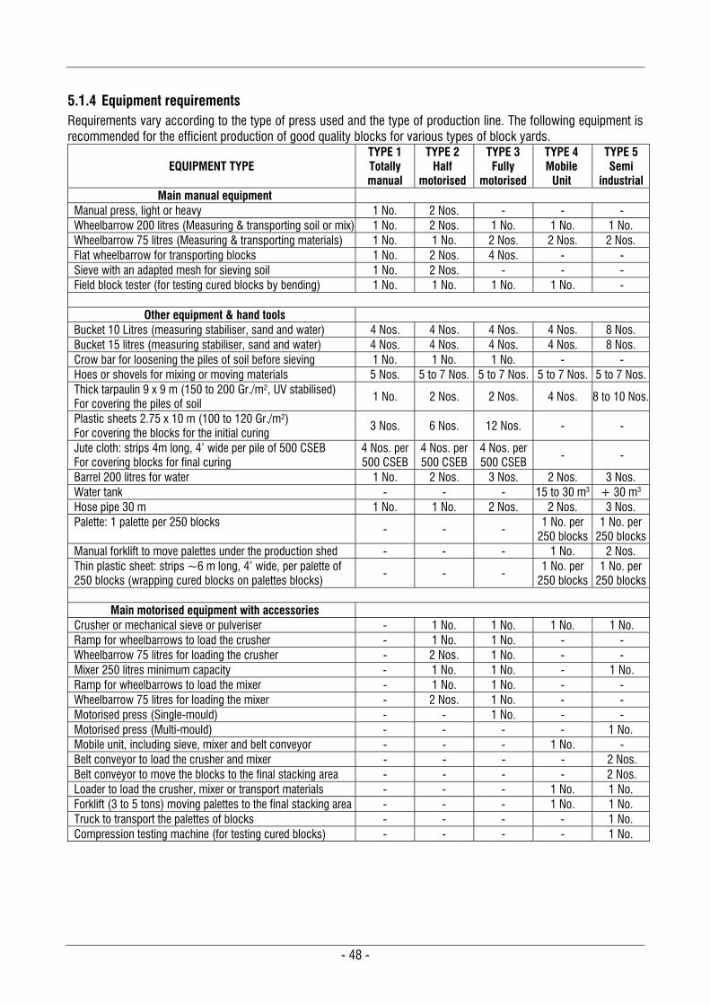
- 48 -
5.1.4 Equipment requirements Requirements vary according to the type of press used and the type of production line. The following equipment is recommended for the efficient production of good quality blocks for various types of block yards.
EQUIPMENT TYPE TYPE 1 Totally manual
TYPE 2 Half
motorised
TYPE 3 Fully
motorised
TYPE 4 Mobile
Unit
TYPE 5 Semi
industrial Main manual equipment
Manual press, light or heavy 1 No. 2 Nos. - - - Wheelbarrow 200 litres (Measuring & transporting soil or mix) 1 No. 2 Nos. 1 No. 1 No. 1 No. Wheelbarrow 75 litres (Measuring & transporting materials) 1 No. 1 No. 2 Nos. 2 Nos. 2 Nos. Flat wheelbarrow for transporting blocks 1 No. 2 Nos. 4 Nos. - - Sieve with an adapted mesh for sieving soil 1 No. 2 Nos. - - - Field block tester (for testing cured blocks by bending) 1 No. 1 No. 1 No. 1 No. -
Other equipment & hand tools
Bucket 10 Litres (measuring stabiliser, sand and water) 4 Nos. 4 Nos. 4 Nos. 4 Nos. 8 Nos. Bucket 15 litres (measuring stabiliser, sand and water) 4 Nos. 4 Nos. 4 Nos. 4 Nos. 8 Nos. Crow bar for loosening the piles of soil before sieving 1 No. 1 No. 1 No. - - Hoes or shovels for mixing or moving materials 5 Nos. 5 to 7 Nos. 5 to 7 Nos. 5 to 7 Nos. 5 to 7 Nos. Thick tarpaulin 9 x 9 m (150 to 200 Gr./m², UV stabilised) For covering the piles of soil
1 No. 2 Nos. 2 Nos. 4 Nos. 8 to 10 Nos.
Plastic sheets 2.75 x 10 m (100 to 120 Gr./m²) For covering the blocks for the initial curing
3 Nos. 6 Nos. 12 Nos. - -
Jute cloth: strips 4m long, 4’ wide per pile of 500 CSEB For covering blocks for final curing
4 Nos. per 500 CSEB
4 Nos. per 500 CSEB
4 Nos. per 500 CSEB
- -
Barrel 200 litres for water 1 No. 2 Nos. 3 Nos. 2 Nos. 3 Nos. Water tank - - - 15 to 30 m3 + 30 m3 Hose pipe 30 m 1 No. 1 No. 2 Nos. 2 Nos. 3 Nos. Palette: 1 palette per 250 blocks - - - 1 No. per
250 blocks 1 No. per
250 blocks Manual forklift to move palettes under the production shed - - - 1 No. 2 Nos. Thin plastic sheet: strips ~6 m long, 4’ wide, per palette of 250 blocks (wrapping cured blocks on palettes blocks)
- - - 1 No. per 250 blocks
1 No. per 250 blocks
Main motorised equipment with accessories
Crusher or mechanical sieve or pulveriser - 1 No. 1 No. 1 No. 1 No. Ramp for wheelbarrows to load the crusher - 1 No. 1 No. - - Wheelbarrow 75 litres for loading the crusher - 2 Nos. 1 No. - - Mixer 250 litres minimum capacity - 1 No. 1 No. - 1 No. Ramp for wheelbarrows to load the mixer - 1 No. 1 No. - - Wheelbarrow 75 litres for loading the mixer - 2 Nos. 1 No. - - Motorised press (Single-mould) - - 1 No. - - Motorised press (Multi-mould) - - - - 1 No. Mobile unit, including sieve, mixer and belt conveyor - - - 1 No. - Belt conveyor to load the crusher and mixer - - - - 2 Nos. Belt conveyor to move the blocks to the final stacking area - - - - 2 Nos. Loader to load the crusher, mixer or transport materials - - - 1 No. 1 No. Forklift (3 to 5 tons) moving palettes to the final stacking area - - - 1 No. 1 No. Truck to transport the palettes of blocks - - - - 1 No. Compression testing machine (for testing cured blocks) - - - - 1 No.
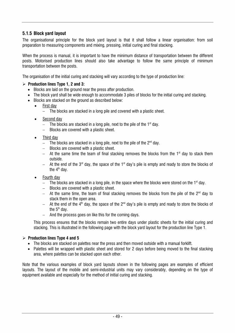
- 49 -
5.1.5 Block yard layout The organisational principle for the block yard layout is that it shall follow a linear organisation: from soil preparation to measuring components and mixing, pressing, initial curing and final stacking. When the process is manual, it is important to have the minimum distance of transportation between the different posts. Motorised production lines should also take advantage to follow the same principle of minimum transportation between the posts. The organisation of the initial curing and stacking will vary according to the type of production line:
Production lines Type 1, 2 and 3: Blocks are laid on the ground near the press after production. The block yard shall be wide enough to accommodate 3 piles of blocks for the initial curing and stacking. Blocks are stacked on the ground as described below:
First day The blocks are stacked in a long pile and covered with a plastic sheet.
Second day The blocks are stacked in a long pile, next to the pile of the 1st day. Blocks are covered with a plastic sheet.
Third day The blocks are stacked in a long pile, next to the pile of the 2nd day. Blocks are covered with a plastic sheet. At the same time the team of final stacking removes the blocks from the 1st day to stack them
outside. At the end of the 3rd day, the space of the 1st day’s pile is empty and ready to store the blocks of
the 4th day.
Fourth day The blocks are stacked in a long pile, in the space where the blocks were stored on the 1st day. Blocks are covered with a plastic sheet. At the same time, the team of final stacking removes the blocks from the pile of the 2nd day to
stack them in the open area. At the end of the 4th day, the space of the 2nd day’s pile is empty and ready to store the blocks of
the 5th day. And the process goes on like this for the coming days.
This process ensures that the blocks remain two entire days under plastic sheets for the initial curing and stacking. This is illustrated in the following page with the block yard layout for the production line Type 1.
Production lines Type 4 and 5
The blocks are stacked on palettes near the press and then moved outside with a manual forklift. Palettes will be wrapped with plastic sheet and stored for 2 days before being moved to the final stacking
area, where palettes can be stacked upon each other. Note that the various examples of block yard layouts shown in the following pages are examples of efficient layouts. The layout of the mobile and semi-industrial units may vary considerably, depending on the type of equipment available and especially for the method of initial curing and stacking.
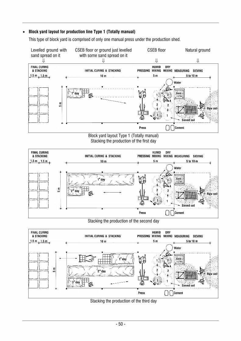
- 50 -
Block yard layout for production line Type 1 (Totally manual)
This type of block yard is comprised of only one manual press under the production shed. Levelled ground with sand spread on it
CSEB floor or ground just levelled with some sand spread on it
CSEB floor
Natural ground
Block yard layout Type 1 (Totally manual)
Stacking the production of the first day
Stacking the production of the second day
Stacking the production of the third day
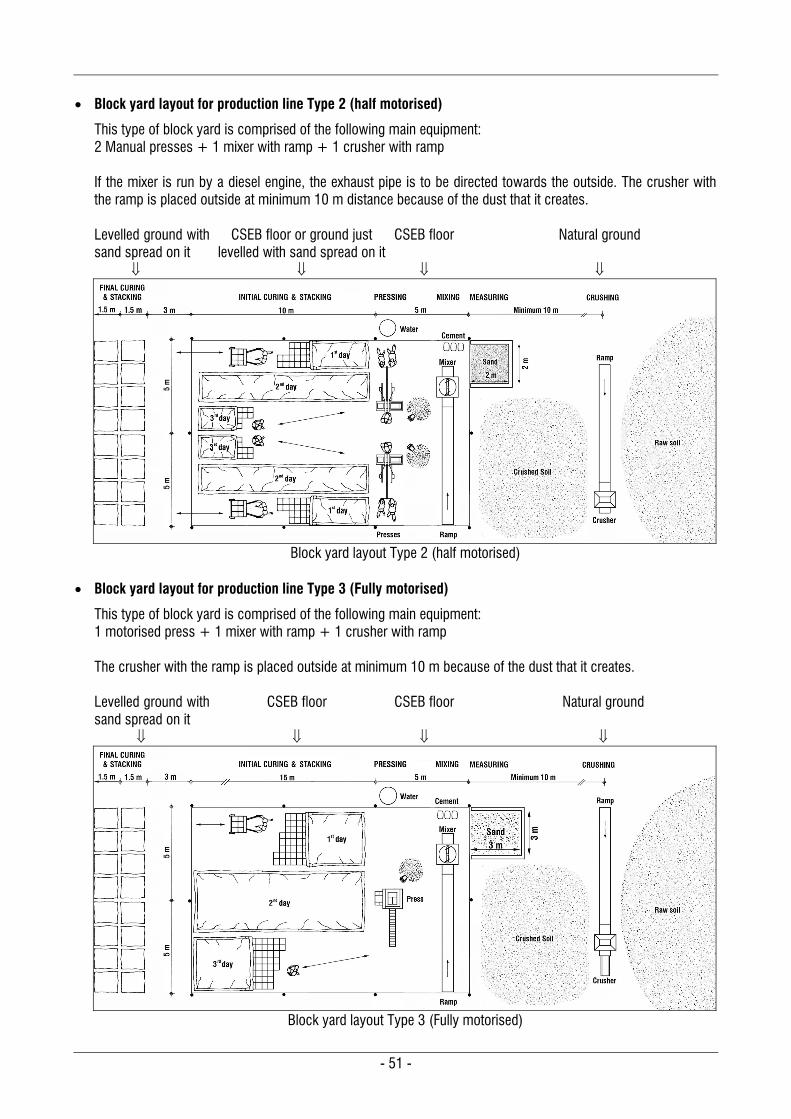
- 51 -
Block yard layout for production line Type 2 (half motorised)
This type of block yard is comprised of the following main equipment: 2 Manual presses + 1 mixer with ramp + 1 crusher with ramp If the mixer is run by a diesel engine, the exhaust pipe is to be directed towards the outside. The crusher with the ramp is placed outside at minimum 10 m distance because of the dust that it creates. Levelled ground with sand spread on it
CSEB floor or ground just levelled with sand spread on it
CSEB floor
Natural ground
Block yard layout Type 2 (half motorised)
Block yard layout for production line Type 3 (Fully motorised)
This type of block yard is comprised of the following main equipment: 1 motorised press + 1 mixer with ramp + 1 crusher with ramp The crusher with the ramp is placed outside at minimum 10 m because of the dust that it creates. Levelled ground with sand spread on it
CSEB floor
CSEB floor
Natural ground
Block yard layout Type 3 (Fully motorised)
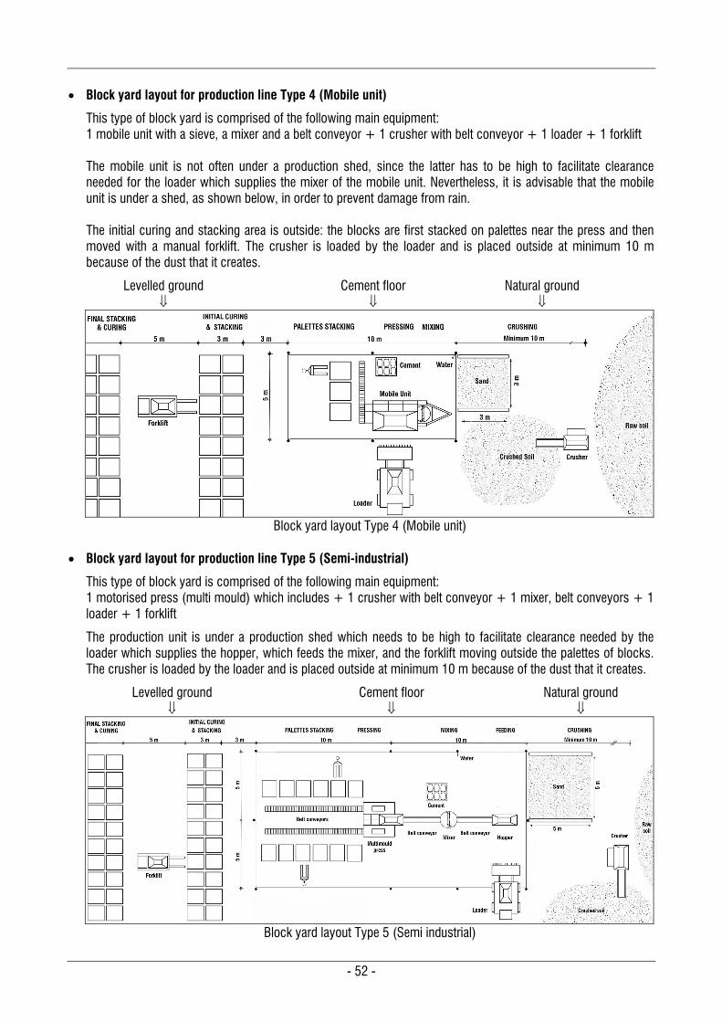
- 52 -
Block yard layout for production line Type 4 (Mobile unit)
This type of block yard is comprised of the following main equipment: 1 mobile unit with a sieve, a mixer and a belt conveyor + 1 crusher with belt conveyor + 1 loader + 1 forklift The mobile unit is not often under a production shed, since the latter has to be high to facilitate clearance needed for the loader which supplies the mixer of the mobile unit. Nevertheless, it is advisable that the mobile unit is under a shed, as shown below, in order to prevent damage from rain. The initial curing and stacking area is outside: the blocks are first stacked on palettes near the press and then moved with a manual forklift. The crusher is loaded by the loader and is placed outside at minimum 10 m because of the dust that it creates.
Levelled ground
Cement floor
Natural ground
Block yard layout Type 4 (Mobile unit)
Block yard layout for production line Type 5 (Semi-industrial)
This type of block yard is comprised of the following main equipment: 1 motorised press (multi mould) which includes + 1 crusher with belt conveyor + 1 mixer, belt conveyors + 1 loader + 1 forklift
The production unit is under a production shed which needs to be high to facilitate clearance needed by the loader which supplies the hopper, which feeds the mixer, and the forklift moving outside the palettes of blocks. The crusher is loaded by the loader and is placed outside at minimum 10 m because of the dust that it creates.
Levelled ground
Cement floor
Natural ground
Block yard layout Type 5 (Semi industrial)

- 53 -
5.2 BLOCK MAKING PROCESS AND QUALITY CONTROL
Producing good quality block requires following the correct process and conducting regular quality control tests. The following procedure is detailed and illustrated for a manual production unit, Type 1. Apart from the soil preparation and mixing, the process is identical for mechanised production units.
5.2.1 Soil preparation Almost all soils have to be sieved. Sieving a soil is necessary to remove gravel larger than 10 mm and most of the lumps. The size of the mesh is to be adapted according to the soil type: from 5 to 10 mm. (See for the mesh size paragraph 2.1.3.2 “Improvement and stabilisation of soils according to their classification”, page 10.) It is important to control the angle of the sieve to check what is passing through and how much waste is generated. Once a mesh size has been chosen, the angle of the sieve can be adjusted to control the gradation of the soil: A very flat sieve will allow more coarse particles to pass through. A very vertical sieve will remove more coarse particles and the soil will be thinner.
Good angle: ~45
Sieved soil is well graded
Flatter:
Many coarse particles pass through
More vertical:
Sieved soil is thinner, more waste A maximum of 15 % of gravel or lumps shall be allowed through the sieve. If they are too many lumps or gravel, the sieve shall be laid more vertically. On the other hand, if more gravel is needed, the sieve shall be laid flatter. Some soils, especially clayey ones with hard lumps, may need to be crushed. Crushing by hand is very difficult and labour intensive. It is preferable to use a motorised crusher of pulveriser. For both processes, manual or motorised, the soil to be crushed shall be absolutely dry.
5.2.2 Measuring and mixing Measuring
The volume of every container shall be known as the specifications are given according to their size. Measuring the various components properly is essential to ensure consistent quality. All containers used for soil and sand shall be filled to the top and levelled with a straight edge, as shown here, e.g. for filling the wheelbarrow of soil. The container should never be filled partially nor should it be overfilled, e.g. higher with a bump. The stabiliser shall be divided at once into 3 or 4 buckets. The reason being, if buckets are filled one after the other, the last one will never have the same amount of stabiliser: always check that all buckets are filled in the same way. Cement bags of 50 Kg can be divided into 3 or 4 buckets: 1/4 bag cement will need 4 buckets of 10 litres 1/3 bag cement will need 3 buckets of 15 litres
Fill the stabiliser at once into 3 or 4 buckets
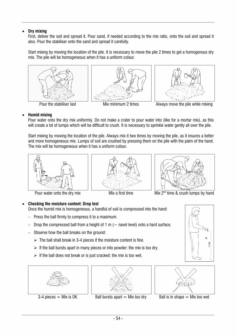
- 54 -
Dry mixing
First, deliver the soil and spread it. Pour sand, if needed according to the mix ratio, onto the soil and spread it also. Pour the stabiliser onto the sand and spread it carefully. Start mixing by moving the location of the pile. It is necessary to move the pile 2 times to get a homogenous dry mix. The pile will be homogeneous when it has a uniform colour.
Pour the stabiliser last
Mix minimum 2 times
Always move the pile while mixing
Humid mixing
Pour water onto the dry mix uniformly. Do not make a crater to pour water into (like for a mortar mix), as this will create a lot of lumps which will be difficult to crush. It is necessary to sprinkle water gently all over the pile. Start mixing by moving the location of the pile. Always mix it two times by moving the pile, as it insures a better and more homogeneous mix. Lumps of soil are crushed by pressing them on the pile with the palm of the hand. The mix will be homogeneous when it has a uniform colour.
Pour water onto the dry mix
Mix a first time
Mix 2nd time & crush lumps by hand
Checking the moisture content: Drop test
Once the humid mix is homogeneous, a handful of soil is compressed into the hand:
Press the ball firmly to compress it to a maximum.
Drop the compressed ball from a height of 1 m (~ navel level) onto a hard surface.
Observe how the ball breaks on the ground:
The ball shall break in 3-4 pieces if the moisture content is fine.
If the ball bursts apart in many pieces or into powder: the mix is too dry.
If the ball does not break or is just cracked: the mix is too wet.
3-4 pieces = Mix is OK
Ball bursts apart = Mix too dry
Ball is in shape = Mix too wet
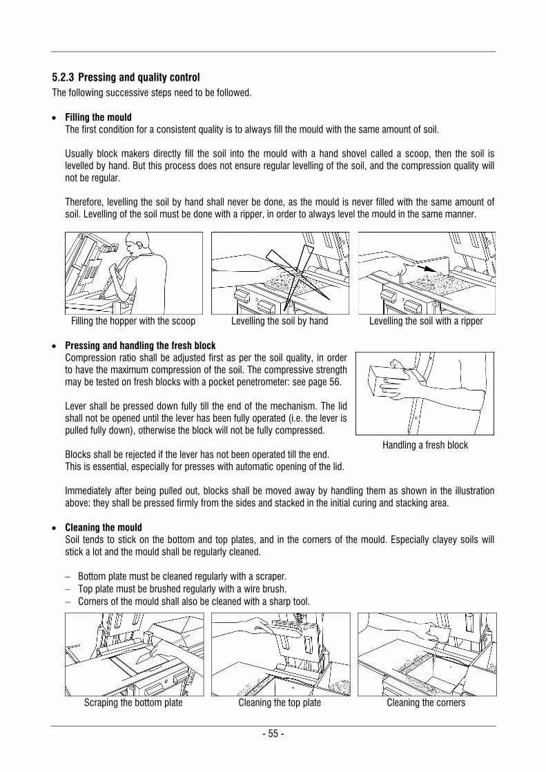
- 55 -
5.2.3 Pressing and quality control The following successive steps need to be followed. Filling the mould
The first condition for a consistent quality is to always fill the mould with the same amount of soil. Usually block makers directly fill the soil into the mould with a hand shovel called a scoop, then the soil is levelled by hand. But this process does not ensure regular levelling of the soil, and the compression quality will not be regular. Therefore, levelling the soil by hand shall never be done, as the mould is never filled with the same amount of soil. Levelling of the soil must be done with a ripper, in order to always level the mould in the same manner.
Filling the hopper with the scoop
Levelling the soil by hand
Levelling the soil with a ripper
Pressing and handling the fresh block
Compression ratio shall be adjusted first as per the soil quality, in order to have the maximum compression of the soil. The compressive strength may be tested on fresh blocks with a pocket penetrometer: see page 56. Lever shall be pressed down fully till the end of the mechanism. The lid shall not be opened until the lever has been fully operated (i.e. the lever is pulled fully down), otherwise the block will not be fully compressed. Blocks shall be rejected if the lever has not been operated till the end. This is essential, especially for presses with automatic opening of the lid. Immediately after being pulled out, blocks shall be moved away by handling them as shown in the illustration above: they shall be pressed firmly from the sides and stacked in the initial curing and stacking area.
Cleaning the mould Soil tends to stick on the bottom and top plates, and in the corners of the mould. Especially clayey soils will stick a lot and the mould shall be regularly cleaned. Bottom plate must be cleaned regularly with a scraper. Top plate must be brushed regularly with a wire brush. Corners of the mould shall also be cleaned with a sharp tool.
Scraping the bottom plate
Cleaning the top plate
Cleaning the corners
Handling a fresh block
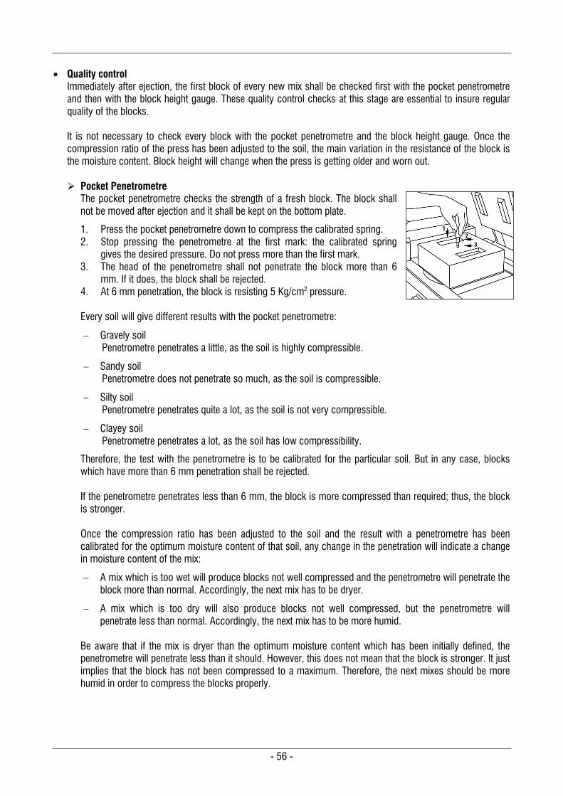
- 56 -
Quality control
Immediately after ejection, the first block of every new mix shall be checked first with the pocket penetrometre and then with the block height gauge. These quality control checks at this stage are essential to insure regular quality of the blocks. It is not necessary to check every block with the pocket penetrometre and the block height gauge. Once the compression ratio of the press has been adjusted to the soil, the main variation in the resistance of the block is the moisture content. Block height will change when the press is getting older and worn out. Pocket Penetrometre
The pocket penetrometre checks the strength of a fresh block. The block shall not be moved after ejection and it shall be kept on the bottom plate.
1. Press the pocket penetrometre down to compress the calibrated spring. 2. Stop pressing the penetrometre at the first mark: the calibrated spring
gives the desired pressure. Do not press more than the first mark. 3. The head of the penetrometre shall not penetrate the block more than 6
mm. If it does, the block shall be rejected. 4. At 6 mm penetration, the block is resisting 5 Kg/cm2 pressure. Every soil will give different results with the pocket penetrometre:
Gravely soil Penetrometre penetrates a little, as the soil is highly compressible.
Sandy soil Penetrometre does not penetrate so much, as the soil is compressible.
Silty soil Penetrometre penetrates quite a lot, as the soil is not very compressible.
Clayey soil Penetrometre penetrates a lot, as the soil has low compressibility.
Therefore, the test with the penetrometre is to be calibrated for the particular soil. But in any case, blocks which have more than 6 mm penetration shall be rejected. If the penetrometre penetrates less than 6 mm, the block is more compressed than required; thus, the block is stronger. Once the compression ratio has been adjusted to the soil and the result with a penetrometre has been calibrated for the optimum moisture content of that soil, any change in the penetration will indicate a change in moisture content of the mix:
A mix which is too wet will produce blocks not well compressed and the penetrometre will penetrate the block more than normal. Accordingly, the next mix has to be dryer.
A mix which is too dry will also produce blocks not well compressed, but the penetrometre will penetrate less than normal. Accordingly, the next mix has to be more humid.
Be aware that if the mix is dryer than the optimum moisture content which has been initially defined, the penetrometre will penetrate less than it should. However, this does not mean that the block is stronger. It just implies that the block has not been compressed to a maximum. Therefore, the next mixes should be more humid in order to compress the blocks properly.
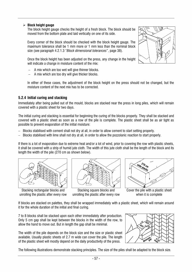
- 57 -
Block height gauge
The block height gauge checks the height of a fresh block. The block should be moved from the bottom plate and laid vertically on one of its side. Every corner of the block should be checked with the block height gauge. The maximum tolerance shall be 1 mm more or 1 mm less than the nominal block size (see paragraph 4.2.1.3 “Block dimensional tolerances”, page 38). Once the block height has been adjusted on the press, any change in the height will indicate a change in moisture content of the mix:
A mix which are too wet will give thinner blocks. A mix which are too dry will give thicker blocks.
In either of these cases, the adjustment of the block height on the press should not be changed, but the moisture content of the next mix has to be corrected.
5.2.4 Initial curing and stacking Immediately after being pulled out of the mould, blocks are stacked near the press in long piles, which will remain covered with a plastic sheet for two days. The initial curing and stacking is essential for beginning the curing of the blocks properly. They shall be stacked and covered with a plastic sheet as soon as a row of the pile is complete. The plastic sheet shall be as air tight as possible to prevent evaporation of the initial moisture:
Blocks stabilised with cement shall not dry at all, in order to allow cement to start setting properly. Blocks stabilised with lime shall not dry at all, in order to allow the pozzolanic reaction to start properly. If there is a lot of evaporation due to extreme heat and/or a lot of wind, prior to covering the row with plastic sheets, it shall be covered with a strip of humid jute cloth. The width of this jute cloth shall be the length of the block and its length the width of the pile (270 cm as shown below).
Stacking rectangular blocks and
unrolling the plastic after every row
Stacking square blocks and
unrolling the plastic after every row
Cover the pile with a plastic sheet
when it is complete If blocks are stacked on palettes, they shall be wrapped immediately with a plastic sheet, which will remain around it for the whole duration of the initial and final curing. 7 to 8 blocks shall be stacked upon each other immediately after production. Only 5 cm gap shall be kept between the blocks in the width of the row, to allow the hand to move out. But in length the gap shall be minimal. The width of the pile depends on the block size and the size or plastic sheet available. Usually plastic sheets of 2.7 m wide can cover the pile. The length of the plastic sheet will mostly depend on the daily productivity of the press. The following illustrations demonstrate stacking principles. The size of the piles shall be adapted to the block size.
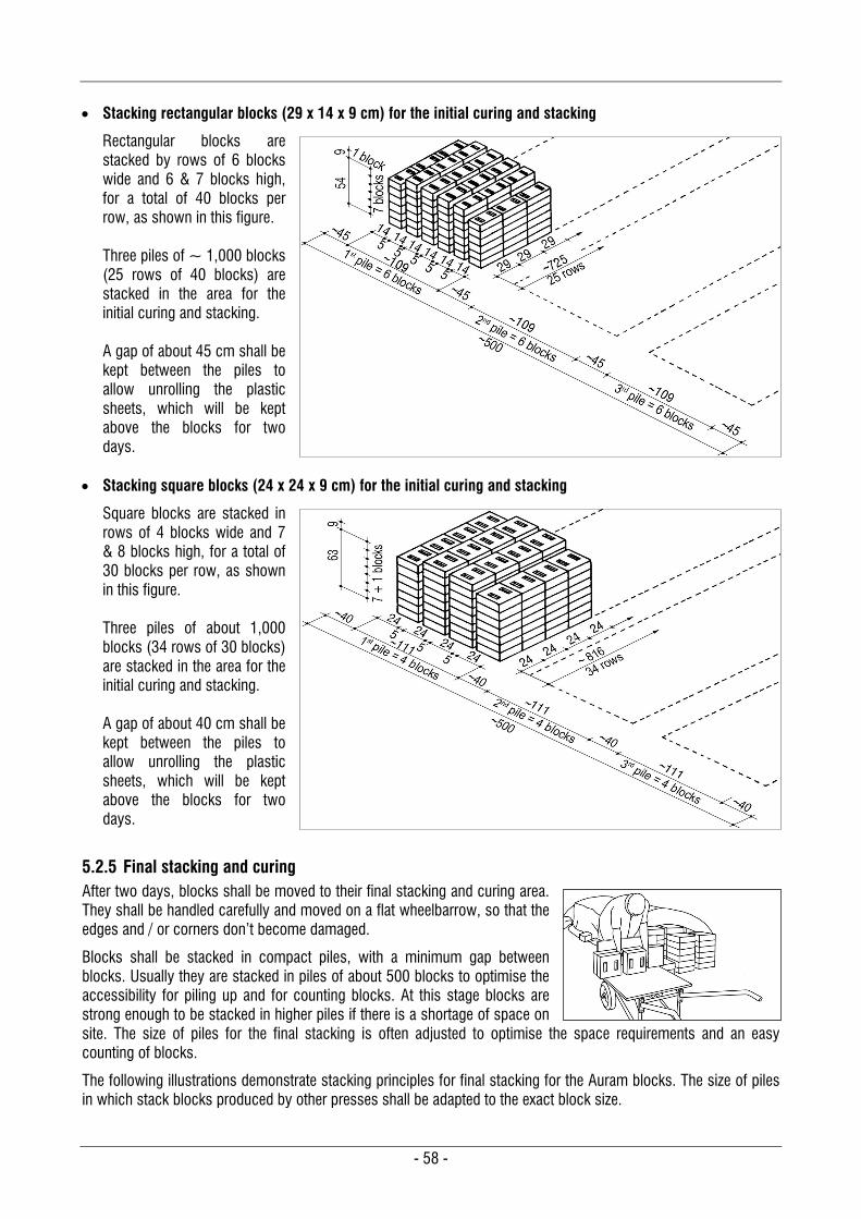
- 58 -
Stacking rectangular blocks (29 x 14 x 9 cm) for the initial curing and stacking
Rectangular blocks are stacked by rows of 6 blocks wide and 6 & 7 blocks high, for a total of 40 blocks per row, as shown in this figure. Three piles of ~ 1,000 blocks (25 rows of 40 blocks) are stacked in the area for the initial curing and stacking. A gap of about 45 cm shall be kept between the piles to allow unrolling the plastic sheets, which will be kept above the blocks for two days.
Stacking square blocks (24 x 24 x 9 cm) for the initial curing and stacking
Square blocks are stacked in rows of 4 blocks wide and 7 & 8 blocks high, for a total of 30 blocks per row, as shown in this figure. Three piles of about 1,000 blocks (34 rows of 30 blocks) are stacked in the area for the initial curing and stacking. A gap of about 40 cm shall be kept between the piles to allow unrolling the plastic sheets, which will be kept above the blocks for two days.
5.2.5 Final stacking and curing After two days, blocks shall be moved to their final stacking and curing area. They shall be handled carefully and moved on a flat wheelbarrow, so that the edges and / or corners don’t become damaged.
Blocks shall be stacked in compact piles, with a minimum gap between blocks. Usually they are stacked in piles of about 500 blocks to optimise the accessibility for piling up and for counting blocks. At this stage blocks are strong enough to be stacked in higher piles if there is a shortage of space on site. The size of piles for the final stacking is often adjusted to optimise the space requirements and an easy counting of blocks.
The following illustrations demonstrate stacking principles for final stacking for the Auram blocks. The size of piles in which stack blocks produced by other presses shall be adapted to the exact block size.
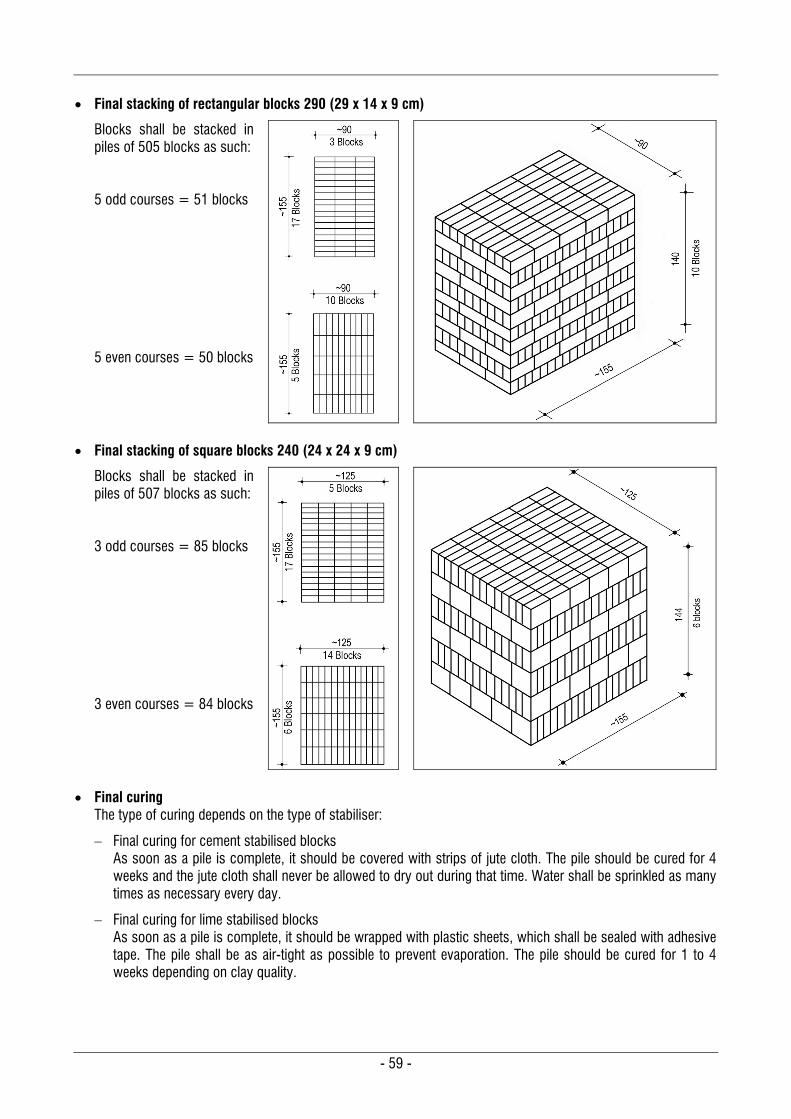
- 59 -
Final stacking of rectangular blocks 290 (29 x 14 x 9 cm)
Blocks shall be stacked in piles of 505 blocks as such: 5 odd courses = 51 blocks 5 even courses = 50 blocks
Final stacking of square blocks 240 (24 x 24 x 9 cm)
Blocks shall be stacked in piles of 507 blocks as such: 3 odd courses = 85 blocks 3 even courses = 84 blocks
Final curing The type of curing depends on the type of stabiliser:
Final curing for cement stabilised blocks As soon as a pile is complete, it should be covered with strips of jute cloth. The pile should be cured for 4 weeks and the jute cloth shall never be allowed to dry out during that time. Water shall be sprinkled as many times as necessary every day.
Final curing for lime stabilised blocks As soon as a pile is complete, it should be wrapped with plastic sheets, which shall be sealed with adhesive tape. The pile shall be as air-tight as possible to prevent evaporation. The pile should be cured for 1 to 4 weeks depending on clay quality.
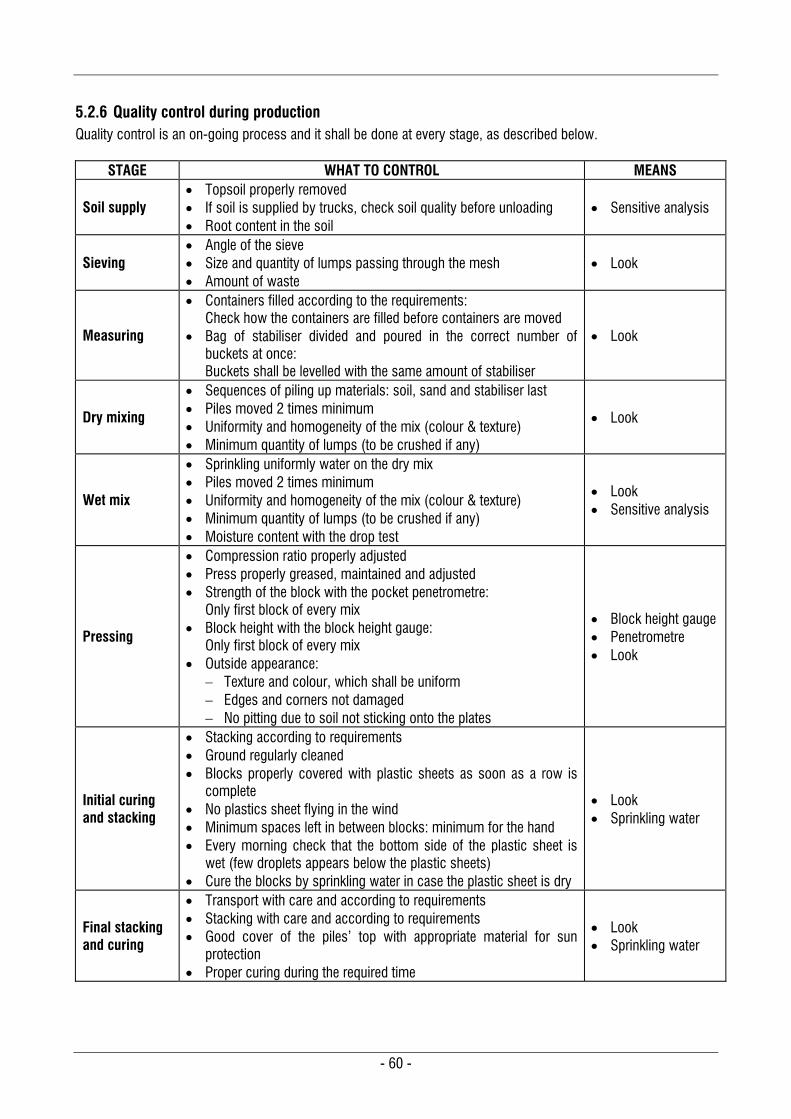
- 60 -
5.2.6 Quality control during production Quality control is an on-going process and it shall be done at every stage, as described below.
STAGE WHAT TO CONTROL MEANS
Soil supply Topsoil properly removed If soil is supplied by trucks, check soil quality before unloading Root content in the soil
Sensitive analysis
Sieving Angle of the sieve Size and quantity of lumps passing through the mesh Amount of waste
Look
Measuring
Containers filled according to the requirements: Check how the containers are filled before containers are moved
Bag of stabiliser divided and poured in the correct number of buckets at once: Buckets shall be levelled with the same amount of stabiliser
Look
Dry mixing
Sequences of piling up materials: soil, sand and stabiliser last Piles moved 2 times minimum Uniformity and homogeneity of the mix (colour & texture) Minimum quantity of lumps (to be crushed if any)
Look
Wet mix
Sprinkling uniformly water on the dry mix Piles moved 2 times minimum Uniformity and homogeneity of the mix (colour & texture) Minimum quantity of lumps (to be crushed if any) Moisture content with the drop test
Look Sensitive analysis
Pressing
Compression ratio properly adjusted Press properly greased, maintained and adjusted Strength of the block with the pocket penetrometre:
Only first block of every mix Block height with the block height gauge:
Only first block of every mix Outside appearance:
Texture and colour, which shall be uniform Edges and corners not damaged No pitting due to soil not sticking onto the plates
Block height gauge Penetrometre Look
Initial curing and stacking
Stacking according to requirements Ground regularly cleaned Blocks properly covered with plastic sheets as soon as a row is
complete No plastics sheet flying in the wind Minimum spaces left in between blocks: minimum for the hand Every morning check that the bottom side of the plastic sheet is
wet (few droplets appears below the plastic sheets) Cure the blocks by sprinkling water in case the plastic sheet is dry
Look Sprinkling water
Final stacking and curing
Transport with care and according to requirements Stacking with care and according to requirements Good cover of the piles’ top with appropriate material for sun
protection Proper curing during the required time
Look Sprinkling water
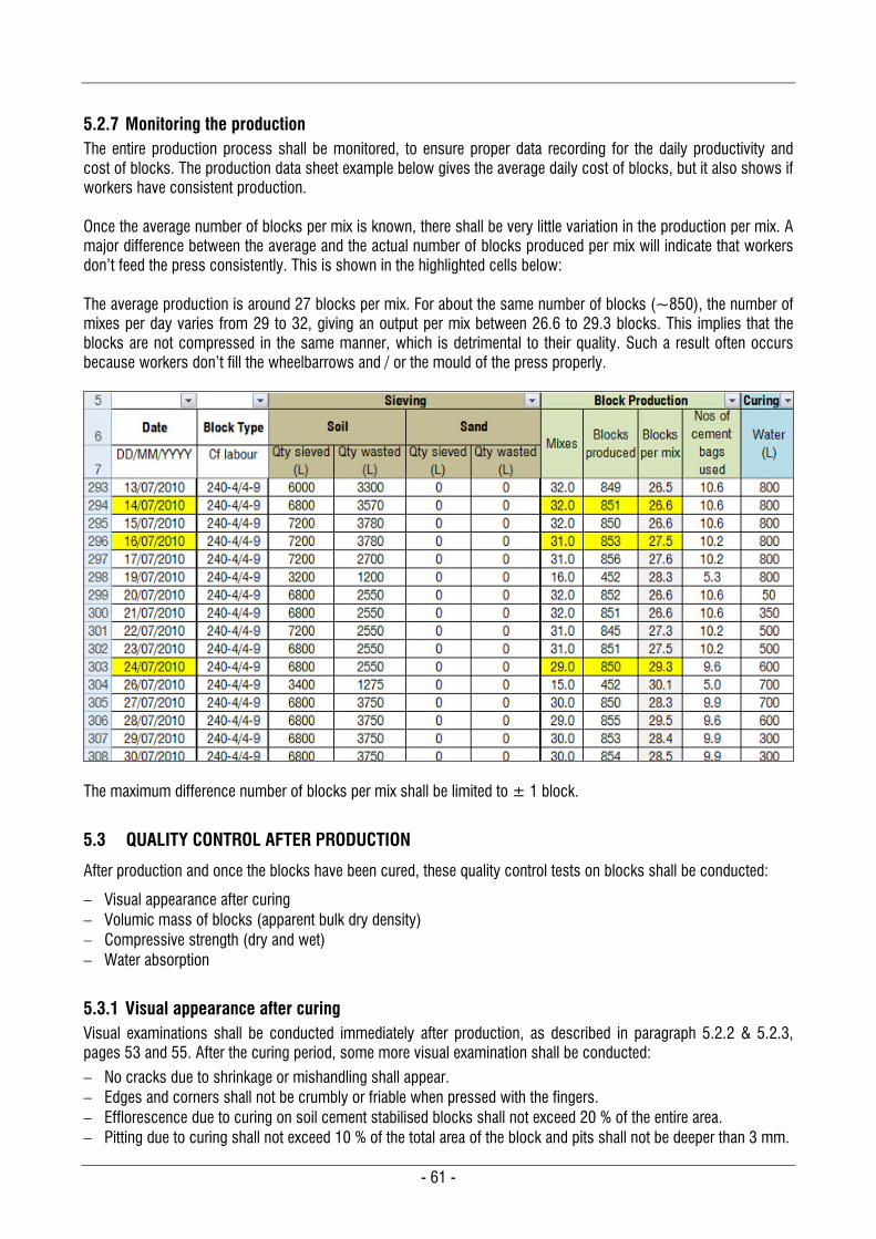
- 61 -
5.2.7 Monitoring the production The entire production process shall be monitored, to ensure proper data recording for the daily productivity and cost of blocks. The production data sheet example below gives the average daily cost of blocks, but it also shows if workers have consistent production. Once the average number of blocks per mix is known, there shall be very little variation in the production per mix. A major difference between the average and the actual number of blocks produced per mix will indicate that workers don’t feed the press consistently. This is shown in the highlighted cells below: The average production is around 27 blocks per mix. For about the same number of blocks (~850), the number of mixes per day varies from 29 to 32, giving an output per mix between 26.6 to 29.3 blocks. This implies that the blocks are not compressed in the same manner, which is detrimental to their quality. Such a result often occurs because workers don’t fill the wheelbarrows and / or the mould of the press properly.
The maximum difference number of blocks per mix shall be limited to ± 1 block.
5.3 QUALITY CONTROL AFTER PRODUCTION
After production and once the blocks have been cured, these quality control tests on blocks shall be conducted:
Visual appearance after curing Volumic mass of blocks (apparent bulk dry density) Compressive strength (dry and wet) Water absorption
5.3.1 Visual appearance after curing Visual examinations shall be conducted immediately after production, as described in paragraph 5.2.2 & 5.2.3, pages 53 and 55. After the curing period, some more visual examination shall be conducted:
No cracks due to shrinkage or mishandling shall appear. Edges and corners shall not be crumbly or friable when pressed with the fingers. Efflorescence due to curing on soil cement stabilised blocks shall not exceed 20 % of the entire area. Pitting due to curing shall not exceed 10 % of the total area of the block and pits shall not be deeper than 3 mm.
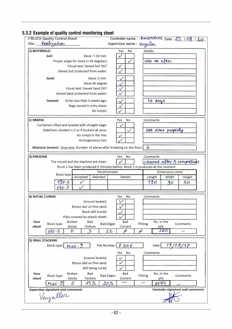
- 62 -
5.3.2 Example of quality control monitoring sheet
- 63 -
5.3.3 Volumic mass of blocks, Block The compression achieved with the press shall be such that no block shall have a volumic mass under 18 kN/m3 (1800 Kg/m3). Procedure is as follows: The volumic mass shall be calculated by dividing the air-dry mass of a block (in Kg) by the volume of material (in m3). The volume of material of a block is calculated from its outside dimensions, deducting the indents and cavities.
5.3.4 Compressive strength (dry and wet) The compressive strength shall be tested on cured samples (after 28 days for cement stabilised blocks and after 3 months for lime stabilised blocks). Blocks shall be tested in two states: dry and wet compression. Both values are important to know, but the ultimate value used for the design shall be the wet compressive strength, Cw The wet compressive strength shall be conducted on samples immersed in water for 24 hours at a temperature close to 27 C. The wet compressive strength of any individual block shall not be less than:
3 MPa for blocks of Class A
2 MPa for blocks of Class B
1.5 MPa for blocks of Class C
See section 4.2.2 “Physical requirements and characteristics of CSEB”, page 39, for the dry compressive strength Cd and wet compressive strength Cw according to the class of blocks. The compressive strength can be determined in the field or in a laboratory:
Blocks will be tested in the laboratory with a hydraulic compression testing machine. Compressive strength testing shall be done in accordance to the relevant standard.
In the field, blocks shall be tested by bending, and the compressive strength shall be derived with the formula shown on the following page.
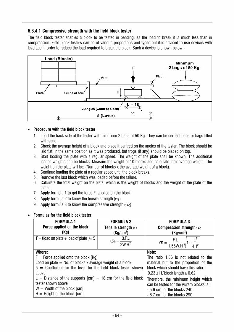
- 64 -
5.3.4.1 Compressive strength with the field block tester The field block tester enables a block to be tested in bending, as the load to break it is much less than in compression. Field block testers can be of various proportions and types but it is advised to use devices with leverage in order to reduce the load required to break the block. Such a device is shown below.
Procedure with the field block tester
1. Load the back side of the tester with minimum 2 bags of 50 Kg. They can be cement bags or bags filled with sand.
2. Check the average height of a block and place it centred on the angles of the tester. The block should be laid flat, in the same position as it was produced, but frogs (if any) should be placed on top.
3. Start loading the plate with a regular speed. The weight of the plate shall be known. The additional loaded weights can be blocks: Measure the weight of 10 blocks and calculate their average weight. The weight on the plate will be: (Number of blocks x the average weight of a block).
4. Continue loading the plate at a regular speed until the block breaks. 5. Remove the last block which was loaded before the failure. 6. Calculate the total weight on the plate, which is the weight of blocks and the weight of the plate of the
tester. 7. Apply formula 1 to get the force F, applied on the block. 8. Apply formula 2 to know the tensile strength (B) 9. Apply formula 3 to know the compressive strength (C)
Formulas for the field block tester
FORMULA 1 Force applied on the block
(Kg)
FORMULA 2 Tensile strength B
(Kg/cm2)
FORMULA 3 Compression strength C
(Kg/cm2) 5 plate of load plate on loadF
2b
H.W2L.F.3
2
2
4H
L1
W.H56.1F.L
c
Where: F = Force applied onto the block [Kg] Load on plate = No. of blocks x average weight of a block 5 = Coefficient for the lever for the field block tester shown above L = Distance of the supports [cm] = 18 cm for the field block tester shown above W = Width of the block [cm] H = Height of the block [cm]
Note: The ratio 1.56 is not related to the material but to the proportion of the block which should have this ratio:
62.0length block/H23.0 Therefore, the minimum height which can be tested for the Auram blocks is: - 5.6 cm for the blocks 240 - 6.7 cm for the blocks 290
- 65 -
5.3.4.2 Compressive strength with a compression testing machine The test consists of subjecting a block sample to simple compression until failure. A calibrated crushing press for hard materials shall be used, and it shall have a capacity of a minimum of 1,000 kN (~100 tons). The loading plates shall be absolutely flat and one of them shall be mounted on a ball allowing the plate to adjust itself to any unevenness in height of the block. The size of the plates shall be large enough to accommodate samples up to 40 cm x 40 cm x 40 cm. Preparation of specimens
1. Samples shall be oven dried for 24 hours at 90˚C. 2. After 24 hours, check the weight of the oven dried samples. 3. Leave the samples in ambient conditions for another 24 hours before testing. 4. After 24 hours in ambient air conditions, check the weight of samples again. 5. For blocks to be tested in wet compression, immerse these samples in water for 24 hours. After 24
hours immersion, check the weight of samples again. 6. The upper and lower faces of each specimen shall be coated with a pure mortar paste made of a mix of
high alumina melted cement and Portland cement in a proportion which sets within a maximum time of 10 to 15 min. Frogs shall also be filled with the same mortar quality.
7. Alternatively, instead of this coating, plywood sheets or solid cardboard of 3 mm thick shall be laid on the faces in contact with the loading plates.
Procedure with a compression testing machine
1. The press shall be set for a displacement of 0.02 mm/sec. 2. The load shall be applied axially at a rate of 12 N/mm2 (120 Kgf/cm2) per minute (0.20 MPa/s). 3. The crushing is considered as complete when the specimen cannot take any more load.
4. The compressive strength of the block is calculated as AF
c in MPa (N/mm²) or Kg/cm2
Where: F = Maximum load borne by the specimen in Newton or Kg A = Average area of the test faces in mm2 (for MPa) or cm² (for Kg/cm2)
5.3.5 Water absorption The increase in mass of an oven dried specimen, due to immersion in water for 24 hours, is determined as a percentage of the specimen’s initial dry mass. Water absorption of an oven dried block shall not be more than 10%. Water absorption is measured on an oven dried sample, but it is useful to compare this with an ambient air sample.
Procedure for the absorption test 1. Sample shall be oven dried for 24 hours at 105˚C. Its weight shall be checked immediately after
removing the specimen from the oven. This weight shall be referenced as MOven 2. Leave the sample in ambient air conditions for another 24 hours. 3. After 24 hours in the ambient air conditions, check the weight of sample again, referenced as MAir.
4. Immerse this sample 24 hours in water at ~27 C. After this period, remove it from the water and allow it to drain for not more than 1 minute. Check again the weight of the wet sample, referenced as MWet.
5. Water absorption, expressed in percentage, is calculated by this formula: 100x M
)M-(M
Oven
OvenWet
6. It is interesting to compare water absorption, between the oven dried and ambient air sample. This
percentage is calculated by this formula: 100x M
)M-(M
Air
AirWet

- 66 -
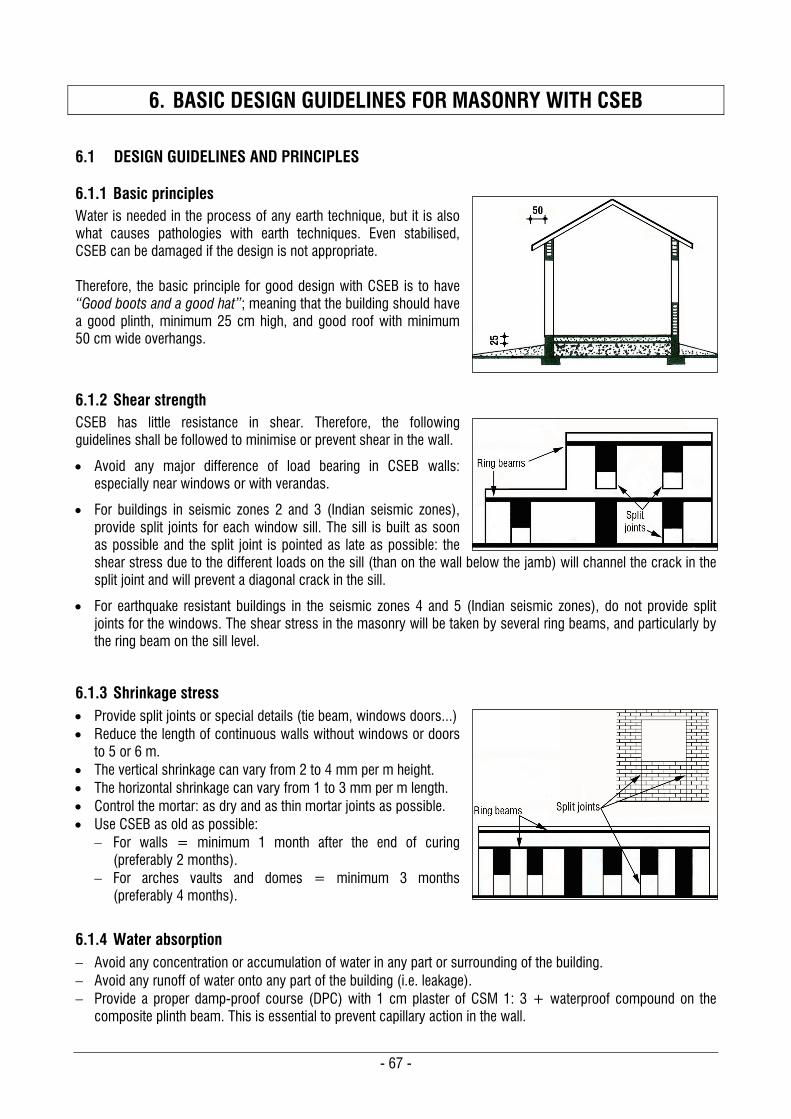
- 67 -
6. BASIC DESIGN GUIDELINES FOR MASONRY WITH CSEB
6.1 DESIGN GUIDELINES AND PRINCIPLES
6.1.1 Basic principles Water is needed in the process of any earth technique, but it is also what causes pathologies with earth techniques. Even stabilised, CSEB can be damaged if the design is not appropriate. Therefore, the basic principle for good design with CSEB is to have “Good boots and a good hat”; meaning that the building should have a good plinth, minimum 25 cm high, and good roof with minimum 50 cm wide overhangs.
6.1.2 Shear strength CSEB has little resistance in shear. Therefore, the following guidelines shall be followed to minimise or prevent shear in the wall.
Avoid any major difference of load bearing in CSEB walls: especially near windows or with verandas.
For buildings in seismic zones 2 and 3 (Indian seismic zones), provide split joints for each window sill. The sill is built as soon as possible and the split joint is pointed as late as possible: the shear stress due to the different loads on the sill (than on the wall below the jamb) will channel the crack in the split joint and will prevent a diagonal crack in the sill.
For earthquake resistant buildings in the seismic zones 4 and 5 (Indian seismic zones), do not provide split joints for the windows. The shear stress in the masonry will be taken by several ring beams, and particularly by the ring beam on the sill level.
6.1.3 Shrinkage stress Provide split joints or special details (tie beam, windows doors...) Reduce the length of continuous walls without windows or doors
to 5 or 6 m. The vertical shrinkage can vary from 2 to 4 mm per m height. The horizontal shrinkage can vary from 1 to 3 mm per m length. Control the mortar: as dry and as thin mortar joints as possible. Use CSEB as old as possible:
For walls = minimum 1 month after the end of curing (preferably 2 months).
For arches vaults and domes = minimum 3 months (preferably 4 months).
6.1.4 Water absorption Avoid any concentration or accumulation of water in any part or surrounding of the building. Avoid any runoff of water onto any part of the building (i.e. leakage). Provide a proper damp-proof course (DPC) with 1 cm plaster of CSM 1: 3 + waterproof compound on the
composite plinth beam. This is essential to prevent capillary action in the wall.
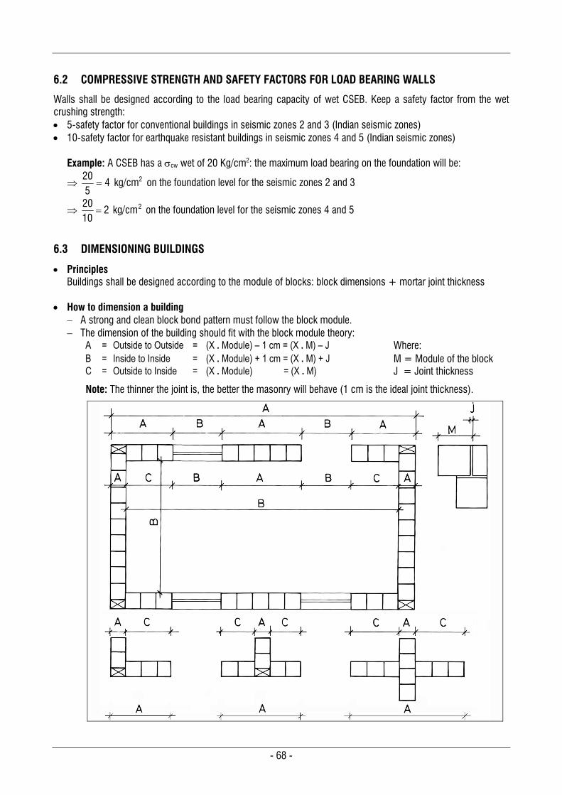
- 68 -
6.2 COMPRESSIVE STRENGTH AND SAFETY FACTORS FOR LOAD BEARING WALLS
Walls shall be designed according to the load bearing capacity of wet CSEB. Keep a safety factor from the wet crushing strength: 5-safety factor for conventional buildings in seismic zones 2 and 3 (Indian seismic zones) 10-safety factor for earthquake resistant buildings in seismic zones 4 and 5 (Indian seismic zones)
Example: A CSEB has a cw wet of 20 Kg/cm2: the maximum load bearing on the foundation will be:
2kg/cm 4520
on the foundation level for the seismic zones 2 and 3
2kg/cm 21020
on the foundation level for the seismic zones 4 and 5
6.3 DIMENSIONING BUILDINGS
Principles Buildings shall be designed according to the module of blocks: block dimensions + mortar joint thickness
How to dimension a building
A strong and clean block bond pattern must follow the block module. The dimension of the building should fit with the block module theory:
A = Outside to Outside = (X . Module) – 1 cm = (X . M) – J Where: B = Inside to Inside = (X . Module) + 1 cm = (X . M) + J M = Module of the block C = Outside to Inside = (X . Module) = (X . M) J = Joint thickness
Note: The thinner the joint is, the better the masonry will behave (1 cm is the ideal joint thickness).
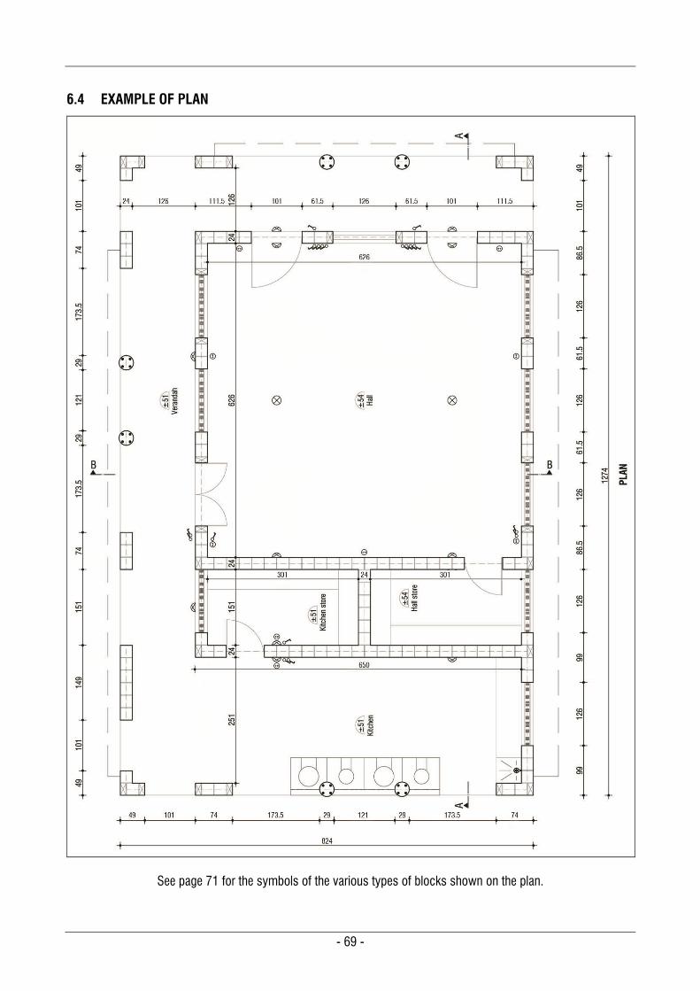
- 69 -
6.4 EXAMPLE OF PLAN
See page 71 for the symbols of the various types of blocks shown on the plan.
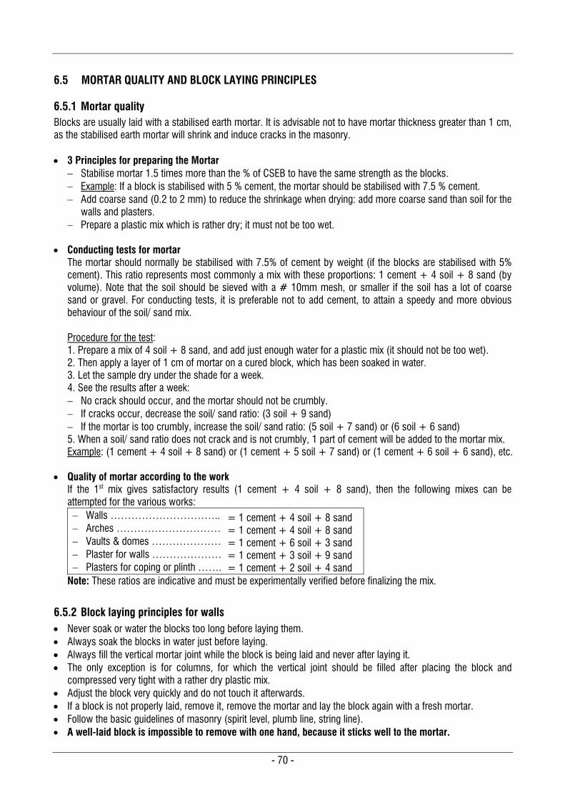
- 70 -
6.5 MORTAR QUALITY AND BLOCK LAYING PRINCIPLES
6.5.1 Mortar quality Blocks are usually laid with a stabilised earth mortar. It is advisable not to have mortar thickness greater than 1 cm, as the stabilised earth mortar will shrink and induce cracks in the masonry. 3 Principles for preparing the Mortar
Stabilise mortar 1.5 times more than the % of CSEB to have the same strength as the blocks. Example: If a block is stabilised with 5 % cement, the mortar should be stabilised with 7.5 % cement. Add coarse sand (0.2 to 2 mm) to reduce the shrinkage when drying: add more coarse sand than soil for the
walls and plasters. Prepare a plastic mix which is rather dry; it must not be too wet.
Conducting tests for mortar
The mortar should normally be stabilised with 7.5% of cement by weight (if the blocks are stabilised with 5% cement). This ratio represents most commonly a mix with these proportions: 1 cement + 4 soil + 8 sand (by volume). Note that the soil should be sieved with a # 10mm mesh, or smaller if the soil has a lot of coarse sand or gravel. For conducting tests, it is preferable not to add cement, to attain a speedy and more obvious behaviour of the soil/ sand mix. Procedure for the test: 1. Prepare a mix of 4 soil + 8 sand, and add just enough water for a plastic mix (it should not be too wet). 2. Then apply a layer of 1 cm of mortar on a cured block, which has been soaked in water. 3. Let the sample dry under the shade for a week. 4. See the results after a week: No crack should occur, and the mortar should not be crumbly. If cracks occur, decrease the soil/ sand ratio: (3 soil + 9 sand) If the mortar is too crumbly, increase the soil/ sand ratio: (5 soil + 7 sand) or (6 soil + 6 sand) 5. When a soil/ sand ratio does not crack and is not crumbly, 1 part of cement will be added to the mortar mix. Example: (1 cement + 4 soil + 8 sand) or (1 cement + 5 soil + 7 sand) or (1 cement + 6 soil + 6 sand), etc.
Quality of mortar according to the work If the 1st mix gives satisfactory results (1 cement + 4 soil + 8 sand), then the following mixes can be attempted for the various works: Walls ………………………….. Arches ………………………… Vaults & domes ………………… Plaster for walls ………………… Plasters for coping or plinth …….
= 1 cement + 4 soil + 8 sand = 1 cement + 4 soil + 8 sand = 1 cement + 6 soil + 3 sand = 1 cement + 3 soil + 9 sand = 1 cement + 2 soil + 4 sand
Note: These ratios are indicative and must be experimentally verified before finalizing the mix.
6.5.2 Block laying principles for walls Never soak or water the blocks too long before laying them. Always soak the blocks in water just before laying. Always fill the vertical mortar joint while the block is being laid and never after laying it. The only exception is for columns, for which the vertical joint should be filled after placing the block and
compressed very tight with a rather dry plastic mix. Adjust the block very quickly and do not touch it afterwards. If a block is not properly laid, remove it, remove the mortar and lay the block again with a fresh mortar. Follow the basic guidelines of masonry (spirit level, plumb line, string line). A well-laid block is impossible to remove with one hand, because it sticks well to the mortar.
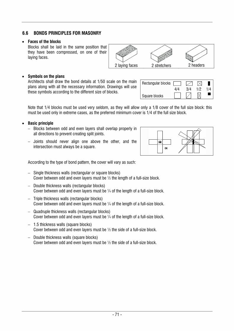
- 71 -
6.6 BONDS PRINCIPLES FOR MASONRY
Faces of the blocks Blocks shall be laid in the same position that they have been compressed, on one of their laying faces.
2 laying faces
2 stretchers
2 headers
Symbols on the plans
Architects shall draw the bond details at 1/50 scale on the main plans along with all the necessary information. Drawings will use these symbols according to the different size of blocks. Note that 1/4 blocks must be used very seldom, as they will allow only a 1/8 cover of the full size block: this must be used only in extreme cases, as the preferred minimum cover is 1/4 of the full size block.
Basic principle
Blocks between odd and even layers shall overlap properly in all directions to prevent creating split joints.
Joints should never align one above the other, and the intersection must always be a square.
According to the type of bond pattern, the cover will vary as such: Single thickness walls (rectangular or square blocks)
Cover between odd and even layers must be ½ the length of a full-size block.
Double thickness walls (rectangular blocks) Cover between odd and even layers must be ¼ of the length of a full-size block.
Triple thickness walls (rectangular blocks) Cover between odd and even layers must be ¼ of the length of a full-size block.
Quadruple thickness walls (rectangular blocks) Cover between odd and even layers must be ¼ of the length of a full-size block.
1.5 thickness walls (square blocks) Cover between odd and even layers must be ½ the side of a full-size block.
Double thickness walls (square blocks) Cover between odd and even layers must be ½ the side of a full-size block.
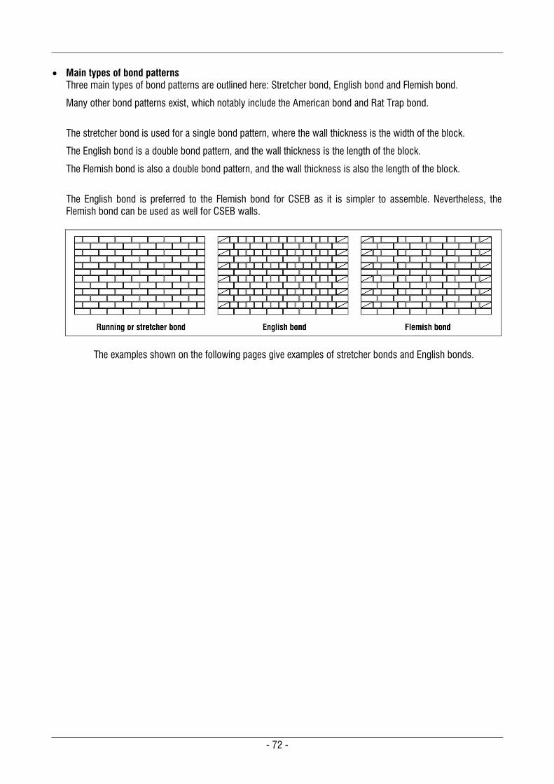
- 72 -
Main types of bond patterns
Three main types of bond patterns are outlined here: Stretcher bond, English bond and Flemish bond.
Many other bond patterns exist, which notably include the American bond and Rat Trap bond.
The stretcher bond is used for a single bond pattern, where the wall thickness is the width of the block.
The English bond is a double bond pattern, and the wall thickness is the length of the block.
The Flemish bond is also a double bond pattern, and the wall thickness is also the length of the block.
The English bond is preferred to the Flemish bond for CSEB as it is simpler to assemble. Nevertheless, the Flemish bond can be used as well for CSEB walls.
The examples shown on the following pages give examples of stretcher bonds and English bonds.
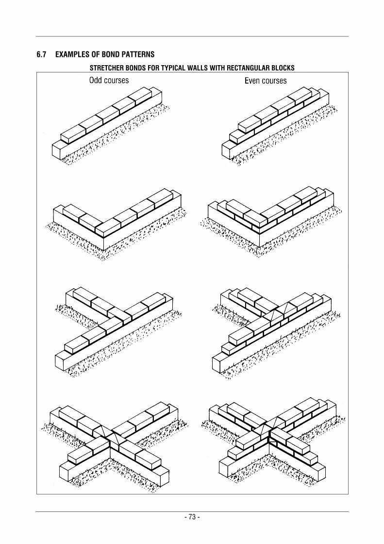
- 73 -
6.7 EXAMPLES OF BOND PATTERNS
STRETCHER BONDS FOR TYPICAL WALLS WITH RECTANGULAR BLOCKS
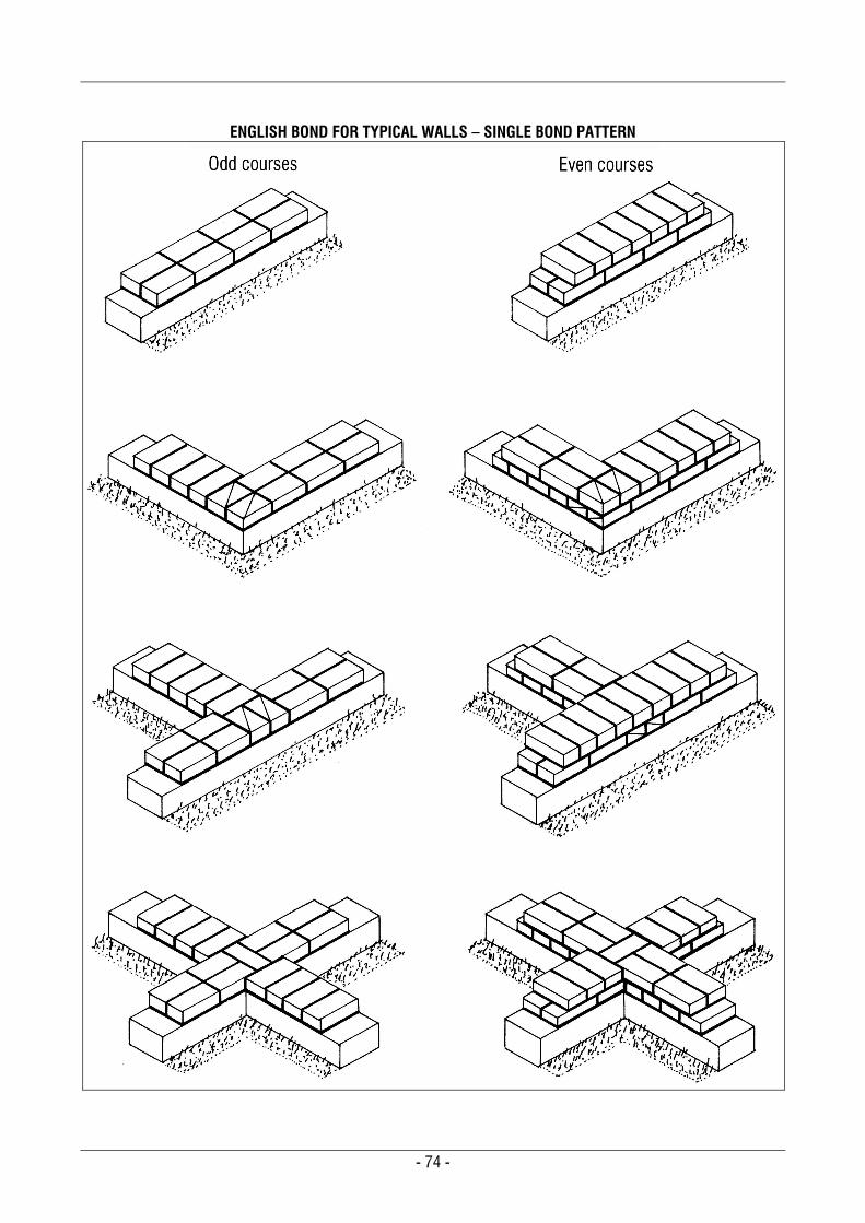
- 74 -
ENGLISH BOND FOR TYPICAL WALLS – SINGLE BOND PATTERN
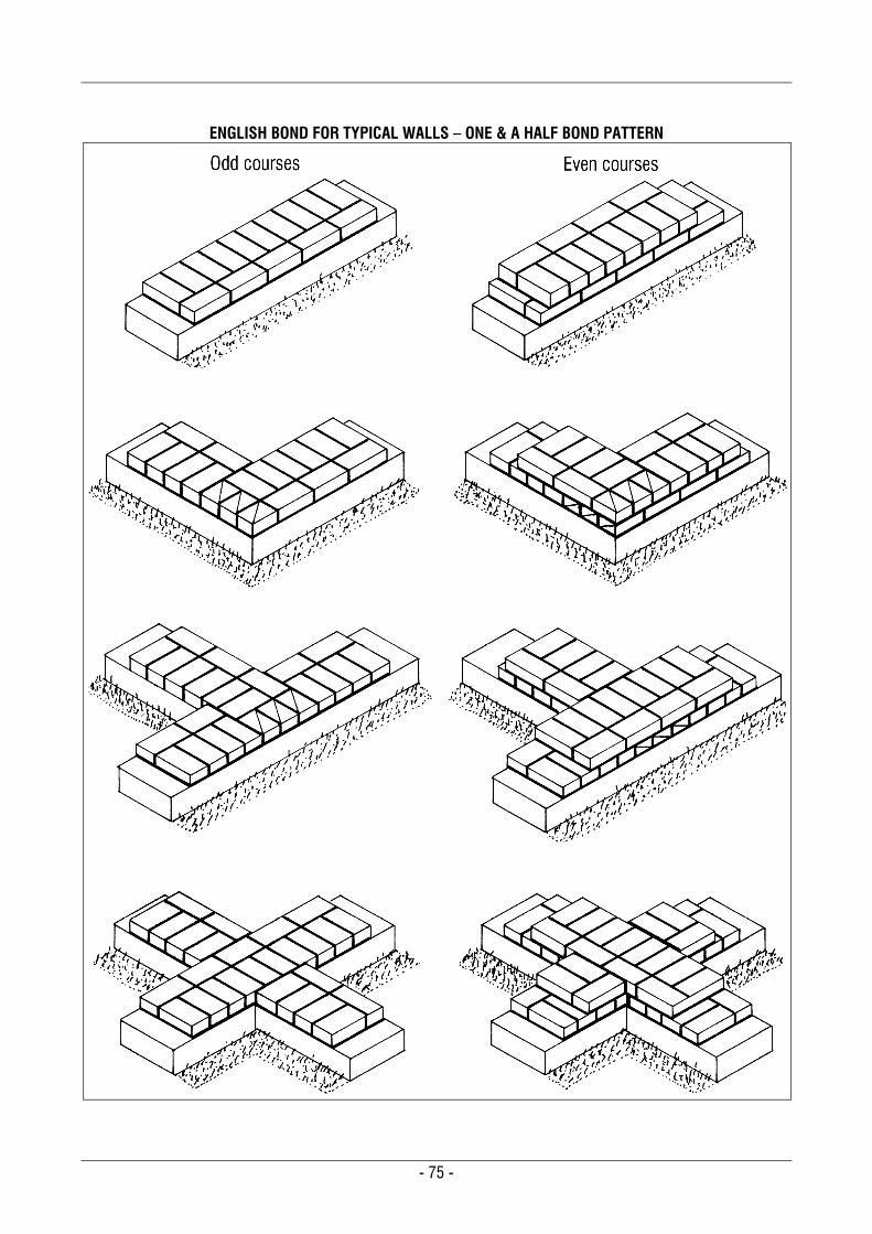
- 75 -
ENGLISH BOND FOR TYPICAL WALLS – ONE & A HALF BOND PATTERN
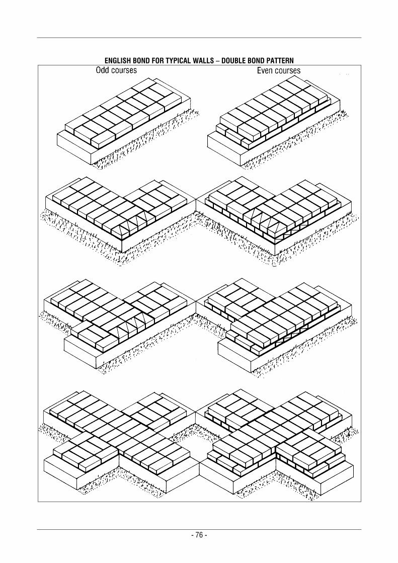
- 76 -
ENGLISH BOND FOR TYPICAL WALLS – DOUBLE BOND PATTERN
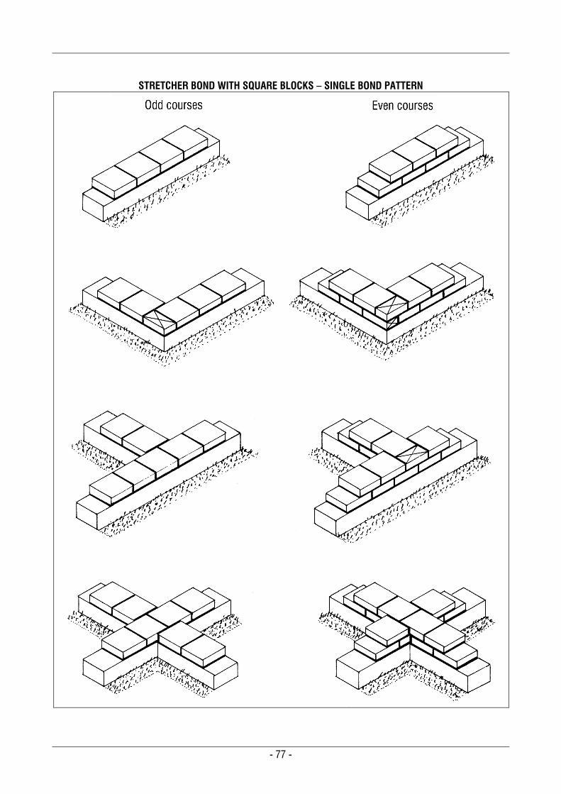
- 77 -
STRETCHER BOND WITH SQUARE BLOCKS – SINGLE BOND PATTERN
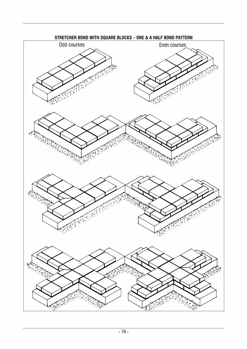
- 78 -
STRETCHER BOND WITH SQUARE BLOCKS – ONE & A HALF BOND PATTERN
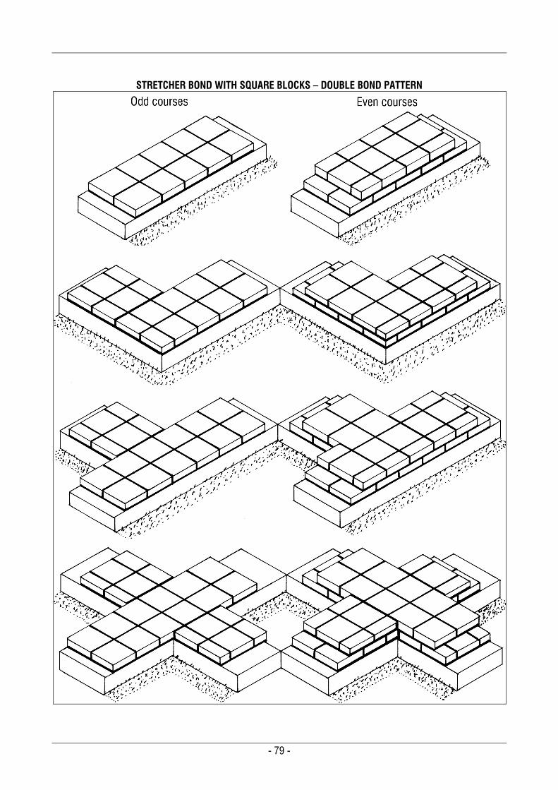
- 79 -
STRETCHER BOND WITH SQUARE BLOCKS – DOUBLE BOND PATTERN

- 80 -
BOND EXAMPLES FOR VARIOUS WALLS – STRETCHER BOND PATTERN WITH RECTANGULAR BLOCKS
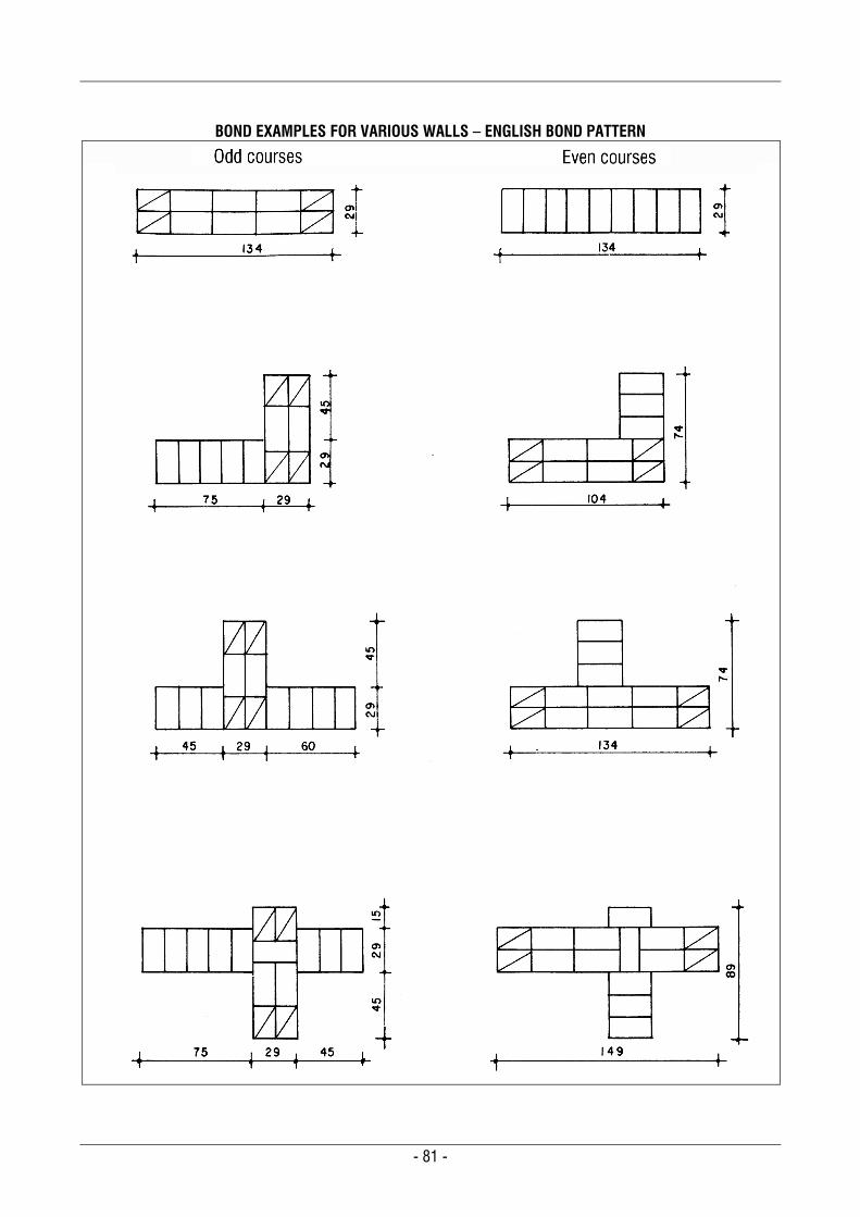
- 81 -
BOND EXAMPLES FOR VARIOUS WALLS – ENGLISH BOND PATTERN
- 82 -
BOND EXAMPLES FOR VARIOUS WALLS – ONE & A HALF BOND PATTERN WITH RECTANGULAR BLOCKS
- 83 -
BOND EXAMPLES FOR VARIOUS WALLS – DOUBLE BOND PATTERN WITH RECTANGULAR BLOCKS
- 84 -
BOND EXAMPLES FOR VARIOUS WALLS – SINGLE BOND PATTERN WITH SQUARE BLOCKS
- 85 -
BOND EXAMPLES FOR VARIOUS WALLS – ONE & A HALF BOND PATTERN WITH SQUARE BLOCKS
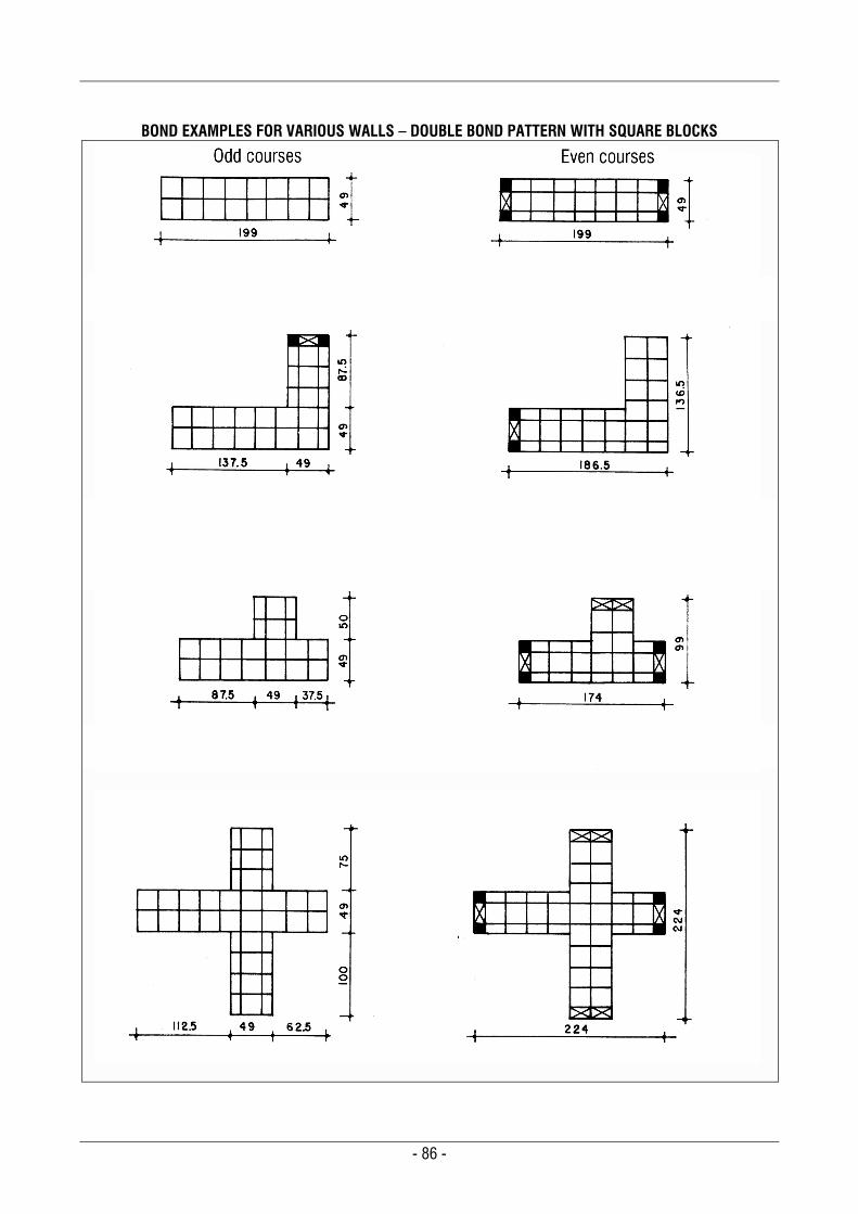
- 86 -
BOND EXAMPLES FOR VARIOUS WALLS – DOUBLE BOND PATTERN WITH SQUARE BLOCKS
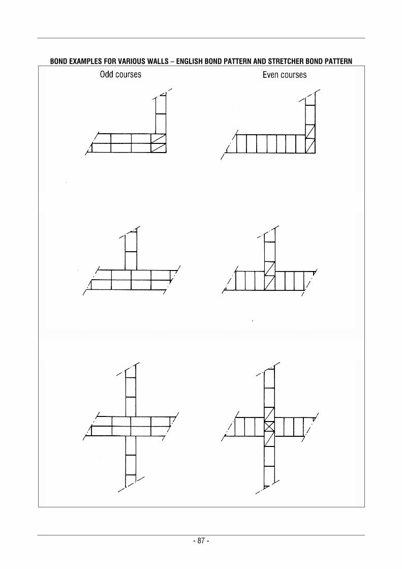
- 87 -
BOND EXAMPLES FOR VARIOUS WALLS – ENGLISH BOND PATTERN AND STRETCHER BOND PATTERN
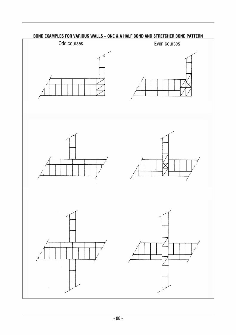
- 88 -
BOND EXAMPLES FOR VARIOUS WALLS – ONE & A HALF BOND AND STRETCHER BOND PATTERN
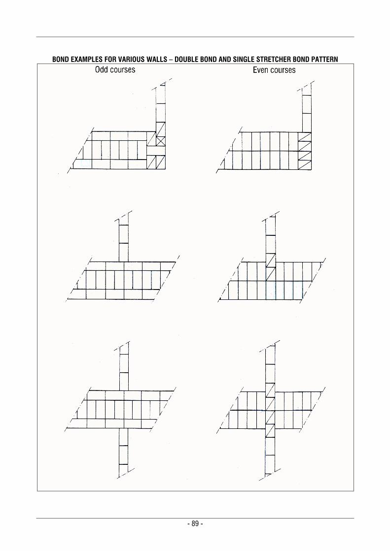
- 89 -
BOND EXAMPLES FOR VARIOUS WALLS – DOUBLE BOND AND SINGLE STRETCHER BOND PATTERN
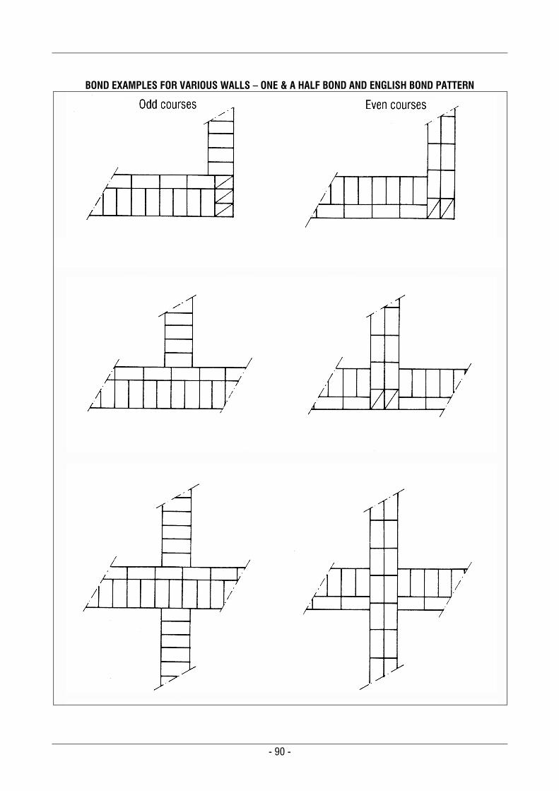
- 90 -
BOND EXAMPLES FOR VARIOUS WALLS – ONE & A HALF BOND AND ENGLISH BOND PATTERN
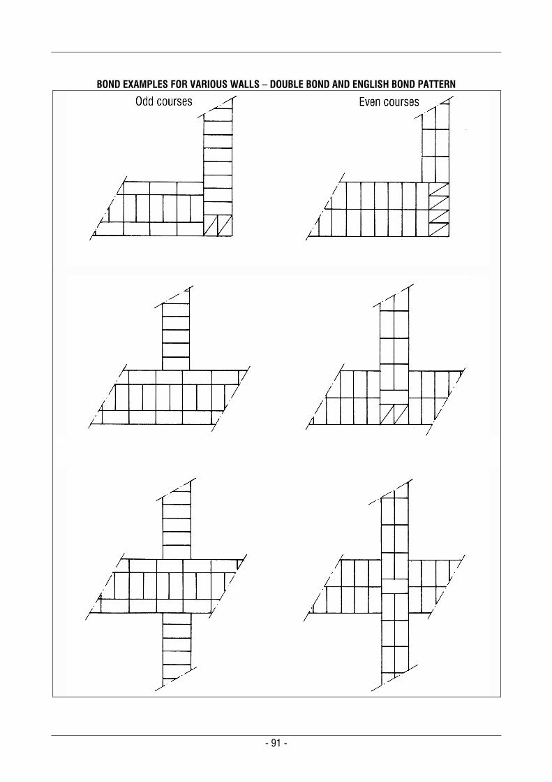
- 91 -
BOND EXAMPLES FOR VARIOUS WALLS – DOUBLE BOND AND ENGLISH BOND PATTERN
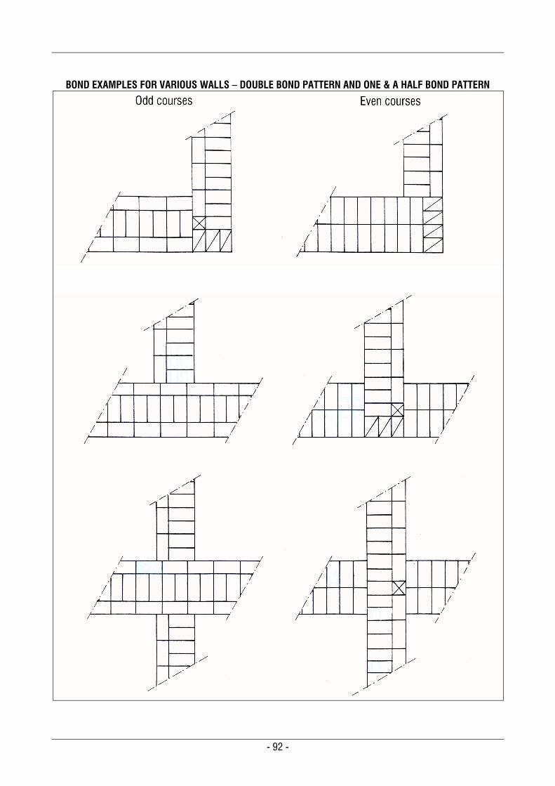
- 92 -
BOND EXAMPLES FOR VARIOUS WALLS – DOUBLE BOND PATTERN AND ONE & A HALF BOND PATTERN
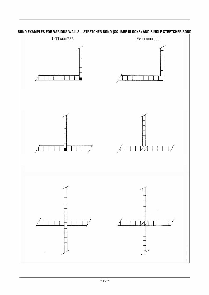
- 93 -
BOND EXAMPLES FOR VARIOUS WALLS – STRETCHER BOND (SQUARE BLOCKS) AND SINGLE STRETCHER BOND
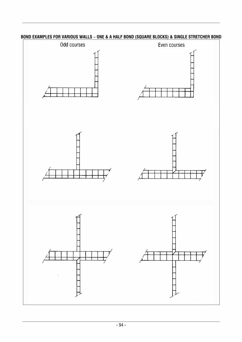
- 94 -
BOND EXAMPLES FOR VARIOUS WALLS – ONE & A HALF BOND (SQUARE BLOCKS) & SINGLE STRETCHER BOND
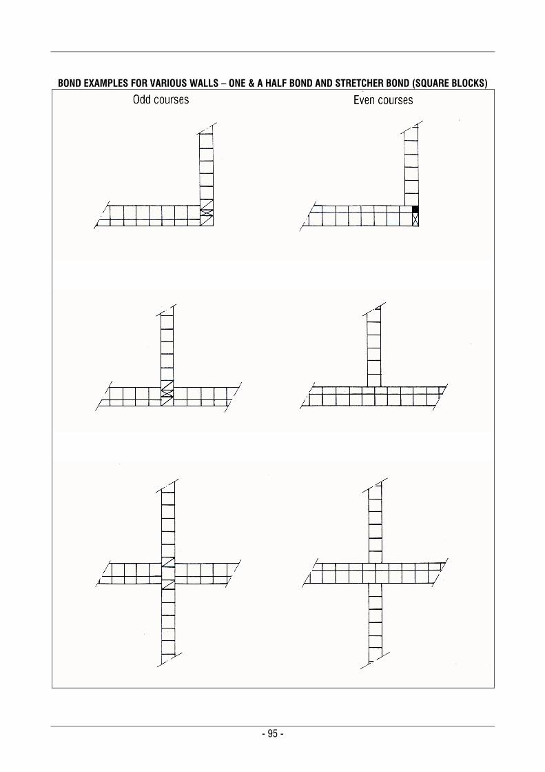
- 95 -
BOND EXAMPLES FOR VARIOUS WALLS – ONE & A HALF BOND AND STRETCHER BOND (SQUARE BLOCKS)
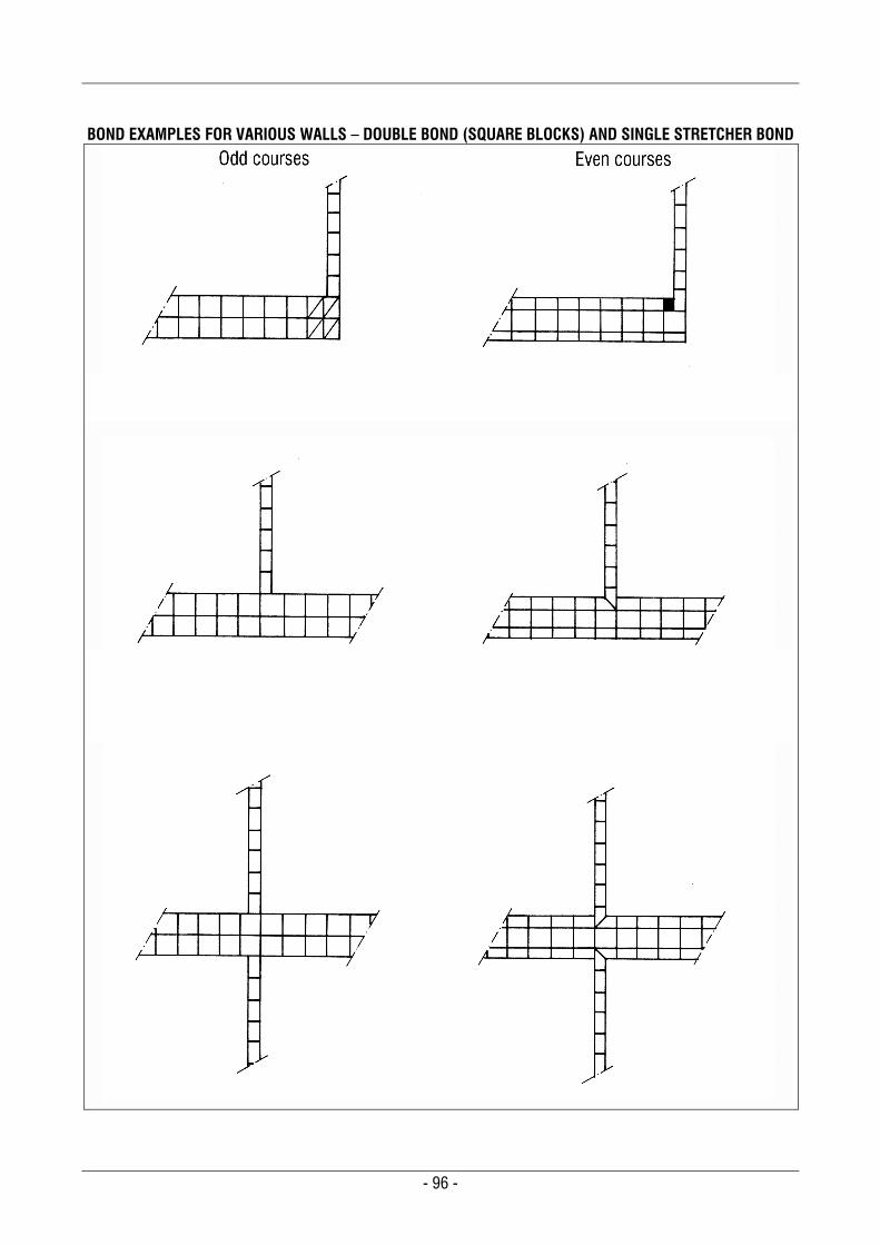
- 96 -
BOND EXAMPLES FOR VARIOUS WALLS – DOUBLE BOND (SQUARE BLOCKS) AND SINGLE STRETCHER BOND
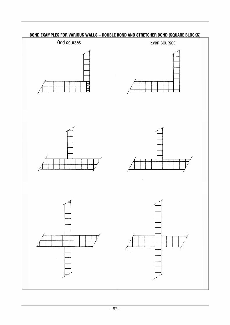
- 97 -
BOND EXAMPLES FOR VARIOUS WALLS – DOUBLE BOND AND STRETCHER BOND (SQUARE BLOCKS)
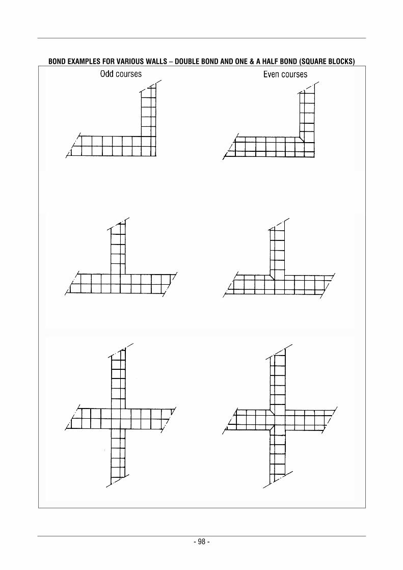
- 98 -
BOND EXAMPLES FOR VARIOUS WALLS – DOUBLE BOND AND ONE & A HALF BOND (SQUARE BLOCKS)
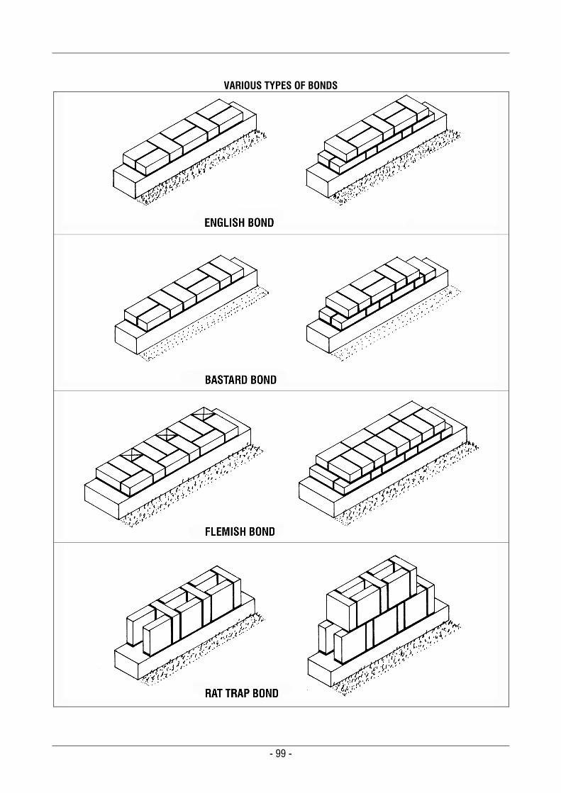
- 99 -
VARIOUS TYPES OF BONDS
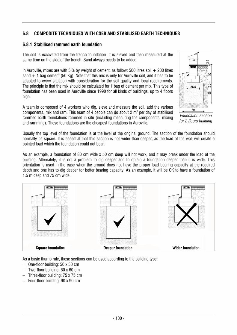
- 100 -
6.8 COMPOSITE TECHNIQUES WITH CSEB AND STABILISED EARTH TECHNIQUES
6.8.1 Stabilised rammed earth foundation
The soil is excavated from the trench foundation. It is sieved and then measured at the same time on the side of the trench. Sand always needs to be added. In Auroville, mixes are with 5 % by weight of cement, as follow: 500 litres soil + 200 litres sand + 1 bag cement (50 Kg). Note that this mix is only for Auroville soil, and it has to be adapted to every situation with consideration for the soil quality and local requirements. The principle is that the mix should be calculated for 1 bag of cement per mix. This type of foundation has been used in Auroville since 1990 for all kinds of buildings, up to 4 floors high. A team is composed of 4 workers who dig, sieve and measure the soil, add the various components, mix and ram. This team of 4 people can do about 2 m3 per day of stabilised rammed earth foundations rammed in situ (including measuring the components, mixing and ramming). These foundations are the cheapest foundations in Auroville.
Foundation section for 2 floors building
Usually the top level of the foundation is at the level of the original ground. The section of the foundation should normally be square. It is essential that this section is not wider than deeper, as the load of the wall will create a pointed load which the foundation could not bear. As an example, a foundation of 80 cm wide x 50 cm deep will not work, and it may break under the load of the building. Alternately, it is not a problem to dig deeper and to obtain a foundation deeper than it is wide. This orientation is used in the case when the ground does not have the proper load bearing capacity at the required depth and one has to dig deeper for better bearing capacity. As an example, it will be OK to have a foundation of 1.5 m deep and 75 cm wide.
As a basic thumb rule, these sections can be used according to the building type: One-floor building: 50 x 50 cm Two-floor building: 60 x 60 cm Three-floor building: 75 x 75 cm Four-floor building: 90 x 90 cm
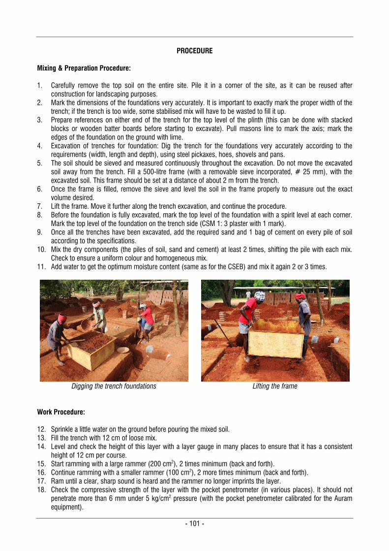
- 101 -
PROCEDURE
Mixing & Preparation Procedure: 1. Carefully remove the top soil on the entire site. Pile it in a corner of the site, as it can be reused after
construction for landscaping purposes. 2. Mark the dimensions of the foundations very accurately. It is important to exactly mark the proper width of the
trench; if the trench is too wide, some stabilised mix will have to be wasted to fill it up. 3. Prepare references on either end of the trench for the top level of the plinth (this can be done with stacked
blocks or wooden batter boards before starting to excavate). Pull masons line to mark the axis; mark the edges of the foundation on the ground with lime.
4. Excavation of trenches for foundation: Dig the trench for the foundations very accurately according to the requirements (width, length and depth), using steel pickaxes, hoes, shovels and pans.
5. The soil should be sieved and measured continuously throughout the excavation. Do not move the excavated soil away from the trench. Fill a 500-litre frame (with a removable sieve incorporated, # 25 mm), with the excavated soil. This frame should be set at a distance of about 2 m from the trench.
6. Once the frame is filled, remove the sieve and level the soil in the frame properly to measure out the exact volume desired.
7. Lift the frame. Move it further along the trench excavation, and continue the procedure. 8. Before the foundation is fully excavated, mark the top level of the foundation with a spirit level at each corner.
Mark the top level of the foundation on the trench side (CSM 1: 3 plaster with 1 mark). 9. Once all the trenches have been excavated, add the required sand and 1 bag of cement on every pile of soil
according to the specifications. 10. Mix the dry components (the piles of soil, sand and cement) at least 2 times, shifting the pile with each mix.
Check to ensure a uniform colour and homogeneous mix. 11. Add water to get the optimum moisture content (same as for the CSEB) and mix it again 2 or 3 times.
Digging the trench foundations
Lifting the frame
Work Procedure: 12. Sprinkle a little water on the ground before pouring the mixed soil. 13. Fill the trench with 12 cm of loose mix. 14. Level and check the height of this layer with a layer gauge in many places to ensure that it has a consistent
height of 12 cm per course. 15. Start ramming with a large rammer (200 cm2), 2 times minimum (back and forth). 16. Continue ramming with a smaller rammer (100 cm2), 2 more times minimum (back and forth). 17. Ram until a clear, sharp sound is heard and the rammer no longer imprints the layer. 18. Check the compressive strength of the layer with the pocket penetrometer (in various places). It should not
penetrate more than 6 mm under 5 kg/cm2 pressure (with the pocket penetrometer calibrated for the Auram equipment).
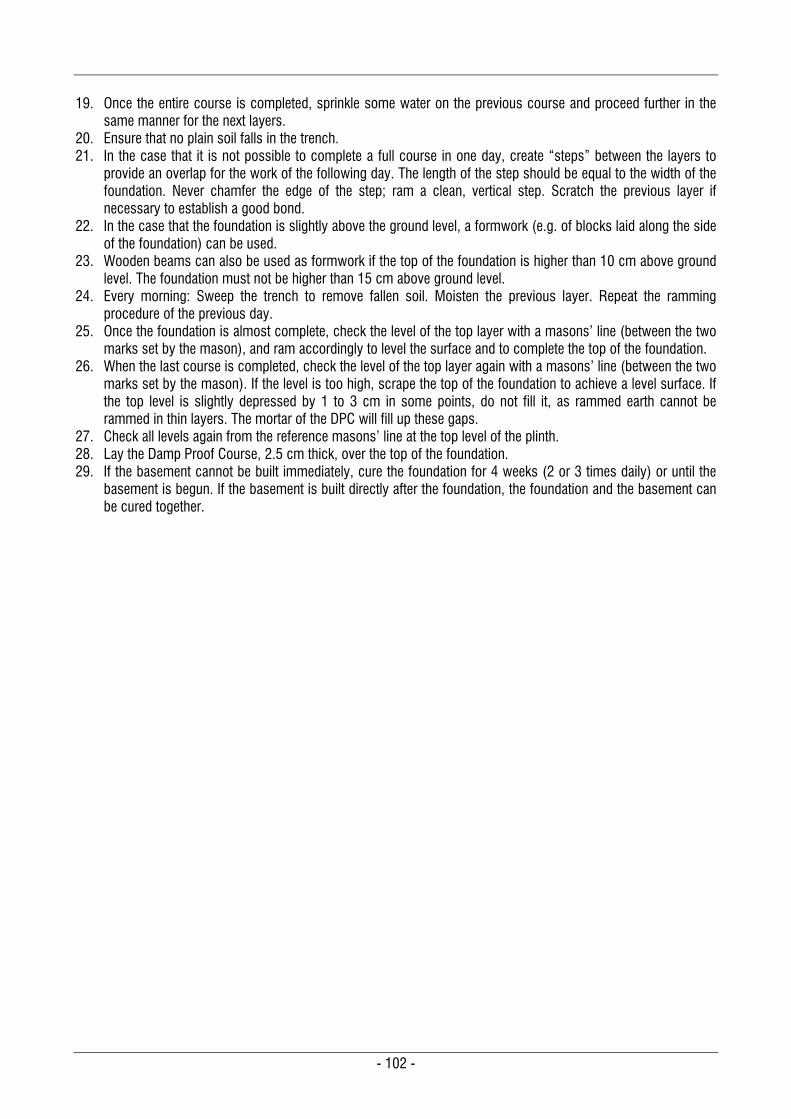
- 102 -
19. Once the entire course is completed, sprinkle some water on the previous course and proceed further in the
same manner for the next layers. 20. Ensure that no plain soil falls in the trench. 21. In the case that it is not possible to complete a full course in one day, create “steps” between the layers to
provide an overlap for the work of the following day. The length of the step should be equal to the width of the foundation. Never chamfer the edge of the step; ram a clean, vertical step. Scratch the previous layer if necessary to establish a good bond.
22. In the case that the foundation is slightly above the ground level, a formwork (e.g. of blocks laid along the side of the foundation) can be used.
23. Wooden beams can also be used as formwork if the top of the foundation is higher than 10 cm above ground level. The foundation must not be higher than 15 cm above ground level.
24. Every morning: Sweep the trench to remove fallen soil. Moisten the previous layer. Repeat the ramming procedure of the previous day.
25. Once the foundation is almost complete, check the level of the top layer with a masons’ line (between the two marks set by the mason), and ram accordingly to level the surface and to complete the top of the foundation.
26. When the last course is completed, check the level of the top layer again with a masons’ line (between the two marks set by the mason). If the level is too high, scrape the top of the foundation to achieve a level surface. If the top level is slightly depressed by 1 to 3 cm in some points, do not fill it, as rammed earth cannot be rammed in thin layers. The mortar of the DPC will fill up these gaps.
27. Check all levels again from the reference masons’ line at the top level of the plinth. 28. Lay the Damp Proof Course, 2.5 cm thick, over the top of the foundation. 29. If the basement cannot be built immediately, cure the foundation for 4 weeks (2 or 3 times daily) or until the
basement is begun. If the basement is built directly after the foundation, the foundation and the basement can be cured together.
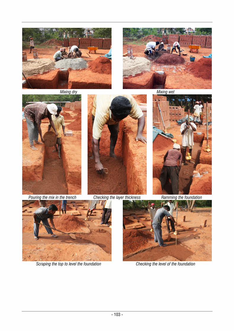
- 103 -
Mixing dry
Mixing wet
Pouring the mix in the trench
Checking the layer thickness
Ramming the foundation
Scraping the top to level the foundation
Checking the level of the foundation
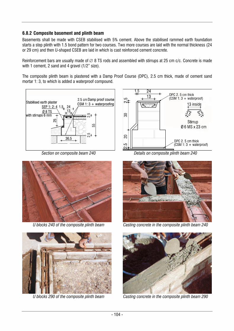
- 104 -
6.8.2 Composite basement and plinth beam Basements shall be made with CSEB stabilised with 5% cement. Above the stabilised rammed earth foundation starts a step plinth with 1.5 bond pattern for two courses. Two more courses are laid with the normal thickness (24 or 29 cm) and then U-shaped CSEB are laid in which is cast reinforced cement concrete. Reinforcement bars are usually made of 8 TS rods and assembled with stirrups at 25 cm c/c. Concrete is made with 1 cement, 2 sand and 4 gravel (1/2” size). The composite plinth beam is plastered with a Damp Proof Course (DPC), 2.5 cm thick, made of cement sand mortar 1: 3, to which is added a waterproof compound.
Section on composite beam 240
Details on composite plinth beam 240
U blocks 240 of the composite plinth beam
Casting concrete in the composite plinth beam 240
U blocks 290 of the composite plinth beam
Casting concrete in the composite plinth beam 290
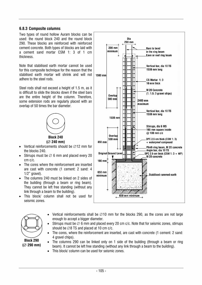
- 105 -
6.8.3 Composite columns Two types of round hollow Auram blocks can be used: the round block 240 and the round block 290. These blocks are reinforced with reinforced cement concrete. Both types of blocks are laid with a cement sand mortar CSM 1: 3 of 1 cm thickness. Note that stabilised earth mortar cannot be used for this composite technique for the reason that the stabilised earth mortar will shrink and will not adhere to the steel rods. Steel rods shall not exceed a height of 1.5 m, as it is difficult to slide the blocks down if the steel bars are the entire height of the column. Therefore, some extension rods are regularly placed with an overlap of 50 times the bar diameter.
Block 240
( 240 mm) Vertical reinforcements should be 12 mm for
the blocks 240. Stirrups must be 6 mm and placed every 20
cm c/c. The cores where the reinforcement are inserted
are cast with concrete (1 cement: 2 sand: 4 1/2” gravel).
The columns 240 must be linked on 2 sides of the building (through a beam or ring beam). They cannot be left free standing (without any link through a beam to the building).
This block/ column shall not be used for seismic zones.
Block 290
( 290 mm)
Vertical reinforcements shall be 10 mm for the blocks 290, as the cores are not large enough to accept a bigger diameter.
Stirrups must be 6 mm and placed every 20 cm c/c. Note that for seismic zones, stirrups should be 8 TS and placed at 10 cm c/c.
The cores, where the reinforcement are inserted, are cast with concrete (1 cement: 2 sand: 4 gravel chips).
The columns 290 can be linked only on 1 side of the building (through a beam or ring beam). It cannot be left free standing (without any link through a beam to the building).
This block/ column can be used for seismic zones.
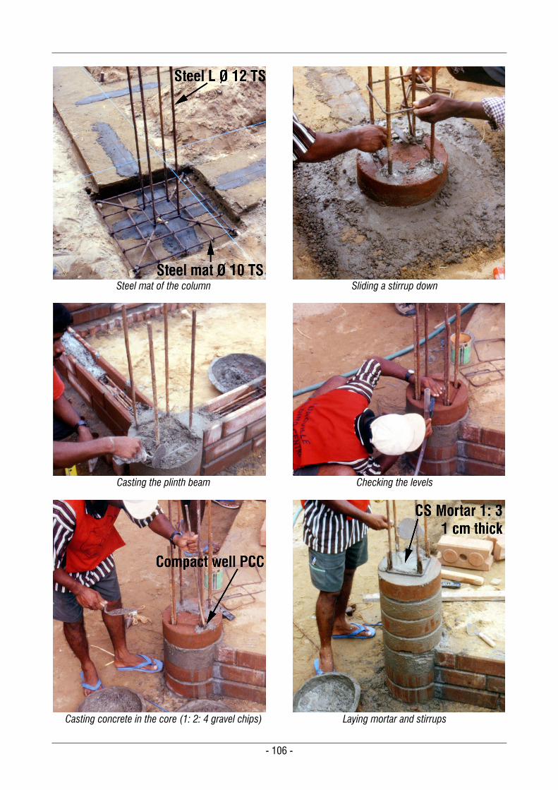
- 106 -
Steel mat of the column
Sliding a stirrup down
Casting the plinth beam
Checking the levels
Casting concrete in the core (1: 2: 4 gravel chips)
Laying mortar and stirrups

- 107 -
6.8.4 Composite beams and lintels U-shaped CSEB are reinforced with reinforced cement concrete. Reinforcements vary with the span, but the rod diameter cannot exceed 12 mm for the Auram blocks 290 & 295 and 16 mm for the Auram blocks 240 & 245. The bottom part of the beam is precast in a reversed position on the ground. Once cured, it is lifted and the middle and top parts are built above it in situ. The U blocks are used as lost shuttering, but they also aid the compressive strength of the beam. Hence it is a composite technique, as the reinforced concrete works in tension and the U blocks work in compression. The concrete cast into the U-shape is normally 1 cement: 2 sand: 4 gravel ½”. The vertical mortar in between the U blocks is cement sand mortar CSM 1: 3 of a 1 cm thickness. Three types of beams have been developed:
Single height beams (only 1 U block) The U block is laid on a bed of sand of 1 cm and the concrete is cast in the U-shape. After 1 month of curing, the beam is turned and laid on the wall. The maximum span for a single height beam shall be limited to 1.5 m, with 2 steel bars Ø 12 mm. 6 mm
stirrups are laid at 25 cm c/c.
Casting a single height Beam on the ground
Single height beam reversed
on the wall
Single height beam section
Double height beams (2 U blocks in opposite directions)
The bottom part of the beam is cast first in a reversed position, and after 1 month it is turned: Either it is turned on the ground and the top part is precast in other U blocks, or the incomplete beam is lifted
with care and the concrete is cast in situ into other U blocks. The maximum span for a double height beam shall be limited to 2.25 m, with 2 steel bars Ø 12 mm on the top
and 2 steel bars Ø 12 mm on the bottom. 6 mm stirrups are laid in the thickness of the vertical mortar to link the tensile and compressive bars of the
beam. The horizontal mortar joint is with cement sand mortar CSM 1: 3
Casting a double height
beam on the ground
Lifting a double height
beam
Double height beam
reversed & cast on the wall
Double height beam
section
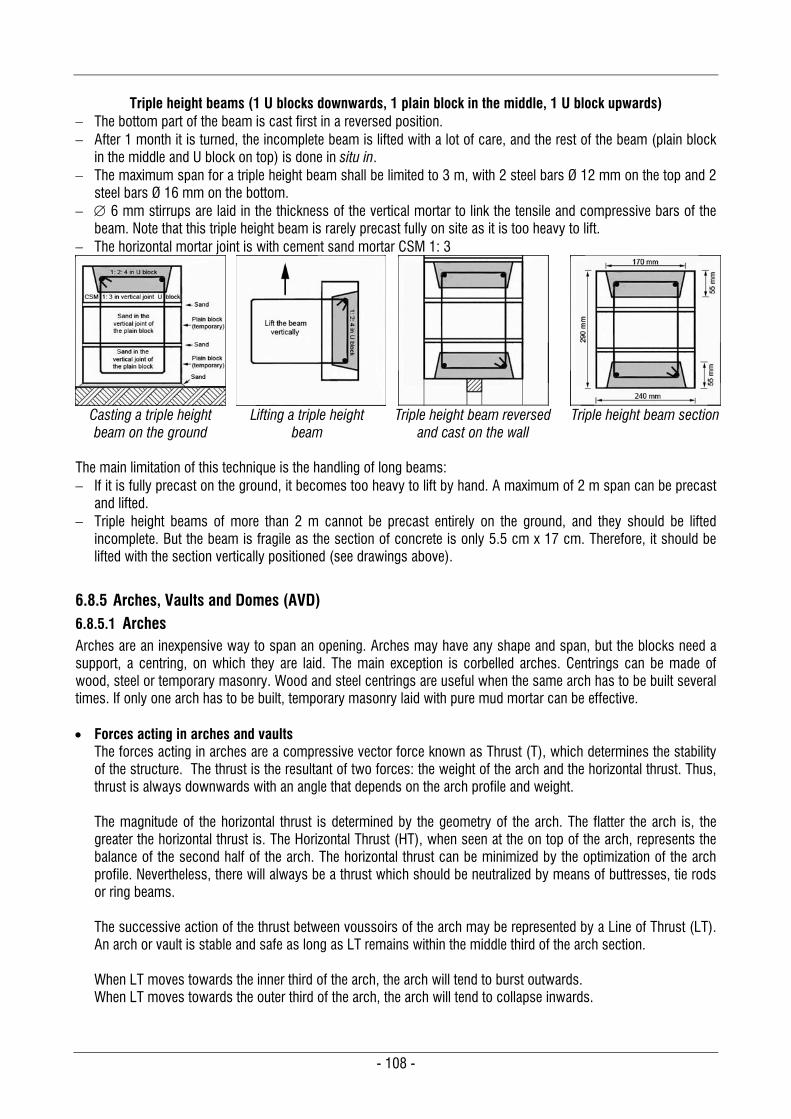
- 108 -
Triple height beams (1 U blocks downwards, 1 plain block in the middle, 1 U block upwards)
The bottom part of the beam is cast first in a reversed position. After 1 month it is turned, the incomplete beam is lifted with a lot of care, and the rest of the beam (plain block
in the middle and U block on top) is done in situ in. The maximum span for a triple height beam shall be limited to 3 m, with 2 steel bars Ø 12 mm on the top and 2
steel bars Ø 16 mm on the bottom. 6 mm stirrups are laid in the thickness of the vertical mortar to link the tensile and compressive bars of the
beam. Note that this triple height beam is rarely precast fully on site as it is too heavy to lift. The horizontal mortar joint is with cement sand mortar CSM 1: 3
Casting a triple height beam on the ground
Lifting a triple height
beam
Triple height beam reversed
and cast on the wall
Triple height beam section
The main limitation of this technique is the handling of long beams: If it is fully precast on the ground, it becomes too heavy to lift by hand. A maximum of 2 m span can be precast
and lifted. Triple height beams of more than 2 m cannot be precast entirely on the ground, and they should be lifted
incomplete. But the beam is fragile as the section of concrete is only 5.5 cm x 17 cm. Therefore, it should be lifted with the section vertically positioned (see drawings above).
6.8.5 Arches, Vaults and Domes (AVD) 6.8.5.1 Arches Arches are an inexpensive way to span an opening. Arches may have any shape and span, but the blocks need a support, a centring, on which they are laid. The main exception is corbelled arches. Centrings can be made of wood, steel or temporary masonry. Wood and steel centrings are useful when the same arch has to be built several times. If only one arch has to be built, temporary masonry laid with pure mud mortar can be effective. Forces acting in arches and vaults
The forces acting in arches are a compressive vector force known as Thrust (T), which determines the stability of the structure. The thrust is the resultant of two forces: the weight of the arch and the horizontal thrust. Thus, thrust is always downwards with an angle that depends on the arch profile and weight. The magnitude of the horizontal thrust is determined by the geometry of the arch. The flatter the arch is, the greater the horizontal thrust is. The Horizontal Thrust (HT), when seen at the on top of the arch, represents the balance of the second half of the arch. The horizontal thrust can be minimized by the optimization of the arch profile. Nevertheless, there will always be a thrust which should be neutralized by means of buttresses, tie rods or ring beams. The successive action of the thrust between voussoirs of the arch may be represented by a Line of Thrust (LT). An arch or vault is stable and safe as long as LT remains within the middle third of the arch section. When LT moves towards the inner third of the arch, the arch will tend to burst outwards. When LT moves towards the outer third of the arch, the arch will tend to collapse inwards.
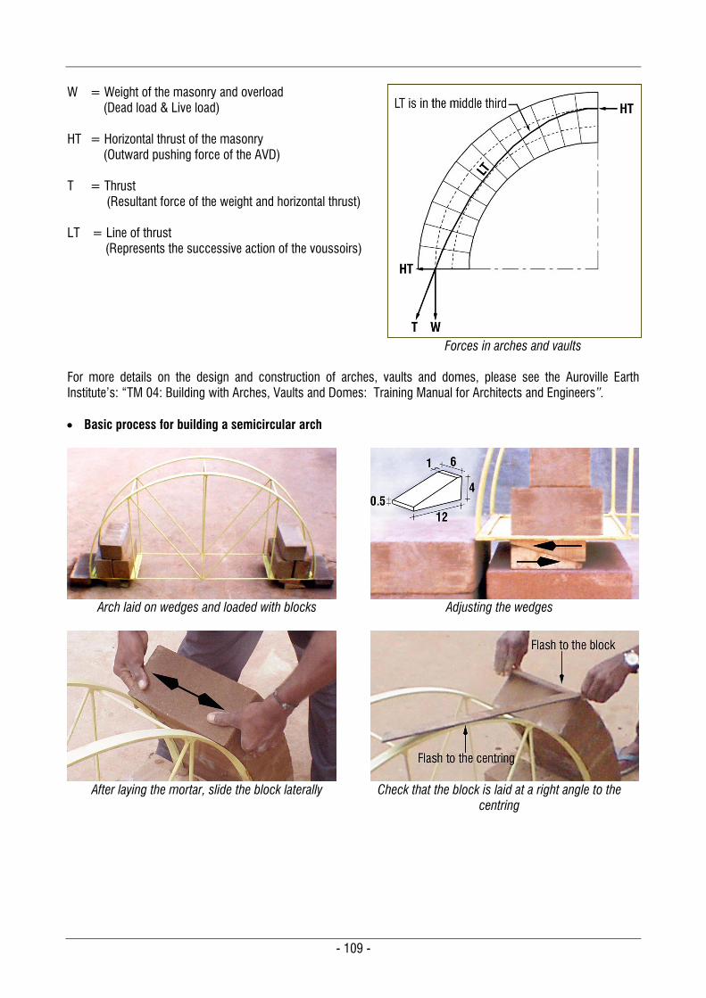
- 109 -
W HT T LT
= Weight of the masonry and overload (Dead load & Live load) = Horizontal thrust of the masonry (Outward pushing force of the AVD)
= Thrust (Resultant force of the weight and horizontal thrust) = Line of thrust (Represents the successive action of the voussoirs)
Forces in arches and vaults For more details on the design and construction of arches, vaults and domes, please see the Auroville Earth Institute’s: “TM 04: Building with Arches, Vaults and Domes: Training Manual for Architects and Engineers”. Basic process for building a semicircular arch
Arch laid on wedges and loaded with blocks
Adjusting the wedges
After laying the mortar, slide the block laterally
Check that the block is laid at a right angle to the
centring

- 110 -
Triangular joint and blocks touching at the intrados
Building the arch symmetrically
Closing the arch with a very tight mortar
Sliding out wedges progressively for decentring
6.8.5.2 Vaults and domes
Forces acting in domes The forces acting in domes are also characterized by a thrust, which determines the stability of the structure. Just as in arches and vaults, the dome’s thrust is also the resultant of its weight and the horizontal thrust of the basic arch section. Therefore, there is also a line of thrust which corresponds to the arch section. When a dome is generated by the intersection of two vaults, the forces involved are identical to those of vaults. However, when a dome is created by the rotation of an arch around a vertical axis, other forces are acting in it: the hoop forces (HF). The hoop force is the result of forces acting circumferentially in the dome. The hoop force in a “circular dome” is acting in a horizontal plan, a ring, and can be assimilated to the thrust which acts downwards in a vertical plan, in the case of arches or vaults. This force explains why it is possible to build circular domes without support. The dome is self-supporting at every stage of its construction, because the horizontal thrust of one half of the dome is transferred to the other half by the various rings. The force of gravity will transfer hoop forces vertically into the line of thrust.
HF LT HT W T PT
= Hoop force in every ring = Line of Thrust of “an arch” of the dome = Horizontal thrust of “an arch” of the dome = Vertical weight of “an arch” and the overload = Thrust, resultant force of horizontal thrust and weight of “an arch” = Peripheral tension, created by the combination of the horizontal thrust of all
“arches”, which radiate from the centre
Forces in domes
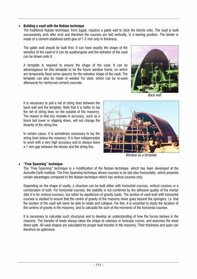
- 111 -
Building a vault with the Nubian technique
The traditional Nubian technique, from Egypt, requires a gable wall to stick the blocks onto. The vault is built successively arch after arch and therefore the courses are laid vertically, in a leaning position. The binder is made of a cement-stabilised earth glue of 1-2 mm only in thickness. The gable wall should be built first. It can have exactly the shape of the extrados of the vault or it can be quadrangular and the extrados of the vault can be drawn onto it. A template is required to ensure the shape of the vault. It can be advantageous for this template to be the future window frame, on which are temporarily fixed some spacers for the extrados shape of the vault. The template can also be made of welded Tor steel, which can be re-used afterwards for reinforced cement concrete.
Back wall
It is necessary to pull a net of string lines between the back wall and the template. Note that it is better to lay the net of string lines on the outside of the masonry. The reason is that any mistake in accuracy, such as a block laid lower or slipping down, will not change the linearity of the string line. In certain cases, it is sometimes necessary to lay the string lines below the masonry. It is then indispensable to work with a very high accuracy and to always leave a 1 mm gap between the blocks and the string line.
Window as a template
“Free Spanning” technique
The “Free Spanning” technique is a modification of the Nubian technique, which has been developed at the Auroville Earth Institute. The Free Spanning technique allows courses to be laid also horizontally, which presents certain advantages compared to the Nubian technique which has vertical courses only. Depending on the shape of vaults, a structure can be built either with horizontal courses, vertical courses or a combination of both. For horizontal courses, the stability is not conferred by the adhesive quality of the mortar (like it is for vertical courses), but rather by equilibrium of gravity loads. The section of vault built with horizontal courses is studied to ensure that the centre of gravity of the masonry never goes beyond the springers, i.e. that the section of the vault will never be able to rotate and collapse. For this, it is essential to study the location of the centres of gravity in the masonry, and to calculate the sum of the moments of the horizontal courses. It is necessary to calculate such structures and to develop an understanding of how the forces behave in the masonry. The transfer of loads always takes the shape of catenary or funicular curves, and assumes the most direct path. All vault shapes are calculated for proper load transfer in the masonry. Their thickness and span can therefore be optimised.
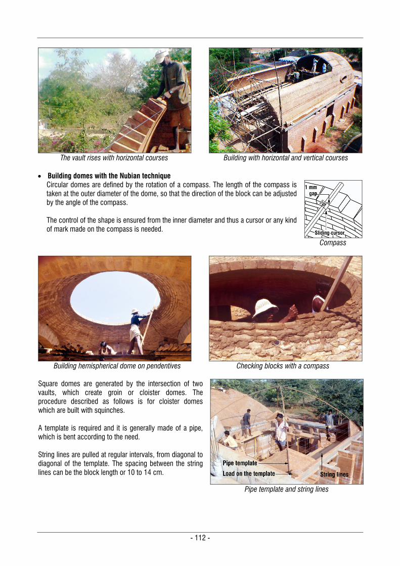
- 112 -
The vault rises with horizontal courses
Building with horizontal and vertical courses
Building domes with the Nubian technique
Circular domes are defined by the rotation of a compass. The length of the compass is taken at the outer diameter of the dome, so that the direction of the block can be adjusted by the angle of the compass. The control of the shape is ensured from the inner diameter and thus a cursor or any kind of mark made on the compass is needed.
Compass
Building hemispherical dome on pendentives
Checking blocks with a compass
Square domes are generated by the intersection of two vaults, which create groin or cloister domes. The procedure described as follows is for cloister domes which are built with squinches. A template is required and it is generally made of a pipe, which is bent according to the need. String lines are pulled at regular intervals, from diagonal to diagonal of the template. The spacing between the string lines can be the block length or 10 to 14 cm.
Pipe template and string lines
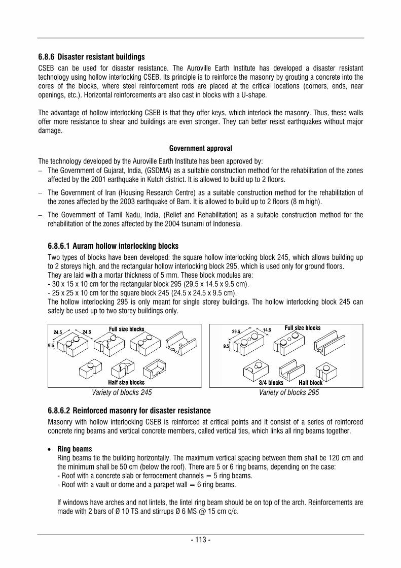
- 113 -
6.8.6 Disaster resistant buildings CSEB can be used for disaster resistance. The Auroville Earth Institute has developed a disaster resistant technology using hollow interlocking CSEB. Its principle is to reinforce the masonry by grouting a concrete into the cores of the blocks, where steel reinforcement rods are placed at the critical locations (corners, ends, near openings, etc.). Horizontal reinforcements are also cast in blocks with a U-shape. The advantage of hollow interlocking CSEB is that they offer keys, which interlock the masonry. Thus, these walls offer more resistance to shear and buildings are even stronger. They can better resist earthquakes without major damage.
Government approval
The technology developed by the Auroville Earth Institute has been approved by: The Government of Gujarat, India, (GSDMA) as a suitable construction method for the rehabilitation of the zones
affected by the 2001 earthquake in Kutch district. It is allowed to build up to 2 floors.
The Government of Iran (Housing Research Centre) as a suitable construction method for the rehabilitation of the zones affected by the 2003 earthquake of Bam. It is allowed to build up to 2 floors (8 m high).
The Government of Tamil Nadu, India, (Relief and Rehabilitation) as a suitable construction method for the rehabilitation of the zones affected by the 2004 tsunami of Indonesia.
6.8.6.1 Auram hollow interlocking blocks Two types of blocks have been developed: the square hollow interlocking block 245, which allows building up to 2 storeys high, and the rectangular hollow interlocking block 295, which is used only for ground floors. They are laid with a mortar thickness of 5 mm. These block modules are: - 30 x 15 x 10 cm for the rectangular block 295 (29.5 x 14.5 x 9.5 cm). - 25 x 25 x 10 cm for the square block 245 (24.5 x 24.5 x 9.5 cm). The hollow interlocking 295 is only meant for single storey buildings. The hollow interlocking block 245 can safely be used up to two storey buildings only.
Variety of blocks 245
Variety of blocks 295
6.8.6.2 Reinforced masonry for disaster resistance Masonry with hollow interlocking CSEB is reinforced at critical points and it consist of a series of reinforced concrete ring beams and vertical concrete members, called vertical ties, which links all ring beams together. Ring beams
Ring beams tie the building horizontally. The maximum vertical spacing between them shall be 120 cm and the minimum shall be 50 cm (below the roof). There are 5 or 6 ring beams, depending on the case: - Roof with a concrete slab or ferrocement channels = 5 ring beams. - Roof with a vault or dome and a parapet wall = 6 ring beams. If windows have arches and not lintels, the lintel ring beam should be on top of the arch. Reinforcements are made with 2 bars of Ø 10 TS and stirrups Ø 6 MS @ 15 cm c/c.
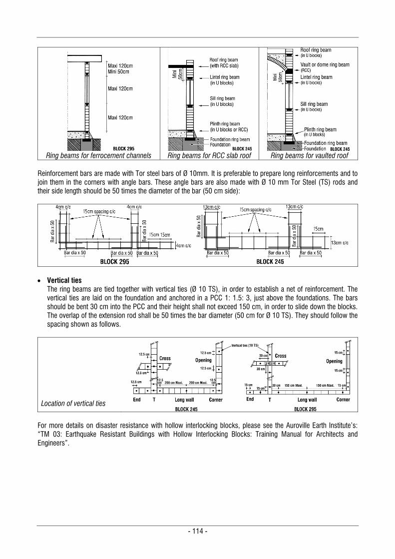
- 114 -
Ring beams for ferrocement channels
Ring beams for RCC slab roof
Ring beams for vaulted roof
Reinforcement bars are made with Tor steel bars of Ø 10mm. It is preferable to prepare long reinforcements and to join them in the corners with angle bars. These angle bars are also made with Ø 10 mm Tor Steel (TS) rods and their side length should be 50 times the diameter of the bar (50 cm side):
Vertical ties
The ring beams are tied together with vertical ties (Ø 10 TS), in order to establish a net of reinforcement. The vertical ties are laid on the foundation and anchored in a PCC 1: 1.5: 3, just above the foundations. The bars should be bent 30 cm into the PCC and their height shall not exceed 150 cm, in order to slide down the blocks. The overlap of the extension rod shall be 50 times the bar diameter (50 cm for Ø 10 TS). They should follow the spacing shown as follows.
Location of vertical ties
For more details on disaster resistance with hollow interlocking blocks, please see the Auroville Earth Institute’s: “TM 03: Earthquake Resistant Buildings with Hollow Interlocking Blocks: Training Manual for Architects and Engineers”.
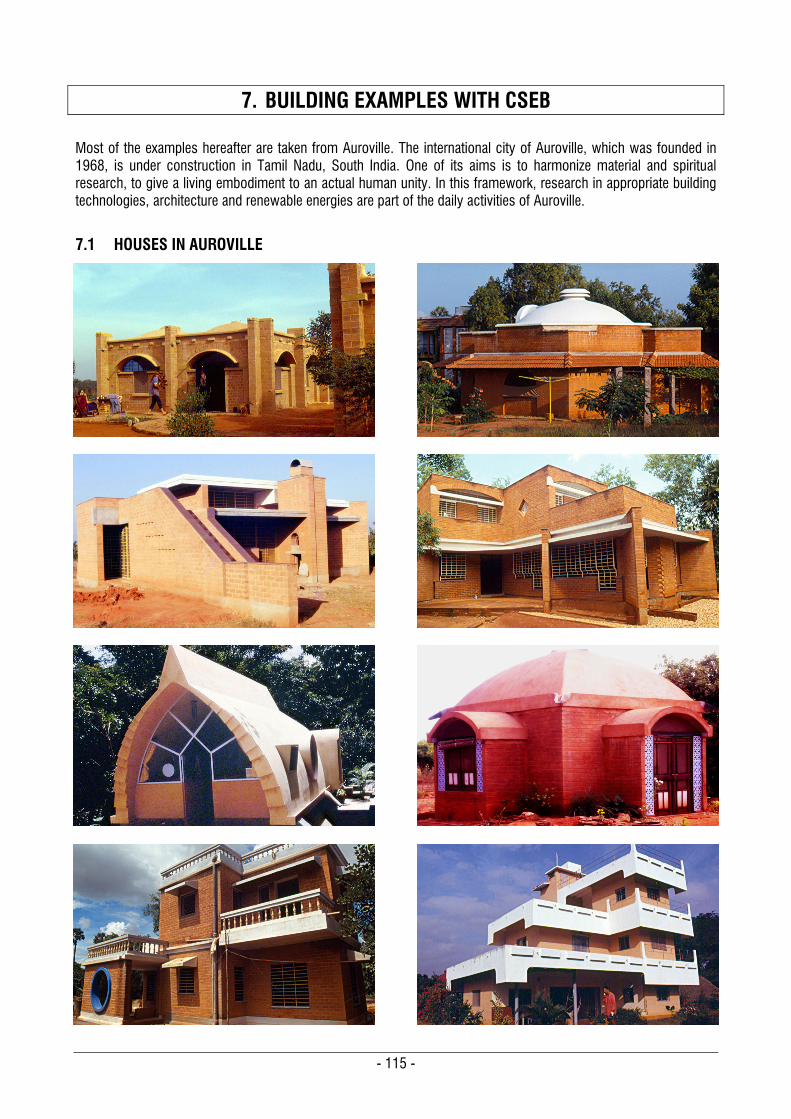
- 115 -
7. BUILDING EXAMPLES WITH CSEB Most of the examples hereafter are taken from Auroville. The international city of Auroville, which was founded in 1968, is under construction in Tamil Nadu, South India. One of its aims is to harmonize material and spiritual research, to give a living embodiment to an actual human unity. In this framework, research in appropriate building technologies, architecture and renewable energies are part of the daily activities of Auroville.
7.1 HOUSES IN AUROVILLE

- 116 -
7.2 APARTMENTS IN AUROVILLE
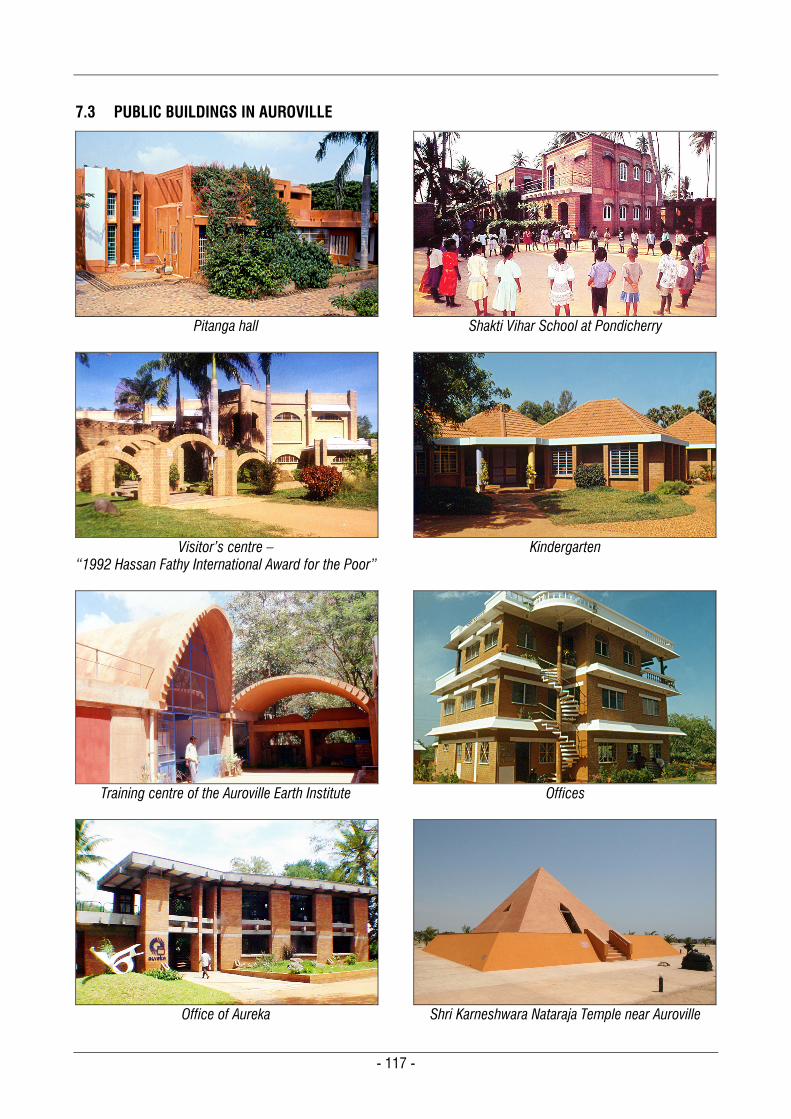
- 117 -
7.3 PUBLIC BUILDINGS IN AUROVILLE
Pitanga hall
Shakti Vihar School at Pondicherry
Visitor’s centre –
“1992 Hassan Fathy International Award for the Poor”
Kindergarten
Training centre of the Auroville Earth Institute
Offices
Office of Aureka
Shri Karneshwara Nataraja Temple near Auroville
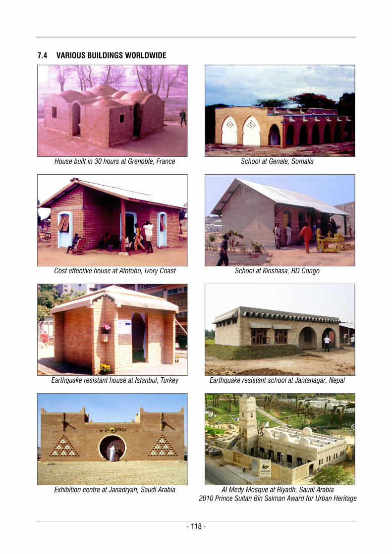
- 118 -
7.4 VARIOUS BUILDINGS WORLDWIDE
House built in 30 hours at Grenoble, France
School at Genale, Somalia
Cost effective house at Afotobo, Ivory Coast
School at Kinshasa, RD Congo
Earthquake resistant house at Istanbul, Turkey
Earthquake resistant school at Jantanagar, Nepal
Exhibition centre at Janadryah, Saudi Arabia
Al Medy Mosque at Riyadh, Saudi Arabia
2010 Prince Sultan Bin Salman Award for Urban Heritage
- 119 -
8. ANNEXES
8.1 REFERENCES
1. IS: 1725-1982 – Specification for soil-based blocks used in general construction –BIS – New Delhi, India 2. SP 36-Part 1-1987 – Compendium of Indian standards on soil engineering – BIS – New Delhi, India 3. IS: 1905-1987 – Code of Practice for structural use of unreinforced masonry – BIS – New Delhi, India 4. IS: 2110-1980 – Code of Practice - In situ construction of walls in buildings with soil-cement masonry – BIS –
New Delhi, India 5. IS: 3495-1992 – Methods of test of burnt building bricks – BIS – New Delhi, India 1. Part 1: Determination of compressive strength 6. IS: 3495-1992 – Methods of test of burnt building bricks – BIS – New Delhi, India 1. Part 2: Determination of water absorption 7. IS: 712-1973 – Specification for building limes – BIS – New Delhi, India 8. IS: 8112-1989 – Specification for 43 grades ordinary Portland cement – BIS – New Delhi, India 9. NZS 4297: 1998 – Engineering design of earth buildings – New Zealand Standards – Wellington, New Zealand 10. NZS 4298: 1998 – Materials and workmanship for earth buildings – New Zealand Standards – Wellington,
New Zealand 11. NZS 4299: 1998 – Earth buildings not requiring specific design – New Zealand Standards – Wellington, New
Zealand 12. HB195-2002 – The Australian earth building handbook – Australian Standards – Sydney, Australia 13. ASTM D 422-63-2007 Test Particle-Size Analysis Soils – Standards from the American Society for Testing
and Materials – USA 14. BS 5628-1:2005 – Code of Practice for the use of masonry, Part 1: Structural use of unreinforced masonry –
British Standards Institute – United Kingdom 15. BS 5628-3:2005 – Code of Practice for the use of masonry, Part 3: Materials and components, design and
workmanship – British Standards Institute – United Kingdom 16. Sri Lanka Standard, 2006 – Specification for compressed stabilised earth blocks, Part 1: Requirements– Sri
Lanka Standards Institution – Colombo, Sri Lanka 17. Sri Lanka Standard, 2006 – Specification for compressed stabilised earth blocks, Part 2: Test methods – Sri
Lanka Standards Institution – Colombo, Sri Lanka 18. Sri Lanka Standard, 2006 – Production, design and construction of compressed stabilised earth blocks, Part
3: Code of Practice – Sri Lanka Standards Institution – Colombo, Sri Lanka 19. Production and use of CSEB, Summary of lecture of training courses (SL 01) – Satprem Maïni, Auroville Earth
Institute – Auroville 1991/2009 20. Production of CSEB, A training manual for technicians and entrepreneurs – Alexandre Douline, Satprem Maïni,
Sylvain Arnoux, CRATerre/Earth Institute – France, Auroville 1996/1997 21. Masonry with compressed stabilised earth blocks – Satprem Maïni, Auroville Earth Institute – Auroville 1997 22. Building with arches, vaults and domes, A training manual for architects and engineers (TM 04) – Satprem
Maïni, Auroville Earth Institute – Auroville 2002, revised 2010 23. Earthquake resistant buildings with hollow interlocking blocks, A Training manual for architects and engineers
(TM 03) – Satprem Maïni – Auroville Earth Institute – Auroville 2001, revised 2005 24. Compressed earth blocks, Standards – Centre for the Development of Industry – CRATerre / EAG / BASIN –
Belgium 1998 25. Compressed earth blocks, Vol. I Manual of production – Vincent Rigassi, CRATerre-EAG – Germany 1995 26. Compressed earth blocks, Vol. II Manual of design and construction – Hubert Guillaud, Thierry Joffroy, Pascal
Odul, CRATerre-EAG – Germany 1995 27. Compressed earth blocks: testing procedures – CDE, CRATerre-EAG, ENTPE, Centre for the Development of
Enterprise – France 2000 28. Earth construction, a comprehensive guide – Hugo Houben, Hubert Guillaud, CRATerre-EAG – France 1994
Note: BIS = Bureau of Indian Standards
- 120 -
8.2 TERMINOLOGY FOR SOILS, EARTH RELATED TERMS AND RAW MATERIALS
8.2.1 Terminology for soils and clay types Aeolian soil
A type of soil that is transported from one place to another by wind, such as loess.
Alluvium Soils resulting from detritus deposits, generally sediments transported by rivers and laid down in river beds, flood plains, lakes and fans at the foot of mountain slopes and estuaries.
Bentonite Bentonite is a type of clay, consisting mostly of montmorillonite. It is usually characterized by high swelling on wetting.
Black cotton soil Black cotton soils are inorganic clays of medium to high compressibility and form a large soil group in India. They are predominantly montmorillonitic in structure and black or blackish-grey in colour. They are characterized by high shrinkage and swelling properties.
Caliche A sedimentary rock, a hardened deposit of calcium carbonate. This calcium carbonate cements together other materials, including gravel, sand, clay, and silt.
Clay A component of soil with a grain size finer than 0.002 mm (2 microns). It is an aggregate of microscopic and sub-microscopic particles derived from the chemical decomposition and disintegration of rock constituents. It is plastic within a moderate to wide range of water content. Clay shows plasticity through a variable range of water content, which can be hardened when dried and/or fired.
Clayey soil A soil in which the clay size component is predominant. It is a fine soil but it can be lumpy. It sometimes needs to be corrected by adding coarse sand.
Cohesive soils A soil that, when unconfined, has considerable strength when air-dried and has significant cohesion when submerged.
Cohesion-less soil A soil that, when unconfined, has little or no strength when air-dried and has little or no cohesion when submerged.
Colloids Soil particles that are so small that the surface activity has an appreciable influence on the properties of the mass. The physico-chemical forces dominate the gravitational forces and they behave like glue.
Earth See ‘Soil’.
Gravel The component of soil with a grain size between 2 and 20 mm.
Gravely soil A soil in which the gravel size component is predominant. It is a coarse soil with granular structure. The gravel particle most influences the behaviour of the soil. Gravely soils can produce very strong CSEB if the clay content in the soil is sufficient.
- 121 -
Hardpan Hardpan is a general term for a dense layer of soil, usually found below the upper-most topsoil layer. Hardpan is formed by precipitation of dissolved materials, such as calcium carbonate or silica at depths below the surface year after year.
Humus A brown or black material formed by the partial decomposition of vegetable or animal matter; the organic portion of soil.
Illite A non-expanding clay which contains mica. Illite is a phyllosilicate or layered alumino-silicate. Illite possesses good cation exchange capacity and it undergoes less volume change and therefore shows low shrinkage.
Kaolinite A type of clay which has a low shrink-swell capacity and a low cation exchange capacity. Kaolinite has the lowest cation exchange capacity among three groups of clay.
Laterite Laterite is a soil type formation in hot and wet tropical areas which is rich in iron oxides. The clay type in laterites is mostly kaolinite. They have a red-brown colour and they follow a process of induration. They will harden in time due to a chemical reaction within the soil and with the carbon dioxide of the air. Laterites are now defined by two scientific names, according to their quality: Plinthite and Petro Plinthite (see further down).
Loam Loam is soil composed of sand, silt, and clay in relatively even concentration. Loam may or may not contain organic matter.
Loess Loess is aeolian uniform sediment formed by the accumulation of wind-blown silt and lesser and variable amounts of sand and clay. It has a relatively high cohesion due to cementation of clay or calcareous materials. A characteristic of loess deposits is that they can stand with nearly vertical slopes.
Montmorillonite A type of clay, very soft phyllosilicate group of minerals that typically form in microscopic crystals. Montmorillonite is a member of the smectite family and it a very active particle.
Moraine A moraine is any glacially formed accumulation of unconsolidated glacial debris (soil and rock) which can occur in currently glaciated and formerly glaciated regions. Moraines may be composed of debris ranging in size from silt-like glacial flour to large boulders. The debris is typically sub-angular to round in shape.
Muck Muck is a soil made up primarily of humus from drained swampland. It has a very soft consistency and it is not suitable for CSEB.
Mud A mixture of soil and water in a fluid or weak solid-state.
Organic soil A soil which contains high humus content. In general, organic soils are very compressible and have poor load sustaining properties. They are not suitable for CSEB.
Peat An accumulation of partially decayed vegetation matter. Peat forms in wetlands or peatlands. These soils are not suitable for CSEB.
- 122 -
Plinthite
Plinthite is a soil rich in iron, with kaolinite clay, quartz and other minerals. Plinthite follows a process of induration and changes irreversibly to an “ironstone” hardpan on exposure to repeated wetting and drying, and the contact with carbon dioxide of the air. The induration process of plinthite occurs only when the soil becomes exposed to the air. Over the months a plinthite becomes a petro plinthite.
Petro Plinthite Petro plinthite is a similar soil to plinthite: it is a soil rich in iron, with also kaolinite clay, quartz and other minerals. But the difference from plinthite is that the process of induration has already occurred in the ground over the years and that petro plinthite forms a crust similar to a soft stone.
Sand A component of soil with a grain size between 2 mm and 0.06 mm. It is cohesion-less particle of unaltered rocks or mineral. It is used for reducing plasticity of clay and it shall conform to IS: 2116-1980.
Sandy soil A soil in which the sand size component is predominant. The sand size most influences the behaviour of the soil. Sandy soils can produce strong CSEB if the clay content in the soil is sufficient.
Silt A component of soil with a grain size between 0.06 mm to 0.002 mm (60 to 2 microns). Silt exhibits little or no plasticity and has little or no strength when air-dried.
Silty soil A soil in which the silt size component is predominant. It is a fine soil which has in general not much structure and sometimes need to be corrected by adding coarse sand.
Soil (Earth) Soils are the result of transformation of the parent rock under the influence of a range of physical, chemical and biological processes related to biological and climatic conditions and to animal and plant life. Soils may or may not contain organic matter.
Soil / combined Combined soils are defined as such when two of the components of the soil are influencing its behaviour: i.e. “Silty sand” when the soil is mostly sandy with an influential proportion of silt, or “clayey gravel” when the soil is mostly gravely with an influential proportion of clay.
Soil / typical Typical soils are defined as gravely, sandy, silty and clayey soils. They are the soils for which one component mostly influences the behaviour of the soil: i.e. gravely when the gravel most influences behaviour, sandy when sand most influences behaviour, etc.
Smectite A group of clay minerals that includes montmorillonite. This type of mineral tends to swell a lot with water.
Subsoil The soil profile occurring below ‘A’ horizon.
Talus Rock fragments mixed with soil at the foot of a natural slope from which they have been separated.
Topsoil The surface soil which usually contains organic matter in decomposition (humus). It cannot be used for building purposes.
Varved Clay Alternating thin layers of silt (or fine sand) and clay formed by variations in sedimentation during the various seasons of the year, often exhibiting contrasting colours when partially dried.
- 123 -
8.2.2 Terminology for soil properties, characteristics and earth related terms Absorbed water
Water held mechanically (by surface tension) in a soil mass and having physical properties not different from ordinary water at the same temperature and pressure.
Activity The ratio of the plasticity index to the clay fraction. It characterises how plastic a soil is and how clay binds the grains, shrinks and swells.
Adhesion Shearing resistance between soil and another material under zero externally applied pressure.
Analyses / laboratory Laboratory analysis is meant to identify the soil and its characteristics, in particular, the grain size distribution by sieving and sedimentation, plasticity indexes, compressibility, cohesion, etc.
Analyses / sensitive (field test) Sensitive analysis, also known as field testing, is also meant to identify the soil and its characteristics, including grain size distribution, plasticity, compressibility and cohesion. It is not as accurate as laboratory analysis, but in most of cases it can give enough information on the soil’s suitability.
Bearing capacity The maximum intensity of loading that the soil will safely carry with a factor of safety against shear failure irrespective of any settlement that may result.
Bulb of pressure The zone in a loaded soil mass bounded by an arbitrarily selected isobar of stress. The angle of the bulb of pressure varies with the soil quality, but it is around 45 from the vertical.
Bulking ratio A coefficient due to the increase in volume of a material as a result of excavation and/or handling: it is the ratio of the volume of loosened material to the original volume into the ground. The bulking ratio for a soil will vary as per the quality of soil.
California Bearing Ratio (CBR) The ratio of the force per unit area required to penetrate a soil mass with a circular piston of 50 mm diameter at the rate of 1.25 mm/ min to that required for corresponding penetration of a standard material.
The ratio is usually determined for penetrations of 2.5 mm and 5 mm. Where the ratio at 5 mm is consistently higher than that at 2.5 mm, the ratio at 5 mm is used.
Capillary action (Capillarity) The rise or movement of water in the interstices of a soil due to capillary forces.
Coefficient of permeability (Permeability) The rate of flow of water under laminar flow conditions through a unit cross-sectional area of porous medium under a unit hydraulic gradient and standard temperature conditions (usually 27 C).
Cohesion The capacity of the grains of soil to remain together. This property is linked to the plasticity.
Compaction, Compression The densification of a soil by means of mechanical pressure.
Compressibility The property of a soil to be compressed to a maximum. It is related to the energy of compaction and the moisture content (OMC).
- 124 -
Deflocculant
A deflocculant is an agent for thinning suspensions or slurries. It is used to reduce viscosity or prevent flocculation. It prevents the soil particles in suspension from coalescing to form flocs.
Density, The mass (Kg) of a unit volume (Litre).
Density / Apparent bulk, APB The apparent bulk density is the weight per unit volume of a material, including voids that exist in the tested material. It is also called bulk density.
Density / Air Dry, AD The air dry density is the apparent bulk density of an air dry soil sample (weight in Kg of 1 litre).
Density / Oven Dry, OD The dry density is the apparent bulk density of an oven dry soil sample (weight in Kg of 1 litre).
Density / Specific (Specific gravity), SG Specific density is normally called specific gravity. It is the ratio of the density of a substance to the density (mass of the same unit volume) of a reference substance, which is normally water. Note: Specific gravity shall not be confused with specific weight, which is the weight per unit volume of a material.
Fines The portion of a soil finer than 60 microns (0.06 mm), which are silt and clay.
Floc A loose, open-structured mass formed in a suspension by the aggregation of small particles.
Flocculation A process where clay particles and colloids come out of suspension in the form of flocs or flakes. This occurs normally in a solution of soil and water. But it occurs also in a humid soil stabilised with lime as the clay particles are more attracted to each other and they create flocs because of the effect of lime.
Gradation (Grain size distribution or texture) The grain size distribution of a soil which represents the percentage by weight of the different grain sizes.
Grain size analysis The process of determining gradation. It is done by sieving and sedimentation.
Horizon (Soil horizon) One of the layers of the soil profile, distinguished by its texture, colour, structure and chemical content:
‘A’ Horizon
: The uppermost layer of a soil profile from which inorganic colloids and other soluble materials have been leached. It usually contains remnants of organic matter.
‘B’ Horizon
: The layer of a soil profile in which material leached from the overlying A Horizon is accumulated.
‘C’ Horizon : Undisturbed parent material from which the overlying soil profile has been developed. Induration
The process of forming indurated horizons or hardpans that have a high bulk density. They will harden in time due to alternation of wetting and drying. There is also a chemical reaction within the soil and with the carbon dioxide of the air. This process occurs in every soil to various extents but it can be reversible. In laterites the process is irreversible and once induration has occurred, the soil remains as a soft stone, as petro plinthite.
Leaching Leaching is the removal of soluble soil elements and colloids by percolating water.
Linear shrinkage, L Decrease in one dimension of a soil mass, expressed as a percentage of the original dimension, when the water content is reduced from a given value to the shrinkage limit.
- 125 -
Liquid limit, WL
The water content, expressed as a percentage of the weight of the oven dry soil, at the boundary between liquid and plastic states of consistency of soil.
Modulus of elasticity, E The ratio of stress to strain for a material under given loading conditions; numerically equal to the slope of the tangent or the secant of stress-strain curve. It is expressed in force per unit area.
Moisture content (Water content), WC The ratio expressed as percentage of the weight of water in a given soil mass to the weight of solid particles under a specified testing condition.
Optimum Moisture Content, WOMC The water content at which a soil can be compacted to the maximum dry unit weight by a given compaction force. It is expressed as a percentage of the weight of water to the weight of the dry soil.
Permeability The property of a soil which permits percolation.
Plasticity The property of a soil to be shaped or formed and to be submitted to deformation without elastic failure.
Plasticity index, IP The numerical difference between the liquid limit and the plastic limit.
Plastic limit, WP The water content, expressed as a percentage of the weight of oven dry soil, at the boundary between the plastic and the semi-solid states of consistency of the soil. For purposes of determination, plastic limit is defined as the water content at which a soil will just begin to crumble when rolled into a thread approximately 3 mm in diameter.
Plastic soil A soil that exhibits plasticity.
Porosity, n The ratio, usually expressed as a percentage of the volume of voids of a given soil mass, to the total volume of the soil mass.
Shrinkage limit (Undisturbed Soil), WSU The maximum water content expressed as a percentage of oven-dry weight at which any further reduction in water content will not cause a decrease in volume of the soil mass.
Skeleton The soil skeleton is related to the quantity and grain size of coarse grains. In general, the soil skeleton considers the particles larger than 2 mm (gravel size). For CSEB, the skeleton will include the coarse sand and gravel: from 1 to 20 mm. Fine soils (silty and clayey) have little or no skeleton as they have few coarse particles.
Soil profile (Profile) The vertical section of soil, showing the nature and sequence of the various layers, as developed by deposition or weathering or both.
Soil stabilisation Chemical or mechanical treatment designed to increase or maintain the stability of a soil when wet or to improve its engineering properties.
- 126 -
Soil structure
Soil structure is determined by how individual soil particles clump or bind together and aggregate. It is therefore the arrangement of soil pores between them. The soil structure is also related to the quantity of the different grain size. We differentiate mostly these structures: - Granular structure : Arrangement composed of coarse individual particles: i.e. gravel and coarse sand. - Fragmented structure : Discontinuous arrangement of soil particles, having large differences in size between
themselves: i.e. gravel and clay. - Continuous structure : Continuous arrangement of particles from clay to gravel. This is the best soil structure
for CSEB. Soil texture
See ‘Gradation’.
Strain, e The change in length per unit length in a given direction.
Stress, The force per unit area acting within the soil mass.
Volume mass, The mass (Kg) of a unit volume (m3). It is expressed by the unit Kg/m3.
8.2.3 Terminology for rocks and aggregates Bedrock
An in situ solid rock below the soil.
Boulder A rounded rock which is normally larger than 250 mm diameter. Usually boulders are rounded by being carried or rolled along by water or ice; sometimes also by weathering in place.
Cobble A rock fragment, usually rounded or semi-rounded, with a size between 60 and 250 mm.
Pebble A rock fragment, usually rounded or semi-rounded, with a size between 20 and 200 mm.
Gravel A rock fragment, which can be angular, rounded or semi-rounded, with a size between 2 and 20 mm.
Parent rock A rock from which the soil has been derived.
Rock A solid mineral connected by strong and permanent cohesive forces, occurring in large masses or fragments.
Sand A cohesion-less aggregate of angular, sub-angular, sub-rounded, rounded, flaky or flat fragments of more or less unaltered rocks, or mineral of size between 2 mm and 60 microns (0.06 mm).
- 127 -
8.3 TERMINOLOGY FOR STABILISERS AND SOIL STABILISATION
Binder An active material which binds inert grains such as sand or gravel. Clay is a natural binder but is not stable with water. Cement and lime are processed products which are water resistant.
Bitumen Bitumen is originally a natural organic liquid - viscous, black and sticky. Bitumen is also obtained by fractional distillation of crude oil. Bitumen can now be made from non-petroleum based renewable resources such as sugar, molasses and rice, corn and potato starches. Bitumen for soil stabilisation can be used as a cutback or as an emulsion. A cutback bitumen or asphalt is a solution of bitumen in a solvent.
Cement (Ordinary Portland Cement) Cement is a binder which hardens independently when mixed with water. It can bind other materials together and stabilise soils. Cement is made by heating limestone at 1450°C with small quantities of clay & other materials. Cement is a hydraulic binder which can harden under water. Cement shall conform to IS: 8112-1989.
Fly ash One of the residues generated in the combustion of coal. Depending upon the source and makeup of the coal being burned, the components of fly ash vary considerably, but all fly ash include substantial amount of silicon dioxide (SiO2) and calcium oxide (CaO).
Lime Hydrated or slaked lime Ca(OH)2 is used for stabilising CSEB. The name lime in this standard will refer to hydrated lime. It is an aerial binder, which especially hardens with the carbon dioxide of the air. Lime shall conform to IS: 712-1980. Hydraulic lime (which can harden in water) is not considered here as lime.
Lime fixation point This corresponds to the point at which further addition of lime does not alter the plastic limit of the soil. It is expressed as a percentage of lime to the soil by weight of dry materials. This percentage is therefore the optimum amount of lime needed to modify the plasticity of soil, and it is normally between 1 and 3% of lime added. Beyond this point, lime will increase the strength of the soil.
Pozzolan Pozzolan has primarily a volcanic origin. Pozzolans are primarily vitreous siliceous materials which react with calcium hydroxide to form calcium silicates.
Pozzolanic reaction The Pozzolanic reaction primarily occurs between amorphous siliceous materials (pozzolan) and slaked lime (calcium hydroxide) to form calcium silicate hydrates. The pozzolanic reaction gives hydraulic properties to slaked lime and allows it to harden in water. Powdered fired brick can have a pozzolanic reaction, as it was the basis of the Roman concrete. When a soil is stabilised with lime, the pozzolanic reaction between clay and lime is the most important reaction, which will reduce the plasticity of clay.
Retention time Normally the time gap between the hydration of a binder and the compression of the blocks. Practically, it is the time that a binder needs to hydrate and before it starts to set. Retention time is about 30 to 40 minutes for cement. Retention time for lime can be any time as long as the lime mix does not dry and reacts with air.
Setting A chemical reaction of binder which hardens after hydration. This process can occur in the presence of water for cement or only with air for lime. Cement sets due to a crystallisation process. Lime sets through a carbonation process with carbon dioxide of the air.
- 128 -
Soil stabilisation
A chemical or mechanical treatment of soil which aims to increase or maintain the stability of silt and clay against water, in order to obtain lasting properties and strength when the soil gets wet.
Soil stabiliser A processed product which has a chemical action on the soil. Not only does it increase the mechanical properties of soil, but it also increases the soil’s water resistance.
8.4 TERMINOLOGY FOR PRODUCTS AND CSEB EQUIPMENT
8.4.1 Terminology for products, specifications and terms related to CSEB Block area
The apparent area of the block taken from its external dimensions. This includes the area of cores (if any).
Block bearing area The net area (excluding cores) of the block on which the load of the building is applied. It is normally the area of the laying face of the blocks from which the cores’ area (if any) has to be subtracted.
Block volumic mass, Block The volumic mass calculated by dividing the air-dry mass of a block by the overall volume (volume of the block calculated from its outside dimensions), including indents and cavities. The volumic mass is expressed in Kg/m3 or kN/m3.
Block faces (Bed, Header, Laying, Stretcher) Bed face: The horizontal bottom side of the block, which is laid on the mortar.
Note that the frog shall be on the bed face and not the laying face. Header: The short side of the block. Laying face: The horizontal top side of the block, on which the mortar is laid. Stretcher: The long side of a block.
Block module, M The block size plus the mortar joint thickness. The block module is the unit size for dimensioning a building. The dimensions of the block module shall preferably be plain numbers in the decimal system. The thickness of the mortar joint, which is integrated in the block module shall be limited to 1 cm. Manufacturers of presses shall normally design a block size by proposing a module easy to work with: For example, the standard block size has these dimensions: 29 x 14 x 9 cm The block module will be 30 x 15 x 10 cm with 1 cm mortar joint thickness.
Block sizes Nominal block size
The apparent dimensions of the full-size block which are given by the mould dimensions. The dimensions of the block shall be specified as such: Length, width, height (L, W, H).
Fractional block sizes (3/4, 1/2) The nominal block size can be fractioned in order to get 3/4 and 1/2 sizes. The width of these blocks will always be identical to the standard block size. Only their length will vary according to these formulas:
4
3x mj/3) - (L block 3/4 Length 4/4
2
mj) - (L block 1/2 Length 4/4
Where L4/4 is the length of the nominal size (full size) block and mj is the mortar joint thickness.
- 129 -
Compressed stabilised earth block (CSEB) A masonry unit which is manufactured by mixing a suitable soil, cement, water and sometimes sand in correct quantities. The mix is compressed straight away in a press, which can be manually operated or mechanized.
Frog An indent on the laying face of a block, which is meant to increase the bond with the mortar. A frog will also make it possible to lay blocks more easily, as the mortar will flow in and the workability will be increased. Note that frogs shall not be put upwards but downwards on the bed face of the block.
Hollow block A block which has one or more cores or cavities throughout the height of the block. Blocks are considered to be hollow when voids are between 8 % and 30 % of the total gross volume. (Volume of the block calculated from its overall dimensions).
Hollow interlocking blocks A hollow block which has keys and frogs, which interlock into each other. Cores allow vertical reinforcement to be inserted. Hollow interlocking blocks are especially designed for earthquake resistance.
Honey comb A structure of small holes on the surface of the block due to pitting. This occurs mostly when the soil-stabiliser mix has not been mixed properly and the un-stabilised lumps of clay expand during weathering.
Interlocking block (solid) A block which has keys and frogs, which interlock into each other. Masonry with interlocking blocks offers more resistance to shear. They are solid and cannot be used for earthquake resistance.
Lamination The process when over-pressure on the block creates an organisation by thin layers of agglomerated clay particles: The over-compression induces an expansion of the clay particles when the block is pulled out of the mould, and this creates a laminated structure of the blocks which reduces its water resistance significantly. The possible lamination of the soil is due to the combination of an over force and an excessive compression ratio.
Mega Pascal, MPa A Mega Pascal is 106 Pascal. Pascal, (symbol Pa) is the SI derived unit of pressure. 1 Pa = 1 Newton/m2 and 1 MPa = 10.19716 Kg/cm2
Pitting The presence of small holes on the surface of the block. Pitting can be due to lumps of clay bursting during curing or weathering, due to a non-homogeneous mix of the soil stabiliser.
Solid block A block which has solid material not less than 90 % of the gross total volume. (Volume of the block calculated from its outside dimensions).
Special block These are blocks used for particular applications in a building. They can be U block (channel section) for lintels and beams, Chamfer block, Coping block for parapet walls, Flashing block for the protection of waterproofing, Indented blocks with indentation for pipes, tiles, etc.
Strength (Bending, Compression, Shear) Bending strength, B
The average flexural tensile strength under which three or more blocks break in a testing machine. The bending strength, expressed in Mega Pascals, shall be tested in accordance to the relevant standard. Note that the bending strength is not the admissible strength, as it is the failure point of blocks. The bending strength shall be tested under dry condition (Bd) and wet conditions, after 24 hours immersion, (Bw).
- 130 -
Compressive strength, C The average pressure under which three or more blocks crush in a testing machine. The compressive strength, expressed in Mega Pascals, shall be tested in accordance to the relevant standard. Note that the compressive strength is not the admissible strength, as it is the failure point of blocks. The compressive strength shall be tested under dry condition (Cd) and wet conditions, after 24 hours immersion, (Cw).
Shear stress, The average shear strength under which three or more blocks break in a testing machine under a stress which is applied parallel or tangentially to a face of the block. The shear stress, expressed in Mega Pascals, shall be tested in accordance to the relevant standard. Note that the shear stress is not the admissible strength, as it is the failure point of blocks. The shear stress shall be tested under dry condition (d) and wet conditions, after 24 hours immersion, (w).
Void The ratio of the total volume of voids to the gross volume of the block. It is expressed in percentage.
Volume (gross) The volume of a block calculated from its overall dimensions, including the volume of voids (e.g. cavities and cores) if blocks are hollow.
Volume (net) The gross volume of the block, deducting the volume of voids if blocks are hollow. Note that the volume of the frog is not deducted here, as it is in general not significant.
Water absorption The increase in mass of an air-dried specimen due to immersion in water for 24 hours.
8.4.2 Terminology for CSEB equipment Compression ratio
The ratio between the height of the loose soil in the mould (filling depth of the mould) and the height of the compressed soil (block height):
height blocksoil looseheight
ratio nCompressio
The compression ratio varies according to the types of machine: manual presses will have a compression ratio of 1.6 to 1.8, while motorised will have a higher compression ratio of: 1.8 to 2. Note that the compression ratio should preferable not be higher than 2, as a higher compression ratio will create lamination in the soil which will reduce the mechanical properties of the block.
Compression type (Static, Dynamic by impact or vibration) Static compression
The piston moves with a progressive motion. Most of presses apply the force with a static compression. Dynamic compression by impact
When the compression mechanism transfers the force by a sudden impact. This type of compression is more efficient than a static one, but is seldom seen in presses.
Dynamic compression by vibration When a mechanical system vibrates the soil in the mould. This type of compression is in general combined with static compression or dynamic compression by impact, as the vibration alone is not sufficient to compress the soil properly.
Folding back lid When the lid folds back into the mould and gives a dynamic impact on top of the soil. This system has an advantage compared to sliding lids, as it increases the compression of the block.
- 131 -
Presses types (Manual, Motorised, Mobile Units, Semi-industrial plants) Manual presses
Manual presses are manually operated, light or heavy presses. Light presses are generally inexpensive but not long lasting, because of their simple design and light weight. Their productivity can vary from 400 to 850 strokes per day.
Motorised presses Motorised presses employ an engine or electrical motor to operate the press. The transmission of energy can be mechanical or hydraulic. Motorised presses can be mobile and be hooked behind a car. But they are single units, which only compress the block without including a crusher or mixer. Their productivity can vary from 3,000 to 10,000 strokes per day.
Mobile Units Mobile units are integrated machinery, which can be moved on site behind a truck. They always integrate a mixer and sometimes a sieve and / or crusher. Belt conveyors can also be attached to the unit.
Semi-industrial plants Semi-industrial plants are fixed production units with a lot of integrated equipment: crusher, sieve, mixer, multi mould presses, belt conveyors, frontal loaders, forklifts, etc. Their productivity fits in a totally different scale of production and cannot be specified here as it varies considerably from case to case.
Mould The steel frame with a bottom and top plate, into which is poured the mix to be compressed. Moulds can be interchangeable on the frame of the press, and they can have insert plates to produce 3/4 and 1/2 blocks sizes.
Nominal compression force The potentially available force to compress the earth. This force can be classified as follows:
Very low force:
Low force:
Medium force:
High force:
3 to 5 tons
5 to 10 tons
10 to 20 tons
above 20 tons
Note that it is not advisable to compress with greater than 50 tons, as it may create lamination.
Nominal compression pressure The pressure theoretically applied to the mix. It is the ratio of the nominal compaction force to the area of the block on which the force is applied. This nominal compression pressure can be classified as follows:
Very low pressure:
Low pressure:
Medium pressure:
High pressure:
1 to 2 N/mm2
2 to 3 N/mm2
3 to 5 N/mm2
5 to 10 N/mm2
Operating energy (Manual, Motorised) Manual operation
The press is totally manually operated, and the compression force is given by the labour force only.
Motorised operation The piston mechanism and sometimes more operations of the press are powered by an engine or an electrical motor. The transmission of energy can be mechanical or hydraulic.
- 132 -
Output (Practical, Theoretical) Practical output
The output which can be practically accomplished by a trained team. This considers the various breaks spent to clean the press, adjust it, and so forth. The output can be given per hour or per day.
Theoretical output Calculated on the basis of the time required to compress 1 block. It does not consider the time wasted to clean the press, and so forth. The output can be given per hour or per day. The theoretical output given by the manufacturer can often be 20 % greater than the practical output.
Stroke The action of the compression piston travelling the full height of the mould.
8.5 TERMINOLOGY FOR PRODUCTION OF CSEB
Block yard The place where the blocks are produced, which is normally covered with a shed. The block yard includes the entire area of the production unit.
Curing The process of keeping the blocks in a humid state, to allow the hardening process of the stabiliser. Blocks shall not dry during the curing period, which varies according to the stabiliser: 4 weeks for cement stabilised blocks. 2 to 4 weeks or lime stabilised blocks, depending on the soil and lime quality.
Curing initial & stacking The initial curing and stacking period is the first stage of curing, just after production: the blocks are stacked near the press under a shed and they are kept under a plastic sheet for two days, which shall be as airtight as possible, so that blocks don’t dry and lose their initial moisture.
Curing final & stacking After the initial curing period of two days, the blocks are moved to their final stacking area. They are stacked in compact piles, which are covered with strips of jute cloth (or similar material) to limit evaporation. The piles of blocks are kept humid during the entire curing period and shall never be allowed to dry.
Drying period Once the block have been cured properly, they are left to dry under sun.
Mixing This consists of mixing the various components of the soil stabilised mix: soil, sometimes sand and/or gravel, stabiliser and water. Mixing can be done manually or mechanically with a motorised machine. Mixing is done first with the dry components, and again for a humid mix after adding water.
Moisture Content The water content which has to be added to the soil to compress it. The moisture content is checked with a small test on site, and it shall be as close as possible to the optimum moisture content, so that the soil can be compacted to the maximum.
Pressing The action to compress the soil in the machine.
Production line The production line corresponds to the type of the production unit set-up, from mixing to pressing and curing. It is related to the type of machinery used and the scale of production.
- 133 -
Pulverising / Crushing Consists of powdering the soil with a motorised machine, in order to break pebbles and lumps.
Sieving Consists of sieving the soil, in order to remove gravel and lumps. Sieving can be done manually or mechanically with a motorised machine.
Soil preparation Consists of sieving or crushing/ pulverizing the soil to remove gravel, coarse particles or lumps. Sieving can be done manually or mechanically, but crushing/ pulverizing is done with a motorised machine.
8.6 TERMINOLOGY FOR DESIGN GUIDELINES WITH CSEB AND FOR LOAD BEARING MASONRY
Arch Curved element of masonry built with masonry units and mortar to span an opening.
Beam Horizontal member to support the load of masonry above a large opening.
Beam – Composite beam Beam composed of U-shape CSEB’s and reinforced cement concrete.
Bond pattern An arrangement of masonry units to create a cohesive wall system. This arrangement shall be such that the odd and even courses do not coincide with each other, to establish a staggered pattern.
Bond – Double bond wall This bond pattern is also called double leaf wall. Blocks are laid alternately in headers and stretchers, and the wall thickness is the same as the length of the block. Blocks overlap by ¼ of their length between odd and even courses. English and Flemish bonds are typical examples of double bond walls.
Bond – English Bond A bond pattern in which rows of stretchers alternate with rows of headers. Blocks overlap by ¼ of their length between odd and even courses.
Bond – Flemish Bond For every course, blocks are laid alternately in stretchers and headers: the headers of each row are centred on the stretchers of the row below. Blocks overlap by ¼ of their length between odd and even courses.
Bond – Header Bond Blocks are laid only in headers, and the wall thickness is the same as the length of the block. Blocks overlap by ¼ of their length between odd and even courses. This bond pattern is not recommended for earthquake prone areas.
Bond – Single bond wall This bond pattern is also called single leaf wall or stretcher bond. Blocks are laid in stretcher and the wall thickness is the width of the block. Blocks overlap each other between courses by ½ of their length.
Bond – Stretcher Bond A bond pattern made using only stretchers, meaning that blocks are laid lengthwise in the direction of the wall. Blocks overlap by ½ of their length between odd and even courses.
Buttress A structural member which is perpendicular to the wall, to strengthen it and to aid in resisting lateral loads.
Column An isolated vertical load bearing member for which the width is not more than four times its thickness.
- 134 -
Coping The upper part of the building, which protects the top of a wall or parapet from rainwater.
Course A single layer of masonry units of the same height, which include the bed joint.
Damp proof course A waterproof layer, which prevents water from rising by capillary force into the wall.
Design strength
The compressive crushing strength of the block multiplied by a partial safety factor.
Dome Doubly curved structure made of masonry units and mortar to span a room, which can be circular or polygonal.
Drip Projection below a horizontal surface and away from the wall, which prevents water from flowing back to a wall.
Effective height Height of a wall, pier or column to be considered for calculation of the slenderness ratio.
Effective thickness Thickness of a wall, pier or column assumed for calculation of the slenderness ratio.
Efflorescence A crystalline deposit of minerals and salts on the surface of a wall caused by evaporation of water containing soluble salts. Efflorescence is normally caused by mineral salts in the soil.
Free standing wall A wall or part of a wall that stands above any horizontal support and which is not connected to a roof or a beam.
Footing A spread constructed in brickwork, masonry or concrete under the base of a wall or column, used to distribute the load of the super-story structure over a larger area.
Grout A liquid mortar, fluid enough to be poured.
Flashing Continuous member of masonry projecting out of a wall, to protect the top of waterproofing along the wall.
Foundation The underground part of the structure, which is in direct contact with the ground and transmits loads to it.
Foundation – Stabilised rammed earth foundation A foundation made from a mix of earth, sand and stabilised (mostly with cement), which is rammed in situ.
Foundation – Trench foundation Also called a strip foundation, this foundation is made by digging a trench, which is then filled with appropriate materials.
Jamb Vertical part of a wall on the side of an opening.
Joint Horizontal or vertical space between two masonry units.
Joint – Bed joint The horizontal mortar joint of a course in a wall.
- 135 -
Lintel Short span beam supporting the masonry above an opening.
Lintel – Composite lintel Lintel composed of U-shape CSEB’s and reinforced cement concrete.
Load bearing wall Wall primarily designed to carry the vertical load of the building, its own weight and required live loads.
Load – Dead loads Dead loads are the weights of all materials for walls, floors, roofs, ceilings, stairways, built-in partitions, finishes, cladding and other items which are part of a building. All permanent loads are considered dead loads.
Load – Live loads Live loads include all the forces that are variable within and on the building, such as weight of inhabitants, furniture and the environmental loads: wind load, snow load, rain load, earthquake load, flood load.
Masonry Assemblage of masonry units, either laid in situ or constructed with prefabricated components, in which the masonry units are bonded solidly together with mortar or grout.
Masonry unit A building component, generally of a small size, which is used to build walls or other parts of a building. Masonry units can be CSEB, concrete block, fired bricks, stones, etc.
Mortar A workable paste used to bind masonry units together and fill in the gaps between them. Mortar is composed of aggregates (sand and or soil), a binder (usually cement or lime) and water.
Mortar – Cement sand mortar A mortar based on cement and sand in various proportions, intended to meet the particular requirements. Composition of cement sand mortar shall be indicated as CSM 1: 3 (1 cement and 3 sand).
Mortar – Stabilised earth mortar A mortar based on cement, soil and sand in various proportions, intended to meet the particular requirements. Composition of stabilised earth mortar shall be indicated as SEM 1: 4: 8 (1 cement, 4 soil and 8 sand).
Partition wall A relatively thin non-load bearing wall inside a room.
Pier A structural member, which is placed between openings in a wall. It can be placed perpendicularly to the wall to act as a buttress.
Pile foundation A thin column, which is introduced or cast into soils of low bearing capacity. It can either be inserted until a deep strata which can bear the load, or it can be driven into the soil and transfer the building’s loads by friction to the ground.
Plaster A workable paste used to cover walls, in order to protect them from rain and to obtain a smooth finish. Plaster is composed of aggregates (sand and or soil), a binder (usually cement or lime) and water.
Plaster – Stabilised earth plaster A plaster based on cement, soil and sand in various proportions, intended to meet the particular requirements for strength. Composition of stabilised earth plaster shall be indicated as SEP 1: 3: 6 (1 cement, 3 soil and 6 sand).
Plinth Also called basement, it is the bottom part of a wall just above the foundation.
- 136 -
Plinth beam A horizontal course on the basement of a wall which is reinforced, usually with reinforced cement concrete, to stiffen the basement.
Plinth beam – Composite plinth beam Ring beam located on top of the last course of the basement, which is composed of U-shape CSEB’s and reinforced cement concrete.
Ring beam A horizontal course in a wall which is reinforced, usually with reinforced cement concrete, to increase lateral and longitudinal resistances of that wall.
Ring beam – Composite ring beam Ring beam composed of U-shape CSEB’s and reinforced cement concrete.
Safety factor A coefficient considered to safely calculate a building.
Shear wall A wall designed to withstand horizontal forces acting within the plane of the wall, with or without vertical imposed loads.
Shrinkage stress Stress induced by shrinkage of clay in the material, which creates cracks in a wall.
Sill Wall below an opening.
Slenderness ratio Ratio of the effective height of a wall, column or pier to the effective thickness.
Split joint Vertical joints created by masonry units that are laid above each other without a staggered bond pattern. Split joints are not acceptable for proper bond pattern in masonry, because they create weak planes through the masonry system.
Vault Arched roof structure to span a room, which is made of masonry units and mortar.