Aerodynamic Analysis of an AK-47 Bullet Moving at Mach 2.0 ...
13
© Faculty of Mechanical Engineering, Belgrade. All rights reserved FME Transactions (2022) 50, 369-381 369 Received: January 2022, Accepted: April 2022 Correspondence to: Prof. Devabrata Sahoo, Dept. of Aerospace Engineering, MIT School of Engineering, MIT ADT University, Pune, India – 412201 E-mail: [email protected] doi:10.5937/fme2201369G Tanmay B. Gholap Engineering Student Department of Aeronautical Engineering Annasaheb Dange College of Engineering & Technology, Ashta India Ruturaj V. Salokhe Engineering Student Department of Aeronautical Engineering Annasaheb Dange College of Engineering & Technology, Ashta India Ganesh V. Ghadage Engineering Student Department of Aeronautical Engineering Annasaheb Dange College of Engineering & Technology, Ashta India Shankar V. Mane Engineering Student Department of Aeronautical Engineering Annasaheb Dange College of Engineering & Technology, Ashta India Devabrata Sahoo Associate Professor Department of Aerospace Engineering MIT School of Engineering, MIT ADT University, Pune India Aerodynamic Analysis of an AK-47 Bullet Moving at Mach 2.0 in Close Proximity to the Ground The bullet is shot near the wall or the ground during urban warfare. This nearness leads to a pressure distribution on the bullet's entire body, which is asymmetric. For every case of difference in the height of the ground/wall proximity, the shock reflection angle changes, and a particular shock wave's effect on the bullet varies. In the present study, the flowfield around a 7.82-mm bullet of an AK-47 Rifle moving at a supersonic speed of Mach 2 near the ground is studied using Computational Fluid Dynamics. Computational simulations have been carried out for the bullet moving at different heights from the nearby wall. The level of impact on the projectile is illustrated from the region of nearest influence to a ground distance which is five times the bullet's diameter. Ground effects from height to diameter ratios (h/D) of 0.25 to 5 are showcased, describing the influence on overall flowfield, pressure coefficient distributions, lift drag, and moment coefficients. The wake region flow field is also analyzed. It has been observed that a detached bow shock wave is generated at the tip of the bullet, which increases the drag coefficient experienced by the bullet. Generation of lift is the maximum for certain h/D cases like 1.0, 1.5, and 2.0 as the shock reflections from the ground hit the bullet. Further increas- ing the altitude from the near-wall reduces the lift and drag forces acting on the bullet due to the lesser ground effect. From the present investiga- tion, the heights above the h/D ratio of 2.0 are suitable for firing the shot. Keywords: External Ballistics, Ground Effect, Urban Warfare, Near Wall Proximity, Bullet’s Computational Aerodynamics. 1. INTRODUCTION External ballistics, in general, deals with the occurrence of a projectile's path from the muzzle of the gun to the target. The flow environment generated around the rifle indicates the influence on the bullet. To avoid misguidance in the shot's trajectory, it is necessary to predict the aerodynamic coefficients such as lift, drag, and moment acting on the bullet's surface. For the bullets shot near the ground, the shock reflections from the ground are responsible for producing lift force on the projectile. For better target hit accuracy, these factors need to be investigated for higher performance and a proper aim on the target. This makes the study of aerodynamics around a bullet of utmost importance. A typical bullet consists mainly of a tip that can be sharp or blunt in geometry. The tip is followed by an ogive region, a flat base, a boat tail, and a base. The boat tail requires a precise architecture for having a high fineness ratio. The Magnus torque coefficient for such geometries is extremely sensitive for designing a boat tail. Misjudgment in the aft portion can cause dynamic instability. Bullets with a size smaller than 1.5 calibers have higher drag, and for the lengths of boat tails between 0.5 and 1.5 calibers, conical boat tails compose less drag than convex or concave shapes [1]. Stivers [2] did the hypersonic wind tunnel tests for the revolution of slender bodies with constant values in zero incidences from Mach 2 to Mach 12. The Sears-Haack profile offered the lowest drag in all Mach number cases as the drag coefficient was the lowest. Kentfield [3] carried out wind tunnel tests for axially symmetric bodies to reduce drag from separated flows and reported that controlled separated flows efficiently reduce the drag of bluff-shaped rear geometries. These were obta– ined from the drag measurement tests performed on a simple wind tunnel. An axisymmetric stepped afterbody equipped with vortex entrapping features attained 56% drag reduction. Cler et al. [4] performed a case validation of a Discontinuous Galerkin Code (D.G.) and a Fluent 6.1.11 solver and differentiated them with experimental shadowgraph data, and reported that the discontinuous solvers could model blast with a coarser grid adaption than standard solvers; also, it can poten– tially take longer solving times than standard solvers. Weinacht [5] illustrated the influence of grooves on the performance of small caliber ammunition by validation and prediction. Computational study and aerodynamic characteristics were carried out to investigate the influence of twist grooves. The rifling grooves geometry was validated with the data obtained from the wind tunnel at Mach 2. Magnus force and moment and roll damping moment are most sensitive to rifling grooves, but these do not generate trim angle effects. Dayan and
-
Upload
khangminh22 -
Category
Documents
-
view
0 -
download
0
Transcript of Aerodynamic Analysis of an AK-47 Bullet Moving at Mach 2.0 ...
© Faculty of Mechanical Engineering, Belgrade. All rights reserved FME Transactions (2022) 50, 369-381 369
Received: January 2022, Accepted: April 2022 Correspondence to: Prof. Devabrata Sahoo, Dept. of Aerospace Engineering, MIT School of Engineering, MIT ADT University, Pune, India – 412201 E-mail: [email protected] doi:10.5937/fme2201369G
Tanmay B. Gholap Engineering Student
Department of Aeronautical Engineering Annasaheb Dange College of Engineering &
Technology, Ashta India
Ruturaj V. Salokhe
Engineering Student Department of Aeronautical Engineering
Annasaheb Dange College of Engineering & Technology, Ashta
India
Ganesh V. Ghadage Engineering Student
Department of Aeronautical Engineering Annasaheb Dange College of Engineering &
Technology, Ashta India
Shankar V. Mane
Engineering Student Department of Aeronautical Engineering
Annasaheb Dange College of Engineering & Technology, Ashta
India
Devabrata Sahoo Associate Professor
Department of Aerospace Engineering MIT School of Engineering, MIT ADT
University, Pune India
Aerodynamic Analysis of an AK-47 Bullet Moving at Mach 2.0 in Close Proximity to the Ground The bullet is shot near the wall or the ground during urban warfare. This nearness leads to a pressure distribution on the bullet's entire body, which is asymmetric. For every case of difference in the height of the ground/wall proximity, the shock reflection angle changes, and a particular shock wave's effect on the bullet varies. In the present study, the flowfield around a 7.82-mm bullet of an AK-47 Rifle moving at a supersonic speed of Mach 2 near the ground is studied using Computational Fluid Dynamics. Computational simulations have been carried out for the bullet moving at different heights from the nearby wall. The level of impact on the projectile is illustrated from the region of nearest influence to a ground distance which is five times the bullet's diameter. Ground effects from height to diameter ratios (h/D) of 0.25 to 5 are showcased, describing the influence on overall flowfield, pressure coefficient distributions, lift drag, and moment coefficients. The wake region flow field is also analyzed. It has been observed that a detached bow shock wave is generated at the tip of the bullet, which increases the drag coefficient experienced by the bullet. Generation of lift is the maximum for certain h/D cases like 1.0, 1.5, and 2.0 as the shock reflections from the ground hit the bullet. Further increas-ing the altitude from the near-wall reduces the lift and drag forces acting on the bullet due to the lesser ground effect. From the present investiga-tion, the heights above the h/D ratio of 2.0 are suitable for firing the shot. Keywords: External Ballistics, Ground Effect, Urban Warfare, Near Wall Proximity, Bullet’s Computational Aerodynamics.
1. INTRODUCTION
External ballistics, in general, deals with the occurrence of a projectile's path from the muzzle of the gun to the target. The flow environment generated around the rifle indicates the influence on the bullet. To avoid misguidance in the shot's trajectory, it is necessary to predict the aerodynamic coefficients such as lift, drag, and moment acting on the bullet's surface. For the bullets shot near the ground, the shock reflections from the ground are responsible for producing lift force on the projectile. For better target hit accuracy, these factors need to be investigated for higher performance and a proper aim on the target. This makes the study of aerodynamics around a bullet of utmost importance.
A typical bullet consists mainly of a tip that can be sharp or blunt in geometry. The tip is followed by an ogive region, a flat base, a boat tail, and a base. The boat tail requires a precise architecture for having a high fineness ratio. The Magnus torque coefficient for such geometries is extremely sensitive for designing a boat tail. Misjudgment in the aft portion can cause dynamic instability. Bullets with a size smaller than 1.5 calibers have higher drag, and for the lengths of boat tails
between 0.5 and 1.5 calibers, conical boat tails compose less drag than convex or concave shapes [1]. Stivers [2] did the hypersonic wind tunnel tests for the revolution of slender bodies with constant values in zero incidences from Mach 2 to Mach 12. The Sears-Haack profile offered the lowest drag in all Mach number cases as the drag coefficient was the lowest. Kentfield [3] carried out wind tunnel tests for axially symmetric bodies to reduce drag from separated flows and reported that controlled separated flows efficiently reduce the drag of bluff-shaped rear geometries. These were obta–ined from the drag measurement tests performed on a simple wind tunnel. An axisymmetric stepped afterbody equipped with vortex entrapping features attained 56% drag reduction. Cler et al. [4] performed a case validation of a Discontinuous Galerkin Code (D.G.) and a Fluent 6.1.11 solver and differentiated them with experimental shadowgraph data, and reported that the discontinuous solvers could model blast with a coarser grid adaption than standard solvers; also, it can poten–tially take longer solving times than standard solvers. Weinacht [5] illustrated the influence of grooves on the performance of small caliber ammunition by validation and prediction. Computational study and aerodynamic characteristics were carried out to investigate the influence of twist grooves. The rifling grooves geometry was validated with the data obtained from the wind tunnel at Mach 2. Magnus force and moment and roll damping moment are most sensitive to rifling grooves, but these do not generate trim angle effects. Dayan and

370 ▪ VOL. 50, No 2, 2022 FME Transactions
Touati [6] showed grid methodology of overset type gives meshing models of higher accuracy for simulation of bullet’s motion and gun’s muzzle. Purdon et al. [7] performed wind tunnel tests at Mach 2.4 for bullets of different diameters close to a solid wall. Far-field recompression shock and wake region are the only parameters affected at higher distances. Steadiness comes up at more relative distances from the wall, affecting the projectile's trajectory. Silton and Weinacht [8] carried out an experimental and computational investigation to watch the performance of a bullet having rifling grooves. The results obtained did not show any cause of grooves leading to a change in spin rate or aerodynamic coefficients. The one equation Spalart Allmaras turbulence model was adopted and compared with wind tunnel experiments and live range tests. A distinct lift force was generated when the distance between the bullet and the ground plane was less than the bullet's diameter, Doig et al. [9]. At lower ground clearances, more pressure at the base of the projectile is produced, which leads to the moment force causing a nose-up condition [10]. For plasma bullet propagation, the bullet's trajectory is adjudged by the voltage applied and the duty cycles. The plasma bullet's speed, volume, and luminosity became more significant for the plasma jet driven by a pulsed wave at low duty cycles [11]. Børvik et al. [12] performed a numerical and experimental investigation on an aluminum protective plate of 20 mm impacted by the NATO ball (7.62 mm x 63 mm) for both oblique and normal impact. A bullet with a partial core shows minor variation in spin and range when it has a compressible airflow around it. A partial core does not affect the stability, penetration, stopping power, and range limitations as with a usual bullet [13]. Forces and moments have a very little effect within the transonic regime. The precession effect represents the normal force of the bullet in the transverse force, although the forces acting is very small in magnitude. Figure 1 shows a bullet passing over a near wall and its shock reflections due to the bow shock generated from the leading edge of the bullet's tip [14]. Consideration of total aerodynamic moment and Magnus moment is essential for turning a rising fired bullet. The ammo turns and falls nose first when it has a launch angle equal eighty-one degrees or less [15]. Doig et al. [16] studied the behavior of bullets close to a surface at
Mach 0.9, 1.1, and 1.2. It has been reported that the drag was approximately 30% higher at the lowest ground clearances. Mach 1.2 cases resulted in maximum fluctuations in the trends. The bullet's velocity is reduced at smaller near-wall distances, and the ammo trajectory is observed to be affected. Decker et al. [17] experimented with an Automated Small Arms Photogrammetry (ASAP) analysis to determine a small-caliber projectile's size, model, and alignment before it hits the target area. Holmen et al. [18] reported that the perforation capacity increases with sand-filled panels. The addition of sand improves the resistance of its capacity by 43.5%. A positive lift force induces the projectile from the ground. The suction force's absence for Mach 1 or 1.5 is equal to or higher. It has also been observed that the disturbance in the wake area acts as a causing factor for the generation of more drag [19]. Mariotti et al. [20] carried out an experimental and numerical investigation to monitor the performance of contoured transverse grooves as a method to delay the flow separation. In all the cases, the introduction of the groove leads to a decrease in the mean total drag coefficient of the boat tail, ranging from a minimum of 5% to a maximum of 29%. Boundary layer separation delay and a decrease in its thickness are also observed to be achieved by the adoption of groove. The nose geometry of the bullet also affects its performance of the bullet. In the nose region, hybrid bullets have secant ogive and tangent ogive shapes, which improves the aiming for long-range shooting by Muruganantham and Babin [21]. Pooneh Aref et al. [22] carried outflow control techniques of two types. Firstly, using a vortex generator and secondly with a synthetic jet actuator. The distortion coefficient at the face of the engine was reduced in both these techniques. A 79.1% reduction in Jet vortex generators was seen.
Distortion in the flow and pressure recovery was better than the baseline diffuser. Pressure recovery is decreased a little in impeller-type vortex generators. Finned Smart Bullets without and with macro-actuator tallied aerodynamic characterization and the overall configuration. It is observed that Fine Smart Bullets, in the absence of a rear actuator, give optimum results than others [23]. A boat tail angle of 14° results in minimum drag even at low speeds. Before the flow is completely separated, pressure drag is found to have a higher consistency on the afterbody [24]. The
Figure 1: Projectile moving at Mach 2.4 in-ground proximity to a near-wall [14].
FME Transactions VOL. 50, No 2, 2022 ▪ 371
gravitational force decreases the height of the bullet as the range enhances. In the simulation of trajectory, flat firing approximation is usually considered. Atmospheric air density also affects the bullet dynamics as it is less at higher altitudes. At 4 km altitude, the air density is reduced by 37% compared to the mean sea level, and the terminal velocity and the range of the bullet are observed to be increased by 13% and 16% [25]. In the case of the design of hybrid bullets, the 14° afterbody angle showcased less drag because of the minimum negative pressure peak compared to 10° and 20° afterody angles [26]. Charan et al. [27] analyzed supersonic conditions for the random moving of geometries having conical shapes like bi-cone, tangent ogive, conical, elliptical, and blunt cone.
Pressure, temperature, velocity contours, and the amount of drag produced by each conical shape were drafted. The elliptic cone geo–metry demonstrated the lowest drag coefficient value. Damljanovic et al. [28] compared the transonic experi–mental wind tunnel tests for the AGARD-B model at 0.77, 1.0, and 1.17 Mach numbers. The average value and the scatter of the aerodynamic coefficients were drawn out. Milicev [29] illustrated an experimental case in which the effect of a spike at the transonic speed of Mach 1.03 and a supersonic speed of Mach 1.89 from zero to ten degrees angle of attacks was studied for the flow over a hemispheric body. Schlieren technique was used to visualize the case of supersonic flow. Five different models, one without the spike and the other four with different types of tips, were used. The transonic flow case does not affect the model's performance without spikes. All the cases enhanced the aerodynamic properties in the supersonic flow only. In addition to the bullets, numerous studies have also been conducted to investigate the aerodynamic forces over other streamlined bodies like cone, ogive, and spiked bodies [30-33]. However, the present research focuses on bullets moving at a supersonic speed close to the ground/wall.
As per the best of the authors' knowledge, based on the above literature survey, the computational aero–dynamics of larger diameter bullets moving close to the ground is yet to be analyzed. In the preliminary study carried out by the authors Gholap et al. [34], the generation of shock reflection and its interaction with the AK-47 bullet moving close to the ground at a given height has been reported. This motivated the authors to study flow characteristics on an AK-47 7.82-mm bullet moving at a supersonic speed of Mach 2 and different proximities from the ground. The present computational study focuses on the flow physics associated with the bullet and near-wall proximity varying from a height to diameter ratios (h/D) of 0.25 to 5. The present study illustrates a minimal safe height from the ground where the bullet can be fired without affecting the shot's trajectory. In the current investigation, the contour of Mach number has been visualized and pressure distribution, lift, drag. The moment coefficients are captured, analyzed, and elaborated along with the wake region's behavior.
2. COMPUTATIONAL METHODOLOGY
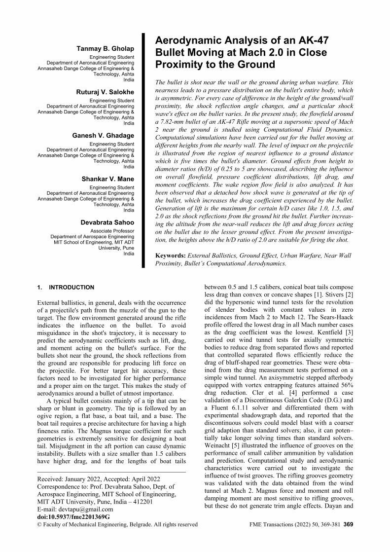
2.1 Model Geometry A 7.82-mm Bullet from AK-47 Rifle has been con–sidered for the present study. The geometrical speci–fications of the bullet have been adopted from Reddy et al. [25]. The total length of the bullet is 32.67 mm, with a diameter of 7.82 mm. Figure 2a presents the dimen–sional details of the bullet model adopted for the present computational study. The tip region of the model is blunt-shaped (with a diameter of 1.04 mm). The Ogive region is continued from the top to the flat base region. A boat tail shape with a base region is present the aft. The three-dimensional isometric view of the adopted bullet is -shown in Figure 2b.
Figure 2: a) Geometrical details of 7.82 mm ammo. All dim–ensions are in millimeters, b) 3-Dimensional isometric view of the bullet. The specifications are taken from Reddy et al. [25].
2.2 Computational Solver A Two-Dimensional structured mesh has been used to solve the Reynolds Averaged Navier Stokes equations. An explicit density-based solver has been implemented to obtain a steady-state solution and three coefficient Sutherland viscosity method with density set at ideal gas in air as fluid material. For turbulence accuracy, a second-order upwind scheme has been employed. The walls in the domain are set to no-slip condition. To apprehend the sophisticated method of the reflection of shock waves, a standard k-ε turbulence model has been applied by Reddy et al. [25]. The Green Gauss cell-based method has been utilized for spatial discretization, and the results have been analyzed after the residual convergence was achieved below 10-3. 2.3 Meshing and Boundary Conditions The generation of mesh and computations has been done in Ansys® software. The entire domain consists of
372 ▪ VOL. 50, No 2, 2022 FME Transactions
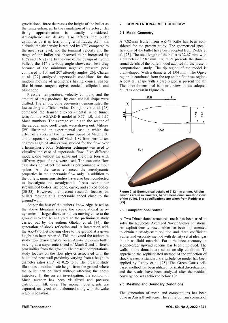
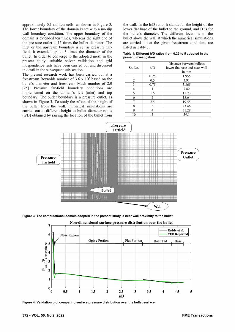
approximately 0.1 million cells, as shown in Figure 3. The lower boundary of the domain is set with a no-slip wall boundary condition. The upper boundary of the domain is extended ten times, whereas the right end of the pressure outlet is 15 times the bullet diameter. The inlet or the upstream boundary is set as pressure far-field. It extended up to 5 times the diameter of the bullet. In order to converge to the adopted mesh in the present study, suitable solver validation and grid independence tests have been carried out and discussed in detail in the subsequent sub-section. The present research work has been carried out at a freestream Reynolds number of 3.6 x 10⁵ based on the bullet's diameter and freestream Mach number of 2.0 [25]. Pressure far-field boundary conditions are implemented on the domain's left (inlet) and top boundary. The outlet boundary is a pressure outlet, as shown in Figure 3. To study the effect of the height of the bullet from the wall, numerical simulations are carried out at different height to bullet diameter ratios (h/D) obtained by raising the location of the bullet from
the wall. In the h/D ratio, h stands for the height of the lower flat base of the bullet to the ground, and D is for the bullet's diameter. The different locations of the bullet above the wall at which the numerical simulations are carried out at the given freestream conditions are listed in Table 1. Table 1: Different h/D ratios from 0.25 to 5 adopted in the present investigation
Sr. No. h/D Distance between bullet's
lower flat base and near-wall in mm
1 0.25 1.955 2 0.5 3.91 3 0.75 5.865 4 1 7.82 5 1.5 11.73 6 2 15.64 7 2.5 19.55 8 3 23.46 9 4 31.28 10 5 39.1
Figure 3. The computational domain adopted in the present study is near wall proximity to the bullet.
Figure 4: Validation plot comparing surface pressure distribution over the bullet surface.

FME Transactions VOL. 50, No 2, 2022 ▪ 373
Figure 5: Grid Independence Test for surface pressure distribution over the bullet
2.4 Validation and Grid Independence Test For the validation purpose, the bullet model moving at a freestream Mach number of 2.0, as reported by Reddy et al. [25], has been adopted, and 2D-axisymmetric simulations have been carried out. The surface pressure distribution computed over the bullet's surface has been validated with the reported data. The comparison is shown in Figure 4 and is found to be fairly matching. Furthermore, a grid independence test has also been conducted to converge to a suitable grid. Five different grids (in terms of grid density), five different grids have been simulated from very coarse to very fine. Table-2 shows the details of the grids adopted for the grid independence test. With the grid density variation, the surface pressure distribution with the reported data is shown in Figure 5. Simultaneously, with an increasing grid density, the Variation in the wall Y-plus value has also been observed and tabulated in Table 2.
Based on comparing the pressure distribution and variation of the wall Y-Plus values, a fine grid with 104,500 cell counts has been adopted for the present research. Table 2: Details of Grid density and Wall Yplus values
Type Cells Wall Yplus Very Coarse 35470 < 10
Coarse 50000 < 1 Medium 75025 < 0.5
Fine 104500 < 0.25 Very Fine 148000 < 0.1
3. RESULTS AND DISCUSSIONS
The effect of the presence of a wall in the proximity to a 7.82-mm AK 47 rifle bullet moving at a speed of Mach 2.00 has been numerically investigated in the present study. Furthermore, the variation in the near bullet flowfield with the change in the height of the wall proximity is also studied and analyzed. Qualitative analysis is carried out by capturing and analyzing the computationally obtained Mach contours of the different
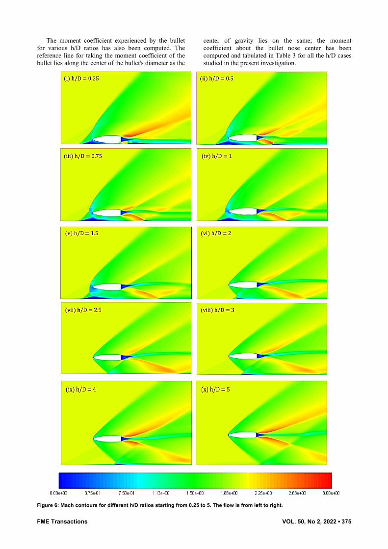
cases investigated in the present study. In addition to that, the variation in the flow around the wake of the bullet has been investigated with the help of computed velocity vectors. For quantitative analysis, computed surface pressure distribution and aerodynamic coeffi–cients like a drag, lift, and moment are also analyzed and reported in detail in the following sub-sections. 3.1 Flowfield in Mach Contour The computed Mach contours obtained for different h/D ratios (h/D=0.25 to h/D=5) while the bullet moves at Mach 2.00 are shown in Figure 6(i-x). For all the cases that have been numerically simulated, a detached bow shock wave can be expected to be formed in front of the bullet tip; however, for the cases of h/D < 1.5, a flow separation region is generated near the wall surface ahead of the bullet, and this separation region gives rise to the formation of a separation shock. The separation shock wave, in turn, interacts with the bow shock wave formed ahead of the bullet, thereby changing the flow physics around the bullet when moving near the wall with a h/D value of less than 1.5. For the minimum h/D case (h/D=0.25), the flow separation region is very close to the bullet tip, and hence the formation of the bow shock wave is restricted, as shown in Figure 6i. For the case of h/D=0.25, the separation shock is the only shock existing in the vicinity of the bullet; hence, the bullet can be expected to experience a minimum drag coef–ficient. However, as the h/D increases, the separation flow region moves away from the bullet tip. Hence, both the separation shock and the bow shock waves are generated and can be distinguished (see Figure 6ii-v). In addition, the generation of the bow shock wave will thereby lead to an increase in the drag coefficient experienced by the bullet. For the cases with higher values of h/D (h/D>1.5), it is observed that the separation shock interacts with the bow shock wave away from the bullet vicinity. Hence the separation shock will have minimal impact on the drag coefficient generated by the bullet, and the drag values will be on a
374 ▪ VOL. 50, No 2, 2022 FME Transactions
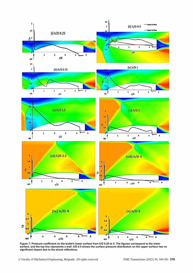
higher side due to the presence of the bow shock. However, for cases with higher h/D values, the bow shock wave completely develops and hits the wall due to the increase in the distance between the wall and the bullet base surface, and shock reflections are generated. The reflected shock wave then hits back the lower surface of the bullet for the limited number of h/D cases of 1, 1.5, and 2.0 (Figure 6iv-vi). As a result of this flow phenomenon, a maximum lift generation can be ex–pected for the above said h/D cases (1, 1.5, and 2.0). On further increase in the h/D ratios (h/D>2.0), it is observed that the reflected bow shock wave misses the bullet surface and hits the wake region of the bullet, thereby altering the dynamics of the bullet aft flow (please see Figure 6vii-x). A redirection in the wake region of the projectile is observed when the bow shock hits the ground and reflects for the cases of h/D larger than 2.0. The wake region is diverted upwards due to the force from the shock reflected at a particular angle. Due to the reflection of the shock wave and its inte–raction either with the lower surface of the bullet or the wake region, a finite amount of moment coefficient is expected to be generated on the bullet even if it is moving at a zero-degree angle of attack. This finite mo–ment generated over the bullet can impact the trajectory and need to be kept at a minimum side. The wake region after a certain distance is again reverted downwards as the effect of shock decreases downstream. 3.2 Pressure Distribution The computed pressure distribution along the lower surface of the bullet is displayed in Figure 7 (i-x). For better understanding, the pressure distribution plots are overlapped on the corresponding Mach contours (inverted) of the lower surfaces of the respective h/D ratios. The shapes are so placed that the top of the contours corresponds to the wall surface. For the case of the lowest wall clearance case, h/D = 0.25, one spike in the pressure distribution is observed, which might be due to the merged separation and bow shock wave just ahead of the bullet tip. At the height of 3.91 mm, i.e., h/D = 0.5, the pressure coefficient for the compressible flow on the lower and upper surface of the ammo is shown along with the surface length distribution of the entire body (Figure 7ii). It can be observed from the pressure distribution plot that the reflected bow shock from the ground on the bullet causes an additional peak at s/D of around 0.65, followed by a steady decrease in the pressure coefficient on the lower surface. However, no specific effect on the upper surface of the bullet due to shock reflection is observed. The trend for the upper surface of the shot is similar to that of the validation case. The pressure coefficient rises at the nose region due to the sonic line, followed by a steady decrease, and it drops suddenly at the base region in some cases due to the expansion fan. For the case of h/D = 0.75, one major peak at around s/D = 1.25 is observed, corresponding to the shock wave's location hitting the lower surface of the bullet after getting reflected from the wall. Further, as the h/D increases, the location of the reflected shock hitting the lower surface of the bullet is found to be shifted downstream. For higher wall clearances
(h/D>2.0), it can be observed that there is no particular pressure spike followed along the lower surface of the bullet, indicating the absence of the reflected shock wave hitting the bullet (see Figure7vii-x). This phenomenon aligns with the one discussed in the previous sub-section concerning the qualitative results (Mach Contours).
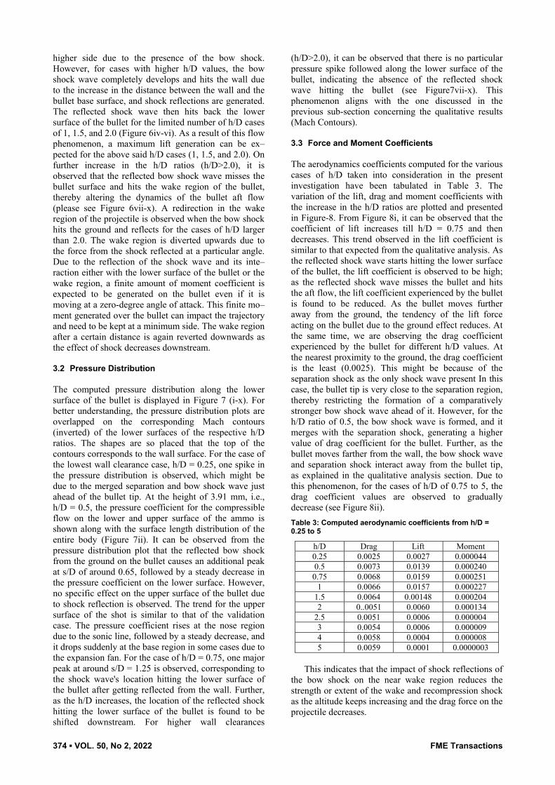
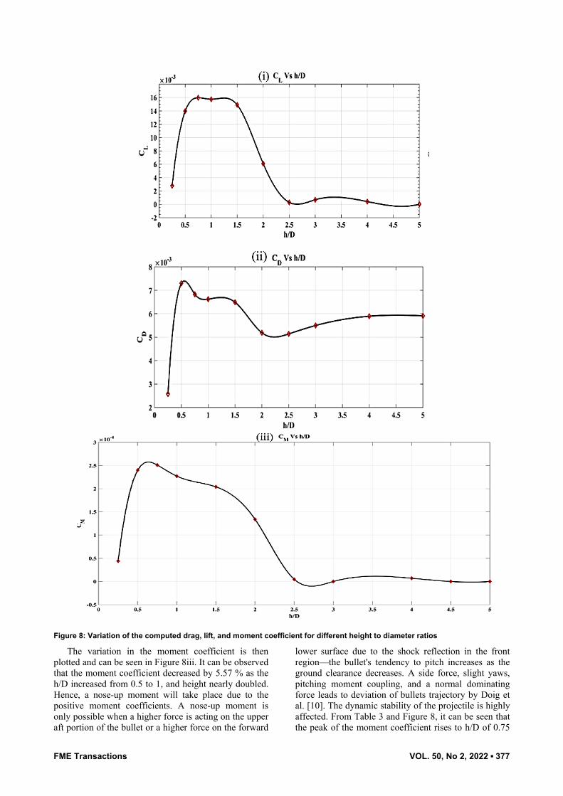
3.3 Force and Moment Coefficients The aerodynamics coefficients computed for the various cases of h/D taken into consideration in the present investigation have been tabulated in Table 3. The variation of the lift, drag and moment coefficients with the increase in the h/D ratios are plotted and presented in Figure-8. From Figure 8i, it can be observed that the coefficient of lift increases till h/D = 0.75 and then decreases. This trend observed in the lift coefficient is similar to that expected from the qualitative analysis. As the reflected shock wave starts hitting the lower surface of the bullet, the lift coefficient is observed to be high; as the reflected shock wave misses the bullet and hits the aft flow, the lift coefficient experienced by the bullet is found to be reduced. As the bullet moves further away from the ground, the tendency of the lift force acting on the bullet due to the ground effect reduces. At the same time, we are observing the drag coefficient experienced by the bullet for different h/D values. At the nearest proximity to the ground, the drag coefficient is the least (0.0025). This might be because of the separation shock as the only shock wave present In this case, the bullet tip is very close to the separation region, thereby restricting the formation of a comparatively stronger bow shock wave ahead of it. However, for the h/D ratio of 0.5, the bow shock wave is formed, and it merges with the separation shock, generating a higher value of drag coefficient for the bullet. Further, as the bullet moves farther from the wall, the bow shock wave and separation shock interact away from the bullet tip, as explained in the qualitative analysis section. Due to this phenomenon, for the cases of h/D of 0.75 to 5, the drag coefficient values are observed to gradually decrease (see Figure 8ii). Table 3: Computed aerodynamic coefficients from h/D = 0.25 to 5
h/D Drag Lift Moment 0.25 0.0025 0.0027 0.000044 0.5 0.0073 0.0139 0.000240 0.75 0.0068 0.0159 0.000251
1 0.0066 0.0157 0.000227 1.5 0.0064 0.00148 0.000204 2 0..0051 0.0060 0.000134
2.5 0.0051 0.0006 0.000004 3 0.0054 0.0006 0.000009 4 0.0058 0.0004 0.000008 5 0.0059 0.0001 0.0000003
This indicates that the impact of shock reflections of
the bow shock on the near wake region reduces the strength or extent of the wake and recompression shock as the altitude keeps increasing and the drag force on the projectile decreases.
FME Transactions VOL. 50, No 2, 2022 ▪ 375
The moment coefficient experienced by the bullet for various h/D ratios has also been computed. The reference line for taking the moment coefficient of the bullet lies along the center of the bullet's diameter as the
center of gravity lies on the same; the moment coefficient about the bullet nose center has been computed and tabulated in Table 3 for all the h/D cases studied in the present investigation.
Figure 6: Mach contours for different h/D ratios starting from 0.25 to 5. The flow is from left to right.
© Faculty of Mechanical Engineering, Belgrade. All rights reserved FME Transactions (2022) 50, 369-381 376
Received: January 2022, Accepted: April 2022 Correspondence to: Prof. Devabrata Sahoo, Dept. of Aerospace Engineering, MIT School of Engineering, MIT ADT University, Pune, India – 412201 E-mail: [email protected] doi:10.5937/fme2201369G
Figure 7: Pressure coefficient on the bullet's lower surface from h/D 0.25 to 5. The figures correspond to the lower surface, and the top line represents a wall. h/D 0.5 shows the surface pressure distribution on the upper surface has no significant impact due to the shock reflections.
FME Transactions VOL. 50, No 2, 2022 ▪ 377
Figure 8: Variation of the computed drag, lift, and moment coefficient for different height to diameter ratios
The variation in the moment coefficient is then plotted and can be seen in Figure 8iii. It can be observed that the moment coefficient decreased by 5.57 % as the h/D increased from 0.5 to 1, and height nearly doubled. Hence, a nose-up moment will take place due to the positive moment coefficients. A nose-up moment is only possible when a higher force is acting on the upper aft portion of the bullet or a higher force on the forward
lower surface due to the shock reflection in the front region—the bullet's tendency to pitch increases as the ground clearance decreases. A side force, slight yaws, pitching moment coupling, and a normal dominating force leads to deviation of bullets trajectory by Doig et al. [10]. The dynamic stability of the projectile is highly affected. From Table 3 and Figure 8, it can be seen that the peak of the moment coefficient rises to h/D of 0.75
378 ▪ VOL. 50, No 2, 2022 FME Transactions
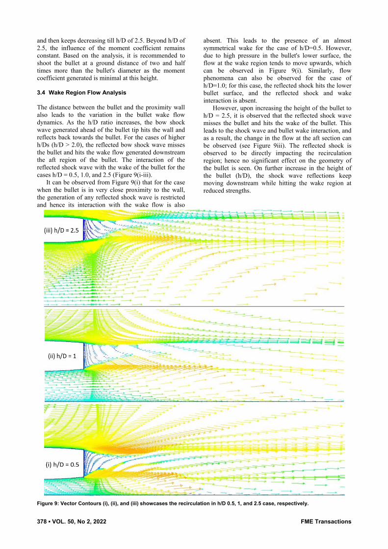
and then keeps decreasing till h/D of 2.5. Beyond h/D of 2.5, the influence of the moment coefficient remains constant. Based on the analysis, it is recommended to shoot the bullet at a ground distance of two and half times more than the bullet's diameter as the moment coefficient generated is minimal at this height. 3.4 Wake Region Flow Analysis The distance between the bullet and the proximity wall also leads to the variation in the bullet wake flow dynamics. As the h/D ratio increases, the bow shock wave generated ahead of the bullet tip hits the wall and reflects back towards the bullet. For the cases of higher h/Ds (h/D > 2.0), the reflected bow shock wave misses the bullet and hits the wake flow generated downstream the aft region of the bullet. The interaction of the reflected shock wave with the wake of the bullet for the cases h/D = 0.5, 1.0, and 2.5 (Figure 9(i-iii).
It can be observed from Figure 9(i) that for the case when the bullet is in very close proximity to the wall, the generation of any reflected shock wave is restricted and hence its interaction with the wake flow is also
absent. This leads to the presence of an almost symmetrical wake for the case of h/D=0.5. However, due to high pressure in the bullet's lower surface, the flow at the wake region tends to move upwards, which can be observed in Figure 9(i). Similarly, flow phenomena can also be observed for the case of h/D=1.0; for this case, the reflected shock hits the lower bullet surface, and the reflected shock and wake interaction is absent.
However, upon increasing the height of the bullet to h/D = 2.5, it is observed that the reflected shock wave misses the bullet and hits the wake of the bullet. This leads to the shock wave and bullet wake interaction, and as a result, the change in the flow at the aft section can be observed (see Figure 9iii). The reflected shock is observed to be directly impacting the recirculation region; hence no significant effect on the geometry of the bullet is seen. On further increase in the height of the bullet (h/D), the shock wave reflections keep moving downstream while hitting the wake region at reduced strengths.
Figure 9: Vector Contours (i), (ii), and (iii) showcases the recirculation in h/D 0.5, 1, and 2.5 case, respectively.

FME Transactions VOL. 50, No 2, 2022 ▪ 379
4. CONCLUSION
In the present study, 2D Steady computations have been conducted to investigate the effect of wall proxi–mity on an AK-47 bullet with a 0.72-m diameter moving at a supersonic speed of Mach 2.00. To inves–tigate the effect of the wall proximity on the bullet, 10 different heights are considered. They analyzed their influence on the flow field, pressure distributions, aero–dynamic coefficients, and flow in the wake region. For the cases when the bullet is moving very close to the wall (h/D<0.75), flow separation is observed to be formed on the wall surface in very close vicinity to the bullet tip; thereby, the formation of the bow shock wave is restricted and thereby the drag experienced by the bullet is minimal among all the cases studied in the present research. As the height at which the bullet is moving increases (up to h/D = 1.5), the bow shock wave is generated and interacts with the separation shock. A significant increase in the drag value experienced by the bullet is observed. On further increase in the height of the bullet beyond h/D = 1.5, the separation shock interacts with the bow shock wave away from the bullet vicinity thereby, a reduction in the drag value is observed. However, throughout all the h/D ratios starting from h/D = 0.75, the bow shock wave generated from the bullet tip hits the wall and reflects. The reflected shock wave is observed to be hitting the bullet's lower surface, thereby generating a lifting force, and a considerable nose-up moment is induced on the bullet at this altitude. As the h/D increases beyond 2, the reflected shock wave is missing the bullet, and the lifting force experienced by the bullet is significantly reduced, and so is the moment. For the cases with ratios from h/d = 2.5 to h/D = 5, no significant influence of shock wave on the bullet is observed. No significant shift in the moment coefficient would lead to an accurate aim while shooting the target with an AK-47 rifle. Therefore, these ratios equal to and higher than 2.5 can be considered as the optimum height from which the bullet is needed to be fired close to the wall.
An in-depth study of the complete 3-D analysis should be performed. The conical bow shock and the expansion waves would provide slightly different and more realistic results and conclusions than obtained here by the presented 2-D analysis as the scope of future work.
REFERENCES
[1] Karpov, B.G.: “The Effect of Various Boat tail Shapes on Base Pressure and Other Aerodynamic of a 7-Caliber Long Body of Revolution at M = 1.70, U. S. Army Materiel Command Ballistic Research Laboratories, Aberdeen Proving Ground, Maryland, USA, August 1965.
[2] Stivers, L.S., Jr.: Calculated pressure distributions and components of total-drag coefficients for 18 constant-volume, slender bodies of revolution at zero incidence for Mach numbers from 2.0 to 12.0, with experimental aerodynamic characteristics for three of the bodies, NASA Ames Research Center, Moffett Field, CA, United States, October 1971.
[3] Kentfield, J.A.C.: Drag Reduction by Means of Controlled Separated Flows, 12th Atmospheric Flight Mechanics Conference, Snowmass, CO, U.S.A., August 1985.
[4] Cler, D.L., Chevaugeon, N., Shephard, M.S. and Remacle, J.-F.: CFD Application to Gun Muzzle Blast – A Validation Case Study, 41st Aerospace Sciences Meeting and Exhibit, Reno, Nevada, U.S.A., January 2003.
[5] Weinacht, P.: Validation and Prediction of the Effect of Rifling Grooves on Small-Caliber Ammunition Performance”, AIAA Atmospheric Flight Mechanics Conference and Exhibit, Keystone, Colorado, USA, August 2006.
[6] Dayan, Y. and Touati, D.: Simulation of Unsteady Muzzle Flow of a Small-Caliber Gun, Advances in Fluid Mechanics VI, Vol. 52, pp. 165-171, 2006.
[7] Purdon, J.P., Mudford, M.R. and Kleine H.: Supersonic projectiles in the vicinity of solid obstacles, 27th International Congress on High-Speed Photography and Photonics, Xi’an, China, January 2007.
[8] Silton, S.I. and Weinacht, P.: Effect of Rifling Grooves on The Performance of Small-Caliber Ammunition, US Army Research Laboratory, Aberdeen Proving Ground, MD, USA, 2008.
[9] Doig, G., Kleine, H., Neely, A.J., Barber, T.J., Leonardi, E., Purdon, J.P., Appleby, E.M., and Mudford, N.R.: The Aerodynamics of a Supersonic Projectile in Ground Effect”, 26th International Symposium on Shock Waves, Berlin, Heidelberg, Germany, Vol. 2, No. 2, pp. 1521-1526, 2009.
[10] Doig, G., Barber T.J., Leonardi E., Neely, A.J. and Kleine, H.: Aerodynamics of a Supersonic Projectile in Proximity to a Solid Surface, AIAA Journal, Vol. 48, No. 12, December 2010.
[11] Kim, S.J., Chung, T.H. and Bae S.H.: Striation and Plasma Bullet Propagation in An Atmospheric Pressure Plasma Jet, American Institute of Physics, Physics of Plasma, Vol. 17, No. 5, 2010.
[12] Børvik, T., Olovsson, L., Dey, S. and Langseth M.: Normal and Oblique Impact of Small Arms Bullets on AA6082-T4 Aluminium Protective Plates”, International Journal of Impact Engineering, Vol. 38, No. 7, pp. 577-589, 2011.
[13] Silva, U. S., Sandoval, J. M., Flores, L. A., Muñoz, N., and Hernández, V.: Numerical Simulation and Experimental Study of Flowfield Around a Bullet with a Partial Core." ASME. J. Appl. Mech, Vol. 78, No. 5, 2011.
[14] Doig, G., Wang, S., Young, J., and Kleine, H.: Aerodynamics of Transonic and Supersonic Projectiles in Ground Effect, 52nd Aerospace Sciences Meeting, National Harbor, Maryland, USA, January 2014.
[15] Sailaranta, T., Honkanen, T., Laaksonen, A., and Siltavuori, A.: Bullet Turning at Trajectory Apex, Journal of Aerospace Engineering, Vol. 27, No. 5, 2014.
380 ▪ VOL. 50, No 2, 2022 FME Transactions
[16] Doig, G., Wang, S., Young, J., and Kleine, H.: Aerodynamic Analysis of Projectiles in Ground Effect at Near-Sonic Mach Numbers,” AIAA Journal, Vol. 54, No. 1, 2016.
[17] Decker, R., Duca, M., and Spickert-Fulton, S.: Measurement of Bullet Impact Conditions Using Automated In-Flight Photography System, Defence Technology, Vol. 13, No. 4, pp. 288-294, 2017.
[18] Holmen, J.K., Børvik, T., Hopperstad, O.S.: Experiments and Simulations of Empty and Sand-Filled Aluminum Alloy Panels Subjected to Ballistic Impact, Engineering Structures, Vol. 130, pp. 216-228, 2017.
[19] Sheridan, C., Young, J., Kleine, H., Hiraki, K., and Nonaka, S.: Ground Effect of Transonic and Supersonic Projectiles: Influence of Mach Number and Ground Clearance, 30th International Symposium on Shock Waves, Vol. 1, pp. 635-640, 2017.
[20] Mariotti, A., Buresti, G., Gaggini, G., and Salvetti, M.V.: Separation Control and Drag Reduction for Boat-Tailed Axisymmetric Bodies Through Contoured Transverse Grooves, Journal of Fluid Mechanics, pp. 514-549, December 2017.
[21] Muruganantham, V. R., and Babin, T.: Numerical Investigation of Hybrid Blend Design Target Bullets, 3rd International Conference on Design, Analysis, Manufacturing and Simulation, Vol. 172, June 2018.
[22] Aref, P., Ghoreyshi, M., Jirasek, A., and Satchell, M.J.: CFD Validation and Flow Control of RAE-M2129 S-Duct Diffuser Using CREATE-AV Kestrel Simulation Tools, Aerospace, Vol. 5, No. 1, 2018.
[23] Zhang, C., Wang, H., Zhang, P., Gao, S., and Xiong, H.: CFD Simulation of a Finned Smart Bullet with Microactuator, IOP Conf. Series: Jou of Physics: Conf. Series 1064, July 2018.
[24] Tran, T.H., Ambo, T., Chen, L., Nonomura, T., and Asai, K.: Effect of Boattail Angle on Pressure Distribution and Drag of Axisymmetric Afterbodies under Low-Speed Conditions, Transactions of the Japan Society for Aeronautical and Space Sciences, Vol. 62, No. 4, pp. 219-226, 2019.
[25] Reddy, D.S.K., Padhy, B.P., and Reddy, B. K.: “Flat-Fire Trajectory Simulation of AK-47 Assault Rifle 7.82-mm Bullet, Emerging Trends in Mechanical Engineering, Springer, Singapore, pp. 415-425, December 2020.
[26] Divsalar, K.: Improving the hydrodynamic performance of the SUBOFF bare hull model: a CFD approach, Acta Mech., Vol. 36, pp. 44–56, 2020.
[27] Charan M.S., Pavan G.K., Raghavendra G.D., and Dharamendara, M.: Simulation of Radome Moving at Supersonic Speed, International Journal of Scientific & Engineering Research, Vol. 11, No. 6, 2020.
[28] Milićev, S.S.: An Experimental Study of the Influence of Spike in Supersonic and Transonic
Flows Past a Hemispheric Body, FME Transactions, Vol. 50, No. 1, pp. 24-31, 2022.
[29] Damljanović, D., Vuković, D., Ocokoljić, G., Rašuo, B.: Convergence of Transonic Wind Tunnel Test Results of the AGARD-B Standard Model, FME Transactions, Vol. 48, No. 4, pp. 761-769, 2020.
[30] Damljanović, D. and Rašuo, B.: Testing of Calibration Models in Order to Certify the Overall Reliability of the Trisonic Blowdown Wind Tunnel of VTI, FME Transactions, Vol. 38, No. 4, pp. 167-172, 2010.
[31] Samardžić M., Isaković, J., Miloš, M., Anastasijević, Z., and Nauparac D. B.: Measurement of the Direct Damping Derivative in Roll of the Two Callibration Missile Models, FME Transactions, Vol. 41, pp. 189-194, 2013.
[32] Tarakka R., Salam, N., Jalaluddin, and Ihsan H.: Effect of Blowing Flow Control and Front Geometry Towards the Reduction of Aerodynamic Drag on Vehicle Models, FME Transactions, Vol. 47, pp. 552-559, 2019.
[33] Payal V. Tembhurnikar, Akash T. Jadhav, Devabrata Sahoo.: Effect of Intermediate Aerodisk Spike on the Drag reduction over a Blunt body at Supersonic speed”, FME Transactions, Vol 48, No. 4, Sept. 2020.
[34] Gholap, T.B., Salokhe, R.V., Ghadage, G.V., Mane, S.V., Bajaj, D.K., and Sahoo, D.: Computational Aerodynamics of an AK-47 Rifle’s 7.82 mm Bullet in Proximity to a Near Wall, IEEE PuneCon2021 Conference, December, Pune, India, 2021.
АЕРОДИНАМИЧКА АНАЛИЗА МЕТКА АК-47 КОЈИ СЕ КРЕЋЕ БРЗИНОМ ОД 2.0 МАХА У
НЕПОСРЕДНОЈ БЛИЗИНИ ЗЕМЉЕ
Т.Б. Голап, Р.В. Салоке, Г.В. Гадаге, Ш.В. Мане, Д. Саху
Метак се испаљује близу зида или тла током урбаног ратовања. Ова близина доводи до расподеле притиска на цело тело метка, које је асиметрично. За сваки случај разлике у висини близине тла/зида, угао рефлексије удара се мења, а ефекат одређеног ударног таласа на метак варира. У овој студији, поље струјања око метка калибра 7,82 мм из пушке АК-47 који се креће надзвучном брзином од 2 маха у близини земље проучава се коришћењем рачунарске динамике флуида. Извршене су рачунарске симулације за метак који се креће на различитим висинама од оближњег зида. Ниво ударца на пројектил је илустрован од области најближег утицаја до удаљености од земље која је пет пута већа од пречника метка. Приказани су ефекти тла од односа висине до пречника (х/Д) од 0,25 до 5, описујући утицај на укупно поље протока, дистрибуцију коефицијента притиска, отпор подизања и коефицијенте момента. Анализирано је и поље струјања будног региона. Примећено је да се

FME Transactions VOL. 50, No 2, 2022 ▪ 381
на врху метка ствара одвојени прамчани ударни талас, који повећава коефицијент отпора који метак доживљава. Генерисање узгона је максимум за одређене х/Д случајеве као што су 1.0, 1.5 и 2.0 док рефлексије удара од тла погађају метак. Даље
повећање висине од близу зида смањује силе подизања и отпора које делују на метак због мањег ефекта тла. Према садашњем истраживању, висине изнад односа х/Д од 2,0 су погодне за испаљивање метка.