AK Hinds University Center First Floor Renovations
648
Project Manual AK Hinds University Center First Floor Renovations Western Carolina University Cullowhee, NC SCO ID No. 19-20070-01A Code: 41829 Item: 304 Biloba Architecture, PLLC
-
Upload
khangminh22 -
Category
Documents
-
view
0 -
download
0
Transcript of AK Hinds University Center First Floor Renovations

Project Manual
AK Hinds University Center First Floor Renovations Western Carolina University Cullowhee, NC SCO ID No. 19-20070-01A Code: 41829 Item: 304
Biloba Architecture, PLLC

PROJECT MANUAL AK HINDS UNIVERSITY CENTER FIRST FLOOR RENOVATIONS WESTERN CAROLINA UNIVERSITY CULLOWHEE, NC SCO ID NO. 19-20070-01A CODE: 41829 ITEM: 304 BILOBA ARCHITECTURE, PLLC 8801 JM KEYNES DRIVE, SUITE 365 CHARLOTTE, NC 28262 BA PROJECT NO.: 095 JANUARY 8, 2020

WCU AK HINDS UC 1ST FLOOR RENOVATIONS
SEALS PAGE 00 0107 - 1
DOCUMENT 000107 - SEALS PAGE
1.1 DESIGN PROFESSIONALS OF RECORD
A. Architect:
1. Biloba Architecture, PLLC. 2. 52974. 3. Responsible for Divisions 00-12 Sections except where indicated as prepared by other design
professionals of record.
ARCHITECT Ian Patrick – NC License No. 12802
B. Fire-Protection, Plumbing, Mechanical, and Electrical Engineer:
1. Optima Engineering, PA. 2. C-0914. 3. Responsible for Sections 21-28.
PLUMBING /FP ENGINEER: George Fowler – NC License No. 026023
MECHANICAL ENGINEER: Ronald V. Almond – NC License No. 17228

WCU AK HINDS UC 1ST FLOOR RENOVATIONS
SEALS PAGE 00 0107 - 2
ELECTRICAL ENGINEER: Brandon Miller – NC License No. 028297
END OF DOCUMENT

WCU AK HINDS UC 1ST FLOOR RENOVATIONS
TABLE OF CONTENTS TOC - 1
TABLE OF CONTENTS TITLE PAGE SEALS PAGE TABLE OF CONTENTS NOTICE TO BIDDERS STATE OF NORTH CAROLINA GENERAL CONDITIONS OF THE CONTRACT (OC-15) SUPPLEMENTARY GENERAL CONDITIONS MBE GUIDELINES AND AFFIDAVITS FORM OF PROPOSAL FORM OF PERFORMANCE BOND FORM OF PAYMENT BOND FORM OF BID BOND WESTERN CAROLINA UNIVERSITY WASTE MANAGEMENT FORMS DIVISION 01 - GENERAL REQUIREMENTS 01 1000 - SUMMARY 01 2100 - ALLOWANCES 01 2200 - UNIT PRICES 01 2300 - ALTERNATES 01 2500 - SUBSTITUTION PROCEDURES 01 2600 - CONTRACT MODIFICATION PROCEDURES 01 2900 - PAYMENT PROCEDURES 01 3100 - PROJECT MANAGEMENT AND COORDINATION 01 3200 - CONSTRUCTION PROGRESS DOCUMENTATION 01 3300 - SUBMITTAL PROCEDURES 01 4000 - QUALITY REQUIREMENTS 01 4200 - REFERENCES 01 5000 - TEMPORARY FACILITIES AND CONTROLS 01 6000 - PRODUCT REQUIREMENTS 01 7300 - EXECUTION 01 7700 - CLOSEOUT PROCEDURES 01 7823 - OPERATION AND MAINTENANCE DATA 01 7839 - PROJECT RECORD DOCUMENTS 01 7900 - DEMONSTRATION AND TRAINING DIVISION 02 - EXISTING CONDITIONS 02 4119 - SELECTIVE DEMOLITION DIVISION 06 - WOOD, PLASTICS, AND COMPOSITES 06 1053 - MISCELLANEOUS ROUGH CARPENTRY 06 4116 - PLASTIC-LAMINATE-CLAD ARCHITECTURAL CABINETS DIVISION 07 - THERMAL AND MOISTURE PROTECTION 07 8100 - APPLIED FIREPROOFING 07 9200 - JOINT SEALANTS 07 9219 - ACOUSTICAL JOINT SEALANTS DIVISION 08 - OPENINGS 08 1213 - HOLLOW METAL FRAMES

WCU AK HINDS UC 1ST FLOOR RENOVATIONS
TABLE OF CONTENTS TOC - 2
08 1416 - FLUSH WOOD DOORS 08 4113 - ALUMINUM-FRAMED ENTRANCES AND STOREFRONTS 08 7100 - DOOR HARDWARE 08 7113 - AUTOMATIC DOOR OPERATORS 08 8000 - GLAZING 08 8113 - DECORATIVE GLASS GLAZING DIVISION 09 - FINISHES 09 2216 - NON-STRUCTURAL METAL FRAMING 09 2900 - GYPSUM BOARD 09 3013 - CERAMIC TILING 09 5113 - ACOUSTICAL PANEL CEILINGS 09 5423 - LINEAR METAL CEILINGS 09 6513 - RESILIENT BASE AND ACCESSORIES 09 6519 - RESILIENT TILE FLOORING 09 6813 - TILE CARPETING 09 9123 - INTERIOR PAINTING DIVISION 10 - SPECIALTIES 10 2219 - DEMOUNTABLE PARTITIONS 10 4413 - FIRE PROTECTION CABINETS DIVISION 12 - FURNISHINGS 12 3661.19 - QUARTZ AGGLOMERATE COUNTERTOPS 12 3661.19 - SOLID SURFACING COUNTERTOPS DIVISION 21 - FIRE SUPPRESSION 21 0500 - FIRE PROTECTION GENERAL 21 1313 - WET PIPE SPRINKLER SYSTEM DIVISION 22 - PLUMBING 22 0500 - PLUMBING GENERAL 22 0503 - PLUMBING PIPE, TUE, AND FITTINGS 22 0523 - GENERAL DUTY VALVES FOR PLUMBING PIPING 22 0529 - HANGERS AND SUPPORTS FOR PLUMBING PIPING AND EQUIPMENT 22 0553 - IDENTIFICATION FOR PLUMBING PIPING AND EQUIPMENT 22 0700 - PLUMBING INSULATION 22 4200 - PLUMBING FIXTURES DIVISION 23 - HEATING, VENTILATING, AND AIR-CONDITIONING (HVAC) 23 0500 - COMMON WORK RESULTS FOR HVAC 23 0513 - COMMON MOTOR REQUIREMENTS FOR HVAC EQUIPMENT 23 0519 - METERS AND GAGES FOR HVAC EQUIPMENT 23 0523 - GENERAL DUTY VALVES FOR HVAC PIPING 23 0529 - HANGERS AND SUPPORTS FOR HVAC PIPING AND EQUIPMENT 23 0553 - IDENTIFICATION FOR HVAC PIPING AND EQUIPMENT 23 0593 - TESTING, ADJUSTING, AND BALANCING FOR HVAC 23 0700 - HVAC INSULATION 23 2113 - HYDRONIC PIPING 23 3113 - METAL DUCTS

WCU AK HINDS UC 1ST FLOOR RENOVATIONS
TABLE OF CONTENTS TOC - 3
23 3300 - AIR DUCT ACCESSORIES 23 3600 - AIR TERMINAL UNITS 23 3713 - DIFFUSERS, REGISTERS, AND GRILLES
DIVISION 26 - ELECTRICAL
26 0500 - COMMON WORK RESULTS FOR ELECTRICAL 26 0519 - LOW-VOLTAGE ELECTRICAL POWER CONDUCTORS AND CABLES 26 0526 - GROUNDING AND BONDING FOR ELECTRICAL SYSTEMS 26 0529 - HANGERS AND SUPPORTS FOR ELECTRICAL SYSTEMS 26 0533 - RACEWAY AND BOXES FOR ELECTRICAL SYSTEMS 26 0543 - UNDERGROUND DUCTS AND RACEWAYS FOR ELECTRICAL SYSTEMS 26 0548 - VIBRATION AND SEISMIC CONTROLS FOR ELECTRICAL SYSTEMS 26 0553 - IDENTIFICATION FOR ELECTRICAL SYSTEMS 26 0923 - LIGHTING CONTROL DEVICES 26 4216 - PANELBOARDS 26 2726 - WIRING DEVICES 26 2813 - FUSES 26 2816 - ENCLOSED SWITCHES AND CIRCUIT BREAKERS 26 5119 - LED INTERIOR LIGHTING
DIVISION 28 - ELECTRONIC SAFETY AND SECURITY
28 0528 - PATHWAYS FOR ELECTRONIC SAFTEY AND SECURITY
END OF TABLE OF CONTENTS
SCO-Notice To Bidders 2010 – (Updated Dec. 2010)
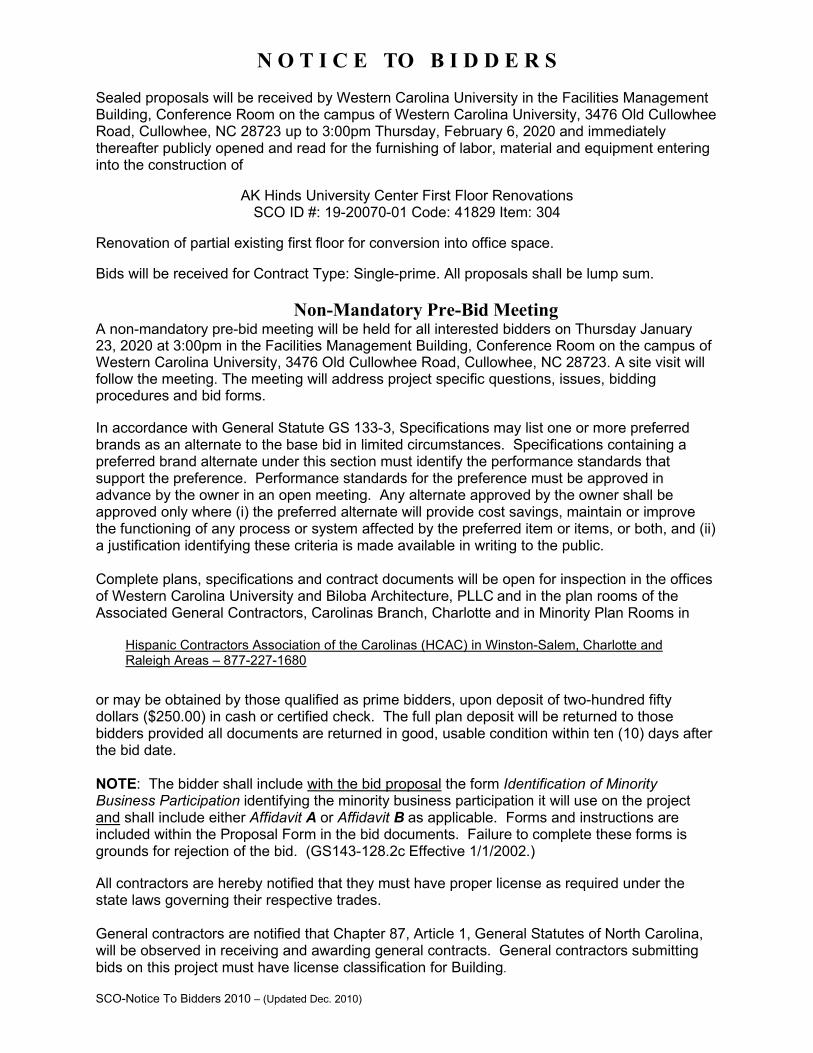
N O T I C E TO B I D D E R S
Sealed proposals will be received by Western Carolina University in the Facilities Management Building, Conference Room on the campus of Western Carolina University, 3476 Old Cullowhee Road, Cullowhee, NC 28723 up to 3:00pm Thursday, February 6, 2020 and immediately thereafter publicly opened and read for the furnishing of labor, material and equipment entering into the construction of
AK Hinds University Center First Floor Renovations SCO ID #: 19-20070-01 Code: 41829 Item: 304
Renovation of partial existing first floor for conversion into office space.
Bids will be received for Contract Type: Single-prime. All proposals shall be lump sum.
Non-Mandatory Pre-Bid Meeting A non-mandatory pre-bid meeting will be held for all interested bidders on Thursday January 23, 2020 at 3:00pm in the Facilities Management Building, Conference Room on the campus of Western Carolina University, 3476 Old Cullowhee Road, Cullowhee, NC 28723. A site visit will follow the meeting. The meeting will address project specific questions, issues, bidding procedures and bid forms.
In accordance with General Statute GS 133-3, Specifications may list one or more preferred brands as an alternate to the base bid in limited circumstances. Specifications containing a preferred brand alternate under this section must identify the performance standards that support the preference. Performance standards for the preference must be approved in advance by the owner in an open meeting. Any alternate approved by the owner shall be approved only where (i) the preferred alternate will provide cost savings, maintain or improve the functioning of any process or system affected by the preferred item or items, or both, and (ii) a justification identifying these criteria is made available in writing to the public.
Complete plans, specifications and contract documents will be open for inspection in the offices of Western Carolina University and Biloba Architecture, PLLC and in the plan rooms of the Associated General Contractors, Carolinas Branch, Charlotte and in Minority Plan Rooms in
Hispanic Contractors Association of the Carolinas (HCAC) in Winston-Salem, Charlotte and Raleigh Areas – 877-227-1680
or may be obtained by those qualified as prime bidders, upon deposit of two-hundred fifty dollars ($250.00) in cash or certified check. The full plan deposit will be returned to those bidders provided all documents are returned in good, usable condition within ten (10) days after the bid date.
NOTE: The bidder shall include with the bid proposal the form Identification of Minority Business Participation identifying the minority business participation it will use on the project and shall include either Affidavit A or Affidavit B as applicable. Forms and instructions are included within the Proposal Form in the bid documents. Failure to complete these forms is grounds for rejection of the bid. (GS143-128.2c Effective 1/1/2002.)
All contractors are hereby notified that they must have proper license as required under the state laws governing their respective trades.
General contractors are notified that Chapter 87, Article 1, General Statutes of North Carolina, will be observed in receiving and awarding general contracts. General contractors submitting bids on this project must have license classification for Building.

SCO-Notice To Bidders 2010 (Updated Dec. 2010)
Each proposal shall be accompanied by a cash deposit or a certified check drawn on some bank or trust company, insured by the Federal Deposit Insurance Corporation, of an amount equal to not less than five percent (5%) of the proposal, or in lieu thereof a bidder may offer a bid bond of five percent (5%) of the bid executed by a surety company licensed under the laws of North Carolina to execute the contract in accordance with the bid bond. Said deposit shall be retained by the owner as liquidated damages in event of failure of the successful bidder to execute the contract within ten days after the award or to give satisfactory surety as required by law. A performance bond and a payment bond will be required for one hundred percent (100%) of the contract price. Payment will be made based on ninety-five percent (95%) of monthly estimates and final payment made upon completion and acceptance of work. No bid may be withdrawn after the scheduled closing time for the receipt of bids for a period of 30 days. The owner reserves the right to reject any or all bids and to waive informalities. Designer: Owner: Ian Patrick, AIA Javier Torres, AIA Biloba Architecture, PLLC Western Carolina University 8801 JM Keynes Drive; Suite 365 3476 OId Cullowhee Road Charlotte, NC 28262 Cullowhee, NC 28723 704.773.4766 828.227.2345 [email protected]

INSTRUCTIONS TO BIDDERS
AND
GENERAL CONDITIONS OF THE CONTRACT
STANDARD FORM FOR CONSTRUCTION PROJECTS
STATE CONSTRUCTION OFFICE
NORTH CAROLINA
DEPARTMENT OF ADMINISTRATION Form OC-15 This document is intended for use on State capital construction projects and shall not be used on any project that is not reviewed and approved by the State Construction Office. Extensive modification to the General Conditions by means of “Supplementary General Conditions” is strongly discouraged. State agencies and institutions may include special requirements in “Division 1 – General Requirements” of the specifications, where they do not conflict with the General Conditions. Twenty Fourth Edition January 2013

Page 2
INSTRUCTIONS TO BIDDERS For a proposal to be considered it must be in accordance with the following instructions: 1. PROPOSALS Proposals must be made in strict accordance with the Form of Proposal provided therefor, and
all blank spaces for bids, alternates, and unit prices applicable to bidder’s work shall be properly filled in. When requested alternates are not bid, the proposer shall so indicate by the words “No Bid”. Any blanks shall also be interpreted as “No Bid”.The bidder agrees that bid on Form of Proposal detached from specifications will be considered and will have the same force and effect as if attached thereto. Photocopied or faxed proposals will not be considered. Numbers shall be stated both in writing and in figures for the base bids and alternates. If figures and writing differ, the written number will supersede the figures.
Any modifications to the Form of Proposal (including alternates and/or unit prices) will
disqualify the bid and may cause the bid to be rejected. The bidder shall fill in the Form of Proposal as follows: a. If the documents are executed by a sole owner, that fact shall be evidenced by the word
"Owner" appearing after the name of the person executing them. b. If the documents are executed by a partnership, that fact shall be evidenced by the word
"Co-Partner" appearing after the name of the partner executing them. c. If the documents are executed on the part of a corporation, they shall be executed by
either the president or the vice president and attested by the secretary or assistant secretary in either case, and the title of the office of such persons shall appear after their signatures. The seal of the corporation shall be impressed on each signature page of the documents.
d. If the proposal is made by a joint venture, it shall be executed by each member of the joint
venture in the above form for sole owner, partnership or corporation, whichever form is applicable.
e. All signatures shall be properly witnessed. f. If the contractor's license of a bidder is held by a person other than an owner, partner or
officer of a firm, then the licensee shall also sign and be a party to the proposal. The title "Licensee" shall appear under his/her signature.
Proposals should be addressed as indicated in the Advertisement for Bids and be delivered,
enclosed in an opaque sealed envelope, marked "Proposal" and bearing the title of the work, name of the bidder, and the contractor’s license number of the bidder. Bidders should clearly mark on the outside of the bid envelope which contract(s) they are bidding.
Bidder shall identify on the bid, the minority businesses that will be utilized on the project with
corresponding total dollar value of the bid and affidavit listing good faith efforts or an affidavit indicating work under contract will be self-performed, as required by G.S. 143-128.2(c) and G.S. 143-128.2(f). Failure to comply with these requirements is grounds for rejection of the bid.

Page 3
For projects bid in the single-prime alternative, the names and license numbers of major subcontractors shall be listed on the proposal form.
It shall be the specific responsibility of the bidder to deliver his bid to the proper official at the selected place and prior to the announced time for the opening of bids. Later delivery of a bid for any reason, including delivery by any delivery service, shall disqualify the bid.
Unit prices quoted in the proposal shall include overhead and profit and shall be the full compensation for the contractor's cost involved in the work. See General Conditions, Article 19c-1.
2. EXAMINATION OF CONDITIONS
It is understood and mutually agreed that by submitting a bid the bidder acknowledges that he has carefully examined all documents pertaining to the work, the location, accessibility and general character of the site of the work and all existing buildings and structures within and adjacent to the site, and has satisfied himself as to the nature of the work, the condition of existing buildings and structures, the conformation of the ground, the character, quality and quantity of the material to be encountered, the character of the equipment, machinery, plant and any other facilities needed preliminary to and during prosecution of the work, the general and local conditions, the construction hazards, and all other matters, including, but not limited to, the labor situation which can in any way affect the work under the contract, and including all safety measures required by the Occupational Safety and Health Act of 1970 and all rules and regulations issued pursuant thereto. It is further mutually agreed that by submitting a proposal the bidder acknowledges that he has satisfied himself as to the feasibility and meaning of the plans, drawings, specifications and other contract documents for the construction of the work and that he accepts all the terms, conditions and stipulations contained therein; and that he is prepared to work in cooperation with other contractors performing work on the site.
Reference is made to contract documents for the identification of those surveys and investigation reports of subsurface or latent physical conditions at the site or otherwise affecting performance of the work which have been relied upon by the designer in preparing the documents. The owner will make copies of all such surveys and reports available to the bidder upon request.
Each bidder may, at his own expense, make such additional surveys and investigations as he may deem necessary to determine his bid price for the performance of the work. Any on-site investigation shall be done at the convenience of the owner. Any reasonable request for access to the site will be honored by the owner.
3. BULLETINS AND ADDENDA
Any addenda to specifications issued during the time of bidding are to be considered covered in the proposal and in closing a contract they will become a part thereof. It shall be the bidder’s responsibility to ascertain prior to bid time the addenda issued and to see that his bid includes any changes thereby required.
Should the bidder find discrepancies in, or omission from, the drawings or documents or should he be in doubt as to their meaning, he shall at once notify the designer who will send written instructions in the form of addenda to all bidders. Notification should be no later than seven (7) days prior to the date set for receipt of bids. Neither the owner nor the designer will be responsible for any oral instructions.
Page 4
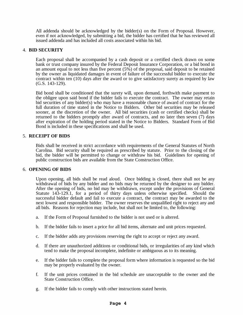
All addenda should be acknowledged by the bidder(s) on the Form of Proposal. However, even if not acknowledged, by submitting a bid, the bidder has certified that he has reviewed all issued addenda and has included all costs associated within his bid.
4. BID SECURITY Each proposal shall be accompanied by a cash deposit or a certified check drawn on some
bank or trust company insured by the Federal Deposit Insurance Corporation, or a bid bond in an amount equal to not less than five percent (5%) of the proposal, said deposit to be retained by the owner as liquidated damages in event of failure of the successful bidder to execute the contract within ten (10) days after the award or to give satisfactory surety as required by law (G.S. 143-129).
Bid bond shall be conditioned that the surety will, upon demand, forthwith make payment to
the obligee upon said bond if the bidder fails to execute the contract. The owner may retain bid securities of any bidder(s) who may have a reasonable chance of award of contract for the full duration of time stated in the Notice to Bidders. Other bid securities may be released sooner, at the discretion of the owner. All bid securities (cash or certified checks) shall be returned to the bidders promptly after award of contracts, and no later then seven (7) days after expiration of the holding period stated in the Notice to Bidders. Standard Form of Bid Bond is included in these specifications and shall be used.
5. RECEIPT OF BIDS Bids shall be received in strict accordance with requirements of the General Statutes of North
Carolina. Bid security shall be required as prescribed by statute. Prior to the closing of the bid, the bidder will be permitted to change or withdraw his bid. Guidelines for opening of public construction bids are available from the State Construction Office.
6. OPENING OF BIDS Upon opening, all bids shall be read aloud. Once bidding is closed, there shall not be any
withdrawal of bids by any bidder and no bids may be returned by the designer to any bidder. After the opening of bids, no bid may be withdrawn, except under the provisions of General Statute 143-129.1, for a period of thirty days unless otherwise specified. Should the successful bidder default and fail to execute a contract, the contract may be awarded to the next lowest and responsible bidder. The owner reserves the unqualified right to reject any and all bids. Reasons for rejection may include, but shall not be limited to, the following:
a. If the Form of Proposal furnished to the bidder is not used or is altered. b. If the bidder fails to insert a price for all bid items, alternate and unit prices requested. c. If the bidder adds any provisions reserving the right to accept or reject any award. d. If there are unauthorized additions or conditional bids, or irregularities of any kind which
tend to make the proposal incomplete, indefinite or ambiguous as to its meaning. e. If the bidder fails to complete the proposal form where information is requested so the bid
may be properly evaluated by the owner. f. If the unit prices contained in the bid schedule are unacceptable to the owner and the
State Construction Office. g. If the bidder fails to comply with other instructions stated herein.

Page 5
7. BID EVALUATION The award of the contract will be made to the lowest responsible bidder as soon as practical.
The owner may award on the basis of the base bid and any alternates the owner chooses. Before awarding a contract, the owner may require the apparent low bidder to qualify himself
to be a responsible bidder by furnishing any or all of the following data: a. The latest financial statement showing assets and liabilities of the company or other
information satisfactory to the owner. b. A listing of completed projects of similar size. c. Permanent name and address of place of business. d. The number of regular employees of the organization and length of time the organization
has been in business under present name. e. The name and home office address of the surety proposed and the name and address of
the responsible local claim agent. f. The names of members of the firms who hold appropriate trade licenses, together with
license numbers. g. If prequalified, contractor info will be reviewed and evaluated comparatively to submitted
prequalification package. Failure or refusal to furnish any of the above information, if requested, shall constitute a basis
for disqualification of any bidder. In determining the lowest responsible, responsive bidder, the owner shall take into
consideration the bidder’s compliance with the requirements of G.S. 143-128.2(c), the past performance of the bidder on construction contracts for the State with particular concern given to completion times, quality of work, cooperation with other contractors, and cooperation with the designer and owner. Failure of the low bidder to furnish affidavit and/or documentation as required by G.S. 143-128.2(c) shall constitute a basis for disqualification of the bid.
Should the owner adjudge that the apparent low bidder is not the lowest responsible,
responsive bidder by virtue of the above information, said apparent low bidder will be so notified and his bid security shall be returned to him.
8. PERFORMANCE BOND The successful bidder, upon award of contract, shall furnish a performance bond in an amount
equal to 100 percent of the contract price. See Article 35, General Conditions. 9. PAYMENT BOND The successful bidder, upon award of contract, shall furnish a payment bond in an amount
equal to 100 percent of the contract price. See Article 35, General Conditions.

Page 6
10. PAYMENTS Payments to the successful bidders (contractors) will be made on the basis of monthly
estimates. See Article 31, General Conditions. 11. PRE-BID CONFERENCE Prior to the date set for receiving bids, the Designer may arrange and conduct a Pre-Bid
Conference for all prospective bidders. The purpose of this conference is to review project requirements and to respond to questions from prospective bidders and their subcontractors or material suppliers related to the intent of bid documents. Attendance by prospective bidders shall be as required by the “Notice to Bidders”.
12. SUBSTITUTIONS
In accordance with the provisions of G.S. 133-3, material, product, or equipment substitutions proposed by the bidders to those specified herein can only be considered during the bidding phase until ten (10) days prior to the receipt of bids when submitted to the Designer with sufficient data to confirm material, product, or equipment equality. Proposed substitutions submitted after this time will be considered only as potential change order.
Submittals for proposed substitutions shall include the following information: a. Name, address, and telephone number of manufacturer and supplier as appropriate. b. Trade name, model or catalog designation. c. Product data including performance and test data, reference standards, and technical
descriptions of material, product, or equipment. Include color samples and samples of available finishes as appropriate.
d. Detailed comparison with specified products including performance capabilities,
warranties, and test results. e. Other pertinent data including data requested by the Designer to confirm product
equality. If a proposed material, product, or equipment substitution is deemed equal by the Designer to
those specified, all bidders of record will be notified by Addendum.

Page 7
GENERAL CONDITIONS OF THE CONTRACT The use or reproduction of this document or any part thereof is authorized for and limited to use on projects of the State of North Carolina, and is distributed by, through and at the discretion of the State Construction Office, Raleigh, North Carolina, for that distinct and sole purpose. TABLE OF CONTENTS ARTICLE TITLE PAGE 1 Definitions .................................................................................................................. 9 2 Intent and Execution of Documents ............................................................................ 11 3 Clarifications and Detail Drawings .............................................................................. 12 4 Copies of Drawings and Specifications ....................................................................... 12 5 Shop Drawings, Submittals, Samples, Data ................................................................. 13 6 Working Drawings and Specifications at the Job Site .................................................. 13 7 Ownership of Drawings and Specifications ................................................................. 14 8 Materials, Equipment, Employees ............................................................................... 14 9 Royalties, Licenses and Patent .................................................................................... 15 10 Permits, Inspections, Fees, Regulations ....................................................................... 15 11 Protection of Work, Property and the Public ............................................................... 16 12 Sedimentation Pollution Control Act of 1973 .............................................................. 17 13 Inspection of the Work ............................................................................................... 17 14 Construction Supervision and Schedule ....................................................................... 18 15 Separate Contracts and Contractor Relationships ........................................................ 22 16 Subcontracts and Subcontractors ................................................................................ 23 17 Contractor and Subcontractor Relationships ............................................................... 23 18 Designer's Status ........................................................................................................ 24 19 Changes in the Work .................................................................................................. 25 20 Claims for Extra Cost ................................................................................................. 27 21 Minor Changes in the Work ........................................................................................ 29 22 Uncorrected Faulty Work ........................................................................................... 29 23 Time of Completion, Delays, Extension of Time ......................................................... 29 24 Partial Utilization: Beneficial Occupancy .................................................................... 30 25 Final Inspection, Acceptance, and Project Closeout .................................................... 31 26 Correction of Work Before Final Payment .................................................................. 31 27 Correction of Work After Final Payment ..................................................................... 32 28 Owner's Right to Do Work ......................................................................................... 32 29 Annulment of Contract ............................................................................................... 32 30 Contractor's Right to Stop Work or Terminate the Contract ........................................ 33 31 Requests for Payments ................................................................................................ 33 32 Certificates of Payment and Final Payment .................................................................. 34 33 Payments Withheld ..................................................................................................... 36 34 Minimum Insurance Requirements .............................................................................. 36 35 Performance Bond and Payment Bond ........................................................................ 37 36 Contractor's Affidavit ................................................................................................. 38 37 Assignments ............................................................................................................... 38 38 Use of Premises .......................................................................................................... 38 39 Cutting, Patching and Digging .................................................................................... 38 40 Utilities, Structures, Signs ........................................................................................... 38 41 Cleaning Up ................................................................................................................ 40 42 Guarantee ................................................................................................................... 41

Page 8
43 Codes and Standards ............................................................................................... … 41 44 Indemnification ........................................................................................................ … 41 45 Taxes ...................................................................................................................... … 41 46 Equal Opportunity Clause ........................................................................................ … 42 47 Employment of the Handicapped ............................................................................. … 42 48 Asbestos-Containing Materials (ACM) .................................................................... … 43 49 Minority Business Participation ............................................................................... … 43 50 Contractor Evaluation ............................................................................................. … 43 51 Gifts ......................................................................................................................... 43 52 Auditing Access to Persons and Records .................................................................. 44 53 North Carolina False Claims Act ............................................................................... 44 54 Termination for Convenience .................................................................................... 45

Page 9
ARTICLE 1 - DEFINITIONS a. The contract documents consist of the Notice to Bidders; Instructions to Bidders;
General Conditions of the Contract; special conditions if applicable; Supplementary General Conditions; the drawing and specifications, including all bulletins, addenda or other modifications of the drawings and specifications incorporated into the documents prior to their execution; the proposal; the contract; the performance bond; the payment bond; insurance certificates; the approval of the attorney general; and the certificate of the Office of State Budget and Management. All of these items together form the contract.
b. The owner is the State of North Carolina through the agency named in the contract. c. The designer(s) are those referred to within this contract, or their authorized
representatives. The Designer(s), as referred to herein, shall mean architect and/or engineer. They will be referred to hereinafter as if each were of the singular number, masculine gender.
d. The contractor, as referred to hereinafter, shall be deemed to be either of the several
contracting parties called the "Party of the First Part" in either of the several contracts in connection with the total project. Where, in special instances hereinafter, a particular contractor is intended, an adjective precedes the word "contractor," as "general," "heating," etc. For the purposes of a single prime contract, the term Contractor shall be deemed to be the single contracting entity identified as the “Party of the First Part” in the single Construction Contract. Any references or adjectives that name or infer multiple prime contractors shall be interpreted to mean the single prime Contractor.
e. A subcontractor, as the term is used herein, shall be understood to be one who has
entered into a direct contract with a contractor, and includes one who furnishes materials worked to a special design in accordance with plans and specifications covered by the contract, but does not include one who only sells or furnishes materials not requiring work so described or detailed.
f. Written notice shall be defined as notice in writing delivered in person to the contractor,
or to a partner of the firm in the case of a partnership, or to a member of the contracting organization, or to an officer of the organization in the case of a corporation, or sent to the last known business address of the contracting organization by registered mail.
g. Work, as used herein as a noun, is intended to include materials, labor, and workmanship
of the appropriate contractor. h. The project is the total construction work to be performed under the contract documents
by the several contractors.
i. Project Expediter, as used herein, is an entity stated in the contract documents, designated to effectively facilitate scheduling and coordination of work activities. See Article 14(f) for responsibilities of a Project Expediter. For the purposes of a single prime contract, the single prime contractor shall be designated as the Project Expediter.
j. Change order, as used herein, shall mean a written order to the contractor subsequent to
the signing of the contract authorizing a change in the contract. The change order shall be signed by the contractor, designer and the owner, and approved by the State Construction Office, in that order (Article 19).

Page 10
k. Field Order, as used herein, shall mean a written approval for the contractor to proceed with the work requested by owner prior to issuance of a formal Change Order. The field order shall be signed by the contractor, designer, owner, and State Construction Office.
l. Time of completion, as stated in the contract documents, is to be interpreted as
consecutive calendar days measured from the date established in the written Notice to Proceed, or such other date as may be established herein (Article 23).
m. Liquidated damages, as stated in the contract documents [, is an amount reasonably
estimated in advance to cover the consequential damages associated with the Owner’s economic loss in not being able to use the Project for its intended purposes at the end of the contract’s completion date as amended by change order, if any, by reason of failure of the contractor(s) to complete the work within the time specified. Liquidated damages does not include the Owner’s extended contract administration costs (including but not limited to additional fees for architectural and engineering services, testing services, inspection services, commissioning services, etc.), such other damages directly resulting from delays caused solely by the contractor, or consequential damages that the Owner identified in the bid documents that may be impacted by any delay caused soley by the Contractor (e.g., if a multi-phased project-subsequent phases, delays in start other projects that are dependent on the completion of this Project, extension of leases and/or maintenance agreements for other facilities).
n. Surety, as used herein, shall mean the bonding company or corporate body which is
bound with and for the contractor, and which engages to be responsible for the contractor and his acceptable performance of the work.
o. Routine written communications between the Designer and the Contractor are any
communication other than a “request for information” provided in letter, memo, or transmittal format, sent by mail, courier, electronic mail, or facsimile. Such communications can not be identified as “request for information”.
p. Clarification or Request for information (RFI) is a request from the Contractor
seeking an interpretation or clarification by the Designer relative to the contract documents. The RFI, which shall be labeled (RFI), shall clearly and concisely set forth the issue or item requiring clarification or interpretation and why the response is needed. The RFI must set forth the Contractor’s interpretation or understanding of the contract documents requirements in question, along with reasons for such an understanding.
q. Approval means written or imprinted acknowledgement that materials, equipment or
methods of construction are acceptable for use in the work.
r. Inspection shall mean examination or observation of work completed or in progress to determine its compliance with contract documents.
s. “Equal to” or “approved equal” shall mean materials, products, equipment, assemblies,
or installation methods considered equal by the bidder in all characteristics (physical, functional, and aesthetic) to those specified in the contract documents. Acceptance of equal is subject to approval of Designer and owner.
t. “Substitution” or “substitute” shall mean materials, products, equipment, assemblies,
or installation methods deviating in at least one characteristic (physical, functional, or aesthetic) from those specified, but which in the opinion of the bidder would improve competition and/or enhance the finished installation. Acceptance of substitution is subject to the approval of the Designer and owner.

Page 11
u. Provide shall mean furnish and install complete in place, new, clean, operational, and ready for use.
v. Indicated and shown shall mean provide as detailed, or called for, and reasonably
implied in the contract documents.
w. Special inspector is one who inspects materials, installation, fabrication, erection or
placement of components and connections requiring special expertise to ensure compliance with the approved construction documents and referenced standards.
x. Commissioning is a quality assurance process that verifies and documents that building
components and systems operate in accordance to the owner’s project requirements and the project design documents.
y. Designer Final Inspection is the inspection performed by the design team to determine
the completeness of the project in accordance with approved plans and specifications. This inspection occurs prior to SCO final inspection.
z. SCO Final Inspection is the inspection performed by the State Construction Office to
determine the completeness of the project in accordance with NC Building Codes and approved plans and specifications.
aa. Beneficial Occupancy is requested by the owner and is occupancy or partial occupancy
of the building after all life safety items have been completed as determined by the State Construction Office. Life safety items include but not limited to fire alarm, sprinkler, egress and exit lighting, fire rated walls, egress paths and security.
bb. Final Acceptance is the date in which the State Construction Office accepts the
construction as totally complete. This includes the SCO Final Inspection and certification by the designer that all punch lists are completed.
ARTICLE 2 - INTENT AND EXECUTION OF DOCUMENTS a. The drawings and specifications are complementary, one to the other, and that which is
shown on the drawings or called for in the specifications shall be as binding as if it were both called for and shown. The intent of the drawings and specifications is to establish the scope of all labor, materials, transportation, equipment, and any and all other things necessary to provide a bid for a complete job. In case of discrepancy or disagreement in the contract documents, the order of precedence shall be: Form of Contract, specifications, large-scale detail drawings, small-scale drawings.
b. The wording of the specifications shall be interpreted in accordance with common usage
of the language except that words having a commonly used technical or trade meaning shall be so interpreted in preference to other meanings.
c. The contractor shall execute each copy of the proposal, contract, performance bond and
payment bond as follows: 1. If the documents are executed by a sole owner, that fact shall be evidenced by the
word "Owner" appearing after the name of the person executing them. 2. If the documents are executed by a partnership, that fact shall be evidenced by the
word "Co-Partner" appearing after the name of the partner executing them.
Page 12
3. If the documents are executed on the part of a corporation, they shall be executed by
either the president or the vice president and attested by the secretary or assistant secretary in either case, and the title of the office of such persons shall appear after their signatures. The seal of the corporation shall be impressed on each signature page of the documents.
4. If the documents are made by a joint venture, they shall be executed by each member
of the joint venture in the above form for sole owner, partnership or corporation, whichever form is applicable to each particular member.
5. All signatures shall be properly witnessed. 6. If the contractor's license is held by a person other than an owner, partner or officer
of a firm, then the licensee shall also sign and be a party to the contract. The title "Licensee" shall appear under his/her signature.
7. The bonds shall be executed by an attorney-in-fact. There shall be attached to each
copy of the bond a certified copy of power of attorney properly executed and dated. 8. Each copy of the bonds shall be countersigned by an authorized individual agent of
the bonding company licensed to do business in North Carolina. The title "Licensed Resident Agent" shall appear after the signature.
9. The seal of the bonding company shall be impressed on each signature page of the
bonds. 10. The contractor's signature on the performance bond and the payment bond shall
correspond with that on the contract. The date of performance and payment bond shall not be prior to the date of the contract.
ARTICLE 3 - CLARIFICATIONS AND DETAIL DRAWINGS a. In such cases where the nature of the work requires clarification by the designer, such
clarification shall be furnished by the designer with reasonable promptness by means of written instructions or detail drawings, or both. Clarifications and drawings shall be consistent with the intent of contract documents, and shall become a part thereof.
b. The contractor(s) and the designer shall prepare, if deemed necessary, a schedule fixing
dates upon which foreseeable clarifications will be required. The schedule will be subject to addition or change in accordance with progress of the work. The designer shall furnish drawings or clarifications in accordance with that schedule. The contractor shall not proceed with the work without such detail drawings and/or written clarifications.
ARTICLE 4 - COPIES OF DRAWINGS AND SPECIFICATIONS The designer or Owner shall furnish free of charge to the contractors electronic copies of
plans and specifications. If requested by the contractor, paper copies of plans and specifications shall be furnished free of charge as follows:
a. General contractor - Up to twelve (12) sets of general contractor drawings and
specifications, up to six (6) sets of which shall include drawings and specifications of all other contracts, plus a clean set of black line prints on white paper of all appropriate drawings, upon which the contractor shall clearly and legibly record all work-in-place that is at variance with the contract documents.

Page 13
b. Each other contractor - Up to six (6) sets of the appropriate drawings and specifications,
up to three (3) sets of which shall include drawings and specifications of all other contracts, plus a clean set of black line prints on white paper of all appropriate drawings, upon which the contractor shall clearly and legibly record all work-in-place that is at variance with the contract documents.
c. Additional sets shall be furnished at cost, including mailing, to the contractor upon
request by the contractor. This cost shall be stated in the bidding documents.
d. For the purposes of a single-prime contract, the contractor shall receive up to 30 sets of drawings and specifications, plus a clean set of black line prints on white paper of all appropriate drawings, upon which the contractor shall clearly and legibly record all work-in-place that is at variance with the contract documents.
ARTICLE 5 - SHOP DRAWINGS, SUBMITTALS, SAMPLES, DATA
a. Within 15 consecutive calendar days after the notice to proceed, each prime contractor shall submit a schedule for submission of all shop drawings, product data, samples, and similar submittals through the Project Expediter to the Designer. This schedule shall indicate the items, relevant specification sections, other related submittal, data, and the date when these items will be furnished to the designer.
b. The Contractor(s) shall review, approve and submit to the Designer all Shop Drawings,
Coordination Drawings, Product Data, Samples, Color Charts, and similar submittal data required or reasonably implied by the Contract Documents. Required Submittals shall bear the Contractor’s stamp of approval, any exceptions to the Contract Documents shall be noted on the submittals, and copies of all submittals shall be of sufficient quantity for the Designer to retain up to three (3) copies of each submittal for his own use plus additional copies as may be required by the Contractor. Submittals shall be presented to the Designer in accordance with the schedule submitted in paragraph (a). so as to cause no delay in the activities of the Owner or of separate Contractors.
c. The Designer shall review required submittals promptly, noting desired corrections if any,
and retaining three (3) copies (1 for the Designer, 1 for the owner and 1 for SCO) for his use. The remaining copies of each submittal shall be returned to the Contractor not later than twenty (20) days from the date of receipt by the Designer, for the Contractor’s use or for corrections and resubmittal as noted by the Designer. When resubmittals are required, the submittal procedure shall be the same as for the original submittals.
d. Approval of shop drawings/submittals by the Designer shall not be construed as relieving
the Contractor from responsibility for compliance with the design or terms of the contract documents nor from responsibility of errors of any sort in the shop drawings, unless such lack of compliance or errors first have been called in writing to the attention of the Designer by the Contractor.
ARTICLE 6 - WORKING DRAWINGS AND SPECIFICATIONS AT THE JOB SITE a. The contractor shall maintain, in readable condition at his job office, one complete set of
working drawings and specifications for his work including all shop drawings. Such drawings and specifications shall be available for use by the designer, his authorized representative, owner or State Construction Office.

Page 14
b. The contractor shall maintain at the job office, a day-to-day record of work-in-place that is at variance with the contract documents. Such variations shall be fully noted on project drawings by the contractor and submitted to the designer upon project completion and no later than 30 days after final acceptance of the project.
c. The contractor shall maintain at the job office a record of all required tests that have been performed, clearly indicating the scope of work inspected and the date of approval or rejection.
ARTICLE 7 - OWNERSHIP OF DRAWINGS AND SPECIFICATIONS
All drawings and specifications are instruments of service and remain the property of the owner. The use of these instruments on work other than this contract without permission of the owner is prohibited. All copies of drawings and specifications other than contract copies shall be returned to the owner upon request after completion of the work.
ARTICLE 8 - MATERIALS, EQUIPMENT, EMPLOYEES a. The contractor shall, unless otherwise specified, supply and pay for all labor,
transportation, materials, tools, apparatus, lights, power, heat, sanitary facilities, water, scaffolding and incidentals necessary for the completion of his work, and shall install, maintain and remove all equipment of the construction, other utensils or things, and be responsible for the safe, proper and lawful construction, maintenance and use of same, and shall construct in the best and most workmanlike manner, a complete job and everything incidental thereto, as shown on the plans, stated in the specifications, or reasonably implied therefrom, all in accordance with the contract documents.
b. All materials shall be new and of quality specified, except where reclaimed material is
authorized herein and approved for use. Workmanship shall at all times be of a grade accepted as the best practice of the particular trade involved, and as stipulated in written standards of recognized organizations or institutes of the respective trades except as exceeded or qualified by the specifications.
c. Upon notice, the contractor shall furnish evidence as to quality of materials. d. Products are generally specified by ASTM or other reference standard and/or by
manufacturer's name and model number or trade name. When specified only by reference standard, the Contractor may select any product meeting this standard, by any manufacturer. When several products or manufacturers are specified as being equally acceptable, the Contractor has the option of using any product and manufacturer combination listed. However, the contractor shall be aware that the cited examples are used only to denote the quality standard of product desired and that they do not restrict bidders to a specific brand, make, manufacturer or specific name; that they are used only to set forth and convey to bidders the general style, type, character and quality of product desired; and that equivalent products will be acceptable. Request for substitution of materials, items, or equipment shall be submitted to the designer for approval or disapproval; such approval or disapproval shall be made by the designer prior to the opening of bids. Alternate materials may be requested after the award if it can clearly be demonstrated that it is an added benefit to the owner and the designer and owner approves.
e. The designer is the judge of equality for proposed substitution of products, materials or
equipment.

Page 15
g. If at any time during the construction and completion of the work covered by these contract documents, the language, conduct, or attire of any workman of the various crafts be adjudged a nuisance to the owner or designer, or if any workman be considered detrimental to the work, the contractor shall order such parties removed immediately from grounds.
ARTICLE 9 - ROYALTIES, LICENSES AND PATENTS
It is the intention of the contract documents that the work covered herein will not constitute in any way infringement of any patent whatsoever unless the fact of such patent is clearly evidenced herein. The contractor shall protect and save harmless the owner against suit on account of alleged or actual infringement. The contractor shall pay all royalties and/or license fees required on account of patented articles or processes, whether the patent rights are evidenced hereinafter.
ARTICLE 10 - PERMITS, INSPECTIONS, FEES, REGULATIONS a. The contractor shall give all notices and comply with all laws, ordinances, codes, rules
and regulations bearing on the conduct of the work under this contract. If the contractor observes that the drawings and specifications are at variance therewith, he shall promptly notify the designer in writing. See Instructions to Bidders, Paragraph 3, Bulletins and Addenda. Any necessary changes required after contract award shall be made by change order in accordance with Article 19. If the contractor performs any work knowing it to be contrary to such laws, ordinances, codes, rules and regulations, and without such notice to the designer, he shall bear all cost arising therefrom. Additional requirements implemented after bidding will be subject to equitable negotiations.
b. All work under this contract shall conform to the North Carolina State Building Code and
other State, local and national codes as are applicable. The cost of all required inspections and permits shall be the responsibility of the contractor and included within the bid proposal. All water taps, meter barrels, vaults and impact fees shall be paid by the contractor unless otherwise noted.
d. Projects constructed by the State of North Carolina or by any agency or institution of the
State are not subject to inspection by any county or municipal authorities and are not subject to county or municipal building codes. The contractor shall, however, cooperate with the county or municipal authorities by obtaining building permits. Permits shall be obtained at no cost.
e. Projects involving local funding (community colleges) are subject also to county and
municipal building codes and inspection by local authorities. The contractor shall pay the cost of these permits and inspections.

Page 16
ARTICLE 11 - PROTECTION OF WORK, PROPERTY AND THE PUBLIC
a. The contractors shall be jointly responsible for the entire site and the building or construction of the same and provide all the necessary protections, as required by the owner or designer, and by laws or ordinances governing such conditions. They shall be responsible for any damage to the owner's property, or of that of others on the job, by them, their personnel, or their subcontractors, and shall make good such damages. They shall be responsible for and pay for any damages caused to the owner. All contractors shall have access to the project at all times.
b. The contractor shall provide cover and protect all portions of the structure when the
work is not in progress, provide and set all temporary roofs, covers for doorways, sash and windows, and all other materials necessary to protect all the work on the building, whether set by him, or any of the subcontractors. Any work damaged through the lack of proper protection or from any other cause, shall be repaired or replaced without extra cost to the owner.
c. No fires of any kind will be allowed inside or around the operations during the course of
construction without special permission from the designer and owner. d. The contractor shall protect all trees and shrubs designated to remain in the vicinity of the
operations by building substantial boxes around same. He shall barricade all walks, roads, etc., as directed by the designer to keep the public away from the construction. All trenches, excavations or other hazards in the vicinity of the work shall be well barricaded and properly lighted at night.
e. The contractor shall provide all necessary safety measures for the protection of all
persons on the job, including the requirements of the A.G.C. Accident Prevention Manual in Construction, as amended, and shall fully comply with all state laws or regulations and North Carolina State Building Code requirements to prevent accident or injury to persons on or about the location of the work. He shall clearly mark or post signs warning of hazards existing, and shall barricade excavations, elevator shafts, stairwells and similar hazards. He shall protect against damage or injury resulting from falling materials and he shall maintain all protective devices and signs throughout the progress of the work.
f. The contractor shall adhere to the rules, regulations and interpretations of the North
Carolina Department of Labor relating to Occupational Safety and Health Standards for the Construction Industry (Title 29, Code of Federal Regulations, Part 1926, published in Volume 39, Number 122, Part II, June 24, 1974, Federal Register), and revisions thereto as adopted by General Statutes of North Carolina 95-126 through 155.
g. The contractor shall designate a responsible person of his organization as safety
officer/inspector to inspect the project site for unsafe health and safety hazards, to report these hazards to the contractor for correction, and whose duties also include accident prevention on the project, and to provide other safety and health measures on the project site as required by the terms and conditions of the contract.The name of the safety inspector shall be made known to the designer and owner at the time of the preconstruction conference and in all cases prior to any work starting on the project.
h. In the event of emergency affecting the safety of life, the protection of work, or the safety
of adjoining properties, the contractor is hereby authorized to act at his own discretion, without further authorization from anyone, to prevent such threatened injury or damage.

Page 17
Any compensation claimed by the contractor on account of such action shall be determined as provided for under Article 19(b).
i. Any and all costs associated with correcting damage caused to adjacent properties of the construction site or staging area shall be borne by the contractor. These costs shall include but not be limited to flooding, mud, sand, stone, debris, and discharging of waste products.
ARTICLE 12 - SEDIMENTATION POLLUTION CONTROL ACT OF 1973 a. Any land-disturbing activity performed by the contractor(s) in connection with the project
shall comply with all erosion control measures set forth in the contract documents and any additional measures which may be required in order to ensure that the project is in full compliance with the Sedimentation Pollution Control Act of 1973, as implemented by Title 15, North Carolina Administrative Code, Chapter 4, Sedimentation Control, Subchapters 4A, 4B and 4C, as amended (15 N.C.A.C. 4A, 4B and 4C).
b. Upon receipt of notice that a land-disturbing activity is in violation of said act, the
contractor(s) shall be responsible for ensuring that all steps or actions necessary to bring the project in compliance with said act are promptly taken.
c. The contractor(s) shall be responsible for defending any legal actions instituted pursuant
to N.C.G.S. 113A-64 against any party or persons described in this article. d. To the fullest extent permitted by law, the contractor(s) shall indemnify and hold harmless
the owner, the designer and the agents, consultants and employees of the owner and designer, from and against all claims, damages, civil penalties, losses and expenses, including, but not limited to, attorneys' fees, arising out of or resulting from the performance of work or failure of performance of work, provided that any such claim, damage, civil penalty, loss or expense is attributable to a violation of the Sedimentation Pollution Control Act. Such obligation shall not be construed to negate, abridge or otherwise reduced any other right or obligation of indemnity which would otherwise exist as to any party or persons described in this article.
ARTICLE 13 - INSPECTION OF THE WORK a. It is a condition of this contract that the work shall be subject to inspection during normal
working hours and during any time work is in preparation and progress by the designer, designated official representatives of the owner, State Construction Office and those persons required by state law to test special work for official approval. The contractor shall therefore provide safe access to the work at all times for such inspections.
b. All instructions to the contractor will be made only by or through the designer or his
designated project representative. Observations made by official representatives of the owner shall be conveyed to the designer for review and coordination prior to issuance to the contractor.
c. All work shall be inspected by designer, special inspector and/or State Construction
Office prior to being covered by the contractor. Contractor shall give a minimum two weeks notice unless otherwise agreed to by all parties. If inspection fails, after the first reinspection all costs associated with additional reinspections shall be borne by the contractor.

Page 18
d. Where special inspection or testing is required by virtue of any state laws, instructions of the designer, specifications or codes, the contractor shall give adequate notice to the designer of the time set for such inspection or test, if the inspection or test will be conducted by a party other than the designer. Such special tests or inspections will be made in the presence of the designer, or his authorized representative, and it shall be the contractor's responsibility to serve ample notice of such tests.
e. All laboratory tests shall be paid by the owner unless provided otherwise in the contract
documents except the general contractor shall pay for laboratory tests to establish design mix for concrete, and for additional tests to prove compliance with contract documents where materials have tested deficient except when the testing laboratory did not follow the appropriate ASTM testing procedures.
f. Should any work be covered up or concealed prior to inspection and approval by the
designer, special inspector, and/or State Construction Office such work shall be uncovered or exposed for inspection, if so requested by the designer in writing. Inspection of the work will be made upon notice from the contractor. All cost involved in uncovering, repairing, replacing, recovering and restoring to design condition, the work that has been covered or concealed will be paid by the contractor involved.
ARTICLE 14 - CONSTRUCTION SUPERVISION AND SCHEDULE a. Throughout the progress of the work, each contractor shall keep at the job site, a
competent superintendent and supervisory staff satisfactory to the designer and the owner. The superintendent and supervisory staff shall not be changed without the consent of the designer and owner unless said superintendent ceases to be employed by the contractor or ceases to be competent as determined by the contractor, designer or owner. The superintendent and other staff designated by the contractor in writing shall have authority to act on behalf of the contractor, and instructions, directions or notices given to him shall be as binding as if given to the contractor. However, directions, instructions, and notices shall be confirmed in writing.
b. The contractor shall examine and study the drawings and specifications and fully
understand the project design, and shall provide constant and efficient supervision to the work. Should he discover any discrepancies of any sort in the drawings or specifications, he shall report them to the designer without delay. He will not be held responsible for discrepancies in the drawings and/or specifications, but shall be held responsible to report them should they become known to him.
c. All contractors shall be required to cooperate and consult with each other during the
construction of this project. Prior to installation of work, all contractors shall jointly prepare coordination drawings, showing locations of various ductworks, piping, motors, pumps, and other mechanical or electrical equipment, in relation to the structure, walls and ceilings. These drawings shall be submitted to the designer through the Project Expediter for information only. Each contractor shall lay out and execute his work to cause the least delay to other contractors. Each contractor shall be financially responsible for any damage to other contractor's work and for undue delay caused to other contractors on the project.
d. The contractor is required to attend job site progress conferences as called by the
designer. The contractor shall be represented at these job progress conferences by both home office and project personnel. These representatives shall have authority to act on behalf of the contractor. These meetings shall be open to subcontractors, material

Page 19
suppliers and any others who can contribute toward maintaining required job progress. It shall be the principal purpose of these meetings, or conferences, to effect coordination, cooperation and assistance in every practical way toward the end of maintaining progress of the project on schedule and to complete the project within the specified contract time. Each contractor shall be prepared to assess progress of the work as required in his particular contract and to recommend remedial measures for correction of progress as may be appropriate. The designer or his authorized representative shall be the coordinator of the conferences and shall preside as chairman. The contractor shall turn over a copy of his daily reports to the Designer and Owner at the job site progress conference. Owner will determine daily report format.
e The contractor(s) shall, employ an engineer or a land surveyor licensed in the State of
North Carolina to lay out the work and to establish a bench mark in a location where same will not be disturbed and where direct instruments sights may be taken.
f. The designer shall designate a Project Expediter on projects involving two or more prime
contracts. The Project Expediter shall be designated in the Supplementary General Conditions. The Project Expediter shall have at a minimum the following responsibilities.
1. Prepare the project construction schedule and shall allow all prime contractors
(multi-prime contract) and subcontractors (single-prime contract) performing
general, plumbing, HVAC, and electrical work equal input into the preparation of the
initial construction schedule.
2. Maintain a project progress schedule for all contractors.
3. Give adequate notice to all contractors to ensure efficient continuity of all phases of
the work.
4. Notify the designer of any changes in the project schedule.
5. Recommend to the owner whether payment to a contractor shall be approved.
g. It shall be the responsibility of the Project Expediter to cooperate with and obtain from
several prime contractors and subcontractors on the job, their respective work activities
and integrate these activities into a project construction schedule in form of a detailed bar
chart or Critical Path Method (CPM), schedule. Each prime contractor shall provide
work activities within fourteen (14) days of request by the Project Expediter. A “work
activity”, for scheduling purposes, shall be any component or contractual requirement of
the project requiring at least one (1) day, but not more than fourteen (14) days, to
complete or fulfill. The project construction schedule shall graphically show all salient
features of the work required to construct the project from start to finish and within the
allotted time established in the contract. The time (in days) between the contractor’s
early completion and contractual completion dates is part of the project total float time;
and shall be used as such, unless amended by a change order. On a multi-prime project,
each prime contractor shall review the proposed construction schedule and approve same
in writing. The Project Expediter shall submit the proposed construction schedule to the
designer for comments. The complete Project construction schedule shall be of the type
set forth in the Supplementary General Condition or subparagraph (1) or (2) below, as
appropriate:

Page 20
1. For a project with total contracts of $500,000 or less, a bar chart schedule will satisfy
the above requirement. The schedule shall indicate the estimated starting and completion dates for each major element of the work.
2. For a project with total contracts over $500,000, a Critical Path Method (CPM)
schedule shall be utilized to control the planning and scheduling of the Work. The CPM schedule shall be the responsibility of the Project Expediter and shall be paid for by the Project Expediter.
Bar Chart Schedule: Where a bar chart schedule is required, it shall be time-scaled in
weekly increments, shall indicate the estimated starting and completion dates for each
major element of the work by trade and by area, level, or zone, and shall schedule dates
for all salient features, including but not limited to the placing of orders for materials,
submission of shop drawings and other Submittals for approval, approval of shop
drawings by designers, the manufacture and delivery of material, the testing and the
installation of materials, supplies and equipment, and all Work activities to be performed
by the Contractor. The Contractor shall allow sufficient time in his schedule for all
commissioning, required inspections and completion of final punchlist(s). Each Work
activity will be assigned a time estimate by the Contractor. One day shall be the smallest
time unit used.
CPM Schedule: Where a CPM schedule is required, it shall be in time-scaled
precedence format using the Project Expediter’s logic and time estimates. The CPM
schedule shall be drawn or plotted with activities grouped or zoned by Work area or
subcontract as opposed to a random (or scattered) format. The CPM schedule shall be
time-scaled on a weekly basis and shall be drawn or plotted at a level of detail and logic
which will schedule all salient features of the work to be performed by the Contractor.
The Contractor shall allow sufficient time in his schedule for all commissioning, required
inspections and completion of final punchlist(s).. Each Work activity will be assigned a
time estimate by the Contractor. One day shall be the smallest time unit used.
The CPM schedule will identify and describe each activity, state the duration of each
activity, the calendar dates for the early and late start and the early and late finish of each
activity, and clearly highlight all activities on the critical path. "Total float" and "free
float" shall be indicated for all activities. Float time shall not be considered for the
exclusive use or benefit of either the Owner or the Contractor, but must be allocated in
the best interest of completing the Work within the Contract time. Extensions to the
Contract time, when granted by Change Order, will be granted only when equitable time
adjustment exceeds the Total Float in the activity or path of activities affected by the
change. On contracts with a price over $2,500,000, the CPM schedule shall also show
what part of the Contract Price is attributable to each activity on the schedule, the sum of
which for all activities shall equal the total Contract Price.
Early Completion of Project: The Contractor may attempt to complete the project
prior to the Contract Completion Date. However, such planned early completion shall be
for the Contractor's convenience only and shall not create any additional rights of the
Contractor or obligations of the Owner under this Contract, nor shall it change the Time

Page 21
for Completion or the Contract Completion Date. The Contractor shall not be required
to pay liquidated damages to the Owner because of its failure to complete by its planned
earlier date. Likewise, the Owner shall not pay the Contractor any additional
compensation for early completion nor will the Owner owe the Contractor any
compensation should the Owner, its officers, employees, or agents cause the Contractor
not to complete earlier than the date required by the Contract Documents.
h. The proposed project construction schedule shall be presented to the designer no later
than fifteen (15) days after written notice to proceed. No application for payment will be
processed until this schedule is accepted by the designer and owner.
i. The approved project construction schedule shall be distributed to all contractors and
displayed at the job site by the Project Expediter. j. The several contractors shall be responsible for their work activities and shall notify the
Project Expediter of any necessary changes or adjustments to their work. The Project Expediter shall maintain the project construction schedule, making biweekly adjustments, updates, corrections, etc., that are necessary to finish the project within the Contract time, keeping all contractors and the designer fully informed. Copy of a bar chart schedule annotated to show the current progress shall be submitted by the Contractor(s) to the designer, along with monthly request for payment. For project requiring CPM schedule, the Contractor shall submit a biweekly report of the status of all activities. The bar chart schedule or status report shall show the actual Work completed to date in comparison with the original Work scheduled for all activities. If any activities of the work of several contractors are behind schedule, the contractor must indicate in writing, what measures will be taken to bring each such activity back on schedule and to ensure that the Contract Completion Date is not exceeded. A plan of action and recovery schedule shall be developed and submitted to the designer by the Project Expediter, when (1) the contractor’s report indicates delays, that are in the opinion of the designer or the owner, of sufficient magnitude that the contractor’s ability to complete the work by the scheduled completion is brought into question; (2) the updated construction schedule is thirty (30) days behind the planned or baseline schedule and no legitimate time extensions, as determined by the Designer, are in process; and (3) the contractor desires to make changes in the logic (sequencing of work) or the planned duration of future activities of the CPM schedule which, in the opinion of the designer or the owner, are of a major nature. The plan of action, when required shall be submitted to the Owner for review within two (2) business days of the Contractor receiving the Owner's written demand. The recovery schedule, when required, shall be submitted to the Owner within five (5) calendar days of the Contractor's receiving the Owner's written demand. Failure to provide an updated construction schedule or a recovery schedule may be grounds for rejection of payment applications or withholding of funds as set forth in Article 33.
k. The Project Expediter shall notify each contractor of such events or time frames that are
critical to the progress of the job. Such notice shall be timely and reasonable. Should the progress be delayed due to the work of any of the several contractors, it shall be the duty of the Project Expediter to immediately notify the contractor(s) responsible for such delay, the designer, the State Construction Office and other prime contractors. The designer shall determine the contractor(s) who caused the delays and notify the bonding company of the responsible contractor(s) of the delays; and shall make a recommendation to the owner regarding further action.
l. Designation as Project Expediter entails an additional project control responsibility and
does not alter in any way the responsibility of the contractor so designated, nor the

Page 22
responsibility of the other contractors involved in the project. The project expeditor’s Superintendent(s) shall be in attendance at the Project site at all times when work is in progress unless conditions are beyond the control of the Contractor or until termination of the Contract in accordance with the Contract Documents. It is understood that such Superintendent shall be acceptable to the Owner and Designer and shall be the one who will be continued in that capacity for the duration of the project unless he ceases to be on the Contractor’s payroll or the Owner otherwise agrees. The Superintendent shall not be employed on any other project for or by the Contractor or by any other entity during the course of the Work. If the Superintendent is employed by the Contractor on another project without the Owner’s approval, then the Owner may deduct from the Contractor’s monthly general condition costs and amount representing the Superintendent’s cost and shall deduct that amount for each month thereafter until the Contractor has the Superintendent back on the Owner’s Project full-time.
ARTICLE 15 - SEPARATE CONTRACTS AND CONTRACTOR RELATIONSHIPS a. Effective from January 1, 2002, Chapter 143, Article 8, was amended, to allow public
contracts to be delivered by the following delivery methods: single-prime, dual (single-prime and separate-prime), construction manager at risk, and alternative contracting method as approved by the State Building Commission. The owner reserves the right to prepare separate specifications, receive separate bids, and award separate contracts for such other major items of work as may be in the best interest of the State. For the purposes of a single prime contract, refer to Article 1 – Definitions.
b. All contractors shall cooperate with each other in the execution of their work, and shall
plan their work in such manner as to avoid conflicting schedules or delay of the work. See Article 14, Construction Supervision.
c. If any part of contractor's work depends upon the work of another contractor, defects
which may affect that work shall be reported to the designer in order that prompt inspection may be made and the defects corrected. Commencement of work by a contractor where such condition exists will constitute acceptance of the other contractor's work as being satisfactory in all respects to receive the work commenced, except as to defects which may later develop. The designer shall be the judge as to the quality of work and shall settle all disputes on the matter between contractors.
d. Any mechanical or electrical work such as sleeves, inserts, chases, openings, penetrations,
etc., which is located in the work of the general contractor shall be built in by the general contractor. The respective mechanical and electrical contractors shall set all sleeves, inserts and other devices that are to be incorporated into the structure in cooperation and under the supervision of the general contractor. The responsibility for the exact location of such items shall be that of the mechanical and/or electrical contractor.
e. The designer and the owner shall have access to the work whenever it is in preparation
and progress and during normal working hours. The contractor shall provide facilities for such access so the designer may perform his functions under the contract documents.
f. Should a contractor cause damage to the work or property of another contractor, he shall
be directly responsible, and upon notice, shall promptly settle the claim or otherwise resolve the dispute.
ARTICLE 16 - SUBCONTRACTS AND SUBCONTRACTORS

Page 23
a. Within thirty (30) days after award of the contract, the contractor shall submit to the designer, owner and to the State Construction Office a list giving the names and addresses of subcontractors and equipment and material suppliers he proposes to use, together with the scope of their respective parts of the work. Should any subcontractor be disapproved by the designer or owner, the designer or owner shall submit his reasons for disapproval in writing to the State Construction Office for its consideration with a copy to the contractor. If the State Construction Office concurs with the designer's or owner’s recommendation, the contractor shall submit a substitute for approval. The designer and owner shall act promptly in the approval of subcontractors, and when approval of the list is given, no changes of subcontractors will be permitted except for cause or reason considered justifiable by the designer or owner.
b. The designer will furnish to any subcontractor, upon request, evidence regarding amounts
of money paid to the contractor on account of the subcontractor's work. c. The contractor is and remains fully responsible for his own acts or omissions as well as
those of any subcontractor or of any employee of either. The contractor agrees that no contractual relationship exists between the subcontractor and the owner in regard to the contract, and that the subcontractor acts on this work as an agent or employee of the contractor.
d. The owner reserves the right to limit the amount of portions of work to be subcontracted
as hereinafter specified. ARTICLE 17 - CONTRACTOR AND SUBCONTRACTOR RELATIONSHIPS
The contractor agrees that the terms of these contract documents shall apply equally to each subcontractor as to the contractor, and the contractor agrees to take such action as may be necessary to bind each subcontractor to these terms. The contractor further agrees to conform to the Code of Ethical Conduct as adopted by the Associated General Contractors of America, Inc., with respect to contractor-subcontractor relationships, and that payments to subcontractors shall be made in accordance with the provisions of G.S. 143-134.1 titled Interest on final payments due to prime contractors: payments to subcontractors.
a. On all public construction contracts which are let by a board or governing body of the
state government or any political subdivision thereof, except contracts let by the Department of Transportation pursuant to G.S. 136-28.1, the balance due prime contractors shall be paid in full within 45 days after respective prime contracts of the project have been accepted by the owner, certified by the architect, engineer or designer to be completed in accordance with terms of the plans and specifications, or occupied by the owner and used for the purpose for which the project was constructed, whichever occurs first. Provided, however, that whenever the architect or consulting engineer in charge of the project determines that delay in completion of the project in accordance with terms of the plans and specifications is the fault of the contractor, the project may be occupied and used for the purposes for which it was constructed without payment of any interest on amounts withheld past the 45 day limit. No payment shall be delayed because of the failure of another prime contractor on such project to complete his contract. Should final payment to any prime contractor beyond the date such contracts have been certified to be completed by the designer or architect, accepted by the owner, or occupied by the owner and used for the purposes for which the project was constructed, be delayed by more than 45 days, said prime contractor shall be paid interest, beginning on the 46th day, at the rate of one percent (1%) per month or fraction thereof unless a lower rate is

Page 24
agreed upon on such unpaid balance as may be due. In addition to the above final payment provisions, periodic payments due a prime contractor during construction shall be paid in accordance with the payment provisions of the contract documents or said prime contractor shall be paid interest on any such unpaid amount at the rate stipulated above for delayed final payments. Such interest shall begin on the date the payment is due and continue until the date on which payment is made. Such due date may be established by the terms of the contract. Funds for payment of such interest on state-owned projects shall be obtained from the current budget of the owning department, institution or agency. Where a conditional acceptance of a contract exists, and where the owner is retaining a reasonable sum pending correction of such conditions, interest on such reasonable sum shall not apply.
b. Within seven days of receipt by the prime contractor of each periodic or final payment,
the prime contractor shall pay the subcontractor based on work completed or service provided under the subcontract. Should any periodic or final payment to the subcontractor be delayed by more than seven days after receipt of periodic or final payment by the prime contractor, the prime contractor shall pay the subcontractor interest, beginning on the eighth day, at the rate of one percent (1%) per month or fraction thereof on such unpaid balance as may be due.
c. The percentage of retainage on payments made by the prime contractor to the
subcontractor shall not exceed the percentage of retainage on payments made by the owner to the prime contractor. Any percentage of retainage on payments made by the prime contractor to the subcontractor that exceeds the percentage of retainage on payments made by the owner to the prime contractor shall be subject to interest to be paid by the prime contractor to the subcontractor at the rate of one percent (1%) per month or fraction thereof.
d. Nothing in this section shall prevent the prime contractor at the time of application and
certification to the owner from withholding application and certification to the owner for payment to the subcontractor for unsatisfactory job progress; defective construction not remedied; disputed work; third-party claims filed or reasonable evidence that claim will be filed; failure of subcontractor to make timely payments for labor, equipment and materials; damage to prime contractor or another subcontractor; reasonable evidence that subcontract cannot be completed for the unpaid balance of the subcontract sum; or a reasonable amount for retainage not to exceed the initial percentage retained by owner.
ARTICLE 18 - DESIGNER'S STATUS a. The designer shall provide general administration of the performance of construction
contracts, including liaison and necessary inspection of the work to ensure compliance with plans and specifications. He is the agent of the owner only for the purpose of constructing this work and to the extent stipulated in the contract documents. He has authority to direct work to be performed, to stop work, to order work removed, or to order corrections of faulty work, where any such action by the designer may be necessary to assure successful completion of the work.
b. The designer is the impartial interpreter of the contract documents, and, as such, he shall
exercise his powers under the contract to enforce faithful performance by both the owner and the contractor, taking sides with neither.
c. Should the designer cease to be employed on the work for any reason whatsoever, then
the owner shall employ a competent replacement who shall assume the status of the former designer.

Page 25
d. The designer and his consultants will make inspections of the project. He will inspect the progress, the quality and the quantity of the work.
e. The designer and the owner shall have access to the work whenever it is in preparation
and progress during normal working hours. The contractor shall provide facilities for such access so the designer and owner may perform their functions under the contract documents.
f. Based on the designer's inspections and evaluations of the project, the designer shall issue
interpretations, directives and decisions as may be necessary to administer the project. His decisions relating to artistic effect and technical matters shall be final, provided such decisions are within the limitations of the contract.
ARTICLE 19 - CHANGES IN THE WORK a. The owner may have changes made in the work covered by the contract. These changes
will not invalidate and will not relieve or release the contractor from any guarantee given by him pertinent to the contract provisions. These changes will not affect the validity of the guarantee bond and will not relieve the surety or sureties of said bond. All extra work shall be executed under conditions of the original contract.
b. Except in an emergency endangering life or property, no change shall be made by the
contractor except upon receipt of approved change order or written field order from the designer, countersigned by the owner and the state construction office authorizing such change. No claim for adjustments of the contract price shall be valid unless this procedure is followed. A field order, transmitted by fax, electronically, or hand delivered, may be used where the change involved impacts the critical path of the work. A formal change order shall be issued as expeditiously as possible. In the event of emergency endangering life or property, the contractor may be directed to proceed on a time and material basis whereupon the contractor shall proceed and keep accurately on such form as specified by the designer or owner, a correct account of costs together with all proper invoices, payrolls and supporting data. Upon completion of the work the change order will be prepared as outlined under either Method "c(1)" or Method "c(2)" or both.
c. In determining the values of changes, either additive or deductive, contractors are restricted to the use of the following methods:
1. Where the extra work involved is covered by unit prices quoted in the proposal, or
subsequently agreed to by the Contractor, Designer, Owner and State Construction Office the value of the change shall be computed by application of unit prices based on quantities, estimated or actual as agreed of the items involved, except is such cases where a quantity exceeds the estimated quantity allowance in the contract by one hundred percent (100%) or more. In such cases, either party may elect to proceed under subparagraph c2 herein. If neither party elects to proceed under c2, then unit prices shall apply.
2. The contracting parties shall negotiate and agree upon the equitable value of the
change prior to issuance of the change order, and the change order shall stipulate the corresponding lump sum adjustment to the contract price.

Page 26
d. Under Paragraph “b” and Methods "c(2)" above, the allowances for overhead and profit combined shall be as follows: all contractors (the single contracting entity (prime), his subcontractors(1
st tier subs), or their sub-subcontractors (2
nd tier subs, 3
rd tier subs, etc))
shall be allowed a maximum of 10% on work they each self-perform; the prime contractor shall be allowed a maximum of 5% on contracted work of his 1
st tier sub; 1
st
tier, 2nd
tier, 3rd
tier, etc contractors shall be allowed a maximum of 2.5% on the contracted workof their subs. ; Under Method "c(1)", no additional allowances shall be made for overhead and profit. In the case of deductible change orders, under Method "c(2)" and Paragraph (b) above, the contractor shall include no less than five percent (5%) profit, but no allowances for overhead.
e. The term "net cost" as used herein shall mean the difference between all proper cost
additions and deductions. The "cost" as used herein shall be limited to the following:
1. The actual costs of materials and supplies incorporated or consumed as part of the work;
2. The actual costs of labor expended on the project site; labor expended in coordination, change order negotiation, record document maintenance, shop drawing revision or other tasks necessary to the administration of the project are considered overhead whether they take place in an office or on the project site.
3. The actual costs of labor burden, limited to the costs of social security (FICA) and Medicare/Medicaid taxes; unemployment insurance costs; health/dental/vision insurance premiums; paid employee leave for holidays, vacation, sick leave, and/or petty leave, not to exceed a total of 30 days per year; retirement contributions; worker’s compensation insurance premiums; and the costs of general liability insurance when premiums are computed based on payroll amounts; the total of which shall not exceed thirty percent (30%) of the actual costs of labor;
4. The actual costs of rental for tools, excluding hand tools; equipment; machinery; and temporary facilities required for the work;
5. The actual costs of premiums for bonds, insurance, permit fees, and sales or use taxes related to the work.
Overtime and extra pay for holidays and weekends may be a cost item only to the extent approved by the owner.
f. Should concealed conditions be encountered in the performance of the work below grade,
or should concealed or unknown conditions in an existing structure be at variance with the conditions indicated by the contract documents, the contract sum and time for completion may be equitably adjusted by change order upon claim by either party made within thirty (30) days after the condition has been identified. The cost of such change shall be arrived at by one of the foregoing methods. All change orders shall be supported by a unit cost breakdown showing method of arriving at net cost as defined above.
g. In all change orders, the procedure will be for the designer to request proposals for the
change order work in writing. The contractor will provide such proposal and supporting data in suitable format. The designer shall verify correctness. Delay in the processing of the change order due to lack of proper submittal by the contractor of all required supporting data shall not constitute grounds for a time extension or basis of a claim. Within fourteen (14) days after receipt of the contractor’s accepted proposal including all supporting documentation required by the designer, the designer shall prepare the change order and forward to the contractor for his signature or otherwise respond, in writing, to

Page 27
the contractor’s proposal. Within seven (7) days after receipt of the change order executed by the contractor, the designer shall, certify the change order by his signature, and forward the change order and all supporting data to the owner for the owner's signature. The owner shall execute the change order and forward to the State Construction Office for final approval, within seven (7) days of receipt. The State Construction Office shall act on the change order within seven (7) days. In case of emergency or extenuating circumstances, approval of changes may be obtained verbally by telephone or field orders approved by all parties, then shall be substantiated in writing as outlined under normal procedure.
h. At the time of signing a change order, the contractor shall be required to certify as
follows: "I certify that my bonding company will be notified forthwith that my contract has been
changed by the amount of this change order, and that a copy of the approved change order will be mailed upon receipt by me to my surety."
i. A change order, when issued, shall be full compensation, or credit, for the work included,
omitted or substituted. It shall show on its face the adjustment in time for completion of the project as a result of the change in the work.
j. If, during the progress of the work, the owner requests a change order and the
contractor's terms are unacceptable, the owner, with the approval of the State Construction Office, may require the contractor to perform such work on a time and material basis whereupon the contractor shall proceed and keep accurately on such form as specified by the Designer or owner, a correct account of cost together with all proper invoices, payrolls and supporting data. Upon completion of the work a change order will be prepared with allowances for overhead and profit per paragraph d. above and “net cost” and “cost” per paragraph e. above. Without prejudice, nothing in this paragraph shall preclude the owner from performing or to have performed that portion of the work requested in the change order.
ARTICLE 20 - CLAIMS FOR EXTRA COST a. Should the contractor consider that as a result of instructions given by the designer, he is
entitled to extra cost above that stated in the contract, he shall give written notice thereof to the designer within seven (7) days without delay. The written notice shall clearly state that a claim for extra cost is being made and shall provide a detailed justification for the extra cost. The contractor shall not proceed with the work affected until further advised, except in emergency involving the safety of life or property, which condition is covered in Article 19(b) and Article 11(h). No claims for extra compensation shall be considered unless the claim is so made. The designer shall render a written decision within seven (7) days of receipt of claim.
b. The contractor shall not act on instructions received by him from persons other than the
designer, and any claims for extra compensation or extension of time on account of such instruction will not be honored. The designer shall not be responsible for misunderstandings claimed by the contractor of verbal instructions which have not been confirmed in writing, and in no case shall instructions be interpreted as permitting a departure from the contract documents unless such instruction is confirmed in writing and supported by a properly authorized change order.
c. Should a claim for extra compensation that complies with the requirements of (a) above
by the contractor and is denied by the designer or owner, and cannot be resolved by a

Page 28
representative of the State Construction Office, the contractor may request a mediation in connection with GS 143-128(f1) in the dispute resolution rules adopted by the State Building Commission (1 N.C.A.C. 30H .0101 through .1001). If the contractor is unable to resolve its claim as a result of mediation, the contractor may pursue the claim in accordance with the provisions of G.S. 143-135.3, or G.S. 143-135.6 where Community Colleges are the owner,and the following:
1. A contractor who has not completed a contract with a board for construction or
repair work and who has not received the amount he claims is due under the contract may submit a verified written claim to the director of the State Construction Office of the Department of Administration for the amount the contractor claims is due. The director may deny, allow or compromise the claim, in whole or in part. A claim under this subsection is not a contested case under Chapter 150B of the General Statutes.
2. (a) A contractor who has completed a contract with a board for construction or
repair work and who has not received the amount he claims is due under the contract may submit a verified written claim to the director of the State Construction Office of the Department of Administration for the amount the contractor claims is due. The claim shall be submitted within sixty (60) days after the contractor receives a final statement of the board's disposition of his claim and shall state the factual basis for the claim.
(b) The director shall investigate a submitted claim within ninety (90) days of
receiving the claim, or within any longer time period upon which the director and the contractor agree. The contractor may appear before the director, either in person or through counsel, to present facts and arguments in support of his claim. The director may allow, deny or compromise the claim, in whole or in part. The director shall give the contractor a written statement of the director's decision on the contractor's claim.
(c) A contractor who is dissatisfied with the director's decision on a claim submitted
under this subsection may commence a contested case on the claim under Chapter 150B of the General Statutes. The contested case shall be commenced within sixty (60) days of receiving the director's written statement of the decision.
(d) As to any portion of a claim that is denied by the director, the contractor may, in
lieu of the procedures set forth in the preceding subsection of this section, within six (6) months of receipt of the director's final decision, institute a civil action for the sum he claims to be entitled to under the contract by filing a verified complaint and the issuance of a summons in the Superior Court of Wake County or in the superior court of any county where the work under the contract was performed. The procedure shall be the same as in all civil actions except that all issues shall be tried by the judge, without a jury.
ARTICLE 21 - MINOR CHANGES IN THE WORK
The designer will have the authority to order minor changes in the work not involving an adjustment in the contract sum or time for completion, and not inconsistent with the intent of the contract documents. Such changes shall be effected by written order, copied to the State Construction Office, and shall be binding on the owner and the contractor.
ARTICLE 22 - UNCORRECTED FAULTY WORK

Page 29
Should the correction of faulty or damaged work be considered inadvisable or inexpedient by the owner and the designer, the owner shall be reimbursed by the contractor. A change order will be issued to reflect a reduction in the contract sum.
ARTICLE 23 - TIME OF COMPLETION, DELAYS, EXTENSION OF TIME
a. The time of completion is stated in the Supplementary General Conditions and in the Form of Construction Contract. The Project Expediter, upon notice of award of contract, shall prepare a construction schedule to complete the project within the time of completion as required by Article 14.
b. The contractors shall commence work to be performed under this agreement on a date to
be specified in a written Notice to Proceed from the designer and shall fully complete all work hereunder within the time of completion stated. Time is of the essence and the contractor acknowledges the Owner will likely suffer financial damage for failure to complete the work within the time of completion. For each day in excess of the above number of days, the contractor(s) shall pay the owner the sum stated as liquidated damages reasonably estimated in advance to cover the losses to be incurred by the owner by reason of failure of said contractor(s) to complete the work within the time specified, such time being in the essence of this contract and a material consideration thereof.
c. In the event of multiple prime contractors, the designer shall be the judge as to the
division of responsibility between the contractor(s), based on the construction schedule, weekly reports and job records, and shall apportion the amount of liquidated damages to be paid by each of them, according to delay caused by any or all of them.
d. If the contractor is delayed at any time in the progress of his work solely by any act or
negligence of the owner, the designer, or by any employee of either; by any separate contractor employed by the owner; by changes ordered in the work; by labor disputes at the project site; by abnormal weather conditions not reasonably anticipated for the locality where the work is performed; by unavoidable casualties; by any causes beyond the contractor's control; or by any other causes which the designer and owner determine may justify the delay, then the contract time may be extended by change order only for the time which the designer and owner may determine is reasonable.
Time extensions will not be granted for rain, wind, snow or other natural phenomena of
normal intensity for the locality where work is performed. For purpose of determining extent of delay attributable to unusual weather phenomena, a determination shall be made by comparing the weather for the contract period involved with the average of the preceding five (5) year climatic range during the same time interval based on the National Oceanic and Atmospheric Administration National Weather Service statistics for the locality where work is performed and on daily weather logs kept on the job site by the contractor reflecting the effect of the weather on progress of the work and initialed by the designer's representative. No weather delays shall be considered after the building is dried in unless work claimed to be delayed is on the critical path of the baseline schedule or approved updated schedule. Time extensions for weather delays, acts of God, labor disputes, fire, delays in transportation, unavoidable casualties or other delays which are beyond the control of the Owner do not entitle the Contractor to compensable damages for delays. Any contractor claim for compensable damages for delays is limited to delays caused solely by the owner or its agents. Contractor caused delays shall be accounted for before owner or designer caused delays in the case of concurrent delays.

Page 30
e. Request for extension of time shall be made in writing to the designer, copies to the owner and SCO, within twenty (20) days following cause of delay. In case of continuing cause for delay, the Contractor shall notify the Designer to the designer, copies to the owner and SCO, of the delay within 20 days of the beginning of the delay and only one claim is necessary.
f. The contractor shall notify his surety in writing of extension of time granted. g. No claim for time extension shall be allowed on account of failure of the designer to
furnish drawings or instructions until twenty (20) days after demand for such drawings and/or instructions. See Article 5c. Demand must be in written form clearly stating the potential for delay unless the drawings or instructions are provided. Any delay granted will begin after the twenty (20) day demand period is concluded.
ARTICLE 24 - PARTIAL UTILIZATION/BENEFICIAL OCCUPANCY a. The owner may desire to occupy or utilize all or a portion of the project prior to the
completion of the project.
b. Should the owner request a utilization of a building or portion thereof, the designer shall perform a designer final inspection of area after being notified by the contractor that the area is ready for such. After the contractor has completed designer final inspection punch list and the designer has verified, then the designer shall schedule a beneficial occupancy inspection at a time and date acceptable to the owner, contractor(s) and State Construction Office. If beneficial occupancy is granted by the State Construction Office, in such areas the following will be established:
1. The beginning of guarantees and warranties period for the equipment necessary to
support. in the area. 2. The owner assumes all responsibiliites for utility costs for entire building.
2. Contractor will obtain consent of surety.
3. Contractor will obtain endorsement from insurance company permitting beneficial occupancy.
c. The owner shall have the right to exclude the contractor from any part of the project
which the designer has so certified to be substantially complete, but the owner will allow the contractor reasonable access to complete or correct work to bring it into compliance with the contract.
d. Occupancy by the owner under this article will in no way relieve the contractor from his
contractual requirement to complete the project within the specified time. The contractor will not be relieved of liquidated damages because of beneficial occupancy. The designer may prorate liquidated damages based on the percentage of project occupied.
ARTICLE 25 - FINAL INSPECTION, ACCEPTANCE, AND PROJECT CLOSEOUT a. Upon notification from the contractor(s) that the project is complete and ready for
inspection, the designer shall make a Designer final inspection to verify that the project is complete and ready for SCO final inspection. Prior to SCO final inspection, the contractor(s) shall complete all items requiring corrective measures noted at the Designer

Page 31
final inspection. The designer shall schedule a SCO final inspection at a time and date acceptable to the owner, contractor(s) and State Construction Office.
b. At the SCO final inspection, the designer and his consultants shall, if job conditions
warrant, record a list of items that are found to be incomplete or not in accordance with the contract documents. At the conclusion of the SCO final inspection, the designer and State Construction Office representative shall make one of the following determinations:
1. That the project is completed and accepted. 2. That the project will be accepted subject to the correction of the list of discrepancies
(punch list). All punch list items must be completed within thirty (30) days of SCO final inspection or the owner may invoke Article 28, Owner's Right to Do Work.
4. That the project is not complete and another date for a SCO final inspection will be
established.
c. Within fourteen (14) days of final acceptance per Paragraph b1 or within fourteen (14) days after completion of punch list per Paragraph b2 above, the designer shall certify the work and issue applicable certificate(s) of compliance.
d. Any discrepancies listed or discovered after the date of SCO final inspection and
acceptance under Paragraphs b1 or b2 above shall be handled in accordance with Article 42, Guarantee.
f. The final acceptance date will establish the following: 1. The beginning of guarantees and warranties period. 2. The date on which the contractor's insurance coverage for public liability, property
damage and builder's risk may be terminated. 3. That no liquidated damages (if applicable) shall be assessed after this date. 4. The termination date of utility cost to the contractor. g. Prior to issuance of final acceptance date, the contractor shall have his authorized
representatives visit the project and give full instructions to the designated personnel regarding operating, maintenance, care, and adjustment of all equipment and special construction elements. In addition, the contractor shall provide to the owner a complete instructional video (media format acceptable to the owner) on the operation, maintenance, care and adjustment of all equipment and special construction elements.
ARTICLE 26 - CORRECTION OF WORK BEFORE FINAL PAYMENT a. Any work, materials, fabricated items or other parts of the work which have been
condemned or declared not in accordance with the contract by the designer shall be promptly removed from the work site by the contractor, and shall be immediately replaced by new work in accordance with the contract at no additional cost to the owner. Work or property of other contractors or the owner, damaged or destroyed by virtue of such faulty work, shall be made good at the expense of the contractor whose work is faulty.

Page 32
b. Correction of condemned work described above shall commence within twenty-four (24) hours after receipt of notice from the designer, and shall make satisfactory progress, as determined by the designer, until completed.
c. Should the contractor fail to proceed with the required corrections, then the owner may
complete the work in accordance with the provisions of Article 28. ARTICLE 27 - CORRECTION OF WORK AFTER FINAL PAYMENT
See Article 35, Performance Bond and Payment Bond, and Article 42, Guarantee. Neither the final certificate, final payment, occupancy of the premises by the owner, nor any provision of the contract, nor any other act or instrument of the owner, nor the designer, shall relieve the contractor from responsibility for negligence, or faulty material or workmanship, or failure to comply with the drawings and specifications. Contractor shall correct or make good any defects due thereto and repair any damage resulting there from, which may appear during the guarantee period following final acceptance of the work except as stated otherwise under Article 42, Guarantee. The owner will report any defects as they may appear to the contractor and establish a time limit for completion of corrections by the contractor. The owner will be the judge as to the responsibility for correction of defects.
ARTICLE 28 - OWNER'S RIGHT TO DO WORK
If, during the progress of the work or during the period of guarantee, the contractor fails to prosecute the work properly or to perform any provision of the contract, the owner, after seven (7) days' written notice sent by certified mail, return receipt requested, to the contractor from the designer, may perform or have performed that portion of the work. The cost of the work may be deducted from any amounts due or to become due to the contractor, such action and cost of same having been first approved by the designer. Should the cost of such action of the owner exceed the amount due or to become due the contractor, then the contractor or his surety, or both, shall be liable for and shall pay to the owner the amount of said excess.
ARTICLE 29 - ANNULMENT OF CONTRACT
If the contractor fails to begin the work under the contract within the time specified, or the progress of the work is not maintained on schedule, or the work is not completed within the time above specified, or fails to perform the work with sufficient workmen and equipment or with sufficient materials to ensure the prompt completion of said work, or shall perform the work unsuitably or shall discontinue the prosecution of the work, or if the contractor shall become insolvent or be declared bankrupt or commit any act of bankruptcy or insolvency, or allow any final judgment to stand against him unsatisfied for a period of forty-eight (48) hours, or shall make an assignment for the benefit of creditors, or for any other cause whatsoever shall not carry on the work in an acceptable manner, the owner may give notice in writing, sent by certified mail, return receipt requested, to the contractor and his surety of such delay, neglect or default, specifying the same, and if the contractor within a period of seven (7) days after such notice shall not proceed in accordance therewith, then the owner shall, declare this contract in default, and, thereupon, the surety shall promptly take over the work and complete the performance of this contract in the manner and within the time frame specified. In the event the surety shall fail to take over the work to be done under this contract within seven (7) days after being so notified and notify the owner in writing, sent by certified mail, return receipt requested, that he is taking the same over and stating that he will diligently pursue and complete the same, the owner shall have full power and authority, without violating the contract, to take the prosecution of the work out of the hands of said contractor, to appropriate or use any or all contract materials and equipment on the grounds as may be suitable and acceptable and may enter into an agreement, either by public letting or negotiation, for the completion of said contract according to the terms and provisions thereof

Page 33
or use such other methods as in his opinion shall be required for the completion of said contract in an acceptable manner. All costs and charges incurred by the owner, together with the costs of completing the work under contract, shall be deducted from any monies due or which may become due said contractor and surety. In case the expense so incurred by the owner shall be less than the sum which would have been payable under the contract, if it had been completed by said contractor, then the said contractor and surety shall be entitled to receive the difference, but in case such expense shall exceed the sum which would have been payable under the contract, then the contractor and the surety shall be liable and shall pay to the owner the amount of said excess.
ARTICLE 30 - CONTRACTOR'S RIGHT TO STOP WORK OR TERMINATE THE
CONTRACT a. Should the work be stopped by order of a court having jurisdiction, or by order of any
other public authority for a period of three months, due to cause beyond the fault or control of the contractor, or if the owner should fail or refuse to make payment on account of a certificate issued by the designer within forty-five (45) days after receipt of same, then the contractor, after fifteen (15) days' written notice sent by certified mail, return receipt requested, to the owner and the designer, may suspend operations on the work or terminate the contract.
b. The owner shall be liable to the contractor for the cost of all materials delivered and work
performed on this contract plus 10 percent overhead and profit and shall make such payment. The designer shall be the judge as to the correctness of such payment.
ARTICLE 31 - REQUEST FOR PAYMENT a. Not later than the fifth day of the month, the contractor shall submit to the designer a
request for payment for work done during the previous month. The request shall be in the form agreed upon between the contractor and the designer, but shall show substantially the value of work done and materials delivered to the site during the period since the last payment, and shall sum up the financial status of the contract with the following information:
1. Total of contract including change orders. 2. Value of work completed to date. 3. Less five percent (5%) retainage, provided however, that after fifty percent (50%) of
the contractor’s work has been satisfactorily completed on schedule, with approval of the owner and the State Construction Office and written consent of the surety, further requirements for retainage will be waived only so long as work continues to be completed satisfactorily and on schedule.
4. Less previous payments. 5. Current amount due. b. The contractor, upon request of the designer, shall substantiate the request with invoices
of vouchers or payrolls or other evidence. c. Prior to submitting the first request, the contractor shall prepare for the designer a
schedule showing a breakdown of the contract price into values of the various parts of the work, so arranged as to facilitate payments to subcontractors in accordance with Article 17, Contractor and Subcontractor Relationships. The contractor(s) shall list the

Page 34
value of each subcontractor and supplier, identifying each minority business subcontractor and supplier as listed in Affidavit C, if applicable.
d. When payment is made on account of stored materials and equipment, such materials
must be stored on the owner's property, and the requests for payments shall be accompanied by invoices or bills of sale or other evidence to establish the owner's title to such materials and equipment. Such payments will be made only for materials that have been customized or fabricated specifically for this project. Raw materials or commodity products including but not limited to piping, conduit, CMU, metal studs and gypsum board may not be submitted. Responsibility for such stored materials and equipment shall remain with the contractor regardless of ownership title. Such stored materials and equipment shall not be removed from the owner's property. Should the space for storage on-site be limited, the contractor, at his option, shall be permitted to store such materials and/or equipment in a suitable space off-site. Should the contractor desire to include any such materials or equipment in his application for payment, they must be stored in the name of the owner in an independent, licensed, bonded warehouse approved by the designer, owner and the State Construction Office and located as close to the site as possible. The warehouse selected must be approved by the contractor's bonding and insurance companies; the material to be paid for shall be assigned to the owner and shall be inspected by the designer. Upon approval by the designer, owner and SCO of the storage facilities and materials and equipment, payment therefore will be certified. Responsibility for such stored materials and equipment shall remain with the contractor. Such stored materials and equipment shall not be moved except for transportation to the project site. Under certain conditions, the designer may approve storage of materials at the point of manufacture, which conditions shall be approved by the designer, the owner and the State Construction Office prior to approval for the storage and shall include an agreement by the storing party which unconditionally gives the State absolute right to possession of the materials at anytime. Bond, security and insurance protection shall continue to be the responsibility of the contractor(s).
e. In the event of beneficial occupancy, retainage of funds due the contractor(s) may be
reduced with the approval of the State Construction Office to an equitable amount to cover the list of items to be completed or corrected. Retainage may not be reduced to less than two and one-half (2 1/2) times the estimated value of the work to be completed or corrected. Reduction of retainage must be with the consent and approval of the contractor's bonding company.
ARTICLE 32 - CERTIFICATES OF PAYMENT AND FINAL PAYMENT a. Within five (5) days from receipt of request for payment from the contractor, the designer
shall issue and forward to the owner a certificate for payment. This certificate shall indicate the amount requested or as approved by the designer. If the certificate is not approved by the designer, he shall state in writing to the contractor and the owner his reasons for withholding payment.
b. No certificate issued or payment made shall constitute an acceptance of the work or any
part thereof. The making and acceptance of final payment shall constitute a waiver of all claims by the owner except:
1. Claims arising from unsettled liens or claims against the contractor. 2. Faulty work or materials appearing after final payment. 3. Failure of the contractor to perform the work in accordance with drawings and
specifications, such failure appearing after payment.

Page 35
4. As conditioned in the performance bond and payment bond. c. The making and acceptance of final payment shall constitute a waiver of all claims by the
contractor except those claims previously made and remaining unsettled (Article 20(c)).
d. Prior to submitting request for final payment to the designer for approval, the contractor shall fully comply with all requirements specified in the“ project closeout” section of the specifications. These requirements include but not limited to the following:
1. Submittal of Product and Operating Manuals, Warranties and Bonds,
Guarantees, Maintenance Agreements, As-Built Drawings, Certificates of Inspection or Approval from agencies having jurisdiction. (The designer must approve the Manuals prior to delivery to the owner).
2. Transfer of Required attic stock material and all keys in an organized manner.
3. Record of Owner’s training.
4. Resolution of any final inspection discrepancies. 5. Granting access to Contractor’s records, if Owner’s internal auditors have made
a request for such access pursuant to Article 52.
e. The contractor shall forward to the designer, the final application for payment along with the following documents:
1. List of minority business subcontractors and material suppliers showing
breakdown of contract amounts and total actual payments to subs and material suppliers.
2. Affidavit of Release of Liens.
3. Affidavit of contractors of payment to material suppliers and subcontractors. (See Article 36).
4. Consent of Surety to Final Payment.
5. Certificates of state agencies required by state law. f. The designer will not authorize final payment until the work under contract has been
certified by designer, certificates of compliance issued, and the contractor has complied with the closeout requirements. The designer shall forward the contractor’s final application for payment to the owner along with respective certificate(s) of compliance required by law.
ARTICLE 33 - PAYMENTS WITHHELD a. The designer with the approval of the State Construction Office may withhold payment
for the following reasons: 1. Faulty work not corrected.

Page 36
2. The unpaid balance on the contract is insufficient to complete the work in the judgment of the designer.
3. To provide for sufficient contract balance to cover liquidated damages that will be
assessed. b. The secretary of the Department of Administration may authorize the withholding of
payment for the following reasons: 1. Claims filed against the contractor or evidence that a claim will be filed. 2. Evidence that subcontractors have not been paid. c. The Owner may withhold all or a portion of Contractor’s general conditions costs set
forth in the approved schedule of values, if Contractor has failed to comply with: (1) a request to access its records by Owner’s internal auditors pursuant to Article 52; (2) a request for a plan of action and/or recovery schedule under Article 14.j or provide The Owner; (3) a request to provide an electronic copies of Contractor’s baseline schedule, updates with all logic used to create the schedules in the original format of the scheduling software; and (4) Contractor’s failure to have its Superintendent on the Project full-time; (
d. When grounds for withholding payments have been removed, payment will be released.
Delay of payment due the contractor without cause will make owner liable for payment of interest to the contractor in accordance with G.S. 143-134.1. As provided in G.S.143-134.1(e) the owner shall not be liable for interest on payments withheld by the owner for unsatisfactory job progess, defective construction not remedied, disputed work, or third-party claims filed against the owner or reasonable evidence that a third-party claim will be filed.
ARTICLE 34 - MINIMUM INSURANCE REQUIREMENTS
The work under this contract shall not commence until the contractor has obtained all required insurance and verifying certificates of insurance have been approved in writing by the owner. These certificates shall document that coverages afforded under the policies will not be cancelled, reduced in amount or coverages eliminated until at least thirty (30) days after mailing written notice, by certified mail, return receipt requested, to the insured and the owner of such alteration or cancellation. If endorsements are needed to comply with the notification or other requirements of this article copies of the endorsements shall be submitted with the certificates.
a. Worker’s Compensation and Employer's Liability The contractor shall provide and maintain, until final acceptance, workmen's
compensation insurance, as required by law, as well as employer's liability coverage with minimum limits of $100,000.
b. Public Liability and Property Damage The contractor shall provide and maintain, until final acceptance, comprehensive general
liability insurance, including coverage for premises operations, independent contractors, completed operations, products and contractual exposures, as shall protect such contractors from claims arising out of any bodily injury, including accidental death, as well as from claims for property damages which may arise from operations under this contract, whether such operations be by the contractor or by any subcontractor, or by

Page 37
anyone directly or indirectly employed by either of them and the minimum limits of such insurance shall be as follows:
Bodily Injury: $500,000 per occurrence Property Damage: $100,000 per occurrence / $300,000 aggregate In lieu of limits listed above, a $500,000 combined single limit shall satisfy both
conditions. Such coverage for completed operations must be maintained for at least two (2) years
following final acceptance of the work performed under the contract. c. Property Insurance (Builder’s Risk/Installation Floater) The contractor shall purchase and maintain property insurance until final acceptance,
upon the entire work at the site to the full insurable value thereof. This insurance shall include the interests of the owner, the contractor, the subcontractors and sub-subcontractors in the work and shall insure against the perils of fire, wind, rain, flood, extended coverage, and vandalism and malicious mischief. If the owner is damaged by failure of the contractor to purchase or maintain such insurance, then the contractor shall bear all reasonable costs properly attributable thereto; the contractor shall effect and maintain similar property insurance on portions of the work stored off the site when request for payment per articles so includes such portions.
d. Deductible Any deductible, if applicable to loss covered by insurance provided, is to be borne by the
contractor. e. Other Insurance The contractor shall obtain such additional insurance as may be required by the owner or
by the General Statutes of North Carolina including motor vehicle insurance, in amounts not less than the statutory limits.
f. Proof of Carriage The contractor shall furnish the owner with satisfactory proof of carriage of the insurance
required before written approval is granted by the owner. ARTICLE 35 - PERFORMANCE BOND AND PAYMENT BOND a. Each contractor shall furnish a performance bond and payment bond executed by a surety
company authorized to do business in North Carolina. The bonds shall be in the full contract amount. Bonds shall be executed in the form bound with these specifications.
b. All bonds shall be countersigned by an authorized agent of the bonding company who is
licensed to do business in North Carolina. ARTICLE 36 - CONTRACTOR'S AFFIDAVIT
The final payment of retained amount due the contractor on account of the contract shall not become due until the contractor has furnished to the owner through the designer an affidavit signed, sworn and notarized to the effect that all payments for materials, services or subcontracted work in connection with his contract have been satisfied, and that no claims or

Page 38
liens exist against the contractor in connection with this contract. In the event that the contractor cannot obtain similar affidavits from subcontractors to protect the contractor and the owner from possible liens or claims against the subcontractor, the contractor shall state in his affidavit that no claims or liens exist against any subcontractor to the best of his (the contractor's) knowledge, and if any appear afterward, the contractor shall save the owner harmless.
ARTICLE 37 - ASSIGNMENTS
The contractor shall not assign any portion of this contract nor subcontract in its entirety. Except as may be required under terms of the performance bond or payment bond, no funds or sums of money due or become due the contractor under the contract may be assigned.
ARTICLE 38 - USE OF PREMISES a. The contractor(s) shall confine his apparatus, the storage of materials and the operations
of his workmen to limits indicated by law, ordinances, permits or directions of the designer and owner and shall not exceed those established limits in his operations.
b. The contractor(s) shall not load or permit any part of the structure to be loaded with a
weight that will endanger its safety. c. The contractor(s) shall enforce the designer's and owner’s instructions regarding signs,
advertisements, fires and smoking.
d. No firearms, any type of alcoholic beverages, or drugs (other than those prescribed by a physician) will be permitted at the job site.
ARTICLE 39 - CUTTING, PATCHING AND DIGGING a. The contractor shall do all cutting, fitting or patching of his work that may be required to
make its several parts come together properly and fit it to receive or be received by work of other contractors shown upon or reasonably implied by the drawings and specifications for the completed structure, as the designer may direct.
b. Any cost brought about by defective or ill-timed work shall be borne by the party
responsible therefor. c. No contractor shall endanger any work of another contractor by cutting, digging or other
means. No contractor shall cut or alter the work of any other contractor without the consent of the designer and the affected contractor(s).
ARTICLE 40 - UTILITIES, STRUCTURES, SIGNS a. The contractor shall provide necessary and adequate facilities for water, electricity, gas,
oil, sewer and other utility services which maybe necessary and required for completion of the project including all utilities required for testing, cleaning, balancing, and sterilization of designated plumbing, mechanical and electrical systems. Any permanent meters installed shall be listed in the contractor’s name until work has a final acceptance. The contractor will be solely responsible for all utility costs prior to final acceptance. Contractor shall contact all affected utility companies prior to bid to determine their requirements to provide temporary and permanent service and include all costs associated with providing those services in their bid. Coordination of the work of the utility companies during construction is the sole responsibility of the contractor.

Page 39
b. Meters shall be relisted in the owner's name on the day following final acceptance of the Project Expediter's work, and the owner shall pay for services used after that date.
c. The owner shall be reimbursed for all metered utility charges after the meter is relisted in
the owner's name and prior to completion and acceptance of the work of all contractors. Reimbursement shall be made by the contractor whose work has not been completed and accepted. If the work of two or more contractors has not been completed and accepted, reimbursement to the owner shall be paid by the contractors involved on the basis of assessments by the designer.
d Prior to the operation of permanent systems, the Project Expediter will provide
temporary power, lighting, water, and heat to maintain space temperature above freezing, as required for construction operations.
e. All contractors shall have the permanent building systems in sufficient readiness for
furnishing temporary climatic control at the time a building is enclosed and secured. The HVAC systems shall maintain climatic control throughout the enclosed portion of the building sufficient to allow completion of the interior finishes of the building. A building shall be considered enclosed and secured when windows, doorways (exterior, mechanical, and electrical equipment rooms), and hardware are installed; and other openings have protection which will provide reasonable climatic control. The appropriate time to start the mechanical systems and climatic condition shall be jointly determined by the contractor(s), the designer and owner. Use of the equipment in this manner shall be subject to the approval of the Designer and owner and shall in no way affect the warranty requirements of the contractor(s).
f. The electrical contractor shall have the building's permanent power wiring distribution
system in sufficient readiness to provide power as required by the HVAC contractor for temporary climatic control.
g. The electrical contractor shall have the building's permanent lighting system ready at the
time the general contractor begins interior painting and shall provide adequate lighting in those areas where interior painting and finishing is being performed.
h. Each prime contractor shall be responsible for his permanently fixed service facilities and
systems in use during progress of the work. The following procedures shall be strictly adhered to:
1. Prior to final acceptance of work by the State Construction Office, each contractor
shall remove and replace any parts of the permanent building systems damaged through use during construction.
2. Temporary filters as recommended by the equipment manufacturer in order to keep
the equipment and ductwork clean and free of dust and debris shall be installed in each of the heating and air conditioning units and at each return grille during construction. New filters shall be installed in each unit prior to the owner's acceptance of the work.
3. Extra effort shall be maintained to keep the building and the site adjacent to the
building clean and under no circumstances shall air systems be operated if finishing and site work operations are creating dust in excess of what would be considered normal if the building were occupied.
4. It shall be understood that any warranty on equipment presented to the owner shall
extend from the day of final acceptance by the owner. The cost of warranting the

Page 40
equipment during operation in the finishing stages of construction shall be borne by the contractor whose system is utilized.
5. The electrical contractor shall have all lamps in proper working condition at the time
of final project acceptance. i. The Project Expediter shall provide, if required and where directed, a shed for toilet
facilities and shall furnish and install in this shed all water closets required for a complete and adequate sanitary arrangement. These facilities will be available to other contractors on the job and shall be kept in a neat and sanitary condition at all times. Chemical toilets are acceptable.
j. The Project Expediter shall, if required by the Supplementary General Conditions and
where directed, erect a temporary field office, complete with lights, telephone, heat and air conditioning. A portion of this office shall be partitioned off, of sufficient size, for the use of a resident inspector, should the designer so direct.
k. On multi-story construction projects, the Project Expediter shall provide temporary
elevators, lifts, or other special equipment for the general use of all contractors. The cost for such elevators, lifts or other special equipment and the operation thereof shall be included in the Project Expediter’s bid.
l. The Project Expediter will erect one sign on the project if required. The sign shall be of
sound construction, and shall be neatly lettered with black letters on white background. The sign shall bear the name of the project, and the names of prime contractors on the project, and the name of the designer and consultants. Directional signs may be erected on the owner's property subject to approval of the owner with respect to size, style and location of such directional signs. Such signs may bear the name of the contractor and a directional symbol. No other signs will be permitted except by permission of the owner.
ARTICLE 41 - CLEANING UP
a. The contractors shall keep the building and surrounding area reasonably free from rubbish at all times, and shall remove debris from the site on a timely basis or when directed to do so by the designer or Project Expediter. The Project Expediter shall provide an on site refuse container(s) for the use of all contractors. Each contractor shall remove their rubbish and debris from the building on a daily basis. The Project Expediter shall broom clean the building as required to minimize dust and dirt accumulation.
b. The Project Expediter shall provide and maintain suitable all-weather access to the
building.
c. Before final inspection and acceptance of the building, each contractor shall clean his portion of the work, including glass, hardware, fixtures, masonry, tile and marble (using no acid), clean and wax all floors as specified, and completely prepare the building for use by the owner, with no cleaning required by the owner.
ARTICLE 42 - GUARANTEE
a. The contractor shall unconditionally guarantee materials and workmanship against patent defects arising from faulty materials, faulty workmanship or negligence for a period of twelve (12) months following the date of final acceptance of the work or beneficial occupancy and shall replace such defective materials or workmanship without cost to the owner.

Page 41
b. Where items of equipment or material carry a manufacturer's warranty for any period in excess of twelve (12) months, then the manufacturer's warranty shall apply for that particular piece of equipment or material. The contractor shall replace such defective equipment or materials, without cost to the owner, within the manufacturer's warranty period.
c. Additionally, the owner may bring an action for latent defects caused by the negligence of
the contractor which is hidden or not readily apparent to the owner at the time of beneficial occupancy or final acceptance, whichever occurred first, in accordance with applicable law.
d. Guarantees for roof, equipment, materials, and supplies shall be stipulated in the
specifications sections governing such roof, equipment, materials, or supplies. ARTICLE 43 - CODES AND STANDARDS
Wherever reference is given to codes, standard specifications or other data published by regulating agencies including, but not limited to, national electrical codes, North Carolina state building codes, federal specifications, ASTM specifications, various institute specifications, etc., it shall be understood that such reference is to the latest edition including addenda published prior to the date of the contract documents.
ARTICLE 44 - INDEMNIFICATION
To the fullest extent permitted by law, the contractor shall indemnify and hold harmless the owner, the designer and the agents, consultants and employees of the owner and designer, from and against all claims, damages, losses and expenses, including, but not limited to, attorneys' fees, arising out of or resulting from the performance or failure of performance of the work, provided that any such claim, damage, loss or expense (1) is attributable to bodily injury, sickness, disease or death, or to injury to or destruction of tangible property (other than the work itself) including the loss of use resulting there from, and (2) is caused in whole or in part by any negligent act or omission of the contractor, the contractor's subcontractor, or the agents of either the contractor or the contractor's subcontractor. Such obligation shall not be construed to negate, abridge or otherwise reduce any other right or obligation of indemnity which would otherwise exist as to any party or person described in this article.
ARTICLE 45 - TAXES a. Federal excise taxes do not apply to materials entering into state work (Internal Revenue
Code, Section 3442(3)). b. Federal transportation taxes do not apply to materials entering into state work (Internal
Revenue Code, Section 3475(b) as amended). c. North Carolina sales tax and use tax, as required by law, do apply to materials entering
into state work and such costs shall be included in the bid proposal and contract sum. d. Local option sales and use taxes, as required by law, do apply to materials entering into
state work as applicable and such costs shall be included in the bid proposal and contract sum.
e. Accounting Procedures for Refund of County Sales & Use Tax Amount of county sales and use tax paid per contractor's statements:

Page 42
Contractors performing contracts for state agencies shall give the state agency for whose project the property was purchased a signed statement containing the information listed in G.S. 105-164.14(e).
The Department of Revenue has agreed that in lieu of obtaining copies of sales receipts
from contractors, an agency may obtain a certified statement as of April 1, 1991 from the contractor setting forth the date, the type of property and the cost of the property purchased from each vendor, the county in which the vendor made the sale and the amount of local sales and use taxes paid thereon. If the property was purchased out-of-state, the county in which the property was delivered should be listed. The contractor should also be notified that the certified statement may be subject to audit.
In the event the contractors make several purchases from the same vendor, such certified
statement must indicate the invoice numbers, the inclusive dates of the invoices, the total amount of the invoices, the counties, and the county sales and use taxes paid thereon.
Name of taxing county: The position of a sale is the retailer's place of business located
within a taxing county where the vendor becomes contractually obligated to make the sale. Therefore, it is important that the county tax be reported for the county of sale rather than the county of use.
When property is purchased from out-of-state vendors and the county tax is charged, the
county should be identified where delivery is made when reporting the county tax. Such statement must also include the cost of any tangible personal property withdrawn
from the contractor's warehouse stock and the amount of county sales or use tax paid thereon by the contractor.
Similar certified statements by his subcontractors must be obtained by the general
contractor and furnished to the claimant. Contractors are not to include any tax paid on supplies, tools and equipment which they
use to perform their contracts and should include only those building materials, supplies, fixtures and equipment which actually become a part of or annexed to the building or structure.
ARTICLE 46 - EQUAL OPPORTUNITY CLAUSE
The non-discrimination clause contained in Section 202 (Federal) Executive Order 11246, as amended by Executive Order 11375, relative to equal employment opportunity for all persons without regard to race, color, religion, sex or national origin, and the implementing rules and regulations prescribed by the secretary of Labor, are incorporated herein.
ARTICLE 47 - EMPLOYMENT OF INDIVIDUALS WITH DISABILITIES
The contractor(s) agree not to discriminate against any employee or applicant for employment because of physical or mental disabilities in regard to any position for which the employee or applicant is qualified. The contractor agrees to take affirmative action to employ, advance in employment and otherwise treat qualified individuals with such disabilities without discrimination based upon their physical or mental disability in all employment practices.
ARTICLE 48 - ASBESTOS-CONTAINING MATERIALS (ACM)
The State of North Carolina has attempted to address all asbestos-containing materials that are to be disturbed in the project. However, there may be other asbestos-containing materials in the work areas that are not to be disturbed and do not create an exposure hazard.

Page 43
Contractors are reminded of the requirements of instructions under Instructions to Bidders and General Conditions of the Contract, titled Examination of Conditions. Statute 130A, Article 19, amended August 3, 1989, established the Asbestos Hazard Management Program that controls asbestos abatement in North Carolina. The latest edition of Guideline Criteria for Asbestos Abatement from the State Construction Office is to be incorporated in all asbestos abatement projects for the Capital Improvement Program.
ARTICLE 49 - MINORITY BUSINESS PARTICIPATION
GS 143-128.2 establishes a ten percent (10%) goal for participation by minority businesses in total value of work for each State building project. The document, Guidelines for Recruitment and Selection of Minority Businesses for Participation in State Construction Contracts including Affidavits and Appendix E are hereby incorporated into and made a part of this contract.
ARTICLE 50 – CONTRACTOR EVALUATION
The contractor’s overall work performance on the project shall be fairly evaluated in accordance with the State Building Commission policy and procedures, for determining qualifications to bid on future State capital improvement projects. In addition to final evaluation, interim evaluation may be prepared during the progress of project. The document, Contractor Evaluation Procedures, is hereby incorporated and made a part of this contract. The owner may request the contractor’s comments to evaluate the designer.
ARTICLE 51 – GIFTS
Pursuant to N.C. Gen. Stat. § 133-32, it is unlawful for any vendor or contractor ( i.e. architect, bidder, contractor, construction manager, design professional, engineer, subcontractor, supplier, vendor, etc.), to make gifts or to give favors to any State employee. This prohibition covers those vendors and contractors who: (1) have a contract with a governmental agency; or (2) have performed under such a contract within the past year; or (3) anticipate bidding on such a contract in the future. For additional information regarding the specific requirements and exemptions, vendors and contractors are encouraged to review G.S. Sec. 133-32.
During the construction of the Project, the Contractor is prohibited from making gifts to any of the Owner’s employees, Owner’s project representatives (architect, engineers, construction manager and their employees), employees of the State Construction Office and/or any other State employee that may have any involvement, influence, responsibilities, oversight, management and/or duties that pertain to and/or relate to the contract administration, financial administration and/or disposition of claims arising from and/or relating to the Contract and/or Project.
ARTICLE 52 – AUDITING-ACCESS TO PERSONS AND RECORDS
In accordance with N.C. General Statute 147-64.7, the State Auditor shall have access to Contractor’s officers, employees, agents and/or other persons in control of and/or responsible for the Contractor’s records that relate to this Contracts for purposes of conducting audits under the referenced statute. The Owner’s internal auditors shall also have the right to access and copy the Contractor’s records relating to the Contract and Project during the term of the Contract and within two years following the completion of the Project/close-out of the Contract to verify accounts, accuracy, information, calculations and/or data affecting and/or

Page 44
relating to Contractor’s requests for payment, requests for change orders, change orders, claims for extra work, requests for time extensions and related claims for delay/extended general conditions costs, claims for lost productivity, claims for loss efficiency, claims for idle equipment or labor, claims for price/cost escalation, pass-through claims of subcontractors and/or suppliers, and/or any other type of claim for payment or damages from Owner and/or its project representatives.
ARTICLE 53 – NORTH CAROLINA FALSE CLAIMS ACT
The North Carolina False Claims Act (“NCFCA”), N.C Gen. Stat. § 1-605 through 1-618, applies to this Contract. The Contractor should familiarize itself with the entire NCFCA and should seek the assistance of an attorney if it has any questions regarding the NCFCA and its applicability to any requests, demands and/or claims for payment its submits to the State through the contracting state agency, institution, university or community college.
The purpose of the NCFCA “is to deter persons from knowingly causing or assisting in causing the State to pay claims that are false or fraudulent and to provide remedies in the form of treble damages and civil penalties when money is obtained from the State by reason of a false or fraudulent claim.” (Section 1-605(b).) A contractor’s liability under the NCFCA may arise from, but is not limited to: requests for payment, invoices, billing, claims for extra work, requests for change orders, requests for time extensions, claims for delay damages/extended general conditions costs, claims for loss productivity, claims for loss efficiency, claims for idle equipment or labor, claims for price/cost escalation, pass-through claims of subcontractors and/or suppliers, documentation used to support any of the foregoing requests or claims, and/or any other request for payment from the State through the contracting state agency, institution, university or community college. The parts of the NCFCA that are most likely to be enforced with respect to this type of contract are as follows:
A “claim” is “[a]ny request or demand, whether under a contract or otherwise, for money or property and whether or not the State has title to the money or property that (i) is presented to an officer, employee, or agent of the State or (ii) is made to a contractor … if the money or property is to be spent or used on the State's behalf or to advance a State program or interest and if the State government: (a) provides or has provided any portion of the money or property that is requested or demanded; or (b) will reimburse such contractor … for any portion of the money or property which is requested or demanded.” (Section 1-606(2).)
"Knowing" and "knowingly." – Whenever a person, with respect to information, does
any of the following: (a) Has actual knowledge of the information; (b) Acts in deliberate ignorance of the truth or falsity of the information; and/or (c) Acts in reckless disregard of the truth or falsity of the information. (Section 1-606(4).) Proof of specific intent to defraud is not required. (Section 1-606(4).)
"Material" means having a natural tendency to influence, or be capable of influencing,
the payment or receipt of money or property. (Section 1-606(4).)
Liability. – “Any person who commits any of the following acts shall be liable to the State for three times the amount of damages that the State sustains because of the act of that person[:] … (1) Knowingly presents or causes to be presented a false or fraudulent claim for payment or approval. (2) Knowingly makes, uses, or causes to be made or used, a false record or statement material to a false or fraudulent claim. (3) Conspires to commit a violation of subdivision (1), (2) …” (Section 1-607(a)(1), (2).)

Page 45
The NCFCA shall be interpreted and construed so as to be consistent with the federal False Claims Act, 31 U.S.C. § 3729, et seq., and any subsequent amendments to that act. (Section 1-616(c).)
Finally, the contracting state agency, institution, university or community college may refer any suspected violation of the NCFCA by the Contractor to the Attorney General’s Office for investigation. Under Section 1-608(a), the Attorney General is responsible for investigating any violation of NCFCA, and may bring a civil action against the Contractor under the NCFCA. The Attorney General’s investigation and any civil action relating thereto are independent and not subject to any dispute resolution provision set forth in this Contract. (See Section 1-608(a).)
ARTICLE 54 – TERMINATION FOR CONVENIENCE
Owner may at any time and for any reason terminate Contractor’s services and work at Owner's convenience. Upon receipt of such notice, Contractor shall, unless the notice directs otherwise, immediately discontinue the work and placing of orders for materials, facilities and supplies in connection with the performance of this Agreement. Upon such termination, Contractor shall be entitled to payment only as follows: (1) the actual cost of the work completed in conformity with this Agreement; plus, (2) such other costs actually incurred by Contractor as are permitted by the prime contract and approved by Owner; (3) plus ten percent (10%) of the cost of the work referred to in subparagraph (1) above for overhead and profit. There shall be deducted from such sums as provided in this subparagraph the amount of any payments made to Contractor prior to the date of the termination of this Agreement. Contractor shall not be entitled to any claim or claim of lien against Owner for any additional compensation or damages in the event of such termination and payment.

Supplementary General Conditions of the Formal Contract Revised May 6, 2019 The following special requirements of the contract augment the State Construction Office, North Carolina Department of Administration Form OC-15, 24th, January 2013 Edition "General Conditions,". Where any article of the General Conditions is modified or any Paragraph, Subparagraph or Clause thereof is modified or deleted by these Supplementary General Conditions, the unaltered provisions of that Article, Paragraph, Subparagraph or Clause shall remain in effect. ARTICLE 1 – DEFINITIONS Paragraph b., add the following: “The owner is the State of North Carolina, acting through Western Carolina University, Cullowhee, NC. The University’s Director of Design & Construction represents the Owner in all matters pertaining to contract construction. The Department will designate a Construction Manager, who will be the single spokes-person for the University during the construction of the project. All official contact, decisions, direction, problem resolution, and coordination with the University will be through the assigned Construction Manager.” Paragraph c., add the following: “The designer is: Biloba Architecture, PLLC, Charlotte, NC.” Paragraph h., add the following: “The project is the AK Hinds UC 1st Floor Renovations.” Paragraph t., add the following: “1. Substitute products by manufacturers other than those specified in the Project Manual, Addenda, and
on the Drawings may be incorporated in the Work after review and concurrence by the Designer and acceptance by the Owner. This review shall be in accordance with the General Requirements.”
Add the following new paragraphs: “cc. “Provide” shall mean furnish and install complete, in place, and ready for use. dd. “Indicated” and “Shown” shall mean as detailed, scheduled, or called for in the Contract Documents. ee. “Latest Edition” shall mean the current printed document issued up to 30 calendar days prior to date
of receipt of bids, unless specified otherwise. ff. “Quality” shall mean the meticulous attention to the detail of installation and workmanship necessary
to the assemblage of products in the highest grade of excellence by skilled craftsman of the trade. gg. “Drawings” or “Plans” shall mean the drawings enumerated on the Title Sheet of the Contract
Drawings. hh. “Specifications” shall mean this Project Manual and Addenda.”
ARTICLE 2 – INTENT AND EXECUTION OF DOCUMENTS
Paragraph a., add the following:
“Prints do not reproduce to accurate scale. Dimensions are not to be taken from prints by scaling only, but all measurements thus taken are to be figured and checked with dimensions shown or field measurements.
All work shall be in accordance with the Contract Documents. No change therefrom shall be made without a review by the Designer. Where more detailed information is needed, or when an interpretation of the Contract Documents is needed, the Contractor, before proceeding with the work, shall refer the matter to the Designer, who will furnish information or interpretation in the form of a Field Order or other written forms or drawings. If any errors, inconsistencies, or omissions in the Contract Documents are recognized by the Contractor or any member of his organization, the Contractor shall notify the Designer in writing of such error, inconsistency, or omission before proceeding with the work.
Should the specifications and drawings fail to particularly describe the material or kind of goods to be used in any place, then it shall be the duty of the Contractor to make inquiry of the Designer for what is best suited. The material that would normally be used in this place to produce first-quality finished work shall be considered a part of the Contract.
Site Visitation
The Contractor shall examine the site before bidding the project and shall familiarize himself or herself with all existing conditions. Failure of the Contractor to visit the site before submission of a bid shall not relive him or her of any special problems which might have been avoided had the Contractor examined the existing site conditions.
Contract Drawings
The Contract drawings contain information to a degree of detail which is considered to be both consistent with their scales and adequate to accomplish their purpose. Beyond this point they are diagrammatic. The Contractor shall provide all miscellaneous materials required to completely install the work in accordance with the intent of the drawings and the specified functions. Any omissions from either the drawing or the specifications are unintentional and it shall be the responsibility of the Contractor to call to the attention of the Designer any pertinent omissions prior to submission of a bid.”
ARTICLE 3 – CLARIFICATIONS AND DETAIL DRAWINGS
Paragraph a., add the following:
“1. If, in the opinion of the Contractor, work is indicated or is specified in such a manner as will make it impossible to produce a first-class piece of work, or should discrepancies appear within the Contract Documents, he shall refer same to the Designer for interpretation before proceeding with the work. If the Contractor fails to make such reference, no excuse will thereafter be entertained for failure to carry out work in a satisfactory manner. Where only part of the work is indicated, similar parts shall be considered repetition. Where any detail is shown and the components therefore are fully described, similar details shall be construed to require equal materials and construction.”
ARTICLE 4 - COPIES OF DRAWINGS AND SPECIFICATIONS Delete Paragraph A and replace with the following: General contractor - Up to twelve (12) sets of general contractor drawings and specifications, up to six (6) sets of which shall include drawings and specifications of all other contracts, plus a clean set of black line prints on white paper of all appropriate drawings, upon which the contractor shall clearly and legibly record all work-in-place that is at variance with the contract documents.
The Designer shall furnish at no cost to the General Contractor (GC) or Construction Manager (CM) an electronic copy in PDF format of the bid documents. Delete Paragraph B: Each other contractor - Up to six (6) sets of the appropriate drawings and specifications, up to three (3) sets of which shall include drawings and specifications of all other contracts, plus a clean set of black li ne prints on white paper of all appropriate drawings, upon which the contractor shall clearly and legibly record all work-in-place that is at variance with the contract documents. Delete Paragraph D: For the purposes of a single - prime contract, the contractor shall receive up to 30 sets of drawings and specifications, plus a clean set of black line prints on white paper of all appropriate drawings, upon which the contractor shall clearly and legibly record all work-in-place that is at variance with the contract documents. ARTICLE 5 - SHOP DRAWINGS, SUBMITTALS, SAMPLES, DATA Add Paragraph E: The GC/CM shall submit with initial approval of the design documents for compliance and accuracy, electronic copies in PDF format of all shop drawings and submittals. Physical samples shall be submitted for color and workmanship (mock-up) approval. All Shop Drawings, Samples and Submittals for approval shall be completed within ninety (90) days after award of the sub-contract agreement between the GC/CM and the specialty subcontractor. Add Paragraph F: The GC/CM shall direct specific attention, in writing or on resubmitted Shop Drawings, Product Data, Samples or similar submittals, to revisions or modifications including those requested by the Designer on previous submittals. In the absence of such written notice, the Designer’s approval of a resubmission shall not apply to such revisions. ARTICLE 6 - WORKING DRAWINGS AND SPECIFICATIONS AT THE JOB SITE Modify Paragraph B as follows: The contractor shall maintain at the job office, a day-to-day record of work-in-place that varies from the contract documents. Such variations shall be fully noted on project drawings by the contractor and submitted to the Designer and Owner upon request, and at project completion and no later than 30 days after final acceptance of the project. Add Paragraph D: The GC/CM shall submit a copy of the daily field reports by its field supervision listing but not limited to personnel on site (including all subcontractors); weather conditions; major scopes of work under construction; material deliveries; safety incidents; progress photographs, and inspections. ARTICLE 8 - MATERIALS, EQUIPMENT, EMPLOYEES Modify Paragraph A as follows: The contractor GC/CM shall, unless otherwise specified, supply and pay for all labor, transportation, materials, tools, apparatus, lights, power, temporary heat and humidity control required for concurrent building occupancy (when applicable), sensitive construction material storage, concrete curing, drywall joint compound curing, painting, etc., sanitary facilities, water, scaffolding and incidentals necessary for

the completion of his work, and shall install, maintain and remove all equipment of the construction, other utensils or things, and be responsible for the safe, proper and lawful construction, maintenance and use of same, and shall construct in the best and most workmanlike manner, a complete job and everything incidental thereto, as shown on the plans, stated in the specifications, or reasonably implied therefrom, all in accordance with the contract documents. Add Paragraph H: The GC/CM shall provide the Owner a complete list of addresses and emergency telephone numbers for the GC/CM, his key personnel, and all subcontractors. This list shall be provided to the Owner prior to beginning the Work and shall be updated regularly with the updated provided to the Owner. Add Paragraph I: The GC/CM acknowledges and agrees that, to the best of its knowledge, neither GC/CM nor its employees, representatives or sub-contractors has at any time (1) been charged with personal or professional misconduct; (2) been convicted of any crime (other than traffic fines); (3) been required to register as a sex offender under Title I of the Sex Offender Registration and Notification Act of 2006 (SORNA). GC/CM shall notify Owner immediately should any of the above conditions come into being. Add Paragraph J: The GC/CM and subcontractors at its cost, agrees to perform criminal background checks, using services through companies such as 123nc.com, and screen all its employees, Consultants, and representatives prior to assigning them to perform any Service at Western Carolina University. Such background checks will be made available to Western Carolina University upon request. Add Paragraph K: The GC/CM and subcontractors shall verify the work authorization of all employees that work on Western Carolina University property through E-Verify. Such authorization will be made available to Western Carolina University upon request. Add Paragraph L: Should an accident or disruption occur on the project work site, the GC/CM shall notify Western Carolina University Safety Officer within 24 hours of occurrence. Add Paragraph M: The GC/CM and each of its subcontractors shall be responsible for security to his/their equipment and the site-stored materials under his/their jurisdiction whether paid for by the Owner or not, until acceptance of the Project. Add Paragraph N:
Workmanship
All work shall be executed in a neat and workmanlike manner by skilled mechanics and shall have a neat appearance when complete. All contract and sub-contract work shall be done by personnel normally employed for such work.
Condition of Contiguous Work
If any part of the Contractor's work is dependent for its proper execution, or for its subsequent efficiency or appearance, on the character or condition of contiguous work not executed by him or her, then the Contractor shall examine and measure such contiguous work and report to the Designer in writing any imperfection therein, or any condition which renders it unsuitable for the reception of his or her work. In case the Contractor proceeds without making such written report, he or she shall be held to have accepted such work and the existing conditions. Consequently, the Contractor shall be responsible for any defects in his or her work thereon. The Contractor will not be relieved of the obligation of any guarantee because

of any such imperfection or condition.
Equipment Manufacturers
In certain instances the name of a particular manufacturer may be mentioned in connection with materials to be furnished and installed on this project. In every case this shall be construed to be for descriptive rather than restrictive purposes, unless otherwise noted. The Contractor shall submit to the Designer, within twenty (20) days following the award of the contract, a complete list of materials and manufacturers proposed for the project.” ARTICLE 10 - PERMITS, INSPECTIONS, FEES, REGULATIONS Add Paragraph F: A minimum of 7 days for any interruption of utility or services, the GC/CM shall request and obtain permission from the Owner for such interruption. Failure of the GC/CM to obtain Owner permission shall not be grounds for an extension of time. Add Paragraph G: Prior to performing any “hot work” or any work above ceiling in existing buildings, the GC/CM shall obtain a permit for such from the Owner’s Facilities Management Department. Add Paragraph H: The GC/CM shall comply with Owner’s Interim Life Safety Plan requirements to maintain egress from all occupied buildings. ARTICLE 14 - CONSTRUCTION SUPERVISION AND SCHEDULE MODIFY Article 14, Section ‘e’ as follows: e. The contractor(s) GC/CM shall employ an engineer or a land surveyor licensed in the State of North Carolina, to lay out the work and to establish a bench mark in a location where same will not be disturbed and where direct instruments sights may be taken. ADD the following as the third paragraph of Article 14, Section ‘g’, under the heading ‘CPM Schedule’: CPM schedule shall indicate early start; early finish; late start; late finish; and float for each listed task. Critical Path shall be defined as zero float. Promptly following Contract Award, the Contractor shall hold a meeting for the purpose of establishing and preparing Contractor’s construction schedule for the Work. Each major subcontractor shall be represented. The Contractor’s construction schedule shall be in a detailed format satisfactory to the Owner and the Architect. If not accepted, the construction schedule shall be promptly revised by the Contractor in accordance with the recommendations of the Owner and the Architect and re-submitted for acceptance. The Contractor’ construction schedule shall be sufficiently detailed to permit proper and complete coordination of all trades in each portion of the Work. Therefore, the Contractor’s construction schedule shall specifically indicate the following dates:
Dates scheduled for completion of installation of major items of equipment.
The anticipated date of Substantial Completion.

The date of Final Completion of the Project, as established by the Contract. The accepted Contractor’s construction schedule, bearing the approval signature of the Contractor and major subcontractors, shall be distributed to all interested parties in quantities as required. No application for payment will be approved until the Contractor’s construction schedule has been received and accepted by Owner. ARTICLE 23 - TIME OF COMPLETION, DELAYS, EXTENSION OF TIME ADD the following paragraph at the end of Section ‘b’, Article 23: The Contractor shall commence work to be performed under this Contract on a Notice to Proceed (NTP) date to be specified in written order from the Designer and Owner. The Notice to Proceed date will be set as early as possible based on execution of the construction contract. The Contractor shall fully complete all work hereunder within 150 (One-hundred and Fifty) consecutive calendar days from the Notice to Proceed for the contracted work. No increase in contract time will be allotted for the addition of Bid Alternate work. If the Contractor should fail to complete the Work within the time specified (including approved Change Orders) and this failure directly prevents the Owner from utilizing and/or occupying the building, or results in other direct costs to the Owner, Liquidated damages in the amount of $500.00 (Five-hundred Dollars) per day will be assessed for each day the schedule of the Work exceeds the contractual duration set forth in the contract or therefore extended by approved change order. Other reduction/restrictions to work hours, site use, and other construction general conditions may occur if the contract time extends beyond the contract time specified (including approved Change Orders). Refer to the plans and specifications for additional information. ADD the following statement after second sentence of second paragraph of Article 23, Section ‘d’: Non-compensable weather delays affecting the critical path shall be tracked during the period leading up to the building being dried-in, and calculated and awarded via Change Order if warranted, at the end of the construction period. ARTICLE 34 - MINIMUM INSURANCE REQUIREMENTS ADD the following to the end of first paragraph, Article 34: GC/CM shall provide and maintain, or cause to be provided or maintained in the case of sub-consultants to GC/CM, the following insurance at GC/CM’s sole expense: DELETE Article 34, Section ‘a’, and substitute the following in lieu thereof: Workers’ Compensation insurance (the “WC Insurance”) insuring the GC/CM and GC/CM’s employees in such amounts as otherwise required by applicable law. Employer’s liability insurance (the “EL Insurance”) for claims and all perils for errors, omissions, and damages of any kind or character which may arise out of or result from GC/CM’s performance under this Agreement. The EL Insurance shall be written with limits of coverage of no less than $100,000 per occurrence. ADD the following paragraphs to Article 34: g. Automobile Liability insurance (the “Auto Insurance”) for claims and all perils for errors, omissions, and damages of any kind or character which may arise out of or result from GC/CM’s performance under this Agreement. The Auto Insurance shall cover owned, non-owned, and hired vehicles. The Auto Insurance shall be written in the amount of no less than $1,000,000 Combined Single Limit (property and bodily injury) per occurrence.

h. All insurance required shall be written by a company or companies with a current and ongoing A.M. Best rating of “A” or better lawfully authorized to do business in North Carolina. Insurance shall be written on a first dollar basis without application of a deductible or self-insured retention. i. If insurance is written on a claims-made basis, GC/CM shall purchase and maintain an unlimited term extended reporting period endorsement (“Tail Insurance”) on the same terms and conditions as otherwise required herein upon cancellation or non-renewal of the respective insurance for any reason. All insurance and Tail Insurance required shall be primary and noncontributory to any other insurance coverage available. j. All insurance required shall be endorsed to specify that, without thirty (30) days prior written notice to Western Carolina University (WCU), the insurance shall not be canceled, non-renewed, or coverage and/or limits materially altered. The endorsement shall also provide that the notices required by this paragraph be sent by certified mail to WCU at the notice address otherwise provided by this Agreement. Prior to commencing work under this Agreement, GC/CM shall provide WCU with certificates of insurance evidencing the insurance required under this paragraph. k. Provide insurance certificate(s) to this office with language appropriately inserted in the insurance certificate block provided for Special Provisions, as follows:
1. “Not-withstanding the preprinted cancellation provisions on this form, coverages afforded under the policies will not be cancelled, reduced in amount nor will any coverages be eliminated until at least thirty (30) days after mailing written notice, by certified mail, return receipt requested, to the insured and the owner, of such alteration or cancellation.”
ARTICLE 41 - CLEANING UP ADD the following paragraph to Article 41: d. GC/CM shall comply with Owner’s requirements for Interim Life Safety Plan requirements. ARTICLE 42 – GUARANTEE ADD the following sentence to the end of Article 42, paragraph ‘a’: Individual specifications requirements shall have warranties start at the date of Final Acceptance. ADD the following paragraph to Article 42: e. In addition to the individual guarantees and warranties provided for components of the Work, the GC/CM shall provide a general warranty on the entire Work, for a period of 12 months, in the form provided within the Project Manual, warranting the quality and performance of the Work in accordance with these stipulations.

Attach to Bid Attach to Bid Attach to Bid Attach to Bid Attach to Bid Attach to Bid Attach to Bid Attach to Bid
MBForms 2002-Revised July 2010
Identification of HUB Certified/ Minority Business Participation
I, ,
(Name of Bidder)
do hereby certify that on this project, we will use the following HUB Certified/ minority business as construction subcontractors, vendors, suppliers or providers of professional services. Firm Name, Address and Phone # Work Type *Minority **HUB
Category Certified (Y/N)
*Minority categories: Black, African American (B), Hispanic (H), Asian American (A) American Indian (I), Female (F) Socially and Economically Disadvantaged (D)
** HUB Certification with the state HUB Office required to be counted toward state participation goals.
The total value of minority business contracting will be ($) .

Attach to Bid Attach to Bid Attach to Bid Attach to Bid Attach to Bid Attach to Bid Attach to Bid Attach to Bid
MBForms 2002-Revised July 2010
State of North Carolina AFFIDAVIT A – Listing of Good Faith Efforts
County of
(Name of Bidder)
Affidavit of I have made a good faith effort to comply under the following areas checked:
Bidders must earn at least 50 points from the good faith efforts listed for their bid to be considered responsive. (1 NC Administrative Code 30 I.0101)
❑ 1 – (10 pts) Contacted minority businesses that reasonably could have been expected to submit a quote and that were known to the contractor, or available on State or local government maintained lists, at least 10 days before the bid date and notified them of the nature and scope of the work to be performed.
❑ 2 --(10 pts) Made the construction plans, specifications and requirements available for review by prospective minority businesses, or providing these documents to them at least 10 days before the bids are due.
❑ 3 – (15 pts) Broken down or combined elements of work into economically feasible units to facilitate minority participation.
❑ 4 – (10 pts) Worked with minority trade, community, or contractor organizations identified by the Office of Historically Underutilized Businesses and included in the bid documents that provide assistance in recruitment of minority businesses.
❑ 5 – (10 pts) Attended prebid meetings scheduled by the public owner.
❑ 6 – (20 pts) Provided assistance in getting required bonding or insurance or provided alternatives to bonding or insurance for subcontractors.
❑ 7 – (15 pts) Negotiated in good faith with interested minority businesses and did not reject them as unqualified without sound reasons based on their capabilities. Any rejection of a minority business based on lack of qualification should have the reasons documented in writing.
❑ 8 – (25 pts) Provided assistance to an otherwise qualified minority business in need of equipment, loan capital, lines of credit, or joint pay agreements to secure loans, supplies, or letters of credit, including waiving credit that is ordinarily required. Assisted minority businesses in obtaining the same unit pricing with the bidder's suppliers in order to help minority businesses in establishing credit.
❑ 9 – (20 pts) Negotiated joint venture and partnership arrangements with minority businesses in order to increase opportunities for minority business participation on a public construction or repair project when possible.
❑ 10 - (20 pts) Provided quick pay agreements and policies to enable minority contractors and suppliers to meet cash-flow demands.
The undersigned, if apparent low bidder, will enter into a formal agreement with the firms listed in the Identification of Minority Business Participation schedule conditional upon scope of contract to be executed with the Owner. Substitution of contractors must be in accordance with GS143-128.2(d) Failure to abide by this statutory provision will constitute a breach of the contract. The undersigned hereby certifies that he or she has read the terms of the minority business commitment and is authorized to bind the bidder to the commitment herein set forth.
Date: Name of Authorized Officer:
Signature:
Title:
State of______________, County of
Subscribed and sworn to before me this day of 20
Notary Public
My commission expires
SEAL

Attach to Bid Attach to Bid Attach to Bid Attach to Bid Attach to Bid Attach to Bid Attach to Bid Attach to Bid
MBForms 2002-Revised July 2010
State of North Carolina --AFFIDAVIT B-- Intent to Perform Contract
with Own Workforce. County of
Affidavit of (Name of Bidder)
I hereby certify that it is our intent to perform 100% of the work required for the contract.
(Name of Project)
In making this certification, the Bidder states that the Bidder does not customarily subcontract elements of this type project, and normally performs and has the capability to perform and will perform all elements of the work on this project with his/her own current work forces; and
The Bidder agrees to provide any additional information or documentation requested by the owner in support of the above statement. The Bidder agrees to make a Good Faith Effort to utilize minority suppliers where possible. The undersigned hereby certifies that he or she has read this certification and is authorized to bind the Bidder to the commitments herein contained. Date: Name of Authorized Officer: Signature: Title: State of _________ __ , County of ________________________
Subscribed and sworn to before me this day of 20___
Notary Public
My commission expires
SEAL

Do not submit with bid Do not submit with bid Do not submit with bid Do not submit with bid
MBForms 2002-Revised July 2010
State of North Carolina - AFFIDAVIT C - Portion of the Work to be Performed by HUB Certified/Minority Businesses County of
(Note this form is to be submitted only by the apparent lowest responsible, responsive bidder.)
If the portion of the work to be executed by HUB certified/minority businesses as defined in GS143-128.2(g) and 128.4(a),(b),(e) is equal to or greater than 10% of the bidders total contract price, then the bidder must complete this affidavit. This affidavit shall be provided by the apparent lowest responsible, responsive bidder within 72 hours after notification of being low bidder.
Affidavit of I do hereby certify that on the (Name of Bidder)
(Project Name)
Project ID# Amount of Bid $ I will expend a minimum of % of the total dollar amount of the contract with minority business enterprises. Minority businesses will be employed as construction subcontractors, vendors, suppliers or providers of professional services. Such work will be subcontracted to the following firms listed below. Attach additional sheets if required
Name and Phone Number *Minority Category
**HUB Certified
Y/N
Work Description
Dollar Value
*Minority categories: Black, African American (B), Hispanic (H), Asian American (A) American Indian (I), Female (F) Socially and Economically Disadvantaged (D)
** HUB Certification with the state HUB Office required to be counted toward state participation goals.
Pursuant to GS143-128.2(d), the undersigned will enter into a formal agreement with Minority Firms for work listed in this schedule conditional upon execution of a contract with the Owner. Failure to fulfill this commitment may constitute a breach of the contract.
The undersigned hereby certifies that he or she has read the terms of this commitment and is authorized to bind the bidder to the commitment herein set forth. Date: Name of Authorized Officer: Signature:
Title:
State of , County of
Subscribed and sworn to before me this day of 20
Notary Public
My commission expires
SEAL

Do not submit with the bid Do not submit with the bid Do not submit with the bid Do not submit with the bid Do not submit with the bid
MBForms 2002-Revised May 2010 -1-
State of North Carolina AFFIDAVIT D – Good Faith Efforts
County of
(Note this form is to be submitted only by the apparent lowest responsible, responsive bidder.)
If the goal of 10% participation by HUB Certified/ minority business is not achieved, the Bidder shall provide the following documentation to the Owner of his good faith efforts:
Affidavit of I do hereby certify that on the (Name of Bidder)
(Project Name)
Project ID# Amount of Bid $ I will expend a minimum of % of the total dollar amount of the contract with HUB certified/ minority business enterprises. Minority businesses will be employed as construction subcontractors, vendors, suppliers or providers of professional services. Such work will be subcontracted to the following firms listed below. (Attach additional sheets if required)
Name and Phone Number *Minority Category
**HUB Certified
Y/N
Work Description
Dollar Value
*Minority categories: Black, African American (B), Hispanic (H), Asian American (A) American Indian (I), Female (F) Socially and Economically Disadvantaged (D)
** HUB Certification with the state HUB Office required to be counted toward state participation goals.
Examples of documentation that may be required to demonstrate the Bidder's good faith efforts to meet the goals set forth in these provisions
include, but are not necessarily limited to, the following:
A. Copies of solicitations for quotes to at least three (3) minority business firms from the source list provided by the State for each subcontract
to be let under this contract (if 3 or more firms are shown on the source list). Each solicitation shall contain a specific description of the
work to be subcontracted, location where bid documents can be reviewed, representative of the Prime Bidder to contact, and location,
date and time when quotes must be received.
B. Copies of quotes or responses received from each firm responding to the solicitation.
C. A telephone log of follow-up calls to each firm sent a solicitation.
D. For subcontracts where a minority business firm is not considered the lowest responsible sub-bidder, copies of quotes received from all firms submitting quotes for that particular subcontract.
E. Documentation of any contacts or correspondence to minority business, community, or contractor organizations in an attempt to meet the goal.
F. Copy of pre-bid roster
G. Letter documenting efforts to provide assistance in obtaining required bonding or insurance for minority business.
H. Letter detailing reasons for rejection of minority business due to lack of qualification.
I. Letter documenting proposed assistance offered to minority business in need of equipment, loan capital, lines of credit, or joint pay
agreements to secure loans, supplies, or letter of credit, including waiving credit that is ordinarily required.
Failure to provide the documentation as listed in these provisions may result in rejection of the bid and award to the next lowest responsible
and responsive bidder.
Pursuant to GS143-128.2(d), the undersigned will enter into a formal agreement with Minority Firms for work listed in this schedule conditional upon execution of a contract with the Owner. Failure to fulfill this commitment may constitute a breach of the contract.

Do not submit with the bid Do not submit with the bid Do not submit with the bid Do not submit with the bid Do not submit with the bid
MBForms 2002-Revised May 2010 -2-
The undersigned hereby certifies that he or she has read the terms of this commitment and is authorized to bind the bidder to the commitment herein set forth.
Date: Name of Authorized Officer:
Signature:
Title: State of , County of
Subscribed and sworn to before me this day of 20
Notary Public
My commission expires
SEAL

SCO-Proposal Form 2013 1 of 3
F O R M OF P R O P O S A L
AK Hinds University Center First Floor Renovations Contract: Western Carolina University Bidder: SCO-ID # 19-20070-01 Date: The undersigned, as bidder, hereby declares that the only person or persons interested in this proposal as principal or principals is or are named herein and that no other person than herein mentioned has any interest in this proposal or in the contract to be entered into; that this proposal is made without connection with any other person, company or parties making a bid or proposal; and that it is in all respects fair and in good faith without collusion or fraud. The bidder further declares that he has examined the site of the work and the contract documents relative thereto, and has read all special provisions furnished prior to the opening of bids; that he has satisfied himself relative to the work to be performed. The bidder further declares that he and his subcontractors have fully complied with NCGS 64, Article 2 in regards to E-Verification as required by Section 2.(c) of Session Law 2013-418, codified as N.C. Gen. Stat. § 143-129(j).
The Bidder proposes and agrees if this proposal is accepted to contract with the
State of North Carolina through Western Carolina University in the form of contract specified below, to furnish all necessary materials, equipment, machinery, tools, apparatus, means of transportation and labor necessary to complete the construction of AK Hinds University Center First Floor Renovations
in full in complete accordance with the plans, specifications and contract documents, to the full and entire satisfaction of the State of North Carolina, and Western Carolina University and Biloba Architecture, PLLC
with a definite understanding that no money will be allowed for extra work except as set forth in the General Conditions and the contract documents, for the sum of:
SINGLE PRIME CONTRACT: Base Bid: Dollars($) Alternate No. 1 (Add/Subtract) $_____________ Alternate No. 2 (Add/Subtract) $_____________ Alternate No. 3 (Add/Subtract) $_____________ Unit Price No. 1 $_____________ Unit Price No. 2 $_____________ General Subcontractor: Plumbing Subcontractor: Lic Lic Mechanical Subcontractor: Electrical Subcontractor: Lic Lic GS143-128(d) requires all single prime bidders to identify their subcontractors for the above subdivisions of work. A contractor whose bid is accepted shall not substitute any person as subcontractor in the place of the subcontractor listed in the original bid, except (i) if the listed subcontractor's bid is later determined by the contractor to be non-responsible or non-responsive or the listed subcontractor refuses to enter into a contract for the complete performance of the bid work, or (ii) with the approval of the awarding authority for good cause shown by the contractor.
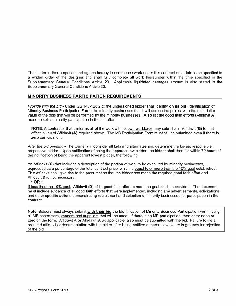
SCO-Proposal Form 2013 2 of 3
The bidder further proposes and agrees hereby to commence work under this contract on a date to be specified in a written order of the designer and shall fully complete all work thereunder within the time specified in the Supplementary General Conditions Article 23. Applicable liquidated damages amount is also stated in the Supplementary General Conditions Article 23. MINORITY BUSINESS PARTICIPATION REQUIREMENTS Provide with the bid - Under GS 143-128.2(c) the undersigned bidder shall identify on its bid (Identification of Minority Business Participation Form) the minority businesses that it will use on the project with the total dollar value of the bids that will be performed by the minority businesses. Also list the good faith efforts (Affidavit A) made to solicit minority participation in the bid effort.
NOTE: A contractor that performs all of the work with its own workforce may submit an Affidavit (B) to that effect in lieu of Affidavit (A) required above. The MB Participation Form must still be submitted even if there is zero participation.
After the bid opening - The Owner will consider all bids and alternates and determine the lowest responsible, responsive bidder. Upon notification of being the apparent low bidder, the bidder shall then file within 72 hours of the notification of being the apparent lowest bidder, the following: An Affidavit (C) that includes a description of the portion of work to be executed by minority businesses, expressed as a percentage of the total contract price, which is equal to or more than the 10% goal established. This affidavit shall give rise to the presumption that the bidder has made the required good faith effort and Affidavit D is not necessary; * OR * If less than the 10% goal, Affidavit (D) of its good faith effort to meet the goal shall be provided. The document must include evidence of all good faith efforts that were implemented, including any advertisements, solicitations and other specific actions demonstrating recruitment and selection of minority businesses for participation in the contract.
Note: Bidders must always submit with their bid the Identification of Minority Business Participation Form listing all MB contractors, vendors and suppliers that will be used. If there is no MB participation, then enter none or zero on the form. Affidavit A or Affidavit B, as applicable, also must be submitted with the bid. Failure to file a required affidavit or documentation with the bid or after being notified apparent low bidder is grounds for rejection of the bid.

SCO-Proposal Form 2013 3 of 3
Proposal Signature Page The undersigned further agrees that in the case of failure on his part to execute the said contract and the bonds within ten (10) consecutive calendar days after being given written notice of the award of contract, the certified check, cash or bid bond accompanying this bid shall be paid into the funds of the owner's account set aside for the project, as liquidated damages for such failure; otherwise the certified check, cash or bid bond accompanying this proposal shall be returned to the undersigned. Respectfully submitted this day of
(Name of firm or corporation making bid) WITNESS: By: Signature Name: (Proprietorship or Partnership) Print or type Title______________ (Owner/Partner/Pres./V.Pres) Address ATTEST: By: License No. Title: Federal I.D. No.
(Corp. Sec. or Asst. Sec. only) Email Address:
(CORPORATE SEAL)
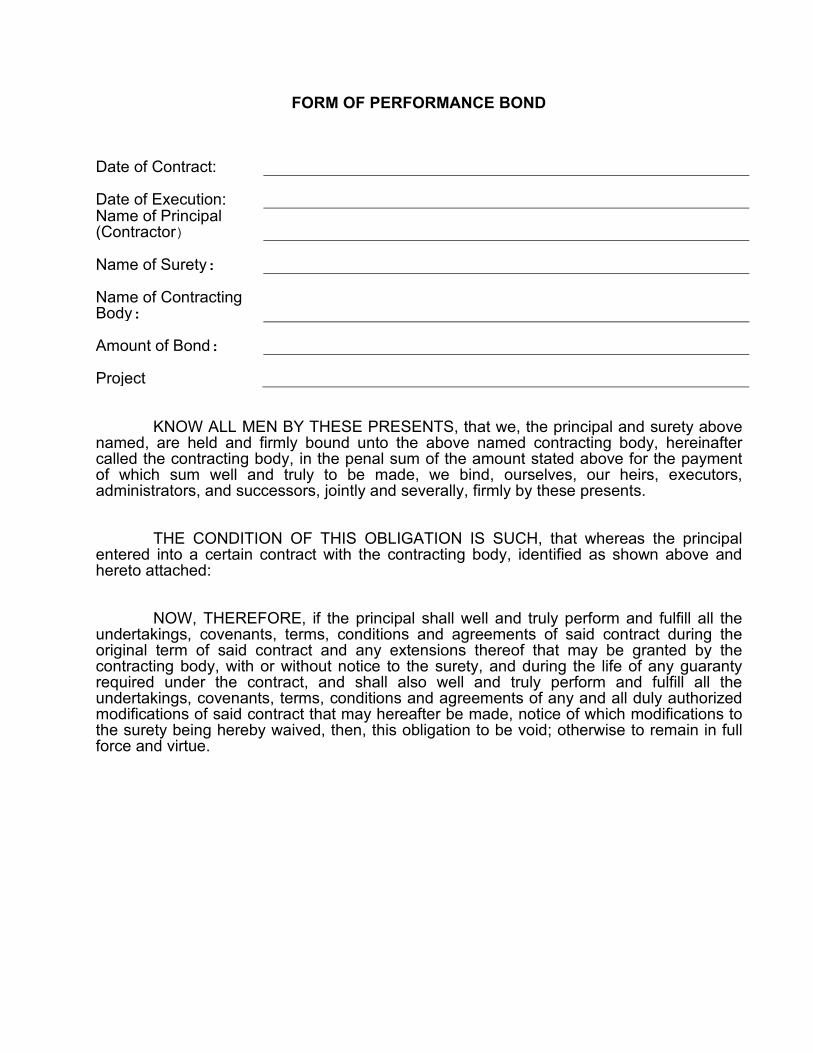
FORM OF PERFORMANCE BOND Date of Contract:
Date of Execution:
Name of Principal (Contractor)
Name of Surety:
Name of Contracting Body:
Amount of Bond:
Project
KNOW ALL MEN BY THESE PRESENTS, that we, the principal and surety above named, are held and firmly bound unto the above named contracting body, hereinafter called the contracting body, in the penal sum of the amount stated above for the payment of which sum well and truly to be made, we bind, ourselves, our heirs, executors, administrators, and successors, jointly and severally, firmly by these presents. THE CONDITION OF THIS OBLIGATION IS SUCH, that whereas the principal entered into a certain contract with the contracting body, identified as shown above and hereto attached: NOW, THEREFORE, if the principal shall well and truly perform and fulfill all the undertakings, covenants, terms, conditions and agreements of said contract during the original term of said contract and any extensions thereof that may be granted by the contracting body, with or without notice to the surety, and during the life of any guaranty required under the contract, and shall also well and truly perform and fulfill all the undertakings, covenants, terms, conditions and agreements of any and all duly authorized modifications of said contract that may hereafter be made, notice of which modifications to the surety being hereby waived, then, this obligation to be void; otherwise to remain in full force and virtue.

IN WITNESS WHEREOF, the above-bounden parties have executed this instrument under their several seals on the date indicated above, the name and corporate seal of each corporate party being hereto affixed and these presents duly signed by its undersigned representative, pursuant to authority of its governing body. Executed in counterparts. Witness: Contractor: (Trade or Corporate Name) By: (Proprietorship or Partnership) Attest: (Corporation) Title: (Owner, Partner, or Corp. Pres. or Vice Pres. only) By: Title: (Corp. Sec. or Asst. Sec.. only) (Corporate Seal) (Surety Company) Witness: By: Title: (Attorney in Fact) Countersigned: (Surety Corporate Seal) (N.C. Licensed Resident Agent) Name and Address-Surety Agency Surety Company Name and N.C. Regional or Branch Office Address

FORM OF PAYMENT BOND Date of Contract:
Date of Execution:
Name of Principal (Contractor)
Name of Surety:
Name of Contracting Body:
Amount of Bond:
Project
KNOW ALL MEN BY THESE PRESENTS, that we, the principal and surety above named, are held and firmly bound unto the above named contracting body, hereinafter called the contracting body, in the penal sum of the amount stated above for the payment of which sum well and truly to be made, we bind ourselves, our heirs, executors, administrators, and successors, jointly and severally, firmly by these presents. THE CONDITION OF THIS OBLIGATION IS SUCH, that whereas the principal entered into a certain contract with the contracting body identified as shown above and hereto attached: NOW, THEREFORE, if the principal shall promptly make payment to all persons supplying labor/material in the prosecution of the work provided for in said contract, and any and all duly authorized modifications of said contract that may hereafter be made, notice of which modifications to the surety being hereby waived, then this obligation to be void; otherwise to remain in full force and virtue. IN WITNESS WHEREOF, the above-bounden parties have executed this instrument under their several seals on the date indicated above, the name and corporate seal of each corporate party being hereto affixed and these presents duly signed by its undersigned representative, pursuant to authority of its governing body. Executed in counterparts.

Witness: Contractor: (Trade or Corporate Name) By: (Proprietorship or Partnership) Attest: (Corporation) Title: (Owner, Partner, or Corp. Pres. or Vice Pres. only) By: Title: (Corp. Sec. or Asst. Sec.. only) (Corporate Seal) (Surety Company) Witness: By: Title: (Attorney in Fact) Countersigned: (Surety Corporate Seal) (N.C. Licensed Resident Agent) Name and Address-Surety Agency Surety Company Name and N.C. Regional or Branch Office Address

FORM OF BID BOND
KNOW ALL MEN BY THESE PRESENTS THAT ________________ __________________________________________________________________ as principal, and _______________________________________________, as surety, who is duly licensed to act as surety in North Carolina, are held and firmly bound unto the State of North Carolina* through _______________________________________________ as obligee, in the penal sum of ___________________________ DOLLARS, lawful money of the United States of America, for the payment of which, well and truly to be made, we bind ourselves, our heirs, executors, administrators, successors and assigns, jointly and severally, firmly by these presents. Signed, sealed and dated this day of 20 WHEREAS, the said principal is herewith submitting proposal for and the principal desires to file this bid bond in lieu of making the cash deposit as required by G.S. 143-129. NOW, THEREFORE, THE CONDITION OF THE ABOVE OBLIGATION is such, that if the principal shall be awarded the contract for which the bid is submitted and shall execute the contract and give bond for the faithful performance thereof within ten days after the award of same to the principal, then this obligation shall be null and void; but if the principal fails to so execute such contract and give performance bond as required by G.S. 143-129, the surety shall, upon demand, forthwith pay to the obligee the amount set forth in the first paragraph hereof. Provided further, that the bid may be withdrawn as provided by G.S. 143-129.1 (SEAL) (SEAL) (SEAL) (SEAL) (SEAL)

245
Management of Regulated Demolition Debris Contractor Waste Management Form
Project Name:
Contact Information WCU Project Manager:
Contractor Name: Subcontractor Name:
Address: Address:
Phone Number: Phone Number: Onsite Contact: Emergency Contact: Phone Number: Phone Number: Emergency Contact: Phone Number:
Recycling/Reclamation Facility:
Phone Number:
Treatment/Disposal Facility:
Phone Number:
Wastes of Concern Type Container Type* Storage Location Comments
Asbestos Decontamination/ Cleaning Liquids
Lead Paint Fluorescent Lamps
Ballast (PCB or Non PCB)
Mercury Containing Equipment
Batteries Sink Traps (labs only)
Oil Scrap Tires
White Goods Other: Other: Other: Other: Other: Other:
*Container Type – Roll-off, Tank, Drum (specify size), Boxes, Other (specify)
Signature Date
Please complete this form and e-mail to the Project Manager

246

247

WCU AK HINDS UC 1ST FLOOR RENOVATIONS
SUMMARY 01 1000 - 1
SECTION 01 1000 - SUMMARY
PART 1 - GENERAL
1.1 RELATED DOCUMENTS
A. Drawings and general provisions of the Contract, including General and Supplementary Conditions and other Division 01 Specification Sections, apply to this Section.
1.2 SUMMARY
A. Section Includes:
1. Project information. 2. Work covered by Contract Documents. 3. Work performed by Owner. 4. Contractor's use of site and premises. 5. Coordination with occupants. 6. Work restrictions. 7. Specification and Drawing conventions.
B. Related Requirements:
1. Section 01 5000 "Temporary Facilities and Controls" for limitations and procedures governing temporary use of Owner's facilities.
2. Section 01 7300 "Execution" for coordination of Owner-installed products.
1.3 PROJECT INFORMATION
A. Project Identification: AK Hinds UC 1st Floor Renovations. SCO ID No. 19-20070-01. Code: 41829. Item: 304.
1. Project Location: Western Carolina University. AK Hinds University Center. 245 Memorial Drive. Cullowhee, NC. 28273.
B. Owner: The State of North Carolina through Western Carolina University.
1. Owner's Representative: Javier Torres, AIA; University Architect. Western Carolina University. Facilities Management. 3476 Old Cullowhee Road. Cullowhee, NC 28273. (828) 227-2345.
C. Architect: Biloba Architecture, PLLC. 8801 JM Keynes Drive, Suite 365. Charlotte, NC 28262. (704) 248-2922.
1. Architect's Representative: Ian Patrick, AIA. (704) 248-2922.
D. Architect's Consultants: Architect has retained the following design professionals, who have prepared designated portions of the Contract Documents:
1. Plumbing, Mechanical, Electrical, Fire Alarm, Fire Protection Engineer: Optima Engineering, PA. 1927 S. Tryon Street, Suite 300. Charlotte, NC 28203. (704) 338-1292.

WCU AK HINDS UC 1ST FLOOR RENOVATIONS
SUMMARY 01 1000 - 2
1.4 WORK COVERED BY CONTRACT DOCUMENTS
A. The Work of Project is defined by the Contract Documents and includes, but is not limited to, the following:
1. Renovation of the partial first floor of the AK Hinds University Center and other Work indicated in the Contract Documents.
B. Type of Contract:
1. Project will be constructed under a single prime contract.
1.5 WORK PERFORMED BY OWNER
A. Cooperate fully with Owner, so work may be carried out smoothly, without interfering with or delaying Work under this Contract or work by Owner. Coordinate the Work of this Contract with work performed by Owner.
B. Concurrent Work: Owner will perform the following construction operations at Project site. Those operations will be conducted simultaneously with Work under this Contract.
1. Installation of Owner Provided Room Identification Signage. 2. Data cabling installation.
1.6 CONTRACTOR'S USE OF SITE AND PREMISES
A. Restricted Use of Site: Contractor shall have limited use of Project site for construction operations as indicated on Drawings by the Contract limits and as indicated by requirements of this Section.
B. Limits on Use of Site: Limit use of Project site to Work in areas indicated. Do not disturb portions of Project site beyond areas in which the Work is indicated.
1. Driveways, Walkways and Entrances: Keep driveways and entrances serving premises clear and available to Owner, Owner's employees, and emergency vehicles at all times. Do not use these areas for parking or for storage of materials.
a. Schedule deliveries to minimize use of driveways and entrances by construction operations. b. Schedule deliveries to minimize space and time requirements for storage of materials and
equipment on-site.
C. Condition of Existing Building: Maintain portions of existing building affected by construction operations in a weathertight condition throughout construction period. Repair damage caused by construction operations.
D. Condition of Existing Grounds: Maintain portions of existing grounds, landscaping, and hardscaping affected by construction operations throughout construction period. Repair damage caused by construction operations.

WCU AK HINDS UC 1ST FLOOR RENOVATIONS
SUMMARY 01 1000 - 3
1.7 COORDINATION WITH OCCUPANTS
A. Partial Owner Occupancy: Owner will occupy the premises during entire construction period, with the exception of areas under construction. Cooperate with Owner during construction operations to minimize conflicts and facilitate Owner usage. Perform the Work so as not to interfere with Owner's operations. Maintain existing exits unless otherwise indicated.
1. Maintain access to existing walkways, corridors, and other adjacent occupied or used facilities. Do not close or obstruct walkways, corridors, or other occupied or used facilities without written permission from Owner and authorities having jurisdiction.
2. Provide not less than 72 hours' notice to Owner of activities that will affect Owner's operations.
B. Owner Beneficial Occupancy of Completed Areas of Construction: In accordance with General Conditions, Ch. 24, Owner reserves the right to occupy and to place and install equipment in completed portions of the Work, prior to Final Completion of the Work, provided such occupancy does not interfere with completion of the Work. Such placement of equipment and limited occupancy shall not constitute acceptance of the total Work.
1. Architect will prepare a State Construction Office "Project Approval Authorization: Partial Utilization (Beneficial Occupancy)" Form for each specific portion of the Work to be occupied prior to Owner acceptance of the completed Work.
2. Obtain approval from the State Construction Office before limited Owner occupancy. 3. Before limited Owner occupancy, mechanical and electrical systems shall be fully operational, and
required tests and inspections shall be successfully completed. On occupancy, Owner will operate and maintain mechanical and electrical systems serving occupied portions of Work.
4. On occupancy, Owner will assume responsibility for maintenance and custodial service for occupied portions of Work.
1.8 WORK RESTRICTIONS
A. Comply with restrictions on construction operations.
1. Comply with limitations on use of public streets, work on public streets, rights of way, and other requirements of authorities having jurisdiction.
B. On-Site Work Hours: Limit work to between 7:00 a.m. to 5:00 p.m., Monday through Friday, unless otherwise indicated. Work hours may be modified to meet Project requirements if approved by Owner and authorities having jurisdiction.
1. Weekend Hours: Provide Owner 72 hours notice for weekend work. 2. Early Morning Hours: Provide Owner 72 hours notice for noisy work. 3. Hours for Utility Shutdowns: Provide Owner 72 hours notice.
C. Existing Utility Interruptions: Do not interrupt utilities serving facilities occupied by Owner or others unless permitted under the following conditions and then only after arranging for temporary utility services according to requirements indicated:
1. Notify Owner not less than three days in advance of proposed utility interruptions. 2. Obtain Owner's written permission before proceeding with utility interruptions.
D. Noise, Vibration, Dust, and Odors: Coordinate operations that may result in high levels of noise and vibration, dust, odors, or other disruption to Owner occupancy with Owner.
1. Notify Owner not less than three days in advance of proposed disruptive operations.

WCU AK HINDS UC 1ST FLOOR RENOVATIONS
SUMMARY 01 1000 - 4
2. Obtain Owner'swritten permission before proceeding with disruptive operations.
E. Smoking and Controlled Substance Restrictions: Use of tobacco products, alcoholic beverages, and other controlled substances on Owner's property is not permitted.
F. Employee Identification: Provide identification tags for Contractor personnel working on Project site. Require personnel to use identification tags at all times.
G. Employee Screening: Comply with Owner's requirements for screening of Contractor personnel working on Project site.
1. Maintain list of approved screened personnel with Owner's representative.
1.9 SPECIFICATION AND DRAWING CONVENTIONS
A. Specification Content: The Specifications use certain conventions for the style of language and the intended meaning of certain terms, words, and phrases when used in particular situations. These conventions are as follows:
1. Imperative mood and streamlined language are generally used in the Specifications. The words "shall," "shall be," or "shall comply with," depending on the context, are implied where a colon (:) is used within a sentence or phrase.
2. Text Color: Text used in the Specifications, including units of measure, manufacturer and product names, and other text may appear in multiple colors or underlined as part of a hyperlink; no emphasis is implied by text with these characteristics.
3. Hypertext: Text used in the Specifications may contain hyperlinks. Hyperlinks may allow for access to linked information that is not residing in the Specifications. Unless otherwise indicated, linked information is not part of the Contract Documents.
4. Specification requirements are to be performed by Contractor unless specifically stated otherwise.
B. Division 00 Contracting Requirements: General provisions of the Contract, including General and Supplementary Conditions, apply to all Sections of the Specifications.
C. Division 01 General Requirements: Requirements of Sections in Division 01 apply to the Work of all Sections in the Specifications.
D. Drawing Coordination: Requirements for materials and products identified on Drawings are described in detail in the Specifications. One or more of the following are used on Drawings to identify materials and products:
1. Terminology: Materials and products are identified by the typical generic terms used in the individual Specifications Sections.
2. Abbreviations: Materials and products are identified by abbreviations scheduled on Drawings and published as part of the U.S. National CAD Standard.
3. Keynoting: Materials and products are identified by reference keynotes referencing Specification Section numbers found in this Project Manual.

WCU AK HINDS UC 1ST FLOOR RENOVATIONS
SUMMARY 01 1000 - 5
PART 2 - PRODUCTS (Not Used)
PART 3 - EXECUTION (Not Used)
END OF SECTION 01 1000

WCU AK HINDS UC 1ST FLOOR RENOVATIONS
SECTION 01 2100 - ALLOWANCES
PART 1 - GENERAL
1.1 RELATED DOCUMENTS
A. Drawings and general provisions of the Contract, including General and Supplementary Conditions and other Division 01 Specification Sections, apply to this Section.
1.2 SUMMARY
A. Section includes administrative and procedural requirements governing allowances.
B. Types of allowances include the following:
1. Quantity allowances.
C. Related Requirements:
1. Section 01 2200 "Unit Prices" for procedures for using unit prices, including adjustment of quantity allowances when applicable.
2. Section 01 2600 "Contract Modification Procedures" for procedures for submitting and handling Change Orders.
3. Section 01 4000 "Quality Requirements" for procedures governing the use of allowances for field testing by an independent testing agency.
1.3 DEFINITIONS
A. Allowance: A quantity of work or dollar amount included in the Contract, established in lieu of additional requirements, used to defer selection of actual materials and equipment to a later date when direction will be provided to Contractor. If necessary, additional requirements will be issued by Change Order.
1.4 ACTION SUBMITTALS
A. Submit proposals for purchase of products or systems included in allowances in the form specified for Change Orders.
1.5 INFORMATIONAL SUBMITTALS
A. Submit invoices or delivery slips to show actual quantities of materials delivered to the site for use in fulfillment of each allowance.
B. Submit time sheets and other documentation to show labor time and cost for installation of allowance items that include installation as part of the allowance.
C. Coordinate and process submittals for allowance items in same manner as for other portions of the Work.
ALLOWANCES 01 2100 - 1

WCU AK HINDS UC 1ST FLOOR RENOVATIONS
1.6 QUANTITY ALLOWANCES
A. Allowance shall include cost to Contractor of specific products and materials ordered by Owner or selected by Architect under allowance and shall include taxes, freight, and delivery to Project site.
B. Unless otherwise indicated, Contractor's costs for receiving and handling at Project site, labor, installation, overhead and profit, and similar costs related to products and materials ordered by Owner or selected by Architect under allowance shall be included as part of the Contract Sum and not part of the allowance.
C. Unused Materials: Return unused materials purchased under an allowance to manufacturer or supplier for credit to Owner, after installation has been completed and accepted.
1. If requested by Architect, retain and prepare unused material for storage by Owner. Deliver unused material to Owner's storage space as directed.
1.7 ADJUSTMENT OF ALLOWANCES
A. Allowance Adjustment: To adjust allowance amounts, prepare a Change Order proposal based on the difference between purchase amount and the allowance, multiplied by final measurement of work-in-place where applicable. If applicable, include reasonable allowances for cutting losses, tolerances, mixing wastes, normal product imperfections, required maintenance materials, and similar margins.
1. Include installation costs in purchase amount only where indicated as part of the allowance.2. If requested, prepare explanation and documentation to substantiate distribution of overhead costs
and other markups.3. Submit substantiation of a change in scope of Work, if any, claimed in Change Orders related to
unit-cost allowances.4. Owner reserves the right to establish the quantity of work-in-place by independent quantity
survey, measure, or count.
B. Submit claims for increased costs due to a change in the scope or nature of the allowance described in the Contract Documents, whether for the purchase order amount or Contractor's handling, labor, installation, overhead, and profit.
1. Do not include Contractor's or subcontractor's indirect expense in the Change Order cost amount unless it is clearly shown that the nature or extent of Work has changed from what could have been foreseen from information in the Contract Documents.
2. No change to Contractor's indirect expense is permitted for selection of higher- or lower-priced materials or systems of the same scope and nature as originally indicated.
ALLOWANCES 01 2100 - 2

WCU AK HINDS UC 1ST FLOOR RENOVATIONS
PART 2 - PRODUCTS (Not Used)
PART 3 - EXECUTION
3.1 EXAMINATION
A. Examine products covered by an allowance promptly on delivery for damage or defects. Return damaged or defective products to manufacturer for replacement.
3.2 PREPARATION
A. Coordinate materials and their installation for each allowance with related materials and installations to ensure that each allowance item is completely integrated and interfaced with related work.
3.3 SCHEDULE OF ALLOWANCES
A. Allowance No. 1: Quantity Allowance: Include 1000 sq. ft. of applied fireproofing on existing metal floor deck and 200 sq. ft. of applied fireproofing on existing steel columns as specified in Section 07 8100 "Applied Fireproofing."
1. Coordinate quantity allowance adjustment with unit-price requirements in Section 01 2200 "Unit Prices."
END OF SECTION 01 2100
ALLOWANCES 01 2100 - 3

WCU AK HINDS UC 1ST FLOOR RENOVATIONS
SECTION 01 2200 - UNIT PRICES
PART 1 - GENERAL
1.1 RELATED DOCUMENTS
A. Drawings and general provisions of the Contract, including General and Supplementary Conditions and other Division 01 Specification Sections, apply to this Section.
1.2 SUMMARY
A. Section includes administrative and procedural requirements for unit prices.
B. Related Requirements:
1. Section 01 2100 "Allowances" for procedures for using unit prices to adjust quantity allowances.2. Section 01 2600 "Contract Modification Procedures" for procedures for submitting and handling
Change Orders.
1.3 DEFINITIONS
A. Unit price is a price per unit of measurement for materials, equipment, or services, or a portion of the Work, added to or deducted from the Contract Sum by appropriate modification, if the scope of Work or estimated quantities of Work required by the Contract Documents are increased or decreased.
1.4 PROCEDURES
A. Unit prices include all necessary material, plus cost for delivery, installation, insurance, applicable taxes, overhead, and profit.
B. Measurement and Payment: See individual Specification Sections for work that requires establishment of unit prices. Methods of measurement and payment for unit prices are specified in those Sections.
C. Owner reserves the right to reject Contractor's measurement of work-in-place that involves use of established unit prices and to have this work measured, at Owner's expense, by an independent surveyor acceptable to Contractor.
D. List of Unit Prices: A schedule of unit prices is included in Part 3. Specification Sections referenced in the Part 3 "Schedule of Unit Prices" Article contain requirements for materials described under each unit price.
UNIT PRICES 01 2200 - 1
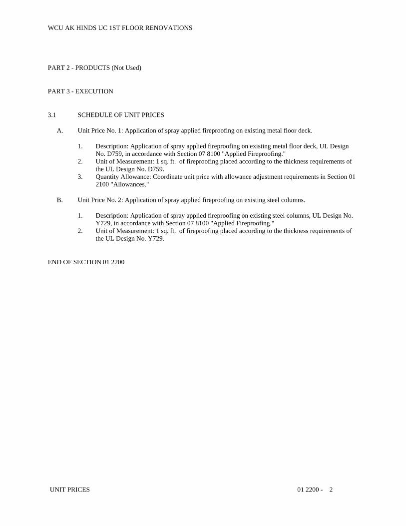
WCU AK HINDS UC 1ST FLOOR RENOVATIONS
PART 2 - PRODUCTS (Not Used)
PART 3 - EXECUTION
3.1 SCHEDULE OF UNIT PRICES
A. Unit Price No. 1: Application of spray applied fireproofing on existing metal floor deck.
1. Description: Application of spray applied fireproofing on existing metal floor deck, UL Design No. D759, in accordance with Section 07 8100 "Applied Fireproofing."
2. Unit of Measurement: 1 sq. ft. of fireproofing placed according to the thickness requirements of the UL Design No. D759.
3. Quantity Allowance: Coordinate unit price with allowance adjustment requirements in Section 01 2100 "Allowances."
B. Unit Price No. 2: Application of spray applied fireproofing on existing steel columns.
1. Description: Application of spray applied fireproofing on existing steel columns, UL Design No. Y729, in accordance with Section 07 8100 "Applied Fireproofing."
2. Unit of Measurement: 1 sq. ft. of fireproofing placed according to the thickness requirements of the UL Design No. Y729.
END OF SECTION 01 2200
UNIT PRICES 01 2200 - 2

WCU AK HINDS UC 1ST FLOOR RENOVATIONS
SECTION 01 2300 - ALTERNATES
PART 1 - GENERAL
1.1 RELATED DOCUMENTS
A. Drawings and general provisions of the Contract, including General and Supplementary Conditions and other Division 01 Specification Sections, apply to this Section.
1.2 SUMMARY
A. Section includes administrative and procedural requirements for alternates.
1.3 DEFINITIONS
A. Alternate: An amount proposed by bidders and stated on the Bid Form for certain work defined in the bidding requirements that may be added to or deducted from the base bid amount if the Owner decides to accept a corresponding change either in the amount of construction to be completed or in the products, materials, equipment, systems, or installation methods described in the Contract Documents.
1. Alternates described in this Section are part of the Work only if enumerated in the Agreement.2. The cost or credit for each alternate is the net addition to or deduction from the Contract Sum to
incorporate alternates into the Work. No other adjustments are made to the Contract Sum.
1.4 PROCEDURES
A. Coordination: Revise or adjust affected adjacent work as necessary to completely integrate work of the alternate into Project.
1. Include, as part of each alternate, miscellaneous devices, accessory objects, and similar items incidental to or required for a complete installation, whether or not indicated as part of alternate.
B. Execute accepted alternates under the same conditions as other Work of the Contract.
C. Schedule: A Part 3 "Schedule of Alternates" Article is included at the end of this Section. Specification Sections referenced in schedule contain requirements for materials necessary to achieve the work described under each alternate.
PART 2 - PRODUCTS (Not Used)
PART 3 - EXECUTION
3.1 SCHEDULE OF ALTERNATES
A. Alternate No. 1: Owner-preferred door hardware.
ALTERNATES 01 2300 - 1

WCU AK HINDS UC 1ST FLOOR RENOVATIONS
1. Base Bid: Provide Door hardware in compliance with Section 08 7100 "Door Hardware" and 08 7113 "Automatic Door Operators" by available manufacturer's listed.
2. Alternate: Provide Owner Preferred Door Hardware brands as listed in the Hardware Schedule in Section Section 08 7100 "Door Hardware".
B. Alternate No. 2: Linear metal baffle ceilings.
1. Base Bid: Provide acoustical panel ceilings and mechanical, electrical, and fire protection devices as indicated on Drawings and as specified in Sections 09 5113 "Acoustical Panel Ceilings."
2. Alternate: Provide linear metal ceilings and wall baffles and mechanical, electrical, and fire protection devices as indicated on Drawings and as specified in Section 09 5423 "Linear Metal Ceilings."
C. Alternate No. 3: Exterior storefront windows.1. Base Bid: Existing metal stud and gypsum board wall to remain as indicated on Demolition
Drawings.2. Alternate: Demolish existing brick infill and provide new exterior storefront windows, glazing and
solid surface sills as indicated on Drawings and as specified in Sections 08 4113 "Aluminum-framed Entrances and Storefronts", 08 8000 "Glazing", and "12 3661.16 "Solid Surfacing Countertops."
D. Alternate No. 4: Demountable Partitions.
1. Base Bid: Provide wood doors and hollow metal frames, or, if no door indicated, gypsum board and stud walls as indicated in the door schedule and as specified in 08 1213 "Hollow Metal Frames" and 08 1416 "Flush Wood Doors," and 09 2216 "Non-Structural Metal Framing" and 09 2900 "Gypsum Board."
2. Alternate: In lieu of wood doors, hollow metal frames, or gypsum board walls, provide Demountable Partitions as indicated on the Drawings, in the Door Schedule, and as Specified in 10 2219 "Demountable Partitions."
END OF SECTION 01 2300
ALTERNATES 01 2300 - 2

WCU AK HINDS UC 1ST FLOOR RENOVATIONS
SUBSTITUTION PROCEDURES 01 2500 - 1
SECTION 01 2500 - SUBSTITUTION PROCEDURES
PART 1 - GENERAL
1.1 RELATED DOCUMENTS
A. Drawings and general provisions of the Contract, including General and Supplementary Conditions and other Division 01 Specification Sections, apply to this Section.
1.2 SUMMARY
A. Section includes administrative and procedural requirements for substitutions.
B. Related Requirements:
1. Section 01 6000 "Product Requirements" for requirements for submitting comparable product submittals for products by listed manufacturers.
1.3 DEFINITIONS
A. Substitutions: Changes in products, materials, equipment, and methods of construction from those required by the Contract Documents.
1. Substitutions for Cause: Changes proposed by Contractor that are required due to changed Project conditions, such as unavailability of product, regulatory changes, or unavailability of required warranty terms.
2. Substitutions for Convenience: Changes proposed by Contractor or Owner that are not required to meet other Project requirements but may offer advantage to Contractor or Owner.
1.4 ACTION SUBMITTALS
A. Substitution Requests: Submit documentation identifying product or fabrication or installation method to be replaced. Include Specification Section number and title and Drawing numbers and titles.
1. Substitution Request Form: Use form acceptable to Architect. 2. Documentation: Show compliance with requirements for substitutions and the following, as
applicable:
a. Statement indicating why specified product or fabrication or installation method cannot be provided, if applicable.
b. Coordination of information, including a list of changes or revisions needed to other parts of the Work and to construction performed by Owner and separate contractors that will be necessary to accommodate proposed substitution.
c. Detailed comparison of significant qualities of proposed substitutions with those of the Work specified. Include annotated copy of applicable Specification Section. Significant qualities may include attributes, such as performance, weight, size, durability, visual effect, sustainable design characteristics, warranties, and specific features and requirements indicated. Indicate deviations, if any, from the Work specified.

WCU AK HINDS UC 1ST FLOOR RENOVATIONS
SUBSTITUTION PROCEDURES 01 2500 - 2
d. Product Data, including drawings and descriptions of products and fabrication and installation procedures.
e. Samples, where applicable or requested. f. Certificates and qualification data, where applicable or requested. g. List of similar installations for completed projects, with project names and addresses as
well as names and addresses of architects and owners. h. Material test reports from a qualified testing agency, indicating and interpreting test results
for compliance with requirements indicated. i. Research reports evidencing compliance with building code in effect for Project, from
ICC-ES. j. Detailed comparison of Contractor's construction schedule using proposed substitutions
with products specified for the Work, including effect on the overall Contract Time. If specified product or method of construction cannot be provided within the Contract Time, include letter from manufacturer, on manufacturer's letterhead, stating date of receipt of purchase order, lack of availability, or delays in delivery.
k. Cost information, including a proposal of change, if any, in the Contract Sum. l. Contractor's certification that proposed substitution complies with requirements in the
Contract Documents, except as indicated in substitution request, is compatible with related materials and is appropriate for applications indicated.
m. Contractor's waiver of rights to additional payment or time that may subsequently become necessary because of failure of proposed substitution to produce indicated results.
3. Architect's Action: If necessary, Architect will request additional information or documentation for evaluation within seven days of receipt of a request for substitution. Architect will notify Contractor of acceptance or rejection of proposed substitution within 15 days of receipt of request, or seven days of receipt of additional information or documentation, whichever is later.
a. Forms of Acceptance: Change Order, Construction Change Directive, or Architect's Supplemental Instructions for minor changes in the Work.
b. Use product specified if Architect does not issue a decision on use of a proposed substitution within time allocated.
1.5 QUALITY ASSURANCE
A. Compatibility of Substitutions: Investigate and document compatibility of proposed substitution with related products and materials. Engage a qualified testing agency to perform compatibility tests recommended by manufacturers.
1.6 PROCEDURES
A. Coordination: Revise or adjust affected work as necessary to integrate work of the approved substitutions.
1.7 SUBSTITUTIONS
A. Substitutions will only be considered during bidding, up to ten days prior to the bid opening. Substitutions after this time will be considered only as a potential change order.
B. Substitutions for Cause: Submit requests for substitution immediately on discovery of need for change, but not later than 15 days prior to time required for preparation and review of related submittals.

WCU AK HINDS UC 1ST FLOOR RENOVATIONS
SUBSTITUTION PROCEDURES 01 2500 - 3
1. Conditions: Architect will consider Contractor's request for substitution when the following conditions are satisfied. If the following conditions are not satisfied, Architect will return requests without action, except to record noncompliance with these requirements:
a. Requested substitution is consistent with the Contract Documents and will produce indicated results.
b. Substitution request is fully documented and properly submitted. c. Requested substitution will not adversely affect Contractor's construction schedule. d. Requested substitution has received necessary approvals of authorities having jurisdiction. e. Requested substitution is compatible with other portions of the Work. f. Requested substitution has been coordinated with other portions of the Work. g. Requested substitution provides specified warranty.
C. Substitutions for Convenience: Not allowed.
PART 2 - PRODUCTS (Not Used)
PART 3 - EXECUTION (Not Used)
END OF SECTION 01 2500

WCU AK HINDS UC 1ST FLOOR RENOVATIONS
CONTRACT MODIFICATION PROCEDURES 01 2600 - 1
SECTION 01 2600 - CONTRACT MODIFICATION PROCEDURES
PART 1 - GENERAL
1.1 RELATED DOCUMENTS
A. Drawings and general provisions of the Contract, including General and Supplementary Conditions and other Division 01 Specification Sections, apply to this Section.
1.2 SUMMARY
A. Section includes administrative and procedural requirements for handling and processing Contract modifications.
B. Related Requirements:
1. Section 01 2500 "Substitution Procedures" for administrative procedures for handling requests for substitutions made after the Contract award.
2. Section 01 3100 "Project Management and Coordination" for requirements for forms for contract modifications provided as part of web-based Project management software.
1.3 MINOR CHANGES IN THE WORK
A. Architect will issue supplemental instructions authorizing minor changes in the Work, not involving adjustment to the Contract Sum or the Contract Time.
1.4 PROPOSAL REQUESTS
A. Owner-Initiated Proposal Requests: Architect will issue a detailed description of proposed changes in the Work that may require adjustment to the Contract Sum or the Contract Time. If necessary, the description will include supplemental or revised Drawings and Specifications.
1. Work Change Proposal Requests issued by Architect are not instructions either to stop work in progress or to execute the proposed change.
2. Within time specified in Proposal Request or 15 days, when not otherwise specified, 15 days after receipt of Proposal Request, submit a quotation estimating cost adjustments to the Contract Sum and the Contract Time necessary to execute the change.
a. Include a list of quantities of products required or eliminated and unit costs, with total amount of purchases and credits to be made. If requested, furnish survey data to substantiate quantities.
b. Indicate applicable taxes, delivery charges, equipment rental, and amounts of trade discounts.
c. Include costs of labor and supervision directly attributable to the change. d. Include an updated Contractor's construction schedule that indicates the effect of the change,
including, but not limited to, changes in activity duration, start and finish times, and activity relationship. Use available total float before requesting an extension of the Contract Time.
e. Quotation Form: Use forms acceptable to Architect.

WCU AK HINDS UC 1ST FLOOR RENOVATIONS
CONTRACT MODIFICATION PROCEDURES 01 2600 - 2
B. Contractor-Initiated Proposals: If latent or changed conditions require modifications to the Contract, Contractor may initiate a claim by submitting a request for a change to Architect.
1. Include a statement outlining reasons for the change and the effect of the change on the Work. Provide a complete description of the proposed change. Indicate the effect of the proposed change on the Contract Sum and the Contract Time.
2. Include a list of quantities of products required or eliminated and unit costs, with total amount of purchases and credits to be made. If requested, furnish survey data to substantiate quantities.
3. Indicate applicable taxes, delivery charges, equipment rental, and amounts of trade discounts. 4. Include costs of labor and supervision directly attributable to the change. 5. Include an updated Contractor's construction schedule that indicates the effect of the change,
including, but not limited to, changes in activity duration, start and finish times, and activity relationship. Use available total float before requesting an extension of the Contract Time.
6. Comply with requirements in Section 01 2500 "Substitution Procedures" if the proposed change requires substitution of one product or system for product or system specified.
7. Proposal Request Form: Use form acceptable to Architect.
1.5 CHANGE ORDER PROCEDURES
A. On Owner's approval of a Work Change Proposal Request, Architect will issue a Change Order for signatures of Owner and Contractor on the State Construction Office’s Standard Form.
1.6 CONSTRUCTION CHANGE DIRECTIVE
A. Construction Change Directive: Architect may issue a Construction Change Directive on State Construction Office’s Standard Form. Construction Change Directive instructs Contractor to proceed with a change in the Work, for subsequent inclusion in a Change Order.
1. Construction Change Directive contains a complete description of change in the Work. It also designates method to be followed to determine change in the Contract Sum or the Contract Time.
B. Documentation: Maintain detailed records on a time and material basis of work required by the Construction Change Directive.
1. After completion of change, submit an itemized account and supporting data necessary to substantiate cost and time adjustments to the Contract.
PART 2 - PRODUCTS (Not Used)
PART 3 - EXECUTION (Not Used)
END OF SECTION 01 2600

WCU AK HINDS UC 1ST FLOOR RENOVATIONS
PAYMENT PROCEDURES 01 2900 - 1
SECTION 01 2900 - PAYMENT PROCEDURES
PART 1 - GENERAL
1.1 RELATED DOCUMENTS
A. Drawings and general provisions of the Contract, including General and Supplementary Conditions and other Division 01 Specification Sections, apply to this Section.
1.2 SUMMARY
A. Section includes administrative and procedural requirements necessary to prepare and process Applications for Payment.
B. Related Requirements: 1. Section 01 2600 "Contract Modification Procedures" for administrative procedures for handling
changes to the Contract. 2. Section 01 3200 "Construction Progress Documentation" for administrative requirements
governing the preparation and submittal of the Contractor's construction schedule.
1.3 DEFINITIONS
A. Schedule of Values: A statement furnished by Contractor allocating portions of the Contract Sum to various portions of the Work and used as the basis for reviewing Contractor's Applications for Payment.
1.4 SCHEDULE OF VALUES
A. Coordination: Coordinate preparation of the schedule of values with preparation of Contractor's construction schedule.
1. Coordinate line items in the schedule of values with items required to be indicated as separate activities in Contractor's construction schedule.
2. Submit the schedule of values to Architect at earliest possible date, but no later than seven days before the date scheduled for submittal of initial Applications for Payment.
3. Subschedules for Separate Elements of Work: Where the Contractor's construction schedule defines separate elements of the Work, provide subschedules showing values coordinated with each element.
B. Format and Content: Use Project Manual table of contents as a guide to establish line items for the schedule of values. Provide at least one line item for each Specification Section.
1. Identification: Include the following Project identification on the schedule of values:
a. Project name and location. b. Owner's name. c. Owner's Project number. d. Name of Architect. e. Architect's Project number. f. Contractor's name and address.

WCU AK HINDS UC 1ST FLOOR RENOVATIONS
PAYMENT PROCEDURES 01 2900 - 2
g. Date of submittal.
2. Arrange schedule of values consistent with format of AIA Document G703. 3. Arrange the schedule of values in tabular form, with separate columns to indicate the following for
each item listed:
a. Related Specification Section or division. b. Description of the Work. c. Name of subcontractor. d. Name of manufacturer or fabricator. e. Name of supplier. f. Change Orders (numbers) that affect value. g. Dollar value of the following, as a percentage of the Contract Sum to nearest one-hundredth
percent, adjusted to total 100 percent. Round dollar amounts to whole dollars, with total equal to Contract Sum.
1) Labor. 2) Materials. 3) Equipment.
4. Provide a breakdown of the Contract Sum in enough detail to facilitate continued evaluation of Applications for Payment and progress reports. Provide multiple line items for principal subcontract amounts in excess of five percent of the Contract Sum.
5. Provide a separate line item in the schedule of values for each part of the Work where Applications for Payment may include materials or equipment purchased or fabricated and stored, but not yet installed.
a. Differentiate between items stored on-site and items stored off-site. 6. Overhead Costs, Proportional Distribution: Include total cost and proportionate share of general
overhead and profit for each line item. 7. Temporary Facilities: Show cost of temporary facilities and other major cost items that are not
direct cost of actual work-in-place as separate line items. 8. Closeout Costs. Include separate line items under Contractor and principal subcontracts for Project
closeout requirements in an amount totaling five percent of the Contract Sum and subcontract amount.
9. Schedule of Values Revisions: Revise the schedule of values when Change Orders or Construction Change Directives result in a change in the Contract Sum. Include at least one separate line item for each Change Order and Construction Change Directive.
1.5 APPLICATIONS FOR PAYMENT
A. Each Application for Payment following the initial Application for Payment shall be consistent with previous applications and payments, as certified by Architect and paid for by Owner.
B. Payment Application Times: The date for each progress payment is indicated in the Owner/Contractor Agreement. The period of construction work covered by each Application for Payment is the period indicated in the Agreement.
1. Submit draft copy of Application for Payment seven days prior to due date for review by Architect.
C. Application for Payment Forms: Use AIA Document G702 and AIA Document G703 as form for Applications for Payment.

WCU AK HINDS UC 1ST FLOOR RENOVATIONS
PAYMENT PROCEDURES 01 2900 - 3
D. Application Preparation: Complete every entry on form. Notarize and execute by a person authorized to sign legal documents on behalf of Contractor. Architect will return incomplete applications without action.
1. Entries shall match data on the schedule of values and Contractor's construction schedule. Use updated schedules if revisions were made.
2. Include amounts for work completed following previous Application for Payment, whether or not payment has been received. Include only amounts for work completed at time of Application for Payment.
3. Include amounts of Change Orders and Construction Change Directives issued before last day of construction period covered by application.
4. Indicate separate amounts for work being carried out under Owner-requested project acceleration.
E. Stored Materials: Include in Application for Payment amounts applied for materials or equipment purchased or fabricated and stored, but not yet installed. Differentiate between items stored on-site and items stored off-site.
1. Provide certificate of insurance, evidence of transfer of title to Owner, and consent of surety to payment for stored materials.
2. Provide supporting documentation that verifies amount requested, such as paid invoices. Match amount requested with amounts indicated on documentation; do not include overhead and profit on stored materials.
3. Provide summary documentation for stored materials indicating the following:
a. Value of materials previously stored and remaining stored as of date of previous Applications for Payment.
b. Value of previously stored materials put in place after date of previous Application for Payment and on or before date of current Application for Payment.
c. Value of materials stored since date of previous Application for Payment and remaining stored as of date of current Application for Payment.
F. Transmittal: Submit three signed and notarized original copies of each Application for Payment to Architect by a method ensuring receipt. One copy shall include waivers of lien and similar attachments if required.
1. Transmit each copy with a transmittal form listing attachments and recording appropriate information about application.
G. Initial Application for Payment: Administrative actions and submittals that must precede or coincide with submittal of first Application for Payment include the following:
1. List of subcontractors. 2. Schedule of values. 3. Contractor's construction schedule (preliminary if not final). 4. Products list (preliminary if not final). 5. Submittal schedule (preliminary if not final). 6. List of Contractor's staff assignments. 7. List of Contractor's principal consultants. 8. Copies of authorizations and licenses from authorities having jurisdiction for performance of the
Work. 9. Initial progress report. 10. Report of preconstruction conference. 11. Certificates of insurance and insurance policies. 12. Performance and payment bonds. 13. Data needed to acquire Owner's insurance.

WCU AK HINDS UC 1ST FLOOR RENOVATIONS
PAYMENT PROCEDURES 01 2900 - 4
H. Application for Payment at Final Acceptance : After Architect issues the Certificate of Final Acceptance, submit an Application for Payment showing 100 percent completion for portion of the Work claimed as substantially complete.
1. Include documentation supporting claim that the Work is substantially complete and a statement showing an accounting of changes to the Contract Sum.
a. Complete administrative actions, submittals, and Work preceding this application, as described in Section 01 7700 "Closeout Procedures."
I. Final Payment Application: After completing Project closeout requirements, submit final Application for Payment with releases and supporting documentation not previously submitted and accepted, including, but not limited, to the following:
1. Evidence of completion of Project closeout requirements. 2. Certification of completion of final punch list items. 3. Insurance certificates for products and completed operations where required and proof that taxes,
fees, and similar obligations were paid. 4. Updated final statement, accounting for final changes to the Contract Sum. 5. AIA Document G706. 6. AIA Document G706A. 7. AIA Document G707. 8. Evidence that claims have been settled. 9. Final meter readings for utilities, a measured record of stored fuel, and similar data as of date of
Substantial Completion or when Owner took possession of and assumed responsibility for corresponding elements of the Work.
10. Final liquidated damages settlement statement. 11. Proof that taxes, fees, and similar obligations are paid. 12. Waivers and releases.
PART 2 - PRODUCTS (Not Used)
PART 3 - EXECUTION (Not Used)
END OF SECTION 01 2900

WCU AK HINDS UC 1ST FLOOR RENOVATIONS
PROJECT MANAGEMENT AND COORDINATION
01 3100 - 1
SECTION 01 3100 - PROJECT MANAGEMENT AND COORDINATION
PART 1 - GENERAL
1.1 RELATED DOCUMENTS
A. Drawings and general provisions of the Contract, including General and Supplementary Conditions and other Division 01 Specification Sections, apply to this Section.
1.2 SUMMARY
A. Section includes administrative provisions for coordinating construction operations on Project, including, but not limited to, the following:
1. General coordination procedures. 2. Coordination drawings. 3. RFIs. 4. Project meetings.
B. Related Requirements: 1. Section 01 3200 "Construction Progress Documentation" for preparing and submitting
Contractor's construction schedule. 2. Section 01 7300 "Execution" for procedures for coordinating general installation and
field-engineering services, including establishment of benchmarks and control points. 3. Section 01 7700 "Closeout Procedures" for coordinating closeout of the Contract.
1.3 DEFINITIONS
A. BIM: Building Information Modeling.
B. RFI: Request for Information. Request from Owner, Architect, or Contractor seeking information required by or clarifications of the Contract Documents.
1.4 INFORMATIONAL SUBMITTALS
A. Subcontract List: Prepare a written summary identifying individuals or firms proposed for each portion of the Work, including those who are to furnish products or equipment fabricated to a special design. Include the following information in tabular form:
1. Name, address, telephone number, and email address of entity performing subcontract or supplying products.
2. Number and title of related Specification Section(s) covered by subcontract. 3. Drawing number and detail references, as appropriate, covered by subcontract.
B. Key Personnel Names: Within 15 days of starting construction operations, submit a list of key personnel assignments, including superintendent and other personnel in attendance at Project site. Identify individuals and their duties and responsibilities; list addresses, cellular telephone numbers, and e-mail addresses. Provide names, addresses, and telephone numbers of individuals assigned as alternates in the absence of individuals assigned to Project.

WCU AK HINDS UC 1ST FLOOR RENOVATIONS
PROJECT MANAGEMENT AND COORDINATION
01 3100 - 2
1. Post copies of list in Project meeting room, in temporary field office, and in prominent location inbuilt facility. Keep list current at all times.
1.5 GENERAL COORDINATION PROCEDURES
A. Coordination: Coordinate construction operations included in different Sections of the Specifications to ensure efficient and orderly installation of each part of the Work. Coordinate construction operations included in different Sections that depend on each other for proper installation, connection, and operation.
1. Schedule construction operations in sequence required to obtain the best results, where installation of one part of the Work depends on installation of other components, before or after its own installation.
2. Coordinate installation of different components to ensure maximum performance and accessibility for required maintenance, service, and repair.
3. Make adequate provisions to accommodate items scheduled for later installation.
B. Prepare memoranda for distribution to each party involved, outlining special procedures required for coordination. Include such items as required notices, reports, and list of attendees at meetings.
1. Prepare similar memoranda for Owner and separate contractors if coordination of their Work is required.
C. Administrative Procedures: Coordinate scheduling and timing of required administrative procedures with other construction activities to avoid conflicts and to ensure orderly progress of the Work. Such administrative activities include, but are not limited to, the following:
1. Preparation of Contractor's construction schedule. 2. Preparation of the schedule of values. 3. Installation and removal of temporary facilities and controls. 4. Delivery and processing of submittals. 5. Progress meetings. 6. Preinstallation conferences. 7. Project closeout activities. 8. Startup and adjustment of systems.
1.6 COORDINATION DRAWINGS
A. Coordination Drawings, General: Prepare coordination drawings according to requirements in individual Sections, and additionally where installation is not completely indicated on Shop Drawings, where limited space availability necessitates coordination, or if coordination is required to facilitate integration of products and materials fabricated or installed by more than one entity.
1. Content: Project-specific information, drawn accurately to a scale large enough to indicate and resolve conflicts. Do not base coordination drawings on standard printed data. Include the following information, as applicable:
a. Use applicable Drawings as a basis for preparation of coordination drawings. Prepare sections, elevations, and details as needed to describe relationship of various systems and components.
b. Coordinate the addition of trade-specific information to coordination drawingsin a sequence that best provides for coordination of the information and resolution of conflicts between installed components before submitting for review.

WCU AK HINDS UC 1ST FLOOR RENOVATIONS
PROJECT MANAGEMENT AND COORDINATION
01 3100 - 3
c. Indicate functional and spatial relationships of components of architectural, structural, civil, mechanical, and electrical systems.
d. Indicate space requirements for routine maintenance and for anticipated replacement of components during the life of the installation.
e. Show location and size of access doors required for access to concealed dampers, valves, and other controls.
f. Indicate required installation sequences. g. Indicate dimensions shown on Drawings. Specifically note dimensions that appear to be in
conflict with submitted equipment and minimum clearance requirements. Provide alternative sketches to Architect indicating proposed resolution of such conflicts. Minor dimension changes and difficult installations will not be considered changes to the Contract.
B. Coordination Drawing Organization: Organize coordination drawings as follows:
1. Floor Plans and Reflected Ceiling Plans: Show architectural and structural elements, and mechanical, plumbing, fire-protection, fire-alarm, and electrical Work. Show locations of visible ceiling-mounted devices relative to acoustical ceiling grid. Supplement plan drawings with section drawings where required to adequately represent the Work.
2. Plenum Space: Indicate subframing for support of ceiling and wall systems, mechanical and electrical equipment, and related Work. Locate components within plenums to accommodate layout of light fixtures and other components indicated on Drawings. Indicate areas of conflict between light fixtures and other components.
3. Mechanical Rooms: Provide coordination drawings for mechanical rooms, showing plans and elevations of mechanical, plumbing, fire-protection, fire-alarm, and electrical equipment.
4. Structural Penetrations: Indicate penetrations and openings required for all disciplines. 5. Slab Edge and Embedded Items: Indicate slab edge locations and sizes and locations of embedded
items for metal fabrications, sleeves, anchor bolts, bearing plates, angles, door floor closers, slab depressions for floor finishes, curbs and housekeeping pads, and similar items.
6. Mechanical and Plumbing Work: Show the following:
a. Sizes and bottom elevations of ductwork, piping, and conduit runs, including insulation, bracing, flanges, and support systems.
b. Dimensions of major components, such as dampers, valves, diffusers, access doors, cleanouts and electrical distribution equipment.
c. Fire-rated enclosures around ductwork.
7. Electrical Work: Show the following:
a. Runs of vertical and horizontal conduit 1-1/4 inches in diameter and larger. b. Light fixture, exit light, emergency battery pack, smoke detector, and other fire-alarm
locations. c. Panel board, switchboard, switchgear, transformer, busway, generator, and motor-control
center locations. d. Location of pull boxes and junction boxes, dimensioned from column center lines.
8. Fire-Protection System: Show the following:
a. Locations of standpipes, mains piping, branch lines, pipe drops, and sprinkler heads.
9. Review: Architect will review coordination drawings to confirm that, in general, the Work is being coordinated, but not for the details of the coordination, which are Contractor's responsibility. If Architect determines that coordination drawings are not being prepared in sufficient scope or detail, or are otherwise deficient, Architect will so inform Contractor, who shall make suitable modifications and resubmit.

WCU AK HINDS UC 1ST FLOOR RENOVATIONS
PROJECT MANAGEMENT AND COORDINATION
01 3100 - 4
10. Coordination Drawing Prints: Prepare coordination drawing prints according to requirements in Section 01 3300 "Submittal Procedures."
C. Coordination Drawing Process: Prepare coordination drawings in the following manner:
1. Schedule submittal and review of Fire Sprinkler, Plumbing, HVAC, and Electrical Shop Drawings to make required changes prior to preparation of coordination drawings.
2. Commence routing of coordination drawing files with HVAC Installer, who will provide drawing plan files denoting approved ductwork. HVAC Installer will locate ductwork and piping on a single layer, using orange color. Forward drawings to Plumbing Installer.
3. Plumbing Installer will locate plumbing and equipment on a single layer, using blue color. 4. Fire Sprinkler Installer will locate piping and equipment, using red color. Fire Sprinkler Installer
shall forward drawing files to Electrical Installer. 5. Electrical Installer will indicate service and feeder conduit runs and equipment in green color.
Electrical Installer shall forward drawing files to Communications and Electronic Safety and Security Installer.
6. Communications and Electronic Safety and Security Installer will indicate cable trays and cabling runs and equipment in purple color. Communications and Electronic Safety and Security Installer shall forward completed drawing files to Contractor.
7. Contractor shall perform the final coordination review. As each coordination drawing is completed, Contractor will meet with Architect to review and resolve conflicts on the coordination drawings.
1.7 REQUEST FOR INFORMATION (RFI)
A. General: Immediately on discovery of the need for additional information, clarification, or interpretation of the Contract Documents, Contractor shall prepare and submit an RFI in the form specified.
1. Architect will return without response those RFIs submitted to Architect by other entities controlled by Contractor.
2. Coordinate and submit RFIs in a prompt manner to avoid delays in Contractor's work or work of subcontractors.
B. Content of the RFI: Include a detailed, legible description of item needing information or interpretation and the following:
1. Project name. 2. Owner name. 3. Owner's Project number. 4. Name of Architect. 5. Architect's Project number. 6. Date. 7. Name of Contractor. 8. RFI number, numbered sequentially. 9. RFI subject. 10. Specification Section number and title and related paragraphs, as appropriate. 11. Drawing number and detail references, as appropriate. 12. Field dimensions and conditions, as appropriate. 13. Contractor's suggested resolution. If Contractor's suggested resolution impacts the Contract Time
or the Contract Sum, Contractor shall state impact in the RFI. 14. Contractor's signature. 15. Attachments: Include sketches, descriptions, measurements, photos, Product Data, Shop Drawings,
coordination drawings, and other information necessary to fully describe items needing interpretation.

WCU AK HINDS UC 1ST FLOOR RENOVATIONS
PROJECT MANAGEMENT AND COORDINATION
01 3100 - 5
a. Include dimensions, thicknesses, structural grid references, and details of affected materials, assemblies, and attachments on attached sketches.
C. RFI Forms: Software-generated form with substantially the same content as indicated above, acceptable to Architect.
1. Attachments shall be electronic files in PDF format.
D. Architect's Action: Architect will review each RFI, determine action required, and respond. Allow seven days for Architect's response for each RFI. RFIs received by Architect after 1:00 p.m. will be considered as received the following working day.
1. The following Contractor-generated RFIs will be returned without action:
a. Requests for approval of submittals. b. Requests for approval of substitutions. c. Requests for approval of Contractor's means and methods. d. Requests for coordination information already indicated in the Contract Documents. e. Requests for adjustments in the Contract Time or the Contract Sum. f. Requests for interpretation of Architect's actions on submittals. g. Incomplete RFIs or inaccurately prepared RFIs.
2. Architect's action may include a request for additional information, in which case Architect's time for response will date from time of receipt by Architectof additional information.
3. Architect's action on RFIs that may result in a change to the Contract Time or the Contract Sum may be eligible for Contractor to submit Change Proposal according to Section 01 2600 "Contract Modification Procedures."
a. If Contractor believes the RFI response warrants change in the Contract Time or the Contract Sum, notify Architect in writing within 5 days of receipt of the RFI response.
E. RFI Log: Prepare, maintain, and submit a tabular log of RFIs organized by the RFI number. Submit log monthly. Include the following:
1. Project name. 2. Name and address of Contractor. 3. Name and address of Architect. 4. RFI number, including RFIs that were returned without action or withdrawn. 5. RFI description. 6. Date the RFI was submitted. 7. Date Architect's response was received. 8. Identification of related Minor Change in the Work, Construction Change Directive, and Proposal
Request, as appropriate. 9. Identification of related Field Order, Work Change Directive, and Proposal Request, as
appropriate.
F. On receipt of Architect's action, update the RFI log and immediately distribute the RFI response to affected parties. Review response and notify Architect within seven days if Contractor disagrees with response.
1.8 DIGITAL PROJECT MANAGEMENT PROCEDURES
A. Use of Architect's Digital Data Files: Digital data files of Architect's BIM model and CAD drawings will be provided by Architect for Contractor's use during construction.

WCU AK HINDS UC 1ST FLOOR RENOVATIONS
PROJECT MANAGEMENT AND COORDINATION
01 3100 - 6
1. Digital data files may be used by Contractor in preparing coordination drawings, Shop Drawings, and Project Record Drawings.
2. Architect makes no representations as to the accuracy or completeness of digital data files as they relate to Contract Drawings.
3. Contractor shall execute a data licensing agreement in the form of Agreement form acceptable to Owner and Architect.
a. Subcontractors and other parties granted access by Contractor to Architect's digital data files shall execute a data licensing agreement in the form of Agreement acceptable to Owner and Architect.
B. PDF Document Preparation: Where PDFs are required to be submitted to Architect, prepare as follows:
1. Assemble complete submittal package into a single indexed file, incorporating submittal requirements of a single Specification Section and transmittal form with links enabling navigation to each item.
2. Name file with submittal number or other unique identifier, including revision identifier. 3. Certifications: Where digitally submitted certificates and certifications are required, provide a
digital signature with digital certificate on where indicated.
1.9 PROJECT MEETINGS
A. General: Architect will schedule and conduct meetings and conferences at Project site unless otherwise indicated. 1. Minutes: Architect will record significant discussions and agreements achieved and distribute the
meeting minutes to everyone concerned.
B. Preconstruction Conference: Architect will schedule and conduct a preconstruction conference before starting construction, at a time convenient to Owner and Architect, but no later than 15 days after execution of the Agreement.
1. Attendees: Authorized representatives of Owner Architect, and their consultants; Contractor and its superintendent; major subcontractors; suppliers; and other concerned parties shall attend the conference. Participants at the conference shall be familiar with Project and authorized to conclude matters relating to the Work.
2. Agenda: Discuss items of significance that could affect progress, including the following:
a. Responsibilities and personnel assignments. b. Tentative construction schedule. c. Schedule of Values and MBE subcontract work. d. Liquidated damages. e. Meeting schedule. f. Critical work sequencing and long lead items. g. Designation of key personnel and their duties. h. Lines of communications. i. Procedures for processing field decisions and Change Orders. j. Procedures for RFIs. k. Procedures for testing and inspecting. l. Procedures for processing Applications for Payment. m. Distribution of the Contract Documents. n. Submittal procedures. o. Preparation of Record Documents. p. Use of the premises and existing building. q. Work restrictions.

WCU AK HINDS UC 1ST FLOOR RENOVATIONS
PROJECT MANAGEMENT AND COORDINATION
01 3100 - 7
r. Working hours. s. Owner's occupancy requirements. t. Responsibility for temporary facilities and controls. u. Procedures for moisture and mold control. v. Procedures for disruptions and shutdowns. w. Construction waste management and recycling. x. Parking availability. y. Office, work, and storage areas. z. Equipment deliveries and priorities. aa. First aid. bb. Security. cc. Decorum. dd. Progress cleaning.
3. Minutes: Entity responsible for conducting meeting will record and distribute meeting minutes.
C. Preinstallation Conferences: Conduct a preinstallation conference at Project site before each construction activity when required by other Sections and when required for coordination with other construction.
1. Attendees: Installer and representatives of manufacturers and fabricators involved in or affected by the installation and its coordination or integration with other materials and installations that have preceded or will follow, shall attend the meeting. Advise Architect of scheduled meeting dates.
2. Agenda: Review progress of other construction activities and preparations for the particular activity under consideration, including requirements for the following:
a. Contract Documents. b. Options. c. Related RFIs. d. Related Change Orders. e. Purchases. f. Deliveries. g. Submittals. h. Sustainable design requirements. i. Review of mockups. j. Possible conflicts. k. Compatibility requirements. l. Time schedules. m. Weather limitations. n. Manufacturer's written instructions. o. Warranty requirements. p. Compatibility of materials. q. Acceptability of substrates. r. Temporary facilities and controls. s. Space and access limitations. t. Regulations of authorities having jurisdiction. u. Testing and inspecting requirements. v. Installation procedures. w. Coordination with other work. x. Required performance results. y. Protection of adjacent work. z. Protection of construction and personnel.
3. Record significant conference discussions, agreements, and disagreements, including required corrective measures and actions.
4. Reporting: Distribute minutes of the meeting to each party present and to other parties requiring information.

WCU AK HINDS UC 1ST FLOOR RENOVATIONS
PROJECT MANAGEMENT AND COORDINATION
01 3100 - 8
5. Do not proceed with installation if the conference cannot be successfully concluded. Initiate whatever actions are necessary to resolve impediments to performance of the Work and reconvene the conference at earliest feasible date.
D. Project Closeout Conference: Schedule and conduct a project closeout conference, at a time convenient to Owner and Architect, but no later than 30 days prior to the scheduled date of Preliminary Final Inspection.
1. Conduct the conference to review requirements and responsibilities related to Project closeout. 2. Attendees: Authorized representatives of Owner, Architect, and their consultants; Contractor and
its superintendent; major subcontractors; suppliers; and other concerned parties shall attend the meeting. Participants at the meeting shall be familiar with Project and authorized to conclude matters relating to the Work.
3. Agenda: Discuss items of significance that could affect or delay Project closeout, including the following:
a. Preparation of Record Documents. b. Procedures required prior to inspection for Preliminary Final Inspection and for final
inspection for acceptance. c. Procedures for completing and archiving web-based Project software site data files. d. Submittal of written warranties. e. Requirements for completing sustainable design documentation. f. Requirements for preparing operations and maintenance data. g. Requirements for delivery of material samples, attic stock, and spare parts. h. Requirements for demonstration and training. i. Preparation of Contractor's punch list. j. Procedures for processing Applications for Payment at Preliminary Final Inspection and for
final payment. k. Submittal procedures. l. Owner's partial occupancy requirements. m. Installation of Owner's furniture, fixtures, and equipment. n. Responsibility for removing temporary facilities and controls.
4. Minutes: Entity conducting meeting will record and distribute meeting minutes.
E. Progress Meetings: Conduct progress meetings at regular intervals.
1. Coordinate dates of meetings with preparation of payment requests. 2. Attendees: In addition to representatives of Owner and Architect, each contractor, subcontractor,
supplier, and other entity concerned with current progress or involved in planning, coordination, or performance of future activities shall be represented at these meetings. All participants at the meeting shall be familiar with Project and authorized to conclude matters relating to the Work.
3. Agenda: Review and correct or approve minutes of previous progress meeting. Review other items of significance that could affect progress. Include topics for discussion as appropriate to status of Project.
a. Contractor's Construction Schedule: Review progress since the last meeting. Determine whether each activity is on time, ahead of schedule, or behind schedule, in relation to Contractor's construction schedule. Determine how construction behind schedule will be expedited; secure commitments from parties involved to do so. Discuss whether schedule revisions are required to ensure that current and subsequent activities will be completed within the Contract Time.
1) Review schedule for next period.

WCU AK HINDS UC 1ST FLOOR RENOVATIONS
PROJECT MANAGEMENT AND COORDINATION
01 3100 - 9
b. Review present and future needs of each entity present, including the following:
1) Interface requirements. 2) Sequence of operations. 3) Status of submittals. 4) Deliveries. 5) Off-site fabrication. 6) Access. 7) Site use. 8) Temporary facilities and controls. 9) Progress cleaning. 10) Quality and work standards. 11) Status of correction of deficient items. 12) Field observations. 13) Status of RFIs. 14) Status of Proposal Requests. 15) Pending changes. 16) Status of Change Orders. 17) Pending claims and disputes. 18) Documentation of information for payment requests.
4. Minutes: Entity responsible for conducting the meeting will record and distribute the meeting minutes to each party present and to parties requiring information.
a. Schedule Updating: Revise Contractor's construction schedule after each progress meeting, where revisions to the schedule have been made or recognized. Issue revised schedule concurrently with the report of each meeting.
PART 2 - PRODUCTS (Not Used)
PART 3 - EXECUTION (Not Used)
END OF SECTION 01 3100

WCU AK HINDS UC 1ST FLOOR RENOVATIONS
CONSTRUCTION PROGRESS DOCUMENTATION
01 3200 - 1
SECTION 01 3200 - CONSTRUCTION PROGRESS DOCUMENTATION
PART 1 - GENERAL
1.1 RELATED DOCUMENTS
A. Drawings and general provisions of the Contract, including General and Supplementary Conditions and other Division 01 Specification Sections, apply to this Section.
1.2 SUMMARY
A. Section includes administrative and procedural requirements for documenting the progress of construction during performance of the Work, including the following: 1. Contractor's Construction Schedule. 2. Unusual event reports.
B. Related Requirements: 1. Section 01 4000 "Quality Requirements" for schedule of tests and inspections. 2. Section 01 2900 "Payment Procedures" for schedule of values and requirements for use of
cost-loaded schedule for Applications for Payment.
1.3 DEFINITIONS
A. Activity: A discrete part of a project that can be identified for planning, scheduling, monitoring, and controlling the construction Project. Activities included in a construction schedule consume time and resources.
1. Critical Activity: An activity on the critical path that must start and finish on the planned early start and finish times.
2. Predecessor Activity: An activity that precedes another activity in the network. 3. Successor Activity: An activity that follows another activity in the network.
B. CPM: Critical path method, which is a method of planning and scheduling a construction project where activities are arranged based on activity relationships. Network calculations determine the critical path of Project and when activities can be performed.
C. Critical Path: The longest connected chain of interdependent activities through the network schedule that establishes the minimum overall Project duration and contains no float.
D. Event: The starting or ending point of an activity.
E. Float: The measure of leeway in starting and completing an activity.
1. Float time is not for the exclusive use or benefit of either Owner or Contractor, but is a jointly owned, expiring Project resource available to both parties as needed to meet schedule milestones and Contract completion date.
2. Free float is the amount of time an activity can be delayed without adversely affecting the early start of the successor activity.
3. Total float is the measure of leeway in starting or completing an activity without adversely affecting the planned Project completion date.

WCU AK HINDS UC 1ST FLOOR RENOVATIONS
CONSTRUCTION PROGRESS DOCUMENTATION
01 3200 - 2
1.4 INFORMATIONAL SUBMITTALS
A. Format for Submittals: Submit required submittals in the following format:
1. Working electronic copy of schedule file. 2. PDF file. 3. Two paper copies, of sufficient size to display entire period or schedule, as required.
B. Contractor's Construction Schedule: Initial schedule, of size required to display entire schedule for entire construction period.
C. Unusual Event Reports: Submit at time of unusual event.
1.5 COORDINATION
A. Coordinate Contractor's Construction Schedule with the schedule of values, submittal schedule, progress reports, payment requests, and other required schedules and reports.
1. Secure time commitments for performing critical elements of the Work from entities involved. 2. Coordinate each construction activity in the network with other activities, and schedule them in
proper sequence.
1.6 CONTRACTOR'S CONSTRUCTION SCHEDULE
A. Computer Scheduling Software: Prepare schedules using current version of a program that has been developed specifically to manage construction schedules.
B. Time Frame: Extend schedule from date established for the Notice to Proceed to date of Final Completion.
1. Contract completion date shall not be changed by submission of a schedule that shows an early completion date, unless specifically authorized by Change Order.
C. Activities: Treat each floor or separate area as a separate numbered activity for each main element of the Work. Comply with the following:
1. Activity Duration: Define activities so no activity is longer than 10 days, unless specifically allowed by Architect.
2. Temporary Facilities: Indicate start and completion dates for the following as applicable:
a. Securing of approvals and permits required for performance of the Work. b. Temporary facilities. c. Construction of mock-ups, prototypes and samples. d. Owner interfaces and furnishing of items. e. Interfaces with Separate Contracts. f. Regulatory agency approvals. g. Punch list.
3. Procurement Activities: Include procurement process activities for long lead-time items and major items, requiring a cycle of more than 60 days, as separate activities in schedule. Procurement cycle activities include, but are not limited to, submittals, approvals, purchasing, fabrication, and delivery.

WCU AK HINDS UC 1ST FLOOR RENOVATIONS
CONSTRUCTION PROGRESS DOCUMENTATION
01 3200 - 3
4. Submittal Review Time: Include review and resubmittal times indicated in Section 01 3300 "Submittal Procedures" in schedule. Coordinate submittal review times in Contractor's Construction Schedule with submittal schedule.
5. Startup and Testing Time: Include no fewer than 15 days for startup and testing. 6. Final Completion: Indicate completion in advance of date established for Final Completion, and
allow time for Architect's administrative procedures necessary for certification of Final Completion.
7. Punch List and Final Completion: Include not more than 15 days for completion of punch list items and Final Completion.
D. Constraints: Include constraints and work restrictions indicated in the Contract Documents and as follows in schedule, and show how the sequence of the Work is affected. 1. Work by Owner: Include a separate activity for each portion of the Work performed by Owner. 2. Owner-Furnished Products: Include a separate activity for each product. Include delivery date
indicated in Section 01 1000 "Summary." Delivery dates indicated stipulate the earliest possible delivery date.
3. Work Restrictions: Show the effect of the following items on the schedule:
a. Coordination with existing construction. b. Limitations of continued occupancies. c. Uninterruptible services. d. Use-of-premises restrictions. e. Provisions for future construction. f. Seasonal variations. g. Environmental control.
4. Work Stages: Indicate important stages of construction for each major portion of the Work, including, but not limited to, the following:
a. Submittals. b. Purchases. c. Mockups. d. Fabrication. e. Sample testing. f. Deliveries. g. Installation. h. Tests and inspections. i. Adjusting. j. Startup and placement into final use and operation.
E. Milestones: Include milestones indicated in the Contract Documents in schedule, including, but not limited to, the Notice to Proceed, Substantial Completion, and Final Completion.
F. Upcoming Work Summary: Prepare summary report indicating activities scheduled to occur or commence prior to submittal of next schedule update. Summarize the following issues:
1. Unresolved issues. 2. Unanswered Requests for Information. 3. Rejected or unreturned submittals. 4. Notations on returned submittals. 5. Pending modifications affecting the Work and the Contract Time.
G. Contractor's Construction Schedule Updating: At monthly intervals, update schedule to reflect actual construction progress and activities. Issue schedule one week before each regularly scheduled progress meeting.

WCU AK HINDS UC 1ST FLOOR RENOVATIONS
CONSTRUCTION PROGRESS DOCUMENTATION
01 3200 - 4
1. Revise schedule immediately after each meeting or other activity where revisions have been recognized or made. Issue updated schedule concurrently with the report of each such meeting.
2. Include a report with updated schedule that indicates every change, including, but not limited to, changes in logic, durations, actual starts and finishes, and activity durations.
3. As the Work progresses, indicate Final Completion percentage for each activity.
H. Recovery Schedule: When periodic update indicates the Work is 14 or more calendar days behind the current approved schedule, submit a separate recovery schedule indicating means by which Contractor intends to regain compliance with the schedule. Indicate changes to working hours, working days, crew sizes, equipment required to achieve compliance, and date by which recovery will be accomplished.
I. Distribution: Distribute copies of approved schedule to Architect Owner, separate contractors, testing and inspecting agencies, and other parties identified by Contractor with a need-to-know schedule responsibility.
1. Post copies in Project meeting rooms and temporary field offices. 2. When revisions are made, distribute updated schedules to the same parties and post in the same
locations. Delete parties from distribution when they have completed their assigned portion of the Work and are no longer involved in performance of construction activities.
1.7 CPM SCHEDULE REQUIREMENTS
A. Prepare network diagrams using AON (activity-on-node) format.
B. Startup Network Diagram: Submit diagram within 14 days of date established for the Notice to Proceed. Outline significant construction activities for the first 90 days of construction. Include skeleton diagram for the remainder of the Work and a cash requirement prediction based on indicated activities.
C. CPM Schedule: Prepare Contractor's Construction Schedule using a time-scaled CPM network analysis diagram for the Work.
1. Develop network diagram in sufficient time to submit CPM schedule, so it can be accepted for use no later than 14 days after date established for the Notice to Proceed.
a. Failure to include any work item required for performance of this Contract shall not excuse Contractor from completing all work within applicable completion dates.
2. Establish procedures for monitoring and updating CPM schedule and for reporting progress. Coordinate procedures with progress meeting and payment request dates.
3. Use "one workday" as the unit of time for individual activities. Indicate nonworking days and holidays incorporated into the schedule to coordinate with the Contract Time.
D. CPM Schedule Preparation: Prepare a list of all activities required to complete the Work. Using the startup network diagram, prepare a skeleton network to identify probable critical paths.
1. Activities: Indicate the estimated time duration, sequence requirements, and relationship of each activity in relation to other activities. Include estimated time frames for the following activities:
a. Preparation and processing of submittals. b. Mobilization and demobilization. c. Purchase of materials. d. Delivery. e. Fabrication. f. Utility interruptions.
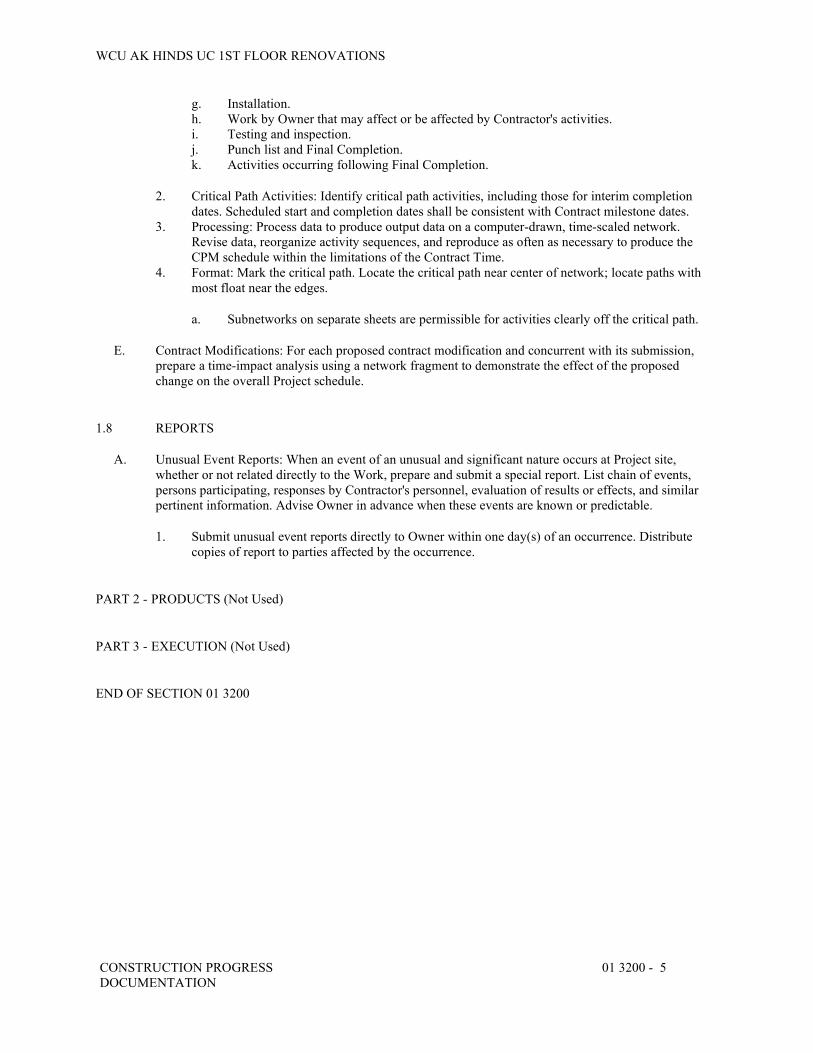
WCU AK HINDS UC 1ST FLOOR RENOVATIONS
CONSTRUCTION PROGRESS DOCUMENTATION
01 3200 - 5
g. Installation. h. Work by Owner that may affect or be affected by Contractor's activities. i. Testing and inspection. j. Punch list and Final Completion. k. Activities occurring following Final Completion.
2. Critical Path Activities: Identify critical path activities, including those for interim completion dates. Scheduled start and completion dates shall be consistent with Contract milestone dates.
3. Processing: Process data to produce output data on a computer-drawn, time-scaled network. Revise data, reorganize activity sequences, and reproduce as often as necessary to produce the CPM schedule within the limitations of the Contract Time.
4. Format: Mark the critical path. Locate the critical path near center of network; locate paths with most float near the edges.
a. Subnetworks on separate sheets are permissible for activities clearly off the critical path.
E. Contract Modifications: For each proposed contract modification and concurrent with its submission, prepare a time-impact analysis using a network fragment to demonstrate the effect of the proposed change on the overall Project schedule.
1.8 REPORTS
A. Unusual Event Reports: When an event of an unusual and significant nature occurs at Project site, whether or not related directly to the Work, prepare and submit a special report. List chain of events, persons participating, responses by Contractor's personnel, evaluation of results or effects, and similar pertinent information. Advise Owner in advance when these events are known or predictable.
1. Submit unusual event reports directly to Owner within one day(s) of an occurrence. Distribute copies of report to parties affected by the occurrence.
PART 2 - PRODUCTS (Not Used)
PART 3 - EXECUTION (Not Used)
END OF SECTION 01 3200

WCU AK HINDS UC 1ST FLOOR RENOVATIONS
SUBMITTAL PROCEDURES 01 3300 - 1
SECTION 01 3300 - SUBMITTAL PROCEDURES
PART 1 - GENERAL
1.1 RELATED DOCUMENTS
A. Drawings and general provisions of the Contract, including General and Supplementary Conditions and other Division 01 Specification Sections, apply to this Section.
1.2 SUMMARY
A. Section Includes:
1. Submittal schedule requirements. 2. Administrative and procedural requirements for submittals.
B. Related Requirements:
1. Section 01 2900 "Payment Procedures" for submitting Applications for Payment and the schedule of values.
2. Section 01 3100 "Project Management and Coordination" for submitting coordination drawings and subcontract list and for requirements for web-based Project software.
3. Section 01 3200 "Construction Progress Documentation" for submitting schedules and reports, including Contractor's construction schedule.
4. Section 01 4000 "Quality Requirements" for submitting test and inspection reports, and schedule of tests and inspections.
5. Section 01 7700 "Closeout Procedures" for submitting closeout submittals and maintenance material submittals.
6. Section 01 7823 "Operation and Maintenance Data" for submitting operation and maintenance manuals.
7. Section 01 7839 "Project Record Documents" for submitting record Drawings, record Specifications, and record Product Data.
1.3 DEFINITIONS
A. Action Submittals: Written and graphic information and physical samples that require Architect's responsive action. Action submittals are those submittals indicated in individual Specification Sections as "action submittals."
B. Informational Submittals: Written and graphic information and physical samples that do not require Architect's responsive action. Submittals may be rejected for not complying with requirements. Informational submittals are those submittals indicated in individual Specification Sections as "informational submittals."

WCU AK HINDS UC 1ST FLOOR RENOVATIONS
SUBMITTAL PROCEDURES 01 3300 - 2
1.4 SUBMITTAL SCHEDULE
A. Submittal Schedule: Within 15 calendar days of the Notice to Proceed, submit, as an action submittal, a list of submittals, arranged in chronological order by dates required by construction schedule. Include time required for review, ordering, manufacturing, fabrication, and delivery when establishing dates. Include additional time required for making corrections or revisions to submittals noted by Architect and additional time for handling and reviewing submittals required by those corrections.
1. Coordinate submittal schedule with list of subcontracts, the schedule of values, and Contractor's construction schedule.
2. Initial Submittal Schedule: Submit concurrently construction schedule. Include submittals required during the first 60 days of construction. List those submittals required to maintain orderly progress of the Work and those required early because of long lead time for manufacture or fabrication.
3. Final Submittal Schedule: Submit concurrently with the first complete submittal of Contractor's construction schedule.
a. Submit revised submittal schedule as required to reflect changes in current status and timing for submittals.
4. Format: Arrange the following information in a tabular format:
a. Scheduled date for first submittal. b. Specification Section number and title. c. Submittal Category: Action; informational. d. Name of subcontractor. e. Description of the Work covered. f. Scheduled date for Architect's final release or approval. g. Scheduled dates for purchasing. h. Scheduled date of fabrication. i. Scheduled dates for installation. j. Activity or event number.
1.5 SUBMITTAL FORMATS
A. Submittal Information: Include the following information in each submittal:
1. Project name. 2. Date. 3. Name of Architect. 4. Name of Contractor. 5. Name of firm or entity that prepared submittal. 6. Names of subcontractor, manufacturer, and supplier. 7. Unique submittal number, including revision identifier. Include Specification Section number with
sequential alphanumeric identifier and alphanumeric suffix for resubmittals. 8. Category and type of submittal. 9. Submittal purpose and description. 10. Number and title of Specification Section, with paragraph number and generic name for each of
multiple items. 11. Drawing number and detail references, as appropriate. 12. Indication of full or partial submittal. 13. Location(s) where product is to be installed, as appropriate. 14. Other necessary identification. 15. Remarks. 16. Signature of transmitter.
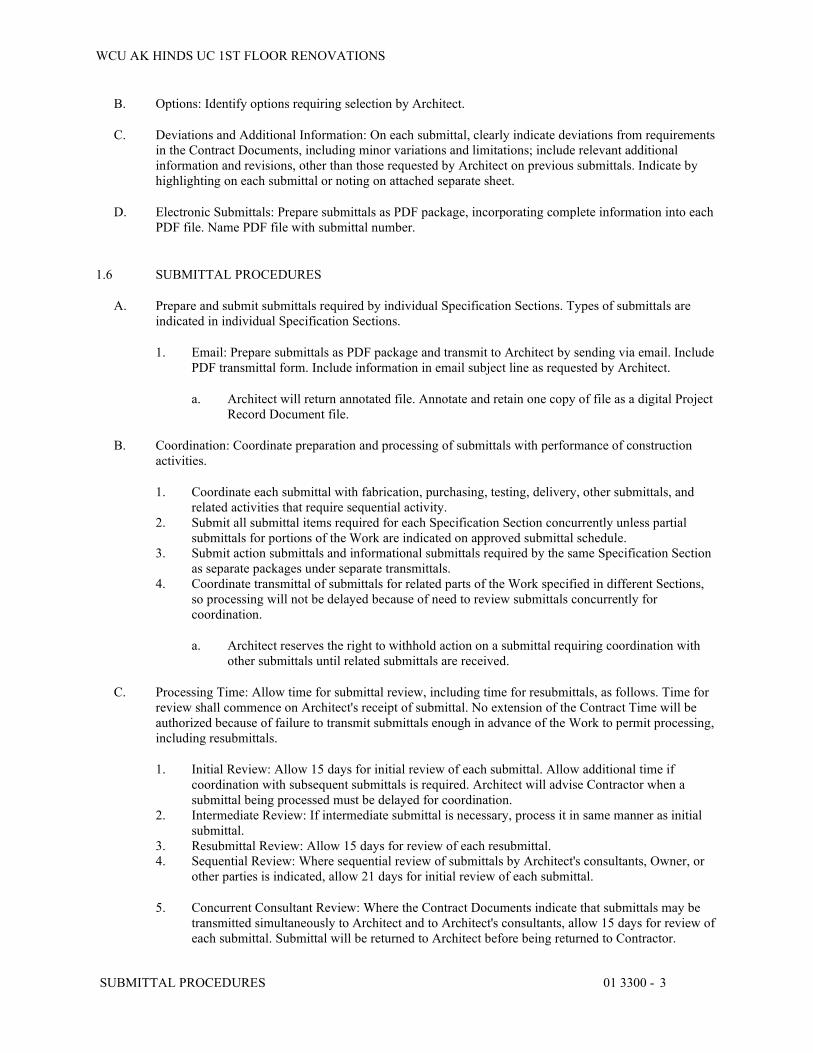
WCU AK HINDS UC 1ST FLOOR RENOVATIONS
SUBMITTAL PROCEDURES 01 3300 - 3
B. Options: Identify options requiring selection by Architect.
C. Deviations and Additional Information: On each submittal, clearly indicate deviations from requirements in the Contract Documents, including minor variations and limitations; include relevant additional information and revisions, other than those requested by Architect on previous submittals. Indicate by highlighting on each submittal or noting on attached separate sheet.
D. Electronic Submittals: Prepare submittals as PDF package, incorporating complete information into each PDF file. Name PDF file with submittal number.
1.6 SUBMITTAL PROCEDURES
A. Prepare and submit submittals required by individual Specification Sections. Types of submittals are indicated in individual Specification Sections.
1. Email: Prepare submittals as PDF package and transmit to Architect by sending via email. Include PDF transmittal form. Include information in email subject line as requested by Architect.
a. Architect will return annotated file. Annotate and retain one copy of file as a digital Project Record Document file.
B. Coordination: Coordinate preparation and processing of submittals with performance of construction activities.
1. Coordinate each submittal with fabrication, purchasing, testing, delivery, other submittals, and related activities that require sequential activity.
2. Submit all submittal items required for each Specification Section concurrently unless partial submittals for portions of the Work are indicated on approved submittal schedule.
3. Submit action submittals and informational submittals required by the same Specification Section as separate packages under separate transmittals.
4. Coordinate transmittal of submittals for related parts of the Work specified in different Sections, so processing will not be delayed because of need to review submittals concurrently for coordination.
a. Architect reserves the right to withhold action on a submittal requiring coordination with other submittals until related submittals are received.
C. Processing Time: Allow time for submittal review, including time for resubmittals, as follows. Time for review shall commence on Architect's receipt of submittal. No extension of the Contract Time will be authorized because of failure to transmit submittals enough in advance of the Work to permit processing, including resubmittals.
1. Initial Review: Allow 15 days for initial review of each submittal. Allow additional time if coordination with subsequent submittals is required. Architect will advise Contractor when a submittal being processed must be delayed for coordination.
2. Intermediate Review: If intermediate submittal is necessary, process it in same manner as initial submittal.
3. Resubmittal Review: Allow 15 days for review of each resubmittal. 4. Sequential Review: Where sequential review of submittals by Architect's consultants, Owner, or
other parties is indicated, allow 21 days for initial review of each submittal.
5. Concurrent Consultant Review: Where the Contract Documents indicate that submittals may be transmitted simultaneously to Architect and to Architect's consultants, allow 15 days for review of each submittal. Submittal will be returned to Architect before being returned to Contractor.

WCU AK HINDS UC 1ST FLOOR RENOVATIONS
SUBMITTAL PROCEDURES 01 3300 - 4
a. Submit one copy of submittal to concurrent reviewer in addition to specified number of copies to Architect.
D. Resubmittals: Make resubmittals in same form and number of copies as initial submittal.
1. Note date and content of previous submittal. 2. Note date and content of revision in label or title block, and clearly indicate extent of revision. 3. Resubmit submittals until they are marked with approval notation from Architect's action stamp.
E. Distribution: Furnish copies of final submittals to manufacturers, subcontractors, suppliers, fabricators, installers, authorities having jurisdiction, and others as necessary for performance of construction activities. Show distribution on transmittal forms.
F. Use for Construction: Retain complete copies of submittals on Project site. Use only final action submittals that are marked with approval notation from Architect's action stamp.
1.7 SUBMITTAL REQUIREMENTS
A. Product Data: Collect information into a single submittal for each element of construction and type of product or equipment.
1. If information must be specially prepared for submittal because standard published data are unsuitable for use, submit as Shop Drawings, not as Product Data.
2. Mark each copy of each submittal to show which products and options are applicable. 3. Include the following information, as applicable:
a. Manufacturer's catalog cuts. b. Manufacturer's product specifications. c. Standard color charts. d. Statement of compliance with specified referenced standards. e. Testing by recognized testing agency. f. Application of testing agency labels and seals. g. Notation of coordination requirements. h. Availability and delivery time information.
4. For equipment, include the following in addition to the above, as applicable:
a. Wiring diagrams that show factory-installed wiring. b. Printed performance curves. c. Operational range diagrams. d. Clearances required to other construction, if not indicated on accompanying Shop
Drawings.
B. Shop Drawings: Prepare Project-specific information, drawn accurately to scale. Do not base Shop Drawings on reproductions of the Contract Documents or standard printed data unless submittal based on Architect's digital data drawing files is otherwise permitted.
1. Preparation: Fully illustrate requirements in the Contract Documents. Include the following information, as applicable:
a. Identification of products. b. Schedules. c. Compliance with specified standards. d. Notation of coordination requirements.

WCU AK HINDS UC 1ST FLOOR RENOVATIONS
SUBMITTAL PROCEDURES 01 3300 - 5
e. Notation of dimensions established by field measurement. f. Relationship and attachment to adjoining construction clearly indicated. g. Seal and signature of professional engineer if specified.
C. Samples: Submit Samples for review of type, color, pattern, and texture for a check of these characteristics with other materials.
1. Transmit Samples that contain multiple, related components, such as accessories together in one submittal package.
2. Identification: Permanently attach label on unexposed side of Samples that includes the following:
a. Project name and submittal number. b. Generic description of Sample. c. Product name and name of manufacturer. d. Sample source. e. Number and title of applicable Specification Section. f. Specification paragraph number and generic name of each item.
3. Email Transmittal: Provide PDF transmittal. Include digital image file illustrating Sample characteristics and identification information for record.
4. Paper Transmittal: Include paper transmittal, including complete submittal information indicated. 5. Disposition: Maintain sets of approved Samples at Project site, available for quality-control
comparisons throughout the course of construction activity. Sample sets may be used to determine final acceptance of construction associated with each set.
a. Samples that may be incorporated into the Work are indicated in individual Specification Sections. Such Samples must be in an undamaged condition at time of use.
b. Samples not incorporated into the Work, or otherwise designated as Owner's property, are the property of Contractor.
6. Samples for Initial Selection: Submit manufacturer's color charts consisting of units or sections of units, showing the full range of colors, textures, and patterns available.
a. Number of Samples: Submit one full set(s) of available choices where color, pattern, texture, or similar characteristics are required to be selected from manufacturer's product line. Architect will return submittal with options selected.
7. Samples for Verification: Submit full-size units or Samples of size indicated, prepared from same material to be used for the Work, cured and finished in manner specified, and physically identical with material or product proposed for use, and that show full range of color and texture variations expected. Samples include, but are not limited to, the following: partial sections of manufactured or fabricated components; small cuts or containers of materials; complete units of repetitively used materials; swatches showing color, texture, and pattern; color range sets; and components used for independent testing and inspection.
a. Number of Samples: Submit three sets of Samples. Architect will retain two Sample sets; remainder will be returned.
1) Submit a single Sample where assembly details, workmanship, fabrication techniques, connections, operation, and other similar characteristics are to be demonstrated.
2) If variation in color, pattern, texture, or other characteristic is inherent in material or product represented by a Sample, submit at least three sets of paired units that show approximate limits of variations.

WCU AK HINDS UC 1ST FLOOR RENOVATIONS
SUBMITTAL PROCEDURES 01 3300 - 6
D. Product Schedule: As required in individual Specification Sections, prepare a written summary indicating types of products required for the Work and their intended location. Include the following information in tabular form:
1. Type of product. Include unique identifier for each product indicated in the Contract Documents or assigned by Contractor if none is indicated.
2. Manufacturer and product name, and model number if applicable. 3. Number and name of room or space. 4. Location within room or space.
E. Qualification Data: Prepare written information that demonstrates capabilities and experience of firm or person. Include lists of completed projects with project names and addresses, contact information of architects and owners, and other information specified.
F. Design Data: Prepare and submit written and graphic information indicating compliance with indicated performance and design criteria in individual Specification Sections. Include list of assumptions and summary of loads. Include load diagrams if applicable. Provide name and version of software, if any, used for calculations. Number each page of submittal.
G. Certificates:
1. Certificates and Certifications Submittals: Submit a statement that includes signature of entity responsible for preparing certification. Certificates and certifications shall be signed by an officer or other individual authorized to sign documents on behalf of that entity. Provide a notarized signature where indicated.
2. Installer Certificates: Submit written statements on manufacturer's letterhead, certifying that Installer complies with requirements in the Contract Documents and, where required, is authorized by manufacturer for this specific Project.
3. Manufacturer Certificates: Submit written statements on manufacturer's letterhead, certifying that manufacturer complies with requirements in the Contract Documents. Include evidence of manufacturing experience where required.
4. Material Certificates: Submit written statements on manufacturer's letterhead, certifying that material complies with requirements in the Contract Documents.
5. Product Certificates: Submit written statements on manufacturer's letterhead, certifying that product complies with requirements in the Contract Documents.
H. Test and Research Reports:
1. Compatibility Test Reports: Submit reports written by a qualified testing agency, on testing agency's standard form, indicating and interpreting results of compatibility tests performed before installation of product. Include written recommendations for substrate preparation and primers required.
2. Field Test Reports: Submit written reports indicating and interpreting results of field tests performed either during installation of product or after product is installed in its final location, for compliance with requirements in the Contract Documents.
3. Material Test Reports: Submit reports written by a qualified testing agency, on testing agency's standard form, indicating and interpreting test results of material for compliance with requirements in the Contract Documents.
4. Preconstruction Test Reports: Submit reports written by a qualified testing agency, on testing agency's standard form, indicating and interpreting results of tests performed before installation of product, for compliance with performance requirements in the Contract Documents.
5. Product Test Reports: Submit written reports indicating that current product produced by manufacturer complies with requirements in the Contract Documents. Base reports on evaluation of tests performed by manufacturer and witnessed by a qualified testing agency, or on comprehensive tests performed by a qualified testing agency.

WCU AK HINDS UC 1ST FLOOR RENOVATIONS
SUBMITTAL PROCEDURES 01 3300 - 7
6. Research Reports: Submit written evidence, from a model code organization acceptable to authorities having jurisdiction, that product complies with building code in effect for Project. Include the following information:
a. Name of evaluation organization. b. Date of evaluation. c. Time period when report is in effect. d. Product and manufacturers' names. e. Description of product. f. Test procedures and results. g. Limitations of use.
1.8 CONTRACTOR'S REVIEW
A. Action Submittals and Informational Submittals: Review each submittal and check for coordination with other Work of the Contract and for compliance with the Contract Documents. Note corrections and field dimensions. Mark with approval stamp before submitting to Architect.
B. Contractor's Approval: Indicate Contractor's approval for each submittal with a uniform approval stamp. Include name of reviewer, date of Contractor's approval, and statement certifying that submittal has been reviewed, checked, and approved for compliance with the Contract Documents.
1. Architect will not review submittals received from Contractor that do not have Contractor's review and approval.
1.9 ARCHITECT'S REVIEW
A. Action Submittals: Architect will review each submittal, indicate corrections or revisions required, and return.
1. PDF Submittals: Architect will indicate, via markup on each submittal, the appropriate action
B. Informational Submittals: Architect will review each submittal and will not return it, or will return it if it does not comply with requirements. Architect will forward each submittal to appropriate party.
C. Incomplete submittals are unacceptable, will be considered nonresponsive, and will be returned for resubmittal without review.
D. Architect will discard submittals received from sources other than Contractor.
E. Submittals not required by the Contract Documents will be returned by Architect without action.
PART 2 - PRODUCTS (Not Used)
PART 3 - EXECUTION (Not Used)
END OF SECTION 01 3300
WCU AK HINDS UC 1ST FLOOR RENOVATIONS
QUALITY REQUIREMENTS 01 4000 - 1
SECTION 01 4000 - QUALITY REQUIREMENTS
PART 1 - GENERAL
1.1 RELATED DOCUMENTS
A. Drawings and general provisions of the Contract, including General and Supplementary Conditions and other Division 01 Specification Sections, apply to this Section.
1.2 SUMMARY
A. Section includes administrative and procedural requirements for quality assurance and quality control.
B. Testing and inspection services are required to verify compliance with requirements specified or indicated. These services do not relieve Contractor of responsibility for compliance with the Contract Document requirements.
1. Specific quality-assurance and quality-control requirements for individual work results are specified in their respective Specification Sections. Requirements in individual Sections may also cover production of standard products.
2. Specified tests, inspections, and related actions do not limit Contractor's other quality-assurance and quality-control procedures that facilitate compliance with the Contract Document requirements.
3. Requirements for Contractor to provide quality-assurance and quality-control services required by Architect, Owner, or authorities having jurisdiction are not limited by provisions of this Section.
1.3 DEFINITIONS
A. Experienced: When used with an entity or individual, "experienced," unless otherwise further described, means having successfully completed a minimum of five previous projects similar in nature, size, and extent to this Project; being familiar with special requirements indicated; and having complied with requirements of authorities having jurisdiction.
B. Field Quality-Control Tests and Inspections: Tests and inspections that are performed on-site for installation of the Work and for completed Work.
C. Installer/Applicator/Erector: Contractor or another entity engaged by Contractor as an employee, subcontractor, or sub-subcontractor, to perform a particular construction operation, including installation, erection, application, assembly, and similar operations.
1. Use of trade-specific terminology in referring to a Work result does not require that certain construction activities specified apply exclusively to specific trade(s).
D. Mockups: Full-size physical assemblies that are constructed either as freestanding temporary built elements or as part of permanent construction. Mockups are constructed to verify selections made under Sample submittals; to demonstrate aesthetic effects and qualities of materials and execution; to review coordination, testing, or operation; to show interface between dissimilar materials; and to demonstrate compliance with specified installation tolerances. Mockups are not Samples. Unless otherwise indicated, approved mockups establish the standard by which the Work will be judged.

WCU AK HINDS UC 1ST FLOOR RENOVATIONS
QUALITY REQUIREMENTS 01 4000 - 2
1. Product Mockups: Mockups that may include multiple products, materials, or systems specified in a single Section.
2. In-Place Mockups: Mockups constructed on-site in their actual final location as part of permanent construction.
E. Preconstruction Testing: Tests and inspections performed specifically for Project before products and materials are incorporated into the Work, to verify performance or compliance with specified criteria. Unless otherwise indicated, copies of reports of tests or inspections performed for other than the Project do not meet this definition.
F. Product Tests: Tests and inspections that are performed by a nationally recognized testing laboratory (NRTL) according to 29 CFR 1910.7, by a testing agency accredited according to NIST's National Voluntary Laboratory Accreditation Program (NVLAP), or by a testing agency qualified to conduct product testing and acceptable to authorities having jurisdiction, to establish product performance and compliance with specified requirements.
G. Source Quality-Control Tests and Inspections: Tests and inspections that are performed at the source (e.g., plant, mill, factory, or shop).
H. Testing Agency: An entity engaged to perform specific tests, inspections, or both. The term "testing laboratory" shall have the same meaning as the term "testing agency."
I. Quality-Assurance Services: Activities, actions, and procedures performed before and during execution of the Work, to guard against defects and deficiencies and substantiate that proposed construction will comply with requirements.
J. Quality-Control Services: Tests, inspections, procedures, and related actions during and after execution of the Work, to evaluate that actual products incorporated into the Work and completed construction comply with requirements. Contractor's quality-control services do not include contract administration activities performed by Architect.
1.4 CONFLICTING REQUIREMENTS
A. Conflicting Standards and Other Requirements: If compliance with two or more standards or requirements is specified and the standards or requirements establish different or conflicting requirements for minimum quantities or quality levels, inform the Architect regarding the conflict and obtain clarification prior to proceeding with the Work. Refer conflicting requirements that are different, but apparently equal, to Architect for clarification before proceeding.
B. Minimum Quantity or Quality Levels: The quantity or quality level shown or specified shall be the minimum provided or performed. The actual installation may comply exactly with the minimum quantity or quality specified, or it may exceed the minimum within reasonable limits. To comply with these requirements, indicated numeric values are minimum or maximum, as appropriate, for the context of requirements. Refer uncertainties to Architect for a decision before proceeding.
1.5 INFORMATIONAL SUBMITTALS
A. Testing Agency Qualifications: For testing agencies specified in "Quality Assurance" Article to demonstrate their capabilities and experience. Include proof of qualifications in the form of a recent report on the inspection of the testing agency by a recognized authority.
B. Schedule of Tests and Inspections: Prepare in tabular form and include the following:

WCU AK HINDS UC 1ST FLOOR RENOVATIONS
QUALITY REQUIREMENTS 01 4000 - 3
1. Specification Section number and title. 2. Entity responsible for performing tests and inspections. 3. Description of test and inspection. 4. Identification of applicable standards. 5. Identification of test and inspection methods. 6. Number of tests and inspections required. 7. Time schedule or time span for tests and inspections. 8. Requirements for obtaining samples. 9. Unique characteristics of each quality-control service.
C. Reports: Prepare and submit certified written reports and documents as specified.
D. Permits, Licenses, and Certificates: For Owner's record, submit copies of permits, licenses, certifications, inspection reports, releases, jurisdictional settlements, notices, receipts for fee payments, judgments, correspondence, records, and similar documents established for compliance with standards and regulations bearing on performance of the Work.
1.6 REPORTS AND DOCUMENTS
A. Test and Inspection Reports: Prepare and submit certified written reports specified in other Sections. Include the following:
1. Date of issue. 2. Project title and number. 3. Name, address, telephone number, and email address of testing agency. 4. Dates and locations of samples and tests or inspections. 5. Names of individuals making tests and inspections. 6. Description of the Work and test and inspection method. 7. Identification of product and Specification Section. 8. Complete test or inspection data. 9. Test and inspection results and an interpretation of test results. 10. Record of temperature and weather conditions at time of sample-taking and testing and inspection. 11. Comments or professional opinion on whether tested or inspected Work complies with the
Contract Document requirements. 12. Name and signature of laboratory inspector. 13. Recommendations on retesting and reinspecting.
B. Manufacturer's Technical Representative's Field Reports: Prepare written information documenting manufacturer's technical representative's tests and inspections specified in other Sections. Include the following:
1. Name, address, telephone number, and email address of technical representative making report. 2. Statement on condition of substrates and their acceptability for installation of product. 3. Statement that products at Project site comply with requirements. 4. Summary of installation procedures being followed, whether they comply with requirements and,
if not, what corrective action was taken. 5. Results of operational and other tests and a statement of whether observed performance complies
with requirements. 6. Statement of whether conditions, products, and installation will affect warranty. 7. Other required items indicated in individual Specification Sections.
C. Factory-Authorized Service Representative's Reports: Prepare written information documenting manufacturer's factory-authorized service representative's tests and inspections specified in other Sections. Include the following:
WCU AK HINDS UC 1ST FLOOR RENOVATIONS
QUALITY REQUIREMENTS 01 4000 - 4
1. Name, address, telephone number, and email address of factory-authorized service representative making report.
2. Statement that equipment complies with requirements. 3. Results of operational and other tests and a statement of whether observed performance complies
with requirements. 4. Statement of whether conditions, products, and installation will affect warranty. 5. Other required items indicated in individual Specification Sections.
1.7 QUALITY ASSURANCE
A. Qualifications paragraphs in this article establish the minimum qualification levels required; individual Specification Sections specify additional requirements.
B. Manufacturer Qualifications: A firm experienced in manufacturing products or systems similar to those indicated for this Project and with a record of successful in-service performance, as well as sufficient production capacity to produce required units. As applicable, procure products from manufacturers able to meet qualification requirements, warranty requirements, and technical or factory-authorized service representative requirements.
C. Fabricator Qualifications: A firm experienced in producing products similar to those indicated for this Project and with a record of successful in-service performance, as well as sufficient production capacity to produce required units.
D. Installer Qualifications: A firm or individual experienced in installing, erecting, applying, or assembling work similar in material, design, and extent to that indicated for this Project, whose work has resulted in construction with a record of successful in-service performance.
E. Specialists: Certain Specification Sections require that specific construction activities shall be performed by entities who are recognized experts in those operations. Specialists shall satisfy qualification requirements indicated and shall be engaged in the activities indicated.
1. Requirements of authorities having jurisdiction shall supersede requirements for specialists.
F. Testing and Inspecting Agency Qualifications: An NRTL, an NVLAP, or an independent agency with the experience and capability to conduct testing and inspection indicated, as documented in accordance with ASTM E329, and with additional qualifications specified in individual Sections; and, where required by authorities having jurisdiction, that is acceptable to authorities.
G. Manufacturer's Technical Representative Qualifications: An authorized representative of manufacturer who is trained and approved by manufacturer to observe and inspect installation of manufacturer's products that are similar in material, design, and extent to those indicated for this Project.
H. Factory-Authorized Service Representative Qualifications: An authorized representative of manufacturer who is trained and approved by manufacturer to inspect, demonstrate, repair, and perform service on installations of manufacturer's products that are similar in material, design, and extent to those indicated for this Project.
I. Preconstruction Testing: Where testing agency is indicated to perform preconstruction testing for compliance with specified requirements for performance and test methods, comply with the following Contractor's responsibilities, including the following:
1. Provide test specimens representative of proposed products and construction. 2. Submit specimens in a timely manner with sufficient time for testing and analyzing results to
prevent delaying the Work.

WCU AK HINDS UC 1ST FLOOR RENOVATIONS
QUALITY REQUIREMENTS 01 4000 - 5
3. Provide sizes and configurations of test assemblies, mockups, and laboratory mockups to adequately demonstrate capability of products to comply with performance requirements.
4. Testing Agency Responsibilities: Submit a certified written report of each test, inspection, and similar quality-assurance service to Architect, with copy to Contractor. Interpret tests and inspections, and state in each report whether tested and inspected Work complies with or deviates from the Contract Documents.
1.8 QUALITY CONTROL
A. Owner Responsibilities: Where quality-control services are indicated as Owner's responsibility, Owner will engage a qualified testing agency to perform these services.
1. Owner will furnish Contractor with names, addresses, and telephone numbers of testing agencies engaged and a description of types of testing and inspection they are engaged to perform.
2. Costs for retesting and reinspecting construction that replaces or is necessitated by Work that failed to comply with the Contract Documents will be charged to Contractor, and the Contract Sum will be adjusted by Change Order.
B. Contractor Responsibilities: Tests and inspections not explicitly assigned to Owner are Contractor's responsibility. Perform additional quality-control activities, whether specified or not, to verify and document that the Work complies with requirements.
1. Unless otherwise indicated, provide quality-control services specified and those required by authorities having jurisdiction. Perform quality-control services required of Contractor by authorities having jurisdiction, whether specified or not.
2. Engage a qualified testing agency to perform quality-control services.
a. Contractor shall not employ same entity engaged by Owner, unless agreed to in writing by Owner.
3. Notify testing agencies at least 72 hours in advance of time when Work that requires testing or inspection will be performed.
4. Where quality-control services are indicated as Contractor's responsibility, submit a certified written report, in duplicate, of each quality-control service.
5. Testing and inspection requested by Contractor and not required by the Contract Documents are Contractor's responsibility.
6. Submit additional copies of each written report directly to authorities having jurisdiction, when they so direct.
C. Retesting/Reinspecting: Regardless of whether original tests or inspections were Contractor's responsibility, provide quality-control services, including retesting and reinspecting, for construction that replaced Work that failed to comply with the Contract Documents.
D. Testing Agency Responsibilities: Cooperate with Architect and Contractor in performance of duties. Provide qualified personnel to perform required tests and inspections.
1. Notify Architect and Contractor promptly of irregularities or deficiencies observed in the Work during performance of its services.
2. Determine the locations from which test samples will be taken and in which in-situ tests are conducted.
3. Conduct and interpret tests and inspections, and state in each report whether tested and inspected Work complies with or deviates from requirements.
4. Submit a certified written report, in duplicate, of each test, inspection, and similar quality-control service through Contractor.

WCU AK HINDS UC 1ST FLOOR RENOVATIONS
QUALITY REQUIREMENTS 01 4000 - 6
5. Do not release, revoke, alter, or increase the Contract Document requirements or approve or accept any portion of the Work.
6. Do not perform duties of Contractor.
E. Manufacturer's Field Services: Where indicated, engage a factory-authorized service representative to inspect field-assembled components and equipment installation, including service connections. Report results in writing as specified in Section 01 3300 "Submittal Procedures."
F. Manufacturer's Technical Services: Where indicated, engage a manufacturer's technical representative to observe and inspect the Work. Manufacturer's technical representative's services include participation in preinstallation conferences, examination of substrates and conditions, verification of materials, observation of Installer activities, inspection of completed portions of the Work, and submittal of written reports.
G. Contractor's Associated Requirements and Services: Cooperate with agencies and representatives performing required tests, inspections, and similar quality-control services, and provide reasonable auxiliary services as requested. Notify agency sufficiently in advance of operations to permit assignment of personnel. Provide the following:
1. Access to the Work. 2. Incidental labor and facilities necessary to facilitate tests and inspections. 3. Adequate quantities of representative samples of materials that require testing and inspection.
Assist agency in obtaining samples. 4. Facilities for storage and field curing of test samples. 5. Delivery of samples to testing agencies. 6. Preliminary design mix proposed for use for material mixes that require control by testing agency. 7. Security and protection for samples and for testing and inspection equipment at Project site.
H. Coordination: Coordinate sequence of activities to accommodate required quality-assurance and quality-control services with a minimum of delay and to avoid necessity of removing and replacing construction to accommodate testing and inspection.
1. Schedule times for tests, inspections, obtaining samples, and similar activities.
I. Schedule of Tests and Inspections: Prepare a schedule of tests, inspections, and similar quality-control services required by the Contract Documents. Coordinate and submit concurrently with Contractor's Construction Schedule. Update and submit with each Application for Payment.
1. Schedule Contents: Include tests, inspections, and quality-control services, including Contractor- and Owner-retained services, commissioning activities, and other Project-required services paid for by other entities.
2. Distribution: Distribute schedule to Owner, Architect, testing agencies, and each party involved in performance of portions of the Work where tests and inspections are required.
PART 2 - PRODUCTS (Not Used)
PART 3 - EXECUTION
3.1 TEST AND INSPECTION LOG
A. Test and Inspection Log: Prepare a record of tests and inspections. Include the following:

WCU AK HINDS UC 1ST FLOOR RENOVATIONS
QUALITY REQUIREMENTS 01 4000 - 7
1. Date test or inspection was conducted. 2. Description of the Work tested or inspected. 3. Date test or inspection results were transmitted to Architect. 4. Identification of testing agency or special inspector conducting test or inspection.
B. Maintain log at Project site. Post changes and revisions as they occur. Provide access to test and inspection log for Architect's and Construction Manager's and authorities' having jurisdiction reference during normal working hours.
1. Submit log at Project closeout as part of Project Record Documents.
3.2 REPAIR AND PROTECTION
A. General: On completion of testing, inspection, sample-taking, and similar services, repair damaged construction and restore substrates and finishes.
1. Provide materials and comply with installation requirements specified in other Specification Sections or matching existing substrates and finishes. Restore patched areas and extend restoration into adjoining areas with durable seams that are as invisible as possible. Comply with the Contract Document requirements for cutting and patching in Section 01 7300 "Execution."
B. Protect construction exposed by or for quality-control service activities.
C. Repair and protection are Contractor's responsibility, regardless of the assignment of responsibility for quality-control services.
END OF SECTION 01 4000
WCU AK HINDS UC 1ST FLOOR RENOVATIONS
SECTION 01 4200 - REFERENCES
PART 1 - GENERAL
1.1 RELATED DOCUMENTS
A. Drawings and general provisions of the Contract, including General and Supplementary Conditions and other Division 01 Specification Sections, apply to this Section.
1.2 DEFINITIONS
A. General: Basic Contract definitions are included in the Conditions of the Contract.
B. "Approved": When used to convey Architect's action on Contractor's submittals, applications, and requests, "approved" is limited to Architect's duties and responsibilities as stated in the Conditions of the Contract.
C. "Directed": A command or instruction by Architect. Other terms including "requested," "authorized," "selected," "required," and "permitted" have the same meaning as "directed."
D. "Indicated": Requirements expressed by graphic representations or in written form on Drawings, in Specifications, and in other Contract Documents. Other terms including "shown," "noted," "scheduled," and "specified" have the same meaning as "indicated."
E. "Regulations": Laws, ordinances, statutes, and lawful orders issued by authorities having jurisdiction, and rules, conventions, and agreements within the construction industry that control performance of the Work.
F. "Furnish": Supply and deliver to Project site, ready for unloading, unpacking, assembly, installation, and similar operations.
G. "Install": Unload, temporarily store, unpack, assemble, erect, place, anchor, apply, work to dimension, finish, cure, protect, clean, and similar operations at Project site.
H. "Provide": Furnish and install, complete and ready for the intended use.
I. "Project Site": Space available for performing construction activities. The extent of Project site is shown on Drawings and may or may not be identical with the description of the land on which Project is to be built.
1.3 INDUSTRY STANDARDS
A. Applicability of Standards: Unless the Contract Documents include more stringent requirements, applicable construction industry standards have the same force and effect as if bound or copied directly into the Contract Documents to the extent referenced. Such standards are made a part of the Contract Documents by reference.
B. Publication Dates: Comply with standards in effect as of date of the Contract Documents unless otherwise indicated.
REFERENCES 01 4200 - 1

WCU AK HINDS UC 1ST FLOOR RENOVATIONS
C. Copies of Standards: Each entity engaged in construction on Project should be familiar with industry standards applicable to its construction activity. Copies of applicable standards are not bound with the Contract Documents.
1. Where copies of standards are needed to perform a required construction activity, obtain copies directly from publication source.
1.4 ABBREVIATIONS AND ACRONYMS
A. Industry Organizations: Where abbreviations and acronyms are used in Specifications or other Contract Documents, they shall mean the recognized name of the entities indicated in Gale's "Encyclopedia of Associations: National Organizations of the U.S." or in Columbia Books' "National Trade & Professional Associations of the United States."
B. Code Agencies: Where abbreviations and acronyms are used in Specifications or other Contract Documents, they shall mean the recognized name of the entities in the following list. This information is believed to be accurate as of the date of the Contract Documents.
C. ICC - International Code Council; www.iccsafe.org.
D. Federal Government Agencies: Where abbreviations and acronyms are used in Specifications or other Contract Documents, they shall mean the recognized name of the respective entities listed.
E. Standards and Regulations: Where abbreviations and acronyms are used in Specifications or other Contract Documents, they shall mean the recognized name of the standards and regulations in the following list. This information is subject to change and is believed to be accurate as of the date of the Contract Documents.
F. ADAAG – Americans with Disabilities Act (ADA).
G. ABA – Architectural Barriers Act.
H. FED-STD - Federal Standard; (See FS).
I. FS - Federal Specification; Available from DLA Document Services; www.quicksearch.dla.mil.
J. Available from Defense Standardization Program; www.dsp.dla.mil.
K. Available from General Services Administration; www.gsa.gov.
L. Available from National Institute of Building Sciences/Whole Building Design Guide; www.wbdg.org/ccb.
M. State Government Agencies: Where abbreviations and acronyms are used in Specifications or other Contract Documents, they shall mean the recognized name of the respective entities listed.
PART 2 - PRODUCTS (Not Used)
PART 3 - EXECUTION (Not Used)
REFERENCES 01 4200 - 2

WCU AK HINDS UC 1ST FLOOR RENOVATIONS
END OF SECTION 01 4200
REFERENCES 01 4200 - 3

WCU AK HINDS UC 1ST FLOOR RENOVATIONS
TEMPORARY FACILITIES AND CONTROLS 01 5000 - 1
SECTION 01 5000 - TEMPORARY FACILITIES AND CONTROLS
PART 1 - GENERAL
1.1 RELATED DOCUMENTS
A. Drawings and general provisions of the Contract, including General and Supplementary Conditions and other Division 01 Specification Sections, apply to this Section.
1.2 SUMMARY
A. Section includes requirements for temporary utilities, support facilities, and security and protection facilities.
B. Related Requirements:
1. Section 01 1000 "Summary" for work restrictions and limitations on utility interruptions. 2. Western Carolina University Design and Construction Standard, Appendix J " Waste Management
Plan."
1.3 USE CHARGES
A. Installation, removal, and use charges for temporary facilities shall be included in the Contract Sum unless otherwise indicated. Allow other entities engaged in the Project to use temporary services and facilities without cost, including, but not limited to, Owner's construction forces, Architect, testing agencies, and authorities having jurisdiction.
B. Water and Sewer Service from Existing System: Water from Owner's existing water system is available for use without metering and without payment of use charges. Provide connections and extensions of services as required for construction operations.
C. Electric Power Service from Existing System: Electric power from Owner's existing system is available for use without metering and without payment of use charges. Provide connections and extensions of services as required for construction operations.
1.4 INFORMATIONAL SUBMITTALS
A. Site Utilization Plan: Show temporary facilities, temporary utility lines and connections, staging areas, construction site entrances, vehicle circulation, and parking areas for construction personnel.
B. Construction Waste Management Forms. Submit at monthly intervals.
C. Implementation and Termination Schedule: Within 15 days of date established for commencement of the Work, submit schedule indicating implementation and termination dates of each temporary utility.
D. Fire-Safety Program: Show compliance with requirements of NFPA 241 and authorities having jurisdiction. Indicate Contractor personnel responsible for management of fire-prevention program.

WCU AK HINDS UC 1ST FLOOR RENOVATIONS
TEMPORARY FACILITIES AND CONTROLS 01 5000 - 2
E. Moisture- and Mold-Protection Plan: Describe procedures and controls for protecting materials and construction from water absorption and damage and mold. Describe delivery, handling, storage, installation, and protection provisions for materials subject to water absorption or water damage.
1. Indicate procedures for discarding water-damaged materials, protocols for mitigating water intrusion into completed Work, and requirements for replacing water-damaged Work.
2. Indicate sequencing of work that requires water, such as sprayed fire-resistive materials, plastering, and terrazzo grinding, and describe plans for dealing with water from these operations. Show procedures for verifying that wet construction has dried sufficiently to permit installation of finish materials.
3. Indicate methods to be used to avoid trapping water in finished work.
F. Dust- and HVAC-Control Plan: Submit coordination drawing and narrative that indicates the dust- and HVAC-control measures proposed for use, proposed locations, and proposed time frame for their operation. Include the following:
1. Locations of dust-control partitions at each phase of work. 2. HVAC system isolation schematic drawing. 3. Location of proposed air-filtration system discharge. 4. Waste-handling procedures. 5. Other dust-control measures.
G. Noise and Vibration Control Plan: Identify construction activities that may impact the occupancy and use of existing spaces within the building or adjacent existing buildings, whether occupied by others, or occupied by the Owner. Include the following:
1. Methods used to meet the goals and requirements of the Owner. 2. Concrete cutting method(s) to be used. 3. Location of construction devices on the site. 4. Show compliance with the use and maintenance of quieted construction devices for the duration of
the Project. 5. Indicate activities that may disturb building occupants and that are planned to be performed during
non-standard working hours as coordinated with the Owner. 6. Indicate locations of sensitive equipment areas or other areas requiring special attention as
identified by Owner. Indicate means for complying with Owner's requirements.
1.5 QUALITY ASSURANCE
A. Electric Service: Comply with NECA, NEMA, and UL standards and regulations for temporary electric service. Install service to comply with NFPA 70.
B. Tests and Inspections: Arrange for authorities having jurisdiction to test and inspect each temporary utility before use. Obtain required certifications and permits.
C. Accessible Temporary Egress: Comply with applicable provisions in the United States Access Board's ADA-ABA Accessibility Guidelines and ICC/ANSI A117.1.
1.6 PROJECT CONDITIONS
A. Temporary Use of Permanent Facilities: Engage Installer of each permanent service to assume responsibility for operation, maintenance, and protection of each permanent service during its use as a construction facility before Owner's acceptance, regardless of previously assigned responsibilities.

WCU AK HINDS UC 1ST FLOOR RENOVATIONS
TEMPORARY FACILITIES AND CONTROLS 01 5000 - 3
PART 2 - PRODUCTS
2.1 MATERIALS
A. Portable Chain-Link Fencing: Minimum 2-inch, 0.148-inch- thick, galvanized-steel, chain-link fabric fencing; minimum 6 feet high with galvanized-steel pipe posts; minimum 2-3/8-inch- OD line posts and 2-7/8-inch- OD corner and pull posts, with 1-5/8-inch- OD top and bottom rails. Provide bases for supporting posts.
B. Polyethylene Sheet: Reinforced, fire-resistive sheet, 10-mil minimum thickness, with flame-spread rating of 15 or less in accordance with ASTM E84 and passing NFPA 701 Test Method 2.
C. Dust-Control Adhesive-Surface Walk-Off Mats: Provide mats, minimum 36 by 60 inches.
D. Insulation: Unfaced mineral-fiber blanket, manufactured from glass, slag wool, or rock wool; with maximum flame-spread and smoke-developed indexes of 25 and 50, respectively.
2.2 TEMPORARY FACILITIES
A. Field Offices: Owner will provide conditioned interior space to conduct construction progress meetings for duration of Project.
B. Storage and Fabrication Sheds: Provide sheds sized, furnished, and equipped to accommodate materials and equipment for construction operations.
1. Store combustible materials apart from building.
2.3 EQUIPMENT
A. Fire Extinguishers: Portable, UL rated; with class and extinguishing agent as required by locations and classes of fire exposures.
B. HVAC Equipment: Unless Owner authorizes use of permanent HVAC system, provide vented, self-contained, liquid-propane-gas or fuel-oil heaters with individual space thermostatic control.
1. Use of gasoline-burning space heaters, open-flame heaters, or salamander-type heating units is prohibited.
2. Heating, Cooling, and Dehumidifying Units: Listed and labeled for type of fuel being consumed, by a qualified testing agency acceptable to authorities having jurisdiction, and marked for intended location and application.
3. Permanent HVAC System: If Owner authorizes use of permanent HVAC system for temporary use during construction, provide filter with MERV of 8 at each return-air grille in system and remove at end of construction.
C. Air-Filtration Units: Primary and secondary HEPA-filter-equipped portable units with four-stage filtration. Provide single switch for emergency shutoff. Configure to run continuously.

WCU AK HINDS UC 1ST FLOOR RENOVATIONS
TEMPORARY FACILITIES AND CONTROLS 01 5000 - 4
PART 3 - EXECUTION
3.1 TEMPORARY FACILITIES, GENERAL
A. Conservation: Coordinate construction and use of temporary facilities with consideration given to conservation of energy, water, and materials. Coordinate use of temporary utilities to minimize waste.
1. Salvage materials and equipment involved in performance of, but not actually incorporated into, the Work. See other Sections for disposition of salvaged materials that are designated as Owner's property.
3.2 INSTALLATION, GENERAL
A. Locate facilities where they will serve Project adequately and result in minimum interference with performance of the Work. Relocate and modify facilities as required by progress of the Work.
1. Locate facilities to limit site disturbance as specified in Section 01 1000 "Summary."
B. Provide each facility ready for use when needed to avoid delay. Do not remove until facilities are no longer needed or are replaced by authorized use of completed permanent facilities.
3.3 TEMPORARY UTILITY INSTALLATION
A. General: Install temporary service or connect to existing service.
1. Arrange with utility company, Owner, and existing users for time when service can be interrupted, if necessary, to make connections for temporary services.
B. Sewers and Drainage: Provide temporary utilities to remove effluent lawfully.
1. Connect temporary sewers to municipal system as directed by authorities having jurisdiction.
C. Water Service: Connect to Owner's existing water service facilities. Clean and maintain water service facilities in a condition acceptable to Owner. At Substantial Completion, restore these facilities to condition existing before initial use.
D. Sanitary Facilities: Provide temporary toilets, wash facilities, safety shower and eyewash facilities, and drinking water for use of construction personnel. Comply with requirements of authorities having jurisdiction for type, number, location, operation, and maintenance of fixtures and facilities.
1. Use of Permanent Toilets: Use of Owner's existing or new toilet facilities will be permitted, as long as facilities are cleaned and maintained in a condition acceptable to Owner. At Substantial Completion, restore these facilities to condition existing before initial use.
E. Temporary Heating and Cooling: Provide temporary heating and cooling required by construction activities for curing or drying of completed installations or for protecting installed construction from adverse effects of low temperatures or high humidity. Select equipment that will not have a harmful effect on completed installations or elements being installed.
1. Provide temporary dehumidification systems when required to reduce ambient and substrate moisture levels to level required to allow installation or application of finishes and their proper curing or drying.

WCU AK HINDS UC 1ST FLOOR RENOVATIONS
TEMPORARY FACILITIES AND CONTROLS 01 5000 - 5
F. Isolation of Work Areas in Occupied Facilities: Prevent dust, fumes, and odors from entering occupied areas.
1. Prior to commencing work, isolate the HVAC system in area where work is to be performed.
a. Disconnect supply and return ductwork in work area from HVAC systems servicing occupied areas.
b. Maintain negative air pressure within work area, using HEPA-equipped air-filtration units, starting with commencement of temporary partition construction, and continuing until removal of temporary partitions is complete.
2. Maintain dust partitions during the Work. Use vacuum collection attachments on dust-producing equipment. Isolate limited work within occupied areas using portable dust-containment devices.
3. Perform daily construction cleanup and final cleanup using approved, HEPA-filter-equipped vacuum equipment.
G. Electric Power Service: Connect to Owner's existing electric power service. Maintain equipment in a condition acceptable to Owner.
H. Lighting: Provide temporary lighting with local switching that provides adequate illumination for construction operations, observations, inspections, and traffic conditions.
1. Install and operate temporary lighting that fulfills security and protection requirements without operating entire system.
3.4 SUPPORT FACILITIES INSTALLATION
A. Comply with the following:
1. Provide construction for temporary field offices, shops, and sheds located within construction area or within 30 feet of building lines that is noncombustible in accordance with ASTM E136. Comply with NFPA 241.
2. Maintain support facilities until Architect schedules Final Completion inspection. Remove before Substantial Completion. Personnel remaining after Final Completion will be permitted to use permanent facilities, under conditions acceptable to Owner.
B. Traffic Controls: Comply with requirements of authorities having jurisdiction.
1. Protect existing site improvements to remain, including curbs, pavement, and utilities. 2. Maintain access for fire-fighting equipment and access to fire hydrants.
C. Parking: Use designated areas of Owner's existing parking areas for construction personnel. Provide Owner with information on each vehicle, update weekly.
D. Storage and Staging: Use designated areas of Project site for storage and staging needs.
E. Dewatering Facilities and Drains: Comply with requirements of authorities having jurisdiction. Maintain Project site, excavations, and construction free of water.
1. Dispose of rainwater in a lawful manner that will not result in flooding Project or adjoining properties or endanger permanent Work or temporary facilities.
2. Remove snow and ice as required to minimize accumulations.
F. Project Signs: Provide Project signs as indicated. Unauthorized signs are not permitted.

WCU AK HINDS UC 1ST FLOOR RENOVATIONS
TEMPORARY FACILITIES AND CONTROLS 01 5000 - 6
1. Temporary Signs: Provide other signs as indicated and as required to inform public and individuals seeking entrance to Project.
a. Provide temporary, directional signs for construction personnel and visitors.
2. Maintain and touch up signs, so they are legible at all times.
G. Waste Disposal Facilities: Provide waste-collection containers in sizes adequate to handle waste from construction operations. Comply with requirements of Western Carolina University's Design and Construction Manual, Appendix J. Comply with progress cleaning requirements in Section 01 7300 "Execution."
H. Lifts and Hoists: Provide facilities necessary for hoisting materials and personnel.
1. Truck cranes and similar devices used for hoisting materials are considered "tools and equipment" and not temporary facilities.
I. Existing Elevator Use: Use of Owner's existing elevators will not be permitted.
J. Existing Stair Usage: Use of Owner's existing stairs will be permitted, provided stairs are cleaned and maintained in a condition acceptable to Owner. At Final Completion, restore stairs to condition existing before initial use.
1. Provide protective coverings, barriers, devices, signs, or other procedures to protect stairs and to maintain means of egress. If stairs become damaged, restore damaged areas, so no evidence remains of correction work.
3.5 SECURITY AND PROTECTION FACILITIES INSTALLATION
A. Protection of Existing Facilities: Protect existing vegetation, equipment, structures, utilities, and other improvements at Project site and on adjacent properties, except those indicated to be removed or altered. Repair damage to existing facilities.
1. Where access to adjacent properties is required in order to affect protection of existing facilities, obtain written permission from adjacent property owner to access property for that purpose.
B. Environmental Protection: Provide protection, operate temporary facilities, and conduct construction as required to comply with environmental regulations and that minimize possible air, waterway, and subsoil contamination or pollution or other undesirable effects.
1. Comply with work restrictions specified in Section 01 1000 "Summary."
C. Site Enclosure Fence: Before construction operations begin, furnish and install site enclosure fence in a manner that will prevent people from easily entering site except by entrance gates.
1. Extent of Fence: As indicated on Drawings. 2. Maintain security by limiting number of keys and restricting distribution to authorized
personnel. Furnish one set of keys to Owner.
D. Security Enclosure and Lockup: Install temporary enclosure around partially completed areas of construction. Provide lockable entrances to prevent unauthorized entrance, vandalism, theft, and similar violations of security. Lock entrances at end of each workday.
WCU AK HINDS UC 1ST FLOOR RENOVATIONS
TEMPORARY FACILITIES AND CONTROLS 01 5000 - 7
E. Barricades, Warning Signs, and Lights: Comply with requirements of authorities having jurisdiction for erecting structurally adequate barricades, including warning signs and lighting.
F. Temporary Egress: Provide temporary egress from existing occupied facilities as indicated and as required by authorities having jurisdiction. Provide signage directing occupants to temporary egress.
G. Temporary Enclosures: Provide temporary enclosures for protection of construction, in progress and completed, from exposure, foul weather, other construction operations, and similar activities. Provide temporary weathertight enclosure for building exterior.
1. Where heating or cooling is needed and permanent enclosure is incomplete, insulate temporary enclosures.
H. Temporary Partitions: Provide floor-to-ceiling dustproof partitions to limit dust and dirt migration and to separate areas occupied by Owner from fumes and noise.
1. Construct dustproof partitions with gypsum wallboard, with joints taped on occupied side, and fire-retardant-treated plywood on construction operations side.
2. Where fire-resistance-rated temporary partitions are indicated or are required by authorities having jurisdiction, construct partitions according to the rated assemblies.
3. Insulate partitions to control noise transmission to occupied areas. 4. Seal joints and perimeter. Equip partitions with gasketed dustproof doors and security locks where
openings are required. 5. Protect air-handling equipment. 6. Provide walk-off mats at each entrance through temporary partition.
I. Temporary Fire Protection: Install and maintain temporary fire-protection facilities of types needed to protect against reasonably predictable and controllable fire losses. Comply with NFPA 241; manage fire-prevention program.
1. Prohibit smoking in construction areas. Comply with additional limits on smoking specified in other Sections.
2. Supervise welding operations, combustion-type temporary heating units, and similar sources of fire ignition in accordance with requirements of authorities having jurisdiction.
3. Develop and supervise an overall fire-prevention and -protection program for personnel at Project site. Review needs with local fire department and establish procedures to be followed. Instruct personnel in methods and procedures. Post warnings and information.
4. Provide temporary standpipes and hoses for fire protection. Hang hoses with a warning sign, stating that hoses are for fire-protection purposes only and are not to be removed. Match hose size with outlet size and equip with suitable nozzles.
3.6 MOISTURE AND MOLD CONTROL
A. Controlled Construction Period: After completing and sealing of the building enclosure but prior to the full operation of permanent HVAC systems, maintain as follows:
1. Control moisture and humidity inside building by maintaining effective dry-in conditions. 2. Use temporary or permanent HVAC system to control humidity within ranges specified for
installed and stored materials. 3. Comply with manufacturer's written instructions for temperature, relative humidity, and exposure
to water limits.

WCU AK HINDS UC 1ST FLOOR RENOVATIONS
TEMPORARY FACILITIES AND CONTROLS 01 5000 - 8
a. Hygroscopic materials that may support mold growth, including wood and gypsum-based products, that become wet during the course of construction and remain wet for 48 hours are considered defective and require replacing.
b. Measure moisture content of materials that have been exposed to moisture during construction operations or after installation. Record readings beginning at time of exposure and continuing daily for 48 hours. Identify materials containing moisture levels higher than allowed. Report findings in writing to Architect.
c. Remove and replace materials that cannot be completely restored to their manufactured moisture level within 48 hours.
3.7 OPERATION, TERMINATION, AND REMOVAL
A. Supervision: Enforce strict discipline in use of temporary facilities. To minimize waste and abuse, limit availability of temporary facilities to essential and intended uses.
B. Maintenance: Maintain facilities in good operating condition until removal.
1. Maintain operation of temporary enclosures, heating, cooling, humidity control, ventilation, and similar facilities on a 24-hour basis where required to achieve indicated results and to avoid possibility of damage.
C. Temporary Facility Changeover: Do not change over from using temporary security and protection facilities to permanent facilities until Substantial Completion.
D. Termination and Removal: Remove each temporary facility when need for its service has ended, when it has been replaced by authorized use of a permanent facility, or no later than Substantial Completion. Complete or, if necessary, restore permanent construction that may have been delayed because of interference with temporary facility. Repair damaged Work, clean exposed surfaces, and replace construction that cannot be satisfactorily repaired.
1. Materials and facilities that constitute temporary facilities are property of Contractor. Owner reserves right to take possession of Project identification signs.
2. At Substantial Completion, repair, renovate, and clean permanent facilities used during construction period. Comply with final cleaning requirements specified in Section 01 7700 "Closeout Procedures."
END OF SECTION 01 5000

WCU AK HINDS UC 1ST FLOOR RENOVATIONS
SECTION 01 6000 - PRODUCT REQUIREMENTS
PART 1 - GENERAL
1.1 RELATED DOCUMENTS
A. Drawings and general provisions of the Contract, including General and Supplementary Conditions and other Division 01 Specification Sections, apply to this Section.
1.2 SUMMARY
A. Section includes administrative and procedural requirements for selection of products for use in Project; product delivery, storage, and handling; manufacturers' standard warranties on products; special warranties; and comparable products.
B. Related Requirements:
1. Section 01 1000 "Summary" for Contractor requirements related to Owner-furnished products.2. Section 01 2500 "Substitution Procedures" for requests for substitutions.3. Section 01 4200 "References" for applicable industry standards for products specified.4. Section 01770 "Closeout Procedures" for submitting warranties.
1.3 DEFINITIONS
A. Products: Items obtained for incorporating into the Work, whether purchased for Project or taken from previously purchased stock. The term "product" includes the terms "material," "equipment," "system," and terms of similar intent.
1. Named Products: Items identified by manufacturer's product name, including make or model number or other designation shown or listed in manufacturer's published product literature that is current as of date of the Contract Documents.
2. New Products: Items that have not previously been incorporated into another project or facility. Salvaged items or items reused from other projects are not considered new products. Items that are manufactured or fabricated to include recycled content materials are considered new products, unless indicated otherwise.
3. Comparable Product: Product by named manufacturer that is demonstrated and approved through the comparable product submittal process described in Part 2 "Comparable Products" Article, to have the indicated qualities related to type, function, dimension, in-service performance, physical properties, appearance, and other characteristics that equal or exceed those of specified product.
B. Basis-of-Design Product Specification: A specification in which a single manufacturer's product is named and accompanied by the words "basis-of-design product," including make or model number or other designation. Published attributes and characteristics of basis-of-design product establish salient characteristics of products.
PRODUCT REQUIREMENTS 01 6000 - 1

WCU AK HINDS UC 1ST FLOOR RENOVATIONS
1. Evaluation of Comparable Products: In addition to the basis-of-design product description, product attributes and characteristics may be listed to establish the significant qualities related to type, function, in-service performance and physical properties, weight, dimension, durability, visual characteristics, and other special features and requirements for purposes of evaluating comparable products of additional manufacturers named in the specification. Manufacturer's published attributes and characteristics of basis-of-design product also establish salient characteristics of products for purposes of evaluating comparable products.
C. Subject to Compliance with Requirements: Where the phrase "Subject to compliance with requirements" introduces a product selection procedure in an individual Specification Section, provide products qualified under the specified product procedure. In the event that a named product or product by a named manufacturer does not meet the other requirements of the specifications, select another named product or product from another named manufacturer that does meet the requirements of the specifications; submit a comparable product request or substitution request, if applicable.
D. Comparable Product Request Submittal: An action submittal requesting consideration of a comparable product, including the following information:
1. Identification of basis-of-design product or fabrication or installation method to be replaced, including Specification Section number and title and Drawing numbers and titles.
2. Data indicating compliance with the requirements specified in Part 2 "Comparable Products" Article.
E. Basis-of-Design Product Specification Submittal: An action submittal complying with requirements in Section 01 3300 "Submittal Procedures."
F. Substitution: Refer to Section 01 2500 "Substitution Procedures" for definition and limitations on substitutions.
1.4 QUALITY ASSURANCE
A. Compatibility of Options: If Contractor is given option of selecting between two or more products for use on Project, select product compatible with products previously selected, even if previously selected products were also options.
B. Identification of Products: Except for required labels and operating data, do not attach or imprint manufacturer or product names or trademarks on exposed surfaces of products or equipment that will be exposed to view in occupied spaces or on the exterior.
1. Labels: Locate required product labels and stamps on a concealed surface, or, where required for observation following installation, on a visually accessible surface that is not conspicuous.
2. Equipment Nameplates: Provide a permanent nameplate on each item of service- or power-operated equipment. Locate on a visually accessible but inconspicuous surface. Include information essential for operation, including the following:
a. Name of product and manufacturer.b. Model and serial number.c. Capacity.d. Speed.e. Ratings.
3. See individual identification Sections in Divisions 21, 22, 23, and 26 for additional equipment identification requirements.
PRODUCT REQUIREMENTS 01 6000 - 2

WCU AK HINDS UC 1ST FLOOR RENOVATIONS
1.5 COORDINATION
A. Modify or adjust affected work as necessary to integrate work of approved comparable products and approved substitutions.
1.6 PRODUCT DELIVERY, STORAGE, AND HANDLING
A. Deliver, store, and handle products, using means and methods that will prevent damage, deterioration, and loss, including theft and vandalism. Comply with manufacturer's written instructions.
B. Delivery and Handling:
1. Schedule delivery to minimize long-term storage at Project site and to prevent overcrowding of construction spaces.
2. Coordinate delivery with installation time to ensure minimum holding time for items that are flammable, hazardous, easily damaged, or sensitive to deterioration, theft, and other losses.
3. Deliver products to Project site in an undamaged condition in manufacturer's original sealed container or other packaging system, complete with labels and instructions for handling, storing, unpacking, protecting, and installing.
4. Inspect products on delivery to determine compliance with the Contract Documents and that products are undamaged and properly protected.
C. Storage:
1. Provide a secure location and enclosure at Project site for storage of materials and equipment.2. Store products to allow for inspection and measurement of quantity or counting of units.3. Store materials in a manner that will not endanger Project structure.4. Store products that are subject to damage by the elements under cover in a weathertight enclosure
above ground, with ventilation adequate to prevent condensation and with adequate protection from wind.
5. Protect foam plastic from exposure to sunlight, except to extent necessary for period of installation and concealment.
6. Comply with product manufacturer's written instructions for temperature, humidity, ventilation, and weather-protection requirements for storage.
7. Protect stored products from damage and liquids from freezing.8. Provide a secure location and enclosure at Project site for storage of materials and equipment by
Owner's construction forces. Coordinate location with Owner.
1.7 PRODUCT WARRANTIES
A. Warranties specified in other Sections shall be in addition to, and run concurrent with, other warranties required by the Contract Documents. Manufacturer's disclaimers and limitations on product warranties do not relieve Contractor of obligations under requirements of the Contract Documents.
1. Manufacturer's Warranty: Written standard warranty form furnished by individual manufacturer for a particular product and issued in the name of the Owner or endorsed by manufacturer to Owner.
2. Special Warranty: Written warranty required by the Contract Documents to provide specific rights for Owner and issued in the name of the Owner or endorsed by manufacturer to Owner.
PRODUCT REQUIREMENTS 01 6000 - 3

WCU AK HINDS UC 1ST FLOOR RENOVATIONS
B. Special Warranties: Prepare a written document that contains appropriate terms and identification, ready for execution.
1. Manufacturer's Standard Form: Modified to include Project-specific information and properly executed.
2. Specified Form: When specified forms are included in the Project Manual, prepare a written document, using indicated form properly executed.
3. See other Sections for specific content requirements and particular requirements for submitting special warranties.
C. Submittal Time: Comply with requirements in Section 01 7700 "Closeout Procedures."
PART 2 - PRODUCTS
2.1 PRODUCT SELECTION PROCEDURES
A. General Product Requirements: Provide products that comply with the Contract Documents, are undamaged and, unless otherwise indicated, are new at time of installation.
1. Provide products complete with accessories, trim, finish, fasteners, and other items needed for a complete installation and indicated use and effect.
2. Standard Products: If available, and unless custom products or nonstandard options are specified, provide standard products of types that have been produced and used successfully in similar situations on other projects.
3. Owner reserves the right to limit selection to products with warranties meeting requirements of the Contract Documents.
4. Where products are accompanied by the term "as selected," Architect will make selection.5. Descriptive, performance, and reference standard requirements in the Specifications establish
salient characteristics of products.6. Or Equal: For products specified by name and accompanied by the term "or equal," "or approved
equal," or "or approved," comply with requirements in "Comparable Products" Article to obtain approval for use of an unnamed product.
a. Submit additional documentation required by Architect in order to establish equivalency of proposed products. Unless otherwise indicated, evaluation of "or equal" product status is by the Architect, whose determination is final.
B. Product Selection Procedures:
1. Sole Product: Where Specifications name a single manufacturer and product, provide the named product that complies with requirements. Comparable products or substitutions for Contractor's convenience will not be considered.
a. Sole product may be indicated by the phrase "Subject to compliance with requirements, provide the following."
2. Sole Manufacturer/Source: Where Specifications name a single manufacturer or source, provide a product by the named manufacturer or source that complies with requirements. Comparable products or substitutions for Contractor's convenience will not be considered.
a. Sole manufacturer/source may be indicated by the phrase "Subject to compliance with requirements, provide products by the following."
PRODUCT REQUIREMENTS 01 6000 - 4

WCU AK HINDS UC 1ST FLOOR RENOVATIONS
3. Limited List of Products: Where Specifications include a list of names of both manufacturers and products, provide one of the products listed that complies with requirements. Comparable products or substitutions for Contractor's convenience will not be considered unless otherwise indicated.
a. Limited list of products may be indicated by the phrase "Subject to compliance with requirements, provide one of the following."
4. Non-Limited List of Products: Where Specifications include a list of names of both available manufacturers and products, provide one of the products listed or an unnamed product that complies with requirements.
a. Non-limited list of products is indicated by the phrase "Subject to compliance with requirements, available products that may be incorporated in the Work include, but are not limited to, the following."
b. Provision of an unnamed product is not considered a substitution, if the product complies with requirements.
5. Limited List of Manufacturers: Where Specifications include a list of manufacturers' names, provide a product by one of the manufacturers listed that complies with requirements. Comparable products or substitutions for Contractor's convenience will not be considered unless otherwise indicated.
a. Limited list of manufacturers is indicated by the phrase "Subject to compliance with requirements, provide products by one of the following."
6. Non-Limited List of Manufacturers: Where Specifications include a list of available manufacturers, provide a product by one of the manufacturers listed or a product by an unnamed manufacturer that complies with requirements.
a. Non-limited list of manufacturers is indicated by the phrase "Subject to compliance with requirements, available manufacturers whose products may be incorporated in the Work include, but are not limited to, the following."
b. Provision of products of an unnamed manufacturer is not considered a substitution, if the product complies with requirements.
7. Basis-of-Design Product: Where Specifications name a product, or refer to a product indicated on Drawings, and include a list of manufacturers, provide the specified or indicated product or a comparable product by one of the other named manufacturers. Drawings and Specifications may additionally indicate sizes, profiles, dimensions, and other characteristics that are based on the product named. Comply with requirements in "Comparable Products" Article for consideration of an unnamed product by one of the other named manufacturers.
a. For approval of products by unnamed manufacturers, comply with requirements in Section 01 2500 "Substitution Procedures" for substitutions for convenience.
C. Visual Matching Specification: Where Specifications require the phrase "match Architect's sample," provide a product that complies with requirements and matches Architect's sample. Architect's decision will be final on whether a proposed product matches.
1. If no product available within specified category matches and complies with other specified requirements, comply with requirements in Section 01 2500 "Substitution Procedures" for proposal of product.
PRODUCT REQUIREMENTS 01 6000 - 5

WCU AK HINDS UC 1ST FLOOR RENOVATIONS
D. Visual Selection Specification: Where Specifications include the phrase "as selected by Architect from manufacturer's full range" or a similar phrase, select a product that complies with requirements. Architect will select color, gloss, pattern, density, or texture from manufacturer's product line that includes both standard and premium items.
E. Sustainable Product Selection: Where Specifications require product to meet sustainable product characteristics, select products complying with indicated requirements. Comply with requirements in Division 01 sustainability requirements Section and individual Specification Sections.
1. Select products for which sustainable design documentation submittals are available from manufacturer.
2.2 COMPARABLE PRODUCTS
A. Conditions for Consideration of Comparable Products: Architect will consider Contractor's request for comparable product when the following conditions are satisfied. If the following conditions are not satisfied, Architect may return requests without action, except to record noncompliance with the following requirements:
1. Evidence that proposed product does not require revisions to the Contract Documents, is consistent with the Contract Documents, will produce the indicated results, and is compatible with other portions of the Work.
2. Detailed comparison of significant qualities of proposed product with those of the named basis-of-design product. Significant product qualities include attributes, such as type, function, in-service performance and physical properties, weight, dimension, durability, visual characteristics, and other specific features and requirements.
3. Evidence that proposed product provides specified warranty.4. List of similar installations for completed projects, with project names and addresses and names
and addresses of architects and owners, if requested.5. Samples, if requested.
B. Architect's Action on Comparable Products Submittal: If necessary, Architect will request additional information or documentation for evaluation, as specified in Section 01 3300 "Submittal Procedures."
1. Form of Approval of Submittal: As specified in Section 01 3300 "Submittal Procedures."2. Use product specified if Architect does not issue a decision on use of a comparable product
request within time allocated.
C. Submittal Requirements, Two-Step Process: Approval by the Architect of Contractor's request for use of comparable product is not intended to satisfy other submittal requirements. Comply with specified submittal requirements.
PART 3 - EXECUTION (Not Used)
END OF SECTION 01 6000
PRODUCT REQUIREMENTS 01 6000 - 6

WCU AK HINDS UC 1ST FLOOR RENOVATIONS
SECTION 01 7300 - EXECUTION
PART 1 - GENERAL
1.1 RELATED DOCUMENTS
A. Drawings and general provisions of the Contract, including General and Supplementary Conditions and other Division 01 Specification Sections, apply to this Section.
1.2 SUMMARY
A. Section includes general administrative and procedural requirements governing execution of the Work, including, but not limited to, the following:
1. Construction layout.2. Field engineering and surveying.3. Installation of the Work.4. Cutting and patching.5. Coordination of Owner's portion of the Work.6. Coordination of Owner-installed products.7. Progress cleaning.8. Starting and adjusting.9. Protection of installed construction.
B. Related Requirements:
1. Section 01 1000 "Summary" for coordination of , Owner-performed work, and limits on use of Project site.
2. Section 02 4119 "Selective Demolition" for demolition and removal of selected portions of the building.
1.3 DEFINITIONS
A. Cutting: Removal of in-place construction necessary to permit installation or performance of subsequent work.
B. Patching: Fitting and repair work required to restore construction to original conditions after installation of subsequent work.
1.4 QUALITY ASSURANCE
A. Cutting and Patching: Comply with requirements for and limitations on cutting and patching of construction elements.
1. Structural Elements: When cutting and patching structural elements, or when encountering the need for cutting and patching of elements whose structural function is not known, notify Architect of locations and details of cutting and await directions from Architect before proceeding. Shore, brace, and support structural elements during cutting and patching. Do not cut and patch structural elements in a manner that could change their load-carrying capacity or increase deflection.
EXECUTION 01 7300 - 1

WCU AK HINDS UC 1ST FLOOR RENOVATIONS
2. Operational Elements: Do not cut and patch operating elements and related components in a manner that results in reducing their capacity to perform as intended or that results in increased maintenance or decreased operational life or safety. Operational elements include the following:
a. Primary operational systems and equipment.b. Fire separation assemblies.c. Air or smoke barriers.d. Fire-suppression systems.e. Plumbing piping systems.f. Mechanical systems piping and ducts.g. Control systems.h. Communication systems.i. Fire-detection and -alarm systems.j. Conveying systems.k. Electrical wiring systems.l. Operating systems of special construction.m. Smoke evacuation system.
3. Other Construction Elements: Do not cut and patch other construction elements or components in a manner that could change their load-carrying capacity, that results in reducing their capacity to perform as intended, or that results in increased maintenance or decreased operational life or safety. Other construction elements include but are not limited to the following:
a. Water, moisture, or vapor barriers.b. Membranes and flashings.c. Exterior curtain-wall construction.d. Sprayed fire-resistive material.e. Equipment supports.f. Piping, ductwork, vessels, and equipment.g. Noise- and vibration-control elements and systems.
4. Visual Elements: Do not cut and patch construction in a manner that results in visual evidence of cutting and patching. Do not cut and patch exposed construction in a manner that would, in Architect's opinion, reduce the building's aesthetic qualities. Remove and replace construction that has been cut and patched in a visually unsatisfactory manner.
B. Manufacturer's Installation Instructions: Obtain and maintain on-site manufacturer's written recommendations and instructions for installation of specified products and equipment.
PART 2 - PRODUCTS
2.1 MATERIALS
A. Comply with requirements specified in other Sections.
1. For projects requiring compliance with sustainable design and construction practices and procedures, use products for patching that comply with sustainable design requirements.
B. In-Place Materials: Use materials for patching identical to in-place materials. For exposed surfaces, use materials that visually match in-place adjacent surfaces to the fullest extent possible.
EXECUTION 01 7300 - 2

WCU AK HINDS UC 1ST FLOOR RENOVATIONS
1. If identical materials are unavailable or cannot be used, use materials that, when installed, will provide a match acceptable to Architect for the visual and functional performance of in-place materials. Use materials that are not considered hazardous.
C. Cleaning Agents: Use cleaning materials and agents recommended by manufacturer or fabricator of the surface to be cleaned. Do not use cleaning agents that are potentially hazardous to health or property or that might damage finished surfaces.
1. Use cleaning products that comply with Green Seal's GS-37, or if GS-37 is not applicable, use products that comply with the California Code of Regulations maximum allowable VOC levels.
PART 3 - EXECUTION
3.1 EXAMINATION
A. Examination and Acceptance of Conditions: Before proceeding with each component of the Work, examine substrates, areas, and conditions, with Installer or Applicator present where indicated, for compliance with requirements for installation tolerances and other conditions affecting performance. Record observations.
1. Examine roughing-in for mechanical and electrical systems to verify actual locations of connections before equipment and fixture installation.
2. Examine walls, floors, and roofs for suitable conditions where products and systems are to be installed.
3. Verify compatibility with and suitability of substrates, including compatibility with existing finishes or primers.
B. Written Report: Where a written report listing conditions detrimental to performance of the Work is required by other Sections, include the following:
1. Description of the Work, including Specification Section number and paragraph, and Drawing sheet number and detail, where applicable.
2. List of detrimental conditions, including substrates.3. List of unacceptable installation tolerances.4. Recommended corrections.
C. Proceed with installation only after unsatisfactory conditions have been corrected. Proceeding with the Work indicates acceptance of surfaces and conditions.
3.2 PREPARATION
A. Existing Utility Information: Furnish information to Owner that is necessary to adjust, move, or relocate existing utility structures, utility poles, lines, services, or other utility appurtenances located in or affected by construction. Coordinate with authorities having jurisdiction.
B. Field Measurements: Take field measurements as required to fit the Work properly. Recheck measurements before installing each product. Where portions of the Work are indicated to fit to other construction, verify dimensions of other construction by field measurements before fabrication. Coordinate fabrication schedule with construction progress to avoid delaying the Work.
EXECUTION 01 7300 - 3

WCU AK HINDS UC 1ST FLOOR RENOVATIONS
C. Space Requirements: Verify space requirements and dimensions of items shown diagrammatically on Drawings.
D. Review of Contract Documents and Field Conditions: Immediately on discovery of the need for clarification of the Contract Documents, submit a request for information to Architect in accordance with requirements in Section 01 3100 "Project Management and Coordination."
3.3 CONSTRUCTION LAYOUT
A. Verification: Before proceeding to lay out the Work, verify layout information shown on Drawings, in relation to the property survey and existing benchmarks and existing conditions. If discrepancies are discovered, notify Architect promptly.
3.4 INSTALLATION
A. Locate the Work and components of the Work accurately, in correct alignment and elevation, as indicated.
1. Make vertical work plumb, and make horizontal work level.2. Where space is limited, install components to maximize space available for maintenance and ease
of removal for replacement.3. Conceal pipes, ducts, and wiring in finished areas unless otherwise indicated.4. Maintain minimum headroom clearance of 96 inches in occupied spaces and 90 inches in
unoccupied spaces, unless otherwise indicated on Drawings.
B. Comply with manufacturer's written instructions and recommendations for installing products in applications indicated.
C. Install products at the time and under conditions that will ensure satisfactory results as judged by Architect. Maintain conditions required for product performance until Substantial Completion.
D. Conduct construction operations, so no part of the Work is subjected to damaging operations or loading in excess of that expected during normal conditions of occupancy of type expected for Project.
E. Sequence the Work and allow adequate clearances to accommodate movement of construction items on-site and placement in permanent locations.
F. Tools and Equipment: Select tools or equipment that minimize production of excessive noise levels.
G. Templates: Obtain and distribute to the parties involved templates for Work specified to be factory prepared and field installed. Check Shop Drawings of other portions of the Work to confirm that adequate provisions are made for locating and installing products to comply with indicated requirements.
H. Attachment: Provide blocking and attachment plates and anchors and fasteners of adequate size and number to securely anchor each component in place, accurately located and aligned with other portions of the Work. Where size and type of attachments are not indicated, verify size and type required for load conditions with manufacturer.
1. Mounting Heights: Where mounting heights are not indicated, mount components at heights directed by Architect.
2. Allow for building movement, including thermal expansion and contraction.
EXECUTION 01 7300 - 4

WCU AK HINDS UC 1ST FLOOR RENOVATIONS
3. Coordinate installation of anchorages. Furnish setting drawings, templates, and directions for installing anchorages, including sleeves, concrete inserts, anchor bolts, and items with integral anchors, that are to be embedded in concrete or masonry. Deliver such items to Project site in time for installation.
I. Joints: Make joints of uniform width. Where joint locations in exposed Work are not indicated, arrange joints for the best visual effect, as judged by Architect. Fit exposed connections together to form hairline joints.
J. Repair or remove and replace damaged, defective, or nonconforming Work.
1. Comply with Section 01 7700 "Closeout Procedures" for repairing or removing and replacing defective Work.
3.5 CUTTING AND PATCHING
A. General: Employ skilled workers to perform cutting and patching. Proceed with cutting and patching at the earliest feasible time, and complete without delay.
1. Cut in-place construction to provide for installation of other components or performance of other construction, and subsequently patch as required to restore surfaces to their original condition.
B. Existing Warranties: Remove, replace, patch, and repair materials and surfaces cut or damaged during installation or cutting and patching operations, by methods and with materials so as not to void existing warranties.
C. Temporary Support: Provide temporary support of Work to be cut.
D. Protection: Protect in-place construction during cutting and patching to prevent damage. Provide protection from adverse weather conditions for portions of Project that might be exposed during cutting and patching operations.
E. Adjacent Occupied Areas: Where interference with use of adjoining areas or interruption of free passage to adjoining areas is unavoidable, coordinate cutting and patching in accordance with requirements in Section 01 1000 "Summary."
F. Existing Utility Services and Mechanical/Electrical Systems: Where existing services/systems are required to be removed, relocated, or abandoned, bypass such services/systems before cutting to minimize interruption to occupied areas.
G. Cutting: Cut in-place construction by sawing, drilling, breaking, chipping, grinding, and similar operations, including excavation, using methods least likely to damage elements retained or adjoining construction. If possible, review proposed procedures with original Installer; comply with original Installer's written recommendations.
1. In general, use hand or small power tools designed for sawing and grinding, not hammering and chopping. Cut holes and slots neatly to minimum size required, and with minimum disturbance of adjacent surfaces. Temporarily cover openings when not in use.
2. Finished Surfaces: Cut or drill from the exposed or finished side into concealed surfaces.3. Concrete and Masonry: Cut using a cutting machine, such as an abrasive saw or a diamond-core
drill.4. Mechanical and Electrical Services: Cut off pipe or conduit in walls or partitions to be removed.
Cap, valve, or plug and seal remaining portion of pipe or conduit to prevent entrance of moisture or other foreign matter after cutting.
EXECUTION 01 7300 - 5

WCU AK HINDS UC 1ST FLOOR RENOVATIONS
5. Proceed with patching after construction operations requiring cutting are complete.
H. Patching: Patch construction by filling, repairing, refinishing, closing up, and similar operations following performance of other Work. Patch with durable seams that are as invisible as practicable, as judged by Architect. Provide materials and comply with installation requirements specified in other Sections, where applicable.
1. Inspection: Where feasible, test and inspect patched areas after completion to demonstrate physical integrity of installation.
2. Exposed Finishes: Restore exposed finishes of patched areas and extend finish restoration into retained adjoining construction in a manner that will eliminate evidence of patching and refinishing.
a. Clean piping, conduit, and similar features before applying paint or other finishing materials.
b. Restore damaged pipe covering to its original condition.
3. Floors and Walls: Where walls or partitions that are removed extend one finished area into another, patch and repair floor and wall surfaces in the new space. Provide an even surface of uniform finish, color, texture, and appearance. Remove in-place floor and wall coverings and replace with new materials, if necessary, to achieve uniform color and appearance.
a. Where patching occurs in a painted surface, prepare substrate and apply primer and intermediate paint coats appropriate for substrate over the patch, and apply final paint coat over entire unbroken surface containing the patch, corner to corner of wall and edge to edge of ceiling. Provide additional coats until patch blends with adjacent surfaces.
4. Ceilings: Patch, repair, or rehang in-place ceilings as necessary to provide an even-plane surface of uniform appearance.
5. Exterior Building Enclosure: Patch components in a manner that restores enclosure to a weathertight condition and ensures thermal and moisture integrity of building enclosure.
I. Cleaning: Clean areas and spaces where cutting and patching are performed. Remove paint, mortar, oils, putty, and similar materials from adjacent finished surfaces.
3.6 COORDINATION OF OWNER'S PORTION OF THE WORK
A. Site Access: Provide access to Project site for Owner's construction personnel.
B. Coordination: Coordinate construction and operations of the Work with work performed by Owner's construction personnel .
1. Construction Schedule: Inform Owner of Contractor's preferred construction schedule for Owner's portion of the Work. Adjust construction schedule based on a mutually agreeable timetable. Notify Owner if changes to schedule are required due to differences in actual construction progress.
2. Preinstallation Conferences: Include Owner's construction personnel at preinstallation conferences covering portions of the Work that are to receive Owner's work. Attend preinstallation conferences conducted by Owner's construction personnel if portions of the Work depend on Owner's construction.
EXECUTION 01 7300 - 6

WCU AK HINDS UC 1ST FLOOR RENOVATIONS
3.7 PROGRESS CLEANING
A. Clean Project site and work areas daily, including common areas. Enforce requirements strictly. Dispose of materials lawfully.
1. Comply with requirements in NFPA 241 for removal of combustible waste materials and debris.2. Do not hold waste materials more than seven days during normal weather or three days if the
temperature is expected to rise above 80 deg F.3. Containerize hazardous and unsanitary waste materials separately from other waste. Mark
containers appropriately and dispose of legally, according to regulations.
a. Use containers intended for holding waste materials of type to be stored.
4. Coordinate progress cleaning for joint-use areas where Contractor and other contractors are working concurrently.
B. Site: Maintain Project site free of waste materials and debris.
C. Work Areas: Clean areas where Work is in progress to the level of cleanliness necessary for proper execution of the Work.
1. Remove liquid spills promptly.2. Where dust would impair proper execution of the Work, broom-clean or vacuum the entire work
area, as appropriate.
D. Installed Work: Keep installed work clean. Clean installed surfaces according to written instructions of manufacturer or fabricator of product installed, using only cleaning materials specifically recommended. If specific cleaning materials are not recommended, use cleaning materials that are not hazardous to health or property and that will not damage exposed surfaces.
E. Concealed Spaces: Remove debris from concealed spaces before enclosing the space.
F. Exposed Surfaces: Clean exposed surfaces and protect as necessary to ensure freedom from damage and deterioration at time of Substantial Completion.
G. Waste Disposal: Do not bury or burn waste materials on-site. Do not wash waste materials down sewers or into waterways. Comply with waste disposal requirements in Section 01 5000 "Temporary Facilities and Controls."
H. During handling and installation, clean and protect construction in progress and adjoining materials already in place. Apply protective covering where required to ensure protection from damage or deterioration at Substantial Completion.
I. Clean and provide maintenance on completed construction as frequently as necessary through the remainder of the construction period. Adjust and lubricate operable components to ensure operability without damaging effects.
J. Limiting Exposures: Supervise construction operations to ensure that no part of the construction, completed or in progress, is subject to harmful, dangerous, damaging, or otherwise deleterious exposure during the construction period.
EXECUTION 01 7300 - 7

WCU AK HINDS UC 1ST FLOOR RENOVATIONS
3.8 STARTING AND ADJUSTING
A. Start equipment and operating components to confirm proper operation. Remove malfunctioning units, replace with new units, and retest.
B. Adjust equipment for proper operation. Adjust operating components for proper operation without binding.
C. Test each piece of equipment to verify proper operation. Test and adjust controls and safeties. Replace damaged and malfunctioning controls and equipment.
D. Manufacturer's Field Service: Comply with qualification requirements in Section 01 4000 "Quality Requirements."
3.9 PROTECTION AND REPAIR OF INSTALLED CONSTRUCTION
A. Provide final protection and maintain conditions that ensure installed Work is without damage or deterioration at time of Substantial Completion.
B. Repair Work previously completed and subsequently damaged during construction period. Repair to like-new condition.
C. Protection of Existing Items: Provide protection and ensure that existing items to remain undisturbed by construction are maintained in condition that existed at commencement of the Work.
D. Comply with manufacturer's written instructions for temperature and relative humidity.
END OF SECTION 01 7300
EXECUTION 01 7300 - 8

WCU AK HINDS UC 1ST FLOOR RENOVATIONS
CLOSEOUT PROCEDURES 01 7700 - 1
SECTION 01 7700 - CLOSEOUT PROCEDURES
PART 1 - GENERAL
1.1 RELATED DOCUMENTS
A. Drawings and general provisions of the Contract, including General and Supplementary Conditions and other Division 01 Specification Sections, apply to this Section.
1.2 SUMMARY
A. Section includes administrative and procedural requirements for Contract closeout, including, but not limited to, the following:
1. Substantial Completion procedures. 2. Final completion procedures. 3. Warranties. 4. Final cleaning.
B. Related Requirements:
1. Section 01 2900 "Payment Procedures" for requirements for Applications for Payment for Substantial Completion and Final Completion.
2. Section 01 7823 "Operation and Maintenance Data" for additional operation and maintenance manual requirements.
3. Section 01 7839 "Project Record Documents" for submitting Record Drawings, Record Specifications, and Record Product Data.
4. Section 01 7900 "Demonstration and Training" for requirements to train the Owner's maintenance personnel to adjust, operate, and maintain products, equipment, and systems.
1.3 DEFINITIONS
A. List of Incomplete Items: Contractor-prepared list of items to be completed or corrected, prepared for the Architect's use prior to Architect's inspection, to determine if the Work is substantially complete.
1.4 ACTION SUBMITTALS
A. Product Data: For each type of cleaning agent.
B. Contractor's List of Incomplete Items: Initial submittal at Preliminary Final Inspection.
1.5 CLOSEOUT SUBMITTALS
A. Certificates of Release: From authorities having jurisdiction.
B. Certificate of Insurance: For continuing coverage.
C. Field Report: For pest-control inspection.

WCU AK HINDS UC 1ST FLOOR RENOVATIONS
CLOSEOUT PROCEDURES 01 7700 - 2
1.6 MAINTENANCE MATERIAL SUBMITTALS
A. Schedule of Maintenance Material Items: For maintenance material submittal items required by other Sections.
1.7 FINAL COMPLETION PROCEDURES
A. Contractor's List of Incomplete Items: Prepare and submit a list of items to be completed and corrected (Contractor's "punch list"), indicating the value of each item on the list and reasons why the Work is incomplete.
B. Submittals Prior to Final Completion: Complete the following a minimum of 10 days prior to requesting inspection for determining date of Final Completion. List items below that are incomplete at time of request.
1. Certificates of Release: Obtain and submit releases from authorities having jurisdiction, permitting Owner unrestricted use of the Work and access to services and utilities. Include occupancy permits, operating certificates, and similar releases.
2. Submit closeout submittals specified in other Division 01 Sections, including Project Record Documents, operation and maintenance manuals, damage or settlement surveys, property surveys, and similar final record information.
3. Submit closeout submittals specified in individual Sections, including specific warranties, workmanship bonds, maintenance service agreements, final certifications, and similar documents.
4. Submit maintenance material submittals specified in individual Sections, including tools, spare parts, extra materials, and similar items, and deliver to location designated by Architect. Label with manufacturer's name and model number.
a. Schedule of Maintenance Material Items: Prepare and submit schedule of maintenance material submittal items, including name and quantity of each item and name and number of related Specification Section. Obtain Architect's signature for receipt of submittals.
5. Submit testing, adjusting, and balancing records. 6. Submit sustainable design submittals not previously submitted. 7. Submit changeover information related to Owner's occupancy, use, operation, and maintenance. 8. Submit documents and forms required by the State Construction Office.
C. Procedures Prior to Final Completion: Complete the following a minimum of 10 days prior to requesting inspection for determining date of FInal Completion. List items below that are incomplete at time of request.
1. Advise Owner of pending insurance changeover requirements. 2. Complete startup and testing of systems and equipment. 3. Perform preventive maintenance on equipment used prior to Substantial Completion. 4. Instruct Owner's personnel in operation, adjustment, and maintenance of products, equipment, and
systems. Submit demonstration and training video recordings specified in Section 01 7900 "Demonstration and Training."
5. Advise Owner of changeover in utility services. 6. Participate with Owner in conducting inspection and walkthrough with local emergency
responders. 7. Terminate and remove temporary facilities from Project site, along with mockups, construction
tools, and similar elements. 8. Complete final cleaning requirements. 9. Touch up paint and otherwise repair and restore marred exposed finishes to eliminate visual
defects.

WCU AK HINDS UC 1ST FLOOR RENOVATIONS
CLOSEOUT PROCEDURES 01 7700 - 3
D. Inspection: Submit a written request for inspection to determine Final Completion a minimum of 10 days prior to date the Work will be completed and ready for final inspection and tests. On receipt of request, Architect will either proceed with inspection or notify Contractor of unfulfilled requirements. Architect will prepare the Completion Agreement Form after inspection or will notify Contractor of items, either on Contractor's list or additional items identified by Architect, that must be completed or corrected before certificate will be issued.
1. Request reinspection when the Work identified in previous inspections as incomplete is completed or corrected.
2. Results of completed inspection will form the basis of requirements for Final Completion.
1.8 FINAL COMPLETION PROCEDURES
A. Submittals Prior to Final Completion: Before requesting final inspection for determining Final Completion, complete the following:
1. Submit a final Application for Payment in accordance with Section 01 2900 "Payment Procedures."
2. Certified List of Incomplete Items: Submit certified copy of Architect's Substantial Completion inspection list of items to be completed or corrected (punch list), endorsed and dated by Architect. Certified copy of the list shall state that each item has been completed or otherwise resolved for acceptance.
3. Certificate of Insurance: Submit evidence of final, continuing insurance coverage complying with insurance requirements.
4. Submit pest-control final inspection report. 5. Other documents as required by the State Construction Office.
B. Inspection: Submit a written request for final inspection to determine acceptance a minimum of 10 days prior to date the Work will be completed and ready for final inspection and tests. On receipt of request, Architect will either proceed with inspection or notify Contractor of unfulfilled requirements. Architect will prepare a final Certificate for Payment after inspection or will notify Contractor of construction that must be completed or corrected before certificate will be issued.
1. Request reinspection when the Work identified in previous inspections as incomplete is completed or corrected.
1.9 LIST OF INCOMPLETE ITEMS
A. Organization of List: Include name and identification of each space and area affected by construction operations for incomplete items and items needing correction including, if necessary, areas disturbed by Contractor that are outside the limits of construction.
1. Organize list of spaces in sequential order, listed by room or space number. 2. Organize items applying to each space by major element, including categories for ceilings,
individual walls, floors, equipment, and building systems. 3. Include the following information at the top of each page:
a. Project name. b. Date. c. Name of Architect. d. Name of Contractor. e. Page number.

WCU AK HINDS UC 1ST FLOOR RENOVATIONS
CLOSEOUT PROCEDURES 01 7700 - 4
4. Submit list of incomplete items in the following format:
a. MS Excel Electronic File: Architect will return annotated file.
1.10 SUBMITTAL OF PROJECT WARRANTIES
A. Time of Submittal: Submit written warranties on request of Architect for designated portions of the Work where warranties are indicated to commence on dates other than date of Final Acceptance, or when delay in submittal of warranties might limit Owner's rights under warranty.
B. Partial Occupancy: Submit properly executed warranties within 15 days of completion of designated portions of the Work that are completed and occupied or used by Owner during construction period by separate agreement with Contractor.
C. Organize warranty documents into an orderly sequence based on the table of contents of Project Manual.
D. Warranty Electronic File: Provide warranties and bonds in PDF format. Assemble complete warranty and bond submittal package into a single electronic PDF file with bookmarks enabling navigation to each item. Provide bookmarked table of contents at beginning of document.
1. Submit on digital media acceptable to Architect.
E. Warranties in Paper Form:
1. Bind warranties and bonds in heavy-duty, three-ring, vinyl-covered, loose-leaf binders, thickness as necessary to accommodate contents, and sized to receive 8-1/2-by-11-inch paper.
2. Provide heavy paper dividers with plastic-covered tabs for each separate warranty. Mark tab to identify the product or installation. Provide a typed description of the product or installation, including the name of the product and the name, address, and telephone number of Installer.
3. Identify each binder on the front and spine with the typed or printed title "WARRANTIES," Project name, and name of Contractor.
F. Provide additional copies of each warranty to include in operation and maintenance manuals.
PART 2 - PRODUCTS
2.1 MATERIALS
A. Cleaning Agents: Use cleaning materials and agents recommended by manufacturer or fabricator of the surface to be cleaned. Do not use cleaning agents that are potentially hazardous to health or property or that might damage finished surfaces.
1. Use cleaning products that comply with Green Seal's GS-37, or if GS-37 is not applicable, use products that comply with the California Code of Regulations maximum allowable VOC levels.

WCU AK HINDS UC 1ST FLOOR RENOVATIONS
CLOSEOUT PROCEDURES 01 7700 - 5
PART 3 - EXECUTION
3.1 FINAL CLEANING
A. General: Perform final cleaning. Conduct cleaning and waste-removal operations to comply with local laws and ordinances and Federal and local environmental and antipollution regulations.
B. Cleaning: Employ experienced workers or professional cleaners for final cleaning. Clean each surface or unit to condition expected in an average commercial building cleaning and maintenance program. Comply with manufacturer's written instructions.
1. Complete the following cleaning operations before requesting inspection for certification of Substantial Completion for entire Project or for a designated portion of Project:
a. Clean Project site of rubbish, waste material, litter, and other foreign substances. b. Sweep paved areas broom clean. Remove petrochemical spills, stains, and other foreign
deposits. c. Rake grounds that are not planted, mulched, or paved to a smooth, even-textured surface. d. Remove tools, construction equipment, machinery, and surplus material from Project site. e. Clean exposed exterior and interior hard-surfaced finishes to a dirt-free condition, free of
stains, films, and similar foreign substances. Avoid disturbing natural weathering of exterior surfaces. Restore reflective surfaces to their original condition.
f. Remove debris and surface dust from limited-access spaces, including roofs, plenums, shafts, trenches, equipment vaults, manholes, attics, and similar spaces.
g. Clean flooring, removing debris, dirt, and staining; clean according to manufacturer's recommendations.
h. Vacuum and mop concrete. i. Vacuum carpet and similar soft surfaces, removing debris and excess nap; clean according
to manufacturer's recommendations if visible soil or stains remain. j. Clean transparent materials, including mirrors and glass in doors and windows. Remove
glazing compounds and other noticeable, vision-obscuring materials. Polish mirrors and glass, taking care not to scratch surfaces.
k. Remove labels that are not permanent. l. Wipe surfaces of mechanical and electrical equipment and similar equipment. Remove
excess lubrication, paint and mortar droppings, and other foreign substances. m. Clean plumbing fixtures to a sanitary condition, free of stains, including stains resulting
from water exposure. n. Replace disposable air filters and clean permanent air filters. Clean exposed surfaces of
diffusers, registers, and grills. o. Clean ducts, blowers, and coils if units were operated without filters during construction or
that display contamination with particulate matter on inspection.
p. Clean luminaires, lamps, globes, and reflectors to function with full efficiency. q. Clean strainers. r. Leave Project clean and ready for occupancy.
C. Construction Waste Disposal: Comply with waste-disposal requirements in Section 01 5000 "Temporary Facilities and Controls."
3.2 REPAIR OF THE WORK
A. Complete repair and restoration operations required by Section 01 7300 "Execution" before requesting inspection for determination of Substantial Completion.

WCU AK HINDS UC 1ST FLOOR RENOVATIONS
CLOSEOUT PROCEDURES 01 7700 - 6
END OF SECTION 01 7700

WCU AK HINDS UC 1ST FLOOR RENOVATIONS
SECTION 01 7823 - OPERATION AND MAINTENANCE DATA
PART 1 - GENERAL
1.1 RELATED DOCUMENTS
A. Drawings and general provisions of the Contract, including General and Supplementary Conditions and other Division 01 Specification Sections, apply to this Section.
1.2 SUMMARY
A. Section includes administrative and procedural requirements for preparing operation and maintenance manuals, including the following:1. Systems and equipment operation manuals.2. Systems and equipment maintenance manuals.3. Product maintenance manuals.
B. Related Requirements:1. Section 01 3300 "Submittal Procedures" for submitting copies of submittals for operation and
maintenance manuals.
1.3 DEFINITIONS
A. System: An organized collection of parts, equipment, or subsystems united by regular interaction.
B. Subsystem: A portion of a system with characteristics similar to a system.
1.4 CLOSEOUT SUBMITTALS
A. Submit operation and maintenance manuals indicated. Provide content for each manual as specified in individual Specification Sections, and as reviewed and approved at the time of Section submittals. Submit reviewed manual content formatted and organized as required by this Section.
1. Architect will comment on whether content of operation and maintenance submittals is acceptable.2. Where applicable, clarify and update reviewed manual content to correspond to revisions and field
conditions.
B. Format: Submit operation and maintenance manuals in the following format:
1. Submit on digital media acceptable to Architect. Enable reviewer comments on draft submittals.2. Submit three paper copies. Architect will return two copies.
C. Initial Manual Submittal: Submit draft copy of each manual at least 10 days before commencing demonstration and training. Architect will comment on whether general scope and content of manual are acceptable.
D. Final Manual Submittal: Submit each manual in final form prior to requesting inspection for Substantial Completion and at least 15 days before commencing demonstration and training. Architect will return copy with comments.
OPERATION AND MAINTENANCE DATA 01 7823 - 1

WCU AK HINDS UC 1ST FLOOR RENOVATIONS
1. Correct or revise each manual to comply with Architect's comments. Submit copies of each corrected manual within 15 days of receipt of Architect's comments and prior to commencing demonstration and training.
E. Comply with Section 01 7700 "Closeout Procedures" for schedule for submitting operation and maintenance documentation.
1.5 FORMAT OF OPERATION AND MAINTENANCE MANUALS
A. Manuals, Electronic Files: Submit manuals in the form of a multiple file composite electronic PDF file for each manual type required.
1. Electronic Files: Use electronic files prepared by manufacturer where available. Where scanning of paper documents is required, configure scanned file for minimum readable file size.
2. File Names and Bookmarks: Bookmark individual documents based on file names. Name document files to correspond to system, subsystem, and equipment names used in manual directory and table of contents. Group documents for each system and subsystem into individual composite bookmarked files, then create composite manual, so that resulting bookmarks reflect the system, subsystem, and equipment names in a readily navigated file tree. Configure electronic manual to display bookmark panel on opening file.
B. Manuals, Paper Copy: Submit manuals in the form of hard-copy, bound and labeled volumes.
1. Binders: Heavy-duty, three-ring, vinyl-covered, [loose-leaf] [post-type] binders, in thickness necessary to accommodate contents, sized to hold 8-1/2-by-11-inch paper; with clear plastic sleeve on spine to hold label describing contents and with pockets inside covers to hold folded oversize sheets.
a. If two or more binders are necessary to accommodate data of a system, organize data in each binder into groupings by subsystem and related components. Cross-reference other binders if necessary to provide essential information for proper operation or maintenance of equipment or system.
b. Identify each binder on front and spine, with printed title "OPERATION AND MAINTENANCE MANUAL," Project title or name,[ and] subject matter of contents[, and indicate Specification Section number on bottom of spine]. Indicate volume number for multiple-volume sets.
2. Dividers: Heavy-paper dividers with plastic-covered tabs for each section of the manual. Mark each tab to indicate contents. Include typed list of products and major components of equipment included in the section on each divider, cross-referenced to Specification Section number and title of Project Manual.
3. Protective Plastic Sleeves: Transparent plastic sleeves designed to enclose diagnostic software storage media for computerized electronic equipment. Enclose title pages and directories in clear plastic sleeves.
4. Supplementary Text: Prepared on 8-1/2-by-11-inch white bond paper.5. Drawings: Attach reinforced, punched binder tabs on drawings and bind with text.
a. If oversize drawings are necessary, fold drawings to same size as text pages and use as foldouts.
b. If drawings are too large to be used as foldouts, fold and place drawings in labeled envelopes and bind envelopes in rear of manual. At appropriate locations in manual, insert typewritten pages indicating drawing titles, descriptions of contents, and drawing locations.
OPERATION AND MAINTENANCE DATA 01 7823 - 2
WCU AK HINDS UC 1ST FLOOR RENOVATIONS
1.6 SYSTEMS AND EQUIPMENT OPERATION MANUALS
A. Systems and Equipment Operation Manual: Assemble a complete set of data indicating operation of each system, subsystem, and piece of equipment not part of a system. Include information required for daily operation and management, operating standards, and routine and special operating procedures.
1. Engage a factory-authorized service representative to assemble and prepare information for each system, subsystem, and piece of equipment not part of a system.
2. Prepare a separate manual for each system and subsystem, in the form of an instructional manual for use by Owner's operating personnel.
B. Content: In addition to requirements in this Section, include operation data required in individual Specification Sections and the following information:
1. System, subsystem, and equipment descriptions. Use designations for systems and equipment indicated on Contract Documents.
2. Performance and design criteria if Contractor has delegated design responsibility.3. Operating standards.4. Operating procedures.5. Operating logs.6. Wiring diagrams.7. Control diagrams.8. Piped system diagrams.9. Precautions against improper use.10. License requirements including inspection and renewal dates.
C. Descriptions: Include the following:
1. Product name and model number. Use designations for products indicated on Contract Documents.
2. Manufacturer's name.3. Equipment identification with serial number of each component.4. Equipment function.5. Operating characteristics.6. Limiting conditions.7. Performance curves.8. Engineering data and tests.9. Complete nomenclature and number of replacement parts.
D. Operating Procedures: Include the following, as applicable:
1. Startup procedures.2. Equipment or system break-in procedures.3. Routine and normal operating instructions.4. Regulation and control procedures.5. Instructions on stopping.6. Normal shutdown instructions.7. Seasonal and weekend operating instructions.8. Required sequences for electric or electronic systems.9. Special operating instructions and procedures.
E. Systems and Equipment Controls: Describe the sequence of operation, and diagram controls as installed.
OPERATION AND MAINTENANCE DATA 01 7823 - 3

WCU AK HINDS UC 1ST FLOOR RENOVATIONS
F. Piped Systems: Diagram piping as installed, and identify color coding where required for identification.
1.7 SYSTEMS AND EQUIPMENT MAINTENANCE MANUALS
A. Systems and Equipment Maintenance Manuals: Assemble a complete set of data indicating maintenance of each system, subsystem, and piece of equipment not part of a system. Include manufacturers' maintenance documentation, preventive maintenance procedures and frequency, repair procedures, wiring and systems diagrams, lists of spare parts, and warranty information.1. Prepare a separate manual for each system and subsystem, in the form of an instructional manual
for use by Owner's operating personnel.
B. Content: For each system, subsystem, and piece of equipment not part of a system, include source information, manufacturers' maintenance documentation, maintenance procedures, maintenance and service schedules, spare parts list and source information, maintenance service contracts, and warranties and bonds as described below.
C. Source Information: List each system, subsystem, and piece of equipment included in manual, identified by product name and arranged to match manual's table of contents. For each product, list name, address, and telephone number of Installer or supplier and maintenance service agent, and cross-reference Specification Section number and title in Project Manual and drawing or schedule designation or identifier where applicable.
D. Manufacturers' Maintenance Documentation: Include the following information for each component part or piece of equipment:
1. Standard maintenance instructions and bulletins; include only sheets pertinent to product or component installed. Mark each sheet to identify each product or component incorporated into the Work. If data include more than one item in a tabular format, identify each item using appropriate references from the Contract Documents. Identify data applicable to the Work and delete references to information not applicable.
a. Prepare supplementary text if manufacturers' standard printed data are not available and where the information is necessary for proper operation and maintenance of equipment or systems.
2. Drawings, diagrams, and instructions required for maintenance, including disassembly and component removal, replacement, and assembly.
3. Identification and nomenclature of parts and components.4. List of items recommended to be stocked as spare parts.
E. Maintenance Procedures: Include the following information and items that detail essential maintenance procedures:
1. Test and inspection instructions.2. Troubleshooting guide.3. Precautions against improper maintenance.4. Disassembly; component removal, repair, and replacement; and reassembly instructions.5. Aligning, adjusting, and checking instructions.6. Demonstration and training video recording, if available.
F. Maintenance and Service Schedules: Include service and lubrication requirements, list of required lubricants for equipment, and separate schedules for preventive and routine maintenance and service with standard time allotment.
OPERATION AND MAINTENANCE DATA 01 7823 - 4

WCU AK HINDS UC 1ST FLOOR RENOVATIONS
1. Scheduled Maintenance and Service: Tabulate actions for daily, weekly, monthly, quarterly, semiannual, and annual frequencies.
2. Maintenance and Service Record: Include manufacturers' forms for recording maintenance.
G. Spare Parts List and Source Information: Include lists of replacement and repair parts, with parts identified and cross-referenced to manufacturers' maintenance documentation and local sources of maintenance materials and related services.
H. Warranties and Bonds: Include copies of warranties and bonds and lists of circumstances and conditions that would affect validity of warranties or bonds.
1. Include procedures to follow and required notifications for warranty claims.
I. Drawings: Prepare drawings supplementing manufacturers' printed data to illustrate the relationship of component parts of equipment and systems and to illustrate control sequence and flow diagrams. Coordinate these drawings with information contained in record Drawings to ensure correct illustration of completed installation.
1. Do not use original project record documents as part of maintenance manuals.
1.8 PRODUCT MAINTENANCE MANUALS
A. Product Maintenance Manual: Assemble a complete set of maintenance data indicating care and maintenance of each product, material, and finish incorporated into the Work.
B. Content: Organize manual into a separate section for each product, material, and finish. Include source information, product information, maintenance procedures, repair materials and sources, and warranties and bonds, as described below.
C. Source Information: List each product included in manual, identified by product name and arranged to match manual's table of contents. For each product, list name, address, and telephone number of Installer or supplier and maintenance service agent, and cross-reference Specification Section number and title in Project Manual and drawing or schedule designation or identifier where applicable.
D. Product Information: Include the following, as applicable:
1. Product name and model number.2. Manufacturer's name.3. Color, pattern, and texture.4. Material and chemical composition.5. Reordering information for specially manufactured products.
E. Maintenance Procedures: Include manufacturer's written recommendations and the following:
1. Inspection procedures.2. Types of cleaning agents to be used and methods of cleaning.3. List of cleaning agents and methods of cleaning detrimental to product.4. Schedule for routine cleaning and maintenance.5. Repair instructions.
F. Repair Materials and Sources: Include lists of materials and local sources of materials and related services.
OPERATION AND MAINTENANCE DATA 01 7823 - 5

WCU AK HINDS UC 1ST FLOOR RENOVATIONS
G. Warranties and Bonds: Include copies of warranties and bonds and lists of circumstances and conditions that would affect validity of warranties or bonds.
1. Include procedures to follow and required notifications for warranty claims.
PART 2 - PRODUCTS (Not Used)
PART 3 - EXECUTION (Not Used)
END OF SECTION 01 7823
OPERATION AND MAINTENANCE DATA 01 7823 - 6

WCU AK HINDS UC 1ST FLOOR RENOVATIONS
PROJECT RECORD DOCUMENTS 01 7839 - 1
SECTION 01 7839 - PROJECT RECORD DOCUMENTS
PART 1 - GENERAL
1.1 RELATED DOCUMENTS
A. Drawings and general provisions of the Contract, including General and Supplementary Conditions and other Division 01 Specification Sections, apply to this Section.
1.2 SUMMARY
A. Section includes administrative and procedural requirements for Project Record Documents, including the following:
1. Record Drawings. 2. Record specifications. 3. Miscellaneous record submittals.
B. Related Requirements: 1. Section 01 7700 "Closeout Procedures" for general closeout procedures. 2. Section 01 7823 "Operation and Maintenance Data" for operation and maintenance manual
requirements.
1.3 CLOSEOUT SUBMITTALS
A. Record Drawings: Comply with the following:
1. Number of Copies: Submit one set(s) of marked-up record prints.
B. Record Specifications: Submit annotated PDF electronic files of Project's Specifications, including addenda and Contract modifications.
C. Miscellaneous Record Submittals: See other Specification Sections for miscellaneous record-keeping requirements and submittals in connection with various construction activities. Submit annotated PDF electronic files and directories of each submittal.
1.4 RECORD DRAWINGS
A. Record Prints: Maintain one set of marked-up paper copies of the Contract Drawings and Shop Drawings, incorporating new and revised drawings as modifications are issued.
1. Preparation: Mark record prints to show the actual installation, where installation varies from that shown originally. Require individual or entity who obtained record data, whether individual or entity is Installer, subcontractor, or similar entity, to provide information for preparation of corresponding marked-up record prints.
a. Give particular attention to information on concealed elements that would be difficult to identify or measure and record later.
b. Accurately record information in an acceptable drawing technique.

WCU AK HINDS UC 1ST FLOOR RENOVATIONS
PROJECT RECORD DOCUMENTS 01 7839 - 2
c. Record data as soon as possible after obtaining it. d. Record and check the markup before enclosing concealed installations. e. Cross-reference record prints to corresponding photographic documentation.
2. Content: Types of items requiring marking include, but are not limited to, the following:
a. Dimensional changes to Drawings. b. Revisions to details shown on Drawings. c. Revisions to routing of piping and conduits. d. Revisions to electrical circuitry. e. Actual equipment locations. f. Duct size and routing. g. Locations of concealed internal utilities. h. Changes made by Change Order or Construction Change Directive. i. Changes made following Architect's written orders. j. Details not on the original Contract Drawings. k. Field records for variable and concealed conditions. l. Record information on the Work that is shown only schematically.
3. Mark the Contract Drawings and Shop Drawings completely and accurately. Use personnel proficient at recording graphic information in production of marked-up record prints.
4. Mark record prints with erasable, red-colored pencil. Use other colors to distinguish between changes for different categories of the Work at same location.
5. Mark important additional information that was either shown schematically or omitted from original Drawings.
6. Note Construction Change Directive numbers, alternate numbers, Change Order numbers, and similar identification, where applicable.
B. Format: Identify and date each Record Drawing; include the designation "PROJECT RECORD DRAWING" in a prominent location.
1. Record Prints: Organize record prints into manageable sets. Bind each set with durable paper cover sheets. Include identification on cover sheets.
2. Format: Annotated PDF electronic file. 3. Identification: As follows:
a. Project name. b. Date. c. Designation "PROJECT RECORD DRAWINGS." d. Name of Architect. e. Name of Contractor.
1.5 RECORD SPECIFICATIONS
A. Preparation: Mark Specifications to indicate the actual product installation, where installation varies from that indicated in Specifications, addenda, and Contract modifications.
1. Give particular attention to information on concealed products and installations that cannot be readily identified and recorded later.
2. Mark copy with the proprietary name and model number of products, materials, and equipment furnished, including substitutions and product options selected.
3. Record the name of manufacturer, supplier, Installer, and other information necessary to provide a record of selections made.

WCU AK HINDS UC 1ST FLOOR RENOVATIONS
PROJECT RECORD DOCUMENTS 01 7839 - 3
4. For each principal product, indicate whether Record Product Data has been submitted in operation and maintenance manuals instead of submitted as Record Product Data.
5. Note related Change Orders and Record Drawings where applicable.
B. Format: Submit record specifications as annotated PDF electronic file.
1.6 RECORD PRODUCT DATA
A. Recording: Maintain one copy of each submittal during the construction period for Project Record Document purposes. Post changes and revisions to Project Record Documents as they occur; do not wait until end of Project.
B. Preparation: Mark Product Data to indicate the actual product installation where installation varies substantially from that indicated in Product Data submittal.
1. Give particular attention to information on concealed products and installations that cannot be readily identified and recorded later.
2. Include significant changes in the product delivered to Project site and changes in manufacturer's written instructions for installation.
3. Note related Change Orders[, Record Specifications,] and Record Drawings where applicable.
C. Format: Submit Record Product Data as annotated PDF electronic file.
1. Include Record Product Data directory organized by Specification Section number and title, electronically linked to each item of Record Product Data.
1.7 MISCELLANEOUS RECORD SUBMITTALS
A. Assemble miscellaneous records required by other Specification Sections for miscellaneous record keeping and submittal in connection with actual performance of the Work. Bind or file miscellaneous records and identify each, ready for continued use and reference.
B. Format: Submit miscellaneous record submittals as PDF electronic file.
1. Include miscellaneous record submittals directory organized by Specification Section number and title, electronically linked to each item of miscellaneous record submittals.
1.8 MAINTENANCE OF RECORD DOCUMENTS
A. Maintenance of Record Documents: Store Record Documents in the field office apart from the Contract Documents used for construction. Do not use Project Record Documents for construction purposes. Maintain Record Documents in good order and in a clean, dry, legible condition, protected from deterioration and loss. Provide access to Project Record Documents for Architect's and Construction Manager's reference during normal working hours.

WCU AK HINDS UC 1ST FLOOR RENOVATIONS
PROJECT RECORD DOCUMENTS 01 7839 - 4
PART 2 - PRODUCTS (Not Used)
PART 3 - EXECUTION (Not Used)
END OF SECTION 01 7839

WCU AK HINDS UC 1ST FLOOR RENOVATIONS
SECTION 01 7900 - DEMONSTRATION AND TRAINING
PART 1 - GENERAL
1.1 RELATED DOCUMENTS
A. Drawings and general provisions of the Contract, including General and Supplementary Conditions and other Division 01 Specification Sections, apply to this Section.
1.2 SUMMARY
A. Section includes administrative and procedural requirements for instructing Owner's personnel, including the following:
1. Instruction in operation and maintenance of systems, subsystems, and equipment.
1.3 INFORMATIONAL SUBMITTALS
A. Instruction Program: Submit outline of instructional program for demonstration and training, including a list of training modules and a schedule of proposed dates, times, length of instruction time, and instructors' names for each training module. Include learning objective and outline for each training module.
B. Qualification Data: For facilitator.
C. Attendance Record: For each training module, submit list of participants and length of instruction time.
D. Evaluations: For each participant and for each training module, submit results and documentation of performance-based test.
1.4 QUALITY ASSURANCE
A. Facilitator Qualifications: A firm or individual experienced in training or educating maintenance personnel in a training program similar in content and extent to that indicated for this Project, and whose work has resulted in training or education with a record of successful learning performance.
1.5 COORDINATION
A. Coordinate instruction schedule with Owner's operations. Adjust schedule as required to minimize disrupting Owner's operations and to ensure availability of Owner's personnel.
B. Coordinate instructors, including providing notification of dates, times, length of instruction time, and course content.
C. Coordinate content of training modules with content of approved emergency, operation, and maintenance manuals. Do not submit instruction program until operation and maintenance data have been reviewed and approved by Architect.
DEMONSTRATION AND TRAINING 01 7900 - 1

WCU AK HINDS UC 1ST FLOOR RENOVATIONS
1.6 INSTRUCTION PROGRAM
A. Program Structure: Develop an instruction program that includes individual training modules for each system and for equipment not part of a system, as required by individual Specification Sections.
1.7 PREPARATION
A. Assemble educational materials necessary for instruction, including documentation and training module. Assemble training modules into a training manual organized in coordination with requirements in Section 01 7823 "Operation and Maintenance Data."
B. Set up instructional equipment at instruction location.
1.8 INSTRUCTION
A. Facilitator: Engage a qualified facilitator to prepare instruction program and training modules, to coordinate instructors, and to coordinate between Contractor and Owner for number of participants, instruction times, and location.
B. Engage qualified instructors to instruct Owner's personnel to adjust, operate, and maintain systems, subsystems, and equipment not part of a system.1. Owner will furnish an instructor to describe Owner's operational philosophy.2. Owner will furnish Contractor with names and positions of participants.
C. Scheduling: Provide instruction at mutually agreed-on times. For equipment that requires seasonal operation, provide similar instruction at start of each season.
1. Schedule training with Owner with at least seven days' advance notice.
D. Training Location and Reference Material: Conduct training on-site in the completed and fully operational facility using the actual equipment in-place. Conduct training using final operation and maintenance data submittals.
E. Cleanup: Collect used and leftover educational materials and give to Owner. Remove instructional equipment. Restore systems and equipment to condition existing before initial training use.
PART 2 - PRODUCTS
PART 3 - EXECUTION
END OF SECTION 01 7900
DEMONSTRATION AND TRAINING 01 7900 - 2

WCU AK HINDS UC 1ST FLOOR RENOVATIONS
SECTION 02 4119 - SELECTIVE DEMOLITION
PART 1 - GENERAL
1.1 RELATED DOCUMENTS
A. Drawings and general provisions of the Contract, including General and Supplementary Conditions and Division 01 Specification Sections, apply to this Section.
1.2 SUMMARY
A. Section Includes:
1. Demolition and removal of selected portions of building or structure.2. Salvage of existing items to be reused or recycled.
B. Related Requirements:
1. Section 01 1000 "Summary" for restrictions on the use of the premises, Owner-occupancy requirements, and phasing requirements.
2. Section 01 7300 "Execution" for cutting and patching procedures.
1.3 DEFINITIONS
A. Remove: Detach items from existing construction and legally dispose of them off-site unless indicated to be removed and salvaged or removed and reinstalled.
B. Remove and Salvage: Carefully detach from existing construction, in a manner to prevent damage, and deliver to Owner ready for reuse.
C. Remove and Reinstall: Detach items from existing construction, prepare for reuse, and reinstall where indicated.
D. Existing to Remain: Existing items of construction that are not to be permanently removed and that are not otherwise indicated to be removed, removed and salvaged, or removed and reinstalled.
1.4 MATERIALS OWNERSHIP
A. Unless otherwise indicated, demolition waste becomes property of Contractor.
B. Historic items, relics, antiques, and similar objects including, but not limited to, cornerstones and their contents, commemorative plaques and tablets, and other items of interest or value to Owner that may be uncovered during demolition remain the property of Owner.
1. Carefully salvage in a manner to prevent damage and promptly return to Owner.
SELECTIVE DEMOLITION 02 4119 - 1

WCU AK HINDS UC 1ST FLOOR RENOVATIONS
1.5 INFORMATIONAL SUBMITTALS
A. Proposed Protection Measures: Submit report, including drawings, that indicates the measures proposed for protecting individuals and property , for environmental protection , for dust control and , for noise control. Indicate proposed locations and construction of barriers.
B. Inventory: Submit a list of items to be removed and salvaged and deliver to Owner prior to start of demolition.
1.6 CLOSEOUT SUBMITTALS
A. Inventory: Submit a list of items that have been removed and salvaged.
1.7 QUALITY ASSURANCE
A. Refrigerant Recovery Technician Qualifications: Certified by an EPA-approved certification program.
1.8 FIELD CONDITIONS
A. Owner will occupy portions of building immediately adjacent to selective demolition area. Conduct selective demolition so Owner's operations will not be disrupted.
B. Conditions existing at time of inspection for bidding purpose will be maintained by Owner as far as practical.
1. Before selective demolition, Owner will remove the following items:
a. All movable equipment, furniture, and and furnishings excluding foodservice equipment..
C. Notify Architect of discrepancies between existing conditions and Drawings before proceeding with selective demolition.
D. Hazardous Materials: It is not expected that hazardous materials will be encountered in the Work.
1. If suspected hazardous materials are encountered, do not disturb; immediately notify Architect and Owner. Hazardous materials will be removed by Owner under a separate contract.
E. Storage or sale of removed items or materials on-site is not permitted.
F. Utility Service: Maintain existing utilities indicated to remain in service and protect them against damage during selective demolition operations.
1. Maintain fire-protection facilities in service during selective demolition operations.
SELECTIVE DEMOLITION 02 4119 - 2
WCU AK HINDS UC 1ST FLOOR RENOVATIONS
PART 2 - PRODUCTS
2.1 PEFORMANCE REQUIREMENTS
A. Regulatory Requirements: Comply with governing EPA notification regulations before beginning selective demolition. Comply with hauling and disposal regulations of authorities having jurisdiction.
B. Standards: Comply with ANSI/ASSE A10.6 and NFPA 241.
PART 3 - EXECUTION
3.1 EXAMINATION
A. Verify that utilities have been disconnected and capped before starting selective demolition operations.
B. Survey existing conditions and correlate with requirements indicated to determine extent of selective demolition required.
C. When unanticipated mechanical, electrical, or structural elements that conflict with intended function or design are encountered, investigate and measure the nature and extent of conflict. Promptly submit a written report to Architect.
D. Perform an engineering survey of condition of building to determine whether removing any element might result in structural deficiency or unplanned collapse of any portion of structure or adjacent structures during selective building demolition operations.
E. Survey of Existing Conditions: Record existing conditions by use of measured drawings.
1. Inventory and record the condition of items to be removed and salvaged. Provide photographs of conditions that might be misconstrued as damage caused by salvage operations.
3.2 UTILITY SERVICES AND MECHANICAL/ELECTRICAL SYSTEMS
A. Existing Services/Systems to Remain: Maintain services/systems indicated to remain and protect them against damage.
1. Comply with requirements for existing services/systems interruptions specified in Section 01 1000 "Summary."
B. Existing Services/Systems to Be Removed, Relocated, or Abandoned: Locate, identify, disconnect, and seal or cap off indicated utility services and mechanical/electrical systems serving areas to be selectively demolished.
1. Owner will arrange to shut off indicated services/systems when requested by Contractor.2. If services/systems are required to be removed, relocated, or abandoned, provide temporary
services/systems that bypass area of selective demolition and that maintain continuity of services/systems to other parts of building.
3. Disconnect, demolish, and remove fire-suppression systems, plumbing, and HVAC systems, equipment, and components indicated to be removed.
SELECTIVE DEMOLITION 02 4119 - 3

WCU AK HINDS UC 1ST FLOOR RENOVATIONS
a. Piping to Be Removed: Remove portion of piping indicated to be removed and cap or plug remaining piping with same or compatible piping material.
b. Piping to Be Abandoned in Place: Drain piping and cap or plug piping with same or compatible piping material.
c. Equipment to Be Removed: Disconnect and cap services and remove equipment.d. Equipment to Be Removed and Salvaged: Disconnect and cap services and remove
equipment and deliver to Owner.e. Ducts to Be Removed: Remove portion of ducts indicated to be removed and plug
remaining ducts with same or compatible ductwork material.
C. Refrigerant: Remove refrigerant from mechanical equipment to be selectively demolished according to 40 CFR 82 and regulations of authorities having jurisdiction.
3.3 PREPARATION
A. Site Access and Temporary Controls: Conduct selective demolition and debris-removal operations to ensure minimum interference with roads, streets, walks, walkways, and other adjacent occupied and used facilities.
1. Comply with requirements for access and protection specified in Section 01 5000 "Temporary Facilities and Controls."
B. Temporary Facilities: Provide temporary barricades and other protection required to prevent injury to people and damage to adjacent buildings and facilities to remain.
1. Provide protection to ensure safe passage of people around selective demolition area and to and from occupied portions of building.
2. Provide temporary weather protection, during interval between selective demolition of existing construction on exterior surfaces and new construction, to prevent water leakage and damage to structure and interior areas.
3. Protect walls, ceilings, floors, and other existing finish work that are to remain or that are exposed during selective demolition operations.
4. Comply with requirements for temporary enclosures, dust control, heating, and cooling specified in Section 01 5000 "Temporary Facilities and Controls."
C. Temporary Shoring: Provide and maintain shoring, bracing, and structural supports as required to preserve stability and prevent movement, settlement, or collapse of construction and finishes to remain, and to prevent unexpected or uncontrolled movement or collapse of construction being demolished.
1. Strengthen or add new supports when required during progress of selective demolition.
3.4 SELECTIVE DEMOLITION, GENERAL
A. General: Demolish and remove existing construction only to the extent required by new construction and as indicated. Use methods required to complete the Work within limitations of governing regulations and as follows:
1. Proceed with selective demolition systematically, from higher to lower level. Complete selective demolition operations above each floor or tier before disturbing supporting members on the next lower level.
SELECTIVE DEMOLITION 02 4119 - 4

WCU AK HINDS UC 1ST FLOOR RENOVATIONS
2. Neatly cut openings and holes plumb, square, and true to dimensions required. Use cutting methods least likely to damage construction to remain or adjoining construction. Use hand tools or small power tools designed for sawing or grinding, not hammering and chopping, to minimize disturbance of adjacent surfaces. Temporarily cover openings to remain.
3. Cut or drill from the exposed or finished side into concealed surfaces to avoid marring existing finished surfaces.
4. Do not use cutting torches until work area is cleared of flammable materials. At concealed spaces, such as duct and pipe interiors, verify condition and contents of hidden space before starting flame-cutting operations. Maintain[ fire watch and] portable fire-suppression devices during flame-cutting operations.
5. Maintain adequate ventilation when using cutting torches.6. Remove decayed, vermin-infested, or otherwise dangerous or unsuitable materials and promptly
dispose of off-site.7. Remove structural framing members and lower to ground by method suitable to avoid free fall and
to prevent ground impact or dust generation.8. Locate selective demolition equipment and remove debris and materials so as not to impose
excessive loads on supporting walls, floors, or framing.9. Dispose of demolished items and materials promptly.
B. Removed and Salvaged Items:
1. Clean salvaged items.2. Pack or crate items after cleaning. Identify contents of containers.3. Store items in a secure area until delivery to Owner.4. Transport items to Owner's storage area designated by Owner.5. Protect items from damage during transport and storage.
C. Removed and Reinstalled Items:
1. Clean and repair items to functional condition adequate for intended reuse.2. Pack or crate items after cleaning and repairing. Identify contents of containers.3. Protect items from damage during transport and storage.4. Reinstall items in locations indicated. Comply with installation requirements for new materials
and equipment. Provide connections, supports, and miscellaneous materials necessary to make item functional for use indicated.
3.5 SELECTIVE DEMOLITION PROCEDURES FOR SPECIFIC MATERIALS
A. Concrete: Demolish in sections. Cut concrete full depth at junctures with construction to remain and at regular intervals using power-driven saw, then remove concrete between saw cuts.
B. Masonry: Demolish in small sections. Cut masonry at junctures with construction to remain, using power-driven saw, then remove masonry between saw cuts.
C. Concrete Slabs-on-Grade: Saw-cut perimeter of area to be demolished, then break up and remove.
D. Resilient Floor Coverings: Remove floor coverings and adhesive according to recommendations in RFCI's "Recommended Work Practices for the Removal of Resilient Floor Coverings." Do not use methods requiring solvent-based adhesive strippers.
SELECTIVE DEMOLITION 02 4119 - 5

WCU AK HINDS UC 1ST FLOOR RENOVATIONS
3.6 DISPOSAL OF DEMOLISHED MATERIALS
A. General: Except for items or materials indicated to be recycled, reused, salvaged, reinstalled, or otherwise indicated to remain Owner's property, remove demolished materials from Project site and legally dispose of them in an EPA-approved landfill.
1. Do not allow demolished materials to accumulate on-site.2. Remove and transport debris in a manner that will prevent spillage on adjacent surfaces and areas.
B. Burning: Do not burn demolished materials.
C. Disposal: Transport demolished materials off Owner's property and legally dispose of them.
3.7 CLEANING
A. Clean adjacent structures and improvements of dust, dirt, and debris caused by selective demolition operations. Return adjacent areas to condition existing before selective demolition operations began.
3.8 SELECTIVE DEMOLITION SCHEDULE
A. Existing Items to Be Removed and Salvaged: All Foodservice equipment, and as indicated.
B. Existing Items to Be Removed and Reinstalled: ANSUL Fire protection system for existing hood.
END OF SECTION 02 4119
SELECTIVE DEMOLITION 02 4119 - 6

WCU AK HINDS UC 1ST FLOOR RENOVATIONS
SECTION 06 1053 - MISCELLANEOUS ROUGH CARPENTRY
PART 1 - GENERAL
1.1 RELATED DOCUMENTS
A. Drawings and general provisions of the Contract, including General and Supplementary Conditions and Division 01 Specification Sections, apply to this Section.
1.2 SUMMARY
A. Section Includes:
1. Wood blocking and nailers.
1.3 DEFINITIONS
A. Boards or Strips: Lumber of less than 2 inches nominal size in least dimension.
B. Dimension Lumber: Lumber of 2 inches nominal or greater size but less than 5 inches nominal size in least dimension.
1.4 ACTION SUBMITTALS
A. Product Data: For each type of process and factory-fabricated product. Indicate component materials and dimensions and include construction and application details.
1. Include data for wood-preservative treatment from chemical treatment manufacturer and certification by treating plant that treated materials comply with requirements. Indicate type of preservative used and net amount of preservative retained.
2. Include data for fire-retardant treatment from chemical treatment manufacturer and certification by treating plant that treated materials comply with requirements. Include physical properties of treated materials based on testing by a qualified independent testing agency.
3. For fire-retardant treatments, include physical properties of treated lumber both before and after exposure to elevated temperatures, based on testing by a qualified independent testing agency according to ASTM D5664.
4. For products receiving a waterborne treatment, include statement that moisture content of treated materials was reduced to levels specified before shipment to Project site.
PART 2 - PRODUCTS
2.1 WOOD PRODUCTS, GENERAL
A. Certified Wood: Lumber shall be certified as "FSC Pure" or "FSC Mixed Credit" according to FSC STD-01-001 and FSC STD-40-004.
MISCELLANEOUS ROUGH CARPENTRY 06 1053 - 1

WCU AK HINDS UC 1ST FLOOR RENOVATIONS
B. Lumber: DOC PS 20 and applicable rules of grading agencies indicated. If no grading agency is indicated, provide lumber that complies with the applicable rules of any rules-writing agency certified by the ALSC Board of Review. Provide lumber graded by an agency certified by the ALSC Board of Review to inspect and grade lumber under the rules indicated.
1. Factory mark each piece of lumber with grade stamp of grading agency.
C. Maximum Moisture Content of Lumber: 19 percent unless otherwise indicated.
2.2 FIRE-RETARDANT-TREATED MATERIALS
A. General: Where fire-retardant-treated materials are indicated, materials shall comply with requirements in this article, that are acceptable to authorities having jurisdiction, and with fire-test-response characteristics specified as determined by testing identical products per test method indicated by a qualified testing agency.
B. Fire-Retardant-Treated Lumber and Plywood by Pressure Process: Products with a flame-spread index of 25 or less when tested according to ASTM E84, and with no evidence of significant progressive combustion when the test is extended an additional 20 minutes, and with the flame front not extending more than 10.5 feet beyond the centerline of the burners at any time during the test.
1. Treatment shall not promote corrosion of metal fasteners.2. Interior Type A: Treated materials shall have a moisture content of 28 percent or less when tested
according to ASTM D3201 at 92 percent relative humidity. Use where exterior type is not indicated.
C. Kiln-dry lumber after treatment to a maximum moisture content of 19 percent.
D. Identify fire-retardant-treated wood with appropriate classification marking of qualified testing agency.
E. Application: Treat all miscellaneous carpentry unless otherwise indicated.
2.3 MISCELLANEOUS LUMBER
A. General: Provide miscellaneous lumber indicated and lumber for support or attachment of other construction, including the following:
1. Blocking.
2.4 FASTENERS
A. General: Provide fasteners of size and type indicated that comply with requirements specified in this article for material and manufacture.
B. Screws for Fastening to Metal Framing: ASTM C1002, length as recommended by screw manufacturer for material being fastened.
C. Power-Driven Fasteners: Fastener systems with an evaluation report acceptable to authorities having jurisdiction, based on ICC-ES AC70.
MISCELLANEOUS ROUGH CARPENTRY 06 1053 - 2
WCU AK HINDS UC 1ST FLOOR RENOVATIONS
D. Post-Installed Anchors: Fastener systems with an evaluation report acceptable to authorities having jurisdiction, based on ICC-ES AC01 ICC-ES AC58 ICC-ES AC193 or ICC-ES AC308 as appropriate for the substrate.
1. Material: Carbon-steel components, zinc plated to comply with ASTM B633, Class Fe/Zn 5.2. Material: Stainless steel with bolts and nuts complying with ASTM F593 and ASTM F594, Alloy
Group 1 or 2.
2.5 METAL FRAMING ANCHORS
A. Manufacturers: Subject to compliance with requirements, [provide products by the following] [provide products by one of the following] [available manufacturers offering products that may be incorporated into the Work include, but are not limited to, the following]:
1. Cleveland Steel Specialty Co.2. KC Metals Products, Inc.3. Phoenix Metal Products, Inc.
B. Galvanized-Steel Sheet: Hot-dip, zinc-coated steel sheet complying with ASTM A653/A653M, G60 coating designation.
1. Use for interior locations unless otherwise indicated.
2.6 MISCELLANEOUS MATERIALS
A. Adhesives for Gluing Furring to Concrete or Masonry: Formulation complying with ASTM D3498 that is approved for use indicated by adhesive manufacturer.
1. Adhesives shall have a VOC content of 70 g/L or less.2. Adhesive shall comply with the testing and product requirements of the California Department of
Public Health's "Standard Method for the Testing and Evaluation of Volatile Organic Chemical Emissions from Indoor Sources Using Environmental Chambers."
B. Flexible Flashing: Composite, self-adhesive, flashing product consisting of a pliable, butyl rubber rubberized-asphalt compound, bonded to a high-density polyethylene film, aluminum foil, or spunbonded polyolefin to produce an overall thickness of not less than 0.025 inch.
PART 3 - EXECUTION
3.1 INSTALLATION, GENERAL
A. Set carpentry to required levels and lines, with members plumb, true to line, cut, and fitted. Fit carpentry accurately to other construction. Locate furring, nailers, blocking, and similar supports to comply with requirements for attaching other construction.
B. Install plywood backing panels by fastening to studs; coordinate locations with utilities requiring backing panels.
C. Install metal framing anchors to comply with manufacturer's written instructions. Install fasteners through each fastener hole.
MISCELLANEOUS ROUGH CARPENTRY 06 1053 - 3

WCU AK HINDS UC 1ST FLOOR RENOVATIONS
D. Do not splice structural members between supports unless otherwise indicated.
E. Provide blocking and framing as indicated and as required to support facing materials, fixtures, specialty items, and trim.
1. Provide metal clips for fastening gypsum board or lath at corners and intersections where framing or blocking does not provide a surface for fastening edges of panels. Space clips not more than 16 inches o.c.
F. Sort and select lumber so that natural characteristics do not interfere with installation or with fastening other materials to lumber. Do not use materials with defects that interfere with function of member or pieces that are too small to use with minimum number of joints or optimum joint arrangement.
G. Comply with AWPA M4 for applying field treatment to cut surfaces of preservative-treated lumber.
1. Use inorganic boron for items that are continuously protected from liquid water.2. Use copper naphthenate for items not continuously protected from liquid water.
H. Where wood-preservative-treated lumber is installed adjacent to metal decking, install continuous flexible flashing separator between wood and metal decking.
I. Securely attach carpentry work to substrate by anchoring and fastening as indicated, complying with the following:
1. Table 2304.9.1, "Fastening Schedule," in ICC's International Building Code.2. ICC-ES evaluation report for fastener.
3.2 PROTECTION
A. Protect wood that has been treated with inorganic boron (SBX) from weather. If, despite protection, inorganic boron-treated wood becomes wet, apply EPA-registered borate treatment. Apply borate solution by spraying to comply with EPA-registered label.
B. Protect miscellaneous rough carpentry from weather. If, despite protection, miscellaneous rough carpentry becomes wet, apply EPA-registered borate treatment. Apply borate solution by spraying to comply with EPA-registered label.
END OF SECTION 06 1053
MISCELLANEOUS ROUGH CARPENTRY 06 1053 - 4

WCU AK HINDS UC 1ST FLOOR RENOVATIONS
PLASTIC-LAMINATE-CLAD ARCHITECTURAL CABINETS
06 4116 - 1
SECTION 06 4116 - PLASTIC-LAMINATE-CLAD ARCHITECTURAL CABINETS
PART 1 - GENERAL
1.1 RELATED DOCUMENTS
A. Drawings and general provisions of the Contract, including General and Supplementary Conditions and Division 01 Specification Sections, apply to this Section.
1.2 SUMMARY
A. Section Includes:
1. Plastic-laminate-clad architectural cabinets.
B. Related Requirements:
1. Section 06 1053 "Miscellaneous Rough Carpentry" for wood furring, blocking, shims, and hanging strips required for installing cabinets that are concealed within other construction before cabinet installation.
2. Section 08 8133 "Decorative Glazing" for glazing provided as part of cabinets.
1.3 COORDINATION
A. Coordinate sizes and locations of framing, blocking, furring, reinforcements, and other related units of Work specified in other Sections to support loads imposed by installed and fully loaded cabinets.
1.4 ACTION SUBMITTALS
A. Product Data: For each type of product.
1. Include data for fire-retardant treatment from chemical-treatment manufacturer and certification by treating plant that treated materials comply with requirements.
B. Sustainable Design Submittals:
1. Product Data: For recycled content, indicating postconsumer and preconsumer recycled content and cost.
2. Chain-of-Custody Certificates: For certified wood products. Include statement of costs. 3. Laboratory Test Reports: For adhesives, indicating compliance with requirements for low-emitting
materials. 4. Product Data: For adhesives, indicating that product contains no urea formaldehyde.
C. Shop Drawings:
1. Include plans, elevations, sections, and attachment details. 2. Show large-scale details. 3. Show locations and sizes of furring, blocking, and hanging strips, including concealed blocking
and reinforcement specified in other Sections.

WCU AK HINDS UC 1ST FLOOR RENOVATIONS
PLASTIC-LAMINATE-CLAD ARCHITECTURAL CABINETS
06 4116 - 2
4. Show locations and sizes of cutouts and holes for items installed in plastic-laminate architectural cabinets.
D. Samples: For each exposed product and for each color and texture specified, in manufacturer's or manufacturer's standard size.
E. Samples for Verification: For the following:
1. Plastic Laminates: 8 by 10 inches, for each type, color, pattern, and surface finish required.
a. Provide one sample applied to core material with specified edge material applied to one edge.
2. Thermoset Decorative Panels: 8 by 10 inches, for each color, pattern, and surface finish.
a. Provide edge banding on one edge.
3. Exposed Cabinet Hardware and Accessories: One full-size unit for each type and finish.
1.5 INFORMATIONAL SUBMITTALS
A. Qualification Data: For manufacturer and Installer.
B. Product Certificates: For each type of product.
1.6 QUALITY ASSURANCE
A. Manufacturer's Qualifications: Employs skilled workers who custom fabricate products similar to those required for this Project and whose products have a record of successful in-service performance.
B. Installer Qualifications: Manufacturer of products.
C. Mockups: Build mockups to verify selections made under Sample submittals, to demonstrate aesthetic effects, and to set quality standards for materials and execution.
1. Build mockups of Reception Desk. 2. Subject to compliance with requirements, approved mockups may become part of the completed
Work if undisturbed at time of Substantial Completion.
1.7 DELIVERY, STORAGE, AND HANDLING
A. Do not deliver cabinets until painting and similar finish operations that might damage architectural cabinets have been completed in installation areas. Store cabinets in installation areas or in areas where environmental conditions comply with requirements specified in "Field Conditions" Article.
1.8 FIELD CONDITIONS
A. Environmental Limitations: Do not deliver or install cabinets until building is enclosed, wet-work is complete, and HVAC system is operating and maintaining temperature between 60 and 90 deg F and relative humidity between 25 and 55 percent during the remainder of the construction period.

WCU AK HINDS UC 1ST FLOOR RENOVATIONS
PLASTIC-LAMINATE-CLAD ARCHITECTURAL CABINETS
06 4116 - 3
B. Field Measurements: Where cabinets are indicated to fit to other construction, verify dimensions of other construction by field measurements before fabrication, and indicate measurements on Shop Drawings. Coordinate fabrication schedule with construction progress to avoid delaying the Work.
1. Locate concealed framing, blocking, and reinforcements that support cabinets by field measurements before being enclosed/concealed by construction, and indicate measurements on Shop Drawings.
C. Established Dimensions: Where cabinets are indicated to fit to other construction, establish dimensions for areas where cabinets are to fit. Provide allowance for trimming at site, and coordinate construction to ensure that actual dimensions correspond to established dimensions.
PART 2 - PRODUCTS
2.1 PLASTIC-LAMINATE-CLAD ARCHITECTURAL CABINETS
A. Quality Standard: Unless otherwise indicated, comply with the Architectural Woodwork Standards for grades of cabinets indicated for construction, finishes, installation, and other requirements.
1. The Contract Documents contain requirements that are more stringent than the referenced quality standard. Comply with requirements of Contract Documents in addition to those of the referenced quality standard.
B. Architectural Woodwork Standards Grade: Premium at Reception Desk.
C. Architectural Woodwork Standards Grade: Custom at all other cabinets.
D. Certified Wood: Wood products shall be certified as "FSC Pure" or "FSC Mixed Credit" according to FSC STD-01-001 and FSC STD-40-004.
E. Type of Construction: Frameless.
F. Door and Drawer-Front Style: Flush overlay.
G. High-Pressure Decorative Laminate: NEMA LD 3, grades as indicated or if not indicated, as required by quality standard.
1. Manufacturers: Subject to compliance with requirements, provide products by one of the following:
a. Abet Laminati Inc. b. Formica Corporation. c. Lamin-Art, Inc. d. Wilsonart LLC.
H. Laminate Cladding for Exposed Surfaces:
1. Horizontal Surfaces: Grade HGS. 2. Postformed Surfaces: Grade HGP. 3. Vertical Surfaces: Grade VGS. 4. Edges: Grade HGS. 5. Pattern Direction: Vertically for drawer fronts, doors, and fixed panels As indicated.

WCU AK HINDS UC 1ST FLOOR RENOVATIONS
PLASTIC-LAMINATE-CLAD ARCHITECTURAL CABINETS
06 4116 - 4
I. Materials for Semiexposed Surfaces:
1. Surfaces Other Than Drawer Bodies: High-pressure decorative laminate, NEMA LD 3, Grade VGS.
a. Edges of Plastic-Laminate Shelves: PVC tape, 0.018-inch minimum thickness, matching laminate in color, pattern, and finish.
b. For semiexposed backs of panels with exposed plastic-laminate surfaces, provide surface of high-pressure decorative laminate, NEMA LD 3, Grade VGS.
2. Drawer Sides and Backs: Thermoset decorative panels with PVC or polyester edge banding. 3. Drawer Bottoms: Thermoset decorative panels.
J. Dust Panels: 1/4-inch plywood or tempered hardboard above compartments and drawers unless located directly under tops.
K. Concealed Backs of Panels with Exposed Plastic-Laminate Surfaces: High-pressure decorative laminate, NEMA LD 3, Grade BKL.
L. Drawer Construction: Fabricate with exposed fronts fastened to subfront with mounting screws from interior of body.
1. Join subfronts, backs, and sides with glued rabbeted joints supplemented by mechanical fasteners.
M. Colors, Patterns, and Finishes: Provide materials and products that result in colors and textures of exposed laminate surfaces complying with the following requirements:
1. As indicated by laminate manufacturer's designations.
2.2 WOOD MATERIALS
A. Wood Products: Provide materials that comply with requirements of referenced quality standard for each type of architectural cabinet and quality grade specified unless otherwise indicated.
1. Wood Moisture Content: 5 to 10 percent.
B. Composite Wood Products: Products shall be made without urea formaldehyde.
1. Medium-Density Fiberboard (MDF): ANSI A208.2, Grade 130. 2. Particleboard: ANSI A208.1, Grade M-2. 3. Thermoset Decorative Panels: Particleboard or MDF finished with thermally fused,
melamine-impregnated decorative paper and complying with requirements of NEMA LD 3, Grade VGL, for Test Methods 3.3, 3.4, 3.6, 3.8, and 3.10.
2.3 CABINET HARDWARE AND ACCESSORIES
A. General: Provide cabinet hardware and accessory materials associated with architectural cabinets except for items specified in Section 08 7100 "Door Hardware."
1. Manufacturers: Subject to compliance with requirements, available manufacturers offering products that may be incorporated into the Work include, but are not limited to, the following:
a. Accuride International.

WCU AK HINDS UC 1ST FLOOR RENOVATIONS
PLASTIC-LAMINATE-CLAD ARCHITECTURAL CABINETS
06 4116 - 5
b. Blum, Julius & Co., Inc. c. Hettich America L.P. d. Hafele.
B. Frameless Concealed Hinges (European Type): ANSI/BHMA A156.9, B01602, 170 degrees of opening.
C. Wire Pulls: Back mounted, solid , 4 inches long, 5/16 inch in diameter.
D. Catches: Ball friction catches, ANSI/BHMA A156.9, B03013.
E. Adjustable Shelf Standards and Supports: ANSI/BHMA A156.9, B04071; with shelf rests, B04081.
F. Shelf Rests: ANSI/BHMA A156.9, B04013; metal.
G. Drawer Slides: ANSI/BHMA A156.9.
1. Grade 1HD-100 and Grade 1HD-200: Side mounted; full-overtravel-extension type; zinc-plated-steel ball-bearing slides.
2. For drawers not more than 3 inches high and not more than 24 inches wide, provide Grade 2. 3. For drawers more than 3 inches high, but not more than 6 inches high and not more than 24 inches
wide, provide Grade 1. 4. For drawers more than 6 inches high or more than 24 inches wide, provide Grade 1HD-100.
H. Door Locks: ANSI/BHMA A156.11, E07121.
I. Drawer Locks: ANSI/BHMA A156.11, E07041.
J. Door and Drawer Silencers: ANSI/BHMA A156.16, L03011.
K. Decorative Glass for Cabinet Doors: Provide decorative glass complying with Section 08 8113 "Decorative Glass Glazing."
L. Grommets for Cable Passage: 2-inch OD, molded-plastic grommets and matching plastic caps with slot for wire passage.
1. Color: Black.
M. Exposed Hardware Finishes: For exposed hardware, provide finish that complies with ANSI/BHMA A156.18 for ANSI/BHMA finish number indicated.
1. Satin Stainless Steel: ANSI/BHMA 630.
N. For concealed hardware, provide manufacturer's standard finish that complies with product class requirements in ANSI/BHMA A156.9.
2.4 MISCELLANEOUS MATERIALS
A. Furring, Blocking, Shims, and Hanging Strips: Fire-retardant-treated softwood lumber, kiln-dried to less than 15 percent moisture content.
B. Anchors: Select material, type, size, and finish required for each substrate for secure anchorage. Provide metal expansion sleeves or expansion bolts for post-installed anchors. Use nonferrous-metal or hot-dip galvanized anchors and inserts at inside face of exterior walls and at floors.

WCU AK HINDS UC 1ST FLOOR RENOVATIONS
PLASTIC-LAMINATE-CLAD ARCHITECTURAL CABINETS
06 4116 - 6
C. Adhesives: Do not use adhesives that contain urea formaldehyde.
D. Adhesive for Bonding Plastic Laminate: Unpigmented contact cement.
1. Adhesive for Bonding Edges: Hot-melt adhesive or adhesive specified above for faces.
2.5 FABRICATION
A. Fabricate architectural cabinets to dimensions, profiles, and details indicated.
B. Complete fabrication, including assembly and hardware application, to maximum extent possible before shipment to Project site. Disassemble components only as necessary for shipment and installation. Where necessary for fitting at site, provide ample allowance for scribing, trimming, and fitting.
1. Notify Architect seven days in advance of the dates and times architectural cabinet fabrication will be complete.
2. Trial fit assemblies at manufacturer's shop that cannot be shipped completely assembled. Install dowels, screws, bolted connectors, and other fastening devices that can be removed after trial fitting. Verify that various parts fit as intended and check measurements of assemblies against field measurements before disassembling for shipment.
C. Shop-cut openings to maximum extent possible to receive hardware, appliances, electrical work, and similar items. Locate openings accurately and use templates or roughing-in diagrams to produce accurately sized and shaped openings. Sand edges of cutouts to remove splinters and burrs.
D. Install glass to comply with applicable requirements in Section 08 8113 "Decorative Glazing" and in GANA's "Glazing Manual."
1. For exposed glass edges, polish and grind smooth.
PART 3 - EXECUTION
3.1 PREPARATION
A. Before installation, condition cabinets to humidity conditions in installation areas for not less than 72 hours.
3.2 INSTALLATION
A. Architectural Woodwork Standards Grade: Install cabinets to comply with quality standard grade of item to be installed.
B. Assemble cabinets and complete fabrication at Project site to extent that it was not completed in the shop.
C. Anchor cabinets to anchors or blocking built in or directly attached to substrates. Secure with wafer-head cabinet installation screws.
D. Install cabinets level, plumb, and true in line to a tolerance of 1/8 inch in 96 inches using concealed shims.

WCU AK HINDS UC 1ST FLOOR RENOVATIONS
PLASTIC-LAMINATE-CLAD ARCHITECTURAL CABINETS
06 4116 - 7
1. Scribe and cut cabinets to fit adjoining work, refinish cut surfaces, and repair damaged finish at cuts.
2. Install cabinets without distortion so doors and drawers fit openings and are accurately aligned. Adjust hardware to center doors and drawers in openings and to provide unencumbered operation. Complete installation of hardware and accessory items as indicated.
3. Fasten wall cabinets through back, near top and bottom, and at ends not more than 16 inches o.c. with No. 10 wafer-head sheet metal screws through metal backing or metal framing behind wall finish.
3.3 ADJUSTING AND CLEANING
A. Repair damaged and defective cabinets, where possible, to eliminate functional and visual defects. Where not possible to repair, replace architectural cabinets. Adjust joinery for uniform appearance.
B. Clean, lubricate, and adjust hardware.
C. Clean cabinets on exposed and semiexposed surfaces.
END OF SECTION 06 4116

WCU AK HINDS UC 1ST FLOOR RENOVATIONS
SECTION 07 8100 - APPLIED FIRE PROTECTION
PART 1 - GENERAL
1.1 RELATED DOCUMENTS
A. Drawings and general provisions of the Contract, including General and Supplementary Conditions and Division 01 Specification Sections, apply to this Section.
1.2 SUMMARY
A. Section Includes:
1. Sprayed fire-resistive materials.
B. Related Requirements:
1. Section 01 2100 "Allowances" for allowances governing sprayed fire-resistive materials.
1.3 DEFINITIONS
A. SFRM: Sprayed fire-resistive materials.
1.4 ACTION SUBMITTALS
A. Product Data: For the following:
1. Sprayed fire-resistive material.
1.5 INFORMATIONAL SUBMITTALS
A. Product Certificates: For each type of sprayed fire-resistive material.
B. Evaluation Reports: For sprayed fire-resistive material, from ICC-ES.
C. Field quality-control reports.
1.6 FIELD CONDITIONS
A. Environmental Limitations: Do not apply fire protection when ambient or substrate temperature is 44 deg F or lower unless temporary protection and heat are provided to maintain temperature at or above this level for 24 hours before, during, and for 24 hours after product application.
B. Ventilation: Ventilate building spaces during and after application of fire protection, providing complete air exchanges according to manufacturer's written instructions. Use natural means or, if they are inadequate, forced-air circulation until fire protection dries thoroughly.
APPLIED FIREPROOFING 07 8100 - 1

WCU AK HINDS UC 1ST FLOOR RENOVATIONS
PART 2 - PRODUCTS
2.1 PERFORMANCE REQUIREMENTS
A. Assemblies: Provide fire protection, including auxiliary materials, according to requirements of each fire-resistance design and manufacturer's written instructions.
B. Source Limitations: Obtain fire protection from single source.
C. Fire-Resistance Design: Indicated on Drawings, tested according to ASTM E119 or UL 263; testing by a qualified testing agency. Identify products with appropriate markings of applicable testing agency.
1. Steel members are to be considered unrestrained unless specifically noted otherwise.
D. Asbestos: Provide products containing no detectable asbestos.
2.2 SPRAYED FIRE-RESISTIVE MATERIALS
A. Sprayed Fire-Resistive Material UL Designs D759 and Y729: Manufacturer's standard, factory-mixed, lightweight, dry formulation, complying with indicated fire-resistance design, and mixed with water at Project site to form a slurry or mortar before conveyance and application.
1. Manufacturers: Subject to compliance with requirements, available manufacturers offering products that may be incorporated into the Work include, but are not limited to, the following:
a. Carboline Company; a subsidiary of RPM International.b. Isolatek International.c. Southwest Fireproofing Products Co.
2. Bond Strength: Minimum cohesive and adhesive strength based on field testing according to ASTM E736.
3. Density: Not less than density specified in the approved fire-resistance design, according to ASTM E605.
4. Thickness: As required for fire-resistance design indicated, measured according to requirements of fire-resistance design or ASTM E605, whichever is thicker, but not less than 0.375 inch.
5. Combustion Characteristics: ASTM E136.6. Surface-Burning Characteristics: Comply with ASTM E84; testing by a qualified testing agency.
Identify products with appropriate markings of applicable testing agency.
a. Flame-Spread Index: 0 or less.b. Smoke-Developed Index: 0 or less.
7. Compressive Strength: Minimum 1,440 psf according to ASTM E761.8. Corrosion Resistance: No evidence of corrosion according to ASTM E937.9. Deflection: No cracking, spalling, or delamination according to ASTM E759.10. Effect of Impact on Bonding: No cracking, spalling, or delamination according to ASTM E760.11. Air Erosion: Maximum weight loss of 0.025 g/sq. ft. in 24 hours according to ASTM E859.
APPLIED FIREPROOFING 07 8100 - 2

WCU AK HINDS UC 1ST FLOOR RENOVATIONS
2.3 AUXILIARY MATERIALS
A. Provide auxiliary materials that are compatible with sprayed fire-resistive material and substrates and are approved by UL or another testing and inspecting agency acceptable to authorities having jurisdiction for use in fire-resistance designs indicated.
PART 3 - EXECUTION
3.1 EXAMINATION
A. Examine substrates, areas, and conditions, with Installer present, for compliance with requirements for substrates and other conditions affecting performance of the Work and according to each fire-resistance design.
1. Verify that substrates are free of dirt, oil, grease, release agents, rolling compounds, mill scale, loose scale, incompatible primers, paints, and encapsulants, or other foreign substances capable of impairing bond of fire protection with substrates under conditions of normal use or fire exposure.
2. Verify that objects penetrating fire protection, including clips, hangers, support sleeves, and similar items, are securely attached to substrates.
3. Verify that substrates receiving fire protection are not obstructed by ducts, piping, equipment, or other suspended construction that will interfere with fire protection application.
B. Conduct tests according to sprayed fire-resistive material manufacturer's written instructions to verify that substrates are free of substances capable of interfering with bond.
C. Prepare written report, endorsed by Installer, listing conditions detrimental to performance of the Work.
D. Proceed with installation only after unsatisfactory conditions have been corrected.
3.2 PREPARATION
A. Cover other work subject to damage from fallout or overspray of fire protection materials during application.
B. Clean substrates of substances that could impair bond of fire protection.
C. Prime substrates where included in fire-resistance design and where recommended in writing by sprayed fire-resistive material manufacturer unless compatible shop primer has been applied and is in satisfactory condition to receive fire protection.
D. For applications visible on completion of Project, repair substrates to remove surface imperfections that could affect uniformity of texture and thickness in finished surface of fire protection. Remove minor projections and fill voids that would telegraph through fire-resistive products after application.
3.3 APPLICATION
A. Construct fire protection assemblies that are identical to fire-resistance design indicated and products as specified, tested, and substantiated by test reports; for thickness, primers, sealers, topcoats, finishing, and other materials and procedures affecting fire protection Work.
APPLIED FIREPROOFING 07 8100 - 3

WCU AK HINDS UC 1ST FLOOR RENOVATIONS
B. Comply with sprayed fire-resistive material manufacturer's written instructions for mixing materials, application procedures, and types of equipment used to mix, convey, and apply fire protection; as applicable to particular conditions of installation and as required to achieve fire-resistance ratings indicated.
C. Coordinate application of fire protection with other construction to minimize need to cut or remove fire protection.
1. Do not begin applying fire protection until clips, hangers, supports, sleeves, and other items penetrating fire protection are in place.
2. Defer installing ducts, piping, and other items that would interfere with applying fire protection until application of fire protection is completed.
D. Metal Decks:
1. Do not apply fire protection to underside of metal deck substrates until concrete topping, if any, is completed.
E. Install auxiliary materials as required, as detailed, and according to fire-resistance design and sprayed fire-resistive material manufacturer's written instructions for conditions of exposure and intended use. For auxiliary materials, use attachment and anchorage devices of type recommended in writing by sprayed fire-resistive material manufacturer.
F. Spray apply fire protection to maximum extent possible. After the spraying operation in each area, complete the coverage by trowel application or other placement method recommended in writing by sprayed fire-resistive material manufacturer.
G. Extend fire protection in full thickness over entire area of each substrate to be protected.
H. Install body of fire protection in a single course unless otherwise recommended in writing by sprayed fire-resistive material manufacturer.
I. Where sealers are used, apply products that are tinted to differentiate them from fire protection over which they are applied.
J. Provide a uniform finish complying with description indicated for each type of fire protection material and matching finish approved for required mockups.
K. Cure fire protection according to sprayed fire-resistive material manufacturer's written instructions.
L. Do not install enclosing or concealing construction until after fire protection has been applied, inspected, and tested and corrections have been made to deficient applications.
3.4 FIELD QUALITY CONTROL
A. Special Inspections: Engage a qualified special inspector to perform the following special inspections:
1. Test and inspect as required by the NCBC, Subsection 1705.14, "Sprayed Fire-Resistant Materials."
APPLIED FIREPROOFING 07 8100 - 4

WCU AK HINDS UC 1ST FLOOR RENOVATIONS
B. Perform the tests and inspections of completed Work in successive stages. Do not proceed with application of fire protection for the next area until test results for previously completed applications of fire protection show compliance with requirements. Tested values must equal or exceed values as specified and as indicated and required for approved fire-resistance design.
C. Fire protection will be considered defective if it does not pass tests and inspections.
1. Remove and replace fire protection that does not pass tests and inspections, and retest.2. Apply additional fire protection, per manufacturer's written instructions, where test results indicate
insufficient thickness, and retest.
D. Prepare test and inspection reports.
3.5 CLEANING
A. Cleaning: Immediately after completing spraying operations in each containable area of Project, remove material overspray and fallout from surfaces of other construction and clean exposed surfaces to remove evidence of soiling.
3.6 PROTECTION
A. Protect fire protection, according to advice of manufacturer and Installer, from damage resulting from construction operations or other causes, so fire protection is without damage or deterioration at time of Substantial Completion.
3.7 REPAIRS
A. As installation of other construction proceeds, inspect fire protection and repair damaged areas and fire protection removed due to work of other trades.
B. Repair fire protection damaged by other work before concealing it with other construction.
C. Repair fire protection by reapplying it using same method as original installation or using manufacturer's recommended trowel-applied product.
END OF SECTION 07 8100
APPLIED FIREPROOFING 07 8100 - 5

WCU AK HINDS UC 1ST FLOOR RENOVATIONS
SECTION 07 9200 - JOINT SEALANTS
PART 1 - GENERAL
1.1 RELATED DOCUMENTS
A. Drawings and general provisions of the Contract, including General and Supplementary Conditions and Division 01 Specification Sections, apply to this Section.
1.2 SUMMARY
A. Section Includes:
1. Silicone joint sealants.2. Mildew-resistant joint sealants.3. Butyl joint sealants.4. Latex joint sealants.
B. Related Requirements:
1. Section 07 9219 "Acoustical Joint Sealants" for sealing joints in sound-rated construction.
1.3 ACTION SUBMITTALS
A. Product Data: For each joint-sealant product.
B. Samples for Initial Selection: Manufacturer's color charts consisting of strips of cured sealants showing the full range of colors available for each product exposed to view.
C. Samples for Verification: For each kind and color of joint sealant required, provide Samples with joint sealants in 1/2-inch- wide joints formed between two 6-inch- long strips of material matching the appearance of exposed surfaces adjacent to joint sealants.
D. Joint-Sealant Schedule: Include the following information:
1. Joint-sealant application, joint location, and designation.2. Joint-sealant manufacturer and product name.3. Joint-sealant formulation.4. Joint-sealant color.
1.4 FIELD CONDITIONS
A. Do not proceed with installation of joint sealants under the following conditions:
1. When ambient and substrate temperature conditions are outside limits permitted by joint-sealant manufacturer or are below 40 deg F.
2. When joint substrates are wet.3. Where joint widths are less than those allowed by joint-sealant manufacturer for applications
indicated.
JOINT SEALANTS 07 9200 - 1

WCU AK HINDS UC 1ST FLOOR RENOVATIONS
4. Where contaminants capable of interfering with adhesion have not yet been removed from joint substrates.
PART 2 - PRODUCTS
2.1 JOINT SEALANTS, GENERAL
A. Compatibility: Provide joint sealants, backings, and other related materials that are compatible with one another and with joint substrates under conditions of service and application, as demonstrated by joint-sealant manufacturer, based on testing and field experience.
B. VOC Content of Interior Sealants: Sealants and sealant primers used inside the weatherproofing system shall comply with the following:
1. Sealants and sealant primers for nonporous substrates shall have a VOC content of 250 g/L or less.
2. Sealants and sealant primers for nonporous substrates shall have a VOC content of 775 g/L or less.
C. Colors of Exposed Joint Sealants: As selected by Architect from manufacturer's full range.
2.2 SILICONE JOINT SEALANTS
A. Silicone, S, NS, 50, NT: Single-component, nonsag, plus 50 percent and minus 50 percent movement capability, nontraffic-use, neutral-curing silicone joint sealant; ASTM C 920, Type S, Grade NS, Class 50, Use NT.
1. Products: Subject to compliance with requirements, available products that may be incorporated into the Work include, but are not limited to, the following:
a. Dow Corning Corporation; 791.b. GE Construction Sealants; Momentive Performance Materials Inc; SCS2000 SilPruf.c. May National Associates, Inc., a subsidiary of Sika Corporation U.S.; Bondaflex
Sil 265 LTS.d. Pecora Corporation; PCS.e. Sika Corporation U.S.; Sikasil WS-295.
2.3 MILDEW-RESISTANT JOINT SEALANTS
A. Mildew-Resistant Joint Sealants: Formulated for prolonged exposure to humidity with fungicide to prevent mold and mildew growth.
B. Silicone, Mildew Resistant, Acid Curing, S, NS, 25, NT: Mildew-resistant, single-component, nonsag, plus 25 percent and minus 25 percent movement capability, nontraffic-use, acid-curing silicone joint sealant; ASTM C 920, Type S, Grade NS, Class 25, Use NT.
1. Products: Subject to compliance with requirements, available products that may be incorporated into the Work include, but are not limited to, the following:
a. Dow Corning Corporation; 786-M.b. GE Construction Sealants; Momentive Performance Materials Inc.; SCS1700 Sanitary.
JOINT SEALANTS 07 9200 - 2

WCU AK HINDS UC 1ST FLOOR RENOVATIONS
c. May National Associates, Inc., a subsidiary of Sika Corporation U.S.; Bondaflex Sil 100 WF.
d. Soudal USA; RTV GP.e. Tremco Incorporated; Tremsil 200.
2.4 LATEX JOINT SEALANTS
A. Acrylic Latex: Acrylic latex or siliconized acrylic latex, ASTM C 834, Type OP, Grade NF.
1. Products: Subject to compliance with requirements, available products that may be incorporated into the Work include, but are not limited to, the following:
a. BASF Construction Chemicals - Building Systems; Sonolac.b. Pecora Corporation; AC-20.c. Sherwin-Williams Company (The); 950A.
2.5 JOINT-SEALANT BACKING
A. Sealant Backing Material, General: Nonstaining; compatible with joint substrates, sealants, primers, and other joint fillers; and approved for applications indicated by sealant manufacturer based on field experience and laboratory testing.
2.6 MISCELLANEOUS MATERIALS
A. Primer: Material recommended by joint-sealant manufacturer where required for adhesion of sealant to joint substrates indicated, as determined from preconstruction joint-sealant-substrate tests and field tests.
B. Cleaners for Nonporous Surfaces: Chemical cleaners acceptable to manufacturers of sealants and sealant backing materials, free of oily residues or other substances capable of staining or harming joint substrates and adjacent nonporous surfaces in any way, and formulated to promote optimum adhesion of sealants to joint substrates.
C. Masking Tape: Nonstaining, nonabsorbent material compatible with joint sealants and surfaces adjacent to joints.
PART 3 - EXECUTION
3.1 EXAMINATION
A. Examine joints indicated to receive joint sealants, with Installer present, for compliance with requirements for joint configuration, installation tolerances, and other conditions affecting performance of the Work.
B. Proceed with installation only after unsatisfactory conditions have been corrected.
3.2 PREPARATION
A. Surface Cleaning of Joints: Clean out joints immediately before installing joint sealants to comply with joint-sealant manufacturer's written instructions and the following requirements:
JOINT SEALANTS 07 9200 - 3
WCU AK HINDS UC 1ST FLOOR RENOVATIONS
1. Remove all foreign material from joint substrates that could interfere with adhesion of joint sealant, including dust, paints (except for permanent, protective coatings tested and approved for sealant adhesion and compatibility by sealant manufacturer), old joint sealants, oil, grease, waterproofing, water repellents, water, surface dirt, and frost.
2. Clean porous joint substrate surfaces by brushing, grinding, mechanical abrading, or a combination of these methods to produce a clean, sound substrate capable of developing optimum bond with joint sealants. Remove loose particles remaining after cleaning operations above by vacuuming or blowing out joints with oil-free compressed air. Porous joint substrates include the following:
a. Masonry.b. Unglazed surfaces of ceramic tile.c. Exterior insulation and finish systems.
3. Clean nonporous joint substrate surfaces with chemical cleaners or other means that do not stain, harm substrates, or leave residues capable of interfering with adhesion of joint sealants. Nonporous joint substrates include the following:
a. Metal.
B. Joint Priming: Prime joint substrates where recommended by joint-sealant manufacturer or as indicated by preconstruction joint-sealant-substrate tests or prior experience. Apply primer to comply with joint-sealant manufacturer's written instructions. Confine primers to areas of joint-sealant bond; do not allow spillage or migration onto adjoining surfaces.
C. Masking Tape: Use masking tape where required to prevent contact of sealant or primer with adjoining surfaces that otherwise would be permanently stained or damaged by such contact or by cleaning methods required to remove sealant smears. Remove tape immediately after tooling without disturbing joint seal.
3.3 INSTALLATION OF JOINT SEALANTS
A. General: Comply with joint-sealant manufacturer's written installation instructions for products and applications indicated, unless more stringent requirements apply.
B. Sealant Installation Standard: Comply with recommendations in ASTM C 1193 for use of joint sealants as applicable to materials, applications, and conditions indicated.
C. Install sealant backings of kind indicated to support sealants during application and at position required to produce cross-sectional shapes and depths of installed sealants relative to joint widths that allow optimum sealant movement capability.
1. Do not leave gaps between ends of sealant backings.2. Do not stretch, twist, puncture, or tear sealant backings.3. Remove absorbent sealant backings that have become wet before sealant application, and replace
them with dry materials.
D. Install bond-breaker tape behind sealants where sealant backings are not used between sealants and backs of joints.
E. Install sealants using proven techniques that comply with the following and at the same time backings are installed:
JOINT SEALANTS 07 9200 - 4
WCU AK HINDS UC 1ST FLOOR RENOVATIONS
1. Place sealants so they directly contact and fully wet joint substrates.2. Completely fill recesses in each joint configuration.3. Produce uniform, cross-sectional shapes and depths relative to joint widths that allow optimum
sealant movement capability.
F. Tooling of Nonsag Sealants: Immediately after sealant application and before skinning or curing begins, tool sealants according to requirements specified in subparagraphs below to form smooth, uniform beads of configuration indicated; to eliminate air pockets; and to ensure contact and adhesion of sealant with sides of joint.
1. Remove excess sealant from surfaces adjacent to joints.2. Use tooling agents that are approved in writing by sealant manufacturer and that do not discolor
sealants or adjacent surfaces.3. Provide concave joint profile per Figure 8A in ASTM C 1193 unless otherwise indicated.
3.4 CLEANING
A. Clean off excess sealant or sealant smears adjacent to joints as the Work progresses by methods and with cleaning materials approved in writing by manufacturers of joint sealants and of products in which joints occur.
3.5 PROTECTION
A. Protect joint sealants during and after curing period from contact with contaminating substances and from damage resulting from construction operations or other causes so sealants are without deterioration or damage at time of Substantial Completion. If, despite such protection, damage or deterioration occurs, cut out, remove, and repair damaged or deteriorated joint sealants immediately so installations with repaired areas are indistinguishable from original work.
3.6 JOINT-SEALANT SCHEDULE
A. Joint-Sealant Application: Exterior joints in vertical surfaces and horizontal nontraffic surfaces.
1. Joint Locations:
a. Perimeter joints between unit masonry and insulation and finish systems and frames of windows.
b. Other joints as indicated on Drawings.
2. Joint Sealant: Silicone, nonstaining, S, NS, 50, NT.3. Joint-Sealant Color: As selected by Architect from manufacturer's full range of colors.
B. Joint-Sealant Application: Interior joints in vertical surfaces and horizontal nontraffic surfaces not subject to significant movement.
1. Joint Locations:
a. Control joints on exposed interior surfaces of exterior walls.b. Perimeter joints between interior wall surfaces and frames of interior doors windows.c. Other joints as indicated on Drawings.
JOINT SEALANTS 07 9200 - 5

WCU AK HINDS UC 1ST FLOOR RENOVATIONS
2. Joint Sealant: Acrylic latex.3. Joint-Sealant Color: As selected by Architect from manufacturer's full range of colors.
C. Joint-Sealant Application: Mildew-resistant interior joints in vertical surfaces and horizontal nontraffic surfaces.
1. Joint Locations:
a. Joints between plumbing fixtures and adjoining walls, floors, and counters.b. Tile control and expansion joints where indicated.
2. Joint Sealant: Silicone, mildew resistant, acid curing, S, NS, 25, NT.3. Joint-Sealant Color: As selected by Architect from manufacturer's full range of colors.
END OF SECTION 07 9200
JOINT SEALANTS 07 9200 - 6

WCU AK HINDS UC 1ST FLOOR RENOVATIONS
ACOUSTICAL JOINT SEALANTS 07 9219 - 1
SECTION 07 9219 - ACOUSTICAL JOINT SEALANTS
PART 1 - GENERAL
1.1 RELATED DOCUMENTS
A. Drawings and general provisions of the Contract, including General and Supplementary Conditions and Division 01 Specification Sections, apply to this Section.
1.2 SUMMARY
A. Section includes acoustical joint sealants.
B. Related Requirements:
1. Section 07 9200 "Joint Sealants" for silicons, latex, and other joint sealants for nonacoustical applications.
1.3 ACTION SUBMITTALS
A. Product Data: For each acoustical joint sealant.
1.4 INFORMATIONAL SUBMITTALS
A. Sample Warranties: For special warranties.
1.5 WARRANTY
A. Special Installer's Warranty: Installer agrees to repair or replace acoustical joint sealants that do not comply with performance and other requirements specified in this Section within specified warranty period.
1. Warranty Period: Two years from date of Final Acceptance.
PART 2 - PRODUCTS
2.1 PERFORMANCE REQUIREMENTS
A. Provide acoustical joint-sealant products that effectively reduce airborne sound transmission through perimeter joints and openings in building construction, as demonstrated by testing representative assemblies according to ASTM E 90.
1. Sealant shall have a VOC content of 250 g/L or less. 2. Sealant shall comply with the testing and product requirements of the California Department of
Public Health's "Standard Method for the Testing and Evaluation of Volatile Organic Chemical Emissions from Indoor Sources Using Environmental Chambers."

WCU AK HINDS UC 1ST FLOOR RENOVATIONS
ACOUSTICAL JOINT SEALANTS 07 9219 - 2
2.2 ACOUSTICAL JOINT SEALANTS
A. Acoustical Sealant for Concealed Joints: Manufacturer's standard nonsag, nondrying, nonhardening, nonskinning, nonstaining, gunnable, synthetic-rubber acoustical sealant.
1. Products: Subject to compliance with requirements, available products that may be incorporated into the Work include, but are not limited to, the following:
a. Pecora Corporation; BA-98. b. Serious Energy Inc.; Quiet Seal 350.
2.3 MISCELLANEOUS MATERIALS
A. Primer: Material recommended by acoustical-joint-sealant manufacturer where required for adhesion of sealant to joint substrates.
B. Cleaners for Nonporous Surfaces: Chemical cleaners acceptable to manufacturers of sealants and sealant backing materials, free of oily residues or other substances capable of staining or harming joint substrates and adjacent nonporous surfaces in any way, and formulated to promote optimum adhesion of sealants to joint substrates.
C. Masking Tape: Nonstaining, nonabsorbent material compatible with joint sealants and surfaces adjacent to joints.
PART 3 - EXECUTION
3.1 EXAMINATION
A. Examine joints indicated to receive acoustical joint sealants, with Installer present, for compliance with requirements for joint configuration, installation tolerances, and other conditions affecting performance of the Work.
B. Proceed with installation only after unsatisfactory conditions have been corrected.
3.2 PREPARATION
A. Surface Cleaning of Joints: Clean out joints immediately before installing acoustical joint sealants to comply with joint-sealant manufacturer's written instructions.
B. Joint Priming: Prime joint substrates where recommended by acoustical-joint-sealant manufacturer. Apply primer to comply with joint-sealant manufacturer's written instructions. Confine primers to areas of joint-sealant bond; do not allow spillage or migration onto adjoining surfaces.
C. Masking Tape: Use masking tape where required to prevent contact of sealant or primer with adjoining surfaces that otherwise would be permanently stained or damaged by such contact or by cleaning methods required to remove sealant smears. Remove tape immediately after tooling without disturbing joint seal.

WCU AK HINDS UC 1ST FLOOR RENOVATIONS
ACOUSTICAL JOINT SEALANTS 07 9219 - 3
3.3 INSTALLATION OF ACOUSTICAL JOINT SEALANTS
A. Comply with acoustical joint-sealant manufacturer's written installation instructions unless more stringent requirements apply.
B. STC-Rated Assemblies: Seal construction at perimeters, behind control joints, and at openings and penetrations with a continuous bead of acoustical joint sealant. Install acoustical joint sealants at both faces of partitions, at perimeters, and through penetrations. Comply with ASTM C 919, ASTM C 1193, and manufacturer's written recommendations for closing off sound-flanking paths around or through assemblies, including sealing partitions to underside of floor slabs above acoustical ceilings.
C. Acoustical Ceiling Areas: Apply acoustical joint sealant at perimeter edge moldings of acoustical ceiling areas in a continuous ribbon concealed on back of vertical legs of moldings before they are installed.
3.4 CLEANING
A. Clean off excess sealant or sealant smears adjacent to joints as the Work progresses by methods and with cleaning materials approved in writing by manufacturers of acoustical joint sealants and of products in which joints occur.
3.5 PROTECTION
A. Protect acoustical joint sealants during and after curing period from contact with contaminating substances and from damage resulting from construction operations or other causes so sealants are without deterioration or damage at time of Substantial Completion. If, despite such protection, damage or deterioration occurs, cut out, remove, and repair damaged or deteriorated acoustical joint sealants immediately so installations with repaired areas are indistinguishable from original work.
END OF SECTION 07 9219

WCU AK HINDS UC 1ST FLOOR RENOVATIONS
HOLLOW METAL FRAMES 08 1213 - 1
SECTION 08 1213 - HOLLOW METAL FRAMES
PART 1 - GENERAL
1.1 RELATED DOCUMENTS
A. Drawings and general provisions of the Contract, including General and Supplementary Conditions and Division 01 Specification Sections, apply to this Section.
1.2 SUMMARY
A. Section Includes:
1. Interior custom hollow-metal frames.
1.3 DEFINITIONS
A. Minimum Thickness: Minimum thickness of base metal without coatings according to NAAMM-HMMA 803 or SDI A250.8.
1.4 COORDINATION
A. Coordinate anchorage installation for hollow-metal frames. Furnish setting drawings, templates, and directions for installing anchorages, including sleeves, concrete inserts, anchor bolts, and items with integral anchors. Deliver such items to Project site in time for installation.
B. Coordinate requirements for installation of door hardware, electrified door hardware, and access control and security systems.
1.5 ACTION SUBMITTALS
A. Product Data: For each type of product.
1. Include construction details, material descriptions, and finishes.
B. Sustainable Design Submittals:
1. Product Data: For recycled content, indicating postconsumer and preconsumer recycled content and cost.
C. Shop Drawings: Include the following:
1. Elevations of each frame type. 2. Frame details for each frame type, including dimensioned profiles and metal thicknesses. 3. Locations of reinforcement and preparations for hardware. 4. Details of each different wall opening condition. 5. Details of electrical raceway and preparation for electrified hardware, access control systems, and
security systems.

WCU AK HINDS UC 1ST FLOOR RENOVATIONS
HOLLOW METAL FRAMES 08 1213 - 2
6. Details of anchorages, joints, field splices, and connections. 7. Details of accessories. 8. Details of moldings, removable stops, and glazing.
D. Product Schedule: For hollow-metal frames, prepared by or under the supervision of supplier, using same reference numbers for details and openings as those on Drawings. Coordinate with final door hardware schedule.
1.6 DELIVERY, STORAGE, AND HANDLING
A. Deliver hollow-metal frames palletized, packaged, or crated to provide protection during transit and Project-site storage. Do not use nonvented plastic.
1. Provide additional protection to prevent damage to factory-finished units.
B. Deliver welded frames with two removable spreader bars across bottom of frames, tack welded to jambs and mullions.
C. Store hollow-metal frames vertically under cover at Project site with head up. Place on minimum 4-inch- high wood blocking. Provide minimum 1/4-inch space between each stacked door to permit air circulation.
PART 2 - PRODUCTS
2.1 CUSTOM HOLLOW-METAL FRAMES
A. Interior Frames: NAAMM-HMMA 861.
1. Materials: Uncoated steel sheet, minimum thickness of 0.053 inch. 2. Construction: Full profile welded. 3. Exposed Finish: Prime.
2.2 FRAME ANCHORS
A. Jamb Anchors:
1. Type: Anchors of minimum size and type required by applicable door and frame standard, and suitable for performance level indicated.
2. Quantity: Minimum of three anchors per jamb, with one additional anchor for frames with no floor anchor. Provide one additional anchor for each 24 inches of frame height above 7 feet.
3. Postinstalled Expansion Anchor: Minimum 3/8-inch- diameter bolts with expansion shields or inserts, with manufacturer's standard pipe spacer.
B. Floor Anchors: Provide floor anchors for each jamb and mullion that extends to floor.
C. Material: ASTM A 879/A 879M, Commercial Steel (CS), 04Z coating designation; mill phosphatized.
1. For anchors built into exterior walls, steel sheet complying with ASTM A 1008/A 1008M or ASTM A 1011/A 1011M; hot-dip galvanized according to ASTM A 153/A 153M, Class B.

WCU AK HINDS UC 1ST FLOOR RENOVATIONS
HOLLOW METAL FRAMES 08 1213 - 3
2.3 MATERIALS
A. Recycled Content of Steel Products: Postconsumer recycled content plus one-half of preconsumer recycled content not less than 60 percent.
B. Cold-Rolled Steel Sheet: ASTM A 1008/A 1008M, Commercial Steel (CS), Type B; suitable for exposed applications.
C. Hot-Rolled Steel Sheet: ASTM A 1011/A 1011M, Commercial Steel (CS), Type B; free of scale, pitting, or surface defects; pickled and oiled.
D. Metallic-Coated Steel Sheet: ASTM A 653/A 653M, Commercial Steel (CS), Type B.
E. Inserts, Bolts, and Fasteners: Hot-dip galvanized according to ASTM A 153/A 153M.
F. Power-Actuated Fasteners in Concrete: Fastener system of type suitable for application indicated, fabricated from corrosion-resistant materials, with clips or other accessory devices for attaching hollow-metal frames of type indicated.
2.4 FABRICATION
A. Hollow-Metal Frames: Fabricate in one piece except where handling and shipping limitations require multiple sections. Where frames are fabricated in sections, provide alignment plates or angles at each joint, fabricated of metal of same or greater thickness as frames.
1. Frames: Provide closed tubular members with no visible face seams or joints, fabricated from same material as door frame. Fasten members at crossings and to jambs by welding.
2. Provide countersunk, flat- or oval-head exposed screws and bolts for exposed fasteners unless otherwise indicated.
3. Door Silencers: Except on weather-stripped frames, drill stops to receive door silencers as follows. Keep holes clear during construction.
a. Single-Door Frames: Drill stop in strike jamb to receive three door silencers. b. Double-Door Frames: Drill stop in head jamb to receive two door silencers.
B. Hardware Preparation: Factory prepare hollow-metal frames to receive templated mortised hardware, and electrical wiring; include cutouts, reinforcement, mortising, drilling, and tapping according to SDI A250.6, the Door Hardware Schedule, and templates.
1. Reinforce frames to receive nontemplated, mortised, and surface-mounted door hardware. 2. Comply with BHMA A156.115 for preparing hollow-metal frames for hardware.
2.5 STEEL FINISHES
A. Prime Finish: Clean, pretreat, and apply manufacturer's standard primer.
1. Shop Primer: Manufacturer's standard, fast-curing, lead- and chromate-free primer complying with SDI A250.10; recommended by primer manufacturer for substrate; compatible with substrate and field-applied coatings despite prolonged exposure.

WCU AK HINDS UC 1ST FLOOR RENOVATIONS
HOLLOW METAL FRAMES 08 1213 - 4
PART 3 - EXECUTION
3.1 PREPARATION
A. Drill and tap frames to receive nontemplated, mortised, and surface-mounted door hardware.
3.2 INSTALLATION
A. General: Install hollow-metal frames plumb, rigid, properly aligned, and securely fastened in place. Comply with approved Shop Drawings and with manufacturer's written instructions. Comply with SDI A250.11.
B. Set frames accurately in position; plumbed, aligned, and braced securely until permanent anchors are set. After wall construction is complete, remove temporary braces without damage to completed Work.
1. Where frames are fabricated in sections, field splice at approved locations by welding face joint continuously; grind, fill, dress, and make splice smooth, flush, and invisible on exposed faces. Touch-up finishes.
2. Install frames with removable stops located on secure side of opening.
C. Floor Anchors: Secure with postinstalled expansion anchors.
1. Floor anchors may be set with power-actuated fasteners instead of postinstalled expansion anchors if so indicated and approved on Shop Drawings.
D. Solidly pack mineral-fiber insulation inside frames.
E. Installation Tolerances: Adjust hollow-metal frames to the following tolerances:
1. Squareness: Plus or minus 1/16 inch, measured at door rabbet on a line 90 degrees from jamb perpendicular to frame head.
2. Alignment: Plus or minus 1/16 inch, measured at jambs on a horizontal line parallel to plane of wall.
3. Twist: Plus or minus 1/16 inch, measured at opposite face corners of jambs on parallel lines, and perpendicular to plane of wall.
4. Plumbness: Plus or minus 1/16 inch, measured at jambs at floor.
3.3 CLEANING AND TOUCHUP
A. Prime-Coat Touchup: Immediately after erection, sand smooth rusted or damaged areas of prime coat and apply touchup of compatible air-drying, rust-inhibitive primer.
B. Factory-Finish Touchup: Clean abraded areas and repair with same material used for factory finish according to manufacturer's written instructions.
C. Touchup Painting: Cleaning and touchup painting of abraded areas of paint are specified in painting Sections.
END OF SECTION 08 1213
WCU AK HINDS UC 1ST FLOOR RENOVATIONS
FLUSH WOOD DOORS 08 1416 - 1
SECTION 08 1416 - FLUSH WOOD DOORS
PART 1 - GENERAL
1.1 RELATED DOCUMENTS
A. Drawings and general provisions of the Contract, including General and Supplementary Conditions and Division 01 Specification Sections, apply to this Section.
1.2 SUMMARY
A. Section Includes:
1. Five-ply flush wood veneer-faced doors and transom panels for transparent finish. 2. Factory finishing flush wood doors. 3. Factory fitting flush wood doors to frames and factory machining for hardware.
B. Related Requirements:
1. Section 08 8000 "Glazing" for glass view panels in flush wood doors.
1.3 ACTION SUBMITTALS
A. Product Data: For each type of product, including the following:
1. Door core materials and construction. 2. Door edge construction 3. Door face type and characteristics. 4. Factory-finishing specifications.
B. Sustainable Design Submittals:
1. Chain-of-Custody Certificates: For certified wood products. Include statement of costs.
C. Shop Drawings: Indicate location, size, and hand of each door; elevation of each type of door; construction details not covered in Product Data; and the following:
1. Door schedule indicating door location, type, size, fire protection rating, and swing. 2. Door elevations, dimension and locations of hardware, lite and louver cutouts, and glazing
thicknesses. 3. Details of frame for each frame type, including dimensions and profile. 4. Dimensions and locations of blocking for hardware attachment. 5. Dimensions and locations of mortises and holes for hardware. 6. Clearances and undercuts. 7. Requirements for veneer matching. 8. Doors to be factory finished and application requirements.
D. Samples for Verification:

WCU AK HINDS UC 1ST FLOOR RENOVATIONS
FLUSH WOOD DOORS 08 1416 - 2
1. Factory finishes applied to actual door face materials, approximately 8 by 10 inches, for each material and finish.
2. Corner sections of doors, approximately 8 by 10 inches, with door faces and edges representing actual materials to be used.
3. Frames for light openings, 6 inches long, for each material, type, and finish required.
1.4 INFORMATIONAL SUBMITTALS
A. Sample Warranty: For special warranty.
1.5 CLOSEOUT SUBMITTALS
A. Special warranties.
1.6 DELIVERY, STORAGE, AND HANDLING
A. Comply with requirements of referenced standard and manufacturer's written instructions.
B. Package doors individually in plastic bags or cardboard cartons.
C. Mark each door on top and bottom rail with opening number used on Shop Drawings.
1.7 FIELD CONDITIONS
A. Environmental Limitations: Do not deliver or install doors until building is enclosed and weathertight, wet work is complete, and HVAC system is operating and maintaining temperature between 60 and 90 deg F and relative humidity between 25 and 55 percent during remainder of construction period.
1.8 WARRANTY
A. Special Warranty: Manufacturer agrees to repair or replace doors that fail in materials or workmanship within specified warranty period.
1. Failures include, but are not limited to, the following:
a. Delamination of veneer. b. Warping (bow, cup, or twist) more than 1/4 inch in a 42-by-84-inch section. c. Telegraphing of core construction in face veneers exceeding 0.01 inch in a 3-inch span.
2. Warranty shall also include installation and finishing that may be required due to repair or replacement of defective doors and frames.
3. Warranty Period for Solid-Core Interior Doors: Life of installation.
PART 2 - PRODUCTS
2.1 MANUFACTURERS
A. Source Limitations: Obtain flush wood doors from single manufacturer.

WCU AK HINDS UC 1ST FLOOR RENOVATIONS
FLUSH WOOD DOORS 08 1416 - 3
2.2 FLUSH WOOD DOORS, GENERAL
A. Quality Standard: In addition to requirements specified, comply with AWI/AWMAC/WI's "Architectural Woodwork Standards."
1. The Contract Documents contain requirements that are more stringent than the referenced quality standard. Comply with the Contract Documents in addition to those of the referenced quality standard.
B. Certified Wood: Wood doors shall be certified as "FSC Pure" or "FSC Mixed Credit" according to FSC STD-01-00 and FSC STD-40-004.
C. Adhesives: Do not use adhesives that contain urea formaldehyde.
2.3 SOLID-CORE FIVE-PLY FLUSH WOOD VENEER-FACED DOORS FOR TRANSPARENT FINISH
A. Interior Doors :
1. Manufacturers: Subject to compliance with requirements, available manufacturers offering products that may be incorporated into the Work include, but are not limited to, the following:
a. Eggers Industries. b. Lambton Doors. c. Oshkosh Door Company. d. VT Industries Inc.
2. Performance Grade: ANSI/WDMA I.S. 1A Extra Heavy Duty.
3. Grade: Premium. 4. Faces: Single-ply wood veneer not less than 1/50 inch thick.
a. Species: Select white maple. b. Cut: Plain sliced (flat sliced). c. Match between Veneer Leaves: Book match. d. Assembly of Veneer Leaves on Door Faces: Center-balance match.
5. Exposed Vertical Edges: Same species as faces or a compatible species - Architectural Woodwork Standards edge Type A.
6. Core for Non-Fire-Rated Doors:
a. ANSI A208.1, Grade LD-1 particleboard.
a) 5-inch top-rail blocking, in doors indicated to have closers. b) 5-inch bottom-rail blocking, in exterior doors and doors indicated to have
kick, mop, or armor plates.
2) Provide doors with glued-wood-stave or WDMA I.S. 10 structural-composite-lumber cores instead of particleboard cores for doors scheduled to receive exit devices in Section 08 7100 "Door Hardware."
b. WDMA I.S. 10 structural composite lumber.
1) Screw Withdrawal, Door Face: 550 lbf.

WCU AK HINDS UC 1ST FLOOR RENOVATIONS
FLUSH WOOD DOORS 08 1416 - 4
7. Construction: Five plies, hot-pressed bonded (vertical and horizontal edging is bonded to core), with entire unit abrasive planed before veneering.
2.4 LIGHT FRAMES
A. Wood Beads for Light Openings in Wood Doors: Provide manufacturer's standard wood beads unless otherwise indicated.
1. Wood Species: Same species as door faces. 2. Profile: Flush rectangular beads.
2.5 FABRICATION
A. Factory machine doors for hardware that is not surface applied.
1. Locate hardware to comply with DHI-WDHS-3. 2. Comply with final hardware schedules, door frame Shop Drawings, ANSI/BHMA-156.115-W,
and hardware templates. 3. Coordinate with hardware mortises in metal frames, to verify dimensions and alignment before
factory machining. 4. For doors scheduled to receive electrified locksets, provide factory-installed raceway and wiring to
accommodate specified hardware.
B. Openings: Factory cut and trim openings through doors.
1. Light Openings: Trim openings with moldings of material and profile indicated. 2. Glazing: Factory install glazing in doors indicated to be factory finished. Comply with applicable
requirements in Section 08 8000 "Glazing."
2.6 FACTORY FINISHING
A. Comply with referenced quality standard for factory finishing.
1. Complete fabrication, including fitting doors for openings and machining for hardware that is not surface applied, before finishing.
2. Finish faces, all four edges, edges of cutouts, and mortises. 3. Stains and fillers may be omitted on[ top and] bottom edges, edges of cutouts, and mortises.
B. Factory finish doors.
C. Transparent Finish:
1. Architectural Woodwork Standards Grade: Premium. 2. Finish: Architectural Woodwork Standards System-11, Polyurethane, Catalyzed. 3. Effect: Semifilled finish, produced by applying an additional finish coat to partially fill the wood
pores. 4. Sheen: Satin.

WCU AK HINDS UC 1ST FLOOR RENOVATIONS
FLUSH WOOD DOORS 08 1416 - 5
PART 3 - EXECUTION
3.1 EXAMINATION
A. Examine doors and installed door frames, with Installer present, before hanging doors.
1. Verify that installed frames comply with indicated requirements for type, size, location, and swing characteristics and have been installed with level heads and plumb jambs.
2. Reject doors with defects.
B. Proceed with installation only after unsatisfactory conditions have been corrected.
3.2 INSTALLATION
A. Hardware: For installation, see Section 08 7100 "Door Hardware."
B. Install doors to comply with manufacturer's written instructions and referenced quality standard, and as indicated.
C. Factory-Finished Doors: Restore finish before installation if fitting or machining is required at Project site.
3.3 ADJUSTING
A. Operation: Rehang or replace doors that do not swing or operate freely.
B. Finished Doors: Replace doors that are damaged or that do not comply with requirements. Doors may be repaired or refinished if Work complies with requirements and shows no evidence of repair or refinishing.
END OF SECTION 08 1416
WCU AK HINDS UC 1ST FLOOR RENOVATIONS
ALUMINUM-FRAMED ENTRANCES AND STOREFRONTS
08 4113 - 1
SECTION 08 4113 - ALUMINUM-FRAMED ENTRANCES AND STOREFRONTS
PART 1 - GENERAL
1.1 RELATED DOCUMENTS
A. Drawings and general provisions of the Contract, including General and Supplementary Conditions and Division 01 Specification Sections, apply to this Section.
1.2 SUMMARY
A. Section Includes:
1. Aluminum-framed storefront systems. 2. Aluminum-framed entrance door systems.
B. Related Requirements:
1. Section 01 2300 "Alternates" for Aluminum-framed storefront systems provided as an Alternate. 2. Section 10 2219 "Demountable Partitions" for interior Demountable Partition Systems.
1.3 ACTION SUBMITTALS
A. Product Data: For each type of product.
1. Include construction details, material descriptions, dimensions of individual components and profiles, and finishes.
B. Sustainable Design Submittals:
1. Product Data: For recycled content, indicating postconsumer and preconsumer recycled content and cost.
C. Shop Drawings: For aluminum-framed entrances and storefronts. Include plans, elevations, sections, full-size details, and attachments to other work specific to this project. Manufacturer's details are not acceptable.
1. Include details of provisions for assembly expansion and contraction and for draining moisture occurring within the assembly to the exterior.
2. Include full-size isometric details of each type of vertical-to-horizontal intersection of aluminum-framed entrances and storefronts, showing the following:
a. Joinery, including concealed welds. b. Anchorage. c. Expansion provisions. d. Glazing. e. Flashing and drainage.
3. Show connection to and continuity with adjacent thermal, weather, air, and vapor barriers. 4. Include point-to-point wiring diagrams showing the following:

WCU AK HINDS UC 1ST FLOOR RENOVATIONS
ALUMINUM-FRAMED ENTRANCES AND STOREFRONTS
08 4113 - 2
a. Power requirements for each electrically operated door hardware. b. Location and types of switches, signal device, conduit sizes, and number and size of wires.
D. Samples for Verification: For each type of exposed finish required, in manufacturer's standard sizes.
1.4 INFORMATIONAL SUBMITTALS
A. Qualification Data:
1. For Installer.
1.5 WARRANTY
A. Special Warranty: Manufacturer agrees to repair or replace components of aluminum-framed entrances and storefronts that do not comply with requirements or that fail in materials or workmanship within specified warranty period.
1. Failures include, but are not limited to, the following:
a. Structural failures, including, but not limited to, excessive deflection. b. Noise or vibration created by wind and thermal and structural movements. c. Deterioration of metals, metal finishes, and other materials beyond normal weathering. d. Water penetration through fixed glazing and framing areas. e. Failure of operating components.
2. Warranty Period: 10 years from date of Final Acceptance.
B. Special Finish Warranty, Anodized Finishes: Standard form in which manufacturer agrees to repair finishes or replace aluminum that shows evidence of deterioration of anodized finishes within specified warranty period.
1. Deterioration includes, but is not limited to, the following:
a. Color fading more than 5 Delta E units when tested according to ASTM D 2244. b. Chalking in excess of a No. 8 rating when tested according to ASTM D 4214. c. Cracking, peeling, or chipping.
2. Warranty Period: 10 years from date of Final Acceptance.
PART 2 - PRODUCTS
2.1 MANUFACTURERS
A. Source Limitations: Obtain all components of aluminum-framed entrance and storefront system, including framing and accessories, from single manufacturer.

WCU AK HINDS UC 1ST FLOOR RENOVATIONS
ALUMINUM-FRAMED ENTRANCES AND STOREFRONTS
08 4113 - 3
2.2 PERFORMANCE REQUIREMENTS
A. General Performance: Comply with performance requirements specified, as determined by testing of aluminum-framed entrances and storefronts representing those indicated for this Project without failure due to defective manufacture, fabrication, installation, or other defects in construction.
1. Aluminum-framed entrances and storefronts shall withstand movements of supporting structure, including, but not limited to, twist, column shortening, long-term creep, and deflection from uniformly distributed and concentrated live loads.
2. Failure also includes the following:
a. Thermal stresses transferring to building structure. b. Glass breakage. c. Noise or vibration created by wind and thermal and structural movements. d. Loosening or weakening of fasteners, attachments, and other components. e. Failure of operating units.
B. Structural: Test according to ASTM E330/E330M as follows:
1. When tested at 150 percent of positive and negative wind-load design pressures, storefront assemblies, including entrance doors and anchorage, do not evidence material failures, structural distress, or permanent deformation of main framing members exceeding 0.2 percent of span.
2. Test Durations: As required by design wind velocity, but not less than 10 seconds.
C. Water Penetration under Static Pressure: Test according to ASTM E331 as follows:
1. No evidence of water penetration through fixed glazing and framing areas, including entrance doors, when tested according to a minimum static-air-pressure differential of 20 percent of positive wind-load design pressure, but not less than 10 lbf/sq. ft..
D. Energy Performance: Certified and labeled by manufacturer for energy performance as follows:
1. Thermal Transmittance (U-factor):
a. Fixed Glazing and Framing Areas: U-factor for the system of not more than 0.45 Btu/sq. ft. x h x deg F as determined according to NFRC 100.
2. Solar Heat-Gain Coefficient (SHGC):
a. Fixed Glazing and Framing Areas: SHGC for the system of not more than 0.26 as determined according to NFRC 200.
3. Air Leakage:
a. Fixed Glazing and Framing Areas: Air leakage for the system of not more than 0.06 cfm/sq. ft. at a static-air-pressure differential of 6.24 lbf/sq. ft. when tested according to ASTM E283.
E. Thermal Movements: Allow for thermal movements resulting from ambient and surface temperature changes.
1. Temperature Change: 120 deg F, ambient; 180 deg F, material surfaces.

WCU AK HINDS UC 1ST FLOOR RENOVATIONS
ALUMINUM-FRAMED ENTRANCES AND STOREFRONTS
08 4113 - 4
2.3 STOREFRONT SYSTEMS
A. Basis of Design: Subject to compliance with requirements, provide Kawneer Trifab Versa Glaze 451T or comparable product by the following:
1. EFCO Corporation. 2. Oldcastle BuildingEnvelope¢. 3. Trulite Glass & Aluminum Solutions, LLC. 4. U.S. Aluminum; a brand of C.R. Laurence. 5. YKK AP America Inc.
B. Framing Members: Manufacturer's extruded- or formed-aluminum framing members of thickness required and reinforced as required to support imposed loads.
1. Exterior Framing Construction: Thermally broken. 2. Glazing System: Retained mechanically with gaskets on four sides. 3. Glazing Plane: Center. 4. Finish: Clear anodic finish. 5. Fabrication Method: Field-fabricated stick system. 6. Aluminum: Alloy and temper recommended by manufacturer for type of use and finish indicated. 7. Steel Reinforcement: As required by manufacturer.
C. Backer Plates: Manufacturer's standard, continuous backer plates for framing members, if not integral, where framing abuts adjacent construction.
D. Brackets and Reinforcements: Manufacturer's standard high-strength aluminum with nonstaining, nonferrous shims for aligning system components.
2.4 ENTRANCE DOOR SYSTEMS
A. Basis of Design: Subject to compliance with requirements, provide Kawneer 350 Tuffline or comparable product by the following:
1. EFCO Corporation. 2. Oldcastle BuildingEnvelope¢. 3. Trulite Glass & Aluminum Solutions, LLC. 4. U.S. Aluminum; a brand of C.R. Laurence. 5. YKK AP America Inc.
B. Entrance Doors: Manufacturer's standard glazed entrance doors for manual-swing or automatic operation.
1. Door Construction: 2-inch overall thickness, with minimum 0.188-inch- thick, extruded-aluminum tubular rail and stile members. Mechanically fasten corners with reinforcing brackets that are deeply penetrated and fillet welded or that incorporate concealed tie rods.
a. Thermal Construction: Non-thermal.
2. Door Design: Medium stile; 3-1/2-inch nominal width. 3. Glazing Stops and Gaskets: Beveled, snap-on, extruded-aluminum stops and preformed gaskets.
a. Provide nonremovable glazing stops on outside of door.
4. Finish: Clear anodonic.

WCU AK HINDS UC 1ST FLOOR RENOVATIONS
ALUMINUM-FRAMED ENTRANCES AND STOREFRONTS
08 4113 - 5
2.5 GLAZING
A. Glazing: Comply with Section 08 8000 "Glazing."
B. Glazing Gaskets: Comply with Section 08 8000 "Glazing."
2.6 MATERIALS
A. Sheet and Plate: ASTM B209.
B. Extruded Bars, Rods, Profiles, and Tubes: ASTM B221.
C. Extruded Structural Pipe and Tubes: ASTM B429/B429M.
D. Structural Profiles: ASTM B308/B308M.
E. Steel Reinforcement:
1. Structural Shapes, Plates, and Bars: ASTM A36/A36M. 2. Cold-Rolled Sheet and Strip: ASTM A1008/A1008M. 3. Hot-Rolled Sheet and Strip: ASTM A1011/A1011M.
F. Steel Reinforcement Primer: Manufacturer's standard zinc-rich, corrosion-resistant primer complying with SSPC-PS Guide No. 12.00; applied immediately after surface preparation and pretreatment. Select surface preparation methods according to recommendations in SSPC-SP COM, and prepare surfaces according to applicable SSPC standard.
G. Recycled Content of Steel Products: Postconsumer recycled content plus one-half of preconsumer recycled content not less than 60 percent.
H. Recycled Content of Aluminum Components: Postconsumer recycled content plus one-half of preconsumer recycled content not less than 30 percent.
I. Regional Materials: Products shall be manufactured within 1000 miles of Project site from materials that have been extracted, harvested, or recovered, as well as manufactured, within 1000 miles of Project site.
2.7 ACCESSORIES
A. Automatic Door Operators: Section 08 7113 "Automatic Door Operators."
B. Concealed Flashing: Manufacturer's standard corrosion-resistant, nonstaining, nonbleeding flashing compatible with adjacent materials.
C. Bituminous Paint: Cold-applied asphalt-mastic paint containing no asbestos, formulated for 30-mil thickness per coat.
D. Rigid PVC Filler.
2.8 FABRICATION
A. Form or extrude aluminum shapes before finishing.

WCU AK HINDS UC 1ST FLOOR RENOVATIONS
ALUMINUM-FRAMED ENTRANCES AND STOREFRONTS
08 4113 - 6
B. Weld in concealed locations to greatest extent possible to minimize distortion or discoloration of finish. Remove weld spatter and welding oxides from exposed surfaces by descaling or grinding.
C. Fabricate components that, when assembled, have the following characteristics:
1. Profiles that are sharp, straight, and free of defects or deformations. 2. Accurately fitted joints with ends coped or mitered. 3. Physical and thermal isolation of glazing from framing members. 4. Accommodations for thermal and mechanical movements of glazing and framing to maintain
required glazing edge clearances. 5. Provisions for field replacement of glazing from interior. 6. Fasteners, anchors, and connection devices that are concealed from view to greatest extent
possible.
D. Mechanically Glazed Framing Members: Fabricate for flush glazing without projecting stops.
E. Storefront Framing: Fabricate components for assembly using shear-block system .
F. Entrance Door Frames: Reinforce as required to support loads imposed by door operation and for installing entrance door hardware.
1. At interior and exterior doors, provide compression weather stripping at fixed stops.
G. Entrance Doors: Reinforce doors as required for installing entrance door hardware.
H. Entrance Door Hardware Installation: Factory install entrance door hardware to the greatest extent possible. Cut, drill, and tap for factory-installed entrance door hardware before applying finishes.
I. After fabrication, clearly mark components to identify their locations in Project according to Shop Drawings.
2.9 ALUMINUM FINISHES
A. Clear Anodic Finish: AAMA 611, AA-M12C22A41, Class I, 0.018 mm or thicker.
PART 3 - EXECUTION
3.1 EXAMINATION
A. Examine areas, with Installer present, for compliance with requirements for installation tolerances and other conditions affecting performance of the Work.
B. Proceed with installation only after unsatisfactory conditions have been corrected.
3.2 INSTALLATION, GENERAL
A. Comply with manufacturer's written instructions.
B. Do not install damaged components.
C. Fit joints to produce hairline joints free of burrs and distortion.

WCU AK HINDS UC 1ST FLOOR RENOVATIONS
ALUMINUM-FRAMED ENTRANCES AND STOREFRONTS
08 4113 - 7
D. Rigidly secure nonmovement joints.
E. Install anchors with separators and isolators to prevent metal corrosion and electrolytic deterioration and to prevent impeding movement of moving joints.
F. Seal perimeter and other joints watertight unless otherwise indicated.
G. Metal Protection:
1. Where aluminum is in contact with dissimilar metals, protect against galvanic action by painting contact surfaces with materials recommended by manufacturer for this purpose or by installing nonconductive spacers.
2. Where aluminum is in contact with concrete or masonry, protect against corrosion by painting contact surfaces with bituminous paint.
H. Set continuous sill members and flashing in full sealant bed, as specified in Section 07 9200 "Joint Sealants," to produce weathertight installation.
I. Install joint filler behind sealant as recommended by sealant manufacturer.
J. Install components plumb and true in alignment with established lines and grades.
3.3 INSTALLATION OF GLAZING
A. Install glazing as specified in Section 08 8000 "Glazing."
3.4 INSTALLATION OF WEATHERSEAL SEALANT
A. Install weatherseal sealant to completely fill cavity, according to sealant manufacturer's written instructions, to produce weatherproof joints.
3.5 INSTALLATION OF ALUMINUM-FRAMED ENTRANCE DOORS
A. Install entrance doors to produce smooth operation and tight fit at contact points.
1. Field-Installed Entrance Door Hardware: Install surface-mounted entrance door hardware according to entrance door hardware manufacturers' written instructions using concealed fasteners to greatest extent possible.
3.6 ERECTION TOLERANCES
A. Install aluminum-framed entrances and storefronts to comply with the following maximum tolerances:
1. Plumb: 1/8 inch in 10 feet; 1/4 inch in 40 feet. 2. Level: 1/8 inch in 20 feet; 1/4 inch in 40 feet. 3. Alignment:
a. Where surfaces abut in line or are separated by reveal or protruding element up to 1/2 inch wide, limit offset from true alignment to 1/16 inch.
b. Where surfaces are separated by reveal or protruding element from 1/2 to 1 inch wide, limit offset from true alignment to 1/8 inch.

WCU AK HINDS UC 1ST FLOOR RENOVATIONS
ALUMINUM-FRAMED ENTRANCES AND STOREFRONTS
08 4113 - 8
c. Where surfaces are separated by reveal or protruding element of 1 inch wide or more, limit offset from true alignment to 1/4 inch.
4. Location: Limit variation from plane to 1/8 inch in 12 feet; 1/2 inch over total length.
END OF SECTION 08 4113

WCU AK HINDS UC 1ST FLOOR RENOVATIONS
DOOR HARDWARE 08 7100 - 1
SECTION 08 7100 - DOOR HARDWARE
PART 1 - GENERAL
1.1 RELATED DOCUMENTS
A. Drawings and general provisions of the Contract, including General and Supplementary Conditions and Division 01 Specification Sections, apply to this Section.
1.2 SUMMARY
A. Section Includes:
1. Mechanical door hardware for the following:
a. Swinging doors.
2. Electrified door hardware.
B. Related Requirements:
1. Section 01 2300 "Alternates" for Owner Preferred Door Hardware provided as an Alternate. 2. Section 06 4116 "Plastic-Laminate-Clad Architectural Cabinets" for cabinet door hardware
provided with cabinets. 3. Section 08 7113 "Automatic Door Operators" for low-energy power operators and low-energy
power-assist operators.
1.3 COORDINATION
A. Floor-Recessed Door Hardware: Coordinate layout and installation with floor construction.
B. Installation Templates: Distribute for doors, frames, and other work specified to be factory prepared. Check Shop Drawings of other work to confirm that adequate provisions are made for locating and installing door hardware to comply with indicated requirements.
C. Electrical System Roughing-In: Coordinate layout and installation of electrified door hardware with connections to power supplies and building safety and security systems.
1.4 PREINSTALLATION MEETINGS
A. Preinstallation Conference: Conduct conference at Project site.
1. Conference participants shall include Contractor, Architect, and Owner's Door Hardware Representative.
1.5 ACTION SUBMITTALS
A. Product Data: For each type of product.
WCU AK HINDS UC 1ST FLOOR RENOVATIONS
DOOR HARDWARE 08 7100 - 2
1. Include construction details, material descriptions, dimensions of individual components and profiles, and finishes.
B. Shop Drawings: For electrified door hardware.
1. Include diagrams for power, signal, and control wiring. 2. Include details of interface of electrified door hardware and building safety and security systems.
C. Samples: For each exposed product in each finish specified, in manufacturer's standard size.
1. Tag Samples with full product description to coordinate Samples with door hardware schedule.
D. Samples for Verification: For each type of exposed product, in each finish specified.
1. Sample Size: Full-size units or minimum 2-by-4-inch Samples for sheet and 4-inch long Samples for other products.
E. Door Hardware Schedule: Prepared by or under the supervision of Installer's Architectural Hardware Consultant. Coordinate door hardware schedule with doors, frames, and related work to ensure proper size, thickness, hand, function, and finish of door hardware.
1. Submittal Sequence: Submit door hardware schedule concurrent with submissions of Product Data, Samples, and Shop Drawings. Coordinate submission of door hardware schedule with scheduling requirements of other work to facilitate the fabrication of other work that is critical in Project construction schedule.
2. Format: Use same scheduling sequence and format and use same door numbers as in door hardware schedule in the Contract Documents.
3. Content: Include the following information:
a. Identification number, location, hand, fire rating, size, and material of each door and frame. b. Locations of each door hardware set, cross-referenced to Drawings on floor plans and to
door and frame schedule. c. Complete designations, including name and manufacturer, type, style, function, size,
quantity, function, and finish of each door hardware product. d. Description of electrified door hardware sequences of operation and interfaces with other
building control systems. e. Fastenings and other installation information. f. Explanation of abbreviations, symbols, and designations contained in door hardware
schedule. g. Mounting locations for door hardware. h. List of related door devices specified in other Sections for each door and frame.
1.6 INFORMATIONAL SUBMITTALS
A. Qualification Data: For Installer.
B. Product Certificates: For each type of electrified door hardware.
C. Product Test Reports: For compliance with accessibility requirements, for tests performed by manufacturer and witnessed by a qualified testing agency, for door hardware on doors located in accessible routes.
D. Sample Warranty: For special warranty.
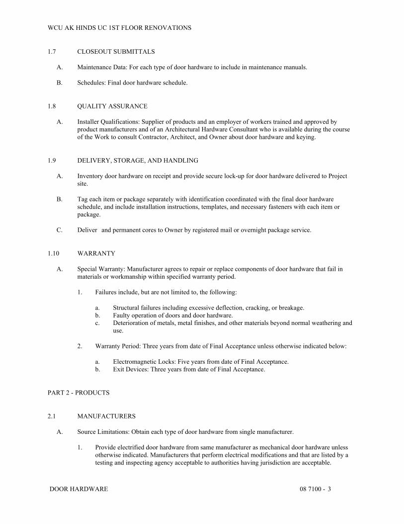
WCU AK HINDS UC 1ST FLOOR RENOVATIONS
DOOR HARDWARE 08 7100 - 3
1.7 CLOSEOUT SUBMITTALS
A. Maintenance Data: For each type of door hardware to include in maintenance manuals.
B. Schedules: Final door hardware schedule.
1.8 QUALITY ASSURANCE
A. Installer Qualifications: Supplier of products and an employer of workers trained and approved by product manufacturers and of an Architectural Hardware Consultant who is available during the course of the Work to consult Contractor, Architect, and Owner about door hardware and keying.
1.9 DELIVERY, STORAGE, AND HANDLING
A. Inventory door hardware on receipt and provide secure lock-up for door hardware delivered to Project site.
B. Tag each item or package separately with identification coordinated with the final door hardware schedule, and include installation instructions, templates, and necessary fasteners with each item or package.
C. Deliver and permanent cores to Owner by registered mail or overnight package service.
1.10 WARRANTY
A. Special Warranty: Manufacturer agrees to repair or replace components of door hardware that fail in materials or workmanship within specified warranty period.
1. Failures include, but are not limited to, the following:
a. Structural failures including excessive deflection, cracking, or breakage. b. Faulty operation of doors and door hardware. c. Deterioration of metals, metal finishes, and other materials beyond normal weathering and
use.
2. Warranty Period: Three years from date of Final Acceptance unless otherwise indicated below:
a. Electromagnetic Locks: Five years from date of Final Acceptance. b. Exit Devices: Three years from date of Final Acceptance.
PART 2 - PRODUCTS
2.1 MANUFACTURERS
A. Source Limitations: Obtain each type of door hardware from single manufacturer.
1. Provide electrified door hardware from same manufacturer as mechanical door hardware unless otherwise indicated. Manufacturers that perform electrical modifications and that are listed by a testing and inspecting agency acceptable to authorities having jurisdiction are acceptable.
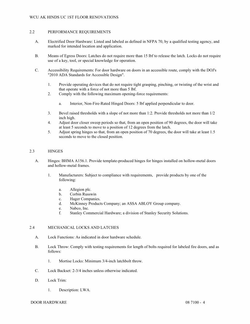
WCU AK HINDS UC 1ST FLOOR RENOVATIONS
DOOR HARDWARE 08 7100 - 4
2.2 PERFORMANCE REQUIREMENTS
A. Electrified Door Hardware: Listed and labeled as defined in NFPA 70, by a qualified testing agency, and marked for intended location and application.
B. Means of Egress Doors: Latches do not require more than 15 lbf to release the latch. Locks do not require use of a key, tool, or special knowledge for operation.
C. Accessibility Requirements: For door hardware on doors in an accessible route, comply with the DOJ's "2010 ADA Standards for Accessible Design".
1. Provide operating devices that do not require tight grasping, pinching, or twisting of the wrist and that operate with a force of not more than 5 lbf.
2. Comply with the following maximum opening-force requirements:
a. Interior, Non-Fire-Rated Hinged Doors: 5 lbf applied perpendicular to door.
3. Bevel raised thresholds with a slope of not more than 1:2. Provide thresholds not more than 1/2 inch high.
4. Adjust door closer sweep periods so that, from an open position of 90 degrees, the door will take at least 5 seconds to move to a position of 12 degrees from the latch.
5. Adjust spring hinges so that, from an open position of 70 degrees, the door will take at least 1.5 seconds to move to the closed position.
2.3 HINGES
A. Hinges: BHMA A156.1. Provide template-produced hinges for hinges installed on hollow-metal doors and hollow-metal frames.
1. Manufacturers: Subject to compliance with requirements, provide products by one of the following:
a. Allegion plc. b. Corbin Russwin c. Hager Companies. d. McKinney Products Company; an ASSA ABLOY Group company. e. Nabco, Inc. f. Stanley Commercial Hardware; a division of Stanley Security Solutions.
2.4 MECHANICAL LOCKS AND LATCHES
A. Lock Functions: As indicated in door hardware schedule.
B. Lock Throw: Comply with testing requirements for length of bolts required for labeled fire doors, and as follows:
1. Mortise Locks: Minimum 3/4-inch latchbolt throw.
C. Lock Backset: 2-3/4 inches unless otherwise indicated.
D. Lock Trim:
1. Description: LWA.

WCU AK HINDS UC 1ST FLOOR RENOVATIONS
DOOR HARDWARE 08 7100 - 5
2. Levers: Wrought.
a. LWA.
3. Escutcheons (Roses): Wrought. 4. Dummy Trim: Match lever lock trim and escutcheons.
E. Strikes: Provide manufacturer's strike for each lock bolt or latchbolt complying with requirements indicated for applicable lock or latch and with strike box and curved lip extended to protect frame; finished to match lock or latch.
F. Mortise Locks: BHMA A156.13; Operational Grade 1; stamped steel case with steel or brass parts; Series 1000.
1. Manufacturers: Subject to compliance with requirements, provide products by one of the following:
a. Allegion plc. b. Best Access Systems; Stanley Security Solutions, Inc. c. Corbin Russwin, Inc.; an ASSA ABLOY Group company. d. Hager Companies. e. SARGENT Manufacturing Company; ASSA ABLOY. f. Stanley Commercial Hardware; a division of Stanley Security Solutions. g. Yale Security Inc; an ASSA ABLOY Group company.
2.5 AUXILIARY LOCKS
A. Mortise Auxiliary Locks: BHMA A156.36; Grade 1; with strike that suits frame.
1. Manufacturers: Subject to compliance with requirements, provide products by one of the following:
a. Allegion plc. b. Best Access Systems; Stanley Security Solutions, Inc. c. Hager Companies. d. SARGENT Manufacturing Company; ASSA ABLOY. e. Stanley Commercial Hardware; a division of Stanley Security Solutions.
2.6 ELECTRIC STRIKES
A. Electric Strikes: BHMA A156.31; Grade 1; with faceplate to suit lock and frame.
1. Manufacturers: Subject to compliance with requirements, provide products by one of the following:
a. Allegion plc. b. Hager Companies. c. Securitron Magnalock Corporation; an ASSA ABLOY Group company. d. Security Door Controls. e. Stanley Commercial Hardware; a division of Stanley Security Solutions.

WCU AK HINDS UC 1ST FLOOR RENOVATIONS
DOOR HARDWARE 08 7100 - 6
2.7 ELECTROMECHANICAL LOCKS
A. Electromechanical Locks: BHMA A156.25; Grade 1; motor or solenoid driven; with strike that suits frame.
1. Manufacturers: Subject to compliance with requirements, provide products by one of the following:
a. Allegion plc. b. SARGENT Manufacturing Company; ASSA ABLOY. c. Stanley Commercial Hardware; a division of Stanley Security Solutions.
2.8 MANUAL FLUSH BOLTS
A. Manual Flush Bolts: BHMA A156.16; minimum 3/4-inch throw; designed for mortising into door edge.
1. Manufacturers: Subject to compliance with requirements, provide products by one of the following:
a. Allegion plc. b. Door Controls International, Inc. c. Trimco.
2.9 EXIT DEVICES AND AUXILIARY ITEMS
A. Exit Devices and Auxiliary Items: BHMA A156.3.
1. Manufacturers: Subject to compliance with requirements, provide products by one of the following:
a. Allegion plc. b. Corbin Russwin, Inc.; an ASSA ABLOY Group company. c. Hager Companies. d. SARGENT Manufacturing Company; ASSA ABLOY. e. Stanley Commercial Hardware; a division of Stanley Security Solutions.
2.10 LOCK CYLINDERS
A. Lock Cylinders: Tumbler type, constructed from brass or bronze, stainless steel, or nickel silver. Provide cylinder from same manufacturer of locking devices.
B. Standard Lock Cylinders: BHMA A156.5; Grade 1 permanent cores; face finished to match lockset.
1. Core Type: Interchangeable.
C. Construction Cores: Provide construction cores that are replaceable by permanent cores. Provide 10 construction master keys.
2.11 KEYING
A. Deliver permanent cores to Owner for keying.

WCU AK HINDS UC 1ST FLOOR RENOVATIONS
DOOR HARDWARE 08 7100 - 7
B. Keys: Nickel silver.
1. Stamping: Permanently inscribe each key with a visual key control number and include the following notation:
a. Notation: Information to be furnished by Owner.
2.12 OPERATING TRIM
A. Operating Trim: BHMA A156.6; brass unless otherwise indicated.
1. Manufacturers: Subject to compliance with requirements, provide products by one of the following:
a. Allegion plc. b. Hager Companies. c. Rockwood Manufacturing Company; an ASSA ABLOY Group company. d. Trimco.
2.13 ACCESSORIES FOR PAIRS OF DOORS
A. Astragals: BHMA A156.22.
2.14 MECHANICAL STOPS AND HOLDERS
A. Wall- and Floor-Mounted Stops: BHMA A156.16.
1. Manufacturers: Subject to compliance with requirements, provide products by one of the following:
a. Burns Manufacturing Incorporated. b. Glynn-Johnson. c. Rockwood Manufacturing Company; an ASSA ABLOY Group company.
2.15 AUXILIARY DOOR HARDWARE
A. Auxiliary Hardware: BHMA A156.16.
1. Manufacturers: Subject to compliance with requirements, provide products by one of the following:
a. Allegion plc. b. Hager Companies. c. Rockwood Manufacturing Company; an ASSA ABLOY Group company. d. Trimco.
2.16 AUXILIARY ELECTRIFIED DOOR HARDWARE
A. Auxiliary Electrified Door Hardware:

WCU AK HINDS UC 1ST FLOOR RENOVATIONS
DOOR HARDWARE 08 7100 - 8
1. Manufacturers: Subject to compliance with requirements, provide products by one of the following:
a. Allegion plc. b. Hager Companies. c. SARGENT Manufacturing Company; ASSA ABLOY. d. Securitron Magnalock Corporation; an ASSA ABLOY Group company.
2.17 FABRICATION
A. Base Metals: Produce door hardware units of base metal indicated, fabricated by forming method indicated, using manufacturer's standard metal alloy, composition, temper, and hardness. Furnish metals of a quality equal to or greater than that of specified door hardware units and BHMA A156.18.
B. Fasteners: Provide door hardware manufactured to comply with published templates prepared for machine, wood, and sheet metal screws. Provide screws that comply with commercially recognized industry standards for application intended, except aluminum fasteners are not permitted. Provide Phillips flat-head screws with finished heads to match surface of door hardware unless otherwise indicated.
1. Concealed Fasteners: For door hardware units that are exposed when door is closed, except for units already specified with concealed fasteners. Do not use through bolts for installation where bolt head or nut on opposite face is exposed unless it is the only means of securely attaching the door hardware. Where through bolts are used on hollow door and frame construction, provide sleeves for each through bolt.
2. Through bolting: Through bolting not allowed.
2.18 FINISHES
A. Provide finishes complying with BHMA A156.18 as indicated in door hardware schedule.
B. Protect mechanical finishes on exposed surfaces from damage by applying a strippable, temporary protective covering before shipping.
C. Appearance of Finished Work: Variations in appearance of abutting or adjacent pieces are acceptable if they are within one-half of the range of approved Samples. Noticeable variations in the same piece are not acceptable. Variations in appearance of other components are acceptable if they are within the range of approved Samples and are assembled or installed to minimize contrast.
PART 3 - EXECUTION
3.1 EXAMINATION
A. Examine doors and frames, with Installer present, for compliance with requirements for installation tolerances, labeled fire-rated door assembly construction, wall and floor construction, and other conditions affecting performance of the Work.
B. Examine roughing-in for electrical power systems to verify actual locations of wiring connections before electrified door hardware installation.
C. Proceed with installation only after unsatisfactory conditions have been corrected.

WCU AK HINDS UC 1ST FLOOR RENOVATIONS
DOOR HARDWARE 08 7100 - 9
3.2 PREPARATION
A. Steel Doors and Frames: For surface-applied door hardware, drill and tap doors and frames according to ANSI/SDI A250.6.
B. Wood Doors: Comply with door and hardware manufacturers' written instructions.
3.3 INSTALLATION
A. Mounting Heights: Mount door hardware units at heights to comply with the following unless otherwise indicated or required to comply with governing regulations.
1. Custom Steel Doors and Frames: HMMA 831. 2. Wood Doors: DHI's "Recommended Locations for Architectural Hardware for Wood Flush
Doors."
B. Install each door hardware item to comply with manufacturer's written instructions. Where cutting and fitting are required to install door hardware onto or into surfaces that are later to be painted or finished in another way, coordinate removal, storage, and reinstallation of surface protective trim units with finishing work. Do not install surface-mounted items until finishes have been completed on substrates involved.
1. Set units level, plumb, and true to line and location. Adjust and reinforce attachment substrates as necessary for proper installation and operation.
2. Drill and countersink units that are not factory prepared for anchorage fasteners. Space fasteners and anchors according to industry standards.
C. Hinges: Install types and in quantities indicated in door hardware schedule, but not fewer than the number recommended by manufacturer for application indicated or one hinge for every 30 inches of door height, whichever is more stringent, unless other equivalent means of support for door, such as spring hinges or pivots, are provided.
D. Lock Cylinders: Install construction cores to secure building and areas during construction period.
1. Furnish permanent cores to Owner for installation.
E. Boxed Power Supplies: Locate power supplies as indicated or, if not indicated, above accessible ceilings. Verify location with Architect.
1. Configuration: Provide least number of power supplies required to adequately serve doors with electrified door hardware.
F. Stops: Provide wall stops for doors unless wall stops are not sufficient. Do not mount floor stops where they will impede traffic.
G. Perimeter Gasketing: Apply to head and jamb, forming seal between door and frame.
1. Do not notch perimeter gasketing to install other surface-applied hardware.
H. Meeting Stile Gasketing: Fasten to meeting stiles, forming seal when doors are closed.
I. Door Bottoms: Apply to bottom of door, forming seal with threshold when door is closed.
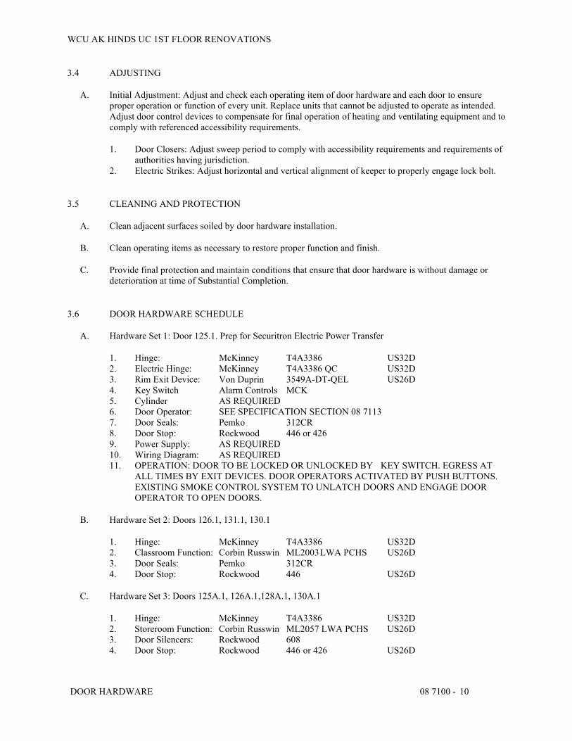
WCU AK HINDS UC 1ST FLOOR RENOVATIONS
DOOR HARDWARE 08 7100 - 10
3.4 ADJUSTING
A. Initial Adjustment: Adjust and check each operating item of door hardware and each door to ensure proper operation or function of every unit. Replace units that cannot be adjusted to operate as intended. Adjust door control devices to compensate for final operation of heating and ventilating equipment and to comply with referenced accessibility requirements.
1. Door Closers: Adjust sweep period to comply with accessibility requirements and requirements of authorities having jurisdiction.
2. Electric Strikes: Adjust horizontal and vertical alignment of keeper to properly engage lock bolt.
3.5 CLEANING AND PROTECTION
A. Clean adjacent surfaces soiled by door hardware installation.
B. Clean operating items as necessary to restore proper function and finish.
C. Provide final protection and maintain conditions that ensure that door hardware is without damage or deterioration at time of Substantial Completion.
3.6 DOOR HARDWARE SCHEDULE
A. Hardware Set 1: Door 125.1. Prep for Securitron Electric Power Transfer
1. Hinge: McKinney T4A3386 US32D 2. Electric Hinge: McKinney T4A3386 QC US32D 3. Rim Exit Device: Von Duprin 3549A-DT-QEL US26D 4. Key Switch Alarm Controls MCK 5. Cylinder AS REQUIRED 6. Door Operator: SEE SPECIFICATION SECTION 08 7113 7. Door Seals: Pemko 312CR 8. Door Stop: Rockwood 446 or 426 9. Power Supply: AS REQUIRED 10. Wiring Diagram: AS REQUIRED 11. OPERATION: DOOR TO BE LOCKED OR UNLOCKED BY KEY SWITCH. EGRESS AT
ALL TIMES BY EXIT DEVICES. DOOR OPERATORS ACTIVATED BY PUSH BUTTONS. EXISTING SMOKE CONTROL SYSTEM TO UNLATCH DOORS AND ENGAGE DOOR OPERATOR TO OPEN DOORS.
B. Hardware Set 2: Doors 126.1, 131.1, 130.1
1. Hinge: McKinney T4A3386 US32D 2. Classroom Function: Corbin Russwin ML2003 LWA PCHS US26D 3. Door Seals: Pemko 312CR 4. Door Stop: Rockwood 446 US26D
C. Hardware Set 3: Doors 125A.1, 126A.1,128A.1, 130A.1
1. Hinge: McKinney T4A3386 US32D 2. Storeroom Function: Corbin Russwin ML2057 LWA PCHS US26D 3. Door Silencers: Rockwood 608 4. Door Stop: Rockwood 446 or 426 US26D

WCU AK HINDS UC 1ST FLOOR RENOVATIONS
DOOR HARDWARE 08 7100 - 11
D. Hardware Set 4: Doors 128.1, 129.1, 133.1, 134.1, 135.1, 136.1
1. Hinge: McKinney T4A3386 US32D 2. Office Function: Corbin Russwin ML2053 LWA PCHS US26D 3. Door Silencers: Rockwood 608 4. Door Stop: Rockwood 446 or 426 US26D
E. Hardware Set 5: Door 138.1
1. Hinge: McKinney T4A3386 US32D 2. Classroom Function: Corbin Russwin ML2003 LWA PCHS US26D 3. Full Dummy Trim: Corbin Russwin ML2070 LWA US26D 4. Flush Bolt: Rockwood 555 US26D 5. Dustproof Strike: Rockwood 570 US26D 6. Adjustable Astragal: Pemko 354CPK 7. Door Silencers: Rockwood 608 8. Door Stop: Rockwood 446 or 426 US26D
END OF SECTION 08 7100

WCU AK HINDS UC 1ST FLOOR RENOVATIONS
AUTOMATIC DOOR OPERATORS 08 7113 - 1
SECTION 08 7113 - AUTOMATIC DOOR OPERATORS
PART 1 - GENERAL
1.1 RELATED DOCUMENTS
A. Drawings and general provisions of the Contract, including General and Supplementary Conditions and Division 01 Specification Sections, apply to this Section.
1.2 SUMMARY
A. Section Includes:
1. Low-energy door operators for swinging doors.
1.3 DEFINITIONS
A. AAADM: American Association of Automatic Door Manufacturers.
B. Activation Device: A control that, when actuated, sends an electrical signal to the door operator to open the door.
C. Safety Device: A control that, to avoid injury, prevents a door from opening or closing.
D. For automatic door terminology, see BHMA A156.10 for definitions of terms.
1.4 COORDINATION
A. Templates: Distribute for doors, frames, and other work specified to be factory prepared and reinforced for installing automatic door operators.
B. Coordinate hardware for doors with operators to ensure proper size, thickness, hand, function, and finish.
C. Electrical System Roughing-in: Coordinate layout and installation of automatic door operators with connections to the following:
1. Power supplies. 2. Remote activation devices. 3. Remote monitoring systems.
1.5 ACTION SUBMITTALS
A. Product Data: For each type of product.
1. Include construction details, material descriptions, dimensions of individual components and profiles, and finishes for automatic door operators.
2. Include rated capacities, operating characteristics, electrical characteristics, and furnished specialties and accessories.

WCU AK HINDS UC 1ST FLOOR RENOVATIONS
AUTOMATIC DOOR OPERATORS 08 7113 - 2
B. Shop Drawings: For automatic door operators.
1. Include plans, elevations, sections, hardware mounting heights, and attachment details. 2. Indicate dimensions, weights, loads, required clearances, method of field assembly, components,
and location and size of each field connection. 3. Indicate locations of activation and safety devices. 4. Include diagrams for power, signal, and control wiring.
1.6 INFORMATIONAL SUBMITTALS
A. Qualification Data: For Certified Inspector.
1.7 CLOSEOUT SUBMITTALS
A. Maintenance Data: For automatic door operators, safety devices, and control systems, to include in maintenance manuals.
1.8 QUALITY ASSURANCE
A. Installer Qualifications: An authorized representative who is trained and approved by manufacturer for installation and maintenance of units required for this Project[ and who employs a Certified Inspector].
B. Certified Inspector Qualifications: Certified by AAADM.
1.9 WARRANTY
A. Special Warranty: Manufacturer agrees to repair or replace components of automatic door operators that fail in materials or workmanship within specified warranty period.
1. Failures include, but are not limited to, the following:
a. Faulty or sporadic operation of automatic door operator, including controls. b. Deterioration of metals, metal finishes, and other materials beyond normal weathering or
use.
2. Warranty Period: Three years from date of Substantial Completion.
PART 2 - PRODUCTS
2.1 MANUFACTURERS
A. Manufacturers: Subject to compliance with requirements, provide products by one of the following:
1. LCN; an Allegion brand. 2. NABCO Entrances, Inc. 3. Stanley Access Technologies.
B. Source Limitations: Obtain automatic door operators, including activation and safety devices, from single source from single manufacturer.

WCU AK HINDS UC 1ST FLOOR RENOVATIONS
AUTOMATIC DOOR OPERATORS 08 7113 - 3
2.2 AUTOMATIC DOOR OPERATORS, GENERAL
A. General: Provide operators of size recommended by manufacturer for door size, weight, and movement; for condition of exposure; and for long-term, maintenance-free operation under normal traffic load for occupancy type indicated; and in accordance with UL 325. Coordinate operator mechanisms with door operation, hinges, and activation and safety devices.
B. Electromechanical Operating System: Self-contained unit powered by permanent-magnet dc motor; with closing speed controlled mechanically by gear train and dynamically by braking action of electric motor, connections for power and activation- and safety-device wiring, and manual operation, including spring closing when power is off.
C. Hinges: See Section 08 7100 "Door Hardware" for hinge type for each door that door operator shall accommodate.
D. Cover for Surface-Mounted Operators: Fabricated from 0.125-inch- thick, extruded or formed aluminum; continuous over full width of operator-controlled door opening; with enclosed end caps, provision for maintenance access, and fasteners concealed when door is in closed position.
E. Brackets and Reinforcements: Fabricated from aluminum with nonstaining, nonferrous shims for aligning system components.
F. Electrical Components, Devices, and Accessories: Listed and labeled as defined in NFPA 70, by a qualified testing agency, and marked for intended location and application.
2.3 LOW-ENERGY DOOR OPERATORS FOR SWINGING DOORS
A. Standard: BHMA A156.19.
B. Performance Requirements:
1. Opening Force if Power Fails: Not more than 15 lbf required to release latch if provided, not more than 30 lbf required to manually set door in motion, and not more than 15 lbfrequired to fully open door.
2. Entrapment-Prevention Force: Not more than 15 lbf required to prevent stopped door from closing or opening.
C. Configuration: Operator to control pair of swinging doors.
1. Traffic Pattern: One way. 2. Operator Mounting: Surface.
D. Operating System: Electromechanical.
E. Microprocessor Control Unit: Solid-state controller.
F. Features:
1. Adjustable opening and closing speed. 2. Adjustable opening and closing force. 3. Adjustable backcheck. 4. Adjustable hold-open time from zero to limitless. 5. Adjustable time delay. 6. Adjustable acceleration.
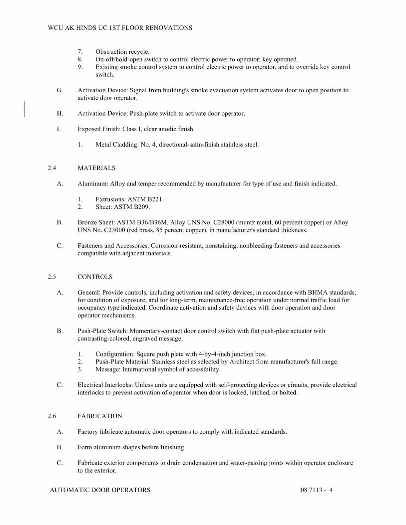
WCU AK HINDS UC 1ST FLOOR RENOVATIONS
AUTOMATIC DOOR OPERATORS 08 7113 - 4
7. Obstruction recycle. 8. On-off/hold-open switch to control electric power to operator; key operated. 9. Existing smoke control system to control electric power to operator, and to override key control
switch.
G. Activation Device: Signal from building's smoke evacuation system activates door to open position.to activate door operator.
H. Activation Device: Push-plate switch to activate door operator.
I. Exposed Finish: Class I, clear anodic finish.
1. Metal Cladding: No. 4, directional-satin-finish stainless steel.
2.4 MATERIALS
A. Aluminum: Alloy and temper recommended by manufacturer for type of use and finish indicated.
1. Extrusions: ASTM B221. 2. Sheet: ASTM B209.
B. Bronze Sheet: ASTM B36/B36M, Alloy UNS No. C28000 (muntz metal, 60 percent copper) or Alloy UNS No. C23000 (red brass, 85 percent copper), in manufacturer's standard thickness.
C. Fasteners and Accessories: Corrosion-resistant, nonstaining, nonbleeding fasteners and accessories compatible with adjacent materials.
2.5 CONTROLS
A. General: Provide controls, including activation and safety devices, in accordance with BHMA standards; for condition of exposure; and for long-term, maintenance-free operation under normal traffic load for occupancy type indicated. Coordinate activation and safety devices with door operation and door operator mechanisms.
B. Push-Plate Switch: Momentary-contact door control switch with flat push-plate actuator with contrasting-colored, engraved message.
1. Configuration: Square push plate with 4-by-4-inch junction box. 2. Push-Plate Material: Stainless steel as selected by Architect from manufacturer's full range. 3. Message: International symbol of accessibility.
C. Electrical Interlocks: Unless units are equipped with self-protecting devices or circuits, provide electrical interlocks to prevent activation of operator when door is locked, latched, or bolted.
2.6 FABRICATION
A. Factory fabricate automatic door operators to comply with indicated standards.
B. Form aluminum shapes before finishing.
C. Fabricate exterior components to drain condensation and water-passing joints within operator enclosure to the exterior.

WCU AK HINDS UC 1ST FLOOR RENOVATIONS
AUTOMATIC DOOR OPERATORS 08 7113 - 5
D. Use concealed fasteners to greatest extent possible. Where exposed fasteners are required, use countersunk Phillips flat-head machine screws, finished to match operator.
E. Provide metal cladding, completely covering visible surfaces before shipment to Project site. Fabricate cladding with concealed fasteners and connection devices, with accurately fitted joints with ends coped or mitered to produce hairline joints free of burrs and distortion, and with allowance for thermal expansion at exterior doors.
2.7 GENERAL FINISH REQUIREMENTS
A. Protect mechanical finishes on exposed surfaces from damage by applying strippable, temporary, protective covering before shipping.
B. Apply organic and anodic finishes to formed metal after fabrication unless otherwise indicated.
C. Appearance of Finished Work: Noticeable variations in same piece are unacceptable. Variations in appearance of adjoining components are acceptable if they are within range of approved Samples and are assembled or installed to minimize contrast.
PART 3 - EXECUTION
3.1 EXAMINATION
A. Examine conditions, with Installer present, for compliance with requirements for installation tolerances, door and frame preparation and reinforcements, and other conditions affecting performance of automatic door operators.
B. Examine roughing-in for compressed-air piping systems to verify actual locations of piping connections before automatic door operator installation.
C. Verify that full-height finger guards are installed at each door with pivot hinges, where door has a clearance at hinge side greater than 1/4 inch and less than 3/4 inch with door in any position.
D. Proceed with installation only after unsatisfactory conditions have been corrected.
3.2 INSTALLATION, GENERAL
A. Install automatic door operators in accordance with manufacturer's written instructions and cited BHMA standard for type of door operation and direction of pedestrian travel, including signage, controls, wiring, remote power units if any, and connection to building's power supply.
1. Do not install damaged components. Fit joints to produce hairline joints free of burrs and distortion.
2. Install operators true in alignment with established lines and door geometry without warp or rack. Anchor securely in place.
B. Controls: Install activation and safety devices in accordance with manufacturer's written instructions and cited BHMA standard for operator type and direction of pedestrian travel.
C. Signage: Apply on both sides of each door as required by cited BHMA standard for type of door operator and direction of pedestrian travel.
WCU AK HINDS UC 1ST FLOOR RENOVATIONS
AUTOMATIC DOOR OPERATORS 08 7113 - 6
3.3 FIELD QUALITY CONTROL
A. Certified Inspector: Engage a Certified Inspector to test and inspect components, assemblies, and installations, including connections.
B. Perform the following tests and inspections:
1. Test and inspect each automatic door operator installation, using AAADM inspection forms, to determine compliance of installed systems with applicable BHMA standards.
C. Automatic door operators will be considered defective if they do not pass tests and inspections.
D. Prepare test and inspection reports.
3.4 ADJUSTING
A. Adjust automatic door operators to function smoothly, and lubricate as recommended by manufacturer; comply with requirements of applicable BHMA standards.
B. After completing installation of automatic door operators, inspect exposed finishes on doors and operators. Repair damaged finish to match original finish.
C. Readjust automatic door operators and controls after repeated operation of completed installation equivalent to three days' use by normal traffic (100 to 300 cycles).
END OF SECTION 08 7113

WCU AK HINDS UC 1ST FLOOR RENOVATIONS
GLAZING 08 8000 - 1
SECTION 08 8000 - GLAZING
PART 1 - GENERAL
1.1 RELATED DOCUMENTS
A. Drawings and general provisions of the Contract, including General and Supplementary Conditions and Division 01 Specification Sections, apply to this Section.
1.2 SUMMARY
A. Section Includes:
1. Glass for doors and storefront framing, and demountable partitions. 2. Glazing sealants and accessories.
B. Related Requirements:
1. Section 08 8113 "Decorative Glass Glazing."
1.3 DEFINITIONS
A. Glass Manufacturers: Firms that produce primary glass, fabricated glass, or both, as defined in referenced glazing publications.
B. Glass Thicknesses: Indicated by thickness designations in millimeters according to ASTM C1036.
C. IBC: International Building Code.
D. Interspace: Space between lites of an insulating-glass unit.
1.4 COORDINATION
A. Coordinate glazing channel dimensions to provide necessary bite on glass, minimum edge and face clearances, and adequate sealant thicknesses, with reasonable tolerances.
1.5 ACTION SUBMITTALS
A. Product Data: For each type of product.
B. Glass Samples: For each type of glass product other than clear monolithic vision glass; 12 inches square.
C. Glazing Schedule: List glass types and thicknesses for each size opening and location. Use same designations indicated on Drawings.

WCU AK HINDS UC 1ST FLOOR RENOVATIONS
GLAZING 08 8000 - 2
1.6 INFORMATIONAL SUBMITTALS
A. Sample Warranties: For special warranties.
1.7 QUALITY ASSURANCE
A. Manufacturer Qualifications for Insulating-Glass Units with Sputter-Coated, Low-E Coatings: A qualified insulating-glass manufacturer who is approved and certified by coated-glass manufacturer.
1.8 DELIVERY, STORAGE, AND HANDLING
A. Protect glazing materials according to manufacturer's written instructions. Prevent damage to glass and glazing materials from condensation, temperature changes, direct exposure to sun, or other causes.
1.9 FIELD CONDITIONS
A. Environmental Limitations: Do not proceed with glazing when ambient and substrate temperature conditions are outside limits permitted by glazing material manufacturers and when glazing channel substrates are wet from rain, frost, condensation, or other causes.
1. Do not install glazing sealants when ambient and substrate temperature conditions are outside limits permitted by sealant manufacturer or are below 40 deg F.
1.10 WARRANTY
A. Manufacturer's Special Warranty for Coated-Glass Products: Manufacturer agrees to replace coated-glass units that deteriorate within specified warranty period. Deterioration of coated glass is defined as defects developed from normal use that are not attributed to glass breakage or to maintaining and cleaning coated glass contrary to manufacturer's written instructions. Defects include peeling, cracking, and other indications of deterioration in coating.
1. Warranty Period: 10 years from date of Final Acceptance.
PART 2 - PRODUCTS
2.1 MANUFACTURERS
A. Manufacturers: Subject to compliance with requirements, available manufacturers offering products that may be incorporated into the Work include, but are not limited to, the following:
1. AGC Glass Company North America, Inc. 2. Guardian Glass; SunGuard. 3. Oldcastle BuildingEnvelope. 4. Pilkington North America. 5. Trulite Glass & Aluminum Solutions, LLC. 6. Viracon, Inc.
B. Source Limitations for Glass: Obtain from single source from single manufacturer for each glass type.

WCU AK HINDS UC 1ST FLOOR RENOVATIONS
GLAZING 08 8000 - 3
C. Source Limitations for Glazing Accessories: Obtain from single source from single manufacturer for each product and installation method.
2.2 PERFORMANCE REQUIREMENTS
A. General: Installed glazing systems shall withstand normal thermal movement and wind and impact loads (where applicable) without failure, including loss or glass breakage attributable to the following: defective manufacture, fabrication, or installation; failure of sealants or gaskets to remain watertight and airtight; deterioration of glazing materials; or other defects in construction.
B. Safety Glazing: Where safety glazing is indicated, provide glazing that complies with 16 CFR 1201, Category II.
C. Thermal and Optical Performance Properties: Provide glass with performance properties specified, as indicated in manufacturer's published test data, based on procedures indicated below:
1. For monolithic-glass lites, properties are based on units with lites 6 mm thick. 2. For insulating-glass units, properties are based on units of thickness indicated for overall unit and
for each lite. 3. U-Factors: Center-of-glazing values, according to NFRC 100 and based on LBL's WINDOW 5.2
computer program, expressed as Btu/sq. ft. x h x deg F. 4. Solar Heat-Gain Coefficient and Visible Transmittance: Center-of-glazing values, according to
NFRC 200 and based on LBL's WINDOW 5.2 computer program. 5. Visible Reflectance: Center-of-glazing values, according to NFRC 300.
2.3 GLASS PRODUCTS, GENERAL
A. Glazing Publications: Comply with published recommendations of glass product manufacturers and organizations below unless more stringent requirements are indicated. See these publications for glazing terms not otherwise defined in this Section or in referenced standards.
1. GANA Publications: "Glazing Manual." 2. IGMA Publication for Insulating Glass: SIGMA TM-3000, "North American Glazing Guidelines
for Sealed Insulating Glass Units for Commercial and Residential Use."
B. Safety Glazing Labeling: Where safety glazing is indicated, permanently mark glazing with certification label of the SGCC the SGCC or another certification agency acceptable to authorities having jurisdiction or manufacturer. Label shall indicate manufacturer's name, type of glass, thickness, and safety glazing standard with which glass complies.
C. Thickness: Where glass thickness is indicated, it is a minimum. Provide glass that complies with performance requirements and is not less than the thickness indicated.
1. Minimum Glass Thickness for Exterior Lites: 6 mm.
D. Strength: Where annealed float glass is indicated, provide annealed float glass, heat-strengthened float glass, or fully tempered float glass as needed to comply with "Performance Requirements" Article. Where heat-strengthened float glass is indicated, provide heat-strengthened float glass or fully tempered float glass as needed to comply with "Performance Requirements" Article. Where fully tempered float glass is indicated, provide fully tempered float glass.

WCU AK HINDS UC 1ST FLOOR RENOVATIONS
GLAZING 08 8000 - 4
2.4 GLASS PRODUCTS
A. Clear Annealed Float Glass: ASTM C1036, Type I, Class 1 (clear), Quality-Q3.
B. Fully Tempered Float Glass: ASTM C1048, Kind FT (fully tempered), Condition A (uncoated) unless otherwise indicated, Type I, Class 1 (clear) or Class 2 (tinted) as indicated, Quality-Q3.
1. Fabrication Process: By horizontal (roller-hearth) process with roll-wave distortion parallel to bottom edge of glass as installed unless otherwise indicated.
C. Pyrolytic-Coated, Low-Maintenance Glass: Clear float glass with a coating on first surface having both photocatalytic and hydrophilic properties that act to loosen dirt and to cause water to sheet evenly over the glass instead of beading.
2.5 INSULATING GLASS
A. Insulating-Glass Units: Factory-assembled units consisting of sealed lites of glass separated by a dehydrated interspace, qualified according to ASTM E2190.
1. Sealing System: Dual seal, with manufacturer's standard primary and secondary sealants. 2. Perimeter Spacer: Manufacturer's standard spacer material and construction.
2.6 GLAZING SEALANTS
A. General:
1. Compatibility: Compatible with one another and with other materials they contact, including glass products, seals of insulating-glass units, and glazing channel substrates, under conditions of service and application, as demonstrated by sealant manufacturer based on testing and field experience.
2. Suitability: Comply with sealant and glass manufacturers' written instructions for selecting glazing sealants suitable for applications indicated and for conditions existing at time of installation.
3. Sealant shall have a VOC content of 250 g/L or less. 4. Sealant shall comply with the testing and product requirements of the California Department of
Public Health's "Standard Method for the Testing and Evaluation of Volatile Organic Chemical Emissions from Indoor Sources Using Environmental Chambers."
5. Colors of Exposed Glazing Sealants: As selected by Architect from manufacturer's full range.
B. Glazing Sealant:
1. Neutral-curing silicone glazing sealant complying with ASTM C920, Type S, Grade NS, Class 100/50, Use NT.
2.7 GLAZING TAPES
A. Back-Bedding Mastic Glazing Tapes: Preformed, butyl-based, 100 percent solids elastomeric tape; nonstaining and nonmigrating in contact with nonporous surfaces; with or without spacer rod as recommended in writing by tape and glass manufacturers for application indicated; and complying with ASTM C1281 and AAMA 800 for products indicated below:
1. AAMA 806.3 tape, for glazing applications in which tape is subject to continuous pressure.

WCU AK HINDS UC 1ST FLOOR RENOVATIONS
GLAZING 08 8000 - 5
B. Expanded Cellular Glazing Tapes: Closed-cell, PVC foam tapes; factory coated with adhesive on both surfaces; and complying with AAMA 800 for the following types:
1. AAMA 810.1, Type 1, for glazing applications in which tape acts as the primary sealant. 2. AAMA 810.1, Type 2, for glazing applications in which tape is used in combination with a full
bead of liquid sealant.
2.8 MISCELLANEOUS GLAZING MATERIALS
A. General: Provide products of material, size, and shape complying with referenced glazing standard, with requirements of manufacturers of glass and other glazing materials for application indicated, and with a proven record of compatibility with surfaces contacted in installation.
B. Cleaners, Primers, and Sealers: Types recommended by sealant or gasket manufacturer.
C. Setting Blocks:
1. Type recommended by sealant or glass manufacturer.
D. Spacers:
1. Type recommended by sealant or glass manufacturer.
E. Edge Blocks:
1. Type recommended by sealant or glass manufacturer.
F. Cylindrical Glazing Sealant Backing: ASTM C1330, Type O (open-cell material), of size and density to control glazing sealant depth and otherwise produce optimum glazing sealant performance.
2.9 FABRICATION OF GLAZING UNITS
A. Fabricate glazing units in sizes required to fit openings indicated for Project, with edge and face clearances, edge and surface conditions, and bite complying with written instructions of product manufacturer and referenced glazing publications, to comply with system performance requirements.
1. Allow for thermal movements from ambient and surface temperature changes acting on glass framing members and glazing components.
a. Temperature Change: 120 deg F, ambient; 180 deg F, material surfaces.
B. Clean-cut or flat-grind vertical edges of butt-glazed monolithic lites to produce square edges with slight chamfers at junctions of edges and faces.
C. Grind smooth and polish exposed glass edges and corners.
PART 3 - EXECUTION
3.1 EXAMINATION
A. Examine framing, glazing channels, and stops, with Installer present, for compliance with the following:

WCU AK HINDS UC 1ST FLOOR RENOVATIONS
GLAZING 08 8000 - 6
1. Manufacturing and installation tolerances, including those for size, squareness, and offsets at corners.
2. Presence and functioning of weep systems. 3. Minimum required face and edge clearances. 4. Effective sealing between joints of glass-framing members.
B. Proceed with installation only after unsatisfactory conditions have been corrected.
3.2 PREPARATION
A. Clean glazing channels and other framing members receiving glass immediately before glazing. Remove coatings not firmly bonded to substrates.
B. Examine glazing units to locate exterior and interior surfaces. Label or mark units as needed so that exterior and interior surfaces are readily identifiable. Do not use materials that leave visible marks in the completed Work.
3.3 GLAZING, GENERAL
A. Comply with combined written instructions of manufacturers of glass, sealants, gaskets, and other glazing materials, unless more stringent requirements are indicated, including those in referenced glazing publications.
B. Protect glass edges from damage during handling and installation. Remove damaged glass from Project site and legally dispose of off Project site. Damaged glass includes glass with edge damage or other imperfections that, when installed, could weaken glass, impair performance, or impair appearance.
C. Apply primers to joint surfaces where required for adhesion of sealants, as determined by preconstruction testing.
D. Install setting blocks in sill rabbets, sized and located to comply with referenced glazing publications, unless otherwise required by glass manufacturer. Set blocks in thin course of compatible sealant suitable for heel bead.
E. Do not exceed edge pressures stipulated by glass manufacturers for installing glass lites.
F. Provide spacers for glass lites where length plus width is larger than 50 inches.
1. Locate spacers directly opposite each other on both inside and outside faces of glass. Install correct size and spacing to preserve required face clearances, unless gaskets and glazing tapes are used that have demonstrated ability to maintain required face clearances and to comply with system performance requirements.
2. Provide 1/8-inch minimum bite of spacers on glass and use thickness equal to sealant width. With glazing tape, use thickness slightly less than final compressed thickness of tape.
G. Provide edge blocking where indicated or needed to prevent glass lites from moving sideways in glazing channel, as recommended in writing by glass manufacturer and according to requirements in referenced glazing publications.
H. Set glass lites in each series with uniform pattern, draw, bow, and similar characteristics.
I. Set glass lites with proper orientation so that coatings face exterior or interior as specified.

WCU AK HINDS UC 1ST FLOOR RENOVATIONS
GLAZING 08 8000 - 7
J. Where wedge-shaped gaskets are driven into one side of channel to pressurize sealant or gasket on opposite side, provide adequate anchorage so gasket cannot walk out when installation is subjected to movement.
K. Square cut wedge-shaped gaskets at corners and install gaskets in a manner recommended by gasket manufacturer to prevent corners from pulling away; seal corner joints and butt joints with sealant recommended by gasket manufacturer.
3.4 TAPE GLAZING
A. Position tapes on fixed stops so that, when compressed by glass, their exposed edges are flush with or protrude slightly above sightline of stops.
B. Install tapes continuously, but not necessarily in one continuous length. Do not stretch tapes to make them fit opening.
C. Cover vertical framing joints by applying tapes to heads and sills first, then to jambs. Cover horizontal framing joints by applying tapes to jambs, then to heads and sills.
D. Place joints in tapes at corners of opening with adjoining lengths butted together, not lapped. Seal joints in tapes with compatible sealant approved by tape manufacturer.
E. Do not remove release paper from tape until right before each glazing unit is installed.
F. Apply heel bead of elastomeric sealant.
G. Center glass lites in openings on setting blocks, and press firmly against tape by inserting dense compression gaskets formed and installed to lock in place against faces of removable stops. Start gasket applications at corners and work toward centers of openings.
H. Apply cap bead of elastomeric sealant over exposed edge of tape.
3.5 GASKET GLAZING (DRY)
A. Cut compression gaskets to lengths recommended by gasket manufacturer to fit openings exactly, with allowance for stretch during installation.
B. Insert soft compression gasket between glass and frame or fixed stop so it is securely in place with joints miter cut and bonded together at corners.
C. Installation with Drive-in Wedge Gaskets: Center glass lites in openings on setting blocks, and press firmly against soft compression gasket by inserting dense compression gaskets formed and installed to lock in place against faces of removable stops. Start gasket applications at corners and work toward centers of openings. Compress gaskets to produce a weathertight seal without developing bending stresses in glass. Seal gasket joints with sealant recommended by gasket manufacturer.
D. Installation with Pressure-Glazing Stops: Center glass lites in openings on setting blocks, and press firmly against soft compression gasket. Install dense compression gaskets and pressure-glazing stops, applying pressure uniformly to compression gaskets. Compress gaskets to produce a weathertight seal without developing bending stresses in glass. Seal gasket joints with sealant recommended by gasket manufacturer.
E. Install gaskets so they protrude past face of glazing stops.

WCU AK HINDS UC 1ST FLOOR RENOVATIONS
GLAZING 08 8000 - 8
3.6 CLEANING AND PROTECTION
A. Immediately after installation remove nonpermanent labels and clean surfaces.
B. Protect glass from contact with contaminating substances resulting from construction operations. Examine glass surfaces adjacent to or below exterior concrete and other masonry surfaces at frequent intervals during construction, but not less than once a month, for buildup of dirt, scum, alkaline deposits, or stains.
1. If, despite such protection, contaminating substances do come into contact with glass, remove substances immediately as recommended in writing by glass manufacturer. Remove and replace glass that cannot be cleaned without damage to coatings.
C. Remove and replace glass that is damaged during construction period.
D. Wash glass on both exposed surfaces not more than four days before date scheduled for inspections that establish date of Substantial Completion. Wash glass as recommended in writing by glass manufacturer.
3.7 MONOLITHIC GLASS SCHEDULE
A. Glass Type G-1: Clear annealed float glass.
1. Minimum Thickness:1/4 inch.
B. Glass Type:G-2: Clear fully tempered float glass.
1. Minimum Thickness: 1/4 inch. 2. Safety glazing required.
C. Glass Type:G-4: Dual Layer, Clear fully tempered float glass for demountable partitions.
1. Minimum Thickness: 1/4 inch per layer. 2. Safety glazing required. 3. Interspace Content: Air.
3.8 INSULATING GLASS SCHEDULE
A. Glass Type G-3: Low-E-coated, clear insulating glass.
1. Basis-of-Design Product: AGC Glass Energy Select 40. 2. Overall Unit Thickness: 1 inch. 3. Minimum Thickness of Each Glass Lite: 1/4 inch. 4. Outdoor Lite: Fully tempered float glass. 5. Interspace Content: Air. 6. Indoor Lite: Fully tempered float glass. 7. Low-E Coating: Pyrolytic on second surface. 8. Winter Nighttime U-Factor: 0.29 maximum. 9. Visible Light Transmittance: 69 percent minimum. 10. Solar Heat Gain Coefficient: 0.39 maximum. 11. Safety glazing required.
END OF SECTION 08 8000

WCU AK HINDS UC 1ST FLOOR RENOVATIONS
GLAZING 08 8000 - 9

WCU AK HINDS UC 1ST FLOOR RENOVATIONS
SECTION 08 8113 - DECORATIVE GLASS GLAZING
PART 1 - GENERAL
1.1 RELATED DOCUMENTS
A. Drawings and general provisions of the Contract, including General and Supplementary Conditions and Division 01 Specification Sections, apply to this Section.
1.2 SUMMARY
A. Section Includes:
1. Coated glass.
1.3 DEFINITION
A. Glass Thickness: Indicated by thickness designations in millimeters according to ASTM C 1036.
1.4 COORDINATION
A. Coordinate glazing channel dimensions to provide necessary bite on glass, minimum edge and face clearances, and adequate sealant thicknesses, with reasonable tolerances.
1.5 ACTION SUBMITTALS
A. Product Data: For each type of product.
B. Shop Drawings: For decorative glass. Show fabrication and installation details. Include the following:
1. Size and location of penetrations.2. Mounting method.3. Attachments to other work.4. Full-size details of edge-finished profiles.
C. Glass Samples: For the following products, 12 inches square:
1. Each type of decorative glass.2. Each edge treatment on type of decorative glass.3. Each applied coating on type of decorative glass.
1.6 DELIVERY, STORAGE, AND HANDLING
A. Protect decorative glass and glazing materials according to manufacturer's written instructions. Prevent damage to glass and glazing materials from condensation, temperature changes, direct exposure to sun, or other causes.
DECORATIVE GLASS GLAZING 08 8113 - 1

WCU AK HINDS UC 1ST FLOOR RENOVATIONS
1.7 FIELD CONDITIONS
A. Environmental Limitations: Do not deliver or install decorative glass until spaces are enclosed and weathertight, wet work in spaces is complete and dry, and temporary HVAC system is operating and maintaining ambient temperature and humidity conditions at occupancy levels during the remainder of the construction period.
B. Field Measurements: Verify actual dimensions of openings and construction contiguous with decorative glass by field measurements before fabrication.
PART 2 - PRODUCTS
2.1 MANUFACTURERS
A. Source Limitations for Glass: Obtain each type of decorative glass from single source from single manufacturer.
B. Source Limitations for Glazing Accessories: Obtain from single source from single manufacturer, for each product and installation method.
2.2 GLASS PRODUCTS, GENERAL
A. Thickness: Where glass thickness is indicated, it is a minimum. Provide glass lites in thicknesses as needed to comply with requirements indicated.
B. Strength: Where annealed float glass is indicated, provide annealed float glass, heat-strengthened float glass, or fully tempered float glass as needed to comply with requirements indicated. Where heat-strengthened glass is indicated, provide heat-strengthened float glass or fully tempered float glass as needed to comply with requirements indicated. Where fully tempered glass is indicated, provide fully tempered float glass.
2.3 GLASS PRODUCTS
A. Clear Annealed Float Glass: ASTM C 1036, Type I, Class 1 (clear), Quality-Q3.
2.4 GLAZING MATERIALS
A. Glazing Sealants, Tapes, and Miscellaneous Glazing Materials: As specified in Section 08 8000 "Glazing."
1. Colors: As selected by Architect from manufacturer's full range.
2.5 HARDWARE FOR GLASS INSTALLATION
A. Hardware: Stand-off display system with caps.
DECORATIVE GLASS GLAZING 08 8113 - 2

WCU AK HINDS UC 1ST FLOOR RENOVATIONS
1. Basis-of-Design Product: Subject to compliance with requirements, provide C.R. Laurence Co., Inc. SOB24PS Standoff with LPC2PS Low Profile Cap Assembly or comparable product by one of the following:
a. EPCO, Engineered Products Co.b. Gyford Productions, LLC.c. KL megla America, LLC.d. Sugatsune America, Inc.
2.6 DECORATIVE-GLASS FABRICATION
A. Fabricate decorative glass and provide other glazing products in sizes and radiuses required to glaze openings indicated for Project, with edge and face clearances, edge and surface conditions, and bite complying with product manufacturer's written instructions and with referenced glazing standard.
B. Edge Finishing: Finish edges smooth and polished, without chips, scratches, or warps.
1. Finished Edge: Clean cut or flat grind vertical edges of butt-glazed lites in a manner that produces square edges with slight kerfs.
2. Edge-Finished Glass Adhesive: Clear, nonyellowing, as recommended by manufacturer.
PART 3 - EXECUTION
3.1 EXAMINATION
A. Examine decorative-glass framing members, with Installer present, for compliance with the following:
1. Manufacturing and installation tolerances, including those for size, squareness, and offsets at corners.
2. Minimum required face or edge clearances.3. Effective sealing between joints of decorative-glass framing members.
B. Proceed with installation only after unsatisfactory conditions have been corrected.
3.2 PREPARATION
A. Clean glazing channels and other framing members receiving glass immediately before glazing. Remove coatings not firmly bonded to substrates.
B. Examine glazing units to locate orientation of outer surfaces[ as indicated on Drawings]. Label or mark units as needed so that surface orientation is readily identifiable. Do not use materials that leave visible marks in the completed Work.
3.3 INSTALLATION
A. Set decorative-glass units in each series true in line with uniform orientation, pattern, draw, bow, and similar characteristics.
DECORATIVE GLASS GLAZING 08 8113 - 3

WCU AK HINDS UC 1ST FLOOR RENOVATIONS
B. Set decorative glass in locations indicated on Drawings. Install glass with hardware and accessories according to hardware manufacturer's written instructions. Attach hardware securely to mounting surfaces.
C. Set decorative glass in locations indicated on Drawings and as specified in .
3.4 CLEANING AND PROTECTION
A. Immediately after installation, remove nonpermanent labels and clean surfaces.
B. Protect glass from contact with contaminating substances resulting from construction operations. If, despite such protection, contaminating substances do come into contact with glass, remove substances immediately as recommended in writing by glass manufacturer.
C. Remove and replace glass that is damaged during construction period.
D. Wash glass on both exposed surfaces not more than four days before date scheduled for inspections that establish date of Substantial Completion. Wash glass as recommended in writing by glass manufacturer.
3.5 DECORATIVE GLASS SCHEDULE
A. Decorative Glass>]: Coated glass with decorative glass paint or ink applied to glass surface and cured.
1. Basis-of-Design Product: Subject to compliance with requirements, provide AGC Glass Lacobel or comparable product.
2. Glass Type: Clear, float glass.3. Glass Thickness: As indicated.4. Coating Colors: White.
END OF SECTION 08 8113
DECORATIVE GLASS GLAZING 08 8113 - 4

WCU AK HINDS UC 1ST FLOOR RENOVATIONS
NON-STRUCTURAL METAL FRAMING 09 2216 - 1
SECTION 09 2216 - NON-STRUCTURAL METAL FRAMING
PART 1 - GENERAL
1.1 RELATED DOCUMENTS
A. Drawings and general provisions of the Contract, including General and Supplementary Conditions and Division 01 Specification Sections, apply to this Section.
1.2 SUMMARY
A. Section Includes:
1. Non-load-bearing steel framing systems for interior partitions.
1.3 ACTION SUBMITTALS
A. Product Data: For each type of product.
B. Sustainable Design Submittals:
1. Product Data: For recycled content, indicating postconsumer and preconsumer recycled content and cost.
PART 2 - PRODUCTS
2.1 PERFORMANCE REQUIREMENTS
A. STC-Rated Assemblies: For STC-rated assemblies, provide materials and construction identical to those tested in assembly indicated on Drawings, according to ASTM E 90 and classified according to ASTM E 413 by an independent testing agency.
B. Horizontal Deflection: For composite wall assemblies, limited to 1/240 of the wall height based on horizontal loading of 10 lbf/sq. ft..
2.2 FRAMING SYSTEMS
A. Recycled Content of Steel Products: Postconsumer recycled content plus one-half of preconsumer recycled content not less than 25 percent.
B. Framing Members, General: Comply with ASTM C 754 for conditions indicated.
1. Protective Coating: ASTM A 653/A 653M, G40, hot-dip galvanized unless otherwise indicated.
C. Studs and Tracks: ASTM C 645. Use either conventional steel studs and tracks or embossed, high-strength steel studs and tracks.

WCU AK HINDS UC 1ST FLOOR RENOVATIONS
NON-STRUCTURAL METAL FRAMING 09 2216 - 2
1. Steel Studs and Tracks:
a. Minimum Base-Steel Thickness: As required by performance requirements for horizontal deflection.
b. Depth: As indicated on Drawings.
2. Embossed, High Strength Steel Studs and Tracks: Roll-formed and embossed with surface deformations to stiffen the framing members so that they are structurally comparable to conventional ASTM C 645 steel studs and tracks.
a. Minimum Base-Steel Thickness: As required by horizontal deflection performance requirements.
b. Depth: As indicated on Drawings.
D. Slip-Type Head Joints: Where indicated, provide the following:
1. Deflection Track: Steel sheet top track manufactured to prevent cracking of finishes applied to interior partition framing resulting from deflection of structure above; in thickness not less than indicated for studs and in width to accommodate depth of studs.
E. Flat Strap and Backing Plate: Steel sheet for blocking and bracing in length and width indicated.
1. Minimum Base-Steel Thickness: As indicated on Drawings.
F. Cold-Rolled Channel Bridging: Steel, 0.0538-inch minimum base-steel thickness, with minimum 1/2-inch- wide flanges.
1. Depth: As indicated on Drawings.
G. Resilient Furring Channels: 1/2-inch- deep, steel sheet members designed to reduce sound transmission.
1. Configuration: Asymmetrical .
H. Z-Shaped Furring: With slotted or nonslotted web, face flange of 1-1/4 inches, wall attachment flange of 7/8 inch, minimum uncoated-steel thickness of 0.0179 inch, and depth required to fit insulation thickness indicated.
2.3 AUXILIARY MATERIALS
A. General: Provide auxiliary materials that comply with referenced installation standards.
1. Fasteners for Steel Framing: Of type, material, size, corrosion resistance, holding power, and other properties required to fasten steel members to substrates.
B. Isolation Strip at Exterior Walls: Provide one of the following:
1. Asphalt-Saturated Organic Felt: ASTM D 226/D 226M, Type I (No. 15 asphalt felt), nonperforated.
2. Foam Gasket: Adhesive-backed, closed-cell vinyl foam strips that allow fastener penetration without foam displacement, 1/8 inch thick, in width to suit steel stud size.

WCU AK HINDS UC 1ST FLOOR RENOVATIONS
NON-STRUCTURAL METAL FRAMING 09 2216 - 3
PART 3 - EXECUTION
3.1 EXAMINATION
A. Examine areas and substrates, with Installer present, and including welded hollow-metal frames, cast-in anchors, and structural framing, for compliance with requirements and other conditions affecting performance of the Work.
B. Proceed with installation only after unsatisfactory conditions have been corrected.
3.2 PREPARATION
A. Suspended Assemblies: Coordinate installation of suspension systems with installation of overhead structure to ensure that inserts and other provisions for anchorages to building structure have been installed to receive hangers at spacing required to support the Work and that hangers will develop their full strength.
1. Furnish concrete inserts and other devices indicated to other trades for installation in advance of time needed for coordination and construction.
B. Coordination with Sprayed Fire-Resistive Materials:
1. Before sprayed fire-resistive materials are applied, attach offset anchor plates or ceiling tracks to surfaces indicated to receive sprayed fire-resistive materials. Where offset anchor plates are required, provide continuous plates fastened to building structure not more than 24 inches o.c.
2. After sprayed fire-resistive materials are applied, remove them only to extent necessary for installation of non-load-bearing steel framing. Do not reduce thickness of fire-resistive materials below that are required for fire-resistance ratings indicated. Protect adjacent fire-resistive materials from damage.
3.3 INSTALLATION, GENERAL
A. Installation Standard: ASTM C 754.
1. Gypsum Board Assemblies: Also comply with requirements in ASTM C 840 that apply to framing installation.
B. Install framing and accessories plumb, square, and true to line, with connections securely fastened.
C. Install supplementary framing, and blocking to support fixtures, equipment services, heavy trim, grab bars, toilet accessories, furnishings, or similar construction.
D. Install bracing at terminations in assemblies.
E. Do not bridge building control and expansion joints with non-load-bearing steel framing members. Frame both sides of joints independently.
3.4 INSTALLING FRAMED ASSEMBLIES
A. Install framing system components according to spacings indicated, but not greater than spacings required by referenced installation standards for assembly types.
WCU AK HINDS UC 1ST FLOOR RENOVATIONS
NON-STRUCTURAL METAL FRAMING 09 2216 - 4
1. Single-Layer Application: As required by horizontal deflection performance requirements unless otherwise indicated.
2. Multilayer Application: As required by horizontal deflection performance requirements unless otherwise indicated.
B. Where studs are installed directly against exterior masonry walls or dissimilar metals at exterior walls, install isolation strip between studs and exterior wall.
C. Install studs so flanges within framing system point in same direction.
D. Install tracks at floors and overhead supports. Extend framing full height to structural supports or substrates above suspended ceilings except where partitions are indicated to terminate at suspended ceilings. Continue framing around ducts that penetrate partitions above ceiling.
1. Slip-Type Head Joints: Where framing extends to overhead structural supports, install to produce joints at tops of framing systems that prevent axial loading of finished assemblies.
2. Door Openings: Screw vertical studs at jambs to jamb anchor clips on door frames; install track section (for cripple studs) at head and secure to jamb studs.
a. Install two studs at each jamb unless otherwise indicated. b. Install cripple studs at head adjacent to each jamb stud, with a minimum 1/2-inch clearance
from jamb stud to allow for installation of control joint in finished assembly. c. Extend jamb studs through suspended ceilings and attach to underside of overhead
structure.
3. Other Framed Openings: Frame openings other than door openings the same as required for door openings unless otherwise indicated. Install framing below sills of openings to match framing required above door heads.
4. Sound-Rated Partitions: Install framing to comply with sound-rated assembly indicated. 5. Curved Partitions:
a. Bend track to uniform curve and locate straight lengths so they are tangent to arcs. b. Begin and end each arc with a stud, and space intermediate studs equally along arcs. On
straight lengths of no fewer than two studs at ends of arcs, place studs 6 inches o.c.
E. Installation Tolerance: Install each framing member so fastening surfaces vary not more than 1/8 inch from the plane formed by faces of adjacent framing.
END OF SECTION 09 2216

WCU AK HINDS UC 1ST FLOOR RENOVATIONS
GYPSUM BOARD 09 2900 - 1
SECTION 09 2900 - GYPSUM BOARD
PART 1 - GENERAL
1.1 RELATED DOCUMENTS
A. Drawings and general provisions of the Contract, including General and Supplementary Conditions and Division 01 Specification Sections, apply to this Section.
1.2 SUMMARY
A. Section Includes:
1. Interior gypsum board.
B. Related Requirements:
1. Section 07 9219 "Acoustical Joint Sealants" for acoustical joint sealants installed in gypsum board assemblies.
2. Section 09 2216 "Non-Structural Metal Framing" for non-structural steel framing and suspension systems that support gypsum board panels.
1.3 ACTION SUBMITTALS
A. Product Data: For the following:
1. Gypsum wallboard. 2. Gypsum board, Type X. 3. Flexible gypsum board. 4. Gypsum ceiling board. 5. Interior trim. 6. Joint treatment materials. 7. Sound-attenuation blankets. 8. Acoustical sealant.
B. Sustainable Design Submittals:
1. Environmental Product Declaration: For each product. 2. Health Product Declaration: For each product. 3. Product Data: For adhesives and sealants, indicating VOC content. 4. Laboratory Test Reports: For adhesives and sealants, indicating compliance with requirements for
low-emitting materials. 5. Laboratory Test Reports: For ceiling and wall materials, indicating compliance with requirements
for low-emitting materials.

WCU AK HINDS UC 1ST FLOOR RENOVATIONS
GYPSUM BOARD 09 2900 - 2
1.4 DELIVERY, STORAGE AND HANDLING
A. Store materials inside under cover and keep them dry and protected against weather, condensation, direct sunlight, construction traffic, and other potential causes of damage. Stack panels flat and supported on risers on a flat platform to prevent sagging.
1.5 FIELD CONDITIONS
A. Environmental Limitations: Comply with ASTM C840 requirements or gypsum board manufacturer's written instructions, whichever are more stringent.
B. Do not install paper-faced gypsum panels until installation areas are enclosed and conditioned.
C. Do not install panels that are wet, moisture damaged, and mold damaged.
1. Indications that panels are wet or moisture damaged include, but are not limited to, discoloration, sagging, or irregular shape.
2. Indications that panels are mold damaged include, but are not limited to, fuzzy or splotchy surface contamination and discoloration.
PART 2 - PRODUCTS
2.1 PERFORMANCE REQUIREMENTS
A. STC-Rated Assemblies: For STC-rated assemblies, provide materials and construction identical to those tested in assembly indicated according to ASTM E90 and classified according to ASTM E413 by an independent testing agency.
B. Ceiling and wall materials shall comply with the requirements of the California Department of Public Health's "Standard Method for the Testing and Evaluation of Volatile Organic Chemical Emissions from Indoor Sources Using Environmental Chambers."
2.2 GYPSUM BOARD, GENERAL
A. Size: Provide maximum lengths and widths available that will minimize joints in each area and that correspond with support system indicated.
2.3 INTERIOR GYPSUM BOARD
A. Gypsum Board, Type X: ASTM C1396/C1396M.
1. Manufacturers: Subject to compliance with requirements, available manufacturers offering products that may be incorporated into the Work include, but are not limited to, the following:
a. American Gypsum. b. Georgia-Pacific Gypsum LLC. c. National Gypsum Company. d. USG Corporation.
2. Thickness: 5/8 inch.

WCU AK HINDS UC 1ST FLOOR RENOVATIONS
GYPSUM BOARD 09 2900 - 3
3. Long Edges: Tapered and featured (rounded or beveled) for prefilling.
B. Flexible Gypsum Board: ASTM C1396/C1396M. Manufactured to bend to fit radii and to be more flexible than standard regular-type gypsum board of same thickness.
1. Manufacturers: Subject to compliance with requirements, available manufacturers offering products that may be incorporated into the Work include, but are not limited to, the following:
a. Georgia-Pacific Gypsum LLC. b. National Gypsum Company. c. USG Corporation.
2. Thickness: 1/4 inch. 3. Long Edges: Tapered.
C. Gypsum Ceiling Board: ASTM C1396/C1396M.
1. Manufacturers: Subject to compliance with requirements, available manufacturers offering products that may be incorporated into the Work include, but are not limited to, the following:
a. American Gypsum. b. Georgia-Pacific Gypsum LLC. c. National Gypsum Company. d. USG Corporation.
2. Thickness: 1/2 inch. 3. Long Edges: Tapered.
2.4 TRIM ACCESSORIES
A. Interior Trim: ASTM C1047.
1. Material: Galvanized or aluminum-coated steel sheet, rolled zinc, plastic, or paper-faced galvanized-steel sheet.
2. Shapes:
a. Cornerbead. b. LC-Bead: J-shaped; exposed long flange receives joint compound. c. Expansion (control) joint. d. Curved-Edge Cornerbead: With notched or flexible flanges.
2.5 JOINT TREATMENT MATERIALS
A. General: Comply with ASTM C475/C475M.
B. Joint Tape:
1. Interior Gypsum Board: Paper.
C. Joint Compound for Interior Gypsum Board: For each coat, use formulation that is compatible with other compounds applied on previous or for successive coats.

WCU AK HINDS UC 1ST FLOOR RENOVATIONS
GYPSUM BOARD 09 2900 - 4
1. Prefilling: At open joints, rounded or beveled panel edges, and damaged surface areas, use setting-type taping compound.
2. Embedding and First Coat: For embedding tape and first coat on joints, fasteners, and trim flanges, use setting-type taping compound.
a. Use setting-type compound for installing paper-faced metal trim accessories.
3. Fill Coat: For second coat, use setting-type, sandable topping compound. 4. Finish Coat: For third coat, use drying-type, all-purpose compound.
2.6 AUXILIARY MATERIALS
A. Provide auxiliary materials that comply with referenced installation standards and manufacturer's written instructions.
B. Laminating Adhesive: Adhesive or joint compound recommended for directly adhering gypsum panels to continuous substrate.
1. Adhesives shall have a VOC content of 50 g/L or less. 2. Adhesive shall comply with the testing and product requirements of the California Department of
Public Health's "Standard Method for the Testing and Evaluation of Volatile Organic Chemical Emissions from Indoor Sources Using Environmental Chambers."
C. Steel Drill Screws: ASTM C1002 unless otherwise indicated.
1. Use screws complying with ASTM C954 for fastening panels to steel members from 0.033 to 0.112 inch thick.
D. Sound-Attenuation Blankets: ASTM C665, Type I (blankets without membrane facing) produced by combining thermosetting resins with mineral fibers manufactured from glass, slag wool, or rock wool.
E. Acoustical Sealant: As specified in Section 07 9219 "Acoustical Joint Sealants."
1. Sealant shall have a VOC content of 250 g/L or less.
PART 3 - EXECUTION
3.1 EXAMINATION
A. Examine areas and substrates including welded hollow-metal frames and support framing, with Installer present, for compliance with requirements and other conditions affecting performance of the Work.
B. Examine panels before installation. Reject panels that are wet, moisture damaged, and mold damaged.
C. Proceed with installation only after unsatisfactory conditions have been corrected.
3.2 INSTALLATION AND FINISHING OF PANELS, GENERAL
A. Comply with ASTM C840.

WCU AK HINDS UC 1ST FLOOR RENOVATIONS
GYPSUM BOARD 09 2900 - 5
B. Install ceiling panels across framing to minimize the number of abutting end joints and to avoid abutting end joints in central area of each ceiling. Stagger abutting end joints of adjacent panels not less than one framing member.
C. Install panels with face side out. Butt panels together for a light contact at edges and ends with not more than 1/16 inch of open space between panels. Do not force into place.
D. Locate edge and end joints over supports, except in ceiling applications where intermediate supports or gypsum board back-blocking is provided behind end joints. Do not place tapered edges against cut edges or ends. Stagger vertical joints on opposite sides of partitions. Do not make joints other than control joints at corners of framed openings.
E. Form control and expansion joints with space between edges of adjoining gypsum panels.
F. Cover both faces of support framing with gypsum panels in concealed spaces (above ceilings, etc.), except in chases braced internally.
1. Unless concealed application is indicated or required for sound, fire, air, or smoke ratings, coverage may be accomplished with scraps of not less than 8 sq. ft. in area.
2. Fit gypsum panels around ducts, pipes, and conduits. 3. Where partitions intersect structural members projecting below underside of floor/roof slabs and
decks, cut gypsum panels to fit profile formed by structural members; allow 1/4- to 3/8-inch- wide joints to install sealant.
G. Isolate perimeter of gypsum board applied to non-load-bearing partitions at structural abutments. Provide 1/4- to 1/2-inch- wide spaces at these locations and trim edges with edge trim where edges of panels are exposed. Seal joints between edges and abutting structural surfaces with acoustical sealant.
H. Attachment to Steel Framing: Attach panels so leading edge or end of each panel is attached to open (unsupported) edges of stud flanges first.
I. STC-Rated Assemblies: Seal construction at perimeters, behind control joints, and at openings and penetrations with a continuous bead of acoustical sealant. Install acoustical sealant at both faces of partitions at perimeters and through penetrations. Comply with ASTM C919 and with manufacturer's written instructions for locating edge trim and closing off sound-flanking paths around or through assemblies, including sealing partitions above acoustical ceilings.
J. Install sound attenuation blankets before installing gypsum panels unless blankets are readily installed after panels have been installed on one side.
3.3 INSTALLATION OF INTERIOR GYPSUM BOARD
A. Install interior gypsum board in the following locations:
1. Type X: Vertical surfaces unless otherwise indicated. 2. Flexible Type: As indicated on Drawings. 3. Ceiling Type: Ceiling surfaces.
B. Single-Layer Application:
1. On ceilings, apply gypsum panels before wall/partition board application to greatest extent possible and at right angles to framing unless otherwise indicated.
2. On partitions/walls, apply gypsum panels vertically (parallel to framing) unless otherwise indicated or required by fire-resistance-rated assembly, and minimize end joints.

WCU AK HINDS UC 1ST FLOOR RENOVATIONS
GYPSUM BOARD 09 2900 - 6
a. Stagger abutting end joints not less than one framing member in alternate courses of panels.
3. On Z-shaped furring members, apply gypsum panels vertically (parallel to framing) with no end joints. Locate edge joints over furring members.
4. Fastening Methods: Apply gypsum panels to supports with steel drill screws.
C. Multilayer Application:
1. On partitions/walls, apply gypsum board indicated for base layers and face layers vertically (parallel to framing) with joints of base layers located over stud or furring member and face-layer joints offset at least one stud or furring member with base-layer joints unless otherwise indicated or required by fire-resistance-rated assembly. Stagger joints on opposite sides of partitions.
2. Fastening Methods: Fasten base layers and face layers separately to supports with screws.
D. Laminating to Substrate: Where gypsum panels are indicated as directly adhered to a substrate (other than studs, joists, furring members, or base layer of gypsum board), comply with gypsum board manufacturer's written instructions and temporarily brace or fasten gypsum panels until fastening adhesive has set.
E. Curved Surfaces:
1. Install panels horizontally (perpendicular to supports) and unbroken, to extent possible, across curved surface plus 12-inch- long straight sections at ends of curves and tangent to them.
2. For double-layer construction, fasten base layer to studs with screws 16 inches o.c. Center gypsum board face layer over joints in base layer, and fasten to studs with screws spaced 12 inches o.c.
3.4 INSTALLATION OF TRIM ACCESSORIES
A. General: For trim with back flanges intended for fasteners, attach to framing with same fasteners used for panels. Otherwise, attach trim according to manufacturer's written instructions.
B. Control Joints: Install control joints according to ASTM C840 and in specific locations approved by Architect for visual effect.
C. Interior Trim: Install in the following locations:
1. Cornerbead: Use at outside corners unless otherwise indicated. 2. LC-Bead: Use at exposed panel edges. 3. Curved-Edge Cornerbead: Use at curved openings.
3.5 FINISHING GYPSUM BOARD
A. General: Treat gypsum board joints, interior angles, edge trim, control joints, penetrations, fastener heads, surface defects, and elsewhere as required to prepare gypsum board surfaces for decoration. Promptly remove residual joint compound from adjacent surfaces.
B. Prefill open joints, rounded or beveled edges, and damaged surface areas.
C. Apply joint tape over gypsum board joints, except for trim products specifically indicated as not intended to receive tape.
D. Gypsum Board Finish Levels: Finish panels to levels indicated below and according to ASTM C840:

WCU AK HINDS UC 1ST FLOOR RENOVATIONS
GYPSUM BOARD 09 2900 - 7
1. Level 1: Ceiling plenum areas, concealed areas, and where indicated. 2. Level 2: Panels that are substrate for acoustical tile. 3. Level 3: At wallcoverings. 4. Level 4: At panel surfaces that will be exposed to view unless otherwise indicated.
a. Primer and its application to surfaces are specified in Section 09 9123 "Interior Painting."
5. Level 5: Where indicated on Drawings.
a. Primer and its application to surfaces are specified in Section 09 9123 "Interior Painting."
3.6 PROTECTION
A. Protect adjacent surfaces from drywall compound and promptly remove from floors and other non-drywall surfaces. Repair surfaces stained, marred, or otherwise damaged during drywall application.
B. Protect installed products from damage from weather, condensation, direct sunlight, construction, and other causes during remainder of the construction period.
C. Remove and replace panels that are wet, moisture damaged, and mold damaged.
1. Indications that panels are wet or moisture damaged include, but are not limited to, discoloration, sagging, or irregular shape.
2. Indications that panels are mold damaged include, but are not limited to, fuzzy or splotchy surface contamination and discoloration.
END OF SECTION 09 2900

WCU AK HINDS UC 1ST FLOOR RENOVATIONS
CERAMIC TILING 09 3013 - 1
SECTION 09 3013 - CERAMIC TILING
PART 1 - GENERAL
1.1 RELATED DOCUMENTS
A. Drawings and general provisions of the Contract, including General and Supplementary Conditions and Division 01 Specification Sections, apply to this Section.
1.2 SUMMARY
A. Section Includes:
1. Porcelain tile. 2. Metal edge strips.
B. Related Requirements:
1. Section 07 9200 "Joint Sealants" for sealing of expansion, contraction, control, and isolation joints in tile surfaces.
1.3 DEFINITIONS
A. General: Definitions in the ANSI A108 series of tile installation standards and in ANSI A137.1 apply to Work of this Section unless otherwise specified.
B. ANSI A108 Series: ANSI A108.01, ANSI A108.02, ANSI A108.1A, ANSI A108.1B, ANSI A108.1C, ANSI A108.4, ANSI A108.5, ANSI A108.6, ANSI A108.8, ANSI A108.9, ANSI A108.10, ANSI A108.11, ANSI A108.12, ANSI A108.13, ANSI A108.14, ANSI A108.15, ANSI A108.16, and ANSI A108.17, which are contained in its "Specifications for Installation of Ceramic Tile."
C. Face Size: Actual tile size, excluding spacer lugs.
D. Module Size: Actual tile size plus joint width indicated.
1.4 ACTION SUBMITTALS
A. Product Data: For each type of product.
B. Sustainable Design Submittals:
1. Product Data: For adhesives, indicating VOC content.
C. Samples for Verification:
1. Full-size units of each type and composition of tile and for each color and finish required. 2. Metal edge strips in 6-inch lengths.

WCU AK HINDS UC 1ST FLOOR RENOVATIONS
CERAMIC TILING 09 3013 - 2
1.5 DELIVERY, STORAGE, AND HANDLING
A. Deliver and store packaged materials in original containers with seals unbroken and labels intact until time of use. Comply with requirements in ANSI A137.1 for labeling tile packages.
B. Store tile and cementitious materials on elevated platforms, under cover, and in a dry location.
C. Store aggregates where grading and other required characteristics can be maintained and contamination can be avoided.
1.6 FIELD CONDITIONS
A. Environmental Limitations: Do not install tile until construction in spaces is complete and ambient temperature and humidity conditions are maintained at the levels indicated in referenced standards and manufacturer's written instructions.
PART 2 - PRODUCTS
2.1 MANUFACTURERS
A. Source Limitations for Tile: Obtain tile of each type and color or finish from single source or producer.
1. Obtain tile of each type and color or finish from same production run and of consistent quality in appearance and physical properties for each contiguous area.
B. Source Limitations for Setting and Grouting Materials: Obtain ingredients of a uniform quality for each mortar, adhesive, and grout component from single manufacturer and each aggregate from single source or producer.
1. Obtain setting and grouting materials, except for unmodified Portland cement and aggregate, from single manufacturer.
2. Obtain waterproof membrane, except for sheet products, from manufacturer of setting and grouting materials.
C. Source Limitations for Other Products: Obtain each of the following products specified in this Section from a single manufacturer:
1. Metal edge strips.
2.2 PRODUCTS, GENERAL
A. ANSI Ceramic Tile Standard: Provide tile that complies with ANSI A137.1 for types, compositions, and other characteristics indicated.
1. Provide tile complying with Standard grade requirements unless otherwise indicated.
B. ANSI Standards for Tile Installation Materials: Provide materials complying with ANSI A108.02, ANSI standards referenced in other Part 2 articles, ANSI standards referenced by TCNA installation methods specified in tile installation schedules, and other requirements specified.

WCU AK HINDS UC 1ST FLOOR RENOVATIONS
CERAMIC TILING 09 3013 - 3
C. Factory Blending: For tile exhibiting color variations within ranges, blend tile in factory and package so tile units taken from one package show same range in colors as those taken from other packages and match approved Samples.
2.3 TILE PRODUCTS
A. Ceramic Tile Type POR-1: Unglazed porcelain tile.
1. Manufacturers: Subject to compliance with requirements, provide products by one of the following:
a. American Marazzi Tile, Inc. b. American Olean; a division of Dal-Tile Corporation. c. Crossville, Inc. d. Daltile.
2. Certification: Tile certified by the Porcelain Tile Certification Agency. 3. Face Size: 24 inch by 24 inch. 4. Thickness: 0.41 inch. 5. Face: Plain with square edges . 6. Dynamic Coefficient of Friction: Not less than 0.42. 7. Tile Color, Glaze, and Pattern: As indicated . 8. Grout Color: As selected by Architect from manufacturer's full range. 9. Trim Units: Coordinated with sizes and coursing of adjoining flat tile where applicable and
matching characteristics of adjoining flat tile. Provide shapes as follows, selected from manufacturer's standard shapes:
a. Base Cap: Surface bullnose, module size 4 inch x 12 inch.
2.4 SETTING MATERIALS
A. Improved Modified Dry-Set Mortar (Thinset): ANSI A118.15.
1. Manufacturers: Subject to compliance with requirements, provide products by one of the following:
a. ARDEX Americas. b. C-Cure. c. MAPEI Corporation.
2. Provide prepackaged, dry-mortar mix combined with acrylic resin or styrene-butadiene-rubber liquid-latex additive at Project site.
2.5 GROUT MATERIALS
A. Water-Cleanable Epoxy Grout: ANSI A118.3, with a VOC content of 65 g/L or less.
1. Manufacturers: Subject to compliance with requirements, provide products by one of the following:
a. ARDEX Americas. b. C-Cure.

WCU AK HINDS UC 1ST FLOOR RENOVATIONS
CERAMIC TILING 09 3013 - 4
c. MAPEI Corporation.
2. Provide product capable of withstanding continuous and intermittent exposure to temperatures of up to 140 and 212 deg F, respectively, and certified by manufacturer for intended use.
2.6 MISCELLANEOUS MATERIALS
A. Trowelable Underlayments and Patching Compounds: Latex-modified, portland cement-based formulation provided or approved by manufacturer of tile-setting materials for installations indicated.
B. Metal Edge Strips: Angle or L-shaped, height to match tile and setting-bed thickness, metallic or combination of metal and PVC or neoprene base, designed specifically for flooring applications; stainless steel, ASTM A276/A276M or ASTM A666, 300 Series exposed-edge material.
1. Manufacturers: Subject to compliance with requirements, [provide products by the following] [provide products by one of the following] [available manufacturers offering products that may be incorporated into the Work include, but are not limited to, the following]:
a. Blanke Corporation. b. Ceramic Tool Company, Inc. c. Schluter Systems L.P.
C. Tile Cleaner: A neutral cleaner capable of removing soil and residue without harming tile and grout surfaces, specifically approved for materials and installations indicated by tile and grout manufacturers.
2.7 MIXING MORTARS AND GROUT
A. Mix mortars and grouts to comply with referenced standards and mortar and grout manufacturers' written instructions.
B. Add materials, water, and additives in accurate proportions.
C. Obtain and use type of mixing equipment, mixer speeds, mixing containers, mixing time, and other procedures to produce mortars and grouts of uniform quality with optimum performance characteristics for installations indicated.
PART 3 - EXECUTION
3.1 EXAMINATION
A. Examine substrates, areas, and conditions where tile will be installed, with Installer present, for compliance with requirements for installation tolerances and other conditions affecting performance of the Work.
1. Verify that substrates for setting tile are firm; dry; clean; free of coatings that are incompatible with tile-setting materials, including curing compounds and other substances that contain soap, wax, oil, or silicone; and comply with flatness tolerances required by ANSI A108.01 for installations indicated.
2. Verify that concrete substrates for tile floors installed with thinset mortar comply with surface finish requirements in ANSI A108.01 for installations indicated.

WCU AK HINDS UC 1ST FLOOR RENOVATIONS
CERAMIC TILING 09 3013 - 5
a. Verify that surfaces that received a steel trowel finish have been mechanically scarified. b. Verify that protrusions, bumps, and ridges have been removed by sanding or grinding.
3. Verify that installation of grounds, anchors, recessed frames, electrical and mechanical units of work, and similar items located in or behind tile has been completed.
4. Verify that joints and cracks in tile substrates are coordinated with tile joint locations; if not coordinated, adjust joint locations in consultation with Architect.
B. Proceed with installation only after unsatisfactory conditions have been corrected.
3.2 PREPARATION
A. Fill cracks, holes, and depressions in concrete substrates for tile floors installed with thinset mortar with trowelable leveling and patching compound specifically recommended by tile-setting material manufacturer.
B. Blending: For tile exhibiting color variations, verify that tile has been factory blended and packaged so tile units taken from one package show same range of colors as those taken from other packages and match approved Samples. If not factory blended, either return to manufacturer or blend tiles at Project site before installing.
3.3 INSTALLATION OF CERAMIC TILE
A. Comply with TCNA's "Handbook for Ceramic, Glass, and Stone Tile Installation" for TCNA installation methods specified in tile installation schedules. Comply with parts of the ANSI A108 series "Specifications for Installation of Ceramic Tile" that are referenced in TCNA installation methods, specified in tile installation schedules, and apply to types of setting and grouting materials used.
1. For the following installations, follow procedures in the ANSI A108 series of tile installation standards for providing 95 percent mortar coverage:
a. Tile floors consisting of tiles 8 by 8 inches or larger.
B. Extend tile work into recesses and under or behind equipment and fixtures to form complete covering without interruptions unless otherwise indicated. Terminate work neatly at obstructions, edges, and corners without disrupting pattern or joint alignments.
C. Accurately form intersections and returns. Perform cutting and drilling of tile without marring visible surfaces. Carefully grind cut edges of tile abutting trim, finish, or built-in items for straight aligned joints. Fit tile closely to electrical outlets, piping, fixtures, and other penetrations so plates, collars, or covers overlap tile.
D. Provide manufacturer's standard trim shapes where necessary to eliminate exposed tile edges.
E. Jointing Pattern: Lay tile in grid pattern unless otherwise indicated. Lay out tile work and center tile fields in both directions in each space or on each wall area. Lay out tile work to minimize the use of pieces that are less than half of a tile. Provide uniform joint widths unless otherwise indicated.
1. Where adjoining tiles on floor, base, walls, or trim are specified or indicated to be same size, align joints.
2. Where tiles are specified or indicated to be whole integer multiples of adjoining tiles on floor, base, walls, or trim, align joints unless otherwise indicated.

WCU AK HINDS UC 1ST FLOOR RENOVATIONS
CERAMIC TILING 09 3013 - 6
F. Joint Widths: Unless otherwise indicated, install tile with the following joint widths:
1. Porcelain Tile: 1/4 inch.
G. Expansion Joints: Provide expansion joints and other sealant-filled joints, including control, contraction, and isolation joints, where indicated. Form joints during installation of setting materials, mortar beds, and tile. Do not saw-cut joints after installing tiles.
1. Where joints occur in concrete substrates, locate joints in tile surfaces directly above them.
H. Metal Edge Strips: Install where exposed edge of tile flooring meets carpet, wood, or other flooring that finishes flush with or below top of tile and no threshold is indicated.
3.4 ADJUSTING AND CLEANING
A. Remove and replace tile that is damaged or that does not match adjoining tile. Provide new matching units, installed as specified and in a manner to eliminate evidence of replacement.
B. Cleaning: On completion of placement and grouting, clean all ceramic tile surfaces so they are free of foreign matter.
1. Remove grout residue from tile as soon as possible. 2. Clean grout smears and haze from tile according to tile and grout manufacturer's written
instructions but no sooner than 10 days after installation. Use only cleaners recommended by tile and grout manufacturers and only after determining that cleaners are safe to use by testing on samples of tile and other surfaces to be cleaned. Protect metal surfaces and plumbing fixtures from effects of cleaning. Flush surfaces with clean water before and after cleaning.
3.5 PROTECTION
A. Protect installed tile work with kraft paper or other heavy covering during construction period to prevent staining, damage, and wear. If recommended by tile manufacturer, apply coat of neutral protective cleaner to completed tile walls and floors.
B. Prohibit foot and wheel traffic from tiled floors for at least seven days after grouting is completed.
C. Before final inspection, remove protective coverings and rinse neutral protective cleaner from tile surfaces.
3.6 INTERIOR CERAMIC TILE INSTALLATION SCHEDULE
A. Interior Floor Installations, Concrete Subfloor:
1. Ceramic Tile Installation : TCNA F115; thinset mortar; epoxy grout.
a. Thinset Mortar: Improved modified dry-set mortar. b. Grout: Water-cleanable epoxy grout.
END OF SECTION 09 3013

WCU AK HINDS UC 1ST FLOOR RENOVATIONS
ACOUSTICAL PANEL CEILINGS 09 5113 - 1
SECTION 09 5113 - ACOUSTICAL PANEL CEILINGS
PART 1 - GENERAL
1.1 RELATED DOCUMENTS
A. Drawings and general provisions of the Contract, including General and Supplementary Conditions and Division 01 Specification Sections, apply to this Section.
1.2 SUMMARY
A. Section includes acoustical panels and exposed suspension systems for interior ceilings.
1.3 ACTION SUBMITTALS
A. Product Data: For each type of product.
B. Sustainable Design Submittals:
1. Product Data: For recycled content, indicating postconsumer and preconsumer recycled content and cost.
C. Samples: For each exposed product and for each color and texture specified, 6 inches in size.
D. Samples for Initial Selection: For components with factory-applied finishes.
E. Samples for Verification: For each component indicated and for each exposed finish required, prepared on Samples of sizes indicated below:
1. Exposed Suspension-System Members, Moldings, and Trim: Set of 6-inch- long Samples of each type, finish, and color.
2. Clips: Full-size seismic clips.
1.4 INFORMATIONAL SUBMITTALS
A. Qualification Data: For testing agency.
B. Product Test Reports: For each acoustical panel ceiling, for tests performed by a qualified testing agency.
C. Evaluation Reports: For each acoustical panel ceiling suspension system and anchor and fastener type, from ICC-ES.
D. Field quality-control reports.
1.5 CLOSEOUT SUBMITTALS
A. Maintenance Data: For finishes to include in maintenance manuals.

WCU AK HINDS UC 1ST FLOOR RENOVATIONS
ACOUSTICAL PANEL CEILINGS 09 5113 - 2
1.6 MAINTENANCE MATERIAL SUBMITTALS
A. Furnish extra materials, from the same product run, that match products installed and that are packaged with protective covering for storage and identified with labels describing contents.
1. Acoustical Ceiling Units: Full-size panels equal to 2 percent of quantity installed.
1.7 DELIVERY, STORAGE, AND HANDLING
A. Deliver acoustical panels, suspension-system components, and accessories to Project site and store them in a fully enclosed, conditioned space where they will be protected against damage from moisture, humidity, temperature extremes, direct sunlight, surface contamination, and other causes.
B. Before installing acoustical panels, permit them to reach room temperature and a stabilized moisture content.
1.8 FIELD CONDITIONS
A. Environmental Limitations: Do not install acoustical panel ceilings until spaces are enclosed and weathertight, wet-work in spaces is complete and dry, work above ceilings is complete, and ambient temperature and humidity conditions are maintained at the levels indicated for Project when occupied for its intended use.
PART 2 - PRODUCTS
2.1 MANUFACTURERS
A. Source Limitations: Obtain each type of acoustical ceiling panel and its supporting suspension system from single source from single manufacturer.
2.2 PERFORMANCE REQUIREMENTS
A. Seismic Performance: Suspended ceilings shall withstand the effects of earthquake motions determined according to ASCE/SEI 7.
B. Surface-Burning Characteristics: Comply with ASTM E 84; testing by a qualified testing agency. Identify products with appropriate markings of applicable testing agency.
1. Flame-Spread Index: Class A according to ASTM E 1264. 2. Smoke-Developed Index: 50 or less.
2.3 ACOUSTICAL PANELS APC-1
A. Basis-of-Design Product: Subject to compliance with requirements, provide Armstrong World Industries;Schoolzone-Fine Fissured #1820 or comparable product by one of the following:
1. American Gypsum. 2. CertainTeed Corporation. 3. Chicago Metallic Corporation.

WCU AK HINDS UC 1ST FLOOR RENOVATIONS
ACOUSTICAL PANEL CEILINGS 09 5113 - 3
4. Tectum Inc. 5. United States Gypsum Company.
B. Acoustical Panel Standard: Provide manufacturer's standard panels according to ASTM E 1264 and designated by type, form, pattern, acoustical rating, and light reflectance unless otherwise indicated.
C. Recycled Content: Postconsumer recycled content plus one-half of preconsumer recycled content not less than 50 percent.
D. Classification: Provide panels as follows:
1. Type and Form: Type III, mineral base with painted finish; Form 2, water felted. 2. Pattern: C(perforated, small holes) .
E. Color: White.
F. Light Reflectance (LR): Not less than 0.85.
G. Ceiling Attenuation Class (CAC): Not less than 35.
H. Noise Reduction Coefficient (NRC): Not less than 0.70.
I. Edge/Joint Detail: Angled tegular.
J. Thickness: 3/4 inch .
K. Modular Size: 24 by 24 inches.
L. Antimicrobial Treatment: Manufacturer's standard broad spectrum, antimicrobial formulation that inhibits fungus, mold, mildew, and gram-positive and gram-negative bacteria and showing no mold, mildew, or bacterial growth when tested according to ASTM D 3273, ASTM D 3274, or ASTM G 21 and evaluated according to ASTM D 3274 or ASTM G 21.
2.4 METAL SUSPENSION SYSTEM
A. Basis-of-Design Product: Subject to compliance with requirements, provide Armstrong World Industries; Prelude XL or comparable product by one of the following:
1. CertainTeed Corporation. 2. Chicago Metallic Corporation. 3. United States Gypsum Company.
B. Metal Suspension-System Standard: Provide manufacturer's standard, direct-hung, metal suspension system and accessories according to ASTM C 635/C 635M and designated by type, structural classification, and finish indicated.
C. Recycled Content: Postconsumer recycled content plus one-half of preconsumer recycled content not less than 50 percent.
D. Wide-Face, Capped, Double-Web, Steel Suspension System: Main and cross runners roll formed from cold-rolled steel sheet; prepainted, electrolytically zinc coated, or hot-dip galvanized, G30 coating designation; with prefinished 15/16-inch- wide metal caps on flanges.
1. Structural Classification: Intermediate -duty system.

WCU AK HINDS UC 1ST FLOOR RENOVATIONS
ACOUSTICAL PANEL CEILINGS 09 5113 - 4
2. End Condition of Cross Runners: Override (stepped) type. 3. Face Design: Flat, flush. 4. Cap Material: Cold-rolled steel. 5. Cap Finish: Painted white.
2.5 ACCESSORIES
A. Attachment Devices: Size for five times the design load indicated in ASTM C 635/C 635M, Table 1, "Direct Hung," unless otherwise indicated. Comply with seismic design requirements.
1. Anchors in Concrete: Anchors of type and material indicated below, with holes or loops for attaching hangers of type indicated and with capability to sustain, without failure, a load equal to five times that imposed by ceiling construction, as determined by testing according to ASTM E 488/E 488M or ASTM E 1512 as applicable, conducted by a qualified testing and inspecting agency.
a. Type: Postinstalled expansion anchors. b. Corrosion Protection: Carbon-steel components zinc plated according to ASTM B 633,
Class SC 1 (mild) service condition.
2. Power-Actuated Fasteners in Concrete: Fastener system of type suitable for application indicated, fabricated from corrosion-resistant materials, with clips or other accessory devices for attaching hangers of type indicated and with capability to sustain, without failure, a load equal to 10 times that imposed by ceiling construction, as determined by testing according to ASTM E 1190, conducted by a qualified testing and inspecting agency.
B. Wire Hangers, Braces, and Ties: Provide wires as follows:
1. Zinc-Coated, Carbon-Steel Wire: ASTM A 641/A 641M, Class 1 zinc coating, soft temper. 2. Size: Wire diameter sufficient for its stress at three times hanger design load
(ASTM C 635/C 635M, Table 1, "Direct Hung") will be less than yield stress of wire, but not less than 0.135-inch- diameter wire.
C. Seismic Clips: Manufacturer's standard seismic clips designed to secure acoustical panels in place during a seismic event.
2.6 METAL EDGE MOLDINGS AND TRIM
A. Roll-Formed, Sheet-Metal Edge Moldings and Trim: Type and profile indicated or, if not indicated, manufacturer's standard moldings for edges and penetrations that comply with seismic design requirements; formed from sheet metal of same material, finish, and color as that used for exposed flanges of suspension-system runners.
1. Edge moldings shall fit acoustical panel edge details and suspension systems indicated and match width and configuration of exposed runners unless otherwise indicated.
2.7 ACOUSTICAL SEALANT
A. Acoustical Sealant: As specified in Section 07 9219 "Acoustical Joint Sealants."

WCU AK HINDS UC 1ST FLOOR RENOVATIONS
ACOUSTICAL PANEL CEILINGS 09 5113 - 5
PART 3 - EXECUTION
3.1 EXAMINATION
A. Examine substrates, areas, and conditions, including structural framing to which acoustical panel ceilings attach or abut, with Installer present, for compliance with requirements specified in this and other Sections that affect ceiling installation and anchorage and with requirements for installation tolerances and other conditions affecting performance of acoustical panel ceilings.
B. Examine acoustical panels before installation. Reject acoustical panels that are wet, moisture damaged, or mold damaged.
C. Proceed with installation only after unsatisfactory conditions have been corrected.
3.2 PREPARATION
A. Measure each ceiling area and establish layout of acoustical panels to balance border widths at opposite edges of each ceiling. Avoid using less-than-half-width panels at borders unless otherwise indicated, and comply with layout shown on reflected ceiling plans.
B. Layout openings for penetrations centered on the penetrating items.
3.3 INSTALLATION
A. Install acoustical panel ceilings according to ASTM C 636/C 636M[, seismic design requirements,] and manufacturer's written instructions.
B. Suspend ceiling hangers from building's structural members and as follows:
1. Install hangers plumb and free from contact with insulation or other objects within ceiling plenum that are not part of supporting structure or of ceiling suspension system.
2. Splay hangers only where required[ and, if permitted with fire-resistance-rated ceilings,] to miss obstructions; offset resulting horizontal forces by bracing, countersplaying, or other equally effective means.
3. Where width of ducts and other construction within ceiling plenum produces hanger spacings that interfere with location of hangers at spacings required to support standard suspension-system members, install supplemental suspension members and hangers in form of trapezes or equivalent devices.
4. Secure wire hangers to ceiling-suspension members and to supports above with a minimum of three tight turns. Connect hangers directly to structure or to inserts, eye screws, or other devices that are secure and appropriate for substrate and that will not deteriorate or otherwise fail due to age, corrosion, or elevated temperatures.
5. Secure flat, angle, channel, and rod hangers to structure, including intermediate framing members, by attaching to inserts, eye screws, or other devices that are secure and appropriate for both the structure to which hangers are attached and the type of hanger involved. Install hangers in a manner that will not cause them to deteriorate or fail due to age, corrosion, or elevated temperatures.
6. Do not support ceilings directly from permanent metal forms or floor deck. Fasten hangers to cast-in-place hanger inserts, postinstalled mechanical or adhesive anchors, or power-actuated fasteners that extend through forms into concrete.
7. When steel framing does not permit installation of hanger wires at spacing required, install carrying channels or other supplemental support for attachment of hanger wires.
WCU AK HINDS UC 1ST FLOOR RENOVATIONS
ACOUSTICAL PANEL CEILINGS 09 5113 - 6
8. Space hangers not more than 48 inches o.c. along each member supported directly from hangers unless otherwise indicated; provide hangers not more than 8 inches from ends of each member.
9. Size supplemental suspension members and hangers to support ceiling loads within performance limits established by referenced standards.
C. Secure bracing wires to ceiling suspension members and to supports with a minimum of four tight turns. Suspend bracing from building's structural members as required for hangers, without attaching to permanent metal forms, steel deck, or steel deck tabs. Fasten bracing wires into concrete with cast-in-place or postinstalled anchors.
D. Install edge moldings and trim of type indicated at perimeter of acoustical ceiling area and where necessary to conceal edges of acoustical panels.
1. Apply acoustical sealant in a continuous ribbon concealed on back of vertical legs of moldings before they are installed.
2. Screw attach moldings to substrate at intervals not more than 16 inches o.c. and not more than 3 inches from ends. Miter corners accurately and connect securely.
3. Do not use exposed fasteners, including pop rivets, on moldings and trim.
E. Install suspension-system runners so they are square and securely interlocked with one another. Remove and replace dented, bent, or kinked members.
F. Install acoustical panels with undamaged edges and fit accurately into suspension-system runners and edge moldings. Scribe and cut panels at borders and penetrations to provide precise fit.
1. Arrange directionally patterned acoustical panels as follows:
a. As indicated on reflected ceiling plans.
2. For reveal-edged panels on suspension-system runners, install panels with bottom of reveal in firm contact with top surface of runner flanges.
3. Paint cut edges of panel remaining exposed after installation; match color of exposed panel surfaces using coating recommended in writing for this purpose by acoustical panel manufacturer.
4. Install seismic clips; space according to panel manufacturer's written instructions unless otherwise indicated.
5. Protect lighting fixtures and air ducts according to requirements indicated for fire-resistance-rated assembly.
3.4 ERECTION TOLERANCES
A. Suspended Ceilings: Install main and cross runners level to a tolerance of 1/8 inch in 12 feet, non-cumulative.
B. Moldings and Trim: Install moldings and trim to substrate and level with ceiling suspension system to a tolerance of 1/8 inch in 12 feet, non-cumulative.
3.5 CLEANING
A. Clean exposed surfaces of acoustical panel ceilings, including trim, edge moldings, and suspension-system members. Comply with manufacturer's written instructions for cleaning and touchup of minor finish damage.

WCU AK HINDS UC 1ST FLOOR RENOVATIONS
ACOUSTICAL PANEL CEILINGS 09 5113 - 7
B. Remove and replace ceiling components that cannot be successfully cleaned and repaired to permanently eliminate evidence of damage.
END OF SECTION 09 5113

WCU AK HINDS UC 1ST FLOOR RENOVATIONS
LINEAR METAL CEILINGS 09 5423 - 1
SECTION 09 5423 - LINEAR METAL CEILINGS
PART 1 - GENERAL
1.1 RELATED DOCUMENTS
A. Drawings and general provisions of the Contract, including General and Supplementary Conditions and Division 01 Specification Sections, apply to this Section.
1.2 SUMMARY
A. Section includes strip, linear metal pans and suspension systems for ceilings and walls.
B. Related Requirements:
1. Section 01 2100 "Alternates" for Linear Metal Ceilings Provided as an Alternate.
1.3 DEFINITIONS
A. LR: Light Reflectance coefficient.
B. NRC: Noise Reduction Coefficient.
1.4 COORDINATION
A. Coordinate layout and installation of linear metal pans and suspension system with other construction that penetrates ceilings or is supported by them, including light fixtures, HVAC equipment, fire-suppression system, and partition assemblies.
1.5 PREINSTALLATION MEETINGS
A. Preinstallation Conference: Conduct conference at Project site.
1.6 ACTION SUBMITTALS
A. Product Data: For each type of product.
B. Sustainable Design Submittals:
1. Product Data: For recycled content, indicating postconsumer and preconsumer recycled content and cost.
C. Samples for Initial Selection: For components with factory-applied color and other decorative finishes.
D. Samples for Verification: For each component indicated and for each exposed finish required, prepared on Samples of size indicated below:
WCU AK HINDS UC 1ST FLOOR RENOVATIONS
LINEAR METAL CEILINGS 09 5423 - 2
1. Linear Metal Pan: Set of 12-inch- long Samples of each type and color and a 12-inch- long spliced section.
2. Suspension System Members: 12-inch- long Sample of each type.
1.7 INFORMATIONAL SUBMITTALS
A. Coordination Drawings: Reflected ceiling plans, drawn to scale, on which the following items are shown and coordinated with each other, using input from installers of the items involved:
1. Linear pattern. 2. Joint pattern. 3. Ceiling suspension members. 4. Method of attaching hangers to building structure.
a. Furnish layouts for cast-in-place anchors, clips, and other ceiling attachment devices whose installation is specified in other Sections.
5. Ceiling-mounted items including light fixtures, diffusers, grilles, speakers, sprinklers, and access panels.
6. Ceiling perimeter and penetrations through ceiling; trim and moldings. 7. Minimum Drawing Scale: 1/4 inch = 1 foot .
B. Product Test Reports: For each linear metal ceiling, for tests performed by a qualified testing agency.
C. Evaluation Reports: For linear metal ceiling and components and anchor and fastener type.
1.8 CLOSEOUT SUBMITTALS
A. Maintenance Data: For finishes to include in maintenance manuals.
1.9 QUALITY ASSURANCE
A. Mockups: Build mockups to verify selections made under Sample submittals and to demonstrate aesthetic effects and to set quality standards for materials and execution. Mockup shall be minimum 4 feet in length and as required to demonstrate all selected colors.
1. Subject to compliance with requirements, approved mockups may become part of the completed Work if undisturbed at time of Final Acceptance.
1.10 DELIVERY, STORAGE, AND HANDLING
A. Deliver linear metal pans, suspension system components, and accessories to Project site in original, unopened packages and store them in a fully enclosed, conditioned space where they are protected against damage from moisture, humidity, temperature extremes, direct sunlight, surface contamination, and other causes.
B. Handle linear metal pans, suspension system components, and accessories carefully to avoid damaging units and finishes in any way.

WCU AK HINDS UC 1ST FLOOR RENOVATIONS
LINEAR METAL CEILINGS 09 5423 - 3
1.11 PROJECT CONDITIONS
A. Environmental Limitations: Do not install linear metal ceilings until spaces are enclosed and weathertight, wet work in spaces is complete and dry, work above ceilings is complete, and ambient temperature and humidity conditions are maintained at the levels indicated for Project when occupied for its intended use.
PART 2 - PRODUCTS
2.1 PERFORMANCE REQUIREMENTS
A. Thermal Movements: Allow for thermal movements from ambient and surface temperature changes.
1. Temperature Change (Range): 120 deg F, ambient; 180 deg F material surfaces.
B. Recycled Content of Steel Products: Postconsumer recycled content plus one-half of preconsumer recycled content not less than 25 percent.
C. Surface-Burning Characteristics: Comply with ASTM E 84; testing by a qualified testing agency. Identify products with appropriate markings of applicable testing agency.
1. Flame-Spread Index: Comply with ASTM E 1264 for Class A materials. 2. Smoke-Developed Index: 50 or less.
2.2 LINEAR METAL CEILING PANS
A. Acoustical Metal Pan Standard: Provide manufacturer's standard linear metal pans of configuration indicated that comply with ASTM E 1264 classifications as designated by types, acoustical ratings, and light reflectances unless otherwise indicated.
1. Mounting Method for Measuring NRC: Type E-400; plenum mounting in which face of test specimen is 15-3/4 inches away from test surface per ASTM E 795.
B. Sheet Metal Characteristics: For metal components exposed to view in the completed Work, provide materials with smooth, flat surfaces without blemishes. Do not use materials with exposed pitting, seam marks, roller marks, roughness, stains, or discolorations.
1. Steel Sheet: Commercial-quality, cold-rolled, carbon-steel sheet; stretcher leveled; with protective coating complying with ASTM C 635/C 635M.
a. Painted Finishes: Electrolytic zinc-coated steel complying with ASTM A 879/A 879M, 04Z coating; surface treatment as recommended by finish manufacturer for type of use and finish indicated. All colors to be custom colors, matched to Owner's branded colors, to be determined.
C. Pan Fabrication: Manufacturer's standard units of size, profile, and edge treatment indicated, formed from metal indicated to snap on and be securely retained on carriers without separate fasteners, and finished to comply with requirements indicated.
D. Pan Splices: Construction same as pans, in lengths 8 to 12 inches ; with manufacturer's standard finish.
E. End Caps: Metal matching pans; fabricated to fit and conceal exposed ends of pans.

WCU AK HINDS UC 1ST FLOOR RENOVATIONS
LINEAR METAL CEILINGS 09 5423 - 4
F. Filler Strips: Metal matching pans; fabricated to uninterruptedly close voids between pans.
G. Moldings and Trim: Provide manufacturer's standard moldings and trim for exposed members, and as indicated or required, for edges and penetrations of ceiling, around fixtures, at changes in ceiling height, and for other conditions; of same metal and finish as linear metal ceiling pans.
H. Sound-Absorbent Fabric Layer: Provide fabric layer, sized to fit concealed surface of pan, and consisting of black, nonwoven, nonflammable, sound-absorbent material with surface-burning characteristics for flame-spread index of 25 or less and smoke-developed index of 50 or less, as determined by testing per ASTM E 84.
2.3 METAL SUSPENSION SYSTEMS
A. Metal Suspension Systems Standard: Provide ceiling manufacturer's standard metal suspension systems of types and finishes indicated that comply with applicable ASTM C 635/C 635M requirements.
B. Suspension Systems: Provide systems complete with carriers, splice sections, connector clips, alignment clips, leveling clips, hangers, molding, trim, retention clips, load-resisting struts, fixture adapters, and other suspension components required to support ceiling units and other ceiling-supported construction.
C. Attachment Devices: Size for five times the design load indicated in ASTM C 635/C 635M, Table 1, Direct Hung, unless otherwise indicated.
1. Cast-in-Place and Postinstalled Anchors in Concrete: Anchors of type and material indicated below, with holes or loops for attaching hangers of type indicated and with capability to sustain, without failure, a load equal to five times that imposed by ceiling construction, as determined by testing per ASTM E 488/E 488M or ASTM E 1512 as applicable, conducted by a qualified testing and inspecting agency.
a. Type: Postinstalled expansion anchors. b. Corrosion Protection: Carbon-steel components zinc plated to comply with ASTM B 633,
Class Fe/Zn 5 for Class SC service condition (mild). c. Corrosion Protection: Stainless-steel components complying with ASTM F 593 and
ASTM F 594, Group 1 Alloy 304 or 316 for bolts; Alloy 304 or 316 for anchors. d. Corrosion Protection: Components fabricated from nickel-copper-alloy rods complying
with ASTM B 164 for UNS No. N04400 alloy.
D. Hanger Rods: Mild steel, zinc coated or protected with rust-inhibitive paint.
E. Angle Hangers: Angles with legs not less than 7/8 inch wide; formed from 0.04-inch- thick, galvanized-steel sheet complying with ASTM A 653/A 653M, G90 coating designation; with bolted connections and 5/16-inch- diameter bolts.
F. Carriers: Factory finished with matte-black baked finish.
1. Main Carriers: Steel, not less than 0.0209-inch nominal thickness, cold-rolled sheet, with factory-applied protective coating, complying with ASTM C 635/C 635M.
a. Electrolytic Zinc-Coated Steel: ASTM A 879/A 879M, not less than 08Z zinc coating.
G. Carrier Splices: Same metal, profile, and finish as for carriers.

WCU AK HINDS UC 1ST FLOOR RENOVATIONS
LINEAR METAL CEILINGS 09 5423 - 5
H. Stabilizer Channels, Tees, and Bars: Manufacturer's standard components for stabilizing main carriers at regular intervals and at light fixtures, air-distribution equipment, access doors, and other equipment; spaced as standard with manufacturer for use indicated; and factory finished with matte-black baked finish.
I. Seismic Struts: Manufacturer's standard compression struts designed to accommodate seismic forces.
2.4 STEEL PANS AND SUSPENSION SYSTEM FOR LINEAR METAL CEILING LMB-1
A. Steel Pans and Suspension System:
1. Basis-of-Design Product: Subject to compliance with requirements, provide Lindner-Group LMD-L 601Type 1 or comparable product by one of the following:
a. Armstrong Ceiling and Wall Solutions
b. Ceilings Plus. c. Chicago Metallic Corporation. d. Hunter Douglas Architectural Products, Inc. e. United States Gypsum Company.
B. Pan Thickness: Manufacturer's standard.
C. Pan Edge Detail: Manufacturer's standard edge detail.
D. Linear Module Width and Pan Face Width: As indicated on Drawings.
E. Pan Depth: As indicated.
F. Pan Face Finish: Electroplated finish as indicated on Drawings.
G. End Cap, Finish of Exposed Portions: Matte black Manufacturer's standard finish.
H. Filler Strip Design: An integral extension of pan profile.
I. Filler Strip, Finish of Exposed Portions: To match pan.
J. NRC: Not less than 0.70.
K. Suspension-System Main-Carrier Material: Manufacturer's standard material and protective finish.
2.5 GENERAL FINISH REQUIREMENTS
A. Protect mechanical finishes on exposed surfaces from damage by applying a strippable, temporary protective covering before shipping.
B. Appearance of Finished Work: Noticeable variations in same piece are not acceptable. Variations in appearance of adjoining components are acceptable if they are within the range of approved Samples and are assembled or installed to minimize contrast.
C. High-Humidity Finish: Comply with ASTM C 635/C 635M requirements for "Coating Classification for Severe Environment Performance" where high-humidity finishes are indicated.

WCU AK HINDS UC 1ST FLOOR RENOVATIONS
LINEAR METAL CEILINGS 09 5423 - 6
2.6 STEEL SHEET FINISHES
A. Electroplated Finish: Electroplating process complying with finish manufacturer's written instructions for surface preparation, pretreatment, process, and minimum thickness to produce a coating uniform in appearance and free of blisters, pits, roughness, nodules, burning, cracks, unplated areas, and other visible defects.
PART 3 - EXECUTION
3.1 EXAMINATION
A. Examine substrates, areas, and conditions, including structural framing and substrates to which linear metal ceilings attach or abut, with Installer present, for compliance with requirements specified in this and other Sections that affect ceiling installation and anchorage and with requirements for installation tolerances and other conditions affecting performance of linear metal ceilings.
B. Proceed with installation only after unsatisfactory conditions have been corrected.
3.2 PREPARATION
A. Measure each ceiling area and establish layout of linear metal pans to balance border widths at opposite edges of each ceiling. Avoid using less-than-half-width pans at borders, and comply with layout shown on reflected ceiling plans and on Coordination Drawings.
3.3 INSTALLATION
A. Comply with ASTM C 636/C 636M and seismic requirement indicated, per manufacturer's written instructions and CISCA's "Ceiling Systems Handbook."
B. Suspend ceiling hangers from building's structural members and as follows:
1. Install hangers plumb and free from contact with insulation or other objects within ceiling plenum that are not part of supporting structure or of ceiling suspension system.
2. Splay hangers only where required to miss obstructions; offset resulting horizontal forces by bracing, countersplaying, or other equally effective means.
3. Where width of ducts and other construction within ceiling plenum produces hanger spacings that interfere with location of hangers at spacings required to support standard suspension system members, install supplemental suspension members and hangers in form of trapezes or equivalent devices.
4. Secure flat, angle, channel, and rod hangers to structure, including intermediate framing members, by attaching to inserts, eye screws, or other devices that are secure and appropriate for both structure to which hangers are attached and type of hanger involved. Install hangers in a manner that does not cause them to deteriorate or fail due to age, corrosion, or elevated temperatures.
5. Do not support ceilings directly from permanent metal forms or floor deck. Fasten hangers to cast-in-place hanger inserts, postinstalled mechanical or adhesive anchors, or power-actuated fasteners that extend through forms into concrete.
6. When steel framing does not permit installation of hanger wires at spacing required, install carrying channels or other supplemental support for attachment of hanger wires.
7. Do not attach hangers to steel deck tabs. 8. Do not attach hangers to steel roof deck. Attach hangers to structural members.

WCU AK HINDS UC 1ST FLOOR RENOVATIONS
LINEAR METAL CEILINGS 09 5423 - 7
9. Space hangers not more than 48 inches o.c. along each member supported directly from hangers unless otherwise indicated; provide hangers not more than 8 inches from ends of each member.
10. Size supplemental suspension members and hangers to support ceiling loads within performance limits established by referenced standards and publications.
C. Install edge moldings and trim of type indicated at perimeter of linear metal ceiling area and where necessary to conceal edges and ends of linear metal pans.
1. Screw attach moldings to substrate at intervals not more than 16 inches o.c. and not more than 3 inches from ends, leveling with ceiling suspension system to a tolerance of 1/8 inch in 12 feet. Miter corners accurately and connect securely.
2. Do not use exposed fasteners, including pop rivets, on moldings and trim.
D. Install suspension system carriers so they are aligned and securely interlocked with one another. Remove and replace dented, bent, or kinked members.
E. Cut linear metal pans for accurate fit at borders and at interruptions and penetrations by other work through ceilings. Stiffen edges of cut units as required to eliminate evidence of buckling or variations in flatness exceeding referenced standards for stretcher-leveled metal sheet.
F. Install linear metal pans in coordination with suspension system and exposed moldings and trim.
1. Align joints in adjacent courses to form uniform, straight joints parallel to room axis in both directions unless otherwise indicated.
2. Fit adjoining units to form flush, tight joints. Scribe and cut units for accurate fit at borders and around construction penetrating ceiling.
3. Install pans with butt joints using internal pan splices and in the following joint configuration:
a. As indicated.
4. Where metal pan ends are visible, install end caps unless trim is indicated.
3.4 CLEANING
A. Clean exposed surfaces of linear metal ceilings, including trim and edge moldings after removing strippable, temporary protective covering if any. Comply with manufacturer's written instructions for stripping of temporary protective covering, cleaning, and touchup of minor finish damage. Remove and replace ceiling components that cannot be successfully cleaned and repaired to permanently eliminate evidence of damage, including dented and bent units.
END OF SECTION 09 5423

WCU AK HINDS UC 1ST FLOOR RENOVATIONS
RESILIENT BASE AND ACCESSORIES 09 6513 - 1
SECTION 09 6513 - RESILIENT BASE AND ACCESSORIES
PART 1 - GENERAL
1.1 RELATED DOCUMENTS
A. Drawings and general provisions of the Contract, including General and Supplementary Conditions and Division 01 Specification Sections, apply to this Section.
1.2 SUMMARY
A. Section Includes:
1. Thermoset-rubber base.
1.3 ACTION SUBMITTALS
A. Product Data: For each type of product.
B. Sustainable Design Submittals:
1. Product Data: For adhesives, indicating VOC content. 2. Laboratory Test Reports: For adhesives, indicating compliance with requirements for low-emitting
materials.
C. Samples for Verification: For each type of product indicated and for each color, texture, and pattern required in manufacturer's standard-size Samples, but not less than 12 inches long.
1.4 MAINTENANCE MATERIAL SUBMITTALS
A. Furnish extra materials[, from the same product run,] that match products installed and that are packaged with protective covering for storage and identified with labels describing contents.
1. Furnish not less than 10 linear feet for every 500 linear feet or fraction thereof, of each type, color, pattern, and size of resilient product installed.
1.5 DELIVERY, STORAGE, AND HANDLING
A. Store resilient products and installation materials in dry spaces protected from the weather, with ambient temperatures maintained within range recommended by manufacturer, but not less than 50 deg F or more than 90 deg F.
1.6 FIELD CONDITIONS
A. Maintain ambient temperatures within range recommended by manufacturer, but not less than 70 deg F or more than 95 deg F, in spaces to receive resilient products during the following periods:

WCU AK HINDS UC 1ST FLOOR RENOVATIONS
RESILIENT BASE AND ACCESSORIES 09 6513 - 2
1. 48 hours before installation. 2. During installation. 3. 48 hours after installation.
B. After installation and until Substantial Completion, maintain ambient temperatures within range recommended by manufacturer, but not less than 55 deg F or more than 95 deg F.
C. Install resilient products after other finishing operations, including painting, have been completed.
PART 2 - PRODUCTS
2.1 PERFORMANCE REQUIREMENTS
A. Products shall comply with the requirements of the California Department of Public Health's "Standard Method for the Testing and Evaluation of Volatile Organic Chemical Emissions from Indoor Sources Using Environmental Chambers."
2.2 THERMOSET-RUBBER BASE RES-1
A. Basis of Design Product: Subject to compliance with requirements, provide Johnsonite Traditional Rubber Wall base DC-XX, 63 Burnt Umber or comparable product by one of the following:
1. Flexco. 2. Roppe Corporation, USA.
B. Product Standard: ASTM F 1861, Type TS (rubber, vulcanized thermoset), Group I (solid, homogeneous).
1. Style and Location:
a. Style A, Straight: Provide in areas with carpet. b. Style B, Cove: Provide in areas with resilient floor coverings.
C. Thickness: 0.125 inch.
D. Height: 4 inches.
E. Lengths: Cut lengths 48 inches long or coils in manufacturer's standard length.
F. Outside Corners: Preformed.
G. Inside Corners: Job formed.
H. Colors: As indicated on Drawings.
2.3 INSTALLATION MATERIALS
A. Trowelable Leveling and Patching Compounds: Latex-modified, portland-cement-based or blended hydraulic-cement-based formulation provided or approved by resilient-product manufacturer for applications indicated.

WCU AK HINDS UC 1ST FLOOR RENOVATIONS
RESILIENT BASE AND ACCESSORIES 09 6513 - 3
B. Adhesives: Water-resistant type recommended by resilient-product manufacturer for resilient products and substrate conditions indicated.
1. Adhesives shall have a VOC content of 50 g/L or less.
PART 3 - EXECUTION
3.1 EXAMINATION
A. Examine substrates, with Installer present, for compliance with requirements for maximum moisture content and other conditions affecting performance of the Work.
1. Verify that finishes of substrates comply with tolerances and other requirements specified in other Sections and that substrates are free of cracks, ridges, depressions, scale, and foreign deposits that might interfere with adhesion of resilient products.
B. Proceed with installation only after unsatisfactory conditions have been corrected.
1. Installation of resilient products indicates acceptance of surfaces and conditions.
3.2 PREPARATION
A. Prepare substrates according to manufacturer's written instructions to ensure adhesion of resilient products.
B. Fill cracks, holes, and depressions in substrates with trowelable leveling and patching compound; remove bumps and ridges to produce a uniform and smooth substrate.
C. Do not install resilient products until materials are the same temperature as space where they are to be installed.
1. At least 48 hours in advance of installation, move resilient products and installation materials into spaces where they will be installed.
D. Immediately before installation, sweep and vacuum clean substrates to be covered by resilient products.
3.3 RESILIENT BASE INSTALLATION
A. Comply with manufacturer's written instructions for installing resilient base.
B. Apply resilient base to walls, columns, pilasters, casework and cabinets in toe spaces, and other permanent fixtures in rooms and areas where base is required.
C. Install resilient base in lengths as long as practical without gaps at seams and with tops of adjacent pieces aligned.
D. Tightly adhere resilient base to substrate throughout length of each piece, with base in continuous contact with horizontal and vertical substrates.
E. Do not stretch resilient base during installation.

WCU AK HINDS UC 1ST FLOOR RENOVATIONS
RESILIENT BASE AND ACCESSORIES 09 6513 - 4
F. On masonry surfaces or other similar irregular substrates, fill voids along top edge of resilient base with manufacturer's recommended adhesive filler material.
G. Preformed Corners: Install preformed corners before installing straight pieces.
H. Job-Formed Corners:
1. Inside Corners: Use straight pieces of maximum lengths possible and form with returns not less than 3 inches in length.
a. Miter or cope corners to minimize open joints.
3.4 CLEANING AND PROTECTION
A. Comply with manufacturer's written instructions for cleaning and protecting resilient products.
B. Perform the following operations immediately after completing resilient-product installation:
1. Remove adhesive and other blemishes from surfaces. 2. Sweep and vacuum horizontal surfaces thoroughly. 3. Damp-mop horizontal surfaces to remove marks and soil.
C. Protect resilient products from mars, marks, indentations, and other damage from construction operations and placement of equipment and fixtures during remainder of construction period.
D. Cover resilient products subject to wear and foot traffic until Substantial Completion.
END OF SECTION 09 6513

WCU AK HINDS UC 1ST FLOOR RENOVATIONS
RESILIENT TILE FLOORING 09 6519 - 1
SECTION 09 6519 - RESILIENT TILE FLOORING
PART 1 - GENERAL
1.1 RELATED DOCUMENTS
A. Drawings and general provisions of the Contract, including General and Supplementary Conditions and Division 01 Specification Sections, apply to this Section.
1.2 SUMMARY
A. Section Includes:
1. Solid vinyl floor tile.
1.3 ACTION SUBMITTALS
A. Product Data: For each type of product.
B. Sustainable Design Submittals:
1. Product Data: For adhesives, indicating VOC content.
C. Samples for Verification: Full-size units of each color and pattern of floor tile required.
1.4 MAINTENANCE MATERIAL SUBMITTALS
A. Furnish extra materials, from the same product run, that match products installed and that are packaged with protective covering for storage and identified with labels describing contents.
1. Floor Tile: Furnish one box for every 50 boxes or fraction thereof, of each type, color, and pattern of floor tile installed.
1.5 DELIVERY, STORAGE, AND HANDLING
A. Store floor tile and installation materials in dry spaces protected from the weather, with ambient temperatures maintained within range recommended by manufacturer, but not less than 50 deg F or more than 90 deg F. Store floor tiles on flat surfaces.
1.6 FIELD CONDITIONS
A. Maintain ambient temperatures within range recommended by manufacturer, but not less than 70 deg F or more than 95 deg F, in spaces to receive floor tile during the following periods:
1. 48 hours before installation. 2. During installation. 3. 48 hours after installation.

WCU AK HINDS UC 1ST FLOOR RENOVATIONS
RESILIENT TILE FLOORING 09 6519 - 2
B. After installation and until Substantial Completion, maintain ambient temperatures within range recommended by manufacturer, but not less than 55 deg F or more than 95 deg F.
C. Close spaces to traffic during floor tile installation.
D. Close spaces to traffic for 48 hours after floor tile installation.
E. Install floor tile after other finishing operations, including painting, have been completed.
PART 2 - PRODUCTS
2.1 PERFORMANCE REQUIREMENTS
A. Fire-Test-Response Characteristics: For resilient floor tile, as determined by testing identical products according to ASTM E 648 or NFPA 253 by a qualified testing agency.
1. Critical Radiant Flux Classification: Class I, not less than 0.45 W/sq. cm.
2.2 SOLID VINYL FLOOR TILE LVT-1
A. Basis of Design: Subject to compliance with requirements, provide Interface Walk of Life Colorline or comparable product by one of the following:
1. Armstrong World Industries, Inc; . 2. Johnsonite; A Tarkett Company; . 3. Mannington Mills, Inc.; 4. Shaw Contract Group; a Berkshire Hathaway company; .
B. Tile Standard: ASTM F 1700.
1. Class: Class III, Printed Film Vinyl Tile. 2. Type: B, Embossed Surface.
C. Thickness: 4.5mm.
D. Size: nominally 19.69 inches by 19.69 inchess.
E. Colors and Patterns: As indicated on Drawings.
PART 3 - EXECUTION
3.1 EXAMINATION
A. Examine substrates, with Installer present, for compliance with requirements for maximum moisture content and other conditions affecting performance of the Work.
1. Verify that finishes of substrates comply with tolerances and other requirements specified in other Sections and that substrates are free of cracks, ridges, depressions, scale, and foreign deposits that might interfere with adhesion of floor tile.

WCU AK HINDS UC 1ST FLOOR RENOVATIONS
RESILIENT TILE FLOORING 09 6519 - 3
B. Proceed with installation only after unsatisfactory conditions have been corrected.
3.2 PREPARATION
A. Prepare substrates according to floor tile manufacturer's written instructions to ensure adhesion of resilient products.
B. Concrete Substrates: Prepare according to ASTM F 710.
1. Verify that substrates are dry and free of curing compounds, sealers, and hardeners. 2. Remove substrate coatings and other substances that are incompatible with adhesives and that
contain soap, wax, oil, or silicone, using mechanical methods recommended by floor tile manufacturer. Do not use solvents.
3. Alkalinity and Adhesion Testing: Perform tests recommended by floor tile manufacturer. Proceed with installation only after substrate alkalinity falls within range on pH scale recommended by manufacturer in writing, but not less than 5 or more than 9 pH.
C. Fill cracks, holes, and depressions in substrates with trowelable leveling and patching compound; remove bumps and ridges to produce a uniform and smooth substrate.
D. Do not install floor tiles until materials are the same temperature as space where they are to be installed.
1. At least 48 hours in advance of installation, move resilient floor tile and installation materials into spaces where they will be installed.
E. Immediately before installation, sweep and vacuum clean substrates to be covered by resilient floor tile.
3.3 FLOOR TILE INSTALLATION
A. Comply with manufacturer's written instructions for installing floor tile.
B. Lay out floor tiles from center marks established with principal walls, discounting minor offsets, so tiles at opposite edges of room are of equal width. Adjust as necessary to avoid using cut widths that equal less than one-half tile at perimeter.
1. Lay tiles in pattern indicated.
C. Scribe, cut, and fit floor tiles to butt neatly and tightly to vertical surfaces and permanent fixtures including built-in furniture, cabinets, pipes, outlets, and door frames.
D. Extend floor tiles into toe spaces, door reveals, closets, and similar openings. Extend floor tiles to center of door openings.
E. Maintain reference markers, holes, and openings that are in place or marked for future cutting by repeating on floor tiles as marked on substrates. Use chalk or other nonpermanent marking device.
F. Install floor tiles on covers for telephone and electrical ducts, building expansion-joint covers, and similar items in installation areas. Maintain overall continuity of color and pattern between pieces of tile installed on covers and adjoining tiles. Tightly adhere tile edges to substrates that abut covers and to cover perimeters.

WCU AK HINDS UC 1ST FLOOR RENOVATIONS
RESILIENT TILE FLOORING 09 6519 - 4
G. Adhere floor tiles to substrates using a full spread of adhesive applied to substrate to produce a completed installation without open cracks, voids, raising and puckering at joints, telegraphing of adhesive spreader marks, and other surface imperfections.
3.4 CLEANING AND PROTECTION
A. Comply with manufacturer's written instructions for cleaning and protecting floor tile.
B. Perform the following operations immediately after completing floor tile installation:
1. Remove adhesive and other blemishes from surfaces. 2. Sweep and vacuum surfaces thoroughly. 3. Damp-mop surfaces to remove marks and soil.
C. Protect floor tile from mars, marks, indentations, and other damage from construction operations and placement of equipment and fixtures during remainder of construction period.
D. Floor Polish: Remove soil, adhesive, and blemishes from floor tile surfaces before applying liquid floor polish.
1. Apply two coat(s).
E. Sealers and Finish Coats: Remove soil, visible adhesive, and surface blemishes from resilient terrazzo floor tile surfaces before applying liquid cleaners, sealers, and finish products.
1. Sealer: Apply two base coats of liquid sealer. 2. Finish: Apply two coats of liquid floor finish.
F. Cover floor tile until Final Completion.
END OF SECTION 09 6519

WCU AK HINDS UC 1ST FLOOR RENOVATIONS
TILE CARPETING 09 6813 - 1
SECTION 09 6813 - TILE CARPETING
PART 1 - GENERAL
1.1 RELATED DOCUMENTS
A. Drawings and general provisions of the Contract, including General and Supplementary Conditions and Division 01 Specification Sections, apply to this Section.
1.2 SUMMARY
A. Section Includes:
1. Modular carpet tile.
B. Related Requirements:
1. Section 09 6513 "Resilient Base and Accessories" for resilient wall base and accessories installed with carpet tile.
1.3 ACTION SUBMITTALS
A. Product Data: For each type of product.
1. Include manufacturer's written data on physical characteristics, durability, and fade resistance. 2. Include manufacturer's written installation recommendations for each type of substrate.
B. Sustainable Design Submittals:
1. Product Data: For adhesives, indicating VOC content. 2. Laboratory Test Reports: For adhesives, indicating compliance with requirements for low-emitting
materials.
C. Samples for Verification: For each of the following products and for each color and texture required. Label each Sample with manufacturer's name, material description, color, pattern, and designation indicated on Drawings and in schedules.
1. Carpet Tile: Full-size Sample. 2. Exposed Edge, Transition, and Other Accessory Stripping: 12-inch- long Samples.
1.4 INFORMATIONAL SUBMITTALS
A. Sample Warranty: For special warranty.
1.5 MAINTENANCE MATERIAL SUBMITTALS
A. Furnish extra materials, from the same product run, that match products installed and that are packaged with protective covering for storage and identified with labels describing contents.

WCU AK HINDS UC 1ST FLOOR RENOVATIONS
TILE CARPETING 09 6813 - 2
1. Carpet Tile: Full-size units equal to 5 percent of amount installed for each type indicated, but not less than 10 sq. yd..
1.6 DELIVERY, STORAGE, AND HANDLING
A. Comply with the Carpet and Rug Institute's CRI 104.
1.7 FIELD CONDITIONS
A. Comply with the Carpet and Rug Institute's CRI 104 for temperature, humidity, and ventilation limitations.
B. Environmental Limitations: Do not deliver or install carpet tiles until spaces are enclosed and weathertight, wet-work in spaces is complete and dry, and ambient temperature and humidity conditions are maintained at levels planned for building occupants during the remainder of the construction period.
C. Do not install carpet tiles over concrete slabs until slabs have cured and are sufficiently dry to bond with adhesive and concrete slabs have pH range recommended by carpet tile manufacturer.
D. Where demountable partitions or other items are indicated for installation on top of carpet tiles, install carpet tiles before installing these items.
1.8 WARRANTY
A. Special Warranty for Carpet Tiles: Manufacturer agrees to repair or replace components of carpet tile installation that fail in materials or workmanship within specified warranty period.
1. Warranty does not include deterioration or failure of carpet tile due to unusual traffic, failure of substrate, vandalism, or abuse.
2. Failures include, but are not limited to, the following:
a. More than 10 percent edge raveling, snags, and runs. b. Dimensional instability. c. Excess static discharge. d. Loss of tuft-bind strength. e. Loss of face fiber. f. Delamination.
3. Warranty Period: 10 years from date of Final Acceptance.
PART 2 - PRODUCTS
2.1 CARPET TILE CPT-1 and CPT-2
A. Basis of Design: Provide Interface View From Above Collection or comparable product by one of the following:
1. Mannington Mills, Inc. 2. Milliken & Company. 3. Mohawk Group (The); Mohawk Carpet, LLC.

WCU AK HINDS UC 1ST FLOOR RENOVATIONS
TILE CARPETING 09 6813 - 3
4. Patcraft; a division of Shaw Industries, Inc. 5. Shaw Contract Group; a Berkshire Hathaway company. 6. Tandus; a Tarkett company.
B. Color: As indicated on Drawings.
C. Fiber Content: 100 percent nylon 6.
D. Pile Characteristic: Tufted pattern loop.
E. Density: 6.216 oz./cu. yd..
F. Pile Thickness: 0.139 for finished carpet tile according to ASTM D6859.
G. Primary Backing/Backcoating: Manufacturer's standard composite materials .
H. Size: As indicated on Drawings.
I. Applied Treatments:
1. Soil-Resistance Treatment: Manufacturer's standard treatment. 2. Antimicrobial Treatment: Manufacturer's standard treatment that protects carpet tiles as follows:
a. Antimicrobial Activity: Not less than 2-mm halo of inhibition for gram-positive bacteria, not less than 1-mm halo of inhibition for gram-negative bacteria, and no fungal growth, according to AATCC 174.
2.2 CARPET TILE CPT-3
A. Basis of Design: Provide Interface View From Above Collection or comparable product by one of the following:
1. Mannington Mills, Inc. 2. Milliken & Company. 3. Mohawk Group (The); Mohawk Carpet, LLC. 4. Patcraft; a division of Shaw Industries, Inc. 5. Shaw Contract Group; a Berkshire Hathaway company. 6. Tandus; a Tarkett company. 7. .
B. Color: As indicated on Drawings.`
C. Fiber Content: 100 percent nylon 6, 6.
D. Pile Characteristic: Tufted pattern loop.
E. Density: 6.216 oz./cu. yd..
F. Pile Thickness: 0.139 for finished carpet tile according to ASTM D6859.
G. Primary Backing/Backcoating: Manufacturer's standard composite materials .
H. Size: As indicated on Drawings.

WCU AK HINDS UC 1ST FLOOR RENOVATIONS
TILE CARPETING 09 6813 - 4
I. Applied Treatments:
1. Soil-Resistance Treatment: Manufacturer's standard treatment. 2. Antimicrobial Treatment: Manufacturer's standard treatment that protects carpet tiles as follows:
a. Antimicrobial Activity: Not less than 2-mm halo of inhibition for gram-positive bacteria, not less than 1-mm halo of inhibition for gram-negative bacteria, and no fungal growth, according to AATCC 174.
J. Sustainable Design Requirements:
1. Carpet and cushion shall comply with testing and product requirements of CRI's "Green Label Plus" testing program.
2.3 INSTALLATION ACCESSORIES
A. Trowelable Leveling and Patching Compounds: Latex-modified, hydraulic-cement-based formulation provided or recommended by carpet tile manufacturer.
B. Adhesives: Water-resistant, mildew-resistant, nonstaining, pressure-sensitive type to suit products and subfloor conditions indicated, that comply with flammability requirements for installed carpet tile, and are recommended by carpet tile manufacturer for releasable installation.
1. Adhesives shall have a VOC content of 50 g/L or less.
C. Metal Edge/Transition Strips: Extruded aluminum with mill finish of profile and width shown, of height required to protect exposed edge of carpet, and of maximum lengths to minimize running joints.
PART 3 - EXECUTION
3.1 EXAMINATION
A. Examine substrates, areas, and conditions, with Installer present, for compliance with requirements for maximum moisture content, alkalinity range, installation tolerances, and other conditions affecting carpet tile performance.
B. Examine carpet tile for type, color, pattern, and potential defects.
C. Concrete Slabs: Verify that finishes comply with requirements specified in Section 03 3000 "Cast-in-Place Concrete" and that surfaces are free of cracks, ridges, depressions, scale, and foreign deposits.
D. Proceed with installation only after unsatisfactory conditions have been corrected.
3.2 PREPARATION
A. General: Comply with the Carpet and Rug Institute's CRI 104 and with carpet tile manufacturer's written installation instructions for preparing substrates indicated to receive carpet tile.

WCU AK HINDS UC 1ST FLOOR RENOVATIONS
TILE CARPETING 09 6813 - 5
B. Use trowelable leveling and patching compounds, according to manufacturer's written instructions, to fill cracks, holes, depressions, and protrusions in substrates. Fill or level cracks, holes and depressions 1/8 inch wide or wider, and protrusions more than 1/32 inch unless more stringent requirements are required by manufacturer's written instructions.
C. Concrete Substrates: Remove coatings, including curing compounds, and other substances that are incompatible with adhesives and that contain soap, wax, oil, or silicone, without using solvents. Use mechanical methods recommended in writing by adhesive and carpet tile manufacturers.
D. Broom and vacuum clean substrates to be covered immediately before installing carpet tile.
3.3 INSTALLATION
A. General: Comply with the Carpet and Rug Institute's CRI 104, Section 10, "Carpet Tile," and with carpet tile manufacturer's written installation instructions.
B. Installation Method: As recommended in writing by carpet tile manufacturer.
C. Maintain dye-lot integrity. Do not mix dye lots in same area.
D. Maintain pile-direction patterns indicated on Drawings.
E. Cut and fit carpet tile to butt tightly to vertical surfaces, permanent fixtures, and built-in furniture including cabinets, pipes, outlets, edgings, thresholds, and nosings. Bind or seal cut edges as recommended by carpet tile manufacturer.
F. Extend carpet tile into toe spaces, door reveals, closets, open-bottomed obstructions, removable flanges, alcoves, and similar openings.
G. Maintain reference markers, holes, and openings that are in place or marked for future cutting by repeating on carpet tile as marked on subfloor. Use nonpermanent, nonstaining marking device.
H. Install pattern parallel to walls and borders.
3.4 CLEANING AND PROTECTION
A. Perform the following operations immediately after installing carpet tile:
1. Remove excess adhesive and other surface blemishes using cleaner recommended by carpet tile manufacturer.
2. Remove yarns that protrude from carpet tile surface. 3. Vacuum carpet tile using commercial machine with face-beater element.
B. Protect installed carpet tile to comply with the Carpet and Rug Institute's CRI 104, Section 13.7.
C. Protect carpet tile against damage from construction operations and placement of equipment and fixtures during the remainder of construction period. Use protection methods indicated or recommended in writing by carpet tile manufacturer.
END OF SECTION 09 6813

WCU AK HINDS UC 1ST FLOOR RENOVATIONS
SECTION 09 9123 - INTERIOR PAINTING
PART 1 - GENERAL
1.1 RELATED DOCUMENTS
A. Drawings and general provisions of the Contract, including General and Supplementary Conditions and Division 01 Specification Sections, apply to this Section.
1.2 SUMMARY
A. Section includes surface preparation and the application of paint systems on the following interior substrates:
1. Steel and iron.2. Gypsum board.3. Cotton or canvas insulation covering.
1.3 DEFINITIONS
A. MPI Gloss Level 1: Not more than five units at 60 degrees and 10 units at 85 degrees, according to ASTM D 523.
B. MPI Gloss Level 2: Not more than 10 units at 60 degrees and 10 to 35 units at 85 degrees, according to ASTM D 523.
C. MPI Gloss Level 3: 10 to 25 units at 60 degrees and 10 to 35 units at 85 degrees, according to ASTM D 523.
D. MPI Gloss Level 4: 20 to 35 units at 60 degrees and not less than 35 units at 85 degrees, according to ASTM D 523.
E. MPI Gloss Level 5: 35 to 70 units at 60 degrees, according to ASTM D 523.
F. MPI Gloss Level 6: 70 to 85 units at 60 degrees, according to ASTM D 523.
G. MPI Gloss Level 7: More than 85 units at 60 degrees, according to ASTM D 523.
1.4 ACTION SUBMITTALS
A. Product Data: For each type of product. Include preparation requirements and application instructions.
1. Include Printout of current "MPI Approved Products List" for each product category specified, with the proposed product highlighted.
2. Indicate VOC content.
B. Sustainable Design Submittals:
INTERIOR PAINTING 09 9123 - 1

WCU AK HINDS UC 1ST FLOOR RENOVATIONS
1. Product Data: For paints and coatings, indicating VOC content.2. Laboratory Test Reports: For paints and coatings, indicating compliance with requirements for
low-emitting materials.
C. Samples for Verification: For each type of paint system and in each color and gloss of topcoat.
1. Submit Samples on rigid backing, 8 inches square.2. Apply coats on Samples in steps to show each coat required for system.3. Label each coat of each Sample.4. Label each Sample for location and application area.
D. Product List: Cross-reference to paint system and locations of application areas. Use same designations indicated on Drawings and in schedules. Include color designations.
1.5 MAINTENANCE MATERIAL SUBMITTALS
A. Furnish extra materials[, from the same product run,] that match products installed and that are packaged with protective covering for storage and identified with labels describing contents.
1. Paint: 5 percent, but not less than 1 gal. of each material and color applied.
1.6 DELIVERY, STORAGE, AND HANDLING
A. Store materials not in use in tightly covered containers in well-ventilated areas with ambient temperatures continuously maintained at not less than 45 deg F.
1. Maintain containers in clean condition, free of foreign materials and residue.2. Remove rags and waste from storage areas daily.
1.7 FIELD CONDITIONS
A. Apply paints only when temperature of surfaces to be painted and ambient air temperatures are between 50 and 95 deg F.
B. Do not apply paints when relative humidity exceeds 85 percent; at temperatures less than 5 deg F above the dew point; or to damp or wet surfaces.
PART 2 - PRODUCTS
2.1 PAINT, GENERAL
A. MPI Standards: Products shall comply with MPI standards indicated and shall be listed in its "MPI Approved Products Lists."
B. VOC Content: For field applications that are inside the weatherproofing system, paints and coatings shall comply with VOC content limits of authorities having jurisdiction and the following VOC content limits:1. Flat Paints and Coatings: 50 g/L.2. Nonflat Paints and Coatings: 50 g/L.3. Dry-Fog Coatings: 150 g/L.
INTERIOR PAINTING 09 9123 - 2

WCU AK HINDS UC 1ST FLOOR RENOVATIONS
4. Primers, Sealers, and Undercoaters: 100 g/L.5. Rust-Preventive Coatings: 100 g/L.
C. Colors: As indicated in a color schedule.
PART 3 - EXECUTION
3.1 EXAMINATION
A. Examine substrates and conditions, with Applicator present, for compliance with requirements for maximum moisture content and other conditions affecting performance of the Work.
B. Maximum Moisture Content of Substrates: When measured with an electronic moisture meter as follows:
1. Fiber-Cement Board: 12 percent.2. Gypsum Board: 12 percent.
C. Gypsum Board Substrates: Verify that finishing compound is sanded smooth.
D. Verify suitability of substrates, including surface conditions and compatibility, with existing finishes and primers.
E. Proceed with coating application only after unsatisfactory conditions have been corrected.
1. Application of coating indicates acceptance of surfaces and conditions.
3.2 PREPARATION
A. Comply with manufacturer's written instructions and recommendations in "MPI Architectural Painting Specification Manual" applicable to substrates and paint systems indicated.
B. Remove hardware, covers, plates, and similar items already in place that are removable and are not to be painted. If removal is impractical or impossible because of size or weight of item, provide surface-applied protection before surface preparation and painting.
1. After completing painting operations, use workers skilled in the trades involved to reinstall items that were removed. Remove surface-applied protection if any.
C. Clean substrates of substances that could impair bond of paints, including dust, dirt, oil, grease, and incompatible paints and encapsulants.
1. Remove incompatible primers and reprime substrate with compatible primers or apply tie coat as required to produce paint systems indicated.
D. Steel Substrates: Remove rust, loose mill scale, and shop primer, if any. Clean using methods recommended in writing by paint manufacturer.
E. Shop-Primed Steel Substrates: Clean field welds, bolted connections, and areas where shop paint is abraded. Paint exposed areas with the same material as used for shop priming to comply with SSPC-PA 1 for touching up shop-primed surfaces.
INTERIOR PAINTING 09 9123 - 3
WCU AK HINDS UC 1ST FLOOR RENOVATIONS
F. Cotton or Canvas Insulation Covering Substrates: Remove dust, dirt, and other foreign material that might impair bond of paints to substrates.
3.3 APPLICATION
A. Apply paints according to manufacturer's written instructions and to recommendations in "MPI Manual."
1. Use applicators and techniques suited for paint and substrate indicated.2. Paint surfaces behind movable equipment and furniture same as similar exposed surfaces. Before
final installation, paint surfaces behind permanently fixed equipment or furniture with prime coat only.
3. Paint front and backsides of access panels, removable or hinged covers, and similar hinged items to match exposed surfaces.
4. Do not paint over labels of independent testing agencies or equipment name, identification, performance rating, or nomenclature plates.
5. Primers specified in painting schedules may be omitted on items that are factory primed or factory finished if acceptable to topcoat manufacturers.
B. Tint each undercoat a lighter shade to facilitate identification of each coat if multiple coats of same material are to be applied. Tint undercoats to match color of topcoat, but provide sufficient difference in shade of undercoats to distinguish each separate coat.
C. If undercoats or other conditions show through topcoat, apply additional coats until cured film has a uniform paint finish, color, and appearance.
D. Apply paints to produce surface films without cloudiness, spotting, holidays, laps, brush marks, roller tracking, runs, sags, ropiness, or other surface imperfections. Cut in sharp lines and color breaks.
E. Painting Fire Suppression, Plumbing, HVAC, Electrical, Communication, and Electronic Safety and Security Work:
1. Paint the following work where exposed in occupied spaces:
a. Equipment, including panelboards.b. Uninsulated metal piping.c. Uninsulated plastic piping.d. Pipe hangers and supports.e. Metal conduit.f. Plastic conduit.g. Duct, equipment, and pipe insulation having cotton or canvas insulation covering or other
paintable jacket material.h. Other items as directed by Architect.i. Srpay Applied fireproofing where exposed to view above linear metal ceilings.
2. Paint portions of internal surfaces of metal ducts, without liner, behind air inlets and outlets that are visible from occupied spaces.
3.4 CLEANING AND PROTECTION
A. At end of each workday, remove rubbish, empty cans, rags, and other discarded materials from Project site.
INTERIOR PAINTING 09 9123 - 4

WCU AK HINDS UC 1ST FLOOR RENOVATIONS
B. After completing paint application, clean spattered surfaces. Remove spattered paints by washing, scraping, or other methods. Do not scratch or damage adjacent finished surfaces.
C. Protect work of other trades against damage from paint application. Correct damage to work of other trades by cleaning, repairing, replacing, and refinishing, as approved by Architect, and leave in an undamaged condition.
D. At completion of construction activities of other trades, touch up and restore damaged or defaced painted surfaces.
3.5 INTERIOR PAINTING SCHEDULE
A. Steel Substrates:
1. Institutional Low-Odor/VOC Latex System MPI INT 5.1S:
a. Prime Coat: Primer, rust inhibitive, water based MPI #107.b. Intermediate Coat: Latex, interior, institutional low odor/VOC, matching topcoat.c. Topcoat: Latex, interior, institutional low odor/VOC, flat (MPI Gloss Level 1), MPI #143.d. Topcoat: Latex, interior, institutional low odor/VOC, semi-gloss (MPI Gloss
Level 5), MPI #147.
B. Gypsum Board Substrates:
1. Institutional Low-Odor/VOC Latex System MPI INT 9.2M:
a. Prime Coat: Primer sealer, interior, institutional low odor/VOC, MPI #149.b. Intermediate Coat: Latex, interior, institutional low odor/VOC, matching topcoat.c. Topcoat: Latex, interior, institutional low odor/VOC (MPI Gloss Level 3)[, MPI #145].
C. Cotton or Canvas Insulation-Covering Substrates: Including pipe and duct coverings.
1. Institutional Low-Odor/VOC Latex System MPI INT 10.1D:
a. Prime Coat: Primer sealer, latex, interior, MPI #50.b. Intermediate Coat: Latex, interior, institutional low odor/VOC, matching topcoat.c. Topcoat: Latex, interior, institutional low odor/VOC, flat (MPI Gloss Level 1), MPI #143.
END OF SECTION 09 9123
INTERIOR PAINTING 09 9123 - 5

WCU AK HINDS UC 1ST FLOOR RENOVATIONS
DEMOUNTABLE PARTITIONS 10 2219 - 1
SECTION 10 2219 - DEMOUNTABLE PARTITIONS
PART 1 - GENERAL
1.1 RELATED DOCUMENTS
A. Drawings and general provisions of the Contract, including General and Supplementary Conditions and Division 01 Specification Sections, apply to this Section.
1.2 SUMMARY
A. Section Includes:
1. Site-assembled demountable partitions.
1.3 ACTION SUBMITTALS
A. Product Data: For each type of product.
B. Shop Drawings: For demountable partitions.
1. Include plans, elevations, sections, and attachment details at floors, columns, permanent partitions, and ceilings; and method of erection and disassembly.
1.4 CLOSEOUT SUBMITTALS
A. Maintenance Data: For demountable partitions to include in maintenance manuals.
1.5 QUALITY ASSURANCE
A. Manufacturer Qualifications: A qualified manufacturer that is certified for chain of custody by an FSC-accredited certification body.
B. Vendor Qualifications: A vendor that is certified for chain of custody by an FSC-accredited certification body.
1.6 FIELD CONDITIONS
A. Finished Spaces: Do not deliver or install demountable partitions until finishes in spaces to receive them are complete, including suspended ceilings, floors, carpeting, and painting.

WCU AK HINDS UC 1ST FLOOR RENOVATIONS
DEMOUNTABLE PARTITIONS 10 2219 - 2
PART 2 - PRODUCTS
2.1 PERFORMANCE REQUIREMENTS
A. Surface-Burning Characteristics: Comply with ASTM E 84 or UL 723; testing by a qualified testing agency. Identify products with appropriate markings of applicable testing agency.
1. Flame-Spread Index: 25 or less. 2. Smoke-Developed Index: 450 or less.
B. Acoustical Performance: Where acoustical rating is indicated, provide demountable-partition assembly tested by a qualified testing agency for sound transmission loss performance according to ASTM E 90, calculated according to ASTM E 413, and rated for not less than the STC value indicated.
2.2 SITE-ASSEMBLED DEMOUNTABLE PARTITIONS (DMP)
A. General: Site-assembled, demountable-partition assembly and components that are the standard products of manufacturer.
1. Basis-of-Design Product: Subject to compliance with requirements, provide Clestra Hauserman Metropolines 1 or comparable product by one of the following:
a. Avanti. b. CRL. c. Maars.
B. Acoustical Rating: Sound Reduction Index 47.
C. Framing: aluminum studs and top and bottom tracks, depth as indicated on Drawings.
D. Trim: Continuous, factory-finished, snap-on type; adjustable for variations in floor level.
1. Trim Material: aluminum. 2. Panel Joints: Butt joints without trim. 3. Outside Corner Trim: Square. 4. Base Profile: Flush. 5. Ceiling Trim Profile: Recessed. 6. Exposed-Metal Trim Finish: Factory-applied, baked-enamel or powder-coat finish .
E. Doors: As specified in Section 08 1416 "Flush Wood Doors."
F. Door Frames: Manufacturer's standard frames for 1-3/4-inch doors, reversible, factory mortised to receive hardware.
1. Frame Finish: Factory-applied, baked-enamel or powder-coat finish . 2. Frame Color: As selected by Architect from manufacturer's full range.
G. Door Hardware: As specified in Section 08 7100 "Door Hardware."
H. Glazing Frames: Manufacturer's standard aluminum frames for glazing thickness indicated.
1. Frame Finish: Factory-applied, baked-enamel or powder-coat finish. 2. Frame Color: As selected by Architect from manufacturer's full range.

WCU AK HINDS UC 1ST FLOOR RENOVATIONS
DEMOUNTABLE PARTITIONS 10 2219 - 3
I. Glazing: Dual glazed as specified in Section 08 8000 "Glazing" and as indicated on Drawings.
J. Seals: Manufacturer's standard.
2.3 FABRICATION
A. General: Fabricate demountable walls for installation with concealed fastening devices and pressure-fit members that will not damage ceiling or floor coverings. Fabricate systems for installation with continuous seals at floor, ceiling, and other locations where partitions abut fixed construction.
2.4 GENERAL FINISH REQUIREMENTS
A. Protect mechanical finishes on exposed surfaces from damage by applying a strippable, temporary protective covering before shipping.
B. Appearance of Finished Work: Noticeable variations in same piece are not acceptable. Variations in appearance of adjoining components are acceptable if they are within the range of approved Samples and are assembled or installed to minimize contrast.
2.5 ALUMINUM FINISHES
A. Baked-Enamel or Powder-Coat Finish: AAMA 2603 except with a minimum dry film thickness of 1.5 mils. Comply with coating manufacturer's written instructions for cleaning, conversion coating, and applying and baking finish.
PART 3 - EXECUTION
3.1 EXAMINATION
A. Examine substrates, areas, and conditions, with Installer present, for compliance with requirements for installation tolerances and other conditions affecting performance of the Work.
B. Examine components before installation. Reject components that are wet, moisture damaged, mold damaged, broken, cracked, chipped, deformed, or unmatched.
C. Proceed with installation only after unsatisfactory conditions have been corrected.
3.2 INSTALLATION
A. Install demountable partitions after other finishing operations have been completed.
1. Install partitions rigid, level, plumb, and aligned. Install seals at connections with floors, ceilings, fixed walls, and abutting surfaces to prevent light and sound transmission.
2. Do not modify manufacturer's standard components.
B. Suspended-Ceiling System: Make alterations to suspended-ceiling system required by partition installation or to gain access to electrical or communication systems without affecting the structural integrity of suspended-ceiling system. Make alterations so they are not noticeable after panel installation.

WCU AK HINDS UC 1ST FLOOR RENOVATIONS
DEMOUNTABLE PARTITIONS 10 2219 - 4
C. Doors and Frames: Install door-and-frame and glazing-and-glazing-frame assemblies securely anchored to partitions and with doors aligned and fitted. Install and adjust door hardware for proper operation.
3.3 ERECTION TOLERANCES
A. Install each demountable partition so surfaces vary not more than 1/8 inch from the plane formed by the faces of adjacent partitions.
3.4 ADJUSTING
A. Inspect installation, correct misalignments, and tighten loose connections.
B. Doors: Adjust doors to operate smoothly and easily, without binding or warping. Adjust hardware to function smoothly, and lubricate as recommended by manufacturer. Verify that latches and locks engage accurately and securely without forcing or binding.
C. Remove and replace defaced or damaged components that cannot be satisfactorily repaired.
END OF SECTION 10 2219

WCU AK HINDS UC 1ST FLOOR RENOVATIONS
SECTION 10 4413 - FIRE PROTECTION CABINETS
PART 1 - GENERAL
1.1 RELATED DOCUMENTS
A. Drawings and general provisions of the Contract, including General and Supplementary Conditions and Division 01 Specification Sections, apply to this Section.
1.2 SUMMARY
A. Section Includes:
1. Fire-protection cabinets for the following:
a. Portable fire extinguisher.
1.3 ACTION SUBMITTALS
A. Product Data: For each type of product.
1. Show door hardware, cabinet type, trim style, and panel style. Include roughing-in dimensions and details showing recessed-, semirecessed-, or surface-mounting method and relationships of box and trim to surrounding construction.
B. Shop Drawings: For fire-protection cabinets.
1. Include plans, elevations, sections, details, and attachments to other work.
1.4 COORDINATION
A. Coordinate size of fire-protection cabinets to ensure that type and capacity of fire extinguishers indicated are accommodated.
B. Coordinate sizes and locations of fire-protection cabinets with wall depths.
PART 2 - PRODUCTS
2.1 MANUFACTURERS
A. Source Limitations: Obtain fire-protection cabinets, accessories, and fire extinguishers from single source from single manufacturer.
FIRE PROTECTION CABINETS 10 4413 - 1

WCU AK HINDS UC 1ST FLOOR RENOVATIONS
2.2 FIRE-PROTECTION CABINET
A. Cabinet Type: Suitable for fire extinguisher.
1. Manufacturers: Subject to compliance with requirements, provide products by one of the following:
a. Babcock-Davis.b. Guardian Fire Equipment, Inc.c. JL Industries, Inc.; a division of the Activar Construction Products Group.d. Larsens Manufacturing Company.e. Modern Metal Products, Division of Technico Inc.
B. Cabinet Construction: Nonrated.
C. Cabinet Material: Stainless steel sheet.
D. Recessed Cabinet:
1. Trimless with Concealed Flange: Surface of surrounding wall finishes flush with exterior finished surface of cabinet frame and door, without overlapping trim attached to cabinet. Provide recessed flange, of same material as box, attached to box, to act as drywall bead.
E. Cabinet Trim Material: Stainless steel sheet.
F. Door Material: Stainless steel sheet.
G. Door Style: Vertical duo panel with frame.
H. Door Glazing: Tempered float glass (clear).
I. Door Hardware: Manufacturer's standard door-operating hardware of proper type for cabinet type, trim style, and door material and style indicated.
1. Provide recessed door pull and friction latch.2. Provide concealed hinge , permitting door to open 180 degrees.
J. Accessories:
1. Mounting Bracket: Manufacturer's standard steel, designed to secure fire extinguisher to fire-protection cabinet, of sizes required for types and capacities of fire extinguishers indicated, with plated or baked-enamel finish.
2. Fire Extinguishers: Provide one DC-10 fire extinguisher with each cabinet.
K. Materials:
1. Stainless Steel: ASTM A240/A240M or ASTM A666, Type 304.
a. Finish: ASTM A480/A480M No. 4 directional satin finish,.
2. Tempered Float Glass: ASTM C1048, Kind FT, Condition A, Type I, Quality q3, 3 mm thick, Class 1 (clear).
FIRE PROTECTION CABINETS 10 4413 - 2

WCU AK HINDS UC 1ST FLOOR RENOVATIONS
2.3 FABRICATION
A. Fire-Protection Cabinets: Provide manufacturer's standard box (tub) with trim, frame, door, and hardware to suit cabinet type, trim style, and door style indicated.
1. Weld joints and grind smooth.2. Miter corners and grind smooth.3. Provide factory-drilled mounting holes.
B. Cabinet Doors: Fabricate doors according to manufacturer's standards, from materials indicated and coordinated with cabinet types and trim styles.
1. Fabricate door frames with tubular stiles and rails and hollow-metal design, minimum 1/2 inch thick.
2. Fabricate door frames of one-piece construction with edges flanged.3. Miter and weld perimeter door frames and grind smooth.
C. Cabinet Trim: Fabricate cabinet trim in one piece with corners mitered, welded, and ground smooth.
2.4 GENERAL FINISH REQUIREMENTS
A. Comply with NAAMM's AMP 500, "Metal Finishes Manual for Architectural and Metal Products," for recommendations for applying and designating finishes.
B. Protect mechanical finishes on exposed surfaces of fire-protection cabinets from damage by applying a strippable, temporary protective covering before shipping.
C. Finish fire-protection cabinets after assembly.
D. Appearance of Finished Work: Noticeable variations in same piece are unacceptable. Variations in appearance of adjoining components are acceptable if they are within the range of approved Samples and are assembled or installed to minimize contrast.
PART 3 - EXECUTION
3.1 EXAMINATION
A. Examine walls and partitions for suitable framing depth and blocking where recessed cabinets will be installed.
B. Proceed with installation only after unsatisfactory conditions have been corrected.
3.2 PREPARATION
A. Prepare recesses for recessed fire-protection cabinets as required by type and size of cabinet and trim style.
FIRE PROTECTION CABINETS 10 4413 - 3

WCU AK HINDS UC 1ST FLOOR RENOVATIONS
3.3 INSTALLATION
A. General: Install fire-protection cabinets in locations and at mounting heights indicated or, if not indicated, at height indicated below:
1. Fire-Protection Cabinets: 42 inches above finished floor to top of fire extinguisher.
B. Fire-Protection Cabinets: Fasten cabinets to structure, square and plumb.
1. Unless otherwise indicated, provide recessed fire-protection cabinets. If wall thickness is inadequate for recessed cabinets, provide semirecessed fire-protection cabinets.
2. Fasten mounting brackets to inside surface of fire-protection cabinets, square and plumb.3. Install fire extinguisher.
3.4 ADJUSTING AND CLEANING
A. Remove temporary protective coverings and strippable films, if any, as fire-protection cabinets are installed unless otherwise indicated in manufacturer's written installation instructions.
B. Adjust fire-protection cabinet doors to operate easily without binding. Verify that integral locking devices operate properly.
C. On completion of fire-protection cabinet installation, clean interior and exterior surfaces as recommended by manufacturer.
D. Touch up marred finishes, or replace fire-protection cabinets that cannot be restored to factory-finished appearance. Use only materials and procedures recommended or furnished by fire-protection cabinet and mounting bracket manufacturers.
E. Replace fire-protection cabinets that have been damaged or have deteriorated beyond successful repair by finish touchup or similar minor repair procedures.
END OF SECTION 10 4413
FIRE PROTECTION CABINETS 10 4413 - 4

WCU AK HINDS UC 1ST FLOOR RENOVATIONS
SECTION 12 3661.16 - SOLID SURFACING COUNTERTOPS
PART 1 - GENERAL
1.1 RELATED DOCUMENTS
A. Drawings and general provisions of the Contract, including General and Supplementary Conditions and Division 01 Specification Sections, apply to this Section.
1.2 SUMMARY
A. Section Includes:
1. Solid surface material countertops.2. Solid surface material window sills.
1.3 ACTION SUBMITTALS
A. Product Data: For countertop materials.
B. Sustainable Design Submittals:
1. Product Data: For adhesives, indicating VOC content.2. Laboratory Test Reports: For adhesives, indicating compliance with requirements for low-emitting
materials.3. Laboratory Test Reports: For composite wood products, indicating compliance with requirements
for low-emitting materials.
C. Shop Drawings: For countertops. Show materials, finishes, edge and backsplash profiles, methods of joining, and cutouts for plumbing fixtures.
1. Show locations and details of joints.2. Show direction of directional pattern, if any.
D. Samples for Verification: For the following products:
1. Countertop material, 6 inches square.2. Sill, 8 inches long.
1.4 FIELD CONDITIONS
A. Field Measurements: Verify dimensions of countertops by field measurements[ after base cabinets are installed but] before countertop fabrication is complete.
1.5 COORDINATION
A. Coordinate locations of utilities that will penetrate countertops or backsplashes.
SOLID SURFACING COUNTERTOPS 12 3661.16 - 1

WCU AK HINDS UC 1ST FLOOR RENOVATIONS
PART 2 - PRODUCTS
2.1 SOLID SURFACE COUNTERTOP AND SILL MATERIALS
A. Solid Surface Material: Homogeneous-filled plastic resin complying with ICPA SS-1.
1. Basis-of-Design Product: Subject to compliance with requirements, provide product indicated on Drawings or comparable product by one of the following:
a. Avonite Surfaces.b. Formica Corporation.c. LG Chemical, Ltd.d. Samsung Chemical USA, Inc.e. Wilsonart International Holdings, Inc.f. Insert manufacturer's name.
2. Type: Provide Standard type unless Special Purpose type is indicated.3. Colors and Patterns: As indicated on Drawings .
2.2 COUNTERTOP FABRICATION
A. Fabricate countertops according to solid surface material manufacturer's written instructions and to the AWI/AWMAC/WI's "Architectural Woodwork Standards."
1. Grade: Custom.
B. Configuration:
1. Front: Straight, slightly eased at top.2. Backsplash: Straight, slightly eased at corner.3. End Splash: Matching backsplash.
C. Countertops: 1/2-inch- thick, solid surface material with front edge built up with same material.
D. Backsplashes: 1/2-inch- thick, solid surface material.
E. Fabricate tops with shop-applied edges and backsplashes unless otherwise indicated. Comply with solid surface material manufacturer's written instructions for adhesives, sealers, fabrication, and finishing.
1. Fabricate with loose backsplashes for field assembly.
F. Joints: Fabricate countertops without joints.
G. Joints: Fabricate countertops in sections for joining in field.
1. Joint Locations: Not where a countertop section less than 36 inches long would result, unless unavoidable.
H. Cutouts and Holes:
SOLID SURFACING COUNTERTOPS 12 3661.16 - 2

WCU AK HINDS UC 1ST FLOOR RENOVATIONS
1. Fittings: Drill countertops in shop for plumbing fittings, undercounter soap dispensers, and similar items.
2.3 INSTALLATION MATERIALS
A. Adhesive: Product recommended by solid surface material manufacturer.
1. Adhesives shall have a VOC content of 70 g/L or less.
B. Sealant for Countertops: Comply with applicable requirements in Section 07 9200 "Joint Sealants."
PART 3 - EXECUTION
3.1 EXAMINATION
A. Examine substrates to receive solid surface material countertops and conditions under which countertops will be installed, with Installer present, for compliance with requirements for installation tolerances and other conditions affecting performance of countertops.
B. Proceed with installation only after unsatisfactory conditions have been corrected.
3.2 INSTALLATION
A. Install countertops level to a tolerance of 1/8 inch in 8 feet, 1/4 inch maximum. Do not exceed 1/64-inch difference between planes of adjacent units.
B. Fasten countertops by screwing through corner blocks of base units into underside of countertop. Predrill holes for screws as recommended by manufacturer. Align adjacent surfaces and, using adhesive in color to match countertop, form seams to comply with manufacturer's written instructions. Carefully dress joints smooth, remove surface scratches, and clean entire surface.
C. Fasten subtops to cabinets by screwing through subtops into cornerblocks of base cabinets. Shim as needed to align subtops in a level plane.
D. Secure countertops to subtops with adhesive according to solid surface material manufacturer's written instructions. Align adjacent surfaces and, using adhesive in color to match countertop, form seams to comply with manufacturer's written instructions. Carefully dress joints smooth, remove surface scratches, and clean entire surface.
E. Bond joints with adhesive and draw tight as countertops are set. Mask areas of countertops adjacent to joints to prevent adhesive smears.
1. Install metal splines in kerfs in countertop edges at joints. Fill kerfs with adhesive before inserting splines and remove excess immediately after adjoining units are drawn into position.
2. Clamp units to temporary bracing, supports, or each other to ensure that countertops are properly aligned and joints are of specified width.
F. Install backsplashes and end splashes by adhering to wall and countertops with adhesive. Mask areas of countertops and splashes adjacent to joints to prevent adhesive smears.
SOLID SURFACING COUNTERTOPS 12 3661.16 - 3

WCU AK HINDS UC 1ST FLOOR RENOVATIONS
G. Install aprons to backing and countertops with adhesive. Mask areas of countertops and splashes adjacent to joints to prevent adhesive smears. Fasten by screwing through backing. Predrill holes for screws as recommended by manufacturer.
H. Complete cutouts not finished in shop. Mask areas of countertops adjacent to cutouts to prevent damage while cutting. Make cutouts to accurately fit items to be installed, and at right angles to finished surfaces unless beveling is required for clearance. Ease edges slightly to prevent snipping.
1. Seal edges of cutouts in particleboard subtops by saturating with varnish.
I. Apply sealant to gaps at walls; comply with Section 07 9200 "Joint Sealants."
END OF SECTION 12 3661.16
SOLID SURFACING COUNTERTOPS 12 3661.16 - 4
WCU AK HINDS UC 1ST FLOOR RENOVATIONS
SECTION 12 3661.19 - QUARTZ AGGLOMERATE COUNTERTOPS
PART 1 - GENERAL
1.1 RELATED DOCUMENTS
A. Drawings and general provisions of the Contract, including General and Supplementary Conditions and Division 01 Specification Sections, apply to this Section.
1.2 SUMMARY
A. Section Includes:
1. Quartz agglomerate countertops.2. Quartz agglomerate backsplashes.
1.3 ACTION SUBMITTALS
A. Product Data: For countertop materials.
B. Shop Drawings: For countertops. Show materials, finishes, edge and backsplash profiles, methods of joining, and cutouts for plumbing fixtures.
1. Show locations and details of joints.2. Show direction of directional pattern, if any.
C. Samples for Verification: For the following products:
1. Countertop material, 6 inches square.
1.4 FIELD CONDITIONS
A. Field Measurements: Verify dimensions of countertops by field measurements[ after base cabinets are installed but] before countertop fabrication is complete.
1.5 COORDINATION
A. Coordinate locations of utilities that will penetrate countertops or backsplashes.
PART 2 - PRODUCTS
2.1 QUARTZ AGGLOMERATE COUNTERTOP MATERIALS
A. Quartz Agglomerate: Solid sheets consisting of quartz aggregates bound together with a matrix of filled plastic resin and complying with ICPA SS-1, except for composition.
QUARTZ AGGLOMERATE COUNTERTOPS 12 3661.19 - 1

WCU AK HINDS UC 1ST FLOOR RENOVATIONS
1. Basis-of-Design Product: Subject to compliance with requirements, provide E. I. du Pont de Nemours and Company Corian Quartz or comparable product by one of the following:
a. Cambria.b. Cosentino USA.c. Samsung Chemical USA, Inc.d. Technistone USA, Inc.
2. Colors and Patterns: As indicated on Drawings.
B. Composite Wood Products: Products shall be made using ultra-low-emitting formaldehyde resins as defined in the California Air Resources Board's "Airborne Toxic Control Measure to Reduce Formaldehyde Emissions from Composite Wood Products" or shall be made with no added formaldehyde.
2.2 COUNTERTOP FABRICATION
A. Fabricate countertops according to quartz agglomerate manufacturer's written instructions and the AWI/AWMAC/WI's "Architectural Woodwork Standards."
1. Grade: Premium.
B. Configuration:
1. Front: Straight, slightly eased at top .2. Backsplash: Straight, slightly eased at corner.3. End Splash: Matching backsplash.
C. Countertops: 1/2-inch- thick, quartz agglomerate with front edge built up with same material.
D. Backsplashes: 1/2-inch- thick, quartz agglomerate.
E. Fabricate tops with shop-applied edges and backsplashes unless otherwise indicated. Comply with quartz agglomerate manufacturer's written instructions for adhesives, sealers, fabrication, and finishing.
F. Joints: Fabricate countertops in sections for joining in field.
1. Joint Locations: Not within 18 inches of a sink or cooktop and not where a countertop section less than 36 inches long would result, unless unavoidable.
2. Splined Joints: Accurately cut kerfs in edges at joints for insertion of metal splines to maintain alignment of surfaces at joints. Make width of cuts slightly more than thickness of splines to provide snug fit. Provide at least three splines in each joint.
2.3 INSTALLATION MATERIALS
A. Adhesive: Product recommended by quartz agglomerate manufacturer.
1. Adhesives shall have a VOC content of 70 g/L or less.
B. Sealant for Countertops: Comply with applicable requirements in Section 07 9200 "Joint Sealants."
QUARTZ AGGLOMERATE COUNTERTOPS 12 3661.19 - 2
WCU AK HINDS UC 1ST FLOOR RENOVATIONS
PART 3 - EXECUTION
3.1 EXAMINATION
A. Examine substrates to receive quartz agglomerate countertops and conditions under which countertops will be installed, with Installer present, for compliance with requirements for installation tolerances and other conditions affecting performance of countertops.
B. Proceed with installation only after unsatisfactory conditions have been corrected.
3.2 INSTALLATION
A. Install countertops level to a tolerance of 1/8 inch in 8 feet, 1/4 inch maximum. Do not exceed 1/64-inch difference between planes of adjacent units.
B. Fasten subtops to cabinets by screwing through subtops into cornerblocks of base cabinets. Shim as needed to align subtops in a level plane.
C. Secure countertops to subtops with adhesive according to quartz agglomerate manufacturer's written instructions. Align adjacent surfaces and, using adhesive in color to match countertop, form seams to comply with quartz agglomerate manufacturer's written instructions. Carefully dress joints smooth, remove surface scratches, and clean entire surface.
D. Bond joints with adhesive and draw tight as countertops are set. Mask areas of countertops adjacent to joints to prevent adhesive smears.
1. Install metal splines in kerfs in countertop edges at joints. Fill kerfs with adhesive before inserting splines and remove excess immediately after adjoining units are drawn into position.
2. Clamp units to temporary bracing, supports, or each other to ensure that countertops are properly aligned and joints are of specified width.
E. Install backsplashes and end splashes by adhering to wall and countertops with adhesive. Mask areas of countertops and splashes adjacent to joints to prevent adhesive smears.
F. Complete cutouts not finished in shop. Mask areas of countertops adjacent to cutouts to prevent damage while cutting. Make cutouts to accurately fit items to be installed, and at right angles to finished surfaces unless beveling is required for clearance. Ease edges slightly to prevent snipping.
1. Seal edges of cutouts in particleboard subtops by saturating with varnish.
G. Apply sealant to gaps at walls; comply with Section 07 9200 "Joint Sealants."
END OF SECTION 12 3661.19
QUARTZ AGGLOMERATE COUNTERTOPS 12 3661.19 - 3

WCU AK HINDS UC 1ST FLOOR RENOVATIONS
FIRE PROTECTION GENERAL 21 0500 - 1
SECTION 21 0500 - FIRE PROTECTION SYSTEM GENERAL
PART 1 - GENERAL
1.1 SCOPE
A. Design, fabricate, install, and secure required approvals for a complete fire protection automatic sprinkler
system where shown on the Drawings, as specified herein, and as needed for a complete and proper
installation in accordance with pertinent requirements of NFPA 13 and local governmental agencies
having jurisdiction.
B. Work includes providing design services; furnishing all labor, material, equipment and installation as
necessary and reasonably incidental to the proper completion and proper operation of the fire protection
systems. The work shall consist of but shall not necessarily be limited to the following:
1. Automatic wet-pipe sprinkler system as specified in Section 21 13 13.
1.2 RELATED DOCUMENTS
A. Drawings and general provisions of the Contract, including General and Supplementary Conditions and
other Division 01 (General Requirements) sections of the Project Manual apply to this Section.
B. The General Conditions shall be carefully examined before proposals for any work are submitted.
Division 21 shall not be interpreted as waiving or overruling any requirements expressed in the General
Conditions unless Division 21 specifications contain statements more definitive or more restrictive.
1.3 DEFINITIONS
A. Words and phrases used throughout the Contract Documents shall be interpreted as indicated below:
1. Construction Documents – the basis for the work. It includes both the Drawings (plans) and
Project Manual (specifications).
2. Contractor – The person or organization awarded the contract for fire protection design and
construction services.
In the case of a construction project administered as a multiple-prime contract, the term shall be
further defined as the Contractor holding a prime contract for fire protection design and
construction work.
The terms “Fire Protection Contractor” and “Sprinkler Contractor” may be used interchangeably
with the term Contractor.
3. Provide – To furnish and install materials, equipment or systems.
4. Submittals – Submittals shall include Manufacturer’s Catalog Data, Shop Drawings, Calculations,
Certificates of Compliance, Testing Reports, Samples, and Operation and Maintenance Manuals.
5. Professional – The Architect and/or Engineer of record.
6. Work by Others – Work provided by a person or organization other than the Contractor.

WCU AK HINDS UC 1ST FLOOR RENOVATIONS
FIRE PROTECTION GENERAL 21 0500 - 2
1.4 CODES, REFERENCES, AND STANDARDS
A. The Contractor shall comply with all laws, ordinances, and regulations of all Authorities Having
Jurisdiction, including those of all applicable City, County, State, Federal and Public Utility entities. All
licenses, permits, fees, connection fees, tapping fees, inspection fees, etc., shall be obtained by the
Contractor and the cost shall be included in the Contract price.
B. The minimum standard of work under this contract shall be in accordance with the following model
building codes and standards:
1. International Code Council (ICC)
a. International Building Code with North Carolina Amendments
b. International Fire Prevention Code with North Carolina Amendments
2. National Fire Protection Association
a. NFPA 13 – Standard for the Installation of Sprinkler Systems
b. NFPA 24 – Standard for the Installation of Private Fire Service Mains and Their
Appurtenances
c. NFPA 70 – National Electric Code
3. North Carolina Department of Insurance (NCDOI)
a. Requirements for Automatic Sprinkler Systems, latest edition.
C. Other publications listed throughout Division 22 form a part of this specification to the extent referenced.
All publications shall be the latest edition as adopted by the Authority Having Jurisdiction. The
publications are referred to in the text by basic designation only.
1.5 QUALITY ASSURANCE, WORKMANSHIP AND COORDINATION
A. The Contractor must coordinate his work with that of the other trades so that all work will be performed
in an orderly manner and with the least possible interference. Where coordination with other trades is
required, the Professional shall make the final decision regarding changes to be made in the work.
B. The Contractor must thoroughly familiarize himself with all specifications and drawings for the project so
that he clearly understands his responsibility in relationship to the work to be performed. The Contractor
must plan and perform his work so as to permit the use of the building at the earliest possible date.
1. Sprinklers shall be referred to on drawings, submittals, and other documentation, by the sprinkler
identification or model number as specifically published in the appropriate agency listing or
approval. Trade names or other abbreviated designations shall not be allowed.
C. The Contractor shall guarantee the workmanship, materials and equipment, furnished against defects,
leaks, performance and non-operation for a period of one (1) year after the date of final acceptance.
Defective workmanship shall be construed as meaning defective materials and unsatisfactory installation
and not intended to apply to ordinary wear and tear. The Contractor shall pay for any repairs or
replacements caused by defective workmanship as construed herein within the period covered by the
Guarantee, including all incidental work required to correct the deficiency.
D. The Contractor shall expressly and completely follow all manufacturers’ instructions required for
validation of the manufacturer’s warranty agreement including but not limited to service, maintenance
and adjustments of the equipment.

WCU AK HINDS UC 1ST FLOOR RENOVATIONS
FIRE PROTECTION GENERAL 21 0500 - 3
E. The Contractor will be held responsible for the proper installation of all materials and equipment required
for a complete installation within the intent and meaning of the Contract Documents.
1. All grooved joint couplings, fittings, valves, and specialties shall be the products of a single
manufacturer. Grooving tools shall be of the same manufacturer as the grooved components.
2. All castings used for coupling housings, fittings, valve bodies, etc., shall be date stamped for
quality assurance and traceability.
F. The grooved coupling manufacturer’s factory trained representative shall provide on-site training for
contractor’s field personnel in the use of grooving tools and installation of grooved joint products. The
representative shall periodically visit the jobsite and review contractor is following best recommended
practices in grooved product installation. (A distributor’s representative is not considered qualified to
conduct the training or jobsite visit(s).)
1.6 PROJECT RECORD DRAWINGS
A. Deviations from the Contractor’s approved Design and Fabrication Drawings necessary to coordinate the
work with other trades, to conform to the building conditions or to conform to the rules and regulations of
Authorities Having Jurisdiction shall be made only after obtaining written permission from the
Professional.
B. The Contractor shall keep a record of construction changes and deviations from the original Design and
Fabrication Drawings. All changes shall be recorded on a separate set of prints which shall be kept at the
job site specifically for that purpose. The record shall be made immediately after the work is completed.
Documentation shall include:
1. changes in pipe routing location
2. valve locations
3. Equipment locations, etc.
4. actual capacities and values of equipment provided as indicated in equipment schedules
C. The marked-up record set of drawings shall be submitted to the Professional for review and approval
before final acceptance of the Fire Protection Contract work.
1.7 FIELD MEASUREMENTS
A. Before ordering any equipment and material, or performing any work, the Contractor shall verify all
measurements and dimensions at the job site and shall be held responsible for the correctness of same.
B. No extra compensation will be allowed on account of differences between actual dimensions and
measurements and those indicated on the Contractor’s drawings.
1.8 PROTECTION OF SERVICES AND EQUIPMENT
A. The Contractor, at his own expense, shall repair, replace and maintain in service any utilities, facilities or
services (underground, aboveground, interior or exterior) damaged, broken, or otherwise rendered
inoperative during the course of construction due to activities on the part of the Contractor. The method
used by the Contractor in repairing, replacing or maintaining the services shall be approved by the
Professional.
B. The Contractor shall protect, at his own expense, such of his work, materials or equipment that is subject
to damage during the project duration. All openings into any piping, ducts or equipment must be securely
covered, or otherwise protected, to prevent injury due to carelessly or maliciously dropped tools or

WCU AK HINDS UC 1ST FLOOR RENOVATIONS
FIRE PROTECTION GENERAL 21 0500 - 4
materials, grit, dirt, or any foreign material. The Contractor shall be held responsible for all damage so
done until his work is fully and finally accepted.
C. It shall be the responsibility of the Contractor to protect motors, pumps, electrical equipment, and all
similar items of equipment from dirt, grime, plaster, water, etc. during all phases of construction. This
protection shall be provided by covering equipment with transparent plastic sheeting and/or locating the
materials and equipment in an area free from the elements.
D. Temporary Dust Partition (Floor-to-Ceiling): Shall be provided during cutting and patching of walls, floors and ceilings. Dust partition size and arrangement shall be determined by the Contractor as required to complete work. Provide temporary dust partition as required to protect existing facility from alterations work. No demolition equipment removal or new construction shall begin until dust partition is in place.
1.9 INTERRUPTION OF SERVICES
A. The Contractor shall schedule his work to avoid any major interruption of any utility services.
B. Existing utilities serving facilities occupied and used by the Owner or others shall not be interrupted
except when such interruptions have been authorized in writing by the Owner or the Professional.
Interruptions shall occur only after acceptable temporary utility services have been provided. The
Contractor shall provide a minimum of ten (10) working days notice to the Professional and receive
written notice to proceed before interrupting any utility.
1.10 CLEANUP
A. The Contractor shall maintain buildings, grounds, and public properties free from accumulations of waste
materials, debris and rubbish. At reasonable intervals during the progress of work, and when directed by
the Owner’s Authorized Representative, the site and public properties shall be cleaned and waste
materials, debris and rubbish shall be disposed of in appropriate manner. The Contractor shall provide
containers for collection of waste materials, debris and rubbish. Waste materials, debris and rubbish shall
be removed from the job site and legally disposed of at a landfill area in accordance with all applicable
regulations. Burning or burying waste materials, debris or rubbish on project site shall not be permitted.
B. At the completion of the Project, remove waste materials, rubbish, tools, equipment, machinery, surplus
materials, etc., and clean all sight-exposed fire protection fixtures and equipment. Remove grease, dust,
dirt, stains, labels, fingerprints and other foreign materials from sight-exposed fire protection fixtures and
equipment. Broom clean paved and concrete surfaces; rake clean other ground surfaces. Repair, patch
and touch up marred surfaces to specified finish or to match adjacent surfaces.
1.11 SUBMITTALS
A. Submittals shall be in accordance with Division o1 of the Project Manual.
B. General
1. The Contractor shall provide to the Professional for review six (6) copies of required submittals,
unless noted otherwise. All Catalog Data, Shop Drawings, Design (hydraulic) Calculations, and
Certificates of Compliance shall be submitted as a single package. All delays to the job resulting
from the Contractor’s failure to provide submittals at one time will be the responsibility of the
Contractor. Four (4) copies will be returned to the Contractor.

WCU AK HINDS UC 1ST FLOOR RENOVATIONS
FIRE PROTECTION GENERAL 21 0500 - 5
2. Submittals provided for review shall clearly and completely describe the specific product(s) they
represent. Where differences exist between the item specified and that submitted for review, the
submittal shall be highlighted.
3. Shop Drawings shall be prepared by a Certified NICET Level III technician. The plans should
bear the signature, stamp and certificate number of the technician.
4. Submittals shall bear the review stamp of the Contractor. The review stamp of the Contractor
shall be affixed to shop drawings to indicate:
a. The Contractor has coordinated the electrical characteristics of the equipment.
b. The Contractor has verified that the equipment submitted will physically fit into the space
allocated with adequate clearances for maintenance, access, and egress requirements.
c. The Contractor shall bear all associated costs that may accrue due to failure to completely
represent a given product.
5. Material and equipment shown on the drawings or specified herein shall not be incorporated in the
work of this Contract until shop drawings, hydraulic calculations, engineering data and catalog
information have been reviewed and accepted by the Professional.
6. Grooved joint couplings and fittings shall be shown on drawings and product submittals and shall
be specifically identified with the applicable style or series designation.
C. Operation and Maintenance Manuals
1. Submit two (2) sets of 8-1/2” x 11” text sixty (60) days prior to operator training/pre-final
inspection bound in three D side ring capacity expansion binders with durable plastic covers for
review by the Professional.
2. Prepare binder covers with printed title “OPERATION AND MAINTENANCE INSTRUCTIONS
– FIRE PROTECTION SYSTEMS”, title of project, and subject matter of binder when multiple
binders are required.
3. Internally subdivide the binder contents with permanent page dividers, logically organized as
described below; with tab titling clearly printed under reinforced laminated plastic tabs.
4. Contents: Prepare a Table of Contents for each volume, with each Product or system description
identified type on thirty (30) pound white paper.
a. Part 1: Directory, listing names, addresses, and telephone numbers of Contractor,
Subcontractors, and equipment suppliers.
b. Part 2: Operation and maintenance instructions arranged by system or process flow and
subdivided by specification section. For each category, identify names, addresses, and
telephone numbers of Subcontractors and suppliers. Identify the following:
1) Significant design criteria.
2) List of equipment.
3) Parts list for each component.
4) Maintenance instructions for equipment and systems.
5) Maintenance instructions for finishes, including recommended cleaning methods
and materials and operating instructions.
6) Special precautions identifying detrimental agents.
7) Special Requirements of other sections of this specification noted to be included in
the operating and maintenance manual.
8) Original copy (reproductions will not be accepted) of NFPA 25 – Standard for the
Inspection, Testing and Maintenance of Water-Based Fire Protection Systems.
c. Part 3: Project documents and certificates, including the following:
1) All approved Submittals

WCU AK HINDS UC 1ST FLOOR RENOVATIONS
FIRE PROTECTION GENERAL 21 0500 - 6
2) Shop Drawings
3) Hydraulic Calculations
4) Certificates of Compliance
5) Photocopies of warranties and bonds
6) Material safety data sheets
5. Submit two (2) copies of completed volumes in final form fifteen (15) days prior to owner
training. These copies will include Professional’s previous review comments.
1.12 ELECTRICAL EQUIPMENT
A. The Contractor shall furnish all motors, combination starters/disconnects, overload protection and
controls for equipment required to provide complete and workable systems, unless noted otherwise.
B. All motors, motor control equipment and wiring shall meet the requirements of the National Electric
Code and shall comply with the requirements of the Public Utility Company furnishing service and with
the rules and regulations of all Authorities Having Jurisdiction.
C. The Contractor shall verify electrical characteristics at the site before ordering electrical equipment.
D. Motors under ½ (one-half) horsepower shall be 120 volts. Motors ½ (one-half) horsepower and over
shall be 3 (three) phase. All motors to be 1750 revolutions per minute (rpm) unless noted otherwise.
Combination motor starters shall be of the fused switch type complete with magnetic motor starter. Units
shall be of the NEMA size and type applicable to motor size, with 3-pole overload. Overload elements
and fuses shall be of the proper size to protect the motor. Unless noted otherwise, units shall be equipped
with indicating lights, HAND-OFF-AUTOMATIC (HOA) selector switch, four (4) auxiliary contacts two
(2) normally open (N.O.) and two (2) normally closed (N.C.) and fused control transformer to provide
120 volt control voltage. Fusible disconnect switch operating handles shall be interlocked with the door
so that the door cannot be opened with the switch in the “ON” position, except through a hidden release
mechanism. The operating handle shall be arranged for padlocking in the “OFF” position with up to
three padlocks. Fuses shall be furnished by the Contractor as required to comply with NEC requirements.
Where R type fuses are indicated, fuse holders shall be provided with rejection clips. Equipment shall be
Square D, Allen-Bradley, or General Electric or accepted substitute, and shall be provided with a NEMA
Type 1 enclosure, unless noted otherwise.
1.13 CONTROL WIRING
A. The Contractor shall provide all necessary control wiring and related conduit required for complete and
workable systems.
B. All conduit and wiring shall be in accordance with the latest edition of the National Electrical Code.
Installation of control wiring shall be performed in a neat and workmanlike manner by competent
workmen. Workmanship shall be as specified in Division 16.
C. Control circuits shall be wired for 110-volt control, using fused individual control transformers. Circuits
shall be fused and shall be interrupted when the disconnect device is opened.
1.14 CONCRETE
A. Concrete shall comply with Division 3 of the Project Manual.

WCU AK HINDS UC 1ST FLOOR RENOVATIONS
FIRE PROTECTION GENERAL 21 0500 - 7
B. Reinforcing shall conform to ASTM A-615, Grade 60. Concrete exposed to freezing and thawing, salts,
sulfates and corrosion shall comply with International Building Code with North Carolina amendments.
C. All concrete shall be of minimum 3000 pounds per square inch (psi) strength in 28 (twenty-eight) days.
All concrete shall be mixed by machine. No wet or moistened mixture containing cement shall remain
unplaced for a period exceeding 30 (thirty) minutes and shall not be used after its initial set. Retempering
after initial set is prohibited. Exposed surfaces shall be protected from drying for at least 7 (seven) days.
All forms shall be built true and rigid. Form removal shall not injure the concrete.
D. All concrete is to be finished with a hard, smooth trowelled finish and is to be faced smooth with rounded
corners.
1.15 INSPECTION AND TESTING
A. General
1. New fire protection systems and parts of existing systems which have been altered, extended or
repaired shall be tested to disclose leaks and defects.
2. The Contractor shall notify the Professional a minimum of 5 (five) working days prior to testing to
coordinate the testing and inspection procedures.
3. If the Professional determines that the fire protection systems do not pass the prescribed tests, then
the Contractor shall be required to make the necessary repairs, at his own expense, and the
Contractor shall re-inspect and re-test the systems. Repairing, inspection and testing shall be
continued until all systems pass as determined by the Professional.
4. All new, altered, extended or replaced fire protection shall be left uncovered and unconcealed until
it has been inspected, tested and accepted by the Professional. Where such work has been covered
or concealed before it has been inspected, tested and accepted, it shall be uncovered by the
Contractor, at his own expense as directed by the Professional.
5. All equipment, material, labor, etc., required for testing the fire protection systems shall be
furnished by the Contractor.
1.16 INSTRUCTION OF THE OWNER
A. After acceptance of the Project, the Contractor shall furnish the services of personnel thoroughly familiar
with the completed installation to instruct the Owner in the proper operation and maintenance of all
equipment and appurtenances provided.
B. The Contractor shall provide the Owner with two weeks advance notice before the instruction session.
1.17 DEMOLITION
A. The Contractor shall disconnect and remove all fire protection equipment, materials, and existing services
no longer required, unless noted otherwise. All exposed piping shall be removed and capped either below
floors, in walls or above ceilings as may be required. All materials used for capping of existing services
shall be fully compatible with existing piping materials and appropriate for the pressure involved.
B. Removal shall include the removal of materials from the site and the proper disposal of such material,
unless noted otherwise.
C. Materials to be retained by the Owner shall be stored in a suitable location, as directed by the Owner,
clear of any access corridors and clear of all new work.

WCU AK HINDS UC 1ST FLOOR RENOVATIONS
FIRE PROTECTION GENERAL 21 0500 - 8
D. All demolition shall be made in a neat, workmanlike manner so as not to damage any surfaces or
equipment to remain.
E. Demolition of piping shall include the removal of existing hangers and similar items not to be reused.
Demolition of equipment shall include the removal of anchors and similar items not to be reused.
F. The Contractor shall patch and finish all holes associated with the demolition work. All patching and
finishing shall match existing adjacent undisturbed surfaces to the satisfaction of the Professional.
1.18 CUTTING, PATCHING, FINISHING (EXISTING BUILDING)
A. Unless otherwise noted, the Contractor shall cut, patch and finish all chases and openings required for the
installation of work to be performed under this Contract. All patching and finishing shall match existing
adjacent undisturbed surfaces.
B. Cutting shall not cause damage to the building or leave unsightly surfaces. Where such unsightly
conditions are caused by the Contractor, he shall be required to repair these.
C. The Contractor shall contact the holder of the guarantee and obtain written approval before cutting the
roofing membrane so as not to void said guarantee.
D. No structural member shall be cut.
E. Penetrations made in existing fire rated chases, partitions, floors, etc. shall be sealed with an approved
material and method as required to maintain the integrity of the fire separation.
F. All materials and methods to be used for patching and repairing shall be subject to the approval of the
Professional and the Owner’s Authorized Representative.
G. The Contractor shall set all sleeves, hangers, and anchors required for the Fire Protection Contract work
and shall be responsible for their proper and permanent location.
H. No cutting shall be done which may affect the building structurally or architecturally without first
securing the approval of the Professional. Cutting shall be accomplished in such a manner as not to cause
damage to the building or leave unsightly surfaces which cannot be concealed by plates, escutcheons or
other construction. Where such unsightly conditions are caused, the Contractor shall be required, at his
own expense, to repair the damaged areas.
I. Cutting of the construction excessively or carelessly done shall be repaired to match the original by the
Contractor and to the satisfaction of the Professional who will make the final decision with respect to
excessive or careless cutting work. The Contractor shall seal all openings he has made in plenum spaces,
fire rated floors, ceilings or partitions after his work has been installed. The material used for sealing the
openings shall have a fire rating equal to or greater than the rating on the floor, ceiling or partition
material.
J. Where present equipment is removed and unused openings remain in walls, floors, partitions, etc., the
Contractor shall properly patch all such openings except as hereinafter specified under “Work by Others.”
All patching and repairing shall be done by workmen skilled in this type of work and shall match present
or new finishes.
K. Cutting, patching, and repairing of openings in the existing exterior walls and roof shall be by the General
Contractor.
WCU AK HINDS UC 1ST FLOOR RENOVATIONS
FIRE PROTECTION GENERAL 21 0500 - 9
1.19 CHASES AND OPENINGS
A. All chases and openings required for the installation of the work shall be coordinated with the other
trades. The Contractor shall provide the other trades with sufficient time (1 (one) week minimum) for
coordination of all chases and openings. The contractor shall be responsible for all work required to cut
and patch the required openings. The work shall be performed to the satisfaction of the Professional.
B. Penetrations made in fire rated chases, partitions, floors, etc., shall be sealed with an approved material
and method as required to maintain the integrity of the fire separation.
C. The Contractor shall provide all sleeves, hangers, and anchors required for installation of work in chases
and openings.
1.20 PAINTING
A. Painting shall be in accordance with Division 09.
1.21 RELATED WORK
A. All work related to providing complete fire protection systems and equipment shall be the responsibility
of the Contractor. The following related work shall be provided as indicated in other specification
Divisions, unless noted otherwise, but shall remain the responsibility of the Contractor for workmanship
and completeness:
1. General Contractor
a. Installation of access panels.
b. Final painting of existing walls, floors and ceilings where the surfaces are being refinished
and remodeled under the General Contract. Refer to General Construction Drawings.
2. Electrical Contractor
a. Verification of the proper rotation of three phase equipment, and making modifications as
required to correct improper rotation.
b. Installation of all combination starters/disconnects and overload protectors.
1.22 MISCELLANEOUS STEEL AND ACCESSORIES
A. The contractor shall provide all necessary steel angles, channels, pipe, rods, nuts, bolts, etc., as shown on
plans, as specified, or as may be required for complete and proper installation of sprinkler piping, systems
and equipment. All material and workmanship shall be of the best quality and shall be installed in
accordance with the best practices of the trade.
1.23 ACCESS PANELS
A. The Contractor shall furnish access doors to the General Contractor for installation in ceilings, walls,
partitions and floors for access to valve and other appurtenances.
B. Access panels shall be of sufficient size to permit removal or access to equipment, except that the
minimum size shall be 12-inches by 16-inches.

WCU AK HINDS UC 1ST FLOOR RENOVATIONS
FIRE PROTECTION GENERAL 21 0500 - 10
C. Access door locations shall be as determined by field conditions for optimum access to equipment, and
shall be reviewed by the Professional before final installation
D. Access doors shall be suitable for installation in the finish material of the ceilings, walls, partitions and
floors.
E. Frame and panel access doors in restrooms, kitchens and as indicated shall be stainless steel.
F. Access doors with UL Listing shall be provided in rated construction assemblies. Access doors shall be
“B-Label” and shall have a UL one and one-half (1-1/2) hour rating at 250 degrees F rating for both door
and frame. Maximum size shall be 20” x 20” or 400 square inches in area. Frame shall be sixteen (16)
gauge minimum steel, panel shall be twenty (20) gauge minimum steel. Access doors shall be provided
with a baked-on enamel finish (prime coat), continuous type hinge on one side, flush-face type lock with
key operation and self-latching cylinder locks.
G. Access doors without UL label shall be provided in all non-rated construction assemblies: Frame shall be
sixteen (16) gauge minimum steel, panel shall be fourteen (14) gauge minimum steel. Access doors shall
be provided with a baked-on enamel finish (prime coat), concealed spring type hinges and flush-face type
lock with key operation and self-latching cylinder locks. Door shall open 175 degrees (minimum).
H. All access doors shall be keyed alike.
PART 2 - PRODUCTS
2.1 GENERAL
A. All materials used on fire protection systems shall meet the requirements of applicable codes, standards,
and requirements of Local Authorities Having Jurisdiction and the Owner’s Insurance Carrier.
2.2 SPRINKLER PIPING, ABOVE GROUND
A. Piping: black steel meeting ASTM A53, ASTM A135, or ASTM A795.
1. Piping 2-½” and larger shall be Schedule 10 or the approximately equal
“flow” products with roll-grooved, flanged or welded connections.
2. Piping 2” and smaller shall be Schedule 40 with threaded or welded
connections.
3. Piping shall be provided with powder coated exterior for corrosion protection where specified
herein or noted on the drawings.
B. Fittings: UL-listed, standard weight suitable for pressures up to 250 psig, cast iron meeting ASTM A126
or malleable iron meeting ASTM A197. Threaded cast iron fittings shall meet ANSI B16.4; flanged cast
iron fittings shall meet ANSI B16.1. Threaded malleable iron fittings shall meet ANSI B16.3. Grooved
fittings and couplings shall be UL-listed and shall be of ductile iron meeting ASTM A536, utilizing an
EDPM gasket. Fittings shall be short pattern, with flow equal to standard pattern fittings. Plain-end
fittings and couplings or welded-segmented fittings shall not be used. Changes in pipe diameter shall be
made using tapered reducing fittings. Bushings or grooved end reducing couplings shall not be used
unless standard reducing fittings are not regularly available.
1. Grooved joint couplings shall be:

WCU AK HINDS UC 1ST FLOOR RENOVATIONS
FIRE PROTECTION GENERAL 21 0500 - 11
a. Rigid Type: Housings shall be cast with offsetting angle-pattern bolt pads to provide rigidity
and system support and hanging in accordance with NFPA-13. Couplings shall be fully
installed at visual pad-to-pad offset contact. (Tongue and recess type couplings, or any
coupling that requires exact gapping of bolt pads on each side of the coupling at specified
torque ratings, are not allowed.)
b. Flexible Type: For use in locations where vibration attenuation and stress relief are required,
and for seismic applications. Victaulic Style 75 or 77.
2. Gaskets:
Fire Protection Service Temp. Range Gasket Recommendation
Dry Systems Ambient FlushSeal®, Grade EPDM, Type A
Freezer Applications -40°F to 0°F FlushSeal®, Grade L, Silicone
Water/Wet Systems Ambient Grade EPDM, Type A
2.4 VALVES FOR FIRE PROTECTION SYSTEMS
A. Gates Valves: Class 125, comply with MSS SP-80, bronze body, screwed bonnet, rising stem, solid
wedge. 3" and larger; comply with MSS SP-70, iron body, bronze trim, rising stem, hand wheel, OS&Y,
flanged or grooved ends.
B. Butterfly Valves:
1. Comply with MSS SP-67, lug type, cast or ductile iron body, chrome plated ductile iron disk,
EPDM seat, extended neck, handwheel and gear drive and integral indicating device, built-in
tamper proof switch, 200 PSI rating.
2. Grooved end type with ductile iron body, EPDM coated ductile iron disk with integrally cast stem,
handwheel and gear drive and integral indicating devices, with weatherproof actuator and
supervisory switches, 300 PSI rating. Victaulic Series 705W.
C. Spring-Actuated Check Valves: 250 PSI rating, grooved end ductile iron one-piece body, stainless steel
spring and shaft, suitable for vertical or horizontal installations. Victaulic Series 717.
D. Check Valves: Class 125, comply with MSS SP-80 bronze body, screwed cap. "Y" pattern swing,
bronze disc. 3" and larger, comply with MSS SP-71, class 125, iron body, bronze mounted, horizontal
swing, cast iron disc.
2.5 DRAIN VALVES
A. Provide bronze compression stop with hose thread nipple and cap.
PART 3 - EXECUTION
3.1 GENERAL
A. All materials and equipment used shall be installed in strict accordance with the Standards under which
the materials are accepted and approved, and in strict accordance with the manufacturer’s instructions.
B. The Contractor’s Drawings shall indicate every bend, offset, change in direction and appurtenance
required to provide a complete and workable system.

WCU AK HINDS UC 1ST FLOOR RENOVATIONS
FIRE PROTECTION GENERAL 21 0500 - 12
C. Grooved joints shall be installed in accordance with the manufacturer’s latest published installation
instructions. Grooved ends shall be clean and free from indentations, projections, and roll marks in the
area from pipe end to groove. Gaskets shall be of an elastomer grade suitable for the intended service, and
shall be molded and produced by the coupling manufacturer. The grooved coupling manufacturer’s
factory trained representative shall provide on-site training for contractor’s field personnel in the use of
grooving tools and installation of grooved joint products. The representative shall periodically visit the
jobsite and review contractor is following best recommended practices in grooved product installation. (A
distributor’s representative is not considered qualified to conduct the training or jobsite visit(s).)
3.2 INSTALLATION OF EQUIPMENT
A. Aboveground Pipe
1. Run pipe parallel to column centerlines. Install pipe as high as possible in unfinished areas to
maintain maximum headroom. Piping shall bear evenly on hangers and supports.
2. Provide means to drain entire piping system.
3. Use Schedule 40 black steel piping and fittings for compressed air piping, ball drip discharges, and
test or drain piping subject to alternate wetting and drying. Where dry sprinkler piping is installed
outside or exposed to exterior corrosion, provide powder coated pipe for corrosion protection.
4. Threads on fittings and bolts shall be fully engaged. Pipe threads shall be made up using joint
compound or Teflon tape.
5. Pipe drains and discharges from relief valves and automatic ball drip valves to spill directly over
the nearest floor drain or outside the building. Pipe main drain and test connections to discharge
at a safe point outside the building unless indicated otherwise on the Drawings.
6. Torch cutting and field welding are not permitted in sprinkler or standpipe systems.
7. System layout shall follow the layout and minimum sizes indicated on the Drawings. Provide
additional fittings and offsets as required to coordinate with other trades.
8. Piping shall not be supported from ductwork or other equipment.
9. Install a pressure gauge with gauge cock in an accessible location at the top of each standpipe
riser.
B. Control Valves and Accessories
1. Install gate valves with stems pointing at or above the pipe centerline.
C. Alarm and Supervisory Devices
1. Tamper switches shall not interfere with valve operation and shall be adjusted to initiate a signal
before the valve stem moves more than 20% of its total travel or two handwheel revolutions from
its normal position. Valves shall be monitored in the normally open positions unless indicated as
normally closed on the Drawings.
2. Adjust retard mechanisms of vane-type water flow switches for a 20-second delay.
3. Provide an inspector’s test connection with site glass, orifice, and shutoff valve for each water
flow switch in each system.
WCU AK HINDS UC 1ST FLOOR RENOVATIONS
FIRE PROTECTION GENERAL 21 0500 - 13
D. Accessories
1. Install sprinkler cabinet near the sprinkler water entrance or as directed by the Owner.
2. Install valve identification signs as required by NFPA 13. Install hydraulic nameplates on system
risers. Record all hydraulic data on each nameplate as required by NFPA 13.
3.3 SEISMIC RESTRAINTS
A. The Sprinkler Contractor shall coordinate with the General Contractor to determine site
classification and seismic requirements for this project. Where required, the Sprinkler Contractor
shall be responsible for providing restraints to resist the earthquake effects on the Sprinkler
system(s). The requirements for these restraints are found in the 2018 North Carolina Building
Code.
B. The Sprinkler Contractor shall refer to the latest edition of the “Seismic Restraint Manual
Guidelines for Mechanical Systems” published by SMACNA for guidelines to determine the
correct restraints for piping.
C. The Sprinkler Contractor shall include shop drawings of the specific methods of seismic restraint
to be used for this project before installation of piping, ductwork, and equipment.
D. Any required anchorage of the equipment and materials for this project shall be an integral part of
the design and specification of such equipment and materials. Manufacturers of all equipment
shall provide anchorage details, isolators, seismic mounts and restraints, etc. necessary to comply
with Code requirements.
E. Internal seismic restraint elements of manufactured equipment shall be certified by a Professional
Engineer retained by the manufacturer. Such certificate applies only to internal elements of the
equipment. All equipment anchorage requirements shall be coordinated with the building structure
and shall be compatible thereto. All such anchorage shall be reviewed by the project’s structural
engineer.
F. Review of the seismic design and shop drawings by the Engineer/Architect or his agent shall not
relieve the Sprinkler Contractor of his responsibility to comply with the seismic or any other
requirements of the Building Code.
END OF SECTION 21 0500

WCU AK HINDS UC 1ST FLOOR RENOVATIONS
WET-PIPE SPRINKLER SYSTEMS 21 1313 - 1
SECTION 21 1313 - WET-PIPE SPRINKLER SYSTEMS
PART 1 - GENERAL
1.1 SUMMARY
A. Section includes wet-pipe sprinkler system guidelines for system design, installation, and
certification.
B. Related Sections:
1. Section 26 05 03 - Equipment Wiring Connections: Execution requirements for
electric connections to equipment specified by this section.
1.2 REFERENCES
A. National Fire Protection Association:
1. NFPA 13 - Installation of Sprinkler Systems.
1.3 SYSTEM DESCRIPTION
A. System to provide coverage for building areas noted on drawings.
B. Provide a hydraulically designed system to NFPA 13 occupancy requirements.
C. All components shall be listed by Underwriter’s Laboratories and approved by Factory Mutual for
their intended use, as applicable.
D. Obtain up-to-date flow test data. Determine volume and pressure of incoming water supply from
water flow test data. A safety factor of 10 psi less static/residual and 10% less flow shall be
provided per SCO requirements. Provide flow test data on the Shop Drawings.
E. Interface sprinkler system with building fire and smoke alarm system.
1.4 SUBMITTALS
A. Division 01 - Submittal Procedures: Submittal procedures.
B. Shop Drawings: Provide layout of finished ceiling areas indicating sprinkler locations coordinated
with ceiling installation and the work of other trades (ductwork, lights and any other ceiling
mounted devices). Show detailed pipe layout, hangers and supports, sprinklers, components and
accessories. Indicate system controls.
C. Product Data: Submit data on sprinklers, valves, and specialties, including manufacturers catalog
information. Submit performance ratings, rough-in details, weights, support requirements, and
piping connections.
D. Design Data: Submit design calculations signed and sealed by a professional engineer.
E. Sprinklers shall be referred to on drawings, submittals, and other documentation, by the sprinkler
identification or model number as specifically published in the appropriate agency listing or
approval. Trade names or other abbreviated designations shall not be allowed.

WCU AK HINDS UC 1ST FLOOR RENOVATIONS
WET-PIPE SPRINKLER SYSTEMS 21 1313 - 2
1.5 CLOSEOUT SUBMITTALS
A. Division 01 - Execution and Closeout Requirements: Closeout procedures.
B. Project Record Documents: Record actual locations of sprinklers and deviations of piping from
drawings. Indicate drain and inspector’s test locations.
C. Operation and Maintenance Data: Submit components of system, servicing requirements, record
drawings, inspection data, replacement part numbers and availability, and location and numbers of
service depot.
1.6 QUALITY ASSURANCE
A. Perform Work in accordance with NFPA 13.
1.7 QUALIFICATIONS
A. Manufacturer: Company specializing in manufacturing products specified in this section with
minimum three years documented experience.
B. Installer: Company specializing in performing Work of this section with minimum three years
documented experience.
C. Design system under direct supervision of Professional Engineer experienced in design of this
Work and licensed at Project location (state).
1.8 DELIVERY, STORAGE, AND HANDLING
A. Division 01 - Product Requirements: Product storage and handling requirements.
B. Store products in shipping containers until installation.
C. Furnish piping with temporary inlet and outlet caps until installation.
1.9 WARRANTY
A. Division 01 - Execution and Closeout Requirements: Product warranties and product bonds.
B. Furnish five (5) year manufacturer warranty for system components.
1.10 EXTRA MATERIALS
A. Division 01 - Execution and Closeout Requirements: Spare parts and maintenance products.
B. Furnish extra sprinklers under provisions of NFPA 13.
C. Furnish suitable wrenches for each sprinkler type.
D. Furnish metal storage cabinet in location designated by Architect, adjacent to system riser.

WCU AK HINDS UC 1ST FLOOR RENOVATIONS
WET-PIPE SPRINKLER SYSTEMS 21 1313 - 3
PART 2 PRODUCTS
2.1 SPRINKLERS
A. Sprinklers shall be UL listed or FMG approved, with 175-psig minimum pressure ratings.
B. Manufacturers:
1. Central
2. Victaulic
3. Viking
C. Automatic Sprinklers: Sprinklers shall be the products of a single manufacturer and shall be UL
listed with a ½” orifice, ½” threaded connection, and glass bulb or soldered metal thermal element.
Sprinklers incorporating O-rings shall not be used. Unless specified or noted otherwise on the
drawings or as required by NFPA 13, temperature rating shall be ordinary. Thermal element shall
be quick response.
D. Suspended Lay-in Ceiling Type:
1. Type: Semi-recessed pendant type with matching escutcheon plate.
2. Finish: Chrome plated
3. Escutcheon plate finish: Chrome plated.
4. Body: Brass body
5. Fusible Link: temperature rated for specific area hazard.
E. Suspended Gypboard Ceiling Type:
1. Type: Concealed pendant type with coverplate.
2. Color of Coverplate: Coordinate with Architect
3. Body: Brass body
4. Fusible Link: temperature rated for specific area hazard.
F. Exposed Area Type:
1. Type: Standard upright type.
2. Finish: Brass.
3. Fusible Link: temperature rated for specific area hazard.
G. Guards: Finish to match sprinkler finish.
2.2 PIPING SPECIALTIES
A. Flexible Connectors
1. Manufacturers:
a. Victualic
b. Viking
c. Flexhead
2. Stainless steel hose / Stainless steel pipe, flexible connectors: Corrugated,
stainless steel, inner tubing covered with stainless steel wire braid. Include
stainless steel nipples or flanges, welded to hose.

WCU AK HINDS UC 1ST FLOOR RENOVATIONS
WET-PIPE SPRINKLER SYSTEMS 21 1313 - 4
PART 3 EXECUTION
3.1 INSTALLATION
A. Install in accordance with NFPA 13.
B. Place pipe runs to minimize obstruction to other work.
C. Install piping in concealed spaces above finished ceilings.
D. Center sprinklers in two directions in ceiling tile and install piping offsets.
E. Do not install sprinklers that have been dropped, damaged, or show a visible loss of fluid. Never
install sprinklers with cracked bulbs.
F. Sprinkler bulb protector shall be removed by hand after installation. Do not use tools or any other
device(s) to remove the protector that could damage the bulb in any way.
G. Install guards on sprinklers where required to protect sprinklers from physical damage.
H. Hydrostatically test entire system.
I. Require test be witnessed by authority having jurisdiction.
3.2 INTERFACE WITH OTHER PRODUCTS
A. Verify signal devices are installed and connected to fire alarm system.
3.3 CLEANING
A. Section 01 70 00 - Execution and Closeout Requirements: Final cleaning.
B. Flush entire piping system of foreign matter.
3.4 PROTECTION OF INSTALLED CONSTRUCTION
A. Section 01 70 00 - Execution and Closeout Requirements: Protecting installed construction.
B. Apply masking tape or paper cover to protect concealed sprinklers, cover plates, and sprinkler
escutcheons not receiving field paint finish. Remove after painting. Replace painted sprinklers
with new.
END OF SECTION 21 1313

WCU AK HINDS UC 1ST FLOOR RENOVATIONS
PLUMBING GENERAL 22 0500 - 1
SECTION 22 0500 - PLUMBING GENERAL
PART 1 - GENERAL
1.1 RELATED DOCUMENTS
A. Drawings and general provisions of the Contract, including General and Supplementary
Conditions and other Division 01 (General Requirements) sections of the Project Manual apply to
this Section.
B. The General Conditions shall be carefully examined before proposals for any work are submitted.
Division 22 shall not be interpreted as waiving or overruling any requirements expressed in the
General Conditions unless Division 22 sections contain statements more definitive or more
restrictive.
1.2 SCOPE
A. Provide all labor, material, equipment and services necessary and reasonably incidental to the
proper completion and proper operation of the building plumbing systems. The work shall consist
of but shall not necessarily limited to the following:
1. Domestic water system including extension of piping and connections to all fixtures and/or
equipment. The domestic water system shall connect to the existing domestic water system
serving the building.
2. Sanitary drain, waste and vent system including extension of piping and connection to all
fixtures and/or equipment. The sanitary system shall connect to the existing sanitary building
drain.
1.3 DEFINITIONS
A. Words and phrases used throughout the Contract Documents shall be interpreted as indicated below:
1. Construction Documents – the basis for the work. It includes both the Drawings (plans) and
Project Manual (specifications).
2. Contractor – The person or organization awarded the contract for construction services.
In the case of a construction project administered as a multiple-prime contract, the term shall be
further defined as the Contractor holding a prime contract for plumbing construction work.
The term “Plumbing Contractor” is used interchangeably with the term “Contractor”.
3. Provide – To furnish and install materials, equipment or systems.
4. Submittals – Submittals shall include Manufacturer’s Catalog Data, Shop Drawings, Calculations,
Certificates of Compliance, Testing Reports, Samples, and Operation and Maintenance Manuals.
5. Professional – The Architect and/or Engineer of record.
6. Work by Others – Work provided by a person or organization other than the Contractor.
1.4 CODES, REFERENCES AND STANDARDS
A. The Contractor shall comply with all laws, ordinances, and regulations of all Authorities Having
Jurisdiction, including those of all applicable City, County, State, Federal and Public Utility

WCU AK HINDS UC 1ST FLOOR RENOVATIONS
PLUMBING GENERAL 22 0500 - 2
entities. All licenses, permits, fees, connection fees, tapping fees, inspection fees, etc., shall be
obtained by the Contractor and the cost shall be included in the Contract price.
B. The minimum standard of work under this contract shall be in accordance with the following
model building codes:
1. North Carolina State Building Codes 2018 Edition:
a. North Carolina State Building Code.
b. North Carolina State Plumbing Code.
c. North Carolina State Mechanical Code.
d. North Carolina State Fire Prevention Code.
e. North Carolina State Energy Code.
C. Other publications listed throughout Division 22 form a part of this specification to the extent
referenced. All publications shall be the latest edition as adopted by the Authority Having
Jurisdiction. The publications are referred to in the text by basic designation only.
1.5 QUALITY ASSURANCE, WORKMANSHIP AND COORDINATION
A. The Contractor must coordinate his work with that of the other trades so that all work will be
performed in an orderly manner and with the least possible interference. Where coordination with
other trades is required, the Professional shall make the final decision regarding changes to be
made in the work.
B. The Contractor must thoroughly familiarize himself with all the Construction Documents for the
project so that he clearly understands his responsibility in relationship to the work to be
performed. The Contractor must plan and perform his work so as to permit the use of the building
at the earliest possible date.
C. The Contractor shall guarantee the workmanship, materials, and equipment, furnished against
defects, leaks, performance and non-operation for a period of one (1) year after the date of final
acceptance. Defective workmanship shall be construed as meaning defective materials and
unsatisfactory installation and not intended to apply to ordinary wear and tear. The Contractor
shall pay for any repairs or replacements caused by defective workmanship as construed herein
within the period covered by the Guarantee, including all incidental work required to correct the
deficiency.
D. The Contractor shall expressly and completely follow all manufacturers’ instructions required for
validation of the manufacturer’s warranty agreement including but not limited to service,
maintenance and adjustments of the equipment.
E. The Contractor shall be held responsible for the proper installation of all materials and equipment
required for a complete installation within the intent and meaning of the Contract Documents.
1.6 PROJECT RECORD DRAWINGS
A. Changes from the Contract Drawings necessary to coordinate the work with other trades, to
conform to the building conditions or to conform to the rules and regulations of Authorities
Having Jurisdiction shall be made only after obtaining written permission from the Professional.
B. The Contractor shall keep a record of construction changes and deviations from the original
Contract Drawings. All changes shall be recorded on a separate set of prints which shall be kept at

WCU AK HINDS UC 1ST FLOOR RENOVATIONS
PLUMBING GENERAL 22 0500 - 3
the job site specifically for that purpose. The record shall be made immediately after the work is
completed. Documentation shall include:
1. location and elevation of new and existing utility lines
2. points of connection to existing utility lines
3. changes in pipe routing location
4. valve locations
5. equipment locations, etc.
6. actual capacities and values of equipment provided as indicated in equipment schedules
C. The marked-up record set of drawings shall be delivered to the Professional before final
acceptance of the Plumbing Contract work.
1.7 FIELD MEASUREMENTS
A. It shall be the Contractor’s responsibility to verify the location of any and all existing underground
utilities in the vicinity of his work. When it has been indicated that these utilities are to remain in
place, the Contractor shall provide adequate means of support and protection during excavation
operations.
B. Before ordering any equipment and material, or performing any work, the Contractor shall verify
all measurements and dimensions at the job site and shall be held responsible for the correctness
of same.
C. No extra compensation will be allowed on account of differences between actual dimensions and
measurements and those indicated on the drawings.
D. Any difference which may be found shall be submitted to the Professional for consideration before
proceeding with the work.
1.8 PROTECTION OF SERVICES AND EQUIPMENT
A. The Contractor, at his own expense, shall repair, replace and maintain in service any utilities,
facilities or services (underground, aboveground, interior or exterior) damaged, broken, or
otherwise rendered inoperative during the course of construction due to activities on the part of the
Contractor. The method used by the Contractor in repairing, replacing or maintaining the services
shall be approved by the Professional.
B. The Contractor shall protect, at his own expense, such of his work, materials or equipment that is
subject to damage during the project duration. All openings into any piping, ducts or equipment
must be securely covered, or otherwise protected, to prevent injury due to carelessly or
maliciously dropped tools or materials, grit, dirt, or any foreign material. The Contractor shall be
held responsible for all damage so done until his work is fully and finally accepted.
C. It shall be the responsibility of the Contractor to protect motors, pumps, electrical equipment, and
all similar items of equipment from dirt, grime, plaster, water, etc. during all phases of
construction. This protection shall be provided by covering equipment with transparent plastic
sheeting and/or locating the materials and equipment in an area free from the elements.
D. Temporary Dust Partition (Floor-to-Ceiling): Shall be installed during cutting and patching of
walls, floors and ceilings. Dust partition size and arrangement shall be determined by the
Contractor as required to complete work. Provide temporary dust partition as required to protect

WCU AK HINDS UC 1ST FLOOR RENOVATIONS
PLUMBING GENERAL 22 0500 - 4
existing facility from alterations work. No demolition equipment removal or new construction
shall begin until dust partition is in place.
1.9 INTERRUPTION OF SERVICES
A. The Contractor shall schedule his work to avoid any major interruption of any utility services.
B. Existing utilities serving facilities occupied and used by the Owner or others shall not be
interrupted except when such interruptions have been authorized in writing by the Owner or the
Professional. Interruptions shall occur only after acceptable temporary utility services have been
provided. The Contractor shall provide a minimum of ten (10) working days notice to the
Professional and receive written notice to proceed before interrupting any utility.
1.10 CLEANUP
A. The Contractor shall maintain buildings, grounds and public properties free from accumulations of
waste materials, debris and rubbish. At reasonable intervals during the progress of work, and
when directed by the Owner’s Authorized Representative, the site and public properties shall be
cleaned and waste materials, debris and rubbish shall be disposed of in appropriate manner. The
Contractor shall provide containers for collection of waste materials, debris and rubbish. Waste
materials, debris and rubbish shall be removed from the job site and legally disposed of at a
landfill area in accordance with all applicable regulations. Burning or burying waste materials,
debris or rubbish on project site shall not be permitted.
B. At the completion of the Project, remove waste materials, rubbish, tools, equipment, machinery,
surplus materials, etc., and clean all sight-exposed plumbing fixtures and equipment. Remove
grease, dust, dirt, stains, labels, fingerprints and other foreign materials from sight-exposed
plumbing fixtures and equipment. Broom clean paved and concrete surfaces; rake clean other
ground surfaces. Repair, patch and touch up marred surfaces to specified finish or to match
adjacent surfaces.
1.11 SUBMITTALS
A. Submittals shall be in accordance with Division 01 of the Project Manual.
B. General
1. The Contractor shall provide to the Professional for review 6 (six) copies of required
submittals, unless noted otherwise. All Catalog Data, Shop Drawings, Calculations, and
Certificates of Compliance shall be submitted as a single package. Failure of the contractor to
provide a complete submittal package may result in delay in processing time. All such delays
to the job resulting from the contractor’s failure to provide submittals at one time will be the
responsibility of the Contractor. Three (3) copies will be returned to the Contractor.
Submittals shall clearly identify the contract documents specification section or drawing
referenced, identifying and highlighting each item to be reviewed.
2. Submittals provided for review shall clearly and completely describe the specific product(s)
they represent. Where differences exist between the item specified and that submitted for
review, the submittal shall be highlighted.
3. Submittals shall bear the review stamp of the Contractor. The review stamp of the Contractor
shall be affixed to shop drawings to indicate:
a. The Contractor has coordinated the electrical characteristics of the equipment.
b. The Contractor has verified that the equipment submitted will physically fit into the space
allocated with adequate clearances for maintenance, access, and egress requirements.

WCU AK HINDS UC 1ST FLOOR RENOVATIONS
PLUMBING GENERAL 22 0500 - 5
c. The Contractor shall bear all associated costs that may accrue due to failure to completely
represent a given product.
4. Material and equipment shown on the drawings or specified herein shall not be incorporated
in the work of this Contract until shop drawings, engineering data and catalog information
have been reviewed and accepted by the Professional.
C. Trade Name References
1. Material and equipment are described and listed in the Project Documents by trade name,
by manufacturer’s name and model number, or by performance attributes. It is intended that
trade names or manufacturer’s names shall establish standards of quality, performance,
capacity, materials, and design for the item specified.
2. Where more than one manufacturer is listed for an item, those mentioned are considered
equivalent provided that the quality, style, capacities, materials and performance of the
specified item are equivalent. All materials and equipment shall be subject to the
acceptance by the Professional.
D. Substitutions
1. No substitution shall be made without the review and acceptance by the Professional.
2. Where the phrase “or accepted substitute” or “or equal” appears in the Contract Documents, it
shall refer to the requirement of acceptance by the Professional of the material or equipment
involved.
3. It shall be the responsibility of the Contractor to insure that each manufacturer can furnish a
substitute in complete conformity with the requirements of this Project. The Contractor shall
assume all costs or extra charges associated with the substitution, including: any architectural,
structural, mechanical, or electrical changes required, costs in connection with work of the
other trades necessitated substitutes, and any additional engineering costs required.
4. The Contractor shall indicate the specified equivalent on shop drawings or catalog data which
are submitted as substitutions.
5. At the request of the Professional samples of items that are to be used in substitution of
specified items shall be submitted. If such a request is made, a sample of both the specified
item and the proposed substitute item shall be submitted simultaneously. The scheduling of
the submission of such samples shall be as directed and shall in no way delay the progress of
the project. The Professional will assume no liability whatsoever for any samples submitted.
E.Operation and Maintenance Manuals
1. Submit two (2) sets of 8-1/2” x 11” text sixty (60) days prior to operator training/pre-final
inspection bound in three D side ring capacity expansion binders with durable plastic covers
for review by the Professional.
2. Prepare binder covers with printed title “OPERATION AND MAINTENANCE
INSTRUCTIONS”, title of project, and subject matter of binder when multiple binders are
required.
3. Internally subdivide the binder contents with permanent page dividers, logically organized as
described below; with tab titling clearly printed under reinforced laminated plastic tabs.
4. Contents: Prepare a Table of Contents for each volume, with each Product or system
description identified type on thirty (30) pound white paper.

WCU AK HINDS UC 1ST FLOOR RENOVATIONS
PLUMBING GENERAL 22 0500 - 6
a. Part 1: Directory, listing names, addresses, and telephone numbers of Professional,
Contractor, Subcontractors, and equipment suppliers.
b. Part 2: Operation and maintenance instructions arranged by system or process floor
and subdivided by specification section. For each category, identify names,
addresses, and telephone numbers of Subcontractors and suppliers. Identify the
following:
1) Significant design criteria.
2) List of equipment.
3) Parts list for each component.
4) Maintenance instructions for equipment and systems.
5) Maintenance instructions for finishes, including recommended cleaning methods
and materials and Operating instructions.
6) Special precautions identifying detrimental agents.
7) Special Requirements of other sections of this specification noted to be included
in the operating and maintenance manual.
c. Part 3: Project documents and certificates, including the following:
1) All approved Submittals
2) Certificates of Compliance
3) Photocopies of warranties and bonds
4) Material safety data sheets
5. Submit five (5) copies of completed volumes in final form fifteen (15) days prior to owner
training. These copies will include Professional’s previous review comments.
6. Submit eight final volumes revised, within ten (10) days after pre-final observation.
F. Samples
1. The Contractor shall furnish, for review by the Professional, all samples specified or
requested by the Professional. The finished work shall match accepted samples and shop
drawings.
1.12 ELECTRICAL EQUIPMENT
A. The Contractor shall furnish all motors, combination starters/disconnects, overload protection and
controls for equipment required to provide complete and workable systems, unless noted
otherwise.
B. All motors, motor control equipment and wiring shall meet the requirements of the National
Electric Code and shall comply with the requirements of the Public Utility Company furnishing
service and with the rules and regulations of all Authorities Having Jurisdiction.
C. The contractor shall verify electrical characteristics at the site before ordering electrical
equipment.

WCU AK HINDS UC 1ST FLOOR RENOVATIONS
PLUMBING GENERAL 22 0500 - 7
D. Motors under ½ (one-half) horsepower shall be 120 volts. Motors ½ (one-half) horsepower and
over shall be 3 (three phases. All motors to be 1750 revolutions per minute (rpm) unless noted
otherwise. Combination motor starters shall of the fused switch type to complete with magnetic
motor starter. Units shall be of the NEMA size and type applicable to motor size, with 3-pole
overload. Overload elements and fuses shall be of the proper size to protect the motor. Unless
noted otherwise, units shall be equipped with indicating lights, HAND-OFF-AUTOMATIC
(HOA) selector switch, 4 (four) auxiliary contacts 2 (two) normally open (N.O.) and 2 (two)
normally closed (N.C.) and fused control transformer to provide 120-volt control voltage. Fusible
disconnect switch operating handles shall be interlocked with the door so that the door cannot be
opened with the switch in the “ON” position, except through a hidden release mechanism. The
operating handle shall be arranged for padlocking in the “OFF” position with up to three padlocks.
Fuses shall be furnished by the Contractor as required to comply with NEC requirements. Where
R type fuses are indicated, fuse holders shall be provided with rejection clips. Equipment shall be
Square D, Allen-Bradley, or General Electric or accepted substitute, and shall be provided with a
NEMA Type 1 enclosure, unless noted otherwise.
1.13 CONTROL WIRING
A. The Contractor shall provide all necessary control wiring and related conduit required for
complete and workable systems.
B. All conduit and wiring shall be in accordance with the latest edition of the National Electrical
Code. Installation of control wiring shall be performed in a neat and workmanlike manner by
competent workmen. Workmanship shall be as specified in Division 26.
C. Control circuits shall be wired for 110-volt control, using fused individual control transformers.
Circuits shall be fused and shall be interrupted when the disconnect device is opened.
1.14 EXCAVATION, BACKFILLING AND COMPACTION
A. Excavation, Backfilling and Compaction shall comply with Division 31 of the Project Manual
B. General
1. The Contractor shall notify one call prior to any work.
2. The Contractor shall perform all excavation, backfilling, compaction and necessary finishing
for all piping, equipment, and accessories. Piping installation shall be in accordance with local
water, sewer and gas utility regulations and applicable State and Local codes.
3. The Contractor shall do all bracing, sheathing and shoring necessary to perform and protect
his excavations. The contractor shall provide safety rails, lights, signs, etc. as necessary or
required for safety, as directed by the Professional, or as required to conform to governing
laws.
4. The Contractor shall provide, maintain, and operate pumping equipment of sufficient capacity
to insure that all his excavations and trenches are kept free of water at all times.
5. All surfaces of streets, walkways, seeded areas, or finished grade areas disturbed by the
excavation shall be restored to their original condition and/or as indicated on the Project
Documents.
6. Protect existing structures, utilities, sidewalks, pavements and other facilities not indicated for
removal, from damage caused by settlement, lateral movement, undermining, washout and
other hazards resulting from excavation operations.
7. Existing utility lines shown on the Project Documents do not indicate the exact in-place
location of the lines. They do not show every pipe, fitting or appurtenance that may exist at

WCU AK HINDS UC 1ST FLOOR RENOVATIONS
PLUMBING GENERAL 22 0500 - 8
the project site. The location and depth of all utilities shall be marked and recorded prior to
any excavation. Should uncharted or incorrectly charted, existing piping or other utilities be
uncovered during excavation, contact the Professional immediately for directions before
proceeding further with work in this area. Cooperate with owner and utility companies in
keeping respective services and facilities in operation. Repair damaged utilities to the
satisfaction of the utility owner.
8. If it becomes necessary to install any lines or equipment in locations other than those shown,
the Professional’s acceptance shall be obtained before starting the excavation.
9. The presence of explosives on the project site or the use of explosives in the execution of the
work under this contract is not permitted.
C. Excavation
1. All plumbing excavation is unclassified.
2. Trenches shall be dug to uniform width not less than 12-inches or more than 16-inches wider
than the bell diameter of the piping. Trench sides shall be vertical. Excavate trenches to depth
indicated or required. Carry depth of trenches for piping as required to establish required
slopes and invert elevations. Beyond building perimeter, keep bottom of trenches sufficiently
below finished grade to protect against frost. The bottom of trenches shall be accurately
graded to provide uniform and smooth flow throughout. Any over-excavation shall be
backfilled with modified aggregate and thoroughly tamped.
3. If trench excavation operations are performed when the atmospheric temperature is less than
thirty-five (35) degrees Fahrenheit, the Contractor shall provide at his own expense cold
weather protection as required to protect excavated trench bottoms from freezing. Under no
circumstances will any pipe be permitted to be laid in a trench containing water or on a
subgrade containing frost.
4. Take up and re-lay pipe that is not laid true to required alignment or grade. Pipe that has had
its joints disturbed after laying shall be taken up and relayed. Deviation from the required
lines and grades will not be permitted unless approved by the Professional.
5. Catch Basins, Pits, Manholes, Tanks, etc., - Excavation for the various catch basins, pits,
manholes, etc., shall follow the general procedures as outlines hereinbefore. The excavation
shall extend as required for proper installation or construction. Backfill shall be carefully
placed in layers and tamped.
a. The base for all tanks, pits, manholes, etc., shall be a minimum of 12-inches
compacted fill in 4-inch layers to ninety-five (95) percent compaction or as detailed
and noted on the Project Documents.
6. Pipe Embedment – All pipe shall be laid on a First-Class granular bedding. The bedding shall
be a minimum depth of 6-inches (six) or ¼ (one-fourth) the pipe diameter, whichever is
greater. The bedding shall provide uniform longitudinal support to the pipe and shall be laid
to provide the grade and line as shown on the drawings or as directed by the Professional.
Compaction of embedment materials under the haunches and around the pipe to the springline
of the pipe shall be by hand tamping. Final embedment for ferrous pipe materials shall extend
from the springline of the pipe to a depth of 6-inches (minimum) above the top of the pipe.
Final embedment for PVC pipe shall extend from the springline of the pipe to a depth of 18-
inches (minimum) above the top of the pipe.
D. Backfilling

WCU AK HINDS UC 1ST FLOOR RENOVATIONS
PLUMBING GENERAL 22 0500 - 9
1. Backfilling shall not be undertaken until all tests and inspections have been made. Use care to
avoid damaging or displacing piping systems. All backfill material shall be free from cinders,
ashes, refuse, organic material, boulders, rocks or stones, frozen soil, or other material that is
unsuitable. When the type of backfill, material is not indicated on the plans or is not specified,
the excavated material may be used, provided that such material consists of loam, clay, sand,
gravel, or other material that is suitable for backfilling. From 1-foot above the top of the pipe
to the subgrade of the pavement, material containing stones greater than 6-inches in their
greatest dimension may not be used.
2. Backfilling shall be carefully performed, and the original surface restored.
3. All trench backfill shall be brought to subgrade ready for base material or topsoil. After the
initial aggregate backfill layer has been paced, refill remainder of the trench using backfill
materials as follows:
a. Lawns – Successive 6-inch layers of clean earth backfill material shall be deposited
after initial aggregate backfill. This backfill shall consist of excavated material free
from large clods of earth and stone. If large stones (greater than 6-inches) are
encountered, remove stones from site and haul in clean earth backfill. The entire
trench shall be uniformly tamped after each successive layer is deposited. Replace
topsoil to approximate depth of existing as final refill operation and crown to such
height as required by the Professional. Maintain crowned surface to the satisfaction
of the Professional.
b. Walks and Parking Areas – Clean earth backfill compacted in 6-inch layers to a point
8-inches below the adjacent existing surfaces. Refill the remaining 8-inches with
compacted stone and replace walk or paving as required.
c. Paved Areas – When working within the right-of-way limits of all North Carolina
State highways, backfilling must be in conformance with the requirements of the
North Carolina Department of Transportation, which is made a part of these
specifications by this reference thereto. Trenches located within the areas described
above shall be backfilled with aggregate material from the top of the “pipe bedding”
to the bottom elevation of the pavement structure and must be spread and compacted
in layers not to exceed 4 inches when using a mechanical damper. The Contractor is
to understand that payment for special backfilling material shall not be made unless
specifically provided in the form of Proposal.
E.Compaction
1. Thoroughly compact subgrade prior to the installation of 6-inches of First-Class pipe bedding.
Following satisfactory pipe laying and in-line structure installation, backfill trenches to a
height of at least 12-inches above the top of the outside barrel of the pipe.
2. All fill shall be compacted to ninety-five (95) percent. Each layer shall be compacted to the
specified percent of maximum density obtained at optimum moisture content, in accordance
with ASTM D1557, method D and ASTM D1556 sand cone method.
3. Compactions shall be accomplished by approved equipment suited to the soil being
compacted. Material shall be moistened or aerated as necessary to provide the moisture
content that will readily facilitate obtaining the specified compaction with the equipment
used.
4. Thoroughly compact successive layers of backfill material with a vibrating compactor of a
type and size satisfactory to the Professional. Compacting of this backfill by puddling or
jetting will not be permitted. Use mechanical tampers to compact backfill materials in trench

WCU AK HINDS UC 1ST FLOOR RENOVATIONS
PLUMBING GENERAL 22 0500 - 10
refill operations to produce a density of backfill at the bottom of each layer of not less than
95-percent of the maximum density obtained at optimum moisture content.
5. The use of special equipment such as the “HYDRA-HAMMER” for compaction of backfill is
prohibited.
1.15 CONCRETE
A. Concrete shall comply with Division 03 of the Project Manual.
B. Reinforcing shall conform to ASTM A-615, Grade 60. Concrete exposed to freezing and thawing,
salts, sulfates and corrosion shall comply with International Building Code with North Carolina
amendments.
C. All concrete shall be of minimum 3000 pounds per square inch (psi) strength in 28 (twenty-eight)
days. All concrete shall be mixed by machine. No wet or moistened mixture containing cement
shall remain unplaced for a period exceeding 30 (thirty) minutes and shall not be used after its
initial set. Retempering after initial set is prohibited. Exposed surfaces shall be protected from
drying for at least 7 (seven) days. All forms shall be built true and rigid. Form removal shall not
injure the concrete.
D. All concrete is to be finished with a hard, smooth troweled finish and is to be faced smooth with
rounded corners.
1.16 INSPECTION AND TESTING
A. General
1. New plumbing systems and parts of existing systems which have been altered, extended or
repaired shall be tested to disclose leaks and defects.
2. The Contractor shall notify the Professional a minimum of 5 (five) working days prior to
testing to coordinate the testing and inspection procedures.
3. If the Professional determines that the plumbing systems do not pass the prescribed tests, then
the Contractor shall be required to make the necessary repairs, at his own expense, and the
Contractor shall re-inspect and re-test the systems. Repairing, inspection and testing shall be
continued until all systems pass as determined by the Professional.
4. All new, altered, extended or replaced plumbing shall be left uncovered and unconcealed until
it has been inspected, tested and accepted by the Professional. Where such work has been
covered or concealed before it has been inspected, tested and accepted, it shall be uncovered
by the contractor, at his own expense as directed by the Professional.
5. All equipment, material, labor, etc., required for testing the plumbing systems shall be
furnished by the Contractor.
6. The Engineer or Engineer’s representative is the inspector for the state. The Engineer or
Engineer’s representative shall witness all pipe installations, pressure tests, etc. Underground
piping shall be kept uncovered until all testing has been completed and the installation
methods have been approved. If the underground pipe is covered before approval, it shall be
uncovered at the Contractor’s expense for inspection and testing.
B. Sanitary Waste and Vent Systems
1. The system shall be tested in accordance with the North Carolina State Plumbing Code.

WCU AK HINDS UC 1ST FLOOR RENOVATIONS
PLUMBING GENERAL 22 0500 - 11
2. Rough Plumbing – Systems shall be tested upon completion of the rough piping installation
and proved watertight. The water test shall be applied to the system either in its entirety or in
sections after rough piping has been installed.
a. Where applied to the entire system, all openings in the piping shall be closed, except
the highest opening, and the system filled with water to point of overflow.
b. Where the system is tested in sections, each opening shall be plugged, except the
highest opening of the section under test, and each section shall be filled with water.
A section shall not be tested with less than a 10-foot head of water.
c. In testing successive sections, at least the upper 10-feet of the next preceding section
shall be tested, such that a joint or pipe in the building, except the uppermost 10 feet
of the system, shall not have been subjected to a test of less than a 10-foot head of
water.
d. The water shall be kept in the system or in the portion under test for a minimum of 2
(two) hours before inspection starts. The system shall then be inspected to ensure
that it is tight at all points.
e. The Contractor shall provide a written Test and Inspection Report that the above
prescribed test(s) have been performed in accordance with these Specifications. The
report is subject to approval by the Professional.
3. Finished Plumbing – After the plumbing fixtures have been set and their traps filled with
water, the plumbing fixture connections shall be tested and proved gas and watertight.
a. A smoke test shall be made by filling all traps with water and then introducing into
the system smoke produced by one or more smoke machines. When the smoke
appears at stack openings on the roof, the stack openings shall be closed and a
pressure equivalent to a 1-inch water column shall be introduced and maintained for
the period of the inspection.
b. Where the local Authority Have Jurisdiction finds that a smoke test need not be
performed, a peppermint test shall be performed. Two (2) ounces of oil of
peppermint shall be poured into the roof terminal of every line or stack to be tested.
The oil of peppermint shall be followed at once by 10 quarts of hot (140-degrees
Fahrenheit) water. All roof vent terminals shall then be sealed. The system shall then
be inspected for the detection of odor of peppermint. If odor of peppermint is
detected, repairs shall be made, and the system shall be retested.
c. The above tests shall be witnessed by the Authority Having Jurisdiction or by
Professional.
d. The Contractor shall provide a written Test and Inspection Report that the above
prescribed test(s) have been performed in accordance with these Specifications. The
report is subject to approval by the Professional.
C. Building Sewer
1. The building sewer shall be tested by insertion of a test plug at the point of connection with
the existing sewer system. The building sewer shall then be filled with water under a head of
not less than 10-feet. The water level at the top of the test head of water shall not drop for at
least 15 (fifteen) minutes.
D. Domestic Water Systems
1. The system shall be tested either in its entirety or in sections.

WCU AK HINDS UC 1ST FLOOR RENOVATIONS
PLUMBING GENERAL 22 0500 - 12
2. The system shall be tested and proved tight under a water pressure of 125 pounds per
square inch for a period of 2 hours.
3. Potable water shall be used for testing.
1.17 STERILIZATION OF THE DOMESTIC WATER SYSTEM
A. After the system has been tested and approved, the entire new system, including valves and
accessories, shall be chlorinated. Disinfecting shall be in accordance with AWWA C651.
B. Chlorine may be applied in any of the following forms:
1. Liquid chlorine gas-water mixture
a. Chlorine gas-water mixture shall be applied by a solution feed chlorinating device.
2. Direct chlorine gas feed
a. Chlorine gas shall b fed directly from a chlorine cylinder with a suitable device for
regulating the rate of flow and the effective diffusion of gas within the line.
3. Calcium hypochlorite and water mixture.
a. Calcium hypochlorite shall be HTH, Perchlorene and Maxochlor, or accepted
substitute. A solution consisting of five (5%) percent powder to ninety-five (95%)
percent water by weight shall be prepared. The calcium hypochlorite and water
mixture, first made into a paste and then thinned to a slurry, shall be injected or
pumped into the system.
C. The system or part thereof shall be filled with a water/chlorine solution containing at least 50 parts
per million of chlorine, and the system or part thereof shall be valved off and allowed to stand for
24 hours; or the system or part thereof shall be filled with a water/chlorine solution containing at
least 200 parts per million of chlorine and allowed to stand for 3 hours. During the chlorination
process all valves and accessories shall be operated.
D. After the chlorination process, the chlorine shall be flushed from the system until the system water
is equal in chemical and bacteriological composition to those of the permanent source of water
supply.
E. Laboratory tests of the water shall be paid for by the Contractor.
F. Water supply shall not be placed into service until bacteriological test results of representative
water samples analyzed by an EPA approved laboratory are found to be satisfactory. Water
samples analyzed for bacteriological testing shall be collected in the most remote outlets at least in
three locations. The “Water Test Report for Use,” after accepted by the Engineer of Records, is
required to be submitted to SCO prior to sending the request for Final Inspection and Occupancy
Permit.
1.18 INSTRUCTION OF THE OWNER
A. After acceptance of the Project, the Contractor shall furnish the services of personnel thoroughly
familiar with the completed installation to instruct the Owner in the proper operation and
maintenance of all equipment and appurtenances provided.
B. The Contractor shall provide the Owner with two weeks advance notice before the instruction
session.
1.19 DEMOLITION

WCU AK HINDS UC 1ST FLOOR RENOVATIONS
PLUMBING GENERAL 22 0500 - 13
A. The Contractor shall disconnect and remove all plumbing equipment, materials, fixtures and
existing services no longer required, unless noted otherwise. All exposed piping shall be removed
and capped either below floors, in walls or above ceilings as may be required. All materials used
for capping of existing services shall be fully compatible with existing piping materials and
appropriate for the pressure involved.
B. Removal shall include the removal of materials from the site and the proper disposal of such
material, unless noted otherwise.
C. Materials to be retained by the Owner shall be stored in a suitable location, as directed by the
Owner, clear of any access corridors and clear of all new work.
D. All demolition shall be made in a neat, workmanlike manner so as not to damage any surfaces or
equipment to remain.
E. Demolition of pipeline shall include the removal of existing hangers and similar items not to be
reused. Demolition of equipment shall include the removal of anchors and similar items not to be
reused.
F. The Contractor shall patch and finish all holes associated with the demolition work. All patching
and finishing shall match existing adjacent undisturbed surfaces to the satisfaction of the
Professional.
1.20 CUTTING, PATCHING, FINISHING (EXISTING BUILDING)
A. Unless otherwise noted, the Contractor shall cut, patch and finish all chases and openings required
for the installation of work to be performed under this Contract. All patching and finishing shall
match existing adjacent undisturbed surfaces.
B. Cutting shall not cause damage to the building or leave unsightly surfaces. Where such unsightly
conditions are caused by the Contractor, he shall be required to repair these.
C. The Contractor shall contact the holder of the guarantee and obtain written approval before cutting
the roofing membrane so as not to void said guarantee.
D. No structural member shall be cut.
E. Penetrations made in existing fire rated chases, partitions, floors, etc. shall be sealed with an
approved material and method as required to maintain the integrity of the fire separation.
F. All materials and methods to be used for patching and repairing shall be subject to the approval of
the Professional and the Owner’s Authorized Representative.
G. The Contractor shall set all sleeves, hangers, and anchors required for the Plumbing Contract work
and shall be responsible for their proper and permanent location.
H. No cutting shall be done which may affect the building structurally or architecturally without first
securing the approval of the Professional. Cutting shall be accomplished in such a manner as not
to cause damage to the building or leave unsightly surfaces which cannot be concealed by plates,
escutcheons or other construction. Where such unsightly conditions are caused, the Contractor
shall be required, at his own expense, to repair the damaged areas.
I. Cutting of the construction excessively or carelessly done shall be repaired to match the original
work by the Contractor and to the satisfaction of the professional who will make the final decision
with respect to excessive or careless cutting work. The Contractor shall seal all openings he has
made in plenum spaces, fire rated floors, ceilings or partitions after his work has been installed.
The material used for sealing the openings shall have a fire rating equal to or greater than the
rating of the floor, ceiling or partition material.
WCU AK HINDS UC 1ST FLOOR RENOVATIONS
PLUMBING GENERAL 22 0500 - 14
J. Where present equipment is removed and unused openings remain in walls, floors, partitions, etc.,
the Contractor shall properly patch all such openings except as hereinafter specified under “Work
by Others.” All patching and repairing shall be done by workmen skilled in this type of work and
shall match present or new finishes.
K. Cutting, patching, and repairing of openings in the existing exterior walls and roof shall be by the
General Contractor.
1.21 CHASES AND OPENINGS
A. All chases and openings required for the installation of the work shall be coordinated with the
other trades. The Contractor shall provide the other trades with sufficient time (1 (one) week
minimum) for coordination of all chases and openings. The contractor shall be responsible for all
work required to cut and patch the required openings. The work shall be performed to the
satisfaction of the Professional.
B. Penetrations made in fire rated chases, partitions, floors, etc. shall be sealed with an approved
material and method as required to maintain the integrity of the fire separation. Contractor shall
submit the UL listed detail of utilized systems as a part of the shop drawing submittals.
C. The Contractor shall provide all sleeves, hangers, and anchors required for installation of the work
in chases and openings.
1.22 PAINTING
A. Painting shall be in accordance with Division 09.
1.23 RELATED WORK
A. All work related to providing complete plumbing systems and equipment shall be the
responsibility of the Contractor. The following related work shall be provided as indicated in other
specification Divisions, unless noted otherwise, but shall remain the responsibility of the
Contractor for workmanship and completeness:
1. General Contractor
a. Installation of access panels.
b. Final painting of existing walls, floors and ceilings where the surfaces are being
refinished and remodeled under the General Contract. Refer to General Construction
Drawings.
2. Mechanical Contractor
a. Condensate drain piping.
3. Electrical Contractor
a. Installation of all combination starters/disconnects and overload protectors.
1.24 MISCELLANEOUS STEEL AND ACCESSORIES
A. The contractor shall provide all necessary steel angles, channels, pipe, rods, nuts, bolts, etc., as
shown on plans, as specified, or as may be required for complete and proper installation of
plumbing fixtures, systems and equipment. All material and workmanship shall be of the best
quality and shall be installed in accordance with the best practices of the trade.
1.25 ACCESS PANELS
WCU AK HINDS UC 1ST FLOOR RENOVATIONS
PLUMBING GENERAL 22 0500 - 15
A. The Contractor shall furnish access doors to the General Contractor for installation in ceilings,
walls, partitions and floors for access to valves, traps, fittings, and all appurtenances.
B. Access panels shall be of sufficient size to permit removal or access to equipment, except that the
minimum size shall be 12-inches by 16-inches.
C. Access door locations shall be as determined by field conditions for optimum access to equipment
and shall be reviewed by the Professional before final installation and shall be subject to the
following.
1. Bottom of access doors shall not be lower than the top of the partition base, or a minimum of
6 inches above floor.
2. Tops and/or sides of access panels shall be a minimum of 6-inches from the ceiling or
opening or from the edge of a wall return.
D. Access doors shall be suitable for installation in the finish material of the ceilings, walls, partitions
and floors.
E. Frame and panel access doors in restrooms, kitchens and as indicated shall be stainless steel.
F. Access doors with UL Listing shall be provided in rated construction assemblies. Access doors
shall be “B-Label” and shall have a UL one and one-half (1-1/2) hour rating at 250 degrees F
rating for both door and frame. Maximum size shall be 20” x 20” or 400 square inches in area.
Frame shall be sixteen (16) gauge minimum steel, panel shall be twenty (20) gauge minimum
steel. Access doors shall be provided with a baked-on enamel finish (prime coat), continuous type
hinge on one side, flush-face type lock with key operation and self-latching cylinder locks.
G. Access doors without UL label shall be provided in all non-rated construction assemblies: Frame
shall be sixteen (16) gauge minimum steel, panel shall be fourteen (14) gauge minimum steel.
Access doors shall be provided with a baked-on enamel finish (prime coat), concealed spring type
hinges and flush-face type lock with key operation and self-latching cylinder locks. Door shall
open 175 degrees (minimum).
H. All access doors shall be keyed alike.
PART 2 - PRODUCTS
2.1 GENERAL
A. All materials used on plumbing systems shall comply with the following lead ban requirements:
1. Solders with lead content exceeding 0.2% (two-tenths of a percent) are prohibited. Brass and
bronze materials containing 8.0% (eight percent) or greater lead are prohibited.
PART 3 - EXECUTION
3.1 GENERAL
A. All materials and equipment used shall be installed in strict accordance with the Standards under
which the materials are accepted and approved, and in strict accordance with the manufacturer’s
instructions.
B. The Contract Documents are not intended to indicate every bend, offset, change in direction and
appurtenance required to provide a complete and workable system.
C. The contract drawings are diagrammatic and are indicative of the work to be performed. It is not
intended that they show every pipe, fitting or apparatus required for a complete installation.

WCU AK HINDS UC 1ST FLOOR RENOVATIONS
PLUMBING GENERAL 22 0500 - 16
D. Except where otherwise indicated, minimum cover shall not be less than the following:
1. sanitary sewer piping: 3’-0”
2. water piping: 3’-0”
3.2 EQUIPMENT INSTALLATION - COMMON REQUIREMENTS
A. Install equipment to allow maximum possible headroom unless specific mounting heights are not
indicated.
B. Install equipment level and plumb, parallel and perpendicular to other building systems and
components in exposed interior spaces, unless otherwise indicated.
C. Install plumbing equipment to facilitate service, maintenance, and repair or replacement of
components. Connect equipment for ease of disconnecting, with minimum interference to other
installations.
D. Install equipment to allow right of way for piping installed at required slope.
END OF SECTION 22 0500

WCU AK HINDS UC 1ST FLOOR RENOVATIONS
PLUMBING PIPE, TUBE AND FITTINGS 22 0503 - 1
SECTION 22 0503 - PLUMBING PIPE, TUBE AND FITTINGS
PART 1 - GENERAL
1.1 SUMMARY
A. Section Includes: Pipe and pipe fittings for the following systems:
1. Domestic water piping within 5 feet of building.
2. Sanitary waste and vent piping, within 5 feet of building.
3. Unions and flanges.
B. Related Sections:
1. Division 08 - Access Doors and Frames
2. Division 09 - Painting
3. Section 22 05 23 - General-Duty Valves for Plumbing Piping.
4. Section 22 05 29 - Hangers and Supports for Plumbing Piping and Equipment.
5. Section 22 07 00 - Plumbing Insulation.
6. Division 31 - Excavation, Trenching and Backfill
1.2 REFERENCES
A. American Society of Mechanical Engineers:
1. ASME Section IX - Boiler and Pressure Vessel Code - Welding and Brazing
Qualifications.
B. ASTM International:
1. ASTM A53/A53M - Standard Specification for Pipe, Steel, Black and Hot-Dipped,
Zinc-Coated, Welded and Seamless.
2. ASTM A74 - Standard Specification for Cast Iron Soil Pipe and Fittings.
3. ASTM B42 - Standard Specification for Seamless Copper Pipe, Standard Sizes.
4. ASTM B75 - Standard Specification for Seamless Copper Tube.
5. ASTM B88 - Standard Specification for Seamless Copper Water Tube.
6. ASTM B306 - Standard Specification for Copper Drainage Tube (DWV).
C. American Welding Society:
1. AWS A5.8 - Specification for Filler Metals for Brazing and Braze Welding.
2. AWS D1.1 - Structural Welding Code - Steel.
D. American Water Works Association:

WCU AK HINDS UC 1ST FLOOR RENOVATIONS
PLUMBING PIPE, TUBE AND FITTINGS 22 0503 - 2
1. AWWA C104 - American National Standard for Cement-Mortar Lining for Ductile-
Iron Pipe and Fittings for Water.
2. AWWA C151 - American National Standard for Ductile-Iron Pipe, Centrifugally Cast,
for Water.
E. Cast Iron Soil Pipe Institute:
1. CISPI 301 - Standard Specification for Hubless Cast Iron Soil Pipe and Fittings for
Sanitary and Storm Drain, Waste, and Vent Piping Applications.
2. CISPI 310 - Specification for Coupling for Use in Connection with Hubless Cast Iron
Soil Pipe and Fittings for Sanitary and Storm Drain, Waste, and Vent Piping
Applications.
3. All cast iron soil pipe and fittings shall be marked with the collective trademark of the
Cast iron Soil Pipe institute (CISPI) and be listed by NSF International.
1.3 SUBMITTALS
A. Division 01 - Submittal Procedures.
B. Shop Drawings: Indicate layout of piping systems, including equipment, critical dimensions,
and sizes.
C. Product Data: Submit data on pipe materials and fittings. Submit manufacturers catalog
information.
D. Welders’ Certificate: Include welders’ certification of compliance with ASME Section IX.
1.4 QUALITY ASSURANCE
A. Perform Work in accordance with ASME B31.9 code for installation of piping systems and
ASME Section IX for welding materials and procedures.
B. All grooved joint couplings, fittings, valves, and specialties shall be the products of a single
manufacturer. Grooving tools shall be supplied by the same manufacturer as the grooved
components.
C. All castings used for coupling housings, fittings, valve bodies, etc., shall be date stamped for
quality assurance and traceability.
1.5 QUALIFICATIONS
A. Manufacturer: Company specializing in manufacturing Products specified in this section with
minimum five years documented experience.
B. Installer: Company specializing in performing work of this section with minimum 10 years
documented experience.
C. Design pipe hangers and supports under direct supervision of Professional Engineer experienced
in design of this Work and licensed at Project location
1.6 DELIVERY, STORAGE, AND HANDLING
A. Division 01 - Requirements for transporting, handling, storing, and protecting products.
B. Furnish temporary end caps and closures on piping and fittings. Maintain in place until
installation.
WCU AK HINDS UC 1ST FLOOR RENOVATIONS
PLUMBING PIPE, TUBE AND FITTINGS 22 0503 - 3
C. Protect piping from entry of foreign materials by temporary covers, completing sections of the
Work, and isolating parts of completed system.
1.7 ENVIRONMENTAL REQUIREMENTS
A. Division 01 - Environmental conditions affecting products on site.
B. Do not install underground piping when bedding is wet or frozen.
1.8 FIELD MEASUREMENTS
A. Verify field measurements prior to fabrication.
1.9 COORDINATION
A. Division 01 - Requirements for coordination.
B. Coordinate installation of buried piping with trenching.
PART 2 PRODUCTS
2.1 DOMESTIC WATER PIPING, ABOVE GRADE
A. Copper Tubing: ASTM B88, Type K hard drawn.
1. Fittings: ASME B16.18, cast copper alloy or ASME B16.22, wrought copper and
bronze.
2. Joints:
a. 2” and smaller: Solder, lead free, ASTM B32, 95-5 tin-antimony, or tin and
silver, with melting range 430 to 535 degrees F.
b. 2-1/2” and larger: Braze, AWS A5.8 BCuP silver/phosphorus/copper alloy with
melting range 1190 to 1480 degrees F.
2.2 SANITARY WASTE PIPING, BURIED WITHIN 5 FEET OF BUILDING
A. Cast Iron Soil Pipe: ASTM A74, service weight extra heavy, bell and spigot ends.
1. Fittings: Cast iron, ASTM A74.
2. Joints: Hub-and-spigot, CISPI HSN compression type with ASTM C564 neoprene
gaskets.
2.3 SANITARY WASTE AND VENT PIPING, ABOVE GRADE
A. Cast Iron Pipe: CISPI 301, hub-less, service weight.
1. Fittings: Cast iron, CISPI 301.
2. Joints: Heavy Duty, neoprene gaskets and stainless-steel clamp-and-shield assemblies.
Approved Manufactures: Husky, Clamp-all, Mission
B. Copper Tube: ASTM B306, DWV.
1. Fittings: ASME B16.23, cast bronze, or ASME B16.29, wrought copper.
2. Joints: Solder, lead free, ASTM B32, 95-5 tin-antimony, or tin and silver, with melting
range 430 to 535 degrees F.

WCU AK HINDS UC 1ST FLOOR RENOVATIONS
PLUMBING PIPE, TUBE AND FITTINGS 22 0503 - 4
2.4 UNIONS AND FLANGES
A. Unions for Pipe 2 inches and Smaller:
1. Ferrous Piping: Class 150, malleable iron, threaded.
2. Copper Piping: Class 150, bronze unions with soldered joints.
3. Dielectric Connections: Union with galvanized or plated steel threaded end, copper
solder end, water impervious isolation barrier.
B. Flanges for Pipe 2-1/2 inches and Larger:
1. Ferrous Piping: Class 150, forged steel, slip-on flanges.
2. Copper Piping: Class 150, slip-on bronze flanges.
3. Gaskets: 1/16 inch thick preformed neoprene gaskets.
C. Flange Adapter for Pipe 2 inches and Larger:
1. Ferrous Piping: Class 125, 150 & 300, ductile iron, flat face.
PART 3 EXECUTION
3.1 EXAMINATION
A. Division 01 - Verification of existing conditions before starting work.
B. Verify excavations are to required grade, dry, and not over-excavated.
C. Verify trenches are ready to receive piping.
3.2 PREPARATION
A. Ream pipe and tube ends. Remove burrs. Bevel plain end ferrous pipe.
B. Remove scale and dirt on inside and outside before assembly.
C. Prepare piping connections to equipment with flanges or unions.
D. Keep open ends of pipe free from scale and dirt. Protect open ends with temporary plugs or
caps.
3.3 INSTALLATION - BURIED PIPING SYSTEMS
A. Verify connection to existing piping system size, location, and invert are as indicated on
Drawings.
B. Establish elevations of buried piping with not less than 2 ft of cover.
C. Establish minimum separation from other services in accordance with applicable codes.
D. Install pipe to elevation as indicated on Drawings.
E. Install pipe on prepared bedding.
F. Route pipe in straight line.
G. Install pipe to allow for expansion and contraction without stressing pipe or joints.
H. Pipe Cover and Backfilling:

WCU AK HINDS UC 1ST FLOOR RENOVATIONS
PLUMBING PIPE, TUBE AND FITTINGS 22 0503 - 5
1. Backfill trench in accordance with Section 22 05 00.
3.4 INSTALLATION - ABOVE GROUND PIPING
A. Route piping in orderly manner and maintain gradient. Route parallel and perpendicular to
walls.
B. Install piping to maintain headroom without interfering with use of space or taking more space
than necessary.
C. Group piping whenever practical at common elevations.
D. Sleeve pipe passing through partitions, walls and floors. Refer to Section 22 05 29.
E. Install piping to allow for expansion and contraction without stressing pipe, joints, or connected
equipment.
F. Provide clearance in hangers and from structure and other equipment for installation of
insulation and access to valves and fittings. Refer to Section 22 07 00.
G. Provide access where valves and fittings are not accessible. Coordinate size and location of
access doors with Division 08.
H. Install non-conducting dielectric connections wherever jointing dissimilar metals.
I. Establish invert elevations, slopes for drainage to 1/8 inch per foot minimum (1/4 inch per foot
for 2” pipes). Maintain gradients.
J. Slope piping and arrange systems to drain at low points.
K. Protect piping systems from entry of foreign materials by temporary covers, completing sections
of the Work, and isolating parts of completed system.
L. Install piping penetrating roofed areas to maintain integrity of roof assembly.
M. Install valves in accordance with Section 22 05 23.
N. Insulate piping. Refer to Section 22 07 00.
O. Install pipe identification in accordance with Section 22 05 53.
3.5 INSTALLATION - DOMESTIC WATER PIPING SYSTEMS
A. Install domestic water piping system in accordance with ASME B31.9.
B. Pipes carrying pressurized water and laid under the building shall be installed with NO joints.
3.6 INSTALLATION - SANITARY WASTE AND VENT PIPING SYSTEMS
A. Install sanitary waste and vent piping systems in accordance with ASME B31.9.
B. Install sanitary waste and vent piping systems in accordance with local plumbing code.
C. Install bell and spigot pipe with bell end upstream.
D. Support cast iron drainage piping at every joint.
3.7 FIELD QUALITY CONTROL
A. Refer to Division 01 - Execution and Closeout Requirements: Field inspecting, testing and
adjusting.

WCU AK HINDS UC 1ST FLOOR RENOVATIONS
PLUMBING PIPE, TUBE AND FITTINGS 22 0503 - 6
B. Test domestic water piping system in accordance with applicable code. Refer to Section 22 05
00.
C. Test sanitary waste and vent piping system in accordance with applicable code. Refer to Section
22 05 00.
3.8 CLEANING
A. Division 01 – Execution and Closeout Requirements: Field inspecting, testing and adjusting.
B. Clean and disinfect domestic water distribution system in accordance with Section 22 05 00.
END OF SECTION 22 0503

WCU AK HINDS UC 1ST FLOOR RENOVATIONS
GENERAL-DUTY VALVES FOR PLUMBING PIPING 22 0523 - 1
SECTION 22 0523 - GENERAL-DUTY VALVES FOR PLUMBING PIPING
PART 1 – GENERAL
1.1 SUMMARY
A. Section Includes:
1. Ball valves.
B. Related Sections:
1. Section 22 05 03 – Plumbing Pipe, Tube and Fittings
2. Section 22 05 29 - Hangers and Supports for Plumbing Piping and Equipment.
3. Section 22 07 00 - Plumbing Insulation
1.2 REFERENCES
A. Manufacturers Standardization Society of the Valve and Fittings Industry:
1. MSS SP 80 - Bronze Gate, Globe, Angle and Check Valves.
2. MSS SP 110 - Ball Valves Threaded, Socket-Welding, Solder Joint, Grooved and Flared
Ends.
1.3 SUBMITTALS
A. Division 01 - Submittal Procedures: Requirements for submittals.
B. Product Data: Submit manufacturers catalog information with valve data and ratings for each
service.
C. Manufacturer's Installation Instructions: Submit hanging and support methods, joining procedures.
D. Manufacturer's Certificate: Certify products meet or exceed specified requirements.
1.4 CLOSEOUT SUBMITTALS
A. Division 01 - Execution and Closeout Requirements: Requirements for submittals.
B. Project Record Documents: Record actual locations of valves.
C. Operation and Maintenance Data: Submit installation instructions, spare parts lists, exploded
assembly views.
1.5 QUALIFICATIONS
A. Manufacturer: Company specializing in manufacturing Products specified in this section with
minimum three years documented experience.
B. Installer: Company specializing in performing work of this section with minimum years
documented experience.

WCU AK HINDS UC 1ST FLOOR RENOVATIONS
GENERAL-DUTY VALVES FOR PLUMBING PIPING 22 0523 - 2
1.6 DELIVERY, STORAGE, AND HANDLING
A. Division 01 - Product Requirements: Requirements for transporting, handling, storing, and
protecting products.
B. Accept valves on site in shipping containers with labeling in place. Inspect for damage.
C. Provide temporary protective coating on cast iron and steel valves.
1.7 ENVIRONMENTAL REQUIREMENTS
A. Division 01 - Product Requirements: Environmental conditions affecting products on site.
B. Do not install valves underground when bedding is wet or frozen.
1.8 WARRANTY
A. Division 01 - Execution and Closeout Requirements: Requirements for warranties.
B. Furnish five year manufacturer warranty for valves excluding packing.
1.9 EXTRA MATERIALS
A. Division 01 - Execution and Closeout Requirements: Requirements for extra materials.
B. Furnish two packing kits for each size valve.
PART 2 - PRODUCTS
2.1 BALL VALVES
A. Manufacturers:
1. Apollo Valves, Conbraco Company.
2. Crane Valve, North America.
3. Hammond Valve Model.
4. Milwaukee Valve Company.
5. NIBCO, Inc. Model.
6. Stockham Valves & Fittings Model.
7. Victaulic
B. 4 inch and Smaller: MSS SP 110, 600 psi WOG, two-piece brass or bronze body, chrome plated
brass ball and stem, full port, PTFE seats, blow-out proof stem, solder or threaded ends, lever
handle.
PART 3 - EXECUTION
3.1 EXAMINATION
A. Division 01 - Administrative Requirements:Verification of existing conditions before starting
work.
B. Verify piping system is ready for valve installation.

WCU AK HINDS UC 1ST FLOOR RENOVATIONS
GENERAL-DUTY VALVES FOR PLUMBING PIPING 22 0523 - 3
3.2 INSTALLATION
A. Install valves with stems upright or horizontal, not inverted.
B. Install brass male adapters each side of valves in copper piped system. Solder adapters to pipe.
C. Install valves with clearance for installation of insulation and allowing access.
D. Provide access where valves and fittings are not accessible. Coordinate size and location of access
doors with Division 08.
E. Refer to Section 22 05 29 for pipe hangers.
F. Refer to Section 22 07 00 for insulation requirements for valves.
G. Refer to Section 22 05 03 for piping materials applying to various system types.
3.3 VALVE APPLICATIONS
A. Valves installed in the domestic water piping system shall be Lead-Free per NSF 61, Annex G
requirements.
B. Install shutoff and drain valves at locations indicated on Drawings in accordance with this Section.
C. Install ball valves for shut-off and to isolate equipment, part of systems, or vertical risers.
D. Install ball valves in domestic water systems for shut-off service.
END OF SECTION 22 0523

WCU AK HINDS UC 1ST FLOOR RENOVATIONS
HANGERS AND SUPPORTS FOR PLUMBING PIPING AND EQUIPMENT 22 0529 - 1
SECTION 22 0529 - HANGERS AND SUPPORTS FOR PLUMBING PIPING AND EQUIPMENT
PART 1 - GENERAL
1.1 SUMMARY
A. Section Includes:
1. Pipe hangers and supports.
2. Hanger rods.
3. Inserts.
4. Sleeves.
5. Formed steel channel.
6. Firestopping relating to plumbing work.
7. Firestopping accessories.
B. Related Sections:
1. Section 22 05 03 – Plumbing Pipe, Tube and Fittings.
2. Division 03 - Concrete Forming and Accessories.
3. Division 03 - Cast-In-Place Concrete.
4. Division 07 - Joint Protection.
5. Division 09 - Painting and Coating.
6. Division 07 - Requirements for roof flashing installation.
1.2 REFERENCES
A. American Society of Mechanical Engineers:
1. ASME B31.9 - Building Services Piping.
B. ASTM International:
1. ASTM E84 - Test Method for Surface Burning Characteristics of Building Materials.
2. ASTM E119 - Method for Fire Tests of Building Construction and Materials.
3. ASTM E814 - Test Method of Fire Tests of Through Penetration Firestops.
4. ASTM F708 - Standard Practice for Design and Installation of Rigid Pipe Hangers.
5. ASTM E1966 - Standard Test Method for Fire-Resistive Joint Systems.
C. American Welding Society:
1. AWS D1.1 - Structural Welding Code - Steel.

WCU AK HINDS UC 1ST FLOOR RENOVATIONS
HANGERS AND SUPPORTS FOR PLUMBING PIPING AND EQUIPMENT 22 0529 - 2
D. FM Global:
1. FM - Approval Guide, A Guide to Equipment, Materials & Services Approved by
Factory Mutual Research For Property Conservation.
E. Manufacturers Standardization Society of the Valve and Fittings Industry:
1. MSS SP 58 - Pipe Hangers and Supports - Materials, Design and Manufacturer.
2. MSS SP 69 - Pipe Hangers and Supports - Selection and Application.
3. MSS SP 89 - Pipe Hangers and Supports - Fabrication and Installation Practices.
F. Underwriters Laboratories Inc.:
1. UL 263 - Fire Tests of Building Construction and Materials.
2. UL 723 - Tests for Surface Burning Characteristics of Building Materials.
3. UL 1479 - Fire Tests of Through-Penetration Firestops.
4. UL 2079 - Tests for Fire Resistance of Building Joint Systems.
5. UL - Fire Resistance Directory.
1.3 DEFINITIONS
A. Firestopping (Through-Penetration Protection System): Sealing or stuffing material or assembly
placed in spaces between and penetrations through building materials to arrest movement of fire,
smoke, heat, and hot gases through fire rated construction.
1.4 SYSTEM DESCRIPTION
A. Firestopping Materials: shall comply with ASTM E119, ASTM E814, and/or UL 263, UL 1479 to
achieve fire ratings as noted on Drawings for adjacent construction, but not less than 1 hour fire
rating.
1. Ratings may be 3-hours for firestopping in through-penetrations of 4-hour fire rated
assemblies unless otherwise required by applicable codes.
1.5 PERFORMANCE REQUIREMENTS
A. Firestopping: Conform to UL for fire resistance ratings and surface burning characteristics.
B. Firestopping: Provide certificate of compliance from authority having jurisdiction indicating
approval of materials used.
1.6 SUBMITTALS
A. Division 01 - Submittal Procedures.
B. Product Data:
1. Hangers and Supports: Submit manufacturers catalog data including load capacity.
2. Firestopping: Submit data on product characteristics, performance and limitation criteria.
C. Firestopping Schedule: Submit schedule of opening locations and sizes, penetrating items, and
required listed design numbers to seal openings to maintain fire resistance rating of adjacent
assembly.
D. Manufacturer's Installation Instructions:

WCU AK HINDS UC 1ST FLOOR RENOVATIONS
HANGERS AND SUPPORTS FOR PLUMBING PIPING AND EQUIPMENT 22 0529 - 3
1. Hangers and Supports: Submit special procedures and assembly of components.
2. Firestopping: Submit preparation and installation instructions.
E. Manufacturer's Certificate: Certify products meet or exceed specified requirements.
1.7 QUALITY ASSURANCE
A. Through Penetration Firestopping of Fire Rated Assemblies: UL 1479 or ASTM E814 with 0.10-
inch water gage minimum positive pressure differential to achieve fire F-Ratings and temperature
T-Ratings as indicated on Drawings, but not less than 1-hour.
1. Wall Penetrations: Fire F-Ratings as indicated on Drawings, but not less than 1-hour.
2. Floor and Roof Penetrations: Fire F-Ratings and temperature T-Ratings as indicated on
Drawings, but not less than 1-hour.
a. Floor Penetrations within Wall Cavities: T-Rating is not required.
B. Through Penetration Firestopping of Non-Fire Rated Floor and Roof Assemblies: Materials to
resist free passage of flame and products of combustion.
1. Noncombustible Penetrating Items: Noncombustible materials for penetrating items
connecting maximum of three stories.
2. Penetrating Items: Materials approved by authorities having jurisdiction for penetrating
items connecting maximum of two stories.
C. Fire Resistant Joints in Fire Rated Floor, Roof, and Wall Assemblies: ASTM E1966 or UL 2079
to achieve fire resistant rating as indicated on Drawings for assembly in which joint is installed.
D. Fire Resistant Joints Between Floor Slabs and Exterior Walls: ASTM E119 with 0.10-inch water
gage minimum positive pressure differential to achieve fire resistant rating as indicated on
Drawings for floor assembly.
E. Surface Burning Characteristics: 25/450 flame spread/smoke developed index when tested in
accordance with ASTM E84.
F. Perform Work in accordance AWS D1.1 for welding hanger and support attachments to building
structure.
1.8 QUALIFICATIONS
A. Manufacturer: Company specializing in manufacturing Products specified in this section with 5
years documented experience.
B. Installer: Company specializing in performing Work of this section with minimum 5 years
documented experience.
1.9 DELIVERY, STORAGE, AND HANDLING
A. Division 01 - Product Requirements: Requirements for transporting, handling, storing, and
protecting products.
B. Accept materials on site in original factory packaging, labeled with manufacturer's identification.
C. Protect from weather and construction traffic, dirt, water, chemical, and damage, by storing in
original packaging.
WCU AK HINDS UC 1ST FLOOR RENOVATIONS
HANGERS AND SUPPORTS FOR PLUMBING PIPING AND EQUIPMENT 22 0529 - 4
1.10 ENVIRONMENTAL REQUIREMENTS
A. Division 01 - Product Requirements: Environmental conditions affecting products on site.
B. Do not apply firestopping materials when temperature of substrate material and ambient air is
below 60 degrees F.
C. Maintain this minimum temperature before, during, and for minimum 3 days after installation of
firestopping materials.
D. Provide ventilation in areas to receive solvent cured materials.
1.11 FIELD MEASUREMENTS
A. Verify field measurements prior to fabrication.
1.12 WARRANTY
A. Division 01 - Execution and Closeout Requirements: Product warranties and product bonds.
B. Furnish five-year manufacturer warranty for pipe hangers and supports.
PART 2 PRODUCTS
2.1 PIPE HANGERS AND SUPPORTS
A. Manufacturers:
1. Carpenter & Paterson Inc.
2. Creative Systems Inc.
3. Flex-Weld, Inc.
4. Glope Pipe Hanger Products Inc.
5. Michigan Hanger Co.
6. Superior Valve Co.
B. Plumbing Piping - DWV:
1. Conform to ASME B31.9, ASTM F708, MSS SP58, MSS SP69 and MSS SP89.
2. Hangers for Pipe Sizes 1-1/2 inches and Larger: Carbon steel, adjustable, clevis.
3. Multiple or Trapeze Hangers: Steel channels with welded spacers and hanger rods.
4. Vertical Support: Steel riser clamp.
5. Floor Support: Cast iron adjustable pipe saddle, lock nut, nipple, floor flange, and
concrete pier or steel support.
6. Copper Pipe Support: Copper-plated, carbon-steel adjustable, ring.
C. Plumbing Piping - Water:
1. Conform to ASME B31.9, ASTM F708, MSS SP58, MSS SP69 and MSS SP89.
2. Hangers for Pipe Sizes 1/2 to 1-1/2 inch: Carbon steel, adjustable swivel, split ring.
3. Hangers for Cold Pipe Sizes 2 inches and Larger: Carbon steel, adjustable, clevis.

WCU AK HINDS UC 1ST FLOOR RENOVATIONS
HANGERS AND SUPPORTS FOR PLUMBING PIPING AND EQUIPMENT 22 0529 - 5
4. Multiple or Trapeze Hangers: Steel channels with welded spacers and hanger rods.
5. Vertical Support: Steel riser clamp.
6. Floor Support for Cold Pipe: Cast iron adjustable pipe saddle, lock nut, nipple, floor
flange, and concrete pier or steel support.
7. Floor Support for Hot Pipe Sizes 4 inches and Smaller: Cast iron adjustable pipe saddle,
lock nut, nipple, floor flange, and concrete pier or steel support.
8. Copper Pipe Support: Copper-plated, Carbon-steel ring.
2.2 ACCESSORIES
A. Hanger Rods: Mild steel threaded both ends, threaded on one end, or continuous threaded.
2.3 INSERTS
A. Inserts: Malleable iron case of galvanized steel shell and expander plug for threaded connection
with lateral adjustment, top slot for reinforcing rods, lugs for attaching to forms; size inserts to suit
threaded hanger rods.
2.4 SLEEVES
A. Sleeves for Pipes Through Non-fire Rated Floors: 18 gage thick galvanized steel.
B. Sleeves for Pipes Through Non-fire Rated Beams, Walls, Footings, and Potentially Wet Floors:
Steel pipe or 18 gage thick galvanized steel.
C. Sealant: Acrylic; refer to Section 07 90 00.
2.5 FORMED STEEL CHANNEL
A. Manufacturers:
1. B-Line Systems.
2. Unistrut Corp.
B. Product Description: Galvanized 12 gage thick steel. With holes 1-1/2 inches on center.
2.6 FIRESTOPPING
A. Manufacturers:
1. Dow Corning Corp.
2. Fire Trak Corp.
3. Hilti Corp.
4. International Protective Coating Corp.
5. 3M fire Protection Products.
6. Specified Technology, Inc.
B. Product Description: Different types of products by multiple manufacturers are acceptable as
required to meet specified system description and performance requirements; provide only one
type for each similar application.

WCU AK HINDS UC 1ST FLOOR RENOVATIONS
HANGERS AND SUPPORTS FOR PLUMBING PIPING AND EQUIPMENT 22 0529 - 6
1. Silicone Firestopping Elastomeric Firestopping: Single component silicone elastomeric
compound and compatible silicone sealant.
2. Foam Firestopping Compounds: [Single] [Multiple] component foam compound.
3. Formulated Firestopping Compound of Incombustible Fibers: Formulated compound
mixed with incombustible non-asbestos fibers.
4. Fiber Stuffing and Sealant Firestopping: Composite of mineral fiber stuffing insulation
with silicone elastomer for smoke stopping.
5. Mechanical Firestopping Device with Fillers: Mechanical device with incombustible
fillers and silicone elastomer, covered with sheet stainless steel jacket, joined with
collars, penetration sealed with flanged stops.
6. Intumescent Firestopping: Intumescent putty compound which expands on exposure to
surface heat gain.
7. Firestop Pillows: Formed mineral fiber pillows.
C. Color: As selected from manufacturer’s full range of colors.
2.7 FIRESTOPPING ACCESSORIES
A. Primer: Type recommended by firestopping manufacturer for specific substrate surfaces and
suitable for required fire ratings.
B. Installation Accessories: Provide clips, collars, fasteners, temporary stops or dams, and other
devices required to position and retain materials in place.
C. General:
1. Furnish UL listed products or products tested by other approved independent testing
laboratory.
2. Select products with rating not less than rating of wall or floor being penetrated.
D. Non-Rated Surfaces:
1. Stamped steel, chrome plated, hinged, split ring escutcheons or floor plates or ceiling
plates for covering openings in occupied areas where piping is exposed.
2. For exterior wall openings below grade, furnish mechanical sealing device to
continuously fill annular space between piping and cored opening or water-stop type wall
sleeve.
PART 3 EXECUTION
3.1 EXAMINATION
A. Division 01 - Administrative Requirements: Verification of existing conditions before starting
work.
B. Verify openings are ready to receive sleeves.
C. Verify openings are ready to receive firestopping.
3.2 PREPARATION
A. Clean substrate surfaces of dirt, dust, grease, oil, loose material, or other matter affecting bond of
firestopping material.

WCU AK HINDS UC 1ST FLOOR RENOVATIONS
HANGERS AND SUPPORTS FOR PLUMBING PIPING AND EQUIPMENT 22 0529 - 7
B. Remove incompatible materials affecting bond.
C. Install backing or damming materials to arrest liquid material leakage.
D. Obtain permission from Architect/Engineer before using powder-actuated anchors.
E. Obtain permission from Architect/Engineer before drilling or cutting structural members.
3.3 INSTALLATION - INSERTS
A. Install inserts for placement in concrete forms.
B. Install inserts for suspending hangers from reinforced concrete slabs and sides of reinforced
concrete beams.
C. Provide hooked rod to concrete reinforcement section for inserts carrying pipe 4 inches and larger.
D. Where concrete slabs form finished ceiling, locate inserts flush with slab surface.
3.4 INSTALLATION - PIPE HANGERS AND SUPPORTS
A. Install in accordance with ASME B31.1, ASME B31.5, ASME 31.9, ASTM F708, MSS SP 58,
MSS SP 69, MSS SP 89.
B. Support vertical piping and tubing at base and at each floor.
C. Support horizontal piping as scheduled.
D. Install hangers with minimum 1/2-inch space between finished covering and adjacent work.
E. Rod diameter may be reduced 1 size for double-rod hangers, with 3/8-inch (10-mm) minimum
rods.
F. Maximum spans below were taken from MSS SP-69 for water service and from model plumbing
codes. Most restrictive piping and spacing dimensions are shown.
G. Install hangers for CAST-IRON SOIL piping with the following maximum horizontal spacing and
minimum rod diameters:
PIPE SIZE
(IN.)
HORIZONTAL HANGER
SPACING
(FT)
ROD DIAMETER
(IN.)
1½, 2 5 3/8
3 5 1/2
4, 5 5 5/8
6 5 3/4
8 - 12 5 7/8
1. Install supports for vertical cast-iron soil piping every 15 feet.
H. Install hangers for STEEL piping with the following maximum horizontal spacing and minimum
rod diameters:
PIPE SIZEHORIZONTAL HANGER
SPACINGROD DIAMETER

WCU AK HINDS UC 1ST FLOOR RENOVATIONS
HANGERS AND SUPPORTS FOR PLUMBING PIPING AND EQUIPMENT 22 0529 - 8
(IN.) (FT) (IN.)
< 1¼ 7 3/8
1½ 9 3/8
2 10 3/8
3 11 1/2
4 12 5/8
6 12 3/4
8 - 12 12 7/8
1. Install supports for vertical steel piping every 15 feet.
I. Install hangers for COPPER tubing with the following maximum horizontal spacing and minimum
rod diameters:
PIPE SIZE
(IN.)
HORIZONTAL HANGER
SPACING
(FT)
ROD DIAMETER
(IN.)
< 1¼ 5 3/8
1½, 2 6 3/8
2½ 8 1/2
3, 4, 5 10 1/2
6 10 5/8
8 10 3/4
1. Install supports for vertical copper tubing every 10 feet (3 m).
J. Place hangers within 12 inches of each horizontal elbow.
K. Use hangers with 1-1/2-inch minimum vertical adjustment.
L. Support horizontal cast iron pipe adjacent to each hub.
M. Support vertical piping at every floor. Support vertical cast iron pipe at each floor at hub.
N. Support piping and tubing not listed above according to MSS SP-69 and manufacturer's written
instructions.
O. Prime coat exposed steel hangers and supports. Refer to Division 09. Hangers and supports
located in crawl spaces, pipe shafts, and suspended ceiling spaces are not considered exposed.
P. Provide clearance in hangers and from structure and other equipment for installation of insulation.
Refer to Section 22 07 00.
3.5 INSTALLATION - SLEEVES
A. Exterior watertight entries: Seal with mechanical sleeve seals.

WCU AK HINDS UC 1ST FLOOR RENOVATIONS
HANGERS AND SUPPORTS FOR PLUMBING PIPING AND EQUIPMENT 22 0529 - 9
B. Set sleeves in position in forms. Provide reinforcing around sleeves.
C. Size sleeves large enough to allow for movement due to expansion and contraction. Provide for
continuous insulation wrapping.
D. Extend sleeves through floors 1inch above finished floor level. Caulk sleeves.
E. Where piping penetrates floor, ceiling, or wall, close off space between pipe and adjacent work
with firestopping insulation and caulk airtight. Provide close fitting metal collar or escutcheon
covers at both sides of penetration.
F. Install chrome plated steel or stainless-steel escutcheons at finished surfaces.
3.6 INSTALLATION - FIRESTOPPING
A. Install material at fire rated construction perimeters and openings containing penetrating sleeves,
piping and other items, requiring firestopping.
B. Fire Rated Surface:
1. Seal opening at rated floor, wall, partition, ceiling, and/or roof as follows:
a. Install sleeve through opening and extending beyond minimum of 1 inch on both
sides of building element.
b. Size sleeve allowing minimum of 1-inch void between sleeve and building
element.
c. Pack void with backing material.
d. Seal ends of sleeve with UL listed fire resistive silicone compound to meet fire
rating of structure penetrated.
C. Non-Rated Surfaces:
1. Seal opening through non-fire rated wall, partition, floor, ceiling, and/or roof opening as
follows:
a. Install sleeve through opening and extending beyond minimum of 1 inch on both
sides of building element.
b. Size sleeve allowing minimum of 1-inch void between sleeve and building
element.
c. Install type of firestopping material recommended by manufacturer.
2. Install wall escutcheons, floor plates or ceiling plates where conduit, penetrates non-fire
rated surfaces in occupied spaces. Occupied spaces include rooms with finished ceilings
and where penetration occurs below finished ceiling.
3. Exterior wall openings below grade: Assemble rubber links of mechanical sealing device
to size of piping and tighten in place, in accordance with manufacturer's instructions.
4. Interior partitions: Seal pipe penetrations at clean rooms, laboratories, hospital spaces,
computer rooms, telecommunication rooms, data rooms and. Apply sealant to both sides
of penetration to completely fill annular space between sleeve and conduit.
3.7 FIELD QUALITY CONTROL
A. Division 01 - Execution and Closeout Requirements: Field inspecting, testing, adjusting, and
balancing.

WCU AK HINDS UC 1ST FLOOR RENOVATIONS
HANGERS AND SUPPORTS FOR PLUMBING PIPING AND EQUIPMENT 22 0529 - 10
B. Inspect installed firestopping for compliance with specifications and submitted schedule.
3.8 CLEANING
A. Division 01 - Execution and Closeout Requirements: Requirements for cleaning.
B. Clean adjacent surfaces of firestopping materials.
3.9 PROTECTION OF FINISHED WORK
A. Division 01 - Execution and Closeout Requirements: Requirements for protecting finished Work.
B. Protect adjacent surfaces from damage by material installation.
END OF SECTION 22 0529

WCU AK HINDS UC 1ST FLOOR RENOVATIONS
IDENTIFICATION FOR PLUMBING PIPING AND EQUIPMENT 22 0553 - 1
SECTION 22 0553 - IDENTIFICATION FOR PLUMBING PIPING AND EQUIPMENT
PART 1 - GENERAL
1.1 SUMMARY
A. Section Includes:
1. Nameplates.
2. Tags.
3. Pipe Markers
4. Ceiling tacks.
5. Labels.
B. Related Sections:
1. Division 09 - Painting and Coating: Execution requirements for painting specified by this
section.
1.2 REFERENCES
A. American Society of Mechanical Engineers:
1. ASME A13.1 - Scheme for the Identification of Piping Systems.
1.3 SUBMITTALS
A. Division 01 - Submittal Procedures: Submittal procedures.
B. Product Data: Submit manufacturers catalog literature for each product required.
C. Manufacturer's Installation Instructions: Indicate installation instructions, special procedures, and
installation.
D. Manufacturer's Certificate: Certify products meet or exceed specified requirements.
1.4 CLOSEOUT SUBMITTALS
A. Division 01 - Execution and Closeout Requirements: Closeout procedures.
B. Project Record Documents: Record actual locations of tagged valves; include valve tag numbers.
1.5 QUALITY ASSURANCE
A. Conform to ASME A13.1 for color scheme for identification of piping systems and accessories.
1.6 QUALIFICATIONS
A. Manufacturer: Company specializing in manufacturing products specified in this section with
minimum three years documented experience.
B. Installer: Company specializing in performing Work of this section with minimum three years
documented experience.

WCU AK HINDS UC 1ST FLOOR RENOVATIONS
IDENTIFICATION FOR PLUMBING PIPING AND EQUIPMENT 22 0553 - 2
1.7 FIELD MEASUREMENTS
A. Verify field measurements prior to fabrication.
1.8 EXTRA MATERIALS
A. Division 01 - Execution and Closeout Requirements: Spare parts and maintenance products.
B. Furnish two containers of spray-on adhesive.
PART 2 - PRODUCTS
2.1 NAMEPLATES
A. Manufacturers:
1. Craftmark Identification Systems.
2. Safety Sign Co.
3. Seton Identification Products.
B. Product Description: Laminated three-layer plastic with engraved black letters on light contrasting
background color.
2.2 TAGS
A. Manufacturers:
1. Craftmark Identification Systems.
2. Safety Sign Co.
3. Seton Identification Products.
B. Plastic Tags:
1. Laminated three-layer plastic with engraved letters on light contrasting background color.
Tag size minimum 1-1/2 inches diameter.
C. Metal Tags:
1. Aluminum with stamped letters; tag size minimum 1-1/2 inches diameter with finished
edge.
D. Information Tags:
1. Clear plastic with printed "Danger," "Caution," or "Warning" and message; size 3-1/4 x
5-5/8 inches with grommet and self-locking nylon ties.
E. Tag Chart: Typewritten letter size list of applied tags and location in anodized aluminum frame.
2.3 PIPE MARKERS
A. Color and Lettering: Conform to ASME A13.1; “Scheme for the Identification of Piping Systems”
B. Pipe markers installed above ceiling in return air plenums shall be plenum rated.
C. Plastic Pipe Markers:
1. Factory fabricated, flexible, semi-rigid plastic, preformed to fit around pipe or pipe
covering. Larger sizes may have maximum sheet size with spring fastener.

WCU AK HINDS UC 1ST FLOOR RENOVATIONS
IDENTIFICATION FOR PLUMBING PIPING AND EQUIPMENT 22 0553 - 3
D. Plastic Tape Pipe Markers:
1. Flexible, vinyl film tape with pressure sensitive adhesive backing and printed markings.
2.4 CEILING TACKS
A. Description: Steel with 3/4-inch diameter color-coded head.
B. Color code as follows:
1. Plumbing valves: Green.
2.5 LABELS
A. Description: Aluminum, size 1.9 x 0.75 inches, adhesive backed with printed identification and
bar code.
PART 3 - EXECUTION
3.1 PREPARATION
A. Degrease and clean surfaces to receive adhesive for identification materials.
B. Prepare surfaces in accordance with Division 09 for stencil painting.
3.2 INSTALLATION
A. Install identifying devices after completion of coverings and painting.
B. Install plastic nameplates with corrosive-resistant mechanical fasteners, or adhesive.
C. Install labels with sufficient adhesive for permanent adhesion and seal with clear lacquer. For
unfinished canvas covering, apply paint primer before applying labels.
D. Install tags using corrosion resistant chain. Number tags consecutively by location.
E. Identify water heaters, pumps, tanks, and water treatment devices with plastic nameplates. Identify
in-line pumps and other small devices with tags.
F. Identify control panels and major control components outside panels with plastic nameplates.
G. Identify valves in main and branch piping with tags.
H. Identify piping, concealed or exposed, with plastic pipe markers or plastic tape pipe markers.
Identify service, flow direction, and pressure. Install in clear view and align with axis of piping.
Locate identification not to exceed 20 feet on straight runs including risers and drops, adjacent to
each valve and tee, at each side of penetration of structure or enclosure, and at each obstruction.
I. Provide ceiling tacks to locate valves above T-bar type panel ceilings. Locate in corner of panel
closest to equipment.
END OF SECTION 22 0553
WCU AK HINDS UC 1ST FLOOR RENOVATIONS
PLUMBING INSULATION 22 0700 - 1
SECTION 22 0700 - PLUMBING INSULATION
PART 1 - GENERAL
1.1 SUMMARY
A. Section Includes:
1. Plumbing piping insulation, jackets and accessories.
B. Related Sections:
1. Section 22 05 29 – Hangers and Supports for Plumbing Piping and Equipment.
2. Division 09 - Painting and Coating: Execution requirements for painting insulation
jackets and covering specified by this section.
1.2 REFERENCES
A. ASTM International:
1. ASTM A167 - Standard Specification for Stainless and Heat-Resisting Chromium-Nickel
Steel Plate, Sheet, and Strip.
2. ASTM B209 - Standard Specification for Aluminum and Aluminum-Alloy Sheet and
Plate.
3. ASTM C450 - Standard Practice for Prefabrication and Field Fabrication of Thermal
Insulating Fitting Covers for NPS Piping, Vessel Lagging, and Dished Head Segments.
4. ASTM C534 - Standard Specification for Preformed Flexible Elastomeric Cellular
Thermal Insulation in Sheet and Tubular Form.
5. ASTM C578 - Standard Specification for Rigid, Cellular Polystyrene Thermal Insulation.
6. ASTM C585 - Standard Practice for Inner and Outer Diameters of Rigid Thermal
Insulation for Nominal Sizes of Pipe and Tubing (NPS System).
7. ASTM C921 - Standard Practice for Determining the Properties of Jacketing Materials
for Thermal Insulation.
8. ASTM C1136 - Standard Specification for Flexible, Low Permeance Vapor Retarders for
Thermal Insulation.
9. ASTM D1784 - Standard Specification for Rigid Poly (Vinyl Chloride) (PVC)
Compounds and Chlorinated Poly (Vinyl Chloride) (CPVC) Compounds.
10. ASTM E84 - Standard Test Method for Surface Burning Characteristics of Building
Materials.
11. ASTM E96 - Standard Test Methods for Water Vapor Transmission of Materials.
B. National Fire Protection Association:
1. NFPA 255 - Standard Method of Test of Surface Burning Characteristics of Building
Materials.
C. Underwriters Laboratories Inc.:
1. UL 723 - Tests for Surface Burning Characteristics of Building Materials.

WCU AK HINDS UC 1ST FLOOR RENOVATIONS
PLUMBING INSULATION 22 0700 - 2
1.3 SUBMITTALS
A. Division: Submittal procedures.
B. Product Data: Submit product description, thermal characteristics and list of materials and
thickness for each service, and location.
C. Manufacturer's Installation Instructions: Submit manufacturers published literature indicating
proper installation procedures.
D. Manufacturer's Certificate: Certify products meet or exceed specified requirements.
1.4 QUALITY ASSURANCE
A. Test pipe insulation for maximum flame spread index of 25 and maximum smoke developed
index of not exceeding 50 in accordance with ASTM E84, UL 723, and NFPA 255.
B. Pipe insulation manufactured in accordance with ASTM C585 for inner and outer diameters.
C. Factory fabricated fitting covers manufactured in accordance with ASTM C450.
1.5 QUALIFICATIONS
A. Manufacturer: Company specializing in manufacturing products specified in this section with
minimum three years documented experience.
B. Applicator: Company specializing in performing Work of this section with minimum three years
documented experience.
1.6 DELIVERY, STORAGE, AND HANDLING
A. Division 01: Requirements for transporting, handling, storing, and protecting products.
B. Accept materials on site in original factory packaging, labeled with manufacturer's
identification, including product density and thickness.
C. Protect insulation from weather and construction traffic, dirt, water, chemical, and damage, by
storing in original wrapping.
1.7 ENVIRONMENTAL REQUIREMENTS
A. Division 01 - Product Requirements: Environmental conditions affecting products on site.
B. Install insulation only when ambient temperature and humidity conditions are within range
recommended by manufacturer.
C. Maintain temperature before, during, and after installation for minimum period of 24 hours.
1.8 FIELD MEASUREMENTS
A. Verify all field measurements prior to fabrication.
1.9 WARRANTY
A. Division 01: Product warranties and product bonds.
B. Furnish one year minimum.
C. Furnish five-year manufacturer warranty for man made fiber.

WCU AK HINDS UC 1ST FLOOR RENOVATIONS
PLUMBING INSULATION 22 0700 - 3
PART 2 - PRODUCTS
2.1 MANUFACTURER
A. Manufacturers for Glass Fiber and Mineral Fiber Insulation Products:
1. CertainTeed.
2. Knauf.
3. Johns Manville.
4. Owens-Corning.
B. Manufacturers for Closed Cell Elastomeric Insulation Products:
1. Aeroflex. Aerocell.
2. Armacell, LLC. Armaflex.
3. Nomaco. K-flex.
2.2 PIPE INSULATION
A. TYPE P-1: ASTM C547, molded glass fiber pipe insulation.
1. Thermal Conductivity: 0.27 at 75 degrees F.
2. Operating Temperature Range: 0 to 850 degrees F.
3. Vapor Barrier Jacket: ASTM C1136, Type I, factory applied reinforced foil kraft with
self-sealing adhesive joints.
4. Jacket Temperature Limit: minus 20 to 150 degrees F.
B. TYPE P-5: ASTM C534, Type I, flexible, closed cell elastomeric insulation, tubular.
1. Thermal Conductivity: 0.27 at 75 degrees F.
2. Operating Temperature Range: Range: Minus 70 to 180 degrees F.
2.3 PIPE INSULATION JACKETS
A. Vapor Retarder Jacket:
1. ASTM C921, white Kraft paper with glass fiber yarn, bonded to aluminized film.
2. Moisture vapor transmission: ASTM E96; 0.02 perm-inches.
B. PVC Plastic Pipe Jacket:
1. Product Description: ASTM D1784, one-piece molded type fitting covers and sheet
material, off-white color.
2. Thickness: 15 mil.
3. Connections: Pressure sensitive color matching vinyl tape.
2.4 PIPE INSULATION ACCESSORIES
A. Vapor Retarder Lap Adhesive: Compatible with insulation.

WCU AK HINDS UC 1ST FLOOR RENOVATIONS
PLUMBING INSULATION 22 0700 - 4
B. Covering Adhesive Mastic: Compatible with insulation.
C. Piping 1-1/2 inches diameter and smaller: Galvanized steel insulation protection shield. MSS
SP-69, Type 40. Length: Based on pipe size and insulation thickness.
D. Piping 2 inches diameter and larger: Wood insulation saddle, hard maple. Inserts length: not less
than 6 inches long, matching thickness and contour of adjoining insulation.
E. Closed Cell Elastomeric Insulation Pipe Hanger: Polyurethane insert with aluminum or
stainless-steel jacket single piece construction with self adhesive closure. Thickness to match
pipe insulation.
F. Insulating Cement: ASTM C195; hydraulic setting on mineral wool.
G. Adhesives: Compatible with insulation.
1. Indoor Vapor Retarder Finish:
a. Cloth: Untreated; 9 oz/sq yd weight.
b. Vinyl emulsion type acrylic, compatible with insulation, white color.
2.5 ADHESIVES
A. Materials shall be compatible with insulation materials, jackets, and substrates and for bonding
insulation to itself and to surfaces to be insulated, unless otherwise indicated.
B. Calcium Silicate Adhesive: Fibrous, sodium-silicate-based adhesive with a service temperature
range of 50 to 800 deg F.
1. Manufacturers:
a. Childers Products, Division of ITW; CP-97.
b. Foster Products Corporation, H. B. Fuller Company; 81-27/81-93.
c. Marathon Industries, Inc.; 290.
2. For indoor applications, use adhesive that has a VOC content of 80 g/L or less when
calculated according to 40 CFR 59, Subpart D (EPA Method 24).
C. Cellular-Glass, Phenolic, Polyisocyanurate, and Polystyrene Adhesive: Solvent-based resin
adhesive, with a service temperature range of minus 75 to plus 300 deg F.
1. Products: Subject to compliance with requirements, provide one of the following
available products that may be incorporated into the Work include, but are not limited to,
the following:
a. Childers Products, Division of ITW; CP-96.
b. Foster Products Corporation, H. B. Fuller Company; 81-33.
2. calculated according to 40 CFR 59, Subpart D (EPA Method 24).
D. Flexible Elastomeric and Polyolefin Adhesive: Comply with MIL-A-24179A, Type II, Class I.
1. Manufacturers:
a. Aeroflex USA Inc.; Aeroseal.
b. Armacell LCC; 520 Adhesive.
c. Foster Products Corporation, H. B. Fuller Company; 85-75.
2. For indoor applications, use adhesive that has a VOC content of 50 g/L or less when
calculated according to 40 CFR 59, Subpart D (EPA Method 24).

WCU AK HINDS UC 1ST FLOOR RENOVATIONS
PLUMBING INSULATION 22 0700 - 5
E. Mineral-Fiber Adhesive: Comply with MIL-A-3316C, Class 2, Grade A.
1. Manufacturers:
a. Childers Products, Division of ITW; CP-82.
b. Foster Products Corporation, H. B. Fuller Company; 85-20.
c. Marathon Industries, Inc.; 225.
2. For indoor applications, use adhesive that has a VOC content of 80 g/L or less when
calculated according to 40 CFR 59, Subpart D (EPA Method 24).
F. ASJ Adhesive, and FSK and PVDC Jacket Adhesive: Comply with MIL-A-3316C, Class 2,
Grade A for bonding insulation jacket lap seams and joints.
1. Manufacturers:
a. Childers Products, Division of ITW; CP-82.
b. Foster Products Corporation, H. B. Fuller Company; 85-20.
c. Marathon Industries, Inc.; 225.
2. For indoor applications, use adhesive that has a VOC content of 50 g/L or less when
calculated according to 40 CFR 59, Subpart D (EPA Method 24).
G. PVC Jacket Adhesive: Compatible with PVC jacket.
1. Manufacturers:
a. Dow Chemical Company (The); 739, Dow Silicone.
b. Johns-Manville; Zeston Perma-Weld, CEEL-TITE Solvent Welding Adhesive.
c. Speedline Corporation; Speedline Vinyl Adhesive.
2. For indoor applications, use adhesive that has a VOC content of 50 g/L or less when
calculated according to 40 CFR 59, Subpart D (EPA Method 24).
2.6 MASTICS
A. Materials shall be compatible with insulation materials, jackets, and substrates; comply with
MIL-C-19565C, Type II.
1. For indoor applications, use mastics that have a VOC content that meets the requirement
of the South Coast Air Quality Management District Rule #1168. VOC limits to be per
amendment date 1/7/05.
B. Vapor-Barrier Mastic: Water based; suitable for indoor and outdoor use on below ambient
services.
1. Manufacturers:
a. Childers Products, Division of ITW; CP-35.
b. Foster Products Corporation, H. B. Fuller Company; 30-90.
c. Marathon Industries, Inc.; 590.
2. Water-Vapor Permeance: ASTM E 96, Procedure B, 0.013 perm at 43-mil dry film
thickness.
3. Service Temperature Range: Minus 20 to plus 180 deg F.
4. Solids Content: ASTM D 1644, 59 percent by volume and 71 percent by weight.

WCU AK HINDS UC 1ST FLOOR RENOVATIONS
PLUMBING INSULATION 22 0700 - 6
5. Color: White.
C. Vapor-Barrier Mastic: Solvent based; suitable for indoor use on below ambient services.
1. Manufacturers:
a. Childers Products, Division of ITW; CP-30.
b. Foster Products Corporation, H. B. Fuller Company; 30-35.
c. Marathon Industries, Inc.; 501.
2. Water-Vapor Permeance: ASTM F 1249, 0.05 perm at 35-mil dry film thickness.
3. Service Temperature Range: 0 to 180 deg F.
4. Solids Content: ASTM D 1644, 44 percent by volume and 62 percent by weight.
5. Color: White.
D. Vapor-Barrier Mastic: Solvent based; suitable for outdoor use on below ambient services.
1. Manufacturers:
a. Childers Products, Division of ITW; Encacel.
b. Foster Products Corporation, H. B. Fuller Company; 60-95/60-96.
c. Marathon Industries, Inc.; 570.
2. Water-Vapor Permeance: ASTM F 1249, 0.05 perm at 30-mil dry film thickness.
3. Service Temperature Range: Minus 50 to plus 220 deg F.
4. Solids Content: ASTM D 1644, 33 percent by volume and 46 percent by weight.
5. Color: White.
6. For outdoor aluminum finish, use 60-39 mastic.
2.7 SEALANTS
A. Joint Sealants:
1. Joint Sealants for Cellular-Glass, Phenolic, and Polyisocyanurate Products -
Manufacturers:
a. Childers Products, Division of ITW; CP-76.
b. Foster Products Corporation, H. B. Fuller Company; 30-45.
c. Marathon Industries, Inc.; 405.
2. Joint Sealant for Polystyrene Products - Manufacturers:
a. Childers Products, Division of ITW; CP-70.
b. Foster Products Corporation, H. B. Fuller Company; 30-45/30-46.
c. Marathon Industries, Inc.; 405.
3. Materials shall be compatible with insulation materials, jackets, and substrates.
4. Permanently flexible, elastomeric sealant.
5. Service Temperature Range: Minus 100 to plus 300 deg F.
6. Color: White or gray.

WCU AK HINDS UC 1ST FLOOR RENOVATIONS
PLUMBING INSULATION 22 0700 - 7
7. For indoor applications, use sealants that have a VOC content of 250 g/L or less when
calculated according to 40 CFR 59, Subpart D (EPA Method 24).
B. FSK and Metal Jacket Flashing Sealants:
1. Manufacturers:
a. Childers Products, Division of ITW; CP-76-8.
b. Foster Products Corporation, H. B. Fuller Company; 95-44.
c. Marathon Industries, Inc.; 405.
2. Materials shall be compatible with insulation materials, jackets, and substrates.
3. Fire- and water-resistant, flexible, elastomeric sealant.
4. Service Temperature Range: Minus 40 to plus 250 deg F.
5. Color: Aluminum.
6. For indoor applications, use sealants that have a VOC content of 250 g/L or less when
calculated according to 40 CFR 59, Subpart D (EPA Method 24).
C. ASJ Flashing Sealants, and Vinyl, PVDC, and PVC Jacket Flashing Sealants:
1. Manufacturers:
a. Childers Products, Division of ITW; CP-76.
2. Materials shall be compatible with insulation materials, jackets, and substrates.
3. Fire- and water-resistant, flexible, elastomeric sealant.
4. Service Temperature Range: Minus 40 to plus 250 deg F.
5. Color: White.
6. For indoor applications, use sealants that have a VOC content of 250 g/L or less when
calculated according to 40 CFR 59, Subpart D (EPA Method 24).
2.8 FIELD APPLIED FABRIC – REINFORCING MASH
A. Woven Glass-Fiber Fabric for Pipe Insulation: Approximately 2 oz./sq. yd. with a thread count
of 10 strands by 10 strands/sq. inch for covering pipe and pipe fittings.
1. Manufacturers:
a. Vimasco Corporation; Elastafab 894.
B. Woven Glass-Fiber Fabric for Equipment Insulation: Approximately 6 oz./sq. yd. with a thread
count of 5 strands by 5 strands/sq. inch for covering equipment.
1. Manufacturers:
a. Childers Products, Division of ITW; Chil-Glas No. 5.
C. Woven Polyester Fabric: Approximately 1 oz./sq. yd. with a thread count of 10 strands by 10
strands/sq. inch, in a Leno weave, for equipment and pipe.

WCU AK HINDS UC 1ST FLOOR RENOVATIONS
PLUMBING INSULATION 22 0700 - 8
1. Manufacturers:
a. Foster Products Corporation, H. B. Fuller Company; Mast-A-Fab.
b. Vimasco Corporation; Elastafab 894.
2.9 FIELD-APPLIED CLOTHS
A. Woven Glass-Fiber Fabric: Comply with MIL-C-20079H, Type I, plain weave, and presized a
minimum of 8 oz./sq. yd..
1. Manufacturers:
a. Alpha Associates, Inc.; Alpha-Maritex 84215 and 84217/9485RW, Luben 59.
2.10 SECUREMENTS
A. Bands:
1. Manufacturers:
a. Childers Products; Bands.
b. PABCO Metals Corporation; Bands.
c. RPR Products, Inc.; Bands.
2. Stainless Steel: ASTM A 167 or ASTM A 240/A 240M, Type 304 or Type 316; 0.015-
inch-thick, 3/4-inch-wide with closed seal.
3. Aluminum: ASTM B 209, Alloy 3003, 3005, 3105, or 5005; Temper H-14, 0.020-inch-
thick, 3/4-inch-wide with closed seal.
4. Springs: Twin spring set constructed of stainless steel with ends flat and slotted to accept
metal bands. Spring size determined by manufacturer for application.
5. Copper clad annealed steel wire having a minimum 16-gauge thickness.
B. Insulation Pins and Hangers:
1. Capacitor-Discharge-Weld Pins: Copper- or zinc-coated steel pin, fully annealed for
capacitor-discharge welding, 0.135-inch- diameter shank, length to suit depth of
insulation indicated.
a. Manufacturers:
1) AGM Industries, Inc.; CWP-1.
2) GEMCO; CD.
3) Midwest Fasteners, Inc.; CD.
2. Cupped-Head, Capacitor-Discharge-Weld Pins: Copper- or zinc-coated steel pin, fully
annealed for capacitor-discharge welding, 0.135-inch- diameter shank, length to suit
depth of insulation indicated with integral 1-1/2-inch galvanized carbon-steel washer.
a. Manufacturers:
1) AGM Industries, Inc.; CWP-1.
2) GEMCO; Cupped Head Weld Pin.
3) Midwest Fasteners, Inc.; Cupped Head.

WCU AK HINDS UC 1ST FLOOR RENOVATIONS
PLUMBING INSULATION 22 0700 - 9
3. Insulation-Retaining Washers: Self-locking washers formed from 0.016-inch- thick,
stainless-steel sheet, with beveled edge sized as required to hold insulation securely in
place but not less than 1-1/2 inches in diameter.
a. Manufacturers:
1) AGM Industries, Inc.; RC-150.
2) GEMCO; R-150.
3) Midwest Fasteners, Inc.; WA-150.
b. Protect ends with capped self-locking washers incorporating a spring steel insert
to ensure permanent retention of cap in exposed locations.
4. Nonmetal Insulation-Retaining Washers: Self-locking washers formed from 0.016-inch-
thick nylon sheet, with beveled edge sized as required to hold insulation securely in place
but not less than 1-1/2 inches in diameter.
a. Manufacturers:
1) GEMCO.
2) Midwest Fasteners, Inc.
C. Staples: Outward-clinching insulation staples, nominal 3/4-inch- wide, stainless steel or Monel.
D. Wire: 0.080-inch nickel-copper alloy.
1. Manufacturers:
a. C & F Wire.
b. Childers Products.
c. PABCO Metals Corporation.
2.11 CORNER ANGLES
A. PVC Corner Angles: 30 mils thick, minimum 1 by 1 inch, PVC according to ASTM D 1784,
Class 16354-C. White or color-coded to match adjacent surface.
PART 3 - EXECUTION
3.1 EXAMINATION
A. Division 01: Coordination and project conditions.
B. Verify piping and or equipment has been tested before applying insulation materials.
C. Verify surfaces are clean and dry, with foreign material removed.
3.2 INSTALLATION - PIPING SYSTEMS
A. Piping Exposed to View in Finished Spaces: Locate insulation and cover seams in least visible
locations.
B. Continue insulation through penetrations of building assemblies or portions of assemblies
having fire resistance rating of one hour or less. Provide intumescent firestopping when
continuing insulation through assembly. Finish at supports, protrusions, and interruptions.
C. Piping Systems Conveying Fluids Below Ambient Temperature:
1. Insulate entire system including fittings, valves, unions, flanges, strainers, flexible
connections, and expansion joints.

WCU AK HINDS UC 1ST FLOOR RENOVATIONS
PLUMBING INSULATION 22 0700 - 10
2. Furnish factory-applied or field-applied vapor retarder jackets. Secure factory-applied
jackets with pressure sensitive adhesive self-sealing longitudinal laps and butt strips.
Secure field-applied jackets with outward clinch expanding staples and seal staple
penetrations with vapor retarder mastic.
3. Insulate fittings, joints, and valves with molded insulation of like material and thickness
as adjacent pipe. Finish with glass cloth and vapor retarder adhesive or PVC fitting
covers.
D. Hot Piping Systems less than 140 degrees F:
1. Furnish factory-applied or field-applied standard jackets. Secure with outward clinch
expanding staples or pressure sensitive adhesive system on standard factory-applied
jacket and butt strips or both.
2. Insulate fittings, joints, and valves with insulation of like material and thickness as
adjoining pipe. Finish with glass cloth and adhesive or PVC fitting covers.
3. Do not insulate unions and flanges at equipment, but bevel and seal ends of insulation at
such locations.
E. Inserts and Shields:
1. Piping 1-1/2 inches Diameter and Smaller: Install galvanized steel shield between pipe
hanger and insulation.
2. Piping 2 inches Diameter and Larger: Install insert between support shield and piping and
under finish jacket.
a. Insert Configuration: Minimum 6 inches long, of thickness and contour
matching adjoining insulation; may be factory fabricated.
b. Insert Material: Compression resistant insulating material suitable for planned
temperature range and service.
3. Piping Supported by Roller Type Pipe Hangers: Install galvanized steel shield between
roller and inserts.
F. Insulation Terminating Points:
1. Branch Piping 1 inch and Smaller: Terminate hot water piping at union upstream of the
control valve.
2. Condensate Piping: Insulate entire piping system and components to prevent
condensation.
G. Closed Cell Elastomeric Insulation:
1. Push insulation on to piping.
2. Miter joints at elbows.
3. Seal seams and butt joints with manufacturer’s recommended adhesive.
4. When application requires multiple layers, apply with joints staggered.
5. Insulate fittings and valves with insulation of like material and thickness as adjacent pipe.
H. Pipe Exposed in Mechanical Equipment Rooms or Finished Spaces: Finish with PVC jacket and
fitting covers.
I. Prepare pipe insulation for finish painting. Refer to Division 09.
3.3 PENETRATIONS
A. Insulation Installation at Roof Penetrations: Install insulation continuously through roof
penetrations.

WCU AK HINDS UC 1ST FLOOR RENOVATIONS
PLUMBING INSULATION 22 0700 - 11
1. Seal penetrations with flashing sealant.
2. For applications requiring only indoor insulation, terminate insulation above roof surface
and seal with joint sealant. For applications requiring indoor and outdoor insulation,
install insulation for outdoor applications tightly joined to indoor insulation ends. Seal
joint with joint sealant.
3. Extend jacket of outdoor insulation outside roof flashing at least 2 inches below top of
roof flashing.
4. Seal jacket to roof flashing with flashing sealant.
B. Insulation Installation at Aboveground Exterior Wall Penetrations: Install insulation
continuously through wall penetrations.
1. Seal penetrations with flashing sealant.
2. For applications requiring only indoor insulation, terminate insulation inside wall surface
and seal with joint sealant. For applications requiring indoor and outdoor insulation,
install insulation for outdoor applications tightly joined to indoor insulation ends. Seal
joint with joint sealant.
3. Extend jacket of outdoor insulation outside wall flashing and overlap wall flashing at
least 2 inches.
4. Seal jacket to wall flashing with flashing sealant.
C. Insulation Installation at Interior Wall and Partition Penetrations (That Are Not Fire Rated):
Install insulation continuously through walls and partitions.
D. Insulation Installation at Fire-Rated Wall and Partition Penetrations: Install insulation
continuously through penetrations of fire-rated walls and partitions.
1. Comply with requirements for firestopping and fire-resistive joint sealers.
E. Insulation Installation at Floor Penetrations:
1. Pipe: Install insulation continuously through floor penetrations.
2. Seal penetrations through fire-rated assemblies.
3.4 SCHEDULES
A. Water Supply Services Piping Insulation Schedule:
PIPING SYSTEMINSULATION
TYPEPIPE SIZE
INSULATION
THICKNESS
(inches)
Domestic Hot Water Supply and
Recirculation
P-1 or P-5 1-1/4 inches and smaller
1-1/2 inches and larger
1.0
1.5
Domestic Cold Water P-1 or P-5 1-1/4 inches and smaller
1-1/2 inches and larger
0.5
1.0
END OF SECTION 22 0700

WCU AK HINDS UC 1ST FLOOR RENOVATIONS
PLUMBING FIXTURES 22 4200 - 1
SECTION 22 4200 - PLUMBING FIXTURES
PART 1 - GENERAL
1.1 RELATED DOCUMENTS
A. Drawings and general provisions of the Contract, including General and Supplementary
Conditions and other Division 01 (General Requirements) sections of the Project Manual apply to
this Section.
B. The General Conditions shall be carefully examined before proposals for any work are submitted.
Division 22 shall not be interpreted as waiving or overruling any requirements expressed in the
General Conditions unless Division 22 sections contain statements more definitive or more
restrictive.
1.2 SUMMARY
A. This Section includes the following:
1. Sinks
B. Related Sections include the following:
1. Section 22 05 03 – Plumbing Pipe, Tube and Fittings
2. Section 22 05 23 – General-Duty Valves for Plumbing Piping
3. Section 22 05 29 – Hangers and Supports for Plumbing Piping and Equipment
4. Section 22 07 00 – Plumbing Insulation
1.3 SUBMITTALS
A. Submittals shall be in accordance with Section 220500 – Plumbing General.
B. The Contractor shall submit manufacturer’s catalog data for the following:
1. Sinks
2. Faucets
C. The Contractor shall submit Operation and Maintenance Data in accordance with Section 220500 for the
following:
1. Faucets and Mixing Valves
PART 2 - PRODUCTS
2.1 GENERAL
A. All fixtures shall be furnished complete with traps, faucets, wastes, supplies with stops, etc., as
required. All exposed metal parts shall be chromium plated.
B. Fixtures and equipment shall be those of reputable manufacturers and shall be new and the best of
their respective kinds.
C. All fixtures and equipment of similar types shall be of the same manufacturer unless indicated
otherwise on the drawings or specified herein.
D. Fixtures shall be mounted at mounting heights as indicated.

WCU AK HINDS UC 1ST FLOOR RENOVATIONS
PLUMBING FIXTURES 22 4200 - 2
E. If fixtures and equipment indicated in the Contract Documents are not currently manufactured, the
manufacturer’s current equivalent to the indicated fixtures and equipment shall be provided at no
additional cost, subject to review and acceptance by the Professional.
2.2 PLUMBING FIXTURES
A. See Plumbing Fixture Schedule on Drawings for Fixture Specification. Manufacturers shall be
equal to those listed on the drawings.
PART 3 - EXECUTION
3.1 INSTALLATION
A. Fixtures and equipment shall be installed in a neat and workmanlike manner and in accordance
with the manufacturer’s recommendations. The quality of installation shall be subject to the
approval of the Professional.
B. All wall mounted lavatories, chair carriers and supports shall be suitable to the type of
construction wherein they are located. Water closets shall be supported by chair carriers.
C. All fixtures and equipment must be protected against damage during the progress of construction.
Upon completion of construction, all fixtures and equipment must be thoroughly cleaned and left
in perfect working order. All piping and accessories having polished, plated or finished surfaces
shall be protected to prevent scarring or other damage and protect the finish against damage.
D. Provide isolation valves for all fixtures, equipment, and accessories.
E. All fixture supplies and waste lines shall be run to wall unless construction requires, they be run to
floor. All supplies through walls shall be provided with angle stops. All supplies through floors
shall be provided with straight stops. Unions shall be provided adjacent to all equipment or
wherever necessary to facilitate the removal of equipment for repair or replacement. Unions for
copper tubing up to and including 2-inch diameter shall be brass ground joint with socket ends for
solder. Unions for copper tubing 2-1/2 inches in diameter and over shall be standard brass flanges
and so stamped. No lip type unions or long screws will be permitted. The contractor shall furnish
and install all structural steel angles, channels, etc. necessary to properly support all fixtures and
equipment to the satisfaction of the Professional.
F. Apply a bead of waterproof caulking around the edge of surface mounted plumbing fixture to
mask any irregularities between the fixture and wall finish. Color of caulk shall match the fixture
color.
3.2 MOUNTING HEIGHTS
A. Plumbing fixture mounting heights shall be as indicated on the drawings. Mounting heights for
barrier free fixtures shall meet the requirements of the ADA Accessibility guidelines. These
guidelines shall apply unless superseded by more stringent State or Local requirements.
END OF SECTION 22 4200

WCU AK HINDS UC 1ST FLOOR RENOVATIONS
COMMON WORK RESULTS FOR HVAC 23 0500 - 1
SECTION 23 0500 - COMMON WORK RESULTS FOR HVAC
PART 1: GENERAL
1.1 RELATED PROVISIONS
A. The requirements of the general conditions and of Division 01 apply to that portion of the work specified
in this section.
B. These specifications and the accompanying drawings shall include the furnishing of all labor, tools,
materials, fixtures, transportation, appurtenances and service necessary and incidental to the installation
of a complete and operative system as indicated and intended on the Drawings and as herein specified.
C. Contractor shall coordinate the work and equipment of this division with the work and equipment
specified elsewhere in order to assure a complete and satisfactory installation. Work such as excavation,
backfill, concrete, flashing, etc., which is required by the work of this Division of the Specifications, shall
be provided by this Division unless otherwise indicated.
D. Minor details not usually shown or specified, but necessary for the proper installation and operation, shall
be included in the work, the same as if herein specified or shown.
1.2 DESCRIPTION OF THE WORK:
A. Work included under this Division includes installation of a new cooling and heating system and
associated electrical system and controls system. The systems shall be installed complete, with boilers,
piping, chiller, pumps and auxiliaries as hereinafter called for. Miscellaneous items including conduits,
concrete slab, etc., are to be provided as indicated.
B. It shall be the responsibility of the Contractor to provide a complete and operating system according to
the true intent and meaning of the plans and specifications and all pipe, controls and equipment, etc.
1.3 DEFINITION
A. The word "Contractor" as used in this Section of the Specifications refers to the HVAC Contractor unless
specifically noted otherwise. The word "provide" means furnish, fabricate, complete, install, erect,
including labor and incidental materials, necessary to complete in place and ready for operation or use the
items referred to or described herein, and/or as shown or referred to on the Contract Drawings.
1.4 HVAC CONTRACTOR'S QUALIFICATIONS
A. It is assumed that the contractor has had sufficient general knowledge and experience to anticipate the
needs for a construction of this nature. The contractor shall furnish all items required to complete the
construction in accordance with reasonable interpretation of the intent of the Drawings and
Specifications. Any minor items required by Code, law or regulations shall be provided whether or not
specified or specifically shown.
B. All work must be done by first class and experienced mechanics properly supervised, and it is understood
that the Engineer has the right to stop any work that is not being properly done and has the right to
demand that any incompetent workman be removed from the job and a competent workman be
substituted therefor.
C. All work must be done in strict accordance with standards of AME, ASHRAE and the building laws of all
character in force in the locality where the apparatus is being installed. All work must also be in
accordance with rules and regulations of the National Board of Fire Underwriters.

WCU AK HINDS UC 1ST FLOOR RENOVATIONS
COMMON WORK RESULTS FOR HVAC 23 0500 - 2
1.5 DUTIES OF CONTRACTOR
A. Contractor is responsible for familiarizing himself with the details of the construction of the building.
Work under these specifications installed improperly or which requires changing due to improper reading
or interpretation of building plans shall be corrected and changed as directed by Engineer without
additional cost to the Owner.
B. Contractor shall leave the premises in a clean and orderly manner upon completion of work, and shall
remove from premises all debris that has accumulated during the progress of the work. The HVAC
Contractor shall have the permanent HVAC systems in sufficient readiness for furnishing temporary
climatic control at the time the building is enclosed. The HVAC systems control shall maintain climatic
control throughout the enclosed portion of the building sufficient to allow completion of the interior
finishers of the building. A building shall be considered enclosed when it has windows installed and
when doorways and other openings have protection which will provide reasonable climatic control. The
appropriate climatic condition shall be jointly determined by the Contractor and the Architect. Use of the
equipment in this manner shall in no way affect the warranty requirements of the Contractor.
1.6 CODES, RULES, PERMITS AND FEES
A. The contractor shall give all necessary notices, obtain all permits and pay all government sales taxes, fees
and other costs including utility connections or extension, in connection with his work; file all necessary
plans, prepare all documents and obtain all necessary approvals of all governmental departments having
jurisdiction; obtain all required certificates for inspection for his work and deliver same to the Architect
before request for acceptance and final payment for the work.
B. The contractor shall include in the work, without extra cost to the Owner, any labor,
materials, services, apparatus, ordinances, rules and regulations as required to complete the
project in accordance with the intent of the drawings.
C. All materials furnished, and all work installed shall comply with the National Fire Codes of
the National Fire Protection Association, with the requirements of all governmental
departments having jurisdiction.
D. Party agencies shall be amongst those accredited by the NCBCC (North Carolina Building
Code Council) to Label Electrical & Mechanical Equipment
1.7 SURVEYS AND MEASUREMENTS
A. The contractor shall base all measurements, both horizontal and vertical, from established
benchmarks. All work shall agree with these established lines and levels. Verify all
measurements at the site and check correctness of same as related to the work.
B. Should the contractor discover any discrepancy between actual measurements and those indicated,
which prevents following good practice or the intent of the drawings and Specifications, he shall
notify the Architect and shall not proceed with his work until he has received instructions from the
Architect.
1.8 PLANS
A. Except where dimensions are shown, mechanical plans are diagrammatic; see Architectural
drawings for building dimensions and locations of windows, doors, ceiling diffusers, lights, etc.
The plans are not intended to show each and every fitting, valve, pipe or pipe hanger, or a
complete detail of all the work to be done, but are for the purpose of illustrating the type of
system, pipe and duct sizes, etc. and special conditions considered necessary for the experienced

WCU AK HINDS UC 1ST FLOOR RENOVATIONS
COMMON WORK RESULTS FOR HVAC 23 0500 - 3
mechanic to take off his material and lay out his work. Contractor shall be responsible for taking
such measurements as may be necessary at the job and adapting his work to the local conditions.
1.9 DRAWINGS AND SPECIFICATIONS
A. Plans are diagrammatic, and it sometimes occurs that conditions exist in buildings which require
certain changes in drawings and specifications. In event that such changes are necessary, the same
are to be made by Contractor without expense to the Owner, provided however, that such changes,
do not require furnishing more material or performing more labor than the true intent of the
drawings and specifications demand.
B. It is understood that while the drawings are to be followed as closely as circumstances will permit,
the Contractor is held responsible for the installation of the system according to the true intent and
meaning of the drawings. Anything not entirely clear on the drawings or in the specifications will
be fully explained if application is made to the Engineer. Should however, conditions arise where
in the judgment of the Contractor certain changes would be advisable. Contractor will
communicate with Engineer and secure approval of the changes before going ahead with the work.
C. The electrical and mechanical systems for this job have been designed on the basis of the
mechanical equipment listed or data given herein or on the drawings. It shall be the responsibility
of the Contractor to determine that the electrical service outlets, wiring, conduit and all
overcurrent protective and safety devices furnished are adequate to meet Code Requirements and
North Carolina State Construction Office electrical requirements for the equipment which he
proposes to use. Changes required in the electrical system to accommodate the proposed
mechanical equipment shall be coordinated between trades and the details submitted for approval.
The cost of making the necessary changes to the electrical system shall be the responsibility of the
Contractor.
1.10 SHOP DRAWINGS
A. Refer to Division 01.
B. All items submitted to Architect for review shall bear stamp or notation indicating contractor's
prior review and approval.
C. Any Electrical or other changes required by substituted equipment to be made at no change in
contract price.
D. Submit manufacturer's certified performance data for all equipment.
E. Coordinate installation drawings with other parts of the work, whether specified in this Division or
other Divisions.
F. Approval of shop drawings by the Engineer shall not relieve the Contractor from his obligation to
provide equipment, control, and operation to the true intent of plans and specifications.
G. The Contractor shall submit to the Engineer, within ten (10) days after approval of bids by the
owner, a list indicating the manufacturer of all equipment and materials which he proposes to use.
After that date, no substitution will be approved, and all items shall be as specified.
1.11 COORDINATION DRAWINGS
A. Coordination Drawings: Reflected ceiling plans and other details, drawn to scale, on
which the following items are shown and coordinated with each o ther, based on input from installers
of the items involved:

WCU AK HINDS UC 1ST FLOOR RENOVATIONS
COMMON WORK RESULTS FOR HVAC 23 0500 - 4
1. Roof framing and support members relative to duct penetrations.
1. Ceiling suspension assembly members.
2. Size and location of initial access modules for acoustical tile.
3. Ceiling-mounted items including light fixtures, diffusers, grilles, speakers,
sprinklers, access panels, and special moldings.
1.12 SCAFFOLDING, RIGGING, HOISTING:
A. This contractor shall furnish all scaffolding rigging, hoisting, and services necessary to erection and
delivery into the premises of any equipment and apparatus furnished. Remove same from premises when
no longer required.
1.13 FOUNDATIONS, SUPPORTS, PIERS, ATTACHMENTS:
A. Contractor shall furnish and install all necessary foundations, supports, pads, bases and piers required for
all air conditioning equipment, piping, pumps, tanks, compressors, and for all other equipment furnished
under this contract.
1.14 SLEEVES AND OPENINGS:
A. Contractor must have an experienced mechanic on the job before concrete slab floors or concrete
masonry walls are poured or built into place, whose duty it shall be to locate exact positions of any and all
holes necessary for future installation of his pipe work, ducts or equipment. Where pipes pass through
concrete or masonry walls or floors, steel pipe sleeves shall be furnished. These shall be the same length
as wall thickness and shall extend 1/2" above finished floors. Pipe sleeves in equipment room floors shall
extend 3" above refinished floor. Pipe sleeves in equipment room floors shall extend 3" above finished
floor. Sleeves shall be placed in position by this Contractor.
B. This Contractor shall arrange for proper openings in the building to admit his equipment. If it becomes
necessary to cut any portion of building to admit his equipment, portions cut must be restored to their
former condition by this Contractor.
C. This Contractor will provide duct openings or chases in masonry or concrete; however, it is this
Contractor's responsibility to advise exact dimensions, shape and locations of openings required in
sufficient time for the Contractor to make necessary provisions. This Contractor shall be responsible for
correct size and location of each opening for his equipment through these openings.
D. Wall openings that require a fire or smoke damper shall be made as nearly possible to the damper or duct
size so that an angle frame can close the opening entirely.
E. Where pipes or ducts penetrate floors or partitions which are fire or smoke barriers, the integrity of the
barrier shall not be compromised by such penetration.
1.15 CUTTING AND PATCHING:
A. The Contractor shall do all cutting, fitting and patching as required to install piping and equipment except
openings through the roof shall be provided by the General Contractor. Patching shall be done by
mechanics skilled in the various trades and work shall match the existing work.
B. All exposed openings in walls and floors for piping shall be core drilled. Cutting of holes by hand will
not be allowed.
C. Provide all required protection including but not limited to, welding blankets, dust covers, shoring
bracing and supports to maintaining structural integrity, safety and cleanliness of the work.

WCU AK HINDS UC 1ST FLOOR RENOVATIONS
COMMON WORK RESULTS FOR HVAC 23 0500 - 5
1.16 EXCAVATION AND BACKFILLING:
A. All excavation and backfilling, pudding and tamping required to properly install work under this contract
shall be done by this Contractor.
B. Trenches shall be on an even grade and firmly packed to form a solid foundation for laying piping. The
Contractor is cautioned to comply with the North Carolina Department of Labor requirements concerning
shoring for excavations.
C. Backfill shall be clear of rocks and trash. Backfilling shall be water tamped so as to provide firm footing
for finish work and shall be maintained at proper level for duration of the Contract. No backfilling shall
be done until work to be covered has been inspected. Excessive excavation material shall be deposited on
site and leveled as directed by the engineer.
1.17 POURED IN PLACE CONCRETE WORK:
A. Furnish and install all concrete work required for the construction of anchors, guide bases and
elsewhere as indicated on the Drawings. Refer to appropriate Section in Division 3 for specification
requirements.
PART 2: PRODUCTS
2.1 MATERIALS
A. Provide equipment complete with all components and accessories necessary to its satisfactory operation.
B. Listing of a manufacturer's name in this Division does not infer conformity to all requirements of the
Contract Documents, nor waive requirements thereof.
PART 3 - EXECUTION
3.1 BELT DRIVES
A. V-belt drives shall be rated at not less than 200% of nominal motor horsepower.
B. Motor sheaves shall be fixed pitch type.
C. Scheduled fan static pressures are estimated. Provide one extra drive per device as required to allow
adjustment to deliver scheduled air quantities against actual system resistance.
d. Provide guards for all belt drives not enclosed within equipment housings. Provide openings
in guard at driving and driven sheaves for use of revolution counter.
3.2 MAINTENANCE AND OPERATING INSTRUCTIONS
A. Upon completion of all work, the Contractor shall furnish a complete set of operating instructions for all
equipment. Such instructions shall be diagrammatic in form on heavy white paper, suitably framed,
protected with glass and hung where directed by the owner. A preliminary draft of the instruction sheets
shall be submitted to the engineer for approval before making same.
B. Manufacturer's instruction books, card, etc., (to each individual piece of equipment furnished under this
contract) shall be furnished to the owner. These shall contain instructions for the operation and
maintenance of all equipment. Where such is not furnished by the manufacturer, the contractor shall give
written instructions to the owner for the maintenance of the equipment involved.

WCU AK HINDS UC 1ST FLOOR RENOVATIONS
COMMON WORK RESULTS FOR HVAC 23 0500 - 6
3.3 OWNER TRAINING
A. Engage a factory-authorized service representative with complete knowledge of Project-specific system
installed to train Owner's maintenance personnel to adjust, operate, and maintain the equipment listed
below:
1. DDC Control Systems
2. Split Systems
B. Extent of Training:
1. Base extent of training on scope and complexity of equipment installed and training requirements
indicated. Provide extent of training required to satisfy requirements indicated even if more than
minimum training requirements are indicated.
2. Inform Owner of anticipated training requirements if more than minimum training requirements
are indicated.
3. Minimum Training Requirements:
a. Provide not less than the number days of training indicated below.
1) DDC Control Systems - 2 days (16 hours)
2) Split Systems - 1 day (8 hours)
b. Stagger training over multiple training classes to accommodate Owner's requirements. All
training shall occur before end of warranty period.
C. Training Schedule:
1. Schedule training with Owner 20 business days before expected Substantial Completion.
2. Training shall occur within normal business hours at a mutually agreed on time. Unless otherwise
agreed to, training shall occur Monday through Friday, except on U.S. Federal holidays, with two
morning sessions and two afternoon sessions.
3. Provide staggered training schedule as requested by Owner.
D. Training Attendee List and Sign-in Sheet:
1. Request from Owner in advance of training a proposed attendee list with name, phone number and
e-mail address.
2. Provide a preprinted sign-in sheet for each training session with proposed attendees listed and no
fewer than six blank spaces to add additional attendees.
3. Circulate sign-in sheet at beginning of each session and solicit attendees to sign or initial in
applicable location.
4. At end of each training day, send Owner an e-mail with an attachment of scanned copy (PDF) of
circulated sign-in sheet for each session.
E. Attendee Training Manuals:
1. Provide each attendee with a color hard copy of all training materials and visual presentations.
2. Hard-copy materials shall be organized in a three-ring binder with table of contents and individual
divider tabs marked for each logical grouping of subject matter. Organize material to provide
space for attendees to take handwritten notes within training manuals.
3. In addition to hard-copy materials included in training manual, provide each binder with a sleeve
or pocket that includes a DVD or flash drive with PDF copy of all hard-copy materials.
F. Organization of Training Sessions:

WCU AK HINDS UC 1ST FLOOR RENOVATIONS
COMMON WORK RESULTS FOR HVAC 23 0500 - 7
1. Organize training sessions into logical groupings of technical content and to reflect different levels
of operators having access to system. Plan training sessions to accommodate the following three
levels of operators:
a. Daily operators.
b. Advanced operators.
c. System managers and administrators.
G. Training Outline:
1. Submit training outline for Owner review at least 10 business day before scheduling training.
2. Outline shall include a detailed agenda for each training day that is broken down into each of four
training sessions that day, training objectives for each training session and synopses for each
lesson planned.
H. On-Site Training:
1. Owner will provide conditioned classroom or workspace with ample desks or tables, chairs, power
and data connectivity for instructor and each attendee.
2. Instructor shall provide training materials, projector and other audiovisual equipment used in
training.
3. Provide as much of training located on-site as deemed feasible and practical by Owner.
4. On-site training shall include regular walk-through tours, as required, to observe each unique
product type installed with hands-on review of operation, calibration and service requirements.
5. Operator workstation provided with DDC system shall be used in training. If operator workstation
is not indicated, provide a temporary workstation to convey training content.
I. Training Content:
1. Basic operation of each system.
2. Understanding each unique product type installed including performance and service requirements
for each.
3. Understanding operation of each system and equipment controlled by DDC system including
sequences of operation, each unique control algorithm and each unique optimization routine.
3.4 DUCTS, PLENUM, ETC.
A. As indicated on drawings, provide a system of ducts for supplying returning and exhausting air from
various spaces. All details of the ductwork are not indicated, and the necessary bends, offsets and
transformations must be furnished whether shown or not.
B. All sheet metal ducts, casing, plenums, etc., of sizes indicated, shall be constructed from prime
galvanized sheet steel, and shall be in accordance with or equal to standards set forth in latest issue of
SMACNA low velocity duct manual for gauges of materials, (2" pressure), workmanship, method of
fabrication and erection.
C. All uninsulated panels of ducts over twelve inches (12") wide shall be cross-broken, except on plenums,
which shall be braced with angle iron as required to prevent breathing.
D. All ductwork must present a smooth interior and joints must be airtight. Where there is evidence of
undue leakage at the joints in low pressure ducts, they shall be sealed with cement similar to Foster 30-
02.
E. Depending upon space requirements, round or square elbows may be used as required or at the
Contractors option in low velocity ducts. All elbows shall be constructed for minimum pressure drop.

WCU AK HINDS UC 1ST FLOOR RENOVATIONS
COMMON WORK RESULTS FOR HVAC 23 0500 - 8
All elbows with an inside radius less than 3/4 the width of the duct must be fitted with multiple double
thickness turning vanes.
F. No transformations or offsets shall be made with a slope greater than (7 to 1), space conditions
permitting.
G. Where indicated on drawings, ductwork is to be lined with flexible fiberglass acoustics material weighing
not less than 1 1/2 lb. per cubic foot and having a flame spread classification of not more than twenty-five
(25) as listed under Underwriters Laboratories. Liner shall be applied according to SMACNA duct liner
standard. Thickness shall be as indicated on the drawings. Duct sizes on plan are sheet metal dimensions
where liner is required as an allowance has been made for the liner in sizing the duct.
H. The lining shall be secured to the ductwork with a suitable adhesive and with mechanical fasteners center.
Liner shall be cut such that adjacent sections of insulation butt together and are sealed with Foster 30-02
joints.
I. All duct connections to and from all centrifugal fans or cabinets containing fans, shall be made with
fabric equal to "Ventfab" as made by Ventfabrics, Inc., not less than four inches (4") long secured by
peripheral iron straps holding fabric in galvanized iron, except as otherwise noted.
J. Vertical ducts shall be supported by means of an angle iron frame riveted to the ductwork on at least two
(2) sides. Horizontal runs of ductwork shall be supported on not more than 8'-0" centers as required.
K. Manual volume and splitter dampers shall be furnished and installed where shown and where necessary
for proper regulation of the air distribution. A quadrant and set screw equal to "Ventlock" #641 shall be
installed for all dampers which are concealed above plaster or gypsum board ceilings, or behind the
masonry construction, furnish and install concealed regulators ("Ventlock" #666) with chrome cover
plate.
L. All ductwork shall operate without chatter and vibration and shall be free from pulsations.
M. See section 23 31 13 for metal ductwork requirements.
3.5 ACCESS DOORS OR PANELS
A. Provide duct access doors of approved construction at any apparatus requiring service and inspection.
Doors shall suit finish in which installed.
B. Access doors in rated walls or assemblies shall be rated as required to maintain rating of assembly. Rated
access doors shall bear U.L. Label.
C. Access doors shall be per WCU Facility Guidelines minimum size REQUIREMENTS.
3.6 CLEANING DUCT SYSTEM
A. Upon complete installation of ducts, clean entire system of rubbish, plaster, dirt, etc., before installing any
outlets. After installation of outlets and connections to fans are made, blow out entire systems with all
control devices wide open.
3.7 ITEMS OF ELECTRICAL EQUIPMENT
A. All electrical work shall be done by properly licensed electrical mechanics in accordance with Division
26 of the specifications under supervision of a licensed Electrical Contractor as approved by the
Architect.
WCU AK HINDS UC 1ST FLOOR RENOVATIONS
COMMON WORK RESULTS FOR HVAC 23 0500 - 9
B. The Mechanical Contractor’s licensed electricians shall provide all load-side power, disconnects, starters,
control wiring, low voltage or line voltage, as required for the operation of all mechanical equipment.
Refer to mechanical and electrical drawings for details on electrical/mechanical contractor demarcation
requirements of the North Carolina State Construction Office. All control devices such as motor starters,
thermostats, switches, etc. shall be provided by the Mechanical Contractor.
C. All motor starters shall be provided with a “hand-off-auto” switch on the starter cover.
D. All items of mechanical equipment electrically operated shall be in complete accordance with electrical
division of the specifications. Mechanical equipment, other than individually mounted motors, shall be
factory prewired so that it will only be necessary to bring connections to a single set of terminals.
E. Mechanical equipment electrical components shall all be bonded together and connected to electrical
system ground.
F. All mechanical equipment electrical components shall be U.L. listed and labeled. All electrical work and
electrical equipment labeling shall meet all requirements of division 26.
3.8 WARRANTY AND SERVICE
A. Upon completion of all work, the contractor shall check the system out so that all motor bearings are
greased as required and have all systems balanced. He shall be responsible for original service, of
starting the system up, and providing one set of replacement filters after final acceptance.
B. All equipment shall carry a full one - year warranty with a five - year warranty on the cooling cycle on all
packaged type equipment in accordance with Division 01 of the specifications.
3.9 INSPECTION AND ACCEPTANCE TEST
A. The project will be checked periodically as construction progresses. The contractor shall be responsible
for notifying the Engineer at least 48 hours in advance when any work to be covered up is ready for
inspection. No work will be covered up until approved by the Engineer.
B. Upon completion of erection of all equipment and work specified herein and shown approved shop
drawings, and at the time designated by the engineer, the contractor shall start all apparatus, making
necessary tests as directed and as specified herein, and make adjustments of all parts of all equipment
before acceptance of equipment by the owner. The contractor must demonstrate to the owner, by
performance, that all equipment operates as specified and meets the guarantee called for.
C. Tests shall include satisfactory evidence that all systems operate as called for on the drawings, and that all
pieces of equipment operate at specified ratings under specified operating conditions.
D. The contractor shall furnish all fuel and power required for these purposes and provide the proper and
necessary help required to operate the system while tests are being made.
E. All drainage piping shall be tested by filling with water to a point 10' above the underground drains or to
point of discharge to grade and let stand thus filled for 3 hours.
F. Tests on all pipe work shall be subject to the inspection of the Engineer. He shall be given 24-hours
notice when a section pipe is to be tested and the test shall not be removed until permission is given by
the Engineer.
3.10 AS BUILT DRAWINGS
WCU AK HINDS UC 1ST FLOOR RENOVATIONS
COMMON WORK RESULTS FOR HVAC 23 0500 - 10
A. This contractor shall keep on the job at all times, a clean set of contract drawings in blueprint form. As
the job progresses, any and all deviations from the arrangements, piping runs, equipment locations, etc.,
shown on the bid prints shall be marked on this set with red ink. These prints shall not be used for any
other purpose than to be marked up as "As-Built" Drawings.
END OF SECTION 23 0500

WCU AK HINDS UC 1ST FLOOR RENOVATIONS
COMMON MOTOR REQUIREMENTS FOR HVAC EQUIPMENT 23 0513 - 1
SECTION 23 0513 - COMMON MOTOR REQUIREMENTS FOR HVAC EQUIPMENT
PART 1 - GENERAL
1.1 RELATED DOCUMENTS
A. Drawings and general provisions of the Contract, including General and Supplementary Conditions and
Division 01 Specification Sections, apply to this Section.
1.2 SUMMARY
A. Section includes general requirements for single-phase and polyphase, general-purpose, horizontal, small
and medium, squirrel-cage induction motors for use on ac power systems up to 600 V and installed at
equipment manufacturer's factory or shipped separately by equipment manufacturer for field installation.
1.3 COORDINATION
A. Coordinate features of motors, installed units, and accessory devices to be compatible with the following:
1. Motor controllers.
2. Torque, speed, and horsepower requirements of the load.
3. Ratings and characteristics of supply circuit and required control sequence.
4. Ambient and environmental conditions of installation location.
PART 2 - PRODUCTS
2.1 GENERAL MOTOR REQUIREMENTS
A. Comply with requirements in this Section except when stricter requirements are specified in HVAC
equipment schedules or Sections.
B. Comply with NEMA MG 1 unless otherwise indicated.
C. Comply with IEEE 841 for severe-duty motors.
2.2 MOTOR CHARACTERISTICS
A. Duty: Continuous duty at ambient temperature of 40 deg C and at altitude of 3300 feet above sea level.
B. Capacity and Torque Characteristics: Sufficient to start, accelerate, and operate connected loads at
designated speeds, at installed altitude and environment, with indicated operating sequence, and without
exceeding nameplate ratings or considering service factor.
2.3 POLYPHASE MOTORS
A. Description: NEMA MG 1, Design B, medium induction motor.
WCU AK HINDS UC 1ST FLOOR RENOVATIONS
COMMON MOTOR REQUIREMENTS FOR HVAC EQUIPMENT 23 0513 - 2
B. Efficiency: Premium.
C. Service Factor: 1.15.
D. Multispeed Motors: Variable torque.
1. For motors with 2:1 speed ratio, consequent pole, single winding.
2. For motors with other than 2:1 speed ratio, separate winding for each speed.
E. Multispeed Motors: Separate winding for each speed.
F. Rotor: Random-wound, squirrel cage.
G. Bearings: Regreasable, shielded, antifriction ball bearings suitable for radial and thrust loading.
H. Temperature Rise: Match insulation rating.
I. Insulation: Class F.
J. Code Letter Designation:
1. Motors 15 HP and Larger: NEMA starting Code F or Code G.
2. Motors Smaller than 15 HP: Manufacturer's standard starting characteristic.
K. Enclosure Material: Cast iron for motor frame sizes 324T and larger; rolled steel for motor frame sizes
smaller than 324T.
2.4 POLYPHASE MOTORS WITH ADDITIONAL REQUIREMENTS
A. Motors Used with Reduced-Voltage and Multispeed Controllers: Match wiring connection requirements
for controller with required motor leads. Provide terminals in motor terminal box, suited to control
method.
B. Motors Used with Variable Frequency Controllers: Ratings, characteristics, and features coordinated
with and approved by controller manufacturer.
1. Windings: Copper magnet wire with moisture-resistant insulation varnish, designed and tested to
resist transient spikes, high frequencies, and short time rise pulses produced by pulse-width
modulated inverters.
2. Energy- and Premium-Efficient Motors: Class B temperature rise; Class F insulation.
3. Inverter-Duty Motors: Class F temperature rise; Class H insulation.
4. Thermal Protection: Comply with NEMA MG 1 requirements for thermally protected motors.
C. Severe-Duty Motors: Comply with IEEE 841, with 1.15 minimum service factor.
2.5 SINGLE-PHASE MOTORS
A. Motors larger than 1/20 hp shall be one of the following, to suit starting torque and requirements of
specific motor application:
1. Permanent-split capacitor.
2. Split phase.
3. Capacitor start, inductor run.
4. Capacitor start, capacitor run.
B. Multispeed Motors: Variable-torque, permanent-split-capacitor type.

WCU AK HINDS UC 1ST FLOOR RENOVATIONS
COMMON MOTOR REQUIREMENTS FOR HVAC EQUIPMENT 23 0513 - 3
C. Bearings: Prelubricated, antifriction ball bearings or sleeve bearings suitable for radial and thrust
loading.
D. Motors 1/20 HP and Smaller: Shaded-pole type.
E. Thermal Protection: Internal protection to automatically open power supply circuit to motor when
winding temperature exceeds a safe value calibrated to temperature rating of motor insulation. Thermal-
protection device shall automatically reset when motor temperature returns to normal range.
PART 3 - EXECUTION (Not Applicable)
END OF SECTION 23 0513

WCU AK HINDS UC 1ST FLOOR RENOVATIONS
METERS AND GAGES FOR HVAC PIPING 23 0519 - 1
SECTION 23 0519 - METERS AND GAGES FOR HVAC PIPING
PART 1 - GENERAL
1.1 RELATED DOCUMENTS
A. Drawings and general provisions of the Contract, including General and Supplementary Conditions and
Division 01 Specification Sections, apply to this Section.
1.2 SUMMARY
A. Section Includes:
1. Thermometers.
2. Gages.
3. Test plugs.
B. Related Sections:
1. Division 23 Section "Hydronic Piping”
1.3 DEFINITIONS
A. CR: Chlorosulfonated polyethylene synthetic rubber.
B. EPDM: Ethylene-propylene-diene terpolymer rubber.
1.4 SUBMITTALS
A. Product Data: For each type of product indicated; include performance curves.
B. Shop Drawings: Schedule for thermometers, gages, flowmeters and thermal-energy meters indicating
manufacturer's number, scale range, and location for each.
C. Product Certificates: For each type of thermometer, gage, flowmeter and thermal-energy meter, signed
by product manufacturer.
D. Operation and Maintenance Data: For flowmeters and thermal-energy meters to include operation and
maintenance manuals.
PART 2 - PRODUCTS
2.1 METAL-CASE, LIQUID-IN-GLASS THERMOMETERS
A. Case: Die-cast aluminum or brass, 5 inches long.
B. Tube: Red or blue reading, mercury or organic liquid filled, with magnifying lens.
C. Tube Background: Satin-faced, nonreflective aluminum with permanently etched scale markings.

WCU AK HINDS UC 1ST FLOOR RENOVATIONS
METERS AND GAGES FOR HVAC PIPING 23 0519 - 2
D. Window: Glass or plastic.
E. Connector: Adjustable type, 180 degrees in vertical plane, 360 degrees in horizontal plane, with locking
device.
F. Stem: Copper-plated steel, aluminum, or brass for thermowell installation and of length to suit
installation.
G. Accuracy: Plus or minus 1 percent of range or plus or minus 1 scale division to maximum of 1.5 percent
of range.
2.2 DUCT-TYPE, LIQUID-IN-GLASS THERMOMETERS
A. Case: Die-cast aluminum, 5 inches long.
B. Tube: Red or blue reading, mercury or organic filled, with magnifying lens.
C. Tube Background: Satin-faced, nonreflective aluminum with permanently etched scale markings.
D. Window: Glass or plastic.
E. Connector: Adjustable type, 180 degrees in vertical plane, 360 degrees in horizontal plane, with locking
device.
F. Stem: Metal, for installation in mounting bracket and of length to suit installation.
G. Mounting Bracket: Flanged fitting for attachment to duct and made to hold thermometer stem.
H. Accuracy: Plus or minus 1 percent of range or plus or minus 1 scale division to maximum of 1.5 percent
of range.
2.3 THERMOWELLS
A. Manufacturers: Same as manufacturer of thermometer being used.
B. Description: Pressure-tight, socket-type metal fitting made for insertion into piping and of type, diameter,
and length required to hold thermometer.
2.4 PRESSURE GAGES
A. Direct-Mounting, Dial-Type Pressure Gages: Indicating-dial type complying with ASME B40.100.
1. Case: Liquid-filled type, drawn steel or cast aluminum, 4-1/2-inch diameter.
2. Pressure-Element Assembly: Bourdon tube, unless otherwise indicated.
3. Pressure Connection: Brass, NPS 1/4, bottom-outlet type unless back-outlet type is indicated.
4. Movement: Mechanical, with link to pressure element and connection to pointer.
5. Dial: Satin-faced, nonreflective aluminum with permanently etched scale markings.
6. Pointer: Red metal.
7. Window: Glass or plastic.
8. Ring: Brass.
9. Accuracy: Grade A, plus or minus 1 percent of middle half scale.
10. Vacuum-Pressure Range: 30-in. Hg of vacuum to 25 psig of pressure.
11. Range for Fluids under Pressure: Two times operating pressure.

WCU AK HINDS UC 1ST FLOOR RENOVATIONS
METERS AND GAGES FOR HVAC PIPING 23 0519 - 3
a. Operating point shall be in the middle 1/3 of the provided range of the gauge for clear
reading
B. Remote-Mounting, Dial-Type Pressure Gages: ASME B40.100, indicating-dial type.
1. Case: Dry type, drawn steel or cast aluminum, 4-1/2-inch diameter for panel mounting.
2. Pressure-Element Assembly: Bourdon tube, unless otherwise indicated.
3. Pressure Connection: Brass, NPS 1/4, bottom-outlet type unless back-outlet type is indicated.
4. Movement: Mechanical, with link to pressure element and connection to pointer.
5. Dial: Satin-faced, nonreflective aluminum with permanently etched scale markings.
6. Pointer: Red metal.
7. Window: Glass or plastic.
8. Ring: Brass.
9. Accuracy: Grade A, plus or minus 1 percent of middle half scale.
10. Vacuum-Pressure Range: 30-in. Hg of vacuum to 15 psig of pressure.
11. Range for Fluids under Pressure: Zero to two times operating pressure.
a. Operating point shall be in the middle 1/3 of the provided range of the gauge for clear
reading
b.
C. Pressure-Gage Fittings:
1. Valves: NPS 1/4 brass or stainless-steel needle type.
2. Syphons: NPS 1/4 coil of brass tubing with threaded ends.
3. Snubbers: ASME B40.5, NPS 1/4 brass bushing with corrosion-resistant, porous-metal disc of
material suitable for system fluid and working pressure.
2.5 TEST PLUGS
A. Description: Corrosion-resistant brass or stainless-steel body with core inserts and gasketed and threaded
cap, with extended stem for units to be installed in insulated piping.
B. Minimum Pressure and Temperature Rating: 300 psig at 250 deg F.
C. Core Inserts: One or two self-sealing rubber valves.
1. Insert material for air, water, oil, or gas service at 20 to 200 deg F shall be CR.
2. Insert material for air or water service at minus 30 to plus 275 deg F shall be EPDM.
D. Test Kit: Furnish one test kit(s) containing one pressure gage and adaptor, two thermometer(s), and
carrying case. Pressure gage, adapter probes, and thermometer sensing elements shall be of diameter to
fit test plugs and of length to project into piping.
1. Pressure Gage: Small bourdon-tube insertion type with 2- to 3-inch- diameter dial and probe.
Dial range shall be 0 to 200 psig.
2. Low-Range Thermometer: Small bimetallic insertion type with 1- to 2-inch- diameter dial and
tapered-end sensing element. Dial ranges shall be 25 to 100 deg F.
3. High-Range Thermometer: Small bimetallic insertion type with 1- to 2-inch- diameter dial and
tapered-end sensing element. Dial ranges shall be 0 to 200 deg F.
4. Carrying case shall have formed instrument padding.
PART 3 - EXECUTION
3.1 THERMOMETER APPLICATIONS
A. Install liquid-in-glass thermometers as indicated on the drawings and in the following locations:

WCU AK HINDS UC 1ST FLOOR RENOVATIONS
METERS AND GAGES FOR HVAC PIPING 23 0519 - 4
B.
1. Main mechanical room utility CHS, CHR, HWS, HWR at primary piping. CHS, CHR, HWS,
HWR at secondary piping distributions system.
C. Provide the following temperature ranges for thermometers:
1. Heating Hot Water: 30 to 200 deg F, with 2-degree scale divisions.
2. Chilled Water: 30 to 100 deg F, with 2-degree scale divisions.
3.2 GAGE APPLICATIONS
A. Install dry-case-type pressure gages for discharge of each pressure-reducing valve.
B. Install liquid-filled-case-type pressure gages at suction and discharge of each pump.
3.3 INSTALLATIONS
A. Install direct-mounting thermometers and adjust vertical and tilted positions.
B. Install remote-mounting dial thermometers on panel, with tubing connecting panel and thermometer bulb
supported to prevent kinks. Use minimum tubing length.
C. Install thermowells with socket extending one-third of diameter of pipe and in vertical position in piping
tees where thermometers are indicated.
D. Duct Thermometer Support Flanges: Install in wall of duct where duct thermometers are indicated.
Attach to duct with screws.
E. Install direct-mounting pressure gages in piping tees with pressure gage located on pipe at most readable
position.
F. Install remote-mounting pressure gages on panel.
G. Install needle-valve and snubber fitting in piping for each pressure gage for fluids (except steam).
H. Install needle-valve and syphon fitting in piping for each pressure gage for steam.
I. Install test plugs in tees in piping.
J. Install flow indicators, in accessible positions for easy viewing, in piping systems.
K. Assemble and install connections, tubing, and accessories between flow-measuring elements and
flowmeters as prescribed by manufacturer's written instructions.
L. Install flowmeter elements in accessible positions in piping systems.
M. Install differential-pressure-type flowmeter elements with at least minimum straight lengths of pipe
upstream and downstream from element as prescribed by manufacturer's written instructions.
N. Install wafer-orifice flowmeter elements between pipe flanges.
O. Install permanent indicators on walls or brackets in accessible and readable positions.
P. Install connection fittings for attachment to portable indicators in accessible locations.

WCU AK HINDS UC 1ST FLOOR RENOVATIONS
METERS AND GAGES FOR HVAC PIPING 23 0519 - 5
3.4 CONNECTIONS
A. Install gages adjacent to machines and equipment to allow service and maintenance for gages, machines,
and equipment.
3.5 ADJUSTING
A. Calibrate meters according to manufacturer's written instructions, after installation.
B. Adjust faces of meters and gages to proper angle for best visibility.
END OF SECTION 23 0519

WCU AK HINDS UC 1ST FLOOR RENOVATIONS
GENERAL-DUTY VALVES FOR HVAC PIPING 23 0523 - 1
SECTION 23 0523 - GENERAL-DUTY VALVES FOR HVAC PIPING
PART 1 - GENERAL
1.1 RELATED DOCUMENTS
A. Drawings and general provisions of the Contract, including General and Supplementary Conditions and
Division 01 Specification Sections, apply to this Section.
1.2 SUMMARY
A. Section Includes:
1. Bronze ball valves.
2. Iron, single-flange butterfly valves.
3. Iron, grooved-end butterfly valves.
4. High-performance butterfly valves.
5. Bronze lift check valves.
6. Bronze swing check valves.
7. Iron swing check valves.
8. Iron swing check valves with closure control.
9. Iron, grooved-end swing-check valves.
10. Iron, center-guided check valves.
11. Iron, plate-type check valves.
12. Bronze globe valves.
13. Iron globe valves.
14. Lubricated plug valves.
15. Eccentric plug valves.
16. Chainwheels.
B. Related Sections:
1. Division 23 HVAC piping Sections for specialty valves applicable to those Sections only.
2. Division 23 Section "Identification for HVAC Piping and Equipment" for valve tags and
schedules.
1.3 DEFINITIONS
A. CWP: Cold working pressure.
B. EPDM: Ethylene propylene copolymer rubber.
C. NBR: Acrylonitrile-butadiene, Buna-N, or nitrile rubber.
D. NRS: Nonrising stem.
E. OS&Y: Outside screw and yoke.
F. RS: Rising stem.

WCU AK HINDS UC 1ST FLOOR RENOVATIONS
GENERAL-DUTY VALVES FOR HVAC PIPING 23 0523 - 2
1.4 SUBMITTALS
A. Product Data: For each type of valve indicated.
1.5 ACCEPTABLE MANUFACTURERS
A. All valves shall be manufactured in the USA.
B. Manufacturers: Subject to compliance with requirements, provide products by one of the following:
1. American Valve Co.
2. Cameron
3. Conbraco Industries.
4. Crane Co.
5. Hammond Valve
6. Milwaukee Valve Co.
7. NIBCO Inc.
8. Powell Valves
9. Watts Regulator Co
1.6 QUALITY ASSURANCE
A. Source Limitations for Valves: Obtain each type of valve from single source from single manufacturer.
B. ASME Compliance:
1. ASME B16.10 and ASME B16.34 for ferrous valve dimensions and design criteria.
2. ASME B31.1 for power piping valves.
3. ASME B31.9 for building services piping valves.
1.7 DELIVERY, STORAGE, AND HANDLING
A. Prepare valves for shipping as follows:
1. Protect internal parts against rust and corrosion.
2. Protect threads, flange faces, grooves, and weld ends.
3. Set angle, gate, and globe valves closed to prevent rattling.
4. Set ball and plug valves open to minimize exposure of functional surfaces.
5. Set butterfly valves closed or slightly open.
6. Block check valves in either closed or open position.
B. Use the following precautions during storage:
1. Maintain valve end protection.
2. Store valves indoors and maintain at higher than ambient dew point temperature. If outdoor
storage is necessary, store valves off the ground in watertight enclosures.
C. Use sling to handle large valves; rig sling to avoid damage to exposed parts. Do not use handwheels or
stems as lifting or rigging points.
WCU AK HINDS UC 1ST FLOOR RENOVATIONS
GENERAL-DUTY VALVES FOR HVAC PIPING 23 0523 - 3
PART 2 - PRODUCTS
2.1 GENERAL REQUIREMENTS FOR VALVES
A. Refer to HVAC valve schedule articles for applications of valves.
B. Valve Pressure and Temperature Ratings: Not less than indicated and as required for system pressures
and temperatures.
C. Valve Sizes: Same as upstream piping unless otherwise indicated.
D. Valve Actuator Types:
1. Gear Actuator: For quarter-turn valves NPS 8 and larger.
2. Handwheel: For valves other than quarter-turn types.
3. Handlever: For quarter-turn valves NPS 6 and smaller.
4. Wrench: For plug valves with square heads. Furnish Owner with 1 wrench for every 10 plug
valves, for each size square plug-valve head.
5. Chainwheel: Device for attachment to valve handwheel, stem, or other actuator; of size and with
chain for mounting height, as indicated in the "Valve Installation" Article.
E. Valves in Insulated Piping: With 2-inch stem extensions and the following features:
1. Gate Valves: With rising stem.
2. Ball Valves: With extended operating handle of non-thermal-conductive material, and protective
sleeve that allows operation of valve without breaking the vapor seal or disturbing insulation.
3. Butterfly Valves: With extended neck.
F. Valve-End Connections:
1. Flanged: With flanges according to ASME B16.1 for iron valves.
2. Grooved: With grooves according to AWWA C606.
3. Solder Joint: With sockets according to ASME B16.18.
4. Threaded: With threads according to ASME B1.20.1.
G. Valve Bypass and Drain Connections: MSS SP-45.
2.2 BRONZE BALL VALVES
A. One-Piece, Reduced-Port, Bronze Ball Valves with Bronze Trim:
1. Description:
a. Standard: MSS SP-110.
b. CWP Rating: 400 psig.
c. Body Design: One piece.
d. Body Material: Bronze.
e. Ends: Threaded.
f. Seats: PTFE or TFE.
g. Stem: Bronze.
h. Ball: Chrome-plated brass.
i. Port: Reduced.

WCU AK HINDS UC 1ST FLOOR RENOVATIONS
GENERAL-DUTY VALVES FOR HVAC PIPING 23 0523 - 4
B. One-Piece, Reduced-Port, Bronze Ball Valves with Stainless-Steel Trim:
1. Description:
a. Standard: MSS SP-110.
b. CWP Rating: 600 psig.
c. Body Design: One piece.
d. Body Material: Bronze.
e. Ends: Threaded.
f. Seats: PTFE or TFE.
g. Stem: Stainless steel.
h. Ball: Stainless steel, vented.
i. Port: Reduced.
C. Two-Piece, Full-Port, Bronze Ball Valves with Bronze Trim:
1. Description:
a. Standard: MSS SP-110.
b. SWP Rating: 150 psig.
c. CWP Rating: 600 psig.
d. Body Design: Two piece.
e. Body Material: Bronze.
f. Ends: Threaded.
g. Seats: PTFE or TFE.
h. Stem: Bronze.
i. Ball: Chrome-plated brass.
j. Port: Full.
D. Two-Piece, Full-Port, Bronze Ball Valves with Stainless-Steel Trim:
1. Description:
a. Standard: MSS SP-110.
b. SWP Rating: 150 psig.
c. CWP Rating: 600 psig.
d. Body Design: Two piece.
e. Body Material: Bronze.
f. Ends: Threaded.
g. Seats: PTFE or TFE.
h. Stem: Stainless steel.
i. Ball: Stainless steel, vented.
j. Port: Full.
E. Two-Piece, Regular-Port, Bronze Ball Valves with Bronze Trim:
1. Description:
a. Standard: MSS SP-110.
b. SWP Rating: 150 psig.
c. CWP Rating: 600 psig.
d. Body Design: Two piece.
e. Body Material: Bronze.
f. Ends: Threaded.
g. Seats: PTFE or TFE.
WCU AK HINDS UC 1ST FLOOR RENOVATIONS
GENERAL-DUTY VALVES FOR HVAC PIPING 23 0523 - 5
h. Stem: Bronze.
i. Ball: Chrome-plated brass.
j. Port: Regular.
F. Two-Piece, Regular-Port, Bronze Ball Valves with Stainless-Steel Trim:
1. Description:
a. Standard: MSS SP-110.
b. SWP Rating: 150 psig.
c. CWP Rating: 600 psig.
d. Body Design: Two piece.
e. Body Material: Bronze.
f. Ends: Threaded.
g. Seats: PTFE or TFE.
h. Stem: Stainless steel.
i. Ball: Stainless steel, vented.
j. Port: Regular.
G. Three-Piece, Full-Port, Bronze Ball Valves with Bronze Trim:
1. Description:
a. Standard: MSS SP-110.
b. SWP Rating: 150 psig.
c. CWP Rating: 600 psig.
d. Body Design: Three piece.
e. Body Material: Bronze.
f. Ends: Threaded.
g. Seats: PTFE or TFE.
h. Stem: Bronze.
i. Ball: Chrome-plated brass.
j. Port: Full.
H. Three-Piece, Full-Port, Bronze Ball Valves with Stainless-Steel Trim:
1. Description:
a. Standard: MSS SP-110.
b. SWP Rating: 150 psig.
c. CWP Rating: 600 psig.
d. Body Design: Three piece.
e. Body Material: Bronze.
f. Ends: Threaded.
g. Seats: PTFE or TFE.
h. Stem: Stainless steel.
i. Ball: Stainless steel, vented.
j. Port: Full.
2.3 IRON, SINGLE-FLANGE BUTTERFLY VALVES
A. 150 CWP, Iron, Single-Flange Butterfly Valves with EPDM Seat and Aluminum-Bronze Disc:
1. Description:

WCU AK HINDS UC 1ST FLOOR RENOVATIONS
GENERAL-DUTY VALVES FOR HVAC PIPING 23 0523 - 6
a. Standard: MSS SP-67, Type I.
b. CWP Rating: 150 psig.
c. Body Design: Lug type; suitable for bidirectional dead-end service at rated pressure
without use of downstream flange.
d. Body Material: ASTM A 126, cast iron or ASTM A 536, ductile iron.
e. Seat: EPDM.
f. Stem: One- or two-piece stainless steel.
g. Disc: Aluminum bronze.
B. 150 CWP, Iron, Single-Flange Butterfly Valves with NBR Seat and Aluminum-Bronze Disc:
1. Description:
a. Standard: MSS SP-67, Type I.
b. CWP Rating: 150 psig.
c. Body Design: Lug type; suitable for bidirectional dead-end service at rated pressure
without use of downstream flange.
d. Body Material: ASTM A 126, cast iron or ASTM A 536, ductile iron.
e. Seat: NBR.
f. Stem: One- or two-piece stainless steel.
g. Disc: Aluminum bronze.
C. 150 CWP, Iron, Single-Flange Butterfly Valves with EPDM Seat and Ductile-Iron Disc:
1. Description:
a. Standard: MSS SP-67, Type I.
b. CWP Rating: 150 psig.
c. Body Design: Lug type; suitable for bidirectional dead-end service at rated pressure
without use of downstream flange.
d. Body Material: ASTM A 126, cast iron or ASTM A 536, ductile iron.
e. Seat: EPDM.
f. Stem: One- or two-piece stainless steel.
g. Disc: Nickel-plated or -coated ductile iron.
D. 150 CWP, Iron, Single-Flange Butterfly Valves with NBR Seat and Ductile-Iron Disc:
1. Description:
a. Standard: MSS SP-67, Type I.
b. CWP Rating: 150 psig.
c. Body Design: Lug type; suitable for bidirectional dead-end service at rated pressure
without use of downstream flange.
d. Body Material: ASTM A 126, cast iron or ASTM A 536, ductile iron.
e. Seat: NBR.
f. Stem: One- or two-piece stainless steel.
g. Disc: Nickel-plated or -coated ductile iron.
E. 150 CWP, Iron, Single-Flange Butterfly Valves with EPDM Seat and Stainless-Steel Disc:
1. Description:
a. Standard: MSS SP-67, Type I.
b. CWP Rating: 150 psig.

WCU AK HINDS UC 1ST FLOOR RENOVATIONS
GENERAL-DUTY VALVES FOR HVAC PIPING 23 0523 - 7
c. Body Design: Lug type; suitable for bidirectional dead-end service at rated pressure
without use of downstream flange.
d. Body Material: ASTM A 126, cast iron or ASTM A 536, ductile iron.
e. Seat: EPDM.
f. Stem: One- or two-piece stainless steel.
g. Disc: Stainless steel.
F. 150 CWP, Iron, Single-Flange Butterfly Valves with NBR Seat and Stainless-Steel Disc:
1. Description:
a. Standard: MSS SP-67, Type I.
b. CWP Rating: 150 psig.
c. Body Design: Lug type; suitable for bidirectional dead-end service at rated pressure
without use of downstream flange.
d. Body Material: ASTM A 126, cast iron or ASTM A 536, ductile iron.
e. Seat: NBR.
f. Stem: One- or two-piece stainless steel.
g. Disc: Stainless steel.
G. 200 CWP, Iron, Single-Flange Butterfly Valves with EPDM Seat and Aluminum-Bronze Disc:
1. Description:
a. Standard: MSS SP-67, Type I.
b. CWP Rating: 200 psig.
c. Body Design: Lug type; suitable for bidirectional dead-end service at rated pressure
without use of downstream flange.
d. Body Material: ASTM A 126, cast iron or ASTM A 536, ductile iron.
e. Seat: EPDM.
f. Stem: One- or two-piece stainless steel.
g. Disc: Aluminum bronze.
H. 200 CWP, Iron, Single-Flange Butterfly Valves with NBR Seat and Aluminum-Bronze Disc:
1. Description:
a. Standard: MSS SP-67, Type I.
b. CWP Rating: 200 psig.
c. Body Design: Lug type; suitable for bidirectional dead-end service at rated pressure
without use of downstream flange.
d. Body Material: ASTM A 126, cast iron or ASTM A 536, ductile iron.
e. Seat: NBR.
f. Stem: One- or two-piece stainless steel.
g. Disc: Aluminum bronze.
I. 200 CWP, Iron, Single-Flange Butterfly Valves with EPDM Seat and Ductile-Iron Disc:
1. Description:
a. Standard: MSS SP-67, Type I.
b. CWP Rating: 200 psig.
c. Body Design: Lug type; suitable for bidirectional dead-end service at rated pressure
without use of downstream flange.
d. Body Material: ASTM A 126, cast iron or ASTM A 536, ductile iron.
WCU AK HINDS UC 1ST FLOOR RENOVATIONS
GENERAL-DUTY VALVES FOR HVAC PIPING 23 0523 - 8
e. Seat: EPDM.
f. Stem: One- or two-piece stainless steel.
g. Disc: Nickel-plated or -coated ductile iron.
J. 200 CWP, Iron, Single-Flange Butterfly Valves with NBR Seat and Ductile-Iron Disc:
1. Description:
a. Standard: MSS SP-67, Type I.
b. CWP Rating: 200 psig.
c. Body Design: Lug type; suitable for bidirectional dead-end service at rated pressure
without use of downstream flange.
d. Body Material: ASTM A 126, cast iron or ASTM A 536, ductile iron.
e. Seat: NBR.
f. Stem: One- or two-piece stainless steel.
g. Disc: Nickel-plated or -coated ductile iron.
K. 200 CWP, Iron, Single-Flange Butterfly Valves with EPDM Seat and Stainless-Steel Disc:
1. Description:
a. Standard: MSS SP-67, Type I.
b. CWP Rating: 200 psig.
c. Body Design: Lug type; suitable for bidirectional dead-end service at rated pressure
without use of downstream flange.
d. Body Material: ASTM A 126, cast iron or ASTM A 536, ductile iron.
e. Seat: EPDM.
f. Stem: One- or two-piece stainless steel.
g. Disc: Stainless steel.
L. 200 CWP, Iron, Single-Flange Butterfly Valves with NBR Seat and Stainless-Steel Disc:
1. Description:
a. Standard: MSS SP-67, Type I.
b. CWP Rating: 200 psig.
c. Body Design: Lug type; suitable for bidirectional dead-end service at rated pressure
without use of downstream flange.
d. Body Material: ASTM A 126, cast iron or ASTM A 536, ductile iron.
e. Seat: NBR.
f. Stem: One- or two-piece stainless steel.
g. Disc: Stainless steel.
2.4 IRON, GROOVED-END BUTTERFLY VALVES
A. 175 CWP, Iron, Grooved-End Butterfly Valves:
1. Description:
a. Standard: MSS SP-67, Type I.
b. CWP Rating: 175 psig.
c. Body Material: Coated, ductile iron.
d. Stem: Two-piece stainless steel.
e. Disc: Coated, ductile iron.

WCU AK HINDS UC 1ST FLOOR RENOVATIONS
GENERAL-DUTY VALVES FOR HVAC PIPING 23 0523 - 9
f. Seal: EPDM.
B. 300 CWP, Iron, Grooved-End Butterfly Valves:
1. Description:
a. Standard: MSS SP-67, Type I.
b. NPS 8 and Smaller CWP Rating: 300 psig.
c. NPS 10 and Larger CWP Rating: 200 psig.
d. Body Material: Coated, ductile iron.
e. Stem: Two-piece stainless steel.
f. Disc: Coated, ductile iron.
g. Seal: EPDM.
2.5 HIGH-PERFORMANCE BUTTERFLY VALVES
A. Class 150, Single-Flange, High-Performance Butterfly Valves:
1. Description:
a. Standard: MSS SP-68.
b. CWP Rating: 285 psig at 100 deg F.
c. Body Design: Lug type; suitable for bidirectional dead-end service at rated pressure
without use of downstream flange.
d. Body Material: Carbon steel, cast iron, ductile iron, or stainless steel.
e. Seat: Reinforced PTFE or metal.
f. Stem: Stainless steel; offset from seat plane.
g. Disc: Carbon steel.
h. Service: Bidirectional.
B. Class 300, Single-Flange, High-Performance Butterfly Valves:
1. Description:
a. Standard: MSS SP-68.
b. CWP Rating: 720 psig at 100 deg F.
c. Body Design: Lug type; suitable for bidirectional dead-end service at rated pressure
without use of downstream flange.
d. Body Material: Carbon steel, cast iron, or ductile iron.
e. Seat: Reinforced PTFE or metal.
f. Stem: Stainless steel; offset from seat plane.
g. Disc: Carbon steel.
h. Service: Bidirectional.
2.6 BRONZE LIFT CHECK VALVES
A. Class 125, Lift Check Valves with Bronze Disc:
1. Description:
a. Standard: MSS SP-80, Type 1.
b. CWP Rating: 200 psig.
c. Body Design: Vertical flow.

WCU AK HINDS UC 1ST FLOOR RENOVATIONS
GENERAL-DUTY VALVES FOR HVAC PIPING 23 0523 - 10
d. Body Material: ASTM B 61 or ASTM B 62, bronze.
e. Ends: Threaded.
f. Disc: Bronze.
B. Class 125, Lift Check Valves with Nonmetallic Disc:
1. Description:
a. Standard: MSS SP-80, Type 2.
b. CWP Rating: 200 psig.
c. Body Design: Vertical flow.
d. Body Material: ASTM B 61 or ASTM B 62, bronze.
e. Ends: Threaded.
f. Disc: NBR, PTFE, or TFE.
2.7 BRONZE SWING CHECK VALVES
A. Class 125, Bronze Swing Check Valves with Bronze Disc:
1. Description:
a. Standard: MSS SP-80, Type 3.
b. CWP Rating: 200 psig.
c. Body Design: Horizontal flow.
d. Body Material: ASTM B 62, bronze.
e. Ends: Threaded.
f. Disc: Bronze.
B. Class 125, Bronze Swing Check Valves with Nonmetallic Disc:
1. Description:
a. Standard: MSS SP-80, Type 4.
b. CWP Rating: 200 psig.
c. Body Design: Horizontal flow.
d. Body Material: ASTM B 62, bronze.
e. Ends: Threaded.
f. Disc: PTFE or TFE.
C. Class 150, Bronze Swing Check Valves with Bronze Disc:
1. Description:
a. Standard: MSS SP-80, Type 3.
b. CWP Rating: 300 psig.
c. Body Design: Horizontal flow.
d. Body Material: ASTM B 62, bronze.
e. Ends: Threaded.
f. Disc: Bronze.
D. Class 150, Bronze Swing Check Valves with Nonmetallic Disc:
1. Description:

WCU AK HINDS UC 1ST FLOOR RENOVATIONS
GENERAL-DUTY VALVES FOR HVAC PIPING 23 0523 - 11
a. Standard: MSS SP-80, Type 4.
b. CWP Rating: 300 psig.
c. Body Design: Horizontal flow.
d. Body Material: ASTM B 62, bronze.
e. Ends: Threaded.
f. Disc: PTFE or TFE.
2.8 IRON SWING CHECK VALVES
A. Class 125, Iron Swing Check Valves with Metal Seats:
1. Description:
a. Standard: MSS SP-71, Type I.
b. NPS 2-1/2 to NPS 12, CWP Rating: 200 psig.
c. NPS 14 to NPS 24, CWP Rating: 150 psig.
d. Body Design: Clear or full waterway.
e. Body Material: ASTM A 126, gray iron with bolted bonnet.
f. Ends: Flanged.
g. Trim: Bronze.
h. Gasket: Asbestos free.
B. Class 125, Iron Swing Check Valves with Nonmetallic-to-Metal Seats:
1. Description:
a. Standard: MSS SP-71, Type I.
b. NPS 2-1/2 to NPS 12, CWP Rating: 200 psig.
c. NPS 14 to NPS 24, CWP Rating: 150 psig.
d. Body Design: Clear or full waterway.
e. Body Material: ASTM A 126, gray iron with bolted bonnet.
f. Ends: Flanged.
g. Trim: Composition.
h. Seat Ring: Bronze.
i. Disc Holder: Bronze.
j. Disc: PTFE or TFE.
k. Gasket: Asbestos free.
C. Class 250, Iron Swing Check Valves with Metal Seats:
1. Description:
a. Standard: MSS SP-71, Type I.
b. NPS 2-1/2 to NPS 12, CWP Rating: 500 psig.
c. NPS 14 to NPS 24, CWP Rating: 300 psig.
d. Body Design: Clear or full waterway.
e. Body Material: ASTM A 126, gray iron with bolted bonnet.
f. Ends: Flanged.
g. Trim: Bronze.
h. Gasket: Asbestos free.

WCU AK HINDS UC 1ST FLOOR RENOVATIONS
GENERAL-DUTY VALVES FOR HVAC PIPING 23 0523 - 12
2.9 IRON SWING CHECK VALVES WITH CLOSURE CONTROL
A. Class 125, Iron Swing Check Valves with Lever- and Spring-Closure Control:
1. Description:
a. Standard: MSS SP-71, Type I.
b. NPS 2-1/2 to NPS 12, CWP Rating: 200 psig.
c. NPS 14 to NPS 24, CWP Rating: 150 psig.
d. Body Design: Clear or full waterway.
e. Body Material: ASTM A 126, gray iron with bolted bonnet.
f. Ends: Flanged.
g. Trim: Bronze.
h. Gasket: Asbestos free.
i. Closure Control: Factory-installed, exterior lever and spring.
B. Class 125, Iron Swing Check Valves with Lever and Weight-Closure Control:
1. Description:
a. Standard: MSS SP-71, Type I.
b. NPS 2-1/2 to NPS 12, CWP Rating: 200 psig.
c. NPS 14 to NPS 24, CWP Rating: 150 psig.
d. Body Design: Clear or full waterway.
e. Body Material: ASTM A 126, gray iron with bolted bonnet.
f. Ends: Flanged.
g. Trim: Bronze.
h. Gasket: Asbestos free.
i. Closure Control: Factory-installed, exterior lever and weight.
2.10 IRON, GROOVED-END SWING CHECK VALVES
A. 300 CWP, Iron, Grooved-End Swing Check Valves:
1. Description:
a. CWP Rating: 300 psig.
b. Body Material: ASTM A 536, ductile iron.
c. Seal: EPDM.
d. Disc: Spring operated, ductile iron or stainless steel.
2.11 IRON, CENTER-GUIDED CHECK VALVES
A. Class 125, Iron, Compact-Wafer, Center-Guided Check Valves with Metal Seat:
1. Description:
a. Standard: MSS SP-125.
b. NPS 2-1/2 to NPS 12, CWP Rating: 200 psig.
c. NPS 14 to NPS 24, CWP Rating: 150 psig.
d. Body Material: ASTM A 126, gray iron.
e. Style: Compact wafer.
f. Seat: Bronze.

WCU AK HINDS UC 1ST FLOOR RENOVATIONS
GENERAL-DUTY VALVES FOR HVAC PIPING 23 0523 - 13
B. Class 125, Iron, Globe, Center-Guided Check Valves with Metal Seat:
1. Description:
a. Standard: MSS SP-125.
b. NPS 2-1/2 to NPS 12, CWP Rating: 200 psig.
c. NPS 14 to NPS 24, CWP Rating: 150 psig.
d. Body Material: ASTM A 126, gray iron.
e. Style: Globe, spring loaded.
f. Ends: Flanged.
g. Seat: Bronze.
C. Class 150, Iron, Compact-Wafer, Center-Guided Check Valves with Metal Seat:
1. Description:
a. Standard: MSS SP-125.
b. NPS 2-1/2 to NPS 12, CWP Rating: 300 psig.
c. NPS 14 to NPS 24, CWP Rating: 250 psig.
d. Body Material: ASTM A 395/A 395M or ASTM A 536, ductile iron.
e. Style: Compact wafer.
f. Seat: Bronze.
D. Class 150, Iron, Globe, Center-Guided Check Valves with Metal Seat:
1. Description:
a. Standard: MSS SP-125.
b. NPS 2-1/2 to NPS 12, CWP Rating: 300 psig.
c. NPS 14 to NPS 24, CWP Rating: 250 psig.
d. Body Material: ASTM A 395/A 395M or ASTM A 536, ductile iron.
e. Style: Globe, spring loaded.
f. Ends: Flanged.
g. Seat: Bronze.
E. Class 250, Iron, Compact-Wafer, Center-Guided Check Valves with Metal Seat:
1. Description:
a. Standard: MSS SP-125.
b. NPS 2-1/2 to NPS 12, CWP Rating: 400 psig.
c. NPS 14 to NPS 24, CWP Rating: 300 psig.
d. Body Material: ASTM A 126, gray iron.
e. Style: Compact wafer, spring loaded.
f. Seat: Bronze.
F. Class 250, Iron, Globe, Center-Guided Check Valves with Metal Seat:
1. Description:
a. Standard: MSS SP-125.
b. NPS 2-1/2 to NPS 12, CWP Rating: 400 psig.
c. NPS 14 to NPS 24, CWP Rating: 300 psig.
d. Body Material: ASTM A 126, gray iron.
e. Style: Globe, spring loaded.

WCU AK HINDS UC 1ST FLOOR RENOVATIONS
GENERAL-DUTY VALVES FOR HVAC PIPING 23 0523 - 14
f. Ends: Flanged.
g. Seat: Bronze.
G. Class 300, Iron, Compact-Wafer, Center-Guided Check Valves with Metal Seat:
1. Description:
a. Standard: MSS SP-125.
b. NPS 2-1/2 to NPS 12, CWP Rating: 500 psig.
c. NPS 14 to NPS 24, CWP Rating: 400 psig.
d. Body Material: ASTM A 395/A 395M or ASTM A 536, ductile iron.
e. Style: Compact wafer, spring loaded.
f. Seat: Bronze.
H. Class 300, Iron, Globe, Center-Guided Check Valves with Metal Seat:
1. Description:
a. Standard: MSS SP-125.
b. NPS 2-1/2 to NPS 12, CWP Rating: 500 psig.
c. NPS 14 to NPS 24, CWP Rating: 400 psig.
d. Body Material: ASTM A 395/A 395M or ASTM A 536, ductile iron.
e. Style: Globe, spring loaded.
f. Ends: Flanged.
g. Seat: Bronze.
I. Class 125, Iron, Compact-Wafer, Center-Guided Check Valves with Resilient Seat:
1. Description:
a. Standard: MSS SP-125.
b. NPS 2-1/2 to NPS 12, CWP Rating: 200 psig.
c. NPS 14 to NPS 24, CWP Rating: 150 psig.
d. Body Material: ASTM A 126, gray iron.
e. Style: Compact wafer.
f. Seat: EPDM or NBR.
J. Class 125, Iron, Globe, Center-Guided Check Valves with Resilient Seat:
1. Description:
a. Standard: MSS SP-125.
b. NPS 2-1/2 to NPS 12, CWP Rating: 200 psig.
c. NPS 14 to NPS 24, CWP Rating: 150 psig.
d. Body Material: ASTM A 126, gray iron.
e. Style: Globe, spring loaded.
f. Ends: Flanged.
g. Seat: EPDM or NBR.
K. Class 150, Iron, Compact-Wafer, Center-Guided Check Valves with Resilient Seat:
1. Description:
a. Standard: MSS SP-125.
b. NPS 2-1/2 to NPS 12, CWP Rating: 300 psig.

WCU AK HINDS UC 1ST FLOOR RENOVATIONS
GENERAL-DUTY VALVES FOR HVAC PIPING 23 0523 - 15
c. NPS 14 to NPS 24, CWP Rating: 250 psig.
d. Body Material: ASTM A 395/A 395M or ASTM A 536, ductile iron.
e. Style: Compact wafer.
f. Seat: EPDM or NBR.
L. Class 150, Iron, Globe, Center-Guided Check Valves with Resilient Seat:
1. Description:
a. Standard: MSS SP-125.
b. NPS 2-1/2 to NPS 12, CWP Rating: 300 psig.
c. NPS 14 to NPS 24, CWP Rating: 250 psig.
d. Body Material: ASTM A 395/A 395M or ASTM A 536, ductile iron.
e. Style: Globe, spring loaded.
f. Ends: Flanged.
g. Seat: EPDM or NBR.
M. Class 250, Iron, Compact-Wafer, Center-Guided Check Valves with Resilient Seat:
1. Description:
a. Standard: MSS SP-125.
b. NPS 2-1/2 to NPS 12, CWP Rating: 400 psig.
c. NPS 14 to NPS 24, CWP Rating: 300 psig.
d. Body Material: ASTM A 126, gray iron.
e. Style: Compact wafer, spring loaded.
f. Seat: EPDM or NBR.
N. Class 250, Iron, Globe, Center-Guided Check Valves with Resilient Seat:
a.
2. Description:
a. Standard: MSS SP-125.
b. NPS 2-1/2 to NPS 12, CWP Rating: 400 psig.
c. NPS 14 to NPS 24, CWP Rating: 300 psig.
d. Body Material: ASTM A 126, gray iron.
e. Style: Globe, spring loaded.
f. Ends: Flanged.
g. Seat: EPDM or NBR.
O. Class 300, Iron, Compact-Wafer, Center-Guided Check Valves with Resilient Seat:
1. Description:
a. Standard: MSS SP-125.
b. NPS 2-1/2 to NPS 12, CWP Rating: 500 psig.
c. NPS 14 to NPS 24, CWP Rating: 400 psig.
d. Body Material: ASTM A 395/A 395M or ASTM A 536, ductile iron.
e. Style: Compact wafer, spring loaded.
f. Seat: EPDM or NBR.
P. Class 300, Iron, Globe, Center-Guided Check Valves with Resilient Seat:
1. Description:

WCU AK HINDS UC 1ST FLOOR RENOVATIONS
GENERAL-DUTY VALVES FOR HVAC PIPING 23 0523 - 16
a. Standard: MSS SP-125.
b. NPS 2-1/2 to NPS 12, CWP Rating: 500 psig.
c. NPS 14 to NPS 24, CWP Rating: 400 psig.
d. Body Material: ASTM A 395/A 395M or ASTM A 536, ductile iron.
e. Style: Globe, spring loaded.
f. Ends: Flanged.
g. Seat: EPDM or NBR.
2.12 IRON, PLATE-TYPE CHECK VALVES
A. Class 125, Iron, Dual-Plate Check Valves with Metal Seat:
1. Description:
a. Standard: API 594.
b. NPS 2-1/2 to NPS 12, CWP Rating: 200 psig.
c. NPS 14 to NPS 24, CWP Rating: 150 psig.
d. Body Design: Wafer, spring-loaded plates.
e. Body Material: ASTM A 126, gray iron.
f. Seat: Bronze.
B. Class 150, Iron, Dual-Plate Check Valves with Metal Seat:
1. Description:
a. Standard: API 594.
b. NPS 2-1/2 to NPS 12, CWP Rating: 300 psig.
c. NPS 14 to NPS 24, CWP Rating: 250 psig.
d. Body Design: Wafer, spring-loaded plates.
e. Body Material: ASTM A 395/A 395M or ASTM A 536, ductile iron.
f. Seat: Bronze.
C. Class 250, Iron, Dual-Plate Check Valves with Metal Seat:
1. Description:
a. Standard: API 594.
b. NPS 2-1/2 to NPS 12, CWP Rating: 400 psig.
c. NPS 14 to NPS 24, CWP Rating: 300 psig.
d. Body Design: Wafer, spring-loaded plates.
e. Body Material: ASTM A 126, gray iron.
f. Seat: Bronze.
D. Class 300, Iron, Dual-Plate Check Valves with Metal Seat:
1. Description:
a. Standard: API 594.
b. NPS 2-1/2 to NPS 12, CWP Rating: 500 psig.
c. NPS 14 to NPS 24, CWP Rating: 400 psig.
d. Body Design: Wafer, spring-loaded plates.
e. Body Material: ASTM A 395/A 395M or ASTM A 536, ductile iron.
f. Seat: Bronze.
WCU AK HINDS UC 1ST FLOOR RENOVATIONS
GENERAL-DUTY VALVES FOR HVAC PIPING 23 0523 - 17
E. Class 125, Iron, Single-Plate Check Valves with Resilient Seat:
1. Description:
a. Standard: API 594.
b. NPS 2-1/2 to NPS 12, CWP Rating: 200 psig.
c. NPS 14 to NPS 24, CWP Rating: 150 psig.
d. Body Design: Wafer, spring-loaded plate.
e. Body Material: ASTM A 126, gray iron.
f. Seat: EPDM or NBR.
F. Class 125, Iron, Dual-Plate Check Valves with Resilient Seat:
1. Description:
a. Standard: API 594.
b. NPS 2-1/2 to NPS 12, CWP Rating: 200 psig.
c. NPS 14 to NPS 24, CWP Rating: 150 psig.
d. Body Design: Wafer, spring-loaded plates.
e. Body Material: ASTM A 126, gray iron.
f. Seat: EPDM or NBR.
G. Class 150, Iron, Dual-Plate Check Valves with Resilient Seat:
1. Description:
a. Standard: API 594.
b. NPS 2-1/2 to NPS 12, CWP Rating: 300 psig.
c. NPS 14 to NPS 24, CWP Rating: 250 psig.
d. Body Design: Wafer, spring-loaded plates.
e. Body Material: ASTM A 395/A 395M or ASTM A 536, ductile iron.
f. Seat: EPDM or NBR.
H. Class 250, Iron, Wafer, Single-Plate Check Valves with Resilient Seat:
1. Description:
a. Standard: API 594.
b. NPS 2-1/2 to NPS 12, CWP Rating: 400 psig.
c. NPS 14 to NPS 24, CWP Rating: 300 psig.
d. Body Design: Wafer, spring-loaded plate.
e. Body Material: ASTM A 126, gray iron.
f. Seat: EPDM or NBR.
I. Class 250, Iron, Dual-Plate Check Valves with Resilient Seat:
1. Description:
a. Standard: API 594.
b. NPS 2-1/2 to NPS 12, CWP Rating: 400 psig.
c. NPS 14 to NPS 24, CWP Rating: 300 psig.
d. Body Design: Wafer, spring-loaded plates.
e. Body Material: ASTM A 126, gray iron.
f. Seat: EPDM or NBR.

WCU AK HINDS UC 1ST FLOOR RENOVATIONS
GENERAL-DUTY VALVES FOR HVAC PIPING 23 0523 - 18
J. Class 300, Iron, Dual-Plate Check Valves with Resilient Seat:
1. Description:
a. Standard: API 594.
b. NPS 2-1/2 to NPS 12, CWP Rating: 500 psig.
c. NPS 14 to NPS 24, CWP Rating: 400 psig.
d. Body Design: Wafer, spring-loaded plates.
e. Body Material: ASTM A 395/A 395M or ASTM A 536, ductile iron.
f. Seat: EPDM or NBR.
2.13 BRONZE GLOBE VALVES
A. Class 125, Bronze Globe Valves with Bronze Disc:
1. Description:
a. Standard: MSS SP-80, Type 1.
b. CWP Rating: 200 psig.
c. Body Material: ASTM B 62, bronze with integral seat and screw-in bonnet.
d. Ends: Threaded.
e. Stem and Disc: Bronze.
f. Packing: Asbestos free.
g. Handwheel: Malleable iron, bronze, or aluminum.
B. Class 125, Bronze Globe Valves with Nonmetallic Disc:
1. Description:
a. Standard: MSS SP-80, Type 2.
b. CWP Rating: 200 psig.
c. Body Material: ASTM B 62, bronze with integral seat and screw-in bonnet.
d. Ends: Threaded.
e. Stem: Bronze.
f. Disc: PTFE or TFE.
g. Packing: Asbestos free.
h. Handwheel: Malleable iron, bronze, or aluminum.
C. Class 150, Bronze Globe Valves with Bronze Disc:
1. Description:
a. Standard: MSS SP-80, Type 2.
b. CWP Rating: 300 psig.
c. Body Material: ASTM B 62, bronze with integral seat and union-ring bonnet.
d. Ends: Threaded.
e. Stem and Disc: Bronze.
f. Packing: Asbestos free.
g. Handwheel: Malleable iron, bronze, or aluminum.
2.14 IRON GLOBE VALVES
A. Class 125, Iron Globe Valves:
WCU AK HINDS UC 1ST FLOOR RENOVATIONS
GENERAL-DUTY VALVES FOR HVAC PIPING 23 0523 - 19
1. Description:
a. Standard: MSS SP-85, Type I.
b. CWP Rating: 200 psig.
c. Body Material: ASTM A 126, gray iron with bolted bonnet.
d. Ends: Flanged.
e. Trim: Bronze.
f. Packing and Gasket: Asbestos free.
B. Class 250, Iron Globe Valves:
1. Description:
a. Standard: MSS SP-85, Type I.
b. CWP Rating: 500 psig.
c. Body Material: ASTM A 126, gray iron with bolted bonnet.
d. Ends: Flanged.
e. Trim: Bronze.
f. Packing and Gasket: Asbestos free.
2.15 LUBRICATED PLUG VALVES
A. Class 125, Regular-Gland, Lubricated Plug Valves with Threaded Ends:
1. Description:
a. Standard: MSS SP-78, Type II.
b. NPS 2-1/2 to NPS 12, CWP Rating: 200 psig.
c. NPS 14 to NPS 24, CWP Rating: 150 psig.
d. Body Material: ASTM A 48/A 48M or ASTM A 126, cast iron with lubrication-sealing
system.
e. Pattern: Regular or short.
f. Plug: Cast iron or bronze with sealant groove.
B. Class 125, Regular-Gland, Lubricated Plug Valves with Flanged Ends:
1. Description:
a. Standard: MSS SP-78, Type II.
b. NPS 2-1/2 to NPS 12, CWP Rating: 200 psig.
c. NPS 14 to NPS 24, CWP Rating: 150 psig.
d. Body Material: ASTM A 48/A 48M or ASTM A 126, cast iron with lubrication-sealing
system.
e. Pattern: Regular or short.
f. Plug: Cast iron or bronze with sealant groove.
C. Class 125, Cylindrical, Lubricated Plug Valves with Threaded Ends:
1. Description:
a. Standard: MSS SP-78, Type IV.
b. NPS 2-1/2 to NPS 12, CWP Rating: 200 psig.
c. NPS 14 to NPS 24, CWP Rating: 150 psig.

WCU AK HINDS UC 1ST FLOOR RENOVATIONS
GENERAL-DUTY VALVES FOR HVAC PIPING 23 0523 - 20
d. Body Material: ASTM A 48/A 48M or ASTM A 126, cast iron with lubrication-sealing
system.
e. Pattern: Regular or short.
f. Plug: Cast iron or bronze with sealant groove.
D. Class 125, Cylindrical, Lubricated Plug Valves with Flanged Ends:
1. Description:
a. Standard: MSS SP-78, Type IV.
b. NPS 2-1/2 to NPS 12, CWP Rating: 200 psig.
c. NPS 14 to NPS 24, CWP Rating: 150 psig.
d. Body Material: ASTM A 48/A 48M or ASTM A 126, cast iron with lubrication-sealing
system.
e. Pattern: Regular or short.
f. Plug: Cast iron or bronze with sealant groove.
E. Class 250, Regular-Gland, Lubricated Plug Valves with Threaded Ends:
1. Description:
a. Standard: MSS SP-78, Type II.
b. NPS 2-1/2 to NPS 12, CWP Rating: 400 psig.
c. NPS 14 to NPS 24, CWP Rating: 300 psig.
d. Body Material: ASTM A 48/A 48M or ASTM A 126, cast iron with lubrication-sealing
system.
e. Pattern: Regular or short.
f. Plug: Cast iron or bronze with sealant groove.
F. Class 250, Regular-Gland, Lubricated Plug Valves with Flanged Ends:
1. Description:
a. Standard: MSS SP-78, Type II.
b. NPS 2-1/2 to NPS 12, CWP Rating: 400 psig.
c. NPS 14 to NPS 24, CWP Rating: 300 psig.
d. Body Material: ASTM A 48/A 48M or ASTM A 126, cast iron with lubrication-sealing
system.
e. Pattern: Regular or short.
f. Plug: Cast iron or bronze with sealant groove.
G. Class 250, Cylindrical, Lubricated Plug Valves with Threaded Ends:
1. Description:
a. Standard: MSS SP-78, Type IV.
b. NPS 2-1/2 to NPS 12, CWP Rating: 400 psig.
c. NPS 14 to NPS 24, CWP Rating: 300 psig.
d. Body Material: ASTM A 48/A 48M or ASTM A 126, cast iron with lubrication-sealing
system.
e. Pattern: Regular or short.
f. Plug: Cast iron or bronze with sealant groove.
H. Class 250, Cylindrical, Lubricated Plug Valves with Flanged Ends:
WCU AK HINDS UC 1ST FLOOR RENOVATIONS
GENERAL-DUTY VALVES FOR HVAC PIPING 23 0523 - 21
1. Description:
a. Standard: MSS SP-78, Type IV.
b. NPS 2-1/2 to NPS 12, CWP Rating: 400 psig.
c. NPS 14 to NPS 24, CWP Rating: 300 psig.
d. Body Material: ASTM A 48/A 48M or ASTM A 126, Grade 40 cast iron with lubrication-
sealing system.
e. Pattern: Regular or short.
f. Plug: Cast iron or bronze with sealant groove.
2.16 ECCENTRIC PLUG VALVES
A. 175 CWP, Eccentric Plug Valves with Resilient Seating.
1. Description:
a. Standard: MSS SP-108.
b. CWP Rating: 175 psig minimum.
c. Body and Plug: ASTM A 48/A 48M, gray iron; ASTM A 126, gray iron; or ASTM A 536,
ductile iron.
d. Bearings: Oil-impregnated bronze or stainless steel.
e. Ends: Flanged.
f. Stem-Seal Packing: Asbestos free.
g. Plug, Resilient-Seating Material: Suitable for potable-water service unless otherwise
indicated.
2.17 CHAINWHEELS
A. Description: Valve actuation assembly with sprocket rim, brackets, and chain.
1. Brackets: Type, number, size, and fasteners required to mount actuator on valve.
2. Attachment: For connection to ball butterfly and plug valve stems.
3. Sprocket Rim with Chain Guides: Ductile or cast iron, of type and size required for valve.
4. Chain: Hot-dip, galvanized steel, of size required to fit sprocket rim.
PART 3 - EXECUTION
3.1 EXAMINATION
A. Examine valve interior for cleanliness, freedom from foreign matter, and corrosion. Remove special
packing materials, such as blocks, used to prevent disc movement during shipping and handling.
B. Operate valves in positions from fully open to fully closed. Examine guides and seats made accessible by
such operations.
C. Examine threads on valve and mating pipe for form and cleanliness.
D. Examine mating flange faces for conditions that might cause leakage. Check bolting for proper size,
length, and material. Verify that gasket is of proper size, that its material composition is suitable for
service, and that it is free from defects and damage.

WCU AK HINDS UC 1ST FLOOR RENOVATIONS
GENERAL-DUTY VALVES FOR HVAC PIPING 23 0523 - 22
E. Do not attempt to repair defective valves; replace with new valves.
3.2 VALVE INSTALLATION
A. Install valves with unions or flanges at each piece of equipment arranged to allow service, maintenance,
and equipment removal without system shutdown.
B. Locate valves for easy access and provide separate support where necessary.
C. Install valves in horizontal piping with stem at or above center of pipe.
D. Install valves in position to allow full stem movement.
E. Install chainwheels on operators for ball butterfly gate globe and plug valves NPS 8 and larger and more
than 96 inches above floor. Extend chains to 60 inches above finished floor.
F. Install check valves for proper direction of flow and as follows:
1. Swing Check Valves: In horizontal position with hinge pin level.
2. Center-Guided and Plate-Type Check Valves: In horizontal or vertical position, between flanges.
3. Lift Check Valves: With stem upright and plumb.
3.3 ADJUSTING
A. Adjust or replace valve packing after piping systems have been tested and put into service but before final
adjusting and balancing. Replace valves if persistent leaking occurs.
3.4 GENERAL REQUIREMENTS FOR VALVE APPLICATIONS
A. If valve applications are not indicated, use the following:
1. Shutoff Service: Ball, butterfly valves.
2. Butterfly Valve Dead-End Service: Single-flange (lug) type.
3. Throttling Service except Steam: Globe, ball, or butterfly valves.
4. Pump-Discharge Check Valves:
a. NPS 2 and Smaller: Bronze swing check valves with bronze disc.
b. NPS 2-1/2 and Larger: Iron swing check valves with lever and weight or with spring or
iron, center-guided, metal or resilient-seat check valves.
B. If valves with specified SWP classes or CWP ratings are not available, the same types of valves with
higher SWP classes or CWP ratings may be substituted.
C. Select valves, except wafer types, with the following end connections:
1. For Copper Tubing, NPS 2 and Smaller: Threaded ends except where solder-joint valve-end
option is indicated in valve schedules below.
2. For Copper Tubing, NPS 2-1/2 to NPS 4: Flanged ends except where threaded valve-end option is
indicated in valve schedules below.
3. For Copper Tubing, NPS 5 and Larger: Flanged ends.
4. For Steel Piping, NPS 2 and Smaller: Threaded ends.

WCU AK HINDS UC 1ST FLOOR RENOVATIONS
GENERAL-DUTY VALVES FOR HVAC PIPING 23 0523 - 23
5. For Steel Piping, NPS 2-1/2 to NPS 4: Flanged ends except where threaded valve-end option is
indicated in valve schedules below.
6. For Steel Piping, NPS 5 and Larger: Flanged ends.
3.5 HOT WATER VALVE SCHEDULE
A. Pipe NPS 2 and Smaller:
1. Ball Valves: Three-piece, full port, bronze with trim.
2. Bronze Swing Check Valves: Class 150, bronze disc.
3. Bronze Globe Valves: Class 150, bronze disc.
B. Pipe NPS 2-1/2 and Larger:
1. Iron Valves, NPS 2-1/2 to NPS 4: May be provided with threaded ends instead of flanged ends.
2. Iron, Single-Flange Butterfly Valves, NPS 2-1/2 to NPS 12: 200 CWP, NBR seat, aluminum-
bronze disc.
3. Iron, Single-Flange Butterfly Valves, NPS 14 to NPS 24: 150 CWP, NBR seat, aluminum-bronze
disc.
4. Iron, Grooved-End Butterfly Valves, NPS 2-1/2 to NPS 12: 175 CWP.
5. High-Performance Butterfly Valves: Class 150, single flange.
6. Iron Swing Check Valves: Class 125, metal seats.
7. Iron Swing Check Valves with Closure Control, NPS 2-1/2 to NPS 12: Class 125, lever and
spring.
8. Iron, Grooved-End Check Valves, NPS 3 to NPS 12: 300 CWP.
9. Iron, Center-Guided Check Valves: Class 150, compact-wafer, resilient seat.
10. Iron, Plate-Type Check Valves: Class 150; single plate; resilient seat.
11. Iron Gate Valves: Class 125, OS&Y.
12. Iron Globe Valves: Class 125.
13. Lubricated Plug Valves: Class 125, flanged.
14. Eccentric Plug Valves: 175 CWP, resilient seating.
END OF SECTION 23 0523

WCU AK HINDS UC 1ST FLOOR RENOVATIONS
HANGERS AND SUPPORTS FOR HVAC PIPING AND EQUIPMENT 23 0529 - 1
SECTION 23 0529 - HANGERS AND SUPPORTS FOR HVAC PIPING AND EQUIPMENT
PART 1 - GENERAL
1.1 RELATED DOCUMENTS
A. Drawings and general provisions of the Contract, including General and Supplementary Conditions and
Division 1 Specification Sections, apply to this Section.
1.2 SUMMARY
A. This Section includes the following hangers and supports for HVAC system piping and equipment:
1. Steel pipe hangers and supports.
2. Trapeze pipe hangers.
3. Metal framing systems.
4. Thermal-hanger shield inserts.
5. Fastener systems.
6. Pipe stands.
7. Equipment supports.
B. Related Sections include the following:
1. Division 05 Section "Metal Fabrications" for structural-steel shapes and plates for trapeze hangers
for pipe and equipment supports.
2. Division 21 Section "Water-Based Fire-Suppression Systems" for pipe hangers for fire-protection
piping.
3. Division 23 Section "Expansion Fittings and Loops for HVAC Piping" for pipe guides and
anchors.
4. Division 23 Section "Vibration and Seismic Controls for HVAC Piping and Equipment" for
vibration isolation devices.
5. Division 23 Section(s) "Metal Ducts" for duct hangers and supports.
1.3 DEFINITIONS
A. MSS: Manufacturers Standardization Society for The Valve and Fittings Industry Inc.
B. Terminology: As defined in MSS SP-90, "Guidelines on Terminology for Pipe Hangers and Supports."
1.4 PERFORMANCE REQUIREMENTS
A. Design supports for multiple pipes, including pipe stands, capable of supporting combined weight of
supported systems, system contents, and test water.
B. Design equipment supports capable of supporting combined operating weight of supported equipment
and connected systems and components.

WCU AK HINDS UC 1ST FLOOR RENOVATIONS
HANGERS AND SUPPORTS FOR HVAC PIPING AND EQUIPMENT 23 0529 - 2
1.5 SUBMITTALS
A. Product Data: For the following:
1. Steel pipe hangers and supports.
2. Fiberglass pipe hangers.
3. Thermal-hanger shield inserts.
4. Powder-actuated fastener systems.
B. Shop Drawings: Show fabrication and installation details and include calculations for the following:
1. Trapeze pipe hangers. Include Product Data for components.
2. Metal framing systems. Include Product Data for components.
3. Pipe stands. Include Product Data for components.
4. Equipment supports.
5. Bearing wall connection methods for angle iron attachment
a. Shop drawing submittal shall be reviewed by Structural Engineer for Approval.
C. Welding certificates.
1.6 QUALITY ASSURANCE
A. Welding: Qualify procedures and personnel according to AWS D1.1, "Structural Welding Code--Steel.",
AWS D1.3, "Structural Welding Code--Sheet Steel.", AWS D1.4, "Structural Welding Code--Reinforcing
Steel." and ASME Boiler and Pressure Vessel Code: Section IX.
B. Welding: Qualify procedures and personnel according to the following:
1. AWS D1.1, "Structural Welding Code--Steel."
2. AWS D1.2, "Structural Welding Code--Aluminum."
3. AWS D1.3, "Structural Welding Code--Sheet Steel."
4. AWS D1.4, "Structural Welding Code--Reinforcing Steel."
5. ASME Boiler and Pressure Vessel Code: Section IX.
PART 2 - PRODUCTS
2.1 MANUFACTURERS
A. In other Part 2 articles where titles below introduce lists, the following requirements apply to product
selection:
1. Available Manufacturers: Subject to compliance with requirements, manufacturers offering
products that may be incorporated into the Work include, but are not limited to, manufacturers
specified.
2.
3. Manufacturers: Subject to compliance with requirements, provide products by one of the
manufacturers specified.
2.2 STEEL PIPE HANGERS AND SUPPORTS
A. Description: MSS SP-58, Types 1 through 58, factory-fabricated components. Refer to Part 3 "Hanger
and Support Applications" Article for where to use specific hanger and support types.
WCU AK HINDS UC 1ST FLOOR RENOVATIONS
HANGERS AND SUPPORTS FOR HVAC PIPING AND EQUIPMENT 23 0529 - 3
B. Material: Carbon Steel
C. Coating: Galvanized
D. Nonmetallic Coatings: Plastic coating, jacket, or liner.
E. Padded Hangers: Hanger with fiberglass or other pipe insulation pad or cushion for support of bearing
surface of piping.
2.3 TRAPEZE PIPE HANGERS
A. Description: MSS SP-69, Type 59, shop- or field-fabricated pipe-support assembly made from structural-
steel shapes with MSS SP-58 hanger rods, nuts, saddles, and U-bolts.
2.4 METAL FRAMING SYSTEMS
A. Description: MFMA-3, shop- or field-fabricated pipe-support assembly made of steel channels and other
components.
B. Coatings: galvanized, unless bare metal surfaces are indicated.
C. Nonmetallic Coatings: Plastic coating, jacket, or liner.
2.5 THERMAL-HANGER SHIELD INSERTS
A. Description: 100-psig- minimum, compressive-strength insulation insert encased in sheet metal shield.
B. Insulation-Insert Material for Cold Piping: Water-repellent treated, ASTM C 533, Type I calcium silicate
or ASTM C 552, Type II cellular glass with vapor barrier.
C. Insulation-Insert Material for Hot Piping: Water-repellent treated, ASTM C 533, Type I calcium silicate
or ASTM C 552, Type II cellular glass.
D. For Trapeze or Clamped Systems: Insert and shield shall cover entire circumference of pipe.
E. For Clevis or Band Hangers: Insert and shield shall cover lower 180 degrees of pipe.
F. Insert Length: Extend 2 inches beyond sheet metal shield for piping operating below ambient air
temperature.
2.6 FASTENER SYSTEMS
A. Powder-Actuated Fasteners: Threaded-steel stud, for use in hardened portland cement concrete with pull-
out, tension, and shear capacities appropriate for supported loads and building materials where used.
B. Mechanical-Expansion Anchors: Insert-wedge-type zinc-coated steel, for use in hardened portland
cement concrete with pull-out, tension, and shear capacities appropriate for supported loads and building
materials where used.

WCU AK HINDS UC 1ST FLOOR RENOVATIONS
HANGERS AND SUPPORTS FOR HVAC PIPING AND EQUIPMENT 23 0529 - 4
2.7 PIPE STAND FABRICATION
A. Pipe Stands, General: Shop or field-fabricated assemblies made of manufactured corrosion-resistant
components to support roof-mounted piping.
B. Compact Pipe Stand: One-piece plastic unit with integral-rod-roller, pipe clamps, or V-shaped cradle to
support pipe, for roof installation without membrane penetration.
C. Low-Type, Single-Pipe Stand: One-piece plastic base unit with plastic roller, for roof installation without
membrane penetration.
D. High-Type, Single-Pipe Stand: Assembly of base, vertical and horizontal members, and pipe support, for
roof installation without membrane penetration.
1. Base: Plastic.
2. Vertical Members: Two or more cadmium-plated-steel or stainless-steel, continuous-thread rods.
3. Horizontal Member: Cadmium-plated-steel or stainless-steel rod with plastic or stainless-steel,
roller-type pipe support.
E. High-Type, Multiple-Pipe Stand: Assembly of bases, vertical and horizontal members, and pipe supports,
for roof installation without membrane penetration.
1. Bases: One or more plastic.
2. Vertical Members: Two or more protective-coated-steel channels.
3. Horizontal Member: Protective-coated-steel channel.
4. Pipe Supports: Galvanized-steel, clevis-type pipe hangers.
F. Curb-Mounting-Type Pipe Stands: Shop- or field-fabricated pipe support made from structural-steel
shape, continuous-thread rods, and rollers for mounting on permanent stationary roof curb.
2.8 EQUIPMENT SUPPORTS
A. Description: Welded, shop- or field-fabricated equipment support made from structural-steel shapes.
2.9 MISCELLANEOUS MATERIALS
A. Structural Steel: ASTM A 36/A 36M, steel plates, shapes, and bars; black and galvanized.
B. Grout: ASTM C 1107, factory-mixed and -packaged, dry, hydraulic-cement, nonshrink and nonmetallic
grout; suitable for interior and exterior applications.
1. Properties: Nonstaining, noncorrosive, and nongaseous.
2. Design Mix: 5000-psi, 28-day compressive strength.
PART 3 - EXECUTION
3.1 HANGER AND SUPPORT APPLICATIONS
A. Specific hanger and support requirements are specified in Sections specifying piping systems and
equipment.

WCU AK HINDS UC 1ST FLOOR RENOVATIONS
HANGERS AND SUPPORTS FOR HVAC PIPING AND EQUIPMENT 23 0529 - 5
B. Comply with MSS SP-69 for pipe hanger selections and applications that are not specified in piping
system Sections.
C. Use hangers and supports with galvanized, metallic coatings for piping and equipment that will not have
field-applied finish.
D. Use nonmetallic coatings on attachments for electrolytic protection where attachments are in direct
contact with copper tubing.
E. Use padded hangers for piping that is subject to scratching.
F. Horizontal-Piping Hangers and Supports: Unless otherwise indicated and except as specified in piping
system Sections, install the following types:
1. Adjustable, Steel Clevis Hangers (MSS Type 1): For suspension of noninsulated or insulated
stationary pipes, NPS 1/2 to NPS 30.
2. Yoke-Type Pipe Clamps (MSS Type 2): For suspension of 120 to 450 deg F pipes, NPS 4 to
NPS 16, requiring up to 4 inches of insulation.
3. Carbon- or Alloy-Steel, Double-Bolt Pipe Clamps (MSS Type 3): For suspension of pipes,
NPS 3/4 to NPS 24, requiring clamp flexibility and up to 4 inches of insulation.
4. Steel Pipe Clamps (MSS Type 4): For suspension of cold and hot pipes, NPS 1/2 to NPS 24, if
little or no insulation is required.
5. Pipe Hangers (MSS Type 5): For suspension of pipes, NPS 1/2 to NPS 4, to allow off-center
closure for hanger installation before pipe erection.
6. Adjustable, Swivel Split- or Solid-Ring Hangers (MSS Type 6): For suspension of noninsulated
stationary pipes, NPS 3/4 to NPS 8.
7. Adjustable, Steel Band Hangers (MSS Type 7): For suspension of noninsulated stationary pipes,
NPS 1/2 to NPS 8.
8. Adjustable Band Hangers (MSS Type 9): For suspension of noninsulated stationary pipes,
NPS 1/2 to NPS 8.
9. Adjustable, Swivel-Ring Band Hangers (MSS Type 10): For suspension of noninsulated
stationary pipes, NPS 1/2 to NPS 2.
10. Split Pipe-Ring with or without Turnbuckle-Adjustment Hangers (MSS Type 11): For suspension
of noninsulated stationary pipes, NPS 3/8 to NPS 8.
11. Extension Hinged or 2-Bolt Split Pipe Clamps (MSS Type 12): For suspension of noninsulated
stationary pipes, NPS 3/8 to NPS 3.
12. U-Bolts (MSS Type 24): For support of heavy pipes, NPS 1/2 to NPS 30.
13. Clips (MSS Type 26): For support of insulated pipes not subject to expansion or contraction.
14. Pipe Saddle Supports (MSS Type 36): For support of pipes, NPS 4 to NPS 36, with steel pipe
base stanchion support and cast-iron floor flange.
15. Pipe Stanchion Saddles (MSS Type 37): For support of pipes, NPS 4 to NPS 36, with steel pipe
base stanchion support and cast-iron floor flange and with U-bolt to retain pipe.
16. Adjustable, Pipe Saddle Supports (MSS Type 38): For stanchion-type support for pipes, NPS 2-
1/2 to NPS 36, if vertical adjustment is required, with steel pipe base stanchion support and cast-
iron floor flange.
17. Single Pipe Rolls (MSS Type 41): For suspension of pipes, NPS 1 to NPS 30, from 2 rods if
longitudinal movement caused by expansion and contraction might occur.
18. Adjustable Roller Hangers (MSS Type 43): For suspension of pipes, NPS 2-1/2 to NPS 20, from
single rod if horizontal movement caused by expansion and contraction might occur.
19. Complete Pipe Rolls (MSS Type 44): For support of pipes, NPS 2 to NPS 42, if longitudinal
movement caused by expansion and contraction might occur but vertical adjustment is not
necessary.
20. Pipe Roll and Plate Units (MSS Type 45): For support of pipes, NPS 2 to NPS 24, if small
horizontal movement caused by expansion and contraction might occur and vertical adjustment is
not necessary.

WCU AK HINDS UC 1ST FLOOR RENOVATIONS
HANGERS AND SUPPORTS FOR HVAC PIPING AND EQUIPMENT 23 0529 - 6
21. Adjustable Pipe Roll and Base Units (MSS Type 46): For support of pipes, NPS 2 to NPS 30, if
vertical and lateral adjustment during installation might be required in addition to expansion and
contraction.
G. Vertical-Piping Clamps: Unless otherwise indicated and except as specified in piping system Sections,
install the following types:
1. Extension Pipe or Riser Clamps (MSS Type 8): For support of pipe risers, NPS 3/4 to NPS 20.
2. Carbon- or Alloy-Steel Riser Clamps (MSS Type 42): For support of pipe risers, NPS 3/4 to
NPS 20, if longer ends are required for riser clamps.
H. Hanger-Rod Attachments: Unless otherwise indicated and except as specified in piping system Sections,
install the following types:
1. Steel Turnbuckles (MSS Type 13): For adjustment up to 6 inches for heavy loads.
2. Steel Clevises (MSS Type 14): For 120 to 450 deg F piping installations.
3. Swivel Turnbuckles (MSS Type 15): For use with MSS Type 11, split pipe rings.
4. Malleable-Iron Sockets (MSS Type 16): For attaching hanger rods to various types of building
attachments.
5. Steel Weldless Eye Nuts (MSS Type 17): For 120 to 450 deg F piping installations.
I. Building Attachments: Unless otherwise indicated and except as specified in piping system Sections,
install the following types:
1. Steel or Malleable Concrete Inserts (MSS Type 18): For upper attachment to suspend pipe
hangers from concrete ceiling.
2. Top-Beam C-Clamps (MSS Type 19): For use under roof installations with bar-joist construction
to attach to top flange of structural shape.
3. Side-Beam or Channel Clamps (MSS Type 20): For attaching to bottom flange of beams,
channels, or angles.
4. Center-Beam Clamps (MSS Type 21): For attaching to center of bottom flange of beams.
5. Welded Beam Attachments (MSS Type 22): For attaching to bottom of beams if loads are
considerable and rod sizes are large.
6. C-Clamps (MSS Type 23): For structural shapes.
7. Top-Beam Clamps (MSS Type 25): For top of beams if hanger rod is required tangent to flange
edge.
8. Side-Beam Clamps (MSS Type 27): For bottom of steel I-beams.
9. Steel-Beam Clamps with Eye Nuts (MSS Type 28): For attaching to bottom of steel I-beams for
heavy loads.
10. Linked-Steel Clamps with Eye Nuts (MSS Type 29): For attaching to bottom of steel I-beams for
heavy loads, with link extensions.
11. Malleable Beam Clamps with Extension Pieces (MSS Type 30): For attaching to structural steel.
12. Welded-Steel Brackets: For support of pipes from below, or for suspending from above by using
clip and rod. Use one of the following for indicated loads:
a. Light (MSS Type 31): 750 lb.
b. Medium (MSS Type 32): 1500 lb.
c. Heavy (MSS Type 33): 3000 lb.
13. Side-Beam Brackets (MSS Type 34): For sides of steel or wooden beams.
14. Plate Lugs (MSS Type 57): For attaching to steel beams if flexibility at beam is required.
15. Horizontal Travelers (MSS Type 58): For supporting piping systems subject to linear horizontal
movement where headroom is limited.
J. Saddles and Shields: Unless otherwise indicated and except as specified in piping system Sections,
install the following types:
1. Steel Pipe-Covering Protection Saddles (MSS Type 39): To fill interior voids with insulation that
matches adjoining insulation.

WCU AK HINDS UC 1ST FLOOR RENOVATIONS
HANGERS AND SUPPORTS FOR HVAC PIPING AND EQUIPMENT 23 0529 - 7
2. Protection Shields (MSS Type 40): Of length recommended in writing by manufacturer to prevent
crushing insulation.
3. Thermal-Hanger Shield Inserts: For supporting insulated pipe.
K. Spring Hangers and Supports: Unless otherwise indicated and except as specified in piping system
Sections, install the following types:
1. Restraint-Control Devices (MSS Type 47): Where indicated to control piping movement.
2. Spring Cushions (MSS Type 48): For light loads if vertical movement does not exceed 1-1/4
inches.
3. Spring-Cushion Roll Hangers (MSS Type 49): For equipping Type 41 roll hanger with springs.
4. Spring Sway Braces (MSS Type 50): To retard sway, shock, vibration, or thermal expansion in
piping systems.
5. Variable-Spring Hangers (MSS Type 51): Preset to indicated load and limit variability factor to
25 percent to absorb expansion and contraction of piping system from hanger.
6. Variable-Spring Base Supports (MSS Type 52): Preset to indicated load and limit variability
factor to 25 percent to absorb expansion and contraction of piping system from base support.
7. Variable-Spring Trapeze Hangers (MSS Type 53): Preset to indicated load and limit variability
factor to 25 percent to absorb expansion and contraction of piping system from trapeze support.
8. Constant Supports: For critical piping stress and if necessary, to avoid transfer of stress from one
support to another support, critical terminal, or connected equipment. Include auxiliary stops for
erection, hydrostatic test, and load-adjustment capability. These supports include the following
types:
a. Horizontal (MSS Type 54): Mounted horizontally.
b. Vertical (MSS Type 55): Mounted vertically.
c. Trapeze (MSS Type 56): Two vertical type supports and one trapeze member.
L. Comply with MSS SP-69 for trapeze pipe hanger selections and applications that are not specified in
piping system Sections.
M. Comply with MFMA-102 for metal framing system selections and applications that are not specified in
piping system Sections.
N. Use mechanical-expansion anchors instead of building attachments where required in concrete
construction.
3.2 HANGER AND SUPPORT INSTALLATION
A. Steel Pipe Hanger Installation: Comply with MSS SP-69 and MSS SP-89. Install hangers, supports,
clamps, and attachments as required to properly support piping from building structure.
B. Trapeze Pipe Hanger Installation: Comply with MSS SP-69 and MSS SP-89. Arrange for grouping of
parallel runs of horizontal piping and support together on field-fabricated trapeze pipe hangers.
1. Pipes of Various Sizes: Support together and space trapezes for smallest pipe size or install
intermediate supports for smaller diameter pipes as specified above for individual pipe hangers.
2. Field fabricate from ASTM A 36/A 36M, steel shapes selected for loads being supported. Weld
steel according to AWS D1.1.
C. Metal Framing System Installation: Arrange for grouping of parallel runs of piping and support together
on field-assembled metal framing systems.
D. Thermal-Hanger Shield Installation: Install in pipe hanger or shield for insulated piping.
E. Fastener System Installation:
WCU AK HINDS UC 1ST FLOOR RENOVATIONS
HANGERS AND SUPPORTS FOR HVAC PIPING AND EQUIPMENT 23 0529 - 8
1. Install powder-actuated fasteners for use in lightweight concrete or concrete slabs less than 4
inches thick in concrete after concrete is placed and completely cured. Use operators that are
licensed by powder-actuated tool manufacturer. Install fasteners according to powder-actuated
tool manufacturer's operating manual.
2. Install mechanical-expansion anchors in concrete after concrete is placed and completely cured.
Install fasteners according to manufacturer's written instructions.
F. Pipe Stand Installation:
1. Pipe Stand Types except Curb-Mounting Type: Assemble components and mount on smooth roof
surface. Do not penetrate roof membrane.
2. Curb-Mounting-Type Pipe Stands: Assemble components or fabricate pipe stand and mount on
permanent, stationary roof curb. Refer to Division 07 Section "Roof Accessories" for curbs.
G. Install hangers and supports complete with necessary inserts, bolts, rods, nuts, washers, and other
accessories.
H. Equipment Support Installation: Fabricate from welded-structural-steel shapes.
I. Install hangers and supports to allow controlled thermal and seismic movement of piping systems, to
permit freedom of movement between pipe anchors, and to facilitate action of expansion joints,
expansion loops, expansion bends, and similar units.
J. Install lateral bracing with pipe hangers and supports to prevent swaying.
K. Install building attachments within concrete slabs or attach to structural steel. Install additional
attachments at concentrated loads, including valves, flanges, and strainers, NPS 2-1/2 and larger and at
changes in direction of piping. Install concrete inserts before concrete is placed; fasten inserts to forms
and install reinforcing bars through openings at top of inserts.
L. Load Distribution: Install hangers and supports so piping live and dead loads and stresses from
movement will not be transmitted to connected equipment.
M. Pipe Slopes: Install hangers and supports to provide indicated pipe slopes and so maximum pipe
deflections allowed by ASME B31.1 (for power piping) and ASME B31.9 (for building services piping)
are not exceeded.
N. Insulated Piping: Comply with the following:
1. Attach clamps and spacers to piping.
a. Piping Operating above Ambient Air Temperature: Clamp may project through insulation.
b. Piping Operating below Ambient Air Temperature: Use thermal-hanger shield insert with
clamp sized to match OD of insert.
c. Do not exceed pipe stress limits according to ASME B31.1 for power piping and
ASME B31.9 for building services piping.
2. Install MSS SP-58, Type 39, protection saddles if insulation without vapor barrier is indicated.
Fill interior voids with insulation that matches adjoining insulation.
a. Option: Thermal-hanger shield inserts may be used. Include steel weight-distribution plate
for pipe NPS 4 and larger if pipe is installed on rollers.
3. Install MSS SP-58, Type 40, protective shields on cold piping with vapor barrier. Shields shall
span an arc of 180 degrees.
a. Option: Thermal-hanger shield inserts may be used. Include steel weight-distribution plate
for pipe NPS 4 and larger if pipe is installed on rollers.
4. Shield Dimensions for Pipe: Not less than the following:

WCU AK HINDS UC 1ST FLOOR RENOVATIONS
HANGERS AND SUPPORTS FOR HVAC PIPING AND EQUIPMENT 23 0529 - 9
a. NPS 1/4 to NPS 3-1/2: 12 inches long and 0.048 inch thick.
b. NPS 4: 12 inches long and 0.06 inch thick.
c. NPS 5 and NPS 6: 18 inches long and 0.06 inch thick.
d. NPS 8 to NPS 14: 24 inches long and 0.075 inch thick.
e. NPS 16 to NPS 24: 24 inches long and 0.105 inch thick.
5. Pipes NPS 8 and Larger: Include wood inserts.
6. Insert Material: Length at least as long as protective shield.
7. Thermal-Hanger Shields: Install with insulation same thickness as piping insulation.
3.3 EQUIPMENT SUPPORTS
A. Fabricate structural-steel stands to suspend equipment from structure overhead or to support equipment
above floor.
B. Grouting: Place grout under supports for equipment and make smooth bearing surface.
C. Provide lateral bracing, to prevent swaying, for equipment supports.
3.4 METAL FABRICATIONS
A. Cut, drill, and fit miscellaneous metal fabrications for trapeze pipe hangers and equipment supports.
B. Fit exposed connections together to form hairline joints. Field weld connections that cannot be shop
welded because of shipping size limitations.
C. Field Welding: Comply with AWS D1.1 procedure for shielded metal arc welding, appearance and
quality of welds, and methods used in correcting welding work, and with the following:
1. Use materials and methods that minimize distortion and develop strength and corrosion resistance
of base metals.
2. Obtain fusion without undercut or overlap.
3. Remove welding flux immediately.
4. Finish welds at exposed connections so no roughness shows after finishing and contours of welded
surfaces match adjacent contours.
3.5 ADJUSTING
A. Hanger Adjustments: Adjust hangers to distribute loads equally on attachments and to achieve indicated
slope of pipe.
B. Trim excess length of continuous-thread hanger and support rods to 2”.
3.6 PAINTING
A. Touch Up: Clean field welds and abraded areas of shop paint. Paint exposed areas immediately after
erecting hangers and supports. Use same materials as used for shop painting. Comply with SSPC-PA 1
requirements for touching up field-painted surfaces.
1. Apply paint by brush or spray to provide minimum dry film thickness of 2.0 mils.
B. Touch Up: Cleaning and touchup painting of field welds, bolted connections, and abraded areas of shop
paint on miscellaneous metal are specified in Division 09 painting Sections.

WCU AK HINDS UC 1ST FLOOR RENOVATIONS
HANGERS AND SUPPORTS FOR HVAC PIPING AND EQUIPMENT 23 0529 - 10
C. Galvanized Surfaces: Clean welds, bolted connections, and abraded areas and apply galvanizing-repair
paint to comply with ASTM A 780.
END OF SECTION 23 0529

WCU AK HINDS UC 1ST FLOOR RENOVATIONS
IDENTIFICATION FOR HVAC PIPING AND EQUIPMENT 23 0553 - 1
SECTION 23 0553 - IDENTIFICATION FOR HVAC PIPING AND EQUIPMENT
PART 1 - GENERAL
1.1 SUMMARY
A. Section Includes:
1. Equipment labels.
2. Warning signs and labels.
3. Pipe labels.
4. Valve tags.
1.2 SUBMITTAL
A. Product Data: For each type of product indicated.
PART 2 - PRODUCTS
2.1 EQUIPMENT LABELS
A. Plastic Labels for Equipment (Note: Plastic Labels utilized in a return air plenum shall be listed and
approved for use in a return air plenum):
1. Material and Thickness: Multilayer, multicolor, plastic labels for mechanical engraving, 1/16-
inch-thick, and having predrilled holes for attachment hardware.
2. Letter Color: White.
3. Background Color: Red.
4. Maximum Temperature: Able to withstand temperatures up to 160 deg F.
5. Minimum Label Size: Length and width vary for required label content, but not less than 2-1/2 by
3/4 inch.
6. Minimum Letter Size: 1/4 inch for name of units if viewing distance is less than 24 inches, 1/2
inch for viewing distances up to 72 inches, and proportionately larger lettering for greater viewing
distances. Include secondary lettering two-thirds to three-fourths the size of principal lettering.
7. Fasteners: Stainless-steel rivets or self-tapping screws.
8. Adhesive: Contact-type permanent adhesive, compatible with label and with substrate.
B. Label Content: Include equipment's Drawing designation or unique equipment number, drawing numbers
where equipment is indicated (plans, details, and schedules), plus the Specification Section number and
title where equipment is specified.
2.2 WARNING SIGNS AND LABELS
A. Material and Thickness: Multilayer, multicolor, plastic labels for mechanical engraving, 1/16-inch-thick,
and having predrilled holes for attachment hardware.
B. Letter Color: Red.

WCU AK HINDS UC 1ST FLOOR RENOVATIONS
IDENTIFICATION FOR HVAC PIPING AND EQUIPMENT 23 0553 - 2
C. Background Color: White.
D. Maximum Temperature: Able to withstand temperatures up to 160 deg F.
E. Minimum Label Size: Length and width vary for required label content, but not less than 2-1/2 by 3/4
inch.
F. Minimum Letter Size: 1/4 inch for name of units if viewing distance is less than 24 inches, 1/2 inch for
viewing distances up to 72 inches, and proportionately larger lettering for greater viewing distances.
Include secondary lettering two-thirds to three-fourths the size of principal lettering.
G. Fasteners: Stainless-steel rivets or self-tapping screws.
H. Adhesive: Contact-type permanent adhesive, compatible with label and with substrate.
I. Label Content: Include caution and warning information, plus emergency notification instructions.
2.3 PIPE LABELS
A. General Requirements for Manufactured Pipe Labels: Preprinted, color-coded, with lettering indicating
service, and showing flow direction. (Note: Plastic Labels utilized in a return air plenum shall be listed
and approved for use in a return air plenum):
B. Pretensioned Pipe Labels: Precoiled, semirigid plastic formed to cover full circumference of pipe and to
attach to pipe without fasteners or adhesive.
C. Self-Adhesive Pipe Labels: Printed plastic with contact-type, permanent-adhesive backing.
D. Pipe Label Contents: Include identification of piping service using same designations or abbreviations as
used on Drawings, and an arrow indicating flow direction.
1. Flow-Direction Arrows: Integral with piping system service lettering to accommodate both
directions, or as separate unit on each pipe label to indicate flow direction.
2. Lettering Size: At least 1-1/2 inches high.
2.4 VALVE TAGS
A. Valve Tags: Stamped or engraved with 1/4-inch letters for piping system abbreviation and 1/2-inch
numbers.
1. Tag Material: Brass, 0.032-inch minimum thickness, and having predrilled or stamped holes for
attachment hardware.
2. Fasteners: Brass wire-link or beaded chain.
B. Valve Schedules: For each piping system, on 8-1/2-by-11-inch bond paper. Tabulate valve number,
piping system, system abbreviation (as shown on valve tag), location of valve (room or space), normal-
operating position (open, closed, or modulating), and variations for identification. Mark valves for
emergency shutoff and similar special uses.
1. Valve-tag schedule shall be included in operation and maintenance data.

WCU AK HINDS UC 1ST FLOOR RENOVATIONS
IDENTIFICATION FOR HVAC PIPING AND EQUIPMENT 23 0553 - 3
PART 3 - EXECUTION
3.1 PREPARATION
A. Clean piping and equipment surface of substances that could impair bond of identification devices,
including dirt, oil, grease, release agents, and incompatible primers, paints, and encapsulants.
3.2 EQUIPMENT LABEL INSTALLATION
A. Install or permanently fasten labels on each major item of mechanical equipment.
B. Locate equipment labels where accessible and visible.
3.3 PIPE LABEL INSTALLATION
A. Piping Color-Coding: Painting of piping is specified in Division 09.
B. Locate pipe labels where piping is exposed or above accessible ceilings in finished spaces; machine
rooms; accessible maintenance spaces such as shafts, tunnels, and plenums; and exterior exposed
locations as follows:
1. Near each valve and control device.
2. Near each branch connection, excluding short takeoffs for fixtures and terminal units. Where flow
pattern is not obvious, mark each pipe at branch.
3. Near penetrations through walls, floors, ceilings, and inaccessible enclosures.
4. At access doors, manholes, and similar access points that permit view of concealed piping.
5. Near major equipment items and other points of origination and termination.
6. Spaced at maximum intervals of 50 feet along each run. Reduce intervals to 25 feet in areas of
congested piping and equipment.
7. On piping above removable acoustical ceilings. Omit intermediately spaced labels.
C. Pipe Label Color Schedule: (Per CPCC Standards or as noted below)
1. Heating Water Piping:
a. Background Color: Yellow.
b. Letter Color: Black.
2. Drain Piping:
a. Background Color: Yellow.
b. Letter Color: Black.
3.4 VALVE-TAG INSTALLATION
A. Install tags on valves and control devices in piping systems, except check valves; valves within factory-
fabricated equipment units; and shutoff valves. List tagged valves in a valve schedule.
B. Valve-Tag Application Schedule: Tag valves according to size, shape, and color scheme and with
captions similar to those indicated in the following subparagraphs:

WCU AK HINDS UC 1ST FLOOR RENOVATIONS
IDENTIFICATION FOR HVAC PIPING AND EQUIPMENT 23 0553 - 4
1. Valve-Tag Size and Shape:
a. Drain 2 inches, round.
b. Hot Water: 2 inches, round.
2. Valve-Tag Color:
a. Drain: Natural.
b. Hot Water: Natural.
3. Letter Color:
a. Drain: Black.
b. Hot Water: Black.
3.5 WARNING-TAG INSTALLATION
A. Write required message on, and attach warning tags to, equipment and other items where required.
END OF SECTION 23 0553

WCU AK HINDS UC 1ST FLOOR RENOVATIONS
TESTING, ADJUSTING, AND BALANCING FOR HVAC 23 0593 - 1
SECTION 23 0593 - TESTING, ADJUSTING, AND BALANCING FOR HVAC
PART 1 - GENERAL
1.1 RELATED DOCUMENTS
A. Drawings and general provisions of the Contract, including General and Supplementary Conditions and
Division 01 Specification Sections, apply to this Section.
1.2 SUMMARY
A. This Section includes TAB to produce design objectives for the following:
1. Air Systems:
a. Variable-air-volume systems.
2. Hydronic Piping Systems:
a. Variable-flow systems.
3. HVAC equipment quantitative-performance settings.
4. Space pressurization testing and adjusting.
5. Existing systems TAB.
6. Verifying that automatic control devices are functioning properly.
7. Reporting results of activities and procedures specified in this Section.
1.3 DEFINITIONS
A. Adjust: To regulate fluid flow rate and air patterns at the terminal equipment, such as to reduce fan speed
or adjust a damper.
B. Balance: To proportion flows within the distribution system, including submains, branches, and
terminals, according to indicated quantities.
C. Barrier or Boundary: Construction, either vertical or horizontal, such as walls, floors, and ceilings that
are designed and constructed to restrict the movement of airflow, smoke, odors, and other pollutants.
D. Draft: A current of air, when referring to localized effect caused by one or more factors of high air
velocity, low ambient temperature, or direction of airflow, whereby more heat is withdrawn from a
person's skin than is normally dissipated.
E. NC: Noise criteria.
F. Procedure: An approach to and execution of a sequence of work operations to yield repeatable results.
G. RC: Room criteria.
H. Report Forms: Test data sheets for recording test data in logical order.
I. Smoke-Control System: An engineered system that uses fans to produce airflow and pressure differences
across barriers to limit smoke movement.

WCU AK HINDS UC 1ST FLOOR RENOVATIONS
TESTING, ADJUSTING, AND BALANCING FOR HVAC 23 0593 - 2
J. Smoke-Control Zone: A space within a building that is enclosed by smoke barriers and is a part of a
zoned smoke-control system.
K. Stair Pressurization System: A type of smoke-control system that is intended to positively pressurize stair
towers with outdoor air by using fans to keep smoke from contaminating the stair towers during an alarm
condition.
L. Static Head: The pressure due to the weight of the fluid above the point of measurement. In a closed
system, static head is equal on both sides of the pump.
M. Suction Head: The height of fluid surface above the centerline of the pump on the suction side.
N. System Effect: A phenomenon that can create undesired or unpredicted conditions that cause reduced
capacities in all or part of a system.
O. System Effect Factors: Allowances used to calculate a reduction of the performance ratings of a fan
when installed under conditions different from those presented when the fan was performance tested.
P. TAB: Testing, adjusting, and balancing.
Q. Terminal: A point where the controlled medium, such as fluid or energy, enters or leaves the distribution
system.
R. Test: A procedure to determine quantitative performance of systems or equipment.
S. Testing, Adjusting, and Balancing (TAB) Firm: The entity responsible for performing and reporting
TAB procedures.
1.4 SUBMITTALS
A. Qualification Data: Within 15 days from Contractor's Notice to Proceed, submit 4 copies of evidence that
TAB firm and this Project's TAB team members meet the qualifications specified in "Quality Assurance"
Article.
B. Contract Documents Examination Report: Within 30 45 days from Contractor's Notice to Proceed,
submit 4 copies of the Contract Documents review report as specified in Part 3.
C. Strategies and Procedures Plan: Within 60 days from Contractor's Notice to Proceed, submit 4 copies of
TAB strategies and step-by-step procedures as specified in Part 3 "Preparation" Article. Include a
complete set of report forms intended for use on this Project.
D. Certified TAB Reports: Submit two copies of reports prepared, as specified in this Section, on approved
forms certified by TAB firm.
E. Sample Report Forms: Submit two sets of sample TAB report forms.
F. Warranties specified in this Section.
1.5 QUALITY ASSURANCE
A. TAB Firm Qualifications: Engage a TAB firm certified by AABC or NEBB.

WCU AK HINDS UC 1ST FLOOR RENOVATIONS
TESTING, ADJUSTING, AND BALANCING FOR HVAC 23 0593 - 3
B. TAB Conference: Meet with Owner's and Architect's representatives on approval of TAB strategies and
procedures plan to develop a mutual understanding of the details. Ensure the participation of TAB team
members, equipment manufacturers' authorized service representatives, HVAC controls installers, and
other support personnel. Provide seven days' advance notice of scheduled meeting time and location.
1. Agenda Items: Include at least the following:
a. Submittal distribution requirements.
b. The Contract Documents examination report.
c. TAB plan.
d. Work schedule and Project-site access requirements.
e. Coordination and cooperation of trades and subcontractors.
f. Coordination of documentation and communication flow.
C. Certification of TAB Reports: Certify TAB field data reports. This certification includes the following:
1. Review field data reports to validate accuracy of data and to prepare certified TAB reports.
2. Certify that TAB team complied with approved TAB plan and the procedures specified and
referenced in this Specification.
D. TAB Report Forms: Use standard forms from AABC's "National Standards for Testing and Balancing
Heating, Ventilating, and Air Conditioning Systems." or NEBB's "Procedural Standards for Testing,
Adjusting, and Balancing of Environmental Systems."
E. Instrumentation Type, Quantity, and Accuracy: As described in AABC's "National Standards for Testing
and Balancing Heating, Ventilating, and Air Conditioning Systems or NEBB's "Procedural Standards for
Testing, Adjusting, and Balancing of Environmental Systems," Section II, "Required Instrumentation for
NEBB Certification."
F. Instrumentation Calibration: Calibrate instruments at least every six months or more frequently if
required by instrument manufacturer.
1. Keep an updated record of instrument calibration that indicates date of calibration and the name of
party performing instrument calibration.
G. ASHRAE Compliance: Applicable requirements in ASHRAE 62.1-2007, Section 7.2.2 - "Air
Balancing."
H. ASHRAE/IESNA 90.1-2007 Compliance: Applicable requirements in ASHRAE/IESNA 90.1-2007,
Section 6.7.2.3 - "System Balancing."
1.6 PROJECT CONDITIONS
A. Partial Owner Occupancy: Owner may occupy completed areas of building before Substantial
Completion. Cooperate with Owner during TAB operations to minimize conflicts with Owner's
operations.
1.7 COORDINATION
A. Coordinate the efforts of factory-authorized service representatives for systems and equipment, HVAC
controls installers, and other mechanics to operate HVAC systems and equipment to support and assist
TAB activities.

WCU AK HINDS UC 1ST FLOOR RENOVATIONS
TESTING, ADJUSTING, AND BALANCING FOR HVAC 23 0593 - 4
B. Notice: Provide seven days' advance notice for each test. Include scheduled test dates and times.
C. Perform TAB after leakage and pressure tests on air and water distribution systems have been
satisfactorily completed.
1.8 WARRANTY
A. National Project Performance Guarantee: Provide a guarantee on AABC's "National Standards for
Testing and Balancing Heating, Ventilating, and Air Conditioning Systems" forms stating that AABC
will assist in completing requirements of the Contract Documents if TAB firm fails to comply with the
Contract Documents. Guarantee includes the following provisions:
1. The certified TAB firm has tested and balanced systems according to the Contract Documents.
2. Systems are balanced to optimum performance capabilities within design and installation limits.
B. Special Guarantee: Provide a guarantee on NEBB forms stating that NEBB will assist in completing
requirements of the Contract Documents if TAB firm fails to comply with the Contract Documents.
Guarantee shall include the following provisions:
1. The certified TAB firm has tested and balanced systems according to the Contract Documents.
2. Systems are balanced to optimum performance capabilities within design and installation limits.
PART 2 - PRODUCTS (Not Applicable)
PART 3 - EXECUTION
3.1 EXAMINATION
A. Examine the Contract Documents to become familiar with Project requirements and to discover
conditions in systems' designs that may preclude proper TAB of systems and equipment.
1. Contract Documents are defined in the General and Supplementary Conditions of Contract.
2. Verify that balancing devices, such as test ports, gage cocks, thermometer wells, flow-control
devices, balancing valves and fittings, and manual volume dampers, are required by the Contract
Documents. Verify that quantities and locations of these balancing devices are accessible and
appropriate for effective balancing and for efficient system and equipment operation.
B. Examine approved submittal data of HVAC systems and equipment.
C. Examine Project Record Documents described in Division 01 Section "Project Record Documents."
D. Examine design data, including HVAC system descriptions, statements of design assumptions for
environmental conditions and systems' output, and statements of philosophies and assumptions about
HVAC system and equipment controls.
E. Examine equipment performance data including fan and pump curves. Relate performance data to
Project conditions and requirements, including system effects that can create undesired or unpredicted
conditions that cause reduced capacities in all or part of a system. Calculate system effect factors to
reduce performance ratings of HVAC equipment when installed under conditions different from those
presented when the equipment was performance tested at the factory. To calculate system effects for air
systems, use tables and charts found in AMCA 201, "Fans and Systems," Sections 7 through 10; or in

WCU AK HINDS UC 1ST FLOOR RENOVATIONS
TESTING, ADJUSTING, AND BALANCING FOR HVAC 23 0593 - 5
SMACNA's "HVAC Systems--Duct Design," Sections 5 and 6. Compare this data with the design data
and installed conditions.
F. Examine system and equipment installations to verify that they are complete and that testing, cleaning,
adjusting, and commissioning specified in individual Sections have been performed.
G. Examine system and equipment test reports.
H. Examine HVAC system and equipment installations to verify that indicated balancing devices, such as
test ports, gage cocks, thermometer wells, flow-control devices, balancing valves and fittings, and manual
volume dampers, are properly installed, and that their locations are accessible and appropriate for
effective balancing and for efficient system and equipment operation.
I. Examine systems for functional deficiencies that cannot be corrected by adjusting and balancing.
J. Examine HVAC equipment to ensure that clean filters have been installed, bearings are greased, belts are
aligned and tight, and equipment with functioning controls is ready for operation.
K. Examine terminal units, such as variable-air-volume boxes, to verify that they are accessible and their
controls are connected and functioning.
L. Examine plenum ceilings used for supply air to verify that they are airtight. Verify that pipe penetrations
and other holes are sealed.
M. Examine strainers for clean screens and proper perforations.
N. Examine three-way valves for proper installation for their intended function of diverting or mixing fluid
flows.
O. Examine heat-transfer coils for correct piping connections and for clean and straight fins.
P. Examine system pumps to ensure absence of entrained air in the suction piping.
Q. Examine equipment for installation and for properly operating safety interlocks and controls.
R. Examine automatic temperature system components to verify the following:
1. Dampers, valves, and other controlled devices are operated by the intended controller.
2. Dampers and valves are in the position indicated by the controller.
3. Integrity of valves and dampers for free and full operation and for tightness of fully closed and
fully open positions. This includes dampers in multizone units, mixing boxes, and variable-air-
volume terminals.
4. Automatic modulating and shutoff valves, including two-way valves and three-way mixing and
diverting valves, are properly connected.
5. Thermostats and humidistats are located to avoid adverse effects of sunlight, drafts, and cold
walls.
6. Sensors are located to sense only the intended conditions.
7. Sequence of operation for control modes is according to the Contract Documents.
8. Controller set points are set at indicated values.
9. Interlocked systems are operating.
10. Changeover from heating to cooling mode occurs according to indicated values.
S. Report deficiencies discovered before and during performance of TAB procedures. Observe and record
system reactions to changes in conditions. Record default set points if different from indicated values.

WCU AK HINDS UC 1ST FLOOR RENOVATIONS
TESTING, ADJUSTING, AND BALANCING FOR HVAC 23 0593 - 6
3.2 PREPARATION
A. Prepare a TAB plan that includes strategies and step-by-step procedures.
B. Complete system readiness checks and prepare system readiness reports. Verify the following:
1. Permanent electrical power wiring is complete.
2. Hydronic systems are filled, clean, and free of air.
3. Automatic temperature-control systems are operational.
4. Equipment and duct access doors are securely closed.
5. Balance, smoke, and fire dampers are open.
6. Isolating and balancing valves are open and control valves are operational.
7. Ceilings are installed in critical areas where air-pattern adjustments are required and access to
balancing devices is provided.
8. Windows and doors can be closed so indicated conditions for system operations can be met.
3.3 GENERAL PROCEDURES FOR TESTING AND BALANCING
A. Perform testing and balancing procedures on each system according to the procedures contained in
AABC's "National Standards for Testing and Balancing Heating, Ventilating, and Air Conditioning
Systems", NEBB's "Procedural Standards for Testing, Adjusting, and Balancing of Environmental
Systems" and this Section.
1. Comply with requirements in ASHRAE 62.1-2007, Section 7.2.2 - "Air Balancing."
B. Cut insulation, ducts, pipes, and equipment cabinets for installation of test probes to the minimum extent
necessary to allow adequate performance of procedures. After testing and balancing, close probe holes
and patch insulation with new materials identical to those removed. Restore vapor barrier and finish
according to insulation Specifications for this Project.
C. Mark equipment and balancing device settings with paint or other suitable, permanent identification
material, including damper-control positions, valve position indicators, fan-speed-control levers, and
similar controls and devices, to show final settings.
D. Take and report testing and balancing measurements in inch-pound (IP) units.
3.4 GENERAL PROCEDURES FOR BALANCING AIR SYSTEMS
A. Prepare test reports for both fans and outlets. Obtain manufacturer's outlet factors and recommended
testing procedures. Crosscheck the summation of required outlet volumes with required fan volumes.
B. Prepare schematic diagrams of systems' "as-built" duct layouts.
C. For variable-air-volume systems, develop a plan to simulate diversity.
D. Determine the best locations in main and branch ducts for accurate duct airflow measurements.
E. Check airflow patterns from the outside-air louvers and dampers and the return- and exhaust-air dampers,
through the supply-fan discharge and mixing dampers.
F. Locate start-stop and disconnect switches, electrical interlocks, and motor starters.
G. Verify that motor starters are equipped with properly sized thermal protection.

WCU AK HINDS UC 1ST FLOOR RENOVATIONS
TESTING, ADJUSTING, AND BALANCING FOR HVAC 23 0593 - 7
H. Check dampers for proper position to achieve desired airflow path.
I. Check for airflow blockages.
J. Check condensate drains for proper connections and functioning.
K. Check for proper sealing of air-handling unit components.
L. Check for proper sealing of air duct system.
3.5 PROCEDURES FOR VARIABLE-AIR-VOLUME SYSTEMS
A. Compensating for Diversity: When the total airflow of all terminal units is more than the indicated
airflow of the fan, place a selected number of terminal units at a maximum set-point airflow condition
until the total airflow of the terminal units equals the indicated airflow of the fan. Select the reduced
airflow terminal units so they are distributed evenly among the branch ducts.
B. Pressure-Independent, Variable-Air-Volume Systems: After the fan systems have been adjusted, adjust
the variable-air-volume systems as follows:
1. Set outside-air dampers at minimum, and return- and exhaust-air dampers at a position that
simulates full-cooling load.
2. Select the terminal unit that is most critical to the supply-fan airflow and static pressure. Measure
static pressure. Adjust system static pressure so the entering static pressure for the critical
terminal unit is not less than the sum of terminal-unit manufacturer's recommended minimum inlet
static pressure plus the static pressure needed to overcome terminal-unit discharge system losses.
3. Measure total system airflow. Adjust to within indicated airflow.
4. Set terminal units at maximum airflow and adjust controller or regulator to deliver the designed
maximum airflow. Use terminal-unit manufacturer's written instructions to make this adjustment.
When total airflow is correct, balance the air outlets downstream from terminal units as described
for constant-volume air systems.
5. Set terminal units at minimum airflow and adjust controller or regulator to deliver the designed
minimum airflow. Check air outlets for a proportional reduction in airflow as described for
constant-volume air systems.
a. If air outlets are out of balance at minimum airflow, report the condition but leave outlets
balanced for maximum airflow.
6. Remeasure the return airflow to the fan while operating at maximum return airflow and minimum
outside airflow. Adjust the fan and balance the return-air ducts and inlets as described for
constant-volume air systems.
7. Measure static pressure at the most critical terminal unit and adjust the static-pressure controller at
the main supply-air sensing station to ensure that adequate static pressure is maintained at the most
critical unit.
8. Record the final fan performance data.
C. Pressure-Dependent, Variable-Air-Volume Systems without Diversity: After the fan systems have been
adjusted, adjust the variable-air-volume systems as follows:
1. Balance systems similar to constant-volume air systems.
2. Set terminal units and supply fan at full-airflow condition.
3. Adjust inlet dampers of each terminal unit to indicated airflow and verify operation of the static-
pressure controller. When total airflow is correct, balance the air outlets downstream from
terminal units as described for constant-volume air systems.

WCU AK HINDS UC 1ST FLOOR RENOVATIONS
TESTING, ADJUSTING, AND BALANCING FOR HVAC 23 0593 - 8
4. Readjust fan airflow for final maximum readings.
5. Measure operating static pressure at the sensor that controls the supply fan, if one is installed, and
verify operation of the static-pressure controller.
6. Set supply fan at minimum airflow if minimum airflow is indicated. Measure static pressure to
verify that it is being maintained by the controller.
7. Set terminal units at minimum airflow and adjust controller or regulator to deliver the designed
minimum airflow. Check air outlets for a proportional reduction in airflow as described for
constant-volume air systems.
a. If air outlets are out of balance at minimum airflow, report the condition but leave the
outlets balanced for maximum airflow.
8. Measure the return airflow to the fan while operating at maximum return airflow and minimum
outside airflow. Adjust the fan and balance the return-air ducts and inlets as described for
constant-volume air systems.
D. Pressure-Dependent, Variable-Air-Volume Systems with Diversity: After the fan systems have been
adjusted, adjust the variable-air-volume systems as follows:
1. Set system at maximum indicated airflow by setting the required number of terminal units at
minimum airflow. Select the reduced airflow terminal units so they are distributed evenly among
the branch ducts.
2. Adjust supply fan to maximum indicated airflow with the variable-airflow controller set at
maximum airflow.
3. Set terminal units at full-airflow condition.
4. Adjust terminal units starting at the supply-fan end of the system and continuing progressively to
the end of the system. Adjust inlet dampers of each terminal unit to indicated airflow. When total
airflow is correct, balance the air outlets downstream from terminal units as described for
constant-volume air systems.
5. Adjust terminal units for minimum airflow.
6. Measure static pressure at the sensor.
7. Measure the return airflow to the fan while operating at maximum return airflow and minimum
outside airflow. Adjust the fan and balance the return-air ducts and inlets as described for
constant-volume air systems.
3.6 GENERAL PROCEDURES FOR HYDRONIC SYSTEMS
A. Prepare test reports with pertinent design data and number in sequence starting at pump to end of system.
Check the sum of branch-circuit flows against approved pump flow rate. Correct variations that exceed
plus or minus 5 percent.
B. Prepare schematic diagrams of systems' "as-built" piping layouts.
C. Prepare hydronic systems for testing and balancing according to the following, in addition to the general
preparation procedures specified above:
1. Open all manual valves for maximum flow.
2. Check expansion tank liquid level.
3. Check makeup-water-station pressure gage for adequate pressure for highest vent.
4. Check flow-control valves for specified sequence of operation and set at indicated flow.
5. Set differential-pressure control valves at the specified differential pressure. Do not set at fully
closed position when pump is positive-displacement type unless several terminal valves are kept
open.
6. Set system controls so automatic valves are wide open to heat exchangers.

WCU AK HINDS UC 1ST FLOOR RENOVATIONS
TESTING, ADJUSTING, AND BALANCING FOR HVAC 23 0593 - 9
7. Check pump-motor load. If motor is overloaded, throttle main flow-balancing device so motor
nameplate rating is not exceeded.
8. Check air vents for a forceful liquid flow exiting from vents when manually operated.
3.7 PROCEDURES FOR HYDRONIC SYSTEMS
A. Measure water flow at pumps. Use the following procedures, except for positive-displacement pumps:
1. Verify impeller size by operating the pump with the discharge valve closed. Read pressure
differential across the pump. Convert pressure to head and correct for differences in gage heights.
Note the point on manufacturer's pump curve at zero flow and verify that the pump has the
intended impeller size.
2. Check system resistance. With all valves open, read pressure differential across the pump and
mark pump manufacturer's head-capacity curve. Adjust pump discharge valve until indicated
water flow is achieved.
3. Verify pump-motor brake horsepower. Calculate the intended brake horsepower for the system
based on pump manufacturer's performance data. Compare calculated brake horsepower with
nameplate data on the pump motor. Report conditions where actual amperage exceeds motor
nameplate amperage.
4. Report flow rates that are not within plus or minus 5 percent of design.
B. Set calibrated balancing valves, if installed, at calculated presettings.
C. Measure flow at all stations and adjust, where necessary, to obtain first balance.
1. System components that have Cv rating or an accurately cataloged flow-pressure-drop relationship
may be used as a flow-indicating device.
D. Measure flow at main balancing station and set main balancing device to achieve flow that is 5 percent
greater than indicated flow.
E. Adjust balancing stations to within specified tolerances of indicated flow rate as follows:
1. Determine the balancing station with the highest percentage over indicated flow.
2. Adjust each station in turn, beginning with the station with the highest percentage over indicated
flow and proceeding to the station with the lowest percentage over indicated flow.
3. Record settings and mark balancing devices.
F. Measure pump flow rate and make final measurements of pump amperage, voltage, rpm, pump heads,
and systems' pressures and temperatures including outdoor-air temperature.
G. Measure the differential-pressure control valve settings existing at the conclusions of balancing.
3.8 PROCEDURES FOR VARIABLE-FLOW HYDRONIC SYSTEMS
A. Balance systems with automatic two- and three-way control valves by setting systems at maximum flow
through heat-exchange terminals and proceed as specified above for hydronic systems.
3.9 PROCEDURES FOR MOTORS
A. Motors, 1/2 HP and Larger: Test at final balanced conditions and record the following data:

WCU AK HINDS UC 1ST FLOOR RENOVATIONS
TESTING, ADJUSTING, AND BALANCING FOR HVAC 23 0593 - 10
1. Manufacturer, model, and serial numbers.
2. Motor horsepower rating.
3. Motor rpm.
4. Efficiency rating.
5. Nameplate and measured voltage, each phase.
6. Nameplate and measured amperage, each phase.
7. Starter thermal-protection-element rating.
B. Motors Driven by Variable-Frequency Controllers: Test for proper operation at speeds varying from
minimum to maximum. Test the manual bypass for the controller to prove proper operation. Record
observations, including controller manufacturer, model and serial numbers, and nameplate data.
3.10 PROCEDURES FOR HEAT-TRANSFER COILS
A. Water Coils: Measure the following data for each coil:
1. Entering- and leaving-water temperature.
2. Water flow rate.
3. Water pressure drop.
4. Dry-bulb temperature of entering and leaving air.
5. Wet-bulb temperature of entering and leaving air for cooling coils.
6. Airflow.
7. Air pressure drop.
B. Refrigerant Coils: Measure the following data for each coil:
1. Dry-bulb temperature of entering and leaving air.
2. Wet-bulb temperature of entering and leaving air.
3. Airflow.
4. Air pressure drop.
5. Refrigerant suction pressure and temperature.
3.11 PROCEDURES FOR TEMPERATURE MEASUREMENTS
A. During TAB, report the need for adjustment in temperature regulation within the automatic temperature-
control system.
B. Measure indoor wet- and dry-bulb temperatures every other hour for a period of two successive eight-
hour days, in each separately controlled zone, to prove correctness of final temperature settings. Measure
when the building or zone is occupied.
C. Measure outside-air, wet- and dry-bulb temperatures.
3.12 TEMPERATURE-CONTROL VERIFICATION
A. Verify that controllers are calibrated and commissioned.
B. Check transmitter and controller locations and note conditions that would adversely affect control
functions.
C. Record controller settings and note variances between set points and actual measurements.

WCU AK HINDS UC 1ST FLOOR RENOVATIONS
TESTING, ADJUSTING, AND BALANCING FOR HVAC 23 0593 - 11
D. Check the operation of limiting controllers (i.e., high- and low-temperature controllers).
E. Check free travel and proper operation of control devices such as damper and valve operators.
F. Check the sequence of operation of control devices. Note air pressures and device positions and correlate
with airflow and water flow measurements. Note the speed of response to input changes.
G. Check the interaction of electrically operated switch transducers.
H. Check the interaction of interlock and lockout systems.
I. Check main control supply-air pressure and observe compressor and dryer operations.
J. Record voltages of power supply and controller output. Determine whether the system operates on a
grounded or nongrounded power supply.
K. Note operation of electric actuators using spring return for proper fail-safe operations.
3.13 TOLERANCES
A. Set HVAC system airflow and water flow rates within the following tolerances (code required minimums
must meet or exceed rates indicated on plans):
1. Supply, Return, and Exhaust Fans and Equipment with Fans: Minus 5 to plus 10 percent.
2. Air Outlets and Inlets: minus 10 to plus 10 percent.
3. Heating-Water Flow Rate: minus 10 to plus 10 percent.
4. Cooling-Water Flow Rate: minus 10 to plus 10 percent.
3.14 REPORTING
A. Initial Construction-Phase Report: Based on examination of the Contract Documents as specified in
"Examination" Article, prepare a report on the adequacy of design for systems' balancing devices.
Recommend changes and additions to systems' balancing devices to facilitate proper performance
measuring and balancing. Recommend changes and additions to HVAC systems and general
construction to allow access for performance measuring and balancing devices.
B. Status Reports: As Work progresses, prepare reports to describe completed procedures, procedures in
progress, and scheduled procedures. Include a list of deficiencies and problems found in systems being
tested and balanced. Prepare a separate report for each system and each building floor for systems
serving multiple floors.
3.15 FINAL REPORT
A. General: Typewritten, or computer printout in letter-quality font, on standard bond paper, in three-ring
binder, tabulated and divided into sections by tested and balanced systems.
B. Include a certification sheet in front of binder signed and sealed by the certified testing and balancing
engineer.
1. Include a list of instruments used for procedures, along with proof of calibration.
C. Final Report Contents: In addition to certified field report data, include the following:

WCU AK HINDS UC 1ST FLOOR RENOVATIONS
TESTING, ADJUSTING, AND BALANCING FOR HVAC 23 0593 - 12
1. Pump curves.
2. Fan curves.
3. Manufacturers' test data.
4. Field test reports prepared by system and equipment installers.
5. Other information relative to equipment performance, but do not include Shop Drawings and
Product Data.
D. General Report Data: In addition to form titles and entries, include the following data in the final report,
as applicable:
1. Title page.
2. Name and address of TAB firm.
3. Project name.
4. Project location.
5. Architect's name and address.
6. Engineer's name and address.
7. Contractor's name and address.
8. Report date.
9. Signature of TAB firm who certifies the report.
10. Table of Contents with the total number of pages defined for each section of the report. Number
each page in the report.
11. Summary of contents including the following:
a. Indicated versus final performance.
b. Notable characteristics of systems.
c. Description of system operation sequence if it varies from the Contract Documents.
12. Nomenclature sheets for each item of equipment.
13. Data for terminal units, including manufacturer, type size, and fittings.
14. Notes to explain why certain final data in the body of reports varies from indicated values.
15. Test conditions for fans and pump performance forms including the following:
a. Settings for outside-, return-, and exhaust-air dampers.
b. Conditions of filters.
c. Cooling coil, wet- and dry-bulb conditions.
d. Face and bypass damper settings at coils.
e. Fan drive settings including settings and percentage of maximum pitch diameter.
f. Inlet vane settings for variable-air-volume systems.
g. Settings for supply-air, static-pressure controller.
h. Other system operating conditions that affect performance.
E. System Diagrams: Include schematic layouts of air and hydronic distribution systems. Present each
system with single-line diagram and include the following:
1. Quantities of outside, supply, return, and exhaust airflows.
2. Water and steam flow rates.
3. Duct, outlet, and inlet sizes.
4. Pipe and valve sizes and locations.
5. Terminal units.
6. Balancing stations.
7. Position of balancing devices.
F. Air-Handling Unit Test Reports: For air-handling units with coils, include the following:
1. Unit Data: Include the following:

WCU AK HINDS UC 1ST FLOOR RENOVATIONS
TESTING, ADJUSTING, AND BALANCING FOR HVAC 23 0593 - 13
a. Unit identification.
b. Location.
c. Make and type.
d. Model number and unit size.
e. Manufacturer's serial number.
f. Unit arrangement and class.
g. Discharge arrangement.
h. Sheave make, size in inches, and bore.
i. Sheave dimensions, center-to-center, and amount of adjustments in inches.
j. Number of belts, make, and size.
k. Number of filters, type, and size.
2. Motor Data:
a. Make and frame type and size.
b. Horsepower and rpm.
c. Volts, phase, and hertz.
d. Full-load amperage and service factor.
e. Sheave make, size in inches, and bore.
f. Sheave dimensions, center-to-center, and amount of adjustments in inches.
3. Test Data (Indicated and Actual Values):
a. Total airflow rate in cfm.
b. Total system static pressure in inches wg.
c. Fan rpm.
d. Discharge static pressure in inches wg.
e. Filter static-pressure differential in inches wg.
f. Preheat coil static-pressure differential in inches wg.
g. Cooling coil static-pressure differential in inches wg.
h. Heating coil static-pressure differential in inches wg.
i. Outside airflow in cfm.
j. Return airflow in cfm.
k. Outside-air damper position.
l. Return-air damper position.
m. Vortex damper position.
G. Apparatus-Coil Test Reports:
1. Coil Data:
a. System identification.
b. Location.
c. Coil type.
d. Number of rows.
e. Fin spacing in fins per inch o.c.
f. Make and model number.
g. Face area in sq. ft..
h. Tube size in NPS.
i. Tube and fin materials.
j. Circuiting arrangement.
2. Test Data (Indicated and Actual Values):
a. Airflow rate in cfm.

WCU AK HINDS UC 1ST FLOOR RENOVATIONS
TESTING, ADJUSTING, AND BALANCING FOR HVAC 23 0593 - 14
b. Average face velocity in fpm.
c. Air pressure drop in inches wg.
d. Outside-air, wet- and dry-bulb temperatures in deg F.
e. Return-air, wet- and dry-bulb temperatures in deg F.
f. Entering-air, wet- and dry-bulb temperatures in deg F.
g. Leaving-air, wet- and dry-bulb temperatures in deg F.
h. Water flow rate in gpm.
i. Water pressure differential in feet of head or psig.
j. Entering-water temperature in deg F.
k. Leaving-water temperature in deg F.
l. Refrigerant expansion valve and refrigerant types.
m. Refrigerant suction pressure in psig.
n. Refrigerant suction temperature in deg F.
o. Inlet steam pressure in psig.
H. Round, Flat-Oval, and Rectangular Duct Traverse Reports: Include a diagram with a grid representing
the duct cross-section and record the following:
1. Report Data:
a. System and air-handling unit number.
b. Location and zone.
c. Traverse air temperature in deg F.
d. Duct static pressure in inches wg.
e. Duct size in inches.
f. Duct area in sq. ft..
g. Indicated airflow rate in cfm.
h. Indicated velocity in fpm.
i. Actual airflow rate in cfm.
j. Actual average velocity in fpm.
k. Barometric pressure in psig.
I. Air-Terminal-Device Reports:
1. Unit Data:
a. System and air-handling unit identification.
b. Location and zone.
c. Test apparatus used.
d. Area served.
e. Air-terminal-device make.
f. Air-terminal-device number from system diagram.
g. Air-terminal-device type and model number.
h. Air-terminal-device size.
i. Air-terminal-device effective area in sq. ft..
2. Test Data (Indicated and Actual Values):
a. Airflow rate in cfm.
b. Air velocity in fpm.
c. Preliminary airflow rate as needed in cfm.
d. Preliminary velocity as needed in fpm.
e. Final airflow rate in cfm.
f. Final velocity in fpm.
g. Space temperature in deg F.

WCU AK HINDS UC 1ST FLOOR RENOVATIONS
TESTING, ADJUSTING, AND BALANCING FOR HVAC 23 0593 - 15
J. System-Coil Reports: For reheat coils and water coils of terminal units, include the following:
1. Unit Data:
a. System and air-handling unit identification.
b. Location and zone.
c. Room or riser served.
d. Coil make and size.
e. Flowmeter type.
2. Test Data (Indicated and Actual Values):
a. Airflow rate in cfm.
b. Entering-water temperature in deg F.
c. Leaving-water temperature in deg F.
d. Water pressure drop in feet of head or psig.
e. Entering-air temperature in deg F.
f. Leaving-air temperature in deg F.
K. Instrument Calibration Reports:
1. Report Data:
a. Instrument type and make.
b. Serial number.
c. Application.
d. Dates of use.
e. Dates of calibration.
3.16 INSPECTIONS
A. Initial Inspection:
1. After testing and balancing are complete, operate each system and randomly check measurements
to verify that the system is operating according to the final test and balance readings documented
in the Final Report.
2. Randomly check the following for each system:
a. Measure airflow of at least 10 percent of air outlets.
b. Measure water flow of at least 5 percent of terminals.
c. Measure room temperature at each thermostat/temperature sensor. Compare the reading to
the set point.
d. Measure sound levels at two locations.
e. Measure space pressure of at least 10 percent of locations.
f. Verify that balancing devices are marked with final balance position.
g. Note deviations to the Contract Documents in the Final Report.
B. Final Inspection:
1. After initial inspection is complete and evidence by random checks verifies that testing and
balancing are complete and accurately documented in the final report, request that a final
inspection be made by Architect.
2. TAB firm test and balance engineer shall conduct the inspection in the presence of Architect.

WCU AK HINDS UC 1ST FLOOR RENOVATIONS
TESTING, ADJUSTING, AND BALANCING FOR HVAC 23 0593 - 16
3. Architect shall randomly select measurements documented in the final report to be rechecked.
The rechecking shall be limited to either 10 percent of the total measurements recorded, or the
extent of measurements that can be accomplished in a normal 8-hour business day.
4. If the rechecks yield measurements that differ from the measurements documented in the final
report by more than the tolerances allowed, the measurements shall be noted as "FAILED."
5. If the number of "FAILED" measurements is greater than 10 percent of the total measurements
checked during the final inspection, the testing and balancing shall be considered incomplete and
shall be rejected.
6. TAB firm shall recheck all measurements and make adjustments. Revise the final report and
balancing device settings to include all changes and resubmit the final report.
7. Request a second final inspection. If the second final inspection also fails, Owner shall contract
the services of another TAB firm to complete the testing and balancing in accordance with the
Contract Documents and deduct the cost of the services from the final payment.
3.17 ADDITIONAL TESTS
A. Within 90 days of completing TAB, perform additional testing and balancing to verify that balanced
conditions are being maintained throughout and to correct unusual conditions.
B. Seasonal Periods: If initial TAB procedures were not performed during near-peak summer and winter
conditions, perform additional testing, inspecting, and adjusting during near-peak summer and winter
conditions.
END OF SECTION 23 0593
WCU AK HINDS UC 1ST FLOOR RENOVATIONS
HVAC INSULATION 23 0700 - 1
SECTION 23 0700 - HVAC INSULATION
PART 1 - GENERAL
1.1 RELATED DOCUMENTS
A. Drawings and general provisions of the Contract, including General and Supplementary Conditions and
Division 01 Specification Sections, apply to this Section.
1.2 SUMMARY
A. Section Includes:
1. Insulation Materials:
a. Calcium silicate.
b. Cellular glass.
c. Flexible elastomeric.
d. Mineral fiber.
e. Phenolic.
f. Polyisocyanurate.
g. Polyolefin.
h. Polystyrene.
i. Mass loaded vinyl
2. Adhesives.
3. Mastics.
4. Lagging adhesives.
5. Sealants.
6. Factory-applied jackets.
7. Field-applied fabric-reinforcing mesh.
8. Field-applied cloths.
9. Field-applied jackets.
10. Tapes.
11. Securements.
12. Corner angles.
B. Related Sections:
1. Division 21 Section "Fire-Suppression Systems Insulation."
2. Division 22 Section "Plumbing Insulation."
3. Division 23 Section "Metal Ducts" for duct liners.
4. Division 33 Section "Underground Hydronic Energy Distribution" for loose-fill pipe insulation in
underground piping outside the building.
1.3 ACCEPTABLE MANUFACTURERS
A. Manufacturers: Subject to compliance with requirements, provide products by one of the following:
1. Aeroflex
2. Armacell
WCU AK HINDS UC 1ST FLOOR RENOVATIONS
HVAC INSULATION 23 0700 - 2
3. Certain Teed Corp.
4. Johns Manville
5. Knauf Insulation
6. Owens Corning
7. Pittsburg Corning Corp.
B. Listing of manufacturers name does not guarantee approval. All equipment must meet or exceed quality
and capacities of specified equipment. Final approval will be based on equipment submittals. Any
manufacturer not listed but wishing to bid this project shall submit a written request 14 days prior to bid
date, prior approval is required for all manufacturers not listed.
1.4 SUBMITTALS
A. Product Data: For each type of product indicated. Include thermal conductivity, thickness, and jackets
(both factory and field applied, if any).
B. Shop Drawings:
1. Detail application of protective shields, saddles, and inserts at hangers for each type of insulation
and hanger.
2. Detail attachment and covering of heat tracing inside insulation.
3. Detail insulation application at pipe expansion joints for each type of insulation.
4. Detail insulation application at elbows, fittings, flanges, valves, and specialties for each type of
insulation.
5. Detail removable insulation at piping specialties, equipment connections, and access panels.
6. Detail application of field-applied jackets.
7. Detail application at linkages of control devices.
8. Detail field application for each equipment type.
C. Samples: For each type of insulation and jacket indicated. Identify each Sample, describing product and
intended use.
1. Sample Sizes:
a. Preformed Pipe Insulation Materials: 12 inches long by NPS 2.
b. Sheet Form Insulation Materials: 12 inches square.
c. Jacket Materials for Pipe: 12 inches long by NPS 2.
d. Sheet Jacket Materials: 12 inches square.
e. Manufacturer's Color Charts: For products where color is specified, show the full range of
colors available for each type of finish material.
D. Qualification Data: For qualified Installer.
E. Material Test Reports: From a qualified testing agency acceptable to authorities having jurisdiction
indicating, interpreting, and certifying test results for compliance of insulation materials, sealers,
attachments, cements, and jackets, with requirements indicated. Include dates of tests and test methods
employed.
F. Field quality-control reports.
G. Chilled water pump insulation installation instructions.

WCU AK HINDS UC 1ST FLOOR RENOVATIONS
HVAC INSULATION 23 0700 - 3
1.5 QUALITY ASSURANCE
A. Installer Qualifications: Skilled mechanics who have successfully completed an apprenticeship program
or another craft training program certified by the Department of Labor, Bureau of Apprenticeship and
Training.
B. Fire-Test-Response Characteristics: Insulation and related materials shall have fire-test-response
characteristics indicated, as determined by testing identical products per ASTM E 84, by a testing and
inspecting agency acceptable to authorities having jurisdiction. Factory label insulation and jacket
materials and adhesive, mastic, tapes, and cement material containers, with appropriate markings of
applicable testing and inspecting agency.
1. Insulation Installed Indoors: Flame-spread index of 25 or less, and smoke-developed index of 50
or less.
2. Insulation Installed Outdoors: Flame-spread index of 75 or less, and smoke-developed index of
150 or less.
1.6 DELIVERY, STORAGE, AND HANDLING
A. Packaging: Insulation material containers shall be marked by manufacturer with appropriate ASTM
standard designation, type and grade, and maximum use temperature.
1.7 COORDINATION
A. Coordinate size and location of supports, hangers, and insulation shields specified in Division 23 Section
"Hangers and Supports for HVAC Piping and Equipment."
B. Coordinate clearance requirements with piping Installer for piping insulation application, duct Installer
for duct insulation application, and equipment Installer for equipment insulation application. Before
preparing piping and ductwork Shop Drawings, establish and maintain clearance requirements for
installation of insulation and field-applied jackets and finishes and for space required for maintenance.
C. Coordinate installation and testing of heat tracing.
1.8 SCHEDULING
A. Schedule insulation application after pressure testing systems and, where required, after installing and
testing heat tracing. Insulation application may begin on segments that have satisfactory test results.
B. Complete installation and concealment of plastic materials as rapidly as possible in each area of
construction.
PART 2 - PRODUCTS
2.1 INSULATION MATERIALS
A. Comply with requirements in Part 3 schedule articles for where insulating materials shall be applied.
B. Products shall not contain asbestos, lead, mercury, or mercury compounds.

WCU AK HINDS UC 1ST FLOOR RENOVATIONS
HVAC INSULATION 23 0700 - 4
C. Products that come in contact with stainless steel shall have a leachable chloride content of less than 50
ppm when tested according to ASTM C 871.
D. Insulation materials for use on austenitic stainless steel shall be qualified as acceptable according to
ASTM C 795.
E. Foam insulation materials shall not use CFC or HCFC blowing agents in the manufacturing process.
F. Calcium Silicate:
1. Preformed Pipe Sections: Flat-, curved-, and grooved-block sections of noncombustible,
inorganic, hydrous calcium silicate with a non-asbestos fibrous reinforcement. Comply with
ASTM C 533, Type I.
2. Flat-, curved-, and grooved-block sections of noncombustible, inorganic, hydrous calcium silicate
with a non-asbestos fibrous reinforcement. Comply with ASTM C 533, Type I.
3. Prefabricated Fitting Covers: Comply with ASTM C 450 and ASTM C 585 for dimensions used
in preforming insulation to cover valves, elbows, tees, and flanges.
G. Cellular Glass: Inorganic, incombustible, foamed or cellulated glass with annealed, rigid, hermetically
sealed cells. Factory-applied jacket requirements are specified in "Factory-Applied Jackets" Article.
1. Block Insulation: ASTM C 552, Type I.
2. Special-Shaped Insulation: ASTM C 552, Type III.
3. Board Insulation: ASTM C 552, Type IV.
4. Preformed Pipe Insulation without Jacket: Comply with ASTM C 552, Type II, Class 1.
5. Preformed Pipe Insulation with Factory-Applied ASJ-SSL: Comply with ASTM C 552, Type II,
Class 2.
6. Factory fabricate shapes according to ASTM C 450 and ASTM C 585.
H. Flexible Elastomeric: Closed-cell, sponge- or expanded-rubber materials. Comply with ASTM C 534,
Type I for tubular materials and Type II for sheet materials.
I. Mineral-Fiber Blanket Insulation: Mineral or glass fibers bonded with a thermosetting resin. Comply
with ASTM C 553, Type II and ASTM C 1290, Type I. Factory-applied jacket requirements are specified
in "Factory-Applied Jackets" Article.
J. Mineral-Fiber Board Insulation: Mineral or glass fibers bonded with a thermosetting resin. Comply with
ASTM C 612, Type IA or Type IB. For duct and plenum applications, provide insulation with factory-
applied FSK jacket. For equipment applications, provide insulation with factory-applied FSK jacket.
Factory-applied jacket requirements are specified in "Factory-Applied Jackets" Article.
K. Mineral-Fiber, Preformed Pipe Insulation:
1. Type I, 850 deg F Materials: Mineral or glass fibers bonded with a thermosetting resin. Comply
with ASTM C 547, Type I, Grade A, with factory-applied ASJ-SSL. Factory-applied jacket
requirements are specified in "Factory-Applied Jackets" Article.
2. Type II, 1200 deg F Materials: Mineral or glass fibers bonded with a thermosetting resin.
Comply with ASTM C 547, Type II, Grade A, with factory-applied ASJ-SSL. Factory-applied
jacket requirements are specified in "Factory-Applied Jackets" Article.
L. Mineral-Fiber, Pipe Insulation Wicking System: Preformed pipe insulation complying with
ASTM C 547, Type I, Grade A, with absorbent cloth factory applied to the entire inside surface of
preformed pipe insulation and extended through the longitudinal joint to outside surface of insulation
under insulation jacket. Factory apply a white, polymer, vapor-retarder jacket with self-sealing adhesive

WCU AK HINDS UC 1ST FLOOR RENOVATIONS
HVAC INSULATION 23 0700 - 5
tape seam and evaporation holes running continuously along the longitudinal seam, exposing the
absorbent cloth.
M. Mineral-Fiber, Pipe and Tank Insulation: Mineral or glass fibers bonded with a thermosetting resin.
Semirigid board material with factory applied ASJ complying with ASTM C 1393, Type II or Type IIIA
Category 2, or with properties similar to ASTM C 612, Type IB. Nominal density is 2.5 lb/cu. ft. or
more. Thermal conductivity (k-value) at 100 deg F is 0.29 Btu x in./h x sq. ft. x deg F or less. Factory-
applied jacket requirements are specified in "Factory-Applied Jackets" Article.
N. Phenolic:
1. Preformed pipe insulation of rigid, expanded, closed-cell structure. Comply with ASTM C 1126,
Type III, Grade 1.
2. Block insulation of rigid, expanded, closed-cell structure. Comply with ASTM C 1126, Type II,
Grade 1.
3. Factory fabricate shapes according to ASTM C 450 and ASTM C 585.
4. Factory-Applied Jacket: Requirements are specified in "Factory-Applied Jackets" Article.
a. Preformed Pipe Insulation: ASJ.
b. Board for Duct and Plenum Applications: ASJ.
c. Board for Equipment Applications: ASJ.
O. Polyisocyanurate: Unfaced, preformed, rigid cellular polyisocyanurate material intended for use as
thermal insulation.
1. Comply with ASTM C 591, Type I or Type IV, except thermal conductivity (k-value) shall not
exceed 0.19 Btu x in./h x sq. ft. x deg F at 75 deg F after 180 days of aging.
2. Flame-spread index shall be 25 or less and smoke-developed index shall be 50 or less for
thickness up to 1-1/2 inches as tested by ASTM E 84.
3. Fabricate shapes according to ASTM C 450 and ASTM C 585.
4. Factory-Applied Jacket: Requirements are specified in "Factory-Applied Jackets" Article.
a. Pipe Applications: ASJ-SSL.
b. Equipment Applications: ASJ-SSL.
P. Polyolefin: Unicellular, polyethylene thermal plastic insulation. Comply with ASTM C 534 or
ASTM C 1427, Type I, Grade 1 for tubular materials and Type II, Grade 1 for sheet materials.
Q. Polystyrene: Rigid, extruded cellular polystyrene intended for use as thermal insulation. Comply with
ASTM C 578, Type IV or Type XIII, except thermal conductivity (k-value) shall not exceed 0.26 Btu x
in./h x sq. ft. x deg F after 180 days of aging. Fabricate shapes according to ASTM C 450 and
ASTM C 585.
R. Mass Loaded Vinyl: Flexible, non-reinforced mass loaded vinyl that resists the passage of sound waves
and reduced the transmission of airborne noise. Weight of 1 lb/sq ft; 0.100” thickness, -40 deg F to 180
deg F temperature range. Noise transmission loss (db) shall be included in the submittal per ASTM E-90-
97 E413-87.
2.2 ADHESIVES
A. Materials shall be compatible with insulation materials, jackets, and substrates and for bonding insulation
to itself and to surfaces to be insulated, unless otherwise indicated.

WCU AK HINDS UC 1ST FLOOR RENOVATIONS
HVAC INSULATION 23 0700 - 6
B. Calcium Silicate Adhesive: Fibrous, sodium-silicate-based adhesive with a service temperature range of
50 to 800 deg F.
1. For indoor applications, use adhesive that has a VOC content of 80 g/L or less when calculated
according to 40 CFR 59, Subpart D (EPA Method 24).
C. Cellular-Glass, Phenolic, Polyisocyanurate, and Polystyrene Adhesive: Solvent-based resin adhesive,
with a service temperature range of minus 75 to plus 300 deg F.
1. For indoor applications, use adhesive that has a VOC content of 50 g/L or less when calculated
according to 40 CFR 59, Subpart D (EPA Method 24).
D. Flexible Elastomeric and Polyolefin Adhesive: Comply with MIL-A-24179A, Type II, Class I.
1. For indoor applications, use adhesive that has a VOC content of 50 g/L or less when calculated
according to 40 CFR 59, Subpart D (EPA Method 24).
E. Mineral-Fiber Adhesive: Comply with MIL-A-3316C, Class 2, Grade A.
1. For indoor applications, use adhesive that has a VOC content of 80 g/L or less when calculated
according to 40 CFR 59, Subpart D (EPA Method 24).
F. Polystyrene Adhesive: Solvent- or water-based, synthetic resin adhesive with a service temperature range
of minus 20 to plus 140 deg F.
G. ASJ Adhesive, and FSK and PVDC Jacket Adhesive: Comply with MIL-A-3316C, Class 2, Grade A for
bonding insulation jacket lap seams and joints.
1. For indoor applications, use adhesive that has a VOC content of 50 g/L or less when calculated
according to 40 CFR 59, Subpart D (EPA Method 24).
H. PVC Jacket Adhesive: Compatible with PVC jacket.
1. For indoor applications, use adhesive that has a VOC content of 50 g/L or less when calculated
according to 40 CFR 59, Subpart D (EPA Method 24).
2.3 MASTICS
A. Materials shall be compatible with insulation materials, jackets, and substrates; comply with MIL-C-
19565C, Type II.
1. For indoor applications, use mastics that have a VOC content of 50 g/L or less when calculated
according to 40 CFR 59, Subpart D (EPA Method 24).
B. Vapor-Barrier Mastic: Water based; suitable for indoor and outdoor use on below ambient services.
1. Water-Vapor Permeance: ASTM E 96, Procedure B, 0.013 perm at 43-mil dry film thickness.
2. Service Temperature Range: Minus 20 to plus 180 deg F.
3. Solids Content: ASTM D 1644, 59 percent by volume and 71 percent by weight.
4. Color: White.
C. Vapor-Barrier Mastic: Solvent based; suitable for indoor use on below ambient services.
1. Water-Vapor Permeance: ASTM F 1249, 0.05 perm at 35-mil dry film thickness.

WCU AK HINDS UC 1ST FLOOR RENOVATIONS
HVAC INSULATION 23 0700 - 7
2. Service Temperature Range: 0 to 180 deg F.
3. Solids Content: ASTM D 1644, 44 percent by volume and 62 percent by weight.
4. Color: White.
D. Vapor-Barrier Mastic: Solvent based; suitable for outdoor use on below ambient services.
1. Water-Vapor Permeance: ASTM F 1249, 0.05 perm at 30-mil dry film thickness.
2. Service Temperature Range: Minus 50 to plus 220 deg F.
3. Solids Content: ASTM D 1644, 33 percent by volume and 46 percent by weight.
4. Color: White.
E. Breather Mastic: Water based; suitable for indoor and outdoor use on above ambient services.
1. Water-Vapor Permeance: ASTM F 1249, 3 perms at 0.0625-inch dry film thickness.
2. Service Temperature Range: Minus 20 to plus 200 deg F.
3. Solids Content: 63 percent by volume and 73 percent by weight.
4. Color: White.
2.4 LAGGING ADHESIVES
A. Description: Comply with MIL-A-3316C Class I, Grade A and shall be compatible with insulation
materials, jackets, and substrates.
1. For indoor applications, use lagging adhesives that have a VOC content of 50 g/L or less when
calculated according to 40 CFR 59, Subpart D (EPA Method 24).
2. Fire-resistant, water-based lagging adhesive and coating for use indoors to adhere fire-resistant
lagging cloths over duct, equipment, and pipe insulation.
3. Service Temperature Range: Minus 50 to plus 180 deg F.
4. Color: White.
2.5 SEALANTS
A. Joint Sealants: Cellular-Glass, Phenolic, Polyisocyanurate and Polystyrene Products.
1. Materials shall be compatible with insulation materials, jackets, and substrates.
2. Permanently flexible, elastomeric sealant.
3. Service Temperature Range: Minus 100 to plus 300 deg F.
4. Color: White or gray.
5. For indoor applications, use sealants that have a VOC content of 250 g/L or less when calculated
according to 40 CFR 59, Subpart D (EPA Method 24).
B. FSK and Metal Jacket Flashing Sealants:
1. Materials shall be compatible with insulation materials, jackets, and substrates.
2. Fire- and water-resistant, flexible, elastomeric sealant.
3. Service Temperature Range: Minus 40 to plus 250 deg F.
4. Color: Aluminum.
5. For indoor applications, use sealants that have a VOC content of 250 g/L or less when calculated
according to 40 CFR 59, Subpart D (EPA Method 24).
C. ASJ Flashing Sealants, and Vinyl, PVDC, and PVC Jacket Flashing Sealants:

WCU AK HINDS UC 1ST FLOOR RENOVATIONS
HVAC INSULATION 23 0700 - 8
1. Materials shall be compatible with insulation materials, jackets, and substrates.
2. Fire- and water-resistant, flexible, elastomeric sealant.
3. Service Temperature Range: Minus 40 to plus 250 deg F.
4. Color: White.
5. For indoor applications, use sealants that have a VOC content of 250 g/L or less when calculated
according to 40 CFR 59, Subpart D (EPA Method 24).
2.6 FACTORY-APPLIED JACKETS
A. Insulation system schedules indicate factory-applied jackets on various applications. When factory-
applied jackets are indicated, comply with the following:
1. ASJ: White, kraft-paper, fiberglass-reinforced scrim with aluminum-foil backing; complying with
ASTM C 1136, Type I.
2. ASJ-SSL: ASJ with self-sealing, pressure-sensitive, acrylic-based adhesive covered by a
removable protective strip; complying with ASTM C 1136, Type I.
3. FSK Jacket: Aluminum-foil, fiberglass-reinforced scrim with kraft-paper backing; complying
with ASTM C 1136, Type II.
4. FSP Jacket: Aluminum-foil, fiberglass-reinforced scrim with polyethylene backing; complying
with ASTM C 1136, Type II.
5. PVDC Jacket for Indoor Applications: 4-mil- thick, white PVDC biaxially oriented barrier film
with a permeance at 0.02 perms when tested according to ASTM E 96 and with a flame-spread
index of 5 and a smoke-developed index of 20 when tested according to ASTM E 84.
6. PVDC Jacket for Outdoor Applications: 6-mil- thick, white PVDC biaxially oriented barrier film
with a permeance at 0.01 perms when tested according to ASTM E 96 and with a flame-spread
index of 5 and a smoke-developed index of 25 when tested according to ASTM E 84.
7. PVDC-SSL Jacket: PVDC jacket with a self-sealing, pressure-sensitive, acrylic-based adhesive
covered by a removable protective strip.
8. Vinyl Jacket: White vinyl with a permeance of 1.3 perms when tested according to ASTM E 96,
Procedure A, and complying with NFPA 90A and NFPA 90B.
2.7 FIELD-APPLIED FABRIC-REINFORCING MESH
A. Woven Glass-Fiber Fabric for Pipe Insulation: Approximately 2 oz./sq. yd. with a thread count of 10
strands by 10 strands/sq. inch for covering pipe and pipe fittings.
B. Woven Glass-Fiber Fabric for Duct and Equipment Insulation: Approximately 6 oz./sq. yd. with a thread
count of 5 strands by 5 strands/sq. inch for covering equipment.
C. Woven Polyester Fabric: Approximately 1 oz./sq. yd. with a thread count of 10 strands by 10 strands/sq.
inch, in a Leno weave, for duct, equipment, and pipe.
2.8 FIELD-APPLIED CLOTHS
A. Woven Glass-Fiber Fabric: Comply with MIL-C-20079H, Type I, plain weave, and presized a minimum
of 8 oz./sq. yd..
2.9 FIELD-APPLIED JACKETS
A. Field-applied jackets shall comply with ASTM C 921, Type I, unless otherwise indicated.

WCU AK HINDS UC 1ST FLOOR RENOVATIONS
HVAC INSULATION 23 0700 - 9
B. FSK Jacket: Aluminum-foil-face, fiberglass-reinforced scrim with kraft-paper backing.
C. PVC Jacket: High-impact-resistant, UV-resistant PVC complying with ASTM D 1784, Class 16354-C;
thickness as scheduled; roll stock ready for shop or field cutting and forming. Thickness is indicated in
field-applied jacket schedules.
1. Adhesive: As recommended by jacket material manufacturer.
2. Color: Color-code jackets based on system.
3. Factory-fabricated fitting covers to match jacket if available; otherwise, field fabricate.
a. Shapes: 45- and 90-degree, short- and long-radius elbows, tees, valves, flanges, unions,
reducers, end caps, soil-pipe hubs, traps, mechanical joints, and P-trap and supply covers
for lavatories.
4. Factory-fabricated tank heads and tank side panels.
D. Metal Jacket:
1. Aluminum Jacket: Comply with ASTM B 209, Alloy 3003, 3005, 3105 or 5005, Temper H-14.
a. Finish and thickness are indicated in field-applied jacket schedules.
b. Moisture Barrier for Indoor Applications: 3-mil- thick, heat-bonded polyethylene and kraft
paper.
c. Moisture Barrier for Outdoor Applications: 3-mil- thick, heat-bonded polyethylene and
kraft paper.
d. Factory-Fabricated Fitting Covers:
1) Same material, finish, and thickness as jacket.
2) Preformed 2-piece or gore, 45- and 90-degree, short- and long-radius elbows.
3) Tee covers.
4) Flange and union covers.
5) End caps.
6) Beveled collars.
7) Valve covers.
8) Field fabricate fitting covers only if factory-fabricated fitting covers are not
available.
2. Stainless-Steel Jacket: ASTM A 167 or ASTM A 240/A 240M.
a. Material, finish, and thickness are indicated in field-applied jacket schedules.
b. Moisture Barrier for Indoor Applications: 3-mil- thick, heat-bonded polyethylene and kraft
paper.
c. Moisture Barrier for Outdoor Applications: 3-mil- thick, heat-bonded polyethylene and
kraft paper.
d. Factory-Fabricated Fitting Covers:
1) Same material, finish, and thickness as jacket.
2) Preformed 2-piece or gore, 45- and 90-degree, short- and long-radius elbows.
3) Tee covers.
4) Flange and union covers.
5) End caps.
6) Beveled collars.
7) Valve covers.
8) Field fabricate fitting covers only if factory-fabricated fitting covers are not
available.
WCU AK HINDS UC 1ST FLOOR RENOVATIONS
HVAC INSULATION 23 0700 - 10
E. Self-Adhesive Outdoor Jacket: 60-mil- thick, laminated vapor barrier and waterproofing membrane for
installation over insulation located aboveground outdoors; consisting of a rubberized bituminous resin on
a crosslaminated polyethylene film covered with white aluminum-foil facing.
F. PVDC Jacket for Indoor Applications: 4-mil- thick, white PVDC biaxially oriented barrier film with a
permeance at 0.02 perms when tested according to ASTM E 96 and with a flame-spread index of 5 and a
smoke-developed index of 20 when tested according to ASTM E 84.
G. PVDC Jacket for Outdoor Applications: 6-mil- thick, white PVDC biaxially oriented barrier film with a
permeance at 0.01 perms when tested according to ASTM E 96 and with a flame-spread index of 5 and a
smoke-developed index of 25 when tested according to ASTM E 84.
H. PVDC-SSL Jacket: PVDC jacket with a self-sealing, pressure-sensitive, acrylic-based adhesive covered
by a removable protective strip.
2.10 TAPES
A. ASJ Tape: White vapor-retarder tape matching factory-applied jacket with acrylic adhesive, complying
with ASTM C 1136.
1. Width: 3 inches.
2. Thickness: 11.5 mils.
3. Adhesion: 90 ounces force/inch in width.
4. Elongation: 2 percent.
5. Tensile Strength: 40 lbf/inch in width.
6. ASJ Tape Disks and Squares: Precut disks or squares of ASJ tape.
B. FSK Tape: Foil-face, vapor-retarder tape matching factory-applied jacket with acrylic adhesive;
complying with ASTM C 1136.
1. Width: 3 inches.
2. Thickness: 6.5 mils.
3. Adhesion: 90 ounces force/inch in width.
4. Elongation: 2 percent.
5. Tensile Strength: 40 lbf/inch in width.
6. FSK Tape Disks and Squares: Precut disks or squares of FSK tape.
C. PVC Tape: White vapor-retarder tape matching field-applied PVC jacket with acrylic adhesive. Suitable
for indoor and outdoor applications.
1. Width: 2 inches.
2. Thickness: 6 mils.
3. Adhesion: 64 ounces force/inch in width.
4. Elongation: 500 percent.
5. Tensile Strength: 18 lbf/inch in width.
D. Aluminum-Foil Tape: Vapor-retarder tape with acrylic adhesive.
1. Width: 2 inches.
2. Thickness: 3.7 mils.
3. Adhesion: 100 ounces force/inch in width.
4. Elongation: 5 percent.
5. Tensile Strength: 34 lbf/inch in width.

WCU AK HINDS UC 1ST FLOOR RENOVATIONS
HVAC INSULATION 23 0700 - 11
E. PVDC Tape for Indoor Applications: White vapor-retarder PVDC tape with acrylic adhesive.
1. Width: 3 inches.
2. Film Thickness: 4 mils.
3. Adhesive Thickness: 1.5 mils.
4. Elongation at Break: 145 percent.
5. Tensile Strength: 55 lbf/inch in width.
F. PVDC Tape for Outdoor Applications: White vapor-retarder PVDC tape with acrylic adhesive.
1. Width: 3 inches.
2. Film Thickness: 6 mils.
3. Adhesive Thickness: 1.5 mils.
4. Elongation at Break: 145 percent.
5. Tensile Strength: 55 lbf/inch in width.
2.11 SECUREMENTS
A. Bands:
1. Aluminum: ASTM B 209, Alloy 3003, 3005, 3105, or 5005; Temper H-14, 0.020-inch-thick, 1/2
inch wide with wing or closed seal.
2. Springs: Twin spring set constructed of stainless steel with ends flat and slotted to accept metal
bands. Spring size determined by manufacturer for application.
B. Insulation Pins and Hangers:
1. Capacitor-Discharge-Weld Pins: Copper- or zinc-coated steel pin, fully annealed for capacitor-
discharge welding, 0.106-inch- diameter shank, length to suit depth of insulation indicated.
2. Cupped-Head, Capacitor-Discharge-Weld Pins: Copper- or zinc-coated steel pin, fully annealed
for capacitor-discharge welding, 0.106-inch- diameter shank, length to suit depth of insulation
indicated with integral 1-1/2-inch galvanized carbon-steel washer.
3. Metal, Adhesively Attached, Perforated-Base Insulation Hangers: Baseplate welded to projecting
spindle that is capable of holding insulation, of thickness indicated, securely in position indicated
when self-locking washer is in place. Comply with the following requirements:
a. Baseplate: Perforated, galvanized carbon-steel sheet, 0.030-inch-thick by 2 inches square.
b. Spindle: Aluminum, fully annealed, 0.106-inch- diameter shank, length to suit depth of
insulation indicated.
c. Adhesive: Recommended by hanger manufacturer. Product with demonstrated capability
to bond insulation hanger securely to substrates indicated without damaging insulation,
hangers, and substrates.
4. Nonmetal, Adhesively Attached, Perforated-Base Insulation Hangers: Baseplate fastened to
projecting spindle that is capable of holding insulation, of thickness indicated, securely in position
indicated when self-locking washer is in place. Comply with the following requirements:
a. Baseplate: Perforated, nylon sheet, 0.030-inch-thick by 1-1/2 inches in diameter.
b. Spindle: Nylon, 0.106-inch- diameter shank, length to suit depth of insulation indicated, up
to 2-1/2 inches.

WCU AK HINDS UC 1ST FLOOR RENOVATIONS
HVAC INSULATION 23 0700 - 12
c. Adhesive: Recommended by hanger manufacturer. Product with demonstrated capability
to bond insulation hanger securely to substrates indicated without damaging insulation,
hangers, and substrates.
5. Self-Sticking-Base Insulation Hangers: Baseplate welded to projecting spindle that is capable of
holding insulation, of thickness indicated, securely in position indicated when self-locking washer
is in place. Comply with the following requirements:
a. Baseplate: Galvanized carbon-steel sheet, 0.030-inch-thick by 2 inches square.
b. Spindle: Aluminum, fully annealed, 0.106-inch- diameter shank, length to suit depth of
insulation indicated.
c. Adhesive-backed base with a peel-off protective cover.
6. Insulation-Retaining Washers: Self-locking washers formed from 0.016-inch- thick, aluminum
sheet, with beveled edge sized as required to hold insulation securely in place but not less than 1-
1/2 inches in diameter.
a. Protect ends with capped self-locking washers incorporating a spring steel insert to ensure
permanent retention of cap in exposed locations.
7. Nonmetal Insulation-Retaining Washers: Self-locking washers formed from 0.016-inch- thick
nylon sheet, with beveled edge sized as required to hold insulation securely in place but not less
than 1-1/2 inches in diameter.
C. Staples: Outward-clinching insulation staples, nominal 3/4-inch- wide, stainless steel or Monel.
D. Wire: 0.062-inch soft-annealed, stainless steel.
2.12 CORNER ANGLES
A. PVC Corner Angles: 30 mils thick, minimum 1 by 1 inch, PVC according to ASTM D 1784,
Class 16354-C. White or color-coded to match adjacent surface.
B. Aluminum Corner Angles: 0.040-inch-thick, minimum 1 by 1 inch, aluminum according to
ASTM B 209, Alloy 3003, 3005, 3105 or 5005; Temper H-14.
PART 3 - EXECUTION
3.1 EXAMINATION
A. Examine substrates and conditions for compliance with requirements for installation and other conditions
affecting performance of insulation application.
1. Verify that systems and equipment to be insulated have been tested and are free of defects.
2. Verify that surfaces to be insulated are clean and dry.
3. Proceed with installation only after unsatisfactory conditions have been corrected.
3.2 PREPARATION
A. Surface Preparation: Clean and prepare surfaces to be insulated. Before insulating, apply a corrosion
coating to insulated surfaces as follows:

WCU AK HINDS UC 1ST FLOOR RENOVATIONS
HVAC INSULATION 23 0700 - 13
1. Stainless Steel: Coat 300 series stainless steel with an epoxy primer 5 mils thick and an epoxy
finish 5 mils thick if operating in a temperature range between 140 and 300 deg F. Consult
coating manufacturer for appropriate coating materials and application methods for operating
temperature range.
2. Carbon Steel: Coat carbon steel operating at a service temperature between 32 and 300 deg F with
an epoxy coating. Consult coating manufacturer for appropriate coating materials and application
methods for operating temperature range.
B. Coordinate insulation installation with the trade installing heat tracing. Comply with requirements for
heat tracing that apply to insulation.
C. Mix insulating cements with clean potable water; if insulating cements are to be in contact with stainless-
steel surfaces, use demineralized water.
3.3 GENERAL INSTALLATION REQUIREMENTS
A. Install insulation materials, accessories, and finishes with smooth, straight, and even surfaces; free of
voids throughout the length of equipment, ducts and fittings, and piping including fittings, valves, and
specialties.
B. Install insulation materials, forms, vapor barriers or retarders, jackets, and thicknesses required for each
item of equipment, duct system, and pipe system as specified in insulation system schedules.
C. Install accessories compatible with insulation materials and suitable for the service. Install accessories
that do not corrode, soften, or otherwise attack insulation or jacket in either wet or dry state.
D. Install insulation with longitudinal seams at top and bottom of horizontal runs.
E. Install multiple layers of insulation with longitudinal and end seams staggered.
F. Do not weld brackets, clips, or other attachment devices to piping, fittings, and specialties.
G. Keep insulation materials dry during application and finishing.
H. Install insulation with tight longitudinal seams and end joints. Bond seams and joints with adhesive
recommended by insulation material manufacturer.
I. Install insulation with least number of joints practical.
J. Where vapor barrier is indicated, seal joints, seams, and penetrations in insulation at hangers, supports,
anchors, and other projections with vapor-barrier mastic.
1. Install insulation continuously through hangers and around anchor attachments.
2. For insulation application where vapor barriers are indicated, extend insulation on anchor legs
from point of attachment to supported item to point of attachment to structure. Taper and seal
ends at attachment to structure with vapor-barrier mastic.
3. Install insert materials and install insulation to tightly join the insert. Seal insulation to insulation
inserts with adhesive or sealing compound recommended by insulation material manufacturer.
4. Cover inserts with jacket material matching adjacent pipe insulation. Install shields over jacket,
arranged to protect jacket from tear or puncture by hanger, support, and shield.
K. Apply adhesives, mastics, and sealants at manufacturer's recommended coverage rate and wet and dry
film thicknesses.

WCU AK HINDS UC 1ST FLOOR RENOVATIONS
HVAC INSULATION 23 0700 - 14
L. Install insulation with factory-applied jackets as follows:
1. Draw jacket tight and smooth.
2. Cover circumferential joints with 3-inch- wide strips, of same material as insulation jacket. Secure
strips with adhesive and outward clinching staples along both edges of strip, spaced 4 inches o.c.
3. Overlap jacket longitudinal seams at least 1-1/2 inches. Install insulation with longitudinal seams
at bottom of pipe. Clean and dry surface to receive self-sealing lap. Staple laps with outward
clinching staples along edge at 2 inches o.c.
a. For below ambient services, apply vapor-barrier mastic over staples.
4. Cover joints and seams with tape as recommended by insulation material manufacturer to maintain
vapor seal.
5. Where vapor barriers are indicated, apply vapor-barrier mastic on seams and joints and at ends
adjacent to duct and pipe flanges and fittings.
M. Cut insulation in a manner to avoid compressing insulation more than 75 percent of its nominal thickness.
N. Finish installation with systems at operating conditions. Repair joint separations and cracking due to
thermal movement.
O. Repair damaged insulation facings by applying same facing material over damaged areas. Extend patches
at least 4 inches beyond damaged areas. Adhere, staple, and seal patches similar to butt joints.
P. For above ambient services, do not install insulation to the following:
1. Vibration-control devices.
2. Testing agency labels and stamps.
3. Nameplates and data plates.
4. Manholes.
5. Handholes.
6. Cleanouts.
3.4 PENETRATIONS
A. Insulation Installation at Roof Penetrations: Install insulation continuously through roof penetrations.
1. Seal penetrations with flashing sealant.
2. For applications requiring only indoor insulation, terminate insulation above roof surface and seal
with joint sealant. For applications requiring indoor and outdoor insulation, install insulation for
outdoor applications tightly joined to indoor insulation ends. Seal joint with joint sealant.
3. Extend jacket of outdoor insulation outside roof flashing at least 2 inches below top of roof
flashing.
4. Seal jacket to roof flashing with flashing sealant.
B. Insulation Installation at Underground Exterior Wall Penetrations: Terminate insulation flush with sleeve
seal. Seal terminations with flashing sealant.
C. Insulation Installation at Aboveground Exterior Wall Penetrations: Install insulation continuously
through wall penetrations.
1. Seal penetrations with flashing sealant.

WCU AK HINDS UC 1ST FLOOR RENOVATIONS
HVAC INSULATION 23 0700 - 15
2. For applications requiring only indoor insulation, terminate insulation inside wall surface and seal
with joint sealant. For applications requiring indoor and outdoor insulation, install insulation for
outdoor applications tightly joined to indoor insulation ends. Seal joint with joint sealant.
3. Extend jacket of outdoor insulation outside wall flashing and overlap wall flashing at least 2
inches.
4. Seal jacket to wall flashing with flashing sealant.
D. Insulation Installation at Interior Wall and Partition Penetrations (That Are Not Fire Rated): Install
insulation continuously through walls and partitions.
E. Insulation Installation at Fire-Rated Wall and Partition Penetrations: Install insulation continuously
through penetrations of fire-rated walls and partitions. Terminate insulation at fire damper sleeves for
fire-rated wall and partition penetrations. Externally insulate damper sleeves to match adjacent insulation
and overlap duct insulation at least 2 inches.
1. Comply with requirements in Division 07 Section "Penetration Firestopping" firestopping and
fire-resistive joint sealers.
F. Insulation Installation at Floor Penetrations:
1. Duct: Install insulation continuously through floor penetrations that are not fire rated. For
penetrations through fire-rated assemblies, terminate insulation at fire damper sleeves and
externally insulate damper sleeve beyond floor to match adjacent duct insulation. Overlap damper
sleeve and duct insulation at least 2 inches.
2. Pipe: Install insulation continuously through floor penetrations.
3. Seal penetrations through fire-rated assemblies. Comply with requirements in Division 07 Section
"Penetration Firestopping."
3.5 EQUIPMENT, TANK, AND VESSEL INSULATION INSTALLATION
A. Mineral Fiber, Pipe and Tank Insulation Installation for Tanks and Vessels: Secure insulation with
adhesive and anchor pins and speed washers.
1. Apply adhesives according to manufacturer's recommended coverage rates per unit area, for 100
percent coverage of tank and vessel surfaces.
2. Groove and score insulation materials to fit as closely as possible to equipment, including
contours. Bevel insulation edges for cylindrical surfaces for tight joints. Stagger end joints.
3. Protect exposed corners with secured corner angles.
4. Install adhesively attached or self-sticking insulation hangers and speed washers on sides of tanks
and vessels as follows:
a. Do not weld anchor pins to ASME-labeled pressure vessels.
b. Select insulation hangers and adhesive that are compatible with service temperature and
with substrate.
c. On tanks and vessels, maximum anchor-pin spacing is 3 inches from insulation end joints,
and 16 inches o.c. in both directions.
d. Do not overcompress insulation during installation.
e. Cut and miter insulation segments to fit curved sides and domed heads of tanks and vessels.
f. Impale insulation over anchor pins and attach speed washers.
g. Cut excess portion of pins extending beyond speed washers or bend parallel with insulation
surface. Cover exposed pins and washers with tape matching insulation facing.
5. Secure each layer of insulation with stainless-steel or aluminum bands. Select band material
compatible with insulation materials.

WCU AK HINDS UC 1ST FLOOR RENOVATIONS
HVAC INSULATION 23 0700 - 16
6. Where insulation hangers on equipment and vessels are not permitted or practical and where
insulation support rings are not provided, install a girdle network for securing insulation. Stretch
prestressed aircraft cable around the diameter of vessel and make taut with clamps, turnbuckles, or
breather springs. Place one circumferential girdle around equipment approximately 6 inches from
each end. Install wire or cable between two circumferential girdles 12 inches o.c. Install a wire
ring around each end and around outer periphery of center openings and stretch prestressed aircraft
cable radially from the wire ring to nearest circumferential girdle. Install additional
circumferential girdles along the body of equipment or tank at a minimum spacing of 48 inches
o.c. Use this network for securing insulation with tie wire or bands.
7. Stagger joints between insulation layers at least 3 inches.
8. Install insulation in removable segments on equipment access doors, manholes, handholes, and
other elements that require frequent removal for service and inspection.
9. Bevel and seal insulation ends around manholes, handholes, ASME stamps, and nameplates.
10. For equipment with surface temperatures below ambient, apply mastic to open ends, joints, seams,
breaks, and punctures in insulation.
B. Flexible Elastomeric Thermal Insulation Installation for Tanks and Vessels: Install insulation over entire
surface of tanks and vessels.
1. Apply 100 percent coverage of adhesive to surface with manufacturer's recommended adhesive.
2. Seal longitudinal seams and end joints.
C. Insulation Installation on Pumps:
1. Provide 1” foam-core insulation on all chilled water pumps. Install pump insulation per foam-core
insulation manufacturer’s pump insulation installation instructions. Include pump insulation
installation instructions with insulation submittals.
2. For below ambient services, install a vapor barrier at seams, joints, and penetrations. Seal
between flanges with replaceable gasket material to form a vapor barrier.
3.6 GENERAL PIPE INSULATION INSTALLATION
A. Requirements in this article generally apply to all insulation materials except where more specific
requirements are specified in various pipe insulation material installation articles.
B. Insulation Installation on Fittings, Valves, Strainers, Flanges, and Unions:
1. Install insulation over fittings, valves, strainers, flanges, unions, and other specialties with
continuous thermal and vapor-retarder integrity, unless otherwise indicated.
2. Insulate pipe elbows using preformed fitting insulation or mitered fittings made from same
material and density as adjacent pipe insulation. Each piece shall be butted tightly against
adjoining piece and bonded with adhesive. Fill joints, seams, voids, and irregular surfaces with
insulating cement finished to a smooth, hard, and uniform contour that is uniform with adjoining
pipe insulation.
3. Insulate tee fittings with preformed fitting insulation or sectional pipe insulation of same material
and thickness as used for adjacent pipe. Cut sectional pipe insulation to fit. Butt each section
closely to the next and hold in place with tie wire. Bond pieces with adhesive.
4. Insulate valves using preformed fitting insulation or sectional pipe insulation of same material,
density, and thickness as used for adjacent pipe. Overlap adjoining pipe insulation by not less
than two times the thickness of pipe insulation, or one pipe diameter, whichever is thicker. For
valves, insulate up to and including the bonnets, valve stuffing-box studs, bolts, and nuts. Fill
joints, seams, and irregular surfaces with insulating cement.
5. Insulate strainers using preformed fitting insulation or sectional pipe insulation of same material,
density, and thickness as used for adjacent pipe. Overlap adjoining pipe insulation by not less
than two times the thickness of pipe insulation, or one pipe diameter, whichever is thicker. Fill
joints, seams, and irregular surfaces with insulating cement. Insulate strainers so strainer basket

WCU AK HINDS UC 1ST FLOOR RENOVATIONS
HVAC INSULATION 23 0700 - 17
flange or plug can be easily removed and replaced without damaging the insulation and jacket.
Provide a removable reusable insulation cover. For below ambient services, provide a design that
maintains vapor barrier.
6. Insulate flanges and unions using a section of oversized preformed pipe insulation. Overlap
adjoining pipe insulation by not less than two times the thickness of pipe insulation, or one pipe
diameter, whichever is thicker.
7. Cover segmented insulated surfaces with a layer of finishing cement and coat with a mastic.
Install vapor-barrier mastic for below ambient services and a breather mastic for above ambient
services. Reinforce the mastic with fabric-reinforcing mesh. Trowel the mastic to a smooth and
well-shaped contour.
8. For services not specified to receive a field-applied jacket except for flexible elastomeric and
polyolefin, install fitted PVC cover over elbows, tees, strainers, valves, flanges, and unions.
Terminate ends with PVC end caps. Tape PVC covers to adjoining insulation facing using PVC
tape.
9. Stencil or label the outside insulation jacket of each union with the word "UNION." Match size
and color of pipe labels.
C. Insulate instrument connections for thermometers, pressure gages, pressure temperature taps, test
connections, flow meters, sensors, switches, and transmitters on insulated pipes, vessels, and equipment.
Shape insulation at these connections by tapering it to and around the connection with insulating cement
and finish with finishing cement, mastic, and flashing sealant.
D. Install removable insulation covers at locations indicated. Installation shall conform to the following:
1. Make removable flange and union insulation from sectional pipe insulation of same thickness as
that on adjoining pipe. Install same insulation jacket as adjoining pipe insulation.
2. When flange and union covers are made from sectional pipe insulation, extend insulation from
flanges or union long at least two times the insulation thickness over adjacent pipe insulation on
each side of flange or union. Secure flange cover in place with stainless-steel or aluminum bands.
Select band material compatible with insulation and jacket.
3. Construct removable valve insulation covers in same manner as for flanges except divide the two-
part section on the vertical center line of valve body.
4. When covers are made from block insulation, make two halves, each consisting of mitered blocks
wired to stainless-steel fabric. Secure this wire frame, with its attached insulation, to flanges with
tie wire. Extend insulation at least 2 inches over adjacent pipe insulation on each side of valve.
Fill space between flange or union cover and pipe insulation with insulating cement. Finish cover
assembly with insulating cement applied in two coats. After first coat is dry, apply and trowel
second coat to a smooth finish.
5. Unless a PVC jacket is indicated in field-applied jacket schedules, finish exposed surfaces with a
metal jacket.
3.7 CALCIUM SILICATE INSULATION INSTALLATION
A. Insulation Installation on Boiler Breechings and Ducts:
1. Secure single-layer insulation with stainless-steel bands at 12-inch intervals and tighten bands
without deforming insulation material.
2. Install 2-layer insulation with joints tightly butted and staggered at least 3 inches. Secure inner
layer with wire spaced at 12-inch intervals. Secure outer layer with stainless-steel bands at 12-
inch intervals.
3. On exposed applications without metal jacket, finish insulation surface with a skim coat of
mineral-fiber, hydraulic-setting cement. When cement is dry, apply flood coat of lagging adhesive
and press on one layer of glass cloth. Overlap edges at least 1 inch. Apply finish coat of lagging
adhesive over glass cloth. Thin finish coat to achieve smooth, uniform finish.

WCU AK HINDS UC 1ST FLOOR RENOVATIONS
HVAC INSULATION 23 0700 - 18
B. Insulation Installation on Straight Pipes and Tubes:
1. Secure single-layer insulation with stainless-steel bands at 12-inch intervals and tighten bands
without deforming insulation materials.
2. Install 2-layer insulation with joints tightly butted and staggered at least 3 inches. Secure inner
layer with wire spaced at 12-inch intervals. Secure outer layer with stainless-steel bands at 12-
inch intervals.
3. Apply a skim coat of mineral-fiber, hydraulic-setting cement to insulation surface. When cement
is dry, apply flood coat of lagging adhesive and press on one layer of glass cloth or tape. Overlap
edges at least 1 inch. Apply finish coat of lagging adhesive over glass cloth or tape. Thin finish
coat to achieve smooth, uniform finish.
C. Insulation Installation on Pipe Flanges:
1. Install preformed pipe insulation to outer diameter of pipe flange.
2. Make width of insulation section same as overall width of flange and bolts, plus twice the
thickness of pipe insulation.
3. Fill voids between inner circumference of flange insulation and outer circumference of adjacent
straight pipe segments with cut sections of block insulation of same material and thickness as pipe
insulation.
4. Finish flange insulation same as pipe insulation.
D. Insulation Installation on Pipe Fittings and Elbows:
1. Install preformed sections of same material as straight segments of pipe insulation when available.
Secure according to manufacturer's written instructions.
2. When preformed insulation sections of insulation are not available, install mitered sections of
calcium silicate insulation. Secure insulation materials with wire or bands.
3. Finish fittings insulation same as pipe insulation.
E. Insulation Installation on Valves and Pipe Specialties:
1. Install mitered segments of calcium silicate insulation to valve body. Arrange insulation to permit
access to packing and to allow valve operation without disturbing insulation.
2. Install insulation to flanges as specified for flange insulation application.
3. Finish valve and specialty insulation same as pipe insulation.
3.8 CELLULAR-GLASS INSULATION INSTALLATION
A. Insulation Installation on Straight Pipes and Tubes:
1. Secure each layer of insulation to pipe with wire or bands and tighten bands without deforming
insulation materials.
2. Where vapor barriers are indicated, seal longitudinal seams, end joints, and protrusions with
vapor-barrier mastic and joint sealant.
3. For insulation with factory-applied jackets on above ambient services, secure laps with outward
clinched staples at 6 inches o.c.
4. For insulation with factory-applied jackets on below ambient services, do not staple longitudinal
tabs but secure tabs with additional adhesive as recommended by insulation material manufacturer
and seal with vapor-barrier mastic and flashing sealant.
B. Insulation Installation on Pipe Flanges:
1. Install preformed pipe insulation to outer diameter of pipe flange.

WCU AK HINDS UC 1ST FLOOR RENOVATIONS
HVAC INSULATION 23 0700 - 19
2. Make width of insulation section same as overall width of flange and bolts, plus twice the
thickness of pipe insulation.
3. Fill voids between inner circumference of flange insulation and outer circumference of adjacent
straight pipe segments with cut sections of cellular-glass block insulation of same thickness as
pipe insulation.
4. Install jacket material with manufacturer's recommended adhesive, overlap seams at least 1 inch,
and seal joints with flashing sealant.
C. Insulation Installation on Pipe Fittings and Elbows:
1. Install preformed sections of same material as straight segments of pipe insulation when available.
Secure according to manufacturer's written instructions.
2. When preformed sections of insulation are not available, install mitered sections of cellular-glass
insulation. Secure insulation materials with wire or bands.
D. Insulation Installation on Valves and Pipe Specialties:
1. Install preformed sections of cellular-glass insulation to valve body.
2. Arrange insulation to permit access to packing and to allow valve operation without disturbing
insulation.
3. Install insulation to flanges as specified for flange insulation application.
3.9 FLEXIBLE ELASTOMERIC INSULATION INSTALLATION
A. Seal longitudinal seams and end joints with manufacturer's recommended adhesive to eliminate openings
in insulation that allow passage of air to surface being insulated.
B. Insulation Installation on Pipe Flanges:
1. Install pipe insulation to outer diameter of pipe flange.
2. Make width of insulation section same as overall width of flange and bolts, plus twice the
thickness of pipe insulation.
3. Fill voids between inner circumference of flange insulation and outer circumference of adjacent
straight pipe segments with cut sections of sheet insulation of same thickness as pipe insulation.
4. Secure insulation to flanges and seal seams with manufacturer's recommended adhesive to
eliminate openings in insulation that allow passage of air to surface being insulated.
C. Insulation Installation on Pipe Fittings and Elbows:
1. Install mitered sections of pipe insulation.
2. Secure insulation materials and seal seams with manufacturer's recommended adhesive to
eliminate openings in insulation that allow passage of air to surface being insulated.
D. Insulation Installation on Valves and Pipe Specialties:
1. Install preformed valve covers manufactured of same material as pipe insulation when available.
2. When preformed valve covers are not available, install cut sections of pipe and sheet insulation to
valve body. Arrange insulation to permit access to packing and to allow valve operation without
disturbing insulation.
3. Install insulation to flanges as specified for flange insulation application.
4. Secure insulation to valves and specialties and seal seams with manufacturer's recommended
adhesive to eliminate openings in insulation that allow passage of air to surface being insulated.

WCU AK HINDS UC 1ST FLOOR RENOVATIONS
HVAC INSULATION 23 0700 - 20
3.10 MINERAL-FIBER INSULATION INSTALLATION
A. Insulation Installation on Straight Pipes and Tubes:
1. Secure each layer of preformed pipe insulation to pipe with wire or bands and tighten bands
without deforming insulation materials.
2. Where vapor barriers are indicated, seal longitudinal seams, end joints, and protrusions with
vapor-barrier mastic and joint sealant.
3. For insulation with factory-applied jackets on above ambient surfaces, secure laps with outward
clinched staples at 6 inches o.c.
4. For insulation with factory-applied jackets on below ambient surfaces, do not staple longitudinal
tabs but secure tabs with additional adhesive as recommended by insulation material manufacturer
and seal with vapor-barrier mastic and flashing sealant.
B. Insulation Installation on Pipe Flanges:
1. Install preformed pipe insulation to outer diameter of pipe flange.
2. Make width of insulation section same as overall width of flange and bolts, plus twice the
thickness of pipe insulation.
3. Fill voids between inner circumference of flange insulation and outer circumference of adjacent
straight pipe segments with mineral-fiber blanket insulation.
4. Install jacket material with manufacturer's recommended adhesive, overlap seams at least 1 inch,
and seal joints with flashing sealant.
C. Insulation Installation on Pipe Fittings and Elbows:
1. Install preformed sections of same material as straight segments of pipe insulation when available.
2. When preformed insulation elbows and fittings are not available, install mitered sections of pipe
insulation, to a thickness equal to adjoining pipe insulation. Secure insulation materials with wire
or bands.
D. Insulation Installation on Valves and Pipe Specialties:
1. Install preformed sections of same material as straight segments of pipe insulation when available.
2. When preformed sections are not available, install mitered sections of pipe insulation to valve
body.
3. Arrange insulation to permit access to packing and to allow valve operation without disturbing
insulation.
4. Install insulation to flanges as specified for flange insulation application.
E. Blanket Insulation Installation on Ducts and Plenums: Secure with adhesive and insulation pins.
1. Apply adhesives according to manufacturer's recommended coverage rates per unit area, for 75
percent coverage of duct and plenum surfaces.
2. Apply adhesive to entire circumference of ducts and to all surfaces of fittings and transitions.
3. Install either capacitor-discharge-weld pins and speed washers or cupped-head, capacitor-
discharge-weld pins on sides and bottom of horizontal ducts and sides of vertical ducts as follows:
a. On duct sides with dimensions 18 inches and smaller, place pins along longitudinal
centerline of duct. Space 3 inches maximum from insulation end joints, and 16 inches o.c.
b. On duct sides with dimensions larger than 18 inches, place pins 16 inches o.c. each way,
and 3 inches maximum from insulation joints. Install additional pins to hold insulation
tightly against surface at cross bracing.
c. Pins may be omitted from top surface of horizontal, rectangular ducts and plenums.
d. Do not overcompress insulation during installation.

WCU AK HINDS UC 1ST FLOOR RENOVATIONS
HVAC INSULATION 23 0700 - 21
e. Impale insulation over pins and attach speed washers.
f. Cut excess portion of pins extending beyond speed washers or bend parallel with insulation
surface. Cover exposed pins and washers with tape matching insulation facing.
4. For ducts and plenums with surface temperatures below ambient, install a continuous unbroken
vapor barrier. Create a facing lap for longitudinal seams and end joints with insulation by
removing 2 inches from 1 edge and 1 end of insulation segment. Secure laps to adjacent
insulation section with 1/2-inch outward-clinching staples, 1-inch o.c. Install vapor barrier
consisting of factory- or field-applied jacket, adhesive, vapor-barrier mastic, and sealant at joints,
seams, and protrusions.
a. Repair punctures, tears, and penetrations with tape or mastic to maintain vapor-barrier seal.
b. Install vapor stops for ductwork and plenums operating below 50 deg F at 18-foot intervals.
Vapor stops shall consist of vapor-barrier mastic applied in a Z-shaped pattern over
insulation face, along butt end of insulation, and over the surface. Cover insulation face
and surface to be insulated a width equal to 2 times the insulation thickness but not less
than 3 inches.
5. Overlap unfaced blankets a minimum of 2 inches on longitudinal seams and end joints. At end
joints, secure with steel bands spaced a maximum of 18 inches o.c.
6. Install insulation on rectangular duct elbows and transitions with a full insulation section for each
surface. Install insulation on round and flat-oval duct elbows with individually mitered gores cut
to fit the elbow.
7. Insulate duct stiffeners, hangers, and flanges that protrude beyond insulation surface with 6-inch-
wide strips of same material used to insulate duct. Secure on alternating sides of stiffener, hanger,
and flange with pins spaced 6 inches o.c.
F. Board Insulation Installation on Ducts and Plenums: Secure with adhesive and insulation pins.
1. Apply adhesives according to manufacturer's recommended coverage rates per unit area, for 75
percent coverage of duct and plenum surfaces.
2. Apply adhesive to entire circumference of ducts and to all surfaces of fittings and transitions.
3. Install either capacitor-discharge-weld pins and speed washers or cupped-head, capacitor-
discharge-weld pins on sides and bottom of horizontal ducts and sides of vertical ducts as follows:
a. On duct sides with dimensions 18 inches and smaller, place pins along longitudinal
centerline of duct. Space 3 inches maximum from insulation end joints, and 16 inches o.c.
b. On duct sides with dimensions larger than 18 inches, space pins 16 inches o.c. each way,
and 3 inches maximum from insulation joints. Install additional pins to hold insulation
tightly against surface at cross bracing.
c. Pins may be omitted from top surface of horizontal, rectangular ducts and plenums.
d. Do not overcompress insulation during installation.
e. Cut excess portion of pins extending beyond speed washers or bend parallel with insulation
surface. Cover exposed pins and washers with tape matching insulation facing.
4. For ducts and plenums with surface temperatures below ambient, install a continuous unbroken
vapor barrier. Create a facing lap for longitudinal seams and end joints with insulation by
removing 2 inches from 1 edge and 1 end of insulation segment. Secure laps to adjacent
insulation section with 1/2-inch outward-clinching staples, 1-inch o.c. Install vapor barrier
consisting of factory- or field-applied jacket, adhesive, vapor-barrier mastic, and sealant at joints,
seams, and protrusions.
a. Repair punctures, tears, and penetrations with tape or mastic to maintain vapor-barrier seal.
b. Install vapor stops for ductwork and plenums operating below 50 deg F at 18-foot intervals.
Vapor stops shall consist of vapor-barrier mastic applied in a Z-shaped pattern over
insulation face, along butt end of insulation, and over the surface. Cover insulation face
WCU AK HINDS UC 1ST FLOOR RENOVATIONS
HVAC INSULATION 23 0700 - 22
and surface to be insulated a width equal to 2 times the insulation thickness but not less
than 3 inches.
5. Install insulation on rectangular duct elbows and transitions with a full insulation section for each
surface. Groove and score insulation to fit as closely as possible to outside and inside radius of
elbows. Install insulation on round and flat-oval duct elbows with individually mitered gores cut
to fit the elbow.
6. Insulate duct stiffeners, hangers, and flanges that protrude beyond insulation surface with 6-inch-
wide strips of same material used to insulate duct. Secure on alternating sides of stiffener, hanger,
and flange with pins spaced 6 inches o.c.
3.11 PHENOLIC INSULATION INSTALLATION
A. General Installation Requirements:
1. Secure single-layer insulation with stainless-steel bands at 12-inch intervals and tighten bands
without deforming insulation materials.
2. Install 2-layer insulation with joints tightly butted and staggered at least 3 inches. Secure inner
layer with 0.062-inch wire spaced at 12-inch intervals. Secure outer layer with stainless-steel
bands at 12-inch intervals.
B. Insulation Installation on Straight Pipes and Tubes:
1. Secure each layer of insulation to pipe with wire or bands and tighten bands without deforming
insulation materials.
2. Where vapor barriers are indicated, seal longitudinal seams, end joints, and protrusions with
vapor-barrier mastic and joint sealant.
3. For insulation with factory-applied jackets on above ambient services, secure laps with outward
clinched staples at 6 inches o.c.
4. For insulation with factory-applied jackets with vapor retarders on below ambient services, do not
staple longitudinal tabs but secure tabs with additional adhesive as recommended by insulation
material manufacturer and seal with vapor-barrier mastic and flashing sealant.
C. Insulation Installation on Pipe Flanges:
1. Install preformed pipe insulation to outer diameter of pipe flange.
2. Make width of insulation section same as overall width of flange and bolts, plus twice the
thickness of pipe insulation.
3. Fill voids between inner circumference of flange insulation and outer circumference of adjacent
straight pipe segments with cut sections of block insulation of same material and thickness as pipe
insulation.
D. Insulation Installation on Pipe Fittings and Elbows:
1. Install preformed insulation sections of same material as straight segments of pipe insulation.
Secure according to manufacturer's written instructions.
E. Insulation Installation on Valves and Pipe Specialties:
1. Install preformed insulation sections of same material as straight segments of pipe insulation.
Secure according to manufacturer's written instructions.
2. Arrange insulation to permit access to packing and to allow valve operation without disturbing
insulation.
3. Install insulation to flanges as specified for flange insulation application.

WCU AK HINDS UC 1ST FLOOR RENOVATIONS
HVAC INSULATION 23 0700 - 23
3.12 POLYISOCYANURATE INSULATION INSTALLATION
A. Insulation Installation on Straight Pipes and Tubes:
1. Secure each layer of insulation to pipe with tape or bands and tighten without deforming insulation
materials. Orient longitudinal joints between half sections in 3 and 9 o'clock positions on the pipe.
2. For insulation with factory-applied jackets with vapor barriers, do not staple longitudinal tabs but
secure tabs with additional adhesive or tape as recommended by insulation material manufacturer
and seal with vapor-barrier mastic.
3. All insulation shall be tightly butted and free of voids and gaps at all joints. Vapor barrier must be
continuous. Before installing jacket material, install vapor-barrier system.
B. Insulation Installation on Pipe Flanges:
1. Install preformed pipe insulation to outer diameter of pipe flange.
2. Make width of insulation section same as overall width of flange and bolts, same thickness of
adjacent pipe insulation, not to exceed 1-1/2-inch thickness.
3. Fill voids between inner circumference of flange insulation and outer circumference of adjacent
straight pipe segments with cut sections of polyisocyanurate block insulation of same thickness as
pipe insulation.
C. Insulation Installation on Fittings and Elbows:
1. Install preformed sections of same material as straight segments of pipe insulation. Secure
according to manufacturer's written instructions.
D. Insulation Installation on Valves and Pipe Specialties:
1. Install preformed sections of polyisocyanurate insulation to valve body.
2. Arrange insulation to permit access to packing and to allow valve operation without disturbing
insulation.
3. Install insulation to flanges as specified for flange insulation application.
3.13 POLYOLEFIN INSULATION INSTALLATION
A. Insulation Installation on Straight Pipes and Tubes:
1. Seal split-tube longitudinal seams and end joints with manufacturer's recommended adhesive to
eliminate openings in insulation that allow passage of air to surface being insulated.
B. Insulation Installation on Pipe Flanges:
1. Install pipe insulation to outer diameter of pipe flange.
2. Make width of insulation section same as overall width of flange and bolts, plus twice the
thickness of pipe insulation.
3. Fill voids between inner circumference of flange insulation and outer circumference of adjacent
straight pipe segments with cut sections of polyolefin sheet insulation of same thickness as pipe
insulation.
4. Secure insulation to flanges and seal seams with manufacturer's recommended adhesive to
eliminate openings in insulation that allow passage of air to surface being insulated.
C. Insulation Installation on Pipe Fittings and Elbows:
1. Install mitered sections of polyolefin pipe insulation.

WCU AK HINDS UC 1ST FLOOR RENOVATIONS
HVAC INSULATION 23 0700 - 24
2. Secure insulation materials and seal seams with manufacturer's recommended adhesive to
eliminate openings in insulation that allow passage of air to surface being insulated.
D. Insulation Installation on Valves and Pipe Specialties:
1. Install cut sections of polyolefin pipe and sheet insulation to valve body.
2. Arrange insulation to permit access to packing and to allow valve operation without disturbing
insulation.
3. Install insulation to flanges as specified for flange insulation application.
4. Secure insulation to valves and specialties, and seal seams with manufacturer's recommended
adhesive to eliminate openings in insulation that allow passage of air to surface being insulated.
3.14 POLYSTYRENE INSULATION INSTALLATION
A. Insulation Installation on Straight Pipes and Tubes:
1. Secure each layer of insulation with tape or bands and tighten bands without deforming insulation
materials. Orient longitudinal joints between half sections in 3 and 9 o'clock positions on the pipe.
2. For insulation with factory-applied jackets with vapor barriers, do not staple longitudinal tabs but
secure tabs with additional adhesive or tape as recommended by insulation material manufacturer
and seal with vapor-barrier mastic.
3. All insulation shall be tightly butted and free of voids and gaps at all joints. Vapor barrier must be
continuous. Before installing jacket material, install vapor-barrier system.
B. Insulation Installation on Pipe Flanges:
1. Install preformed pipe insulation to outer diameter of pipe flange.
2. Make width of insulation section same as overall width of flange and bolts, same thickness of
adjacent pipe insulation, not to exceed 1-1/2-inch thickness.
3. Fill voids between inner circumference of flange insulation and outer circumference of adjacent
straight pipe segments with cut sections of polystyrene block insulation of same thickness as pipe
insulation.
C. Insulation Installation on Pipe Fittings and Elbows:
1. Install preformed insulation sections of same material as straight segments of pipe insulation.
Secure according to manufacturer's written instructions.
D. Insulation Installation on Valves and Pipe Specialties:
1. Install preformed section of polystyrene insulation to valve body.
2. Arrange insulation to permit access to packing and to allow valve operation without disturbing
insulation.
3. Install insulation to flanges as specified for flange insulation application.
3.15 FIELD-APPLIED JACKET INSTALLATION
A. Where glass-cloth jackets are indicated, install directly over bare insulation or insulation with factory-
applied jackets.
1. Draw jacket smooth and tight to surface with 2-inch overlap at seams and joints.
2. Embed glass cloth between two 0.062-inch- thick coats of lagging adhesive.
3. Completely encapsulate insulation with coating, leaving no exposed insulation.
WCU AK HINDS UC 1ST FLOOR RENOVATIONS
HVAC INSULATION 23 0700 - 25
B. Where FSK jackets are indicated, install as follows:
1. Draw jacket material smooth and tight.
2. Install lap or joint strips with same material as jacket.
3. Secure jacket to insulation with manufacturer's recommended adhesive.
4. Install jacket with 1-1/2-inch laps at longitudinal seams and 3-inch- wide joint strips at end joints.
5. Seal openings, punctures, and breaks in vapor-retarder jackets and exposed insulation with vapor-
barrier mastic.
C. Where PVC jackets are indicated, install with 1-inch overlap at longitudinal seams and end joints; for
horizontal applications, install with longitudinal seams along top and bottom of tanks and vessels. Seal
with manufacturer's recommended adhesive.
1. Apply two continuous beads of adhesive to seams and joints, one bead under lap and the finish
bead along seam and joint edge.
D. Where metal jackets are indicated, install with 2-inch overlap at longitudinal seams and end joints.
Overlap longitudinal seams arranged to shed water. Seal end joints with weatherproof sealant
recommended by insulation manufacturer. Secure jacket with stainless-steel bands 12 inches o.c. and at
end joints.
E. Where PVDC jackets are indicated, install as follows:
1. Apply three separate wraps of filament tape per insulation section to secure pipe insulation to pipe
prior to installation of PVDC jacket.
2. Wrap factory-presized jackets around individual pipe insulation sections with one end overlapping
the previously installed sheet. Install presized jacket with an approximate overlap at butt joint of 2
inches over the previous section. Adhere lap seal using adhesive or SSL, and then apply 1-1/4
circumferences of appropriate PVDC tape around overlapped butt joint.
3. Continuous jacket can be spiral wrapped around a length of pipe insulation. Apply adhesive or
PVDC tape at overlapped spiral edge. When electing to use adhesives, refer to manufacturer's
written instructions for application of adhesives along this spiral edge to maintain a permanent
bond.
4. Jacket can be wrapped in cigarette fashion along length of roll for insulation systems with an outer
circumference of 33-1/2 inches or less. The 33-1/2-inch- circumference limit allows for 2-inch-
overlap seal. Using the length of roll allows for longer sections of jacket to be installed at one
time. Use adhesive on the lap seal. Visually inspect lap seal for "fishmouthing," and use PVDC
tape along lap seal to secure joint.
5. Repair holes or tears in PVDC jacket by placing PVDC tape over the hole or tear and wrapping a
minimum of 1-1/4 circumferences to avoid damage to tape edges.
3.16 FINISHES
A. Duct, Equipment, and Pipe Insulation with ASJ, Glass-Cloth, or Other Paintable Jacket Material: Paint
jacket with paint system identified below and as specified in Division 09 painting Sections.
1. Flat Acrylic Finish: Two finish coats over a primer that is compatible with jacket material and
finish coat paint. Add fungicidal agent to render fabric mildew proof.
a. Finish Coat Material: Interior, flat, latex-emulsion size.
B. Flexible Elastomeric Thermal Insulation: Coat exposed outdoor flexible elastomeric insulation with two
coats of manufacturer’s recommended protective white coating; or cover with aluminum jacketing all
exposed outdoor flexible elastomeric insulation, in lieu of paint.

WCU AK HINDS UC 1ST FLOOR RENOVATIONS
HVAC INSULATION 23 0700 - 26
C. Color: Final color as selected by Architect. Vary first and second coats to allow visual inspection of the
completed Work.
D. Do not field paint aluminum or stainless-steel jackets.
3.17 FIELD QUALITY CONTROL
A. Perform tests and inspections.
B. Tests and Inspections:
1. Inspect ductwork, randomly selected by Architect, by removing field-applied jacket and insulation
in layers in reverse order of their installation. Extent of inspection shall be limited to one
location(s) for each duct system defined in the "Duct Insulation Schedule, General" Article.
2. Inspect field-insulated equipment, randomly selected by Architect, by removing field-applied
jacket and insulation in layers in reverse order of their installation. Extent of inspection shall be
limited to one location(s) for each type of equipment defined in the "Equipment Insulation
Schedule" Article. For large equipment, remove only a portion adequate to determine compliance.
3. Inspect pipe, fittings, strainers, and valves, randomly selected by Architect, by removing field-
applied jacket and insulation in layers in reverse order of their installation. Extent of inspection
shall be limited to three locations of straight pipe, three locations of threaded fittings, three
locations of welded fittings, two locations of threaded strainers, two locations of welded strainers,
three locations of threaded valves, and three locations of flanged valves for each pipe service
defined in the "Piping Insulation Schedule, General" Article.
C. All insulation applications will be considered defective Work if sample inspection reveals noncompliance
with requirements.
3.18 DUCT INSULATION SCHEDULE, GENERAL
A. Plenums and Ducts Requiring Insulation:
1. Indoor, concealed supply, return, and outdoor air.
2. Indoor, exposed outdoor air.
3. Outdoor, concealed supply and return.
4. Outdoor, exposed supply and return.
B. Items Not Insulated:
1. Fibrous-glass ducts.
2. Metal ducts with duct liner of sufficient thickness to comply with energy code and
ASHRAE/IESNA 90.1.
3. Indoor, exposed supply and return air in air conditioned, occupied spaces
4. Exhaust ductwork
5. Factory-insulated flexible ducts.
6. Factory-insulated plenums and casings.
7. Flexible connectors.
8. Vibration-control devices.
9. Factory-insulated access panels and doors.

WCU AK HINDS UC 1ST FLOOR RENOVATIONS
HVAC INSULATION 23 0700 - 27
3.19 INDOOR DUCT AND PLENUM INSULATION SCHEDULE
A. Supply-air Ducts, concealed (installed above ceilings):
1. Mineral-Fiber Blanket: 2 inches thick and installed R-5.0.
B. Return Air Ducts, concealed (installed above ceilings):
1. 1” thick flexible elastomeric duct liner.
C. Exposed Supply and Return Ductwork in Air Conditioned, Occupied Spaces, and Exhaust Air Ductwork:
1. Wrap the first 10’-0” of exposed supply, return or exhaust ductwork in occupied areas with a mass
loaded vinyl noise barrier.
D. Exposed Supply and Return Ductwork exposed in Air-Conditioned Utility Spaces (Conditioned
Mechanical Rooms or Mechanical Rooms used as Return Air Plenums) and Exposed in Non-Air
Conditioned Spaces (Boiler Rooms, et. Al):
1. Mineral-Fiber Board Insulation: 2 inches thick and installed R-5.0.
E. Outside-Air Ducts:
1. Mineral-Fiber Blanket: 2 inches thick and installed R-5.0.
3.20 PIPING INSULATION SCHEDULE, GENERAL
A. Acceptable preformed pipe and tubular insulation materials and thicknesses are identified for each piping
system and pipe size range. If more than one material is listed for a piping system, selection from
materials listed is Contractor's option.
B. Items Not Insulated: Unless otherwise indicated, do not install insulation on the following:
1. Drainage piping located in crawl spaces.
2. Underground piping.
3. Chrome-plated pipes and fittings unless there is a potential for personnel injury.
3.21 INDOOR PIPING INSULATION SCHEDULE
A. Equipment Drain Water:
1. All Pipe Sizes: Insulation shall be one of the following:
a. Cellular Glass: 1-1/2 inches thick.
b. Flexible Elastomeric: 3/4 inch thick.
c. Polyisocyanurate: 1 inch thick.
B. Heating-Hot-Water Supply and Return:
1. NPS 1-1/2” and Smaller: Insulation shall be one of the following:
a. Cellular Glass: 2 inches thick.
b. Mineral-Fiber, Preformed Pipe, Type I: 1-1/2 inches thick.

WCU AK HINDS UC 1ST FLOOR RENOVATIONS
HVAC INSULATION 23 0700 - 28
c. Phenolic: 1-1/2 inch thick.
d. Polyisocyanurate: 1-1/2 inches thick.
2. NPS 2” and Larger: Insulation shall be the following:
a. Cellular Glass: 2 inches thick.
b. Mineral-Fiber, Preformed Pipe, Type I: 2 inches thick.
c. Phenolic: 2 inches thick.
d. Polyisocyanurate: 2 inches thick.
3.22 INDOOR, FIELD-APPLIED JACKET SCHEDULE
A. Install jacket over insulation material. For insulation with factory-applied jacket, install the field-applied
jacket over the factory-applied jacket.
B. If more than one material is listed, selection from materials listed is Contractor's option.
C. Ducts, Plenums, and Piping, concealed (installed above ceilings) and Exposed in Air-Conditioned
Occupied Spaces:
1. None.
D. Ducts, Plenums, and Piping, Exposed in Air-Conditioned Utility Spaces (Conditioned Mechanical Rooms
and Mechanical Rooms used as Return Air Plenums):
1. 8-ounce canvas with lagging adhesive.
E. Ducts, Plenums, and Piping, Exposed in Non-Air-Conditioned Spaces (Boiler Rooms, et. al.):
1. PVC: 20 mils thick (N/A if installed in a return air plenum).
2. Aluminum, Smooth: 0.016 inch thick.
F. Equipment, concealed (installed above ceilings):
1. None.
G. Equipment, Exposed (all applications):
1. PVC: 20 mils thick (N/A if installed in a return air plenum)
2. Aluminum, Smooth: 0.016 inch thick.
END OF SECTION 23 0700

WCU AK HINDS UC 1ST FLOOR RENOVATIONS
HYDRONIC PIPING 23 2113 - 1
SECTION 23 2113 - HYDRONIC PIPING
PART 1 - GENERAL
1.1 RELATED DOCUMENTS
A. Drawings and general provisions of the Contract, including General and Supplementary Conditions and
Division 01 Specification Sections, apply to this Section.
1.2 SUMMARY
A. This Section includes pipe and fitting materials, joining methods, special-duty valves, and specialties for
the following:
1. Hot-water heating piping.
2. Air-vent piping.
B. Related Sections include the following:
1. Division 23 Section "Hydronic Pumps" for pumps, motors, and accessories for hydronic piping.
2. Division 23 Section “Below Grade Preinsulated Piping”
1.3 PERFORMANCE REQUIREMENTS
A. Hydronic piping components and installation shall be capable of withstanding the following minimum
working pressure and temperature:
1. Hot-Water Heating Piping: 150 psig at 200 deg F.
2. Air-Vent Piping: 200 deg F.
1.4 ACCEPTABLE MANUFACTURERS
A. All piping shall be manufactured in the USA.
1.5 SUBMITTALS
A. Product Data: For each type of the following:
1. Plastic pipe and fittings with solvent cement.
2. Pressure-seal fittings.
3. Valves. Include flow and pressure drop curves based on manufacturer's testing for calibrated-
orifice balancing valves and automatic flow-control valves.
4. Air control devices.
5. Chemical treatment.
6. Hydronic specialties.
B. Shop Drawings: Detail, at 1/4 scale, the piping layout, fabrication of pipe anchors, hangers, supports for
multiple pipes, alignment guides, expansion joints and loops, and attachments of the same to the building
structure. Detail location of anchors, alignment guides, and expansion joints and loops.
WCU AK HINDS UC 1ST FLOOR RENOVATIONS
HYDRONIC PIPING 23 2113 - 2
C. Welding certificates.
D. Qualification Data: For Installer.
E. Field quality-control test reports.
F. Operation and Maintenance Data: For air control devices, hydronic specialties, and special-duty valves to
include in emergency, operation, and maintenance manuals.
G. Water Analysis: Submit a copy of the water analysis to illustrate water quality available at Project site.
1.6 QUALITY ASSURANCE
A. Installer Qualifications:
1. Installers of Pressure-Sealed Joints: Installers shall be certified by the pressure-seal joint
manufacturer as having been trained and qualified to join piping with pressure-seal pipe couplings
and fittings.
B. Steel Support Welding: Qualify processes and operators according to AWS D1.1/D1.1M, "Structural
Welding Code - Steel."
C. Welding: Qualify processes and operators according to ASME Boiler and Pressure Vessel Code:
Section IX.
1. Comply with provisions in ASME B31 Series, "Code for Pressure Piping."
2. Certify that each welder has passed AWS qualification tests for welding processes involved and
that certification is current.
D. ASME Compliance: Comply with ASME B31.9, "Building Services Piping," for materials, products, and
installation. Safety valves and pressure vessels shall bear the appropriate ASME label. Fabricate and
stamp air separators and expansion tanks to comply with ASME Boiler and Pressure Vessel Code:
Section VIII, Division 01.
1.7 EXTRA MATERIALS
A. Water-Treatment Chemicals: Furnish enough chemicals for initial system startup and for preventive
maintenance for one year from date of Substantial Completion.
B. Differential Pressure Meter: For each type of balancing valve and automatic flow control valve, include
flowmeter, probes, hoses, flow charts, and carrying case.
PART 2 - PRODUCTS
2.1 COPPER TUBE AND FITTINGS
A. Drawn-Temper Copper Tubing: ASTM B 88, Type L.
B. Annealed-Temper Copper Tubing: ASTM B 88, Type K.
C. DWV Copper Tubing: ASTM B 306, Type DWV.

WCU AK HINDS UC 1ST FLOOR RENOVATIONS
HYDRONIC PIPING 23 2113 - 3
D. Wrought-Copper Unions: ASME B16.22.
2.2 STEEL PIPE AND FITTINGS
A. Steel Pipe: ASTM A 53/A 53M, black steel with plain ends; type, grade, and wall thickness as indicated
in Part 3 "Piping Applications" Article.
B. Cast-Iron Threaded Fittings: ASME B16.4; Classes 125 and 250 as indicated in Part 3 "Piping
Applications" Article.
C. Malleable-Iron Threaded Fittings: ASME B16.3, Classes 150 and 300 as indicated in Part 3 "Piping
Applications" Article.
D. Malleable-Iron Unions: ASME B16.39; Classes 150, 250, and 300 as indicated in Part 3 "Piping
Applications" Article.
E. Cast-Iron Pipe Flanges and Flanged Fittings: ASME B16.1, Classes 25, 125, and 250; raised ground face,
and bolt holes spot faced as indicated in Part 3 "Piping Applications" Article.
F. Wrought-Steel Fittings: ASTM A 234/A 234M, wall thickness to match adjoining pipe.
G. Wrought Cast- and Forged-Steel Flanges and Flanged Fittings: ASME B16.5, including bolts, nuts, and
gaskets of the following material group, end connections, and facings:
1. Material Group: 1.1.
2. End Connections: Butt welding.
3. Facings: Raised face.
H. Steel Pipe Nipples: ASTM A 733, made of same materials and wall thicknesses as pipe in which they are
installed.
2.3 JOINING MATERIALS
A. Pipe-Flange Gasket Materials: Suitable for chemical and thermal conditions of piping system contents.
1. ASME B16.21, nonmetallic, flat, asbestos free, 1/8-inch maximum thickness unless thickness or
specific material is indicated.
a. Full-Face Type: For flat-face, Class 125, cast-iron and cast-bronze flanges.
b. Narrow-Face Type: For raised-face, Class 250, cast-iron and steel flanges.
B. Flange Bolts and Nuts: ASME B18.2.1, carbon steel, unless otherwise indicated.
C. Plastic, Pipe-Flange Gasket, Bolts, and Nuts: Type and material recommended by piping system
manufacturer, unless otherwise indicated.
D. Solder Filler Metals: ASTM B 32, lead-free alloys. Include water-flushable flux according to
ASTM B 813.
E. Brazing Filler Metals: AWS A5.8, BCuP Series, copper-phosphorus alloys for joining copper with
copper; or BAg-1, silver alloy for joining copper with bronze or steel.
F. Welding Filler Metals: Comply with AWS D10.12/D10.12M for welding materials appropriate for wall
thickness and chemical analysis of steel pipe being welded.

WCU AK HINDS UC 1ST FLOOR RENOVATIONS
HYDRONIC PIPING 23 2113 - 4
G. Gasket Material: Thickness, material, and type suitable for fluid to be handled and working temperatures
and pressures.
2.4 DIELECTRIC FITTINGS
A. Description: Combination fitting of copper-alloy and ferrous materials with threaded, solder-joint, plain,
or weld-neck end connections that match piping system materials.
B. Insulating Material: Suitable for system fluid, pressure, and temperature.
C. Dielectric Unions:
1. Factory-fabricated union assembly, for 250-psig minimum working pressure at 180 deg F.
D. Dielectric Flanges:
1. Factory-fabricated companion-flange assembly, for 150- or 300-psig minimum working pressure
as required to suit system pressures.
E. Dielectric-Flange Kits:
1. Companion-flange assembly for field assembly. Include flanges, full-face- or ring-type neoprene
or phenolic gasket, phenolic or polyethylene bolt sleeves, phenolic washers, and steel backing
washers.
2. Separate companion flanges and steel bolts and nuts shall have 150- or 300-psig minimum
working pressure where required to suit system pressures.
F. Dielectric Couplings:
1. Galvanized-steel coupling with inert and noncorrosive thermoplastic lining; threaded ends; and
300-psig minimum working pressure at 225 deg F.
G. Dielectric Nipples:
1. Electroplated steel nipple with inert and noncorrosive, thermoplastic lining; plain, threaded, or
grooved ends; and 300-psig minimum working pressure at 225 deg F.
2.5 VALVES
A. Gate, Globe, Check, Ball, and Butterfly Valves: Comply with requirements specified in Division 23
Section "General-Duty Valves for HVAC Piping."
B. Automatic Temperature-Control Valves, Actuators, and Sensors: Comply with requirements specified in
Division 23 Section "Instrumentation and Control for HVAC."
C. Bronze, Calibrated-Orifice, Balancing Valves:
1. Available Manufacturers: Subject to compliance with requirements, manufacturers offering
products that may be incorporated into the Work include, but are not limited to, the following:
2. Manufacturers: Subject to compliance with requirements, provide products by one of the
following:
3. Basis-of-Design Product: Subject to compliance with requirements, provide the product indicated
on Drawings or a comparable product by one of the following:
a. Armstrong Pumps, Inc.
b. Bell & Gossett Domestic Pump; a division of ITT Industries.
c. Flow Design Inc.

WCU AK HINDS UC 1ST FLOOR RENOVATIONS
HYDRONIC PIPING 23 2113 - 5
d. Griswold Controls.
e. Pro Hydronic Specialties
f. Taco.
4. Body: Bronze, ball or plug type with calibrated orifice or venturi.
5. Ball: Brass or stainless steel.
6. Plug: Resin.
7. Seat: PTFE.
8. End Connections: Threaded or socket.
9. Pressure Gage Connections: Integral seals for portable differential pressure meter.
10. Handle Style: Lever, with memory stop to retain set position.
11. CWP Rating: Minimum 125 psig.
12. Maximum Operating Temperature: 250 deg F.
D. Cast-Iron or Steel, Calibrated-Orifice, Balancing Valves:
1. Available Manufacturers: Subject to compliance with requirements, manufacturers offering
products that may be incorporated into the Work include, but are not limited to, the following:
2. Manufacturers: Subject to compliance with requirements, provide products by one of the
following:
3. Basis-of-Design Product: Subject to compliance with requirements, provide the product indicated
on Drawings or a comparable product by one of the following:
a. Armstrong Pumps, Inc.
b. Bell & Gossett Domestic Pump; a division of ITT Industries.
c. Flow Design Inc.
d. Griswold Controls.
e. Pro Hydronic Specialties
f. Taco.
g.
4. Body: Cast-iron or steel body, ball, plug, or globe pattern with calibrated orifice or venturi.
5. Ball: Brass or stainless steel.
6. Stem Seals: EPDM O-rings.
7. Disc: Glass and carbon-filled PTFE.
8. Seat: PTFE.
9. End Connections: Flanged or grooved.
10. Pressure Gage Connections: Integral seals for portable differential pressure meter.
11. Handle Style: Lever, with memory stop to retain set position.
12. CWP Rating: Minimum 125 psig.
13. Maximum Operating Temperature: 250 deg F.
E. Diaphragm-Operated, Pressure-Reducing Valves:
1. Available Manufacturers: Subject to compliance with requirements, manufacturers offering
products that may be incorporated into the Work include, but are not limited to, the following:
2. Manufacturers: Subject to compliance with requirements, provide products by one of the
following:
3. Basis-of-Design Product: Subject to compliance with requirements, provide the product indicated
on Drawings or a comparable product by one of the following:
a. Amtrol, Inc.
b. Armstrong Pumps, Inc.
c. Bell & Gossett Domestic Pump; a division of ITT Industries.
d. Conbraco Industries, Inc.
e. Spence Engineering Company, Inc.
f. Watts Regulator Co.; a division of Watts Water Technologies, Inc.
4. Body: Bronze or brass.
5. Disc: Glass and carbon-filled PTFE.
6. Seat: Brass.
7. Stem Seals: EPDM O-rings.

WCU AK HINDS UC 1ST FLOOR RENOVATIONS
HYDRONIC PIPING 23 2113 - 6
8. Diaphragm: EPT.
9. Low inlet-pressure check valve.
10. Inlet Strainer: stainless steel, removable without system shutdown.
11. Valve Seat and Stem: Noncorrosive.
12. Valve Size, Capacity, and Operating Pressure: Selected to suit system in which installed, with
operating pressure and capacity factory set and field adjustable.
F. Diaphragm-Operated Safety Valves:
1. Available Manufacturers: Subject to compliance with requirements, manufacturers offering
products that may be incorporated into the Work include, but are not limited to, the following:
a. Amtrol, Inc.
b. Armstrong Pumps, Inc.
c. Bell & Gossett Domestic Pump; a division of ITT Industries.
d. Conbraco Industries, Inc.
e. Spence Engineering Company, Inc.
f. Watts Regulator Co.; a division of Watts Water Technologies, Inc.
2. Body: Bronze or brass.
3. Disc: Glass and carbon-filled PTFE.
4. Seat: Brass.
5. Stem Seals: EPDM O-rings.
6. Diaphragm: EPT.
7. Wetted, Internal Work Parts: Brass and rubber.
8. Inlet Strainer: stainless steel, removable without system shutdown.
9. Valve Seat and Stem: Noncorrosive.
10. Valve Size, Capacity, and Operating Pressure: Comply with ASME Boiler and Pressure Vessel
Code: Section IV, and selected to suit system in which installed, with operating pressure and
capacity factory set and field adjustable.
G. Automatic Flow-Control Devices / Valves:
1. Available Manufacturers: Subject to compliance with requirements, manufacturers offering
products that may be incorporated into the Work include, but are not limited to, the following:
2. Manufacturers: Subject to compliance with requirements, provide products by one of the
following:
3. Basis-of-Design Product: Subject to compliance with requirements, provide the product indicated
on Drawings or a comparable product by one of the following:
a. Flow Design Inc.
b. Griswold Controls
c. Pro Hydronic Specialties
d. Hays
4. Body: Brass or ferrous metal.
5. Piston and Spring Assembly: Stainless steel, tamper proof, self-cleaning, and removable.
6. Combination Assemblies: Include bonze or brass-alloy ball valve.
7. Identification Tag: Marked with zone identification, valve number, and flow rate.
8. Size: Same as pipe in which installed.
9. Performance: Maintain constant flow, plus or minus 5 percent over system pressure fluctuations.
10. Minimum CWP Rating: 175 psig.
11. Maximum Operating Temperature: 250 deg F.
2.6 AIR CONTROL DEVICES
A. Available Manufacturers: Subject to compliance with requirements, manufacturers offering products that
may be incorporated into the Work include, but are not limited to, the following:
B. Manufacturers: Subject to compliance with requirements, provide products by one of the following:

WCU AK HINDS UC 1ST FLOOR RENOVATIONS
HYDRONIC PIPING 23 2113 - 7
1. Amtrol, Inc.
2. Armstrong Pumps, Inc.
3. Bell & Gossett Domestic Pump; a division of ITT Industries.
4. Taco.
C. Manual Air Vents:
1. Body: Bronze.
2. Internal Parts: Nonferrous.
3. Operator: Screwdriver or thumbscrew.
4. Inlet Connection: NPS 1/2.
5. Discharge Connection: NPS 1/8.
6. CWP Rating: 150 psig.
7. Maximum Operating Temperature: 225 deg F.
D. Automatic Air Vents:
1. Body: Bronze or cast iron.
2. Internal Parts: Nonferrous.
3. Operator: Noncorrosive metal float.
4. Inlet Connection: NPS 1/2.
5. Discharge Connection: NPS 1/4.
6. CWP Rating: 150 psig.
7. Maximum Operating Temperature: 240 deg F.
E. Expansion Tanks:
1. Tank: Welded steel, rated for 125-psig working pressure and 375 deg F maximum operating
temperature, with taps in bottom of tank for tank fitting and taps in end of tank for gage glass.
Tanks shall be factory tested with taps fabricated and labeled according to ASME Boiler and
Pressure Vessel Code: Section VIII, Division 1.
2. Air-Control Tank Fitting: Cast-iron body, copper-plated tube, brass vent tube plug, and stainless-
steel ball check, 100-gal. unit only; sized for compression-tank diameter. Provide tank fittings for
125-psig working pressure and 250 deg F maximum operating temperature.
3. Tank Drain Fitting: Brass body, nonferrous internal parts; 125-psig working pressure and 240
deg F maximum operating temperature; constructed to admit air to compression tank, drain water,
and close off system.
4. Gage Glass: Full height with dual manual shutoff valves, 3/4-inch- diameter gage glass, and
slotted-metal glass guard.
F. Bladder-Type Expansion Tanks:
1. Tank: Welded steel, rated for 125-psig working pressure and 375 deg F maximum operating
temperature. Factory test with taps fabricated and supports installed and labeled according to
ASME Boiler and Pressure Vessel Code: Section VIII, Division 1.
2. Bladder: Securely sealed into tank to separate air charge from system water to maintain required
expansion capacity.
3. Air-Charge Fittings: Schrader valve, stainless steel with EPDM seats.
G. Tangential-Type Air Separators:
1. Tank: Welded steel; ASME constructed and labeled for 125-psig minimum working pressure and
375 deg F maximum operating temperature.
2. Air Collector Tube: Perforated stainless steel, constructed to direct released air into expansion
tank.
3. Tangential Inlet and Outlet Connections: Threaded for NPS 2 and smaller; flanged connections
for NPS 2-1/2 and larger.
4. Blowdown Connection: Threaded.
5. Size: Match system flow capacity

WCU AK HINDS UC 1ST FLOOR RENOVATIONS
HYDRONIC PIPING 23 2113 - 8
6. Manufacturer – Bell and Gosset, Armstrong, Spirovent, or approved equal.
H. Air Purgers:
1. Body: Cast iron with internal baffles that slow the water velocity to separate the air from solution
and divert it to the vent for quick removal.
2. Maximum Working Pressure: 150 psig.
3. Maximum Operating Temperature: 250 deg F.
2.7 CHEMICAL TREATMENT
A. Bypass Chemical Feeder: Welded steel construction; 125-psig working pressure; 5-gal. capacity; with fill
funnel and inlet, outlet, and drain valves.
1. Chemicals: Specially formulated, based on analysis of makeup water, to prevent accumulation of
scale and corrosion in piping and connected equipment.
2.8 HYDRONIC PIPING SPECIALTIES
A. Y-Pattern Strainers:
1. Body: ASTM A 126, Class B, cast iron with bolted cover and bottom drain connection.
2. End Connections: Threaded ends for NPS 2 and smaller; flanged ends for NPS 2-1/2 and larger.
3. Strainer Screen: 40-mesh startup strainer and perforated stainless-steel basket with 50 percent free
area.
4. CWP Rating: 125 psig.
B. Basket Strainers:
1. Body: ASTM A 126, Class B, high-tensile cast iron with bolted cover and bottom drain
connection.
2. End Connections: Threaded ends for NPS 2 and smaller; flanged ends for NPS 2-1/2 and larger.
3. Strainer Screen: 40-mesh startup strainer and perforated stainless-steel basket with 50 percent free
area.
4. CWP Rating: 125 psig.
C. T-Pattern Strainers:
1. Body: Ductile or malleable iron with removable access coupling and end cap for strainer
maintenance.
2. End Connections: Grooved ends.
3. Strainer Screen: 40-mesh startup strainer and perforated stainless-steel basket with 57 percent free
area.
4. CWP Rating: 750 psig.
D. Stainless-Steel Bellow, Flexible Connectors:
1. Body: Stainless-steel bellows with woven, flexible, bronze, wire-reinforcing protective jacket.
2. End Connections: Threaded or flanged to match equipment connected.
3. Performance: Capable of 3/4-inch misalignment.
4. CWP Rating: 150 psig.
5. Maximum Operating Temperature: 250 deg F.
E. Spherical, Rubber, Flexible Connectors:
1. Body: Fiber-reinforced rubber body.
2. End Connections: Steel flanges drilled to align with Classes 150 and 300 steel flanges.

WCU AK HINDS UC 1ST FLOOR RENOVATIONS
HYDRONIC PIPING 23 2113 - 9
3. Performance: Capable of misalignment.
4. CWP Rating: 150 psig.
5. Maximum Operating Temperature: 250 deg F.
F. Expansion fittings are specified in Division 23 Section "Expansion Fittings and Loops for HVAC
Piping."
PART 3 - EXECUTION
3.1 PIPING APPLICATIONS
A. Hot-water piping, aboveground, NPS 2 and smaller, shall be any of the following:
1. Type L, drawn-temper copper tubing, wrought-copper fittings, and soldered joints.
2. Schedule 40 steel pipe; Class 150, malleable-iron fittings; cast-iron flanges and flange fittings; and
threaded joints.
B. Hot-water heating piping, aboveground, NPS 2-1/2 and larger, shall be the following:
1. Schedule 40 steel pipe, wrought-steel fittings and wrought-cast or forged-steel flanges and flange
fittings, and welded and flanged joints.
C. Air-Vent Piping:
1. Inlet: Same as service where installed with metal-to-plastic transition fittings for plastic piping
systems according to the piping manufacturer's written instructions.
2. Outlet: Type K, annealed-temper copper tubing with soldered or flared joints.
D. Safety-Valve-Inlet and -Outlet Piping for Hot-Water Piping: Same materials and joining methods as for
piping specified for the service in which safety valve is installed with metal-to-plastic transition fittings
for plastic piping systems according to the piping manufacturer's written instructions.
E. All piping penetrations of floors above grade, shall be provided with a water-resistant seal to prevent
leaks spilling to floors below.
3.2 VALVE APPLICATIONS
A. Install shut off-duty valves at each branch connection to supply mains, and at supply connection to each
piece of equipment.
B. Install calibrated-orifice, balancing valves in the return pipe of each heating or cooling terminal.
C. Install check valves at each pump discharge and elsewhere as required to control flow direction.
D. Install safety valves at hot-water generators and elsewhere as required by ASME Boiler and Pressure
Vessel Code. Install drip-pan elbow on safety-valve outlet and pipe without valves to the outdoors; and
pipe drain to nearest floor drain or as indicated on Drawings. Comply with ASME Boiler and Pressure
Vessel Code: Section VIII, Division 1, for installation requirements.
E. Install pressure-reducing valves at makeup-water connection to regulate system fill pressure.

WCU AK HINDS UC 1ST FLOOR RENOVATIONS
HYDRONIC PIPING 23 2113 - 10
3.3 PIPING INSTALLATIONS
A. Drawing plans, schematics, and diagrams indicate general location and arrangement of piping systems.
Indicate piping locations and arrangements if such were used to size pipe and calculate friction loss,
expansion, pump sizing, and other design considerations. Install piping as indicated unless deviations to
layout are approved on Coordination Drawings.
B. Install piping in concealed locations, unless otherwise indicated and except in equipment rooms and
service areas.
C. Install piping indicated to be exposed and piping in equipment rooms and service areas at right angles or
parallel to building walls. Diagonal runs are prohibited unless specifically indicated otherwise.
D. Install piping above accessible ceilings to allow sufficient space for ceiling panel removal.
E. Install piping to permit valve servicing.
F. Install piping at indicated slopes.
G. Install piping free of sags and bends.
H. Install fittings for changes in direction and branch connections.
I. Install piping to allow application of insulation.
J. Select system components with pressure rating equal to or greater than system operating pressure.
K. Install groups of pipes parallel to each other, spaced to permit applying insulation and servicing of valves.
L. Install drains, consisting of a tee fitting, NPS 3/4 ball valve, and short NPS 3/4 threaded nipple with cap,
at low points in piping system mains and elsewhere as required for system drainage.
M. Install piping at a uniform grade upward in direction of flow, where possible. When not possible due to
space limitations, contractor shall notify the engineer and provide a plan for additional air vents as
required to properly vent system prior to installation.
N. Reduce pipe sizes using eccentric reducer fitting installed with level side up.
O. Install branch connections to mains using mechanically formed tee fittings in main pipe, with the branch
connected to the bottom of the main pipe. For up-feed risers, connect the branch to the top of the main
pipe. When not possible due to space limitations, contractor shall notify the engineer and provide a plan
for additional air vents as required to properly vent system prior to installation.
P. Install valves according to Division 23 Section "General-Duty Valves for HVAC Piping."
Q. Install unions in piping, NPS 2 and smaller, adjacent to valves, at final connections of equipment, and
elsewhere as indicated.
R. Install flanges in piping, NPS 2-1/2 and larger, at final connections of equipment and elsewhere as
indicated.
S. Install strainers on inlet side of each control valve, pressure-reducing valve, solenoid valve, in-line pump,
and elsewhere as indicated. Install NPS 3/4 nipple and ball valve in blowdown connection of strainers
NPS 2 and larger. Match size of strainer blowoff connection for strainers smaller than NPS 2.

WCU AK HINDS UC 1ST FLOOR RENOVATIONS
HYDRONIC PIPING 23 2113 - 11
T. Install expansion loops, expansion joints, anchors, and pipe alignment guides as specified in Division 23
Section "Expansion Fittings and Loops for HVAC Piping."
U. Identify piping as specified in Division 23 Section "Identification for HVAC Piping and Equipment."
3.4 HANGERS AND SUPPORTS
A. Hanger, support, and anchor devices are specified in Division 23 Section "Hangers and Supports for
HVAC Piping and Equipment." Comply with the following requirements for maximum spacing of
supports.
B. Install the following pipe attachments:
1. Adjustable steel clevis hangers for individual horizontal piping less than 20 feet long.
2. Adjustable roller hangers and spring hangers for individual horizontal piping 20 feet or longer.
3. Pipe Roller: MSS SP-58, Type 44 for multiple horizontal piping 20 feet or longer, supported on a
trapeze.
4. Spring hangers to support vertical runs.
5. Provide copper-clad hangers and supports for hangers and supports in direct contact with copper
pipe.
6. On plastic pipe, install pads or cushions on bearing surfaces to prevent hanger from scratching
pipe.
C. Install hangers for steel piping with the following maximum spacing and minimum rod sizes:
1. NPS 3/4: Maximum span, 7 feet; minimum rod size, 1/4 inch.
2. NPS 1: Maximum span, 7 feet; minimum rod size, 1/4 inch.
3. NPS 1-1/2: Maximum span, 9 feet; minimum rod size, 3/8 inch.
4. NPS 2: Maximum span, 10 feet; minimum rod size, 3/8 inch.
5. NPS 2-1/2: Maximum span, 11 feet; minimum rod size, 3/8 inch.
6. NPS 3: Maximum span, 12 feet; minimum rod size, 3/8 inch.
7. NPS 4: Maximum span, 14 feet; minimum rod size, 1/2 inch.
8. NPS 6: Maximum span, 17 feet; minimum rod size, 1/2 inch.
9. NPS 8: Maximum span, 19 feet; minimum rod size, 5/8 inch.
D. Install hangers for drawn-temper copper piping with the following maximum spacing and minimum rod
sizes:
1. NPS 3/4: Maximum span, 5 feet; minimum rod size, 1/4 inch.
2. NPS 1: Maximum span, 6 feet; minimum rod size, 1/4 inch.
3. NPS 1-1/2: Maximum span, 8 feet; minimum rod size, 3/8 inch.
4. NPS 2: Maximum span, 8 feet; minimum rod size, 3/8 inch.
5. NPS 2-1/2: Maximum span, 9 feet; minimum rod size, 3/8 inch.
6. NPS 3: Maximum span, 10 feet; minimum rod size, 3/8 inch.
E. Support vertical runs at roof, at each floor, and at 8-foot intervals between floors.
3.5 PIPE JOINT CONSTRUCTION
A. Join pipe and fittings according to the following requirements and Division 23 Sections specifying piping
systems.
B. Ream ends of pipes and tubes and remove burrs. Bevel plain ends of steel pipe.
C. Remove scale, slag, dirt, and debris from inside and outside of pipe and fittings before assembly.

WCU AK HINDS UC 1ST FLOOR RENOVATIONS
HYDRONIC PIPING 23 2113 - 12
D. Soldered Joints: Apply ASTM B 813, water-flushable flux, unless otherwise indicated, to tube end.
Construct joints according to ASTM B 828 or CDA's "Copper Tube Handbook," using lead-free solder
alloy complying with ASTM B 32.
E. Brazed Joints: Construct joints according to AWS's "Brazing Handbook," "Pipe and Tube" Chapter,
using copper-phosphorus brazing filler metal complying with AWS A5.8.
F. Threaded Joints: Thread pipe with tapered pipe threads according to ASME B1.20.1. Cut threads full
and clean using sharp dies. Ream threaded pipe ends to remove burrs and restore full ID. Join pipe
fittings and valves as follows:
1. Apply appropriate tape or thread compound to external pipe threads unless dry seal threading is
specified.
2. Damaged Threads: Do not use pipe or pipe fittings with threads that are corroded or damaged.
Do not use pipe sections that have cracked or open welds.
G. Welded Joints: Construct joints according to AWS D10.12/D10.12M, using qualified processes and
welding operators according to Part 1 "Quality Assurance" Article.
H. Flanged Joints: Select appropriate gasket material, size, type, and thickness for service application.
Install gasket concentrically positioned. Use suitable lubricants on bolt threads.
3.6 HYDRONIC SPECIALTIES INSTALLATION
A. Install manual air vents at high points in piping, at heat-transfer coils, and elsewhere as required for
system air venting.
B. Install piping from boiler air outlet, air separator, or air purger to expansion tank with a 2 percent upward
slope toward tank.
C. Install in-line air separators in pump suction. Install drain valve on air separators NPS 2 and larger.
D. Install tangential air separator in pump suction. Install blowdown piping with gate or full-port ball valve;
extend full size to nearest floor drain.
E. Install bypass chemical feeders in each hydronic system where indicated, in upright position with top of
funnel not more than 48 inches above the floor. Install feeder in minimum NPS 3/4 bypass line, from
main with full-size, full-port, ball valve in the main between bypass connections. Install NPS 3/4 pipe
from chemical feeder drain, to nearest equipment drain and include a full-size, full-port, ball valve.
F. Install expansion tanks on the floor. Vent and purge air from hydronic system, and ensure tank is
properly charged with air to suit system Project requirements.
3.7 TERMINAL EQUIPMENT CONNECTIONS
A. Sizes for supply and return piping connections shall be the same as or larger than equipment connections.
B. Install control valves in accessible locations close to connected equipment.
C. Install bypass piping with globe valve around control valve. If parallel control valves are installed, only
one bypass is required.
D. Install ports for pressure gages and thermometers at coil inlet and outlet connections according to
Division 23 Section "Meters and Gages for HVAC Piping."

WCU AK HINDS UC 1ST FLOOR RENOVATIONS
HYDRONIC PIPING 23 2113 - 13
3.8 CHEMICAL TREATMENT
A. Perform an analysis of makeup water to determine type and quantities of chemical treatment needed to
keep system free of scale, corrosion, and fouling, and to sustain the following water characteristics:
1. pH: 9.0 to 10.5.
2. "P" Alkalinity: 100 to 500 ppm.
3. Boron: 100 to 200 ppm.
4. Chemical Oxygen Demand: Maximum 100 ppm.
5. Corrosion Inhibitor:
a. Sodium Nitrate: 1000 to 1500 ppm.
b. Molybdate: 200 to 300 ppm.
c. Chromate: 200 to 300 ppm.
d. Sodium Nitrate Plus Molybdate: 100 to 200 ppm each.
e. Chromate Plus Molybdate: 50 to 100 ppm each.
6. Soluble Copper: Maximum 0.20 ppm.
7. Tolyiriazole Copper and Yellow Metal Corrosion Inhibitor: Minimum 10 ppm.
8. Total Suspended Solids: Maximum 10 ppm.
9. Ammonia: Maximum 20 ppm.
10. Free Caustic Alkalinity: Maximum 20 ppm.
11. Microbiological Limits:
a. Total Aerobic Plate Count: Maximum 1000 organisms/ml.
b. Total Anaerobic Plate Count: Maximum 100 organisms/ml.
c. Nitrate Reducers: 100 organisms/ml.
d. Sulfate Reducers: Maximum 0 organisms/ml.
e. Iron Bacteria: Maximum 0 organisms/ml
B. Fill system with fresh water and add liquid alkaline compound with emulsifying agents and detergents to
remove grease and petroleum products from piping. Circulate solution for a minimum of 24 hours, drain,
clean strainer screens, and refill with fresh water.
C. Add initial chemical treatment and maintain water quality in ranges noted above for the first year of
operation.
3.9 FIELD QUALITY CONTROL
A. Prepare hydronic piping according to ASME B31.9 and as follows:
1. Leave joints, including welds, uninsulated and exposed for examination during test.
2. Provide temporary restraints for expansion joints that cannot sustain reactions due to test pressure.
If temporary restraints are impractical, isolate expansion joints from testing.
3. Flush hydronic piping systems with clean water; then remove and clean or replace strainer screens.
4. Isolate equipment from piping. If a valve is used to isolate equipment, its closure shall be capable
of sealing against test pressure without damage to valve. Install blinds in flanged joints to isolate
equipment.
5. Install safety valve, set at a pressure no more than one-third higher than test pressure, to protect
against damage by expanding liquid or other source of overpressure during test.
B. Perform the following tests on hydronic piping:
1. Use ambient temperature water as a testing medium unless there is risk of damage due to freezing.
Another liquid that is safe for workers and compatible with piping may be used.
2. While filling system, use vents installed at high points of system to release air. Use drains
installed at low points for complete draining of test liquid.
3. Isolate expansion tanks and determine that hydronic system is full of water.
4. Subject piping system to hydrostatic test pressure that is not less than 1.5 times the system's
working pressure. Test pressure shall not exceed maximum pressure for any vessel, pump, valve,

WCU AK HINDS UC 1ST FLOOR RENOVATIONS
HYDRONIC PIPING 23 2113 - 14
or other component in system under test. Verify that stress due to pressure at bottom of vertical
runs does not exceed 90 percent of specified minimum yield strength or 1.7 times "SE" value in
Appendix A in ASME B31.9, "Building Services Piping."
5. After hydrostatic test pressure has been applied for at least 24 hours, examine piping, joints, and
connections for leakage. Eliminate leaks by tightening, repairing, or replacing components, and
repeat hydrostatic test until there are no leaks.
6. Prepare written report of testing.
C. Perform the following before operating the system:
1. Open manual valves fully.
2. Inspect pumps for proper rotation.
3. Set makeup pressure-reducing valves for required system pressure.
4. Inspect air vents at high points of system and determine if all are installed and operating freely
(automatic type), or bleed air completely (manual type).
5. Set temperature controls so all coils are calling for full flow.
6. Inspect and set operating temperatures of hydronic equipment to specified values.
7. Verify lubrication of motors and bearings.
END OF SECTION 23 2113

WCU AK HINDS UC 1ST FLOOR RENOVATIONS
METAL DUCTS 23 3113 - 1
SECTION 23 3113 - METAL DUCTS
PART 1 - GENERAL
1.1 RELATED DOCUMENTS
A. Drawings and general provisions of the Contract, including General and Supplementary Conditions and
Division 01 Specification Sections, apply to this Section.
1.2 SUMMARY
A. Section Includes:
1. Single-wall rectangular ducts and fittings.
2. Single-wall round ducts and fittings.
3. Sheet metal materials.
4. Duct liner.
5. Sealants and gaskets.
6. Hangers and supports.
B. Related Sections:
1. Division 23 Section "Testing, Adjusting, and Balancing for HVAC" for testing, adjusting, and
balancing requirements for metal ducts.
2. Division 23 Section "Air Duct Accessories" for dampers, sound-control devices, duct-mounting
access doors and panels, turning vanes, and flexible ducts.
1.3 PERFORMANCE REQUIREMENTS
A. Duct Design: Duct construction, including sheet metal thicknesses, seam and joint construction,
reinforcements, and hangers and supports, shall comply with SMACNA's "HVAC Duct Construction
Standards - Metal and Flexible" and performance requirements and design criteria indicated in "Duct
Schedule" Article.
B. Airstream Surfaces: Surfaces in contact with the airstream shall comply with requirements in ASHRAE
62.1-2007.
1.4 SUBMITTALS
A. Product Data: For each type of the following products:
1. Liners and adhesives.
2. Sealants and gaskets.
B. Shop Drawings:
1. Fabrication, assembly, and installation, including plans, elevations, sections, components, and
attachments to other work.
2. Factory- and shop-fabricated ducts and fittings.
3. Duct layout indicating sizes, configuration, liner material, and static-pressure classes.
4. Elevation of top of ducts.

WCU AK HINDS UC 1ST FLOOR RENOVATIONS
METAL DUCTS 23 3113 - 2
5. Dimensions of main duct runs from building grid lines.
6. Fittings.
7. Reinforcement and spacing.
8. Seam and joint construction.
9. Penetrations through fire-rated and other partitions.
10. Equipment installation based on equipment being used on Project.
11. Locations for duct accessories, including dampers, turning vanes, and access doors and panels.
12. Hangers and supports, including methods for duct and building attachment, seismic restraints, and
vibration isolation.
C. Submittal:
1. Sheet metal thicknesses.
2. Joint and seam construction and sealing.
3. Reinforcement details and spacing.
4. Materials, fabrication, assembly, and spacing of hangers and supports.
5. Design Calculations: Calculations, including analysis data signed and sealed by the qualified
professional engineer responsible for their preparation for selecting hangers and supports and
seismic restraints.
D. Coordination Drawings: Plans, drawn 1/4” scale, on which the following items are shown and
coordinated with each other, using input from installers of the items involved:
1. Duct installation in congested spaces, indicating coordination with general construction, building
components, and other building services. Indicate proposed changes to duct layout.
2. Suspended ceiling components.
3. Structural members to which duct will be attached.
4. Size and location of initial access modules for acoustical tile.
5. Penetrations of smoke barriers and fire-rated construction.
6. Items penetrating finished ceiling including the following:
a. Lighting fixtures.
b. Air outlets and inlets.
c. Speakers.
d. Sprinklers.
e. Access panels.
f. Perimeter moldings.
E. Welding certificates.
1.5 QUALITY ASSURANCE
A. Welding Qualifications: Qualify procedures and personnel according to AWS D1.1/D1.1M, "Structural
Welding Code - Steel," for hangers and supports.
B. Welding Qualifications: Qualify procedures and personnel according to the following:
1. AWS D1.1/D1.1M, "Structural Welding Code - Steel," for hangers and supports.
2. AWS D1.2/D1.2M, "Structural Welding Code - Aluminum," for aluminum supports.
3. AWS D9.1M/D9.1, "Sheet Metal Welding Code," for duct joint and seam welding.
C. ASHRAE Compliance: Applicable requirements in ASHRAE 62.1-2007, Section 5 - "Systems and
Equipment" and Section 7 - "Construction and System Start-Up."
D. ASHRAE/IESNA Compliance: Applicable requirements in ASHRAE/IESNA 90.1-2007, Section 6.4.4 -
"HVAC System Construction and Insulation."

WCU AK HINDS UC 1ST FLOOR RENOVATIONS
METAL DUCTS 23 3113 - 3
PART 2 - PRODUCTS
2.1 SINGLE-WALL RECTANGULAR DUCTS AND FITTINGS
A. General Fabrication Requirements: Comply with SMACNA's "HVAC Duct Construction Standards -
Metal and Flexible" based on indicated static-pressure class unless otherwise indicated.
B. Transverse Joints: Select joint types and fabricate according to SMACNA's "HVAC Duct Construction
Standards - Metal and Flexible," Figure 1-4, "Transverse (Girth) Joints," for static-pressure class,
applicable sealing requirements, materials involved, duct-support intervals, and other provisions in
SMACNA's "HVAC Duct Construction Standards - Metal and Flexible."
C. Longitudinal Seams: Select seam types and fabricate according to SMACNA's "HVAC Duct
Construction Standards - Metal and Flexible," Figure 1-5, "Longitudinal Seams - Rectangular Ducts," for
static-pressure class, applicable sealing requirements, materials involved, duct-support intervals, and
other provisions in SMACNA's "HVAC Duct Construction Standards - Metal and Flexible."
D. Elbows, Transitions, Offsets, Branch Connections, and Other Duct Construction: Select types and
fabricate according to SMACNA's "HVAC Duct Construction Standards - Metal and Flexible,"
Chapter 2, "Fittings and Other Construction," for static-pressure class, applicable sealing requirements,
materials involved, duct-support intervals, and other provisions in SMACNA's "HVAC Duct
Construction Standards - Metal and Flexible."
2.2 SINGLE-WALL ROUND DUCTS AND FITTINGS
A. General Fabrication Requirements: Comply with SMACNA's "HVAC Duct Construction Standards -
Metal and Flexible," Chapter 3, "Round, Oval, and Flexible Duct," based on indicated static-pressure
class unless otherwise indicated.
1. Manufacturers: Subject to compliance with requirements, available manufacturers offering
products that may be incorporated into the Work include, but are not limited to, the following:
a. Lindab Inc.
b. McGill AirFlow LLC.
c. SEMCO Incorporated.
d. Sheet Metal Connectors, Inc.
e. Spiral Manufacturing Co., Inc.
f. Hamlin
B. Flat-Oval Ducts: Indicated dimensions are the duct width (major dimension) and diameter of the round
sides connecting the flat portions of the duct (minor dimension).
C. Transverse Joints: Select joint types and fabricate according to SMACNA's "HVAC Duct Construction
Standards - Metal and Flexible," Figure 3-2, "Transverse Joints - Round Duct," for static-pressure class,
applicable sealing requirements, materials involved, duct-support intervals, and other provisions in
SMACNA's "HVAC Duct Construction Standards - Metal and Flexible."
1. Transverse Joints in Ducts Larger Than 60 Inches in Diameter: Flanged.
D. Longitudinal Seams: Select seam types and fabricate according to SMACNA's "HVAC Duct
Construction Standards - Metal and Flexible," Figure 3-1, "Seams - Round Duct and Fittings," for static-
pressure class, applicable sealing requirements, materials involved, duct-support intervals, and other
provisions in SMACNA's "HVAC Duct Construction Standards - Metal and Flexible."
1. Fabricate round ducts larger than 90 inches in diameter with butt-welded longitudinal seams.

WCU AK HINDS UC 1ST FLOOR RENOVATIONS
METAL DUCTS 23 3113 - 4
2. Fabricate flat-oval ducts larger than 72 inches in width (major dimension) with butt-welded
longitudinal seams.
E. Tees and Laterals: Select types and fabricate according to SMACNA's "HVAC Duct Construction
Standards - Metal and Flexible," Figure 3-4, "90 Degree Tees and Laterals," and Figure 3-5, "Conical
Tees," for static-pressure class, applicable sealing requirements, materials involved, duct-support
intervals, and other provisions in SMACNA's "HVAC Duct Construction Standards - Metal and
Flexible."
2.3 SHEET METAL MATERIALS
A. General Material Requirements: Comply with SMACNA's "HVAC Duct Construction Standards - Metal
and Flexible" for acceptable materials, material thicknesses, and duct construction methods unless
otherwise indicated. Sheet metal materials shall be free of pitting, seam marks, roller marks, stains,
discolorations, and other imperfections.
B. Galvanized Sheet Steel: Comply with ASTM A 653/A 653M.
1. Galvanized Coating Designation: G60.
2. Finishes for Surfaces Exposed to View: Mill phosphatized.
C. Carbon-Steel Sheets: Comply with ASTM A 1008/A 1008M, with oiled, matte finish for exposed ducts.
D. Stainless-Steel Sheets: Comply with ASTM A 480/A 480M, Type 304 or 316, as indicated in the "Duct
Schedule" Article; cold rolled, annealed, sheet. Exposed surface finish shall be No. 2B, No. 2D, No. 3, or
No. 4 as indicated in the "Duct Schedule" Article.
E. Aluminum Sheets: Comply with ASTM B 209 Alloy 3003, H14 temper; with mill finish for concealed
ducts, and standard, one-side bright finish for duct surfaces exposed to view.
F. Reinforcement Shapes and Plates: ASTM A 36/A 36M, steel plates, shapes, and bars; black and
galvanized.
1. Where black- and galvanized-steel shapes and plates are used to reinforce aluminum ducts, isolate
the different metals with butyl rubber, neoprene, or EPDM gasket materials.
G. Tie Rods: Galvanized steel, 1/4-inch minimum diameter for lengths 36 inches or less; 3/8-inch minimum
diameter for lengths longer than 36 inches.
2.4 DUCT LINER
A. Flexible Elastomeric Duct Liner: Preformed, cellular, closed-cell, sheet materials complying with
ASTM C 534, Type II, Grade 1; and with NFPA 90A or NFPA 90B.
B.
1. Basis-of-Design Product: Subject to compliance with requirements, provide product indicated on
Drawings or comparable product by one of the following:
a. Aeroflex USA Inc.
b. Armacell LLC.
c. K-Flex USA.
2. Surface-Burning Characteristics: Maximum flame-spread index of 25 and maximum smoke-
developed index of 50 when tested according to UL 723; certified by an NRTL.

WCU AK HINDS UC 1ST FLOOR RENOVATIONS
METAL DUCTS 23 3113 - 5
3. Liner Adhesive: As recommended by insulation manufacturer and complying with NFPA 90A or
NFPA 90B.
a. For indoor applications, use adhesive that has a VOC content of 50 g/L or less when
calculated according to 40 CFR 59, Subpart D (EPA Method 24).
C. Insulation Pins and Washers:
1. Cupped-Head, Capacitor-Discharge-Weld Pins: Copper- or zinc-coated steel pin, fully annealed
for capacitor-discharge welding, 0.106-inch- diameter shank, length to suit depth of insulation
indicated with integral 1-1/2-inch galvanized carbon-steel washer.
2. Insulation-Retaining Washers: Self-locking washers formed from 0.016-inch- thick galvanized
steel; with beveled edge sized as required to hold insulation securely in place but not less than 1-
1/2 inches in diameter.
D. Shop Application of Duct Liner: Comply with SMACNA's "HVAC Duct Construction Standards - Metal
and Flexible," Figure 2-19, "Flexible Duct Liner Installation."
1. Adhere a single layer of indicated thickness of duct liner with at least 90 percent adhesive
coverage at liner contact surface area. Attaining indicated thickness with multiple layers of duct
liner is prohibited.
2. Apply adhesive to transverse edges of liner facing upstream that do not receive metal nosing.
3. Butt transverse joints without gaps, and coat joint with adhesive.
4. Fold and compress liner in corners of rectangular ducts or cut and fit to ensure butted edge
overlapping.
5. Do not apply liner in rectangular ducts with longitudinal joints, except at corners of ducts, unless
duct size and dimensions of standard liner make longitudinal joints necessary.
6. Apply adhesive coating on longitudinal seams in ducts with air velocity of 2500 fpm.
7. Secure liner with mechanical fasteners 4 inches from corners and at intervals not exceeding 12
inches transversely; at 3 inches from transverse joints and at intervals not exceeding 18 inches
longitudinally.
8. Secure transversely oriented liner edges facing the airstream with metal nosings that have either
channel or "Z" profiles or are integrally formed from duct wall. Fabricate edge facings at the
following locations:
a. Fan discharges.
b. Intervals of lined duct preceding unlined duct.
c. Upstream edges of transverse joints in ducts where air velocities are higher than 2500 fpm
or where indicated.
9. Terminate inner ducts with buildouts attached to fire-damper sleeves, dampers, turning vane
assemblies, or other devices. Fabricated buildouts (metal hat sections) or other buildout means are
optional; when used, secure buildouts to duct walls with bolts, screws, rivets, or welds.
2.5 SEALANT AND GASKETS
A. General Sealant and Gasket Requirements: Surface-burning characteristics for sealants and gaskets shall
be a maximum flame-spread index of 25 and a maximum smoke-developed index of 50 when tested
according to UL 723; certified by an NRTL.
B. Two-Part Tape Sealing System:
1. Tape: Woven cotton fiber impregnated with mineral gypsum and modified acrylic/silicone
activator to react exothermically with tape to form hard, durable, airtight seal.
2. Tape Width: 4 inches.
3. Sealant: Modified styrene acrylic.
4. Water resistant.
5. Mold and mildew resistant.
6. Maximum Static-Pressure Class: 10-inch wg, positive and negative.

WCU AK HINDS UC 1ST FLOOR RENOVATIONS
METAL DUCTS 23 3113 - 6
7. Service: Indoor and outdoor.
8. Service Temperature: Minus 40 to plus 200 deg F.
9. Substrate: Compatible with galvanized sheet steel (both PVC coated and bare), stainless steel, or
aluminum.
10. For indoor applications, use sealant that has a VOC content of 250 g/L or less when calculated
according to 40 CFR 59, Subpart D (EPA Method 24).
C. Water-Based Joint and Seam Sealant:
1. Application Method: Brush on.
2. Solids Content: Minimum 65 percent.
3. Shore A Hardness: Minimum 20.
4. Water resistant.
5. Mold and mildew resistant.
6. VOC: Maximum 75 g/L (less water).
7. Maximum Static-Pressure Class: 10-inch wg, positive and negative.
8. Service: Indoor or outdoor.
9. Substrate: Compatible with galvanized sheet steel (both PVC coated and bare), stainless steel, or
aluminum sheets.
D. Solvent-Based Joint and Seam Sealant:
1. Application Method: Brush on.
2. Base: Synthetic rubber resin.
3. Solvent: Toluene and heptane.
4. Solids Content: Minimum 60 percent.
5. Shore A Hardness: Minimum 60.
6. Water resistant.
7. Mold and mildew resistant.
8. For indoor applications, use sealant that has a VOC content of 250 g/L or less when calculated
according to 40 CFR 59, Subpart D (EPA Method 24).
9. VOC: Maximum 395 g/L.
10. Maximum Static-Pressure Class: 10-inch wg, positive or negative.
11. Service: Indoor or outdoor.
12. Substrate: Compatible with galvanized sheet steel (both PVC coated and bare), stainless steel, or
aluminum sheets.
E. Flanged Joint Sealant: Comply with ASTM C 920.
1. General: Single-component, acid-curing, silicone, elastomeric.
2. Type: S.
3. Grade: NS.
4. Class: 25.
5. Use: O.
6. For indoor applications, use sealant that has a VOC content of 250 g/L or less when calculated
according to 40 CFR 59, Subpart D (EPA Method 24).
F. Flange Gaskets: Butyl rubber, neoprene, or EPDM polymer with polyisobutylene plasticizer.
G. Round Duct Joint O-Ring Seals:
1. Seal shall provide maximum leakage class of 3 cfm/100 sq. ft. at 1-inch wg and shall be rated for
10-inch wg static-pressure class, positive or negative.
2. EPDM O-ring to seal in concave bead in coupling or fitting spigot.
3. Double-lipped, EPDM O-ring seal, mechanically fastened to factory-fabricated couplings and
fitting spigots.

WCU AK HINDS UC 1ST FLOOR RENOVATIONS
METAL DUCTS 23 3113 - 7
2.6 HANGERS AND SUPPORTS
A. Hanger Rods for Noncorrosive Environments: Cadmium-plated steel rods and nuts.
B. Hanger Rods for Corrosive Environments: Electrogalvanized, all-thread rods or galvanized rods with
threads painted with zinc-chromate primer after installation.
C. Strap and Rod Sizes: Comply with SMACNA's "HVAC Duct Construction Standards - Metal and
Flexible," Table 4-1, "Rectangular Duct Hangers Minimum Size," and Table 4-2, "Minimum Hanger
Sizes for Round Duct."
D. Steel Cables for Galvanized-Steel Ducts: Galvanized steel complying with ASTM A 603.
E. Steel Cables for Stainless-Steel Ducts: Stainless steel complying with ASTM A 492.
F. Steel Cable End Connections: Cadmium-plated steel assemblies with brackets, swivel, and bolts
designed for duct hanger service; with an automatic-locking and clamping device.
G. Duct Attachments: Sheet metal screws, blind rivets, or self-tapping metal screws; compatible with duct
materials.
H. Trapeze and Riser Supports:
1. Supports for Galvanized-Steel Ducts: Galvanized-steel shapes and plates.
2. Supports for Stainless-Steel Ducts: Stainless-steel shapes and plates.
3. Supports for Aluminum Ducts: Aluminum or galvanized steel coated with zinc chromate.
PART 3 - EXECUTION
3.1 DUCT INSTALLATION
A. Drawing plans, schematics, and diagrams indicate general location and arrangement of duct system.
Indicated duct locations, configurations, and arrangements were used to size ducts and calculate friction
loss for air-handling equipment sizing and for other design considerations. Install duct systems as
indicated unless deviations to layout are approved on Shop Drawings and Coordination Drawings.
B. Install ducts according to SMACNA's "HVAC Duct Construction Standards - Metal and Flexible" unless
otherwise indicated.
C. Install round ducts in maximum practical lengths.
D. Install ducts with fewest possible joints.
E. Install factory- or shop-fabricated fittings for changes in direction, size, and shape and for branch
connections.
F. Unless otherwise indicated, install ducts vertically and horizontally, and parallel and perpendicular to
building lines.
G. Install ducts close to walls, overhead construction, columns, and other structural and permanent enclosure
elements of building.
H. Install ducts with a clearance of 1 inch, plus allowance for insulation thickness.

WCU AK HINDS UC 1ST FLOOR RENOVATIONS
METAL DUCTS 23 3113 - 8
I. Route ducts to avoid passing through transformer vaults and electrical equipment rooms and enclosures.
J. Where ducts pass through non-fire-rated interior partitions and exterior walls and are exposed to view,
cover the opening between the partition and duct or duct insulation with sheet metal flanges of same
metal thickness as the duct. Overlap openings on four sides by at least 1-1/2 inches.
K. Where ducts pass through fire-rated interior partitions and exterior walls, install fire dampers. Comply
with requirements in Division 23 Section "Air Duct Accessories" for fire and smoke dampers.
L. Protect duct interiors from moisture, construction debris and dust, and other foreign materials. Comply
with SMACNA's "Duct Cleanliness for New Construction Guidelines."
3.2 INSTALLATION OF EXPOSED DUCTWORK
A. Protect ducts exposed in finished spaces from being dented, scratched, or damaged.
B. Trim duct sealants flush with metal. Create a smooth and uniform exposed bead. Do not use two-part
tape sealing system.
C. Grind welds to provide smooth surface free of burrs, sharp edges, and weld splatter. When welding
stainless steel with a No. 3 or 4 finish, grind the welds flush, polish the exposed welds, and treat the
welds to remove discoloration caused by welding.
D. Maintain consistency, symmetry, and uniformity in the arrangement and fabrication of fittings, hangers
and supports, duct accessories, and air outlets.
E. Repair or replace damaged sections and finished work that does not comply with these requirements.
F. Paint to match adjacent ceiling finish, all associated insulation jacketing shall be capable of being painted
per mfr installation requirements.
3.3 DUCT SEALING
A. Seal ducts for duct static-pressure, seal classes, and leakage classes specified in "Duct Schedule" Article
according to SMACNA's "HVAC Duct Construction Standards - Metal and Flexible."
B. Seal ducts to the following seal classes according to SMACNA's "HVAC Duct Construction Standards -
Metal and Flexible":
1. Comply with SMACNA's "HVAC Duct Construction Standards - Metal and Flexible."
2. Outdoor, Supply-Air Ducts: Seal Class A.
3. Outdoor, Exhaust Ducts: Seal Class C.
4. Outdoor, Return-Air Ducts: Seal Class C.
5. Unconditioned Space, Supply-Air Ducts in Pressure Classes 2-Inch wg and Lower: Seal Class B.
6. Unconditioned Space, Supply-Air Ducts in Pressure Classes Higher Than 2-Inch wg: Seal
Class A.
7. Unconditioned Space, Exhaust Ducts: Seal Class C.
8. Unconditioned Space, Return-Air Ducts: Seal Class B.
9. Conditioned Space, Supply-Air Ducts in Pressure Classes2-Inch wg and Lower: Seal Class C.
10. Conditioned Space, Supply-Air Ducts in Pressure Classes Higher Than 2-Inch wg: Seal Class B.
11. Conditioned Space, Exhaust Ducts: Seal Class B.
12. Conditioned Space, Return-Air Ducts: Seal Class C.

WCU AK HINDS UC 1ST FLOOR RENOVATIONS
METAL DUCTS 23 3113 - 9
3.4 HANGER AND SUPPORT INSTALLATION
A. Comply with SMACNA's "HVAC Duct Construction Standards - Metal and Flexible," Chapter 4,
"Hangers and Supports."
B. Building Attachments: Concrete inserts, powder-actuated fasteners, or structural-steel fasteners
appropriate for construction materials to which hangers are being attached.
1. Where practical, install concrete inserts before placing concrete.
2. Install powder-actuated concrete fasteners after concrete is placed and completely cured.
3. Use powder-actuated concrete fasteners for standard-weight aggregate concretes or for slabs more
than 4 inches thick.
4. Do not use powder-actuated concrete fasteners for lightweight-aggregate concretes or for slabs
less than 4 inches thick.
5. Do not use powder-actuated concrete fasteners for seismic restraints.
C. Hanger Spacing: Comply with SMACNA's "HVAC Duct Construction Standards - Metal and Flexible,"
Table 4-1, "Rectangular Duct Hangers Minimum Size," and Table 4-2, "Minimum Hanger Sizes for
Round Duct," for maximum hanger spacing; install hangers and supports within 24 inches of each elbow
and within 48 inches of each branch intersection.
D. Hangers Exposed to View: Threaded rod and angle or channel supports.
E. Support vertical ducts with steel angles or channel secured to the sides of the duct with welds, bolts, sheet
metal screws, or blind rivets; support at each floor and at a maximum interval of 16 feet.
F. Install upper attachments to structures. Select and size upper attachments with pull-out, tension, and
shear capacities appropriate for supported loads and building materials where used.
1.
3.5 CONNECTIONS
A. Make connections to equipment with flexible connectors complying with Division 23 Section "Air Duct
Accessories."
B. Comply with SMACNA's "HVAC Duct Construction Standards - Metal and Flexible" for branch, outlet
and inlet, and terminal unit connections.
3.6 PAINTING
A. Paint interior of metal ducts that are visible through registers and grilles and that do not have duct liner.
Apply one coat of flat, black, latex paint over a compatible galvanized-steel primer. Paint materials and
application requirements are specified in Division 09 painting Sections.
3.7 FIELD QUALITY CONTROL
A. Perform tests and inspections.
B. Leakage Tests:
1. All low-pressure ductwork mains and ducts concealed in shafts will be subject to pressure testing
(regardless of duct pressure classification). Supply and Exhaust mains in shafts, corridors
including taps to rooms shall be tested as a complete system.

WCU AK HINDS UC 1ST FLOOR RENOVATIONS
METAL DUCTS 23 3113 - 10
2. Utilize SMACNA's "HVAC Air Duct Leakage Test Manual." As a basis for testing requirements.
Submit a test report for each test.
3. Disassemble, reassemble, and seal segments of systems to accommodate leakage testing and for
compliance with test requirements.
4. Test for leaks before applying external insulation.
5. Conduct tests at static pressures equal to maximum design pressure of system or section being
tested. If static-pressure classes are not indicated, test system at maximum system design
pressure. Do not pressurize systems above maximum design operating pressure.
6. Give seven days' advance notice for testing.
C. Duct System Cleanliness Tests:
1. Visually inspect duct system to ensure that no visible contaminants are present.
2. Test sections of metal duct system, chosen randomly by Owner, for cleanliness according to
"Vacuum Test" in NADCA ACR, "Assessment, Cleaning and Restoration of HVAC Systems."
a. Acceptable Cleanliness Level: Net weight of debris collected on the filter media shall not
exceed 0.75 mg/100 sq. cm.
D. Duct system will be considered defective if it does not pass tests and inspections.
E. Prepare test and inspection reports.
3.8 DUCT CLEANING
A. Clean new duct system(s) before testing, adjusting, and balancing.
B. Use service openings for entry and inspection.
1. Create new openings and install access panels appropriate for duct static-pressure class if required
for cleaning access. Provide insulated panels for insulated or lined duct. Patch insulation and
liner as recommended by duct liner manufacturer. Comply with Division 23 Section "Air Duct
Accessories" for access panels and doors.
2. Disconnect and reconnect flexible ducts as needed for cleaning and inspection.
3. Remove and reinstall ceiling to gain access during the cleaning process.
C. Particulate Collection and Odor Control:
1. When venting vacuuming system inside the building, use HEPA filtration with 99.97 percent
collection efficiency for 0.3-micron-size (or larger) particles.
2. When venting vacuuming system to outdoors, use filter to collect debris removed from HVAC
system, and locate exhaust downwind and away from air intakes and other points of entry into
building.
D. Clean the following components by removing surface contaminants and deposits:
1. Air outlets and inlets (registers, grilles, and diffusers).
2. Supply, return, and exhaust fans including fan housings, plenums (except ceiling supply and return
plenums), scrolls, blades or vanes, shafts, baffles, dampers, and drive assemblies.
3. Air-handling unit internal surfaces and components including mixing box, coil section, air wash
systems, spray eliminators, condensate drain pans, humidifiers and dehumidifiers, filters and filter
sections, and condensate collectors and drains.
4. Coils and related components.
5. Return-air ducts, dampers, actuators, and turning vanes except in ceiling plenums and mechanical
equipment rooms.
6. Supply-air ducts, dampers, actuators, and turning vanes.
7. Dedicated exhaust and ventilation components and makeup air systems.

WCU AK HINDS UC 1ST FLOOR RENOVATIONS
METAL DUCTS 23 3113 - 11
E. Mechanical Cleaning Methodology:
1. Clean metal duct systems using mechanical cleaning methods that extract contaminants from
within duct systems and remove contaminants from building.
2. Use vacuum-collection devices that are operated continuously during cleaning. Connect vacuum
device to downstream end of duct sections so areas being cleaned are under negative pressure.
3. Use mechanical agitation to dislodge debris adhered to interior duct surfaces without damaging
integrity of metal ducts, duct liner, or duct accessories.
4. Clean fibrous-glass duct liner with HEPA vacuuming equipment; do not permit duct liner to get
wet. Replace fibrous-glass duct liner that is damaged, deteriorated, or delaminated or that has
friable material, mold, or fungus growth.
5. Clean coils and coil drain pans according to NADCA 1992. Keep drain pan operational. Rinse
coils with clean water to remove latent residues and cleaning materials; comb and straighten fins.
6. Provide drainage and cleanup for wash-down procedures.
7. Antimicrobial Agents and Coatings: Apply EPA-registered antimicrobial agents if fungus is
present. Apply antimicrobial agents according to manufacturer's written instructions after removal
of surface deposits and debris.
3.9 START UP
A. Air Balance: Comply with requirements in Division 23 Section "Testing, Adjusting, and Balancing for
HVAC."
3.10 DUCT SCHEDULE
A. Fabricate ducts with galvanized sheet steel unless noted otherwise.
B. Exhaust Ducts:
1. Ducts Connected to Fans Exhausting (ASHRAE 62.1, Class 1 and 2) Air:
a. Pressure Class: Negative 2-inch wg.
b. Minimum SMACNA Seal Class: A.
c. SMACNA Leakage Class for Rectangular: 4.
d. SMACNA Leakage Class for Round and Flat Oval: 4.
2. Ducts Connected to Equipment Not Listed Above:
a. Pressure Class: Positive or negative 3-inch wg.
b. Minimum SMACNA Seal Class: A.
c. SMACNA Leakage Class for Rectangular: 4.
d. SMACNA Leakage Class for Round and Flat Oval: 4.
C. Outdoor-Air (Not Filtered, Heated, or Cooled) Ducts:
1. Ducts Connected to Indoor Units or Packaged Heat Pumps:
a. Pressure Class: Positive or negative 2-inch wg.
b. Minimum SMACNA Seal Class: A.
c. SMACNA Leakage Class for Rectangular: 4.
d. SMACNA Leakage Class for Round and Flat Oval: 4.
2. Ducts Connected to Equipment Not Listed Above:
a. Pressure Class: Positive or negative 2-inch wg.
b. Minimum SMACNA Seal Class: A.
c. SMACNA Leakage Class for Rectangular: 4.
d. SMACNA Leakage Class for Round and Flat Oval: 4.
D. Intermediate Reinforcement:

WCU AK HINDS UC 1ST FLOOR RENOVATIONS
METAL DUCTS 23 3113 - 12
1. Galvanized-Steel Ducts: Galvanized steel.
2. Stainless-Steel Ducts:
a. Exposed to Airstream: Match duct material.
b. Not Exposed to Airstream: Match duct material.
3. Aluminum Ducts: Aluminum.
E. Double-Wall Duct Interstitial Insulation:
1. Supply Air Ducts: 1 inch thick.
2. Return Air Ducts: 1 inch thick.
F. Elbow Configuration:
1. Rectangular Duct: Comply with SMACNA's "HVAC Duct Construction Standards - Metal and
Flexible," Figure 2-2, "Rectangular Elbows."
a. Velocity 1000 fpm or Lower:
1) Radius Type RE 1 with minimum 0.5 radius-to-diameter ratio.
2) Mitered Type RE 4 without vanes.
b. Velocity 1000 to 1500 fpm:
1) Radius Type RE 1 with minimum 1.0 radius-to-diameter ratio.
2) Radius Type RE 3 with minimum 0.5 radius-to-diameter ratio and two vanes.
3) Mitered Type RE 2 with vanes complying with SMACNA's "HVAC Duct
Construction Standards - Metal and Flexible," Figure 2-3, "Vanes and Vane
Runners," and Figure 2-4, "Vane Support in Elbows."
c. Velocity 1500 fpm or Higher:
1) Radius Type RE 1 with minimum 1.5 radius-to-diameter ratio.
2) Radius Type RE 3 with minimum 1.0 radius-to-diameter ratio and two vanes.
3) Mitered Type RE 2 with vanes complying with SMACNA's "HVAC Duct
Construction Standards - Metal and Flexible," Figure 2-3, "Vanes and Vane
Runners," and Figure 2-4, "Vane Support in Elbows."
2. Rectangular Duct: Comply with SMACNA's "HVAC Duct Construction Standards - Metal and
Flexible," Figure 2-2, "Rectangular Elbows."
a. Radius Type RE 1 with minimum 1.5 radius-to-diameter ratio.
b. Radius Type RE 3 with minimum 1.0 radius-to-diameter ratio and two vanes.
c. Mitered Type RE 2 with vanes complying with SMACNA's "HVAC Duct Construction
Standards - Metal and Flexible," Figure 2-3, "Vanes and Vane Runners," and Figure 2-4,
"Vane Support in Elbows."
3. Round Duct: Comply with SMACNA's "HVAC Duct Construction Standards - Metal and
Flexible," Figure 3-3, "Round Duct Elbows."
a. Minimum Radius-to-Diameter Ratio and Elbow Segments: Comply with SMACNA's
"HVAC Duct Construction Standards - Metal and Flexible," Table 3-1, "Mitered Elbows."
Elbows with less than 90-degree change of direction have proportionately fewer segments.
1) Velocity 1000 fpm or Lower: 0.5 radius-to-diameter ratio and three segments for
90-degree elbow.
2) Velocity 1000 to 1500 fpm: 1.0 radius-to-diameter ratio and four segments for 90-
degree elbow.
3) Velocity 1500 fpm or Higher: 1.5 radius-to-diameter ratio and five segments for
90-degree elbow.
4) Radius-to Diameter Ratio: 1.5.
b. Round Elbows, 12 Inches and Smaller in Diameter: Stamped or pleated.
c. Round Elbows, 14 Inches and Larger in Diameter: Standing seam.

WCU AK HINDS UC 1ST FLOOR RENOVATIONS
METAL DUCTS 23 3113 - 13
G. Branch Configuration:
1. Rectangular Duct: Comply with SMACNA's "HVAC Duct Construction Standards - Metal and
Flexible," Figure 2-6, "Branch Connections."
a. Rectangular Main to Rectangular Branch: 45-degree entry.
b. Rectangular Main to Round Branch: Spin in.
2. Round and Flat Oval: Comply with SMACNA's "HVAC Duct Construction Standards - Metal
and Flexible," Figure 3-4, "90 Degree Tees and Laterals," and Figure 3-5, "Conical Tees." Saddle
taps are permitted in existing duct.
a. Velocity 1000 fpm or Lower: 90-degree tap.
b. Velocity 1000 to 1500 fpm: Conical tap.
c. Velocity 1500 fpm or Higher: 45-degree lateral.
END OF SECTION 23 3113

WCU AK HINDS UC 1ST FLOOR RENOVATIONS
AIR DUCT ACCESSORIES 23 3300 - 1
SECTION 23 3300 - AIR DUCT ACCESSORIES
PART 1 - GENERAL
1.1 RELATED DOCUMENTS
A. Drawings and general provisions of the Contract, including General and Supplementary Conditions and
Division 01 Specification Sections, apply to this Section.
1.2 SUMMARY
A. Section Includes:
1. Manual volume dampers.
2. Control dampers.
3. Fire dampers.
4. Smoke dampers.
5. Combination fire and smoke dampers.
6. Flange connectors.
7. Turning vanes.
8. Remote damper operators.
9. Duct-mounted access doors.
10. Flexible connectors.
11. Flexible ducts.
12. Duct accessory hardware.
B. Related Sections:
1. Division 23 Section "HVAC Gravity Ventilators" for roof-mounted ventilator caps.
2. Division 28 Section "Fire Detection and Alarm" for duct-mounted fire and smoke detectors.
1.3 SUBMITTALS
A. Product Data: For each type of product indicated.
1. For duct silencers, include pressure drop and dynamic insertion loss data. Include breakout noise
calculations for high transmission loss casings.
B. Shop Drawings: For duct accessories. Include plans, elevations, sections, details and attachments to
other work.
1. Detail duct accessories fabrication and installation in ducts and other construction. Include
dimensions, weights, loads, and required clearances; and method of field assembly into duct
systems and other construction. Include the following:
a. Special fittings.
b. Manual volume damper installations.
c. Control damper installations.
d. Fire-damper, smoke-damper, combination fire- and smoke-damper, ceiling, and corridor
damper installations, including sleeves; and duct-mounted access doors and remote damper
operators.

WCU AK HINDS UC 1ST FLOOR RENOVATIONS
AIR DUCT ACCESSORIES 23 3300 - 2
e. Duct security bars.
f. Wiring Diagrams: For power, signal, and control wiring.
C. Source quality-control reports.
D. Operation and Maintenance Data: For air duct accessories to include in operation and maintenance
manuals.
1.4 QUALITY ASSURANCE
A. Comply with NFPA 90A, "Installation of Air Conditioning and Ventilating Systems," and with
NFPA 90B, "Installation of Warm Air Heating and Air Conditioning Systems."
B. Comply with AMCA 500-D testing for damper rating.
1.5 EXTRA MATERIALS
A. Furnish extra materials that match products installed and that are packaged with protective covering for
storage and identified with labels describing contents.
1. Fusible Links: Furnish quantity equal to 10 percent of amount installed.
PART 2 - PRODUCTS
2.1 MATERIALS
A. Comply with SMACNA's "HVAC Duct Construction Standards - Metal and Flexible" for acceptable
materials, material thicknesses, and duct construction methods unless otherwise indicated. Sheet metal
materials shall be free of pitting, seam marks, roller marks, stains, discolorations, and other
imperfections.
B. Galvanized Sheet Steel: Comply with ASTM A 653/A 653M.
1. Galvanized Coating Designation: G90.
2. Exposed-Surface Finish: Mill phosphatized.
C. Stainless-Steel Sheets: Comply with ASTM A 480/A 480M, Type 304.
D. Aluminum Sheets: Comply with ASTM B 209, Alloy 3003, Temper H14; with mill finish for concealed
ducts and standard, 1-side bright finish for exposed ducts.
E. Extruded Aluminum: Comply with ASTM B 221, Alloy 6063, Temper T6.
F. Reinforcement Shapes and Plates: Galvanized-steel reinforcement where installed on galvanized sheet
metal ducts; compatible materials for aluminum and stainless-steel ducts.
G. Tie Rods: Galvanized steel, 1/4-inch minimum diameter for lengths 36 inches or less; 3/8-inch minimum
diameter for lengths longer than 36 inches.

WCU AK HINDS UC 1ST FLOOR RENOVATIONS
AIR DUCT ACCESSORIES 23 3300 - 3
2.2 MANUAL VOLUME DAMPERS
A. Standard, Steel, Manual Volume Dampers:
1. Manufacturers: Subject to compliance with requirements, provide products by one of the
following:
a. Air Balance Inc.; a division of Mestek, Inc.
b. American Warming and Ventilating; a division of Mestek, Inc.
c. METALAIRE, Inc.
d. Nailor Industries Inc.
e. Ruskin Company.
2. Suitable for horizontal or vertical applications.
3. Frames:
a. Hat-shaped, galvanized-steel channels, 16-gauge minimum thickness.
b. Mitered and welded corners.
c. Flanges for attaching to walls and flangeless frames for installing in ducts.
4. Blades:
a. Multiple or single blade.
b. Parallel- or opposed-blade design.
c. Stiffen damper blades for stability.
d. Galvanized-steel, 16-gauge thick.
5. Blade Axles: Galvanized steel.
6. Bearings:
a. Molded synthetic.
b. Dampers in ducts with pressure classes of 3-inch wg or less shall have axles full length of
damper blades and bearings at both ends of operating shaft.
7. Tie Bars and Brackets: Galvanized steel.
2.3 CONTROL DAMPERS
A. Manufacturers: Subject to compliance with requirements, provide products by one of the following:
1. American Warming and Ventilating; a division of Mestek, Inc.
2. Greenheck Fan Corporation.
3. METALAIRE, Inc.
4. Metal Form Manufacturing, Inc.
5. Nailor Industries Inc.
6. Ruskin Company.
B. Low-leakage rating, with linkage outside airstream, and bearing AMCA's Certified Ratings Seal for both
air performance and air leakage.
C. Frames:
1. Hat shaped.

WCU AK HINDS UC 1ST FLOOR RENOVATIONS
AIR DUCT ACCESSORIES 23 3300 - 4
2. Galvanized-steel channels, 0.064 inch thick.
3. Mitered and welded corners.
D. Blades:
1. Multiple blade with maximum blade width of 8 inches, airfoil design.
2. Opposed-blade design.
3. Galvanized steel.
4. 14-gauge thickness.
5. Blade Edging: Closed-cell neoprene edging.
6. Blade Edging: Inflatable seal blade edging, or replaceable rubber seals.
E. Blade Axles: 1/2-inch- diameter; galvanized steel; blade-linkage hardware of zinc-plated steel and brass;
ends sealed against blade bearings.
1. Operating Temperature Range: From minus 40 to plus 200 deg F.
F. Bearings:
1. Stainless-steel sleeve.
2. Dampers in ducts with pressure classes of 3-inch wg or less shall have axles full length of damper
blades and bearings at both ends of operating shaft.
3. Thrust bearings at each end of every blade.
2.4 FIRE DAMPERS
A. Type: Static and dynamic; rated and labeled according to UL 555 by an NRTL.
B. Closing rating in ducts up to 4-inch wg static pressure class and minimum 2000-fpm velocity.
C. Fire Rating: 1-1/2 and 3 hours.
D. Frame: Curtain type with blades outside airstream except when located behind grille where blades may
be inside airstream; fabricated with roll-formed, 20-gauge galvanized steel; with mitered and interlocking
corners.
E. Mounting Sleeve: Factory- or field-installed, galvanized sheet steel.
1. Minimum Thickness: 0.052 or 0.138 inch thick, as indicated, and of length to suit application.
2. Exception: Omit sleeve where damper-frame width permits direct attachment of perimeter
mounting angles on each side of wall or floor; thickness of damper frame must comply with sleeve
requirements.
F. Mounting Orientation: Vertical or horizontal as indicated.
G. Blades: Roll-formed, interlocking, 0.034-inch- thick, galvanized sheet steel. In place of interlocking
blades, use full-length, 0.034-inch- thick, galvanized-steel blade connectors.
H. Horizontal Dampers: Include blade lock and stainless-steel closure spring.
I. Heat-Responsive Device: Replaceable, 165 deg F rated, fusible links (unless noted otherwise).

WCU AK HINDS UC 1ST FLOOR RENOVATIONS
AIR DUCT ACCESSORIES 23 3300 - 5
2.5 COMBINATION FIRE AND SMOKE DAMPERS
A. Type: Dynamic; rated and labeled according to UL 555 and UL 555S by an NRTL.
B. Closing rating in ducts up to 4-inch wg static pressure class and minimum 2000-fpm velocity.
C. Fire Rating: 1-1/2 and 3 hours.
D. Frame: Multiple-blade type; fabricated with roll-formed, 0.034-inch- thick galvanized steel; with mitered
and interlocking corners.
E. Heat-Responsive Device: Replaceable, 165 deg F rated, fusible links (unless noted otherwise).
F. Heat-Responsive Device: Electric resettable link and switch package, factory installed, rated.
G. Blades: Roll-formed, horizontal, interlocking, 0.034-inch- thick, galvanized sheet steel. In place of
interlocking blades, use full-length, 0.034-inch- thick, galvanized-steel blade connectors.
H. Leakage: Class I.
I. Rated pressure and velocity to exceed design airflow conditions.
J. Mounting Sleeve: Factory-installed, 20-gauge thickness, galvanized sheet steel; length to suit wall or
floor application.
K. Master control panel for use in dynamic smoke-management systems.
L. Damper Motors: Modulating or two-position action.
M. Comply with NEMA designation, temperature rating, service factor, enclosure type, and efficiency
requirements for motors specified in Division 23 Section "Common Motor Requirements for HVAC
Equipment."
1. Motor Sizes: Minimum size as indicated. If not indicated, large enough so driven load will not
require motor to operate in service factor range above 1.0.
2. Controllers, Electrical Devices, and Wiring: Comply with requirements for electrical devices and
connections specified in Division 23 Section "Instrumentation and Control for HVAC." and
Division 26 Sections.
3. Permanent-Split-Capacitor or Shaded-Pole Motors: With oil-immersed and sealed gear trains.
4. Spring-Return Motors: Equip with an integral spiral-spring mechanism where indicated. Enclose
entire spring mechanism in a removable housing designed for service or adjustments. Size for
running torque rating of 150 in. x lbf and breakaway torque rating of 150 in. x lbf.
5. Outdoor Motors and Motors in Outdoor-Air Intakes: Equip with O-ring gaskets designed to make
motors weatherproof. Equip motors with internal heaters to permit normal operation at minus 40
deg F.
6. Nonspring-Return Motors: For dampers larger than 25 sq. ft., size motor for running torque rating
of 150 in. x lbf and breakaway torque rating of 300 in. x lbf.
7. Electrical Connection: 120V or 24V as noted on the drawings.
N. Accessories: (as indicated on the drawings)
1. Auxiliary switches for position indication.
2. Momentary test switch, damper mounted.

WCU AK HINDS UC 1ST FLOOR RENOVATIONS
AIR DUCT ACCESSORIES 23 3300 - 6
2.6 TURNING VANES
A. Manufactured Turning Vanes for Metal Ducts: Curved blades of galvanized sheet steel; support with bars
perpendicular to blades set; set into vane runners suitable for duct mounting.
1. Acoustic Turning Vanes: Fabricate airfoil-shaped aluminum extrusions with perforated faces and
fibrous-glass fill.
B. Manufactured Turning Vanes for Nonmetal Ducts: Fabricate curved blades of resin-bonded fiberglass
with acrylic polymer coating; support with bars perpendicular to blades set; set into vane runners suitable
for duct mounting.
C. General Requirements: Comply with SMACNA's "HVAC Duct Construction Standards - Metal and
Flexible"; Figures 2-3, "Vanes and Vane Runners," and 2-4, "Vane Support in Elbows."
D. Vane Construction: Single wall for ducts up to 30 inches wide and double wall for larger dimensions.
2.7 REMOTE DAMPER OPERATORS
A. Manufacturers: Subject to compliance with requirements, provide products by one of the following:
1. Pottorff; a division of PCI Industries, Inc.
2. Ventfabrics, Inc.
3. Young Regulator Company.
4. Metropolitan.
B. Description: Cable system designed for remote manual damper adjustment.
C. Tubing: Brass.
D. Cable: Stainless steel.
E. Wall-Box Mounting: Recessed, 3/4 inches deep.
F. Wall-Box Cover-Plate Material: Stainless steel.
2.8 DUCT-MOUNTED ACCESS DOORS
A. Manufacturers: Subject to compliance with requirements, provide products by one of the following:
1. American Warming and Ventilating; a division of Mestek, Inc.
2. Ductmate Industries, Inc.
3. Greenheck Fan Corporation.
4. McGill AirFlow LLC.
5. Nailor Industries Inc.
6. Pottorff; a division of PCI Industries, Inc.
7. Ruskin
B. Duct-Mounted Access Doors: Fabricate access panels according to SMACNA's "HVAC Duct
Construction Standards - Metal and Flexible"; Figures 2-10, "Duct Access Doors and Panels," and 2-11,
"Access Panels - Round Duct."
1. Door:

WCU AK HINDS UC 1ST FLOOR RENOVATIONS
AIR DUCT ACCESSORIES 23 3300 - 7
a. Double wall, rectangular.
b. Galvanized sheet metal with insulation fill and thickness as indicated for duct pressure
class.
c. Hinges and Latches: 1-by-1-inch butt or piano hinge and cam latches.
d. Fabricate doors airtight and suitable for duct pressure class.
2. Frame: Galvanized sheet steel, with bend-over tabs and foam gaskets.
3. Number of Hinges and Locks:
a. Access Doors Less Than 12 Inches Square: No hinges and two sash locks.
b. Access Doors up to 18 Inches Square: Two hinges and two sash locks.
c. Access Doors up to 24 by 48 Inches: Three hinges and two compression latches.
d. Access Doors Larger Than 24 by 48 Inches: Four hinges and two compression latches with
outside and inside handles.
C. Pressure Relief Access Door:
1. Door and Frame Material: Galvanized sheet steel.
2. Door: Single wall, 12-gauge.
3. Operation: Open outward for positive-pressure ducts and inward for negative-pressure ducts.
4. Factory set at 2” to 10” for positive pressure and -4” to -10” for negative pressure.
5. Doors close when pressures are within set-point range.
6. Hinge: Continuous piano.
7. Latches: Cam.
8. Seal: Neoprene or foam rubber.
9. Insulation Fill: 1-inch- thick, fibrous-glass or polystyrene-foam board.
2.9 FLEXIBLE CONNECTORS
A. Manufacturers: Subject to compliance with requirements, provide products by one of the following:
1. Ductmate Industries, Inc.
2. Duro Dyne Inc.
3. Ventfabrics, Inc.
4. Ward Industries, Inc.; a division of Hart & Cooley, Inc.
B. Materials: Flame-retardant or noncombustible fabrics.
C. Coatings and Adhesives: Comply with UL 181, Class 1.
D. Metal-Edged Connectors: Factory fabricated with a fabric strip 3-1/2 inches wide attached to 2 strips of
2-3/4-inch- wide, 0.028-inch- thick, galvanized sheet steel or 0.032-inch- thick aluminum sheets. Provide
metal compatible with connected ducts.
E. Indoor System, Flexible Connector Fabric: Glass fabric double coated with neoprene.
1. Minimum Weight: 26 oz./sq. yd..
2. Tensile Strength: 480 lbf/inch in the warp and 360 lbf/inch in the filling.
3. Service Temperature: Minus 40 to plus 200 deg F.
F. Outdoor System, Flexible Connector Fabric: Glass fabric double coated with weatherproof, synthetic
rubber resistant to UV rays and ozone.
1. Minimum Weight: 24 oz./sq. yd..

WCU AK HINDS UC 1ST FLOOR RENOVATIONS
AIR DUCT ACCESSORIES 23 3300 - 8
2. Tensile Strength: 530 lbf/inch in the warp and 440 lbf/inch in the filling.
3. Service Temperature: Minus 50 to plus 250 deg F.
G. High-Temperature System, Flexible Connectors: Glass fabric coated with silicone rubber.
1. Minimum Weight: 16 oz./sq. yd..
2. Tensile Strength: 285 lbf/inch in the warp and 185 lbf/inch in the filling.
3. Service Temperature: Minus 67 to plus 500 deg F.
H. Thrust Limits: Combination coil spring and elastomeric insert with spring and insert in compression, and
with a load stop. Include rod and angle-iron brackets for attaching to fan discharge and duct.
1. Frame: Steel, fabricated for connection to threaded rods and to allow for a maximum of 30
degrees of angular rod misalignment without binding or reducing isolation efficiency.
2. Outdoor Spring Diameter: Not less than 80 percent of the compressed height of the spring at rated
load.
3. Minimum Additional Travel: 50 percent of the required deflection at rated load.
4. Lateral Stiffness: More than 80 percent of rated vertical stiffness.
5. Overload Capacity: Support 200 percent of rated load, fully compressed, without deformation or
failure.
6. Elastomeric Element: Molded, oil-resistant rubber or neoprene.
7. Coil Spring: Factory set and field adjustable for a maximum of 1/4-inch movement at start and
stop.
2.10 FLEXIBLE DUCTS
A. Manufacturers: Subject to compliance with requirements, provide products by one of the following:
1. Flexmaster U.S.A., Inc.
2. McGill AirFlow LLC.
3. Ward Industries, Inc.; a division of Hart & Cooley, Inc.
B. Noninsulated, Flexible Duct: UL 181, Class 1, 2-ply vinyl film supported by helically wound, spring-
steel wire.
1. Pressure Rating: 10-inch wg positive and 1.0-inch wg negative.
2. Maximum Air Velocity: 4000 fpm.
3. Temperature Range: Minus 10 to plus 160 deg F.
C. Insulated, Flexible Duct: UL 181, Class 1, 2-ply vinyl film supported by helically wound, spring-steel
wire; fibrous-glass insulation; aluminized vapor-barrier film.
1. Pressure Rating: 10-inch wg positive and 1.0-inch wg negative.
2. Maximum Air Velocity: 4000 fpm.
3. Temperature Range: Minus 20 to plus 250 deg F.
4. Insulation R-value: Comply with ASHRAE/IESNA 90.1-2007.
D. Flexible Duct Connectors:
1. Clamps: Stainless-steel band with cadmium-plated hex screw to tighten band with a worm-gear
action or nylon strap in sizes 3 through 18 inches, to suit duct size.

WCU AK HINDS UC 1ST FLOOR RENOVATIONS
AIR DUCT ACCESSORIES 23 3300 - 9
2.11 DUCT ACCESSORY HARDWARE
A. Instrument Test Holes: Cast iron or cast aluminum to suit duct material, including screw cap and gasket.
Size to allow insertion of pitot tube and other testing instruments and of length to suit duct-insulation
thickness.
B. Adhesives: High strength, quick setting, neoprene based, waterproof, and resistant to gasoline and
grease.
PART 3 - EXECUTION
3.1 INSTALLATION
A. Install duct accessories according to applicable details in SMACNA's "HVAC Duct Construction
Standards - Metal and Flexible" for metal ducts and in NAIMA AH116, "Fibrous Glass Duct
Construction Standards," for fibrous-glass ducts.
B. Install duct accessories of materials suited to duct materials; use galvanized-steel accessories in
galvanized-steel and fibrous-glass ducts, stainless-steel accessories in stainless-steel ducts, and aluminum
accessories in aluminum ducts.
C. Install backdraft dampers at inlet of exhaust fans or exhaust ducts as close as possible to exhaust fan
unless otherwise indicated.
D. Install volume dampers at points on supply, return, and exhaust systems where branches extend from
larger ducts. Where dampers are installed in ducts having duct liner, install dampers with hat channels of
same depth as liner, and terminate liner with nosing at hat channel.
1. Install steel volume dampers in steel ducts.
2. Install aluminum volume dampers in aluminum ducts.
E. Set dampers to fully open position before testing, adjusting, and balancing.
F. Install test holes at fan inlets and outlets and elsewhere as indicated.
G. Install fire and smoke dampers according to UL listing and manufacturer’s instructions.
H. Connect ducts to duct silencers with flexible duct connectors.
I. Install duct access doors on sides of ducts to allow for inspecting, adjusting, and maintaining accessories
and equipment at the following locations:
1. On both sides of duct coils.
2. Upstream from duct filters.
3. At drain pans and seals.
4. Downstream from manual volume dampers, control dampers, backdraft dampers, and equipment.
5. Adjacent to and close enough to fire or smoke dampers, to reset or reinstall fusible links. Access
doors for access to fire or smoke dampers having fusible links shall be pressure relief access doors
and shall be outward operation for access doors installed upstream from dampers and inward
operation for access doors installed downstream from dampers.
6. Control devices requiring inspection.
7. Elsewhere as indicated.

WCU AK HINDS UC 1ST FLOOR RENOVATIONS
AIR DUCT ACCESSORIES 23 3300 - 10
J. Install access doors with swing against duct static pressure.
K. Access Door Sizes:
1. One-Hand or Inspection Access: 8 by 5 inches.
2. Two-Hand Access: 12 by 6 inches.
3. Head and Hand Access: 18 by 10 inches.
4. Head and Shoulders Access: 21 by 14 inches.
5. Body Access: 25 by 14 inches.
6. Body plus Ladder Access: 25 by 17 inches.
L. Label access doors according to Division 23 Section "Identification for HVAC Piping and Equipment" to
indicate the purpose of access door.
M. Install flexible connectors to connect ducts to equipment.
N. For fans developing static pressures of 5-inch wg and more, cover flexible connectors with loaded vinyl
sheet held in place with metal straps.
O. Connect terminal units to supply ducts directly or with maximum 6-inch lengths of flexible duct. Do not
use flexible ducts to change directions.
P. Connect diffusers or light troffer boots to ducts with maximum 48-inch lengths of flexible duct clamped
or strapped in place.
Q. Connect flexible ducts to metal ducts with approved strap and sealant.
R. Install duct test holes where required for testing and balancing purposes.
S. Install thrust limits at centerline of thrust, symmetrical on both sides of equipment. Attach thrust limits at
centerline of thrust and adjust to a maximum of 1/4-inch movement during start and stop of fans.
3.2 FIELD QUALITY CONTROL
A. Tests and Inspections:
1. Operate dampers to verify full range of movement.
2. Inspect locations of access doors and verify that purpose of access door can be performed.
3. Operate fire, smoke, and combination fire and smoke dampers to verify full range of movement
and verify that proper heat-response device is installed.
4. Inspect turning vanes for proper and secure installation.
5. Operate remote damper operators to verify full range of movement of operator and damper.
END OF SECTION 23 3300

WCU AK HINDS UC 1ST FLOOR RENOVATIONS
AIR TERMINAL UNITS 23 3600 - 1
SECTION 23 3600 - AIR TERMINAL UNITS
PART 1 - GENERAL
1.1 RELATED DOCUMENTS
A. Drawings and general provisions of the Contract, including General and Supplementary Conditions and
Division 01 Specification Sections, apply to this Section.
1.2 SUMMARY
A. This Section includes the following:
1. Shutoff single-duct air terminal units.
1.3 SUBMITTALS
A. Product Data: For each type of product indicated, include rated capacities, furnished specialties, sound-
power ratings, and accessories.
B. Shop Drawings: Detail equipment assemblies and indicate dimensions, required clearances, method of
field assembly, components, and location and size of each field connection.
1. Include a schedule showing unique model designation, room location, model number, size, and
accessories furnished.
2. Wiring Diagrams: Power, signal, and control wiring.
C. Coordination Drawings: Reflected ceiling plans, drawn to scale, on which the following items are shown
and coordinated with each other, based on input from installers of the items involved:
1. Ceiling suspension assembly members.
2. Method of attaching hangers to building structure.
3. Size and location of initial access modules for acoustical tile.
4. Ceiling-mounted items including lighting fixtures, diffusers, grilles, speakers, sprinklers, access
panels, and special moldings.
D. Operation and Maintenance Data: For air terminal units to include in emergency, operation, and
maintenance manuals. In addition to items specified in Division 01 Section "Operation and Maintenance
Data," include the following:
1. Instructions for resetting minimum and maximum air volumes.
2. Instructions for adjusting software set points.
1.4 QUALITY ASSURANCE
A. Product Options: Drawings indicate size, profiles, and dimensional requirements of air terminal units and
are based on the specific system indicated. Refer to Division 01 Section "Product Requirements."
B. Electrical Components, Devices, and Accessories: Listed and labeled as defined in NFPA 70, Article 100,
by a testing agency acceptable to authorities having jurisdiction, and marked for intended use.

WCU AK HINDS UC 1ST FLOOR RENOVATIONS
AIR TERMINAL UNITS 23 3600 - 2
C. Compliance: Applicable requirements in ASHRAE 62.1-2007, Section 5 - "Systems and Equipment" and
Section 7 - "Construction and Startup."
D. NFPA Compliance: Install air terminal units according to NFPA 90A, "Standard for the Installation of
Air Conditioning and Ventilating Systems."
E. Listing of manufacturers name does not guarantee approval. All equipment must meet or exceed quality
and capacities of specified equipment. Final approval will be based on equipment submittals. Any
manufacturer not listed but wishing to bid this project shall submit a written request 14 days prior to bid
date, prior approval is required for all manufacturers not listed.
1.5 COORDINATION
A. Coordinate layout and installation of air terminal units and suspension system with other construction that
penetrates ceilings or is supported by them, including light fixtures, HVAC equipment, fire-suppression
system, and partition assemblies.
PART 2 - PRODUCTS
2.1 SHUTOFF SINGLE-DUCT AIR TERMINAL UNITS
A. Configuration: Volume-damper assembly inside unit casing with control components located inside a
protective metal shroud.
B. Casing: 22-gauge steel.
1. Casing Lining: 1/2-inch- thick, coated, fibrous-glass duct liner complying with ASTM C 1071;
secured with adhesive. Cover liner with nonporous foil.
2. Air Inlet: Round stub connection or S-slip and drive connections for duct attachment.
3. Air Outlet: S-slip and drive connections.
4. Access: Removable panels for access to dampers and other parts requiring service, adjustment, or
maintenance; with airtight gasket.
5. Airstream Surfaces: Surfaces in contact with the airstream shall comply with requirements in
ASHRAE 62.1-2007.
C. Regulator Assembly: Extruded-aluminum or galvanized-steel components; key damper blades onto shaft
with nylon-fitted pivot points located inside unit casing.
1. Automatic Flow-Control Assembly: Combined spring rates shall be matched for each volume-
regulator size with machined dashpot for stable operation.
2. Factory-calibrated and field-adjustable assembly with shaft extension for connection to externally
mounted control actuator.
D. Volume Damper: Galvanized steel with peripheral gasket and self-lubricating bearings.
1. Maximum Damper Leakage: ARI 880 rated, 3 percent of nominal airflow at 3-inch wg inlet static
pressure.
E. Hot-Water Heating Coil: Copper tube, mechanically expanded into aluminum-plate fins; leak tested
underwater to 200 psig; and factory installed.

WCU AK HINDS UC 1ST FLOOR RENOVATIONS
AIR TERMINAL UNITS 23 3600 - 3
1. Primary and secondary overtemperature protection.
2. Nickel chrome 80/20 heating elements.
3. Airflow switch.
4. Noninterlocking disconnect switch.
5. Fuses (for coils more than 48 A).
6. Magnetic contactor for each step of control (for three-phase coils).
F. DDC Controls: Bidirectional damper operators and microprocessor-based controller and room sensor
shall be compatible with temperature controls specified in Division 23 Section "Instrumentation and
Control for HVAC" and shall have the following features:
1. Damper Actuator: 24 V, powered closed, spring return open.
2. Terminal Unit Controller: Pressure-independent, variable-air-volume controller with electronic
airflow transducer with multipoint velocity sensor at air inlet, factory calibrated to minimum and
maximum air volumes, and having the following features:
a. Proportional, plus integral control of room temperature.
b. Time-proportional reheat-coil control.
c. Occupied and unoccupied operating mode.
d. Remote reset of airflow or temperature set points.
e. Adjusting and monitoring with portable terminal.
f. Communication with temperature-control system specified in Division 23 Section
"Instrumentation and Control for HVAC."
3. Room Sensor: Wall mounted temperature sensor
4. DDC controller shall be supplied by the BAS contractor to be factory mounted by the terminal box
manufacturer.
G. Control Sequence: See Sequence of Operation.
2.2 SOURCE QUALITY CONTROL
A. Identification: Label each air terminal unit with plan number, nominal airflow, maximum and minimum
factory-set airflows, coil type, and ARI certification seal.
B. Verification of Performance: Rate air terminal units according to ARI 880.
PART 3 - EXECUTION
3.1 INSTALLATION
A. Install air terminal units’ level and plumb. Maintain sufficient clearance for normal service and
maintenance.
3.2 CONNECTIONS
A. Piping installation requirements are specified in other Division 23 Sections. Drawings indicate general
arrangement of piping, fittings, and specialties.
B. Install piping adjacent to air terminal units to allow service and maintenance.

WCU AK HINDS UC 1ST FLOOR RENOVATIONS
AIR TERMINAL UNITS 23 3600 - 4
C. Hot-Water Piping: In addition to requirements in Division 23 Section "Hydronic Piping," connect heating
coils to supply with shutoff valve, strainer, control valve, and union or flange; and to return with
balancing valve and union or flange.
D. Connect ducts to air terminal units according to Division 23 Section "Metal Ducts."
E. Ground units with electric heating coils according to Division 26 Section "Grounding and Bonding for
Electrical Systems."
F. Connect wiring according to Division 26 Section "Low-Voltage Electrical Power Conductors and Cables."
G. Tighten electrical connectors and terminals according to manufacturer's published torque-tightening
values. If manufacturer's torque values are not indicated, use those specified in UL 486A and UL 486B.
3.3 FIELD QUALITY CONTROL
A. Perform the following field tests and inspections and prepare test reports:
1. After installing air terminal units and after electrical circuitry has been energized, test for
compliance with requirements.
2. Leak Test: After installation, fill water coils and test for leaks. Repair leaks and retest until no
leaks exist.
3. Operational Test: After electrical circuitry has been energized, start units to confirm proper motor
rotation and unit operation.
4. Test and adjust controls and safeties. Replace damaged and malfunctioning controls and
equipment.
B. Remove and replace malfunctioning units and retest as specified above.
3.4 STARTUP SERVICE
A. Complete installation and startup checks according to manufacturer's written instructions and do the
following:
a. Verify that inlet duct connections are as recommended by air terminal unit manufacturer to
achieve proper performance.
b. Verify that controls and control enclosure are accessible.
c. Verify that control connections are complete.
d. Verify that nameplate and identification tag are visible.
e. Verify that controls respond to inputs as specified.
3.5 DEMONSTRATION
A. Train Owner's maintenance personnel to adjust, operate, and maintain air terminal units. Refer to
Division 01 Section "Demonstration and Training."
END OF SECTION 23 3600

WCU AK HINDS UC 1ST FLOOR RENOVATIONS
DIFFUSERS, REGISTERS, AND GRILLES 23 3713 - 1
SECTION 23 3713 - DIFFUSERS, REGISTERS, AND GRILLES
PART 1 - GENERAL
1.1 RELATED DOCUMENTS
A. Drawings and general provisions of the Contract, including General and Supplementary Conditions and
Division 01 Specification Sections, apply to this Section.
1.2 SUMMARY
A. Section Includes:
1. Rectangular and square ceiling diffusers.
2. Perforated diffusers.
3. Square Plaque diffusers.
4. Linear slot diffusers.
B. Related Sections:
1. Division 08 Section "Louvers and Vents" for fixed and adjustable louvers and wall vents, whether
or not they are connected to ducts.
2. Division 23 Section "Air Duct Accessories" for fire and smoke dampers and volume-control
dampers not integral to diffusers, registers, and grilles.
1.3 SUBMITTALS
A. Product Data: For each type of product indicated, include the following:
1. Data Sheet: Indicate materials of construction, finish, and mounting details; and performance data
including throw and drop, static pressure drop, and noise ratings.
2. Diffuser, Register, and Grille Schedule: Indicate drawing designation, room location, quantity,
model number, size, and accessories furnished.
B. Samples for Initial Selection: For diffusers, registers, and grilles with factory-applied color finishes.
C. Samples for Verification: For diffusers, registers, and grilles, in manufacturer's standard sizes to verify
color selected.
D. Coordination Drawings: Reflected ceiling plans, drawn to scale, on which the following items are shown
and coordinated with each other, using input from Installers of the items involved:
1. Ceiling suspension assembly members.
2. Method of attaching hangers to building structure.
3. Size and location of initial access modules for acoustical tile.
4. Ceiling-mounted items including lighting fixtures, diffusers, grilles, speakers, sprinklers, access
panels, and special moldings.
5. Duct access panels.
E. Source quality-control reports.

WCU AK HINDS UC 1ST FLOOR RENOVATIONS
DIFFUSERS, REGISTERS, AND GRILLES 23 3713 - 2
PART 2 - PRODUCTS
2.1 CEILING DIFFUSERS
A. Rectangular and Square Ceiling Diffusers:
1. Devices shall be specifically designed for variable-air-volume flows.
2. Material: Steel or Aluminum as indicated on the drawings.
3. Finish: Baked enamel, white unless noted otherwise.
4. Face Size: 24 by 24 inches or as indicated on the drawings.
5. Face Style: Four cone.
6. Mounting: As required.
7. Pattern: Fixed.
8. Dampers: Radial opposed blade.
B. Perforated Diffuser:
1. Devices shall be specifically designed for variable-air-volume flows.
2. Material: Steel backpan and pattern controllers, with steel or aluminum face as indicated on the
drawings.
3. Finish: Baked enamel, white unless noted otherwise.
4. Face Size: 24 by 24 inches or as indicated on the drawings.
5. Duct Inlet: Round or Square as indicated on the drawings.
6. Face Style: Flush.
7. Mounting: T-bar.
8. Pattern Controller: Adjustable with louvered pattern modules at inlet.
9. Dampers: Radial opposed blade.
C. Square Plaque Diffuser:
1. Devices shall be specifically designed for variable-air-volume flows.
2. Material: Steel or Aluminum as indicated on the drawings.
3. Finish: Baked enamel, white unless noted otherwise.
4. Face Size: As indicated on the drawings.
5. Mounting: As required.
6. Pattern: Four-way core style, unless noted otherwise.
7. Dampers: Radial opposed blade.
2.2 CEILING LINEAR SLOT OUTLETS
A. Linear Slot Diffuser:
1. Devices shall be specifically designed for variable-air-volume flows.
2. Material - Shell: Steel or Aluminum as indicated on the drawings.
3. Material - Pattern Controller and Tees: Aluminum.
4. Finish - Face and Shell: Baked enamel, white exterior with black interior, unless noted otherwise.
5. Finish - Pattern Controller: Baked enamel, black.
6. Finish - Tees: Baked enamel, white.
7. Slot Width: As indicated on the drawings.
8. Number of Slots: as indicated on the drawings.
9. Length: as indicated on the drawings.
10. Accessories:
a. End caps in lay-in ceilings.

WCU AK HINDS UC 1ST FLOOR RENOVATIONS
DIFFUSERS, REGISTERS, AND GRILLES 23 3713 - 3
b. End Borders where not installed in lay-in ceilings.
c. Insulated plenum: By manufacturer black finish unless otherwise noted.
2.3 SOURCE QUALITY CONTROL
A. Verification of Performance: Rate diffusers, registers, and grilles according to ASHRAE 70, "Method of
Testing for Rating the Performance of Air Outlets and Inlets."
PART 3 - EXECUTION
3.1 EXAMINATION
A. Examine areas where diffusers, registers, and grilles are to be installed for compliance with requirements
for installation tolerances and other conditions affecting performance of equipment.
B. Proceed with installation only after unsatisfactory conditions have been corrected.
3.2 INSTALLATION
A. Install diffusers, registers, and grilles level and plumb.
B. Ceiling-Mounted Outlets and Inlets: Drawings indicate general arrangement of ducts, fittings, and
accessories. Air outlet and inlet locations have been indicated to achieve design requirements for air
volume, noise criteria, airflow pattern, throw, and pressure drop. Make final locations where indicated, as
much as practical. For units installed in lay-in ceiling panels, locate units in the center of panel. Where
architectural features or other items conflict with installation, notify Architect for a determination of final
location.
C. Install diffusers, registers, and grilles with airtight connections to ducts and to allow service and
maintenance of dampers, air extractors, and fire dampers.
3.3 ADJUSTING
A. After installation, adjust diffusers, registers, and grilles to air patterns indicated, or as directed, before
starting air balancing.
END OF SECTION 23 3713

WCU AK HINDS UC 1ST FLOOR RENOVATIONS
COMMON WORK RESULTS FOR ELECTRICAL 26 0500 - 1
SECTION 26 0500 - COMMON WORK RESULTS FOR ELECTRICAL
1.01 GENERAL
A. Drawings and general provisions of the Contract, including General and Supplementary Conditions and
Division 01 Specification Sections, apply to this Section.
B. All free-standing electrical equipment such as switchboards, motor control centers, transformers,
generators, etc., shall be mounted on 4inch housekeeping pads mechanically connected to the structural
floor.
C. Conductors serving two separate power systems (i.e. 120/208 V and 277/480 V) shall not be mixed in the
same raceway, pull box, or junction box. Exception is where control wiring is a different voltage than
the power.
D. Conductors feeding lighting outlets shall not be combined in the same raceway with conduit serving
convenience receptacles. Lighting outlets and convenience receptacles shall not be connected on the
same circuit unless specifically intended.
E. Boxes and devices installed in suspended ceilings are to be supported to the grid with an independent
support wire to structure.
F. Provide electrical equipment with NCDOI approved third party listing and label where recognized
testing standard exists. Various specification sections restrict labeling to UL.
G. Provide section addressing electrical contractor support for commissioning of electrical,
telecommunications, audio / visual, security and safety systems.
1.02 SUMMARY
A. Section Includes:
1. Electrical equipment coordination and installation.
2. Sleeves for raceways and cables.
3. Sleeve seals.
4. Grout.
5. Common electrical installation requirements.
6. Thermographic Imaging.
1.03 DEFINITIONS
A. EPDM: Ethylene-propylene-diene terpolymer rubber.
B. NBR: Acrylonitrile-butadiene rubber.

WCU AK HINDS UC 1ST FLOOR RENOVATIONS
COMMON WORK RESULTS FOR ELECTRICAL 26 0500 - 2
1.04 SUBMITTALS
A. Product Data: For sleeve seals.
1.05 COORDINATION
A. Coordinate arrangement, mounting, and support of electrical equipment:
1. To allow maximum possible headroom unless specific mounting heights that reduce headroom are
indicated.
2. To provide for ease of disconnecting the equipment with minimum interference to other
installations.
3. To allow right of way for piping and conduit installed at required slope.
4. So, connecting raceways, cables, wireways, cable trays, and busways will be clear of obstructions
and of the working and access space of other equipment.
B. Coordinate installation of required supporting devices and set sleeves in cast-in-place concrete, masonry
walls, and other structural components as they are constructed.
C. Coordinate location of access panels and doors for electrical items that are behind finished surfaces or
otherwise concealed. Access doors and panels are specified in Division 08 Section "Access Doors and
Frames."
D. Coordinate sleeve selection and application with selection and application of firestopping specified in
Division 07 Section "Penetration Firestopping. “.”
PART 2 - PRODUCTS
2.01 SLEEVES FOR RACEWAYS AND CABLES
A. Steel Pipe Sleeves: ASTM A 53/A 53M, Type E, Grade B, Schedule 40, galvanized steel, plain ends.
B. Cast-Iron Pipe Sleeves: Cast or fabricated "wall pipe," equivalent to ductile-iron pressure pipe, with plain
ends and integral waterstop, unless otherwise indicated.
C. Sleeves for Rectangular Openings: Galvanized sheet steel.
1. Minimum Metal Thickness:
a. For sleeve cross-section rectangle perimeter less than 50 inches and no side more than 16
inches, thickness shall be 0.052 inch.
b. For sleeve cross-section rectangle perimeter equal to, or more than, 50 inches and 1 or
more sides equal to, or more than, 16 inches, thickness shall be 0.138 inch.
2.02 SLEEVE SEALS
A. Description: Modular sealing device, designed for field assembly, to fill annular space between sleeve
and raceway or cable.

WCU AK HINDS UC 1ST FLOOR RENOVATIONS
COMMON WORK RESULTS FOR ELECTRICAL 26 0500 - 3
1. Manufacturers: Subject to compliance with requirements, available manufacturers offering
products that may be incorporated into the Work include, but are not limited to, the following:
a. Advance Products & Systems, Inc.
b. Calpico, Inc.
c. Metraflex Co.
d. Pipeline Seal and Insulator, Inc.
2. Sealing Elements: EPDM NBR interlocking links shaped to fit surface of cable or conduit.
Include type and number required for material and size of raceway or cable.
3. Pressure Plates: Carbon steel. Include two for each sealing element.
4. Connecting Bolts and Nuts: Carbon steel with corrosion-resistant coating of length required to
secure pressure plates to sealing elements. Include one for each sealing element.
2.03 GROUT
A. Nonmetallic, Shrinkage-Resistant Grout: ASTM C 1107, factory-packaged, nonmetallic aggregate grout,
noncorrosive, nonstaining, mixed with water to consistency suitable for application and a 30-minute
working time.
PART 3 - EXECUTION
3.01 COMMON REQUIREMENTS FOR ELECTRICAL INSTALLATION
A. Comply with NECA 1.
B. Measure indicated mounting heights to bottom of unit for suspended items and to center of unit for wall-
mounting items.
C. Headroom Maintenance: If mounting heights or other location criteria are not indicated, arrange and install
components and equipment to provide maximum possible headroom consistent with these requirements.
D. Equipment: Install to facilitate service, maintenance, and repair or replacement of components of both
electrical equipment and other nearby installations. Connect in such a way as to facilitate future
disconnecting with minimum interference with other items in the vicinity.
E. Right of Way: Give to piping systems installed at a required slope.
3.02 SLEEVE INSTALLATION FOR ELECTRICAL PENETRATIONS
A. Electrical penetrations occur when raceways, cables, wireways, cable trays, or busways penetrate concrete
slabs, concrete or masonry walls, or fire-rated floor and wall assemblies.
B. Concrete Slabs and Walls: Install sleeves for penetrations unless core-drilled holes or formed openings are
used. Install sleeves during erection of slabs and walls.
C. Use pipe sleeves unless penetration arrangement requires rectangular sleeved opening.

WCU AK HINDS UC 1ST FLOOR RENOVATIONS
COMMON WORK RESULTS FOR ELECTRICAL 26 0500 - 4
D. Fire-Rated Assemblies: Install sleeves for penetrations of fire-rated floor and wall assemblies unless
openings compatible with firestop system used are fabricated during construction of floor or wall.
E. Cut sleeves to length for mounting flush with both surfaces of walls.
F. Extend sleeves installed in floors 2 inches above finished floor level.
G. Size pipe sleeves to provide 1/4-inch annular clear space between sleeve and raceway or cable, unless
indicated otherwise.
H. Seal space outside of sleeves with grout for penetrations of concrete and masonry.
I. Promptly pack grout solidly between sleeve and wall so no voids remain. Tool exposed surfaces smooth;
protect grout while curing.
J. Interior Penetrations of Non-Fire-Rated Walls and Floors: Seal annular space between sleeve and raceway
or cable, using joint sealant appropriate for size, depth, and location of joint. Comply with requirements in
Division 07 Section "Joint Sealants.".
K. Fire-Rated-Assembly Penetrations: Maintain indicated fire rating of walls, partitions, ceilings, and floors at
raceway and cable penetrations. Install sleeves and seal raceway and cable penetration sleeves with
firestop materials. Comply with requirements in Division 07 Section "Penetration Firestopping."
L. Roof-Penetration Sleeves: Seal penetration of individual raceways and cables with flexible boot-type
flashing units applied in coordination with roofing work.
M. Aboveground, Exterior-Wall Penetrations: Seal penetrations using steel pipe sleeves and mechanical
sleeve seals. Select sleeve size to allow for 1-inch annular clear space between pipe and sleeve for
installing mechanical sleeve seals.
N. Underground, Exterior-Wall Penetrations: Install cast-iron pipe sleeves. Size sleeves to allow for 1-inch
annular clear space between raceway or cable and sleeve for installing mechanical sleeve seals.
3.03 SLEEVE-SEAL INSTALLATION
A. Install to seal exterior wall penetrations.
B. Use type and number of sealing elements recommended by manufacturer for raceway or cable material and
size. Position raceway or cable in center of sleeve. Assemble mechanical sleeve seals and install in
annular space between raceway or cable and sleeve. Tighten bolts against pressure plates that cause sealing
elements to expand and make watertight seal.
3.04 FIRESTOPPING
A. Apply firestopping to penetrations of fire-rated floor and wall assemblies for electrical installations to
restore original fire-resistance rating of assembly. Firestopping materials and installation requirements are
specified in Division 07 Section "Penetration Firestopping."

WCU AK HINDS UC 1ST FLOOR RENOVATIONS
COMMON WORK RESULTS FOR ELECTRICAL 26 0500 - 5
3.05 Thermographic Imaging
A. Thermographic imaging survey shall be required for the following equipment installations:
1. Medium Voltage Cable terminations.
2. Pad Mount Transformer connections (primary and secondary).
3. Service Entrance Switchboard Connections.
4. Emergency Generator Connections.
5. Automatic Transfer Switch Connections.
B. The thermographic imaging survey shall be performed by a thermographic imaging contractor who is a
level III certified Thermographer and who has received accreditation through a NETA accredited
Thermography training program. The imaging contractor shall have an equipment calibration program that
is traceable to the National Institute of Standards and Technology (NIST). Imaging equipment must be
calibrated within the last six months. Imaging equipment shall include a Forward-Looking InfraRed
camera able to detect emitted thermal infrared radiation and convert the detected emissions into a visual
image. The imaging contractor shall provide a test report to the engineer and owner. Deficiencies shall be
addressed by the Electrical Contractor.
3.06 Required Inspections
It shall be the responsibility of the electrical contractor to notify the Office of the State Electrical Inspector
at the State Construction Office to schedule required inspections including rough-in, above ceiling and final
inspections. Inspections are available during working hours M-F, unless prior approval is obtained from
SCO. Inspections are usually performed a specific day a week.
END OF SECTION 26 0500

WCU AK HINDS UC 1ST FLOOR RENOVATIONS
LOW-VOLTAGE ELECTRICAL POWER CONDUCTORS AND CABLES 26 0519 - 1
SECTION 26 0519 - LOW-VOLTAGE ELECTRICAL POWER CONDUCTORS AND CABLES
PART 1 - GENERAL
1. All wire and cable shall be listed by an "approved" third-party testing agency.
2. Prior to energizing feeders, sub-feeders and service conductor cables shall be tested for
electrical continuity and short circuits. A copy of these tests shall be sent to the State
Construction Office, the engineer of record, and the owner.
3. Individual neutral wire shall be provided for each branch circuit. Shared neutrals will not be accepted.
4. All wire shall be new, manufactured within the last six months.
5. MC cable is NOT allowed.
6. Testing Reports should be included in project document notebook (along with completed copy of NFPA 72,
Generator Load Bank Test, Ground Report, etc.) compiled by designer and not mailed into SCO Office. .
1.1 RELATED DOCUMENTS
A. Drawings and general provisions of the Contract, including General and Supplementary Conditions and
Division 01 Specification Sections, apply to this Section.
1.2 SUMMARY
A. This Section includes the following:
1. Building wires and cables rated 600 V and less.
2. Connectors, splices, and terminations rated 600 V and less.
3. Sleeves and sleeve seals for cables.
B. Related Sections include the following:
1. Division 27 Section "Communications Horizontal Cabling" for cabling used for voice and data
circuits.
1.3 DEFINITIONS
A. EPDM: Ethylene-propylene-diene terpolymer rubber.
B. NBR: Acrylonitrile-butadiene rubber.

WCU AK HINDS UC 1ST FLOOR RENOVATIONS
LOW-VOLTAGE ELECTRICAL POWER CONDUCTORS AND CABLES 26 0519 - 2
1.4 SUBMITTALS
A. Product Data: For each type of product indicated.
B. Qualification Data: For testing agency.
C. Field quality-control test reports.
1.5 QUALITY ASSURANCE
A. Testing Agency Qualifications: An independent agency, with the experience and capability to conduct
the testing indicated, that is a member company of the InterNational Electrical Testing Association or is a
nationally recognized testing laboratory (NRTL) as defined by OSHA in 29 CFR 1910.7, and that is
acceptable to authorities having jurisdiction.
1. Testing Agency's Field Supervisor: Person currently certified by the InterNational Electrical
Testing Association or the National Institute for Certification in Engineering Technologies to
supervise on-site testing specified in Part 3.
B. Electrical Components, Devices, and Accessories: Listed and labeled as defined in NFPA 70,
Article 100, by a testing agency acceptable to authorities having jurisdiction, and marked for intended
use.
C. Comply with NFPA 70.
1.6 COORDINATION
A. Set sleeves in cast-in-place concrete, masonry walls, and other structural components as they are
constructed.
PART 2 - PRODUCTS
2.1 CONDUCTORS AND CABLES
A. Manufacturers: Subject to compliance with requirements, provide products by one of the following:
1. Alcan Products Corporation; Alcan Cable Division.
2. American Insulated Wire Corp.; a Leviton Company.
3. General Cable Corporation.
4. Senator Wire & Cable Company.
5. Southwire Company.
B. Copper Conductors: Comply with NEMA WC 70.
C. Aluminum conductors are not allowed.
D. Conductor Insulation: Comply with NEMA WC 70 for Types THHN-THWN and XHHW.
E. Power and lighting circuits’ minimum conductor size shall be #12 AWG, and maximum conductor size
allowed shall be 500 Kcmil.

WCU AK HINDS UC 1ST FLOOR RENOVATIONS
LOW-VOLTAGE ELECTRICAL POWER CONDUCTORS AND CABLES 26 0519 - 3
F. Conductors for branch circuits shall be sized to prevent a voltage drop exceeding three percent (3%) at
the farthest outlet of power, heating and lighting loads, or any combination of such loads. The maximum
total voltage drop on both feeders and branch circuits to the farthest outlet shall not exceed five percent
(5%).
G. Power and lighting circuits #10 AWG and smaller shall have solid copper conductors.
Conductor sizes #8 AWG and larger shall have Class B stranded copper conductors.
2.2 CONNECTORS AND SPLICES
A. Manufacturers: Subject to compliance with requirements, provide products by one of the following:
1. AFC Cable Systems, Inc.
2. Hubbell Power Systems, Inc.
3. O-Z/Gedney; EGS Electrical Group LLC.
4. 3M; Electrical Products Division.
5. Tyco Electronics Corp.
2.3 SLEEVES FOR CABLES
A. Steel Pipe Sleeves: ASTM A 53/A 53M, Type E, Grade B, Schedule 40, galvanized steel, plain ends.
B. Cast-Iron Pipe Sleeves: Cast or fabricated "wall pipe," equivalent to ductile-iron pressure pipe, with plain
ends and integral waterstop, unless otherwise indicated.
C. Sleeves for Rectangular Openings: Galvanized sheet steel with minimum 0.052- or 0.138-inch thickness
as indicated and of length to suit application.
D. Coordinate sleeve selection and application with selection and application of firestopping specified in
Division 07 Section "Penetration Firestopping."
2.4 SLEEVE SEALS
A. Basis-of-Design Product: Subject to compliance with requirements, provide the product indicated on
Drawings or a comparable product by one of the following:
1. Advance Products & Systems, Inc.
2. Calpico, Inc.
3. Metraflex Co.
4. Pipeline Seal and Insulator, Inc.
B. Description: Modular sealing device, designed for field assembly, to fill annular space between sleeve
and cable.
1. Sealing Elements: EPDM NBR interlocking links shaped to fit surface of cable or conduit.
Include type and number required for material and size of raceway or cable.
2. Pressure Plates: Carbon steel. Include two for each sealing element.
3. Connecting Bolts and Nuts: Carbon steel with corrosion-resistant coating of length required to
secure pressure plates to sealing elements. Include one for each sealing element.

WCU AK HINDS UC 1ST FLOOR RENOVATIONS
LOW-VOLTAGE ELECTRICAL POWER CONDUCTORS AND CABLES 26 0519 - 4
PART 3. EXECUTION
3.1 CONDUCTOR MATERIAL APPLICATIONS
A. Feeders: Copper. Solid for No. 10 AWG and smaller; stranded for No. 8 AWG and larger.
B. Branch Circuits: Copper. Solid for No. 10 AWG and smaller; stranded for No. 8 AWG and larger.
3.2 CONDUCTOR INSULATION AND MULTICONDUCTOR CABLE APPLICATIONS AND WIRING
METHODS
A. Service Entrance: Type THHN-THWN, single conductors in raceway.
B. Exposed Feeders: Type THHN-THWN, single conductors in raceway.
C. Feeders Concealed in Ceilings, Walls, Partitions, and Crawlspaces: Type THHN-THWN, single
conductors in raceway.
D. Feeders Concealed in Concrete, below Slabs-on-Grade, and Underground: Type THHN-THWN, single
conductors in raceway.
E. Feeders Installed below Raised Flooring: Type THHN-THWN, single conductors in raceway.
F. Exposed Branch Circuits, Including in Crawlspaces: Type THHN-THWN, single conductors in raceway.
G. Branch Circuits Concealed in Ceilings, Walls, and Partitions: Type THHN-THWN, single conductors in
raceway
H. Branch Circuits Concealed in Concrete, below Slabs-on-Grade, and Underground: Type THHN-THWN,
single conductors in raceway.
I. Branch Circuits Installed Below Raised Flooring: Type THHN-THWN, single conductors in raceway.
J. Cord Drops and Portable Appliance Connections: Type SO, hard service cord with stainless-steel, wire-
mesh, strain relief device at terminations to suit application.
K. Class 1 Control Circuits: Type THHN-THWN, in raceway.
L. Class 2 Control Circuits: Type THHN-THWN, in raceway Power-limited cable, concealed in building
finishes Power-limited tray cable, in cable tray.
M. Power and lighting circuits’ minimum conductor size shall be #12 AWG copper
N. The maximum conductor size shall be 500 kcmil
O. An individual neutral wire is required for each circuit.
P. Conductors for branch circuits shall be sized to prevent a voltage drop exceeding three percent (3%) at
the farthest outlet of power, heating and lighting loads, or any combination of such loads. The maximum
total voltage drop on both feeders and branch circuits to the farthest outlet shall not exceed five percent
(5%).

WCU AK HINDS UC 1ST FLOOR RENOVATIONS
LOW-VOLTAGE ELECTRICAL POWER CONDUCTORS AND CABLES 26 0519 - 5
Q. Where the conductor length from the panel to the first outlet on a 277-volt circuit exceeds 125 feet, the
branch circuit conductors from the panel to the first outlet shall not be smaller than #10 AWG.
R. Where the conductor length from the panel to the first outlet on a 120-volt circuit exceeds 50 feet, the
branch circuit conductors from the panel to the first outlet shall not be smaller than #10 AWG.
3.3 INSTALLATION OF CONDUCTORS AND CABLES
A. Conceal cables in finished walls, ceilings, and floors, unless otherwise indicated.
B. Use manufacturer-approved pulling compound or lubricant where necessary; compound used must not
deteriorate conductor or insulation. Do not exceed manufacturer's recommended maximum pulling
tensions and sidewall pressure values.
C. Use pulling means, including fish tape, cable, rope, and basket-weave wire/cable grips, that will not
damage cables or raceway.
D. Install exposed cables parallel and perpendicular to surfaces of exposed structural members and follow
surface contours where possible.
E. Support cables according to Division 26 Section "Hangers and Supports for Electrical Systems."
F. Identify and color-code conductors and cables according to Division 26 Section "Identification for
Electrical Systems."
3.4 CONNECTIONS
A. Tighten electrical connectors and terminals according to manufacturer's published torque-tightening
values. If manufacturer's torque values are not indicated, use those specified in UL 486A and UL 486B.
B. Make splices and taps that are compatible with conductor material and that possess equivalent or better
mechanical strength and insulation ratings than un-spliced conductors.
C. Wiring at Outlets: Install conductor at each outlet, with at least 6 inches of slack.
3.5 SLEEVE INSTALLATION FOR ELECTRICAL PENETRATIONS
A. Coordinate sleeve selection and application with selection and application of firestopping specified in
Division 07 Section "Penetration Firestopping."
B. Concrete Slabs and Walls: Install sleeves for penetrations unless core-drilled holes or formed openings
are used. Install sleeves during erection of slabs and walls.
C. Use pipe sleeves unless penetration arrangement requires rectangular sleeved opening.
D. Rectangular Sleeve Minimum Metal Thickness:
1. For sleeve rectangle perimeter less than 50 inches and no side greater than 16 inches, thickness
shall be 0.052 inch.
2. For sleeve rectangle perimeter equal to, or greater than, 50 inches and 1 or more sides equal to, or
greater than, 16 inches, thickness shall be 0.138 inch.

WCU AK HINDS UC 1ST FLOOR RENOVATIONS
LOW-VOLTAGE ELECTRICAL POWER CONDUCTORS AND CABLES 26 0519 - 6
E. Fire-Rated Assemblies: Install sleeves for penetrations of fire-rated floor and wall assemblies unless
openings compatible with firestop system used are fabricated during construction of floor or wall.
F. Cut sleeves to length for mounting flush with both wall surfaces.
G. Extend sleeves installed in floors 2 inches above finished floor level.
H. Size pipe sleeves to provide 1/4-inch annular clear space between sleeve and cable unless sleeve seal is to
be installed or unless seismic criteria require different clearance.
I. Seal space outside of sleeves with grout for penetrations of concrete and masonry and with approved joint
compound for gypsum board assemblies.
J. Interior Penetrations of Non-Fire-Rated Walls and Floors: Seal annular space between sleeve and cable,
using joint sealant appropriate for size, depth, and location of joint according to Division 07 Section
"Joint Sealants."
K. Fire-Rated-Assembly Penetrations: Maintain indicated fire rating of walls, partitions, ceilings, and floors
at cable penetrations. Install sleeves and seal with firestop materials according to Division 07 Section
"Penetration Firestopping."
L. Roof-Penetration Sleeves: Seal penetration of individual cables with flexible boot-type flashing units
applied in coordination with roofing work.
M. Aboveground Exterior-Wall Penetrations: Seal penetrations using sleeves and mechanical sleeve seals.
Size sleeves to allow for 1-inch annular clear space between pipe and sleeve for installing mechanical
sleeve seals.
N. Underground Exterior-Wall Penetrations: Install cast-iron "wall pipes" for sleeves. Size sleeves to allow
for 1-inch annular clear space between cable and sleeve for installing mechanical sleeve seals.
3.6 SLEEVE-SEAL INSTALLATION
A. Install to seal underground exterior-wall penetrations.
B. Use type and number of sealing elements recommended by manufacturer for cable material and size.
Position cable in center of sleeve. Assemble mechanical sleeve seals and install in annular space
between cable and sleeve. Tighten bolts against pressure plates that cause sealing elements to expand
and make watertight seal.
3.7 FIRESTOPPING
A. Apply firestopping to electrical penetrations of fire-rated floor and wall assemblies to restore original
fire-resistance rating of assembly according to Division 07 Section "Penetration Firestopping."
3.8 FIELD QUALITY CONTROL
A. Testing Agency: Engage a qualified testing agency to perform tests and inspections and prepare test
reports.
B. Perform tests and inspections and prepare test reports.

WCU AK HINDS UC 1ST FLOOR RENOVATIONS
LOW-VOLTAGE ELECTRICAL POWER CONDUCTORS AND CABLES 26 0519 - 7
C. Tests and Inspections:
1. After installing conductors and cables and before electrical circuitry has been energized,
test service entrance and feeder conductors, and conductors feeding the following critical
equipment and services for compliance with requirements.
2. Infrared Scanning: After Completion, but not more than 60 days after Final Acceptance, perform
an infrared scan of each splice in cables and conductors No. 3 AWG and larger. Remove box and
equipment covers so splices are accessible to portable scanner.
D. Follow-up Infrared Scanning: Perform an additional follow-up infrared scan of each splice 11 months
after date of Completion.
E. Instrument: Use an infrared scanning device designed to measure temperature or to detect significant
deviations from normal values. Provide calibration record for device.
F. Record of Infrared Scanning: Prepare a certified report that identifies splices checked and that describes
scanning results. Include notation of deficiencies detected, remedial action taken, and observations after
remedial action.
G. Test Reports: Prepare a written report to record the following:
1. Test procedures used.
2. Test results that comply with requirements.
3. Test results that do not comply with requirements and corrective action taken to achieve compliance
with requirements.
3.9 FEEDER INSULATION RESISTANCE TESTING
A. All current carrying phase conductors and neutrals shall be tested as installed, and before connections are
made, for insulation resistance and accidental grounds. This shall be done with a 500-volt megger. The
procedures listed below shall be followed:
1. Minimum readings shall be one million (1,000,000) or more ohms for #6 AWG wire and smaller,
250,000 ohms or more for #4 AWG wire or larger, between conductors and between conductor
and the grounding conductor.
2. After all fixtures, devices and equipment are installed and all connections completed to each panel,
the contractor shall disconnect the neutral feeder conductor from the neutral bar and take a megger
reading between the neutral bar and the grounded enclosure. If this reading is less than 250,000
ohms, the contractor shall disconnect the branch circuit neutral wires from this neutral bar. He
shall then test each one separately to the panel and until the low readings are found. The contractor
shall correct troubles, reconnect and retest until at least 250,000 ohms from the neutral bar to the
grounded panel can be achieved with only the neutral feeder disconnected.
3. At final inspection, the contractor shall furnish a megger and show the engineers and State
Construction Office representatives that the panels comply with the above requirements. He shall
also furnish a hook-on type ammeter and voltmeter to take current and voltage readings as directed
by the representatives.
END OF SECTION 26 0519

WCU AK HINDS UC 1ST FLOOR RENOVATIONS
GROUNDING AND BONDING FOR ELECTRICAL SYSTEMS 26 0526 - 1
SECTION 26 0526 - GROUNDING AND BONDING FOR ELECTRICAL SYSTEMS
PART 1 - GENERAL
1.1 RELATED DOCUMENTS
A. Drawings and general provisions of the Contract, including General and Supplementary Conditions and
Division 01 Specification Sections, apply to this Section.
1.2 SUMMARY
A. This Section includes methods and materials for grounding systems and equipment, plus the following
special applications:
1. Overhead-lines grounding.
2. Underground distribution grounding.
3. Common ground bonding with lightning protection system.
1.3 SUBMITTALS
A. Product Data: For each type of product indicated.
B. Other Informational Submittals: Plans showing dimensioned as-built locations of grounding features
specified in Part 3 "Field Quality Control" Article, including the following:
1. Test wells.
2. Ground rods.
3. Ground rings.
4. Grounding arrangements and connections for separately derived systems.
5. Grounding for sensitive electronic equipment.
C. Qualification Data: For testing agency and testing agency's field supervisor.
D. Field quality-control test reports.
E. Operation and Maintenance Data: For grounding to include the following in emergency, operation, and
maintenance manuals:
1. Instructions for periodic testing and inspection of grounding features at test wells ground rings
grounding connections for separately derived systems based on NFPA 70B.
a. Tests shall be to determine if ground resistance or impedance values remain within
specified maximums, and instructions shall recommend corrective action if they do not.
b. Include recommended testing intervals.
1.4 QUALITY ASSURANCE
A. Testing Agency Qualifications: An independent agency, with the experience and capability to conduct
the testing indicated, that is a member company of the InterNational Electrical Testing Association or is a

WCU AK HINDS UC 1ST FLOOR RENOVATIONS
GROUNDING AND BONDING FOR ELECTRICAL SYSTEMS 26 0526 - 2
nationally recognized testing laboratory (NRTL) as defined by OSHA in 29 CFR 1910.7, and that is
acceptable to authorities having jurisdiction.
1. Testing Agency's Field Supervisor: Person currently certified by the InterNational Electrical
Testing Association to supervise on-site testing specified in Part 3.
B. Electrical Components, Devices, and Accessories: Listed and labeled as defined in NFPA 70,
Article 100, by a testing agency acceptable to authorities having jurisdiction, and marked for intended
use.
C. Comply with UL 467 for grounding and bonding materials and equipment.
PART 2 - PRODUCTS
2.1 CONDUCTORS
A. Insulated Conductors: Copper wire or cable insulated for 600 V unless otherwise required by applicable
Code or authorities having jurisdiction.
B. Bare Copper Conductors:
1. Solid Conductors: ASTM B 3.
2. Stranded Conductors: ASTM B 8.
3. Tinned Conductors: ASTM B 33.
4. Bonding Cable: 28 kcmil, 14 strands of No. 17 AWG conductor, 1/4 inch in diameter.
5. Bonding Conductor: No. 4 or No. 6 AWG, stranded conductor.
6. Bonding Jumper: Copper tape, braided conductors, terminated with copper ferrules; 1-5/8 inches
wide and 1/16 inch thick.
7. Tinned Bonding Jumper: Tinned-copper tape, braided conductors, terminated with copper
ferrules; 1-5/8 inches wide and 1/16 inch thick.
C. Bare Grounding Conductor and Conductor Protector for Wood Poles:
1. No. 4 AWG minimum, soft-drawn copper.
2. Conductor Protector: Half-round PVC or wood molding. If wood, use pressure-treated fir or
cypress or cedar.
D. Grounding Bus: Rectangular bars of annealed copper, 1/4 by 2 inches in cross section, unless otherwise
indicated; with insulators.
2.2 CONNECTORS
A. Listed and labeled by a nationally recognized testing laboratory acceptable to authorities having
jurisdiction for applications in which used, and for specific types, sizes, and combinations of conductors
and other items connected.
B. Bolted Connectors for Conductors and Pipes: Copper or copper alloy, bolted pressure-type, with at least
two bolts.
1. Pipe Connectors: Clamp type, sized for pipe.

WCU AK HINDS UC 1ST FLOOR RENOVATIONS
GROUNDING AND BONDING FOR ELECTRICAL SYSTEMS 26 0526 - 3
C. Welded Connectors: Exothermic-welding kits of types recommended by kit manufacturer for materials
being joined and installation conditions.
2.3 GROUNDING ELECTRODES
A. Ground Rods: Copper-clad steel; 3/4-inch by10 feet in diameter.
B. Chemical-Enhanced Grounding Electrodes: Copper tube, straight or L-shaped, charged with
nonhazardous electrolytic chemical salts.
1. Termination: Factory-attached No. 4/0 AWG bare conductor at least 48 inches long.
2. Backfill Material: Electrode manufacturer's recommended material.
PART 3 - EXECUTION
3.1 APPLICATIONS
A. Power and lighting circuits #10 AWG and smaller shall have solid copper conductors. Conductor sizes
#8 AWG and larger shall have Class B stranded conductors.
B. Underground Grounding Conductors: Install bare copper conductor, No. 2/0 AWG minimum, or as
indicated on the plans.
1. Bury at least 24 inches below grade.
2. Duct-Bank Grounding Conductor: Bury 12 inches above duct bank when indicated as part of
duct-bank installation.
C. Isolated Grounding Conductors: Green-colored insulation with continuous yellow stripe. On feeders
with isolated ground, identify grounding conductor where visible to normal inspection, with alternating
bands of green and yellow tape, with at least three bands of green and two bands of yellow.
D. Grounding Bus: Install in electrical and telephone equipment rooms, in rooms housing service
equipment, and elsewhere as indicated.
1. Install bus on insulated spacers 1 inch, minimum, from wall 6 inches above finished floor, unless
otherwise indicated.
2. Where indicated on both sides of doorways, route bus up to top of door frame, across top of
doorway, down to specified height above floor, and connect to horizontal bus.
E. Conductor Terminations and Connections:
1. Pipe and Equipment Grounding Conductor Terminations: Bolted connectors.
2. Underground Connections: Welded connectors, except at test wells and as otherwise indicated.
3. Connections to Ground Rods at Test Wells: Bolted connectors.
4. Connections to Structural Steel: Welded connectors.
3.2 GROUNDING UNDERGROUND DISTRIBUTION SYSTEM COMPONENTS
A. Comply with IEEE C2 grounding requirements.

WCU AK HINDS UC 1ST FLOOR RENOVATIONS
GROUNDING AND BONDING FOR ELECTRICAL SYSTEMS 26 0526 - 4
B. Grounding Manholes and Handholes: Install a driven ground rod through manhole or handhole floor,
close to wall, and set rod depth so 4 inches will extend above finished floor. If necessary, install ground
rod before manhole is placed and provide No. 1/0 AWG bare, tinned-copper conductor from ground rod
into manhole through a waterproof sleeve in manhole wall. Protect ground rods passing through concrete
floor with a double wrapping of pressure-sensitive insulating tape or heat-shrunk insulating sleeve from 2
inches above to 6 inches below concrete. Seal floor opening with waterproof, nonshrink grout.
C. Grounding Connections to Manhole Components: Bond exposed-metal parts such as inserts, cable racks,
pulling irons, ladders, and cable shields within each manhole or handhole, to ground rod or grounding
conductor. Make connections with No. 4 AWG minimum, stranded, hard-drawn copper bonding
conductor. Train conductors’ level or plumb around corners and fasten to manhole walls. Connect to
cable armor and cable shields as recommended by manufacturer of splicing and termination kits.
D. Pad-Mounted Transformers and Switches: Install two ground rods and ground ring around the pad.
Ground pad-mounted equipment and noncurrent-carrying metal items associated with substations by
connecting them to underground cable and grounding electrodes. Install tinned-copper conductor not less
than No. 2 AWG for ground ring and for taps to equipment grounding terminals. Bury ground ring not
less than 6 inches from the foundation.
3.3 EQUIPMENT GROUNDING
A. Install insulated equipment grounding conductors with all feeders and branch circuits.
B. Install insulated equipment grounding conductors with the following items, in addition to those required
by NFPA 70:
1. Feeders and branch circuits.
2. Lighting circuits.
3. Receptacle circuits.
4. Single-phase motor and appliance branch circuits.
5. Three-phase motor and appliance branch circuits.
6. Flexible raceway runs.
7. Armored and metal-clad cable runs.
8. Busway Supply Circuits: Install insulated equipment grounding conductor from grounding bus in
the switchgear, switchboard, or distribution panel to equipment grounding bar terminal on busway.
9. Computer and Rack-Mounted Electronic Equipment Circuits: Install insulated equipment
grounding conductor in branch-circuit runs from equipment-area power panels and power-
distribution units.
C. Air-Duct Equipment Circuits: Install insulated equipment grounding conductor to duct-mounted
electrical devices operating at 120 V and more, including air cleaners, heaters, dampers, humidifiers, and
other duct electrical equipment. Bond conductor to each unit and to air duct and connected metallic
piping.
D. Water Heater, Heat-Tracing, and Antifrost Heating Cables: Install a separate insulated equipment
grounding conductor to each electric water heater and heat-tracing cable. Bond conductor to heater units,
piping, connected equipment, and components.
E. Removed Section.
F. Isolated Equipment Enclosure Circuits: For designated equipment supplied by a branch circuit or feeder,
isolate equipment enclosure from supply circuit raceway with a nonmetallic raceway fitting listed for the
purpose. Install fitting where raceway enters enclosure and install a separate insulated equipment
grounding conductor. Isolate conductor from raceway and from panelboard grounding terminals.

WCU AK HINDS UC 1ST FLOOR RENOVATIONS
GROUNDING AND BONDING FOR ELECTRICAL SYSTEMS 26 0526 - 5
Terminate at equipment grounding conductor terminal of the applicable derived system or service, unless
otherwise indicated.
G. Signal and Communication Equipment: For telephone, alarm, voice and data, and other communication
equipment, provide No. 4 AWG minimum insulated grounding conductor in raceway from grounding
electrode system to each service location, terminal cabinet, wiring closet, and central equipment location.
1. Service and Central Equipment Locations and Wiring Closets: Terminate grounding conductor on
a 1/4-by-2-by-12-inch grounding bus.
2. Terminal Cabinets: Terminate grounding conductor on cabinet grounding terminal.
H. Metal Poles Supporting Outdoor Lighting Fixtures: Install grounding electrode and a separate insulated
equipment grounding conductor in addition to grounding conductor installed with branch-circuit
conductors.
3.4 INSTALLATION
A. Grounding Conductors: Route along shortest and straightest paths possible, unless otherwise indicated or
required by Code. Avoid obstructing access or placing conductors where they may be subjected to strain,
impact, or damage.
B. Common Ground Bonding with Lightning Protection System: Comply with NFPA 780 and UL 96 when
interconnecting with lightning protection system. Bond electrical power system ground directly to
lightning protection system grounding conductor at closest point to electrical service grounding electrode.
Use bonding conductor sized same as system grounding electrode conductor and install in conduit.
Ground ring system is to be a minimum of 30” below grade, if Lightning protection alternate is accepted.
C. Ground Rods: Drive rods until tops are 2 inches below finished floor or final grade, unless otherwise
indicated.
1. Interconnect ground rods with grounding electrode conductor below grade and as otherwise
indicated. Make connections without exposing steel or damaging coating, if any.
2. For grounding electrode system, install at least three rods spaced at least one-rod length from each
other and located at least the same distance from other grounding electrodes, and connect to the
service grounding electrode conductor.
D. Test Wells: Ground rod driven through drilled hole in bottom of handhole. Handholes are specified in
Division 26 Section "Underground Ducts and Raceways for Electrical Systems," and shall be at least 12
inches deep, with cover.
1. Test Wells: Install at least one test well for each service, unless otherwise indicated. Install at the
ground rod electrically closest to service entrance. Set top of test well flush with finished grade or
floor.
E. Bonding Straps and Jumpers: Install in locations accessible for inspection and maintenance, except
where routed through short lengths of conduit.
1. Bonding to Structure: Bond straps directly to basic structure, taking care not to penetrate any
adjacent parts.
2. Bonding to Equipment Mounted on Vibration Isolation Hangers and Supports: Install so vibration
is not transmitted to rigidly mounted equipment.
3. Use exothermic-welded connectors for outdoor locations, but if a disconnect-type connection is
required, use a bolted clamp.

WCU AK HINDS UC 1ST FLOOR RENOVATIONS
GROUNDING AND BONDING FOR ELECTRICAL SYSTEMS 26 0526 - 6
F. Grounding and Bonding for Piping:
1. Metal Water Service Pipe: Install insulated copper grounding conductors, in conduit, from
building's main service equipment, or grounding bus, to main metal water service entrances to
building. Connect grounding conductors to main metal water service pipes, using a bolted clamp
connector or by bolting a lug-type connector to a pipe flange, using one of the lug bolts of the
flange. Where a dielectric main water fitting is installed, connect grounding conductor on street
side of fitting. Bond metal grounding conductor conduit or sleeve to conductor at each end.
2. Water Meter Piping: Use braided-type bonding jumpers to electrically bypass water meters.
Connect to pipe with a bolted connector.
3. Bond each aboveground portion of gas piping system downstream from equipment shutoff valve.
G. Bonding Interior Metal Ducts: Bond metal air ducts to equipment grounding conductors of associated
fans, blowers, electric heaters, and air cleaners. Install tinned bonding jumper to bond across flexible
duct connections to achieve continuity.
H. Grounding for Steel Building Structure: Install a driven ground rod at base of each corner column and at
intermediate exterior columns at distances not more than 60 feet apart.
3.5 FIELD QUALITY CONTROL
A. Testing Agency: Engage a qualified testing and inspecting agency to perform the following field tests
and inspections and prepare test reports:
B. Perform the following tests and inspections and prepare test reports:
1. After installing grounding system but before permanent electrical circuits have been energized,
test for compliance with requirements.
2. Test completed grounding system at each location where a maximum ground-resistance level is
specified, at service disconnect enclosure grounding terminal, at ground test wells, and at
individual ground rods. Make tests at ground rods before any conductors are connected.
a. Measure ground resistance not less than two full days after last trace of precipitation and
without soil being moistened by any means other than natural drainage or seepage and
without chemical treatment or other artificial means of reducing natural ground resistance.
b. Perform tests by fall-of-potential method according to IEEE 81.
3. Prepare dimensioned drawings locating each test well, ground rod and ground rod assembly, and
other grounding electrodes. Identify each by letter in alphabetical order, and key to the record of
tests and observations. Include the number of rods driven and their depth at each location and
include observations of weather and other phenomena that may affect test results. Describe
measures taken to improve test results.
C. Report measured ground resistances that exceed the following values: Ground resistance shall be tested
with a ground resistance tester.
1. Power and Lighting Equipment or System with Capacity 500 kVA and Less: 25 ohms.
2. Power and Lighting Equipment or System with Capacity 500 to 1000 kVA: 25 ohms.
3. Power and Lighting Equipment or System with Capacity More Than 1000 kVA: 25 ohms.
4. Power Distribution Units or Panelboards Serving Electronic Equipment: 25 ohm(s).
5. Substations and Pad-Mounted Equipment: 25 ohms.
6. Manhole Grounds: 25 ohms.
D. Upon completion of installation of the electrical grounding and bonding systems, the

WCU AK HINDS UC 1ST FLOOR RENOVATIONS
GROUNDING AND BONDING FOR ELECTRICAL SYSTEMS 26 0526 - 7
ground resistance shall be tested with a ground resistance tester. Where tests show
resistance-to-ground is over 25 ohms, appropriate action should be taken to reduce theresistance to 25
ohms, or less, by driving additional ground rods. (The compliance should be demonstrated by retest-
ing.)
END OF SECTION 26 0526

WCU AK HINDS UC 1ST FLOOR RENOVATIONS
HANGERS AND SUPPORTS FOR ELECTRICAL SYSTEMS 26 0529 - 1
SECTION 26 0529 - HANGERS AND SUPPORTS FOR ELECTRICAL SYSTEMS
PART 1 - GENERAL
1.1 RELATED DOCUMENTS
A. Drawings and general provisions of the Contract, including General and Supplementary Conditions and
Division 01 Specification Sections, apply to this Section.
1.2 SUMMARY
A. This Section includes the following:
1. Hangers and supports for electrical equipment and systems.
2. Construction requirements for concrete bases.
B. Related Sections include the following:
1. Division 26 Section 26 0548 "Vibration and Seismic Controls for Electrical Systems" for products
and installation requirements necessary for compliance with seismic criteria.
1.3 DEFINITIONS
A. EMT: Electrical metallic tubing.
B. IMC: Intermediate metal conduit.
C. RMC: Rigid metal conduit.
1.4 PERFORMANCE REQUIREMENTS
A. Delegated Design: Design supports for multiple raceways, including comprehensive engineering analysis
by a qualified professional engineer, using performance requirements and design criteria indicated.
B. Design supports for multiple raceways capable of supporting combined weight of supported systems and
its contents.
C. Design equipment supports capable of supporting combined operating weight of supported equipment
and connected systems and components.
D. Rated Strength: Adequate in tension, shear, and pullout force to resist maximum loads calculated or
imposed for this Project, with a minimum structural safety factor of five times the applied force.
1.5 SUBMITTALS
A. Product Data: For the following:
1. Steel slotted support systems.

WCU AK HINDS UC 1ST FLOOR RENOVATIONS
HANGERS AND SUPPORTS FOR ELECTRICAL SYSTEMS 26 0529 - 2
2. Nonmetallic slotted support systems.
B. Shop Drawings: Show fabrication and installation details and include calculations for the following:
1. Trapeze hangers. Include Product Data for components.
2. Steel slotted channel systems. Include Product Data for components.
3. Nonmetallic slotted channel systems. Include Product Data for components.
4. Equipment supports.
C. Welding certificates.
1.6 QUALITY ASSURANCE
A. Welding: Qualify procedures and personnel according to AWS D1.1/D1.1M, "Structural Welding Code -
Steel."
B. Comply with NFPA 70.
1.7 COORDINATION
A. Coordinate size and location of concrete bases. Cast anchor-bolt inserts into bases. Concrete,
reinforcement, and formwork requirements are specified in Division 03.
B. Coordinate installation of roof curbs, equipment supports, and roof penetrations. These items are
specified in Division 07 Section "Roof Accessories."
PART 2 - PRODUCTS
2.1 SUPPORT, ANCHORAGE, AND ATTACHMENT COMPONENTS
A. Steel Slotted Support Systems: Comply with MFMA-4, factory-fabricated components for field
assembly.
1. Manufacturers: Subject to compliance with requirements, provide products by one of the
following:
a. Allied Tube & Conduit.
b. Cooper B-Line, Inc.; a division of Cooper Industries.
c. ERICO International Corporation.
d. GS Metals Corp.
e. Thomas & Betts Corporation.
f. Unistrut; Tyco International, Ltd.
g. Wesanco, Inc.
2. Metallic Coatings: Hot-dip galvanized after fabrication and applied according to MFMA-4.
3. Nonmetallic Coatings: Manufacturer's standard PVC, polyurethane, or polyester coating applied
according to MFMA-4.
4. Painted Coatings: Manufacturer's standard painted coating applied according to MFMA-4.
5. Channel Dimensions: Selected for applicable load criteria.

WCU AK HINDS UC 1ST FLOOR RENOVATIONS
HANGERS AND SUPPORTS FOR ELECTRICAL SYSTEMS 26 0529 - 3
B. Nonmetallic Slotted Support Systems: Structural-grade, factory-formed, glass-fiber-resin channels and
angles with 9/16-inch- diameter holes at a maximum of 8 inches o.c., in at least 1 surface.
1. Available Manufacturers: Subject to compliance with requirements, manufacturers offering
products that may be incorporated into the Work include, but are not limited to, the following:
2. Manufacturers: Subject to compliance with requirements, provide products by one of the
following:
a. Allied Tube & Conduit.
b. Cooper B-Line, Inc.; a division of Cooper Industries.
c. Fabco Plastics Wholesale Limited.
d. Seasafe, Inc.
3. Fittings and Accessories: Products of channel and angle manufacturer and designed for use with
those items.
4. Fitting and Accessory Materials: Same as channels and angles.
5. Rated Strength: Selected to suit applicable load criteria.
C. Raceway and Cable Supports: As described in NECA 1 and NECA 101.
D. Conduit and Cable Support Devices: Steel and malleable-iron hangers, clamps, and associated fittings,
designed for types and sizes of raceway or cable to be supported.
E. Support for Conductors in Vertical Conduit: Factory-fabricated assembly consisting of threaded body
and insulating wedging plug or plugs for non-armored electrical conductors or cables in riser conduits.
Plugs shall have number, size, and shape of conductor gripping pieces as required to suit individual
conductors or cables supported. Body shall be malleable iron.
F. Structural Steel for Fabricated Supports and Restraints: ASTM A 36/A 36M, steel plates, shapes, and
bars; black and galvanized.
G. Power actuated fasteners are not permitted.
H. Mounting, Anchoring, and Attachment Components: Items for fastening electrical items or their supports
to building surfaces include the following:
1. Mechanical-Expansion Anchors: Insert-wedge-type, zinc-coated steel, for use in hardened
portland cement concrete with tension, shear, and pullout capacities appropriate for supported
loads and building materials in which used.
a. Available Manufacturers: Subject to compliance with requirements, manufacturers
offering products that may be incorporated into the Work include, but are not limited to,
the following:
b. Manufacturers: Subject to compliance with requirements, provide products by one of the
following:
1) Cooper B-Line, Inc.; a division of Cooper Industries.
2) Empire Tool and Manufacturing Co., Inc.
3) Hilti Inc.
4) ITW Ramset/Red Head; a division of Illinois Tool Works, Inc.
5) MKT Fastening, LLC.
2. Concrete Inserts: Steel or malleable-iron, slotted support system units similar to MSS Type 18;
complying with MFMA-4 or MSS SP-58.
WCU AK HINDS UC 1ST FLOOR RENOVATIONS
HANGERS AND SUPPORTS FOR ELECTRICAL SYSTEMS 26 0529 - 4
3. Clamps for Attachment to Steel Structural Elements: MSS SP-58, type suitable for attached
structural element.
4. Through Bolts: Structural type, hex head, and high strength. Comply with ASTM A 325.
5. Toggle Bolts: All-steel springhead type.
6. Hanger Rods: Threaded steel.
2.2 FABRICATED METAL EQUIPMENT SUPPORT ASSEMBLIES
A. Description: Welded or bolted, structural-steel shapes, shop or field fabricated to fit dimensions of
supported equipment.
B. Materials: Comply with requirements in Division 05 Section "Metal Fabrications" for steel shapes and
plates.
PART 3 - EXECUTION
3.1 APPLICATION
A. Comply with NECA 1 and NECA 101 for application of hangers and supports for electrical equipment
and systems except if requirements in this Section are stricter.
B. Maximum Support Spacing and Minimum Hanger Rod Size for Raceway: Space supports for EMT,
IMC, and RMC as required by NFPA 70. Minimum rod size shall be 1/4 inch in diameter.
C. Multiple Raceways or Cables: Install trapeze-type supports fabricated with steel slotted or other support
system, sized so capacity can be increased by at least 25 percent in future without exceeding specified
design load limits.
1. Secure raceways and cables to these supports with single-bolt conduit clamps.
D. Spring-steel clamps designed for supporting single conduits without bolts may be used for 1-1/2-inch and
smaller raceways serving branch circuits and communication systems above suspended ceilings and for
fastening raceways to trapeze supports.
3.2 SUPPORT INSTALLATION
A. Comply with NECA 1 and NECA 101 for installation requirements except as specified in this Article.
B. Raceway Support Methods: In addition to methods described in NECA 1, EMT, IMC, and RMC may be
supported by openings through structure members, as permitted in NFPA 70.
C. Strength of Support Assemblies: Where not indicated, select sizes of components so strength will be
adequate to carry present and future static loads within specified loading limits. Minimum static design
load used for strength determination shall be weight of supported components plus 200 lb.
D. Mounting and Anchorage of Surface-Mounted Equipment and Components: Anchor and fasten electrical
items and their supports to building structural elements by the following methods unless otherwise
indicated by code:
1. To Wood: Fasten with lag screws or through bolts.
2. To New Concrete: Bolt to concrete inserts.

WCU AK HINDS UC 1ST FLOOR RENOVATIONS
HANGERS AND SUPPORTS FOR ELECTRICAL SYSTEMS 26 0529 - 5
3. To Masonry: Approved toggle-type bolts on hollow masonry units and expansion anchor
fasteners on solid masonry units.
4. To Existing Concrete: Expansion anchor fasteners.
5. To Steel: Beam clamps (MSS Type 19, 21, 23, 25, or 27) complying with MSS SP-69.
6. To Light Steel: Sheet metal screws.
7. Items Mounted on Hollow Walls and Nonstructural Building Surfaces: Mount cabinets,
panelboards, disconnect switches, control enclosures, pull and junction boxes, transformers, and
other devices on slotted-channel racks attached to substrate by means that meet seismic-restraint
strength and anchorage requirements.
E. Drill holes for expansion anchors in concrete at locations and to depths that avoid reinforcing bars.
F. Please add to the specifications that conduits installed on the interior of exterior building walls shall be
spaced off the wall surface a minimum of ¼-inch using "clamp-backs" or strut.
3.3 INSTALLATION OF FABRICATED METAL SUPPORTS
A. Comply with installation requirements in Division 05 Section "Metal Fabrications" for site-fabricated
metal supports.
B. Cut, fit, and place miscellaneous metal supports accurately in location, alignment, and elevation to
support and anchor electrical materials and equipment.
C. Field Welding: Comply with AWS D1.1/D1.1M.
3.4 CONCRETE BASES
A. Construct concrete bases of dimensions indicated but not less than 4 inches larger in both directions than
supported unit, and so anchors will be a minimum of 10 bolt diameters from edge of the base.
B. Use 3000-psi, 28-day compressive-strength concrete. Concrete materials, reinforcement, and placement
requirements are specified in Division 03 Section " Cast-in-Place Concrete (Limited Applications)."
C. Anchor equipment to concrete base.
1. Place and secure anchorage devices. Use supported equipment manufacturer's setting drawings,
templates, diagrams, instructions, and directions furnished with items to be embedded.
2. Install anchor bolts to elevations required for proper attachment to supported equipment.
3. Install anchor bolts according to anchor-bolt manufacturer's written instructions.
3.5 PAINTING
A. Touchup: Clean field welds and abraded areas of shop paint. Paint exposed areas immediately after
erecting hangers and supports. Use same materials as used for shop painting. Comply with SSPC-PA 1
requirements for touching up field-painted surfaces.
1. Apply paint by brush or spray to provide minimum dry film thickness of 2.0 mils.
B. Touchup: Comply with requirements in Division 09 painting Sections for cleaning and touchup painting
of field welds, bolted connections, and abraded areas of shop paint on miscellaneous metal.

WCU AK HINDS UC 1ST FLOOR RENOVATIONS
HANGERS AND SUPPORTS FOR ELECTRICAL SYSTEMS 26 0529 - 6
C. Galvanized Surfaces: Clean welds, bolted connections, and abraded areas and apply galvanizing-repair
paint to comply with ASTM A 780.
END OF SECTION 26 0529

WCU AK HINDS UC 1ST FLOOR RENOVATIONS
RACEWAY AND BOXES FOR ELECTRICAL SYSTEMS 26 0533 - 1
SECTION 26 0533 - RACEWAY AND BOXES FOR ELECTRICAL SYSTEMS
PART 1 - GENERAL
1.1 RELATED DOCUMENTS
A. Drawings and general provisions of the Contract, including General and Supplementary Conditions and
Division 01 Specification Sections, apply to this Section.
1.2 SUMMARY
A. This Section includes raceways, fittings, boxes, enclosures, and cabinets for electrical wiring.
B. Related Sections include the following:
1. Division 26 Section "Underground Ducts and Raceways for Electrical Systems" for exterior duct
banks, manholes, and underground utility construction.
C. Raceways shall be metal except as specifically noted, or where non-metallic raceway is permitted by
these specifications. A Green Grounding conductor shall be provided in all conduit except for
telecommunications, data and audio conduits.
1. Use heavy wall metal conduit (RMC) or intermediate metal conduit (IMC) for any conduit
exposed below a height of 60".
2. Electric metallic tubing (EMT) is permitted for most other general applications except for:
a. Where tubing, couplings, elbows and fittings would be in direct contact with the earth or
underground (in/below slab-on-grade or in earth).
b. Any location outdoors where the tubing, etc., would be exposed to the elements.
c. Where exposed to severe corrosive influence and/or physical damage.
D. Use flexible conduit for appropriate applications. Use galvanized type for dry locations and liquid-tight
type for wet locations, or as noted. Flexible conduit shall be minimum 1/2" diameter. Liquid-tight
flexible metal conduit shall be used for final connection to all motors, transformers, and other rotating or
vibrating equipment. Flexible metal conduit shall be used for final connection to fluorescent lighting
fixtures mounted in or on suspended ceilings, and similar applications with a maximum of 6’ length. MC
cable shall NOT be allowed to be used as a wiring method for branch circuits.
E. Non-metallic raceway shall be minimum Schedule 40 PVC. In general, non-metallic raceway will be
permitted for use underground or in poured concrete (including panel feeders, branch circuits, etc.),
provided all 90 degree Ells up out of the floor are heavy wall rigid metal conduit (RMC), no exception.
Non-metallic raceways will not be permitted for any exposed work or for raceways in ceiling spaces, etc.
F. No raceway may be exposed in any finished space unless specifically so approved, in written form, prior
to rough-in. Raceways exposed in finished spaces shall be of an appropriate type "wiremold" type
surface raceway or approved equal. In the event of an accepted alternate that requires exposed conditions
in a finished space, devices and fixtures shall be located to minimize exposure of raceway and maintain
WCU AK HINDS UC 1ST FLOOR RENOVATIONS
RACEWAY AND BOXES FOR ELECTRICAL SYSTEMS 26 0533 - 2
all required clearances, coverage, etc. Devices, fixture, etc. shall be positioned aesthetically/orthogonal
to the orientation of the room.
G. Minimum metal conduit size shall be 3/4" (interior) and 1" (exterior) for premises wiring system.
Exception shall be 1/2" for switch legs, control circuits, signal wiring and applications for flexible metal
conduits not exceeding four circuit conductors.
H. Where installing conduit on interior surface of exterior walls, mount conduit minimum ¼ -inch from wall
with clamp-backs or strut.
I. Branch circuits only are allowed to be direct buried in conduit.
1.3 DEFINITIONS
A. EMT: Electrical metallic tubing.
B. ENT: Electrical nonmetallic tubing, not allowed on this project.
C. EPDM: Ethylene-propylene-diene terpolymer rubber.
D. FMC: Flexible metal conduit.
E. IMC: Intermediate metal conduit.
F. LFMC: Liquidtight flexible metal conduit.
G. LFNC: Liquidtight flexible nonmetallic conduit, not allowed on this project.
H. NBR: Acrylonitrile-butadiene rubber.
I. RNC: Rigid nonmetallic conduit.
1.4 SUBMITTALS
A. Product Data: For surface raceways, wireways and fittings, floor boxes, hinged-cover enclosures, and
cabinets.
B. Shop Drawings: For the following raceway components. Include plans, elevations, sections, details, and
attachments to other work.
1. Custom enclosures and cabinets.
2. For handholes and boxes for underground wiring, including the following:
a. Duct entry provisions, including locations and duct sizes.
b. Frame and cover design.
c. Grounding details.
d. Dimensioned locations of cable rack inserts, and pulling-in and lifting irons.
e. Joint details.
C. Manufacturer Seismic Qualification Certification: Submit certification that enclosures and cabinets and
their mounting provisions, including those for internal components, will withstand seismic forces defined
in Division 26 Section "Vibration and Seismic Controls for Electrical Systems." Include the following:

WCU AK HINDS UC 1ST FLOOR RENOVATIONS
RACEWAY AND BOXES FOR ELECTRICAL SYSTEMS 26 0533 - 3
1. Basis for Certification: Indicate whether withstand certification is based on actual test of
assembled components or on calculation.
a. The term "withstand" means "the cabinet or enclosure will remain in place without
separation of any parts when subjected to the seismic forces specified and the unit will
retain its enclosure characteristics, including its interior accessibility, after the seismic
event."
2. Dimensioned Outline Drawings of Equipment Unit: Identify center of gravity and locate and
describe mounting and anchorage provisions.
3. Detailed description of equipment anchorage devices on which the certification is based and their
installation requirements.
D. Qualification Data: For professional engineer and testing agency.
E. Source quality-control test reports.
1.5 QUALITY ASSURANCE
A. Electrical Components, Devices, and Accessories: Listed and labeled as defined in NFPA 70,
Article 100, by a testing agency acceptable to authorities having jurisdiction, and marked for intended
use.
B. Comply with NFPA 70.
PART 2 - PRODUCTS
2.1 METAL CONDUIT AND TUBING
A. Manufacturers: Subject to compliance with requirements, provide products by one of the following:
1. AFC Cable Systems, Inc.
2. Alflex Inc.
3. Allied Tube & Conduit; a Tyco International Ltd. Co.
4. Anamet Electrical, Inc.; Anaconda Metal Hose.
5. Electri-Flex Co.
6. Manhattan/CDT/Cole-Flex.
7. Maverick Tube Corporation.
8. O-Z Gedney; a unit of General Signal.
9. Wheatland Tube Company.
B. Rigid Steel Conduit: ANSI C80.1.
C. IMC: ANSI C80. 6..5.
D. PVC-Coated Steel Conduit: PVC-coated IMC.
1. Comply with NEMA RN 1.
2. Coating Thickness: 0.040 inch, minimum.
E. EMT: ANSI C80.3.

WCU AK HINDS UC 1ST FLOOR RENOVATIONS
RACEWAY AND BOXES FOR ELECTRICAL SYSTEMS 26 0533 - 4
F. FMC: Zinc-coated steel.
G. LFMC: Flexible steel conduit with PVC jacket.
H. Fittings for Conduit (Including all Types and Flexible and Liquidtight), EMT, and Cable: NEMA FB 1;
listed for type and size raceway with which used, and for application and environment in which installed.
1. Conduit Fittings for Hazardous (Classified) Locations: Comply with UL 886.
2. Fittings for EMT: Steel, compression type.
3. Coating for Fittings for PVC-Coated Conduit: Minimum thickness, 0.040 inch, with overlapping
sleeves protecting threaded joints.
I. Joint Compound for Rigid Steel Conduit or IMC: Listed for use in cable connector assemblies and
compounded for use to lubricate and protect threaded raceway joints from corrosion and enhance their
conductivity.
2.2 NONMETALLIC CONDUIT AND TUBING
A. Manufacturers: Subject to compliance with requirements, provide products by one of the following:
1. AFC Cable Systems, Inc.
2. Anamet Electrical, Inc.; Anaconda Metal Hose.
3. Arnco Corporation.
4. CANTEX Inc.
5. CertainTeed Corp.; Pipe & Plastics Group.
6. Condux International, Inc.
7. ElecSYS, Inc.
8. Electri-Flex Co.
9. Lamson & Sessions; Carlon Electrical Products.
10. Manhattan/CDT/Cole-Flex.
11. RACO; a Hubbell Company.
12. Thomas & Betts Corporation.
B. ENT: Not allowed.
C. RNC: NEMA TC 2, Type EPC-40-PVC, unless otherwise indicated.
D. LFNC: Not allowed.
E. Fittings for RNC: NEMA TC 3; match to conduit or tubing type and material.
2.3 OPTICAL FIBER/COMMUNICATIONS CABLE RACEWAY AND FITTINGS
A. Manufacturers: Subject to compliance with requirements, provide products by one of the following:
1. Arnco Corporation.
2. Endot Industries Inc.
3. IPEX Inc.
4. Lamson & Sessions; Carlon Electrical Products.
B. Description: Comply with UL 2024; flexible type, approved for plenum installation.

WCU AK HINDS UC 1ST FLOOR RENOVATIONS
RACEWAY AND BOXES FOR ELECTRICAL SYSTEMS 26 0533 - 5
2.4 METAL WIREWAYS
A. Manufacturers: Subject to compliance with requirements, provide products by one of the following:
1. Cooper B-Line, Inc.
2. Hoffman.
3. Square D; Schneider Electric.
B. Description: Sheet metal sized and shaped as indicated, NEMA 250, Type 12, unless otherwise indicated.
C. Fittings and Accessories: Include couplings, offsets, elbows, expansion joints, adapters, hold-down
straps, end caps, and other fittings to match and mate with wireways as required for complete system.
D. Wireway Covers: Hinged type.
E. Finish: Manufacturer's standard enamel finish.
2.5 SURFACE RACEWAYS
A. Surface Metal Raceways: Galvanized metallic with snap-on covers. Manufacturer's standard enamel
finish in color selected by Architect.
1. Manufacturers: Subject to compliance with requirements, provide products by one of the
following:
a. Thomas & Betts Corporation.
b. Walker Systems, Inc.; Wiremold Company (The).
c. Wiremold Company (The); Electrical Sales Division.
2.6 BOXES, ENCLOSURES, AND CABINETS
A. Manufacturers: Subject to compliance with requirements, provide products by one of the following:
1. Cooper Crouse-Hinds; Div. of Cooper Industries, Inc.
2. EGS/Appleton Electric.
3. Erickson Electrical Equipment Company.
4. Hoffman.
5. Hubbell Incorporated; Killark Electric Manufacturing Co. Division.
6. O-Z/Gedney; a unit of General Signal.
7. RACO; a Hubbell Company.
8. Robroy Industries, Inc.; Enclosure Division.
9. Scott Fetzer Co.; Adalet Division.
10. Spring City Electrical Manufacturing Company.
11. Thomas & Betts Corporation.
12. Walker Systems, Inc.; Wiremold Company (The).
13. Woodhead, Daniel Company; Woodhead Industries, Inc. Subsidiary.
B. Sheet Metal Outlet and Device Boxes: NEMA OS 1.
C. Cast-Metal Outlet and Device Boxes: NEMA FB 1, ferrous alloy, Type FD, with gasketed cover.
D. Nonmetallic Outlet and Device Boxes: NEMA OS 2.

WCU AK HINDS UC 1ST FLOOR RENOVATIONS
RACEWAY AND BOXES FOR ELECTRICAL SYSTEMS 26 0533 - 6
E. Metal Floor Boxes: Cast or sheet metal, fully adjustable, rectangular.
F. Nonmetallic Floor Boxes: Nonadjustable, round.
G. Small Sheet Metal Pull and Junction Boxes: NEMA OS 1.
H. Cast-Metal Access, Pull, and Junction Boxes: NEMA FB 1, galvanized, cast iron with gasketed cover.
I. Hinged-Cover Enclosures: NEMA 250, Type 1, with continuous-hinge cover with flush latch, unless
otherwise indicated.
1. Metal Enclosures: Steel, finished inside and out with manufacturer's standard enamel.
2. Nonmetallic Enclosures: Plastic.
J. Cabinets:
1. NEMA 250, Type 1, galvanized-steel box with removable interior panel and removable front,
finished inside and out with manufacturer's standard enamel.
2. Hinged door in front cover with flush latch and concealed hinge.
3. Key latch to match panelboards.
4. Metal barriers to separate wiring of different systems and voltage.
5. Accessory feet where required for freestanding equipment.
2.7 HANDHOLES AND BOXES FOR EXTERIOR UNDERGROUND WIRING
A. Description: Comply with SCTE 77.
1. Color of Frame and Cover: See drawings.
2. Configuration: Units shall be designed for flush burial and have open bottom, unless otherwise
indicated.
3. Cover: Weatherproof, secured by tamper-resistant locking devices and having structural load
rating consistent with enclosure.
4. Cover Finish: Nonskid finish shall have a minimum coefficient of friction of 0.50.
5. Cover Legend: Molded lettering, as indicated for each service.
6. Conduit Entrance Provisions: Conduit-terminating fittings shall mate with entering ducts for
secure, fixed installation in enclosure wall.
7. Handholes 12 inches wide by 24 inches long and larger shall have inserts for cable racks and
pulling-in irons installed before concrete is poured.
B. Polymer-Concrete Handholes and Boxes with Polymer-Concrete Cover: Molded of sand and aggregate,
bound together with polymer resin, and reinforced with steel or fiberglass or a combination of the two.
1. Basis-of-Design Product: Subject to compliance with requirements, provide the product indicated
on Drawings or a comparable product by one of the following:
a. Armorcast Products Company.
b. Carson Industries LLC.
c. CDR Systems Corporation.
d. NewBasis.
C. Fiberglass Handholes and Boxes with Polymer-Concrete Frame and Cover: Sheet-molded, fiberglass-
reinforced, polyester-resin enclosure joined to polymer-concrete top ring or frame.

WCU AK HINDS UC 1ST FLOOR RENOVATIONS
RACEWAY AND BOXES FOR ELECTRICAL SYSTEMS 26 0533 - 7
1. Basis-of-Design Product: Subject to compliance with requirements, provide the product indicated
on Drawings or a comparable product by one of the following:
a. Armorcast Products Company.
b. Carson Industries LLC.
c. Christy Concrete Products.
d. Synertech Moulded Products, Inc.; a division of Oldcastle Precast.
D. Fiberglass Handholes and Boxes: Molded of fiberglass-reinforced polyester resin, with covers of
polymer concrete.
1. Basis-of-Design Product: Subject to compliance with requirements, provide the product indicated
on Drawings or a comparable product by one of the following:
a. Carson Industries LLC.
b. Christy Concrete Products.
c. Nordic Fiberglass, Inc.
2.8 SLEEVES FOR RACEWAYS
A. Steel Pipe Sleeves: ASTM A 53/A 53M, Type E, Grade B, Schedule 40, galvanized steel, plain ends.
B. Cast-Iron Pipe Sleeves: Cast or fabricated "wall pipe," equivalent to ductile-iron pressure pipe, with plain
ends and integral waterstop, unless otherwise indicated.
C. Sleeves for Rectangular Openings: Galvanized sheet steel with minimum 0.052- or 0.138-inch thickness
as indicated and of length to suit application.
D. Coordinate sleeve selection and application with selection and application of firestopping specified in
Division 07 Section "Penetration Firestopping."
2.9 SLEEVE SEALS
A. Basis-of-Design Product: Subject to compliance with requirements, provide the product indicated on
Drawings or a comparable product by one of the following:
1. Advance Products & Systems, Inc.
2. Calpico, Inc.
3. Metraflex Co.
4. Pipeline Seal and Insulator, Inc.
B. Description: Modular sealing device, designed for field assembly, to fill annular space between sleeve
and cable.
1. Sealing Elements: EPDM interlocking links shaped to fit surface of cable or conduit. Include
type and number required for material and size of raceway or cable.
2. Pressure Plates: Carbon steel. Include two for each sealing element.
3. Connecting Bolts and Nuts: Carbon steel with corrosion-resistant coating of length required to
secure pressure plates to sealing elements. Include one for each sealing element.

WCU AK HINDS UC 1ST FLOOR RENOVATIONS
RACEWAY AND BOXES FOR ELECTRICAL SYSTEMS 26 0533 - 8
2.10 SOURCE QUALITY CONTROL FOR UNDERGROUND ENCLOSURES
A. Handhole and Pull-Box Prototype Test: Test prototypes of handholes and boxes for compliance with
SCTE 77. Strength tests shall be for specified tier ratings of products supplied.
1. Tests of materials shall be performed by a independent testing agency.
2. Strength tests of complete boxes and covers shall be by either an independent testing agency or
manufacturer. A qualified registered professional engineer shall certify tests by manufacturer.
3. Testing machine pressure gages shall have current calibration certification complying with
ISO 9000 and ISO 10012, and traceable to NIST standards.
PART 3 - EXECUTION
3.1 RACEWAY INSTALLATION
A. Underground runs, except under concrete floor slabs, shall have a minimum of 24" cover. Backfill shall
be made in 6" layers – tamping each layer to a density of 95% of maximum possible.
B. Raceways run external to building foundation walls, with the exception of branch circuit raceways, shall
be encased with a minimum of 3" of concrete on all sides. Encased raceways
shall have a minimum cover of 18", except for raceways containing circuits with voltages above 600
volts, which shall have a minimum cover of 30".
C. All underground raceways shall be identified by underground line marking tape located directly above the
raceway at 6" to 8” below finished grade. Tape shall be permanent, bright colored, continuous printed,
metal compounded for direct burial not less than 6" wide and 4 mils thick. Printed legend on tape shall
indicate general type of underground line below.
3.2 RACEWAY APPLICATION
A. Outdoors: Apply raceway products as specified below, unless otherwise indicated:
1. Exposed Conduit: Rigid steel conduit
2. Concealed Conduit, Aboveground: IMC (including elbows that turn up from below grade).
3. Underground Conduit: RNC, Type EPC- 80-PVC, direct buried.
4. Connection to Vibrating Equipment (Including Transformers and Hydraulic, Pneumatic, Electric
Solenoid, or Motor-Driven Equipment): LFMC.
5. Boxes and Enclosures, Aboveground: NEMA 250, Type 4.
6. Application of Handholes and Boxes for Underground Wiring:
a. Handholes and Pull Boxes in Driveway, Parking Lot, and Off-Roadway Locations, Subject
to Occasional, Nondeliberate Loading by Heavy Vehicles: Polymer concrete, SCTE 77,
Tier 15 structural load rating.
b. Handholes and Pull Boxes in Sidewalk and Similar Applications with a Safety Factor for
Nondeliberate Loading by Vehicles: Polymer-concrete units, SCTE 77, Tier 8 structural
load rating.
c. Handholes and Pull Boxes Subject to Light-Duty Pedestrian Traffic Only: Fiberglass-
reinforced polyester resin, structurally tested according to SCTE 77 with 3000-lbf vertical
loading.
B. Comply with the following indoor applications, unless otherwise indicated:

WCU AK HINDS UC 1ST FLOOR RENOVATIONS
RACEWAY AND BOXES FOR ELECTRICAL SYSTEMS 26 0533 - 9
1. Exposed, Not Subject to Physical Damage: EMT.
2. Exposed, Not Subject to Severe Physical Damage: EMT.
3. Exposed and Subject to Severe Physical Damage: Rigid steel conduit. Includes raceways in the
following locations:
a. Loading dock.
b. Corridors used for traffic of mechanized carts, forklifts, and pallet-handling units.
c. Mechanical rooms.
4. Concealed in Ceilings and Interior Walls and Partitions: EMT.
5. Connection to Vibrating Equipment (Including Transformers and Hydraulic, Pneumatic, Electric
Solenoid, or Motor-Driven Equipment): FMC, except use LFMC in damp or wet locations.
6. Damp or Wet Locations: IMC.
7. Raceways for Optical Fiber or Communications Cable in Spaces Used for Environmental Air:
Plenum-type, optical fiber/communications cable raceway.
8. Raceways for Optical Fiber or Communications Cable Risers in Vertical Shafts: Riser-type,
optical fiber/communications cable raceway.
9. Raceways for Concealed General-Purpose Distribution of Optical Fiber or Communications
Cable: General-use, optical fiber/communications cable raceway.
10. Boxes and Enclosures: NEMA 250, Type 1, except use NEMA 250, Type 4, nonmetallic in damp
or wet locations.
C. Minimum Raceway Size: 3/4-inch trade size.
D. Raceway Fittings: Compatible with raceways and suitable for use and location.
1. Rigid and Intermediate Steel Conduit: Use threaded rigid steel conduit fittings, unless otherwise
indicated.
2. PVC Externally Coated, Rigid Steel Conduits: Use only fittings listed for use with that material.
Patch and seal all joints, nicks, and scrapes in PVC coating after installing conduits and fittings.
Use sealant recommended by fitting manufacturer.
3.3 INSTALLATION
A. Comply with NECA 1 for installation requirements applicable to products specified in Part 2 except
where requirements on Drawings or in this Article are stricter.
B. Keep raceways at least 6 inches away from parallel runs of flues and steam or hot-water pipes. Install
horizontal raceway runs above water and steam piping.
C. Complete raceway installation before starting conductor installation.
D. Support raceways as specified in Division 26 Section "Hangers and Supports for Electrical Systems."
E. Arrange stub-ups so curved portions of bends are not visible above the finished slab.
F. Install no more than the equivalent of three 90-degree bends in any conduit run except for
communications conduits, for which fewer bends are allowed.
G. Conceal conduit and EMT within finished walls, ceilings, and floors, unless otherwise indicated.
H. Raceways Embedded in Slabs:

WCU AK HINDS UC 1ST FLOOR RENOVATIONS
RACEWAY AND BOXES FOR ELECTRICAL SYSTEMS 26 0533 - 10
1. Run conduit larger than 1-inch trade size, parallel or at right angles to main reinforcement. Where
at right angles to reinforcement, place conduit close to slab support.
2. Arrange raceways to cross building expansion joints at right angles with expansion fittings.
I. Threaded Conduit Joints, Exposed to Wet, Damp, Corrosive, or Outdoor Conditions: Apply listed
compound to threads of raceway and fittings before making up joints. Follow compound manufacturer's
written instructions.
J. Raceway Terminations at Locations Subject to Moisture or Vibration: Use insulating bushings to protect
conductors, including conductors smaller than No. 4 AWG.
K. Install pull wires in empty raceways. Use polypropylene or monofilament plastic line with not less than
200-lb tensile strength. Leave at least 12 inches of slack at each end of pull wire.
L. Raceways for Optical Fiber and Communications Cable: Install raceways, metallic and nonmetallic, rigid
and flexible, as follows:
1. 3/4-Inch Trade Size and Smaller: Install raceways in maximum lengths of 50 feet.
2. 1-Inch Trade Size and Larger: Install raceways in maximum lengths of 75 feet.
3. Install with a maximum of two 90-degree bends or equivalent for each length of raceway unless
Drawings show stricter requirements. Separate lengths with pull or junction boxes or terminations
at distribution frames or cabinets where necessary to comply with these requirements.
M. Install raceway sealing fittings at suitable, approved, and accessible locations and fill them with listed
sealing compound. For concealed raceways, install each fitting in a flush steel box with a blank cover
plate having a finish similar to that of adjacent plates or surfaces. Install raceway sealing fittings at the
following points:
1. Where conduits pass from warm to cold locations, such as boundaries of refrigerated spaces.
2. Where otherwise required by NFPA 70.
N. Expansion-Joint Fittings for RNC: Install in each run of aboveground conduit that is located where
environmental temperature change may exceed 30 deg F, and that has straight-run length that exceeds 25
feet.
1. Install expansion-joint fittings for each of the following locations, and provide type and quantity
of fittings that accommodate temperature change listed for location:
a. Outdoor Locations Not Exposed to Direct Sunlight: 125 deg F temperature change.
b. Outdoor Locations Exposed to Direct Sunlight: 155 deg F temperature change.
c. Indoor Spaces: Connected with the Outdoors without Physical Separation: 125 deg F
temperature change.
d. Attics: 135 deg F temperature change.
2. Install fitting(s) that provide expansion and contraction for at least 0.00041 inch per foot of length
of straight run per deg F of temperature change.
3. Install each expansion-joint fitting with position, mounting, and piston setting selected according
to manufacturer's written instructions for conditions at specific location at the time of installation.
O. Flexible Conduit Connections: Use maximum of 72 inches of flexible conduit for recessed and
semirecessed lighting fixtures, equipment subject to vibration, noise transmission, or movement; and for
transformers and motors.
1. Use LFMC in damp or wet locations subject to severe physical damage.
2. Use LFMC in damp or wet locations not subject to severe physical damage.

WCU AK HINDS UC 1ST FLOOR RENOVATIONS
RACEWAY AND BOXES FOR ELECTRICAL SYSTEMS 26 0533 - 11
P. Recessed Boxes in Masonry Walls: Saw-cut opening for box in center of cell of masonry block and
install box flush with surface of wall.
Q. Set metal floor boxes level and flush with finished floor surface.
R. Set nonmetallic floor boxes level. Trim after installation to fit flush with finished floor surface.
3.4 INSTALLATION OF UNDERGROUND CONDUIT
A. Direct-Buried Conduit:
1. Excavate trench bottom to provide firm and uniform support for conduit. Prepare trench bottom
as specified in Division 31 Section "Earth Moving" for pipe less than 6 inches in nominal
diameter.
2. Install backfill as specified in Division 31 Section "Earth Moving."
3. After installing conduit, backfill and compact. Start at tie-in point, and work toward end of
conduit run, leaving conduit at end of run free to move with expansion and contraction as
temperature changes during this process. Firmly hand tamp backfill around conduit to provide
maximum supporting strength. After placing controlled backfill to within 12 inches of finished
grade, make final conduit connection at end of run and complete backfilling with normal
compaction as specified in Division 31 Section "Earth Moving."
4. Install manufactured duct elbows for stub-ups at poles and equipment and at building entrances
through the floor, unless otherwise indicated. Encase elbows for stub-up ducts throughout the
length of the elbow.
5. Install manufactured rigid steel conduit elbows for stub-ups at poles and equipment and at
building entrances through the floor.
a. Couple steel conduits to ducts with adapters designed for this purpose and encase coupling
with 3 inches of concrete.
b. For stub-ups at equipment mounted on outdoor concrete bases, extend steel conduit
horizontally a minimum of 60 inches from edge of equipment pad or foundation. Install
insulated grounding bushings on terminations at equipment.
6. All underground raceways shall be identified by underground line marking tape located directly
above the raceway at 6 to 8 inches below finished grade. Tape shall be permanent, bright-colored,
continuous printed, plastic tape compounded for direct burial not less than 6 inches wide and 4
mils thick. Printed legend shall be indicative of general type of underground line below.
3.5 INSTALLATION OF UNDERGROUND HANDHOLES AND BOXES
A. Install handholes and boxes level and plumb and with orientation and depth coordinated with connecting
conduits to minimize bends and deflections required for proper entrances.
B. Unless otherwise indicated, support units on a level bed of crushed stone or gravel, graded from 1/2-inch
sieve to No. 4 sieve and compacted to same density as adjacent undisturbed earth.
C. Elevation: In paved areas, set so cover surface will be flush with finished grade. Set covers of other
enclosures 1 inch above finished grade.
D. Install handholes and boxes with bottom below the frost line, below grade.
E. Install removable hardware, including pulling eyes, cable stanchions, cable arms, and insulators, as
required for installation and support of cables and conductors and as indicated. Select arm lengths to be

WCU AK HINDS UC 1ST FLOOR RENOVATIONS
RACEWAY AND BOXES FOR ELECTRICAL SYSTEMS 26 0533 - 12
long enough to provide spare space for future cables, but short enough to preserve adequate working
clearances in the enclosure.
F. Field-cut openings for conduits according to enclosure manufacturer's written instructions. Cut wall of
enclosure with a tool designed for material to be cut. Size holes for terminating fittings to be used, and
seal around penetrations after fittings are installed.
3.6 SLEEVE INSTALLATION FOR ELECTRICAL PENETRATIONS
A. Coordinate sleeve selection and application with selection and application of firestopping specified in
Division 07 Section "Penetration Firestopping."
B. Concrete Slabs and Walls: Install sleeves for penetrations unless core-drilled holes or formed openings
are used. Install sleeves during erection of slabs and walls.
C. Use pipe sleeves unless penetration arrangement requires rectangular sleeved opening.
D. Rectangular Sleeve Minimum Metal Thickness:
1. For sleeve cross-section rectangle perimeter less than 50 inches and no side greater than 16 inches,
thickness shall be 0.052 inch.
2. For sleeve cross-section rectangle perimeter equal to, or greater than, 50 inches and 1 or more
sides equal to, or greater than, 16 inches, thickness shall be 0.138 inch.
E. Fire-Rated Assemblies: Install sleeves for penetrations of fire-rated floor and wall assemblies unless
openings compatible with firestop system used are fabricated during construction of floor or wall.
F. Cut sleeves to length for mounting flush with both surfaces of walls.
G. Extend sleeves installed in floors 2 inches above finished floor level.
H. Size pipe sleeves to provide 1/4-inch annular clear space between sleeve and raceway unless sleeve seal
is to be installed or unless seismic criteria require different clearance.
I. Seal space outside of sleeves with grout for penetrations of concrete and masonry and with approved joint
compound for gypsum board assemblies.
J. Interior Penetrations of Non-Fire-Rated Walls and Floors: Seal annular space between sleeve and
raceway, using joint sealant appropriate for size, depth, and location of joint. Refer to Division 07
Section "Joint Sealants" for materials and installation.
K. Fire-Rated-Assembly Penetrations: Maintain indicated fire rating of walls, partitions, ceilings, and floors
at raceway penetrations. Install sleeves and seal with firestop materials. Comply with Division 07
Section "Penetration Firestopping."
L. Roof-Penetration Sleeves: Seal penetration of individual raceways with flexible, boot-type flashing units
applied in coordination with roofing work.
M. Aboveground, Exterior-Wall Penetrations: Seal penetrations using sleeves and mechanical sleeve seals.
Select sleeve size to allow for 1-inch annular clear space between pipe and sleeve for installing
mechanical sleeve seals.
N. Underground, Exterior-Wall Penetrations: Install cast-iron "wall pipes" for sleeves. Size sleeves to allow
for 1-inch annular clear space between raceway and sleeve for installing mechanical sleeve seals.

WCU AK HINDS UC 1ST FLOOR RENOVATIONS
RACEWAY AND BOXES FOR ELECTRICAL SYSTEMS 26 0533 - 13
3.7 SLEEVE-SEAL INSTALLATION
A. Install to seal underground, exterior wall penetrations.
B. Use type and number of sealing elements recommended by manufacturer for raceway material and size.
Position raceway in center of sleeve. Assemble mechanical sleeve seals and install in annular space
between raceway and sleeve. Tighten bolts against pressure plates that cause sealing elements to expand
and make watertight seal.
3.8 FIRESTOPPING
A. Apply firestopping to electrical penetrations of fire-rated floor and wall assemblies to restore original
fire-resistance rating of assembly. Firestopping materials and installation requirements are specified in
Division 07 Section "Penetration Firestopping."
3.9 PROTECTION
A. Provide final protection and maintain conditions that ensure coatings, finishes, and cabinets are without
damage or deterioration at time of Completion.
1. Repair damage to galvanized finishes with zinc-rich paint recommended by manufacturer.
2. Repair damage to PVC or paint finishes with matching touchup coating recommended by
manufacturer.
END OF SECTION 26 0533

WCU AK HINDS UC 1ST FLOOR RENOVATIONS
UNDERGROUND DUCTS AND RACEWAYS FOR ELECTRICAL SYSTEMS 26 0543 - 1
SECTION 26 0543 - UNDERGROUND DUCTS AND RACEWAYS FOR ELECTRICAL SYSTEMS
PART 1 - GENERAL
1.1 RELATED DOCUMENTS
A. Drawings and general provisions of the Contract, including General and Supplementary Conditions and
Division 01 Specification Sections, apply to this Section.
1.2 SUMMARY
A. This Section includes the following:
1. Conduit, ducts, and duct accessories for direct-buried and concrete-encased duct banks, and in
single duct runs.
2. Handholes and boxes.
3. Manholes.
1.3 DEFINITION
A. RNC: Rigid nonmetallic conduit.
1.4 SUBMITTALS
A. Product Data: For the following:
1. Duct-bank materials, including separators and miscellaneous components.
2. Ducts and conduits and their accessories, including elbows, end bells, bends, fittings, and solvent
cement.
3. Accessories for manholes, handholes, boxes, and other utility structures.
4. Warning tape.
5. Warning planks.
B. Shop Drawings for Precast or Factory-Fabricated Underground Utility Structures: Include plans,
elevations, sections, details, attachments to other work, and accessories, including the following:
1. Duct entry provisions, including locations and duct sizes.
2. Reinforcement details.
3. Frame and cover design and manhole frame support rings.
4. Ladder details.
5. Grounding details.
6. Dimensioned locations of cable rack inserts, pulling-in and lifting irons, and sumps.
7. Joint details.
C. Shop Drawings for Factory-Fabricated Handholes and Boxes Other Than Precast Concrete: Include
dimensioned plans, sections, and elevations, and fabrication and installation details, including the
following:
1. Duct entry provisions, including locations and duct sizes.
2. Cover design.
3. Grounding details.

WCU AK HINDS UC 1ST FLOOR RENOVATIONS
UNDERGROUND DUCTS AND RACEWAYS FOR ELECTRICAL SYSTEMS 26 0543 - 2
4. Dimensioned locations of cable rack inserts, and pulling-in and lifting irons.
D. Duct-Bank Coordination Drawings: Show duct profiles and coordination with other utilities and
underground structures.
1. Include plans and sections, drawn to scale, and show bends and locations of expansion fittings.
2. Drawings shall be signed and sealed by a qualified professional engineer.
E. Product Certificates: For concrete and steel used in precast concrete manholes and handholes, as required
by ASTM C 858.
F. Qualification Data: For professional engineer and testing agency.
G. Source quality-control test reports.
H. Field quality-control test reports.
1.5 QUALITY ASSURANCE
A. Testing Agency Qualifications: Qualified according to ASTM E 329 for testing indicated.
B. Comply with ANSI C2.
C. Comply with NFPA 70.
1.6 DELIVERY, STORAGE, AND HANDLING
A. Deliver ducts to Project site with ends capped. Store nonmetallic ducts with supports to prevent bending,
warping, and deforming.
B. Store precast concrete and other factory-fabricated underground utility structures at Project site as
recommended by manufacturer to prevent physical damage. Arrange so identification markings are
visible.
C. Lift and support precast concrete units only at designated lifting or supporting points.
1.7 PROJECT CONDITIONS
A. Interruption of Existing Electrical Service: Do not interrupt electrical service to facilities occupied by
Owner or others unless permitted under the following conditions and then only after arranging to provide
temporary electrical service according to requirements indicated:
1. Notify Construction Manager no fewer than two days in advance of proposed interruption of
electrical service.
2. Do not proceed with interruption of electrical service without Owner's written permission.
1.8 COORDINATION
A. Coordinate layout and installation of ducts, manholes, handholes, and boxes with final arrangement of
other utilities, site grading, and surface features as determined in the field.

WCU AK HINDS UC 1ST FLOOR RENOVATIONS
UNDERGROUND DUCTS AND RACEWAYS FOR ELECTRICAL SYSTEMS 26 0543 - 3
B. Coordinate elevations of ducts and duct-bank entrances into manholes, handholes, and boxes with final
locations and profiles of ducts and duct banks as determined by coordination with other utilities,
underground obstructions, and surface features. Revise locations and elevations from those indicated as
required to suit field conditions and to ensure that duct runs drain to manholes and handholes, and as
approved by Architect.
1.9 EXTRA MATERIALS
A. Furnish extra materials described below that match products installed and that are packaged with
protective covering for storage and identified with labels describing contents.
B. Furnish cable-support stanchions, arms, insulators, and associated fasteners in quantities equal to 5
percent of quantity of each item installed.
PART 2 - PRODUCTS
2.1 CONDUIT
A. Rigid Steel Conduit: Galvanized. Comply with ANSI C80.1.
B. RNC: NEMA TC 2, Type EPC-40-PVC and Type EPC-80-PVC, UL 651, with matching fittings by same
manufacturer as the conduit, complying with NEMA TC 3 and UL 514B.
2.2 NONMETALLIC DUCTS AND DUCT ACCESSORIES
A. Basis-of-Design Product: Subject to compliance with requirements, provide the product indicated on
Drawings or a comparable product by one of the following:
1. ARNCO Corp.
2. Beck Manufacturing.
3. Cantex, Inc.
4. CertainTeed Corp.; Pipe & Plastics Group.
5. Condux International, Inc.
6. ElecSys, Inc.
7. Electri-Flex Company.
8. IPEX Inc.
9. Lamson & Sessions; Carlon Electrical Products.
10. Manhattan/CDT; a division of Cable Design Technologies.
11. Spiraduct/AFC Cable Systems, Inc.
B. Underground Plastic Utilities Duct: NEMA TC 6 & 8, Type DB-60-PVC and Type DB-80-PVC,
ASTM F 512, with matching fittings by the same manufacturer as the duct, complying with NEMA TC 9.
C. Duct Accessories:
1. Duct Separators: Factory-fabricated rigid PVC interlocking spacers, sized for type and sizes of
ducts with which used, and selected to provide minimum duct spacings indicated while supporting
ducts during concreting or backfilling.
2. Warning Tape: Underground-line warning tape specified in Division 26 Section "Identification
for Electrical Systems."
3. Concrete Warning Planks: Nominal 12 by 24 by 3 inches in size, manufactured from 6000-psi
concrete.

WCU AK HINDS UC 1ST FLOOR RENOVATIONS
UNDERGROUND DUCTS AND RACEWAYS FOR ELECTRICAL SYSTEMS 26 0543 - 4
a. Color: Red dye added to concrete during batching.
b. Mark each plank with "ELECTRIC" in 2-inch- high, 3/8-inch- deep letters.
2.3 PRECAST CONCRETE HANDHOLES AND BOXES
A. Manufacturers: Subject to compliance with requirements, provide products by one of the following:
1. Carder Concrete Products.
2. Christy Concrete Products.
3. Elmhurst-Chicago Stone Co.
4. Oldcastle Precast Group.
5. Riverton Concrete Products; a division of Cretex Companies, Inc.
6. Utility Concrete Products, LLC.
7. Utility Vault Co.
8. Wausau Tile, Inc.
B. Comply with ASTM C 858 for design and manufacturing processes.
C. Description: Factory-fabricated, reinforced-concrete, monolithically poured walls and bottom unless
open-bottom enclosures are indicated. Frame and cover shall form top of enclosure and shall have load
rating consistent with that of handhole or box.
1. Frame and Cover: Weatherproof cast-iron frame, with cast-iron cover with recessed cover hook
eyes and tamper-resistant, captive, cover-securing bolts.
2. Frame and Cover: Weatherproof steel frame, with steel cover with recessed cover hook eyes and
tamper-resistant, captive, cover-securing bolts.
3. Frame and Cover: Weatherproof steel frame, with hinged steel access door assembly with tamper-
resistant, captive, cover-securing bolts.
a. Cover Hinges: Concealed, with hold-open ratchet assembly.
b. Cover Handle: Recessed.
4. Frame and Cover: Weatherproof aluminum frame with hinged aluminum access door assembly
with tamper-resistant, captive, cover-securing bolts.
a. Cover Hinges: Concealed, with hold-open ratchet assembly.
b. Cover Handle: Recessed.
5. Cover Finish: Nonskid finish shall have a minimum coefficient of friction of 0.50.
6. Cover Legend: Molded lettering, "ELECTRIC." Or "TELEPHONE." As indicated for each
service.
7. Configuration: Units shall be designed for flush burial and have integral closed bottom, unless
otherwise indicated.
8. Extensions and Slabs: Designed to mate with bottom of enclosure. Same material as enclosure.
a. Extension shall provide increased depth of 12 inches.
b. Slab: Same dimensions as bottom of enclosure and arranged to provide closure.
9. Windows: Precast openings in walls, arranged to match dimensions and elevations of approaching
ducts and duct banks plus an additional 12 inches vertically and horizontally to accommodate
alignment variations.
a. Windows shall be located no less than 6 inches from interior surfaces of walls, floors, or
frames and covers of handholes, but close enough to corners to facilitate racking of cables
on walls.

WCU AK HINDS UC 1ST FLOOR RENOVATIONS
UNDERGROUND DUCTS AND RACEWAYS FOR ELECTRICAL SYSTEMS 26 0543 - 5
b. Window opening shall have cast-in-place, welded wire fabric reinforcement for field
cutting and bending to tie into concrete envelopes of duct banks.
c. Window openings shall be framed with at least two additional No. 4 steel reinforcing bars
in concrete around each opening.
10. Duct Entrances in Handhole Walls: Cast end-bell or duct-terminating fitting in wall for each
entering duct.
a. Type and size shall match fittings to duct or conduit to be terminated.
b. Fittings shall align with elevations of approaching ducts and be located near interior
corners of handholes to facilitate racking of cable.
11. Handholes 12 inches wide by 24 inches long and larger shall have inserts for cable racks and
pulling-in irons installed before concrete is poured.
2.4 HANDHOLES AND BOXES OTHER THAN PRECAST CONCRETE
A. Description: Comply with SCTE 77.
1. Color: Gray.
2. Configuration: Units shall be designed for flush burial and have integral closed bottom, unless
otherwise indicated.
3. Cover: Weatherproof, secured by tamper-resistant locking devices and having structural load
rating consistent with enclosure.
4. Cover Finish: Nonskid finish shall have a minimum coefficient of friction of 0.50.
5. Cover Legend: Molded lettering, "ELECTRIC." Or "TELEPHONE." As indicated for each
service.
6. Direct-Buried Wiring Entrance Provisions: Knockouts equipped with insulated bushings or end-
bell fittings, selected to suit box material, sized for wiring indicated, and arranged for secure, fixed
installation in enclosure wall.
7. Duct Entrance Provisions: Duct-terminating fittings shall mate with entering ducts for secure,
fixed installation in enclosure wall.
8. Handholes 12 inches wide by 24 inches long and larger shall have factory-installed inserts for
cable racks and pulling-in irons.
B. Polymer Concrete Handholes and Boxes with Polymer Concrete Cover: Molded of sand and aggregate,
bound together with a polymer resin, and reinforced with steel or fiberglass or a combination of the two.
1. Basis-of-Design Product: Subject to compliance with requirements, provide the product indicated
on Drawings or a comparable product by one of the following:
a. Armorcast Products Company.
b. Carson Industries LLC.
c. CDR Systems Corporation.
d. NewBasis.
C. Fiberglass Handholes and Boxes with Polymer Concrete Frame and Cover: Sheet-molded, fiberglass-
reinforced, polyester resin enclosure joined to polymer concrete top ring or frame.
1. Basis-of-Design Product: Subject to compliance with requirements, provide the product indicated
on Drawings or a comparable product by one of the following:

WCU AK HINDS UC 1ST FLOOR RENOVATIONS
UNDERGROUND DUCTS AND RACEWAYS FOR ELECTRICAL SYSTEMS 26 0543 - 6
a. Armorcast Products Company.
b. Carson Industries LLC.
c. Christy Concrete Products.
d. Synertech Moulded Products, Inc.; a division of Oldcastle Precast.
D. Fiberglass Handholes and Boxes: Molded of fiberglass-reinforced polyester resin, with covers of
polymer concrete.
1. Basis-of-Design Product: Subject to compliance with requirements, provide the product indicated
on Drawings or a comparable product by one of the following:
a. Carson Industries LLC.
b. Christy Concrete Products.
c. Nordic Fiberglass, Inc.
E. High-Density Plastic Boxes: Injection molded of high-density polyethylene or copolymer-polypropylene.
Cover shall be polymer concrete.
1. Basis-of-Design Product: Subject to compliance with requirements, provide the product indicated
on Drawings or a comparable product by one of the following:
a. Carson Industries LLC.
b. Nordic Fiberglass, Inc.
c. PenCell Plastics.
2.5 MANHOLES AND VAULTS
A. Underground structures shall be poured in place or may be of precast construction. Horizontal concrete
surface of floors shall have a smooth trowel finish. Concrete shall be cured by applying two coats of
white pigmented membrane forming-curing compound in strict accordance with the manufacturer’s
printed instructions, except that precast concrete may be steam cured. Curing compound shall conform to
ASTM C 309. Duct entrances and windows shall be located near the corners of structures to facilitate
cable racking. Covers shall fit the frames without undue play. Steel and iron shall be formed to shape
and size with sharp lines and angles. Casting shall be free from warp and blow holes that may impair
their strength or appearance. Exposed metal shall have a smooth finish and sharp lines and arises.
Provide all necessary lugs, rabbets and brackets. Set pulling-in irons and other built-in items in place
before depositing concrete. The words “electric” and “telephone” shall be cast in the top face of all
power and telephone manhole covers, respectively.
B. Medium Voltage Switch vaults shall have spring assist lids for access to termination and switching
compartments.
C. Optional Precast Concrete Construction: In lieu of poured-in-place concrete manholes and hand holds, the
Contractor may, at his option, provide precast concrete structures subject to the requirements specified
below. Precast units shall be the product of a manufacturer regularly engaged in the manufacture of
precast concrete products, including precast manholes and handholds.

WCU AK HINDS UC 1ST FLOOR RENOVATIONS
UNDERGROUND DUCTS AND RACEWAYS FOR ELECTRICAL SYSTEMS 26 0543 - 7
D. General: Precast concrete structures shall have the same accessories and facilities as required for poured-
in-place structures. Likewise, they shall have plan area and clear heights not less than those of poured-in-
place structures. Concrete materials and methods of construction shall be the same as for poured-in-place
concrete construction, as modified herein. Slope in floor may be omitted provided precast sections are
poured in reinforced steel forms. Concrete for precast work shall have an ultimate 28-day compressive
strength of not less than 4000 pounds per square inch. Structures may be precast to the design and details
shown for poured-in-place construction, precast monolithically and placed as a unit; or, they may be of
assembled sections, designed and produced by the manufacturer in accordance with the requirements
specified. All structures shall be identified with the manufacturer's name embedded in, or otherwise
permanently attached to, an interior wall face.
E. Structure top and bottom shall be designed for full dead, superimposed dead and live load including
impact. Structure sidewalls shall be designed for lateral earth and hydrostatic pressures plus live load
(H20 Truck) adjacent to structure. Tops and walls of structures shall be designed for AASHTO standard
H20 highway loading, with 30 percent loading added for impact and with design load being that which
produces maximum shear and moment. All dead and live loads, as well as impact loading, shall be
considered in design. Walls shall be designed to withstand all soil pressures, taking into consideration the
soil to be encountered and ground water level present at the site and assuming that the H20 design vehicle
will operate on surfaces adjacent to the structure. Ground water level shall be assumed to be three feet
below ground surface unless a higher water table is indicated in the boring logs. Design shall also take
into consideration stresses induced in handling units. Lifting devices shall be provided for properly
handling units. Calculations and shop drawings shall be submitted covering the design and manufacture
of precast units and shall bear the seal of registered professional engineer.
F. Joints: Mating edges of precast components shall be provided with tongue and grooved joints. Joints shall
be designed to firmly interlock adjoining components and to provide waterproof junctions. Joints shall be
sealed watertight using preformed plastic strip conforming to AASHTO M 198, Type B. Sealing material
shall be installed in strict accordance with the sealant manufacturer's printed instructions. Provisions shall
be made for waterproofing cable entrances into structures and at covers in the top slab.
G. Pulling-in irons shall be steel bars bent as indicated on drawings and cast in the walls and floors. In the
floor they shall be centered under the cover, and in the wall, they shall be not less than 6 inches above or
below, and opposite the conduits entering the structure. Pulling-in irons shall be projected into the
structure approximately 4 inches. Irons shall be zinc-coated after fabrication.
H. Cable racks, including arms shall be made from 50% glass-reinforced nylon or a non-metallic material
having equal mechanical strength, thermal resistance, chemical resistance and dielectric physical
properties. Cable racks, including rack arms and insulators, shall be sufficient to accommodate the
cables. Racks in power manholes shall be spaced not more than 3 feet apart and each manhole wall shall
be provided with a minimum of 2 racks.
1. Provide stainless steel hardware for mounting fasteners. Coat threads of anchor bolts with anti-
seize compound immediately prior to installing nuts.
2. Rack arms shall be 8”, removable type, and rated capable of supporting 450 lbs working load and
1,000 lbs short term rated.
3. Rack arms shall have slots or holes for securing cables with non-metallic cable wire tires.
I. Precast Manhole/Vault Installation: Commercial precast assembly shall be set on 6 inches of level, 90
percent compacted granular fill, 3/4 inch to one-inch size extending 12 inches beyond the manhole on
each side. Granular fill shall be compacted by a minimum of four passes with a plate type vibrator. Drain
sumps shall be provided for all precast structures.
J. Coordinate requirement for sump pumps in manholes and vaults with Project Manager.

WCU AK HINDS UC 1ST FLOOR RENOVATIONS
UNDERGROUND DUCTS AND RACEWAYS FOR ELECTRICAL SYSTEMS 26 0543 - 8
K. Install 1/0 bars copper ground conduct around inside perimeter of manhole. Connect to 3/4” x 10’ - 0”
ground rod inside manhole. Bond with #6 bare copper from ring to manhole cover frame, sump covers,
etc.PRECAST MANHOLES
L. Manufacturers: Subject to compliance with requirements, provide products by one of the following:
1. Carder Concrete Products.
2. Christy Concrete Products.
3. Elmhurst-Chicago Stone Co.
4. Oldcastle Precast Group.
5. Riverton Concrete Products; a division of Cretex Companies, Inc.
6. Utility Concrete Products, LLC.
7. Utility Vault Co.
8. Wausau Tile, Inc.
M. Comply with ASTM C 858, with structural design loading as specified in Part 3 "Underground Enclosure
Application" Article and with interlocking mating sections, complete with accessories, hardware, and
features.
1. Windows: Precast openings in walls, arranged to match dimensions and elevations of approaching
ducts and duct banks plus an additional 12 inches vertically and horizontally to accommodate
alignment variations.
a. Windows shall be located no less than 6 inches from interior surfaces of walls, floors, or
roofs of manholes, but close enough to corners to facilitate racking of cables on walls.
b. Window opening shall have cast-in-place, welded wire fabric reinforcement for field
cutting and bending to tie in to concrete envelopes of duct banks.
c. Window openings shall be framed with at least two additional No. 4 steel reinforcing bars
in concrete around each opening.
2. Duct Entrances in Manhole Walls: Cast end-bell or duct-terminating fitting in wall for each
entering duct.
a. Type and size shall match fittings to duct or conduit to be terminated.
b. Fittings shall align with elevations of approaching ducts and be located near interior
corners of manholes to facilitate racking of cable.
N. Concrete Knockout Panels: 1-1/2 to 2 inches thick, for future conduit entrance and sleeve for ground rod.
O. Joint Sealant: Asphaltic-butyl material with adhesion, cohesion, flexibility, and durability properties
necessary to withstand maximum hydrostatic pressures at the installation location with the ground-water
level at grade.
2.6 CAST-IN-PLACE MANHOLES
A. Description: Underground utility structures, constructed in place, complete with accessories, hardware,
and features. Include concrete knockout panels for conduit entrance and sleeve for ground rod.
B. Materials: Comply with ASTM C 858 and with Division 03 Section "Cast-in-Place Concrete."
C. Structural Design Loading: As specified in Part 3 "Underground Enclosure Application" Article.

WCU AK HINDS UC 1ST FLOOR RENOVATIONS
UNDERGROUND DUCTS AND RACEWAYS FOR ELECTRICAL SYSTEMS 26 0543 - 9
2.7 UTILITY STRUCTURE ACCESSORIES
A. Manufacturers: Subject to compliance with requirements, provide products by one of the following:
1. Bilco Company (The).
2. Campbell Foundry Company.
3. Carder Concrete Products.
4. Christy Concrete Products.
5. East Jordan Iron Works, Inc.
6. Elmhurst-Chicago Stone Co.
7. McKinley Iron Works, Inc.
8. Neenah Foundry Company.
9. NewBasis.
10. Oldcastle Precast Group.
11. Osburn Associates, Inc.
12. Pennsylvania Insert Corporation.
13. Riverton Concrete Products; a division of Cretex Companies, Inc.
14. Strongwell Corporation; Lenoir City Division.
15. Underground Devices, Inc.
16. Utility Concrete Products, LLC.
17. Utility Vault Co.
18. Wausau Tile, Inc.
B. Manhole Frames, Covers, and Chimney Components: Comply with structural design loading specified
for manhole.
1. Frame and Cover: Weatherproof, gray cast iron complying with ASTM A 48/A 48M, Class 30B
with milled cover-to-frame bearing surfaces; diameter, 26 inches.
a. Cover Finish: Nonskid finish shall have a minimum coefficient of friction of 0.50.
b. Special Covers: Recess in face of cover designed to accept finish material in paved areas.
2. Cover Legend: Cast in. Selected to suit system.
a. Legend: "ELECTRIC-LV" for duct systems with power wires and cables for systems
operating at 600 V and less.
b. Legend: "ELECTRIC-HV" for duct systems with medium-voltage cables.
c. Legend: "SIGNAL" for communications, data, and telephone duct systems.
3. Manhole Chimney Components: Precast concrete rings with dimensions matched to those of roof
opening.
a. Mortar for Chimney Ring and Frame and Cover Joints: Comply with ASTM C 270,
Type M, except for quantities less than 2.0 cu. ft. where packaged mix complying with
ASTM C 387, Type M, may be used.
C. Manhole Sump Frame and Grate: ASTM A 48/A 48M, Class 30B, gray cast iron.

WCU AK HINDS UC 1ST FLOOR RENOVATIONS
UNDERGROUND DUCTS AND RACEWAYS FOR ELECTRICAL SYSTEMS 26 0543 - 10
D. Pulling Eyes in Concrete Walls: Eyebolt with reinforcing-bar fastening insert, 2-inch- diameter eye, and
1-by-4-inch bolt.
1. Working Load Embedded in 6-Inch, 4000-psi Concrete: 13,000-lbf minimum tension.
E. Pulling Eyes in Nonconcrete Walls: Eyebolt with reinforced fastening, 1-1/4-inch- diameter eye, rated
2500-lbf minimum tension.
F. Pulling-In and Lifting Irons in Concrete Floors: 7/8-inch- diameter, hot-dip galvanized, bent steel rod;
stress relieved after forming; and fastened to reinforcing rod. Exposed triangular opening.
1. Ultimate Yield Strength: 40,000-lbf shear and 60,000-lbf tension.
G. Bolting Inserts for Concrete Utility Structure Cable Racks and Other Attachments: Flared, threaded
inserts of noncorrosive, chemical-resistant, nonconductive thermoplastic material; 1/2-inch ID by 2-3/4
inches deep, flared to 1-1/4 inches minimum at base.
1. Tested Ultimate Pullout Strength: 12,000 lbf minimum.
H. Expansion Anchors for Installation after Concrete Is Cast: Zinc-plated, carbon-steel-wedge type with
stainless-steel expander clip with 1/2-inch bolt, 5300-lbf rated pullout strength, and minimum 6800-lbf
rated shear strength.
I. Cable Rack Assembly: Steel, hot-dip galvanized, except insulators.
1. Stanchions: T-section or channel; 2-1/4-inch nominal size; punched with 14 holes on 1-1/2-inch
centers for cable-arm attachment.
2. Arms: 1-1/2 inches wide, lengths ranging from 3 inches with 450-lb minimum capacity to 18
inches with 250-lb minimum capacity. Arms shall have slots along full length for cable ties and
be arranged for secure mounting in horizontal position at any vertical location on stanchions.
3. Insulators: High-glaze, wet-process porcelain arranged for mounting on cable arms.
J. Cable Rack Assembly: Nonmetallic. Components fabricated from nonconductive, fiberglass-reinforced
polymer.
1. Stanchions: Nominal 36 inches high by 4 inches wide, with minimum of 9 holes for arm
attachment.
2. Arms: Arranged for secure, drop-in attachment in horizontal position at any location on cable
stanchions, and capable of being locked in position. Arms shall be available in lengths ranging
from 3 inches with 450-lb minimum capacity to 20 inches with 250-lb minimum capacity. Top of
arm shall be nominally 4 inches wide, and arm shall have slots along full length for cable ties.
K. Duct-Sealing Compound: Nonhardening, safe for contact with human skin, not deleterious to cable
insulation, and workable at temperatures as low as 35 deg F. Capable of withstanding temperature of 300
deg F without slump and adhering to clean surfaces of plastic ducts, metallic conduits, conduit coatings,
concrete, masonry, lead, cable sheaths, cable jackets, insulation materials, and common metals.
L. Fixed Manhole Ladders: Arranged for attachment to roof or wall and floor of manhole. Ladder and
mounting brackets and braces shall be fabricated from hot-dip galvanized steel.
M. Portable Manhole Ladders: UL-listed, heavy-duty fiberglass specifically designed for portable use for
access to electrical manholes. Minimum length equal to distance from deepest manhole floor to grade
plus 36 inches. One required.
N. Cover Hooks: Heavy duty, designed for lifts 60 lbf and greater. Two required.

WCU AK HINDS UC 1ST FLOOR RENOVATIONS
UNDERGROUND DUCTS AND RACEWAYS FOR ELECTRICAL SYSTEMS 26 0543 - 11
2.8 SOURCE QUALITY CONTROL
A. Test and inspect precast concrete utility structures according to ASTM C 1037.
B. Nonconcrete Handhole and Pull-Box Prototype Test: Test prototypes of manholes and boxes for
compliance with SCTE 77. Strength tests shall be for specified tier ratings of products supplied.
1. Tests of materials shall be performed by an independent testing agency.
2. Strength tests of complete boxes and covers shall be by either an independent testing agency or the
manufacturer. A qualified registered professional engineer shall certify tests by manufacturer.
3. Testing machine pressure gages shall have current calibration certification complying with ISO
9000 and ISO 10012, and traceable to NIST standards.
2.9 SOURCE QUALITY CONTROL
A. Test and inspect precast concrete utility structures according to ASTM C 1037.
B. Nonconcrete Handhole and Pull-Box Prototype Test: Test prototypes of manholes and boxes for
compliance with SCTE 77. Strength tests shall be for specified tier ratings of products supplied.
1. Tests of materials shall be performed by an independent testing agency.
2. Strength tests of complete boxes and covers shall be by either an independent testing agency or the
manufacturer. A qualified registered professional engineer shall certify tests by manufacturer.
3. Testing machine pressure gages shall have current calibration certification complying with ISO
9000 and ISO 10012, and traceable to NIST standards.
PART 3 - EXECUTION
3.1 UNDERGROUND DUCT APPLICATION
A. Ducts for Electrical Cables Over 600 V: RNC, NEMA Type EPC-80-PVC, in concrete-encased duct
bank, unless otherwise indicated.
B. Ducts for Electrical Feeders 600 V and Less: RNC, NEMA Type EPC-80-PVC, in concrete-encased duct
bank, unless otherwise indicated.
C. Ducts for Electrical Feeders 600 V and Less: RNC, NEMA Type EPC-80-PVC, in direct-buried duct
bank, unless otherwise indicated.
D. Ducts for Electrical Branch Circuits: RNC, NEMA Type EPC-80-PVC, in direct-buried duct bank,
unless otherwise indicated.
E. Underground Ducts for Telephone, Communications, or Data Utility Service Cables: RNC, NEMA
Type EPC-40-PVC, in concrete-encased duct bank, unless otherwise indicated.
F. Underground Ducts for Telephone, Communications, or Data Utility Service Cables: RNC, NEMA
Type EPC-40-PVC, installed in direct-buried duct bank, unless otherwise indicated.
G. Underground Ducts for Telephone, Communications, or Data Circuits: RNC, NEMA Type EPC-40-
PVC, in direct-buried duct bank, unless otherwise indicated.
H. Underground Ducts for Telephone, Communications, or Data Circuits: RNC, NEMA Type 40-PVC, in
concrete-encased duct bank, unless otherwise indicated.

WCU AK HINDS UC 1ST FLOOR RENOVATIONS
UNDERGROUND DUCTS AND RACEWAYS FOR ELECTRICAL SYSTEMS 26 0543 - 12
I. Underground Ducts Crossing Paved Paths Walks and Driveways Roadways and Railroads: RNC, NEMA
Type EPC-40-PVC, encased in reinforced concrete.
3.2 UNDERGROUND ENCLOSURE APPLICATION
A. Handholes and Boxes for 600 V and Less, Including Telephone, Communications, and Data Wiring:
1. Units in Roadways and Other Deliberate Traffic Paths: Precast concrete. AASHTO HB 17, H-20
structural load rating.
2. Units in Driveway, Parking Lot, and Off-Roadway Locations, Subject to Occasional,
Nondeliberate Loading by Heavy Vehicles: Precast concrete, AASHTO HB 17, H-20 Polymer
concrete, SCTE 77, Tier 15 structural load rating.
3. Units in Sidewalk and Similar Applications with a Safety Factor for Nondeliberate Loading by
Vehicles: Precast concrete, AASHTO HB 17, H-10 structural load rating.
4. Units Subject to Light-Duty Pedestrian Traffic Only: Fiberglass-reinforced polyester resin,
structurally tested according to SCTE 77 with 3000-lbf vertical loading.
B. Manholes: Precast or cast-in-place concrete.
1. Units Located in Roadways and Other Deliberate Traffic Paths by Heavy or Medium Vehicles: H-
20 structural load rating according to AASHTO HB 17.
2. Units Not Located in Deliberate Traffic Paths by Heavy or Medium Vehicles: H-10 load rating
according to AASHTO HB 17.
3.3 EARTHWORK
A. Excavation and Backfill: Comply with Division 22 Section "Earth Moving," but do not use heavy-duty,
hydraulic-operated, compaction equipment.
B. Restore surface features at areas disturbed by excavation and reestablish original grades, unless otherwise
indicated. Replace removed sod immediately after backfilling is completed.
C. Restore areas disturbed by trenching, storing of dirt, cable laying, and other work. Restore vegetation and
include necessary topsoiling, fertilizing, liming, seeding, sodding, sprigging, and mulching. Comply with
Division 32 Sections "Turfs and Grasses" and "Plants."
D. Cut and patch existing pavement in the path of underground ducts and utility structures according to
Division 01 Section "Cutting and Patching."
3.4 DUCT INSTALLATION
A. Slope: Pitch ducts a minimum slope of 1:300 down toward manholes and handholes and away from
buildings and equipment. Slope ducts from a high point in runs between two manholes to drain in both
directions.
B. Curves and Bends: Use 5-degree angle couplings for small changes in direction. Use manufactured long
sweep bends with a minimum radius of 48 inches 12.5 feet 25 feet, both horizontally and vertically, at
other locations, unless otherwise indicated.
C. Joints: Use solvent-cemented joints in ducts and fittings and make watertight according to manufacturer's
written instructions. Stagger couplings so those of adjacent ducts do not lie in same plane.
WCU AK HINDS UC 1ST FLOOR RENOVATIONS
UNDERGROUND DUCTS AND RACEWAYS FOR ELECTRICAL SYSTEMS 26 0543 - 13
D. Duct Entrances to Manholes and Concrete and Polymer Concrete Handholes: Use end bells, spaced
approximately 10 inches o.c. for 5-inch ducts, and vary proportionately for other duct sizes.
1. Begin change from regular spacing to end-bell spacing 10 feet from the end bell without reducing
duct line slope and without forming a trap in the line.
2. Direct-Buried Duct Banks: Install an expansion and deflection fitting in each conduit in the area
of disturbed earth adjacent to manhole or handhole.
3. Grout end bells into structure walls from both sides to provide watertight entrances.
E. Building Wall Penetrations: Make a transition from underground duct to rigid steel conduit at least 10
feet outside the building wall without reducing duct line slope away from the building, and without
forming a trap in the line. Use fittings manufactured for duct-to-conduit transition. Install conduit
penetrations of building walls as specified in Division 26 Section "Common Work Results for
Electrical/Common Work Results for Communications/Common Work Results for Electronic Safety and
Security."
F. Sealing: Provide temporary closure at terminations of ducts that have cables pulled. Seal spare ducts at
terminations. Use sealing compound and plugs to withstand at least 15-psig hydrostatic pressure.
G. Pulling Cord: Install 100-lbf- test nylon cord in ducts, including spares.
H. Concrete-Encased Ducts: Support ducts on duct separators.
1. Separator Installation: Space separators close enough to prevent sagging and deforming of ducts,
with not less than 4 spacers per 20 feet of duct. Secure separators to earth and to ducts to prevent
floating during concreting. Stagger separators approximately 6 inches between tiers. Tie entire
assembly together using fabric straps; do not use tie wires or reinforcing steel that may form
conductive or magnetic loops around ducts or duct groups.
2. Concreting Sequence: Pour each run of envelope between manholes or other terminations in one
continuous operation.
a. Start at one end and finish at the other, allowing for expansion and contraction of ducts as
their temperature changes during and after the pour. Use expansion fittings installed
according to manufacturer's written recommendations or use other specific measures to
prevent expansion-contraction damage.
b. If more than one pour is necessary, terminate each pour in a vertical plane and install 3/4-
inch reinforcing rod dowels extending 18 inches into concrete on both sides of joint near
corners of envelope.
3. Pouring Concrete: Spade concrete carefully during pours to prevent voids under and between
conduits and at exterior surface of envelope. Do not allow a heavy mass of concrete to fall
directly onto ducts. Use a plank to direct concrete down sides of bank assembly to trench bottom.
Allow concrete to flow to center of bank and rise up in middle, uniformly filling all open spaces.
Do not use power-driven agitating equipment unless specifically designed for duct-bank
application.
4. Reinforcement: Reinforce concrete-encased duct banks where they cross disturbed earth and
where indicated. Arrange reinforcing rods and ties without forming conductive or magnetic loops
around ducts or duct groups.
5. Forms: Use walls of trench to form side walls of duct bank where soil is self-supporting and
concrete envelope can be poured without soil inclusions; otherwise, use forms.
6. Minimum Space between Ducts: 3 inches between ducts and exterior envelope wall, 2 inches
between ducts for like services, and 4 inches between power and signal ducts.

WCU AK HINDS UC 1ST FLOOR RENOVATIONS
UNDERGROUND DUCTS AND RACEWAYS FOR ELECTRICAL SYSTEMS 26 0543 - 14
7. Depth: Install top of duct bank at least 24 inches below finished grade in areas not subject to
deliberate traffic, and at least 30 inches below finished grade in deliberate traffic paths for
vehicles, unless otherwise indicated.
8. Stub-Ups: Use manufactured duct elbows for stub-ups at poles and equipment and at building
entrances through the floor, unless otherwise indicated. Extend concrete encasement throughout
the length of the elbow.
9. Stub-Ups: Use manufactured rigid steel conduit elbows for stub-ups at poles and equipment and
at building entrances through the floor.
a. Couple steel conduits to ducts with adapters designed for this purpose and encase coupling
with 3 inches of concrete.
b. Stub-Ups to Equipment: For equipment mounted on outdoor concrete bases, extend steel
conduit horizontally a minimum of 60 inches from edge of base. Install insulated
grounding bushings on terminations at equipment.
10. Underground Identification: All underground piping and utilities (both metallic and non-metallic),
except copper pipe, shall have a separate copper tracer wire and non-metallic warning tape
installed above the utility line.
A. The tracer wire shall be traced for continuity prior to backfill, immediately upon completion
of backfill and compaction and once again during final utility location/as built at the end of the
project. This also will include landscape irrigation mains to the points of the valves. All above
ground utility features such as vaults, manholes, valves, handholds, etc to be properly labeled.
Contractor shall provide an inventory of all installed outdoor utility features including type and
model.
B. IDENTIFICATION TAPE: The 1st stage of identification shall be a buried warning tape.
This tape shall provide an early warning at shallow depth excavation. The tape shall be 6" wide
and buried approximately 18" to 30" above the service pipe, but a minimum of 10" below finished
grade. It shall consist of multiple layers of polyethylene with an overall thickness of 3 to 5 mils. It
shall be installed continuous from valve box to valve box or manhole to manhole and shall termi-
nate just outside of valve box or manhole wall. The black colored lettering on the warning tape
shall be abrasion resistant and be imprinted on a color-coded background that conforms to APWA
color code standards. The lettering on the tape should name the utility it is protecting (i.e. Caution
buried sewer line below).
C. TRACER WIRE: The 2nd stage of identification shall be a buried tracer wire. This tracer
wire shall provide pipeline identification, be fully detectable from above grade utility locators, and
be able to provide a depth reference point to top of pipe.
D. All pipe, including lawn irrigation lines, and metallic pipe with compression gasket fittings
installed underground shall have a tracer wire installed along the length of the pipe. The wire shall
be taped to the top of the pipe at a maximum of 10' intervals and not allowed to "float freely" with-
in the backfill.
E. Tracer wire shall be single-conductor, 12 gauge minimum, copper single-conductor wire with
type "UF" (Underground Feeder) insulation and shall be continuous along the pipeline passing
through the inside of each valve box. A #12 AWG or heavier (smaller AWG number), solid, insu-
lated (RHW, THW, or polyethylene insulation is recommended); copper wire shall be taped to
pipe at 10-foot intervals. Do not wrap wire around pipe. The wire must be one continuous, un-
broken length. Coil tracer wire at meter location and street end with enough wire to extend a min-
imum of two feet above grade.
I. Direct-Buried Duct Banks:
1. Support ducts on duct separators coordinated with duct size, duct spacing, and outdoor
temperature.

WCU AK HINDS UC 1ST FLOOR RENOVATIONS
UNDERGROUND DUCTS AND RACEWAYS FOR ELECTRICAL SYSTEMS 26 0543 - 15
2. Space separators close enough to prevent sagging and deforming of ducts, with not less than 4
spacers per 20 feet of duct. Secure separators to earth and to ducts to prevent displacement during
backfill and yet permit linear duct movement due to expansion and contraction as temperature
changes. Stagger spacers approximately 6 inches between tiers.
3. Excavate trench bottom to provide firm and uniform support for duct bank. Prepare trench
bottoms as specified in Division 22 Section "Earth Moving" for pipes less than 6 inches in
nominal diameter.
4. Install backfill as specified in Division 22 Section "Earth Moving."
5. After installing first tier of ducts, backfill and compact. Start at tie-in point and work toward end
of duct run, leaving ducts at end of run free to move with expansion and contraction as
temperature changes during this process. Repeat procedure after placing each tier. After placing
last tier, hand-place backfill to 4 inches over ducts and hand tamp. Firmly tamp backfill around
ducts to provide maximum supporting strength. Use hand tamper only. After placing controlled
backfill over final tier, make final duct connections at end of run and complete backfilling with
normal compaction as specified in Division 22 Section "Earth Moving."
6. Install ducts with a minimum of 3 inches between ducts for like services and 6 inches between
power and signal ducts.
7. Depth: Install top of duct bank at least 36 inches below finished grade, unless otherwise indicated.
8. Set elevation of bottom of duct bank below the frost line.
9. Install manufactured duct elbows for stub-ups at poles and equipment and at building entrances
through the floor, unless otherwise indicated. Encase elbows for stub-up ducts throughout the
length of the elbow.
10. Install manufactured rigid steel conduit elbows for stub-ups at poles and equipment and at
building entrances through the floor.
a. Couple steel conduits to ducts with adapters designed for this purpose and encase coupling
with 3 inches of concrete.
b. For equipment mounted on outdoor concrete bases, extend steel conduit horizontally a
minimum of 60 inches from edge of equipment pad or foundation. Install insulated
grounding bushings on terminations at equipment.
11. Underground Identification: All underground piping and utilities (both metallic and non-metallic),
except copper pipe, shall have a separate copper tracer wire and non-metallic warning tape
installed above the utility line.
A. The tracer wire shall be traced for continuity prior to backfill, immediately upon completion
of backfill and compaction and once again during final utility location/as built at the end of the
project. This also will include landscape irrigation mains to the points of the valves. All above
ground utility features such as vaults, manholes, valves, handholds, etc to be properly labeled.
Contractor shall provide an inventory of all installed outdoor utility features including type and
model.
B. IDENTIFICATION TAPE: The 1st stage of identification shall be a buried warning tape.
This tape shall provide an early warning at shallow depth excavation. The tape shall be 6" wide
and buried approximately 18" to 30" above the service pipe, but a minimum of 10" below finished
grade. It shall consist of multiple layers of polyethylene with an overall thickness of 3 to 5 mils. It
shall be installed continuous from valve box to valve box or manhole to manhole and shall termi-
nate just outside of valve box or manhole wall. The black colored lettering on the warning tape
shall be abrasion resistant and be imprinted on a color-coded background that conforms to APWA
color code standards. The lettering on the tape should name the utility it is protecting (i.e. Caution
buried sewer line below).

WCU AK HINDS UC 1ST FLOOR RENOVATIONS
UNDERGROUND DUCTS AND RACEWAYS FOR ELECTRICAL SYSTEMS 26 0543 - 16
C. TRACER WIRE: The 2nd stage of identification shall be a buried tracer wire. This tracer
wire shall provide pipeline identification, be fully detectable from above grade utility locators, and
be able to provide a depth reference point to top of pipe.
D. All pipe, including lawn irrigation lines, and metallic pipe with compression gasket fittings
installed underground shall have a tracer wire installed along the length of the pipe. The wire shall
be taped to the top of the pipe at a maximum of 10' intervals and not allowed to "float freely" with-
in the backfill.
E. Tracer wire shall be single-conductor, 12 gauge minimum, copper single-conductor wire with
type "UF" (Underground Feeder) insulation and shall be continuous along the pipeline passing
through the inside of each valve box. A #12 AWG or heavier (smaller AWG number), solid, insu-
lated (RHW, THW, or polyethylene insulation is recommended); copper wire shall be taped to
pipe at 10-foot intervals. Do not wrap wire around pipe. The wire must be one continuous, un-
broken length. Coil tracer wire at meter location and street end with enough wire to extend a min-
imum of two feet above grade.
3.5 INSTALLATION OF CONCRETE MANHOLES, HANDHOLES, AND BOXES
A. Cast-in-Place Manhole Installation:
1. Finish interior surfaces with a smooth-troweled finish.
2. Windows for Future Duct Connections: Form and pour concrete knockout panels 1-1/2 to 2
inches thick, arranged as indicated.
3. Cast-in-place concrete, formwork, and reinforcement are specified in Division 03 Section "Cast-
in-Place Concrete."
B. Precast Concrete Handhole and Manhole Installation:
1. Comply with ASTM C 891, unless otherwise indicated.
2. Install units’ level and plumb and with orientation and depth coordinated with connecting ducts to
minimize bends and deflections required for proper entrances.
3. Unless otherwise indicated, support units on a level bed of crushed stone or gravel, graded from 1-
inch sieve to No. 4 sieve and compacted to same density as adjacent undisturbed earth.
C. Elevations:
1. Manhole Roof: Install with rooftop at least 15 inches below finished grade.
2. Manhole Frame: In paved areas and trafficways, set frames flush with finished grade. Set other
manhole frames 1 inch above finished grade.
3. Install handholes with bottom below the frost line, 12” below grade.
4. Handhole Covers: In paved areas and trafficways, set surface flush with finished grade. Set
covers of other handholes 1 inch above finished grade.
5. Where indicated, cast handhole cover frame integrally with handhole structure.
D. Drainage: Install drains in bottom of manholes where indicated. Coordinate with drainage provisions
indicated.
E. Manhole Access: Circular opening in manhole roof; sized to match cover size.
1. Manholes with Fixed Ladders: Offset access opening from manhole centerlines to align with
ladder.
2. Install chimney, constructed of precast concrete collars and rings to support frame and cover and
to connect cover with manhole roof opening. Provide moisture-tight masonry joints and
waterproof grouting for cast-iron frame to chimney.

WCU AK HINDS UC 1ST FLOOR RENOVATIONS
UNDERGROUND DUCTS AND RACEWAYS FOR ELECTRICAL SYSTEMS 26 0543 - 17
F. Waterproofing: Apply waterproofing to exterior surfaces of manholes and handholes after concrete has
cured at least three days. Waterproofing materials and installation are specified in Division 07 Section "
Thermoplastic Sheet Waterproofing."After ducts have been connected and grouted, and before
backfilling, waterproof joints and connections and touch up abrasions and scars. Waterproof exterior of
manhole chimneys after mortar has cured at least three days.
G. Dampproofing: Apply dampproofing to exterior surfaces of manholes and handholes after concrete has
cured at least three days. Dampproofing materials and installation are specified in Division 07 Section
"Bituminous Dampproofing." After ducts have been connected and grouted, and before backfilling,
dampproof joints and connections and touch up abrasions and scars. Dampproof exterior of manhole
chimneys after mortar has cured at least three days.
H. Hardware: Install removable hardware, including pulling eyes, cable stanchions, and cable arms, and
insulators, as required for installation and support of cables and conductors and as indicated.
I. Fixed Manhole Ladders: Arrange to provide for safe entry with maximum clearance from cables and
other items in manholes.
J. Field-Installed Bolting Anchors in Manholes and Concrete Handholes: Do not drill deeper than 3-7/8
inches for manholes and 2 inches for handholes, for anchor bolts installed in the field. Use a minimum of
two anchors for each cable stanchion.
K. Warning Sign: Install "Confined Space Hazard" warning sign on the inside surface of each manhole
cover.
3.6 INSTALLATION OF HANDHOLES AND BOXES OTHER THAN PRECAST CONCRETE
A. Install handholes and boxes level and plumb and with orientation and depth coordinated with connecting
ducts to minimize bends and deflections required for proper entrances. Use box extension if required to
match depths of ducts, and seal joint between box and extension as recommended by the manufacturer.
B. Unless otherwise indicated, support units on a level bed of crushed stone or gravel, graded from 1/2-inch
sieve to No. 4 sieve and compacted to same density as adjacent undisturbed earth.
C. Elevation: In paved areas and traffic ways, set so cover surface will be flush with finished grade. Set
covers of other handholes 1 inch above finished grade.
D. Install handholes and boxes with bottom below the frost line, 12” below grade.
E. Install removable hardware, including pulling eyes, cable stanchions, cable arms, and insulators, as
required for installation and support of cables and conductors and as indicated. Select arm lengths to be
long enough to provide spare space for future cables, but short enough to preserve adequate working
clearances in the enclosure.
F. Field-cut openings for ducts and conduits according to enclosure manufacturer's written instructions. Cut
wall of enclosure with a tool designed for material to be cut. Size holes for terminating fittings to be
used, and seal around penetrations after fittings are installed.
G. For enclosures installed in asphalt paving and subject to occasional, nondeliberate, heavy vehicle loading,
form and pour a concrete ring encircling, and in contact with, enclosure and with top surface screeded to
top of box cover frame. Bottom of ring shall rest on compacted earth.
1. Concrete: 3000 psi, 28-day strength, complying with Division 03 Section "Cast-in-Place
Concrete," with a troweled finish.
2. Dimensions: 10 inches wide by 12 inches deep.

WCU AK HINDS UC 1ST FLOOR RENOVATIONS
UNDERGROUND DUCTS AND RACEWAYS FOR ELECTRICAL SYSTEMS 26 0543 - 18
3.7 GROUNDING
A. Ground underground ducts and utility structures according to Division 26 Section "Grounding and
Bonding for Electrical Systems."
3.8 FIELD QUALITY CONTROL
A. Perform the following tests and inspections and prepare test reports:
1. Demonstrate capability and compliance with requirements on completion of installation of
underground ducts and utility structures.
2. After the duct line has been completed, a mandrel not less than 12 inches long, having across
section approximately one-fourth inch less than the inside cross section of the conduit shall be
pulled through each conduit after which a brush with stiff bristles shall be pulled through to make
certain that no particles of earth, sand, or gravel have been left in the lines.
3. Test manhole and handhole grounding to ensure electrical continuity of grounding and bonding
connections. Measure and report ground resistance as specified in Division 26 Section
"Grounding and Bonding for Electrical Systems."
B. Correct deficiencies and retest as specified above to demonstrate compliance.
3.9 CLEANING
A. Pull leather-washer-type duct cleaner, with graduated washer sizes, through full length of ducts. Follow
with rubber duct swab for final cleaning and to assist in spreading lubricant throughout ducts.
B. Clean internal surfaces of manholes, including sump. Remove foreign material.
END OF SECTION 26 0543

WCU AK HINDS UC 1ST FLOOR RENOVATIONS
VIBRATION AND SEISMIC CONTROLS FOR ELECTRICAL SYSTEMS 26 0548 - 1
SECTION 26 0548 - VIBRATION AND SEISMIC CONTROLS FOR ELECTRICAL SYSTEMS
PART 1 - GENERAL
1.1 RELATED DOCUMENTS
A. Drawings and general provisions of the Contract, including General and Supplementary Conditions and
Division 01 Specification Sections, apply to this Section.
1.2 SUMMARY
A. This Section includes the following:
1. Isolation pads.
2. Spring isolators.
3. Restrained spring isolators.
4. Channel support systems.
5. Restraint cables.
6. Hanger rod stiffeners.
7. Anchorage bushings and washers.
B. Related Sections include the following:
1. Division 26 Section "Hangers and Supports for Electrical Systems" for commonly used electrical
supports and installation requirements.
1.3 DEFINITIONS
A. The IBC: International Building Code.
B. ICC-ES: ICC-Evaluation Service.
1.4 PERFORMANCE REQUIREMENTS
A. Seismic-Restraint Loading:
1. Site Class as Defined in the IBC: D
2. Assigned Seismic Use Group or Building Category as Defined in the IBC: I
a. Component Importance Factor: 1.25
b. Component Response Modification Factor:
c. Component Amplification Factor:
3. Design Spectral Response Acceleration at Short Periods (0.2 Second):
4. Design Spectral Response Acceleration at 1.0-Second Period:

WCU AK HINDS UC 1ST FLOOR RENOVATIONS
VIBRATION AND SEISMIC CONTROLS FOR ELECTRICAL SYSTEMS 26 0548 - 2
1.5 SUBMITTALS
A. Product Data: For the following:
1. Include rated load, rated deflection, and overload capacity for each vibration isolation device.
2. Illustrate and indicate style, material, strength, fastening provision, and finish for each type and
size of seismic-restraint component used.
a. Tabulate types and sizes of seismic restraints, complete with report numbers and rated
strength in tension and shear as evaluated by an agency acceptable to authorities having
jurisdiction.
b. Annotate to indicate application of each product submitted and compliance with
requirements.
3. Restrained-Isolation Devices: Include ratings for horizontal, vertical, and combined loads.
B. Delegated-Design Submittal: For vibration isolation and seismic-restraint details indicated to comply
with performance requirements and design criteria, including analysis data signed and sealed by the
qualified professional engineer, Licensed in North Carolina, responsible for their preparation.
1. Design Calculations: Calculate static and dynamic loading due to equipment weight and
operation, seismic forces required to select vibration isolators and seismic restraints.
a. Coordinate design calculations with wind-load calculations required for equipment
mounted outdoors. Comply with requirements in other Division 26 Sections for equipment
mounted outdoors.
2. Indicate materials and dimensions and identify hardware, including attachment and anchorage
devices.
3. Field-fabricated supports.
4. Seismic-Restraint Details:
a. Design Analysis: To support selection and arrangement of seismic restraints. Include
calculations of combined tensile and shear loads.
b. Details: Indicate fabrication and arrangement. Detail attachments of restraints to the
restrained items and to the structure. Show attachment locations, methods, and spacings.
Identify components, list their strengths, and indicate directions and values of forces
transmitted to the structure during seismic events. Indicate association with vibration
isolation devices.
c. Preapproval and Evaluation Documentation: an agency acceptable to authorities having
jurisdiction, showing maximum ratings of restraint items and the basis for approval (tests
or calculations).
C. Coordination Drawings: Show coordination of seismic bracing for electrical components with other
systems and equipment in the vicinity, including other supports and seismic restraints.
D. Welding certificates.
E. Qualification Data: For professional engineer and testing agency.

WCU AK HINDS UC 1ST FLOOR RENOVATIONS
VIBRATION AND SEISMIC CONTROLS FOR ELECTRICAL SYSTEMS 26 0548 - 3
1.6 QUALITY ASSURANCE
A. Testing Agency Qualifications: An independent agency, with the experience and capability to conduct
the testing indicated, that is a nationally recognized testing laboratory (NRTL) as defined by OSHA in
29 CFR 1910.7, and that is acceptable to authorities having jurisdiction.
B. Comply with seismic-restraint requirements in the IBC unless requirements in this Section are more
stringent.
C. Welding: Qualify procedures and personnel according to AWS D1.1/D1.1M, "Structural Welding Code -
Steel."
D. Seismic-restraint devices shall have horizontal and vertical load testing and analysis and shall bear
anchorage preapproval OPA number from OSHPD, preapproval by ICC-ES, or preapproval by another
agency acceptable to authorities having jurisdiction, showing maximum seismic-restraint ratings. Ratings
based on independent testing are preferred to ratings based on calculations. If preapproved ratings are not
available, submittals based on independent testing are preferred. Calculations (including combining shear
and tensile loads) to support seismic-restraint designs must be signed and sealed by a qualified
professional engineer.
E. Comply with NFPA 70.
PART 2 - PRODUCTS
2.1 VIBRATION ISOLATORS
A. Basis-of-Design Product: Subject to compliance with requirements, provide the product indicated on
Drawings or a comparable product by one of the following:
1. Ace Mountings Co., Inc.
2. Amber/Booth Company, Inc.
3. California Dynamics Corporation.
4. Isolation Technology, Inc.
5. Kinetics Noise Control.
6. Mason Industries.
7. Vibration Eliminator Co., Inc.
8. Vibration Isolation.
9. Vibration Mountings & Controls, Inc.
B. Pads: Arrange in single or multiple layers of sufficient stiffness for uniform loading over pad area,
molded with a nonslip pattern and galvanized-steel baseplates, and factory cut to sizes that match
requirements of supported equipment.
1. Resilient Material: Oil- and water-resistant neoprene rubber hermetically sealed compressed
fiberglass.
C. Spring Isolators: Freestanding, laterally stable, open-spring isolators.
1. Outside Spring Diameter: Not less than 80 percent of the compressed height of the spring at rated
load.
2. Minimum Additional Travel: 50 percent of the required deflection at rated load.
3. Lateral Stiffness: More than 80 percent of rated vertical stiffness.

WCU AK HINDS UC 1ST FLOOR RENOVATIONS
VIBRATION AND SEISMIC CONTROLS FOR ELECTRICAL SYSTEMS 26 0548 - 4
4. Overload Capacity: Support 200 percent of rated load, fully compressed, without deformation or
failure.
5. Baseplates: Factory drilled for bolting to structure and bonded to 1/4-inch- thick, rubber isolator
pad attached to baseplate underside. Baseplates shall limit floor load to 500 psig.
6. Top Plate and Adjustment Bolt: Threaded top plate with adjustment bolt and cap screw to fasten
and level equipment.
D. Restrained Spring Isolators: Freestanding, steel, open-spring isolators with seismic or limit-stop restraint.
1. Housing: Steel with resilient vertical-limit stops to prevent spring extension due to weight being
removed; factory-drilled baseplate bonded to 1/4-inch- thick, neoprene or rubber isolator pad
attached to baseplate underside; and adjustable equipment mounting and leveling bolt that acts as
blocking during installation.
2. Restraint: Seismic or limit-stop as required for equipment and authorities having jurisdiction.
3. Outside Spring Diameter: Not less than 80 percent of the compressed height of the spring at rated
load.
4. Minimum Additional Travel: 50 percent of the required deflection at rated load.
5. Lateral Stiffness: More than 80 percent of rated vertical stiffness.
6. Overload Capacity: Support 200 percent of rated load, fully compressed, without deformation or
failure.
2.2 SEISMIC-RESTRAINT DEVICES
A. Basis-of-Design Product: Subject to compliance with requirements, provide the product indicated on
Drawings or a comparable product by one of the following:
1. Amber/Booth Company, Inc.
2. California Dynamics Corporation.
3. Cooper B-Line, Inc.; a division of Cooper Industries.
4. Hilti Inc.
5. Loos & Co.; Seismic Earthquake Division.
6. Mason Industries.
7. TOLCO Incorporated; a brand of NIBCO INC.
8. Unistrut; Tyco International, Ltd.
B. General Requirements for Restraint Components: Rated strengths, features, and application requirements
shall be as defined in reports by an evaluation service member of ICC-ES OSHPD an agency acceptable
to authorities having jurisdiction.
1. Structural Safety Factor: Allowable strength in tension, shear, and pullout force of components
shall be at least four times the maximum seismic forces to which they will be subjected.
C. Channel Support System: MFMA-3, shop- or field-fabricated support assembly made of slotted steel
channels with accessories for attachment to braced component at one end and to building structure at the
other end and other matching components and with corrosion-resistant coating; and rated in tension,
compression, and torsion forces.
D. Restraint Cables: ASTM A 603 galvanized -steel cables with end connections made of steel assemblies
with thimbles, brackets, swivels, and bolts designed for restraining cable service; and with a minimum of
two clamping bolts for cable engagement.
E. Hanger Rod Stiffener: Steel tube or steel slotted-support-system sleeve with internally bolted
connections to hanger rod. Do not weld stiffeners to rods.

WCU AK HINDS UC 1ST FLOOR RENOVATIONS
VIBRATION AND SEISMIC CONTROLS FOR ELECTRICAL SYSTEMS 26 0548 - 5
F. Bushings for Floor-Mounted Equipment Anchor: Neoprene bushings designed for rigid equipment
mountings and matched to type and size of anchors and studs.
G. Bushing Assemblies for Wall-Mounted Equipment Anchorage: Assemblies of neoprene elements and
steel sleeves designed for rigid equipment mountings and matched to type and size of attachment devices.
H. Resilient Isolation Washers and Bushings: One-piece, molded, oil- and water-resistant neoprene, with a
flat washer face.
I. Mechanical Anchor: Drilled-in and stud-wedge or female-wedge type in zinc-coated steel for interior
applications and stainless steel for exterior applications. Select anchors with strength required for anchor
and as tested according to ASTM E 488. Minimum length of eight times diameter.
J. Adhesive Anchor: Drilled-in and capsule anchor system containing polyvinyl or urethane methacrylate-
based resin and accelerator, or injected polymer or hybrid mortar adhesive. Provide anchor bolts and
hardware with zinc-coated steel for interior applications and stainless steel for exterior applications.
Select anchor bolts with strength required for anchor and as tested according to ASTM E 488.
2.3 FACTORY FINISHES
A. Finish: Manufacturer's standard prime coat finish ready for field painting.
B. Finish: Manufacturer's standard paint applied to factory-assembled and -tested equipment before
shipping.
1. Powder coating on springs and housings.
2. All hardware shall be galvanized. Hotdip galvanize metal components for exterior use.
3. Baked enamel or powder coat for metal components on isolators for interior use.
4. Color-code or otherwise mark vibration isolation and seismic-control devices to indicate capacity
range.
PART 3 - EXECUTION
3.1 EXAMINATION
A. Examine areas and equipment to receive vibration isolation and seismic-control devices for compliance
with requirements for installation tolerances and other conditions affecting performance.
B. Examine roughing-in of reinforcement and cast-in-place anchors to verify actual locations before
installation.
C. Proceed with installation only after unsatisfactory conditions have been corrected.
3.2 APPLICATIONS
A. Multiple Raceways or Cables: Secure raceways and cables to trapeze member with clamps approved for
application by an agency acceptable to authorities having jurisdiction.
B. Hanger Rod Stiffeners: Install hanger rod stiffeners where indicated or scheduled on Drawings to receive
them and where required to prevent buckling of hanger rods due to seismic forces.

WCU AK HINDS UC 1ST FLOOR RENOVATIONS
VIBRATION AND SEISMIC CONTROLS FOR ELECTRICAL SYSTEMS 26 0548 - 6
C. Strength of Support and Seismic-Restraint Assemblies: Where not indicated, select sizes of components
so strength will be adequate to carry present and future static and seismic loads within specified loading
limits.
3.3 SEISMIC-RESTRAINT DEVICE INSTALLATION
A. Equipment and Hanger Restraints:
1. Install restrained isolators on electrical equipment.
2. Install resilient, bolt-isolation washers on equipment anchor bolts where clearance between anchor
and adjacent surface exceeds 0.125 inch.
3. Install seismic-restraint devices using methods approved by an agency acceptable to authorities
having jurisdiction providing required submittals for component.
B. Install bushing assemblies for mounting bolts for wall-mounted equipment, arranged to provide resilient
media where equipment or equipment-mounting channels are attached to wall.
C. Attachment to Structure: If specific attachment is not indicated, anchor bracing to structure at flanges of
beams, at upper truss chords of bar joists, or at concrete members.
D. Drilled-in Anchors:
1. Identify position of reinforcing steel and other embedded items prior to drilling holes for anchors.
Do not damage existing reinforcing or embedded items during coring or drilling. Notify the
structural engineer if reinforcing steel or other embedded items are encountered during drilling.
Locate and avoid prestressed tendons, electrical and telecommunications conduit, and gas lines.
2. Do not drill holes in concrete or masonry until concrete, mortar, or grout has achieved full design
strength.
3. Wedge Anchors: Protect threads from damage during anchor installation. Heavy-duty sleeve
anchors shall be installed with sleeve fully engaged in the structural element to which anchor is to
be fastened.
4. Adhesive Anchors: Clean holes to remove loose material and drilling dust prior to installation of
adhesive. Place adhesive in holes proceeding from the bottom of the hole and progressing toward
the surface in such a manner as to avoid introduction of air pockets in the adhesive.
5. Set anchors to manufacturer's recommended torque, using a torque wrench.
6. Install zinc-coated steel anchors for interior and stainless-steel anchors for exterior applications.
3.4 ACCOMMODATION OF DIFFERENTIAL SEISMIC MOTION
A. Install flexible connections in runs of raceways, cables, wireways, cable trays, and busways where they
cross seismic joints, where adjacent sections or branches are supported by different structural elements,
and where they terminate with connection to equipment that is anchored to a different structural element
from the one supporting them as they approach equipment.
3.5 FIELD QUALITY CONTROL
A. Testing Agency: Engage a qualified testing agency to perform tests and inspections and prepare test
reports.
B. Tests and Inspections:

WCU AK HINDS UC 1ST FLOOR RENOVATIONS
VIBRATION AND SEISMIC CONTROLS FOR ELECTRICAL SYSTEMS 26 0548 - 7
1. Provide evidence of recent calibration of test equipment by a testing agency acceptable to
authorities having jurisdiction.
2. Schedule test with Owner, through Architect, before connecting anchorage device to restrained
component (unless post-connection testing has been approved), and with at least seven days'
advance notice.
3. Obtain Architect's approval before transmitting test loads to structure. Provide temporary load-
spreading members.
4. Test at least four of each type and size of installed anchors and fasteners selected by Architect.
5. Test to 90 percent of rated proof load of device.
6. Measure isolator restraint clearance.
7. Measure isolator deflection.
8. Verify snubber minimum clearances.
9. If a device fails test, modify all installations of same type and retest until satisfactory results are
achieved.
C. Remove and replace malfunctioning units and retest as specified above.
D. Prepare test and inspection reports.
3.6 ADJUSTING
A. Adjust isolators after isolated equipment is at operating weight.
B. Adjust limit stops on restrained spring isolators to mount equipment at normal operating height. After
equipment installation is complete, adjust limit stops so they are out of contact during normal operation.
C. Adjust active height of spring isolators.
D. Adjust restraints to permit free movement of equipment within normal mode of operation.
END OF SECTION 26 0548

WCU AK HINDS UC 1ST FLOOR RENOVATIONS
IDENTIFICATION FOR ELECTRICAL SYSTEMS 26 0553 - 1
SECTION 26 0553 - IDENTIFICATION FOR ELECTRICAL SYSTEMS
PART 1 - GENERAL
1.1 RELATED DOCUMENTS
A. Drawings and general provisions of the Contract, including General and Supplementary Conditions and
Division 01 Specification Sections, apply to this Section.
1.2 SUMMARY
A. This Section includes the following:
1. Identification for raceway and metal-clad cable.
2. Identification for conductors and communication and control cable.
3. Underground-line warning tape.
4. Warning labels and signs.
5. Instruction signs.
6. Equipment identification labels.
7. Miscellaneous identification products.
1.3 SUBMITTALS
A. Product Data: For each electrical identification product indicated.
B. Identification Schedule: An index of nomenclature of electrical equipment and system components used
in identification signs and labels.
C. Samples: For each type of label and sign to illustrate size, colors, lettering style, mounting provisions,
and graphic features of identification products.
1.4 QUALITY ASSURANCE
A. Comply with ANSI A13.1 and ANSI C2.
B. Comply with NFPA 70.
C. Comply with 29 CFR 1910.145.
1.5 COORDINATION
A. Coordinate identification names, abbreviations, colors, and other features with requirements in the
Contract Documents, Shop Drawings, manufacturer's wiring diagrams, and the Operation and
Maintenance Manual, and with those required by codes, standards, and 29 CFR 1910.145. Use consistent
designations throughout Project.
B. Coordinate installation of identifying devices with completion of covering and painting of surfaces where
devices are to be applied.

WCU AK HINDS UC 1ST FLOOR RENOVATIONS
IDENTIFICATION FOR ELECTRICAL SYSTEMS 26 0553 - 2
C. Coordinate installation of identifying devices with location of access panels and doors.
D. Install identifying devices before installing acoustical ceilings and similar concealment.
PART 2 - PRODUCTS
2.1 RACEWAY AND METAL-CLAD CABLE IDENTIFICATION MATERIALS
A. Comply with ANSI A13.1 for minimum size of letters for legend and for minimum length of color field
for each raceway and cable size.
B. Color for Printed Legend:
1. Power Circuits: Black letters on an orange field.
2. Normal Power = Black; Emergency = Red; UPS = Blue
3. Legend: Indicate system or service and voltage, if applicable.
C. Self-Adhesive Vinyl Labels: Preprinted, flexible label laminated with a clear, weather- and chemical-
resistant coating and matching wraparound adhesive tape for securing ends of legend label.
D. Snap-Around Labels: Slit, pretensioned, flexible, preprinted, color-coded acrylic sleeves, with diameter
sized to suit diameter of raceway or cable it identifies and to stay in place by gripping action.
E. Snap-Around, Color-Coding Bands: Slit, pretensioned, flexible, solid-colored acrylic sleeves, 2 inches
long, with diameter sized to suit diameter of raceway or cable it identifies and to stay in place by gripping
action.
F. Self-Adhesive Vinyl Tape: Colored, heavy duty, waterproof, fade resistant; 2 inches wide; compounded
for outdoor use.
2.2 CONDUCTOR AND COMMUNICATION- AND CONTROL-CABLE IDENTIFICATION
MATERIALS
A. Color-Coding Conductor Tape: Colored, self-adhesive vinyl tape not less than 3 mils thick by 1 to 2
inches wide.
B. Marker Tapes: Vinyl or vinyl-cloth, self-adhesive wraparound type, with circuit identification legend
machine printed by thermal transfer or equivalent process.
C. Aluminum Wraparound Marker Labels: Cut from 0.014-inch- thick aluminum sheet, with stamped,
embossed, or scribed legend, and fitted with tabs and matching slots for permanently securing around
wire or cable jacket or around groups of conductors.
D. Metal Tags: Brass or aluminum, 2 by 2 by 0.05 inch, with stamped legend, punched for use with self-
locking nylon tie fastener.
E. Write-On Tags: Polyester tag, 0.010-inch-thick, with corrosion-resistant grommet and polyester or nylon
tie for attachment to conductor or cable.
1. Marker for Tags: Permanent, waterproof, black ink marker recommended by tag manufacturer.

WCU AK HINDS UC 1ST FLOOR RENOVATIONS
IDENTIFICATION FOR ELECTRICAL SYSTEMS 26 0553 - 3
2.3 UNDERGROUND-LINE WARNING TAPE
A. Description: Permanent, bright-colored, continuous-printed, polyethylene tape.
1. Not less than 6 inches wide by 4 mils thick.
2. Compounded for permanent direct-burial service.
3. Embedded continuous metallic strip or core.
4. Printed legend shall indicate type of underground line.
2.4 WARNING LABELS AND SIGNS
A. Comply with NFPA 70 and 29 CFR 1910.145.
B. Self-Adhesive Warning Labels: Factory printed, multicolor, pressure-sensitive adhesive labels,
configured for display on front cover, door, or other access to equipment, unless otherwise indicated.
C. Baked-Enamel Warning Signs: Preprinted aluminum signs, punched or drilled for fasteners, with colors,
legend, and size required for application. 1/4-inch grommets in corners for mounting. Nominal size, 7 by
10 inches.
D. Metal-Backed, Butyrate Warning Signs: Weather-resistant, nonfading, preprinted, cellulose-acetate
butyrate signs with 0.0396-inch galvanized-steel backing; and with colors, legend, and size required for
application. 1/4-inch grommets in corners for mounting. Nominal size, 10 by 14 inches.
E. Warning label and sign shall include, but are not limited to, the following legends:
1. Multiple Power Source Warning: "DANGER - ELECTRICAL SHOCK HAZARD -
EQUIPMENT HAS MULTIPLE POWER SOURCES."
2. Workspace Clearance Warning: "WARNING - OSHA REGULATION - AREA IN FRONT OF
ELECTRICAL EQUIPMENT MUST BE KEPT CLEAR FOR 36 INCHES."
3. Provide “ARC FLASH” warning labels on all switchboards, power panels, enclosed circuit
breakers, ATS and other equipment where this hazard exists, as per NEC 110.16
2.5 INSTRUCTION SIGNS
A. Engraved, laminated acrylic or melamine plastic, minimum 1/16-inch-thick for signs up to 20 sq. in. and
1/8-inch-thick for larger sizes.
1. Engraved legend with black letters on white face.
2. Punched or drilled for mechanical fasteners.
3. Framed with mitered acrylic molding and arranged for attachment at applicable equipment.
2.6 EQUIPMENT IDENTIFICATION LABELS
A. Furnish and install engraved laminated phenolic nameplates for all safety switches, panelboards, and
other electrical equipment supplied for the project for identification. Nameplates shall be securely
attached to equipment with self-tapping stainless-steel screws; if the screw sharp end is protected;
otherwise, rivets shall be used. Letters shall be approximately 1/2-inch-high minimum. Embossed, self-
adhesive plastic tape is not acceptable for marking equipment. Nameplate material colors shall be:
• Blue surface with white core for 120/208-volt equipment

WCU AK HINDS UC 1ST FLOOR RENOVATIONS
IDENTIFICATION FOR ELECTRICAL SYSTEMS 26 0553 - 4
• Black surface with white core for 277/480-volt equipment
• Bright red surface with white core for all equipment related to fire alarm system.
• Dark red (burgundy) surface with white core for all equipment related to security.
• Green surface with white core for all equipment related to "emergency" systems.
• Orange surface with white core for all equipment related to telephone systems.
• Brown surface with white core for all equipment related to data systems.
• White surface with black core for all equipment related to paging systems.
• Purple surface with white core for all equipment related to TV systems.
B. All outlet boxes, junction boxes and pull boxes shall have their covers and exterior visible surfaces
painted with colors to match the surface color scheme outlined for nameplate materials. This includes
exposed installations and covers on boxes above lift-out and other type accessible ceilings. Identification
shall also include branch circuit designations.
2.7 MISCELLANEOUS IDENTIFICATION PRODUCTS
A. Cable Ties: Fungus-inert, self-extinguishing, 1-piece, self-locking, Type 6/6 nylon cable ties.
1. Minimum Width: 3/16 inch.
2. Tensile Strength: 50 lb, minimum.
3. Temperature Range: Minus 40 to plus 185 deg F.
4. Color: Black, except where used for color-coding.
B. Paint: Paint materials and application requirements are specified in Division 09 painting Sections.
1. Exterior Concrete, Stucco, and Masonry (Other Than Concrete Unit Masonry):
a. Semigloss Acrylic-Enamel Finish: Two finish coat(s) over a primer.
1) Primer: Exterior concrete and masonry primer.
2) Finish Coats: Exterior semigloss acrylic enamel.
2. Exterior Concrete Unit Masonry:
a. Semigloss Acrylic-Enamel Finish: Two finish coat(s) over a block filler.
1) Block Filler: Concrete unit masonry block filler.
2) Finish Coats: Exterior semigloss acrylic enamel.
3. Exterior Ferrous Metal:
a. Semigloss Alkyd-Enamel Finish: Two finish coat(s) over a primer.
1) Primer: Exterior ferrous-metal primer.
2) Finish Coats: Exterior semigloss alkyd enamel.
4. Exterior Zinc-Coated Metal (except Raceways):
a. Semigloss Alkyd-Enamel Finish: One finish coat(s) over a primer.

WCU AK HINDS UC 1ST FLOOR RENOVATIONS
IDENTIFICATION FOR ELECTRICAL SYSTEMS 26 0553 - 5
1) Primer: Exterior zinc-coated metal primer.
2) Finish Coats: Exterior semigloss alkyd enamel.
5. Interior Concrete and Masonry (Other Than Concrete Unit Masonry):
a. Semigloss Alkyd-Enamel Finish: One finish coat(s) over a primer.
1) Primer: Interior concrete and masonry primer.
2) Finish Coats: Interior semigloss alkyd enamel.
6. Interior Concrete Unit Masonry:
a. Semigloss Acrylic-Enamel Finish: One finish coat(s) over a block filler.
1) Block Filler: Concrete unit masonry block filler.
2) Finish Coats: Interior semigloss acrylic enamel.
7. Interior Gypsum Board:
a. Semigloss Acrylic-Enamel Finish: One finish coat(s) over a primer.
1) Primer: Interior gypsum board primer.
2) Finish Coats: Interior semigloss acrylic enamel.
8. Interior Ferrous Metal:
a. Semigloss Acrylic-Enamel Finish: One finish coat(s) over a primer.
1) Primer: Interior ferrous-metal primer.
2) Finish Coats: Interior semigloss acrylic enamel.
9. Interior Zinc-Coated Metal (except Raceways):
a. Semigloss Acrylic-Enamel Finish: One finish coat(s) over a primer.
1) Primer: Interior zinc-coated metal primer.
2) Finish Coats: Interior semigloss acrylic enamel.
C. Fasteners for Labels and Signs: Self-tapping, stainless-steel screws
PART 3 - EXECUTION
3.1 APPLICATION
A. Raceways and Duct Banks More Than 600 V Concealed within Buildings: 4-inch- wide black stripes on
10-inch centers over orange background that extends full length of raceway or duct and is 12 inches wide.
Stencil legend "DANGER CONCEALED HIGH VOLTAGE WIRING" with 3-inch- high black letters on
20-inch centers. Stop stripes at legends. Apply to the following finished surfaces:
1. Floor surface directly above conduits running beneath and within 12 inches of a floor that is in
contact with earth or is framed above unexcavated space.
2. Wall surfaces directly external to raceways concealed within wall.

WCU AK HINDS UC 1ST FLOOR RENOVATIONS
IDENTIFICATION FOR ELECTRICAL SYSTEMS 26 0553 - 6
3. Accessible surfaces of concrete envelope around raceways in vertical shafts, exposed in the
building, or concealed above suspended ceilings.
B. Accessible Raceways and Metal-Clad Cables More Than 600 V: Identify with "DANGER-HIGH
VOLTAGE" in black letters at least 2 inches high, with self-adhesive vinyl labels. Repeat legend at 10-
foot maximum intervals.
C. Accessible Raceways and Metal-Clad Cables, 600 V or Less, for Service, Feeder, and Branch Circuits
More Than 100A: Identify with orange self-adhesive vinyl label.
D. Accessible Raceways and Cables of Auxiliary Systems: Identify the following systems with color-coded,
self-adhesive vinyl tape applied in bands: Unless there is standard campus-wide color code, use the
following Nameplate material colors shall be as follows:
Blue surface with white core for 120/208-volt equipment.
Black surface with white core for 277/480-volt equipment.
Bright red surface with white core for all equipment related to fire alarm system.
Dark red (burgundy) surface with white core for all equipment related to security.
Green surface with white core for all equipment related to "emergency" systems.
Orange surface with white core for all equipment related to telephone systems.
Brown surface with white core for all equipment related to data systems.
White surface with black core for all equipment related to paging systems.
Purple surface with white core for all equipment related to TV systems.
E. Power-Circuit Conductor Identification: For primary and secondary conductors No. 1/0 AWG and larger
in vaults, pull and junction boxes, manholes, and handholes use metal tags. Identify source and circuit
number of each set of conductors. For single conductor cables, identify phase in addition to the above.
F. Branch-Circuit Conductor Identification: Where there are conductors for more than three branch circuits
in same junction or pull box, use color-coding conductor tape. Identify each ungrounded conductor
according to source and circuit number.
G. Conductors to Be Extended in the Future: Attach write-on tags to conductors and list source and circuit
number.
H. Auxiliary Electrical Systems Conductor Identification: Identify field-installed alarm, control, signal,
sound, intercommunications, voice, and data connections.
1. Identify conductors, cables, and terminals in enclosures and at junctions, terminals, and pull
points. Identify by system and circuit designation.
2. Use system of marker tape designations that is uniform and consistent with system used by
manufacturer for factory-installed connections.
3. Coordinate identification with Project Drawings, manufacturer's wiring diagrams, and Operation
and Maintenance Manual.
I. Locations of Underground Lines: Identify with underground-line warning tape for power, lighting,
communication, and control wiring and optical fiber cable. Install underground-line warning tape for both
direct-buried cables and cables in raceway.
J. Warning Labels for Indoor Cabinets, Boxes, and Enclosures for Power and Lighting: Comply with
29 CFR 1910.145 and apply self-adhesive warning label s. Identify system voltage with black letters on
an orange background. Apply to exterior of door, cover, or other access.

WCU AK HINDS UC 1ST FLOOR RENOVATIONS
IDENTIFICATION FOR ELECTRICAL SYSTEMS 26 0553 - 7
1. Equipment with Multiple Power or Control Sources: Apply to door or cover of equipment
including, but not limited to, the following:
a. Power transfer switches.
b. Controls with external control power connections.
2. Equipment Requiring Workspace Clearance According to NFPA 70: Unless otherwise indicated,
apply to door or cover of equipment but not on flush panelboards and similar equipment in
finished spaces.
K. Instruction Signs:
1. Operating Instructions: Install instruction signs to facilitate proper operation and maintenance of
electrical systems and items to which they connect. Install instruction signs with approved legend
where instructions are needed for system or equipment operation.
2. Emergency Operating Instructions: Install instruction signs with white legend on a red
background with minimum 3/8-inch- high letters for emergency instructions at equipment used for
power transfer or load shedding.
L. Equipment Identification Labels: On each unit of equipment, install unique designation label that is
consistent with wiring diagrams, schedules, and Operation and Maintenance Manual. Apply labels to
disconnect switches and protection equipment, central or master units, control panels, control stations,
terminal cabinets, and racks of each system. Systems include power, lighting, control, communication,
signal, monitoring, and alarm systems unless equipment is provided with its own identification.
1. Labeling Instructions: In Accordance with paragraph 3.1.D:
a. Indoor Equipment: Engraved, laminated acrylic or melamine label. Unless otherwise
indicated, provide a single line of text with 1/2-inch- high letters on 1-1/2-inch- high label;
where 2 lines of text are required, use labels 2 inches high.
b. Outdoor Equipment: Engraved, laminated acrylic or melamine label.
c. Elevated Components: Increase sizes of labels and letters to those appropriate for viewing
from the floor.
2. Equipment to Be Labeled:
a. Panelboards, electrical cabinets, and enclosures.
b. Access doors and panels for concealed electrical items.
c. Electrical switchgear and switchboards.
d. Transformers.
e. Electrical substations.
f. Emergency system boxes and enclosures.
g. Motor-control centers.
h. Disconnect switches.
i. Enclosed circuit breakers.
j. Motor starters.
k. Push-button stations.
l. Power transfer equipment.
m. Contactors.
n. Remote-controlled switches, dimmer modules, and control devices.
o. Battery inverter units.
p. Battery racks.
q. Power-generating units.
r. Voice and data cable terminal equipment.
s. Master clock and program equipment.

WCU AK HINDS UC 1ST FLOOR RENOVATIONS
IDENTIFICATION FOR ELECTRICAL SYSTEMS 26 0553 - 8
t. Intercommunication and call system master and staff stations.
u. Television/audio components, racks, and controls.
v. Fire-alarm control panel and annunciators.
w. Security and intrusion-detection control stations, control panels, terminal cabinets, and
racks.
x. Monitoring and control equipment.
y. Uninterruptible power supply equipment.
z. Terminals, racks, and patch panels for voice and data communication and for signal and
control functions.
aa. Receptacle and Switch coverplates. Label is to include Panel and circuit number.
3.2 INSTALLATION
A. Verify identity of each item before installing identification products.
B. Location: Install identification materials and devices at locations for most convenient viewing without
interference with operation and maintenance of equipment.
C. Apply identification devices to surfaces that require finish after completing finish work.
D. Self-Adhesive Identification Products: Clean surfaces before application, using materials and methods
recommended by manufacturer of identification device.
E. Attach nonadhesive signs and plastic labels with screws and auxiliary hardware appropriate to the
location and substrate.
F. System Identification Color Banding for Raceways and Cables: Each color band shall completely
encircle cable or conduit. Place adjacent bands of two-color markings in contact, side by side. Locate
bands at changes in direction, at penetrations of walls and floors, at 50-foot maximum intervals in straight
runs, and at 25-foot maximum intervals in congested areas.
G. Color-Coding for Phase and Voltage Level Identification, 600 V and Less: Use the colors listed below
for ungrounded service, feeder, and branch-circuit conductors.
1. Color shall be factory applied or, for sizes larger than No. 10 AWG if authorities having
jurisdiction permit, field applied.
2. Colors for 208/120-V Circuits:
a. Phase A: Black.
b. Phase B: Red.
c. Phase C: Blue.
d. Neutral: White
e. Ground: Green
3. Colors for 480/277-V Circuits:
a. Phase A: Brown.
b. Phase B: Orange.
c. Phase C: Yellow.
d. Neutral: Grey
e. Ground: Green
4. Field-Applied, Color-Coding Conductor Tape: Apply in half-lapped turns for a minimum distance
of 6 inches from terminal points and in boxes where splices or taps are made. Apply last two turns
WCU AK HINDS UC 1ST FLOOR RENOVATIONS
IDENTIFICATION FOR ELECTRICAL SYSTEMS 26 0553 - 9
of tape with no tension to prevent possible unwinding. Locate bands to avoid obscuring factory
cable markings.
H. Aluminum Wraparound Marker Labels and Metal Tags: Secure tight to surface of conductor or cable at a
location with high visibility and accessibility.
I. Underground-Line Warning Tape: During backfilling of trenches install continuous underground-line
warning tape directly above line at 6 to 8 inches below finished grade. Use multiple tapes where width of
multiple lines installed in a common trench or concrete envelope exceeds 16 inches overall.
J. Painted Identification: Prepare surface and apply paint according to Division 09 painting Sections.
END OF SECTION 26 0553

WCU AK HINDS UC 1ST FLOOR RENOVATIONS
LIGHTING CONTROL DEVICES 26 0923 - 1
SECTION 26 0923 - LIGHTING CONTROL DEVICES
PART 1 - GENERAL
1.1 RELATED DOCUMENTS
A. Drawings and general provisions of the Contract, including General and Supplementary Conditions and
Division 01 Specification Sections, apply to this Section.
1.2 SUMMARY
A. This Section includes the following lighting control devices:
1. Time switches.
2. Outdoor and indoor photoelectric switches.
3. Indoor occupancy sensors.
4. Outdoor motion sensors.
5. Lighting contactors.
6. Emergency shunt relays.
B. Related Sections include the following:
1. Division 26 Section "Wiring Devices" for wall-box dimmers, wall-switch occupancy sensors, and
manual light switches.
1.3 DEFINITIONS
A. LED: Light-emitting diode.
B. PIR: Passive infrared.
1.4 SUBMITTALS
A. Product Data: For each type of product indicated.
B. Shop Drawings: Show installation details for occupancy and light-level sensors.
1. Interconnection diagrams showing field-installed wiring.
C. Field quality-control test reports.
D. Operation and Maintenance Data: For each type of product to include in emergency, operation, and
maintenance manuals.
1.5 QUALITY ASSURANCE
A. Electrical Components, Devices, and Accessories: Listed and labeled as defined in NFPA 70,
Article 100, by a testing agency acceptable to authorities having jurisdiction, and marked for intended
use.

WCU AK HINDS UC 1ST FLOOR RENOVATIONS
LIGHTING CONTROL DEVICES 26 0923 - 2
1.6 COORDINATION
A. Coordinate layout and installation of ceiling-mounted devices with other construction that penetrates
ceilings or is supported by them, including light fixtures, HVAC equipment, smoke detectors, fire-
suppression system, and partition assemblies.
PART 2 - PRODUCTS
2.1 TIME SWITCHES
A. Basis-of-Design Product: Subject to compliance with requirements, provide the product indicated on
Drawings or a comparable product by one of the following:
1. Area Lighting Research, Inc.; Tyco Electronics.
2. Grasslin Controls Corporation; a GE Industrial Systems Company.
3. Intermatic, Inc.
4. Leviton Mfg. Company Inc.
5. Lightolier Controls; a Genlyte Company.
6. Lithonia Lighting; Acuity Lighting Group, Inc.
7. Paragon Electric Co.; Invensys Climate Controls.
8. Square D; Schneider Electric.
9. TORK.
10. Touch-Plate, Inc.
11. Watt Stopper (The).
B. Electronic Time Switches: Electronic, solid-state programmable units with alphanumeric display;
complying with UL 917.
1. Contact Configuration: DPST.
2. Contact Rating: 20-A ballast load, 120/240-V ac.
3. Program: 8 on-off set points on a 24-hour schedule and an annual holiday schedule that overrides
the weekly operation on holidays.
4. Program: 2 on-off set points on a 24-hour schedule, allowing different set points for each day of
the week and an annual holiday schedule that overrides the weekly operation on holidays.
5. Programs: 4 channels; each channel shall be individually programmable with 8 on-off set points
on a 24-hour schedule.
6. Programs: 2 channels; each channel shall be individually programmable with 2 on-off set points
on a 24-hour schedule with skip-a-day weekly schedule.
7. Programs: 2 channels; each channel shall be individually programmable with 2 on-off set points
on a 24-hour schedule, allowing different set points for each day of the week.
8. Programs: 2 channels; each channel shall be individually programmable with 40 on-off operations
per week and an annual holiday schedule that overrides the weekly operation on holidays.
9. Programs: 2 channels; each channel shall be individually programmable with 40 on-off operations
per week, plus 4 seasonal schedules that modify the basic program, and an annual holiday
schedule that overrides the weekly operation on holidays.
10. Program: 2 and an annual holiday schedule that overrides the weekly operation on holidays.
11. Circuitry: Allow connection of a photoelectric relay as substitute for on-off function of a program
on selected channels.
12. Astronomic Time: selected channels.
13. Battery Backup: For schedules and time clock.
C. Electromechanical-Dial Time Switches: Type complying with UL 917.
WCU AK HINDS UC 1ST FLOOR RENOVATIONS
LIGHTING CONTROL DEVICES 26 0923 - 3
1. Contact Configuration: DPST.
2. Contact Rating: 20-A ballast load, 120/240-V ac.
3. Circuitry: Allow connection of a photoelectric relay as substitute for on-off function of a program.
4. Astronomic time dial.
5. Eight-Day Program: Uniquely programmable for each weekday and holidays.
6. Skip-a-day mode.
7. Wound-spring reserve carryover mechanism to keep time during power failures, minimum of 16
hours.
2.2 OUTDOOR PHOTOELECTRIC SWITCHES
A. Basis-of-Design Product: Subject to compliance with requirements, provide the product indicated on
Drawings or a comparable product by one of the following:
1. Area Lighting Research, Inc.; Tyco Electronics.
2. Grasslin Controls Corporation; a GE Industrial Systems Company.
3. Intermatic, Inc.
4. Lithonia Lighting; Acuity Lighting Group, Inc.
5. Novitas, Inc.
6. Paragon Electric Co.; Invensys Climate Controls.
7. Square D; Schneider Electric.
8. TORK.
9. Touch-Plate, Inc.
10. Watt Stopper (The).
B. Description: Solid state, with DPST dry contacts rated for 1800-VA tungsten or 1000-VA inductive, to
operate connected relay, contactor coils, or microprocessor input; complying with UL 773A.
1. Light-Level Monitoring Range: 1.5 to 10 fc, with an adjustment for turn-on and turn-off levels
within that range, and a directional lens in front of photocell to prevent fixed light sources from
causing turn-off.
2. Time Delay: 15-second minimum, to prevent false operation.
3. Surge Protection: Metal-oxide varistor, complying with IEEE C62.41.1, IEEE C62.41.2, and
IEEE 62.45 for Category A1 locations.
4. Mounting: Twist lock complying with IEEE C136.10, with base-and-stem mounting or stem-and-
swivel mounting accessories as required to direct sensor to the north sky exposure.
C. Description: Solid state, with DPST dry contacts rated for 1800 VA to operate connected load, relay, or
contactor coils; complying with UL 773.
1. Light-Level Monitoring Range: 1.5 to 10 fc, with an adjustment for turn-on and turn-off levels
within that range.
2. Time Delay: 30-second minimum, to prevent false operation.
3. Lightning Arrester: Air-gap type.
4. Mounting: Twist lock complying with IEEE C136.10, with base.
2.3 INDOOR PHOTOELECTRIC SWITCHES
A. Basis-of-Design Product: Subject to compliance with requirements, provide the product indicated on
Drawings or a comparable product by one of the following:
1. Allen-Bradley/Rockwell Automation.
2. Area Lighting Research, Inc.; Tyco Electronics.
WCU AK HINDS UC 1ST FLOOR RENOVATIONS
LIGHTING CONTROL DEVICES 26 0923 - 4
3. Eaton Electrical Inc; Cutler-Hammer Products.
4. Grasslin Controls Corporation; a GE Industrial Systems Company.
5. Intermatic, Inc.
6. Lithonia Lighting; Acuity Lighting Group, Inc.
7. MicroLite Lighting Control Systems.
8. Novitas, Inc.
9. Paragon Electric Co.; Invensys Climate Controls.
10. Square D; Schneider Electric.
11. TORK.
12. Touch-Plate, Inc.
13. Watt Stopper (The).
B. Ceiling-Mounted Photoelectric Switch: Solid-state, light-level sensor unit, with separate relay unit, to
detect changes in lighting levels that are perceived by the eye. Cadmium sulfide photoresistors are not
acceptable.
1. Sensor Output: Contacts rated to operate the associated relay, complying with UL 773A. Sensor
shall be powered from the relay unit.
2. Relay Unit: Dry contacts rated for 20-A ballast load at 120- and 277-V ac, for 13-A tungsten at
120-V ac, and for 1 hp at 120-V ac. Power supply to sensor shall be 24-V dc, 150-mA, Class 2
power source as defined by NFPA 70.
3. Light-Level Monitoring Range: 10 to 200 fc, with an adjustment for turn-on and turn-off levels
within that range.
4. Time Delay: Adjustable from 5 to 300 seconds to prevent cycling, with deadband adjustment.
5. Indicator: Two LEDs to indicate the beginning of on-off cycles.
C. Skylight Photoelectric Sensors: Solid-state, light-level sensor; housed in a threaded, plastic fitting for
mounting under skylight, facing up at skylight; with separate relay unit mounted on luminaire, to detect
changes in lighting levels that are perceived by the eye. Cadmium sulfide photoresistors are not
acceptable.
1. Sensor Output: Contacts rated to operate the associated relay, complying with UL 773A. Sensor
shall be powered from the relay unit.
2. Relay Unit: Dry contacts rated for 20-A ballast load at 120- and 277-V ac, for 13-A tungsten at
120-V ac, and for 1 hp at 120-V ac. Power supply to sensor shall be 24-V dc, 150-mA, Class 2
power source as defined by NFPA 70.
3. Light-Level Monitoring Range: 1000 to 10,000 fc, with an adjustment for turn-on and turn-off
levels within that range.
4. Time Delay: Adjustable from 5 to 300 seconds to prevent cycling, with deadband adjustment.
5. Indicator: Two LEDs to indicate the beginning of on-off cycles.
2.4 INDOOR OCCUPANCY SENSORS
A. Basis-of-Design Product: Subject to compliance with requirements, provide the product indicated on
Drawings or a comparable product by one of the following:
1. Hubbell Lighting.
2. Leviton Mfg. Company Inc.
3. Lithonia Lighting; Acuity Lighting Group, Inc.
4. Novitas, Inc.
5. RAB Lighting, Inc.
6. Sensor Switch, Inc.
7. TORK.
8. Watt Stopper (The).

WCU AK HINDS UC 1ST FLOOR RENOVATIONS
LIGHTING CONTROL DEVICES 26 0923 - 5
B. General Description: Wall- or ceiling-mounting, solid-state units with a separate relay unit.
1. Operation: Unless otherwise indicated, turn lights on when covered area is occupied and off when
unoccupied; with a time delay for turning lights off, adjustable over a minimum range of 1 to 15
minutes.
2. Sensor Output: Contacts rated to operate the connected relay, complying with UL 773A. Sensor
shall be powered from the relay unit.
3. Relay Unit: Dry contacts rated for 20-A ballast load at 120- and 277-V ac, for 13-A tungsten at
120-V ac, and for 1 hp at 120-V ac. Power supply to sensor shall be 24-V dc, 150-mA, Class 2
power source as defined by NFPA 70.
4. Mounting:
a. Sensor: Suitable for mounting in any position on a standard outlet box.
b. Relay: Externally mounted through a 1/2-inch knockout in a standard electrical enclosure.
c. Time-Delay and Sensitivity Adjustments: Recessed and concealed behind hinged door.
5. Indicator: LED, to show when motion is being detected during testing and normal operation of the
sensor.
6. Bypass Switch: Override the on function in case of sensor failure.
7. Automatic Light-Level Sensor: Adjustable from 2 to 200 fc; keep lighting off when selected
lighting level is present.
C. PIR Type: Ceiling mounting; detect occupancy by sensing a combination of heat and movement in area
of coverage.
1. Detector Sensitivity: Detect occurrences of 6-inch- minimum movement of any portion of a
human body that presents a target of not less than 36 sq. in.
2. Detection Coverage (Room): Detect occupancy anywhere in a circular area of 1000 sq. ft. when
mounted on a 96-inch- high ceiling.
3. Detection Coverage (Corridor): Detect occupancy within 90 feet when mounted on a 10-foot-
high ceiling.
D. Ultrasonic Type: Ceiling mounting; detect occupancy by sensing a change in pattern of reflected
ultrasonic energy in area of coverage.
1. Detector Sensitivity: Detect a person of average size and weight moving not less than 12 inches in
either a horizontal or a vertical manner at an approximate speed of 12 inches/s.
2. Detection Coverage (Small Room): Detect occupancy anywhere within a circular area of 600 sq.
ft. when mounted on a 96-inch- high ceiling.
3. Detection Coverage (Standard Room): Detect occupancy anywhere within a circular area of 1000
sq. ft. when mounted on a 96-inch- high ceiling.
4. Detection Coverage (Large Room): Detect occupancy anywhere within a circular area of 2000 sq.
ft. when mounted on a 96-inch- high ceiling.
5. Detection Coverage (Corridor): Detect occupancy anywhere within 90 feet when mounted on a
10-foot- high ceiling in a corridor not wider than 14 feet.
E. Dual-Technology Type: Ceiling mounting; detect occupancy by using a combination of PIR and
ultrasonic detection methods in area of coverage. Particular technology or combination of technologies
that controls on-off functions shall be selectable in the field by operating controls on unit.
1. Sensitivity Adjustment: Separate for each sensing technology.
2. Detector Sensitivity: Detect occurrences of 6-inch- minimum movement of any portion of a
human body that presents a target of not less than 36 sq. in., and detect a person of average size
and weight moving not less than 12 inches in either a horizontal or a vertical manner at an
approximate speed of 12 inches/s.

WCU AK HINDS UC 1ST FLOOR RENOVATIONS
LIGHTING CONTROL DEVICES 26 0923 - 6
3. Detection Coverage (Standard Room): Detect occupancy anywhere within a circular area of 1000
sq. ft. when mounted on a 96-inch- high ceiling.
2.5 LIGHTING CONTACTORS
A. Basis-of-Design Product: Subject to compliance with requirements, provide the product indicated on
Drawings or a comparable product by one of the following:
1. Allen-Bradley/Rockwell Automation.
2. ASCO Power Technologies, LP; a division of Emerson Electric Co.
3. Eaton Electrical Inc.; Cutler-Hammer Products.
4. GE Industrial Systems; Total Lighting Control.
5. Grasslin Controls Corporation; a GE Industrial Systems Company.
6. Hubbell Lighting.
7. Lithonia Lighting; Acuity Lighting Group, Inc.
8. MicroLite Lighting Control Systems.
9. Square D; Schneider Electric.
10. TORK.
11. Touch-Plate, Inc.
12. Watt Stopper (The).
B. Description: Electrically operated and mechanically held, combination type with nonfused disconnect,
complying with NEMA ICS 2 and UL 508.
1. Current Rating for Switching: Listing or rating consistent with type of load served, including
tungsten filament, inductive, and high-inrush ballast (ballast with 15 percent or less total harmonic
distortion of normal load current).
2. Fault Current Withstand Rating: Equal to or exceeding the available fault current at the point of
installation.
3. Enclosure: Comply with NEMA 250.
4. Provide with control and pilot devices as indicated on Drawings, matching the NEMA type
specified for the enclosure.
2.6 EMERGENCY SHUNT RELAY
A. Basis-of-Design Product: Subject to compliance with requirements, provide the product indicated on
Drawings or a comparable product by one of the following:
1. Lighting Control and Design, Inc.
B. Description: Normally closed, electrically held relay, arranged for wiring in parallel with manual or
automatic switching contacts; complying with UL 924.
1. Coil Rating: 120 V.
2.7 CONDUCTORS AND CABLES
A. Power Wiring to Supply Side of Remote-Control Power Sources: Not smaller than No. 12 AWG.
Comply with requirements in Division 26 Section "Low-Voltage Electrical Power Conductors and
Cables."

WCU AK HINDS UC 1ST FLOOR RENOVATIONS
LIGHTING CONTROL DEVICES 26 0923 - 7
B. Classes 2 and 3 Control Cable: Multiconductor cable with stranded-copper conductors not smaller than
No. 18 AWG. Comply with requirements in Division 26 Section "Low-Voltage Electrical Power
Conductors and Cables."
C. Class 1 Control Cable: Multiconductor cable with stranded-copper conductors not smaller than No. 14
AWG. Comply with requirements in Division 26 Section "Low-Voltage Electrical Power Conductors
and Cables."
PART 3 - EXECUTION
3.1 SENSOR INSTALLATION
A. Install and aim sensors in locations to achieve not less than 90 percent coverage of areas indicated. Do
not exceed coverage limits specified in manufacturer's written instructions.
3.2 CONTACTOR INSTALLATION
A. Mount electrically held lighting contactors with elastomeric isolator pads, to eliminate structure-borne
vibration, unless contactors are installed in an enclosure with factory-installed vibration isolators.
3.3 WIRING INSTALLATION
A. Wiring Method: Comply with Division 26 Section "Low-Voltage Electrical Power Conductors and
Cables." Minimum conduit size shall be 1/2 inch.
B. Wiring within Enclosures: Comply with NECA 1. Separate power-limited and nonpower-limited
conductors according to conductor manufacturer's written instructions.
C. Size conductors according to lighting control device manufacturer's written instructions, unless otherwise
indicated.
D. Splices, Taps, and Terminations: Make connections only on numbered terminal strips in junction, pull,
and outlet boxes; terminal cabinets; and equipment enclosures.
3.4 IDENTIFICATION
A. Identify components and power and control wiring according to Division 26 Section "Identification for
Electrical Systems."
1. Identify controlled circuits in lighting contactors.
2. Identify circuits or luminaries controlled by photoelectric and occupancy sensors at each sensor.
B. Label time switches and contactors with a unique designation.
3.5 FIELD QUALITY CONTROL
A. Perform the following field tests and inspections and prepare test reports:

WCU AK HINDS UC 1ST FLOOR RENOVATIONS
LIGHTING CONTROL DEVICES 26 0923 - 8
1. After installing time switches and sensors, and after electrical circuitry has been energized, adjust
and test for compliance with requirements.
2. Operational Test: Verify operation of each lighting control device and adjust time delays.
B. Lighting control devices that fail tests and inspections are defective work.
3.6 ADJUSTING
A. Occupancy Adjustments: When requested within 12 months of date of Completion, provide on-site
assistance in adjusting sensors to suit occupied conditions. Provide up to two visits to Project during
other-than-normal occupancy hours for this purpose.
3.7 DEMONSTRATION
A. Coordinate demonstration of products specified in this Section with demonstration requirements for low-
voltage, programmable lighting control system specified in Division 26 Section "Network Lighting
Controls."
B. Engage a factory-authorized service representative to train Owner's maintenance personnel to adjust,
operate, and maintain lighting control devices. Refer to Division 01 Section "Demonstration and
Training."
END OF SECTION 26 0923

WCU AK HINDS UC 1ST FLOOR RENOVATIONS
PANELBOARDS 26 2416 - 1
SECTION 26 2416 - PANELBOARDS
PART 1 - GENERAL
1.1 RELATED DOCUMENTS
A. Drawings and general provisions of the Contract, including General and Supplementary Conditions and
Division 01 Specification Sections, apply to this Section.
B. E.C. responsible for all On-Site Breaker Testing required.
C. Gear manufacturer shall provide a full coordination study to the Engineer for approval during submittal
process.
D. E.C.is to label service equipment with maximum available fault current per NEC Art 110.24A
1.2 SUMMARY
A. This Section includes the following:
1. Distribution panelboards.
2. Lighting and appliance branch-circuit panelboards.
3. Load centers.
4. Transient voltage suppression panelboards.
1.3 DEFINITIONS
A. EMI: Electromagnetic interference.
B. GFCI: Ground-fault circuit interrupter.
C. RFI: Radio-frequency interference.
D. RMS: Root mean square.
E. SPDT: Single pole, double throw.
1.4 SUBMITTALS
A. Product Data: For each type of panelboard, overcurrent protective device, transient voltage suppression
device, accessory, and component indicated. Include dimensions and manufacturers' technical data on
features, performance, electrical characteristics, ratings, and finishes.
B. Shop Drawings: For each panelboard and related equipment.
1. Dimensioned plans, elevations, sections, and details. Show tabulations of installed devices,
equipment features, and ratings. Include the following:
a. Enclosure types and details for types other than NEMA 250, Type 1.
b. Bus configuration, current, and voltage ratings.
c. Short-circuit current rating of panelboards and overcurrent protective devices.
d. Series Rated Breakers are not permitted.

WCU AK HINDS UC 1ST FLOOR RENOVATIONS
PANELBOARDS 26 2416 - 2
e. Features, characteristics, ratings, and factory settings of individual overcurrent protective
devices and auxiliary components.
f. Include time-current coordination curves for each type and rating of overcurrent protective
device included in switchboards. Submit on translucent log-log graft paper; include
selectable ranges for each type of overcurrent protective device.
2. Wiring Diagrams: Power, signal, and control wiring.
C. Manufacturer Seismic Qualification Certification: Submit certification that panelboards, overcurrent
protective devices, accessories, and components will withstand seismic forces defined in Division 26
Section "Vibration and Seismic Controls for Electrical Systems" Include the following:
1. Basis of Certification: Indicate whether withstand certification is based on actual test of
assembled components or on calculation.
a. The term "withstand" means "the unit will remain in place without separation of any parts
from the device when subjected to the seismic forces specified."
b. The term "withstand" means "the unit will remain in place without separation of any parts
from the device when subjected to the seismic forces specified and the unit will be fully
operational after the seismic event."
2. Dimensioned Outline Drawings of Equipment Unit: Identify center of gravity and locate and
describe mounting and anchorage provisions.
3. Detailed description of equipment anchorage devices on which the certification is based and their
installation requirements.
D. Qualification Data: For testing agency.
E. Field quality-control test reports including the following:
1. Test procedures used.
2. Test results that comply with requirements.
3. Results of failed tests and corrective action taken to achieve test results that comply with
requirements.
F. Panelboard Schedules: For installation in panelboards.
G. Operation and Maintenance Data: For panelboards and components to include in emergency, operation,
and maintenance manuals. In addition to items specified in Division 01 Section "Operation and
Maintenance Data,” include the following:
1. Manufacturer's written instructions for testing and adjusting overcurrent protective devices.
2. Time-current curves, including selectable ranges for each type of overcurrent protective device.
1.5 QUALITY ASSURANCE
A. Testing Agency Qualifications: An independent agency, with the experience and capability to conduct
the testing indicated, that is a member company of the InterNational Electrical Testing Association or is a
nationally recognized testing laboratory (NRTL) as defined by OSHA in 29 CFR 1910.7, and that is
acceptable to authorities having jurisdiction.
1. Testing Agency's Field Supervisor: Person currently certified by the InterNational Electrical
Testing Association or the National Institute for Certification in Engineering Technologies to
supervise on-site testing specified in Part 3.
B. Testing Agency Qualifications: An independent agency, with the experience and capability to conduct
the testing indicated, that is a nationally recognized testing laboratory (NRTL) as defined by OSHA in
29 CFR 1910.7.

WCU AK HINDS UC 1ST FLOOR RENOVATIONS
PANELBOARDS 26 2416 - 3
C. Source Limitations: Obtain panelboards, overcurrent protective devices, components, and accessories
through one source from a single manufacturer.
D. Product Options: Drawings indicate size, profiles, and dimensional requirements of panelboards and are
based on the specific system indicated. Refer to Division 01 Section "Product Requirements."
E. Electrical Components, Devices, and Accessories: Listed and labeled as defined in NFPA 70,
Article 100, by a testing agency acceptable to authorities having jurisdiction, and marked for intended
use.
F. Comply with NEMA PB 1.
G. Comply with NFPA 70.
1.6 PROJECT CONDITIONS
A. Environmental Limitations: Rate equipment for continuous operation under the following conditions,
unless otherwise indicated:
1. Ambient Temperature: Not exceeding 104 deg F.
2. Altitude: Not exceeding 6600 feet.
B. Service Conditions: NEMA PB 1, usual service conditions, as follows:
1. Ambient temperatures within limits specified.
2. Altitude not exceeding 6600 feet.
1.7 COORDINATION
A. Coordinate layout and installation of panelboards and components with other construction that penetrates
walls or is supported by them, including electrical and other types of equipment, raceways, piping, and
encumbrances to workspace clearance requirements.
B. Coordinate size and location of concrete bases. Cast anchor-bolt inserts into bases. Concrete,
reinforcement, and formwork requirements are specified in Division 03.
1.8 EXTRA MATERIALS
A. Furnish extra materials described below that match products installed and that are packaged with
protective covering for storage and identified with labels describing contents.
1. Keys: Three spares for each type of panelboard cabinet lock.
PART 2 - PRODUCTS
2.1 MANUFACTURERS
A. Manufacturers: Subject to compliance with requirements, provide products by one of the following:
1. Panelboards, Overcurrent Protective Devices, Controllers, Contactors, and Accessories:
a. Eaton Corporation; Cutler-Hammer Products.
b. General Electric Co.; Electrical Distribution & Protection Div.
c. Siemens Energy & Automation, Inc.
d. Square D.

WCU AK HINDS UC 1ST FLOOR RENOVATIONS
PANELBOARDS 26 2416 - 4
2.2 MANUFACTURED UNITS
A. Fabricate and test panelboards according to IEEE 344 to withstand seismic forces defined in Division 26
Section "Vibration and Seismic Controls for Electrical Systems."
B. Enclosures: Flush- and surface-mounted cabinets. NEMA PB 1, Type 1.
1. Rated for environmental conditions at installed location.
a. Outdoor Locations: NEMA 250, Type 3R.
b. Kitchen Areas: NEMA 250, Type 4X, stainless steel.
c. Other Wet or Damp Indoor Locations: NEMA 250, Type 4.
d. Hazardous Areas Indicated on Drawings: NEMA 250, Type 7C.
2. Front: Secured to box with concealed trim clamps. For surface-mounted fronts, match box
dimensions; for flush-mounted fronts, overlap box.
3. Hinged Front Cover: Entire front trim hinged to box and with standard door within hinged trim
cover.
4. Skirt for Surface-Mounted Panelboards: Same gage and finish as panelboard front with flanges
for attachment to panelboard, wall, and ceiling or floor.
5. Gutter Extension and Barrier: Same gage and finish as panelboard enclosure; integral with
enclosure body. Arrange to isolate individual panel sections.
6. Column-Type Panelboards: Narrow gutter extension, with cover, to overhead junction box
equipped with ground and neutral terminal buses.
7. Finish: Manufacturer's standard enamel finish over corrosion-resistant treatment or primer coat.
8. Directory Card: With transparent protective cover, mounted in metal frame, inside panelboard
door.
C. Phase, neutral, bolt-on circuit breakers and Ground Buses:
1. Material: Copper.
2. Equipment Ground Bus: Adequate for feeder and branch-circuit equipment ground conductors;
bonded to box.
3. Isolated Equipment Ground Bus: Adequate for branch-circuit equipment ground conductors;
insulated from box.
4. Extra-Capacity Neutral Bus: Neutral bus rated 200 percent of phase bus and UL listed as suitable
for nonlinear loads.
5. Split Bus: Vertical buses divided into individual vertical sections.
D. Conductor Connectors: Suitable for use with conductor material.
1. Main and Neutral Lugs: Compression type.
2. Ground Lugs and Bus Configured Terminators: Compression type.
3. Extra-Capacity Neutral Lugs: Rated 200 percent of phase lugs mounted on extra-capacity neutral
bus.
E. Service Equipment Label: UL labeled for use as service equipment for panelboards with main service
disconnect switches.
F. Future Devices: Mounting brackets, bus connections, and necessary appurtenances required for future
installation of devices.
G. The maximum number of breakers in a panelboard shall not exceed 42 poles.
2.3 PANELBOARD SHORT-CIRCUIT RATING
A. Fully rated to interrupt symmetrical short-circuit current available at terminals.
B. Series rated equipment is not allowed.

WCU AK HINDS UC 1ST FLOOR RENOVATIONS
PANELBOARDS 26 2416 - 5
2.4 DISTRIBUTION PANELBOARDS
A. Doors: Secured with vault-type latch with tumbler lock; keyed alike.
B. Main Overcurrent Protective Devices: Circuit breaker, see plans.
C. Branch Overcurrent Protective Devices:
1. For Circuit-Breaker Frame Sizes 125 A and Smaller: Bolt-on circuit breakers.
2. For Circuit-Breaker Frame Sizes Larger Than 125 A: Bolt-on circuit breakers; plug-in circuit
breakers where individual positive-locking device requires mechanical release for removal.
2.5 LIGHTING AND APPLIANCE BRANCH-CIRCUIT PANELBOARDS
A. Branch Overcurrent Protective Devices: Bolt-on circuit breakers, replaceable without disturbing adjacent
units.
B. Doors: Concealed hinges; secured with flush latch with tumbler lock; keyed alike.
2.6 OVERCURRENT PROTECTIVE DEVICES
A. Molded-Case Circuit Breaker: UL 489, with full rating to meet available fault currents.
1. Thermal-Magnetic Circuit Breakers: Inverse time-current element for low-level overloads, and
instantaneous magnetic trip element for short circuits. Adjustable magnetic trip setting for circuit-
breaker frame sizes 100 A and larger. A push-to trip button shall be provided on the cover for
mechanically tripping the breaker. The breaker shall have reverse connection capability and be
suitable for mounting and operating in any position.
2. Adjustable Instantaneous-Trip Circuit Breakers: Magnetic trip element with front-mounted, field-
adjustable trip setting.
3. Electronic trip-unit circuit breakers shall have RMS sensing; field-replaceable rating plug; and
with the following field-adjustable settings:
a. Instantaneous trip.
b. Long- and short-time pickup levels.
c. Long- and short-time time adjustments.
d. Ground-fault pickup level, time delay, and I2t response.
4. Current-Limiting Circuit Breakers: Frame sizes 400 A and smaller; let-through ratings less than
NEMA FU 1, RK-5.
5. GFCI Circuit Breakers: Single- and two-pole configurations with [5] [30]-mA trip sensitivity.
B. Molded-Case Circuit-Breaker Features and Accessories: Standard frame sizes, trip ratings, and number
of poles.
1. Lugs: Compression style, suitable for number, size, trip ratings, and conductor materials.
2. Application Listing: Appropriate for application; Type SWD for switching fluorescent lighting
loads; Type HACR for heating, air-conditioning, and refrigerating equipment.
3. Ground-Fault Protection: Integrally mounted relay and trip unit with adjustable pickup and time-
delay settings, push-to-test feature, and ground-fault indicator.
4. Communication Capability: Universal-mounted communication module with functions and
features compatible with power monitoring and control system specified in Division 26 Section
"Electrical Power Monitoring and Control."
5. Shunt Trip: 120-V trip coil energized from separate circuit, set to trip at 75 percent of rated
voltage.
6. Undervoltage Trip: Set to operate at 35 to 75 percent of rated voltage with field-adjustable 0.1- to
0.6-second time delay.

WCU AK HINDS UC 1ST FLOOR RENOVATIONS
PANELBOARDS 26 2416 - 6
7. Auxiliary Contacts: Two SPDT switches with "a" and "b" contacts; "a" contacts mimic circuit-
breaker contacts, "b" contacts operate in reverse of circuit-breaker contacts.
8. Key Interlock Kit: Externally mounted to prohibit circuit-breaker operation; key shall be
removable only when circuit breaker is in off position.
9. Zone-Selective Interlocking: Integral with electronic trip unit; for interlocking ground-fault
protection function.
10. Multipole units enclosed in a single housing or factory-assembled to operate as a single unit.
11. Arc-Fault Circuit Interrupter Circuit Breakers: Comply with UL 1699; 120/240-V, single-pole
configuration.
2.7 CONTROLLERS
A. Motor Controllers: NEMA ICS 2, Class A, combination controller equipped for panelboard mounting
and including the following accessories:
1. Individual control-power transformers.
2. Fuses for control-power transformers.
3. Bimetallic-element overload relay.
4. Indicating lights.
5. Seal-in contact.
6. 2 convertible auxiliary contacts.
7. Push buttons.
8. Selector switches.
B. Contactors: NEMA ICS 2, Class A, combination controller equipped for panelboard mounting and
including the following accessories:
1. Individual control-power transformers.
2. Fuses for control-power transformers.
3. Indicating lights.
4. Seal-in contact.
5. 2 convertible auxiliary contacts.
6. Push buttons.
7. Selector switches.
C. Controller Disconnect Switches: Fused switch Adjustable instantaneous-trip circuit breaker integrally
mounted mounted adjacent to and interlocked with controller.
1. Auxiliary Contacts: Integral with disconnect switches to de-energize external control-power
source.
D. Contactors in Main Bus: NEMA ICS 2, Class A, mechanically held general-purpose controller.
1. Control-Power Source: Control-power transformer, with fused primary and secondary terminals,
connected to main bus ahead of contactor connection.
2. Control-Power Source: 120-V branch circuit.
2.8 ACCESSORY COMPONENTS AND FEATURES
A. Furnish accessory set including tools and miscellaneous items required for overcurrent protective device
test, inspection, maintenance, and operation.
B. Furnish portable test set to test functions of solid-state trip devices without removal from panelboard.
C. Fungus Proofing: Permanent fungicidal treatment for panelboard interior, including overcurrent
protective devices and other components.

WCU AK HINDS UC 1ST FLOOR RENOVATIONS
PANELBOARDS 26 2416 - 7
PART 3 - EXECUTION
3.1 INSTALLATION
A. Install panelboards and accessories according to NEMA PB 1.1.
B. Comply with mounting and anchoring requirements specified in Division 26 Section "Vibration and
Seismic Controls for Electrical Systems."
C. Mount top of trim 74 inches above finished floor, unless otherwise indicated.
D. Mount plumb and rigid without distortion of box. Mount recessed panelboards with fronts uniformly
flush with wall finish.
E. Install overcurrent protective devices and controllers.
1. Set field-adjustable switches and circuit-breaker trip ranges.
F. Install filler plates in unused spaces.
G. Stub five 1-inch empty conduits from panelboard into accessible ceiling space or space designated to be
ceiling space in the future. Stub four 1-inch empty conduits into raised floor space or below slab not on
grade.
H. Arrange conductors in gutters into groups and bundle and wrap with wire ties.
3.2 IDENTIFICATION
A. Identify field-installed conductors, interconnecting wiring, and components; provide warning signs as
specified in Division 26 Section "Identification for Electrical Systems."
B. Create a directory to indicate installed circuit loads. Obtain approval before installing. Use a computer
or typewriter to create directory; handwritten directories are not acceptable.
C. Panelboard Nameplates: Label each panelboard with engraved metal or lamenated phenolic nameplate
mounted with corrosion-resistant screws. Nameplate colors shall be consistent.
3.3 CONNECTIONS
A. Ground equipment according to Division 26 Section "Grounding and Bonding for Electrical Systems."
B. Connect wiring according to Division 26 Section "Low-Voltage Electrical Power Conductors and
Cables."
3.4 FIELD QUALITY CONTROL
A. Prepare for acceptance tests as follows:
1. Test insulation resistance for each panelboard bus, component, connecting supply, feeder, and
control circuit.
2. Test continuity of each circuit.
B. Perform the following field tests and inspections and prepare test reports:
WCU AK HINDS UC 1ST FLOOR RENOVATIONS
PANELBOARDS 26 2416 - 8
1. Correct malfunctioning units on-site, where possible, and retest to demonstrate compliance;
otherwise, replace with new units and retest.
C. Load Balancing: After Completion, but not more than 60 days after Final Acceptance, measure load
balancing and make circuit changes.
1. Measure as directed during period of normal system loading.
2. Perform load-balancing circuit changes outside normal occupancy/working schedule of the facility
and at time directed. Avoid disrupting critical 24-hour services such as fax machines and on-line
data processing, computing, transmitting, and receiving equipment.
3. After circuit changes, recheck loads during normal load period. Record all load readings before
and after changes and submit test records.
4. Tolerance: Difference exceeding 20 percent between phase loads, within a panelboard, is not
acceptable. Rebalance and recheck as necessary to meet this minimum requirement.
D. Infrared Scanning: Completion, but not more than 60 days after Final Acceptance, perform an infrared
scanning of each panelboard. Remove panel fronts so joints and connections are accessible to portable
scanner.
1. Follow-up Infrared Scanning: Perform an additional follow-up infrared scan of each panelboard
11 months after date of Completion.
2. Instrument: Use an infrared scanning device designed to measure temperature or to detect
significant deviations from normal values. Provide calibration record for device.
3. Record of Infrared Scanning: Prepare a certified report that identifies panelboards checked and
describes scanning results. Include notation of deficiencies detected, remedial action taken, and
observations after remedial action.
E. FEEDER INSULATION RESISTANCE TESTING
1. All current carrying phase conductors and neutrals shall be tested as installed, and before connec-
tions are made, for insulation resistance and accidental grounds. This shall be done with a 500-volt
megger. The procedures listed below shall be followed:
a. Minimum readings shall be one million (1,000,000) or more ohms for #6 AWG wire and smaller,
250,000 ohms or more for #4 AWG wire or larger, between conductors and between conductor
and the grounding conductor.
b. After all fixtures, devices and equipment are installed and all connections completed to each pan-
el, the contractor shall disconnect the neutral feeder conductor from the neutral bar and take a
megger reading between the neutral bar and the grounded enclosure. If this reading is less than
250,000 ohms, the contractor shall disconnect the branch circuit neutral wires from this neutral
bar. He shall then test each one separately to the panel and until the low readings are found.
The contractor shall correct troubles, reconnect and retest until at least 250,000 ohms from the
neutral bar to the grounded panel can be achieved with only the neutral feeder disconnected.
c. At final inspection, the contractor shall furnish a megger and show the engineers and State Con-
struction Office representatives that the phase, neutral, and ground bus within panels comply with the
above requirements. He shall also furnish a hook-on type ammeter and voltmeter to take current and
voltage readings as directed by the representatives.
F. GROUND SYSTEM TESTING
1. Upon completion of installation of the electrical grounding and bonding systems, the ground resistance
shall be tested with a ground resistance tester. Where tests show resistance-to-ground is over 25

WCU AK HINDS UC 1ST FLOOR RENOVATIONS
PANELBOARDS 26 2416 - 9
ohms, appropriate action should be taken to reduce the resistance to 25 ohms, or less, by driving addi-
tional ground rods. (The compliance should be demonstrated by retesting.)
G. CIRCUIT BREAKER TESTS
1. For services 1000 amperes and larger, the following tests should be performed on the service circuit
breakers and the distribution circuit breakers. Testing shall be performed by a qualified factory techni-
cian at the job site. All readings shall be tabulated:
a. Phase tripping tolerance (within 20% of U/L requirements).
b. Trip time (per phase) in seconds.
c. Instantaneous trip (amps) per phase.
d. Insulation resistance (in megaohms) at 100 volts (phase to phase, and line to load).
e. Set final trip functions to match the engineers approved overcurrent protection device
coordination and arc flash study.
f. Ground fault protection on circuit breakers shall be tested in the field in accordance with
the NEC and properly calibrated and set to match the coordination and arc flash studies.
g. List all breakers settings on the as-built drawings.
H. GROUND FAULT PROTECTION SYSTEM
1. The ground fault protection on the new circuit breakers (if provided) shall be performance tested in
the field and properly calibrated and set in accordance with the coordination study.
I. DOCUMENTATION
1. All tests specified shall be completely documented indicating time of day, date, temperature and all
pertinent test information.
2. All required documentation of readings indicated above shall be submitted to the engineer prior to,
and as one of the prerequisites for, final acceptance of the project.
J. The ground fault protection on the new circuit breakers (if provided) shall be performance tested in the
field and properly calibrated and set in accordance with the coordination study.
3.5 CLEANING
A. On completion of installation, inspect interior and exterior of panelboards. Remove paint splatters and
other spots. Vacuum dirt and debris; do not use compressed air to assist in cleaning. Repair exposed
surfaces to match original finish.
3.6 SHORT CIRCUIT STUDY
A. A complete short circuit and protection coordination study with coordination plots for each medium and
low voltage distribution system shall be provided. The studies shall include the power company's system
and relay characteristics, the base quantities selected, impedance source data, calculation methods and
tabulations, one-line diagrams, impedance diagrams, conclusions and recommendations. A ground fault
study shall be provided for the low voltage system, which shall include the associated zero sequence
impedance diagrams. Short circuit momentary duties, when applicable, and interrupting duties shall be

WCU AK HINDS UC 1ST FLOOR RENOVATIONS
PANELBOARDS 26 2416 - 10
calculated on the basis of an assumed fault at each medium voltage switchgear line-up, low voltage
switchgear line-up, switchboard, distribution panelboard, pertinent branch circuit panelboard, generator and
other significant locations throughout the systems. The short circuit tabulations shall include the fault
impedances, X to R ratios, asymmetry factors, KVA symmetrical and asymmetrical fault currents.
B. The coordination plots required shall graphically indicate the coordination proposed for the several systems
centered on full scale log forms. The coordination plots shall include complete titles, representative one-
line diagrams and legends, associated power company's relay or system characteristics, medium voltage
fuses and relays, significant equipment starting characteristics, complete parameters for transformers,
complete operating bands for low voltage switchgear or switchboard circuit breaker trip devices, and the
associated system load protective devices. The coordination plots shall define the types of protective
devices selected, together with the proposed coil taps, time dial settings and pick up settings required. The
long-time region of the coordination plots shall indicate a complete tap scale for each medium voltage
relay, full load current and 150, 400 or 600 percent full load current transformer parameters and designate
the pickups required for the low voltage circuit breakers. The short time region shall indicate the medium
voltage relay instantaneous elements, the magnetizing inrush, ANSI withstand thermal and mechanical
transformer parameters, fuse manufacturing tolerance bands, and significant symmetrical and asymmetrical
fault currents. Each primary protective device required for a delta-grounded wye connected transformer
shall be selected so the characteristic or operating band is within the transformer parameters and shall
include a parameter equivalent to 58 percent of the ANSI withstand point to afford protection for secondary
line to ground faults. The transformer damage curve shall be included for each transformer. Low voltage
power circuit breakers shall provide long time, long time delay, short time, short time delay, ground fault,
ground fault delay, and I2t in/out settings with coordination plots and shall be separated from each other
and the associated primary protective device by a 16 percent current margin for coordination and protection
in the event of secondary line to line or line to ground fault. Medium voltage relays shall be separated by a
0.4 second time margin when the maximum three phase fault flows, to assure proper selectivity. The
protective device characteristics or operating band shall reflect the actual symmetrical and asymmetrical
fault currents sensed by the device.
C. The contractor shall note that the drawings and specifications indicate the general requirements for the
equipment, the medium voltage and low voltage equipment, but additional specific characteristics of
equipment furnished shall be determined in accordance with the results of the short circuit and protection
coordination study. The equipment design discrepancies and the proposed corrective modifications, if
required, shall be submitted with the short circuit and protection coordination study with any variations
clearly noted on the subsequent shop drawings. Necessary field settings, adjustments and minor
modifications for conformance with the approved short circuit and protection coordination study shall be
accomplished by the particular manufacturer or by the Contractor without additional expense to the Owner.
However, should equipment specified be outside the parameters required by this study, a change order to
modify the equipment shall be issued if the engineer's review warrants such a change. Equipment shop
drawings shall not be submitted until the short circuit and protection coordination study has been reviewed
by the Owner's engineer.
D. Arc-Flash labels shall be printed per OSHA requirements and shall be installed by the contractor.
3.7 POINT SETTINGS
A. The Electrical Contractor shall set and calibrate all target points and settings indicated on the approved
coordination study prior to energizing and testing the system.
B. The study shall require the Electrical Contractor to provide the following information:

WCU AK HINDS UC 1ST FLOOR RENOVATIONS
PANELBOARDS 26 2416 - 11
1. Length, type, resistance, reactance of all cables both medium and low voltages.
2. Fuse curves as required.
3. Utility information.
END OF SECTION 26 2416

WCU AK HINDS UC 1ST FLOOR RENOVATIONS
WIRING DEVICES 26 2726 - 1
SECTION 26 2726 - WIRING DEVICES
PART 1 - GENERAL
1.1 RELATED DOCUMENTS
A. Drawings and general provisions of the Contract, including General and Supplementary Conditions and
Division 01 Specification Sections, apply to this Section.
1.2 SUMMARY
A. This Section includes the following:
1. Receptacles, receptacles with integral GFCI, and associated device plates.
2. Twist-locking receptacles.
3. Receptacles with integral surge suppression units.
4. Wall-box motion sensors.
5. Isolated-ground receptacles.
6. Snap switches and wall-box dimmers.
7. Solid-state fan speed controls.
8. Wall-switch and exterior occupancy sensors.
9. Communications outlets.
10. Pendant cord-connector devices.
11. Cord and plug sets.
12. Floor service outlets, poke-through assemblies, service poles, and multioutlet assemblies.
B. Related Sections include the following:
1. Division 27 Section "Communications Horizontal Cabling" for workstation outlets.
1.3 DEFINITIONS
A. EMI: Electromagnetic interference.
B. GFCI: Ground-fault circuit interrupter.
C. Pigtail: Short lead used to connect a device to a branch-circuit conductor.
D. RFI: Radio-frequency interference.
E. TVSS: Transient voltage surge suppressor.
F. UTP: Unshielded twisted pair.
1.4 SUBMITTALS
A. Product Data: For each type of product indicated.
B. Shop Drawings: List of legends and description of materials and process used for premarking wall plates.

WCU AK HINDS UC 1ST FLOOR RENOVATIONS
WIRING DEVICES 26 2726 - 2
C. Samples: One for each type of device and wall plate specified, in each color specified.
D. Field quality-control test reports.
E. Operation and Maintenance Data: For wiring devices to include in all manufacturers' packing label
warnings and instruction manuals that include labeling conditions.
1.5 QUALITY ASSURANCE
A. Source Limitations: Obtain each type of wiring device and associated wall plate through one source from
a single manufacturer. Insofar as they are available, obtain all wiring devices and associated wall plates
from a single manufacturer and one source.
B. Electrical Components, Devices, and Accessories: Listed and labeled as defined in NFPA 70,
Article 100, by a testing agency acceptable to authorities having jurisdiction, and marked for intended
use.
C. Comply with NFPA 70.
1.6 COORDINATION
A. Receptacles for Owner-Furnished Equipment: Match plug configurations.
1. Cord and Plug Sets: Match equipment requirements.
PART 2 - PRODUCTS
2.1 MANUFACTURERS
A. Manufacturers' Names: Shortened versions (shown in parentheses) of the following manufacturers'
names are used in other Part 2 articles:
1. Cooper Wiring Devices; a division of Cooper Industries, Inc. (Cooper).
2. Hubbell Incorporated; Wiring Device-Kellems (Hubbell).
3. Leviton Mfg. Company Inc. (Leviton).
4. Pass & Seymour/Legrand; Wiring Devices & Accessories (Pass & Seymour).
2.2 STRAIGHT BLADE RECEPTACLES
A. Convenience Receptacles, 125 V, 20 A: Receptacles shall be industrial specification grade or heavy-duty
grade meeting NEMA WD 1, NEMA WD 6, DSCC W-C-596G, UL-498 and shall be approved third-
party listed.
1. Products: Subject to compliance with requirements, provide one of the following:
a. Cooper; 5351 (single), 5352 (duplex).
b. Hubbell; HBL5351 (single), CR5352 (duplex).
c. Leviton; 5891 (single), 5352 (duplex).
d. Pass & Seymour; 5381 (single), 5352 (duplex).
2. Receptacles shall have side wired terminals with brass screws and hex head grounding
screw.

WCU AK HINDS UC 1ST FLOOR RENOVATIONS
WIRING DEVICES 26 2726 - 3
B. Isolated-Ground, Duplex Convenience Receptacles, 125 V, 20 A: Comply with NEMA WD 1,
NEMA WD 6 configuration 5-20R, and UL 498.
1. Products: Subject to compliance with requirements, provide one of the following:
a. Hubbell; CR 5253IG.
b. Leviton; 5362-IG.
c. Pass & Seymour; IG6300.
2. Description: Straight blade; equipment grounding contacts shall be connected only to the green
grounding screw terminal of the device and with inherent electrical isolation from mounting strap.
Isolation shall be integral to receptacle construction and not dependent on removable parts.
C. Tamper-Resistant Convenience Receptacles, 125 V, 20 A: Comply with NEMA WD 1, NEMA WD 6
configuration 5-20R, and UL 498.
1. Products: Subject to compliance with requirements, provide one of the following:
a. Cooper; TR8300.
b. Hubbell; HBL8300SG.
c. Leviton; 8300-SGG.
d. Pass & Seymour; 63H.
2.3 GFCI RECEPTACLES
A. General Description: Straight blade, feed-throug h type. Comply with NEMA WD 1, NEMA WD 6,
UL 498, and UL 943, Class A, and include indicator light that is lighted when device is tripped.
B. Duplex GFCI Convenience Receptacles, 125 V, 20 A:
1. Products: Subject to compliance with requirements, provide one of the following:
a. Cooper; GF20.
b. Pass & Seymour; 2084.
c. Levition
2.4 TWIST-LOCKING RECEPTACLES
A. Single Convenience Receptacles, 125 V, 20 A: Comply with NEMA WD 1, NEMA WD 6 configuration
L5-20R, and UL 498.
1. Products: Subject to compliance with requirements, provide one of the following:
a. Cooper; L520R.
b. Hubbell; HBL2310.
c. Leviton; 2310.
d. Pass & Seymour; L520-R.
B. Isolated-Ground, Single Convenience Receptacles, 125 V, 20 A:
1. Products: Subject to compliance with requirements, provide one of the following:
a. Hubbell; IG2310.
b. Leviton; 2310-IG.
c. Pass & Seymour
d. Cooper
WCU AK HINDS UC 1ST FLOOR RENOVATIONS
WIRING DEVICES 26 2726 - 4
2. Description: Comply with NEMA WD 1, NEMA WD 6 configuration L5-20R, and UL 498.
Equipment grounding contacts shall be connected only to the green grounding screw terminal of
the device and with inherent electrical isolation from mounting strap. Isolation shall be integral to
receptacle construction and not dependent on removable parts.
2.5 PENDANT CORD-CONNECTOR DEVICES
A. Description: Matching, locking-type plug and receptacle body connector; NEMA WD 6
configurations L5-20P and L5-20R, heavy-duty grade.
1. Body: Nylon with screw-open cable-gripping jaws and provision for attaching external cable grip.
2. External Cable Grip: Woven wire-mesh type made of high-strength galvanized-steel wire strand,
matched to cable diameter, and with attachment provision designed for corresponding connector.
2.6 CORD AND PLUG SETS
A. Description: Match voltage and current ratings and number of conductors to requirements of equipment
being connected.
1. Cord: Rubber-insulated, stranded-copper conductors, with Type SOW-A jacket; with green-
insulated grounding conductor and equipment-rating ampacity plus a minimum of 30 percent.
2. Plug: Nylon body and integral cable-clamping jaws. Match cord and receptacle type for
connection.
2.7 SNAP SWITCHES
A. Comply with NEMA WD 1 and UL 20.
B. Switches, 120/277 V, 20 A:
1. Products: Subject to compliance with requirements, provide one of the following:
a. Cooper; 2221 (single pole), 2222 (two pole), 2223 (three way), 2224 (four way).
b. Hubbell; CS1221 (single pole), CS1222 (two pole), CS1223 (three way), CS1224 (four
way).
c. Leviton; 1221-2 (single pole), 1222-2 (two pole), 1223-2 (three way), 1224-2 (four way).
d. Pass & Seymour; 20AC1 (single pole), 20AC2 (two pole), 20AC3 (three way), 20AC4
(four way).
2. Wall switches shall have a side wired terminal with brass screws and hex head
grounding screw.
3. Toggle switches shall have quiet operating mechanisms without the use of mercury switches. All
switches shall be listed by an approved third-party agency, approved for the voltage and amperage
indicated.
C. Pilot Light Switches, 20 A:
1. Products: Subject to compliance with requirements, provide one of the following:
a. Cooper; 2221PL for 120 V and 277 V.
b. Hubbell; HPL1221PL for 120 V and 277 V.
c. Leviton; 1221-PLR for 120 V, 1221-7PLR for 277 V.
d. Pass & Seymour; PS20AC1-PLR for 120 V.
2. Description: Single pole, with neon-lighted handle, illuminated when switch is "ON."

WCU AK HINDS UC 1ST FLOOR RENOVATIONS
WIRING DEVICES 26 2726 - 5
D. Key-Operated Switches, 120/277 V, 20 A:
1. Products: Subject to compliance with requirements, provide one of the following:
a. Cooper; 2221L.
b. Hubbell; HBL1221L.
c. Leviton; 1221-2L.
d. Pass & Seymour; PS20AC1-L.
2. Description: Single pole, with factory-supplied key in lieu of switch handle.
E. Single-Pole, Double-Throw, Momentary Contact, Center-Off Switches, 120/277 V, 20 A; for use with
mechanically held lighting contactors.
1. Products: Subject to compliance with requirements, provide one of the following:
a. Cooper; 1995.
b. Hubbell; HBL1557.
c. Leviton; 1257.
d. Pass & Seymour; 1251.
F. Key-Operated, Single-Pole, Double-Throw, Momentary Contact, Center-Off Switches, 120/277 V, 20 A;
for use with mechanically held lighting contactors, with factory-supplied key in lieu of switch handle.
1. Products: Subject to compliance with requirements, provide one of the following:
a. Cooper; 1995L.
b. Hubbell; HBL1557L.
c. Leviton; 1257L.
d. Pass & Seymour; 1251L.
2.8 WALL-BOX DIMMERS
A. Dimmer Switches: Modular, full-wave, solid-state units with integral, quiet on-off switches, with audible
frequency and EMI/RFI suppression filters.
B. Control: Continuously adjustable slider; with single-pole or three-way switching. Comply with
UL 1472.
C. Incandescent Lamp Dimmers: 120 V; control shall follow square law dimming curve. On-off switch
positions shall bypass dimmer module.
1. 600 W; dimmers shall require no derating when ganged with other devices. Illuminated when
"OFF."
D. Fluorescent Lamp Dimmer Switches: Modular; compatible with dimmer ballasts; trim potentiometer to
adjust low-end dimming; dimmer-ballast combination capable of consistent dimming with low end not
greater than 20 percent of full brightness.
2.9 FAN SPEED CONTROLS
A. Modular, 120-V, full-wave, solid-state units with integral, quiet on-off switches and audible frequency
and EMI/RFI filters. Comply with UL 1917.

WCU AK HINDS UC 1ST FLOOR RENOVATIONS
WIRING DEVICES 26 2726 - 6
1. Continuously adjustable slider,
2. Three-speed adjustable slider, 1.5 A.
2.10 OCCUPANCY SENSORS
A. Wall-Switch Sensors:
1. Products: Subject to compliance with requirements, provide one of the following:
a. Cooper; 6111 for 120 V, 6117 for 277 V.
b. Hubbell; WS1277.
c. Leviton; ODS 10-ID.
d. Pass & Seymour; WS3000.
e. Watt Stopper (The); WS-200.
2. Description: Passive-infrared type, 120/277 V, adjustable time delay up to 30 minutes, 180-
degree field of view, with a minimum coverage area of 900 sq. ft.
B. Wall-Switch Sensors:
1. Products: Subject to compliance with requirements, provide one of the following:
a. Hubbell; AT120 for 120 V, AT277 for 277 V.
b. Leviton; ODS 15-ID.
c. Watt Stopper
2. Description: Adaptive-technology type, 120/277 V, adjustable time delay up to 20 minutes, 180-
degree field of view, with a minimum coverage area of 900 sq. ft.
C. Long-Range Wall-Switch Sensors:
1. Products: Subject to compliance with requirements, provide one of the following:
a. Hubbell; ATP1600WRP.
b. Leviton; ODWWV-IRW.
c. Pass & Seymour; WA1001.
d. Watt Stopper (The); CX-100.
2. Description: Passive-infrared type, 120/277 V, adjustable time delay up to 30 minutes, 110-
degree field of view, with a minimum coverage area of 1200 sq. ft.
D. Long-Range Wall-Switch Sensors:
1. Products: Subject to compliance with requirements, provide one of the following:
a. Hubbell; ATD1600WRP.
b. Leviton; ODW12-MRW.
c. Watt Stopper (The); DT-200.
2. Description: Dual technology, with both passive-infrared- and ultrasonic-type sensing,
120/277 V, adjustable time delay up to 30 minutes, 110-degree field of view, and a minimum
coverage area of 1200 sq. ft.
E. Wide-Range Wall-Switch Sensors:
1. Products: Subject to compliance with requirements, provide one of the following:
a. Hubbell; ATP120HBRP.
b. Leviton; ODWHB-IRW.

WCU AK HINDS UC 1ST FLOOR RENOVATIONS
WIRING DEVICES 26 2726 - 7
c. Pass & Seymour; HS1001.
d. Watt Stopper (The); CX-100-3.
2. Description: Passive-infrared type, 120/277 V, adjustable time delay up to 30 minutes, 150-
degree field of view, with a minimum coverage area of 1200 sq. ft.
F. Exterior Occupancy Sensors:
1. Products: Subject to compliance with requirements, provide one of the following:
a. Leviton; PS200-10.
b. Watt Stopper (The); EW-100-120.
c. Hubbell
2. Description: Passive-infrared type, 120/277 V, weatherproof, adjustable time delay up to 15
minutes, 180-degree field of view, and 110-foot detection range. Minimum switch rating: 1000-
W incandescent, 500-VA fluorescent.
2.11 COMMUNICATIONS OUTLETS
A. Telephone Outlet:
1. Available Products: Subject to compliance with requirements, products that may be incorporated
into the Work include, but are not limited to, the following: Cooper, Pass & Seymour, Hubbell,
Leviton.
2. Products: Subject to compliance with requirements, provide one of the following:
a. Cooper; 3560-6.
b. Leviton; 40649.
c. Hubbell
d. Pass & Seymour
3. Description: Single RJ-45 jack for terminating 100-ohm, balanced, four-pair UTP; TIA/EIA-568-
B.1; complying with Category 5e. Comply with UL 1863.
B. Combination TV and Telephone Outlet:
1. Available Products: Subject to compliance with requirements, products that may be incorporated
into the Work include, but are not limited to, the following: Cooper, Pass & Seymour, Hubbell,
Leviton.
2. Products: Subject to compliance with requirements, provide one of the following:
a. Cooper; 3562.
b. Leviton; 40595.
c. Hubbell
d. Pass & Seymour
3. Description: Single RJ-45 jack for 100-ohm, balanced, four-pair UTP; TIA/EIA-568-B.1;
complying with Category 5e; and one Type F coaxial cable connector.
2.12 WALL PLATES
A. Single and combination types to match corresponding wiring devices.
WCU AK HINDS UC 1ST FLOOR RENOVATIONS
WIRING DEVICES 26 2726 - 8
1. Plate-Securing Screws: Metal with head color to match plate finish.
2. Material for Finished Spaces: See the Plans.
3. Material for Unfinished Spaces: See the plans.
4. Material for Damp Locations: Thermoplastic with spring-loaded lift cover and listed and labeled
for use in "wet locations."
B. Wet-Location, Weatherproof Cover Plates: NEMA 250, complying with type 3R weather-resistant
thermoplastic with lockable cover.
2.13 FLOOR SERVICE FITTINGS
A. Type: Modular, flush-type, dual-service units suitable for wiring method used.
B. Compartments: Barrier separates power from voice and data communication cabling.
C. Service Plate: See the Plans.
D. Power Receptacle: NEMA WD 6 configuration 5-20R, gray finish, unless otherwise indicated.
E. Voice and Data Communication Outlet: See the Plans.
2.14 POKE-THROUGH ASSEMBLIES
A. Manufacturers: Subject to compliance with requirements, provide products by one of the following:
1. Hubbell Incorporated; Wiring Device-Kellems.
2. Pass & Seymour/Legrand; Wiring Devices & Accessories.
3. Square D/ Schneider Electric.
4. Thomas & Betts Corporation.
5. Wiremold Company (The).
B. Description: Factory-fabricated and -wired assembly of below-floor junction box with multichanneled,
through-floor raceway/firestop unit and detachable matching floor service outlet assembly.
1. Service Outlet Assembly: Flush type with four simplex receptacles and space for four RJ-
45 jacks.
2. Size: Selected to fit nominal 4-inch cored holes in floor and matched to floor thickness.
3. Fire Rating: Unit is listed and labeled for fire rating of floor-ceiling assembly.
4. Closure Plug: Arranged to close unused 4-inch cored openings and reestablish fire rating of floor.
5. Wiring Raceways and Compartments: For a minimum of four No. 12 AWG conductors and a
minimum of four, 4-pair, Category 5e voice and data communication cables.
2.15 MULTIOUTLET ASSEMBLIES
A. Manufacturers: Subject to compliance with requirements, provide products by one of the Cooper, Pass &
Seymour, Hubbell, Leviton.
B. Components of Assemblies: Products from a single manufacturer designed for use as a complete,
matching assembly of raceways and receptacles.
C. Raceway Material: Metal, with manufacturer's standard finish.

WCU AK HINDS UC 1ST FLOOR RENOVATIONS
WIRING DEVICES 26 2726 - 9
D. Wire: No. 12 AWG.
2.16 SERVICE POLES
A. Description: Factory-assembled and -wired units to extend power and voice and data communication
from distribution wiring concealed in ceiling to devices or outlets in pole near floor.
1. Poles: Nominal 2.5-inch- square cross section, with height adequate to extend from floor to at
least 6 inches above ceiling, and with separate channels for power wiring and voice and data
communication cabling.
2. Mounting: Ceiling trim flange with concealed bracing arranged for positive connection to ceiling
supports; with pole foot and carpet pad attachment.
3. Finishes: Satin-anodized aluminum.
4. Wiring: Sized for minimum of five No. 12 AWG power and ground conductors and a minimum
of four, 4-pair, Category 3 or 5 voice and data communication cables.
5. Power Receptacles: Two duplex, 20-A, heavy-duty, NEMA WD 6 configuration 5-20R units.
6. Voice and Data Communication Outlets: Blank insert with bushed cable opening.
2.17 FINISHES
A. Color: Wiring device catalog numbers in Section Text do not designate device color.
1. Wiring Devices Connected to Normal Power System: See the Plans., unless otherwise indicated
or required by NFPA 70 or device listing.
2. Wiring Devices Connected to Emergency Power System: Red.
3. TVSS Devices: Blue.
4. Isolated-Ground Receptacles: As specified above, with orange triangle on face.
PART 3 - EXECUTION
3.1 INSTALLATION
A. Comply with NECA 1, including the mounting heights listed in that standard, unless otherwise noted.
B. Coordination with Other Trades:
1. Take steps to ensure that devices and their boxes are protected. Do not place wall finish materials
over device boxes and do not cut holes for boxes with routers that are guided by riding against
outside of the boxes.
2. Keep outlet boxes free of plaster, drywall joint compound, mortar, cement, concrete, dust, paint,
and other material that may contaminate the raceway system, conductors, and cables.
3. Install device boxes in brick or block walls so that the cover plate does not cross a joint unless the
joint is troweled flush with the face of the wall.
4. Install wiring devices after all wall preparation, including painting, is complete.
C. Conductors:
1. Do not strip insulation from conductors until just before they are spliced or terminated on devices.
2. Strip insulation evenly around the conductor using tools designed for the purpose. Avoid scoring
or nicking of solid wire or cutting strands from stranded wire.

WCU AK HINDS UC 1ST FLOOR RENOVATIONS
WIRING DEVICES 26 2726 - 10
3. The length of free conductors at outlets for devices shall meet provisions of NFPA 70, Article 300,
without pigtails.
4. Existing Conductors:
a. Cut back and pigtail or replace all damaged conductors.
b. Straighten conductors that remain and remove corrosion and foreign matter.
c. Pig-tailing existing conductors is permitted provided the outlet box is large enough.
D. Device Installation:
1. Replace all devices that have been in temporary use during construction or that show signs that
they were installed before building finishing operations were complete.
2. Keep each wiring device in its package or otherwise protected until it is time to connect
conductors.
3. Do not remove surface protection, such as plastic film and smudge covers, until the last possible
moment.
4. Connect devices to branch circuits using pigtails that are not less than 6 inches in length.
5. When there is a choice, use side wiring with binding-head screw terminals. Wrap solid conductor
tightly clockwise, 2/3 to 3/4 of the way around terminal screw.
6. Use a torque screwdriver when a torque is recommended or required by the manufacturer.
7. When conductors larger than No. 12 AWG are installed on 15- or 20-A circuits, splice
No. 12 AWG pigtails for device connections.
8. Tighten unused terminal screws on the device.
9. When mounting into metal boxes, remove the fiber or plastic washers used to hold device
mounting screws in yokes, allowing metal-to-metal contact.
10. Receptacles shall not utilize “push-in modular” connectors.
E. Receptacle Orientation:
1. Install ground pin of vertically mounted receptacles up, and on horizontally mounted receptacles
to the right.
F. Device Plates: Do not use oversized or extra-deep plates. Repair wall finishes and remount outlet boxes
when standard device plates do not fit flush or do not cover rough wall opening.
G. Dimmers:
1. Install dimmers within terms of their listing.
2. Verify that dimmers used for fan speed control are listed for that application.
3. Install unshared neutral conductors online and load side of dimmers according to manufacturers'
device listing conditions in the written instructions.
H. Arrangement of Devices: Unless otherwise indicated, mount flush, with long dimension vertical and with
grounding terminal of receptacles on top. Group adjacent switches under single, multi-gang wall plates.
I. Adjust locations of floor service outlets and service poles to suit arrangement of partitions and
furnishings.
3.2 IDENTIFICATION
A. Comply with Division 26 Section "Identification for Electrical Systems."

WCU AK HINDS UC 1ST FLOOR RENOVATIONS
WIRING DEVICES 26 2726 - 11
1. Receptacles: Identify panelboard and circuit number from which served. Use hot, stamped or
engraved machine printing with black-filled lettering on face of plate, and durable wire markers or
tags inside outlet boxes.
3.3 FIELD QUALITY CONTROL
A. Perform tests and inspections and prepare test reports.
1. Test Instruments: Use instruments that comply with UL 1436.
2. Test Instrument for Convenience Receptacles: Digital wiring analyzer with digital readout or
illuminated LED indicators of measurement.
B. Tests for Convenience Receptacles:
1. Line Voltage: Acceptable range is 105 to 132 V.
2. Percent Voltage Drop under 15-A Load: A value of 6 percent or higher is not acceptable.
3. Ground Impedance: Values of up to 2 ohms are acceptable.
4. GFCI Trip: Test for tripping values specified in UL 1436 and UL 943.
5. Using the test plug, verify that the device and its outlet box are securely mounted.
6. The tests shall be diagnostic, indicating damaged conductors, high resistance at the circuit breaker,
poor connections, inadequate fault current path, defective devices, or similar problems. Correct
circuit conditions remove malfunctioning units and replace with new ones, and retest as specified
above.
END OF SECTION 26 2726

WCU AK HINDS UC 1ST FLOOR RENOVATIONS
FUSES 26 2813 - 1
SECTION 26 2813 - FUSES
PART 1 - GENERAL
1.1 RELATED DOCUMENTS
A. Drawings and general provisions of the Contract, including General and Supplementary Conditions and
Division 01 Specification Sections, apply to this Section.
1.2 SUMMARY
A. This Section includes the following:
1. Cartridge fuses rated 600 V and less for use in switches panelboards switchboards controllers and
motor-control centers.
2. Spare-fuse cabinets.
1.3 SUBMITTALS
A. Product Data: Include the following for each fuse type indicated:
1. Dimensions and manufacturer's technical data on features, performance, electrical characteristics,
and ratings.
2. Let-through current curves for fuses with current-limiting characteristics.
3. Time-current curves, coordination charts and tables, and related data.
4. Fuse size for elevator feeders and elevator disconnect switches.
B. Ambient Temperature Adjustment Information: If ratings of fuses have been adjusted to accommodate
ambient temperatures, provide list of fuses with adjusted ratings.
1. For each fuse having adjusted ratings, include location of fuse, original fuse rating, local ambient
temperature, and adjusted fuse rating.
2. Provide manufacturer's technical data on which ambient temperature adjustment calculations are
based.
C. Operation and Maintenance Data: For fuses to include in emergency, operation, and maintenance
manuals.
1. In addition to items specified in Division 01 Section "Operation and Maintenance Data," include
the following:
a. Let-through current curves for fuses with current-limiting characteristics.
b. Time-current curves, coordination charts and tables, and related data.
c. Ambient temperature adjustment information.
1.4 QUALITY ASSURANCE
A. Source Limitations: Obtain fuses from a single manufacturer.

WCU AK HINDS UC 1ST FLOOR RENOVATIONS
FUSES 26 2813 - 2
B. Electrical Components, Devices, and Accessories: Listed and labeled as defined in NFPA 70,
Article 100, by a testing agency acceptable to authorities having jurisdiction, and marked for intended
use.
C. Comply with NEMA FU 1.
D. Comply with NFPA 70.
1.5 PROJECT CONDITIONS
A. Where ambient temperature to which fuses are directly exposed is less than 40 deg F or more than 100
deg F, apply manufacturer's ambient temperature adjustment factors to fuse ratings.
1.6 COORDINATION
A. Coordinate fuse ratings with utilization equipment nameplate limitations of maximum fuse size.
1.7 EXTRA MATERIALS
A. Furnish extra materials described below that match products installed and that are packaged with
protective covering for storage and identified with labels describing contents.
1. Fuses: Quantity equal to 5 percent of each fuse type and size, but no fewer than 3 of each type and
size.
PART 2 - PRODUCTS
2.1 MANUFACTURERS
A. Manufacturers: Subject to compliance with requirements, provide products by one of the following:
1. Cooper Bussman, Inc.
2. Eagle Electric Mfg. Co., Inc.; Cooper Industries, Inc.
3. Ferraz Shawmut, Inc.
4. Tracor, Inc.; Littelfuse, Inc. Subsidiary.
2.2 CARTRIDGE FUSES
A. Characteristics: NEMA FU 1, nonrenewable cartridge fuse; class and current rating indicated; voltage
rating consistent with circuit voltage.
2.3 SPARE-FUSE CABINET
A. Cabinet: Wall-mounted, 0.05-inch- thick steel unit with full-length, recessed piano-hinged door and key-
coded cam lock and pull.
1. Size: Adequate for storage of spare fuses specified with 15 percent spare capacity minimum.
2. Finish: Gray, baked enamel.
WCU AK HINDS UC 1ST FLOOR RENOVATIONS
FUSES 26 2813 - 3
3. Identification: "SPARE FUSES" in 1-1/2-inch- high letters on exterior of door.
4. Fuse Pullers: For each size of fuse.
PART 3 - EXECUTION
3.1 EXAMINATION
A. Examine utilization equipment nameplates and installation instructions. Install fuses of sizes and with
characteristics appropriate for each piece of equipment.
B. Evaluate ambient temperatures to determine if fuse rating adjustment factors must be applied to fuse
ratings.
C. Proceed with installation only after unsatisfactory conditions have been corrected.
3.2 FUSE APPLICATIONS
A. Service Entrance: Class L, time delay J, fast acting J, time delay T, fast acting.
B. Feeders: Class L, time delay J, time delay RK5, time delay.
C. Motor Branch Circuits: Class RK5, time delay.
D. Other Branch Circuits: Class RK1, time delay.
3.3 INSTALLATION
A. Install fuses in fusible devices. Arrange fuses so rating information is readable without removing fuse.
B. Install spare-fuse cabinet(s).
3.4 IDENTIFICATION
A. Install labels indicating fuse replacement information on inside door of each fused switch.
END OF SECTION 26 2813

WCU AK HINDS UC 1ST FLOOR RENOVATIONS
ENCLOSED SWITCHES AND CIRCUIT BREAKERS 26 2816 - 1
SECTION 26 2816 - ENCLOSED SWITCHES AND CIRCUIT BREAKERS
PART 1 - GENERAL
1.1 RELATED DOCUMENTS
A. Drawings and general provisions of the Contract, including General and Supplementary Conditions and
other Division 01 Specification Sections, apply to this Section.
1.2 SUMMARY
A. This Section includes the following individually mounted, enclosed switches and circuit breakers:
1. Fusible switches.
2. Nonfusible switches.
3. Bolted-pressure contact switches.
4. High-pressure, butt-type contact switches.
5. Molded-case circuit breakers.
6. Molded-case switches.
7. Enclosures.
1.3 DEFINITIONS
A. GD: General duty.
B. GFCI: Ground-fault circuit interrupter.
C. HD: Heavy duty.
D. RMS: Root mean square.
E. SPDT: Single pole, double throw.
1.4 SUBMITTALS
A. Product Data: For each type of enclosed switch, circuit breaker, accessory, and component indicated.
Include dimensioned elevations, sections, weights, and manufacturers' technical data on features,
performance, electrical characteristics, ratings, and finishes.
1. Enclosure types and details for types other than NEMA 250, Type 1.
2. Current and voltage ratings.
3. Short-circuit current rating.
4. UL listing for series rating of installed devices.
5. Features, characteristics, ratings, and factory settings of individual overcurrent protective devices
and auxiliary components.
B. Shop Drawings: Diagram power, signal, and control wiring.
WCU AK HINDS UC 1ST FLOOR RENOVATIONS
ENCLOSED SWITCHES AND CIRCUIT BREAKERS 26 2816 - 2
C. Manufacturer Seismic Qualification Certification: Submit certification that enclosed switches and circuit
breakers, accessories, and components will withstand seismic forces defined in Division 26 Section
"Vibration and Seismic Controls for Electrical Systems" Include the following:
1. Basis of Certification: Indicate whether withstand certification is based on actual test of
assembled components or on calculation.
a. The term "withstand" means "the unit will remain in place without separation of any parts
from the device when subjected to the seismic forces specified."
b. The term "withstand" means "the unit will remain in place without separation of any parts
from the device when subjected to the seismic forces specified and the unit will be fully
operational after the seismic event."
2. Dimensioned Outline Drawings of Equipment Unit: Identify center of gravity and locate and
describe mounting and anchorage provisions.
3. Detailed description of equipment anchorage devices on which the certification is based and their
installation requirements.
D. Qualification Data: For testing agency.
E. Field quality-control test reports including the following:
1. Test procedures used.
2. Test results that comply with requirements.
3. Results of failed tests and corrective action taken to achieve test results that comply with
requirements.
F. Manufacturer's field service report.
G. Operation and Maintenance Data: For enclosed switches and circuit breakers to include in emergency,
operation, and maintenance manuals. In addition to items specified in Division 01 Section "Operation
and Maintenance Data," include the following:
1. Manufacturer's written instructions for testing and adjusting enclosed switches and circuit
breakers.
2. Time-current curves, including selectable ranges for each type of circuit breaker.
1.5 QUALITY ASSURANCE
A. Testing Agency Qualifications: An independent agency, with the experience and capability to conduct
the testing indicated, that is a member company of the InterNational Electrical Testing Association or is a
nationally recognized testing laboratory (NRTL) as defined by OSHA in 29 CFR 1910.7, and that is
acceptable to authorities having jurisdiction.
1. Testing Agency's Field Supervisor: Person currently certified by the InterNational Electrical
Testing Association or the National Institute for Certification in Engineering Technologies to
supervise on-site testing specified in Part 3.
B. Electrical Components, Devices, and Accessories: Listed and labeled as defined in NFPA 70,
Article 100, by a testing agency acceptable to authorities having jurisdiction, and marked for intended
use.
C. Comply with NFPA 70.

WCU AK HINDS UC 1ST FLOOR RENOVATIONS
ENCLOSED SWITCHES AND CIRCUIT BREAKERS 26 2816 - 3
D. Product Selection for Restricted Space: Drawings indicate maximum dimensions for enclosed switches
and circuit breakers, including clearances between enclosures, and adjacent surfaces and other items.
Comply with indicated maximum dimensions.
1.6 PROJECT CONDITIONS
A. Environmental Limitations: Rate equipment for continuous operation under the following conditions,
unless otherwise indicated:
1. Ambient Temperature: Not less than minus 22 deg F and not exceeding 104 deg F.
2. Altitude: Not exceeding 6600 feet.
1.7 COORDINATION
A. Coordinate layout and installation of switches, circuit breakers, and components with other construction,
including conduit, piping, equipment, and adjacent surfaces. Maintain required workspace clearances and
required clearances for equipment access doors and panels.
1.8 EXTRA MATERIALS
A. Furnish extra materials described below that match products installed and that are packaged with
protective covering for storage and identified with labels describing contents.
1. Spares: For the following:
a. Potential Transformer Fuses: 3
b. Control-Power Fuses: 3
c. Fuses and Fusible Devices for Fused Circuit Breakers: 3
d. Fuses for Fusible Switches: 3
e. Fuses for Fused Power Circuit Devices: 3
2. Spare Indicating Lights: Six of each type installed.
PART 2 - PRODUCTS
2.1 MANUFACTURERS
A. In other Part 2 articles where titles below introduce lists, the following requirements apply to product
selection:
1. Available Manufacturers: Subject to compliance with requirements, manufacturers offering
products that may be incorporated into the Work include, but are not limited to, manufacturers
specified.
2. Manufacturers: Subject to compliance with requirements, provide products by one of the
manufacturers specified.
2.2 FUSIBLE AND NONFUSIBLE SWITCHES
A. Manufacturers:

WCU AK HINDS UC 1ST FLOOR RENOVATIONS
ENCLOSED SWITCHES AND CIRCUIT BREAKERS 26 2816 - 4
1. Eaton Corporation; Cutler-Hammer Products.
2. General Electric Co.; Electrical Distribution & Control Division.
3. Siemens Energy & Automation, Inc.
4. Square D/Group Schneider.
B. Fusible Switch, 600 A and Smaller: NEMA KS 1, Type HD, with clips or bolt pads to accommodate
specified fuses, lockable handle with capability to accept two padlocks, and interlocked with cover in
closed position.
C. Nonfusible Switch, 600 A and Smaller: NEMA KS 1, Type HD, lockable handle with capability to
accept two padlocks, and interlocked with cover in closed position.
D. Accessories:
1. Equipment Ground Kit: Internally mounted and labeled for copper and aluminum ground
conductors.
2. Neutral Kit: Internally mounted; insulated, capable of being grounded, and bonded; and labeled
for copper and aluminum neutral conductors.
3. Auxiliary Contact Kit: Auxiliary set of contacts arranged to open before switch blades open.
2.3 FUSED POWER CIRCUIT DEVICES
A. Bolted-Pressure Contact Switch: UL 977; operating mechanism shall use a rotary-mechanical-bolting
action to produce and maintain high-clamping pressure on the switch blade after it engages the stationary
contacts.
1. Manufacturers:
a. Boltswitch, Inc.
b. Eaton Corporation; Cutler-Hammer Products.
c. Pringle Electrical Mfg. Co.
d. Siemens Energy & Automation, Inc.
e. Square D/Group Schneider.
2.4 MOLDED-CASE CIRCUIT BREAKERS AND SWITCHES
A. Manufacturers:
1. Eaton Corporation; Cutler-Hammer Products.
2. Moeller Electric Corporation.
3. Siemens Energy & Automation, Inc.
4. Square D/Group Schneider.
B. Molded-Case Circuit Breaker: NEMA AB 1, with interrupting capacity to meet available fault currents.
1. Thermal-Magnetic Circuit Breakers: Inverse time-current element for low-level overloads and
instantaneous magnetic trip element for short circuits. Adjustable magnetic trip setting for circuit-
breaker frame sizes 250 A and larger.
2. Adjustable Instantaneous-Trip Circuit Breakers: Magnetic trip element with front-mounted, field-
adjustable trip setting.
3. Electronic Trip-Unit Circuit Breakers: RMS sensing; field-replaceable rating plug; with the
following field-adjustable settings:

WCU AK HINDS UC 1ST FLOOR RENOVATIONS
ENCLOSED SWITCHES AND CIRCUIT BREAKERS 26 2816 - 5
a. Instantaneous trip.
b. Long- and short-time pickup levels.
c. Long- and short-time time adjustments.
d. Ground-fault pickup level, time delay, and I2t response.
4. Current-Limiting Circuit Breakers: Frame sizes 400 A and smaller and let-through ratings less
than NEMA FU 1, RK-5.
5. Integrally Fused Circuit Breakers: Thermal-magnetic trip element with integral limiter-style fuse
listed for use with circuit breaker and trip activation on fuse opening or on opening of fuse
compartment door.
6. GFCI Circuit Breakers: Single- and two-pole configurations with 30-mA trip sensitivity.
C. Molded-Case Circuit-Breaker Features and Accessories:
1. Standard frame sizes, trip ratings, and number of poles.
2. Lugs: Mechanical style with compression lug kits suitable for number, size, trip ratings, and
conductor material.
3. Application Listing: Type SWD for switching fluorescent lighting loads; Type HACR for heating,
air-conditioning, and refrigerating equipment.
4. Ground-Fault Protection: Integrally mounted relay and trip unit with adjustable pickup and time-
delay settings, push-to-test feature, and ground-fault indicator.
5. Communication Capability: Universal-mounted communication module with functions and
features compatible with power monitoring and control system specified in Division 26 Section
"Electrical Power Monitoring and Control."
6. Shunt Trip: 120-V trip coil energized from separate circuit, set to trip at 75 percent of rated
voltage.
7. Undervoltage Trip: Set to operate at 35 to 75 percent of rated voltage with field-adjustable 0.1- to
0.6-second time delay.
8. Auxiliary Switch: Two SPDT switches with "a" and "b" contacts; "a" contacts mimic circuit-
breaker contacts, "b" contacts operate in reverse of circuit-breaker contacts.
9. Key Interlock Kit: Externally mounted to prohibit circuit-breaker operation; key shall be
removable only when circuit breaker is in off position.
10. Zone-Selective Interlocking: Integral with electronic trip unit; for interlocking ground-fault
protection function.
D. Molded-Case Switches: Molded-case circuit breaker with fixed, high-set instantaneous trip only, and
short-circuit withstand rating equal to equivalent breaker frame size interrupting rating.
E. Molded-Case Switch Accessories:
1. Lugs: Mechanical style with compression lug kits suitable for number, size, trip ratings, and
material of conductors.
2. Application Listing: Type HACR for heating, air-conditioning, and refrigerating equipment.
3. Shunt Trip: 120-V trip coil energized from separate circuit, set to trip at 75 percent of rated
voltage. Provide "dummy" trip unit where required for proper operation.
4. Undervoltage Trip: Set to operate at 35 to 75 percent of rated voltage with field-adjustable 0.1- to
0.6-second time delay. Provide "dummy" trip unit where required for proper operation.
5. Auxiliary Switch: Two SPDT switches with "a" and "b" contacts; "a" contacts mimic circuit-
breaker contacts, "b" contacts operate in reverse of circuit-breaker contacts.
6. Key Interlock Kit: Externally mounted to prohibit operation; key shall be removable only when
switch is in off position.

WCU AK HINDS UC 1ST FLOOR RENOVATIONS
ENCLOSED SWITCHES AND CIRCUIT BREAKERS 26 2816 - 6
2.5 ENCLOSURES
A. NEMA AB 1 and NEMA KS 1 to meet environmental conditions of installed location.
1. Outdoor Locations: NEMA 250, Type 3R.
2. Kitchen Areas: NEMA 250, Type 4X, stainless steel.
3. Other Wet or Damp Indoor Locations: NEMA 250, Type 4.
4. Hazardous Areas Indicated on Drawings: NEMA 250, Type 7C.
PART 3 - EXECUTION
3.1 EXAMINATION
A. Examine elements and surfaces to receive enclosed switches and circuit breakers for compliance with
installation tolerances and other conditions affecting performance.
B. Proceed with installation only after unsatisfactory conditions have been corrected.
3.2 CONCRETE BASES
A. Coordinate size and location of concrete bases. Verify structural requirements with structural engineer.
B. Concrete base is specified in Division 26 Section "Hangers and Supports for Electrical Systems," and
concrete materials and installation requirements are specified in Division 03.
3.3 INSTALLATION
A. Comply with applicable portions of NECA 1, NEMA PB 1.1, and NEMA PB 2.1 for installation of
enclosed switches and circuit breakers.
B. Mount individual wall-mounting switches and circuit breakers with tops at uniform height, unless
otherwise indicated. Anchor floor-mounting switches to concrete base.
C. Comply with mounting and anchoring requirements specified in Division 26 Section "Vibration and
Seismic Controls for Electrical Systems."
D. Temporary Lifting Provisions: Remove temporary lifting eyes, channels, and brackets and temporary
blocking of moving parts from enclosures and components.
3.4 IDENTIFICATION
A. Identify field-installed conductors, interconnecting wiring, and components; provide warning signs as
specified in Division 26 Section "Identification for Electrical Systems."
B. Enclosure Nameplates: Label each enclosure with engraved metal or laminated-plastic nameplate as
specified in Division 26 Section "Identification for Electrical Systems."

WCU AK HINDS UC 1ST FLOOR RENOVATIONS
ENCLOSED SWITCHES AND CIRCUIT BREAKERS 26 2816 - 7
3.5 FIELD QUALITY CONTROL
A. Manufacturer's Field Service: Engage a factory-authorized service representative to inspect, test, and
adjust field-assembled components and equipment installation, including connections, and to assist in
field testing. Report results in writing.
B. Prepare for acceptance testing as follows:
1. Inspect mechanical and electrical connections.
2. Verify switch and relay type and labeling verification.
3. Verify rating of installed fuses.
4. Inspect proper installation of type, size, quantity, and arrangement of mounting or anchorage
devices complying with manufacturer's certification.
C. Perform the following field tests and inspections and prepare test reports:
1. Test mounting and anchorage devices according to requirements in Division 26 Section "Vibration
and Seismic Controls for Electrical Systems."
2. Correct malfunctioning units on-site, where possible, and retest to demonstrate compliance;
otherwise, replace with new units and retest.
3. Infrared Scanning:
a. Initial Infrared Scanning: After Completion, but not more than 60 days after Final
Acceptance, perform an infrared scan of each enclosed switch and circuit breaker. Open or
remove doors or panels so connections are accessible to portable scanner.
b. Follow-Up Infrared Scanning: Perform an additional follow-up infrared scan of each unit
11 months after date of Completion.
c. Instruments, Equipment and Reports:
1) Use an infrared scanning device designed to measure temperature or to detect
significant deviations from normal values. Provide calibration record for device.
2) Prepare a certified report that identifies enclosed switches and circuit breakers
included and describes scanning results. Include notation of deficiencies detected,
remedial action taken, and observations after remedial action.
3.6 ADJUSTING
A. Set field-adjustable switches and circuit-breaker trip ranges.
3.7 CLEANING
A. On completion of installation, vacuum dirt and debris from interiors; do not use compressed air to assist
in cleaning.
B. Inspect exposed surfaces and repair damaged finishes.
END OF SECTION 26 2816

WCU AK HINDS UC 1ST FLOOR RENOVATIONS
LED INTERIOR LIGHTING 26 5119 - 1
SECTION 26 5119 - LED INTERIOR LIGHTING
PART 1 - GENERAL
1.1 SUMMARY
A. Section Includes:
1. Interior solid-state luminaires that use LED technology.
2. Lighting fixture supports.
B. Related Requirements:
1. Section 26 0923"Lighting Control Devices" for automatic control of lighting, including time
switches, photoelectric relays, occupancy sensors, and multipole lighting relays and contactors.
2. Section 26 0926"Lighting Control Panelboards" for panelboards used for lighting control.
3. Section 26 0933"Central Dimming Controls" or Section 26 0936.19 "Standalone Multipreset
Modular Dimming Controls" for architectural dimming systems and for fluorescent dimming
controls with dimming ballasts specified in interior lighting Sections.
4. Section 26 0943.16"Addressable-Fixture Lighting Controls" and Section 26 0943.23 "Relay-Based
Lighting Controls" for manual or programmable control systems with low-voltage control wiring or
data communication circuits.
1.2 DEFINITIONS
A. CCT: Correlated color temperature.
B. CRI: Color Rendering Index.
C. Fixture: See "Luminaire."
D. IP: International Protection or Ingress Protection Rating.
E. LED: Light-emitting diode.
F. Lumen: Measured output of lamp and luminaire, or both.
G. Luminaire: Complete lighting unit, including lamp, reflector, and housing.
1.3 ACTION SUBMITTALS
A. Product Data: For each type of product, arranged by designation.
B. Shop Drawings: For nonstandard or custom luminaires.
1. Include plans, elevations, sections, and mounting and attachment details.
2. Include details of luminaire assemblies. Indicate dimensions, weights, loads, and required
clearances, method of field assembly, components, and location and size of each field connection.
3. Include diagrams for power, signal, and control wiring.

WCU AK HINDS UC 1ST FLOOR RENOVATIONS
LED INTERIOR LIGHTING 26 5119 - 2
C. LEED Submittals:
1. Product Data for Credit IEQ 4.2: For paints and coatings, documentation including printed
statement of VOC content.
2. Laboratory Test Reports for Credit IEQ 4.2: For paints and coatings, documentation indicating that
products comply with the testing and product requirements of the California Department of Public
Health's "Standard Method for the Testing and Evaluation of Volatile Organic Chemical Emissions
from Indoor Sources Using Environmental Chambers."
D. Product Schedule: For luminaires and lamps.
1.4 INFORMATIONAL SUBMITTALS
A. Coordination Drawings: Reflected ceiling plan(s) and other details, drawn to scale and coordinated with
each other, using input from installers of the items involved:
B. Seismic Qualification Certificates: For luminaires, accessories, and components, from manufacturer.
C. Product Certificates: For each type of luminaire.
D. Sample warranty.
1.5 CLOSEOUT SUBMITTALS
A. Operation and maintenance data.
1.6 WARRANTY
A. Warranty: Manufacturer and Installer agree to repair or replace components of luminaires that fail in
materials or workmanship within specified warranty period.
B. Warranty Period: Five year(s) from date of Final Inspection and acceptance.
PART 2 - PRODUCTS
2.1 PERFORMANCE REQUIREMENTS
A. Seismic Performance: Luminaires shall withstand the effects of earthquake motions determined according
to ASCE/SEI 7
B. Seismic Performance: Luminaires and lamps shall be labeled vibration and shock resistant.
1. The term "withstand" means "the luminaire will remain in place without separation of any parts
when subjected to the seismic forces specified and the luminaire will be fully operational during and
after the seismic event."

WCU AK HINDS UC 1ST FLOOR RENOVATIONS
LED INTERIOR LIGHTING 26 5119 - 3
2.2 LUMINAIRE REQUIREMENTS
A. Electrical Components, Devices, and Accessories: Listed and labeled as defined in NFPA 70, by a qualified
testing agency, and marked for intended location and application.
B. NRTL Compliance: Luminaires for hazardous locations shall be listed and labeled for indicated class and
division of hazard by an NRTL.
C. FM Global Compliance: Luminaires for hazardous locations shall be listed and labeled for indicated class
and division of hazard by FM Global.
D. Recessed Fixtures: Comply with NEMA LE 4.
E. CRI of 80. CCT of 4000 K.
F. Rated lamp life of 50,000 hours.
G. Lamps dimmable from 100 percent to 0 percent of maximum light output.
H. Internal driver.
I. Nominal Operating Voltage: As circuited on the drawings.
1. Lens Thickness: At least 0.125-inch (3.175 mm) minimum unless otherwise indicated.
2.3 MATERIALS
A. Metal Parts:
1. Free of burrs and sharp corners and edges.
2. Sheet metal components shall be steel unless otherwise indicated.
3. Form and support to prevent warping and sagging
B. Doors, Frames, and Other Internal Access: Smooth operating, free of light leakage under operating
conditions, and designed to permit relamping without use of tools. Designed to prevent doors, frames,
lenses, diffusers, and other components from falling accidentally during relamping and when secured in
operating position.
1. Acrylic: One hundred percent virgin acrylic plastic, with high resistance to yellowing and other
changes due to aging, exposure to heat, and UV radiation.
2. Glass: Annealed crystal glass unless otherwise indicated.
3. Lens Thickness: At least 0.125-inch (3.175 mm) minimum unless otherwise indicated.
2.4 METAL FINISHES
A. Variations in finishes are unacceptable in the same piece. Variations in finishes of adjoining components
are acceptable if they are within the range of approved Samples and if they can be and are assembled or
installed to minimize contrast.
2.5 LUMINAIRE SUPPORT COMPONENTS
A. Comply with requirements in Section 26 0529 "Hangers and Supports for Electrical Systems" for channel
and angle iron supports and nonmetallic channel and angle supports.

WCU AK HINDS UC 1ST FLOOR RENOVATIONS
LED INTERIOR LIGHTING 26 5119 - 4
B. Single-Stem Hangers: 1/2-inch (13-mm) steel tubing with swivel ball fittings and ceiling canopy. Finish
same as luminaire.
C. Wires: ASTM A 641/A 641 M, Class 3, soft temper, zinc-coated steel, 12 gage (2.68 mm)
D. Rod Hangers: 3/16-inch (5-mm) minimum diameter, cadmium-plated, threaded steel rod.
E. Hook Hangers: Integrated assembly matched to luminaire, line voltage, and equipment with threaded
attachment, cord, and locking-type plug.
PART 3 - EXECUTION
3.1 INSTALLATION
A. Comply with NECA 1.
B. Install luminaires level, plumb, and square with ceilings and walls unless otherwise indicated.
C. Install lamps in each luminaire.
D. Supports: Sized and rated for luminaire weight.
E. Flush-Mounted Luminaire Support: Secured to outlet box.
F. Wall-Mounted Luminaire Support:
1. Attached to structural members in walls.
2. Do not attach luminaires directly to gypsum board.
G. Ceiling-Mounted Luminaire Support:
1. Ceiling mount with two 5/32-inch- diameter aircraft cable supports adjustable to 120 inches in
length.
2. Ceiling mount with pendant mount with 5/32-inch diameter aircraft cable supports adjustable to 120
inches.
H. Suspended Luminaire Support:
1. Pendants and Rods: Where longer than 48 inches brace to limit swinging.
2. Stem-Mounted, Single-Unit Luminaires: Suspend with twin-stem hangers. Support with approved
outlet box and accessories that hold stem and provide damping of luminaire oscillations. Support
outlet box vertically to building structure using approved devices.
3. Continuous Rows of Luminaires: Use tubing or stem for wiring at one point and tubing or rod for
suspension for each unit length of luminaire chassis, including one at each end.
4. Do not use ceiling grid as support for pendant luminaires. Connect support wires or rods to building
structure.
I. Ceiling-Grid-Mounted Luminaires:
1. Secure to any required outlet box.
2. Secure luminaire using approved fasteners in a minimum of four locations, spaced near corners of
luminaire.
3. Secure with a screw at each corner to a MAIN ceiling runner.

WCU AK HINDS UC 1ST FLOOR RENOVATIONS
LED INTERIOR LIGHTING 26 5119 - 5
J. Comply with requirements in Section 26 0519 "Low-Voltage Electrical Power Conductors and Cables" for
wiring connections.
K. Identify system components, wiring, cabling, and terminals. Comply with requirements for identification
specified in Section 26 0553 "Identification for Electrical Systems."
3.2 FIELD QUALITY CONTROL
A. Perform the following tests and inspections:
1. Operational Test: After installing luminaires, switches, and accessories, and after electrical circuitry
has been energized, test units to confirm proper operation.
2. Test for Emergency Lighting: Interrupt power supply to demonstrate proper operation. Verify
transfer from normal power to battery power and retransfer to normal.
B. Luminaire will be considered defective if it does not pass operation tests and inspections.
C. Prepare test and inspection reports.
END OF SECTION 26 5119

WCU AK HINDS UC 1ST FLOOR RENOVATIONS
PATHWAYS FOR ELECTRONIC SAFETY AND SECURITY 28 0528 - 1
SECTION 28 0528 - PATHWAYS FOR ELECTRONIC SAFETY AND SECURITY
PART 1 - GENERAL
1.1 SUMMARY
A. Section Includes:
1. Metal conduits, tubing, and fittings.
2. Nonmetallic conduits, tubing, and fittings.
3. Surface pathways.
4. Boxes, enclosures, and cabinets.
5. Handholes and boxes for exterior underground cabling.
B. Related Requirements:
1. Section 26 0533 "Raceways and Boxes for Electrical Systems" for conduits, wireways, surface
raceways, boxes, enclosures, cabinets, handholes, and faceplate adapters serving electrical
systems.
2. Section 27 0528 "Pathways for Communications Systems" for conduits, surface pathways,
innerduct, boxes, and faceplate adapters serving communications systems.
1.2 ACTION SUBMITTALS
A. Product Data: For surface pathways, wireways and fittings, floor boxes, hinged-cover enclosures, and
cabinets.
B. Shop Drawings: For custom enclosures and cabinets.
1.3 INFORMATIONAL SUBMITTALS
A. Seismic Qualification Certificates: For pathway racks, enclosures, cabinets, and equipment racks and
their mounting provisions, including those for internal components, from manufacturer.
PART 2 - PRODUCTS
2.1 METAL CONDUITS, TUBING, AND FITTINGS
A. General Requirements for Metal Conduits and Fittings:
1. Listed and labeled as defined in NFPA 70, by a qualified testing agency, and marked for intended
location and application.
2. Comply with TIA-569-B.
B. GRC: Comply with ANSI C80.1 and UL 6.
C. EMT: Comply with ANSI C80.3 and UL 797.

WCU AK HINDS UC 1ST FLOOR RENOVATIONS
PATHWAYS FOR ELECTRONIC SAFETY AND SECURITY 28 0528 - 2
D. FMC: Comply with UL 1; zinc-coated steel.
E. Fittings for Metal Conduit: Comply with NEMA FB 1 and UL 514B.
1. Conduit Fittings for Hazardous (Classified) Locations: Comply with UL 886 and NFPA 70.
2. Fittings for EMT:
a. Material: Steel.
b. Type: compression.
3. Expansion Fittings: PVC or steel to match conduit type, complying with UL-467, rated for
environmental conditions where installed, and including flexible external bonding jumper.
F. Joint Compound for GRC or ARC: Approved, as defined in NFPA 70, by authorities having jurisdiction
for use in conduit assemblies, and compounded for use to lubricate and protect threaded conduit joints
from corrosion and to enhance their conductivity.
2.2 NONMETALLIC CONDUITS, TUBING, AND FITTINGS
A. General Requirements for Nonmetallic Conduits and Fittings:
1. Listed and labeled as defined in NFPA 70, by a qualified testing agency, and marked for intended
location and application.
2. Comply with TIA-569-B.
B. RNC: Type EPC-40-PVC, complying with NEMA TC 2 and UL 651 unless otherwise indicated.
C. Fittings for ENT and RNC: Comply with NEMA TC 3; match to conduit or tubing type and material.
2.3 OPTICAL-FIBER-CABLE PATHWAYS AND FITTINGS
A. Description: Comply with UL 2024; flexible-type pathway, approved for plenum or general-use
installation unless otherwise indicated.
1. Listed and labeled as defined in NFPA 70, by a qualified testing agency, and marked for intended
location and application.
2. Comply with TIA-569-B.
2.4 SURFACE PATHWAYS
A. General Requirements for Surface Pathways:
1. Listed and labeled as defined in NFPA 70, by a qualified testing agency, and marked for intended
location and application.
2. Comply with TIA-569-B.
B. Surface Metal Pathways: Galvanized steel with snap-on covers complying with UL 5. Manufacturer's
standard enamel finish.
C. Surface Nonmetallic Pathways: Two- or three-piece construction, complying with UL 5A, and
manufactured of rigid PVC with texture and color selected by Architect from manufacturer's standard
colors. Product shall comply with UL-94 V-0 requirements for self-extinguishing characteristics.

WCU AK HINDS UC 1ST FLOOR RENOVATIONS
PATHWAYS FOR ELECTRONIC SAFETY AND SECURITY 28 0528 - 3
2.5 BOXES, ENCLOSURES, AND CABINETS
A. General Requirements for Boxes, Enclosures, and Cabinets:
1. Comply with TIA-569-B.
2. Boxes, enclosures and cabinets installed in wet locations shall be listed for use in wet locations.
B. Sheet-Metal Outlet and Device Boxes: Comply with NEMA OS 1 and UL 514A.
C. Cast-Metal Outlet and Device Boxes: Comply with NEMA FB 1, ferrous alloy, Type FD, with gasketed
cover.
D. Box extensions used to accommodate new building finishes shall be of same material as recessed box.
E. Metal Floor Boxes:
1. Material: Cast or sheet metal.
2. Type: Fully adjustable.
3. Listing and Labeling: Metal floor boxes shall be listed and labeled as defined in NFPA 70, by a
qualified testing agency, and marked for intended location and application.
F. Small Sheet Metal Pull and Junction Boxes: NEMA OS 1.
G. Cast-Metal Access, Pull, and Junction Boxes: Comply with NEMA FB 1 and UL 1773, cast aluminum
with gasketed cover.
H. Device Box Dimensions: 4 inches square by 2-1/8 inches deep or 4 inches by 2-1/8 inches by 2-1/8
inches deep.
I. Gangable boxes are prohibited.
J. Nonmetallic Outlet and Device Boxes: Comply with NEMA OS 2 and UL 514C.
K. Hinged-Cover Enclosures: Comply with UL 50 and NEMA 250, Type 1 or Type 3R with continuous-
hinge cover with flush latch unless otherwise indicated.
1. Metal Enclosures: Steel, finished inside and out with manufacturer's standard enamel.
2. Nonmetallic Enclosures: Plastic or fiberglass.
3. Interior Panels: Steel; all sides finished with manufacturer's standard enamel.
L. Cabinets:
1. NEMA 250, Type 1 or Type 3R, galvanized-steel box with removable interior panel and
removable front, finished inside and out with manufacturer's standard enamel.
2. Hinged door in front cover with flush latch and concealed hinge.
3. Key latch to match panelboards.
4. Metal barriers to separate wiring of different systems and voltage.
5. Accessory feet where required for freestanding equipment.
6. Nonmetallic cabinets shall be listed and labeled as defined in NFPA 70, by a qualified testing
agency, and marked for intended location and application.
2.6 HANDHOLES AND BOXES FOR EXTERIOR UNDERGROUND CABLING
A. General Requirements for Handholes and Boxes:
WCU AK HINDS UC 1ST FLOOR RENOVATIONS
PATHWAYS FOR ELECTRONIC SAFETY AND SECURITY 28 0528 - 4
1. Boxes and handholes for use in underground systems shall be designed and identified as defined in
NFPA 70, for intended location and application.
2. Boxes installed in wet areas shall be listed and labeled as defined in NFPA 70, by a qualified
testing agency, and marked for intended location and application.
3. Comply with TIA-569-B.
B. Polymer-Concrete Handholes and Boxes with Polymer-Concrete Cover: Molded of sand and aggregate,
bound together with polymer resin, and reinforced with steel, fiberglass, or a combination of the two.
1. Standard: Comply with SCTE 77.
2. Configuration: Designed for flush burial with open bottom unless otherwise indicated.
3. Cover: Weatherproof, secured by tamper-resistant locking devices and having structural load
rating consistent with enclosure and handhole location.
4. Cover Finish: Nonskid finish shall have a minimum coefficient of friction of 0.50.
5. Cover Legend: Molded lettering, "ELECTRIC.".
C. Fiberglass Handholes and Boxes: Molded of fiberglass-reinforced polyester resin, with covers of polymer
concrete.
1. Standard: Comply with SCTE 77.
2. Color of Frame and Cover: Gray.
3. Configuration: Designed for flush burial with open bottom unless otherwise indicated.
4. Cover: Weatherproof, secured by tamper-resistant locking devices and having structural load
rating consistent with enclosure and handhole location.
5. Cover Finish: Nonskid finish shall have a minimum coefficient of friction of 0.50.
6. Cover Legend: Molded lettering, "ELECTRIC.".
PART 3 - EXECUTION
3.1 PATHWAY APPLICATION
A. Outdoors: Apply pathway products as specified below unless otherwise indicated:
1. Exposed Conduit: GRC.
2. Concealed Conduit, Aboveground: GRC or EMT.
3. Underground Conduit: RNC, Type EPC-80-PVC, concrete encased.
4. Boxes and Enclosures, Aboveground: NEMA 250, Type 3R.
B. Indoors: Apply pathway products as specified below unless otherwise indicated:
1. Exposed, Not Subject to Physical Damage: EMT.
2. Exposed, Not Subject to Severe Physical Damage: EMT.
3. Exposed and Subject to Severe Physical Damage: GRC.
4. Concealed in Ceilings and Interior Walls and Partitions: EMT.
5. Connection to Vibrating Equipment (Including Transformers and Hydraulic, Pneumatic, Electric-
Solenoid, or Motor-Driven Equipment): FMC.
6. Damp or Wet Locations: GRC.
7. Pathways for Optical-Fiber or Communications Cable in Spaces Used for Environmental Air:
Plenum-type, optical-fiber-cable pathway.
8. Pathways for Optical-Fiber or Communications-Cable Risers in Vertical Shafts: Riser-type,
optical-fiber-cable pathway.
9. Pathways for Concealed General-Purpose Distribution of Optical-Fiber or Communications Cable:
General-use, optical-fiber-cable pathway.

WCU AK HINDS UC 1ST FLOOR RENOVATIONS
PATHWAYS FOR ELECTRONIC SAFETY AND SECURITY 28 0528 - 5
10. Boxes and Enclosures: NEMA 250 Type 1, except use NEMA 250, Type 4 nonmetallic in
institutional and commercial kitchens and damp or wet locations.
C. Minimum Pathway Size: 3/4-inch trade size. Minimum size for optical-fiber cables is 1 inch.
D. Pathway Fittings: Compatible with pathways and suitable for use and location.
1. Rigid Steel Conduit: Use threaded rigid steel conduit fittings unless otherwise indicated. Comply
with NEMA FB 2.10.
2. EMT: Use setscrew fittings. Comply with NEMA FB 2.10.
3. Flexible Conduit: Use only fittings listed for use with flexible conduit. Comply with
NEMA FB 2.20.
E. Do not install aluminum conduits, boxes, or fittings in contact with concrete or earth.
F. Install surface pathways only where indicated on Drawings.
G. Do not install nonmetallic conduit where ambient temperature exceeds 120 deg F.
3.2 INSTALLATION
A. Comply with NECA 1, NECA 101, and TIA-569-B for installation requirements except where
requirements on Drawings or in this article are stricter. Comply with NECA 102 for aluminum pathways.
Comply with NFPA 70 limitations for types of pathways allowed in specific occupancies and number of
floors.
B. Keep pathways at least 6 inches away from parallel runs of flues and steam or hot-water pipes. Install
horizontal pathway runs above water and steam piping.
C. Comply with requirements in Section 26 0529 "Hangers and Supports for Electrical Systems" for hangers
and supports.
D. Install no more than the equivalent of three 90-degree bends in any conduit run except for
communications wiring conduits for which only two 90-degree bends are allowed. Support within 12
inches of changes in direction.
E. Conceal conduit and EMT within finished walls, ceilings, and floors unless otherwise indicated. Install
conduits parallel or perpendicular to building lines.
F. Pathways Embedded in Slabs:
1. Run conduit larger than 1-inch trade size, parallel or at right angles to main reinforcement. Where
at right angles to reinforcement, place conduit close to slab support. Secure pathways to
reinforcement at maximum 10-foot intervals.
2. Arrange pathways to cross building expansion joints at right angles with expansion fittings.
3. Arrange pathways to keep a minimum of 1 inches of concrete cover in all directions.
4. Do not embed threadless fittings in concrete unless specifically approved by Architect for each
specific location.
G. Stub-ups to Above Recessed Ceilings:
1. Use a conduit bushing or insulated fitting to terminate stub-ups not terminated in hubs or in an
enclosure.

WCU AK HINDS UC 1ST FLOOR RENOVATIONS
PATHWAYS FOR ELECTRONIC SAFETY AND SECURITY 28 0528 - 6
H. Coat field-cut threads on PVC-coated pathway with a corrosion-preventing conductive compound prior to
assembly.
I. Terminate threaded conduits into threaded hubs or with locknuts on inside and outside of boxes or
cabinets. Install insulated bushings on conduits terminated with locknuts.
J. Install pathways square to the enclosure and terminate at enclosures with locknuts. Install locknuts hand
tight plus 1/4 turn more.
K. Do not rely on locknuts to penetrate nonconductive coatings on enclosures. Remove coatings in the
locknut area prior to conduit assembly to assure a continuous ground path.
L. Spare Pathways: Install pull wires in empty pathways. Cap underground pathways designated as spare
above grade alongside pathways in use.
M. Surface Pathways:
1. Install surface pathway for surface electrical outlet boxes only where indicated on Drawings.
N. Pathways for Optical-Fiber and Communications Cable: Install pathways as follows:
1. 3/4-Inch Trade Size and Smaller: Install pathways in maximum lengths of 50 feet.
2. 1-Inch Trade Size and Larger: Install pathways in maximum lengths of 75 feet.
3. Install with a maximum of two 90-degree bends or equivalent for each length of pathway unless
Drawings show stricter requirements.
O. Install pathway sealing fittings at accessible locations according to NFPA 70 and fill them with listed
sealing compound.
P. Locate seals so no fittings or boxes are between the seal and the following changes of environments. Seal
the interior of all pathways at the following points:
1. Where conduits pass from warm to cold locations, such as boundaries of refrigerated spaces.
2. Where an underground service pathway enters a building or structure.
3. Where otherwise required by NFPA 70.
Q. Expansion-Joint Fittings:
1. Install in each run of aboveground RNC that is located where environmental temperature change
may exceed 30 deg F, and that has straight-run length that exceeds 25 feet. Install in each run of
aboveground RMC and EMT that is located where environmental temperature change may exceed
100 deg F and that has straight-run length that exceeds 100 feet.
2. Install type and quantity of fittings that accommodate temperature change listed for each of the
following locations:
a. Outdoor Locations Not Exposed to Direct Sunlight: 125 deg F temperature change.
b. Outdoor Locations Exposed to Direct Sunlight: 155 deg F temperature change.
c. Indoor Spaces Connected with Outdoors without Physical Separation: 125 deg F
temperature change.
d. Attics: 135 deg F temperature change.
3. Install fitting(s) that provide expansion and contraction for at least 0.00041 inch per foot of length
of straight run per deg F of temperature change for PVC conduits. Install fitting(s) that provide
expansion and contraction for at least 0.000078 inch per foot of length of straight run per deg F of
temperature change for metal conduits.

WCU AK HINDS UC 1ST FLOOR RENOVATIONS
PATHWAYS FOR ELECTRONIC SAFETY AND SECURITY 28 0528 - 7
4. Install expansion fittings at all locations where conduits cross building or structure expansion
joints.
5. Install each expansion-joint fitting with position, mounting, and piston setting selected according
to manufacturer's written instructions for conditions at specific location at time of installation.
Install conduit supports to allow for expansion movement.
R. Flexible Conduit Connections: Comply with NEMA RV 3. Use a maximum of 72 inches of flexible
conduit for luminaires, equipment subject to vibration, noise transmission, or movement; and for
transformers and motors.
S. Mount boxes at heights indicated on Drawings according to ADA requirements. Install boxes with height
measured to center of box unless otherwise indicated.
T. Horizontally separate boxes mounted on opposite sides of walls, so they are not in the same vertical
channel.
3.3 INSTALLATION OF UNDERGROUND CONDUIT
A. Direct-Buried Conduit:
1. Excavate trench bottom to provide firm and uniform support for conduit. Prepare trench bottom as
specified in Section 31 2000 "Earth Moving" for pipe less than 6 inches in nominal diameter.
2. Install backfill as specified in Section 31 2000 "Earth Moving."
3. After installing conduit, backfill and compact. After placing controlled backfill to within 12 inches
of finished grade, make final conduit connection at end of run and complete backfilling with
normal compaction as specified in Section 31 2000 "Earth Moving."
4. Install manufactured rigid steel conduit elbows for stub-ups at poles and equipment and at
building entrances through floor.
a. Couple steel conduits to ducts with adapters designed for this purpose.
b. For stub-ups at equipment mounted on outdoor concrete bases and where conduits
penetrate building foundations, extend steel conduit horizontally a minimum of 60 inches
from edge of foundation or equipment base. Install insulated grounding bushings on
terminations at equipment.
5. Underground Warning Tape: Comply with requirements in Section 26 0553 "Identification for
Electrical Systems."
3.4 INSTALLATION OF UNDERGROUND HANDHOLES AND BOXES
A. Install handholes and boxes level and plumb and with orientation and depth coordinated with connecting
conduits to minimize bends and deflections required for proper entrances.
B. Elevation: In paved areas, set so cover surface will be flush with finished grade. Set covers of other
enclosures 1 inch above finished grade.
C. Install handholes with bottom below frost line, 36” below grade.
D. Field cut openings for conduits according to enclosure manufacturer's written instructions.
WCU AK HINDS UC 1ST FLOOR RENOVATIONS
PATHWAYS FOR ELECTRONIC SAFETY AND SECURITY 28 0528 - 8
3.5 SLEEVE AND SLEEVE-SEAL INSTALLATION FOR ELECTRONIC SAFETY AND SECURITY
PENETRATIONS
A. Install sleeves and sleeve seals at penetrations of exterior floor and wall assemblies. Comply with
requirements in Section 26 0544 "Sleeves and Sleeve Seals for Electronic Safety and Security Pathways
and Cabling."
3.6 FIRESTOPPING
A. Install firestopping at penetrations of fire-rated floor and wall assemblies. Comply with requirements in
Section 07 8413 "Penetration Firestopping."
3.7 PROTECTION
A. Protect coatings, finishes, and cabinets from damage and deterioration.
END OF SECTION 28 0528