Advanced Hydrodynamic Interaction Theory - ISOMAse.org
315
Advanced Hydrodynamic Interaction Theories Application on Floating Offshore Structures First Edition October, 201 7 J.Koto, C.L.Siow, C.Guedes Soares , H.Yasukawa, A.Maimun Published By Ocean & Aerospace Research Institute, Indonesia
-
Upload
khangminh22 -
Category
Documents
-
view
4 -
download
0
Transcript of Advanced Hydrodynamic Interaction Theory - ISOMAse.org

A dv a n c e d H yd r o dy n a m i c
I n t e r a c t i o n T h e o r i e s
A p p l i c a t i o n o n F l o a t i n g
O f f s h o r e S t r u c t u r e s
F i r s t E d i t i o n
O c t o b e r , 2 0 1 7
J . K o t o , C . L . S i o w , C . G u e d e s S o a r e s ,
H . Y a s u k a w a , A . M a i m u n
P u b l i s h e d B y
O c e a n & A e r o s p a c e R e s e a r c h I n s t i t u t e ,
I n d o n e s i a

Advanced Hydrodynamic Interaction Theories -Application on Floating Offshore Structures-
Published by Ocean & Aerospace Research Institute, Indonesia | Preface 1
Preface
This book discuss on advanced hydrodynamic interaction theories and their application on
offshore floating structures which consists of nine chapters. They are orderly challenge on
hydrodynamic of floating structures in chapter-1, loading on offshore floating structures in
chapter-2, review on hydrodynamic of offshore floating structures in chapter-3, hydrodynamic
theories of floating structures in chapter-4, advanced hydrodynamic interaction theories of
floating structures in chapter-5, Numerical solution of hydrodynamic of floating structures,
experimental hydrodynamic interaction of FPSO-Shuttle tanker in chapter-7, simulation of
hydrodynamic interaction of FPSO-Shuttle tanker in Chapter-8 and gad distance theories with
application on semi-submersible-TLP as last chapter.
In the book, many pictures, derivation of equations and illustrations are enclosed to assist the
readers’ understanding.
2017 (First Edition)
BN: 20092016013
Published by
Ocean and Aerospace Research Institute, Indonesia

Advanced Hydrodynamic Interaction Theories -Application on Floating Offshore Structures-
Published by Ocean & Aerospace Research Institute, Indonesia | Authors 2
Authors
Jaswar Koto Dr
Professor on Offshore Engineering
President of Ocean & Aerospace Research Institute, Indonesia
Contract at Faculty of Mechanical Engineering, Universiti Teknologi Malaysia, Malaysia.
Email: [email protected] or [email protected]
Siow Chee Loon, Dr
Lecturer on Offshore Engineering
Faculty of Mechanical Engineering, Universiti Teknologi Malaysia, Malaysia
Email: [email protected]
Carlos Guedes Soares, Dr
Professor on Offshore Engineering
Director of Center for Marine Technology and Engineering,
Technical University of Lisbon, Portugal
Email: [email protected] or [email protected]
Hironori Yasukawa, Dr
Professor on Hydrodynamic
Department of Transportation and Environmental Systems, Hiroshima University, Japan
Email: [email protected]
Adi Maimun, Dr
Professor on Naval Architecture
Head of Ship and Offshore Technology Research Group,
Faculty of Mechanical Engineering, Universiti Teknologi Malaysia,
Email: [email protected]

Advanced Hydrodynamic Interaction Theories -Application on Floating Offshore Structures-
Published by Ocean & Aerospace Research Institute, Indonesia | Acknowledgements 3
Acknowledgements
First and foremost, praises, thanks and syukur to Allah (S.W.T) to give the authors strength
and ability to complete this book.
The authors would like to take this opportunity to express our highest appreciation to our
colleagues in the Ocean and Aerospace Research Institute, Indonesia, Universiti Teknologi
Malaysia, Center for Marine Technology and Engineering, Technical University of Lisbon,
Hiroshima University and National Research Institute of Fisheries Engineering (NRIFE),
Japan to provide proper guidance, encouragement, invaluable ideas, comment,
recommendation, critics, suggestions and advice that to assist us for the successful completion
of this book.
Also, the authors would like to thank Dr Hirata and the laboratory managers, Dr.Matsuda and
Dr.Terada for the stimulating discussions on the experiment setup. The authors also thank
fellow laboratory mates: Mr Khairuddin, Mr Matsumoto, Mr Zakiyama, Mr Hamasaki and Mr
Yamashita and others who helped us in conducting the experiment and worked together to
ensure the experiment is able to complete on time. Without they precious support, it would
not be possible to conduct the research successfully.
To authors’ families that always pray for our successful, all this things cannot pay for all what
they all have done. Our special thanks also to our postgraduate students.
The authors are grateful to all colleagues, friends, institutions and parties for supporting this
book.

Advanced Hydrodynamic Interaction Theories -Application on Floating Offshore Structures-
Published by Ocean & Aerospace Research Institute, Indonesia | List of Tables 4
List of Tables
TABLE
NO.
TITLE PAG
E
Table 5.1 Drag Coefficient �� in the function of L/D 101
Table 6.1 Selected wavelength used to simulate by self-developed programing
code
161
Table.7.1 Model particular for round shape FLNG 166
Table.7.2 Model particular for KVLCC2 167
Table.7.3 Ranges of the independent variables 169
Table 7.1 Mooring line segment information 178
Table 7.2 The natural period of the round shape FLNG for each direction of
motion
179
Table 7.3 Particular of Soft Spring used to attach the KVLCC2 Model 181
Table 7.4 Selected wavelength for motion experiments 187

Advanced Hydrodynamic Interaction Theories -Application on Floating Offshore Structures-
Published by Ocean & Aerospace Research Institute, Indonesia | List of Figures 5
List of Figures
FIGURE NO. TITLE PAGE
Figure.1.1 The dominant factor in influence the heave RAO of cylinder
structure
19
Figure.1.2 Allowance for the change of arrangement of LNG carrier during
offloading process
20
Figure.2.1 Components of an Offshore Rig 24
Figure.2.2 Example of Floating Production System 25
Figure.2.3 Example of Floating Production, Storage and Offloading 26
Figure.2.4 Truss SPAR DTU in Kikeh, Malaysia 27
Figure.2.5 Three types of SPAR 28
Figure.2.6 Typical of Semi-submersible for Malikai Project, Malaysia 29
Figure.2.7 Loading on floating offshore structures 30
Figure.3.1 Overall research flow chart 34
Figure.3.2 Arrangement of structures in interaction cases study 43
Figure.4.1 Definition of direction, coordinates and variables in diffraction
potential theory
54
Figure.4.2 Local coordinate of each vertex in plan view 67
Figure.4.3 The notation used to define the quadratic spline curve 91
Figure.4.4 Prediction of spherical Wave propagation by Huygens Principle 93
Figure.4.5 Prediction of Plane Wave propagation by Huygens Principle 94
Figure.4.6 Predicting of direction of wave propagation by Huygens Principle 95
Figure.5.1 Dimension of Vertical Cylinder and flow direction 107
Figure.5.2 The label of segment of floating structure in plan view 109
Figure.5.3 Tangent direction and normal direction of each segment plane 111
Figure.5.4 Calculation of distance between the segment planes number one
from origin follows the normal direction
112
Figure.5.5 The radiating wave generated by inverted pyramid shape structure 113
Figure.5.6 Parameter required to project the panels of structure surface to 115

Advanced Hydrodynamic Interaction Theories -Application on Floating Offshore Structures-
Published by Ocean & Aerospace Research Institute, Indonesia | List of Figures 6
segment plane
Figure.5.7 Divide the segment plane into n number of strips 116
Figure.5.8 Define the coordinate of strip cut on segment plane 117
Figure.5.9 Adjust strip position according to the strip area normal vector
direction
120
Figure.5.10 The quadratic equation to represent the curve of the hull surface 123
Figure.5.11 The direction of wave propagation from the source location 126
Figure.5.12 Leading phase between radiating wave in respective to incident
wave
146
Figure.5.13 Radiating wave interaction between structure P and structure Q 146
Figure.6.1 The proposed method using diffraction potential theory with drag
equation
152
Figure.6.2 The proposed method to predict RAO of floating structure on
interaction case
155
Figure.6.3 Prediction of damping and drag force using drag equation 158
Figure.6.4 The flow chart of proposed method to predict the propagation wave
generated by structure motion
160
Figure.6.5 Programing flow chart to predict the propagation wave generated
by structure motion
162
Figure.6.6 Mesh of round shape FLNG applied in the prediction of the RAO
by using self-developed programming code
165
Figure.6.7 Mesh of KVLCC2 tanker ship applied in the prediction of the RAO
by using self-developed programming code
166
Figure.6.8 Mesh of round shape FLNG and KVLCC2 tanker ship applied in
the prediction of the RAO by using self-developed programming
code
166
Figure.7.1 The wave dynamic tank used to conduct motion experiment in this
research
172
Figure.7.2 Measure the mass of steel blocks before arranged the steel block
into round Shape FLNG model
173
Figure.7.3 Marking of design draught of the round shape FLNG model 173
Figure.7.4 Inclining test to identify the position of the centre of gravity for 174

Advanced Hydrodynamic Interaction Theories -Application on Floating Offshore Structures-
Published by Ocean & Aerospace Research Institute, Indonesia | List of Figures 7
round shape FLNG
Figure.7.5 Round shape FLNG’s Roll decay result 175
Figure.7.6 Arrangement of mooring lines and anchor in wave basin 176
Figure.7.7 Round shape FLNG model fixed with mooring lines in wave basin
in static condition
176
Figure.7.8 Mooring line profile 177
Figure.7.9 FLNG restoring force due to mooring effect 178
Figure.7.10 The position of Round Shape FLNG and KVLCC2 tanker in
interaction motion experiment
180
Figure.7.11 The location of connection point and fix point to join the soft spring 181
Figure.7.12 Theodolite camera system to capture linear motion of FLNG model 182
Figure.7.13 Gyroscope to capture model rotational motion of FLNG model 183
Figure.7.14 Servo-type wave height measurement device used to measure
generated wave height
183
Figure.7.15 Wireless remote controller used to synchronize the start function
and stop function of all measurement devices in the experiment
184
Figure.7.16 The position of the gyroscope and reflective optical tracking
markers
185
Figure.7.17 Location of model and measurement device in single structure
motion experiment
185
Figure.7.18 Location of model and measurement device in interaction motion
experiment
186
Figure.7.19 The relationship between the positions of reflective optical tracking
markers and position of centre of gravity of model
189
Figure.7.20 Plan view of coordinate system 191
Figure.7.21 Interface of the self-developed experiment data processing
programming code
196
Figure.7.22 Surge motion of FLNG measure from head sea single structure
motion experiment test with wavelength 2.27 meters
197
Figure.7.23 Heave motion of FLNG measure from head sea single structure
motion experiment test with wavelength 2.27 meters
197

Advanced Hydrodynamic Interaction Theories -Application on Floating Offshore Structures-
Published by Ocean & Aerospace Research Institute, Indonesia | List of Figures 8
Figure.7.24 Pitch motion of FLNG measure from head sea single structure
motion experiment test with wavelength 2.27 meters
198
Figure.7.25 Wave data from head sea single structure motion experiment test
with wavelength 2.27 meters
198
Figure.7.26 Frequency domain surge RAO of round shape FLNG in wavelength
2.27 meters
199
Figure.7.27 Frequency domain heave RAO of round shape FLNG in
wavelength 2.27 meters
200
Figure.7.28 Frequency domain pitch RAO of round shape FLNG in wavelength
2.27 meters
200
Figure.7.29 Frequency domain wave data in wavelength 2.27 meters 201
Figure.8.1 Surge added mass of round shape FLNG predicted by the proposed
method
205
Figure.8.2 Pitch added mass of round shape FLNG predicted by the proposed
method
205
Figure.8.3 Heave added mass of round shape FLNG predicted by the proposed
method
206
Figure.8.4 Yaw added mass of round shape FLNG predicted by the proposed
method
206
Figure.8.5 Surge damping coefficient of round shape FLNG predicted by the
proposed method
209
Figure.8.6 Pitch damping coefficient of round shape FLNG predicted by the
proposed method
209
Figure.8.7 Heave damping coefficient of round shape FLNG predicted by the
proposed method
210
Figure.8.8 Yaw damping coefficient of round shape FLNG predict by the
proposed method
210
Figure.8.9 Surge wave force act on round shape FLNG predicted by the
proposed method
213
Figure.8.10 Pitch wave moment act on round shape FLNG predicted by the
proposed method
214
Figure.8.11 Heave wave force act on round shape FLNG predicted by the 214

Advanced Hydrodynamic Interaction Theories -Application on Floating Offshore Structures-
Published by Ocean & Aerospace Research Institute, Indonesia | List of Figures 9
proposed method
Figure.8.12 Comparison of heave damping coefficient of round shape FLNG
predict by propose method
218
Figure.8.13 Comparison of heave force of round shape FLNG predicted by the
proposed method
220
Figure.8.14 Surge RAO predicts by proposed method (diffraction potential
theory), experiment and ANSYS AQWA
222
Figure.8.15 Pitch RAO predicts by proposed method (diffraction potential
theory), experiment and ANSYS AQWA
222
Figure.8.16 Heave RAO predicts by the proposed method (diffraction potential
theory and Jaswar & Siow drag damping correction method ),
experiment and ANSYS AQWA
225
Figure.8.17 Predicted propagation of radiation wave generated by round shape
FLNG
228
Figure.8.18 Total surge direction wave force act on the round shape FLNG 229
Figure.8.19 Total sway direction wave force act on the round shape FLNG 230
Figure.8.20 Total heave direction wave force act on the round shape FLNG 231
Figure.8.21 Total roll direction wave moment act on the round shape FLNG 232
Figure.8.22 Total pitch direction wave moment act on the round shape FLNG 233
Figure.8.23 Total yaw direction wave moment act on the round shape FLNG 234
Figure.8.24 Surge RAO of round shape FLNG in interaction cases 241
Figure.8.25 Sway RAO of round shape FLNG in interaction cases 242
Figure.8.26 Heave RAO of round shape FLNG in interaction cases 243
Figure.8.27 Roll RAO of round shape FLNG in interaction cases 244
Figure.8.28 Pitch RAO of round shape FLNG in interaction cases 245
Figure.8.29 Yaw RAO of round shape FLNG in interaction cases 246
Figure.8.30 Comparison of round shape FLNG surge RAO when it alone with
when interacting with another floating structure arranged in gap
distance 0.5 to breadth of FLNG and in gap distance 0.3 to breadth
of FLNG
251
Figure.8.31 Comparison of round shape FLNG sway RAO when it alone with
when interacting with another floating structure arranged in gap
252

Advanced Hydrodynamic Interaction Theories -Application on Floating Offshore Structures-
Published by Ocean & Aerospace Research Institute, Indonesia | 10
distance 0.5 to breadth of FLNG and in gap distance 0.3 to breadth
of FLNG
Figure.8.32 Comparison of round shape FLNG heave RAO when it alone with
when interacting with another floating structure arranged in gap
distance 0.5 to breadth of FLNG and in gap distance 0.3 to breadth
of FLNG
252
Figure.8.33 Comparison of round shape FLNG roll RAO when it alone with
when interacting with another floating structure arranged in gap
distance 0.5 to breadth of FLNG and in gap distance 0.3 to breadth
of FLNG
253
Figure.8.34 Comparison of round shape FLNG pitch RAO when it alone with
when interacting with another floating structure arranged in gap
distance 0.5 to breadth of FLNG and in gap distance 0.3 to breadth
of FLNG
253
Figure.8.35 Comparison of round shape FLNG yaw RAO when it alone with
when interacting with another floating structure arranged in gap
distance 0.5 to breadth of FLNG and in gap distance 0.3 to breadth
of FLNG
254

Advanced Hydrodynamic Interaction Theories -Application on Floating Offshore Structures-
Published by Ocean & Aerospace Research Institute, Indonesia | Table of Contents 11
Table of Contents
Preface ................................................................................................................................................................. 1
Authors ................................................................................................................................................................ 2
Acknowledgements .......................................................................................................................................... 3
List of Tables ..................................................................................................................................................... 4
List of Figures ................................................................................................................................................... 5
Table of Contents ........................................................................................................................................... 11
1.0. Introduction ............................................................................................................................................ 15
1.1. Background ................................................................................................................................................ 15
1.2. Challenge on Hydrodynamic of Floating Structures .................................................................................. 20
2.0. Loading on Floating Structures ....................................................................................................... 23
2.1. Introduction ................................................................................................................................................ 23
2.2. Floating Structures ..................................................................................................................................... 24
2.2.1 Floating Production System ................................................................................................................. 24
2.2.2 Floating Production, Storage and Offloading ....................................................................................... 24
2.2.3. SPAR ................................................................................................................................................... 25
2.2.4. Semi-Submersible and Tension Leg Platform ..................................................................................... 27
2.3. Loading on Floating Structures .................................................................................................................. 28
3.0. Hydrodynamic of Floating Structures ........................................................................................... 30
3.1. Previous Research ...................................................................................................................................... 30
3.2. Hydrodynamic Interaction on Multiple Floating Structures ....................................................................... 31
3.2.1. Basic Concept on Hydrodynamic Interaction Simulation ................................................................... 31
3.2.2. Phenomena on Multiple Structure Interaction ..................................................................................... 32
3.2.3. Application of Higher Order Boundary Element Method (HOBEM) in Hydrodynamic Interaction Study ............................................................................................................................................................. 34
3.2.4. Comparison of Available Numerical model for Hydrodynamic Interaction Study ............................. 35
3.2.5. Alternative Solution in Hydrodynamic Interaction Study ................................................................... 36
3.2.6. Relative Motion and Intact Force between floating structures ............................................................ 37
3.2.7. Application of Numerical Software in Hydrodynamic Interaction Study ........................................... 38
3.2.8. Summary of Multiple Floating Structures’ Hydrodynamic Interaction .............................................. 39
3.3. Time Domain and Frequency Domain Analysis of Hydrodynamic Interaction ......................................... 39
3.4. Factors Influence the Motion Response and Numerical wave ................................................................... 39
3.5. Non-Ship-Shape Large Floating Structure Developments and Studies ...................................................... 40
3.6. Effect Mooring on Large Floating Structure Wave Frequency Motion ..................................................... 41
3.7. Effect of Regular and Irregular Wave on Motion of Floating structure ..................................................... 43
3.8. Summary .................................................................................................................................................... 44
4.0. Basic Hydrodynamic Theories of Floating Structures ............................................................ 45
4.1. Diffraction Potential Theory ...................................................................................................................... 45

Advanced Hydrodynamic Interaction Theories -Application on Floating Offshore Structures-
Published by Ocean & Aerospace Research Institute, Indonesia | Table of Contents 12
4.1.1. 3-Dimension Diffraction Theory ..................................................................................................... 46
4.1.2. Constant Panel Method on Solving 3-Dimension Diffraction potential Theory ............................. 52
4.1.3. Solution of Source and Normal Dipoles over a Quadrilateral Panel ............................................... 57
4.1.4. Solution for Real Part of Wave Term of Three Dimension Green Function ................................... 60
4.1.5 Execution of Hydrodynamic Force and Hydrodynamic Coefficient ............................................... 67
4.1.6 General Floating Body Motion Formulation ................................................................................... 69
4.2. Drag Force on an Oscillating Structure in Wave........................................................................................ 73
4.2.1. Drag Force Act on an Oscillating Structure in Wave .......................................................................... 74
4.3. Wave Energy in Regular Wave Condition ................................................................................................. 76
4.4. Dynamic of Rigid Structure and Its Energy Relations ............................................................................... 80
4.5. Quadratic Splines for Curve Fitting ........................................................................................................... 82
4.6. Huygens Principle for Wave Propagation .................................................................................................. 85
4.6.1. Application of Huygens Principle in Generating Oblique Wave ........................................................ 86
4.7. Bisection Method to Solve the Root of Equation ....................................................................................... 88
4.8. Fourier Series Linearization ....................................................................................................................... 89
4.9. Summary .................................................................................................................................................... 91
5.0. Advanced Hydrodynamic Interaction Theories of Floating Structures ........................... 92
5.1. Diffraction Potential Theory with Drag Equation Correction Method ....................................................... 92
5.1.1. Combination of Diffraction Potential Theory with Drag Equation ..................................................... 93
5.1.2. Solution of Water Particle Velocity to Predict Drag Force ................................................................. 94
5.1.3. Execution of Projected Area ............................................................................................................... 97
5.1.4. Determination of Drag Coefficient...................................................................................................... 98
5.2. Progressive Radiating Wave Generated by Free Moving Floating Structure ............................................. 99
5.2.1. Curve of Wave Crest for Progressive Radiating Wave ....................................................................... 99
5.2.2. Propagation of Radiating Wave Generated by Floating Structure Motion ........................................ 117
5.2.5. Interaction Wave Force due to Motion Dissipated Energy ............................................................... 134
5.3. Summary .................................................................................................................................................. 140
6.0. Numerical Solution of Hydrodynamic of Floating Structures ........................................... 141
6.1. Prediction of the RAO of Single Structure ............................................................................................... 141
6.2. Prediction of RAO due to Interaction Effect ............................................................................................ 145
6.3. Estimation of Viscous Damping and Drag Force ..................................................................................... 148
6.4. Prediction of the Propagation of Radiating Wave Generated by Structure Motion ................................. 150
6.5. Prediction of the Interaction Wave Force ................................................................................................. 152
6.6. Numerical Setup for the proposed method ............................................................................................... 155
6.7. Numerical Setup for ANSYS AQWA ...................................................................................................... 160
6.8. Summary .................................................................................................................................................. 161
7.0. Experiment on Hydrodynamic Interaction of FPSO-Shuttle Tanker ............................. 162
7.1. Models Selection and Design ................................................................................................................... 162
7.2. Considered Variables ............................................................................................................................... 164
7.3. Data Collection ........................................................................................................................................ 166
7.4. Experiment Setup for Wave Induce Motion Test ..................................................................................... 167

Advanced Hydrodynamic Interaction Theories -Application on Floating Offshore Structures-
Published by Ocean & Aerospace Research Institute, Indonesia | Table of Contents 13
7.4.1. Round Shape FLNG Model Installation ............................................................................................ 168
7.4.2. Natural Period of the Round Shape FLNG.................................................................................... 175
7.4.3. KVLCC2 Model Installation ............................................................................................................. 176
7.4.4. Measurement Instrument of Model Test ........................................................................................... 177
7.4.5. Experiment Test Condition ............................................................................................................... 183
7.5. Experimental Data Analysis ..................................................................................................................... 184
7.5.1. Transferring the Linear Motion Data to the Centre of Gravity of the Structure ................................ 185
7.5.2. Fourier Series Transformation .......................................................................................................... 188
7.5.3. Execution of Response Amplitude .................................................................................................... 190
7.5.4. Experiment Data Analysis Program .................................................................................................. 191
7.6. Sample of Wave Frequency Motion of Round Shape FLNG estimate from Motion Experiment ............ 192
7.7. Summary .................................................................................................................................................. 198
8.0. Simulation on Hydrodynamic Interaction of FPSO-Shuttle Tanker .............................. 200
8.1. Response Amplitude Operator of Single Round Shape FLNG ................................................................ 200
8.1.1. Added Mass and Damping Coefficient of the Round Shape FLNG ................................................. 201
8.1.2. Wave force act on the Round Shape FLNG ...................................................................................... 209
8.1.3. Influence of Drag Equation in the Heave Damping and Heave Force .............................................. 213
8.1.4. Estimated Response Amplitude Operator of Round Shape FLNG................................................ 218
8.2. RAO of Round Shape FLNG When Interacting with another Structure .................................................. 224
8.2.1. Wave Exciting Force act on the Round Shape FLNG ....................................................................... 224
8.2.2. Estimated RAO of Round Shape FLNG When Interacting with another Structure .......................... 237
8.3. Comparison RAO of Single Round Shape FLNG without Interaction and RAO of Round Shape FLNG Interacting with another Structure ................................................................................................................... 247
8.4. Summary .................................................................................................................................................. 256
9.0. Gap Distance of Semi-Submersible – TLP in Tandem Arrangement .............................. 258
9.1. Introduction .............................................................................................................................................. 258
9.2. Literature Review ..................................................................................................................................... 259
9.3 Model Experimental .................................................................................................................................. 262
9.3.1 Models particulars .............................................................................................................................. 262
9.3.2. Motion tests ....................................................................................................................................... 263
9.4. Concept of Gap Distance Between Structures.......................................................................................... 266
9.5. Experimental Data Analysis ..................................................................................................................... 268
9.6. Model Experiment Result ........................................................................................................................ 269
9.7. Discussion and Analysis .......................................................................................................................... 273
References ...................................................................................................................................................... 275
Appendix A ..................................................................................................................................................... 289
Appendix B ..................................................................................................................................................... 292
Appendix C ..................................................................................................................................................... 295
Appendix D ..................................................................................................................................................... 298
Appendix E ..................................................................................................................................................... 301
Appendix F ..................................................................................................................................................... 306

Advanced Hydrodynamic Interaction Theories -Application on Floating Offshore Structures-
Published by Ocean & Aerospace Research Institute, Indonesia | 14
Autobiographies ........................................................................................................................................... 312

Advanced Hydrodynamic Interaction Theories -Application on Floating Offshore Structures-
Published by Ocean & Aerospace Research Institute, Indonesia | 1.0. Introduction 15
Chapter 1
1.0. Introduction
1.1. Background
Study on floating structure system is an important research topic in offshore industry. The
floating structures are often used to explore natural resources in deep water area because fixed
structures such as jacket structure is not applicable in deep water. The floating structures are
allowed to move freely within the design limit when the motion of structures is induced by
external force such as wave force, drift force, wind force and current force. Besides, the
motion characteristics of the floating structures are also easily influenced by the hulls design
and the arrangement of structures on sea surface. These motion characteristics would be
affected when the floating structures interact with each other on sea surface.
Interaction between floating structures becomes an important research topic especially
on the study of the Floating Liquefied Natural Gas Storage (FLNG) offloading system design.
This is because the gap between the FLNG with tanker ship is one of the important criteria to
determine workability of the offloading system and the success of fluid transfer. To transfer
liquefied natural gas (LNG), the distance between the storage tank and shuttle tanker should
be as close as possible in order to reduce the amount of LNG boil off when the LNG is
transferring from FLNG to the tanker ship. In recent development, it is suggested that the
shuttle tanker has to be arranged side by side with the storage tank so that the pipe length can
be minimised. Due to the close distance between floating structures, accurate prediction on
the Response Amplitude Operator (RAO) of each structure in a multiple floating structures
system are important to ascertain the safety of the structures’ arrangement. In general, this
study will concentrate on the dynamic motion interaction between floating structures which is
used to extract natural gas in deep water area.
As mentioned above, the environmental condition is one of the obstructions in limiting
the arrangement of floating structures in the offshore system. Due to effect of wave, current
and wind, motions of the floating structures are difficult to predict. In this research, only the
influence of first order wave forces to the motion of floating structure was studied because it
is a significant factor in inducing the motion of floating structures. According to Ali et al.

Advanced Hydrodynamic Interaction Theories -Application on Floating Offshore Structures-
Published by Ocean & Aerospace Research Institute, Indonesia | 1.0. Introduction 16
(2010), the external force acting on the single floating structure is only caused by incident
wave in single floating structure system. However, the study of the wave load on the multiple
floating structures becomes more complicated as the total wave force acted to the floating
structures is the summation of the force from incident wave, the scattering wave from nearby
structures and radiating wave due to the motion from nearby structures. This situation
increases the complexity of the system and calls for a comprehensive study.
In previous research on hydrodynamic interaction, the studies on the interaction
between floating structures focused on the wave drift force and motion response due to the
interaction effect. From the research conducted by Ali et al. (2010), the outcome showed that
the interaction between multiple floating structures causes the motion response to become
higher due to the extra radiating wave force transferred from one floating structure to the
nearby floating structures. The observation was evaluated and proved by many researchers
through their experimental studies or numerical simulation. However, there are still
weaknesses from the numerical method used in the previous research. For example, some of
the mathematical models to simulate the effect of hydrodynamic interaction are not applicable
for the study of the structures arrange with a very small gap distance. This is because some of
the proposed mathematical models applied Bessel function to simulate the wave propagation.
Hence, if the condition could not satisfy the cylindrical coordinate function of Bessel
function, the result gained may be incorrect. This problem was raised by Kashiwagi (2008);
Kashiwagi and Shi (2010) in their research on comparing the wave interaction theory to their
Higher-Order Boundary Element Method (HOBEM). The horizontal wave force they
calculated using the theory shows consistent similarity with the result obtained from
HOBEM. However, the different results were obtained from both of the theories for vertical
wave force. To solve this problem, they applied the exact algebra method to their HOBEM
method to allow their methodology works for multiple body interaction in very close gap.
Besides, most of the previous proposed methods were developed based on the
potential theory. The diffraction potential theory executes the wave load on the floating
structure by estimating the wave diffraction effect. In the potential theory, it is assumed that
the viscous effect can be ignored in the calculation. This assumption causes the potential
theory to estimate a lower damping coefficient for the motion of floating structures. The
damping coefficient of the floating structure is under-predicted, causing the RAO of floating
structures prediction to become higher than the actual value in damping dominant region.
This weakness of the potential theory was reported by Loken (1981) and Lu et al. (2011).

Advanced Hydrodynamic Interaction Theories -Application on Floating Offshore Structures-
Published by Ocean & Aerospace Research Institute, Indonesia | 1.0. Introduction 17
Regarding this problem, over-prediction of RAO by the potential theory is negligible if the
natural frequencies of the motions are not in the range of the wave frequency which exists in
the structure operating environment. However, if the natural frequency of the motion is
within the range of the favour wave frequency, then accurate estimation on the floating
structure’s RAO in the damping dominant region is required to ensure the safety of the
floating structure.
Furthermore, the RAO of floating structures outside the damping dominant region can
be predicted accurately as the diffraction potential theory is able to estimate the added mass
and wave force of the floating structures correctly. From the motion equation, the motion of
the floating structures in different wavelength depends on different factors as shown in Figure
1.1. Figure 1.1 shows the example of the heave RAO tendency curve in different length of
wavelength for the cylinder structure. When the wavelength is much shorter than the
structure length, the motion of floating structure is more dominated by the mass term of the
structure. On the other hand, in very long wavelength region, the motion of floating structure
is more dominated by the restoring force of floating structure. Typically, the motion response
amplitude operator, RAO is equal to one in the region if the wavelength is much longer than
the structure length. In the region where the wave frequency is near to the natural frequency
of the motion of floating structure, the RAO of the floating structure is more dominated by the
damping term. In this region, high resonance effect would be existed. The RAO in the
damping dominant region becomes the peak response in the RAO tendency curve.

Advanced Hydrodynamic Interaction Theories -Application on Floating Offshore Structures-
Published by Ocean & Aerospace Research Institute, Indonesia | 1.0. Introduction 18
Figure 1.1: The dominant factor in influence the heave RAO of cylinder structure (Journee
and Massie, 2001).
In this book, the new generation of round shape FLNG was selected for the study.
The advantage of round shape FLNG over the traditional ship-shape FLNG was studied by
Lamport and Josefsson (2008). Their research includes the comparison of motion response,
mooring system design, constructability and fabrication, operability, safety and costing
between both the structures. The study conducted by Lamport and Josefsson (2008) and
Arslan et al. (2011) obtained that this new design of FLNG has a better hydrodynamic
behaviour as compared to ship shape structure. Besides, oil and gas companies prefer the
FLNG design because it has larger storage volume and larger area for topside facilities.
Lamport and Josefsson (2008) also found that the round shape FLNG performed better than
ship shape FLNG in these two important factors. Moreover, the simple hull shape for the
round shape FLNG also helps to reduce the construction cost as simple hull structures are
easier to construct.
Motion Dominated by
mass term
Motion Dominated by damping
term
Motion Dominated by restoring force
Wavelength
Hea
ve R
AO

Advanced Hydrodynamic Interaction Theories -Application on Floating Offshore Structures-
Published by Ocean & Aerospace Research Institute, Indonesia | 1.0. Introduction 19
Due to the innovative design of a new generation of FLNG technology, there is more
freedom to arrange other floating structures around the FLNG. For example, the structure
arrangements in the previous design are typically placed in a side by side arrangement or in a
tandem arrangement due to the shape of the FLNG. Also, the direction of tanker and FLNG
arrangement are respected to the wave propagation direction and cannot be changed during
the offloading process. According to Lamport and Josefsson (2008), the round FLNG
increases the flexibility of structure arrangement. The relative direction of shuttle tanker to
the wave propagation direction is adjustable during the offloading process for a safer
arrangement. To allow for horizontal rotations, the offloading system can be designed by
utilizing an offloading reel station with the mooring hawser and hose attached on a pinned
connection on a 90º trackline system at the periphery of the round shape FLNG. Therefore,
the angle of arrangement for the Round Shape FLNG and shuttle tanker can be varied up to
180 degrees as shown in Figure 1.2. Hence, In this book, the study on the RAO of the round
shape FLNG only focuses on cases where the structure is alone and the interaction of FLNG
with shuttle tanker due to the effect of gap distance between floating structures.
Figure 1.2: Allowance for the change of arrangement of LNG carrier during offloading
process (Sevan Marine, 2014).

Advanced Hydrodynamic Interaction Theories -Application on Floating Offshore Structures-
Published by Ocean & Aerospace Research Institute, Indonesia | 1.0. Introduction 20
1.2. Challenge on Hydrodynamic of Floating Structures
Offshore industry often requests for an accurate and efficient numerical model to predict the
behaviour of the floating structure. The numerical model should be able to estimate the
dynamic motion of floating structure accurately either the motion is dependent by the mass
term, restoring force term or damping term. The amount of over-predict or under-predict in
the prediction of motion of floating structure by the numerical model should be minimized to
avoid large difference in the motion of the floating structure observed during operating stage
when compared to the numerical method result.
However, the current numerical model which has been developed based on the
diffraction potential theory to estimate the damping coefficient of the floating structure also
has its weakness. The theory ignores the viscous effect in estimating the hydrodynamic
behaviour of floating structure, causing the under-estimation of damping coefficient predicted
by the theory. This weakness causes the current numerical model to over-predict the motion
of the floating structure significantly when the motion is dominant by the damping term. The
over-estimation on the dynamic motion of floating structure in damping dominant region by
diffraction potential theory causes the numerical model to be less accurate, and causes the
hydrodynamic behaviour of floating structure difficult to predict by the numerical model in
damping dominant region.
The inaccuracy of the current numerical model causes higher design cost and
consumes longer time during floating structure design process. To predict the hydrodynamic
behaviour of the floating structure in damping dominant region, model experiment test can be
a good solution. However, the model experiment test is a costly and time consuming method
to test the behaviour of floating structure. Therefore, the cost and time consumed to design
the floating structure will increase because large amount of experiment test is required in
estimating the motion of floating structure in damping dominant region. This is due to the
weakness of the current numerical model in predicting the motion of floating structure in the
damping dominant region.
According to Kvittem et al. (2012), the diffraction potential theory can predict the
hydrodynamic behaviour of large floating structure accurately. This is because the effect of
wave diffraction is significant when the incident wave interacts with large floating structure.
When the motion of floating structure is dominant by the mass term or dominant by restoring
force term, the motion of the floating structure estimated by the diffraction potential theory is

Advanced Hydrodynamic Interaction Theories -Application on Floating Offshore Structures-
Published by Ocean & Aerospace Research Institute, Indonesia | 1.0. Introduction 21
close to the experiment result. However, the viscous effect is ignored by the diffraction
potential theory, causing the motion predicted by the theory at damping dominant region to
become over-estimated significantly. Based on the available literatures, the weakness of the
diffraction potential theory as mentioned was also reported by Loken (1981) and Lu et al.
(2011). Loken (1981) found that the diffraction potential theory would over predict the
motion response of floating structure in damping dominant region due to under prediction of
radiation damping by the theory. Besides, Lu et al. (2011) reported similar finding in their
research when comparing the potential theory and viscous theory. They found that the
viscous theory mostly under-predicts the wave force in the calculation while the potential
theory over predicts the motion when the viscous effect is ignored in the approach of potential
theory.
Since the diffraction potential theory is accurate in most regions, except in the
damping dominant region, this research proposed to develop the numerical model based on
the theory. To improve the numerical model develop based on diffraction potential theory, the
numerical model applies drag equation to predict the viscous effect acting on the floating
structure because the viscous effect is ignored by the diffraction potential theory. The drag
equation is modified In this book. So, The additional viscous damping and linearize drag
force calculated by using the modified drag equation can be combined with the radiation
damping and radiating wave force estimated by using diffraction potential theory. The
damping coefficients and the wave force estimated by both mathematical models are
combined in the motion equation to calculate the dynamic motion of floating structure.
Therefore, the motion of the floating structure when it is alone and when it is interacting with
other structure was calculated by the new numerical model In this book to have a more
accurate result regardless of the motion is dominant by mass term, restoring force term or
damping term.
From the improvement made to the numerical model, offshore industry stands to
benefit substantially from the new proposed numerical model which combines the diffraction
potential theory with the drag equation to estimate the motion of floating structure. Through
the improved the numerical model, the hydrodynamic behaviour of the floating structure can
be predicted by numerical method with higher accuracy. As the motion of the floating
structure in damping dominant region is important in designing the floating structure, the
proposed numerical model is able to estimate the motion of floating structure with better
accuracy. The amount of over-predict in the motion of floating structure can be reduced by

Advanced Hydrodynamic Interaction Theories -Application on Floating Offshore Structures-
Published by Ocean & Aerospace Research Institute, Indonesia | 1.0. Introduction 22
the new proposed method. This proposed numerical model provides a better motion analysis
method to the offshore industry and helps to reduce the cost and time consumed in designing
a floating structure. This target can be achieved by reducing the amount of experiment test
required to test the hydrodynamic behaviour of the floating structure.
Improving the accuracy of the numerical model to predict the hydrodynamic
behaviour of floating structure is crucial to increase the reliability of the numerical solution to
analyse the motion floating structure. The current numerical model is developed based on
diffraction potential theory, which is accurate in predicting the motion of floating structure in
most regions except the damping dominant region. In this book, the alternative numerical
model proposed includes the viscous effect which was ignored by diffraction potential theory
in estimating the hydrodynamic behaviour of the floating structure. Through this
improvement, the proposed numerical model is able to estimate the motion of floating
structure in all the regions of motion regardless of the motion is dominant by mass term,
restoring force term or damping term. This is because the under-estimation of the damping
coefficient by the diffraction potential theory is improved by introducing the drag equation to
predict the viscous damping which is ignored by the diffraction potential theory.

Advanced Hydrodynamic Interaction Theories -Application on Floating Offshore Structures-
Published by Ocean & Aerospace Research Institute, Indonesia | 2.0. Loading on Floating Structures 23
Chapter 2
2.0. Loading on Floating Structures
2.1. Introduction
Floating offshore structures are used on open and ice seas, lakes, rivers, and oceans for a
variety of activities, such as drilling and exploration of oil and gas and warfare. The floating
offshore structures are constructed using the principles of naval architecture that require same
structural components and their classification is based on their function. The floating offshore
structures have huge structures with a number of components as an example shown in
Figure.2.1. It consists of various parts that are bind together to make this huge structure resist
a huge amount of forces that act upon it, during its life at the sea.
Figure.2.1: Components of an Offshore Rig [Drilling Info].

Advanced Hydrodynamic Interaction Theories -Application on Floating Offshore Structures-
Published by Ocean & Aerospace Research Institute, Indonesia | 2.0. Loading on Floating Structures 24
2.2. Floating Structures
2.2.1 Floating Production System
Floating Production System (FPS) is equipped with production equipment. It is anchored in
place with wire rope and chain, or can be dynamically positioned using rotating thrusters.
Production from subsea wells is transported to the surface deck through production risers
designed to accommodate platform motion.
Figure.2.2: Example of Floating Production System [SBS].
2.2.2 Floating Production, Storage and Offloading
Floating Production, Storage and Offloading System (FPSO) consists of a large tanker type
vessel moored to the seafloor. An FPSO is designed to process and stow production from
nearby subsea wells and to periodically offload the stored oil to a smaller shuttle tanker. The
shuttle tanker then transports the oil to an onshore facility for further processing. An FPSO
may be suited for marginally economic fields located in remote deep-water areas where a
pipeline infrastructure does not exist. Currently, there are no FPSO’s approved for use in the
Gulf of Mexico. However, there are over 70 of these systems being used elsewhere in the
world.

Advanced Hydrodynamic Interaction Theories -Application on Floating Offshore Structures-
Published by Ocean & Aerospace Research Institute, Indonesia | 2.0. Loading on Floating Structures 25
Figure.2.3: Example of Floating Production, Storage and Offloading [Offshore Technology].
2.2.3. SPAR
A spar is a type of floating oil platform typically used in very deep waters, and is named for
logs used as buoys in shipping that are moored in place vertically. Spar production platforms
have been developed as an alternative to conventional platforms. The deep draft design of
spars makes them less affected by wind, wave and currents and allows for both dry tree and
subsea production. Spars are most prevalent in the US Gulf of Mexico; however, there are
also spars located offshore Malaysia and Norway.

Advanced Hydrodynamic Interaction Theories -Application on Floating Offshore Structures-
Published by Ocean & Aerospace Research Institute, Indonesia | 2.0. Loading on Floating Structures 26
Figure.2.4: Truss SPAR DTU in Kikeh, Malaysia [Koto, 2017].
A spar platform consists of a large-diameter, single vertical cylinder supporting a deck.
The cylinder is weighted at the bottom by a chamber filled with a material that is denser than
water to lower the center of gravity of the platform and provide stability. Additionally, the
spar hull is encircled by helical strakes to mitigate the effects of vortex-induced motion. Spars
are permanently anchored to the seabed by way of a spread mooring system composed of
either a chain-wire-chain or chain-polyester-chain configuration.
There are three primary types of spars; the classic spar, truss spar and cell spar. The
classic spar consists of the cylindrical hull noted above, with heavy ballast tanks located at the
bottom of the cylinder.

Advanced Hydrodynamic Interaction Theories -Application on Floating Offshore Structures-
Published by Ocean & Aerospace Research Institute, Indonesia | 2.0. Loading on Floating Structures 27
Figure.2.5: Three types of SPAR [Koto, 2017].
A truss spar has a shorter cylindrical "hard tank" than a classic spar and has a truss
structure connected to the bottom of the hard tank. This truss structure consists of four large
orthogonal "leg" members with X-braces between each of the legs and heave plates at
intermediate depths to provide damping. At the bottom of the truss structure, there is a
relatively small keel, or soft tank, that houses the heavy ballasting material. Soft tanks are
typically rectangular in shape but have also been round to accommodate specific construction
concerns. The majority of spars are of this type.
A third type of spar, the cell spar, has a large central cylinder surrounded by smaller
cylinders of alternating lengths. At the bottom of the longer cylinders is the soft tank housing
the heavy ballasting material, similar to a truss spar. The cell spar design was only ever used
for one platform, the Red Hawk spar, which was decommissioned in 2014 under the Bureau
of Safety and Environmental Enforcement's "Rigs-to-Reefs" program. At the time of its
decommissioning it was the deepest floating platform to ever be decommissioned.
2.2.4. Semi-Submersible and Tension Leg Platform
They are floating installations which rest on four or six pillar-like legs called columns with an
equal weight distribution on each. These columns or legs are in turn attached to large
basements called pontoons floating on the water surface. These pontoons may be ballasted or
de-ballasted accordingly on and off operations. Often these pontoons delve deeper under the

Advanced Hydrodynamic Interaction Theories -Application on Floating Offshore Structures-
Published by Ocean & Aerospace Research Institute, Indonesia | 2.0. Loading on Floating Structures 28
water surface and maintain the buoyancy and position of the floating system. There is always
a greater draft. Thereafter the operational deck is kept well aloof from the wave disturbance or
the rough seas. However due to Small Water-plane Area the structure is sensitive to load
variations and must be trimmed accordingly. They by the virtue of their equivalent weight
distribution and a high draft, it has a greater stability than normal ships. The number of legs,
pontoon design, the situation of the risers and drill equipment are decided at pre-design stage.
They are generally instrumental in Ultra-deep waters where the fixed structures pose a
problem. Their position is maintained generally by a catenary mooring system or sometimes
in modern structures by Dynamic: Positioning System. These structures are gigantic and may
be towed from one location to another by the virtue of a kind of ships called Heavy Lift ships.
Figure.2.6: Typical of Tension Leg Platform for Malikai Project, Malaysia.
2.3. Loading on Floating Structures
Loads acting on ships and offshore structures are from gravity, environment and seismic. The
gravity loads are arising from dead weight of structure and facilities either permanent or
temporary. Seismic loads are arising from gravity loads which are a derived type. The

Advanced Hydrodynamic Interaction Theories -Application on Floating Offshore Structures-
Published by Ocean & Aerospace Research Institute, Indonesia | 2.0. Loading on Floating Structures 29
environmental loads play a major role governing the design of offshore structures. Before
starting the design of any structure, prediction of environmental loads accurately is important.
Figure.2.7: Loading on floating offshore structures.
Types of Loads
Gravity Loads
Structure
Facilities
Cargo
Live
Drilling
Environment
Wind
Wave
Current
Ice

Advanced Hydrodynamic Interaction Theories -Application on Floating Offshore Structures-
Published by Ocean & Aerospace Research Institute, Indonesia | 3.0. Hydrodynamic of Floating Structures
30
Chapter 3
3.0. Hydrodynamic of Floating
Structures
3.1. Previous Research
This chapter discusses the previous researches conducted to study the phenomena of
interaction between floating structures. Selected previous methods applied to study the
interaction phenomena were reviewed in this chapter. From the available literature, most of
the method proposed to analyse hydrodynamic interaction between multiple structures are
based on the diffraction potential theory. The previous methods such as the exact interaction
theory proposed by Kagemoto and Yue (1987), higher order boundary element method
(HOBEM) proposed by Kashiwagi (2000) and exact algebraic method proposed by Siddorn
and Taylor (2008) were developed based on the diffraction potential theory.
In the previous literature, the existing methods to predict the hydrodynamic interaction
between floating structures show the capability of each method to predict the motion response
of the floating structures due to interaction phenomena. The weaknesses of the existing
method to predict the motion response of multiple structures system have been mentioned in
the literature published by some scholars. The main weakness of the methods developed
based on the potential theory is over predicting the motion response of the floating structures
in resonance region. This weakness of the methods based on potential theory has been
reported by Loken (1981). Besides, the similar problem of the potential theory in the study of
hydrodynamic interaction also has been reported by Lu et al. (2011).
In addition, this chapter also reviews the design concept of non-ship shape Floating
Liquefied Natural Gas Storage (FLNG). The design of non-ship shape FLNG is currently in
the process of development to fulfil the requirement of offshore industry. One of the
successful new types of FLNG is the cylinder shape floating structure which has been
proposed by Sevan Marine ptd. (Lamport et al., 2008). Currently, a few units of the cylinder
shape floating structure designed by Sevan Marine are operating in open sea. The

Advanced Hydrodynamic Interaction Theories -Application on Floating Offshore Structures-
Published by Ocean & Aerospace Research Institute, Indonesia | 3.0. Hydrodynamic of Floating Structures
31
performance of the cylinder type floating structure compared to traditional ship shape floating
structure has been reviewed in the literature from this chapter before selecting the model as
the FLNG model for this research.
The third part of this chapter presents the factors that would influence the motion data
collected in the experiment test. The effect of the experiment setup on the floating structure
motion data which can be collected in this study was reviewed in the literature before
conducting the experiment. The aim of this research is to study the wave frequency motions
of the selected model. From the literature reviewed, the wave frequency motion for large
structure is not much influenced by the mooring system due to the size of the structure. The
recommendations from the literatures are considered In this book when the collected
experiment data is processed.
3.2. Hydrodynamic Interaction on Multiple Floating Structures
According to McIver (2002), he suggested that the concept of the hydrodynamic interaction
which has been introduced by Kagemoto and Yue and then revised by Murai et al. and
Kashiwagi, is the suitable numerical method used to study wave interaction with large arrays
of floating bodies containing thousands of individual elements. Achievement of that
numerical method leads to further development on approximation and asymptotic methods for
the study of system consisting large arrays of interactions structures. Besides, Zhao et al.
(2011) commented that hydrodynamic interaction study is also important in the design of
FLNG in their research study. This is because the study of the multi-structures hydrodynamics
interaction is an essential guiding to design a FLNG positioning system. Better understanding
of hydrodynamics among the floating structures would help to improve the risk assessment
and prevent collisions between vessels.
3.2.1. Basic Concept on Hydrodynamic Interaction Simulation
The study of interaction between multiple floating structures system has been started long
time ago and a lot of concepts to predict the hydrodynamic interaction phenomena have been

Advanced Hydrodynamic Interaction Theories -Application on Floating Offshore Structures-
Published by Ocean & Aerospace Research Institute, Indonesia | 3.0. Hydrodynamic of Floating Structures
32
introduced. In 1974, a practical theory to analyse hydrodynamic forces on multiple cylinders
in waves has been introduced by Ohkusu (1974). The concept proposed was considered as
the hydrodynamic interaction effect in multiple cylinders system. In the study, he
investigated the hydrodynamic forces acting on the cylinders in two dimensional study.
Besides, Ohkusu (1974) also found that the magnitude of the interaction effect between
vertical cylinders is roughly inversely proportional to the square root of the spacing between
the cylinders. In general, his research shows that the wave exciting force leads to the
structures motion in waves which are able to influence the hydrodynamic interaction effect
between the cylinders in the system.
Besides that, an exact interaction theory based on linear potential theory to study the
hydrodynamic interaction among multiple 3-D floating bodies has been introduced by
Kagemoto and Yue (1987). This concept became the essential concept for further
development in the method for hydrodynamic interaction study by many researchers. In the
research conducted by Kagemoto and Yue (1987), their proposed interaction concept has been
applied in the study of interaction between two elastically connected cylinders. Aluminium
strip was used to connect both the cylinders in model experiment. Their simulation result
shows that the concept is able to predict the strong interaction effect which can influence the
pitch and heave motion of cylinders. Besides, they found that the interaction effect also
induce surge motion for the structures at beam sea condition.
3.2.2. Phenomena on Multiple Structure Interaction
A research on hydrodynamic interaction between two vertical cylinders in waves by using
linearized potential theory has been conducted by Zhou et al. (1996). The method proposed
by them calculates the velocity potential by using Graf’s addition theorem. Graf’s addition
theorem is also known as a Neumann's addition theorem. In the research, Zhou et al. (1996)
found that the magnitude of wave exciting forces acting on cylinders depend on the incident
wave angle and the separation distance between the cylinders. In addition, they also found
that the increase in size of the front cylinder in tandem arrangement causes the motion on the
back cylinder to reduce due to larger wake of the front cylinder. Besides, their research was
also found that the added mass for articulated cylinder becomes minimum value if the
incident wave is propagated in beam sea direction. At the beam sea condition, the radiation
damping for the cylinder becomes maximum value at this incident wave angle.

Advanced Hydrodynamic Interaction Theories -Application on Floating Offshore Structures-
Published by Ocean & Aerospace Research Institute, Indonesia | 3.0. Hydrodynamic of Floating Structures
33
The interaction phenomenon was also observed by Sannasiraj et al. (2001) in their
study related to diffraction and radiation problem on multiple floating structures in directional
wave. Finite element method of two dimensional models was applied in that research to
evaluate hydrodynamic coefficients and forces in an oblique wave field. In the research, they
found that the interference resonant frequencies are maintained the same regardless any
incident wave angle.
Besides, the study related to hydrodynamic interaction has been carried out by
Chakrabarti (2000). He conducted a research to investigate hydrodynamic forces acting on
multi-module structures. In addition, motion response due to the interaction of moored
structures also has been investigated by him. The wave forces on the structures were
estimated by using an analytical approach. Chakrabarti (2000) found that the wave force is
mostly depending on the progressive wave coefficients. Besides, the interaction effect is able
to give significant influence to close spaced module and this effect is increased when the
spacing is decreased. His comparison has shown that both the interaction technique and
complete diffraction technique used in his research are good. Based on experimental result,
the interaction technique is more efficient and faster to analyse the multiple structures cases.
The effect of waves heading on hydrodynamic interaction has been investigated by
Kim et al. (2002). The motion program used in the study was developed based on three
dimensional linearized potential theory and three dimensional source distribution technique.
Their proposed method was applied to study interaction between barge and ship model. In
their case study, the size of barge model selected is larger than ship model. On the other
hand, Inoue and Ali (2003) also applied the similar technique to investigate the motion
behaviour and second order wave drift force on multiple floating structures system. The same
study was also repeated by Ali et al. (2010) again to study the hydrodynamic interaction
between two rectangular boxes with different sizes. Their numerical result shows that the
hydrodynamic loads and structures’ response is changed rapidly along the wave frequency
due to hydrodynamic interaction phenomena. One of the observations obtained in the study is
the motion response of the ship in side by side arrangement is smaller when the model is
arranged on the lee side compare to the motion response of the ship model when it is arranged
on the weather side due to the sheltering effect. Besides, they also observed that the peak
frequency of ship motion response is shifted to a higher frequency zone if the gap is reduced
and this behaviour is caused by the standing wave between the two floating structures.

Advanced Hydrodynamic Interaction Theories -Application on Floating Offshore Structures-
Published by Ocean & Aerospace Research Institute, Indonesia | 3.0. Hydrodynamic of Floating Structures
34
A numerical method has been employed by Zhu et al. (2006) to study the effect of gap
in multiple box shape structures system. In that study, the potential of incident wave and
scattering wave were ignored and the motion of the structures was assumed only affected by
radiated wave. The numerical method was used to calculate the interaction effect between the
multiple structures. The gap distance selected in the research ranged from 1% of breadth to
50% of breadth. The simulation result obtained showed the hydrodynamic interaction
between floating structures can influence the surge, sway and heave motion. However, only
sway motion showed a strong interaction effect on certain resonance wave number. Besides,
their study obtained showed that the increase of gap width causes the resonance amplitude for
adding mass and damping coefficients to decrease significantly. Also, the effect of
hydrodynamic interaction due to the numbers of floating structures to the motion response of
the structures has been also studied by Tajali and Shafieefar (2011). Their research results
showed that the increase in the amount of pontoons can cause the peak frequency and peak
amplitude of all direction of motion to increase.
In order to improve the safety of FLNG, the hydrodynamic interaction between FLNG
vessel and LNG carrier which arranged in side by side arrangement has been studied by Zhao
et al. (2012). A numerical modelling based on potential theory was developed by them to
study the case. In their study, they separated all six types of motions into two groups. There
is low frequency motion which involve surge, sway and yaw while the second group of
motion was named as wave frequency motion which include heave, roll and pitch motion. In
their simulation, they observed that the hydrodynamic interactions give more influence to the
low frequency motion. In addition, they found that this phenomenon can affect the load on
the structures connection systems.
3.2.3. Application of Higher Order Boundary Element Method (HOBEM) in
Hydrodynamic Interaction Study
Hierarchical interaction theory in the framework of linear potential theory was introduced by
Kashiwagi (2000). His theory was applied in the research on hydrodynamic interaction
between a large numbers of columns supporting flexible structure. To further the study,
Kashiwagi et al., (2005) conducted a research to investigate the wave drift force and moment

Advanced Hydrodynamic Interaction Theories -Application on Floating Offshore Structures-
Published by Ocean & Aerospace Research Institute, Indonesia | 3.0. Hydrodynamic of Floating Structures
35
on two side by side arranged ships by using Higher-Order Boundary Element method
(HOBEM). The HOBEM method proposed by them was validated by comparing the
generated result from their method with the result from previous available methods and
experiment. Their research showed that the hydrodynamic interaction forces are more
dominant in the motion equation in the shorter wavelength region due to resonant phenomena.
Finally, they concluded that the intensity of the interaction force depends on the ratio of the
wavelength to the separation distance between two adjacent cylinders. They also highlighted
that the second order steady force on each structure is large in both sway and heave motion if
the hydrodynamic interaction effect is taken into consideration.
In addition, the similar HOBEM method also has been developed by Hong et al.
(2005). In that study, the HOBEM is combined with a generalized model approach and later
used to study the structure motion response and the drift force of side-by side moored
structures. From the study, the hydrodynamic interaction between multiple structures systems
can generate the sheltering effects and resonance of trapped water between two floating
structures. At the same time, the radiation problem exists in the multiple structure system due
to the nearer structures act as a wave maker to generate extra wave to influence another
structure. Besides that, the research also found that the wave drift force is not significantly
affected by roll resonance motion in side-by-side moored structures arrangement.
3.2.4. Comparison of Available Numerical model for Hydrodynamic
Interaction Study
The applicability of wave interaction theory to study multiple floating bodies arranged in very
small gap distance has been investigated by Kashiwagi (2008) and Kashiwagi and Shi (2010).
The motion of four identical boxes-shaped structures has been simulated by using their
developed numerical method. The studies obtained that the wave interaction theory is able to
predict the motion accurately if the separation between the structures is satisfied with the
addition theorem of Bessel functions. They also highlighted that the horizontal wave force
calculated by the theory at a very small separation distance is good, agreed with the result
obtained from HOBEM. However, both theories shows different results when use to predict
the vertical wave force.
Comparison between the capability of potential theory and viscous fluid theory to
predict the fluid characteristic in the narrow gaps between the floating bodies has been

Advanced Hydrodynamic Interaction Theories -Application on Floating Offshore Structures-
Published by Ocean & Aerospace Research Institute, Indonesia | 3.0. Hydrodynamic of Floating Structures
36
conducted by Lu et al. (2011). Their simulation results show that the viscous fluid theory is
able to show the fluid characteristic but the predicted result is slightly smaller than the
experimental result. However, the potential theory is over predicting the fluid resonance
amplitude. The over prediction of wave force by potential theory can be reduced by
modifying the theory with included artificial damping term, µ equal to 0.4 to 0.5. This
modification would enable the potential theory to calculate the fluid resonance more
accurately. The research also obtained almost similar finding as previous research and new
finding of this study is the two peak wave forces that can be observed in two different
frequencies if three floating bodies are in the system.
Furthermore, the liquid resonant motion confined between two floating structures has
been simulated by Wang et al. (2011) using fully nonlinear theory. The simulation result
shows that resonant phenomena causes significant resonant motion effect to angular cylinder.
They also found that the linear theory may overestimate the resonant effect if it is applied for
flare or curvature body. Similar theory also applies by Yan (2011). He used the nonlinear
theory to study the hydrodynamic interaction between two floating structures in the small gap
arrangement. His research observed a strong fluid resonance phenomenon in the gap between
structures and strong effect of hydrodynamic interaction between structures. The strong
hydrodynamic interaction effect is able to change the motion response of structures if two
structures are placed in small distance.
3.2.5. Alternative Solution in Hydrodynamic Interaction Study
Some researchers also introduced an approximation method applicable for the hydrodynamic
interaction study. An iterative procedure to study diffraction of wave by a vertical cylinder
with circular cross section has been proposed by Yilmaz (2004). The proposed iterative
method was developed to solve the body boundary condition for each cylinder in the system
with considering the scattering wave field due to another nearby cylinders. In the research, he
also highlighted that the number of iterations taken by his method should be increased to
obtain a better accuracy of prediction if the distance between cylinders is decreased. Besides,
the iterative method is more efficient and faster to simulate the interaction cases if the number
of structures is large.
A design oriented semi-analytical method to solve the radiation problem and evaluate
the hydrodynamic and interaction coefficients has been proposed by Mavrakos (2004). In

Advanced Hydrodynamic Interaction Theories -Application on Floating Offshore Structures-
Published by Ocean & Aerospace Research Institute, Indonesia | 3.0. Hydrodynamic of Floating Structures
37
addition, analytical approach for a solution of hydrodynamic diffraction by arrays of elliptical
cylinders has been also introduced by Chatjigeorgiou and Mavrakos (2010). The semi-
analytical solution was developed using Mathieu function. To further the study,
Chatjigeorgiou (2011) developed his previous analytic solution to enable it to analyse the
hydrodynamic interaction effect between elliptical and circular cylinders structures. In the
research, he found that the variation of hydrodynamic loading on the interaction cases is
relative to the wave heading angle. Besides, the interaction effect also depends on total
number of structures and the structures’ arrangement in the system.
In addition, Siddorn and Taylor (2008) have been tried to solve the radiation and
diffraction problem for an array of truncated cylinders in the frequency domain by using exact
algebraic method. In their method, the accuracy of the calculation depends on the number of
evanescent modes and the evanescent modes can be increased to improve the accuracy. The
research also found that closer space between cylinders can lead to larger free surface
elevation and wave forces. They also highlighted that the observed phenomena mostly
depend on the frequency of the incident wave and its direction. Besides that, they also
commented that the radiation impedance matrix can be influenced by wave number.
3.2.6. Relative Motion and Intact Force between floating structures
Research on relative motion and wave elevation between two floating structures also has been
simulated by Fang and Chen (2001) using the linear potential theory. The method they used
is able to simulate three dimensional hydrodynamic interaction effects. From the research,
they found that three dimensional method is able to predict the structures motion more
accurately compared to two dimensional method because standing wave is considered not
fully trap in three dimensional method. Besides, relative motion between two moored
floating structures in side by side arrangement was also investigated by Koo and Kim (2005).
In that research, the combined matrix method for hydrodynamic interaction problem has been
proposed by them. The method proposed by them can solve for all hydrodynamic coefficients
of all hulls simultaneously. Besides, the research also found that the wave elevation is
smaller on the lee side of the models compared to the weather side due to the sheltering effect.
On the other hand, Feng (2009) tried to investigate the effect of structural interaction
from another point of view. His research focused on the force act on two cables-connect
floating structure. The numerical simulation method for contact phase was developed by him

Advanced Hydrodynamic Interaction Theories -Application on Floating Offshore Structures-
Published by Ocean & Aerospace Research Institute, Indonesia | 3.0. Hydrodynamic of Floating Structures
38
using random contact kinematics and dynamic method. By comparing the numerical result to
experimental result, it is shown that the impact force obtained by the numerical method is
always larger than experimental result.
3.2.7. Application of Numerical Software in Hydrodynamic Interaction Study
Due to the complexity of actual structures’ hull form, the hydrodynamic response of an
offshore spar structure which is linked to semi-submersible under regular waves has been
investigate by Nallayarasu and Prasad (2012) using experimental and numerical method
(ANSYS-AQWA). In their simulation, they included the viscous damping coefficient to
predict the motion response using the AQWA software. The viscous damping coefficient
they applied was estimated from the model decay experiment. From both the experimental
and numerical result, it is obtained that the response of the spar is reduced after linking to
semi-submersible due to the interaction of radiation wave generated by both the structures.
However, the research also found that the motion response for unmoored semi-submersible is
increased after linked to spar.
The ANSYS-AQWA commercial software has been used by Farid (2014) to simulate
the phenomena of hydrodynamic interaction between floating structures. He used the
ANSYS-AQWA to simulate the motion of large floating structure when the selected floating
structure is alone, when the selected floating structure is interacting with another one floating
structure and when the selected structure is interacting with another two floating structures.
Besides, the research has been considered the effect of different gap distance between floating
structures and effect of incident wave propagation direction to the motion of selected floating
structure. His research showed that the ANSYS-AQWA commercial software able to predict
the hydrodynamic behaviour of floating structure with acceptable result in the conditions
when the floating structure is alone and when the floating structure is interacting with other
floating structure.
Besides that, Yus-Farid (2015) also has been conducted a research to study the effect
of main deck diameter to the motion response of his new designed X-round shape floating
structure. In the design study, he used ANSYS-AQWA as the research tool to simulate the
hydrodynamic behaviour of the X-round shape floating structure. Compared to the
hydrodynamic behaviour of round shape floating structure, he found that the X-round shape
floating structure have lower motion amplitude in heave direction and pitch direction. But,

Advanced Hydrodynamic Interaction Theories -Application on Floating Offshore Structures-
Published by Ocean & Aerospace Research Institute, Indonesia | 3.0. Hydrodynamic of Floating Structures
39
the surge RAO of round shape floating structure and X-round shape floating structure are
same. From his simulation research, it was obtained that the X-round shape floating structure
have lower motion amplitude compare to round shape floating structure because the radiation
damping and added mass of the X-round shape floating structure is larger.
3.2.8. Summary of Multiple Floating Structures’ Hydrodynamic Interaction
From the available literatures, the existing methods to predict the interaction between floating
structures were mostly developed based on diffraction potential theory. The accuracy of the
methods which developed from the diffraction potential theory was reviewed from the
literatures. As commented by Loken (1981), it is predicted that the diffraction potential
theory would over predict the motion response of floating structure in resonance wave
frequency region due to under prediction of radiation damping by the diffraction potential
theory. However, the diffraction potential theory can predict the motion response of floating
structure accurately other than the resonance region.
3.3. Time Domain and Frequency Domain Analysis of Hydrodynamic
Interaction
The hydrodynamic resonance phenomena of three dimensional multiple floating structures
has been studied by Zhu et al. (2008) using a time domain method. The research found that
the peak force response on floating structures at resonance frequency is the same between the
result obtained from frequency domain technique and time domain technique. This finding
showed that the time domain linear potential theory can be an alternative solution to solve the
problem related to motion response due to hydrodynamic interaction between the floating
structures in small gap.
3.4. Factors Influence the Motion Response and Numerical wave
The influence of water depth to the wave kinematics, wave force and sea keeping has been
investigated by Clauss et al. (2009) using panel code WAMIT. In their research, the
hydrodynamic coefficient of the structure such as damping, added mass and exciting force

Advanced Hydrodynamic Interaction Theories -Application on Floating Offshore Structures-
Published by Ocean & Aerospace Research Institute, Indonesia | 3.0. Hydrodynamic of Floating Structures
40
were also calculated by panel code WAMIT in their research. Besides using the diffraction
potential theory, CFD software is an alternative tool used to study the effect of wave to
structure motion. Capability of CFD to simulate the wave has been investigated by Finnegan
and Goggins (2012) by studying several types of numerical techniques to model the numerical
wave tanks (NWT’s). The ANSYS CFX software which applies the finite volume technique
was used in his research to generate the numerical wave tanks. The research obtained that
ANSYS CFX software is able to achieve the target to simulate the linear regular wave in the
numerical wave tank.
Besides that, Sun and Kang (2012) also has been studied the method to simulate the
wave and flow based on the Navier-Stokes equation and Computational Lagrangian-Eulerian
Advection Remap-Volume of Fluid (CLEAR-VOF). The Navier-Stokes equation was
discretized using three-step finite element method. The purpose of the research is to establish
the wave and fluid flow in two dimensional numerical methods. The research obtained that
CLEAR-VOF method is also suitable to simulate the wave in both structured and unstructured
meshes since the finite element method is applied. Therefore, the simulation of wave for
complex boundaries is possible to achieve by their proposed method.
3.5. Non-Ship-Shape Large Floating Structure Developments and Studies
A study to compare the advantages and disadvantage of round-fit shape floating structure to
traditional ship shape floating structure has been conducted by Lamport and Josefsson (2008).
After that, Arslan, Pettersen, and Andersson (2011) also performed a study on fluid flow
around the round shape floating structure in side-by-side offloading condition. Both of the
studies obtained that hydrodynamic behaviour for round shape floating structure is better than
traditional ship shape floating structure. Besides that, Lamport and Josefsson (2008) found
that the round-shape floating structure have better offloading benefits where it can provide
significant shielding from waves, winds and current. They commented that the horizontal
rotation between structures can be achieved by using an offloading reel station. By using this
suggested offloading system, the offloading operation envelope can be as large as 270 degree.
In addition, a non-ship-shaped circular FPSO concept which has a capability for
round-the-year drilling and production operation within an Arctic Frontier Region has been
proposed by Srinivasan et al. (2008). Another type of non-ship shape FPSO was also

Advanced Hydrodynamic Interaction Theories -Application on Floating Offshore Structures-
Published by Ocean & Aerospace Research Institute, Indonesia | 3.0. Hydrodynamic of Floating Structures
41
designed by Wang, Zhang, and Liu (2012) and their designed floating structure has been
named as inverted fillet quadrangular frustum pyramid-shaped structure (IQFP). Their study
obtained that the IQFP has larger stability margin and better hydrodynamic performance
compare to the ship-shaped floating structure.
3.6. Effect Mooring on Large Floating Structure Wave Frequency Motion
Typically, floating structures is fixed at the position using mooring system. Due to the extra
weight contribute from the mooring system to the floating structures; the effect from the
mooring cables may affect the motion characteristic of the floating structures. Recently, a
study on the effect of mooring lines arrangement to the motion of spar platform has been
conducted by Montasir et al. (2015). They studied the effect of the symmetric mooring
configuration and asymmetric mooring configuration to the response of the selected truss spar
model. Based on their study, the mooring system designed with different configurations do
not cause any significant effect on horizontal type wave frequency motion and the effect of
mooring to heave wave frequency motion is absolutely does not exist. However, the mooring
system would give a significant effect on the initial offset of the truss spar model and
influence the slow vary motion which is induced by drift force.
The floating structures on open sea experience two types of motions there are wave
frequency motion and low frequency motion. According to Dercksen and Wichers (1992),
the low frequency motion is induced by wind, current and wave drift force but the wave
frequency motion is induced by first order wave force. In these two types of motions, only
the low frequency motion corresponds to the mooring system’s natural frequency. They
commented that the low frequency motion is a type of resonance motion and is able to induce
very large displacements and mooring force. Besides, Fitzgerald and Bergdahl (2007) also
commented that the influence of mooring system to wave frequency motion response of large
floating structure such as FPSO or FLNG is often negligible in the general offshore
engineering practice. The similar opinion also mentioned by Cozijn and Bunnik (2004) in
their study on the effect of coupled mooring effect to deep water calm buoy. They stated that
the mooring coupling only affect the low frequency motion of large size floating structures
but the wave frequency motion of the large structures would not be affected by the mooring
coupling effect generally. In addition, another similar study has been conducted by Heurtier
(2001) to study the effect of mooring coupled to the dynamic response of large floating

Advanced Hydrodynamic Interaction Theories -Application on Floating Offshore Structures-
Published by Ocean & Aerospace Research Institute, Indonesia | 3.0. Hydrodynamic of Floating Structures
42
structure. In his research, the effect of mooring to the response of floating structures was
studied using time domain simulation method and his simulations were made for the
conditions where the mooring system is coupled and the mooring system is uncoupled to the
motion of large floating structure. From the simulation results, he observed that the response
amplitude operator of the selected large floating structure executed by coupled simulation and
uncoupled simulation is almost similar. The mooring only have relatively small effect on the
large floating structure surge dynamic motion and it does not have mooring effect on heave
dynamic motion observed from his simulation.
In order to study the effect of mooring system to the motion of large floating structure
in detail, Soares et al. (2005) has been conducted both experimental study and numerical
study to estimate the motion of moored large floating structure in waves. In their experiment
setup, the large floating structure was fixed in tank using six lines single point mooring
system scaled to model size. In their numerical simulation, the motion of large floating
structure was calculated by both the strip theory and panel method. The panel method
program used for the calculation was WAMIT code. In their panel method, they made the
calculation for the cases including the mooring force and without including the mooring force.
In the comparison, the results from the panel method showed a very good prediction of the
motion response of the floating structure in all directions of motion when compared to their
experimental result. Besides, they also compared the panel method results which executed
the motion response of large floating structure including mooring force and without including
the mooring force in the calculation. In comparison, the panel method results showed that the
effect of mooring system to the wave frequency oscillatory motion of the floating structure
was very small hence they concluded that the mooring force have a negligible effect in
calculating the wave frequency motions. Also, this shows that the panel method without
including the mooring force in the estimation of the large size floating structure motion
response amplitude is still able to provide good and accurate prediction.
From the literature reviewed, it is obtained that the mooring system would affect the
low frequency motion of the large floating structure where the motion is induced by wind,
current and wave drift force. However, the mooring system only has negligible effect to the
wave frequency motion of the large floating structure where the motion is induced by first
order wave force. This opinion is also similar with Yong et al. (2004). They commented that
the mooring effect to the wave frequency motion of large size floating structure can be

Advanced Hydrodynamic Interaction Theories -Application on Floating Offshore Structures-
Published by Ocean & Aerospace Research Institute, Indonesia | 3.0. Hydrodynamic of Floating Structures
43
negligible when the wave amplitude is small because the inertial properties of the large
floating structure have a higher order of magnitude compare to the mooring lines and riser.
Therefore, the effect of the mooring system to the large floating structure wave frequency
motion become relatively small and could be ignored directly in moderate sea state.
3.7. Effect of Regular and Irregular Wave on Motion of Floating
structure
The dynamic motion of floating structure can be estimated by using regular and irregular
wave simulation. The motion of floating structure in regular wave condition and irregular
wave condition has been studied by Yu (1995). He conducted experiment test to simulate the
motion of floating dock in regular wave and irregular wave condition so his research able to
compare the different of response amplitude operate (RAO) of the moored floating dock
simulated by both regular and irregular wave condition. From his experiment test, he obtained
that the RAO of the floating dock simulated by regular and irregular wave condition are
agreed between each other. Besides, he also found that the RAO of floating dock remains
constant regardless of wave height selected in experiment test. His research concluded that
the regular wave simulation is preferred if the maximum value of the motion is targeted in the
research while irregular wave simulation is better for simulate the significant value of motion
in wave.
In addition, Shen et al. (2004) has been conducted a research on ship motion using
their proposed unsteady incompressible Reynolds-Average Navier-Stokes method (URANS).
In their study, they simulated the ship motion in regular wave condition and irregular wave
condition numerically in order to calculate the RAO of ship. The numerical result also
compared to experiment result in purpose to verify their method. In their comparison, the
simulation result calculated by regular wave condition and irregular wave condition are
closely agree between each other. They commented that the existed small difference between
the results is negligible. Besides that, both the simulation results generated by regular wave
and irregular wave test shows good agree with experiments result.
On the other hand, a study to test the accuracy of DREA's strip theory based, linear
frequency domain code (SHIPMO) has been conducted by Menon and Vienneau (1992).
They compared the RAO of their model ship calculated by SHIPMO with the RAO of the
ship obtained from regular wave experiment and irregular wave experiment. From their

Advanced Hydrodynamic Interaction Theories -Application on Floating Offshore Structures-
Published by Ocean & Aerospace Research Institute, Indonesia | 3.0. Hydrodynamic of Floating Structures
44
research, they found that the RAO calculated by SHIPMO is agreed with the RAO results
from both the regular wave experiment and irregular wave experiment. However, the
comparison shows that the RAO from SHIPMO is closer correlation with the RAO from
regular wave experiment. Besides, Menon and Vienneau (1992) also commented that
experiment tests in irregular oblique waves may not return data suitable for correlation of the
predicted RAO of ship in some cases. This is because in irregular wave test may include
insufficient number of encounters, unavailability of phase data and degree of short
crestedness in the case of data collect under natural conditions.
From the literature reviewed, it is found that the RAO of the floating structure can be
estimated using the regular wave test or irregular wave test. This is because both the regular
wave test and irregular wave test are able to predict the RAO of floating structure with the
similar tendency. However, as mentioned by Yu (1995), regular wave test is more suitable to
find the maximum value of RAO of floating structure due to the wave force. On the other
hand, the irregular wave test will show more exact hydrodynamic behavior of the floating
structure when the structure operate in the design operating condition.
3.8. Summary
This chapter presents the literature review about previous work done by other researchers.
The phenomena of the hydrodynamic interaction between the multiple floating structures
system were reviewed. Besides that, this chapter also reviews the limitation of simulation and
capability of computer hardware to simulate the hydrodynamic fluid structure interaction
cases. From this chapter, the factors that would influence the wave frequency motion of
floating structure are also presented. From the literatures reviewed, the methodology of this
research is designed and presented in Chapter Three.

Advanced Hydrodynamic Interaction Theories -Application on Floating Offshore Structures-
Published by Ocean & Aerospace Research Institute, Indonesia | 4.0. Basic Hydrodynamic Theories of Floating Structures
45
Chapter 4
4.0. Basic Hydrodynamic Theories of Floating Structures
Motions and hydrodynamic coefficient of floating structures can be estimated using several
theories. In this book, the diffraction potential theory was selected as the basic theory in
predicting the motions of floating structures. In this chapter, the mathematical models
discussed are diffraction potential theory and the method to solve the theory in numerical
method. Besides, the drag equation is also presented in this chapter to describe the basic idea
of this method in estimating the hydrodynamic force act on floating structures.
4.1. Diffraction Potential Theory
The floating structures float on the sea surface is forced to oscillate according to the frequency
of wave. Typically, the fluid is assumed to be incompressible, irrational, in-viscid and
negligible surface tension. If the motion is in steady state condition and the floating structure
motion amplitude is relatively small, then the linear term of free surface condition, kinematic
boundary condition and the Bernoulli equation can be ignored. In this condition, the
hydrodynamic force or moment induce on the wetted surface of floating structures can be
obtained by integrating the hydrodynamic pressure acting on the surface of floating structure
which is obtained from the linear Bernoulli equation by using known velocity potentials in the
desired direction.
In this book, the three dimension potential theory was applied to predict the motion of
floating structures. The theory was applied to arbitrarily shape of floating structures and it
was developed based on right-handed, earth-bound coordinated system origin at the mean
water level and the Z-direction is positive downward. In this study, the water depth is
assumed infinite depth condition.

Advanced Hydrodynamic Interaction Theories -Application on Floating Offshore Structures-
Published by Ocean & Aerospace Research Institute, Indonesia | 4.0. Basic Hydrodynamic Theories of Floating Structures
46
4.1.1. 3-Dimension Diffraction Theory
In Figure 4.1, it shows the flow area, namely the wetted surface area of floating structure, SH,
the free surface area, SF, the boundary located in the infinity distance, �� and the seabed
surface, SB, will influence the hydrodynamic force. The mathematical model presented in this
part are assumed that the wave attach angle is zero at positive X-axis and rotate toward
positive Y-axis as shown in the Figure.4.1.
Figure 4.1: Definition of direction, coordinates and variables in diffraction potential theory
(Kashiwagi et al., 2003).
The regular wave acts upon the floating structure can be described from the velocity
potential. Based on the linear potential theory, the flow potential around the floating
structures can be summed up by superposition theory where it involves superposition of
undisturbed incident wave, ��, the wave diffracted from incident wave due the exist of
floating structure, �� and the radiating wave potential, �� generated by the six degree motion
of floating structure. The velocity potential equation is normally written in respective to the
flow direction and the time is as shown below (Kashiwagi, 2008).
Incident wave

Advanced Hydrodynamic Interaction Theories -Application on Floating Offshore Structures-
Published by Ocean & Aerospace Research Institute, Indonesia | 4.0. Basic Hydrodynamic Theories of Floating Structures
47
�, , �, �� = �����, , ������� = ����� �� + �� 4.1�
Where g is gravity acceleration, �� is the incident wave amplitude, � is the circular
frequency.
The first part of equation (4.1) is sum of the incidents-wave potential (��) and the
scattering wave potential (��� which is referred as the total diffraction potential (��) as
expressed as in equation (4.2).
�� = #���, , �� + ���, , ��$%&&&&&&&'&&&&&&&()*+,-+./0 1*2 3.112/4+.*- 5/6, 4.2�
Second part of the equation (4.1) represents the radiating potential (��).
�� = 8 ��9:�:�, , ��;:<=%&&&&&'&&&&&()*+,-+./0 1*2 >/3./+.*- 5/6,
4.3�
Where 9: refer to motions amplitude which can be determined by solving the motion
equation.
�: is the radiation wave potential due to motions. In the radiating component, j refers
to the j-th mode of motion, where j=1 is surge, j=2 is sway, j=3 is heave, j=4 is roll, j=5 is
pitch, j=6 is yaw.
The equations above show the total wave potentials in the system which are
contributed by the potential of incident wave, ��, scattering wave, �� and radiating wave, ∅�.
The phase and amplitude for both the incident wave and scattering wave are assumed to be
the same. Radiating wave potential, ∅� is produced by the motion of the each single floating
structure, whereas the total potential of radiating wave generated by each single structure is
the summation of the radiating wave generated by each direction of the structures’ motion.

Advanced Hydrodynamic Interaction Theories -Application on Floating Offshore Structures-
Published by Ocean & Aerospace Research Institute, Indonesia | 4.0. Basic Hydrodynamic Theories of Floating Structures
48
The diffraction wave potential (��) and radiating wave potential (∅�) must fulfil the
conditions below (Kashiwagi, 2008).
i. Laplace equation
∇B�� = 0 and ∇B�� = 0 GHI 0 ≤ � ≤ ℎ 4.4�
ii. Free surface boundary condition
L��L� + M�� = 0 and L��L� + M�� = 0 at � = 0 4.5�
iii. Sea bed boundary condition
L��L� = 0 and L��L� = 0 at � = ∞ 4.6�
iv. Radiating Condition
The condition stated that the diffraction potential and the radiating potential
would disappear when the distance from the floating structures is of great
distance.
��~ 1√I �T�UVW and ��~ 1√I �T�UVW should be 0 if I ∞ 4.7�
v. Kinematic sea-surface condition
The condition is applied to submerge surface area of the floating structure in
its mean position.
L��Lbcd = 0 and L��,:Lbcd = b: 4.8�

Advanced Hydrodynamic Interaction Theories -Application on Floating Offshore Structures-
Published by Ocean & Aerospace Research Institute, Indonesia | 4.0. Basic Hydrodynamic Theories of Floating Structures
49
Where; b: is the normal vector of the hull in direction j and it is positive into
the fluid.
The velocity potential for the incident wave (∅�) is a type of surface wave, hence it is
expressed in Euler form as shown as follow.
�� = �Tfgh�fi 4*j khl j.- k� 4.9�
Where n is the coming angle of incident wave relative to the x-axis (Figure 6.1).
Besides, the radiated wave (∅�) is the wave potential related to the structure’s motion.
The velocity potential for the radiated wave is shown below.
∅� = 8 ��9:�:�, , ��;:<= 4.10�
The wave potential (�:) due to the continuous surface of fluid can be explained by the
following equation (Chakrabarti, 2000).
�:op� = q rL�:sp�Lbcdtp uop; sp� − �:sp� Luop; sp�Lbcdtp x y�sp�� 4.11�
From equation (4.11), the wave potential function at point P on the wetted floating
structure surface due to the motion of the floating structure (j=1 to 6) and diffraction potential,
(j=D ) are represented by continuing distribution of wave sources over the mean wetted
structure surface. �:op� is the potential function on the wetted floating structure surface in a
coordinate (x, y, z). In the diffraction case where (j=D ), the potential is the diffraction
potential. However, in the radiating case where (j=1 to 6), the potential is caused by the
motion of the floating structure in the j th direction. All potentials must fulfil all the boundary
conditions.

Advanced Hydrodynamic Interaction Theories -Application on Floating Offshore Structures-
Published by Ocean & Aerospace Research Institute, Indonesia | 4.0. Basic Hydrodynamic Theories of Floating Structures
50
In equation (4.11), �:sp� represents the source strength on the surface area located at
a coordinatezp, {p, |̅�. The source strength is from the motion of the floating structure in the j th
direction. uop; sp� in the equation (4.11) is the Green function of the pulsating source �:sp�
in the coordinate zp, {p, |̅� and on the potential located at (x, y, z). The Green function also
fulfils the Laplace equation, free surface boundary condition, sea bed boundary condition and
radiation condition. The surface �sp� in the equation (4.11) consists of wetted surface area of
floating structure, free surface area, the boundary located in the infinity distance and the
seabed surface.
Since the study focuses on the flow around the floating structure, the surface
integration should focus on the wetted surface area of floating structure, SH. In the case of
structure floating on free surface, the surface integration can be written as follow (Kashiwagi
et al., 2003).
12 �:op� = q rL�:sp�Lbcdtp − �:sp� LLbcdtp x uop; sp�y�sp��~ 4.12�
In radiating case, the kinematic sea-surface condition as shown in equation (4.8) is
applied in equation (4.12). The surface integration equation in equation (4.12) can be
rewritten as follow.
12 �:op� = − q �:sp� LLbcdtp uop; sp�y�sp��~+ q b:uop; sp�y�sp��~
4.13�
Where in equation (4.13), j=1 to 6.
In diffraction case, the diffraction wave potential refers to the total of incident wave
potential and scattering wave potential as shown in equation (4.2), �� = �� + ��.
According to radiating boundary condition, the scattering wave disappeared when the distance
from the floating structure is far enough. Therefore, surface integration in the boundary
surface located at the infinity distance from the floating structure only need to consider the
incident wave potential. Besides, the kinematic sea-surface condition as shown in equation

Advanced Hydrodynamic Interaction Theories -Application on Floating Offshore Structures-
Published by Ocean & Aerospace Research Institute, Indonesia | 4.0. Basic Hydrodynamic Theories of Floating Structures
51
(4.8) for diffraction case state that differentiation of the diffraction potential to surface normal
direction at wetted surface of floating structure is zero, L�� Lbcd⁄ = 0. Thus, equation (4.11)
for diffraction case can be written as follow.
12 ��op�= − q ��sp� LLbcdtp uop; sp�y�sp��~+ q rL��sp�Lbcdtp − ��sp� LLbcdtp x uop; sp�y�sp���
4.14�
Integration of variable ��sp� and uop; sp� in the second term on the right side of
equation (4.14) to the boundary surface located at the infinity distance from the floating
structure using Green Equation can obtain the undisturbed incident wave potential function on
the wetted floating structure, ��op�. Therefore, equation (4.14) is rewritten as follow.
12 ��op� = − q ��sp� LLbcdtp uop; sp�y�sp��~+ ��op� 4.15�
By rearranging equation (4.13) and equation (4.16) with all the collected unknown
variables to the left and the known variables to the right, the equation can be written as in
equation (4.16).
12 �:op� + q �:sp� LLbcdtp uop; sp�y�sp��~
= q b:sp�uop; sp�y�sp��~ if � = 1 to 6
= ��op� if � = � 4.16�
From equation (4.11) to equation (4.16),

Advanced Hydrodynamic Interaction Theories -Application on Floating Offshore Structures-
Published by Ocean & Aerospace Research Institute, Indonesia | 4.0. Basic Hydrodynamic Theories of Floating Structures
52
uop; sp� = 14� �− �1I + 1I=� + u�9, ��� 4.17�
And
IIB� = �� − zp�B + − {p�B + � ∓ |̅�B 4.18�
9 = ��� − zp�B + − {p�B , � = �� + |̅� 4.19�
In equation (4.18) and equation (4.19), u�9, �� represents the Green surface wave
function. The coordinate P(x, y, z) is the point of potential function while szp, {p, |̅� is the
point of the source.
4.1.2. Constant Panel Method on Solving 3-Dimension Diffraction potential
Theory
The equation (4.16) is required to solve by numerical solution especially the equation is
applied to predict the hydrodynamic pressure on complex floating structure. Typically, the
potential function in equation (4.16) is solved using constant panel method. Using this
method, immerge area of the floating structure is subdivided into a number of panels, N. The
normal vector, b: and the incident wave potential, ��o� on each panel can be calculated by
direct mathematical equation. Hence, all the variables on the right side of equation (4.16) are
known.
The numerical equation of equation (4.16) after equation (4.17) is inserted is shown as
follow.

Advanced Hydrodynamic Interaction Theories -Application on Floating Offshore Structures-
Published by Ocean & Aerospace Research Institute, Indonesia | 4.0. Basic Hydrodynamic Theories of Floating Structures
53
12 �:op�� + 14� 8 �:sp�� �r− LLbcdtp �1I + 1I=� + LLbcdtp u�op�, sp��x Δ�����<=
= 14� 8 b:sp�� ���1I + 1I=� + u�op�, sp��� �����<=
= ��op�� ; � = 1 to � 4.20�
To simplify equation (4.20), the whole equation can be multiplied by 4� and rewritten
in the following form.
2��:op�� + 8 �:sp�� �−��� + r LLbt u�op�, sp��x Δ�����<=
= 8 b:sp���−��� + #u�op�, sp��$Δ�����<=
= 4���op�� ; � = 1 to � 4.21�
Where the unknown ��� and ��� are the normal dipoles over a quadrilateral panel
and source over a quadrilateral panel.
��� = q LLbtp �1I + 1I=� y�sp��� 4.22�
��� = q �1I + 1I=� y�sp��� 4.23�
The solution of distribution of normal dipoles, ��� and source, ��� over a
quadrilateral panel can be solved using the Newman method (Newman, 1986). In this case,
only the wetted surface area of floating structure has to be considered in obtaining the normal
dipole and source.

Advanced Hydrodynamic Interaction Theories -Application on Floating Offshore Structures-
Published by Ocean & Aerospace Research Institute, Indonesia | 4.0. Basic Hydrodynamic Theories of Floating Structures
54
The general solution for green surface wave, u�op�, sp�� in equation (4.20) and
equation (4.21) is shown as follow.
u�op, sp� = −2�u�9, �� 4.24�
LLbcdtp u�op, sp� = −2�B �bizp − �� + bl{p − �� Lu�L9 + bg Lu�L�� 4.25�
u�9, �� = ��9, �� − ���T���9� 4.26�
Lu�L9 = �=9, �� + ���T���9� 4.27�
Lu�L� = − 1√9B + �B − u�9, �� 4.28�
From equation (4.24) to equation (4.28), variables 9, � are the same as equation
(4.19). The coordinate op(x, y, z) is the point of potential function while szp, {p, |̅� is the
point of the source.
Where bi is the normal vector of the panel in x-direction, bl is the normal vector of
the panel in y-direction, bg is the normal vector of the panel in z-direction, �� is the first kind
of Bessel function in order 0, �� is the first kind of Bessel function in order 1, �� is the real
part of the wave term, �= is the derivative of �� with respect to X.
In diffraction cases, the right side of integration equation (4.20), ��op�� can be
estimated using wave equation (4.9). The wave potential in X direction and Y direction is
related to the combination of trigonometry functions expend from wave equation (4.9). By
applying Euler’s theorem, equation (4.9) can be rewritten as follow.

Advanced Hydrodynamic Interaction Theories -Application on Floating Offshore Structures-
Published by Ocean & Aerospace Research Institute, Indonesia | 4.0. Basic Hydrodynamic Theories of Floating Structures
55
�� = �Tfg ∙ #cos�M� ∙ |H¢n + ∙ ¢�bn��+ � sin�M� ∙ |H¢n + ∙ ¢�bn��$ 4.29�
Equation (4.29) can be expended using trigonometry theory to obtain the final solution
as follow.
�� = �Tfg ∙ #cos M� cos n cos M sin n − sin M� cos n sin M sin n + �∙ �sin M� cos n cos M sin n+ cos M� cos n sin M sin n�$ 4.30�
From equation (4.30), it is obtained that the incident wave potential can be divided
into four terms and each term represents the incident wave potential in each respected
direction. The four terms of wave potential divided from equation (4.30) are X direction, Y
direction, Z direction and N direction which represent the yaw direction. To select the
incident wave term for X, Y, Z, N direction, the following trigonometry theory are applied
(Kashiwagi et al., 2003).
i. Flow velocity in X direction:
The maximum velocity obtained when wave angle, n is zero degree and the
zero velocity at wave angle, n is 90 degree.
ii. Flow velocity in Y direction:
The maximum velocity obtained when wave angle, n is 90 degree and the zero
velocity at wave angle, n is zero degree.
iii. Flow velocity in Z direction:
The wave velocity should not equal to zero at any wave angle, n.
iv. Flow velocity in N direction:
The wave velocity become zero when wave angle, n equal to zero degree and
90 degree.

Advanced Hydrodynamic Interaction Theories -Application on Floating Offshore Structures-
Published by Ocean & Aerospace Research Institute, Indonesia | 4.0. Basic Hydrodynamic Theories of Floating Structures
56
Hence, the wave potential in the direction X, Y, Z, N can be obtained from equation
(4.30) based on the stated assumptions above. Where,
£¤¥<¦§¨©∙ j.- Ui 4*j k 4*j Ul j.- k£¤ª<¦§¨©∙ 4*j Ui 4*j k j.- Ul j.- k£¤«<¦§¨©∙ 4*j Ui 4*j k 4*j Ul j.- k£¤¬<T¦§¨©∙ j.- Ui 4*j k j.- Ul j.- k 4.31�
By considering the floating structure is symmetry in Y –axis, the radiating wave
generated by each type of motion is related to the normal vector on the wetted surface and
incident wave potential can be separated into four main types as presented in equation (4.31),
then wave exciting force or moment induce the motions of floating body can be grouped as
follow.
i. Flow velocity in X direction:
Surge motion (j=1) and pitch motion (j=5)
ii. Flow velocity in Y direction:
Sway motion (j=2) and Roll motion (j=4)
iii. Flow velocity in Z direction:
Heave motion (j=3)
iv. Flow velocity in N direction:
Yaw motion (j=6)
Finally, assumption is made that immerge area of the floating structure is subdivided
into a number of panels, N. Therefore, equation (4.21) can be transformed into N set of
simultaneous linear equation with N unknown complex source strength as shown in the
following matrix.
®¯=,= ⋯ ¯=,�⋮ ⋱ ⋮¯�,= ⋯ ¯�,�³ ∙ ®�:,=⋮�:,�³ = ® :́,=⋮:́,�³ 4.32�

Advanced Hydrodynamic Interaction Theories -Application on Floating Offshore Structures-
Published by Ocean & Aerospace Research Institute, Indonesia | 4.0. Basic Hydrodynamic Theories of Floating Structures
57
Where, j=1 to 6 in radiation case and j=D in diffraction case.
¯�,� = 2� 4.33�
¯�,� = �−��� + r LLbcdtp u�op�, sp��x Δ��� 4.34�
:́,� = 8 b:sp���−��� + #u�op�, sp��$Δ�����<= in radiating case 4.35�
:́,� = 4���op�� in diffraction case 4.36�
The matrix equation (4.32) represents the total N number of unknowns and N number
of simultaneous linear equations. Therefore, the matrix equation (4.32) can be solved using
direct solution method. Once the matrix equation (4.32) is solved, the diffraction wave
potential and radiating wave potential on each panel located on the wetted surface of floating
structures are obtained. In this book, the direct solution method applied in solving the
complex matrix equation (4.32) is Gauss’s elimination method using pivoting technique.
4.1.3. Solution of Source and Normal Dipoles over a Quadrilateral Panel
Equation (4.21) has shown the numerical solution to solve the boundary condition
integration equation. In the equation, the wetted surface of floating structure is divided into N
number of panels. In order to solve equation (4.21), the source, Ss and normal dipole, Dd
over a quadrilateral panel have to be computed accurately on each panel. The equations to
calculate the normal dipole and source are shown in equation (4.22) and (4.23) respectively.
In this book, assumption is made that the wetted surface is covered by N number of rectangle
panels. The solution to solve equation (4.22) and equation (4.23) was explained by Newman
(Newman, 1986).

Advanced Hydrodynamic Interaction Theories -Application on Floating Offshore Structures-
Published by Ocean & Aerospace Research Institute, Indonesia | 4.0. Basic Hydrodynamic Theories of Floating Structures
58
By considering the field point coordinate, op as (x, y, z), the flat quadrilateral panel is
in the plane z=0 with vertices at the point � = ·�and = ¸� and n=1 to 4 as it is a rectangle
panel. The potential at coordinate op due to the distribution of normal dipoles, Dd and source
distribution, Ss with the constant strength of -4π over the panel is written as follow.
�y = q � LL¹ �1I��º<� y· y¸ = − q � LL� �1I��º<� y· y¸ 4.37�
�¢ = q ��1I��º<� y· y¸ = » �y y��g = − » � y�y − ��y�
g 4.38�
Equation (4.37) is the surface integrals over the domain of the panel. The value of Dd
in equation (4.37) is equal to the panel’s solid angle viewed from the field point op. The solid
angle also has similar algebraic convention sign as z. The solid angle can be defined from
elementary plane geometry and it is related to independent properties of each vertex.
The solid angle covered by a surface is defined as the surface area of a unit sphere
covered by the surface’s projection onto the sphere and the equation can be written as follow.
¼ = q bcd ∙ IIB ∆�� = q LLbcdtp �1I� y�� 4.39�
Where bcd is the unit vector from the origin, op, y� is the differential area of the surface
and r is the distance from the origin to the surface, dS. The solid angle is measured in
steradians. If the surface is covered by the whole sphere then the number of steradians is 4π.
By comparing equation (4.39) to equation (4.22), the solution for equation (4.22) can be
obtained if the solid angle between field point, P with vertex can be executed.

Advanced Hydrodynamic Interaction Theories -Application on Floating Offshore Structures-
Published by Ocean & Aerospace Research Institute, Indonesia | 4.0. Basic Hydrodynamic Theories of Floating Structures
59
According to Newman (1986), equation (4.37) and equation (4.38) can be transformed
to direct numerical solution. The numerical solution for both the equations provided by
Newman (1986) is shown in equation (4.40) and (4.41).
First, the execution should be conducted in local coordinate system and the panel
surface is assumed at z=0. In Figure 4.2, local coordinate of each vertex is � = ·�, = ¸�
and n=1 to 4. The length of each side of the square panel is ¢� and n=1 to 4. Therefore, the
normal dipole and source at coordinate op(x, y, z) due to vertex at sp(·�, ¸�, 0� can be
calculated by equation (4.40) and (4.41).
Figure 4.2: Local coordinate of each vertex in plan view
�y
= 8 rtanT= ¾¸��� − ·��B + �B� − ¾·�� − ·�� − ¸�����¾·�¿
�<=− tanT= ¾¸��� − ·�h=�B + �B� − ¾·�� − ·�h=� − ¸�h=���h=�¾·�h= x 4.40�
�¢ = 8�� − ·�� sin À� − − ¸�� cos À�� log �� + ��h= + ¢��� + ��h= − ¢�¿
�<= − �� 4.41�
S1
S2
S3
S4
·B, ¸B�
·=, ¸=�
·Á, ¸Á�
·¿, ¸¿�
y
x

Advanced Hydrodynamic Interaction Theories -Application on Floating Offshore Structures-
Published by Ocean & Aerospace Research Institute, Indonesia | 4.0. Basic Hydrodynamic Theories of Floating Structures
60
Where,
¾·� = ·�h= − ·� 4.42�
¾¸� = ¸�h= − ¸� 4.43�
�� = Â� − ·��B + − ¸��B + �B 4.44�
��h= = Â� − ·�h=�B + − ¸�h=�B + �B 4.45�
À� = tanT= ¾¸�¾·� 4.46�
4.1.4. Solution for Real Part of Wave Term of Three Dimension Green
Function
The solution for green surface wave, u�op�, sp�� is shown from equation (4.24) to equation
(4.28). In these equations, �� and �� are the Bessel function of First Kind in order 0 and 1
respectively. While, the �� and �= are the real part of the wave term and derivative of ��. To
obtain the value of ��, ��, �� and �= which are required in calculating the green surface wave u�op�, sp�� in equation (4.24), this book used the subroutine provided by Prof Takagi Ken
from Tokyo University (Kashiwagi et al., 2003). The subroutine solves the variables in non-
dimensional form. To apply the subroutine in execution, it is assumed that variable o� in
equation (4.24) is the coordinate of field point and it is labelled as coordinate op��, , ��.
Variable s� in equation (4.24) is the coordinate of source point where the coordinate is
labelled as sp�z, {, |�. In equation (4.24), the variable X is the non-dimensional distance in
horizontal plane and variable Y is the non-dimensional distance in vertical plane and the
solutions of X and Y are as follow.

Advanced Hydrodynamic Interaction Theories -Application on Floating Offshore Structures-
Published by Ocean & Aerospace Research Institute, Indonesia | 4.0. Basic Hydrodynamic Theories of Floating Structures
61
9 = à ∙ ��� − zp�B + Ä − {pÅB 4.47�
� = à ∙ �� + |̅� 4.48�
Where L is the overall length of the floating structure, K is the wave number, � =2� Æ⁄ , and Æ is wavelength.
The real part of wave term, �� in equation (4.26) and the derivative of �� with respect
to X in equation (4.27) can be calculated based on the horizontal and vertical distance between
source point and field point. In the subroutine provided by Prof. Takagi Ken, the conditions
applied to execute �� and �= can be separated into six conditions as shown below (Kashiwagi
et al., 2003).
i. If horizontal place distance is equal to zero, X=0
ii. If vertical plane distance is equal to zero, Y=0
iii. If the horizontal place distance is small, Y > 1.7X and X < 7.5
iv. If horizontal plane distance and vertical plane distance is large, √9B + �B > 14
v. If horizontal plane distance and vertical plane distance is small, Y > 0.25X
vi. If the vertical place distance is small.
The equations applied to execute �� and �=in the six mentioned conditions are as
follow:
I. If horizontal place distance is equal to zero, X=0 (Kashiwagi et al., 2003).
��0, �� = È �Tf�� − 1 yM�� = �T� » �T�� y� − ���T��
T�
= �T�#É=−� − �0� − ��$ = �T����É=−��� 4.49�
�=0, �� = 0 4.50�

Advanced Hydrodynamic Interaction Theories -Application on Floating Offshore Structures-
Published by Ocean & Aerospace Research Institute, Indonesia | 4.0. Basic Hydrodynamic Theories of Floating Structures
62
Where,
��É=�� = 1� 8 b !−����
�<� 4.51�
II. If vertical plane distance is equal to zero, Y=0 (Kashiwagi et al., 2003).
��9, 0� = − �2 #Ë�9� + Ì�9�$ 4.52�
�=9, 0� = �2 #Ë=9� + Ì�9�$ − 1 4.53�
Where,
Ë�9� = 2� 8 −1�� �B�h=�2b + 1�‼�B�
�<�Ë=9� = 2� 8 −1�� �B�hB2b + 1�‼ 2b + 3�‼
��<� ÎÏÐ
ÏÑ if 9 < 25 4.54�
Ë�9� = ���� + 2� 8 −1���B�h=�
�<� �2b − 1�‼�BË=9� = �=�� + 2� Ó1 + 8 −1���B�hB
��<� 2b − 1�‼ 2b + 1�‼ÔÎÏÐ
ÏÑ if 9 ≥ 25 4.55�
� and � is second kind of Bessel function in order 0 and order 1 respectively.
III. If the horizontal place distance is small, Y > 1.7X and X < 7.5 (Newman,
1984).

Advanced Hydrodynamic Interaction Theories -Application on Floating Offshore Structures-
Published by Ocean & Aerospace Research Institute, Indonesia | 4.0. Basic Hydrodynamic Theories of Floating Structures
63
��9, �� = 8 �− 9B4 ��b!�B
��<� �Ö��� + �T� É=−��� 4.56�
�=9, �� = 29 8 �− 9B4 ��b! b − 1�! �Ö��� + �T�É=−����
�<� 4.57�
Where,
Ö��� = 0 Ö=�� = 1� + 1�B Ö��� = Ö�T= + 2b − 2�!�B�T= + 2b − 1�!�B� b ≥ 2� ÎÏÐ
ÏÑ 4.58�
Solution of É=�� is similar to equation (4.51)
IV. If horizontal plane distance and vertical plane distance is large, √9B + �B > 14
(Noblesse, 1982)
��9, �� = − 8 1I=�h= o� ��I=� − ��T� Ì�9���<� 4.59�
�=9, �� = 9 8 1I=�hÁ s� ��I=� + ��T� Ì�9���<� 4.60�
Where,
I= = Â9B + �B 4.61�

Advanced Hydrodynamic Interaction Theories -Application on Floating Offshore Structures-
Published by Ocean & Aerospace Research Institute, Indonesia | 4.0. Basic Hydrodynamic Theories of Floating Structures
64
o� ��I=� = 1 o= ��I=� = ��I=� o� ��I=� = 2b − 1� ��I=� ∙ o�T= ��I=� − b − 1�Bo�TB ��I=�ÎÏÏ
ÐÏÏÑ 4.62�
s� ��I=� = 1 s= ��I=� = 3 ��I=� s� ��I=� = 2b + 1� ��I=� ∙ s�T= ��I=� − bB − 1�s�TB ��I=�ÎÏÏ
ÐÏÏÑ 4.63�
� and � is second kind of Bessel function in order 0 and order 1 respectively
V. If horizontal plane distance and vertical plane distance is small, Y > 0.25X
(Newman, 1984).
��9, ��= −�T� Ó�2 Ì�9� + ��9� log �� + I=9 � + �2 Ë�9� I=9+ 8 � 12b�! ×B�9, ���
�<=+ 12b + 1�! ×B�h=9, ���Ô 4.64�

Advanced Hydrodynamic Interaction Theories -Application on Floating Offshore Structures-
Published by Ocean & Aerospace Research Institute, Indonesia | 4.0. Basic Hydrodynamic Theories of Floating Structures
65
�=9, ��= −�T� Ó− �2 Ì�9� − ��9� log �� + I=9 � − �� � �9I=�− �2 Ë�9� �B9BI= + Ø1 − �2 Ë=9�Ù I=9+ 8 � 12b�! ÚB�9, ���
�<=+ 12b + 1�! ÚB�h=9, ���Ô 4.65�
Where,
×B9, �� = �2 I= ×B�9, �� = − 2b − 12b 9B ×B�TB9, �� + �B�T=2b I= ×Á9, �� = �B3 I= ×B�h=9, �� = − 2b2b + 1 9B ×B�T=9, �� + �B�2b + 1 I=ÎÏÏ
ÏÐÏÏÏÑ
4.66�
ÚB9, �� = 9�2I= ÚB�9, �� = − 2b − 12b Ä9B ÚB�TB9, �� + 29 ×B�TB9, ��Å + �B�T=2b 9I= ÚÁ9, �� = 9�B3I= ÚB�h=9, �� = − 2b2b + 1 Ä9B ÚB�TB9, �� + 29 ×B�T=9, ��Å + �B�2b + 1 9I=ÎÏÏ
ÏÐÏÏÏÑ
4.67�
Where �� and �� are the first kind of Bessel function in order 0 and order 1
respectively, � and � are the second kind of Bessel function in order 0 and order 1
respectively, solution for Ë�9� and Ë=9� are similar to equation (4.54) and equation (4.55).

Advanced Hydrodynamic Interaction Theories -Application on Floating Offshore Structures-
Published by Ocean & Aerospace Research Institute, Indonesia | 4.0. Basic Hydrodynamic Theories of Floating Structures
66
VI. If the vertical place distance is small (Newman, 1984).
��9, �� = −�T� Ó8 ��b! Û� �9�� + �2 #Ë�9� + Ì�9�$��<= Ô 4.68�
�=9, �� = −�T� Ó8 ��T=b! Û�Ü �9�� − �2 #Ë=9� + Ì�9�$ + 1��<= Ô 4.69�
Where,
Û� �9�� = log ÝÞ1 + �ß9�àB + 1
ß9�à áâ
Û= �9�� = ã�9��B + 1 − �9�� Û� �9�� = �ß9�àB + 1 − ß9�àB b − 1� Û�TB ß9�àb ÎÏÏ
ÏÏÐÏÏÏÏÑ
4.70�
Û�Ü �9�� = − 19� �ß9�àB + 1 Û=Ü �9�� = ß9�à
�ß9�àB + 1 − 1
Û�Ü �9�� =ß9�à
�ß9�àB + 1 − ß9�à b − 1� Ø2Û�TB ß9�à + ß9�à Û�TBÜ ß9�àÙb ÎÏÏ
ÏÏÏÐÏÏÏÏÏÑ
4.71�
Where � and � are the second kind of Bessel function in order 0 and order 1
respectively.

Advanced Hydrodynamic Interaction Theories -Application on Floating Offshore Structures-
Published by Ocean & Aerospace Research Institute, Indonesia | 4.0. Basic Hydrodynamic Theories of Floating Structures
67
To obtain the real part of the wave term and derivation of the wave term, Bessel
Function is applied in the calculation. The Bessel function is typically used to describe the
particle motions. The Bessel function is always applied as the solution to solve second order
differential equation as in the form below (Niedziela, 2008).
�B ÜÜ + � Ü + �B − äB� = 0 4.72�
Equation (4.72) can be rearranged into the following form.
�� Ü�Ü + �B − äB� = 0 4.73�
Hence, the Bessel function is the solution for equation (4.73) and it is written in the
power series as follow (Niedziela, 2008).
= �å�� = 8 −1��b! ä + b�! ß�2àB�hæ��<� 4.74�
Equation (4.74) is the Bessel function of the first kind. The variable v is the order of
the Bessel function.
The Bessel function of the second kind also known as Neumann function and it is
singular at the origin. The second kind of Bessel function was developed as a linear
combination of the Bessel function of the first order as shown below (Niedziela, 2008).
Ìå�� = �å�� cos ä� − �Tå��sin ä� 4.75�
4.1.5 Execution of Hydrodynamic Force and Hydrodynamic Coefficient
i. Hydrodynamic Force

Advanced Hydrodynamic Interaction Theories -Application on Floating Offshore Structures-
Published by Ocean & Aerospace Research Institute, Indonesia | 4.0. Basic Hydrodynamic Theories of Floating Structures
68
Summation of the diffraction wave potential, ∅� and the radiating wave potential, ∅�
give the total wave potential. The linear wave theory can be used to compute the dynamic
pressure (Journee and Massie, 2001).
oç = −è LΦL� 4.76�
Therefore the wave excitation forces and moments of all six directions of motion can
be obtained by the equation below (Journee and Massie, 2001).
Ö: = − q oçb:y�é�ê
= −è�B¹��T��� q�� + ���b:y�é�ê 4.77�
Where, j=1, 2, … 6 represent the six directions of motion for the structure, �éis the
wetted surface area of the structure, è is the fluid density, � is time, ¹� is incident wave
amplitude, b: is the normal vector on the structure surface and Ö: is the force or moment acted
in the direction of motion j. The motion of the structure can be estimated if the external force
or moment acted to the structure due to the wave force is known.
ii. Added Mass, Damping coefficient and Restoring force
To predict the added mass and damping coefficients at the equation above, the
equation (4.78) and equation (4.79) can be used (Kashiwagi et al., 2003).
Added Mass, ¯�: = −è q �� ��:�, , ���b�y��~ 4.78�
Damping, ´�: = è� q Û� ��:�, , ���b�y� 4.79��~

Advanced Hydrodynamic Interaction Theories -Application on Floating Offshore Structures-
Published by Ocean & Aerospace Research Institute, Indonesia | 4.0. Basic Hydrodynamic Theories of Floating Structures
69
Where è is the density of fluid, �:�, , �� is radiation wave potential due to motion in
direction j, b� is unit normal vector of structure, � = 1,2,3, … ,6 represent 6 direction of
structure motions, and � is the direction of normal vector.
From the equation above, the added mass for the motion in each direction is the real
part of radiating wave potential while the damping coefficient is the imaginary part of
radiating wave potential.
4.1.6 General Floating Body Motion Formulation
The motions of floating bodies can be categorised into linear motion or rotational
motion and oscillation motion or non-oscillation motion. For rotational motion it involves the
motion of roll, pitch and yaw while linear motion involves the motion of surge, sway and
heave. Besides, in this book all six types of motion are considered as oscillation motion.
After all coefficients of these six types of motions are determined, the motion
amplitude due to the wave loading can be calculated. The motions amplitude is calculated
based on coupling motion equation. The equations developed by Kashiwagi et al. (2003)
were used in this book to calculate the motion response of floating structure.
4.1.6.1. Surge - Pitch Coupling Motion
Equation of coupling motion between surge and pitch motion are given by Kashiwagi
et al. (2003) by referring to the force, added mass and damping to the centre of gravity of the
structure as shown follow.
�−�Bè∇ + ¯==� + ��´==�9= + �−�B¯=ñ + ��´=ñ�9ñ = Ö= 4.80�

Advanced Hydrodynamic Interaction Theories -Application on Floating Offshore Structures-
Published by Ocean & Aerospace Research Institute, Indonesia | 4.0. Basic Hydrodynamic Theories of Floating Structures
70
�−�Bè∇ + ¯ñ=� + ��´ñ=�9= + �−�BÄè∇MllB + ¯ññÅ + ��´ññ + è�∇uòópppppp�9ñ= Öñ 4.81�
Where; � is the circular frequency, è is the fluid density, ∇ is displacement of the
structure, Mll is radius of gyration in y direction, uòópppppp is distance of centre of gravity to
centre of moment in longitudinal direction, 9= is surge motion amplitude, 9ñ is pitch motion
amplitude, Ö=is surge force and Öñ is pitch moment, ̄�: is added mass of i direction by due to
motion in i direction where i, j =1, 5 and ́ �: is damping of j direction due to motion in i
direction where i, j =1, 5.
In equation (4.80) and equation (4.81), the variables needed to solve are the surge
motion amplitude, 9= and pitch motion amplitude ( 9ñ). The equation (4.80) and (4.81) can
be solved by the following way in order to obtain the surge and pitch motion amplitude.
The following assumptions are made,
z = −�Bè∇ + ¯==� + ��´== { = −�B¯=ñ + ��´=ñ | = −�Bè∇ + ¯ñ=� + ��´ñ= y = −�BÄè∇MllB + ¯ññÅ + ��´ññ + è�∇uòópppppp
Hence, equations (4.80) and (4.81) can be simplified as below,
z9= + {9ñ = Ö= 4.82 i�� |9= + y9ñ = Öñ 4. 82 ii��
Re-structure equations 4.82i� and 4.82ii�
9= = Ö= − {9ñz 4.82 iii�� 9ñ = Öñ − |9=y 4.82 iv��

Advanced Hydrodynamic Interaction Theories -Application on Floating Offshore Structures-
Published by Ocean & Aerospace Research Institute, Indonesia | 4.0. Basic Hydrodynamic Theories of Floating Structures
71
By replacing equation 4.82iv� into equation 4.82iii�, it is obtained that,
9= = Ö=z − {z �Öñ − |9=y � 4.82 v��
By solving equation 4.82 v�, the surge motion amplitude is obtained as follow.
Surge motion amplitude, 9= = yÖ= − {Öñzy − |{ 4.83�
By replacing equation 4.81� into equation 4.82iv�, the pitch motion amplitude is
obtained as follow.
Pitch motion amplitude, 9ñ = Öñy − |y �yÖ= − {Öñzy − |{ � 4.84�
4.1.6.2. Sway - Roll Coupling Motion
Same as surge – pitch motion equation, the sway – roll coupling motion equation were
also provided by Kashiwagi et al. (2003) as mentioned in the book. The equation for sway –
roll coupling motion by refer the force, added mass and damping to the centre of gravity of
the structure is shown as follow.
�−�Bè∇ + ¯BB� + ��´BB�9B + �−�B¯B¿ + ��´B¿�9¿ = ÖB 4.85�
�−�B¯¿B + �� ¿́B�9B + �−�Bè∇MiiB + ¯¿¿� + �� ¿́¿ + è�∇uòépppppp�9¿= Ö¿ 4.86�
Where � is the circular frequency, è is the fluid density, ∇ is displacement floating
structure, Mii is radius of gyration in x direction, uòépppppp is distance of centre of gravity to

Advanced Hydrodynamic Interaction Theories -Application on Floating Offshore Structures-
Published by Ocean & Aerospace Research Institute, Indonesia | 4.0. Basic Hydrodynamic Theories of Floating Structures
72
centre of transverse direction moment, 9B is sway motion amplitude, 9¿ is roll motion
amplitude, ÖB is sway force, Ö¿ is roll moment, ̄ �: is added mass of j direction due to motion
in i direction and i, j =2, 4, ́ �: is damping of j direction due to motion in i direction where i, j
=2, 4.
So, assumptions are made that,
z = −�Bè∇ + ¯BB� + ��´BB { = −�B¯B¿ + ��´B¿ | = −�Bè∇ + ¯ñ=� + ��´ñ= y = −�BÄè∇MllB + ¯ññÅ + ��´ññ + è�∇uòópppppp
After that, the motion amplitude for the sway and roll motion can be calculated by the
following equations.
Sway motion amplitude, 9B = yÖB − {Ö¿zy − |{ 4.87�
Roll motion amplitude, 9¿ = Ö¿y − |y �yÖ¿ − {Ö=zy − |{ � 4.88�
4.1.6.3. Heave Motion
The uncoupling heave motion equation given by Kashiwagi et al. (2003) in the book is
presented at equation (4.89). The equation of motion refers to the force, added mass and
damping to the structure’s centre of gravity.
�−1 + ¯ÁÁ� + �´ÁÁ + ¯��∇� 9Á� = ¯��∇ ÖÁ 4.89�

Advanced Hydrodynamic Interaction Theories -Application on Floating Offshore Structures-
Published by Ocean & Aerospace Research Institute, Indonesia | 4.0. Basic Hydrodynamic Theories of Floating Structures
73
Where ̄ ÁÁ is added mass of heave motion, ´ÁÁ is damping of heave motion, ÖÁ is
heave force, 9Á is heave motion amplitude, ¯� is water plane area, � is wave number, ∇ is
displacement of floating structure and � is wave amplitude.
4.1.6.4. Yaw Motion
Besides, the uncoupling yaw motion equation which was given by Kashiwagi et al.
(2003) in the same book is presented at equation (4.90). The equation of yaw motion refers to
the force, added mass and damping to the structure’s centre of gravity.
�− r��ggà �B + ¯;;x + �´;;� 9;Ã� = ¯��∇ Ö; 4.90�
Where ̄ ;; is added mass of yaw motion, ´;; is damping of yaw motion, Ö; is yaw
moment, 9; is yaw motion amplitude, �gg is radius of gyration for Z direction, � is wave
number, Ã is length of floating body, ∇ is displacement of floating structure, and � is wave
amplitude.
4.2. Drag Force on an Oscillating Structure in Wave
The adapted quadratic drag force equation can be used to estimate the drag force by
considering the effect of fluid in non-steady motion condition. When the fluid particle past
through a structure in a non-steady condition, the motion of fluid particle around the structure
will produce a force component. In this sub-chapter, let assume that the structure is a uniform
slender cylinder with diameter equal to D, and then the force per unit length calculate by drag
equation can be obtained from the equation below (Journee and Massie, 2001).
yÖ��� = 12 è��� ∙ ú��|ú��| 4.91�

Advanced Hydrodynamic Interaction Theories -Application on Floating Offshore Structures-
Published by Ocean & Aerospace Research Institute, Indonesia | 4.0. Basic Hydrodynamic Theories of Floating Structures
74
Where yÖ��� is the total drag force per unit length, è is fluid density, � is the
diameter of pile, �� is drag coefficient and ú�� is fluid particle velocity.
In equation (4.91), the drag coefficient in equation (4.91) can be predicted by
experimental method. The drag coefficient is included the frictional drag due to the dynamic
effect of fluid and the disturbance fluid around structure surface. If the fluid motion around
the structure is due to oscillatory wave, then the flow field with respect to time in submerged
structure is in a non-uniform condition. To obtain the total drag force acted on the structure at
any instant of time by drag equation, the flow velocity along the length of the structure must
be calculated first and then the total drag force can be calculated by integrating equation
(4.91) over the total submerged structure length. Therefore, equation (4.91) can be rewritten
as follow to get the total drag force acted on the structure. (Journee and Massie, 2001).
Ö��� = » �12 è��� ∙ ú�, ��|ú�, ��|� y�ói<� 4.92�
Where Ö��� is the total drag force at any instant of time, è is fluid density, � is the
diameter of pile, �� is drag coefficient, ú�, �� is fluid particle velocity at location x and at
instant of time, t.
To continue, if the structure is free to move and oscillate due to the fluid flow, the
calculation must then considers the factors where the exerted force by the structure due to the
water particle motion around its wetted surface and the force to induce the structure to
oscillate. To solve the drag equation for the case where structure is free to move in wave, the
drag force acted on the structure is considered causes by the flow disturbance and the wake
near the structure.
4.2.1. Drag Force Act on an Oscillating Structure in Wave

Advanced Hydrodynamic Interaction Theories -Application on Floating Offshore Structures-
Published by Ocean & Aerospace Research Institute, Indonesia | 4.0. Basic Hydrodynamic Theories of Floating Structures
75
The drag force is complicated to evaluate in the case where the flow is oscillating and the
structure is free to move. This is because the drag force acted on the structure is due to the
disturbance of structure to fluid particle motion and the wake near to the structure. Therefore,
both the fluid particle motion and structure motion must be taken into consideration in
evaluating the drag force as shown in equation (4.93) (Journee and Massie, 2001).
´9ü �� ≡ 12 è��� ßúþ�� − 9ü ��à �úþ�� − 9ü ��� 4.93�
Where {ü is the damping coefficient (N.s/m), úþ�� is the time-dependent fluid particle
velocity (m/s) and, 9ü �� is the time-dependent structure velocity (m/s).
There are two available methods to solve equation (4.93). First, the relative velocity
approach method can be used to solve the drag equation. In this approach, it is assumed that
the wake near to the structure is dependent on the relative velocity of fluid particle to the
structure velocity, ßúþ�� − 9ü ��à. The drag force acted on the structure is in the relation of
square to the relative velocity between fluid particle velocities with respect to the structure
velocity. In this approach, the unknown structure velocity is not able to be separated from the
undisturbed fluid particle velocities when executing the drag force acted on the structure.
Therefore, this approach does not allow the time dependent drag force to execute separately
without considering the response of the structure. To solve the drag equation by this
approach, simultaneous solution of the differential motion equation with iterative loop is
required to perform in each time step until approximate result of structure velocity is obtained
in each time step (Journee and Massie, 2001).
Secondly, the drag equation also can be evaluated by absolute velocity approach. This
approach applies the superposition principle to solve the drag equation. The structure motion
and the fluid particle motion are treated as the independent phenomena in this approach. The
right side of equation (4.93) can be expanded as shown in equation (4.94). In this approach, it
is assumed that the drag force is the summation of the waves force on a stationary structure
which is in the relationship to úþ���úþ��� and the force exerted on the structure motion in

Advanced Hydrodynamic Interaction Theories -Application on Floating Offshore Structures-
Published by Ocean & Aerospace Research Institute, Indonesia | 4.0. Basic Hydrodynamic Theories of Floating Structures
76
still water with the relationship to 9ü B. In addition, this approach also assumes that the
structure velocity is relatively smaller as compared to the fluid particle velocity and this also
means that the drag force is mostly contributed by the úþ���úþ��� term. Assumption is
made that the relative small magnitude of 9ü Bin the drag equation can be linearized and
moved to the left side of the motion equation. And then, the linearized drag force is assumed
as a linear damping and the effect causes the increase of the structure’s damping. In this
approach, the differential motion equation involved the nonlinear drag force calculation is
linearized and the wave exciting force acted on the structure is assumed to have no influence
from the structure motion. Therefore, the execution of the structure motion and wave drag
force by this method is simpler and more straightforward as compared to relative velocity
approach (Journee and Massie, 2001).
´9ü �� ≡ 12 è����úþ���úþ���− 2úþ��9ü �� + 9ü ���9ü ���� 4.94�
4.3. Wave Energy in Regular Wave Condition
The wave energy is formed from the kinetic energy which is related to the motion of wave
particle motion and the potential energy which is in relationship with elevation of wave
amplitude. The total wave energy on the ocean surface is obtained by summing up the
potential energy and kinetic energy.
Assumption is made that wave potential in equation (4.9) can be rewritten in two
dimension form and the distance coordinate and time dependent term are considered. The real
part of two dimension wave potential in general case is shown in equation (4.95) (Journee and
Massie, 2001).
�� = ¹��� ∙ cosh Mℎ + ��cosh Mℎ ∙ sinM� − ��� 4.95�

Advanced Hydrodynamic Interaction Theories -Application on Floating Offshore Structures-
Published by Ocean & Aerospace Research Institute, Indonesia | 4.0. Basic Hydrodynamic Theories of Floating Structures
77
Where �� is incident wave potential, ¹� is wave amplitude, ℎ is water deep, � is
gravity acceleration, � is wave velocity in 2� �zä� o�I�Hy,��⁄ , M is wave number, 2� �zä���b��ℎ, Æ�⁄ , � is the horizontal distance from origin, � is the vertical distance from
origin, and � is time.
The wave kinetic energy can be obtained by integrating the wave particle velocity in
horizontal plane and vertical plane in the proportional of square over a wavelength and the
length from seabed to sea surface. The equation of kinetic energy is shown as follow
(Journee and Massie, 2001):
�É = 12 è » » úü B + �ü B� ∙ y� ∙ y��º
��
= 12 è » » úü B + �ü B� ∙ y� ∙ y���
�� + 12 è » » úü B + �ü B� ∙ y� ∙ y��
º�
� 4.96�
Where ℎ is water deep, è is fluid density, Æ is wavelength, ¹ is wave elevation, ú is
horizontal wave particle velocity, � is vertical wave particle velocity.
In the equation (4.96), the second term is in approximate to
12 è » » úü B + �ü B� ∙ y� ∙ y��º
�� ≅ 12 è » r» ∙ y��
º x�� úü B + �ü B� ∙ y�
= − 12 è¹ » úü B + �ü B� ∙ y��� 4.97�
The equation (4.97) is a nonlinear equation, to linearize the kinetic wave energy
equation, assumption is made that the second part of equation (4.96) can be ignored.
Therefore, the evaluation of kinetic energy only requires the region from seabed to sea surface
in vertical direction. The wave particle velocity in horizontal direction and vertical direction
can be obtained by differentiate the wave potential equation (4.95) in the respective direction
as shown below.

Advanced Hydrodynamic Interaction Theories -Application on Floating Offshore Structures-
Published by Ocean & Aerospace Research Institute, Indonesia | 4.0. Basic Hydrodynamic Theories of Floating Structures
78
úü = L��L� = ¹� M�� ∙ cosh Mℎ + ��cosh Mℎ ∙ cosM� − ���
= ¹�� ∙ cosh Mℎ + ��sinh Mℎ ∙ cosM� − ��� 4.98�
�ü = L��L� = −¹� M�� ∙ sinh Mℎ + ��cosh Mℎ ∙ sinM� − ���
= −¹�� ∙ sinh Mℎ + ��sinh Mℎ ∙ sinM� − ��� 4.99�
Where M� = �Btanh Mℎ
By ignoring the second part of equation (4.96) and inserting equation (4.98) and (4.99)
into equation (4.96), the following equation (4.100) is obtained.
�É = 12 è » » ��¹�� ∙ cosh Mℎ + ��sinh Mℎ ∙ cosM� − ����B��
��
+ �−¹�� ∙ sinh Mℎ + ��sinh Mℎ ∙ sinM� − ����B� ∙ y� ∙ y� 4.100�
Equation (4.100) is integrated and simplified by using trigonometry relationship and
dispersion relationship to estimate wave kinetic energy per unit wave crest length. The
equation obtained can be written as follow:
�É = 14 è�¹�B ∙ Æ 4.101�
On the other hand, the wave potential energy is also contributed by the change of
wave elevation, ¹. By considering the wave amplitude, the equation of wave potential energy
can be written as follow:
oÉ = 12 » è�¹B ∙ y��� 4.102�

Advanced Hydrodynamic Interaction Theories -Application on Floating Offshore Structures-
Published by Ocean & Aerospace Research Institute, Indonesia | 4.0. Basic Hydrodynamic Theories of Floating Structures
79
Where ¹ is wave elevation, ¹ = ¹� cosM� − ���, � is gravity acceleration, � is wave
velocity in 2� �zä� o�I�Hy,��⁄ , M is wave number, 2� �zä� ��b��ℎ, Æ�⁄ , � is horizontal
distance from origin, and � is time.
The wave elevation at any distance from the origin and at any time can be calculated
using equation ¹ = ¹� cosM� − ���. By inserting the wave elevation equation into equation
(4.102), equation (4.103) is obtained. After that, the wave potential energy can be evaluated
by integrating equation (4.103) over a wavelength.
oÉ = 12 è�¹�B » cosBM� − ��� ∙ y��� 4.103�
By solving equation (4.103), the wave potential energy per unit length of wave crest
can be calculated using the equation (4.104).
oÉ = 14 è�¹�B ∙ Æ 4.104�
Trigonometry relationship applied to simplify equation (4.100) and equation (4.103) is
listed in equation (4.105).
» sinhB Mℎ + �� ∙ y��� = 14M sinh 2Mℎ + 12 ℎ 4.105z�
» coshB Mℎ + �� ∙ y��� = 14M sinh 2Mℎ − 12 ℎ 4.105{�
» sinBM� − ��� ∙ y��� = 12 Æ 4.105|�
» cosBM� − ��� ∙ y��� = 12 Æ 4.105y�

Advanced Hydrodynamic Interaction Theories -Application on Floating Offshore Structures-
Published by Ocean & Aerospace Research Institute, Indonesia | 4.0. Basic Hydrodynamic Theories of Floating Structures
80
As mentioned in the beginning of this sub-chapter, total wave energy, � on the ocean
surface is obtained from the sum of the potential energy and kinetic energy. Then, equation
(4.101) and equation (4.104) are combined to estimate the total wave energy per length of
crest which is as shown in equation (4.106).
É� = �É + oÉ = 14 è�¹�B ∙ Æ + 14 è�¹�B ∙ Æ
= 12 è�¹�B ∙ Æ 4.106�
4.4. Dynamic of Rigid Structure and Its Energy Relations
The motion of floating structure is often described by a single linear mass-spring system. To
explain the energy and motion relationship, assumption is made that the structure would
experience uncouple harmonic oscillation motion in vertical direction. In equation (4.107),
the motion equation describes the vertical motion of structure with decaying motion in still
water condition without any external force (Journee and Massie, 2001).
� + ¯��� + ´�ü + �� = 0 4.107�
Where � is the mass of structure, ¯ is added mass, ´ is damping, � is restoring force, ��, �ü and � is the structure vertical acceleration, vertical velocity and vertical distance from
origin.
In the equation (4.107), the structure distance from origin can be written in following
equation.
� = �� sin �� 4.108�
Where, �� is the amplitude of structure vertical motion, � is the motion frequency, � is
time.

Advanced Hydrodynamic Interaction Theories -Application on Floating Offshore Structures-
Published by Ocean & Aerospace Research Institute, Indonesia | 4.0. Basic Hydrodynamic Theories of Floating Structures
81
By differentiate equation (4.108) with respect to time, motion velocity and motion
acceleration, the motion velocity and motion acceleration equations obtained are as shown in
equation (4.109) and equation (4.110).
�ü = y�y� = � ∙ �� cos �� 4.109�
�� = y�üy� = −�B ∙ �� sin �� 4.110�
The motion equation which represents the structure motion in vertical direction and
still water condition is shown in equation (4.107). From the three terms in the motion
equation, it is shown that the work can be done in mass, damping and restoring force
components. To obtain the work done by each component in the oscillation motion, each
component involved in the motion equation can be integrated over a period of motion, T
(Journee and Massie, 2001).
The work done by mass term in motion equation in unit of time is shown in equation
(4.111). 1�» #� + ¯� ∙ ��$ ∙ #�ü ∙ y�$�� = −��B� + ¯��Á
� » sin �� ∙ cos �� ∙ y���
= 0 4.111�
The work done by the damping term in motion equation in unit of time is shown in
equation (4.112).
1�» #´ ∙ �ü$ ∙ #�ü ∙ y�$�� = ��B´ �B
� » cosB �� ∙ y���
= 12 ´ �B��B 4.112�

Advanced Hydrodynamic Interaction Theories -Application on Floating Offshore Structures-
Published by Ocean & Aerospace Research Institute, Indonesia | 4.0. Basic Hydrodynamic Theories of Floating Structures
82
The work done by the restoring force term in motion equation in unit of time is as
shown in equation (4.113).
1�» #� ∙ �$ ∙ #�ü ∙ y�$�� = ��B� �� » sin �� ∙ cos �� ∙ y��
�= 0 4.113�
From the equation (4.111) to equation (4.113), it is shown that the mass term and the
restoring force term in the motion equation do not dissipate energy in motion. The energy can
only be dissipated from the motion to water and wave is generated through damping effect.
Therefore, the energy dissipate, Éç from the structure motion can be calculated by integrating
the damping force of structures { ∙ �ü times the distance the structure travel �ü ∙ y� and then
divided by motion period � (Journee and Massie, 2001).
Éç = 12 ´ �B��B 4.114�
In equation (4.114), the dissipate energy evaluated is in unit of work done per unit of
time. The dissipate energy calculated by equation (4.114) is also equal to the energy
dissipated to generate radiating wave by the motion of floating structure. This approach to
estimate dissipates energy from motion is suitable for all six directions of oscillation motion.
4.5. Quadratic Splines for Curve Fitting
The quadratic splines technique is used to define a second order quadratic curve for each
interval between two data points. This technique would link the two data point using
polynomial equation as shown in equation (4.115) (Chapra and Canale, 2010).
G��� = z��B + {�� + |� 4.115�

Advanced Hydrodynamic Interaction Theories -Application on Floating Offshore Structures-
Published by Ocean & Aerospace Research Institute, Indonesia | 4.0. Basic Hydrodynamic Theories of Floating Structures
83
Where z�, {�, |� is the constant of the polynomial equation defined by quadratic
splines technique, b is the number of interval between two data points.
From Figure 4.3, if the total interval available is N, then the total number of data
required is N + 1, therefore, the subscript n = 1, 2, 3, …, N+1. Besides, equation (4.115) also
shows that three unknowns are required to define the quadratic equation which represents the
curve of the interval. So, a total of 3 × N equations must be identified to solve all the
unknowns.
Figure 4.3: The notation used to define the quadratic spline curve.
To obtain a total of 3 × N equations from the available N + 1 data points, four
conditions is stated in quadratic spline techniques.
i. At the data point n = 2, 3, 4, …, N, the function of the adjacent polynomials must
be equal. This means that at these data points, a total of two equations can be
obtained at each data point.
z�T=��B + {�T=�� + |�T= = G��� 4.116�
z���B + {��� + |� = G��� 4.117�
f(x)
Interval 1 Interval 2 Interval 3
f(x1 ) f(x
2 )
f(x3 )
f(x4 )
z=�B + {=� + |=
zB�B + {B� + |B zÁ�B + {Á� + |Á
x1
n=1 x
2
n=2
x3
n=3 x
4
n=4

Advanced Hydrodynamic Interaction Theories -Application on Floating Offshore Structures-
Published by Ocean & Aerospace Research Institute, Indonesia | 4.0. Basic Hydrodynamic Theories of Floating Structures
84
ii. The first function must pass through the point �=, G�=�Šwhile the last function
must pass through the point Ä��h=, G��h=�Å.
z=�=B + {=�= + |= = G�=� 4.118�
z���h=B + {���h= + |� = G��h=� 4.119�
iii. At the data point n = 2, 3, 4, …, N, the first derivatives between the function GÜ��T=� and function GÜ��� must be equal.
G�T=Ü ��� = G�Ü���
Where,
G�T=Ü ��� = 2z�T=�� + {�T=�� 4.120�
G���� = 2z��� + {��� 4.121�
iv. Let the second derivative of the first function at first data point equal to zero.
2z= = 0 4.122�
By solving the available equations simultaneously, the unknown z�, {�, |� in each
function G��� are evaluated.

Advanced Hydrodynamic Interaction Theories -Application on Floating Offshore Structures-
Published by Ocean & Aerospace Research Institute, Indonesia | 4.0. Basic Hydrodynamic Theories of Floating Structures
85
4.6. Huygens Principle for Wave Propagation
According to Renato et al. (2015) and Kagawa (1999), the Huygens Principle state that all the
points at the wave front can be considered as a centre position of the secondary source given
rise to spherical wavelet; the new wave front is considered as an envelope for all the wavelet
from the secondary source as shown in Figure 4.4 and Figure 4.5.
Figure 4.4: Prediction of spherical Wave propagation by Huygens Principle.

Advanced Hydrodynamic Interaction Theories -Application on Floating Offshore Structures-
Published by Ocean & Aerospace Research Institute, Indonesia | 4.0. Basic Hydrodynamic Theories of Floating Structures
86
Figure 4.5: Prediction of Plane Wave propagation by Huygens Principle.
Based on the prediction by Huygens Principle, the spherical wave fronts will remain
as spherical wave fronts even when it propagates away from its initial source point as shown
in Figure 4.4. Similar to the propagation of the plane wave fronts as shown in Figure 4.5, the
plane wave fronts still remains as plane wave fronts when it propagates from its initial source.
Therefore, it is observed that the direction of wave propagation is always in normal direction
to the wave fronts.
4.6.1. Application of Huygens Principle in Generating Oblique Wave
This part of the study assumes that wave is generated by the paddles type wave generator.
The oblique wave generates and then propagates in the direction of certain angle according to
the normal direction of the wave generator. This condition can be achieved by determining
the delay time between the wave paddles. The amount of delay time required between the
neighbouring waves paddled can be calculated using the equations follow (Frigaard et al.,
1993).
� = �þ ∙ 2� sin�Æ 4.123�
Where, � is the delay time required between the neighbouring waves paddled, �þ is the
length of wave paddle, � is the angle of wave propagation direction with respect to the normal
direction of the wave generator, Æ is wavelength.

Advanced Hydrodynamic Interaction Theories -Application on Floating Offshore Structures-
Published by Ocean & Aerospace Research Institute, Indonesia | 4.0. Basic Hydrodynamic Theories of Floating Structures
87
Figure 4.6: Predicting of direction of wave propagation by Huygens Principle.
In Figure 4.6, the wave crest of the oblique wave generated by wave generator is
predicted by Huygens principle. The generated wave propagated in the angle of � with
respect to the normal direction of wave generator, assuming that the wave generator is built
by N number of wave paddles. The wavelet with the radius �� is generated by wave paddles
n and the radius �� can be calculated by the equation below.
�� = Æ ∙ � ∙ b − 1�2� 4.124�
Also, the energy flux, Ef in the generated oblique wave over the total crest length can
be calculated by the following equation (Frigaard et al., 1993).
É� ∼ ¹B� ��W¦�� cos� 4.125�
Where ¹ is the wave amplitude, � is the wave speed, ��W¦�� is the length of wave crest,
� is the angle of wave propagation direction with respect to the normal direction of the wave
generator.
The energy flux, Ef in equation (4.125) also can be evaluated by estimating the amount
of energy from the wave generator absorbed by fluid to generate the oblique wave.

Advanced Hydrodynamic Interaction Theories -Application on Floating Offshore Structures-
Published by Ocean & Aerospace Research Institute, Indonesia | 4.0. Basic Hydrodynamic Theories of Floating Structures
88
4.7. Bisection Method to Solve the Root of Equation
To apply the bisection method, the interval from xl to xu which must consist the value of G���
and G��� in opposite sign. Bisection method is categorised as incensement search method.
This method divides the interval into half if the interval consists of the root. This method
assumes that the root is located at the middle point of the subinterval which made the function
to change the sign. The method evaluates the function value at the middle point if the
function changed sign over the interval. This process is repeated until relative error has
achieved the required percentage. The procedure to find the root by using bisection method is
explained as follow (Chapra and Canale, 2010).
i. Select the lower �� and upper �� and then check the selected interval either the
function would change sign.
G��� ∙ G��� < 0 4.126�
ii. Estimate the root, �W by obtained the middle point of the interval
�W = �� + ��2 4.127�
iii. Search the subinterval which causes the function change sign by following rules.
a. If G��� ∙ G��� < 0 then this means the root is lies in the lower interval.
Therefore, set the value �W = ��. b. If G��� ∙ G��� > 0 then this means the root is lies in the upper interval.
Therefore, set the value �W = ��.
c. If G��� ∙ G��� = 0 then this means the root is obtained and equal to �W, the
process to find the root has ended.
iv. Evaluate an approximate percentage relative error, ��, if the relative error falls
below the minimum error required, then terminate the process and assume the root

Advanced Hydrodynamic Interaction Theories -Application on Floating Offshore Structures-
Published by Ocean & Aerospace Research Institute, Indonesia | 4.0. Basic Hydrodynamic Theories of Floating Structures
89
is equal to �W. Else, repeat step ii to step iv. The approximate percentage relative
error, �� can be calculated using the equation below.
�� = ��W�¦� − �W��ç�W�¦� � × 100% 4.128�
4.8. Fourier Series Linearization
Fourier series linearization is used in the research to linearize the second order drag equation
to calculate the linearized drag force. Based on the method, the expansion of a time
dependent periodic function F(t) in terms of an infinite sum of sines and cosines can be
described by Fourier series. The Fourier series provide a method to simplify an arbitrary
periodic function into a few simple terms so the Fourier series is able to solve each term
individually and recombine to obtain the solution to the original equation. Typically, the
Fourier series is represented by the following equation (Journee and Massie, 2001).
�� = z� + 8�z� cosb��� + {� sinb������<= 4.129�
Where �� is the periodic function for a time series, z� is the coefficient and n=0, 1,
2, 3, …, {� is the coefficient and n=1, 2, 3, …, n is the integer, t is time, w is the frequency in
radian, 2� �⁄ and T is the period of the function.
Besides, the coefficient z� and {� can be solved by the following equations.
z� = 1�» Ö��y� ��
z� = 2�» Ö�� ∙ cosb��� y�, �ℎ�b b > 1��
4.130�
{� = 2�» Ö�� ∙ sinb��� y��� 4.131�

Advanced Hydrodynamic Interaction Theories -Application on Floating Offshore Structures-
Published by Ocean & Aerospace Research Institute, Indonesia | 4.0. Basic Hydrodynamic Theories of Floating Structures
90
The periodic function represented by the Fourier series can be linearized. In
engineering application, the quadratic function such as the drag equation which represented in
the periodic series function typically can be written as in equation (4.132).
Ö�� = ¯ cosb��� ∙ |cosb���| 4.132�
Equation (4.132) can be linearized by the Fourier series Linearization method so the
linearized force can be used for further study. Based on the Fourier series, the coefficient z�
and {� for the equation (4.132) is listed as follow:
z� = 0
z= = 83�
zÁ = 815�
zñ = 8105�
z� = 0 �G b = 2, 4, 6, 8, … {� = 0, b = 1, 2, 3, …
From the Fourier series linearization method, the linear equivalent value for the
equation (4.132) after linearized should be equal to z=. However, even though the second
coefficient zB is equal to zero, the coefficient zÁ still represents the 20% of amplitude
compared to coefficient z=. Therefore, it is unavoidable that the signal is missing when
linearization the quadratic function by Fourier series linearization method (Journee and
Massie, 2001).

Advanced Hydrodynamic Interaction Theories -Application on Floating Offshore Structures-
Published by Ocean & Aerospace Research Institute, Indonesia | 4.0. Basic Hydrodynamic Theories of Floating Structures
91
4.9. Summary
This chapter discusses the basic theory used in developing the proposed method. The
diffraction potential theory is discussed in detail and the equations applied in developing the
proposed method is presented in this chapter. Besides, the drag equation, Huygens Principle
and motion dissipate energy concepts are also discussed in this chapter. The presented
concepts in this chapter were used to further improve the proposed method to estimate the
RAO of floating structure more accurately and to estimate the interaction effect of between
floating structures. The application of the available concepts to further develop the proposed
method is discussed in Chapter 5.

Advanced Hydrodynamic Interaction Theories -Application on Floating Offshore Structures-
Published by Ocean & Aerospace Research Institute, Indonesia | 5.0. Advanced Hydrodynamic Interaction Theories of Floating Structures
92
Chapter 5
5.0. Advanced Hydrodynamic
Interaction Theories of Floating
Structures
5.1. Diffraction Potential Theory with Drag Equation Correction Method
In theoretical point of view, the diffraction potential theory solves the hydrodynamic
coefficient and force acting on floating structure in frequency domain and this theory is a type
of linear theory. However, the drag equation is a time domain non-linear theory. The drag
equation estimates the wave force acting on the floating structure in two dimensional forms.
A research conducted by Harnois et al. (2015) obtained that the diffraction potential
theory is an efficient and established method to solve wave induced motion problem. The
method is quite accurate in obtaining the motion amplitude of large floating structure because
the wave diffraction effect is quite strong for the large structure. However, the diffraction
potential theory is not considered as the viscous effect in the calculation and this causes the
method fail to perform well in predicting the structure RAO at damping dominant region.
On the other hand, the drag equation calculate the drag force by includes the viscous
effect due to the interaction between structure wetted surfaces with fluid. Therefore, in this
research, the drag equation was selected to be modified and was involved in the estimation of
the heave motion of floating structure together with diffraction potential theory in order to
improve the accuracy of the heave RAO of floating structure predicted by the proposed
method. This is because the diffraction potential theory could not predict the viscous effect in
the calculation and lead to over prediction of heave RAO in damping dominant region.

Advanced Hydrodynamic Interaction Theories -Application on Floating Offshore Structures-
Published by Ocean & Aerospace Research Institute, Indonesia | 5.0. Advanced Hydrodynamic Interaction Theories of Floating Structures
93
5.1.1. Combination of Diffraction Potential Theory with Drag Equation
The general drag equation is discussed in sub-chapter 4.2 and written in equation (4.91). The
drag force due to the wave effect on submerge model is calculated using drag force equation
as shown in equation (5.1).
Ö� = 12 è¯�W�:����ü� − 9üg�Ä�ü� − 9ügÅ 5.1�
Where è is fluid density, ̄ �W�: is projected area in Z direction, �� is drag coefficient
in wave particular motion direction, �ü� is velocity of particle motion in Z-direction in
complex form, 9üg is structure velocity in Z-direction.
In order to simplify the calculation, the calculation is conducted based on the absolute
velocity approach as presented in Chapter 4.2.1. The floating structure dominant term is
ignored in the calculation because it is assumed that the fluid particular velocity is much
higher compared to structure velocity. Expansion of the equation (5.1) is shown as follows.
Ö� = 12 è¯�W�:����ü��Ä�ü�Å − 12 è¯�W�:����ü��9üg − 12 è¯�W�:���9üg��ü�+ 12 è¯�W�:���9üg�9üg 5.2�
By ignoring all the terms consisting of �9üg�, the equation (5.2) can be reduced to the
following format.
Ö� = 12 è¯�W�:����ü��Ä�ü�Å − 12 è¯�W�:����ü��9üg 5.3�
The above equation (5.3) is still highly nonlinear and this is impossible to combine
with the linear analysis based on diffraction potential theory. To enable the drag force to
combine with the diffraction force calculated by diffraction potential theory, the nonlinear
drag term can be expanded in Fourier series. By using the Fourier series linearization method
as presented in sub-chapter 4.8, equation (5.3) is written in the linear form as follow.

Advanced Hydrodynamic Interaction Theories -Application on Floating Offshore Structures-
Published by Ocean & Aerospace Research Institute, Indonesia | 5.0. Advanced Hydrodynamic Interaction Theories of Floating Structures
94
Ö� = 12 è¯�W�:�� 83� Ú��iÄ�ü�Å − 12 è¯�W�:�� 83� Ú��i9üg 5.4�
Where ��i in equation (5.4) is the magnitude of complex fluid particle velocity in Z
direction. From the equation (5.4), it is summarized that the first term is linearize drag force
due to wave and the second term is the viscous damping force due to the drag effect.
According to Sjöbris (2012), the linearize term �Á Ú��i in the equation (5.4) is the
standard result which can be obtained if the work of floating structure performance at
resonance is assumed equal between nonlinear and linearized damping term.
Next, the linearized drag equation as shown in equation (5.4) and the diffraction term
which is calculated by diffraction potential theory is combined in motion equation. The
modified motion equation is shown in equation (5.5).
� + ¯�9�g + �{þ + 12 è¯�W�:�� 83� Ú��i� 9üg + M9g= Öþ + 12 è¯�W�:�� 83� Ú��iÄ�ü�Å 5.5�
Where � is structure mass, M is restoring force, ̄, {þ, Öþ is heave added mass, heave
diffraction damping coefficient and heave diffraction force calculated from diffraction
potential method respectively, =B è¯�W�:�� �Á Ú��i is the viscous damping,
=B è¯�W�:�� �Á Ú��iÄ�ü�Å is the drag force defined from the drag equation.
5.1.2. Solution of Water Particle Velocity to Predict Drag Force
To obtain the drag force contributed to heave motion, the wave particle velocity in heave
direction must be obtained. This water particle motion can be estimated from the linear wave

Advanced Hydrodynamic Interaction Theories -Application on Floating Offshore Structures-
Published by Ocean & Aerospace Research Institute, Indonesia | 5.0. Advanced Hydrodynamic Interaction Theories of Floating Structures
95
potential equation. From the theory, the speed of water particle motion in the Z-direction can
be calculated by using differential wave potential motion in Z-direction.
As mentioned, the drag force calculated by using the drag equation is in the function
of time; therefore, the time and space dependent wave potential in the complex form should
be used here. The wave potential in Euler form as follows.
��, , �� = ��� �Tfgh�f�h�! 5.6�
Equation (5.6) is expanded and the following equation is obtained.
��, , �� = ��� �Tfg ∙ �cos��� + � sin���� ∙ �cos� + � sin�� 5.7�
Rearrange the equation (5.7), the simplify equation is shows in equation (5.8).
��, , �� = ��� �Tfg ∙ �cos�� + �� + � sin�� + ��� 5.8�
Differentiate the equation (5.8) to the Z-direction, the water particle velocity at Z-
direction is shown in equation (5.9).
�ü��, , �� = ��� −���Tfg ∙ �cos�� + �� + � sin�� + ��� 5.9�
Since this numerical model is built for deep water condition, hence based on
dispersion equation, the wave speed, � in equation (5.9) can be replaced by �� = �B and
rewritten as in equation (5.10).
�ü��, , �� = ���Tfg ∙ �cos�� + �� + � sin�� + ��� 5.10�
Whereas in the equations (5.6) to (5.10), � is the wave amplitude, � is the gravity
acceleration, � is the wave speed, � is wave number, � is the horizontal distance referring to
zero coordinate, � is the time dependent variable.

Advanced Hydrodynamic Interaction Theories -Application on Floating Offshore Structures-
Published by Ocean & Aerospace Research Institute, Indonesia | 5.0. Advanced Hydrodynamic Interaction Theories of Floating Structures
96
The horizontal distance, � and the time dependent variable, � can be calculated by the
following equation (5.11) and equation (5.12).
� = �� cos n + � sin n 5.11�
� = �� + " 5.12�
Where in equation (5.11) and equation (5.12), n is wave heading angle, " is the
leading phase of the wave particle velocity at the Z-direction and � is time.
To calculate the drag forces by using the drag equation, equation (5.10) can be
modified by the following assumptions.
First, since the drag equation is a two dimensional method, therefore the wetted
surface area in Z-direction is all projected to the bottom of structure.
Second, as mentioned in the previous part, this method applies the absolute velocity
method and the heave motion of model is considered very small and can be neglected.
Therefore, the change of displacement in Z-direction is neglected.
From the first and second assumptions, the variable � in equation (5.10) is not affected
by time. The variable z is a constant and equal to the draught of the structure. By ignoring
the time series term, the equation (5.10) can be rewritten in equation (5.13).
�ü��, , �� = ���Tfg ∙ �Cos��� + � Sin���� 5.13�
The above equation (5.13) is used in this research to calculate the water particle
velocity which is required to estimate the drag force by using the drag equation as shown in
equation (5.4).

Advanced Hydrodynamic Interaction Theories -Application on Floating Offshore Structures-
Published by Ocean & Aerospace Research Institute, Indonesia | 5.0. Advanced Hydrodynamic Interaction Theories of Floating Structures
97
5.1.3. Execution of Projected Area
As shown in the drag equation, the drag force calculated by drag equation is proportional to
the projected area in the desire direction. In this research, the drag equation is only applied to
improve the heave motion prediction by diffraction potential theory. Therefore, the surface
area of the whole structure should be projected into X-Y plane at the bottom of structure.
To obtain the projected area in X-Y plane, the integration can be made by integrating
from the wetted surface of structure to the normal vector of structure. The projected area is
calculated by the equation (5.14).
¯�W�: = q bÁy�é�ê 5.14�
In diffraction potential theory, the integration equation is solved by constant panel
method. The constant panel method divides the wetted surface of floating structure into
number of panels and the total force acting on the structure can be obtained by summing up
the force acting on each panel in vector form. The similar approach also can be applied to
calculate the projected area and drag force using the drag equation. Since the information of
each panel such as the unit normal vector of area, centre point of panel and surface area of
panel are known and calculated in the part of diffraction potential theory, then the same
information is used to estimate the drag force.
The equation (5.4) can be calculated using the panel data generated in diffraction
potential theory where the ¯�W�:Ä�ü�Å = ∑ bÁ,���,�Ä�ü�,�Å��<= and n is the panel number. The
total force acting on the structure wetted surface can be calculated by summing up the force
acting on each panel. The numerical solution for equation (5.4) is shown in equation (5.15).

Advanced Hydrodynamic Interaction Theories -Application on Floating Offshore Structures-
Published by Ocean & Aerospace Research Institute, Indonesia | 5.0. Advanced Hydrodynamic Interaction Theories of Floating Structures
98
Ö� = 12 è�� 83� Ú��i 8 bÁ,���,�Ä�ü�,�Å��<=
− 12 è�� 83� Ú��i9üg 8 bÁ,���,��
�<= 5.15�
Where Ú��i is the amplitude of complex fluid particle velocity in Z direction, bÁ,� is
the area normal vector in Z direction for panel n, ��,� is the area of panel n, �ü�,� is the Z
direction of wave velocity for panel n and it is calculated using equation (5.10), è is fluid
density, �� is drag coefficient in wave particular motion direction.
Besides, the wave velocity potential at each panel can be calculated by equation (5.10)
if the centre point position of each panel and wave attached angle are known.
5.1.4. Determination of Drag Coefficient
Typically the drag coefficient can be identified from experimental results. In this study, the
drag coefficient is determined based on previous empirical data. To enable the previous
empirical to be used in this study, the round shape FLNG is assumed as a vertical cylinder.
Second, the laminar flow condition is applied to calculate the drag damping and drag force so
that it is matched with the assumption applied in diffraction potential theory. In this research,
the drag coefficient applied is listed in Table 5.1. The variable L and variable D which need
to select the suitable drag coefficient is shown in the Figure 5.1.
Figure 5.1: Dimension of Vertical Cylinder and flow direction
%

Advanced Hydrodynamic Interaction Theories -Application on Floating Offshore Structures-
Published by Ocean & Aerospace Research Institute, Indonesia | 5.0. Advanced Hydrodynamic Interaction Theories of Floating Structures
99
Table 5.1: Drag Coefficient �� in the function of L/D (Cengel and Cimbala, 2010)
&/D '(
0.5 1.1
1 0.9
2 0.9
4 0.9
8 1.0
In the Table 5.1, the variable % is the draught of the floating structure and D is the
diameter of the floating structure. The drag coefficient listed in Table 5.1 is only suitable for
vertical cylinder type structure such spar and round shape FLNG.
5.2. Progressive Radiating Wave Generated by Free Moving Floating
Structure
The radiating wave can be generated by the motion of floating structure. The radiating wave
is generated due to dissipation of energy from the motion of floating structure. In this
condition, the floating structure is treated as a wave generator. Due to the complex shape of
the floating structure, the wave generated by the floating structure requires detail
consideration on the shape of the wetted surface. In this sub-chapter, a mathematical model is
proposed to obtain the curve to represent the radiating wave crest on sea surface.
5.2.1. Curve of Wave Crest for Progressive Radiating Wave
To predict the curve of the radiating wave crest, the floating structure is divided into four
quarter in this method as shown in Figure 5.2. The propsed method to predict the curve of
radiating wave crest in this research is applicable for any monohull floating structure.
In Figure 5.2, the general floating structure is divided into four segments by two
straight lines. One line connects the forward point perpendicular to aft-ward point
perpendicular of the structure and another line connects the port-side to starboard side. Four
planes are created in each quarter of segment and the length of the planes, �þ�,� (n = 1 to 4)
can be calculated if the coordinates (FA,0), (0,BD), (AA,0), (0,-BD) are known. Where,
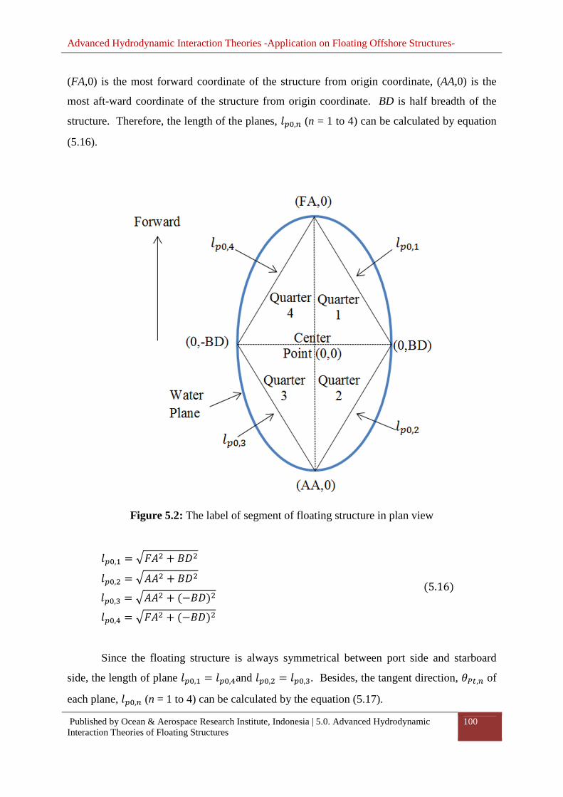
Advanced Hydrodynamic Interaction Theories -Application on Floating Offshore Structures-
Published by Ocean & Aerospace Research Institute, Indonesia | 5.0. Advanced Hydrodynamic Interaction Theories of Floating Structures
100
(FA,0) is the most forward coordinate of the structure from origin coordinate, (AA,0) is the
most aft-ward coordinate of the structure from origin coordinate. BD is half breadth of the
structure. Therefore, the length of the planes, �þ�,� (n = 1 to 4) can be calculated by equation
(5.16).
Figure 5.2: The label of segment of floating structure in plan view
�þ�,= = ÂÖ¯B + ´�B �þ�,B = ¯¯B + ´�B �þ�,Á = ¯¯B + −´��B�þ�,¿ = ÂÖ¯B + −´��B
5.16�
Since the floating structure is always symmetrical between port side and starboard
side, the length of plane �þ�,= = �þ�,¿and �þ�,B = �þ�,Á. Besides, the tangent direction, À��,� of
each plane, �þ�,� (n = 1 to 4) can be calculated by the equation (5.17).

Advanced Hydrodynamic Interaction Theories -Application on Floating Offshore Structures-
Published by Ocean & Aerospace Research Institute, Indonesia | 5.0. Advanced Hydrodynamic Interaction Theories of Floating Structures
101
À��,= = tanT= � ´�−Ö¯�À��,B = tanT= � ´�−¯¯�À��,Á = tanT= �−´�−¯¯�À��,¿ = tanT= �−´�Ö¯ �
5.17�
In equation (5.17), the angle of tangent direction, À��,� calculated is zero at x=0 as
show in Figure 5.3. The angle of the normal direction, À��,� to angle of tangent direction, À��,� is always different by � 2) . The normal direction should be pointing outward from the
center coordinate. Therefore, the normal direction of each plane, À��,� can be calculated by
the equation (5.18).
À��,= = À��,= − Ä� 2) ÅÀ��,B = À��,B + Ä� 2) ÅÀ��,Á = À��,Á − Ä� 2) ÅÀ��,¿ = À��,¿ + Ä� 2) Å 5.18�
The distance of the segment plane, �þ�,� (n = 1 to 4) from origin following the normal
direction of the plane À��,� is calculated after the angle of normal plane direction is known.
The equation used to estimate the distance of the segment plane from origin that follows the
normal direction of the plane, �þ��,� (n = 1 to 4) is shown in equation (5.19).
�þ��,= = ´� ∙ sin À��,=�þ��,B = ´� ∙ sin À��,B �þ��,Á = −´� ∙ sin À��,Á�þ��,¿ = −´� ∙ sin À��,¿
5.19�

Advanced Hydrodynamic Interaction Theories -Application on Floating Offshore Structures-
Published by Ocean & Aerospace Research Institute, Indonesia | 5.0. Advanced Hydrodynamic Interaction Theories of Floating Structures
102
Figure 5.3: Tangent direction and normal direction of each segment plane
The distance of the segment plane from origin following the normal direction of the
plane can be calculated using the equation (5.19) and it was developed using the geometry
rule as shown in Figure 5.4.
From the Figure 5.4, the angle of a, b can be calculated by using the the equation
(5.20) and the equation (5.21).
z = � 2) − À��,= 5.20�
{ = � − � 2) − z = � 2) − Ä� 2) − À��,=Å = À��,= 5.21�

Advanced Hydrodynamic Interaction Theories -Application on Floating Offshore Structures-
Published by Ocean & Aerospace Research Institute, Indonesia | 5.0. Advanced Hydrodynamic Interaction Theories of Floating Structures
103
Using the trigonometry theorem, the equation for distance �þ��,� (n =1 to 4) as shown
in equation (5.19) is obtained.
Figure 5.4: Calculation of distance between the segment planes number one from origin
follows the normal direction
Typically, the wave-front of the radiating wave generated would take the shape of the
structure generating the wave and the generated wave always propagates outward in all
directions from the center position of the structure. This research assume that the radiating
wave generated by the motion of floating structure would propagate outward following the
normal direction of the structure’s wetted surface generating the wave. At the same time, the
crest length of the radiating wave is expanded following the tangent direction of the wave
crest. The generated radiating wave will disappeare after it propagates in a long distance
away from the structure. This is because the amount of wave energy in one wave crest is
always constant and every single unit of wave crest would share the same amount of energy.
When the radiating wave propagates outward from the center of structure, the wave crest
expands. This means that, the available wave energy in each single unit of length of wave
crest is reduced since the amount of wave energy in the total length of wave crest remain the
same. Therefore, when the radiating wave propagates far from the structure, the crest length
becomes longer and causes the available radiating wave energy obtain by each unit area on
the sea surface to become very small and finally can be ignored. This observation is similar
to the radiating wave boundary condition which is explained at equation (4.7).

Advanced Hydrodynamic Interaction Theories -Application on Floating Offshore Structures-
Published by Ocean & Aerospace Research Institute, Indonesia | 5.0. Advanced Hydrodynamic Interaction Theories of Floating Structures
104
As mentioned, the radiating wave length is assumed to take the shape of floating
structure, progressing outward in normal direction of structure surface and the wave expands
in tangential direction of wave-front. If the floating structure is an inverted pyramid shape,
then the generated radiating wave in heave motion and the pattern of wave crest is assumed as
shown in Figure 5.5.
Figure 5.5: The radiating wave generated by inverted pyramid shape structure
However, the floating structures have more complex shape especially the ship shape
floating structure. Therefore, a mathematical model to represent the curve of the wave-front
for the radiating wave generated by floating structure is required. In Chapter Four, the
progressive wave is represented by the wave potential. The wave force acting on the structure
surface can be calculated by integrating the wave potential over the surface in the normal
direction of the surface as shown in equation (4.77). Therefore, it is obtained that the wave
force acting on the surface is in the function of normal direction of structure surface.
According to the equation (4.77), the relationship between wave force acting on the structure
with the surface normal direction can be written as in the equation (5.22):

Advanced Hydrodynamic Interaction Theories -Application on Floating Offshore Structures-
Published by Ocean & Aerospace Research Institute, Indonesia | 5.0. Advanced Hydrodynamic Interaction Theories of Floating Structures
105
Ö: ∝ q b:y�é�ê 5.22�
Where Ö: is the wave force in each direction of motion, j = 1 to 6, b: is the surface
normal vector in each direction of motion, j = 1 to 6, �é is the wetted structure surface.
Since the wave force acting on the structure is related to the surface normal vector,
hence, it is logically accepted that the radiating wave generated by the motion of structure is
also in relationship with the surface normal vector. However, the surface wave is progressing
outward in horizontal plane, so only surface normal vector in X-direction and Y-direction is
considered here to predict the curve of the wave-front for radiating wave generated by
structure motion.
Besides, the constant panel method as explain in Chapter Four is used to solve the
diffraction potential theory. The constant panel method divides the wetted structure surface to
a number of panels. Each panel on the wetted surface represent a small portion of wetted
surface area. In the Figure 5.2, the floating structure is divided into four segments and a
segment plane can be created in each segment to connect the most forward point or aft-ward
point with the half-breadth point of the structure. To obtain the distribution of area normal
vector on the segment plane, all panels representing the structure wetted surface is projected
to the segment plane as shown in Figure 5.6.
The Figure 5.6 shows the projection of panel representing the wetted surface area of
structure to the segment plane. In the figure, �þ��,= is the distance of the segment plane from
center point following the normal direction of the plane and it is calculated by equation
(5.19). À��,= is the normal direction of the segment plane.

Advanced Hydrodynamic Interaction Theories -Application on Floating Offshore Structures-
Published by Ocean & Aerospace Research Institute, Indonesia | 5.0. Advanced Hydrodynamic Interaction Theories of Floating Structures
106
Figure 5.6: Parameter required to project the panels of structure surface to segment plane
The position of the panel projected to the segment plane, ��þ,� (m = 1 to Total
number of panel, M) can be evaluated by considering the location of the panel and calculated
by using the equation (5.23) to equation (5.25).
À�þ,� = tanT= ��� 5.23�
Where � is the y coordinate of the panel m, �� is the x coordinate of the panel m.
���W = �þ��,= ∙ tanÄ� 2) − À��,=Å 5.24�
��þ,� = ���W + �þ��,= ∙ tanÄÀ��,= − À�þ,�Å 5.25�
Repeating from equation (5.23) to equation (5.25) for all panels, the projected position
of each panel to the segment plane, ��þ,� (m = 1 to Total number of panel, M) is evaluated.

Advanced Hydrodynamic Interaction Theories -Application on Floating Offshore Structures-
Published by Ocean & Aerospace Research Institute, Indonesia | 5.0. Advanced Hydrodynamic Interaction Theories of Floating Structures
107
In the next step, the segment panel is divided into a number of strips as shown in
Figure 5.7. Each strip on the segment panel is assumed to have the same function as a paddle
of wave maker which is able to generate wave when the strip oscillates.
Figure 5.7: Divide the segment plane into n number of strips
As shown in the Figure 5.7, the ���,�, ��,�Šis the coordinate of the strips on the
segment plane. If the total number of strips is equal to N, then the total number of coordinates
available is equal to (N+ 1).
The length of strip ��� is depending on the length of the segment plane and the number
of strip divided. In general, the number of strip that should be divided is depending on the
complication of hull. More strips are required to make each segment plane for more
complicated hull. The length of the strip at the segment can be calculated by the equation
(5.26).
���,= = �þ�,=b 5.26�
Where �þ�,= is the length of the segment plane one, n is the number of strips in the
segment.

Advanced Hydrodynamic Interaction Theories -Application on Floating Offshore Structures-
Published by Ocean & Aerospace Research Institute, Indonesia | 5.0. Advanced Hydrodynamic Interaction Theories of Floating Structures
108
The coordinate ���,=, ��,=Šcan be calculated by the following equation after the
length of strip is known. The variable required to calculate the coordinate is shown in Figure
5.8.
Figure 5.8: Define the coordinate of strip cut on segment plane
In the Figure 5.8, ¾� and ¾ are the length of strip in x-direction and y-direction. The
angle of tangent direction of the segment plane one, À��,= is calculated in equation (5.18). To
obtain ¾� and ¾ , the equation (5.31) and equation (5.32) are applied.
¾�B + ¾ B = ���,=B 5.27�
By dividing the whole equation (5.27) with ¾�B we can obtain,
1 + ¾ B¾�B = ���,=B¾�B 5.28�
Where the slope of the plane is,

Advanced Hydrodynamic Interaction Theories -Application on Floating Offshore Structures-
Published by Ocean & Aerospace Research Institute, Indonesia | 5.0. Advanced Hydrodynamic Interaction Theories of Floating Structures
109
� = ¾ ¾� = tan À��,= 5.29�
And then, the equation (5.28) can be rewritten in following form,
1 + �B = ���,=B¾�B 5.30�
By rearranging the equation (5.30) and inserting the equation (5.29) into equation
(5.30), the variable ¾� and ¾ can be calculated in equation (5.31) and equation (5.32)
respectively.
¾� = ã ���,=B1 + tanB À��,= 5.31�
¾ = ¾� ∙ � = ¾� ∙ tan À��,= 5.32�
In segment one, the segment plane has the angle of segment plane larger than � 2) .
Therefore, the calculated ¾ in segment 1 should be in negative sign. After that, the
coordinate of each strip can be calculated by equation (5.33) and (5.34).
���,� = ¾� ∙ b − 1� 5.33�
��,� = ´� + ¾ ∙ b − 1� 5.34�
In the equation (5.34), the variable BD is the length of half-breadth of the structure.
Since the plane is created to represent the surface of the floating structure, therefore
each strip on the segment plane should have different normal vector in X-direction and Y-
direction according to the normal vector of the panel on the structure surface project to the
plane. As reminded, the equation to predict the location of the panel project to the segment

Advanced Hydrodynamic Interaction Theories -Application on Floating Offshore Structures-
Published by Ocean & Aerospace Research Institute, Indonesia | 5.0. Advanced Hydrodynamic Interaction Theories of Floating Structures
110
plane surface is calculated by equation (5.25). Assuming the panel has area normal vector in
X, Y direction b�þ,� = �̅�� + p�� and m is the panel number, the area normal vector of the
strip can be calculated by summing up the normal vector of each panel projected to the strip.
Let the area normal vector of the strip n is (b��,� = �̅��,� � + p��,� ��, then the variable �̅��,� and p��,� can be calculated by the equation (5.35) and the equation (5.36).
�̅��,� = 8 �̅�+
�<= �ℎ�I� b = 1 �H �H�z� ¢�I�,, � 5.35�
p��,� = 8 p�+
�<= �ℎ�I� b = 1 �H �H�z� ¢�I�,, � 5.36�
Whereas in the equation (5.35) and (5.36), � is the number of panel projected to the
strip n and M is the total number of panels projected to the surface of strip n.
As shown in Figure 5.9 (a), the strip is not jointed to each other on segment plane due
to the area normal vector of each strip is not same. To make the strip to be jointed to each
other; the strip position is required to be adjusted according to its area normal vector and the
area normal vector of another strip near to it.
In the Figure 5.9, it shows the concept to adjust the strip position according to the strip
area normal vector direction so that each strip can be connected to each other to form a
continuous line to represent the hull form. In Figure (5.9b), the original coordinate of strip
n,���,�, ��,�Šis calculated by equation (5.33) and equation (5.34). The new coordinate of
strip n, �-�,�, -�,�Šcan be calculated by finding the intersection point between the strip
surface and the strip boundary. The equation to calculate the new coordinate of strip n is
shown as follow.
Let the first coordinate of �-�,�, -�,�Što be the same as the original coordinate of
strip n Ä���,�, ��,�Å, where
�-�,= = ���,= 5.37�

Advanced Hydrodynamic Interaction Theories -Application on Floating Offshore Structures-
Published by Ocean & Aerospace Research Institute, Indonesia | 5.0. Advanced Hydrodynamic Interaction Theories of Floating Structures
111
-�,= = ��,= 5.38�
(a) (b)
Figure 5.9: Adjust strip position according to the strip area normal vector direction
Then, the following coordinate of each strip can be calculated by following the
equation:
Let the normal direction of strip n, ���W,� be
���W,� = p��,��̅��,� 5.39�
It is known that multiplication of normal direction slope of plane, ���W with tangent
direction slope of plane, ����. is equal to -1, ���W ∙ ����. = −1. Hence, the tangent
direction of slope for strip n can be calculated by the equation (5.40).
����.,� = −1���W,� = − �̅��,� p��,� 5.40�

Advanced Hydrodynamic Interaction Theories -Application on Floating Offshore Structures-
Published by Ocean & Aerospace Research Institute, Indonesia | 5.0. Advanced Hydrodynamic Interaction Theories of Floating Structures
112
Since the original coordinate of strip n ���,�, ��,�Šis known, the boundary of each
strip can be calculated by the equation (5.41).
���,� = ��,����,� 5.41�
As mentioned, the new coordinate of strip n �-�,�, -�,�Šis located at the intersection
point between the strip surface and the strip boundary. By using the ����.,� and ���,�, two
equations of lines can be formed as follow.
��é,� = ���,����é,� 5.42�
���,� = ����.,�T=����,� + ����,� 5.43�
Where lines represented by equation (5.42) and equation (5.43) intersect then ��é,� = ���,� = �-�,�and ���é,� = ����,� = -�,�. The new coordinate of strip n Ä�-�,�, -�,�Å can
be obtained by equation (5.45) and equation (5.46). Also, to ensure each strip is connected
between each other, ����,� can be calculated using the previous known new strip n – 1
coordinate, Ä�-�,�T=, -�,�T=Å.
����,� = -�,�T= − ����.,�T= ∙ �-�,�T= 5.44�
�-�,� = ����,����,� − ����.,�T= , b = 2 �H N+ 1 5.45�
-�,� = ���,� ∙ �-,� , �G b = 2 �H N+ 1 5.46�
Whereas in equation (5.45) and equation (5.46), the variable N is total number of strip
divided.

Advanced Hydrodynamic Interaction Theories -Application on Floating Offshore Structures-
Published by Ocean & Aerospace Research Institute, Indonesia | 5.0. Advanced Hydrodynamic Interaction Theories of Floating Structures
113
The generated radiating wave will take the shape of the hull that generate it. Also, the
generated radiating wave propagates outward following the normal direction of wave front.
At the same time, the length of wave crest is increased following the tangent direction of
wave crest as shown in Figure 5.5. Therefore, if the shape of wave crest for the generated
radiating wave is known, then the direction of the radiating wave progressing outward can be
easily predicted using the direction of the first wave crest generated by the motion of floating
structure.
To obtain the first wave crest of the wave generated by the floating structure, this
research assumes the first wave crest would have similar shape of the hull because the wave is
generated by the motion of structures through the energy dissipated from the wetted surface of
the structure. Since the strip coordinates �-�,�, -�,�Šrepresents the curve of the structure
hull in two-dimensional plan view can be calculated, the curve fitting technique is applied
here to represent the curve of the hull using the coordinates Ä�-�,�, -�,�Å. The fitted curve is
assumed same as the curve of the first wave crest of the radiating wave generated by structure
motion.
In this research, quadratic splines method is applied to fit the
coordinatesÄ�-�,�, -�,�Å. The basic idea about quadratic Splines method is presented in
Chapter 4.5. In this part, the solution to solve the quadratic splines was modified so that a
more direct method to get the variables on the curve can be obtained. The curve of the hull
formed to generate the wave is represented by a series of quadratic equations passing through
all the coordinates �-�,�, -�,�Šas shown in Figure 5.10. The coordinates �-�,�, -�,�Šis
known and calculated by equation (5.53) and equation (5.46). The variable z�, {�, |� can be
defined using the quadratic spline technique.

Advanced Hydrodynamic Interaction Theories -Application on Floating Offshore Structures-
Published by Ocean & Aerospace Research Institute, Indonesia | 5.0. Advanced Hydrodynamic Interaction Theories of Floating Structures
114
Figure 5.10: The quadratic equation to represent the curve of the hull surface
According to quadratic spline technique as presented in Chapter 4.5, the second
derivative at the first point is assumed equal to zero. Also, the first curve G�� = z=�B +{=� + |= is linked to the coordinate Ä�-�,=, -�,=Å and coordinate Ä�-�,B, -�,BÅ. Therefore,
first curve as shown in Figure 5.10 can be obtained by the equation (5.47) to the equation
(5.49).
z= = 0 5.47�
|= = -�,= 5.48�
{= = -�,B − |=�-�,B 5.49�
After that, the equation of G�� = z��B + {�� + |�, n > 1 can be evaluated by using
the conditions of quadratic spline presented by in Chapter 4.5 where the
coordinates Ä�-�,�, -�,�Å, n = 2, 3, 4, …. The first derivatives of the curves intersect at the
coordinate must be equal. This means that, 2z�T=�-�,� + {�T= = 2z��-�,� + {� = �� 5.50�

Advanced Hydrodynamic Interaction Theories -Application on Floating Offshore Structures-
Published by Ocean & Aerospace Research Institute, Indonesia | 5.0. Advanced Hydrodynamic Interaction Theories of Floating Structures
115
Where �� is the first derivatives of the curves at coordinate Ä�-�,�, -�,�Å.
The variables z�T= and {�T= must be known before the following variables z� and {�
can be evaluated. Therefore, the variable �� can be calculated using the value of z�T=and {�T=.
�� = 2z�T=�-�,� + {�T= 5.51�
Besides, two more equations can be obtained by inserting the
coordinates Ä�-�,�, -�,�Åand Ä�-�,�h=, -�,�h=Å into the equation G�� = z��B + {�� + |�.
-�,� = z��-�,�B + {��-�,� + |� 5.52�
-�,�h= = z��-�,�h=B + {��-�,�h= + |�h= 5.53�
By solving the equation (5.51) to equation (5.53), the variables of z�, {�, |� for n > 1
can be evaluated by using the equation (5.54) to the equation (5.56)
z� = -�,�h= − -�,� + �� ∙ �-�,� − �� ∙ �-�,�h=�-�,�h=B − 2 ∙ �-�,� ∙ �-�,�h= + �-�,�B 5.54�
{� = �� − 2 ∙ z� ∙ �-�,� 5.55�
|� = -�,� + z� ∙ �-�,�B − �� ∙ �-�,� 5.56�
The equations (5.51), (5.54), (5.55) and (5.56) are repeated until all value of variables z�, {�, |� for each curve is obtained.
As mentioned, the first wave crest would take the shape of the surface of the floating
structure. Therefore, the quadratic curve defined in equation (5.54) to equation (5.56) can be
represented by the curve of the first wave crest of radiating wave generated by the structure
motion. To obtain the total length of wave crest, ScST, the length of wave crest represented by

Advanced Hydrodynamic Interaction Theories -Application on Floating Offshore Structures-
Published by Ocean & Aerospace Research Institute, Indonesia | 5.0. Advanced Hydrodynamic Interaction Theories of Floating Structures
116
each quadratic curve, ScS,n is summed up. The length of wave crest represented by each
quadratic curve, ScS,n can be evaluated by integrating the first derivative of the quadratic
curve.
�/�,� = » ã1 + �y y��B y�i01,�23i01,� 5.57�
Where,
y y� = 2z�� + {� 5.58�
The final solution of equation (5.57) is shown in equation (5.59). The procedure to
solve the equation (5.57) is presented in Appendix A.
�/�,� = 12z� Ó2z� + {��Â1 + 2z� + {��B2+ ln�Â1 + 2z� + {��B + 2z� + {���2 Ô4�-�,�h=
�-�,� 5.59�
And then, total length of wave crest, ScST can be obtained by the equation (5.60)
�/�� = 8 �/�,��
�<= 5.60�
Where N is the total number of quadratic curves applied to represent the wave crest.

Advanced Hydrodynamic Interaction Theories -Application on Floating Offshore Structures-
Published by Ocean & Aerospace Research Institute, Indonesia | 5.0. Advanced Hydrodynamic Interaction Theories of Floating Structures
117
5.2.2. Propagation of Radiating Wave Generated by Floating Structure
Motion
The radiating wave created by the structure motion would progress outward following the
normal direction of the wave crest which is represented by the quadratic curves. In the Figure
5.11, lets assume one point P is located at the coordinate �� , �� somewhere outside the
structure which generate the radiating wave. To predict the direction of the radiating wave
and the distance travelled by the radiating wave before it arrived at P, the source
coordinate��, �� which is located at the first wave front must be known. The coordinate � ��, �� is the source location which the radiating wave generated at the location would pass
through P. The variable ���W is the normal direction of the wave crest represented by the
parabolic curve and ���W is the direction of P from S.
Figure 5.11: The direction of wave propagation from the source location.
As shown in the Figure 5.11, it is obtained that the wave angle of source to coordinate
P must be the same as the normal direction of the wave generated at the source so that the
generated wave can arrive at coordinate P. This assumption is made based on the Huygens
principle. The Huygens Principle is presented in Chapter 4.6. From the Figure 4.4 and Figure
4.5, it is observed that the progressive wave arrived at any location should be in normal
direction to the wavelet which is generated by the secondary wave source. Based on this

Advanced Hydrodynamic Interaction Theories -Application on Floating Offshore Structures-
Published by Ocean & Aerospace Research Institute, Indonesia | 5.0. Advanced Hydrodynamic Interaction Theories of Floating Structures
118
assumption, the location of source which generates the wave arrive at point P can be
evaluated.
Assuming that,
���W = ���W 5.61�
Where,
���W = −1G′�� = −12z���B + {� 5.62�
���W = � − ��� − �� 5.63�
� = G��� = z���B + {��� + |� 5.64�
Insert the equation (5.62) to equation (5.64) into equation (5.61), then
12z���B + {� = � − z���B + {��� + |���� − �� 5.65�
In equation (5.65), the variables z�, {�, |�, �� , � are known. The only unknown in
the equation (5.65) is variable ��. Rearrange the equation (5.65) by moving all the terms to
the left hand side and leave the right hand side to zero to get equation (5.66).
−2z�B���Á + −3z�{����B + Ä2z� � − 2z�|� − {�B + 1Å��+ {� � − {�|� − ��� = 0 5.66�
In this research, bisection method is applied to obtain the value of ��. The bisection
method to find the root of the equation is presented at Chapter 4.8. To applied the bisection
method, the upper boundary of the equation is equal to �-�,�h= and the lower boundary of the

Advanced Hydrodynamic Interaction Theories -Application on Floating Offshore Structures-
Published by Ocean & Aerospace Research Institute, Indonesia | 5.0. Advanced Hydrodynamic Interaction Theories of Floating Structures
119
equation is equal to �-�,�. The variable n used in the equation (5.62) to equation (5.66) is the
number of parabolic equation.
Once the value of �� is obtained, the value of � can be calculated by using equation
(5.70). After that, the direction of the radiating wave arrives at the location P, ÀW�ç and the
distance of location P from the source S, �W�ç can be calculated by the equation (5.67) and the
equation (5.68).
ÀW�ç = tan −12z���B + {� − � 5.67�
�W�ç = �� − ��� cos ÀW�ç + � − �� sin ÀW�ç 5.68�
To predict the length of wave crest arriving at the location P, the curve of the wave-
front at location P need to be defined. Before the curve of the wave crest can be defined, the
coordinates of the wave-front representing the curve must be obtained first. The coordinate of
wave-front curve arrives at location P, �-�,�, -�,�Šcan be evaluated if the coordinate of
source is known.
Let the coordinate of the wave crest at the source be �-�,�, -�,�Šand this source
coordinates are evaluated by equation (5.45) and equation (5.46). Then, the coordinate to
represent the curve of wave-front at location P can be calculated by the equation (5.69) to the
equation (5.71).
À-�,� = �2 �G b = 1 À-�,� = tanT= −12z�T=�-�,�B + {� �G b = 2 �H N + 1 5.69� �-�,� = �-�,� + �W�ç ∗ cos À-�,� 5.70�
-�,� = -�,� + �W�ç ∗ sin À-�,� 5.71�

Advanced Hydrodynamic Interaction Theories -Application on Floating Offshore Structures-
Published by Ocean & Aerospace Research Institute, Indonesia | 5.0. Advanced Hydrodynamic Interaction Theories of Floating Structures
120
Where in the equation (5.69) to equation (5.71), b is the number of coordinate,
N is the total available quadratic equation to represent the curve of the wave-front at location
P.
After the coordinates representing the wave-front pass through the location P are
known, then the parabolic curve representing the wave-front at the location P can be defined
by using equation (5.47) to equation (5.56). Then the length of the wave crest represented by
each parabolic curve at location P, �/�,� can be calculated with similar method applied to
calculate the length of the first wave crest generated by structure motion. The equation to
calculate the length of wave crest at location P is shown in equation (5.72).
�/�,� = 12z� Ó2z� + {��Â1 + 2z� + {��B2+ ln�Â1 + 2z� + {��B + 2z� + {���2 Ô4�-�,�h=
�-�,� 5.72�
Then, total length of wave crest, ScPT can be obtained by the equation (5.73).
�/�� = 8 �/�,��
�<= 5.73�
If another floating structure arranged nearby is divided into total number of panel, M,
the equation (5.66) to equation (5.73) should be repeated for M times to obtain the
information about the distance of the radiating wave progressed from the structure generating
the wave to each panel of nearby structure, direction of radiating wave progressed from the
structure generating the wave to each panel of nearby structure and the length of wave crest
when the radiating wave progressed from the structure generating the wave to each panel of
nearby structure.
5.2.3. Amplitude of Radiating Wave Generated by Floating Structure Motion

Advanced Hydrodynamic Interaction Theories -Application on Floating Offshore Structures-
Published by Ocean & Aerospace Research Institute, Indonesia | 5.0. Advanced Hydrodynamic Interaction Theories of Floating Structures
121
In the next step, wave amplitude at location P can be evaluated if the length of wave
chest and the wave attack direction are known. In Chapter 4.3, it is known that the wave
energy over a crest length is in the function of wave amplitude, wave length, fluid density and
gravity. Since the fluid density and the gravity acceleration are always constant, the wave
energy equation as shown in equation (4.106) can be rewritten in the equation (5.74).
É� = �7� ∙ ¹�B ∙ Æ ∙ �/�� 5.74�
By rewritting the equation (5.74), the wave amplitude at any location can be evaluated
by the following equation (5.75).
¹� = ã É��7� ∙ Æ ∙ �/�� 5.75�
Whereas in equation (5.74) and equation (5.75), � is the total wave energy over a
wave crest, �7� is a constant and �7� = 1 2) è�, ¹� is wave amplitude at the location where
wave crest occurs, Æ is the wavelength, �/�� is the length of the wave crest.
The equation (5.75) is valid if the wave energy carried by each single portion of wave
crest is similar. This research assumes that the radiating wave could be generated by each
direction of structure motion. Total radiating wave is the summation of the wave generated
by each direction of motion by superposition theory. To evaluate the radiating wave
generated by the structure in each direction of motion, the motion direction and wave
propagation direction should be considered. There are six conditions applied here to evaluate
wave energy at each segment of wave crest length.
In surge motion and sway motion, the wave generated follows the direction of
structure motion. According to equation (4.125), the total radiating wave energy contributed
by the surge motion or sway motion is shared by the length of wave crest in the tangent
direction to the motion. Therefore, the wave amplitude at any location can be evaluated by

Advanced Hydrodynamic Interaction Theories -Application on Floating Offshore Structures-
Published by Ocean & Aerospace Research Institute, Indonesia | 5.0. Advanced Hydrodynamic Interaction Theories of Floating Structures
122
reversing the equation (4.125). Besides, the equation (4.125) assumes that the wave
amplitude generated is uniform along the wave crest, while in this part, it is assumed that the
wave energy is uniform along the wave crest in tangent direction to the structure motion.
Therefore, the wave amplitude generated by the surge motion and sway motion can be
calculated by the equation (5.76) and the equation (5.77).
¹�,� = ã É�,� ∙ cos ��7� ∙ Æ ∙ 2´� + �W�ç� if � = 1 5.76�
¹�,� = ã É�,� ∙ sin ��7� ∙ Æ ∙ Ö¯ + ¯¯ + 2�W�ç� if � = 2 5.77�
In heave motion, the dissipated energy by heave motion is assumed to deliver to the
entire wave crest in average. Therefore, the wave amplitude at any location can be evaluated
by dividing the total dissipated energy by heave motion with the length of wave crest.
¹�,� = ã É�,��7� ∙ Æ ∙ �/�� �G � = 3 5.78�
Whereas from equation (5.76) to equation (5.78), �/�� is the length of wave crest
generated by the structure motion at location P, ´� is the half breadth length of the structure,
FA is the forward perpendicular point of structure, AA is aft-ward perpendicular point of
structure, �W�ç is the distance of location P from the source S, É�,�, is the wave energy
dissipated by linear motion in i direction, i = 1 to 3.
The radiating wave amplitude generated by rotational motions are assumed to generate
from moments acting in two directions where the roll motion is due to the moments in Y
direction and Z direction, pitch motion is due to moments in X direction and Z direction and
yaw motion is due to moments in X direction and Y direction. The moments induced by the
rotational motions in each direction can be calculated by the equation (5.79) to equation
(5.84).

Advanced Hydrodynamic Interaction Theories -Application on Floating Offshore Structures-
Published by Ocean & Aerospace Research Institute, Indonesia | 5.0. Advanced Hydrodynamic Interaction Theories of Floating Structures
123
Moments induced by roll motion,
ò�,¿ = 8 bB,� ∙ ���
�<= 5.79�
ò�,¿ = 8 bÁ,� ∙ ��
�<= 5.80�
Moments induced by pitch motion,
ò8,ñ = 8 b=,� ∙ ���
�<= 5.81�
ò�,ñ = 8 bÁ,� ∙ ���
�<= 5.82�
Moments induced by yaw motion,
ò8,; = 8 b=,� ∙ ��
�<= 5.83�
ò�,; = 8 bB,� ∙ ���
�<= 5.84�
Whereas from equation (5.79) to equation (5.84), b=,�, bB,� and bÁ,� are the area
normal vector of panel n in X direction, Y direction and Z direction respectively, �� is the x
coordinate of panel n, � is the y coordinate of panel n, �� is the z coordinate of panel n, ò�,¿
is the roll moment due to the Y direction motion, ò�,¿ is the roll moment due to the Z

Advanced Hydrodynamic Interaction Theories -Application on Floating Offshore Structures-
Published by Ocean & Aerospace Research Institute, Indonesia | 5.0. Advanced Hydrodynamic Interaction Theories of Floating Structures
124
direction motion, ò8,ñ is the pitch moment due to the X direction motion, ò�,ñ is the pitch
moment due to the Z direction motion, ò8,; is the yaw moment due to the X direction motion, ò�,; is the yaw moment due to the Y direction motion.
The ratio of roll moment due to the force in Y direction and Z direction can be
calculated by equation (5.85) and equation (5.86).
���,¿ = ò�,¿ò�,¿ + ò�,¿ 5.85�
���,¿ = ò�,¿ò�,¿ + ò�,¿ 5.86�
Where ���,¿ is the ratio of roll moment in Y direction, ���,¿ is the ratio of roll moment
in Z direction.
The ratio of pitch moment due to the force in X direction and Z direction can be
calculated by equation (5.87) and equation (5.88).
��8,ñ = ò8,ñò8,ñ + ò�,ñ 5.87�
���,ñ = ò�,ñò8,ñ + ò�,ñ 5.88�
Where ��8,ñ is the ratio of pitch moment in X direction, ���,ñ is the ratio of pitch
moment in Z direction.
The ratio of yaw moment due to the force in X direction and Y direction can be
calculated by equation (5.89) and equation (5.90).

Advanced Hydrodynamic Interaction Theories -Application on Floating Offshore Structures-
Published by Ocean & Aerospace Research Institute, Indonesia | 5.0. Advanced Hydrodynamic Interaction Theories of Floating Structures
125
��8,; = ò8,;ò8,; + ò�,; 5.89�
���,; = ò�,;ò8,; + ò�,; 5.90�
Where ��8,; is the ratio of yaw moment in X direction, ���,; is the ratio of yaw
moment in Y direction.
The wave amplitude at any location due to the roll moment in Y direction can be
evaluated by equation (5.91).
¹��,¿ = ã É�,¿ ∙ sin � ∙ ���,¿�7� ∙ Æ ∙ Ö¯ + ¯¯ + 2�W�ç� 5.91�
The wave amplitude at any location due to the roll moment in Z direction can be
evaluated by equation (5.92).
¹��,¿ = ã 1�7� ∙ Æ ∙ ãG¿ ∙ ��/���/��� ∙ � �´� + �W�ç� 5.92�
Also, the wave amplitude at any location due to the pitch moment in X direction can
be evaluated by equation (5.93).
¹�8,ñ = ã É�,ñ ∙ cos � ∙ ��8,ñ�7� ∙ Æ ∙ 2´� + �W�ç� 5.93�
The wave amplitude at any location due to the pitch moment in Z direction can be
evaluated by equation (5.94).

Advanced Hydrodynamic Interaction Theories -Application on Floating Offshore Structures-
Published by Ocean & Aerospace Research Institute, Indonesia | 5.0. Advanced Hydrodynamic Interaction Theories of Floating Structures
126
¹��,ñ = � 1�7� ∙ Æ ∙ �Gñ ∙ ß�/���/��à ∙ ß ��Ö¯ + �W�çà �G �� ≥ 0 � 1�7� ∙ Æ ∙ �Gñ ∙ ß�/���/��à ∙ ß ��¯¯ + �W�çà �G �� < 0 5.94�
Also, the wave amplitude at any location due to the yaw moment in X direction can be
evaluated by equation (5.95).
¹�8,; = � 1�7� ∙ Æ ∙ �G; ∙ ß�/���/��à ∙ ß ��Ö¯ + �W�çà �G �� ≥ 0 � 1�7� ∙ Æ ∙ �G; ∙ ß�/���/��à ∙ ß ��¯¯ + �W�çà �G �� < 0 5.95�
The wave amplitude at any location due to the yaw moment in Y direction can be
evaluated by equation (5.96).
¹��,; = ã 1�7� ∙ Æ ∙ ãG9 ∙ ��/���/��� ∙ � �´� + �W�ç� 5.96�
Where �/�� is the length of first wave crest generated by the structure motion, �/�� is
the length of wave crest generated by the structure motion at location P, � is the y coordinate
at location P, ´� is the half breadth length of the structure, FA is the forward perpendicular
point of structure, AA is aft-ward perpendicular point of structure, �W�çthe distance of location
P from the source S, G� is the average distribution force caused by the moment which induces
the rotational motion (i = 3 to 7).
Average distribution force, G� that causes the moment in respective direction to
generate the wave can be evaluated by estimating the change of wave energy over a single
unit crest length in the ratio of moment arm.

Advanced Hydrodynamic Interaction Theories -Application on Floating Offshore Structures-
Published by Ocean & Aerospace Research Institute, Indonesia | 5.0. Advanced Hydrodynamic Interaction Theories of Floating Structures
127
Let the wave energy due to the roll moment in Z direction, pitch moment in Z
direction, yaw moment in X direction and yaw moment in Y direction be calculated by
equation (5.97) to equation (5.100).
LÉ��,¿ = G¿ I� À¿ 5.97�
LÉ��,ñ = Gñ I� Àñ 5.98�
LÉ�8,; = G; I� À; 5.99�
LÉ��,; = G9 I� À; 5.100�
The total wave energy over a total length of wave crest due to one unit radian of
rotational motion (assume À: = 1, � = 4 to 6) can be calculated by summing up the wave
energy in a single unit of length of wave crest.
É��,¿ = 8 LÉ��,¿ ∙ L�/� = » G¿ I� ∙ 1 ∙ y�/� 5.101�
É��,ñ = 8 LÉ��,ñ ∙ L�/� = » Gñ I� ∙ 1 ∙ y�/� 5.102�
É�8,; = 8 LÉ�8,; ∙ L�/� = » G; I� ∙ 1 ∙ y�/� 5.103�
É��,; = 8 LÉ��,; ∙ L�/� = » G9 I� ∙ 1 ∙ y�/� 5.104�
In general form, let G� be constant, then the change of wave energy in each unit of
wave crest is due to the moment arm W� then the G� can be calculated by equation (5.105) to
equation (5.108).

Advanced Hydrodynamic Interaction Theories -Application on Floating Offshore Structures-
Published by Ocean & Aerospace Research Institute, Indonesia | 5.0. Advanced Hydrodynamic Interaction Theories of Floating Structures
128
G¿ = É��,¿: I� ∙ 1 ∙ y�/� 5.105�
Gñ = É��,ñ: I� ∙ 1 ∙ y�/� 5.106�
G; = É�8,;: I� ∙ 1 ∙ y�/� 5.107�
G9 = É��,;: I� ∙ 1 ∙ y�/� 5.108�
To solve the equation (5.105) to equation (5.108) by numerical method, the wave crest
length is divided into several unit of small strips, and then sum up the value of each small
strip of wave crest length multiplied with the distance of the strip from structure centre
position in respective direction of the moment.
G¿ = É�,¿ ∙ ���,¿∑ ;I:� ∙ �/�,:< 5.109�
Where I or I: is the distance of the wave crest from the center of structure in Y
direction, � is the half breadth length of structure.
Gñ = É�,ñ ∙ ���,ñ∑ ;I:� ∙ �/�,:< 5.110�
Where I or I: is the distance of the wave crest from the center of structure in X
direction, � is the forward perpendicular point of structure if I: is positive and it is aft-ward
perpendicular point if I: is negative.

Advanced Hydrodynamic Interaction Theories -Application on Floating Offshore Structures-
Published by Ocean & Aerospace Research Institute, Indonesia | 5.0. Advanced Hydrodynamic Interaction Theories of Floating Structures
129
G; = É�,; ∙ ��8,;∑ ;I:� ∙ �/�,:< 5.111�
Where I or I: is the distance of the wave crest from the center of structure in Y
direction, � is the half breadth length of structure.
G9 = É�,; ∙ ���,;∑ ;I:� ∙ �/�,:< 5.112�
Where I or I: is the distance of the wave crest from the center of structure in Y
direction, � is the forward perpendicular point of structure if I: is positive and it is aft-ward
perpendicular point if I: is negative.
Also, from equation (5.109) to equation (5.112), �,�, is the wave energy dissipated
by rotation motion in i direction, i = 4 to 6, �/� or �/�,: is the length of wave crest in each
strip.
Finally, the radiating wave amplitude due to the rotational motion can be calculated by
summing up the wave amplitude due to the dissipated energy in both directions.
¹�,¿ = ¹��,¿ + ¹��,¿ 5.113�
¹�,ñ = ¹�8,ñ + ¹��,ñ 5.114�
¹�,; = ¹�8,; + ¹��,; 5.115�
5.2.4 Potential of Radiating Wave Generated by the Motion of Nearby Structure

Advanced Hydrodynamic Interaction Theories -Application on Floating Offshore Structures-
Published by Ocean & Aerospace Research Institute, Indonesia | 5.0. Advanced Hydrodynamic Interaction Theories of Floating Structures
130
Hydrodynamic interaction occurs when more than one floating structure is placed
close to each other in one location. To study the effect of radiating wave generated by nearby
structure on the motion of the focus structure, the generated radiating wave from nearby
structure is considered as an incoming wave progressing to the focus structure. Let the focus
structure be structure P, the nearby structure generates the radiating wave where it propagates
to structure P labelled as structure Q, then the pattern of radiating wave generated by structure
Q can be evaluated by using equation(5.16) to equation (5.60) and then the direction, wave
propagation distance and the amplitude of the radiating wave arriving at structure P can be
evaluated using equation (5.61) to equation (5.115).
In Chapter 4.1, the constant panel method is applied to solve the diffraction potential
problem. The constant panel method divides the structure into a number of panels and then
the diffracted wave potential on the structure wetted surface can be evaluated by diffraction
potential theory. In this chapter, it is mentioned that the radiating wave propagated from
nearby structure Q to the focus structure P is treated as extra incident wave acting on the
structure P. To study the diffracted effect of the radiating wave generated by nearby structure
Q, the direction, wave propagation distance and the amplitude of the radiating wave arriving
at each panel of focus structure P must be evaluated before the diffraction potential theory can
be applied.
In Chapter 4.1, the incident wave is initially at the centre position of the structure
hence the leading phase, α do not need to be considered as shown in equation (4.9). However,
the initial radiating wave generated by nearby structure Q is assumed at the centre position of
structure Q. Therefore, the leading phase which shows the time required for the radiating
wave generated by the structure Q arriving on structure P must be included in evaluating the
effect of the generated radiating wave on the motions of structure P. The arrival of potential
wave can be written in the equation (5.116).
��,�,t��, , �� = �Tfgh�fi 4*j khl j.- k�h�! 5.116�
After expanding the equation above,

Advanced Hydrodynamic Interaction Theories -Application on Floating Offshore Structures-
Published by Ocean & Aerospace Research Institute, Indonesia | 5.0. Advanced Hydrodynamic Interaction Theories of Floating Structures
131
��,�,t��, , �� = �Tfg ∙ ��fi 4*j khl j.- k� ∙ ��! 5.117�
By applying Euler’s law,
��,�,t��, , ��= �Tfg ∙ �cos�� cos n + � sin n� + � sin�� cos n + � sin n��∙ �cos� + � sin�� 5.118�
Expanding the equation (5.118) using the trigonometry law, it is obtained that the
wave potential equation, ��,�,t��, , �� is formed by four terms in its equation as shown in
equation (5.119). The equation of incoming radiating wave (5.119) is similar to the solution
of incident wave potential equation (4.30) which is not considered as the leading phase of
wave.
��,�,t��, , ��= �Tfg∙ �cos�� cos n� ∙ cos� sin n� ∙ cos�− sin�� cos n� ∙ sin� sin n� ∙ cos�+ sin�� cos n� ∙ cos� sin n� ∙ sin� + cos�� cos n�∙ sin� sin n� ∙ sin�+ �#cos�� cos n� ∙ cos� sin n� ∙ sin�− sin�� cos n� ∙ sin� sin n� ∙ sin�+ sin�� cos n� ∙ cos� sin n� ∙ cos� + cos�� cos n�∙ sin� sin n� ∙ cos�$� 5.119�
By applying similar symmetric and anti-symmetric conditions to obtain equation
(4.31), the incoming radiating wave contributing to the force acting on X, Y, Z and N
direction can be predicted using the following equation.

Advanced Hydrodynamic Interaction Theories -Application on Floating Offshore Structures-
Published by Ocean & Aerospace Research Institute, Indonesia | 5.0. Advanced Hydrodynamic Interaction Theories of Floating Structures
132
��,�,t;:��, , ��= ¹�,:∙ ���,�,t�� + � ��,�,t�� + ��,�,t�� + � ��,�,t�� + ��,�,t�8 + ���,�,t�8+ ��,�,t�� + ���,�,t�� � 5.120�
Where,
£=,>,?;@�¥ <¦§¨© j.-fi 4*j k�∙4*jfl j.- k�∙j.-! h � ¦§¨© j.-fi 4*j k�∙4*jfl j.- k�∙4*j!£=,>,?;@�ª <¦§¨© 4*jfi 4*j k�∙j.-fl j.- k�∙j.-! h� ¦§¨© 4*jfi 4*j k�∙j.-fl j.- k�∙4*j!£=,>,?;@�« <¦§¨© 4*jfi 4*j k�∙4*jfl j.- k�∙4*j! h� ¦§¨© 4*jfi 4*j k�∙4*jfl j.- k�∙j.-!£=,>,?;@�¬ <T¦§¨© j.-fi 4*j k�∙j.-fl j.- k�∙4*j! T� ¦§¨© j.-fi 4*j k�∙j.-fl j.- k�∙j.-! ÎÏÏÐÏÏÑ 5.121�
Where in equation (5.116) to equation (5.121), ��,�,t� is the wave potential due to
radiating wave generated by structure Q acting on the structure P, �, , �� are the coordinates
of the panel on the wetted surface of structure P, � is wave number , � is the leading phase of
wave potential ��,�,t� at the wetted surface of structure P. The � needs to consider the
distance required for the radiating wave generated by structure Q and its propagation to the
wetted surface of structure P.
To estimate the diffracted effect of radiating wave generated by structure Q when it
arrives on structure P, the radiating wave potential on each panel can be solved with similar
method as incident wave arrives at each panel of structure surface. In equation (4.32), the
unknown source strength is arranged on the left hand side of the equation, while the unknown
diffracted wave potential and radiating wave potential of structure P are arranged on the right-
hand side. To obtain the diffraction force of structure Q’s radiating wave arriving at structure
P, the equation (4.32) can be modified so that it can obtain the diffraction force due to
incident wave, ���, , ��, radiating wave force of structure P and diffraction force due to
radiating wave of structure Q, ��,�,t��, , �� in single step once the unknown at left hand
side of equation (4.32) is solved.

Advanced Hydrodynamic Interaction Theories -Application on Floating Offshore Structures-
Published by Ocean & Aerospace Research Institute, Indonesia | 5.0. Advanced Hydrodynamic Interaction Theories of Floating Structures
133
®¯=,= ⋯ ¯=,�⋮ ⋱ ⋮¯�,= ⋯ ¯�,�³ ∙ ®�:,=⋮�:,�³ = ® :́,=⋮:́,�³ 5.122�
Where j=1 to 6 in radiating case and j=D in diffraction case, and,
¯�,� = 2� 5.123�
¯�,� = �−��� + r LLbt u��; b�x Δ��� 5.124�
:́,� = 8 b:b��−��� + #u��; b�$Δ�����<= in radiating case 5.125�
:́,� = 4����� in diffraction case 5.126�
:́,� = 4���,�,t;:���in interaction case 5.127�
Where subscript n is the coordinate of source panel which is located at structure P,
subscript m is the coordinate of respected panel m which is located at structure P.
The equation (5.122) to equation (5.126) is similar with equation (4.32) to equation
(4.36) where the explanation of the matrix and equation (5.122) to equation (5.126) can be
found at Chapter 4.1.2. In equation (5.127), the subscript j is representing the direction of
motion of structure Q. Once the matrix equation (5.122) is solved, the radiating wave
potential from structure Q acting on each panel of structure P is obtained as ��,�,t;:�� ��.
Then, the interaction wave force acting on structure P due to the wave generated at structure
Q can be evaluated by equation (5.129).
oç = −è L��,�,t;:�� ��L� 5.128�

Advanced Hydrodynamic Interaction Theories -Application on Floating Offshore Structures-
Published by Ocean & Aerospace Research Institute, Indonesia | 5.0. Advanced Hydrodynamic Interaction Theories of Floating Structures
134
Therefore the wave excitation forces and moments in all six directions of motion can
be obtained by the equation below (Journee and Massie, 2001).
Ö�,�;t,:� = − q oçb�y�é�ê
= −è�B qÄ��,�,t;:�� Åb:y�é�ê 5.129�
Where in equation (5.128) and equation (5.129), Ö�,�;t,:� is the wave force acting on
the structure P in direction i due to the radiating wave generated by structure Q in the motion
direction j, ��,�,t;:�� is the solved radiating wave potential generated by the motion of floating
structure Q in direction j and diffracted when it arrives on structure P, b� is the normal vector
of the wetted surface area of structure P, �é is the wetted surface area of structure P ,� is the
wave speed, è is fluid density
5.2.5. Interaction Wave Force due to Motion Dissipated Energy
The wave force acting on the structure P due to the motion of structure Q is evaluated in
equation (5.129). However, the energy dissipated by structure Q to generate the radiating
wave propagating to structure P can only be known after the equation (4.32) is solved. To
enable the radiating wave due to motion of structure Q acting on structure P to be solved
together with the diffraction effect of incident wave potential, it is easier to assume the energy
dissipated by structure Q to generate radiating wave is one unit before the motion of structure
Q is known. In this way, the radiating wave force acting on the structure P due to the motion
of structure Q based on every single unit of energy dissipated by structure Q can be evaluated
together with the effect of incident wave to the structure P using equation (5.122).

Advanced Hydrodynamic Interaction Theories -Application on Floating Offshore Structures-
Published by Ocean & Aerospace Research Institute, Indonesia | 5.0. Advanced Hydrodynamic Interaction Theories of Floating Structures
135
After the equation (5.122) is solved for both structure P and Q, then the radiating
wave force acting on structure P can be evaluated directly. The dissipated energy due to the
motion of structure Q is evaluated using equation (4.114). By assuming the total dissipated
energy from the motion of structure Q is used for generating the radiating wave, the amplitude
of the radiating wave can be evaluated using equation (4.106). After that, the relationship
between the wave amplitude and wave force can be obtained by using equation (4.77).
Hence, the relationship between structure dissipated energy due to damped motion, wave
amplitude and wave force can be summarized as follow.
Éç = É� = 12 ´ �B��B 5.130�
¹� ∝ ÂÉ� 5.131�
Ö��,�;t,:� ∝ ¹� 5.132�
By combining the equation (5.130) to equation (5.132), it can obtain that the
mathematical model gives the relationship between dissipated energy due to the motion of
structure Q in direction j with the radiating wave force acting on structure P to induce the
motion in direction i.
Ö�,�;t,:��,� = � ∙ ã12 :́�B��,:B ∙ �� 5.133�
Whereas from equation (5.130) to equation (5.133), Éç is the dissipated wave energy
due to the motion of floating structure, É� is the radiating wave energy along a wave crest, :́
is the structure damping coefficient in direction j, � is wave speed, ��,: is the motion
amplitude of floating structure in direction j, ¹� is the radiating wave amplitude generated by
the motion of floating structure, �,�;t,:��,� is the wave force acting on structure P to induce the
motion in direction i due to the motion of structure Q in direction j moving with motion
amplitude �� in stage n , � is a constant and it is equal to magnitude of �,�;t,:� where it

Advanced Hydrodynamic Interaction Theories -Application on Floating Offshore Structures-
Published by Ocean & Aerospace Research Institute, Indonesia | 5.0. Advanced Hydrodynamic Interaction Theories of Floating Structures
136
represents the amplitude of wave force acting on structure P to induce the motion in direction
i due to the motion of structure Q in direction j in every single unit of energy dissipated by the
structure Q through its motion, � is the leading phase between the radiating wave force in
respective to the phase of incident wave potential.
It is known that the variable Ö�,�;t,:��,� = Ö��þcos�= + sin�=� then the variable C and
� can be calculated using equation (5.134) and equation (5.135).
� = �Ö��þ� 5.134�
� = �= − �B − �Á 5.135�
Where �= is the phase between the radiating wave force acting on focus structure and
the radiating wave generated by the nearby structure. It is equal to the phase of �,�;t,:��,� , �Bis
the phase between incident wave arriving on the structure P compare to the nearby structure
Q.
Lets assume the centre coordinate of structure P is �� , � , ��� and the centre
coordinate of structure Q is �t , t , �t�, then the phase �B can be calculated by equation
(5.136).
�B = �Ä�t − ��Å cos n + �Ä t − �Å sin n 5.136�
In the equation (5.135), the variable �Á is the phase between the incident wave
arriving on the structure Q and the radiating wave generated by structure Q. If the motion of
structure Q is A�,: = ��,:cos À + sin À� , then the phase �Á should be double of the À. This
is because the time required for the motion of structure to generate the radiating wave is the
same as the time required for the incident wave to push the structure Q to move. Therefore,
the phase �Á can be calculated by equation (5.137).
�Á = 2 ∙ À 5.137�

Advanced Hydrodynamic Interaction Theories -Application on Floating Offshore Structures-
Published by Ocean & Aerospace Research Institute, Indonesia | 5.0. Advanced Hydrodynamic Interaction Theories of Floating Structures
137
Where the phase of the radiating wave that must be considered is shown in Figure
5.12.
Figure 5.12: Leading phase between radiating wave in respective to incident wave.
In two structures case, the interaction of both structures P and Q can be shown in
Figure 5.13.
I → P → Q → P → Q → P …
I → Q → P → Q → P → Q …
Stage 0 Stage 1 Stage 2 Stage 3 Stage 4
(→) is wave propagation direction
I is incident wave
P and Q is lable of floating structures
Figure 5.13: Radiating wave interaction between structure P and structure Q
In the Figure 5.13, I is the wave force due to the incident wave, P is the radiating wave
due to motion of structure P and Q is the radiating wave due to motion of structure Q. In
n
��, �, ���
�t , t , �t�
�=
�B
�Á

Advanced Hydrodynamic Interaction Theories -Application on Floating Offshore Structures-
Published by Ocean & Aerospace Research Institute, Indonesia | 5.0. Advanced Hydrodynamic Interaction Theories of Floating Structures
138
stage 0, the motions of structure P and structure Q are induced by incident wave. In stage 1,
the motion of structure P is induced by the radiating wave force due to the motion of floating
structure Q in stage 0 while the motion of structure Q is induced by the radiating wave force
due to the motion of floating structure P in stage 0. In this method, it is assumed that the
motion of structure in the following stage is due to the radiating wave generated by the
motion of nearby floating structure in the previous stage.
As mentioned, the wave force inducing the motion of floating structure in stage 0 only
needs to consider the effect of incident wave and it is evaluated by using diffraction potential
theory as presented in Chapter 4.1. From stage 1 until stage n, the radiating wave force acting
on the structure P due to the structure Q, �;�� is the summation of radiating wave due to the
force generated by each direction of motion of structure Q.
�;�� = 8 �,�;t,:��,�T=;:<= 5.138z�
Ö�;�t = 8 Öt,�;�,:��,�T=;:<= 5.138{�
After the radiating wave force acting on the structure P or Q needed to induce the
motion in direction i is known, then the motion of each floating structure in direction i can be
evaluated using the motion equation (4.82) to equation (4.90). After that, the wave force
acting on the floating structure due to the motion of nearby floating structure for stage n+1
can be evaluated using the equation (5.133). This process is iterative until the wave force due
to the motion of floating structure in the previous stage is small enough and assumed to be
ignored.
After that, the total wave force needed to induce the motion of floating structure can
be evaluated by summing up the wave force used to generate the motion of floating structure
in every stage by using equation (5.139).

Advanced Hydrodynamic Interaction Theories -Application on Floating Offshore Structures-
Published by Ocean & Aerospace Research Institute, Indonesia | 5.0. Advanced Hydrodynamic Interaction Theories of Floating Structures
139
�;���� = 8 �;���
�<� 5.139z�
�;���t = 8 �;�t��<� 5.139{�
Where subscript i is the direction of motion, superscript P or Q represents the wave
force acting on structure P or structure Q, �;���� is the total wave force due to incident wave
force and total every stage radiating wave force acting on the floating structure P inducing the
motion in direction i, �;���t is the total wave force due to incident wave force and total every
stage radiating wave force acting on the floating structure Q inducing the motion in direction
i, �;�� is the total wave force due to stage n radiating wave force acting on the floating
structure P inducing the motion in direction i, Ö�;�t is the total wave force due to stage n
radiating wave force acting on the floating structure Q inducing the motion in direction i,
subscript n is the number of stage and n=0 is the wave force due to incident wave.
Then apply the motion equation (4.82) to equation (4.90) to obtain the motion of
floating structure in each direction due to the interaction effect. To include the interaction
effect, the wave force from the motion equation (4.82) to equation (4.90) is replaced with the
wave force due to the incident wave and interaction wave as shown in equation (5.140).
¯�:� 9��� + ´�:�9ü�� + ���9�� = Ö�;���� 5.140z�
¯�:t 9��t + �́:t9ü�t + ��t9�t = Ö�;���t 5.140{�
Where subscript i and j are the directions of motion, superscript P or Q represents the
wave force acting on structure P or structure Q, �;���� is the total wave force due to incident
wave force and total every stage radiating wave force acting on the floating structure P
inducing the motion in direction i, �;���t is the total wave force due to incident wave force and
total every stage radiating wave force acting on the floating structure Q inducing the motion

Advanced Hydrodynamic Interaction Theories -Application on Floating Offshore Structures-
Published by Ocean & Aerospace Research Institute, Indonesia | 5.0. Advanced Hydrodynamic Interaction Theories of Floating Structures
140
in direction i, ¯�:� is the added mass of the floating structure P for direction i due to motion in j
direction,̄ �:t is the added mass of the floating structure Q for direction i due to motion in j
direction, ́ �:� is the damping coefficient of the floating structure P for direction i due to
motion in j direction, ́ �:tis the damping coefficient of the floating structure Q for direction i
due to motion in j direction, ���is the restoring force of the floating structure P for direction i, ��tis the restoring force of the floating structure Q for direction i, 9��� , 9ü�� and 9�� are the
acceleration, velocity and displacement of the motion of structure P in direction i, 9��t , 9ü�t and 9�t are the acceleration, velocity and displacement of the motion of structure Q in direction i.
5.3. Summary
In this chapter, the solution to improve the diffraction potential theory by using the drag
equation is explained. The consideration taken to combine both the theories to form the
proposed method is discussed in this chapter. After that, this chapter also presents the
development of the proposed method to estimate the interaction effect when two structures
are arranged near to each other. The concepts used to develop the method and the
mathematical models developed from the concepts are also explained in this chapter. The
calculation procedures by using the proposed method explained in this chapter is discussed in
the Chapter Six.

Advanced Hydrodynamic Interaction Theories -Application on Floating Offshore Structures-
Published by Ocean & Aerospace Research Institute, Indonesia | 6.0. Numerical Solution of Hydrodynamic of Floating Structures
141
Chapter 6
6.0. Numerical Solution of
Hydrodynamic of Floating
Structures
6.1. Prediction of the RAO of Single Structure
The diffraction potential theory is an effective solution to predict the RAO of floating
structure. The diffraction potential theory is suitable to predict the motion of large structure
because the significant wave diffraction effect is portrayed on large structure. The accuracy
of diffraction potential theory has been tested by many previous researchers. However, it is
observed that the diffraction potential theory would over predict the RAO in damping
dominant region. Therefore, this research tries to integrate the diffraction potential theory
with the drag equation to improve the diffraction potential theory in predicting the RAO of
floating structure especially in damping dominant region.
The flow chart of proposed method showing the procedure to estimate the RAO of
floating structure using diffraction potential theory is shown in Figure 6.1. The Figure 6.1
also shows the modification of the diffraction potential theory with the drag equation. In the
figure, the black colour shape is the original diffraction potential theory solution steps applied
to predict the motion of floating structure. On the other hand, the red colour shape shows the
modification on the solution of original diffraction potential method with drag equation.
In Figure 6.1, the flow chart shows the procedure to predict the RAO of floating
structure. The execution starts with the input of the wave data to the simulation program
developed by using the proposed method. After that, the offset data and the hydrostatic data
of the floating structure are also required by the proposed simulation program. The proposed

Advanced Hydrodynamic Interaction Theories -Application on Floating Offshore Structures-
Published by Ocean & Aerospace Research Institute, Indonesia | 6.0. Numerical Solution of Hydrodynamic of Floating Structures
142
simulation program will loop for each wavelength input by the user to predict the floating
structure’s RAO in the selected wavelength.
The potential of wave over the structure wetted surface is solved using Green function
numerically as shown in equation (4.21). The equation (4.21) consists of two terms that are
required to estimate which are the dipole, ���, source, ��� and the Green surface wave, u�o�, s��. In step number 4), the proposed simulation program will start with predicting
the dipole and source of panel m due to the panel n using equation (4.40) and equation (4.41).
By using both the equations the source strength between panel m with panel n on wetted
surface is calculated. If the wetted surface is represented by N number of panel, then the
process is required to be repeated N × N times because � = 1, 2, 3 …N and b = 1, 2, 3 …N.

Advanced Hydrodynamic Interaction Theories -Application on Floating Offshore Structures-
Published by Ocean & Aerospace Research Institute, Indonesia | 6.0. Numerical Solution of Hydrodynamic of Floating Structures
143
Start
2) Read Offset and Hydrostatic
1) Read wave angle and wavelength
4) Predict normal dipole and source over panel on wetted surface
3) Repeat for input wavelength and wave angle
5) Solve for free surface Green function wave
6) Generate the source strength matrix element
7) Solve the source strength matrix element
8) Estimate the wave force, damping and added mass
10) Combine the wave force and damping coefficient
11) Solve motion equation to obtain RAO
End
9) Estimate drags force and viscous damping using Drag Equation
(A)

Advanced Hydrodynamic Interaction Theories -Application on Floating Offshore Structures-
Published by Ocean & Aerospace Research Institute, Indonesia | 6.0. Numerical Solution of Hydrodynamic of Floating Structures
144
Figure 6.1: The proposed method using diffraction potential theory with drag equation
In the next step, step number 5) is conducted to predict the real part of the wave term
using the green function. In this step, the term u�o�, s�� and B
B�? u�o�, s�� is predicted
using equation (4.24) and equation (4.25). Where equation (4.24) is used to predict the real
part of the wave term using three dimension Green function and the equation (4.25) is the
derivative to the wave term predicted by equation (4.24). Equations to predict the real part of
the wave term using three dimension Green function are shown from equation (4.47) to
equation (4.75).
After that, total number of N equations can be obtained to represent the wave potential
on N number of panels constructed on the wetted surface of the structure using the equation
(4.21). In step number 6), the matrix equation (4.32) is constructed by collecting all the
variables to represent the potential on each panel generate by equation (4.21). After that, the
matrix equation (4.32) is solved by using Gauss’s elimination method using pivoting
technique in step number 7).
After solving the matrix equation (4.32), the value of radiation wave potential and the
diffraction wave potential on each panel is calculated directly from the right-hand side of the
matrix equation (4.32). In the next step, the added mass and damping coefficient is calculated
using equation (4.78) and equation (4.79). The wave force acting on the structure is
calculated using equation (4.77).
In step number 9), the drag equation is introduced to predict the drag force and viscous
damping acting on the floating structure. The method is presented in Chapter 5.1 and the
detail flow chart for the subroutine is shown in Figure 6.3. The damping based on the drag
equation is predicted using the first term of equation (5.15) and the drag force is predicted
using the second term of equation (5.15). The drag equation only applies in predicting the
heave motion since the heave motion of structure is always over predicted by diffraction
potential theory in damping dominate region. While other direction of motion is directly
predicted using the wave force, damping and added mass calculated by diffraction potential
theory.

Advanced Hydrodynamic Interaction Theories -Application on Floating Offshore Structures-
Published by Ocean & Aerospace Research Institute, Indonesia | 6.0. Numerical Solution of Hydrodynamic of Floating Structures
145
In step number 10), the RAO of structure is calculated. The RAOs of surge, pitch,
sway, roll and yaw motion is predicted using equation (4.83), equation (4.84), equation (4.87),
equation (4.88) and equation (4.90) respectively. As mentioned, the drag equation is only
applied to improve the heave RAO predicted by diffraction potential theory. The combination
of the damping and wave force predicted by diffraction potential theory and drag equation is
shown in equation (5.5). Therefore, in equation (4.89), the ́ ÁÁ is the total radiation damping
from diffraction theory and viscous damping from drag equation. Also the term ÉÁ is the total
wave force predicted by diffraction potential theory and drag equation. Finally, the heave
RAO is predicted by using equation (4.89).
6.2. Prediction of RAO due to Interaction Effect
In this study, the interaction between two floating structures is assumed to happen when one
structure generates the radiating wave and propagate to a nearby structure to increase the
wave force added on the nearby structure. Therefore, if the wave force due to the wave
generated by the motion of nearby structure is known, then total wave force acting on the
floating structure can be estimated by summing up the wave force due to the incident wave
and interaction radiating wave propagated from the nearby structure to the influence structure
by using superposition technique. The programming flow chart to show the procedure
applied to predict the RAO of floating structure in interaction phenomena is shown in Figure
6.2.

Advanced Hydrodynamic Interaction Theories -Application on Floating Offshore Structures-
Published by Ocean & Aerospace Research Institute, Indonesia | 6.0. Numerical Solution of Hydrodynamic of Floating Structures
146
Start
2) Read Offset and Hydrostatic
1) Read wave angle and wavelength
4) Predict normal dipole and source over panel on wetted surface
3) Repeat for input wavelength and wave angle
5) Solve for free surface Green function wave
6) Generate the source strength matrix element
7) Solve the source strength matrix element
8) Estimate the incident wave force, interaction wave force damping and
added mass
End
9) Estimate drags force and
viscous damping using Drag Equation
(A)
11) Repeat for all structures
10) Predict the radiating wave generated by
nearby structure (B)
12) Output the calculated data (incident wave force, interaction wave force, damping, added
mass, drags force and viscous damping)
13) Predict Interaction Force
and motion (C)

Advanced Hydrodynamic Interaction Theories -Application on Floating Offshore Structures-
Published by Ocean & Aerospace Research Institute, Indonesia | 6.0. Numerical Solution of Hydrodynamic of Floating Structures
147
Figure 6.2: The proposed method to predict RAO of floating structure on interaction case
In the Figure 6.2, the black colour shape is the original diffraction potential theory
calculation solutions applied to predict the motion of floating structure. It is similar to the
procedure applied to predict the RAO of floating structure in single structure cases. On the
other hand, the red colour shape shows the modification on the original diffraction potential
solution so it is able to predict the RAO of floating structure due to interaction with another
structure. In the Figure 5.2, the mathematical model from task number 1) until task number
9) are similar to the mathematical model used to predict the RAO of single structure by
diffraction potential theory, presented in Chapter 6.1.
There are a few tasks added into the original code to enable the single structure
diffraction potential theory solution to estimate the interaction effect between two floating
structures. The tasks added are from task 10) until task 13). In task number 10), a subroutine
used to estimate the radiating wave generated by the nearby floating structure propagating to
the influence structure is included in the calculation. The mathematical model used in task
number 10) is presented in Chapter 5.2, equation (5.16) until equation (5.115). From the
equations, the arrival of the radiation wave generated by nearby structure on each panel of
influence structure is estimated in propose to form the matrix equation (5.122) using equation
(5.127). At this moment, the dissipated energy from the nearby structure will still remain
unknown. So the amplitude of wave generated by the motion of nearby structure is in
function of unit of energy dissipated by the motion of structure in this stage. The flow chart
of proposed method to estimate the propagated radiation wave generated by nearby structure
is shown in Figure 6.4. In the matrix equation (5.122), the left hand side variables are
identified by using Green function which is similar to the mathematical model used to predict
the left hand side variables of matrix equation (4.32). At the right hand side of the matrix
equation (5.122), they are calculated by using equation (5.125), equation (5.126) and equation
(5.127) where the equation of (5.125) to equation (5.127) are targeted to find the radiating
wave potential of the influence structure, diffracted wave potential of the influence structure
and the interaction wave potential of the influence structure.
In task number 8), the wave force due to the radiating wave generated by nearby
structure is calculated by using equation (5.129) after the matrix equation (5.122) is solved.

Advanced Hydrodynamic Interaction Theories -Application on Floating Offshore Structures-
Published by Ocean & Aerospace Research Institute, Indonesia | 6.0. Numerical Solution of Hydrodynamic of Floating Structures
148
After that, the same process is required to repeat for another structure as shown in task
number 11). In task number 12), all calculated wave forces, damping and added mass in
every selected wavelength are recorded and saved into a file which will be used for future
task.
Task number 13) shown in Figure 6.2 is conducted after the damping of both
structures, added mass of both structures, wave force act on both structures due to the incident
wave and interaction effect are calculated. In the task number 13), the motion of floating
structure due to the incident wave and wave generated by nearby structure are calculated by
using the motion equation as shown in equation (4.83), equation (4.84), equation (4.87),
equation (4.88), equation (4.89) and equation (4.90). The dissipated energy due to the motion
of floating structure is calculated using equation (5.130). And then, amount of wave force
acting on the influence structure due to the motion of nearby structure can be calculated using
equation (5.133). By summing up the wave force due to the incident wave and the wave force
due to the radiating wave generated by nearby structure in superposition technique, the total
wave force due to the interaction is obtained. The detail of the task number 13) is presented
in Figure 6.5.
6.3. Estimation of Viscous Damping and Drag Force
The viscous damping and the drag force acting on the floating structure are calculated using
the drag equation. The proposed method based on the drag equation was developed in this
research so the execution can involve the viscous effect. The flow chart of proposed method
for executing the viscous damping and drag force is shown in Figure 6.3.

Advanced Hydrodynamic Interaction Theories -Application on Floating Offshore Structures-
Published by Ocean & Aerospace Research Institute, Indonesia | 6.0. Numerical Solution of Hydrodynamic of Floating Structures
149
Figure 6.3: Prediction of damping and drag force using drag equation
The procedure to estimate the viscous damping and drag force is shown in Figure 6.3.
In this research, improvement of heave RAO predicted by diffraction potential theory is only
conducted on the round shape FLNG. In task number 1), the drag coefficient for the round
shape FLNG is selected from Table 5.1. The ratio of diameter to draught for the round shape
FLNG is calculated using the structure data provided to the simulation program.
In task number 2), the Z-direction of water particle speed on each panel is calculated
using the equation (5.13). Since the area of panel and area normal vector of the panel are
known, then the drag force acting on the structure is calculated using the first term of equation
(5.15) directly. And then, in task number 4), the viscous damping predicted by using the drag
3) Estimate Drag force by Drag Equation
4) Estimate viscous damping by Drag equation
(A) Drags force and viscous damping
2) Predict the speed of water particle on each panel
1) Select drag coefficient
Exit the Subroutine

Advanced Hydrodynamic Interaction Theories -Application on Floating Offshore Structures-
Published by Ocean & Aerospace Research Institute, Indonesia | 6.0. Numerical Solution of Hydrodynamic of Floating Structures
150
equation is calculated using the second term of equation (5.15). In the equation (5.15), the
total drag force and damping acting on the round shape FLNG is calculated by summing up
the drag force and damping acting on each panel at the wetted surface.
6.4. Prediction of the Propagation of Radiating Wave Generated by
Structure Motion
To predict the wave force due to the wave generated by the motion of nearby structure, the
propagation direction of the radiation wave generated by motion is required to be predicted
first. The procedure to predict the radiation wave generated by the nearby structure
propagating to the influence structure is shown in Figure 6.4.
In this study, interaction involves two floating structures which are round shape FLNG
and tanker ship. In task number 1), the global coordination of both structures are selected to
be used in this calculation. In task number 2), the first wave crest generated by the motion of
floating structure is predicted and represented by quadratic equation (5.52). The variables z�, {�, |� which determine the curve of the quadratic equation (5.52) are calculated using the
equation (5.54) to equation (5.56).
After that, the information about the wave generated by the nearby structure arriving
on each panel of the influence structure can start to be predicted as shown in task number 3).
In this task, the dissipated energy due to the motion of nearby floating structure in each
direction is assumed as one unit. The wave amplitude of the wave generated by motion of
nearby structure in each direction of motion arriving on the influence structure is calculated
using the equation (5.76) to equation (5.78) and equation (5.113) to equation (5.115). The
direction of the radiating wave generated by motion of nearby structure arriving on the
influence structure is calculated using equation (5.67) and the distance of the wave propagated
from the hull generates wave to the influence structure is calculated using the equation (5.68).

Advanced Hydrodynamic Interaction Theories -Application on Floating Offshore Structures-
Published by Ocean & Aerospace Research Institute, Indonesia | 6.0. Numerical Solution of Hydrodynamic of Floating Structures
151
Figure 6.4: The flow chart of proposed method to predict the propagation wave generated by
structure motion
In task number 4), the potential of the wave generated by motion of nearby structure
arriving on the influence structure is calculated using the equation (5.120) and equation
(5.121). Since floating structure is allowed to move in six directions, a total of six interaction
wave potentials are obtained in this task. Then, the predicted interaction wave potentials are
inserted into the right hand side of matrix equation (5.122) so the interaction wave forces
acting on the influence structure are calculated.
(B) Interaction Wave
1) Convert the local coordinate of each structure to global coordinate
2) Predict the shape of the first wave crest generated by the nearby structure
3) Predict the arrived radiating wave generated by nearby structure. (Wave amplitude, direction, and distance from the hull of nearby structure)
4) Calculate the potential of radiating wave generated by nearby structure arriving on each panel of the influence structure
Exit the Subroutine
5) Output the calculated potential of radiating wave generated by nearby structure arriving on each panel of the
influence structure

Advanced Hydrodynamic Interaction Theories -Application on Floating Offshore Structures-
Published by Ocean & Aerospace Research Institute, Indonesia | 6.0. Numerical Solution of Hydrodynamic of Floating Structures
152
The task number 5) is proposed to output the potential of radiating wave generated by
motion of nearby structure arriving on the influence structure. This data is later used to
calculate the drag force and viscous damping due to the interaction wave.
6.5. Prediction of the Interaction Wave Force
After the added mass, damping coefficient and wave force due to the incident wave for both
structures are calculated, the wave force due to the interaction between two floating structures
can be predicted. The flow chart to predict the interaction wave force is shown in Figure 6.5.
Added mass, damping, wave force due to incident wave, wave force due to the wave
generated by motion of nearby structure in the unit of energy dissipated is solved by using the
proposed method developed based on diffraction potential theory. The viscous damping and
drag force due to the incident wave are solved using the drag equation. In task number 1) in
this subroutine, data required to form the motion equation is transferred from the solution of
diffraction potential theory to this subroutine.
In task number 3), the RAO due the incident wave is calculated using the motion
equation. The RAO of surge, pitch, sway, roll, heave and yaw are calculated using equation
(4.83), equation (4.84), equation (4.87), equation (4.88), equation (4.89) and equation (4.90)
respectively. After the RAO of the floating structures are estimated, the energy dissipated by
the floating structures to generate the radiating wave is estimated using the equation (5.130).
In task number 5), the interaction wave force acting on the influence floating structure due to
the interaction wave generated by the nearby structure in each direction of motion is
calculated using equation (5.133). The total wave force to cause the motion of influence
structure in each direction is calculated using equation (5.138).

Advanced Hydrodynamic Interaction Theories -Application on Floating Offshore Structures-
Published by Ocean & Aerospace Research Institute, Indonesia | 6.0. Numerical Solution of Hydrodynamic of Floating Structures
153
(C) Radiating wave from
nearby structure
4) Calculate the dissipated energy due to the motion of nearby structure for both structure
1) Read the calculated incident wave force, interaction wave force, damping, added mass, drags force and viscous damping for both structures
2) Repeat for input wavelength and wave angle
10) If total dissipated energy can be ignored
5) Calculate the radiating wave force due to the motion of
nearby structure
8) Calculate the structure motion due to the radiating wave
3) Calculate the RAO due to incident wave for both structures
7) Estimate drags force and viscous damping using Drag Equation
(A)
6) Calculate the amplitude of radiating wave arriving on the influence structure
9) Estimate the dissipated energy due to the motion induced by radiating wave
11) Sum up the incident wave force and radiating wave force due to the motion of nearby structure
12) Calculate the RAO due to interaction effect
Exit Subroutine

Advanced Hydrodynamic Interaction Theories -Application on Floating Offshore Structures-
Published by Ocean & Aerospace Research Institute, Indonesia | 6.0. Numerical Solution of Hydrodynamic of Floating Structures
154
Figure 6.5: Programing flow chart to predict the propagation wave generated by structure
motion
In task number 6), the radiating wave amplitude generated by the motion of nearby
structure arriving on the influence structure is predicted by using the equation (5.131). The
equation (5.131) gives the relationship between the wave amplitude and the dissipated energy
of the structure motion. The amplitude of the radiating wave generated by the motion of
nearby structure due to one unit of the energy dissipated by the structure motion is calculated
in Chapter 6.4. The interaction wave amplitude arriving on the influence structure is calculate
by multiplying the amplitude of radiating wave due to one unit of energy dissipated by the
structure (Explain in Chapter 6.4) with the square root of the dissipated energy due to the
structure motion (Equation 5.130).
Task number 7) is conducted after the amplitude of interaction wave arriving on each
panel is estimated. By knowing the amplitude of the interaction wave, speed of water particle
motion in Z-direction can be calculated using equation (5.10) and then the viscous damping
and the drag force acting on the structure is predicted using the drag equation. The output
from task number 7) is the viscous damping and drag force due to the interaction wave.
In task number 8), the damping and wave force executed by the diffraction potential
theory and drag equation are summed up. Then, the structure motion due to the interaction
wave force is calculated using the motion equations. Up to this step, the motion of the
floating structure predicted is due to the interaction wave force in first stage.
After that, task number 9) is conducted using the equation (5.130) to calculate the
dissipated energy due the structure motion induced by first stage of interaction wave. If the
dissipated energy due to the structure motion induced by this stage of interaction wave cannot
be negligible, then task number 5) to task number 9) are repeated to predict the interaction
wave force in the next step. The wave force used in the repeated calculation is the interaction
wave force of previous stage. The calculation process is repeated until the dissipated energy
in the stage of interaction is negligible.

Advanced Hydrodynamic Interaction Theories -Application on Floating Offshore Structures-
Published by Ocean & Aerospace Research Institute, Indonesia | 6.0. Numerical Solution of Hydrodynamic of Floating Structures
155
In task number 11), the wave force due to the incident wave and the wave force due to
the interaction wave in each stage is summed up together by superposition principle. The
equation used to calculate the total wave force is shown in equation (5.139). In task number
12), the motion equation for each direction of motion is used to calculate the RAO of the
floating structure due to the interaction with nearby structure. To calculate the RAO due to
interaction, the total wave force estimated in task number 11) is used in the calculation of task
number 12). After that the same process is repeated for the other wavelength (task number 2)
until the RAO for all the selected wavelengths are calculated.
6.6. Numerical Setup for the proposed method
The proposed method was developed to predict the RAO of floating structure. The
procedures to execute the RAO of single floating structure system are shown in Figure 6.1.
The original programming code for diffraction potential theory is modified to predict the
RAO in interaction condition as shown in Figure 6.2. In this research, the programming code
is written in programming language visual-basic 2010. The interface of the self-developed
programming code is shown in Appendix B. In this research, two floating structures are
selected to be simulated by the proposed method. The selected models are round shape
FLNG and the KVLCC2 model’s shuttle tanker. The model particular for both models are
listed in Table 3.1 and Table 3.2.
In this research, the numerical simulation data for single structure system and two
floating structures interaction system were generated by using the self-developed proposed
method based on the diffraction potential theory and diffraction potential theory with
improvement on heave motion prediction by drag equation. The numerical method apply
constant panel method to compute the wave force acting on the floating structure. The
constant panel method divides the structure wetted surface into a number of panels so that
each panel is representing a small amount of area on the wetted surface of the structure. The
wave potential on each panel is solved using the Green function which is presented in Chapter
Four. After that, the total wave force acting on the floating structure is calculated by

Advanced Hydrodynamic Interaction Theories -Application on Floating Offshore Structures-
Published by Ocean & Aerospace Research Institute, Indonesia | 6.0. Numerical Solution of Hydrodynamic of Floating Structures
156
summing up the wave force acting on each panel constructed on the wetted surface of floating
structure.
In this research, the self-developed programming code for proposed method used 3370
panels for round shape FLNG and 3672 panels for KVLCC2 shuttle tanker to compute RAO
of floating structure either in single structure system or in interaction system. The numbers of
panels for both the structures were decided from the grid independent study. Based on the
grid independent study, it is found that the peak motion response value of the structures would
not have much change if the number of panels for both structures used in the research is
increased. The self-developed programming code for proposed method only constructs the
panel on the wetted surface because only the wetted surface is affected by the wave effect.
The mesh of both floating structures used in the execution is shown in Figure 6.6 and Figure
6.7.
Figure 6.6: Mesh of round shape FLNG applied in the prediction of the RAO by using self-
developed programming code

Advanced Hydrodynamic Interaction Theories -Application on Floating Offshore Structures-
Published by Ocean & Aerospace Research Institute, Indonesia | 6.0. Numerical Solution of Hydrodynamic of Floating Structures
157
Figure 6.7: Mesh of KVLCC2 tanker ship applied in the prediction of the RAO by using self-
developed programming code
As presented in Chapter One, the research also proposed to study the effect of existing
of nearby floating structure on the motion of round shape FLNG. To simulate the RAO of
round shape FLNG in interaction cases, same amount of mesh for the condition when FLNG
is alone and when FLNG is interacting with KVLCC2 is used in the computation. The
arrangement of structures and the mesh in computing the RAO in interaction cases is shown
in Figure 6.8.

Advanced Hydrodynamic Interaction Theories -Application on Floating Offshore Structures-
Published by Ocean & Aerospace Research Institute, Indonesia | 6.0. Numerical Solution of Hydrodynamic of Floating Structures
158
Figure 6.8: Mesh of round shape FLNG and KVLCC2 tanker ship applied in the prediction of
the RAO by using self-developed programming code.
The diffraction potential theory calculates the RAO of floating structure in regular
wave condition. The wave amplitude used in the simulation is settled to 1 unit for any
condition. The execution is repeated to obtain the RAO data of the structure in selected range
of wavelength. According to Det Norske Veritas (DNV) recommended practice published in
year 2011, the computations are normally performed for at least 30 frequencies for a motion
analysis conducted in the frequency domain. Besides, the guideline is also recommended to
increase the number of computation if the motion’s natural frequency is lies within the wave
spectral frequency range. To detect the peak response of the RAO, the wavelength spacing
used for computations was selected through iterative process. Where the selected wavelength
spacing use for the computations should able to detect magnitude of peak motion response
similar with the magnitude of peak motion response detect by the computations using finer
wavelength spacing. In this research, total 153 wavelengths were selected to be executed by
the proposed method so the RAO tendencies can be plotted. The selected list of wavelengths
is shown in Table 6.1.
Table 6.1: Selected wavelength used to simulate by self-developed programing code
List 1: Selected Wavelength (λ) Model Scale
Full Scale
λ/DFLNG Model Scale
Full Scale
λ/DFLNG Model Scale
Full Scale
λ/DFLNG
(m) (m) (m/m) (m) (m) (m/m) (m) (m) (m/m)
0.5 55 0.491 1.7 187 1.670 *3.060 336.62 3.006
0.6 66 0.589 1.8 198 1.768 3.1 341 3.045
0.7 77 0.688 *1.889 207.81 1.856 3.2 352 3.143
*0.765 84.15 0.751 1.9 209 1.866 3.3 363 3.242
0.8 88 0.786 2 220 1.965 3.4 374 3.340
0.9 99 0.884 2.1 231 2.063 3.5 385 3.438
*0.999 109.91 0.981 2.2 242 2.161 *3.513 386.42 3.451
1 110 0.982 *2.248 247.31 2.208 3.6 396 3.536
1.1 121 1.081 2.3 253 2.259 3.7 407 3.635
1.2 132 1.179 2.4 264 2.358 3.8 418 3.733
*1.264 139.12 1.242 2.5 275 2.456 3.9 429 3.831
1.3 143 1.277 2.6 286 2.554 *3.997 439.67 3.926
1.4 154 1.375 2.7 297 2.652 4 440 3.929

Advanced Hydrodynamic Interaction Theories -Application on Floating Offshore Structures-
Published by Ocean & Aerospace Research Institute, Indonesia | 6.0. Numerical Solution of Hydrodynamic of Floating Structures
159
1.5 165 1.473 2.8 308 2.750 4.1 451 4.028
*1.561 171.74 1.533 2.9 319 2.849 4.2 462 4.126
1.6 176 1.572 3 330 2.947 4.3 473 4.224
List 2: Selected Wavelength (λ) Model Scale
Full Scale
λ/DFLNG Model Scale
Full Scale
λ/DFLNG Model Scale
Full Scale λ/DFLNG
(m) (m) (m/m) (m) (m) (m/m) (m) (m) (m/m)
4.4 484 4.322 *7.557 831.23 7.423 10.8 1188 10.609
4.5 495 4.420 7.6 836 7.466 10.9 1199 10.707
*4.5122 496.34 4.432 7.7 847 7.564 11 1210 10.806
4.6 506 4.519 7.8 858 7.662 11.1 1221 10.904
4.7 517 4.617 7.9 869 7.760 11.2 1232 11.002
4.8 528 4.715 8 880 7.859 11.3 1243 11.100
4.9 539 4.813 8.1 891 7.957 11.4 1254 11.198
5 550 4.912 8.2 902 8.055 11.5 1265 11.297
*5.057 556.45 4.968 8.3 913 8.153 11.6 1276 11.395
5.1 561 5.010 8.4 924 8.251 11.7 1287 11.493
5.2 572 5.108 *8.444 928.85 8.295 11.8 1298 11.591
5.3 583 5.206 8.5 935 8.350 11.9 1309 11.690
5.4 594 5.305 8.6 946 8.448 12 1320 11.788
5.5 605 5.403 8.7 957 8.546 12.1 1331 11.886
5.6 616 5.501 8.8 968 8.644 12.2 1342 11.984
5.7 627 5.599 8.9 979 8.743 12.3 1353 12.083
5.8 638 5.697 9 990 8.841 12.4 1364 12.181
5.9 649 5.796 9.1 1001 8.939 12.5 1375 12.279
6 660 5.894 9.2 1012 9.037 12.6 1386 12.377
6.1 671 5.992 9.3 1023 9.136 12.7 1397 12.475
6.2 682 6.090 9.4 1034 9.234 12.8 1408 12.574
*6.245 686.97 6.135 9.5 1045 9.332 12.9 1419 12.672
6.3 693 6.189 9.6 1056 9.430 13 1430 12.770
6.4 704 6.287 9.7 1067 9.528 13.2 1452 12.967
6.5 715 6.385 *9.758 1073.40 9.585 13.4 1474 13.163
6.6 726 6.483 9.8 1078 9.627 13.6 1496 13.360
6.7 737 6.582 9.9 1089 9.725 13.8 1518 13.556
6.8 748 6.680 10 1100 9.823 14 1540 13.752
6.9 759 6.778 10.1 1111 9.921 14.2 1562 13.949
7 770 6.876 10.2 1122 10.020 14.4 1584 14.145
7.1 781 6.974 10.3 1133 10.118 14.6 1606 14.342
7.2 792 7.073 10.4 1144 10.216 14.8 1628 14.538
7.3 803 7.171 10.5 1155 10.314 15 1650 14.735
7.4 814 7.269 10.6 1166 10.413 15.2 1672 14.931
7.5 825 7.367 10.7 1177 10.511 15.4 1694 15.128
λ/DFLNG is ratio of wavelength to the diameter of round shape FLNG
* is the selected wavelength for conduct the motion experiment test

Advanced Hydrodynamic Interaction Theories -Application on Floating Offshore Structures-
Published by Ocean & Aerospace Research Institute, Indonesia | 6.0. Numerical Solution of Hydrodynamic of Floating Structures
160
** wave amplitude used in the simulation is 1 meter.
6.7. Numerical Setup for ANSYS AQWA
This study also generates the comparative data using commercial software ANSYS AQWA to
compare the RAO of round shape FLNG calculated by different numerical software. In this
research, only the hydrodynamic diffraction numerical model of ANSYS-AQWA is used to
calculate the RAO of round shape FLNG. In general, the hydrodynamic diffraction of
ANSYS AQWA predicts the RAO of the floating structure based on diffraction potential
theory. The basic mathematical model used by the ANSYS AQWA is similar to the
mathematical model used to develop the proposed method. ANSYS AQWA also applies
panel method to compute the wave force acting on the floating structure and use the computed
wave force to predict the RAO of floating structure.
To simulate the RAO of round shape FLNG when it alone and when it interacting with
KVLCC2 shuttle tanker, the particular of the round shape FLNG and KVLCC2 model as
shows in the Table 3.1 and Table 3.2 were used. In this research, the round shape FLNG
model was designed using AutoCAD software then the image file of the structure is exported
in .iges file type before it is imported to ANSYS AQWA. The mesh used in the computation
by ANSYS AQWA was generated by the ANSYS Design Modeler. The number of panels
used in the computation by ANSYS AQWA for round shape FLNG is 3680 on whole
structure surface and 1948 panel on wetted surface. The amount of panel used for KVLCC2
ship is 2461 on whole structure surface and 2131 panels on wetted surface. The number of
mesh used to simulate the hydrodynamic characteristic of the structures using ANSYS
AQWA was check by grid independent study. From the study, it is found that increase the
number of mesh compare to the number of mesh used in this research would not causes the
significant change to the peak motion response value of floating structure. Besides that,
same simulation setting in the ANSYS AQWA for the condition when FLNG is alone and
when FLNG is interacting with KVLCC2 was used in the computation simulate the RAO of
round shape FLNG in interaction cases,. The sample of mesh constructed by ANSYS
software is shown in Appendix C.

Advanced Hydrodynamic Interaction Theories -Application on Floating Offshore Structures-
Published by Ocean & Aerospace Research Institute, Indonesia | 6.0. Numerical Solution of Hydrodynamic of Floating Structures
161
In addition, the range of wavelengths simulate by ANSYS AQWA is from 39 meter to
2498 meter in full scale where it is 0.36 meter to 22.71 meter after converted to model scale.
The total number of wavelengths selected from the range is 40. The same condition is applied
to simulate for the condition when the round shape FLNG is alone and the round shape FLNG
is interacting with the KVLCC2 tanker ship.
6.8. Summary
This chapter presents the programming flow chart to simulate the RAO of floating structure.
The equations applied in each task of numerical computation are stated in this chapter to
explain the execution step of the proposed method. After that, the input data required to insert
into the numerical software before the simulation can be performed is presented. The
developed proposed method presented in this chapter is required to be validated by using
experiment test. The setup of the experiment test is presented in Chapter Seven. The
comparison of RAO predicted by the developed proposed method and experiment test is
presented in Chapter Eight.

Advanced Hydrodynamic Interaction Theories -Application on Floating Offshore Structures-
Published by Ocean & Aerospace Research Institute, Indonesia | 7.0. Experiment on Hydrodynamic Interaction of FPSO-Shuttle Tanker
162
Chapter 7
7.0. Experiment on Hydrodynamic Interaction of FPSO-Shuttle
Tanker This chapter is proposed to present the motion experiment conducted in this research,
generating a comparative result in order to validate the proposed method. The experiments
were conducted for the cases where round shape FLNG is alone in the wave tank and round
shape FLNG is interacting with KVLCC2 tanker ship. In interaction study, the models of
both floating structures were arranged in two selected distances. Photos for the experiment
test are presented in Appendix D. Besides, this chapter also present the procedures to analyse
the experimental result so that the RAO of floating structures can be obtained from the
experimental test.
7.1. Models Selection and Design
In this research, the full size models were scaled to models size with the scale ratio of 1 to
110. To conduct the cases study in this research, two floating structures were selected. One
of the objective in this research is to study the hydrodynamic behaviour of new generation
round shape FLNG. The round shape FLNG is selected in this research because the available
published literature about the hydrodynamic behaviour for this FLNG is limited. The round
shape floating structure was introduced by Saven Marine ASA and the first unit of the round
shape floating structure designed by the company to commence operations is name as Sevan
300 in year 2007. Currently, the Sevan 300 is operated by Petrobras S.A. on the Piranema
field where the water depth of the location is 1100 meters (Saven Marine, 2016a). To design
the round shape FLNG in this research, the model particular was referred to the largest round
shape floating structure which success developed by Sevan Marine ASA, which named as
Sevan 1000 (Saven Marine, 2016b). The Sevan 1000 model has been modified in this

Advanced Hydrodynamic Interaction Theories -Application on Floating Offshore Structures-
Published by Ocean & Aerospace Research Institute, Indonesia | 7.0. Experiment on Hydrodynamic Interaction of FPSO-Shuttle Tanker
163
research so the round shape FLNG in this research has a larger displacement compare to
Saven 1000 in full scale. The model particular for the round shape FLNG used in the research
is presented in Table.7.1.
Table.7.1: Model particular for round shape FLNG
Symbol Model Full scale Diameter (m) 1.018 111.98
Depth (m) 0.4401 48.41 Draught (m) 0.2901 31.91 Free board (m) 0.150 16.5 Displacement (m3) 0.2361 314249 Water plane Area (m2) 0.814 9849 KG (m) 0.225 24.8 GM (m) 0.069 7.6 Kxx (m) 0.268 29.48 Kyy (m) 0.268 29.48 Kzz (m) 0.360 39.60 CB 0.785 CW 0.785
Besides, the shuttle tanker was selected in this research to generate the interaction
effect to the round shape FLNG. The shuttle tanker selected in this research is KVLCC2 ship
model. The KVLCC2 ship model was selected in this research because the model has the
displacement closer to the round shape FLNG. The information of the KVLCC2 model used
in this research was referred to SIMMAN 2014 workshop and National Maritime Research
Institute, Japan (NMRI). The SIMMAN 2014 and NMRI were provided all the required
information about the KVLCC2 tanker ship such as the model particular, offset data and
operation condition and the model IGES file which required to run the simulation in ANSYS
AQWA software (SIMMAN, 2014; NMRI, 2016). The model particular for the KVLCC2
model used in the research is presented in Table.7.2.

Advanced Hydrodynamic Interaction Theories -Application on Floating Offshore Structures-
Published by Ocean & Aerospace Research Institute, Indonesia | 7.0. Experiment on Hydrodynamic Interaction of FPSO-Shuttle Tanker
164
Table.7.2: Model particular for KVLCC2
Symbol Model Full scale Length between perpendicular (m) 2.9091 320
Water line length (m) 2.9591 325.5 Breadth (m) 0.5273 58 Depth (m) 0.2727 30 Draught (m) 0.1891 20.8 Displacement (m3) 0.2349 312677 Water Plane Area (m2) 1.3843 16750 CB 0.8098
CW 0.9 LCB (m), fwd+ 0.1012 11.136 LCG (m), fwd+ 0.1012 11.136 KG (m) 0.138 15.18 GMT (m) 0.0272 2.992 GML (m) 3.34 367.4 Kxx (m) 0.0696 7.656 Kyy (m) 0.24 26.4 Kzz (m) 0.24 26.4
7.2. Considered Variables
There were few variables considered in this research to study the effect on the motions
response of round shape FLNG. In this study, the dependent variables are the six direction
motions response of round shape FLNG. The symbol use to represent the motions is as
follows:
Motion of round shape FLNG, 9:
Where i = 1, 2… 6 to represent surge, sway, heave, roll, pitch and yaw motion of
round shape FLNG
The factors influence the RAO of round shape FLNG studied in this research, which
included arrive of incident wave and the arrangement of floating structures in interaction
cases. When the round shape FLNG is alone, the RAO of the round shape FLNG is only
influenced by wave propagation direction and wavelength. In this research, only the effect of

Advanced Hydrodynamic Interaction Theories -Application on Floating Offshore Structures-
Published by Ocean & Aerospace Research Institute, Indonesia | 7.0. Experiment on Hydrodynamic Interaction of FPSO-Shuttle Tanker
165
wavelength to the RAO of FLNG was studied. Therefore, the motion of FLNG in head sea
condition was simulated with different wavelength in this research.
In the interaction cases, the effect of arrangement to the RAO of FLNG was studied in
this research. There are many factors of interaction, which could influence the RAO of the
FLNG as highlighted in the literature review. In this study, only the effect of separation
distance was considered here to test the accuracy of the proposed method. The arrangement
of the structure tested to simulate is shown in Figure 3.2.
Figure 7.1 shows the selected arrangement simulated by using the proposed method.
In the interaction cases study, two factors were considered in this research. The considered
factors are the incident wavelength and the gap distance between round shape FLNG with
second structure. In each selected gap distance between FLNG with second structure, the
simulation was conducted with a number of selected wavelengths in the desired range of
wavelength to predict the tendencies of the RAO.
Figure 7.1: Arrangement of structures in interaction cases study

Advanced Hydrodynamic Interaction Theories -Application on Floating Offshore Structures-
Published by Ocean & Aerospace Research Institute, Indonesia | 7.0. Experiment on Hydrodynamic Interaction of FPSO-Shuttle Tanker
166
7.3. Data Collection
There are three main groups of FLNG RAO data collected to validate the proposed method in
this research and study effect of interaction to the RAO of round shape FLNG. First group of
data is the RAO of FLNG predicted by the proposed method. The proposed method was used
to predict the RAO of FLNG when it is alone and when it interacts with second floating
structure. The second group of data is the RAO of FLNG estimated by using commercial
software, ANSYS AQWA. The ANSYS AQWA was used to simulate the RAO of FLNG in
the similar cases with the RAO predicted by the proposed method. The RAO data from the
ANSYS AQWA were used to conduct a comparative study between the RAOs of round shape
FLNG estimated by proposed method with commercial software. The third group of data
required in this research is the motion experiment data. The experiment was conducted in the
regular wave condition. The RAO of the floating structure in each regular wave test was
estimated by proper process with the time domain motion data.
To obtain the tendencies of the RAOs, the regular wave simulation was repeated to
different wavelengths within the selected range of wavelength required to study. After that,
the RAO of the FLNG in each wavelength was obtained from each simulation result. The
RAO tendencies were shown by plotting the RAO of FLNG in each wavelength against the
wavelength, which induces the motion. This process was used to collect the RAO data
simulated by the proposed method, ANSYS-AQWA software and the regular wave motion
experiment. The simulation data collected from this research to validate the proposed method
and study the RAOs of Round Shape FLNG in the selected cases are shown as follow in
Table 7.3:
Table 7.3: Ranges of the independent variables
Variable Range
Gap Distance(m): Gap Distance 1
Gap Distance 2
0.5 to Diameter of FLNG
0.3 to Diameter of FLNG
FLNG and KVLCC2 arrangement angle Parallel Head sea
Ratio of wavelength to FLNG length, 0.5 up to 10
• The model used in the study was constructed in the scale 1:110

Advanced Hydrodynamic Interaction Theories -Application on Floating Offshore Structures-
Published by Ocean & Aerospace Research Institute, Indonesia | 7.0. Experiment on Hydrodynamic Interaction of FPSO-Shuttle Tanker
167
7.4. Experiment Setup for Wave Induce Motion Test
In the study, the experiment was conducted in wave dynamic tank owned by National
Research Institute of Fisheries Engineering (NRIFE), Japan. The length, width and depth of
the wave dynamic tank are 60m, 25m and 3.2m respectively. In this dynamic tank, the
gravity wave is generated by 80-segment plunger type wave maker and each plunger is driven
by individual 1.8kw AC servo. The plungers are arranged along the width of the dynamic
wave tank at the end of the tank. The plungers have the capability to generate regular wave in
the range of wave period from 0.3 seconds to 4.0 seconds with the maximum wave height of
0.4 meter within the wave period mentioned. The dynamic wave tank used for the experiment
task is completed with passive type wave absorber. The wave absorber was constructed by
three-slope solid structure coated with roughening bars with the length of 12.4m each. The
slope of the solid structure at waterline is inclined at 7.0 degrees. The Figure 7.1 shows the
facility of the dynamic wave tank used to conduct the motion experiments test in this
research.
Figure 7.1: The wave dynamic tank used to conduct motion experiment in this research

Advanced Hydrodynamic Interaction Theories -Application on Floating Offshore Structures-
Published by Ocean & Aerospace Research Institute, Indonesia | 7.0. Experiment on Hydrodynamic Interaction of FPSO-Shuttle Tanker
168
7.4.1. Round Shape FLNG Model Installation
In the study, the Round Shape FLNG model was designed and constructed. The model was
tested in wave dynamic experiment tank to obtain the wave induce motion response of the
structure. The round shape FLNG model was constructed based on full scale model where its
diameter at designed draught is 112m. In the experiment, the round shape FLNG model was
scaled down with the ratio of 1:110.
To increase the displacement of the constructed round shape FLNG model, steel
blocks were arranged inside the model carefully so that the centre of gravity was adjusted to
the designed condition before the experiment. The mass of the steel blocks were measured by
using weighting scale shows in Figure 7.2 before it is arranged inside the FLNG model. The
required draught of the FLNG model during model test was marked on the surface of the
FLNG model as shown in Figure 7.3. To ensure the final weight of model was settled to
designed condition, the draught of the model was checked after the steel blocks arranged in
the model.
Figure 7.2: Measure the mass of steel blocks before arranged the steel block into round Shape
FLNG model

Advanced Hydrodynamic Interaction Theories -Application on Floating Offshore Structures-
Published by Ocean & Aerospace Research Institute, Indonesia | 7.0. Experiment on Hydrodynamic Interaction of FPSO-Shuttle Tanker
169
Figure 7.3: Marking of design draught of the round shape FLNG model.
After that, inclining test was conducted to check the final centre of gravity of the
round shape FLNG. The steel blocks as shown in the Figure 7.4 was adjusted and then the
inclining test is repeated until the desired condition was obtained. In the inclining test, bevel
box was used to measure the angle of inclination of the round shape FLNG when the position
of steel block was shifted. From the inclining test, the equation 7.1 is used to calculate the
distance between centre of moment to the centre of gravity of the model.
uò� = �é y��� �zbÀ�� 7.1�
Where, �é weight of steel block which shifted, y� is the distance the steal block
shifted from original position in transvers direction, �� is the total weight of the model and À�� is the angle the model inclines after the steel block shifted.
Design draught

Advanced Hydrodynamic Interaction Theories -Application on Floating Offshore Structures-
Published by Ocean & Aerospace Research Institute, Indonesia | 7.0. Experiment on Hydrodynamic Interaction of FPSO-Shuttle Tanker
170
Figure 7.4: Inclining test to identify the position of the centre of gravity for round shape
FLNG.
Besides, decay test was also carried out to identify the particular for the round shape
FLNG model. In roll decay test, the rolling angle was measured by using gyroscope. The
result of roll decay test is shows in Figure 7.5. Natural period of the roll motion was also
obtained from the decay test. From the decay test, the roll natural period obtained is 2.47
seconds in model scale. The radius of gyration for roll direction also calculated based on the
decay test result to ensure the round shape FLNG model has been modelling properly. Since
the round shape FLNG is four sided symmetry model, then the radius of gyration for pitch
direction is assumed similar with the radius of gyration for roll direction in this research. The
procedure to calculate the natural frequency and radius of gyration of the FLNG model from
decay test is presented in Appendix E. The particular of the models is summarized and
presented in Table 3.1.

Advanced Hydrodynamic Interaction Theories -Application on Floating Offshore Structures-
Published by Ocean & Aerospace Research Institute, Indonesia | 7.0. Experiment on Hydrodynamic Interaction of FPSO-Shuttle Tanker
171
Figure 7.5: Round shape FLNG’s Roll decay result
After that, the round shape FLNG model was brought to the middle of wave dynamic
tank and fixed in the middle of the tank by four model scale mooring lines which were
connected between the fairleads located at the bottom of FLNG model with the anchors that
sank into the bottom of tank. Each anchor used in the experiment weighed 20kg in the air.
The position of the anchors and the arrangement of the mooring lines inside the tank were the
same for the case when the round shape FLNG was alone and when the round shape FLNG
was interacting with KVLCC2 tanker model. The mooring arrangement is showed in Figure
7.6 and the view of FLNG model inside wave dynamic tank after it was installed with
mooring lines is shown in Figure 7.7.
-15
-10
-5
0
5
10
15
0 1 2 3 4 5 6 7 8 9 10 11 12 13 14 15 16 17 18 19 20
Rol
l Mot
ion,
deg
.
Time, Sec.
Roll Decay Test
15.2-0.4=14.8 sec.

Advanced Hydrodynamic Interaction Theories -Application on Floating Offshore Structures-
Published by Ocean & Aerospace Research Institute, Indonesia | 7.0. Experiment on Hydrodynamic Interaction of FPSO-Shuttle Tanker
172
Figure 7.6: Arrangement of mooring lines and anchor in wave basin
Figure 7.7: Round shape FLNG model fixed with mooring lines in wave basin in static
condition
The soft mooring lines were selected to fix the model at the dynamic wave tank to
avoid large movement of the round shape FLNG model due to the drift force from wave
Reflective optical tracking markers
FLNG

Advanced Hydrodynamic Interaction Theories -Application on Floating Offshore Structures-
Published by Ocean & Aerospace Research Institute, Indonesia | 7.0. Experiment on Hydrodynamic Interaction of FPSO-Shuttle Tanker
173
particle motion. The mooring line selected to fix the structure was assumed to have negligible
effect on the wave frequency motion.
The mooring lines were designed by using the catenary theory. The mooring line
profile used in this experiment is shown in Figure 7.8 and the segment particular is shown in
Table 7.1. The size of these mooring lines was pre-determined before the model experiment
and the suitability of the mooring lines were analysed using numerical software to simulate
the mooring performance in both static and dynamic condition.
The restoring force which is able to be generated by the mooring lines to avoid the
round shape FLNG model from experiencing large amount of slow drift motion is shown in
Figure 7.9. Besides, the surge and sway natural frequency for round shape FLNG model
attached in this mooring are 32 seconds.
Figure 7.8: Mooring line profile
Segment C
Segment B
Segment A

Advanced Hydrodynamic Interaction Theories -Application on Floating Offshore Structures-
Published by Ocean & Aerospace Research Institute, Indonesia | 7.0. Experiment on Hydrodynamic Interaction of FPSO-Shuttle Tanker
174
Table 7.1: Mooring line segment information
Particular Segment A Segment B Segment C
Model Model Model
Nominal Diameter (mm) 3.0 3.0 3.0
Type Chain Wire Rope Chain
Segment Length (m) 4.0 9.4 1.4
Air Weight (kg/m) 0.16 0.0369 0.16
Water weight in water (kg/m)
Model scale water density:
1000kg/m3
0.1425 0.03119 0.1425
Breaking Load (KN) 10.79 5.40 10.79
Modulus Elasticity (GPa) 114.59 61.00 114.59
Figure 7.9: FLNG restoring force due to mooring effect
0
5
10
15
20
25
30
35
40
0 0.05 0.1 0.15 0.2
Hor
izon
tal R
esto
ring
For
ce, N
Movement, m

Advanced Hydrodynamic Interaction Theories -Application on Floating Offshore Structures-
Published by Ocean & Aerospace Research Institute, Indonesia | 7.0. Experiment on Hydrodynamic Interaction of FPSO-Shuttle Tanker
175
7.4.2. Natural Period of the Round Shape FLNG
The natural period of the round shape FLNG is able to calculate using the equation 7.2 if the
restoring force and the mass term in each direction of motion are known. The restoring force
can be contributed from the mooring system and the structure hydrostatic term. On the other
hand, the natural period of the floating structure also can be obtained through the decay
experiment. Natural period of each direction of motion of this round shape FLNG is shows in
Table 7.2.
��,� = 2�ã∑ò�|� 7.2�
Where, in equation (7.2), the i = 1 to 6 which represent the motion of 6 DoF, ∑ò� is
the mass term which also take consider the added mass term and |� is the restoring force in
the direction i.
Table 7.2: The natural period of the round shape FLNG for each direction of motion
Natural Period Period, �� (Seconds) Wavelength, λ (meter)
λ/DFLNG, (meter/meter)
Direction of Motion Model Full Scale Model Full Scale Surge 32.0 335.62 1598.78 175866.0 1570.20 Sway 32.0 335.62 1598.78 175866.0 1570.20 Heave 1.49 15.63 3.47 381.3 3.404 Roll 2.47 25.91 9.53 1047.8 9.355 Pitch 2.47 25.91 9.53 1047.8 9.355 Yaw 7.46 78.24 86.89 9557.8 85.34
In Table 7.2, the natural period of surge, sway, heave and yaw motion were calculated
using the equation 7.2, while the natural period of roll and pitch motion were calculated from
the decay test. According to Boulluec (2014), the natural period of surge, sway and yaw
motion are related to the mooring system used. To calculate the natural period of surge, sway
and yaw motion using the equation 7.2, the restoring force due to the mooring system acting
on the round shape FLNG is required to estimate first.

Advanced Hydrodynamic Interaction Theories -Application on Floating Offshore Structures-
Published by Ocean & Aerospace Research Institute, Indonesia | 7.0. Experiment on Hydrodynamic Interaction of FPSO-Shuttle Tanker
176
On the other hand, the heave natural period of the round shape FLNG is depended on
the hydrostatic term. In this study, the heave restoring force was directly calculated from the
hydrostatic term. Besides that, the roll and pitch natural period is also able to calculate
directly from the hydrostatic term of the round shape FLNG. However, since the decay test
for these direction are available, then the natural period of the pitch and roll motion show in
Table 7.2 were estimated from the decay test data. As information, the sample calculations to
predict the natural period of surge, heave and pitch motions are presented in Appendix E.
7.4.3. KVLCC2 Model Installation
To study the effect of second structure to the motion of round shape FLNG model, KVLCC2
model was selected to induce the interaction effect that influenced the RAO of the round
shape FLNG model. In this research, several positions of the KVLCC2 model with respect to
the round shape FLNG model were selected in the experiment test to obtain the influence of
interaction to the RAO of round shape FLNG model. The Figure 7.10 shows the position of
the KVLCC2 tanker model after the model was installed in the tank. To reduce the time
required to shift the position of the KVLCC2 tanker model in the wave tank, the KVLCC2
tanker model was attached to the carriage using two soft springs. Both springs connected the
carriage with the KVLCC2 model in horizontal plane to avoid the influence of sprints onto
the vertical motion of the KVLCC2 model.

Advanced Hydrodynamic Interaction Theories -Application on Floating Offshore Structures-
Published by Ocean & Aerospace Research Institute, Indonesia | 7.0. Experiment on Hydrodynamic Interaction of FPSO-Shuttle Tanker
177
Figure 7.10: The position of Round Shape FLNG and KVLCC2 tanker in interaction motion
experiment.
The positions of the connected rods installed in the KVLCC2 model are shown in the
Figure 7.11. The information of the springs is listed in Table 7.3.
Figure 7.11: The location of connection point and fix point to join the soft spring
Table 7.3: Particular of Soft Spring used to attach the KVLCC2 Model
Particular Model Scale Full Scale Fix Point Forward (m) 1.967 216.41 Fix Point Aft-ward (m) -2.005 -220.60 Connection Point Forward (m) 1.468 161.51 Connection Point Aft-ward (m) -1.505 -165.60 Length Between Fix Point and Connection Point (m)
0.5 55
Spring Stiffness (KN/m) 0.2066 2500 Pretension of spring (KN) 0.02066 27500 Spring Upstretched Length (m) 0.4 44
7.4.4. Measurement Instrument of Model Test
The same measurement devices were used to measure the motion of models in single round
shape FLNG experiment test and the test of interaction between round shape FLNG with
Carriage
0.410 m
Center of Gravity
0.50 m 0.50 m
0.866 m 1.084 m
Connecting rode
Soft Spring

Advanced Hydrodynamic Interaction Theories -Application on Floating Offshore Structures-
Published by Ocean & Aerospace Research Institute, Indonesia | 7.0. Experiment on Hydrodynamic Interaction of FPSO-Shuttle Tanker
178
KVLCC2 model. The round shape FLNG model and KVLCC2 model experienced the
motion in six degrees of freedom (DoF) during the experiment. The linear DoF motions of
the round shape FLNG models on model size were measured by theodolite camera system as
shown in Figure 7.12a. The theodolite camera is able to capture the position of the reflective
optical tracking markers which is shown in Figure 7.12b automatically. The reflective optical
tracking marker was placed on top of round shape FLNG model. Since the theodolite camera
is only able to measure the distance between model from the camera and the angle between
optical marker respective to the camera, then mathematical model is required to calculate the
position of model in wave basin tank based on the data measured from theodolite camera.
During the experiment, the position of the FLNG model was calculated by the data
measurement software provided by the laboratory. The interface of the software to calculate
the position of model and the mathematical model apply by the software to calculate the
model position is presented in Appendix F. Besides, the sample of the data measured by the
theodolite camera is also presented in Appendix F.
(a)
(b)
Figure 7.12: Theodolite camera system to capture linear motion of FLNG model

Advanced Hydrodynamic Interaction Theories -Application on Floating Offshore Structures-
Published by Ocean & Aerospace Research Institute, Indonesia | 7.0. Experiment on Hydrodynamic Interaction of FPSO-Shuttle Tanker
179
The Rotational DoF motions of the FLNG models were measured by gyroscope shown
in Figure 7.13. The gyroscope was installed at the centre of buoyancy of the FLNG during
the experiment test. The rotational motion of the model is able to measure by the gyroscope
directly. During the experiment, computer software was provided from the laboratory and
used to receive the signal from the gyroscope. The interface of the software is presented in
Appendix F.
Figure 7.13: Gyroscope to capture model rotational motion of FLNG model
A servo-type wave height measurement device as shown in Figure 7.14 was attached
to the carriage which was located at the position between models and wave generator to
record the wave height generated by the wave generator in the single round shape FLNG
model test.

Advanced Hydrodynamic Interaction Theories -Application on Floating Offshore Structures-
Published by Ocean & Aerospace Research Institute, Indonesia | 7.0. Experiment on Hydrodynamic Interaction of FPSO-Shuttle Tanker
180
Figure 7.14: Servo-type wave height measurement device used to measure generated wave
height
All the measurement devices were linked to separate computer to maximize the
consistency of the measuring speed. To synchronize the device and ensure all devices start
and stop measure the data without delay, the wireless remote controller as shown in Figure
7.15 was used to give instructions to start and stop all measurement devices. During the
experiment test, the theodolite camera and gyroscope measured the motion data of the round
shape FLNG with the rate of 20 data per second. The servo-type wave height measurement
device measured the wave height with the rate of 100 data per second.
Figure 7.15: Wireless remote controller used to synchronize the start function and stop
function of all measurement devices in the experiment

Advanced Hydrodynamic Interaction Theories -Application on Floating Offshore Structures-
Published by Ocean & Aerospace Research Institute, Indonesia | 7.0. Experiment on Hydrodynamic Interaction of FPSO-Shuttle Tanker
181
The location of the measurement devices during the experiments is shown in Figure
7.16 to Figure 7.18. The reflective optical tracking markers and gyroscope were installed in
the round shape FLNG. The theodolite camera was installed beside the wave dynamic tank to
capture the motion of the round shape FLNG model. The servo-type wave height
measurement device was attached to the carriage and the position of the carriage was shifted
to the middle position between wave generator and the model in single structure wave motion
experiment. In interaction motion experiments, the carriage was arranged in parallel direction
with the models.
Figure 7.16: The position of the gyroscope and reflective optical tracking markers
Gyroscope
Reflective optical tracking markers
0.145 m
0.772 m
Vertical Center of Buoyancy

Advanced Hydrodynamic Interaction Theories -Application on Floating Offshore Structures-
Published by Ocean & Aerospace Research Institute, Indonesia | 7.0. Experiment on Hydrodynamic Interaction of FPSO-Shuttle Tanker
182
Figure 7.17: Location of model and measurement device in single structure motion experiment
Wave Maker
Carriage
Wave Measurement Device
Theodolite camera
Round Shape FLNG
Wave Maker
Wave Measurement
Device
Theodolite camera
Round Shape FLNG
Carriage KVLCC2

Advanced Hydrodynamic Interaction Theories -Application on Floating Offshore Structures-
Published by Ocean & Aerospace Research Institute, Indonesia | 7.0. Experiment on Hydrodynamic Interaction of FPSO-Shuttle Tanker
183
Figure 7.18: Location of model and measurement device in interaction motion experiment
7.4.5. Experiment Test Condition
The experiment tests were conducted in regular wave condition. In these experiments, the
wavelengths were properly selected so that it can obtain the tendency of all motion responses
in response to different wavelengths. The experiments for single structure motion test and
interaction motion test were conducted in head sea condition. In initial planning, the regular
wave motion experiments were conducted with a total of 12 wavelengths for each case. In
order to predict the motion behaviour of round shape FLNG with higher accuracy through
experiment method, two more run of regular wave experiment was made to the single round
shape FLNG case and three more run of regular wave experiment was made to the interaction
motion experiments with the gap distance of 0.51 meter. The list of selected wave condition
is presented in Table 7.4.
Table 7.4: Selected wavelength for motion experiments
No Wave Period (s)
Wave Height (m)
Wavelength (m) Wave Slope
λ/DFLN
G Model
Scale Full
Scale Model Scale
Full Scale
Model Scale
Full Scale
1 0.7 7.34 0.04 4.4 0.765 84.155 1/19.1 0.751
2 0.8 8.39 0.04 4.4 0.999 109.916 1/25.0 0.981 3 0.9 9.44 0.04 4.4 1.265 139.113 1/31.6 1.243 4 1.0 10.49 0.04 4.4 1.561 171.744 1/39.0 1.533 5 1.1 11.54 0.04 4.4 1.889 207.810 1/47.2 1.856 6 1.2 12.59 0.04 4.4 2.248 247.312 1/56.2 2.208 7 1.4 14.68 0.04 4.4 3.060 336.618 1/76.5 3.006 8 1.6 16.78 0.04 4.4 3.997 439.665 1/99.9 3.926 9 1.8 18.88 0.04 4.4 5.059 556.451 1/126.4 4.970
10 2.0 20.98 0.04 4.4 6.245 686.976 1/156.1 6.135 11*** 2.2 23.07 0.04 4.4 7.557 831.241 1/188.9 7.423
12 2.5 26.22 0.04 4.4 9.758 1073.401 1/243.9 9.585 13* 1.5 15.73 0.04 4.4 3.512 386.424 1/87.8 3.449 14* 1.7 17.83 0.04 4.4 4.512 496.340 1/112.8 4.431 15** 2.1 22.02 0.04 4.4 6.885 757.391 1/172.1 6.763 16** 2.3 24.12 0.04 4.4 8.259 908.526 1/206.5 8.113 Remark:

Advanced Hydrodynamic Interaction Theories -Application on Floating Offshore Structures-
Published by Ocean & Aerospace Research Institute, Indonesia | 7.0. Experiment on Hydrodynamic Interaction of FPSO-Shuttle Tanker
184
* The wave condition only applied for case single round shape FLNG and case FLNG
interaction motion experiments in the gap distance between models equal to 0.51
meters.
** The wave condition only applied for case FLNG interaction motion experiments in the
gap distance between models equal to 0.51 meters.
*** Run number 11 was not applied for case FLNG interaction motion experiments in the
gap distance between models equal to 0.51 meters.
• The models were arranged in head sea condition in all experiments.
• λ/DFLNG is ratio of wavelength to the diameter of round shape FLNG
7.5. Experimental Data Analysis
The data measured from the experiments was required to be processed carefully so that the
response amplitude operator, RAO of floating structures can be obtained. It has two major
processes required to conduct to the data measured from the devices so that the RAO of
structures’ motion can be obtained. The first process is transferring the linear motion data
from the measuring point which was located at the reflective optical tracking markers to the
centre of gravity because the RAO of structures’ motion is describing the motion of floating
structure at its centre of gravity.
Secondly, the time domain data measured from the devices required to transfer into
frequency domain to obtain different motion amplitude of the floating structure. This
procedure also recommended by ITTC (2002) in order to obtain the average amplitude and
period of waves and responses. Besides, The motion of floating structure in wave induce
motion can be separated into two types which are the wave frequency motion where this
motion is depended on the wave frequency and the slow drift motion where the motion is
depended on the wave drift force and mooring system. The RAO floating structure’s motion
describe the response of floating structures due to the wave frequency motion. Therefore,
process the motion data in frequency domain by proper Fourier series transformation method
is able to provide the experiment result with higher accuracy.

Advanced Hydrodynamic Interaction Theories -Application on Floating Offshore Structures-
Published by Ocean & Aerospace Research Institute, Indonesia | 7.0. Experiment on Hydrodynamic Interaction of FPSO-Shuttle Tanker
185
7.5.1. Transferring the Linear Motion Data to the Centre of Gravity of the
Structure
The height of the reflective optical tracking markers is 0.547m above the vertical centre of
gravity of the round shape FLNG model. This means that the position of the FLNG in wave
tank measured by the theodolite camera is not located at the centre of gravity of the model.
To obtain the exact position of the model referring to the centre of gravity of the model, the
linear motion data must be transferred to the centre of gravity of the model. To transfer the
data, respective roll, pitch and yaw motion of the model occurred at the same time must be
considered in the calculation. The relationship between the positions of the reflective optical
tracking markers and the position of centre of gravity of the model by considering the roll,
pitch and yaw motions are shown in Figure 7.19.
Figure 7.19: The relationship between the positions of reflective optical tracking markers and
position of centre of gravity of model

Advanced Hydrodynamic Interaction Theories -Application on Floating Offshore Structures-
Published by Ocean & Aerospace Research Institute, Indonesia | 7.0. Experiment on Hydrodynamic Interaction of FPSO-Shuttle Tanker
186
From the Figure 7.19, �Fþ, Fþ, �̃þ represent the X, Y and Z position of the reflective
optical tracking markers while �FH , FH , �̃H are the X, Y and Z position of the center of gravity
of model. The relationship between both the position is in the function of length of rod, ��ç , roll angle (ÀI=), pitch angle (ÀIB), yaw angle (ÀIÁ) and model initial heading angle (JF). Therefore, the position information at the centre of gravity of the model can be calculated as
follow.
�F. = �Fþ − ¾� 7.3�
F. = Fþ − ¾ 7.4� �̃. = �̃þ − ��ç + ¾� 7.5�
Where, ¾�, ¾ and ¾� can be calculated by using the following equations.
¾� = � ��çB�zbBÄÀI=Å + �zbBÄÀIBÅ + 1�=/B 7.6�
¾I = ���çB − ¾�B�=/B 7.7�
� = �zbT= L�zb ÀI=�zb ÀIBM 7.8�
¾� = ¾I �H¢ÀIÁ + � + JF� 7.9�
¾ = ¾I ��bÄÀIÁ + � + JFÅ 7.10�
After the position of model, referring to its centre of gravity, is obtained for the entire
time series, the information can be used to calculate all 6 degree of motions of model. In this
experiment setup, the rotational motions of the FLNG models were measured by gyroscope
installed in the centre of gravity of the model, hence, the measured roll, pitch and yaw motion
by the gyroscope were used directly as the model rotational motions data. However, extra

Advanced Hydrodynamic Interaction Theories -Application on Floating Offshore Structures-
Published by Ocean & Aerospace Research Institute, Indonesia | 7.0. Experiment on Hydrodynamic Interaction of FPSO-Shuttle Tanker
187
treatment is needed for the linear motions which were measured by theodolite camera because
the time domain position data obtained from the theodolite camera is the model position in the
wave tank without considering its initial direction. By considering the model initial position
and initial heading direction, the position data returned from theodolite camera can be used to
obtain the model surge, sway and heave motion. In Figure 7.20, the plan drawing shows the
difference of global coordinate where these data are measured by theodolite camera with the
local coordinate system which is required to calculate the linear motion of the FLNG due to
the wave.
Figure 7.20: Plan view of coordinate system
In Figure 7.20, X and Y represent the global directions used in the experiment setup
while x and y are the local directions where the zero position of local coordinate system is
located in the model centre of gravity before the wave arrives. The model initial heading
angle (JF) is measured from wave propagation direction and positive clockwise direction. Let
the zero global coordinates be located at the model centre of gravity at calm sea condition, the
6 DoF motions of the model are calculated by following equations.

Advanced Hydrodynamic Interaction Theories -Application on Floating Offshore Structures-
Published by Ocean & Aerospace Research Institute, Indonesia | 7.0. Experiment on Hydrodynamic Interaction of FPSO-Shuttle Tanker
188
à = 9B + �B�=/B 7.11�
n = �zbT= �9 7.12�
And the six degree freedoms of motion for the round shape FLNG are calculated from
equation (7.13) to equation (7.18).
Surge, 9= = à �H¢n − J + 180� 7.13� Sway, 9B = à ��bn − J + 180� 7.14�
Heave, 9Á = O. 7.15�
Roll, 9¿ = À= 7.16�
Pitch, 9ñ = ÀB 7.17�
Yaw, 9; = ÀÁ 7.18�
7.5.2. Fourier Series Transformation
The experiment data collected in time series provides the information of wave frequency
motion for all 6 degree of motion and slow drift motion at horizontal plane motion. To split
the different motion data, the analysis were conducted in frequency domain where the
amplitude of the different types of motion are extracted from the motion amplitude occurring
at the respective frequency.
According to sampling theorem, discretely frequency (Fs) of signal data must be at
least twice the highest continuous motion signal frequency (F). The continuous motion signal

Advanced Hydrodynamic Interaction Theories -Application on Floating Offshore Structures-
Published by Ocean & Aerospace Research Institute, Indonesia | 7.0. Experiment on Hydrodynamic Interaction of FPSO-Shuttle Tanker
189
frequency should be discrete using the rate of the sampling frequency, 1/Fs. Let the discrete
sample of the continuous motion signal have the magnitude of x(k), k=1,2,3,…,n and period
between the sample is 1/Fs than a function of a continuous signal, f(t) can be reconstructed
back from the discrete sample by the equation below.
G�� = 8 �M� ¢�b|� × G¢ − M�U<�U<= 7.19�
Where,
¢�b|�� = sin� ��� � 7.20�
To convert the data in time domain to the frequency domain, Fast Fourier Transform
method is applied. The relationship between function in the time domain, f(t) and frequency
domain F(f) can be related by the equation below.
ÖG� = » G���T:B ���y��T� 7.21�
Also, for the variable j, it represents the square root of (-1) in the natural exponential
function.
�:Q = cosÀ� + � sinÀ� 7.22�
Therefore, the discrete data can be written in complex number form as follows:
�� = ���W¦�� + � ������.���Wl 7.23�
And,

Advanced Hydrodynamic Interaction Theories -Application on Floating Offshore Structures-
Published by Ocean & Aerospace Research Institute, Indonesia | 7.0. Experiment on Hydrodynamic Interaction of FPSO-Shuttle Tanker
190
���W¦�� = 8 9M� × cos �2�M�b �U<�U<� 7.24�
������.��¦W� = 8 9M� × sin �2�M�b �U<�U<� 7.25�
And, i = 2b is the number of data require by Fast Fourier Transform method where b
can be any integer number larger than or equal to 1.
Finally, the magnitude, phase and frequency of the signal can be calculated by
following equations.
9����.����ç¦ = ‖9��‖ = 2 ×����W¦��B + ������.��¦W�Bb 7.26�
9��þ���¦ = �zbT= �������.��¦W����W¦�� � 7.27�
9���W¦S�¦�/l = � × Ö¢b 7.28�
7.5.3. Execution of Response Amplitude
To calculate the response amplitude operator, the amplitude of the generated wave and the
amplitude of motion in each direction must be known. The experiments conducted in this
research recorded the wave data and motion data in all six directions. The amplitude of wave
and motions were obtained after the experimental data processed using the mathematical
models explained in Chapter 7.2.1 and Chapter 7.2.2.
The wave amplitude and the wave frequency generated by the wave maker were
actually obtained from the frequency domain data. In regular wave experiment, only one

Advanced Hydrodynamic Interaction Theories -Application on Floating Offshore Structures-
Published by Ocean & Aerospace Research Institute, Indonesia | 7.0. Experiment on Hydrodynamic Interaction of FPSO-Shuttle Tanker
191
peak would be obtained if the collected wave data plot in frequency domain. By identifying
the peak value and corresponding frequency of the peak value from the wave data plotted in
frequency domain, the wave amplitude and the wave frequency were obtained.
The wave frequency motion of the floating structure was identified after the wave
frequency was known when the collected wave data was processed. The amplitude of the
structure wave frequency motion was identified from the collected motion data plotted in
frequency domain. The amplitude of the wave frequency motion was obtained by finding the
amplitude of motion occurred in the frequency similar to the wave frequency from the motion
data plotted in frequency domain.
After that, the response amplitude operator, RAO was calculated by dividing the
amplitude of motion with the amplitude of wave with the same frequency. The equation to
find the RAO for linear motion and rotational motion is shown in equation (7.29) and
equation (7.30) respectively.
�¯TU = 9�Ö��Ö� 7.29�
�¯TU = 9�Ö�� ∙ �Ö� 7.30�
Where 9�Ö� is the amplitude of the motion in direction i occur at the frequency
F,�Ö�is the amplitude of the wave in frequency F and K is the wave number.
7.5.4. Experiment Data Analysis Program
To fasten up the data analysis process and reduce the mistake in data analysis process,
numerical programming code was developed in this research to process the collected data.
The interface of the developed programming code is shown in Figure 7.21. The programming

Advanced Hydrodynamic Interaction Theories -Application on Floating Offshore Structures-
Published by Ocean & Aerospace Research Institute, Indonesia | 7.0. Experiment on Hydrodynamic Interaction of FPSO-Shuttle Tanker
192
code applies the equation (7.3) until equation (7.18) to transfer the time series motions data of
the floating structures model to the centre of gravity of the model. After that, the
programming code transforms the time series motion data to the frequency domain form using
the equation (7.19) to equation (7.28). To calculate the RAO of the floating structure, the
programming code applies the solution explained in chapter 7.2.3 and the equation (7.29) to
equation (7.30). The calculated results are then output to excel file for further study.
Figure 7.21: Interface of the self-developed experiment data processing programming code
7.6. Sample of Wave Frequency Motion of Round Shape FLNG estimate
from Motion Experiment
The data from motion experiment were collected in time domain series. In this research, the
round shape FLNG was fixed in the middle of wave tank using model scale mooring lines.
Since the mooring lines were used to attach the FLNG model, the FLNG model experienced
the wave frequency motion and low frequency motion during the experimental test.
According to Dercksen and Wichers (1992), they commented that the low frequency motion
is induced by wind, current and wave drift force, but the wave frequency motion is induced by
first order wave force. In this research, the main objective is to study the motion of round

Advanced Hydrodynamic Interaction Theories -Application on Floating Offshore Structures-
Published by Ocean & Aerospace Research Institute, Indonesia | 7.0. Experiment on Hydrodynamic Interaction of FPSO-Shuttle Tanker
193
shape FLNG induced by the first order wave force. Therefore, the wave frequency motion
data are required as extras from the experiment test.
As example, the time series motion data for the round shape FLNG motion experiment
in the wavelength equals to 2.27 metres are shown in Figure 7.22 to Figure 7.24. The sample
experiment results shown in these figures are the data collected from the experiment
conducted in the condition FLNG alone in the wave tank. Since the FLNG is in head sea
condition, then the motion of the FLNG induced is only in the direction of surge, pitch and
heave. Besides, the time series wave data, which induce the motion of FLNG is shown in the
Figure 7.25.
Figure 7.22: Surge motion of FLNG measure from head sea single structure motion
experiment test with wavelength 2.27 meters
-0.15
-0.1
-0.05
0
0.05
0.1
0.15
100 120 140 160 180
Dis
tanc
e, m
Time, sec.
Surge Motion

Advanced Hydrodynamic Interaction Theories -Application on Floating Offshore Structures-
Published by Ocean & Aerospace Research Institute, Indonesia | 7.0. Experiment on Hydrodynamic Interaction of FPSO-Shuttle Tanker
194
Figure 7.23: Heave motion of FLNG measure from head sea single structure motion
experiment test with wavelength 2.27 meters
Figure 7.24: Pitch motion of FLNG measure from head sea single structure motion
experiment test with wavelength 2.27 meters
-0.01-0.008-0.006-0.004-0.002
00.0020.0040.0060.0080.01
100 120 140 160 180
Dis
tanc
e, m
Time, sec
Heave Motion
-0.2
-0.15
-0.1
-0.05
0
0.05
0.1
0.15
100 120 140 160 180
Rot
atio
n, d
eg
Time, sec.
Pitch Motion
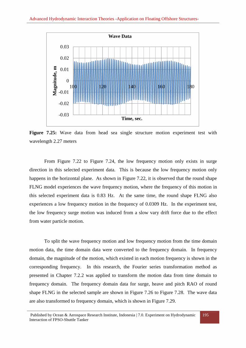
Advanced Hydrodynamic Interaction Theories -Application on Floating Offshore Structures-
Published by Ocean & Aerospace Research Institute, Indonesia | 7.0. Experiment on Hydrodynamic Interaction of FPSO-Shuttle Tanker
195
Figure 7.25: Wave data from head sea single structure motion experiment test with
wavelength 2.27 meters
From Figure 7.22 to Figure 7.24, the low frequency motion only exists in surge
direction in this selected experiment data. This is because the low frequency motion only
happens in the horizontal plane. As shown in Figure 7.22, it is observed that the round shape
FLNG model experiences the wave frequency motion, where the frequency of this motion in
this selected experiment data is 0.83 Hz. At the same time, the round shape FLNG also
experiences a low frequency motion in the frequency of 0.0309 Hz. In the experiment test,
the low frequency surge motion was induced from a slow vary drift force due to the effect
from water particle motion.
To split the wave frequency motion and low frequency motion from the time domain
motion data, the time domain data were converted to the frequency domain. In frequency
domain, the magnitude of the motion, which existed in each motion frequency is shown in the
corresponding frequency. In this research, the Fourier series transformation method as
presented in Chapter 7.2.2 was applied to transform the motion data from time domain to
frequency domain. The frequency domain data for surge, heave and pitch RAO of round
shape FLNG in the selected sample are shown in Figure 7.26 to Figure 7.28. The wave data
are also transformed to frequency domain, which is shown in Figure 7.29.
-0.03
-0.02
-0.01
0
0.01
0.02
0.03
100 120 140 160 180
Mag
nitu
de, m
Time, sec.
Wave Data

Advanced Hydrodynamic Interaction Theories -Application on Floating Offshore Structures-
Published by Ocean & Aerospace Research Institute, Indonesia | 7.0. Experiment on Hydrodynamic Interaction of FPSO-Shuttle Tanker
196
Figure 7.26: Frequency domain surge RAO of round shape FLNG in wavelength 2.27 meters
Figure 7.27: Frequency domain heave RAO of round shape FLNG in wavelength 2.27 meters
00.010.020.030.040.050.060.070.080.09
0 0.2 0.4 0.6 0.8 1 1.2 1.4
Mot
ion
Am
plit
ude,
m
Frequency, Hz
Surge Motion
0
0.001
0.002
0.003
0.004
0.005
0.006
0.007
0 0.2 0.4 0.6 0.8 1 1.2 1.4
Mot
ion
Am
plit
ude,
m
Frequency, Hz
Heave Motion

Advanced Hydrodynamic Interaction Theories -Application on Floating Offshore Structures-
Published by Ocean & Aerospace Research Institute, Indonesia | 7.0. Experiment on Hydrodynamic Interaction of FPSO-Shuttle Tanker
197
Figure 7.28: Frequency domain pitch RAO of round shape FLNG in wavelength 2.27 meters
Figure 7.29: Frequency domain wave data in wavelength 2.27 meters
From Figure 7.29, it is observed that the actual generated wave has a frequency of
0.833 Hz, where the generated wave frequency is close to the desired wave frequency. In
Figure 7.26 to Figure 7.28, it is observed that the magnitude of the surge and heave motion of
round shape FLNG in the frequency, which is the same as the wave frequency is ranged at
0
0.02
0.04
0.06
0.08
0.1
0.12
0 0.2 0.4 0.6 0.8 1 1.2 1.4
Mot
ion
Am
plit
ude,
deg
Frequency , Hz
Pitch Motion
00.0020.0040.0060.0080.01
0.0120.0140.0160.018
0 0.2 0.4 0.6 0.8 1 1.2 1.4
Wav
e A
mpl
itud
e, m
Frequency, Hz
Wave Data

Advanced Hydrodynamic Interaction Theories -Application on Floating Offshore Structures-
Published by Ocean & Aerospace Research Institute, Indonesia | 7.0. Experiment on Hydrodynamic Interaction of FPSO-Shuttle Tanker
198
0.0071 metres and 0.0059 metres respectively, while the pitch motion at the frequency is at
0.1023 degrees.
As mentioned in the previous part, the round shape FLNG experiences two types of
motion in horizontal plane. The wave frequency motion in surge direction has the oscillation
frequency, which is the same as the wave frequency. According to Dercksen and Wichers
(1992), the low frequency motion in surge direction is depended on the natural frequency of
mooring system. Typically, the frequency of the low frequency motion is much lower
compared to the frequency of wave frequency motion. In the experiment test, the round shape
FLNG experiences a low frequency motion with the frequency of 0.0309 Hz in model scale.
In this research, the wave frequency motion of round shape FLNG is studied. The
proposed method calculated the wave frequency motion of round shape FLNG without
considering the effect of mooring system. This is because the effect of mooring in the wave
frequency motion is negligible for large structure, such as FLNG. The suggestion to ignore
the effect of mooring in estimating the wave frequency motion is also supported by Soares et
al. (2005), where he obtained the panel method without including the mooring force in
estimating the RAO amplitude of large size floating structure used in his studies, which was
able to provide a good accurate prediction compared to the experiment results. In his
experimental test, he also included the mooring system to simulate the mooring effect in
horizontal plane motion. Hence, the same methodology was applied here to validate the
proposed method.
7.7. Summary
This chapter discusses the experiment setup to collect the comparative data to validate the
proposed mathematical models. After that, this chapter also explains the method used to
process the experimental data until the response amplitude operator of the floating structure in
each direction is able to estimate from the collected experimental data. The experimental

Advanced Hydrodynamic Interaction Theories -Application on Floating Offshore Structures-
Published by Ocean & Aerospace Research Institute, Indonesia | 7.0. Experiment on Hydrodynamic Interaction of FPSO-Shuttle Tanker
199
results obtained were used to validate the proposed method and the results are shown in
Chapter Eight.

Advanced Hydrodynamic Interaction Theories -Application on Floating Offshore Structures-
Published by Ocean & Aerospace Research Institute, Indonesia | 8.0. Simulation on Hydrodynamic Interaction of FPSO-Shuttle Tanker
200
Chapter 8
8.0. Simulation on Hydrodynamic Interaction of FPSO-Shuttle
Tanker This chapter discusses the estimated RAO of the round shape FLNG structure. The
RAO of the round shape FLNG was predicted by the proposed method discussed in Chapter
Six. Besides, experiment study was conducted to evaluate the RAO of round shape FLNG.
From the motion experiment test, comparative data used to validate the proposed method was
obtained. In addition, numerical comparative study was conducted in this research. The RAO
of the round shape FLNG was also estimated using the ANSYS AQWA software. The RAOs
of round shape FLNG predicted by the mentioned methods are shown in this chapter.
Besides, this chapter consists of two main parts, which are RAO of round shape FLNG
when it is free from interact with other floating structures and the RAO of the round shape
FLNG when it is interacting with another floating structure. In the second part of this chapter,
the RAO of round shape FLNG when interacting with the KVLCC2 tanker arranged in two
different gap distance is presented. The motions response of the round shape FLNG when
interacting with second structure was also estimated using the proposed method in this
research, ANSYS AQWA and experiment method. The influence of the second floating
structure to the RAO of round shape FLNG due to the difference gap distance is also
discussed in this chapter.
8.1. Response Amplitude Operator of Single Round Shape FLNG
The RAO of round shape FLNG was predicted by using the proposed method and compared
with the result predicted by ANSYS AQWA and motion experiment test. The proposed
method predicted the RAO of round shape FLNG based on the diffraction potential theory. In
heave motion, the heave RAO was predicted by using Jaswar and Siow drag damping

Advanced Hydrodynamic Interaction Theories -Application on Floating Offshore Structures-
Published by Ocean & Aerospace Research Institute, Indonesia | 8.0. Simulation on Hydrodynamic Interaction of FPSO-Shuttle Tanker
201
correction method where in this method the damping and exciting force calculated by
diffraction potential theory are improved by using the drag equation in order to estimate the
viscous effect. The proposed method was able to estimate the damping, added mass and wave
force of the round shape FLNG and then, solve the motion equation to obtain the RAO of the
round shape FLNG.
8.1.1. Added Mass and Damping Coefficient of the Round Shape FLNG
The added mass and damping coefficient of the round shape FLNG was predicted by the
proposed method in this research. Since the round shape FLNG is the symmetry in X-
direction and Y-direction, then the discussion is only focused in surge, pitch, heave and yaw
condition. The added mass and damping in sway direction in any wavelength is similar with
the added mass and damping in surge direction. The added mass and damping in roll
direction are similar with the added mass and damping in pitch direction in this four sides
symmetry structure.
Let the added mass predicted by proposed method in surge, pitch, heave and yaw
directions are labelled as ¯==, ¯ññ, ¯ÁÁ and ̄ ;; respectively. The predicted added mass in
each direction of motion response is shown from Figure 8.1 to Figure 8.4.

Advanced Hydrodynamic Interaction Theories -Application on Floating Offshore Structures-
Published by Ocean & Aerospace Research Institute, Indonesia | 8.0. Simulation on Hydrodynamic Interaction of FPSO-Shuttle Tanker
202
Figure 8.1: Surge added mass of round shape FLNG predicted by the proposed method
Figure 8.2: Pitch added mass of round shape FLNG predicted by the proposed method
0
0.1
0.2
0.3
0.4
0.5
0.6
0.7
0.8
0.9
1
0 1 2 3 4 5 6 7 8 9 10 11 12 13 14 15
¯ 11/(ρ∇)
λ/DFLNG
Surge Added Mass
0
0.01
0.02
0.03
0.04
0.05
0 1 2 3 4 5 6 7 8 9 10 11 12 13 14 15
¯ 55/(ρ∇L)
λ/DFLNG
Pitch Added Mass

Advanced Hydrodynamic Interaction Theories -Application on Floating Offshore Structures-
Published by Ocean & Aerospace Research Institute, Indonesia | 8.0. Simulation on Hydrodynamic Interaction of FPSO-Shuttle Tanker
203
Figure 8.3: Heave added mass of round shape FLNG predicted by the proposed method
Figure 8.4: Yaw added mass of round shape FLNG predicted by the proposed method
0
0.2
0.4
0.6
0.8
1
1.2
1.4
0 1 2 3 4 5 6 7 8 9 10 11 12 13 14 15
¯ 33/(ρ∇)
λ/DFLNG
Heave Added Mass
0
0.01
0.02
0.03
0.04
0.05
0 1 2 3 4 5 6 7 8 9 10 11 12 13 14 15
¯ 66/(ρ∇L)
λ/DFLNG
Yaw Added Mass

Advanced Hydrodynamic Interaction Theories -Application on Floating Offshore Structures-
Published by Ocean & Aerospace Research Institute, Indonesia | 8.0. Simulation on Hydrodynamic Interaction of FPSO-Shuttle Tanker
204
In Figure 8.1 to Figure 8.4, the added mass in each direction of motion predicted by
the proposed method was plotted against the ratio of wavelength to the structure length,
λ/DFLNG. The surge added mass and heave added mass show in Figure 8.1 and Figure 8.3
were non-dimensional with the mass of the structure, ρ∇ while the pitch added mass and yaw
added mass shown in Figure 8.2 and Figure 8.4 were non-dimensional with the mass of the
structure multiplied by structure length, ρ∇L.
From the Figure 8.1, the estimated surge added mass of the round shape FLNG
increased from the ratio of λ/DFLNG 0.5 to 4.0 gradually. If the ratio λ/DFLNG is larger than
4.0, the surge added mass starts to decrease slowly by increasing the ratio of λ/DFLNG. This
means that the surge added mass of round shape FLNG is small if the wavelength is short.
The added mass of pitch motion is shown in Figure 8.2. The estimated non-dimensional
added mass of pitch motion was around 0.03 in the selected range of wavelength. The added
mass of pitch motion had not much of changes if the wavelength increased up to λ/DFLNG,
which equals to 15 as shown in Figure 8.2.
The predicted heave added mass of the round shape FLNG was varied from the range
of 0.8 to 1.2 in the selected range of wavelength. This means that the added mass of the
round shape FLNG in heave motion is almost equal to the weight of the structure. Higher
heave added mass would help to shift the resonance frequency of heave motion to a longer
wavelength region. The yaw motion added mass predict by the proposed method is shown in
Figure 8.4. From Figure 8.4, it shows that the yaw added mass is almost zero in any
condition. The added mass for yaw motion is relatively low because the round shape FLNG
is a cylinder type structure and less fluid particle would accelerate with the yaw motion of the
structure.
In compared to other study, it is found that the tendencies of surge added mass and
heave added mass calculated by the proposed method is similar with the result from
Perwitasari (2010). Where she has been conducted a research to study the mooring system of
round shapes FPSO. However, the peak added mass for the surge and heave direction
calculated by the proposed method is slightly higher. The different magnitude of the added

Advanced Hydrodynamic Interaction Theories -Application on Floating Offshore Structures-
Published by Ocean & Aerospace Research Institute, Indonesia | 8.0. Simulation on Hydrodynamic Interaction of FPSO-Shuttle Tanker
205
mass coefficient obtained from both study is because the size of round shape floating structure
used is different where the size of the FLNG in this research is slightly larger compare to the
size of floating structure used in previous study. Besides that, the tendency of pitch added
mass coefficient of round shape FLNG predicted by the proposed method is also almost
similar with the pitch added mass tendency predicted by Jiang et al. (2012). In their study,
they used higher order boundary element method (HOBEM) to calculate the hydrodynamic
coefficient of the cylinder type floating structure.
On the yaw direction, the added mass for yaw motion calculated is always zero in any
wavelength because the shape of the hull of the structure. As shown in the equation (4.78),
the equation to calculate the added mass is in the function of surface normal vector. The
round shape FLNG is the cylinder type structure, so the yaw normal vector is zero for this
type of structure. From this finding, it can be expected that the round shape FLNG have very
limited capability to accelerate the fluid particle in yaw direction. Therefore, the predicted
yaw added mass of this FLNG by proposed method is always zero.
On the other hand, the damping coefficient predicted by the proposed method on
surge, pitch, heave and yaw directions are represented by symbols ́ ==, ´ññ, ´ÁÁ and ́ ;;
respectively in this thesis. The damping coefficients are estimated by the proposed method
developed based on diffraction potential theory. The predicted damping coefficient in each
direction of motion response is shown from Figure 8.5 to Figure 8.8.
In Figure 8.5 to Figure 8.8, the damping coefficient of round shape FLNG in each
direction of motion predicted by the proposed method was plotted against the ratio of
wavelength to the structure length, λ/DFLNG. The surge damping coefficient and heave
damping coefficient shown in Figure 8.5 and Figure 8.17 were non-dimensional with the mass
of the structure and angular wave speed, ρ∇w while the pitch added mass and yaw added
mass shown in Figure 8.6 and Figure 8.8 were non-dimensional with the mass of the structure,
angular wave speed and structure length, ρ∇wL.

Advanced Hydrodynamic Interaction Theories -Application on Floating Offshore Structures-
Published by Ocean & Aerospace Research Institute, Indonesia | 8.0. Simulation on Hydrodynamic Interaction of FPSO-Shuttle Tanker
206
Figure 8.5: Surge damping coefficient of round shape FLNG predicted by the proposed
method
Figure 8.6: Pitch damping coefficient of round shape FLNG predicted by the proposed
method
0
0.1
0.2
0.3
0.4
0.5
0.6
0 1 2 3 4 5 6 7 8 9 10 11 12 13 14 15
B11
/(ρ
∇w)
λ/DFLNG
Surge Damping Coefficient
0
0.0002
0.0004
0.0006
0.0008
0.001
0.0012
0 1 2 3 4 5 6 7 8 9 10 11 12 13 14 15
B55
/(ρ
∇wL)
λ/DFLNG
Pitch Damping Coefficient

Advanced Hydrodynamic Interaction Theories -Application on Floating Offshore Structures-
Published by Ocean & Aerospace Research Institute, Indonesia | 8.0. Simulation on Hydrodynamic Interaction of FPSO-Shuttle Tanker
207
Figure 8.7 Heave damping coefficient of round shape FLNG predicted by the proposed
method
Figure 8.8 Yaw damping coefficient of round shape FLNG predict by the proposed method
0
0.1
0.2
0.3
0.4
0.5
0.6
0 1 2 3 4 5 6 7 8 9 10 11 12 13 14 15
B33
/(ρ
∇w)
λ/DFLNG
Heave Damping Coefficient
0
0.0002
0.0004
0.0006
0.0008
0.001
0.0012
0.0014
0 1 2 3 4 5 6 7 8 9 10 11 12 13 14 15
B66
/(ρ
∇wL)
λ/DFLNG
Yaw Damping Coefficient

Advanced Hydrodynamic Interaction Theories -Application on Floating Offshore Structures-
Published by Ocean & Aerospace Research Institute, Indonesia | 8.0. Simulation on Hydrodynamic Interaction of FPSO-Shuttle Tanker
208
From Figure 8.5, the estimated surge damping coefficient of the round shape FLNG is
maximum at the ratio of λ/DFLNG equal to 2.2 and the maximum surge damping is equal to 2.
After that, increased of the ratio of λ/DFLNG caused the surge damping coefficient decreased.
This means that the surge motion would follow the wave when the wavelength is sufficiently
long. The damping coefficient of pitch motion is shown in Figure 8.6. The estimated
damping coefficient of pitch motion achieved maximum value of 0.01 when the ratio of
λ/DFLNG is around 1. The pitch damping coefficient of this structure is almost zero when the
ratio λ/DFLNG is larger than 5. From the estimated pitch damping coefficient, the pitch motion
of this structure is larger in the long wavelength region compared to the short wavelength
region.
The predicted heave damping coefficient of the round shape FLNG was increasing
gradually when the ratio of λ/DFLNG increased. The heave damping coefficient is almost
constant after the ratio λ/DFLNG is larger than 6. The yaw damping coefficient predicted by
the proposed method is shown in Figure 8.8. Similar with the yaw added mass, the yaw
damping coefficient was almost zero in any wavelength predicted by the proposed method.
The proposed method was developed based on potential theory. Therefore, only radiation
damping coefficient was predicted by the proposed method for yaw motion. Since the round
shape FLNG is a cylinder type structure, then the capability of the structure to dissipate the
energy in yaw motion is very limited due to the amount of water particle, which can be
accelerated by yaw motion of the structure is very small.
By comparing the tendencies of surge damping, pitch damping and heave damping
predicted by proposed method in this research with the previous literature, it was found that
the tendencies of surge damping and heave damping for the FLNG predicted by this research
is almost similar with the results presented by Perwitasari (2010). In her study, she used
WADEM software to calculate the hydrodynamic coefficient of the round shape floating
structure. Besides, the pitch damping tendency estimated in this research is also similar with
the pitch damping tendency predicted by Jiang et al. (2012) by using HOBEM method.

Advanced Hydrodynamic Interaction Theories -Application on Floating Offshore Structures-
Published by Ocean & Aerospace Research Institute, Indonesia | 8.0. Simulation on Hydrodynamic Interaction of FPSO-Shuttle Tanker
209
As predicted by the proposed method, both the surge damping coefficient and pitch
damping coefficient is small in long wavelength region. These tendencies observed because
the floating structure typically would move follow the wave motion when the wavelength is
long. When the motion of the FLNG is move follow the wave motion, then the amount of
motion energy able to dissipate to fluid and generate the radiating wave become lesser. From
this point of view, the radiation damping coefficient for both the surge and pitch direction
predicted by the proposed method is smaller in long wavelength region is quite agree with the
normal phenomena.
From the mathematical point of view, the damping coefficient for each direction is in
the function of area normal vector as shown in equation (4.79). When the wavelength is long,
the potential of wave acting on the every unit of wetted are of FLNG is almost similar due to
lower wave diffraction effect. Therefore, the cancellation of damping force is happened for
surge and pitch direction. This is because the area normal vectors of the wetted area for these
two directions in forward part of FLNG and aft-ward part of FLNG are in opposite sign. This
cancellation of damping force are not happen to the heave direction since the area normal
vector of this FLNG structure for vertical direction are all in the similar direction and pointing
downward. In addition, the proposed method predicted the damping using potential theory
where the potential theory is the linear theory and neglects the viscous effect. Since the
viscous effect is neglected, then the damping predicted by the proposed method is only the
radiating damping. Therefore, the damping for the yaw motion predicted by the proposed
method is always zero because of the area normal vector of this FLNG for yaw direction is
zero and the viscous effect was neglected from the calculation of damping coefficient.
8.1.2. Wave force act on the Round Shape FLNG
In this research, the wave force act on the wetted surface of round shape FLNG was estimated
by the proposed method, which was developed based on diffraction potential theory. In this
chapter, the wave force act on the structure in head sea condition is discussed. In head sea

Advanced Hydrodynamic Interaction Theories -Application on Floating Offshore Structures-
Published by Ocean & Aerospace Research Institute, Indonesia | 8.0. Simulation on Hydrodynamic Interaction of FPSO-Shuttle Tanker
210
condition, the wave force act on the floating structure is only able to induce surge, pitch and
heave motion. Hence, only the surge force, pitch moment and heave force are discussed here.
The wave force act on surge, pitch and heave direction be labelled as symbols É=, Éñ
and ÉÁ in this thesis. The estimated wave force acts on the round shape FLNG by diffraction
potential theory are shown in Figure 8.9 to Figure 8.11.
The wave forces act on the round shape FLNG in head sea condition were plotted
against the ratio of wavelength to structure length, λ/DFLNG are shown in Figure 8.9 to Figure
8.11. The amplitude of wave force act on surge direction and heave direction as shown in
Figure 8.9 and Figure 8.11 were non-dimensional with the fluid density, ρ, gravity
acceleration, g, wave amplitude, ¹a and the water plane area, AW. The pitch moment shown in
the Figure 8.10 was non-dimensional with the fluid density, ρ, gravity acceleration, g, wave
amplitude, ¹a, water plane area, AW and the length of the structure.
Figure 8.9: Surge wave force act on round shape FLNG predicted by the proposed method
0
0.1
0.2
0.3
0.4
0.5
0.6
0 1 2 3 4 5 6 7 8 9 10 11 12 13 14 15
E1/
(ρg ¹ aA W
)
λ/DFLNG
Surge Force

Advanced Hydrodynamic Interaction Theories -Application on Floating Offshore Structures-
Published by Ocean & Aerospace Research Institute, Indonesia | 8.0. Simulation on Hydrodynamic Interaction of FPSO-Shuttle Tanker
211
Figure 8.10: Pitch wave moment act on round shape FLNG predicted by the proposed
method
Figure 8.11: Heave wave force act on round shape FLNG predicted by the proposed method
0
0.002
0.004
0.006
0.008
0.01
0.012
0.014
0.016
0.018
0.02
0 1 2 3 4 5 6 7 8 9 10 11 12 13 14 15
E5/
(ρg ¹ aA W
L)
λ/DFLNG
Pitch Moment
0
0.2
0.4
0.6
0.8
1
0 1 2 3 4 5 6 7 8 9 10 11 12 13 14 15
E3/
(ρg ¹ aA W
)
λ/DFLNG
Heave Force

Advanced Hydrodynamic Interaction Theories -Application on Floating Offshore Structures-
Published by Ocean & Aerospace Research Institute, Indonesia | 8.0. Simulation on Hydrodynamic Interaction of FPSO-Shuttle Tanker
212
In Figure 8.9, the wave force act on the surge direction achieved maximum amplitude
at the ratio λ/DFLNG, which is equal to 3. After that, the wave force act on the surge direction
decreased gradually when the wavelength increased. The pitch moment of the round shape
FLNG induced by the wave in head sea condition is shown in Figure 8.10. The predicted
pitch moment achieved maximum at the ratio λ/DFLNG is equal to 1.5. The pitch moment was
almost zero when the ratio λ/DFLNG is equal to 5.5. After that, the pitch moment of round
shape FLNG increased slowly with the increased of wavelength.
The heave force, which induces the heave motion to the round shape FLNG is shown
in Figure 8.11. The heave force shown in the Figure 8.11, which is predicted by the proposed
method was developed based on diffraction potential theory. The heave force predicted
increased when the wavelength increased and trended to become constant at long wavelength.
Round shape FLNG would experience a larger heave force in long wavelength region
predicted by the proposed method.
From the literature, it is obtained that the tendencies of the surge and heave exciting
forces predicted by the proposed method are similar with the results obtained by Perwitasari
(2010). The surge exciting force for this FLNG is trend to reduce by increase of wavelength
is because the surge motion of FLNG is followed wave motion in long wavelength. When the
wavelength become longer, the time for FLNG to accelerate and decelerate become longer.
Therefore the wave load on the FLNG to cause the structure move follows the wave become
lesser.
On the other hand, the heave wave exciting force is shown increased and trend to
become constant at long wavelength. The heave exciting force predicted by the proposed
method was increased if the wavelength was increased. This is because increase the
wavelength is able to increase amount of wave load on the heave direction. As presented by
equation (4.77), the equation shows that the wave exciting force is in the function of floating
structure’s area normal vector and the wave potential. The entire wetted surface of this FLNG
model has the area normal vector all pointing downward. Therefore, the change of heave
exciting force direction is depending on the velocity of wave motion. When the wavelength is

Advanced Hydrodynamic Interaction Theories -Application on Floating Offshore Structures-
Published by Ocean & Aerospace Research Institute, Indonesia | 8.0. Simulation on Hydrodynamic Interaction of FPSO-Shuttle Tanker
213
increased, the amount of heave wave force acting in same direction across the FLNG is
increasing. This causes the amount of heave exciting wave force increases when the
wavelength becomes longer. However, when the wavelength is increased to very long
wavelength condition, the change of heave wave force direction across the FLNG wetted
surface area is no happened. So, the heave wave exciting force start to become constant by
increase of wavelength as presented in the Figure 8.11.
By compared to the result obtained by Jiang et al. (2012), it was found that the
tendency of pitch exciting force is slightly different between the prediction of proposed
method and Jiang et al. (2012). The different between the pitch exciting force tendency
between both the researches is the proposed method detect the cancellation of pitch moment
happened at the λ/DFLNG equal to 5.5. From the equation to calculate the wave exciting as
presented in equation (4.77), the wave exciting force acting on each wetted surface of FLNG
is in function of the surface area normal vector. The area normal vector in pitch direction is in
opposite sign for forward part of structure’s wetted surface and aft-ward part of structure’s
wetted surface. When the wavelength at λ/DFLNG is equal to 5.5, it was found that the total
pitch moment acting on the forward part of FLNG and aft-ward part of FLNG was same.
Therefore, the cancellation of the pitch moment was happened and the total pitch moment
becomes zero at this wave condition. Besides, it was found that the pitch moment was trend
to become constant at long wavelength because the FLNG is move follow the wave. The
constant pitch moment at long wavelength is predicted able to encounter by the pitch restoring
force to avoid large pitch motion at long wavelength region.
8.1.3. Influence of Drag Equation in the Heave Damping and Heave Force
The proposed method applied diffraction potential theory to predict the added mass, damping
and wave forces or wave moment act on the round shape FLNG to induce the motions to the
round shape FLNG. The diffraction potential theory only predicted the radiation damping of
the floating structure without considering the viscous effect. Neglect of viscous effect in the
calculation causes over-prediction on RAO by the proposed method in some conditions. In

Advanced Hydrodynamic Interaction Theories -Application on Floating Offshore Structures-
Published by Ocean & Aerospace Research Institute, Indonesia | 8.0. Simulation on Hydrodynamic Interaction of FPSO-Shuttle Tanker
214
the selected round shape FLNG model, the proposed method over-predicted the heave RAO
of the Round shape FLNG in the damping dominant region. The damping dominant region of
the round shape FLNG is located at the wavelength around 381 metres or wave period of 15.6
seconds in full scale. From the study, it is possible of ocean wave occurring at the wave
period around the 15.6 seconds so the accuracy on the prediction of heave RAO at the
damping dominant region is important to ensure the safety of the selected round shape FLNG
operated at open sea.
To improve the heave motion predicted by the proposed method, the heave RAO
predict by the propose method is calculated using the diffraction potential theory with drag
equation. The diffraction potential theory is responsible to predict the heave added mass,
heave radiation damping and heave diffraction force. The drag equation used in the
calculation is responsible to calculate the viscous damping and the drag force act on the
floating structure. The proposed method introduced to improve the accuracy on predicts the
heave motion is explained in Chapter 5.1.
The heave damping predicted by the proposed method which developed using
diffraction potential theory with drag equation is shown in Figure 8.12. The Figure 8.12
shown the non-dimensional heave damping calculated by diffraction potential theory, drag
equation and summation of both the heave damping by both the method. From the
comparison, it is obtained that the heave damping calculated by both the methods have almost
similar tendency at the selected range of wavelength. The heave damping predicted by both
methods was increased gradually when wavelength was increased.

Advanced Hydrodynamic Interaction Theories -Application on Floating Offshore Structures-
Published by Ocean & Aerospace Research Institute, Indonesia | 8.0. Simulation on Hydrodynamic Interaction of FPSO-Shuttle Tanker
215
Figure 8.12: Comparison of heave damping coefficient of round shape FLNG predict by
propose method
From Figure 8.12, the viscous damping calculated by the drag equation was slightly
larger compared to the radiation damping estimated by diffraction potential theory at the ratio
λ/DFLNG, which is below than 2. If the ratio λ/DFLNG is larger than 2, the radiation damping is
larger compared to the viscous damping. Besides, the tendency of the radiation heave
damping and viscous heave damping is almost stable when the ratio λ/DFLNG is larger than 5.
According to Kvittem et al. (2012), the wave diffracted effect is more dominant to the
large size structure compare to the viscous effect because the wave is mostly diffracted from
the structure when the undisturbed incident wave interacting with the large size floating
structure. The estimated viscous damping coefficient by the drag equation is lower compared
to the radiation damping estimated by the diffraction potential theory as presented in the
Figure 8.12 is because of the wave diffraction effect is more dominated in this round shape
FLNG. However, according to Loken (1981), he stated that the damping coefficient typically
under-estimate by the diffraction potential theory since the viscous effect is ignored. From
this Figure 8.12, it is showed that the ignored viscous damping by the diffraction potential
theory is almost one third of the total damping coefficient for this selected FLNG structure.
0
0.1
0.2
0.3
0.4
0.5
0.6
0 1 2 3 4 5 6 7 8 9 10 11 12 13 14 15
B33
/(ρ
∇w)
λ/DFLNG
Heave Damping
Radiation Damping Viscous Damping Total Damping

Advanced Hydrodynamic Interaction Theories -Application on Floating Offshore Structures-
Published by Ocean & Aerospace Research Institute, Indonesia | 8.0. Simulation on Hydrodynamic Interaction of FPSO-Shuttle Tanker
216
Hence, it is cannot avoided of over predict of structure motion response by the diffraction
potential theory especially in damping dominant region.
To obtain the total damping for heave motion of round shape FLNG, the magnitude of
damping coefficient predicted by drag equation and diffraction potential theory were sum up
together in this research. As shown in Figure 8.12, the total damping which sum-up the
damping predicted by the two mentioned methods increased the damping coefficient for the
heave motion of round shape FLNG. The tendency of the radiation damping and viscous
damping for this selected structure is almost similar within the selected range of wavelength.
Besides, the tendency of total damping is similar with the tendency of the damping coefficient
calculated by both the method but the magnitude of the total damping coefficient is larger
than the damping coefficient only predict by diffraction potential theory.
As mentioned, the heave motion of the FLNG dominated by damping term is located
at a wavelength around 385 metres, where the ratio λ/DFLNG equals to 3.44. By referring to
Figure 8.12, the damping coefficient obtained by summing up the damping calculated from
both the methods is around 0.376 as compared to the radiation damping coefficient, which
was predicted by diffraction potential theory is 0.239. At this calculated magnitude, it is
summarised that the addition viscous damping by using drag equation able to increase the
damping coefficient and reduce the amount of over-prediction of the heave RAO estimated at
the damping dominant region.
Besides, involving the drag equation in the calculation introduces the drag force in the
motion equation. The total heave force calculated by the proposed method is the summation
of diffraction force calculated by diffraction potential theory and the drag force calculated by
drag equation. As shown in Figure 8.13, the heave force calculated by the diffraction
potential theory increased gradually when the ratio λ/DFLNG increased.

Advanced Hydrodynamic Interaction Theories -Application on Floating Offshore Structures-
Published by Ocean & Aerospace Research Institute, Indonesia | 8.0. Simulation on Hydrodynamic Interaction of FPSO-Shuttle Tanker
217
Figure 8.13: Comparison of heave force of round shape FLNG predicted by the proposed
method
The drag force calculated by drag equation is shown in Figure 8.13. The figure shows
that the tendencies of heave force predicted by both methods are different between each other.
The heave force calculated by the drag equation is almost zero at the ratio λ/DFLNG below one.
At the longer wavelength region, the wave drag force in heave direction is almost unchanged
when the wavelength increased. The magnitude of the heave force calculated by the drag
equation is much lower compare to the diffraction force calculated by diffraction potential
theory. This is because the diffracted effect is much higher compare to drag effect for the
round shape FLNG structure. This opinion is also similar with the finding obtained by
Kvittem et al. (2012) in their study. The higher diffraction force acting on the FLNG because
the large size round shape FLNG is able to diffract most of the incident wave. The large size
structure is considered as an obstacle for the propagation of wave so the wave would be
diffracted around the structure especially the wavelength is shorter than the length of the
structure. When the wavelength is longer than the length of structure, the fluid particle is able
to drag around the floating structure. But, the size of the structure is still play a main role to
determine the phenomena of fluid particle pass through the structure. Since the displacement
and the length of the round shape FLNG is very large, then the amount of fluid particle drag
0
0.1
0.2
0.3
0.4
0.5
0.6
0.7
0.8
0 1 2 3 4 5 6 7 8 9 10 11 12 13 14 15
E3/
(ρg ¹ aA W
)
λ/DFLNG
Heave Force
Diffraction Force Drag Force Total Force

Advanced Hydrodynamic Interaction Theories -Application on Floating Offshore Structures-
Published by Ocean & Aerospace Research Institute, Indonesia | 8.0. Simulation on Hydrodynamic Interaction of FPSO-Shuttle Tanker
218
over the wetted surface of the structures is still much smaller compare to amount of fluid
particle diffracted from the FLNG.
To combine the heave force contributed by both the methods, the superposition theory
was applied. In this study, the heave force calculated by the diffraction potential theory and
the drag force calculated the linearly drag term from the drag equation were total up to
calculate the heave RAO. Both the heave forces contributed by both the methods were total
up by vector summation theory.
By referring to Figure 8.13, it is obtained that the tendency of total heave force which
total up by involved the diffraction force and drag force is mostly follow the tendency of
heave force calculated by diffraction potential theory. This tendency is obtained because the
diffraction force of the round shape FLNG is much higher compare to the drag force. The
existing of the drag force from the drag equation in the calculation only give limited influence
to the total heave force estimate by proposed method. Compared to the influence of drag
effect to the total heave damping, it is obtained that involved the drag effect in calculate the
heave RAO would able to reduce the estimate heave RAO calculated by proposed method
especially in the damping dominant region.
8.1.4. Estimated Response Amplitude Operator of Round Shape FLNG
The results applied to study the round shape FLNG’s RAO were collected from the numerical
simulation and experiment method. The numerical results were generated using ANSYS
AQWA software and proposed method based on Diffraction Potential Theory and Diffraction
potential theory with drag equation. The experiment results used to study the RAO of the
new FLNG were conducted in regular wave condition.
In the motion experiment, the wavelengths were properly selected so it can obtain the
tendencies of all direction of FLNG motion responses in the function of difference
wavelength. In this part, the response amplitude of round shape FLNG model in head sea
condition is discussed. As shown in Figure 8.14 to Figure 8.16, the tendency of surge, pitch

Advanced Hydrodynamic Interaction Theories -Application on Floating Offshore Structures-
Published by Ocean & Aerospace Research Institute, Indonesia | 8.0. Simulation on Hydrodynamic Interaction of FPSO-Shuttle Tanker
219
and heave RAO obtained by both the numerical and experimental method is agreed between
each other.
Figure 8.14: Surge RAO predicts by proposed method (diffraction potential theory),
experiment and ANSYS AQWA
The comparative study was conducted to compare the RAO of round shape FLNG
predicted by the proposed method to ANSYS AQWA. The comparison between the surge
RAOs of the round shape FLNG predicted by both methods is shown in Figure 8.14. As
shown in Figure 8.14, the surge RAO predicted by the proposed method and ANSYS AQWA
is almost similar when the wavelength λ/DFLNG below 10. Both the proposed method and
ANSYS AQWA have predicted same tendency and almost similar magnitudes of surge RAO
because both methods were developed using similar concept that is diffraction potential
theory. However, when the wavelength λ/DFLNG larger than 10, it was obtained that the surge
RAO of proposed method was trend to become stable by increased of wavelength while the
surge RAO predicted by Ansys AQWA was trend to increase by increased of wavelength.
This observation obtained because the proposed method only consider the motion of FLNG
due to the first order wave force while ANSYS AQWA take consideration of wave frequency
motion and the slow varying motion. According to Herbich et al. (1999), the slow varying
0
0.2
0.4
0.6
0.8
1
1.2
1.4
1.6
0 1 2 3 4 5 6 7 8 9 10 11 12 13 14 15
RA
O, X
1/¹ a(m
/m)
λ/DFLNG
Surge RAO
Diffraction Potential Experiment Ansys AQWA

Advanced Hydrodynamic Interaction Theories -Application on Floating Offshore Structures-
Published by Ocean & Aerospace Research Institute, Indonesia | 8.0. Simulation on Hydrodynamic Interaction of FPSO-Shuttle Tanker
220
motion of the FLNG typically become more dominant compared to the wave frequency
motion when the wavelength become very long. Due to the consideration taken by the Ansys
AQWA, the surge motion response predicted by Ansys AQWA do not become constant with
the increase of wavelength.
Figure 8.15: Pitch RAO predicts by proposed method (diffraction potential theory),
experiment and ANSYS AQWA
Comparison between the pitch RAOs predicted using proposed method with ANSYS
AQWA commercial code is shown in Figure 8.15. The tendency of the pitch RAO predicted
by both methods was similar between each other. By comparing with the experimental result,
both the proposed method and ANSYS AQWA commercial code was able to generate the
same tendency of pitch RAO compared to experimental result. Besides, the proposed method
and the ANSYS AQWA were successes to predict the peak RAO of the pitch motion. The
peak pitch RAO of this FLNG predicted by the proposed method and ANSYS AQWA is
happened at its pitch natural frequency where the corresponding wavelength for the pitch
natural frequency is at λ/DFLNG equal to 9.53. From the Figure 8.15, the pitch motion
response predicted was very small at short wavelength region and start to increase exponential
at λ/DFLNG equal to 4. This is because the pitch damping coefficient is high at the short
wavelength region and almost zero at the long wavelength region. The large pitch damping
00.5
11.5
22.5
33.5
44.5
5
0 1 2 3 4 5 6 7 8 9 10 11 12 13 14 15
RA
O, X
5/(K
¹ a) (Rad
/Rad
)
λ/DFLNG
Pitch RAO
Diffraction Potential Experiment Ansys AQWA

Advanced Hydrodynamic Interaction Theories -Application on Floating Offshore Structures-
Published by Ocean & Aerospace Research Institute, Indonesia | 8.0. Simulation on Hydrodynamic Interaction of FPSO-Shuttle Tanker
221
for this FLNG at short wavelength condition is able to reduce the pitch RAO of this round
shape FLNG. This observation shows that the FLNG is very stable at short wavelength
region.
The numerical method predicted that the surge motion tendency experience has a large
difference of RAO between the ratio λ/DFLNG 8.5 to 10. However, due to lack of experimental
data in this region, the actual condition is difficult to predict. From the Table 7.2, the natural
period for surge motion of this round shape FLNG is happened at the λ/DFLNG equal to 1570
where it is far away from the wavelength the surge motion tendency fluctuates detected by
both the proposed method and ANSYS AQWA. In this research, the large fluctuates of the
surge motion tendency is caused by the coupling effect between surge and pitch motion. This
is because the experiment and numerical result also showed that the designed FLNG model
experienced large pitch motion at long wavelength region. The large pitch motion response at
the wavelength λ/DFLNG around 9.5 is because the resonance effect. From the decay test
result, it was obtained that the natural frequency of the pitch motion is happened at the
wavelength λ/DFLNG equal to 9.53. As shown in Figure 8.6, the pitch damping coefficient for
the round shape FLNG is very low and almost zero in the wavelength where resonance
happened. The low pitch damping coefficient of pitch motion when resonance happened
causes the predict pitch motion response become significant high. In addition, by comparing
the pitch and surge response tendency calculation by the proposed method and ANSYS
AQWA, it is showed that the large change of surge tendency between the ratio λ/DFLNG 8.5 to
10 is due to the coupling motion with pitch response. The resonance of pitch motion, which
caused the pitch motion to increase significantly also influenced the surge RAO of this
designed model.
Comparing between the predicted heave tendency using proposed method and ANSYS
AQWA, it was observed that the proposed method developed was based on diffraction
potential theory without any extra viscous effect, which predicted similar tendency and
magnitude of heave RAO of round shape FLNG compared to ANSYS AQWA. In
comparison to the experimental result, it was noted that the proposed method without
involved viscous effect and ANSYS AQWA commercial code over predicted the heave RAO
of round shape FLNG in damping dominant region. To reduce the amount of over-prediction

Advanced Hydrodynamic Interaction Theories -Application on Floating Offshore Structures-
Published by Ocean & Aerospace Research Institute, Indonesia | 8.0. Simulation on Hydrodynamic Interaction of FPSO-Shuttle Tanker
222
on heave RAO in damping dominant region, the proposed method was developed to involve
the viscous effect in predicting the heave RAO. The proposed method developed, which was
based on diffraction potential theory and drag equation is shown in the blue colour line in
Figure 8.16. By this proposed method, the predicted magnitude of heave RAO of round shape
FLNG is much lower in the damping dominant region. The maximum heave RAO shifted
from 2.4 to 1.7 after the viscous effect was considered in the calculation.
Figure 8.16: Heave RAO predicts by the proposed method (diffraction potential theory and
Jaswar & Siow drag damping correction method ), experiment and ANSYS AQWA
Moreover, the result from proposed method showed a good agreement with
experiment result in predicting the heave response tendency. Due to the involvement of the
extra viscous damping estimated by the drag equation in the calculation, the heave response
of the round shape FLNG model predicted by the proposed method at the damping dominant
region did not show a significance over prediction error. From Figure 8.16, the maximum
0
0.5
1
1.5
2
2.5
0 1 2 3 4 5 6 7 8 9 10 11 12 13 14 15
RA
O, X
3/¹ a(m
/m)
λ/DFLNG
Heave RAO
Jaswar & Siow Drag Damping Correction MethodDiffraction PotentialExperimentAnsys AQWA

Advanced Hydrodynamic Interaction Theories -Application on Floating Offshore Structures-
Published by Ocean & Aerospace Research Institute, Indonesia | 8.0. Simulation on Hydrodynamic Interaction of FPSO-Shuttle Tanker
223
heave response predicted by the proposed method is 1.74, while the maximum heave response
predicted by experiment method is 1.68. Comparing the heave response tendency predicted
by both the methods, Figure 8.16 also showed the heave response tendency estimated by the
proposed method (blue line), which was fixed quite well to the heave response data collected
from experiment (red dot). This showed that the proposed method, which combined the drag
equation with diffraction potential theory can be an alternative method, which was applied to
predict the heave response of this round shape FLNG even in damping dominant region and
obtain reasonably accurate results.
However, compared experiment result to numerical result, it was observed that the
peak heave RAO was shifted to longer wavelength region in experiment result. From the
Table 7.2, the corresponding wavelength for heave natural frequency is located at λ/DFLNG
equal to 3.40. The peak heave RAO for this FLNG predicted by the proposed method was
happened at the wavelength closer to the heave natural frequency compared to experiment
result. One of the reasons causes the peak heave RAO predicted by experiment result to shift
to longer wavelength region is because of the mooring line. Although, Heurtier (2010) stated
that there are limited mooring effect on the heave motion of large floating structure. But, the
existing of mooring system can causes the stiffness and mass of the floating system increase.
According to the Cheema et al. (2014), the small change on the stiffness and mass of the
floating system could cause the shift of the motion natural frequency. Hence, the peak heave
RAO predicted by experiment test is shifted slightly into longer wavelength region.
Besides, reason for the numerical method used in this research could not detect the
shift of peak heave RAO compared to the experiment result is because of the under-estimated
of the heave added mass. Chung (1994) has been conducted a study to compare the added
mass coefficient predict by the three-dimension diffraction potential theory and the added
mass coefficient predict by the experiment test. According to Chung (1994), his research
found that the added mass coefficient predict by the diffraction potential theory typically 10%
to 20% lower than the experiment value. From the mathematical point of view, the natural
period for heave motion is in direct function to the mass term. Lower predicting of the heave
added mass coefficient by the diffraction potential theory used in the research could be a
reason for the numerical method predict the peak heave RAO happened at the shorter

Advanced Hydrodynamic Interaction Theories -Application on Floating Offshore Structures-
Published by Ocean & Aerospace Research Institute, Indonesia | 8.0. Simulation on Hydrodynamic Interaction of FPSO-Shuttle Tanker
224
wavelength region compare to experiment value. Therefore, the numerical method used in the
computation of this research predicted the heave natural period is located at the shorter
wavelength region compared experiment method.
In general, it is observed that the proposed method is able to predict the six DoF wave
motion responses of the round shape FLNG in good accuracy if it is compared to experiment
result. Since this designed FLNG model has four symmetry sides (bow and stern symmetry,
port-side and starboard side symmetry), then the study conducted in the head sea condition is
enough to present the RAO characteristics of this model.
8.2. RAO of Round Shape FLNG When Interacting with another Structure
The RAO of round shape FLNG interacting with another structure was predicted by using
proposed method and compared with the result predicted by ANSYS AQWA and motion
experiment test. In this research, the KVLCC2 model was chosen to interact with the round
shape FLNG model. In this case, the KVLCC2 was arranged in the parallel arrangement with
the round shape FLNG. The measurements of gap distance between the both floating
structures selected to simulate and conduct experiment test are 0.5 to the breadth of FLNG
and 0.3 to the breadth of FLNG. The measurements of gap distance between both structures
in full scales are 56.1 metres and 34.1 metres, as well as the model scales are 0.51 metres and
0.31 metres.
8.2.1. Wave Exciting Force act on the Round Shape FLNG
In this research, the proposed method predicts the RAO of round shape FLNG based on the
wave force acting on the round shape FLNG. The interaction wave force act on the round
shape FLNG was predicted based on the radiating wave generated by the nearby structure.
The method used to predict the propagation of radiating wave and character of the radiating
wave generated by the nearby structure, which arrived at the round shape FLNG was
developed based on the method presented in Figure 6.2 and Figure 6.4. The sample of the

Advanced Hydrodynamic Interaction Theories -Application on Floating Offshore Structures-
Published by Ocean & Aerospace Research Institute, Indonesia | 8.0. Simulation on Hydrodynamic Interaction of FPSO-Shuttle Tanker
225
radiating wave generated by the round shape FLNG in heave motion and direction of the
wave propagate is shown in Figure 8.17.
(a) (b)
Figure 8.17: Predicted propagation of radiation wave generated by round shape FLNG. (a)
wavelength equal to length of FLNG, (b) wavelength equal to 5 times of length of FLNG
After the potential of the interaction wave generated by the motion of nearby structure
is estimated, the interaction wave force contributed to induce the motion of round shape
FLNG is predicted using the method present by Figure 6.2 and Figure 6.5. The wave forces
or wave moments to induce the motion in each direction is shown from Figure 8.18 to Figure
8.23.

Advanced Hydrodynamic Interaction Theories -Application on Floating Offshore Structures-
Published by Ocean & Aerospace Research Institute, Indonesia | 8.0. Simulation on Hydrodynamic Interaction of FPSO-Shuttle Tanker
226
(a)
(b)
Figure 8.18: Total surge direction wave force act on the round shape FLNG. (a) Interaction in
gap distance 0.3 to the breadth of FLNG (b) Interaction in gap distance 0.5 to the breadth of
FLNG
0
0.1
0.2
0.3
0.4
0.5
0.6
0.7
0.8
0.9
1
0 1 2 3 4 5 6 7 8 9 10 11 12 13 14 15
E1/
(ρg ¹aA W
)
λ/DFLNG
Surge Force
0
0.1
0.2
0.3
0.4
0.5
0.6
0.7
0.8
0.9
1
0 1 2 3 4 5 6 7 8 9 10 11 12 13 14 15
E1/
(ρg ¹aA W
)
λ/DFLNG
Surge Force

Advanced Hydrodynamic Interaction Theories -Application on Floating Offshore Structures-
Published by Ocean & Aerospace Research Institute, Indonesia | 8.0. Simulation on Hydrodynamic Interaction of FPSO-Shuttle Tanker
227
(a)
(b) Figure 8.19: Total sway direction wave force act on the round shape FLNG. (a) Interaction in
gap distance 0.3 to the breadth of FLNG; (b) Interaction in gap distance 0.5 to the breadth of
FLNG
0
0.05
0.1
0.15
0.2
0.25
0.3
0.35
0.4
0.45
0.5
0 1 2 3 4 5 6 7 8 9 10 11 12 13 14 15
E2/
(ρg ¹ aA W
)
λ/DFLNG
Sway Force
0
0.05
0.1
0.15
0.2
0.25
0.3
0.35
0.4
0.45
0.5
0 1 2 3 4 5 6 7 8 9 10 11 12 13 14 15
E2/
(ρg ¹ aA w
)
λ/DFLNG
Sway Force

Advanced Hydrodynamic Interaction Theories -Application on Floating Offshore Structures-
Published by Ocean & Aerospace Research Institute, Indonesia | 8.0. Simulation on Hydrodynamic Interaction of FPSO-Shuttle Tanker
228
(a)
(b)
Figure 8.20: Total heave direction wave force act on the round shape FLNG. (a) Interaction
in gap distance 0.3 to the breadth of FLNG; (b) Interaction in gap distance 0.5 to the breadth
of FLNG
0
0.1
0.2
0.3
0.4
0.5
0.6
0.7
0.8
0.9
1
0 1 2 3 4 5 6 7 8 9 10 11 12 13 14 15
E3/
(ρg ¹ aA W
)
λ/DFLNG
Heave Force
0
0.1
0.2
0.3
0.4
0.5
0.6
0.7
0.8
0.9
1
0 1 2 3 4 5 6 7 8 9 10 11 12 13 14 15
E3/
(ρg ¹ aA W
)
λ/DFLNG
Heave Force

Advanced Hydrodynamic Interaction Theories -Application on Floating Offshore Structures-
Published by Ocean & Aerospace Research Institute, Indonesia | 8.0. Simulation on Hydrodynamic Interaction of FPSO-Shuttle Tanker
229
(a)
(b)
0
0.005
0.01
0.015
0.02
0.025
0 1 2 3 4 5 6 7 8 9 10 11 12 13 14 15
E4/
(ρg ¹ aA W
L)
λ/DFLNG
Roll Moment
0
0.005
0.01
0.015
0.02
0.025
0 1 2 3 4 5 6 7 8 9 10 11 12 13 14 15
E4/
(ρg ¹ aA W
L)
λ/DFLNG
Roll Moment

Advanced Hydrodynamic Interaction Theories -Application on Floating Offshore Structures-
Published by Ocean & Aerospace Research Institute, Indonesia | 8.0. Simulation on Hydrodynamic Interaction of FPSO-Shuttle Tanker
230
Figure 8.21: Total roll direction wave moment act on the round shape FLNG. (a) Interaction
in gap distance 0.3 to the breadth of FLNG; (b) Interaction in gap distance 0.5 to the breadth
of FLNG
(a)
(b)
0
0.005
0.01
0.015
0.02
0.025
0 1 2 3 4 5 6 7 8 9 10 11 12 13 14 15
E5/
(ρg ¹ aA W
L)
λ/DFLNG
Pitch Moment
0
0.005
0.01
0.015
0.02
0.025
0 1 2 3 4 5 6 7 8 9 10 11 12 13 14 15
E5/
(ρg ¹ aA W
L)
λ/DFLNG
Pitch Moment

Advanced Hydrodynamic Interaction Theories -Application on Floating Offshore Structures-
Published by Ocean & Aerospace Research Institute, Indonesia | 8.0. Simulation on Hydrodynamic Interaction of FPSO-Shuttle Tanker
231
Figure 8.22: Total pitch direction wave moment act on the round shape FLNG. (a) Interaction
in gap distance 0.3 to the breadth of FLNG; (b) Interaction in gap distance 0.5 to the breadth
of FLNG
(a)
(b)
0
0.005
0.01
0.015
0.02
0.025
0 1 2 3 4 5 6 7 8 9 10 11 12 13 14 15
E6/
(ρg ¹ aA W
L)
λ/DFLNG
Yaw Moment
0
0.005
0.01
0.015
0.02
0.025
0 1 2 3 4 5 6 7 8 9 10 11 12 13 14 15
E6/
(ρg ¹ aA W
L)
λ/DFLNG
Yaw Moment
Advanced Hydrodynamic Interaction Theories -Application on Floating Offshore Structures-
Published by Ocean & Aerospace Research Institute, Indonesia | 8.0. Simulation on Hydrodynamic Interaction of FPSO-Shuttle Tanker
232
Figure 8.23: Total yaw direction wave moment act on the round shape FLNG. (a) Interaction
in gap distance 0.3 to the breadth of FLNG; (b) Interaction in gap distance 0.5 to the breadth
of FLNG
The wave force act on the round shape FLNG to induce the motion in each direction
for the condition when it is interacting with KVLCC2 arranged with the gap distance 0.5 to
the breadth of FLNG and 0.3 to the breadth of FLNG is shown in Figure 8.18 to Figure 8.21.
The interaction tests were conducted in both floating structures arranged in parallel head sea
arrangement. The simulated wave force for surge, sway, heave, roll, and pitch, yaw direction
was plotted against the ratio of wavelength to the diameter of round shape FLNG, λ/DFLNG in
Figure 8.18 to Figure 8.21. The wave forces acting on surge, sway and heave direction shown
in the figures were non-dimensioned with density of fluid, gravity acceleration, wave
amplitude, and water plane area of round shape FLNG. However, the wave induced moment
in roll, pitch and yaw direction was non-dimensioned with density of fluid, gravity
acceleration, wave amplitude, water plane area of round shape FLNG, and length of round
shape FLNG.
In the Figure 8.18, the wave force act on the surge direction achieved maximum
amplitude at the ratio λ/DFLNG, which is equal to 3 for both the interaction cases. After that,
the wave force act on the surge direction decreased gradually when the wavelength increased.
In comparison with the surge forces induced by wave in both the selected interaction
conditions, the surge force in both the interaction cases is almost similar within the selected
range of wavelength. The pitch moment of the round shape FLNG induced by wave for both
the selected interaction cases is shown in Figure 8.22. The predicted pitch moment achieved
maximum at the ratio λ/DFLNG, which is equal to 1.5 and the pitch moment was almost zero
when the ratio λ/DFLNG equal to 5.5 at both the selected interaction cases. In compared to the
wave moment induce the pitch moment in the both cases, it was obtained that the influence of
structures gap distance to the pitch moment for the round shape is limited.

Advanced Hydrodynamic Interaction Theories -Application on Floating Offshore Structures-
Published by Ocean & Aerospace Research Institute, Indonesia | 8.0. Simulation on Hydrodynamic Interaction of FPSO-Shuttle Tanker
233
The wave forces acting on sway direction is shown in Figure 8.19. From Figure 8.19,
it was observed that the strong interaction wave forces act on round shape FLNG in the
region, where the ratio of λ/DFLNG is below 4.5. If the wavelength is longer than the ratio of
λ/DFLNG, which is equal to 4.5, the wave force act on sway direction start to decrease to zero
by increasing the wavelength. The tendency of wave force act on sway direction for both the
selected interaction cases is similar within the range of the selected wavelength. However,
the interaction wave force was observed stronger at the interaction case, where the KVLCC2
arranged in the gap distance 0.5 to the breadth of FLNG. The similar observation was
obtained for the wave induces roll moment as shown in Figure 8.21. The roll moments due to
the effect of interaction in both selected cases are stronger in short wavelength region
compared to the roll moment due to interaction effect in long wavelength region. The roll
moment was also mostly larger in the case, where the KVLCC2 is arranged in the gap
distance 0.5 to the breadth of FLNG within the selected range of wavelength for the
simulation.
The heave force induces the heave motion to the round shape FLNG in both the
interaction cases as shown in Figure 8.20. The heave force is predicted to increase when the
wavelength increases in both the interaction cases. Round shape FLNG is predicted to
experience a larger heave force in long wavelength region by the proposed method. On the
other hand, the heave force estimated for both the interaction cases is almost similar between
each other as shown in Figure 8.20. The influence of changes of the interaction gap distance
to the wave force act on heave direction is not very distinct for the selected round shape
FLNG structure.
The wave moment act on the round shape FLNG in yaw direction for both the selected
interaction cases is shown in Figure 8.23. From Figure 8.23, the yaw moment due to the
interaction effect is negligible in any wavelength. This observation also explains the reason
of yaw motion of this round shape FLNG as shown in Figure 8.29, which is very small and
can be neglected in any wavelength.

Advanced Hydrodynamic Interaction Theories -Application on Floating Offshore Structures-
Published by Ocean & Aerospace Research Institute, Indonesia | 8.0. Simulation on Hydrodynamic Interaction of FPSO-Shuttle Tanker
234
From the discussed wave force tendencies for each direction of motion, it was
observed that the interaction between floating structures only influenced the wave force for
sway, heave and roll direction for this parallel head sea arrangement. This is because the
interaction wave generate by the motion of floating structure in parallel head sea arrangement
only propagate in sway direction. Therefore, the interaction wave potential does not
contribute any wave force to the surge direction and pitch direction. In these interacting
cases, the surge exciting force and pitch exciting moment shown in the Figure 8.19 and Figure
8.22 existed in the calculation is due to the effect from the incident wave. By compared the
magnitudes and tendencies of the surge force and pitch moment in interacting cases (Figure
8.19 and Figure 8.22) to the surge force and pitch moment when the FLNG is alone (Figure
8.9 and Figure 8.10), this obtained that the surge force and pitch moment are similar between
the condition where the FLNG is alone and when the FLNG is interacting with shuttle tanker.
This is because the wave propagation direction is the important parameter to determine the
direction of the wave force induces by the interaction wave. Since no any interaction wave is
propagated across the round shape FLNG in surge direction, then surge force and pitch
moment remain unchanged when it is interacting with the LNG shuttle tanker in parallel head
sea condition.
From the Figure 8.23, the yaw moment shown it is remain zero and does not
influenced due to the interaction effect. The yaw moment does not increased in the
interaction cases are because of the shape of the round shape FLNG. The cylindrical structure
is typically have very limited yaw motion because the propagation of wave from any direction
does not induce the yaw moment. The reason for the zero yaw moment in any wavelength
predicted by the proposed method in the interaction cases is because of the area normal vector
in yaw direction. From the equation (4.77), it is shown that the wave exciting force is in the
function of wave potential, wetted surface area and the area normal vector. Since the area
normal vector in yaw direction for this round shape FLNG is always zero, so the zero yaw
moment calculated by the proposed method is agreed with the expectation when refer to the
mathematical equation to calculate the yaw moment.
The interaction between round shape FLNG and the LNG shuttle tanker in parallel
head sea condition causes the change of the wave exciting force in sway, heave and roll

Advanced Hydrodynamic Interaction Theories -Application on Floating Offshore Structures-
Published by Ocean & Aerospace Research Institute, Indonesia | 8.0. Simulation on Hydrodynamic Interaction of FPSO-Shuttle Tanker
235
direction. Only the wave forces in these three directions were influenced in interaction cases
because the interaction wave is propagated across the round shape FLNG in sway direction.
As shown in the Figure 8.19 and Figure 8.21, both the sway force and roll moment were only
excited in the interaction cases. When the round shape FLNG is alone in head sea condition,
the sway force and roll moment do not exist because no incident wave propagated in sway
direction in head sea condition. The sway force and roll moment in the selected interaction
cases all are contributed from the interaction wave generated by the motion of nearby floating
structure. Compare to previous research, Zhu et al. (2006) and Kagemoto and Yue (1987)
also obtained this similar finding. Both the previous researches also detected exist of the
sway force and roll moment when the floating structure interacting with nearby structure in
parallel head sea arrangement.
On the other hand, the calculated heave force by proposed method also influenced by
interaction effect. The heave force in short wavelength region become fluctuates as shown in
Figure 8.20 in interaction cases. The heave motion of the round shape FLNG is able to
influence by the interaction effect if another floating structure arranged nearby it regardless of
any arrangement. This is because the propagation of wave in any direction toward the FLNG
would cause the change of wave potential in heave direction. From the Figure 8.20, the heave
exciting force is the summation of the wave force due to incident wave and the wave force
due to the interaction effect.
In addition, from the calculated sway force, heave force and roll moment, the
tendencies of the exciting forces show that the effect of interaction between floating structure
is stronger in short wavelength region. This finding is also similar with the research outcome
from Kashiwagi et al. (2005). The effect of interaction is stronger in short wavelength region
is because of the wave radiating and diffracting phenomena. The diffraction and radiation
effect of the floating structure is more dominant in the short wavelength region. Higher
amount of the wave can be diffracted and radiated from the nearby LNG shuttle tanker which
arranged near to the round shape LNG in shorter wavelength region. This cause the FLNG
receive higher amount of wave exciting force due to the interaction effect in short wavelength
condition. According to Faltinsen (1990), the wave diffraction and radiation is the dominant
parameter must be considered when analyse the motion of floating structure in the ratio of

Advanced Hydrodynamic Interaction Theories -Application on Floating Offshore Structures-
Published by Ocean & Aerospace Research Institute, Indonesia | 8.0. Simulation on Hydrodynamic Interaction of FPSO-Shuttle Tanker
236
wavelength to structure length below 5. In long wavelength region, the floating structure has
enough time to response to the incident wave and the motion of the floating structure is
typically following the wave. Therefore, the amount of radiating wave able to generate by the
motion of floating structure become very limited. This causes the interaction effect in long
wavelength region is smaller compare to short wavelength region.
One of the main targets of this research is to study the wave frequency motion
response of the round shape FLNG. The motion experiment was conducted to obtain the six
DoF RAO of the round shape FLNG. Therefore, the proposed method is only validated by
comparing the RAO of the FLNG which estimated by proposed method to the RAO of the
similar model which estimated by experiment test in this research. However, the wave
exciting is also an important parameter must be study to predict the RAO of the FLNG.
According to Ohkusu (1998), validate the hydrodynamics numerical method by using
experiment test can be achieved by compare the RAO of floating structure estimated by
numerical method to result obtained from experiment method. The experiment tests are
indeed practically useful to study the applicable of the proposed numerical method. However,
some should understand that the good agreement of the predicted structure RAO by numerical
method in compare to the RAO estimated by experiment test does not directly shows the
theoretical approach is correctly estimated the wave exciting force. This is because the total
wave exciting force is an integrated effect of hydrodynamic pressure on the wetted surface of
the floating structure. Besides, the RAO from the experiment is the combination result of the
effect of all hydrodynamic parameter such as added mass, damping, restoring force and wave
exciting force. The motion experiment was selected in this research to validate the proposed
method because the objective of the research is to develop the numerical method which is
able to estimate the RAO of the FLNG. The wave exciting force shown in this sub-chapter is
proposed to present the idea on the effect of interaction to the tendency of wave exciting
force. The wave exciting force is a main parameter to ensure the motion characteristic of the
FLNG is modelling correctly. If the wave exciting force is the main target of the research,
the analytical experiment such as measurement of fluid pressure distribution and flow
visualization will be necessary to conducted to check the fluid particle motion and this would
be a another study could be extended from the current study.

Advanced Hydrodynamic Interaction Theories -Application on Floating Offshore Structures-
Published by Ocean & Aerospace Research Institute, Indonesia | 8.0. Simulation on Hydrodynamic Interaction of FPSO-Shuttle Tanker
237
8.2.2. Estimated RAO of Round Shape FLNG When Interacting with another
Structure
The RAO of round shape FLNG when interacting with LNG shuttle tanker (KVLCC2) was
estimated using proposed method, experimental test and ANSYS AQWA. The proposed
method developed from diffraction potential theory with drag equation was further developed
to enable it for estimation of the influence of second structure to the RAO of round shape
FLNG. The solution of proposed method applied to simulate the RAO of Round Shape
FLNG in interacting with second structure was shown in Figure 6.2.
Due to the influence from interaction, the round shape FLNG experienced the motion
in all six directions of motion although in head sea condition. The motion responses of round
shape FLNG when interacting with LNG shuttle tanker are shown in Figure 8.24 to Figure
8.29. In Figure 8.24 to Figure 8.29, each shows the RAO of round shape FLNG in each
direction of motion when the KVLCC2 model is arranged in the distance of 0.5 to the breadth
of FLNG and 0.3 to the breadth of FLNG. The RAO of the round shape FLNG predicted by
proposed method, experiment test and ANSYS AQWA was plotted in the same figure to
illustrate the difference of the RAO tendency obtained from each different method.
From the Figure 8.24 to Figure 8.29, the research obtained that the interaction between
round shape FLNG with the LNG shuttle tanker in parallel head sea arrangement did not
causes the interaction effect to the round shape FLNG in the surge, pitch and yaw direction.
The interaction effect on the motion of FLNG in this arrangement is observed in the direction
of sway, heave and roll. This observation is similar with the research which has been
conducted by Zhu et al. (2006) and Kagemoto and Yue (1987). The reason to obtain this
result is because the generated wave due to interaction effect between FLNG with LNG
shuttle tanker is only propagated in the sway direction. Therefore, the extra wave force due to
the interaction effect does not contribute to the surge, pitch and yaw exciting force. This
reason also explained in the sub-chapter 8.2.1 where the sub-chapter present the calculated
wave exciting force for each direction of motion in both the interaction cases.

Advanced Hydrodynamic Interaction Theories -Application on Floating Offshore Structures-
Published by Ocean & Aerospace Research Institute, Indonesia | 8.0. Simulation on Hydrodynamic Interaction of FPSO-Shuttle Tanker
238
(a)
(b)
Figure 8.24: Surge RAO of round shape FLNG in interaction cases. (a) Interaction in gap
distance 0.3 to the breadth of FLNG (b) Interaction in gap distance 0.5 to the breadth of
FLNG
0
0.2
0.4
0.6
0.8
1
1.2
1.4
0 1 2 3 4 5 6 7 8 9 10 11 12 13 14 15
RA
O, X
1/¹ a(m
/m)
λ/DFLNG
Surge RAO
Jaswar & Siow Interaction Method Experiment Ansys AQWA
0
0.2
0.4
0.6
0.8
1
1.2
1.4
0 1 2 3 4 5 6 7 8 9 10 11 12 13 14 15
RA
O, X
1/¹ a(m
/m)
λ/DFLNG
Surge RAO
Jaswar & Siow Interaction Method Experiment Ansys AQWA

Advanced Hydrodynamic Interaction Theories -Application on Floating Offshore Structures-
Published by Ocean & Aerospace Research Institute, Indonesia | 8.0. Simulation on Hydrodynamic Interaction of FPSO-Shuttle Tanker
239
(a)
(b)
Figure 8.25: Sway RAO of round shape FLNG in interaction cases. (a) Interaction in gap
distance 0.3 to the breadth of FLNG; (b) Interaction in gap distance 0.5 to the breadth of
FLNG
0
0.05
0.1
0.15
0.2
0.25
0.3
0.35
0.4
0 1 2 3 4 5 6 7 8 9 10 11 12 13 14 15
RA
O, X
2/¹ a(m
/m)
λ/DFLNG
Sway RAO
Jaswar & Siow Interaction Method Experiment Ansys AQWA
0
0.05
0.1
0.15
0.2
0.25
0.3
0.35
0.4
0 1 2 3 4 5 6 7 8 9 10 11 12 13 14 15
RA
O, X
2/¹ a(m
/m)
λ/DFLNG
Sway RAO
Jaswar & Siow Interaction Method Experiment Ansys AQWA

Advanced Hydrodynamic Interaction Theories -Application on Floating Offshore Structures-
Published by Ocean & Aerospace Research Institute, Indonesia | 8.0. Simulation on Hydrodynamic Interaction of FPSO-Shuttle Tanker
240
(a)
(b) Figure 8.26: Heave RAO of round shape FLNG in interaction cases. (a) Interaction in gap
distance 0.3 to the breadth of FLNG; (b) Interaction in gap distance 0.5 to the breadth of
FLNG
0
0.5
1
1.5
2
2.5
3
0 1 2 3 4 5 6 7 8 9 10 11 12 13 14 15
RA
O, X
3/¹ a(m
/m)
λ/DFLNG
Heave RAO
Jaswar & Siow Interaction Method Experiment Ansys AQWA
0
0.5
1
1.5
2
2.5
3
0 1 2 3 4 5 6 7 8 9 10 11 12 13 14 15
RA
O, X
3/¹ a(m
/m)
λ/DFLNG
Heave RAO
Jaswar & Siow Interaction Method Experiment Ansys AQWA

Advanced Hydrodynamic Interaction Theories -Application on Floating Offshore Structures-
Published by Ocean & Aerospace Research Institute, Indonesia | 8.0. Simulation on Hydrodynamic Interaction of FPSO-Shuttle Tanker
241
(a)
(b)
0
0.5
1
1.5
2
0 1 2 3 4 5 6 7 8 9 10 11 12 13 14 15
RA
O, X
4/(K
¹ a) (Rad
/Rad
)
λ/DFLNG
Roll RAO
Jaswar & Siow Interaction Method Experiment Ansys AQWA
0
0.5
1
1.5
2
0 1 2 3 4 5 6 7 8 9 10 11 12 13 14 15
RA
O, X
4/(K
¹ a) (Rad
/Rad
)
λ/DFLNG
Roll RAO
Jaswar & Siow Interaction Method Experiment Ansys AQWA

Advanced Hydrodynamic Interaction Theories -Application on Floating Offshore Structures-
Published by Ocean & Aerospace Research Institute, Indonesia | 8.0. Simulation on Hydrodynamic Interaction of FPSO-Shuttle Tanker
242
Figure 8.27: Roll RAO of round shape FLNG in interaction cases. (a) Interaction in gap
distance 0.3 to the breadth of FLNG; (b) Interaction in gap distance 0.5 to the breadth of
FLNG
(a)
(b)
0
1
2
3
4
5
0 1 2 3 4 5 6 7 8 9 10 11 12 13 14 15
RA
O, X
5/(K
¹ a) (Rad
/Rad
)
λ/DFLNG
Pitch RAO
Jaswar & Siow Interaction Method Experiment Ansys AQWA
0
1
2
3
4
5
0 1 2 3 4 5 6 7 8 9 10 11 12 13 14 15
RA
O, X
5/(K
¹ a) (Rad
/Rad
)
λ/DFLNG
Pitch RAO
Jaswar & Siow Interaction Method Experiment Ansys AQWA

Advanced Hydrodynamic Interaction Theories -Application on Floating Offshore Structures-
Published by Ocean & Aerospace Research Institute, Indonesia | 8.0. Simulation on Hydrodynamic Interaction of FPSO-Shuttle Tanker
243
Figure 8.28: Pitch RAO of round shape FLNG in interaction cases. (a) Interaction in gap
distance 0.3 to the breadth of FLNG; (b) Interaction in gap distance 0.5 to the breadth of
FLNG
(a)
0
0.2
0.4
0.6
0.8
1
0 1 2 3 4 5 6 7 8 9 10 11 12 13 14 15
RA
O, X
6/¹ aλ (R
ad m
/m)
λ/DFLNG
Yaw RAO
Jaswar & Siow Interaction Method Experiment Ansys AQWA
0
0.2
0.4
0.6
0.8
1
0 1 2 3 4 5 6 7 8 9 10 11 12 13 14 15
RA
O, X
6/¹ aλ (R
ad m
/m)
λ/DFLNG
Yaw RAO
Jaswar & Siow Interaction Method Experiment Ansys AQWA

Advanced Hydrodynamic Interaction Theories -Application on Floating Offshore Structures-
Published by Ocean & Aerospace Research Institute, Indonesia | 8.0. Simulation on Hydrodynamic Interaction of FPSO-Shuttle Tanker
244
(b) Figure 8.29: Yaw RAO of round shape FLNG in interaction cases. (a) Interaction in gap
distance 0.3 to the breadth of FLNG; (b) Interaction in gap distance 0.5 to the breadth of
FLNG
The Figure 8.24 shows the surge RAO of round shape FLNG in the condition
interacting with the KVLCC2 tanker ship at gap distance 0.5 to the breadth of FLNG and 0.3
to the breadth of FLNG. From this figure, it shows the proposed method predicted almost
similar tendency of the surge RAO of round shape FLNG compared to the experimental result
and ANSYS AQWA commercial code in the condition FLNG interacting with second floating
structure. Similar surge RAO obtained in the interaction cases compare to no interaction
cases because the surge motion of FLNG is only induced by the incident wave. Interaction
between floating structures in parallel head sea arrangement do not increase the surge exciting
force which induce the surge motion of the FLNG. The surge RAO of the round shape FLNG
when KVLCC2 model was arranged in the gap distance 0.5 to the breadth of FLNG and 0.3 to
the breadth of FLNG is increasing gradually if the wavelength is increasing. Similar with the
Surge RAO of round shape FLNG when it is alone, the surge RAO of the round shape FLNG
in interaction phenomena is predicted to experience a large change of surge RAO between the
ratio λ/DFLNG 8.5 to 10. The natural frequency for FLNG’s surge motion is at the wavelength
λ/DFLNG equal to 1570. Therefore, fluctuation of the tendencies of surge RAO is not because
of the resonance effect. By comparing the surge and pitch response tendency shown in Figure
8.24 and Figure 8.28, it can relate the large change of surge tendency between the ratio
λ/DFLNG 8.5 to 10, which may be due to the coupling motion of pitch response.
Figure 8.28 shows the tendency of pitch RAO of round shape FLNG predicted by
proposed method, experimental test and ANSYS AQWA. In comparison, the pitch RAO
prediction by proposed method shows an agreement with the experiment result in the selected
range of wavelength. Similar as surge motion, the pitch motion is induced by the incident
wave. Interaction between FLNG and shuttle tanker did not affect the pitch motion due to the
arrangement of the floating structures. The tendency of the pitch RAO predicted by proposed

Advanced Hydrodynamic Interaction Theories -Application on Floating Offshore Structures-
Published by Ocean & Aerospace Research Institute, Indonesia | 8.0. Simulation on Hydrodynamic Interaction of FPSO-Shuttle Tanker
245
method is quite similar with the ANSYS AQWA result for the wavelength in the ratio of
λ/DFLNG, which is below 3.8. If the ratio of λ/DFLNG is larger than 3.8, the proposed method
predicts a higher pitch RAO compared to the pitch RAO predicted by ANSYS AQWA in both
the interaction cases. From the decay test, it is obtained that the pitch natural frequency is at
λ/DFLNG equal to 9.35. From the Figure 8.28, the peak RAO of pitch motion is happened at it
natural period due to the resonance effect. The pitch RAO is large at the long wavelength
because the pitch damping coefficient of the round shape FLNG is small at the long
wavelength region.
The sway RAO of the round shape FLNG is shown in Figure 8.25. The sway motion
of the FLNG is only existed in the interaction cases due to the interaction effect. The wave
exciting force contribute to the sway motion is come from the interaction wave. The sway
RAOs predicted by proposed method and experimental method are agreed with each other.
The tendency of the sway motion predicted by proposed method is slightly different
compared to the tendency of sway motion predicted by ANSYS AQWA in the ratio λ/DFLNG
from 0.5 to 3.5. However, if the wavelength at the ratio λ/DFLNG is larger than 3.5, the sway
motion predicted by ANSYS AQWA and proposed method is almost similar. From the
Figure 8.25, the peak sway RAO for the FLNG is found at λ/DFLNG around 2 for both the
interaction cases. The peak sway RAO happened in the wavelength is because of strong
interaction effect. Due to the interaction effect, the peak sway exciting force is observed at
the similar wavelength as the wavelength for peak sway RAO. In comparing with the
experiment result, both the proposed method and ANSYS AQWA under predict the sway
RAO of the round shape FLNG at the ratio of λ/DFLNG, which is equal to 9.5, where the sway
RAO predicted by the experiment test is increased, but the proposed method and ANSYS
AQWA cannot predict the similar tendency. The reason for the proposed method and Ansys
AQWA do not predict the similar sway RAO compare to experiment result at λ/DFLNG equal
to 9.5 because both the numerical method do not consider the mooring effect in the
calculation. The higher sway RAO predicted by the experiment test is believed causes by the
coupling effect between sway direction to pitch direction. According to Journee and Massie
(2001), the symmetry floating structure such as the round shape FLNG and the LNG shuttle
tanker have negligible coupling effect between surge-pitch and sway-roll motion because the
two set of motion equations is distinguished for this symmetry structure. However, if the

Advanced Hydrodynamic Interaction Theories -Application on Floating Offshore Structures-
Published by Ocean & Aerospace Research Institute, Indonesia | 8.0. Simulation on Hydrodynamic Interaction of FPSO-Shuttle Tanker
246
floating structure is connected by a mooring line, then it is possible for the coupling effect
exist between the surge-pitch and sway-roll motion via the mooring cable.
The roll RAO of round shape FLNG is shown in Figure 8.27. Similar with the sway
motion, the roll motion of the round shape FLNG is only existed in interaction cases. This is
because there are no incident wave can be generated the roll moment in head sea arrangement.
In comparison with the experiment result, the proposed method is able to predict the roll RAO
of round shape FLNG at short wavelength region. When the ratio of λ/DFLNG is below 3.5, the
proposed method predicted the roll motion or round shape FLNG quite accurate. However, if
the λ/DFLNG is larger than 3.5, the roll motion predicted by the proposed method is larger than
the roll RAO predict by experiment test. In roll RAO, the ANSYS AQWA is shown, which is
better fixed with experimental result compared to proposed method. The higher roll motion
predicted by the proposed method compared to ANSYS AQWA is due to higher roll moment
predicted by proposed method in both the interaction cases. The estimated roll natural
frequency from decay test is at λ/DFLNG equal to 9.35. From Figure 8.27, the proposed
method predicted the roll RAO of round shape FLNG is larger at the long wavelength
condition because of the resonance effect and the damping predicted by the proposed method
is small at long wavelength condition. Besides, the experiment result is also predicted much
higher roll RAO at λ/DFLNG equal to 9.5 compared to the roll RAO estimated by the proposed
method and ANSYS AQWA. The reason for this difference between numerical result and
experiment result is because of the mooring line used in the experiment. The mooring line
causes the coupling effect between surge-pitch motion and the sway-roll motion but the
coupling effect via the mooring line is not considered in the numerical calculation due to the
limitation of the numerical method.
The heave RAO of round shape FLNG is shown in Figure 8.26. In general, the
tendency of heave RAO predicted by proposed method and ANSYS AQWA is quite similar
within the selected range of wavelength. The figure also shows that both the numerical
methods and the experiment result show that the peak heave RAO is happened at the heave
motion natural period. However, the magnitude of heave RAO predicted by proposed method
is smaller compared to the heave RAO predicted by ANSYS AQWA at the ratio of λ/DFLNG
from 2.5 to 4.5. The smaller heave RAO predicted by using proposed method compared to

Advanced Hydrodynamic Interaction Theories -Application on Floating Offshore Structures-
Published by Ocean & Aerospace Research Institute, Indonesia | 8.0. Simulation on Hydrodynamic Interaction of FPSO-Shuttle Tanker
247
ANSYS AQWA is due to the involvement of viscous effect calculated by using the drag
equation. Compared with the experimental result, it is observed that the heave motion
tendency predicted by the proposed method is fixed better to experimental result compared to
the tendency of heave motion predicted by ANSYS AQWA. The proposed method is able to
reduce the predicted heave RAO because viscous damping is considered in the calculation. In
damping dominant region, the RAO of the floating structure is more dependent on the
damping coefficient in the motion equation. Better prediction of damping coefficient helps to
improve the prediction of RAO in the damping dominant region.
The yaw RAO of round shape FLNG predicted by the proposed method compared to
the experimental result and ANSYS AQWA is shown in Figure 8.29. From Figure 8.29, it
shows that the yaw motion of the round shape FLNG predicted by the proposed method is
very small and insignificant compared to the motion in other directions. The yaw motion for
this round shape FLNG is very small because the yaw moment is not induced by the incident
wave and interaction effect. The yaw moment is negligible for this FLNG because the FLNG
is no able to capture the wave in yaw direction due to the shape of the FLNG. The tendency
of yaw RAO predicted by proposed method is similar with the tendency of yaw RAO
predicted by the experimental method and ANSYS AQWA. In both the interaction cases
selected to study in this research, it shows that the effect of the interaction between FLNG
with the KVLCC2 does not induce the yaw motion to the FLNG.
8.3. Comparison RAO of Single Round Shape FLNG without Interaction
and RAO of Round Shape FLNG Interacting with another Structure
The RAOs of round shape FLNG when it is alone and interacting with KVLCC2 model were
predicted using the proposed method, experimental method and ANSYS AQWA commercial
code in this research. To study the effect of interaction between floating structures to the
RAO of round shape FLNG, the RAO results estimated by proposed method and experimental
tests are further studied here. The estimated RAOs of round shape FLNG when it is alone and
interacting with KVLCC2 with the gap distance 0.3 to the breadth of FLNG, as well as when

Advanced Hydrodynamic Interaction Theories -Application on Floating Offshore Structures-
Published by Ocean & Aerospace Research Institute, Indonesia | 8.0. Simulation on Hydrodynamic Interaction of FPSO-Shuttle Tanker
248
it is interacting with KVLCC2 with the gap distance 0.5 to the breadth of FLNG are shown in
Figure 8.30 to Figure 8.35.
From Figure 8.30 to Figure 8.35, the RAO tendencies shown in the figures are plotted
against the ratio of wavelength to length of the Round Shape FLNG, λ/DFLNG. The figures are
proposed to show the comparison of the RAOs of FLNG in different selected conditions. As
mentioned, the conditions selected to study the RAOs of round shape FLNG are when the
FLNG is alone and interacting with KVLCC2, where the second structure is arranged in the
gap distance 0.5 to the breadth of FLNG and when the FLNG is interacting with KVLCC2,
where the second structure is arranged in gap distance 0.3 to the breadth of FLNG. In all the
selected conditions, both the floating structures are arranged in parallel arrangement and head
sea condition.
Figure 8.30 Comparison of round shape FLNG surge RAO when it alone with when
interacting with another floating structure arranged in gap distance 0.5 to breadth of FLNG
and in gap distance 0.3 to breadth of FLNG
0
0.2
0.4
0.6
0.8
1
1.2
1.4
0 1 2 3 4 5 6 7 8 9 10 11 12 13 14 15
RA
O, X
1/¹ a(m
/m)
λ/DFLNG
Surge RAOExperiment (Alone) Jaswar & Siow Method (Alone)Experiment (0.5B) Jaswar & Siow Method (0.5B)Experiment (0.3B) Jaswar & Siow Method (0.3B)

Advanced Hydrodynamic Interaction Theories -Application on Floating Offshore Structures-
Published by Ocean & Aerospace Research Institute, Indonesia | 8.0. Simulation on Hydrodynamic Interaction of FPSO-Shuttle Tanker
249
Figure 8.31 Comparison of round shape FLNG sway RAO when it alone with when
interacting with another floating structure arranged in gap distance 0.5 to breadth of FLNG
and in gap distance 0.3 to breadth of FLNG
Figure 8.32 Comparison of round shape FLNG heave RAO when it alone with when
interacting with another floating structure arranged in gap distance 0.5 to breadth of FLNG
and in gap distance 0.3 to breadth of FLNG
0
0.05
0.1
0.15
0.2
0.25
0.3
0.35
0.4
0 1 2 3 4 5 6 7 8 9 10 11 12 13 14 15
RA
O, X
2/¹ a(m
/m)
λ/DFLNG
Sway RAO
Experiment (Alone) Jaswar & Siow Method (Alone)Experiment (0.5B) Jaswar & Siow Method (0.5B)Experiment (0.3B) Jaswar & Siow Method (0.3B)
0
0.5
1
1.5
2
2.5
0 1 2 3 4 5 6 7 8 9 10 11 12 13 14 15
RA
O, X
3/¹ a(m
/m)
λ/DFLNG
Heave RAO
Experiment (Alone) Jaswar & Siow Method (Alone)Experiment (0.5B) Jaswar & Siow Method (0.5B)Experiment (0.3B) Jaswar & Siow Method (0.3B)

Advanced Hydrodynamic Interaction Theories -Application on Floating Offshore Structures-
Published by Ocean & Aerospace Research Institute, Indonesia | 8.0. Simulation on Hydrodynamic Interaction of FPSO-Shuttle Tanker
250
Figure 8.33 Comparison of round shape FLNG roll RAO when it alone with when
interacting with another floating structure arranged in gap distance 0.5 to breadth of FLNG
and in gap distance 0.3 to breadth of FLNG
00.20.40.60.8
11.21.41.61.8
2
0 1 2 3 4 5 6 7 8 9 10 11 12 13 14 15
RA
O, X
4/(K
¹ a) (Rad
/Rad
)
λ/DFLNG
Roll RAOExperiment (Alone) Jaswar & Siow Method (Alone)Experiment (0.5B) Jaswar & Siow Method (0.5B)Experiment (0.3B) Jaswar & Siow Method (0.3B)
00.5
11.5
22.5
33.5
44.5
5
0 1 2 3 4 5 6 7 8 9 10 11 12 13 14 15
RA
O, X
5/(K
¹ a) (Rad
/Rad
)
λ/DFLNG
Pitch RAOExperiment (Alone) Jaswar & Siow Method (Alone)Experiment (0.5B) Jaswar & Siow Method (0.5B)Experiment (0.3B) Jaswar & Siow Method (0.3B)

Advanced Hydrodynamic Interaction Theories -Application on Floating Offshore Structures-
Published by Ocean & Aerospace Research Institute, Indonesia | 8.0. Simulation on Hydrodynamic Interaction of FPSO-Shuttle Tanker
251
Figure 8.34: Comparison of round shape FLNG pitch RAO when it alone with when
interacting with another floating structure arranged in gap distance 0.5 to breadth of FLNG
and in gap distance 0.3 to breadth of FLNG
Figure 8.35: Comparison of round shape FLNG yaw RAO when it alone with when
interacting with another floating structure arranged in gap distance 0.5 to breadth of FLNG
and in gap distance 0.3 to breadth of FLNG
From Figure 8.30 to Figure 8.35, it is observed that the interaction between round
shape FLNG with KVLCC2 only gives very limited influence to the surge motion and pitch
motion of the FLNG. In this research, the interaction studies are conducted to parallel head
sea condition. Therefore, the generated wave due to the motion of nearby structure only
propagates in sway direction. Since the interaction wave only propagate in sway direction in
the parallel head sea arrangement, then the interaction wave generated by nearby structure
does not influence the wave force to the surge and pitch direction. The surge motion and
pitch motion for the round shape FLNG are induced by the incident wave. This finding is
proved by both the experiment result and numerical result. The obtained results show that the
surge RAO and pitch RAO when the FLNG is alone and when the FLNG is interacting with
nearby structure in parallel head sea arrangement is similar.
00.10.20.30.40.50.60.70.80.9
1
0 1 2 3 4 5 6 7 8 9 10 11 12 13 14 15
RA
O, X
6/¹ a.λ (
Rad
/m.m
)
λ/DFLNG
Yaw RAOExperiment (Alone) Jaswar & Siow Method (Alone)Experiment (0.5B) Jaswar & Siow Method (0.5B)Experiment (0.3B) Jaswar & Siow Method (0.3B)

Advanced Hydrodynamic Interaction Theories -Application on Floating Offshore Structures-
Published by Ocean & Aerospace Research Institute, Indonesia | 8.0. Simulation on Hydrodynamic Interaction of FPSO-Shuttle Tanker
252
From the Figure 8.30 and Figure 8.34, it can be observed that the surge RAO
fluctuated at long wavelength due to the coupling effect with the pitch motion. From the
decay test, the recorded pitch natural frequency is location at the wavelength λ/DFLNG equal to
9.53. According to Clauss et al. (1992), most of the survival dominant wave period of a 100
year wave is happened in the range of 14 seconds to 17 seconds. In full scale, the pitch
natural period is existed at 25.9 seconds. The predicted pitch natural period for this round
shape FLNG is much exceeding the most of the survival dominant wave period of a 100 year
wave observed by Clauss et al. (1992). The good dynamic stability of this FLNG is able to
achieve by large pitch damping coefficient at shorter wavelength region. From the Figure
8.34, the pitch RAO for this FLNG is almost zero at shorter wavelength and the pitch motion
start to increase after wavelength, λ/DFLNG equal to 4.0. The corresponding wave period for
the wavelength λ/DFLNG equal to 4.0 is 17 seconds. From this finding, it is shows that the
pitch RAO is start to increase after the most of the survival dominant wave period of a 100
year wave observed by Clauss et al. (1992). So, it can be summarized that this round shape
FLNG is a very stable FLNG in it operating environment. Besides, this opinion also
supported by Lamport and Josefsson (2008) where they found that the advantage of this round
shape floating structure is it have better stability compare to ship shape floating structure in
most of the survival dominant wave period of a 100 year wave.
On the other hand, the sway RAO and roll RAO of the round shape FLNG are
showing strong interaction effect in the interaction cases. Especially in sway direction, the
RAO of round shape FLNG achieved maximum response around 0.2 at the ratio λ/DFLNG,
which is equal to 2 in both the selected interaction cases. This observation is similar with the
finding reported by Zhu et al. (2006) and the finding from research of Kagemoto and Yue
(1987), where they also obtained that the interaction of floating structure in parallel head sea
condition would lead to strong interaction effect in sway motion.
In comparison, the sway RAO is negligible as predicted by the proposed method and
experimental result when the round shape FLNG is alone. This is because the wave force due
to the incident wave contributes to inducing the sway motion in head sea condition, which
does not exist. However, due to the existence of the KVLCC2 arranged nearby the round

Advanced Hydrodynamic Interaction Theories -Application on Floating Offshore Structures-
Published by Ocean & Aerospace Research Institute, Indonesia | 8.0. Simulation on Hydrodynamic Interaction of FPSO-Shuttle Tanker
253
shape FLNG structure, the motion of the KVLCC2 will generate the wave by dissipating its
motion energy to the fluid. After that, the generated wave by KVLCC2 motion is propagated
to influence round shape FLNG, as well as induces the sway motion and roll motion of round
shape FLNG. This opinion to explain the existence of sway and roll motion in round shape
FLNG in interaction cases is similar with the comment from Hong, S.Y. et al. (2005) to their
finding in their research.
Besides, comparison of the sway RAO of round shape FLNG when it is alone to the
interaction cases, it is observed that the interaction of KVLCC2 to round shape FLNG is
stronger in short wavelength condition compared to the long wavelength condition. This is
because the interaction wave force is stronger in the shorter wavelength region. The peak
sway RAO in the interaction cases is not happened in the sway natural frequency. The peak
sway RAO interaction cases happened at λ/DFLNG around 2 is because the sway exciting force
due to the interaction wave maximum at this wavelength. The sway RAO of the round shape
FLNG in both interaction cases reduced after the ratio of λ/DFLNG equals to 4 and it was
almost of no sway motion of round shape FLNG when the ratio of λ/DFLNG equals to 10. The
finding is similar with the outcome obtained from the previous research conducted by
Kashiwagi et al. (2005). They studied the hydrodynamic interaction between floating
structure using HOBEM method and their research showed that the hydrodynamic interaction
forces are more dominant in the motion equation in the shorter wavelength region.
In the roll RAO shown in Figure 8.33, the roll motion of round shape FLNG does not
exist when the FLNG is alone. In interaction cases, the roll motion is induced due to the
influence of interaction wave generated by the motion of nearby structure. The peak motion
response of roll motion of the FLNG is predicted to occur at the ratio λ/DFLNG, which is equal
to 9.2. The large roll RAO existed at the long wavelength region in both interaction cases
because the roll damping is small at the long wavelength region. Hence, small interaction
wave force act on the FLNG is able to induce the large roll motion to the floating structure.
Comparing the sway RAO and the roll RAO predicted by the proposed method and
experiment result, it is observed that both the sway RAO and roll RAO is under estimation by
the proposed method at the λ/DFLNG around 9.5. The higher sway RAO and roll RAO

Advanced Hydrodynamic Interaction Theories -Application on Floating Offshore Structures-
Published by Ocean & Aerospace Research Institute, Indonesia | 8.0. Simulation on Hydrodynamic Interaction of FPSO-Shuttle Tanker
254
predicted by the experiment result is due to the coupling effect between sway-roll direction
with the surge-pitch direction. As mentioned in the previous part of this chapter, this
phenomenon is well explained by Journee and Massie (2001). The coupling effect between
surge-pitch and sway-roll direction is negligible for the symmetry floating structure such as
the round shape FLNG. However, if the mooring line is used in the experiment, so the
coupling effect between the surge-pitch direction and sway-roll direction can be existed via
the mooring line. Since the proposed method calculate the wave frequency motion without
consider the existing of the mooring line, so the coupling effect due to exist of the mooring
line is no able to estimate by the proposed method. Therefore, the sway RAO and roll RAO
estimate by proposed method at the wavelength, λ/DFLNG around 9.5 is under estimated.
The heave RAOs for the round shape FLNG are shown in Figure 8.32. Comparing the
heave RAO estimated by the proposed method with the experimental test for the selected
cases, it is observed that the influence of interaction between round shape FLNG with
KVLCC2, which is stronger in the damping dominant region of the heave motion for this
FLNG structure. Strong interaction effect is observed in the damping dominant region of
heave motion because the heave motion is very sensitive to the change of heave exciting force
when the damping is low. The heave motion is easy to amplify by the wave exciting force
when the heave damping coefficient is low. Therefore, the heave RAO for both the
interaction cases is much higher compared to the heave RAO for the case, where round shape
FLNG is alone at the damping dominant region.
To estimate the heave RAO of the round shape FLNG, the damping coefficient for
heave motion is required to be predicted accurately. The potential theory typically under-
predicted the damping coefficient since the theory ignored the viscous effect in the
calculation. Over-predicting of RAO of the floating structures by diffraction potential theory
in resonance region by using the potential theory without considering the viscous effect was
reported by Loken (1981) and Lu et al. (2011). In this research, the heave RAO predicted by
the proposed method was developed from the diffraction potential theory and drag equation.
The proposed method involves the diffraction effect and viscous effect in calculating the
heave RAO of round shape FLNG. The predicted maximum heave RAO of round shape
FLNG by proposed method is close to the experimental result, where the estimated heave

Advanced Hydrodynamic Interaction Theories -Application on Floating Offshore Structures-
Published by Ocean & Aerospace Research Institute, Indonesia | 8.0. Simulation on Hydrodynamic Interaction of FPSO-Shuttle Tanker
255
RAO of round shape FLNG in both interaction cases is around 2.1, but the maximum heave
RAO of the FLNG when it alone and estimated by proposed method is around 1.75. The
increase of heave RAO of round shape FLNG is due to the extra interaction wave force
transferred to the round shape FLNG through the interaction wave generated by the motion of
LNG shuttle tanker.
Besides, it is observed that the peak RAO for the heave motion estimate by
experiment test was shifted to the shorted wavelength in the interaction cases. The heave
natural frequency is located at the λ/DFLNG equals to 3.40. From the comparison, the peak
heave RAO for the interaction cases is happened closer to the heave natural period compare to
the peak heave RAO for the case when the FLNG is alone. There are two possible reason can
cause the peak heave RAO to shift to different wavelength. First, in interaction cases, the
interaction effect is much stronger in shorter wavelength region and this finding is well study
by Kashiwagi et al. (2005). So the wave exciting force due to interaction effect in the shorter
wavelength is much stronger and the interaction effect will reduce by increase of wavelength.
Due to the larger heave exciting force obtain in shorter wavelength, then the peak heave RAO
is possible to shift to the shorter wavelength in interaction cases.
On the other hand, the effect of the wave amplitude use in motion experiment to
estimated RAO of the floating structure has been studied by Liu and Papanikolaou (2012).
From their research, they found that the different wave amplitude used in the experiment test
can cause the peak heave RAO and peak pitch RAO to shift slightly to other wave period.
The reason for this shifting may due to the change of the added mass of the motion in
different wave amplitude. They commented that the shifting of the peak heave RAO
happened at different wavelength due to the different wave amplitude is difficult to detect by
the numerical method they apply in the research. For this study, the wave amplitude is
typically higher in the interaction cases compare to the case where the FLNG is alone due to
the interaction effect. This is because total wave amplitude in the interaction cases is the
summation of the wave amplitude due to the incident wave and the interaction wave generate
by the motion of floating structure. Since the total wave amplitude to induce the motion in
interaction cases and FLNG alone case is slightly difference, so the little shifting of the peak
heave RAO is observed from the experiment test.

Advanced Hydrodynamic Interaction Theories -Application on Floating Offshore Structures-
Published by Ocean & Aerospace Research Institute, Indonesia | 8.0. Simulation on Hydrodynamic Interaction of FPSO-Shuttle Tanker
256
The yaw RAO is shown in Figure 8.35. The similar tendency of yaw RAO is
predicted by proposed method and experimental test. It is observed that the yaw motion of
the round shape FLNG does not exist in the cases, where the FLNG is alone and interacting
with another floating structure. This is because the round shape FLNG is a cylindrical
structure and the wave propagates from any direction, which is not able to induce the yaw
moment to move the round shape FLNG in a yaw direction. This opinion is also explained by
the Figure 8.23, where the Figure 8.23 shows that the yaw moment is no existed in any
wavelength for both the interaction cases and FLNG alone case.
In general, the existence of the KVLCC2 structure arranged nearby the round shape
FLNG would induce the sway motion and roll motion to the FLNG. However, the interaction
effect gives more significant influence to the sway motion in shorter wavelength region. The
heave RAO of the round shape FLNG at damping dominant region is increased when it
interacts with KVLCC2 tanker. By shifting the KVLCC2 tanker to the gap distance closer to
the FLNG, the RAO of the round shape FLNG in all six directions has not changed much. In
this study, the measurements of gap distance of both floating structures are 0.5 to the breadth
of FLNG and 0.3 to the breadth of FLNG. If the gap distance of round shape FLNG is
reduced 40% from the distance of 0.5 to the breadth of FLNG to 0.3 to the breadth of FLNG,
both the experiment result and the result from proposed method only show a little bit of
change on the RAO on both the interaction cases. This means that the interaction of the round
shape FLNG with the KVLCC2 tanker in parallel arrangement is not very strong. The effect
of interacting with KVLCC2 tanker only influences the RAO of FLNG in sway and roll
motion, as well as the heave motion at damping dominant region.
8.4. Summary
In this chapter, the discussions are focused on the comparing the round shape FLNG’s RAO
tendencies predicted by the proposed method with the RAO tendencies estimated by
experimental test and ANSYS AQWA. From the comparison in this chapter, it is obtained
that the proposed method able to estimate the RAO of round shape FLNG with good accuracy

Advanced Hydrodynamic Interaction Theories -Application on Floating Offshore Structures-
Published by Ocean & Aerospace Research Institute, Indonesia | 8.0. Simulation on Hydrodynamic Interaction of FPSO-Shuttle Tanker
257
in both single FLNG case and selected interaction cases. The estimated RAO results in this
chapter shown that involved the viscous effect in the calculation as suggested in proposed
method able to reduce the amount of over-prediction in round shape FLNG’s heave RAO.
The predicted heave RAO by involved viscous effect is closer to experiment result. Finally,
this chapter also discuss the effect of interaction to the RAO of round shape FLNG and the
experiment test to validate the proposed method. In next chapter, the conclusion of this
research is draw based on this result and discussion highlighted in this chapter.
,

Advanced Hydrodynamic Interaction Theories -Application on Floating Offshore Structures-
Published by Ocean & Aerospace Research Institute, Indonesia | 9.0. Gap Distance of Semi-Submersible – TLP in Tandem Arrangement
258
Chapter 9
9.0. Gap Distance of Semi-Submersible – TLP in Tandem
Arrangement
9.1. Introduction
The number of offshore exploration activity in deep water area is increasing now day due to
reduce of natural source in land or near shore area. In deep water area, floating structures are
only alternative to apply for the oil and gas exploration process. However, the motion of
floating structure is easily influence by wave and this arise a safety issue especially in
multiple floating structure system. During LNG offloading process, the FPSO and ship is
required to arrange in small distance to ensure the effectiveness of the offloading process.
Hence, the study of the gap distance in multiple floating structures becomes important to
ascertain the safety of the structures arrangement and avoid of accident to occur.
Response of structures to environment at open water is an important criterion required to
evaluate to ensure the system operates safely. The comparison between single floating
structures with multiple structures made by Siow et al. showed that the hydrodynamic
interaction effect may cause the floating structures to experience larger motion amplitude in
all six types of motion [13]. This phenomenon can cause accidents on floating structures such
as crash between structures. Therefore, multi structures operation should give more attention
during design and it requires more accurate analysis of hydrodynamic interactions between
closely moored structures [6].
To avoid collision occur in multiple floating structures system, the proper arrangement
of the floating structures is required. One of the factors must evaluate in structures
arrangement is the distance between floating structures. The ocean wave is one of the energy
sources to generate the motion of floating structures. The gap distance between floating
structures is changed depend on the motion of both floating structures from time to time. This
causes the study of the influence of structures motion to reduce of the distance between

Advanced Hydrodynamic Interaction Theories -Application on Floating Offshore Structures-
Published by Ocean & Aerospace Research Institute, Indonesia | 9.0. Gap Distance of Semi-Submersible – TLP in Tandem Arrangement
259
structures respect to the original distance become significant important to avoid accident
occur.
To understand changing distance between floating structures due to the motion induced
by wave, Siow et al studied theoretical concept on the effect of structure motions to the
reduce of gap distance between floating structure and conduced an experimental study [24,
25]. In this research, the analysis of influence of wave to the minimum distance between
structures is focused. The mentioned minimum gap distance in this paper mean minimum
distance between two floating structures achieved due to surge motions induced by wave. To
study this, the semi-submersible and TLP models are selected and arranged in tandem
arrangement. The model experimental is conducted from wavelength around 2 meters to 9
meters. The analysis is made to obtain the relationship between minimum gap distance
between both the selected structures to the effect of structures’ motion response and wave
condition.
9.2. Literature Review
Matos et.al commented that the vertical plane motions induced by heave, roll and pitch should
be kept adequately low to guarantee the safety of the floating structure, risers and umbilical
pipes and other important facilities use in oil production [22]. The operability and safety of
floating bodies operation are greatly determined by the relative motions between them. So,
the accurate motion prediction of two bodies included all the hydrodynamic interaction is
greatly important [10].
Motions of floating structures can be analysed by applying strip theory and potential
theory. A number of notable studies were carried out to study hydrodynamic interaction
phenomena such as Ohkusu[12] and Kodan[9].
Hess and Smith [5], Van Oortmerssen[17] and Loken[11] studied on non-lifting
potential flow calculation about arbitrary 3D objects. They utilized a source density
distribution along the structure surface and solved for distribution necessary to lake the
normal component of the fluid velocity zero on the boundary. Also, Wu etal.studied the
motion of a moored semi-submersible in regular waves numerically and experimentally. In
their mathematical formulation, the moored semi-submersible was modeled as an externally

Advanced Hydrodynamic Interaction Theories -Application on Floating Offshore Structures-
Published by Ocean & Aerospace Research Institute, Indonesia | 9.0. Gap Distance of Semi-Submersible – TLP in Tandem Arrangement
260
constrained floating body in waves, and derived the linearized equation of motion [18].
Yilmaz and Incecik analysed the excessive motion of moored semi-submersible. They
developed two different time domain techniques due to mooring stiffness, viscous drag forces
and damping; the mathematic models are strong nonlinearities in the system. In the first
technique, first-order wave forces acting on a structure which considered as a solitary
excitation force and evaluated by using the Morison equation. In the second technique, mean
drift forces were used to calculate slow varying wave forces and simulate slow varying and
steady motions [19]. Söylemez developed a technique to predict damaged semi-submersible
motion under wind, current and wave. An approaching equation of motion based on Newton’s
second law was used in the research to develop a nonlinear numerical technique for both
intact and damaged condition in time domain [14].
Besides, the hydrodynamic interaction effect was studied by Kashiwagi. He introduced
a hierarchical interaction theory in the framework of linear potential theory used to study
hydrodynamic interactions between a large numbers of columns supporting flexible structure.
He also furthers the research to investigate wave drift force and moment on two side by side
arranged ships by using Higher-Order Boundary Element Method (HOBEM). His research
obtained that the hydrodynamic interaction force is more predominant in the motion equation
in the shorter wavelength region due to resonant phenomena. Kashiwagi was also concluded
that the intensity of the interaction force is dependent upon the ratio of the wavelength to the
separation distance between two adjacent cylinders. After that, Kashiwagi was also
investigated the applicability of wave interaction theory apply to simulate the small gap
length condition. The study obtained that the wave interaction theory able to predict the
motion accurately if the separation between the structures is satisfied with the addition
theorem of Bessel functions [8].
Besides, Choi and Hong were also applied HOBEM to analysis hydrodynamic
interactions of multi-body system [3]. Clauss et al. analyzed the sea-keeping behavior of a
semi-submersible in rough waves in the North Sea by numerical and experimental method.
They used panel method TiMIT (Time-domain investigations, developed at the Massachusetts
Institute of Technology) for wave-structure interactions in time domain. The theory behind
TiMIT is strictly linear and thus applicable to moderate sea condition only [4].
On the other hand, Spyros was also purposed a design oriented semi-analytical method
to solve the radiation problem and evaluate the hydrodynamic and interaction coefficients

Advanced Hydrodynamic Interaction Theories -Application on Floating Offshore Structures-
Published by Ocean & Aerospace Research Institute, Indonesia | 9.0. Gap Distance of Semi-Submersible – TLP in Tandem Arrangement
261
[15]. An analytical solution to solve hydrodynamic diffraction problem of arrays of elliptical
cylinders were also introduced by Ioannis and Spyros [7]. In the research, he obtained that the
variation of hydrodynamic loading on the interaction cases is in relative to the wave heading
angle. Besides, the effect of structures numbers affects to hydrodynamic interaction was also
covered by Tajali et al. [16]. Their research results indicated that by increase the number of
pontoons can cause the peak frequency and peak amplitude for all motion increase.
A numerical method also employed by Zhu et.al to study the effect of gap in multiple
box shape structures system. In that study, the potential for incident wave and scattering wave
were ignored, the motion of the structures is assumed only affected by radiated wave [21].
The gap distance was ranged from 1% of breadth to 50% of breadth. The simulation showed
that the hydrodynamic interaction between floating structures can caused by the surge, sway
and heave motion; however, only sway motion shows a strong interaction at certain resonance
wave number. And then, Zhu et al. also conducted a research on hydrodynamic resonance
phenomena of three dimensional multiple floating structures by applying linear potential
theory in time domain. The gap was limited to 1% compared to the breadth. The research
found that peak force response on floating bodies at resonance frequency is same between
frequency domain technique and time domain technique. This proved that the time domain
technique can be an alternative to investigate hydrodynamic interaction phenomena between
floating bodies in small gap [21].
Zhao etal. was carried out a study of hydrodynamic interaction between FLNG vessel
and LNG carrier which arranged in side by side arrangement. They were observed that the
hydrodynamic interactions give more influence to the surge, sway and yaw motions. In
addition, they also discovered that the interaction between structures able to affect the load on
the structures connection systems [20].
In addition, few experimental tests were carried out to obtain the motion response of
structures. A model test related to interaction between semi-submersible and TLP was carried
out by Hassan Abyn et al [1]. In continue Hassan Abyn et.al also tried to simulate the motion
of semi-submersible by using HydroSTAR and then analyze the effect of meshing number to
the accuracy of execution result and execution time [2]. Besides that, K.U. Tiau was
simulating the motion of mobile floating harbor which have similar hull form as semi-
submersible by using Morison Equation [23]. To investigate the interaction effect to
structures motions, C. L. Siow et.al were made a comparison on the motion of semi-

Advanced Hydrodynamic Interaction Theories -Application on Floating Offshore Structures-
Published by Ocean & Aerospace Research Institute, Indonesia | 9.0. Gap Distance of Semi-Submersible – TLP in Tandem Arrangement
262
submersible when it alone to interaction condition by using experimental result [13].
To evaluate the effect of the motion to the change of distance between floating
structures, the conceptual study was carried out by Siow et.al [24]. This study obtained that
the wavelength and the initial distance between floating structures are the main factors
influence the minimum distance possible to achieve by the floating structure. The
experimental study of minimum gap distance between floating structures also conducted by
Siow et al. to propose an empirical equation which can use to define the minimum achievable
distance between floating structures when the motion is induced by wave [25].
From the series of reviews, it obtain that a lot of effort was made by many researchers
to study the hydrodynamic interaction phenomena. The literature review also shown that the
previous research on this area are preferred to study on the effect of hydrodynamic interaction
to wave forces acting of structures, change of hydrodynamic coefficient and structures motion
in response to wave. To improve the safety of the multiple floating structures system which
arranged in small gap distances, this research is proposed to evaluate the change of the gap
distance due to the motion of floating structures which induced by wave.
9.3 Model Experimental
In this study, model experiment was conducted to study the minimum gap length of the
floating structures arranged in small gap. The experiment was made at UTM’s towing tank.
The long, wide and deep for this towing tank are 120m, 4m and 2.5m. In addition, gravity
wave can be generated by this tank has the range of wave period from 0.5 to 2.5 sec with
maximum wave heights 0.44m. The experiments were conducted for the conditions where the
semi-submersible arranged behind the TLP structure. The distance between both structures in
model scale is 310 mm in this experiment tests.
9.3.1 Models particulars
In this experiment, the semi-submersible model was constructed based on GVA 4000 type
model. Both the semi-submersible and TLP model were scaled down with ratio 1:70.

Advanced Hydrodynamic Interaction Theories -Application on Floating Offshore Structures-
Published by Ocean & Aerospace Research Institute, Indonesia | 9.0. Gap Distance of Semi-Submersible – TLP in Tandem Arrangement
263
Upon the model completely constructed, inclining test, swing frame test, oscillating test,
decay test and bifilar test were carried out to identify the hydrostatic particular for both the
semi-submersible and TLP. Results collected from there tests were summarized as in table 1.
Table 9.1: Principal particular of Models
Character TLP Semi Unit
Length 57.75 66.78 m
Width 57.75 58.45 m
Draft 21 16.73 m
Displacement 23941 14921 m3
Water Plan Area 715 529.6 m2
Number of Columns 4 4
Pontoon length 31 66.78 m
Pontoon depth 7.28 6.3 m
Pontoon width 9.73 13.3 m
Pontoons centerline separation - 45.15 m
Columns longitudinal spacing (centre) - 45.58 m
Column diameter - 10.59 m
GMT 7.77 2.87 m
GML 7.63 4.06 m
KXX 26.11 31.64 m
KYY 26.46 26.95 m
KZZ 30.8 35 m
CGZ -6.37 -0.28 m
9.3.2. Motion tests
The floating structures were assumed to experience six degrees of freedom. The six DOF
motions of the models were moored on springs and measured by optical tracking system
(Qualisys Camera).
Water-proof load cells are attached to the springs at the model fairlead locations to
measure applied tension force on the model from the mooring springs directly. The purpose of

Advanced Hydrodynamic Interaction Theories -Application on Floating Offshore Structures-
Published by Ocean & Aerospace Research Institute, Indonesia | 9.0. Gap Distance of Semi-Submersible – TLP in Tandem Arrangement
264
this setup is to avoid any losses in force. Lightweight ring gauge load cells used here are
sufficiently sensitive to provide a good signal for small mooring line tensions. The measured
mooring line tensions are recorded by Dewetron Data Acquisition System (DAQ).
Due to the limitation of this tank, the tendons, risers and moorings are not actually
presented in the model tests. Therefore, this model setup was expected had less damping and
caused larger motion amplitude at model scale compared to the prototype.
Soft lateral springs were attached to the TLP and Semi-submersible to give horizontal
restoring force to prototype TLP tendons and Semi-submersible moorings. One Side of the
soft lateral spring was clamped to the mooring posts attached to the carriage and other side of
the ends was connected to load cells at model side to measure the spring tension forces at the
model. Anchor locations for the springs were proper selected to ensure mooring lines of the
model make 45 degree angle with respect to the fairlead attachment points on the model. The
spring pretension and spring stiffness applied in the test was same as horizontal stiffness
required for the system to match the natural periods of the horizontal motion (surge, sway) for
the TLP and Semi-submersible. Due to limitation of water deep, almost horizontal springs set
considered for compensation of horizontal forces (Figure 1). Also, the TLP and Semi-
submersible are connected between each other by two connectors to control the gap between
the floating bodies (Figure 2).
Figure 9.1: Model test set-up in available water depth
Hydrodynamic interaction between floating structures model test for TLP and Semi-
submersible was set up as shown in figure 2. In the arrangement, progressive wave firstly
attached TLP model before semi-submersible.

Advanced Hydrodynamic Interaction Theories -Application on Floating Offshore Structures-
Published by Ocean & Aerospace Research Institute, Indonesia | 9.0. Gap Distance of Semi-Submersible – TLP in Tandem Arrangement
265
Figure 9.2: Layout TLP and semi-submersible model experimental set up (Dimension is in
model scale).
Figure 9.3: TLP and Semi-Submersible set up into towing tank.
The models were attached to tow carriage by springs and regular waves generated by
wave-maker at the end of towing tank (figure 3). At the start and end of these tests, the model
was carefully held to prevent large offsets due to sudden wave exciting forces which could
damage the mooring springs. The measurement starts to take when the wave height starts to
become constant. In this model test, wave periods were carefully chosen to cover the models’
natural period. The selected wave condition is shown in table 2.
Table 2: Input wave parameter for model test.
Wave Parameter
No Variable

Advanced Hydrodynamic Interaction Theories -Application on Floating Offshore Structures-
Published by Ocean & Aerospace Research Institute, Indonesia | 9.0. Gap Distance of Semi-Submersible – TLP in Tandem Arrangement
266
T(s) λ (m) H(1/20) (cm) H(1/40) (cm) H(1/60) (cm)
1 1.25 2.44 12.2
2 1.46 3.33
8.3
3 1.65 4.25
10.6
4 1.85 5.34
13.3
5 1.97 6.03
15.1
6 2.15 7.14
17.8
7 2.50 9.39
15.6
9.4. Concept of Gap Distance Between Structures
The gap distance between floating structures is assumed effected by the relative motion
between two floating structures. In this study, the gap distance between floating structures
which arrange in tandem arrangement is studied. Only surge motion is influence the gap
distance between floating structures in this study.
The figure 4 showed that two floating structures arranged in a separate distance, l.
Hence, the same wave will arrive at the in front structure to induce the motion before it is
proceeded to induce the motion at behind structures. Therefore, leading phase between two
structures is existed due to the time required by the wave travel from one structure to another
structure.
From the theoretical point of view, the leading phase between structures can be
calculated if the separate distance between structures and the wavelength, Æ is known. The
equation to calculate the leading phase between structures as follow:
� = �Æ × 2� 9.1�

Advanced Hydrodynamic Interaction Theories -Application on Floating Offshore Structures-
Published by Ocean & Aerospace Research Institute, Indonesia | 9.0. Gap Distance of Semi-Submersible – TLP in Tandem Arrangement
267
Figure 9.4: Progressive wave and Structure interaction.
The equation (1) shown that the leading phase between structures, � is in the ratio of
structures separation distance, � to the wave length, Æ.
Due to the arrangement of structure, it is obtained that wave arrived on structure (B)
always leading by a phase, � respect to structure (A). Therefore, the motion on the structure
(B) will always have a leading phase of � compare to structure (A). In this case, the surge
motion of the floating structures can be represented as following equation.
9V�� = 9pV sin−�� + nV� 9.2�
9é�� = 9pé sin� − �� + né� 9.33�
Where 9V�� and 9é�� is the surge motion for structure (A) and structure (B), 9pV and 9péis
the surge amplitude for structure (A) and structure (B), nV and néis the leading phase between
wave to structure motion for structure (A) and structure (B), � is the leading phase between
structures, � is the wave speed in rad/seconds and � is the time in seconds.
Next, the change of gap distance between two floating structures can be calculated
based on the relative motion of the floating structures. The gap distance between two floating
structures, u�� in tandem arrangement can be calculated by considered the original gap
distance, u�������, surge motion of both structures. The simplified equation as follows,
u�� = u������� + �9V�� − 9é��� 9.4�
u�� = u������� + �9pV sin−�� + nV� − 9pé sin� − �� + né�� 9.5�
Leading phase between structures, α
Separate Distance, l
(A) (B) Initial Gap Distance, GD

Advanced Hydrodynamic Interaction Theories -Application on Floating Offshore Structures-
Published by Ocean & Aerospace Research Institute, Indonesia | 9.0. Gap Distance of Semi-Submersible – TLP in Tandem Arrangement
268
From the equation (4), it is obtained that the individual surge motion of the floating
structures will contribute to the change of gap distance between floating structures when the
wave progress pass through the floating structures.
Based on the equation (5), it is obtained that the gap distance is changed according to
time. The minimum gap distance in the specific wave condition will depend on the response
of the structures’ motion response, wavelength and original gap distance. The function of the
minimum gap distance between two floating structures possible to achieve can be represented
in following function.
u��� ∝ Gò��W�/T=, ò��W�/TB, Æ, u�������� 9.6�
Where u��� is the nearest gap distance between two floating structure achieved due to surge
motion, ò��W�/T= and ò��W�/TB is the surge motion of structures 1 and structures 2 and u������� is the initial structures distance before the wave arrive.
9.5. Experimental Data Analysis
The experiment in this research is interested to find the possible minimum gap distance
between two floating structures when the motion is induced by wave. The Qualisys Camera is
used in the experiment to record the time domain position coordinate of the floating structures
in wave tank. The changing of distance between two floating structure in time domain was
calculated by considering the changing of position in the tank for both the TLP and semi-
submersible respective to its original position. The equation to calculate the distance between
two floating structures, u�� in the function of time, t, initial gap length, u������� and the
amount of gap, u�) decrease in time as follow:
u�� = u������� + u�� 9.7�
where the amount of gap u�� decrease in time is calculated as follows:

Advanced Hydrodynamic Interaction Theories -Application on Floating Offshore Structures-
Published by Ocean & Aerospace Research Institute, Indonesia | 9.0. Gap Distance of Semi-Submersible – TLP in Tandem Arrangement
269
u�� = ò��W�/T=�� − ò��W�/TB�� 9.8�
where, ò��W�/T=�� Is the position of in front structure which is TLP and ò��W�/TB�� Is the
position of behind structure which is Semi-Submersible in this experiment. Zero position is
located at the structures’ individual initial position before advance by incident wave.
To obtain the minimum gap distance possible to achieve by the motion of both structures,
the time domain gap distance data, u�� is converted to frequency domain, u� to obtain the
amplitude of the minimum gap length [25]. The relationship between the minimum gap
distance with the structures’ motion and wave condition is defining using the experimental
data which converted to frequency domain.
9.6. Model Experiment Result
The regular wave experiment was conducted in head sea condition and the floating structures
arranged in tandem arrangement. From the data recorded, the gap distance between floating
structures was calculated by equation (8).From the conceptual study, it is obtained that the
minimum achieved gap distance between floating structures is in the functionu��� ∝Gò��W�/T=, ò��W�/TB, Æ, u��������. Due to the experiment is only conducted in same initial gap
distance, hence only the relationship between minimum achieved gap length with structures
motion and wavelength is focused and discussed here.
The figure 5 and 6 showed the distribution of amount of gap length reduced verses the
structure motion and summation of structures motion. From both the figure, it is obtained that
the gap length between floating structures is reduced in the linear relationship to the
individual structure motion and the summation of structures motion. From both the figures, it
is clearly obtained that the larger structures motion will lead to closer distance between
floating structures. This observation shown that the better mooring systems which can reduce
the structure horizontal motions and help to reduce the possibility of clashing between
floating structures.
From the finding, it can be represented the relationship between amount of gap distance
decrease compare to initial gap distance is in the linear function to the structures motion
where

Advanced Hydrodynamic Interaction Theories -Application on Floating Offshore Structures-
Published by Ocean & Aerospace Research Institute, Indonesia | 9.0. Gap Distance of Semi-Submersible – TLP in Tandem Arrangement
270
u�¦ç�/¦ ∝ ò��W�/T= + ò��W�/TB� 9.9�
Since the structures motion in wave condition is often represent by the response amplitude
operator, hence the above function can be written in the following format
u�¦ç�/¦ ∝ Ä�¯T��W.¦WXYZ[T= + �¯T��W.¦WXYZ[TBÅ�\2 9.10�
Also, the equation to link the amount of the gap distance can be reduced due to the structures
motion can be written as an equation as follow
u�¦ç�/¦ = � ∙ Ä�¯T��W.¦WXYZ[T= + �¯T��W.¦WXYZ[TBÅ�\2 11�
From the equation (11), the amount of gap reduced is assumed linearly to the structures
motion. The constant C in the equation (11) is assumed involved the other variables which
will affect the amount of gap length reduced due to structures motion. In the study, this
constant C is defined from wavelength and structures arrangement.
Figure 5: Comparison between surge amplitudes of TLP and Semi-submersible to the amount
of gap length reduced respect to initial gap length.
0
20
40
60
80
100
120
140
160
180
0 50 100 150
Gap
Dis
tan
ce R
edu
ced
, G_
initi
al-G
_m
in
Surge Amplitude
Semi-Sub. TLP

Advanced Hydrodynamic Interaction Theories -Application on Floating Offshore Structures-
Published by Ocean & Aerospace Research Institute, Indonesia | 9.0. Gap Distance of Semi-Submersible – TLP in Tandem Arrangement
271
Figure 9.6: Comparison between amounts of gap distance reduced respect to initial gap
distance to the summation of surge amplitude of TLP and Semi-submersible.
To study the effect of wavelength to the amount of gap distance can be reduced due to
the structures motion, the figure 7 is plotted against wavelength in axis-x. The axis-y at figure
7 is equal to the amount of gap distance reduced divided by the total summation surge
amplitude of both the semi-submersible and TLP.
Figure 9.7: The tendency of ratio of amounts of gap distance reduced to wavelength.
0
20
40
60
80
100
120
140
160
180
0 100 200 300
Gap
Dis
tan
ce R
edu
ced
, G_
initi
al-G
_m
in
Summation of Surge Amplitude (X_Semi+X_TLP)
y = 1.195e-0.093x
0.4
0.5
0.6
0.7
0.8
0.9
1
1.1
0 2 4 6 8 10
(G_
init
ial-
G_
min
) /
(ò_(¢
�Iú|−1
)+ ò
_(¢�Iú
|−2))
Wavelength

Advanced Hydrodynamic Interaction Theories -Application on Floating Offshore Structures-
Published by Ocean & Aerospace Research Institute, Indonesia | 9.0. Gap Distance of Semi-Submersible – TLP in Tandem Arrangement
272
From the figure 7, it is observed that the exponential curve is able to fix well with the
experiment data. In this study, the equation to link both the axis-y and axis-x in figure 7 is
= �=��]i 9.12�
Where, y is (u������� − u���)/(ò��W�/T=+ ò��W�/TB), x is wavelength, Æ and �=and �B is the
constant and in this arrangement and selected models the value is 1.195 and -0.093
respectively.
From the figure 7, it is showed that if the wavelength become longer, the amount of gap
distance reduced due to the motions is lesser. This mean that the in very long wave condition,
the reduction of gap distance between floating structures respectively to the initial gap
distance become very less and the effect of gap reduced due to the motion of structure can be
ignored.
To obtain the empirical equation which can be apply to predict the minimum gap distance
between floating structures in wave induced condition, the equation (12) can be used and
rearranged as follow:
= �=��]i 9.13�
u������� − u���ò��W�/T= + ò��W�/TB = �=��]� 9.14�
u���<u������� − ò��W�/T= + ò��W�/TB� ∗ �=��]� 9.15�
Also, from equation (11), we can rewrite the equation to include the structure response
amplitude operator as follow
u���<u������� − Ä�¯T��W.¦WXYZ[T= + �¯T��W.¦WXYZ[TBÅ�\2∗ �=��]� 9.16�

Advanced Hydrodynamic Interaction Theories -Application on Floating Offshore Structures-
Published by Ocean & Aerospace Research Institute, Indonesia | 9.0. Gap Distance of Semi-Submersible – TLP in Tandem Arrangement
273
9.7. Discussion and Analysis
From the Figure 8, the empirical equation showed well agreed with experiment’s result. The
comparison in Table 3 shown the percentage of difference between the result obtained by
empirical equation and experiment is relatively small. The trend of change for the minimum
gap to wavelength between both methods is similar as shown in the figure 8. The minimum
observed gap length in this study is occurring at wavelength around 7.07meters. This is
because both the floating structures experienced the largest surge motion in this wavelength.
In the comparison between experimental result and the empirical equation, it is
observed that the introduced empirical equation (equation 16)can be fixed will with the
experimental result directly measured from experiment. Based on the Table 3, the largest
different between these two results is around 4.11%. This shown that the introduced empirical
equation is fixed with the experimental result for this selected experiment model. However, to
ensure the accuracy of the calculated result from the empirical equation, the RAO of the
structures must be executed correctly. This is because the empirical equation is very sensitive
with the RAO of both the structures.
The weakness in this empirical equation is the effect of the arrangement or initial
distance between floating structures is no take into the consideration. This is because the
experiment is only conducted for same initial gap distance. It is predicted that if the initial gap
distance is changed, the constant, �= and �B in the equation (16) will change. Therefore, the
accuracy of this empirical equation for other models is required to recheck.
0
50
100
150
200
250
300
0 2 4 6 8 10
Min
imu
m G
ap D
ista
nce
Wavelength
Experimental Data Empirical Cal.

Advanced Hydrodynamic Interaction Theories -Application on Floating Offshore Structures-
Published by Ocean & Aerospace Research Institute, Indonesia | 9.0. Gap Distance of Semi-Submersible – TLP in Tandem Arrangement
274
Figure 9.8: Predicted minimum gap distance between floating structures based on
experimental data and empirical calculation.
In this study, the relationship between the amount gap distance reduced due to the
structures motion and the wavelength is studied. From the experimental result, it can be
observed the strong relationship is existed between the reduced gap distance with the
structures motions and wavelength. To reduce the possibility of crash between structures, the
structures horizontal plane motions should be properly control and analysis. Because the
better control of structures motion is the initial step to avoid large change on the distance
between floating structures.
Table 9.3: Comparison minimum gap distance predicted by empirical calculation to
experimental data.
Wavelength, m Percentage different between empirical and experimental result, %
2.48 1.27
3.33 0.85
4.20 0.83
5.35 1.41
6.00 2.20
7.07 0.46
9.39 4.11

Advanced Hydrodynamic Interaction Theories -Application on Floating Offshore Structures-
Published by Ocean & Aerospace Research Institute, Indonesia | References 275
References
1. Offshore Technology, The Price of Nigerian Oil http://www.offshore-
technology.com/features/feature1975/feature1975-2.html
2. SBS, http://www.sbs-international.com/business-areas/floating-production-systems/
3. Drilling Info, Oil and Gas Offshore Rigs: a Primer on Offshore Drilling,
http://info.drillinginfo.com/offshore-rigs-primer-offshore-drilling/
4. ANSYS. (2012). AQWA User Manual.
5. Ali, M. T., Rahaman, M. M., and Anan, T. (2010). A Numerical Study on Hydrodynamic
Interaction for a Small 3-D Body Floating Freely Close to a Large 3-D Body in Wave.
Proceedings of The International Conference on Marine Technology. 11-12 December.
Dhaka, Bangladesh, 279-284.
6. Arslan, T., Pettersen, B., and Andersson, H. I. (2011). Calculation of the Flow Around
Two Interacting Ships. The IV International Conference on Computational Methods in
Marine Engineering. 28-30 September 2011. Lisbon, Portugal, 254-265.
7. Cengel, Y. A., and Cimbala, J. M. (2010). Fluid Mechanics Fundamentals and
Application. (2 ed.). New York, America: McGraw-Hill.
8. Chakrabarti, S. (2000). Hydrodynamic interaction forces on multi-moduled structures.
Ocean Engineering. 27 (10), 1037-1063.
9. Chakrabarti, S. K. (2001). Response due to moored multiple structure interaction. Marine
Structures. 14 (1-2), 231-258.
10. Chapra, S. C., and Canale, R. P. (2010). Numerical Method for Engineers. (6th-ed.).
New York, US: McGraw Hill Higher Education.
11. Chatjigeorgiou, I. K., and Mavrakos, S. A. (2010). An analytical approach for the
solution of the hydrodynamic diffraction by arrays of elliptical cylinders. Applied Ocean
Research. 32 (2), 242-251.
12. Chatjigeorgiou, I. K. (2011). Three dimensional wave scattering by arrays of elliptical
and circular cylinders. Ocean Engineering. 38 (13), 1480-1494.
13. Chung, J. S. (1994). Added Mass and Damping on an Oscillating Surface-Piercing
Circular Column with a Circular Footing. International Journal of Offshore and Polar
Engineering. 4 (1), 11-17.

Advanced Hydrodynamic Interaction Theories -Application on Floating Offshore Structures-
Published by Ocean & Aerospace Research Institute, Indonesia | References 276
14. Clauss, G., Lehmann, E. and Östergaard, C. (1992). Offshore Structures: Volume I:
Conceptual Design and Hydromechanics. London, United Kingdom: Springer-Verlag.
15. Clauss, G., Stempinski, F., Dudek, M., and Klein, M. (2009). Water depth influence on
wave–structure-interaction. Ocean Engineering. 36 (17-18), 1396-1403.
16. Cozijn, J. L., and Bunnik, T. H. J. (2004). Coupled Mooring Analysis for a Deep Water
Calm Buoy. 23rd International Conference on Offshore Mechanics and Arctic
Engineering. 20-25 June. Vancouver, Canada, 1-11.
17. Dercksen, A., and Winchers, J. E. W. (1992). A Discrete Element Method on a Chain
Turret Tanker Exposed to Survival Condition. 6th International Conference on Behaviour
of Offshore Structures: BOSS '92. 7-10 July. London, UK, 1-13.
18. Det Norske Veritas, DNV (2011). DNV-RP-H103. Oslo, Norway: Det Norske Veritas.
19. Faltinsen, O. M. (1999). Sea Loads on Ships and Offshore Structures. Cambridge, United
Kingdom: Cambridge University Press.
20. Fang, M. C., and Chen, G. R. (2001). The Relative Motion and Wave Elevation Between
Two Floating Structures in Waves. Proceedings of the Eleventh International Offshore
and Polar Engineering Conference. 17−22 June. Stavanger, Norway, 361-368.
21. Farid, M. (2014). Motion of Three Offshore Structures Due to the Effect of Hydrodynamic
Interaction. Bachelor of Engineering Thesis. Universiti Teknologi Malaysia, Skudai,
Johor, Malaysia.
22. Feng, Q. (2009). Contact dynamics of two floating cable-connected bodies. Ocean
Engineering. 36 (9–10), 681-690.
23. Finnegan, W., and Goggins, J. (2012). Numerical simulation of linear water waves and
wave–structure interaction. Ocean Engineering. 43 (0), 23-31.
24. Fitzgerald, J., and Bergdahl, L. (2007). Including Mooring in the Assessment of a
Generic Offshore Wave Energy Converter: A Frequency Domain Apporch. Marine
Structures. 21 (1), 23-46.
25. Frigaard, P., Høgedal, M., and Christensen, M. (1993). Wave Generation Theory.
Aalborg: Hydraulics & Coastal Engineering Laboratory, Department of Civil Engineering,
Aalborg University.
26. Heavens, O. S., and Ditchburn, R. W. (1991). Insight into Optics. Chichester: Wiley &
Sons.

Advanced Hydrodynamic Interaction Theories -Application on Floating Offshore Structures-
Published by Ocean & Aerospace Research Institute, Indonesia | References 277
27. Harnois V., Weller, S. D., Johanning, L., Thies, P. R., Marc, L. B., Dominique, L. R.,
Veronique, S., and Jeremy, O. (2015). Numerical model validation for mooring systems:
Method and application for wave energy converters. Renewable Energy. 75, 869-887.
28. Herbich, J. B., Ansari, K. A., Chakrabarti, S. K., Demirbilek, Z., Fenton, J. D., Isobe, M.,
Kim, M. H., Panchang, V. G., Randall, R. E., Triantafyllou, M. S., Webster, W. C. and
Xu, B (1999). In Developments in Offshore Engineering. Houston, America: Gulf
Professional Publishing.
29. Heurtier, J. M. (2001). Coupled Dynamic Response of Moored FPSO with Risers.
Proceedings of the Eleventh International Offshore and Polar Engineering Conference.
17-22 June. Stavanger, Norway, 319 - 326.
30. Hong, S. Y., Kim, J. H., Cho, S. K., Choi, Y. R., and Kim, Y. S. (2005). Numerical and
experimental study on hydrodynamic interaction of side-by-side moored multiple vessels.
Ocean Engineering. 32 (7), 783-801.
31. International Towing Tank Conference, ITTC (2002). 7.5-02, 07-02.1. Kgs. Lyngby,
Denmark: International Towing Tank Conference.
32. Inoue, Y., and Ali, M. T. (2003). A Numerical Investigation on the Behaviour of Multiple
Floating Bodies of Arbitrary Arrangements in Regular Waves. Proceedings of The
Thirteenth (2003) International Offshore and Polar Engineering Conference. 25-30 May.
Honolulu, Hawaii, USA, 558-562.
33. Journee, J. M. J and Massie, W. W. (2001). Offshore Hydromechanics. (1st ed.). Delf
University of Technology.
34. Kagawa, Y., Tsuchiya, T., Fujioka, K., and Takeuchi, M. (1999). Discrete Huygens'
Model Approach To Sound Wave Propagation—Reverberation In A Room, Sound Source
Identification And Tomography In Time Reversal. Journal of Sound and Vibration. 225,
61-78.
35. Kagemoto, H., and Yue, K. P. (1987). Wave-Induced Motions of Multiple Floating
Bodies. Journal of The Society of Naval Architects of Japan. 161, 152-158.
36. Kashiwagi, M. (2000). Hydrodynamic Interactions Among A Great Number Of Columns
Supporting A Very Large Flexible Structure. Journal of Fluids and Structures. 14 (7),
1013-1034.
37. Kashiwagi M., Takagi, K., Yoshida, N., Murai, M., and Higo, Y (2003). Practical
Floating Body Fluid Dynamic Study: Mathematic Calculation Method on Oscillation
Motion Problem. Tokyo, Japan: Seizando-Shoten Publishing Co. Ltd. (柏木 正, 高木

Advanced Hydrodynamic Interaction Theories -Application on Floating Offshore Structures-
Published by Ocean & Aerospace Research Institute, Indonesia | References 278
建,吉田 尚史, 村井 基彦,と 肥後 靖。(2003)。実践浮体の流体力学前編-動搖問
題の数値計算法。東京都,日本:成山堂書店)
38. Kashiwagi, M., Endo, K., and Yamaguchi, H. (2005). Wave drift forces and moments on
two ships arranged side by side in waves. Ocean Engineering. 32 (5-6), 529-555.
39. Kashiwagi, M. (2008). 3-D Calculation for Multiple Floating Bodies in Proximity Using
Wave Interaction Theory. International Journal of Offshore and Polar Engineering. 18
(1), 14–20.
40. Kashiwagi, M., and Shi, Q. Q. (2010). Pressure distribution computed by wave-
interaction theory for adjacent multiple bodies. Journal of Hydrodynamics, Ser. B. 22 (5-
1), 526-531.
41. Kim, M. S., and Ha, M. K. (2002). Prediction of Motion Responses between Two
Offshore Floating Structures in Waves. Journal of Ship and Ocean Technology. 6 (3),
13- 25.
42. Koo, B. J., and Kim, M.H. (2005). Hydrodynamic interactions and relative motions of
two floating platforms with mooring lines in side-by-side offloading operation. Applied
Ocean Research. 27 (6), 292-310.
43. Kvittem, M. I., Bachynski, E. E. and Moan, T. (2012). Effect of Hydrodynamic modeling
in Fully Coupled Simulations of a Semi-Submersible Wind Turbine. Energy Procedia. 24.
44. Lamport, W. B., and Josefsson, P. M. (2008). The Next Generation Of Round Fit-For-
Purpose Hull Form FPSOS Offers Advantages Over Traditional Ship-Shaped Hull Forms.
2008 DeepGulf Conference. 9-11 December. New Orleans, Louisiana, USA, 1-9.
45. Liu, S. and Papanikolaou, A. (2012). On Nonlinear Simulation Method and Tools for
Evaluating the Performance of Ships and Offshore Structures in Wave. Journal of
Applied athematics. 2012 (2012).
46. Loken, A. E. (1981). Hydrodynamic interaction between several floating bodies of
arbitrary form in waves. Proc. of Int'l Symposium on Hydrodynamics in Ocean
Engineering. 24-28 August. NIT, Trondheim, Vol. 2,745-779.
47. Lu, L., Teng, B., Sun, L., and Chen, B. (2011). Modelling of multi-bodies in close
proximity under water waves—Fluid forces on floating bodies. Ocean Engineering.
38(13), 1403-1416.
48. Mavrakos, S. A. (2004). Hydrodynamic coefficients in heave of two concentric surface-
piercing truncated circular cylinders. Applied Ocean Research. 26 (3-4), 84-97.

Advanced Hydrodynamic Interaction Theories -Application on Floating Offshore Structures-
Published by Ocean & Aerospace Research Institute, Indonesia | References 279
49. McIver, P. (2002). Wave interaction with arrays of structures. Applied Ocean Research.
24 (3), 121-126.
50. Menon, B and V ienneau, J. (1992). SHIPMO Seakeeping Predictions and Correlations.
The Twenty-Third American Towing Tank Conference. 11-12 June. New Orleans,
Louisiana, United States, 55-63.
51. Montasir, O. A., Yenduri, A., and Kurian, V. J. (2015). Effect of Mooring Line
Configuration on the Dynamic Response of Truss Spar Platforms. Ocean Engineering.
96, 161-172.
52. Nallayarasu, S., and Prasad, P. S. (2012). Hydrodynamic response of spar and semi-
submersible interlinked by a rigid yoke – Part I: regular waves. Journal of Ships and
Offshore Structure. 7 (3), 297-309.
53. Newman, J. N. (1984). An expansion of the oscillatory source potential. Applied Ocean
Research. 6 (2), 116-117.
54. Newman, J. N. (1986). Distributions of sources and normal dipoles over a quadrilateral
panel. Journal of Engineering Mathematics. 20, 113 – 126.
55. Niedziela, J. (2008). Bessel Functions and Their Applications. University of Tennessee,
Knoxville.
56. NMRI, 2016: Model Ship KVLCC2M retrieved March, 2, 2016 from
https://www.nmri.go.jp/institutes/fluid_performance_evaluation/cfd_rd/cfdws05/gothenbu
rg2000/KVLCC/kvlcc_g&c.htm.
57. Noblesse, F. (1982). The Green function in the theory of radiation and diffraction of
regular water waves by a body. Journal of Engineering Mathematics. 16 (2), 137-169.
58. Ohkusu, M. (1974). Hydrodynamic Force on Multiple Cylinders in Waves. International
Symposium on the Dynamics of Marine Vehicles and Structures in Waves. 1-5 April.
London, UK, 107-112.
59. Ohkusu, M. (1998). Validation of Theoretical Methods for Ship Motions by Means of
Experiment. Twenty-Second Symposium on Naval Hydrodynamics. 9-14 August.
Washington, D.C., USA, 341-358.
60. Perwitasari, R. N. (2010). Hydrodynamic Interaction and Mooring Analysis for
Offloading between FPSO and LNG Shuttle Tanker. Master of Engineering Thesis.
Norwegian University of Sciences and Technologi, Norway.

Advanced Hydrodynamic Interaction Theories -Application on Floating Offshore Structures-
Published by Ocean & Aerospace Research Institute, Indonesia | References 280
61. Renato, S. T. d. C., Lenzi, A., and Cordioli, J. A. (2015). Time domain representation of
frequency-dependent surface impedance using finite impulse response filters in discrete
Huygens’ modeling. Applied Acoustics. 96, 180-190,
62. Sannasiraj, S. A., Sundaravadivelu, R., and Sundar, V. (2001). Diffraction–radiation of
multiple floating structures in directional waves. Ocean Engineering. 28 (2), 201-234.
63. Saven Marine, 2016a: Piranema Spirit retrieved March, 2, 2016 from
http://www.sevanmarine.com/projects/floating-production?id=14:piranema-
spirit&catid=41.
64. Saven Marine, 2016b: Sevan 1000 FPSO for Goliat retrieved March, 2, 2016 from
http://www.sevanmarine.com/projects/floating-production?id=582:sevan-1000-fpso-for-
goliat&catid=41.
65. Shen, Z-r., Ye, H-x, and Wan, D-c. (2014). URANS simulations of ship motion responses
in long-crest irregular waves. Journal of Hydrodynamics. 26 (3), 436-446.
66. Siddorn, P. and Taylor, R. E. (2008). Diffraction and independent radiation by an array of
floating cylinders. Ocean Engineering. 35 (13), 1289-1303.
67. Siow, C. L., Koto, J., Yasukawa, H., Matsuda, A., Terada, D., Soares, C. G., Incecik, A.,
and Pauzi, M. A. G. (2015). Mooring effect on wave frequency response of round shape
FPSO. Jurnal Teknologi. 74(5), 59-68.
68. SIMMAN, 2014: Geometry and Conditions of KVLCC2 retrieved March, 2, 2016 from
http://simman2014.dk/ship-data/moeri-kvlcc2-tanker/geometry-and-conditions-moeri-
kvlcc2-tanker/.
69. Sjöbris, C. (2012). Decommissioning of SPM buoy. Master of Science Thesis. Chalmers
University of Technology, Gothenburg, Sweden.
70. Soares, C. G., Fonseca, N. and Pascoal, R. (2005). Experimental and Numerical Study of
the Motions of a Turret Moored FPSO in Waves. Journal of Offshore Mechanics and
Arctic Engineering. 127(3), 197-204.
71. Srinivasan, N., Singh, S., Chakrabarti, S., Sundaravadivelu, R., and Kanotra, R. (2008).
Design of Non-Ship-Shape FPSO for Sakhalin-V Deepwater. SPE Russion Oil and Gas
Technical Conference and Exhibition. 28-30 October. Moscow, Russia.
72. Sun, Y. W., and Kang, H. G. (2012). Application of CLEAR-VOF method to wave and
flow simulations. Water Science and Engineering. 5 (1), 67-78.
73. Tajali, Z., and Shafieefar, M. (2011). Hydrodynamic analysis of multi-body floating piers
under wave action. Ocean Engineering. 38 (17–18), 1925-1933.

Advanced Hydrodynamic Interaction Theories -Application on Floating Offshore Structures-
Published by Ocean & Aerospace Research Institute, Indonesia | References 281
74. Wang, C. Z., Wu, G. X., and Khoo, B. C. (2011). Fully nonlinear simulation of resonant
motion of liquid confined between floating structures. Computers and Fluids. 44 (1), 89-
101.
75. Wang, T. Y., Zhang, J., and Liu, J. K. (2012). Concept Design of a New Non-Ship-
Shaped FPSO. Applied Mechanics and Materials. 170-173, 2222-2227.
76. Yan, S., Ma, Q. W., and Cheng, X. M. (2011). Fully Nonlinear Hydrodynamic Interaction
Between Two 3D Floating Structures in Close Proximity. International Journal of
Offshore and Polar Engineering. 21 (3), 178–185.
77. Yılmaz, O. (2004). An iterative procedure for the diffraction of water waves by multiple
cylinders. Ocean Engineering. 31 (11–12), 1437-1446.
78. Yong, L., Baudic, S., Poranski, P., Wichers, J., Stansberg., C. T., and Ormberg, H. (2004).
Deepstar Study on Predicting FPSO Responses. Offshore Technology Conference. 3-6
May. Houston, Texas, USA, 1-15.
79. Yu, R. (1995). Dynamic Response of a Floating Dock in Regular and Irregular Waves.
Master of Engineering Thesis. Memorial University of Newfoundland, Newfoundland,
Canada.
80. Yus-Farid, M. (2015). Numerical Simulation Dynamic Characteristic of X Round-Shaped
FPSO. Bachelor of Engineering Thesis. Universiti Teknologi Malaysia, Skudai, Johor,
Malaysia.
81. Zhao, W. H., Yang, J. M., Hu, Z. Q., and Wei, Y. F. (2011). Recent developments on the
hydrodynamics of floating liquid natural gas (FLNG). Ocean Engineering. 38 (14–15),
1555-1567.
82. Zhao, W. H., Yang, J. M. and Hu, Z. Q. (2012). Hydrodynamic interaction between
FLNG vessel and LNG carrier in side by side configuration. Journal of Hydrodynamics,
Ser. B. 24 (5), 648-657.
83. Zhou, X. C., Wang, D. J., and Chwang, A. T. (1996). Hydrodynamic Interaction between
Two Vertical Cylinders in Water Waves. Applied Mathematics and Mechanics. 18 (10),
927-940.
84. Zhu, H. R., Zhu, R. C., and Miao, G. P. (2008). A Time Domain Investigation on the
Hydrodynamic Resonance Phenomena of 3-D Multiple Floating Structures. Journal of
Hydrodynamics, Ser. B. 20 (5), 611-616.

Advanced Hydrodynamic Interaction Theories -Application on Floating Offshore Structures-
Published by Ocean & Aerospace Research Institute, Indonesia | References 282
85. Zhu, R. C., Miao, G. P., and Zhu, H. R. (2006). The radiation problem of multiple
structures with small gaps in between. Journal of Hydrodynamics, Ser. B. 18 (5), 520-
526.
86. Siow, C. L., Koto, J., Yasukawa, H., Matsuda, A., Terada, D., Soares, C. G., Atilla
Incecik and Pauzi, M. A. G. (2015). Mooring effect on wave frequency response of round
shape FPSO. Jurnal Teknologi. 74(5), 59-68.
87. Siow, C. L., Koto, J., Yasukawa, H., Matsuda, A., Terada, D. and Soares, C. G. (2015).
Theoretical Review on Prediction of Motion Response using Diffraction Potential and
Morison. Journal of Ocean, Mechanical and Aerospace -Science and Engineering-. 18, 8-
13.
88. Siow, C. L., Koto, J., Yasukawa, H., Matsuda, A., Terada, D., Soares, C. G., Atilla
Incecik, Pauzi, M. and Maimun, A. (2015). Experimental Study on Effect of Mooring on
Motion Response of Rounded-Shape FPSO Model. Journal of Ocean, Mechanical and
Aerospace -Science and Engineering-. 19, 1-7.
89. Siow, C. L., Koto, J., Pauzi, M., Yasukawa, H., Matsuda, A. and Terada, D. (2015).
Prediction of Motion Responses of Ship Shape Floating Structure using Diffraction
Potential. Journal of Ocean, Mechanical and Aerospace -Science and Engineering-. 20, 1-
5.
90. Siow, C. L., Koto, J., Yasukawa, H., Matsuda, A., Terada, D., Soares, C. G., Muhamad
Zameri bin Mat Samad and Priyanto, A., (2015). Wave Induce Motion of Round Shaped
FPSO. Journal of Subsea and Offshore-Science and Engineering-. 1, 9-17.
91. Siow, C. L., Koto, J., Pauzi, M., Yasukawa, H., Matsuda, A. and Terada, D. (2015).
Prediction of Motion Responses of Rounded-Shape FPSO using Diffraction Potential.
Journal of Subsea and Offshore-Science and Engineering-. 2, 12-15.
92. Jaswar, Siow, C. L., Maimun, A. and Soares, C. G. (2014). Estimation of Electrical-Wave
Power in Merang Shore, Terengganu, Malaysia. Jurnal Teknologi (Sciences &
Engineering). 66(2), 9–14.
93. Siow, C. L., Jaswar and Efi Afrizal (2014). Computational fluid dynamic using parallel
loop of multi-cores processor. Applied Mechanics and Materials. 493, 80-85.
94. Siow, C. L., Jaswar Koto, Hassan Abby and Khairuddin, N. M. (2014). Prediction of
Semi-Submersible’s Motion Response by Using Diffraction Potential Theory and Heave
Viscous Damping Correction, Jurnal Teknologi (Sciences & Engineering). 69:7, 127–133.

Advanced Hydrodynamic Interaction Theories -Application on Floating Offshore Structures-
Published by Ocean & Aerospace Research Institute, Indonesia | References 283
95. Koto, J., Siow, C. L., Khairuddin, N. M., Afrizal, Abyn, H. and Soares, C. G. (2014).
Comparison of floating structures motion prediction between diffraction, diffraction-
viscous and diffraction-Morison methods. The 2nd International Conference on Maritime
Technology and Engineering.
96. J. Koto, Moh Hafidz Efendy, Amirrudin Bin Yaacob, Construction -Ship and Offshore
Structure-, Ocean & Aerospace Research Institute, Indonesia.
97. Siow, C. L., Koto, J., Yasukawa, H., Matsuda, A., Terada, D., Soares, C. G. and Zameri,
M. (2014). Experiment Study on Hydrodynamics Characteristic of Rounded- Shape
FPSO. The 1st Conference on Ocean, Mechanical and Aerospace-Science and
Engineering-.
98. Hassan Abyn, Adi Maimun, Jaswar, M. Rafiqul Islam, Allan Magee, Behnam Bodaghi,
Mohamad Pauzi, Siow; C. L. and M. Mobassher Tofa (2014). Hydrodynamic interaction
of floating structure in regular waves. Jurnal Teknologi (Sciences and Engineering). 66(2),
91-96.
99. Jaswar, Tiau, K.U., Hassan Abyn and Siow, C.L. (2014). Stability of mobile floating
harbor container crane. Jurnal Teknologi (Sciences and Engineering). 66(2), 133-139.
100. Hassan Abyn, Adi Maimun, M. Rafiqul Islam, Allan Magee, Jaswar, Behnam
Bodaghi, Mohamad Pauzi and Siow, C. L. (2014). Effect of mesh number on accuracy of
semi-submersible motion prediction. Jurnal Teknologi (Sciences and Engineering). 66(2),
67-72. Abyn, H., Maimun. A., Jaswar, M. Rafiqul Islam, Siow, C. L. and Behnam
Bodaghi (2014). TLP motion effect on semi-submersible motion. Proceedings of the
Annual Offshore Technology Conference. 538-548.
101. Siow, C. L., Jaswar Koto and Hassan Abyn (2014). Semi-Submersible Heave
Response Study Using Diffraction Potential Theory with Viscous Damping Correction.
Journal of Ocean, Mechanical and Aerospace -Science and Engineering-.5, 23-29.
102. Siow, C. L., Jaswar Koto, Hassan Abyn and Khairuddin. N. M. (2014). Linearized
Morison Drag for Improvement Heave Response of Semi-Submersible by Diffraction
Potential. Journal of Ocean, Mechanical and Aerospace -Science and Engineering-. 6, 8-
16.Jaswar Koto and Siow. C. L. (2014). Experimental Study of Gap Distance between
Floating Structures in Tandem Arrangement. Journal of Ocean, Mechanical and
Aerospace -Science and Engineering-. 9, 1-8.

Advanced Hydrodynamic Interaction Theories -Application on Floating Offshore Structures-
Published by Ocean & Aerospace Research Institute, Indonesia | References 284
103. Siow, C. L., Jaswar Koto and Khairuddin, N. M. (2014). Study on Model Scale
Rounded-Shape FPSO’s Mooring Lines. Journal of Ocean, Mechanical and Aerospace -
Science and Engineering-. 12, 1-4.
104. Siow, C. L., Koto, J., Hassan Abyn and Adi Maimun (2013). Gap distance Analysis of
floating structures in tandem arrangement. Developments in Maritime Transportation and
Exploitation of Sea Resources - Proceedings of IMAM 2013, 15th International Congress
of the International Maritime Association of the Mediterranean. 255-263.
105. Afrizal, E., Mufti, F. M., Siow, C. L. and Jaswar (2013). Study of Fluid Flow
Characteristic around Rounded-Shape FPSO Using RANS Method. The 8th International
Conference on Numerical Analysis in Engineering. Pg. 46 – 56.
106. Siow, C. L., Jaswar, Afrizal, E., Abyn, H., Maimun, A. and Pauzi, M. (2013).
Comparative of Hydrodynamic Effect between Double Bodies to Single Body in Tank.
The 8th International Conference on Numerical Analysis in Engineering. Pekanbaru,
Indonesia.
107. Siow, C. L., Abby Hassan, and Jaswar (2013). Semi-Submersible’s Response
Prediction by Diffraction Potential Method. The International Conference on Marine
Safety and Environment.
108. Jaswar, Sanusi, Siow, C. L. and Azaniza Wati (2013). Optimization of Rounded-
Shape Floating LNG Supply Chain Efficiency with Simulation Modeling. The 12th
International Conference on System Science and Simulation in Engineering. 23-April-
2013. Morioka, Japan,26-33.
109. Jaswar, Siow, C. L. and Efi Afrizal (2013). Fluid Flow Characteristic around Round-
Shaped FPSO. The 12th Asian International Conference on Fluid Machinery, 25-
September-2013. Yogyakarta, Indonesia, 1-12.
110. Jaswar, Hashim, M. H., Abd. Khair Junaidi and Siow, C. L. (2013). Axial Force of
Offshore Pipeline. The International Conference on Marine Safety and Environment. 12-
November- 2013. Johor Bahru, Malaysia.
111. Jaswar, Rashid, H A., Abd Khair Junaidi and Siow, C. L. (2013). Expansion of Deep
Water Subsea Pipeline. The International Conference on Marine Safety and Environment.
12- November-2013. Johor Bahru, Malaysia.
112. Jaswar, Prayetno, E., Kader, A. S. A. and Siow, C. L. (2013). Wing-In-Ground for
Rescue Operation in Kepulauan Riau. The International Conference on Marine Safety and
Environment. 12-November-2013. Johor Bahru, Malaysia.

Advanced Hydrodynamic Interaction Theories -Application on Floating Offshore Structures-
Published by Ocean & Aerospace Research Institute, Indonesia | References 285
113. Jaswar, Razak, M. K. R. A. and Siow, C. L. (2013). Vortex-Induced Vibration of
Riser. The International Conference on Marine Safety and Environment. 12-November-
2013. Johor Bahru, Malaysia.
114. Jaswar and Siow, C. L. (2013). Concept of Gap Distance in Motion Interaction
between Multiple Floating Bodies. Journal of Ocean, Mechanical and Aerospace -Science
and Engineering-, 2,13-19.
115. Siow, C. L. (2013). Design Study of High Performance Steam Propulsion System for
LNG Carrier. Journal of Ocean, Mechanical and Aerospace -Science and Engineering-. 1,
1-7.
116. Tiau, K. U., Jaswar, Hassan Abyn and Siow, C. L. (2012). Study On Mobile Floating
Harbor Concept. Proceedings of The 6th Asia Pacific Workshop on Marine
Hydrodynamics. Pg. 202- 206.
117. Fikri, M., Jaswar, Mufti, F.M, Agustin, Maimun, A., Sanusi and Siow, C. L. (2012).
Study on Stability of Floating Liquefied Natural Gas (LNG). Proceedings of the 6th Asia
Pacific Workshop on Marine Hydrodynamics. Pg. 364-369.
118. Jaswar, Amin, A., Agustin, Maimun, A., Munirah, Mufti, F.M., Jonathan and Siow, C.
L. (2012). Study on Powering of Podded Propulsion VLCC. Proceedings of the 6th Asia
Pacific Workshop on Marine Hydrodynamics. Pg. 499-504.
119. Abyn, H., Maimun, A., Jaswar, Rafiqul Islam, M., Magee, A., Bodagi, B., Pauzi, M.
(2012).Model Test of Hydrodynamic Interactions of Floating Structures in Regular
Waves.Proc. of The 6th Asia-Pacific Workshop on Marine Hydrodynamics
(APHydro2012).UTM, Malaysia.
120. Abyn, H., Maimun, A., Jaswar, Rafiqul Islam, M., Magee, A., Bodagi, B., Pauzi, M.
(2012). Effect of Mesh Number on Accuracy of Semi-Submersible Motion
Prediction.Proc. of the 6th Asia-Pacific Workshop on Marine Hydrodynamics
(APHydro2012).UTM, Malaysia (2012).
121. Choi, Y. R., Hong, S. Y. (2002). An analysis of hydrodynamic interaction of floating
multi-body using higher-order boundary element method.Proc. of 12th ISOPE.Kita-
Kyushu.
122. Clauss, G. F., Schmittner, C., Stutz, K. (2002). Time-Domain Investigation of a Semi-
Submersible in Rogue Waves. Proc. of the 21st International Conference on Offshore
Mechanics and Arctic Engineering (OMAE2002).

Advanced Hydrodynamic Interaction Theories -Application on Floating Offshore Structures-
Published by Ocean & Aerospace Research Institute, Indonesia | References 286
123. Hess, J. L., Smith, A. M. O. (1964). Calculation of Nonlifting Potential Flow About
Arbitrary 3D Bodies. Journal of Ship Research.
124. Hong, S. Y., Kim, J. H., Cho, S. K., Choi, Y. R., Kim, Y. S. (2005). Numerical and
experimental study on hydrodynamic interaction of side-by-side moored multiple vessels.
Ocean Engineering, 32(7), 783-801.
125. Ioannis, K. C. (2011). Three dimensional wave scattering by arrays of elliptical and
circular cylinders.Ocean Engineering, Vol. 38(13), pp. 1480-1494.
126. Kashiwagi, M. and Q.-q.Shi. (2010). Pressure distribution computed by wave-
interaction theory for adjacent multiple bodies. Journal of Hydrodynamics, Ser. B, 22(5,
Supplement 1): p. 526-531.
127. Kodan, N. (1984). The motions of adjacent floating structures in oblique waves. Proc.
of Third Offshore Mechanics and Arctic Engineering OMAE, New Orleans.
128. Koo, B. J., Kim, M. H. (2005). Hydrodynamic interactions and relative motions of two
floating platforms with mooring lines in side-by-side offloading operation.Applied Ocean
Research, 27(6), 292-310.
129. Loken, A. E. (1981). Hydrodynamic interaction between several floating bodies of
arbitrary form in Waves.Proc. of International Symposium on Hydrodynamics in Ocean
Engineering, NIT, Trondheim.
130. Ohkusu, M., (1974). Ship motions in vicinity of a structure. Proc. of International
Conference on Behavior of Offshore Structure.NIT, Trondheim.
131. Siow, C.L., Jaswar, Afrizal, E., Abyn, H., Adi, M., Pauzi, M. (2013). Comparative of
Hydrodynamic Effect between Double Bodies to Single Body in Tank.The 8th
International Conference On Numerical Analysis In Engineering.Pekanbaru, Indonesia
132. Söylemez, M. (1995). Motion tests of a twin-hulled semi-submersible. Ocean
Engineering, 22(6), 643-660.
133. Spyros A. M. (2004). Hydrodynamic coefficients in heave of two concentric surface-
piercing truncated circular cylinders.Applied Ocean Research, Vol. 26 (3-4), pp. 84-97.
134. Tajali, Z. and Shafieefar, M. (2011).Hydrodynamic analysis of multi-body floating
piers under wave action. Ocean Engineering, 38(17–18): p. 1925-1933.
135. Van Oortmerssen, G. (1979). Hydrodynamic interaction between two structures of
floating in waves. Proc. of BOSS ‘79. Second International Conference on Behavior of
Offshore Structures, London.

Advanced Hydrodynamic Interaction Theories -Application on Floating Offshore Structures-
Published by Ocean & Aerospace Research Institute, Indonesia | References 287
136. Wu, S., Murray, J. J., Virk, G. S. (1997). The motions and internal forces of a moored
semi-submersible in regular waves.Ocean Engineering, 24(7), 593-603.
137. Yilmaz, O., Incecik, A. (1996). Extreme motion response analysis of moored semi-
submersibles.Ocean Engineering, 23(6), 497-517.
138. Zhao, W.H,Yang, J.M, andHu, Z.Q. (2012).Hydrodynamic interaction between FLNG
vessel and LNG carrier in side by side configuration. Journal of Hydrodynamics.Ser. B,
Vol. 24, Issue 5, Pages 648-657.
139. Zhu, H.-r., Zhu, R.-c., Miao,G.-p. (2008). A Time Domain Investigation on the
Hydrodynamic Resonance Phenomena of 3-D Multiple Floating Structures. Journal of
Hydrodynamics.Ser. B, 20(5): p. 611-616.
140. Matos, V. L. F., Simos, A. N., and Sphaier, S. H. (2011). Second-order resonant
heave, roll and pitch motions of a deep-draft semi-submersible: Theoretical and
experimental results. Ocean Engineering. 38(17–18), 2227-2243.
141. Tiau, K.U., Jaswar, Abyn, H. and Siow, C.L. (2012). Study On Mobile Floating
Harbor Concept.Proc. of the 6th Asia-Pacific Workshop on Marine Hydrodynamics
(APHydro2012). UTM, Malaysia.
142. Jaswar and Siow, C. L. (2013). Concept of Gap Distance in Motion Interaction
between Multiple Floating Bodies. Journal of Ocean, Mechanical and Aerospace Science
and Engineering. Vol.2, 13-19.
143. Siow, C.L., Koto, J., Abyn, H. &Maimum, A. (2013). Gap distance analysis of
floating structures in tandem arrangement. Developments in Maritime Transportation and
Exploitation of Sea Resources. Taylor & Francis Group, London. P. 255-263.
144. C.L Sow, Jaswar Koto and Hassan Abyn. (2014). Semi-Submersible Heave Response
Study Using Diffraction Potential Theory with Viscous Damping Correction. Journal of
Ocean, Mechanical and Aerospace Science and Engineering. Vol.5, 23-29.
145. Siow, C. L, Jaswar Koto, Hassan Abyn, N.M Khairuddin. (2014). Linearized Morison
Drag for Improvement Heave Response of Semi-Submersible by Diffraction Potential.
Journal of Ocean, Mechanical and Aerospace Science and Engineering. Vol.6, 8-16.
146. Muhammad Farid Abdul Halim and Jaswar Koto (2014). Hydrodynamic Interaction of
Three Floating Structures. Journal of Ocean, Mechanical and Aerospace Science and
Engineering. Vol.8, 1-11.

Advanced Hydrodynamic Interaction Theories -Application on Floating Offshore Structures-
Published by Ocean & Aerospace Research Institute, Indonesia | 288

Advanced Hydrodynamic Interaction Theories -Application on Floating Offshore Structures-
Published by Ocean & Aerospace Research Institute, Indonesia | Appendix A 289
Appendix A
SOLUTION ON CALCULATE LENGTH OF WAVE CREST
Assuming that the length of wave crest can be represented by a quadratic equation n as �/,�. Then the length of the wave crest can be calculated by integrate the equation (A-1).
�/,� = » ã1 + �y y��B y�i0,�23i0,� A − 1�
Where,
y y� = 2z� + {� A − 2�
�/,� = » Â1 + 2z� + {��By�i0,�23i0,� A − 3�
Let,
2z�� + {� = tan ú A − 4�
� = tan ú2z� − {�2z� A − 5�
y� = 12z� secB ú yú A − 6�
ú = tanT=2z�� + {�� A − 7� Insert equation (A-4) and equation (A-6) into equation (A-3),
�/,� = » Â1 + tanB ú 12z� secB ú yúi0,�23i0,� A − 8�

Advanced Hydrodynamic Interaction Theories -Application on Floating Offshore Structures-
Published by Ocean & Aerospace Research Institute, Indonesia | Appendix A 290
�/,� = 12z� » Â1 + tanB ú secB ú yúi0,�23i0,� A − 9�
Where the trigonometry identity said that 1 + tanB ú = secB ú, then
�/,� = 12z� » ÂsecB ú secB ú yúi0,�23i0,�
= 12z� » secÁ ú yúi0,�23i0,� A − 10�
Solving the equation (A-10) obtained that
�/,� = 12z� �sec ú ∙ tan ú2 + ln|sec ú + tan ú|2 �� �-,�h=�-,� A − 11�
Insert equation (A-7) into equation (A-11), then
�/,� = 12z� �sectanT=2z�� + {��� ∙ tantanT=2z�� + {���2+ ln|sectanT=2z�� + {��� + tantanT=2z�� + {���|2 �� �-,�h=
�-,� A− 12�
Based on the trigonometry rule,
tantanT=2z�� + {��� = 2z�� + {� A − 13� sectanT=2z�� + {��� = Â1 + 2z� + {��B A − 14� Insert equation (A-13) and equation (A-14) into equation (A-12), then
�/,� = 12z� Ó2z� + {��Â1 + 2z� + {��B2+ ln�Â1 + 2z� + {��B + 2z� + {���2 Ô4 �-,�h=
�-,� ¯ − 15�

Advanced Hydrodynamic Interaction Theories -Application on Floating Offshore Structures-
Published by Ocean & Aerospace Research Institute, Indonesia | 291
Where, from the equation (A-1) to equation (A-15), �/,� is the length of the wave crest
represent by the quadratic equation n, �-,� is the X-coordinate of the wave crest, z� and {�is
the coefficient of the quadratic equation which represent the wave crest.

Advanced Hydrodynamic Interaction Theories -Application on Floating Offshore Structures-
Published by Ocean & Aerospace Research Institute, Indonesia | Appendix B 292
Appendix B
INTERFACE OF SELF-DEVELOPED SOFTWARE
The interface of the self-developed programming code is shown in the following
figures.
Figure B-1 The main frame of the self-developed software

Advanced Hydrodynamic Interaction Theories -Application on Floating Offshore Structures-
Published by Ocean & Aerospace Research Institute, Indonesia | Appendix B 293
Figure B-2 The interface of the self-developed software designed for model construction
Figure B-3 The interface of the self-developed software designed for insert environment data

Advanced Hydrodynamic Interaction Theories -Application on Floating Offshore Structures-
Published by Ocean & Aerospace Research Institute, Indonesia | 294
Figure B-4 The interface of the self-developed software designed for user to select the basic
theory used for calculation. The interface also allows the user to insert the extra damping
coefficient for the calculation
Figure B-5 The interface of the self-developed software designed present the meshes
constructed by the software

Advanced Hydrodynamic Interaction Theories -Application on Floating Offshore Structures-
Published by Ocean & Aerospace Research Institute, Indonesia | Appendix C 295
Appendix C
MESH OF THE FLOATING STRUCTURE GENERATED BY ANSYS AQWA
The mesh of the Round Shape FLNG generated by ANSYS AQWA used for
execution is showed in Figure C-1. The mesh of the KVLCC2 tanker ship generated by
ANSYS AQWA used for execution is showed in Figure C-2.
To predict the interaction between Round Shape FLNG with KVLCC2 tanker, both
the selected model were arranged close to each other. The Figure C-3 shows the meshes for
both structures used in execute the motion response of floating structure when both structures
are interacting between each other.
Figure C-1 The meshes for the Round Shape FLNG constructed by ANSYS AQWA.

Advanced Hydrodynamic Interaction Theories -Application on Floating Offshore Structures-
Published by Ocean & Aerospace Research Institute, Indonesia | Appendix C 296
Figure C-2 The meshes for the KVLCC2 Tanker Ship constructed by ANSYS AQWA
Figure C-3 The meshes for the both the Round Shape FLNG and KVLCC2 Tanker Ship
constructed by ANSYS AQWA for predict the motion interaction effect

Advanced Hydrodynamic Interaction Theories -Application on Floating Offshore Structures-
Published by Ocean & Aerospace Research Institute, Indonesia | 297

Advanced Hydrodynamic Interaction Theories -Application on Floating Offshore Structures-
Published by Ocean & Aerospace Research Institute, Indonesia | Appendix D 298
Appendix D
PHOTO OF MODEL EXPERIMENT
The photos for the model experiment are presented as follow:
Figure D-1 Model preparation

Advanced Hydrodynamic Interaction Theories -Application on Floating Offshore Structures-
Published by Ocean & Aerospace Research Institute, Indonesia | Appendix D 299
Figure D-2 Model preparation
Figure D-3 Model installation

Advanced Hydrodynamic Interaction Theories -Application on Floating Offshore Structures-
Published by Ocean & Aerospace Research Institute, Indonesia | 300
Figure D-4 Model installation
Figure D-5 Motion data recording

Advanced Hydrodynamic Interaction Theories -Application on Floating Offshore Structures-
Published by Ocean & Aerospace Research Institute, Indonesia | Appendix E 301
Appendix E
SAMPLES CALCULATION PROCEDURE TO PREDICT MOTION NATURAL
FREQUENCY
The motion natural frequency of the round shape FLNG is predicted by using simple
mathematical equation and decay experiment. Three samples of calculation are presented in
this appendix. The three samples are the process to calculate natural frequency for surge
motion, heave motion and pitch motion.
To calculate the surge natural frequency, the mooring force is required to estimate
first. The restoring force for surge motion is contributed from the attached mooring line. So
the mooring force is the main parameter to determine the natural frequency for surge motion.
Besides, the natural frequency of other horizontal plane motion such as sway motion and yaw
motion also calculate using the similar process to calculate the surge natural frequency in this
research.
The surge restoring force mooring force is able to calculate after the amount mooring
force able to generate by the mooring cables are known. The amount of mooring force
generated by the designed round shape FLNG mooring system to avoid the FLNG experience
large surge motion is presented in the Figure E-1. The calculation process to estimate the
surge natural frequency is presented as follow.

Advanced Hydrodynamic Interaction Theories -Application on Floating Offshore Structures-
Published by Ocean & Aerospace Research Institute, Indonesia | Appendix E 302
Figure E-1 FLNG surge restoring force due to mooring effect
Mass, ∆Uó�H= è∇ = 1000 ∙ 0.2361 = 236.1 M�
Surge Added Mass, ¯== = è��B� = 1000 ∙ � ∙ 0.509B ∙ 0.2901 = 236.1M�
Surge Restoring Force, �= = 22.5 − 2.5�/9.810.145 − 0.35 = 18.53M�/�
Surge natural period,�= = 2�ã∆ + ¯==�=
= 2�ã236.1 + 236.118.53 = 32 ¢�|
Surge natural frequency = 1�=
= 132 = 0.03125 �
0
5
10
15
20
25
30
35
40
0 0.05 0.1 0.15 0.2
Hor
izon
tal R
esto
ring
For
ce, N
Movement, m
k=(22.5-2.5)/(0.145-0.35)
=181.8 N/m

Advanced Hydrodynamic Interaction Theories -Application on Floating Offshore Structures-
Published by Ocean & Aerospace Research Institute, Indonesia | Appendix E 303
The heave restoring force is contributed from the hydrostatic term. In this research,
the heave natural frequency is calculated direction using the equation 7.2. The parameters
involved in calculate the heave natural period are shown in Table E-1 and the sample
calculated to obtain the heave natural frequency of this round shape FLNG is presented as
follow.
Table E-1: Parameters used to calculate heave natural frequency
Diameter of FLNG 1.0182 m Water plane area, Aw 0.81425 m2 Volume, ∇ 0.2361 m3
Mass, ∆ 236.1 kg Added Mass, A33 212.49 kg Density, è 1000 kg/m3
Gravity Acceleration, g 9.80665 m/s Heave restoring force, �Á = è�Aw = 7985.06 �. �
Heave natural period,�Á = 2�ã∆ + ¯ÁÁ�Á = 1.489 ¢
Heave natural frequency = 1�Á = 0.6716 Ë�
The roll natural period is estimate from the decay experiment. The similar process is
used to obtain the pitch natural period. The recorded roll decay time series data is presented
in Figure E-2 and the parameters used to estimate the roll natural frequency and the radius of
gyration of this round shape FLNG is shown in Table E-2. The calculation process to obtain
the roll natural frequency is as follow.
Table E-2 : Parameters used to calculate roll natural frequency
Diameter of FLNG 1.0182 m GMT 0.0691 m Volume, ∇ 0.2361 m3
Mass, ∆ 236.1 kg Added Mass, A44 7.53 kg. m2 Density, è 1000 kg/m3
Gravity Acceleration, g 9.80665 m/s

Advanced Hydrodynamic Interaction Theories -Application on Floating Offshore Structures-
Published by Ocean & Aerospace Research Institute, Indonesia | Appendix E 304
Figure E-2 Round shape FLNG’s Roll decay result
Average natural period of roll,�¿ = 15.2 − 0.4�6 = 2.47 ¢
Roll natural frequency = 1�¿ = 0.4049 Ë�
Roll restoring force, �¿ = è�∇ uò� = 160.0 �. �
Roll natural frequency,��,¿ = 2��¿ = 2.547 Izy/¢
Moment of inertia, Ûll = �¿��,¿B −¯¿¿ = 17.13 M�. �B
Radius of Gyration, Mll = ãÛll è∇ = 0.269 �B
-15
-10
-5
0
5
10
15
0 1 2 3 4 5 6 7 8 9 10 11 12 13 14 15 16 17 18 19 20
Rol
l Mot
ion,
deg
.
Time, Sec.
Roll Decay Test
15.2-0.4=14.8 sec.

Advanced Hydrodynamic Interaction Theories -Application on Floating Offshore Structures-
Published by Ocean & Aerospace Research Institute, Indonesia | 305

Advanced Hydrodynamic Interaction Theories -Application on Floating Offshore Structures-
Published by Ocean & Aerospace Research Institute, Indonesia | Appendix F 306
Appendix F
MOTION MEASUREMENT SOFTWARE FOR MODEL EXPERIMENT
The 6 DoF motion of round shape FLNG are measured by theodolite camera and
gyroscope. The programming software is used to process the signal from the measurement
devices so the motion data of the FLNG is obtained from experiment. As mentioned in
chapter 7, the linear motion of the FLNG is measured by theodolite camera, the theodolite
camera able to obtain the distance of optical marker from the camera, vertical angle and
horizontal angle between the optical marker and the camera. The software to measure the
linear motion of the FLNG using the data measure by theodolite camera is provided by the
laboratory. The interface of the software is shown in the Figure F-1 and the sample data
output by the measurement software are shown in Figure F-2 to Figure F-4. As provided by
the laboratory, the mathematical equations to calculate the position of the FLNG in wave
dynamic tank are presented from equation to equation.

Advanced Hydrodynamic Interaction Theories -Application on Floating Offshore Structures-
Published by Ocean & Aerospace Research Institute, Indonesia | Appendix F 307
Figure F-1 Interface of the software to process the data from theodolite camera
Figure F-2 Position of round shape FLNG in X-direction measured from theodolite camera
in head sea single structure motion experiment test with wavelength 2.27 meters
Figure F-3 Position of round shape FLNG in Y-direction measured from theodolite camera
in head sea single structure motion experiment test with wavelength 2.27 meters
30.2
30.25
30.3
30.35
30.4
30.45
30.5
0 50 100 150 200 250 300
x 0po
siti
on, m
eter
Time, sec.
Position of FLNG-X direction
-0.1-0.09-0.08-0.07-0.06-0.05-0.04-0.03-0.02-0.01
00 50 100 150 200 250 300
y 0po
siti
on, m
eter
Time, sec.
Position of FLNG-Y direction

Advanced Hydrodynamic Interaction Theories -Application on Floating Offshore Structures-
Published by Ocean & Aerospace Research Institute, Indonesia | Appendix F 308
Figure F-4 Position of round shape FLNG in Z-direction measured from theodolite camera
in head sea single structure motion experiment test with wavelength 2.27 meters
The position of optical marker can be known if the position of the theodolite camera,
the distance between theodolite camera and optical marker, horizontal angle between
theodolite camera and optical marker and vertical angle between theodolite camera and
optical marker is knows. Since the required information is able to provide by the theodolite
camera, therefore the position of the optical marker can be calculated by the mathematical
model presented in this appendix.
Let the initial X, Y and Z position of the theodolite camera from the zero offset
labeled as 9� , �� and O�. The distance between theodolite camera and optical marker is
labeled as ��_ ��, the horizontal angle between theodolite camera and optical marker is
labeled as À\,�_ �� and the vertical angle between theodolite camera and optical marker is
labeled as À`,�_ ��. The relationship between the variables can be presented as in Figure F-
5.
-0.398-0.396-0.394-0.392-0.39
-0.388-0.386-0.384-0.382-0.38
-0.3780 50 100 150 200 250 300
z 0po
siti
on, m
eter
Time, sec.
Position of FLNG-Z direction

Advanced Hydrodynamic Interaction Theories -Application on Floating Offshore Structures-
Published by Ocean & Aerospace Research Institute, Indonesia | Appendix F 309
Figure F-5 Relationship between the position of the theodolite camera with the optical
marker
Let the position of the optical marker in X, Y and Z position labeled as ����, ��� and ����. Then, the mathematic equation to relate the position between
theodolite camera with the optical marker can be shown as follow.
���� = 9� − ��_ �� sin ßÀ`,�_ ��à sin ßÀ\,�_ ��à Ö − 1�
��� = 9� + ��_ �� sin ßÀ`,�_ ��à cos ßÀ\,�_ ��à Ö − 2�
��� = 9� − ��_ �� cos ßÀ`,�_ ��à Ö − 3�
On the other hand, the rotation motion of the round shape FLNG is able to measure
directly by the gyroscope. The gyroscope is connecting to the computer via Bluetooth system
to transfer the data so the measured data can be saved in the connected computer. The
X Z
Y
Y
X
Z
��_ ��
À`,�_ �� À\,�_ ��,
+ve
+ve
Optical Marker
Theodolite Camera
����, ���, ����
9� , �� ,O�

Advanced Hydrodynamic Interaction Theories -Application on Floating Offshore Structures-
Published by Ocean & Aerospace Research Institute, Indonesia | Appendix F 310
interface of the software to process the data from the gyroscope is shows in Figure F-6 and
the rotational motion data measured by the gyroscope are shown in Figure F-7 to Figure F-9.
Figure F-6 Interface of the software to process the data from gyroscope
-0.06
-0.04
-0.02
0
0.02
0.04
0.06
0.08
0 50 100 150 200 250 300X4,
Rol
l, de
g.
Time, sec.
Roll Motion

Advanced Hydrodynamic Interaction Theories -Application on Floating Offshore Structures-
Published by Ocean & Aerospace Research Institute, Indonesia | Appendix F 311
Figure F-7 Roll motion of round shape FLNG measured by gyroscope in head sea single
structure motion experiment test with wavelength 2.27 meters
Figure F-8 Pitch motion of round shape FLNG measured by gyroscope in head sea single
structure motion experiment test with wavelength 2.27 meters
Figure F-9: Yaw motion of round shape FLNG measured by gyroscope in head sea single
structure motion experiment test with wavelength 2.27 meters
-0.2
-0.15
-0.1
-0.05
0
0.05
0.1
0.15
0.2
0.25
0 50 100 150 200 250 300X5,
Rol
l, de
g.
Time, sec.
Pitch Motion
-0.4
-0.3
-0.2
-0.1
0
0.1
0.2
0.3
0 50 100 150 200 250 300
X6,
Rol
l, de
g.
Time, sec.
Yaw Motion

Advanced Hydrodynamic Interaction Theories -Application on Floating Offshore Structures-
Published by Ocean & Aerospace Research Institute, Indonesia | Autobiographies 312
Autobiographies
Jaswar Koto was born on October, 1970. He is a descendant of the
Prophet Rasullullah S.A.W through Husein R.A. He is currently a
professor on offshore engineering and president at Ocean and Aerospace
Research Institute, Indonesia.
He is currently president of International Society of Ocean, Mechanical & Aerospace
for scientist and engineers. He has been invited as a visiting professor and guest lecturers
more than 16 times and has received several international awards. He actively supervises
PhD, Master and Bachelor Students. He has published more than 200 papers, 13 books on
ship and offshore engineering, has created 10 simulation software and has invented 11
theories such as Ice-Ship, Benefit-Cost-Risk, DSM, helicopter blade and hydrodynamic.
He received his bachelor degree in 1994 from Institut Teknologi Sepuluh Nopember
(ITS), Indonesia, and then continued further studies in Curtin University of Technology and
Notre Dame University. In 2003 he has completed his PhD with “2.5 Years PhD Academic
Award” form Aerospace and Marine Engineering, Osaka Prefecture University, Japan.
Since 1994, he has started his researches on subsea pipeline structure analysis, corrosion
on subsea pipeline due to Carbon Monoxide, hydrodynamic analysis of AUV in Perth,
Australia. He joined Research and Development Institute, Sumitomo Heavy Industries -
Marine Engineering-, Japan. In 2005, he joined ExxonMobil for LNG EPCI projects. He has a
contract with Mechanical Engineering and also appointed as head of High Performance
Computing, CICT, Universiti Teknologi Malaysia.
Dr. Siow Chee Loon was born on November 1987. He is a lecturer
on Naval Architecture and Offshore Engineering, Mechanical
Engineering, Universiti Teknologi. He received his bachelor degree
from Universiti Teknologi Malaysia. He received his PhD from
Mechanical Engineering, Universiti Teknologi Malaysia under
supervision Prof. Koto Universiti Teknologi Malaysia and
Prof.Soares, Technical University of Lisbon, Portugal. He published

Advanced Hydrodynamic Interaction Theories -Application on Floating Offshore Structures-
Published by Ocean & Aerospace Research Institute, Indonesia | Autobiographies 313
papers more than 20 papers. He received several academic awards.
Dr Adi Maimun obtained his B.Sc in Naval Architecture from the
University of Strathclyde, Glasgow in 1983. He joined Universiti
Teknologi Malaysia (UTM) as a tutor the same year. He later return
to Strathclyde University for his Masters and Ph.D. in Marine
Technology and obtained his degrees in 1985 and 1993 respectively
Dr Adi Maimun is currently serving as Professor of Naval Architecture at the Dept.
of Aeronautics, Automotive and Ocean Engineering, Faculty of Mechanical Engineering.
He was Head of Marine Laboratory (1986-1989), Head of Panel for Marine Technology
(1999-2000), Head of Department for Marine Technology (2000-2007) and the Deputy
Dean (Development) for the Faculty of Mechanical Engineering (2007-2011). Head of
Marine Hydrodynamics Research Group, UTM (2010-present).
Dr Adi Maimun specializes mainly in the field of Marine Vehicles/Structures
Dynamics using CFD, AIS, Time domain simulations and experimental work. He had
taught, conducted research and consultancy work in the said field and had published over
70 papers in conferences and journals.
Dr. Adi Maimun is currently a Fellow Member of the Royal Institution of Naval
Architects (UK) and a Chartered Engineer (UK). He had served as committee member for
number years for the Malaysia Joint Branch (MJB) of Royal Institution of Naval
Architects (RINA) and Institute of Marine Engineers Science and Technology
(IMarEST). He is currently the Chairman (2015-2016) for RINA-IMarEST MJB
(Southern Chapter). In the international field he had served in the International committee
board for the conferences of MARTEC (since 2002), APHYDRO (since 2002) and
OMAE (2008). Local organizing chairman for MARTEC 2004 and APHYDRO 2010.
Malaysia Correspondent member for International Ship and Offshore Structures Congress
(ISSC) (2015-2016).

Published by
Ocean & Aerospace Research Institute, Indonesia Pekanbaru-Riau, INDONESIA http://isomase.org/OCAri/Home.php
Edited by
Mechanical-Offshore Engineering, Universiti Teknologi Malaysia, MALAYSIA http://fkm.utm.my/
Supported by
International Society of Ocean, Mechanical & Aerospace - scientists & engineers – D/A: Resty Menara Hotel Jalan Sisingamangaraja No. 89 (28282), Pekanbaru-Riau INDONESIA http://www.isomase.org/
Deep Water & Offshore Indonesian Oil and Gas Community, INDONESIA