Hydrodynamic performance of the minke whale (Balaenoptera acutorostrata) flipper
9
1859 INTRODUCTION Cetaceans (whales, dolphins and porpoises) are exceptional mammals that have adapted to life in a marine environment. They are the only marine mammals that have achieved fast swimming speeds, while also obtaining some of the largest mammalian body sizes in evolutionary history. The two modern suborders, Odontoceti (toothed whales) and Mysticeti (baleen whales), display a variety of adaptations that aid in an aquatic lifestyle, such as hindlimb and hair loss, streamlined and fusiform body contours, and blowholes on the top on their heads. Cetaceans have also evolved four control surfaces that effect rotation about each axis during locomotion – flukes, caudal peduncles, dorsal fins and pectoral flippers (Fish, 2002; Fish, 2004). Cetacean pectoral flippers are composed of the bony elements plesiomorphic to those of tetrapods (humerus, radius, ulna, carpals, metacarpals and digits), all encased in dense connective tissues, creating a stiffened flipper (Fig.·1). Flippers, once deployed, manipulate flow around the body by altering angle of attack and sweep angle to aid in steering, but do not oscillate and do not generate propulsion or thrust during rectilinear locomotion. Compared to other aquatic vertebrates, cetaceans differ either in the structure or function of the pectoral limb. Fish use pectoral fins and other control surfaces to generate thrust and balancing forces (Drucker and Lauder, 1999; Lauder and Drucker, 2004; Fish and Lauder, 2006) by actively controlling fin curvature, displacement and fin area via contractions of muscles that insert on the rays embedded within the fins (Lauder, 2005; Fish and Lauder, 2006). Shark pectoral fins are stiff, but function to alter body pitch via changes in the fin trailing edge (Lauder and Drucker, 2004). Cetacean flippers are stiffened as in sharks, but unlike sharks and rays, retain several bones within the flipper, manipulate flow via coordinated contraction of muscles housed mostly within the body wall, and little deformation has been reported in the flippers in most cetaceans (Cooper et al., 2007b). Role of the cetacean flipper during feeding Balaenopterid whales, including minke whales, employ engulfment feeding, in which a whale will approach a patch of aggregated prey at a high speed and engulf thousands of liters of water and prey, causing an enlarged ventral throat pouch to distend (Lambertsen et al., 1995; Goldbogen et al., 2006, 2007). While the mouth closes, water is pushed through the baleen (Lambertsen et al., 1995), forcing prey to be captured by fringes of baleen along the lingual sides of baleen plates. Although the function of the balaenopterid feeding apparatus has been the subject of anatomical (e.g. Lambertsen et The Journal of Experimental Biology 211, 1859-1867 Published by The Company of Biologists 2008 doi:10.1242/jeb.014134 Hydrodynamic performance of the minke whale (Balaenoptera acutorostrata) flipper Lisa Noelle Cooper 1,2, *, Nils Sedano 3 , Stig Johansson 4 , Bryan May 5 , Joey D. Brown 6 , Casey M. Holliday 7 , Brian W. Kot 8 and Frank E. Fish 9 1 Department of Anatomy, Northeastern Ohio Universities College of Medicine, Rootstown, OH 44201, USA, 2 School of Biomedical Sciences, Kent State University, Kent, OH 44242, USA, 3 Air Force Research Laboratory, Liquid Rocket Engines Branch, 4 Draco Drive, Edwards Air Force Base, CA 93524, USA, 4 Department of Aerospace Engineering and Engineering Mechanics, San Diego State University, 5500 Campanile Drive, San Diego, CA 92182, USA, 5 2217 Burrough Street, Unit #1, San Diego, CA 92111, USA, 6 NASA Jet Propulsion Laboratory, 4800 Oak Grove Drive M/S T1723-118, Pasadena, CA 91109, USA, 7 Department of Anatomy and Pathology, Joan C. Edwards School of Medicine, 1542 Spring Valley Drive, Huntington, WV 25704, USA, 8 Department of Ecology and Evolutionary Biology, University of California, Los Angeles, Box 1606, 621 Charles E. Young Drive South, Los Angeles, CA 90095-1606, USA and 9 Department of Biology, West Chester University, 750 S. Church Street, West Chester, PA 19383, USA *Author for correspondence (e-mail: [email protected]) Accepted 1 April 2008 SUMMARY Minke whales (Balaenoptera acutorostrata) are the smallest member of balaenopterid whales and little is known of their kinematics during feeding maneuvers. These whales have narrow and elongated flippers that are small relative to body size compared to related species such as right and gray whales. No experimental studies have addressed the hydrodynamic properties of minke whale flippers and their functional role during feeding maneuvers. This study integrated wind tunnel, locomotion and anatomical range of motion data to identify functional parameters of the cambered minke whale flipper. A full- sized cast of a minke whale flipper was used in wind tunnel testing of lift, drag and stall behavior at six speeds, corresponding to swimming speeds of 0.7–8.9·m·s –1 . Flow over the model surface stalled between 10° and 14° angle of attack () depending on testing speed. When the leading edge was rotated ventrally, loss in lift occurred around –18° regardless of speed. Range of mobility in the fresh limb was approximately 40% greater than the range of positive lift-generating angles of attack predicted by wind tunnel data (+14° ). Video footage, photographs and observations of swimming, engulfment feeding and gulping minke whales showed limb positions corresponding to low drag in wind tunnel tests, and were therefore hydrodynamically efficient. Flippers play an important role in orienting the body during feeding maneuvers as they maintain trim of the body, an action that counters drag-induced torque of the body during water and prey intake. Key words: Cetacea, forelimb, flipper, wind tunnel, hydrodynamics, feeding, control surface, engulfment, lunge. THE JOURNAL OF EXPERIMENTAL BIOLOGY
Transcript of Hydrodynamic performance of the minke whale (Balaenoptera acutorostrata) flipper
1859
INTRODUCTIONCetaceans (whales, dolphins and porpoises) are exceptionalmammals that have adapted to life in a marine environment. Theyare the only marine mammals that have achieved fast swimmingspeeds, while also obtaining some of the largest mammalian bodysizes in evolutionary history. The two modern suborders, Odontoceti(toothed whales) and Mysticeti (baleen whales), display a varietyof adaptations that aid in an aquatic lifestyle, such as hindlimb andhair loss, streamlined and fusiform body contours, and blowholeson the top on their heads. Cetaceans have also evolved four controlsurfaces that effect rotation about each axis during locomotion –flukes, caudal peduncles, dorsal fins and pectoral flippers (Fish,2002; Fish, 2004). Cetacean pectoral flippers are composed of thebony elements plesiomorphic to those of tetrapods (humerus, radius,ulna, carpals, metacarpals and digits), all encased in dense connectivetissues, creating a stiffened flipper (Fig.·1). Flippers, once deployed,manipulate flow around the body by altering angle of attack andsweep angle to aid in steering, but do not oscillate and do notgenerate propulsion or thrust during rectilinear locomotion.
Compared to other aquatic vertebrates, cetaceans differ either inthe structure or function of the pectoral limb. Fish use pectoral finsand other control surfaces to generate thrust and balancing forces
(Drucker and Lauder, 1999; Lauder and Drucker, 2004; Fish andLauder, 2006) by actively controlling fin curvature, displacementand fin area via contractions of muscles that insert on the raysembedded within the fins (Lauder, 2005; Fish and Lauder, 2006).Shark pectoral fins are stiff, but function to alter body pitch viachanges in the fin trailing edge (Lauder and Drucker, 2004).Cetacean flippers are stiffened as in sharks, but unlike sharks andrays, retain several bones within the flipper, manipulate flow viacoordinated contraction of muscles housed mostly within the bodywall, and little deformation has been reported in the flippers in mostcetaceans (Cooper et al., 2007b).
Role of the cetacean flipper during feedingBalaenopterid whales, including minke whales, employ engulfmentfeeding, in which a whale will approach a patch of aggregated preyat a high speed and engulf thousands of liters of water and prey,causing an enlarged ventral throat pouch to distend (Lambertsen etal., 1995; Goldbogen et al., 2006, 2007). While the mouth closes,water is pushed through the baleen (Lambertsen et al., 1995), forcingprey to be captured by fringes of baleen along the lingual sides ofbaleen plates. Although the function of the balaenopterid feedingapparatus has been the subject of anatomical (e.g. Lambertsen et
The Journal of Experimental Biology 211, 1859-1867Published by The Company of Biologists 2008doi:10.1242/jeb.014134
Hydrodynamic performance of the minke whale (Balaenoptera acutorostrata) flipper
Lisa Noelle Cooper1,2,*, Nils Sedano3, Stig Johansson4, Bryan May5, Joey D. Brown6, Casey M. Holliday7,Brian W. Kot8 and Frank E. Fish9
1Department of Anatomy, Northeastern Ohio Universities College of Medicine, Rootstown, OH 44201, USA, 2School of BiomedicalSciences, Kent State University, Kent, OH 44242, USA, 3Air Force Research Laboratory, Liquid Rocket Engines Branch, 4 DracoDrive, Edwards Air Force Base, CA 93524, USA, 4Department of Aerospace Engineering and Engineering Mechanics, San DiegoState University, 5500 Campanile Drive, San Diego, CA 92182, USA, 52217 Burrough Street, Unit #1, San Diego, CA 92111, USA,
6NASA Jet Propulsion Laboratory, 4800 Oak Grove Drive M/S T1723-118, Pasadena, CA 91109, USA, 7Department of Anatomy andPathology, Joan C. Edwards School of Medicine, 1542 Spring Valley Drive, Huntington, WV 25704, USA, 8Department of Ecology
and Evolutionary Biology, University of California, Los Angeles, Box 1606, 621 Charles E. Young Drive South, Los Angeles,CA 90095-1606, USA and 9Department of Biology, West Chester University, 750 S. Church Street, West Chester, PA 19383, USA
*Author for correspondence (e-mail: [email protected])
Accepted 1 April 2008
SUMMARYMinke whales (Balaenoptera acutorostrata) are the smallest member of balaenopterid whales and little is known of theirkinematics during feeding maneuvers. These whales have narrow and elongated flippers that are small relative to body sizecompared to related species such as right and gray whales. No experimental studies have addressed the hydrodynamicproperties of minke whale flippers and their functional role during feeding maneuvers. This study integrated wind tunnel,locomotion and anatomical range of motion data to identify functional parameters of the cambered minke whale flipper. A full-sized cast of a minke whale flipper was used in wind tunnel testing of lift, drag and stall behavior at six speeds, corresponding toswimming speeds of 0.7–8.9·m·s–1. Flow over the model surface stalled between 10° and 14° angle of attack (�) depending ontesting speed. When the leading edge was rotated ventrally, loss in lift occurred around –18° � regardless of speed. Range ofmobility in the fresh limb was approximately 40% greater than the range of positive lift-generating angles of attack predicted bywind tunnel data (+14° �). Video footage, photographs and observations of swimming, engulfment feeding and gulping minkewhales showed limb positions corresponding to low drag in wind tunnel tests, and were therefore hydrodynamically efficient.Flippers play an important role in orienting the body during feeding maneuvers as they maintain trim of the body, an action thatcounters drag-induced torque of the body during water and prey intake.
Key words: Cetacea, forelimb, flipper, wind tunnel, hydrodynamics, feeding, control surface, engulfment, lunge.
THE JOURNAL OF EXPERIMENTAL BIOLOGY
1860
al., 1995; Lambertsen and Hintz, 2004) and experimental (e.g.Goldbogen et al., 2006) studies, no experiments have tested flipperfunction associated with gulping and engulfment feeding behaviors.This study aims to expand understanding of the hydrodynamicperformance of the flipper and its role during feeding maneuvers.
Studies addressing the functional role of the balaenopteridforelimb have either hypothesized the function based on anatomicalobservations (e.g. Howell, 1930; Benke, 1993; Fish and Battle, 1995;Woodward et al., 2006), or placed synthetic models of flippers inwind tunnels to explore the behavior of air over the surface of themodel (Miklosovic et al., 2004). No tests in water have beenconducted.
This study integrates anatomical, observational and experimentaldata to report on the hydrodynamic performance of the camberedminke whale (Balaenoptera acutorostrata Lacépède 1804) flipper,and addresses the functional role of the flipper during feedingmaneuvers. A cast of a fresh minke whale flipper was constructedand used for wind tunnel testing of lift, drag and stall behavior.Objectives of this study were to identify the functional range of theminke whale forelimb, angles and speed at which the model stalls,and optimal angles of attack for hydrodynamic efficiency. Thesedata were then integrated to address the hydrodynamic performanceof the minke whale flipper during engulfment maneuvers.
MATERIALS AND METHODSAnatomical observations
To determine the range of motion at the glenohumeral joint, a freshneonatal minke whale limb (Balaenoptera acutorostrata, COA no.020717Ba; Fig.·1) with an attached scapula, obtained from theCollege of the Atlantic (COA) in Bar Harbor, ME, USA, wasrotated through its full range of motion. The scapula was securedwith clamps, and range of positive angles of attack (�) wasdetermined through manipulation of the flipper to the mostextreme possible angle. Digital images and videos documentedthis range of motion. No data were gathered regarding negativeangles of attack as the laboratory architecture did not allow thescapula to be secured while manipulating the limb in negativeangles of attack.
Three dimensional architecture of the limb was observed bothvia computed axial tomography (CT) scans and anatomicaldissection. The entire flipper was scanned using a GE Light PlusCT Scanner. CT images of the flipper were then compiled andvisualized with Amira 4.1 (Mercury Computer Systems, Carlsbad,CA, USA; Fig.·1). Detailed osteological and soft tissue descriptionsof this flipper are published elsewhere (Cooper et al., 2007a; Cooperet al., 2007b).
Locomotion observationsObservations of dwarf minke whale locomotion were based on thetelevision documentary ‘Mystery of the Minkes’ (Natural HistoryNew Zealand, 2002) and photos (Arnold et al., 2005), which showedexceptional footage of the dwarf minke whale swimming andengaging in non-feeding gulping behavior. Furthermore,observations of surface-lunge feeding maneuvers supplementedthese data (Kot, 2005). Although it was not possible to reliably gatherquantitative data on forelimb position and range of motion,qualitative data of forelimb position during swimming, gliding andgulping behaviors were gathered. Also, based on still photos ofengulfing and feeding balaenopterid whales, further insight wasadded to standard orientations of flippers during different engulfingmaneuvers.
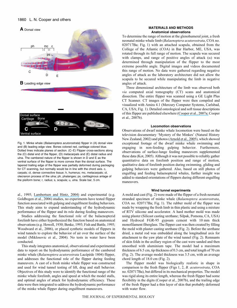
Wind tunnel experimentsA mold and cast (Fig.·2) were made of the flipper of a fresh neonatalstranded specimen of minke whale (Balaenoptera acutorostrata,COA no. 020717Ba; Fig.·1). The rubber mold of the flipper wasmade by wrapping the fresh limb in thin plastic and using a mixtureof RTV silicone and accelerator. A hard mother mold was madeusing plaster (Silicast casting urethane; Silpak, Pomona, CA, USA)and Hydrocal FGR-95 gypsum cement with 10·mm thickmonofilament fiberglass. The flipper cast was then created by fillingthe mold with plaster casting urethane (Fig.·2). Before the urethanedried, a metal rod was embedded along the longitudinal axis forattachment to the yaw plate of the wind tunnel (Fig.·2). Remnantsof skin folds in the axillary region of the cast were sanded and thensmoothed with aluminium tape. The model had a maximumthickness of 6.5·cm, tip thickness of 0.3·cm, and total length of 70·cm(Fig.·2). The average model thickness was 3.5·cm, with an averagechord length of 18.0·cm (Fig.·2).
The flipper model was biologically realistic in shape incomparison to the fresh flipper (Figs·1, 2, B. acutorostrata, COAno. 020717Ba), but differed in its mechanical properties. The modelwas rigid along its entire length, whereas the fresh flipper had someflexibility in the digits (Cooper et al., 2007b), and the trailing edgeof the fresh flipper had a thin layer of skin that probably deformedwith water flow.
L. N. Cooper and others
r
u h
s
ph mc c
A
B
C D E
Dorsal surface
Ventral surface
EDC
ctCartilage Bone
Dorsal view
Leading edge view
ps ol
r u
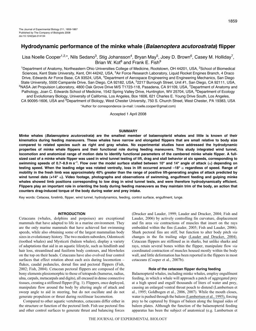
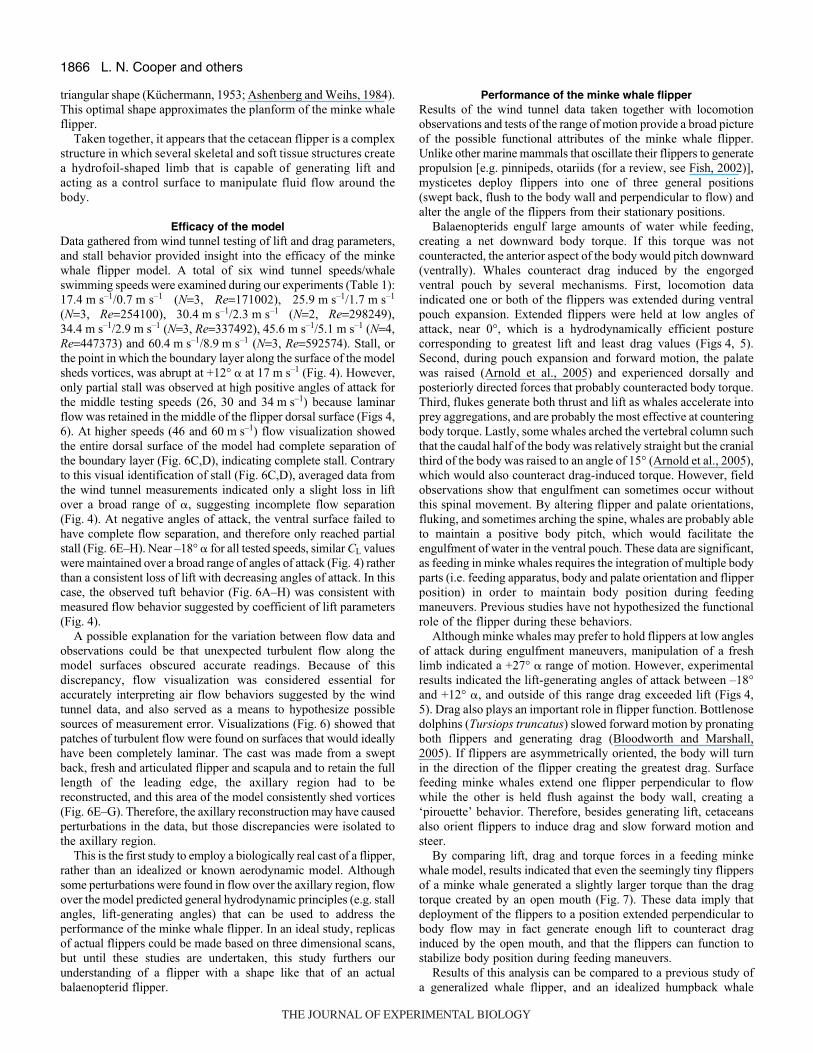
Fig.·1. Minke whale (Balaenoptera acutorostrata) flipper in (A) dorsal viewand (B) leading edge view. Bones colored red, cartilage colored blue.Dotted lines indicate planes of section. (C–E) Flipper cross-sections alongthe (C) distal end of the flipper, (D) metacarpals and (E) distal radius andulna. The cambered nature of the flipper is shown in D and E as theventral surface of the flipper is more convex than the dorsal surface. Thetapered trailing edge of the flipper was partially deformed during packagingfor CT scanning, but normally would be in line with the chord axis. c,carpals; ct, dense connective tissue; h, humerus; mc, metacarpals; ol,olecranon process of the ulna; ph, phalanges; ps, cartilaginous anlage ofthe pisiform bone; r, radius; s, scapula; u, ulna. Scale bar, 5·cm.
THE JOURNAL OF EXPERIMENTAL BIOLOGY
1861Minke whale flipper hydrodynamics
Wind tunnel tests were performed in the low speed, single return,closed jet, continuous flow wind tunnel at the San Diego StateUniversity, Department of Aerospace Engineering and EngineeringMechanics. Airflow was generated by a 150HP electric motordriving a variable pitched, four-blade propeller. The test section was1149·mm wide, 819·mm high and 1727·mm long. The model wasmounted on a computer-controlled turntable with a 0.01 degreeresolution.
To match swimming speeds and wind tunnel speeds, twoReynolds number equations were used: one equation with valuesspecific for air flow behavior, and a second with values for sea waterflow behavior. Experiments were conducted at a range of Reynolds
numbers (Table·1; Re=1.7�105–5.9�105), using the equationRe=(�lU)/�, where � refers to fluid density (�air=1.29·kg·m–3),·l isthe length of the object in the direction of flow, in this case thechord length (0.129·m), U is the swimming speed (m·s–1), and � isthe dynamic viscosity (Ns·m–2) (Reynolds, 1883; Vogel, 1994).
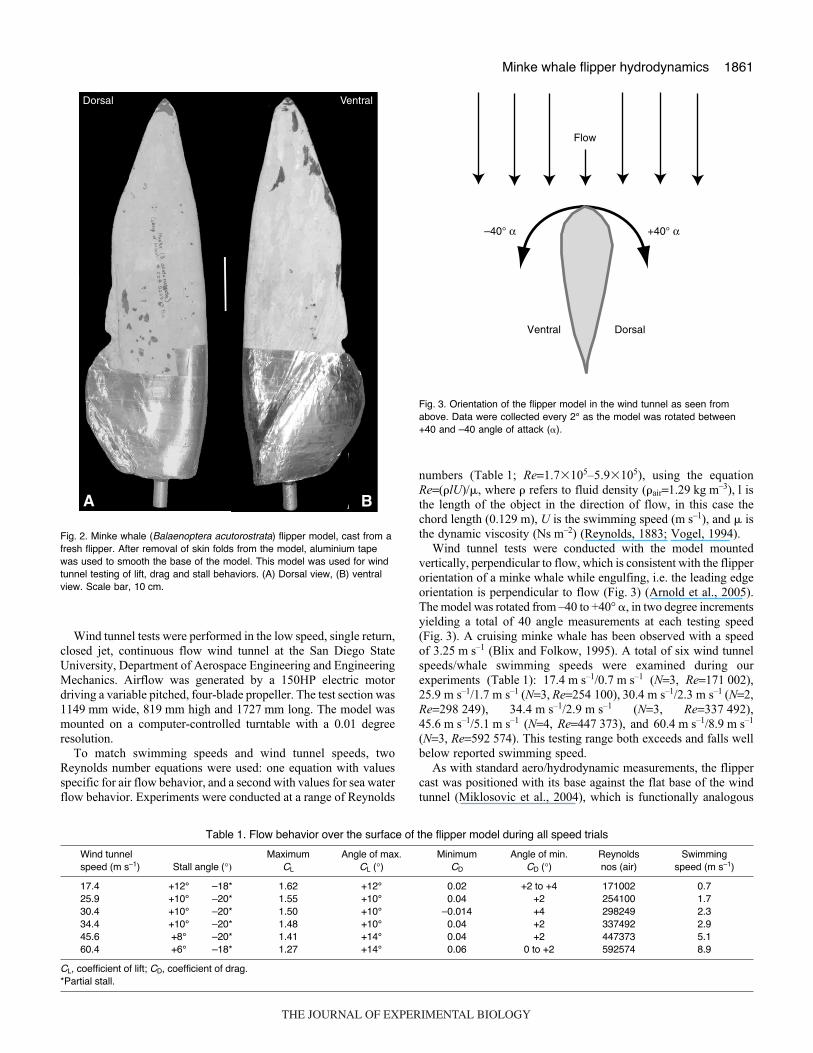
Wind tunnel tests were conducted with the model mountedvertically, perpendicular to flow, which is consistent with the flipperorientation of a minke whale while engulfing, i.e. the leading edgeorientation is perpendicular to flow (Fig.·3) (Arnold et al., 2005).The model was rotated from –40 to +40° �, in two degree incrementsyielding a total of 40 angle measurements at each testing speed(Fig.·3). A cruising minke whale has been observed with a speedof 3.25·m·s–1 (Blix and Folkow, 1995). A total of six wind tunnelspeeds/whale swimming speeds were examined during ourexperiments (Table·1): 17.4·m·s–1/0.7·m·s–1 (N=3, Re=171·002),25.9·m·s–1/1.7·m·s–1 (N=3, Re=254·100), 30.4·m·s–1/2.3·m·s–1 (N=2,Re=298·249), 34.4·m·s–1/2.9·m·s–1 (N=3, Re=337·492),45.6·m·s–1/5.1·m·s–1 (N=4, Re=447·373), and 60.4·m·s–1/8.9·m·s–1
(N=3, Re=592·574). This testing range both exceeds and falls wellbelow reported swimming speed.
As with standard aero/hydrodynamic measurements, the flippercast was positioned with its base against the flat base of the windtunnel (Miklosovic et al., 2004), which is functionally analogous
Dorsal Ventral
A B
Fig.·2. Minke whale (Balaenoptera acutorostrata) flipper model, cast from afresh flipper. After removal of skin folds from the model, aluminium tapewas used to smooth the base of the model. This model was used for windtunnel testing of lift, drag and stall behaviors. (A) Dorsal view, (B) ventralview. Scale bar, 10·cm.
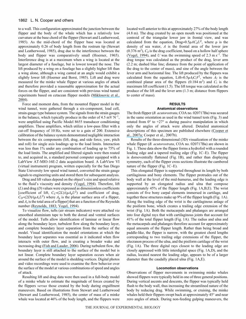
Table·1. Flow behavior over the surface of the flipper model during all speed trials
Wind tunnel Maximum Angle of max. Minimum Angle of min. Reynolds Swimming speed (m·s–1) Stall angle (°) CL CL (°) CD CD (°) nos (air) speed (m·s–1)
17.4 +12° –18* 1.62 +12° 0.02 +2 to +4 171002 0.725.9 +10° –20* 1.55 +10° 0.04 +2 254100 1.730.4 +10° –20* 1.50 +10° –0.014 +4 298249 2.334.4 +10° –20* 1.48 +10° 0.04 +2 337492 2.945.6 +8° –20* 1.41 +14° 0.04 +2 447373 5.160.4 +6° –18* 1.27 +14° 0.06 0 to +2 592574 8.9
CL, coefficient of lift; CD, coefficient of drag.*Partial stall.
Flow
DorsalVentral
–40° α +40° α
Fig.·3. Orientation of the flipper model in the wind tunnel as seen fromabove. Data were collected every 2° as the model was rotated between+40 and –40 angle of attack (�).
THE JOURNAL OF EXPERIMENTAL BIOLOGY
1862
to a wall. This configuration approximated the junction between theflipper and the body of the whale which has a relatively lowcurvature at the base chord of the flipper (Stewart and Leatherwood,1985). As the mid-chord of the flipper base was located atapproximately 0.26 of body length from the rostrum tip (Stewartand Leatherwood, 1985), drag due to the interference between thebody and flipper was comparatively small (Hoerner, 1965).Interference drag is at a maximum when a wing is located at thelargest diameter of a fuselage, but is lowest toward the nose. Thelift produced by a wing on a fuselage has a slightly higher lift thana wing alone, although a wing canted at an angle would exhibit aslightly lower lift (Hoerner and Borst, 1985). Lift and drag weremeasured for the minke whale flipper at various angles of attackand therefore provided a reasonable approximation for the actualforces on the flipper, and are consistent with previous wind tunnelexperiments based on cetacean flipper models (Miklosovic et al.,2004).
Force and moment data, from the mounted flipper model in thewind tunnel, were gathered through a six-component, load cell,strain-gauge type balance system. The signals from the strain gaugesin the balance, which typically produce in the order of 4.5·mV·N–1,were amplified using Pacific Model 8655 transducer conditioningamplifiers. These amplifiers, which utilize a low-pass filter with acut-off frequency of 10·Hz, were set to a gain of 200. Extensivecalibration of the balance system demonstrated negligible interactionbetween the six components (lift, drag, and side force, yaw, pitchand roll) for single axis loadings up to the load limits. Interactionwas less than 1% under any combination of loading up to 75% ofthe load limits. The amplified and filtered signals were then routedto, and acquired in, a standard personal computer equipped with aLabView AT-MIO-16E-2 data acquisition board. A LabView VI(virtual instrument) program, written especially for the San DiegoState University low speed wind tunnel, converted the strain gaugesignals to engineering units and stored them for subsequent analysis.
Drag and lift values depend on the object’s size and speed relativeto the fluid’s viscosity and density (Vogel, 1994). Therefore, lift(L) and drag (D) values were expressed as dimensionless coefficients[coefficient of lift, CL=(2L)/(�ApU2) and coefficient of drag,CD=(2D)/(�AsU2) where Ap is the planar surface area of a flipper,and As is the total area of a flipper] that are a function of the Reynoldsnumber (Reynolds, 1883; Vogel, 1994).
To visualize flow, tufts (air stream indicators) were attached viasmoothed aluminium tape to both the dorsal and ventral surfacesof the model. Tufts allow identification of laminar or linear flowalong the boundary layer, turbulent flow along the boundary layer,and complete boundary layer separation from the surface of themodel. Visual identification the model orientations at which theboundary layer separates was essential as it indicated when flowinteracts with outer flow, and is creating a broader wake andincreasing drag (Fish and Lauder, 2006). During turbulent flow, theboundary layer is still attached to the surface of the model but isnot linear. Complete boundary layer separation occurs when airaround the surface of the model is shedding vortices. Digital photosand video recordings were used to examine the flow behavior overthe surface of the model at various combinations of speed and anglesof attack.
Resulting lift and drag data were then used in a full-body modelof a minke whale to estimate the magnitude of forces created bythe flippers versus those created by the body during engulfmentmaneuvers. Based on illustrations from Stewart and Leatherwood(Stewart and Leatherwood, 1985), the center of mass of a minkewhale was located at 46% of the body length, and the flippers were
located well anterior to this at approximately 27% of the body length(4.8·m). The drag created by an open mouth was positioned at thecentroid of the triangular lower jaw in frontal view, and wascalculated from the equation, Drag=0.5�ACdU2, where � is thedensity of sea water, A is the frontal area of the lower jaw(0.376·m2), Cd is the drag coefficient, based on a hollow half sphere(Vogel, 1994), and U was the swimming speed of 2.3·m·s–1. Thedrag torque was calculated as the product of the drag, lever arm(2.2·m; dashed blue line; distance from the point of application ofthe drag to the center of mass), and sine of the angle between thelever arm and horizontal line. The lift produced by the flippers wascalculated from the equation, Lift=0.5�AfClV2, where Af is thecombined planar area of the flippers (0.184·m2) and Cl is themaximum lift coefficient (1.5). The lift torque was calculated as theproduce of the lift and the lever arm (1.3·m; distance from flippersto center of mass).
RESULTSAnatomical observations
The fresh flipper (B. acutorostrata, COA no. 020717Ba) was securedin the same orientation as used in the wind tunnel tests (Fig.·3) androtated from 0° to +27° � during passive manipulation in whichonly the angles of attack were altered. Detailed anatomicaldescriptions of this specimen are published elsewhere (Cooper etal., 2007a; Cooper et al., 2007b).
Results of the three-dimensional (3D) visualization of the minkewhale flipper (B. acutorostrata, COA no. 020717Ba) are shown inFig.·1. These data show the flipper forms a hydrofoil with a roundedleading edge and a tapered trailing edge (Fig.·1C–E). The flipperis dorsoventrally flattened (Fig.·1B), and rather than displayingsymmetry, each of the flipper cross sections illustrate the camberednature of the flipper (Fig.·1C–E).
This elongated flipper is supported throughout its length by bothcartilaginous and bony elements. The flipper protrudes out of thebody wall at the level of the mid-humerus, and the leading edge issupported by an elongated radius and ulna that composeapproximately 45% of the flipper length (Fig.·1A,B,E). The wristconsists of five bony carpal elements immersed in cartilage, andtogether these structures make up 9% of the flipper length (Fig.·1A).Along the trailing edge of the wrist is the cartilaginous anlage ofthe pisiform bone, which creates a trailing edge extension of thewrist (Fig.·1A). Both the metacarpals and phalanges are arrangedinto four digital rays that with cartilaginous joints that account for41% of the total flipper length (Fig.·1A). The radius and ulna andthe metacarpals and phalanges therefore account for approximatelyequal amounts of the flipper length. Rather than being broad andpaddle-like, the flipper is narrow, with the greatest chord lengthscorresponding to two trailing edge extensions of the flipper, theolecranon process of the ulna, and the pisiform cartilage of the wrist(Fig.·1A). The three digital rays closest to the leading edge areclosely appressed with little interdigital space (Fig.·1A,D), and theradius, located nearest the leading edge, appears to be of a largerdiameter than the caudally placed ulna (Fig.·1A,E).
Locomotion observationsObservations of flipper movements in swimming minke whalesshowed flippers were typically held in one of three general positions.During vertical ascents and descents, the flipper was typically heldflush to the body wall, thus increasing the streamlined nature of thebody by reducing drag. While swimming, or cruising, the minkewhales held their flippers swept back at approximately 45° and nearzero angles of attack. During non-feeding gulping maneuvers, the
L. N. Cooper and others
THE JOURNAL OF EXPERIMENTAL BIOLOGY
1863Minke whale flipper hydrodynamics
flipper was held perpendicular to the longitudinal axis of the body,with a sweep angle near zero (Arnold et al., 2005), and with anglesof attack near 0°. During gulps, the body moved forward viapropulsion from the tail, and as the mouth opened, the rostrum wasraised (Arnold et al., 2005). The flippers were then rotated forwardto approximately 0° sweep, and 0° �. While the mouth was closing,flippers were returned to the swept-back position associated withcruising and sometimes held flush against the body wall.
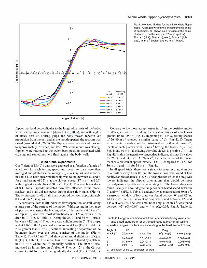
Wind tunnel experimentsCoefficient of lift (CL) data were gathered as a function of angle ofattack (�) for each testing speed and these raw data were thenaveraged and plotted as the average CL vs � (Fig.·4), and reportedin Table·1. A near linear relationship was found between CL and �for a total range of 32° � at the slowest speed (17·m·s–1) and 26°at the highest speeds (46 and 60·m·s–1; Fig.·4). This near linear slopeof 0.11 for all speeds indicated flow was attached to the modelsurface, and stall did not occur during those flow states (Fig.·4).The y-intercept (�=0) of all trials occurred between approximately0.4 and 0.6 CL (Fig.·4).
A substantial loss in lift indicates flow separation, or stall, alonga large part of the surface of the model. While testing in the rangeof positive � (raising the leading edge of the model) at 17·m·s–1,a drop in CL occurred most dramatically at +12° �, with a 31%drop in CL (Fig.·4, Table·1). During the 26, 30 and 34·m·s–1 trials,between +12° and +14° �, there was a slight drop in CL (1% drop),and at +16° �, the CL reached a maximum at 1.49 (Fig.·4, Table·1).At � greater than +16°, CL declined, indicating a separation of theboundary layer over the dorsal surface of the model (Fig.·4,Table·1). The 45.6·m·s–1 trial showed an initial slight loss of CL at8° (Fig.·4, Table·1). This initial loss in lift was followed by a plateauuntil +14° � where the lift gradually declined. The 60·m·s–1 trialindicated an initial drop in CL from 6–8° �. At 12° �, the CL wasconstant until 16° �, and then gradually declined (Fig.·4, Table·1).
Contrary to the more abrupt losses in lift in the positive anglesof attack, all loss of lift along the negative angles of attack wasgradual up to –25° � (Fig.·4). Beginning at –18° �, testing speedsof 26–60·m·s–1 showed a similar value of CL (Fig.·4). Differentexperimental speeds could be distinguished by their differing CL
levels at each plateau with 17·m·s–1 having the lowest CL (–1.6;Fig.·4) and 60·m·s–1 displaying the value closest to positive CL (–1.2;Fig.·4). Within the negative � range, data indicated distinct CL valuesfor 26, 30 and 34·m·s–1. At 26·m·s–1, the negative tail of the curvereached a plateau at approximately –1.6 CL, compared to –1.56 for30·m·s–1, and –1.4 for 34·m·s–1 (Fig.·4).
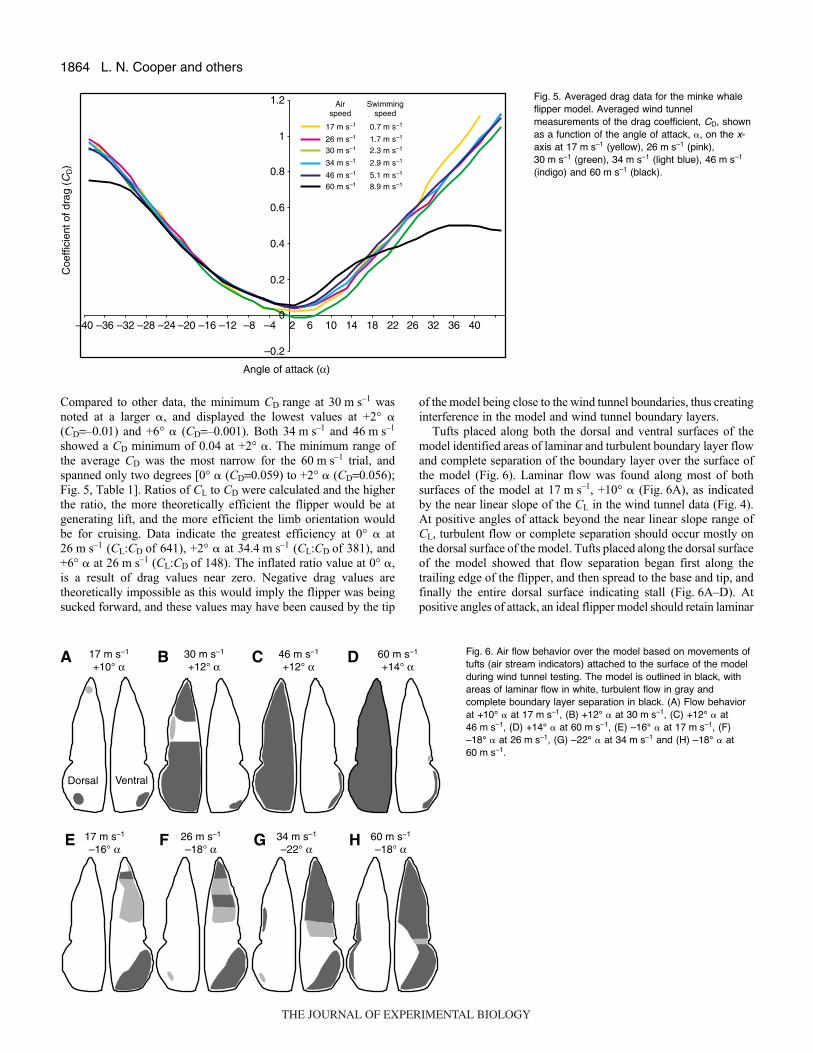
In all speed trials, there was a steady increase in drag at anglesof � further away from 0°, and the lowest drag was found at lowpositive angles of attack (Fig.·5). The angles for which the drag waslowest indicates the flipper orientations that would be mosthydrodynamically efficient at generating lift. The lowest drag wasfound usually in a four degree range for each tested speed, between0° and +4° � (Fig.·5, Tables·1 and·2). However at speeds of 60·m·s–1,a narrower window of low drag was found between 0° and +2° �.At 17·m·s–1 the least amount of drag was found between +2° and+4° � (CD=0.02). The least amount of drag, at 26·m·s–1, was foundbetween +2° (CD=0.04) and +4° � (CD=0.05; Fig.·5, Table·1).
–2
–1.5
–1
–0.5
0
0.5
1
1.5
2
Angle of attack (α)
Coe
ffici
ent o
f lift
(C
L)
17 m s–1
30 m s–1
34 m s–1
46 m s–1
60 m s–1
26 m s–1
Airspeed
Swimmingspeed
0.7 m s–1
2.3 m s–1
2.9 m s–1
5.1 m s–1
8.9 m s–1
1.7 m s–1
0 4 8 12 16 20 24 28 32 36 40–40 –36 –28–32 –24 –20 –16 –12 –8 –4
Fig.·4. Averaged lift data for the minke whale flippermodel. Averaged wind tunnel measurements of thelift coefficient, CL, shown as a function of the angleof attack, �, on the x-axis at 17·m·s–1 (yellow),26·m·s–1 (pink), 30·m·s–1 (green), 34·m·s–1 (lightblue), 46·m·s–1 (indigo) and 60·m·s–1 (black).
Table·2. Range of coefficient of lift and coefficient of drag values andassociated standard error of the estimates (s.e.e.) for all testing
speeds at angles of attack corresponding to the least amount of drag
Angle of Lift Drag attack (�) (CL range) s.e.e. (lift) (CD range) s.e.e. (drag)
0 0.45–0.66 0.01–0.22 –0.01–0.06 0.003–0.072 0.73–0.94 0.04–0.14 –0.01–0.08 0.003–0.084 0.94–1.10 0.02–0.15 –0.0008–0.12 0.003–0.09
CL, coefficient of lift; CD, coefficient of drag.
THE JOURNAL OF EXPERIMENTAL BIOLOGY
1864
Compared to other data, the minimum CD range at 30·m·s–1 wasnoted at a larger �, and displayed the lowest values at +2° �(CD=–0.01) and +6° � (CD=–0.001). Both 34·m·s–1 and 46·m·s–1
showed a CD minimum of 0.04 at +2° �. The minimum range ofthe average CD was the most narrow for the 60·m·s–1 trial, andspanned only two degrees [0° � (CD=0.059) to +2° � (CD=0.056);Fig.·5, Table·1]. Ratios of CL to CD were calculated and the higherthe ratio, the more theoretically efficient the flipper would be atgenerating lift, and the more efficient the limb orientation wouldbe for cruising. Data indicate the greatest efficiency at 0° � at26·m·s–1 (CL:CD of 641), +2° � at 34.4·m·s–1 (CL:CD of 381), and+6° � at 26·m·s–1 (CL:CD of 148). The inflated ratio value at 0° �,is a result of drag values near zero. Negative drag values aretheoretically impossible as this would imply the flipper was beingsucked forward, and these values may have been caused by the tip
of the model being close to the wind tunnel boundaries, thus creatinginterference in the model and wind tunnel boundary layers.
Tufts placed along both the dorsal and ventral surfaces of themodel identified areas of laminar and turbulent boundary layer flowand complete separation of the boundary layer over the surface ofthe model (Fig.·6). Laminar flow was found along most of bothsurfaces of the model at 17·m·s–1, +10° � (Fig.·6A), as indicatedby the near linear slope of the CL in the wind tunnel data (Fig.·4).At positive angles of attack beyond the near linear slope range ofCL, turbulent flow or complete separation should occur mostly onthe dorsal surface of the model. Tufts placed along the dorsal surfaceof the model showed that flow separation began first along thetrailing edge of the flipper, and then spread to the base and tip, andfinally the entire dorsal surface indicating stall (Fig.·6A–D). Atpositive angles of attack, an ideal flipper model should retain laminar
L. N. Cooper and others
–0.2
0
0.2
0.4
0.6
0.8
1
1.2
–40 –36 –32 –28 –24 –20 –16 –12 –8 –4 2 6 10 14 18 22 26 32 36 40
Angle of attack (α)
Coe
ffici
ent o
f dra
g (C
D)
17 m s–1
30 m s–1
34 m s–1
46 m s–1
60 m s–1
26 m s–1
Airspeed
Swimmingspeed
0.7 m s–1
2.3 m s–1
2.9 m s–1
5.1 m s–1
8.9 m s–1
1.7 m s–1
Fig.·5. Averaged drag data for the minke whaleflipper model. Averaged wind tunnelmeasurements of the drag coefficient, CD, shownas a function of the angle of attack, �, on the x-axis at 17·m·s–1 (yellow), 26·m·s–1 (pink),30·m·s–1 (green), 34·m·s–1 (light blue), 46·m·s–1
(indigo) and 60·m·s–1 (black).
30 m s–1
+12° α
Dorsal Ventral
17 m s–1
+10° α
17 m s–1
–16° α
46 m s–1
+12° α60 m s–1
+14° α
34 m s–1
–22° α26 m s–1
–18° α60 m s–1
–18° α
BA C D
FE G H
Fig.·6. Air flow behavior over the model based on movements oftufts (air stream indicators) attached to the surface of the modelduring wind tunnel testing. The model is outlined in black, withareas of laminar flow in white, turbulent flow in gray andcomplete boundary layer separation in black. (A) Flow behaviorat +10° � at 17·m·s–1, (B) +12° � at 30·m·s–1, (C) +12° � at46·m·s–1, (D) +14° � at 60·m·s–1, (E) –16° � at 17·m·s–1, (F)–18° � at 26·m·s–1, (G) –22° � at 34·m·s–1 and (H) –18° � at60·m·s–1.
THE JOURNAL OF EXPERIMENTAL BIOLOGY
1865Minke whale flipper hydrodynamics
flow over the entire ventral surface of the model. However in theaxillary region, near the ventral surface base, a small pocket of flowseparation was found along the trailing edge of the model at lowspeeds (17·m·s–1 and 30·m·s–1; Fig.·6A,B). At higher speeds, flowseparation occurred along the trailing edge of most the model(46·m·s–1 and 60·m·s–1; Fig.·6C,D).
In an ideal model, turbulent and separated flow would berestricted to the ventral surface of the model at negative angles ofattack. However, in the axillary region, at the base of the dorsalsurface, a small pocket of turbulent flow was found along the trailingedge of the model beginning at 26·m·s–1 (Fig.·6E) and this pocketenlarged and flow became more unstable until complete separationwas found along the trailing edge of most of the base at higher speeds(60·m·s–1; Fig.·6H). Along the ventral surface of the model, flowwas separated along the tip and base (axillary region), turbulent nearthe middle of the model, and laminar along a wide swath in themiddle near the leading edge, at 17·m·s–1 and 26·m·s–1 (Fig.·6E,F).At higher speeds (34 and 60·m·s–1), flow never completely separatedover the ventral surface as the leading edge portion near the middleof the model maintained laminar flow (Fig.·6G,H). In total, tuftsindicated that at negative angles of attack flow along the ventralsurface did not completely separate and therefore complete stall wasnot observed.
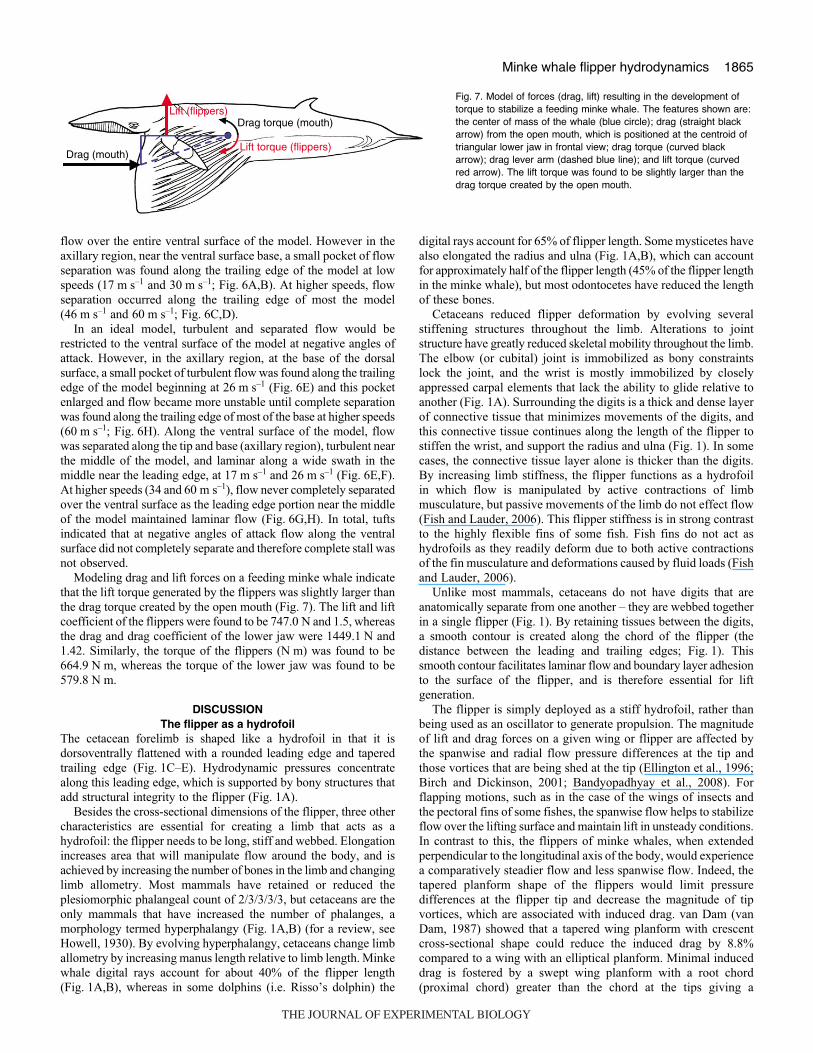
Modeling drag and lift forces on a feeding minke whale indicatethat the lift torque generated by the flippers was slightly larger thanthe drag torque created by the open mouth (Fig.·7). The lift and liftcoefficient of the flippers were found to be 747.0·N and 1.5, whereasthe drag and drag coefficient of the lower jaw were 1449.1·N and1.42. Similarly, the torque of the flippers (N·m) was found to be664.9·N·m, whereas the torque of the lower jaw was found to be579.8·N·m.
DISCUSSIONThe flipper as a hydrofoil
The cetacean forelimb is shaped like a hydrofoil in that it isdorsoventrally flattened with a rounded leading edge and taperedtrailing edge (Fig.·1C–E). Hydrodynamic pressures concentratealong this leading edge, which is supported by bony structures thatadd structural integrity to the flipper (Fig.·1A).
Besides the cross-sectional dimensions of the flipper, three othercharacteristics are essential for creating a limb that acts as ahydrofoil: the flipper needs to be long, stiff and webbed. Elongationincreases area that will manipulate flow around the body, and isachieved by increasing the number of bones in the limb and changinglimb allometry. Most mammals have retained or reduced theplesiomorphic phalangeal count of 2/3/3/3/3, but cetaceans are theonly mammals that have increased the number of phalanges, amorphology termed hyperphalangy (Fig.·1A,B) (for a review, seeHowell, 1930). By evolving hyperphalangy, cetaceans change limballometry by increasing manus length relative to limb length. Minkewhale digital rays account for about 40% of the flipper length(Fig.·1A,B), whereas in some dolphins (i.e. Risso’s dolphin) the
digital rays account for 65% of flipper length. Some mysticetes havealso elongated the radius and ulna (Fig.·1A,B), which can accountfor approximately half of the flipper length (45% of the flipper lengthin the minke whale), but most odontocetes have reduced the lengthof these bones.
Cetaceans reduced flipper deformation by evolving severalstiffening structures throughout the limb. Alterations to jointstructure have greatly reduced skeletal mobility throughout the limb.The elbow (or cubital) joint is immobilized as bony constraintslock the joint, and the wrist is mostly immobilized by closelyappressed carpal elements that lack the ability to glide relative toanother (Fig.·1A). Surrounding the digits is a thick and dense layerof connective tissue that minimizes movements of the digits, andthis connective tissue continues along the length of the flipper tostiffen the wrist, and support the radius and ulna (Fig.·1). In somecases, the connective tissue layer alone is thicker than the digits.By increasing limb stiffness, the flipper functions as a hydrofoilin which flow is manipulated by active contractions of limbmusculature, but passive movements of the limb do not effect flow(Fish and Lauder, 2006). This flipper stiffness is in strong contrastto the highly flexible fins of some fish. Fish fins do not act ashydrofoils as they readily deform due to both active contractionsof the fin musculature and deformations caused by fluid loads (Fishand Lauder, 2006).
Unlike most mammals, cetaceans do not have digits that areanatomically separate from one another – they are webbed togetherin a single flipper (Fig.·1). By retaining tissues between the digits,a smooth contour is created along the chord of the flipper (thedistance between the leading and trailing edges; Fig.·1). Thissmooth contour facilitates laminar flow and boundary layer adhesionto the surface of the flipper, and is therefore essential for liftgeneration.
The flipper is simply deployed as a stiff hydrofoil, rather thanbeing used as an oscillator to generate propulsion. The magnitudeof lift and drag forces on a given wing or flipper are affected bythe spanwise and radial flow pressure differences at the tip andthose vortices that are being shed at the tip (Ellington et al., 1996;Birch and Dickinson, 2001; Bandyopadhyay et al., 2008). Forflapping motions, such as in the case of the wings of insects andthe pectoral fins of some fishes, the spanwise flow helps to stabilizeflow over the lifting surface and maintain lift in unsteady conditions.In contrast to this, the flippers of minke whales, when extendedperpendicular to the longitudinal axis of the body, would experiencea comparatively steadier flow and less spanwise flow. Indeed, thetapered planform shape of the flippers would limit pressuredifferences at the flipper tip and decrease the magnitude of tipvortices, which are associated with induced drag. van Dam (vanDam, 1987) showed that a tapered wing planform with crescentcross-sectional shape could reduce the induced drag by 8.8%compared to a wing with an elliptical planform. Minimal induceddrag is fostered by a swept wing planform with a root chord(proximal chord) greater than the chord at the tips giving a
Drag (mouth)
Lift (flippers)
Lift torque (flippers)
Drag torque (mouth)
Fig.·7. Model of forces (drag, lift) resulting in the development oftorque to stabilize a feeding minke whale. The features shown are:the center of mass of the whale (blue circle); drag (straight blackarrow) from the open mouth, which is positioned at the centroid oftriangular lower jaw in frontal view; drag torque (curved blackarrow); drag lever arm (dashed blue line); and lift torque (curvedred arrow). The lift torque was found to be slightly larger than thedrag torque created by the open mouth.
THE JOURNAL OF EXPERIMENTAL BIOLOGY
1866
triangular shape (Küchermann, 1953; Ashenberg and Weihs, 1984).This optimal shape approximates the planform of the minke whaleflipper.
Taken together, it appears that the cetacean flipper is a complexstructure in which several skeletal and soft tissue structures createa hydrofoil-shaped limb that is capable of generating lift andacting as a control surface to manipulate fluid flow around thebody.
Efficacy of the modelData gathered from wind tunnel testing of lift and drag parameters,and stall behavior provided insight into the efficacy of the minkewhale flipper model. A total of six wind tunnel speeds/whaleswimming speeds were examined during our experiments (Table·1):17.4·m·s–1/0.7·m·s–1 (N=3, Re=171002), 25.9·m·s–1/1.7·m·s–1
(N=3, Re=254100), 30.4·m·s–1/2.3·m·s–1 (N=2, Re=298249),34.4·m·s–1/2.9·m·s–1 (N=3, Re=337492), 45.6·m·s–1/5.1·m·s–1 (N=4,Re=447373) and 60.4·m·s–1/8.9·m·s–1 (N=3, Re=592574). Stall, orthe point in which the boundary layer along the surface of the modelsheds vortices, was abrupt at +12° � at 17·m·s–1 (Fig.·4). However,only partial stall was observed at high positive angles of attack forthe middle testing speeds (26, 30 and 34·m·s–1) because laminarflow was retained in the middle of the flipper dorsal surface (Figs·4,6). At higher speeds (46 and 60·m·s–1) flow visualization showedthe entire dorsal surface of the model had complete separation ofthe boundary layer (Fig.·6C,D), indicating complete stall. Contraryto this visual identification of stall (Fig.·6C,D), averaged data fromthe wind tunnel measurements indicated only a slight loss in liftover a broad range of �, suggesting incomplete flow separation(Fig.·4). At negative angles of attack, the ventral surface failed tohave complete flow separation, and therefore only reached partialstall (Fig.·6E–H). Near –18° � for all tested speeds, similar CL valueswere maintained over a broad range of angles of attack (Fig.·4) ratherthan a consistent loss of lift with decreasing angles of attack. In thiscase, the observed tuft behavior (Fig.·6A–H) was consistent withmeasured flow behavior suggested by coefficient of lift parameters(Fig.·4).
A possible explanation for the variation between flow data andobservations could be that unexpected turbulent flow along themodel surfaces obscured accurate readings. Because of thisdiscrepancy, flow visualization was considered essential foraccurately interpreting air flow behaviors suggested by the windtunnel data, and also served as a means to hypothesize possiblesources of measurement error. Visualizations (Fig.·6) showed thatpatches of turbulent flow were found on surfaces that would ideallyhave been completely laminar. The cast was made from a sweptback, fresh and articulated flipper and scapula and to retain the fulllength of the leading edge, the axillary region had to bereconstructed, and this area of the model consistently shed vortices(Fig.·6E–G). Therefore, the axillary reconstruction may have causedperturbations in the data, but those discrepancies were isolated tothe axillary region.
This is the first study to employ a biologically real cast of a flipper,rather than an idealized or known aerodynamic model. Althoughsome perturbations were found in flow over the axillary region, flowover the model predicted general hydrodynamic principles (e.g. stallangles, lift-generating angles) that can be used to address theperformance of the minke whale flipper. In an ideal study, replicasof actual flippers could be made based on three dimensional scans,but until these studies are undertaken, this study furthers ourunderstanding of a flipper with a shape like that of an actualbalaenopterid flipper.
Performance of the minke whale flipperResults of the wind tunnel data taken together with locomotionobservations and tests of the range of motion provide a broad pictureof the possible functional attributes of the minke whale flipper.Unlike other marine mammals that oscillate their flippers to generatepropulsion [e.g. pinnipeds, otariids (for a review, see Fish, 2002)],mysticetes deploy flippers into one of three general positions(swept back, flush to the body wall and perpendicular to flow) andalter the angle of the flippers from their stationary positions.
Balaenopterids engulf large amounts of water while feeding,creating a net downward body torque. If this torque was notcounteracted, the anterior aspect of the body would pitch downward(ventrally). Whales counteract drag induced by the engorgedventral pouch by several mechanisms. First, locomotion dataindicated one or both of the flippers was extended during ventralpouch expansion. Extended flippers were held at low angles ofattack, near 0°, which is a hydrodynamically efficient posturecorresponding to greatest lift and least drag values (Figs·4, 5).Second, during pouch expansion and forward motion, the palatewas raised (Arnold et al., 2005) and experienced dorsally andposteriorly directed forces that probably counteracted body torque.Third, flukes generate both thrust and lift as whales accelerate intoprey aggregations, and are probably the most effective at counteringbody torque. Lastly, some whales arched the vertebral column suchthat the caudal half of the body was relatively straight but the cranialthird of the body was raised to an angle of 15° (Arnold et al., 2005),which would also counteract drag-induced torque. However, fieldobservations show that engulfment can sometimes occur withoutthis spinal movement. By altering flipper and palate orientations,fluking, and sometimes arching the spine, whales are probably ableto maintain a positive body pitch, which would facilitate theengulfment of water in the ventral pouch. These data are significant,as feeding in minke whales requires the integration of multiple bodyparts (i.e. feeding apparatus, body and palate orientation and flipperposition) in order to maintain body position during feedingmaneuvers. Previous studies have not hypothesized the functionalrole of the flipper during these behaviors.
Although minke whales may prefer to hold flippers at low anglesof attack during engulfment maneuvers, manipulation of a freshlimb indicated a +27° � range of motion. However, experimentalresults indicated the lift-generating angles of attack between –18°and +12° �, and outside of this range drag exceeded lift (Figs·4,5). Drag also plays an important role in flipper function. Bottlenosedolphins (Tursiops truncatus) slowed forward motion by pronatingboth flippers and generating drag (Bloodworth and Marshall,2005). If flippers are asymmetrically oriented, the body will turnin the direction of the flipper creating the greatest drag. Surfacefeeding minke whales extend one flipper perpendicular to flowwhile the other is held flush against the body wall, creating a‘pirouette’ behavior. Therefore, besides generating lift, cetaceansalso orient flippers to induce drag and slow forward motion andsteer.
By comparing lift, drag and torque forces in a feeding minkewhale model, results indicated that even the seemingly tiny flippersof a minke whale generated a slightly larger torque than the dragtorque created by an open mouth (Fig.·7). These data imply thatdeployment of the flippers to a position extended perpendicular tobody flow may in fact generate enough lift to counteract draginduced by the open mouth, and that the flippers can function tostabilize body position during feeding maneuvers.
Results of this analysis can be compared to a previous study ofa generalized whale flipper, and an idealized humpback whale
L. N. Cooper and others
THE JOURNAL OF EXPERIMENTAL BIOLOGY
1867Minke whale flipper hydrodynamics
(Megaptera novaeangliae) flipper. A NACA 0200 airfoil withknown aerodynamic parameters, with a shape superficially similarto the minke whale flipper model tested here, stalled near +12° �for testing speeds from 17–34·m·s–1 (Miklosovic et al., 2004), whichwas consistent with the results of this study. A NACA 0200 witha scalloped leading edge simulated leading edge tubercles inhumpback whales (Fish and Battle, 1995; Miklosovic et al., 2004).The scalloped flipper exhibited a 40% increase in the angle of stallcompared to both the NACA 0200 and the minke whale model.Humpback whale flippers appear to be more hydrodynamicallyefficient at generating and maintaining lift.
Minke whales are the smallest balaenopterid mysticetes withbody proportions similar to all nine species of non-humpbackbalaenopterids (Horwood, 1990). Minke whale flippers are similarin shape and dimensions to all non-humpback balaenopterids, andcan be considered representative of the standard balaenopteridflipper. Flippers of other balaenopterid taxa may display similarhydrodynamic properties and stall behaviors.
CONCLUSIONFew studies have documented the orientation of the balaenopteridforelimb during feeding and associated maneuvers. This studyintegrated experimentally generated hydrodynamic data withobservational data to address flipper function in the minke whale.Data indicate the flipper has a range of motion greater than thepredicted lift-generating angles of attack. Observations oflocomotion behavior indicated the flipper was typically held atangles of attack near 0°, and perpendicular to flow during gulpingand feeding maneuvers. Data from this study suggests this flipperorientation is hydrodynamically efficient as it incurs the least amountof drag, but generates a high degree of lift, and this flipper-generatedlift force contributes to the increase in pitch of the engulfing whales.Furthermore, our data suggest that the flippers generate sufficientlift torque to counteract the drag torque generated by the open mouthduring feeding maneuvers. Taken together, data indicate that thesmall, narrow flippers of minke whales are control surfaces thatplay an important role in maintaining a positively-pitched bodyorientation during various types of feeding maneuvers.
We thank two anonymous reviewers for comments that greatly improved thismanuscript. Funding for this project came from an ONR grant number N00014-02-1-0046 to Dr Frank E. Fish. We are greatly appreciative of Dr Joseph Katz for useof the wind tunnel, Dr J. Allen at the College of the Atlantic in Bar Harbor, ME forthe fresh minke whale specimen, the late Mr Fritz Clark for assistance in buildingthe flipper model, and Dr Ted Cranford for assistance in obtaining CT scans. Wethank Ms Caroline Fyler for assistance with the fresh specimen. We thank DrHans Thewissen, Dr Chris Vinyard, Mr Ronald B. Cooper, Mr Tobin L.Hieronymus, Ms Megan F. McKenna and Ms Angela Horner for helpful commentson this manuscript. We thank Mr Zach Mellor and Mrs Liliana Fajardo-Mellor fordiscussions, Mr Cory M. Redman and Mr Kesler A. Randall for logisticalassistance, and Mr Victor Sanchez for data collection assistance.
REFERENCESArnold, P. W., Birtles, R. A., Sobtzick, S., Matthews, M. and Dunstan, A. (2005).
Gulping behavior in rorqual whales: underwater observations and functionalinterpretation. Mem. Queensl. Mus. 51, 309-332.
Ashenberg, J. and Weihs, D. (1984). Minimum induced drag of wings with curvedplanform. J. Aircr. 21, 89-91.
Bandyopadhyay, P. R., Beal, D. N. and Menozzi, A. (2008). Biorobotic insights intohow animals swim. J. Exp. Biol. 211, 206-214.
Benke, H. (1993). Investigations on the osteology and the functional morphology of theflipper of whales and dolphins (Cetacea). Invest. Cetacea 24, 9-252.
Birch, J. M. and Dickenson, M. H. (2001). Spanwise flow and the attachment of theleading-edge vortex on insect wings. Nature 412, 729-733.
Blix, A. S. and Folkow, L. (1995). Daily energy requirements in free living minkewhales. Acta Physiol. Scand. 153, 61-66.
Bloodworth, B. and Marshall, C. D. (2005). Feeding kinematics of Kogia andTursiops (Odontoceti:Cetacea): characterization of suction and ram feeding. J. Exp.Biol. 208, 3721-3730.
Cooper, L. N., Berta, A., Dawson, S. D. and Reidenberg, J. S. (2007a). Evolution ofhyperphalangy and digit reduction in the cetacean manus. Anat. Rec. Hoboken 209,654-672.
Cooper, L. N., Dawson, S. D., Reidenberg, J. S. and Berta, A. (2007b).Neuromuscular anatomy and evolution of the cetacean forelimb. Anat. Rec. Hoboken209, 1121-1137.
Drucker, E. G. and Lauder, G. V. (1999). Locomotor forces on a swimming fish: threedimensional vortex wake dynamics quantified using digital particle imagevelocimetry. J. Exp. Biol. 202, 2393-2412.
Ellington, C. P., van den Berg, C., Willmott, A. P. and Thomas, A. L. R. (1996).Leading-edge vortices in insect flight. Nature 384, 626-630.
Fish, F. E. (2002). Balancing requirements for stability and maneuverability incetaceans. Integr. Comp. Biol. 42, 85-93.
Fish, F. E. (2004). Structure and mechanics of nonpiscine control surfaces. IEEE J.Ocean. Eng. 29, 605-621.
Fish, F. E. and Battle, J. M. (1995). Hydrodynamic design of the humpback whaleflipper. J. Morphol. 225, 51-60.
Fish, F. E. and Lauder, G. V. (2006). Passive and active flow control by swimmingfishes and mammals. Annu. Rev. Fluid Mech. 38, 193-224.
Goldbogen, J. A., Calambokidis, J., Shadwick, R. E., Oleson, E. M., McDonald, M.A. and Hildebrand, J. A. (2006). Kinematics of diving and lunge-feeding in finwhales. J. Exp. Biol. 209, 1231-1244.
Goldbogen, J. A., Pyenson, N. D. and Shadwick, R. E. (2007). Big gulps requirehigh drag for fin whale lunge feeding. Mar. Ecol. Prog. Ser. 349, 289-301.
Hoerner, S. F. (1965). Fluid-Dynamic Drag. Brick Town, NJ: Hoerner FluidDynamics.
Hoerner, S. F. and Borst, H. V. (1985). Fluid-Dynamic Lift. Bricktown, NJ: HoernerFluid Dynamics.
Horwood, J. W. (1990). Biology and Exploitation of the Minke Whale. Boca Raton:CRC Press.
Howell, A. (1930). Aquatic Mammals. Springfield: Charles C. Thomas.Kot, B. W. (2005). Rorqual whale surface-feeding strategies: biomechanical aspects of
feeding anatomy and exploitation of prey aggregations along tidal fronts. MA Thesis,University of California at Los Angeles, USA.
Küchermann, D. (1953). The distribution of lift over the surface of swept wings.Aeronaut. Q. 4, 261-278.
Lambertsen, R. H. and Hintz, R. J. (2004). Maxillomandibular cam articulationdiscovered in North Atlantic Minke whale. J. Mamm. 85, 446-452.
Lambertsen, R. H., Ulrich, N. and Straley, J. (1995). Frontomandibular stay ofBalaenopteridae: a mechanism for moment recapture during feeding. J. Mamm. 76,877-899.
Lauder, G. V. (2005). Locomotion. In The Physiology of Fishes (3rd edn) (ed. D. H.Evans and J. B. Clairborne), pp. 3-46. Boca Raton: CRC Press.
Lauder, G. V. and Drucker, E. G. (2004). Morphology and experimentalhydrodynamics of fish fin control surfaces. IEEE J. Ocean. Eng. 29, 556-571.
Miklosovic, D. S., Murray, M. M., Howle, L. E. and Fish, F. E. (2004). Leading-edgetubercles delay stall on humpback whale (Megaptera novaeangliae) flippers. Phys.Fluids 16, L39-L42.
Natural History New Zealand (2002). “Mystery of the Minkes” television documentary.National Geographic Society, 55·min.
Reynolds, O. (1883). An experimental investigation of the circumstances whichdetermine whether the motion of water shall be direct or sinuous, and the law ofresistance in parallel channels. Philos. Trans. R. Soc. Lond. 174, 935-982.
Stewart, B. S. and Leatherwood, S. (1985). Minke whale Balaenoptera acutorostrataLacepede, 1804. In Handbook of Marine Mammals. Vol. 3 (ed. S. H. Ridgway andR. Harrison), pp. 91-136. London: Academic Press.
van Dam, C. P. (1987). Efficiency characteristics of crescent-shaped wings and caudalfins. Nature 325, 435-437.
Vogel, S. (1994). Life in Moving Fluids: The Physical Biology of Flow (2nd edn).Princeton: Princeton University Press.
Woodward, B. L., Winn, J. P. and Fish, F. E. (2006). Morphological specializations ofbaleen whales associated with hydrodynamic performance and ecological niche. J.Morphol. 267, 1284-1294.
THE JOURNAL OF EXPERIMENTAL BIOLOGY