AD 654450 - DTIC
70
AD 654450 i APL/JHU CF- 2813 March 1959 Copy No. G‘î AN APPROXIMATE ANALYSIS OF THE TWO-DIMENSIONAL, SUPERSONIC FLOW PAST A PLANE WALL WITH SUPER-CRITICAL HEAT ADDITION IN A NORMAL PLANE by t Kerry W. Woolard The CF series of papers is intended to be a flexible means for the reporting of preliminary investigations, or subject matter of limited interest. The information presented herein may be tentative, and subject to modi¬ fication. This paper may not be reproduced except with the express permission of the issuing agency. Initial distribution of this document is confined to per¬ sons and organizations within Section T immediately concerned with the subject matter. Upon special re¬ quest, copies of this report may be made available to other organizations having a stated need for the infor¬ mation oresented. j i THE JOHNS HOPKINS UNIVERSITY APPLIED PHYSICS LABORATORY Silver Spring, Maryland vurfw Confrocf HOré 73U wM Hm Unw W Ordbrnc*, D^ortmttH at Ik* Navy ' /T5tLC' f I U THIS DOCUMENT HAS BEEN APPROVED FOR PUBLIC RELEASE AND SALE: ITS
-
Upload
khangminh22 -
Category
Documents
-
view
1 -
download
0
Transcript of AD 654450 - DTIC
AD 6
54450
♦
i
APL/JHU CF- 2813
March 1959
Copy No. G‘î
AN APPROXIMATE ANALYSIS OF THE TWO-DIMENSIONAL,
SUPERSONIC FLOW PAST A PLANE WALL WITH SUPER-CRITICAL
HEAT ADDITION IN A NORMAL PLANE
by
t
Kerry W. Woolard
The CF series of papers is intended to be a flexible means for the reporting of preliminary investigations, or subject matter of limited interest. The information presented herein may be tentative, and subject to modi¬ fication. This paper may not be reproduced except with the express permission of the issuing agency.
Initial distribution of this document is confined to per¬ sons and organizations within Section T immediately concerned with the subject matter. Upon special re¬ quest, copies of this report may be made available to other organizations having a stated need for the infor¬ mation oresented.
j
i THE JOHNS HOPKINS UNIVERSITY
APPLIED PHYSICS LABORATORY
Silver Spring, Maryland
vurfw Confrocf HOré 73U wM Hm Unw W Ordbrnc*, D^ortmttH at Ik* Navy
' /T5tLC'
f I U
THIS DOCUMENT HAS BEEN APPROVED
FOR PUBLIC RELEASE AND SALE: ITS
*"1110 "»Sics UltItTNI 'HI I0HNS HOPKINS UNIVIISITT
SIIVCI SPIINC DUTUM
AN APPROXIMATE ANALYSIS OF THE TWO-DIMENSIONAL,
SUPERSONIC FLOW PAST A PLANE WALL WITH SUPER-CRITICAL
HEAT ADDITION IN A NORMAL PLANE
by
Henry W. Woolard
March 1959

í
WIHO rmics UMHTMT INI lONNS «OHUS umviisin Slim SHIM HMTUII
)
SUMMARY
An analysis is performed to determine approximately
the flow field and the normal forces acting for the two-
dimensional, supersonic, zero angle-of-attack flow about a
flat plate with super-critical heat addition (i.e., with
thermal choking downstream) at a normal finite-height
heater plane on one side of the flat plate. The results
of the analysis have possible application to the design of
an external thrust and/or lift producing device for air¬
borne supersonic vehicles.
Charts for the determination of the pertinent flow-
field parameters and the normal force coefficients as a
function of the rate of heat addition and free-stream Mach
number, are presented for Mach numbers ranging from 2.0
to 7.0.
- ii -
\
âPPU» PHYSICS ItIMaTMT
INI lONHS NOPRINS UHlYdSIM
SU*» SPHIHC Rtintll
PRINCIPAL SYMBOLS
a
ã
A
A,
b
B
C
S ho
h2’ 1
»:
i -1
d - hoÎA
%
M
M
P
P
speed of sound
mean speed of sound on the sonic line^Æ (See Fig. 1) 1 * cross-sectional area of a stream tube
cross-sectional area of a stream tube at M 1.0
parameter defined by Eq. (2)
- (P0/P) (A/A,)0
specific heat at constant pressure
- /3 (yâtan ^ -^|/32 tan2 - l.'j 'i * ' ;
pressure coefficient, (p-po)/qo
free-stream capture height (See Fig. 1)
height of the heater (See Fig. 1)
non-dimensional capture height, l^/hg
spillage
spillage corresponding to the case where the mass flow across the sonic line is equal to the mass flow through the heater
shock standoff distance (See Fig. 1)
L/h2
moment
local Mach number
free stream Mach number
mean Mach number just upstream of the second shock wave
static pressure
mean static pressure on the sonic line AiA) (See Fig. 1) _
static pressure corresponding to M and P
iii

VftKI fMSICJ UIMàTMI TM lim Mflllt MIVTIUM Wild tniM Htinui
'10
'll
P 11
r~> P oo
p
p
‘H
R
T
Uc
Y
Y 10
11
11. m
11
11 oO
Y.
Y1
X, y
t
local wall-static pressure along x x0 (See Fig. 1) '’02'
local wall-static pressure downstream of x0 (See Fig. 1) 3
local wall-static pressure downstream of X3 for a simply reflected Prandtl-Meyer expansion (See text)
Pj^ at x - 00
total pressure
total pressure downstream of the first shock wave wave and along the mean streamline having the free-stream ordinate y
total pressure downstream of the first shock wave wave and along the mean streamline having the free-stream ordinate y
free-stream dynamic pressure, p U^/2
heat flow per unit time per unit area
gas constant
static temperature
free-stream velocity
normal force per unit width, parallel to the y- axis, positive in the positive y-direction
forward normal force per unit width acting on the surface \qx2 in Fig. 1
aft normal force per unit width acting on the sur¬ face XgX in Fig, 1
aft normal force per unit width acting on the sur¬ face x3xm in Fig. 1
aft normal force per unit width acting on the face extending from x3 to x
infinite-plate aft normal force per unit width i.e the normal force acting on the surface extend¬ ing from x3 to infinity
normal force coefficient, Y/q h„ 0 2
rectangular coordinates (See Fig. 1)
iv
VJII
«mid mtsics uimitmt t« iONNS MHIIS IIIVEISlir shvci sraiM Hun«M
* * x , y
xi'
m
cp
e
e
e
Ü u
V"
^+0
anS~d/îienSi0nal rectan8ular coordinates, x/hn and y/hg respectively 2
coordinates of the intersection of the first and second shock waves
K-intercept of the unrefracted last Prandtl-Mever
heaterterÍStlC eraanatinS from the top of the
pn,°r?lna^e aî which the cumulative aft normal forc< equals nine-tenths of infinite-plate aft normal force at zero spillage «urmai
forceÍnate °f the center of Pressure of the normal
free-stream ordinate of the mean streamline reore-
line1^Ê2iall-theKflUl//fíOWÍng across the sonicP line V2' y = ho - ho) (See Fig. 1)
- - 1
ratio of specific heats, c /c ’ p V
Mach angle, cot"1^ - sin“1 (1/M)
angle between sonic line and the normal to the free-stream directionV\- 0,,
A1
x-axisflOW directlon "»easured relative to the
oníe'SsfshÓÍXvr81'6“" 0f the SOniC O01“*
shockfíaíedÍreCtÍOn JUSt upstream of the second
Value of i-e* that value of i for which second shock wave becomes a Mach wave
forewhiíhÍtln? ValVe °f i'e* that value of ^ shSck -îaîe nlC VelOCity occurs behind the second
son?í!tí;Mfyei\an?le (angle throußh which a super¬ sonic^ stream is turned in expanding from M - 1 to
acteristicStlC COnstant for a right-running char-
- V -
tmill PHYSICS lUMtlllY
IM UNIS MMIIS NIlVdSITY
sum skim iiiYitn
V“ - 0
P
P
r Ar
? I
$
s=c
5 u
\
0
characteristic constant for a left-running char- ac+eristic
mass density
mean mass density on the sonic line /^,As, (See Fig. 1) 1 ¿
total temperature
-r3
local shock wave angle for the first shock wave
local shock wave angle for the second shock wave
the mean inclination of the second sho^k wave in the vicinity of the heater. Based on U and B, and measured relative to the x-axis
mean inclination of the second shock wave corre¬ sponding to zero flow deflection, i.e. the Mach wave angle corresponding to m •
mean inclination of the second shock wave for the occurrence of sonj.c velocity aft of the shock
- (1 + * M2) M -1 ^2(1 + ) (1 ,- M2)] " 1/2
Subscripts and Superscripts
0¾ denotes conditions corresponding to critical heat addition, i.e., that amount of heat addition which just produces sonic velocity downstream of the heater
o denotes free stream conditions when used as a sub¬ script
m denotes conditions corresponding to the unrefrac¬ ted last Prandtl-Meyer characteristic
R right-running characteristic
L left-running characteristic
A denotes conditions at the sonic line
A. denotes conditions pertaining to the sonic point on the detached shock
t denotes conditions corresponding to the aft normal force Y,, (See Y,, )
AAt iAt
u , JL denotes conditions corresponding respectively to the upper and lower limiting values of B (See B)
vi
«mi[| MTSICt MIMâfMt IM IIMS »ornas oukhiiiv SlifEl tniNO MliniNI
1,2,3, etc.
V"
rJ
denotes conditions at the corresponding stations shown in Fig. 1
denotes conditions corresponding to a Prandtl- Meyer expansion from sonic velocity through the angle V"
denotes mean conditions on the sonic line except when used with ÿ 1 *
denotes mean conditions just upstream of the second shock, except when used with y and Ç
denotes quantities associated with a simply reflec- tec Prandtl-Meyer expansion
denotes a non-dimensional quantity when used as a superscript. Forces are made non-dimensional by dividing by qoh2. by dividing by h2
denotes sonic conditions when used as a subscript
Lengths are made non-dimensional
vii
tMlKI Pmies UllltrNT TUI IMIS MHIRS limiSUT SIIVH SIUM Hâinill
INTRODUCTION
In the ever present effort to improve the over-all op¬
erational and performance capabilities of supersonic airborne
vehicles, consideration has been given recently to the possi¬
bility of obtaining thrust and/or lift by the addition of heat
to the external flow about a vehicle. Conceivably, the heat
is added either by external combustion or by an external heat
exchanger. A comprehensive, although not complete, list of
unclassified publications dealing with various facets of the
subject of heat addition to a flowing fluid is presented
herein as Refs. 1 through 24)1. Most of these publications
are concerned with the basic flow field problem, usually, ex¬
cept for Refs. 21 through 24, without detailed consideration
of the mechanics of the heat addition process itself. Inves¬
tigations comparing the efficiency of lift or thrust produc¬
tion of a vehicle with external heat addition with a conven¬
tional ramjet—or turbojet—powered vehicle are reported by
Pinkel, Seraiini, and Gregg in Ref. 17, Gazley in Ref. 18,
Mager in Ref. 19, and Willmarth in Ref. 20. Briefly, these
later investigations conclude that the efficiency of the
external heat addition system is roughly of the same order
as the more conventional arrangements for small amounts of
heat addition. This, coupled with the difficulties of add¬
ing heat externally, presents a rather pessimistic picture
for the external system. Although, on the basis of the fore¬
going investigations, the external arrangement appears to
have no advantage or at the most only a marginal advantage
over the internal system in its thrust and/or lift producing

*”1110 MTSICS lIMItTMT
1N( I0NNS MOHNS INI*»SlTT
SIIVCI SniM NIITUNI
efficency, it is felt that it should not be abandoned since
other advantages possibly can be realized, such as, for
example, a more compact vehicle or a reduction of cooling
and structural requirements.
Except for the treatments of one-dimensional flow (Refs.
1» 2> 2> 4» and 5)» the explicit solutions obtained in Refs.
1 through 19 for supersonic flow are for small amounts of
heat addition. Willmarth (Ref. 20) treats the case of a
large amount of heat addition on a flat plate wherein the
heat addition region is the shape of a semi-infinite wedge
and produces a semi-infinite oblique shock.
The present paper is concerned with the approximate
analysis of the flow field, and hence the determination of
the normal forces, for two-dimensional, supersonic, zero
angle-of-attack flow about a flat plate with super-oritical
heat addition at a finite-height normal plane (the heater)
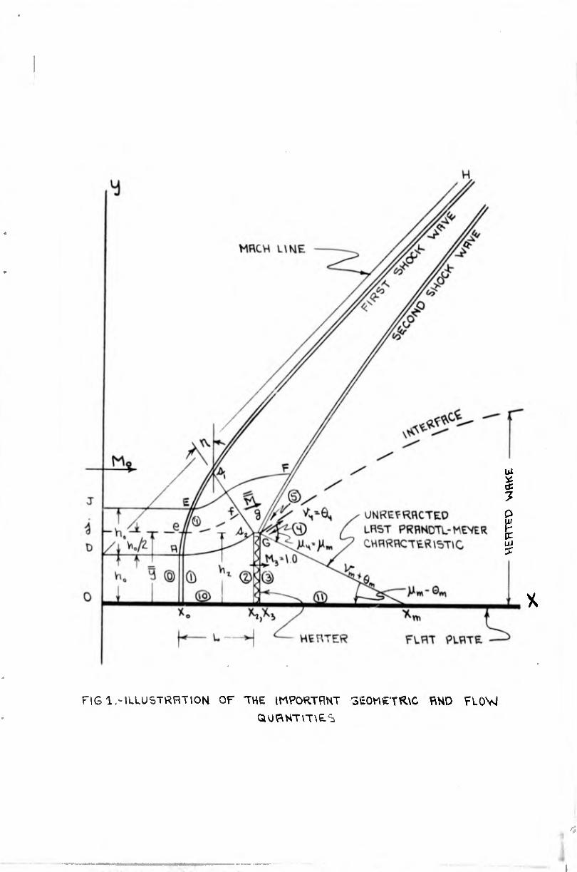
on one side of the flat plate (see Fig. 1). Such a situation
would occur, for example, for plane heat addition on the
double wedge airfoils shown in Fig. 2. The detailed mechan¬
ism of the heat addition process is not considered. Nor is
any consideration given to the determination of the forces
acting on appendages, such as flame holders, or heat ex¬
changers which might be required in the heat addition pro¬
cess. Although the replacement of a combustion region or a
heat exchanger by a heater plane greatly oversimplifies the
real situation, it does serve to establish the order of magni¬
tude of the normal forces. The present analysis represents
an advance over previous work in that it treats large amounts
of heat added over a region of finite extent in the normal
direction.
2------—_____
heat addition ls defined as that amount of heat addition which just produces sonic velocity downstream of the region of heat addition.
2

4
ip <
»mi» FITtICt UIHâTMT iw inis unlit mffisiTf sin» sniN 11111111
For the model analyzed, generalized charts showing the
pertinent flow quantities and normal-force coefficients as a
function of free stream Mach number and heat addition have
been prepared for an ideal gas with a constant gamma of 7/5,
and for Mach numbers ranging from 2.0 to 7.0. Generally, the
gamma associated with heat addition will be different from
7/5 due to the presence of combustion gases or to real-gas
effects associated with high stagnation temperatures, or both.
Refinements taking into account these effects have not been
included in this paper, since the primary purpose is to de¬
termine gross effects, and because their inclusion seems un¬
warranted in view of the numerous approximations which have
been made.
DESCRIPTION OF THE MATHEMATICAL MODEL
In this section a general description of the mathemati¬
cal model employed in the analysis is given for the purpose
of orienting the reader with respect to the detailed discus¬
sions and analyses presented in subsequent sections.
Figure 1 depicts approximately the flow pattern for
super-critical heat addition. For sub-critical heat addition
there is no spillage of the flow over the toj.* of the heater,
and hence, for this regime the first shock wave shown in the
figure does not exist. The gross flow characteristics for
the flow between the x-axis and the streamline DAjJ2 are cal¬
culated on the basis of a one-dimensional stream tube whose
3--- At critical heat addition we will continue to call the shock wave emanating from the top of heat addition region the "second shock wave" even though there no longer exists a first shock wave.
3

WSICS UINâTNT T« IONNS WflINS IIIKIUÎT uivu sraiM Muntii
area varies from hQ to h2 and for which heat addition has
taken place at constant area, i.e. h2 * hg. The dimensions
ho’ h2’ and L’ must of course be compatible with the conti¬
nuity requirements resulting from heat addition, and with
the first shock wave configuration.
The first shock wave configuration is determined by
considering the heater to behave like a supersonic inlet and
by utilizing the continuity method, developed by Moeckel in
Ref. 25, for approximately predicting the form and location
of a detached shock wave ahead of an inlet.
In the Moeckel analysis,the shape of the detached
shock along AH in Fig. 1 is assumed to be a hyperbola with
a Mach line as an asymptote. The location xQ of the vertex
A is dependent upon the inclination and length of the hypo¬
thetical sonic line ^^2. Moeckel assumes that the inclina¬
tion of the sonic line is equal to the flow inclination
, downstream of the sonic point on the detached shock
wave. For a specified spillage, 1 - ho*, the length of the
sonic line is determined from the continuity relation through
the use of a mean sonic velocity ã which is assumed to be
normal to the sonic line. The magnitude of the mean sonic
I velocity is that which would exist on a streamline repre¬
senting the mass centroid of the fluid flowing across the
sonic line~33“3^ in Fig. 1. The ordinate of this streamline
prior to its passage through the shock wave is given by ÿ -
1/2(y^1 - h0> + ho*
Downstream of the heater the flow executes a Prandtl-
Meyer expansion with right-running characteristics centered
at the point G in Fig. 1. The boundary conditions at the
interface require that the pressure and flow directions on
opposite sides of the interface be equal. There is, however,
a discontinuity in velocity, total temperature, and total
pressure across the interface. For any given set of conditions,
4
trniti physics uitiiTMf
TM UMS NOMIRS RNIVEISITT
surti sMiNt mi rum
there exists, as we progress downstream from the heater, a
last curved right-running Prandtl-Meyer characteristic, y- +
®m’ corresPonding to the boundary conditions at G. The
curvature of this characteristics is due to refractions
caused by its intersection with upstream wall-reflected
Prandtl-Meyer characteristics (not shown in the figure). All
right-running characteristics downstream of the last Prandtl-
Meyer characteristic are characteristics which have been
partially reflected from the interface.
For reasons which will soon be apparent, the last right¬
running Prandtl-Meyer characteristic is shown in Fig. 1 as a
straight line, that is. unrefracted. The intersection of the
unrefractfed last Prandtl-Meyer characteristic with the x-
axis is denoted by xm. This intersept is given by
xm* - x3* - (¼ - V
An approximate method of determining the wall pressure
distribution downstream of the heater is developed on the
basis of observations made from method of characteristics
calculations for critical heat addition at M = 2.0 and M = o o
6.0. The details are given in the section entitled "The Down¬
stream Pressure Distribution". It was observed, from these
calculations, that the major portion of the pressure drop
along the plate occurs in the region between x * and x * and •i m 9
that the drop in pressure along the plate from x * to x* to * m
x = occurs at a rather slow spacewise rate. This behavior
of the downstream flow also manifests itself in a very gradual
downstream attenuation of the second shock wave. It was
further observed that the intersection of a wall-reflected
Prandtl-Meyer characteristic with a right-running Prandtl-
Meyer characteristic farther downstream refracted the down¬
stream characteristic only slightly. Consequently, to a
very good approximation, the pressure distribution in the
5
tPPlICI PHYSICS UIHITMT
THE lONIS HOPKINS INIVCISITT
SIIVCI SPUN« HIITUII
+ ft ^ region x3 — x ^ xm can be taken as that occurring for the
reflection of unrefracted straight-line right-running Prandtl-
Meyer characteristics at the wall. This will be referred to
hereafter as a simply reflected Prandtl-Meyer expansion. In
view of the rather gradual downstream interaction of the
shock wave and the heated wake observed in the foregoing
method of characteristics calculations, it appears appropriate
to approximate the pressure distribution downstream of x * by
a two-parameter descending exponential variation with x*. Some
limitations on this approximation are discussed in the section
dealing with the details of the downstream pressure distri¬
bution.
In applying the approximate method to super-critical
heat-addition flow, the mean inclination of the curved sec¬
ond shock wave in the vicinity of the heater top is approxi¬
mately represented by a straight shock wave whose strength
and inclination are dependent upon a mean Mach number JÜ and
a mean flow direction B just upstream, and upon the boundary
conditions at the interface. The methods of determining
these mean values are described in detail in a subsequent
section.
ONE-DIMENSIONAL HEAT ADDITION RELATIONS
The governing relations for heat addition is one-dimen¬
sional flow have been reported upon and discussed many
places in the literature and are now rather familiar to most
engineers and scientists. (See, e.g., Refs. 1, 2, 3, 4, and
5.) For this reason the presentation in this section is
principally concerned with the final relations pertinent to
the analysis.
- 6 -
4
«mid PN?SICS tlllllTMT TNI IINNS MPH« IIIVCISI1I
shin atinin
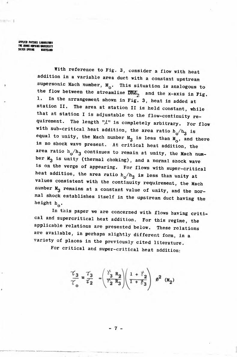
With reference to Fig. 3, consider a flow with heat
addition in a variable area duct with a constant upstream
supersonic Mach number, Mo. This situation is analogous to
the flow between the streamline DRZ^ and the x-axis in Fig.
1. In the arrangement shown in Fig" 3, heat is added at
station II. The area at station II is held constant, while
that at station I is adjustable to the flow-continuity re¬
quirement. The length is completely arbitrary. For flow
with sub-critical heat addition, the area ratio h^hg is
equal to unity, the Mach number Mg is less than M°, and there
is no shock wave present. At critical heat addition, the
area ratio ho/hg continues to remain at unity, the Mach num¬
ber Mg is unity (thermal choking), and a normal snock wave
is on the verge of appearing. For flows with super-critical
heat addition, the area ratio ho/hg is less than unity at
values consistent with the continuity requirement, the Mach
number Mg remains at a constant value of unity, and the nor¬
mal shock establishes itself in the upstream duct having the
height h .
In this paper we are concerned with flows having criti¬
cal and supercritical heat addition. For this regime, the
applicable relations are presented below. These relations
are available, in perhaps slightly different form, in a
variety of places in the previously cited literature.
For critical and super-critical heat addition:
7

«Mil» mil» UIMITMV I« IOMS MNINS MnilUTT »mi spun auniN
'.A .. 2v .. -1
0(M2) (1 + V2 M2 } M (1 + ^2 M22>
+ t2) [2 + - V M22] M2 ^r+*2)
3 P“
. S 1
1 +
» (M2)
Pj ^ ^P3/P3^> / p3\ j(^3 + 1)/2^ 3
<po/Po)
3
p /P o o
2 P"
1 jr
<*0 + 1) M03
2 + (‘'o - » “o"
4
' > 1
2^o - D
P2 _ (P2/P2)
(Po/Po>
P2 P-
O
h o _ (*/*,)i _ m2
(a/a„)2 ÏT «1
1 2+(^- d m;
2 + (P - 1) MÍ
+ 1
tmill MTSJCS UiniTHT tM KIMS IWniRS NlVdSITT »mi sums Ntiruis
2 + «O
2iA„ «O - «o - !>
Oh - cp3 - cp2r
* <£ ■ ^2’ ^
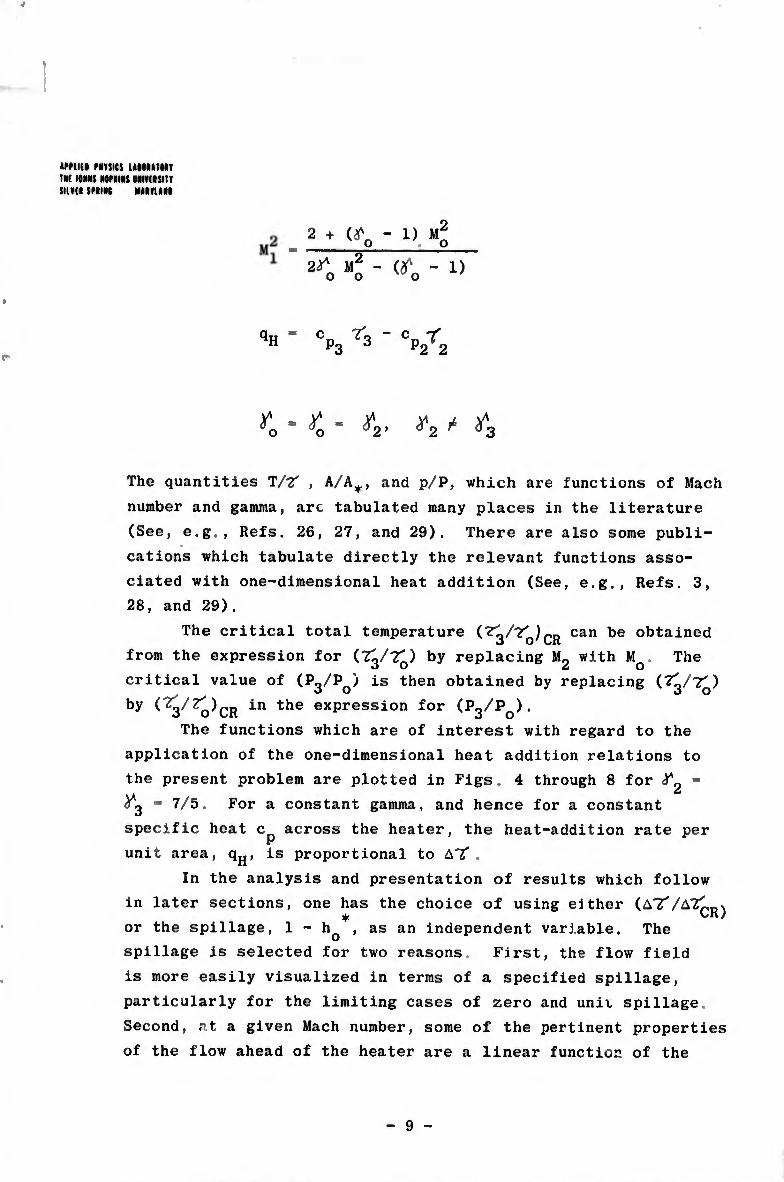
The quantities T/T? , A/A+, and p/P, which are functions of Mach
number and gamma, arc tabulated many places in the literature
(See, e.g., Refs. 26, 27, and 29). There are also some publi¬
cations which tabulate directly the relevant functions asso¬
ciated with one-dimensional heat addition (See, e.g., Refs. 3,
28, and 29).
The critical total temperature can 106 °ktained
from the expression for (^3/2^) by replacing Mg with Mq. The
critical value of (P«/P ) is then obtained by replacing (7l/?") «3 0 «3 0
by in the exPressi°n for (p3/p0) •
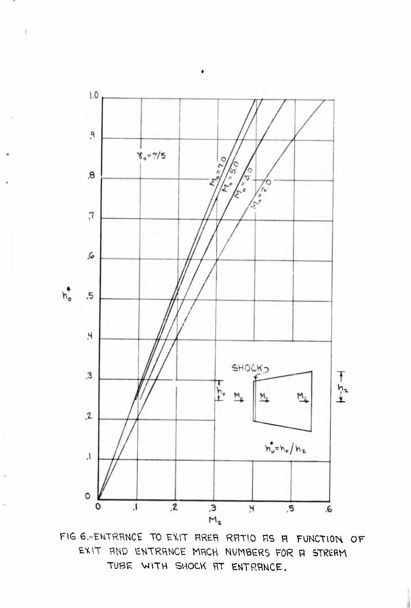
The functions which are of interest with regard to the
application of the one-dimensional heat addition relations to
the present problem are plotted in Figs. 4 through 8 for =
= 7/5. For a constant gamma, and hence for a constant
specific heat c across the heater, the heat-addition rate per
unit area, q^, is proportional to A't .
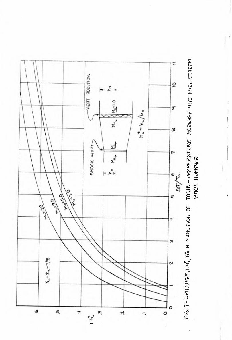
In the analysis and presentation of results which follow
in later sections, one has the choice of using either (aT/A21dv ♦ LIU
or the spillage, 1 - hQ , as an independent variable. The
spillage is selected for two reasons. First, the flow field
is more easily visualized in terms of a specified spillage,
particularly for the limiting cases of zero and unit spillage.
Second, at a given Mach number, some of the pertinent properties
of the flow ahead of the heater are a linear function of the
9
»mift MTSICS UMltTNT TM IIMIS »OPIIIS IRIVUSITT SUMI SPUK MIITUII
spillage. The correspondence between the spillage and the
total temperature increase (and hence the rate of heat addi¬
tion) is shown in Fig. 7. Although not shown in Fig. 7, it
is of interest to note that the total temperature increase
approaches infinity for spillages approaching unity. How¬
ever, physically attainable cases are, in all probability,
limited to spillages considerably less than unity. For the
external combustion of a hydrocarbon fuel, this limitation
is governed by the enthalpy of the fuel. Orders of magnitude
for this case will be presented shortly. If the heat is
added by means of a heat exchanger using a nuclear energy
source, the upper limit of spillage will depend upon the
, temperature limitations imposed by the structural integrity
of the heat exchanger. If the heat from a nuclear energy
source could be added without consideration for structural
limitations, higher spillages possibly could be achieved.
Subsequently in the analysis, in the process of de¬
veloping analytical results for the complete spillage range
from zero to unity the limiting case of unit spillage is
utilized. In doing this, cognizance is taken of the fact
that the extremely high temperatures involved when the spill¬
age approaches unity are not compatible with the use of a
constant gamma through the beater, and of the fact that the
expansion downstream of the heater will be somewhat different
than that for the Prandtl-Meyer expansion for an ideal gas.
Nevertheless, the use of a constant gamma is believed to be
an acceptable procedure for ?stablishing the approximate
flow field in the lower spillage range.
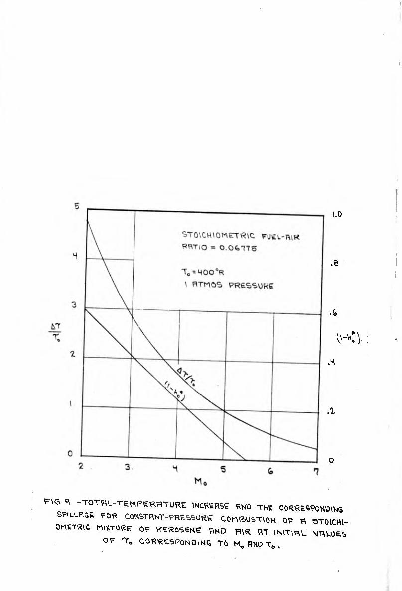
It is of interest to estimate the spillage corre¬
sponding to the external combustion of a particular fuel.
This has been done for the constant pressure combustion of a
stoichiometric mixture of kerosene and air in quiescent air
at initial temperatures cf 1?Q corresponding to M0. The
10
»Mim muet I tint TM T 'Ni lONNS NONIIRS limiSITT
HUH SMIM MâlTlâM
resulting total temperature increase and the corresponding
spillages are shown as a function of free-stream Mach number 4
in Fig. 9. These values serve only as a guide to orders of
magnitude, since they are based on a constant pressure pro¬
cess, whereas the process used in this analysis involves
heat addition to a constant area stream tube with an accom¬
panying spacewise discontinuity in pressure. Note that there
is no spillage possible for free-stream Mach numbers greater
than Mq » 5.5. Conceivably, spillage might be obtained at
the higher Mach numbers through the combustion of a higher
enthalpy fuel or from the use of a nuclear energy source.
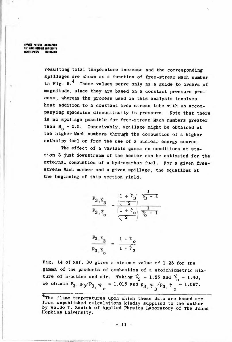
The effect of a variable gamma on conditions at sta¬
tion 3 just downstream of the heater can be estimated for the
external combustion of a hydrocarbon fuel. For a given free-
stream Mach number and a given spillage, the equations at
the beginning of this section yield.
(l + ^
I /
i + t _o
1 +*3
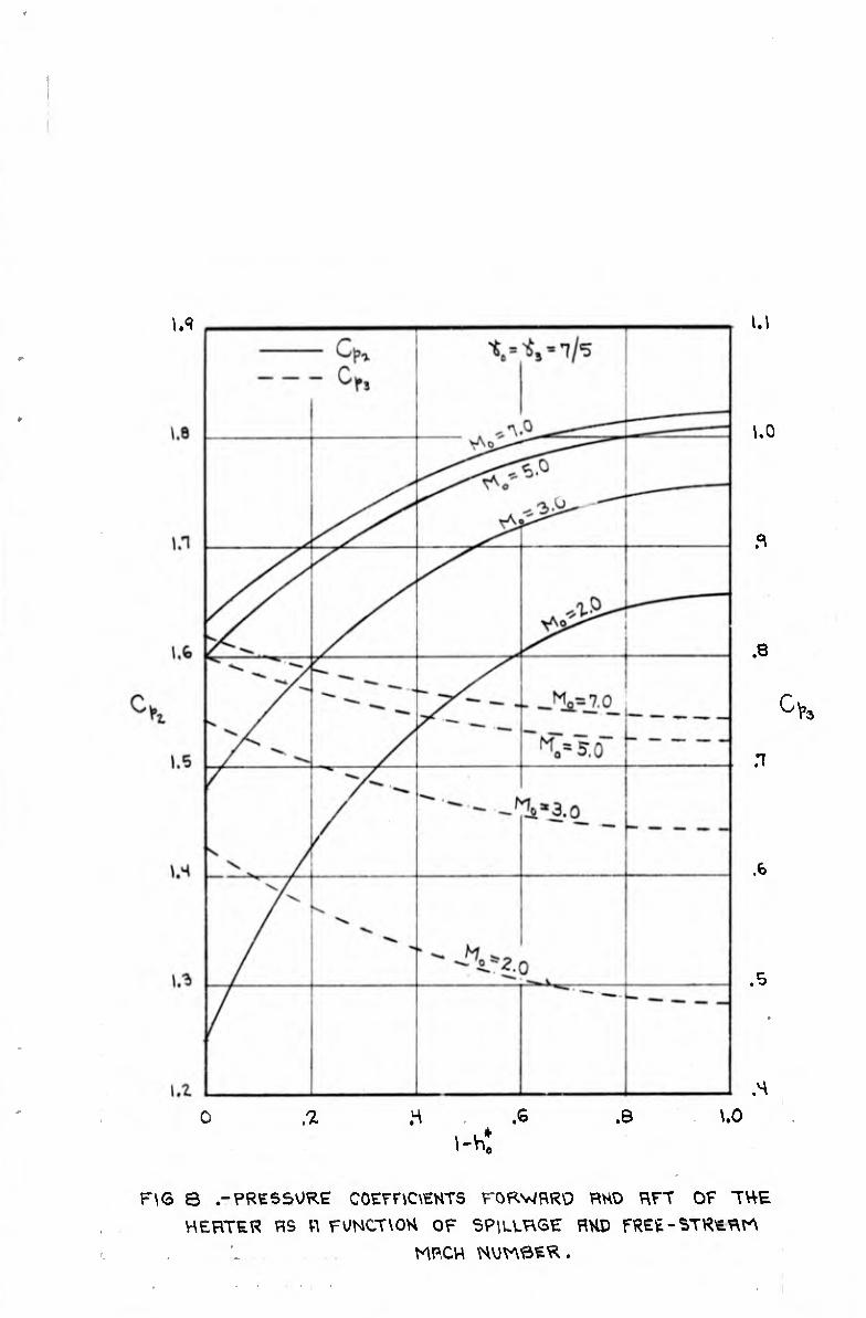
Fig. 14 of Ref. 30 gives a minimum value of 1,25 for the
gamma of the products of combustion of a stoichiometric mix¬
ture of n-octane and air. Taking - 1.25 and ^ - 1.40,
we obtain P3, frg/Pg ^ » 1.015 and p3 # /p3 f * 1.067.
^------ The flame temperatures upon which these data are based are from unpublished calculations kindly supplied to the author by Waldo T. Renich of Applied Physics Laboratory of The Johns Hopkins University.
11

»mie» PHYSICS UMIâTMT tuf IOHHS HOMIRS mmiSIIY shy» spurn Huruii
\
The error in P3, resulting from the assumption of a constant
g.imma, is negligible, and, although the error in p« is slightly
large, it is tolerable in view of the generally approximate
nature of the analysis.
GEOMETRY OF THE FIRST SHOCK WAVE
The assumed shock wave shape used in Moeckel’s analysis
(Ref. 25) is given by the expression
The relations for the important parameters, using the
continuity method of Moeckel and taking \ are found to
be as follows, 1
-ß 2 tan ^ - c 1 - B cos 9„
.A,
tan (/^1
1 - B cos B & 1
(l-h0 ) B cos
1 + 1 - B cos 0 A/

will» MKICS LÄINirilf m um» inmim MNfdtnr »im tniM mm ihn
C + B sin 9.
(1 ” h0) 1 - B cos 9p
c - (ö^tan - U* tan2 ^ . J
B - (P0/P) (A/A,)o
P F~
(tn + 1)M? sin2 P,
(^o - sin S9 + 2 2 *oMo sinZ ^9
M, K +1
2 + (1^0 - DM2
1 (*o,+
tan O, <4 + D “o ^5 ,2 ^2 Mo sin - 2
- 1 tan vf A1,

»Will »»TíltS UINITMT nu IONNS »»»uns imvcisitt SU«» S»ll»t ■IITUN
For further details the interested reader may consult Ref. 25.
The parameter L*/(l - h*), which is a function of
free-stream Mach number only, is plotted on Fig. 10.
ApPROXIMATE FLOW CONDITIONS AT THE INTERSECTION OF THE HEATER PLANE AND THE SECOND SHOCK WAVE
Although the second shock wave is actually curved, in
the approximate analysis of this paper that portion of it
near to the top of the heater is assumed to be represented
"on the average” by a straight shock and to be influenced by
a mean flow just upstream of the shock. This mean flow is
characterized by a mean total pressure P, and a mean Mach
number B,and a mean flow direction $. The shock wave
strength and inclination are dependent upon the mean upstream
flow, and the boundary conditions, to be described subse¬
quently, at the intersection of the heater and the interface.
In attempting to describe grossly the dynamics of the
flow in the region of point G of Fig 1, it seems reasonable
to consider an amount of spilled mass-flow equal in magni¬
tude to the mass flow through the heater. Such a mass flow
is illustrated by the flow between the streamlines 5%¾
and JEF shown in Fig.^1. The mean streamline j¥Tg with
free-stream ordinate ÿ - 3hQ/2, is representative of this
mass flow and is therefore used in the determination of
P, M, and 3.
Downstream of the first shock wave the flow is isen-
tropic along the streamline elgT therefore the mean total
pressure P is the total pressure aft of the first shock at
the ordinate ye - ÿ - 3h0/2 on the wave. The shock wave
angle lf>e corresponding to ye, as determined from the geometric
»MH «TWJ UIIIITMT 'W Ilms Nfims mnusm »mi inin uiniN
relations given in the previous section, is
tan -1 1 4X
* 2
1 +
ß2^2
The relation for xo is given in the previous section.
Now, let us denote by (1 - h*)^ the spillage corre¬
sponding to the passage of the streamline JEF through the
point -d/j shown in Fig. 1. The streamline JEF will pass above
when the spillage is less than (1 - h*)^, , and below yA ,
as shown in the figure, when the spillage is'greater than 1
(1 ' "okj- For spillage greater than (1 - h*)^ , we shall
assume that the stream tube 3EF - ÏÏU^ is approximated by a Prandtl-Meyer expansion of the streamline TJ through the
angle - S. Knowing 5, the mean Mach S is obtainable from the Prandtl-Meyer relations. The method for determining 5
will be described subsequently.
For spillages less than (1 - h*)A . this simple method
for obtaining H is no longer applicable,^ince the upper
streamline of the streamtube DXZÇ~ - jEE crosses the first
shock above the sonic point ^, and hence the streamtube flow
on the average" cannot be considered as having executed a
Prandtl-Meyer expansion. The method for determining P is
still applicable, however, regardless of the amount of spill¬
age. As a consequence of its restriction to a specific
spillage range, the foregoing method for determining S is called the "restricted method" to avoid confusion with the
"final method" which is developed later. The final method
is valid for the complete spillage range, l.e., from zero to unity.
15

i»U(t MTSICS lUIIITNT TNI lOMIIS HOPKINS MtmSITV simci s pint miniH
\
As a prerequisite to the derivation of the final method
it is first necessary to consider some consequences of the
restricted method. In order to do this the boundary condi¬
tions at the point G in Fig. 1 are required.
With reference to Fig. 1, the boundary conditions for
a specified super-critical heat-addition rate require an
oblique second shock wave angle for which p4 = p5 and e4 = 0 .
Noting that (p4/Po) - (p/P)p,4 (P3/Po), and (p5/Po) - *
(P5/p) (p/P0), these boundary conditions yield
P3/Po P5/p
(p/P) (P/P0) (p/P) >*4
For a specified free stream Mach number and heat-addition
rate (or spillage), and a known value if 6, the left hand
side of the first equation is known. Solution for the shock
wave angle § which simultaneously satisfies both of the
above equations must be obtained by trial and error. Since
the mechanics of this process can be performed many differ¬
ent ways, no specific procedure is described here.
We now investigate, by means of the restricted method,
the consequences of assigning upper and lower limiting
values to Ç. The upper limit, 0^ , is that value of 0 for
which the second shock wave becomes a Mach wave. In this
case 0 = Oq. = 04. The lower limit, 0¿ , is that value of
0 for which sonic velocity exists behind the second shock
wave.
16
tmi» MVSICS UIMITNT TW ums mums iwwisitt Juwi sniM aunin
4
Values of e4, corresponding to the upper and lower
values of S, are shown by the solid lines in Fig. 11 for free-
stream Mach numbers of 2, 3, 5, and 7, and for spillage
values ranging from (1 - h*)^ to unity. Also shown, are
the values of^04 for zero spillage. For a given free-stream
Mach number, ^ varies slightly with spillage. A representa¬
tive value of B^along with its possible deviation in the re¬
stricted spillage range is given for each lower limit curve.
It is observed in Fig. 11 that the value of 9. for a
given free-stream Mach number is relatively insensitive to 3.
Therefore, the flow in the region enclosed by the heater, the
wall, and the last Prandtl-Meyer characteristic (i.e., the
region within Gx3xm in Fig. 1) is also relatively unaffected
by S. The flow downstream of the last Prandtl-Meyer char¬
acteristic, however, is affected by 1 via the mean inclina¬
tion, $ , of the second shock wave. The influence of 0 on
the mean inclination of the second shock wave is illustrated
in Fig. 12 for the upper and lower limiting values of 1.
It will be shown in a subsequent section that the major
portion of the aft normal force is obtained from the region
between the heater and the last Prandtl-Meyer characteristic.
Consequently, if the primary interest is in plate forces,
and not flow-field details, the value of 15 which is used is
not especially critical. With this in mind, the flow angle
S will be taken as zero, on the basis of the assumption that
the mean over-the-top stream behaves as if it were flowing
parallel to the flat top of a heater of finite thickness.
Values of 04 calculated by the restricted method us¬
ing a zero value for $ are shown by the appropriately labeled
solid lines in Fig. 11.
Since the values of for zero spillage are known,
it seems reasonable to obtain values of ©4 in the region for
17
»Will W$ICt lâintTMf i« ums mmus iw«(isiTr SU«» smiw iiiniai
\
which a theory has not yet been advanced, i.e., for
0-(1- hQ) -(1- , by simply assuming the inter¬
polated curves shown by lhe dashed lines in Fig. 11. n
is seen that the resulting curves, for the complete spillage
range from zero to unity, yield almost constant values of 0
for a fixed free-stream Mach number. In view of the generally
approximate nature of the analysis it is appropriate, for a
fixed free-stream Mach number, to consider 04 (and hence ^ )
as constant with respect to spillage. This constant value is
taken as that corresponding to zero spillage rather than an
average over the complete spillage range, since the zero
spillage value may be determined exactly. Hence, in the
"final method" ©4 is known "a priori" and is a function only
of free-stream Mach number.
The effect of an error in 04 on the aft normal force
is analyzed in a later section dealing with the normal forces.
The "final method" for approximately analyzing the flow
over the top of the heater is summarized as follows. Referr¬
ing to Fig. 1, the flow is considered to be represented by
the mean streamline JÏTg previously described. The mean total
pressure P along iTg, downstream of the second shock wave, is
that value of the total pressure aft of the first shock wave
at the ordinate ye = 3ho/2 on the wave. The mean streamline
Tg, in passing over the top of the heater, is considered to
expand from a Mach number of unity at the point f through a
Prandtl-Meyer expansion to a final flow direction S = 0. In
the restricted method the Prandtl-Meyer angle for the mean
flow was considered to be known and 04 was to be determined.
In the final method 04 is known for a specified free-stream
Mach number. The Prandtl-Meyer angle for the mean flow,
and the corresponding M, is determined by the .hock-interface
conditions which are governed by the known value of 04, in
18
tmiii MTsicj uintiwT TK( IONNS NtnilS MIVIlSItT timi sraiM Mtimm
this approach, the inclination of the sonic line at the point
f is considered to be slightly different than rj.
The mean Mach number M and the mean second shock~wave
angle | , calculated on the basis of the final method are
shown as functions of spillage and free-stream Mach number in
Fig. 13. These curves are not actually needed for the de¬
termination of the aft normal force, but are presented as a
matter of interest.
THE DOWNSTREAM PRESSURE DISTRIBUTION
As mentioned in the section describing the mathemati¬
cal model, the approximate downstream pressure distribution
from x3 to xm is calculated on the basis of a simply reflected
Prandtl-Meyer expansion. For downstream distances greater
than xm the pressure distribution is assumed to be given
approximately by a two-parameter descending exponential vari¬
ation with X .
In this section, the necessary relations for the use
of these approximations are presented along with their limita¬
tions and a partial verification of their appropriateness.
With reference to Fig, 1, consider any general right¬
running Prandtl-Meyer characteristic centered at the point G.
The geometry shown in the figure for the last Prandtl-Meyer
characteristic, denoted by the subscript "m", will serve
for a general Prandtl-Meyer characteristic if tue subscript
"m” is replaced by the subscript "R". The characteristic
constant (Refs. 31 and 32ji for a. general right-running
Prandtl-Meyer characteristic is (y-R + 0R ) or (2^),
since Mg -= 1.0, This characteristic makes the angle (0R
or (/"p with the plate (See Fig. 1). if we denote
quantities at the intersection of a characteristic and the
wall by symbols without a subscript, we obtain the relation
19
»mi» msics imiiioiT
IM JOHNS HOPKINS ONIVflSITI
SIIVEI SPIINC HtiniNO
\
( V-+ 9) 2 . Since O ~ 0, this becomes
y« 2 V" R
* The X -coordinate of the intersection is given by
X - x3 - cot ÇUR - 0R )= cot (/JR - y-R)
The pressure ratio p/p3 at x' is then obtained from
where
(P/P) +
The pressure ratio p/P as a function of is available in
numerous tables (See, e.g., Ref. 26).
It is convenient to record some properties of a
simply-reflected Prandt1-Meyer expansion for which the last
characteristic intersects the x-axis at infinity. The down¬
stream distribution of wall pressure, denoted by p for this
case, is plotted in Fig. 14. The value of p at infinity,
P«, , is obtained by noting that /R *-/AR at infinity. From
the Prandt1-Meyer relation (See Eq. 171, Ref. 26) we ob¬
tain
(P/P) /- 2y-
R
(p/P)
(*+ 1)/2
t T^~T
0.52283 (^ - 1.4)
20
4
>»U(I MTSICS ItiniTMT im itms Mfiiis muh$ny siiYd tniM Htintii
cot 1
1 tan
For ^ * 1 -4, this yields tR =/UR = 28.63°, and hence 57.26°.
The corresponding value of p/p3 is (p/pg^ = 0.0278.
The pressure distribution downstream of x* is assumed m
to be given approximately by the relation
(b < 0) (1)
where the parameter "b” is determined so that the first de¬
rivative of the pressure distribution matches that for the
simply reflected Prandtl-Meyer expansion at the point x*. „ m Hence we obtain
b
d'"Pll/p3)
d(x - x3) * x =
(2)
The analytical relation for the derivative in Eq. (2) is
given in the Appendix. The derivative itself is plotted on
Fig. 15.
The foregoing approximation is limited to cases where
¿11 — P0’ since for pjj < p it is no longer possible to m m
approximate the pressure distribution downstream of x* by a m
21

»Hl» PNVSICS UllltlUT iNi itmis NtriMS umvcitiTT SU«» SMI« minm
\
simple monotonie variation such as given by Eq. (1). For
Mq — 2.58, p is always greater than p , regardless of the
amount of spillage. For free-stream Mach numbers less than
2.58, there exists for each Mach number, a limiting spillage
value above which p,. is less than p . At M - 2.0, for m *o o ’
example, this limiting spillage value is 1,35. The limiting
spillage value becomes zero at M = 1.50. Hence, the
approximation cannot be applied in any case for a free-stream
Mach number less than 1.50.
In order to partially verify the appropriateness of
the approximate solution, method of characteristics calcula¬
tions have been made for the downstream flow for critical
heat addition at free-stream Mach numbers of two and six.
The characteristics calculations were performed assuming
irrotational flow and using a lattice-point method with a
numerical-graphical procedure (Refs. 31 and 32). The previ¬
ously described boundary conditions at the interface were
satisfied by a trial and error process. The resulting char¬
acteristic nets are shown in Figs. 16 and 17. The fact
that the shock curvature is very small in both cases sub¬
stantiates the assumption of irrotational flow used in the
calculations. Although the wall-pressure distribution is of
principal concern here, the characteristic constants for
the flow are given in Table I as a matter of interest.
Comparisons of the downstream wall-pressure distri¬
butions as calculated by the approximate method and the
characteristics method are shown in Fig. 18. It is seen
in these figures that the two methods are in excellent agree¬
ment for the Mq » 2.0 case, and in fair agreement for the
M0 “ 6-0 case. Note that the agreement is excellent at both
Mach numbers in the region where the simply reflected Prandtl-
Meyer expansion is used. Considering the characteristics
22
mu» UIMITMT ÎM IM« MflllS WHfdUIT SHVH SMIM MSiniN
solution to be an exact one, the ratio of the approximate
normal force to the exact normal force at several x -sta-
• tions is as follows. For a free-stream Mach number of two,
the ratio is 0.98, 0.94, and 0.94 respectively at (x* - x^)
- 2, 4, and 6, while for a free-stream Mach number of six
it is 0.92, 0.85, and 0.79 respectively at (x* - x^) ■= 6, 8,
and 10.
A question arises with regard to the downstream exis¬
tence or non-existence of imbedded oblique-shock or Mach-
shock reflections such as are known to occur in jets exhaust¬
ing into supersonic streams (See, e.g., Refs. 33 and 34).
If such imbedded shocks actually do occur in the present case,
the monotonie pressure distribution assumed herein does not
properly represent the pressure discontinuities of shock
waves. Because of the paucity of information dealing with
both sonic and supersonic jets exhausting into supersonic
streams (Ref. 33), it is not possible to use such information
to make predictions regarding the appearance or non-appear¬
ance of imbedded shocks in the present problem. It is con¬
jectured by the writer that such shocks are more likely to
occur when p^ p . This is, of course, outside the range m °
of applicability of the present approximation. If imbedded
shocks do actually occur within the range of applicability
of the approximate method, there is a reasonable possibility
that the pressure jumps associated with these shocks are
small compared with the pressure drop in the region up to the
last Prandtl-Meyer characteristic (See Ref. 34 for an exam¬
ple of this situation). Briefly, since the greater part of
the downstream force exists in the region up to the Prandtl- 5
Meyer expansion , it is reasoned that the force downstream
5 '■ -—--—•
This may be observed in Fig. 19 which is discussed in a later section.
23 -
»"tin wsics uititToir lm '«« NNIM mmsiT! sit»« {nmt MiiruH
:::1::,: ::::::::: ;;the basis - » — dlstrl.
rather grosS man„er dl*trlbUt1»" ^ a
tei^tVLTT:::0 :ote that the—2-° <=- », the conditions olL ' rreSP°nds rather closely to
Rousso and Baughman (Refr":1** rep°rted bJr
to a Mach 1.91 supersonic stream Th0” C e,Ihaustlng in
that the Rousso-Baughman tests are ! TjJT^ " jet, whereas the nres*n+ i axially-symmetric
How. Ref. 35 presents 1: : S ^ ^"-‘“““‘on,
exhaust for values of P / 64611 photographs of the jet
of these cases (bracketing^/^Vs.22^^10 0, ^ ^
waves are observed in the jet within a di t g* ^
radii downstream. The diagram of Fig ,6 °f fOUr Je* within this region am, i *' 16 reveals no shocks exact 1V Although these situations are not exactly comparable, the fact +ho+ *
tative similarity between the fi ^ ^ ^ 3 qUali' y between the flows is somewhat puzzling.
the normal forces
* Jr f0rward n0rmal for« coefficient per unit width 0> acting on the surface JTIT is ’
o 2
Applying the momentum theorem to th^ fi ^ within the control region x x a a ” enclosed
is normal to A^, we obtain 2 2^X°' aSSU,”lng that a
(3)
- 24

*mi(i MTsics uintiMf 1N( IOIWS MM 11$ IWKISIU tilfCi SMIM MIITUII
(p + p a2 \ / * Po)(x2
♦ kA )
1
or
Y10 “ <2/^Mo> 1)(P/P0 - 1) J (x* - x*A )
jft
Writing (x2 - xA) in terms of the flow variables and taking
we obtain
(^+ 1) (p/p
B sin 0,
1 - B cos 0A,
(4)
where B = (PQ/P) (A/A„)o. The quantity Y^/(1 - h*) , which
is a function only of Mo, is plotted on Fig. 10.
The forward moment coefficient per unit width,%) *,
for the surface xox2, with moments taken about the point x
is °’
It is assumed that the pressure distribution along x^xl is
given approximately by Z
"pj “i(It ♦
X ) 4 O (X* - *.2
x) (6)
25 -

PHYSICS UIOUTUY IN( IOHNS NOHIIS UNIVERSITY simi sniNc NiiYUNO
The coefficients a, and a0 are determined by the condition
that C - C when (x - x ) = L and by the condition p10 p2 °
that YlO is stained when the Eq. (6) is substituted in Eq.
(3). The condition that C =■ C at (x* - x*) - 0 is PlO Pi °
automatically satisfied by . (EqT (6). Evaluation of the
coefficients and «2 and substitution of the resulting ex¬
pression for C in the moment relation yields p10
* 10
*2 (L /2) at’io/L ) + ¿ (c
■ cp} P1 (7)
The aft normal force coefficient per unit width,
acting on the downstream wall in the region from x^ to x* is
r x
ii - q. -i
y
(pll - po)dx (8)
The particular expression which must be used for depends
upon whether x* is greater than or less than x¿!. J-
The aft normal force coefficient for x* x is m
Y *
11 + (P0/q0) (X* -
where
/p^) d (x - 11' Xg)
(9)
26 -

«mi» mui» uiiitiMT '« *■* mmim Mimtm tu«» tMIM Màiruil
The integral I has ♦ o
tion with (x - x_) «J
been evaluated numerically,
is presented in Fig. 15.
The aft normal force coefficient for x*2i
Its
*
varia¬
is
n. - Ynm - (p3/q0) J0 (10)
where Yl is the value of Y given by Eq. (9) when x* = x+ and m m’
rx
•’o *
i (p 11 dx (11)
X* m
Substituting E,. (1) in Eq. (11) and evaluating the integral yields
Jo b ^m^p3 " " ^Pjj’b(x*- x*J^ (12)
where "bM is given by Eq. (2).
The aft moment coefficient per unit width,TM* acting
on the downstream wall in the region from x* to x* is
♦
^11 ~ <1/(lo>i ix - x3.> (P11 - P0)dx^ 'V
(13)
In a manner analogous to that for the normal force, the
particular expression which must be used fordepends upon
- 27

»mito NTSics iiiiitroiT IN( ISNNS NOMINS «RIVCItlTT tuv» tni«( ■áinm
* $ whether x is greater than or less than x .
m * The aft moment coefficient for x*^ x is
m
• 'W h - 2 (Po^oX** ' *3>
where (14)
-X - X,
I, ?! (x+- X3)(p11/p3)d (x*- x*)
rJ The integral I, has been evaluated numerically. Its varia-
tion with (x - x„ ) is presented in Fig. 15.
The aft moment coefficient for x x is m
iP3/qo) J1 (15)
where^^* is the value ofî)|*^ given by Eq. (14) when x* = x*, , m
and
(** - X*) ^(pn - p0)/p3 d(x - x3) (16)
m
Substituting Eq. (1) in Eq. (16) and evaluating the resulting
integral yields
28 -
IMLId MVSICt UMUTMI T« IOMS MHINS INIVEISKI su«» SMiNc Miintm
The cumulative aft. normal force coefficient as a func¬
tion of downstream position for zero spillage is plotted in
Fig. 19 for free-stream Mach numbers of 2, 3, 5, and 7 respec¬
tively. Also shown on this figure is the x*-coordinate x* m
of the last Prandtl-Meyer expansion. It can be seen, as was
previously stated, that the major portion of the normal force
is achieved in the region of the simply reflected Prandtl-
Meyer expansion.
The curves for other spillages are not greatly differ¬
ent from those shown in Fig. 19 due to the fact that is
independent of spillage and to the fact that the variation of
Cp^ with spillage is moderate (See Fig. 8).
Also shown in Fig. 19 is the normal-force coefficient
for an infinitely long plate. Since it is obviously im¬
practical to expand to infinity it is necessary to select
some other suitable refei nee force and length at which to
terminate the expansion. From examination of the figure it
is apparent, that in general, there is little to be gained
by expanding beyond the station where approximately nine-
tenths of the infinite-plate aft normal force is reached.
Consequently, for all spillages at a given free-stream Mach
number, the reference length (i.e., the length at which it
is practical to terminate the plate) will be taken as x*,
29
tmiCI PHYSICS llllllttll
TNI IONNS NOMINS HIIVUSITY
SUYO SPIIHS MtirUNI
\
where x* is the station at which the normal force is nine-
tenths the infinite-plate aft normal-force at zero spillage.
Values of x* - x, are indicated on Fig. 19. The aft normal- t o * +
force coefficient corresponding to x^. is denoted by , jfc
while the corresponding total normal-force coefficient is *
denoted by Y.. t *
The total normal-force coefficient Yt, and the forward ♦ ^
normal-force coefficient Yl0 as functions of free-stream Mach
number are shown in Fig. 20, The limitation on Y^. for M0 *
2.0 is due to the fact the analysis fails to provide a solu- $
tion when Is ^ p • It mav be observed, that Y., is almost m o
♦ 1 * independent of spillage, since the curves of Yt and Yl0 are
almost parallel for a given free-stream Mach number. It is
also of interest to note that with increasing spillage the
forward normal force becomes an increasingly larger fraction
of the total force.
In Fig. 21 there is shown the average normal force
coefficient per unit length for a flat plate terminated at
X* as a function of spillage and free-stream Mach number. It
is seen here that the average force per unit length increases
with spillage. A cross-plot of Fig. 21 at zero spillage re¬
veals a maximum average normal force per unit length at MQ “
2.5. This maximum either disappears or moves to a lower Mach
number very rapidly with increased spillage. This point has
not been explored further because the present method is
inapplicable below Mc> - 1.5, and because the spillage range
for which it is valid for Mach numbers less than 2.68
diminishes very rapidly with decreasing Mach number. It is
also probable that practical applications will tend towards
the higher Mach numbers.
The center of pressure of a flat plate terminated at
X* as a function of spillage and free-stream Mach number as t
shown in Fig. 22.
30 -
‘"lito MTSICS lAlllàTOOT TM louis norms iiimisitt SU«» SMIM MtOHtIO
It will be recalled that the present analysis is
based on the assumption that ô4 is independent of the spill¬
age for a given free-stream Mach number, whereas Fig. 11
indicates there exists a range of possible values for & 4
for a given Mach number. With reference to Fig. 19, it may
be observed that x. is less than x for the curves corre-
sponding to Mach numbers of 2, 3, and 5. Therefore, since
04 does not influence (except indirectly through the
establishment of x ), thetprecise determination of 0,, is
not important. This observation is also true for the com¬
plete spillage range. For Mq = 7.0, is influenced by
04, since xt is greater than x*. The selection of x*,
however, is somewhat arbitrary. If a slightly different
criterion for its selection had been used, it is possible
that xt could have been larger than for all Mach numbers
within the range treated.
Regardless of the specific criterion used for the
selection of xt there is little to be gained by selecting * i ^
xt much larger than x^, since as we progress downstream
most of the aft infinite-plate normal force is achieved
when xm is reached. For example, for Fig. 19, the force
ratio, Y11 /Yn , has values of 1.00, 0 98, 0.92, and 0.88 m
respectively for Mach numbers of 2, 3, 5, and 7. The
corresponding values for other spillages are within about
2 per cent of these. Since Yjj is a reasonably good
measure of the downstream forcemwhich we desire, an esti¬
mate will be made of the effect of an error in 04 on the
value of Yjj . From Eq. (9), we obtain
d Yx* /d0( m
r*
31 -

tmi(D MVSICS LIIHITtlT '« lONKS NOHUS UNIVERSITT SURER SMINR MtRritNO
where
d
rJ d I
o
(x - X ) m o' *
x m
The derivative *s available in the Appendix.
The other properties of a simply reflected Prandtl-Meyer ex¬
pansion are plotted on Figs. 14 and 15. The pressure ratio
VQ/P3 may be obtained from Fig. 8.
The consequence of applying the above relations are
displayed in the table below.
Since the purpose of this table is to indicate orders of
magnitude, a representative value of P0/p3 for the complete
spillage range at each Mach iiumber is used in lieu of show-
ing the variation with spillage. The range of possible
32
•mill PKTSICS UIIIITHI ÎW IHM MPI IM MIX I SI It Jut» spuk amuii
deviations is given in parenthesis under each of the tabu¬
lated representative values. The value of (dY^
listed is the largest value for the given 04 range. The m
smallest value for each Mach number is, on the average, 0.01
less in absolute magnitude than the tabulated value. The
possible error, À04, is the maximum and/or minimum deviation of
the zero spillage value of ©4 from the curves shown In Fig. 11.
The error in Yn corresponding toA©4 is recorded in the
last column in tl?e table. It is seen here that the error
decreases with increasing Mach number. Although the error
in Yn at the lower Mach numbers is slightly larger than m
one might desire, it is tolerable in view of the approxi¬
mate nature of the analysis.
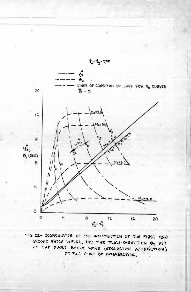
A final point of interest is the possible influence
of the intersection of the first and second shock waves on
the downstream pressure distribution, and hence on the aft
normal force. For a straight second shock, with inclina¬
tion 5 , it is easy to calculate the intersection of the two
shocks. The results of such a calculation are shown in
Fig. 23. The coordinates of the point of intersection of
these shocks are given by the solid-line curves on Fig, 23.
Note that the trace of the intersection of the shock-waves
is almost independent of Mach number for the Mach number
range shown. The flow inclination, downstream of the
first shock, and neglecting interaction with the second
shock, is also shown in Fig. 23, along with lines of con¬
stant spillage corresponding to Sj. It can be seen from
these curves that when the intersection is close to the
heater 0J is large, the intersection is relatively far away,
so that the strong interaction in all probability will be
transmitted relatively far downstream. This favorable be¬
havior becomes less pronounced for increasing free-stream
Mach numbers .
- 33
»«ut# wsies uiouToir IW lONNS HOPKINS UNIVERSITY SIIVCI SMINC NtlVUNI
CONCLUDING REMARKS
On the basis of a simplified model and an approximate
theoretical analysis thereof, calculations have been made,
and charts presented, for the pertinent flow-field parameters
and the normal forces and moments for the super-critical
addition of heat to the external flow about a supersonic air¬
borne vehicle. With due consideration for their limitations,
these charts should serve to obtain approximate estimates of
the performance of vehicles utilizing this mode of propulsion
and/or lift production.
Application of the method to the estimation of the
performance of a specific vehicle configuration is consider¬
ed to be beyond the scope of this paper.
For the model analyzed, the most salient character¬
istic is that the normal-force increase due to increased
super-critical heat addition at a constant Mach number is
obtained almost entirely from the region forward of the heater
the aft normal force is almost constant with increasing heat
addition. The percentage contribution of the forward normal
force to the total normal force varies from zero at zero
spillage to about sixty to eighty per cent, depending upon
the Mach number, at unit spillage.
34

APPENDIX
»Mül# »»(SICS lâlIIITMT
TNI IINNS MMINS MIVIISIT!
SIKH SHIM
DERIVATIVE OF THE WALL-PRESSURE DISTRIBUTION FOR A SIMPLY REFLECTED PRANDTL-MEYER EXPANSION
The detailed derivation of the derivative will not be
given here since it is relatively easy to reproduce. Con¬
sider a Prandtl-Meyer expansion from M3 = 1.0 with the orien¬
tation shown in Fig. 1, except for a coordinate shift so
that x3 = 0. Denote quantities associated with an unrefrac¬
ted right-running Prandtl-Meyer characteristic prior to its
intersection with the wall by the subscript "R". Quantities
at the wall are without a subscript. The relations used are
the Bernoulli equation, the Prandtl-Meyer relation, the Mach
angle relation, the geometry of the intersection, and the
reflected characteristic relation, V- 2^. Using these we
obtain the following result,
where
d(p/p3)
dx*
d(p/P3)
"ar d0ß/dx*
cTÖr/ dM
d(p/PoJ
®R W 1
.2 -1 (1 + X ) 1 +
Vr <dVdMR>
* 35 -
«nifí M»sies uiwtrnr IONIIS NOHINS U«IUISITy
Jltíf» SPIINC MAITLAND
REFERENCES
1.
2.
3 .
4.
5.
6.
Gas ThròughUa Tube with Heat E h" the Steady Flow of a tion. Journal of Aeronauta°r Chemicai Re«- Octoher 1946, p“' 10
p 6Ó0 y PP- 24 and 63’ May PP- 293-294, October
Robert H^^The'one-m0"6^’ D°nald J" and Waterman, sible Fluid Flow in Ducts^withVrictP OÍ 5teady Compres-
j£Th^h5rilv?1:rC0T¿irn"i¿naIhSafpí"-cs & í¿í? ins.^r ^?Äsr"*T?r-A317 Shapiro Ascher H • tho n ^ 4 PP* 4.1-4.58, and
ÄTS»"“
L“ Kr«Hii'-frr‘“l-3m~' “* ” KCÄÄT «i -
Jour, of Aeró.asciBeÍVolk’l6 :NoHei2 SnUrce ln a Unlform oui., vol. 16, No. 12, Dec. 1949. p. 756.
8' 0nC5^tB¿oÍr¿.HurrS¿lforwV,and K?Vlt2' S.: Conaaents Vol. 17, No. 9, Sept. 1950, ^ 595-596.' °f ^0, SCl'’
9‘ CharaS¿terl2Latl0nbo?nFkíeLHoí ¡ZLlUTX’ S" 0n «>• NO. 720, Aberdeen Proving Ground*hÑarylandT* jTr ?9&.
36 -
»mid MTSICS UINHMT TM lims MNINS IRIVIISITI til«» tniM 11111111
10. Hicks, Bruce L.: An Extension of the Theory of Diabatic Flow. Phys. Rev., Vol. 77, No. 2, Jan, 1950, p. 286. Also see, BRL Tech. Note No. 191, Aberdeen Proving Ground, April 1950.
11. Hicks, Bruce L.: On the Characterization of Fields of Diabatic Flow Quart. Appl. Math., Vol. 6, No. 4, Jan. 1949, pp. 405-416. Also see BRL Rept. No. 633, Aberdeen Proving Ground, Maryland, Oct. 1948.
12. Pinkel, I. Irving, and Serafini, John S.: Graphical Method for Obtaining Flow Field in a Two-Dimensional Supersonic Stream to which Heat is Added. NACA TN 2206, Nov. 1950.
13. Tsien, H. S.: Influence of Flame Front on the Flow Field. Jour, of Appl. Mech., Vol. 18, No. 2, June 1951, pp. 188- 194 .
14. Blackshear, Perry L., Jr.: Driving Standing Waves by Heat Addition. NACA TN 2772, 1952.
15. Chu, Boa-Teh: Mechanism of Generation of Pressure Waves at Flame Fronts. NACA TN 3683, 1956
16. Tchen, Chan-Mou: Heat Delivery in a Compressible Flow and Applications to Hot-Wire Anemometry, NACA TN 2436, August 1951.
17. Pinkel, I. I., Serafini, J. S., and Gregg, J. L.: Pres¬ sure Distribution and Aerodynamics Coefficients Associated with Heat Addition to Supersonic Air Stream Adjacent to Two-Dimensional Supersonic Wing. NACA RM E51K26. Feb¬ ruary 1952.
18. Gazley, Carl, Jr.: Linearized Solution for Heat Addition at the Surface of a Supersonic Airfoil. The Rand Corp. EM-1892, ASTIA Doc. No. AD133025, November 1956.
19. Mager, Artur: Supersonic Airfoil Performance with Small Heat Addition. Journal of Aero/Space Sciences, Vol. 26, No. 2, Feb. 1959, pp. 99-107.
20. Willmarth, W. W.: The Production of Aerodynamic Forces by Heat Addition on External Surfaces of Aircraft. The Rand Corp. RM-2078, Dec. 1957.
21. Fletcher, Edward A., Dorsch, Robert G., and Gerstein, Melvin: Combustion of Aluminum Borohydride in a Super¬ sonic Wing Tunnel. NACA RM E55D07a, June 1955.
- 37

imid MTSICS UMIITMT
TN( lONNS NQMINS HlldSITT
simi sminc ■until
22. Dorsch, Robert G. Serafini, John S., and Fletcher, Edward A.: A Preliminary Investigation of Static Pressure Changes Associated with Combustion of Aluminum Borohy- dride in a Supersonic Wind Tunnel. NACA RM E55F07. Aug. 1955. ’ 8
23. Dorsch, Robert G., Serafini, John S., and Fletcher, Ed¬ ward A, : Exploratory Investigation of Aerodynamic Effects of External Combustion of Aluminum Borohyriride in Air- steam Adjacent to Flat Plate in Mach 2.46 Tunnel. NACA RM E57E16, July 1957.
24. Serafini, John S., Dorsch, Robert G., and Fletcher, Edward A.: Exploratory Investigation of Static- and Base-Pres¬ sure Increases Resulting from Combustion of Aluminum Borohydride Adjacent to Body of Revolution in Supersonic Wind Tunnel. NACA RM E57E15, Oct. 1957.
25. Moeckel, W. E.: Approximate Method for Predicting Form and Location of Detached Shock Waves Ahead of Plane or Axially Symmetric Bodies. NACA TN 1921, July 1949.
26. Ames Research Staff: Equations, Tables, and Charts for Compressible Flow. NACA Kept 1135, 1953.
27. Handbook of Supersonic Aerodynamics. NAVORD Rept. 1488 Vol. 2, Oct. 1950.
28. Foa, J. V.: Mach Number Functions for Ideal Diatomic Gases. Cornell Aeronautical Laboratory, Inc. (No. Rept. No.), Oct. 1949.
29. Kennedy, E. C.: New Mach Number Tables for Ram-Jet Flow Analysis. iS" = 7/5 and T?" = 9/7. Ordnance Aerophysics Laboratory OAL Memorandum 50-1. CF-1798-A. Aug. 2 1955. ’
30. Henry, John R., and Bennett, J. Buel: Method for Calcu¬ lation of Ram-Jet Performance. NACA TN 2357. June 1951.
31. Liepmann, H. W., and Roshko, A.: Elements of Gasdy- namics. John Wiley, 1957, pp. 284-300.
32. Cronvich, Lester L.: Numerical-Graphical Methods of Characteristics for Plane Potential Shock-Free Flow Problems. Jour, of Aero. Sciences, Vol. 14, No. 4 April 1947, pp. 237-241.
38

>mi(| Mistes lâlMMMt IM (IMS MMIIS Hilt I SI IT SUMI SMIM MMIURI
33. Love, Eugene S., and Grigsby, Carl E.; Some Studies of Axisymmetric Free Jets Exhausting from Sonic and Super¬ sonic Nozzles into Still Air and into Supersonic Streams. NACA RM L54L31, May 1955.
34. Pack, D. C.: On the Formation of Shock Waves in Super¬ sonic Gas Jets. Quarterly Jour, of Mech. and Appl. Math., Vol. I, Pt. 1, March 1948, pp. 1-17.
35. Rousso, Morris D., and Baughman, L. Eugene: Spreading Characteristics of a Jet Expanding from Choked Nozzles at Mach 1.91. NACA TN 3836, December 1956.

•mill PHYSICS UltttTMY TUI lONIIS MHIIS «MVIISITT simo sume Háinim
TABLE I
CHARACTERISTIC CONSTANTS FOR THE DOWNSTREAM FLOW FIELD AT CRITICAL HEAT ADDITION FOR Mq = 2.0 AND 6.0*
Characteristics in the region between the wall and the inter¬
face .
Mo = 2'0: ^R + GR = ^ " 0L ~ 0-089. I-98?, 7.613, 18.001,
18.1, 18.4, 18.5, 18.8, 18.9,
18.9.
Mo = 6-0: ^R + 0R * ^L ‘ °L ^ °’ 0-089> 1-937, 7.613, 18.001,
36.401, 36.1, 36.5, 37.9, 41.3.
Left-running characteristics emanating from the interface.
Mo = 2-0: ^l ' °L = 8-2’ 9-8*
Mo = 6.0: ^ - 0L = 4.2, 43.2, 47.7.
"Running characteristics emanating from the shock wave.
Mo = 2*0: ^ + 0L - 26.2, 26.2.
Mq “ 6-0: \ + 9L = 77.8, 78.2, 79.5.
Characteristic constants, in degrees, are given in the order in which the characteristics occur as one proceeds downstream from the plane of heat addition in Figs. 16 and 17. Constants for characteristics emanating from linearly interpolated points in the shock-wave-interface region are not presented. Constants for characteristics which are dependent upon the in¬ teraction with the shock wave are specified only to one-tenth degree since the available shock wave charts could be read only to this degree of accuracy.
- 40 -
F161.-ILLUSTRATION OF THE It^PORTFlUT 3£0V\£TR\C f\MD FLOVJ
QvJ^HT\T\£^
HtR
TE
O
VIR
KE

Fis Î.-TWO PO^SLE w^NS COHFUÎO^t.OHS TO WHICH THE
RVmiNSlS 1¾ F\9PL\CRbue.
HEBT RODITION
Í ~
2Ï° i _
? ®iO
i 2h,
X
H—Ä —H
= <i^o
SUB-CRlT\CflL HEBT RDOmoK
2h
^RMICBL HEBT flOPnioM SOPk*R-CR\T\CBE HEBT RODlTlOVA
VBo?N6'0'MeHS'0W’' F''tM Vl'™ HtflT «001TIOH IN O mBLC RRe" 0U« H FIX« MUCH NOMSER
FHR UPST Rsrv\. ' -1

FIS H-TOTÇU.-TEMPERFVTORE R\S£ 0¾ R FUUCTÍ0N OF FREE-
STRERM MRCH NUMBER RT CRlTICRL HERT ROO\T\ON.

■1
I
H ¿
I J cu
fe Y-
ï I O o
u- t o ^
o
5 -Z- 3 U-
cP CC
'Z o p
I i % U- o
3 0- Ui ce
cú
2 o: o ce ?-
I
LO
2C O P 5 ee
£ Id I
J ce u
c¿ uJ Q0 r o z:
o: o ce
£ ¡x Ui oe h:
P £ g ^ ¿ o ä ¿ o. /
X
7 o h u.
o
X
G ? Q
(X O u- p
X Ui LU
X ~ X
ui o
[li V a.
»y» ce u ui 3 X X
X
UJ Q¿ X i c¿ UJ X t ui
C9 h
5 í X >
X UJ X X
t
F\G e.-EUTRRNCE TO Et\T F1RER RRTIO RS R FUNCTlOH OF
^\T RHO FViTRRUCE Y\S\QW FOR P STREßV\
TUBF Vi\TH SHOCK FT EUTPFUCE.
__
\ I
I
HG 7
. R
rV)N
CT
\OH
OF
T0T
RL
-TE
P\P
PR
RT
UF
E
IRC
PtR
SF
RH
D
n^-
ST
RE
RV
A
VA
RCR
NV
Jt'A
'ÓE
K.
\.q
Û n .4 .6 .8 \.o
'-Vit
F\6 8 .-PRESSURE COEFHCVENTS FORV/RRO RHO RFT OF THE
HFRTER PS V\ FUHCT\OR OF SPlLLRGF PHD FRE£-STREPS
L MPCH \4UV4eFR .
\
FIG S -T0TFV.-TSMPERF1TURE INCRERSe HU'O THE CORftEWOHOmS
SPILLFGE POR CONaTRKT-VREWORe COtHßuaTlOH OF n STOlCm-
OMETRtC M«TO«E of KEROSENE RND B\R RT \N\t\MV. VRUOES
OF 'T,, CÛR^ESP0HO\MG TÒ Mp RHO To .

FIG \0 .-SHOCK-STWOOFF O ^F.^CH HKD FORWARD HO'^.u-FORCs CO£f-
F\C\£MT RG H FUKoT'.'jK OF 5F' - wF.GC FH'J FF’£F -ST^FRV\ VMCH
____ _

V-V-7/5
zo O-- *1.0
r i ,™ ^r^r* *>« OF èjt } RUO TH£\« Pû^'.'d.'£ O C VIR T V rs ’ REP'<eStHTRT'Vfe. VRIU^S —K S»„K ,„«

—i

RNJr í u? R RND ™E SECOND - SHOCK RNGLE Î BS „ FONCTION OF SPÍUCHGE BNO FRCE-STREBn
MRCH NUMBER BS OBTBINEO SN THE FmHL METHOO

FIG
H.-
TH
E
OC
MN
ST
RE
Hn
Vm
u\.
-PR
ES
SU
RE
D\S
TR
\BU
T\O
N
FO
B
R
SlM
PL
V
«E
FV
-EC
TE
O
PR
PH
OT
L“
ME
VE
R
EX
9P
\HS
\0M
.
o iß IP
VH
O CNÍ (D T.
O ü-
o
p • £ Z Ç o i ÍÕ
i
UJ
Qi
> lP UJ ui z: 0^ ', 0-
i?
Ui Ci
£ er a 0-
Ui a h
O UJ H- O
LP LU
! ¿ U CÜ B
lU s~ I 1J k
u. 0
y
5 LU û- O Oi 0-
Ui t o ip
I
10
d Z \P
(S Ü

5.2
2.
=
1 r
FIG
.-D
OV
JMS
TR
ER
M
CH
RR
RC
TE
RIS
TIC
S
OIR
GR
RM
FO
R
CR
\TIC
RL-
HE
RT
-RO
OV
TIO
R
FIG
H .
-OO
VN
ST
RE
HM
CH
HR
RC
TE
RIS
TV
CS
OIR
GR
RM
FO
R
CR
ITlC
RL
-HE
RT
- AD
DIT
ION
--1
/5
*
%, I lO
fig
IS.-
CO
MP
RR
ISO
N of th
e
HP
PR
OF
IMR
TE
HH
O
E«H
CT
CO
ViH
ST
RE
HM
VJH
ee-P
RE
SS
UR
É
OIS
TR
lOU
TIû
M
SO
K
C1R
\T\C
RV
.-V
\e.Ç
\T-V
\DD
\T\ô
U
FL
ÖV
I F
T
V^L
—7.
.0
FH
P
-GO
.

p^l I- •
.. . Â

-2.8
-2.4
“2.0
Y
-i/i
-.6
-4
•
s // ' /// /
X
-X
-
<s5y /
''S o/
/ ¿Y
/ / / /
/ /
C\/ >
/ /
/ /
/ / . /y
/ r
/ /
/
^ /
o/
r7^
r-7
/ /
/ •
' /
/ / / / /
/
'' /
/ Cm ----
7| / /
/
/ 's'
%
— X
/> /, V-
//" >
.2 .6 .S \.0 l“K
FIG 20.-THE FORWRRD NORttRL-FORCE COEFF\C\E^T RHO TRE
TOTHL NORMRL-FORCE COEFFlClEMT Yj FUMCTIÛKS OF SP\LLFGE RRD FRCe-^TRFRR) MRCH MU^.\3F\< .
<íj

W ''Z5
Fit» 21 .“TVA F- RVEkFGÉ VI OR MO L PORCF P£R UNIT LFHCTvA FOR F FUFT
PLFTE TEFFUNOTtO \TY F?» FUHCTlOH OF S9\L\.F\GF
F NO MFCW NUMF.FR..
VV/5
F^GZZ.-Tvye center of pressure of r flwt pehte terwhrteo
HT HS H FUNCTION OF S9U.UHGE HNO FKEE- STREHKX
MHCH NUHöEnR.
-©X \
HG tò- C00R0\HÍTT£S OF THE \HTERS£CT\OVi OF THE F\«ST RMQ
^ECÔHC SHOCK FNO THE FLOW O^RECTlON 0* FFT
OF THE F\RST SHOCK WAVE l.NEOV*ECTlNG IHTERRCTIOU)
HT TUF 90mT OF mTfc<xç,£CT\0^.