AD 431063 - DTIC
110
UNCLASSIFIED AD 431063 DEFENSE DOCUMENTATION CENTER FOR SCIENTIFIC AND TECHNICAL INFORMATION CAMERON STATION. ALEXANDRIA. VIRGINIA UNCLASSIFIED
-
Upload
khangminh22 -
Category
Documents
-
view
0 -
download
0
Transcript of AD 431063 - DTIC
UNCLASSIFIED
AD 431063
DEFENSE DOCUMENTATION CENTERFOR
SCIENTIFIC AND TECHNICAL INFORMATION
CAMERON STATION. ALEXANDRIA. VIRGINIA
UNCLASSIFIED

NOrZCZ: Ieo gover~nmt or other drmdWig, aped.fications or other data ame used for any puryoseother ths-' in connection vith a definitely relatedWwave~nt procuzment operation, the U. S.Goverment thereby incurs no responsibility, nor anyobligation ubatmoeverj smd the fact that the Govern-ment say hav formlated, ftrmished, or in any vaysupplied the soid dravings, speoifluttions, or otherdata is not to te regarded by Implication or other-visa as in eny moner licensing the holder or mnyother pereon or corporation, or conveying an riett5or permisoion to manufacture, use or seL enypatented invention that my In any vay be related
thereto.

NDL-TR-43
ATTENUATION OF FALLOUT RADIATION AS A FUNCTION'C,
CýZ OF CONCRETE BLOCKHOUSE WALL THICKNESS
C5
to ~ Murray A Schnioke
Ralph E. Rexroad
Nuclear Testing Division
October 1963
0 ~ ~U. S. ARMY nl
NUCLEAR DEFENSE LABORATORYEDGEWOOD ARSENAL, MARYLAND

*w-'-- -r e Prw• • -- - - - r:w•?_ ...r r , a..,w 41 .P -r- w - -.--. W. a, - -.• -,.•w .•
Qualified requesters may obtain copies of this report from Armed ser-vices TecLuical Information Agency, Arlington Hall Station, Arlington 12,Virginia, ATTN: TIPCR.
iE

gm - t nww r c- -
October 1963 NDL-TR-43
FAT "JATION OF FALLOW RADIATION AS A FUNCTIONOF CONCRETE BLOCMWOSE WALL TEHICKNESS
by
Murray A. Sehmoke• Ralph E. Rexroad
Nuclear Testing Division
p Reco. ending Approval:
DAVID L.Ch'ef, Nuclear Testing Division
P Approved:
U. S. Arr• Nuclear Defense LaboratoryFagewood Arsenal, Mcolan
k'nyln

FOREWORD
This experiment was conducted to verify theoretical calculationsof wall thickness effect on the shielding characteristizs of a concreteblockhytse in a uniformly contaminated fal2- At field. The work waswithin t~le scope of Task Number IAO2260IA089-OI, "Studies and Investi-gattons, Atomic Defense Techniques."
Acknowledgement
The ýathors wish to express their appreciation to Dr. L. V.Spencer of the National Bureau of Standards for the opportunity ofusing his monograph, "Structure Shielding Against Fallout Radiation",prior to its formal pablication, and to Dr. H. J. Tiller for his tech-nical assistance and careful judgment of the subject matter.
Notice
SReproduction ol this document in whole or part is prohibited
r except with permission of the issuing office; however, ASTIA is author-ized to reproduce the document for U. S. Goverment purposes.
Disposition
When this document has served its purpose, DESTROY it; DO NOT
return to U. S. Army Nuclear Defense Laboratory.p•--
.. ... ...F,, l t Jt..--- m -- " -'--•11 1"m i•|i i ! | . .. . .. 2

DIGEST
This experiment was conducted to verify theoretical calcula-tions of wall thickness effect, on the shielding characteristics of aconcrete blockhouse in a uniformly contaminated fallout field.
Two gaama emitters, cobalt 60 and cesium 137, were used tosimulate uniform planes of contamination. The dote rates at various loca.tions within blockhouses with wall thickness of 48 psf, 93.7 psf, anm139 psf were measured with ionization-chamber dosimeters. Reductionfactors were calculated from the data taken at the center detectorpositions and compared with reduction factors computed from thetheoretical calculations of Dr. L. V. Spencer, National Bureau ofStandards.
1. Experimental and theoretical reduction factors 3 feet and6 feet above the center of the concrete blockhouse agreed within±15 percent for a uniformly contaminated plane of cobalt 60, andwithin ±20 percent for cesium 137.
2. Cobalt 60 and cesium 137 radiation show approximatelyexponential attenuation of dose rate as a function of wall thicknessranging from 48 to 1139 psf for detector heights of 0 (ground level),
•t 3, and 6 feet.
)MILITARY APPLICATION
Radiation hazards caused by fallout from nuclear explosionsrequire the military to take advantage of all possiblý means ofshielding to protect both the field armies and personnel in fixedmilitary installations. One means of obtaining protection is toutilize available above-ground structures; however, the militarycommander must be furnished with quantitative estimates of the pro-tcction afforded by available structures. Spencer's mc-hod givesthe means of obtaining this quantitative estimate of protectioncapabilities of structares. An experimental check on the accuracyof this method is essential.
3

CONTENTS
PageCHAPTER 1 i iTNMO-, rT ON ................. . 5
1.1 Objectives . . . . . . . . . . . . . . . . . . . . 51.2 Background .................... 51.3 Theory . . . . . . . . . . . . . . . . . . . . . . 6
CHAPTER 2 EXPERIMENTAL EQUIPMENT AND PROCEDURES .. ............ 9
2.1 Experimental Blockhouse ............. 92.2 Fallout Simulation ...... ................ .... 12
2.2.1 Source Positions .............. 122.2.2 Detector Positions ....... ............. 18
2.3 Radioactive Sources ..... ............... .... 232.4 Source Handling Equipment ....... ............. 232.5 Instrumentation ... .......................... 29
2.5.1 Radiation Detectors ........ ........ ... 92.5.2 Survey and Detection Instruments ........ 12.5.3 Miscellaneour Instrumentation .... ....... 312.5.4 Field laboratory Facility ............ ... 33
CHAPTER 3 EXPERINENTAL AND THEORETICAL RESULTS AND DISCUSSION • • 34
3.1 Data Treatment ............ .................. 343.2 Infinite Field Dose Rates ...... ............. 343.3 Experimental Reduction Factors .............. ... 533.4 Theoretical Reduction Factors. . ..... ........... 543.5 Comparison of Experimental and Theoretical
Reduction Factors ...... ................ .... 55
CHAPTER 4 CONCLUSIONS ......... ... ........... .... 63
APPENDIX, Experimental Point Source Data .... ............. .... 65
4
I
ATTENUATION OF FALLOUT RADIATION AS A FUNCTIONOF CONCRETE BLOCKHOUSE WALL THICKNESS
CHAPTER I
INTRODUCTION
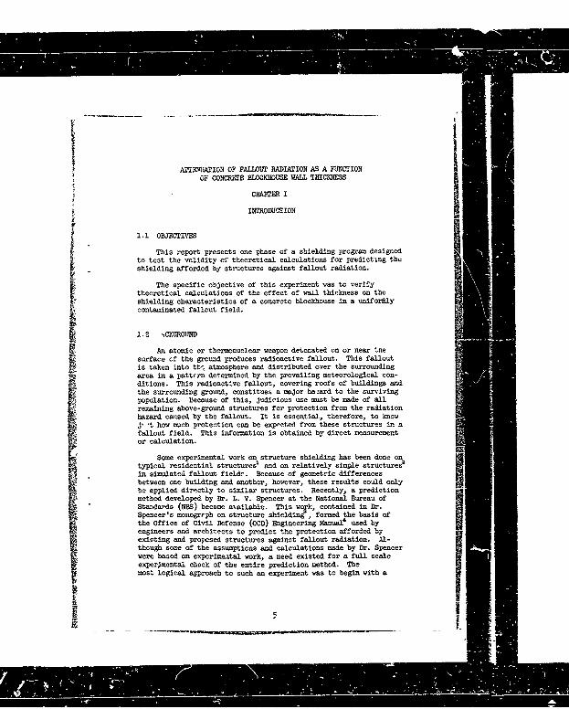
1.1 OBJECTIVE
This report presents one phase of a shielding program designedto test the validity of theoretical calculations for predicting theshielding afforded by structures against fallout radiation.
The specific objective of this experiment was to verify
theoretical calculations of the effect of wall thickness on theshielding characteristics of a concrete blockhouse in a unifortlycontaminated fallout field.
1.2 •CKGROUND
An atomic or thermonuclear weapon detonated on or near thesurface of the ground produces radioactive fallout. This falloutis taken into tbh% atmosphere and distributed over the surroundingarea in a pattern determined by the prevailing meteorological con-ditions. This radioactive fallout, covering roofs of buildings andthe surrounding ground, constitues a major haiard to the survivingpopulation. Because of this, judicious use must be made of allremaining above-ground structures for protection from the radiationhazard caused by the fallout. It is essential, therefore, to know3,t how much protection can be expected from these structures in afallout field. This information is obtained by direct measurementor calculation.
Some experimental work on structure shielding has been done ontypical residential structures
1 and on relatively simple structures2
in simulated fallout fieldr. Because of geometric differencesbetween one building and another, however, these results could onlybe applied directly to similar structures. Recently, a predictionmethod developed by Dr. L. V. Spencer at the National Bureau of"Stanftrds (NBS) became axailable. This wojk, contained in Dr.Spencer's monogrrph on structure shielding , formed the basis ofthe Office of Civil Defense (OCD) Engineering Manual' used byengineers and architects to predict the protection afford•d byexisting and proposed structures against fallout radiation. Al-
though some of the assumptions and calculations made by Dr. Spencerwere based on experimental work, a need existed for a full scaleexperimental check of the entire prediction method. The
most logical approach to such an experiment was to begin with a
I!
-,• • , ,. ; i'•.• I ~ ~~IIIIl i aaa I a ,

simple type of structure, and then proceed to more complex structu-es.Therefore, a simple blockhouse was chosen as the experimental structure.The results of experiments conducted to determine the effect of roofthickness on the gamma dose rate inside the blockhouse have been re-ported previousl~s. The present report concerns the gamma radiationpenetration through the walls of the blockhouse.
1. 3 THEORY
Details of the calculations involved in developing Spenccr'sprediction method are repgrted in his monograph on structure shielding
k against fallout radiation . The monograph was designed to predictthe shielding characteristics of any structure if certain physicalparameters (dimensions, construction materials, wall thickness, etc.)1are known.
Spencer accomplished this by reducing as much as possible thenumber of independent parameters characterizing a fallout radiationshielding problem. Fallout distribution was assumed to be of uniformdensity erd of infinite ex+-rt. MTe changing energy srectrum thatoccurs after the detonation of a weapon was resolved bsy calculating
data for three different energy spectra, namely (if 1.12-hour fissionproducts, (2) cobalt 60, and (3) cesium 137. The differences in the
density and the shielding characteristics of construction materialsof various buildings were simplified by convertlig to a parameter
called effective mass thickness (X) with the dimensions of weightper unit area. The expression for this parameter is
X = 2(2/A) p A (1.1)
SWhere: %7Z/A)- is ýhe ratio of atomic charge, Z, to atomic mass number, A,averaged over the constituent elements of the material.
p is the density of the material
A is the barrier thickness
The dimensionless factor 2(Z/A) is very nearly unity for mostimportant construction materials, such as wood, bric}4 and concrete;consequently, the effective mass thickness for these materialsnearly equals the tume mass thickness, defined as weight per unitarea.
Structure shielding analysis may be visualized by examiAtng
Figure 1.1, taken directly from Figure 20.1 of Reference 3. Figure 1.1shows a blockhouse, similar to the structure studied in the presentexperiment, with fallout on the roof and on the surrounding ground.
It is desired that the dose rate be determined at detector position Aat the center of the building, so that at that point the shieldingeffectiveness of the structure can be determined.
6(Tii
- .,m m m • mm m mm m a -- = _-

xx K
x
(Fgre2, L. V. Spner
xx x x Detec or x7

A convenient measure for the sh~elding effectiveness is the (dose)reduction factor RA for the cente- point inside the structure. 'DiisreductJon factor is defined as the ratio of the dcse inte. DA, measuredat the detector point A inside the structure to the free field doserate, Do, measured by an unshielded detector 3 feet above the infiniteand uniformly contaminated plane source, i.e.,
RA = A (1.2)Do
T'he dose rate at detector DA is due to radiation from all d-rec-tions. Because of the low density of air, most radiation will travelin straight lines from the points of emergence from the walls. Thus,the radiation penetrating the roof is due primarily: to fallout layingon the roof, plus shyshine (from ground contamination), which issignificant for relatively thin roofs. The radiation penetrating thewalls originates from fallout on the ground surrounding the building.Since, as pointed out by Spencer, the radiation penetrating the roofwill have little semblance in intensity or directibnal dostributxonto radiatJon penetratine the walls. it is approoriate to separatethe detector response accordingly.
In Figure 1.1, detector positions B and C, ,ust inside and out-side the wall, represent points at the same height as detectorposition A. Radiation from ground contamination that contributes tothe detector response at position A must first pass through the wallmaterial and then travel through the distance between the wall and thedetector. The total reduction of detector response at A can be repre-Ssented as the product of two factors. The barriez radrection factor
account° for the attenuation 'f radiation by interactions with the walleateria., clearly, this factor is a flunction of the mass thickness X ofthe wall. It should be noted that the ratio of the response of detec-
tors placed at positions B and C provides a very good estimate of themagnitude of the barrier reduction factor. The geometry reductionfactor allows for further reduction of the radiation intensity due tothe finite distance between detector positions B and A; obviously,'his factor is a function of +he solid angle fraction Q subtended bythe wall as seen from the detector position A. A more detailed anal-ysis reveals that the geometry reduction factor depends also on themass thickness X of the wall as an additional variable.
r The procedures, using Spencer's method, for calculating thereduction factors for the blockhouse are snow.n later in Section 3.4.Certain basic parameters, such as effective mass thickness, X, and
the solid angle fractions, are easily calculated. From these, otherfactors are obtained directly from charts cro graphs in Spencer'smonograph.
I
I - - •"[ i'"'i i | i• i =i -i° ii lr iN

CHAPTER 2
DEJGERWD*7TAL EQUIPMENT A 0D PROCEDURES
2.1 W0CKHOUSE
The blockhouse is shown in Figure 2.1. The Inside dimensions
"of the square structure were 12 by 12 by 8 feet. The floor and thebasic i-inch-thick walls were poured concrete. Wall tVicknesseswere added in increments of 3 13/16 inches, or 45.7 psf, to a totalthickness of 11 5/8 inches, or 139 psf.
TABLE 2.1 WALL TRIfCNERSS OF CONCRETE BOCHOUSE
Wall Thickness Mass
AFmber of Concrete Thicknessinches psf
S•4 482 7 13/16 93.73 P 5/8 139
For convenience, the mass thickness (psf) will be used toindicate the appropriate wall thickndss in subsequent sectionsof this report.
t The 2-by-2-foot windows, centered in three of the walls,
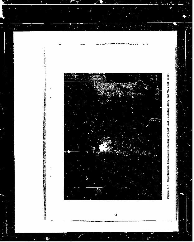
were filled with concrete blocks to the same thickness as thewalls. The fourth wall contained a 2-by-6-foot doorway. A48-psf sliding door (Figure 2.2) was installed to shield outthe contribution of scattered radiation through this opening.
Supporting 'he roof materials was a 10-inch wide flangebeam (Figure 2.1) that spanned the top of the strcture at themidpoints of the walls having opposing windows. Tfe rooffor the 48-psf and 93.7-psf walls corsisted of 1 -/32 inches ofsteel supported by a 1/2-inch "ayer of plywood extending fromthe flange beam to the tops of the opposing walls. The mass
9
I ,''l~~i F ! "W" 'r r "a

I.
I -6ItI
0,.0
.0
0
0
.0
044
0
10
__ V
I4-.00
0,
i C,'
I '-C
0�I44
'-4a'
0�0
x'-40-C,
0
I('3
1 0
I U
- -------- ,�-�------- __

Z_
thickness value cf this roof was 50.2 psf. The roof for the 139-psf
wall, however, was increased to 91.5 psf by replacing the steelwith two layers of 3 13/16-inch thick concrete block supportedby 4-inch steel channels extending from tlŽ flange beam to the topsof the opposing walls. The thickness of the roof was increased toeliminate the contribution of scattered radiation through the -oot.Thus, the dose rates at the detector positions were considered to
I represent only radiation penetrating the walls.
2.2 FALLOUT SIMUIATION
It2.2.1 Source Positions. A continuous distribution of falloutradiatiun was simulated by dividing the field about the teststructure into an array of squares and by placing a point isotropicsource at the center of each. Instead of having sources at eachof the points simultaneously, a single source was moved over the
successive centers until the total ares represented was covered.Because of the symmetry of the experimental structure, only one-eighth of the surrounding fallout field required simulation. Imagedetector positions were 'planed within the structure to obtain thedose contribution for the entire field.
Figures 2.3 through 2.5 show the source positions In relation-ship to the blockhouse. These figures show that the contaminatedarea is bounded by two straight lines intersecting at an angle of450 at the center of the structure.
The grid spacing was chosen so that the outside dimension of the
structtve was a multiple of the grid spacing adjacent to the
structu.e. The overall size of the 48-psf wall building was 152 by152 inches. Thus, the individual grid spacing for the 48-psf wallwas 25 1/3 by 25 ]/3 inches, or 4.46 fta. To reduce the number of
W dose-rate measurements, the grid area was increased by a factorof 4 after every third raw.
A similar pattern was followed in determining the sourcepositions for the 93-7-paf wall. The overall size of the building
increased to 160 by 160 Inches; therefore, the site of the gridadjacent to the blockhouse was 26 2/3 by 26 P/3 Inches, or4.93 ft
2. Likewise, the grid area was increased by a factor of
4 after every tnird row.
. .1

ROW x 50 52 53
ROW•J 46 47 40
ROW I 4042 4 44
ROW H 85363f ROW H
ROW G 31 i2 33
ROW F 25 -!3 27 2. 29
ROW E 10 2L. 2223
ROY. 0 16 17 I 9
ROW CROW AROW A1-1.-
Figure 2.3 48-psa vall grid pattern, rows A-K, point source
positions l-54.
13

II
I 86 87 8 89
Ro0 f 61 82 83 a
ROW 75
RO 77 63
SROW 555575 9
ROW K
70 71iSROW N 6r 7
F e a 8-psf IIhU grid pettern, row J-R,Figure point soigree positrons 46-S0.
Point . .p n 4
S . . .. " I II I ~ [.. .. .. . . D i n '" '! " 'l - • " •, , ..... :,_- •- . .. • .. .. --

IIROW 1 40 41 42 43.
23
ROW D 136 0 is
ROW A
Pigure 2.4 93.7-psf vall grid pattern, rows A-I, pOirt
solree ]positions 1-45.
15

I
ROW R 858 d 9 0
ow 85 86 87' 8• 8• 9
ROW 0 8'0 1 3*2 8 8
ROW P 76 7'7 78 7
ROW 0 70 71 72 73 74
ROW N 65 66 dI 6
ROW M elI Cý2 6
ROW L
ROW K
"LOCKHOUSEFigure 2.4a. 93.7-psf waUl grid puttern, rmas J-R, point
source positions 46-90.
I 1
S~~16 ,

RO~ 25 26 27 28 29
ROW E 20 21 22 i4
ROW D ,6 17 i8
ROWC ol 12 13 14
Figure 2.5 139-psf wall grid patt-rn, rows A-F, point sourcepositions a.e and 5-30. Remaining rows are thesame as those for 48-psf wall grid pattern
(Figure 2.3a).
[,[ 17
£
: I

Except for Row A, the same grid size used for the 139-Psfwall was used for the 48-psf wall. Row A was divided into five gridareas (see Figure 2.5) rather than the four used for the 48-psfwall to facilitate area representation by the single point source.The grid size in Row A was 17 1/3 by 21 inches.
2.2.2 Detector Positions. The detector leyc.t is shr.n !nFigures 2.6 and 2.7. Figure 2.6a is a plan of the building shosi"pthe position of the primary detectors with respect to the walls ofthe building, and Figure 2.6b shows the detector positions withrespect to the floor. This information is summarized in TableS2.2.TABLE 2.2 POSITION OF DEMThMORS INSIDE BOOCCHCUSE
SPerpendicular PerpendicularDetector Distance to Distance to Height AbovePosition Wall 7 Wall II Floor
feet feet feet
A 1 1 3B 3 /2 3 1/2 3c 6' 6 6 6S03' 6 6 3
* 0' 6 6 0D 3 1/2* 6 3
E 11 6 4
E1 3 6 3E 42 1 6 2
* Note: This detector position was at ground level directly above thecenter of a 16 by 16 by 16-inch hole in the center of theblockhouse.
Primary detectors (capital letters) and image detectors (smallletters) were placed within the building as shown in Figure 2.7.Figure 2.8 illustrates the method employed to determine the doserate at the prJmary positions usihg only one-eighth of the fieldr about the structure. In Figure 2.3a, it was desired to measurethe dose rate within the structure, at position A, from radiationoriginating from contaminant in the four shaded squares and in thefour unshaded squares. Because of symmetry, the source-barrier-detector arrangement could be represented by three image detectorpositions so as to obviate placing a source in three of the fourshaded areas of Figure 2.8a. Furthermore, for each of the detectorpositions, there was an unshaded square contributing the sameradiation field as a shaded area. Therefore, the unshaded area
181U

I -
f . CONTAMINAteD OC•. Nr
CONCRETE WALL BLOCKED
WINDOW WALLI,. I. If]I+E ,4+-A
332L. .1 WALLE
-~ 2
6 +D 14-B
DOORWAY + 4C BLOCKEDWINDOW
CLOCKEDWINDOW
Figure 2.6a Plan of primary detector positions vithin
biockhouse.
19

i4 .4
�14.14% �
V0 -
044 -
_____ C,'00C4
U0
.�o01 �
CD N U; ,�U� � W'�*.* CC
-�
0
a, CCF- .4
0 '0z
C', -
4�*. C,, .4
I20 1

I3
3
+0 /
a.- A30/ &.4 �, ''0
+.� A+.a o1 U
/I, U
/ C,
9. 9' /'9. +* +o LX-x-- e-.j
C.
r ''I-.,' U.
9. /1 I3 / C,.
:�;�II ________
I-I- 0 0
0 '0 33 C
IU
I

=- =--InC14 |i -
-- " ---- C a - , i e R[S... = • j : - - ill__ = • i • ==. I• i - -- ,i• ; . .. i0*
= Om 4
""0
g, oo- C)
,Uo4 S.
* i0* -00
__ _ _ _ _ _ _ _ _ 0 i
N_.x
-- I l mR I ! I l " I" i II • I-C
-- •- : :: : ; •' '• i 'I • i i ii i• i i i " • i • i e• .i ..•• i ii - I I I I I I 1' I e

contribution could be accounted for by doubling the contributionindicated by a source at the center of a shaded area. As anexample, the dose rate, DA, at position A for the eight contaminatesareas shown in Figure 2.8L was
DA = 2(DA 1 + D+ + D 3 + %a) (2..)
For the renter detector positions, the three image detector
positions were superimposed upon the primary position. There re,the dose rate at a center position for the above-mentioned contami-nated areas was eight times the single dose-rate measureLent.
As shown in Figures 2.3, 2.4, and 2.5, the diagonal areasI- 'reated as right triangles and the source was placed at theuP oint of the hypotenuse of the triangular area. In determiningthe continaous distribution dose rates it was necessary to halvethe single dose-rate measurements to properly weight this area.
2-3 RkEImQCnyg SOURCES
The gamma radiation sources used in these experiments werecobalt 60 and cesium 137, (Figumes 2.9 and 2.10). Cobalt 60,
Semitting 2 gasma photons of 1.17 and 1.33 MeV, was used in sourceW tre:.gths of 0.346 curies, 3.25 curies, 98.7 curies, and 395 curies.
Cesium 137, emitting a single gamm photon of 0.661 MeV, was usedin source strengths of 1.32 curies, 8.69 curies, and 100 curies.
E2.4 SOURCE. RANING EQUL4 AND PROCE0URES
In simulating fallout contamination with point sources, thehigh intensity radioactive sources were exposed remotely toinsure personnel safety, and were exposed close to the groundto simulate ground contamination. The following methods wereused to accomplish this:
.i Direct place•ent of s iurce on the ground2, Airlift system &Ione
3. Airlift system with tilter4. Airlift system with tilter and reverse-airflow system
The first method involted removing the source from theSs.nicid with a permanent magnet and q~iekly placing it in a
plas~tic holder resting on the source position. This procedurewas used only with the 1.32-curie cesium 137 source and the
C 23

02
Tas
-I -i i I-J
Ic
1A 20"o
'0
d
S.... .. • • b I T___i_ ' li 1iii!-:ii i '
a;" o ii ii... .. i,, , -- ,• -
_ I I I

__OUTER PLUG (PRESS FIT)TYPE 410 OOMAýN.i
STYPNESS1-STEEL93-STE
TYPE 3IC STAINLESS-STEEL
INNER PLUGAI(PRESPTTYPE 316 STAINLESS-STEEL
IICsW CI, ACTIVE MATERIAL
Strength Dimensions of Activeor Dimension Material
Source A B C -Diameter I eightcuries Inches Inches
1.32 0.252 0.925 1.181 0.157 I 0.1578.69 0.329 1.38 1.754 0.236 o.224
100 0-J492 1.575 1.950 o.394 1 0.905
Figure 2.10 Detail of construction of cesium 137 sources.
25

0.346-curie cobalt 60 source for the positions of Rows A, B, and
C with the 48-psf wall.
A section drawing of the airlift system is shown in Figure2.11. Briefly, the system consisted of the source, the shield,and a riser-tube assembly. To lift the source from its lead" sield, a lead plug waý removed and a stainless steel riserplug, containing two concentric aluminum tubes, was inserted±nto the cavity of the shield. An air hose near the base ofthe aluminum tubes was connected to an electrically operatedair compressor that forced air down the outer aluminum tubeand under the source, pushing the source upward into the alumi-num tube. A preset stop rod in the riser tube controlled theheight to which the sours" would move. The source remainedsuspended in the aluminum tube until the power to the aircompressor was turned off.
mhe airlift system alone was used only for Row P throughRow R (Figure 2.4) where it vac not required that the source bepositioned near the ground. At these points the source-to-detector
distances were large; therefore, the difference in slant thicknesshrough the blocknouse -ails was insignificant whether the source
a was near tne ground or as mich as 2 feet above the ground.
Beginning at, Row D, where it was necessary to position a high-xacd•tvy source near the ground (source could not be handled manually),
the airlift system was used in conjunction with toe tilting mechanism,Figare 2.12. This device cos-asted of a two-wheeled trailer with
mounted supports holding two trunUiors. A face plate was welded totne adjacent enos of each trunnlon. Adapter plates with bolt holeswere welded to opposite sides of each shield to match the plates on
o- .the trannion. The shield was placed between the plates and boltedin place. With the riser tube clamped in place, the shield wastilted by remotely actnvatir•g a 1:0-volt AC ratio motor. Thismotor drove a system of pulleys and V-belts that reduced the ro-tation speed and caused the shield to tilt to about 110O from the
sveitical. The source vas then ejected from the shield with their compressor. Source height above The ground was adjusted,
prior to exposure, by means of a positioning rod of the sanslength as the riser tube. At source positions near the building"(Rows D and E), the height of the source above the ground wasapproximately 3 1/2 inches. At source positions farther fromthe blockhouse it was sometimes necessary to place the sourceas much as 8 inches above the ground so that the source would'see" the entire building. The source was returned to theshield by Lprighting the ricer tube and shield. An average
detector response was determnned for the dose ýontribution during
26
__________________________

* IiU-
•54
a .• - *"
_ - _- _- _ _- - •-- _ _ 0_= - _. -.

Slop Ro0d
Alu monum Rihi'Tu be
Wirt Attached To ClipFor Releasing Stop Rod
inCase Source SticksInn Riser Tube
Rope Attached ToArm On TrunnionFor Uprlghling Shield Air Ho T a
Relea!sing Tension
Lead Shield Balled0 To Rotating Shiuflo
F Portable Two-
Il(,-V Gear Motor
System Providing ScewsinShield Tilt Rate Of@ crw
Figure 2.12 Sl'Aeld tilter.
28

the time that the source traveled from the ground position to nearlfabove the shield. This contribution was subtracted to give thedetector response while the source was at ground level.
The fourth and final source-exposure method, the airlift system
and tilter with the reverse air-flow system, was employod for source
positions near the blockhouse where the wall thickness under study wastoo great to permit use of a low activity source. Since the dosecontributed while the source was being returned from the gro. Aiposition to the shield would be a significant part of the total dosereaching the detector, it was undesirable to use the tiller mechanismwith the normal air-lift system. This system, shown in Figure 2.13,entailed the use of an adapter (an aluminum tube the same insidediameter and wall thickness as the riser tube) which was threadedon the upper end of the riser tube. A rubber hose was attached toa smal aluminum tube extending from the cap of the adapter. Thistaue and the air inlet at the base of the riser tube were connectedto opposing outlets of two, remotely operated, three-way solenoidvalves which controlled the direction of the flow of air. With airpressure being supplied by a compressor pump, air could either 'o:made to flow through the shield, pushing the source to the end ofthe adapter, or to flow through the adapter, thus, pushing thssource back into the shield. This method was used to expose ahigh-intensity source to a height of 1/2 inch above the ground at allsource positions of Rows A, B, and C with the 93.7-pef and 139-psf
walls.To reduce the number of source-position measurements, a method
was devised for estimating the dose rate at as many source positionsas possible. Sufficient radial lines were drawn from the center ofthe building to the boundary of the experimental radiation field so asto pass through each source position. Results of the dose-ratemeasurements for the 90 source positions for the 48-psf wall thicknessindicated that, for the center detector positions, a plot of the doserate versus horizontal distance from source t, detector for t:,- sourcepositions on a given radial line yielded a straight line on log-logpaper. Therefore, for the greater wall thickness, the dose rate ats•an" source positions could be estimated by obtaining sufficientpoints to construct the dose-rate distance curve. The source posi-tions for which this procedure was used are indicated in the tablesof the appendix.
2.5 INSTRUMTATION
2.5.1 Radiation Detectors. Quanitative measurements of
the dose inside the blockhouse were obtained with the following
29U-

- - -- - -m-
" FXb.o
iS
IN
30r
_ -
-I,to H

tI
air-equivalent ionization chamber dosimeters and charger-reader(Figure 2.14)
Dosimeters: Victoreen Model 239, Range: 0-10 mrVictoreen Model 208, Range: 0-1 mr
Charger-Reader: Victoreen Model 287 Minometer
These detectors were calibrated against a Victoreen Model
130 dosimeter, range 0 to 0.25r, charged ang. read en a Victoreen con-denser r-meter model 70, which had been calibrated by the NationalBureau of Standards (NBSr . The calibration was made at two energylevels, 215 keV and 1,250 keV. The correction factor for cesium 137was obtained by linear interpolation for 661 keV photon energy levelbetween the two measured energies. It was estimated that the correc-tion factors were accurate within E3 percent.
When taking dose measurements, the dt.imeters were exposedfor a time sufficient to give a reading of not less than 50 percentof full scale. Readings could be reproduced within *1 percent offull scale. The total dose received by a dosimeter was recordedwith the time required for the exposure. This information wasconverted to dose rate in milliroentgens per hour.
2.5.2 Survey and Detection Instruments. Survey and detectioninstruments included the following:
Tracdrlab Midel SU3 Laboratory MonitorNuclear-Chicago-Model 2586 Survey Meter (Cutie-Pie)Victoreen Mod 1 389 Survey Meter (Thyac)
The Tracerlab Model SU3 laborator3 monitor was used to indicate
the exit and return of the source to the shield. This system, inconjunction with an electric timer, was also used to determine thelength of the exposure time.
The survej meters were used to estimate the dose rate withinthe blockhouse at the various detector positions.
2.5.3 Miscellaneous Instrumentation. Correction factors werenecessary to correct the responses of the dosimeters to standardatmospheric conditions (CPC and 760 = Hg).
Atmospaeric pressure was measured by a U. S. Army Signal Corps.mercury barometer. The instrument could be read to *0.1 m Hg.
Air temperatures mere measured by a Yellow Springs InstrumentCo. Model 44 Telethermometer equipped with a Model 405 thermistorair probe.
31 --

__________________________
ý--,- a6
4cl

2.5.•4 Field LaborMtory Facility. A 16-fow-squbae woodenbuilding near the edge of the test area provided a reasonably dust-
free place to charge and read the dosimeters. A 32-Inch thick concrete-
block shielding wall vas erected along tvo sides of the building to
reduce the radiation level sufficiently to allou continued occupancy
by test personnel and to permit dosimeters to be rea vhhile the field
test vas in progress.
33

C}IPTER 3
EVERDIM L AND THEORETICAL RESULTS AND DISCUSSION
3.1 DkTA TRFA74ENT
Table 3.1 is a sample data sheet showing the treatment of theradiation measurements for the 48-psf wall from one source position1 .The radiation dose measurements were corrected for atmosphericconditions, radioactive decay, and dosimeter calibration, and normalizedto yield the dose rate for a source strength of 1 curie. The normalizeddose rates were recorded on analysis sheets as shown in Appendix A,Tables Al through A6. The point-source data were then integrated toobtain the dose rate from a square radiation source field with uniformcontamination density. For example, in Table A-1, the sum of the doserates 3 feet above the center of the floor of the blockhouse from thesource positions of Row A (source positions 1-4), multiplied by 8 andby the area simulated by each source position, shows the dose rate atthis location, if Row A completely surrounded the building.
3.2 INFINITE FIELD DOSE RATES
In these experiments the radiation field could be constructedonly to a finite distance from the blockhouse; whereas, in an actualfallout field, the dose rate at a detector location within thebuilding is due to an effective infinite field of contamination.The infinite field dose rates within the blockhouse were determinedby extrapolation based on experimental open field dose rates givenin Aeference 7-
From data provided in Reference 7, the dose rate 3 feet abovethe open field was determined for the same source geometry and sourcestrength per unit area as that used for the blockhouse wall and roofpenetration measurements. Contaminant located on the roof for theblockhouse measurements was located on the ground for the opln fieldmeasurements. Tables 3.2 and 3.3 show the dose rate 3 feet abovethe oper, field for cobalt 60 and cesium 137, respectively. Thephysical size of the source area is indicated by the distance, d,which is the minimum distance from the center of the field to theouter boundary of the square simulated fallout flildo or, as in-dicated in Tables 3.2 and 3.3, half the length of the contaminatedfield.
Tables 3. rough 3 9 show the experimental dose rates withinthe blockhouse in (mr/hr)/(curie/fts ) totaled through'each squareradiation area for the center detector positions at the 6-foot and3-foot heights anQ at ground level.
I 314
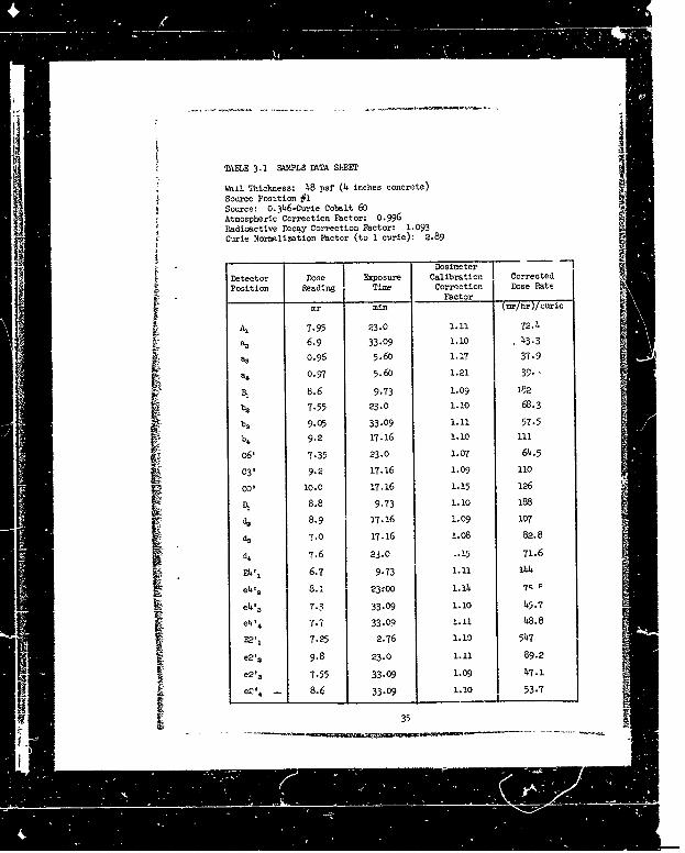
TABLE 3.1 SAMPL. DkTA SUET
Wall Thickness: 48 psf (4 inches concrete)
Source Position #1Source: 0.346-Curie Cobalt 60Atmospheric Correction Factor: 0.996Radioactive Decay Correction Factor: 1.093Curie Normlization Factor (to 1 curie): 2.89
S~DosimeterDetector Dose Exposure Calibration Corrected
Position Reading Time Correction Dose Rate_ _FactorSmr m~in (mr/hir)/curie
A, 7.95 23.0 1.11 72.4
a. 6.9 33.09 1.io 43.3
a3 .96 5.6 1.17 37.9
a, 0.97 5.60 1.21 39. -
B, 8.6 9.73 1.09 1P2
7-55 23.0 1.10 68.3
b3 9.05 33.09 1.11 57.5
b4 9.2 17.16 1.10 ill
c6, 7.35 23.0 1.07 64.5
C3' 9.2 17.16 1.09 110
CO' 10.0 17.16 1.15 126
D, 8.8 9173 1.I0 188
S8.9 17.16 1.09 107
d3 7.0 17.16 1.08 82.8
d4 7.6 23.0 -. 15 71.6
E4'i 6.7 9.73 1.11 144
e4' 2 83. 23:00 1.14 74
eZ•' 7.3 33-09 1.10 45.7
e'.4 • 7.7 33.09 1.11 48.8
E21I 7.25 2.76 1.10 547e2'2 9.8 23.0 1.11 89.2
e2'3 7-55 33.09 1.09 47.1
-eZ" 8.6 3.09 I.10 53.7
35
;; ON
I- --. :_ : =• : ._ i[ ii i• _~~ !!a!!!~ N m

j
TABLE 3.2 CUMULATIVE DOSE RATES 3 FEET ABOVE AN OPEN FIELD
CONTAMINATED WfH COBALT 60
d
Row Lenth of Field Cur.Lative
2 Dose Rate
feet (mr/hr)/(curie/ft')
AA* 2.12 28,100
BB* 4.24 69,300
SCC* 6-3; 101,000
A 8.44 126,000
B 10.6 147,000
C 12.7 163,000
D 16.9 191,u0
E 21 1 212.000
F 25.3 229,000
"G jG 33.8 256, 000
H 42.2 277,000
I 50 7 294,000
J 6-.6 319,000
K 84.4 339,000
L 10"- 355,000
A 2!35 380,000
N 169 397,000
0 270 432,000
( 338 446,000
R 443 2,000
*This portion of the radiation field would be occupied by theI experimental blockhouse.

TABLE 3.3 CUMULATIVE DOSE RATES 3 FEET ABOVE AN OPEN FIELDCONTICAMIAED WITH CESIUM 137
d 1 Cuxu•tive
ROW Length of Field i DEle Rtte
feet (mr/hr)/(curie :t )
SAA* 2.12 7,490
BB* 4.24 18,300
cc* 6.36 27,000
A 8.44 34,100
B 10.6 39,600
S12.7 44,200
D 16.9 51,700
E 21.1 57,500
25.3 62,100
33.8 69,100
H 42.2 74,700
I 50.7 79,000
J 67.6 85,70084.K -4 90,g00
L 101 95,200
135 101,000
N 169 105,000
0 202 109,000
P 270 u4,oooIQ 338 117,000
RP 405 119,0o0o
""This Portiol, of the radiation field would be occupied bf theexperimntal blockhouse.
37

F
}U
ABLE 3.4 OU4UIATIVE MEMLUNAL DOSE RATES AT CM-MR DETOECTRPOSITIONS, COBALT 60, 48-PSF WALL TKIC'mES
dSource Length ofRow Field Cumnulative Dose Rtes
2 Center - 6 ft Center - 3 ft 0enter-roundl[ | Level
feet nrhr/fr)/(curoejfftý
A 8.44 6,67o 9,420 1¢,13OOB 10.6 13,2-C 17,700 18,300
C 12.7 19,400 24,900 24,900
D 16.9 28,800 34,7W-• 33,500
E 21.1 35,900 4-,0 O 39,68
F 25-3 41,700 48,.00 44,2O0
G 33.8 51,500 58,000 52,100H 42.2 59,200 66,ooo 57,&80
I 50.7 64,600 72,100 61,90o
J 67.6 73,500 81,4W0 67,6W0
K 84.4 80,2W0 88,9W0 72,100
IO1 85,500 94,600 76,10O
135 93,400 103,000 82,400
N 169 99,500 110,000 87,100
P 104,0OO 114,000 90,700
270 110,O0 221,000 95,700
Q 338 115,000 126,000 99,400
R 405 117,000 128,000 101,000
I4
__ H • • • • , • " • : "'8:- =... .-. =- -"--[!• ' - -- . -_..-

tIShBL2 3,5 C12I'AM -T ERDOMx L DOSE RATE AT CMER Dz O'ORC
PoSITIos;S, COBALT 60, 93.7-PSF WAUL T•i],SS
Fource ienth ofHO'W _ield Cui lative Dose Pate• -I I Len der - b fft e 3t Center-UrcMdJ _________T~evel
feet (r/hr)/(curie/fte)
IA 8.89 2,120 3,880 3,910
"- 1.1 ,6,51,0 6,350Sc 13.3 6, 1?70 8,81o 8,310 --
D. 9,410 12,400 11,200
E 22.2 212,200 15,300 13,1Oc
I 26.0 -4,500 17,600 1LC50SG 35.6 17,8x0 20,900 16,800
if 44.4 20,700 23,60. 18,00o1 1 53,3 23,300 26,ioo 19,200. 7!. 1 26,7-o 29,500 201900 .
K 88-9 29,10C 32,300 22,600
L 107 31,600 34,500 24,i004 ± -. 2 31,70 32,300 25,900
N78 i 37,000 40,100 27,500
0 213 ý3,800 41,goo 28,600
p 1 284. 41,2010 I 11.1.300 30,3=,
S356 43,000 46,20o 31,700
R 427 14,300, 4, J 32,800
1 39-I! " !

TA•LE 3.6 Cu4ImATIVE mmldENAL DOSE .ATiS AT CNIEN- DSI-'Tw RPOSITIONS, COBALT 60, 139-PSF WALL T.IItH2fSl
dSoa'ce Length ofzSoacW Field Cne ulatire -D e Raes
S2 Center - 6 ft I Center - 3 ft etrGon
Level
feet (mr/hr)/(curie/ft')
A 8.L4 371 666 722
B 10.6 897 1,460 1,64o
12.7 1,500 2,190 2,260
0D !6.9 2,490 3,350 3,260
E 21.1 3,390 4,290 4,020
F 25.3 4,040 5,000 4,640
a 33.8 5,130 .6,190 5,360
H 4-.2 5,970 7,120 5,960
I 50.7 6,640 7,800 6,310
J 67.6 7,610 8,770 6,850
K 84.4 8,430 9,630 7,280
L 101 8,990 10,200 7,680
M 135 9,850 11,200 8,24c
N 169 10,700 12,100 8,540
0 202 11,300 12,700 8,900
P 270 12,100 13,600 9,590
Q 338 12,900 14,500 9,860
R 405 13,400 14,9oo 1o,2CO
-I
S...... . -.-'' " |" i i - ------' . . . . .

TANLE 3.7 CtWJIATIVE EX1EIMUENTAL DOSE BATES AT CENTER DETBcOrPOSITIONS, CmSItam 137, 48-PSF WALL TICKMNESS
dSource Length of Cumulative Dose Rates
Row Field Center - o ft Center - 3 ft Center-Groi ne2| Level
feet mr/hr)/(curie/ft'
A 8.45 1,010 i,660 1, 10B 10.6 2,)90 3,210 2-53)
C 12.7 3,310 4,500 3,670
D 16.9 5,350 6,540 5,360
E 21.1 6,930 8,290 6,480
F 25.7 8,200 9,520 7,410
G 33.8 10,100 11,400 8,250
H 42.2 11,600 12,800 8,940
1 50.7 12,700 13,900 9,420
67.6 14,200 15,500 10,200
K 84.4 15,400 16,800 i0,800
L 101 16,400 17,700 11,300
135 17,700 19,100 12,100N 169 18,700 20,100 12,800
0 203 19,500 20,900 13,200
P 70 20,600 22,000 14,100
Q 338 21,300 22,800 14,600
B 4o5 21,900 23,400 15,100
j 41
""__ _ __ _ __ __ _ __ _ __ _
-- --- -- ,I• i - _ '' • . .

TABLE 3.8 CIm4UIATIV2 EXPESIMENoAL DOSE RPATES 1T CNTER DETECITRPOSITIONS, CESItL4 137, 93.7-PSF WALL THICKNESS
dSource Le.gth ofpow Field Cumulative Dote I'te _
2 Center - 6 ft Center -- 3 1 Center-Grounr dLevel
feet mr/hr)/(cure/ft),
A 8.89 259 475 '475
B 11.1 569 911 871
C 13.3 869 1,280 1,180
D 17.8 1,250 1,680 1,510
E 22.2 1,620 2,060 1,780
? 26.7 1,930 2,370 2,010
G 35.6 2,350 2,790 2,27W
H 44.4 2,720 3,160 2,500
I 53-3 3,020 3,470 2,670
1 71.1 3,410 3,870 2,860
K 88.9 3,760 4,220 3,070
L 4c7 4,o04 4,510 3,220
m i24,440 4,920 3,470
S178 4,770 5,240 3,690
0 213 5,020 5,510 3,860
f4
S•42

TABLE 3.9 CUMUIATIVE EXPERD2ML DOSE PATES AT CMTER DErECTORPOSITIONS, CESPI 137, 139-PSF WALL THI(CIESS
dSo•orce Length ofR. Field Cumulative Dose Pates
2 Center - 6 ft Center - 3 ft Certer-Gro2adI _eVe]
feet (mr/hr)/(curie/ftV)
A 8.44 26.8 52.8 62.9
B 10.6 72.2 128 141
c 12.7 130 208 209
D 16.9 240 341 310
E 21.1 329 432 375
F 25.3 402 509 1,2
37.8 516 629 512
H 42.2 600 718 572
I 50.7 669 7b8 614
J 67.6 780 909 695
K 84.4 859 998 760
L 101 971 1,070 804
43ISII
m 43
_ _ d--__ _ _ . . = , = . ; •. : - . : -_ _. -_I

Figures 3.1 through 3.6 show the cumulative dose rates fron Tables3.V+ through 3.9 plotted versus d, defined as half the length o thesource field or the perpendicular distance from the boundary of thesource field to the center of the blockhouse. The top curve of eachfigure is the 3 foot-high open-field dose rate obtained from data inReference 7. For values of d greater than 100 feet, the resultingcurves for the various wall thicknesses show a family of curves parallelto the open-field curve. It was assumed that the constant raticsbetween the open-field dose rate and-the dose rates at the center ofeach of the three structures continued for an infinite di.tance. Thismade it possible to determine the infinite field doses within thtstructures based on the open-field dose rate reported in Refercuce 7.
The cobalt 60 source field extended to a distance, d, of 405feet for the 48-psf and 139-Psf walls, and to a distance, d, 'of 427 feetfor the 93.7-psf wall. The data from Reference 7 indicate that 92 per-cent of the infinite field dose rate was obtained by the 405-footfield, and 92.5 percent of the infinite field dose rate was accountedfor by the 427-foot field. The infinite field dose rate 3 feet abovethe floor at the center of the blockhouse (wall thickness, 48 psf), inthe cobalt 60 radiation field was determined to be
E DiDC Iý A iý(3.1)
31 0. 92.ý#N.
Where: Z D, indicates the sum of the dose rates from source rowsIA A through R.
Similar calculations were made for the 6-foot and ground-level detectorpositions for all wall thicknesses.
Because of the limited strength of the cesium 137 source, it wasnot possible to obtain a radiation source fielM as extenstveýab that forcobalt 60. With the 48-pof wall, the cesium 137 radiation field ex-tended to a distance, d, of 338 feet. A field of this size represented92 percent of the infinite field dose. The source field for the 93.7-Psfwall could be extended only to 213 feet which included only 87 percentoa the infinite field dose. Finally. the cesium 137 source field forthe 139-pof wall extended only to 101 feet which represents approxi-mately 75 percent of the infinite field dose. The infinite field doserates for the various wall thicknesses are suamuaized in Table 3.10.
Figurea 3.7 and 3.8 show the infinite field dose rate versuswall thickness for cobalt 60 and cesium 137, relspectively. Thedose rate, Di, at zero wall thickness was obtained by subtracting
£414

' II LL -
_ _ _ _ _ _ rI
____ _ _____ _ :11

od
0 0,
464

o ,, 0
I 0
I 4,0
, •,,,•,,,,, ,-4

--- m*. -- -
I
N ��1 *1
8 8 �
I II I
I § 00
t41 .1________ _____ I-- II ________ _____-
__I' ___ ___ �0
____ ___ ri1 -t -4.�
j i� -t ____ I _____
_____ _______ _______ .1
___ -�-i-i-t--AI I -__
______ ____ � ______ -'p I' � 0
-- -±-f ____
I II ______
2 , -�-
C,
ha
- - - -- --.-- � I��0'�'� -- - -

i
- • • •
• 5• g i g
SI "g
I I '
I • • ,•
I I €ot"-S• | .,.• •,,•
/ L, ILt L I ! ;-•
,
,,-• ..... I,.,, ,'L•,•,._•,,, ,'?n•,• ,••,, ,
• •

I'I
I I'i §
__I _ _ ii-- i- • - 4------I __ __
• _ • _I ._.,_.
,,, ,_,_,__ _,, _, _ ,. 4
-4-!- ~ _ ___ __ £ 4)4
" " -- i " " = " ~~~~ ~~' .. . . . .__ --" .... . . . . .. . . .

L I
...........°°, .. ......"E'~'a'I Dma Ralf.0,O 6(t~
Ot Z.OM Wall Thhok'eS 0 3ft
Aof
t IOT
Mass Thickness,psf
Figure 3.7 Intlit field dose rate versus wall thickness in thecenter of th•- blockhouse.Source: Cobalt 6o.center..th-

z Oft T r- r I- II 0 1 1i
F gurem3,8 Ioi e 0 iel dot.
Matss Thlc'tsess, I.,sf
Figure 3.8 Infinite field dose rate veras,, Mall thicetn, as in
the center of the blockhouse.
Source: Cesiumo 137.
!5

TABLE 3.10 INFINITE FIELD DOSE PATES AT TIM CENTER~ POSITIONS OFF TALCONCI=1' BLOCKHOUSE
Detector 48-pif wai l 93.7-psf Wall 1,, -psf Wall
Height
feet ýmn/hr)/(curie/ft') (mr/hr)/(curle/ft?) (mn'hr)/(curie/ft5
)
9: Cobalt 60
6 127,000 47,900 14,6oo
tm
3 140,000 51,500 16,300
0 111,000 35,400 11,100
br'; Cesium 137
6 23,400 5,750 1,280
3 24,800 6,16o 1,480
0 15,700 4,770 1,110_
the contribution of sources within the area covered by the blockhousefrom the in~finite field dose rate. Both cobalt 60 and cesium 137radiation show approximately expornential attenuation of dose rate asa function of wall thickness up to 139 psf for detector heights of 0(ground level), 3, and 6 feet.
3.3 EXPERINML REDUC~TION FACTORS
Teexperimental reduction factors, R, were determined by dividingthe experimental infinite field nose rate, D, from Table 3.9, by theopen-field dose rate, Do~, determined from Reference 7. Poi example,the reduction factor 3 feet above the center of the blockhouse floorfor the 48-psf wall in a cobalt 60 field is
R 6 /Dl 140,000 (m,/hr)/(curie/ft2
0,282 (3.?)6 497,000 (mr/hr)/(curie/ft
2)
"• " "24800 ,160i, h0 i--53

The redaction factor at the same position in a cesium 137 field is:
R = D/Do = U2•81:00 t('02r=lo.194e(3t3)De12,000 mrlhrlcurie/ft - 0191 (3.3)
The experimental reduction factors are listed in Table 3.11.Also shown are the theoretical reduction factors as calculated oySpencer's method and explained in Section 3.4.
3.4 TH!nRmTCAL REDucTON FACTORS
Details of Spencer's methods of obtaining the formulas used in
the calculation of the reduction factors are given in Reference 3;therefore, no extensive discussion will be given in this report.The formulas used in calculating the theoretical reduction factors
* are as follows:
~toRe' .... = D/D0 = 4W(X,h) Wal(X,h,a• 03.41
Where:
the factor of 4 converts the contribution through one wall toaccount for the four walls of the blockhouse; the functionW(Xh) is the barrier reduction and is dependent upon theeffective mass thickness, X, of the wall and the height, h,of 'he detector above the ground.
The function Wal(X,hP5) is the geometry reduction factor and is
written as follows:
Wal(X,h,s) = b(X) W5 (h,s) + 1.151 - b(X)] pa()(s(,A) (3.4a)SWhere:W b(X) is the proportion of unscattered gamma rays estimated
by the ratio
p(O) (x)IP(x)Wi Where:
P , (oY(X) is a function obtained by subtracting P(S) (X), the
total detector response due to scattered radiation from apoint eo•ree in en infinite ho-o-ne--smediun, from P(X),the total detector response to radiation from a point sceircein an irfinite homogeneaasmedlu', or
P(O)(x) = p(x)-P(r)(x) (3.4b)
54
-... .-- * - _ .. .
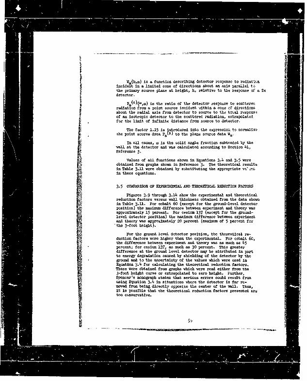
incident In a limited cone of directions shout so axis parallel tothe primary source plane at height, h, relative to the response of a 2g
Pa(h)&,m) is the ratio of the detector response to scatterecradiation from a point source incident within a cone of directionsabout the radial axis from detector to source to the total responsiof an isotropic detector to the scattered radiation, extrapolatedfor the limit of infinite distance from source to detector.
The factor 1.15 is ;n roduced into the expression to normalizethe point source data PAkS to the plane source data Wa.
In all cases, a is the solid angle fraction subtended ty thewall at the detector and was calculated according to Section 41,Re-ference 3.
Values of all functions shown in Equations 3.4 and 3.5 wereobtained from graphs shown in Reference 3. The theoretical resultsin Table 3.11 were obtained by substituting the appropriate vsr :.!'in these equations. •
3.5 COMPARISON OF EXPERW AL AND THEOREICAL REDUCTION FACTORS
Figures 3.9 through 3.14 show the experimental and theoreticalreduction factors versus wall thickness obtained from the data shownin Table 3.11. For cobalt 60 (except for the ground-level detectorposition) the maximum difference between experiment and theory wasapproximately 15 percent. For cesitm 137 (except for the ground-level detector position) the maximum difference between experimentand theory was approximately 20 ,percent (maximum of 5 percent for
"the 3-foot height).
For the ground level detector position, the theoretical re-duction factors were higher than the experimental. For cobalt 60,the difference between experiment and theory was as much as 45percent; for cesium 137, as much as 30 percent. This greaterdifference at the ground level detector may be attributed in portto energy degradation caused by shielding of the detector by theground and to the uncertainty of the values which were used in
Equation 3.4 for calculating the theoretical reduction factors.These were obtained from graphs which were read either from the3-foot height curve or extrapolated to zero height. Further,Spencer's monograph states that serious errors could result fromusing Equation 3.4 in situations where the detector is far re-moved from being directly opposite the center of the wall. Thus,it is possible that the theoretical reduction factors presented aretoo conservative.
m IF ~ II , : i"_ 1 Il 1'ir I I re "

H 0 .0 cII 4 0
R RI I R
4) Cf II Il 0l H
o 0 o 0 0 0
t ~~l H . CIo o
IN 0v oO 6 ~ o
~ O H O 0 0H~ III CI
)O 0 0 0o
co cu0 CI )ý .0
o o o o o
v vHom o \
o5

0 Th Jeapils
10`4 c =0 ....
th cete of thlchus.Suc:.oat6
_ _ _ -- _ -
SIr
~ L±ILMaSS Th~c)kess, gsf
Figure 3.9 •le • adtheoretical reduction f~ctoraversus wall thickness at the 6-toot height in -the center of the blockhouse. Source: Cobalt 60
S• ~ 5 7
-- ].-." , ..... .- . - .- .- _._. _._._- p --- - __,_

V -1-1.I-I- -.-I-i
Figue 3-0 E~elioental nd teoreica reductio nfa torsverss wal thcknes atthe -fo 7heright i
thVetro h lchosSuc:Cbl 0I J1 LI~i8

0 i
0m
I0€0
2~- 0- 5 30& 4 0 5 0, 90 0 too 110 12Dct~ o 4
MOSS Thi~knes. pSI
Figur~e 3.11 Experitmental adtheoretizal recuctionfatrversus wiall thickness at ground level in thecenter of the blockhouse. Ecurce: Cobalt 60.
!5

1001
I°°j j0
0
,20 - -0 0 0 W W - o 90 1 0 1
Moss Thickress, psf
Figtre 3.12 &Per l , and theoretcal reduction factorsversus vail thickness at the 6-foot heligt inthe center of the blockhouse. Source: Cesiu= 137.
: : : • • • , ,,, m • ....

It TV 0s- -o I" -I
i -f
Figure 3.13 FRxPeritzenta1 and theoretical reduction factors f)vereusvall thicknewat the, 3.foot height inthe cent~er -of the blockhouse. 'Source: Cesium 137.~
61

101
10 .~~0 . O 2 3 4
1u r - - " - - t i ac na oI - --I-o
i Hi
Moos- Tlcns, ps
Figure 3.ls Sxperia~ental and theoretical redaction factors
versus wall thickness at ground level in thecenter of the blockhouse. Source: Cesium 137.
62

L m l m4CONCLUSIONS
4.1 CONCLUSIONS
Experimental and theoretical reduction factors 3 feet and 6 feetabove the center of the floor of the concrete blockhouse with wallthicknesses of 48, 93.7, and 139 psf agreed within *15 percent foruniform plane source of cobalt 60 and within *20 percene for casium 37.
Cobalt 60 and cesium 137 radiation show approximately exponent4
lattenuation of dose rate as a function of wall thickness rarglnr frona48 to 139 psf for detector heights of 0, 3, and 6 feet.
63

LITERATUNRE CITED
!. Rexroad, R. E., et al., CHLR 326, Experimental-TreoreticalAttenuation of 1.2 MeV Ga~mm Radiation by Simple Structure?. U. S.Army Cnemcal Corps, Chemical and Radicogical Laboratories, A•myChemical Center, Maryland. September 1953. Unclassified.
2. Eisenhauer, C., NBS Report 6539, Analysis of Experimentson Light Feqidential Structures with DistI•buted Ccbalt 60 Sources
National Bureau of Stataards• Washington, D. C. October 1959.Unclassilfghed.
3. Spencer, L. V., NBS Monograph 42, Structure ShieloungAgainst Fallout Radiation from Nuclear Weapons, National Bureau ofStandards, Washington, D. C. 1 June 1962. Unclassified.
4. Office of Civil Defense, Design and Review of Structuresfor Protection from Fallout Gamma Radiation (OCD EngIneer Yanual,Revised 1 Oct 61). Unclasslfied.
5. Schmoke, M. A. and Eexrcad, R. E., NDL-TR-6, Attenuationof Simulated Fallout Radiation by the Roof of a Concrete Block-house; U. S. Army Chemical Corps Nuclear Defense Laboratory, ALmyChemical Center, Maryland. August 1961. Unclassified.
6. Report on Calibration of Victoreen r-Meter Serial No.2921, Test No. G28398 National Bureau of Standards, 27 December
7. - exrcad, R. E. and Scmokc, ". A., NDL-TR-2, Scattered
Radiation and Free Field Dose h~ates from Distributed Cobalt 60
and Cesium 137 Sources. U. S. Army Chemical Corps Nuclear DefenseLaboratory, Army Chemical Center, Maryland. September 1960.Unclassified.
64
l. V

APPESND3
Experimental Point Source Data
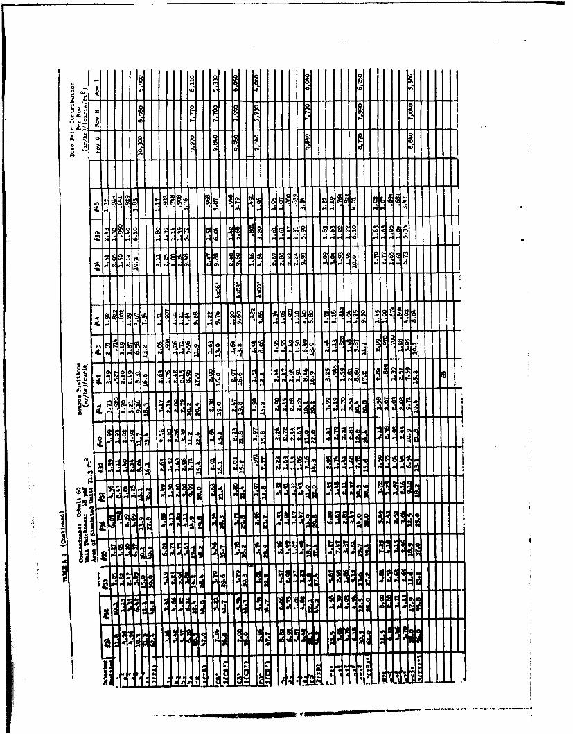
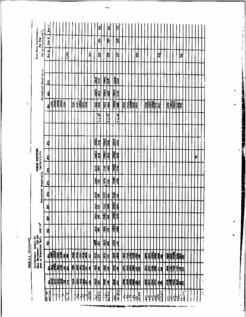
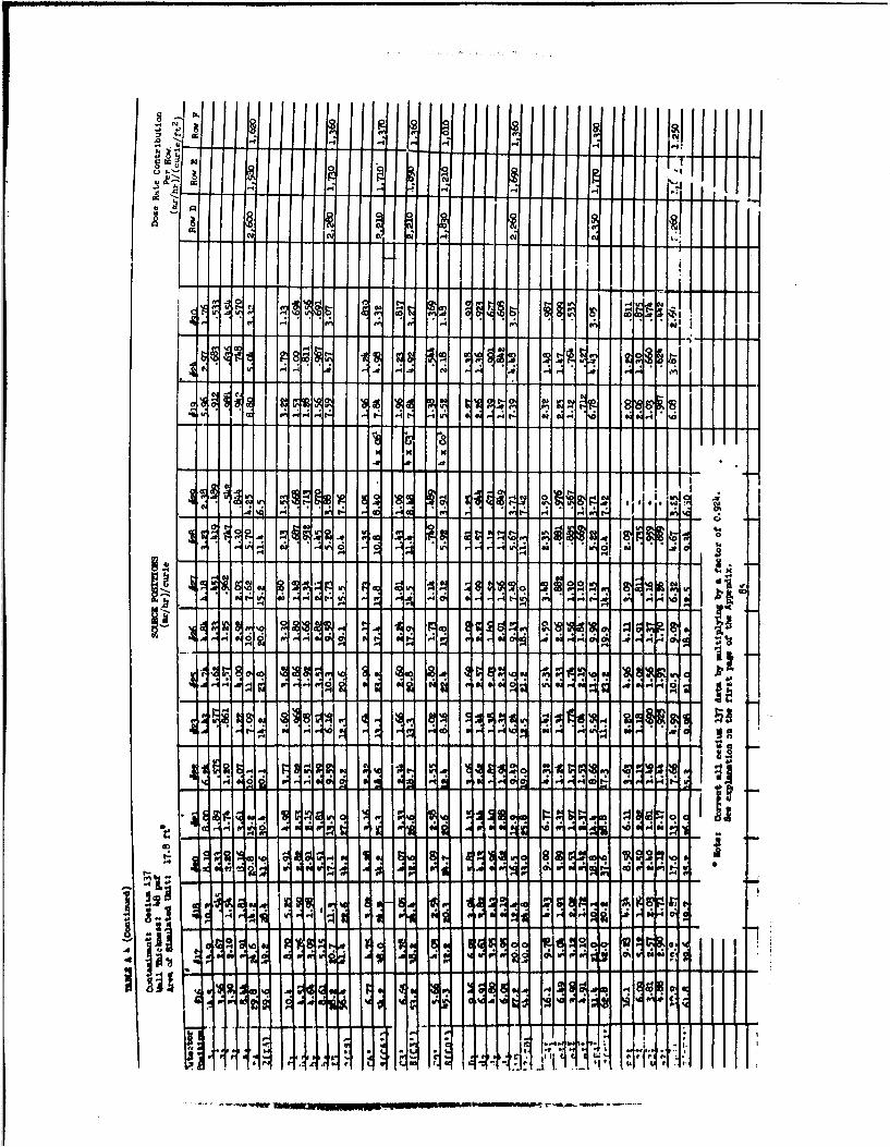
The following pages contain the point source data for each wal)thickness for the source positions shown in Figures 2 ' no 2.5 of ttisreport. Also shown is the dose rate contributicn from each row,obtained by converting the point source data to uniformly contaminat -darea source.
Special attention is called to the notation on Tables A4 throughA6, listing the data for cesium 137. All cesium 137 data must bemultiplied by the factor 0.924. This change resulted from a recal-culation of the specific gamma exposure rate of 1 curie of cesium 137in air. This recalculation was made by Dr. A. Foderaro of PennsylvaniaState University while working under Nuclear Defense Laboratorycontract No. DA 18-i08-AMc-24-A*.
The cesium 137 data shown on the tables were normalized on thebasis of a specific dose rate of 0.39 (r/hr)/curie at one meter. The
factor 0.924 is the ratio which converts the data to the recalculatedvalue of 0.36 (r/hr)/curie, i.e.:
6 curie = 0.924• •_2.• • • 039 (rlhr)cure
Dr. Foderaro suggests that the value of 0.39 r/hr obtained from
the Naticnal Bureau of Standards Bandboox no. 4 does not taxe intoaceount that only 92 percent of the cesium 137 disintegrations areaccompani~ed by gaa rays; the remaintng 8 percent are beta transitionsto the grouna state of the daughter.
All dose rates in the text of the report have been corrected bythe above factor.
* Foderaro, A., Private Communication to R. E. Rexroad, 17 January 1963.
65
ai

u Col ID 0
0 C'! 10 0.4
00 1000
MN
119 itý I? -It 1ý A! Iý 11ý 4ý
1ý 9 CR 11;a C4 0 ff
, C4 CA
co -4 V% oj tv W0
1
`1 -. 4
I
c%* 9 990 " m , - 14C; 44 CQ 19.4 .1m CQ
- cq
0 UN cz Itri CV, CKC13 W
7 N -
N C9
i", cr-119 Hý
w cli X* C"I0 H-
cm.* Pi
0 Ic
t--. If .1110+ M4-[ HM A I
114 M IN 1114
0- 4 4 mlý I 1i M 0 1 ý4 1W Q I
%G ccow lilt lc

r
N IMP M,I... I I ff
rl
cs
13
89 C9 cc 81tz 0; ch
I r
0%
rý 1-91
'i 0 19 1ý 1 1 1 2 A-W 0 t- ff I-- P1 '01 8 -1, 1- 11-11-. 1 .1 11 , in -1
cc r- a,
%D 4 to t 0 r- 1.61
ill 1111 1 1 H I
'a t- 00co No cli 14
t- o fý cc CA c
c 0
:I is 141;H
0 U .4 1 .4 1ý w
W ow 19'. c
ig
I I MI Il.: 11ff-Z
~~0 ' C-4;
rl .1 l~0
QIC

i E
0'4*t3D
i.r 1-
-1 c
I .10fl Bil

I A
01 q
:sI

C4
10 15k
64
E I EE,
rr
I I.-M W
;i
E, E
lit
11 OIJ I 1 10 1 1- 1 1 TR
I M. .0 1 1011 q A I- q I
Q 4W H. I
11 *H 1101 10 M. 1 00
JA I I I

zu -T61 1
t- F- OD
1"N' I
0 ýMol
'D N 0: 14I-
MN Wl
oz 10 9 "D co ,qcoc" cm ftý V; 0;14 . 111R 11! 1ýC.. z .0 co r- m t.- C6 m In r-w W,
10 IT? 5; 12 1 09 11R C:c
OD r- -.1 -1 1-
t- t4 t- "C%0 :K
do en 1- 19 "! ftý
14 91 A ff 4c %0 V; 24
C 9 14.P.-
V I N ICý .4 cc cc c4v
c C! Cc

04 w
iI H1
~O

11PI
S-'Ali

411 Frilul. I
1 IN
MMM r Ill rri MI t. IN 1 -1111
iý d r"I .4% 1.11 1 IýFM 11 1
"M*; 141 M .11111 1111ý - .1 1 1
I 11ý- I; 111111 41 ill N 1111 111111 1ý I Hcat 1101 0 114
0 1111
11% t Ifil 11,491 11 11111 11111 r-MI11 I I

v3
41 Iff le
9,9
El
sp12 is 19 Ef
P I I. III
lit. I I I It IN

Iai 81 8.. A .8 A.11

1 51
'MV
ccaf
at A" cao ; : 4v
C s 5 m' h

I itfl
A 1119
Aoil Gd I I I I I *W 1 d
ltllý_
-1 1 1 1 1 A 46 r:
j i c i a 1ý
12
j 11 ý.4 ý :
1-1 1 0 d; ,I A r Q I IOd.1 Hýd ! ;.j +w I I -
A4Al -1 1: d 1A I 1 *5 1 OW I
ýl I Ow. j M e ýi4' j Hs.
1
10
lot
0 '4lei A
Uall, 1 .1 4 1 4- 1 _li:. I I

IF
-4 *121
0 0
A !m
*-#1* -711 IH

I H 41
I 111 1 W 11 1 1 1
.00 11*1 d I-st H, I M! -d! lo I I I Im I
a 0
I I I I I I W 10 1 1 1 1 1 111 1 1 11 . . ..
OOM MO. 11
4 flý N 1i ýf,, i OM qii i IAil
I -tT
I.:',~41iTJUTh~I1Th4HT 1 h1T
Ahr 1

ii'-M II
1 4" 1-

III N III
AH Ir em 1 :1 qj :I M-1 6; 1 F; C, "64 4ý al W1 1-1 11 1 1
I T 9111 11 1 19 80
gs .0 -4 V o o 1B I ig A 04C;, A .4
0 M, co W 0 04
F
11-S N I id li.
-S 01 9
9 ýR A c .4 f
f- fa P, If
:31 51 Hil
Ice
,c M two
I I I w I I t llw l 1111" 11I I I I I w I I
c I Wý 'a C M -8 1$ 9 8T t T 9 Log b IU: .4 . U: 1ý
9 8
4 owl, -1ýýC; ý;l 1*1 Ný 1 119 ac W4 A A 0 Cc
M W1
0; Ch
102 a, cc .40 IV 'S in c
.!,,C 64 V, al v
0 M C6
v q ZE
imp e r4 A; M .4
Q tj I C Q IRC!Ift A
9 8 9 Is cl, NON I HA 0 W.
fol0
ONJ
iiflýd% wa;
"suf
.4 6 01

-44
040
file
AA

I I K
Ai
i M .11 110 1 1 M I I
I IM 1§ 1+ 4- Ili I Hi i I
a c

co CD
d I
E
c cHIM M 1101 811410
I I I Mo I I I ýP'11 0 44
DIUM 111
I M. -1 M
IE
I
11-P I ti 11
I !V
0 cI C.
6 a Al ý'Ifl 111 ý11 -L-,iq

1.11 1 1 1
11 W. W I W I I f
co
04
lad
;I lo-
.911 IIIs
M .11 t.NOm
M ill.
8 11 All -0
OR il M ill 1 11 1, 9

UA
I~C C4 A 13o
ION~j M.

-* -'J - - - - -
'g * w C, m 1.14. ..
I.-n
'-01
A I

:s C c d'1
.6 . .. . .
.4 .--1 0 ,1 m
A.occ,

sI
ON
e . 1 % *" i ý -ý I; II -I

10A M
M Ak . 1%
ON 114 1.0,41s

00
I rill.

'I It -y 8 P
414
U'.
CD A r
4~0
Q C
v 0
144
* I ~H A ::4

NM1 11 .. e' Id SO ESP
0 Ni i 'M.f
Ali -

I R19 1 to
01
Ms] 1 Olfl
I I it 11 N N
P.41 ONE
Ilk 11-011 1 10A im 0 1 Ol 2
ONO, NO
4, liL
.Pa l M III Olt I Mt I; 1ý
All 11 111 1 111 4111 1 i 1
sit .0
1- -S -i
I
lol, I " t.z.

DISTRIBUTION LIST C
copies
Internal Distribution
I Commander, U. S. Army Nuclear Defense laboratory, Building
716, Edgewood Arsenal, Maryland
5 Division Chiefs, Nuclear Defense laboratorySMail and File Record Center, NDL (Record Copy),k. 5 NDL Library
20 Authors
1 Commnding Officer, U. S. Army Environmental Hygiene Agency,ATTN: Librarian, Edgewood Arsenal, Maryland
1 Comeanding Officer, Rocky Mountain Arsenal, ATTN: Surgeon,Denver 30, Colorado
The Surgeon General, Department of the Army, ATTN-: MEIUS-PO,Washington 25, D. C.
1 Cccmnnding Officer, Harry Diamond Laboratories, ATTN: LibraryWashington 25, D. C.
1 Department of the Army, Office of the Adjutant General,ATTN: AGAL-CD, Washington 25, D. C.
1 Office Deputy Chief of Staff for Military Operations, CBRDirectorate, Operations and Training Division, Room 3A526,The Psntagon, Washington 25, D. C.
1 ArrW Materiel Cor=and, Research and Development Directorate,Development Division, Nuclear Branch, Washington 25, D. C.
of the Army, ATN: Atomic Office, Washington 2 M, D. C.1 Headquarters) Joint Task Force EIGHT, ATTN: Chief, RADSAFE
Branch, Washington 25 , D. C.C Safety Division, AMUAD-SA-N, Army Materiel Co••and e Room
G-742, Building T-7, Washington 25, D. C.2 Chief of EngTneers, Department of the Army, ATTN: E SGMC-:M,
Washington 25 , D. C.I Commanding General, U. S. Army Medical Research and Development
Comcnd, Main Navy Building, Washington 25, D. C., ATTN:MXDDH-SR
2 Office Chief of Transportation, Department of the Army ATTN:
I -CENG D-',5sin, Washington 25, D. C.
DISTRIBUION LIST C (ContdaY
Copies
1 Cormnnding General, H~adquarters, USCONARC, ATTN: ATTING-CBR,Fort Monroe, Virginia
2 Demolitions and Fortifications Branch, Military Depnrtmezcc,USAERDL, Fort Belvoir, Virginia
2 Commander, U. S. Army Engineer Research and DevelopmentLaboratories, ATTN: Information Resources Branch, FortBelvoir, Virginia
2 Chief, Field Office, Foreign Science and Technology ^enter,Edgewood Arsenal, Maryland
SCommanding Officer, U. S. Army Edgevood Arsenal ProcurementAgen-y, Edgewooc Arsenal, Maryland
S 14Mr. Clark D. Greene, CBR Defense Division, U. S. Army CBREngineering Group, Edgewood Arsenal, Maryland
4 Commanding Officer, Aberdeen Proving Ground, Yarylar.d,AMTT: Technical Library, Building 313
1 Commanding General, ATl1S: Technical Library, Asmy Researchand Engineering Center, Natick, Massachusetts
S 1 Commanding Officer, U. S. Army Material'. Research Agency,Technical Information Center, Watertown Arsenal,Watertown 72, Massachusetts
1 Commanding General, U. S. Army Electronics Command, ATTN:AMSEL-CB, Fort Monmouth, New Jersey
1 Commanding Officer, U. S. Army Electronics Research andDevelopment Laborator-, Fort Huachuca, Arizona
1 Coemandirg Officer, U. S. Army Electronics Research andDevelopment Agency, Fort Monmouth, New Jersey, ATTN:
SELRA/SAT2 Commanding Officer, Picatinny Arsenal, ATTN: Techaical
Information Section, SMUPA-VA6, Dover, New Jersey2 Medical Field Service School, Brooke Army Medical Center,rATTN: Stinson Library, Fort Sam Houston, Texas (bUCIASSIFIED)SCommanding Officer, USAOSWD-USACDC, Fort Bliss 16, Texas2 Redstone Scientific Irformation Center, U. S. Army Missile
Cocvmond, Redstone Arsenal, Alabama, ATIN: Chief, DocumentSection
t 1 Commanding Officer, U. S. Army CB Combat Developments Agency,Fort McClellan, Alabama
1 President, United States Army Infantry Board, Fort Benning,C~eorgia
5 Library, U. S. ArMY Chemical Research and Development
laboratories, ERgewood Arsenal, Marylar.d
Rajor L. H. Harris CER Branch Unit, Training ant ReadinessElvision, Fort Monroe, Virginia

DISTRIBUTION LIST C (Conta)
Copies
1 Chairman, Chemical Cocmittee2, Command and Staff Department,U. S. Army Infantry School, Fort Benning, Georgia
4 Commanding Officer, Army Tank-Automotive Center, ?E251 VanDyke, ATIN: SMOTA-RCM.4, Center Line, Michigan
2 Headquarters, U. S. Army Tank-Automotive Center, ATMN:SMOTA-RCS.l, Detroit Arsenal, Center Line, Michigan
1 Course Director, U. S. Army CBR Weapons Orientation Course,Dsgwaj Proving Ground, Dugway, Utah
1 Commanding Officer, USA ARTY CI=, Fort Sill, Oklahoma1 Commanding General, U. S. Army Electronic Proving Ground,
ATTN: AG Technical Library, Fort Huachuca, Arizona2 President, U. S. Army Arctic Test Board, APO 733, Seattle,
Washington1 Office of the Senior Standardization Representative,
U. S. Army Standardization Group, Canada, c/9 Directorateof Weapons and Development, Canadian Army Headquarters,Ottawa, Canada
2 Senior Representative, U. S. Army Standardization Group, X.,AT??: Chemical Representative Box 65, USN 100, FPO,New York, N. Y. (HO RD OR FRDS
I CERCIA Liaison Officer, CEEC, Fort Ord, California1 President, U S. Arqj Armor Board, Fort Knox, KentuckyI Commanding General, U. S. Army Weapons Comuand, Rock Island
Arsenal, Rock Island, Illinois1 Commanding Officer, ATIff: CRD-AA-IPO, U. S. Army Research
Office-Derham, Box CM, Duke Station, Durham, North
Carolina
Director, Special Weapons Defense Division, Bureau o:Medicine and Surgery (Code 74), Navy Department, PotomacAnnex, Washington 25, D. C.
3 Director, U. S. Naval Research Laboratory, AWN: Codes 4030,7200, 7400, Washington 25, D. C.
VIEI

DISTRIBUTION LIST C (Contd(
Copies
i Co=manding Officer and Director, U. S. Naval CivilEngineering Laboratory, ATTN: Code L31, Port Hueneme,California
Chief, Bureau of Naval Weapons, ATTN: r.SNU, Department ofthe Navy, Washington 25, D. C.
2 Department of the Navy, Bureau of Yards and Docks, Code 74B,Washington 25, D. C.
Director, Armed. Forces Nadiobiology Research Institute,National Naval Medical Center, Bethesda 14, Maryland,AT'N: I/Lt. George N. Bardis, USAF Security Officer
I Material Laboratory Library, Building 291, Code 911B,New York Naval Shipyard, Brooklyn 1, New York
1 Conmanding Officer, Nuclear Weapons Training Center,Atlantic. Nuclear Warfare School, Norfolk 11, Virginia
I Director, Marine Corps Landing Force Development Center,Marine Corps Schools, Quantico, Virginia
1 Cosmanding Officer and Director (222a), U. S. Naval.•adiological Defense Laboratory, San Francisco 24,California
1 Commander, U. S. Naval Missile Center, ATTN: TechnicalLibrary, Code N03022, Point Mugu, California
1 Nuclear Weapons Training Center, Pacific, U. S. NavalAir Station, North Island, San Diego 35, California
I Senior Medical Officer, Code 88, U. S. Naval OrdnanceTes' Station, China lake, California
1 Comanding Officer, U. S. Naval Schools Command,Restricted Weapons Defense Department, Building 194,Boy 104, Treasure Island, San Francisco, CaliforniaATTIN: Technical Library
Air Force
I USAF School of Aerospace Medicine, Aeromedical Library,Brooks Air Force Base, Texas
1 AFSWC (S-WOI), Kirtland Air Force Base, New Mexicoi
tor
_ _ .I • • ! -!•• _- . .. .

S~DISTRIBUTION LIST C (ContdO
Copies ~1 Science Division, Drectorate of Science and Technology,
DCS/Researca and Development, Loqr USAF, Washinston 25, D. C.1 Headquarters USAF (AFMSPAA)n Buuldinc T-8 , A tT : 25, D. C.1 APcC(PGAPI), eglin Air Force Basea Florida2 Deputy The Inspector General, USAF (AFIN-LP, Kirttand Air
Force Base, New Mexico1 Director, Air UniversFty Library, ATTN: AUL3T-62-157,
Marxwell Air Force Base, AVabama1 392d Aerospace Medical Group (SlAM-3), Vandenberg Air Force
Base, California3 Technical Training Center (TS-AS), Lawry Air Force Base 30,
Colorado1 Commander, Aeronautical Systems Division, ATTN: ASAPRi-NS,
(Nuclear Science), Wreght-Patterson Air Force BaseN Ohio.Foreign Technology Division, FTDBTL, Wright-Patterson Air
Force Base, Ohio
I SAC (SUP), Offutt Air Force Base, NebraskaHeadquarters, TAC (s n, Langley Air Force Base, Virginia
2 Headquarters, Ballistic Missile Division, Norton Air ForfeBase, California
1 U. S. Atomic Energy Commission, Health and Safety laboratory,Radiation Physics Division, ATTN: Mr. Keran O'Brien,New York 14, New York
3 U.S. Atomic bnergy Commission, Washingt, 25P . BxC EATId: Technical Reports Library
I Office of Atomic Programs, ODDF&E, Room 3E1071, ThePentagon, Washing•ton 25, D. C.
1 U.S. Atomic Energy Commission, Army Reactors, Division ofReactor Dev;elopment, A70T: Donald A. Hoatson, Washington 25,D. C.
3 U. S. Atomic Energy Commission, Oak Ridge Operations Office,Fail and Document Accountability Section, P. 0. Box E.Oeak Ridge, Tennessee, ATTN: Document Library
I International Atomic Energy Agency, Vienna 1, Kaerntnerring,
Austria
________!
DISTRIBUTION LIST C (Contd)
Copies
Other Government Agencies
I Defense Intelligence Agency. Production Center (DIAAP-sRlf)Depaxtment of Defense, Washington 25, D. C.
6 Mr. Ronald Holmes, Munxtions/TW, Defence Research Staff,3100 Massachusetts Ave. N. W., British Embassy,Washington 8, D. C.
1 Lt. Col. David C. White, Chief, Radiation PathologyBranch, Armed Forces Institute of Pathology,Washington 25, D. C.
1 Director, Weapons Systems Evaluation Group, Room ID-847,The Pentagon, Washington 25, D. C.
2 Commanding Officer, Foreign Science and Technology Center,ATTN: Tech Data Branch, Arlington Hall, Washington 25, D. C.
1 National Bureau of Standards, ATTN: Dr. M. J. Berger, Washington25, D. C. (NO CIA.SSIFIED)
3 Mr. Neal FitzSimons, Staff Director, Protective StructuresDivision, Office of CiGti Defense, Department of Defense,Room 3B283 Pentagon, Arlington, Virginia
20 ASTIA (TISBAS Arlington Hall Station, Arlington 12, Virginia1 Mr. Charles H. Harp, Deputy Chief, Research Branch,
Division of Health Mobilization, Public Health Service,Room 1011, Tempo "R" Building, Washington 25, D.C.
2 Commanding General, ATTN: Technical Library Branch,White Sands Missile Range, New Mexico
5 Chief, Defense Atomic Support Agency, Washington 25, D. C.
Others
1 Ottawa University, ATTN: Dr. L. V. Spencer, Ottawa, Kansas(NO CLASSIFIED)
1 Edgerton, Germesbausen and Grier, Inc., P. 0. Box 98,A¶LTN: M. B. Carpenter, Goleta, California
1 Edgerton, Germeshausen and Grier, Inc., P. 0. Box 1912,ATTN: Mr. Zolin G. Burson, Las Vegas, Nevada
1 University of Illinois, ATTN: Prof. A. B. Chilton,Urbana, Illinois
1 Pennsylvania State University, ATIT: Dr. A. Foderaro,University Park, Penasylvania
1 Los Alamos Scientific Laboratory, B. 0. Box 1663, LosAlamnos, New Mexico, ATTNq: Report Librarian
1 Radiation Shielding Informatior Center, Oak Ridge NationalLaboratories, P. 0. Box X, ATTN: S. K. Penny, Oak Ridge,Tennes1ee

DISTRIBUTION LIST C (Contd)
Copies1 Chief Superintendent, Defence Research Chemical laoramtories,
Defenc& Research Board, ATI: Dr. C. E. Clifford, "A"Wing, Ottawa, Canada
2 The. Boeing Company, Aero-Space Division, Library 13-84,P. 0. Box 3t07, Seattle 24,'Washington, AT3N: F. H. York2 Dr. Eric T. Clarke, Vice President, Technical Operations
Research, Burlington, MassachusettsI Radiation Effects Information Center, Battelle Memorial
Institute, ATTN: Mr. Walter H. Yeazie, 505 King Avenue,Columbus 1, Ohio
1 Aerojet-General Nucleonics, P. 0. Box 86, AmT: Barbara m.Probert, S RanF n, California
S Commeanding General, White Sands Missile Range, ATMU:Mr. Glenn E. Elder, Nuclear Effects Laboratory, New Mexaln
1 The RAND Corporation, 1700 Main Streets, ATTN: Dr. -. I.Mircum, Physics Department, Santa MOt4=A, California
2 The RAND Corporation, 1700 Main Street, iTTN: Dr. Jerald E.Hill, Santa Monlca, Califorvia
1 Hughes Aircraft Company, P. 0. Box 3310, ATTN: T. D.Banscome, Building 393, MS B121, Fulle ton, California
4 Atomics International, P. 0. Box 309, ATM: Library,Canoga Park, California
1 Brookhaven National laboratory, Technical InforationD-ivision, AlPS: Classified DocinentsGroup, Upton,New York
I Sandia Corporation, P. 0. Box 5800, ATTN: Technical Library,Sandia Base, Albuquerque, New Mexico
1 Sandia Corporation Livermore Laboratory, P. 0. Box 969,ATTN: Technical Library, Livermore, California
1 Martin-Nuclear, Division of Martin Marietta Corporation,P. 0. Box 5042, Middle River, Baltimore 20, Miiyland
1 Oak Ridge National Laboratories, Radiation Snield.npCenter, -P. 0. Box X, Oak Ridge, T•rnessee
1 - University of California, LawrenceBadiation laborstoob'Technical Informtion Di'vision, P. 0. Box 08M, Livjore,California, ATTM: Clacia Z. Craig
5 Major Robert W. Vollett, Candian Liaison Officer, BuildiJng3310, Edgewood Arsenal, VMaryland
- , • .- • .- _-_ - -

I __ UNCLASSIFIED
SUNCLASSIFIED
I ... ..... t~..-- -ttltAt.A+ MtA
z. Al TCn9 3-- ttAA.
UNCLASSIFIED
UNCLASSIFIED :-
U AI
Ut.L 1. A c.t..At4 h ttit. tAo
- 13 jAIAttiAtttttc'AA, AAIAtAi