AD-785 549 HISTORY OF US ARMY ENGINEER TOPO - DTIC
378
I1HHJI.I. ii mniiuiwjuiiijii •'•<-"i '•-••' ftmmm i wn WpwpwmffPWWWHP *"•"* I •"• I iipnnmiumilikijii 11 Uli .•IUB.IWI .1, ppBMWTJWMWW ' . • AD-785 549 HISTORY OF U. S. ARMY ENGINEER TOPO- GRAPHIC LABORATORIES (1920 TO 1970) John T. Pennington Army Engineer Topographic Laboratories Fort Belvoir, Virginia November 1973 DISTRIBUTED BY: KJÜ1 National Technical information Service U. S. DEPARTMENT OF COMMERCE 5285 Port Royal Road, Springfield Va. 22151
-
Upload
khangminh22 -
Category
Documents
-
view
3 -
download
0
Transcript of AD-785 549 HISTORY OF US ARMY ENGINEER TOPO - DTIC

I1HHJI.I. ii mniiuiwjuiiijii •'•<-"i '•-••' ftmmm i wn WpwpwmffPWWWHP *"•"* I •"• I iipnnmiumilikijii 11 Uli .•IUB.IWI .1, ppBMWTJWMWW
' . •
AD-785 549
HISTORY OF U. S. ARMY ENGINEER TOPO- GRAPHIC LABORATORIES (1920 TO 1970)
John T. Pennington
Army Engineer Topographic Laboratories Fort Belvoir, Virginia
November 1973
DISTRIBUTED BY:
KJÜ1 National Technical information Service U. S. DEPARTMENT OF COMMERCE 5285 Port Royal Road, Springfield Va. 22151

vmrnm&mmnnmm mmmmmwuiwwwi w» ijnuwumnipimjujiii J» " ^"^•W8WWI»'mPR!^IW!«WIPIKr*WWM^I«P^FIIP
UNCLASSIFIED SECURITY CLASSIFICATION O' THIS PAGE (Whan Data Emend)
REPORT DOCUMENTATION PAGE READ INSTRUCTIONS BEFORE COMPLETING FORM
TT REPORT NUMBER
ETLSR-74-1 2. GOVT ACCESSION NO
4. TITLE (and Subtitle)
HISTORY OF U. S. ARMY ENGINEER TOPOGRAPHIC LABORATORIES (1920 to 1970)
s. TYRE OF REPORT a PERIOD COVERED
Historical 1920-1970
* PERFORMING ORG. REPORT NUMBER
7. AUTMORf«;
John T. Pennington
8. CONTRACT OR GRANT NUM^ERfiJ
9 PERFORMING ORGANIZATION NAME AND AODRESS
U.S. Army Engineer Topographic Laboratories Fort Heivoir. Virginia
«0. PROGRAM ELEMENT. PROJECT, TASK AREA 6 WORK UNIT NUMBERS
II. CONTROLLING OFFICE NAME AND ADORESS
U.S. Army Engineer Topographic Laboratories Fort Rclvoir, Virginia
12 REPORT DATE
November 1973 13 uiiuRER OF PAGES
U MONITORING AGENCY NAME 8 A DDR ES V" di Iterant from Controlling Oltice) <3 79
15. SECURITY CLASS (of thla report)
Unclassified
'S«. DECLASSIFIC ATI ON'DOWNGRADING SCHEDULE
16- DISTRIBUTION STATEMENT (ul thle Report)
Approved for public release; distribution unlimited.
IT. DISTRIBUTION STATEMENT (ol tha abattact entered In Block 20, II dlllarant Irotn Report)
18. SUPPLEMENTARY NOTES
C«-p I01, IT
L: 19. KEY WOROr (Continue on 'evetee aide II naceaaary and Identity by block number)
biü^ ..; U
20 ABSTRACT (Continue or, reverie aide II neceaamry and Identity by block numb«r)
This document presents the historical development of the Engineer Topographic Laboratories
from Ihe period immediately following World War I to 1970. It includes a description of the major research and development program« <>f thai period and listings in the Appendices of tech- nical personnel responsible for these research and development programs as well as listings of
technical reports published. " NATIONAL TECHNICAL
INFORMATION SERVICE
DO ljANM73 1473 COITION OF I NOV «SIS OBSOLETE '
SpringfieW VA ?2'15I
UNCLASSIFIED SECURITY CLASSIF CATION OF THIS PAGE (Whan Data Entered)

ppBWIpnWpilHlllllll. lllll!HlUHIl)l,)|JH,ll,l>».ll|HI].IW.miJII Jl..'.l'l ,1,1 l..l»*>IW»'.MHHI.-fl»w,»!•»* »«» .-..> H.HIIIIHIUM»» m» t»:il»m'l^|ilU. I ^'»Jl'-MMH.»'!»! iWflwwt» IIIPH»'» W'lHWff1'!»»»
FOREWORD
In the preparation of this history, the information for the period from post World War I through World War II was based largely on three unpublished volumes available in typed manuscript form and the personal involvement of the author in the later days of that period. These unpublished volumes were prepared by the Historical Staff of the Engineer Board at the close of World War II. For the period from World War II to the establishment of the U.S. Army Geodesy Intelligence and Mapping Agency (GIMRADA) in 1960, the historical information was based largely on consolidated, annual project reports of the U..c. Army Engineer Research and Development Laboratories (ERDL) which are available for most of the period. The author was also personally involved in the research and development activity throughout that period. For the period since the establishment of GIMRADA, the author relied primarily on historical summaries of the period's major programs, which were prepared by present Engineer Topographic Laboratories (ETL) personnel, supplemented by information contained in technical reports prepared during the period. Organizational and management information was obtained from the files of the Administrative Services Department of ETL and the old records retained in the management office of the Mobility Research and Development Command.
This history contains no information concerning classified research and develop- ment activity although significant classified programs were accomplished, particularly in the I960 to 1970 period.
\*y~
*". -ilVMMW/WMloa

f"?~"T 'W'Wt*'-"1
CONTENTS
Section Title Page
II
III
IV
VI
FOREWORD
ILLUSTRATIONS
INTRODUCTION
BACKGROUND
1. Organization through World War II 2. Evolution of the Organization to 1960
ESTABLISHMENT OF THE U. S. ARMY ENGINEER GEODESY, INTELLIGENCE AND MAPPING RESEARCH AND DEVELOPMENT AGENCY (GIMRADA)
3. Rationale for GIMRADA 4. Authorization 5. Mission
ORGANIZATION AND FUNCTIONS
6. Original Organization of GIMRADA 7. Evolution of the GIMRADA Organization 8. Redesignation as the U. S. Army Engineer
Topographic Laboratories (ETL) 9. Reorganization of 1968
10. Integration into the U. S. Army Topographic Command
ADMINISTRATIVE ACTIVITIES
11. C mmenders of GIMR ADA-ETL through FY71 12. Key Civilian Positions, GIMRADA-ETL 13. Cosl of Development 11. Facilities 15. Education and Training Program 16. Awards Program
RESEARCH AND DEVELOPMENT PROGRAMS
17. Research and Development Programs through World War II
18. Research and Development Progress through World War II
a. General h. Photomapping Accomplishments through
World War II (1) Development of Multiplex Equipment (2) The Stereocomparagraph (3) Stereoscopes
i
viii
1
6 8
11 11 13
14 14 16 18 19 19
24
29 29
32 32 34 35

in•n»im«i»i.iiiii!»i»uJi.ii»"i.ii«J".im"i"«fU""Mil'"..iw"-"1".'••w*»i"^,»'i»».'Jin1 WU"""I.""K * •
Section Title Page
VI (4) Hasty Maps from Wide-Angle Photon 36 (cont'd) (5) Mapping with Minimum Ground Control 38
(6) Tri-Metrogon Equipment 39 (7) Miscellaneous Investigations 45
(a) Vectographs 45 (b) Fairchild Detail Sketcher 45 (c) Polaroid Projector 45 (d) Stable Cartographic Bases 45 (e) Mapping from Relief Models 46 (f) Tangential Distortion 46 (g) 12-inch Focal Length Widc-AngU Camera 46 (h) Portable Plotters 46 (i) Multiplex Inspection 48 (j) Camera Calibration 48
e. Mar Reproduction Accomplishments through World War 11 49
(1) General 49 (2) Development of the Corps Company Mobile
Reproduction Plant 49 (3) Development of the Army Topographic
Battalion Mobile Reproduction Train 50 (4) Portable Task Force Equipment 53 (5) Lithographic Press Development 55 (6) Copy Camera Development 57 (7) Rapid Photographic Printers 59 (8) Miscellaneous Investigations 61
(a) Bloom Process 61 (b) Halftone Screens 62 (c) Map Paper 62 (d) Microfilming 62 (e) Printing Plates 62
d. Surveying Accomplishments through World War II 63 (1) General 63 (2) The 1-second Direction Theodolite 63 (3) Military Level 65 (4) Surveying Altimeters 65 (5) Survey Computer 66 (6) Astronomical Position Finding Equipment 66 (7) Compasses 70 (8) Miscellaneous Investigations 71
(a) Military Slide Rule 71 (b) Special Navigation Equipment 71 (c) Subtense Method 71 (d) Plotting Boards 72
19. Research and Development Programs, World War II to 1960 72
a. Introduction 72
III
'•~*H-M.»»m

wgrnmr •'«•• m mm> i. «•ppmmnn'P
Section
V! (cont'd)
Viilc Page
b. Photomapping Accomplishments, World War II to 1960 76
(1) Tri-Metrogon Equipment 76 (2) Photogram me trie Rectifier 81 (3) Motorized Photomapping Equipment 83 (4) Mapping from High Altitude Photography 85 (5) Autofocusing Reflecting Projector 86 (6) Mirror Stereoscope 87 (7) Portable Plotter 80 (8) High Precision Stereoplotter 90 (9) Utilization of SHORAN for Mapping 92
(10) Equipment and Techniques for Convergent Photography 93
(11) Radar Mapping 96 (12) Analytical Photogrammetry 97 (13) Automatic Map Compilation 99 (14) Mapping with Minimum Ground Control 103 (15) Research for M. > Compilation 105 (16) Miscellaneous Investigations 106
(a) Precision Globes and Spherical Map Sections 106
(b) Multiplex Short Frame 107 (c) Multiplex Reduction Printer 107 (d) Diapositive Processing Equipment 107 (e) Field Artillery Plotting Equipment 111
c. Cartographic Drafting Accomplishments — World War II to 1960 112
(1) Stable Cartographic Bases 113 (2) Plastic Scribing 114 (3) Grid Ruling and Point Plotting 115 (4) Automation of Cartographic Operations 116
d. Map Reproduction Accomplishments - World War II to I960 116
(1) Research for Map Reproduction 116 (2) Rapid Production of Photographic Print«
for Ground Forces 120 (3) Mobile Copy Camera 121 (4) Lithographic Offset Presses 122 (5) Spirit Duplicator 124 (6) Lightweight Paper Cutter 125 (7) Light Sources for Photolithography 125 (8) Photolettering Machines 126 (9) Motorized Map Reproduction Sections 128
(10) Electrostatic Printing 130 (11) Target Map Coordinate Locator 132 (12) Color Separation 132 (13) Terrain Model Making 135
IV
gmppjinqupiimRsupni PPR» w«jni«.p"w*wwpiwMi wimwii iiw-jpinn'immi i.nnijippWffE.n«i'iu „ JH
Section Title Page
VI e. Surveying and Geodesy Accomplishments — (cont'd) World War II to 1960 137
(1) Theodolites 137 (2) Survey Computers 142 (3) Compasses 144 (4) Mobile Survey Control Section 145 (5) Electronic Distance Measuring Equipment 146 (6) Geodimeters 150 (7) Use of Aircraft in Survey Operations 152 (8) Automatic Position Survey Equipment 153 (9) Automatic Tracking Theodolite 154
(10) Artillery Survey System 155 (11) Intertial Survey Equipment 156 (12) Miscellaneous Developments 157
(a) Astronomic Orientation Attachment 157 (b) Radio Time Comparator 157 (e) Surveying Altimeter 158 (d) Universal Sun Compass 159 (c) Tripods and Tribrachs 160 (f) Ranging Pole Tripod 161 (g) Triangulation Tower 161 (h) Indirect Distance Measuring 161
(13) Research for Surveying .*»rtd Geodesy 161 20. Resea-ch and Development Progress 1960 to 1970 163
a. Introduction 163 I». Basic and Exploratory Research 171 e. Analytical Photogrammelry 188
(1) Analytical Photogram met ry Software Development 188
(2) Analytical Photogrammclry Hardware Development 192
(a) Xurlindcn Equipment 192 (b) Automatic Point Transfer Instrument 192 (<) Variscale Stereo Point Marking lustrum» ill 194 (d) Semiautomalie Coordinate Reader !96
d. Map Compilation Systems 198 (1) Ultra Wide Angle Mapping Equipment 199 (2) Interim Nigh Altitude Mapping System 200 (3) Automatic Mosaicking System 204 (4) Automatic Mm Compilation 206 (5) Analytical Stereoploller 210 (6) Digital Mapping System 211 (7) Radar Mapping 212 (8) Mapping from Reconnaissance Photography 219 (9) Rapid Combat Mapping System (RACOMS) 224
(10) Precision Enlarging Printers 233 (11) Glass Plate Processor 233

PPSK'JUPW*-,: H »HP l.i .P. PPlWiW
Section
VI (cont'd)
c.
Title Page
(12) Utilization of Color Photography for Mapping 235 (13) Photogrammelric Support for Artillery 235
Cartographic and Graphic Systems 236 (1) Electrostatic Printing 236 (2) Target Map Coordinate Locator (TMCL) 240 (3) Automatic Point Reading, Plotting, and
Grid Ruling Machine 242 (4) Planimetrie Compiler 244 (5) Automatic Contour Digitizer 24C (6) Semi-automatic Cartography System 247
(a) Stcreocompilation Digitizer 250 (b) Digital Planimetrie Compiler 250 (c) Drum Scanner Plotter 250 (d) Digital Input/Output Display Device 250
(7) Other Cartographic and Graphic Developments of the 1960V 251
(a) Multipower Army Stereoscope 25! (b) Command Retrieval Information
System/Direct Input (CRIS/DI) 251 («•) Micromap Camera for Display Systems 252
Surveying and Geodesy 253 (1) Astronomic Survey Equipment (6^** Pendulum
Astrolabe with Electronic Trans,( Detector) (Automatic Position Survey Equipment) 254
(2) Short Range Electronic Positioning Equipment (SREPE) 256
(3) Airborne Tellurometer 258 (4) Long Range Survey System 259 (5) Long Range Position Determination System
(LRPDS) 262 (6) Elevation Determining System 262 (7) Inertial Survey Equipment (LSE) 266 (8) Position and Azimuth Determining System
(PADS) 267 (9) Lightweight Gyro Azimuth Theodolite 269
(10) Small North Orienting Device (Minh'urized Gyrocompass) 273
(11) Sequential Collation of Runge (SECOR) System 276
(12) Translocation Eield Equipment 280 (13) All-Weather Angle Measuring 285 (14) Distance and Angle Measuring System 287
Geographic Sciences 289 (1) Development of Research and Development
Program 289 (2) Modernization of Terrain Detachments 290 (3) NASA Support Program 291
VI
P|P|BPPHB«P*|!PPPP«piq^ »,->i> !llLI.>,l|piIV>l II pill I - v&rvr*\* > «^T-r
Section
VI (4) (cont'd) (5)
(6) (7) (8) (9)
(10t (11) (12)
(13) (14) (15)
VII
(16)
(17)
Title
Aerial Color Photography Multiband Photography Radar Applications for MGI Radar Calibration Radar Scattering Project THEMIS Project SAND Automatic Image Data Extraction Automated System for Handling Military
Geographic Information (MGI) MGI Products Development Reserve Unit Activities On-thc-Job Training of Graduates of the
Terrain Analysis Course Status of Military Geographic Analysis
Programs at FY 70 Status of Project for Advanced Development
of MGI Systems at FY 70
CONCLUSIONS
APPENDICES
A. Organi/ition Charts
B. Personnel Responsible for Topographic Research and Development through World War II
C. Personnel of Technical Department V, Engineer Board, and Topographie Engineering Department, Engineer Research and Development Laboratories Responsible For Development from World War II to I960
I). Technical Reports on Development
E. Roster of Technical Personnel of the Geodesy, Intelligence and Mapping Research and Development Agency <uui II?» SUKIMIH the Engineer Topographic Laboratories Responsible for Development Since 1960
292 294 294 295 296 296 297 299
301 303 303
304
305
306
307
310
315
327
333
352
VII

•pnjHpfltn.ilJ JH!« •
ILLUSTRATIONS
Figure Title Page
1 Wide-Angle Multiplex Equipment: The First 15 Projectors Manufactured by the Bausch and Lomb Optical Company Set up for AerotrianguJution Tests (194 I) 33
2 The Stercocomparagraph 35
3 Keuffel and Esscr Lens-Prism Stereoscope 36
4 Folding Pocket Stereoscope 37
5 Magnifying Mirror Stereoscope 37
6 Vertical Sketchmaster 40
7 Oblique Sketchmaster 40
8 I nivcrsal Rectifier Designed by Engineer Board Mapping Branch Personnel and Fabricated in Engineer Board Shops (1943) 41
9 Wide-Angle Multiplex Projectors Adapted for Tri Metrogon Oblique Photo Compilation with the Adjustable Tilt Bar Support 42
10 I'reversal Slot Cutter designer' to Accommodate Rectified Tri-Metrogon Oblique Photos us well as Vertical Photos 42
11 High Oblique Rcctificr-Aero Service Corporation Model 43
12 High Oblique Rectifier-Bausch and Lomb Model 44
13 High Oblique Multiplex Projector 44
14 Experimental Multiplex Reduction Printer for 12-Inch Focal Length, 18- by 18-Inch Format Photography with Metrogon Lens 47
1.1 The KEK Plotter Manufactured by Philip B. Kail Associates. Denver, Colorado 48
16 Pre World War II Map Reproduction Trailer 50
17 Map Reproduction Train Developed in World War II 51
18 Map Reproduction I nit with Van Type Body on 2.5-Ton Truck Chassis-Laboratory Section-Developed in World War M 52
l!9 Portable Task Fore«- Equipment Developed in World War II. Plate Whirlcr and Processor 53
20 Portable Task Force Equipment Developed in World War II. Process Camera 54
21 Portable Task Force Equipment Developed in World War il- Davidson Duplicator 54
22 The Model LTE Harris Prcss-20- by 22!4 Inch Shed Size 56
23 Unebner Vertical Projection Camera, 10 by 10 Inch 58
24 Mobile Process Camera 24 by 24 Inch 59
25 Carraway Rapid Photographic Projection Printer 61
26 Ourlcy I -Second Direction Theodolite, 1944 64
VIII

Figur* Tille Page
27 Surveying Altimeter-6000 Feel 65
28 Surveying Altimeter-15,000 Feet 66
29 60° Pendulum Astrolabe Manufaetured by David White Company 68
30 Zenith Camera Equipment 69
31 High Ohlique Rectifier-Bausch and Lomb Model Modified and Rebuilt by Fred P. Wileox 77
32 Photoatigulator for Cse with Tri-Mctrogon Oblique Photography 78
33 Mechanical Slutted Templet Set 79
31 Experimental Oblique Height Finder 79
35 Oblique Phot odd i neat or 80
36 Automat!" Focusing Vertieal Projecting Heetifier 81
37 Autol'ocusmg Reetifier. 9 b> 18 Ineb 82
38 Expansible Van Developed by the Corps of Engineers for the Pholomappin^ Train 84
39 Autofoeusing Refleeting Projector 87
40 Experimental Improved Mirror Stcrcosco|fc with Binoculars 88
41 Tlie Model PI.-3 Rykcr Hotter-W( rnsledl Mahon Type 89
42 The Bausch and Lomb 720 Stereoplotter 90
43 High-Precision Stereoplot ter 91
44 Adapted Multiple Equipment with the Stcrcopontomctcr foi Convergent Photo Aerotriangulalion 94
45 Experimental Multiplex Setup for Convergent Photo Compilation ('sing the Adjustable Tilt Rar 94
46 Experimental Transforming Printer for 20° Convergent Photography 95
47 E\ fieri mental Scanning Stereoscope Designed for Viewing Transformed 20° Convergent Photos 95
48 PPI Radar Restitutor 96
49 /iirlindcn Equipment for Analy tical Photogrammctrie Procedures: Enlarging Camera. Pass Point Selecting and Marking Instrument. Measuring Instrument 98
50 Experimental Automatic Profile Carving Equipment Developed under Bausch and Lomb Optical Company Contract, 1951 99
51 Experimental Automatic Profile Carving Equipment as Modified by Pickard and Burns, 1954 100
52 Hycon Automatic Contour Plotter, 1957 101
53 Automatic St"reomapping System Employing the Hobrough Electronic Image Scanning, 1959 102
IX

•HPUBPf^i iimwi ip,i»wwpnwwiW^^WWPPiwpwwgpp*iwwpw«wppwiww!p»iiiii»i u.iui IPIIIIIPJIIJIHUIIIUHU
Figure Title Page
54 Short Frame Multiplex Set 108 55 Multiplex Reduction Printer with Interchangeable Heads for
Metrogon and Planigon Lens Photography, Developed in the Vidiyriov 108
56 Diapositive Plate Processor lor 9H- by 9'/j-In<h Plates 109 57 Point Light Source Diapositive Plate Printer with Exposure
and Dodging Control 110
58 An Karl) Model All-Electronic Exposure and Dodging Control Contact Printer (Log K) Produced by LogEtronies, inc., Based on Principles Developed under FRDI, Contract with Reed Research, Inc. 110
59 Aluminum Range and Deflection Protractor Developed for Field Artillery in Early L950V 111
60 Range and Deflection Instrument 112
61 Drafting Equipment Set No. 13—Plastic Scribing 115
'»2 The Fltrasonic Scrihcr--Conlrol Panel. Transducer, and Commutators in Holder 116
63 Experimental Brush Plate Surfacing Equipment, 1955 118 64 Ammonia Process Machine Developed for Quantity Production
of Continuous Tone Photography by the Diazo Process 121 65 The 24- by 30-Inch Mobil«' Process Camera 122 66 Lightweight Lithographic Offset Press-22'/2 by 30 Inch 123 67 Spirit Duplicator 124 68 Lightweight Paper Cutter 126 69 The Hadego Photo Compositor 127 70 The Photonymograph 128
7! The llcadlirier 129 72 Photomechanical Film Processing Unit 130 73 Experimental Electrostatic Plate Making Equipment, 1958 131 74 Demonstration Model Electrostatic Printing Machine by RCA
(1959) 133 75 Experimental Model Target Map Coordinate Locator,
Fail-child Camera and Instrument Corporation (1960) 134 76 Semi-Automatic Model Making Machine, Kaiser Aircraft
and Electronics Corporation (1958) i 36
77 Keuffe! and Esser I -Second Throdolilc, Pile» Model (1946) 138
78 Curiey l-Second Theodolite, Experimental Model (1950) 138 79 Keuffe I and Esser 10 -Second Theodolite Experimental Model
(194") 139

Figure Title
30 Keuffel and Esser 1-Minute Direction Theodolite, Experimental Model (1949) 140
81 The Brunsen 1-Minute Theodolite 142
82 Experimental Electric Survey Computer, International Business Machines Corporation (1949) 143
83 Experimental Electric Survey Computer, Monroe Calculating Machine Company (1955) 144
84 Experimental Model Lensalie Compass, Induction Damped, Taylor Instrument Company (1948) 145
85 Wrist Compass, Induction Damped, 1949 Model 145
86 AN/PPN-13 Electronic Distance Measuring Equipment, Motorola, Inc. (1956) 147
87 Tellurometer, Maste/ Set and Auxiliary Equipment, 1957 148
88 Micro-Dist Equipment, Cubic «'.»iporation (1959) 149
89 Advanced Models of the Eleetrotape Produced by the Cubic Corporation and the Tellurometer Produced by Tellurometer, Ltd. 150
90 Geodimeters, Models II, III, and IV (1957) 151
91 Automatic Position Survey Equipment Observation Instrument 153
92 Automatic Position Survey Equipment Computer and Typewriter ' 4
93 Automatic Tracking Theodolite io5
94 Artillery Survey System 156
95 Astronomic Orientation Attachment, Daviu White Companv, 1948 158
% Surveying Altimeter, 4500-Meter 159
97 Universal Sun Compass, 0° to 90° North and South Latitudes 160
98 Triangulation Tower, Lightweight 162
99 Automatic Point Marking, Measuring, and Recording Instrument (APMMR1) 193
100 Automatic Point Transfer Instrument (APTI) 194
101 Variscale Stereo Point Marking Instrument 195
102 Semi-Automatic Coordinate Reader (SACR) 197
103 Ultra-Wide-Angle Stereoplotter 201
104 Interim HALCON Stereoplotter. 12-Inch Focal Length 202
105 Diapositive Correction Printer for Interim HALCON Mapping System 203
106 Automatic Mosaicking Sysli m 205
107 Prototype Automatic Map Compilation System 207
XI

Figure Title Page
100 Universal Automatic Map Compilation Equipment (UNAMACE) 208 109 Automatic Photomapper: Input/Output Printer, Scanning/
Printing Table, Computer, Controller 209 110 Automatic Photomapper: Controller, Electronic Racks,
Control Console, Input/Output Printer 209 111 Radar Sketchmaster 215 112 Prototype Side-Looking Radar Restitutor (1962) 216 113 Side-Looking Radar Presentation Viewing and Measuring
Instrument 216
114 Radar Image Mapper 217 115 Universal Radar Signal Processor 217
116 Orthographic Radar Restitutor 218 117 Radar Stereo Equipment 218 118 Universal Analog Rectification System 219 119 Chart Analysis Device (CAD) 220 120 Transforming Printer-24»/2-Degree 221 121 Transforming Pririter-49-Dcgree 222
122 Expansible Van on Dolly Wheels as Developed for RACOMS 227 123 RACOMS Operations Module 228 124 RACOMS Image Processing Module 228 125 RACOMS Compilation Module I Automatic Photomapper 229 126 RACOMS Data Processing Module 229 127 RACOMS Cartographic Module 230 128 RACOMS Image Processing Module II 230 129 RACOMS Reproduction Module 231 1 an R 4COMS Compilation Module H Map Revision 231 131 Precision Enlarging Printer (3.3 X) 234 132 Precision Enlarging Printer (2.0 X) 234 133 Electrostatic Printing Machine-Single Color (Harris Intertype
Corporation) 238 134 Electrostatic Printing Machine-Multicolor (Harris Intertype
Corporation Test Model) 238 135 Electrostatic Printing Machine— Multicolor (Harris Intertype
Corporation Advanced Model) 239 136 Electrostatic Printer for R ACOMS (MOD Research and
Development Laboratories) 239 137 Target Map Coordinate Locator with Hard Copy Printout
(Pollak and Scan. Inc.) 241
\ii

Hp,»HLIIHfUIII"-"' V" "'" tffon^^f^mmmm .in.,. ..I.J I.in'» miiiuMwumuwiim-^
Figure Title Page
138 Automatic Point Reading, Plotting and Grid Ruling Machine 243 139 Planimetrie Compiler 245 140 Automatic Contour Digitizer 246 141 Stcreocompilation Digitizer 248 142 Digital Planimetrie Compiler 248
143 Drum Scanner/Plotter 249 144 Digital Input/Output Display Equipment 249 145 Multipower Army Stereoscope 251
146 Micromap Camera for Display Systems 253 147 Astrolabe-60" Pendulum with Electronic Transit Detector 255 148 Short Range Electronic Positioning Equipment (SREPE),
Conceptual Schematic 257 149 Airborne Tellurorr^eter: Ground and Air Station Equipment 258 150 Long Range Survey System Concept 260 151 long Range Position Determination Concept 263 152 Lo.tg Range Position Determination System: Control Station 263 153 Long Range Position Determination >\»tem: Positioning Set 254 154 Height Determining Device. Lightweight 265 155 Inertial Surveying Equipment—Engineering Design Model 267 156 Position and Azimuth Determining System (PADS): Concept
and Goals 268
157 ABLE Orienter and Lightweight Gyro Azimuth Theodolite 269 158 Gyro Azimuth Theodolite-Lightweight: Lear Experimental
Model 270 159 Gyro Azimuth Theodolite, Lightweight-Autonctics and Lear
Models 271 160 Lightweight Gvro Azimuth Surveying lnstriimcnl-ET/EST
Model 272 161 Miniaturized Gyrocompass-Doign Concept and Goals 275
162 Miniaturized Gyrocompass- Experimental Model 275 163 SECOR Ground Station 1965 278 164 SECOR Type I Satellite 279 165 SECOR Type II Satellite 279 166 Doppler Transit ration Concept 283 167 Doppler Translocalion Receiver-hvpcrimcntal Model 284
1611 Doppler Translocalion Masler Station-Experimental Model with FAD AC Computer 284
Mil
mm pmnHwtP^* •«•• ,I.»,"»H1IIJ««.P W*W!WI.«l»*Wt»W.wulli»»äJiJ
Figure Title Page
169 Geoeeiver System for Doppler Translocation 285
170 Electronic Angle Measuring Equipment: 35 GHz 286
171 Electronic Angle Measuring Equipment: 90 GHz 287
172 Distance and Angle Measuring Equipment (DAME) Investigations 288
173 Natural Image Computer (NIC) 300
XIV

",-»T-^ir""""^*^f-"'^n»r*:-
HISTORY OF THE U.S. ARMY ENGINEER TOPOGRAPHIC LABORATORIES
I. INTRODUCTION
The U.S. Army Engineer Topographic Laboratories (ETL) is the principal field activity of the Army for research and development of topographic science equipment, procedures, and techniques. These include mapping, geodesy, and military geographic information. Work is assigned to the laboratories under research and development pro- jects utilizing research, development, test and evaluation (RDTE) funds or other appro- priate funds.
At the close of the period covered by this history, ETL's internal organization comprised a Research Institute, a Computer Sciences Laboratory, and five operating divisions: the Topographic Engineering Division, the Automated Mapping Division, the Photographic Interpretation Research Division, the Geographie Sciences Division, and the Surveying and Geodesy Division. The organization also included a field office at Wright-Patterson Air Force Base. The total staff was 7 military and 205 civilian personnel.
The U.S. Army Engineer Topographic Laboratories as a separate class II activity under the Chief of Engineers actually dates from 1 August I960. At that time, the U.S. Army Engineer Geodesy, Intelligence and Mapping Research and Development Agency (GIMRADA) Has established. (The name of the organization was changed to the U.S. Army Engineer Topographic Laboratories by General Order No. 13, Office of the Chief of Engineers, 31 July 1967.) However, the organization actually resulted from an evolution over the years beginning with a small research and development activity in the topographic field in pre-World War II days. A history of the organization would not he complete without reviewing these early beginnings and the work accom- plished in the pioneering days. This period covers almost 50 years. It was an era in which surveying practice advanced from the transit and tape traverse and the invar steel tape for baseline measurement to the application of sophisticated electronic and optical distance-measuring devices and systems which, with the use of artificial earth satellite? permit precise geodetic measurements over long distances. The art of mapping has ad- vanced from the plane table to automated and computer-controlled instrumentation for processing photographic and radar sensor information at high rates.
The development of mapping in the early days of this period through World War II is detailed in three unpublished volumes prepared by the Historical Staff of the Engineer Board at the close of World War II. These volumes are: MP 1, Photomapping, 17 July 1946; MP-2, Map Reproduction, 29 October 1946; and MP-3, Surveying and Navigation,

»mjinui>iii|i| |,p^ii,w^wwP*wpp»^p^^^^^wwpiwt^MijliiJiii»uiiiwi.P|i|iijii. HMnnifi.niHiii.inu.<inw-"i ni»-wwipy»wmnH,ww^inmii»i.i i, ijjiju11 in. HI.»,T-jBT-°rro-
27 January 1947. For the period from World War II to the establishment of GIMRADA in 1960, the research and development activities are summarized in the consolidated an- nual project reports of the U. S. Army Engineer R< -earch and Dcvelop.iient Laboratories (ERI)L), which are available for most of the period.
In addition to these source documents, the personal involvement of the author was heavily relied on for technical information concerning research and development activity through 1960. For the period I960 to 1970, the present staff of ETL provided summaries of the major programs which served as a basis for the historical and technical information. Organization charts are located in Appendix A.
II. BACKGROUND
1. Organization Through World War D. In April 1920, Major James W. Bagley, Corps of Engineers, was assigned to cooperate with the Army Air Service in carrying out tests of aerial photographs for topographic mapping. Major Bagley invented the tri lens camera used by the United States Army in World War I. His arrival at Dayton, Ohio, where the Air Service (which later became the U. S. Army Air Corps) had its largest test- ing facility, marked the origin of the Engineer Detachment which was destined to con- duct most of the Corps of Engineers photogrammetric research until 1943.
The Detachment, which was originally called the Aerial Mapping Detachment and operated under funds provideu hy the Air Service, consisted until 1935 of one or two officers and from three to five enlisted men. Since the men were temporarily as- signed fiom various engineer units, personnel turnovers were frequent. In October 1935, the War Department approved a permanent detachment of one master sergeant, one tech- nical sergeant, one sergeant, and one corporal. Two officers and four civilians completed the roster. The limited research and development work in the surveying and map repro- duction areas of the topographic field before the mid-1930's was assigned for the most part to the Engineer Board or its predecessor, the Board on Engineer Equipment, with hcadquart' .s at Fort Belvoir. The Army Map Service did additional research in the field both on Is own initiative and at the request of other agencies.
By AR 100-30, Engineer Hoard, dated 26 January 1933. the Engineer Board was granted authority for technical supervision over the development of engineer equip- ment by the Engineer Detachment. In practice, however, the Detachment continued to operate autonomously under the same general directives as those received by the Board. After the Engineer Board began active photomapping work in 1933. a joint conference of representatives from the Office. Chief of Engineers, the Engineer Board, and the De- tachment decided to coordinate the effort.* of th»* two developing agencies by restricting the Detachment activities. From that time, the Detachment was to investigate only spe- cific technical subjects recommended by the Engince; Board or the Detachment itself

fr
and assigned by the Chief of Engineers. The Engineer Board was to consider the general doctrine of mapping, to suggest subjects for investigation, and to consider the technical reports prepared by the Detachment.
Following this conference, the Engineer Board's mapping work increased con-
siderably. However, it was not until the Engineer Board reorganization of 30 June 1941 that the mapping section of the Board was raised to the status of a Branch. The Branch was placed in Technical Division I some time before 1 July 1942. Major Fredrick J. Dau
was the first Branch Chief. He was succeeded by Captain William C.Cude on 1 July 1942.
A Research Section was established in the Reproduction Division of the Engi-
neer Reproduction Plant (later the Army Map Service) in September 1940 to investigate new techniques and equipment for the duplication and printing of maps. The authority
to exereise technieal supervision over the development of engineer equipment by the En- gineer Reproduction Plant was given to the Engineer Board by AR 100-30. However, this authority was no? exercised in practice.
To take advantage of new facilities being built at Fort Belvoir in 1941 and to concentrate the researrh and development activity in the mapping field, the Engineer
Detachment recommended in March 1941 that it be transferred to Fort Belvoir. It fur-
ther recommended its replacement at Wright Field with a small detail to be known as the Aerial Photograph'e Branch of the Board. On 4 December 1942, this arrangement was approved with the provision that the Aerial Photographic Branch maintain liaison with ihe Air Force on mapping equipment of all types as well as on camera equipment.
Accordingly, on 19 February 1943. the Engineer Detachment terminated its independent existence and became a part of the Engineer Board. The Commanding Of- ficer of the Detachment. Captain (filbert (*. Lorenz, remained at Dayton and became the first Chief of the Aerial Photographic Branch.
2. Evolution of the Organization to I960. Approximately I April 1946. in a general reorganization of the Engineer Board, the Mapping Branch was elevated to Ihe Malu.- ol a Department ami designated Technical Department V. At this time, the au-
thorized number of personnel lor mapping research ami development wa> increased to
about .">(). although only 30 Here on the >taff. Four branches were established within the Department: the Cround Control Branch, the Photo and Lithographic Branch, the
Photogram metric Branch, and the Aerial Photographic Branch at W right Field. The Photo and Lithographic Branch, in addition to its research and development program, provided technical photographic scr\icc lor the entire Engineer Board.
This organization remained essentially intact through the early post-war years. The next change oi any -ignificance occurred in 19." I when Technical it* paih»:*'iit V was
3

jMPWwwwwwwiwppJ"""" ' m*Qmmm*m -
redesignated the Topographic Engineering Department of ERDL. (The Engineer Board was redesignated ERDL in 1947.) At this time (1951), the Ground Control Branch was redesignated the Surveying Branch; the Photogrammetric Branch was redesignated the Map Compilation Branch with Cartography, Photogrammetry, and Map Compilation Techniques Sections; and the Photo and Lithographic Branch was redesignated the Map Reproduction Branch. The changes ir, the section alignment in the Map Compilation Branch were due in part to change in work emphasis. The change resulted from the ex- pansion of the research and development responsibilities of the Chief of Engineers in the field of materials for cartographic drafting and reproduction to include responsibilities within the Department of Defense.*
In 1956, the Surveying Branch was reorganized and redesignated the Survey and Geodesy Branch. It included four sections; Electronic Survey, Air and Ground Techniques, Geodetic and Astronomic, and Application Engineering to better manage expanding research and development programs in these fields. At this time, develop- ment of Ground Survey Electronic Equipment by the Signal Corps (which had been ass.' Tied this task in 1947 on the recommendation of the Chief of Engineers) was termi- nated. Further development in this area was assumed by the Corps of Engineers. Up to this time, research activity of the Corps of Engineers in this area had been limited to the development of methods for using such equipment.
In addition, there was considerable activity in the mid-1950's in the applica- tion of airborne elect: onic equipment for long-range and geodetic surveying applications. This occurred because of advances in the state-of-the-art in these areas and requirements for more rapid and longer-range surveying techniques to provide position data for the newly developed long-rang.* missiles.
The Map Compilation Branch was reorganized in 1956 when the Analytical and Automatic Mapping Section was set up in recognition of the increasing importance and expansion of programs in these areas. At this time, the Cartography Section was made a part of the Map Reproduction Branch. An Applications Engineering Section was added to each of the technical branches in 1957. These j»^plications engineering sections were set up to manage development projects from the engineer test phase through service test and item classification in an effort to expedite these phases of item development projects.
The next significant change in organization occurred in 1959 when a Topo- graphic Systems Branch was formed in recognition of the necessity for an overall system approach to the solution of topographic mapping problems and the need for more basic research for future and longer-range development programs. This branch was staffed by #K()H Memo 244/2. subject: Awiignmrrit of Kruponsihilily to I he Department of Ihr Army for Research in Ihr Field of Material» for Cartographic Drifting and Reproduction, 3 January 1950.

mm»
personnel transferred from the Map Compilation Braneh and the former Map Reproduc- tion Branch. The Map Reproduction Branch oecame a section In the new Topographic Systems Branch. The branch also included a Systems Analysis Section which was charged with the responsibility for research studies on topographic mapping and posi- tion determination systems and the formulation and analysis of proposed systems. A Research Section was responsible for basic and applied research for new surveying, «geod- esy, mapping, position determination, cartographic drafting, and map reproduction prin- ciples and techniques. This actually marked the beginning of the development of the organizational concept separating basic research elements and programs from the devel- opment elements and programs. Later, in the 1960's this separation resulted in the for- mation of the Research Institute in the Engineer Topographic Laboratories.
By the end of 1959, the staff of the Topographic Engineering Department which was assigned to topographic research and development had approximately dou- bled as compared to the number of personnel at the close of World War II. The total re- search and development staff comprised 9 military and 98 civilian personnel. Technical personnel responsible for development through World War II are listed in Appendix B, and those responsible for the development from World War II to I960 are listed in Ap- pendix C. Technical reports on development are listed in Appendix D.
III. ESTABLISHMENT OF THE U. S. ARMY ENGINEER GEODESY, INTELLIGENCE AND MAPPING RESEARCH
AND DEVELOPMENT AGENCY (GIMR ADA)
3. Rationale for GIMR ADA. By the end of 1959, there was ample evidence th?t the research and development activities would have to be greatly increased to fully meet Army research and development responsibilities in the technical field of mapping and geodesy. This expansion was the inevitable outgrowth of two technological advances which were creating a revolution in our ability to produce geodetic data and maps-the application of automation and digital computers in the compilation and the reduction of data; and the use of missiles and satellites as vehicles with which raw data could be obtained.
Army research and development activities in support of mapping and geodesy since World War II had Iren concentrated primarily upon combat mapping and survey systems and items and components for issue to Army tactical units. These requirements were still considered vitally important. However, the envolvement of the missile and sat- ellite era. confirmation rif Army worldwide military mapping and geodetic responsibility by the Department of Defense, and marked advances in the state-of-the-art for future geodetic and mapping operations, highlighted a .iced for greatly increased emphasis and major effort by the Army on global or strategic mapping and geodetic systems to provide

«ww t*liFjmrrmm*mmwrfr!r iilliw|i«i|iar •mpmpiMpm
basic map coverage and geodetic control for common use by al! elements of the Armed Forces.
4. Authorization. In recognition of the need for greatly increased emphasis and major effort in the«? areas and because a substantial research program and staff not properly coordinated with the ERDL program and staff, were being developed at the Army Map Service, the Chief of Engineers established the U. S. Army Engineer Geodesy,
Intelligence and Mapping Research and Development Agency.1 Effective 1 August I960, it became a <'paraie Class II activity under the direct command of the Chief of Engineers, with headquarters at Fort Belvoir, Virginia.
The order establishing the agency directed that all research and development effort <tnd projects in the field of topographic engineering being performed at the time
by the Topographic Engineering Department. ERDL, and all research and development effort in the fields of geodesy, intelligence, and mapping being performed at the time by
the technical developments staff, Army Map Service, be assigned to the U. S. Army En-
gineer Geodesy Intelligence and Mapping Research and Development Agency. Further, the Commanding General. U. S. Army Engineer Center and Fort Belvoir, the Command-
ing Officer. ERDE, and the Commanding Officer, Army Map Service, were directed to perform the necessary administrative and support functions for the elements of GIMRADA at their respective stations. Colonel L. L. Haseman was designated the first
Director of GIMKXDA.
5- Mission. The mission statement for the newly designated agency was as fol- lows:
"The y. S. Army Engineer Geodesy, Intelligence and Mapping Research and Development Agency (GIMRADA) is a Class II activity under the Chief of Engineers. It is the principal field agency of the Corps of Engineers for the accomplishment of re-
search and development of equipment, procedures, and techniques in the specific fields of geodesy, engineer intelligence, and mapping for application both to troop and base- nlant operation. The Chi.'f of Erunnecrs mjiv ««sitni work to this aaencY under research
and development projects utilizing ether RDT&E funds or other appropriate funds."
IV. ORGANIZATION AND FUNCTIONS
6. Original Organization of GIMRADA. The first published organization chart
for GIMRADA is dated I May 1961. The Agency was organized into six operating divi sions under a military director, a civilian assistant director, a civilian technical director, and a military executive officer. At the staff level and reporting to the directorate, the
l,. General Order No. 22. ii: .(Quarters. Department of the Army. Office of the Chief of Knffineem. 2 Auguat I960.

WWW* *m*
organization included a Systems Control Office, an AMS Liaison Office, ?ind a USAF Liaison Office located at Wright-P'tterson Air Force Base (the former Aerial Photo- graphic Branch of the Topographic Engineering Department, ERDL). The USASRDL Liaison Office 'ocated at Fort Monmouth, New Jersey, was established to provide co- ordination between the Corps of Engineers and the Signal Corps—particularly the U. S. Army Signal Research and Development Agency and the U. S. Army Electronic Proving Ground at Fort Huachuca, Arizona. This office was responsible for coordination on matters of joint interest pertaining to geodesy, engineer intelligence, and mapping, in- cluding photographic and radar sensors being developed for Army aircraft and systems.
The AMS Liaison Office was never staffed. It was intended that the personnel of the Technical Development Staff of AMS be transferred to the new agency as were all of the personnel of the Topographic Engineering Department of ERDL. However, no transfer was ever effected, and the personnel were assimilated into various capacities in the AMS operation.
The nix operating divisions of CI1MRADA and their functional statements were as follows:
a. Research and Analygig Division. The Research and Analysis Division conducts basic and applied research in various scientific disciplines as required for new principles and techniques pertinent to surveying, geodesy, mapping, position determina- tion, targeting, cartographic drafting, information display and dissemination, and map reproduction to meet both tactical and strategic requirements for geodetic aj'd mapping data.
b. Intelligence Division. The Intelligence Division conducts research, devel- opment, design, and tests of new and improved methods, techniques, equipment, and systems in support of engineer combat and strategic intelligence in acquisition, process- ing, analysis, evaluation, presentation, dissemination, storage, retrieval, and updating of engineer intelligence d«ua mid information.
c. Strategic Systems Division. The Strategic Systems Division conducts ap- plied research, development, design, and testing of topographic mapping systems involv- ing aircraft, missile, or satellite-borne data acquisition and ground-based data reduction subsystems. The Division's responsibilities included feasibility studies and tests to • <tab- lish system concepts and component requirements, system engineering, system investiga- tion, and systems/components compatibility. In addition, the Strategic Systems Division provided assistance to the Director in the management of topographic systems development.

* UM
d. Photogrammetry Division. The Photogrammetry Division conducts ap- plied research, development, design, and testing of photogrammetric data reduction sys- tems, equipment, and techniques for topographic mapping, control, and position deter- mination in support of Army weapons and general military applications. It also provides computer and statistical support for the Agency.
e. Surveying and Geodesy Division. The Surveying and Geodesy Division conducts applied research, development, design, and testing of surveying and geodetic systems and r lated geodetic control requirements including satellite-tracking equipment for geodetic purposes, for military mapping, and for combat operations.
f. Graphics Division. The graphics Division conducts applied research, de- velopment, design, and testing of cartographic, map reproduction and display systems, equipment, and techniques including terrain model and other related requirements, for the collection, preparation, dissemination, and display of topographic information.
7. Evolution of the GIMRADA Organization. In 1962, under the leadership of Colonel W. H. Van Atta, the directorate of the agency was reorganized to provide ü mili- tary Deputy Director, an advisor)- staff of a Scientific Advisor and a Technical Advisor, an executive office headed hy a civilian executive officer, a Director of Global Systems, and a Director of Tactical Systems. The positions of Director of Global Systems and Director of Tactical Systems were established to assist the Director in the management of the Corps of Engineers and the Army Materiel Command programs, respectively.
The reorganization of the Army in the early 1960's placed the responsibility for researrh and development of Army materiel with the Army Materiel Command. To avoid duplication and ovrrlap of facilities and functions between the Corps of Engineers, with its base plant mapping facility and global operations, and the Army Materiel Com- mand, a memorandum of understanding between the Commanding General. Army Ma- teriel Command, and the Chief of Engineers was developed which provided, in part, the following:2
The Chief of Engineers wil! retain primary responsibility for research and development of mapping and geodetic equipment, systems, and techniques in support of global systems and for op- erational mapping and geodesy.
The Commanding General. Army Materiel Command, will have primary responsibility for research and development necessary
2 Memorandum of .ndrrstanding tx tween Commanding Ceneral, Army Materiel Command and thr Chief of Engi- neer* on the support to he provided A MC by Office, Chief of Engineer», pertaining to research and development of mapping and surveying equipment for the field armie*. I August 1962.

wm/**mmmnm*m**'*'*mm*m"•m-l""" -l •""
to provide mapping and surveying equipment for the field armies.
To provide for coordination of the technical overlap, Army Materiel Command will have direct liaison with the U. S. Army Geodesy, Intelligence and Mapping Research and Pevelopm lit Agency and with the Office, Chief of Engineers.
The U. S. Army Geodesy, Intelligence and Mapping Re- search and Development Agency will conduct the research and development necessary to provide Army Materiel Command with the technical data required for initial specifications. Armv Materiel Command will assist.
Army Materiel Command will have primary responsibility for preparation of the final procurement package». The U. S. Army Geodesy, Intelligence and Mapping Research and Devel- opment Agency will assist.
The Army Materiel Command will have responsibility for funding its portion. Office, Chief of Engineers, will have re- sponsibility for funding its program.
The organization established in 1962 under the leadership of Colonel Van Atta remained in force without significant change until 1965. By this time, the annual budget and the personnel strength were nearly double what thev had been at the estab lishment of GIMRADA in 1960. The total personnel complement was approximately 200, and the annual budget was in the vicinity r-f $12,000,000.
Studies made in 1965 under the direction of Colonel L I,. Rail ami his deputy director Lt. Colonel M. \ . Jonah indicated a need for strengthening the organization in the area of centra! programming control and scheduling. Also. Ike concept of the sepa- ration «if »he "R" from the "!)" (that i:=, the separation o» rtM-di«li fniiciion.s from devel- opment functions in the organizational alignment) was proposed.
Al the same time, discussions were under wa\ with the National Aeronautics and Space Administration (NASA) (oiiccrmmi a Technical Application Center for Geo- graphy which NASA was planning, possibk it» fall under the direction of GIMRADA.
After much discussion within GIMRADA und numerous revisions, a plan for reorganization was finally submitted to the Office. Chief of Engineers, for approval. This plan called for a reorganization in two phases: the first to be implemented on ap- proval by OCE. and the second to be further developed and implemented after some experience with the first phase.

Phase I called for a realignment of the directorate and the administrative offices of the Agency- The operating elements were grouped into two organizational segments — a Research institute for Geodetic Sciences, and a development Laboratories for Mapping and Geodetic Systems, thus separating research from development. Tech-
nical Plans and Systems Analysis Division was established witi.ln the Development Lab- oratories to perform dual functions as coordinating and staff agent for the Director of the Development Laboratories and as a line function in system development. By this time, the NASA Technical Applications Center for Geography had been dropped from further consideration by GIMR.ADA. Phase II was to be a further reorganization of the
line functions within the Development Laboratories.
Phase I of the proposed plan was approved by OCE with sorre modification and was implemented in November 1965. The Directorate was realigned, elimieating the Scientific Advisor and Technical Advisor positions am' the positions of Director of
Global Systems and Director of Tactical Systems. New titles of Comirandipjj Officer
and Deputy Commanding Officer replaced the 4d titles of Director and Deputy Direc-
tor. A Technical Director position was established with responsibility for the Plans and Programs Office and the field office al Wright-Pal I erson Air Force iiase. An office of
Administrative Services, headed bv the Executive Officer, was also established.
After a limited trial period. Phase I proved to be unsatisfactory in several re- spects. Thus, under the direction of Colonel SI. W. Fish, the Phase II reorgam uHion plan
included recommendations to correct the deficiencies. Proposed changes included the
elimination of the Technical Director position as established. The position had actually been neither technical nor directive. These duties wen- to be assumed in dual roles by the Director of the Development Laboratories as Technical Advisor and the Director of
the Research Institute as Scientific Advisor. The Deputy Commanding Officer was to serve in a dual role a.- Program Administrator supervising both the Program ai.d Analysis
Office and the Procurement Office The Technical Plans and Systems Analysis Division was jiMi eliminated. This latter change was made because the older arrangement simply
did not work because of unnecessary layering resulting in confusion as to areas of re- rporvr-ihtüty. 'Fire Pha.«« I! plan «n>o in« luden a major realign men I ot the operating divi- sions of the Development Laboratories and the addition of a planning staff to the Office of the Director of the Development Laboratories, The operating divisions recommended for the Development La bo. alories wen- an Advanced Mapping Division with Automated Cartography. Automated Compilation. Computational Systems, and Special Projects
Branche», a Geographic Sciences Division with Geographic Applications. Geographic In- formation Systems, anil Geography Branche.-: a Surveying and Geodesy Division with Astro-Geodetic. Electronics Surveying Systems. Geodetic Satellite, and Inerlial Survey- ing Branches: and a Topographic Engineering Division with Elecirogrammetric Systems.
Engineering. Mechanic«, and Optio, and Reproduction Branches.

«WH»«"I»'»',T"
The Phase II plan was approved by OCE and implemented in November 1966, 1 year after the Phase I reorganization.
8. Redegignation as the U. S. Army Engineer Topographic Laboratories (ETL). The name, U. S. Army Engineer Geodesy, Intelligence and Mappii g Research and De- velopment Agency, given to the agency at its inception had never L?°n completely satis- factory. First, it was too long, apparently trying to describe the entire operation of the Agency in the title. Second, and more impo-iantly, the word "Intelligence" proved to be a problem in dealing with foreign nationals and in particioatir.g in international organizations.
Despite its shortcomings, the name had quickly become very well known. Consequently, there was not only a reluctance to change but also 'here was no con- sensus concerning a new name. Finally in early 1967, the Commanding Officer of the Agency submitted several suggested new names to OCE with a recommendatioi thai one of them be adopted. On 7 April 1967, after rejecting all of the suggested names, the Chief of Engineers .«elected the new title: U. S. Army Engineer Topographic Labo- ratories (ETL). The redesignation was to be effective on 28 July 196V.3
9. Reorganization of 1 ^68. In August 1967. an ad hoc group from the Army Scientific Advi.ory Panel was formed ai the direction of the Assistant Secretary cf the Army (R&D) to make a study of the Engineer Topographic Laboratories and the direc- tion of the Army'; efforts in research and development for mapping, geodesy, and mili- tary geographic intelligence. The group was chaired by a former Assistant Secretary of the Army for Research and Development, Mr. Hawkins. Their report4 wato submitted to the Chief of Staff of the Army in September 1967. It outlined the scope, content, and direction of Army mapping and geodetic research and development as conducted by the U. S. Army Topographic: Laboratories. It identified the need for a systems approach in mapping, geodesy, and military geographic intelligence projects; the need for increased participation by educational institutions in ETL activities; and the need for a realign- ment of ETL's technical manpower resources including augmentation if required.
The report also pointed out the need for a reexamination by the Army and
the Department of Defense of requirements for mapping, geodesy, and military geo-
graphic intelligence projects in the light of computer technology and optimally ob-
tained source data. The report further noted that the Army was still operating on the
outmoded philosophy that a line map is always the best or only manner to portray to-
pographic information ami that the Army had failed to recognize and properly exploit
' General Ord«*r NO. \.\. Offjrr, (Ifürf of KjtfQtrvn*. H .!"'> («7.
nrview- of Activities and i'lans, r'ntfin« «T TopoKmphir Laboratories dated Srpl l%7 i>v Ad Horiiroufv it the Armv SrinitilH' Advisor* Pawl.

^mm
the full potentials of modern computer technology in providing terrain data to the com- mander in the field within responsive time periods and in new and more useful formats.
Consequently, the report recommended the establishment of a computer sciences capability within the U. S. Army Topographic Laboratories. Only in this man- ner could proper advantage of computer technology be taken in future developments and in the solution of unique topographic science problems using mathematical model- ing and simulation techniques.
The report of the ad hoc group and internal studies of the organization struc- ture led to the conclusion that the Phase II reorganization in November 1966 had not provided the optimum structure for efficient management and had to some degree cre- ated layering and overlapping of functions Thus, a reorganization of ETL was devel- oped and recommended to the Chief of Engineers on 9 February 1968.5
A major recommendation was to revise the mission statement. A more en- compassing phrase "topographic sciences to include mapping, geodesy, and military geo- graphic information" would better describe the area of interest of the Laboratories and would indicate that mapping, geodesy, and geographic information are merely parts of a larger concept of fully describing, portraying, and measuring the ground on which the Army operates.
OCE Regulation No. 10-1-I H, 7 May 1968, assigned the newly stated mission and established the newly constituted organization of USAETL and rescinded ER 13-1- 13, 15 September 1965. The following statements are extracted from that regulation.
Establishment. The U. S. Army Engineer Topographic Labo- ratories, a Class II activity under the Chief of Engineers, was estab- lished as the U. S. Army Engineer Geodesy, Intelligence, and Map- ping Research and Development Agency by General Order No. 22, Office of the Chief of Engineers, 2 August 1960. and continued in that status by General Order No 29. Office of the Chief of Engi- neers, 3 Oe'ober 1961. It was redesignated the U. S. Army Engi- neer Topographic Laboratories by General Order No. 13, Office of the Chief of Engineers. 31 July 1967.
Mission. The U. S. Army Engineer Topographic Laboratories is the principal field activity of the Army for accomplishing re- search and development of equipment, procedures, and techniques applicable to the topographic sciences to include mapping, geodesy,
"Reorganization of Ihr II. S. Army Knginrrr Topographic l.aboratork-»," Lrttrr, CO RTL to Chief of Knginrrr». 9 Frbruary l%8.
12

and military geographic information. The Chief of Engineers may assign work to these laboratories under research and development projects utilizing either RDTE funds or other appropriate funds.
The organization approved by ER 10-1-13 is shown on the chart dated 22 April 1968 in Appendix A. Several highly significant changes in organization were ef- fected by this reorganization. First, the position of Technical Director was re-established The Technical Director reported directly to the Commanding Officer and had line re- sponsibility for the technical operations of the entire organization. This position, which had not been provided since the reorganization of 1962, was needed to develop and maintain a coherency of the laboratory effort and to tie together the technical efforts of the Research Institute, the Field Office, the technical divisions, and the new Com- puter Sciences Laboratory.
Second, the management structure was strengthened and layering was reduced by consolidating all planning, programming, and technical operations performed by sev- eral elements in the old organization into a single Plans and Operation Offi :e. Included in the responsibilities of this office were the development and maintenance of a long- range technical plan covering the entire mission of the Laboratories and the coordina- tion of interagency activities including liaison with other agencies within the mapping community and with user agencies.
Third, the new organization provided for a scientific advisory panel reporting directly to the Commanding Officer as recommended by the ad hoc group report.
Finally, to correct the deficiency noted in the ad hoc group report that the Army had failed to properly exploit the lull potential of computer technology in the so- lution of tcrrair data problems, a Computer Sciences Laboratory was established. The mission of the Computer Sciences Laboratory was to condu. f research and development oriented toward the solution of topographic science problems using mathematical mod- eling, computer technology, and systems analysis. The laboratory was to incorporate these advances into future topographic systems, to conduct research ami development in the disciplines of applied mathematics and computer seiencics for topographic appli- cations, and to provide support and services to other elements of the Laboratories in computer applications and programming. The 1968 organization remained essentially intact except for the addition of a Photographic Interpretation Research Division by transfer fr.im the U. S. Army Cold Regions Research and Engineering Laboratories in June 1970. The authorized strength at the close of FY 71 was 239 civilian-* a.d 15 military personnel.
10. Integration Into the U. S. Army Topographic Command. The U. S. Army Engineer Topographic Laboratories became a subordinate command of the U. S. Army
13

uupjjiiiii mu" •" '' •w.»-"»'"'"-
Topographic Command vhen it was established 1 September 1968 as a Class II activity under the Chief of Engineers. Other subordinate commands of the U. S. Army Topo- graphic Command were L. S. Army Engineer Topographic Production Center, U. S. Army Engineer Topographic Data Center, and U. S. Army Engineer To; .graphic Troop Command.
V. ADMINISTRATIVE ACTIVITIES
11. Commanders of GIMRADA - ETL through FY71. The command of GIMRADA and ETL shows frequent changes through FY71:
COMMANDING OFFICERS
Colonel L L. Haseman Colonel W. H. Van Atta Colonel Lloyd L. Rail
Colonel Hamilton W. Fish
Colonel E. G. And«.-son
Colonel John R. Oswalt, Jr.
Colonel John E. Wagner
First Director, GIMRADA Second Director, GIMRADA Third Director and First Com- manding Officer, GIMRADA Second Commanding Officer, GIMRADA, and First Commanding Officer, ETL Second Commanding Officer, ETL Third Commanding Officer, ETL Fourth Commanding Officer, ETL
i Aug60to23Jul6l 24Jul61 to30Jun64 1 Jul 64 to 9 Jan 66
10 Jan 66 to 31 Jul 67
1 Aug67to30Jun68
1 Jul 68 to 3.1 Jul 71
1 Aug 71 to
Mr. William B. Taylor LTC Robert P. Graves LTC Maxwell V. Jur.al. LTC William R. Cordova Colonel Colin M. Carter Major William R. Revel! Major Alan L. Laubscher LTC George N. Simcox
DEPUTY COMMANDERS
September I960 to December 1961 December 1961 to January 1965 January 3965 lo June 1966 June 1966 to December 1967 December 1967 to December 1967 (2 weeks) January 1968 to February 1968 <2 weeks) March 1968 to June 1968 June 1968
12. Key Civilian Positions, GIMRADA-ETL. Key civilian positions in GIMRADA and ETL during the 1960 to 1970 period are shown below. (Technical personnel re- sponsible for development di.ring this period are listed in Appendix E.)
14

E. A. Bjerhammer
BelaJ. Bodnar
William C. Cude
Robert E. Dudley
Randell D. Esten
Stephen W. Gibson
James E. Gillis, Jr.
- Director, Research Institute
- Acting Director, Research Institute
- Technical Director, GIMRADA Technical Advisor, GIMRADA
- Acting Chief, Photogrammetry Division
- Chief, Photogrammetry Division Chief, Photogrammetry and Mapping Division
- Chief, Graphics Division
- Chief, Intelligence Division Chief, Geographic Intelligence Division Associate Technical Director, ETL Acting Director, Computer Sciences Laboratory
Donald R. Handberg - Executive Officer
Robbius G. Hickson
Kenneth R. Kothe
Robert G. Livingston
Gilbert G. Lorenz
Robert Macchia
Charles R. Manor
Howard (). McComas
Frank A. M< Kurland
Desmond C. O'Connor
- Chief, Systems Control Office Director, Tactical Systems Acting Associate Director, Development Laboratories
- Chief, Geographic Sciences Division
- Chief, USAF Liaison Office Chief, Field Office, W-PAFB
- Chief, Strategic Systems Division Director, Global Systems Director, Development Laboratories Technical Director, ETL
- Chief. Advanced Mapping Division Chief, Automated Mapping Division
- Chief, Surveying & Geodesy Division
- Chief, Strategic Systems Division Chief, Technical Plans & Systems Analysis Division Chief, Topographic Engineering Division
- Chief,Graphics Division
- Director, Research Institute Scientific Advisor. ETL
15

John T. Pcnnington
John R. Richardson
Hcllmut Schmid
Melvin C. Shetler
Chief, Research and Analysis Division Technical Advisor, G1M RAD A Technical Director, GIMRADA
Associate Technical Director, ETL Chief, Plans & Operations Office
Scientific Advisor, GIMKADA
Chief, Surveying & Geodesy Division
13. Cost of Development. Available records indicate that the cost of develop- ment up to FY 40 was minimal: about $37,000. Beginning in FY 40 with the United States involvement in World War 13, sudden increases in expenditures occurred for map- ping research and development to field and equip military topographic units for war- time operations. From FY 40 through FY 44, the largest expenditures occurred in the map reproduction area to provide mobile reproduction facilities for the Army Topo- graphic Battalion and Corps Topographic Companies. In FY 44 expenditures on photo- mapping increased markedly and expenditures on map reproduction were rc.Juced in comparison with the previous war years.
Following World War II, there was another marked increase in funding for mapping and geodesy research and development in a deliberate program to re-equip army units which had been equipped primarily with commercial equipment during World War II. Emphasis was placed on rugged, lightweight, mobile equipment designed to meet established military characteristics and requirements.
Another change in expenditure levels came at the outbreak of the Korean War with a better appreciation within the Army and the Department of Defense of the importance of the availability of accurate topographic data for military operations. They recognized the need to increase markedly the speed and rate at which these data were produced.
From FY 51 until FY 57, expenditure!; remained at approximately the same level. Starting in FY 58, there was a steady increase in expenditures due to the develop- ment of the long-range missile and the successful launching of an earth satellite. Thane developments and the associated technology not only changed the patterns and con- cepts «if military operations, thus affecting the requirements for topographic and geo- detic data, but also provided (he basic tools, which, if properly exploited, eould provide the means for satisfying these requirements.
16

f
Research and development finding for FY 40 through FY 70, with the ex- ception of FY 46, is shown in Table I.6 Two sources of funding are shown for FY 63 and beyond. (As noted previously, the 1V63 reorganization of the Army placed the re- sponsibility for research and development of military equipment with the Army Mate- rial Command.)
Table I. R&I) Funding, FY40 through FY70
Fiscal Year OCE AMC TOTAL 1940 $ 87,400 $ 87,400 1941 267,544 1942 257,732 1943 256,476 1944 158,964 1945 147,246 1946 — 1947 411,047 1948 362,983 1949 427,106 1950 530,530 1951 1,172,225 1952 1,351,009 1953 1,279,202 1954 1,245,219 1955 1,141,955 1956 1,315,500 1957 1,717,800 1958 2,763,873 1959 3,746,691 I960 5,701,178 1961 4,504,521 1962 6,838,000 !963 7,621,492 ä3,28/,000 $10,^08,492 1964 10,576,071 3,254.885 13,830,956 1965 8,350,000 3.268,000 11,618,000 1966 6,993,945 2,258,338 9,252,283 1967 6,573,988 3,458,255 10,032,243 1968 4,155,001 1.050,000 5,205,001 1969 7,689,000 1,728.000 9,417,000 1970 6,579,984 5,431,000 12,010,984
'f»ata through KY45 from History of Development. MP-I PhotomappinK 1946, MP-2 Map Reproduction 1946, am1
MP-3, Surveying & Navigation 1947. Data for r"Y47 through FY70 from Ihr file* of Plan* and Operation* Office, KTL
17

miil»,,«^m>
14. Facilities. As the number of personnel engaged in research and development in the topographic sciences and the expenditure of funds have increased over the years, so has the requirement for building space and laboratory facilities. Present facilities are far from adequate, and planning has been under way for a number of years to provide a better facility. Approval for the facility was finally included in the FY 72 construction program, with completion scheduled for approximately July 1974.
When the Engineer Board occupied the new facility at Fort Belvoir in 1942 (now known as the Mobility Equipment Research and Development Center), space in Building 320 and four small offices in Building 316 were allocated to the Mapping Branch of Technical Division I. A little over ha1' rf Building 320 was designated as the Mapping Branch Laboratory area and the remainder was a photographic laboratory pro- viding duplicating and general photographic services for the Engineer Board. The space was more than adequate at the time. However, with the acquisition of equipment and the increase in staff in the immediate post-war years, a need developed for additional space. This space was provided when a new Materials Laboratory building was complet- ed and occupied. The old Materials Laboratory building, Building 318, was refurbished and assigned to the Topographic Engineering Department, thus more than doubling the laboratory and office space for mapping and geodetic research and development.
Together with some additional office space provided in Building 316, these facilities were adequate until ike early 1960*s when there was further increase in staff. At this time, it was also necessary to have extensive dean-room facilities installed in Building 318 to accommodate the highly sophisticated precision equipment then under development. Since additional building space within the ERDL compound was not available, it was necessary to look elsewhere for space. For a short period in the early 1960V. one of the classrooms on the third floor of the Wheeler building was made avail- able by the Engineer School for the Research and Analysis Division. For additional space, it was ne« "ssary to resort to leased office trailers parked within the compound in the areas around he permanent laboratory buildings. Later in 1966, through the Gen- eral Services Adm.iistraUon, approximately 9000 square feet of leased space in a build- ing at the corner of Washington and Prince Street in Alexandria, Virginia, became avail- able to house the Research Institute.
Early in the 1%0's a building was designed for construction in the parking lot area adjacent to Building 320 to house a part of the GIMRADA complement. With the reorganization of the Anny in 1962, however, there was some doubt that GIMRADA would continue to be located in the ERDL complex at Fort Belvoir. At the time, in fact, some consideration was being given to rehabilitating the Fremont Building at the Army Map Service for a GIMRADA facility. It was therefore decided, practically on the eve of start of construction, to locate the new building at the Army Map Service. It was intended that the newly constructed building, designated the Emory Building, would
18

HWPHWWW U*WII
be occupied by (»IM HAD A personnel. Although desk space was piovided for GIMRADA, for a while the building really never proved useful for itii intended purpose and soon reverted to total usv by the Army Map Service.
At the close of FY 70, BTI occupied 33,260 square feet of laboratory space at Fort Belvoir on loan from the U.S. Army Mobility Equipment Research and Develop- ment Center, 27 leased office trailers, and 9000 square feet of leased space in Alexan- dria, Virginia. Plans were lieing developed for the construction of a 100,000 square foot facility on a site at Fort Belvoir, Virginia, known as the "Protective Structures Site." This area will also provide sites for the Coastal Engineering Research Center (CF.RiJ), 3oard of Engineers for Rivers and Harbors (BERH), Water Resources Institute (WRI), and Engineer Reactor Group (USAIRG;.
15. Education and Training Program.7 Programs of study for engineers and scientists of GIMRADA were started in 1961. The stated objectives of the programs were to improve the overall technical capability to meet increasingly complex engineer- ing requirements, to improve the professional and technical capability of individual em- ployees, to provide an increasingly strong incentive for young engineers and scientists to remain with the agency on a career basis, and to ;»ssir* in the recruitment of college graduates for careers with the agency. The program included two major areas: a gradu- ate resident study program at both the master's and doctorate level, and a program of parttime training in government and non-government facilities. Through the years, the Agency has also given strong support to employee participation in other training oppor- tunities available outside the regular agency programs. Table 2 is a listing of personnel who have participated in these programs since their inception.
16. Awards Program. Awards programs to recognize special acts and services in the Department of the Army, the Corps of Engineers, and the ETL were limited in scope and number until the late 1950's and early 1960's. Until that time, the major rec- ognition awards were the Exceptional Civilian Service Award and the Meritorious Civil- ian Service Award - both of which date from World War II. In later years, both the Army Research and Development Achievement and the Secretary of the Army's Re- search and Study Fellowship Awards programs were established. The establishment of the Army Science Conferences offered another means of recognition of significant sci- entific achievement by Army Research and Development Laboratory personnel. A num- ber of ETL personnel have earned special recognition in these awards programs.
In 1968, the Commander's Awards for Scientific and Technological Achieve- ment and for Leadership* were established within ETL, and the awards have been made
7USAETI. Memo 3501.
BETt. Rrgubtion Numb* 672-1.
19

rmc* HI nil., mum <Himwvi*m* wwpw mmmmmm
Table 2. Training Program Participants
Full Time Graduate Training Under ETL Program
Name Date SCIJOOI Training Level
Donald R. Barnes Walter E. Böge
Sep 1961 to Aug 1962 Sep 1962 to Aug 1963
Reuben I). Cook Sep 1962 to Jim 1963
James R. Skid more Sep 1962 to Jul 1963 James E. Stilwell Sep 1963 to Aug 1964
James W. Gladden, Jr. Sep 1964 to Aug 1965 Carl R. Friberg, Jr. Jan 1965 to Jan 1966 Desmond C. O'Connor Aug 1965 to Aug 1966
Andrew J. Bondi,rant Sep 1965 to Aug 1966 F. Raye Norvelle Sep 1965 to Aug 1966 Armando Mancini Sep 1966 to Sep 1967
Allan Kiisk Donald J.Skala George S. Barber Wesley E. Sanburn
Val E, Sellers
Victor E. Shely Richard Maioiv
Joseph F. Hannigan Bruce Zimmerman
K"nf T Y»»rjto?T?0
Marvin (last
Sep 1966 to Mar 1968 Sep 1966 to Sep 1967 Sep 1967 to Sep 1968 Sep 1967 to Aug 1968
Sep 1968 to Aug 1969
Sep 1968 to Aug 1969 Sep 1968 to Aug 1969
Sep 1969 to Aug 1970 Sep 1969 lo Aug 1970
Sep ! 970 to Aag 1971
Sep 1970 to Aug 1971
Ohio State Photogrammetry Masters
Syracuse Photogrammeti y Geodesy
Masters
Syracuse Photogrammetry Masters Completed
Syracuse Photogrammetry Masters Illinois Photogrammetry
Geodesy Masters
Georgetown Chemistry Masters
Ohio State Geodesy Masters
Illinois Photogrammetry/ Optics
Doctorate Completed
Syracuse Photogrammetry Masters
Syracuse Photogrammetry Masters
Georgetown Agronomy Doctorate Completed
Stanford Electronics Masters
American Mathematics Masters
Ohio State Photogramm: iry Masters
George Washington
Mathematics Masters
Purdue Photogrammetry Masters Completed
Midwestern Mathematics Masters
John Hopkins Space Technologj' Masters Completed
Catholic U. Physics Doctorate
Virginia Poly- technic Institut«
Mechanical > Engineering
Masters
George Washington
Lnginccring Administration
Masters
Maryland Geography Doctorate
20

m wwj wtrnwrwrnrmn
Table 2 (cont'd)
Other Full Time Graduate Training
Name
Robert P. Macchia
Randall [). Esten
Lawrence F. Ayers
James E. Gillis, Jr.
M. Stromberg
Date School Level
Sep 1963 to Jun 1%4 Virginia
Sep I%4 to Jun 1965 Princeton
Sep 1965 to Jun 1966 Indiana Aug 1965 to Jun 1966 Industrial
College of Armed Forces
George Washington
Sep 1967 to Jun 1968 Maryland
Certificate as Fellow, National Institute of Public Affairs
Certificate as Fellow, National Institute of Public Affairs Master of Public Administration
Diploma-Management of National Security Resources
Master of Sciences Degree in Management and Business Administration Master of Arts in Economics
annually since that time. In 1%9, the ETL established the Gallery of Distinguished Ci- vilian Employees9 in which outstanding civilian employees are recognized by the display
of their portraits in the gallery.
Recipients of the various awards in the I960 to 1970 period were as follows:
a. Exceptional Civilian Service Award
Gilbert G. Lorenz, 1968-1970. For exceptional performance of duty as Technical Director, ETL, from 1 April 1968 to 31 January 1970. His extraordinary
leadership, judgment, administrative ability, and professional skill were instrumental in effecting a major redirection of programs to take the greatest possible advantage ol ad- vances in technology and system analysis.
b. Meritorious Civilian Service Award
(1) John T. Pennington10, 1960-1966. For exceptional leadership in accomplishing high priority programs in the mapping and geodetic fields including de-
velopment of a highly complex mapping system.
(2) IVfelvin C. Shetler, 1961-1964. For exceptional leadership and ad-
ministrative capabilities in accomplishing the development of high priority mapping programs including SECOR and the long-range surveying system.
VETL Regulation Number 690-6.
n"hig was the second Meritorious Civilian Service Award pre»nted to Mr. Pennington. The first was presented in 1944 for work on development of photomapping equipment.
21

mmmmmmmmmm^^
(3) John G. Armutead, 1962-1964. Through his technical knowledge and leadership abilities, he accomplihsed the first successful operation of SECOR.
(4) C. Edward Westerman, 1947-1971. As Assistant Chief of the Sur- veying and Geodesy Division, he has shown commendable capability as a Senior Project Engineer and a supervisor in carrying out successful research and development programs of highest priority throughout the scientific disciplines in the surveying and geodesy fields.
c. Army Research & Development Achievement Awards
< 1) 1967-M. Stromberg, J. D. Mayer, E. R. DeMeter, K. T. Yoritomo, E. F. Burzynski. Development of the Universal Automatic Map Compilation Equip- ment (UNAMACE). This revolutionary automated high speed stereo-compilation equip- ment provides the Army with an unprecedented superiority in the field of mapping and automatic photographic data reduction.
(2) 1968—K. T. Yoritomo. For planning, executing, and directing a se- ries of scientific and engineering studies and investigations leading to the establishment of a comprehensive R&D program to provide a military all-weather mapping capability.
(3) 1969-Dr. Angel A. Baldini. Development of the Baldini theory to solve the problem of determining ground station positioning with respect to the center of the earth's mass leading to th< World Geocentric Geodetic System and a mathemati- cal figure of the earth based only on astrogeodetic methods.
(4) 1969-Mr. John G. Armiatead, Mr. G. W. Bunch, Mr. Frederick Gloeckler, Mr. Richard T. Malone, Mr. Robert Nichols, Mr. Walter Simpson. Five year muitimillion dollar R&D achievement culminating in operational satellites and minia- turized ground stations for the Geodetic SECOR System.
(5) 1970—Mr Maurits Roos. Development and implementation of a means to automate precise point measuring on aerial photography.
(6) 1970—Dr. Desmond O'Connor, Dr. Pi-Fuay Chan. For research on one-dimensior «1, high-n solution array systems using mechanical and electronic pertur- bation.
d. Secretary of the Army's Research and Study Fellowship Award
(I) 1969-1970-B. B. Scheps. Conduct a study in the area of terrain and topographic data processing.
22

TW (pmfM«PEIMMn^WH^
(2) 1964-1965-B. J. Bodnar. Determine the state-of-the-art in the field of physical geodesy.
e. Army Science Conference Papers
(1) 1966— L. A. Gambino. A geometric simultaneous multistation de- termination with constraints using data from geodetic satellites.
(2) 1968—L. A. Gambino. Second order regression progress in geome- tric satellite data reduction.
f. Commander's Award for Scientific and Technological Achievement
(1) 1968— Kenneth D. Robertson. For development of highly advanced surveying instruments and techniques which promise radicai changes in present geodetic surveying practices.
(2) 1969—Ernest M. Stiffler. For his contribution to an Advanced Aut jmatic Compilation System.
(3) 1970—Pi-Fuay Chan. For planning and executing systems for more accurate position and velocity detecting systems by perturbating the input image signals on an array sensor. His work opened the way for replacement of film in astronomical cam» ras to yield real time values for stellar and satellite coordinates.
g. Commander? Award for Leadership
(1) 1968—W. Howard Carr. For his excellent performance in planning, organizing, and directing his Branch'? program for development of a Semi-Automatic Cartographic System.
(2) i969—Donald G. Orr. For in* work in planning, organizing, and executing Project Sand, a project to locMc suitable sand and gravel in the Mekong Delta area.
(3) 1970—Oscar W, Bowker. For outstanding supervisory and manager- ial capabilities in efficiently directing the research and development programs for several top priority tasks in the Surveying and Geodesy Division. Particularly for the exception- al work accomplished under his leadership on the lightweight gyro azimuth theodolite and the Position and Azimuth Determining Systems.
23

h. Gallery of Distinguished Civilian Employees
(1) 1970-William C. Cude, John T. Pennington.
(2) 1971-Randall D.Esten.
VI. RESEARCH AND DEVELOPMENT PROGRAMS
17. Research and Development Programs Through World War II. Most of the research and development work in mapping through World War II was carried on under projects assigned to the Eiigifh er itoard or its predecessor, the Hoard on Engineer Equip- ment, by the Chief of Engineers.
The Army Map Service did additional research, particularly in the map repro- duction field both on its own initiative and at the request of other agencies such as the Army Air Forces. This research was not carried under specific project numbers.
The work on photomapping or photogram metric research was accomplished primarily by the Engineer Detachment at Wright Field.
The principal projects assigned by the Chief of Engineers, in order of their opening dates and grouped in areas of general projects, photomapping, map reproduc- tion, and surveying and in order of their authorization, were as follows:
a. General Projects
(1) 1-235. Opened 25 July 1935: Organization. Photogrammetric and Reproduction Equipment of a Topographical Battalion. To define the function and draw up a Table of Organization and a Table of Basic Allowances for th< Engineer Topo- graphic Battalion, Army, and the Engineer Topographic Battalion, GHQ. Closed 6 September 1944.
(2) SP205G. Opened 5 May 1939: General Doctrine for Mapping in Enemy Territory. To studv the general doctrine of mapping in enemy territory. Be- came inactive I June 1940
(3) SP286. Opened 19 July 1939; Organization and Equipment for Corps Engineer Mapping lint. To define the function a»:d draw up a Table of Organ- ization and a Table of Basic Allowances for an engineer mapping unit to be attached to Corps Engineer Headquarters (later known as the Engineer Topographic Company, Corps). Closed I February 1943.
24

(4) EB139, Opened 19 March 1942; Organization and Equipment of Topographic Units Assigned to Army Air Force. To assist in the preparation of a Table of Organization and a Table of Basic Allowances for engineer mapping units assigned to the Army Air Force. Closed 14 February 1943.
b. Photomapping Projects
(1) 1-205, Opened 30 June 1933; Mapping in Enemy Territory by the Use of Aerial Photographs. To consider all possible methods of mapping in enemy terri- tory with emphasis on speed; the use of the aerocartograph or similar instruments was contemplated. In December 1935, the directive for this project was modified to include the determination of the equipment needed.
(2) 1 -209, Opened 30 June 1933; Miscellaneous Engineer Equipment Required for Vcrial Mapping. To investigate miscellaneous equipment used for aerial mapping.
(3) C-216, Opened 26 February 1934; Portable Stereoscope. To develop a portable stereoscope suitable for field use.
(4) SP-205C, Opened 5 May 1939; Improvements in the Battle Map. To improve the accuracy and reduce the time of production of the 1:20,000 battle map.
(5) SP-205D, Opened 5 May 1939; Map Substitutes From Contoured Wide-Angle Photographs. To investigate methods of preparing a contoured wide-angle photograph for use as a hasty map substitute and of preparing mosaics from such photo- graphs as substitutes for the T3A composite.
(6) SP-205E, Opened 5 May 1939; Wide-Angle Mapping Equipment. To develop photogrammetric equipment for use with the T5 camera.
(7) SP205F, Opened 5 May 1939; Miscellaneous To investigate sub jects related to aerial mapping not covered by other projects.
(8) SP216-1, Opened 5 May 1939; Portable Pocket Size Magnifying Stereoscope. To develop a mcgnify'.ig pocket spectacle-type stereoscope as recommend- ed in Infantry Board Report 101P, 12 January 1939.
(9) SP216'*,, Opened 5 May l93Q;(Jeneral-Purpose Mirror Stereoscope for Use by Other Areas. To develop a portable magnifying mirror type stereoscope.
25

uiiiw.n ,wf iinwmwwi^mmmmittimmmmmmmimimmmmii^^wimHmi». ^utmmiimmmmmmmmmmm^mmmmmmmime^'''^*
(10) MP205C(3), Vertical Control for Aeronautical Charting. To find means of determining elevations on aerial photographs by devices installed in the photo- graphic airplane.
(11) MPS408, Opened 17 April 1943; Investigation and Modification of Photomapping Equipment and Technique. To investigate photomapping equipment and techniques. (This was a general service project on photomapping.)
(12) MP488, Opened 30 March 1944; Rectifying Camera. To develop a rectifying camera capable of rectifying the obliques produced by the tri-metrogon mount and the split vertical installation and suitable for mounting in a truck with van- type body.
(13) MP593, Opened 17 July 1945; High Oblique Multiplex Projectors. To develop a multiplex projector for use in preparing topographic maps from high oblique photography such as that obtained by the tri-metrogon system.
(14) MPS 673, Opened 13 August 1945; Application of S1SORAN to Mapping. To expedite the application of SHORAN to map control. (SHORAN is an electronic navigation device developed for the Army Air Forces to facilitate bombing through overcast.)
c. Map Reproduction Projects.
(1) 14, Opened 12 March 1923; Mobile Map Reproduction Plant. To develop a mobile reproduction plant as required by the Army Topographic Battalion.
(2) P 89, Opened Noven V; 1925; Map Reproduction Equipment Regimental. To consider all map reproduction equipment needed by the Engineer Com- bat Regimen«.
(3) 1-61, Opened 15 May 1930; Improved Dietzgcn Printing Frame. To determine lhe suitability of a curved printing frame newly designed by the Eugene Dictzgen Company as a substitute for the current blue printing frame.
(4) S-109, Opened 5 Oct. i r 1932; Fluorigraph Screens. To study the Fluorigraph screen, invented by Mr. Edd\ "* I of the Netherlands, to permit photo- stating without elaborate equipment.
(5) 1-75, Opened 14 November 1932; Ozalid Developing Tubes. To develop a larger Ozalid developing tube as requested by the 3rd Engineers.
26

„pn ,i.w mi ii imwiUMPm» mm •
(6) S-l 14, Opened 30 June 1933; Bromide Reproduction Process. To develop the bromide reproduction process — a simplified photostatie process.
(7) 1-210, Opened 16 November 1939; Mobile Copying Camera. To develop a truck- or trailer-mounted copying camera capable of producing copy nega- tives up to 24 by 24 inches.
(8) SP309, Opened 22 January 1940; Offset Reproduction of Aerial Photographs. To investigate promising methods of lithographic offset reproduction of aerial photographs.
(9) SP319, Opened 5 June 1940; Mobile Map Reproduction Train, Topographic Battalion. To develop a mobile map reproduction train for the Army Topographic Battalion.
(10) SP210B, Opened 24 July 1941; Development of Microfilming in Conjunction with Map Reproduction. To investigate, in cooperation with the Engineer Reproduction Plant, the use of film miniatures prepared by microfilming in the field of map reproduction.
(11) MP286C, Opened 14 July 1942; Map Distribution Trucks. To design a map distribution truck to facilitate sorting, packaging, and addressing maps.
(12) MP304C, Opened 14 July 1942; Mobile Projection Printer (20 by 20 inches). To develop a mobile rapid projection printer capable of enlarging from 9 by 9 inch wide-angle negatives up to 20 by 20 inches.
(13) MP363, Opened 15 September 1942; Lithographic Printing Inks. To prepare specifications for lithographic printing ink' for field map reproduction and evolve methods of testing the inks »• »cured.
(14) MP404, Opened \(i April 1943; Portable Reproduction Equipment for Task Forces. To develop portable reproduction equipment for Task Forces smaller than those with a Corps Topographic Company This equipment is to include a copy - ing camera, a plate processing apparatus, and an offset press.
(15) MPS409, Opened IT April 1943: Investigation and modification of Map Reproduction Equipment and Techniques. To investigate techniques and equip- ment for map reproduction.

«v^M^nnraw^mm* HIM iiiiiiin mm. win. •lamman.,»*.. •» -i "i <m.m:mi" •m*mmm*mmm-mww<*»"i'—»mm*w'"'-'«' '••"'»» »
(16) MP5C0, Opened 20 July 1945; Airborne Camera, 24 by 30 inch, and Plate Pt oeessing Equipment. To develop an airborne 24- by 30-inch copying camera and airborne plate processing equipment.
(17) MP581, Opened 20 July 1945; Airborne Press, Lithographic Offset, 224- by 29-inch. To develop a lightweight, compact, airborne 22*/2- by 29-inch litho- graphic press.
d. Surveying, Projects
(1) S-33, Opened 21 March 1928; Prismatic Compasses. To develop a new prismatic compass for the infantry as proposed by the Infantry Board. Closed 11 March 1929.
(2) S-86, Opened 24 February 1930; Infantry Compass. To modify the Standard Engineer Prismatic compass into a lensatic lype in accordant•>• with the recom- mendations of Infantry Board Report 503. Closed 30 September 1932.
(3) SP-280, Opened 21 October 1938; Marching Compass. To find a commercial magnetic compass, with characteristics as specified by the Infantr\ Board, to replace the standard watch compass. Closed 23 March 1943.
(4) SP-321, Opened 25 July 1940; Military Theodolites. To devel »n American 1-second reading theodolite similar to known European instruments for . by Engineer Troops engaged in surveying. Project still open at end of WWII.
(5) SP333, Opened 25 April 1941: Map Board. To develop a map board conforming to military characteristics presented by the Field Artillery. Closed 13 March 1943.
(6) SP349, Opened 17 February 1942; Navigation in Mobile Warfare. To investigate the methods and equipment of clestial navigation and dead reckoning for use in desert warfare. Closed 23 March 1943.
(7) Ml'354, Opened 4 August 1942: Triangle Slide Rule (Short Base). To develop a slide rule, graduated in mils, lor u>e h\ tin- Field Artillery in the solution of short base triangle problems. Closed 13 \i;.n!i 1943.
(H) VP367, Opened I i Oetober 1942;Clinometer for Mountain Troops. To develop a survey'tig clinometer Miilahlc for mountain troops. Closed 13 March 1943.
28
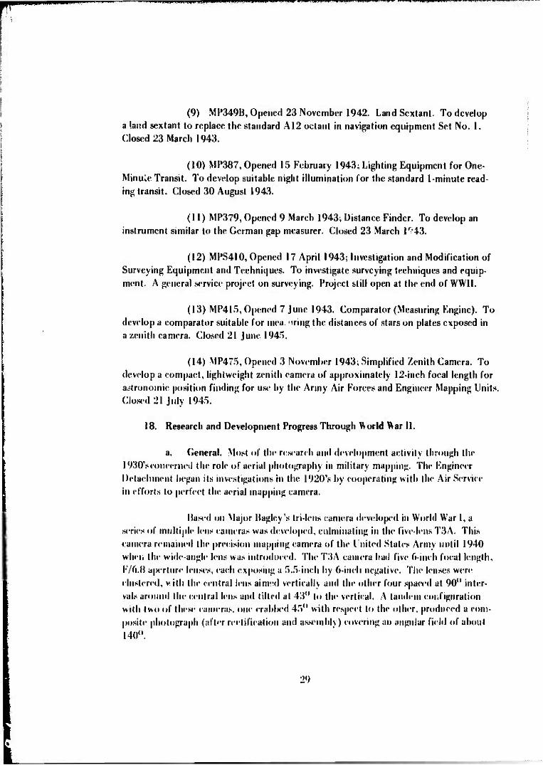
»IIMHHIIPP ii^jmiiun.H«lW"WJ "W ." ' i|H 'IB'JWI^W^
(9) MP349B, Opened 23 November 1942. Land Sextant. To develop a land sextant to replace the standard Al2 octant in navigation equipment Set No. 1. Closed 23 March 1943.
(10) MP387, Opened 15 February 1943; Lighting Equipment for One- Minuie Transit. To develop suitable night illumination for the standard 1-minute read- ing transit. Closed 30 August 1943.
(11) MP379, Opened 9 March 1943; Distance Finder. To develop an instrument similar to the German gap measurer. Closed 23 March 1^43.
(12) MPS410, Opened 17 April 1943; Investigation and Modification of Surveying Equipment and Techniques. To investigate surveying techniques and equip- ment. A general service project on surveying. Project still open at the end of WWII.
(13) MP415, Opened 7 June 1943. Comparator (Measuring Engine). To develop a comparator suitable for mea. '»ring the distances of stars on plates exposed in a zenith camera. Closed 21 June 1945.
(14) MP475, Opened 3 November 1943; Simplified Zenith Camera. To develop a compact, lightweight zenith camera of approximately 12-inch focal length for astronomic position finding for use by the Army Air Forces and Engineer Mapping Units Closed 21 July 1945.
18. Research and Development Progress Through World War 11.
a. General. Most of the research and development activity through the 1930's concerned the role of aerial photography in military mapping. The Engineer Detachment began its investigations in the 1920's by cooperating with the Air Service in efforts to perfect the aerial mapping camera.
Based on Major Bagley's Iri-lens camera developed in World War 1, a series of multiple lens cameras was developed, culminating in the five-lens T3A. This camera remained the precision mapping camera of the United Stales Army until 1940 when the wide-angle lens was introduced. The T3A camera had five 6-inch focal length, F/6.B aperture lenses, each exposing a 5.5-inch by 6-inch negative. The lenses were clustered, v. till the central lens aimwl vertically and the other four spaced at 90° inter- vals around the central lens and lilted al 43° lo the vertical. A tandem configuration with two of these cameras, one crabbed 45° with respect to the other, produced a com- posite photograph (after rectification and assembly) covering an angular field of about 140°.
29

Preparation of map products from aerial photographs was investigated during the 1930's through a series of mapping tests conducted to establish suitable methods and equipment. The products required were a mosaic at photographic scales; a planimetric tactical map at 1:62,500; and a planinu trie fire-control data sheet, called a provisional battle map, at photographic scale. These tests and other investigations led to the development of the progressive mapping scheme. This scheme more than ful- filled the original objectives. By using stereoscopic plotting devices, topographic as well as planimetric maps could be produced. Furthermore control could be extended by photogrammetric methods into "enemy" territory from a strip of "occupied" territory to provide fire control data. The progressiv .. '»ping scheme called for the prepara- tion in sequences of: (1) a composite at 1:40,(X 0 made by tandem T3A photography; (2) a planimetric provisional battle map at 1:20,000 compiled by tracing from t ndem T3A photography; and (3) a topographic battle map at 1:20,000 with a contour inter- val of 50 feet, compiled from single T3A camera photography.
From studies of the organization and equipment needed for topographic mapping, it was concluded that ordinary mapping needs of combat units should be sup- plied by the Army Topographic Battalion—a field organization. The GHQ Topographic Battalion shculd be used to supplement field work, reproduce large quantity orders, and supply the needs of the communication zo» o and of GHQ units." Both battalions should be organized into four companies: Headquarters and Service Company, Survey- ing Company, Photogrammetric Company, and Reproduction Company. Later in 1939, the Engineer Board suggested the need for a mapping unit to be attached to Corps Engi- neer Headquarters to prepare large-scale aerial photographs, mosaics, contoured maps of small areas and overprints. Therefore, Tables of Organization and Equipment for the Engineer Topographic Company, Corps were developed.12
Soon after the United States entered World War II, it became evident that the Air Forces would require assistance in compiling and reproducing their aero- nautical charts. Consequently, two additional types of engineer mapping units, the Engineer Topographic Company, Aviation, and the Engineer Air Force Headquarters Company, were organized and assigned to the Air Force.
While the progressive mapping scheme and the techniques and equip- ment used in tests of the scheme more than fulfilled the original objectives set forth in 1933, the products did not fully satisfy the needs of the Artillery and the Infantry. The accuracy achievable in the topographic battle map was not adequate for the Artil- lery requirement for 60 percent effective artillery fire of 33 y irds horizontally and 25
Organization and Equipment of Topographical Battalion," Engine« Board Report 531, IB April 1938.
'^"Corpn Mapping Unit," Engineer Board Report 583,27 September 1939.
30

^•»^BP^BO^^^
feet ver ically. The time requirement for production was excessive—2 to 3 weeks after receipt of photography. More realistically, there was an urgent need for a map to be available in 12 to 24 hours. The T3A composite photography had failed to meet this need partly because of the poor quality of reproduction.
While the investigations and tests from 1933 to 1939 were based almost entirely on the use of the T3A composite photography and normal angle multiplex equipment, the Engineer detachment became interested in single-lens, wide-angle pho- tography13 in 1935. In that year, Heinz Grüner, a German national employed by the Engineer Detachment, returned from Germany with word that the Zeiss firm was using such a camera in conjunction with a wide-angle, multiplex projector. This equipment was procured from Car! Zeiss, Inc., for testing in 1936. The Air Corps procured the camera and the Corps of Engineers procured two sets of wide-angle multiplex projec- tors and a reduction printer. The Zeiss camera was tried out in the mapping tests of 1937, hut it failed mechanically. It was tried again in 1938, but the photographs could not be used because the multiplex equipment was not suitable. The reduction printer did not compensate for lens distortion in the camera.
In spite of these failures, interest in wide-angle photography remained high. In the meantime, the Bausch and Lomb Optical Company had designed a wide- angle lens called the metrogon, a lens of 6-inch focal length based on the Zeiss topogon lens design. The Air Corps began procurement of these lenses in 1938 and also started the development of the T5 wide-angle mapping camera.
In view of these developments, and following a Military Mapping Ser- vice Test by the 29th Engineers in 1939 employing the T3A camera, the Chief of En- gineers set up a meeting in Washington to discuss the best mapping procedures and the best type of equipment. This mapping conference was held in Washington from 4 to 7 March 1940. Two rather surprising yet crucial decisions resulted from the conference. The first decision was to cease procurement of normal-angle mapping equipment. This meant abandoning the T3A which had been the standard mapping camera since the mid- 1920's. The second decision was to accept the K3B14 camera equipped with a wide- angle metrogon lens as a suitable camera for precise mapping. These decisions were made even though the wide angle mapping equipment had not been tested in this coun- try. The conference did, however, request the continued development of a precision wide-angle mapping camera.
"h'hr term "wide angle" applied to lenses with a total field of more than 80°.
T"he K3B was designed originally ax a general-purpose camera. It had interchangeable lines of 6-inch, 8.25-inch, 12-inch and 24-inch focal lengths, between the lew shutter, a vacuum !wck, and produced negatives of 7 by 9-1 /8 inches or 9 by 9 inches as desired. While built as a precision instrument, it lacked provision for exactly crliimating the i'ilm and the taking lens and thus did not meet requirements for a precision mapping camera.
31

W-UW'IP'
Another development which was destined to have a major impact on both military mapping operations and R&D programs throughout World War II and for some years following was the adoption of the tri-metrogon method for aeronautical charting by the Air Corps e:rly in 1941. This method employed three K-l 7 wide-angle reconnaissance cameras interconnected to make exposures simultaneously. With one camera pointing vertically downward and the other two inclined at an angle of 60° from the vertical on each side, horizon to horizon coverage was provided.
Since thi greatly reduced the amount of flying time, the use of the tri- metrogon system for phi tographic coverage of operation areas became the rule rather than thi* exception a? the war progressed. Thus, it was necessary to develop specifica- tions hastily, procure equipment, and train Engineer Topographic Units to compile re- connaissance maps with this photography. In February 1943, the Chief of Engineers di- rected the Engineer Board to develop methods and equipment to use the tri-metrogon photographs to the best advantage and, specifically, to make contouring possible. Only planimctric compilation at small scale was possible with the techniques and equipment then employed. Since it was realized that the la ge-scale battle map with its customary 50-foot contour interval was out of the question lor the time being, the goal was set for aeronautical charts and strategic topographic map at approximately 1:500,000 with 1000-foot contours.
b. Photomapping Accomplishments Through World War II.
(1) Development of Multiplex Equipment. A number of intricate stereoscopic plotters were developed in Europe before and during World War I. After the war, these were slowly introduced into the United States. In the early 1930's, the Engineer Detachment obtained a Zeiss Aerocartograph, and early in 1935 it obtained the use of multiplex equipment owned by the Pittsburgh District for tests in connec- tion with their investigations of the role of aerial photography in military mapping. Instruments such as the Aerocartograph or the Zeiss Stereoplanigraph were intended for use in the extension of ground control into unsiirveyed areas. The multiplex was to be used for detail compilation. This idea, however, was gradually abandoned in favor of the use of the multiplex equipment for both extension of control and detail compilation even though aerotriangulation with the Aerocartograph or Stereoplanigraph was more accurate. The principal reason for using the multiplex equipment was that the Aerocartograph and similar instruments were expensive, nonportable, and time-con- suming. Further, a domestic source of supply for this type of instrument would be both expensive and difficult to develop: whereas, by 1937. the Bausch and Lomb Op- tical Company had already begun manufacturing multiplex equipment in the United States on Corps of Engineers Specification T-851, dated 3 August 1936.
32

«••II WH 1*1. mmn •L«W.,PWI|IWI
After extensive testing in the late 1930's, the multiplex was finally recommended for standardization by the Corps of Engineers in October 1939. It was noted that the sole source of supply was the Bausch and Lomb Company which con- trolled the American patent rights. However, this equipment was designed to use the photographs taken with the multiple-lens T3A eamera. Both vertical and oblique pro- jectors were developed.
When the T3A eamera was replaced by the single-lens, wide-angle camera as the standard mapping camera in March 1940, it became necessary to provide a different type of multiplex equipment. Actually, the development of the wide-angle multiplex was already underway by the Bausch and Lomb Optical Company which was redesigning and improving the German equipment which had been imported for tests by the Engineer Detachment. The Corps of Engineers had on order 15 experimental projectors and all necessary supplemental equipment based on Corps of Engineers Speci- fication T-896, dated 26 September 1938 (Fig. 1). The delivery of this equipment was not completed until May 1941 after the first large production order for 243 projectors and all necessary supplemental equipment (including four wide-angle reduction printers) had been placed with the Bausch and Lomb Optical Company.
Fig. I. Wide-angle multiplex equipment: the first 15 projectors manufactured by the (tausch and Lomb Optical Company set up for aerotrian^ulation tests (1941).
33

^IIJM Jiliiii uu mmm^mmmrnm* ••••Piii.ni „n—w»m m.Mi.mmiiiiim.nJVH i .1. i^immp»^
Engineering tests of the wide-angle multiplex equipment were con- d^ted in 1941 to 1942 using photography at a 23,000-foot altitude with a K3B camera in the vicinity of Dayton, Ohio. With these photographs, the Engineer Detachment extended control for 70,000 yards and produced a complete battle map of the area.
Both in accuracy and speed, the wide-angle photography and plot- ting instruments proved themselves superior to the normal-angle types. In accuracy, the following results were indicated:
35,000 Yards 70,000 Yards Extension Extension
Mean horizontal error 15 yards 19 yards Mean error of distances 0.192% 0.275% Mean error of azimuths 1.9 mils 3.1 mils Mean vertical error 24 feet 28 feet
The Artillery requirements for position accuracy (no greater than 33 yards) were practically met in this test, but the requirement for elevation accuracy (no greater than 25 feet) was not quite satisfied. It was esiimated that, with the wide- angle multiplex, the first map sheet should be available 6 days after photography and that, thereafter, 600 square miles per day could be produced by a Photomapping Com- pany of the GHQ Engineer Topographic Battalion.
It should be noted that during the course of these investigations leading to the final development and adoption of the wide-angle multiplex, two other stereoscopic plotting instruments designed in the United States were investigated and rejected. One of these was the aerostereograph invented by Mr. Ernest R. Swanson, Junior Engineer, U.S. Engineer Office, St. Louis, Missouri which was investigated in 1936 and was rejected because it was more complex than the multip." J.x and would be costly to develop. The other was the stereoscopic plotter designed by Mr. 0. M. Miller of the American Geographical Society and investigated in 1942. This instrument, the result of a 10-year project of the society, was designed tor both vertical and oblique photography. It was rejected because it was in the initial stage of development, and, although it appeared somewhat simpler than comparable European instruments, the reasons for selection of the multiplex over this type of instrumentation were even more valid with a war in progress.
(2) The Stereocomparagraph. While the multiplex was suitable for base operation, a much smaller and more portable device was desired for the mobile mapping units. Such a device, the Stercocomparagraph, was invented by Captain Ben- jamin B. Talley of the Engineer Detachment and was reported io the Chief of Engineers
34

Fig. 2. The Stereocomparagraph.
in June 1936. As shown in Fig. 2, the Stereocomparagraph consisted essentially of a small mirror stereoscope, a parallax measuring micrometer with floating marks, and a pencil arm extension mounted on a parallel motion drafting machine. No provisions were made in the device to compensate for tilt or relief displacement in the photography. However, it was possible to sketch contours from near-vertical photography with a fair degree of accuracy. The device was service tested in 1937 and 1938 and was recom- mended for adoption as a standard item. However, final adoption and classification were delayed for several years while a Zeiss sketching stereoscope was investigated. In addiHon, the development by the 29th Engineers of a relief-compensating attachment devised by Captain Talley was anticipated. In the meantime, quantity procurement was initiated based on Specification T-1305 dated 9 May 1939. The item was finally standardized 27 March 1942 without the relief-compensating attachment.
(3) Stereoscopes. The development of stereoscopes for viewing over- lapping aerial photographs received considerable attention in the 1930's as an accessory item to facilitate the interpretation of photographic detail. The only item in the inven- tory was a heavy, intricate, table model lens-prism stereoscope developed by the Keuffel and Fsser Co.. (Fig.3). It had been standardized in 1932 and remained standard through
35

wvmmii f in I IJI w
Fig. 3. Keuffel and Esser Lens-Prism Stereoscope.
World War 11. However, it was not portable enough for issue to lower echelons and field units.
After several years of investigation, various cheap spectacle-type stereoscopes, anaglyphies spectacles, and mirror stereoscopes had been discarded from consideration. Finally, development was pursued on two parallel courses. The first approach was the development of a folding pocket stereoscope (Fig. 4) models of which were developed by Bausch and Lomb Optical Company. The other approach involved a magnifying mirror stereoscope (Fig. 5) which was produced by the Fairchild Aerial Camera Corporation. These items were finally perfected and adopted as standard arti- cles in July 1940. The designs of both were based on German models.
(4) Hasty Map« from Wide-Angle Photos. The introduction of wide- angle photography in 1940 revived interest in other types of hasty maps that might satisfy needs of the Field Artillery for fire-control applications. During the years 1940 to 1944, various experiments and tests were conducted in preparation and use of con- toured and uncontoured rectified photographs and controlled, semieontrolled, and
36

mmrjmmm&^m mwm H l>JUP|illiJ»M»li »J> I .11
Fig. 4. Folding Pocket Stereoscope.
Fig. 5. Magnifying Mirror Stereoscope.
37

uncontrolled mosaics. The photo rectifications for these investigations were made with a Zeiss SEG I Rectifier procured from Germany by the Engineer Detachment.
None of these fully satisfied the Field Artillery accuracy require- ments. The rectified photographs, contoured with the Stercocomparagraph, took too long to prepare and the Field Artillery School concluded that single photographs could best be used as contact prints. It took as long to prepare controlled mosaics (which in- cluded slotted templet control net expansion and photo rectification to the control net) as to prepare a complete topographic map. The semicontrolled mosaic assembled from contact prints did shew some promise. The recommendations of the Engineer Board15
resulting f.om these investigations were that mosaic should be further developed but should be considered only as an emergency expedient. The other possibilities of block plots (skeletonized planimetric maps) should be explored to provide a more suitable me- dium for fire control. Hasty maps were used successfully in the Mediterranean theater to satisfy Field Artillery demands for firing data because they were available well in ad- vance of the complete battle map. They were prepared for the area north of Rome16 by the 30th Engineer Topographic Battalion, GHQ, at the request of the 5th Army.
(5) Mapping with Minimum Ground Control. In July 1943, the Com- manding General, Army Air Forces, directed the attention of the Chief of Engineers to SHORAN,17 a device for determining horizontal positions over inaccessible areis. He requested that an officer be designated to represent the Chief of Engineers in the devel- opment of SHORAN. Major Gilbert G. Lorenz, Chief of the Aerial Photographic Branch, was authorized to cooperate with the Air Force in this program.
Preliminary tests were held in the vicinity of Boca Raton, Florida, from January to June 1944. These tests were so successful that the Engineer Board concluded that SHORAN was definitely applicable to the establishment of horizontal control for both multiplex mapping and mosaic making. The Board recommended immediate allotment of sufficient SHORAN equipment for mapping purposes pending further tests. SHORAN was found applicable to the navigation ot precise flight lines as well a» io position determination.
Development and test of the system continued in 1944 and 1945, and in August 1945 an Engineer Board Service Project (MPS 673) was set up to expe- dite the application of SHORAN to map control.
15"Mosaics for Field Artilf-v," Engineer Board Report 843, 21 July 1944.
"Use of Multiplex Equipment for Block Plots," Letter Report from Survey Directorate, Allied Force HQ, APO
SHORAN is the acronym for Short Range Navigation. It was developed by Radio Corporation of America for the
512, US Army to OCE, 2 March 1944.
SHORAN is the acronym for Short Rar Air Force to facilitate bombing through overcast.
3R
mmmgtj* WWWIW!
The Air Force and Corps of Engineers jointly conducted investiga- tions into the establishment of vertical control for mapping with airborne instrumenta- tion in 1942 and 1943. These experiments involved the use of a precise barometric altimeter to record the altitude above sea level and a radio altimeter to record the dis- tance from the aircraft to the ground. Analysis of flight test data demonstrated thai the method was suitable over flat or moderately rolling terrain but was not suitable over mountainous terrain except for small-scale aeronautical charting. The Aerial Photo- graphic Branch found that in the tests conducted the errors were too great to permit the compilation of satisfactory large-scale maps. However, the report18 did conclude that the radio altimeter could be used in the absence of horizontal control to more accurately determine the scale of a photograph, or photomap. The method was not rec- ommended for use in making topographic maps. The radio altimeter was recommended for use in conjunction with the barometric altimeter for that purpose.
(6) Tri-M'.'trogon Equipment. With the sudden adoption of the tri- metrogon method for aeronautical charting early in 1941, it became clear that Engi- neer mapping units in the field would have to use high oblique photographs in mapping whether they wished to or not. In view of the urgency of the situation, the Engineer Board recommended the adoption of three instruments that had been developed by the United States Geological Survey: the vertical sketchmaster (Fig.6), the oblique sketch- master (Fig. 7). and the angulator. The angulalor was designed to plot horizontal direc- tion from the nadir to images on the oblique photographs. The skett hmasters were devices based on the can. »ra lucida principle to plot planimetric detail from the photo- graphs.
In February 1943, the Chief of Engineers directed the Engineer Board to develop methods and equipment to use the tri-metrogon photographs to the best possible advantage and, specifically, to make contouring possible. The first Engi- neer Board report on this investigation, submitted in October 1943,''discussed two approaches: (I) adapting the vertical, wide-angle multiplex projector so that it may be tilted to accommodate oblique photography, and (2) rectifying oblique photographs. A rertificr(Fig.8) to investigate the latter approach was designed by Mapping Branch personnel and was constructed in the Engineer Board Shops.20 It was designed to accom- r date 9- by 18-inch photography at various tilts, since at that time She Air Force was experimenting with other multiple-camera arrangements including 9- by 18-inch photo- graphs with 24-inch focal length lens.
"•'Vertical Control for Aeronautical Chart inn and Mapping." Engineer Board Report 973, 27 February 1946.
'•Improvement of Tri-Metrogon Plotting Equipment and Method»," Engineer Board Report. 19 October 194.1.
"Rectifying Projection Camera Constructed at the Engineer Board," Engineer Board Report. 17 December 1943.
39

liPMWiwipnw ^^m>^^m*
#1~
Fiji, ft. Vertical Sk.U fmiasU-r.
Kip. 7. OUiijii« Skit«hnuistrr.
40

Fig. 8. Universal Rectifier designed by Knpneer Hoard Mapping Brand: personnel and fabri-
cated in Knginecr Board Shops (1943).
This instrumentation served as a valuable testbed for photo rectifica-
tion and other studies. The rectifier was stiJI being used occasionally in the early 1970's.
In 1968, it was used by the A u tome trie Operation of the Raytheon Company to rectify
photographs of Peru taken from a Gemini spacecraft. It was the only instrument that
could IN* located that would accommodate the unusual tilts and formats. A small scale
photomap of the entire country of Peru was prepared from the Gemini photographs.
Further investigation and lest of the two approaches led to the adoption of an adjustable tilt bar which aüowcd vertu a! multiplex projectors to be used
in oblique photo compilation (Fig. 9). To expedite introduction in the field, a number
of these lilt bars were fabricated in the Knginecr Hoard shops pending completion of
s|H'cifications and drawings. Work with the rectified photographs21 led to the establish-
ment of project MP 488, Rectifying Camera, in March 1944 and also to the design of a
new slot culler to accommodate the rectified photos (Fig. 10). A pilot model of the
slot culler was also built in the Knginecr Hoard shops.
21M Military Mapping from Tri-Metrogon Arrial Photography lifting Kretifird Photograph*," Knginerr Board Report 82V. 17 June 1944.
41

I »IB I.I »I. I I HI
Fig. 9. Wide-Angle MutUplex Projectors adapted for tri-metrogon oblique photo compilation with the adjustable tilt bar support.
Fig. 10. Universal Slot Cutter designed to 8' commodate rectified tri-metrogon oblique photos as well as vertical photos.
42

The requirements were so urgent that experimental models of the rectifier were ordered from three firms in May and June 1944: Bausch and Lomb Op- tical Company, Aero Service Corporation, and Rutherford Machinery Corporation. In July 1944, a quotation was requested from Photogram metric Instruments, Inc., Pasa- dena, California, for modification of a commercial rectifying printer known as the Fair- child Model RP1. Subsequently, 14 of these rectifiers, designated the RP2, were pro- cured. They were delivered in May 1945. In the meantime, the development of the improved rectifier by the three companies lagged. The Aero Service Corporation model (Fig. 11) was delivered in October 1945 after the problem of a suitable lens was finally solved when the National Defense Research Committee supplied a "hypergon" lens of 4!4-inch focal length. The Rutherforci contract was cancelled in September 1945, and the Bausch and Lomb rectifier (Fig. 1V) was not delivered until after the end of World War II.
Fig. II. High Oblique Rectifier—Aero Service Corporation Model.
43

Fig. 12. High Oblique Rectifier-Bausch and Lomb Model.
Fig. 13. High Oblique Multiplex Projector.
44

•I iilMUJIflB«1 II. I
Another wartime development of tri-metrogon plotting equipment was a specially designed oblique multiplex projector (Fig. 13). Two experimental pro- jectors were supplied by the Bausch and Lomb Optical Company in April 1945. These were submitted to the Engineer Board for test to determine if a development project should be set up. Such a project, MP593 High Oblique Multiplex Projector, was estab- lished in July 1945. Eighteen units with modifications found desirable in tests of the ex }>eri mental models were ordered from Bausch and Lomb in January 1946.
(7) Miscellaneous Investigations. In addition to the more important work in the photomapping area outlined above, a number of miscellaneous investiga- tions should be noted.
(a) Vectographs. The Vectograph process, developed by the Polaroid Corporation, Cambridge, Massachusetts, for viewing stereoscopic imagery by application of the principles of polarized light, was investigated in 1941 and 1942. The report22 on these investigations concluded that vectographs were practicable but they required over twice as long to prepare as prints. Furthermore, the report noted that vectographs did not present as clear a view as prints viewed through a stereoscope. It was recommended that the use of vectographs be confined to training and that thev not be adopted for issue.
(b) Faircliild Detail Sketcher. The Fairchild Detail Sketcher was a device based oil the camera lueida principle designed for sketching from vertical photo- graphs at either reduced or enlarged scale. It was not adopted because at the time it was preferable to u»v a vertical reflecting projector for this purpose.
(c) Polaroid Projector. The development of a polaroid stereo- scopic projector to enable a group of persons to simultaneously view aerial photography stereoscopically was undertaken in 1941. Two experimental models were produced by Fairchild Aerial Surveys, Inc., Los Angeles, California. These proved to be inferior to a similar and less expensive device made by the Motion Picture Engineering Company, Detroit, Michigan. The project was dropped in 1942 when it appeared there was no longer a requirement.
(d) Stable Cartographic Bases. In 1941, at the instigation of the Engineer Detachment, the Eastman Kodak Company began work on a stable medium for cartographic purposes to replace their matte acetate sheeting. Although it had fav- orable dimensional stability characteristics, the sheeting was not satisfactory because it would only take soft pencil that had a tendency to smear. Eastman Kodak was sin* eessful in producing an acetate sheeting with improved surface characteristics in 1942.
22"Vrrtojsraph»," Knginfer Board Report 693. 10 July 1942.
45

-«in'»--."i^»i n.iini ... i)WnWwprwwtw.i',»n!ii.'ii'*.lniwwM..nu;wi>iywu -M .i»
The Engineer Board also investigated an acetate sheeting manufactured by the Celanese Celluloid Corporation, New York City, which proved to be too expansible for mapping purposes. The improved material of Eastman Kodak Company was adopted and pro- cured in quantity during the remainder of the war. Shortly before the end of the war, vinylite sheeting was tested in comparison with the icetate sheeting and was found to give better results with both pencil and ink drafting. The Engineer Board recommended vinylite sheeting for adoption in November 1945.
(e) Mapping from Relief Models. Late in 1942, the Engineer Board investigated a method devised by Professor H. L. Cooke of Princeton University for making topographic maps from models carved in plaster of paris under multiplex projectors. It was concluded that the Cooke method required an expensive and bulky camera and special training in carving, and it was probably less accurate than the con- ventional method. The method was not recommended for military use.
(f) Tangential Distortion. During triangulation tests with the wide-angle multiplex equipment in 1941 and 1Q42, a rather large and consistent azi- muth error in single-strip extension was noted. The. cause for this was traced to a tan- gential distortion in both the mapping camera and in the multiplex reduction printer. This work was the basis for the inclusion of tangential distortion limitations in map- ping camera lens specifications and also for the development of parallelism tolerances for camera filters and windows.
(g) 12-inch Focal Length Wide Angle Camera. In 1939, the Chief of the Army Air Corps called attention to a camera recently perfected by Fair- child Aerial Surveys, Inc., Los Angeles, California, for its own use. It was fitted with a 12-inch focal length, wide-angle metrogon lens. An experimental camera designated the XT-6 was procured by the Air Corps at the urging of the Chief of Engineers.
The Corps of Engineers procured a special reduction printer from the Bausch and Lomb Optical Company for preparation of multiplex diapositives (Fig. i4).
In September 1940, after an experimental T5 camera (9x9 inch, 6-inch focal length) had been delivered to the Air Corps, comparative tests were made by the Engineer Detachment. The tests demonstrated that photographs taken with the XT-6 camera were of better quality than enlargements of T5 photographs but not sufficiently better to justify the continued procurement of such a large camera. Accordingly, the Chief of Engineers recommended that the development be suspended.
(h) Portable Plotters. In the period 1940 to 1945, several devices were investigated for possible replacement of the stereocomparagraph for contour
46

ww-ww
Fig. 14. Experimental Multiplex Reduction Printer for 12-inch focal length. 18 by J 8-inch format photography with metrogpn fan*.
mapping by t\u. « organizations not equipped with the multiplex. The first of these was the Abrams Contour Finder—a device similar in principle to the stereocomparagraph. However, it was not suitahl" for use with 9- by 9-inch photographs and was rejected. Other devices investigated were the KKK plotter (Fig. 15), designed by Messrs Jasper E. King, John \V. Klliot, and Philip B. Kail, investigated in 1941; the SCS plotter, designed by Mr. Charles Cook of the Soil Conservation Service, investigated in 1943 and early 1944: an improved model of the KKK plotter invesrig«t*»d in 1944; aß improved mode! of the SCS Plotter called the slereotopograph ordered from the Fairchild Aviation Cor- poration in 1944 but not delivered until January 1946; and the stereograph, invented by Mr. Andrew Hendixen of the Army Map Service. All of these devices employed a mir- ror stereoscope arrangement for viewing and compiling from contact prints. They dif- fered in the manner in which the floating marks were introduced in the stereoscopic model and the means provided for compensation for tilt in the photography.
The investigation of the Hendixen Stereograph was completed in 1945. The Hendixen Stereograph was rejected because two principles of stereoscopic vision WIT«' violated, thereby causingeyestrain. Investigations of the KKK Plotter and the slereotopograph were still not completed at the end of the war.
47

Fig. 15. The KEK Plotter manufactured by Philip B. Kail Associates, Denver, Colorado.
(i) Multiplex Inspection. Throughout World War II, the respon- sibility for the factory inspection of all items of multiplex equipment was vested in the Engineer Detachment and later the Mapping Branch of the Engineer Board because of their special nature. This required temporary duty of Corps of Engineers personnel at the Bausch and Lomb Optical Company before each shipment. Later, personnel of the Army M?.p Service were trained to perform the factory inspection, and they inspected equipment procured for the Army Map Service.
(j) Camera Calibration. After adoption of the single-lens, wide- angle camera and during the early part of World War 11, the calibration 01 mapping cameras was performed by the Engineer Detachment using a field range set up at Wright Field. At first, this range was the guardrail on an earth-filled dam near Wright Field. Later, a camera calibration range was set up on the base with an array of specially de- signed targets along one of the boundary fences of the field.
This was the principal calibration facility for the military until a multicollimator facility was built at the Fairchild Camera and Instrument Corporation, Long Island, New York. Up to that time, camera calibrations for both civil and military agencies were made on request by the National Bureau of Standards.
48

c. Map Reproduction Accomplishments Through World War II.
(1) General. In World War I, the map reproduction equipment of the Army was rather limited. As late as 1928, when development work began in earnest, the items in use included only a blueprinting set, a small hectograph duplicator, slow speed lithographic apparatus with a flatbed hand press, and an experimental mobile reproduc- tion train containing elaborate and bulky letterpress equipment mounted on Mack trucks. Some consideration was given at the time to mounting the latter in railroad cars.
Work in the late 1920's and well into the 1930's was directed primar- ily toward investigations of duplicating processes to provide something better than the blueprinting equipment and the hectograph duplicator for issue at the regiment and divi- sion levels. The ammonia process (ozalid), the Bruning black and white process, the bro- mide process, the mimeograph, the spirit duplicator, ä.*vl »he gelatin roll duplicator were investigated. In the mid-1930's, the problem of reproducing photomaps in quantity gained considerable attention. Both photographic and lithographic processes were investigated; the lithographic process had been adopted as more suitable for map reproduction in the Army than the other basic printing techniques.
By the eve of World War II, the Corps of Engineers was not prepared for the unprecedented demand for maps which was ahead and which required the supple- mentation of the basic mapping plant, the Army Map Service, by * large number of field Army units. (Army Map Service operations were supplemented during the war by 4 G1IQ Topographic Battalions, 12 Army Topographic Battalions, 27 Corps Topographic Companies, and 33 Engineer Air Force Companies.) A crash program of development and equipment procurement and assembly was therefore required, and the program was placed under the cognizance of the Engineer Board.
(2) Development of the Corps Company Mobile Reproduction Plant. A mobile reproduction plant for use at the Corps level had been developed in 1937 but hud not been service tested. The plant consisted of a tractor-truck and 2-ton trailer (Fig. 16) fitted with two multilith presses (Models 2066 and 40), a plate whirler, a vac- uum printing frame, an arc lamp, and other accessories, and a l'/^-ton truck fitter! with a 5-kva generator set, drafting and surveying equipment, u black and white developing machine, and a Model LW New Process Duplicator. After a «Ties of service tests, modi- fication, and changes in components, the set eventually evolved in 1941 into an assem- blage of equipment mounted in a single, vantype semitrailer and a 5-kw generator set. The following items of equipment were included:
(a) 10inch by 10 ir.ch vertical projection camera (b) Temperature-controlled photographic processing tray (c) 133-line glass halftone sensor
49
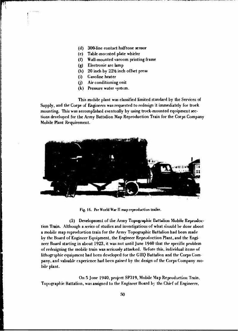
(d) 300-line contact halftone sensor (e) Table mounted plate whirler (f) Wall-mounted vacuum printing frame (g) Electronic arc lamp (h) 20 inch by 22% inch offset press (i) Gasoline heater (j) Air conditioning unit (k) Pressure water system.
This mobile plant was classified limited standard by the Services of Supply, and the Corps of Engineers was requested to redesign it immediately for truck mounting. This was accomplished eventually by using truck-mounted equipment sec- tions developed for the Army Battalion Map Reproduction Train for the Corps Company Mobile Plant Requirement.
Fig. 16. Pre World War II map reproduction trailer.
(3) Development of die Army Topographic Battalion Mobile Reproduc- tion Train. Although a series of studies and investigations of what should be done about a mobile map reproduction train for the Army Topographic Battalion had been made by the Board of Engineer Equipment, the Engineer Reproduction Plant, and the Engi- neer Board starting in about 1923, it was not until June 1940 that the specific problem of redesigning the mobile train was seriously attacked. Before this, individual items of lithographic equipment had been developed for the GHQ Battalion and the Corps Com- pany, and valuable experience had been gained by the design of the Corps Company mo- bile plant.
On 5 June 1940, project SP319, Mobile Map Reproduction Train, Topographic Battalion, was assigned to the Engineer Board by the Chief of Engineers,
50

P9WPPP IP ii. • .,.,111 mil. ipi*n
and the Chief of Engineers requested a list of equipment and an estimate of costs as soon as possible. The Engineer Board replied promptly to this request on 22 June 1940 by describing an eight-trailer train which was estimated to cost $125,000 and would h' equipped with:
Chief" offset press. (a) Trailers 1, 2, and 3 - 22-inch by 29-inch Webendorfer "Big
(b) Trailer 4 — One vacuum printing frame, one 25-ampcre, 110- volt arc I^.mp, and one vertical »late whirler.
(c) Trailer 5 - One 24-inch by 30-inch copyii.^ camera, one 120- line and one 133-iine glass screen.
cessing equipment. (d) Trailer 6 - Oi.c 10-inch by 10-inch contact printer and pro-
(c) Trailer 7 - One or two plate grainers.
(f) Traili.r 8 — Laboratory equipment and supplies.
In September 1940, 9 semitrailer tiain was ordered from the Frue- hauf Trailer Company. The installed equipment was ordered separately and shipped to Detroit where it was assembled under Engineer Board supervision. The first completed reproduction train was delivered to the 30th Engineer Topographic Battalion at Fort Belvoir. Virginia, in April 1941 (Fig. 17).
Fig. \i. Map reproduction train uVvrlopcd art World War II.
51

• WUÜHWill nmmnmmmm wi wwwpp HWf .iiiiinww.i i
Despite the magnitude of the job and the speed with which it was accomplished, this experimental model proved satisfactory with one exception: movement of the grainer trailer during operations prevented that maehine from functioning properly. This was readily corrected by providing portable supports for the trailer.
A second train was ordered in December 1941 incorporating sever- al changes including the installation of the newly developed 20-inch by 22.5-inch light- weight Harris Press and facilities for using the newly developed 300-line contact screen process. Shortly after this procurement in March 1942, the Engineer Board proposed to redesign the tiain to use van-type trucks instead of semitrailers of seven different types:
(a) Four press trucks, 4-ton. (b) One camera truck, 4-ton. (c) One plate-process truck, 2.5-ton. (d) One platc-grainer truck, 2.5-ton. (e) One laboratory truck, 2.5-ton. (f) One photographic truck, 2.5-ton. (g) One map layout truck, 2.5-ton.
The first order for the new type Army Battalion mobile train was placed with Peter Wendel and Sons, Inc., Irvington, New Jersey, in June 1942. The first complete truck-mounted reproduction trains were delivered to the field in January 1943 (Fig. 18).
Kiy. 18. Map reproduction unit with van type hody on 2.5-ton truck chassis ••- lahoratorv section developed in World War II.
52

tmvmmmwni
(4) Portable Task Force Equipment. As World War II progressed, task forces of divisional size would be detached at times from larger units. It was desirable for these forces to provide their own map?, especially those that were reproductions of aerial photographs. The Engineer Board proposed lithographic printing to meet this need, and in November 1942 it began to develop a portable copying camera and plate processing set to accomp ny the Model 40 Multilith. The set weighed only 168 pounds. Eight manufacturers were contacted, and by March 1943 three of them had agreed to construct experimental models. Project MP404 was therefore established. In the mean- time, the requirement was so urgent that the Chief of Engineers procuied 20 Beattie field process cameras and accessories, manufactured by the Progressive Promotions Com- pany, Summit, New Jersey. The Model 221 Davidson duplicator, which weighed 726 poi 's, was supplied witkthis set. This equipment proved unsatisfactory in the field, largely because it could not withstand field usage.
Both the Huebner Laboratories, New York City, and the Ruther- ford Machinery Company Division of the General Printing Ink Corporation, New York City, delivered experimental models to the Engineer Board in April 1943. At approxi- mately the same time, project approval was obtained from the Army Service Forces. The experimental models were promptly tested by the Engineer Board and returned to the manufacturers for some suggested modifications. During July, the third modei man- ufactured by American Type Founders, Inc., Elizabeth, New Jersey, was delivered to the Engineer Board. By September, three sets of equipment, including modified Hueb- ner and Rutherford sets, were submitted to the 665th Engineer Topographic Company Corps for service test (Figs. 19, 20, and 21).
Kij». 19. iWt.iinV task (<*<«• vquipriHni <I<V<I<>|M<! in World War II, plate whirlir and processor.
33

^m
mjm
mw
mrt
wn
m\<
im'f .
u.i»
iimi,i
i. •
im
. ••«
in
-••
PU "i
»«1"
««
"'
' »'
• '
. • f
""
^«'•
iWB
WW
I^W
J^
pP
fWW
f
wT
^
Fig
. 20
. P
orta
ble
task
for
ce e
quip
men
t de
velo
ped
in W
orld
War
II.
pr
oces
s ca
mer
a.
Fig
. 21.
Por
tabl
e ta
sk f
orce
equ
ipm
ent
deve
lope
d in
W
orld W
ar I
I — D
avid
son
dur
licat
or.

(•^MJfRRMMI,!. mtwr
The model 40 multilith was found unsatisfactory in these tests. Of the three portable cameras and plate process sets, the one manufactured by the Ruther- ford Machinery Company was the most satisfactory» primarily because it was lighter and more portable and required 'he least modification. The set was finally classified standard in May 1944, with a modified model 221 Davidson duplicator that had been employed in tests by the Engineer Board.
The project was closed in June 1944 only about 14 months after its approval by the Army Service Forces and barely 18 months after initial contacts with manufacturers regarding equipment development.
(5) Lithographic Press Development. Lithographic press development through World War II consisted primarily of investigating and testing lithographic press equipment on the commercial market for specific field Army applications. In some in- stances, the equipment was modified to better suit Army needs. In 1934, several multi- lith machines manufactured by the Addressograph-Multigraph Corporation, Cleveland, Ohio, were tested for application at the regiment or division levels, and of these the model 200 was favored and recommended for service test. This was a small, hand-oper- ated machine giving a 9-inch by 12^-inch impression. Although the machine proved generally acceptable in service test in 1936, the Engineer Board recommended its rejec- tion in October 1937.because a larger multilith, electrically operated and capable of printing a 12-in< h by 19-inch map, was then being tested.
The larger press, originally model 216 and later model 2Ö66, had been obtained in February 1936 and was slightly modified in the Engineer Board shops. It weighed 1200 pounds and produced 4000 copies per hour. This press, together with another smaller multilith machine, the model 40, was included in the original trailer- mounted Corps Company map reproduction plant developed for service testing in 1937. (The model 40 was also considered later for the Portable Task Force Reproduction Set.)
Later, the Davidson model 221 duplicator was tested by the Engi- neer Board, h was ultimately adopted in 1944 in lieu of the model 40 multilith for the Portable Task Force Equipment.
Although the Model 2066 Multilith had been successfully service tested twice, it was still not completely satisfactory. Heavier offset presses were simpler to operate and gave better results particularly for fine screen halftones. This was becom- ing an overriding consideration in the late i930's with the introduction of the photomape.
In August 1939, the 6th Engineer Topographic Battalion suggested the replacement of the Model 2066 Multilith with a newly developed 17-inch by 22-inch press manufactured by the Harris Seybold Potter Company, Cleveland, Ohio. This
55

wmmmm^mn^mmmm^ mvm.vfm mmwr*^ r^vt^m^m
suggestion was rejected by the Engineer Board on the basis that the press, whieh weighed 4750 pounds, was too heavy for mobile units. By mid-194!, however, the manufaeairer had redesigned the press for Engineer Corps Company uses. The new machine, designat- ed the model LTE, weighed only 2264 pounds. A later change in design enabled the press to accommodate a 20-inch by 221/ü-inch sheet (Fig. 22).
Fig. 22. Th<- Model I.TE Harris Pros.s-20 by 22» inch sWt siz«-.
After a representative of the Engineer Board examined this press at the factory, it was recommended for tninx'dfale procurement. The first or de« f«>i 38 units was placed in Oetober 1941. The pilot model was delivered in November, and a number of changes were made before the production models were fabricated. The model LTE Harris press was standardized on .HO July 1942.
in September 1944, the Army Air Forces called a conference in Washington. D. C, to discuss |he application of the portable task force equipment to Air Force needs. The conference was attended by representatives of the Air Force.«; I he Office. Chief of Engineers; the Engineer Board; the Army Map Service; the Office, Quartermaster General; and G-2 section of the War Department General Staff. It was decided at this conference that all future development and procurement of map
56

reproduction equipment should be of items readily tiansported by air in standard cargo planes. The Army Air Forces Board was directed to determine the military requirements for reproduction equipment. The board filed its report on 28 November 194423 and among other things recommended that the Army Air Forces and the Corps of Engineers open a joint development project on an air-portable reproduction unit consisting of a 22-inch by 29-inch press, 24 inch by 30-inch copying camera, and related equipment. This report was finally approved by the Commanding General, Army Air Forces, on 30 May 1945; but, in the meantime, the Engineer Board had been working on a plan for the proposed joint development. It was decided that the most feasible approach was to divide the project into two parts: one on the airborne camera and plate processing equip merit; and the other on the airborne press. Approval from the Army Service Forces was obtained in July 1945 after coordination with the Army Air Forces and Army Ground Forces. Projects MP 580, Airborne Camera and Plate Process Equipment, and MP 581, Airborne Pre^s, Lithographic Offset were approved on 18 July 1945.
Development work on these items was delayed when the war ended. In August 1945, the Engineer Board ordered an experimental model airborne press from the Webendorfer-Wills Division, American Type Founders, Inc., Mt. Vernon, New York. Production was delayed ny plant reconversions. Also, in August 1945, the Litho Equip- ment and Supply Company of Chicago, Illinois, submitted a promising bid for the air- borne camera, but negotiation of the contract was held up by plant reconversion and eventually lapsed. In March 1946, the Zar kin Machine Company, New York City, con- tracted to build the experimental camera and 3 months later agreed to supply the plate- processing equipment. The airborne press was still not in production at this time.
(6) Copy Camera Development. The service tests of the original Corps Company mobile reproduction plant in 1938 and 1939 disclosed the need for a mobile copying camera. In November 1939, the Engineer Board requested authority to open Project SP210A for a mobile camera capable of producing negatives with a maximum size of 24 inches by 24 inches. On 12 January 1940, a development contract was award- ed lo the Kuthcrford Machinery Company Division, General Printing Ink Corporation. The ex peri mental Kuthcrford camera was delivered in March 1941.
In the meantime, the Engineer Board forwarded a draft specifica- tion lor the 24-inch by 24-inch camera early in March 1940 ami the Chief of Engineers immediately issued invitation for bids so that mobile cameras could be supplied lo the 29th and tin' 30th Engineers in lime lor Army maneuvers in August. As a result of this invitation, a eontrael for three cameras was awarded to the I,ans ton Monotype Machine Company. Philadelphia. Pennsylvania. In July and August 1940. the Engineer Board
'Kquiprnent. ft «product inn. t'orlablr. for Task Korcr.sfF.riKirH'cr Board Mod«-!) and Require m<'nl> for Krproduc- fion Faulitir* for AAF Tarliral Operation!*." AAF Ud. Report, 28 November 1944.
57

fitted out and shipped four trailer-mounted copying cameras, two to the 30th Engineers, and one each to the 29th and 64th Engineers. After brief tests in the field, quantity procurement of the 24-inch by 24-inch camera was initiated in December 1940 by an order to the Lanston Monotype Machine Company. The camera was finally standard- ized on 30 July 1942.
Fiji. 23. HiH'hnrr vcrti« u. |>r<»j<vti'>n caiiNTa, 10 by 10 inch.
The 10-inch by 10-'. > rliiuii projection camera (Fig. 23) was also developed during the war to provide a camera unit within the combination semi- trailer re prod net ion plant developed for the Corps Company so that a separate vehicle as required for the 24-inch by 24-inch camera (Fig. 24) would not be necessary. An experimental model of this camera was ordered from Muebner Laboratories. New York City, in January 1942 and was delivered to the Engineer Board in the same month. A
r>H
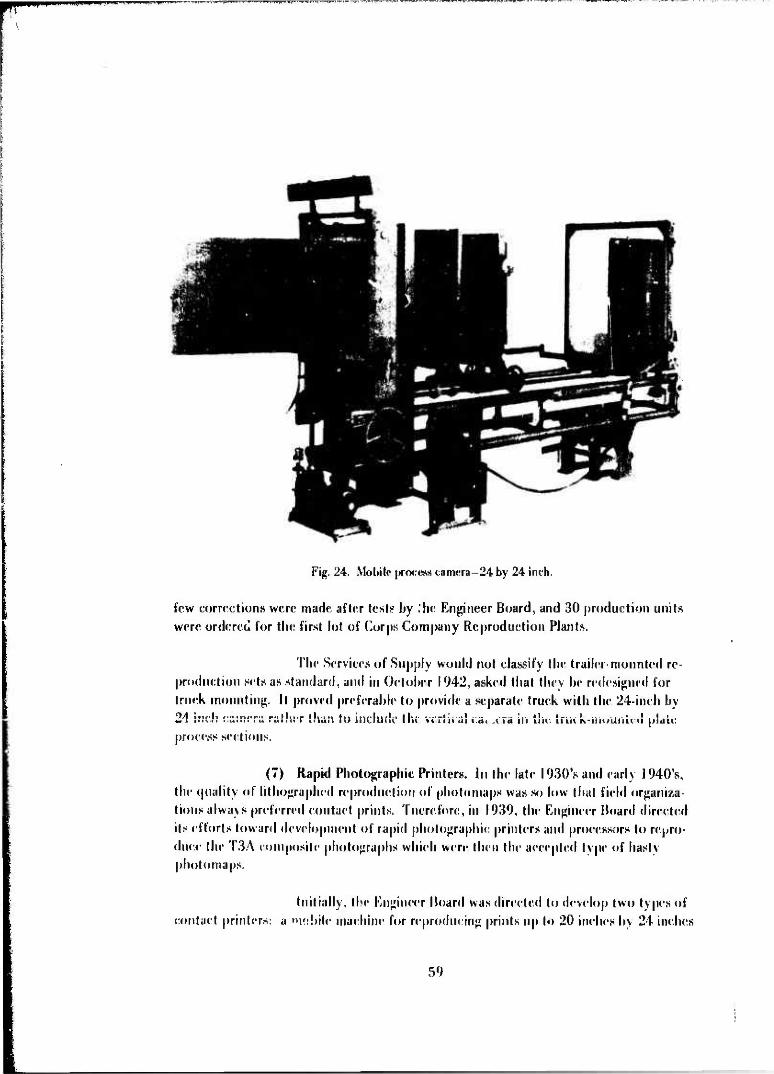
Fig. 24. Mobile process camera-24 by 24 inch.
few corrections were made after test? by Ihc Engineer Board, and 30 production units were ordered for the first lot of Corps Company Reproduction Plants.
The Services of Supply would not classify the trailer-mounted re- production sets as standard, and in October 1942, asked that they be redesigned for truck mounting. It proved preferable to provide a separate truck with the 24-inch by •*4 inch earner« rattier {•;«;; to include the vertical »:a» .era m the true K*jnuuri ted plat«: process sections.
(7) Rapid Photographic Printers. In the late 1930's and early 1940's, the quality of lithographed reproduction of photomaps was so low that field organiza- tions always preferred contact prints. Tnerefore, in 1939, the Engineer Board directed its efforts toward development of rapid photographic printers and processors to repro- duce the T3A composite photographs which were then the accepted type of hasty photomaps.
Initially, the Engineer Hoard was directed to develop two types of contact printers: a 'nobile machine for reproducing prints up to 20 inches by 24 inches
59

in size at the rate of at least 600 per hour, and a larger machine for base plant use. This was later modified at the request of the Engineer Board to the development of a semi- permanent type capable of handling prints up to 20 inches by 24 inches and a truck- or trailer Mounted unit for pn.its up to 10 inches by 15 inches.
Work on the two types proceeded simultaneously, and Mr. Garra- way of the Garraway Company of Rutherford, New Jersey, was engaged to design the equipment and to supervise assembly of the experimental models at Fort Belvoir. De- signs were completed by February 1940. The larger printer was assembled by Septem- ber, and the mobile unit was completed in November.
Neither of these developments was satisfactory. The large unit v. as too bulky for truck mounting, and in November 1942 it was suggested that it be trans- ferred to Army Map Service. Since the Army Map Service did not want it, the Chief of Engineers authorized its salvage in April 1943. The mobile unit was installed in a van-type semitrailer and was shipped to the 64th Engineers for service * si. On 27 June 1941, the 64th Engineers issued an adverse report noting that the print« r should not be added to the reproduction plant of the Corps Company because it had certain mechani- cal defects and the printing area was limited to 10 inches by 15 inches whi<! was too small to eft. lively use the new wide-angle photographs.
In November 1940 after the introduction of wide-angle photogra- phy, work had begun on a mobile machine for enlarging the 9-inch by 9-inch negai **• to as much as 20 inches by 20 inches, with a production rate of 600 per hour. Th< pose of the enlargement was to produce a photomap at a scale of 1:20,000 from pli«»i graphs taken with the 6-inch metrogon lens. In those days, the photographs were5 usi«. ly at a scale of about 1:40,000.
The experimental model of this machine was completed in Febru- ary 1942. It was mounted in a van-type semitrailer and shipped to the 665th Engineer Topographic Battalion for service le*i in October 1942 (Fig. 25).
The trailer-mounted Garraway projection printer was tested exten- sively in the summer of 1943 during the Second Army maneuvers in Tennessee. In August 1943, the 665th Engineers reported that il would be a valuable addition to the mobile reproduction equipment with certain changes, including provision for production of prints of the same size as the original w*ali .e and truck mounting for better mobility.
The unit in a truck-mounted versio' was standardized in March 1944. The exfierimcntal model was eventually shipped to the 660th Engineer Topo- graphic Battalion, GHQ, in the European Theater. In June 1944, this unit suggested the addition of a contact-printing attachment. This was accomplished by a change in
60

IP «nil WWP ^iau>Minui|iiii. |i|,j|.
Fig. 25. Garraway Rapid Photographic Projection Printer.
specifications. At the same time, a 1:25,000 grid assembly was added. In May 1946, the Army Ground Forces requested the addition of a printing attachment that would handle roll film. This development was authorized in July 1940.
Only limited procurement of the Garraway printer occurred, be- cause, in February 1944, the Army Ground Forces decided that the standard photo- graphic section of the Army Battalion's mobile train, with its A-14 contact printers and F,dward enlarger, should be issued to the Corps Company instead of the Garraway printer.
(8) Miscellaneous Investigations. In addition to the above outlined major accomplishments of this period, a number of other investigations are significant in terms of the overall problem and development of map reproduction equipment and techniques. Some of the most important of these developments will be noted in the following paragraphs.
(a) Bloom Process. In the period 1934 to 1936, Master Sergeant Fred II. Bloom, who had been assigned to the Engineer Board to work on map reproduc tion problems, developed a method of making fulltone lithographic, piaies direct from
61

»»I.IW'IPPH» imiiiLMWjiW" •i1»"«'"""1
continuous-tone photographic negatives without the use of a copy camera or halftone screen. The Engineer Board issued a pamphlet—Full Tone Reproduction-on the Bloom process around 1936, and a patent was granted in 1938.
This development was particularly significant at the time since the quantity reproduction of continuous tone imagery without loss of detail was a ma- jor problem and halftone techniques had not proved entirely satisfactory.
The Bloom process was used experimentally for a few years but was never adopted primarily because it was not consistently satisfactory in the field. In addition, the development of the halftone process became more profitable with the introduction of a 300-line contact screen.
(b) Halftone Screens. In 1939, the Engineer Reproduction Plant and the Eastman Kodak Cuinpany, Rochester, New York, began joint investigations with an acetate-film contact screen. This led to the successful development of 300-line and 150-line magenta contact screens by the end of 1942—a significant advance in the field of lithography. This development overcame to some extent the widespread preju- dice against lithographed maps.
(c) Map Paper. In lebruary 1940, the Chief of Engineers assigned project SP 309B jointly to the Engineer Board and the Engineer Reproduction Plant to conduct investigations to improve the 50 percent rag stock map paper which had been used up to that time. The assistance and advice of the Government Printing Office and the National Bureau of Standards were obtained, and working closely with leading paper mills, by mid-1943 a 48-pound paper that was highly resistant to water and oil and was considerably stronger than either sulphite or rag stocks was developed. This paper, called high wet strength paper, had remarkable characteristics well suited to military applications.
(d) Microfilming. The possibility of microfilming maps and photo- maps on 35-mm film transparencies with sufficient quality that such miniatures could subsequently be used to make lithographic press plates or maps by enlargement was in vestigated in 1941 and 1942. The work was done primarily by the Engineer Reproduc- tion Plant using the Huebner vertical camera as a test vehicle. It was concluded thai it was impossible to achieve the necessary resolution in either black and white or color film and the project was abandoned.
(e) Printing Plates. Early in 1943, the Army Map Service tested a number of Plastolith (paper base) lithographic print plates produced by the Plastolith Company, Boston, Massachusetts. The tests showed that these plates had a number of advantages over the zinc plate then in use: They required no graining and thus eliminated
62

mmm^**•"^
the need for a plale grainer; they could be coated manually, which made it possible to dispense with the plate whirler; they conserved critical zinc; their use resulted in lower costs; and their weight was only one-eighth that of zinc plates.
Further tests by the Engineer Board and the 654th Engineer Topographic Battalion in May and June 1943 confirmed the findings of the Army Map Service, and procurement of large numbers began in September 1943. Unfortunately, many of the piates procured proved defective due to poor packaging which permitted fungus to attack the plates. This was discovered about the time that the Engineer Board and the Army Map Service were testing two types of paper plates, the Lithomat and the Photomat, manufactured by the Lithomat Corporation, Cambridge, Massachusetts. Fur- ther, it was found that these plates were incapable of producing either halftone or line subjects to any degree of satisfaction, therefore, by March 1945, it was recommended that authorization for use of paper plates by topographic units be rescinded.
d. Surveying Accomplishments Through World War II.
(1) General. Before World War II, there was little or no research and development activity within the Army in the general field of surveying. Since survey- ing is an ancient art and the major surveying instruments had existed for many years, they were adopted and issued to the Army long before World War II.
In September 1939, the official report on the Military Mapping Ser- vice Test held in Southern California complained that the standard field surveying instru- ments wei antiquated and unduly heavy and recommended that they be replaced by modern, lightweight, and more finely graduated instruments that would permit field work to be accomplished more rapidly. The research and development efforts through World War II were directed toward this end.
(2) The I-Second Direction Theodolite. To establish a domestic source of supply and at the same time provide a superior theodolite for military troop use. the Engineer Board on 6 October 1939 recommended that a I-second reading direction theodolite be developed. The Chief of Engineers, alter surveying the possibility of de- velopment with several domestic surveying instrument companies, approved and assigned Project SP321. Military Theodolites, oil 25 July 1940.
This project was beset with diffieultics and exasperating delays from the outset. A development contract for two experimental models was awarded to W. & L.E. (lurlev in September 1940, but the first experimental model was not shipped until November 1941. This instrument was unsatisfactory in both iis optical reading and viewing systems and was returned to the manufacturer. The second experimental model, equipped with tfteel circles in lieu of the aluminum ones on the first model, was
63

ins|H*cted in June 1942 and was found stilJ defective. It too was return 1 to the manu- faeturer and was remodeled and resubmitted in September 1942.
In the meantime the Bureau of Standards began work in December 1941 to devise methods of constructing glass circles like those used in European Theod- olites. It reported some success in the project in mid-1942. In addition, the National Defense Research Committee was working on a new short telescope design for the theod- olite. Therefore, in September 1942, the Engineer Board recommended24 that, pending the incorporation of glass circles and an improved telescope, the Gurley theodolite be classified as substitute standard and procured only to meet urgent requirements. Also, in September 1942, a second development contract was awarded to the Keuffel and Esset Company to obtain an additional source.
A limited quantity procurement order (25 instruments) was placed with the W. & L. E. Gurley Company in October 1942, but production was delayed landing fabrication of an improved ex|ierimerital model. An acceptable model was not completed until March 1944. It incorporated the newly designed telescope but still had steel rather than glass circles (Fig. 26). Nevertheless, the manufacturer was instructed to proceed with production.
Kip. 2«, <iiirl<-\ l-wconillJirritiiin llicodotitr. I"H.
2k. Onr NiTond TIH'.HJOIII«-." KIIKIIM-IT Hoard Itrport 722. IV Srotcmix-r l'H2
hi

•WMH p. i^mum wmmmm
By the end of the war, only 15 units had been delivered on the W. & L.E. (iurley production order, and the Keuffel and Esser Company had not yet delivered experimental models under its development contract.
(3) Military Level. The development of a new military level was autho- rized m March 1941 to provide an instrument more efficient than the Standard issue
du'jipy level and lighter in v* ighl than the precision level. On 30 April 1941, the Engi- neer Board awarded a development contract i * C. L. Berger and Sons, Inc., Boston,
Massachusetts, for a new military level which was to he a modification of their tilting level. The experimental model was tested in December 1941, and a second improved model was ordered. This improved model was tested in the summer of 1942, was found
satisfactory, and was subsequently adopted to supersede tae precision level entirely and the dumpy level for issue to tapping units.
(<+) Surveying Altimeters. The wartime role of the Engineer Board on surveying altimeters was principally one of testing surveying altimeters marketed by
Wallace & Tiernan Products. Inc.. Belleville. New Jersey, working wilh the manufacturer
to improve the design for military application, and preparing procurement spe< ifieations. Tlii« work began in March I942.25 and both the 6000-foot and the 15.000-foot ultime ters were standardized on 31 March 1943 (Figs. 27 and 28).
,£-.<. f
Ftp. 27. Survr\ MI» Mtimrtcr iHHMMWl.
'Survr\itij{ •Vltinii'lrp'.'" KNfinrrr Hoard '{rport 723, I 'n"r«rihfr 14-12.
6".

Fig. 28. Surveying Altimeter - 15.000 feet.
(5) Survey Computer. The first attempt to develop a computer for sur- veying application began in 1940 when Captain Louis J. Rumaggi, then Commanding Officer of the 30th Engineers, proposed that a computer be developed to speed the re- duction of sum » data to provide control for photogrammefric mapping. A machine that would calculate latitudes and departures to an accuracy of 1 part in 30.000, given range and azimuth survey data was required.
In September 1940, a development contract for such a device was negotiated with the W. L, Maxon Corporation, Nv*w York City. It soon became evident that the contractor had undertaken more than he could accomplish, and it was not until April 1943 that the experimental model was ready for examination.
This device was a mechanical computer similar to those produced at that time with sine and cosine cams included for the solution of the survey problem, it was noisy, frequently jammed, and did not meet the accuracy required even when it operated smoothly. Since the item was unacceptable and could not be corrected, the contract was cancelled: and no further attempt to develop a survey computer was made until afler the war.
(6) Astronomical rooiiion Finding Equipment. On the eve of World War II. an urgent requirement developed for a more accurate and rapid method and equipment for astronomic position location than the Navigation Equipment Set No. I v Inch was then available. (This set consisted of an o "taut and a navigation watch.) The astronomical position finding equipment was needed primarily (<> establish reliable posi- tion for basic map and chart control.
66

I.P1IIII I ' lll'l'
This requirement had been anticipated by the Engineer Board, and the development of a suitable astronomical position set had begun in December 1940.
The first approach to this problem was the development of an astro- labe, or equiangulator, an instrument for determining the position of the observer by observing the passage of stars across a circle of equal altitude. During the 1941 to 1943 period, the following types were procured for comparative testing (all were experimental models with the exception of the one manufactured in London):
(a) 45° pentagonai-prim astrolabe — Cooke, Troughton & Simms, Ltd., London (weight 11 pounds).
(b) Type Al 60° prismatic astrolabe - Eastman Kodak Company, Roche.«*er, New York (weight 56 pounds).
(c) Type Al A, the Al rebuül by David Mann, Lincoln, Mass? ,hu- setts (weight 83 pounds).
(d) United States Naval Observatory model — the Al redesigned by the Naval Observatory (weight 101V^ pounJs).
(e) Gacrtner Model — the A1 redesigned, in part, by Dr. I.C. Gard.ier, National Bureau of Standards, and built by the Gaertner Scientific Corporation, Chicago, Illinois (weight 84'/2 pounds).
yf) 60° split-telescope astrolabe, — designed by J. E. Willis, astron- omer, U. S. Naval Observatory, and built by the Observatory (weight 75 pounds).
(g) First experimental model of the 60° pendulum astrolabe, a new type invented by J. E. Willis in 1942 to 1943 and built by the Naval Observatory (weight 74'/2 pounds).
(h) Second experimental model of the 60° pendulum astrolabe built by the David White Company, Milwaukee, Wisconsin (w ight 34 pounds) (Fig. 29).
These investigations resulted ultimately in the selection of the pen- dulum astrolabe, nnd the Engineer Board recommended in February I94426 that tr t
'"ARtrcI'-'^RCKqiumfculalors)," Engineer Board Report 791. 5 February 1944
67

«I KMBI IIIPIV •PBWWPWW^ •nnfW"1 *w «iHWWP
tfcTlCLE LI9MT FOR FlNOER TELESCOPE
^RETICLE LIGHT FOR OFSERVLMG TELESCOPE
^OBSERVING TELESCOPE
^-ETEF.CCE FOCUSW« RIN6
•*•- -«OCUS LOCK RING
TRIBRACH
PENDULUM INSPECTION WINDOWS
Fijr. 29. 00° pendulum astrolabe manufactured by David White (Company.
pendulum astrolabe be standardized and procured for issue in place of the 20-inch tran- sit in I In astronomical position set.
While the astrolabe was being developed, the Army Air Forces be- came interested in the Zenith camera approach to astronomic position location. The Army Air Forces, in conjunction with the Kastman Kodak Company, had designed a 24-inch focal length Zenith camera in 1941.
A pilot model of the Air Forcc-Kastman design, delivered on an Engineer Hoard contract in August 1943, was tested at the Naval Observatory and found quite accurate. However, it weighed about 180 pounds. Therefore, it was decided t > develop a more < npact and simplified camera with approximately 12-inch focal length.
Military characteristics for the simplified Zenith camera (Fig. 30) were prepared by the Air Force. In January and February 1944, the Engineer Board ordered experimental models from the Kastman Kodak Company and from Düvid W. Mann. These models were delivered in August 1944 and were immediately tested by
68

WPWIB^WWWIPBBBH mm. ümqoa mijii .1 uu npummuw 111 in •.•*• J w • »mmm 1 .«>. •«»i.
Fig. 30. Xniith camera •Hpiipmrnt,
Ihr Engineer Board, Ihr Naval Observatory, and the 311th Photo ling. Testing result-
ed in Ihe decision to adopt the Mann eamera. .<\1 though both cameras we sufficiently
aeeurale. the >hnn eamera weighed less than 30 pounds and was considered more suit-
ahle for field use. A final report27 on this development was submitted by trie Kugineer
Hoard in May 1945 recommending that tin* project he closed.
Along with Ihe Zenith camera development, the Kugineer Hoard
also developed a small comparator for measuring Ihe star plates. Six of these compara-
tors were ordered from the David V\. Mann Coin pain in June 1943. The lirsi was ex-
amined by representatives of Ihe Kngiiieer Hoard in August 1943 and was later tested
with favorable results by Ihe National Bureau of Standards and Ihe 31 I th Photo Wing.
The project. MP 115. was closed in June !945.
Vlso in the period 1943 to 194."). th< Kugineer Hoard spent consid-
erable effort on Ihe investigation of timepieces for Ur-r in astronomical position location
"' "Investigation and frst ol" Zrnjih (junm:>." r/»iK»icrr Hoard Itrporl 9.'12 Final Keport. I t Mav 10-1.1.
69
I nlml
wjpi U'HillWPMipini.»
and radar receiving sets for calibration of the timepieces against time signals broadcast
by the Naval Observatory. As a result of investigations, a break-circuit marine chronom- eter28 was adopted and an Engineer Board Manual on timepieces was prepared.29 The
investigations of radio receivers resulted ultimately in the recommendation that the standard AN/PRR-l be adopted.
(7) Compasses. Although the compass is not strictly a surveying instru-
ment, considerable effort was expended by the Mapping Branch of the Engineer Board in the World War II period on the development of small compasses for Infantry and other arms.
The work started in 1938 when the Infantry requested that an in- expensive, commercial-type compass be found to replace the marching compass then
issued because the marching compass was too large, elaborate, and costly. This investi- gation was assigned to the Engineer Board, and :* was soon found that no suitable com-
mercial compass was available. The W. & L.E. Gurlcy and the Taylor Instrument Com-
panies, however, were willing to make a suitable compass based on a new design; and each company made six samples in 1939 as ordered from the Engineer Board.
After testing by both the Infantry and Cavalry and some modifica- tion by the manufacturers, in November 1940 the Engineer Board recommended pro- curement of the cheap lensalie com pass from both manufacturers.
Since the mechanical dampening arrangement in all compasses available up to that time had not been entirely satisfactory, the Engineer Board started investigations of liquid dampening in December 1941. Compasses of both the lensatic and the wrist type with liquid dampening were developed, tested, and adopted in the 1942 to 1944 period; and it was thought for a lime that the compass problem had been
solved. However, it was discovered that, with temperature changes, an air bubble often developed in 'he compass capsule which impeded the free movement of the compass needle and affected the accuracy.
in July 1944, ihe Superior Magnetic Corporation, one of the liquid- filled-con pa.ss suppliers, solved the liquid dampening problem by applying the induction dampening principle. The compass body was made of copper which set up an eddy cur-
rent and magnetic field as the compass needle rotated, tin» acting as a drag to dampen
the needle oscillation Samples were immediately procured and tested. \s a result, the induction dampened wrist compass was standardized in April 1945. and the induction dampened lensatic compass was standardized in Mav I94.">.
Investigation of Timrpinr* for Astro I-"ixes," Ktudnrrr Board ISrporl '120, r'inal 'It-port. 24 March 1945.
IVcluiual Instructions on Can- and I« of Tinw pieces,' K.ntiinccr Board Manual. May 1945.
70

(8) Miscellaneous Investigations. In addition to the above major pro- grams, there were a number of other investigations, the more significant of which are noted in the following paragraphs.
(a) Military Slide Rule. In June 1942, the Field Artillery Board requested that a slide rule be developed to solve base triangle problems, and this develop- ment was assigned to th • Engineer Board. Working closely with the Field Artillery, the Engineer Board developed and recommended for adoption in October 1942 a 20-inch slide rule graduated in mils. Latei, in S944, this design was replaced by a 10-inch engine-divided rule manufactured by the Kcuffel and Esser Company for the Field Ar- tillery School.
(b) Special Navigation Equipment. In February 1942, the Chief of Engineers approved a program for providing navigation aids for desert fighting which had been proposed by the Engineer Board. Under this program, the Engineer Board recommended two navigation sets (Set No. 1, Celestial, and Set NY. 2, Dead Reckoning) in May 1942. These were standardized in September 1942, and tentative field manuals to accompany the sets were prepared by the Engineer Board.30
An interesting part of this investigation was the development of the land sextant, invented by Captain William S. Little of the Mapping Branch, Engi- neer Board. Essentially a climometer that had a low-power telescope with cross hairs and illumination for night operations, it was designed for making rough astro-fixes. It was developed because of the ferif that bubble octants would not be available in suffi- cient quantities. The land sextant weighed only 5 pounds. Models of the land sextant were built by the Engineer Depot, Columbus, Ohio, in September 1942 and by the Naval Observatory in December 1942. The project was dropped in 1943 since the short- age of bubble octants did not develop as anticipated.
(c) Subtense Method. In the subtense method of distance mea- surement, the distance is calculated from the horizontal angle subtended at the survey- ing MI.MIunit HI !»> a lioii/,oului bur of fixed length ai ill*' distant point. This method was investigated in 1940 by both the 29th and the 30th Engineers. Although satisfac- tory results were obtained using a Wild T2 theodolite, no further action was taken until December 1943 when tin* matter was reopened by the Chief of Engineers. Comparative tests were then conducted of the : ibtense method and a short-base triangulation method by the 651st Engineer Topographic Battalion. These tests showed the sub- tense method the more suitable, and as a result the Engineer Board recommended that
"Navigation for (»round r'oro<\«: Part I, OU-Mial v^vijjation. Part II. Drad Krckoninjj," KB Tentative KM, II Marrh 1943.

mm mm» \n,\m ü>w iglfrmm*^^^**"
a subtense bar he developed lor units equipped with the J-second theodolite.31 No fur- ther action was taken on this recommendation through World War II.
(d) Plotting Hoards. In June 1944, the North African Theater Headquarters suggested the development of a night-illuminated plastic grid table to pro* i ide a more suitable means for plotting survey data for artillery fire control. At that 'iine, paper firing charts thumb tacked to wooden plotting boards were being used. The problem was assigned to the Engineer Hoard, and experimental models in the two sizes requested. 28 inches by 28 inches and 38 inches by 38 inches, wen* built in the Engi- neer Hoard Shops. These were approved by representatives of the Army (Iround Forces and were standardized in February 1945 less than 8 months after the suggestion was made by the North African Theater.
19. Research and Development Programs, World War II to 1960.
a. Introduction. By the close of World War 11, there were only 15 active research ami development projects in the topographic engineering field with an annual expenditure of approximately 8150,000. The active projects at V.) day were:
VIP 321 Military Theodolite VIP 321A Military Theodolite MP488 Rectifying Camera MP 580 A'rbome Camera and Photo Process Equipment VIP 581 Airborne Press, Lithographic Offset VIP 593 High Oblique Multiplex Projector V1PS 205(1 Improvements in Map Technique VIPS 205(1 (2) Inspection of Multiplex Equipment MPS 205(1 (3) Vertical Control for Aeronautical Charting VIPS 20511 Wide Angle Mapping Equipment MPS 205E (I) Camera Calibrations VIPS 408 Investigation and Modification of Pholomapping
Equipment and Technique VIPS 409 Investigation and Modification of Map R: produc-
tion Equipment and Techniques VIPS 410 Investigation and Modification of Surveying Equip-
ment VIPS 453 Relief Maps
Closed
Sep 46
24 Jtil 46 24Jul46 24 Jul 46 12 Sep 47 12 Sep 47 12 Dec 47
12 Dec 47
12 Dec 47
12 Dec 48
31... Ku-ld T*,«l.H(»f Short Ham- Triangulation and Siibtmw Bars," Kn^inwr Hoard Krport fl7o. 22 September 1944

in»««'1!'. lllUUIIIIIUHII UIIJIWJU mmit UIBHU'UPHKlllHl.lllI"! » »HI'»»!!.."!!». Win IP .«• P •«»»« Ml»' ,11I N>w H i|IBUIJi ULLI >i I
\fier VJ day, the funding level for topographic research and develop- ment was greatly increased, with a concurrent increase in personnel strength in the Topo- graphic Engineering Department. Programs were implemented to re-equip topographic troop units with items properly designed for field application to replace items adopted in haste during World War II. Most of the research and development projects active at VJ day were either closed or superseded by new projects in the 1946 to 1947 period because new military characteristics were developed based on w» rtirre experience and advances in materials and methods.
In September 1947 the system for numbering projects was changed. In the period from 15 August 1945 to 30 June 1950, the projects approved and worked < n were:
8-34-05-003 Compass, Lensatic 8-34 05-004 Compass, Sun, universal 8-34-05-005 Azimuth Determination Methods 8-34-05-006 Compass, Wrist 8-35-01-001 Authorized Investigations, Mapping, Charting and Geodesy 8-35-01-002 Authorized Investigations, Aerial Photographic Equipment
for Mapping 8-35-02-001 Field Artillery Plotting Equipment* (Old MP 745) 8-35-02-002 Cartographic Rases, Stable* 8-35-02-003 Range Deflection Instruments and Accessories* 8-35-03-001 Rectifying Camera* 8-35-03-002 High Oblique Multiplex Projector* 8-35-03-003 Projector, Reflecting, Portable* (Old MP 742) 8-35-03-004 Camera, Rectifying, Tilts to 20 degrees, Autofocus, 9 by 9 (Old MP 747) inch* 8-35-03-005 Photomapping Equipment Motorized* (Old MP 751) 8-35-03-006 Stereoscope, Magnifying, Mirror, Folding w/Detachabie (Old MP 802) Binoculars and Case* 8-35-03-007 Instruments, Plotting, Stereoscopic, Multiplex, Set Mo. 7
Short Frame* 8-35-03-008 Stereoplotter, Topographic, Portable* 8-35-03-009 Templet, Slotted, Mechanical, Set* 8-35-03-010 Height Finder, Oblique, Topographie* 8-35-03 011 Skelchmaster, Oblique*
•Project* active as of 30 Juni1 I 'ISO.

8-35-03-012 8-35-03-013 8-35-03-014 8-35-04-001 (MP 799) 8-35-04-002 (MP 831) 8-35-05-001 (MP 828) 8-35-05-002 (MP 868)
8-35-05-003 8-35-07-001 8-35-07-002 8-35-08-001 (MP800)
8-35-08-002 (MP 804) 8-35-09-001 8-35-09-002 8-35-09-003 8-35-09-004 (MP 735)
8-35-09-005 (MP 739) 8-35-09-006 (MP 760) 8-3509-007 (MP 790)
8-35-09-008 (MP 791) 8-35-09-009
8-35-09-010
835-10-001 8-35-10-002 (MP 577) 8-35-10-003 (MP 798) 8 35 19 004 8-35-10-005 8-35-10-006 8-35-10-007 8-35-10-008 (MP 867) 8-35-10-009 8-35 10-012 8-35-10-013 8-35-10-014
Photoangulator, Topographic* Multiplex Equipment Motorized* Mapping with Minimum Ground Control* Computer Survey Electronic* Geodesy for Navigation of Long Range Guided Missiles* Utilization of SHORAN for Mapping* Utilization of Ground Survey Electronic Equipment for
Mapping* Utilization of Radar Presentations for Topographic Mapping1
Terrain Model Production Methods* Terrain Model Making Equipment, Mobile Application and Utilization of Very High Altitude Aerial
Photography for Mapping* Color Photography Applied to Mapping* Camera, Copying, Mobile, Process, 24 by 30 Inch* Press, Lithogrr.phic, Offset, 22.5 by 29 Inch* 22- by 29-Inch Spirit Duplicator* Cutter, Paper, Hand and Power Operated, Lightweight,
30.5 Inch* Reproduction Equipment, Ammonia Process* Infrared Light Sources for Lithographic Process* Reproduction Equipment, Topographic, Motorized Map
Layout Section, Set No. 2* Photo Lettering Machine* Rapid Production of Photographic Prints for Ground Force
Use* Lithographic Research Applied to Map Reproduction in the
Field* Theodolite, 1 Second* Theodolite, 10 Second* Tower, Triangulation, Lightweight* Ai'iiim u-i, oui vryuig*
Helicopter Survey Method for Mapping* Tribrach, Universal* Tripod Universal* Surveying Equipment, Mobile Control Section* Theodolite, I Minute Comparator, Radio Time* Astronomic Orientation Attachment* Pedometer, Stride Registering*
'Project« active a.< of 30 June 1950.
74
IMIMtfHMIIÜii

mm
In the period from 1950 to 1960, many of these projects were success- fully completed, resulting in either standardization of an item of equipment, substitu- tion or addition of the item to appropriate sets of equipment, or the publication of a formal report.
Again, around 1950, the annual funding level almost tripled to approxi- mately a nine-fold increase over the last year of World War II. The program continued to concentrate on solving problems of field topographic troop units, although a number of exploratory programs were conducted. These formed a solid foundation on .vhieh to build the research and development program of the 1960's. There was also greater emphasis given lo basic and applied research, particularly in the late 1950's, in various scientific disciplines for new principles and techniques pertinent to surveying, geodesy, mapping, pc sit ion det«>rminat.ori, targeting, cartographic drafting, information display and dissimulation, and map reproduction for application to meeting both tactical and strategic requirements for geodetic and mapping data.
New projects initiated during the 1950's were:
8-35-02-104 Cartographic Drafting Methods and Equipment — Approved 7 Sep 1951
8-35-03-122 Precision Globes and Spherical Map Sections — Approved 7 Nov 1952 8-35-03-215 Stereoplotter, Topographic, Projection Type, High Precision -
Approved 12 Jan 1951 8-35-03-216 Rectifier, Photogrammetric, for 9-Inch by 18-Inch Photography, 12-
and 24-lnch Focal Lengths, Autofocusing — Approved 3 Aug 1951 8-35-03-217 Printer, Photographic Reduction. Multiplex, Variable Ratio, for
6-Inch Photography With Planigon or Metrogon Lens - Approved 4 Jan 1952
.1-35-03-218 Photodelinealor, Oblique - Approved 7 Nov 1952 ti-35-03-220 Convergent Photography in Mapping, Equipment and Techniques for
Utilization of 8-35-03-221 Processing Equipment Diapositive for Stereophotojiramtnetric Map-
ping Requirements — Approved 5 Dec 1952 8-35-03-222 Map Revision Techniques ami Equipment — Approved 3 Aug 1956 8-35-03-520 Orthographic, Photogrammetric Printer — Approved 6 Sep 1957 8-35-03-100 Fundamental Factors lor Map Compilation and Control 8-35-03-1 18 Rasic Error Factors in Stereophologrammetry — Approved 7 Mar 1952 8-35-03-121A Basic Research for Topographic Mapping 8-35-03 460 Convergent Pin ' graphy in Mapping, Equipment and Techniques for-
Approved 2 Apr 1954 8-35-03-540 Army Phot'.- Imagery Interpreters Kit - Approved 2 Dec 1959
t ••>
— ••• •- •*• " •• • i i •-•• •• ——* tjatHMnm awuMttiBM

im, |i|»n»"ilW>J
8-35-09-111 Modification of Motorized Map Reproduction Sections - Approved 6 0ctl950
8-35-09-112 Xerography, Application to Map Reproduction - Approved 4 Jan 1952 8-35-09-1 i 3 Press, Lithographic Offset, Web-Fed, for Map Reproduction - Ap-
proved 7 Mar 1952 8-35-09-114 Aerial Photo Reproduction Equipment Motorized - Approved 12 Sep
1952 8-35-09-115 Separator, Color Scanning Topographic Map — Approved 1 Jul 1955 8-35-09-116 Press. Offset, Lithographic, Two Color 22'/2- by 30-Inch - Approved
I Feh 1957 8-35-09-117 Target Map Coordinate Locator Equipment - Approved 28 Mar 1958 8-35-10-115 Tripod, Ranging Pole - Approved 4 Aug 1950 8-35-10-116 Geodimcter for Measuring Distances by Lightwaves — Approved 2
Feb 1951 8-35-10-117 Target, Light, Pole, Ranging - Approved 5 Oct 1951 8-35-10-118 Triangulation Traverse Equipment - Approved 1 Feb 1952 8-35-10-119 Indirect Distance Measurement - Approved 5 Dec 1952 8-35-10-120 Use of Army Aircraft in Survey Operations - Approved 5 Dec 1952 8-35-10-121 Computer, Survey, Electric - Approved 7 Aug 1953 8-35-10-122 Computer, Traverse, Portable - Approved 2 Feb 1951 8-35-10-123 Utilization of Ground Survey Electronic Equipment for Mapping —
Approved 5 Sep 1947 10-124 Automatic Position Survey Equipment — Approved 7 Dec 1956 10-125 Geodimcter, 3-Kilometer Range - Approved 2 Aug 1957 10-126 Geodimcter, 30-Kilometer Range 10-580 Theodolite Automaiie Tracking — Approved 5 Sep 1958 10-600 Artillery Survey System — Approved 5 Sep 1958 10-620 Inertial Survey Equipment — Approved 3 Oct 1958 1 i-10> Target Location for Army Surfacc-to-Surface Missile 11-106 Analytical Photogrammelry — Approved 5 Oct 1956 I 1-540 Automatic Map Compilation Techniques and Equipment - Approve
6 Sep 1957 8-35-1 1-580 Ultra Wide Angle Photography in Mapping. Equipment and Technique*
for the Utilization of - Approved 6 Nov 1959 8-35-12-400 Research for Surveying and Geodesy 8-35-12 400 Research for Map Compilation 8-35-12-440 Research for Map Reproduction
8-35- 8-35- 8-35- 8-35- 8-35- 8-35- 8-35- 8-35- 8-35-
b. Photomapping Accomplishments, World War II to I960.
(I) Tri-metrogon Equipment. At the close of World War II, work was in progress to improve mea is for exploiting the trirnetrogon photography, particularly

for contouring. Two approaches were being pursued by the Engineer Hoard. One of
these was to rectify the oblique photographs as a step in map compilation. Experiment-
al model rectifiers were ordered - one from the Aero Service Corporation, Philadelphia,
Pennsylvania, and the other from the Mansch and Lomb Optical Company. The other
approach was using specially designed high oblique multiplex projectors. Eighteen of
these projectors were procured from the Bausch arid Lomb Optical Company for test
purposes.
Neither of the experimental model rectifiers vas satisfactory, so a
contract was aw; rded to Fred P. Wileos, hVthesda, Maryland, to modify the Bausch
and Lomb model to provide an improved light source, increased rigidity for van mount-
ing, ami a more satisfactory method for setting and locking the motions (Fig. 31). This
was completed in 194b1 and engineering tests were made in 1948 and 1949.32 This
instrument was a horizontal projecting type, with eircles and scales for mechanically
setting computed angles as well as negative to lens and lens to easel distances. It was
designed to rectify 6-inch focal length photography with tilts up to 70° and 12-inch
focal length photography with tilts up to 30°. Service test of this item was waived by
the Army Field Forces, and it was classified standard in April 1951.
Ki;:. 31. Il'ijrli OMiqur ItrctifiiT Hauxr.hand Lwtti.li 1110(1«-! modified «unl rebuilt !»v Fred I'. Wilcox.
:t2- Printer, Phototfaphie. Horizontal Projection, Kcclilyijuj, Tills Inder 70° for 9,/alnrh Aerial Roll Film," KRPI Report No. 11 fit. i:i March 1950.

The oblique multiplex projectors wen* tested by the Engineer
Hoard and also by (he Army Map Service in 1950. It was found that although the
oblique multiplex projectors met all requirements of the adopted military characteris-
tics, they were not sufficiently superior to the converted vertical projector developed
during the War to warrant classification as a standard item.33
Other items of tri-mclrogon equipment were worked on in the
post-World War II period under projects designed to provide items acceptable for com-
mon use by the Air Force, Corps of Kngineers. and the Army Ground Forces. These
were a photoangulator (Fig. 32). a mechanical slotted templet set (Fig. 33). an oblique
sketch master, and an oblique height finder for measuring elevations on contact prints
of tri-metrogon a« rial photography (Fig. 34). The photoangulator was completed in
1950,M and the item was classified standard in April 1951. The development of the
if <
Fig. 32. I'liotoangulator for use with tri-iii«tro»on oblique oholography
'^'Development of Projector, Multiplex Oblique, Wide Angle," KRDL Report 1204-L, Final Report, .11 May 1951
34"Photoannulator," ERDL Report 1185. TO October !950.

• •i •» in MUMiaaMB» w«i <
Fip. '{.1 Mechanical Slot ltd IVmplei Set.
Kig. 34. Kx|n-ri mental Ohlique Height Fiinler.
79
ii 11 •- —': •*•*

'"'I"«!". 1
mechanical slotted templet set was completed in 1951,3S and the item v as classified standard in September 1952. The Oblique Sketchmaster development was completed in 1952.Ä I he development of the Oblique Height Finder was nut completed until 19553' when the item was classified standard.
Fig. 35. Oblique IMioUxIdineator.
The Oblique Photodelineator was another item of tri-metrogen equipment worked tin in the mid 1950's(l'ig. 35). This item, approved 7 November 1952, was intended to provide a simple sketching instrument to facilitate compiling maps from oblique tri-mctrogon aerial photography and to overcome operational defi- ciencies of the Oblique Sketchmaster. An engineering test model was developed under contract by the Scientific Engineering Company. As a result of engineering tests of this model, it was concluded that, although the design principles were theoretically sound, the aims of the project could not be jciicved with a simple mechanical device
35"5loUrd Templrt Set With Kadial Staink.«* Sterl Anns and Plywood Chrst," KRDL Report 120», 25 July i*Sl.
,6"()bliqiir Ski-lchmanHT," EKDL Report 1274, I4l)«crmbcr 1952.
•*7"l)rvrlopmcnt of üright Findrr, Obliqur, TupoKraphic," KRDL Rrport 13«.*. 8 Nov«-mb«r 1954
HO

:v
^
and that further development of the instrument would result in a large piecieion instru- ment both difficult and expensive to produce. It was further concluded that develop- ment of sketching equipment of this type would offer only marginal improvement over present equipment. This project was cancelled in October 1957.
(2) Photogrammetric Rectifier. While a horizontal projecting rectifier was under development in the late 1940's, primarily for the rectification of the oblique tri-metrogon photographs as noted previously, another rectifier development was initi- ated in November 1946 to provide an automatic focusing, vertical projecting rectifier suitable for installation in a mobile mapping van and capable of rectifying 9-inch by 9-inch photography of either 6-inch or 12-inch focal length with tilts up to 20° (Fig. 36). This device was to be applied primarily to the production of controlled mosaics as a topographic map substitute. Up to this time, only European manufacturers produced equipment of this type, and it was not designed for installation in mobile mapping vans.
^
'/
i Fig. 36. Automatic Focusing Vertical Projecting Rectifier.
This development proceeded smoothly without any unusual com- plications or delays. A development contract was negotiated with the Bausch and Lomh Optical Company, Rochester, New York, and an experimental model was delivered lo ERDL in January 1948. Two service test models were ordered in June 1949, and the
81

IG" *F»
contract was modified shortly thereafter for three additional instruments for the Aero- nautical Chart Service, the Corps of Engineers, and the Navy. Before delivery of these instruments began, another contract was awarded for seven additional instruments in May 1950. By 1952, service tests by the Aii Force and the 656th Engineer Topograph- ic Battalion were completed,38 the item was classified standard, and the project was closed in September of that year.
Fig. 37. Auto focusing Rectifier, 9 by 18 inch.
In the meantime, interest had developed in the use of long focal length photography with 9-inch by 18-inch format in multiple camera installations to supplement basic mapping coverage and to provide sufficient scale and image quality to identify topographic map detail. Consequently, in August 1951, a project was initi- ated to develop an autofocusing rectifier (Fig. 37) for this photography so that it could be used for mosaic construction. The military characteristics called for the rectification of 6-inch foca! length photography with tilts to 10°, 12-inch focal length photography with tilts to 20°, and 24-inch focal length photography with tilts to 30°. It was also to be suitable for mobile van installation.
"^''Development Servier Te«U, and Production Model Test» and Autofocudng Rectifier," ERDL Report 1307, 7 July 1953.
82

*m
/ /
The Kargyl Company, San Antonio, Texas, was contracted for an experimentai model, and the Bausch and Lomb Optical Company was contracted to develop a special 14-inch focal length, wide-angle projection lens for the rectifier.
Engineering tests of the experimental model were completed in 1956,x and the experimental item was modified by Reeu Research Inc., Washington, D.C., to provide a model for service test by the 66th Engineer Topographic Company. By 1959, all development and test work on this item had been completed.
The design of this rectifier was unique; the optical path was bent through 90° so that the negative plane was nominally vertical and the easel was nomi- nally horizontal. This design provided an instrument sufficiently compact for van mounting and, with the nominally horizontal easel, trial and error rectification to con- trol was conveniently accomplished.
(3) Motorized Phot »mapping Equipment. During World War II, photo- mapping facilities were not mounted in trucks as were the map reproduction facilities, so a development program to correct this deficiency and consequently to increase the operational efficiency of the topographic service available to the Field Army was initi- ated in January 1947. This development was destined to pursue a long course, and it was not completed until 1958.
Initial studies indicated the need for 12 or 13 van-type trucks for the Photomapping Company of the Army Topographic Battalion and 3 or 4 vans for the Photomapping Platoon of the Corps Topographic Company. It was intended that the experimental ordnance T-l van40 with expansible sides be used. However, engineer- ing tests concluded that the van was not suitable, primarily because of the impractica- bility of expansion and retraction, the lack of structural r,^ 'ty, and inadequacy weatherproofing.
In the meantime, an investigation was made of the practicability of using multiplex equipment mounted in a van-type truck in Army Topographic battalions. These investigations included service testing by the 62nd Engineering Topographir Com- pany41 of a standard frame and table with nine wide-angle multiplex projectors, a stand- ard reduction printer, and a darkroom facility mounted in a reproduction-type van. As
^ Test and Evaluation of 9 by 18 Rectifier for 12- and 24-Inch Focal Length Photography;' ERDL Report 1460-TR, 7 September 1956.
40.. Body Expansible, T-l," ERDL Report 1187,24 October 1950.
Test« 195a
41 "Test of Motorized Multiplex Equipment," Army Field Forces Board No. 2, Project No. Pi i 7,, 14 December
83

1& T^1
a result of these tests, it was concluded that motorized multiplex equipment was suita- ble for use by Field Army Topographic Units.42
Because of the urgent need for a suitable expansible-type van, the Corps of Engineers was authorized in May 1951 to develop an expansible van body along a different approach.43 ** In the interim, because of the uncertain world situation in 1951, plans were developed for an interim system based on placing heavy technical equipment in two 17-foot solid wall map-reproduction-type vans and using prefabricat- ed buildings as sheltered work space for the remaining technical operations. The two vans were designated the Rectifier Van45 and the Copy Van.
When a suitable expansible van body was developed by the Corps of Engineers, development and testing proceeded for the final motorized sets of equip- ment (Fig. 38). The motorized train consisted of six basic van sections: cartographic,46
"*H~#
3*. .•»•••-..'s *
Fig. 38. Expansible van developed by the Corp» of Engineers for the photomapping train.
^'Multiplex Equipment, Motorized," ERDL Report 1233, 29 May 1952.
^'Expansible Vsn Body (Engineer)," ERDL Report 1264,14 November 1952.
Engineering Testa of the Cartographic Van of the Army Topographic Battalion and the Corps Topographic Com- pany and the Supply Van of the Army Topographic Battalion," ERDL Report 1767,1 December 1952.
^'Interim Solution Rectifier Van," ERDL Reoort 1355,15 June 1954.
^'Engineering Tests of the Cartographic Van Section of the Motorized Photomapping Train," ERDL Report 1373, 3 September 1954.
84

w fr
^
rectifier, multiplex, compilation,47 copy and supply,48 and map revision.49 The Bat- talion train consisted of 11 vans: one rectifier, one multiplex, one copy and supply, two cartographic, two map revision, and four compilation. The Corps train consisted of five vans: one copy and supply, one cartographic, two compilation, anA one rectifier. Final drawings and specifications and proposed set listings were completed in 1958.
(4) Mapping from High Altitude Photography. Current and anticipat- ed trends toward highei altitudes in aircraft and antiaircraft defenses at the close of World War II led to a program in April 1947 to determine ways and means to make satisfactory topographic maps from very high altitude photography, lip to that time, the nominal altitude for mapping photography was around 20,000 feet, and an alti- tude above 30,000 feet was considered very high.
Early in these investigations, a test map was made with the multi- plex equipment using photography flown at a 40,000-foc i altitude. This test demon- strated the inadequacy of the multiplex;50 the accuracy requirements for large scale maps were not met. This along with other investigations indicated that reliable identi- fication of cultural detail for a large-scale map would require photography at a mini- mum scale of 1:30,000.51
To meet this requirement, the concept of simultaneous supple- mental coverage with a long focal length camera assemblage along with the basic map- ping coverage with the 6-inch focal length, wide-angle camera developed.
Accuracy of compilation, particularly contouring, was another facet of yhe problem. Accuracy investigations included an evaluation of the Kelsh Plotter52 and comparative tests and evaluation of the Multiplex, Kelsh Plotter, Stereo- planigraph, Wild Autograph, and Wild Stereoplotter.53 541
"r'ornbi^fd EngineertTig «i«i Service i CM oi the fhotomapping Van Section of the Motorized Photomapping Train," ERDL Report 1428,27 September 1955.
JA
"Combined Engineering and Jervice Teat of the Copy and Supply Van Section of the Motorized Photomapping Train," ERDL Report 1444,27 April 1956.
49 Combined Engineering and Service Teal of the Map Revision Van Section of the Motorized Photomapping
Train," ERDL Report 1447,23 May 1956. 50 "Compilation and Evaluation of Topographic Maps and Controlled Mosaics Prepared from 40,000 Foot Altitude
Photography of Fort Sill, Oklahoma," ERDL Report 1173,28 June 1950.
"Investigation of Photographic Requirements for Mapping from High Altitude Photography," ERDL Report 1205, 4June 1951.
52"lnv<*tigation and Evaluation of the Kelah Plotter," ERDL Report 1191,10 April 1951.
53"Comparative Test« and Evaluation of Multiplex, Kelah Plotter, Stercoplanigmph, Wild Autograph Model A-5 and and Wild Stereoplotter Model A6," ERDL Report 1235,30 May 1952.
"Comparative Aerotrianguiation Teste of the Multiplex, Kelah Plotter, Stereoplanigraph, Wild Autoplanigraph Model A-5, and Wild Stereoplotter Model A-7," ERDL Report 1349.23 April 1954.
85

rdgg
Studies were also made of the effects of earth curvature and atmo- spheric refraction.55 In addition, an investigation was made oi stereophotogrammetric mapping syp* '-ms, including multiple-camera convergent systems,56 to determine the po- tential advantages and limitations for the production of military topographic maps from high altitude photography. These investigations led to a project to develop equipment and techniques for convergent photography use.
Investigations up to the mid-1950's were primarily oriented toward mapping with photography in the altitude range of 40,000 to 50,000 feet since test pho- tography could be obtained in this range. Mapping photography of excellent quality was then successfully obtained from a balloon at about 89,000 feet. This removed the conjecture in some quarters that atmospheric haze would severely limit the quality of photography at these altitudes and higher, and studies were initiated to determine ways to prepare large-scale maps from photography taken at altitudes up to 100,000 feet. These studies result \ in the proposal of a system using 18-inch convergent cameras and a corresponding projection-type stereoplotter.57 To test the system, 12-inch cameras were modified to simulate very high-altitude photography, and a projection plotter was modified to accommodate the 12-inch photography for test compilation.
(5) Autofocusing Reflecting Projector. Experience in World War II showed that the vertical reflecting projector, which projected photographs onto a map manuscript to transfer and compile detail, was a valuable item in the complement of compilation equipment. Tte commercial projectors then available were large and heavy and suitable only for a base plant installation. At the close of the War, development of a portable reflecting projector suitable for installation and operation in a truck or trailer was initiated.
Th»« development pursued a normal course without major difficulty or delay and resulted in the development of the Autofocusing Reflecting Projector** which was standardized in September 1951 (Fig. 39).
The experimental model of this instrument was constructed by Reed Research, Inc., Washington, D. C, and was delivered to ERDL in March 1948.
'Effects of Eaith Curvature and Atmospheric Refraction Upon Measurements Made in Stereoscopic Models of Hifh Altitude Photography;' ERDL Report 1242,9 Ky 1952.
**"Study of Stereophotogrammetrk Systems for Topographic Mapping With V*ry High Altitude Photography," ERDL Report 1352,14 June 1954.
A Proposed Stereophotograrnmetrie System for Topographic Mapping From Photography Taken at Altitudes up to 100,000 Feet," ERDL Report 1518-TR, 1 April 1958.
^'Development of Portable Autofoeus Reflecting Projector," ERDL Report 1212, Final Report, 24 August 1951.

"ar •?r
\
\
Fig. 39. Autcfocusing Reflecting Projector.
Service tests were conducted by the 656th Topographic Battalion, Fort Belvoir, Vir- ginia, and by the Air Force at Eglin Air Force Base, Florida.
(6) Mirror Stt:eo§cope. An unsuccessful project was the development of a new mirror stereoscope with magnifying attachments designed for general stereo- scopic viewing of 9-inch by 9-inch photographs. The project was initiated by the Army Air Forces who requested that the Corps of Engineers develop a new stereoscope incor- porating the better features of other instruments and eliminating the undesirable fea- tures of the present model.
A contract was awarded to Harrison C. Ryker, Inc., in December 1947 for the design and fabrication of a stereoscope with interchangeable binocular mag- nifying attachments for 2- and 3-power magnifi« ation. After repeated delaj s by the contractor, who was having difficulty in designing the optical systems, the contract was cancelled at no cost to the Government.
87
J

., aianvp
v Fig. 40. Experimental improved mirror stereoscope \.ith binoculars.
In December 1950, a contract was awarded to the Fairchild Camera and Instrument Corporation to design and fabricate engineer and service test models (Fig. 40). The engineer test model conformed to the military characteristics when tested by ERDL in October 1952.59 The service test models were srnoped to service test agen- cies in January and February 1953 as follows: Air Proving Ground, Eglin Air Force Base, Florida; Photographic Reconnaissance Laboratory, Wright-Patterson Air Force Bast-, Dayton, Ohio; Marine Corps Supply Depot, Camp Lejeunc, North Carolina; U.S. Naval Photographic Interpretation Center; AFF Board 2, Fort Knox, Kentucky; AFF Board 1, Fort Bragg, North Carolina; and Army General School, Fort Riley, Kansas. The service test agencies almost universally rejected the mirror stereoscope as not opera- tionally suitable or not a suitable replacement for the present stereoscope.
The Chief of Army Field Forces requested a comparative evaluation of the Old Delft stereoscope manufactured by the Old Delft Company, Netherlands. Four of these instruments were procured for evaluation, and the ERDL test60 concluded that the Old Delft stereoscope had some highly desirable features but that it did not con- form to the military characteristics of the project. The project was closed in 1954.
(7) Portable Plotter. Efforts began during World War II to find a suit- able portable stereoscopic plotting instrument which would be superior to and replace the stereocomparagraph in field unit equipment sets and continued in the post-war peri- od. In February 1948, a project was approved to develop such an instrument.
In this program, various stereoplotters were tested which were con- sidered to be in the portable stcreoplotter class: a Soil Conservation Service map plotter,
""Engineering Tert of Mirror Stereoscope," ERDL Report 1260,8 Dec-ember 1952.
"""Final Report Development of Mirror Stereoscope," ERDL Report 1382-TR, November 1954.
88
J

IB TT
a KEK plotter, a stereotopograph developed by Fairchild Camera and Instrument Corpo- ration, and the Ryker PL-3 Plotter produced by Harrison C. Ryker, Inc., Oakland, Cali- fornia.61 62 63 Of these, the Ryker PL-3 Plotter was found to be more accurate and to conform to the military characteristics with minor exceptions. Service tests by the U.S. Air Force, the Army Field Forces, and the U.S. Marine Corps were begun early in 1953. Both the Marine Corps and the Air Force found the Ryker Plotter satisfactory and suit- able for their use. The CONARC service test64 however, concluded that the portable plotter was not suitable as a replacement for the stereocomparagraph and that further research was required to supplement the nonportable stereopiotter.
Fig. 41. The Model PL-3 Ryker Plotter - Wenwtedt-Mahon type.
ERDL continued the research by testing an improved version of the Ryker Plotter, called the Wernstedt-Mahon Stereopiotter (Fig. 41), and a pilot mod- el stereotope developed in Germany. However, by this time, effort* to motorize the multiplex equipment had progressed to the point where a multiplex van section had been developed for the motorized nhotomanninc pmiinm#»n» train and a portable plot \fj was no longer needed. Therefore, in February 1957, a final technical report65 on this project was published. It noted the suitability of the Wernstedt-Mahon Type Plot- ter for the Marines and the Air Force but that CONARC did not consider the plotter a suitable replacement for the stereocomparagraph. The report concluded that no further
61..
63..
64.
Soil Consf rvation Service Topographic Map Plotter," Engineer Board Report, IS February 1944.
'Comparison of the Stereotopograph and the KEK Plotter," ERDL Report 1014. 15 September 1947.
Investigation of the Ryker PL-3 Plotter." ERDL Report 1129, 17 June 1949
Stereopiotter Topographic Portable," CONARC Report 1728, Report of Pre ject No. 1728,17 May 1955.
65 Test and Evaluation of the Direct Viewing Stereopiotter WcrnatedtMahon 1 ype," ERDL Report 1471 -TR, 27 February 1957.
89

"2ET
\
attempts should be made to develop a portable stereoplotter for mapping from near- vertical photography. The project was cancelled in July 1957.
(8) High Precision Stereoplotter. The project on the high precision stereoplotter was approved in January 1951 to provide suitable equipment to compile topographic maps from photography taken at all practicable mapping altitudes up to 50,000 feet. The first phase objective was to determine which commercially available equipment most nearly met the military characteristics and was suitable for has*1 plant use for immediate emergency procurement.
Both the Instruments Corporation Model 5000 Kelsh Stereoplotter66
and the Bausch and Lomb Optical Company Model 720 Stereoplotter67 were tested (F?g. 42). It was concluded that the Model 5000, with correction of some deficiencies
mr
Fig. 42. The Bausch and Lomb 720 Stereoplotter.
^nvt and Evaluation of the KeUh Plotter, Model 5000, Manufactured by the Instrument Corporation," ERDL Report lilt.
67"Test and Evaluation of the 720 Plotter Manufactured by the Bausch and Lomb Optical Company," ERDL Report 1348,23 April 1W4.
90

TB" T^
found in the tests, would be suitable for interim emergency procurement. Tht model 720 was not considered as an interim item since it was not commercially available. A military specification, MIL S-12623A, "Stereoplotter, Projection Type, Topographic, with Table and Cases," was prepared for emergency procurement.
A development contract was awarded to the Kelsh Instrument Com- pany in September 1954 to develop an instrument o be called the Stereoplottcr, Conver- gent, Vertical. This was to be the military model of the high-precision stercoplotter and was designed to use both vertical and convergent photography at high altitudes. WhuV this instrument was being developed, an interim stereoplotter conforming to MILS 12623A was procured for test by ERDL.68 In addition, the Balplex equipment manu- factured by the Bausch and Lomb Optical Company was procured on loan for test and evaluation. (This was the same item as the U.S. Geological Survey ER-55 Stereoplotting Equipment.)
Fig. 43. High-Precision Stereoplotter.
ERDL Report '493-TR concluded that the plotter conforming to MILS-12623 A most nearly met the military rhitracteristics and was suitable for base plant use (Fig. 43). The accuracy ratio of the interim plotter to the multiplex was
^"Test and Ewsautkm of Interim Ster«oplotter, Topographic, Projection Type Hijh rVecWon," ERDL Report l«3,8Auguatl957.
91

4J ' V
/ /
approximately the same as the ratio of the view\ng scales of the two instruments. On a M|uare«mi)e basis, the time required for compilation and aerotriangulation was approxi- mately the same for both the interim stereoplotter and the multiplex, and that no clas- sification action should be taken pending the development of the high-precision military topographic plotter.
It was not until 1959 that engineering tests of the high-precision s^ereoplotter69 developed under the Kelsh Instrument Company contract were complet- ed, and it was recommended that type-classification action be taken without service testing.
(9) Utiliwition of SHORAN for Mapping. Late in World War II, inves- tigations of the possibility of adapting SHORAN (Short Rzng* Navigation) to establish horizontal control, thus eliminating much of the ground survey required for mapping, were initiated. In 1945 and 1946, the first SHORAN-controlled photographic tests were flown using equipment designed for bombardment operations • ut with a photo- graphic distance recorder replacing the bombing computer. These early tests showed that even this bombing equipment would be suitable for establishing control in remote areas.70 "
Between 1947 and 1950, data-reduction techniques and simple photogrammetrie aids to application of the procedure (nadirscope, 35-mm film holder, floating stud holder) were developed72 73 74 and in 1950, instructions for SH v' photogram metric mapping were issued.75
Investigations continued into the 1950*8 with the development o mathematical aids to SHORAN operational planning76 in 1951. Farther, in ihe early 1QJWV*. the U.S. Air Force modified several bombardment-type ir uments to improve precision. The modified equipment was called HIRAN to designate high precision. Additional testing and improvement of techniques were accomplished between 1953
W"Stereoplotter, 1 ,pographic, Projection Type, High Predakxt," ERDL Report 1627-TR, April 1960.
70" Application of SHORAN to Mapping," ERDL Report 987,29 August 1946.
71"An Investigation of Control Point Photography in SHORAN Mapping," ERDL Report 1012,1 September 1947.
72"A Derivation of Simplified Formüaa for Computing SHORAN Range and Path Height," ERDL Report 1106, 11 February 1949.
73,1 Auxiliary Equipment for SHORAN Photogrammetric Mapping," ERDL Report 1110,8 April 1949.
74"An Invert igat ion of Slotted Templet Methods in SHORAN Mapping," ERDL Report 1133.
7S"SHORAN Photogrammetric Mapping Instruction»," ERDL Report 1168, IS May 19S0.
76"Matheinatical Aida to SHORAN Operational Planning," ERDL Report 1218,28 September 1951.
92

?r^-»
and 1957. In June 1957, ERDL Report 1484-TR77 concluded that maps compiled by multiplex methods using HI RAN «controlled photography met °.iergency map accuracy standards for 1:25,000 scale maps and national map accuracy standards for 1:50,000 scale maps.
(10) Equipment and Techniques for Convergent Photography. As pre- viously noted, investigations of the problem of mapping with very high-altitude photog- raphy led to the concept of using convergent phonography taken with a two-camera installation consisting of two 6-inch focal length, wide-angle precision mapping cameras tilted approximately 20° from the vertical, fore and aft, in the line of flight. Therefore, in 1954 a project was approved to develop equipment and techniques for convergent j.i otography.
Over the next 5-year period, a number of items (Figs.44 through 47) were developed and tested at ERDL, including Ihe stereopontometer method of aero- triangulation using convergent photography and a projection type stereoplotter,78 a transforming printer for restitution of the tilted photographs,79 and graphical methods of mapping with convergent photography. Two attempts were made to develop a scan- ning-type stereoscope for viewing the transformed prints. The first, developed under contract by Reed Research Inc., proved too heavy. In addition, the mechanical scanning system was overly complex and did not achieve the desired simplicity.80 Following this attempt, a contract was awarded to Maryland Precision Instruments Company for the manufacture of four improved scanning stereoscopes for service testing. They experi- enced considerable difficulty with optical subcontractors and were unable to deliver a satisfactory stereoscope.
By this time, interest in the use of convergent photography of this type, particularly by topographic field units, began to wane, so the service testing of the scanning stereoscope was cancelled.
r\ »ally, ERDL Report 1583-TR81 was published. This report con- cluded that convergent photography had a higher vertical accuracy potential and about the same horizontal accuracy as vertical photography and it was suitable for base plant
77"EvaIuatk>n of High Precision SHORAN Controlled Photography," ERDL Report 1484-TR, 13 June 1957.
78"Test and Evaluation of the Stereopontometer With Keiah Type Stereoplottera," ERDL Report 1425,7 Septem- ber 1955.
^"Engineering Teata and Evaluation of the Photogrammetric Transforming Printer With 20-Degree Convergent Photogn^y," ERDL Report 1497-TF, 28 Auguat 1957.
^'Engineering Teat of Scanning Stereoscope," ERDL Report 1491-TR, 7 Auguat 1957.
81.. F.qrüpmml and Techniques for the Utilization of Convergent Photography in Mapping," ERDL Report 1583-TR, 'Ji August 1959.
93

KL a • **•
Fig. 44. Adapted multiple equipment with the etereopontometer for convergent photo aeio Triangulation.
\
Fig. 45. Experimental multiplex setu" for convetgent photo compilation using the adjustable tilt bar.
94

7%r~
::./Vjfc* iai ^
^
r/
I
Fig. 46. Experimental transforming printer for 20° convergent photography.
Fig. 47. Experimental scanning stereoscope designed for viewing transformed 20° convergent photos.
%

operations and should be fully exploited at the Army Map Service, especially during peacetime. However, field topographic units can seldom realize the inherent benefits of convergent photography. It was recommended that the project be terminated. It was terminated in 1960.
(11) Radar Mapping. A program of research and study into the use of radar presentations for topographic mapping was approved in August 1949. Such pro- cedures wouid permit mapping from data gathered at night or through an overcast.
Initial studies82 of airborne search radar application to mapping in- dicated that equipment available at the time would be suitable only for small-scale map- ping because of limitations of position accuracy and map detail in radar scope photog- raphy. Research continued in the early 1950*8 on radar relief displacement, parallax, tilt displacement, etc. associated with PPI (plan position indicator) radar.83 An instru- ment (Fig. 48) was designed and constructed to correct geometric distortions in the PPI
Fig. 4a PPI Radar Reatitu»or.
82"Mippi ig From Radar Presentation," ERDL Report 1209, lit Interim Report. 24 July 1951.
83,4Rad« Relief Dfeplacement and Radar Parallax," ERDL Report 1294,12 May 1953.
%

*S?m
presentation. The pilot model was constructed by Paul Rosenberg Associates under ERDL contract and was delivered in September 1952. Two engineering test model Radar Presentation Restitutors were developed by Fairchild Controls Corporation and delivered in December 1955. These instruments were capable of providing corrections to an accuracy of 4 parts per 1000 of the range of the PPI photographs.84
The status of radar mapping development in 1955 was reviewed in ERDL Report 1397.85 At about this time, interest shifted to the use of side-looking radar. After tests with AN/APQ-45 and AN/APQ-56 radar photography and further in- vestigation of these radars which indicated lack of geometric fidelity, it was determined that instrumentation necessary for converting geometry in side-looking radar presenta- tions was feasible, provided the necessary auxiliary data was available.
Studies then began under contract with Northrop Aircraft, Inc., to determine equipment requirements and procedu.es for mapping and target location from radar scope presentations and to establish the requirements for an optimum system to use such presentations under combat conditions.
In 1958, concepts for the development of a radar sketch master were formulated; but, more significantly, coordination between the Corps of Engineers and the Signal Corps for a joint radar test program was initiated. By the end of 1959, plans for joint Corps of Engineers and Signal Corps radar tests were almost complete, and the initial requirements for developing an airborne radar mapping system had been coordinated with the U.S. Army Signal Research and Development Laboratories. Ac- quirements for the development of a side-looking radar restitutor were also completed, a research contract was awarded to the Goodyear Aircraft Corporation for investigation of terrain elevation data from airborne radar, and the design of radar mapping test ranges had been completed under contract by the Aero Service Corporation.
(12) Analytical Photogramme try. The development of analytical photo- grarnmetric procedures for field and base plant use began in ihe mid 1950's. At that time, studies of mapping with minimum ground control indicated that analytical photo graiiiiuciry can be used under conditions of adjustment where there was an abundance of ground control as well as minimum ground control. Further, with the development of electronic data processing equipment, tue formerly cumbersome and time consuming mathematical solutions could be completed quickly and accurately.
^Robert P. Macchia."EnamelingTeat«of the PPI Radar Presentation Reatitutor," fcKDL 1629 TR, May 1960.
85,. Mapping From Radar Presentation," ERDL Report 1397, Second Interim Report, 25 April 1955.
97

Initial efforts to develop analytical photogrammetric procedures were made under contracts with Cornel! University and Mr. Robert Zurlinden.86 Under the Cornell contracts, programs were developed for the AMS Univac I and for the IBM 650 which included a generalized procedure for block adjustment using all applicable airborne and ground control in a simultaneous adjustment. Under the Zurlinden con- tract, the basic designs of a combined analog-analytical method of aerial triangulation, adaptable for use with convergent photography as well as nearly vertical were developed. Unlike the Cornell methods, which required a large scale computer, the method of Mr. Zurlinden was adaptable to a general-purpose, small scale computer. The Zurlinden method was an overall system approach to analytical triangulation and included the de- sign of three instruments for determining photographic coordinates—an enlarging camera, a pass point selecting and marking instrument, and a measuring instrument (Fig. 49). These were subsequently built for test.
Fig. 49. Zurlinden equipment for analytical photogrammetric procedures: enlarging camera, paw point selecting and marking instrument, measuring instrument.
Point marking and coordinate mea»ir*men! for znaly iicaJ irianguia- iicn were Merious limitations to successful application of these procedures in the late 1950*8, even to the extent that ERDL reconditioned an old foreign made Stienheil stereo- comparator for teat purposes. Following an extensive search for a commercial stereo- comparator, a Nistri Model TA-3, manufactured in Italy, was procured. The Mann mono- comparator was also used in triangulation experiments.
By 1960, an optimized program for the general solution of analyt- ical aerial triangulation was ncaring completion, and a program for small computer
^'Anslytkal Acrid Trimfwjbon," ERDL Report 1310 TR. 13 March 1958.
98

TT-
application was ready for test and evaluation. Plans were being made for the design and construction of a semiautomatic electronic pass point measuring, marking, and recording instrument.
\S
(13) Automatic Map Compilation. ERDL began development of auto- matic map compilation in 1950 under a project for the development of terrain model production methods. In May 1950, a contract for basic research on a scanning device was awarded to the Bausch and Lomb Optical Company, Rochester, New York. This research was to determine and demonstrate, if practicable, whether an instrument could be built to locate automatically and rapidly the consecutive positions of terrain points in a three-dimensional optical model. It was also to determine if the position of these terrain prints could be transmitted to a machine that would use this information to pro- duce a three-dimensional terrain model, a contour map, a point-to-point scale corrected mosaic, or a combination (Fig. 50). By April 1952, this contract was completed and the possibility of developing instrumentation for automatically producing three-dimensional maps was successfully established.
AMPLIFIERS (TEMPORARY)
PHASE METER
MULTIPLEX PROJECTORS
O.C. MULTf»LEX J LAMP SUPPLY ^
FILTER AND LIMITEN
SCANNING CHAMBER
vX^f ANO Z DRIVES
.Tuaswwo ^ADJUSTMENTS
Fig. 50. Experimental automatic profile carving equipment developed under Bausch and Lomb Optical Company contract, 1951.
The bade engineering problems involved appeared to be electronic, concerned with correlation metric 4h and optical-to-electrical transducers suitable for de- termining the ir '.ersection of conjugate ray? in an optical stereoscopic model. A contract was awarded to Pickard and Burns in June 1952 to investigate these problems (Fig. 51). Progress on this contract was rather discouraging, but finally in late 1954 the won; had
99

"V ir
\r^
Fig. 51. Experimental automatic profile carving equipment by Pickard and Burns, 1954.
i modified
progressed so that «canning the multiplex stereo model of an artificial cone produced a r%l/%l m nninlo r%t arts!*/*«» frnrl AAvtiiiitM^ •»*»< -^.^* Ui |>v*a*%.*' \s* a«*«A*^M^«^Ui wv#aa •%«|k«*%V' a«*
tour lines could be distinguished. . uiiviov<;iiun ••• mm,!- ii«, • cull I uon.i-iii Ul t,uir
Based on the analysis of the equipment developed by Pickard and Burns, negotiations were initiated in 1955 to develop an instrument to contour auto- matically models projected by a Kelsh-type stereoplotting instrument. This negotiation resulted in the award of a contract to Hycon Manufacturing Company for the delivery of an Automatic Contour flotter, Hycon Model 545, which was developed by that com- pany (Fig. 52). The effort proved to be totally unsuccessful. The Hycon instrument failed to perform üS required tnd the contract was closed. The government purchased the hardware and retained a royalty free license to any patent that may be granted for the instrumentation.
100

V -r* ^^
Fig. 52. Hycon Automatic Contour Plotter, 1957.
This effort was continued by a contract to Hogan Laboratories for the design and construction of equipment to traverse the model and to scan the two stereo projected images mechanically using the Hycon equipment as a basis. The assem- bly built by Hogan Laboratories was eventually delivered to ERDL in June 1959, and when tested it failed to perform as required. However, modification and improvements were made in-house at ERDL, and this modified equipment did indicate the feasibility of an automatic stereomapping system based on a mechanical scanner. Therefore, at the beginning of the 1960's, after almost 10 years of development effort, detailed specifica- tions had been developed for an automatic mapping system based on a mechanical scan- ning SyStCm, Snu preparation» Weft." uicing niauc iu coiuiüCt iof no luiiaiiucuuii.
While the mechanical scanning approach was proving to be the most satisfactory in ERDL efforts to automate ihe location of conjugate imagery, another approach was under development at the Photographic Survey Corporation of Canada by Mr. Gilbert G. Hobrough who automated the contouring function of a Keish plotter in 1956. In this equipment, initially called the "Auscor" for automatic scanning and cor- relation and later the "Stcreomat," the electronic image scanning of the projected dia- positives was accomplished by a flying spot scanner located in the position of the stand- ard tracing table platen (Fig. 53). Rights to this development were obtained by the
101

"ET
Fig. 53. Automatic stereomapping system employing the Hobrough electronic image scanning, 1959.
Benson Lerner Corporation, Los Angeles, California; and in May 1959, ERDL contract- ed with Benson Lerner Corporation for a prototype Stereomat. This instrument, using a Nistri photomapper as the projection stereoplottcr, would automatically determine the components or parallax in a projected stereo model and in this manner provided for the automatic orientation of the stereoscopic model and automatic contouring by the line-drop techniques.
Research in automatic mapping concerned with applying informa- tion and systems theorv to the flow of data through a photogram metric mapping pro- cess was started with a contract awarded to Paul Rosenberg Associates in 1953. Under this and subsequent research contracts with Paul Rosenberg Associates, several concepts for automatic mapping were formulated. One of these concepts used conventional aerial negatives and control information to output a contoured orthophotograph. In opera- tion, the systtM *'&uld scan the negatives, determine the correct elevation of all ground points, and comrdc the correct photocoordinates. This data would be recorded on
102

n ii VHWaifP- V ^^m^^^r
tape which would subsequently control the operations of an automatic orthophoto printout unit. Another concept would perform all the functions of the one described above and also provide an automatic control bridging solution for the aerial flight strip. The most sophisticated of the concepts formulated would be the most completely auto- matic. In this system, the conventional aerial photography would be bypassed by a di- rect terrain line scan system, converting the terrain information to an electrical signal or magnetic tape with subsequent processing to produc • a contoured orthophotograph. The first of these concepts was obviously the easiest to implement and was consequent- ly the approach pursued in subsequent developments, based upon integrating flying spot scanners and electronic correlation with a digital computer for computation and control.
While automatic mapping developments were beginning to provide practicable production instrumentation in the late 1950's, the Army Map Service, with- out waiting for these developments to mature, came up with a requirement for a semi- automatic map compilation system. Under iSie direction of the Office Chief of Engi- neers, in 1958 a contract for this "Integrated Mapping System" was awarded to the Fairchild Camera and Instrument Company, Syosset, New York. This equipment, sub- sequently modified under contract wifJ». the Atlantic Research Corporation, Alexandria, Virginia, was eventually completed for test in the early 1960's. It used a Nistri Photo- mapper and required an operator to raise and lower the tracing table manually while the instrument was driven at a selectable speed, trans versing the model. Each profile was temporarily recorded on magnetic tape. This tape would then be checked and recorded in three forms simultaneously or independently: line-drop contour manuscript, ortho- photograph, and a permanent tape recording. During each subsequent profile, the tem- porarily stored profile information was used to position approximately the height of the facing table platen, thus providing an operator assist in following the new profile.
While this equipment was not economical or efficient, it did serve as a convenient testbed for procedures independent of electronic correlation. It first demonstrated the feasibility of the line-drop technique for contouring, the feasibility i f producing an orthophotograph electronically, the digital recording of profile informa- tion, and the applicability of the previous profile assist.87
(14) Mapping with Minimum Ground Control. Throughout the 1950s and into the 1960's, the development of techniques and photographic requ .ements for mapping inaccessible areas with little or no ground control held a relatively high priority in the Corps of Engireers research and development program. While the post World War II development of SHORAN and related techniques provided an approach to the estab- lishment of horizontal position and scale, the vertical was still a problem.81
^Reuben D. Cook, "Engfrieerim Teat Report of the Integrated Mapping Syitem," GIMRADA TR-7. J uly 1962.
^'Contouring Inacceaatbie Area* Ha vine Limited Vertical Control,'* ERDL Report 1107,4 Mcrrh 1949.
103

4d " "!V^
^
Initial investigations in the early 1950's with the photogrammetric tests and development performed by the Army Map Service concerned the use of record- ed barometric altimeter data alone and in combination with radio altimeter data for scaling and leveling. These investigations resulted in the development by 1952 of multi- plex procedures to use airborne altimeter recordings. Further tests made under contract by the Photographic Survey Corporation, Ltd, Canada, in 1952 confirmed the value of applying aneroid and airLif ne profile recordings.
Later, interest developed in the application of simultaneous aerial photography and airborne profile recording data. Extensive investigations and tests were made under contract by Lockwood, Kessler, and Bartlett, Inc., in 1955 and 1956 and also by the National Research Council of Canada in 1957. The Lock wood, Kessler, and Bartlett investigation indicated appreciable accuracy deficiencies when the method was applied in an area of approximately 1000 square miles. It also indicated that the procedures were to> complex for use by field topographic units. ERDL therefore worked to further simplify the procedures and improve the accuracy of results.89
The next major phase in this development was an investigation of long-distance aerotriangulation with the award of a contract to jack Ammann, photo- grammetric engineer, in late 1957 to perform 100 model triangulation tests with a first- order precision instrument. This contract was modified in 1959 to include triangulation tests using convergent photography. Early in the test program, after the first of three 100 model triangulations were completed, the general conclusion was drawn that bridge solution would yield more reliable results than the cantilever and that the use of 10 mHels as a basis for a 90-model cantilever extension would not result in a reliable extension.
In 1958, investigations began on the use of two aircraft on adjacent flight lines to obtain pairs of simultaneous stereophotographs with the airbase of each stereo pair determined by a radar measurement of the aircraft separation at the instant of exposure. The known airbase would provide direct information for establishment of scale and the vertical datum would be established from airborne profile recorded data obtained by each aircraft. In 1959, a contract was awarded to Fairchild Aerial Surveys, Inc., for test and evaluation of this approach. In 1958 a contract was also awarded to Abram8 Aerial Survey Corporation for an investigation of the Santoni solar method of aerial triangulation. In 1959, a "ontract was awarded to the Autometric Corporation for an analysis of the accuracy of area matching with aerial photography, an approach that accomplishes aerotriangulation by measuring between aerial photographs through matching their images electronically. It is based on the hypothesis that ail displace- ments in the photograph, such as those due to tilt and ground relief, are random and
""Mapping With Minimum Ground Control," ERDL Report 14BS-TF, 13 June 1957.
104

•sr»
*
'f >
therefore their mean positions determined statistically are more accurate than those ob- tained from individual photographs.
At the close of the 1950's, the development of techniques for map- ping in areas with little or no ground control was still active and the program included at that time the investigation of the dual aircraft system, the Santoni solar methods of aerial triangulation, the long distance triangutation, and the area matching techniques.
(15) Research for Map Compilation. In the early 19b0's use of very high- altitude photography was being investigated an 1 work had begun on equipment and techniques for the use of convergent photography in mapping. It became apparent that there was a lack of knowledge concerning the basic 'actors which contributed to or limited the accuracy of measurement in stereophotogrammetric processes. A research program was therefore implemented to develop a better understanding of these basic factors to determine where research and development effort should be concentrated to provide adequate maps from high-altitude photograph v.
The first efforts under this program, star'fd in 1952 and continuing into 1955. were a series of studies by the Ohio State University Research Foundation. These included the influence of errors of interior and relative orientation, the effects of errors in calibration of the mapping camera, the influence of errors of absolute orienta- tion, methods of determining primary observational errors, and the theory of errors for relative orientation of convergent photographs.
Research continued at the Ohio State University Research Founda- tion in 1955 and 1956 with investigations of least-squares methods of aero*rianguhtion adjustment as compared to instrument triangulation with conventional methods oi ad- justment. Surprisingly, the least-squares method was found to be less accurate and more time-consuming than the conventional method when applied 'o strips of vertical photog- raphy with terminal control and one intermediate control band.
In 1956, a study of visual stereoscopic acuity under a wide range of viewing conditions was initiated under contract with the University of Rochester. In addition, a contract was awarded to Fairchild Camera and Instrument Corporation to determine the repeatability of calibrating equipment and operating techniques then em- ployed by this contractor in calibrating mapping cameras for the Air Force. These in- vestigations continued through 1957 and provided experimental data o. l,ich to base 1 jture equipment and technique development.
In 1957, with the imminent availability of aircraft operating at super- sonic flight speeds, an investigation began on the effects of environmental conditions caused by supersonic flight speeds upon the geometric characteristics of aerial photography.
105

fr
/
In 1958, after the first artificial earth satellite was launched and in view of military operational concepts involving missiles with increased capabilities and moLility, accurate topographic maps of extensive areas and rapid means for locating po- sitions of targets became increasingly important. Since existing methods required exces- sive time and jould handicap strategic and tactical planning when unexpected operation- al changes occurred, a greatly expanded research program was implemented. It had supplemental funding to determine new criteria, phenomena, facts, principles, or tech- niques applicable to mapping methods or equipment. Under this expanded program, a study was contracted to Vidya, Inc. in 1959 to study the deleterious effects on mapping photography caused by environmental conditions of supersonic speed, This study pro- vided a theoretical analysis of the problem, including the parameters of aircraft config- uration and location of camera in the aircraft. More important, a study contract was awarded to New York University to research instrumentation and techniques for precise surveying, mapping, and target location using satellite data as well as data obtained with other vehicles - both supersonic and hypersonic. This study continued into I960 and produced a series of quarterly reports in which various problems associated with satellite supersonic and hypersonic vehicles were analyzed and techniques for exploitation were suggested. For ihis program and other research programs in the surveying and geodesy field which ..ill be described later, arrangements were made v/ith the University of Mary- land to furnish an advisory team to assist ERDL in periodic review of the research and guidance of the effort. The advisory team included Dr. Sanford Goldman of Syracuse University, an expert on electronics, Dr. Paul Herget, Director of the Cincinnatti Obser- vatory, an astronomer and specialist in celestial mechanics and developer of the Herget method of aerotriangulation, and Professor Frederick j. Doyle of Ohio State University, a specialist in photogrammetry, surveying, and geodesy.
(16) Miscellaneous Investigations.
(a) Precision Globe» and Spherical Map Sections. Of historical / interest is a project on precision globes and spherical map sections which was conducted
in 1952 by the Committee on Construction and Use of Precise Globes and Spherical Maps, formed under the ecologies! and Geographic Division of the National Rcscaivh Council, ft was assigned to the Corps of Engineers by the Research and L'evelopmcm Division of the Office of the Assistant Chief of Staff, G4, on the bag's that a gap existed in the area of basic research of undistorted maps of the earth surface (possibly on a spherical surface).
At the outset of the program, a contract was awarded to the National Academy of Science to provide technical and program guidance to the project and for three technical investigations: (a) a study of basic map sources and related data available for the compilation of accurate globes, (b) determination of present day
106
J

:T^
^
methods of fabrication and study of ail pertinent data for producing globes and spheri- cal map sections, and (c) a study of present and potential user requirements.
In 1953, funds were transferred to the Rock Island Arsenal for the design and construction ot two o3.-*45-inch diameter accurate spheres and maps (1:15,000,000 scale). At ERDL. eight prototype spherical sections of reinforced poly- ester resin were produced. These sections were nearly equilateral spherical quadrilaterals, about 30 square feet m area, representing any section from a 1:1,000,000 sphere.
In 1955, a 1:1,000,000 map of the world from southern and western South America was mosaicked on »he p.ototype spherical map sections. The Army Map Service and the Rock Island Arsenal determined that it would be extren oly difficult and expensive to apply multicolor cartographic data to the precise spheres by any method other than hand scribing and etching. Thi v fad the development effort and the project was terminated in 1956 in view of the IHO o* * military requirement and the estimated expense of production of accurate glowü *"
(b) Multiplex Short Frame. In the \. c^ul ,'om 1948 to »952, including a 2-year suspension of the project from 9 February 1949 to 2 February 1951, a short-frame multiplex set (Fig. 54) was developed by the Engineer Board.91 This set provided a way to plot individual multiplex models which was smaller, lighter, less costly, and required less space for operation than the standard, single-frame set.
(c) Multiplex Reduction Printer. With the development of the nominally distortion-free Planigon wide-angle camera lens by the Air Force in the early 1950's, it became necessary to develop a multiplex reduction printer suitable for prepar- ing diapositive plates from photography with either the 6-inch Metrogon or the 6-inch Planigon lens (Fig. 55). This was accomplished by the development of a distortion-free projection lens for the multiplex reduction printer and a negative hold down or pressure plate with an aspheric surface to be used when making diapositives from Metrogon tens photography. This was the first known application of the aspheric distortion compensa- tion plate in equipment of U.S. manufacture. The development was approved 4 January 1952 and was completed in 1956.
(d) DUpotitive Processing Equipment. A project waa approved on 5 December 1952 to develop equipment suitable for troop use for the quantity produc- tion of high-quality diapositives for both the multiplex equipment and the high-preci- sion stcrcoplotter then under development. Three items were developed under contract
^''Development of Spherical Map Srctiom and Transparent Conforming Ow-Aya," ERDL Report 1440, 5 March 1956.
91 "Inatrunv nta. Plotting, Stereoscopic, Multiplex, Set No. 7, Short Framr," ERbL heport 1243, 15 July 1952.
107

= ««• ?r»
*>
Fig. 54. Short-Frame Multiplex Set.
'
A Fig. 55. Multiplex Reduction Pnnter with interchangeable hec \ rx n.etrogon and planigon lens photography, developed in th»* mid ' • OV
108

in 1953: (a) diapositive processing unit, (h) exposure and doging control equipment for the multiplex reduction printer, and (c) a contact printer (point light source type) for 9'^-inch aerial roll film with exposure and dodging control.
Trie first diapositive processing unit produced under contract (Fig. 56) failed in test, and it was necessary to contract for a second oodel, thus delay ing completion of this project until the early 1960*s.w
^
^
\
Fig. 56. Diaporitive Plate Procewor fo °S- by 9tt-bich plate«.
It is historically significant that work on the contact printer with exposure and doging control led to the development of the all-electronic system of exposure and dodging control known as the Log E equipment. Under the contract for the point light source printer, the contractor Reed Research, Inc., Washington, D.C, first demonstrated the electronic dodging concept to ERDL personnel and submitted a report recommending its development under the contract. Both the point light source printer (Fig. 57) and the all-electronic contact printer (Fig. 58) were constructed by
92"Engineering Teri of Düpontive Proceiäng I'nit," ERDL Report 1628-TR, May I960.
109
J

T
Fig
. 57
. P
oint
Lig
ht S
ourc
e D
iapo
siti
ve P
late
Pri
nter
wit
h ex
posu
re a
nd d
odgi
ng c
ontr
ol.
Fig. 5
8.
An
earl
y m
odel a
ll-el
ectr
onic
erp
osur
e an
d do
dgin
g co
ntro
l co
ntac
t pr
inte
r (L
og E
) pr
oduc
ed b
y L
ogE
tron
ics, I
nc.,
base
d on
pr
inci
ples
dev
elop
ed u
nder
ER
DL
con
trac
t w
ith
Ree
d R
esea
rch,
Inc
.

V ?r^
Reed Research, Inc. for engineer tests.93 Following this, the electronic printers were developed commercially, and a commercial model 9-inch by 18-inch printer was pro- cured and tested.
(e) Field Artillery Plotting Equipment. In 1946, a project was ap- proved for the development of range and deflection protractors, coordinate scales, and gridded plotting sheets for the field artillery to provide equipment with better accuracy than items then available in consonance with the demands of improved weapons with good firing accuracy. This program resulted in the development of a family of aluminum range deflection protractors (Fig. 59), aluminum coordinate scale, and paper-aluminum foil laminate plotting sheets which were standardized in 1952. Following this, the Quartermaster Corps developed canvas carrying cases for the fire direction center equip- ment sets; and, in 1955, equipment specifications were revised to call for graduation in meters instead of yards at the request of the Continental Army Command. A final re- port94 on the project was published in 1955, and the project was officially closed in 1956.
Fig. 59. Aluminum range and deflection protractor developed for field artillery in early 1950V
Engineering Teat; and Evaluation of Printers (or the Preparation of 9W x Wi Inch Diapositive« for the Precision Plotter," ERDI. Report 1538-TR. 28 July 1958.
94*Field Artillery Plotting Equipment," ERDL Report 1421, Final Report on Project 8-35-02-001.
Ill

TT"»1
\
Fig. 60. Range and Deflection Instrument.
It is of historical interest that in 1948 the field artillery re- quested the development of a range-deflection instrument (Fig. 60) to determine graph- ically and simultaneously ranges and deflections from any combination of three battery positions to a target to implement a newly developed observer fire-direction center pro- cedure. Such equipment was developed under contract by the Onion ln*trtif!f*»nt Cow- pany, Plainfield, New Jersey, and service test models were produced by September 1950. The U. S. Marine Corps, as a result of service tests in early 1951, indicated that with certain modifications the instrument was satisfactory for the intended use. The Army Field Forces, who had requested the development, concluded that the instrument was unnecessary since other types of data computers showed promise of being superior to the range-deflection instrument. The development was therefore suspended in July 1951.
c. Cartographic Drafting Accomplishment - World War II to I960. Al- though responsibility for research in the field of materials for cartographic drafting was
112

IIP! «M •• A»
/
assigned to the Department of the Army in January 195095 and, subsequently, by the Department of the Army to the Chief of Engineers in the same month,96 it was not un- til 7 September 1951 that a formal project on cartographic drafting methods and equip- ment was approved by GSUSA. In the meantime, there had been some activity in this field under other approved projects, most notably the work on stable cartographic bases and some work on plastic scribing. Significant progress was made in both of these areas in the 1950's but the drafting phase still remained a critical factor in the late 1950's, lim- iting the speed of map production. Serious efforts then began to automate the carto- graphic process.
(1) Stable Cartographic Bases. The development of both translucent and opaque dimensionally stable cartographic bases was started in 1948 to provide ma- terial to overcome the deficiencies of paper bases, subject to intolerable dimensional changes, and plastic bases which would distort in high-temperature storage and had un- satisfactory drafting surfaces.
After initial investigation of commercially available bases,97 a series of development contracts was awarded to discover better bases than those available com- mercially. The Keuffel and Esser Company worked on the improvement of glass cloth, but the project failed to meet dimensional stability requirements. The U.S. Rubber Com- pany was unsuccessful in producing u suitable paper-glass cloth laminate. Laboratory samples of translucent materials with exceptional dimensional stability characteristics were produced by Bjorksten Laboratories using plastic materials, glass fibers, finishes, and resins. However, the effort was unsuccessful in developing manufacturing procedures for commercial production. A research study by Reynolds Metals Company did develop paper aluminum foil laminates sufficiently improved to me t all military characteristics except the dimensional stability requirement.98 In service test, however, tl>e Army Map Service, the Air Force, and the Navy Hydrographie office all reported difficulty in using the material for their purposes. On the other hand, CONARC concluded that the paper aluminum foil laminate was suitable for Field Army use and recommended that it be adopted as standard in lieu of Bristol Board. A final report99 on opaque bases was pre- pared in 1956 indicating the superiority of paper aluminum foil laminate over any other m.ifprinlft invpRtivatpH
•RDB Memo 244/2, subject: Assignment of Rrsponability to thr Department of the Army for Research in the Field of Material* for Cartographic Drafting and Reproduction, 3 January 2950.
^Vlemo from GSUSA for Chief of Engineer», subject: Assignment of Research and Development Cognizance in the Field of Material* for Cartographic Drafting and R. production File CSGLD/FI-489I, .1 January 1950.
97"Trst of Cartographic Bases," fcRDL Report 1182, Interim Report. 4 October 1950.
""Engineering Test of Opaque Cartographic Bam," ERDL Report 1190.30 April 1953.
I <n •""Oimenwnally Stable Opaque Cartographic Bases," ERDL Report 1469 TR, 2 November 195f .
i
113
T^
/ /
In the meantime, investigations continued on commercial and ex- perimental translucent materials including polystyrene, polyfluort thene, other synthet- ics in sheet form, and also synthetic fiber papers and glass-reinforced plastics. These investigations resulted in the finding that coated and mechanically grained polyethylene terephthalate polyester sheeting ("Mylar") was sufficiently stable and offered a satis- factory drafting surface.*00 After service testing which generally indicated the superior- ity of this material over vinylite sheeting, which had been in use as an interim item, a final report101 on this development was prepared. The report recommended that Mylar with a drafting surface replace the vinyl acetate supplied as a base in five engineer sets and that the project be closed almost 10 years after its inception in 1948.
(2) Plastic Scribing. When the cartographic drafting methods and equip- ment project began in 1951, a survey was made of cartographic drafting methods and equipment employed by other governmental and civilian organizations to form a base from which to chart the development program. As a result of this survey,102 it was con- cluded that the project should be directed toward mechanizing grid layout and point plotting; improving compilation methods, color separation drafting, map symbolization, and design; the development of took and procedures suitable for the plastic scribing process to be adopted by field mapping units; and continued study and development in the field of plastic scribing to provide methods for proceeding directly from scribed manuscript to the press plate. Between 1952 and 1957, plastic scribing was one of the major development activities of ERDL.103 104 This work resulted in the development of a set of tools for plastic scribing - Drafting Equipment Set No. 13 Plastic Scribing - with novel scribing instruments employing a spring-loading principle to control point pressure, permanent type scribing points, symbol template, measuring magnifier, ind a correction pencil (Fig. 61). Considerable progress was also made in the development of dye-coated plastic sheeting. Later in 1958 and 1959, investigations of photomechanical methods of etching dye-coated and opaque scribing materials resulted in thr develop- ment of suitable resist coatings and etchants. New techniques for applying blueline coat- ing by a simple hand rub-on method was developed by ERDL, thus obviating the need *«— « — -**-.««•«•«•..• •** **sJ f/i^ik« milnpiil IUI IHVO^IIOUIIA^ U^IIWV iliMlwilwi.
One unsuccessful effort was the development of a scribing instru- ment employing ultrasonics to produce dashed and dotted lines, clear large open areas
l(W"Engineering Tc* of Tranalueent Cartographic Bra," ERDL Report 1461-TR, 17 September 1956.
101HFBMI Report on Stable Cartographic Bam," ERDL Report 1542-TR, 3 September 1958.
103HCartographic Drafting Methods and Equipment," ERDL Report 1305, f irrt Interim Report, 7 July 1953.
103"Cartographic Draftmg Method« and Equipment (Plaatie Scribing PTOCCM)," ERDL Report 1339, Second Interim Report, 12 January 1954
104uPlaatic Scribing Color Separation," ERDL Report 1485-TR, 13 June 1957.
114

TEMPLATE,
Fig. 61. Drafting Equipment Set No. 13 - Plastic Scribing.
on the scribe sheet, and scribe symbols such as railroad and depression contour ticks (Fig. 62). However, the work did demonstrate that the basic principles of ultrasonics may be applicable in the development of completely automatic equipment.105
(3) Grid Ruling and Point Plotting. Initial efforts in the early 1950's to provide better means for grid ruling and point plotting resulted in the development of a grid-ruling machine based on the isosceles sliding block principle. This had been sug- gested hy Reed Research, Inc., as a result of their contracted research in this area. This item, developed under contract with the Union instrument Company, had limited appli- cation during service tests and further development was discontinued.106 Further work ou grid ruling during the 1950*8 was limited to the investigation and test of commerc'.ally
l05"Te* and Evaluation of Utaraaonic Scribing Equipment," ERDl Report 1641 -TR, June 1960.
^Engineering Teata of the Cartographic Grid Ruler," ERDL Report 1466-TR, 17 June 1957.
115
..J

IB" "H^
-'• - ^>v - ^aBflHHUajHiMHnHBSMH •UMbdHaBHOBaMHIIHnBH [•••• .'••j •••>.t 5,^ V • •-."¥'•
MI • i-.T 4.'' . • '-j''"'-
i '• :
$ :. . •»L. ^ *.-* "äii. .* '. • . - ' . - - : '';vW£SmmB» MGsf^-**iH •
..: * ''-'• VSSJIEHHP'SH! -"•'' -^R;' ,f--!JWf *. . >-V. i,:^y^S^^MI •(&«£ .\-*^: »V. ./•'l'." •''*'"
'-'•"&'Hs!RW*£5\;3l *? 's ''"•*'""nj' "•'•: ~J. ••'•'& •^"•^P^^^Sli 1 zu ~v" -'^ "/*. . \ * • * '
• -%'- • *£•;•»'•;!« gäv-t •?•••;*- .\jS| j --fei •-'";•'s* •* ,;r-"V?r?3H :/lralHsi&& *'
,S-..;v^^pf^ •«•«Äf - *{3rfß?.--* •'•fv? r ,• IS^MSP-iir it' 1
V<. •' j £*- ' .'. '•'• ' '•» Iftö^ i*-,'*ra'^ l" - W - ' - Mjh^ 8fcXj*A^äB -»^«/^((yp«^ » > ••- tefcaBgfl • ••'TTS^WT;- c •?;^fiHJll ,
KIP' f t
• -•1'-iv:üjffliB •J •v 1
jPP^ •v, N^
Sr ' « A
IL-........ 4
Fig. 62. The Ultrasonic Scriher - control panel, transducer, and commutators in holder.
available coordinatographs107 to provide portable models triable for field use and larg- er models for base-plant use.
(4) Automation of Cartographic Operations. The first organized effort to automate cartographic operations came in 1958 when a contract was awarded to the Benson-Lerner Corporation, Los Angeles, California, to conduct studies to improve or automate cartographic operations. As a result of this study, recommendations were made to develop automatic instruments for point plotting and grid ruling for scribing and for map lettering. It was also recommended that automatic line-following equipment for use in cartographic drafting be developed. Following this study, the requirements for a completely automatic, high-precision, point plotter and grid ruling device were developed by ERDL, and contract negotiations were initiated in 1959 to develop such an inoiniment.
d. Map Reproduction Accomplishment« — World War II to 1960.
(1) Research for Map Reproduction. Research for map reproduction in the period from World War II to the establishment of GIMRADA in 1960 primarily concerned the development and simplification of lithographic equipment and techniques for map reproduction in the field. The need for greater efficiency was revealed in many situations in World War II where field conditions introduced problems not normally en- countered in commercial practice. A need also developed to improve the quality of
107. Tent» and Evaluation of Precision Coordinatofrapha," GIMRADA Report 1-TR, July 1961.
116

TT»
lithographic reproduction of photomaps and mosaics so that they would more nearly equal full-tone photographic reproductions. One of the earliest accomplishments in this area was the first presensitized lithographic plate produced in the United States. This development was actually a byproduct of work on the ammonia process for the repro- duction of photographs, when a plate coated with a diazo type compound was produced which merely required exposure and gumming thus eliminating the inking, developing, and etching steps of the conventional albumin lithographic plates. Engineer Boaid tests early in 1949 showed that reproductions obtained from diazo-sensitized acetate plates were superior to reproductions from conventional grained metal plates. Following this, the development of presensitized lithographic plates was pursued by a number of litho- graphic r'opliers; and, in 1952 and 1953, the Lithographic Technical Foundation, under contract with ERDL, evaluated a number of these plates procured on the commercial market. The information developed in these evaluations was used to prepare a specifica- tion for presensitized plate procurement: Specification MIL-P-13692(CE), "Plates Litho- graphic, Printing, Presensitized, with Processing Chemicals," and a Technical Bulletin TB Eng 159, "Presensitized Lithographic Plates."
During 1951 to 1952, an air ductor dampening system designed to replace the conventional molletin roller dampening system on the lithographic offset press was tested by ERDL. The tests showed that the system would work satisfactorily but that a simplified method to apply moisture to the lithographic plate had not been achieved. Therefore, the process was not adopted. Paper dam pener covers were also investigated, and a testing program carried out with the cooperation of the Map Repro- duction Branch of the Engineer School revealed that excellent results could be obtained by skilled operators. However, roller settings were too critical for trainees and, there- fore, the process could not be recommended for field applications.
In an effort to provide better quality lithographic reproduction of continuous-tone imagery, the investigation of an unscreened, simulated, continuous-tone process called collotype" was initiated in 1952 by contract with Triton Press, Inc. The objectives here were similar to those of the Bloom process developed by Sergeant Bloom before World War II. Under this contract, controls were established, procedures and techniques were adapted to the lithographic offset press, and inks and humectants and their effects on the lithographic process were investigated. Further development and test of the process by ERDL brought it to the point where an experienced platemaker could produce satisfactory plates. However, a comparison of results obtained with a photograph ant! a conventional 300-line offset lithographic reproduction108 showed no great improvement in the amount of detail in the reproduction as compared to the 300- line screen. The photograph was far superior to the other method of reproduction in
10fl"E valuation of Offset Collotype Printing for the Field Reproduction of Aerial Photofriphs." ERDL Report 1465-TR.S October 1956.
117

terms of quality. Here, again, as with the dampening systems investigated, the process was found to be too critical for field application.
Lithographic plates, platemaking materials, and platemaking tech- niques were major areas of investigation in the mid-1950'ß. Tl e Lithographic Technical Foundation was contracted in 1952 to evaluate both standard ind experimental litho- graphic platemaking techniques and materials. This work continued into 1954, and re- sulted in a recommendation for a considerable rewrite of the Army Technical Manual on Map Reproduction, TM 5-245, to bring the manual up to date. Under contract to the Harris-Seybold Company in 1955 to 1956, three casein plate coating formulations which met most of the requirements were produced. However, the beat development was the discovery of a synthetic colloid (PVM/MA), the copolymer of methyl vinyl ether and maleic anhydride, which showed excellent promise both as a plate coating and as a plate desensitizer. Evaluation by the Lithographic Technical Foundation and ERDL demon- strated, hoivever, that the synthetic material was somewhat slower in exposure time and did not prodi.ee as tough an image as the conventional colloids used in lithographic plate- making. These deficiencies were largely overcome by a blend of PVM/MA and casein developed by the Army Map Service.
The most significant accomplishments of ERDL in lithographic platemaking in the mid-195(Vs were the deve'^^^'int of techniques for using aluminum plates instead of zinc, the development of the brush plate surfacing method, and the development of wipe-on techniques for applying plate coatings to the base plate (Fig. 63).
Fig. 63. Experimental brush plate surfacing equipment, 1955.
118

•••'—in * • 9m
^
The brush plate surfacing technique109 allowed elimination of the large, heavy marble plate graining machine from the map reproduction train, and the wipe-on technique permitted elimination of the plate whirler.110
Improvement of military map paper was investigated from 1953 to 1957. An earlier attempt had been made by the S. D. Warren Company to produce dur- able, lightweight map paper with a pigmented printing surface and wet-strength proper- ties. The work in the 1953 to 1957 period, done largely by the National Bureau of Standards, inducted a study of the reaction of the paper fibers and the resin used to give paper its wet strength; investigation of paper-plastic laminates; the use of synthetic fibers such as Nylon, Dacron, and Orion; and the use of combinations of synthetic and natural fibers. Some evaluation of experimental papers, manufactured by commercial organiza- tions wag performed to determine suitability for map printing. None of the papers de- veloped and tested showed sufficient improvement or reduction in manufacturing costs to warrant changes in specifications for map paper.
The investigation of the so-called "dry offset" printing process in 1956 and 1957, by which the press dampening system would be eliminated, was also noteworthy. As practiced commercially, the lithographic plate was prepared by photo- engraving techniques (the nonimage areas being etched to a depth of 0.010 to 0.0! 2 inch). ERDL rendered the nonimage areas of the lithographic plate ink-repellent by a surface treatment or by the use of additives in the press ink. Although varying degrees of suc- cess were achieved with the process, it was not considered adaptable to field Army use.
In the late 1950's, research work on lithographic reproduction was de-emphasized, and the program on research for map reproduction was oriented toward the more fundamental question of the proper output media for effective communica- tion of topographic and related data to the military user. In 1959, a purchase descrii. tion was written and negotiations were initiated for a contract study designed to deter- mine the types of topographic and related data that would be required by the Armv in the time period 1965 and 1975 »*»d to formulate a family of output media for their ef- fective communication. It is of historical interest to note that this negotiation resulted in a contract with Aeronutronics, a division of the Ford Motor Company, and an effort was made to establish the basic requirements o\ the foot soldier for topographic data. While the objectives were limited and the approach taken and the results achieved were questionable, the effort wap so maligned that the program was not continued. However, the Ad Ho*- Committee of the Army Scientific Advisory Panel found in its investigation of ETL in 1967 that this type of progi *«n was badly needed. Therefore, GIANT-75 and CIANT-85 studies were implemented by the Combat Developments Command in 1968. 109"Bruah Surfaced Lithographic Pre» Plate«," ERDL Report 1452-TR, 28 June 1956.
11 °"E valuation and Teat of a Modified Plate Proceaa Section, A Propoaed New Photomechanical Proceaa Section and a Redesigned Bruah-Surfacing Machine," ERDL Report 1560 TR, 6 January 19S9.
119

/ / black on white.
(2) Rapid Production of Photographic Prints for Ground Forces. In the immediate post World War II period, both the Williamson and the Garraway rapid photo- graphic printers were being tested by the Army Field Forces for the quantity reproduc- tion of photographs and photomaps in the field for the Army. The Garraway printer was developed by the Engineer Board, and the Williamson printer had been developed in England during World War II. These tests were completed in 1950. Neither machine was considered satisfactory, and it was recommended that the new ammonia process and equipment be developed for this application. Ammonia process equipment had been under development by ERDL since 1947 when a development project was initiated. The primary objective was to reproduce line tracings and drawings, and a secondary objective was to reproduce lim: ted quantities of aerial photographs and mosaics in continuous tone.111 By 1950, a 42-inch printer-developer had been developed.m In 1950, the pro- ject was revised to place the primary emphasis on reproduction of continuous-tone photo- maps and aerial contact prints from cut or roll film up to 22 inches in width and to devel- op or perfect the process to improve diazo type materials. Under the revised project, various commercial ammonia process printer-developers were investigated including 24- inch machines manufactured by the Ozalid Corporatk n and the Paragon Re volute Cor- poration113 and the "Ozomatic" manufactured by the Ozalid Corporation in 16-inch and 30-inch size (Fig. 64). Considerable work was done on the development of improved diazo papers under contract with the Keuffel and Esser Corporation, resulting in plastic coated papers of good color and color constancy. Work at ERDL concentrated on the production of the ammonia process intermediate114 required for the process since it is a positive working one, that is, a positive is produced through contact exposure with a positive.
By 1956, the development was highly advanced. The process did not require the liquid chemicals and large quantities of water required for the photo- graphic process; development was achieved simply by exposure to ammonia vapors. This was a distinct advantage. The disadvantage was the need for an intermediate trans- parency, and there was some objection to the color of the image - it was not i solid
This development was suspended in 1956, and the Continental Army Command indicated that no further work on aerial photo reproduction was
1' '"Light Sensitive Dissotype Paper for Tropical Uae," ERDL Report 1109,8 April 1949. "Senaitisers for the Production, by the Diaso-Ammonia Process of Non-Photographic Blue Line Drifting
-. dt," ERDL Report II22, 6M.y 1949.
1J * 'Engineering Tests of Experimental Ammonia Process Printer -De veioper," ERDL Report 1174,6 J ury 1950.
11 ^'Engineering TesU of Two Printer-Developer, Ammonia Process, 24-Lich," ERDL Report 1292,12 May 1953.
'Preparation of Intermediates for the Quantity Reproduction of A'.risl Contact Prints by th«> Ammonis Process,' EftDL Report 1253,12 September 1952.
120

?¥"*- W
fig. 64. Ammonia process machine developed for quantity produc- tion of continuous tone photography by the Diazo process.
required by the Corps of Engineers srince the responsibility for quantity aerial photo re- production had been assigned to the Signal Corps.
In the meantime, in the period from 1952 to 1956, ERDL devel- oped a motorized Aerial Photo Reproduction Equipment Train to provide a better facil- ity for the Aeri&l Photo Reproduction Company. The assemblage included five expansi- ble van sections on semitrailers and was designed to produce 25,000 10-inch by 20-inch prints per 8-hour operational period. The unit was accepted by the 67th Engineer Aerial Photo Reproduction Company for service test in November 1953. However, the project was cancelled in January 1956 before the service test report was published when respons- ibility for quantity reproduction was assigned to the Signal Corps.
(3) Mobile Coj»y Camera. One of the first projects to be implemented at the close of World War IJ was the development of a completely new darkroom-t^pe 24-inch by 30-inch procerj copying camera suitable for the reproduction of military maps *nd charts by >V-*J organizations of the Army and Air Force (Fig. 65). Experience
121

~v m v
Fig. 65. The 24- by 30-inch mobile process camera.
during the war had proved the necessity for items specially designed for military appli- cation to obtain the required simple rugged, compact and lightweight feet-res.
The engineering test model camera was developed by the Zarkin Machine Company and was delivered to ERDL in July 1948.11S A service test model was procured in 1950, and service tests were conducted by the Engineer Test Unit at Fort Belvoir, Virginia, between 20 February and 7 August 1951.1I6 The item was even- tually standardized and the project was closed in February 1954 after additional testing had been conducted in 1952 and 1953 dealing with tropicalization of the camera and safe storage during extremes of temperature.
(4) Lithographic Uttset Presses. Between world War II and I960, there was a series of lithographic offset press *r- rlopment projects. The first of these imple- mented in July 1945 was the development *•" a rotary offset lithographic press specially designed with lightweight frame and low center of gravity for air transport and mounting in mobile mapping vans (Fig. 66). This development pursued a normal course without
115
!
116..
Development and Ttshng of Camera, Copying, Mobile, Proem, 24- by 20-Inch," ERDL Report 1194, Interim Report, 6 April W*!.
Development of 24- by 30-Inch Mobil«: Proceaa Copying Camera," ERDL Report 1229-L, 6 May 1952.
122

r- major difficulty or delay. The engineering test model was developed by Webendorfer Division, American Type Founders, Inc., in 1949.117 A service test model was procured and delivered to the Engineer Test Lnit, Fort Belvoir, Virginia, in 1951. Testing was completed in August 1951. In the meantime, the U. S. Air Force proposed a change in sheet size requirement from 22 inches by 29 inches to 22% inches by 30 inches. This was accomplished simply by a change in procurement specifications. The item118 was classified standard in February 1952 and the project was officially closed by Corps of Engineer Technical Committee action lac^r that year.
Fig. 66. Lightweight lithographic offset press - 22.5 by 30 inch.
In March 1952, development of a web-fed (roll-fad) lithographic offs. i press began. The objective was to provide equipment for high-speed map printing in emergency situations to complement sheet-fed presses. A contract was awarded to the Michle Printing Press and Manufacturing Company in 1952 for a design study. This
11 ""Development of Lithographic Offset Pre*. 22- by 29-Inch Sheet Size," ERDL Report 1172, Interim Report, 16 June 1950.
1,8"Development of Lithographic Offset Pre», Mobile, 22.5 by 30-Inch Maximum Sheet Sat" ERDL Report 1247, Final Report, I August 1952.
123

study was completed in October 1953, and it was concluded that a multiunit, web-fed press which prints after sheeting was best suited to the requirement. After evaluating the Miehle report, however, it was concluded that the requirements for such a press and the potential savings offered were not sufficient to warrant development at the time. The project was cancelled in November 1955.
In February 1957, a project was initiated to develop a lightweight, two-color offset press to increase the efficiency of the field map reproduction units. On solicitation of proposals from industry, only two proposals were received — one only for a feasibility study, and the other for the design and fabrication of a press in Europe. The development was then dropped from further consideration because of lack of funds.
(5) Spirit Duplicator. As a result of the unsatisfactory performance of the gelatin duplicator in tropical climates in World War II, a project was approved by the Army Service Forces in November 1945 to develop a lightweight, compact, dependable duplicator in the 22-inch by 29-inch size which would operate satisfactorily under all Held conditions. This type of equipment was required in the field for rapid reproduction of overlays, map overprints, etc., required in such small quantities and on such short no- tice that lithographic reproduction was impracticable or unjustified.
To meet this requirement, ERDL developed a rotary, sheet-fed, hand-operated duplicator based on the spirit process of duplication (Fig. 67).
Fig. 67. Spirit Duplicator.
124

An experimental model spirit duplicator was procured from the Rex-0-Graph Company and was service tested by Army Field Forces Board No. 2 in 1947 to 1948. As a result of these tests, the spirit duplicator was redesigned by ERDL, engineering drawings were prepared, and a revised duplicator was fabricated in the ERDL shops. This was one of the rare cases where the final test model was produced in this fashion.
The development of the spirit duplicator and all testing including tests in temperature extremes and the final report on the development were published inl952.119
^
(6) Lightweight Paper Cutter. Another of the early post-World War II projects was the development of a lightweight, compact, hand- and power-operated paper cutter capable of trimming 22-inch by 29-inch map paper on both dimensions. The cut- ter was required to replace a 23-inch, hand-operated paper cutter that was inadequate because of changes in standard field press and map size. This project was approved on 8 November 1946 by the War Department General Staff.
An engineering test model was constructed by the Zarkin Machine Company, New York Cii,, and was delivered to ERDL in June 1949. This was a bench model portable unit that measured 41 inches by 41 inches by 25 inches and weighed approximately 100 pounds.
After testing, the Zarkin Machine Company was contracted to con- struct a service test model, but the contractor experienced considerable difficulty in consummation of the contract. It was eventually cancelled by mutual agreement and at no cost to the government in 1951.
In the meantime, it was found that the Harris-Seybold Company manufactured for the commercial market a 2616-inch paper cutter which very nearly met the military requirements. A contract was negotiated with Harris-Seybold for a 3014-inch cutter embodying the principles of their 2614-inch cutter but also fulfilling all military reniiirpfnents. This cutter was dcliveicd to ERDL in juiy 1952 (Fig. 68). After service test by the Engineer Test Unit at Fort Bclvoir, Virginia, in 1953 and some fur- ther modification to overcome deficiencies noted in these tests (specifically, the replace- ment of the cast aluminum alloy knife assembly by a steel assembly), the item was class- ified standard in November 1954 and the project was closed.
(7) Light Sources for Photolithography. The project for the develop- ment of an improved light source for photolithographic processes, which was initiated
119.. Development of 22- by 29-Inch Spirit Duplicator," ERDL Report 1227, 28 April 1952.
125

Fig. 68. Lightweight paper cutter.
in October 1946, turn»*d out to be an abortive attempt to replace the arc lamps which were considered unsatisfactory because of the excessive heat, smoke, and noxious fumes, high power consumption, and nonuniform illumination. After almost 9 years of effort, it was finally concluded that the carbon arc lamp was still the best means of illuminating the copy board of a copy camera. The investigation did determine that the motor-driven carbon arc lamp was superior to the solenoid-operated lamps, and military specifications were revised accordingly. The project was cancelled in April 1955.
The initial approach in this project was to develop an electrical discharge light source, and an experimental model was designed and produced under con- tract by the American Speedlight Corporation. This light source was found unsatisfact- ory primarily because of complex electronic circuits requiring frequent servicing, the excessive bulk and weight of the unit, length of required exposure, and the need for an auxiliary light source for focusing and centering copy in the film plane.120
(8) Photolettering Machines. Photolettering machines were investigated starting in February 1947 and continuing through the 1950's and beyond. The objective
120"Elrrtnmic Flash Light Source for a Proceu Copying Camera," ERDL Report 1246,28 July 1952.
126

TT "?r ^^
Fig. 69. The Hadego photo compositor.
was to provide a suitable machine to replace the letter press equipment used in World War II to produce marginal data, titles, place names, etc
Numerous commercial lettering machines were tested under the project, including a modified commercial Fotosetter Photolettering machine,121 the Fairchild Lithotype,122 a desk model Fotosetter,123 an ATF-Hadego Photo Compositor (Fig. 69),124 the Coxhead Liner, the Typro Composer,125 and the Photonymograph126
manufactured in England (Fig. 70). None of these proved to be satisfactory, but the operational tests of the Photonvmom-anh in 1958 indicated that this machine met the
121.
122..
123..
124.
125.
126.
Fotoaetter (FS-4) Photolettering Machine," ERDL ««-»•ort 1259. 28 October 1952.
FairchÜd Lithotype Compoang Machine," ERDL Report 1241, 7 July 1952.
Desk Model Fotosetter Photo-Lettering Machine," ERDL Report 1329,6 November 1953.
ATF-Hadego Photocompoaitor Photoletterir« Machine," ERDL Report 1414, 22 July 1955.
Typro Composer Photolettertng Machine," ERDL Report «504-TR, 16 October 1957.
Teat and Inveatigation of the Photonymograph (PN-4)," ERDL Report 1537-TR, 24 July 1958.
127

V TT *w
Fig. 70. The Photonymograph.
military characteristics more closely than any tested up to that time. Minor deficiencies were noted, and three instruments incorporating the recommended changes were re- quested from the British for user tests.
In the meantime, an instrument called the Headliner (Fig. 71), manufactured by the Varitype Corporation, became available in this country. This was an improved /ersion of the Coxhead Liner which had been investigated earlier. Tests of this machine indicated that it was superior to the Photonymograph from the standpoint of economy and efficiency of operation.127 Three of these instruments, with modifica- tion to meet military requirements, were procured in 1959 for user tests. One of the three Photonymographs was received from the British in 1959. Concurrent tests were conducted, and eventually the Headliner instrument was adopted.
(9) Motorized Map Reproduction Sections. In 1950, a project was ini- tiated to modify and modernize the seven standard engineer mobile map reproduction sections, to adapt the van body dimensions to the new ordnance chassis, and to re*Tse the interior layouts to accommodate new map reproduction equipment developed since World War II. 127, 'Teat and Evaluation of the Headliner Model 400," ERDL Report 1568-TR, 29 April 1951.
128

^B"
Fig. 71. The Headliner.
The first step was to develop a new van body with Army-wide stand- ard heating and air conditioning equipment. The design included a new type of floor with radiant heating and a compartment interchangeable with the rear van body doors to extend the body 3 feet to provide darkroom space for the camera section.128
Development and all tests were completed in 1959.129 The new sec- tion incorporated the newly developed brush plate surfacing equipment in lieu of the
130 tie- plate graining machine and a new photomechanical negative processing section signed to provide better facilities for handling plastic scribing materials and color proving (Fig. 72).
128., Combination Map Reproduction Van Body," ERDL Report 1536TR, 23 July 1958.
129.... Evaluation and Test of a Modified Plate Process Section, a Proponed New Photomechanical Process Section
and a Redesigned Brush Surfacing Machine," ERDL Report 1560-TR, 6 January 1959.
130.... Engineering Tests of a Temperature Controlled Processing Unit, Deep Tank, for Photomechanical Kilm,"
ERDL Report 1599-TR, 1 October 1959.
129

"B"
Fig. 72. Photomechanical film processing unit.
(10) Electrostatic Printing. The development of electrostatic printing by the Corps of Engineers actually began in 1952 when a project was approved by the General Staff, U. S. Army, to investigate and appraise current developments in xerogra- phy. In addition, the project was to determine the possibilities of the process for field production of lithographic plates and to evaluate the report on the long-range possibili- ties of a complete xerographic printing process for the reproduction of maps.
This investigation was pursued in the mid-1950's through a series of contracts with the H»!o»d Company (now the Xerox Corporation). The investigations under these contracts were performed by the Battclle Memorial Institute, Columbus, Ohio. The initial work included investigations of cascade and powder cloud develop- ment of electrostatic images on selenium xerographic plates and subsequent transfer by heat, pressure, and electrical discharge to a lithograph press plate. Later, a magnetic brush image development technique was developed, and still later a procedure was de- vised for reproducing 300-line halftones of good image quality on a zinc oxide-silicone plate coating using magnetic brush development. This work by Battclle for the Haloid Company under ERDL contract furnished much of the technology subsequently applied in the famous Xerox copying machines. As a part of this research, an experimental
130

^
Xerographic-Lithographic plate processing and transfer machine was produced and eval- uated by ERDL in 1955.131
Further work at Battelle Memorial Institute resulted in develop- ment of the process to make nonimage areas of a zinc-oxide silicone coated plate water receptive and ink repellent. Thus, the plate could be used directly on the press as a litho- graphic printing plate.132 This led to the development of the experimental electrostatic platemaking equipment in 1958 under contract with Photo-Devices Inc. (Fig. 73). The equipment was delivered to ERDL in November 1958. It did a creditable job of pro- ducing quality lithographic press plates but was somewhat inconsistent. Nevertheless, it was never adopted for field or other application because presensitized plates or brush surface plates with wipe-on coating were considered more suitable approaches.
Fig. 73. Experimental electrostatic plate making equipment, 1958.
By the late 1950's, progress in the development of Xerography had reached the point where the process could be seriously considered for a complete printing
131..,-. Kvaluation of Experimental Xerographic Process for Lithographic Platemaking," KRDL Report 1417, 28 July
1955.
132.... Evaluation of a Xrrographic Process Preparing Zinc-Oxide-Silicone, Binder-Type Lithographic Plates," ERDL Report 1545-TR, 28 December 1958.
131

T3"
>
\
system to reproduce maps. In 1958, a contract was awarded to the Haloid Company to design an electrostatic printing machine. This contract, completed in July 1959, pro- duced a design based on a "touchdown" development system. However, work contin- ued after the close of the contract at the contractor's expense. In October 1959, a re- port was submitted by Haloid recommending a selenium transfer system using a selenium drum in conjunction with high-speed cascade developing, electrostatic transfer from drum to paper, and heat-image fusion.
In the meantime, the Defense Standards Laboratories, Woodville. South Australia, announced their work on the use of liquid-immersion development of electrostatic latent images which produced images of outstanding quality. Also, the Radio Corporation of America Laboratories, where work on this process had been underway for several years, submitted an unsolicited proposal to design and construct a demonstration model electrostatic printing machine using a 2214-inch web of zinc oxide- binder coated paper and liquid development. This machine would print from 70-mm microfilm separation positives and would, therefore, be ideally suited to the then emerg- ing concept of field map reproduction. Under this concept, maps would be produced in the field on demand rather than by advanced reproduction, storage, and distribution of the large quantities of maps required in an Army operation.
A contract was awarded to RCA Laboratories in January 1959 for the demonstration model which was delivered in December 1959 (Fig. 74). In December 1959, contract negotiations were initiated with three commercial organizations for the design and construction of an experimental multicolor electrostatic printing machine. Therefore, by early 1960 the development of a multicolor electrostatic printing machine had been launched, but a decision concerning the basic process to be used in the system - selenium transfer or liquid-emersion development of zinc oxide-silicone coated paper — had not been made.
(11) Target Map Coordinate Locator. The concepts of military operation in the late 1950's employing long-range, surface-to-surface missiles led to the requirement for equipment and facilities to enable rapid access to map information and the determi- nation of map coordinates of potential targets or for other military purposes throughout the areas commanded by these modern missile systems. As a potential solution to this problem, a project for the development of the Target Map Coordinate Locator was ap- proved in March 1958 by GSUSA. A contract was awarded to the Fairchild Camera and Instrument Corporation in 1958 for the design and fabrication of the Locator and the essential equipment for the preparation of color micromaps. The design was approved in 1959 and fabrication was started (Fig. 75).
(12) Color Separation. ERDL work on electronic color separation began in the early 1950's. A contracted investigation by Edward Stern and Company in 1952
132

^B"
Fig. 74. Demonstration model electrosUl'C printing machine by RCA (1959;.
and 1953, followed by further in-house work in 1954 and 1955,133 concluded that a suitable scanning machine could be developed adopting design features from commercial experience out embodying new concept: for color recognition.
\
In July 1955, a project was approved by GSUSA to develop such a machine. This project was to provide a scanning device, based on electronic color recog- nition principles, which would be suitable for use in base or field topographic units io prepare color separation media from multicolored printed maps or map manuscripts such as captured maps or a «iiigle library copj map.
A development contract for this item was awarded to Outlook Engi- neering Company, Alexandria, Virginia, in January 1956. The design and fabrication of an experimental model was completed early in 1958.
133..«, Evaluation of Color Rf cognition Device« for Making Color Separation From Multi Color Maps and Charta,'
ERDL Report 1401,10 May 1955.
133

•S" ^ fi^"
\
Fig. 75. Experimental model target map coordinate locator, Fairchild Camera and Instrument Corporation (lVoO).
The equipment produced was a flatbed scanning device with elec- tronic color recognition which was rather successful in recognizing and printing major map colors, but the equipment had extensive mechanical and electronic deficiencies ami ihe contract was finally lei iiiiiiaicu.
In the meantime, in-hou3e tests were initiated using a modified pro- cess color separation technique which shewed promise of meeting the basic requirement more simply and directly. This process used standard photographic filters to produce separations on stable base films to be printed by cyan, magenta, and yellow process color inks. In view of this, the development of the electronic scanning color separator equipment was terminated.
134

(13) Terrain Model Making. During World War II, the terrain model and the plastic relief map proved to be valuable and desirable methods of presenting terrain information for use in both operations and operational planning. While troop units were provided with equipment for the production of terrain models, they were poorly equipped since no standard set of model making equipment was available. Special ship- ments of improvised material, mostly nonstandard and not available from normal sup- ply channels, wer? necessary. Further, the techniques of construction and reproduction then available did not adequately meet requirements for fast, initial construction and large output of duplicates in a short time.
Two programs were implemented in December 1947 to overcome these limitations. One program was the development of a mobile terrain model making equipment set. By 1951, the terrain model-making equipment, portable, set ^u. I gen- eral pu»pose,134 had been engineer and service tested. Further action on the project to mount the equipment in motorized sections was held in abeyance pending a re-evaluation of the requirement, and work was finally terminated in 1958. The other program was designed to develop more efficient methods to produce terrain models in the field and in base facilities of the Army.
Under the terrain model production methods program in the late 1940's, investigations led to the adoption of a German pantograph machine and a colli- mating shadow projector for base plant application. Bakelite VU 5801 was selected as the material for .elief maps for both base and field plant operations.
A little later a reliefograph machine was procured and tested and a developed surface cutter was designed at ERDL and tested.135 Neither of these proved suitable; the eliefograph machine was not sufficiently accurate and the developed sur- face cutter required extensive redesign which was not warranted.
In 1959, a contract was awarded to the Bausch and Lomb Optical Company for basic research on an automatic topographic scanning device. This con- tract, completed in 1952, demonstrated the feasibility of automatically locating the con- secutive position of terrain points in a high-contrast, three-dimensional model formed by a pair of overlapping aerial photographs oriented in multiplex projectors. A breadboard model, developed under this contract, transmitted the positions of these terrain points to a plastic cutter which produced profiles of the terrain. The original concept was that this approach would be applicable to the automatic production of terrain models. As it
I34"Terrain Model Making Equipment. Portable. Set No. I, General Purpose," ERDL Report 1192,20 January 1955
,35"RebefoK(niph Machine," ERDL Report 1189, 19 December 1950.
135

V
turned out, this was actually the beginning of the development of automatic mapping equipment.
In 1956, after investigation and rejection of a servomechanical model making instrument based on the profile lamination system in 1953 (Douglas Tool Com- pany contract) and the design of a semiautomatic model making machine by Reed Re- search in 1955, a contract was awarded to the Kaiser Aircraft and Electronics Corpora- tion for a prototype, semiautomatic, rnodel-carving machine (Fig. 76). Fabrication of this machine was completed in 1958. It was designed to automatically sense contour lines as it scanned a contour transparency which was drum mounted immediately in front of an operator and thus control and drive a cutting tool which carved the profile in a block of wax. An operator was required to monitor the operation and to indicate to the device by pushbutton control if the contour sensor was traversing uphill or downhill. This instrument was subsequently tested by the Army Map Service and was rejected as unsuitable for their operations.
Fig. 76. Semi-automatic model makii.b machine, Kaiser Aircraft and Klectronic« Corporation (1958).
During the course of this development, the concept of a fully auto- matic, terrain model-making machine based on a voltage-coded equivalent map source
136

TT-*" wm
was advanced by the Kaiser Aircraft and Electronics Corporation. Although military characteristics for such a device were drawn up in coordination with CONARC, develop- ment was not of sufficient priority and the ERDL program for development of terrain, model-making methods was terminated.
e. Surveying and Geodefy Accomplishment« — World War II to 1960.
(1) Theodolites. At the clo< )i World War II, work was still in prog- ress on the development of a 1-second theodolite of domestic manufacture. During the early post World Wat II period, two other theodolite developments were initiated. The development of a 10-second, directional-type theodolite to replace the conventional, 20-second, repeating type and the establishment of a domestic source of supply were approved in October 1945. In October 1947, a project was approved to develop a 1-minute theodolite, which was to be a compact, lightweight, dust-proof, night- illuminated optical-reading instrument for use in general-purpose military survey work to replace the 1-minute transit then in use.
Inspection and tests of the 1-second theodolites produced by the W. & L.E. Gurley Company and the Keuffel and Esser Company in the closing days of World War II showed that the theodolites produced by the W. & L.E. Gurley Company were generally unsatisfactory, but the instruments produced by the Keuffel and Esser Company met the basic requirements and were considered satisfactory (Fig. 77). How- ever, the Keuffel and Esser Company, because of the difficulties encountered and the expense involved, was no longer interested in producing a 1-second theodolite. There- fore, the W. & L.E. Gurley Company was contracted in 1947 to produce an additional experimental model and five service test models in accordance with revised specifications. The National Bureau of Standards was engaged to produce the graduated glass circles.
Acceptance and engineering tests of the experimental theodolite were completed in September 1950136 and the five service test instruments were accepted later that year (Fig. 78). During the period from 1951 to 1953, cold weather tests137 ,38
were conducted «i Fort Churchill, Canada, and the 1-second theodolite was service tested under the supervision of Army Field Forces Board No. 2.
Although this program did eventually develop a domestically pro- duced 1 -second theodolite, the cost of production could not compete with cost of
1 ^Theodolite, 01 -Second," ERDL Report 1207,13 June 1951.
,37"Cold Weather Teating of I -Second Direction Theodolite, 10-Second Direction Theodolite, Univerul Tripod and Agronomical Attachment," ERDL Report 1223,5 January 1952.
118. """Cold Weather T citing of 10-Second Direction Theodolite, I Minute Direction Theodolite, 1 .Second Direction
Theodolite (Foreign Model) Astronomical Attachment and Winterten ion Kit," ERDL Report 1288,29 April 1953.
137

^
»
X
CD
iVh
O
4
Fig.
77. K
euff
el a
nd E
sser
1-s
eco
id t
heod
olite
, pilo
t m
odel
(1
946)
. Fi
g. 7
8. G
urie
y 1-
seco
nd t
heod
olite
, exp
erim
enta
l mod
el
(195
0).

procurement from European manufacturers. Therefore, on 2 July 1954 almost 14 years after initiation of the development of the 1-second theodolite on 25 July 1940, the de- velopment project was officially cancelled by Corps of Engineers Technical Committee action.
The development of the 10-seeond theodolite pursued a relatively normal and uneventful course, drawing initially on the technology developed in the pro- gram on the )-second theodolite and finally on technology developed in the concurrent 1-minute theodolite development. The Keuffel and Esser Company, Hoboken, New Jer- sey, produced an experimental model which was delivered to ERDL for test in May 1947 (Fig. 79). After some modifications to provide a more serviceable instrument, engineer- ing tests were completed in 1949139 «nd Keuffel and Esser Company was contracted to produce six service test models. Since the Keuffel and Esser Company was also working on the 1-minute theodolite development by this time, it was possible to incorporate ap- plicable features of the 1-minute instrument design into the service test models and thus provide desirable modifications.
i
Fig. 79. Keuffel and Esser 10-second theodolite experimental model (1947).
139.. Theodolite, 10-Second," ERDL Report 1100, 28 January 1949.
139

-ar *m
All development and test work on the 10-second direction theodo- lite was completed in 1953. Arctic winter tests at Fort Churchill, Canada140 in January 1951, desert summer tests at Yuma Test Station in Yuma, Arizona, in August 1952,,41
and service tests by the Army Field Forces had been done.
The development of the 1-minute theodolite was destined to pursue a rather rocky course as did the 1-second theodolite development. After the production of an experimental model by the Keuffel and Esser Company (Fig. 80) and completion of engineering tests142 in 1950, a contract was awarded to *ite David White Company in May 1950 for two service test models. A short time later, the contract was modified to
«•rot EYcneoc
QOMPAM
TELaTSOOPf WITH
AZMUTH UVW
MOMZOMTiL «UM»
OPTICAL «.UMMtT
^Mj Fig. 80. Keuffel and Esser 1-minute direction theodolite, experimental model (1949).
140.. Cold Weather Testing of 1 -Second Direction Theodolite, 10-Second Direction Theodolite, Universal Tripod, and Astronomies Attachment," ERDL R:port 1223, S January 1952.
141.. Hot Weather Testing of 10-Second Direction Theodolite With Universal Tribrach and Universal Tripod, Astro- nomical Attachment, Universal Lens Compass, Lensatie Compass, and Wrist Compass," ERDL Report 1289, 29 April 1953.
142.. Theodolit«-, 1 -Minute," ERDL Report 1197,1 May 1951.
140

V
I /
call for circle graduation in the mil system for one of the instruments on order. The completion of this contract was delayed due to difficulty encountered by the contractor in graduating the circles. Therefore, in January 1953, the Keuffel and Esser Company was contracted to furnish glass circles graduated in the mil system; and, in February 1953, a supplemental agreement was negotiated with the David White Company to fur- nish glass circles for the mil theodolite. Subsequently, in June 1953, a supplemental agreement was negotiated with the David White Company to deliver the mil-reading the- odolite complete except for the glass horizontal and vertical circles.
In the meantime, pre-acceptance inspection and test of the 1-minute theodolite indicated that the David White Company could meet the accuracy requirement of the instrument center only with considerable difficulty and that quan- tity production problems were inevitable. To avoid this, ERDL negotiated with the Brunson Instrument Company to fabricate a new type ball-bearing center for both the mil reading and degree reading theodolites.
One service test model 1-minute theodolite with the new type ball bearing center and Government furnished glass circles was finally shipped to Army Field Fcrces Board No. 1, Fort Bragg, North Carolina, for service testing on 9 June 1954. The second service test model theodolite with mil graduations was shipped to CON ARC Board No. 2, Fort Sill, Oklahoma, for service testing on 1 February 1955. Service test- ing was completed in November 1955. After evaluation of service test reports, OCE re- quested ERDL to investigate the feasibility of providing a telescope with an erecting op- tical system. This investigation revealed that a complete redesign would be necessary to provide an erecting telescope that would transit the full 360° and that this would be very costly and time-consuming. The results of this investigation were discussed with representatives of the Continental Army Command and OCE on 1 May 1957. As a re- sult of information developed at this conference, it was concluded that further modifi- cation and tests of the service test model theodolites with a view to their eventual pro- duction by American industry would not be the most expeditious, economical, and pro- ductive approach to meeting Army troop user requirements. Therefore, it appeared ad- visable to consider procurement of a suitable foreign built surveying instrument.
Eventually, after testing of modified Wild T-16 theodolites equipped with mil circles, the Wild T-16 Theodolite (Theodolite Directional, 0.2 Mil, 5.0-Inch Long Telescope) was type classified standard in September 1958. Type classification of Theodolite, Directional, 1-Minute, 5.9-Inch Long Telescope, was accomplished early in 1960 and the project was closed.
It should be noted here that, in the early 1960's,the Brunson Instru- ment Company, Kansas City, Missouri, was the successful bidder on a quantity
141

T*
procurement of 1 minute theodolites thus providing a domestic source for this instru- ment in compliance with Corps of Engineers specifications (Fig. 81).
Fig. 81. The Branson 1-minute theodolite.
(2) Survey Computers. The effort to develop a survey computer con- tinued in the post World War II period and throughout most of the 1950's. In 1957, Army Regulation AR 1-250 assigned R&D responsibility for electronic data processing and computing equipment required for Army use to the Chief Signal (Xficer. However, the Chief of Ordnance was assigned the same responsibility for such equipment devel- oped for and integral to weapons fire control systems. After this, specific development of computing equipment by ERDL nab discontinued; however, the problem of select- in* and developing soft ware for computing equipment for surveying and mapping appli- cations still remained.
As previously noted, a survey computer was firs! attempted in World War II and was unsuccessful, resulting in termination of a contract with the W. h. Maxon Corporation in January 1944. It is interesting to note that a similar development was again attempted in 1951 with like results. This effort was to develop a lightweight, hand-operated computer suitable for use by a traverse party to compute survey coordi- nates as measurements are completed. A development contract was awarded to Industrial
142

Research Institute, University of Chattanooga, Chattannoga, Tennessee, in December 1951 for an experimental model. The contract ran into mechanical malfunction diffi- culties and was subsequently cancelled. Following this, several manufacturers indicated an interest in developing a transistorized portable computer, but this approach was never pursued since CONARC did not re-affirm its requirement for development by this approach and the project was cancelled in December 1957.
The development of an electric survey computer was initiated in March 1947. International Business Machines Corporation developed an experimental model which was delivered to ERDL in January 1949 (Fig. 82). Engineering143 and service tests144 of this computer indicated a need for a more versatile computer, and as a result revised requirements were prepared.
Fig. 82. Experimental electric survey computer, International Business Machines Corporation (1949).
143» Computer Survey Eiectrie (IBM)," ERDL Report 1146, 3 September 1949.
144. Test of Computer, Survey, Electric and Surveying Equipment, Mobile Control Section," CONARC Board 2 Report P-1434, 8 January 1951.
143
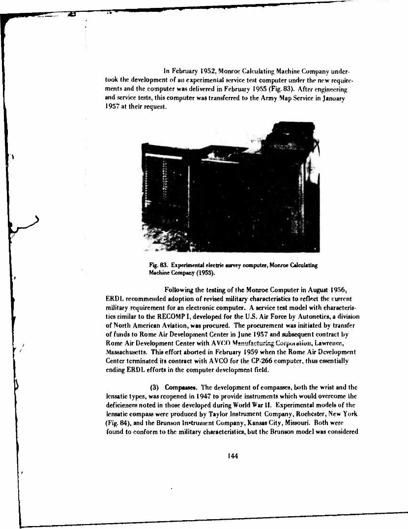
In February 1952, Monroe Calculating Machine Company under- took the development of an experimental service test computer under the new require- ments and the computer was delivered in February 1955 (Fig. 83). After engineering and service tests, this computer was transferred to the Army Map Service in January 1957 at their request.
Fig. 83. Experimental electric survey computer, Monroe Calculating Machine Company (1955).
Following the testing of the Monroe Computer in August 1956, ERDL recommended adoption of revised military characteristics to reflect the current military requirement for an electronic computer. A service test model with characteris- tics similar to the RECOMP I, developed for the U.S. Air Force by Autonetics, a division of North American Aviation, was procured. The procurement was initiated by transfer of funds to Rome Air Development Center in June 1957 and subsequent contract by Rome Air Development Center with A VCO Manufacturing Corpoiaiiori, Lawrence, Massachusetts. This effort aborted in February 1959 when the Rome Air Development Center terminated its contract with A VCO for the CP-266 computer, thus essentially ending ERDL efforts in the computer development field.
(3) Compaasec. The development of compasses, both the wrist and the lensatic types, was reopened in 1947 to provide instruments which would overcome the deficiences noted in those developed during World War II. Experimental models of the lensatic compass were produced by Taylor Instrument Company, Rochester, New York (Fig. 84), and the Brunson Instrument Company, Kansas City, Missouri. Both were found to conform to the military characteristics, but the Brunson model was considered
144

TV ^B»1
Fig. 84. Experimental model lensatic compass, induction damped, Taylor Instrument Company (1948).
Fig. 85. Wrist compass, induction damped, 1949 model.
us superior.'"" Experimental models of the wrist compass were produced by the Rrunson Instrument Company, Kansas City, Missouri (Fig. 85), and were delivered to ERDL in January 1950.144 Cold weather tests of the lensatic compass147 were conducted at Fort Churchill, Canada, and in January 1951 service test mod-Is were procured and shipped to service test agencies. Here again, as with the compass development during World War II, emergency procurement of large quantities of both compasses was made before all testing and development had been completed.
Development of both compasses was completed in 1952.148 The lensatic compass was classified as standard type, and the project was closed in June 1952. The wrist compass was classified as standard type, and the project was closed in Novem- ber 1952.
(4) Mobile Survey Control Section. As a result of wartime experience which indicated that time would be saved and efficiency increased by providing a mobile survey control headquarters, a project was initiated in 1947 to develop such an item. It was to consist of a van-type truck or trucks containing the drafting and computing
14S"Compta, Lensatic" ERDL Report 1154,6 January 1950. 146.. Compasa Wrist," ERDL Report 1183,5 October 1950. 147"Cold Weather Test of the Sun Comps» and Lensatic Compass," ERDL Report 11814,, 22 September 1950.
14B" Lensatic Compssa," ERDL Report 1250,2 September 1952. "Compssa. Wrist," ERDL Report 1266-L, 28 November 1952.
145

facilities and the communication and control center of the survey elements of Engineer Topographic companies and battalions.
Although engineering and user tests of the mobile survey control section were completed by 1956, it was not until 1960 that type classification action was completed and the project was closed. In part, the delay was caused by difficulties encountered in the development of a computer for the section. The final result of the development was a single, van-type truck mounted on a standard ordnance truck chassis and incorporating standard air conditioner and heating equipment. It contained the necessary office furniture, computing and drafting equipment, supplies, and radio com- munication equipment to operate a field computing section of a survey platoon.
(5) Electronic Distance Measuring Equipment. Work on the develop- ment of methods and techniques for the best use of ground survey electronic equipment in establishing control for mapping started in 1947. At that time, the Director of Re- search and Development, WDGS, directed the Chief of Engineers tc prepare military characteristics and a plan of development for "Ground Survey Electronic Surveying Equipment and Methods." The Chief of Engineers forwarded military characteristics to the Director of Research and Development in June 1947 and recommended that the Signal Corps undertake the development of ground electronic surveying equipment and the Corps of Engineers initiate a project to provide methods for the use of such equip- ment.
The Signal Corps development resulted in the design and fabrica- tion of an experimental model AN/PPN-1 3 electronic distance measuring equipment, two models of which were completed in January 1952 (Fig. 86). These were tested on the bench and in the field in 1952. In May of that year, the Signal Corps Engineering Laboratories contracted with Motorola, Inc. for 14 sets of the equipment. This system was based on a pulse technique wherein a distance was measured by the elapsed travel time of a large number of pulses of electromagnetic energy frem master io remote sta- tion and return.
Over the next few years, the Signal Corps Engineering Laboratories continued to modify circuitry on the experimental models to produce suitable results, until in April 1955, after almost 3 years of effort, it was agreed that a change in approach was necessary to expedite the delivery of service test models. Not until December 1958 was one AN/PPN-13 system delivered to ERDL. In the meantime, developments in the phase-comparison system area had overtaken the Signal Corps development. The AN/ PPN-13 was tested in Northern Virginia. Since the equipment was considerably heavier, bulkier, and less accurate than the phase-comparison systems which had become avail- able by this time, further work on the development of the pulse system was dropped.
146

^B"
Fig. 86. AN/PPN-13 electronic distance measuring equipment, Motorola, In«. (1956).
During this time, ERDL was investigating other ranging systems for possible military application. In 1954, the "Raydist System Type 0" of the Raydist Navigation Corporation was tested in the Caribbean over distances ranging from 65 to 175 miles. After these ^sts, a program was set up to evaluate radio continuous wave phase comparison systems as a means of measuring long distances up to 500 miles. There investigations and field tests were made by the Lorn- Service Corporation in ehe i955 to 1957 period.
In Ma'ch 1957, a contract was awarded to the Lorac Service Cor- poration extending the »cope of previous contract worn und requiring optical and radio- optical azimuth and distance determination in a test net in Arizona where ranges were 70 to 86 miles. In this work, some experiments also took place in positioning ground and air vehicles using the Lorac system as a radio locating system.
147
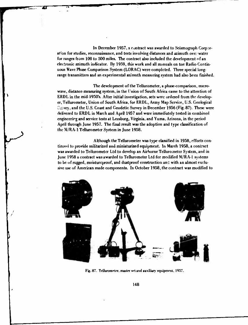
•JB"
In December 1957, a contract was awarded to Seismograph CorpDr- at'*on for studies, reconnaissance, and tests involving distances and azimuth ove/ water for ranges from 100 to 500 miles. The contract also included the development of an electronic azimuth indicator. By 1959, this work and all immuals on the Radio Contin- uous Wave Phase Comparison System (LORAC) were completed. Three special long- range transmitters and an experimental azimuth measuring system had also been finished.
The development of the Tellurometer, a phase-comparison, micro- wave, distance-measuring system, in the I rnion of South Africa came to the attention of ERDL in the mid-1950's. After initial investigation, sets were ordered from the develop- er, Tellurometer, Union of South Africa, for ERDL, Army Map Service, U.S. Geological Curvey, and the U.S. Coast and Geodetic Survey in December 1956 (Fig. 87). These were delivered to ERDL in March and April 1957 and were immediately tested in combined engineerirg and service tests at Leesburg, Virginia, and Yuma, Arizona, in the period April through June 1957. The final result was the adoption and type classification of the M/RA-1 Tellurometer System in June 1958.
Although the Tellurometer was type classified in 1958, efforts con- tinue'! to provide militarized and miniaturized equipment. In March 1958, a contract was awarded to Tellurometer Ltd to develop an Airborne Tellurometer System, and in June 1958 a contract was awarded to Tellurometer Ltd for modified M/RA-1 systems to be of rugged, moisturcproof, and dustproof construction and with an almost exclu- sive use of American made components. In October 1958, the contract was modified to
mi
Fiji. 87- Tellurometer, master wt and auxiliary equipment, 1957.
148

~E
include a dual, master-remote function for each unit. Tellurometer was also contracted in December 1958 to develop portable, short-range electronic positioning equipment. The airborne equipment was delivered for test in 1959, and the portable equipment wag successfully demonstrated in August 1959.
To develop a domestic source for the electronic ranging equipment, a contract was awarded to Cubic Corporation, San Diego, California, in June 1958. In 1959, Cubic Corporation was contracted for miniaturized electronic ranging equipment (Fig. 88). Engineerir 3 tests of the Cubic equipment in 1959 showed it to be a suitable domestic equivalent to the Tellurometer system (Fig. 89).
\
Fig. 88. Micro-diat equipment, Cubic Corporation (1959).
!49

rr
^>
ELECTROTAPE TELLUROMETER
Fig. 89. Advanced models of the Electrotape produced by the Cubic Corporation and the Tellurometer produced by Tellurometer, Ltd.
(6) Geodimeters. While the development of electronic distance- measuring surveying instruments was in progress in the 1950's,parallel investigations were being made of another distance-measuring system, the Geodimeter (invented in Sweden). This equipment, designed to operate in the visible frequency range, employs a light transmitter-receiver at one end of the line to be measured and a retrodirective mirror or prism system at the other.
ERDL had been following the development of the Geodimeter in Sweden before approval of a Geodimeter development project in Februar)' 1951 to adapt the system to military field use for precise baseline measurement for triangulation.
When the Geodimeter, manufactured by the AGA Svenska. AB, Gasaccumulator, Stockholm, Sweden, became available commercially, five instruments were procured by ERDL in 1953 and were distributed to the U. S. Coast and Geodetic Survey, the Ballistics Research Laboratories, and the Army Map Service for test. Two were retained at ERDL. These five instruments were designated Geodimeter Model I.
During the nert several years, modification and improvements were made in the Geodimeter system, including the development of a retrodirective prism
150

-B"
system by ERDL which was superior to the system which was supplied by the AGA Company. In addition, the AGA Company produced an improved version, the Model II (Fig. 90), later designated the 50-kilometer Geodimeter.149 In 1954, a Model III light- weight Geodimeter of lesser accuracy was demonstrated by the AGA Company, and in December arrangements were made to purchase four of these for test. This was later designated the 30-kilometer Geodimeter. Finally, to provide a man-portable device for quickly and accurately measuring distances up to 3 kilometers in length, the AGA Com- pany developed the Model IV Geodimeter. A contract was awarded to Berg Hedstrom Company, New York, for four of these instruments in May 1957. One was delivered in November 1957, one in January 1958, and two in July 1958.
Fig. 90. Geodimeter»: Models II, III, and IV (1957).
The major advantage of the Geodimeter over other distance- measuring systems was the precision and accuracy of measurement. A major disadvant- age foi iiiiiiUi v application was iis limitations for daylight U3e, depending as it did on frequencies in the visible range. Type classification action on the 50-kilometer Geodim- eter was taken in 1958. Later work on the 30-kilometer Geodimeter was suspended, as was work on the 3-kilometer Geodimeter, pending final evaluation of the miniaturized tellurometer as discussed earlier.
i49"Geodimeter Model« I and II," ERDL Report 1495-TR, 21 Augurt 1957.
151

TT"»
Through these programs, the Corps of Engineers played a key role in the development of advanced precision distance measuring instrumentation which was destined to revolutionize surveying practices in many and diverse applications in the years to come.
(7) Use of Aircraft in Survey Operations. The use of aircraft to facili- tate survey operations and provide methods and techniques to substantially increase the rate of extending ground survey control over difficult terrain or long distance was a sub- ject for specific investigation beginning in the immediate post World War II period and extending through the 1950's.
Initial investigations concerned use of a helicopter as a visible signal for horizontal and vertical direction observations. First tests of these techniques in co- operation with the Air Force started in September 1946 and continued through August I947.150 These tests demonstrated feasibility. Further tests with more suitable helicop- ters were planned but were delayed because of unavailability of aircraft until 1952 when tests were conducted to determine the feasibility of extending horizontal control by flare triangulation using an L-20 type aircraft for transporting the signal and flares. Major items in these tests were modified Wild T-3 Theodolites, robot cameras, SCR #624 radio sets, 2.5-kva generators, a special target light, and M-8-A/1 parachute flares. It was concluded from these tests151 that the procedures and applications used were generally suitable for use by topographic survey units for establishing third-order triangulation extensions and provided material advantages over conventional methods when operations were conducted over difficult terrain. Subsequently, Army helicopters and light aircraft were authorized as organic equipment for certain survey units, primarily for transport and reconnaissance applications.
Further tests of the helicopter as an elevated target for intersection and resection triangulation were conducted in Arizona in 1953 using an K-19-C Army Helicopter. Tests were also conducted using an HI 3 Helicopter. Investigations of a light-beam controlled helicopter for use as a stabilized elevated target also took place in the miu-1930'sliiiuügii ä contract with Kcrr.ar. Aircraft Corporation Through a con- tract with Altoscan Company, Inc., an engineering study of means for stabilized tether- ing of helicopters was conducted. Later in 1957, through a Navy contract with Altoscan Company, ERDL participated in research for an elevated target or relay station for elec- tronic surveying equipment.
By 1959, investigation of the use of aircraft in survey operations was associated principally with other development projects such as the Artillery Survey
,5°" Helicopter Survey Method» for Mapping," ERDL Report 1044,15 March 1948.
15l,,Hclicopter Survey Method«for Mipping(FUre^igiMlTri*n«ulitk>nTe«t)," ERDL Report 1230, 19 May 1952.
152

System, Airborne Tellurometer, Automatic Tracking Theodolite, the LORAC project, etc. Therefore, no other specific investigations of helicopter applications were made.
(8) Automatic Position Survey Equipment. In an effort to increase the speed of determination of a first-order geographic position, a project was approved in December 1956 to develop automatic position survey equipment. In June 1957, a con- tract was awarded to the Mechanical Division of General Mills, Inc., Minneapolis, Minne- sota, to: (a) conduct preliminary studies and modifications of existing astronomic equip- ment for interim use, (b) provide manuals and engineering services in connection with testing, operating, and maintaining the interim equipment, and (c) prepare detailed de- sign drawings of the final equipment.
The contractor selected the 60° pendulum astrolabe for the interim item and developed plans to modify the instrument to provide an automatic leveling system, an inertial reference system, and an electronic star transit system. After repeat- ed delays and cosf overruns finally amounting to about 64 percent over the original esti- mate, the equipment was fabricated and delivered to ERDL in July 1959 just before the demonstration of the Interim Artillery Survey System (Fig. 91). Initial testing, limited to eight observations in 5 weeks due to inclement weather, yielded unsatisfactory results.
Fig. 91. Automatic Position Survey Equipment Observation Instrument.
153
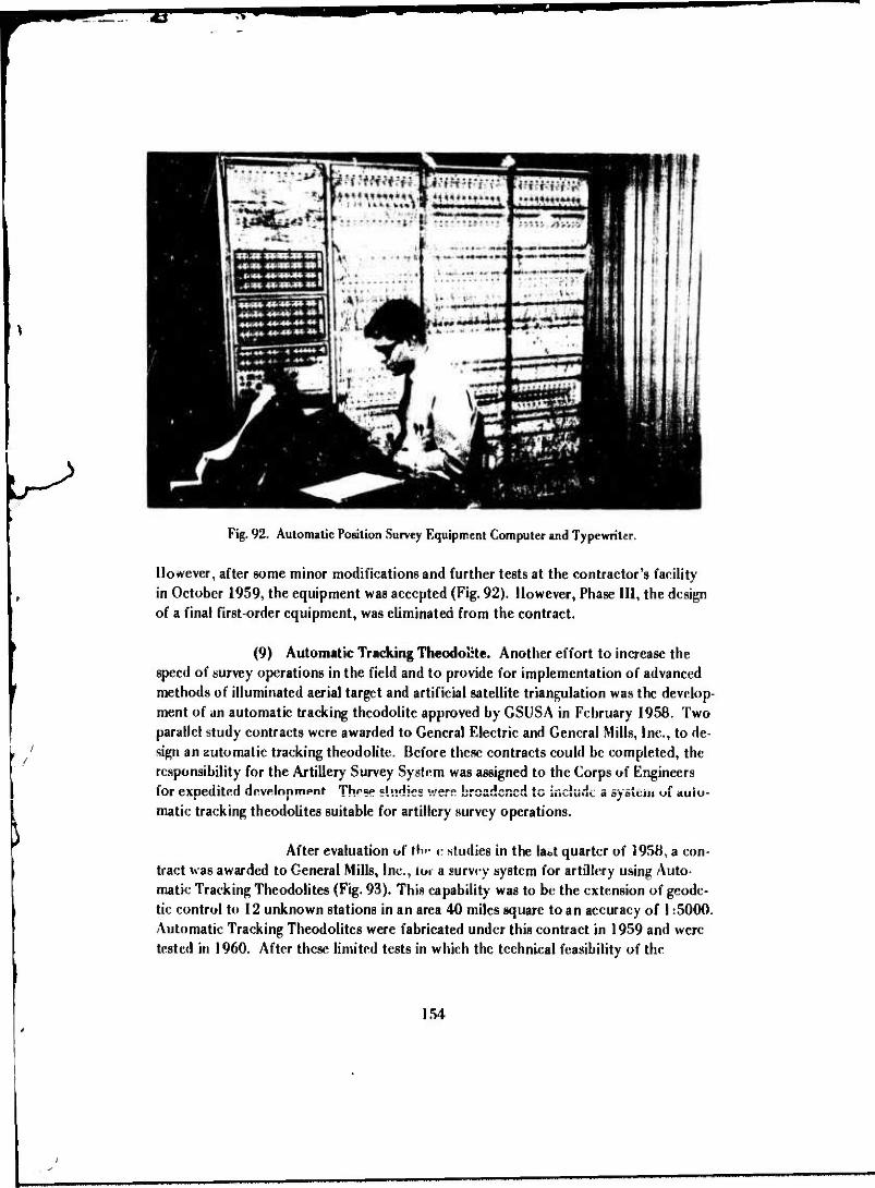
•S" wmm
Fig. 92. Automatic Position Survey Equipment Computer and Typewriter.
However, after some minor modifications and further tests at the contractor's facility in October 1959, the equipment was accepted (Fig. 92). However, Phase III, the design of a final first-order equipment, was eliminated from the contract.
(9) Automatic Tracking Theodolite. Another effort to increase the speed of survey operations in the field and to provide for implementation of advanced methods of illuminated aerial target and artificial satellite triangulation was the develop- ment of an automatic tracking theodolite approved by GSUSA in February 1958. Two parallel study contracts were awarded to General Electric and General Mills, Inc., to de- sign an automatic tracking theodolite. Before these contracts could be completed, the responsibility for the Artillery Survey System was assigned to the Corps of Engineers for expedited dcvelonmpnr These studies v/ere broadened to include a system w auto- matic tracking theodolites suitable for artillery survey operations.
After evaluation of lb«* e studies in the labt quarter of 1958, a con- tract was awarded to General Mills, Inc., loi a survey system for artillery using Auto- matic Tracking Theodolites (Fig. 93). This capability was to be the extension of geode- tic control to 12 unknown stations in an area 40 miles square to an accuracy of 1:5000. Automatic Tracking Theodolites were fabricated under this contract in 1959 and were tested in 1960. After these limited tests in which the technical feasibility of the
154

•C"
Ftg. 93. Automatic Tracking Theodolit«.
automatic tracking theodolite was established, further development for artillery surveys was dropped in favor of the electronic ranging approach.
(10) Artillery Survey System. In May 1958, the Chief of Research and Development, Department of the Army, assigned to the Chief of Engineers overall devel- opment cognizance of the Artillery Survey System and requested expeditious develop- ment of the projects comprising the system under priority 1 A. At the same time, the Chief of Ordnance was officially advised of this assignment of responsibility and was re- quested to establish liaison with the Chief of Engineers to describe the extent of work done on the project and to make available information, records, or equipment relating to the project as desired by the Chief oi" Engineers. The Chief Signal Officer was also advised of this assignment of responsibility and was requested to vork with the Chief of Engineers as required in connection with the data transmission. The project for this development was approved in September 1958. This was the first use of an organized effort to apply an overall systems approach to the solution of a surveying problem as opposed to the individual item development approach.
The objective of the project was to provide « rapid survey system as fully automatic in operation as possible to fulfill field artillery requirements in all- weather, day and night operations. An immediate objective was to demonstrate an ex- perimental system employing the maximum number of components envisioned for the complete system by I August 1959.
An Artillery Survey System demonstration was held on 4 August 1959 at Clark Mountain, Orange County, Virginia. All related items of the system were
55

^"
presented in various stages of completion from mockups to models ready for type clas- sification. The interim system as demonstrated included the Survey Control Center, Jukebox Computer, T-2 Theodolite, Tellurometer, Orienter, Recom II Computer, Short Range Electronic Positioning Equipment, Airborne Tellurometer, 3-km Geodimeter, Automatic Position Survey Equipment, and Automatic Tracking Theodolite (Fig. 94).
flfMUTf
Fig. 94. Artillery Survey System.
(11) Inertia! Survey Equipment. The development of inertial survey equipment by the Corps of Engineers was started in 1958 when, as a result of assign- HM>Rt of de*"*'""****""* *"S"MönssbiIit*' for the ArtUler" Surv?" System to the Chief of En- gineers, the Ordnance Corps on 12 August 1958 transferred to ERDL an Ordnance con- tract for the ABLE gyro-orienter. The orienter was being developed by the Autonetics Division of North American Aviation, Inc.
The project for inertia! survey equipment development was ap- proved in October 1958, and in November 1958 the ABLE orienter was delivered to ERDL. After user testing at Fort Sill, Oklahoma, the orienter was classified standard by CETC on 6 November 1959.
156

^m
\
In August 1959, the Corps of Engineers was assigned full respon- sibility for the development of all gyro-orienting devices except that required by the Pershing missile system. Prior to this, in April 1959, a contract was awarded to Kear- fott Company, Clifton, New Jersey, for a gyro-azimuth theodolite for Engineer use.
In June 1959, ERDL had contracted with the Missiles and Space Vehicles Department of General Electric Company for preliminary design of inertial survey equipment, and late in 1959 negotiations were initiated with General Electric for the fabrication of this equipment. Late in 1959, negotiations were initiated for a light- weight, reconnaissance, gyro-orienting device.
(12) Miscellaneous Developments. Numerous other items were developed or worked on in the late 1940's and through the mid-1950's. The more significant of these are discussed in the following paragraphs.
(a) Astronomic Orientation Attachment. During the development of an astronomic orientation attachment by the W. & L.E. Gurley Company, Troy, New York (which was delivered to ERDL in 1945), a new device (Shattuck) was discovered which indicated advantages over the W. & L.E. Gurley device. An experimental model of this new device was constructed by the U.S. Naval Observatory, Washington, D.C., and delivered to ERDL in 1945. Engineer tests of both models indicated marked advan- tages for" the new model. Some new principles were also discovered during testing, and and a third model was constructed by the David White Company, Milwaukee, Wisconsin (Fig. 95), and delivered to ERDL in June 1948.152 Later, service test models were pro- cured and tested by Army Field Forces and the Marine Corps in 1950 to 1952. Alter Arctic153 and desert tests154 in 1952 and incorporation of required modifications in specifications and drawings, the item was classified standard type 4 in June 1954 and the project was closed.155
(b) Radio Time Comparator. In 1946, an experimental model Radio Time Comparator was fabricated; and after engineering tests, 42 of the units were
152.. Astronomical Attachment, Azimuth Determination. Reflecting, for Transit and Theodolite," ERDL Report 1120. 13 May 1040
153"Cold Weather Testing of 01-Second Direction Theodolite, 10-Second Direction Theodolite. Universal Tripod and Astronomical Attachment," ERDL Report 1223, S January 1952. "Cold Weather Testing of 10-Second Direction Theodolite, 1-Minute Direction Theodolite, 1 Second Direction Theodolite (Foreign Model), Astronomical Attachment, and Winterization Kit," ERDL Report 1288, 29 April 1953.
154"Hot Weather Testing of 10-Second Direction Theodolite With Universal Tribrach and Universal Tripod, Astronomical Attachment, Universal Sun Compass on Wrist Compass," ERDL Report 1289, 29 April 1953.
155,4Astronomical Attachment, Az.muth Determination, Reflecting, for Transit or Theodolite," ERDL Report 1374, 3 September 1954.
157
s

owecTive out*» NOUK CMXECUU»
MOW» CÄCLE
MtTMUOTlOM CUT*
DECLINATION SCALE — MAGNIFIER
HOUR CACLE TANGENT SCREW
MGftOMETER WITH "A"(R£D» ANO ITBUCK) SCALE
SHUTTER (CLOSED)
POLAR REFLECTOR ADJUSTING SCREW
Fig. 95. Astronomic Orientation Attachment, David White Company, 1948.
procured from the W. M. Welch Company, Chicago, Illinois, for use in the Post Hostili- ties Mapping Program. The item was tested by the topographic units participating in that mapping program and also by the Air Forces and the Army Field Forces. ERDL performed additional tests for final evaluation. After all tests were completed; it was finally concluded that: (1) the Radio Time Comparator, although basically sound in principle, was not suitable for universal field use; (2) an electromechanical means of determining chronometer error was not warranted in the standard astronomic position equipment set ENG-6 120-01; and (3) the manual method of determining chronometer error with an automatic timer was more dependable and more consistently accurate in timing star transits than an electromechanical time comparator when used with the ob- serving equipment.156 The project was cancelled 6 July 1951.
UUl ll-JUIt I Ullllll.ll,! . A r*-rat"*i via n«*i«if*»*l •- r»«*«k„.. 10/17
to develop a surveying altimeter of p-eater accuracy and range than those developed in World War II. It was to have sufficient range for leveling up to 15,000 feet altitude (4500 meters) (Fig. 96). Experimental models were fabricated by Wallace and Tiernan Products, Inc., Belleville, New Jersey, and were delivered to ERDL in June 1949.!S7
After service testing of 21 service test models procured in 1950, modifications were in- corporated as recommended, including graduation in the metric system. Five additional
156..
157..
Radio Time Comparator." ERDL Report 1193,19 March 1951.
Altimeter, Surveying, 15,000-Foot, 5-Foot Division»," ERDL Report 1152, 6 December 1949
158

models were produced by Wallace and Tiernan for test.158 The project was finally com- pleted in May 1954 when Altimeter, 4500 Meter, 2-Meter Divisions, was classified standard type and the project was closed.
SPANNER WRENCH FOR TIGHTENING SCREW PLUGS
WIRING OlMRMft
FLASH LIGHT BATTEWES ISA 30D CELL)
BATTERY. SCREW PLUG
LIGHT 0IFFUSOR «PLASTIC RING)
FLASH LIGHT LAMP SCREW TYPE Z { VOLT)
RHEOSTAT SWITCH
CORRECTION AND 7 r&Nmm TABLES
^AÜR SCREW PLUS
Fig. 96. Surveying Altimeter-, 4500 Meter.
(d) Universal Sun Compass. In 1947, a project was approved to develop an improved sun compass that could be used in all latitudes, as opposed to the instrument suitable only between latitudes 45° north and south. Experimental and ser- vice test models were made by the Brunson Instrument Company, Kansas City, Missouri (Fig. 97).159 Arctic winter tests were conducted at Fort Churchill, Canada, in February 1950.160 Desert tests were conducted al Yuma Test Station, Yuma, Arizona, in August 1952.161 and the project was closed 4 June 1954.
,58" Altimeter, Surveying. 4500 Meter», 2-Meter Division«," ERDL Report 1350L, 2 June 1954.
I59"Compass, Sun, Universal, 090 Degrees North and South Latitudes, With Cases," ERDL Report 1153, 6 January 1950.
l60"Cold Weather Tests of the Sun Compass and Lenaatic Compass," ERDL Report 1181-L, 22 September 1950.
161"Hot Weather Teeing of 10-Second Direction Theodolite, With Universal Tribrach and Universal Tripod, Astro- nomical Attachment, Univeml Sun Compass, Lenaatic Compass, and Wriat Compass," ERDL Report 1289,29 April 1953.
159

itY
Fig. 97. Univeraal Sun Compass, 0° to 90° north and south latitudes.
(e) Tripods and Tribrach«. On 3 October 1947, projects were ap- proved by General Staff, U. S. Army, to develop a universal tripod and a universal tri- brach to standardize the mounting of surveying instruments which use tripods thus sim- plifying operations and the supply problem. Experimental and service test models of the universal tripod162 were fabricated by the Keuffel and Esser Company. Experiment al and service test models of the universal tribrach163 were fabricated by the W. & L. E, Gurley Company. Cold weather tests of the tripod were conducted at F.rt Churchill, Canada, in January to February 1951.,64 Hot weather tests of both the tripod and the tribrach were conducted at Yuma Test Station, Yuma, Arizona,in July to August 1952.165
Neither item attained seuaiatc classification status, but detailed drawings and specifica- tions were prepared. Both projects were closed by CETC action on 7 Januar 1955
162' Tripcd Universal, ERD1, Report 1202,21 May 1951.
163"Tribrach Universal," ERDL Report 1112,8 April 1949.
164"Cold Weither Testing of 1 -Second Direction Theodolite. 10-Serond Direction Theodolite, Universal Tripod, and Astronomical Attachment," RRDL Report 1223, 5 January 19S2.
l65"Hot Weather Testing of 10-Second Direction Theodolite With Universal Tribrach and Universal Tripod, Astronomical Attachment, Universal Lena Compass, 1-easatic Compass, Wrist Compass." F.RDl. Report 1289, 29 April 1953.
160

(f) Ranging Pole Tripod. The Ranging Pole Tripod was developed, tested, and adopted in the period from 1950 to 1952166 to provide a lightweight, adjust- able tripod for setting and plumbing range poles in combat survey operations. The tri- pods were needed because survey parties are frequently required to place and plumb ranging poles rapidly and the to take cover while observations are being made. Experi- mental «ind service test models were fabricated in the ERDL shops. The item was includ- ed as a component in applicable sets of equipment, and the project was closed by CETC action on 5 December 1952.
(g) Triangulation Tower. Another of the early post World War II167
projects was the development of a lightweight triangulation tower to replace the Bilby Tower which was too heavy to meet many operational requirements. This project was approved in February 1947.
An experimental model was designed and fabricated by the Aerometer Company, Chicago, Illinois (Fig. 98).IW Service test models were fabricated by Wind Turbine Company, West Chester, Pennsylvania. Three of these models were shipped to the Inter-American Geodetic Survey for test and three were sr;nt to engineer units on the west coast for test. AU development and test work was completed in 1952169
and the tower was included in Surveying Set, Signal and Tower, in lieu of the steel Bilby Tower.
(h) Indirect Distance Measuring. In 1952, a project was initiated to investigate and evaluate for military use methods and equipment to indirectly deter- mine the length of survey traverse courses by optical surveying instruments and auxiliary devices. Very little progress in this project occurred although tests were conducted using available foreign and domestic equipment at ERDL. in 1953, a Wild Tachymeter was procured for test. This project was overtaken by developments in the electronic distance measuring area, and it was terminated 3 August 1956.
(13) Research for Surveying and Geodesy. In 1958, it was recognized that although some advances were being made in surveying and geodetic equipments and methods; these equipments and method» would not provide acceptable survey control and geodetic data for use with missiles or in the production of topographic maps bccauMi- of excessive lead time and new problems introduced under current concepts of military operations. Therefore, intensive research was required to discover new phenomena and
166.. Tripod, Ranging Pole" ERDL Report 1199, Interim Report. 11 Mty 1951.
167.. Tripod. Ranging Pole," ERDL Report 1238-L, Final Report, 10 June 1952.
168.., tower. Thangulttton, Lightweight," ERDL Re j >.rt 1145,30 September 1949.
169.. Tower. Triangulation, lightweight," ERDL Report 1239, 26 June 1952.
161

^
Fig. 98. Triangulation Tower, Lightweight.
principles to advance the state-of-the-art in the field of surveying and geodesy to over- come these limitations. A project was approved on 1 August 1958 to research various scientific fields to determine, establish, or develop new criteria, phenomena, facts, prin- ciples, or techniques to apply in the development of new or improved iuctheds or equip- ment for surveying in military operations, including employment of Army missiles. A supplemental allocation of funds was made available to ER 1)1, to implement this program.
Three contracts were awarded in 1958. One was to the University of Maryland to provide consultant services for the program.170 Under this contract, a
This team al w provided consultant services for research on map compilation as previously noted.

^-- M >W w*
i /
team comprised of Professor Frederick J. Doyle of Ohio State University; Dr. Paul Herget, Director of the Cincinnati Observatory, Cincinnati, Ohio; and Dr. Sanford Goldman of Syracuse University met periodically with ERDL and contract personnel to provide advice and guidance on the conduct of individual research programs.
Another contract was awarded to the Franklin Institute, Philadel- phia, Pennsylvania, for studies of extraterrestrial data as an aid to mapping and position determination. The third contract was awarded to Midwest Research institute to study the effect of natural electromagnetic and geomagnetic forces on advanced methods of target location, precise surveying, and mapping.
The Franklin Institute Studies included sighting geometry and error propagation in satellite observations including the simultaneous case, the almost simul- taneous case, and the nonsimultaneous case. The geometry for 16 basic nonredundant cases for simultaneous satellite sighting for geodetic purposes together with a set of equatic ns fc -or analysis for one of the 16 cases, target objects, observing instruments and techniques, and the geodetic potential of existing satellite tracking data were also studied. The program further considered studies that would lead to choice of specific locations for satellite observation stations for geodetic ties; error propagation for the specific case of the 12 Baker-Nunn camera stations; study of value of a multipath satel- lite; optimum brightness and color in a satellite; photoelectric occultation of stars; and the use of geodetic satellite procedures to improve star catalogs.
The Midwest Research Institute studies included analysis of inertia! navigation errors caused by gravitation anomalies; the influence of the earth's curvature o.i radio v/ave propagation; and the effect of the troposphere on use of electromagnetic waves in geodesy. Effect« «f the ionosphere on Doppler signals from satellites, and ionosphere cross modulation were also studied. A basic study of space mensuration to determine the applicable and proper statistical theories and methods for geodetic measure- ment^ using artificial earth satellites; interaction of electromagnetic waves in the iono- sphere; experimental proof of Doppler satellite tracking methods for geodetic operations; and analytical investigations of satellite orbit perturbations also were considered.
Tiiese research studies continued through 1959 and into the 1960's.
20. Research and Development Progress 1960 to 1970.
a. Introduction. At i c beginning of the 1960's, the mapping and geodesy research and development program of the Topographic Engineering Department of ERDL comprised five basic projects with 36 subprojects. A number of these subprojects were in the final stages of completion. The project structure at tnat time was as follows:
163

jp^— ~g • ^-«r
8T35-03-001 Map Compilation
Engineering Studies and Investigations, Map Compilation
Stereoplotter, Topographic, Projection Type, High Precision
Rectifier, Photogrammetric, 9 by 18-inch Photography
Processing Equipment, Diaposilive, for Stereophotogrammetric Map- ping Requirements
Map Revision Techniques
Orthographic Photogrammetric Printer
Army Photo Imagery Interpreters Kit
8T35-09-001 Map Reproduction
Engineering Studies and Investigations, Map Reproduction
Xerography, Application to Map Reproduction
Separator, Color, Scanning, Topographic Map
Target Map Coordinate Locator Equipment
Cartographic Drafting Methods and Equipment
Photo Lettering Machine
/ 8T35-10-001 Surveying and Geodesy
ES&I, Surveying and Geodesy
) Surveying Equipment, Mobile Control Section
Theodolite, 1 minute
Use of Army Aircraft in Survey Operations
Computer, Survey, Electric
164
k

~«- ^^
Utilization of Ground Survey Electronic Equipment for Mapping
Automatic Position Survey Equipment
Geodimeter, 3-Kilometer Range, for Measuring Distances by Light Waves
Theodolite, Automatic Tracking
Artillery Survey System
Inertial Survey Equipment
8T35-11-001 Combat Mapping and Geodetic Systems
ES&I, Combat Mapping and Geodetic Systems
Liaison with Air Force on Aerial Mapping Systems
Target Location for Army Surface-to-Surface Missiles
Mapping with Minimum Ground Control
Analytical Photogrammctry
I Utilization of High Altitude Photography for Mapping
\ Automatic Map Compilation
I Ultra Wide Angle Photography in Mapping, Equipment and / | Techniques for the Utilization of
Utilization of Radar Presentations for Topographic Mapping
8T35-12001 Mapping and Geodetic Research *
Research for Surveying and Geodesy
Research for Map Convpil2tion
Research for Map Reproduction
•
165

V
At the beginning of the 1960's, the technology in the topographic sci- ences area was at the point in the surveying and geodesy area, where electronic distance measurement was well established as a working tool. The feasibility of the application of itiertial techniques to the solution of surveying problems had been fairly well estab- lished, and the potential in the application of satellites for the solution of geodetic prob- lems had been evaluated. A variety of techniques fc»i satellite exploitation had been proposed. In the map compilation area, the feasibility of automatic compilation of con- toured orthophotomaps from overlapping stereoscopic aerial photography had been dem- onstrated, precision optical stereoscopic plotting instrumentation was in advanced stages of development, the techniques were available for the analytical adjustment of large blocks of photographs in aerotriangulation, and the development of computer programs and the instrumentation required for expli .ation of these techniques was in progress. Development effort directed toward the automation of cartographic operation was just beginning as was the development of systems for mapping from radar presentations. In the map reproduction and presentation areas, the feasibility of the electrostatic repro- duction of topographic maps had been demonstrated. As a result, the concept of map reproduction at point of use and on demand in lieu of advanced quantity map reproduc- tion for areas of predicted military operations was formulated.
Increased interest in and funding for research and development in the mapping and geodesy areas began in the late 1950's because of advances in missile and earth satellite technology which placed greater demands for speed and accuracy in the production of geodetic and mapping data. Expanded programs of research were imple- mented and, while program« for the development of equipment and techniques for appli- cation by field Army units which had been the main thrust of programs through the 1950's continued, the effort was expanded to explore and advance development in the strategic systems area toward base plant application. Some programs were directed specifically toward the provision of specialized equipment for the new Army Precision Photogrammetric Laboratory constructed at Army Map Servic;.
After the establishment of GIMRADA in August I960, programs were formulated in the geographic sciences area to solve problems of acquisition and to pro- cess and disseminate terrain intelligence information in advance of and during military
In the early 1960V, there was a general restructuring and renumbering of Department of Defense research and development programs. Programs were classified in four stages of development: Research (6.11), Exploratory Development (6.21), Ad- vanced Development (6.31), and Equipment Development (6.41). As a result cf this restructuring, the shifts in emphasis, and the implementation of ne* programs during the 1960's, the program structure and the projects undertaken during the mid- to late I960's were as follows.
166

R&D PROGRAM FOR OFFICE, CHIEF OF ENGINEERS
4A061101A91D
4A061102B52C
•01 -02
RESEARCH: 6.11
In-House Laboratory Initiated Research and Development
Mapping and Geodetic Research
Cartography Geodesy
4A061102B52D Research n Geographic Sciences
hT J
EXPLORATORY DEVELOPMENT: 6.21
4A623501A852 Mapping and Geodetic Research
-01 -o; -03 -04
-01
-02 -04 -05 06
-07 -10
11 -12 -13 -14
Research for Surveying and Geodesy Research for Map Compilation Research for Map Reproduction Uiilization of Computer Sciences for Mapping and Geodesy
(Initiated in FY 71)
4A623501A853 Mapping and Geodesy Development
Engineering Studies and Investigations, Global Mapping and Geodesy*
Liaison With Air Force on Aerial Mapping Systems Utilization of Satellite Data for Geodesy Utilization of Satellite Data for Mapping* Analytical Photogrammetry Automatic Map Compilation Utilization of Advanced Sensors for Mapping Utilization of Auxiliary Airuouie Data for Mapping* Mapping From Reconnaissance Photography* Digitized Terrain Data* Micromap System for Display Systems*
•Project compleied, suspended, or renumbered during the decade 1960-1970.
167
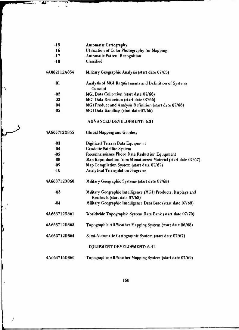
TB"
*
-15 -16 -17 -18
01
-02 -03 -04 -05
-03 -04 -05 -08 -09 -10
4A663712D860
-03
-04
4A663712D861
4A663712D863
4A663712D864
4A664716D866
Automatic Cartography Utilization of Color Photography for Mapping Automatic Pattern Recognition Classified
4A062112A854 Military Geographic Analysis (start date 07/65)
Analysis of MGI Requirements and Definition of Systems Concept
MGI Data Collertion (start date 07/66) MGI Data Reduction (start date 07/66) MGI Product and Analysis Definition (start date 07/66) MGI Data Handling (start date 07/66)
ADVANCED DEVELOPMENT: 6.31
4A663712D855 Global Mapping and Geodesy
Digitized Terrain Data Equipment Geodetic Satellite System Reconnaissiance Photo Data Reduction Equipment Map Reproduction from Miniaturized Material (start date 07/67) Map Compilation System (start date 07/67) Analytical Triangulation Programs
Military Geographic Systems (start date 07/68)
Military Geographic Intelligence (MGI) Products, Displays and Readouts (start date 07/68)
Military Geographic Intelligence Data Base (start date 07/68)
Worldwide Topographic System Data Bank (start date 07/70)
Topographic All-Weather Mapping System (start date 06/68)
Semi-Automatic Cartographic System (start date 07/67)
EQUIPMENT DEVELOPMENT: 6.41
Topographic All-Weather Mapping System (start date 07/69)
168

T~ wmm
R&D PROGRAM FOR ARMY MATERIEL COMMAND
IJ662707A576
-01
-05 -06
1J663712D673
-01 -05
EXPLORATORY DEVELOPMENT: 6.21
Field Army Mapping and Surveying
Engineering Studies and Investigations, Field Army Mapping and Surveying
Distance and Angle Measuring Equipment (start date 07/67) Imaging Materials Studies
ADVANCED DEVELOPMENT: 6.31
Field Army Surveying
Miniaturized Gyro Compass Position and Azimuth Determining System
ADVANCED DEVELOPMENT: 6.41
1S6643315D577 Field Army Map Reproduction Equipment*
01
-03 -05 -07
1S6433J5D578
-01
Engineering Studies and Investigations, Field Army Map Repro- duction Equipment*
Xerography, Application to Map Reproduction* Target Map Coordinate Locator Equipment* Field Army Map Reproduction and Distribution System*
Surveying Equipment for the Field Army*
Engineering Studies and Investigations, Surveying Equipment for the Fieid Army*
Automatic Position Survey Equipment Miniaturized Gyrocompass Angle Measuring System Electronic Inertial Surveying System FADAC Programs for Surveying Problems
•Project completed, suspended, or renumbered during the decade 1960-1970.
169

•=.'-• VAT Bi
•12
-13 14
-15 -23 -24 -27
1J664716D578
-12 -23
1S643315D579
-01
-03 -11
1J664716D579
-03
Long Range Survey System, Light Weight*
Long Range Survey Equipment Surveying Instrument, Gyro Azimuth, Light Weight
Elevation Determining System, All-Wea.ner* Angle Measuring System, All-Weather* Quaser Surveying System* Miniaturized Gyro Compass* Inertia! Surveying Systems* Distance and Azimuth Determining System*
Surveying Equipment for the Field Army
Long Range Position Determining System (start date 03/61) Miniaturized Gyro Compass (start date 06/71)
Field Army Mapping Systems*
Engineering Studies and Investigations, Field Army Mapping Systems*
Rapid Combat Mapping System* Multipower Army Stereoscope*
Field Army Mapping Systems
Rapid Combat Mapping System (RACOMS)
Under these research and development programs, some rather remarkable technological advances were made in the mapping and geodesy area, the most significant of which will be described in the remaining sections of this history. However, it should be noted that while the research and development programs of the I960's continued to address the problem of surveying and mapping in the field by troop units under combat Conditions, a rather lartrp nnrtinn nf trip nrnovam was ffoaionpH tn aAtirvaa tY\p nrnKlpms
o i - r-~o-~ — o — I ~ of the collection, processing, and dissemination of topographic data on a global basis. Up to the 1960*8, the controlling requirements for topographic information were general- ly based on the needs of so-called conventional artillery which required relatively high accuracy over short distances. The advent of long-range missiles and airborne vehicles of various sorts brought the additional requirement for accuracy over intercontinental distances. Better knowledge of the size and shape of the earth, *he position of points thereon, and of the earth's gravity cield was required to provide missile guidance. New
•Project completed, suspended, or renumbered during the decade 1960-1970.
170

concepts of military operation developed unprecedented demands for processing und dis- seminating large volumes of topographic and geographic information for almost any part of the world.
b. Basic and Exploratory Research. At the beginning of the 1960's, there was virtually no basic research program in the topographic mapping and geodesy area. The major effort in the exploratory research area was embodied in three contracted re- search efforts: (1) investigations in fields of science relating to mapping, geodesy, and position determination by the Franklin Institute, Philadelphia, Pennsylvania; (2) re- search on instrumentation of satellites and other hypersonic vehicles for precise survey- ing, mapping, and target location by the New York University Research Division; and (3) research to determine ithc effects of natural phenomena on present and contemplat- ed methods of precise surveying, mapping, and target location and where possible to de- velop new concepts for topographic operations by the Midwest Research Institute, Kan- sas City, Missouri.
With the establishment of GIMRADA in August 1960, a research and an- alysis division was set up as one of the six operating divisions of that organization. This division was responsible for developing a viable research program and organizing a com- petent staff to carry out that program. The concept at that time was to establish within the organization a competent staff of senior „cieniists of recognized stature in several dis- ciplines such as physics, astronomy, mathematics, geodesy, and geophysics. Each scien- tist would pursue research tasks within the general overall area of interest of GIMRADA for which he was specially qualified and in which he had a particular interest. He would be supported in these efforts with outside contractual efforts by universities or other research establishments as the situation required.
While recruitment of personnel was in progress and in view of the short supply of available manpower, a program of basic research by competent scientists in Eu- rope was actively pursued, implemented, and supported through the U.S. Army European Research Office. Under this program, research contracts were let to Professor K. B. P. Hallert, Royal Institute of Technology, Stockholm, Sweden; Professor A. Bjerhammer, Head of the Department of Geodesy, Royal Institute of Technology, Stockholm, Sweden; Dr. C. Morelli, Bari University, Director of Geophysical Laboratory, Trieste, Italy; Pro- fessor K. Ledersteger, Technical University, Vienna, Austria; and Professor W. Grossman Technical University, Uauover, Germany. Later, the research of Professor K. Rinner, Technical University, Graz, Austria, was supported through the U.S. Army European Re- search Office.
The research effort of Professor Hallert was on the theory of errors in photogrammetry. Thiß research for the most part was carried out while Professor Hallert
171

was in residence at GIMRADA for about 1 year starting in October 1961. The research produced seven GIMRADA research notes.I71"177
The research of Dr. Morelli, supported to the mid-1960's, was on the re- finement and interpretation of gravity anomaly computation.178 The research of Pro- fessor Grossman was on the propagation problems of electronic distance measurement specifically with the electrotape equipment to understand better the corrections to be applied to measurements made under adverse conditions.179 The research program of Professor Ledersteger was concerned with the development of new methods for deter- mination of the earth ellipsoid based on additional parameters of densities and interior siiucturc, or model figures of equilibrium that most closely fit the structures and the shape of the earth. This research which was aimed at increasing our knowledge of the earth's constants and internal structure through effciic on satellite orbits and the appli cation of laws of rotating fluids in equilibrium continued to the \aV 1960's and was fund- ed in part by the U.S. Army European Research Office. It produced a series of techni- cal reports on the development of the Ledersteger theory.180 ,81 m
The research of Professor Bjerhammer (including a 6-month period in residence at GIMRADA from June to December 1963 and, in 1966, a brief tour as Di- rector of the Research Institute of Geodetic Sciences, GIMRADA) was aimed at better
171
172
173
RN-1, "Practical Teal» of the Theoretical Accuracy of AeriaJ Triangulation," May 1962.
RN-3, "Determination of the Geometric Quality of Comparator» for Image Coordinate Measurements," August 1962.
KN-4, "Investigation of Basic Geometric Quality of Aerial Photographs and Some Related Problems," August 1962,
T1N-5, "Test of Base Geometric Qualities of Photogrammetric Plotting Instruments," August 1962.
175 RN-6, "Investigations of the Geometric Quality of Relative and Absolute Orientation Procedures and the Final Results of the Photogrammetric Procedure," August 1962.
RN-7, "Some Relations Between the Geometric Quality of Topographic Mapping and Aerial Photogrammetry," August 1962.
RN-9, "Geometric Quabty of Lunar Mapping by Photogrammetric Methods," September 1962.
178P: Final Report, "Research on Refinement and Interpretation of Gravity Anomaly Computations," Correzzo, M. T., and Morrelli,C, July 1967.
179r: '•''";! Report, "investigation of the Electronic Distance Measuring Equipment Electrotape." Grossman, W., December 1964,
180.,: Final Report, "Multi-Parametric Figures of Equilibrium; Curvature of Ihe Plumb Line," March 1964.
181c; Final Report, "Multi-Parametric Theory of Spheroidal Equilibrium Figures and the Normal Spheroids of Earth and Moon," June 1966.
182r: Final Report, "Equilibrium Figures and the Normal Spheroid of the Earth Mass Functions and Isostacy," April 1968.
172

= 4T
gravity data reduction and the development of a figure of the earth based only on hori- zontal distances between observational points, gravity, and potential differences. The results of this research are recorded in several research papers published by Professor Bjerhammer, GIMRADA, and the Royal Institute, Stockholm, Sweden.183'I87 Also, while Professor Bjerhammer was Director of the Research Institute he formulated the concept for an automatic electro-optical satellite triangulation system.188
The research of Professor Rinner of the Technical University, Graz, Aus- tria, which wa3 initiated in 1964 and continued into 1967, was concerned with geodetic networks in space. This included a study in error propagation in space triangulation and space trilatera'ion systems and combination of angle and distance measurements applied over large areas.189 This work gave insight into the behavior of a global trilateration as accomplished by the SECOR program. Other research efforts in th- early 1960's, while the staff of the Research and Analysis Division was being developed, included the devel- opment of a photo flash triangulation concept under contract with Geonautics, Inc., Washington, D. C.190 and a continuation of work started in 1959 on the theoretical an- alysis of the effects of supersonic and hypersonic aircraft speed upon aerial photography by Vidya Inc., Palo Alto, California.191 Also, the research program of New York Univer- sity on the instrumentation of satellite and other hypersonic vehicles for precise survey- ing and target location19' and another study on space photogrammetry193 were completed.
' T»nal Report, "On an Explicit Solution of the Gravimetric Boundary Value Problem for an EUipoidal Surface of Reference," A. Bjerhammer, February 1963.
l8*RN-12, "Gravimetric Geodesy Free of Density Estimates Through Analysis of Discrete Gravity Data," A. Bjerhammer, December 1963.
Royal Institute of Technology, Stockholm, Final Report, "Investigation of Bjerhammer's New Gravity Reduction Method," W. Forstner, November 1964.
^loyal Institute of Technology, Stockholm, Final Report, "Studies of Gravity in Space According to Bjerhammer,*' B. G. Reits, April 1966.
/ American Geophysical Union, Washington, D. C., "A New Geoid," A. Bjerhammer, April 1967.
IRA RN-23, "An Automatic Electro-Optical Satellite Triangulation System," A. Bjerhammer, April 1967.
I QQ * X. Kinner, "Systematic investigation oi Geuücüt "üUUIM ui Space," Fins! Report, Msfch 1967.
190 H. Eichorn, "Photogrammetnc Flash Triangulation for Corps of Engineers Field Use," Final Report, August 1961.
Effects of Supersonic and Hypersonic Aircraft Speed Upon Aerial Photography," Interim Report, August 1959, July 1960, October 1960.
192 Research on Instrumentation of Satellite and Other Hypersonic Vehicles for Precise Surveying, Mapping, and Target Location," Final Report, New York University, February 1961.
193"Research in Space Photogrammetry," Final Report, New York University, October 1961.
173

1ET
The Midwest Research Institute contract194 was extended into the mid- W60s to include techniques to determine the integrated refraction index of the atmo- sphere between two points and ultimately to design an experiment to verify the inverse scattering theory developed in this research.198
The Franklin Institute contract implemented in late 1958 was converted to a longevity funded effort in the early 1960's and included studies in several and varied areas of interest until contract termination in the mid-1960's. The final report was sub- mitted in October I960.196 Under the longevity funded effort, series of studies and re- ports were submitted from 1960 through 1965. These studies included the evaluation of components for some elevation-determining system,197 application of advanced acceler- ometers to surveying and geodesy J98atmospheric refraction,199 a pilot program of lunar photography200 in which photographs of the earth-lit moon were taken at selected obser- vation points around the world in an effort to provide better sensor data for lunar map- ping than the few photographs in current use, lunar mapping from a high altitude balloon, and the application of the coriolis f .rce to geodetic measurement.201
With the addition of specialists in geodesy, physics, astronomy, and math- ematics to the Research and Analysis Division staff in the early 1960's, research activity began to be oriented around the individual scientist's skills and interests as they related to the overall GIMRADA mission. The earliest results of this approach were two studies relating to atmospheric refraction, a problem which had been addressed both by the Franklin Institute and ->he Midwest Research Institute in previous research studies. The results of these studies were published in separate GIMRADA research notes.202 203
'Research Studies Related o Mapping, Geodesy, and Position Determination," Midwest Research institute. Interim Reports December 1060, December 1%1, June 1961, September 1961, March 1962, June 1962, October 1962, Final Report Jinuary 1963.
19D"The Design of a User Experiment for the Verification of the Inverse Scattering Theory," Midwest Research Institute.
,96"Reaearch in Surveying, Mapping, and Geodesy," Final Report, Volume I, Psrt» I and 2, October 1960.
"Evaluation of Component« for Some Elevation Determining Systems," Interim Report, Franklin Institute, May 1963.
Application of Advanced Accelerometers to Surveying snd G»od»«y." Interim Reports, Franklin institute. Volume i, November 1963, Volume II, March 1964.
199"Rerraction in Selected Model Atmospheres," Interim Report, Franklin Institute, February 1964.
"A Pilot Program of Lunar Photography tor Precise Selenodesy,," Interim Report, Franklin I institute, October 1964
Application of Coriolis Force to Geodetic Measurements," Interim Report, Franklin Institute, December 1965.
202 A. A. Bald mi, RNÜ, "Formi'laa for Computing Atmospheric Refraction for Objects Inside or Outside the Atmosphi.-re," January 196'».
H. H. Sc'.mid, RN-10, "Tl* Influence of Atmospheric Refraction on Directions Measured To and From a Satellite," February 1963.
174

wm
By 1962, Dr. Baldini had begun his research on Theory of World Geocen- tric Geodetic System, commonly referred to as the Baldini Theory. Work on this theory continued throughout the decade of the 1960V It provides a basis for expressing the po- sitions of points around the e-jurili in a common system referred to the center of mass of the earth, based on new theoretical concepts for defining astronomical position of ground points with respect to satellite positions against a star background. The absolute deflec- tion of the vertical is also obtained independently of gravity data. A special lunar-stellar camera on an equatorial mount was developed under contract by the Autometric Cor poraiion in 1963 to be used in field verification of certain aspects of this theory. The results of this research have been reported in a number of G1MRADA research notes204*208
and a series of technical papers presented at various technical conferences over the decade. The most significant of these papers were "Determination of Center of Mass and Mathe- matical Figure of the Earth Using Solely Astro-Geodetic Methods" presented at the I1JGG, Switzerland meeting, 1967, and "Determination of Latitude and Longitude of Unknown Station from Photographs of a Satellite Against Stellar Background Indepen- dent of any Distance" presented at the Army Science Conference at West Point, New York, June 1970.
The only outside support to Dr. Baldini's research were a contract inves- tigation and a test by Autometric Corporation in 1963 of a proposed method of geocen- tric position determination with star satellite photography from a single camera station,209
und an evaluation of the stellar-moon camera system by the Ohio State University Depart- ment of Geodetic Sciences210 in the 1966 to 1963 period.
Another in-house research program implemented in the early 1960's dealt with computation of long-line geodesies, geodetic trilateration, and triangulation intersec- tion, and long-line az?muth and distance determination between non-intervisible points by E. M. Sodano. Mr. Sodano is known internationally for the development of the line- crossing method of long-lint azimuth determination. Certain aspects of this research are
W4RN J, "New Formulas Useful When Changing Ellipoidal Parameter or Orientation," J uly 1962.
205 ' RN-17, "New Method for Determining Azinv'h and Latitude Independent of Time and Zenith Distance," February 1966.
RN-19, "Determination of Direct and Inverse Azimuth, Zenith Distance Hour Angle, Declination and Distance Between Two Points on Normal Section," February 1967.
KN-20, "Star Position Determined by Combining Miaometric Observation With an Observed Known Star in a Vertical Plane Close to the Meridian," February 1967.
208RN-32, "Satellite Geodesy Based on Stellar Orientation of Lines Between Uni iown Stations," November 1969.
Geocentric Position and/or Orbital Parameters wiUi Star •Satellite Photography from a Single Camera Station," Autometric Corp., November 1963.
An Evaluation of the Stellar-Moon Camera System," Ohio State University Department of Geodetic Sciences, June 1958.
175

*m* v
/
reported in a GIMRADA research note211 and in a number of technical papers presented at various meetings. This research has produced a new formulation of a geometric field method, improved and refined over the years, for obtaining the distances and vertical and horizontal directions of the earth chord joining distant ground stations using a com- bination of electronic ranging and optical observation of either one or two moving or stationary aerial targets. The most significant of the technical papers on this subject are: "Optical Electronic Azimuth and Range Between Non-Intervisible Distant Ground Sta- tions," Army Science Conference 1964; "Supplement to Inverse Solution of Long Geode- sis," Second International Symposium on Geodetic Calculation, Brussels, Belgium, June 1966; "Data Reduction for Long Aerial Lines of Relatively Low Elevation," Second International Symposium on Geodetic Calculations, Brussels, Belgium, June 1966; "Three Dimensional Station Coordinates of Increasing Vertical Rigidity From Lower Airborne Target," ASP-ACSM Convention 1967; and "Optimum Three-Dimensional Geodetic Formulations and Applications," 1969.
In the physical science areas, the most significant research programs start- ed in the early 1960's were the investigation of lasers for geodetic application, the study of atmospheric effects on electronic pointing and angle measurement, studies of Doppler tracking of artificial satellites for field army applications, and investigations of atmospher- ic effects on light waves; i.e., laser radiation.
The first continuous-wave laser obtained for laboratory investigation was procured from the Raytheon Company in January 1963. Initial research was concerned with techniques of modulation and demodulation of laser radiation and studies of coher- ency over various path lengths and types of terrain. Later, in June 1964, a low-power, continuous-wave gas laser with outputs in the visible (0.63 a) and infrared (1.15 and 3.39 n) was procured from Spectra-Physics, Inc. These early investigations formed the groundwork for later formulation of several highly significant applications of laser tech- nology to problems of geodetic measurement.
The first of these was the application of the laser in an instrument de- signed for measuring the absolute acceleration of gravity,312 a laser gravimeter, conceived in 1964. A feasibility model w*a constructed m-house in 1965; in May 1966, a contract was awarded to Barkley and Dexte« Laboratories, Fitchburg, Massachusetts, for a high performance instrument. This instrument was successfully completed by 1970 und achieved a precision of better than one part in i million. It has a potential accuracy oi 0.2 milligal. The instrument consists of a laser interferometer in which the measuring arm is vertical. The reflector terminating the measuring arm is dropped in a vacuum
21' RN-1I, "General Non-Iterative Solution of the Inverse and Direct Geodetic Problem»," April 1963.
212K. D. Robertson. RN-18, "lnatniment for Merauring Absolute Acceleration of Gravity," June 1966.
176

W«W«l"l."ll • '" '<
chamber and the interferometer fringes generated as it falls are counted for precise time periods. Another was the development of techniques for very precise surveying. A con- tract for an experimental model laser distance-measuring instrument was awarded to Spectra-Physics, Inc., in November 1965 and the instrument was delivered to GIMRADA in June 1967. As a result of intensive in-house field studies with this equipment of at- mospheric parameters which pose a limit to surveying accuracy, techniques evolved dur- ing 1969 and 1970 have produced results as great as five times the accuracy previously obtainable.
Research in laser technology also led to the formulation of a concept for an ultra-precise geodetic baseline213 which was proposed in 1967, and could lead to a redetermination of the velocity of light; and the production in-house in 1969 to 1970 for the Civil Works Division of the Office, Chief of Engineers, of instrumentation con- sisting of a laser projector and a novel centering detector which permitted the precise measurement of alignment both on top of and in the galleries of concrete dams.
To support the research on electronic angle measurement, GIMRADA funded a study by the National Bureau of Standards (NBS) at Boulder, Colorado, of various microwave techniques for measuring angles with emphasis on accuracy and com- patibility with conventional microwave distance measuring instruments including atmo- spheric limitations and their dependence on antenna size. A report on these investiga- tions, which started in September 1961, titled, "Atmospheric Errors in Microwave Range and Short-Baseline Azimuth Measurements" was submitted by NBS in April 1964. These studies under Dr. M. C. Thompson provided background information used by the Survey- ing and Geodesy Division in their development program on electronic angle measuring equipment. Work on atmospheric effects on electromagnetic radiation continued at NBS, Boulder, under GIMRADA sponsorship to mid-1965; the final report was submitted in December of that year. In mid-1965, GIMRADA and the U.S. Coast and Geodetic Survey implemented a joint program of sponsorship of r rch at NBS, Boulder, con- centrating primarily on correction for atmospheric efforts on optical and electronic dis- tance measurement. The research was primarily on the dual optical technique for refrac- tion index correction to distance measurement.
Research and Analysis Division personnel became interested in and start- ed investigations of the application of the U.S. Navy Doppler Satellite Navigation System, Transit, to field army survey problems early in 1961, and started to assemble components to put together a set of doppler tracking instrumentation for experimental purposes. This construction of a tracking station was later abandoned. Little progress was made in this investigation until May 1964 when a contract was awarded to Westinghouse Electric Corporation, Baltimore, Maryland, for an experimental feasibility study using data
21 JK. D. Robertson, RN-?4, "Concept for an Ultra-Precise Ceoditic Baseline." November 1967.
177

obtained with U.S. Navy equipment on a noninterference basis. These investigations were completed and a report was submitted by Westinghouse in May ] 965. The results were sufficiently encouraging that the procurement of backpack Oonpler tracking equip- ment being developed at the time by the U.S. Navy was authorized for further experi- mentation, and this program moved frnm research to exploratory development by the Surveying and Geodesy Division.
In the midst of concerted efforts to build a viable research program and staff in the early I960's,the Research and Analysis Division was called upon to make two special investigations in the satellite geodesy area for the Office, Chief of Engineers. WM!e these special studies diverted attention from the planned research and develop- ment activity and in that sense were disruptive, they did familiarize the staff more inti- mately with some of the basic and realistic problems of satellite tracking applications to geodesy. In January 1962, the Chief of the Research and Analysis Division was called upon to form a special investigative team to evaluate the current Corps of Engineers Geo- detic Satellite program which was embodied primarily in the Army Map Service program with the Sequential Collation of Range (SECOR) System and to advise as to future plans. This system, which had been under procurement by the Army Map Service from the Cubic Corporation, San Diego, California, had run into difficulty in the first efforts to track a satellite transponder, and there was some question as to the validity of the ap- proach and the future role if any it should play in Corps of Engineers geodetic programs. An expedited investigation was requested. The team formed for this investigation con- sisted of personnel of the Research and Analysis Division: Dr. Frederick Rohde, Mr. Joseph Hannigan, and Mr. Emmanuel Sodano with Mr. John Pennington as head of the team; two electronic experts from the Ballistics Research Laboratories, Aberdeen Prov- ing Grounds, Maryland: Dr. Keates Pullen and Mr. Richard Viteck; and an expert on electromagnetic radiation from the National Bureau of Standards at Bculder, Colorado: Dr. M. C. Thompson.
This special study was completed in 6 weeks, and a special report "Review and Analysis of U.S. Army Geodetic SECOR Development" was submitted to Office, Chief of Engineers. The report estabHshed the validity of the SECOR approach, analyzed the problems of development, and recommended a program for continued development by the Corps of Engineers. As a result, development responsibility was assigned to GIMRADA, and the evaluation team was retained in a technical advisory capacity in further development of the system.
A second special investigation came immediately on the heels of the SECOR investigation when, in March 1962, GIMRADA was requested to make a special expedited study of the Corps of Engineers minitrack activities and to determine an effec- tive satellite geodesy program. The same SECOR team personnel augmented by Dr. Angel Baldini of the Research and Analysis Division staff comprised the new working
178

„gjDII—^—^ ^^m <- •'••• •,!•• i ^^'tnr,.- .•-!•"••.*• w<.• • ••-•-ai-.~-=^^->• -.• -- - ._w--.T.:*VV,.v ...ü--—
group formed for this investigation. The report of this group, "Tracking Systems for Geodetic Purposes," was submitted to Office, Chief of Engineers, in May 1962. It in- cluded analyses of various tracking systems including moon dual camera (Markowitz) and positioning of satellites against a star background and mathematics and data reduc- tion for orbital analysis, theodeolite tracking, occulations, and electronic systems appli- cable to geodetic position determination.
With further augmentation of the Research and Analysis Division staff in the mid-1960's, several new programs of investigation and research were implemented. These new programs were generally in the areas of photogrammetric metrology and image evaluation, data reduction and analysis of geodetic satellite tracking data, calibra- tion of both photographic and electronic data acquisition systems, research in solid state UHF amplifiers in support of the SECOR development, and studies of the geodetic ap- plications of the torsion balance and gravity studies.
In the area of photogrammetric metrology and image evaluation, a study had been made in 1962 under contract with General Precision, Inc., Pleasantville, New York, on "Automatic Stereo Perception of Aerial Photography by Means of Optical Correlation."214 In 1963, a comprehensive in-house program of investigation of visual factors involved in pointing precision and measurement was implemented under Mr. Desmond O'Connor. This research involved the in-house construction of special labora- tory apparatus for measuring and recording visual performance data and also special ap- paratus for the controlled generation of edge gradients required for these and other investigations.
The visual factor investigations were augmented *»" studies of fusion and disparity limits for photogranimetry at Purdue University under Professor S. A. Veres,215
studies of mono versus stereo analytical photogrammetry at the University of Illinois under Processor H. M. Karara,216 studies of the role of focal length in image generation at Ohio Flate University, studies of pointing to a sharp edge at Washington University/17
and studies of the effects of nonhomogeneous backgrounds on coordinate measurement at Purdue University.218
Automatic .stereo Perception of Aerial Photography by Means of Optical Correlation," Final Report. General Precision Inc., December 1962.
S. A. Wren. "Investigation of Fusion and Fixation Disparity Limits for Photogrammetry," Final Report, August 1965.
II. M. Karara, "Mono Versus Stereo Analytical Photogrammetry," Final Report, Part I, February 1967. II. M. Karara ar.d C, W. Mark», Part II, February I960.
il 7K. Lund aid J. E. Colcord, "Evaluation of Pointing to a Sharp Edge," April 1968.
1. E. Roger and E. M. Mikhail, "Study of the Effects of Nonhomogeneous Target Background« on Photogram- metric Coordinate Measurement," Final Report, August 1969.
179
HUHU, mimmmmmmmmmmmmmmmmmmm mmm unwinum u ,JWWI ppmm. w^mm mmmm * m
The research on pointing and measuring precision as related to circular targets was virtually completed with the publication of Desmond O'Connor's Doctorate Dissertation, from the University of Illinois, as a GIMRADA research note in January 1967.219 But the longer range objective of this overall research area was to relate measure- ment precision to image quality parameters such as resolution, modulation transfer func- tion, focal length, etc. The connecting link was through the edge gradient generator studies.
Concurrently with the «•»»««»••^h on visual factors and since this research had shown limitations in existing photogrammetrie instruments, a prototype polar co- ordiante comparator was designed to increase the sensitivity of reading. This instrument, using a laser interferometer and an inductocyn encoder, was designed and fabricated in- house without the necessity for delicate craftsmanship.
In the area of data reduction and analysis of geodetic satellite data, re- search activity was implemented in 1964 with the additions of Messrs. Armando Mancini and L. A. Gambino to the Research and Analysis Division staff. Two research notes con- cerning analysis of geodetic satellite tracking data were published in 1965,220 221 and, in November of that year, a research note was published on the satellite ahgulateration concept,222 combining optical and electronic ranging observation, as formulated by Mr. Mancini.
In late 1964 and in 1965, work started on the development of several computer programs required to reduce and analyze geodetic satellite tracking data. In December 1964, a contract was awarded to Wolf Research and Development Corporation, Bladensburg, Maryland, for programs for a computation of Combined Gravity Coeffi- cients and Geocentric Datum Shafts (GEOPS) which was completed in March 1966.123 A research note on GEOPS was published in March 1967.224 In May 1965, a contract was awarded to International Business Machines Corporation, Cambridge, Massachusetts, for
21Q D. D. O'Connor, RN-21, "Visual Factors Affecting the Precision of Coordinate fV.easuremrnt in Aerotrutngu'a- tion," January 1967.
A. Mancini and L. A. Gambino, RN-13, "Results of Space Triangulation Adjustments from Satellite Data," September 1965.
221 RN-14, "Reduction Procedures for Absolute Direction and Geodetic Azimuths from Optical Observation of Satellites."
222 A. Mancini, RN-16, "Satellite Angulateration," November 1965. Note: An attempt was made to employ and evaluate the angulateration concept in 1965 employing Baker-Nunn Camera and SECOR observations on the West Coast and Hawaii. The attempt failed because insufficient data was obtained.
Unified Geodetic Parameter Program (GEOPS)," Volume I, "Mathematical Analysis," Volurie II, "Program Description," r >nal Report, Wolf Development Corporation, March 1966.
224A. Mancini, RN-25, "GEOPS," March 1967.
180

^•WWIP muni.—«in«u »min
"i program for geoid studies from satellite determined gravitational coefficients. This contract was also completed in March 1966.225 In October 1965, a contract was award- ed to Raytheon Company, Autometrics Operation, for a three-dimensional surface tri- angulation adjustment computer program. This contract was successfully completed in April 1966.226 During this time, work was completed in-house on a Simultaneous, An- gulateration, Triangulation, Trilateration Program (SMATI).
These efforts and additional in-house development of mathematical analy- sis procedures and programs provided the tools later used in accuracy studies and simu- lations related to the GEOS-PAGEOS geodetic satellite programs, geoid and gravitational model studies, analyses of SECOR observational data, and studies to develop methods for combining gravity data obtained at the surface of the earth with gecpotential ai.J geo- metric data derived from satellite observations.227 228 229 Preliminary findings on the latter were reported in a paper by Dr. Bjerhammer, "On a Coalescent World Geodetic System, Part 1," July 1967. This paper was presented at the International Association of Geodesy meeting, Lucerne, Switzerland, during September and October 1967. Mr. Mancini, while successfully completing 12 months' resident study at Georgetown Uni- versity in 1967 under the ETL Graduate Study Program, submitted his doctoral disserta- tion on the development of a gravitational model of the earth from a union of optical, Doppler, and surface gravity data.
Although, by November 1968, all available satellite observations and all surface gravity data had been combined into a single solution to derive the earth's gravi- tation field model with all zonal and territorial harmonic coefficients up to the degree and order 14, 14, efforts continued in the late 1960's to refine this model and to provide the best possible representation of the external gravity field of the earth and the best possible earth geoid for direct application to the world geodetic system. In 1970, it was planned to make a combined solution using transit data on six satellites and optical data from the Smithsonian Astro-Physical Observatory on five satellites. It was also planned to use 10° by 10° surface gravity data for the integrated solution. As a part of this over- all research effort to refine the world geodetic system through combining various types of geodetic data, a study of advanced correlation methods bet^ een gravity, geophysics,
225 "Geoid Representation from Satellite Determined Coefficients," Final Report, IBM, Cambridge, March 1966.
Modes of Satellite Triangulation Adjustment," Volume I and Volume II, Fin.il Report, Raytheon Corporation, Alexandria, Virginia, April 1966.
~*" RN-22, "A Geometric Simultaneous Miilti-Station Determination, With Constraints Using Data From Geodetic Satellites."
228A. Mancini, RN-30, "The Earth's Gravitation Field From Observations of NearEarth Satellites and Terrestrial Gr vity Measurements," November 1968.
22i)\. Mancini and Others, RN-31. KTL-211-0D, "Gravitational Models, A Union Solution of Optical and Doppler Satellite D?V. mination," September 1968.
181

Wjl^HlB^^W P^.IU.i.iin-»^ . ,m .mnii^.uinjw,.
tidal motion, heat flow, and polar motions as fsey a/fect the gravitation field of the earth was made in 1969 under contract by Geonautics Operation, Computer Science«; Corporation, Falls Church, Virginia.230
Al"«:, in 1969, a new concept of space adjustment was introduced using satellite data with equations of condition. In addition, a new system of geo-grav coordi- nates and a new concept in defining the astronomic station position were introduced.
The Research Institute Staff continuously supported the Army SECOR program through the late 1960's. Many contributions were made to overcome operation- al bottlenecks, to improve software and hardware, and to provide for the introduction of advanced concepts. The SECOR reduction program was used in 1968 for simulations of various satellite orbit configurations to determine the orbital accuracy to be expected under certain tracking conditions. Advanced techniques for the reduction of geodetic SECOR observations were developed in 1966 under contract by D. Brown Associates, Eau Gallie, Florida.231 Analyses of SECOR data were made under contract by DBA Sys- tems, Inc., Lunham, Maryl, id, in 1968 and 1969.232 In 1966, m connection with SECOR calibration operations, it was shown that by modeling the bias of a ranging sys- tem, ionospheric corrections can be recovered analytically without the need of two-fre- quency instrumentation. It was also shown that the application of SECOR in a short- arc, dynamic mode would provide better geodetic results than using the system in its geometric trilateration mode. In the hardware area, the in-house program of investiga- tion of solid state UHF amplifiers and satellite transponder investigations resulted in sig- nificant contributions to the SECOR System development program of the Surveying and Geodesy Division.
Several other significant accomplishments in the surveying and geodesy area in the late 1960's should be noted here. These are investigations of the shimmer effect on optical observations, an advanced satellite instrumentation study, a study on an ideal world geocentric geodetic system, an investigation of the geodetic application of the eotvos torsion balance, the concept of the application of cesium beam frequency- standards or "atomic clocks" for an electronic measuring device, a new angle measuring concept, and an instrument to correct for atmospheric refraction.
Studies of the shimmer effect on optical observation began in 1965 through analysis of two PC-1000 camera plates of the ECHO satellite. This work was 230"Or2vity Correlation Studies for Determination of the Gravity Field of the Earth," Final Report, Computer
science» Corporation, Geonautics Operation, January 1970.
2'^"Advanced Techniques for the Reduction of Geodetic SECOR Observation," Final Report, D. Brown Associates, July 1966.
2S2" Analy*s of SECOR Data," Final Report, DBA Systems Inc., Volume I, September 1968, Vohme II, October 1969.
182

continuing in 1969 to 1970 using a 12-inch reflecting cassegrain telescope at the Re- search Institute Observatory at the North Area Engineer Proving Ground, Fort Belvoir, Virginia. The objective was to determine the magnitude and the frequency of motion of stellar images for short exposure of optical satellites.
The Advanced Satellite Instrumentation Study was performed under con- tract by Ryan Aeronautics Company, San Diego, California, in the 1967 to 1968 period. The final report was submitted in June 196b.233
A contract was awarded to Ohio State University Research Foundation in 1967, to begin in October of that year, for establishing an ideal error budget for each of the components and defining an ideal world geodetic system. The final report was submitted in June 1969.234
In 1964, a contract was awarded to the Ohio State University Depart- ment of Geodetic Sciences to investigate the geodetic application of the eotvos torsion balance and gravity studies. This work was delayed somewhat by difficulties in procure- ment of a torsion balance from Yugoslavia but was finally completed in December 1967. Four significant technical reports on this subject were submitted during the investiga tion.235*238
The concept of one-way distance measuring using two cesium-beam fre- quency standards or atomic clocks was under investigation in 1969 and 1970. By ihi« technique, the frequency standards would be used as modulation frequencies for an elec- tronic distance measuring device; the distance would be determined by phase comparison over a one-way path. The efficiency of the system lies in the f.v^t that it is nonsaturable since any number of ground stations can receive at any one time. Possible applications would include ground-to-satellite, ground-to-aircraft, and ground-to-ground measurement.
A prototype instrument was completed in-house in 1969 to investigate a new technique for measuring angles by determining the time it takes a rotating disk to
"Advanced Satellite Tracking Instrumentations Study,-' Final Report, Ryan Aeronautics Co , San Diego, California, J'ine 1968.
'Investigation Related to the (Establishment of a World Geodetic System," Final Report, Ohio State University Research Foundation, June 1969.
235 "The Horizontal Gradients of Gravity in Geodesy," January 1964.
"The Horizontal Gradients of Gravity in South West Ohio," September 1967.
237 "Interpolation of Deflections from Horizontal Gravity Gradients," De -mber 1967.
"Geodetic Control by Means of Astronomic and Torsion Balance Observations and the Gravimetric Reductions of levelling," December 1967.
183
i niiMi'tmrn

IWPiwpwwww;yawiw^^ffji'^»H.i.«jiww..i •• • iw-• ui'u 'w'i)')iw>"iiii u.inui NI»IU.U
sweep out an angle. Investigations indicated that precision manufacturing is not required to achieve high accuracy and that precision greater than 1 second of arc is possible.
In the period 1966 to 1968, a prototype instrument was produced to meet a specific requirement in the Airborne Control System (ABC) to correct for errors caused by atmospheric refraction. The instrument provided for correction of the atmo- spheric refraction effect on vertical angles by measuring the difference in angle of arrival of light of two different wavelengths. It had the capability of measuring refraction errors of about 2 seconds of arc.
Although the research activity in the mid- to late 1960's was greatest in those areas associated with surveying and geodesy, there were several additional programs in areas associated with map compilation and data acquisition which should be noted.
In the aerial triangulation area, a contract was awarded to the Ohio State University Research Foundations in October 1963 for a comprehensive analysis of photo- grammetric model orientation methods.239 Later, in February 1964, a contract was awarded to the Ohio State University Department of Geodetic Sciences for studies on adjustment of aerial triangulation to be performed at Ohio State by Major Maxwell Jonah in connection with his Doctoral Dissertation.740 Also, in 1961, a contract was awarded to Cornell University, Ithaca, New York, to study the concept of using triplets as opposed to the use of stereo pairs in analytical aero triangulation to increase accuracy. The final report on this investigation was submitted by Cornell University in September 1965.241
In 1967, the feasibility of in-flight analytical calibration of ar ial mapping cameras was established by a flight test over the McClure test range in Ohio *o si part of the U.S. Air Force Category II tests of the USQ-28 system. This in-house project re- quired the selection and installation of target lights and ballistic cameras on the McClure range, management of the test operation, and subsequent reduction of the data. It was supported by contract studies by DBA Systems, Inc., which continued into 1969 and included dynamic in-flight testing and evaluation of the SHQRAN System as well as ad- vanced methods for the calibration of mapping cameras.242 243
O'lQ Investigations Into the Problems of Relative Orientation in Stcreo-Acral Photogrammetry," Final Report, Ohio
State University Research Foundation, August 1964.
'The Systematic Correction and Weighting of Analogue Aerial Triangulation Observations and Their I lee in Strip and Block Adjustments," Final Report, Ohio State University Dept. of Geodetic Sciences, Septcmh.* 1965.
Analytical Aerotriangulation: Triplets and Subblocks Including Use of Auxiliary Data," Cornell University, De-
partment of Surveying. September 1965.
Advanced Methods for the Calibration of Metric Cameras," Final Report, DBA Systems Inc., December 1968.
243 'The Testing and Evaluation of the SIIORAN System by Advanced Data Reduction Methods," Final Report, October 1969.
184

Since the problem of aircraft altitude d »termination for application in photogrammetric mapping and aerotriangulation processes had always been a major limitation, a contract was awarded to Hughes Aircraft in 1966 to determine a method to replace barometric sensors and isobaric slope techniques to determine the absolute height of an aircraft above datum for altitudes ranging from 500 to 100,000 feet and with operational flight lines of 300 to 400 miles. Accuracies of ±2 feet were a design goal. The final report on this study was submitted in April 1968.244
In the color photography area, there was a requirement for means to measure objectively the color of objects in the field as well as the image on color film for quantitative comparison of field object and photo image. This requirement was ad- dressed as early as 1965 by Mr. K. D. Robertson of the Research and Analysis Division staff; two approaches for a portable color-measuring system were advanced.245 Further work in this area, principally in-house by Mr. Robertson, produced a field instrument in 1969. It consisted of a telescope with a fiber-optic in its focal plane, by which ii»c image of a point whose spectral distribution is required is directed through an adjustable filter so that reflectance at the various wavelengths can be measured.246 The laboratory instru- ment is a microscopic version of this and uses many of the parts of the field instrument.
Research on laser holography began as early as 1965 and by 1969 had progressed to the point where a hologram production and measuring system was designed and assembled using a 2-watt argon-ion laser. Two supporting contract efforts were ini- tiated. The objective of the research was to examine the process of recording and mea- suring the hologram to optimize measurement accuracy and to find the roles for holog- raphy in mapping. The in-house work which set the pace in this area up to 1970 was concerned with accuracy of stereoscopic depth measurements on hologram images under varying reconstruction conditions, including various light wavelengths and reduced "speckle," a grainy appearance of holograms which may affect measurements. The sup- porting contract work which was underway in FY 70 included a study of potential ap- plication of holographic techniques to mapping by the Purdue University Research Foun- dation and a study of the parameters involved in the production of holograms for photo- grammetric purposes hy the California Institute of Technolog)'.
The fundamental studies of visual metrology in the mid-1960$ led to the study of substitutes for film as a recording J'iid information system. More specifically, it led to the study of sensor arrays, which simulated seme a.ipects of the human visual sys- tem, for the accurate measurement of position, velocity, nrea, and object identification.
244"Altitude Deviation Study," Final Report, Hughe« Aircraft Co., April 1968, CONFIDENTIAL til?
K. D. Robertson, RN-15, "Two Approaches to a Portable Color-Measuring System," January 1 966.
246K. I). Kobcrtson, ETL-RN-701, "Instrumentation for Color Aerial Photography," May 1970.
185

lfm «••BMMPNIIffPSMaininHniM. "IP Uli im ..im .> u.uippiip«m».w*" .'•'!. fV"
The sensors would convert optical information into electrical signals convenient for processing, storing, and display.
Theoretical studies in the area were supported in the late I960*.- by the University of Virginia under project THEMIS and by a contract study in FY 70.247 In FY 69 Dr. P. F. Chen, a recent addition to the Research Institute staff, implemented an experimental program, Under this program, a prototype system for linear measurement was completed in FY 70, and an original method was discovered to overcome the accu- racy limitation of available commercial arrays by oscillating the input images on the array either mechanically or electronically. The outputs of the array are summed elec- trically and averaged to give a much better resolution than those which result without image oscillation.
The results of this research program by the end of FY 70 suggested the possibility of the application of array techniques to a wide range of military problems such as: a substitute for film on astronomical cameras enabling real-time measurement of coordinates; application to fine measurement en automatic mapping equipment and surveying instruments; object detection, identification, and tracking; and scanning and digitizing of topographic information from maps and photographs.
Another study in the area of film substitutes for recording and informa- tion systems in the late 1960's \ as a contract study by Illinois University, Department of Civil Engineering, on television display of topographic information.248
Research for map reproduction was extremely limited during the 1960's. The Development Division of GIMRADA and subsequently the Development Labora- tories of the ETL with Research Institute funding, accomplished what little was done since the Institute had no staff in this area.
The most significant accomplishments in map reproduction rescarc were:
(1) A study of the principles of continuous tone electrophotography240
(2) An enhanced photomap study250
9A7 "The Application of Imi*.- Sensing Arrays to Met«-.. „ » tn lion and Instrumentation," Final Report, Univer- sity of Virginia, May 1970.
'Television Display of Topographic Information," Final Report, I diversity of Illinois, Department of Civil Engi- neering, .November 1970.
249.. "Preliminary Study into the Principles of Continuous Tone Elrctrophot .>graphy," Final R« port, American Zinc Lead and Smelting Co., December 1962.
250. "Enhanced Photomap Evaluation Study," Final Report, American Institute for Research. April 1967.
186

(3) A study of lithographic fountain solutions251
(4) A color separation investigation252
(5) A map coating concept study253
(6) Zinc o,.ide photo conductivity studie»254
In the later years of the decade, in-house studies on the properties of zinc oxide were started as were studies on micro-electrostatic analysis and the zinc oxide photo-oxidation process. At the close of the decade, plans were being implemented to emphasize the cartographic aspects of map reproduction since those areas constitute the most serious bottleneck in mapping operations.
A program of basic research in geography was implemented in 1968 to gain deeper knowledge and understanding of the field and to create improved and new theories, concepts, methods, and techniques with the greatest potential for supporting Army capabilities in area analysis and military geography essential to the planning and conduct of military operations. Dr. Roger Leestma was transferred to the Research In- stitute to head this research area.
The program was set up to provide a more precise understanding of theo- retical geography and to examine potential applications of geographic methodology and techniques to military problems in three interconnected areas. The first area was the study of concepts of distribution of geographic phenomena in space r.nd time. This work was to include continuation of a study of geographic spatial patterns and relationships of natural and man-made features of the environment and theories of regionality. The sec- ond ana of research wa.c to examine geographic methodology, including standards of measurement and scale problems in geographic research. The third area included mathe- matical and statistical techniques in geography, sampling methods for acquiring data, and mathematical formulas for regions.
In FY 70, three contracts in banc geography were established: The Theory of Quantitative Geography with the University of Iowa; Sampling: a Technique in Acquisition of Geographic Data From Aerial Photographs and Maps with the Regional
' A Study of Lithographic Fountain Solution*," Final Report, Graphic Art« "K -hnical Foundation. September 1967.
252 F ivr 4 ;olor Separat ion Investigation." Final Report, General Technologie» Corpor.tirn, November 1957.
25\ Map Coating Concept Studies," Fiml Report. General Tci..nologic» Corporation, October 1968.
'Studies in Zinr Oxide Photoconductivity," Gulf Genera! Atomic, Inc.. August 1968.
187

wnp »'• • i '•wo.!
Research Associates at Ann Arbor, Michigan; and Scale: A Problem in Geographic ile- searcli with the University of Denver.
c. Analytical Photogrammetry. Both the software and hardware aspects of analytical photogrammetry, specifically analytical aerotriangulaiion, were areas of major icsemh and development activity in the decade of the 1960's. Software development progressed through a series of steps resulting in the eventual formation of highly sophis- ticated and advanced techniques and computer programs. In the hardware development area, advanced techniques, which are basic to analytical procedures, were developed for marking and measuring photographic coordinates.
(1) Analytical Photogrammetry Software Hevelopment. Investigations of analytical aerial triangulation and its application to fieid use employing a small com- puter had progressed to the point in the early 1,960's where iwo independent methods had been developed: (1) the Ilerget method, which had been developed by Cornell Uni- versity under an FRDL contract*5* and further modified in-house by F.RDL and pro- grammed for the IBM 650 computer; and (2) the Zuriinden method developed under a series of personal service contracts with Mr. Robert Zuriinden and coded under contract by the Roy.il McBee Corporation for the Royal McBee LGP-30 computer.
Paralleling these investigations by ERDL, the U.S. Air Force had also developed the llergct method through contracts with Ohio State L'niversity resulting in a group of piograms coded for the IBM 650, later recoded for the RECOMPII com- puter 'j»y Autonctics, Inc., under a contract from the Aeronautical Chart and Informa- tion Service. Also, the National Research Council of Canada, through the efforts of :\lr. G. H. Schut, developed a method of analytical aerial triangulation coded ior the IBM 650,
In the early 1960's, in order to arrive at a decision as to the most practicable approach for Army field application, a comprehensive comparat analysis of these four methods was made by GIMRADA.256 It was concluded that the Schut method developed by the National Research Council of Canada wa» i*pid enough and had sufficient freedom to be the most practicable method tested for field application and that it should he refined for inclusion in an Army Field System of analytical aerial triangulation with b,na,\ computer. Further refinement of the Schut approach resulted in the development of the Sequential independent Model Block Analytical Triangulation Program (SIMR VT) in 1966.257 This program was originally intended to be for the FADAC computer for use in the RACOMS System; however, this idea was abandoned
A Solution of thf General Analytical Aerotriangulalion Problem," Final Report, ComeU Univerrity, May 1958.
25oR. A. Matoa, 13TR, "Analytical Triangulation with Small Computer," May 1963.
^"Sequential Independent Model Block Analytical Triangulation Program (SIMRAT)," Final Report, Raytheon Company, S ntometric Ope» a lion, June 1966, Supplement to Final, October 1966.
188

ill Mi min , IIILIII.
and SIMBAT was programmed in FORTRAN for the IBM 7094 and the Honeywell 800 computer.
It became clear during initial testing of the Cornell program, coded for the IBM 650 to handle up to six photographs, that the capacit" of the program must be enlarged for it to be of any practical value. However, because of the limited speed and storage capacity of the IBM 650, it was found to be impracticable to expand that program further. Since a 100-photograph block was considered a minimum requirement, it was decided to recode the method for a large-scale computer using the basic Cornell University Formuhtion as revised and reported by Hugh Dodge258 in 1959.
In the I960 to 1962 period, the program was coded and refined through a series of contracted efforts resulting in five programs for simultaneous triangu- lation and adjustment of a strip or a block of aerial photographs. These prr^ams were:
(a) Program 1 (Completed in March 1960): This program was coded by General Kinetics, Inc., for the IBM 704 computer and included the Stiefel method for solving the large system oi equations generated by UK. program.259
(b) Program 2 (Completed in April 1961): This program was a re- vision of Program 1 in which the Stiefel method was replaced by a substitution and elimi- nation method developed and coded for the IBM 7C4 computer by Mrs. Verna Walters öf General Kinetic*, Inc.260
(c) Program 3 (Completed in June 1962): This program was a re- vision of Program 1 made by the Massachusetts Institute of Technology.261 The revision consisted of recoding for the IBM 7090 computer and adding to the program to provide for weighting the input parameters based on the known or predicted accuracy of the data.
(d) Program 4 (Completed in June 1962): This program, also coded by the Massachusetts Institute of Technology, was essentially the same as Program 3 ex- cept that the Jordan direct diagonalization method replaced the Sfietn iterative method. Use of the Jordan method greatly speeded up the block solution but limited the solution to a maximum of 26 photographs.
"A Geometrical Foundation for Actotriangulation," Progress Report 3, U. S. Geological Survey, December 1959.
259 Digital Computer Program for the Solution of a Photogrammetric Net (Preparation of Map* from Aerial Photo- graphs)." Final Report. General Kinetics, March 1960.
"Dicital Computer Program for the Solution of a Photc graphs)," Rc'ised Final Report, General Kinetics Inc., Apri' 1961.
"Analytical Aerial Triangulation Error Analysis and Application of Triangulation and Adjustment Program," Final Report, Massachusetts Institute of Technolog/, February 1962.
260 l%i»al Computer Program for the Solution of a Photogrammetric Net (Preparation of Maps from Aerial Photo- 5
"Analytical Arrial Triangulation Error Analyns and Application of Comparing Equations to the General KkxJc
189

HI !Mnua«iMi|i.nnijiiiiwii..iiiin' 'i1'»» • n.imiii,iwi.'iww.wiimwp'i'uiii")i urn twwypuwMM.»")
(e) Program 5 (Completed in December 1962): This program was a revision of Program 4 in which the Jordan method was replaced with a double- precision square root method which would handle up to 28 photographs in a single- block solution. This revision was coded at the National Bureau of Standards in an ef- fort to test the square root method for direct solution of a large system of equations.
As a result of a test and evaluation of these programs,262 it was con- cluded that the programs provided a practical tool for obtaining first-order accuracy in photogrammetric application but that additional study was required in the are? of error propagation and in developing practical techniques for weighting the observed variables. Also, the technique should be reprogrammed for widespread application on large-scale digital computers.
Further refinement and development of the analytical aerial triangu- lation technique was accomplished in the 1960's through a series of contracts with the Autometric Operation, Raytheon Company, Alexandria, Virginia.
The first of these contracts, completed in December 1965, resulted in a computer program in FORTRAN IV for < peration on the IBM 7090-94. This v.ork included further refinement of compensate i for errors in ground and cameia positional control data and image coordinates which had been initiated by the Massachusetts Insti- tute of Technology. This program was given the designation "Multiple Station Analytical Triangulation Program" (MUSAT).263 In June 1968, MUSAT II was completed employ- ing the coplanarily condition equations for the intersection of conjugate rays. In Febru- ary 1969, MUSAT III was completed using the colliniarity condition which assumes that the object point, image point, and exposure station lie on the same straight line. This version also included blunder elimination, data edit, and the technique called Auto Ray for the rapid solution and inversion of large systems of normal equations. Finally, in November 1970, an expanded MUSAT program designated MUSAT IV was completed.264
In this program, coded in FORTRAN IV for the IBM 7094 and UNIVAC 1109, the geo- metrical and physical conditions were enforced simultaneously with known data influenc- ing the solution in accordance with preassigned weights in a massive least-squares solution. Provisions were made for the following: (1) preprocessing the initial pliulogiaphic ob- servation data to eliminate systematic errors: (2) elimination of blunders; (3) simultan- eous block triangulation and adjustment:and (4) comprehensive data edit of image data to remove any remaining less obvious errors. The program also provided for result •>*.•!
Robrrt A. Malos, TR-34, "Analytical Aerial Triangulation with l.r.rge Computer (Analytical Simultaneous Block Technique)," Octoter 1966.
' "Multiple Station Analytical Triangulation Program«/' Final Report, Raytheon Company, Autometric Operation. December 1965.
"T-'inal Report, Volume I, Volunje II, Volume III, "MUSAT IV," Raytheon Company, Autometric Operation, .November 1970.
190
tfMtt«aMUilti

analysis, error propagation, and output of absolute or relative position and photograph- ic orientation data. As a minimum, the required input data was estimated exposure sta- tion position and orientation, survey ground control, and measured photo coordinates of well-defined image points for which horizontal and vertical positions were to be com- puted. The program would accept position data input in Geographic, UTM, Geocentric, Local, or Rectangular Coordinate systems. The primary outputs were the orientation matrix for each camera, the camera station ?nd ground positions, and the plate residuals for each measured image point.
These highly sophisticated programs provided a major tool for topo- graphic map production at the U.S. Army Topographic Production Center and also a valuable research tool for further technique refinement and extended photogrammetric applications. In 1970, plans were being made to refine and modify the program further to include functional restraints of baseline measurement and direction and azimuth mea- surements, and also input-output routines for a wide range of descriptive data for ad- vanced mapping applications.
While the MUS AT program was being developed in the late 1960's for wide application to the solution of analytical triangulation problems, it became neces- sary to develop another program for use in the RACOMS System. By the mid-1960*b, developments in analytical photogrammetry had overtaken the Zurlinden System, and further consideration of this approach for application in RACOMS was abandoned. It was decided to use the BR-133 computer in the RACOMS since this computer was being used for the Automatic Dhotomappcr (APE). The RACOMS System would be required to map areas with little or no ground control. The requirement to provide input to the APE necessitated the development of a special program for this application. The develop- ment, also under contract by the Raytheon Company, Autometric Operation, produced the Relative Mapping Triangulation Program (RELMAP).265 The program was coded in FORTRAN II for the BR-133 and was limited to 25 photographs.
Other software developments and investigations in analytical photo- grammetry in the 1960's included the in-house development of the Emergency Target Location Function in 1964,266 the development of the Fictitious Data Generator by the Raytheon Company, Autometric Operation, in 1965,267 and the Data Weighting Analy- sis,268 also by the Raytheon Company, Autometric Operation, in 1968.
OAK "Relative Mapping Triangulation Program," Final Report, Volume I, Volume 2, Volume 3, Volume 4, Raytheon Company, Autometric Operation, June 1969.
266Art T. Blackburn, G1MRADA TR-21, "Emergency Target location Function," January 1965.
"Fictitious Data Generator for Analytical Aerotriangulation," Final Repot*, Raytheon Company, Autometric Operation, Sept« mber 1965.
'Data Weighing Analysis," Final Report, Raytheon Company, Autometric Operation, June 1968.
191

(2) Analytical Photogrammetry Hardware Development.
(a) Zurlinden Equipment. The fabrication of a prototype set of pass-point measuring instruments as conceived by Mr. Robert Zurlinden for field appli- cation of analytical aerial triangulation was completed in the early 1960's. This set in- cluded a pass point area-selecting instrument, a pass point selecting and marking instru- ment, and a pass point measuring instrument. The area-selecting instrument was a pre- cision enlarger in which the coordinator of a reference point in the enlargement of an area in the vicinity of each pass point was precisely determined in the photo coordinate system, and a 10X enlargement of a small segment of the photo around each pass point was made. The point selecting and marking instrument was a special stereoscope to view three stereopairs in the enlargements and accurately mark the selected point on each en- largement. The measuring instrument was a small monocomparator for measuring the X and Y coordinates of the marked points in the small 1 OX enlarged segment. These added to the reference-point coordinates of the enlarged photo segment gave the coordi- nate of the point in the coordinate system of the original negative.
As noted previously, other developments in the area of analyti- cal photogrammetry overtook this development. While it was planned in the early 1960's to develop this system for field use, mounted in a van-type truck along with a small elec- tronic computer, it was eventually abandoned for this application, and there was no fur- ther development of the system.
(b) Automatic Point Transfer Instrument. Since one of the major problem areas in analytical photogrammetric procedures was accurate and rapid marking, measuring, and recording of photo image coordinates, GIMRADA, in the early 1960's, embarked on a program to automate this operation and thus increase the speed of the operation and improve the precision and accuracy over the manual stereo and mono marking and measuring approaches then available.
In 1964, the Link Group of Singer, Inc., at Binghamton, New York, produced a prototype instrument which was called the Automatic Point Marking, Measuring, and Recording Instrument (APMMRI)(Fig. 99).269 This instrument incorpo- rated in one assembly precision tables with automatic readout to measure photo points, a marking system to mark selected points, and an elcrtroiiir scanning and correlation sys- tem to select conjugate image points automatically. Il wa< the first of its kind '*ver pro duced and demonstrated the feasibility of electronic image matching. It also demon strated the advantage of doing all operations on one instrument instead of using separate
^"Automatic Point Marking, Measuring, and Rfcoidin« Inntrumrnt," tinal Krport, Genrral Prrrinion. Inr.. Link Division, Dftmber 1964
192

Fig. 99. Automatic Point Marking, Measuring, and Recording Instrument (APMMRI).
marking and measuring instruments as in the Zurlinden Syriern, since it reduced blunders and improved speed of operation.
The APMMRI wns limited in that it could only accept nominal- ly equal scale vertical photographs as input. Therefore, in 1965 work started on the automatic point transfer instrument (APTI), a sophisticated version of the APMMRI (Fig. 100), to provide universal capabilities for all types of photography with variations in scale, tilt, and format including panoramic photography. This instrument was also built by the Link Group of Singer, Inc., and was delivered toGIMRADA in 1967.270 It was basically a three-stage electronic stereocom para tor with a marking capability. The major characteristics of the instrument were highly precise air-bearing tables, independ- ent variable magnification, heated die marking system, and electronic scanning and cor- relation. It had automatic readout on the typewriter and card punch and read-in system tu puaitioii the tables to predetermined coordinates.
This instrument was installed at ETL in a specially de»ign< d white room with controlled environmental conditions; extensive engineering tests were conducted beginning early in 1968 and continuing to the fall of 1970.271 During thi> period, some special tasks were performed with the instrument and an operation and
270., Automatic Point Transfer Instrument," Final Report, General Precision, Inc., Febr my 1968.
271 Maiirits Roos, "Tent Results of the Automatic Point Transfer Instrument,'1 presented at Annual A.«P-AOM Convention, Washington, D. C... March 1971.
193
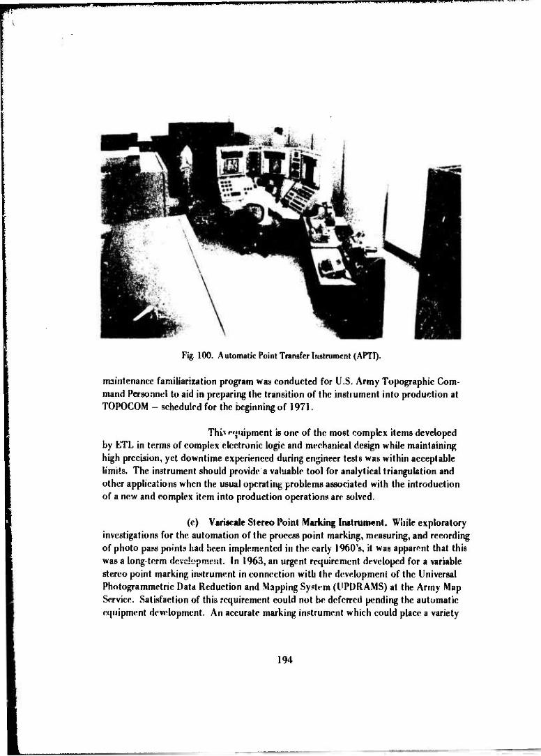
mmmm**mnmm PTniiiiiii iimniiiiiiiinii immwmwwimt H.IMU
Fig. 100. Automatic Point Transfer Instrument (APTI).
maintenance familiarization program was conducted for U.S. Army Topographic Com- mand Personnel to aid in preparing the transition of the instrument into production at TOPOCOM - scheduled for the beginning of 1971.
Thi.T «»«uipment is one of the most complex items developed by ETL in terms of complex electronic logic and mechanical design while maintaining high precision, yet downtime experienced during engineer tests was within acceptable limits. The instrument should provide a valuable tool for analytical triangulaf.ion and other applications when the usual operating problems associated with the introduction of a new and complex item into production operations are solved.
(c) Variscale Stereo Point Marking Instrument. While exploratory investigations for the automation of the process point marking, measuring, and recording of photo pass points had been implemented in the early 1960's, it was apparent that this was a long-term development. In 1963, an urgent requirement developed for a variable stereo point marking instrument in connection with the development of the Universal Photogram metric Data Reduction and Mapping System (UPDRAMS) at the Army Map Service. Satisfaction of this requirement could not be deferred pending the automatic equipment development. An accurate marking instrument which could place a variety
194

mum
of high quality marks on one or two photographs which may have large differences in
scale and format was required.
To meet this requirement, detailed technical characteristics were prepared in 1963. In April 1964. a contract was awarded to Bausch and Lomb, Inc., Rochester, New York, to design, develop, and fabricate two instruments (Fig. 101 ).272 The first of these was completed and delivered to Army Map Service in Sep- tember 1965, and the second was delivered to GIMR AHA in March 1966. After engi- neer tests at GIMR ADA, the second instrument was transferred to Army Map Service in March 1967.
Fip. 101. VarWaii- Strivi» Point Marking; Instrument.
This instrument included two photo carriages with vacuum-
type plate and film holders for sizes up lo 10 inches hy 19 inches, two independent op-
tical trains vhich had continuously variable magnification from 2\ to H2X. and a
choice of reticles arid two photo displays with pointers lo hold reference prints of the
photos In'ing marked. The tables were motor driven by joystick control and had a
272.. hcvrlopnrtil of Varitxal«' Slrrro Point Marking Internment." Final Ki-port. HauM-h and l.omb. Inf.. September
l%6.
195

coarse readout displayed on the console with nixie tubes. A card punch unit was pro- vided with the instrument to record point identification and coordinate data. The marking of the photo emulsion was by a capacitor-discharge heated die with a choice of several sizes and shapes of marks. This was specially developed for this instrument after extensive investigation of other marking approaches which were not satisfactory.
Engineer tests273 indicated a precision and accuracy of better than 2 micrometers standard deviation. High quality marks were produced by the heated die technique.
While no further procurement of this particular item was made to meet production requirements, it did provide valuable information in the development of technical characteristics for subsequent instrument procurement by the Production Center, TOPOCOM.
(d) Semiautomatic Coordinate Reader. Another development of photo-coordinate measuring equipment, initiated in the early 1960's,was the Semiauto- matic Cooronate Reader (SACR) (Fig. 102). This instrument was to provide a mean for measuring marked phoüo points, reseau points, and star plates at relatively high rates of speed and to include a means for automatic centering on these photo images.
A purchase description for this item was developed in August 1962. As a result of contract negotiations in late 1962 and early 1963, a fixed-price contract to design and produce one instrument was awarded to Nuclear Research Instru- ments, Berkeley, California, a Division of Houston Peerless Corporation, in February 1963. Almost exactly 1 year later, this contract was modified to include a card punch and control unit, a format viewer, and a government-furnished computer — the SDS 910 - for programmed control of sequential, image-coordinate measurement. In September 1964 before the first model had been completed, a contract was negotiated with Nuclear Research instruments for a second instrument, and in April 1965 this contract was modi- fied to add a third instrument to meet urgent requirements of the Army Map Service.
This development was fraught with exasperating delays due to varied mechanical and electronic problems, and it was not until May 1966 that the first of the three units under contract, SACR I, was delivered. This »mit was delivered direct- ly !•> the Army Map Service where it was installed and adjusted by the contractor. Accep- tance testing was completed in June 1966; however, it was necessary to relax the auto- matic pull-in radius and size of target requirements of the original specifications.
273M. ROOK, ETH »TR. nV«rhalr Slmro Point Marking Instrument," April 1968.
196
tiaUtt^lMlilli

if« iwiii«i..wa im M.in»»u WIIIIIUJITUPW^IPIP^WWH v
Fig. 102. Semi-Automatic Coordinate Reader (SACR).
The second unit, SACR II, was delivered to GIMRA DA in August 1966. After many problems with the computer. !}•*; air compressor for opera- lion of air bearings of the instrument, etc., acceptance tests were completed in October 1966. SACR III was delivered to the Army Map Service in November 1966, and accept- ance testing was completed by December 1966.
While SACR I and SACR III were placed in production at the Army Map Service, the engineer test of SACR II by GIMRADA was plagued with a series of electronic and mechanical failures including problems with the air conditioning sys- tem of the portable white room installed for the SACR. The instrument deteriorate« to the point where it was concluded in the fall of 1968 that a major overhaul by Nuclear Research Instruments would be necessary to put it in suitable operating condition to provide meaningful performance data. This major overhaul could only be justified if the instrument would eventually be needed by the Production Center, TOPOCOM. Since it was determined that the instrument was not needed there, the overhaul was not made. Rather, engineer testing to develop performance data for the SACR was performed with
197
['I MUM

» mm tll'l npiW«ii
SACR III at the Production Center, and SACRII was declared excess. However, these tests were not performed in til mid-1970.
While this development was plagued with many problems, the equipment did eventually perform in the manner originally intended and with a sufficient degree of accuracy and reliability.
d. Map Compilation Systems. Building on the technology developed during the 1950's and the concurrent advancement of technology in the digital computer field, the work on map compilation systems in the I960's proceeded along several related and parallel courses to meet a rather wide variety of requirements. Basically, it can be said that these requirements called for greater precision and greater speed in the map compil- ation process and the utilization of a wide variety of sensor information, including radar, to produce useful topographic products.
Developments through the 1950*s and into the 1960's can be character- ized as being strictly toward manually operated analogue instruments, although research on automation was started in the early 1950's. The first attempts to automate the com- pilation process were through modification of conventional analogue stereoplotters by adding electronic correlation devices whereby the registration or misregistration of ho- mologous images on overlapping stereoscopic photographs could be precisely measured and control the plotter operation automatically. Since these approaches were rather limited to a specific range of camera focal length, camera format, camera lens distortion, etc., development of the computer-controlled instrument approach was the next logical step to handle the wide variety of sensor input information. Through the computer- controlled instrument approach, the mathematical function describing the relationships between the photo coordinates and ground coordinates is solved in a continuous opera- tion by the digital computer which also controls the scanning of both the input imagery and the output. These mathematical functions may include the parameters of film shrinkage, earth curvature, lens distortion, atmospheric refraction, and other systematic distortions and permit unlimited flexibility in terms of focal length, type of camera, etc. The development of computer controlled approach employing electronic correlation of imagery was one of the major accomplishments of the 1960's.
Paralleling the development of the computer-controlled instrument ap- proach, considerable work was done on the all-digital approach to automation of map compilation. Conjugate images are located by digital correlation; that is, statistical matching of spot densities, by a programmed digital computer which also solves the mathematical function expressing the relationship between photo coordinates and ground coordinates as in the digital controlled plotter. This approach could use a gen- eral purpose computer with hpp'opriate input equipment to convert the input photo- graphic images, spot by spot, n.io digital values representing gray scale levels and an
198

appropriate output device to print out the photo imagery and contours from the com- puter output after analysis and manipulation. This could be the approach that will be followed in the next generation of automation map compilation equipment.
While automation, as exemplified by the Universal Automatic Map Com- pilation Equipment (UNAMACE) and the APE, was a highly significant accomplishment of the 1960's, there were other major programs in the map compilation area in this time period. These included a series of unique developments in the radar data reduction area, continuing developments in the analogue stereoplotter area to accommodate special camera configuration, a major effort to proivde means for accommodating reconnais- sance photography in a base plant operation, and most significantly the development of RACOMS. The RACOMS development brought together the latest technology in the photogrammetric compilation, cartographic, and map reproduction areas to provide a totally integrated map production facility.
(1) Ultra Wide Angle Mapping Equipment. As interest in the develop- ment and application of the convergent 6-inch focal length, 9- by 9-inch, wide-angle photography and applicant- compilation equipment waned in the late 1950's, interest revived in the potential of ultra-wide-angle systems for military mapping when Wild lieerbrugg Ltd., Heerb, Switzerland, announced the development of an ultra-wide-angle camera, the RC-9, and also the Wild A-9 autograph and the U3-A diapositive printer. This system not only provided the inherent advantage of the large base-to-height ratio as in the convergent camera approach but also provided wider coverage per flight strip with near-vertical photography; thus, there were fewer models to handle with the sim- plification of near-vertical photography. Interest in an ultra-wide-angle system by the Corps of Engineers dates to World War II days when it war indicated that an ultra-wide- angle system would be a valuable approach to military mapping. Efforts were made to develop an ultra-wide-angle camera lens in the World War II period through a program set up in the National Research Council, but the program was unsuccessful and the development was abandoned in the mid-1940's.
Both the Army Map Service and the Topographic Engineering De- partment, ERDL, implemented experimental investigations of ultra-wide-angle mapping in the late 1950V. The Topographic Engineering Department, ERDL, procured the Wild equipment for test, and the Army Map Service procured a set of ultra-wide-angle multiplex equipment from Zeiss-Jena of East Germany for test. Concurrently, the Air Force procured the Wild RC-9 Automatic Film Camera.
As a result of these experiments, it was concluded that an ultra- wide-angle mapping system was practical for military mapping: it provided a ground coverage advantage of about double that of the then standard mapping systems, 6-inch focal length and 9- by 9-inch format. The advantage in ground coverage would provide
199
«yHHMHi

lapiipwwPi"«"'''"""'''""««'"""^^^^**"^^^
faster and more economical mapping through reduction in flying time, reduction in field control, and more efficient stereo plotting.274
Following these tests, the development of an ultra-wide-angle stereo- plotter was initiated. A development contract was awarded to the Belfort Instrument Company, Baltimore, Maryland, in 1962 for a projection-type stereoplotter. A separate contract was awarded to Fairchild Camera and Instrument Corporation for six ultra- wide-angle projection lenses to be government-furnished equipment for the stereoplotter. Originally, it was planned to use these lenses to modify both the high precision military plotter and the Army Map Service M-2 plotter to accommodate u'ira-wiJe-, Tgle photog- raphy. Concurrently, the Air Force modified two KC-1 cameras by mounting 88-mm focal length Wild Super-Aviogon Lenses of the Wild RC-9 camera in KC-1 type camera bodies thus providing a camera designated the KC-3 which produced 120° ultra-wide- angle coverage along the diagonals on a 9- by 9-inch format. At the request of the Corps of Engineers, the U.S. Army Signal Research and Development Laboratories initiated the development of an ultra-wide-pngle precision mapping camera.
The Curtis Division of Fairchild Camera and Instrument Company encountered considerable difficulty in producing suitable ultra-wide-a igle projection lenses, and it was not until mid-1964 that acceptable lenses were filially produced. In tie meantime, the plotter development had been delayed, and it was not until Septem- ber 1965 that final acceptance of the plotter was completed and contract termination was begun (Fig. 103).
Further work on the ultra-wide-angle plotter was suspended on acceptance of the prototype plotter. As the result of an ultra-wide-angle n.apping re- view directed by OCE, it was noted that while there were many occasxns where the use of ultra-wide-angle photography would be advantageous, there was no uitra-widc-angle camera produced in the United States. In reply to OCE on this study GIMRADA rec- ommended that the Air Force be requested to develop a suitable camera.
(2) Interim High Altitude Mapping System. Another mapping system development of the early 1960's was the Interim High Altitude Mapping System, gen- erally known as the HALCON Mapping System. This development was actually imple- mented in 1958 as the result of a study om the problem of producing standard topo- gra| ..; maps from photography at altitudes up to 100,000 feet. This study proposed a convergent, 18-inch focal length, 9-inch by 9-inch format camera with an optical pro- jection plotter to match. It was estimated that such a system could produce 20-foot
27*Q. C DeAngelk, UMRADA 6TR, "Teals and Evaluation of Ultra-Wide-Angle Mapping Photography,' June 1962.
200

Fig. 103. Ultra-Wide Angle Stereoplotter.
contours approaching national map accuracy Standards from 100,000-foot altitude photography.275
To test the feasibility of such a system, it was proposed that a trial lie made with 12-inch reconnaissance-type cameras and a Kelsh-type plotter—both modified to meet the requirements of the system. Two K-17,12-inch focal length aerial cameras were obtained. A contract was awarded to V e Kargyl Company, Inc., San Antonio, Texas, in June 1958 to modify the cameras to meet established standards for precision aerial mapping cameras, to fabricate a twin camera mount to hold the two cameras in a 50° convergent configuration, and to obtain 12-inch focal length and simultaneous 6-inch focal length aerial photography of a controlled area.
Concurrently with the camera modification, a companion projec- tion type stereoplotter w.-.s developed under contract with the Fairchüd Aerial Surveys,
275 J. W. Hilbrook, F.RDI. 15I8-TR, "A Proposed Stereophotogrammetrir System for Topographic Mapping from Photography Taken al Altitudes up to lüO.000 Feet," March 1958.
201

wm MMMMPRFir
Inc., Pasaden*, California, also awarded in June 1958, and subsequently subcontracted to Boiler and Chiners, Inc., South Pasadena, California. This instrument, called the HALCON plotter, was delivered to ERDL in December 1959 (Fig. 104). This plotter was of the anaglyphic projection type capable of accepting distortion-free. 12-inch focal length and dis ortion-free or metrogon 6-inch focal length photography. Three matched pairs of cones and projection lenses were provided; one for projection of 12- inch focal lenpth photography at 5-diameter magnification; one for projection of 6-inch focal length photography at 5-diameter magnification; ?.»»d one for the projection of 6-inch focal length photography at a 10-diameter magnifies.Hon. The projector support- ing frame was adjustable in height as required for the various configurations, and pro- vision was made for vertical or convergent, 12-inch or 6-inch photoguioh^ ?nd also transverse 6-inch focai length ^hotogiapuy to « maximum oblique angle of 60°.
Fig. 104. Interim HALCON Stereoplottcr, 12-inch focal length.
Test.« with this equipment in I960 and 1961 confirmed that »he estimated capabilities of the proposed festem as set forth in ERDL Report 1518-TR
202
^m t nnadjMM—kM

lumkji.n Mwuijjii« Ji.imjpi. • r"m
were valid, and the HALCON systems could provide a capability for increased contour- ing accuracy from high altitude photography.
This HALCON equipment proved to be very useful in solving an Advanced Research Projects Agency (ARPA) problem of measuring the subsidence at underground nuclear test sites. GIMRAD \ participated in a series of these events in the 1962 to 1964 period using pre- and post-shot photography of the paneled test areas. Photography was obtained by the U.S. Air Force, 1370th Photo Reconnaissance Wing, and the photogrammetric reduction was done at Fort Belvoir.
Early in 1963, it was decided to explore further the application of the convergent, long-focal-length camera system approach to mapping from extremely high altitudes through experimentation with 12-inch focal length photography on a 9-inch by 18-inch format. In June 1963, a contract was awarded to ihc Aero Service Corporation, Philadelphia, Pennsylvania, to: (1) modify a K-38 rec mnaiösance came. , by equipping it with a high-quality. 12-inch focal length, wide-angle lens and making other changes to meet cartographic camera requirements, (2) design and fabricate r»*w projectors for the HALCON plotter to accommodate 9-inch by 18-inch photography, and (3) design and construct a one-to-one projection printer with an aspheric distortion corrector plate for making diapositives for the new HALCON plotter (Fig. 105).
Fig. 105. Diapositive Correction Printer for interim HALCON mapping system.
203

3IB!{K!P«BBPilPiI^^
The modified K-38 camera was delivered to GIMRADA in June 1964 but had to be rvturned .o the contractor in February 1965 to correct deficiencies found in flight testing. It was returned to GIMRADA in July 1965 but again had to be returned to correct malfunctioning fiducial mark illumination. AH items of the contract were finally completed and delivered to G1MRAUA by October 1965.
With the delivery and acceptance of the updated HALCON equip- ment, this development program was terminated since there was no companion map- ping camera of U.S. manufacture for the system. By this time, it was also apparent that the UNAMACE would be applicable for the reduction of the type of photography for which this system was designed. The equipment, however, was useful as a labora- tory tool. In 1968, the plotter was loaned to Raytheon Corporation, Autometric Oper- ation, for use on a special research project for the Advanced Research Projects Agency, Department of Defense, and later in 1970 it was transferred to the U.S. Geological Sur- vey for use as a research tool.
(3) Automatic Mosaicking System. The concept of an automatic mo- saicking system originated in 1959 in connection with studies of the problems of target location for Army surface-to-surface missiles. In these studies, it was determined that a gridded photo mosaic would be useful for target location if it could be produced at a greater speed than the manual cut and paste method of mosaic assembly. Further, de- velopment» in airborne navigation and aircraft positioning systems indicated that posi- tion and attitude information could be recorded simultaneously with the aerial photog- raphy, thus providing the control which could be used as input to automatic equip- ment for photo rectification and positioning of the photo images on a grid system.
In April 1959, a contract for the design and fabrication of an auto- matic mosaicker was awarded to the Union Instrument Company, Plainfield, New Jersey. Part of the equipment was delivered to GIMRADA in March 1961, but the balance of the contract was not completed until March 1962. The principal requirements were that vertical aerial photography, 6-inch focal length, taken at altitudes from 10,000 to 50,000 feet, with residual tilts up to 10°, be mosaicked into a controlled gridded photo map at 100,000 scale with s physical dimension of 24 by 24 inches (Fig. 106).
While the original concept had envisio led a single unit consisting basically of a rectifying projector, an easel, a supporting structure, and the necessary photographic processing equipment, it was found in the early stages of the contract that this was not feasible within the specified range of magnification and tilt. The system produced, therefore, was a two-stage sy**em, with two basic pieces of equipment. In the first stage, the photos were rectifier "itomatically at a small reduction in scale; and, in the second stage, the final scale adjustment and positioning of the control grid
204
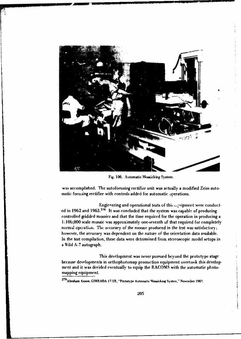
Fig. 106. Automatic Mosaicking System.
was accomplished. The autofocusing rectifier unit was actually a modified Zeiss auto- matic focusing rectifier with controls added for automatic operations.
Engineering and operational tests of this» «^"lipment were conduct- ed in 1962 and 1963.276 It was concluded that the system was capable of producing controlled gridded mosaics and that the time required for the operation in producing a 1:100,000 scale mosaic was approximately one-seventh of that required for completely normal operation. The accuracy of the mosaic produced in the test was satisfactory; however, the accuracy was dependent on the nature of the orientation data available. In the test compilation, these data were determined from stereoscopic model setups in a Wild A-7 autograph.
This development was never pursued beyond the prototype stage because developments in orthophotomap production equipment overtook this develop- ment and it was decided eventually to equip the RACOMS with the automatic photo- mapping equipment. 27ft Abnham Aruwn, GIMRADA 17-TR, "Prototype Automatic Mowicking Syntem," November 1963.
205

(4) Automatic Map Compilation. At the beginning of the 1960's, de- velopments in the automatic map compilation area had progressed to the point where ERDL had successfully demonstrated the feasibility of an automatic stereomapping system based on mechanical scanning utilizing a Nipkow disc. The feasibility of el**"- tronic image scanning by a flying spot »earner had been demonstrated in an automa- tion of the contouring function of the Kelsh plotter by Gilbert L. Hobrough of the Photographic Survey Corporation of Canada. Paul Rosenberg Associates, under an ERDL contract, had breadboarded a piece of hardware which was based upon integrat- ing flying spot scanners and electronic correlation with a digital computer for compu- tation and control.
While G1MRADA continued tests and evaluations of the stereo- mat approach of adapting projection-type stereoplotters to automation in the early 1960's.277 it was realized that these approaches had fundamental limitations in terms of universal application. Therefore, in 1960, a contract was negotiated with Ramo- Wooldridge Corporation, Canoga Park, California, to develop the Automatic Map Com- pilation System. This system was degigned from the start as a completely automatic in- strument for high-speed compilation in a computer-controlled operation with electronic scanning and correlation along the lines suggested and demonstrated by Paul Rosenberg Associates.
The prototype equipment was delivered to GIMRADA in Decem- ber 1963. The principal elements of this equipment were a PB 250 digital computer, a single scanning and print table, and electronic correlation circuitry. The scanning and print table provided for scanning the riiapositive pair with two CRTs and for the prircout of the orthophotograph and the line drop contours by two additional CRTs. These four units were assembled on one t',blc.278 279 280
This development proved to be highly successful as a prototype demonstration of a computer-controlled system (Fig. 107). Therefore, in February 1963, even before the prototype Automatic Map Compilation System was delivered to GIMRADA, a contract was awarded to Ramo-Wooldridge Corporation (later Bunker- Ramo Corporation) for the Universal Automatic Map Compilation Equipment (UN AM ACE). This equipment include«! a number of advanced features designed to enhance its utility in a production environment and increase the speed and accuracy of its operation as compared to the prototype Automatic Map Compilation System. It
277Kent T. Yoritomo, GIMRADA 4-TR, "Prototyp*- Stcreomat Syriern," March 1%2.
' 'Automatic Map Compilation System," Final Report, Phase I, Ti ompson Ramo Wooldridge, 1m-., January 1962.
279 "Automatic Map Compilation System," Kiral Repor\ Phase II. Thompson Ramo Wooldridge, Inc., Mw 1962.
280 "Improvement Program Automatic Map Compilation System," Final Repcrt, TRW Computers Co., January 1964.
206

mm^m*miß**'im
was designed to accept universal inputs, including a large range of camera focai lengths and tilts, 9- by 18-inch input diapositives, and all known photographic camera configu- rations including convergent frame and panoramic pairs.281
Kip. 107. Prototyp«* Automatic Map Compilation System.
The major elements of the IINAMACE were four identical 9- by 18-inch precision comparator tables for scanning the input and printing the output, a TRW-133 digital computer with associated input-output equipment to control the auto- matic operation, a control console for monitoring and manual control of the operation, and a iMgnpfir tap«* recorder and its associated controller (Fig. JOo).
Two t'NAMACE systems were produced under the Bunkar-Kamo contract an«! these v ere delivered, one to the Army Map Service and the other to GIMRADA, in September 1965. Subsequently, two more t'NAMACKs were procured for the Army Map Service. In the period from January 1966 to March 1969, the equip- ment went through a shak«'down in which considerable computer re programming, addi- tional programming, and minor equipment modifications were necessary: and complete
28!.. Universal Automatic Map Compilation Kquipnirnl," final Rrport, Bunker Ramo Corporation. October l%5.
207

Fig- 108. Universal Automatic Map Compilation Equipment (UNAMACE).
engineer design test and evaluation were conducted. In March 1969, the UNAMACE at ETL was relocated to the Production Center, TOPOCOM.
The engineer design tests282 demonstrated the capability of the equipment to produce single-model, TVfe-minute and 15-minute quadrangle contoured orthophotomaps with contouring accuracy ranging from C-factor values of 1150 to 2300 and compilation speeds of 1 hour for a 4.5- by 9-inch single model at input- output ratio of 1:1. 5'/4 hours for a 7%-minute quadrangle at 1:1 input-output ratio, and 4'4 hours for a 15-mintitc quadrangle at a 2:1 input-output ratio (1:100,000 scale). This development produced the first operationally feasible automatic mapping system.
While development of the UNAMACE was in progress in the mid- I960s,a field version of this equipment called the Automatic Photomapper Equipment (APE) was developed under GIMRADA contract to the Bunker-Ramo Corporation and was delivered to GIMRADA in November 1966 (Fig. 109). It wan a ruggediz» J, van- mounted mapping system capable of producing high-quality orthophotos and contours to a desired scale for rapid mapping operations for field topographic units. This unit was incorporated in the experimental Rapid Combat Mapping System (R ACOMS) (Fig. 110). It was designed to accept similar input photography to the UNAMACE up to 10 by 10 inches in size.
282. Kdward V. Burzynaki and (Jrorjje r'erenre, KTI, SI-TK. "Universal Automatic Map Compilation Equipment, December 1969.
208

w-fimm. Mill
Fig. 109. Automatic Photomapper: Input/Output Printer, Scanning/ Printing TaMc, Computer, Controller,
rig. 110. Automatic Photomapper: Controller,Klectronic Rack«, Control Console, Input/Output Printer.
209

wmm
Another development of the late 1960's associated with the UNAMACE development was the High Resolution Orthophoto Output Table (HIROOT) under contact to Singer-General Precision, Link Division, Sunnyvale, California.283
The equipment was designed to provide orthophoto output from the UNAMACE Sys- tem up to 24 by 30 inches in size and with 100-line per millimeter resolution.
As the development of the UNAMACE was coming to a successful conclusion in the late 1960's, in-house work started on a follow-on Advanced Automa- tic Compilation System (AACS). This system would use a calibrated, all-electronic scanning system in lieu of the mechanical X and Y tables to provide greater speed and flexibility of operation, reduction in size and weight in comparison to the UNAMACE, and probably a reduction in cost. The output will be a magnetic tape recording of the X, Y, Z coordinates of incremental, scanned areas. The magnetic tape output will be used to control a plotter for the production of contours or an optical high resolution printer for printing color or black and white orthophotographs. It will also provide a permanent record of terrain elevation data for a digital data bank and other applications.
(5) Analytical Stereoplotter. While the Corps of Engineers was pur- suing the development of automatic compilation equipment, the U.S. Air Force in the late 1950*s undertook a parallel development of the analytical stereoplotter. The prime contractor for this development was Ottico Meccanica Italian (OMI) Corporation of America. OMI of Rome, Italy, fabricated the mechanical and optical systems in the instrument, and the subcontractor, Bendix Corporation, Southfield, Michigan, fabri- cated the control computer and associated electronic systems.
The first analytical plotter, the API, was delivered to the Air Force in 1961. Subsequently, improved models, the AP*2 and the AS-UA, were developed by OMI under Air Force contract; and in 1962, action was initiated by GIMRADA to procure one of these instruments for test. Later, in August 1963 another in trument was procured for the Army Map Service. The first instrument was delivered to the Army Map Service in August 1964. Delivery and final acceptance of the second instrument were completed at GIMRADA in April 1965, and an exhaustive and detailed engineer test program was implemented. This testing continued somewhat intermittent- ly over the next 3-year period, and a report of these tests was published in November 1969.284
The AS-UA tested consisted of a relatively simple, highly accurate, mechanical-optical stereoscopic viewing instrument, which was controlled by ? stored-
^"High Reaolution Orthophoto Output Table (HIROOT)," Final Report, Singer-General Precison, Link Division, July l%9.
284r. Raye Norvelle, ETL 50-TR, "Terts and Evaluation of the AS-11A Stereoplotter " November 1969.
210

program digital computer, and an output coordinatograph. Il was automatic only to the extent that interior, relative and absolute orientation were accomplished by com- puter assist. Operation of the instrument was manual with X and Y handwheels and Z footwheels as in conventional stereoplotters. The computer solved the photogram- metric equations, controlled the motions of the instrument, could be programmed to accommodate any two photographs that could be geometrically defined, and could provide corrections for earth curvature, atmospheric refraction, lens distortion, film shrinkage, and other systematic distortion.
As a result of tests and evaluation, it was concluded that the accur- acy of the AS-11A analytical plotter was equal to or better than the geometric fidelity of most precision cartographic cameras; given adequate 6-inch focal length, frame pho- tography, 20-foot contours could be drawn from 60,000-foot photos. The AS-11A was also mon versatile than previously developed analogue stereoplotters, and the concept of the ci«iputer-c on trolled stcreocomparator provided a satisfactory instrument for ac- commodating frame and.panoramic photography or any other type photography for which the computer can be programmed.
Further development of the analytical plotter ultimately produced the AS11B/C system. This system provided an electronic orthophotoscope capability as an automatic image correlation system to perform automatic compilation of ortho- photographs and form line contour chart.' and record on magnetic tape terrain-surface coordinates during the orthopnoto compilation-capabilities similar to those provided in the UNAMACE and the APE.
(6) Digital Mapping System. The exploratory development of a com- pletely digital approach for automatic map compilation, wherein the pictorial informa- tion is digitized, spot by spot, into values representing grey scale levels, and this digitized information is analyzed and manipulated in a general-purpose computer and subsequent- ly output through appropriate recording means to produce orthophotographs and con- tours, was started by the Topographic Engineering Department, ERDL, in the late 1950's. in the period 1961 to 1964, under successive contracts of GIMRADA, the International Business Machines Corporation, Kingston, New York, conducted experiments using the IBM 7094 computer and an experimental digital scanner printer modification of a gov- ernment furnished Wild STK-1 stereocomparator. The experiments conducted under these investigations285 286 produced orthophotos and contours of sufficient quality to prove the technical feasibility of automatic mapping by digital techniques.
285..
J 286..
A Digital Automatic Map Compilation System," Final Report, International Business Machines Corporation, July 1962.
Optimized Digital Automatic Map Compilation System," Final Report, International Business Machines Cor- poration, July 1964.
211

nniwna mm i I «*»• «MIMI.MMIHIBMII
A contract to continue this exploratory development was awarded to the ITEK Corporation in 1965 to produce the data processing techniques and pro- grams and the associated precision input-output instrumentation. This proved to be an overly ambitious program within the then state-of-the-art, and the contract was eventual- ly terminated.
After this unfortunate experience, the digital mapping program re- mained in limbo for the next few years until 1969 when in-house investigations were re- sumed, and the operations to be performed with such a system were studied in , ome de- tail. As a result, it was properly decided that the best approach was to investigate data processing concepts in depth and to develop mathematical algorithms which vrnld pei- mit optimum computer processing for correlation.
To pursue this course and to ensure that diversified approaches would be investigated, two separate contracts with identical objectives were awardc' in October 1970, one with the Wolf Research and Development Corporation and one with the Kcuffei and Esser Company. In-house investigations were implemented to investi- gate the micro-characteristics of aerial photography which is fundamental to determine the best element or spot size and optimum number of shades of grey required to define the pictorial content adequately.
It was planned to pursue this development actively in the 1970's in view of the projected potential of this approach for increasing the speed of compilation and the quality. It was considered in 1970 that the digital approach could provide the basis for the next generation of automatic map compilation equipment.
(7) Radar Mapping. Although studies and investigations of radar map- ping had been on a continuing basis through the 1950*s, it was not until the beginning of the 1960*8 that radar sensor technology had advanced to the point where new design concepts and techniques were producing high-resolution radars capable of producing radar imagery with increased geometric fidelity, and the potential application of radar to military mapping became more realistic. Research and development efforts in this urea were therefore intensified. A series of significant in-house and contractual pro- grams was conducted not only to determine the feasibility of various approaches to radar mapping but also to develop concepts for the radar ground data reduction system. These studies and investigations also provided the basis for establishing requirements for radar sensor systems suitable for mapping applications. These requirements were pro- vided to the U.S. Signal Research and Development Laboratories and the U.S. Air Force through established liaison channels as guidance in advanced radar sensor development.
The major in-house and contractual studies of the 1960 to 1970 period in chronological order of their completion were:
212
_ —. . ^-ngfrguymmtjMjgM

(a) 1961— Extraction of Mapping Detail from Radar Photography287
(b) 1%2-Radar Network Adjustment288
(c; 1963-Evaluation of Coherent Radar Photography289
(d) »%3-Planimetric Radar Mapping System290
(e) 1964-Feasibility Test of 3-D Radar291
(f) 1965-All-Weather Mapping System Study292
(g) 1966-Evaluation of the AN/APQ-97 as a Radar Mapping
(h) 1966-Stereo Radar Techniques Study**
(i) 1968-Radar Mapping of Panama295
(j) 1968—Topographic Radar Mapping System Design Study296
(k) 1968-Interferometer Data Reduction Study297
(I) 1970-Stereo Radar Analysis of New AN/APQ-102(XA-2) Side-Looking Radar. Raytheon Company/Autometric Operation
28** '"Extraction of Mapping Detail from Radar Photography," Goodyear Aircraft Corporation, Phase I, December 1960, Phase III, November 1961.
"Radar Network Adjustment." Final Report, Northrop Corporation Sp.'je Lab«, October 1962.
289L F. Avers. Jr., GIMRADA 18 TR. "Evaluation of Coherent Radar Photography," November 1963. CONFIDENTIAL.
"Planimetrie Radar Mappug System," Goodyear Aerospace Corporation. 9 Monthly Progress Reports, January Through September 1963, CONFIDENTIAL.
291 "Feasibility Test of a Proposed 3-D Kadar System." Final Report. Goodyear Aerospace Corporation. February IV64.
"All-Weather Mapping System Analysis and Equipment Study," Final Report, Goodyear Corporation, December 1965. CONFIDENTIAL!
291R. A. Kevenor, GIMRADA 31-TK, "Evaluation of the \N/APO-97asa Radar Mapping System," August 1966. CONFIDENTIAL.
'Stereo Radar Techniques Study." Phase I, Volume I, Analysis, Raytheon Corporation/Autometric Operation. Interim June 1966. Supplement June 1966. SECRET.
295 ' "Mapping from Side-Looking Radar," Final Report, Raytheon Corporation, Autometric Operation, July 1968,
"Topographic Radar Mapping System Design Study." Final Report. Goodyear Aerospace Corporation, December 1968.
29" ' "Interferometer Data Reduction Study," Final Report. We.«|inghoui*e Defense and Space Center, 1969. SECRET.
213

|PBHMHBP«MniHMMMpaB»WM«a*pWIM9«'a'^"^"<>. "" ••»••"• •" JWB.I1I • •—i.^nu« ••• •» '•' '• • •'••»•' " 'M" " •'••• "•»
Some of these investigations used real radar imagery. Notable are in-house studies of the AN/APQ-97 side-looking radar reported in GIlViRADA Technical Report 31-TR. These studies established the basic feasibility of stereo radar mapping.
To evaluate further the AN/APQ-97 radar and to determine the overall feasibility of producing topographic maps and radar photo mosaics from ;?ide- looking radar presentations, an experimental program, "Radar Mapping of Panama'' ("Project Ramp"), was conducted in 1967 and 1968. The data acquisition portion of the project was contracted to Westinghousc Aerospace Corporation and the data reduc- tion and compilation portion of the project was contracted to Raytheon Company, Autometric Operation. The products of this project were an original map of the Darien Province of Panama, computer programs used in the data reduction, and techniques of data reduction useful in radar mapping. This project dramatically demonstrates the feasibility of producing topographic maps from radar data.
The stereo radar analysis of the new AN/APQ-102 (XA-2) radar utilized real radar data and the specific applicability to 1:50,000 and 1:250,000 scale topographic mapping was tested. The two basic stereo configurations, opposite side and same side, were tested under various conditions relating to the data-reduction technique, control, and image coordinate weighting. The results indicated that this radar, using stereo techniques, had much promise for all-weather, day-nigh* —pping at 1:50,000 and 1:250,000 scales.
These studies progressed through the decade of the 1960V and, as a direct result several prototype items of data reduction equipment were developed. In the "arly 1960's, three items were produced; a Radar Sketchmaster (Fig. 111),298 devel- oped under contract by Aero Service Corporation in 1960 and 1961, a Radar Presen- tation Resitutor(Fig. 112),299 developed under contract by Beloek Instrument Corpora- tion, College Park, New York, in 1960 and 1962, and a Radar Presentation Viewing and Measuring Instrument, (Fig. 113),300 developed under contract by Boiler and Chivens, Inc.. South Pasadena. California, in I960 to 1963. In the mid-1960's. :i Radar Imaw n
Mapper was designed and constructed under contract by Singer-General Precision, Inc., Link Division, Sunnyvale, California (Fig. 114). This instrument was developed specifi- cally for the RACOMS. These developments served to advance the state-of-the-art in radar mapping, but they were all soon superseded by much improved and highly sophis- ticated items of radar data reduction equipment developed in the late 1960's. These
^Clifford J. Crandall. CIMRADA 20-TR, "Radar Sketching Device," January 1965.
•^Clifford J. Crandall, GIMRADA 29-TR, "Test and Evaluation of the Prototype Side-Looking Radar Restitutor," April 1966.
^Clifford J. Crandall, GIMRADA 22-TR, "Side-Looking Radar Presentation Viewing and Measuring Instrument," January 1965.
214

Fig. 111. RadarSketchmaster.
item.1; w iv the l'uivwmiJ Radar Signal Processor (Fig. 115) built by Goodyear Aerospace
Corporation, Litchficid Park, Arizona; the Orthographic Radar Restitutor (Fig. 116)
built ')> Singer-General Precision. Inc., Link Division, Sunnyvale, California: and Radar
S'«Tco Kquipmen. (Fig. 117), also built by the Goodyear Aerospace Corporation, Litch- field Park, Arizona.
The Urii.vrsal Radar Signal Processor (correlator) was designed to
process accurately all existing and anticipated coherent radar signal film to produce un-
n stiluted radar imagery film suitable for map compilation at 1:50,000 and 1:250,000
scales. The Orthographic Radar Restitutor was designed to remove all the distortions
inherent in radar imagery, including displacements due to relief, to produce a radar
215

mrnrn*
Fig. 112. Prototype S:Je-I.ooking Radar Restitu.or (1%2).
Fig. 113. Sirfr-Tjookirig Kadar Presentation Vkwing and Measuring Instrument.
216

siMiKummmmm i Big.1,11*1 apfwp •«IK.IWI, IHM ii um L •iiijiii »i UIUJIW i ivnm»'»"»11'""1""
Fig. 114. Radar Image Mapper.
Fig. 115, l Iniversal Radar Signal Processor.
21

(wwjwpwmwww«» IWI..HIMIIIM«" •« "-'in
Fig 116. Orthographic Radar Restitutor.
Fig. 117. Radar Strr,-«-> Kquipment.
218

www.il.«!! im • mmrwimm np«w«Hri^^
orthophotograph. The Radar Stereo Equipment was designed to provide a stereo men- suration capability to compile elevation information from a radar stereo model. It em- ployed the analyticaJ approach where the stereo-geometry was modeled mathematically under the control of a small computer.
Based on experience with these developments, a concentrated ef- fort was planned for the early 1970's to develop an operational radar mapping system to be implemented at the Production Center, TOPOCOM.
(8) Mapping from Reconnaissance Photography. Equipment and tech- niques for using high-resolution reconnaissance photography for map compilation and map revision became a particularly acute problem in the I960's. In many instances, reconnaissance photography was the only recent coverage available; and, although not ideal for the production of Class A topographic maps, it was necessary to do the best job possible with the resources available. Some sort of map was better than none at all.
In 1964, GIMRADA had proenred an instrument called the Univer- sal Analog Rectification System (Fig. 118) for test for application to this type of prob- lem. The application of this equipment at that time was visualized for updating existing map coverage. Its procurement for test was an outgrowth of studies in the late 1950's and early 1960'son map-revision techniques and equipment. These studies, particularly one by Mark Hurd Survey, Inc., in the late 1950's, had produced only concepts of tech- niques and equipment which were considered too complex and too heavy for field use, particularly for RACOMS.
Fig. 118. Cnivcrul Analog licrtifiratiori System.
219

www» «w*p»PB«WW
The Universal Analog Rectification System was essentially an XY coordinate plotter, with analog computer control, coupled with an input coordinato- graph. Detail traced in lite photograph on the input coordinatograph table was output in restituted format on the XY coordinate plotter. It was designed to accommodate frame photography of all focal lengths greater than 3 inches, with tilts of 0° to 85° and also to accommodate panoramic photographs with pitch angles of 0° to 25°. roll angles of 0° to 5° and scan angles up to ±60°. It also had provisions to correct for relief dis- placement. It was built by Electronic Associa'^s, Inc., and was delivered to GIMRADA in January 1964. Tests of the equipment in 1964 and 1965,301 for possible application in RACOMS showed in general that it did perform as intended and that it was suitable for Class B map revision and low accuracy planimetric mapping. It was later included for test in one of the modules of the RACOMS.
While testing of the Universal Analog Rectification System was in progress, the Army Map Service developed an urgent requirement for equipment to accommodate reconnaissance photography, both frame and panoramic. In November 1965, GIMRADA received Army Map Service requirements r a Reconnaissance Photo Stereoplotter. About the same time, it was learned that th \ir Force, through Rome Air Development Center, had contracted with Rendix Con »ration for a Chart Analysis Device (CAD) (Fig. 119) which was essentially an analvri- I plotter designed for recon- naissance photography, basically similar in approach to tl & ASl la analytical plotter but with analog computer control rather than digital.
1'ig, 119. Chart Analysis Diwe (CAD).
Ml.. Krank Klimavir/.. (ilMKAI)A 2'4-TK, "universal Analog Reel ifiration System for Map Revision,'* Aupust l%5.
220

On review of the A MS requirements and the procurement docu- ments for the CAD, it was concluded that the CAD was the potential solution to the immediate AMS problem; and, early in 1965, Rome Air Development Center was re- quested to procure an additional instrument for test by GIMRADA. Funds were trans- ferred to RADC for this purpose.
In the meantime, AMS indicated a specific requirement for rectify- ing printer equipment capable of processing long focal length reconnaissance photogra- phy for photomap production, AMS furnished specific technical characteristics to GIMRADA in April 1965 calling for equipment for angular tilts of 24.5° and 49°, nom- inal camera focal length of 36 inches, and format of 18 inches by 18 inches consisting of two 9-inch by 18-inch segments. Rectification of this photography at a 0.5-magnifi- cation was desired.
Based on these requirements, specifications for two instruments, one for the 24'/2° tilt photography and the other for the 49° tilt photography (Figs. 120 and 121) were prepared an 1 contract negotiations were started in July 1965. These ne- gotiations had to be cancelled, however, wher it was found that there was no lens avail- able for the 49° printer. It was decided to change the specification to provide for an initial 2X reduction of the photographs before restitution. A contract fo: the two in- struments was eventually awarded to Keuffel and Esser in April 1965, about 1 year after the initial requirement had been received.
Kip. 120. Transforming Printer •-2454-1 )egrrr
221

"v.-,
Fig. 121. Transforming IVinter-49-Degrec.
Pcrail« ling the effort on the two transforming printers, GIMRADA, by transfer of funds to R ADC, started procurement of another Air Force developed item for test purposes in April 1965. This item was the Electro-Optical Rectifier, being developed by the Air Force by Fairchild Camera and Instrument Corporation (later Fairchild Space and Defense Systems). In July 1965, GIMRADA started work on a pur- chase description for a stereoplotter called the Pan Scan Plotter, for panoramic photog- raphy. This was for special projectors designed to fit the AMS M-4 Plotter frame with film holders for 12-inch, 18-inch and 24-inch focal length panoramic photography. A fixed-price contract for this development was awarded to Photogrammetry Inc., Rock- ville, Maryland, in August 1966.
The development of the 24'/4-de^ree and t9-degree transforming printers proceeded without major incident or delay. Both printers were delivered to GIMRADA in mid-1967 and, after acceptance and engineering tests,302 were transferred to Army Map Service for operational use in September 1967.
302 George S. Barber and J. Wiley Ha I brook, ETl» 40-TR, "Transforming Printer»: Acceptance and Engineering Teats.' May 1968.
222

rw»*B^"WW
The CAD and the Electro-Optical Rectifier programs were quite another story.
The CAD was delivered to GIMRADA in September 1966; and, before final acceptance was completed, trouble developed with the equipment. How- ever, engineer testing was started in March 1967, even though the equipment had not been repaired at that time for panoramic photogi^ohy. After repeated problems with the servo systems, computer malfunction, and problems with potentiometer calibration, it was finally decided in August 1969 that further testing would serve no useful purpose and further work on the CAD was cancelled. Eventually, in July 1970, the equipment was placed on loan to the U.S. Geological Survey for 1 year.
The Electro-Optical Rectifier was delivered to GIMRADA in Au- gust 1966, but it was not in satisfactory operating condition and was picked up by the contractor and returned to his plant for repair in May 1967. It was not until almost 2 years later that the equipment was considered ready for delivery to the Government. In the meantime, it had been decided to forego engineering tests at ETL and to deliver the Electro-Optical Rectifier directly to TOPOCOM.
In January 1969, it was delivered to TOPOCOM, but installation and calibration of the equipment in accordance with Air Force specifications was not completed until May 1970. In January 1970, ETL recommended to TOPOCOM that engii.eering testing of the Electro-Optical Rectifier not be performed since such testing was no longer justified.
The Pan Scan Plotter development, contracted in August 1966, also faced repeated delays in completion, initially, the program was delayed by late delivery of the M-4 Plotter to the contractor. Then, the program was delayed by problems with the projection lenses. The contractor still had not delivered the equipment by Decem- ber 1970 when preliminary acceptance tests were suspended while the contractor inves- tigated ways to improve the focus of off-axis imagery.
Another development of the 1960's under the program on mapping from reconnaissance photography was the Reconnaissance Photo Restitutor. The con- cept for this item was a piece of equipment which would restitute high-resolution re- connaissance photo imagery automatically to position it bit by bit in the same relative plan position as shown on a lower resolution photograph or orthophotograph. Initial studies uf the image correlation problems associated with this approach were made by the Vidya Division, Itek Corporation, in the mid 1960\s.303 This study did not produce a reliable way in which such a correlation could be accomplished.
Study of Panoramk-Metric Image Matching for PhotoKnmmetric Instrumentation, Final Report, Itek Corpor- ation, Vidya Division, Palo Alto, California, April 1965.
223

nw '•>"* ••vr> i^mi ^,-w»f*w «•• "
However, in April 1967, a procurement package for a Reconnais- sance Photo Restitutor was completed; and, after revision as required for suitability for UPDRAMS and RACOMS, contract negotiations were initiated in July 1967. Contract negotiations for this item were not completed until November 1968; because, after the initial proposals weiv received in September 1967, it was tound necessary to review the requirements of the specifications to eliminate those that would not contribute directly to determining the efficacy of the approach. With the revised specifications for a less ambitious program, it was necessary to solicit new proposals from the potential con- tractor. The CPFF contract for development was eventually awarded to Itek Corpora- tion in November 1968.
By March 1969, the design plan had been approved, and the Honey- well 316 computer had been selected as suitable for the equipment; however, by May 1969. it was obvious that there would be a large cost overrun to complete the develop- ment and the contractor was requested to delay major outlays pending a re-examination of the justification for the development. Finally, in June 19<)9, the decision was made to direct the contract toward a feasibility study only rather than hardware; and, in Au- gust 1969, the development contract was terminated due to high cost and other factors.
This was another instance in which the development proved to be too ambitious and somewhat premature until full feasibility had been established through breadboard analysis of critical areas of development. Coincidentally, the same contrac- tor was involved in both of these terminated programs.
This program of the 1960's to develop means for utilizing reconnais- sance photography for mapping again dramatically demonstrated the complication and difficulties involved, as did the World War 11 work in development of equipment and techniques for using tri-metrogon photography. Yet, as long as reconnaissance has pri- ority over mapping when it comes to the allocation of resources to data collection, it is a foregone conclusion that in many military situations only reconnaissance coverage will be available. The most valid approach to »he utilization of such photugraphy at the end of the 1970's was the IN A MACE or the APK. These equipments are rather complex, but this is a factor which cannot be avoided in a system applicable to compilation from a wide variety of input photogranhy.
(9) Rapid Combat Mapping System (RACOMS). Although the project for the development of RACOMS was initiated officially in July 1961, the evolution of the concept can be traced back to the mid-1950*8. In June 1956, the Continental Army Command directed the conduct of Exercise Red Arrow which included a target location test. A detachment from an Engineer Topographic Company was assigned to perform this mission, with support in the form of troop training, preparation of detailed plans,
224

supervision of the exercise, and preparation of a report by the Topographic Engineering Department, ERDL.
As a result of this exercise, it was concluded that a systemhed ap- proach to target location in the form of a complete and high-speed field mapping capa- bility was needed.
In May 1958, a contract was awarded to Technical Operations. Inc., Cambridge, Massachusetts, for a study to formulate a Semi-Automatic Topographic Data Reduction and Presentation System for the 1965 to 1975 decade. Phase I of this study was completed in February 1959. It included an evaluation of existing equipment as well as equipment which would become available by 1965 for applicability to field mapping. Phase II, completed in July 1959, included a selection of equipment for auto- matic data processing and formulated procedures and personnel requirements for such mapping.
In March of I960, a follow-on contract was awarded to Melpar Inc.. Falls Church, Virginia, to design the system based on the Technical Operations, Inc., study. This contract was completed in September 1961. The detailed reports prepared under this contract304 included a task list, data flow and analysis charts, equipment lists, layout of modules, and a detailed description of equipment to be employed in a Topographic Mapping System.
The objective of the task initiated at the completion of the Melpar design study in July 1961 was to develop a highly flexible mobile Rapid Topographic Data Reduction System to prepare military maps by cartographic and photogrammetric methods of a combat area utilizing aerial photographic and positional data. The project remained somewhat in limbo through 1962 although supplemental system design studies were made under contract to Autometric Corporation,305 and a study was made by Bell Aerosystcms Corporation, Buffalo, New York.306 of attitude and positioning components for a rapid combat mapping system. It was not until 1963 that the preparation of a tech- nical «I« v« iupjii< lit |iiaii wtift uiiiiatrd \>s (ilMIJ ADA. Tlim plan was publiMird in Septem- ber 1963. Also in 1963, specifications for th- Automatic Photomapper, which was to be the heart of the system, were prepared and were finalized in October 1963. Subse- quently, in June 1964, the development of this equipment was contracted to Bunkcr- Ramo Corporation, Canoga Park, California.
Design of F.nRincenng Test Vtffldrt, Topographic Data System." Kinal Report. Melpar Inc., Volume I September 196!, Volume II June 1961, Volume HI July 1*1, Volume IV, August 1961, Volume V.July 1961.
' ' "RACOM System Supplemental Design Study (!')." Final Report, Autometric Corporation, New York, New York, March 1962.
'inf. "Study of Attitude and Position Determining Components for a Rapid Combat Mapping System," Hell Aero- systems Corporation, Huffalo. New York, November 1963.
225
••-••- •-••-•--"•

.iUUllllllllJl_Wl.nl...-
While this work was in progress, STRICOM generated an operation- al support requirement for a Rapid Combat Mapping System. This requirement was •ssued in October 1963 and was subsequently validated by the Defense Intelligence Agency. In April 1964, Department of Defense Research and Engineering directed the development of the system and the establishment of a Tri-Service Project Management Office with the Army as Program Manager. The U. S. Navy and the U. S. Air Force were to be concerned with the data acquisition aspects and the U. S. Army was to de- velop the data reduction subsystem. This office was established in the Office, Chief of Engineers, in July 1964, with Colonel Hamilton W. Fish, later Commander of GIMRADA, as Project Manager.
The major activity of the Office of the Project Manager was to pre- pare a Coordinate Technical Development Plan which was submitted to DDR&E in May 1965. In tri-service coordination of this plan, the AN/USQ-28 data acquisition system under development by the U.S. Air Force was selected as the data acquisition subsystem for the RACOMS. This office was subsequently disbanded in January 1966, and remain- ing responsibilities concerned with the development of the data reduction subsystem were transferred to GIMRADA.
It was not until August 1966 that an approved Qualitative Materiel Requirement (QMR) was established as CDOG paragraph 1539b(23). In the meantime, a contract was awarded to MGD Research and Development Corporation in December 1965 to develop an Electrostatic Printer for RACOMS. In January 1967, a contract was awarded to OPTO Mechanism, Inc., for a Pass Point Marking and Measuring Instrument,307
and, in March 1967, a contract was awarded to Potomac Research, Inc., for the installa- tion of RACOMS equipment in expansible standard van modules. Also in the period from December 1965 to January 1967, contracts were awarded as necessary and other procurement actions were taken to assemble the standard military items and off-the- shelf components commercially available for the system.
The system assembled for testing included equipments for exploita- tion of all the latest technological advances in mapping considered applicable in the Rapid Combat Mapping System suitable for field operations. The Engineer Test System consisted of eight expansible-side mobile shelters or modules mounted on detachable running gear to provide ground mobility (Fig. 122). All modules were transportable in a C-130 aircraft. The system was designed to produce four 1:50,000 scale orlhophoto- maps, with some cartographic delineation, in 48 hours and two sheets each 24 hours thereafter using data from the U. S. Air Force AN/USQ-28 Acquisition System. The modules were: (1) Operation Module (Fig. 123) which served as the control center for
307K. Taylor. V.'t 1 P'.-TK, "RACOMS Paw Point Marking and Measuring Instrument. Kngineer Design Test Report," January 1970.
226

EtflP
Fig. 122. Expansible Van on Dolly Wheels as developed for RACOMS.
the system; (2) Image Processing Module I (Fig. 124) containing an auto-dodging printer and photographic processing equipment for making diapositive plates and prints; (3) Compilation Module I (Fig. 125) containing the APE, the heart of the system; (4) Data Processing Module (Fig. 126) containing the computer, pass point marking and measuring instrument, tape recorder, and punch, etc. for analytical aerotriangula- tion operations; (5) Cartographic Module (Fig. 127) containing drafting tables, a co- ordinatograph, type composing machine, and Varityper composing machine for the re- quired cartographic operations: (6) Image Processing Module II (Fig. 128) containing temperature controlled sink, enlarger-reduccr camera, film dryer, vacuum frame and arc lamp, diazo developer, etc. for processing in support of the reproduction operations; (7) Reproduction Module (Fig. 129) containing the five-color Electrostatic Printer for reproduction of the map products; and (8) Map Revision Module (Fig. 130) containing a map revision instrument, an autofocusing reflecting project and a Radar Image Map- per, the equipment required for map revision.
Engineer design tests of the RACOMS were conducted from June 1968 through January 1970.308'313 During the engineer design test period, a joir.I 308 A. W. StolL ETL-ETR-70I, "RACOMS Compilation Module, Engineer Design Test Report," April 1970.
309.. F. P. Vena, ETL-F.TR-70-2, "RACOMS Image Process Module II, Engineer Design Test Report, May 1970.
310., F. P. Vena, ETI.-ETR70-3, "RACOMS Cartographic Module. Engineer Design Test Report," May 1970.
.Ill R. B. Godfrey, ETI. ETR-70-4, "RACOMS Data Processing Module, Engineer Design Test Report," May 1970.
312« E. Taylor, ETL-ETR-70-5, "RACOMS Map Revision Module, Engineer Design Test Report," July 1970.
313c S. Prtsscr, ETI^ETR-70-fl, "Rapid Combat Mapping System Evaluation," August 1970.
227
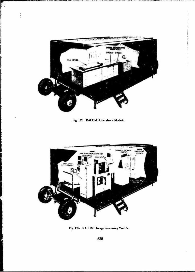
^p*n.Minmim,«i»Limn ,i. nnwnwu-w1 •"»••»wu •-•»
Fig. 123. RACOMS Operations Module.
Fig. 124. RACOMS Image Processing Module.
228

mmm tmmm mmmmmm
Fig. 125. RACOMS Compilation Module I-Automatic Photomapper.
CONVERSION iMJUSTKNT
Fig. 126. RACOMS Data Processing Module.
229

mmammwwwm K. in.1.1 in j ipiipupapaiM. J'lwnii'lMIWlH JW» .APm\im>M.-y>n mw> w>re-ww"
Fig. 127. RACOMS Cartographic Module.
Fig. 128. RACOMS Image Processing Module II.
230

mmmmmmmm ,P»J • i wmmmm HIPMJIPU n^miiui i IIIWP iJJIn• ii11uini muiii.pn in
Fig. 129. KACOMS Reproduction Module.
Fig. 1.10. KACOMS Compilation Module II Map Revision
23
Army/Air Force test of the entire system including the AN/USQ-28 requisition system was conducted in the period June 1968 to January 1969.314
Further operational tests of the RACOMS data reduction system were conducted by the 30th Engineer Base Topographic Battalion in the period A^ril through December I970.315
In the joint Army/Air Force test the objective was to demonstrate the capability of the RACOMS ground subsystem to produce orthophotomaps from photography and control data collected by the airborne subsystem, the AN/USQ-28, as well as from cartographic photography collected by an operational reconnaissance air- craft, the RF-4C. The objectives of the test were only partially achieved because the I SQ-28 subsystem failed to provide satisfactory control data, camera position, and at- titude; awl the required computer programs had not been fully v jveloped for the reduc- tion of reconnaissance photography. Further, a southeast area mapping project was substituted for the reconnaissance data reduction phase of the project. It was demon- strated that the ground subsystem could produce a satisfactory product when l'SQ-28 photography and simulated control data were used. It was further demonstrated that enlisted personnel could be trained to operate the ground data reduction subsystem.
In the engineer design tests it was found that, except for the Elec- trostatic Printer and the Radar Image Mapper, the equipment met the required technical performance characteristics and that the system could produce the required products. The Radar Image Mapper proved to be totally unsatisfactory because of difficulties en- countered in the operation and reliability of the computer and electronic components. The Electrostalic Printer did not consistently produce products having acceptable image quality because of intermittent background tinting. The tests further showed that the specified production rate could be achieved only if the photographic input was at a scale smaller than 1:70,000 and accurate position and attitude data were furnished by the acquisition system.
The operational tests of the 30th Engineer Battalion confirmed that a trained troop unit could operate and maintain RACOMS (with limited assistance). Tils.' test report concluded that selected components of the RACOMS should be type classified and integrated into the 29th, 30th, and 656th Engineer Battalions and that the Automatic Photomapper should be phased into military type operations to replace the Kelsh and Multiplex apparatus. This was never accomplished because of a subsequent
Sidnry Pt.?#rr, "Krport on Joint Army/Air Fore«- T^t." July 1965.
1,1 '(,V> :j Rnipr T. Prllclicr, Evaluation of Ihr Rapid Combat Mapping SysP-m (K ACOMS)," 30th Knginm Hatlali'v:, January 1971.
232
»t »MHWUII
decision of the Army Materiel Command not to pursue type classification primarily be- cause of projected field maintenance problems.
(10) Precision Enlarging Printers. During the 1960's, GIMRADA devel oped three special-purpose, fixed-ratio, precision enlarging printers for special applica- tion at the Army Map Service. The first of these was developed to meet an Army Map Service requirement for a four-time enlarging printer with extremely high resolution and negligible distortion for use in the preparation of 9'/6- by 9'/2-inch glass plates and film positives from 70- by 70-millimeter negatives. It was designed and constructed by the Watson Electronic and Engineering Company, Arlington, Virginia, and was delivered to GIMRADA in May 1964. After acceptance tests, final calibration, and some design changes at GIMRADA, the printer was delivered to the Army Map Service in October 1964. Engineer design tests316 were performed by Army Map Service personnel under the direction of the GIMRADA project engineer and were completed in January 1965.
In 1966, a requirement developed at the Army Map Service for two additional special-purpose, fixed-ratio, precision enlarging printers, one for an en- largement of 3.3 diameters from 70-millimeter negatives (Fig. 131), and the other for an enlargement of 2.0 diameters from a 4'/2- by 9'/2-inch format to 9- by 18-inch output format (Fig. 132). The contract for design and fabrication of the 3.3X printer was awarded to Watson Electronic and Engineering Company. The contract for design and fabrication of the 2.0X printer was awarded to Hoffman Corporation. Springfield, Vir- ginia. Both contracts were awarded in February 1967, and both items were delivered to GIMRADA for acceptance in June 1968.
After acceptance and engineering tests in the later half of 1968 and early 1969, the 2.0X printer was delivered to TOPOCOM in February 1969 for ser- vice test and production use. The 3.3X printer had to IK* returned to the contractor in September 1968 because it did not meet the resolution requirements. No lens could be found that would meet the resolution requirements and, in October 1969, the contract was modified by reducing the resolution requirements and price. The printer was accept- ed from the contractor, and further development and test were suspended.
(11) Gla*s Plate Processor. Another development of the 1960's to meet a special requirement of the Army Map Service was the Glass Plate Processor for the automatic photographic processing of glass plates in images ranging from 54 by 54 milli- meters to 9'/z by 19 inches and suitable fot operation in a white room. This item was contracted to Bar Ray Products, Brooklyn, New York, in May 1965. It was delivered to the Army Map Service in July 1966 and was finally installed and accepted after some repair and adjustment by the contractor in January 1967.
n6Andri-w J. Bondurant and Throdorr L Fick. GIMRADA 27TK, "Prccwion Enlarging Printer (4X)." March 1966
233

Hm
MSH
*wm
^Mw
iv*M
i i.
i.i-
ij
•
mil
»i
n P
iuii M
Piai
*0
Fig
. 13
1.
Pre
cisi
on E
nla
rgin
g P
rin
ter
(3.3
\).
Fig
. 13
2.
Pre
cisi
on E
nla
rgin
g P
rin
ter
(2.0
X).

ijwi.1 iijijwvmniwww
(12) Utilization of Color Photography for Mapping. Use of color pho- tography for mapping was a subject of some interest as early as World War II. However, serious consideration was not given to the use of color photography until the 1960's when commercial color photography had advanced so that acquisition of high quality color aerial photography was considered practicable, the photomap was gaining accept- ance as a military m«. product, and certain advantages were apparent in full color por- trayal of the terrain.
In the mid- 1960's,GIMRADA implemented a project to investigate the application of color photography for mapping and the subsequent problems associ- ated with its use. Two major aspects of this investigation were the photointerpretation applications and the advantages of color photography which are noted in a later section of this history. Another major aspect of the investigation was the processing and repro- ducing of full-color photography and photomaps, including the use of color imagery in map-compilation instruments.
To carry out investigations in these areas, steps were taken in 1967 and 1968 to equip the GIMRADA laboratory for color photography investigation. Color roll film developing equipment, automatic color processing equipment, and contact print- ing equipment specially designed for color work were procured and installed. Also, a Gigas-Zeiss orthoprojector was procured for the experimental production of full-color orthophotomaps in conjunction with the Zeiss Stereoplanigraph. Although of German origin and manufacture, the Zeiss Stereoplanigraph was determined to be the most expe- ditious approach to provide equipment for the experimentation needed in this area. There was considerable interest in the mapping community in the color orthophotomaps produced experimentally with this equipment in 1969 and into the 1970's.
While this work was in progress, other investigations were made in the automatic mapping area on the use of color imagery and also on the production by electronic scanning, using the experimental automatic map compilation equipment, of color separations for subsequent reproduction in color by conventional process color nrintina techniques.
At the beginning of the 1970's,these investigations were laying the groundwork for the inevitable advanced developments in the color photo application area.
(13) Photogrammetric Support for Artillery. Another significant develop- ment of the late 1960's was the provision of a photogrammetric facility in direct support of field artillery units for target-positioning application. In pre World War II days, such a concept had been advanced when Major Baglcy developed the Bagley calculator - a mechanical device for determining the radial ground distance of a point from the center
235

of a photograph, given its photo distance and the photo scale. The device essentially corrected for relief displacement in the photograph and was intended for use with a photograph or gridded mosaic of photographs to spot true position of the point of interest.
In July 1969, a short frame multiplex unit was sent to Fort Sill, Oklahoma, to demonstrate suitability for field use in support of artillery units. Fairly good results were reported, and in March 1970 a letter was received from Fort Sill con- cerning the possible development of photogrammetric equipment and methods suitable for field artillery. Work started immediately in-house on a breadboard target position- ing system, and in July 1970 a Kelsh plotter with digital readout was displayed at a sur- vey and target acquisition conference at Fort Belvoir. In December 1970, procurement was initiated for a commercial Balplex Stereoplotter and a Keuffel and Esser coordinate reading system for further demonstration of an approach for a photogrammetric facility.
e. Cartographic and Graphic Systems.
(1) Electrostatic Printing. The development of electrostatic printing was one of the major projects in the graphics area in the 1960's. It was thought that a multi-color electrostatic printing machine which would print 70-millimeter color sepa- rated film chips would offer an alternate to the rather large logistic problem involved in preprinting, stocking and distributing large volumes of map sheets required for Field Army operation. World War II experience had shown that 'he typical Field An.iy re- quired a total initial issue of 2,700,000 maps weighing lf'2 tons and a daily replenish ment of 120,000 sheets weighing 7.5 tons. Yet, it was estimated that only about 10 percent of all the maps printed were actually used due to outdating of information, changes in battle plans, and revised strategy. With the new concepts involving highly mobile, widely dispersed army units it appeared that the problem was getting worse.
Electrostatic printing offered the possibility for printing maps as needed from microfilm chips. These maps could also be printed close to the user. Thus, all available mapping of the area of interest to a field commander would be carried bv his topo troops in the form of small—perhaps of 70 millimct« i — < <dor-separated film (hips. When the commander determined the need for certain maps, the applicable chips could be pulled from the file, dropped in the electrostatic printing machine, and printed at or near his headquarters.
At the beginning of the 1960's. an electrostatic printing machine con- cept bawd on a selenium transfer system using a selenium drum in conjunction with high- speed cascade image development and electrostatic transfer from drum to paper had been submitted by the Haloid Corporation as a result of their research under ERDL contract through the 1950's. Also, a demonstration model of an electrostatic printing machine
236

«WPP
using a 22!4-inch web of zinc oxide binder coated paper and liquid development had been produced for ERDL by RCA Laboratories.
Contract negotiations were implemented in 1959 for the develop- ment of a five-color electrostatic printing machine, but the basic process to be employed, selenium drum to paper transfer or liquid immersion development on zinc oxide coated paper, was left open to be evaluated with the proposals. Harris Intertype Corporation was awarded the contract to develop the equipment based on the liquid immersion ap- proach. The two primary reasons for this selection were: the equipment would be less complex, and it appeared that image quality would be superior to that of an image-trans- fer system. This later was considered particularly significant in view of the foreseeable need for reproducing continuous tone copy;i.e., photomaps and mosaics.
A phased development was contracted to the Harris Intertype Cor- poration. Phases 1 and II were to design and fabricate a test model single-color machine. Phase III was to develop suitable imaging materials and paper for the process. Phases IV and V were to design and fabricate a test model multicolor machine based on experience with the singie-color machine.
The single-color machine was delivered to GIMRADA in December 1961 (Fig. 133). Evaluation and test of this machine317 demonstrated the feasibility of this approach for reproducing multicolor topographic maps for field use. (Multicolor maps were reproduced by successive passes through the machine.)
The test model of the five-color printing machine was delivered to GIMRADA in June 1963 (Fig. 134). This machine produced multicolor images on a con- tinuously moving web of photoconductive paper by flash exposure at 8.8-diameter en- largement from 70-millimeter microfilm chips. It was capable of reproducing 2000, 22'/2- by 30-inch map sheets per hour after a 30-minute setup time. Evaluation and test of the machine318 showed that it would reproduce acceptable multicolor topographic maps for field use and that the basic machine configuration was sound but that some components needed modification to increase the oualitv and the arriintrv of r«»pmdnrtinn
Following these tests, two additional machines were procured for further testing. These machines were delivered in July 1965; one was retained at GIMRADA (Fig. 135) to evaluate papers and toners for the process and the other was shipped to Southeast Asia for evaluation in a field environment. In December 1965, a contract was awarded to MGD Research and Development Laboratories, Englewood 317Ralph L Marzocco and Frederick C. Myers, GIMRADA 19-TR, "Evaluation and Test of a Single-Color Electro-
Oil
' ' James Gladden, GIMRADA 25-TR, "Evaluation and Test of a Fivr-Color Electrostatic Printing Machine for the
static Printing Machine for the Reproduction of Topographic Maps arid Charts," January 1964.
'james Gladden, GIMRADA 25-TR, "Evaluation and Test of a Eh Reproduction of Topographic Maps and Charts," October 1965.
237

PIPPVWH....W.!...... I .1 I.
Fig. 133. Klrctrostatic Printing Machine- Single Color (Harris Intertype Corporation).
Fiji. 134. Klcctroslatic Printing Machine Multicolor (Harris Intcrtypc Corporation test model).
238

ippiM^^m>*mm<m"|J""i|i -""» J'" '"*•"
»***»-« **•«* "—I—•
• i. •# Ü*» *« •* f. .» c
Fig. 135. Klectrostatic Printing Machine- Multicolor (Harris lntertv pe Corporation ad- vanced IFHKIII).
V 1%. Klectroslatie Printer for K \0OM.S (M<;|) Research and iWlopmrnt laboratories).
239

pmPtHqVpiiiN nun«! iLmiiiiJ|i|ipaiiiii||jiw.Mi.Piiw^ .11 ii»j|iiiiiiiiiini . i IIWWW-HIIIIIIHHHUTOMIPP-I.UWI»-"! «-•' m <^pnn<^•* w,wu^
Cliffs, New Jersey, for an electrostatic printing machine designed for the RACOMS Sys- tem. This machine was delivered in June 1968 (Fig. 136). It was similar to the previously produced machines with one major difference. A transparency holder was provided in the plane of projection in near contact with the moving web of paper. Thus, by insert- ing a full size transparency into the holder, a full sized reproduction could be obtained by flash exposure with the high-intensity xenon light source. The printer also had the capability of printing from 70-millimeter film chips.
In testing the electrostatic printing machine in conjunction with the RACOMS System, as noted elsewhere, consistently high-quality results could not be achieved. These results indicated that the paper and toner technology had not kept pace with the parallel machine development and that if the electrostatic printing approach was to be applied successfully in the field, further research and development would be necessary.
At the beginning of the 1970's, work was continuing on the develop- ment of the electrostatic process and materials, with specific attention to process color approach to multicolor printing for the reproduction of multicolor maps and color pho- tography and the direct color-to-color process which would provide a one-step operation for color reproduction.
(2) Target Map Coordinate Locator (TMCL). In September 1961, the Fairchild Camera and Instrument Corporation finally delivered to GIMRADA the experi- mental model Target Map Coordinate Locator and a laboratory model microfilm camera and associated photographic processing equipment which had been contracted for by the Topographic Engineering Department, ERDL, in May 1958. The equipment was designed to be a companion device to electrostatic printing in the new concept of map supply and reproduction through 70-millimeter microfilm chips.
It was intended to provide users, such as artillery and missile fire direction centers and planning and higher echelon headquarters, with a facility foi out- age and rapid access to the rather large quantity of maps covering their areas of interest together with the means to facilitate determination of map coordinates of potential tar- gets or for other military purposes throughout the large areas commanded by modern missile systems.
The Target Map Coordinate Locator produced by Fairchild Camera and Instrument Corporation was essentially a fixed-focus projector designed to project 70-millimeter microfilmed multicolor maps onto a rear-projection screen at 8.8 diame- ters enlargement. It had sufficient capacity to store 11,000 maps, any of which could be automatically selected and projected for viewing within 15 seconds. Cross hairs, visible on the screen and driven in X and Y from the operator's console, were positioned to
240

coincide with the grid on the projected map image. With the grid coordinates set in the readout, the cross hairs could be traversed to any selected position on the map, and the map coordinates could be read directly from dials on the console.
Engineer design tests of this machine319 concluded that it would make possible the quantity storage of microfilmed topographic maps or photomaps, rapid access to the maps, and speedy and accurate determination of map coordinates but that further improvements in the design were needed to provide a reliable instrument and to facilitate maintenance.
In March 1963, a contract was awarded to Pollak and Skan Inc., for two improved models for engineer and service testing (Fig. 137). A third unit was built at the request of the Naval Reconnaissance and Technical Support Center (NRTSC), Suitland, Maryland.
Fig. 137. Target Map Coordinate Ixxalor with hard copy printout (Pollak and Skan, Inc.).
3"joarph P. Goodwald, GIMRADA 14-TR,"Tert and Evaluation of Target Map« Coordinate Locator Equipment,' July 1963.
241

Several major changes were made in these new models. A hard copy printout was added so that a limited number of copies of a projected map could be made. In addition, an overlay could be made on the projected image and then trans- ferred and overprinted on the hard copy by electrostatic printing techniques. The stor- age capability was made more flexible by using 1000-microamp drums. Two of these drums could be installed in the machine for immediate use, while any number of other drums could be stored in a rack conveniently located near the machine.
These models were tested by the U.S. Army Test and Evaluation Command (TECOM), and a test report dated 10 June 1966 was prepared. However, during the test period, the requirement for the Target Map Coordinate Locator was deleted from the Combat Development Objectives Guide and further development was terminated.
Termination of development was not the end of the story on the TMCL. In October 1965, the U.S. Military Advisory Command, Vietnam, expressed in- terest in field testing the instrument, and one unit was ruggedized and shipped to Viet- nam with a trained military operator. It was used in the Combined Intelligence Center during the period January through August 1967, was returned to the United States, and by request was transferred to the Naval Oceanographic Office, Suitland, Maryland, in January 1970. In August 1971, ETL was asked by ACSFOR to demonstrate the TMCL to a group of officers from U.S. Army Combat Developments Command and Project MASSTER (Modern Army Selected Systems Test Evaluation and Review). As a result of this demonstration in November 1971, ETL was requested to ship one TMCL to Fort Hood, Texas, for evaluation and use in project MASSTER exercise,: to begin in April 1972.
(3) Automatic Point Reading, Plotting, and Grid Ruling Machine. One of the recommendations of studies made in the late 1950's on improving oi automating cartographic operations was that an automatic instrument designed to rule grids and plot points be developed. Prior to that time, investigations of the mechanization of these operations had resulted in the addition of manually operated coordinatographs, which incidentally were produced in Eirope, to applicable sets of field equipment. Investiga- tions of plotters commercially i vailable in the United States revealed that none had the required accuracy, speed, and reliability required for mapping operations.
Specifications were prepared for the development of a machine that would automatically plot or read control point information and generate precision grids for map production. The instrument was to have the ability to plot and identify points either automatically with input from punched paper tape or semi-automatically with input from a keyboard. Grid lines would be scribed on coated plastic sheets or inked on suitable drafting materials. Coordinate information to generate grid lines would be in- serted by punched paper tape or keyboard. When the instrument was used as a point
242

^mm^mw^^•*
reader, joystick controls were to enable the operator to position the carriage with the view screen attached at random over the plotting surface. The operator would then be able to read the X, Y coordinates of any point from display tubes located on the ma- chine control panel; or a punched paper tape and a typewritten record of coordinates could be prepared automatically as the points were located.
The development of this machine was contracted to the Gerber Scientific Instrument Corporation, Hartford. Connecticut, in February 1960. The equipment was delivered to GIMRADA in October 1960 (Fig. 138).
Kip. 138. Automatic Point Reading, Plotting, and (Jrid Ruling Machine.
This equipment was an entirely new concept in plotter design. It was one of the first plotters to use all distal logic and a new type of mechanical drive consisting of precision ball screws. With the elimination of amplifiers, servo svstems, and cable or steel band drives, the inherent problems that had plagued analog plotters were eliminated.
Test and evaluation of this machine, conducted in the period from April 1961 !<» January 1962. concluded that it was capable of plotting and drafting with
243

accuracies equal to those obtained with manual coor iinatographs and at a rate of speed much greater than that obtained with manual instruments. It could effect a significant saving of time and manpower when operating from manual input as well as from tape input. It was suitable for reading coordinates of points from mosaics, etc., for use in positioning systems. It was also sufficiently reliable for military use.320
The equipment was not service tested but it was sent to the Army Map Service where it was put into production. A complete line of modern digital plotters now used extensively in the electronic data processing industry on a worldwide basis evolved from this early development.
(4) Planimetrie Compiler. With the development of automated systems for the production of ori,.zphotographs, planimetric data could be compiled by direct tracing from the orthophoto image. However, experience had shown that reference to supplementary photography or old maps, as well as stereoscopic viewing of the mapping photography, was often necessary to extract and interpret the required data. Thus, a requirement developed for a device which would enable the compiler of the map to uti- lize this supplementary material in an effective manner.
In 1964, technical characteristics for a device called the Planimetric Compiler were prepared and a contract was negotiated wiih the Latady Development Company for detailed design and fabrication of an engineer design test model.
The engineer design test model delivered in June 1966 consisted of an illuminated drafting table, a stereo viewing system, and an autofocusing overhead pro jeetion unit all embodied in a single item of equipment (Fig. 139). The stereo system was capable of both normal and reversed stereo viewing at magnifications of 2X to 32X. accommodating a scale differential of up to 16X between photos of a stereo pair. The overhead projector would accommodate both opaque and transparent copy, with magnif- ications variable from 0.6X io 3X. Two instruments were procured, one for test of GIMRADA and one for service tent di Army Map Service.
Engineer design tests of the Planimetric Compiler at GIMRADA showed that the equipment successfully met the requirements of the technical character- istic.-.321 Subsequent service tests at Army Map Service revealed, however, that the equip- ment was too complex for quantity production use. No further development of this type of equipment was pursued.
' Homer C haluoek, GIMRADA 8-TR, "Tents and Evaljatkm of an Automatic Point Reading, Plotting, rind Grid Ruling Machine." Augunt 1962.
321 Gerald K. MrKain. GIMRADA .'15-TR, "Engineer Design Test and Evaluation of a Planimetrie Compilei."
244

Fig. 139 Planimetrie Compiler.
(5) Automatic Contour Digitizer. In the early 1960's, the Army Map Service began to receive requests from various sources for map data in digital form on magnetic tape so that it could solve nwp problems by electronic computers. By 1964, the Army Map Service had programmed work for the Electromagnetic Compatibility Analysis Center (ECAC) which consisted of 25 United States shee*s at r scale of 1:25,000. This digital map information was essentially a reduction of height informa- tion from existing topographic maps to digital form. The Army Map Service developed techniques for producing thr, digitized map information by manually tracing contours and automatically recording X, Y coordinates. This data was subsequently computer processed to produce the requ'red magnetic tapes in the required format of the user.
It was expected that ultimate user demands based on electronic data reduction equipment would require that all topographic map data be in machine readable form The ef ore, more efficient and rapid means for digitized map produrtion were required. The problem reduced to a two-phase one: (I) reduce height information from existing topographic maps to digital form to saiisfy existing and immediate require- ments, and (2) perform research studies and design and develop advanced methods and equipment to satisfy emerging and future terrain data requirements that wo.ild require all topographic map data in machine readable form.
24.r>

WWiwiniM HI •«'• i»..-
As an initial step in this direction, technical characteristics were de- veloped and were coordinated with the Army Map Service in August 1964 for an Auto- matic Contour Digitizer (ACD). In January 1966, a contract was negotiated with Con- cord Controls, i.e., Boston, Massachusetts, to fabricate two automatic contour digitiz- ers, one of which was to be delivered to the Army Map Service for production use, the other to GIMRADA for continued research and development. The instruments were delivered to ETL in March 1968 (Fig. 140).
Fig. 140. Automatic Contour Digitizer.
The Automatic Contour Digitizer was a computer-controlled, software-dependent system, featuring electro-optical scanning and automatic line follow- ing, data formatting and recording with means for checking the output for errors. The system controller was a Xerox Data System (XDS) 930 general-purpose computer. In- serted into the system via a drum scanner were map contour sheets of black lines on white background or a transparent film positive. The sheets were scanned sequentially in either I- by 1-inch, 2- by 2-inch, or 4- by 4-inch sections, depending on contour den- sity. Each section was scanned in a 400 by 400 matrix of spots by sensing reflected !i"h! as the dn'm« minted at 1200 mm. Data scanned from the drums were stored in computer memory and could then be presented to the operator for interpretation, edit- ing, and system operational control. The contour lines were automatically tracked in computer memory pnd, when suitably formatted and edited, the data was dumped from the computer onto magnetic tape.
During engineer tests, it was found that the basic software delivered with the system required major changes. A contract to develop a new control software system was negotiated in August 1969 with the Wolf Research Corporation. Also, major
246

mm*
design deficiencies noted in these tests resulted in a complete redesign of the operator's console. This was fabricated in-house.
The engineer design tests were finally completed in April 1971, and it was concluded that the ACD system could digitize contour sheets up to 24 by 30 inches.322 One ACD with modified console was sent to TOPOCOM for service test be- ginning in February 1971.
During the later stages of the development of the ACD, the produc- tion center at TOPOCOM expanded its manual digital graphic recording system, and it appeared that there was no further need for work on improving the ACD. Development was terminated in 1971 because this work was being superseded by the Semi-Automatic Cartography System development.
(6) Semi-Automatic Cartography System. Despite advances in geodetic and photogrammetric techniques through the 1960's,the cartographic drafting process (by which the manuscript map copy is symbolized and converted into color separations required for reproduction) remained a manual, time-consuming operation. To meet the demands of future mapping concepts successfully and to benefit fully from advances in other phases of mapping, it was apparent that an automated cartographic system was required.
Based on studies made by an Army Map Service/GIMRADA Com- mittee on Automated Cartography in 1966 and 1967, a formal development plan for a Semi-Automatic Cartographic System was completed on 1 August 1968. The objective of this development was to produce a system of hardware and computer software which would provide an improvement of at least 50 percent in production rate for standard 1:250,000 or larger scale military maps and also provide digital map data for other map- related uses. The basic concept of the cartographic automaton involved digitizing the map manuscript, manipulating the data with a digital computer, and providing final out- put in symbolized and fine drafted format through an automatic X-Y digital plotter.
To further this development, several exploratory items were pro- duced for test in the late 1960's and early 1970's. These included the Stereocompilation Digitizer (Fig. 141), the Digital Planimetrie Compiler (Fig. 142), the Drum Scanner/Plot- ter (Fig. 143). and the Digital Input/Output Display Equipment (Fig. 144). Also procure- ment was initiated for high-precision, flatbed X-Y plotters for the system: one by the Gerber Scientific Instrument Company, Hartford, Connecticut, for in-house system de- velopment work; and the other an older model plotter, reworked by Concord Controls Inc., Boston, Massachusetts, for use in production. Both of these systems were intended
322J. II, (Jarlow, KTI..KTR-71-2, "Automitir Contour Digitir.er." April 1971.
247

Fig. 141. Stereocompilation Digitizer.
Fig. 142. Digital Planimetrie (Compiler
248
— .

iwniKiiiiii.iiii«>iu, i min
Fig. 143. Drum Scanner/Plotter.
Fig. \M. Digital Input/Output Display Kquipmi-nt.
240
— — - - - -•-

«lit M ' im .ifMi.i
primarily for drafting with a controlled light beam on film. Plans were developed for completion of the basic system and implementation in production by 1976.
(a) Stereocompilation Digitizer. The stereocompilation digitizer was an X-Y digitizer, with associated electronics and magnetic tape unit, designed to attach to a standard anaglyphic plotter for digitizing and recording topographic data as it is compiled. The engineer design test mode) was built by the H. Dell Foster Company, San Antonio, Texas, and was successfully tested in 1969. In this test, a five-color test map was produced from 17 stereo models. These were symbolized, scaled, and joined in the computer and output on a Cal Comp plotter. Due to phasing out of anaglyphic plot- ters from production, no further work on this item was planned. Rather, it was planned that further work in this area would involve attaching encoders tc the AS-11 Stereoplot- tcr and using the Stereocompilation Digitizer electronics and tape unit for recording data from this instrument on a «est basis. If successful, the system would then be integrated into production.
(b) Digital Planimetrie Compiler. The Digital Planimetrie Compiler was also at» X-Y digitizer with appropriate electronics and tape unit designed to be used over a light table for compiling planimetrie data from orthophoto mosaics. The engineer design test model, built by Optomechanisms, Inc., included an H. Deli Forster Digitizer and an auxiliary stereoscope and rear projection viewer mounted on the table. Based on the engineer design tests, it was decided to disassociate the optical equipment from the digitizing equipment. The KT/ST model equipment was contracted to Dimensional Sys- tems, Inc., Waltham, Massachusetts, with control software to be written by Information, Inc. It was to consist of a Bcndix Datagrid digitizer interfaced to a minicomputer con- troller and tape unit. It was planned to expand this system in production so that a num- ber of digitizers could share the minicomputer controller under software control, thus lowering the cost per digitizer.
(c) Drum Scanner Plotter. The Drum Scanner/Plotter, contract- ed to the IBM Corporation, Kingston, New York, was designed to digitize and to plot cartographic data in a raster scan mode. The device takes as input cartographic manu- scripts coded in colored pencil. These are in«muled on the drum and digitized by mov- ing a photocell scanning head axially as the drum rotates. Data thus produced, after computer manipulation, is used to prom«-'* tie finalized map color separation on the same equipment. Software for processing < rnwfer data was also contracted to IBM Corporation.
(d) Digital Input/Output Display Device. The Digital Input/Out-
put Display Device was designed for use in editing digital cartographic data before final
plotting. It consisted of a CRT display and an X-Y digitizer on line with a control com-
puter. With the device, the operator was presented with a graphic display of the digital
2.r>()

data on the CRT. He could revise the displayed data by interacting directly with the computer through the X-Y digitizer. The engineer design test system was built by Com- puter Displays, Inc., Boston, Massachusetts. Control software was developed in-house.
(7) Other Cartographic and Graphic Developments of the 1960V Other cartographic and graphic developments of historical significance in the 1960's included the development of a Multipower Army Stereoscope in the early 1960's, the Command Retrieval Information System/Direct Input (CRIS/DI) in the mid-1960's, and the Micro- map System for Display System, also in the mid-1960's.
(a) Multipower Army Stereoscope. The Multipower Army Stereo- scope development was approved by Chief, Research and Development in July 1959, to satisfy a requirement for a versatile stereoscope to view cut stereo pairs, roll film, and roll prints (Fig. 145). The stereoscope was to be suitable for use by photo interpreters at all echelons of command where Army photo imagery interpreters may be assigned from Army levels down to and including combat commands.
Fig. MS. Mattipowcr Army Stcrroscopc.
An engineer design test model, fabricated by the Bausch and Lomb Optical Company, was actually a modified version of the AR-26 stereoscope de- veloped by the 11. S. Air Force. Modifications included the use of a zoom type ptical system, providing continuously variable magnification from 2.5 to 36 powe.r, and a cold light film illumination grid. Engineer design tests were completed in I)c "rrbcr 1962.323
Subsequently, two additional instruments were procured for service test.
323 Homer (',. Babeoek, (JIMKADA 12-TR. "Engineer Design Testsand Evaluation of a Multipower Army Strreo- Mrope," March 1963.
251

(b) Command Retrieval Information System/Direct Input (CRIS/DI). CRIS/DI was designed and built by the Amercon Division of Litton Industries. It was procured and tested by ETL to meet an Army Map Service requirement for mass stor- age and rapid retrieval of a large range of data as a major component in a Geodetic Con- trol Data and Photo Record File System. It was designed to transfer standard, previous- ly processed, 35- or 70-millimeter microfilmed images on a silver halide roll film to a Kalvar film scroll; then store, retrieve, display, and reproduce these images on Kalvar film aperture cards. This equipment was tested from April through September 1967324
and was found to perform the storage and retrieval function as intended, but several design changes were recommended for any future procurement.
(c) Micromap Camera for Display Systems. The development of the Micro map Camera for Display Systems was to meet a requirement for the preparation of color microfilm transparencies (micromaps) of maps, charts, intelligence data, and similar material to be supplied by the Army Map Service or other base plant for various display subsystems and command and control systems then under development for the ADSAF concept. Considerable experience in the development of micromap equipment had been gained by GIMRADA in the early 1960's when equipment was developed to produce 70-millimeter microfilm for the Target Map Coordinate Locator, and the Multi- color Electrostatic Printing Machine.
The item developed was a very v rsatile piece of equipment (Fig. 146). It had two copyboards, one 75 inches by 75 inches for use with opaque copy and the other 30 inches by 40 inches, trans-illun.-nated for use with transparent copy. The light source for the large copyboard was selected to give optimum results with color films, while the trans-illuminated board used green fluorescent tubes for maximum image resolution on black and white film. Interchangeable camera backs were provided for 35-millimeter roll film, 70-miihmetcr roll and cut film, 9'/2- by 9'/2-inch and 8-inch by 10-inch cut film, and a special format 70-millimeter cut film. A wide magnification range from 4:1 to 30:1 was provided.
The engineer design test model was delivered to GIMRADA on 10 March 1967. Engineer tests showed that it met all stated requirements and that it rep- resented a major advance in the state-of-the-art in microminaturization.325 In October 1968, the camera was transferred to TOPOCOM for high priority production work and the completion of engineer tests.
Tosrpii P. Coodwald, ETL 42-TK, "Engineer Test and Evaluation of the Command Retrieval Information System, Director Input (CRIS/PI)," September 1968.
325Erik Woods, ETL-ETR-71-5, "Micromap Camera for Display Systems," October 1971.
252

mtm
Fig. 146. Micromap Camera for Display Systems.
f. Surveying and Geodesy. The development program in surveying and geodesy at the beginning of the 1960's was focused primarily on the Artillery Survey System which had been demonstrated in an interim status on 4 August 1959 at Clark Mountain, Orange County, Virginia. At this demonstration, some of the components of the system were only partially developed; some were only in mockup stage. These items included the Short Range Positioning System (SREPE), Airborne Tellurometer, Automatic Position Survey Equipment, Gyro Orienter or Gyro Azimuth Theodolite, the Automatic Tracking Theodolite, and the Inertial Survey Equipment. The develop- ment of the Artillery Survey System resolved itself into programs of individual items to be developed from those components applicable in the system.
In I960, a QMR was established for a Long Range Survey System which would provide equipment to positions at up to 24 stations within 45 minutes and in areas between 15 and 30 miles from a baseline. Work on the development of this sys- tem was destined to continue through the 1960's leading eventually to the development of the Long Range Position Determining System implemented in the late 1960's.
253
Mulla

Early in 1962, GIMRADA was assigned the high priority project of the development of the SECOR Geodetic Satellite System. This development program con- tinued through the remainder of the 1960's and had a major impact on the overall sur- veying and geodesy program in terms of allocation of personnel and financial resources.
Other significant items worked on during the 1960's included the Small North Orienting Device, All-Weather Elevation Determining System, Position and Azi- muth Determining System, All-Weather Angle Measuring System, Distance and Azimuth Determining System, and the Doppler Translocation Field Equipment.
Most of these programs represented highly sophisticated and advanced approaches to the age old problem of surveying. These advances were made possible by technological advances in computer science, inertia! navigation systems, electronic rang- ing, and navigation and related areas. Through exploitation of these advanced technolo- gies, radical departures from the old transit and tape approach to surveying were made possible.
(1) Astronomic Survey Equipment (60° Pendulum Astrolabe with Electronic Transit Detector) (Automatic Position Survey Equipment). As noted previ- ously, the development of the Automatic P sition Survey Equipment, a component of the Artillery Survey System, started in 1056. In June 1957, a contract was awarded to General Mills, Inc., for the design, fabrication, and test of a system of equipments that would automatically determine an astronomic position. Such equipment was developed and was delivered to ERDL in July 1959. Testing indicated satisfactory operation, proving the feasibility of automating the complex operations of astronomic surveying; but the practicability of the system was questionable because of the complexity of the equipment and the maintenance problems associated with this complexity. Therefore, a second contract was awarded to General Mills to modify the equipment to provide a semi-automatic mode of operation, thereby simplifying the system. This system was tested in the Spring of 1961, and the test results indicated a reliable second-order capability.
Upon completion of these tests, service test procurement was imple- mented and quotations were obtained from industry for this procurement. But before the award of a service test procurement contract, a conference was held at GIMRADA on 22 August 1961 to review the requirements for the automatic Positioning Survey Equipment, requirements for astronomic surveying equipment, to determine the suita- bility of equipment sets in the system and recent developments in the field of astro- surveying equipment and to determine the need for improvement of existing equipment.
At this conference, it was concluded that the requirement for the Automatic Position Survey Equipment was no longer valid and, therefore, GIMRADA
2.54

should stop all work on the APSE and re-orient the effort toward the modernization of the astro position sets of equipment in the system including a redesign of the astrolabe then provided in the set.
The Automatic Position Survey Equipment Program, therefore, re- solved itself into updating and revising astro equipment sets, with the required product improvement to accomplish this updating.
In FY 62, a contract was awarded to Perkin-Elmer Corporation, Norwalk, Connecticut, for the development of an improved astrolabe with electronic transit detector (Fig. 147). In 1963, development contracts were awarded to McKiernan- Terry Corporation for an electronic chronometer and to Century Electronics for a new data recorder. Also, the final design and modifications for a time signal receiver were procured from General Mills, and the preparation of programs for the FADAC computer was initiated.
Fig. 147. Astrolabe - 60° Pendulum with electron»" transit detector.
All components were delivered in April 1963. and engineer design tests were initiated, it was intended that after engineer design tests, engineer and service tests would he conducted by l'SATF.COM. However, in December 1963, the engineer
255
... - — —..
and service test phases of the program were eliminated by Army Materiel Command be- cause the Combat Development Objective Guide paragraph that supported the p. gram had been cancelled. However, product improvement tests were conducted. USATECOM assigned personnel from the U. S. Army Armor Board, Fort Knox, Kentucky, to assist in these tests.
As a result of these tests,326 it was determined that the 60° pendu- lum Astrolabe with Electronic Transit Detector did not improve accuracy. Since it was more costly than the 60° pendulum astrolabes without ETD, it was not suitable for the astro-surveying sets. Satisfactory results were obtained with the other improved items, except for the data recorder which required modification. The final result of this pro- gram, initially intended to provide automatic position survey equipment was a revised equipment set list.
(2) Short Range Electronic Positioning Equipment (SREPE). The SREPE was one of the interim equipments under development in the late 1950's which was also included in the Artillery Survey System as demonstrated in August 1959(Fig. 148). The primary objective of the development of this equipment was to provide an all-weather, day-night, highly portable system for determining survey positions specifi- cally for use by artillery units operating within the 10- by 10-mile area concept of the Artillery Survey System. The requirement for a rapid means of determining positions over short ranges was placed on the Topographic Engineering Department, ERDL, in May 1958.
When it was learned that the National Telecommunications Labora- tories (NTL) of Johannesburg, South Africa, had designed a highly portable system (Terrafix), a so-called hyperbolic, position-fixing system with the required lane identifi- cation feature, negotiations were initiated with the South Africans to develop and build a compact, transistorized version of Terrafix called the SREPE.
In November 1958, a contract for a prototype SREPE was awarded to Tellurometer (PTY) Lfd., Capetown, South Africa, since this firm had been designated by the National Tcllecommunications Laboratories to fabricate the hardware and market the system. This model was delivered to ERDL in July 1959 in lime for the Artillery Survey System demonstration in August 1959.
In December 1958, a contract was awarded to Tellurometer (PTY) Ltd, Plumstead, (IP Union of South Africa, for a portable SREPE. This transistorized equipment was delivered to (ilMRADA on 13 February 1961. After 3 weeks of testing
Peter J. Orvari« h, GIMRADA 28-TR. "Product Improvement Te.tt Report of Aytronomir Surveying Equipment." Marrh I960.
256

SliPf I! STATION
um OH STATIN
MCTIOIIC RAMIIKOUtPMINT
2/IIS
ftECTROIIIC RAM6IH6 HIUtFMENT
27;3S
IHI00OUH
Fig. 148. Shor; Range Electronic Positioning Equipment (SREPE),conceptual schematic.
in Northern Virginia, the equipment had to be returne ' to the contractor for modifica- tion because of excessive breakdowns and delays due to design flaws in circuitry and components. The modified equipment was returned to GIMRADA on 1 September 1961, and although some test data was obtained in late 1961 and early 1962, the equip- ment again had to be returned to the contractor because of equipment failures. It was replaced with a new model designated the service test model in September 1962.
The SREPE consisted of a ba.-:ic control station with transmitter and synchronizing receiver and two outstation transmitters, plus any number of mobile receivers. A small analogue plotter was provided to plot the hyperbolic coordinates at the mobile receiver onto a I'TM grid or other coordinate grid system as desired. Com- riifler programs were also prepared by the FADAC cuiitpuivi. In operation the control station transmitter ami outstation transmitters were located in known positions; the mo- bile receiver, any number of which could be operated simultaneously, was positioned on the unknown point for which position was desired.
After engineer test of the second, or service test, model SREPE at (ilMR ADA, it was delivered to Fort Sill. Oklahoma, for service tests in November 1962.
257

mm***mzja
At the completion of engineer tests,327 it was concluded that the SREPE did meet the accuracy requirements for position determination within the 45- minute time limitation for the 10- by 10-mile area concept of the Artillery Survey Sys- tem (radial error of 15 meters), but it was not sufficiently accurate for geodetic survey applications. It was further concluded that the equipment was suitable for service test.
(3) Airborne Tellurometer. Another item included in the Artillery Sur- vey System demonstration of August 1959 was the Airborne Tellurometer. The develop- ment of this item had been contracted to Tellurometer (PTY) Ltd., Capetown, South Africa, in March 1953. The equipment was delivered in the U.S. in July 1959, in time for the August demonstration.
The airborne tellurometer equipment (Fig. 149) consisted of a master station mounted in an aircraft and three physically identical remote stations for mount- ing on selected ground points. The equipment measured the slant range from the air- borne master station to each of the remote stations by phase-comparison techniques, providing data which with appropriate correction for aircraft altitude and atmospheric propagation effects provided the geodetic distance from aircraft position to each remote station position. The data was continuously recorded in the aircraft. Thus, operating with two known ground stations and one unknown station, the position of the unknown station could be computed by trilateratioii. Or, by line crossing techniques with a remote station at each end of the line, the distance between the end point*, could be determined.
Fig. 149. A irborne Tellurometer: , round and air .station equipment. 327 George P. .Schreiber, Jr., (ilMRADA 9-TR. "(Engineering Test Report: Short Rang" Electronic Positioning Equip-
ment (SREPE)." January 1963.
258
u>iHin«iaM OM

Engineer testing of this equipment3'8 in late 1959 and early I960 was handicapped by inclement weather and equipment malfunction. Although the tests did not reflect the predicted accuracy or repeatability of the system, they did indicate the feasibility of an airborne ranging system for survey operations.
In June 1960, the contract with Tellurometer,Inc, was modified tc include the fabrication of a much lighter, field worthy system and to increase the relia- bility of all items. It is interesting to note that, at the same time, a contract was award- ed to the Cubic Corporation, San Diego. California, for a feasibility study of a more sophisticated automated Long Range Survey System using airborne ranging equipment.
The modified Airborne Tellurometer Equipment was delivered to GIMRADA on 29 June 1961, and combined pre-acceptance and engineering tests were started immediately. Field tests were conducted in the Northern Virginia area from Ju- ly to September 1961.329 These tests A ere also handicapped by inclement weather and equipment malfunction, nut a limited amount of test data was obtained. It was conclud- ed that the aystem could meet an accuracy of ±1 meter per ±1 part in 100,000 and could extend control between non-line-of-sight points with less expenditure of time and personnel than ground survey equipment.
At this point, further work on the development of the Airborne Tellurometer System was suspended in favor of work on the more sophisticated Long Range Survey System - a system which was designed to conform to user requirements not only for position accuracy but also for time of survey of a large number of widely dispersed points.
(4) Lonj» Range Survey System. In the same month that the Qualita- tive Materiel Requirement (QMR) for the Long Range Survey System was approved, June 1960, a contract was awarded to the Cubic Corporation, San Diego, California, for a feasibility study330 of an electronic positioning system utilizing rpread spectrum rang- ing techniques to satisfy the requirements. The overall objective was to provide artillery and topographic mapping units with improved survey methods for mapping and fire control at increased speed, under all-weather, all-terrain, day-night field conditions, in- corporating nondeCnctable, nonjammable techniques. Specifically, the survey system to be developed was to have the capability of positioning at least 24 stations within 45 minutes in areas between 15 and 350 miles from a baseline and transmit forward obser- ver data, such as range and az»muth to target, back to the base station.
128 ' John (;. Armisiead, "ERDL Draft Engineering Tent Repoit Airborne Tellurometer," March 1960.
•'ThoBMi F. Treadway, GIMRADA Draft Engineering Test Report, "Airborne Tellurometer," October 19*1
"I/ong Range Survey System," Interim Report, Cubic Corporation, San Die^o, California, November 1960.
259

wy^^rr^mmamm'n in mini, i j i' •»'» v < • «w IWIH «n^* >«IPIJ|1J"IM.IWI'PI
In March 1961, a contract was awarded to the Cubic Corporation to des.'^n and fabricate an engineer design model of the Long Range Survey System (Fig. li>0). The system developed for test consisted of a master or control station mounted in a 2'/2-ton vehicle, a two- or three-man portable base station, an airborne re- lay station, and up to 25 portable positioning equipments to be located at points for which positions are desired. The positioning equipments were identical to the base sta- tions in all respects except for their use within the system. In operation, the locations of the positioning equipments were determined with respect to the base stations which were located over known control points. AH ranging signals were relayed through the airborne transponder to the unknown points as required to extend the line-of-sight rang- ing capability up to 275 kilometers from the aircraft. AH system elements could auto- matically transmit data along with the ranging signal. All transmissions were made diffi- cult to detect and resistant to jamming by using spread spectrum techniques. All range and related data received at the master station was fed directly to the FADAC computer and was processed and printed out on a teletypewriter.331
IKS <sJ a i mnm wilt m lmi H^
MIT 1200 HI ;*'*>«* 4f*^
UN» min
z-ziums.
MM» MINI
I HMMU
HUM KUH
lUTtJsnmi 27 in
_ "* mum UKIUTM
v'%. l50. Long range survey system concept.
Engineer design tests were completed in August 1963. During these tests, questions arose as to the soundness of this system approach, particularly with
131 "Long Hange Survey System* (U)," Final Report, Volumes I and II, Cubic Corporation, December 1963. CONFIDENTIAL
260
i ill IMIW*"

respect to detectability and jam resistance, but also with respect to system reliability and operation. Therefore, a special investigating team was appointed by GIMRADA on 31 July 1963 10 make a technical analysis of the system's basic concept and design. This team was headed by the Technical Advisor of GIMRADA and included experts both from within and outside of the GIMRADA organization. The team concluded that the basic concept of the system was sound, but there there were some critical problem areas to be resolved to provide a satisfactory service test system. These problem areas include jam resistance, minimum time on the air, false lock, command and message channel lim- itations, lack of voice communications, and lack of automatic plot of aircraft position, height determination capability, and reliability. The team recommended that the trans- mitter power output of the service test system be increased to improve jam resistance and redesign to correct the other problem areas.
In November 1963, an In-Process Review approved the develop- ment of an Engineer/Service Test System with slightly modified military characteristics: i.e., increased weight allowance for the positioning equipment, reduced system reliabil- ity requirements, and reduced accuracy requirements for position and elevation. In June 1964, a fixed-price contract was awarded to the Cubic Corporation for the design and fabrication of the Engineer/Service Test System.332
During in-plant and field evaluation of this system, many deficien- cies were uncovered. The combined effect of these deficiencies and the operational re- liability of the system were such that continuation of engineer/service test of the system was not possible and prevented completion of the acceptance test program. Again, GIMRADA appointed an evaluation team in July 1966 to obtain additional technical data to determine the feasibility of continued development of the Long Range Survey System. The team membership was augmented 4 October 1966 by the appointment of two members from the U. S. Army Electronics Command.
The Evaluation Team report333 again concluded 'hat the overall sys- tem concept was soi'nd and that the system potential was high. However, it pointed out specific hardware and operational changes which must be made before the system poten- tial could be realized. The report recommended that a portion of the Long Range Survey System equipment be modified as specified and subjected to a user evaluation with pro- curement ol additional systems or components deferred pending this user analysis.
After considerable delay, a special in-process review was held in April 1967 to determine the proper course of action with respec* to the Long Range
332 < "l-orig Range Survev System (I')," Interim Report,Cul»ie Corpor.ition. San i>iego, California. November 1964,
'ill ' John (». Armistead and Others, CIMRAOA Speeial Report, "Investigation and V.valuation ol Long Range Survey
CONFIDE NT IA I..
John I». Armistead S'. stem |,jghtweight." NnvermVr 1%6.
261
i i ••! uTMmmtvmmm

mmmmum %* m^u^mmHmmmmmßmmmmim^^^^^^^mm^^^^^^^^^^mw,mmi9mil1 "" '
Survey System. At this review, it was decided to terminate the contract with the Cubic Corporation and to plan a new approach to solve this problem. The Combat Develop-
ments Command was directed to update the QMR, and ETL was directed to prepare a program for a follow-on system. The Cubic Corporation contract was finally terminat- ed in March 1968. The development of the Long Range Survey System, for which such
high hopes had been held over the years, was ended in favor of a more advanced approach.
(5) Long Range Position Determination System (LRPDS). Following
the demise of the Long Range Survey System, an updated QMR was approved in March 1967, and a program plan was approved in May 1968 to develop a follow-on system named the Long Range Position Determination System (LRPDS). A study of the LRPDS was made under contract by Communications and SyV'ttis, Inc., in 1969.334
The configuration of this system is similar to the Long Range Sur- vey System in that it consists of a truck-mounted control, calibration, and maintenance station, a transponder in an aircraft, and up to 30-man portable transponders (Figs. 151,
152, and 153). It differs significantly and fundamentally from the Long Range Survey System in its basic method of position determination. Whereas the Long Range Survey
System was based on a ranging and trilateration approach to position determination, the LRPDS is based on a range-change method. This approach offers many advantages over
the direct-ranging approach, therefore, it is anticipated that it will provide a solution to many of the problems encountered with the Long Range Survey System.
A contract for the design and fabrication of engineer/service test
hardware of the LRPDS was awarded to Motorola, Inc., Government Electronics Divi- sion. Seoltsdale, Arizona, in FY 70 with equipment delivery for test scheduled for tru later part of calendar year 1972.
(6) Elevation Determining System. The problem of the rapid determi-
nation of elevation or difference of elevation over a large area with accuracies suitable lor fire control and mapping in support of artillery, missile, and mapping units was a longstanding one in the early 1960's. Over the years, several studies had been made to
determine the best approach to a solution to this problem, but these studies failed to provide a solution for both s[»«'ed and accisracy.
In the laic 1950's. the V. S. Geological Survey had been using a de-
vice known as the Johnson Elevation Meter to determine elevation foi picture point con- trols an.'! oth'T mapping applications: this application had been followed wilh interest by the Topographic Division. ERDL, wilh the intent of possible development for military
'Study of Ihr l.orm Katigr Position Df terminal ton Synlrai (I1)." ('ommiiniratioiis ;.H Systems In«-., Falls Cluirch, Virginia. Interim Report: (h tober \W). Final Report: January 1970. fiONFIMKNTI »•..
262

••"• I mummm^mmmmm UMIVRIIU'WMJVIII nni.l.ljW IJII.PIII'IPWW.IJII III' W.»»WlW»IIWf^J|Wp«IIIHI|IHIl II II] I
AM/üSQ—56 .(SURVEYING POSmOWIKSYSrnj
- ••"**$/&.,:•,..
• mmnmim AWOWISTATW
Fig. 151. Long Range Position Determination Concept.
f.'A«.
Fig. 152. Long Range Position Determination System: Control Station.
263
i^aamaMiiiH

Fig. 133. Long Range Position Determination System: Positioning Set.
use. Sinee a rapid means of elevation determination w;.s a part of the overall Artillery Survey System requirement, it was decided in 1960 to procure a transistorized Johnson Elevation Meter for test. A contract for this item, subsequently called the Ground Ele- vation Meter, was awarded to the Sperry-Sun Well Surveying Gompaay, Houston, Texas. The Ground Elevation Meter was delivered to GIMRADA on 4 April 1961 and was test- ed in Northern Virginia in April arid May WO.335
The Ground Elevation Meter was a four-wheel drive, four-wheel- steer vehicle equipped with a fifth wheel for measuring distance travelled and a pendu- lum for measuring slope. The distance and slope information was fed automatically to an electronic computer which integrated the information to provide ground elevations.
The tests of this equipment demonstrated that it was capable of meeting the ±5-metcr accuracy requirement of the Artillery Survey System, but it was
.135 Duam- (,'. Bright, GIMRADA 5-TR, Knjrin«*rin|< Tr*t Report: "Elevation Metrr, Ground," March l%2
264

not capable of meeting the 45 minute time limitation for establishing elevations in a 40- by 40-mile area. It was demonstrated that it could provide elevations at speeds up to 40 miles per hour on hard surfaced and improved roads with an accuracy of 1 foot times the square root of the distance traveled with closure adjustment; and without closure adjustment, with an accuracy of ±4 feet per 10 miles.
Further work on the ground elevation meter was suspended at this point since there was no user interest (curiously, not even in the Army Map Service) in the application of the system, and the rapid determination of elevations remained one of the unsolved problems associated with field artillery survey operations.
In March 1965, a Qualitative Materiel Development Objective was approved for a man-portable device to determine rapidly the elevation of points with respeet to rea level (Fig. 154). Significant material objectives of this requirement were a weight of 10 pounds and an accuracy of 10 feet in a time frame of 10 minutes. It was visualized that this would be a small self-contained device invulnerable to electronics counter measures and that it would be applicable for long-range patrols as well as for use with the Long Range Position Determining System. It would be organic to all field artillery survey parties as well as to some engineer units to replace trigonometries level- ing and barometric altimetry. In spite of several exploratory efforts to find a technical approach to meeting these requirements, no feasible solution has been found.
Fig. 154. ilrighl Determining Devi*'*", Lightweight.
265
mrm •nmiii

(7) Inertial Survey Equipment (ISE). The exploratory development of the inertial survey equipment was started in the late 1950's as an approach which could potentially meet all of the requirements of the Artillery Survey System. These require- ments at that time called for methods and equipment which would establish in 45 min- utes, 12 to 14 survey control stations in a division area to an accuracy of 1:3,000 with respect to survey control together with elevation accuracy to ±5 meters and azimuth accuracy to ±20 seconds of arc. Of all the approaches investigated up to that time, in- cluding techniques such as flare triangulation, electronic hyperbolic systems, and simul- taneous electronic ranging to an airborne station, only the inertial technique appeared potentially capable of meeting the full requirements.
In June 1959, a contract was awarded to General Electric Compary for a study and preliminary design of an inertial system suitable for artillery surveys. The study, completed in September 1959, concluded that an inertial system employing data correction techniques theoretically was capable of performing the artillery su eys. hi January 1960, a contract was awarded to General Electric for the final design and fabri- cation of prototype equipment.
Initially, the system concept was based upon a traverse closure tech- nique requiring the use of a separate, general-purpose computer. Position readout was to have been in terms of geographic coordinates to simplify computer requirements. In July 1960, however, the user requested that the system design be changed tj permit en- route data correction (open traverse survey) and position readout in Universal Transverse Mercator (UTM) grid cocrdinates. This change was incorporated in the system design. The prototype system (Fig. 155) designed for use in either a ground vehicle or a helicop- ter was not completed for system test until December 1962. It was tested by General Electric project personnel at Philadelphia and Valley Forge, Pennsylvania, and Burlington, Vermont, under the monitorship of GIMRADA during December 1962 to Aprii 1963. The system was delivered to GIMRADA on 16 April 1963.336
The test of the prototype system demonstrated that it was feasible to perform surveys of 1-hour duration to an enroute accuracy of about 25 meters mean radial distance but that the prototype was not suitable for engineering tests because of sensitivity of the compute:" subsystem io vibration and shock under dynamic conditions.337
On 24 April 1963, an in-process review was held to determine the direction of future development effort in the use of inertial techniques for surveying. At this review. GIMRADA was directed to terminate, by 30 Jun* 1963, the task on inertial
"Inertial Survey Equipment (GEISHA)," Final Report General Electric Co., Burlington, V« -non«, May 1963.
'Robert T. Plow«, GIMRADA I6-TR, Engineering Design Test Report: "lutrtial Survey Equipment (ISE)." (Mober 1963.
266

IPP
suivev (*(
Fig. 1535. Incrtial Surveying Kquipmcnl-Kn^nt-ering Design Model.
equipment pending the approval of a QMR and military characteristics by Com- bat developments Command. Thus ended, for the time, being, the development of the inertial techniques approach to the solution of the artillery survey problem. Work was resumed, however, with the implementation of further studies on the application of incr- tial terhniques lo surveying in 1965. These studies finally led to the implementation of the development program for the Position and Azimuth Determining System (PADS).
(8) Position and Azimuth Determining System (PADS). Although the development of the inertial survey equipment had been terminated in June 1963 pending the approval of a QMR by Combat Development Command, interest remained high in the application of these techniques for artillery survey because of the potential for meet- ing the total requirement for these surveys, horizontal position, elevation, and azimuth. Therefore, in November lW>, a contract was awarded to the Guidance and Control Di- vision, Litton Systems Inc.. to study the application of inertial techniques to surveying (Fig. 156). Th.'se studies, aimed at a feasible approach for performing artillery surveys of 6 hours duration at latitudes as high as 75°, determined that while a pure inertial sys- tem would not rot el all the goals, with such aids as a Laser Yelocimeter and continuous Kaiman filtering tiring high grade incrtial gyros and accelerometers, a vehicle-mounted system would be 'easible.338
m. Application »f It'rrlial Technique* to Surveying," Final Report, Litton Systems. Inc.. Guidance and Control Systems F'.visiort, Woodland Hills. California, November l%6.
267
uMijaiaiafcfcUMtt

pipmmivmmp
THICK MODE CONCEPT
DESIGN GOALS
POSITION"20METERS CEP ELftMTION -10 METERS RMS AZIMUTH-0.3MIL RMS SYSTEM REACTION-IS MINUTES MISSION TMRE-0 HOURS OraUTION-IMV/NIGNTA
AU-WEITHER AREA OF OPERATION-75° N
TO 75'SLAT. SECURITY- SEIF CONTAINED
&NONJAMMARLE
Fig. 156. Position and Azimuth Determining System (PADS): concept and goals.
From December 1967 to June 1968, additional studies were made under contract by Litton Systems to establish a higher level of confidence in the feasi- bility and practicability of the land configuration of the Position and Azimuth Deter- mining System through inertia! instrument testing, systems simulation, and Laser Veloci- meter analysis and test.339 These studies were further supplemented by studies in 1969 aimed at selecting the better of two possible configurations for the system.340
The basic system proposed as a result of these studies included an inertia! platform to provide the coordinate reference frame and to measure the vehicle acceleration. A Laser Veiocimeter was fo bound the inertial velocity error and provide vertical velocity measurements. Calculations to determine present position and azimuth from the measured data provided by the inertial platform and the Laser Veiocimeter were to be performed in the computer which was also to update the system parameters during the mission through the use of Kaiman filter techniques. The azimuth transfer device was to be a conventional theodolite affixed to the inertial platform.
A contract was awarded to Litton Systems, Inc., on 3 February 1971 for one experimental truck-mounted system. Delivery of the equipment was scheduled late in 1972.
Advanced Study of a Position and Azimuth Determining System," Final Report, Litton Systems, Inc., Wood- land Hills, California. December 1968.
"Advanced Study of a Position and Azimuth Determining System," Supplement to Final Report, Litton Systems Inc. Woodland Hills, California, September l%9.
268
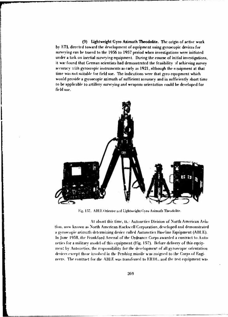
(9) Lightweight Gyro Azimuth Theodolite. The origin of active work by RTL directed toward the development of equipment using gyroscopic devices for surveying can be traced to the 1956 to 1957 period when investigations were initiated under a task on inertial surveying equipment. During the course of initial investigations, it war found that German scientists had demonstrated the feasibility rf achieving survey accuracy v/ilh gyroscopic instruments as early as 1921, although the equipment at that time was not suitable for field use. The indications were that gyro equipment which would provide a gyroscopic azimuth of sufficient accuracy and in sufficiently short time to be applicable to artillery surveying and weapons orientation could be developed for field use.
Ktg. 157. ABLE (Irfefitw and Lightweight (Jyro Azimuth Theodolite.
Al about this time, %h:, Autoneties Division of North American Avia- tion, now known as North American-Kockwell (Corporation, developed and demonstrated a gyroscopic azimuth-determining device called Autoneties Baseline Equipment (ABLE). In June 1958, th«' Frankford Arsenal of the Ordnance Corps awarded a contract to Auto- neties for a military model of this equipment (Fig. 157). Before delivery of this equip- ment by Autoneties, tin* responsibility for the development of all gyroscopie orientation devices except Ihose involved in the Pershing missile was assigned to the Corps of Engi- neers. The eonlraet for the ABLE was transferred to FvRDL, and the test equipment was
269

delivered there in November 1958. With only limited engineer tests at Fort Belvoir and limited service test by the Artillery Board at Fort Sill, Oklahoma, it was determined that the ABLE satisfied an urgent requirement for such a device. It was type classified under the title "Surveying Instrument: Azimuth Gyro, Artillery" in October 1959. This equip- ment weighed approximately 200 pounds and gave an accuracy of 30 seconds (I sigma) at 35° latitude and 1 minute (1 sigma) at 65° latitude.
In 1960, based on the need for a lightweight device for azimuth de- termination as a subsystem of the Long Range Survey System, a contract was negotiated with Lear Siegler, Inc., Astronics Division, for the study, design, and prototype model fabrication of a Lightweight Gyro Azimuth Theodolite with an accuracy capability suit- able for the LRSS.
The Lear Siegler instrument was delivered to GIMRADA in March 1962 for engineer design tests (Fig. 158). In the meantime, the Autonetics Division of North American Rockwell Corporation undertook a company-funded development based on the lightweight Gyro Azimuth Theodolite requirements and delivered to GIMRADA in July 1961 a Miniaturized Autonetics Basel) ^ Equipment (MABLE) (Fig. 159). Engi- neer test of the MABLE sho *">d that it met the objectives and the military characteris- tics for artillery use and could be suitable for field use with correction of deficiencies. It was sent to the U. S. Army Artüicry Board at Fort Sill. Oklahoma, for service test.
Fig. 158. Gyro AaimuthTheodol.t«*-Lightweight: Lear experimental mod«:!.
270
— i . niliiM^hAt—MlfcflMMhi

FWW
Autonetics Lear
P'ig. 159. Gyro Azimuth Theodolite, Ughtweighi-Autonetics and Lear modelt..
The test instrument delivered by the Astronics Division of Lear Siegler, Inc.. in March 1962 consisted of a theodolite mounted on a gyroscopic reference unit, a combined electronic control unit and carrying case, and a tripod. It was powered by internal batte'ies and weighed 31 pounds, 6 ounces. After 20 minutes operation time, it gave azimuth accuracies of 0.38 mil (standard duration). It was concluded as a result o«' engineering tests341 that it met the requirements for short-range weapons orien- tation and, on correction of some minor deficiencies, it would be suitable for field use.
In June 1963, a fixed-price contract was awarded to Leai Siegler for three engineer/expanded service test modele correcting the deficiencies noted in the pro- totype model tests. One of tiiese instruments was delivered to GIMRADA in August 1964 for compatibility tests with an instrument shelter which had been developed in- house to permit accurate instrument operation in high winds. In March 1965, two instru- ments were delivered to Aberdeen Proving Ground, Maryland, for engineer test and one was delivered to the Artillery Board at Fort Sill, Oklahoma.342 At about the same tii.:e, two instruments built by the Astro Space Company with its own funds were submitted for tsjst. One each war. sen! to the Aberdeen Proving Ground äin\ Furt Sill for concurrent testing with the Lear Siegler instrument.
It was not until 25 March 1965 that a QMR for this development, which was initiated in 1962. was approved by the Combat Development Command,
341 Robert T. Flowe and Duano C. Bright, GIMRADA 11-TR Engineering Test Report: "Lightweight Gyro Azimuth Theodolite (I.KAR North Seeking Gyro Model No. IING530A)," F-bruary 1963.
342,. George N. Clausen and Robert T. Flowe, GIMRADA 23-TR, "Research and Development Arceplance Test Report Surveying lustrum*- .1 (Azimuth, Gyro, Light weight/ Lear Siegier Inc. Models)," July 1965. "Lightweight North-Seeking Gyro Azimuth Surveying Instrument," Final Report. Lear Siegler, Inc., June 1965.
271

mm wmm ««ppriwupp mmr^^m*^
providing the needed document for testing. Unfortunately, the ET/EST instruments did not pass all tests, although they did demonstrate system stability for field use. It was decided at a meeting at G! MR AD A in August 1965 that all three test instruments should be modified to correct deficiencies and that further testing should be suspended until this was completed. It was also decided at this meeting to drop further considera- tion of the Astro Space instrument. A contract was awarded to Lear Siegler to correct the deficiencies found in testing to date and, in March 1966, one additional instrument was procured at the request of Army Materiel Command to provide maximum support for ET/EST and production engineering (Fig. 160).
Fig. 160. Lightweight Gyro Azimuth Surveying Instrument --ET/EST model.
This modification proved to be unsuccessful. It was found during acceptance testing in late 1966 that in modifying fKp wr:i?» earlier design provisions liad been disturbed creating additional technical prowlems. Lear Siegler made numerous changes to overcome the major problems; however, in testing at F.TL from June through November 1967, the modified instruments failed to meet the QMR requirements throughout the -65°F to +125°F temperature range. Also, the weight and power re- quirements were exceeded, and the instrument required heating above 0°F. By this time, the instruments hart been through so many hours of environmental testing that the
272

W" -'-".ill. -II»,I,.IM1P
performance reliability of the instruments was questionable due to the deleterious ef- fects of these tests. It was determined that a complete overhaul of the test instruments would be necessary prior to further testing, and such a recommendation was made to Office, Chief of Engineers, in November 1967.
After a delay of more than a year, ETL was directed by the Army Materiel Command in February 1969 to continue development of new ET/EST models that would meet the QMR. A contract was awarded to Lear Siegler, Inc., on 30 June 1969 for the fabrication of four models and for complete research and analysis of past problem areas.
In September 1970, the fabrication phase of the development was completed and acceptance testing started. After a successful high-latitude test at Fort Greeley, Alaska, however, testing was suspended due to excessive equipment failures primarily in temperature, shock, and vibration with the theodolite and isolator system. While the contractor was working on these problems, ETL recommended that a critical review and update of the QMR be made considering real user requirements versus state- of-the-art gyro equipment to preclude unnecessary damage to the equipment during test and thus further delay in development.
Acceptance testing resumed in January 1971. Four instruments were delivered in March 1971 ;M3 three of these went to USATECOM for ET/EST and one to Germany for test and evaluation by U. S. Army topographic personnel and the Pershing Missile Command, U. S. Army Europe. After temporary suspension of engi- neer testing at APG in August 1971 pending Department of the Army approval of the QMR revisions and change to the engineer test plan, service test was satisfactorily com- pleted at Fort Sill in October, changes to the engineer test plan were approved in No- vember, and the revised QMR was approved in December 1971. Expedited completion of all tests and type classification was scheduled for some tim° 'n 1972 after almost 12 years of development effort started with the first Lear Siegle: itract in 1960.
This development is considered to be one of the major achievements in the surveying instrument development field. It provides instrumentation weighing approximately 40 pounds (excluding batteries) which can be carried by one man, is oper- able under all-weather, day-night conditions, and provides azimuth accuracy of 1 minute of arc (1 sigma) at mid latitudes.
(10) Small North Orienting Device (Miniaturized Gyrocompass). A Qualitative Materiel Development Objective (QMDO) for Small North Orienting Device
343.. Design arni Development of Surveying Instrument: Azimuth, Gyro, Lightweight (StAGLfc" Final Report,
Lear Siegler, Inc., March 1971.
273

(Miniaturized Gyrocompass) was approved on 31 March 1965. (The QMDO was subse- quently revised on 17 January 1968.) The objective was to provide a small device weigh- ing not more than 3 pounds which could be carried on a web belt and would determine azimuth to an accuracy of about 2 mils in an operation time of 3 minutes. It would be used by field artillery forward observer ano ground surveillance and target acquisition operations to determine accurate orientation
Preliminary studies had been implemented prior to the QMDO ap- proval under a contract with the Astro Space Laboratories, Inc., Huntsville, Alabama, to examine the feasibility of a spinning gyro for this type of application. In these studies from June 1964 to May 1965, two methods of mechanization of the sphere gyro were examined (Figs. 161 and 162)-one with fluid suspension, and the other with air suspen- sion. The air bearing approach was selected.344
These preliminary studies were followed by an investigation under contract by Lear Siegler, Inc., Santa Monica, California, from September 1965 to April 1966, to investigate the feasibility of employing a piezoelectricai.'y driven, oscillating glass squeeze bearing. Several designs using first a piezoelectric squeeze bearing in a pendulous gyro configuration and secondly a viscous friction gyro were examined345
but all were rejected because of complexity and cost.
A development contract for the Small North Orienting Device was awarded to Astro Space Laboratories in May 1967 to produce an experimental model. In December 1967, another development contract was awarded to the Arma Division, AMBAC Industries, Inc., Garden City, New York, to develop a feasibility model using the Arma G-16 Dynature gyro.
After considerable difficulty was encountered in the development of a suitable air pump and also in the development of an appropriate azimuth transfer device, the Astro Space Laboratories instrument was delivered to ETL for test on 20 May 1969. After preliminary tests in which it was found that the device did not meet the accuracy requirements and that the azimuth transfer device was not satisfactory, it was returned to Astro Space Laboratories for retlesign of the azimuth transfer device, air supply system, and gyro drive meter with invertor. The redesign was completed by August 197Ü.346
After some testing in which it was found that the instrument still did not meet the accu- racy requirements (2.38 mils versus the 2-mil requirement) the instrument started to
Study and Prototype Model Design of a Miniaturized Gyro Compass," Final Report, Astro Space Laboratories, Huntsville, Alabama, May 1965.
Study of the Application of Piezo-Electric Techniques to a Small North Orienting Device," Final Report, Lear Siegler, 'nc., Santa Monica. California.
"Design Studies and Prototype Model Development of a Small North Orienting Device (Miniaturized Gyro- compass)," Final Report, Astro-Space Laboratories. Huntsville, Alabama, August 1970.
274

•mtmipvapiBwamwii.». HI II.M uiiwiiiim miiiiaww»»• '*'» " »,'»T'"»-*'
DESM GOALS
MCHMCV-2IHL90 IMC
WBömOMMMSUff
AZ OETM-3IHNII7ES
WBGKT-3 POUNDS
Fig. 161. Miniaturized Gyrocompass-design concept and goals.
Fig. 162. Miniaturized Gyrocompass -experimental model.
275

gpOQpB|HMpHlinailijp(PipiPivvpmim)iPi«in«^
malfunction and the tests were suspended. This instrument far exceeded the weight limitation goal; it weighed 20 pounds without case and 34 pounds with case, but it did meet the goal of a 3-minute read time. However, during the development, it became apparent that weight savings could be realized in several areas, including the azimuth transfer device, the air pump and motor, the gyro drive motor, the gyro sphere, and the instrument housing. The next step in this development was a redesign to accomplish the desired weight reduction.
The American Borch Arma Corporation model was delivered to ETL on 3 February 1969. It too, was returned to the contractor after preliminary testing for improvement of performance, although the accuracy of the device was well within re- quirements on most tests.347 The principal problem was that the instrument performed erratically when subjected to high winds, and the nulling mechanism operated roughly during the latter stages of testing.
Based on engineering design tests34,1 completed after the return of the device to ETL in August 1969, it was concluded that considerable additional research and development were required to minimize the effects of wind, shield the instrument from magnetic forces, reduce the observation time from the 9 minutes required in tests, correct several mechanical deficiencies, and reduce the size and weight. The total package weight of this instrument was 51 pounds.
(11) Sequential Collation of Range (SECOR) System. In April 1960, the Army Map Service contracted with the Cubic Corporation, San Diego, California, for a Geodetic Sequential Collation of Range (SECOR) System. The objective was to provide a system, which through techniques of electronic ranging to an orbiting earth satellite, would provide means for establishing geodetic positions of points of distances of 100 to 1500 miles from known geodetic positions. Thus, the system would provide means for making intercontinental and inter-island datum ties — a fundamental geodetic problem at that time.
The 1960 Army Map Service procurement was for four prototype ground stations and a prototype satellite transponder unit to be orbited in a U.S. Navy transit system satellite to test and demonstrate the system. In operation, three of the ground stations would be positioned on known geodetic positions and thi fourth on an unknown point. Th? system would provide recorded ranging data from each of the ground stations to the satellite during each orbital pass at the rate of 20 ranges per se- cond. With this configuration, two modes of operation were possible; a simultaneous
" "Development of a Small North Orienting Device," Final Report, AMBAC Industries, Inc., Garden City, New York, February 1970.
lAllan K. Holland, November 1970.
348AUan R. Holland, Sr„ KTI--ETR-7011, "Miniaturized Gyrocompan (Small North Orienting Device),*
276

mode wherein all ground stations ranged on the satellite simultaneously; and an orbital mode wherein an updated satellite orbit established by the ranging data from the known positions was used to compute the unknown positions through its nonsimultaneous rang- ing data. Accuracy could be improved by using several orbital passes. The system could also be used in a line crossing mode wherein simultaneous ranging data to the satellite could be used to compute the geodetic distance between stations as it crossed the line between two stations
Preliminary system tests were conducted in the spring of 1961, and the Army Map Service contracted for two additional ground stations wl.ich were designed "ruggedized" stations since special consideration was given to transportability in their design and construction. However, system tests conducted in the fall of 1961 raised ques- tions as to the validity of the basic system concept, and the entire program was halted by the Office, Chief of Engineers, for re-evaluation.
On 15 January 1962, GIMRADA was directed to form an evaluation team to investigate the SECOR program. The team, composed of scientists and experts from GIMRADA, Ballistics Research Laboratories, and the National Bureau of Standards, made an expedited but complete analysis of the system, determined that the basic con- cepts were valid, and recommended a program of development to ensure reliable opera- tion meeting the desired system accuracy.349
In February 1962, the research and development phase of the SECOR program was assigned to GIMRADA, and on 19 February 1962, GIMRADA was directed to contract for equipment modification in accordance with the evaluation team recom- mendations. An expedited development program was requested, and contracts were awarded soon thereafter for incorporation of these modifications in twc of the proto- type ground stations and the two ruggedized stations. The evaluation team remained active in the program in a consulting basis, and assisted in the development of the sys- tem by frequent inspections and in-process reviews. In addition, a resident engineer of- fice was est iblished in the Cubic Corporation Plant to monitor all SECOR contracts. In June 1962, GIMRADA contracted with the Cubic Corporation for four additional rugged- mftfl ground station* (Fig. 163). All ground stations were delivered by November 1963.350
In the meantime, development of satellites and transponders was also in progress. GIMRADA procured four Type I satellites (Fig. 164) from Cubic Cor- poration in February 1961351 and an additional satellite from International Telephone
J. T. Pe nnington and Others, "Review and Analysis of U. S. Army Geodetic SECOR System and Development," Special Report, February 1962.
-IC*» "Geodetic SECOR Ground Equipment," Final Report, Cubic Corporation. March 1964. "Ruggedized Geodetic SECOR," Final Report, Cubic Corporation, May 1964.
351 "Geodetic Spacecraft," Final Report, Cubic Corporation, October 1961.
277

wmmmm '.IHI'I U«4WUB(H OTI^q
Fig. 163. SECOR Ground Station-1965.
and Telegraph Federal Laboratories (ITTFL) in October 1962.352 This later satellite was, unfortunately, destroyed during predelivery vibration tests. Following this experi- ence, a contract was awarded to ITTFL in March 1963 for three Type II satellites,353 a box-type configuration (Fig. 165). One of these was successfully launched on 11 Janu- ary 1964 for combined engineer/service test for which tracking operations began on 12 January 1964.
The combined engineer and service tests of the system, with Army Map Service participation, were completed in May 1964,354 just a little over 2 years after the assignment of development responsibility to GIMRADA. In these tests, the system was found to be capable of measuring ranges exceeding 3000 kilometers to the satellite. The coordinates of positions were determined with an average error vector magnitude of 16.6 meters on a 500-mile quad and of 33.6 meters on a 1000-mile quad.
352.
353..
354..
Type I Geodetic Satellite," Final Report, ITT Federal Laboratorien, June 1964.
U. S. Army Type II Geodetic Satellite»." Final Report, ITT Federal Laboratories, November 1965
Combined Engineer and Service Test, Geodetic SECOR System," Draft Technical Report, Prepared by Advanced Geodetic Developments Branch, Surveying and Geodesy Division, GIMRADA, 1 July 1964.
278

*f^^^*^W^W •P
Fig. 164. SECOR Type I Satellite.
Fig. 165. SFCOR Type I! Satellite.
279

As a part of these tests, a geodetic distance exceeding 3500 kilometers was measured- San Diego, California, to Herndon, Virginia. It was concluded from these tests that the equipment showed great potential as a first-order survey tool, and the equipment was turned over to the Army Map Service for implementation of an operational program of long-range geodetic measurement.
GIMRADA continued work on the SECOR System in support of the ground operations and in an active program of satellite and transponder development. Also, GIMRADA was charged with the responsibility for satellite launches throughout the life of the program, with the exception of a few launched in the late 1960's which were considered strictly operational and not involving new equipment. Most of the satellite launches were "piggy-back"; that is, they were the secondary pay load on boosters launching satellites primarily for some other purpose. In November 1965 and again in January 1968, SECOR transponders were launched as an integral part of com- bined Department of Defense and National Aeronautics and Space Administration geo- detic satellites designated GEOS A and GEOS B respectively. A complete satellite launch history starting with the 11 January 1964 launch for combined engineer and service tests is shown in Table 3.
The development program, which paralleled the operational program in the mid to late 1960's, included contracts with the Cubic Corporation for Type II satel- lite and High Altitude Transponders (HAT) and with the ITT Federal Laboratories for Multi-Altitude Transponders (MAT) in mid-1965. In late 1966, the Defense Intelligence Agency authorized the development of miniaturized ground stations. These reduced the number of shelters for each ground station from three to one and effected an 8:1 reduc- tion in ground-station weight. A total of eight of these stations was procured from the Cubic Corporation, and four were placed in operation in the field before the program was terminated. Late in 1967, Cubic Corporation produced an improved HAT, and the first MAT production models were produced by ITT.
The entire SECOR program was terminated in April 1070 on com- pletion of an equatorial belt of geodetic control stations.
(12) Translation Field Equipment. Interest in the Doppler Transloca- tion Field Equipment as a possible solution to Army artillery and mapping survey prob- lems started in the early 1960's. In 1964, a contract was awarded to the Westinghouse Electric Corporation, Baltimore, Maryland, to conduct experiments with Doppler satel- lite tracking instrumentations to demonstrate the potential of the systems for Arsny ap- plications. These experiments, using Doppler satellite tracking instrumentation developed for the U.S. Navy, were completed in May 1965 (Fig. J66).355 In the meantime, in
35 Dappler Satellite for Army Field Operation," Final Report, Wentinghouse Eleetric Corporation, Baltimore, Maryland, May 1965.
280

mm
«K.P
WH
PU
UIH
I •
»»»
"I
Tab
le 3
. SE
CO
R S
atel
lite
Lau
nch
Hist
ory
15 J
anua
ry 1
971
Nam
e L
aunc
h D
ate
Sate
llite
Tran
spon
der
(ncl
Pe
riod
(m
in)
Apo
gee
Peri
gee
Rem
arks
r>3
JO
EGR
S 1
11 J
an 6
4 T
ype
II T
R-2
7 (S
/N-2
) C
ubic
IT
T
69.9
1°
103
.4
928
km
916
km
S
ucce
ss.
Cea
sed
oper
atio
n Se
p 65
aft
er a
ppro
xi-
mat
ely
1100
inte
rrog
atio
ns.
EG
RS
HI
9 M
ar 6
5 T
ype
II
(S/N
-l)
ITT
TR
-27
Cub
ic
70.0
9°
103.
5 94
2 km
90
6 km
Su
cces
s.
Not
use
d op
erat
iona
lly a
fter
Jul
67.
C
ompl
eted
120
0 in
terr
ogat
ions
.
EC
RS
H
11 M
ar 6
5 T
ype
II
(S/N
-l)
ITT
TR
-27
Cub
ic
89.9
8°
97.5
99
2 km
9C
2km
L
aunc
her
faile
d to
sep
arat
e ja
teD
ites
. R
e-en
tere
d 26
Feb
68.
EG
RS
IV
3 A
pr 6
5 T
ype
II
(S/N
-5)
ITT
CI0
1 IT
T
90.2
0°
111.
4 13
24 k
m
1266
km
E
xper
imen
tal
tran
spon
der
faile
d du
ring
bu
nch
.
EG
RS
V
10 A
ug 6
5 T
ype
I (S
/N-2
) C
ubic
TR
-27
Cub
ic
69.2
4°
122.
2 24
27 k
m
1135
km
E
xces
sive
spi
n ra
te.
Cea
sed
oper
atio
n M
ar 6
6, a
fter
ap
prox
imat
ely
50 i
nter
roga
tion
s.
GE
OS
A
6 N
ov 6
5 G
EO
S A
PL
TR
-27
Cub
ic
59.3
8°
120.
3 22
73 k
m
1119
km
Su
cces
s.
Cea
sed
oper
atio
n Ja
n 67
, af
ter
appr
oxi-
m
atel
y 50
0 in
terr
ogat
ions
.
EG
RS
VI
9Ju
n66
T
ype
II
(S/N
-")
Cub
ic
TR
-30A
C
ubic
90.0
4°
125.
2 36
55 k
m
171k
m
Hig
hly
ellip
tica
l or
bit
due
to l
aunc
her
failu
re.
Not
us
eful
. R
e-en
tere
d 6
Jul 6
7.
EG
RS
VII
19
Aug
66
Ty
ped
(S
/N-8
) C
ubic
TR
-30A
C
ubic
90
.01
167.
9 37
43 k
m
3686
km
E
xper
imen
tal
tran
spon
der
75%
use
ful.
Bat
tery
fa
ilure
in J
an 6
7 af
ter
appr
oxim
atel
y 20
0 in
terr
ogat
ions
.
EG
RS
VII
I 5
0ct
66
T
ype
11 (S
/N-9
) C
ubic
TR
-30A
C
ubic
90
.19°
16
7.6
3704
km
36
77 k
m
Tra
nspo
nder
app
aren
tly
faile
d du
ring
bu
nch
.

«PH
K
<w
np
«>
nn
Mm
H
rO
00
Tab
le 3
(co
nt'
d)
Nam
r L
aunc
h D
ate
Sate
llite
T
rana
pond
er
Incl
»•*
A
poge
e (m
in)
Peri
gee
Rem
arks
EG
RSI
X
29Ju
n67
T
ype
II
(S/N
-10)
C
ubic
TR
-30A
C
ubic
89
.8°
172.
1
3
945
km
3794
km
Su
cces
s.
Sti
ll u
sabl
e af
ter
appr
oxim
atel
y 18
00
inte
rrog
atio
ns.
CEO
S-B
II J
an 6
8 G
EOS
TR
-30A
105.
8°
1
12.2
157
3 km
108
0 km
Suc
cess
. N
ot u
sed
oper
atio
nally
aft
er J
an 7
0.
APL
Cub
ic
Com
plet
ed 6
00 in
terr
ogat
ions
.
EG
RSX
I
EGR
S X
II
TO
POI
EG
RS X
18 M
ay 6
8 T
ype»
(S
/N-l
) IT
T
Prot
o M
AT
ITT
99l
106
1100
km
110
0 km
Lau
nche
r fa
iled
to a
chie
ve o
rbit.
In
Typ
e II
(S/V
I3)
Cub
k
Tv|
- '\
(S
/N ,
6)
TR
-30B
C
ubic
MA
T IT
T
91.3
°
17
2 39
00 k
m
3
900
km
D
ual p
aylo
ad.
Lau
nche
r fa
iled
to a
chie
ve o
rbit.
EG
RS
XII
I I'
Ap
r 69
T
ype
I (S
/N-1
4)
Cub
ic
TR
-30B
99.9
°
10
7.3
1141
km
1
085
km
S
ucce
ss.
Still
ope
ratio
nal a
fter
appr
oKitn
atel
y 50
inte
rrog
atio
ns.
8 A
pr 7
0 T
ype
II
(S/N
18)
IT
T
MA
T IT
T 99
.86°
1
07.0
109
0 km
108
) km
Suc
cess
. St
ill o
pera
tiona
l aft
er a
ppro
xim
atel
y 50
inte
rrog
atio
ns.

FORWARD STAVtON MASTER STATION
Fig. 166. Doppler transloration concept.
December 1964, the U. S. Navy conducted tests demonstrating the principle at the Quantico Marine Base. These tests were witnessed by GIMRADA personnel. In April 1965. ii was learned that the I. S. Navy planned to develop a set of translocation field equipment, consisting of two identical 40-pound backpacks, which would determine relative positions between two points at short as well as lottg range by tracking U. S. Navy Doppler Navigation Satellites.
This development was an outgrowth of the U. S. Navy Navigation Satellite Systems development-a system in which the orbiting satellite uses a very stable oscillator to transmit a continuous R F signal with orbit ephemeral data and timing sig- nals transmitted at 2-minutc intervals. These RF signals were received on the ground or aboard ship and compared with a stable oscillator t a measure the Doppler shift, which, together with the orbital information, provided the basic data to compute the position of the ground or shipborne station. From the Doppler data from two or more of these ground stations, one of which was designated a master station and located on a known position, the relative positions of the various stations could be computed.
In May 1965, funds were transferred to the U.S. Navy for two single frequency Doppler translocation receivers (backpacks) (Fig. 167). These were received
2a3

WtKTW i'f« im •»«um nu "www IMJIHIL.«.*.. «i»»"
VW >
Fig. 167. Doppler TranaJocation Receiver-experimental model.
RADIO HI,
Fig. 168. Doppler TranaJocation Master Station-experimental model with FADAC computer.
* AN/WC47 i^^m-i^'ih '
284

,H IJRII II 111»
in Ma*ch 1967 and a test program with the U. S. Navy was conducted in the summer of 1967. A FADAC computer was used with this equipment for data reductions (Fig. 168).
The results of these tests indicated a potential application of this type of equipment for tactical positioning purpose» providing certain modifications in the equipment and computer programs were accomplished. Following these tests, the Navy continued the development of advanced receivers under contract with Honeywell, Inc. (Fig. 169), and plans were being made in 1970 for further field tests by the Army and the U. S. Marines to determine the full potential application for tactical positioning.
AMfNNA PBIAMP ASUMBIY •
W
Fip. 169. GReceiver System for Doppler Tratislocation.
(13) All-Weather Angle Measuring. In June 1964? GIMRADA awarded a contract to the Cubic Corporation, San Diego, California, for the design, fabrication, and test of a microwave pointing system to verify the feasibility of using a transmitted microwave signal to achieve rollimaticn between the transmitter and the receiver, there- by extending the useful operational time of angle determination to all-weather condi- tions. Prior to this time, GIMRADA had funded experiments in microwave pointing by the National bureau of Standards, Boulder, Colorado, and in Hawaii at frequencies of
285

EC
••: '.«. ^;^**fevr • -
Fig. 170. Electronic Angle Measuring Equipment: 35 GHz.
9.4 and 18.8 GHz. The equipment produced by the Cubic Corporation operated at 35 GHz (Fig. 170).356
Following experiments with this equipment in 1965, which includ- ed tests at Boulder, Colorado, in July 1965 to obtain simultaneous data pertaining to long-term and short-term signal angle-of-arrival variations at 9.4-, 18.8- and 35-GHz fre- quencies over the same path357 and tests conducted at Fort Belvoir, Virginia, in the period 14 September through 28 October 1965 to determine the feasibility of angle measurement at a fixed frequency instead of multiple frequencies,358 another experi- mental equipment operating at 90-GHz frequency was procured under contract (Fig. 171). This equipment demonstrated the reduction in size and weight which could be realized using the higher frequency. By 1970, these experimental devices had demon- strated absolute angle measurement accuracies better than five records of arc although
356..,-
357
Electronic Poir ting Device (Microwave) System (Flectrotranstt)," Final Keport, Cubic Corporation, San Diego, California, February 1964.
Peter J. Cervarich, GiMRADA Report 26-TR, "Microwave Pointing Variations and Angle Measurements," January 1966.
358MahlonC. Hawker, GIMRADA Report 33-TR, "Fixed and Multiple Frequency Angle Measurements with 35GHz Microwaves," October 1966.
286

»••»l»H'»l-
the equipment was rather bulky for man-portable applications. The next step in the logical course of development of this class of equipment involved a combined distance and angle measuring system with emphasis on short ranges and a more compact config- uration of equipment. In 1970, this further development was projected to provide a system which, when completed, will permit field survey units to extend control by tri- angulation, trilateration, and traverse techniques during adverse climate conditions.
mf\4f^m^n.,
Fig. 171. Electronic Angle Measuring Equipment: 90 GHz.
(14) Distance and Angle Measuring System. As early as 1964, the U.S. Army Combat Developments Command Artillery Agency proposed a Small Development Requirement (SDR) for a small, lightweight equipment to measure azimuth and distances over limited range and to provide low-order accuracy to be used for fourth order survey in field artillery surveying operations. The work on all-weather angle measuring previous- ly discussed was directed toward an eventual application in such an instrument. Another exploratory development of the mid-196(Vs with possible application in such equipment in the future was a Theodolite with Shaft Angle Coder and Digital Display produced by the Pcrkin-Elmer Company under a GIMRADA contract in 1967.3S9 36° This item proved
' Theodolite with Shaft Angle Encoder and Display," Final Report, Perkin-Eimer Company. June 1967.
360. Optical Theodolite Readout." Final Report, Perkin-Elmer Company. Norwalk, Connecticut, June 1967.
287

the feasibility of using a state-of-the-art angle encoder for military surveying although the equipment produced was heavier than desired.
In 1968, ETL contracted with the Elgeo Corporation of America for two prototype instruments called the ELGEO which combined the function of angle and distance measurement in a single instrument. This instrument was aimed at meeting the microwave ranging requirements of the then standard microwave distance-measuring equipment and the optical angle measuring requirements of the standard T-2 theodolite. It did not provide a digital display of angle measurements since conventional visually read circles were provided, but it did provide a direct digital display of range. This equip- ment was delivered to ETL in 1969 (Fig. 172). Engineer test of this equipment continued into the 1970's.
POINTING-356Hz POINTING-90GHz PLANAR ANTENNA
SHAFT ENCODER ELGEO GE0DMETER-7T
Fig. 172. Dfe.«(nce and Angle Measuring Equipment (DAME) investigation«.
Paralleling this development, a number of similar developments for the commercial market were being investigated by ETL. These included the Geodimeter T-7 which provided optical angle measurement with conventional visually read circles and direct digital display of range and the REG ELT A-14 produced by Zciss which pro- vided direct digital readout of both range and angle. Also under consideration was the possibility of retrofitting encoders on standard theodolites.
288

nmumi n.uw»»'"» i
These investigations demonstrated the feasibility of development in the 1970'sof all-weather, day-night, combination distance-measuring and angle-measuring instruments with automatic reading and processing capability ir - format ready for inter- face with modern command and fire control systems.
g. Geographic Sciences.
(1) Development of Research and Development Program. In contrast to surveying, geodesy and mapping, there had been virtually no research and development devoted to the improvement of the collection, processing, and dissemination of terrain information (usually referred to as military geographic information (MGI)) since World War II. With the activation and organization of GIMRADA in 1960, an operating ele- ment called the Intelligence Division was established. This element was responsible for research and development in this area.
During the next several years, with a small staff of only a few indi- viduals acquired by transfer from other elements of GIMRADA, efforts were concentrat- ed on investigation of MGI operations in the Army to gain a familiarity with terrain in- telligence production source materials, methods, and products and an understanding of those problem areas which reflected a requirement for research and development support. Also during these early years, through contacts with industry, some feasibiUty type deter- minations were made at no cost to the government through research and development loan agreements. Significant studies of this type were made in the areas of radar calibra- tion, pattern recognition, and the determination of photo interpretation problems. In addition, work started on the development of a program to modernize the engineer de- tachments (terrain) so that they might perform their function better in support of the field army. A program was also initiated in support of the space application clement of the National Aeronautics and Space Administration.
These early activities and investigations finally led to the authoriza- tion of an exploratory development project titled Military Geographic Intelligence (MGI) in October 1964. The project approval actually came before the QMDO was ap- proved in early 1966 based on the fact that a suitable QMDO was well along in the staff- ing process. The objective of the MGI project was to conduct applied research, explora- tory development, feasibility studies, and evaluation of new techniques to improve sys- tems, including equipment for collecting, processing, analyzing, storing, and disseminat- ing military geographic data for fieiJ army and strategic uses to meet MGI requirements. Initially, the project was set up with two tasks:
Task 1: Exploratory Development in Support of Collection, Pro- cessing, and Presentation of MGI.
289

..,^-.„., ...... .,r..,.„JW -^^^^^^W^^-p-!-.^-^-^.*^*"".«
Task 2: Exploratory Development in Support of Automatic Data Processing of MGI Data.
This project structure was later changed to provide more effective management in FY 71 and beyond, providing five task areas as follows:
(a) 01—Analysis of MGI Requirements and Definition of Systems Concept
(b) 02-MGI Data Collection (c) 03-MGI Data Reduction (d) 04—MGI Product at d Analysis Definition (e) 05-MGI Data Handling
In FY 69, an advanced development project—Military Geographic Intelligence System (MGIS)—was approved. Its objective was to improve the capability of the Army to interpret the output of imaging and nonimaging remote sensors to ob- tain military geographic information; to design new MGI products, displays, and read outs to support specific types of military activities; and to design and operate an experi- mental automated system for the storage, retrieval, manipulation, and analysis of mili- tary topographic information.
Thi& project included four tasks:
(a) 01-Radar Ground Data Reduction for MGI (b) 02-Ground Data Reduction of Photography for MGI (c) 03—MGI Products, Displays, and Readouts (d) 04-MGI Data Base
While these approved, numbered research and development pro- grams in the MGI areas were being developed and processed in the 1960's. the staff of the Intelligence Division (later renamed successively Geographic Intelligence, Geographic Sciences, Geographic Systems, and Geographic Sciences) was involved in a number of other programs, both within and outside th: Department of Defenr«, all of which were related to and supported the overall MGI effort. The more significant of these programs as well as specific efforts under the numbered development project effort will be de- scribed in subsequent sections of this history.
(2) Modernization of Terrain Detachments. One of the earliest efforts in the Geographic Sconces area was an analysis of the capabilities of engineer detach- ment (terrain) to perform its mission in support of the modern field army. This analysis was made in 1963 and indicated that the detachments were operating with obsolete equipment and procedures which seriously hampered their ability to produce tei-ain
290

data of the quality, quantity, and timeliness required. As a result, the preparation of a QMR to authorize research and development of state-of-the-art equipment methods and techniques was started.
A draft QMR was prepared in 1964 through 1965; but, on review by the Combat Development - Command Engineer Agency, it was suggested that an SDR would be more suitable. Higher priority work prevented further effort on this item un- til 1968. In that year, it was recommended that a project be initiated under the Expe- dited Non-standard Urgent Requirements for Equipment (ENSURE) program as an ex- pedited method to get equipment to the troops in Vietnam.
Although the ENSURE program approach was not approved by higher authority, a state-of-the-art equipment brochure was prepared in 1968 and 1909 and was provided to units in Vietnam for their use in requesting items by the ENSURE route. Late in 1969, a review of the original QMR was initiated, and in early 1970 a draft SDR including all changes in the state-of-the-art that had occurred was finally com- pleted for review by the Combat Developments Command Engineer Agency and the U.S. Army Topographic Command.
(3) NASA Support Program. After extensive conferences and discus- sions in 1963 with personnel of the space applications element of the National Aero- nautics and Space Administration, a program was developed to support them in the general area of research and development concerning earth resources. Eventually. 10 additional personnel spaces were allocated to ETL for this program.
This program continued for about 4 years. In addition to the actual work performed under NASA purchase request, there was considerable exchange of in- formation, which included remote sensing and geography through participation in con- ferences, seminars, and commit tees. The program included primarily studies in color and multispectral photography,361 362 the preparation of an earth atlas363 to show the potential of studying the earih from orbiting spacecraft, and the preparation of a bibliog- raphy iff remote scanning resources.364 Mr. D. C. Orr of the Geographic Sciences staff was loaned on a 6-month TDY in 1967 to develop specifications for a multiband camera.
i#» i A. Aruton, "Feasibility of Objective Color System*," September 1964. ' Preliminary Report on Multispectral Experiment." February l%5. "Supplement to Preliminary Report on Multispectral Experiment," June 1965. "Multmprctral Experiment No. 2."
D. t.. Orr. "Multiband Color Yholography for Space Application," ASP Semi-Annual Meeting. October 1967.
R. A. \/rrAna. "The CM- of Multiscnser Imagery From Space in Portraying the Earth and the Multisensor Imagery Collection," 1966.
36 4» rv. E. Jone» (Kothe). "Bibliography of Remote Survey Resources" September 1966.
291
ri Tiaili

He was named the coordinating investigator for a multiband photographic spacecraft experiment to survey earth resources. A multiband camera experiment of six mapping cameras with spectra! filters and selected films was defined and approved by NASA for a future space flight. The definition of this experiment involved consolidating the require- ments of a large number of user scientists in national organizations concerned with earth sciences application. A preliminary multiband experiment consisting of four Hasselblad cameras was flown on the Apollo IX spaceflight.
The earth atlas program, started in July 1964, proved to be a highly successful project providing the best and most comprehensive publication prepared from NASA-generated imagery up to 1970. On initiation of this project- a draft sample was produced and delivered to NASA in August 1965. In November 1965, NASA directed that an improved draft L impie be produced in 6 months to include photos taken from Gemini Spacecraft Missions IV and V of June and August 1965 respectively. In May 1966, a dummy copy of the improved draft sample was delivered to NASA. Six days later, NASA requested that the title of the earth atlas be changed to: "Application of Air and Spaceborne Sensor Imagery for the Study of Natural Resources — Sample Analy- ses and Intei (retation Relating to Agriculture, Cartography, Geography, Geology, Hy- drology, Metcrology, and Oceanography." The) were persuaded to shorten the title to "Earth Resources Surveys From Spacecraft." NASA requested 25 copies to be repro- duced photographically to ensure the absolute highest quality. Later, in May 1967 and again in May 1968, NASA Manned Spacecraft Center, Houston, Texas, requested 50 ad- ditional copies of the publication on each occasion.
In connection with the NASA support activity, it was proposed ir. 1965 that a Technical Application Center be established at ETL to be operated under (he Chief of Engineers as an extension of the NASA staff and with NASA funding to in- clude support by contract activities. This did not materialize however; a Technical Ap- plication Center, simitar in concept, was set up for NASA by the U.S. Geological Survey.
(4) Aerial Color Photography. In addition to and concurrent with the color photography investigation in support of NASA and continuing beyond the NASA program, members of the Geographic Sciences staff maintained a continuing program of investigation of the application of aerial color photography to MGI. In connection with this activity, Mr. \nson of the Geographic Sciences Division staff, became deeply in- volved with the work of the American Society of Photogrammetry Color Photography Committee and was appointed associate editor of the Manual of Color Aerial Photography which was published by the American Society of Photogram metry in 1968. During the period 1964 to 1970, Mr, Anson published a number of technical papers dealing with the application of color photography.365
See paper» lixtrd in ETT-SK-TO-I, 'Biblknrrapn; of In-Housr and Contract Report/»." Augu»t 1970. pp 30-31. and KTI.-SK-70-.1, "HihlioKraphy of In-Houw- and Contract Reports." Supplement I, October 1971, pp8.
292

mpvpnumwaRKW* iwm-uw.imwpnw*" nun niiwiiuii'i'ii i>i
At the start of these investigations in 1964, and after a series of visits to government agencies and civilian manufacturers, a technology brief was pub- lished titled "Status of Aerial Color Photography in Government Agpncin" reporting on the state-of-the-art of cameras, films, and projection equipment. Meanwhile, film coverage from several emulsions, .ver the Bennettsville, South Carolina, test area was ob- tained through the American Society of Photogrammetry Color Photography Commit- tee and was evaluated with the cooperation of several government agencies and private industry.366
A direct result of the report on the Bennettsville test was further field tests of the metric aspects of color photography. In September 1967, while on active duty at the Geographic Sciences Division, Col. D. W. Mintzer produced a study report on photography for soils and terrain data.367
All this work led to the creation of a task, investigation of aerial color photography for mapping, under the exploratory development for mapping and geodesy project; responsibility was assigned to the Geographic Sciences Division. Under this task in the late 1960's, tests of the GIGAS Zeiss orthoprojector were made to deter- mine feasibility of printing color orthophotographs directly from color negatives onto color sensitized materials; tests were made to determine the feasibility of compiling di- rectly from color photography on the UNAMACE; and in-house studies were made of methods of controlling contact printing and processing of aerial color photography. Special color separation equipment was procured from Technical Operations, Inc., to support these in-house investigations directed toward the production of color topo- graphic products.
Further work in the application of color photography in the MGI area utilized the expert.se of Dr. Al Lind and Dr. Jack Rinkcr of the Cold Regions Re- search and Engineering Laboratory (CRREL) through transfer of funds. Two ETL technical reports were produced and published in 1970.368 369 Also, with the assistance of the field office at Wright Patterson Air Force Base, a contract was let to Fairchild Cdinrid and Instrument Corporation to modify a 1-11 camera by the incorporation of a GKOCON I lens to provide a high-resolution, low-distortion, color-corrected carto- graphic camera. The objective here was an improvement in the state-of-the-art of color photography. 366 A. Arutun, TN-66-3. "Comparative Photointrrprctalion from Panchromatic, Color, and Ektachrome Photography.
February 1966.
%7(> W. Mintzer, ETL38-TR, "A Comparative Study of Photography for Soil« and Terrain Data." April 1968.
368,
369
A. (). Lind. ETL-54-TR, "An Evaluation of Multiband and Color Aerial Photography for Selected Military Geographic Intelligence in a Subtropical Dcnert Environment," January 1970.
R. K. Reed and J. N. Rinker. ETL-TR-70 6, "Evaluation of Color Tent Phoiography for Military Geographic AnaiyMH - A Literature Review," July 1970,
293

!.!!••• II1UU UlW.'f I ,>'.
(5) Multiband Photography. Concurrent with the multiband photog- raphy investigation in support of NASA, ETL pursued a program of investigation of the potentials of multiband photography for application tc military geographic analysis. A contract for controlled laboratory and field experiments to determine techniques for extracting military geographic information through the use of multiband photography was awarded to the Aeronutronics Division of Philco Ford Corporation in June 1965. The results of this contract370 indicated that only four bands of the photographic spec- trum were required to extract information on a variety of terrain materials and military targets. Previously, the scientific community had generally considered that nine or more bands H ere required for terrain analysis.
When the NASA support program was terminated in 1967, efforts were directed toward development of a consolidated, long-range research and develop- ment plan for both color and multiband photographic systems to support the Army's MGI requirements.
As a result, several procurements were implemented in the late ?960's. An experimental multiband camera system and an additive color viewer were defined, and contracts for development were awarded in November 1069. A procurement was also initiated for an interference imaging system using defraction gratings for recording color and black and white film.
(6) Radar Applications for MGI. The ^eoscience potential of side-look- ing radar was a subject for continuing study and investigation, both in-house and under contract, since the implementation of the Geographic Sciences program at ETL. The first contracted studies were made by Autometric Operations of Raytheon Corporation in 1965.371 This was followed in 1966 by an experimental production of MGI products.372
In 1969, Purdue University, under contract, investigated the use of side-looking radar imagery for engineering soils studies;373 and in 1970, Mr. Pearson completed an in-house study related to the use of side-looking radar imagery.374 As a part of these investiga- tions, Hughes Aircraft Company was funded in 1966 to study the exploitation of the intelligence potentials of coherent radar signals, taking advantage of image signal 370.,
371.
Investigation of Multiband Photographic Tf chnique*." Volume I, Final Report, Philco Ford Corporation, Aeronutronics Division, November 1965.
Geoscience Potentials of Side Looking Radar," Final Report, Raytheon Corporation, Autometric Operation, Volume I, 1965, Volume N, 1965.
372«
373
374
Experimental Production of Military Geographic Intelligence Products from Side-Looking Airborne Radar Imagery," Final Report, Raytheon Corporation, Autometric Operation, March 1966, SECRET.
D. J. Bodnar, ETL-46TR, "Use of Side-Looking Airborne Radar (SLAR) Imagery for Engineering Soil» Studies," September 1969.
A. F. Pearson, ETL-ETR.70'0, "Military Geographic Intelligence Product« Associated With the SLAR Topo Map Test in Panama, Novembt* '978.
294

processor work being done by Hughes Aircraft Company for the U.S. Navy and the Air Force. The unique design of the HugSies processo«* permitted a wide range of signal pro- cessing variations not feasible or not tractable in a purely optical system. The report375
showed the broad range of operations possible on radar signals from a wide variety of radars and suggested meaningful applications for interpretation and image enhancement. No further funding of this effort was forthcoming pending further development by ETL of the universal radar mapping correlator.
(7) Radar Calibration. As a result of initial studies of radar interpreta- tion, the idea of calibration was defined as a prime requirem* tit for quantitative and re- liable radar interpretation. The idea of radar calibration was to determine all radar sys- tem and geometry parameters so that a scattering coefficient could be computed from a form of the radar range equation. Initial efforts in this direction were funded by ACSI through the Army Intelligence Agency, Fort Holabird. Their funds in turn were committed through a U. S. Air Force Project 665A to calibrate and test the AN/APS-73 (XH-4) radar in a controlled situation in the Mioenix, Arizona, area.
The radar calibration was completed by Goodyear Aerospace Cor- poration in September 1965, and flight tests were made from 15 October to 22 Decem- ber 1965 and from 23 March to 28 April 1966. Following the flight tests ETL con- tracted with Goodyear376 to reduce the flight data to scattering coefficients and deter- mine whether or not a calibrated radar would aid an interpreter of radar imagery. Hie basic conclusion of this study was that the calibrated radar would aid the interpreter significantly in determining features of importance in military geographic analysis.
In-house analysis of the calibration techniques cornludcd basically that the Goodyear technique was valiu if certain conditions were met377 but that Good- year had overlooked many parameters in its data-reduction analysis which were import- ant to the calibration problem. A contract was then initiated with Westinghouse Electric Corporation in November 1969 to obtain a total definition of the calibration problem with par icular emphasis on the AN/APQ-97 real aperture radar.378 The contract pro- vided a thorough derivation of the radar range equation for area targets and a basic sys- tems methodology for calibrating the AN/APQ-97.
375 "Optimum Intelligence Exploitation of Coherent Radf signal«," Hughes Aircraft Company, January 1967.
" Analysis of Radar Calibration Data," Final Report, Goodyear Aerospace Corporation, November 1967, Supplemental Report, May 1968.
377 R. A. Hevrnor, ETI..-43-TR, "A Mathematical Analysis of a Technique for the Calibration of a Synthetic Aperture Radar," November 1968.
"""'Radar Calibration Study," Final Report, Westinghouse Electric Corporation, Februar> 1970.
295
^z_mämmmmm

(8) Radar Scatteiing. R. A. Hevenor started in house studies to under- stand the p^ametcrs that affect the scattering of electromagnetic waves from rough terrain type surfaces in 1968. This study was initiated so that the results of radar cali- bration work might be more understandable and also to furnish design criteria for future side-looking radars.
At first, the problem of wave reflection was solved from a plane surface boundary dividing two homogeneous mediums. An analysis was then made of the effect of nonhomogeneous soil mediums on the reflected fields. Mathematical models were developed assuming continuous nonhomogeneitv and discrete layered nonhomogencity.
The rest t • of these investigations were recorded in the form of a technical paper379 which was accepted for the 1970 Army Science Conference at West Point, New York. Studies continued in 1969 and 1970 to develop the scattering of electromagnetic waves from rough surfaces more accurately.
(9) Project THEMIS. Project THEMIS was to furnish government sup- port through the Defense Department to a limited number of universities not already funded on DOD projects. One of <he 200 proposals selected for funding, based partly on the recommendations of Mr. Scheps of the Geographic Sciences Division staff who participated in proposal evaluation, was the proposal of the Center for Research, Inc., University of Kansas, Lawrence, Kansas, to establish a center of excellence for remote sensing. The proposal included work in developing broadband radar, analysis of radar imagery, pattern recognition, and selective display of photographic imagery fVr density slicing and analysis.
The Geographic Sciences Division was given the responsibility for preparing and monitoring the contract in August 1967. A contract was awarded in Sep- tember 1967.
This program proved to be highly successful and produced high quality work. By 1970, five semiannual interim Technical Progress reports^80 (contain- ing 37 technical papers) had been published, and at least six doctoral dissertations had been produced on radar work, geologic, and geomorphological analysis of radar imagery, pattern recognition of terrain, image discrimination enhancement combining and
179 K. A. Hrvrncr, "A Mat' matical Analysis of the Propagation and Rrflrrtion of Plan? Electromagnetic Wives in a Non-Homogeneous I »topic Medium.'See also it. A. Hi venor, ETL.RN-70-2, "A Relation Between the Spec- trum of Surface Slopes and the Spectrum of Surface Elevation* and Its usefulness in the Tr <ry of Eiectro- magnetir Wave Scattering From Rough Surface«," J.ily 1970.
"Project Themis. A Onter for Remote Sensing," Kart«« University, Progress Report, April 1968, Interim Repurt, October 1968, Interim Report. March 1969, Piogmw Report, September 1969, 5th -ein »Annual Report. March 1970.
2%
MM

^WTTBWP
sampling system, as well as geographic application of multi-image correlation remote sensing techniques.
The center also provided valuable advisory assistance on radar studies and published numerous technical reports in the related field of military geography.381" 3M
(10) Project SAND. In 1967, the Office, Chief of Engineers, requested the Geographic Sciences Division to provide scientific and technical assistance to the U.S. Army Waterways Experiment Station, Vicksburg, Mississippi, in investigating the use of remote sensor imagery for locating engineer c» 'ruction materials in the Mekong Delta, Vietnam, in support of Project SAND. This project was initiated in response to a request for assistance from the Engineer, U.S. Aiir.y Headquarters in Vietnam, and was designed to be conducted i.. three phases.
Phase I was conducted by the Waterways Experiment Station in the summer of 1967. This phase was to determine the extent to which construction materi- als and sites could be located using existing photography and background literature. Several 1:250,000 scale map overlays were produced depicting the distribution o»' po- tential sources of sands and areas suitable for construction.
Phase II extended the results of Phase I through the use of more exotic types of remote sensors and techniques. The Geographic Sciences Division staff prepared a remote sensor package and detailed flight plan for acquisition of multisensor imagery over priority areas of the Mekong Delta. The flight program was conducted in April 1968. A team of scientists and engineers analyzed this imagery at Fort Belvoir in July 1968. It was determined that the primary sources of sand were the flanks of beach
381 "The Baycaian Approach tu Identification of a Krmoldy Sensed Environment." Kansas University, July 1968.
382 Appendix II, "Narrative Report for (lecsciencc Analysis," Kansas University. August 1968.
381 The Frequency Dependence of Backscatter from Rough Surface (An Experiment With Broad .Spectrum
Acoustic Waves)," Interim Report, Kansas University. September 1968.
Ml 'Interpretation of Radar Imagery for Terrain Analysis in Tropical Environment«," Kansas ' 'niversity. October 1968.
385 "Geologir Evaluation of Radar Imagery From Danen Province, Panama," Interim Report, Kansas University. June 1969.
'The Apparent Temperature and Emissivitv of Natural Surtaxes at Microwave Frequencies," Kansas University, March 1970.
"Structural Analysis From hadar Imagery. Eastern Panamanian Isthmus,' Kansas University, July 19?0. 'IS,
'"Broad Spectrum Electromagnetic Backscatter," Kansas I iuven.itv. August 1970.
388 "(fcomorphic Evaluation of Radar Imagery ol Southeastern Panama and Northwestern Columbia," Kansas University. February 1971.
297
mm

umrnnmuup*''"--' •"
ridges and sand bars in river channels. Other potential sources of construction materials were identified.389"391
The Phase HI flight test program was conducted during March 1969 over areas of the Mississippi Delta which contains similar land forms to those occupying the Mekong Delta. Five areas were identified for the flight tests based on the known oc- currence of surface and subsurface sand and gravels. Through correlation of these known occurrence«' with their remote sensor reponses, the relative performance of each sensor could be evaluated.
Again, a team of earth scientists and engineers was assembled, this time at the U.S. Army CRREL during 18 to 29 August 1969 to analyze the remote sen- sor imagery. This team reassembled at CRREL during )5 through 18 September 1969 to consolidate their observations, t luation, and results. Geographic Sciences Division personnel compiled the report in April 1970 describing the approach, procedures, and results of the Phase III study.
The approach to locating sources of construction materials using remote sensor imagery involved two bade analytical steps: (1) study of broad regional geographic and physiographic patterns to delineate the land forms having the highest po- tential as sources of the desired materials, and (2) study of the selected land forms in detail to assess ti. characteristics of materials of which they are composed. Small scale imagery provided the synoptic view, and large scale imagery was required for the detailed analysis.
The results of these investigations392 393 were well received by the military engineers and the scientific community in general.
In addition to these investigations and supplements to them, an analysis of multispectral scanner data for location of sand and ground deposits was made under contract by the Bendix Corporation, Ann Arbor, Michigan.394
Project SA>.'L* -Availability "f Construction Mate*'«!* in the Mekong Delta," K -was University Technical Memo 156-1, August 1963.
390 U. G. Orr ami J. R. Quick, "Project SAND-Remote Sensing for Engineer Construction Mairrials," Presented at ASP-ACSM Convention, Washington, I). C, March 1970.
391
392»
I), (#. Orr, KTL-51.-TR, "Remote Senior im&gery Analysis for the Location erf Construction Materials in the Mekong Delia." Project SAND (Phase II). January 1970.
Report on Project .SAND." Presented at DIAMC Meeting, Cameron Station, Alexandria. Virginia, October 1969.
393 D. CJ. Orr and J. R. Quick, "Project SAND-Remotr Serving for Engineer Construction Materials." Presemed to ASP-ACSM Annual Convention. March 1970.
394.. Analysis of Murtispertral Scanner Data for I .oration of Sand and (»round Deposits." Final Report. Kendix Corporation, January 1970.
298

mmmmmmmmm* mm
(11) Automatic Imagj Data Extraction. Early in its existence, the Geo- graphic Sciences Division started investigations directed toward the automatic or semi- automatic detection, recognition, extraction, and symbolization of military geographic information from aerial photography. These investigations led to the development of a study phi titled "Automated Image Data Extraction System" (AIDES).
One of the first efforts in these investigations was the problem of change detection in photographic imagery. This effort led to the production of a proto- type model change detector by the Goodyear Aerospace Corporation. This prototype was completed and delivered in 1965.39s 396 Concurrently, studies were made by Scope, Inc., under contract on the application of Learning Machine, Conflex I.3*7
These studies were extended for a design stud* foi ^plication in a mapping device.398
The main efforts of the study plan for the automated image data extraction system centered about the Natural Image Computer (NIC)—a prototype pat- tern recognition system. This device waa originally envisioned as a fully optical system using film masking and photographic grey level filtering and clipping techniques for per- forming image data extraction experiments. On analysis, it was decided that a digital computer-based system, capable of generating and applying these masks and pattern recognition logic, would allow simulation of the principle with greater flexibility.
A contract was awarded to Aeronutronics Division of Philco-Ford Corporation in 1964 for the design, fabrication, and system study of a prototype NIC, including testing of the system and development of software to identify and extract mapping features such as orchards, woods, lakes, oil tanks and railroad yards.399 The NIC hardware was delivered in April 1967 (Fig. 173).
In-house testing of the NIC was completed in November 1968.400
It was concluded that the NIC was acceptable for performing pattern recognition exper- iments although improvements in hardware and software were needed. Because of the lengthy digital (serial) processing time required by the NIC, the development of an
J. R. Shepard, "A Concept of Change Detection," Presented at the ASP-ACSM \nnual Conventxm, 1964.
"Development of an Evaluation Model Change Detector," Final Report, Goodyear Aero Space Corporation, November 1965.
397" Cartographic Application of CONFLEX I," First Interim Report, Scope, Inc., Falls Church, Virginia, November 1964.
398"MAPCON Design Study," Final Report, Scope, Inc., May 1967.
399"Nj:tural Image Computer" Final Report, Volume» 1 and II, Philco-rord Corporation, Aeronutronics Division, April 1967.
400L P. Murphy, ETL 48-TR, "Evaluation of the Prototype Natural Image Computer," November 1969.
299

«., W*PHliUMlWMI"<
Fig. 173. Natural Image Crrnputer (NIC).
operational system based on this concept could evolve ordy through long-range devel- opment and perhaps returning to parallel processing made of operations as in the origi- nal concept.
As an interim system goal, consideration was given in 1967 to the development of an analog processing device called the Image Display, Enhancement and Combining System (IDECS). This idea originated at the CRES Laboratories of the Uni- versity of Kansas. Funding for the development of the IDECS device was from NASA, THEMIS funds, and an ETL contract for a system study.401 The IDECS device allows synchronous scanning of whole photographs by four input scanners, grey level clipping in each c! innel, combination of the results, and electronic display in color and black and white. The device permits the operate r to produce false color enhancements of the images and clip and display selected features from multisensor image inputs. Unlike the NIC, the IDECS allows the operator to interact rapidly and perform the decision-making
^"Multi-Image Correlation System Study for MGI," University of Karins, Phase I Report, December 1967, Phase II Report, June 1968, Final Report, December 1968, Supplement to Final Report, September 1969.
300

v*mmm
process within the system. In 1970, the acquisition of an improved prototype ID ECS was planned.
In 1969, a re-evaluation of the change detector device was made. On original evaluation in 1963, this device was found to have severe operational restric- tions in correlation of images flown at different times, altitudes, and formats. The re- evaluation recommended that the change detector be modified to perform in-house correlation analysis studies in the application of marking functions for the classification of topographic features.402
Finally, there was one other investigation related to change detec- tion that was made in the 1964 to 1965 period. This study investigated the potential of change detection as applied in a map revision device using orthophoto inputs. All configurations designed to meet the imposed requirements were found too complex and expensive. In effect, the stereoplotter403 was re-inventeu and further development was terminated.
(12) Automated Syatem for Handling Military Geographic Information. The Corps of Engineers and GIMRADA became involved in the development of an auto- mated system for handling military geographic information in 1963 when the Combat Developments Command requested *nat the Corps of Engineers provide assistance in the field of terrain intelligence. In March 1965, Combat Developments Command provided $140,000 and requested that GIMRADA make a study with the title "Terrain Intelli- gence Input to the Intelligence System of the Command Control Information System - 1970(CCIS-70)."
Because of personnel shortage, it was necessary to contract the job, so in September 1965 a contract was awarded to the Federal Systems Division of the International Business Machines Corporation for a "Study of Engineer Intelligence and Terrain Intelligence Functions in Military Operations."
The first draft of this study was delivered in September 1966, and since it did not go far enough to satisfy the real requirement, the contract was modified in October 1966 under the new title "Terrain Intelligence Input to the Tactical Opera- tion System (TOS) of the Automatic Data System Within the Army in the Field (ADSAF).'
The study was completed in November 1967.404 The major
**2E. G. Trelinski, Jr., "Evaluation of Change Detector for Research," Technical Memorandum, October 196°.
^'Orthophoto Viewer and Transfer Device," Final Report, Goodyear Aeroapace Corporation, June 1%5.
^'Terrain Intelligence Input to the Tactical Operation» Syatem (TOS) of Automatic Data System» Within Army in the Field," Final Report, International Busmen« Machines Corporation, Volumes I through 6, July 1967.
301

mmrirmmwiam
recommendation was the establishment of a separate Engineer Terrain Information System (ENTIS) to support TOS. Combat Developments Command approved the recommendation.
Following this, work started within ETL to refine the information needs cited in the IBM report. A plan was designed to develop ENTIS and a counter- part system for use above field Army level called the "CONUS System for Terrain Infor- mation (CONSTIN)." It was proposed to concentrate initial efforts on CONST1N under the advanced development project on military geographic systems, while staffing of the IBM study was in progress; but, unfortunately, through a series of administrative miscues at Department of the Anr , funds for the project were not approved until April 1969.
Meanwhile, the Department of the Army was considering a project to study the mapping information needs and to design a Field Army mapping system. Since MGI and mapping are interrelated, it was decided that a single study should be done to tie all the Field Army topographic aspects together. This study titled "Geograph- ic Intelligence and Topographic Support for the Army in the Field** (GIANT) was imple- mented by the Combat Developments Command in September 1968. It included studies related to the 1970 to 1975 time frame and also the 1975 to 1985 time frame (GIANT- 75 and GIANT-85).
These studies were designed to address the critical area of user needs for topographic data by analyzing the nature of military problems which require such data for solution. Upon determination of the nature, timeliness, degree of accu- racy, and application of the data, formats most suitable for presentation ol the data for various uses were to be established to form the basis for developing systems including new organizational and equipment concepts. The studies were also to consider the in- terrelationship between field mapping and geodesy and MGI systems and supported sys- tems, such as the TOS and TACFIRE as well as the relationship between the field and supporting systems including a data bank.
In 1970, the GIANT study was being staffed through Department of the Army channels, and the ENTIS effort remained in limbo. In the meantime, in May 1969, the Geographic Sciences Division enlisted the aid of the Engineer Agency for Resources Inventories, Military Geology Branch of the U.S. Geological Survey, and the Waterways Experiment Station and started work on the development of MGI data base. By 1970, an initial data base index had been prepared, input formats for both manual and machine operations were being designed, analytical models for computer applica- tion were being tested, hardware for an experimental system was being evaluated, test sites were being selected for future uses, and concepts for handling raw data were being devised. A revised advanced development plan «or the project was submitted in Febru- ary 1970.
302

(13) MGI Products Development. A TOPOCOM directive of 28 April 1969 approved the initiation of work to develop a prototype family of MGI products designed to meet the needs of an Airmobile Division. Mr. A. R. Pearson of the Geo- graphic Sciences staff organized a project team which included personnel from collabo- rating agencies. Engineer Agency for Resources Inventories (ARIE). Military Geography Branch, USGS, and Waterways Experiment Station.
By November 1969, prototype products were produced and a draft technical report was cot.iplcted by January 1970.405 The three prototype products were: an air movement product designed to support movement of airmobile forces from the staging area to the vicinity of the landing zones; an air landing product d< signed to sup- port the landing and liftoff phases; and a ground tactical product designed to support the ground tactial phase of the operation. The report included a recommended produc- tion outline which was considered a significant step in upgrading the capabilities of en- gineer terrain detachments by providing a production concept that will permit the de- tachments to improve the quality and reaction time of their products.
In 1970, it was planned to develop other prototype products to support military operations such as infantry, armored, and amphibious.
(14) Reserve Unit Activities. In 1968, the Geographic Sciences Division implemented a program of affiliation of U.S. Army Reserve units with the Engineer Topographic Laboratories for training purposes. This program was to provide meaning- ful training for the reserve units to enhance their capabilities and also to accomplish critical phases of the geographic sciences program that had not been initiated because of manpower shortages.
In September 1968, the 401st Military Intelligence Detachment was assigned and given a project to analyze those sections of the National Intelligence Survey that deal with military geography, make a tabulation of data requirements and their precision measurements for 44 MGI data elements, and determine the specific mili- tary and envnisri ing functions which established the requirements. This unit performed its yearly active duty training at ETL and held its monthly drills in the Geographic Sci- ences Division area. This unit completed its original project in January 1970 and was then tasked to develop an urSan area file for the Port Belvoir data base.
In March 1969, the 442nd Military Intelligence Detachment was assigned <.nd given a project to evaluate various types of remote sensor imagery to deter- mine the suitability of each to yield imagery interpretation intelligence data concerning
w A. R. Prawn and Others. r:Tl,F.TR-70-7. "Development of a Prototype Family of Military Geographic Intelli- genre Product* to Support Air Mobile Operation»," August 1970.
303
^^Ma

mm
certain aspects of the terrain which influence military operations. This unit also per- formed its annual active duty training at ETL. It was scheduled to complete its original project by September 1970 and at that time was to be assigned a project in support of selection and development of MGI test sites.
In April 1969, the 334th Engineer Detachment (Terrain), Nashville. Tennessee, was assigned and tasked with the preparation of dossier overlays for part of the Fort Belvoir data base. This unit also performed its annual active du*y training at ETL.
Also, in April 1969, the 572nd Mobilization Designee Detachment, Denver, Colorado, became affiliated with ETL through assignment of specific projects to individuals of the detachment. In 1969 and 1970, COL Robert Cadigan performed active duty training at ETL on a project to conduct an experiment in multivariate statis- tical approaches to terrain intelligence parameters with the objective of finding ways to make broad objective reproducible regional classifications.
In March 1970, the 462nd Military Intelligence Detachment was assigned to ETL and tasked to analyze MGI data base listings, precision requirements and cross-referencing demands, and to develop a genera! system design to develop soft- ware for the MGI experimental system.
Finally, the 378th Engineer Detachment (Terrain) was scheduled for assignment in September 1970 and was to be assigned a project in support of the selection and development of MGI test sites.
This program provided valuable assistance to the Geographic Sci- ences staff in areas not previously covered as well as meaningful training of reserve unit personnel in their military specialties.
(15) On The Job Training of Graduates of the Terrain Analysts Course. In 1968, a program to provide the graduates of the Terrain Analysts Course of the U.S. Army Engineer School with an opportunity to make practical application of their train- ing on projects typical of those that the students would encounter in theii permanent assignments was implemented when ETL agreed to conduct three such on-the-job train- ing courses beginning in August 1968. The first class of 10 students was placed on tem- porary duty with ETL for 7 weeks in August 1968, the second class of nine students in December 1968, and the third, and final class, joined ETL in June 1969.
Through this progrm, Terrain Detachments and Area Analysis Offices received trained personnel with some degree of experience, thus improving the competence of terrain intelligence producing organizations.
304

(16) Status of Military Geographic Analysis Programs at FY 79. In ad- dition to the above-noted research activities, studies and programs related to the devel- opment of advanced integrated MGI systems and several other significant investigations and reports were made which have not been noted previously.
In 1967, Technical Operations, Inc., completed a study on reduc- tion and classification of the data base list;406 Spartan Air Surveys Limited, Ottawa, Canada, completed an evaluation of land-use techniques for processing MGI;407 the Sperry Rand Corporation completed a study on a systems concept for MGI;408 and ETL published a technical report on a methodology for military geographic analysis.409
In 1969, two additional studies and reports were completed. The Ohio State University Research Foundation completed a study on the geographic mod- eling of insurgency resources in February 1969,410 and in December 1969 the Florida Atlantic University, Department of Geography, completed a review of new geographic methods and techniques.411
By 1970, the work on the analysis of MGI requirements and the definition of system concepts had progressed to the point where MGI requirements had been obtained from all sources (FMs, TMs, system and operation analysis) and had been verified through field trips to Europe and Vietnam, providing input to the advanced development of various prototype MGI products. The data requirements had been or- ganized into data fields to provide the bafis for data base organization in advanced sys- tems development. Preparations were in progress to implement the GIANT study rec- ommendation. The stud) to modernize the engineer terrain detachment equipment as- semblage was nearing completion w ith the preparation of an SDR. Work was underway on the selection of MGI test sites. Project SAND was in the final stages o» completion, and technical assistance was being provided TOPOCOM to meet new production requirements.
Reduction and Classification of the Data Base Lint," Final Report, Trchniral Operations, Inc., Hampton. Virginia, May 1967.
"Evaluation of L*nd life Technique* for Processing MGI," Final Report, Spartan Air Service Limited, June 1967.
System« Concept» for Military Geographic Intelligence," Final Report, Volumes I and II, Sperry Rand Corpora- tion, UMVAC Defense Systems Division, June 1967. SECRET.
400 R. A. Leestma, ETI.-TR.fc, "A Mrthodology for Military Geographic Analysis," August 1967.
4,ö,'The Geographic Modeling of Insurgency Resources." Final Report. Ohio State University Research Founda- tion, February 1969, Appendix, April 1969.
41 '"Review of New Geographic Method» and Techniques," Final Report. Florid- Atlantic University, Department of Geography. Volume I. December 1969. Volume II, October 1969.
305

The work on MGI data collection in 1970 was at the point where contracts had been awarded for an experimental multiband camera system and a color corrected camera. Plans were being made for flight testing to be initiated early in FY71. Work on radar and radar calibration was continuing under contract to Westinghouse to obtain expert theoretical radar support for ETL engineers engaged in the definition of APQ-97 radar calibration technique. Plans were being made to calibrate the APQ-97 and to conduct a thorough test program. Also, the Waterways Experiment Station, through transfer of funds, was applying its expertise on studies to broaden the basic understanding and knowledge of the interaction of the terrain and the radar signal to support future development of multifrequency, side-looking radar. The MGI require- ment for the Phase II mapping radar was scheduled for completion in FY70.
Work on MGI data reduction had progressed to the point where, by FY 70, studies by the University of Kansas on multi-image correlation were completed, producing a breadboard instrument for comparing various kinds of imagery to discrimi- nate and enhance selected terrain features. Plans were being made to procure a proto- type Image Discriminating Enhancing Correlating System (IDECS) which, in conjunction with the work with the Natural Image Computer, will provide the basis for developing the capability to automate many of the photo interpretation features at some future date. Remote sensor interpretation techniques had been developed. Pattern recognition studies by CRREL were scheduled for completion and new studies were to be initiated to develop quantitative analytical procedures for extracting terrain information from re- mote sensor imagery as well as theoretical studies on recognition of terrain features. An in-house investigation of the overall data reduction problem associated with MGI pro- cessing was initiated.
Under the MGI product and analysis definition task, by 1970 ex- perimental products associated with the side-looking radar map test in Panama had been completed;412 MGI products for airmobile operation had been completed; work was underway to design MGI products for infantry operations; and work was in progress at Waterways Experiment Station on a survey of existing terrain models and evaluation of th< i MGI applicability.
On MGI data handling by 1970, an experimental data base struc- ture had been basically designed and in-house work had been initiated to investigate off-the-shelf computer hardware and other peripheral equipment required to establish operation of an experimental data base.
4,2A. R. Pearson. ETL-ETR70-10. "Military Geographic Intelligence Products Associated With the SLAR Topo Map Test in Panama (LI)," November 1970, CONFIDENTIAL.
306

•I» Mm I •••• _ • in i"1 upi ikqi Ml
(17) Statut of Project for Advanced Development of MGI Systema at FY 70. Work on the advanced development of the military geographic systems project until 1970 had been limited primarily to the development of terrain data products and the development of an experimental data base for automatic storage retrieval and analy- sis of MGI information. The development of some classified terrain analysis products, air mobile division products and prototype products to support mechanized infantry operation were completed by FY 70 and were being evaluated. Compilation of a Map Symbol Catalog was in progress at the Military Geographic Branch of U. S. Geological Survey. Phase 1 of the MGI data base organization effort, involving identification of each of the information needs for describing each data field was completed, and work started in Phase 2, the development of precision requirements for information needs. Work was nearing completion at Waterways Experiment Station on automation of a sample terrain model and at ETL on the selection and acquisition of MGI test sites.
vn. CONCLUSIONS
In » cense, the history of the Engineer Topographic Laboratories is also a history of the development of surveying and mapping over the past 50-year period. It is fair to say that for nearly all of the advances in technology in these areas, the Engineer Topo- graphic Laboratories or one of its predecessor organizations was either the leader or served as a catalytic agent to stimulate and expedite the development process.
While there were many outstanding accomplishments in the technologies of sur- veying and mapping, there were also many disappointments, and the accomplishments were not made without some false starts and some misdirected efforts. But this is a part of the price which must be paid where new ground is being broken, and it is not possible to see clearly a sufficient distance dc wn the road to predict the ultimate out- come accurately.
In the period covered by this history, U. S. Army's research and development activ- ity in the surveying and mapping fields has grown from practically no activity at all at the close of World War I to a multi-million dollar activity, employing more than 200 per- sons on the ETL staff and many other personnel on the staffs of commercial organiza- tions under contract to ETL. We have seen the technology advance virtually from tran- sit and tape surveying and plane table mapping to the highly sophisticated systems in- volving advanced electronics and electronic ranging, inertia! navigation technology, the most advanced computer technology, digital computer controlled automated mapping systems, automated storage cartographic and display systems, and information dissem- ination. With these developments, surveys can now be made spanning large distances and in a short time, topographic data for vast areas can be produced at remarkably high rates of production, and thpse data can be disseminated to the user in new and more readily understandable formats in a short period of time.
307
•MUHMtft

ummmmmmmm-nf^nmmmmmumm
As remarkable as these developments have been, even more remarkable develop- ments can be anticipated for the future. The surface has barely been scratched in the application of laser technology to the solution of surveying and mapping problems in- cluding high-density storage and readout. Tlie application of advances in computer tech- nology will no doubt revolutionize the mapping, data storage, and data dissemination concepts and systems through the application of digital techniques to these problems. Radar, color photography, and multi-spectral techniques of data sensing will no doubt effect major changes in concepts of data collection, interpretation, and processing. In the surveying and geodesy area, we can expect further refinement of position-determining systems including advanced applications of inertial systems. New system* of reproduction including one-sitep color can be expected to provide greatly simplified means for reproduc- ing color imagery from full color orthophotomaps produced by automated mapping systems.
In anticipation of these advances, surely, it can be said that the past is merely pro- logue and that building on the solid foundation of the past developments of the future will no doubt be even more revolutionary than those of the p?st 50-year period.
308
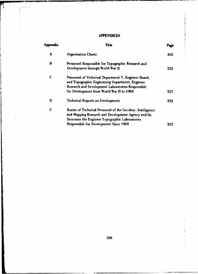
WPP
APPENDICES
Appendix Title Page
A Organization Charts 310
B Personnel Responsible for Topographic Research and Development through World War II 325
C Personnel of Technical Department V, Engineer Board, and Topographic Engineering Department, Engineer Research and Development Laboratories Responsible for Development from World War II to 1960 327
D Technical Reports on Development 333
E Roster of Technical Personnel of the Geodesy, Intelligence and Mapping Research and Development Agency and Its Successor the Engineer Topographic Laboratories Responsible for Development Since 1960 352
309

OP *wp w^ommmmmmmmmwi^mm^
APPENDIX A
ORGANIZATION CHARTS
310

wm
***
msr
nm
m^m
mm
^^m
M'^•
<LO

i ii'ljij, iNHlHl
312
II !<•-• IBtllUMt

16 Fobvuary 1946
TELHMCAI i)i»l3IOi I
din l. EVJM, j.., it. Cci., C. C. Aw.tMnt Ui'tctor
Herbert f. «fuhn, Col., C. f.
»cwiMSrwii« sfcridi Mjrw..-,i H. 'l,cr. Cil-4
*»t»icj. Urrk-Sltno«. UI-3
»onai ricrurt E*A»OI Cft.tf
kirMrd t. »tithltf, CAHl
COCLITtCMS »AM* c («1
1, COCIT . It. Col. . C. £. utitu •t Oinf
W. B S i m i c k >.«. Cunt.. C E.
•OirrlMG *»M> CM«'
*. C. Cult. rU,oc. ( fcliiUnl Chili
GlIUil G. LcrtBI, ,-jjoi
ntwurar. "'cnoi !>• ';*Cra», CAf-7
Ji~t •!. ft ft. CM-» twin Hujiui, CAf-a
s; -.0 yaic* ici-i., i..-j («a. cif- Cti'tei Si i».r.t af-s
1 rnir*ui yen..*.
SfJM»» Suit? Sr-«
i iKt.i.» M'!'"«J cfAt.-ti "uriu
I NMMSiHjrrnf >-.s CifKiCM i—J itcf'tf
, JU .. v»u.i ur-j
CtMfcAl «HUfKA CQl'IfHMr „ ciiü J. C. MCAf'f IC. I«.. C E. 1. «. •V.'v-, lit. lt., C. E. V. I. Fiftl HI. Lt., C. E.
J. E. Pool, P-o J. K r . '"•
It*. 7&i.»t«4 *. Wi; i TSU, C i.
ClEAvAK E Cf iBSTAClES tCTllA .... Csjt., C. E.
t. »1. |,|. 1;.. 0 E, t. j. 6- •• . •. IH. 1!.. C E.
v. r. C >' •••- n, il, .(., C. t.
k. •< fl,n. p.» r>. 1. I'.tf.toB P-*
tKI'-'-Eli *•'<*> I'EIOC'A'IC». A. f. »:ii MU.:I.-' *;?EN<*;I>. «A.
PWULMA rWLSCCIlCK *. J. tot. . »'li . C. E. J. Cko»>i :k, .-.. 1 •.& J. r. f, . '9
A. <C ilMut, f-4 . %• Inklrtr, r% 2 t. Brl|n. P-«
r-l 0 tnlnt-j4 &I/IB IM), C c
«HI. P['<«W.|C Br>AkCH Vr.jBl fi«:i-lh/lon. Ulio
C".el El Jo» P. Utli, Mtjof, C E.
»Mill"! äi.tr I'.-jl" P"i0»*J I. f-i A,Ik flu It', i HI CAf-J
l Eoii'M *t- tt-m* RU, C.E. »•CM«/, tr.j.nt.f,,, ,,?, y-p
»•etf.t». ft.tu.;fi w Uf-9
KtsEAwi w, r«trt;n« SIIWCII'MS 5.'. IICK
J. G. P«k. J'.. U#l., C E.
HAP tPrCviuicn stcricn ». J. 1. ». , Citt. C E. 6. P. Dt (• u. CAJ'. C. £
A, k. s.«, •-•.f.. VitJIC/. ' I; ••' f !. t l.f ) P-a
t.i..r,t,,
!»ll (I ,*-. •. >'^iff(f I:ir»«l j. .. i - , *\,i>, C. £.,
,.* >.' Ei-. Gtt. i. >. «••••••. il. II.. C. £..
E..J. ..• f. i. ^i«. H. Hi''; -I. C •., C. £..
f. r.. r,K|» «. f. Ll-'. '..Ct.. L. £.
J. I. S;M—\ i->. u.. C. E. t i, •»'!. •l. lt.. C. £.
J. .'. ivlri., .-•. u.. C. E. P. f. L-t.».. in, U,, C. I. ». P. ;;«>». I. lt. C. i.
k. (. fi;w..., ut. I'.. C. (. E. •». J" ,tw, .•!. lt.. C. '. «. C. *-:-.. «ut, lt., C. £. J. S. •••• -. .- . U.. C. £. H. C. *.«• B, <••. I'.. C E.
l.'i'i'»,, Uf-J M. P. !-:•-'. Cf»
T. 8. .'.««. CA(-, • ;-t. ar-» > •< CJf-
HfiX »•/ SKIICN * S. l.f ,f H.iof. C. f. 1
C.V ;,* i'. P-i
'«>•'/ l-Btt* P-J
*.!"• iSWAfilfE «ti C' ICAI '.icur*.
H. ' 1.1 K t,.tff » ur-« Hi >* -'tf . . Invi CAf-A
iBfl pY.t:i* iAf-j
J« ;• ;:• . He». >- v J" . i •
V! "'-'' p*< . • J U"
•• Cl» CAf-H
•• -f.» t»a »1 I 71 k rj. C. £.. art. N
r OUI'..* Kr^'T'kfl
-Oft»** £.". .J*
.•.;.iAii»E ALJ
..» MC KM .. i •• 'M-%
• I,-..-.... CAf-, . i ... - t»r-j . tu »••,. C'F-'. ,.,.....». .»(-5 «•»,*, »vi, W-j
313
iNU« ;iri»' CIIAF
^/ •
I Reproduced from W^m [_best availabl« copy, jp

I i
i !*
? 1
Ejl S>!,"Eft fcl*3 •j.-
8 32« i
L 5*1. ft} "A
\H
L i. . J
Üfcj ft'*
t-
Reproduced from best available coov.
314

mm
wm
mm
t.
tat.
, fi
w
tu
Öl
»»•.-. <
»»f
I »
-•H
l, n
ift
1 h«
ix
: c.
>
»- ».
ka
u.
«M
t
THE E
NG
INE
ER
BO
AR
D
FOR
T B
ELV
OIR
, VIR
GIN
IA
EN
GIN
EE
R
RE
SE
AR
CH
A O
EV
ELO
PM
EN
T LA
BO
RA
TOR
IES
1 Ja
mM
ry 1
961
_ia
1 na,
1

_> bl
S w > (0
i;itl 5 «I i» »aba«. «
• fSuJ
3:. $ • § S3g- S B5
i a
S * .1 1 hi
£ * W if
5 5 < a
a 2 j c
u; 1? o •• x v o i c- 0. ( '." 1
# *
\ >- I •i o: •a u
kl c »i > u »
rl
4
"XT 1* J __ X i i o It ; w ' iii 7 1
o ^~ «3 •J
£ !* Q
•3 F |w < i/>
o 0
Z _/ •J
w a in
i 2| -
&
rt - fl B1-" oi .. >- •• 3 : H u.' i ? a'• u i
o -» C
f* - « (i 1» iTi
,1. o
% II u n ' <c ' L t;_ J 1 1 1
316

mmmmmmmm^mm m* Urumm^mm
'i!Jb8<j»88Kä;?88fi£bd«8i>::i4^?''5
U* * S- - I IKK i
." *, i i«s js 5 B s s A $ •'; 5 *.. $, • •' i»a f 3
(• '3 'h 0 a 1? 0 0 8 ß H a 3 ü 0 ü 0 s 4
'>f-
1 *
! 5
'•s..)3fföff ::•< >.*-•!'.•»*;'
m.
*SJK&8 88flHi?'3"»!ifl
(r* 7 -
,= :•< ;•- $:_:
j m s-
5!
Ü- ...J
il
*!'« * 8 f I» 8 » 0 8 8 8 8 ß W'*»
A 3 -
317

i iill
iipiij
PR
aM
H^
im
mm
,L
I«l|
jlli
pi
III H
ill
£5.
O 3
u. s
. A2
.JY E
;;SJK
£IB G
SCDi
sr,
is:u
i!S£.
:a A
:JD
tu&
tiie «
SE
AR
CH
AN
D D
IVE
RS
E.«
AGEK
CT
fCRT s
araa
, mcu
v.x
(V N
ICT
uft
i i
i..
vr;.»
i«N
CO
inr»
;... i}
UC
n.V
C..
. ^
ÄtC
.'ÖA
!
ÄV
ST
NT
ÄN
T
D.4
fC7C
\
t L
',oi
1961
C
CC
Ol
• :tT
' W
B
TA
YIO
I«
1 n
c or
iL.% V
AP
I c£
Ml»
V
0
AM
i ..A
.»O
N O
ff.C
E
U.iA
f I
.AIS
O.N
Ü
'FiC
t
[a
&
LIV
INC
sTO
ft.
CH
IEF
Cl.
ITIll
1 f»
I iJ
I.'S
I
USA
SWO
,. »
'A.S
GN 0
»f.
CI
* L
T
alA
OW
LLl
CM
ifT
~x
,. .k
. v
»;i
f : c
C
lOM
ih^. c
«;:»
r.
G
vs.. C
OM
AS
»4>
T C
H.t
r
__
\J.
1 —
J?
'«
1
l '
X
liAL
HY
"£M
S
1 M
:S4
I
1—
1 : *
t P
„EC
TM
CV
C S
TiT
ifciS
j
MA
CC
IKA
MW
1
Oiv
ii.o
r.
•
!
£»V
.S.G
* '
I B
ivs,
«5fc
I «
U
• K
. C
MII
F
; * I
DL
u.l
V.
AS
M C
MIlf
M
C
WiE
ll«.»
. C
li.t
f C
t.
MA
.%o«
. A
J-1
CM
iLF
1F
A M
C FA
BIA
N!»
. II
I.t»
\S w
C
.I»M
i.\,
AVVT
I S
I»»
K:
J/E
CxA
f.:.
.', *
0^
".C
i
j
AU
IO'J
A:
c v
-i'P
iNü
l
BH
A-N
CH
'
I O
AT A H
iOU
CT.
O.N 6
3AN
CN
I
""""
"^ D
. [
HO
WEL
L 10
UI
,
u ITS
? A
.\0 E
VALU
ATI
ON
of
iAN
Cr.
S. n
tCU
IM
I«
Kt&
*.\
i^ r
jo.'.
tr.c
„ C
[W£
IOP
V.S
;S
aaA
SLH
j c
e »
uii
mio
JIM
I G
EO
OtT
'".
4 A
S.-a
ON
OM
.l IS
OA
NC
H
; S
ui»v
cvi.N
ü *>
$r£
.vs
B
RA
NC
H
'
I TES
T 4 E
VAC
UA
TIO
N B
RA
NC
H i
~]l J
. DU
«», i
n x
iis
;
HC
PS
O0l
;CT;
ON ö
öA
NC
M
; S
EP
SO
OtiC
F C
V
VLK
S
CA
»ro * O
li.'iA
r B
RA
NC
H
j
j W
H C
AH
A
Ml*
«!
JUS
T &
EkA
lL-A
;.GN f
eWA
SCrt
i
I V
G- C
eCfc
ELF.
it 2»;)
'

(• n
il»,,
in ii
^
•^^
•^«
•^^
EX
EC
UT
IVE
OF
FIC
E
-UM
UM
( S
RIC
TW
1 , ,
^L
D6*i
. S
YS
TE
M
L
l» •
• •»
««•
f • »
^*"
kit
I
us
*r
LIA
ISO
N
OFF
ICE
US
Id
«
EN
GM
EE
R
GE
OD
ES
Y.
MTE
LLIG
EN
CE
«MO M
AP
PIN
G
RE
SE
AR
CH A
NO
OE
VtL
OF
ME
NT A
SO
CY
FO
RT
RE
IVO
N.
V*
AD
VIS
OR
Y S
TA
FF
SC
IEN
TIF
IC
AD
VIS
OR
ta
UM
ITla
«•»
TEC
HN
ICA
L A
DV
ISO
R
DIR
EC
TOR
TA
CTI
CA
L S
YS
TE
M
US
AS
RD
L U
AIS
ON
OFF
ICE
INT
IL L
ICE
NC
E
XV
WO
N
STR
ATE
GIC S
YS
TEM
S
OW
ISK
JI
N «
. •«
• a»
«••
<••
a- v
.
iwariM
iaw
l a-
i. I «
pi'«
I»
«-U
ISA
.,,
mo
To
ou
iMM
rriiY
M
V1S
KW
w>
ii,n
,<a
Mi
l ei-
ii u
m
\ ••
—tr
tw 1
91
SU
RV
EY
ING
AM
O G
EOD
ESY
av»O
N
»••»•
•• «
*•»
••>
««•
tp«l
•*•*
) i*
*i >
-* i
n
1 Ju
ly 1
962

•HM
»W
JP
JI
ü. S
. A
RM
Y
EN
GIN
EE
R G
EO
DE
SY I
NT
ELL
IGE
NC
E
A
ND
MA
PP
ING
R
ES
EA
RC
H
AN
D
DE
VE
LO
PM
EN
T
AG
EN
CY
FO
RT
BE
LVO
IR,
VIR
GM
A
L A
DV
ISO
RY
ST
AF
F
[MC
iift
Hc
AD
VIS
OR
I
jCM
MM S
A
_
I
TE
CH
MC
AL
A
DV
ISO
R
J T
P
EN
MN
6T
0N
E
N6«M
-TA
6H
30
DW
EC
TO
R
LI
MIL
, C
OL
ON
EL
. C
E
DE
PU
TY
O
IAE
CT
OR
M
V
JON
AH
. LT
CO
LO
NE
L. C
E
EX
EC
UT
IVE
OF
FIC
E
0 .
*. H
AN
DB
EA
6.
EK
. O
. W
. *
CO
OK
, A
SS
T
EX 0
. a H
AU
CH
tK
ä
«v
«W
Mr-
»M
-..„
..-
._X
_J
OW
EC
TO
R
GL
OB
AL
SY
ST
EM
S
1 G ft
LO
RE
NZ
L
EM
MM
-9S
«H
OI
O
PH
OT
OW
UM
MT
TW
Y
W V
ISIO
N
K.
-. D
UD
LE
Y,
«CT
G.
CH
EF
j J.
* H
AL
MW
OK
, AC
T»
AS
ST C
K
I
j M
TE
LL
tKH
CC
j.
OM
SK
*.
1
J. E
. G
»_U
S.J
R ,
CH
KF
|
T W
. T
CD
EK
EN
, .NC
T. A
SS
T C
HE
F
•22
44
ME
CH
AN
ICS tt O
PT
ICS
•
RA
NC
H
JL
W H
AL
BR
OO
K.C
HE
F 6
2148'
AU
TO
MA
TIC
M
AP
PIN
G
•R
AN
CH
E.R O
SM
ET
ER
.CH
EF
6
3110
,
DA
TA
RE
DU
CT
ION
•
RA
NC
H
_
0. E
. HO
WE
LL
. CH
EF
6
I25
0
EL
EC
TR
ON
ICS «
EM
NN
EE
RM
1;
1 B
RA
NC
M
j
|_S
. FR
ES
SE
R.
CH
EF
«|W
j
AP
PR
OV
ED
:
LL
OV
O
L- «
AL
L.
CO
LO
NE
L.
CE
SY
ST
EM
S
J
,
MU
NC
H
j
_tt
&S
CH
EP
S.«
CT
ttC
H &
ZT
*_.
PR
OC
UC
T3
MU
NC
H
K.R
.KO
TH
E.A
CT
6. C
H«
l2?
6j
DA
TA
FR
OC
ES
S
MU
NC
H
T*T
CD
EK
EN
,»C
TG
CH
«S
2T
4
«E
Od
frA
PH
C
j
BR
AN
CH
, i
j R
.AL
EE
STM
A, A
CT
6.C
R6I
2TS j
RE
SE
AR
CH •
AN
AL
YS
IS
DIV
ISIO
N
M V
. JO
KA
H.L
T C
OL
.CE
. AC
TG C
H.
EN
MM
-RA
•1
113
DIR
EC
TO
R
TA
CT
ICA
L
SY
ST
EM
S
R.
G-H
CK
SO
N
EN
DD
M-T
S
«II
OS
GR
AP
HIC
S
MV
WO
N
S W
G
WS
ON
. C
HE
F
* H
CA
RR
, A
SS
T.
CH
EF
tEN
G«M
-«R
_ ___
•***!
I R
EP
RO
DU
CT
ION
B
RA
NC
H
F
C
MY
ER
S.
CH
EF
62
23
9
r ~
C
AR
TO •
DN
RL
AY
!
BR
AN
CH
I_H C
. BA
BC
OC
K.C
HE
F
«3
22
4
FIE
LD
OF
FIC
E
WtP
AF
O, O
HO
as-f
iii]
E
» 23
125
] R
.6.L
MN
6S
T0
N.C
H
ST
RA
TE
8K
SY
ST
EM
S
D
IVIS
ION
__
H O
. M
cCO
MA
S. C
HE
F
EN
SO
M-S
S
SU
R-»
TY
M« tt D
CO
OE
SY
O
fVU
RO
N
C
R
MA
NO
R.
CH
EF
C
. E
. W
ES
TE
RN
**,
AS
ST.
CH
EF
EN
MM
-S«
«32-*
«
TO
PO
GR
AP
HC
S
YS
TE
MS
n
BR
AN
CH
F L T
RE
AD
WE
LL
.CM
6
32
20
AO
VA
NC
EO
SY
ST
EM
S
BR
AN
CH
[ K
. T. Y
OR
tTO
MO
.CH
EF
6
.153
SP
EC
IAL
PR
OJE
CT
S
BR
AN
CH
E.
P. G
RIF
F«
, ~
HF
F
6
21
42
j A
DV
AN
CE
D
«E
OO
ET
K
[. D
EV
EL
OP
ME
NT
BR
AN
CH
I J. G
. A
RH
ST
EA
D.C
H
SH
OO
«E
OO
ET
K •
AS
TR
ON
OM
*:
BR
AN
CH
M
CR
OW
EL
L.C
HE
F
6
21
06
1
|
S
UR
VE
YW
S
SY
ST
EM
S
BR
AN
CH
0 W
B
OW
KE
R.C
HE
F
62246
TE
ST
B E
VA
LU
AT
ION
B
RA
NC
H
J J
OU
RK
M, C
HE
F
O
ST
It

S. A
RMY
ENG
INEE
R GE
ODES
Y IN
TELL
IGEN
CE A
ND M
APPI
NG R
ESEA
RCH
AND
DEVE
LOPM
ENT
AGEN
CY
FORT
BEI
VOIR
VI
RGIN
IA
CO
MM
AN
DIN
G O
FF
ICE
«
DE
PU
TY
C
OM
MA
ND
ING
OF
FIC
E*
•A.V
. JO
NA
H.
LT
C
OL
ON
EL
C
I w
e«
«»?
TE
CH
NIC
AL
D
IRE
CT
OR
T »fM
MH
CT
ON
, A
CT
C M
IEC
TO
I
FIE
LD
OF
FIC
E
W.P
AF
B.
OM
C
t.C
. L
IVH
HM
TtJ
H,
CH
IEF
•F
C
L^
SM
J,
211»
PL
AN
* A
ND P
RO
GR
AM
S
OF
FK
E
NO
VtlM
KR 1
965
OF
FIC
E O
F
AD
MIN
IST
RA
TIV
E S
ER
VIC
ES
D.I
HA
MO
OE
IC I"
O
. W
.I.
CO
OK
. A
MT
. C
I. 0
E
M6C
AV
AS
__
A
tW
PE
RS
ON
NE
L A
NO
A
DM
INIS
TR
AT
ION M
AN
CH
• I
CO
M.
CH
4IF
LO
GIS
TIC
AL A
ND
T
EC
HN
ICA
L S
VC B
RA
NC
H
PR
OC
UR
EM
EN
T
BR
AN
CH
RE
SE
AR
CH
L
IBR
AR
Y
LIM
A«
AH V
AC
AN
T
OS
ts
3
RE
SE
AR
CH IN
ST
ITU
TE
f
OR G
EO
DE
TIC
SC
KH
CE
S
M.J
. M
cn
ui
AC
T«
, m
itc
ro
*
EM
CC
ull
4M
7*
DE
VeU
)PM
Ofr
LA
MO
«A
TO
RIt
Tre
r M
AP
PIN
G A
GE
OD
ET
IC S
TS
TE
MS
C-6
. L
OIf
MZ
. I.C
H
ICK
tOH
.
INC
Ck
vM
.
AC
TC
DII
ICT
O*
AC
T6. A
UO
C,
Oil
. «M
OI.
am
PHO
TO
CR
AM
ME
TR
Y
AH
O C
AR
TO
GR
APH
Y
O.C
. O
OC
OIH
MI.
TA
SK A
RIA
IN
.
«A
H
TE
CH
NIC
AL P
LA
NS A
ND
S
YS
TE
MS A
NA
LY
Sn D
IVIS
ION
HO
U
.CO
MA
V C
HII
F
EN
CC
At-
Tf
<
GE
OO
ET
IC S
UR
VE
YIN
G
A G
EO
PH
YS
ICS
CJA I
OO
AN
O.
TA
1» A
RE
A L
EA
DE
R
SY
ST
EM
S T
EC
HN
OL
OG
Y
AM
D
AD
VA
NC
ED P
LA
NN
ING B
RA
NC
H
CE
LE
ST
IAL
G
EO
DE
SY
P
RO
GR
AM
MA
NA
GE
ME
NT
A
HO
EV
AL
UA
TIO
N B
RA
NC
H
«.?
• Y
Oli
TO
MO
. C
Mf F
SP
EC
IAL P
RO
JE
CT
S
BR
AN
CH
C.P
. C
RIF
FM
, C
HIE
F
LA
. C
AM
OII
I0.
TA
SK A
SIA
LlA
DE
*
SY
ST
EM
S
AN
AL
YS
IS
BR
AN
CH
CH
IEF V
AC
AN
T
SU
RV
EY
ING
AH
O
GE
OD
ES
Y D
IVIS
ION
C.I
. H
AN
OI.
C
.f •
WE
ST
IIN
AH
. IH
CC
M-1
C
CH
IEF
A
MT C
HII
F
AD
VA
NC
ED G
EO
DE
TIC
D
EV
EL
OP
ME
NT B
RA
NC
H
GE
OD
ET
IC A
ND
A
ST
RO
NO
MIC
BR
AN
CH
•A.C
IOV
CL
L.
CH
IIF
SU
RV
EY
ING S
YS
TE
MS
B
RA
NC
H
O.K
. IO
VK
CI.
C
HIE
F
GE
OG
RA
PH
IC
INT
EL
LIG
EN
CE D
IVIS
ION
i.e. cat«
. ;•
.. C
HIE
F T
.HT
HO
CK
M.
AC
T« A
MT a
«*
E
HC
GM
-U
4JA
44
SY
ST
EM
S
BR
AN
CH
PR
OD
UC
TS
B
RA
NC
H
GE
OG
RA
PH
Y
BR
AN
CH
DA
TA P
RO
CE
SS
ING
B
RA
NC
H
T.H
. T
1ID
CK
EH
A
CT
C C
HIIF
GR
AP
HIC
S A
ND
D
ISP
LA
Y D
IVIS
ION
LW
CilK
M.
CH
IIF
M
M.
CA
R«.
AM
T.
CN
-IF
IH
CC
AkC
O
*MM
RE
PR
OD
UC
TIO
N
BR
AH
CH
F.C
. N
YE
IS,
CH
IEF
CA
RT
OG
RA
PH
IC A
ND
D
ISP
LA
Y B
RA
NC
H
H.C
. •A
MC
OC
K,
CH
IEF
PH
OT
OC
RA
MM
ET
RY
AN
D
MA
PP
ING
DIV
ISIO
N
I.P
. II
TM
,
C
HIE
F
I.E
. M
KH
.ET
. A
MT C
HIIF
IH
CU
A.P
H
.MA
»
ME
CH
AN
ICS A
ND
O
PT
ICS B
RA
NC
H
IM». H
AL
IIO
OC
. C
HIIF
AU
TO
MA
TIC
M
AP
PIN
G B
RA
NC
H
II »
EM
ET
EI.
CH
IEF
DA
TA R
ED
UC
TIO
N
BR
AN
CH
O.E
. H
O*E
LL
C
HII
F
EL
EC
TR
ON
ICS A
ND
E
NG
INE
ER
ING B
RA
NC
H
1 F
UM
E*. C
HIE
F
AF
FIO
VtO
LL
OT
O L
. »A
LL
. C
OL
OH
IL.
CI
CO
OID
1HA
TIO
M

MJ
s
-I OJ
o o
5 s
si if 2 >
s£ o
£2
(9 AC UJ UJ * 3 UJ > S s < erf
%
\i
w
it
58
M
M
if
SI
li
si
«i!
Iv£
ill; ! » U
•I ilil
it
TTZ\ i ' i
h*
I!
if.
pi
II u i!
M il
ii
I!
is M
• J
H
N
ti
»
*!
ii
!!
•W ii 8*
322

mm
wm
wm
x m
m
•m*
m*
mm
mm
m
US.
ARM
Y EN
GINE
ER T
OPOG
RAPH
IC L
ABOR
ATOR
IES,
FT. B
aVO
ffi, V
IRGI
NIA
2206
0
4*3
te
^
*cm
*TrK
.\mm
aa
itm
mtn
mtt
am
-Eoa
ZmO
P
Jü:
.JE
fi
•uu
ftau
Mm
vn
-Eli
""
U'
1* 0
HO
KM
waoi
•K
MA
MC
S a
nrr
o
_
_ft
fBl
-SO
.
-E5-
TT
BB
T
AJB
_
fcfld
SC
-kT
H"
UH
1L
AU
TMH
171B
Dtf
W
PW
MIT
OU
TIO
CM
rro
oM
nn
MT
MU
Ti«
UU
AL
AW
I
AM
tTO
CA
t M
KM
CH
re —
•>
•*«•
TtC
MM
CM
.IT*f
f
i HM
fcl t
JO—
I
f74
X
T
nZ
5S
5f*
mE
»n
»r
rtm
•J
HH
-
tuM
Cn
NC
AC
taac
w
MH
KX
-CG
OiT
IC
wu
Kn
tUC
TM
MC
MN
MM
c •
niM
M
HU
f
StM
tnC
MT
I1U
TI
•W
BC
T
i •
MM
U
«
•ifw
HQ
*—a r
a...«
r">/
' ts
ru.T
?fi
.,. M
r>/ii^
C
j0H
H » O
UM
LT
.41.
CO
L. 4

U.S.
ARM
Y EN
GINE
ER
TOPO
GRAP
HIC
LABO
RATO
RIES
, FT. B
ELVO
IR,
VIRG
INIA 2
2060
SO
W'«
UV
ISM
•K
:
U
IOO
OI
•'
wii v*
•U
UU
WN
T
SERV
CES
off«
•»C
\ «<
N
>«
HW
«M
l
«0Y
1S
MY
P
ME
lS
I
10M
OS
CO
MN
MO
MG
O
llx
.lt
DE
PU
TY
CO
MM
M'.R
1EC
NM
KM
DH
ttC
tOH
mn
is
nc.x
HS
OC
UK
nom
cM.
DU
KC
TM
wt«
lie w
in
eiu
i
AD
MIN
ISTR
ATI
VE
STAF
F nocu
Mw
m
OFFI
CE
'*<
m
-. K
H
.<M
NK
«n
•WJ
RE
SE
UC
H
MS
TIT
Un
m
o c
gco
Mo
•«•1
«i H
IHI
10N
HR
MC
(MU
WE
MIS O
MS
K»
CX
I
«K
l H
»m
»uto
mTE
D m
m« H
YIS
IQM
• •
«£
•*
CM
ilE
CIM
UM
ME
TM
C
SY
ST
EM
S
MM
C*
• »
•wn
aa
(W
"tU
lit H
IM
Hi'.'
ER
CM
CR
MC
MM
CM
!>«>
l«t»
l II« >
u«
«M
M
MEC
MM
KS
t
OTT
CS
MM
CH
ow
i
«1
0
OfE
«
JM
jgji-
Wiy
jBI
*TB
KS
'va
< K
M)
CM
' 5U
JIU
US
SC
ltRTl
fiC I
TEC
MR
HVU
IW
OM
MT
IMI
CIR
KR
•
(
UIM
l«1
l S
t i
«MM
TECH
NICA
L ST
AFF
•IM
S t
OK
tlU
NM
S
OFF
ICE
I •
«C
IWlM
iO«
'T'l
n
HJ
K
CO
MP
UTE
R
SC
XN
CE
S U
UN
MT
Mv
•PR
lKJI
TK
MS
WH
S**
0 1
-M
il.
CM
I
«MC
MV
MC
ED
TE
CM
MO
EW
f D
iYiS
ftM
'«'1
Ci» I
JHIO
PH
OT
OG
RA
PH
IC I
NT
ER
PR
EM
1I0
N
R
ISE
«O
CH
.OlV
ISjO
" ..
_
I I
I M
M
Ml
»in
»i
neo
n
wi
.•'»
7M
.
C«C
R»P
H>
C
SC
IEN
CE
S
DIV
1SH
M
i»
• *
.0'«
für, C
- H
JX
,
•Urü
MiT
ED
CA
RTO
GR
AP
HY
MM
CH
'•£'. I«
U
'OC
MO
W»
«« «
mo
no
« M
AMC
M
>
AUTO
RUTE
O C
OM
PXAT«
M
AR
CH
c
»4-r
« c
xi
•tOG
unw
wto
nu'iM
S
YS
TE
MS
MA
NC
H
surv
tnw t
MO
DES
T or
eis*
*
S«C
Ul P
WM
CTS
M
AM
Ol_
II
M
CI
«U
GR
AR
WC
S
SC
KM
CtS
MM
CM
1 '-
••(•.
CM
)
•f
i
'ip m
a
«m
»i»
» «M
l U
»W
S1
\ V
f«»
r«it
H
iM»
KH
IO I
I 'e
l **tl
•••
•II
IMK
WU
•m
n»
m
ime«'-
UN
imam
i IH
HIM
'IH
M
II 1
10
M*W
!"•
•. D
M »
»II
I «H
III.«I;
H«O
. I
WIK
W •>
'•
nc
'lll
PN
W.
«IH
M«» I
IW
1>
'•n 1
1
«•«
•:
••>
• il'
. «m
i
Isrm
CE
OD
ET
lC
MM
CH
j
• C
MU
lii
'K*. S
t» »
'100
«I
V
1
EU
C1M
MC S
UM
TN
C
SYST
tMS
MM
CM
c
• •»•«
«
mn <
u lim
O
NI
CEO
OET
* S
ATEU
ITE
|
SYST
EMS
MM
CM
{ S
M».:
|«D
'«'I
it
c
|1J0
0 «.
r «
•*'
|
«PP
M H
O j
li-i
.i*.
--'-
^ j,
w
J •
IS»»II
» co
i ci
IH
ERTl
Al
SUR
VEY»
* M
MC
M

rrw^t^^mnrw
APPENDIX B
PERSONNEL RESPONSIBLE FOR TOPOGRAPHIC RESEARCH AND DEVELOPMENT THROUGH WORLD WAR H
Captain R. R. Arnold, Secretary, Engineer Board
Major James W. Bagley, CO, Engineer Detachment
Joseph H. Bakewell, Mapping Branch, Engineer Board
Major Harold E. Beaty, Engineer Detachment
Fred H. Bloom, Mapping Branch, Engineer Board
Michael H. Bruno, Chief, Research Section, Army Map Service
John B. Canada, Mapping Branch, Engineer Board
CWO J. C. Cosby, Mapping Branch, Engineer Board
Major William C. Cude, Director, Technical Division V, Engineer Board
Major Frederick J. Dau, Chief, Mapping Branch, Engineer Board
Charles P. Deibel, Lithographer, Army Map Service
Captain George P. DeRosa, Photo and Lithographic Branch, Engineer Board
Lewis A. Dickerson, Chief, Photogrammetric Division, Army Map Service
Douglas Dingwall, Aerial Phot 0raphic Branch. Engineer Board
F. W. C. French, Topographic Branch, Office, Chief of Engineers
Joseph H. Fuller, Mapping Branch, Engineer Board
Henry H. Furman, Mapping Branch, Engineer Board
George C. Garraway, Consulting Engineer, Engineer Board
Charles M. G 'more, Mapping Branch, Engineer Board
Barnard R. Halpern, Engineer, Mapping Branch, Engineer Board
Colonel Bruce C. Hill, CO, Engineer Detachment
Captain Jack Kronenburg, Army Map Service
325
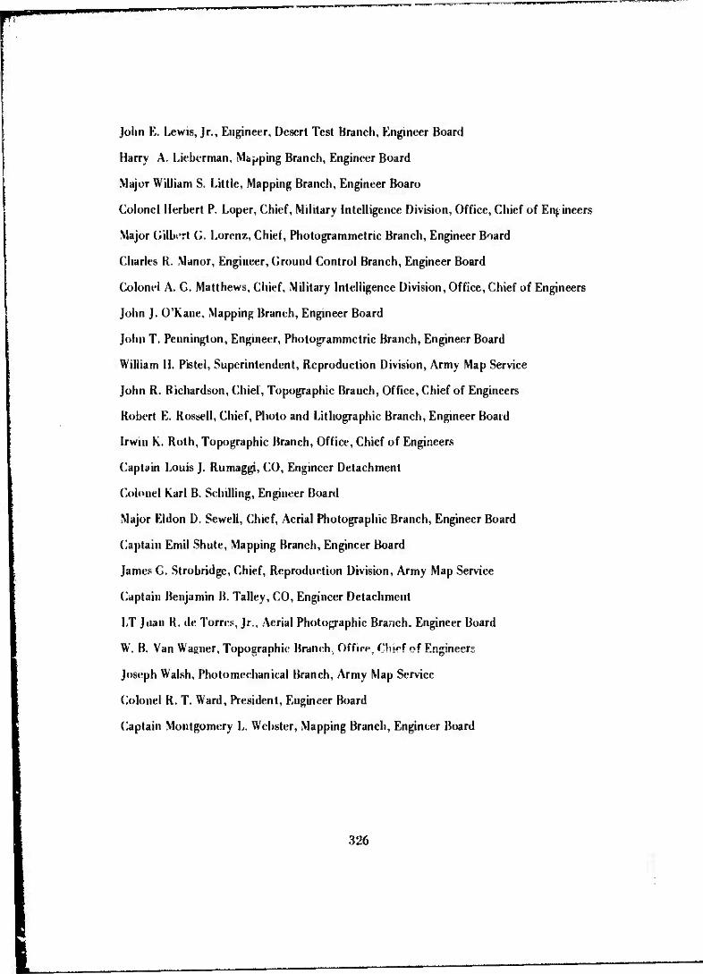
John E. Lewis, Jr., Engineer, Desert Test Branch, Engineer Board
Harry A. Lieberman, Mapping Branch, Engineer Board
Major William S. Little, Mapping Branch, Engineer Boaru
Colonel Herbert P. Loper, Chief, Military Intelligence Division, Office, Chief of Engineers
Major Gilbert G. Lorenz, Chief, Photogrammetric Branch, Engineer Board
Charles R. Manor, Engineer, Ground Control Branch, Engineer Board
Colonel A. G. Matthews, Chief, Military Intelligence Division, Office, Chief of Engineers
John J. O'Kane, Mapping Branch, Engineer Board
John T. Pennington, Engineer, Photogrammetric Branch, Engineer Board
William H. Pistel, Superintendent, Reproduction Division, Army Map Service
John R. Richardson, Chief, Topographic Branch, Office, Chief of Engineers
Robert E. Rossell, Chief, Photo and Lithographic Branch, Engineer Board
Irwin K. Roth, Topographic Branch, Office, Chief of Engineers
Captain Louis J. Rumaggi, CO, Engineer Detachment
Colonel Karl B. Schilling, Engineer Board
Major Eldon D. Sewell, Chief, Aerial Photographic Branch, Engineer Board
Captain Emii Shute, Mapping Branch, Engineer Board
James G. Strobridge, Chief, Reproduction Division, Army Map Service
Captain Benjamin B. Talley, CO, Engineer Detachment
LT Juan R. de Torres, Jr., Aerial Photo^aphic Branch. Engineer Board
W. B. Van Wagner, Topographic Branch. Office, Chief of Engineers
Joseph Walsh, Photomechanical Branch, Army Map Service
Colonel R. T. Ward, President, Engineer Board
Captain Montgomery L. Webster, Mapping Branch, Engineer Board
326

i nanmn 'wi"«' MM.«"iinii»..iiiPi«i!i.»T«j.iw».B.(n. .».»«..in««. •.-, m ,, .««pi ipi
APPENDIX C
PERSONNEL OF TECHNICAL DEPARTMENT V, ENGINEER BOARD, AND TOPOGRAPHIC ENGINEERING DEPARTMENT, ENGINEER RESEARCH
AND DEVELOPMENT LABORATORIES RESPONSIBLE FOR DEVELOPMENT FROM WORLD WAR D TO 1960
Leonard W. Andrukoms, Surveying and Geodesy Branch
Abraham Anson, Project Engineer, Map Compilation Branch
John G. Armistead, Project Engineer, Electronic Survey Section, Surveying Branch
Sidney Augarten, Project Engineer, Map Reproduction Branch
Lawrence F. Ayers, Project Engineer, Topographic Systems Branch
Homer C. Babcock, Project Engineer, Topographic Systems Branch
Clyde E. Berndsen, Project Engineer, Aerial Photographic Branch
Sidney H. Birdseye, Consultant, Surveying Branch
Bela J. Bodner, Chief, Research Section, Topographic Systems Branch
Oscar W. Bowker, Chief, Survey Test Section; Chief, Air and Ground Techniques Section
Berthold Brenner, Map Reprodu iion Branch
William H. Carr, Project Engineer, Cartography Section, Map Compilation Branch
Lt. Alfred R. Castorina, Map Reproduction Branch
Eugene J. Chiliemi, Project Engineer, Photo and Litno Branch
CWO W. C. Chipka, Chief, Survey Studies Section
CWO J. Chomjack, Chief, Experimental Photo Section, Photogram metric Branch
William j. Chudej, Project Engineer, Surveying Branch
W. R. C.arke, Chief, Reproduction Service Section; Chief, Technical Photo Branch; Chief, Technical Photo Laboratory
Barnard A. Claveloux, Chief, Data Reduction Section, Map Compilation Branch
John G. Collins, General Engineer, Map Compilation Branch
327

hl] •••ll> .III! Ill|>
John G. Colwell, M~p Reproduction Branch
CWO J. C. Cosby, Surveying Branch
Clifford J. Crandall, Project Engineer, Map Compilation Branch
Meh in Crowell, Project Engineer, Surveying and Geodesy Branch
William C. Cude, Director, Technical Division V, Engineer Board; Chief, Topographic Engineering Department, Engineer Research and Development Laboratories
WO David W. Davia, Map Compilation Branch
W. W. Davis, Chief, Reproduction Studies Section, Map Reproduction Branch
Quinty C. DeAngelis, Project Engineer, Map Compilation Branch
E. R. DeMcter, Chief, Analytical and Automatic Mapping Section, Map Compilation Branch
George P. DeRosa, Chief, Mobile Reproduction Section, Photo-Litho Branch
WO AM DeYoe, Chief, Special Studies Section, Ground Control Branch
Paul W. Dorst, Consultant, Map Reproduction Branch
Robert E. Dudley, Chief, Phott mapping Section; Chief, Applications Engineering Sec- tion, Map Compilation Branch
John J. Durkin, Chief, Applications Engineering Section, Surveying and Geodesy Branch
Randall D. Esten, Chief, Map Compilation Techniques Section; Chief. Analytical and Automatic Mapping Section; Assistant Chief, Map Compilation Branch
Arthur II. Faulds, Project Engineer, Photogrammetry Branch
Theodore L. Fick, Project Engineer, Map Compilation Branch
Carl R. Friberg, Jr., Project Engineer, Surveying and Geodesy Branch
Seymour J. Friedman, Chief, Photogrammetry Section, Map Compilation Branch
Ernest E. Gallegos, ProjeH Engineer, Survey Equipment Section,Surveying Branch
Francisco F. Garcia, Project Engineer, Map Compilation Branch
Von G. x eckeler, Jr., Chief, Equipment Analysis Section, Map Reproduction Branch; Chief, Applications Engineering Section, Topographic Systems Branch
Stephen \V. Gibson, Chief, Photo-Litho Section, Chief, Research Section, Map Repro- duction Section, Topographic Systems Branch
328

•WH—mmpiui.» ii H w—F i n.UJi.niM»1-1111."1"1 " '• "
James E. Gillis, Jr., Research Section, Topographic Systems Branch
Eugene P. Griffin, Project Engineer, Photogrammetry Section, Map Compilation Branch
J. Wiley Halbrook, Chief, Stereoscopic Equipment Section; Chief, Photomapping Section
Jacob M. Halsey, Project Engineer, Photogrammetry Section, Map Compilation Branch
Donald R. Handberg, Administrative Assistant, Topographic Engineering Department
CWO George S. Hanlen, Map Compilation Branch
Jean A. Hardesty, Mathematician, Map Compilation Branch
Rolland R. Hardy, Project Engineer, Surveying Branch
Thomas J. Hcpler, Equipment Special^*, Map Reproduction Branch
Robbins G. Hickson, Assistant Chief, Topographic Engineering Department
Alan R. Holland, Project Engineer, Surveying and Geodesy Branch
Hobbs H. Horak, Project Engineer, Map Reproduction Branch
Merle L Horton, Project Engineer, Map Reproduction Branch
Dale E. Unwell, Chief, Data Reduction Section, Map Compilation Branch
George M. Hlemszky, Photographer, Photogrammetry Section
Ivan R. Jarrett, Project Engineer, Photogrammetry Section
Quentin S. Johnson, Chief, Cartography Section, Map Reproduction Branch
CWO P. II. Kasten, Map Reproduction Branch
Ronald L Keener, Map Reproduction Branch
J. H. Kelly, Jr., Chief, Reproduction Studies Section, Photo-Utho Branch
Ray A. Kelsey, Project Engineer, Photogrammetric Branch
Clarence W. Kitchens, Assistant Chief, Survey Test Section
William Klein, Project Engineer, Map Compilation Branch
Wilhelm Krieger. Consultant, Map Reproduction Branch
Earl R. I/Abbc, Map Reproduction Branch
R.P.E. Laschobcr, Map Compilation Branch
Charles C. Lane, Photogrammetric Branch
329
1
Robert G. Livingston, Chief, Aerial Photographic Branch
Major Willian J. Locke, Chief, Photomapping Section, Photogrammetric Branch
Gilbert G. Lorenz, Chief, Photogrammetric Branch, Technical Division V; Chief, Map Compilation Branch, Topographic Engineering Department
Robert P. Macchia, Project Engineer, Map Compilation Techniques Section, Map Compi- lation Branch
Silas A. Maddox, Project Engineer, Development Section, Map Reproduction Branch
William C. Mahoney, Project Engineer, Photogrammetric Branch
Armando Mancini, Mathematician Surveying and Geodesy Branch
Charles R. Manor, Chief, Surveying and Field Astronomy Section, Ground Control Branch; Chief, Surveying and Field Astronomy Section, Surveying Branch
Ralph Marzocco, Chemist, Map Reproduction Branch
Robert L. Matos, Project Engineer, Map Compilation Branch
Major Walter R. Mazetis, Military Assistant, Topographic Engineering Department
John D. Mayer, Project Engineer, Topographic Systems Branch
Howard 0. McComas, Chief, Cartography Section, Map Compilation Branch; Chief, Special Mapping Techniques Section, Map Compilation Branch; Chief, Systems Analysis Section, Topographic Systems Branch
Frank A. McFarland, Chief, Mobile Reproduction Section, Map Reproduction Branch; Chief, Reproduction Equipment Section, Map Reproduction Branch; Assistant Chief, Topographic Systems Branch
Ransford P. McGregor, Chief, Survey Studies Section, Surveying Branch; Chief, Planning and Evaluation Group, Topographic Engineering Department
G. B. I. Miller, Chief, Reproduction Studies Section, Map Reproduction Branch
Frederick C. Myers, Piujeci Engineer, Research Section, Map Reproduction Branch
Steven R. Nagy, Project Engineer, Surveying and Geodesy Branch
CWO A. Nelson, Chief, Special Studies .Section, Photo-Litho Branch
John T. Pennington. Chief, Special Studies Section, Photogrammetric Branch; Chief. Photogrammetric Studies Section, Photogrammetric Branch; Chief, Map Reproduction Branch, Topographic Engineering Department;Chief, Topographic Systems Branch, Topographic Engineering Department
330

IWU..II.HIHII»- •WIMI.W-K|.!
Sidney Presser, Project Engineer, Map Compilation Branch
LTC H. E. Rice, Military Assistant, Topographic Engineering Department
Robert M. Rawls, Project Engineer, Surveying Branch
Maurits Roos, Project Engineer, Map Compilation Branch
George H. Rosen field, Map Compilation Techniques Section, Map Compilation Branch
Robert E. Rossell, Chief, Photo-Litho Branch, Technical Department V; Chief, Map Reproduction Branch, Topographic Engineering Department
Joseph P. Rostron, Project Engineer, Map Compilation Branch
Walter P. Scales, Chief, Geodetic and Astronomic Section, Surveying and Geodesy Branch
Bernard B. Scheps, Cartographer, Topographic Systems Branch
George P. Schreiber, General Engineer, Topographic Engineering Department
Günther Schwarz, Photographer, Map Compilation Branch
Eldon D. Sewell, Chief, Aerial Photographic Branch, Topographic Engineering Department
Melvin C. Shetler, Chief, Ground Control Branch, Technical Department V; Chief, Sur- veying Branch, Topographic Engineering Department; Chief, Surveying and Geodesy Branch, Topographic Engineering Department
Guy II. Stockwell, Lithographic Technician, Map Reproduction Branch
Donald Snyder, Map Reproduction Branch
Theodore W. Tiedeken, Project Engineer, Map Compilation Branch
Frank L. Trcadwe.il, Project Engineer, Map Compilation Techniques Section, Map Com- pilation Branch; Liaison Engineer, Signal Research and Development Laboratories
George P. Tyson, Chief, Reproduction Service Section, Photo-Litho Branch
M/Sgt Alvin H. Vollmer. Map Compilation Branch
Alfred J. Watson, Chief, Photornapping Section, Map Compilation Branch
C. E. Westerman, Chief, Electronic Survey Section, Surveying and Geodesy Branch
George E. Whiting, Project Engineer, Aerial Photographic Branch; Project Engineer. Map Compilation Techniques Section, Map Compilation Branch
Archer M. Wilson, Chief, Shoran Section, Photogram metric Branch
Harry W. Woo, Project Engineer, Photogrammetric Branch
331

••IKUail.liMiillKiWWf^'
Marshall S. Wright, Jr., Project Engineer, Photogrammetric Branch
Kent T. Yoritomo, Pioject Engineer, Map Compilation Branch
332

mmimiwi
APPENDIX D
TECHNICAL REPORTS ON DEVELOPMENT
ENGINEER BOARD REPORTS
EB REPORT 501, Test of Stadia Traverse for Field Artillery, by Thomas North, 8 July 1937
EB REPORT 505, Overlay Paper, by R. R. Arnold, 6 August 1937
EB REPORT 506, Portable Stereoscope, by R. R. Arnold, 7 August 1937
EB REPORT 509, Photographic Equipment for Engineer Troops, by R. R. Arnold, 24 September 1937
EB REPORT 510, Map Reproduction Equipment, by R. R. Arnold, 6 October 1937
EB REPORT 521, Aerial Photographs for Preparation of Military Maps, by R. R. Arnold, 10 February 1938
EB REPORT 531, Organization and Equipment of Topographic Battalions, by R. R. Arnold, 18 April 1938
EB REPORT 544, Report on Test of Fire Control Data Sheet, Fort Sill, Oklahoma, 1937, by Thomas North, 10 August 1938
EB REPORT 565, Map Reproduction Equipment, by R. R. Arnold, 17 February 1939
KB REPORT 576, Aerial Photography Reading, by R. R. Arnold, 16 June 1939
EB REPORT 583, Corps Mapping Unit, by R. R. Arnold, 27 September 1939
EB REPORT 589, General Doctrine for Mapping in Enemy Territory, by R. R Arnold, 17 January 1940
EB REPORT 591, Map Reproduction Equipment, by R. R. Arnold, 28 June 1940
EB REPORT 599, General Doctrine for Mapping in Enemy Territory, by R. C. Crawford, il December 1940
EB REPORT 663, Improvement of the Battle Map, by Gilbert G. Lorenz, 10 July 1942
KB REPORT 664, Military Mapping From Tri-Metrogon Aerial Photography, by Lewis A. Dickerson, 15 June 1943
333

EB REPORT 668, Wide Angle Mapping Equipment, by Gilbert G. Lorenz, 10 April 1942
EB REPORT 693, Vectographs, by Lewis A. Dickerson, 10 July 1942
EB REPORT 717, Special Military Level, by Joseph H. Bakewell, 29 August 1942
EB REPORT 719, Surverkrop Pocket Transit, by W. S. Litth, 26 October 1942
EB REPORT 722, One Second Theodolite, by Joseph H. Bakewell, 19 September 1942
EB REPORT 723, Surveying Altimeters, by Joseph H. Bakewell, 4 December 1942
EB REPORT 727, Rapid Production of Photographic Prints, by William C. Cude, 20 November 1942
EB REPORT 791,/ls*roJa6es (Equiangulators), by William S. Little, 5 February 1944
EB REPORT 812, Japanese Magnetic Compasses, by J. C. Cosby, 11 May 1944
EB REPORT 824, Italian Semiprecise Level, by J. C. Cosby, 5 June 1944
EB REPORT 830, Military Mapping From Tri-Metorgon Aerial Photography Using Rec- tified Photographs, by John T. Pennington, 17 June 1944
EB REPORT 836, Japanese Drafting Equipment, by J. C. Cosby, 8 July 1944
EB REPORT 840, German Map Reading Light, by J. C. Cosby, 17 July 1944
EB REPORT 841, German One-Second Theodolites, by J. C. Cosby, 17 July 1944
EB REPORT 843, Mosaics for Field Artillery, by Emil Shute, 21 July 1944
EB REPORT 851, Miscellaneous Japanese Surveying Instruments, by J. C. Cosby, 8 August 1944
EB REPORT 852, The Iconoscope, by John T. Pennington, 15 August 1944
EB REPORT 870, Field Tests of Short-Base Triangulation and Subtense-Bars, by H. A. Liebcrman, 22 September 1944
EB REPORT 871, Portable Perspective Sketcher (llehr-O-Graph). by John T. Pennington, 22 September 1944
EB REPORT 872, Improvement of Multiplex Reduction Printers, by John T. Pennington, 26 September 1944
EB REPORT 889, Japanese Compass-Clinometer, by J. C. Cosby, 9 November 1944
EB REPORT 920, Investigation of Timepiece for Astro-Fixes, by J. C. Cosby, 24 March 1945
334

EB REPORT 932, Investigation and Tests of l< tith Cameras, submitted by Giles L. Evans,* 14 May 1945
EB REPORT 973, Vertical Control for Aeronautical Charting and Mapping, submitted by Giles L. Evans,* 27 February 1946
EB REPORT 987, Application of Shoran to Mapping, by Archer M. Wilson, 29 August 1946
ENGINEER RESEARCH AND DEVELOPMENT LABORATORY REPORTS
ERDL REPORT 1001, Cold Weather Tests of Topographic Equipment, by Walter C. Chipka and William J. Locke, 1 August 1947
ERDL REPORT 1012, An Investigation of Control Point Photography in Shoran Mapping, by Archer M. Wilson and Arthur H. Faulds, 1 September 1947
ERDL REPORT 1014, Comparison of the Stereotopograph and the K. E. K. Plotter, by William J. Locke, 15 September 1947
ERDL REPORT 1020, Two Step Rectification of High Oblique Aerial Photographs, by Frank A. McFarland, 17 December 1947
ERDL REPORT 1044, Helicopter Survey Methods for Mapping, by Ransford P. McGre- gor, 15 March 1948
ERDL REPORT 1047, Modification and Test of the Stereoplanigraph, by John T. Pennington and J. W. flilbrook, 26 April 1948
ERDL REPORT 1055, Tentative Operating Instructions for Shoran Photogrammetric Mapping, by Archer M. Wilson, 6 August 1948
ERDL REPORT 1059, Duplication of Aerial Negatives, by S. J. Friedman, 26 August 1948
ERDL REPORT 1063, Cold Weather Tests of Surveying Equipment, by f.larenee W. Kit« hens, 17 September 1948
ERDL REPORT 1081, utilization of Shoran for Mapping, by Archer M. Wilson, 5 No- vember 1948
ERDL REPORT 1084, Evaluation of German Klein Autographs, by Frank A. McFarland, 5 November 1948
*Kor a period of approximately I year in 1945 and I°46, all Enguieer Board Technical Report» werf submitted by the Director of the trchniral division in which they were prepared. Giles L. Evan* wag Director of Technical Divi- sion I. Authors of these reports are unknown.
335

w^pimn^^
ERDL REPORT 1100, Theodolite, 10-Second, by Charles R. Manor, 28 January 1949
ERDL REPORT 1103, Development of Projector, Multiplex, Oblique, Wide Angle, by Harry W. Woo, 14 January 1949
ERDL REPORT 1106, ,4 Derivation of Simplified Formulas for Computing Shoran Range and Path Height, by Arthur H. Faulds, 1 February 1949
ERDL REPORT 1107, Contouring Inaccessible Areas Having Limited Vertical Control, by Archer M. Wilson, 4 March 1949
ERDL REPORT 1109, Light-Sensitive Diazotype Paper, for Tropical Use, by Wilhelm Krieger, 8 April 1949
ERDL REPORT 1110, Auxiliary Equipment for Shoran Photogrammetric Mapping, by Arthur H. Faulds, 8 April 1949
ERDL REPORT 1112, Tribrach Universal, by John J. Durkin, 8 April 1949
ERDL REPORT 1120, Astronomical Attachment, Azimuth Determination, Reflecting, for Transit or Theodolite, by Charles R. Manor, 13 May 1949
ERDL REPORT 1122,Sensitizers for the Production, by the Diazo-Ammonia Process, of Nonphotographic, Blue-Line Drafting Boards, by J. H. Kelly, 6 May 1949
ERDL REPORT 1124, Development of Autofocus Rectifying Projection Printer, by Harry W. Woo, 13 May 1949
ERDL REPORT 1125, Development of Portable Autofocus Reflecting Projector, by Frank A. McFarland, 13 May 1949
ERD L REPORT 1129, Investigation of the Ryker PL-3 Plotter, by James W. Halbrook, 17 June 1949
ERDL REPORT 1133,/*n Investigation of Slotted Templet Methods in Shoran Mapping, by Charles C. Lane, 8 July 1949
ERDL REPORT 1144. Tripod. Universal., by John J. Durkin, 30 September 1949
ERDL REPORT 1145, Tower, Triangulation, Lightweight, by John J. Durkin, 30 Sep- tember 1949
ERDL REPORT 1146, Computer, Survey, Electric, IBM, by Clarence W. Kitchens, 30 September 1949
ERDL REPORT 1151, Development and Testing of Heater-Ventilator, Gamine Burning, for Reproduction Van, by George P. DeRosa, 8 December 1949
336

ERDL REPORT 1152, Altimeter, Surveying, 15,000 Foot, 5-Foot Divisions, by Oscar W. Bowker, 6 December 1949
ERDL REPORT 1153, Compass, Sun, Universal, 0 to 90 Degrees, North and South Latitudes, with Case, by Ransford P. McGregor, 6 January 1950
ERDL REPORT 1154, Compass Lensatic, by C. Edward Westerman, 6 January 1950
ERDL REPORT 1158, Development of Height Finder, Oblique, Topographic, by Ran- dall D. Esten, 28 February 1950
ERDL REPORT 1161, Printer, Photographic, Horizontal Projection, Rectifying, Tilts Under 70° for 9H-inch Aerial Roll FUm, by Frank A. McFarland, 13 March 1950
ERDL REPORT 1168, Shoran Photogrammetric Mapping Instructions, by Archer M. Wüson, 15 May 1950
ERDL REPORT 1172, Development of lithographic Offset Press, 22 by 29-inch Sheet Size, by Thomas J. Hepler, 16 June 1950
ERDL REPORT 1173, Compilation and Evaluation of Topographic Maps and Con- trolled Mosaics Prepared From 40,000 Foot Altitude Photography of Fort Sill, Okla- homa, by John T. Pennington. 28 June 1950
ERDL REPORT 1174, Engineering Test of Experimental Ammonia Process Printer- Developer, by John H. Kelley, 6 July 1950
ERDL REPORT 1176, Field Resolution Tests with the Metrogon Lens, **y Elton E. Sew ell and Robert G. Livingston, 4 August 1950
ERDL REPORT 1181, Cold Weather Tests of the Sun Compass and Lensatic Compass, by Ranford P. McGregor, 22 September 1950
ERDL REPORT 1182, Test of Cartographic Bases, by R. D. Esten, 4 October 1950
ERDL REPORT 1183, Compass, Wrist, by C. Edward Westerman, 5 October 1950
ERDL REPORT U85,Pkotoangulaior, by Howard O. McComas, 1« October 1950
ERDL REPORT 1187, Body, Van, Expansible, T-l, by Frank A. McFarland, 24 October 1950
ERDL REPORT 1189, Reliefogmph Machine, by W. W. Davis, 19 December 1950
ERDL REPORT 1191, Investigation and Evaluation of the Kelsh Plotter, by Seymour J. Friedman, 10 April 1951
ERDL REPORT 1192, Terrain Model Making Equipment, Portable, Set No. I General Purpose, by W. W. Davis, 20 January 1951
337

ERDL REPORT 1192, Radio Time Comparator, by Oscar W. Bowker and J. C. Cosby, 19 March 1951
ERDL REPORT 1194, Development and Testing of Camera, Copying, Mobile, Process 24 by 60 Inch, by Merle L. Horton and Stephen W. Gibson, 6 April 1951
ERDL REPORT 1195-L, Target Grid, by Alfred J. Watson, 27 April 1951
ERDL REPORT 1197, Theodolite, I-Minute, by Charles R. Manor, 1 May 1951
ERDL REPORT 1199, Tripod, Ranging Poles, by J. C. Cosby, 11 May i 351
ERDL REPORT 1202, Tripod, universal, by John J. Durkin, 21 May 1951
ERDL REPORT 1204-L,Dew>topmeni of Projector, Multiplex, Oblique, Wide Angle, by Harry W. Woo, 31 May 1951
ERDL REPORT 1205, Investigation of Photographic Requirements for Mapping From High Altitude Photography, by Marshall S. Wright, 4 June 1951
ERDL REPORT 1207, Theodolite, Ol-Second, by J. C. Cosby, 13 June 1951
ERDL REPORT 1208, Slotted Templet Set with Radial Stainless Steel Arms and Ply- wood Chest, by Howard O. McComas, 25 July 1951
ERDL REPORT 1209, Mapping From Radar Presentations, by Randall D. Esten, 24 July 1951
ERDL REPORT 1212, Development of Portable Autofocus Reflecti.ig Projector, by Harry W. Woo, 24 August 1951
ERDL REPORT 1218, Mathematical Aids to Shoran Operational Planning, by Randall D. Esten, 28 September 1951
ERDL REPORT 1219, Tangential Distortion m the Metrogon Lens, by Robert G. Livings- ton, 5 November 1951
ERDL REPORT 1223, Cold Weather Testing of I Second Direction Theodolite, 10- Second Direction Theodolite, Universal Tripod, and Astronomical Attachment, by Charles R. Manor, 5 January 1952
ERDL REPORT 1227, Development of 22 x 29-Inch Spirit Duplicator, by George P. DeRosa, 28 Aprill 952
ERDL REPORT 1229-L, Development of 24 x 30-Inch Mobile Process Copying Camera, by Stephen W. Gibson, 6 May 1952
ERDL REPORT 1230, Helicopter Survey Methods for Mapping, Flare-Signal Triangula- tion Test, by Robert M. Rawls and J. C. Cosby, 19 May 1952
338

ERDL REPORT 1233, Multiplex Equipment, Motorized, by Quentin S. Johnson, 29 May 1952
ERDL REPORT 1235, Comparative Tests and Evaluation of Multiplex, Kelsh Hotter, Stereoplanigraph, Wild Autograph Model AS, and Wild Stereoplotter Model A-6, by J. W. Halbrook and John T. Pennington, 30 May 1952
ERDL REPORT 1238-L, Ranging Pole Tripod, by John J. Durkin, 10 June 1952
ERDL REPORT 1239, Tower, Triangulation, Lightweight, by John J. Durkin, 26 June 1952
ERDL REPORT 1241, Fairchild Lithotype Composing Machine, by Donald Snyder, 7 July 1952
ERDL REPORT 1242, Effects of Earth Curvature and Atmospheric Refraction Upon Measurements Made in Stereoscopic Models of High Altitude Photography, by Ray A. Kelsey,9July 1952
ERDL REPORT 1243, Instruments, Plotting, Stereoscopic, Multiplex, Set No. 7, Short Frame, by Marshall S. Wright, Jr., 15 July 1952
ERDL REPORT 1246, Electronic Flash Light Source for a Process Copying Camera, Earl R.L'Abbe, 28 July 1952
ERDL REPORT 1247, Development of Lithographic Offset Press, Mobile, 22X- by 30- Inch Maximum Sheet Size, by Guy N. Stockwell, 1 August 1952
ERDL REPORT 1250, Lensatic Compass, by C. Edward Westerman, 2 September 1952
ERDL REPORT 1252, Precise Astronomic Equipment Set, by J. C. Cosby, 19 August 1952
ERDL REPORT 1253, Preparation of intermediates for the Quantity Reproduction of Aerial Contact Prints by the Ammonia Process, by Berthold Brenner, 12 September 1952
ERDL REPORT 1258-L, Reproduction Equipment, Topographic, Motorized Map Lay- out Section, Set No. 2, by Hobbs H. Horak, 17 October 1952
ERDL REPORT 1259, Fotosetter (FS-4) Photolettering Machine, by Donald Snyder, 28 October 1952
ERDL REPORT 1264, Expansible Van Body (Engineer), by Marshall S. Wright, Jr., 14 November 1952
ERDL REPORT 1266, Compass, Wrist, by C. Edward Westerman, 28 November 1952
339
^». i iiiiii mijjiujiu inmiiniiiimi m i n'-uwrnim. »umi*»
ERDL REPORT 1267, Engineering Tests of the Cartographic Van (of the Army Topo- graphic Battalion and the Corps Topographic Company) and the Supply Van (of the Army Topographic Battalion), by William Klein, 1 December 1952
ERDL REPORT 1269, Engineering Test of Mirror Stereoscope, by J. W. Halbrook, 3 December 1952
ERDL REPORT 1274, Oblique Sketchmaster, by Howard 0. McComas, 24 Decei ber 1952
ERDL REPORT 1288, Cold Weather Testing of 10-Second Direction Theodolite, I-Minute Direction Theodolite, I-Second Direction Theodolite (Foreign Model), Astro- nomical Attachment, and Winterization Kit, by William J. Chudej, 29 April 1953
ERDL REPORT 1289, Hi t Weather Testing of 10-Second Direction Theodolite with Universal Tribrach and Universal Tripod, Astronomical Attachment, Universal Sun Compass, Lensalic Compass, and Wrist Compass, by Oscar W. Bowker, 29 April 1953
ERDL REPORT 1290, Engineering Test of Opaque Cartographic Bases, by Robert E. Dudley, 30 April 1953
ERDL REPORT 1292. Engineering Tests of Two Printer-Developers, Ammonia Proces- sor, 24 Inch, by Sidney Ausarten, 12 May 1953
ERDL REPORT 1294, Radar Relief Displacement and Radar Parallax, by Randall D. Esten, 12 May 1953
ERDL REPORT 1305, Cartographic Drafting Methods and Equipment, by William C. Mahoiiey, 7 July 1953
ERDL REPORT 1307, Development, Service Tests, and Production Model Tests of Auto foe using Rectifier, by Ray A. Kelsey, 7 July 1953
ERDL REPORT 1311, Test and Evaluation of the Kelsh Plotter, Model 5000, Manu- factured by the Instruments Corporation, by Seymour J. Friedman, 21 August 1953
ERDL REPORT 1329. Desk Model Eotosetter Photo-Lettering Machine, by Donald Snvder, 6 iNovember 1953
ERDL REPORT 1339, Cartographic Drafting Methodsand Equipment (Plastic Scribing frocess), by William C. Mahoiiey, 12 January 1954
ERDL REPORT 1348, Test and Evaluation of the 720 Plotter Manufactured by Bausch and Lamb Optical Company, by H. J. Bodriar. 23 April 1954
ERDL REPORT 1349, Comparative Aerotriangulation Test- of the Multiplex, Kelsh Hotter, Stereoplanigruph, Wilti Autograph Model A-5. and Wild Stereoplolter Model 1-6, by James W. Halbrook. 23 April 1954
340

.11 in-iWjUMWLUIIi*.'I. I""1
ERDL REPORT 1350-L, AItimeter, Surveying, 4500 Meters, 2 Meter Division, by Oscar W. Bowker, 2 June 1954
ERDL REPORT 1352, Stvdy of Stereophotogrammetric Systems for Topographic Map- ping with Very High Altitude Aerial Photography, by John T. Pennington, 14 June 1954
ERDL REPORT 1355, Interim Solution Rectifier Van, by Robert E. Dudley, 15 June 1954
ERDL REPORT 1373, F ng'^eering Tests of the Cartographic Van Section of the Motor- ized Photomapping Train, by Robert E. Dudley, 3 September 1954
ERDL REPORT 1374, Astronomical Attachment, Azimuth Determination, Reflecting, for Transit and Theodolite, by John G. Armistead and Charles R. Manor, 3 September 1954
ERDL REPORT 1381, Test and Evaluation of the Stereopontometer and Adapted Mul- tiplex, by B. J. Bodnar, 8 November 1954
ERDL REPORT 1382, Development of Mirror Stereoscope, by J. W. Halbrook, 8 No- vember 1954
ERDL RF.PORT 1383, Development of Height Finder, Oblique, Topographic, by Frank L. Tread well, 8 November 1954
ERDL REPORT 1397, Mapping from Radar Presentations, by Robert P; Macchia, 25 April 1955
ERDL REPORT 1401, Evaluation of Color Recognition Devices for Making Color Sep- arations Jrom Multicolor Maps and Charts, by Paul W. Dorst, 10 May 1955
ERDL REPORT 1402, Light, Target, for Ranging Pole, by John G. Armistead, 11 May 1955
ERDL REPORT 1413, Tripod, Universal, by John j. Durkin, 14 July 1955
ERDL REPORT 1414, ATF-liadc^o Photocomposilor Photo'ettering Machine, by Stephen W. Gibson, 22 July 1955
ERDL REPORT 1417, Evaluation of Experimental Xerographic Process for Lithographic Hale Making, by Ppul W. Dorsl, 28 July 1955
ERDL REPORT ' 421, Field Artillery Plotting Equipment, by Quentin S. Johnson, 8 \ugust 1955
ERDL REPORT 1422. Service Tests and Subsequent Modifications and T*sts of Com- [Miss, Sun, iniversal, 0 to 90 Degrees North and South Latitudes, with Case, by Rolland R. Hardy,« Aupist 1955
341

mupiüwu * m«m»W^^^***^*
ERDL REPORT 1425, Test and Evaluation of the Stereopontometer with Kelsh-Type Stereoplotter, by E. P. Griff in, 7 September 1955
ERDL REPORT 1428, Combined Engineering and Service Tests of the Photomapping Van Section of the Motorized Photomapping Train, by George S. Hanlen and Robert E. Dudley, 27 September 1955
ERDL REPORT 1431, Engineering Tests and Evaluation of Multiplex Reduction Print- er for Metrogon and Distortion Free Photography, by Dale E. Howell, 27 October 1955
ERDL REPORT 1440, Development of Spherical Map Sections and Transparent Con- forming Overlays, by Charles C. Lane, 5 March 1956
ERDL REPORT 1444, Combined Engineering and Service Tests of the Copy and Supply Van Section of the Motorized Photo map Ang Train, by Francisco F. Garcia, 27 April 1956
ERDL REPORT 1452-TR, Brush-Surfaced Lithographic Press Plates, by John G. Colwell, 28 June 1956
ERDL REPORT 1453-TR, Tribrach, Universal, by John J. Durkin, 28 June 1956
ERDL REPORT 1460-TR, Test and Evaluation of 9 by 18 Rectifier for 12 and 24 Inch Focal Length Photography, by Dale E. Howell, 7 September 1956
ERDL REPORT 146) -TR, Engineering Tests of Translucent Carographic Bases, by Quentin S. Johnson, 17 September 1956
ERDL REPORT 1465-TR, Evaluation of Offset Collotype Printing for the Field Repro- duction of Aerial Photographs by Sidney Augarten and Stephen W. Gibson, 5 October 1956
ERDL REPORT 14-69TR, Dimensionally Stable Opaque CaHographU Bases, by Quentin S. Johnson, 7 December 1956
ERDL REPORT 1471-TR, Test and Evaluation of the Direct Viewing Stereoplotter Wernstedt-Mahon Type, by J. W. Haibrook, 27 February 1957
ERDL REPORT 1472 TR, Investigation and Evaluation of Planigon Lens Distortion Characteristics, by S. J. Friedman, 14 February (957
ERDL REPORT I4#3TR, Mapping with Minimum Ground Control, by B. J. Bodnar, 13 June 1957
ERDL REPORT 1484-TR, Evaluation of High Precision Shoran-Cont'oiled Photography, by B. A. ClavHoux, 13 June 1957
342

".I* IIWIIII.um mini .11
ERDL REPORT 1484-TR, Plastic Scribing Color Separation for Military Cartography, by Quentin S. Johnson, 13 June 1957
ERDL REPORT 1486-TR, Engineering Tests of Cartographic Grid Ruler, by William H.Carr, 17 June 1957
ERDL REPORT 1487-TR, Bibliography and Abstracts of Analytical Photogrammetry, by George H. Rosenfield, 8 July 1957
ERDL REPORT \4MTR, Automatic Contouring Instrumentation, by Edward R. DeMeter, 16 July 1957
ERDL REPORT 1490-TR, Evaluation Tests of Royal Zenith, 29-Press, by Stephen W. Gibson, 7 August 1957
ERDL REPORT 1491-TR, Engineering Tests of Scanning Stereoscope, by J. M. Halsey, 7 August 1957
ERDL REPORT 1493-TR, Test and Evaluation of the Interim Stereoplotter, Topogra- phic, Projection-Type, High Precision, by E. P. G-iffin, 8 August 1957
ERDL REPORT 1495-TR, Geodimeter, Models I and II, by C. Edward Westerman, 21 August 1957
ERDL REPORT 1497-TR, Engineering Tests and Evaluation of the Photogrammetric Transforming Printer for 20° Convergent Photography, by Dale E. Howell, 28 August 1957
ERDL REPORT 1498-TR, Engineering Tests of Interim Target Location System for Use in Controlled Areas, by Frank L. Treadwell, 30 August 1957
ERDL REPORT 1504-TR, Typro Composer Photolettering Machine, by Frank A. Mc- Fariand, 16 October 1957
ERDL REPORT 1510-TR, Analytical Aerial Trianc;jlation, by B. J. Bodnar, 13 March 1958
ERDL REPORT I5I8-TR,/! l*ropospd Stereophotogrammetric System for Topographic Mapping from Photography Taken at Altitudes up to 100,000 Feet, by J. W. Halbrook, 1 April 1958
ERDL REPORT I520-TR, Combined Engineering and Service Tests of the Multiplex Van Section of the Motorized Pholomapping Train, by S. Presser, 17 April 1958
ERDL REPORT 1536-TR, Combination Map Reproduction Van Body, by F. A. McFar- land, 23 July 1958
343

ERDL REPORT 1537-TR, Test and Evaluation of the Photonymograph (PM-4), by B. J.Bodnar, 24 July 1958
ERDL REPORT 1538-TR, Engineering Tests and Evaluation of Printers for the Prepa- ration of 9% by 9'/2 Inch Diapositive for the Precision Stereoplotter, by Dale E. Howell, 28 July 1958
ERDL REPORT 1542-TR,S*ab/e Cartographic Bases, by B. J. Bodnar, 3 September 1958
ERDL REPORT 1544-TR, Combined Engineering and Service Tests of the Rectifier Van Section of the Motorized Photo mapping Train, by Francisco F. Garcia and S. Presser, 9 September 1958
ERDL REPORT 1545-TR, Evaluation of a Xerographic Process for Preparing Zinc Oxide-Silicone, Binder-Type Lithographic Plates, by Frederick C Myers, 23 September 1958
ERDL REPORT 1560-TR, Evaluation and Test of a Modified Plate Process Section, a Proposed New Photomechanical Process Section, and a Redesigned Brush-Surfacing Machine, by Ralph Marzocco, 6 January 1959
ERDL REPORT 1566-TR, Test of Reconnaissance Photographic Transposes AN/GSH-lf), by Jean A. Hardesty, 18 February 1959
ERDL REPORT 156" TR, Tests and Evaluation of the Zeiss Stereotope Stereoplotting Instrument, by Q. C. DeAngclis, 11 February 1959
ERDL REPORT 1568-TR, Test and Evaluation of the Headliner, Model 400, by William H. Carr, 29 April 1959
ERDL REPORT 1583-TR, Equipment and Techniques for the Utilization of Conver- gent Photography in Mapping, by Joseph P. Rostron, 28 August 1959
ERDL REPORT 1599-TR. Engineering Tests of a Temperature-Controlled Processing Unit, Deep-Tank, for Photomechanical Film, by Roland L. Keener and Frank A. McFar- land, 1 October 1959
ERDL REPORT 1627-TR, Stereoplotter, Topographic, Projection-Type, High Precision, by E. P. Griffin, April I960
ERDL REPORT 1628-TR, Engineering Tests of Diapositive Processing Unit, by 1). E. Mowell and G. M. Illemszky, May 1960
ERDL REPORT 1629 TR, Engineering Tests of the PPI Radar Presentation Restitutor. by R. P. Macchia, May I960
344

WMHPPMMi **mw*mi—mmiKm**^l'''lm*
ERDL REPORT 1641-TR, Test and Evaluation of Ultrasonic Scribing Equipment, by W. H. CarrJune 1960
ERDL REPORT 1644-TR, Test and Evaluation of the Santoni Cartographic Stereomi- crometer, by R. P. E. Laschober, July 1960
ERDL REPORT 1646-TR, Engineering Tests and Evaluation of a 9 by 18 Inch Electronic Printer, by D. E. Howell, August 1960
GIMRADA TECHNICAL REPORTS
1-TR, Tests ond Evaluation of Precision Coordinatographs, by W. H. Carr, July 1961
2-77?, An Engineering Evaluation of Pulsed Xeron Light Sources for Graphic Arts Use, by H. Wiener, October 1961
3-TR, Test and Evaluation of the Intzrim Halcon Mapping System, by J. G. Collins, December 1961
4-TR, Prototype Slereomat System, by K. T. Yoritomo, March 1962
5-TR, Engineering Test Report, Elevation Meter, Ground, by D. C. Bright, March 1962
6-TR, Tests and Evaluation of Ultrawide Angle Mapping Photography, by Q. C. DeAngelis, June 1962
7-TR, Engineering Test Report of the Integrated Mapping System, by R. D. Ccok, July 1962
8-TR, Tests and Evaluation of an Automatic Point Reading, Plotting and Grid Ruling Machine, by 11. C. Babcock, August 1962
9-TR, Engineering Test Report Short Range Electronic Positioning Equipment (SREPE), by G. P. Schreiber, Jr., January 1963
JO-TR, Test and Evaluation of an Earth Curvature Correction Device, by I. R. Jarrett, February 1963
11-TR, Engineering Test Report: Lightweight Gyro Azimuth Theodolite (Lear North Seeking Gyro Model No. I1NG530A), by R. T. Flowe and D. C. Bright, February 1963
12-TR, Engineering Design Tests and Evaluation of a Multipower Army Stereoscope, by H.C Babcock, March 1963
13-TR, Analytical Aerial Triangulation with Small Computer, by R. A. Matos, May 1963
14-TR, Test and Evaluation of Target Map Coordinate Locator Equipment, by J. P. Goodwald, July 1963
345

wwipi*w««p«p»ip«pww»wwiiwwpw,^pi^^^w—wwwi >|i»i> ii.
15-TR, Test and Evaluation of a Baudet-Field Data Code Converter, by A. E. Luke, August 1963
16-TR, Engineering Design Test Report: Inerlial Survey Equipment (ISE), by R. T. Flo we, October 1963
17-TR, Prototype Automatic Mosaiking System, by A. Anson, November 1963
18-TR, Evaluation of Coherent Radar Photography, by L. F. Ayers, Jr., November 1963
19-TR, Evaluation and Test of a Single-Color Electrostatic Printing Machine for the Reproduction of Topographic Maps and Charts, by R. L. Marzocco and F. C. Myers, January 1964
20-TR, Radar Sketching Device, by C. J. Crandall, January 1965
21-TR, Emergency Target Location Function, by A. T. Blackburn, January 1965
22-TR, Side Looking Radar Presentation Viewing and Measuring Instrument, by C. J. Crandall. January 1965
23-TR, Research and Development Acceptance Test Report Surveying instrument: Azimuth, Gyro, Lightweight (LearSiegler, Inc. Models), by G. N.Clausen and R. T. Flowe, July 1965
24 TR, Universal Analog Rectification System for Map Revision, by F. Klima vicz, August 1965
25-TR, Evaluation and Test of a Five-Color Electrostatic Printing Machine for the Repro- duction of Topographic Maps and Charts, by J. W. Gladden, October 1965
26-TR, Microwave Pointing Variations and Angle Measurements, by P. J. Cervarich, Jan- uary 1966
27-TR, Precision Enlarging Printer (4x), by A. J. Bondurant, Jr. and T. L. Fink, March 1966
28-TR,Procfuc< Improvement Test Report of Astronomic Surveying Equipment, by P. a. Cervarich, March 1966
29-TR, Test and Evaluation of the ProUn titie-Limking Radar Presentation Restitu- tor, by C. J. Crandall, April 1966
30-TR, Practical Field Accuracy Limits for a Wild T-2 Theodolite, by P. J. Cervarich, August 1966
31-TR, Evaluation of Automatic Mapping APQ as a Radar Mapping System, by R. A. Hevcnor. August 1966
346

w**
32-TR, Low Light Level Photography, by J. R. Benton, August 1966
33-TR, Fixed and Multiple Frequency Angle Measurement with 35-Gflz Microwaves
34-TR, Analytical Aerial Triangulation with Large Computer (Analytical Simultaneous Block Triangulation Technique), by R. A. Matos, October 1966
35-TR, Engineer Design Test and Evaluation of a Planimetrie Compiler, by G. E. McKain, November 1966
ETL TECHNICAL REPORTS
36-TR,/l Methodology for Military Geographic Analysis, by R. A. Leestma, August 1967
37-TR, Feasibility Study for an All-Weather Surveying Signal Light, by M. C. Hawker, February I960
38-TR, A Comparative Study of Photography for Soil and Terrain Data, by 0. W. Mintzer, April I960
39-TR, Variscale Stereo Point Marking Instrument, by M. Roos, April 1968
40-TR, Transforming Printer: Acceptance and Engineering Tests, by G. S. Border and J. W. Halbrook, May 1968
41-TR, Doppler Translocation Test Program, by B. W. Schmeidel, R. D. Muniz and J. C. Neubauer, July 1968
42-TR. Engineer Test and Evaluation of the Command Retrieval Information System/ Direct Input (CRIS/DI), by J. P. Goodwald, September 1968
43-TR,/1 Mathematical Analysis of a Technique for the Calibration of a Synthetic Oper- ation Radar, by R. A. Hevenor, November 1968
44-TR, Hamms Operations Module, by F. P. Vena, June 1969
45TR, Miniprim MK II Precision Indicator of the Meridian (British Aircraft Corp.), by L N. Scartz and K. h. Tremain, .September 1909
46-TR, Use of the Side Looking Airborne Radar (SLA R) Imagery for Engineering Soils Studies, by I). J. Barr, September 1969
47-TR. RACOMS Image Processing Module I. Engineer Design Test Repot i, by F. P. Vena, October 1969
48-TK, Evaluation of Prototype Natural Image Computer, by L P. Murpt.v. November 1969
34:

u.U. iiw. • v^mwmwm.** H'limn wi
49-TR, ARK-l Gyro Aiming Circle (Wild Herbrugg Instruments, Inc.), by F. E. Tremain, November 1969
50-TR, Tests and Evaluation of the AS-HA Stereoplotter, by F. R. Norvelle, November 1969
51-TR, Universal Automatic Map Compilation Equipment, by E. F. Burzynski and G. Ference, December 1969
GIMRADA RESEARCH NOTES
RN-1, Practical Tests of the Theoretical Accuracy of Aerial Triangulation, by K. B. P. Hallert, May 1962
RN-2, New Formulas Useful When Charging Ellipsoidal Parameters or Orientation, by A. A. Baldini, July 1962
RN-3, Determination of the Geometrical Quality of Comparators for Image Coordinate Measurements, by K. B. P. Hallert, August 1962
RN-4, Investigations of Basic Geometric Quality of Aerial Photographs and Some Re- lated Problems, by K. B. P. Hallert, August 1962
RN-5, Tests of Basic Geometric Qualities of Photogrammetric Plotting Instrument, by K. B. P. Haifa August 1962
R N-6, Investigations of Geometrical Quality of the Relative and Absolute Orientation Procedures and the Final Results of the Photogrammetric Procedure, by K. B. P. Hallert, August 1962
RN-7, Some Relations Between the Geometrical Quality of Topographic Mapping and Aerial Photogrammelry, by K. B. P. Hallert, August 1962
RN-8, Formulas for Computing Atmospheric Refraction for Objects Inside and Outside the Atmosphere, by A. A. Baldini, January 1963
RN-9, Geometrical Quality of Lunar Mapping by Photogrammetric Methods, by K. B. P. Hallert, September 1962
RN-10. The Influence of Atmospheric Refraction on Directions Measured to and From a Satellite, by It II. Schmid, February 1963
RN-11, General Non-Iterative Solution of the Inverse und Direct Geodetic Problems, by K. M. Sodano, April 1963
RN-12, Gravimetric Geodesy Free of Density Estimates Through Analysis of Discrete Gravity Data, by A. Bjerhammer, December 1963
348
•MMrflMtt

wmm
RN-13, Results of Space Triangulation Adjustments from Satellite Data, by A. Mancini and L, A. Gambino, September 1965
RN-14, Redirection Procedures for Absolute Direction and Geodetic Azimuth From Optical Observation of Satellites, by L. A. Gambino and A. Mancini, October 1965
RN-15, Two Approaches to a Portable Color Measuring System, by K. D. Robertson, January 1966
RN-16, Satellite Angulateration, by A. Mancini, November 1965
RN-17, New Methods for Determining Azimuth uai Latitude Independent of Time and Zenith Distance, by A. A. Baldini, February 1966
RN-18, Instruments for Measuring Absolute Acceleration of Gravity, by K. D. Robert- son, June 1966
RN-19, Determination of Direct and Inverse Azimuths, Zenith Distance, Hour Angle, Declination and Distance Between Two Points on Normal Sections, by A. A. Baldini, February 1967
KN-20, Stars' Positions Determined by Combining Micrometric Observation with an Observed Known Star in a Vertical Plane Close to the Meridian, by A. A. Baldini, February 1967
RN-21, Visual Factors Affecting the Precision of Coordinate Measurement in 4erotri- angulation, by D. C. O'Connor, January 1967
RN-22, A Geometric Simultaneous Multistation Determination with Constraints Using Data From Geodetic Satellites, by L. A. Gambino, March 1967
RN-23,y4n Automatic Electro Optical Satellite Triangulation System, by A. Bjerhammer, April 1967
RN-24, Concept for Ultraprecise Baseline, by K. D. Robertson, November 1967
RN-25, GEOPS, by A. Mancini, March 1967
RN-26, Experimental Determination of Fringe Counting Errors Associated with Rota- tion of a Corner Cube Formingan Arm of a leaser Interferometer, by M. M. McDonnell, June 1967
ETL RESEARCH NOTES
RN-29, On the Energy Integral for Sjldlites, by A. Bjerhammer, July 1968
RN-3Ö, The Earth's Gravitational Field From Observations of Near-Earth Satellites and Terrestrial Gravity Measurements, by A. Mancini, November 1968
349

ww^^"*•»»
RN-31, ETL-211-OD Gravitational Model, A Union Solution of Optical and Doppler Satellite Determinations, by A. Mancini and Others, September 1968
RN-32, Satellite Geodesy Based on Stellar Orientation of Lines Between Unknown Sta- tions, by A. A. Batdini, November 1969
RN-33, A New Solution for the Anomalous Gravity Potential Resulting From a Modifi- cation of Molodensky 's Linear Approximation, Its Practical Significance, and Numerous Ramifications, by H. G. Baussus von Luetzow, January 1970
RN-34, The Military Significance of the USA ET L Research Note "A New Solution for the Anomalous Gravity Potential Resulting From a Modification of Molodensky's Linear Approximation, Its Practical Significance and Numerous Ramifications," by H. G. Baussus von Luetzow, January 1970
RN-35, New Analyses and Methods Leading to Improved Target Acquisition Require- ments Involving Systems, Geodetic and Re-entry Error and Increased Weapons Effective- ness for Conventional Weapons (Part I), by H. G. Baussus von Luetzow, January 1970
FIELD OFFICE TECHNICAL NOTES
TN-59-1, Doppler Navigation Data, by R. G Livingston, March 1959
TN-61-1, Radar Equipment Data, by J. R. Quick, March 1961
TN-63-1, History of Military Mapping Camera Development, by R. G. Livingston, May 1963
TN-63-2, Infrared Sensor Data, by J. R. Quick, August 1963
TN-64-1, The Aerial Camera, by R. G. Livingston and C. E. Berndsen, April 1964
TN-64-2, Rapid Military Mapping, by L. L. Haseman, April 1964
TN-64-3, Secor for Satellite Geodery, by T. J. Hayes, 1964
TN-65-1, Management iystems, by L. F. Rcntmeester, February 1965
TN 65-2, A Diary of the Shoran Flight Test, by C. E. Berndsen, March 1965
TN65-3, Airborne Collection Subsystems for Mapping, by R. G. Livingston, May 1965
TN-65-4, Current Research and Development Trends in Mapping, Charting and Geodesy, by L. F. Rcntmeester, July 1965
TN-65-5, Application of Ergonomics (Human Engineering) in the Development of Map- ping, Charting, and Geodetic Equipment, by C. W. Schlager, July 1965
350

' WJMWI I
TN-65-6, Attainment of Quality in the Military Development of Airborne Mapping Sys- tems, by R. G. Livingston, September 1965
TN-66-1, Problems and Progress in Processing Geographic Data, by L. L. Rail, February 1966
TN-66-2, The Calibration of Military Cartographic Cameras, by R. M. Spriggs, February 1966
TN-66-3, Comparat'*. tnotointerpretation from Panchromatic, Color, and Ektachrome IR Photography, by A. Anson, February 1966
TN-66-4, Cybernetics and Cartography, by F. F. Rentmeester, June 1966
TN-66-5, The DOD Cartographic Equipment Handbook, Interim by R. G. Livingston, October 1966
TN-66-6, RACOMS Data Reduction, by H. 0. McComas, December 1966
TN-67-1, Aerial Flashlight Photography, by J. R. Quick, April 1967
TN-67-2, A Modern System for Aerial Mapping, by R. G. Livingston, June 1967
TN-67-3, The DOD Cartographic Equipment Handbook (Final), by R. G. Livingston, October 1967
TN-68-1, Photo Contrast Consideration for Aerial Mapping, by R. M. Spriggs, January 1968
TN-68-2, Consideration in the Design and Production of Cartographic Lenses, by R. M. Spriggs, February 1968
TN-68-3, Infrared Mapping in Liberia, by C. DiCarlo and J. R. Quick, April 1968
TN-68-4, Automation in Photogrammetry, by G. G. Lorenz, April 1968
TN-68-5, RACOMS Data Acquisition Study, by J. R. Quick and R. G. Livingston, Novem berl968
TN 68-6, image Quality, by G. C. Burch, November 1968
351

APPENDIX E
ROSTER OF TECHNICAL PERSONNEL OF THE GEODESY INTELLIGENCE AND MAPPING RESEARCH AND DEVELOPMENT AGENCY AND ITS SUCCESSOR
THE ENGINEER TOPOGRAPHIC LABORATORIES RESPONSIBLE FOR RESEARCH AND DEVELOPMENT SINCE 1960
Abraham Anson, Project Engineer, Photogrammetry Division; General Engineer, Systems Branch, Geographic Intelligence Division; Acting Chief, Geographic Information Systems Branch, Geographic Sciences Division
John G. Armistead, Physicist, Advanced Geodetic Developments Branch; Chief, Advanced Geodetic Developments Branch; Chief, Geodetic Satellite Systems Branch, Surveying and Geodesy Division
Russe! G. Arnold, Chemist, Cartographic and Display Branch, Graphics Division
Lawrence F. Ayers, Project Engineer, Advanced Systems Branch, Strategic Systems Di- vision; Research Engineer, Program Management and Evaluation Branch, Technical Plans and System.- Analysis Division; Acting Resource Allocation Officer
Homer C. Babcock, Chief, Cartographic and Display Branch, Graphics Division
Angel A. Baldini, Geodesist. Research and Analysis Division; Task Area Leader, Astro- Geodesy, Research Institute
George S. Barber, Civil Engineer, Mechanics and Optics Branch. Photogrammetry Divi- sion
Everhard (J. A. Barnes, Military Intelligence Research Analyst. Data Processing Branch. Geographic Intelligence Division
Donald R. Barnes, Project Engineer, Advanced Systems Branch. Strategic Systems Divi- sion; Genera! Engineer, Special Project Uramli,Technical Plansand Systems Analysis Division
If. (',. Baussus von Luetzow, Acting Systems Analysis Officer
George \V. Bednar, Jr.. Electrical Engineer. Surveying and Geodesy Division
John A. Benton. Electronic Engineer. Data Reduction Branch, Photogrammetry and Mapping Division
Clyde E. Berndscn, Cartographer, Field Office. Wrighl Patterson Air Force Base
352

•nmwwiiv'.ii>!^VB**««r*N^nap!t(MBgpiiv*
James S. Bizzell, Electronic Engineer, Surveying Systems Branch, Surveying and Geod- esy Division
E. A. Bjerhammer, Director, Research Institute
ArtT. Blackburn,Physicist, Data Reduction Branch, Phologrammetry and Mapping Divi- sion
Bela J. Bodnar, Assistant Chief, Rcsearcl and Analysis Division; Acting Director, Re- search Institute
Walter E. Böge, Gener.il Engineer, Special Projects Branch; Acting Chief, Special Projects Branch, Automated Mapping Division
Andrew J. Bonduran:, General Engineer, Test and Evaluation Branch, Photogrammetry Division; General Engineer, Electronics and Engineering Branch, Photogrammetry and Mapping Division
Oscar W. Bowker, Chief, Surveying Systems Branch; Chiei, Inertial Surveying Branch, Surveying and Geodesy Division
William R. Bracket, General Engineer, Mechanics and Optics Branch, Photogrammetry and Mapping Division
Duane C, Bright, Geodesist, Surveying Systems Branch, Surveying and Geodesy Division
CPT W. W. Brown, Research and Development Coordinator, Mathematical Support for Mapping and Geodesy Task Area, Research Institute
Eugene S. Burcher, General Engineer, Surveying and Geodesy Division
William II. Burnett, Mechanical Engineer, Geodetic and Astronomic Branch, Surveying and Geodesy Division
Edward K. Burzynski, General Engineer, Automatic Mapping Branch. Photogrammetry and Mapping Division
William II. Carr. Chief. Carto and Display Branch. Graphics Division; Assistant Chief, Graphics Division; Chief, Automated Cartography Branch, Automated Mapping Division
Alfred R. Castorina. Cartographer. Carto and Display Branch, Graphics Division
Peter J. Cervarieh. General Engineer, Geodetic and Astronomic Branch, Surveying and Geodesy Division
MVJ L J. Chegin. Military Assistant. Strategic Systems Division
Orville R. Childirs, Engineering Technician, PI 10 top-am me try and Mapping Division
353

Wvm*9mmmmm,mmrmmai^r*mm^^fm^m^mm*m^m>mm^^^*mi~*'~•i'" m i^i^^m^mm
Richard A. Clark, Mechanical Engineer, Automated Mapping Division
Ceorge S. Clausen, Geophysicist, Survey Systems Branch, Surveying and Geodesy Divi- sion
Reuben D. Cook, General Engineer, Special Projects Branch, Strategic Systems Division; Acting Exploratory Plans Officer, Development Laboratories for Mapping and Geodetic System
Clifford J. Crandall, Cartographer, Data Reduction Branch, Photogrammetry Division
Melvin Crowell, Jr., Chief, Geodetic and Astronomic Branch; Chief, Astro-Geodetic Branch, Surveying and Geodesy Division
William C. Cude, Technical Director; Technical Advisor, GIMRADA
Quinty C. DeAngelis, Cartographer, Mechanics and Optics Branch, Photogrammetry Divi- sion
Edward R. DeMeter, Chief, Automatic Mapping Branch, Photogrammetry Division; Chief, Automated Compilation Branch, Advanced Mapping Division
Arthur V. DcSautel», Cartographic Technician, Automatic Mapping Branch, Photogram- metry and Mapping Division
John F. Denier, (Cartographic Technician, Test and Evaluation Branch; Cartographic Tech- nician, Electronic and Engineering Branch, Photogrammetry and Mapping Division
Donald P. Derc, Geodesist, Geodetic and Astronomic Branch, Surveying and Geodesy Division
Louis A. Diekson, Electronic Development Technician, Physical Science Support for Mapping and Geodesy Task Area. Research Institute
Jcssee I). Dobbins. Project Engineer, Mechanics and Optics Branch, Photogrammetry Division
Robert E. Dudley, Assistant Chief, Photogrammetry Division; Acting Chief. Photogram- metry Division; Assistant Chief, Photogrammetry and Mapping Division: Assistant Chief, Automated Mapping Division
John J. Durkin, Chief. Test and Evaluation Branch, Surveying and Geodesy Division
V«. D. Early, Research Mathematician,Celestial Geodesy Task Area, Research Institute
John \V. Eastes, (Chemist, Reproduction "ranch, Graphics Division
Randali D. Esten, Chief, Photogrammetry Division; (Chief, Photogrammetry and Mapping Division
354

George Ference, Electrical Engineer, Automatic Mapping Branch, Photogrammetry Divi- sion; Electrical Engineer, Automated Compilation Branch, Automated Mapping Division
Theodore L. Fick, General Engineer, Topographic System Branch, Strategic Systems Division; General Engineer, Electronics and Engineering Branch, Photogrammetry and Mapping Division
Nathan Fishel, Geodesist, Research and Analysis Dhision; Geodesist, Geodesy Surveying and Geophysics Task Area, Research Institute
Robert T. Flo we, Geodesist, Survey Systems Branch, Surveying and Geodesy Division
J. M. Frank, Electronics Engineer, Advanced Geodetic Systems Branch, Surveying and Geodesy Division
Carl R. Friberg, Jr., Geodesist, Advanced Geodetic Developments Branch; Chief, Elec- tronic Surveying Systems Branch, Surveying and Geodesy Division
Lawrence A. Gamhino, Mathematiciar, Data Reduction Branch, Photogrammetry Divi- sion; Task Area Leader, Mathematical Support for Mapping and Geodesy, Research In- stitute; CL. ., Analytic?! Research Branch, Automated Mapping Division; Acting Direc- tor, Computer Science- Laboratory
Marvin Gast, Chief, Geographic Applications Branch, Geographic Sciences Division
John H Carlow, Civil Engineer, Data Reduction Branch, Photogrammetry and Mappi Division
Von G.Geckeler, jr., Chief, Test and Evaluation Branch, Graphics Division
John E. Georges, Electronic Technician, Electronics and Engineering Bra ^ch, Photogram- metry and Mapping Division
Stephen W. Gibson, Chi. \ Graphics and Display Division; Assistant Chief, Topographic Engineering Division
James W. Gladden, Jr., Chemist, Reproduction Branch, Graphics t>i vision; Chemist, Re- search Institute
kav R. f.rwlfrpv F.J^rtrrmw' Technician Electron'.*?.? and Engineering Branch Phctozram metry and Mapping division
Joseph P. Goodwald, Equipment Specialist, Cartography and Display Branch, Graphics Division
Eugene P. Griffin, Chief, Special rojects Branch, Strategic Systems Division; Chief, Spe- cial Projects Blanch, Advanced Mapping Division
355
ii ii im

r^mmmmmaam * ••" ^—r-- --• ....*********««**
Charles A. Haase, Physicist, Advanced Geodetic Developments Branch, Surveying and Geodesy Division
John R. Haff, Physicist, Automatic Mapping Branch, Photogram me try and Mapping Divi- sion
Frank E. Haddock, Mathematician, Systems Branch, Geographic Intelligence Division
J. Wiley Halbrook, Chief, Mechanics and Optics Branch, Photogrammetry Division; Chief, Mechanics and Optics Branch, Photogrammetry and Mapping Division; Chief, Mechanics and Optics Branch, Topographic Engineering Division
Jacob M. Halsey, Chief, Photographic Systems Branch, Strategic Systems Division; General Engineer, Special Projects Branch, Strategic Systems Division and Technical Plan and Sys- tems Analysis Division
Donald R. Handberg, Executive Officer
Joseph F. Hannigan, Physicist, Research and Analysis Division; Task Area Leader, Elec- tronics, Research Institute
Mahlon C. Hawker, Fhysicist, Geodetic and Astronomic Branch, Surveying and Geodesy Division
R. E. Heape, Civil Engineer, Advanced Geodetic Developments Branch, Surveying and Geodesy Division
Richard A. Hevenor, Electronic Engineer, Advanced Systems Branch, Strategic Systems Division; Electronic Engineer, Systems Analysis Branch, Technical Plans and Systems Analysis Division
Robbins G. Hickson, Chief, Systems Control Office; Director, Tactical Systems; Associate Director, Development Laboratories for Mapping and Geodetic Systems
Clayton W. Hite, Mechanical Engineer, Data Reduction Branch, Photogrammetry Division and Photogrammetry and Mapping Division
Alan R. Holland, Geodesist. Special Projects Branch, Strategic System« Division; Geodesist, Plans and Operations Office
Dale E. 'fowell. Chief. Data Rediwiion Branch, Phot «gram rnclry Division and Photogram- metry ar.d Mapping Division; Chief, Computational Systems Branch, Advanced Mapping Division; Chief, Applications Division, Computer Sciences Laboratory
MAJ W. R. Hylandcr, Jr., Systems Control Office, GIMR AD A
George M. Illemszky, Equipment Specialist, Mechanics and Optics Branch, Photogramme- try Division and Photogrammetry and Mapping Division
356

w&a wrnmmm
Myles A. Jackson, Electronic Engineer, Automatic Mapping Branch, Photogrammetry and Mapping Division
Ivan R. Jarrett, Cartographer, Mechanics and Optics Branch, Photogrammetry and Map- ping Division
Alvin T. Jenkins, Electronic Development Technician, Research Institute
Charles C. Johns*,n. Electronic Development Technician, Advanced Geodetic Develop- ments Branch, Surveying and Geodesy Division
Gwynne H. Jones, Electronic Engineer, Automatic Mapping Branch, Photogrammetry and Mapping Division
Allen Kiisk, Electronic Engineer, Advanced Geodetic Developments Branch, Surveying and Geodesy Division
Clarence W. Kitchens, Sr., General Engineer, Surveying Systems Branch, Surveying and Geodesy Division
Frank Klimavicz, General Engineer, Test and Evaluation Branch and Data Reduction Branch, Photogrammetry and Mapping Division
Kenneth R. Kothe, Chief, Products Branch, Geographic Intelligence Division; Chief. Geographic Sciences Division
Natalie E. Kothe, Geographer, Geographic Branch, Geographic Intelligence Division; Task Area Leader, Geogiaphy, Research Institute
Roger A. Leestma, Geographer, Intelligence Division; Chief, Geography Branch, Geo- graphic Sciences Division; Task Area Leader, Geography Research Institute
Philip G. Lern, Mathematician, Carto and Display Branch, Graphics Division
Robert G. Livingston, Chief, Field Office, Wright Patterson Air Force Base
Fau! G. Logan, Civil Engineer, Systems Technology and Advanced Planning Branch, Tech- nical Plans and Systems Analysis Division
jilliert G. Lorenz, Chief, Strategic System Division; Director, Global Systems; Director, Development Laboratories; Technical Director, Engineer Topographic Laboratories
Joseph W. Luckus, General Engineer, Automatic Mapping Branch, Photogrammetry and Mapping Division
Robert P. Macchia, Chief, Electronic System Branch and Advanced System Branch, Strategic Systems Division;Chief, Advanced Mapping Division and Automated Mapping Division, Development Laboratories
357
fcw_ •— — mmm
Silas A. Maddox, General Engineer, Special Projects Branch, Strategic Systems and Tech- nical Plans and Systems Analysis Division
Richard T. Malone, Electronic Engineer, Advanced Geodetic Systems Branch, Survey- ing and Geodesy Division
Armando Mancini, Task Area Leader, Celestial Geodesy and Satellite Geodesy, Research Institute
Charles R. Manor, Chief, Surveying and Geodesy Division
F. A. Marciniak, Research Electronic Engineer, Photogrammetry and Cartography Task Area, Research Institute
Robert L. Matos, Cartographer, Data Reduction Branch, Photogrammetry and Mapping Division
John D. Mayer, General Engineer, Automatic Mapping Branch, Photogrammetry and Mapping Division; Chief, Automated Compilation Branch, Automated Mapping Division
Howard 0. McComas, Chief, Photographic Systems Branch, Strategic Systems Division; Chief, Strategic Systems Division; Chief, Technical Plans and Systems Analysis Division, Topographic Engineering Division
Michael M. McDonald, Physicist, Photogrammetry and Cartography Task Area, Research Institute
Frank A. McFarland, Chief, Graphics Division
Gerald E. McKain, Cartographer, Carto and Display Branch, Graphics Division
Lawrence P. Murphy, Cartographer, Systems Branch, Geographic Intelligence Division
Frederick C. Myers, Chief, Reproduction Branch, Graphics Division and Topographic Engineering Division
Steven R. Nagy, Geodesist, Advanced Geodetic Development Branch, Surveying and Geodesy Division
Aubrey R. Nelson, Electronic Development Technician, Photogiammetry and Cartog- raphy Task Area, Research institute
J. C. Neubauer, Geodesist, Surveying System Branch, Surveying and Geodesy Division
Boyd E. Newman, Electrical Engineer, Advanced Systems Branch, Strategic Systems Division; Program Management and Evaluation Branch, Technical Plansand Systems Analysis Division
358
lt0mygfggggj

Robert H. Nichols, Electronic Development Technician, Surveying and Geodesy Divi- sion
F. Raye Norvelle, Civil Engineer, Mechanics and Optics Branch, Photogrammetry and Mapping Division
Desmond C. O'Connor, General Engineer, Research and Analysis Division; Task Area Leader, Photogram metry, Research Institute; Director, Research Institute
Claude W. Oliver, Engineering Technician, Geodetic and Astronomic Branch, Surveying and Geodesy Division
Donald G. Orr, Physical Scientist, Systems Branch, Geographic Intelligence Division
CPT H. C. Otten, Executive Assistant, Strategic Systems Division
CWO C. W, Overhay, Surveying Systems Branch, Surveying and Geodesy Division
A. W. Patterson, Physicist, Advanced Systems Branch, Strategic Systems Division
John F. Pattie, General Engineer, Topographic Systems Branch, Strategic Systems Divi- sion; Plans and Operations Office
Alexander Pearson, Military Intelligence Research Analyst, Products Branch, Geographic Intelligence Division
John T. Pennii.gton, Chief, Research and Analysis Division; Technical Advisor; Techni- cal Director
Sidney Presser, Chief, Test and Evaluation Branch, Photogrammetry Division; Chief, Electronics and Engineering Branch, Photogrammetry and Mapping Division; Chief, Engineering Branch, Topographic Engineering Division
James W. Quick, Research Engineer, Field Office, Wright Patterson Air Force Base
Henri A. Richardson, Mathematician, Research Institute
John R. Richardson, Associate Technical Director, Engineer Topographic Laboratories
Kenneth I). Robertson, Research Physicist, Task Area Leader, Optics, Research Institute
Richard A. Roiiins, Engineering Technician, EJt-i uuiiicsäiid Engineering Branch, Photo ^rammefry and Mapping Division
Kriedriek Rohde, Phycisist, Research and Analysis Division
Edward Roof, Geodesist, Geodetic and Astronomic Branch, Surveying and Geodesy Di- vision
359
III! III! II I »HI

Maurits Roos, Cartographer, Automatic Mapping Branch, Photogrammetry and Mapping Division
Wesley E. Sanburn, Mathematician, Data Reduction Branch, Photogrammetry and Map- ping Division
Walter P. Scales, Chief, Geodetic and Astronomic Branch, Surveying and Geodesy Divi- sion
Bernard B. Scheps, Chief, Systems Branch, Geographic Intelligence Branch; Chief, Geo- graphic Information Systems Branch, Geographic Sciences Division
Glen Schmeidel, Electrical Engineer, Advanced Geodetic Development Branch, Survey- ing and Geodesy Division
Hellmut Schmid, Scientific Advisor
George P. Schreiber, General Engineer, Surveying and Geodesy Division
OPT R. A. Sehow, Advanced Geodetic Development Branch, Surveying and Geodesy Division
Günther Schwarz, Equipment Specialist, Photogrammetry and Mapping Division
Victor E. Shely, Mathematician, Data Reduction Branch, Photogrammetry and Mapping Division
James R. Shepard, Civil Engineer, Products Branch, Geographic Intelligence Division
Wesley R. Shepard, Civil Engineer, Carto and Display Branch, Graphics Division
Melvin C. Shetlcr, Chief, Surveying and Geodesy Division
Donald J. Skala, Physicist, Advanced Systems Branch, Strategic Systems Division; Sys- tems Analysis Branch. Technical PLns and Systems Analysis Division
James R. Skid more, Project Engineer, Mechanics and Optics Branch, Photogrammetry and Mapping Division
Emanual M. Sodano, Geodesist, Research and Analysis Division; 7'ask Area Leader, Geo- metrical Gcvjdesy, Research Institute
CPT diaries J. Soliofmb, Research and Development Coordinator, Celestial Geodesy, Task Area, Research Institute
Robert M. Spriggs, Engineering Technician, Field Office, Wright Patterson Air Force Base
George A, Stewart, Civil Engine« r, Automatic Mapping Branch, Photogrammetry and Mapping Division
IM)

jjPBGgggggQgg&^^mmi^^i^^^^mm^^mmmif'^rimm^mi^tmimmiimj'mmim^*'
Earnest M. Stifler, Electronic Technician, Automatic Mapping Branch, Photogrammetry and Mapping Division
James E. Stilwell, Physicist, Advanced Systems Branch, Strategic Systems Division; Program Management and Evaluation Branch,Technical Plansand Systems Analysis Division
Guy H. Stockwell, Equipment Specialist, Reproduction Branch, Graphics Division
Anthony W. Stoll, Electronic Engineer, Test and Evaluation Branch, Photogrammetry Division; Electronics and Engineering Branch, Photogrammetry and Mapping Division
Morton Stromberg, General Engineer, Automatic Mapping Branch, Photogrammetry and Mapping Division
LTC George Stukhart, Jr., Research and Development Coordinator, Mathematical Sup- port for Mapping and Geodesy Task Area, Research Institute
Beverly E. Taylo-, Electronic Engineer, Electronics and Engineering Branch, Photogram- metry and Mapping Division
William B. Taylor, Assistant Director, Global Systems
John R. Tedeseo, Electronic Engineer, Surveying and Geodesy Division
Theodore W.Tiedeken. Project Engineer, Intelligence Division; Assistant Chief, Geo- graphic Sciences Division
Thomas F. Treadway, Physicist, Surveying and Geodesy Division
Frank L. Treadwell, Chief, USASRDL Liaison Office; Chief, Topographic Systems Branch, Strategic Systems Division; Advanced Engineering Plans Officer, Development Laboratories
Krank E. Tremain, Mechanical Engineer, Surveying Systems Branch, Surveying and Geodesy Division
T. J. Trenn, Physicist, Advanced Geodetic Developments Branch, Surveying and Geodesy Division
John E. iJnvcrferth, II, Cartographer, Automated Mapping Division
Francis P. Vena, Civil Engineer, Electronics and Engineering Branch, Photogrammetry and Mapping Division
CWO A. II. Vollmer, Data Reduction Branch, Photogrammetry Division
Frank R. Waiden, Jr., Cartographer, Data Reduction Branch, Photogrammetry and Map- ping Division
m
m •iiMilfliiimn imini • ••r i mini— 1 • »•ilfrnii——f^MIMlMM^M II um n ,. , , M^ltM|M|M|^^|>^^>^^MMM^MyMfc

iil.UBHU I IWIPIIIW
Alfred J. Watson, General Engineer, Program Management and Evaluation Branch, Tech- nical Plan and Systems Analysis Division
C. Edward Westerman, Chief, Advanced Geodetic Developments Branch, Surveying and Geodesy Division; Assistant Chief, Surveying and Geodesy Division
Richard A. White, Geographer, Geography Branch, Geographic Intelligence Division
George E. Whiting, Project Engineer, Topographic Systems Branch; Strategic Systems Division; Systems Analysis Branch, Technical Plans and Systems Analysis Division
Thomas L. M. Wiegand, Mechanical Engineer, Reproduction Branch, Graphics Division
Henry Wiener, Equipment Specialist, Reproduction Branch, Graphics Division
Louis R. Wisniewski, Electronic Technician, Automated Mapping Branch, Photogram- mctry and Mapping Division
Erik K. Woods, Engineering Technician, Carto and Display Branch, Graphics Division
Kent T. Yoritonto, Chief, Advanced Systems Branch, Strategic Systems Division- Chief, Program Management and Evaluation Branch, Technical Plans and Systems Analysis Division, Development Laboratories; Chief, Electrogrammetric Systems Branch, Develop- ment Laboratories
Bruce B Zimmerman, Mechanical Engineer
362
mmtt^^ttmattmmm


![La lettera 'Famuli Vestrae Pietatis' di Gelasio di Roma all’imperatore Anastasio I (CPL 1667, Ep. 8) [Published in: Augustinianum 51/2 (2011), pp. 501-549]](https://static.fdokumen.com/doc/165x107/631c12e93e8acd997705bc35/la-lettera-famuli-vestrae-pietatis-di-gelasio-di-roma-allimperatore-anastasio.jpg)