A STUDY OF SLENDER BLUFF-BODY REACTING WAKES FORMED BY CONCURRENT OR COUNTERCURRENT FUEL INJECTION
23
A STUDY OF SLENDER BLUFF-BODY REACTING WAKES FORMED BY CONCURRENT OR COUNTERCURRENT FUEL INJECTION P. Koutmos and K. Souflas Department of Mechanical and Aeronautical Engineering, Laboratory of Applied Thermodynamics, University of Patras, Patras, Greece The work presents an investigation of turbulent propane flames stabilized by planar injection across the span of a square cylinder, either from its leading face against the approach flow or directly into its vortex formation region. The non-premixed or partially premixed reacting wakes were studied by regulating the fuel injection level and position. Turbulent velocities, temperatures, CH , flame images, and exhaust emissions were measured using laser veloci- metry, digitally compensated thermocouples, chemiluminescence imaging, and gas analysis. Lean and ultra-lean fuel/air velocity ratios of 0.36 and 0.23 were investigated under concur- rent and countercurrent injection at a Reynolds number, based on the square burner diameter, of 5700. Large eddy simulations were undertaken using the dynamic Smagorinsky model, the eddy dissipation concept, and an 11-step global mechanism for propane combustion and NOx. The methodology helped to elucidate some aspects regarding the interaction of the flame front with the vortex formation region, the impact of heat release on wake development, and the flame behavior as lean blow-off (LBO) was approached, under both forms of fuel injection. Differences between the partially premixed planar wake and other types of non-premixed or fully premixed configurations were also exposed and discussed. At the initial stages of fuel reduction toward blow-off, the simulations suggested a more efficient stabilization of the flanking reacting fronts within the side vortices of the counter- injected square burner by comparison to axisymmetric counterparts. However, as the two reactive layers were progressively retracted, the large scale asymmetric vortex shedding was reinstated at the flame trailing edges and had a detrimental effect on overall stability leading to a more rapid approach to LBO in the final stages. Keywords: Eddy dissipation concept; Flame stabilization; Large eddy simulations; Partially premixed flames INTRODUCTION New technologies based on partially premixing reactants have recently emerged as promising methodologies in the design of combustion chambers in an Received 14 August 2011; revised 21 March 2012; accepted 3 May 2012. Address correspondence to P. Koutmos, Laboratory of Applied Thermodynamics, Department of Mechanical and Aeronautical Engineering, University of Patras, Patras 26500, Greece. E-mail: koutmos@ mech.upatras.gr Combust. Sci. Technol., 184: 1343–1365, 2012 Copyright # Taylor & Francis Group, LLC ISSN: 0010-2202 print=1563-521X online DOI: 10.1080/00102202.2012.691583 1343
Transcript of A STUDY OF SLENDER BLUFF-BODY REACTING WAKES FORMED BY CONCURRENT OR COUNTERCURRENT FUEL INJECTION
A STUDY OF SLENDER BLUFF-BODY REACTINGWAKES FORMED BY CONCURRENT ORCOUNTERCURRENT FUEL INJECTION
P. Koutmos and K. SouflasDepartment of Mechanical and Aeronautical Engineering, Laboratory ofApplied Thermodynamics, University of Patras, Patras, Greece
The work presents an investigation of turbulent propane flames stabilized by planar injection
across the span of a square cylinder, either from its leading face against the approach flow or
directly into its vortex formation region. The non-premixed or partially premixed reacting
wakes were studied by regulating the fuel injection level and position. Turbulent velocities,
temperatures, CH�, flame images, and exhaust emissions were measured using laser veloci-
metry, digitally compensated thermocouples, chemiluminescence imaging, and gas analysis.
Lean and ultra-lean fuel/air velocity ratios of 0.36 and 0.23 were investigated under concur-
rent and countercurrent injection at a Reynolds number, based on the square burner diameter,
of 5700.
Large eddy simulations were undertaken using the dynamic Smagorinsky model, the eddy
dissipation concept, and an 11-step global mechanism for propane combustion and NOx.
The methodology helped to elucidate some aspects regarding the interaction of the flame
front with the vortex formation region, the impact of heat release on wake development,
and the flame behavior as lean blow-off (LBO) was approached, under both forms of fuel
injection. Differences between the partially premixed planar wake and other types of
non-premixed or fully premixed configurations were also exposed and discussed.
At the initial stages of fuel reduction toward blow-off, the simulations suggested a more
efficient stabilization of the flanking reacting fronts within the side vortices of the counter-
injected square burner by comparison to axisymmetric counterparts. However, as the two
reactive layers were progressively retracted, the large scale asymmetric vortex shedding
was reinstated at the flame trailing edges and had a detrimental effect on overall stability
leading to a more rapid approach to LBO in the final stages.
Keywords: Eddy dissipation concept; Flame stabilization; Large eddy simulations; Partially premixed
flames
INTRODUCTION
New technologies based on partially premixing reactants have recentlyemerged as promising methodologies in the design of combustion chambers in an
Received 14 August 2011; revised 21 March 2012; accepted 3 May 2012.
Address correspondence to P. Koutmos, Laboratory of Applied Thermodynamics, Department of
Mechanical and Aeronautical Engineering, University of Patras, Patras 26500, Greece. E-mail: koutmos@
mech.upatras.gr
Combust. Sci. Technol., 184: 1343–1365, 2012
Copyright # Taylor & Francis Group, LLC
ISSN: 0010-2202 print=1563-521X online
DOI: 10.1080/00102202.2012.691583
1343
effort to meet environmental concerns and stricter controls on NOx and sootpollution (Bradley, 2008). Important parameters that determine the characteristicsof these types of flames are the spatial and temporal variations in the local equival-ence ratio and its large and small scale fluctuations, the local turbulence properties,and the stabilization configuration itself—all aspects that need to be addressed in avariety of possible configurations (Bradley, 2008; Tuttle et al., 2011).
The extrapolation of new concepts into practical arrangements requires priortesting and verification within traditional burner designs that frequently employ someform of bluff-body flame stabilization (e.g., Masri et al., 1998; Shanbhouge et al.,2009). Due to their practical relevance, bluff-body flows have been exploited as aresearch tool in relevant experimental (Bakrozis et al., 1999; Cross et al., 2010;Kim et al., 2010; Masri et al., 1998; Tuttle et al., 2011) and computational (Baudoinet al., 2009; Giacomazzi et al., 2004; Jenny et al., 2001; Nanduri et al., 2010; Papailiouet al., 2000) investigations. These efforts have increased insight into the local turbu-lent flame structure under such complex conditions and have established a databasefor the development of modeling procedures.
Bluff-body stabilization investigations have traditionally treated non-premixedaxisymmetric (e.g., Masri et al., 1998) or fully premixed planar configurations (e.g.,Shanbhouge et al., 2009). However, studies of direct (Bakrozis et al., 1999; Kim et al.,2010; Ohiwa et al., 1994) or indirect (Cross et al., 2010) fuel injection into the wakeof planar center-bodies have emphasized the suitability of the planar fuel-injectedarrangement for highlighting the interactions between the large-scale vortex develop-ment, the fuel injection process, the spatial mixture variation, and their effects onstability, heat release, and emissions. This is also an important configuration forevaluating models and developing practical injectors from struts, such as in somestationary gas turbines, afterburners, furnaces, and utility or household burners.
The present contribution extends the above works to partially premixed flamesestablished by planar (discrete jets of small aspect ratio) injection of propane alongthe center plane of the leading face of a slender square cylinder against the approachflow (countercurrent) and stabilized in the flanks of the formation region. Concurrentfuel injection from the cylinder trailing face into the primary vortex, resulting in anon-premixed configuration, is also documented under the same conditions, andthe respective performances are compared. The above configuration lends itselfto the examination of various forms of fuel injection and flame development underthe action of a dynamically evolving mixing field (Bakrozis et al., 1999; Kim et al.,2010; Cross et al., 2010; Ohiwa et al., 1994; Shanbhouge et al., 2009), while it is alsoappropriate for model development and validation (Baudoin et al., 2009; Giacomazziet al., 2004; Papailiou et al, 2000). Partial fuel premixing and stratification arecurrently being investigated as a core strategy for meeting the combined constraintsof anticipated fuels, pollutant emissions, fuel consumption, and stability throughoptimum control of mixture placement (Tuttle et al., 2011).
Isothermal investigations provided information on the cylinder wake aerody-namics that supported the reacting flows. Under reacting conditions, turbulentvelocities and temperatures were measured with laser velocimetry (LDV) and thindigitally-compensated thermocouples for both concurrent and countercurrent injec-tions at two fuel=air velocity injection ratios and an inflow Reynolds number of5700. Chemiluminescence imaging and exhaust gas analysis were also performed to
1344 P. KOUTMOS AND K. SOUFLAS
evaluate the influence of various operational parameters on the flame front variationsand the emissions of pollutants.
Large eddy simulations of these flames were performed with the software Fluent(Ansys Inc., 2006) employed to benefit from its extended mesh adaption flexibility inthe multiport injection system. The eddy dissipation concept (EDC), which is con-sidered capable of handling ‘‘mixed’’ regime combustion independently from the localmixture conditions or the reaction zone regime (Baudoin et al., 2009; Giacomazziet al., 2004; Gran and Magnussen, 1996; Nanduri et al., 2010), was selected to treatturbulent reactions in conjunction with an 11-step global chemistry model forpropane oxidation and NOx production (Nikokavouras et al., 2010).
Comparisons with measurements demonstrated that with careful meshresolution near the cylinder wall and the multiport injector, and appropriate choiceof turbulent chemistry submodels, the combined methodology has the capability toreproduce many significant features of this compound flow. The differences and simi-larities between the partially premixed bluff-body flames and other types of slender oraxisymmetric, non-premixed or partially premixed configurations are underlined,while the impact of fuel injection placement on flame topology is also exposed bythe present study.
FLAME CONFIGURATIONS STUDIED
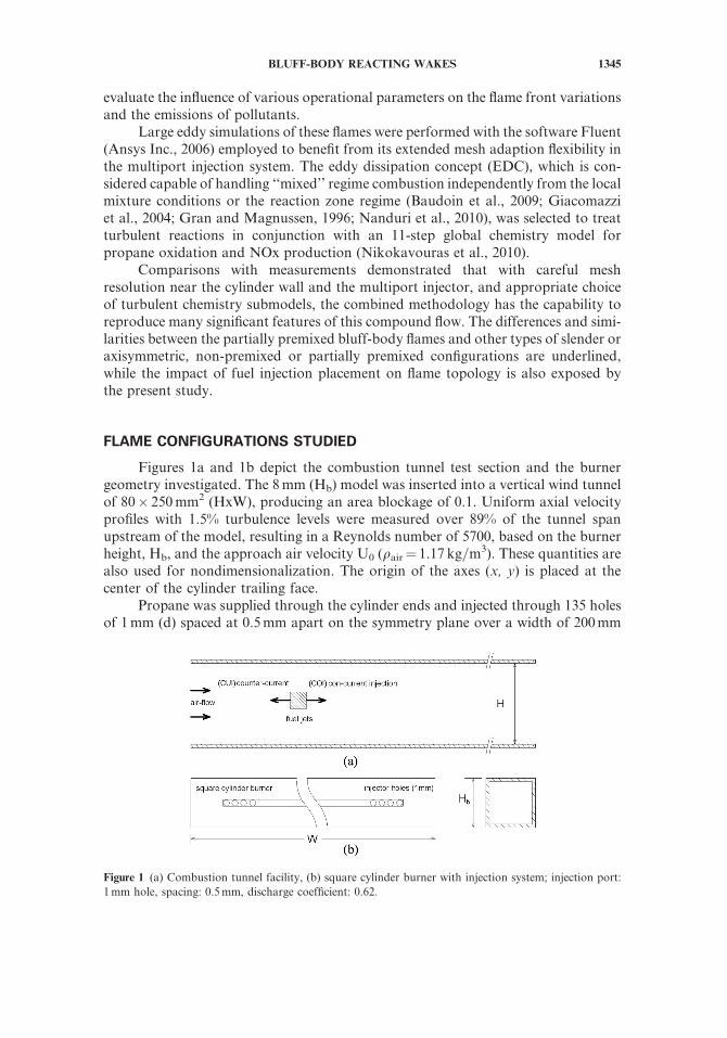
Figures 1a and 1b depict the combustion tunnel test section and the burnergeometry investigated. The 8mm (Hb) model was inserted into a vertical wind tunnelof 80� 250mm2 (HxW), producing an area blockage of 0.1. Uniform axial velocityprofiles with 1.5% turbulence levels were measured over 89% of the tunnel spanupstream of the model, resulting in a Reynolds number of 5700, based on the burnerheight, Hb, and the approach air velocity U0 (qair¼ 1.17 kg=m3). These quantities arealso used for nondimensionalization. The origin of the axes (x, y) is placed at thecenter of the cylinder trailing face.
Propane was supplied through the cylinder ends and injected through 135 holesof 1mm (d) spaced at 0.5mm apart on the symmetry plane over a width of 200mm
Figure 1 (a) Combustion tunnel facility, (b) square cylinder burner with injection system; injection port:
1mm hole, spacing: 0.5mm, discharge coefficient: 0.62.
BLUFF-BODY REACTING WAKES 1345
along the upstream (countercurrent) or downstream (concurrent injection) face of thesquare (Figure 1b). Laser velocimetry suggested that the discrete jets produce a uni-form planar jet within 0.25 Hb when operated without approach air flow; this shortenswith air flow in line with previous findings reported by Bakrozis (1997) and Bakroziset al (1999). The internal hollow of the square was tapered according to inviscid theoryto achieve spanwise fuel injection pressure uniformity across the injection holes. In thepresent uncooled burner setup, the propane temperature within the hollow of thesquare was monitored by four embedded thermocouples and was maintained at640K. Four basic flames lying in the lean operational regime were investigated, twowith countercurrent and two with concurrent injection, at two fuel injection –approach air velocity ratios (FAVR=UFuel=UAir) of 0.23 and 0.37 in each case. UFuel
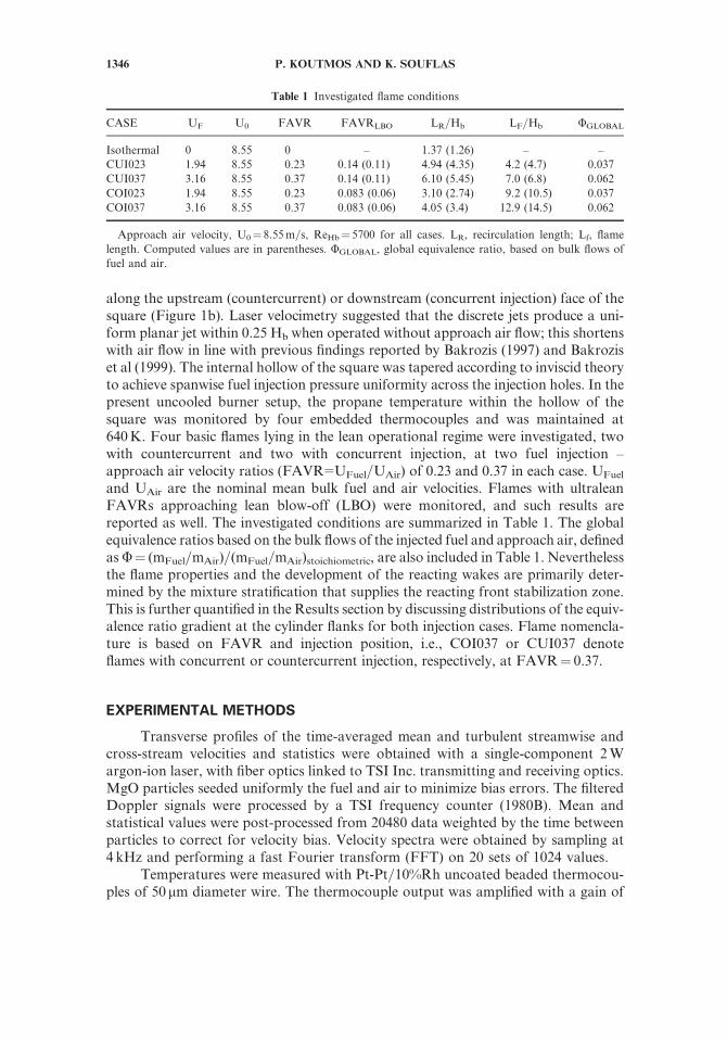
and UAir are the nominal mean bulk fuel and air velocities. Flames with ultraleanFAVRs approaching lean blow-off (LBO) were monitored, and such results arereported as well. The investigated conditions are summarized in Table 1. The globalequivalence ratios based on the bulk flows of the injected fuel and approach air, definedasU¼ (mFuel=mAir)=(mFuel=mAir)stoichiometric, are also included in Table 1. Neverthelessthe flame properties and the development of the reacting wakes are primarily deter-mined by the mixture stratification that supplies the reacting front stabilization zone.This is further quantified in the Results section by discussing distributions of the equiv-alence ratio gradient at the cylinder flanks for both injection cases. Flame nomencla-ture is based on FAVR and injection position, i.e., COI037 or CUI037 denoteflames with concurrent or countercurrent injection, respectively, at FAVR¼ 0.37.
EXPERIMENTAL METHODS
Transverse profiles of the time-averaged mean and turbulent streamwise andcross-stream velocities and statistics were obtained with a single-component 2Wargon-ion laser, with fiber optics linked to TSI Inc. transmitting and receiving optics.MgO particles seeded uniformly the fuel and air to minimize bias errors. The filteredDoppler signals were processed by a TSI frequency counter (1980B). Mean andstatistical values were post-processed from 20480 data weighted by the time betweenparticles to correct for velocity bias. Velocity spectra were obtained by sampling at4 kHz and performing a fast Fourier transform (FFT) on 20 sets of 1024 values.
Temperatures were measured with Pt-Pt=10%Rh uncoated beaded thermocou-ples of 50 mm diameter wire. The thermocouple output was amplified with a gain of
Table 1 Investigated flame conditions
CASE UF U0 FAVR FAVRLBO LR=Hb LF=Hb UGLOBAL
Isothermal 0 8.55 0 – 1.37 (1.26) – –
CUI023 1.94 8.55 0.23 0.14 (0.11) 4.94 (4.35) 4.2 (4.7) 0.037
CUI037 3.16 8.55 0.37 0.14 (0.11) 6.10 (5.45) 7.0 (6.8) 0.062
COI023 1.94 8.55 0.23 0.083 (0.06) 3.10 (2.74) 9.2 (10.5) 0.037
COI037 3.16 8.55 0.37 0.083 (0.06) 4.05 (3.4) 12.9 (14.5) 0.062
Approach air velocity, U0¼ 8.55m=s, ReHb¼ 5700 for all cases. LR, recirculation length; Lf, flame
length. Computed values are in parentheses. UGLOBAL, global equivalence ratio, based on bulk flows of
fuel and air.
1346 P. KOUTMOS AND K. SOUFLAS
about 500 and interfaced to a DaqTemp 7A Omega card. The thermocouple acts as alow-pass filter because of the heat capacity of the thermowires junction and the cer-amic tube. The time constant has typically low values of the order of some Hertz(e.g., 50Hz), depending on various local parameters (temperature, junction material,gas properties, flame structure) and can be evaluated only after the measurement.Here, using an FFT algorithm, the frequency spectrum of the signal was estimated,the amplitude and the phase were corrected, and the signal was transformed back tothe time domain, so that about 50% of the temperature fluctuations spectrum couldbe calculated. Further details of the thermocouple signal procedure can be found inTrimis (1996), Bakrozis et al. (1999), and Xiouris and Koutmos (2011, 2012). Nocorrection was applied for radiation, but for propane flames and uncoated wiresthe systematic error in the mean can be up to 10% at 1900K (Bakrozis et al.,1999). Mean and rms temperature values were derived at a sampling frequency of400Hz. Maximum uncertainties in the velocities were less than 8.5% in the meanand less than 15% in the rms. Uncertainties in the estimation of the thermocoupletime constant are rather unimportant for the mean temperature, but according tothe present compensation procedure, they may affect the variance by 20–35%.
Flame and CH� chemiluminescence (CL) images were obtained using a LaVi-sion FlameMaster imaging system consisting of a charge coupled device (CCD) cam-era (E-lite 2M, an image intensifier IRO unit, camera optical filter at 307þ =–10 nmand achromat lens for OH� imaging. OH� and CH� chemiluminescence measure-ments are considered good markers of the flame front since, e.g., the electronicallyexcited OH� radical exists only in the flame front. Image acquisition (line-of-sighttechnique) and data reduction were performed using the DaVis 8.0 software fromLaVision. The background image, taken under the same integration time and gainof the measured images, was subtracted from the originals. Averages were producedfrom 300 instantaneous images recorded at 16–30 frames per second depending onthe interrogation window. The signal-to-noise ratio of the instantaneous imageswas better than 8:1, and the exposure time was 2.1 ms. The maximum CCD chipresolution was 1626� 1236 pixels. Intensifier gate times of 100 ls were used forthe measurements with a gain of about 60%.
Global emissions from the flames were evaluated with gas analysis. An exhaustprobe, placed at 16Hb downstream of the burner, extracted flue gases and measuredbulk species (NOx, CO, CO2, O2, and CxHy) concentrations with the help of aKane-May KM9106 Quintox flue gas analyzer. The sample gases are drawn througha cooled stainless-steel probe, dried, and transferred to the analyzer to yield emissionson dry basis. Samples were obtained at eleven transverse positions across the symmetryplane and this rake was repeated at five spanwise positions along the injector span; themean of these values is reported in the results. Further details of the experimentalmethods may be found in Bakrozis et al., (1999) and Xiouris and Koutmos (2011).
COMPUTATIONAL MODEL FORMULATION
Aerodynamic Model
The flames were simulated with the software Fluent 6.3.26 (Ansys Inc., 2006).It offered mesh adaption flexibility in the resolution of the multiport injector and
BLUFF-BODY REACTING WAKES 1347
facilitated the exploitation of reduced chemistry within the context of an adequatemodeling scheme for the turbulent reactions. Within the large eddy simulations(LES) formalism, the flow variables, F, can be decomposed into resolvable ~FF andsub-grid F 0 scale quantities using a Favre-weighted filter, ~FF ¼ qF �qq= . The equationsdescribing the resolvable flow quantities are as follows (e.g., Baudoin et al., 2009;Giacomazzi et al., 2004; Papailiou et al., 2000):
@�qq@t
þ @�qq~uu@xi
¼ 0;@�qq~uui@t
þ@ �qq~uui~uuj� �
@xj¼ � @�pp
@xiþ @
@xj~rrij þ
@
@xjsij þ �qq� q1ð Þgi ð1Þ
where q, m, and u are the density, viscosity, temperature, and velocity of the gas andi¼ 1, 2 in a Cartesian system (x, y). �pp ¼ �qqRu
~TTRiYi Mi= , where Yi, Mi, and Ru arethe mass fraction, the molecular weight of species i, and the universal gas constant.~rrij ¼ l ~SSij � 2 3= ~SSkkdij
� �, with (dij¼ 0 for i 6¼ j, dij¼ 1 for i¼ j), sij are the SGS stresses,
and~SSij is the resolvable strain tensor. sij is modeled as sij ¼ ��qq u0iu0j ¼
lt;ij ~SSij � ð2=3Þ~SSkkdij� �
�ð2=3Þ�qq~kksdij, where ks is the subgrid kinetic energy. The sub-grid turbulent viscosity is calculated through the resolvable strain tensor (Baudoinet al., 2009; Giacomazzi et al., 2004): lt;ij ¼ ~qqðCsDÞ2ð2~SSij
~SSijÞ1=2, where D is the filterlength: D ¼
ffiffiffiffiffiffiffiffiffiffiffiffiffiffiffiffiffiffiffiffiffiDxiDyiDzi
p. Simulations employed a dynamic Smagorinsky constant,
Cs (0<Cs< 0.23), and the SIMPLE algorithmwas used for pressure–velocity coupling(Ansys Inc., 2006; Giacomazzi et al., 2004). Central differencing was used for all equa-tions, while temporal integration was performed with a second-order dual time step-ping procedure retaining lowCourant numbers (�0.3) at themedium and finer meshes.
Anticipating that radiative losses can influence NOX levels, the simple P-1radiation model available in the software, which is based on the expansion of theradiation intensity I into an orthogonal series of spherical harmonics (Ansys Inc.,2006), was adopted in the simulations.
Combustion Model
The need to address the impact of the compositional stratification on the flameanchoring alongside the stabilizer flanks, and to represent both non-premixed andpremixed regimes that often coexist in turbulent partially premixed flames, has ledto the adoption of a reduced chemistry scheme with a detailed transport model (kin-etic theory) within a tractable turbulent combustion closure. The measurements havesuggested that the ultralean counterinjected flames are nearer to the broken reactionzone boundary with Karlovitz numbers (Bradley, 2008; Ka¼ sch=sk, where sch and skare the chemical and Kolmogorov timescales), up to 70. The eddy dissipation concept(EDC) (Giacomazzi et al., 2004; Gran et al., 1996; Nanduri et al., 2010) was deemedsuitable to cover the range of conditions and was coupled to an 11-step reducedchemistry scheme for propane oxidation and NOx (Nikokavouras et al., 2010).
Despite its somewhat empirical nature, the EDC model has been successfullyemployed in RANS and LES studies of bluff-body flames (e.g., Baudoin et al.,2009; Nanduri et al., 2010). Due to its more economic treatment of turbulentchemistry, in comparison to the more fundamentally based, albeit significantly moreexpensive, composition PDF approach (e.g., Jenny et al., 2001), it afforded an
1348 P. KOUTMOS AND K. SOUFLAS
increased mesh resolution within the available computational resources. Compari-sons between these two approaches in bluff-body premixed flames (Nanduri et al.,2010) have indicated comparable performance. Nevertheless, efforts could be directedin the future to exploit the PDF approach for exploratory runs of selected configura-tions to appraise its impact on the modeling of these flames. The in situ adaptivetabulation (ISAT) method (e.g., Jenny et al., 2001) with error tolerance 1e-05 reducedthe computational cost in the evaluation of the reaction rate source terms.
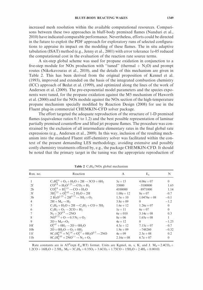
A six-step global scheme was used for propane oxidation in conjunction to afive-step module for NOx production with ‘‘tuned’’ (thermal þ N2O) and promptroutes (Nikokavouras et al., 2010), and the details of this mechanism are given inTable 2. This has been derived from the original proposition of Kennel et al.(1993), improved and extended on the basis of the integrated combustion chemistry(ICC) approach of Bedat et al. (1999), and optimized along the lines of the work ofAndersen et al. (2009). The pre-exponential model parameters and the species expo-nents were tuned, for the propane oxidation against the M5 mechanism of Haworthet al. (2000) and for the NOx module against the NOx section of the high-temperaturepropane mechanism specially modified by Reaction Design (2008) for use in theFluent plug-in commercial CHEMKIN-CFD solver package.
The effort targeted the adequate reproduction of the structure of 1-D premixedflames (equivalence ratios 0.5 to 1.2) and the best possible representation of laminarpartially premixed counterflow and lifted jet propane flames. The procedure was con-strained by the exclusion of all intermediate elementary rates in the final global rateexpressions (e.g., Andersen et al., 2009). In this way, inclusion of the resulting mech-anism into the standard Fluent stiff-chemistry solver was facilitated within the con-text of the present demanding LES methodology, avoiding extensive and possiblycostly chemistry treatments offered by, e.g., the package CHEMKIN-CFD. It shouldbe noted that the primary target in the tuning was the appropriate reproduction of
Table 2 C3H8=NOx global mechanism
Rxn. no. Reaction A Ea N
1 C3H0:68 þO2þH2Oþ 2H! 3COþ 6H2 5eþ 15 4.06eþ 07 0
2f CO0.8þH2O1.25!CO2þH2 33000 –3100000 1.65
2b CO0:82 þH1:15
2 !COþH2O 4100000 –8971000 1.14
3f 3H1:152 þO0:65
2 ! 2 H2Oþ 2H 1.08eþ 12 8eþ 07 –0.7
3b 2 H2O1.25þ 2H0.75! 3H2þO2 1.5eþ 10 1.0476eþ 08 �0.1
4 2HþM4!H2 3.8eþ 09 0 �1.2
5 C3H8þH2Oþ 2H!C2H2þCOþ 5H2 1.6eþ 12 1.26eþ 07 0
6 C2H2þO2! 2COþH2 1eþ 11 6eþ 07 0
7 N2þ 2O0.9! 2NO 6eþ 010 3.14eþ 08 0.3
8 NO0.72þO! 0.5N2þO2 8eþ 06 1.65eþ 08 1
9 2OþM9$O2 4eþ 12 0 �1.25
10f O0:472 þ 0H2! 2Oþ 0H2O 4.5eþ 12 7.15eþ 07 �0.7
10b 2Oþ 0H2O!O2þ 0H2 1.9eþ 09 �748260 �0.32
11f 0C3H0:028 þN1:16
2 þO0:52 þ 0H2O
0.5! 2NO 4eþ 09 2.3eþ 08 0.2
11b 0C3H0:058 þ 2NO1.1!N2þO2 2.16eþ 08 6.7eþ 07 0
Rate constants are in ATbexp(–Ea=RT) format. Units are Kgmol, m, s, K, and J. M4¼ 2.4CO2þ1.2COþ 16H2Oþ 2.5H2, M9¼ 3C3H8þ 0.35O2þ 3.6CO2þ 1.75COþ 15H2Oþ 2.4H2þ 0.001O.
BLUFF-BODY REACTING WAKES 1349
one-dimensional laminar C3H8 partially premixed opposed jet flames such as thosestudied by, e.g., Cheng et al. (2006), and therefore its use in the diffusion flames couldhave required adjustments such as suggested in, e.g., Leung et al. (1993). For ease ofcomparison of the mechanism performance in the two cases, such an effort was notundertaken here.
Computational Details
Emphasis was paid to the sufficient node resolution of the low aspect ratio mul-tiport injector, (dimensions 1: 8: 80mm) ! (injection hole: square cylinder height:tunnel height). Node density was also increased near the square walls where flameanchoring occurs, in the vortex formation region, and at the shear layers flankingthe wake. A hybrid mesh was used for the compound region of the injection holesand the square boundary, unstructured near the round ports and structured in otherlocations with expansion to the outlet. The meshes extended 3.5 Hb upstream of thebody, and the outlet was placed 16 Hb downstream. Meshes of 0.37, 0.78, and 1.45Mcells (the limits of available resources) were employed for the basic runs. Differencesin mean values were diminishing between the two finer densities, with small deviationsremaining in the statistics. The port vicinity proved the most challenging, and success-ive local adaptions of the unstructured mesh were necessary there.
No-slip boundary conditions were used near the cylinder walls with the firstnode placed at Dymin=Hb¼ 0.00015 (yþ� 0.45); this could be succeeded for all facesof the square except the injected one (placed either upstream or downstream) whereexcessive gridding was required. The law of the wall was applied at the tunnel walls.Inlet conditions were taken from measurements, while random fluctuations satisfy-ing the constraints of incompressibility and measured uRMS profile were superim-posed on the mean velocities; at the outlet a static pressure boundary condition(available in the software) was applied, and all outflowing quantities were extrapo-lated from the interior node. As a compromise between large spanwise extent andfiner resolution close to the square, the resolved span was chosen to include seveninjection holes plus one-half spacing on each side, over a width of 1.75Hb, withsymmetry boundary conditions at the lateral boundaries. Periodic conditions werealso tested with no significant alteration of results.
Nonreacting LES first documented the cold wake and provided startingconditions for the reacting simulations. All simulations were left to develop for sixthrough-flow times, after which statistics were sampled for eight more through-flowtimes. According to Pope (2004), an estimate of the quality of the LES can beobtained by calculating the resolved fraction of the turbulence energy, Rk¼ kres=(kresþ ks). More than 88% of the kinetic energy was resolved within the flame envel-ope and in the vortex formation region, while only very close to the injector portsand in the external wake Rk dropped below these levels. The choice of a ratherlow Reynolds number for these laboratory scale experimental conditions is con-ducive to the attainment of this resolution.
Computation times on 36 2.83GHz processors (3 XEON 5660) and 243.33GHz processors (4 i7) run in parallel were about 11 s per inner iteration (includ-ing the chemistry integration time) for the finer mesh; all runs were performed withthe finer mesh.
1350 P. KOUTMOS AND K. SOUFLAS
RESULTS AND DISCUSSION
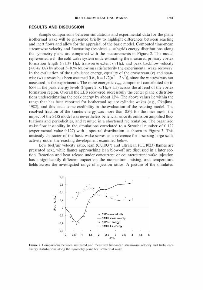
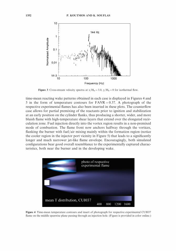
Sample comparisons between simulations and experimental data for the planeisothermal wake will be presented briefly to highlight differences between reactingand inert flows and allow for the appraisal of the basic model. Computed time-meanstreamwise velocity and fluctuating (resolved þ subgrid) energy distributions alongthe symmetry plane are compared with the measurements in Figure 2. The modelrepresented well the cold wake system underestimating the measured primary vortexformation length (�1.37 Hb), transverse extent (�Hb), and peak backflow velocity(�0.42 U0) by about 5–10% following satisfactorily the experimental wake recovery.In the evaluation of the turbulence energy, equality of the crosstream (v) and span-wise (w) stresses has been assumed [i.e., k¼ 1=2(u2þ 2 v2)], since the w stress was notmeasured in the experiments. The more energetic vrms component contributed up to65% in the peak energy levels (Figure 2, x=Hb� 1.5) across the aft end of the vortexformation region. Overall the LES recovered successfully the center plane k distribu-tions underestimating the peak energy by about 12%. The above values lie within therange that has been reported for isothermal square cylinder wakes (e.g., Okajima,1982), and this lends some credibility in the evaluation of the reacting model. Theresolved fraction of the kinetic energy was more than 85% for the finer mesh; theimpact of the SGS model was nevertheless beneficial since its omission amplified fluc-tuations and periodicities, and resulted in a shortened recirculation. The organizedwake flow instability in the simulations correlated to a Strouhal number of 0.122(experimental value 0.127) with a spectral distribution as shown in Figure 3. Thisunsteady character of the basic wake serves as a reference for assessing large scaleactivity under the reacting development examined below.
Low fuel=air velocity ratio, lean (CUI037) and ultralean (CUI023) flames arepresented next, while flames approaching lean blow-off are discussed in a later sec-tion. Reaction and heat release under concurrent or countercurrent wake injectionhas a significantly different impact on the momentum, mixing, and temperaturefields across the investigated range of injection ratios. A picture of the simulated
Figure 2 Comparisons between simulated and measured time-mean streamwise velocity and turbulence
energy distributions along the symmetry plane for isothermal wake.
BLUFF-BODY REACTING WAKES 1351
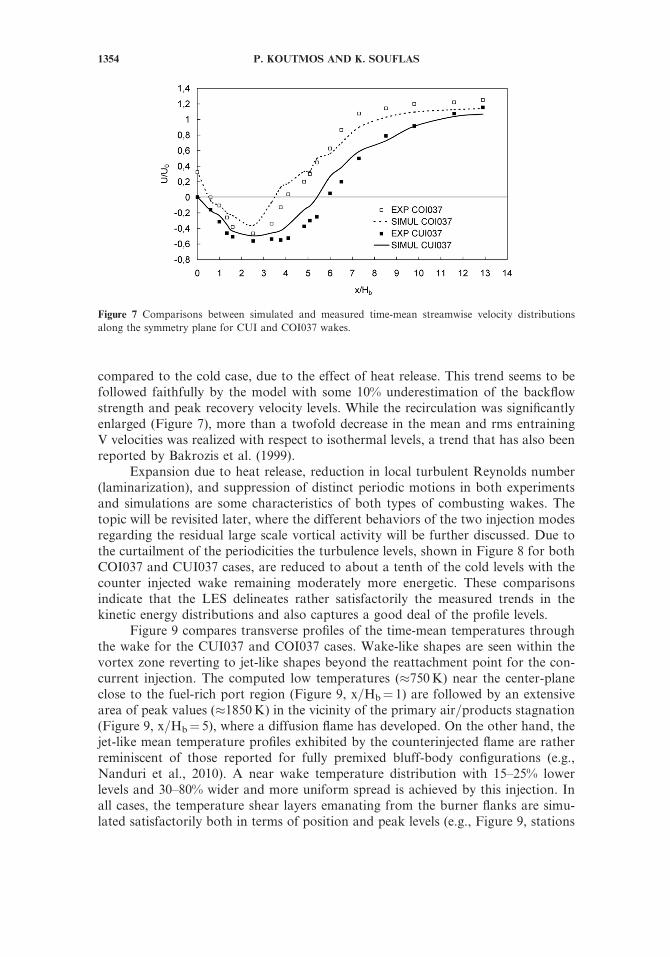
time-mean reacting wake patterns obtained in each case is displayed in Figures 4 and5 in the form of temperature contours for FAVR¼ 0.37. A photograph of therespective experimental flames has also been inserted in these plots. The counterflowcase allows for partial premixing of the reactants prior to ignition and stabilizationat an early position on the cylinder flanks, thus producing a shorter, wider, and morebluish flame with high-temperature shear layers that extend over the elongated recir-culation zone. Fuel injection directly into the vortex region results in a non-premixedmode of combustion. The flame front now anchors halfway through the vortices,flanking the burner with fuel=air mixing mainly within the formation region (noticethe cooler region in the injector port vicinity in Figure 5) that leads to a significantlylonger and much narrower jet-like flame envelope. Encouragingly, both simulatedconfigurations bear good overall resemblance to the experimentally captured charac-teristics, both near the burner and in the developing wake.
Figure 3 Cross-stream velocity spectra at x=Hb¼ 3.0, y=Hb¼ 0 for isothermal flow.
Figure 4 Time-mean temperature contours and insert of photograph for respective experimental CUI037
flame on the middle spanwise plane passing through an injection hole. (Figure is provided in color online.)
1352 P. KOUTMOS AND K. SOUFLAS

The above disparity in temperature topology depends primarily on the turbu-lent velocity and mixing fields established around the square cylinder burner thatsupport and promote a drastically different fuel disposition and premixing with airprior to ignition and stabilization. The equivalence ratio distributions close to theburner provided by the simulations are displayed in Figure 6. Counterinjection(Figure 6, lower panel) allows for a regulated supply of the fuel=air mixture withinthe side vortices, achieving an appropriately stratified flammable mixture profile inthe most favorable position for stabilization. In contrast, wake injection (Figure 6,upper panel) distributes almost uniformly the mixture within the vortex region, andadequate additional flame anchoring (beyond that offered by the hot gas primaryrecirculation or the shear layer mixing) is now dependent on feedback from this richmixture into the cylinder flanks.
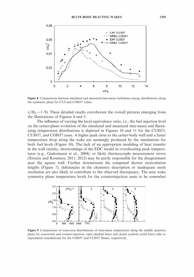
Comparisons of the time-mean streamwise velocity development along thewake symmetry plane are shown in Figure 7 for the corresponding concurrent andcountercurrent lean flames. In both measurements and simulations, the primaryrecirculation region has now been elongated by 2.35 and 4.45 times, respectively,
Figure 5 Time-mean temperature contours and insert of photograph for respective experimental COI037
flame on the middle spanwise plane passing through an injection hole. (Figure is provided in color online.)
Figure 6 Equivalence ratio distributions close to the square cylinder for concurrent and countercurrent
injection at FAVR¼ 0.37.
BLUFF-BODY REACTING WAKES 1353
compared to the cold case, due to the effect of heat release. This trend seems to befollowed faithfully by the model with some 10% underestimation of the backflowstrength and peak recovery velocity levels. While the recirculation was significantlyenlarged (Figure 7), more than a twofold decrease in the mean and rms entrainingV velocities was realized with respect to isothermal levels, a trend that has also beenreported by Bakrozis et al. (1999).
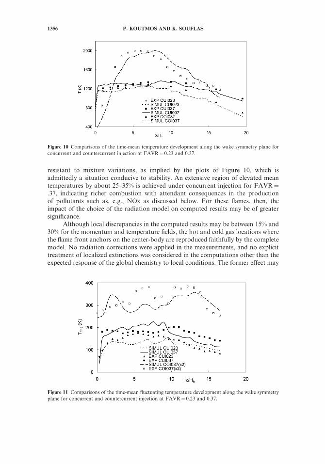
Expansion due to heat release, reduction in local turbulent Reynolds number(laminarization), and suppression of distinct periodic motions in both experimentsand simulations are some characteristics of both types of combusting wakes. Thetopic will be revisited later, where the different behaviors of the two injection modesregarding the residual large scale vortical activity will be further discussed. Due tothe curtailment of the periodicities the turbulence levels, shown in Figure 8 for bothCOI037 and CUI037 cases, are reduced to about a tenth of the cold levels with thecounter injected wake remaining moderately more energetic. These comparisonsindicate that the LES delineates rather satisfactorily the measured trends in thekinetic energy distributions and also captures a good deal of the profile levels.
Figure 9 compares transverse profiles of the time-mean temperatures throughthe wake for the CUI037 and COI037 cases. Wake-like shapes are seen within thevortex zone reverting to jet-like shapes beyond the reattachment point for the con-current injection. The computed low temperatures (�750K) near the center-planeclose to the fuel-rich port region (Figure 9, x=Hb¼ 1) are followed by an extensivearea of peak values (�1850K) in the vicinity of the primary air=products stagnation(Figure 9, x=Hb¼ 5), where a diffusion flame has developed. On the other hand, thejet-like mean temperature profiles exhibited by the counterinjected flame are ratherreminiscent of those reported for fully premixed bluff-body configurations (e.g.,Nanduri et al., 2010). A near wake temperature distribution with 15–25% lowerlevels and 30–80% wider and more uniform spread is achieved by this injection. Inall cases, the temperature shear layers emanating from the burner flanks are simu-lated satisfactorily both in terms of position and peak levels (e.g., Figure 9, stations
Figure 7 Comparisons between simulated and measured time-mean streamwise velocity distributions
along the symmetry plane for CUI and COI037 wakes.
1354 P. KOUTMOS AND K. SOUFLAS
x=Hb¼ 1–9). These detailed results corroborate the overall pictures emerging fromthe illustrations of Figures 4 and 5.
The influence of varying the local equivalence ratio, i.e., the fuel injection levelon the center-plane evolution of the simulated and measured time-mean and fluctu-ating temperature distributions is depicted in Figures 10 and 11 for the CUI023,CUI037, and COI037 cases. A higher peak close to the center-body wall and a fastertemperature drop along the wake are seemingly produced by the simulations forboth fuel levels (Figure 10). The lack of an appropriate modeling of heat transferin the wall vicinity, shortcomings of the EDC model in overshooting peak tempera-tures (e.g., Giakomazzi et al., 2004), or likely thermocouple measurement errors(Xiouris and Koutmos, 2011, 2012) may be partly responsible for the disagreementnear the square wall. Further downstream the computed shorter recirculationlengths (Figure 7), deficiencies in the chemistry description or inadequate meshresolution are also likely to contribute to the observed discrepancy. The near wakesymmetry plane temperature levels for the counterinjection seem to be somewhat
Figure 9 Comparisons of transverse distributions of time-mean temperature along the middle spanwise
plane for concurrent and counter-injection; open (dashed lines) and closed symbols (solid lines) refer to
experiments (simulations) for the COI037 and CUI037 flames, respectively.
Figure 8 Comparisons between simulated and measured time-mean turbulence energy distributions along
the symmetry plane for CUI and COI037 wakes.
BLUFF-BODY REACTING WAKES 1355
resistant to mixture variations, as implied by the plots of Figure 10, which isadmittedly a situation conducive to stability. An extensive region of elevated meantemperatures by about 25–35% is achieved under concurrent injection for FAVR¼.37, indicating richer combustion with attendant consequences in the productionof pollutants such as, e.g., NOx as discussed below. For these flames, then, theimpact of the choice of the radiation model on computed results may be of greatersignificance.
Although local discrepancies in the computed results may be between 15% and30% for the momentum and temperature fields, the hot and cold gas locations wherethe flame front anchors on the center-body are reproduced faithfully by the completemodel. No radiation corrections were applied in the measurements, and no explicittreatment of localized extinctions was considered in the computations other than theexpected response of the global chemistry to local conditions. The former effect may
Figure 10 Comparisons of the time-mean temperature development along the wake symmetry plane for
concurrent and countercurrent injection at FAVR¼ 0.23 and 0.37.
Figure 11 Comparisons of the time-mean fluctuating temperature development along the wake symmetry
plane for concurrent and countercurrent injection at FAVR¼ 0.23 and 0.37.
1356 P. KOUTMOS AND K. SOUFLAS
be important with concurrent injection, while the latter with counterinjection atlower mixture strengths. The exploitation of the 11-step global chemistry that hasbeen calibrated against mixtures between U¼ 0.5 and 1.2 in fully and partiallypremixed counterflow flames may alleviate the second difficulty at least as regardsthe CUI cases.
A more elongated reverse flow zone, steeper cross-stream temperature gradi-ents, and more dominant small- and large-scale wake turbulence is observed for theplane counterinjected wake by comparison to counterpart partially premixed axisym-metric configurations (e.g., Xiouris and Koutmos, 2011, 2012). These properties mayrequire a denser mesh over a longer wake extent for appropriate resolution of itsdownstream features.
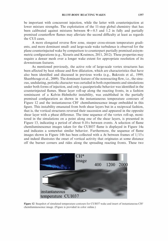
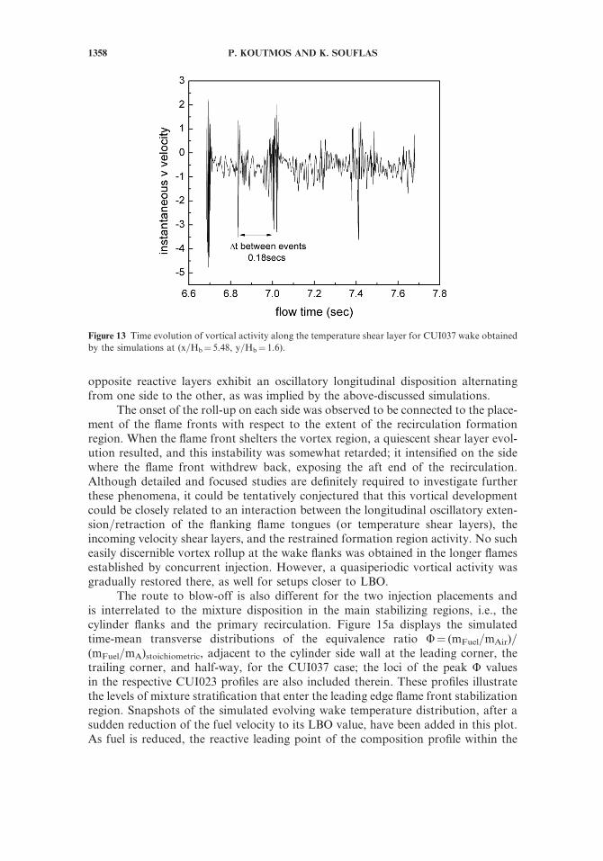
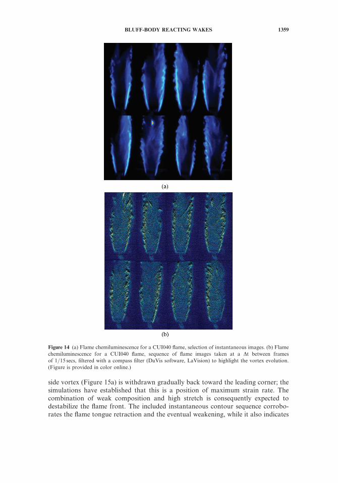
As mentioned previously, the active role of large-scale vortex structures hasbeen affected by heat release and flow dilatation, which are characteristics that havealso been identified and discussed in previous works (e.g., Bakrozis et al., 1999;Shanbhouge et al., 2009). The dominant feature of the nonreacting flow, i.e., the sinu-ous, undulating, periodic character was curtailed in both experiments and simulationsunder both forms of injection, and only a quasiperiodic behavior was identified in thecounterinjected flames. Shear layer roll-up along the reacting fronts, in a fashionreminiscent of a Kelvin–Helmholtz instability, was established in the partiallypremixed configuration as shown in the instantaneous temperature contours ofFigure 12 and the instantaneous CH� chemiluminescence image embedded in thisfigure. This instability emanated from both shear layers but in a reciprocal fashion,that is, the vortical structures reversed their succession and appeared in the oppositeshear layer with a phase difference. The time sequence of the vortex roll-up, moni-tored in the simulations on a point along one of the shear layers, is presented inFigure 13, indicating a period of about 0.18 s between events. A selection of flamechemiluminescence images taken for the CUI037 flame is displayed in Figure 14aand indicates a somewhat similar behavior. Furthermore, the sequence of flameimages shown in Figure 14b has been collected with a Dt between frames of 1=15 sand indeed illustrates the onset of vortical activity that originates at some distanceoff the burner corners and rides along the spreading reacting fronts. These two
Figure 12 Snapshot of simulated temperature contours for CUI037 wake and insert of instantaneous CH�
chemiluminescence image. (Figure is provided in color online.)
BLUFF-BODY REACTING WAKES 1357
opposite reactive layers exhibit an oscillatory longitudinal disposition alternatingfrom one side to the other, as was implied by the above-discussed simulations.
The onset of the roll-up on each side was observed to be connected to the place-ment of the flame fronts with respect to the extent of the recirculation formationregion. When the flame front shelters the vortex region, a quiescent shear layer evol-ution resulted, and this instability was somewhat retarded; it intensified on the sidewhere the flame front withdrew back, exposing the aft end of the recirculation.Although detailed and focused studies are definitely required to investigate furtherthese phenomena, it could be tentatively conjectured that this vortical developmentcould be closely related to an interaction between the longitudinal oscillatory exten-sion=retraction of the flanking flame tongues (or temperature shear layers), theincoming velocity shear layers, and the restrained formation region activity. No sucheasily discernible vortex rollup at the wake flanks was obtained in the longer flamesestablished by concurrent injection. However, a quasiperiodic vortical activity wasgradually restored there, as well for setups closer to LBO.
The route to blow-off is also different for the two injection placements andis interrelated to the mixture disposition in the main stabilizing regions, i.e., thecylinder flanks and the primary recirculation. Figure 15a displays the simulatedtime-mean transverse distributions of the equivalence ratio U¼ (mFuel=mAir)=(mFuel=mA)stoichiometric, adjacent to the cylinder side wall at the leading corner, thetrailing corner, and half-way, for the CUI037 case; the loci of the peak U valuesin the respective CUI023 profiles are also included therein. These profiles illustratethe levels of mixture stratification that enter the leading edge flame front stabilizationregion. Snapshots of the simulated evolving wake temperature distribution, after asudden reduction of the fuel velocity to its LBO value, have been added in this plot.As fuel is reduced, the reactive leading point of the composition profile within the
Figure 13 Time evolution of vortical activity along the temperature shear layer for CUI037 wake obtained
by the simulations at (x=Hb¼ 5.48, y=Hb¼ 1.6).
1358 P. KOUTMOS AND K. SOUFLAS
side vortex (Figure 15a) is withdrawn gradually back toward the leading corner; thesimulations have established that this is a position of maximum strain rate. Thecombination of weak composition and high stretch is consequently expected todestabilize the flame front. The included instantaneous contour sequence corrobo-rates the flame tongue retraction and the eventual weakening, while it also indicates
Figure 14 (a) Flame chemiluminescence for a CUI040 flame, selection of instantaneous images. (b) Flame
chemiluminescence for a CUI040 flame, sequence of flame images taken at a Dt between frames
of 1=15 secs, filtered with a compass filter (DaVis software, LaVision) to highlight the vortex evolution.
(Figure is provided in color online.)
BLUFF-BODY REACTING WAKES 1359
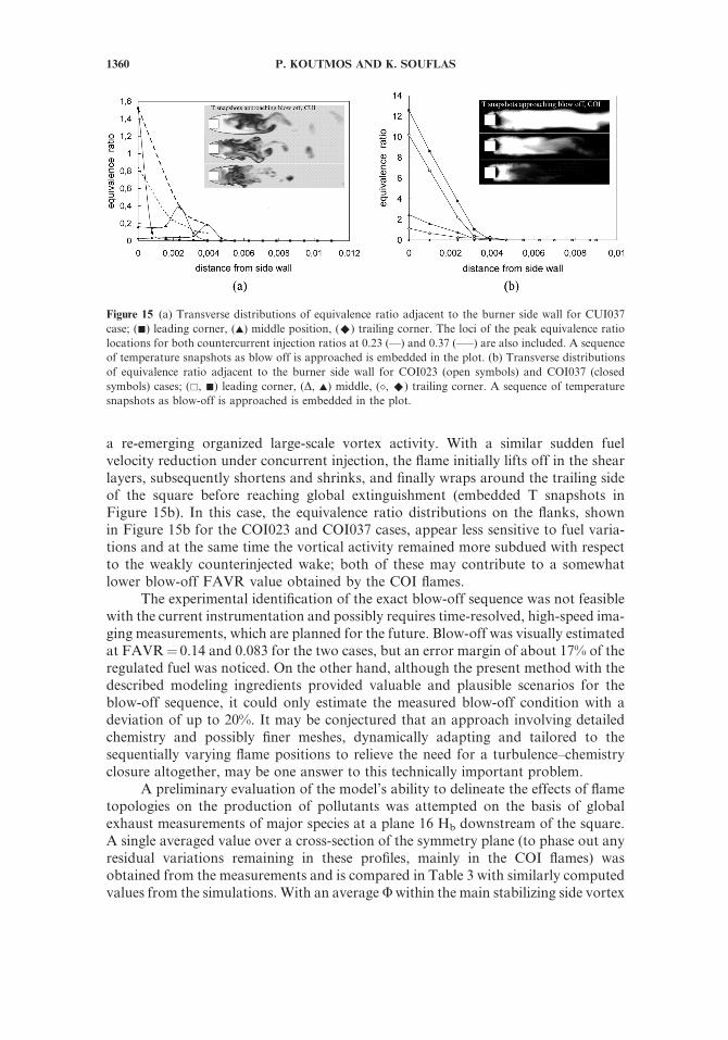
a re-emerging organized large-scale vortex activity. With a similar sudden fuelvelocity reduction under concurrent injection, the flame initially lifts off in the shearlayers, subsequently shortens and shrinks, and finally wraps around the trailing sideof the square before reaching global extinguishment (embedded T snapshots inFigure 15b). In this case, the equivalence ratio distributions on the flanks, shownin Figure 15b for the COI023 and COI037 cases, appear less sensitive to fuel varia-tions and at the same time the vortical activity remained more subdued with respectto the weakly counterinjected wake; both of these may contribute to a somewhatlower blow-off FAVR value obtained by the COI flames.
The experimental identification of the exact blow-off sequence was not feasiblewith the current instrumentation and possibly requires time-resolved, high-speed ima-ging measurements, which are planned for the future. Blow-off was visually estimatedat FAVR¼ 0.14 and 0.083 for the two cases, but an error margin of about 17% of theregulated fuel was noticed. On the other hand, although the present method with thedescribed modeling ingredients provided valuable and plausible scenarios for theblow-off sequence, it could only estimate the measured blow-off condition with adeviation of up to 20%. It may be conjectured that an approach involving detailedchemistry and possibly finer meshes, dynamically adapting and tailored to thesequentially varying flame positions to relieve the need for a turbulence–chemistryclosure altogether, may be one answer to this technically important problem.
A preliminary evaluation of the model’s ability to delineate the effects of flametopologies on the production of pollutants was attempted on the basis of globalexhaust measurements of major species at a plane 16 Hb downstream of the square.A single averaged value over a cross-section of the symmetry plane (to phase out anyresidual variations remaining in these profiles, mainly in the COI flames) wasobtained from the measurements and is compared in Table 3 with similarly computedvalues from the simulations. With an averageUwithin the main stabilizing side vortex
Figure 15 (a) Transverse distributions of equivalence ratio adjacent to the burner side wall for CUI037
case; (&) leading corner, (~) middle position, (^) trailing corner. The loci of the peak equivalence ratio
locations for both countercurrent injection ratios at 0.23 (—) and 0.37 (–––) are also included. A sequence
of temperature snapshots as blow off is approached is embedded in the plot. (b) Transverse distributions
of equivalence ratio adjacent to the burner side wall for COI023 (open symbols) and COI037 (closed
symbols) cases; (&, &) leading corner, (D, ~) middle, (�, ^) trailing corner. A sequence of temperature
snapshots as blow-off is approached is embedded in the plot.
1360 P. KOUTMOS AND K. SOUFLAS
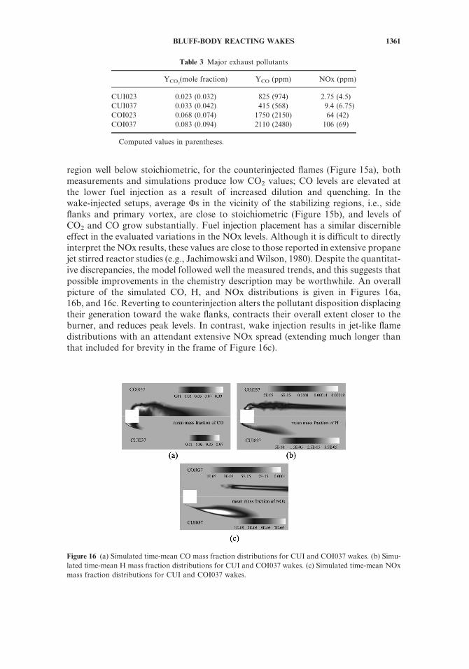
region well below stoichiometric, for the counterinjected flames (Figure 15a), bothmeasurements and simulations produce low CO2 values; CO levels are elevated atthe lower fuel injection as a result of increased dilution and quenching. In thewake-injected setups, average Us in the vicinity of the stabilizing regions, i.e., sideflanks and primary vortex, are close to stoichiometric (Figure 15b), and levels ofCO2 and CO grow substantially. Fuel injection placement has a similar discernibleeffect in the evaluated variations in the NOx levels. Although it is difficult to directlyinterpret the NOx results, these values are close to those reported in extensive propanejet stirred reactor studies (e.g., Jachimowski andWilson, 1980). Despite the quantitat-ive discrepancies, the model followed well the measured trends, and this suggests thatpossible improvements in the chemistry description may be worthwhile. An overallpicture of the simulated CO, H, and NOx distributions is given in Figures 16a,16b, and 16c. Reverting to counterinjection alters the pollutant disposition displacingtheir generation toward the wake flanks, contracts their overall extent closer to theburner, and reduces peak levels. In contrast, wake injection results in jet-like flamedistributions with an attendant extensive NOx spread (extending much longer thanthat included for brevity in the frame of Figure 16c).
Figure 16 (a) Simulated time-mean CO mass fraction distributions for CUI and COI037 wakes. (b) Simu-
lated time-mean H mass fraction distributions for CUI and COI037 wakes. (c) Simulated time-mean NOx
mass fraction distributions for CUI and COI037 wakes.
Table 3 Major exhaust pollutants
YCO2(mole fraction) YCO (ppm) NOx (ppm)
CUI023 0.023 (0.032) 825 (974) 2.75 (4.5)
CUI037 0.033 (0.042) 415 (568) 9.4 (6.75)
COI023 0.068 (0.074) 1750 (2150) 64 (42)
COI037 0.083 (0.094) 2110 (2480) 106 (69)
Computed values in parentheses.
BLUFF-BODY REACTING WAKES 1361
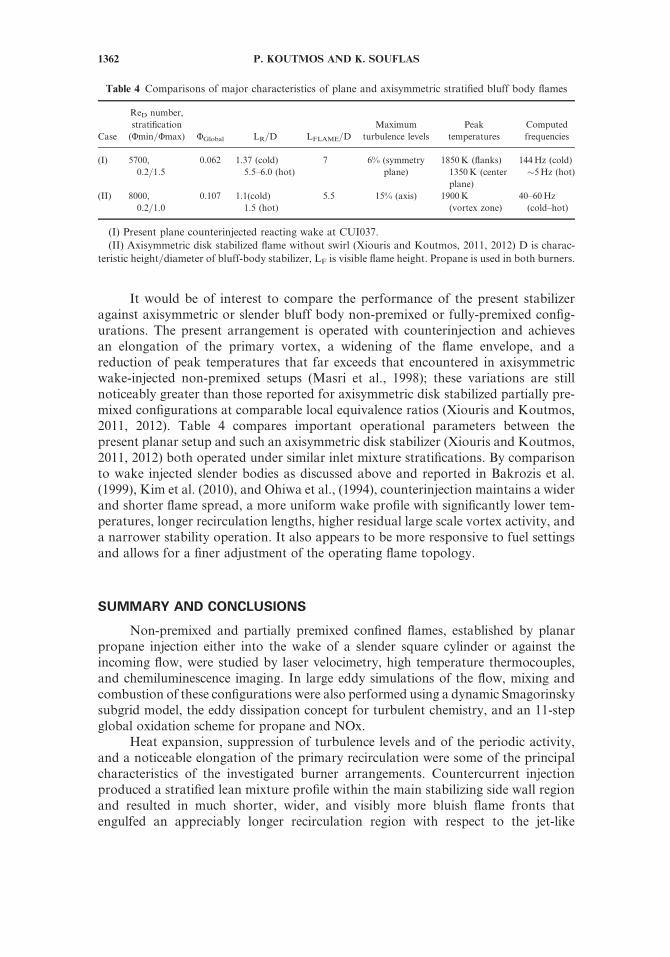
It would be of interest to compare the performance of the present stabilizeragainst axisymmetric or slender bluff body non-premixed or fully-premixed config-urations. The present arrangement is operated with counterinjection and achievesan elongation of the primary vortex, a widening of the flame envelope, and areduction of peak temperatures that far exceeds that encountered in axisymmetricwake-injected non-premixed setups (Masri et al., 1998); these variations are stillnoticeably greater than those reported for axisymmetric disk stabilized partially pre-mixed configurations at comparable local equivalence ratios (Xiouris and Koutmos,2011, 2012). Table 4 compares important operational parameters between thepresent planar setup and such an axisymmetric disk stabilizer (Xiouris and Koutmos,2011, 2012) both operated under similar inlet mixture stratifications. By comparisonto wake injected slender bodies as discussed above and reported in Bakrozis et al.(1999), Kim et al. (2010), and Ohiwa et al., (1994), counterinjection maintains a widerand shorter flame spread, a more uniform wake profile with significantly lower tem-peratures, longer recirculation lengths, higher residual large scale vortex activity, anda narrower stability operation. It also appears to be more responsive to fuel settingsand allows for a finer adjustment of the operating flame topology.
SUMMARY AND CONCLUSIONS
Non-premixed and partially premixed confined flames, established by planarpropane injection either into the wake of a slender square cylinder or against theincoming flow, were studied by laser velocimetry, high temperature thermocouples,and chemiluminescence imaging. In large eddy simulations of the flow, mixing andcombustion of these configurations were also performed using a dynamic Smagorinskysubgrid model, the eddy dissipation concept for turbulent chemistry, and an 11-stepglobal oxidation scheme for propane and NOx.
Heat expansion, suppression of turbulence levels and of the periodic activity,and a noticeable elongation of the primary recirculation were some of the principalcharacteristics of the investigated burner arrangements. Countercurrent injectionproduced a stratified lean mixture profile within the main stabilizing side wall regionand resulted in much shorter, wider, and visibly more bluish flame fronts thatengulfed an appreciably longer recirculation region with respect to the jet-like
Table 4 Comparisons of major characteristics of plane and axisymmetric stratified bluff body flames
Case
ReD number,
stratification
(Umin=Umax) UGlobal LR=D LFLAME=D
Maximum
turbulence levels
Peak
temperatures
Computed
frequencies
(I) 5700,
0.2=1.5
0.062 1.37 (cold)
5.5–6.0 (hot)
7 6% (symmetry
plane)
1850K (flanks)
1350K (center
plane)
144Hz (cold)
�5Hz (hot)
(II) 8000,
0.2=1.0
0.107 1.1(cold)
1.5 (hot)
5.5 15% (axis) 1900K
(vortex zone)
40–60Hz
(cold–hot)
(I) Present plane counterinjected reacting wake at CUI037.
(II) Axisymmetric disk stabilized flame without swirl (Xiouris and Koutmos, 2011, 2012) D is charac-
teristic height=diameter of bluff-body stabilizer, LF is visible flame height. Propane is used in both burners.
1362 P. KOUTMOS AND K. SOUFLAS
development of the wake injected configuration. The former wake operated with amore uniform temperature distribution within an extended, well mixed centralregion, and maintaining considerably lower peak values, while the latter sustainedan expanded lean stability limit.
A residual vortical activity was identified and discussed on the basis of thesimulations and the imaging measurements for the counterinjected burner withinits stable lean operational regime; upon approach to blow-off, this activity intensifiedprogressively, reaching isothermal levels. In contrast, such activity was more effec-tively curtailed in the wake injected setup during the approach to lean extinction,which indeed occurred in a more abrupt manner.
The LES model reproduced successfully the qualitative and quantitativeinfluences of fuel injection placement on the measured first-order statistics of theturbulent velocity and temperature fields. The combined methodology providedvaluable insight into the local mechanism of flame front anchoring adjacent to thecylinder flanks and delineated the time-varying wake topologies due to variable mix-ture disposition. Although the present approach constructively computed significanttrends and variations in these laboratory scale flames, it failed to determine the leanlimit operation with any useful accuracy, and this deficiency somehow detracts fromits wider applicability. Apparently further refinements regarding the adopted chem-istry and the flexibility in the local mesh refinement that may allow for a directchemical closure are required to extend its usefulness as a tool in the assessmentof full scale products.
ACKNOWLEDGMENT
This work was partly supported by the Research Council of the University ofPatras, Patras, Greece.
REFERENCES
Andersen, J., Rasmussen, C.L., Giselsson, T., and Glarborg, P. 2009. Global combustionmechanisms for use in CFD modelling under oxy-fuel conditions. Energy Fuels, 23,1379–1389.
Ansys, Inc. 2006. Fluent 6.1 users Guide. Ansys Inc., Cannonsburg, PA.
Bakrozis, A.G. 1997. Turbulent transport phenomena of slender bluff-body diffusion flames.PhD thesis, University of Patras, Patras, Greece.
Bakrozis, A.G., Papailiou, D., and Koutmos, P. 1999. A study of the turbulent structure of atwo-dimensional diffusion flame formed behind a slender bluff-body. Combust. Flame,119, 291–306.
Baudoin, E., Nogenmyr, K.J., Bai, X.S., and Fureby, C. 2009. Comparison of LES modelsapplied to a bluff-body stabilized flame. In Proceedings of the 47th AIAA AerospaceSciences Meeting, Orlando, Florida, USA; AIAA, Reston, VA, AIAA 2009–1178.
Bedat, B., Egolfopoulos, F.N., and Poinsot, T. 1999. Direct numerical simulations of heatrelease and NOX formation in turbulent non-premixed flames. Combust. Flame, 19, 69–83.
Bradley, D. 2008. Fundamentals of lean combustion. In Derek Dunn-Rankin (Ed.) LeanCombustion: Technology and Control, Elsevier, Academic Press, UK, pp. 19–53.
Cheng, Z., Pitz, R.W., and Wehrmeyer, J.A. 2006. Lean and ultralean stretched propane-aircounterflow flames. Combust. Flame, 145, 647–662.
BLUFF-BODY REACTING WAKES 1363
Cross, C., Fricker, A., Shcherbik, D., Lubarsky, E., Zinn, T.B., and Lovett, J.A. 2010.Dynamics of non-premixed bluff body-stabilized flames in heated air flow. In Proceedingsof the ASME Turbo Expo 2010: Power for Land, Sea, and Air, Glasgow, UK, June 14–18,GT2010–23059, pp. 875–884.
Giacomazzi, E., Battaglia, V., and Bruno, C. 2004. The coupling of turbulence and chemistryin a premixed bluff-body flame as studied by LES. Combust. Flame, 138, 320–335.
Gran, I.R., and Magnussen, B.F. 1996. A numerical study of a bluff-body stabilized diffusionflame, part 2: Influence of combustion modeling and finite-rate chemistry. Combust. Sci.Technol., 119, 191–205.
Haworth, D.C., Blint, R.J., Cuenot, B., and Poinsot, T.J. 2000. Numerical simulation ofturbulent propane–air combustion with nonhomogeneous reactants. Combust. Flame,121, 395–417.
Jachimowski, C.J., and Wilson, C.H. 1980. Chemical kinetic models for combustion ofhydrocarbons and formation of nitric oxide. NASA TP-1794.
Jenny, P., Muradoglu, M., Liu, K., Pope, S.B., and Caughey, D.A. 2001. PDF simulations ofa bluff-body stabilized flow. J. Comput. Phys., 169, 1–23.
Kennel, C., Mauss, F., and Peters, N. 1993. Reduced kinetic mechanisms for premixed propane-air flames. In Peters, N. and Rogg, B. (Eds.), Reduced Kinetic Mechanisms for Applicationsin Combustion Systems, Springer-Verlag, Berlin, pp. 123–141.
Kim, W., Im, S., Do, H., and Mungal, M.G. 2010. Flame liftoff height dependence on geome-trically modified bluff-bodies in a vitiated flow. Exp. Fluids, 49, 27–41.
Leung, K.M., Lindstedt, R.P., and Jones, W.P. 1993. Reduced kinetic mechanisms for propanediffusion flames. In Peters, N. and Rogg, B. (Eds.), Reduced Kinetic Mechanisms for Appli-cations in Combustion Systems, Springer-Verlag, Berlin, pp. 259–283.
Masri, A.R., Barlow, R.S., Fiechtner, G.J., and Fletcher, D.F. 1998. Instantaneous and meancompositional structure of bluff-body stabilised nonpremixed flames. Combust. Flame,114, 119–148.
Nanduri, J.R., Parsons, D.R., Yilmaz, S.L., Celik, I.B., and Strakey, P.A. 2010. Assessmentof RANS based turbulent combustion models for prediction of emissions from leanpremixed combustion of methane. Combust. Sci. Technol., 182, 794–821.
Nikokavouras, N., Neofytidis, G., Koutmos, P., Xiouris, C., Tsapalos, C., and Efstathiou, A.2010. A study of a square cylinder reacting wake operating under a variable equivalenceratio distribution. In Proceedings of the 7th National Conference on ‘‘Flow and TransportPhenomena FLOW 2010,’’ November 12–13, Thessaloniki, Greece, pp. 463–474.
Ohiwa, N., Ishino, Y., and Yamaguchi, S. 1994. Interactions between non-symmetricalwake structure and turbulent diffusion flames behind a rear-facing semicircular cylinder.Combust. Flame, 99, 302–310.
Okajima, A. 1982. Strouhal numbers of rectangular cylinders. J. Fluid Mech., 123, 379–398.Papailiou, D., Koutmos, P., and Bakrozis, A. 2000. Simulations of fuel injection and flame
stabilization in the wake formation region of a slender cylinder. Proc. Combust. Inst.,28, 91–99.
Pope, S.B. 2004. Ten questions concerning the large-eddy simulation of turbulent flows. NewJ. Phys., 6, 35–47.
Reaction Design. 2008. CHEMKIN-MFC 3.0. Reaction Design, San Diego, CA.Shanbhogue, S.J., Hussain, S., and Lieuwen, T. 2009. Lean blowoff of bluff body stabilized
flames: Scaling and dynamics. Prog. Energy Combust. Sci., 35, 96–117.Sweeney, M.S., Hochgreb, S., and Barlow, R.S. 2011. The structure of premixed and stratified
low turbulence flames. Combust. Flame, 158, 935–948.Trimis, D. 1996. Verbrennungsvorgange in Porosen Inerten Medien, BEV 95.5, ESYTEC,
Elangen, Germany.
1364 P. KOUTMOS AND K. SOUFLAS

Tuttle, S.G., Chaudhuri, S., Kopp-Vaughan, K.M., Jenson, T., Cetegen, B., Renfro, M.W.,and Cohen, J.M. 2011. Blowoff dynamics of asymmetrically-fueled, bluffbody flames.In Proceedings of the 49th AIAA Aerospace Sciences Meeting, Orlando, Florida; AIAA,Reston, VA, AIAA 2011–235.
Xiouris, C., and Koutmos, P. 2011. An experimental investigation of the interaction of swirlflow with partially premixed disk stabilized propane flames. Exp. Therm. Fluid Sci., 35,1055–1066.
Xiouris, C., and Koutmos, P. 2012. Fluid dynamics modeling of a stratified disk burner inswirl co-flow. Appl. Therm. Eng., 35, 60–70.
BLUFF-BODY REACTING WAKES 1365