FEM Approach to Perform Parametric Study on Slender Columns for Flat-Plate Structures
10
International Journal of Civil and Structural Engineering Research ISSN 2348-7607 (Online) Vol. 2, Issue 1, pp: (15-24), Month: April 2014 - September 2014, Available at: www.researchpublish.com Page | 15 Research Publish Journals FEM Approach to Perform Parametric Study on Slender Columns for Flat-Plate Structures Mohammad Hossain 1 , Tahsin Hossain 2 1 Assistant Professor, 2 Professor 1 Bradley University, Illinois, USA; 2 Bangladesh University of Engineering and Technology, Dhaka, Bangladesh Abstract: To build attentiveness about slenderness effect of column, this study is done with 15 flat-plate Reinforced Cement Concrete (RCC) structural models. Among these 15 models 45 columns of three locations (i.e. corner, edge and inner columns) are identified for study. First the methods describe in the ACI code for designing slender column is reviewed and then Finite Element Method (FEM) models are developed using ETABS. Parametric study is performed by considering: five different length of column from range of 10′(3048 mm) to 20′(6096 mm) using an increment of 2.5′(762 mm) and three slab panelsof size 15′x15′ (4572 mm x 4572 mm), 20′x20′ (6096 mm x 6096 mm), and 25′x25′(7620 mm x 7620 mm) with three panels in both way, with both gravity and environmental loads . It is observed that, columns in flat-plate structures are very sensitive to become slender. Corner and edge column has most slenderness effect. Column height increase on and beyond 17.5' (5334 mm) is substantially vulnerable for sway effect. Steel ratio increases suddenly when column length increases from one particular stage to another or column section decreases a little.In many cases, a column is not slender by considering now-sway frame but very slender by considering sway frame. For this reason, a designer should check a column for both non-sway sway conditions. Finally, ACI code for column design guidelines seems satisfactory with some outliers in column slenderness evaluation for flat-plat structures. Keywords: Finite Element Method, Slenderness, Sway, Non-sway, Flat-plate. 1. INTRODUCTION The column for which strength is governed entirely by the strength of the materials and cross section is called “Short Column”. On the other hand, for a “Slender Column”, the cross sectional dimension of the column are small enough comparing to its length and strength is controlled by material, cross section as well as length of column. In a building frame, a slender column has less strength than a short column of the same sectional area and hence can carry lesser load as compared to short column. Generally, in Bangladesh, two types of building frames are used, one is beam-column frame and other is flat-plate frame. Mostly, Reinforce Cement Concrete (RCC) is used for both residential and commercial structures. Two types of frames are commonly seen in structures, one is “Sway Frame” and other is “Non-sway Frame”. The frame that is braced against sideway is termed as non-sway frame and that is not braced against sideway known as sway frame. In actual structures, a frame is seldom completely braced or completely un-braced. Slender columns are those members whose ultimate load carrying capacities are affected by the slenderness effect, which produces additional bending stresses and/or instability of columns. The slender increases greatly with increasing length when buckling under gravity load (Halder, 2007). Therefore, evaluation of a slender column involves consideration of the column length in addition to its cross section. Slender columns, when subjected to eccentric loading, show deflections. These deflections produce additional flexural stresses due to the increase in eccentricity by the amount of transverse deflection (∆). This is known as the P-∆ effect. This secondary moment reduces the axial load capacity of slender column (Nilsonet al., 2003). If the total moment including the secondary moment reaches the ultimate capacity of a section, the column fails owing to material failure. The parameters like column buckling effect, elastic shortening and secondary
-
Upload
independent -
Category
Documents
-
view
0 -
download
0
Transcript of FEM Approach to Perform Parametric Study on Slender Columns for Flat-Plate Structures

International Journal of Civil and Structural Engineering Research ISSN 2348-7607 (Online) Vol. 2, Issue 1, pp: (15-24), Month: April 2014 - September 2014, Available at: www.researchpublish.com
Page | 15 Research Publish Journals
FEM Approach to Perform Parametric Study on
Slender Columns for Flat-Plate Structures
Mohammad Hossain1, Tahsin Hossain
2
1Assistant Professor,
2Professor
1Bradley University, Illinois, USA;
2Bangladesh University of Engineering and Technology, Dhaka, Bangladesh
Abstract: To build attentiveness about slenderness effect of column, this study is done with 15 flat-plate Reinforced
Cement Concrete (RCC) structural models. Among these 15 models 45 columns of three locations (i.e. corner, edge
and inner columns) are identified for study. First the methods describe in the ACI code for designing slender
column is reviewed and then Finite Element Method (FEM) models are developed using ETABS. Parametric study
is performed by considering: five different length of column from range of 10′(3048 mm) to 20′(6096 mm) using an
increment of 2.5′(762 mm) and three slab panelsof size 15′x15′ (4572 mm x 4572 mm), 20′x20′ (6096 mm x 6096
mm), and 25′x25′(7620 mm x 7620 mm) with three panels in both way, with both gravity and environmental loads.
It is observed that, columns in flat-plate structures are very sensitive to become slender. Corner and edge column
has most slenderness effect. Column height increase on and beyond 17.5' (5334 mm) is substantially vulnerable for
sway effect. Steel ratio increases suddenly when column length increases from one particular stage to another or
column section decreases a little.In many cases, a column is not slender by considering now-sway frame but very
slender by considering sway frame. For this reason, a designer should check a column for both non-sway sway
conditions. Finally, ACI code for column design guidelines seems satisfactory with some outliers in column
slenderness evaluation for flat-plat structures.
Keywords: Finite Element Method, Slenderness, Sway, Non-sway, Flat-plate.
1. INTRODUCTION
The column for which strength is governed entirely by the strength of the materials and cross section is called “Short
Column”. On the other hand, for a “Slender Column”, the cross sectional dimension of the column are small enough
comparing to its length and strength is controlled by material, cross section as well as length of column. In a building
frame, a slender column has less strength than a short column of the same sectional area and hence can carry lesser load as
compared to short column. Generally, in Bangladesh, two types of building frames are used, one is beam-column frame
and other is flat-plate frame. Mostly, Reinforce Cement Concrete (RCC) is used for both residential and commercial
structures. Two types of frames are commonly seen in structures, one is “Sway Frame” and other is “Non-sway Frame”.
The frame that is braced against sideway is termed as non-sway frame and that is not braced against sideway known as
sway frame. In actual structures, a frame is seldom completely braced or completely un-braced.
Slender columns are those members whose ultimate load carrying capacities are affected by the slenderness effect, which
produces additional bending stresses and/or instability of columns. The slender increases greatly with increasing length
when buckling under gravity load (Halder, 2007). Therefore, evaluation of a slender column involves consideration of the
column length in addition to its cross section. Slender columns, when subjected to eccentric loading, show deflections.
These deflections produce additional flexural stresses due to the increase in eccentricity by the amount of transverse
deflection (∆). This is known as the P-∆ effect. This secondary moment reduces the axial load capacity of slender column
(Nilsonet al., 2003). If the total moment including the secondary moment reaches the ultimate capacity of a section, the
column fails owing to material failure. The parameters like column buckling effect, elastic shortening and secondary

International Journal of Civil and Structural Engineering Research ISSN 2348-7607 (Online) Vol. 2, Issue 1, pp: (15-24), Month: April 2014 - September 2014, Available at: www.researchpublish.com
Page | 16 Research Publish Journals
moment due to lateral deflection, which are not so important to design short column must be considered for designing
slender column (Hassoun, 2005). The concept of diagnosing whether any slender column effect exits is extremely
important and should be considered before the actual slenderness effect calculation procedure are performed (Ferguson et
al., 1987). Second order effects in structure will always occur and always need to be considered (Rathbone, 2002).
Considering the importance and vulnerability, slender column analysis presumably becomes necessary for modern high-
rise structures.
In Bangladesh, construction of high-rise structures is now a common trend for commercial and apartment or residential
buildings. The vertical extension of buildings are now essential for Bangladesh due to deficiency of land, cost of property
and accommodate huge number of growing people in a small area. Most of the buildings are RCC beam-column or flat-
plate frame structures. For high rise structures it is frequently seen that the ground floor height increases from
conventional length due to architectural or functional purpose which turns the column slender. However, with the
increasing use of high strength materials and improved methods of dimensioning members, it is now possible to design
much smaller cross section than the past. Together with the use of more innovative structural concepts, that rational and
reliable design procedure for slender columns have become increasingly important.
2. OBJECTIVES AND METHODOLOGIES
The objective of this study is to understand the effect of slenderness in column by carrying out a parametric study and to
identify the important parameters for column design the flat-plate structures only.
The design procedure of slender column is described in section 10.0 of ACI Code (318-1999). Commercial Finite
Element Method (FEM) modeling software called ETABS is used for this study (Computers & Structures, 2003).
Considering all possible loads (Wind, Earthquake etc.),a typical model of a RCC high-rise building is developed by
ETABS where the different parameters are changed. The parameters those are important for designing building consistent
with slender column like height of column, dimension of column, and span length etc. will be considered as parameter
and are varied in normal range. Results of the parametric study should indicate the important parameters, which need to
be considered and should indicate their significant influence on the column design. Finally, with the factors that create
slenderness in a column being identified.
This study considers only slender columns in RCC flat-plate structures. In another study, parametric study is performed
on slender columns on RCC beam-column structures (Hossain, 2008). It should be noted that ACI code (318-1999) is
used to perform the study. The reason for using an old version of code is due to the fact that Bangladesh National
Building Code (BNBC, 2006) developed by following the old version of ACI code. In this study, BNBC is used to
perform dead load, live load, wind load, and earthquake load calculations and determine other necessary parameters
required for building design. BNBC code is developed using ACI, ASCE (American Society of Civil Engineers), IBC
(International Building Code), and UBC (Uniform Building Code) codes. Thought, BNBC revision is currently under
process to adopt and address the new ACI code (318-2011). However, use of factors to magnify load magnitudes is still
being used by the current and updated ACI code in the Appendix sections. Moreover, the basic slender column design
procedure has not been changed in the current edition of ACI code.
3. SLENDER COLUMN DESIGN GUIDELINE
A short description of slender column design is given in this section. Details of computing slenderness of column can be
found elsewhere (Hossain, 2008). As it mentioned earlier, building structure could be braced or un-braced. A story can be
considered braced if Stability Index is less than 0.05 and can be determined using Eq. (1).
cu
u
lV
PQ
0 (1)
where uP is the total factored vertical load in the story, Vuis thetotal factored story shear in the story, lcisthe length of
the column measured center-to-center of the joints in the frame, and ∆0 isthe first-order relative deflection between the top
and the bottom of the story due to Vu.
International Journal of Civil and Structural Engineering Research ISSN 2348-7607 (Online) Vol. 2, Issue 1, pp: (15-24), Month: April 2014 - September 2014, Available at: www.researchpublish.com
Page | 17 Research Publish Journals
It is now necessary to determine if a column has slenderness effect for the frame. A frame could have both non-sway and
sway effects. For a column, it could have more non-sway effect than sway effect and vice-versa. Primarily, Slenderness
Ratio (kl/r) is determined for each column. For non-sway frame, a designer can neglect slenderness effect if
211234 MMrklu and for sway frame slenderness effect can be neglected if klu/r< 22, where k is the effective
length factor; lu is the unsupported length taken as the clear distance between floor slabs, beams, or other members
providing lateral support; r is the radius of gyration of cross section of column associated with axis about which bending
is occur; M1 is the value of smaller end moment on the column calculated from a conventional first-order elastic analysis
(positive if the member is bent in single curvature and negative if bent in double curvature); andM2 is the value of the
larger factored end moment on the compression number, always positive.
If the column is slender, it will fail by buckling into the shape of a sine wave when the load reaches a particular value
Pc,called the Euler load or critical load, which is given by Eq. (2),
2
2min
kl
EIPc
(2)
whereE is the elastic modulus of column and Imin is the minimum moment of inertia of column. It is seen that the buckling
load decreases rapidly with increasing Slenderness Ratio (kl/r).If a column falls under either non-sway or sway frame and
crossed the limiting value then a moment magnification factor is needed to calculate moment considering slenderness
effect. Steps used to calculate non-sway moment magnification factor(δns) are shown in Eqs. (3) to (6),
d
gcIEEI
1
4.0 (3)
storythe in shearfactored Total
storya withinload dead Factoredd (4)
c
u
mns
P
P
C
75.01
(5)
40.04.06.02
1
M
MCm (6)
whereEc is the elastic modulus of column and Ig is the effective moment of inertia of girder, which is equals to
0.35Igross,Igross is the gross moment of inertia of girder, Pu is the ultimate load of column, and Cm is a factor which is a
function of column moments. The column original moments are then multiplied by the δns to get the moment required for
calculation of steel ratio for slender column. δns value could be less than 1.0 and for that case it is assumed as 1.0. If δns is
greater than 1.0 than the column is considered have slenderness effect. However, a column could have δns value less than
1.0 but the kl/r crossed the limiting value or vice-versa. For those cases, considering a column a slender column would
give some safety factor in the design.
Steps required to calculate sway moment magnification factor (δs) are shown in Eq. (7),
c
u
P
Ps
75.01
1 (7)
Calculate Pc for each column in the story of the column being designed andthen calculate ∑Pc for the given story.
Similarly, calculate Pu for each column in the story of the column and then calculate ∑Pu or the given story.
It should be noted that ACI code describes two methods for determining EI for a column. However, it has been
shown that ETABS uses Eq. (3) to calculate EI for slender column design (Hossain, 2008).

International Journal of Civil and Structural Engineering Research ISSN 2348-7607 (Online) Vol. 2, Issue 1, pp: (15-24), Month: April 2014 - September 2014, Available at: www.researchpublish.com
Page | 18 Research Publish Journals
4. FEM MODEL DEVELOPMENT
A.Model Development
ETABS version 8.4.6 is chosen for the parametric study. All the flat-plate models are of 10 stories and a square shape
building. Every floor consists of three panels in each direction and a shear all at the middle of the building. The
foundations for columns and shear walls are assigned as fixed support. The ground floor is increased from 10' to 20' (3048
mm to 6096 mm) height with an increment of 2'-6″ (762 mm) for the parametric study purposes, which is described in
details in the next section. The other story height is 10' (3048 mm) and kept unchanged in all structures and analysis. The
floor slabs are 8.5" (216 mm) thick that confirms the minimum thickness for flat slab with periphery beam. No drop
panels or column capitals are provided in flat-plate model. All the floors and shear wall have assigned as auto mesh using
4' by 4' (1219 mm x 1219 mm) mesh. Fig.1(a), (b), and (c) present the plan view of ground floor of one model consisting
15'x15' (4572 mm x 4572 mm), 20'x20' (6096 mm x 6096 mm), and 25'x25' (7620 mm x 7620 mm) slab panels
respectively. The tube shape shear wall is 9" (229 mm) thick. The clear cover of concrete column is 1.5" (38 mm). The
compressive strength of concrete is 4.0 ksi(27.6 MPa),strength of steel is 60.0 ksi(413.7 MPa),and modulus of steel is
29,000.0 ksi (200E3 MPa).
Normally in Dhakacity, which is the capital of Bangladesh, a building experiences two types of loads: gravity load and
environmental load? Gravity loads come from self-weight of building and imposed vertical dead and live loads on
building. In Bangladesh only wind load and earthquake load are taken as environmental load. The imposed live load is 60
psf (2.9E-3 MPa)and dead load is 60 psf (2.9E-3 MPa) considering 20 psf (9.6E-4 MPa) floor finish, 30 psf (1.4E-3 MPa)
boundary wall, and 10 psf (4.8E-4 MPa) false ceiling. The dead load from the slabs, beams, and columns are calculated
automatically by the software using the unit weight of concrete. The unit weight of concrete is taken as 150 lb/cubic feet
(2403 kg/cubic meter). The wind and earthquake loads are calculated following BNBC standard for a commercial
building in Dhaka. According to BNBC, the site soil characteristic is considered as S3. As it is a commercial building,
BNBC classified it as a standard occupancy structure and ranked the structural importance category as IV. Details in FEM
modeling of flat-plate structure can be found elsewhere (Hossain, 2008)
B. Parametric Study
Table 1 showed the floor panel size, column position, column length and size and periphery beam size those are used for
the parametric study. In this parametric study 15 models (3 models for each floor panel size with 5 varying column
length) are generated for flat-plate structure with a tube shape shear wall in core of the structure. So, among these 15 flat-
plates structures total 45 ground floor columns are considered for slender column behavior analysis. The column
dimensions satisfied the minimum steel ratio criteria. All the columns and beams are satisfied for most critical condition.
(a) 15′x15′ (4572 mm x 4572 mm) floor panel (b) 20′x20′ (6096 mm x 6096 mm) floor panel

International Journal of Civil and Structural Engineering Research ISSN 2348-7607 (Online) Vol. 2, Issue 1, pp: (15-24), Month: April 2014 - September 2014, Available at: www.researchpublish.com
Page | 19 Research Publish Journals
Fig. 1. Ground floor plan view of flat-plate structures developed in ETABS (dimensions are in feet)
TABLE 1: PARAMETERS FOR PARAMETRIC STUDY
Floor panel
size Column position Column length @ ground level Column size Periphery beam size
15'x15'
(4572 mm x
4572 mm)
Corner column 10' to 20' @ 2'-6″ increment
(3048 mm to 6096 mm @ 762 mm increment)
14"x14"
(356 mm x 356 mm)
10"x18"
(254 mm x 457 mm) Edge column similar
15"x15"
(381 mm x 381 mm)
Inner column similar 16"x16"
(406 mm x 406 mm)
20'x20'
(6096 mm x
6096 mm)
Corner column similar 15"x15"
(381 mm x 381 mm)
similar Edge column similar 17"x17"
(432 mm x 432 mm)
Inner column similar 18"x18"
(457 mm x 457 mm)
25'x25'
(7620 mm x
7620 mm)
Corner column similar 16"x16"
(406 mm x 406 mm)
similar Edge column similar 20"x20"
(508 mm x 508 mm)
Inner column similar 24"x24"
(610 mm x 610 mm)
5. RESULTS AND DISCUSSIONS
A. Corner column
According to ACI code,if the value of Slenderness Ratio (kl/r) is greater than 34-12M1/M2, the column should be treated
as slender column for non-sway frame. The maximum value of 34-12M1/M2that is limiting by ACI code is 40.0. From Fig.
2(a) below, it is seen that kl/rare above or equals to 40 in 8 columnsamong 15 corner columns. In case of three panels, for
column 17.5' (5334 mm) to 20.0' (6096 mm) the Pc value decrease around 25.0%. In general, Pc value decreases with
increase in column length. A column will fail upon applying small load while the length of column increases without
changing other parameters. To understand the influence of loads in slender column, Fig. 2(b) represents the ratio of
Column Design Load (Pu) to Critical Buckling Load (Pc). The corner column showed slender behaviorwhilePuincreased
about 40% ofPc.
(c) 25′x25′ (7620 mm x 7620 mm)floor panel

International Journal of Civil and Structural Engineering Research ISSN 2348-7607 (Online) Vol. 2, Issue 1, pp: (15-24), Month: April 2014 - September 2014, Available at: www.researchpublish.com
Page | 20 Research Publish Journals
According to Fig. 2(c), the noticeable thing is that for 15'x15' (4572 mm x 4572 mm) slab panel size,δns value increased
about 67.0% when column length increased from 17.5' (5334 mm) to 20.0' (6096 mm). δnsvalue increased about 25%
when column length increased from 15.0' (4572 mm) to 17.5' (5334 mm). For 20'x20' (6096 mm x 6096 mm) slab panel
size,δnsvalue increased about 132.0% for same increment of column length (17.5' to 20.0' or 5334 mm to 6096 mm),and
for 25'x25' (7620 mm x 7620 mm) panel size δns increased about 244.0%. So, there is a drastically change observed when
column length increased from 17.5' (5334 mm) to 20.0' (6096 mm) for all three slab sizes. Therefore, the designer should
need some extra attention for a flat-plate frame structure and double height column design. According to ACI code
approach the 17.5' (5334 mm) column should consider as slender column but for 15'x15' (4572 mm x 4572 mm) slab
panel ETABS does not consider it as slender column as δns is lower than 1.0. From this statement, this is understood that
ACI code design approach is more conservative. The corner column of large panel is in esteemed situation. Even the
Slenderness Ratio is not so high from the preceding one but δns value increases a lot. Almost same situation observed in
case of 20'x20' (6096 mm x 6096 mm) panel. Moderate change is caused in case of 15'x15' (4572 mm x 4572 mm) slab
panel with respect to other slab size. A corner column of 25'x25'(7620 mm x 7620 mm)panel needs more attention than
for a same column in 15'x15' (4572 mm x 4572 mm)panel.
Fig. 2.Slender column parameter variations for corner column
Fig. 2(d) showed δs for 15 columns of 5 different lengths and 3 different slab panels. In case of sway frame, according to
ACI code,the column should be treated as slender column if the value of kl/r is greater than 22.0. It is observed that the
value of kl/r is always greater than 22.0for 15 corner columns in flat-plate frame structure. Therefore, the columns which
are neglected due to lower value (less than 1.0) of δns must be consider carefully for sway moment effect even the value
is low. There is not sudden increase observed in the variation in δs values of different columns. For 25'x25' (7620 mm x
7620 mm) slab panel and 20' (6096 mm) column, the kl/r is greater than 100. That means this column is a very slender
and need second order computer analysis. Hence, this could conclude that for flat-plate structure slenderness effect
occurred in all cases for corner column of various extents and the effect is vulnerable.
0
3000
6000
9000
12000
15000
18000
0 20 40 60
Pc
(kip
)
Slenderness Ratio
15'x15' Panel 20'x20' Panel 25'x25' Panel
0
0.2
0.4
0.6
0.8
0 20 40 60
Pu/P
c
Slenderness Ratio
15'x15' Panel 20'x20' Panel 25'x25' Panel
0
2
4
6
8
0 20 40 60
δns
Slenderness Ratio
15'x15' Panel 20'x20' Panel 25'x25' Panel
1.00
1.05
1.10
1.15
1.20
1.25
0 50 100 150
δs
Slenderness Ratio
15'x15' Panel 20'x20' Panel 25'x25' Panel
(a) Critical buckling load variations (b) Ultimate load to critical buckling load ratio variations
(c) Non-sway moment magnification factor variations (d) Sway moment magnification factor variations

International Journal of Civil and Structural Engineering Research ISSN 2348-7607 (Online) Vol. 2, Issue 1, pp: (15-24), Month: April 2014 - September 2014, Available at: www.researchpublish.com
Page | 21 Research Publish Journals
B. Edge column
Critical Buckling Load verses Slenderness Ratio for edge column is shown in Fig. 3(a). In case of three panels, the Pc
value decreased around 25.0%for column 17.5' (5334 mm) to 20.0' (6096 mm). Fig. 3(b) represents the ratio of Column
Design Load to Critical Load of Columnwith Slenderness Ratio. The edge column showed slender behaviorwhile the
design load increased about 40% from critical buckling load.
From Fig. 3(c) it is seen that ten column experience slenderness effect. δns ranges from 1.02 to 5.84. The δns of corner
column for 12.5' (3810 mm) height in 15'x15' (4572 mm x 4572 mm) panel is 1.14. Out of five columns,four columns of
different height of 15'x15' (4572 mm x 4572 mm) panel experience slenderness effect. The same situation occurred in
20'x20' (6096 mm x 6096 mm) panel size. Two columns experience slenderness effectfor 25'x25' (7620 mm x 7620 mm)
slab panel. The extent of δns is remarkablefor 20'x20' (6096 mm x 6096 mm) slab panel. The δnsvalue increases about
164.0% when column length increases from 17.5' (5334 mm) to 20.0' (6096 mm)for 20'x20' (6096 mm x 6096 mm) slab
panel. The δnsvalue increases about 61.0% when column length increases from 15.0' (4572 mm) to 17.5' (5334 mm). For
17.5' (5334 mm) column the δns value is increased about 32.0% from 15.0′(4572 mm) column. It is seen that the trend
lines for 20'x20' (6096 mm x 6096 mm) slab panel and for 15'x15' (4572 mm x 4572 mm) slab panel are much extended
and steeper when it reached from 17.5' to 20.0' comparedto the curve for 25'x25' (7620 mm x 7620 mm).
Fig. 3(d) represents the δswith Slenderness Ratio of 15 columns in 3 panels. In edge column, all the members of different
height of different panel have sway effect like corner columns. Slenderness Ratio is more than 100.0 for 20' (6096 mm)
column in 25'x25' (7620 mm x 7620 mm) panel. According to ACI, the column needs second order computer analysis if k
is greater than 100.0. From comparing with Fig. 2(d) and 3(d) it is seen that the value of δs is varies from 1.03 to 1.22. But
for both corner and edge column in the slab panel 25'x25' (7620 mm x 7620 mm) the Slenderness Ratio is more noticeable
because δs is not so high but Slenderness Ratio increases a lot.
Fig. 3.Slender column parameter variations for edge column
0
3000
6000
9000
12000
15000
18000
0 20 40 60
Pc
(kip
)
Slenderness Ratio
15'x15' Panel 20'x20' Panel 25'x25' Panel
0
0.2
0.4
0.6
0.8
0 20 40 60
Pu/P
c
Slenderness Ratio
15'x15' Panel 20'x20' Panel 25'x25' Panel
0
2
4
6
8
0 20 40 60
δn
s
Slenderness Ratio
15'x15' Panel 20'x20' Panel 25'x25' Panel
1.00
1.05
1.10
1.15
1.20
1.25
0 50 100 150
δs
Slenderness Ratio
15'x15' Panel 20'x20' Panel 25'x25' Panel
(a) Critical buckling load variations (b) Ultimate load to critical buckling load ratio variations
(c) Non-sway moment magnification factor variations (d) Sway moment magnification factor variations
International Journal of Civil and Structural Engineering Research ISSN 2348-7607 (Online) Vol. 2, Issue 1, pp: (15-24), Month: April 2014 - September 2014, Available at: www.researchpublish.com
Page | 22 Research Publish Journals
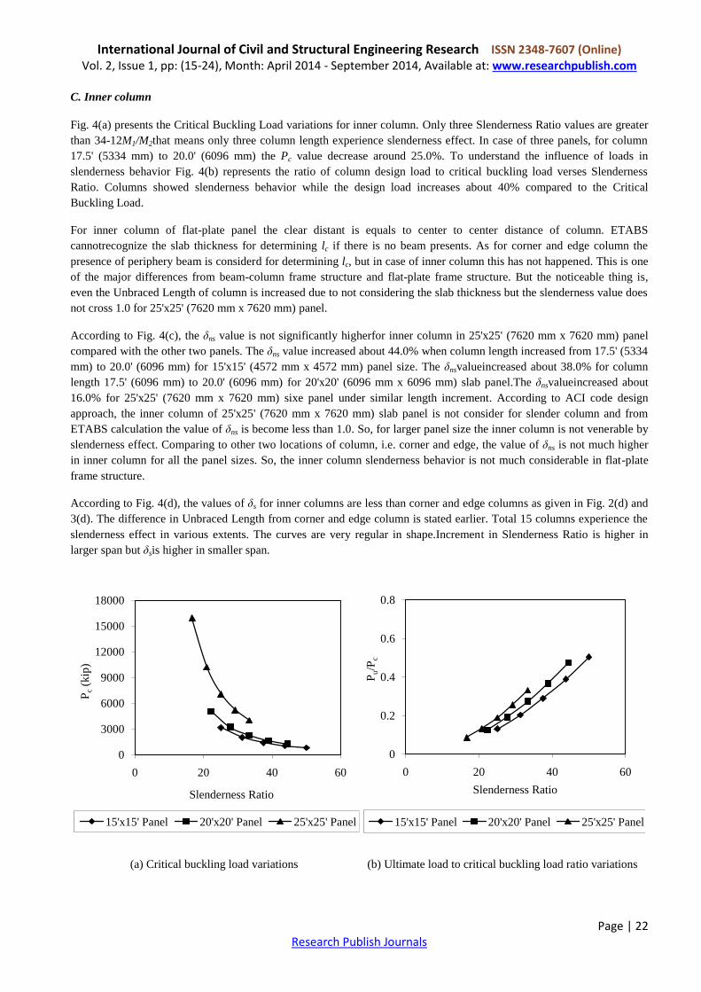
C. Inner column
Fig. 4(a) presents the Critical Buckling Load variations for inner column. Only three Slenderness Ratio values are greater
than 34-12M1/M2that means only three column length experience slenderness effect. In case of three panels, for column
17.5' (5334 mm) to 20.0' (6096 mm) the Pc value decrease around 25.0%. To understand the influence of loads in
slenderness behavior Fig. 4(b) represents the ratio of column design load to critical buckling load verses Slenderness
Ratio. Columns showed slenderness behavior while the design load increases about 40% compared to the Critical
Buckling Load.
For inner column of flat-plate panel the clear distant is equals to center to center distance of column. ETABS
cannotrecognize the slab thickness for determining lc if there is no beam presents. As for corner and edge column the
presence of periphery beam is considerd for determining lc, but in case of inner column this has not happened. This is one
of the major differences from beam-column frame structure and flat-plate frame structure. But the noticeable thing is,
even the Unbraced Length of column is increased due to not considering the slab thickness but the slenderness value does
not cross 1.0 for 25'x25' (7620 mm x 7620 mm) panel.
According to Fig. 4(c), the δns value is not significantly higherfor inner column in 25'x25' (7620 mm x 7620 mm) panel
compared with the other two panels. The δns value increased about 44.0% when column length increased from 17.5' (5334
mm) to 20.0' (6096 mm) for 15'x15' (4572 mm x 4572 mm) panel size. The δnsvalueincreased about 38.0% for column
length 17.5' (6096 mm) to 20.0' (6096 mm) for 20'x20' (6096 mm x 6096 mm) slab panel.The δnsvalueincreased about
16.0% for 25'x25' (7620 mm x 7620 mm) sixe panel under similar length increment. According to ACI code design
approach, the inner column of 25'x25' (7620 mm x 7620 mm) slab panel is not consider for slender column and from
ETABS calculation the value of δns is become less than 1.0. So, for larger panel size the inner column is not venerable by
slenderness effect. Comparing to other two locations of column, i.e. corner and edge, the value of δns is not much higher
in inner column for all the panel sizes. So, the inner column slenderness behavior is not much considerable in flat-plate
frame structure.
According to Fig. 4(d), the values of δs for inner columns are less than corner and edge columns as given in Fig. 2(d) and
3(d). The difference in Unbraced Length from corner and edge column is stated earlier. Total 15 columns experience the
slenderness effect in various extents. The curves are very regular in shape.Increment in Slenderness Ratio is higher in
larger span but δsis higher in smaller span.
0
3000
6000
9000
12000
15000
18000
0 20 40 60
Pc
(kip
)
Slenderness Ratio
15'x15' Panel 20'x20' Panel 25'x25' Panel
0
0.2
0.4
0.6
0.8
0 20 40 60
Pu/P
c
Slenderness Ratio
15'x15' Panel 20'x20' Panel 25'x25' Panel
(a) Critical buckling load variations (b) Ultimate load to critical buckling load ratio variations

International Journal of Civil and Structural Engineering Research ISSN 2348-7607 (Online) Vol. 2, Issue 1, pp: (15-24), Month: April 2014 - September 2014, Available at: www.researchpublish.com
Page | 23 Research Publish Journals
Fig. 4.Slender column parameter variations for inner column
E. Checking ACI code guidelines
For designing any column, a designer should check for slenderness effect. According to the ACI code, for compression
member in non-sway frames, the effect of slenderness may be neglected when klu/r≤34-12M1/M2, where 34-12M1/M2 is
not taken greater than 40. So, if (klu/r)/(34-12M1/M2) is less than 1.0 than the column will not show any slender effect.
Considering this limiting criteria, Fig. 5(a) is drawn.Two dotted perpendicular lines are the limit line for slenderness
effects. For a particular column, if δns is greater than 1.0 and (klu/r)/(34-12M1/M2) is greater than 1.0, will be considered as
slender column. For flat-plate structures, thirteen columns are exceeded the limit bounded by ACI code. Some columns
satisfy either of the conditions. Slenderness consideration of those columns would provide extra safety factor to the
design. The column length greater than 20' (6096 mm) is at risk for slenderness effect. Column length ranges from 17.5' to
20' is substantially consider as slender column.Therefore, from Fig. 5(a), this can conclude that, the ACI guideline for
considering δnsis acceptable.
For compression member in sway frames, the effect of slenderness may be neglected when klu/r is less than 22. So, if
(klu/r)/22 is less than 1.0 than the column will not show any slenderness effect. Fig. 5(b) is plotted against δs against
(klu/r)/22 for flat-plate frame structure. It is seen that only 2 columns are less than (klu/r)/22 but have δs effect.
Considering 45 columns these 2 values are outlier. Therefore, from Fig. 5(b), this can conclude that, the guideline for
considering δsis acceptable and every column is at risk for sway effect even it may not in danger for non-sway effect.
Hence, the designer should check a column for bothnon-sway and sway effect.
Fig. 5.ACI code limits for non-sway and sway slender column analysis
0
2
4
6
8
0 20 40 60
δns
Slenderness Ratio
15'x15' Panel 20'x20' Panel 25'x25' Panel
1.00
1.05
1.10
1.15
1.20
1.25
0 50 100 150
δs
Slenderness Ratio
15'x15' Panel 20'x20' Panel 25'x25' Panel
0
2
4
6
8
0 0.5 1 1.5 2
δn
s
(Klu/r)/(34-12M1/M2)
1
1.05
1.1
1.15
1.2
1.25
0 2 4 6
δs
(klu/r)/22
(a) ACI code limit for non-sway criteria (b) ACI code limit for sway criteria
(c) Non-sway moment magnification factor variations
(d) Sway moment magnification factor variations

International Journal of Civil and Structural Engineering Research ISSN 2348-7607 (Online) Vol. 2, Issue 1, pp: (15-24), Month: April 2014 - September 2014, Available at: www.researchpublish.com
Page | 24 Research Publish Journals
6. CONCLUSIONS
The objective of the study is to identify the important parameters of slenderness in column design for the flat-plate
structuresby carrying out parametric study. From the above discussions, it can be said that flat-plate structures columns
are sensitive to slenderness effects. By location, corner and edge column should carefully judge at the time of calculating
magnification factors. Spatially edge column of flat-plate structure shows maximum slenderness values. Most of the inner
columns do not show any slender effect. Moreover, a column can be consider as non-slender by considering Slenderness
Ratio only but could have slenderness effect if non-sway or sway moment magnification factor is determined. In addition,
a column could have shown non-slenderness behavior of non-sway frame is considered but showed significant
slenderness if sway frame is considered. For this reason, a designer should check a column for both non-sway and sway
frame and determine both non-sway and sway moment magnification factor.
REFERENCES
[1]. B. K. Halder, “Design of Concrete Column Considering Slenderness Effect”, B.Sc. Engineering Thesis, Department
of Civil Engineering, Bangladesh University of Engineering and Technology (BUET), Dhaka, Bangladesh, 2007.
[2]. A. H. Nilson, D. Darwin, and C. W. Dolan, “Design of Concrete Structures”, 13th
Edition, Tata McGraw-Hill
Publishing Company, New Delhi, India, 2003.
[3]. M. N. Hassoun, “Structural Concrete”, Addison-Wesley Publishing Company Inc., New York, USA, 2005.
[4]. P. M. Ferguson, J. E. Breen, and J. O. Jirsa, “Reinforced Concrete Fundamentals”, Fifth Edition, New York, John
Willy & Sons, 1987.
[5]. A. J. Rathbone, “Second-Order effect, Who Needs Them”, The Structural Engineer, vol. 80, no. 21, pp. 19, 2002.
[6]. ACI Committee 318, “Building Code Requirements for Structural Concrete & Commentary: ACI 318-99”, American
Concrete Institute, Detroit, USA, 1999.
[7]. Computers & Structures Inc., “ETABS: Integrated Building Design Software”, Version 8.0, Berkeley, California,
USA, 2003.
[8]. M. I. Hossain, “Effects of Slenderness in Reinforced Concrete Column Design”, M. Engg. Research Project,
Department of Civil Engineering, Bangladesh University of Engineering and Technology (BUET), Dhaka,
Bangladesh, 2008.
[9]. Bangladesh National Building Code, “BNBC: Housing and Building Research Institute”, Dhaka, Bangladesh, 2006.